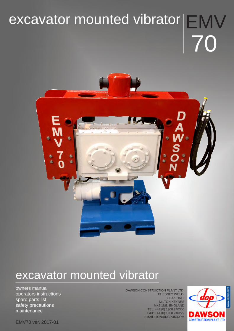
DAWSON CONSTRUCTION PLANT LTD. CHESNEY WOLD, BLEAK HALL MILTON KEYNES MK6 1NE, ENGLAND TEL: +44 (0) 1908 240300 FAX: +44 (0) 1908 240222 EMAIL: [email protected] excavator mounted vibrator excavator mounted vibrator EMV 70 owners manual operators instructions spare parts list safety precautions maintenance EMV70 ver. 2017-01 www.dcpuk.com

Welcome message from author
This document is posted to help you gain knowledge. Please leave a comment to let me know what you think about it! Share it to your friends and learn new things together.
Transcript
DAWSON CONSTRUCTION PLANT LTD.CHESNEY WOLD,
BLEAK HALLMILTON KEYNES
MK6 1NE, ENGLANDTEL: +44 (0) 1908 240300FAX: +44 (0) 1908 240222
EMAIL: [email protected]
excavator mounted vibrator
excavator mounted vibrator EMV70
owners manualoperators instructionsspare parts listsafety precautions maintenance
EMV70 ver. 2017-01
ww
w.d
cpuk
.com

table of contents
This manual is used to familiarise you with safety, assembly, operation, adjustment, troubleshooting, and maintenance. Read and follow the recommendations in this manual to ensure safe and efficient operation. Keep this manual with the attachment at all times for future reference.
We want you to be completely satisfied with your new product, feel free to contact your local authorized service dealer for help with service, replacement parts, or any other information you may require. If you need assistance in locating a dealer, visit our web site at www.dcpuk.com or call customer service at +44 (0) 1908 240300.
When ever you contact your authorised service dealer, always have the model number and serial number of your product available. These numbers will help provide exact information about your specific product. You will find the model and serial numbers on an ID plate located on the product.
The descriptions and specifications in this manual are subject to change without notice. Dawson reserves the right to improve products. Some product improvements may have taken place after this manual was printed.
preface
Preface / Table of Contents 3
EU Declaration of Conformity 5
Basic Technical Specifications 6
Basic Safety Points 7-8
SAFETY FIRST - Quick Reference Guide 9-10
How does the EMV work? 11-12
Mounting Instructions 13-14
Operating Instructions 15-17
Operating Instructions - Driving Piles (Quick Reference Illustrations) 18-19
Operating Instructions - Extracting Piles (Quick Reference Illustrations) 20-21
Recommended Excavator Positions (Quick Reference Illustrations) 22
Maintenance 23-26
Troubleshooting 27-31
EMV70 hose kit 32
Parts lists for the EMV70 - Assembly Drawing 33
Appendix A- Auxiliary equipment(The EMV inspection procedure is also included with this document.)
-

CertificateDeclaration of Conformity
Dawson Construction Plant LtdChesney Wold, Bleak Hall, Milton Keynes MK6 1NE, ENGLAND
Tel: (+44) 1908 240300 Fax: (+44) 1908 240222E-Mail: [email protected] Website: www.dcpuk.com
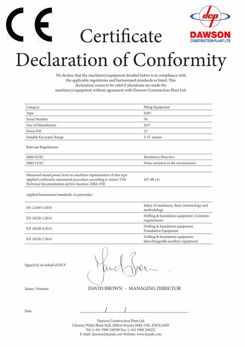
CertificateDeclaration of Conformity
We declare that the machinery/equipment detailed below is in compliance withthe applicable regulations and harmonised standards as listed. This
declaration ceases to be valid if alterations are made themachinery/equipment without agreement with Dawson Construction Plant Ltd.
Category Piling EquipmentType EMVSerial Number 70-Year of Manufacture 2017Power kW 12Suitable Excavator Range 5-15 tonnes
Relevant Regulations:
2006/42/EC Machinery Directive2000/14/EC Noise emission in the environment -
Measured sound power level on machines representative of this type Applied conformity assessment procedure according to Annex VIIITechnical documentation archive location: MK6 1NE
107 dB (A)
Applied harmonised standards, in particular:
EN 12100-1:2010 Safety of machinery. Basic terminology and methodology
EN 16228-1:2014 Drilling & foundation equipment. Common requirements
EN 16228-4:2014 Drilling & foundation equipment. Foundation Equipment
EN 16228-7:2014 Drilling & foundation equipment. Interchangeable auxiliary equipment
Signed by on behalf of DCP
Name / Position DAVID BROWN - MANAGING DIRECTOR
Date / /Dawson Construction Plant Ltd
Chesney Wold, Bleak Hall, Milton Keynes MK6 1NE, ENGLANDTel: (+44) 1908 240300 Fax: (+44) 1908 240222
E-Mail: [email protected] Website: www.dcpuk.com
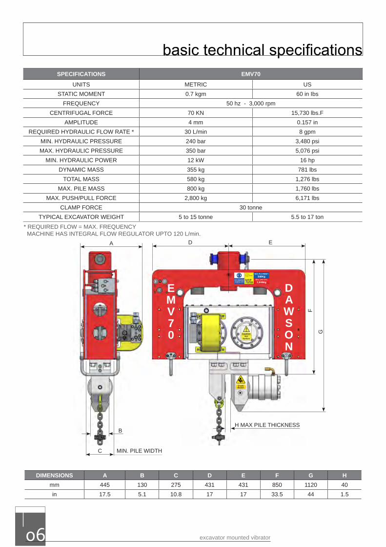
DIMENSIONS A B C D E F G Hmm 445 130 275 431 431 850 1120 40in 17.5 5.1 10.8 17 17 33.5 44 1.5
SPECIFICATIONS EMV70
UNITS METRIC USSTATIC MOMENT 0.7 kgm 60 in Ibs
FREQUENCY 50 hz - 3,000 rpmCENTRIFUGAL FORCE 70 KN 15,730 lbs.F
AMPLITUDE 4 mm 0.157 inREQUIRED HYDRAULIC FLOW RATE * 30 L/min 8 gpm
MIN. HYDRAULIC PRESSURE 240 bar 3,480 psiMAX. HYDRAULIC PRESSURE 350 bar 5,076 psi
MIN. HYDRAULIC POWER 12 kW 16 hpDYNAMIC MASS 355 kg 781 lbs
TOTAL MASS 580 kg 1,276 lbsMAX. PILE MASS 800 kg 1,760 lbs
MAX. PUSH/PULL FORCE 2,800 kg 6,171 lbsCLAMP FORCE 30 tonne
TYPICAL EXCAVATOR WEIGHT 5 to 15 tonne 5.5 to 17 ton
A D E
B
C MIN. PILE WIDTH
F
G
H MAX PILE THICKNESS
EMV70
DAWSON
* REQUIRED FLOW = MAX. FREQUENCYMACHINE HAS INTEGRAL FLOW REGULATOR UPTO 120 L/min.
!Hot
Surface
Caution
basic technical specifications
excavator mounted vibrator06
* REQUIRED FLOW = MAX. FREQUENCY MACHINE HAS INTEGRAL FLOW REGULATOR UPTO 120 L/min.
• The vibrator should only be operated by suitably qualified personnel.• The vibrator/clamps not to be used for lifting operations.• It is prohibited to leave an element suspended in the clamps of a vibrator, which is free hanging and out
of operation.• Don’t leave the vibrator clamped on a pile without being attached to the excavator.• Extraction pulling force not to be exceeded.• Pile to be secured to the lifting chain of equal lifting or greater capacity to the load held in the clamp.• It is prohibited to use vibrator as an impact hammer, by hammering with open clamp.• There should be visual contact between operator and slinger (banksman) at all times.• Monitor the piling operation constantly – stop the process immediately if any danger occurs.• Do not operate the vibrator if any person is within the High Risk Area – see section 2.1.4.• Consider machine stability at all times.• The operator should inspect the equipment for defects every day and before being taken in to service. Any
defects that affect operational safety should be corrected before the equipment is taken into service – seesection 5.
• Pay attention to the Safe Working Load of all lifting accessories at all times. (See table in section 2.1.6).• The working area should be properly illuminated.• Work safely at all times and within the requirements of all local legislation.• The vibrator can become very hot during operation – do not touch it unless wearing appropriate
protective clothing.
WHO IS RESPONSIBLE?Those who are in charge of, or responsible for, the use and maintenance must ensure that the vibrator and all it's auxiliary equipment are in good condition.
Piling should only be carried out under the supervision of an appropriately qualified and experienced person who can assess that the work is carried out safely.
The excavator operator must ensure that his communication signals are understood, by those on the ground, and followed. During piling operations he must watch out for any potential hazards.
WORKING CONDITIONS / ADVERSE WEATHER CONDITIONSVibrators should only be operated and driven on firm ground with clear visibility of the working area and the process monitored constantly. Operators must have a clear understanding of the site assessment and method statement. This assessment will cover risks and site actions that have been implemented for the event of adverse weather conditions.The vibrator stand must stay upright on level ground (at all times) to avoid personnel injury.
WORKING NEAR UNDERGROUND / OVERHEAD OBSTACLESBefore the start of any piling work it is up to the contractor to identify if there are any underground cables, utilities and overhead obstacles within the working area which could be dangerous to personnel, including but not limited to live electrical cables. This should be fully covered in the site specific method statement. All personnel on site should have a full understanding of the risks. In the case of unforeseeable contact or damage of an underground / overhead obstacle, then work must stop immediately and the person in charge informed.
THE HIGH RISK AREAThis is an area defined as that being within an approximate radius of the vibrator which is calculated by the following formula: Pile length (m) + ½(Pile Length)
This area can be either this or within the slewing radius of the excavator, whichever is greater. The High Risk Area is active while the vibrator is working or the excavator is in operation. (Please refer to operator’s instruction for full details)
basic safety points
www.dcpuk.com 07
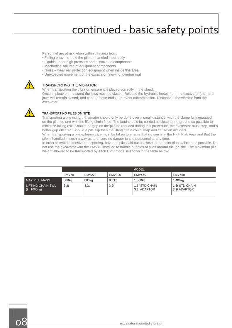
Personnel are at risk when within this area from:• Falling piles – should the pile be handled incorrectly• Liquids under high pressure and associated components• Mechanical failures of equipment components• Noise – wear ear protection equipment when inside this area• Unexpected movement of the excavator (slewing, overturning)
TRANSPORTING THE VIBRATORWhen transporting the vibrator, ensure it is placed correctly in the stand.Once in place on the stand the jaws must be closed. Release the hydraulic hoses from the excavator (the hard jaws will remain closed) and cap the hose ends to prevent contamination. Disconnect the vibrator from the excavator.
TRANSPORTING PILES ON SITETransporting a pile using the vibrator should only be done over a small distance, with the clamp fully engaged on the pile top and with the lifting chain fitted. The load should be carried as close to the ground as possible to minimise falling risk. Should the grip on the pile be reduced during this procedure, the excavator must stop, and a better grip effected. Should a pile slip then the lifting chain could snap and cause an accident.When transporting a pile extreme care must be taken to ensure that no one is in the High Risk Area and that the pile is handled in such a way as to ensure no danger to site personnel at any time.In order to avoid extensive transporting, have the piles laid out as close to the point of installation as possible. Do not use the excavator with the EMV70 installed to handle bundles of piles around the job site. The maximum pile weight allowed to be transported by each EMV model is shown in the table below:
MODEL
EMV70 EMV220 EMV300 EMV450 EMV550
MAX PILE MASS 800kg 800kg 800kg 1,000kg 1,400kg
LIFTING CHAIN SWL(t= 1000kg)
3.2t 3.2t 3.2t 1.6t STD CHAIN3.2t ADAPTOR
1.6t STD CHAIN3.2t ADAPTOR
excavator mounted vibrator08
continued - basic safety points
www.dcpuk.com 09
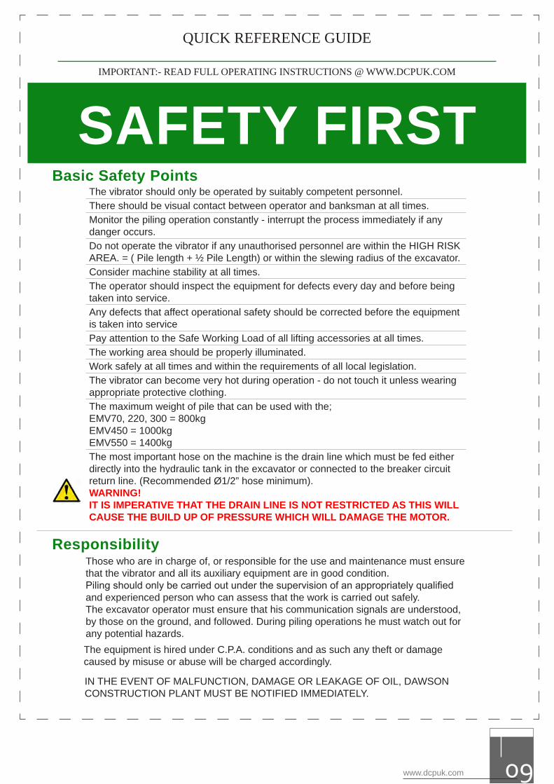
The vibrator should only be operated by suitably competent personnel.There should be visual contact between operator and banksman at all times.Monitor the piling operation constantly - interrupt the process immediately if any danger occurs.Do not operate the vibrator if any unauthorised personnel are within the HIGH RISK AREA. = ( Pile length + ½ Pile Length) or within the slewing radius of the excavator.Consider machine stability at all times.The operator should inspect the equipment for defects every day and before being taken into service.Any defects that affect operational safety should be corrected before the equipment is taken into servicePay attention to the Safe Working Load of all lifting accessories at all times.The working area should be properly illuminated.Work safely at all times and within the requirements of all local legislation.The vibrator can become very hot during operation - do not touch it unless wearing appropriate protective clothing.The maximum weight of pile that can be used with the;EMV70, 220, 300 = 800kg EMV450 = 1000kgEMV550 = 1400kgThe most important hose on the machine is the drain line which must be fed either directly into the hydraulic tank in the excavator or connected to the breaker circuit return line. (Recommended Ø1/2” hose minimum).WARNING! IT IS IMPERATIVE THAT THE DRAIN LINE IS NOT RESTRICTED AS THIS WILL CAUSE THE BUILD UP OF PRESSURE WHICH WILL DAMAGE THE MOTOR.
Basic Safety Points
Responsibility
IN THE EVENT OF MALFUNCTION, DAMAGE OR LEAKAGE OF OIL, DAWSON CONSTRUCTION PLANT MUST BE NOTIFIED IMMEDIATELY.
The equipment is hired under C.P.A. conditions and as such any theft or damage caused by misuse or abuse will be charged accordingly.
SAFETY FIRSTIMPORTANT:- READ FULL OPERATING INSTRUCTIONS @ WWW.DCPUK.COM
Those who are in charge of, or responsible for the use and maintenance must ensure that the vibrator and all its auxiliary equipment are in good condition.Piling should only be carried out under the supervision of an appropriately qualified and experienced person who can assess that the work is carried out safely.The excavator operator must ensure that his communication signals are understood, by those on the ground, and followed. During piling operations he must watch out for any potential hazards.
QUICK REFERENCE GUIDE
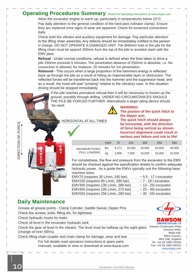
Allow the excavator engine to warm up, particularly in temperatures below 10°C.Pay daily attention to the general condition of the hard jaws (vibrator clamp). Ensure they are replaced once signs of wear are apparent. Check for loosened connections daily.Check both the vibrator and auxiliary equipment for damage. Pay particular attention to the lifting chain assembly. Any defects should be immediately notified to the person in charge. DO NOT OPERATE A DAMAGED UNIT. The Ø40mm hole in the pile for the lifting chain must be spaced 250mm from the top of the pile to avoided clash with the EMV jaws.Refusal - Under normal conditions, refusal is defined when the time taken to drive a pile 250mm exceeds 5 minutes. The penetration distance of 250mm is absolute, i.e. No conversion is allowed, for instance, 20 minutes for 1m penetration.Rebound - This occurs when a large proportion of the hammers energy is reflected back up through the pile as a result of hitting an impenetrable layer or obstruction. The reflected forces will be transferred back into the hammer and the suppressor head, and as a result, the head will start “jumping” relative to the vibratory case. In this situation driving should be stopped immediately. If the pile reaches premature refusal then it will be necessary to loosen up the ground, possibly through drilling. UNDER NO CIRCUMSTANCES SHOULD THE PILE BE FORCED FURTHER. Alternatively a larger piling device should
be used.
Operating Procedures Summary - Read Full Operating Instructions at www.dcpuk.com
Grease all grease points - Clamp Cylinder, Saddle Swival, Dipper PinsCheck the screws, bolts, fitting etc. for tightnessCheck hydraulic hoses for leaksCheck oil level in the excavator hydraulic tankCheck the gear oil level in the vibrator. The level must be halfway up the sight glass(change oil ever 50hrs).Check lifting chain coupler and chain clamp for damage, wear and tear
Daily Maintenance
EMV 70 220 300 450 550
MAXIMUM PUSH/PULL LOADING
lbs 6,171 16,500 33,600 33,600 49,500
kg 2,800 7,500 15,000 15,000 22,500
EMV70 (requires 30 L/min, 240 bar) ~ 5.5 - 17 t excavator EMV220 (requires 90 L/min, 280 bar) ~ 7 - 18 t excavatorEMV300 (requires 130 L/min, 280 bar) ~ 13 - 25t excavatorEMV450 (requires 195 L/min, 270 bar) ~ 25 - 45t excavatorEMV550 (requires 256 L/min, 280 bar) ~ 30 - 55t excavator
For completness, the flow and pressure from the excavator to the EMV should be checked against the specification sheets to confirm adequate hydraulic power. As a guide the EMVs typically suit the following base machine sizes:
Dawson Constrcution PlantChesney Wold.
Bleak Hall,Milton Keynes,
MK6 1NE, EnglandTel: +44 (0) 1908 240300
Fax: +44 (0) 1908 240222www.dcpuk.com
WARNING!The postion of the quick hitch to the dipper arm.The quick hitch should always be horizontal, with the direction of force being vertical as shown. Incorrect alignment could result in serious part failure and risk to life!
For full details read operators instructions & spare parts manuals, available to view or download at www.dcpuk.com
DIR
EC
TIO
N O
F FO
RC
E HORIZONTAL AT ALL TIMES
excavator mounted vibrator10
EMV 70 220 300 450 550
MAXIMUM PUSH/PULL LOADING
lbs 6,171 16,500 33,600 33,600 49,500
kg 2,800 7,500 15,000 15,000 22,500
EMV70 (requires 30 L/min, 240 bar) ~ 5.5 - 17 t excavator EMV220 (requires 90 L/min, 280 bar) ~ 7 - 18 t excavatorEMV300 (requires 130 L/min, 280 bar) ~ 13 - 25t excavatorEMV450 (requires 195 L/min, 270 bar) ~ 25 - 45t excavatorEMV550 (requires 256 L/min, 280 bar) ~ 30 - 55t excavator
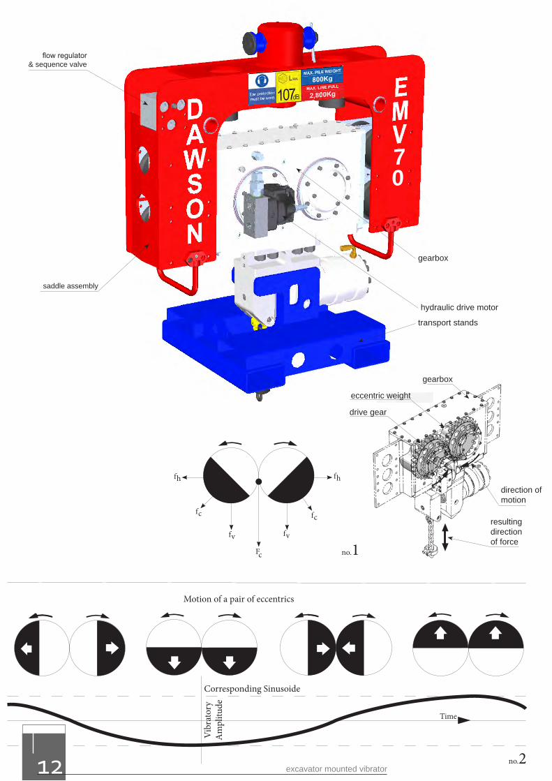
Modern pile vibrators basically work in the same way. Pairs of high-speed contra-rotating eccentric weights are geared together so as to produce net vertical vibratory forces.
The vibrations produced are transmitted to the pile through a powerful hydraulic grip. Consequently the pile is vibrated at the same speed and displacement (or movement) as the gearbox itself. This vibration effect is transmitted to the pile tip where the surrounding soils become almost fluid like.
The fluidising effect on the soil permits particles to shuffle themselves around creating some spaces for the pile to move into. This combined with the weight of the pile and vibrator is adequate to push the pile into the ground.
Not all soil types will however fluidise. Clays soils are very cohesive and extremely dense by comparison to sands and gravels where vibrators work best. The dense clay soil does not allow soil particles to shuffle themselves around, so no fluidising effect can occur. Also the ground effectively sticks itself to the pile and much of the power generated is lost in shaking the ground.
The EMV is particularly effective for its size and weight because it is able to utilise the crowd force available from the excavator to add further push force to the pile.
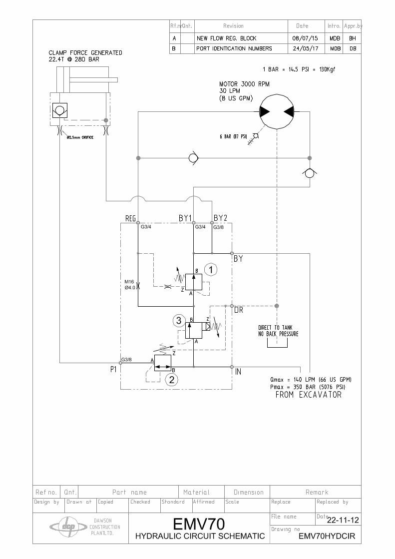
The gearbox in the EMV unit is driven by a hydraulic drive motor that receives hydraulic power from the excavators bucket ram circuit. Typically this circuit will be able to supply adequate working pressure but excessive amount of oil flow rate. The EMV has a built-in flow regulator that limits the oil flow rate supplied to the drive motor so that the gearbox can not be run too fast. This is essential to prevent excessive bearing loads and correct performance of the unit.
In addition, the flow regulator has a sequence valve built-in that will not allow the vibrator to run until adequate clamping force has been applied to the pile – an essential safety feature. This simplified hydraulic system enables simple installation and reliable performance.
how does the emv work?
www.dcpuk.com 11
Fc
fv
fc
fh
fv
fc
fh
no.1
Motion of a pair of eccentrics
Corresponding Sinusoide
no.2
Vib
rato
ryA
mpl
itude
Time
eccentric weight
gearbox
drive gear
direction of motion
resulting directionof force
hydraulic drive motor
transport stands
gearbox
saddle assembly
flow regulator& sequence valve
70
excavator mounted vibrator12
direction of motion
resulting directionof force
www.dcpuk.com 13
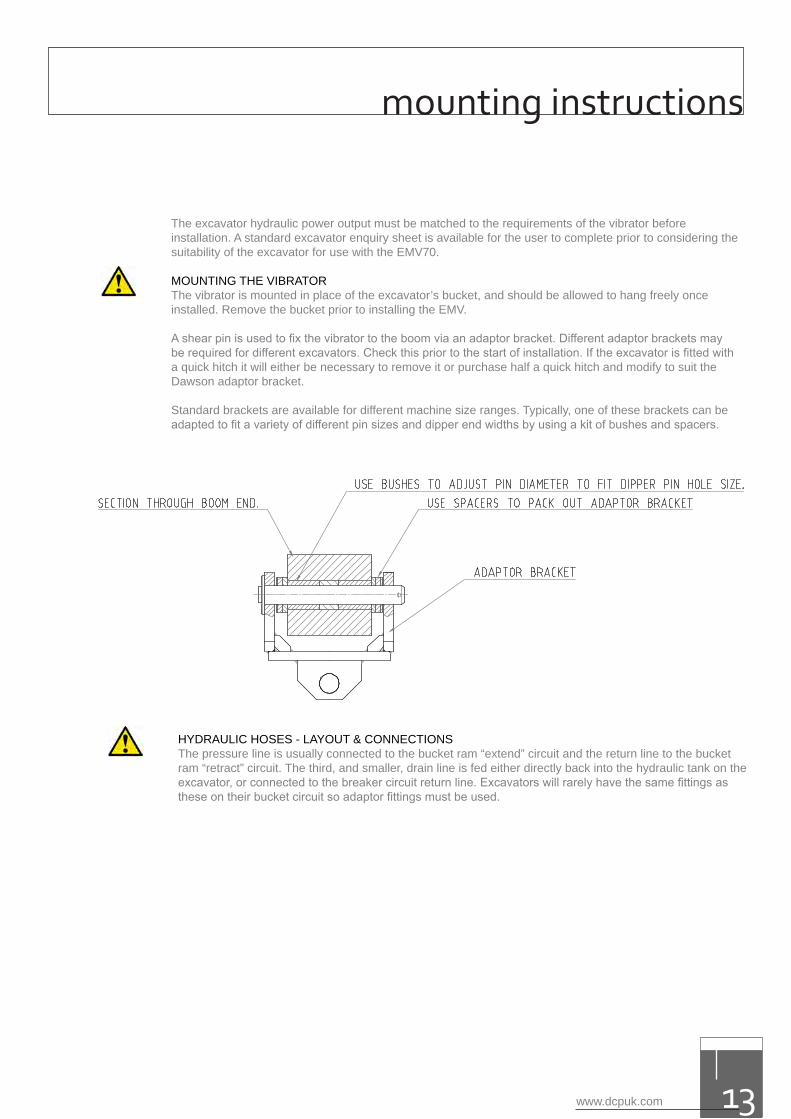
The excavator hydraulic power output must be matched to the requirements of the vibrator before installation. A standard excavator enquiry sheet is available for the user to complete prior to considering the suitability of the excavator for use with the EMV70.
MOUNTING THE VIBRATOR The vibrator is mounted in place of the excavator’s bucket, and should be allowed to hang freely once installed. Remove the bucket prior to installing the EMV.
A shear pin is used to fix the vibrator to the boom via an adaptor bracket. Different adaptor brackets may be required for different excavators. Check this prior to the start of installation. If the excavator is fitted with a quick hitch it will either be necessary to remove it or purchase half a quick hitch and modify to suit the Dawson adaptor bracket.
Standard brackets are available for different machine size ranges. Typically, one of these brackets can be adapted to fit a variety of different pin sizes and dipper end widths by using a kit of bushes and spacers.
mounting instructions
HYDRAULIC HOSES - LAYOUT & CONNECTIONSThe pressure line is usually connected to the bucket ram “extend” circuit and the return line to the bucket ram “retract” circuit. The third, and smaller, drain line is fed either directly back into the hydraulic tank on the excavator, or connected to the breaker circuit return line. Excavators will rarely have the same fittings as these on their bucket circuit so adaptor fittings must be used.
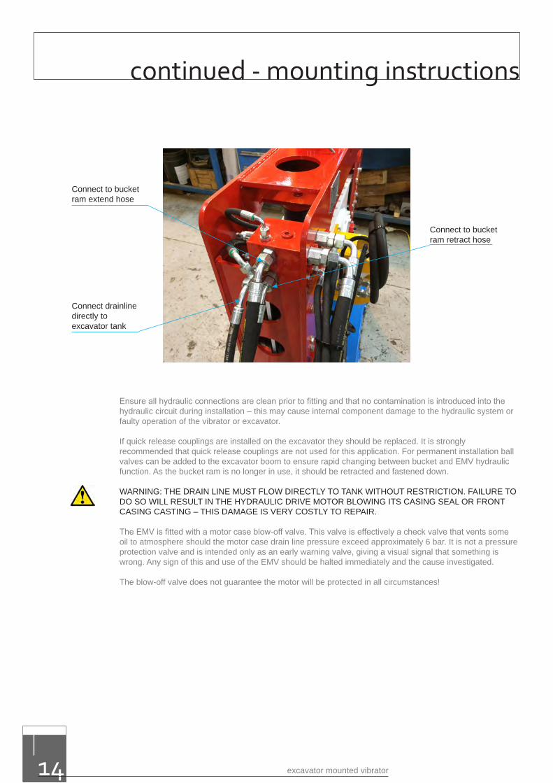
Connect drainline directly to excavator tank
Connect to bucket ram retract hose
Connect to bucket ram extend hose
Ensure all hydraulic connections are clean prior to fitting and that no contamination is introduced into the hydraulic circuit during installation – this may cause internal component damage to the hydraulic system or faulty operation of the vibrator or excavator.
If quick release couplings are installed on the excavator they should be replaced. It is strongly recommended that quick release couplings are not used for this application. For permanent installation ball valves can be added to the excavator boom to ensure rapid changing between bucket and EMV hydraulic function. As the bucket ram is no longer in use, it should be retracted and fastened down.
WARNING: THE DRAIN LINE MUST FLOW DIRECTLY TO TANK WITHOUT RESTRICTION. FAILURE TO DO SO WILL RESULT IN THE HYDRAULIC DRIVE MOTOR BLOWING ITS CASING SEAL OR FRONTCASING CASTING – THIS DAMAGE IS VERY COSTLY TO REPAIR.
The EMV is fitted with a motor case blow-off valve. This valve is effectively a check valve that vents some oil to atmosphere should the motor case drain line pressure exceed approximately 6 bar. It is not a pressure protection valve and is intended only as an early warning valve, giving a visual signal that something is wrong. Any sign of this and use of the EMV should be halted immediately and the cause investigated.
The blow-off valve does not guarantee the motor will be protected in all circumstances!
excavator mounted vibrator14
continued - mounting instructions
PREPARATIONS - BEFORE DRIVING / EXTRACTING PILES It is the excavator operator’s responsibility to ensure that the equipment is functioning and performing correctly and that the EMV method of piling is implemented efficiently.
In order to meet this responsibility please note the following points:
a. Bundles of sheet piles should be set out on the job site so as to minimise the amount of handlingand travelling required with the EMV.
b. Ensure that all piles have Ø40mm(Ø1½”) holes cut in them approximately 250mm(10”) down fromthe top edge and central prior to commencement of the piling operation.
c. Allow the excavator engine to warm up, particularly in temperatures below minus 10°C and warmthe excavators hydraulic system by, for example, tracking backwards and forwards – this avoidsthe EMV’s blow-off valve spitting oil on initial start-up.
d. Before work commences slowly operate the bucket ram lever in both directions. It is particularlyimportant that the vibrator is allowed to run freely for approximately 30 seconds, this allows thegearbox oil to reach all the necessary lubricating points.
e. Review section “2.1 Basic Safety Points” in this manual before starting work.
f. Review section “6.1 Daily Maintenance” before taking the equipment into service.
g. It is particularly important that you make sure that during a piling operation the vibrator is keptdirectly above and in line with the pile, otherwise the piling energy is transferred to the excavatorarm and causes unnecessary wear and may lead to pile damage.
DRIVING PILESa. Ensure that all safety procedures and maintenance has been carried out before starting the
excavator – see section 5.1.
b. Ensure that it is safe to move the dipper arm. Release the stand from the jaws of the vibrator byoperation of the retract bucket ram control function in the cab. Manoeuvre the vibrator above oneend of the pile to be pitched, so that there is enough distance to allow safe insertion of the liftingchain through the hole at the top of the pile.
c. Manoeuvre the vibrator above one end of the pile to be pitched, so that there is enough distance toallow safe insertion of the lifting chain through the hole at the top of the pile.
d. Check which way around the pile has to be lifted before inserting the lifting chain – was theprevious pile pitched left or right handed? Insert the lifting chain correctly (no twists, knots etc)through the lifting hole in the pile and finally with the chain clamp. Allow enough free chain lengthfor the pile to rotate to vertical during the lifting process without jamming against the underside ofthe clamp body. If this happens the chain will be overloaded, may subsequently break and allowthe pile to fall – this is a sever hazard to all site personnel and must be avoided at all times. Do notallow too much chain so that the top of the pile hangs too far away from the clamp when it is raisedto the vertical – this will make it difficult to engage the pile in the clamp.
e. Clear all personnel standing in the High Risk Area and lift up the pile until it just hangs freely off theground.
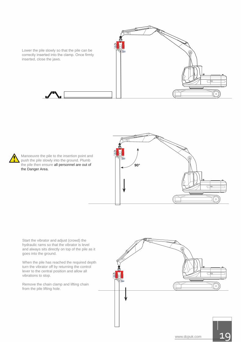
f. Lower the pile slowly so that the pile can be correctly inserted into the clamp. Once firmly inserted,close the jaws.
g. Manoeuvre the pile to the insertion point and push the pile slowly into the ground. Plumb the pileand ensure all personnel are out of the High Risk Area.
operating instructions
www.dcpuk.com 15
h. Start the vibrator and adjust (crowd) the hydraulic rams so that the vibrator is level and always sitsdirectly on top of the pile as it goes into the ground. Do not over push the vibrator - stop pushingwhen the gearbox starts to vibrate against the rubber stops on the underside of the saddle. Withthe EMV220 the deflection is 146mm (5.75”).
i. When the pile has reached the required depth turn the vibrator off by returning the control lever tothe central position and allow all vibrations to stop. Release the hard jaws from the pile by slowlyoperating the control lever in the opposite direction. Do not operate the control lever from oneextreme position to the other whilst the EMV is running – it will cause hydraulic system pressurespikes to occur.
j. Remove the chain clamp and lifting chain from the pile lifting hole.
k. Repeat steps c-j to continue.
l. When piling progress is less than 100mm/min (4ins/min) release groundresistance by augering or by water jetting. Under no circumstances should the pile be forced anyfurther.
EXTRACTING PILESa. Ensure that all safety procedures and maintenance has been carried out before starting the
excavator – see section 5.1.
b. Ensure that it is safe to move the dipper arm. Release the stand from the jaws of the vibrator byoperation of the retract bucket ram control function in the cab. Manoeuvre the vibrator above oneend of the pile to be extracted so that there is enough distance to allow safe insertion of the liftingchain through the hole at the top of the pile. Confirm suitable hole in pile.
c. Insert the lifting chain correctly (no twists, knots etc) through the lifting hole in the pile and securewith the chain clamp. Allow enough free chain length for the pile to rotate to horizontal duringthe lowering process without jamming against the underside of the clamp body. If this happensthechain will be overloaded, may subsequently break and allow the pile to fall – this is a severhazard to all site personnel and must be avoided at all times.
Under no circumstances should a pile be pulled using the lifting chain only.
d. Clamp the vibrator onto the pile head ensuring that it is level. Ensure all personnel are out of theHigh Risk Area.
e. Start the vibrator and allow the soil to loosen around the pile. Start to lift up the pile. Ensure thepile clutches are not rubbing together Pay attention to the distortion of the rubber sandwichmounts - under no circumstances should these mounts be allowed to deflect by more than thestipulated amount shown on Figure 1 in section 2.0. Reduce the extraction force to continuepulling. Continue extracting the pile until the pile foot is almost extracted. Stop vibration at thispoint and carefully pull the pile out the remaining short distance.
f. Move the pile to a suitable area, and place the pile on the ground. Ensure that all personnel areout of the High Risk Area.
g. Hold the pile on the ground and release the jaws. Raise the vibrator off the pile slowly ensuringthat there is no snatch on the lifting chain. Slowly lower the pile towards the ground.
h. Remove the chain clamp and lifting chain from the pile lifting hole.
i. Repeat steps c-h to continue.
excavator mounted vibrator16
continued - operating instructions
www.dcpuk.com 17
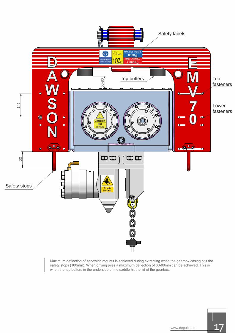
Maximum deflection of sandwich mounts is achieved during extracting when the gearbox casing hits the safety stops (100mm). When driving piles a maximum deflection of 60-80mm can be achieved. This is when the top buffers in the underside of the saddle hit the lid of the gearbox.
Safety stops
Lowerfasteners
Top fasteners
146 7
0
Top buffers
60-8
0
!Hot
Surface
Caution
Safety labels
excavator mounted vibrator18
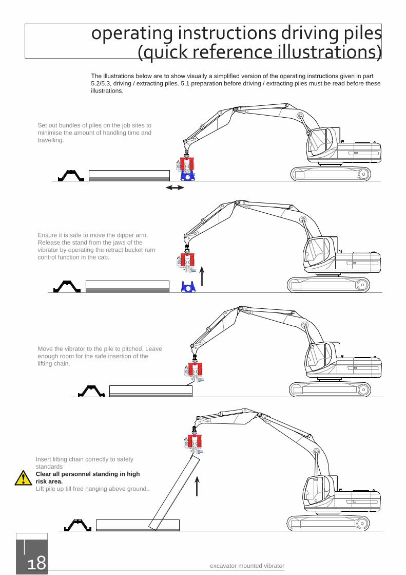
The illustrations below are to show visually a simplified version of the operating instructions given in part 5.2/5.3, driving / extracting piles. 5.1 preparation before driving / extracting piles must be read before these illustrations.
Set out bundles of piles on the job sites to minimise the amount of handling time and travelling.
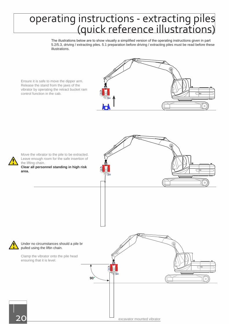
Ensure it is safe to move the dipper arm. Release the stand from the jaws of the vibrator by operating the retract bucket ram control function in the cab.
Move the vibrator to the pile to pitched. Leave enough room for the safe insertion of the lifting chain.
Insert lifting chain correctly to safety standards Clear all personnel standing in high risk area. Lift pile up till free hanging above ground..
operating instructions driving piles (quick reference illustrations)
Lower the pile slowly so that the pile can be correctly inserted into the clamp. Once firmly inserted, close the jaws.
Manoeuvre the pile to the insertion point and push the pile slowly into the ground. Plumb the pile then ensure all personnel are out of the Danger Area.
Start the vibrator and adjust (crowd) the hydraulic rams so that the vibrator is level and always sits directly on top of the pile as it goes into the ground.
When the pile has reached the required depth turn the vibrator off by returning the control lever to the central position and allow all vibrations to stop.
Remove the chain clamp and lifting chain from the pile lifting hole.
90°
www.dcpuk.com 19
excavator mounted vibrator20
Ensure it is safe to move the dipper arm. Release the stand from the jaws of the vibrator by operating the retract bucket ram control function in the cab.
Move the vibrator to the pile to be extracted. Leave enough room for the safe insertion of the lifting chain.Clear all personnel standing in high risk area.
Under no circumstances should a pile br pulled using the liftin chain.
Clamp the vibrator onto the pile head ensuring that it is level.
90°
operating instructions - extracting piles (quick reference illustrations)
The illustrations below are to show visually a simplified version of the operating instructions given in part 5.2/5.3, driving / extracting piles. 5.1 preparation before driving / extracting piles must be read before these illustrations.
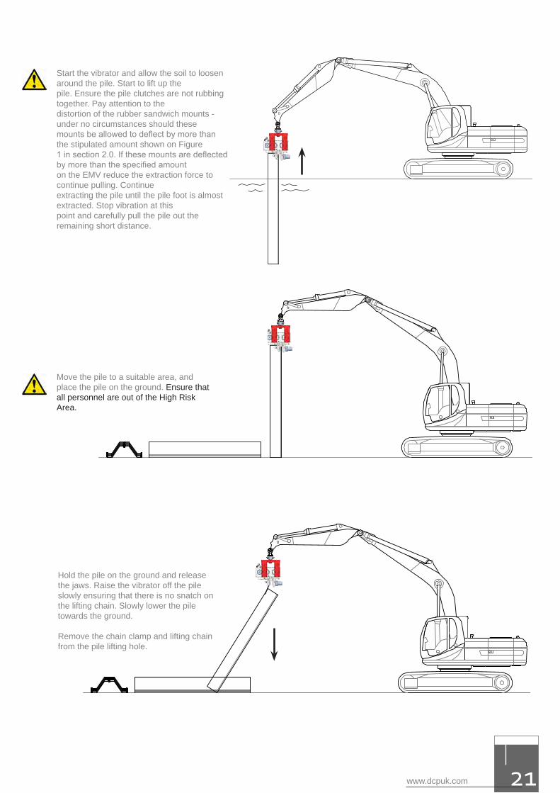
Start the vibrator and allow the soil to loosen around the pile. Start to lift up thepile. Ensure the pile clutches are not rubbing together. Pay attention to thedistortion of the rubber sandwich mounts - under no circumstances should thesemounts be allowed to deflect by more than the stipulated amount shown on Figure1 in section 2.0. If these mounts are deflected by more than the specified amounton the EMV reduce the extraction force to continue pulling. Continueextracting the pile until the pile foot is almost extracted. Stop vibration at thispoint and carefully pull the pile out the remaining short distance.
Move the pile to a suitable area, and place the pile on the ground. Ensure that all personnel are out of the High Risk Area.
Hold the pile on the ground and release the jaws. Raise the vibrator off the pileslowly ensuring that there is no snatch on the lifting chain. Slowly lower the piletowards the ground.
Remove the chain clamp and lifting chain from the pile lifting hole.
www.dcpuk.com 21
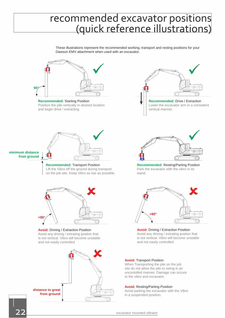
Recommended: Starting PositionPosition the pile vertically in desired location and begin drive / extracting.
Recommended: Drive / ExtractionLower the excavator arm in a consistent vertical manner.
Recommended: Transport PositionLift the Vibro off the ground during transport on the job site. Keep Vibro as low as possible.
Recommended: Resting/Parting PositionPark the excavator with the vibro in its stand.
Avoid: Driving / Extraction PositionAvoid any driving / extrating postion that is not vertical. Vibro will become unstable and not easily controlled
Avoid: Driving / Extraction PositionAvoid any driving / extrating postion that is not vertical. Vibro will become unstable and not easily controlled
Avoid: Transport PositionWhen Transporting the pile on the job site do not allow the pile to swing in an uncontolled manner. Damage can occure to the vibro and excavator.
Avoid: Resting/Parting PositionAvoid parking the excavator with the Vibro in a suspended position.
These illustrations represent the recommended working, transport and resting positions for your Dawson EMV attachment when used with an excavator.
90°
>90°>90°
distance to great from ground
minimum distance from ground
excavator mounted vibrator22
recommended excavator positions (quick reference illustrations)
www.dcpuk.com 23
The Excavator Mounted Vibrators have been designed to give years of trouble free service. Providing the equipment is treated with respect and the basic maintenance procedures are adhered to there will be little work additional work required.
The most important points are correct installation on good quality excavators, cleanliness when connecting to the excavator’s hydraulic system and regular gearbox oil changes using appropriate oils - again cleanliness is paramount.
Visual inspection of the EMV by a competent person on a daily basis and before being taken into service can prevent many potential problems from occurring. Ensure that lifting accessory test certificates are correct and valid at all times.
• All service and maintenance work must be carried out by qualified personnel using originalDawson parts. The use of other parts will invalidate the whole warranty for the equipment.
• The equipment should be inspected at ground level only and should be positioned so as tobe stable at all times.
• Secure the equipment against unexpected starting during the maintenance process.
• The equipment should be inspected by a Dawson technician or by one of their approveddistributors once a year or every 1000 working hours.
DAILY MAINTENANCEa. Grease the two grease points on the EMV70 – one on the Saddle Swivel and the other on the side
of the Clamp Body. Two or three pumps with a molybdenum-based grease will be adequate.
b. Check machine labelling. (Figure 6)
c. Check visible screws, bolts, fittings etc for tightness.
d. Visually inspect all hydraulic hoses and fittings for leaks or damage.
e. Check the gear oil level in the vibrator. The level must be half way up the sight glass.
f. Inspect the lifting chain and chain clamp for damage. The chain should be in good order, free fromany structural damage or
permanent deformation of any kind. The chain clamp should also be free from any structural damage and its correct operation and safe function should be checked by depressing and releasing several times – any binding or hesitancy with its operation should result in it being changed for a new certified item. The chains Coupler and anchorage point should be in good order showing no signs of damage, wear or cracking.
Remember if in doubt change it – lifting chains in the UK are required to have a thorough examination by a competent person at intervals not exceeding 6 months. Any local/national requirements must be adhered to!
g. Inspect the condition of the Hard Jaws. To be acceptable these should look to be in almost as newcondition. The teeth on these pads have some flats on them when new (approximately 1mm). Overtime they will round off, flatten out more and even become chipped. If not changed when requirethey will loose their grip on the pile during driving and certainly during extraction. Besides causing areduction in performance this can become a safety hazard. We define the following wear limit:
Hard Jaw Wear Limit - 90% of all teeth on any hard jaw should make contactwith the pile and 80% of all teeth should have points with flats no greater than 3mm.
Changing the Hard Jaws – Static SideRemove the Cap Screw that hold this jaw in place. Tap out the old jaw and clean/inspect the clamp body seating area to ensure the faces are in good order. Slide in the new jaw and check that it is a snug fit – the
maintenance
jaw should not move up and down. Fit the Cap Screw and tighten using a hexagonal wrench. Remember to install the washers on these screws.
Changing the Hard Jaws – Moving (Cylinder) SideRelease the 8off Cap Screws that hold the Clamp Cylinder in place and remove the Clamp Cylinder. Undo the two clamp supply hoses, carefully marking them to ensure correct re-assembly. Once removed, unscrew the round Hard Jaw counter-clockwise and replace with a new one using a new O-ring. Ensure the Jaw is fully tightened on the Clamp Cylinder piston rod so that the O-ring is no longer visible. Inspect the bronze Guide Bush inside the Clamp Body whilst the cylinder is out – check the grooves in the front area of the bush and the condition of the bore. Replace the bush if badly worn.
Assemble the Clamp Cylinder back into the Clamp Body, fit the clamp hoses then fit and tighten the Cap Screws using the hexagonal wrench. Ensure the clamp functions correctly after completing the work.
h. Inspect the rubber Sandwich Mounts (Elastomers) for wear or damage. Wear is typified by splitting/tares. This usually occurs in the rubber adjacent to the bonded steel plates and is usually a result offatigue in the material over a long period of time. Crazing/softening may occur but this is usuallyassociated with long term exposure to sunlight or exposure to petroleum based products.As a general rule change the Sandwich Mount if any single tare or split exceeds 40mm (1½”) or ifthe rubber has become contaminated.
i. Check the overall condition of the Swivel Assembly. Check that the Lifting Bolt and Nut (that arethe centre piece of this assembly) only allow rotational movement with minimal axial movement.Excessive axial movement will allow the assembly to rattle around, make more noise and cause inturn more wear. If the axial play exceeds 1mm it will be necessary to tighten the nut. To do thisremove the coil/spring pin with a punch and hammer, tighten the nut further and drill and pin it inthe new position.
j. Check the condition of the boom Adaptor Bracket, Shear Pins, Spacers and Bushes. The wholeassembly should be relatively tight with minimal play in the components. The bracket needs tobe able to float a little from side to side – as much as 5/10 mm is acceptable. The pins and bushesshould however be little more than a running fit – clearances of more than 0.5mm would beconsidered excessive.
excavator mounted vibrator24
continued - maintenance
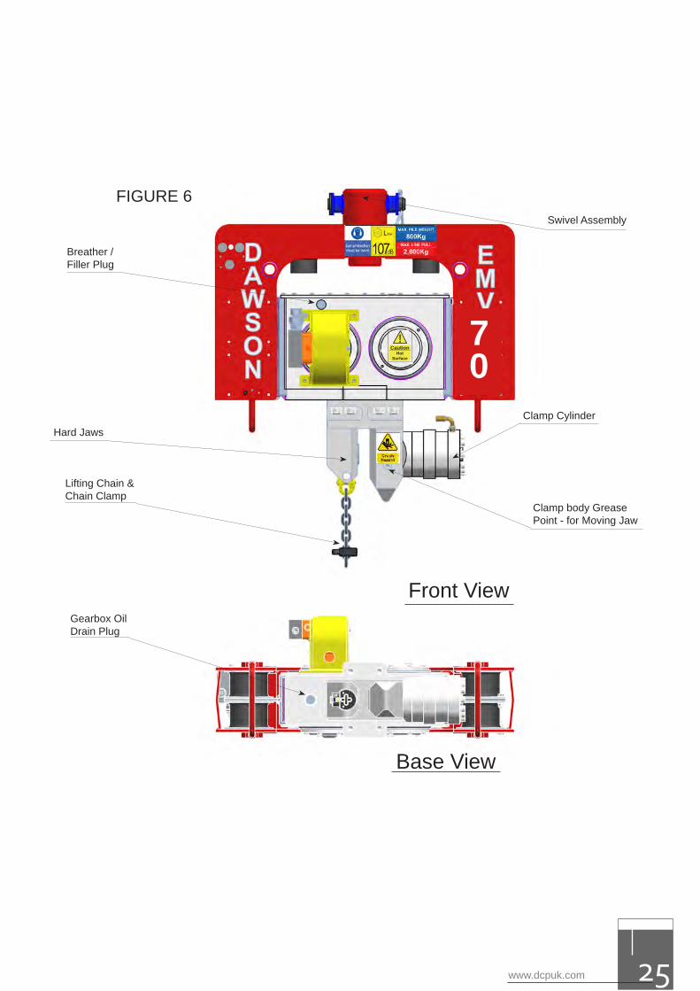
Swivel Assembly
Breather /Filler Plug
Clamp Cylinder
Clamp body Grease Point - for Moving Jaw
Hard Jaws
Lifting Chain &Chain Clamp
Gearbox Oil Drain Plug
Front View
Base View
70
!Hot
Surface
Caution
FIGURE 6
www.dcpuk.com 25
excavator mounted vibrator26
EVERY 50 WORKING HOURSChange the oil in the vibrator gearbox. Remove the Drain Plug from the bottom of the gearbox and the Breather/Filler Plug from the top. Allow the oil to drain out completely into a suitable container – this is best done at the end of a shift when the oil is relatively warm and thin. Replace the Drain plug and fill with new clean oil through the Breather/Filler hole until the oil level in the gearbox is approximately half way up the sight glass – this is approximately 2.5 litres (0.66 US gallons).
Re-fit the Breather/Filler Plug using a new seal and tighten.
The old oil must be taken to a certified waste disposal centre or handed over to a certified waste disposal contractor.
Generally any good quality mineral based gear oil in the class API GL-5 with viscosity class SAE 75W/90 will be suitable. Alternatively, in hotter climates fully synthetic oil of the same classification may be used. For example:
Manufacturer Mineral Oil Reference Synthetic Oil Reference
BP ENEGEAR HT 75W/90
MOBIL MOBILUBE 1 SHC
CASTROL SAF-EXB
ELF TRANSELF B 75W/90 TRANSELF TR2 75W/80
TEXACO GEARTEX EPC80W/90 GEARTEX 5S 75W/90
Note: Maximum ambient operating temperature for the unit +40ºCMinimum ambient operating temperature for the unit –20ºC
EVERY 100 HOURSIt is recommended that the unit be inspected and serviced by the manufacturer. Apart from undertaking to do the relevant preventative maintenance work and checks as described above Dawson will inspect the structural integrity of the equipment and ensure there are no safety related matters that may go unchecked. Bearings and gears will also be inspected to check for signs of unusual wear or potential problems. In some countries it is a requirement by law that the unit be inspected by qualified personnel.
continued - maintenance
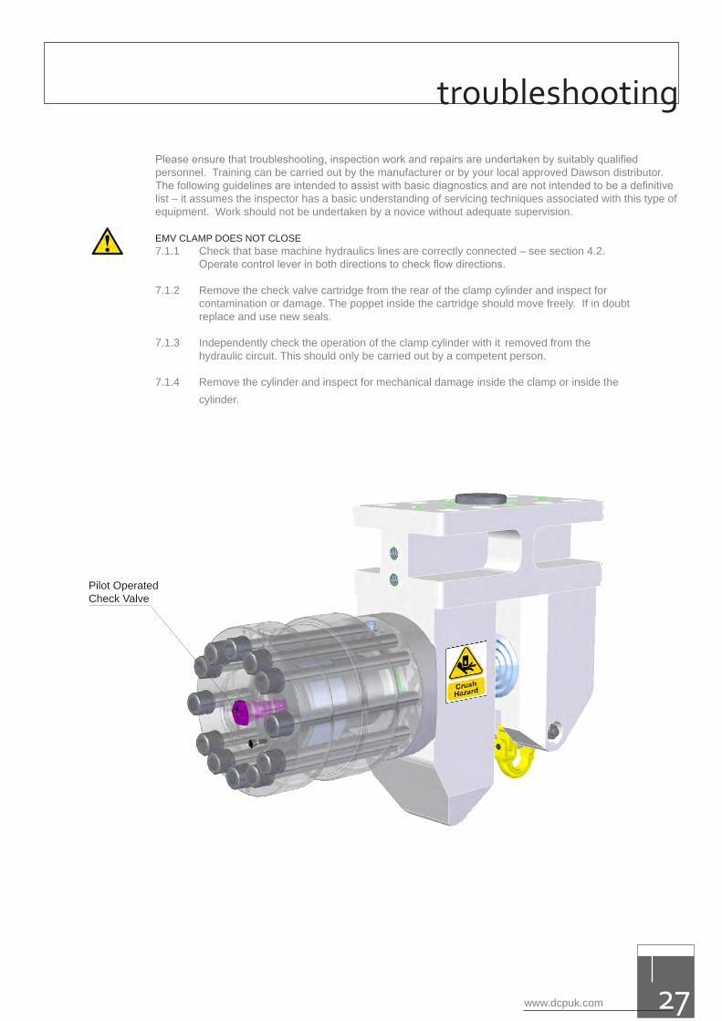
Pilot OperatedCheck Valve
www.dcpuk.com 27
Please ensure that troubleshooting, inspection work and repairs are undertaken by suitably qualified personnel. Training can be carried out by the manufacturer or by your local approved Dawson distributor. The following guidelines are intended to assist with basic diagnostics and are not intended to be a definitive list – it assumes the inspector has a basic understanding of servicing techniques associated with this type of equipment. Work should not be undertaken by a novice without adequate supervision.
EMV CLAMP DOES NOT CLOSE7.1.1 Check that base machine hydraulics lines are correctly connected – see section 4.2.
Operate control lever in both directions to check flow directions.
7.1.2 Remove the check valve cartridge from the rear of the clamp cylinder and inspect for contamination or damage. The poppet inside the cartridge should move freely. If in doubt replace and use new seals.
7.1.3 Independently check the operation of the clamp cylinder with it removed from the hydraulic circuit. This should only be carried out by a competent person.
7.1.4 Remove the cylinder and inspect for mechanical damage inside the clamp or inside the cylinder.
troubleshooting
excavator mounted vibrator28
EMV CLAMP CLOSES BUT THE UNIT WILL NOT VIBRATE7.2.1 Check the base machine operating pressure and flow rate. If the pressure output of the
excavator is too low the EMV will not run at all. This is because the sequence valve pressure setting has to be overcome before oil can pass to the drive motor.
7.2.2 Check the sequence valve setting by installing a pressure test gauge in the clamp close line and monitoring the pressure at which the valve opens. Ensure this is set to 165 bar.
7.2.3 Damaged sequence valve – remove and inspect but replace if in doubt using new seals.
7.2.4 Motor failure or gearbox problem. Try connecting the two main oil supply lines directly to the hydraulic motor ports and running the unit with low engine speed – effectively low oil flow rate. Caution - it will be easy to over-speed the motor in this case because the flow regulator is now out of the circuit.
7.2.5 If the unit does not vibrate either the motor has become damaged or there is a fault with the gearbox. Check the oil level in the gearbox to see that it has not become filled with hydraulic oil from the motor shaft seal – in this case the unit usually runs very slowly unless metal fragments have become entrapped in the transmission system as result.
7.2.6 Remove the motor from the gearbox and test.
7.2.7 As a last resort take the saddle assembly off the EMV and remove the gearbox lid for an internal inspection. The gears, shafts and bearings should rotate freely.
Caution - pay attention to trapping body parts in the mechanism during inspection!
7.2.8 Consult the manufacturer from section 7.2.5 onwards.
UNIT WILL NOT RUN AT THE CORRECT SPEED - “JUMPS AROUND” OR SPEED FLUCTUATES
7.3.1 Check that the base machine hydraulic output complies with the minimum specified for the unit. Specifically check with the excavator supplier/manufacturer what system pressure is available on the bucket ram circuit at 90 l/min.
7.3.2 Check the setting of the flow regulator to ensure adequate flow is reaching the drive motor.
7.3.3 Check the sequence valve pressure setting – see section 7.2.2. If this setting is too close to the operating pressure the EMV will speed up then slow down, speed up then slow down etc.
7.3.4 Check the gearbox oil level. If it is much higher than the sight glass the motor shaft seal has probably blown – see section 7.4.
continued - troubleshooting
www.dcpuk.com 29
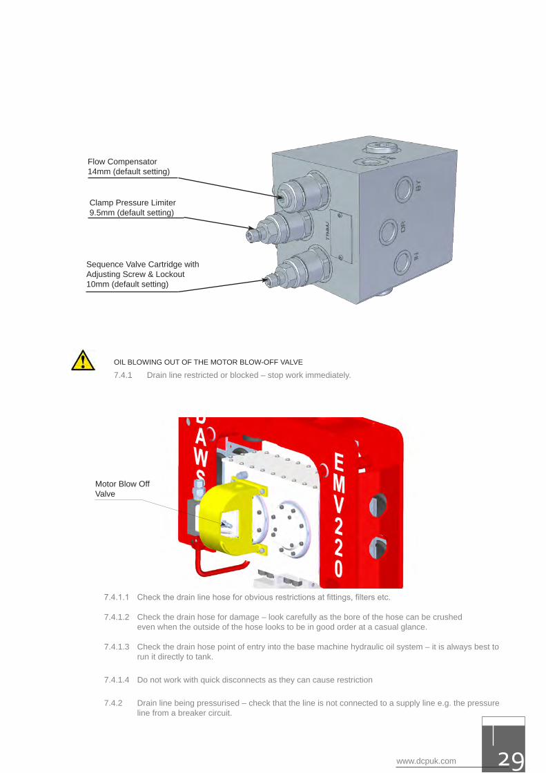
Clamp Pressure Limiter9.5mm (default setting)
Sequence Valve Cartridge with Adjusting Screw & Lockout10mm (default setting)
OIL BLOWING OUT OF THE MOTOR BLOW-OFF VALVE
7.4.1 Drain line restricted or blocked – stop work immediately.
Motor Blow Off Valve
7.4.1.1 Check the drain line hose for obvious restrictions at fittings, filters etc.
7.4.1.2 Check the drain hose for damage – look carefully as the bore of the hose can be crushed even when the outside of the hose looks to be in good order at a casual glance.
7.4.1.3 Check the drain hose point of entry into the base machine hydraulic oil system – it is always best to run it directly to tank.
7.4.1.4 Do not work with quick disconnects as they can cause restriction
7.4.2 Drain line being pressurised – check that the line is not connected to a supply line e.g. the pressure line from a breaker circuit.
Flow Compensator14mm (default setting)
excavator mounted vibrator30
7.4.3 Long drain hose or the hose bore too small – either of these can contribute to an increase in back pressure.
7.4.4 Extremely cold weather – if the base machine hydraulic oil is of an inappropriate viscosity grade for the ambient temperature it may well be too thick. This will cause an increase in back pressure in the drain hose.
7.4.5 Faulty Blow-Off Valve on the motor casing – check that this has a minimum crack pressure of 6 bar and a maximum of 7 bar. Replace if unsure using a new calibrated valve and a new sealing ring.
7.4.6 Leaking seals on the sequence valve cartridge leading to excessive drain line flow rate – remove the drain line from the EMV and measure leakage flow rate. Leakage in excess of 5 l/min (1.33 gpm) indicates either a seal kit problem with the sequence valve or high internal motor leakage. Split the sequence valve drain line and motor case drain line and measure leakage rates independently – the sequence drain line should have little or know leakage.
OIL BLOWING OUT OF THE GEARBOX BREATHER VALVE & THE GEAR BOX IS FULL OF OIL The drive motor case seal has been blown, typically because the drain line pressure has been exceeded – see also section 7.4.
The unit will need to be removed from the job site and repaired in a suitably equipped workshop. The oil in the box will be a mixture of hydraulic and gear oils.
Once in the workshop drain the oil from the gearbox and inspect the oil for signs of debris. If only the seal has blown out without any damage to the motor casting then it may be possible to repair the motor with an authorised Parker Hydraulics (VOAC) distributor, change the gear oil and rebuild the unit.
If however, the motor casting has also been damaged in the area of the seal housing it will be necessary to completely inspect the inside of the gearbox. Remove the gearbox lid and inspect the gear teeth and inspect all bearings. Check the gears for any signs of damage. Remove all bearing covers from the gearbox sides and inspect the outer races for signs of grooves or any other contamination or damage – look at the rollers in each bearing. The bearings and all running faces should be in perfect condition, if not they will need to be replaced. Consult with the manufacturer at this stage or one of their approved distributors – it is strongly recommended that the unit be repaired by the manufacturer in order to ensure correct procedures and materials are used for an effective repair
CLAMP CLOSES ITSELF IMMEDIATELY AFTER BEING OPENEDThis fault can only occur on older units prior to serial number 45-083 without the reverse flow check valve fitted to the return motor port. It occurs when the D reg check valve on the flow regulator becomes jammed shut. When opening the clamp the drive motor can then rotate slowly. Once the control lever is released the motor effectively becomes a pump, driven by the inertia of the eccentric weights in the gearbox. Consequently the clamp can be driven closed again. Should this problem occur Dawson could supply a reverse flow check valve as a fix.Check the condition of the Hard Jaws – see section (61.f).
CLAMP LOOSES GRIP ON THE PILE The clamp can also loose grip on the pile when clamped, with the vibrator not vibrating, if the check valve on the rear of the clamp cylinder has faulty/leaking seals or it the clamp cylinder piston seals are damaged/worn.
Alternatively there may be insufficient system operating pressure if the sequence valve setting has been adjusted down in order to attempt running on an unsuitable excavator. Check the system operating pressure and excavator specifications.
continued - troubleshooting
www.dcpuk.com 31
7.4.3 Long drain hose or the hose bore too small – either of these can contribute to an increase in back pressure.
7.4.4 Extremely cold weather – if the base machine hydraulic oil is of an inappropriate viscosity grade for the ambient temperature it may well be too thick. This will cause an increase in back pressure in the drain hose.
7.4.5 Faulty Blow-Off Valve on the motor casing – check that this has a minimum crack pressure of 6 bar and a maximum of 7 bar. Replace if unsure using a new calibrated valve and a new sealing ring.
7.4.6 Leaking seals on the sequence valve cartridge leading to excessive drain line flow rate – remove the drain line from the EMV and measure leakage flow rate. Leakage in excess of 5 l/min (1.33 gpm) indicates either a seal kit problem with the sequence valve or high internal motor leakage. Split the sequence valve drain line and motor case drain line and measure leakage rates independently – the sequence drain line should have little or know leakage.
OIL BLOWING OUT OF THE GEARBOX BREATHER VALVE & THE GEAR BOX IS FULL OF OIL The drive motor case seal has been blown, typically because the drain line pressure has been exceeded – see also section 7.4.
The unit will need to be removed from the job site and repaired in a suitably equipped workshop. The oil in the box will be a mixture of hydraulic and gear oils.
Once in the workshop drain the oil from the gearbox and inspect the oil for signs of debris. If only the seal has blown out without any damage to the motor casting then it may be possible to repair the motor with an authorised Parker Hydraulics (VOAC) distributor, change the gear oil and rebuild the unit.
If however, the motor casting has also been damaged in the area of the seal housing it will be necessary to completely inspect the inside of the gearbox. Remove the gearbox lid and inspect the gear teeth and inspect all bearings. Check the gears for any signs of damage. Remove all bearing covers from the gearbox sides and inspect the outer races for signs of grooves or any other contamination or damage – look at the rollers in each bearing. The bearings and all running faces should be in perfect condition, if not they will need to be replaced. Consult with the manufacturer at this stage or one of their approved distributors – it is strongly recommended that the unit be repaired by the manufacturer in order to ensure correct procedures and materials are used for an effective repair
CLAMP CLOSES ITSELF IMMEDIATELY AFTER BEING OPENEDThis fault can only occur on older units prior to serial number 45-083 without the reverse flow check valve fitted to the return motor port. It occurs when the D reg check valve on the flow regulator becomes jammed shut. When opening the clamp the drive motor can then rotate slowly. Once the control lever is released the motor effectively becomes a pump, driven by the inertia of the eccentric weights in the gearbox. Consequently the clamp can be driven closed again. Should this problem occur Dawson could supply a reverse flow check valve as a fix.Check the condition of the Hard Jaws – see section (61.f).
CLAMP LOOSES GRIP ON THE PILE The clamp can also loose grip on the pile when clamped, with the vibrator not vibrating, if the check valve on the rear of the clamp cylinder has faulty/leaking seals or it the clamp cylinder piston seals are damaged/worn.
Alternatively there may be insufficient system operating pressure if the sequence valve setting has been adjusted down in order to attempt running on an unsuitable excavator. Check the system operating pressure and excavator specifications.
excavator mounted vibrator32
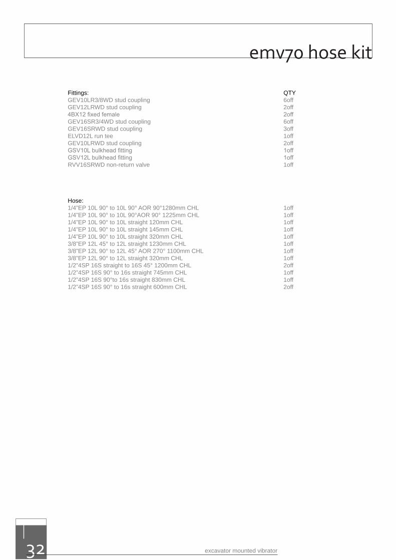
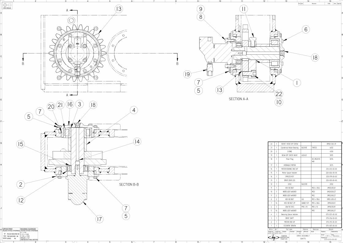
emv70 hose kit
Fittings: QTYGEV10LR3/8WD stud coupling 6offGEV12LRWD stud coupling 2off4BX12 fixed female 2offGEV16SR3/4WD stud coupling 6offGEV16SRWD stud coupling 3offELVD12L run tee 1offGEV10LRWD stud coupling 2offGSV10L bulkhead fitting 1offGSV12L bulkhead fitting 1offRVV16SRWD non-return valve 1off
Hose:1/4”EP 10L 90° to 10L 90° AOR 90°1280mm CHL 1off1/4”EP 10L 90° to 10L 90°AOR 90° 1225mm CHL 1off1/4”EP 10L 90° to 10L straight 120mm CHL 1off1/4”EP 10L 90° to 10L straight 145mm CHL 1off1/4”EP 10L 90° to 10L straight 320mm CHL 1off3/8”EP 12L 45° to 12L straight 1230mm CHL 1off3/8”EP 12L 90° to 12L 45° AOR 270° 1100mm CHL 1off3/8”EP 12L 90° to 12L straight 320mm CHL 1off1/2”4SP 16S straight to 16S 45° 1200mm CHL 2off1/2”4SP 16S 90° to 16s straight 745mm CHL 1off1/2”4SP 16S 90°to 16s straight 830mm CHL 1off1/2”4SP 16S 90° to 16s straight 600mm CHL 2off

parts lists for the emv70
www.dcpuk.com 33
- - - - - -
Qnt.Ref.no. Part name Material Dimension Remark
F
K
J
1 2
I
H
G
3 4 5 6 7
E
D
C
B
A
1 2 3 4 5 6 7
F
8 9 10 11 12 13 14 15
K
J
I
H
G
8 9 10 11 12
E
D
C
13 14 15
B
A
CopiedDesign by Drawn by Checked Standard ScaleAffirmed
Drawing no.
Sheet
Replace
Date
Replaced by
Qnt.Rf.nr Revision Appr.byDate Intro.
DAWSONCONSTRUCTION
PLANT LTD.
3RD ANGLE
ROUGH MACHINE N9
FINE MACHINE N8
GRIND N6
UNLESS STATED OTHERWISESURFACE FINISH
X . X = +/- 0.25
ANGLES +/- 0.5°
MACHINING TOLERANCESUNLESS STATED OTHERWISE
X . XX = +/- 0.05
DIMENSIONS IN MILLIMETERS
X = +/- 0.5 A1
070-000-00-01
10/08/2015
MDBPLW
DAWSON EMV70 1 of 1
A
A
SECTION A-A
B
B
SECTION B-B
51* 8 SOCKET HEAD CAP SCREW 0.0 kg OM10.20.02
50 2 Dawson Sticker 0.2 kg Dawson Sticker
49 2 70 Sticker 0.0 kg 70 Sticker
48 2 SLEEVE 1.1 kg 4069
47 2 FLANGED BUSH 0.5 kg 4068
46 1 SPLIT PIN 0.1 kg 4067
45 1 SHEAR PIN 4.5 kg 4066
44* 2 SPACER 0.4 kg 4065
43* 1 Dowty Washer 0.0 kg 4043D
42 1 Breather Filler Plug 0.2 kg 4043
41* 1 Oil Level Sight Glass 0.2 kg 4039
40 2 BUFFER 2.0 kg 4028
39 1 BEARING 51214 0.8 kg 4026
38 8 SANDWICH MOUNTING 30.8 kg 4025AS
37 1 LIFTING BOLT 20.9 kg 4024
36 1 NUT 3.5 kg 4023
35 1 BUSH bronze 1.2 kg 4022
34 1 THRUST WASHER 1.0 kg 4021
33 1 FLOW REGULATOR BLOCK 0.0 kg 400-2-032756
32* 1 GASKET 0.3 kg 220-021-000-00
31 2 SAFETY RESTRAINT 0.0 kg 220-010-00-00A
30 1 LID 9.6 kg 220-009-00-01
29 4 SOCKET HEAD CAP SCREW MOD 0.0 kg 220-007-21-01
28 1 SADDLE 85.1 kg 220-007-10-01
27* 1 220 GEAR BOX 105.6 kg 220-001-00-00
26 1 CLAMP ASSY Ø120 x 60STROKE
105.6 kg 2018
25 1 GREASE NIPPLE 0.0 kg 1-057-00-01
24 1 BLANKING PLUG 0.1 kg 1-018-15-01
23 1 BLANKING PLUG 0.2 kg 1-018-07-01
22 8 SOC SET SCREW 1.9 kg 0M24.080.05
21 8 HEXAGON NUT 0.9 kg 0M24.000.10
20 8 NORD-LOCK WASHER 0.0 kg 0M24-000-27
19 2 NYLOC NUT 0.2 kg 0M20.000.11
18 8 SOCKET HEAD CAP SCREW 0.0 kg 0M12.25.02
17* 32 HEX HD BOLT 1.7 kg 0M12.040.01
16* 24 SOCKET HEAD CAP SCREW 1.1 kg 0M12.030.02
15* 4 HEX HD BOLT ST.STEEL 0.2 kg 0M12.025.04
14* 28 NORD-LOCK WASHER 0.1 kg 0M12.000.27
13 5 WASHER ST.STEEL 0.0 kg 0M12.000.20
12 64 NYLOC NUT TYPE P M12 1.3 kg 0M12.000.11
11 16 HEX HD BOLT 0.9 kg 0M12-045-01
10 1 SOCKET HEAD CAP SCREW 0.0 kg 0M10.030.02
9 2 NORD-LOCK WASHER 0.0 kg 0M10.000.27
8* 24 HEX HD BOLT 0.4 kg 0M08.025.01
7* 24 WASHER 0.1 kg 0M08.000.20
6* 3 SOCKET HEAD CAP SCREW 0.0 kg 0M05.016.02
5 1 DRIVE ASSEMBLY 44.6 kg 070-013-00-00
4 1 DRIVEN GEAR ASSEMBLY 36.7 kg 070-012-00-00
3 1 SHROUD 10.3 kg 070-008-00-00
2* 1 ROLL PIN 0.0 kg
1* 1 KEY 0.0 kg
26
28
222120
5
4
33
3
4
45
47
46 25
3
5
23
49
50
38
11
13
12
40
42
24
-A REDESIGN - NEW SADDLE SDD10-08-15 MDB
C
C
SECTION C-C
37
39
45
48
35
25
36
19
9 10
DRIVE GEAR SECTION
DRIVEN GEAR SECTION
31
38
34
D
D
18
29
30
1
H
G
F
2 3 4 5 6 7 8 9 10
H
G
F
E
7 8
D
C
B
9 10
A
CopiedDesign by Drawn by Checked Standard ScaleAffirmed
Drawing no.
Sheet
Replace
Date
Replaced by
Qnt.Rf.nr Revision Appr.byDate Intro.
DAWSONCONSTRUCTION
PLANT LTD.
ROUGH MACHINE N9
FINE MACHINE N8
GRIND N6
UNLESS STATED OTHERWISESURFACE FINISH
X . X = +/- 0.25
ANGLES +/- 0.5°
MACHINING TOLERANCESUNLESS STATED OTHERWISE
X . XX = +/- 0.05
DIMENSIONS IN MILLIMETERS
X = +/- 0.5
E
D
C
B
A
1 2 3 4 5 6
3RD ANGLE
F
K
J
1 2
I
H
G
3 4 5 6 7
E
D
C
B
A
1 2 3 4 5 6 7
F
8 9 10 11 12 13 14 15
K
J
I
H
G
8 9 10 11 12
E
D
C
13 14 15
B
A
CopiedDesign by Drawn by Checked Standard ScaleAffirmed
Drawing no.
Sheet
Replace
Date
Replaced by
Qnt.Rf.nr Revision Appr.byDate Intro.
DAWSONCONSTRUCTION
PLANT LTD.
3RD ANGLE
ROUGH MACHINE N9
FINE MACHINE N8
GRIND N6
UNLESS STATED OTHERWISESURFACE FINISH
X . X = +/- 0.25
ANGLES +/- 0.5°
MACHINING TOLERANCESUNLESS STATED OTHERWISE
X . XX = +/- 0.05
DIMENSIONS IN MILLIMETERS
X = +/- 0.5
F
K
J
1 2
I
H
G
3 4 5 6 7
E
D
C
B
A
1 2 3 4 5 6 7
F
8 9 10 11 12 13 14 15
K
J
I
H
G
8 9 10 11 12
E
D
C
13 14 15
B
A
CopiedDesign by Drawn by Checked Standard ScaleAffirmed
Drawing no.
Sheet
Replace
Date
Replaced by
Qnt.Rf.nr Revision Appr.byDate Intro.
DAWSONCONSTRUCTION
PLANT LTD.
3RD ANGLE
ROUGH MACHINE N9
FINE MACHINE N8
GRIND N6
UNLESS STATED OTHERWISESURFACE FINISH
X . X = +/- 0.25
ANGLES +/- 0.5°
MACHINING TOLERANCESUNLESS STATED OTHERWISE
X . XX = +/- 0.05
DIMENSIONS IN MILLIMETERS
X = +/- 0.5
1 2
J
I
H
G
F
3 4 5 6
E
D
C
B
A
1 2 3 4 5 6
7 8 9 10 11 12
J
I
H
G
F
7 8 9 10
E
D
C
11 12
B
A
CopiedDesign by Drawn by Checked Standard ScaleAffirmed
Drawing no.
Sheet
Replace
Date
Replaced by
Qnt.Rf.nr Revision Appr.byDate Intro.
DAWSONCONSTRUCTION
PLANT LTD.
3RD ANGLE
ROUGH MACHINE N9
FINE MACHINE N8
GRIND N6
UNLESS STATED OTHERWISESURFACE FINISH
X . X = +/- 0.25
ANGLES +/- 0.5°
MACHINING TOLERANCESUNLESS STATED OTHERWISE
X . XX = +/- 0.05
DIMENSIONS IN MILLIMETERS
X = +/- 0.5
12
JIHGF
34
56
EDCBA
12
34
56
78
910
1112
JIHGF
78
910
EDC
1112
BA
Copie
dD
esig
n b
yD
raw
n b
yC
hecke
dS
tandard
Scale
Aff
irm
ed
Dra
win
g n
o.
Sheet
Repla
ce
Date
Repla
ced b
y
Qnt.
Rf.
nrR
evis
ion
Appr.
by
Date
Intr
o.
DA
WS
ON
CO
NS
TR
UC
TIO
NP
LA
NT
LT
D.
3R
D A
NG
LE
RO
UG
H M
AC
HIN
E N
9
FIN
E M
AC
HIN
E
N8
GR
IND
N
6
UN
LES
S S
TATE
D O
THE
RW
ISE
SU
RFA
CE
FIN
ISH
X .
X =
+/-
0.25
AN
GLE
S +
/- 0.
5°
MA
CH
ININ
G T
OLE
RA
NC
ES
UN
LES
S S
TATE
D O
THE
RW
ISE
X .
XX
= +
/- 0.
05
DIM
EN
SIO
NS
IN M
ILLI
ME
TER
S
X =
+/-
0.5
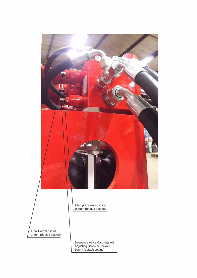
Flow Compensator14mm (default setting)
Clamp Pressure Limiter9.5mm (default setting)
Sequence Valve Cartridge with Adjusting Screw & Lockout10mm (default setting)

appendix a- auxiliary equipment
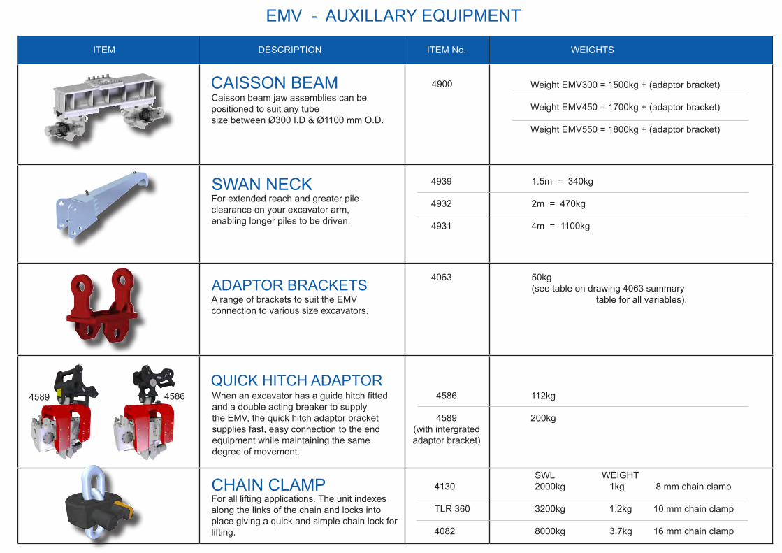
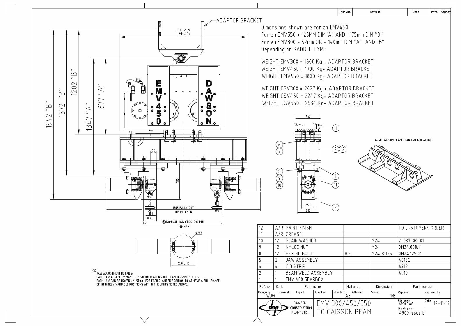
Caisson beam jaw assemblies can be positioned to suit any tube size between Ø300 I.D & Ø1100 mm O.D.
CAISSON BEAM 4900 Weight EMV300 = 1500kg + (adaptor bracket)
Weight EMV450 = 1700kg + (adaptor bracket)
Weight EMV550 = 1800kg + (adaptor bracket)
ITEM DESCRIPTION ITEM No. WEIGHTS
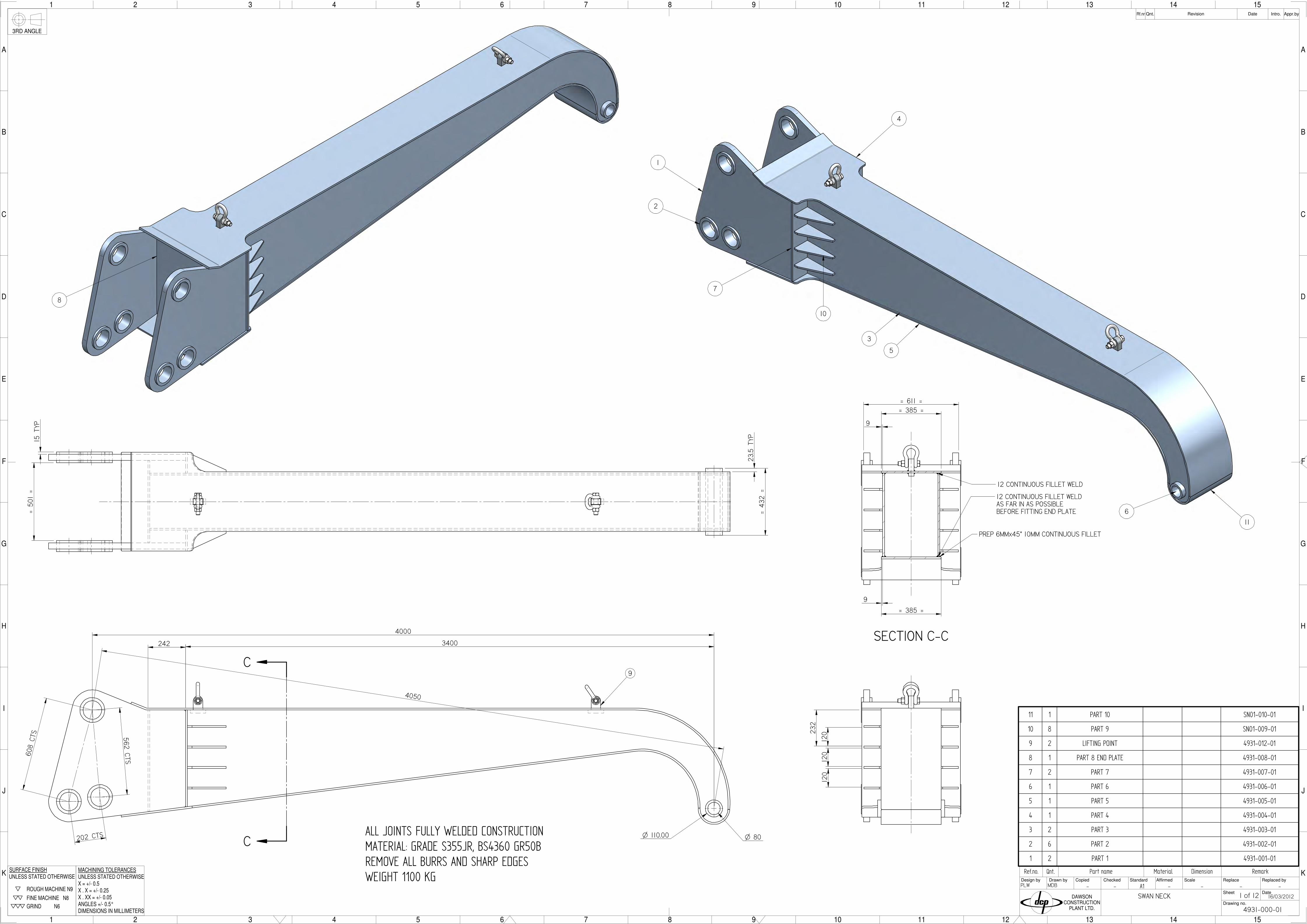
SWAN NECKFor extended reach and greater pile clearance on your excavator arm, enabling longer piles to be driven.
4939 1.5m = 340kg
4932 2m = 470kg
4931 4m = 1100kg
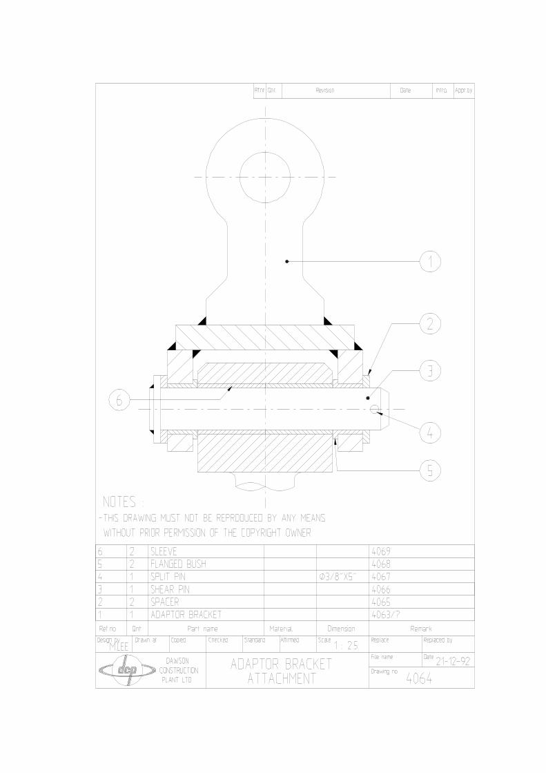
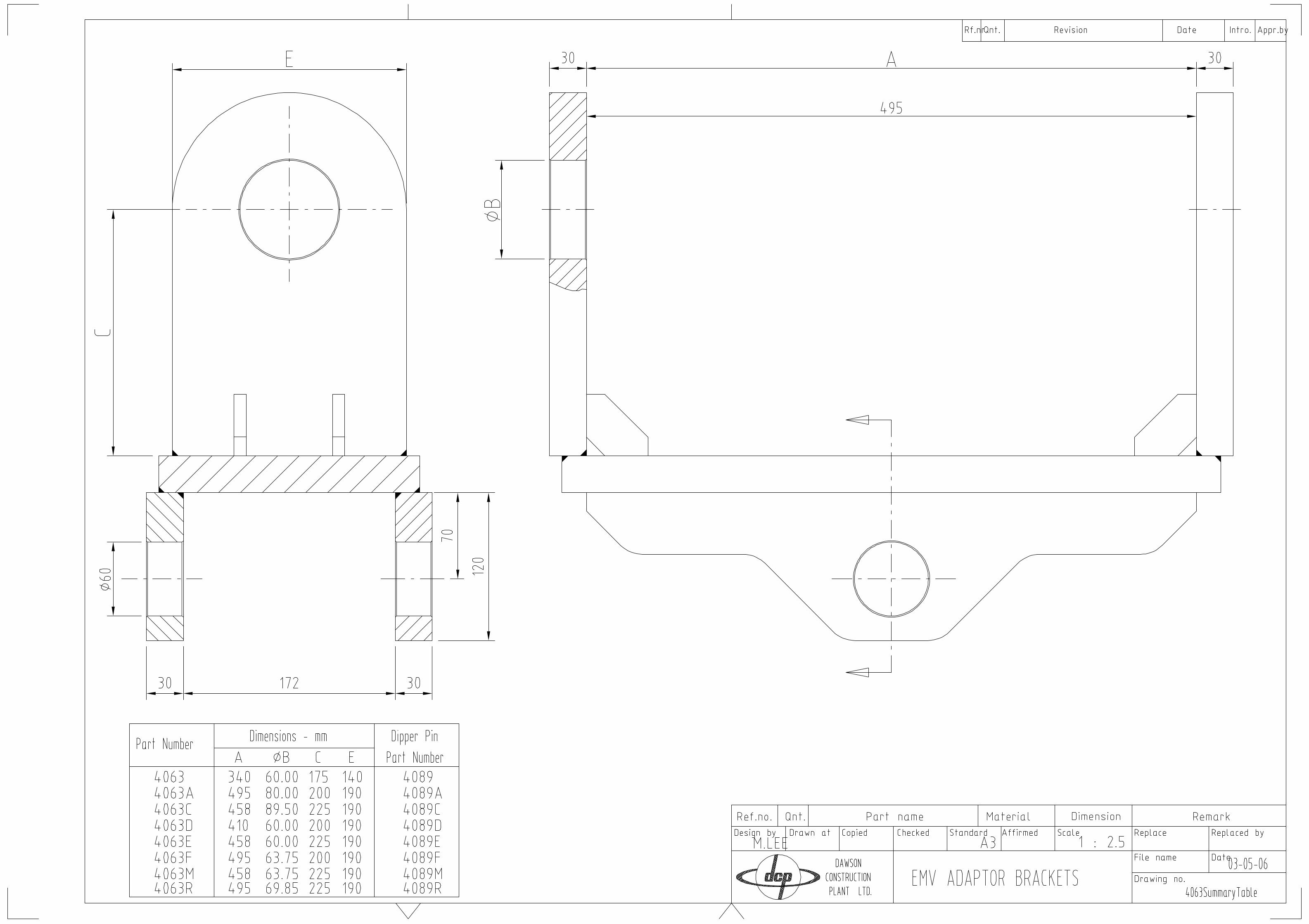
ADAPTOR BRACKETSA range of brackets to suit the EMV connection to various size excavators.
4063 50kg(see table on drawing 4063 summary
table for all variables).
When an excavator has a guide hitch fittedand a double acting breaker to supply the EMV, the quick hitch adaptor bracket supplies fast, easy connection to the end equipment while maintaining the same degree of movement.
QUICK HITCH ADAPTOR45864589 4586
4589(with intergrated adaptor bracket)
112kg
200kg
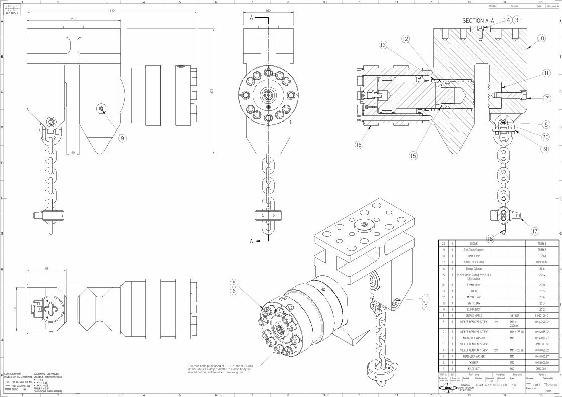
CHAIN CLAMP For all lifting applications. The unit indexes along the links of the chain and locks into place giving a quick and simple chain lock for lifting.
SWL WEIGHT4130 2000kg 1kg 8 mm chain clamp
TLR 360 3200kg 1.2kg 10 mm chain clamp
4082 8000kg 3.7kg 16 mm chain clamp
EMV - AUXILLARY EQUIPMENT
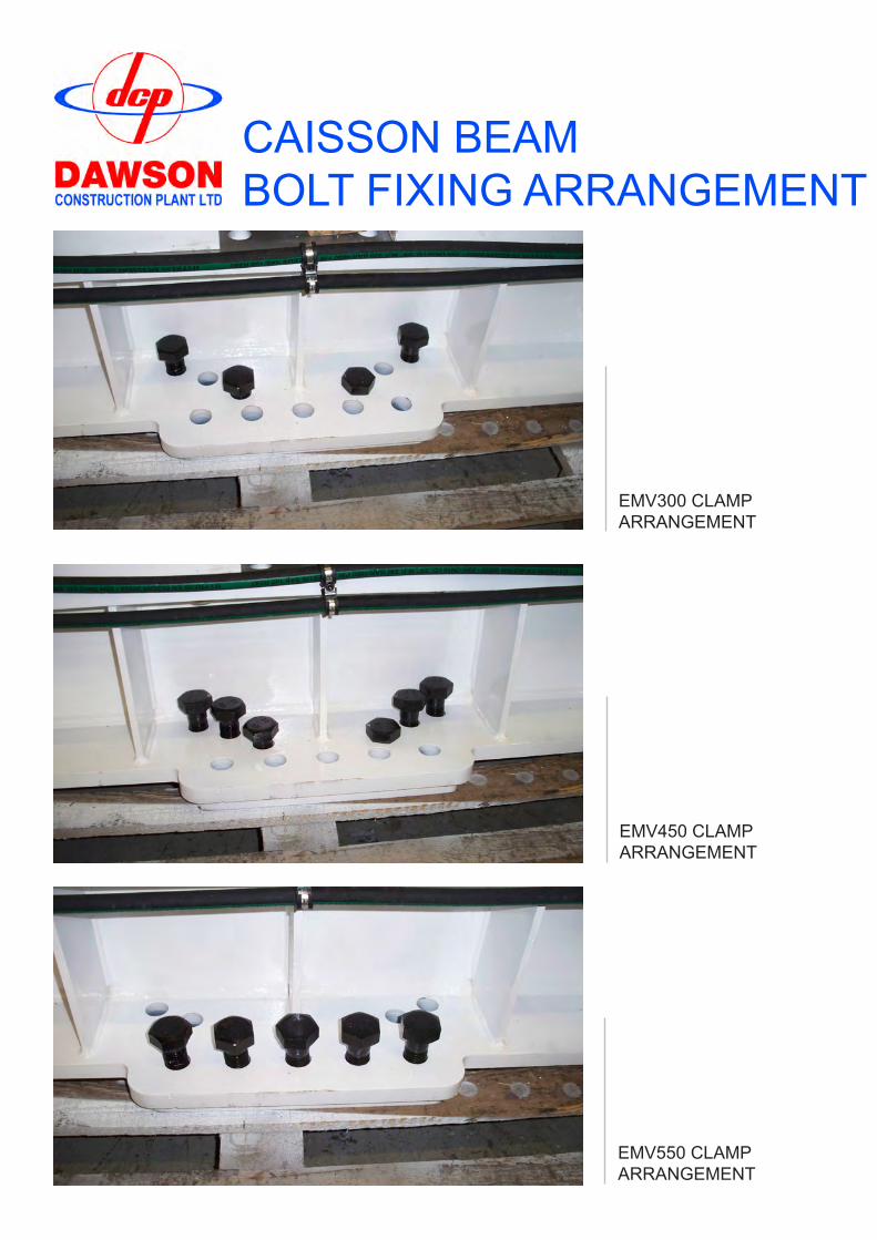
CAISSON BEAMBOLT FIXING ARRANGEMENT
EMV300 CLAMP ARRANGEMENT
EMV450 CLAMP ARRANGEMENT
EMV550 CLAMP ARRANGEMENT
- - - - - -
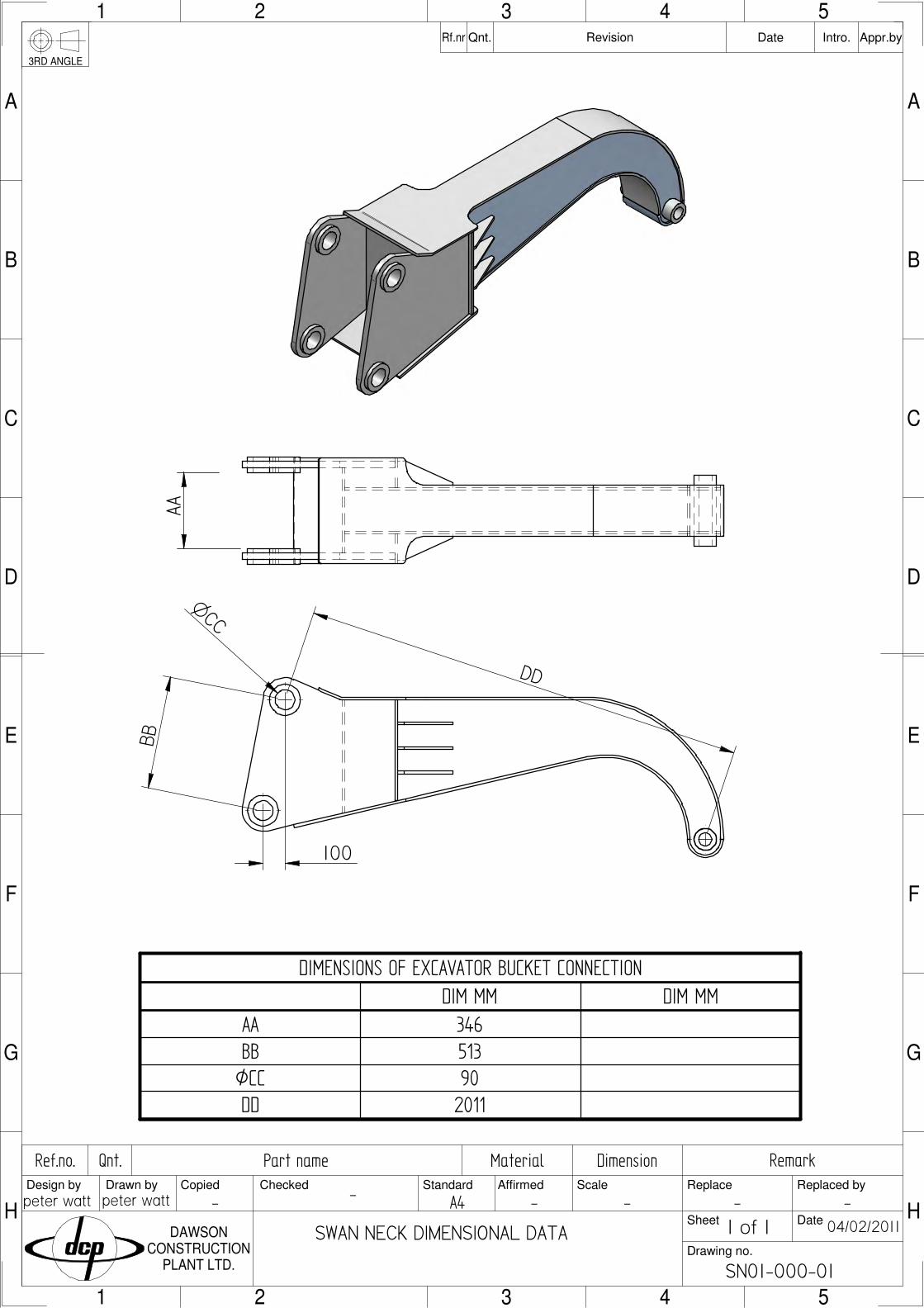
SWAN NECK DIMENSIONAL DATA
peter watt peter watt
04/02/2011
SN01-000-01
Qnt.
3RD ANGLE
Intro.Date Appr.byRevisionRf.nr Qnt.
DAWSONCONSTRUCTION
PLANT LTD.
Replaced by
Date
Replace
Sheet
Drawing no.
Affirmed ScaleStandardCheckedDrawn byDesign by Copied
A
5
B
C
D
43
E
F
G
H
543
21
A
B
C
D
21
E
G
F
H
RemarkDimensionMaterialPart nameRef.no.
A4
1 of 1
AABB
DD
100
OCC
DIMENSIONS OF EXCAVATOR BUCKET CONNECTION
DIM MM DIM MM
AA 346
BB 513
ØCC 90
DD 2011
- - - - - -
Qnt.Ref.no. Part name Material Dimension Remark
F
K
J
1 2
I
H
G
3 4 5 6 7
E
D
C
B
A
1 2 3 4 5 6 7
F
8 9 10 11 12 13 14 15
K
J
I
H
G
8 9 10 11 12
E
D
C
13 14 15
B
A
CopiedDesign by Drawn by Checked Standard ScaleAffirmed
Drawing no.
Sheet
Replace
Date
Replaced by
Qnt.Rf.nr Revision Appr.byDate Intro.
DAWSONCONSTRUCTION
PLANT LTD.
3RD ANGLE
ROUGH MACHINE N9
FINE MACHINE N8
GRIND N6
UNLESS STATED OTHERWISESURFACE FINISH
X . X = +/- 0.25
ANGLES +/- 0.5°
MACHINING TOLERANCESUNLESS STATED OTHERWISE
X . XX = +/- 0.05
DIMENSIONS IN MILLIMETERS
X = +/- 0.5 A1
4931-000-01
16/03/2012
MDBPLW
SWAN NECK 1 of 12
501
==
4000
4050
432
==
O 80ALL JOINTS FULLY WELDED CONSTRUCTIONMATERIAL: GRADE S355JR, BS4360 GR50BREMOVE ALL BURRS AND SHARP EDGESWEIGHT 1100 KG
11 1 PART 10 SN01-010-01
10 8 PART 9 SN01-009-01
9 2 LIFTING POINT 4931-012-01
8 1 PART 8 END PLATE 4931-008-01
7 2 PART 7 4931-007-01
6 1 PART 6 4931-006-01
5 1 PART 5 4931-005-01
4 1 PART 4 4931-004-01
3 2 PART 3 4931-003-01
2 6 PART 2 4931-002-01
1 2 PART 1 4931-001-01
1
2
4
10
6
O 110.00
8
7
C
C
SECTION C-C
PREP 6MMx45° 10MM CONTINUOUS FILLET
3400
232
120
120
15TYP
12 CONTINUOUS FILLET WELD
12 CONTINUOUS FILLET WELDAS FAR IN AS POSSIBLEBEFORE FITTING END PLATE
9
385= =
9
385= =
9
120
611= =
608CTS
202 CTS
562CTS
23.5
TYP
3
5
242
11
- - - - - -
4932
22/01/2013
peter wattpeter watt
SWAN NECK
Qnt.Ref.no. Part name Material Dimension Remark
1 2
J
I
H
G
F
3 4 5 6
E
D
C
B
A
1 2 3 4 5 6
7 8 9 10 11 12
J
I
H
G
F
7 8 9 10
E
D
C
11 12
B
A
CopiedDesign by Drawn by Checked Standard ScaleAffirmed
Drawing no.
Sheet
Replace
Date
Replaced by
Qnt.Rf.nr Revision Appr.byDate Intro.
DAWSONCONSTRUCTION
PLANT LTD.
3RD ANGLE
ROUGH MACHINE N9
FINE MACHINE N8
GRIND N6
UNLESS STATED OTHERWISESURFACE FINISH
X . X = +/- 0.25
ANGLES +/- 0.5°
MACHINING TOLERANCESUNLESS STATED OTHERWISE
X . XX = +/- 0.05
DIMENSIONS IN MILLIMETERS
X = +/- 0.5 A2
1 of 11
316
500
1911
2010
97
490
320
O60
O 80.1080.05
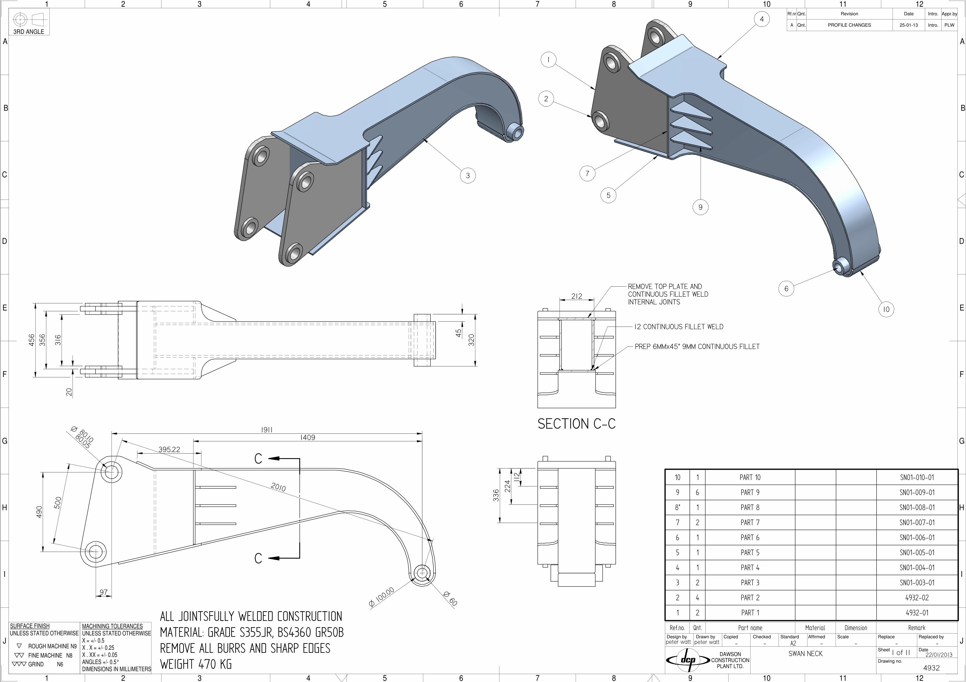
ALL JOINTSFULLY WELDED CONSTRUCTIONMATERIAL: GRADE S355JR, BS4360 GR50BREMOVE ALL BURRS AND SHARP EDGESWEIGHT 470 KG
10 1 PART 10 SN01-010-01
9 6 PART 9 SN01-009-01
8* 1 PART 8 SN01-008-01
7 2 PART 7 SN01-007-01
6 1 PART 6 SN01-006-01
5 1 PART 5 SN01-005-01
4 1 PART 4 SN01-004-01
3 2 PART 3 SN01-003-01
2 4 PART 2 4932-02
1 2 PART 1 4932-01
5
1
2
4
9
6
10
O100
.00
7
45
112
336 22
4
3
C
C
SECTION C-C
REMOVE TOP PLATE AND CONTINUOUS FILLET WELDINTERNAL JOINTS
12 CONTINUOUS FILLET WELD
PREP 6MMx45° 9MM CONTINUOUS FILLET
1409
356
20
456
212
395.22
Qnt.A PROFILE CHANGES PLW25-01-13 Intro.
- - - - - -
4934
15/12/2015
MDBMDB
SWAN NECK
Qnt.Ref.no. Part name Material Dimension Remark
1 2
J
I
H
G
F
3 4 5 6
E
D
C
B
A
1 2 3 4 5 6
7 8 9 10 11 12
J
I
H
G
F
7 8 9 10
E
D
C
11 12
B
A
CopiedDesign by Drawn by Checked Standard ScaleAffirmed
Drawing no.
Sheet
Replace
Date
Replaced by
Qnt.Rf.nr Revision Appr.byDate Intro.
DAWSONCONSTRUCTION
PLANT LTD.
3RD ANGLE
ROUGH MACHINE N9
FINE MACHINE N8
GRIND N6
UNLESS STATED OTHERWISESURFACE FINISH
X . X = +/- 0.25
ANGLES +/- 0.5°
MACHINING TOLERANCESUNLESS STATED OTHERWISE
X . XX = +/- 0.05
DIMENSIONS IN MILLIMETERS
X = +/- 0.5 A2
1500MM
1 of 4
320
ALL JOINTSFULLY WELDED CONSTRUCTIONMATERIAL: GRADE S355JR, BS4360 GR50BREMOVE ALL BURRS AND SHARP EDGESWEIGHT 340 KG
10 1 TUBE PROFILE PLATE 4934-20
9 1 BOTTOM PLATE PROFILE 4934-15
8 1 TOP PLATE PROFILE 4934-14
7 2 SWAN NECK PROFILE 4934-13
6 4 BOSS 4934-12
5 2 CONNECTION PLATE 4934-11
4 4 SIDE RIB 4934-09
3 1 BACK SUPPORT PLATE 4934-08
2 2 MIDDLE SUPPORT PLATE 4934-07
1 1 TUBE 4934-06
4
C
C
SECTION C-C
PREP 6MMx45° 9MM CONTINUOUS FILLET
212
256
==
20
396
100
385
O 65+.100+.050
1500
9
5
6
2
1 10
1360
372
634
500
12MM CONTINUOUS FILLET WELD
REMOVE TOP PLATE ANDCONTINUOUS FILLET WELDINTERNAL JOINTS
8
3
7
9620
8
O 60
45
258 REF
296
REF
- - - - - -
4586
06/03/2012
peter wattpeter watt
Quick Hitch Assy
Qnt.Ref.no. Part name Material Dimension Remark
1 2
J
I
H
G
F
3 4 5 6
E
D
C
B
A
1 2 3 4 5 6
7 8 9 10 11 12
J
I
H
G
F
7 8 9 10
E
D
C
11 12
B
A
CopiedDesign by Drawn by Checked Standard ScaleAffirmed
Drawing no.
Sheet
Replace
Date
Replaced by
Qnt.Rf.nr Revision Appr.byDate Intro.
DAWSONCONSTRUCTION
PLANT LTD.
3RD ANGLE
ROUGH MACHINE N9
FINE MACHINE N8
GRIND N6
UNLESS STATED OTHERWISESURFACE FINISH
X . X = +/- 0.25
ANGLES +/- 0.5°
MACHINING TOLERANCESUNLESS STATED OTHERWISE
X . XX = +/- 0.05
DIMENSIONS IN MILLIMETERS
X = +/- 0.5 A21 of 1
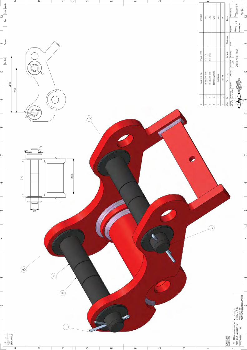
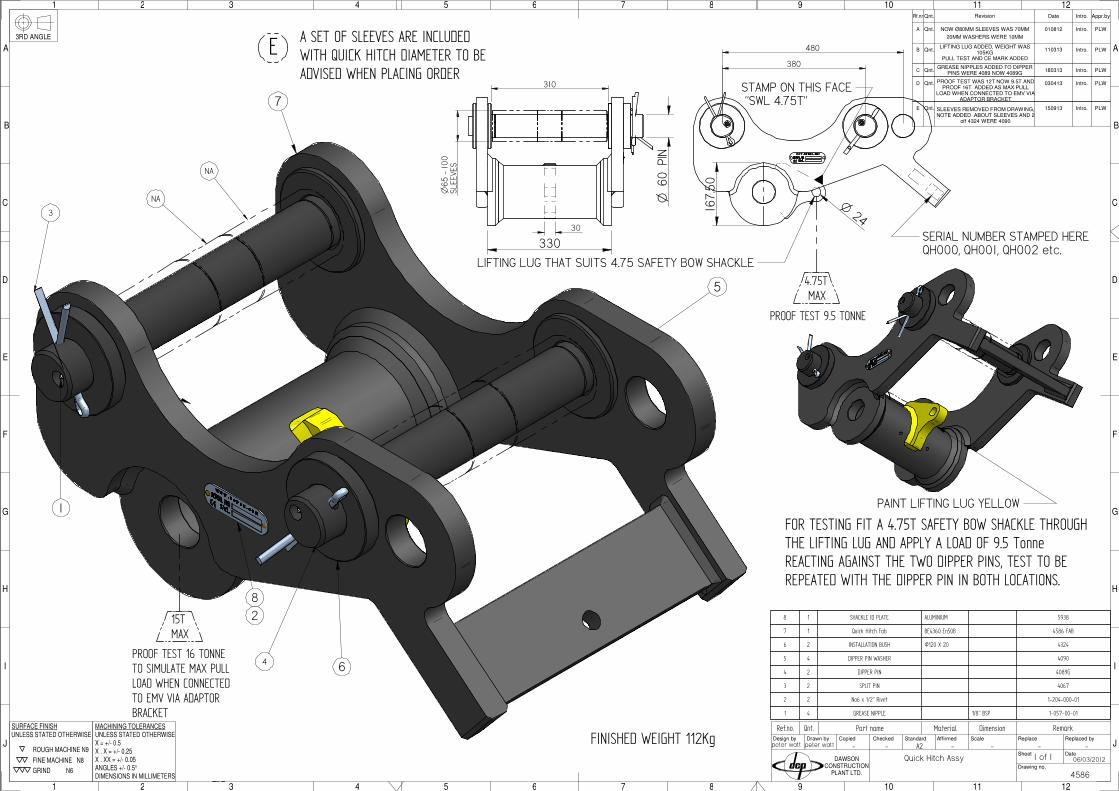
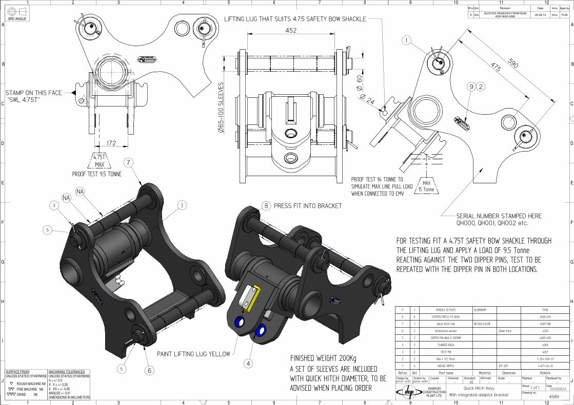
FINISHED WEIGHT 112Kg
6
4
3
7
5
8 1 SHACKLE ID PLATE ALUMINIUM 5938
7 1 Quick Hitch Fab BE4360 En50B 4586 FAB
6 2 INSTALLATION BUSH Ø120 X 20 4324
5 4 DIPPER PIN WASHER 4090
4 2 DIPPER PIN 4089G
3 2 SPLIT PIN 4067
2 2 No6 x 1/2" Rivet 1-204-000-01
1 4 GREASE NIPPLE 1/8" BSP 1-057-00-01
310
O65
- 1
00SL
EEVE
S
380
480
3
NA
NA
4 6
Qnt.BLIFTING LUG ADDED, WEIGHT WAS
105KGPLW110313 Intro.
PULL TEST AND CE MARK ADDED
LIFTING LUG THAT SUITS 4.75 SAFETY BOW SHACKLE
O24
30
Qnt.A NOW Ø80MM SLEEVES WAS 70MM PLW010812 Intro.
20MM WASHERS WERE 10MM
SERIAL NUMBER STAMPED HEREQH000, QH001, QH002 etc.
FOR TESTING FIT A 4.75T SAFETY BOW SHACKLE THROUGHTHE LIFTING LUG AND APPLY A LOAD OF 9.5 TonneREACTING AGAINST THE TWO DIPPER PINS, TEST TO BEREPEATED WITH THE DIPPER PIN IN BOTH LOCATIONS.
4.75T MAX
PROOF TEST 9.5 TONNE
STAMP ON THIS FACE "SWL 4.75T"
PAINT LIFTING LUG YELLOW
330
Qnt.CGREASE NIPPLES ADDED TO DIPPER
PINS WERE 4089 NOW 4089GPLW180313 Intro.
Qnt.D PROOF TEST WAS 12T NOW 9.5T ANDPROOF 16T ADDED AS MAX PULL
LOAD WHEN CONNECTED TO EMV VIAADAPTOR BRACKET
PLW030413 Intro.
15T MAX
PROOF TEST 16 TONNETO SIMULATE MAX PULLLOAD WHEN CONNECTEDTO EMV VIA ADAPTORBRACKET
60O
PIN
Qnt.E SLEEVES REMOVED FROM DRAWING,NOTE ADDED ABOUT SLEEVES AND 2
off 4324 WERE 4090
PLW150913 Intro.
A SET OF SLEEVES ARE INCLUDEDWITH QUICK HITCH DIAMETER TO BEADVISED WHEN PLACING ORDER
E
82
1
167.
50
- - - - - -
4589
01/03/2013
peter wattpeter watt
Quick Hitch Assy
Qnt.Ref.no. Part name Material Dimension Remark
1 2
J
I
H
G
F
3 4 5 6
E
D
C
B
A
1 2 3 4 5 6
7 8 9 10 11 12
J
I
H
G
F
7 8 9 10
E
D
C
11 12
B
A
CopiedDesign by Drawn by Checked Standard ScaleAffirmed
Drawing no.
Sheet
Replace
Date
Replaced by
Qnt.Rf.nr Revision Appr.byDate Intro.
DAWSONCONSTRUCTION
PLANT LTD.
3RD ANGLE
ROUGH MACHINE N9
FINE MACHINE N8
GRIND N6
UNLESS STATED OTHERWISESURFACE FINISH
X . X = +/- 0.25
ANGLES +/- 0.5°
MACHINING TOLERANCESUNLESS STATED OTHERWISE
X . XX = +/- 0.05
DIMENSIONS IN MILLIMETERS
X = +/- 0.5 A2
With integrated adaptor bracket
1 of 1
FINISHED WEIGHT 200Kg
7
9 1 SHACKLE ID PLATE ALUMINIUM 5938
8 6 STEPPED PRESS FIT BUSH 4589-010
7 1 Quick Hitch Fab BE4360 En50B 4589 FAB
6 2 Installation washer 20mm thick 4324
5 2 DIPPER PIN Ø60 X 585MM 4089-005
4 2 FLANGED BUSH 4068
3 2 SPLIT PIN 4067
2 2 No6 x 1/2" Rivet 1-204-000-01
1 6 GREASE NIPPLE 1/8" BSP 1-057-00-01
MAX15 Tonne
3
5
5 6
475590
452
1
9 2
SERIAL NUMBER STAMPED HEREQH000, QH001, QH002 etc.
LIFTING LUG THAT SUITS 4.75 SAFETY BOW SHACKLE
O24
4.75T MAX
PROOF TEST 9.5 TONNE
2
STAMP ON THIS FACE "SWL 4.75T"
FOR TESTING FIT A 4.75T SAFETY BOW SHACKLE THROUGHTHE LIFTING LUG AND APPLY A LOAD OF 9.5 TonneREACTING AGAINST THE TWO DIPPER PINS, TEST TO BEREPEATED WITH THE DIPPER PIN IN BOTH LOCATIONS.
PAINT LIFTING LUG YELLOW
NA
8 PRESS FIT INTO BRACKETNA
4
O65
-100
SLE
EVES
1
PROOF TEST 16 TONNE TOSIMULATE MAX LINE PULL LOADWHEN CONNECTED TO EMV
172
A SET OF SLEEVES ARE INCLUDEDWITH QUICK HITCH DIAMETER, TO BEADVISED WHEN PLACING ORDER
Qnt.ASLEEVES REMOVED FROM BOM
4324 WAS 4090PLW25-09-13 Intro.
60O
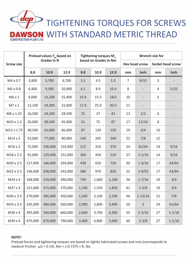
TIGHTENING TORQUES FOR SCREWS WITH STANDARD METRIC THREAD
Screw size
Preload values FM based on Grades in N
Tightening torques MA based on Grades in Nm
Wrench size for
Hex head screw Socket head screw
8.8 10.9 12.9 8.8 10.9 12.9 mm Inch mm Inch
M4 x 0.7 3,900 5,700 6,700 3.1 4.5 5.3 7 9/32 3 -
M5 x 0.8 6,400 9,300 10,900 6.1 8.9 10.4 8 - 4 5/32
M6 x 1 9,000 13,200 15,400 10.4 15.5 18.0 10 - 5 -
M7 x 1 13,100 19,300 22,600 17.0 25.0 30.0 11 - - -
M8 x 1.25 16,500 24,200 28,500 25 37 43 13 1/2 6 -
M10 x 1.5 26,000 38,500 45,000 51 75 87 17 11/16 8 -
M12 x 1.75 38,500 56,000 66,000 87 130 150 19 3/4 10 -
M14 x 2 53,000 77,000 90,000 140 205 240 22 7/8 12 -
M16 x 2 72,000 106,000 124,000 215 310 370 24 61/64 14 9/16
M18 x 2.5 91,000 129,000 151,000 300 430 510 27 1-1/16 14 9/16
M20 x 2.5 117,000 166,000 194,000 430 620 720 30 1-3/16 17 43/64
M22 x 2.5 146,000 208,000 243,000 580 970 830 32 1-9/92 17 43/64
M24 x 3 168,000 239,000 280,000 740 1,060 1,240 36 1-7/16 19 3/4
M27 x 3 221,000 315,000 370,000 1,100 1,550 1,850 41 1-5/8 19 3/4
M30 x 3.5 270,000 385,000 450,000 1,500 2,100 2,500 46 1-13/16 22 7/8
M33 x 3.5 335,000 480,000 560,000 2,000 2,800 3,400 50 2 24 61/64
M36 x 4 395,000 560,000 660,000 2,600 3,700 4,300 55 2-3/16 27 1-1/16
M39 x 4 475,000 670,000 790,000 3,400 4,800 5,600 60 2-3/8 27 1-1/16
NOTE!Preload forces and ghtening torques are based on lightly lubricated screws and nuts (corresponds to medium fric on µG = 0.14). Nm = x 0.7375 = . lbs.
MACHINE TYPEEMV550 EMV450 EMV400 EMV300 EMV70 VPC EMD140 EMD70
SADDLE ASSEMBLY Sandwich Mount Condition
Buffer Stop Condition
Top Swivel Condition Max gap 1mm (ideally no play)
Greased
Remarks:
CLAMP ASSEMBLYSerial No.
Static Jaw Condition
Moving Jaw Condition
GreasedChain Clamp (Serial No. )Lifting Chain (Serial No. )
Coupler (Serial No. )Remarks:
PRE-DELIVERY INSPECTION SHEET EMV’S, VPC’S AND EMD’S
Serial No:
Photo taken before dispatch:
ADAPTOR BRACKET / QUICK HITCH ASSEMBLYAdaptor Pin Diameter Length
Bushes ListAdditional Spares Supplied
GEARBOX ASSEMBLYOil Level
Leaks (Visual)
Case Breather Valve
Motor Blow off Valve
General Condition
Remarks:
HOSESHoses Condition
Spring Guard Condition
Running Leaks
Fittings
Additional Spares Supplied
Remarks:
Inspection Time / Date: Inspector Name:
Stand:Remarks:
VIBRO RUNNING CHECKSCycle Clamp x5 to Check Function
Close Clamp Stop Vibro & Leave for 5 mins (CLAMP MUST STAY CLOSED)
Run Vibro and Check for External Leaks Hoses
Fittings
Motor Blow Off Valve
QRC
Maximum gap allowed due to wear.(see photo)Check using a crowbar to force apart assembly, then insert a feeler gauge at least 20mm into gap, if more than 1mm change lifting bolt and nut immediately and check other components replacing as required.
excavator mounted vibratoremv70
DAWSON CONSTRUCTION PLANT LTD.CHESNEY WOLD,
BLEAK HALLMILTON KEYNES
MK6 1NE, ENGLANDTEL: +44 (0) 1908 240300FAX: +44 (0) 1908 240222
EMAIL: [email protected]
HYDRAULIC PILING HAMMERS
EXCAVATOR MOUNTED VIBRATORS
EXCAVATOR MOUNTED DRILLS
QUIET, VIBRATIONLESS PUSH-PULL PILING
PILE EXTRACTION
SHEET PILE GUIDE FRAMES
SHEET PILE CAPPING SYSTEMS
CFA CLEANERS
PILE POINTS & SPLICERS
SAFETY HANDLING / LIFTING EQUIPMENT
SHEET PILE THREADERS
D.C.P. RESERVES THE RIGHT TO DISCONTINUE EQUIPMENT AT ANY TIME, OR CHANGESPECIFICATIONS OR DESIGNS WITHOUT NOTICE OR INCURRING OBLIGATIONS
INNOVATIVE PILING EQUIPMENT
ww
w.d
cpuk
.com
Related Documents


![Pneumatisk Stempel Vibrator NTK · Pneumatisk Stempel Vibrator NTK Telefon +45 56 87 07 23 Vibrator Variant Arbejdsmoment [cmkg] - Nominel Frekvens [min1] Centrifugalkraft](https://static.cupdf.com/doc/110x72/5e5efb86cf6a1b09186c81a8/pneumatisk-stempel-vibrator-ntk-pneumatisk-stempel-vibrator-ntk-telefon-45-56-87.jpg)