ExCam ® XF P1367 User Manual

Welcome message from author
This document is posted to help you gain knowledge. Please leave a comment to let me know what you think about it! Share it to your friends and learn new things together.
Transcript

ExCam® XF P1367
User Manual
Doc.-ID: 190314-PT08BA-ES-ExCam XF-P1367_EN_rev.00.docx, Page 2 of 32
Table of contents
1 Introduction .............................................................................................................. 4
2 Technical data .......................................................................................................... 4
2.1 Explosion protection ............................................................................................ 4
2.2 Electrical parameters of the camera .................................................................... 5 2.3 Connection cable Ex-d - Ex-e (SKDP03-T) ......................................................... 5 2.4 Video-technical characteristics ............................................................................ 6 2.5 Other technical data ............................................................................................ 6
3 Safety Instructions ................................................................................................... 6
4 Installation ................................................................................................................ 7
5 Electrical connection ............................................................................................... 9
5.1 Potential equalization .......................................................................................... 9
5.2 Connection and Fusing ..................................................................................... 10 5.2.1 Network interface / plug assignment (RJ45) ............................................................................ 11 5.2.2 Connecting the heating (24V DC) ............................................................................................ 11 5.2.3 Connection to a terminal box (alternatively) ............................................................................ 11
5.3 Example: external connection and fusing via the terminal box .......................... 14 5.3.1 Example: direct routing from the ExTB-3 to the safe area ...................................................... 14 5.3.2 Example: Routing via ExConnection Rail (optional accessories) ............................................ 15 5.3.3 Appropriate cables & cable entries .......................................................................................... 16 5.3.4 Cable kits - "plug and play" connection packages ................................................................... 17 5.3.5 Fusing ...................................................................................................................................... 18 5.3.6 Tests prior to switching on the voltage .................................................................................... 19
6 Working in the camera housing ............................................................................ 19
6.1 Work preparation: .............................................................................................. 19 6.2 Opening the pressure-resistant housing ............................................................ 20
6.3 Removing/inserting a SD memory card ............................................................. 23 6.4 Status LED ........................................................................................................ 24
6.5 Hardware Reset ................................................................................................ 24 6.6 Closing of the pressure-resistant housing ......................................................... 24 6.7 Battery ............................................................................................................... 25
7 Settings of the lens ................................................................................................ 26
8 Network access and visualization ........................................................................ 27
8.1 Browser Support................................................................................................ 28 8.2 Assigning the IP address ................................................................................... 28 8.3 Password/ Identification .................................................................................... 29
9 Maintenance/ Modification ..................................................................................... 29
10 Repair ................................................................................................................... 30
11 Disposal/ Recycling ............................................................................................ 30
12 Drawings & 3D models ....................................................................................... 30
13 Certificates and further documentation ............................................................ 31

Doc.-ID: 190314-PT08BA-ES-ExCam XF-P1367_EN_rev.00.docx, Page 3 of 32
Table of Figures and Charts
Fig. 2-1 Sectional view of SKDP03-T ................................................................................ 5
Tab. 2-1. Other technical data ........................................................................................... 6
Tab. 4-1 Mounting Accessories ......................................................................................... 8
Fig. 5-1 ExCam XF P1367 Equipotential Bonding ............................................................. 9
Tab. 5-1 Equipotential Bonding ....................................................................................... 10
Fig. 5-2. Cable gland (KLE) and supply line .................................................................... 10
Fig. 5-3. ExCam XF P1367 T08-VA2.3.K3.BOR2-LL.H-005.N-P ..................................... 10
Tab.5.2 Wire assignment in power cables ....................................................................... 11
Tab. 5-3. Wire assignment of terminal box ExTB-3 ......................................................... 12
Fig. 5-4 Video Tutorial ExTB-3 ........................................................................................ 12
Fig. 5-5 Sample circuit of terminal box ExTB-3 ................................................................ 13
Fig. 5-6 Photo of the occupied terminal box ExTB-3 ....................................................... 13
Fig 5-7 ExTB-3 -> Safe area ............................................................................................ 14
Fig. 5-8 ExTB-3 -> ExConnection Rail ............................................................................. 15
Fig. 5-9 Barrier gland ....................................................................................................... 16
Fig. 5-10 Cable kit – plug & play connection package ..................................................... 17
Tab. 5-4 Available cable kits ............................................................................................ 18
Tab. 5-5 Recommendation for fusing .............................................................................. 18
Fig. 6-1 Removing the weather protection roof (1/2) (this illustration is an example) ...... 20
Fig. 6-2 Removing the weather protection roof (2/2) (similar illustration) ......................... 21
Fig. 6-3 Opening the ExCam XF P1367 (similar illustration)............................................ 21
Fig. 6-4. Mounting adapter with built-in components ....................................................... 23
Fig. 7-1. User Interface for setting the zoom and focus ................................................... 26
Tab.7-1 Lens Data ........................................................................................................... 26
Fig. 8-1 Axis IP Utility ...................................................................................................... 29
History of revisions Product: ExCam® XF P1367
Title: User Manual for ExCam® XF P1367
Doc. -Id. 190314-PT08BA-ES-ExCam XF-P1367_EN_rev.00.docx
Author: Eva Schneider, Grad. Eng. (UAS)
Created: 14.03.2019
Rev.
Index
Date Name Comment Approved by the ATEX Supervisor
0 14.03.2019 E. Schneider Compilation of the document

Doc.-ID: 190314-PT08BA-ES-ExCam XF-P1367_EN_rev.00.docx, Page 4 of 32
1 Introduction
The ExCam XF P1367 is a powerful mega-pixel IP camera of the latest generation, with
5-megapixel resolution at 3072 x 1728 pixels. It is certified according to ATEX, IECEx
and EAC-Ex, and also has MASC certification. The camera has a high-definition televi-
sion resolution. It is equipped with a powerful remote zoom and focus lens (with i-CS).
The ExCam series is certified both in accordance with the European (ATEX) and interna-
tional (IECEx) directive. The explosion-protected housing is approved for ATEX group II
for zones 1, 2, 21 and 22 including the explosion groups IIC / IIIC. The T08 ExCam certi-
fication allows not only stationary device installation but also mobile applications (hand-
held use, etc.). To see other approvals, please visit our website at www.samcon.eu.
When designing the ExCam XF P1367, we focused very much on safety, mechanical
precision and a high quality stainless steel.
2 Technical data
2.1 Explosion protection
Identification marks acc. to Directive 2014/34/EU:
Model key: T08-VA2.3.K3.BOR2-LL.H-005.N-P
II 2G (zone 1 and 2)
II 2D (zone 21 and 22)
Explosion protection (gas): Ex db IIC T5 Gb
Explosion protection (dust): Ex tb IIIC T95°C Db
Protection class: IP 68 (IEC /EN 60529)
Transport/storage temperature: 0°C…+40°C
Ambient temperature (EX): -60°C…+60°C
Named testing laboratory: TÜV Rheinland (number 0035)
EU type approval certificate: TÜV 18 ATEX 8218X (2018)
IECEx Certificate of Conformity: TUR 18.0023X (2018)
EAC-Ex TUR Report: TC RU C-DE.AБ.61.B.00381/19
Other certificates: see https://www.samcon.eu/en/products/network/excam-xf-p1367/

Doc.-ID: 190314-PT08BA-ES-ExCam XF-P1367_EN_rev.00.docx, Page 5 of 32
2.2 Electrical parameters of the camera
Supply of 24 V DC for the heating:
Voltage supply: 24 V DC
Power consumption: approx. 40W@-60°C (temperature-dependent)
Power supply of the camera over Ethernet (PoE):
Voltage supply: PoE, IEEE 802.3af/802.3at type 1 class 3
Reference voltage: +48 V DC (44...54 V DC)
Maximum power consumption: 8.9 W
Typical power consumption: 5.0 W
2.3 Connection cable Ex-d - Ex-e (SKDP03-T)
Description: Data transfer and power supply of the camera
module (compliant with DIN EN 60079-14)
Jacket colour: green (GN), similar to RAL3001
Outside diameter: 12.4 ± 0.3 mm
Bending radius: 8 x Da when installed and 4 x Da after installation
Data line: 4 x 2 x AWG23/1 CAT.6a
Performance elements: 3G1.5 (BK-BU-GN/YE)
Properties: PUR halogen-free, flame-retardant, UV-
resistant, chemical resistance, shielded (see
www.samcon.eu)
Quick link: https://www.samcon.eu/fileadmin/documents/en/60-Assembling%26mounting/SKDP03-T_Datasheet.pdf
Fig. 2-1 Sectional view of SKDP03-T

Doc.-ID: 190314-PT08BA-ES-ExCam XF-P1367_EN_rev.00.docx, Page 6 of 32
2.4 Video-technical characteristics
We use the AXIS P1367 network camera in a pressure-resistant enclosure. For details,
please refer to the Product Documentation, video-technical data of AXIS®:
https://www.axis.com/products/axis-p1367
2.5 Other technical data
Camera (Ex-d)
Permissible ambient temperature 0°C … +60°C (for PoE power supply)
-60°C … +60°C (for 24 V DC power supply)
Protection class as per EN
60529/IEC 529
IP68 (test conditions: 24h/3m water column 5°C°)
Housing material Stainless steel, mat. no. 1.4404
Weight About 8.0 kg
Dimensions D113mm x 310mm
Tab. 2-1. Other technical data
3 Safety Instructions
Please absolutely observe the safety directions stated
in the Ex-installation instructions of the T08 ExCam series!
Quick link: https://www.samcon.eu/fileadmin/documents/en/22-Ex-Network-Cameras/ExCam-Series-T08-EX-Installation-Manual-2018.pdf
It is absolutely mandatory to observe the national safety regulations and regula-tions
for prevention of accidents, as well as the safety instructions given below in this User
Manual!
Attention!
Cameras of the type T08 ExCam are not suitable for use in zone 0 and
zone 20. The ambient temperature, temperature class and explosion
group as stated on type plate must be observed! Alterations are not per-
mitted! The camera is to be operated in sound conditions and in the in-
tended way.
Attention!
Only original parts of SAMCON Prozessleittechnik GmbH may be used for
repairs. Repairs concerning the explosion protection may only be carried
out in accordance with the nationally applied regulations and by
SAMCON Prozessleittechnik GmbH.

Doc.-ID: 190314-PT08BA-ES-ExCam XF-P1367_EN_rev.00.docx, Page 7 of 32
Attention!
Prior to installation, take external sources of heat or cold into account!
The temperature ranges prescribed for storage, transportation, and
operating must be adhered to!
Attention!
Observe the warnings given on the type plate:
“WARNING – DO NOT OPEN IN HAZARD AREAS“
“WARNING – DO NOT OPEN WHILE ENERGIZED“
The use in hazardous areas with regard to temperature and dust layers is
defined in the respective national regulations.
When installing the ExCam, adhere to the requirements of the EN/IEC
60079-14.
4 Installation
For erecting and operating the camera, the relevant national regulations, as well as the
generally accepted rules of technology shall prevail. Before mounting the camera, thor-
oughly check it for any transport damage, especially on the housing and cable. Installa-
tion, electrical connection and the first start must only be carried out by qualified special-
ists.
Work preparation:
Attention!
Prepare your work carefully and in accordance with the relevant
regulations.
Attention!
Depending on classification of hazard areas, a work approval has to
be obtained.
When you open the pressure-resistant enclosure under voltage, it is
absolutely necessary to prevent potentially explosive atmosphere!
To ensure the best image quality delivered by the network camera, plan the installation
site carefully (consider light conditions, object distance or size, angle and minimum object
distance to the focus).

Doc.-ID: 190314-PT08BA-ES-ExCam XF-P1367_EN_rev.00.docx, Page 8 of 32
Use appropriate tools and aids.
When working, ensure a safe stand.
Make sure that any static charge is avoided
Attention!
Please observe the national security, installation and accident preven-
tion regulations (e.g. DIN EN 60079-14) and the safety instructions in
this User Manual, as well as the ones in the Installation Guidelines!
Attention!
Adhere to the provisions of the IECEx, ATEX and EX installation in-
structions for mounting and commissioning!
Attention!
Please pay attention to the national and local regulations for mounting
heavy loads. If in doubt, take appropriate security measures.
Drawings for drill hole patterns and further information can be viewed on our product
page:
Quick link:
https://www.samcon.eu/en/products/network/excam-xf-p1367/
Option mounting accessories
Wall bracket WMB-...
WALL MOUNT EXCAM XF (01569-001)
Wall bracket for devices of T08-VA3 series
Suitable for hanging the camera on walls.
Material: stainless steel 1.4404
Load bearing: 45 kg
Dimensions: 445 x 140 x 185 mm
Pole adapter PMB-…
WALL MOUNT EXCAM XF (01570-001)
Pole adapter for VA wall mount
Material: stainless steel 1.4404
Suitable for pole diameters
between 50 and 105 mm
Load-bearing capacity: 45 kg
Dimensions:120 x 180 (x 130 at masts of Ø
60 mm)
Tab. 4-1 Mounting Accessories

Doc.-ID: 190314-PT08BA-ES-ExCam XF-P1367_EN_rev.00.docx, Page 9 of 32
5 Electrical connection
Attention!
The electrical connection of the equipment may only be carried out by
officially qualified and skilled personnel!
Attention!
It is absolutely necessary to ground the ExCam® series housing via a
PA connection.
Attention!
Please observe the national security, installation and accident preven-
tion regulations (e.g. DIN EN 60079-14) and the safety instructions in
this User Manual, as well as the ones in the Installation Guidelines!
The delivered ExCam® XF P1367 is equipped with an electrical connection cable of the
type SKDP03-T. The maximum transmission range from the camera to the next active
network interface is 100 meters and can be individually specified by the client. The user
is NOT authorised to do electrical connection procedures inside the pressure-resistant
enclosure.
5.1 Potential equalization
The potential equalization/grounding of the camera body is absolutely necessary, in order to
avoid static charges and thus formation of sparks. For this purpose, a screw terminal is
provided at the rear side, at the bottom (right) (see Figure 5.1). The cross-section of the
equipotential bonding should comply with the National Ground Rules (at least 4 mm2).
Fig. 5-1 ExCam XF P1367 Equipotential Bonding

Doc.-ID: 190314-PT08BA-ES-ExCam XF-P1367_EN_rev.00.docx, Page 10 of 32
Wiring table:
Potential Colour (IEC 60757) Cross-
section
Comment
PA GN/YE 4 mm2 (rigid) Terminal: slotted screw M4x0.7 (DIN 84) with
washer Ø9mm (DIN 125A),
Keep 3Nm tightening torque!
Tab. 5-1 Equipotential Bonding
5.2 Connection and Fusing
Fig. 5-2. Cable gland (KLE) and supply line
The green system cable is intended for communication and data transfer to the connect-
ed network devices and, at the same time, for voltage supply (PoE) to the camera. To
ensure the power supply of ExCam XF P1367 (Powered Device/ PD), it is necessary to
make sure that the power-over-Ethernet provider (Power Sourcing Equipment/ PSE) on
the connection side (for example PoE Midspan PoE injector, switch, etc.) fulfils the speci-
fication IEEE 802.3af and 802.3at type 1 Class 3 ("classification current: 26-30 mA
@48VDC, max. feed-in power (power source equipment): 15.4 W, maximum offtake
(power device): 6.49 - 12.95 W"). The data transfer of the ExCam XF P1367 series is
done via a 100 Mbit/s Ethernet connection (100BASE-TX).
Fig. 5-3. ExCam XF P1367 T08-VA2.3.K3.BOR2-LL.H-005.N-P
Cable gland flange 1F, type 6, M20 SKDP03-T - digital video stream Control system and power supply (PoE) of the camera module

Doc.-ID: 190314-PT08BA-ES-ExCam XF-P1367_EN_rev.00.docx, Page 11 of 32
5.2.1 Network interface / plug assignment (RJ45)
Standardly, of the camera’s cable end is furnished with an RJ45 Ethernet plug with Pow-
er over Ethernet (PoE). This plug (Fig. 5-3) should be coupled with the RJ45 PoE socket
of the network device (PSE). Prior to connecting it to the camera, the network device can
already be supplied with power, hence you need not to observe any “power ON” priority.
5.2.2 Connecting the heating (24V DC)
For the housing heating (type LL), you need a second power supply with separate supply
fusing at L+ potential. Pin configuration and power supply fusing should be in accordance
with Tab.5.2.
Potential/
Wire no.
Colour
(IEC60757)
Conductor Voltage Maximum power consumption / fusing
(type LL)
L+ / 1 BK 1.5mm2,
stranded wire
+24 V DC 40 W of continuous power
Fine-wire fuse
(L+) 4000 mA -T- slow-blow
(high inrush load!)
L- / 2 BU 1.5mm2,
stranded wire
0 V DC/GND
Tab.5.2 Wire assignment in power cables
5.2.3 Connection to a terminal box (alternatively)
If you have to connect the camera to a terminal box, please remove the plug properly,
according to good professional practice. In this case it is imperative to ensure a correct
routing of the individual wires according to the EIA/TIA-568B (see Tab. 5.3). As a rule of
thumb, the core wires of the same colour coding (IEC60757) should be connected.
Especially in EMC-critical environments, it is important to ensure that the cable shield is
properly grounded on the terminal box side.
Attention!
Never open the Ex-e terminal box under voltage!
Attention!
Adhere to the international installation regulations for connection
chambers with increased safety (Ex-e).
Attention!
Adhere to the separate Usual Manual for the Ex-e connection chamber
attached in the annex.

Doc.-ID: 190314-PT08BA-ES-ExCam XF-P1367_EN_rev.00.docx, Page 12 of 32
In accordance with standard EIA/TIA-568B for 100BaseTX and 24 V DC for terminal
boxes, we recommend the following core wire assignment for the SKDP03-T cable:
Camera (Ex-d)
(T568B)
Colour
SKDP03-T
(IEC60757)
Terminal
ExTB-3
Cross-
sectional
surface
Comment
Tx+ WH / OG 1 0.25 mm2 Solid conductor
Tx- OG 2 0.25 mm2 Solid conductor
Rx+ WH / GN 3 0.25 mm2 Solid conductor
Rx- GN 4 0.25 mm2 Solid conductor
(PoE +48 VDC) WH / BU 5 0.25 mm2 Solid conductor
(PoE +48 VDC) BU 6 0.25 mm2 Solid conductor
(PoE GND) WH / BN 7 0.25 mm2 Solid conductor
(PoE GND) BN 8 0.25 mm2 Solid conductor
GND/SHD YE / GN PE 2.5 mm2 Flex
L+ BK 9 1.5 mm2 L+ 24VDC
L- BU 10 1.5 mm2 L- 24VDC
PE YE / GN PE 1.5 mm2 PE
Tab. 5-3. Wire assignment of terminal box ExTB-3
Video Tutorial:
Please view our video tutorial:
“SAMCON 01 Wiring the cable SKDP03-T to the junction box ExTB-3”
https://go.samcon.eu/v01
Fig. 5-4 Video Tutorial ExTB-3
Doc.-ID: 190314-PT08BA-ES-ExCam XF-P1367_EN_rev.00.docx, Page 13 of 32
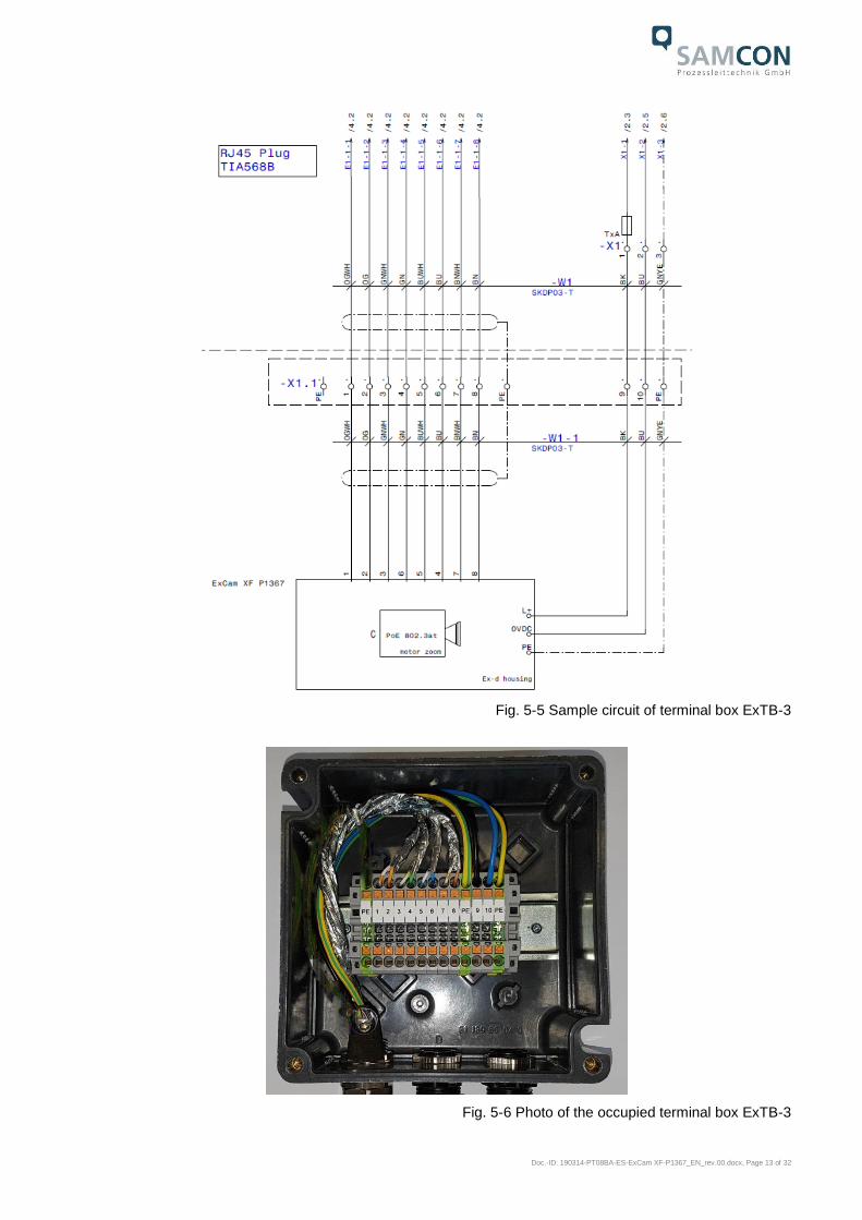
Fig. 5-5 Sample circuit of terminal box ExTB-3
Fig. 5-6 Photo of the occupied terminal box ExTB-3

Doc.-ID: 190314-PT08BA-ES-ExCam XF-P1367_EN_rev.00.docx, Page 14 of 32
Attention!
Introduce the foiling up to about 15 mm to the terminals, in order to pre-
vent alien crosstalk. Make sure that the foiling cannot cause any short
circuit of the data pairs!
Attention!
Bring the twisted pair composite approximately 10mm close to the termi-
nals, in order to ensure the interference immunity.
Attention!
Use only terminals approved by SAMCON.
Attention!
Finally, check your network installation by per Class-D Link Test.
5.3 Example: external connection and fusing via the terminal box
There are several options of routing the ExTB-3 terminal box in a safe area:
5.3.1 Example: direct routing from the ExTB-3 to the safe area
Fig 5-7 ExTB-3 -> Safe area
Switch/ PoE 15W
24 V DC for heating
PoE (802.3at) for camera

Doc.-ID: 190314-PT08BA-ES-ExCam XF-P1367_EN_rev.00.docx, Page 15 of 32
In the case of direct routing from ExTB-3 to the safe area, the power supply and the volt-
age signal are led from the safe area to the terminal box. Please observe the terminal
box assignment, as described above.
Attention!
Cables and wires must comply with the requirements of the
IEC 60079-0/1/7 & 14.
Attention!
The supply line must have a sufficient cross-section. The cable pro-
tection must comply with national and international regulations.
5.3.2 Example: Routing via ExConnection Rail (optional accessories)
Fig. 5-8 ExTB-3 -> ExConnection Rail
In the case of routing the ExTB-3 into an ExConnection Rail, larger installation distances
can be covered.
Please note:
In hazardous areas, the ExConnection Rail (optional accessories) acts as a PoE+ switch, a
media converter from copper to fibre-optic cable, as well as a power supply for the cameras.

Doc.-ID: 190314-PT08BA-ES-ExCam XF-P1367_EN_rev.00.docx, Page 16 of 32
5.3.3 Appropriate cables & cable entries
An integral part of the device safety is the correct selection of the cables, wires and cable
entries.
Attention!
Cables and wires must comply with the requirements of the IEC 60079-
0/1/7 & 14.
Attention!
The supply line must have a sufficient cross-section. The cable pro-
tection must comply with national and international regulations.
To see non-binding configuration and planning guidelines, please
visit our website:
Particularly for installations requiring a suitable barrier gland, make sure that you handle
them correctly and observe the rules and notes given in the respective mounting and as-
sembly instructions.
We show the basic procedures in the following video tutorial:
“SAMCON 02 Mounting and installing Ex-d barrier glands to ExConnection Rails”
https://go.samcon.eu/v02
Fig. 5-9 Barrier gland
Re-twist the cable pairs

Doc.-ID: 190314-PT08BA-ES-ExCam XF-P1367_EN_rev.00.docx, Page 17 of 32
5.3.4 Cable kits - "plug and play" connection packages
As an option, there are various cable kits for different cables are available in different
lengths. The connection packages include everything you need for a professional system
installation:
Fig. 5-10 Cable kit – plug & play connection package
Available connection packages:
Length Non-reinforced cable SKDP03-T
Reinforced cable ASKDP03-T
10 meters SKDP03-T CABLE EXCAM 10M
(01540-001)
This cable set includes:
10 meters SKDP03-T system cable, digital
1 barrier gland Ex-d
5 ml Loctite 243 screw locking
1 x CAT6 RJ45 industrial plug
1 set of documents
ASKDP03-T CABLE EXCAM 10M
(01543-001)
This cable set includes:
10 meters ASKDP03-T system cable, digital
1 bolted connection Ex-d
1 bolted connection Ex-e
5 ml Loctite 243 screw locking
1 x CAT6 RJ45 industrial plug
1 set of documents
(a)
(b)
(c) (d)
10/25/95 m SKDP03-T system
cable, digital (a)
1 barrier gland with sealing
compound (b)
5 ml of Loctite thread locking
(c)
One CAT6 RJ45 industrial
connectors (5.5 - 10.5 mm) (d)
Heat-shrinkable tube 40 cm,
yellow-green (e)
Heat-shrinkable tube 10 cm,
black (e)
8 cable end sleeves (e)
1 set of documents
(e)

Doc.-ID: 190314-PT08BA-ES-ExCam XF-P1367_EN_rev.00.docx, Page 18 of 32
25 meters SKDP03-T CABLE EXCAM 25M
(01541-001)
This cable set includes:
25 meters SKDP03-T system cable, digital
1 barrier gland Ex-d
5 ml Loctite 243 screw locking
1 x CAT6 RJ45 industrial plug
1 set of documents
ASKDP03-T CABLE EXCAM 25M
(01545-001)
This cable set includes:
25 meters ASKDP03-T system cable, digital
1 bolted connection Ex-d
1 bolted connection Ex-e
5 ml Loctite 243 screw locking
1 x CAT6 RJ45 industrial plug
1 set of documents
95 meters SKDP03-T CABLE EXCAM 95M
(01542-001)
This cable set includes:
95 meters SKDP03-T system cable, digital
1 barrier gland Ex-d
5 ml Loctite 243 screw locking
1 x CAT6 RJ45 industrial plug
1 set of documents
ASKDP03-T CABLE EXCAM 95M
(01542-001)
This cable set includes:
95 meters ASKDP03-T system cable, digital
1 bolted connection Ex-d
1 bolted connection Ex-e
5 ml Loctite 243 screw locking
1 x CAT6 RJ45 industrial plug
1 set of documents
Tab. 5-4 Available cable kits
5.3.5 Fusing
PoE power supply requires no fuses.
The power supply fusing depends on the cable cross-section and length.
Attention!
Recommendation for fusing relates to 40W@24VDC at 100 meters
1.5 mm2
Attention!
When the heating switches on, high current peaks occur! Use slow-
blow fuses.
Attention!
Please pay attention to the national and international regulations re-
garding selectivity and line protection.
Potential/
Wire no.
Colour
(IEC60757)
Conductor Voltage Maximum power consump-
tion/fusing:
L+ / 1 BK 1.5mm2,
stranded wire
+24 V DC 40 W of continuous power
Fine-wire fuse
(L+) 4000 mA -T- slow-blow
(high inrush load!)
L- / 2 BU 1.5mm2,
stranded wire
0 VDC / GND
PE YE/GN 1.5mm2,
stranded wire
PE
Tab. 5-5 Recommendation for fusing

Doc.-ID: 190314-PT08BA-ES-ExCam XF-P1367_EN_rev.00.docx, Page 19 of 32
5.3.6 Tests prior to switching on the voltage
Attention!
Prior to starting the device, perform all tests as indicated by the na-
tional regulations. Furthermore, check the correct function and instal-
lation of the device in accordance with this User Manual and other ap-
plicable regulations.
Attention!
Incorrect installation and operation of the camera may lead to a loss of
warranty!
Attention!
Do not switch on the camera at temperatures below 0°C!
6 Working in the camera housing
The customer may open the housing only if it is absolutely necessary. Only exchanging
the SD memory card or a hardware reset are reasons for this.
Open the pressure-resistant housing extremely carefully! After having finished the work,
securely re-close it and ensure that the explosion protection is restored! To do this, you
need to proceed step by step, as described in the instructions below.
6.1 Work preparation:
Attention! Prepare your work carefully and in accordance with the relevant regulations.
Attention!
Depending on classification of hazard areas, it is imperative to obtain
a work approval first!
If you adjust the camera yourself or open the pressure-resistant en-
closure (Ex-d) under voltage, it is absolutely imperative to prevent po-
tentially explosive atmosphere!
Doc.-ID: 190314-PT08BA-ES-ExCam XF-P1367_EN_rev.00.docx, Page 20 of 32
6.2 Opening the pressure-resistant housing
„WARNING – MUST NOT BE OPENED IN HAZARD AREAS“
Note: Depending on classification of hazard areas, a work approval
has to be obtained.
Even after switching on the power supply, it is absolutely imperative
to avoid potentially explosive atmosphere when opening the camera
housing. Opening the housing requires disassembly and working in a
safe (i.e. non-explosive!) area.
Attention!
Pay attention not to damage the thread surface of the flame-proof gap.
Attention!
Pay attention not to damage the housing seals. Keep them clean!
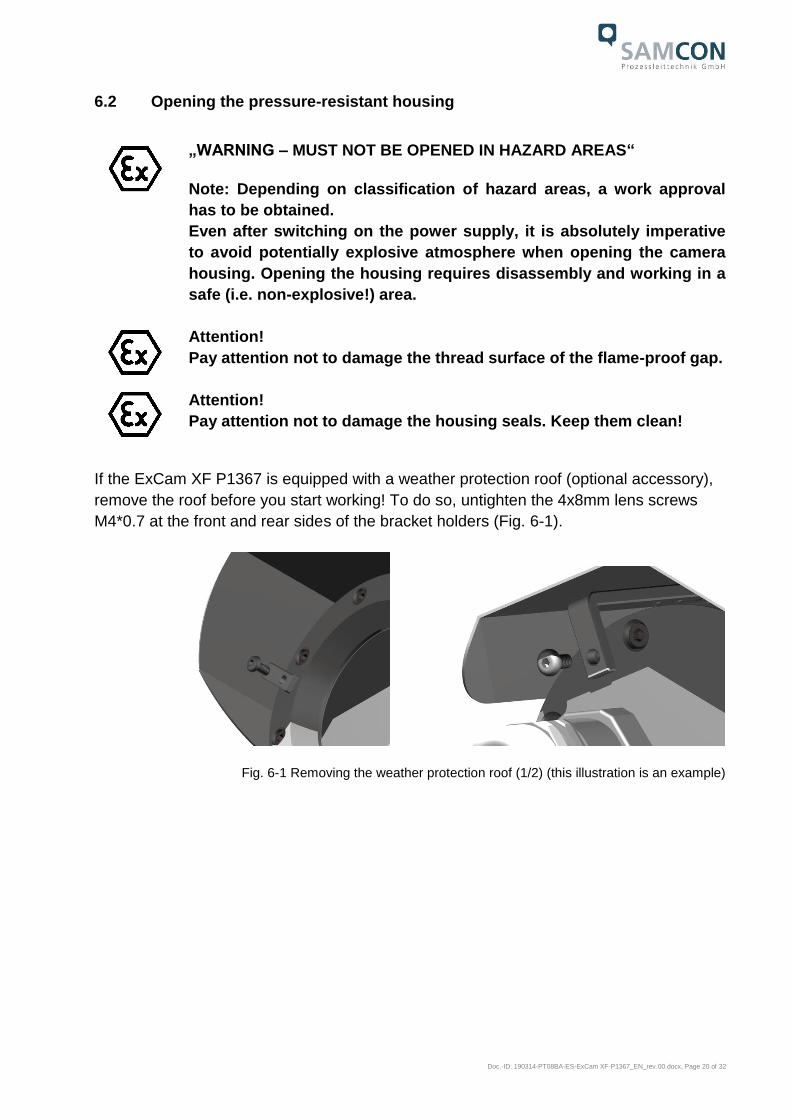
If the ExCam XF P1367 is equipped with a weather protection roof (optional accessory),
remove the roof before you start working! To do so, untighten the 4x8mm lens screws
M4*0.7 at the front and rear sides of the bracket holders (Fig. 6-1).
Fig. 6-1 Removing the weather protection roof (1/2) (this illustration is an example)

Doc.-ID: 190314-PT08BA-ES-ExCam XF-P1367_EN_rev.00.docx, Page 21 of 32
Fig. 6-2 Removing the weather protection roof (2/2) (similar illustration)
To open the ExCam XF P1367’s stainless steel housing (T07 VA2.3.x.x) of, loosen the
eight cylinder-head hexagon screws (DIN 912/ ISO 4762) together with their spring rings
(DIN 127A) on the rear side of the cable and power supply flange (see Fig. 6-3).
Caution: Do not touch the screw threads with your skin or clothes! On the threads, there
is LOCTITE® 243™ (chemical basis is dimethacrylate ester) applied to prevent the bolt-
ed connection from unintentional loosening because of impacts and vibrations and to
seal them tightly. It is not permitted for the customer to open the front-side sight glass
flange! There is no need of such an action.
Carefully pull out the cable and supply flange to the rear, as straight as possible. Be-
cause of negative pressure, it may be difficult to remove the flange. The cylindrical clear-
ance fit (H8f7 - DIN ISO 286) of the camera body and flange may not be tilted! Risk of
damage to the flame-proof gap (DIN EN 60079-1:2012)!
Fig. 6-3 Opening the ExCam XF P1367 (similar illustration)

Doc.-ID: 190314-PT08BA-ES-ExCam XF-P1367_EN_rev.00.docx, Page 22 of 32
Attention: The mounting adapter with the housing’s PTC heater, camera module and op-
tics, as well as the CB06 temperature control and (if applicable) auxiliary relays and ter-
minal box are fixed on the cable and supply flange. Dealing with these components, too,
you have to work very carefully and precisely in order to avoid canting and damage to the
in-built components!
Caution: Do not touch the cylindrical fit surface with your skin or clothes! On the surface,
there is oil lubricating paste to protect the surface against fretting corrosion and mechani-
cal stresses.
When you open the housing, heed that you do not damage the GYLON® flat seal (blue,
RAL5012) and do not make it dirty. The flat gasket is loosely attached to the cable and
power supply flange. It is fixed only by the bolted connections!
Attention!
Make sure not to damage the surface of the drill hole and the shaft (fit-
ting) of the flame-proof gap.
Attention!
Pay attention not to damage the seals. Keep them clean!
Doc.-ID: 190314-PT08BA-ES-ExCam XF-P1367_EN_rev.00.docx, Page 23 of 32
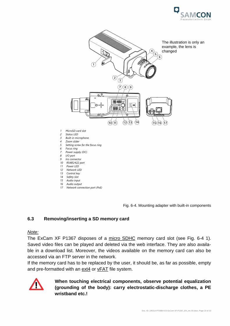
Fig. 6-4. Mounting adapter with built-in components
6.3 Removing/inserting a SD memory card
Note:
The ExCam XF P1367 disposes of a micro SDHC memory card slot (see Fig. 6-4 1).
Saved video files can be played and deleted via the web interface. They are also availa-
ble in a download list. Moreover, the videos available on the memory card can also be
accessed via an FTP server in the network.
If the memory card has to be replaced by the user, it should be, as far as possible, empty
and pre-formatted with an ext4 or vFAT file system.
When touching electrical components, observe potential equalization
(grounding of the body): carry electrostatic-discharge clothes, a PE
wristband etc.!
The illustration is only an example, the lens is changed
1 MicroSD card slot
2 Status LED
3 Built-in microphone.
4 Zoom slider
5 Setting screw for the focus ring
6 Focus ring
7 Power supply (DC)
8 I/O port
9 Iris connector
10 RS48S/422 port
11 Power LED
12 Network LED
13 Control key
14 Safety slot
15 Audio input
16 Audio output
17 Network connection port (PoE)
Doc.-ID: 190314-PT08BA-ES-ExCam XF-P1367_EN_rev.00.docx, Page 24 of 32
6.4 Status LED
The user can see the Status LED (Fig. 6-4) only if the camera housing is open.
6.5 Hardware Reset
To re-set all parameters of the ExCam XF P1367 (including the IP address) to default
setting, a hardware reset has to be carried out.
The parameters can be either reset via the web interface or manually. If the camera in
the network can no longer be reached or its state is uncontrollable, the reset should be
performed manually. To do so, proceed as follows:
1. Disconnect the camera installation module (Axis P1367) from the power supply.
2. Press and hold the control button 13 (see the illustration 6-4) and, at the same
time, connect the system to the voltage supply (PoE).
3. Press and hold the control button until status indicator 2 (Fig. 6-4) lights yellow
(wait about 30 seconds).
4. Release the control button. When the status indicator lights green (it can take
about 1 minute), P1367 will be reset to the factory settings axis. If there is a DHCP
server in the network, the IP address will be the following: 192.168.0.90 (subnet
masking 255.255.255.0).
5. IP address and password can be redefined. If the hardware reset is not satisfacto-
ry, or the network camera shows serious conflicts, or does not work as usually (er-
rors in the browser visualisation, frozen images, control commands no longer pro-
cessed, slowing down of the system, etc.), it may be necessary to re-install the
current firmware, or to install an update (see Chapter 7).
6.6 Closing of the pressure-resistant housing
For closing the housing, proceed in reverse order as when opening. Use exclusively orig-
inal screws included in the supply.
The cable and power-supply flange (K3) is fixed by 8 cylinder-head screws M4*0.7 (ISO
metric right-turning) with 30 mm thread length (DIN 912/ ISO 4762, grade 6g). Materials
of bolted connections are identical to the pressure-resistant stainless steel housing
(standard material no. 1.4404 AISI316L). Check whether the threaded holes are undam-
aged and clean. Before closing, it is also absolutely imperative to check the flame-proof
gap (circular cylindrical fit).
Doc.-ID: 190314-PT08BA-ES-ExCam XF-P1367_EN_rev.00.docx, Page 25 of 32
Attention!
If any mechanical damages occurred to the fitting gap, it is no longer
allowed to use the housing!
Attention!
Do not lock-in any foreign objects in the housing.
Dismantled screw locks (spring washers DIN 127A) must be used again.
The GYLON® gasket must be used in undamaged condition, according to the flange hole
pattern, and placed between the flange and the body. The lateral position of the flat sur-
face/ contact surface is arbitrary.
If, when closing the housing, you see that the surface of the fitting gap is dirty or insuffi-
ciently lubricated, clean it with a clean cloth and de-grease it with a suitable cleaning
agent. Then re-grease it with lubricant suitable for this specific application (e.g., Mo-
lykote® P-40 gel for standard applications or special grease OKS 403 in the event of
heavy seawater influence)).
The screwed connections of flange and body components must always be tightened
crosswise at a torque of 3 Nm! Do not tighten the screws too strongly! It can cause rup-
ture of the cylinder head or over-stretching the threads, and thus leading to an impair-
ment of the pressure resistance or ignition protection class!
Cylinder-head bolts for explosion-proof connection of the camera
body with the flange component must always be tightened at a 3 Nm
torque - crosswise and evenly!
6.7 Battery
ExCam XF P1367 is equipped with a high-temperature resistant Panasonic button cell
BR2330A/VAN. This cell supplies energy to the internal real time clock (RTC). The cus-
tomer is not allowed to replace the battery! In this case, please contact the manufacturer.

Doc.-ID: 190314-PT08BA-ES-ExCam XF-P1367_EN_rev.00.docx, Page 26 of 32
7 Settings of the lens
The ExCam XF P1367 lens can be set up only via the web interface or the visualization
software. The user cannot do any mechanical settings on at remote zoom lens. To con-
figure the focus and tele-range, you can use the control function (slider) via the web inter-
face and mouse command (see Fig. 7-1).
Fig. 7-1. User Interface for setting the zoom and focus
This step is only necessary if the camera factory settings are unsatisfactory, or if user
settings (focus, sharpness, digital zoom, etc.) to be done via the web interface do not al-
low the user to achieve the desired results.
P 1367
Lens type Varifocal, IR-corrected, CS-mount, mega-pixel
Iris control
ICS iris,
F1.2/ 2.9 mm
aspherical
technology No
Focal length 2.8 – 8.5 mm
Image angle,
horizontal 98° (wide) - 36° (tele)
Control
characteristic
(iris)
automatic (the camera module contains an analogue circuit)
MOD
(min. object
distance)
0.30 m (wide)
1.00 m (tele)
Tab.7-1 Lens Data
Please note!
If not agreed otherwise, the ExCam® XF P1367 is pre-configured by the
manufacturer to the maximum sensor resolution and low image com-
pression (high image quality and high network bandwidth). The focus
is optimized for objects at approximately 10 metres distance.
Doc.-ID: 190314-PT08BA-ES-ExCam XF-P1367_EN_rev.00.docx, Page 27 of 32
The focus of the ExCam XF P1367 network camera is optimised by the manufacturer to
about 10 m object distance. The complete viewing angle is located in the "wide" area.
This means a horizontal viewing angle of 98°. Usially, no adjustment is required. To focus
the objects at a smaller or greater distance, or to change the zoom range (wide -> tele),
you can change the lens settings, as follows:
1. Via a web browser (Mozilla Firefox, MS Internet Explorer, etc.), open the user in-
terface of ExCam XF P1367 (for network access, see Chapter 8). Navigate in the
"Setup" menu via the "Basic Setup" pull-down menu to the "Focus" settings.
2. Follow the shown instructions and first click on the "Open iris" button. If this button
is disabled, this means that the iris is already open.
3. Now click on "Reset", to reset the lens level to the default value
4. Release the zoom and sharpness regulators on the lens, by turning it counter-
clockwise. By moving the two regulators, adjust the zoom strength and image
sharpness. Check the image quality in the window below.
5. Re-tighten the zoom and sharpness regulators.
6. The click on the button "Fine-tune focus automatically" in the configuration menu
and wait until the automatic optimization is finished.
7. To re-enable the iris, click "Enable iris". If the button is disabled, this means that
the iris is already activated.
8. If necessary, you can make further settings in the "Advanced” tab.
Please note:
Before you start the automatic fine tuning, adjust the image sharpness as precisely as
possible with the aid of the sharpness regulator or focus wizard. The sharpness regulator
usually provides the best results.
8 Network access and visualization
The most important procedures of the camera’s initial commissioning are described be-
low. The configuration menu of the web surface allows an intuitive navigation and offers
several configuration possibilities. For detailed documentation and information how to
use the web Interface, please see the User Manual for Axis or visit the following website:
https://www.axis.com/products/axis-p1367

Doc.-ID: 190314-PT08BA-ES-ExCam XF-P1367_EN_rev.00.docx, Page 28 of 32
The delivered ExCam XF P1367 is set to the applicable net frequency (50Hz or 60Hz). If
the camera is used at a location with a differing net frequency, the image might start to
flicker, particularly in surroundings with fluorescent tubes. In such a case, the applicable
settings have to be carried out within the menu “System Options > Advanced > Plain
Config”.
User: root
Password: root
8.1 Browser Support
A list of the currently supported web browsers, operating systems, required add-ons, etc.
can be viewed at:
http://www.axis.com/techsup/cam_servers/tech_notes/browsers.htm
8.2 Assigning the IP address
The ExCam XF P1367 is intended for use in an Ethernet network and requires an IP ad-
dress to access and control it. In most of today’s networks, a DHCP server is integrated.
This server automatically assigns an IP address.
If there is no DHCP server available in the network, the IP default address of
ExCam XF P1367 is “192.168.0.90” (subnet masking 255.255.255.0).
With the “AXIS IP Utility”, it is possible to determine the IP address under Windows; the
included USB stick contains this application.
If it is not possible to assign the IP address, it might be necessary to
change the firewall settings!
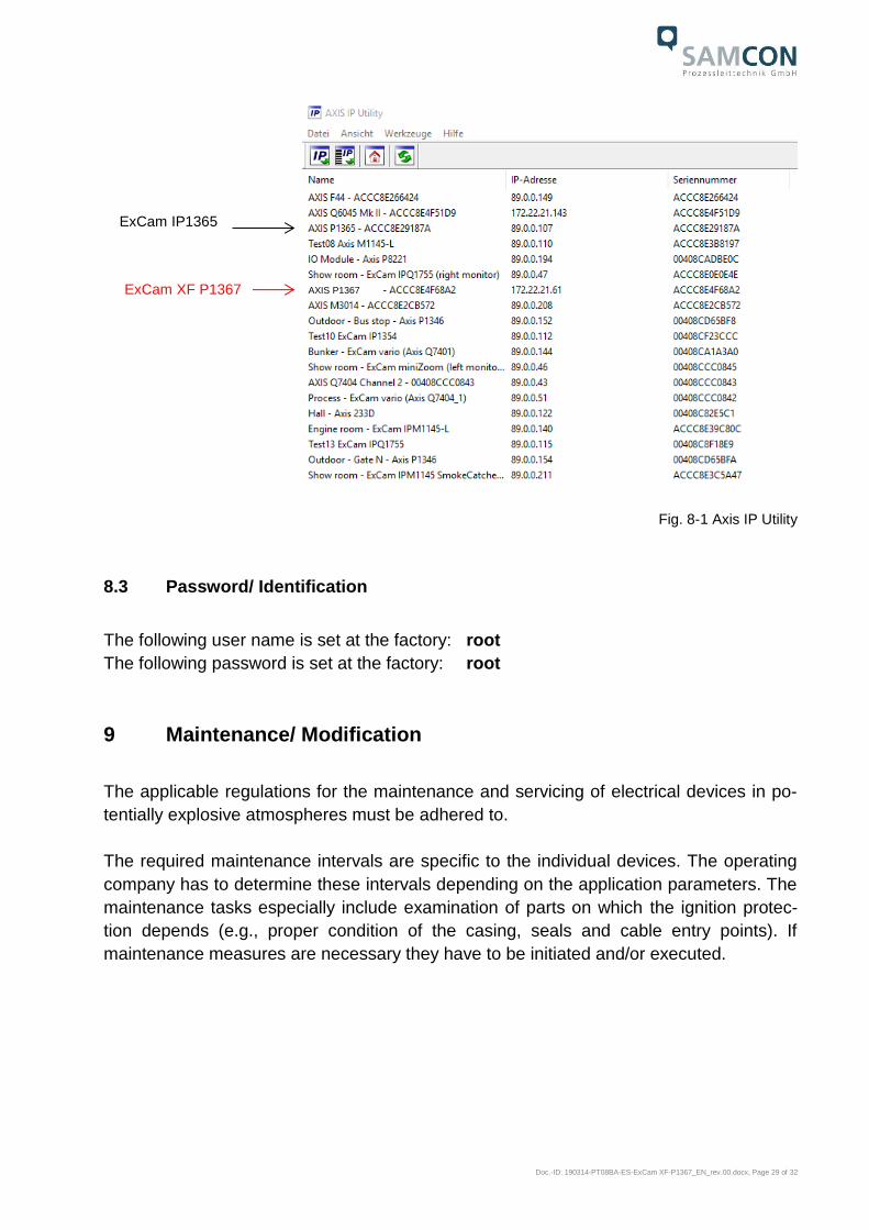
The “AXIS IP Utility” tool automatically recognizes all ExCam devices and visualises
them in the device list. It can also be used to manually assign a static IP address. For this
purpose, the ExCam XF P1367 network camera should be installed in the same physical
network segment (physical subnet) as the computer on which the AXIS IP Utility is run-
ning. The network signature of ExCam XF P1367 is "AXIS P1367" (see Fig. 8-1). MAC
address and serial number for clear device identification are also detected and displayed.
Doc.-ID: 190314-PT08BA-ES-ExCam XF-P1367_EN_rev.00.docx, Page 29 of 32
Fig. 8-1 Axis IP Utility
8.3 Password/ Identification
The following user name is set at the factory: root
The following password is set at the factory: root
9 Maintenance/ Modification
The applicable regulations for the maintenance and servicing of electrical devices in po-
tentially explosive atmospheres must be adhered to.
The required maintenance intervals are specific to the individual devices. The operating
company has to determine these intervals depending on the application parameters. The
maintenance tasks especially include examination of parts on which the ignition protec-
tion depends (e.g., proper condition of the casing, seals and cable entry points). If
maintenance measures are necessary they have to be initiated and/or executed.
ExCam IP1365
ExCam XF P1367 AXIS P1367

Doc.-ID: 190314-PT08BA-ES-ExCam XF-P1367_EN_rev.00.docx, Page 30 of 32
10 Repair
Repairs may only be carried out with original parts of SAMCON Prozessleittechnik GmbH. Damaged pressure-resistant housings have to be replaced completely. If in doubt, send the part in question back to SAMCON Prozessleittechnik GmbH. Repairs concerning the explosion protection must only be carried out in accordance with
nationally applied regulations by SAMCON Prozessleittechnik GmbH or by an electrical
technician authorized by SAMCON Prozessleittechnik GmbH. Rebuilding of or alterations
to the devices are not permitted.
11 Disposal/ Recycling
When disposing of the device, nationally applicable regulations must be observed.
This Document is subject to alterations and additions.
12 Drawings & 3D models
All drawings, 3D models, certificates and other information are available in the download
area of the product page on our website:
Quick link:
https://www.samcon.eu/en/products/network/excam-xf-p1367/
Doc.-ID: 190314-PT08BA-ES-ExCam XF-P1367_EN_rev.00.docx, Page 31 of 32
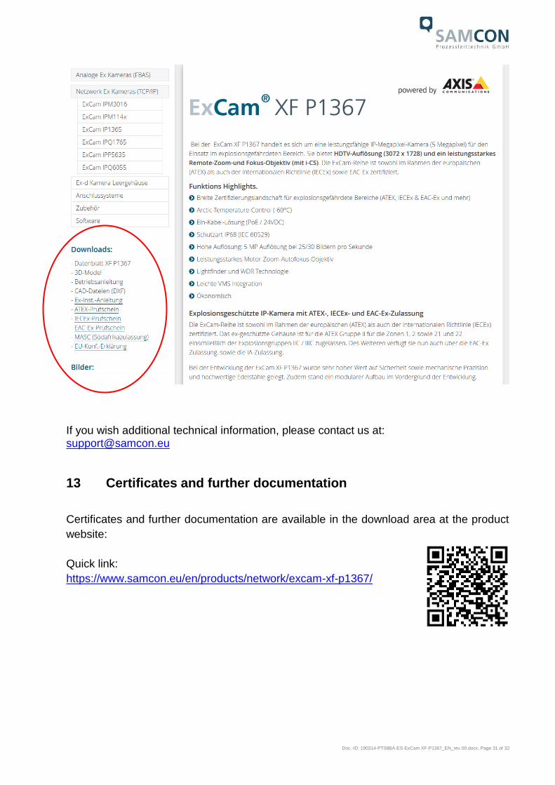
If you wish additional technical information, please contact us at: [email protected]
13 Certificates and further documentation
Certificates and further documentation are available in the download area at the product
website:
Quick link:
https://www.samcon.eu/en/products/network/excam-xf-p1367/

Schillerstrasse 17, 35102 Lohra-Altenvers, Germany www.samcon.eu, [email protected] Phone: +49 6426 9231-0, fax: - 31
Related Documents