EU Onshore RfG Generating plant -12/04/22 Examples of Generic BCA Templates A number of Users have requested if National Grid could provide some examples of the generic templates used to populate the Technical Appendix (Appendix F’s) of Bilateral Connection Agreements. With this in mind, National Grid has provided seven examples of the generic templates. • EU Onshore Generation Template • EU Onshore Demand Template • EU Offshore Generation Template • EU Offshore (OFs) Template • EU LEEMPs Template • EU Interconnectors Template • Storage template In providing these examples, Users should be aware that the Technical Appendices detail the site specific requirements in relation to a connection and are also designed to be consistent with the requirements of the Grid Code and other industry codes. The above examples therefore simply provide a base from which each individual connection offer is tailored to suit the site specific requirements of that connection and the variations that may occur. National Grid ESO is publishing these examples in good faith to provide the Industry with an illustration of the type of technical requirements necessary. It should however be noted that the Power System and Commercial environment is evolving on a continuous basis and these templates are subject to regular review to ensure they remain fit for purpose. In addition, the Technical Appendices are the only method in which National Grid ESO can ensure appropriate technical requirements are placed on a User in a time frame which is consistent with the Connection Application Process. Naturally, any significant technical requirement would need to be subject to wider review amongst the Grid Code Review Panel and associated Working Groups. It must be remembered that the Connection Agreements are Bilateral and hence require the agreement of both parties before signature. A User will have 90 days to sign an offer hence providing ample opportunity for discussion, clarification and amendment of the technical appendices. National Grid ESO is receptive to comments from Users in respect of these agreements as it sees such feedback as an important tool in updating, refining and improving them. There have been numerous examples in the past where comments received from User’s following a specific connection application have then been included within the Generic Template. Notwithstanding this however, National Grid ESO equally needs to balance Customer’s expectations against the requirements of security of supply.

Welcome message from author
This document is posted to help you gain knowledge. Please leave a comment to let me know what you think about it! Share it to your friends and learn new things together.
Transcript
EU Onshore RfG Generating plant -12/04/22
Examples of Generic BCA Templates
A number of Users have requested if National Grid could provide some examples of the generic templates used to populate the Technical Appendix (Appendix F’s) of Bilateral Connection Agreements. With this in mind, National Grid has provided seven examples of the generic templates.
• EU Onshore Generation Template
• EU Onshore Demand Template
• EU Offshore Generation Template
• EU Offshore (OFs) Template
• EU LEEMPs Template
• EU Interconnectors Template
• Storage template
In providing these examples, Users should be aware that the Technical Appendices detail the site specific requirements in relation to a connection and are also designed to be consistent with the requirements of the Grid Code and other industry codes. The above examples therefore simply provide a base from which each individual connection offer is tailored to suit the site specific requirements of that connection and the variations that may occur.
National Grid ESO is publishing these examples in good faith to provide the Industry with an illustration of the type of technical requirements necessary. It should however be noted that the Power System and Commercial environment is evolving on a continuous basis and these templates are subject to regular review to ensure they remain fit for purpose.
In addition, the Technical Appendices are the only method in which National Grid ESO can ensure appropriate technical requirements are placed on a User in a time frame which is consistent with the Connection Application Process. Naturally, any significant technical requirement would need to be subject to wider review amongst the Grid Code Review Panel and associated Working Groups.
It must be remembered that the Connection Agreements are Bilateral and hence require the agreement of both parties before signature. A User will have 90 days to sign an offer hence providing ample opportunity for discussion, clarification and amendment of the technical appendices. National Grid ESO is receptive to comments from Users in respect of these agreements as it sees such feedback as an important tool in updating, refining and improving them. There have been numerous examples in the past where comments received from User’s following a specific connection application have then been included within the Generic Template. Notwithstanding this however, National Grid ESO equally needs to balance Customer’s expectations against the requirements of security of supply.

EU Onshore RfG Generating plant -12/04/22
APPENDIX F
EU RFG TEMPLATE FOR AN ONSHORE EU RFG COMPLIANT POWER STATION
RfG guidance notes can be found here: https://www.nationalgrid.com/sites/default/files/documents/RfG%20Factsheet%20June%202018.pdf
(NOTES – ALL SECTIONS IN [RED] TO BE SELECTED AS REQUIRED) (NOTES – ALL SECTIONS IN [RED] TO BE COMPLETED/DELETED WHERE APPROPRIATE)
ALL SECTIONS IN YELLOW HIGHLIGHTED RED TEXT ARE WHERE A DECISION SHOULD BE
MADE DEPENDING ON THE TYPE OF AGREEMENT
ALL SECTIONS IN YELLOW HIGHLIGHTED BLACK ITALLIC TEXT ARE FOR GUIDANCE AND SHOULD BE DELETED BEFORE COMPLETION
NOTE:- WHERE REFERENCE HAS BEEN MADE TO STAGE 1, THIS
ONLY NEEDS TO BE INCLUDED WHERE THE DEVELOPMENT IS STAGED. IF THERE IS NO REFERENCE TO STAGING THIS REFERENCE CAN BE DELETED
NOTE IF THE EU RFG COMPLIANT GENERATOR IS DIRECTLY CONNECTED AND IS CONNECTED TO A GIS SUBSTATION AND IT HAS OPTED TO USE A GENERATOR
OWNERSHIP BOUNDARY UNDER CUSC 2.12. THEN ENSURE THE CORRECT TEXT IS USED (highlighted in green). IF AN EU RFG COMPLIANT GENERATOR CONNECTS TO A GIS
SUBSTATION BUT THE OWNERSHIP BOUNDARY IS AT THE BUSBAR CLAMPS USE THE STANDARD TEXT and delete all the green highlighted text.
AMENDMENTS RECORD
Issue Date Summary of Changes/
Reasons Authors Approved by
(including Job Title)
1. January
2015 Update and revision from comments received in 2014
A. Johnson N. Martin
G Stein Technical Policy
Manager
1.1 5 March
2015
Removal of Breaker status from Dynamic System Monitoring – Schedule 4 – Appendix F5
A. Johnson G Stein
Technical Policy Manager
1.2 3
February 2016
Addition of operational metering signals to facilitate GC0028 Constant terminal voltage
A. Johnson G Stein
Technical Policy Manager
2. 1 August
2016 Update to wind farm voltage control requirements
D Beaumont Xiaoyao Zhou
Technical Policy Manager
3. 24 Oct 2016
ASM minimum sampling rate reduced to 1Hz.
Phil Tonkin Xiaoyao Zhou
Technical Policy Manager
4. 17 Nov 2016
Operational Metering sampling rate change to 1s or 1Hz following customer feedback
A. Johnson Xiaoyao Zhou
Technical Policy Manager
5. 28 Mar 2017
Addition of “trip relay” column in protection schedule of F4
G. Abeyawardene Xiaoyao Zhou
Technical Policy Manager
6. 28 Mar 2017
Addition of item 33 and 34 in F5 re tidal connections.
A. Johnson Xiaoyao Zhou
Technical Policy Manager
7. 28 Mar 2017
Addition of operational metering signal for tidal connections in Appendix F5 schedule 2
A. Johnson Xiaoyao Zhou
Technical Policy Manager
EU Onshore RfG Generating plant -12/04/22
8. 28 March
2017 Appendix F5 schedule 1, cross-site wiring obligation clarified
A. Johnson Xiaoyao Zhou
Technical Policy Manager
9. 30 March
2018
Appendix F5, more clearly defined obligations relating to control points and emergency instructions
A. Johnson Xiaoyao Zhou
Technical Policy Manager
10. 27Apr 2017
Following completion of GSR18 and GC77, SSR text added to F5
B. Awad Xiaoyao Zhou
Technical Policy Manager
11. 27 June
2017
System Availability and State of Charge added to battery operational metering requirements
A. Johnson Xiaoyao Zhou
Technical Policy Manager
12. 28 June
2017
Update to operational metering schedule 2 re location of marshalling kiosk
A. Johnson/S. Hoar Xiaoyao Zhou
Technical Policy Manager
13. 24 Oct 2017
Update to F4 re provision of a protection setting report
G. Abeyawardene Xiaoyao Zhou
Technical Policy Manager
14. 7 Nov 2017
Non-standard GIS connection text added
A. Johnson/F Williams Xiaoyao Zhou
Technical Policy Manager
15. 8 October
2018 Update to F5 schedule 3 DSM G. Abeyawardene
Xiaoyao Zhou Technical Policy
Manager
16. 23 Apr 2019
Removal of PQM requirement from synchronous
Maxwell Mulimakwenda
Xiaoyao Zhou Customer Technical
Policy Manager
17. 16 May 2019
Power Available signal changed to 1Hz update rate
A. Johnson Xiaoyao Zhou
Customer Technical Policy Manager
18. 1 August
2019
SO/TO wording added; Tertiary info added based on TO advice.
E. Ashton Xiaoyao Zhou
Customer Technical Policy Manager
19. 15 August
2019
F3 intertrips section split into Scottish section and English section.
E. Ashton Xiaoyao Zhou
Customer Technical Policy Manager
20. 11 March
2020
Harmonic Performance update due to update of Engineering Recommendation G5.
E. Ashton Xiaoyao Zhou
Customer Technical Policy Manager
21. 24 April
2020 Reactive Capability updated following customer feedback
F Williams Xiaoyao Zhou
Customer Technical Policy Manager
22. 13 July 2020
Model and study requirements added to F5 replacing SSR
F Ghassemi/Yun Lei Xiaoyao Zhou
Customer Technical Policy Manager
23. 11 Jan 21 Tertiary wording update Nick Tart Xiaoyao Zhou
Customer Technical Policy Manager
24. 21 Jan 2021
Short Circuit level section added Iky Rai Xiaoyao Zhou
Customer Technical Policy Manager
25. 11 June
2021 Flicker requirement specified F Ghassemi
Xiaoyao Zhou Customer Technical
Policy Manager
26. 13 Sept
2021 Harmonic performance update for tertiaries
Iky Rai Xiaoyao Zhou
Customer Technical Policy Manager
27. 13 Sept
2021 API communications option added John Walsh
Xiaoyao Zhou Customer Techical
Policy Manager
EU Onshore RfG Generating plant -12/04/22
28. 9 Dec 2021
MPSI removed for BELLAs, replaced with API
Stuart Brace Xiaoyao Zhou
Customer Techical Policy Manager
29. 16 Dec 2021
F5 Schedule 2, metering interaction clarification
Oliver Garfield Xiaoyao Zhou
Customer Techical Policy Manager
30. 22 Jan 2022
F4 protection update (reverse looking element)
Gihan Abeyawardene Xiaoyao Zhou
Customer Techical Policy Manager
31. 25 Jan 2022
F5 update to harmonic performance and new schedule
Iky Rai Xiaoyao Zhou
Customer Techical Policy Manager
(this whole page to be deleted after the appendices have been checked by the Customer Technical Policy Team)
EU Onshore RfG Generating plant -12/04/22
APPENDIX F
SITE SPECIFIC TECHNICAL CONDITIONS CONTENTS
User: [XXXX]
Type of User: EU Code User
Connection Site: [XXXX]
Contents F1 Agreed Ancillary Services F2 Derogated Plant F3 Special Automatic Facilities F4 Relay Settings and Protection F5 Other Technical Requirements Delete the Electrical Standard paragraphs if embedded, if direct connect select the appropriate one and delete the other.
Electrical Standards These appendices contain references to the Relevant Transmission Licensee’s Relevant Electrical Standards [(RES) and/or The Scottish Electrical Standards for SPT’s Transmission System (SPTS) or Scottish Electrical Standards for SHET’s Transmission System (SHETS)] throughout. The EU Code User shall ensure that all EU Code User equipment contained within the Relevant Transmission Licensee’s busbar protection zone at the EU Code User/National Transmission Connection Point (see Grid Code ECC 6.2.1.2) complies with the RES/SPTS/SHETS. The EU Code User can access these standards from The Company’s website at:- https://www.nationalgrideso.com/uk/electricity/codes/grid-code/electrical-standards-documents-including-specifications-electronic The SPTS/SHETS/RES are updated periodically. If the SPTS / SHETS/RES is updated in the period between issuing the Connection Offer and the EU Code User completing the connection to the National Transmission System then The Company will seek agreement with the EU Code User to use the updated RES/SPTS/SHETS as the standard for plant and apparatus at the Connection Point. General (following paragraph for tidal/solar/wave agreements only, otherwise delete) In so far as the Grid Code is concerned, the EU Code User will be considered as a Power Park Module, in which the Power Park Module includes the tidal/solar/wave generating units. In addition to supplying all data associated with each Power Park Module (as appropriate) under the Grid Code, it is also recognised that this application contains new generation technology. As further information becomes available, and the EU Code User’s design becomes more clearly established, The Company may need to revise and update the technical requirements and parameters specified in this Technical Appendix

EU Onshore RfG Generating plant -12/04/22
(Appendix F) in collaboration with the EU Code User and the Construction Programme timeframe specified in the Appendix J of the Construction Agreement /date to be agreed with The Company, the Relevant Transmission Licensee and the EU Code User (use to be agreed for Scottish agreements). Use the following paragraph for Generator Connected GIS Ownership Boundaries As further information becomes available, and the EU Code User’s design becomes more clearly established, The Company and the Relevant Transmission Licensee may need to revise and update the technical requirements and parameters specified in this Technical Appendix (Appendix F) in collaboration with the EU Code User, together with the Construction Programme timeframe specified in the Appendix J/date to be agreed with The Company, the Relevant Transmission Licensee and the EU Code User(use to be agreed for Scottish agreements) of the Construction Agreement.
EU Onshore RfG Generating plant -12/04/22
APPENDIX F1
SITE SPECIFIC TECHNICAL CONDITIONS AGREED BALANCING SERVICES
User: [XXXX]
Type of User: EU Code User
Connection Site: [XXXX]
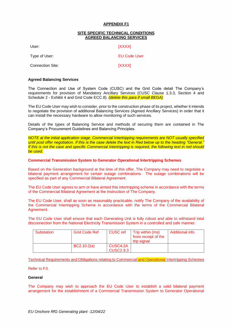
Agreed Balancing Services The Connection and Use of System Code (CUSC) and the Grid Code detail The Company’s requirements for provision of Mandatory Ancillary Services (CUSC Clause 1.3.3, Section 4 and Schedule 2 - Exhibit 4 and Grid Code ECC.8). (delete this para if small BEGA) The EU Code User may wish to consider, prior to the construction phase of its project, whether it intends to negotiate the provision of additional Balancing Services (Agreed Ancillary Services) in order that it can install the necessary hardware to allow monitoring of such services. Details of the types of Balancing Service and methods of securing them are contained in The Company’s Procurement Guidelines and Balancing Principles. NOTE at the initial application stage, Commercial Intertripping requirements are NOT usually specified until post offer negotiation. If this is the case delete the text in Red below up to the heading “General.” If this is not the case and specific Commercial Intertripping is required, the following text in red should be used. Commercial Transmission System to Generator Operational Intertripping Schemes Based on the Generation background at the time of this offer, The Company may need to negotiate a bilateral payment arrangement for certain outage combinations. The outage combinations will be specified as part of any Commercial Bilateral Agreement. The EU Code User agrees to arm or have armed this intertripping scheme in accordance with the terms of the Commercial Bilateral Agreement at the Instruction of The Company. The EU Code User, shall as soon as reasonably practicable, notify The Company of the availability of the Commercial Intertripping Scheme in accordance with the terms of the Commercial Bilateral Agreement. The EU Code User shall ensure that each Generating Unit is fully robust and able to withstand total disconnection from the National Electricity Transmission System in a controlled and safe manner.
Substation Grid Code Ref CUSC ref Trip within (ms) from receipt of the trip signal
Additional info
BC2.10.2(a) CUSC4.2A CUSC2.9.3
Technical Requirements and Obligations relating to Commercial and Operational Intertripping Schemes Refer to F3. General The Company may wish to approach the EU Code User to establish a valid bilateral payment arrangement for the establishment of a Commercial Transmission System to Generator Operational

EU Onshore RfG Generating plant -12/04/22
Intertripping Scheme in the future. This approach would be made at such time that The Company has established certainty in the local generation background. (Delete if intertrip specified above) The EU Code User shall co-operate with The Company in enhancing/amending these facilities and will not unreasonably withhold its agreement to any such proposals should The Company require this at a later date. Any changes to this Appendix F1 and/or to The Company’s and/or EU Code User’s obligations shall be subject to the provisions of Paragraph 2.9.3 of the CUSC which states that if either party wishes to modify, alter or change the site specific technical conditions it shall be deemed to be a Modification for the purposes of the CUSC unless CUSC 4.2B.3 (Agreed Ancillary Services) applies. CUSC 4.2B.3 states that if both parties have failed to reach agreement within a reasonable period then The Company is entitled to initiate the procedure for resolution as an “Other Dispute.” This does not apply in the case of Maximum Generation or System to Generator Operational Intertripping.
EU Onshore RfG Generating plant -12/04/22
APPENDIX F2
SITE SPECIFIC TECHNICAL CONDITIONS DEROGATED PLANT
User: [XXXX]
Type of User: EU Code User
Connection Site: [XXXX]
Derogated Plant Not applicable.
EU Onshore RfG Generating plant -12/04/22
APPENDIX F3
SITE SPECIFIC TECHNICAL CONDITIONS SPECIAL AUTOMATIC FACILITIES
User: [XXXX]
Type of User: EU Code User
Connection Site: [XXXX]
Special Automatic Facilities
If intertrip is specified, use the text in red below. Select the appropriate one for your region, and delete the other.
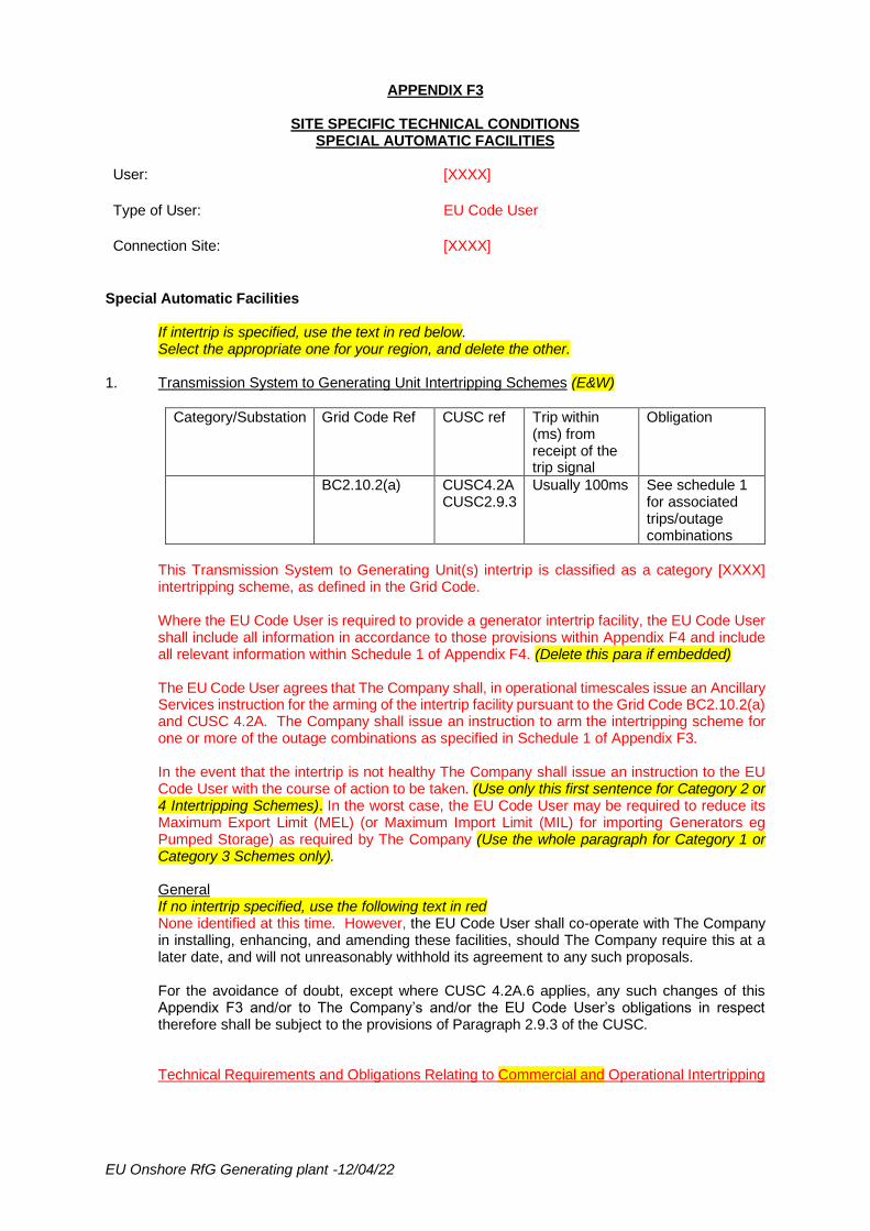
1. Transmission System to Generating Unit Intertripping Schemes (E&W)
Category/Substation Grid Code Ref CUSC ref Trip within (ms) from receipt of the trip signal
Obligation
BC2.10.2(a) CUSC4.2A CUSC2.9.3
Usually 100ms See schedule 1 for associated trips/outage combinations
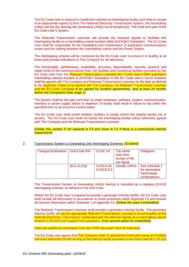
This Transmission System to Generating Unit(s) intertrip is classified as a category [XXXX] intertripping scheme, as defined in the Grid Code. Where the EU Code User is required to provide a generator intertrip facility, the EU Code User shall include all information in accordance to those provisions within Appendix F4 and include all relevant information within Schedule 1 of Appendix F4. (Delete this para if embedded) The EU Code User agrees that The Company shall, in operational timescales issue an Ancillary Services instruction for the arming of the intertrip facility pursuant to the Grid Code BC2.10.2(a) and CUSC 4.2A. The Company shall issue an instruction to arm the intertripping scheme for one or more of the outage combinations as specified in Schedule 1 of Appendix F3. In the event that the intertrip is not healthy The Company shall issue an instruction to the EU Code User with the course of action to be taken. (Use only this first sentence for Category 2 or 4 Intertripping Schemes). In the worst case, the EU Code User may be required to reduce its Maximum Export Limit (MEL) (or Maximum Import Limit (MIL) for importing Generators eg Pumped Storage) as required by The Company (Use the whole paragraph for Category 1 or Category 3 Schemes only). General If no intertrip specified, use the following text in red None identified at this time. However, the EU Code User shall co-operate with The Company in installing, enhancing, and amending these facilities, should The Company require this at a later date, and will not unreasonably withhold its agreement to any such proposals. For the avoidance of doubt, except where CUSC 4.2A.6 applies, any such changes of this Appendix F3 and/or to The Company’s and/or the EU Code User’s obligations in respect therefore shall be subject to the provisions of Paragraph 2.9.3 of the CUSC. Technical Requirements and Obligations Relating to Commercial and Operational Intertripping
EU Onshore RfG Generating plant -12/04/22
The EU Code User is required to install and maintain an intertripping facility such that on receipt of an appropriate signal (s) from The National Electricity Transmission System, the Generating Unit(s) will trip (by opening the Generating Unit(s) circuit breaker(s)). This shall form part of the EU Code User’s System. The Relevant Transmission Licensee will provide the required signals to facilitate this intertripping facility to a marshalling cubicle located within [XXXX]kV Substation. The EU Code User shall be responsible for the installation and maintenance of duplicated communications routes and the cabling between the marshalling cubicle and the Power Station. The intertripping scheme will be monitored by the EU Code User to ensure it is healthy at all times and provide indications to The Company for all selections. The functionality, performance, availability, accuracy, dependability, security, protocol and repair times of the communications links, trip facilities and monitoring facilities provided by the EU Code User from the Relevant Transmission Licensee’s/EU Code User’s DNO substation marshalling cubicles located at [XXXX]kV Substation to the EU Code User’s circuit breakers shall be agreed with The Company and Relevant Transmission Licensee by the date as defined in the Appendix J/date to be agreed with The Company, the Relevant Transmission Licensee and the EU Code User(use to be agreed for Scottish agreements) (and at least 24 months before the Completion Date stage 1) The System shall be fail safe such that no single hardware, software, system, communication, interface or power supply failure or depletion of facility shall result in failure to trip within the specified time or an incorrect control action. The EU Code User shall install isolation facilities to locally switch the intertrip facility out of service. The EU Code User shall not isolate the intertripping facility unless otherwise agreed with The Company and the Relevant Transmission Licensee. (Delete this section if not required in F3 and move to F1 if there is a commercial intertrip requirement)
2. Transmission System to Generating Unit Intertripping Schemes (Scotland)
Category/Substation Grid Code Ref CUSC ref Trip within (ms) from receipt of the trip signal
Obligation
BC2.10.2(a) CUSC4.2A CUSC2.9.3
Usually 100ms See schedule 1 for associated trips/outage combinations
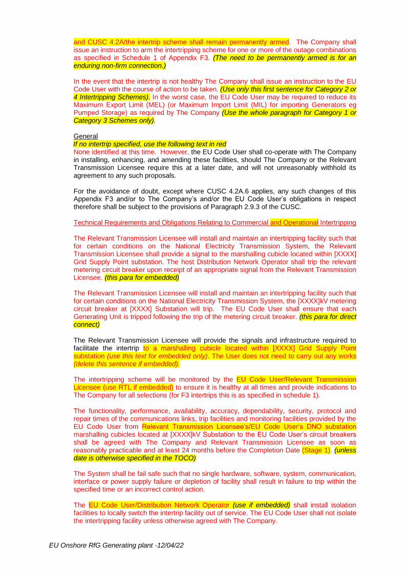
This Transmission System to Generating Unit(s) intertrip is classified as a category [XXXX] intertripping scheme, as defined in the Grid Code. Where the EU Code User is required to provide a generator intertrip facility, the EU Code User shall include all information in accordance to those provisions within Appendix F4 and include all relevant information within Schedule 1 of Appendix F4. (Delete this para if embedded) The Relevant Transmission Licensee shall provide a generator intertrip facility. The generator intertrip facility will trip the appropriate Relevant Transmission Licensee’s circuit breaker on the National Electricity Transmission System/provide the relevant signals at a marshalling cubicle located in [XXXX] Grid Supply Point substation. (Use second option for embedded) (Add any additional information from the TORI document here for intertrips) The EU Code User agrees that The Company shall, in operational timescales issue an Ancillary Services instruction for the arming of the intertrip facility pursuant to the Grid Code BC2.10.2(a)
EU Onshore RfG Generating plant -12/04/22
and CUSC 4.2A/the intertrip scheme shall remain permanently armed. The Company shall issue an instruction to arm the intertripping scheme for one or more of the outage combinations as specified in Schedule 1 of Appendix F3. (The need to be permanently armed is for an enduring non-firm connection.) In the event that the intertrip is not healthy The Company shall issue an instruction to the EU Code User with the course of action to be taken. (Use only this first sentence for Category 2 or 4 Intertripping Schemes). In the worst case, the EU Code User may be required to reduce its Maximum Export Limit (MEL) (or Maximum Import Limit (MIL) for importing Generators eg Pumped Storage) as required by The Company (Use the whole paragraph for Category 1 or Category 3 Schemes only). General If no intertrip specified, use the following text in red None identified at this time. However, the EU Code User shall co-operate with The Company in installing, enhancing, and amending these facilities, should The Company or the Relevant Transmission Licensee require this at a later date, and will not unreasonably withhold its agreement to any such proposals. For the avoidance of doubt, except where CUSC 4.2A.6 applies, any such changes of this Appendix F3 and/or to The Company’s and/or the EU Code User’s obligations in respect therefore shall be subject to the provisions of Paragraph 2.9.3 of the CUSC. Technical Requirements and Obligations Relating to Commercial and Operational Intertripping The Relevant Transmission Licensee will install and maintain an intertripping facility such that for certain conditions on the National Electricity Transmission System, the Relevant Transmission Licensee shall provide a signal to the marshalling cubicle located within [XXXX] Grid Supply Point substation. The host Distribution Network Operator shall trip the relevant metering circuit breaker upon receipt of an appropriate signal from the Relevant Transmission Licensee. (this para for embedded) The Relevant Transmission Licensee will install and maintain an intertripping facility such that for certain conditions on the National Electricity Transmission System, the [XXXX]kV metering circuit breaker at [XXXX] Substation will trip. The EU Code User shall ensure that each Generating Unit is tripped following the trip of the metering circuit breaker. (this para for direct connect) The Relevant Transmission Licensee will provide the signals and infrastructure required to facilitate the intertrip to a marshalling cubicle located within [XXXX] Grid Supply Point substation (use this text for embedded only). The User does not need to carry out any works (delete this sentence if embedded). The intertripping scheme will be monitored by the EU Code User/Relevant Transmission Licensee (use RTL if embedded) to ensure it is healthy at all times and provide indications to The Company for all selections (for F3 intertrips this is as specified in schedule 1). The functionality, performance, availability, accuracy, dependability, security, protocol and repair times of the communications links, trip facilities and monitoring facilities provided by the EU Code User from Relevant Transmission Licensee’s/EU Code User’s DNO substation marshalling cubicles located at [XXXX]kV Substation to the EU Code User’s circuit breakers shall be agreed with The Company and Relevant Transmission Licensee as soon as reasonably practicable and at least 24 months before the Completion Date (Stage 1). (unless date is otherwise specified in the TOCO) The System shall be fail safe such that no single hardware, software, system, communication, interface or power supply failure or depletion of facility shall result in failure to trip within the specified time or an incorrect control action. The EU Code User/Distribution Network Operator (use if embedded) shall install isolation facilities to locally switch the intertrip facility out of service. The EU Code User shall not isolate the intertripping facility unless otherwise agreed with The Company.
EU Onshore RfG Generating plant -12/04/22
(Delete this section if not required in F3 and move to F1 if there is a commercial intertrip requirement)
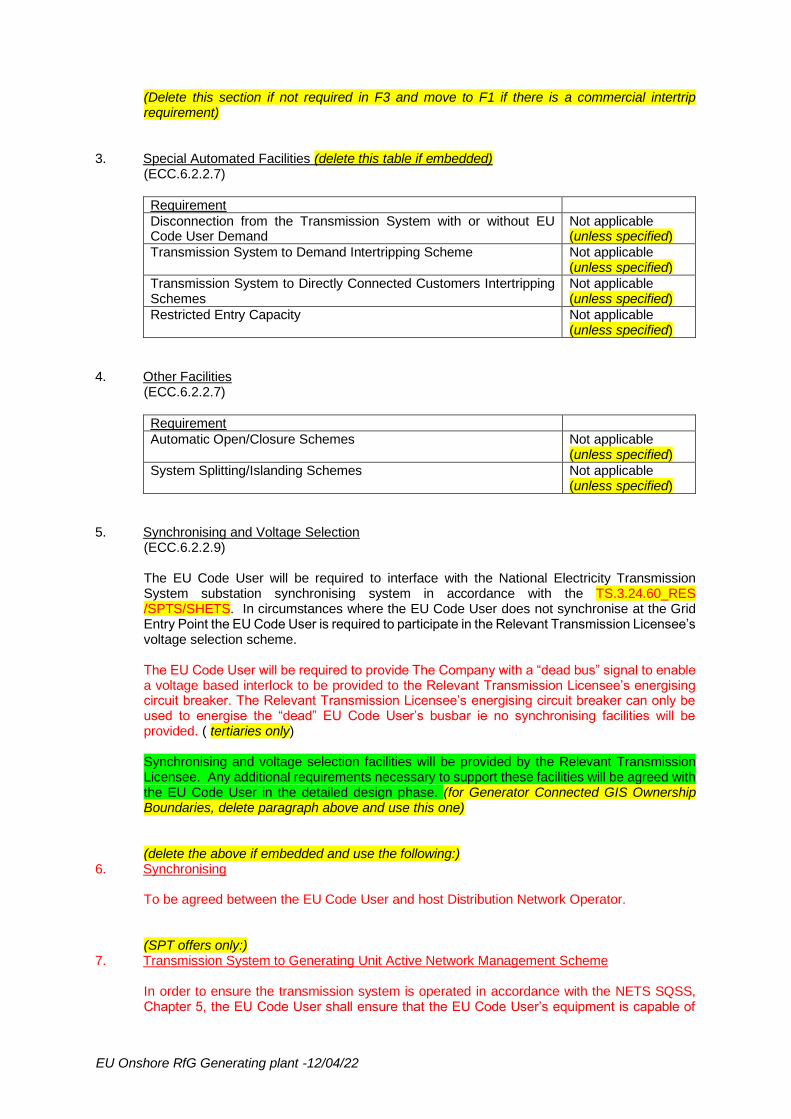
3. Special Automated Facilities (delete this table if embedded) (ECC.6.2.2.7)
Requirement
Disconnection from the Transmission System with or without EU Code User Demand
Not applicable (unless specified)
Transmission System to Demand Intertripping Scheme Not applicable (unless specified)
Transmission System to Directly Connected Customers Intertripping Schemes
Not applicable (unless specified)
Restricted Entry Capacity Not applicable (unless specified)
4. Other Facilities (ECC.6.2.2.7)
Requirement
Automatic Open/Closure Schemes Not applicable (unless specified)
System Splitting/Islanding Schemes Not applicable (unless specified)
5. Synchronising and Voltage Selection (ECC.6.2.2.9) The EU Code User will be required to interface with the National Electricity Transmission System substation synchronising system in accordance with the TS.3.24.60_RES /SPTS/SHETS. In circumstances where the EU Code User does not synchronise at the Grid Entry Point the EU Code User is required to participate in the Relevant Transmission Licensee’s voltage selection scheme. The EU Code User will be required to provide The Company with a “dead bus” signal to enable a voltage based interlock to be provided to the Relevant Transmission Licensee’s energising circuit breaker. The Relevant Transmission Licensee’s energising circuit breaker can only be used to energise the “dead” EU Code User’s busbar ie no synchronising facilities will be provided. ( tertiaries only) Synchronising and voltage selection facilities will be provided by the Relevant Transmission Licensee. Any additional requirements necessary to support these facilities will be agreed with the EU Code User in the detailed design phase. (for Generator Connected GIS Ownership Boundaries, delete paragraph above and use this one) (delete the above if embedded and use the following:)
6. Synchronising To be agreed between the EU Code User and host Distribution Network Operator. (SPT offers only:)
7. Transmission System to Generating Unit Active Network Management Scheme In order to ensure the transmission system is operated in accordance with the NETS SQSS, Chapter 5, the EU Code User shall ensure that the EU Code User’s equipment is capable of

EU Onshore RfG Generating plant -12/04/22
providing Operational Visibility and Commercial Control of the EU Code User’s Power Station, via GEMS, to The Company. The detailed interfaces, specifications and other arrangements required to meet this Site Specific Condition shall be developed and agreed with the EU Code User. GEMS local Intelligent Electronic Device (IED) shall be installed by the Relevant Transmission Licensee at the local substation. This will interface to the EU Code User’s equipment. The local GEMS IED will have a direct communications connection to a Generator interface equipment located at the EU Code User’s site. Both the local and remote IED’s would need to be capable of transmitting analogue and digital signals and would require communication modules to be installed for transmitting information from end to end. Details of the interface will be determined between the Relevant Transmission Licensee and the EU Code User.

EU Onshore RfG Generating plant -12/04/22
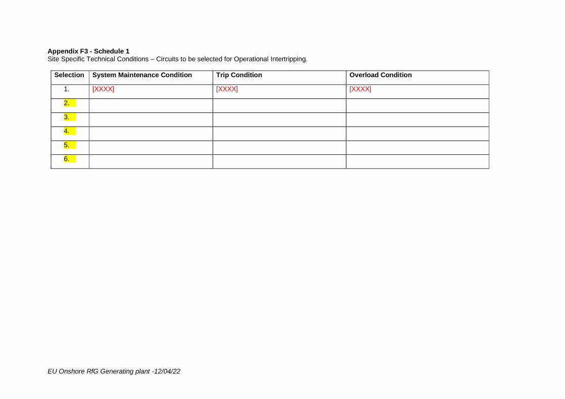
Appendix F3 - Schedule 1 Site Specific Technical Conditions – Circuits to be selected for Operational Intertripping.
Selection System Maintenance Condition Trip Condition Overload Condition
1. [XXXX] [XXXX] [XXXX]
2.
3.
4.
5.
6.

EU Onshore RfG Generating plant -12/04/22
APPENDIX F4
SITE SPECIFIC TECHNICAL CONDITIONS RELAY SETTINGS AND PROTECTION
User: [XXXX]
Type of User: EU Code User
Connection Site: [XXXX]
Relay Settings and Protection Relay settings and Power Station Protection Arrangements to be agreed between the EU Code User and the host Distribution Network Operator. If embedded (eg. BEGA, BELLA, LEEMPS…) use the red text above, and delete all F4 text below this. Relay Settings and Protection For direct connect only, delete this section if embedded. 1. Relay Settings
(ECC.6.2.2.5, ECC.6.2.2.6) The EU Code User shall complete the attached blank protection schedule pro-forma (Schedule 1 of this Appendix). The EU Code User shall submit the protection coordination report and settings on its plant for agreement with The Company and the Relevant Transmission Licensee. This shall include details of the following:
a) Circuit diagrams of both ac connections and tripping for the purposes of interpreting the schedule.
b) Protection co-ordination report confirming compliance with the applicable clauses of the Grid Code Connection Conditions. The report shall also show how co-ordination with the Transmission Owner’s existing system backup protection is achieved including proposed back-up protection grading curves.
c) Details of the Protection Dependability Index per protected zone. (ECC 6.2.2.2.2 d)
Not less than 3 months before the Commissioning Programme Commencement Date for the agreed works, the EU Code User shall have agreed the protection settings on the EU Code User’s equipment with The Company and the Relevant Transmission Licensee. The Company and the Relevant Transmission Licensee shall then finalise the protection settings on the National Electricity Transmission System equipment, complete the protection schedule with supporting details where necessary, and supply it to the EU Code User. Any subsequent alterations to the protection settings (whether by the EU Code User or The Company or the Relevant Transmission Licensee) shall be agreed between The Company, the Relevant Transmission Licensee and the EU Code User in accordance with the Grid Code. (ECC.6.2.2.5 and ECC.6.2.2.6) No EU Code User equipment shall be energised until the protection settings have been finalised. The EU Code User shall agree with The Company and the Relevant Transmission Licensee, and carry out a combined commissioning programme for the protection systems, and generally, to a minimum standard as specified in the Relevant Transmission Licensee’s Transmission Procedure (TP) 106 which is available from the Relevant Transmission Licensee’s Extranet. Access to the Relevant Transmission Licensee’s Extranet can be requested via email to:- [email protected]. / by the Relevant Transmission Licensee.
2. Generating Unit and Power Station/Power Park Module Protection Arrangements (ECC 6.2.2.2)
EU Onshore RfG Generating plant -12/04/22
The fault clearance time (from fault inception to circuit breaker arc extinction) for faults on all the EU Code User’s equipment directly connected to The National Transmission System shall meet the following minimum requirement(s): - [400kV within 80ms or 275kV within 100ms or 132kV and below within 120ms]. For faults on transformers the clearance time is specified for the HV side (e.g. for a fault on a [400/21(33 if wind farm)]kV Amend HV voltage as appropriate, eg. 132kV for SHE-T interconnecting transformer the maximum clearance time is [80]ms. Where intertripping is required to open circuit breakers, the overall fault clearance time shall not be extended by more than [60]ms (total [140]ms in this example) to allow such intertripping to operate. (The following paragraph for E&W direct connect only) In addition, the EU Code User shall consider provision of the facility to enable (through local intervention) a dedicated setting group within the IED(s) of their circuit protection(s) to enable a reverse looking distance element that can cover for the EU Code User circuit’s infeed to a busbar fault during short periods of loss/unavailability of the busbar protection system. This feature is in line with wider Transmission System contingency planning. The settings shall be discussed and agreed with the Relevant Transmission Licensee during detailed design and delivery. The maximum backup fault clearance time at 400/275/132kV and below is 500ms/500ms/1.5s. (tertiaries only) (Scotland only) Backup clearance time should be as specified in the TOCO or if not, use the following text with the appropriate values for the voltage required. The corresponding backup clearance time at 400kV where there is only one main protection shall be less than 300ms. (For Generator Ownership boundary GIS Connections delete all of section 2 so far and replace with the following:) The overall feeder protection scheme shall be designed to the Relevant Transmission Licensee’s standards and all equipment used in the protection scheme shall be Type Registered to the Relevant Transmission Licensee’s standards, as per Transmission Procedure TP183(E&W only). Any additional requirements will be discussed and agreed with the EU Code User in the detailed design phase. The EU Code User shall design, install, own and supply the feeder protection equipment at [XXXX]kV substation in respect of the EU Code User’s incoming feeders. The relay protection and operating times shall be in accordance with National Grid Technical Specification (NGTS) 1 – Issue 7 section 2.5, NGTS.3.24.07 and other relevant NGTS which are part of the NGTS.3.24.XX series/the Relevant Transmission Licensee’s SPTS/SHETS. The Relevant Transmission Licensee will assist and advise the EU Code User on which Technical Specifications are relevant for this project. Any dispensations relating to compliance with the Relevant Transmission Licensee’s Technical Specifications and Policies applicable to the feeder protection shall be agreed between the EU Code User and The Company and the Relevant Transmission Licensee in the detailed design phase.
EU Onshore RfG Generating plant -12/04/22
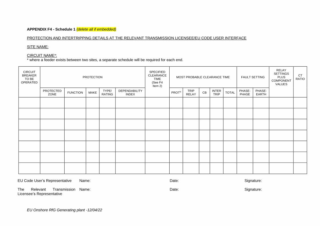
APPENDIX F4 - Schedule 1 (delete all if embedded) PROTECTION AND INTERTRIPPING DETAILS AT THE RELEVANT TRANSMISSION LICENSEE/EU CODE USER INTERFACE SITE NAME: CIRCUIT NAME*: * where a feeder exists between two sites, a separate schedule will be required for each end.
CIRCUIT BREAKER
TO BE
OPERATED
PROTECTION
SPECIFIED CLEARANCE
TIME
(See F4 Item 2)
MOST PROBABLE CLEARANCE TIME FAULT SETTING
RELAY SETTINGS
PLUS COMPONENT
VALUES
CT RATIO
PROTECTED ZONE
FUNCTION MAKE TYPE/
RATING DEPENDABILITY
INDEX PROTN
TRIP RELAY
CB INTER TRIP
TOTAL PHASE- PHASE
PHASE- EARTH
EU Code User’s Representative Name: Date: Signature: The Relevant Transmission Licensee’s Representative
Name: Date: Signature:

EU Onshore RfG Generating plant -12/04/22
APPENDIX F5
SITE SPECIFIC TECHNICAL CONDITIONS OTHER TECHNICAL REQUIREMENTS
User: [XXXX]
Type of User: EU Code User
Connection Site: [XXXX]
Other Technical Requirements The EU Code User can gain access to the technical specifications from the Relevant Transmission Licensee’s Extranet website. Access to the Relevant Transmission Licensee’s Extranet website can be requested via email to:- [email protected]. (delete this para if in Scotland)
Criteria Applies to? Delete this column when finished
Grid Code Ref – User to comply with:
Obligations
1. Protection of interconnecting connections Busbar Protection (to be specified by the Relevant Transmission Licensee) (use this heading if a Generator Connected
For tertiary connections, use cyan text. For embedded, use text at bottom.
ECC 6.2.2.3.1 Delete above and use below if GIS ECC.6.2.2.2.2
Defined as connections between current transformers on the Generator circuit side of the circuit breaker to the Grid Entry Point at the busbar clamps on the busbar side of the busbar selector disconnectors. (Use the black text for NGET and SHE Transmission offers, and delete the SPT one below) Defined as the primary conductors between the current transformer accommodation in the Relevant Transmission Licensee-owned [XXX]kV circuit breaker, within the [XXX]kV busbar protection zone in [XXXX] Substation, to the Connection Point. (Use this para for SPT offers, and delete the above one) Relevant Transmission Licensee: Shall design the protection scheme for the Interconnection Connections at the site once the Construction Programme has commenced. (Use the black text for NGET and SHE Transmission offers, and delete the SPT ones below) (Use these 2 paragraphs, and delete all others under the Relevant Transmission Licensee heading, if it is an SPT offer, and if the TOCO specifies that it is the Relevant Transmission Licensee’s responsibility to provide the CT):
EU Onshore RfG Generating plant -12/04/22
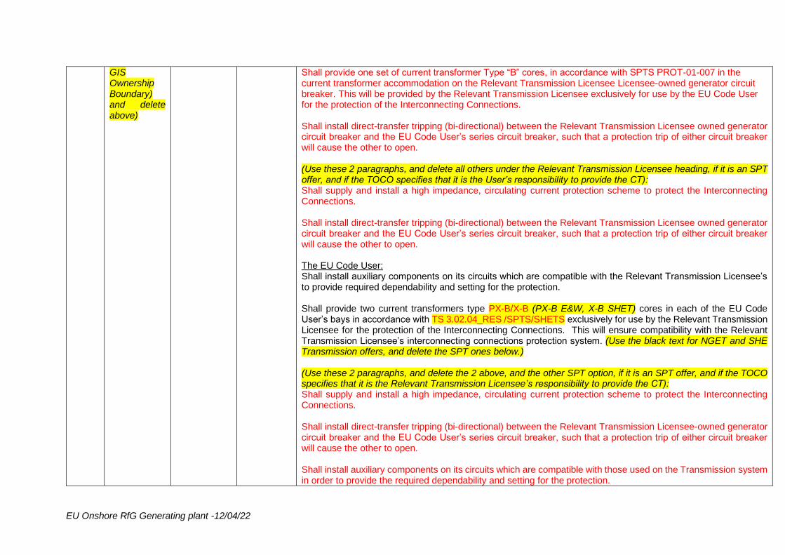
GIS Ownership Boundary) and delete above)
Shall provide one set of current transformer Type “B” cores, in accordance with SPTS PROT-01-007 in the current transformer accommodation on the Relevant Transmission Licensee Licensee-owned generator circuit breaker. This will be provided by the Relevant Transmission Licensee exclusively for use by the EU Code User for the protection of the Interconnecting Connections. Shall install direct-transfer tripping (bi-directional) between the Relevant Transmission Licensee owned generator circuit breaker and the EU Code User’s series circuit breaker, such that a protection trip of either circuit breaker will cause the other to open. (Use these 2 paragraphs, and delete all others under the Relevant Transmission Licensee heading, if it is an SPT offer, and if the TOCO specifies that it is the User’s responsibility to provide the CT): Shall supply and install a high impedance, circulating current protection scheme to protect the Interconnecting Connections. Shall install direct-transfer tripping (bi-directional) between the Relevant Transmission Licensee owned generator circuit breaker and the EU Code User’s series circuit breaker, such that a protection trip of either circuit breaker will cause the other to open. The EU Code User: Shall install auxiliary components on its circuits which are compatible with the Relevant Transmission Licensee’s to provide required dependability and setting for the protection. Shall provide two current transformers type PX-B/X-B (PX-B E&W, X-B SHET) cores in each of the EU Code User’s bays in accordance with TS 3.02.04_RES /SPTS/SHETS exclusively for use by the Relevant Transmission Licensee for the protection of the Interconnecting Connections. This will ensure compatibility with the Relevant Transmission Licensee’s interconnecting connections protection system. (Use the black text for NGET and SHE Transmission offers, and delete the SPT ones below.) (Use these 2 paragraphs, and delete the 2 above, and the other SPT option, if it is an SPT offer, and if the TOCO specifies that it is the Relevant Transmission Licensee’s responsibility to provide the CT): Shall supply and install a high impedance, circulating current protection scheme to protect the Interconnecting Connections. Shall install direct-transfer tripping (bi-directional) between the Relevant Transmission Licensee-owned generator circuit breaker and the EU Code User’s series circuit breaker, such that a protection trip of either circuit breaker will cause the other to open. Shall install auxiliary components on its circuits which are compatible with those used on the Transmission system in order to provide the required dependability and setting for the protection.
EU Onshore RfG Generating plant -12/04/22
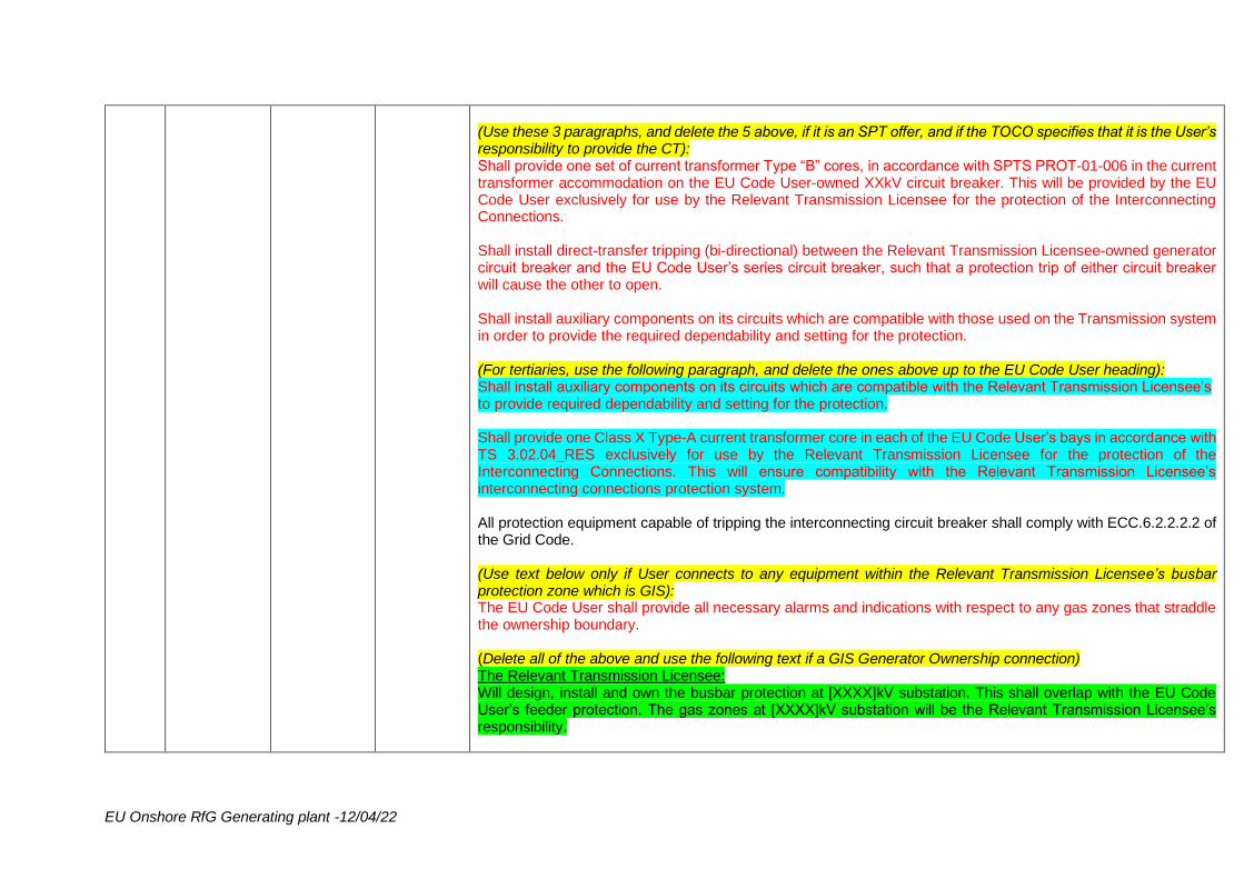
(Use these 3 paragraphs, and delete the 5 above, if it is an SPT offer, and if the TOCO specifies that it is the User’s responsibility to provide the CT): Shall provide one set of current transformer Type “B” cores, in accordance with SPTS PROT-01-006 in the current transformer accommodation on the EU Code User-owned XXkV circuit breaker. This will be provided by the EU Code User exclusively for use by the Relevant Transmission Licensee for the protection of the Interconnecting Connections. Shall install direct-transfer tripping (bi-directional) between the Relevant Transmission Licensee-owned generator circuit breaker and the EU Code User’s series circuit breaker, such that a protection trip of either circuit breaker will cause the other to open. Shall install auxiliary components on its circuits which are compatible with those used on the Transmission system in order to provide the required dependability and setting for the protection. (For tertiaries, use the following paragraph, and delete the ones above up to the EU Code User heading): Shall install auxiliary components on its circuits which are compatible with the Relevant Transmission Licensee’s to provide required dependability and setting for the protection. Shall provide one Class X Type-A current transformer core in each of the EU Code User’s bays in accordance with TS 3.02.04_RES exclusively for use by the Relevant Transmission Licensee for the protection of the Interconnecting Connections. This will ensure compatibility with the Relevant Transmission Licensee’s interconnecting connections protection system. All protection equipment capable of tripping the interconnecting circuit breaker shall comply with ECC.6.2.2.2.2 of the Grid Code. (Use text below only if User connects to any equipment within the Relevant Transmission Licensee’s busbar protection zone which is GIS): The EU Code User shall provide all necessary alarms and indications with respect to any gas zones that straddle the ownership boundary. (Delete all of the above and use the following text if a GIS Generator Ownership connection) The Relevant Transmission Licensee: Will design, install and own the busbar protection at [XXXX]kV substation. This shall overlap with the EU Code User’s feeder protection. The gas zones at [XXXX]kV substation will be the Relevant Transmission Licensee’s responsibility.
EU Onshore RfG Generating plant -12/04/22
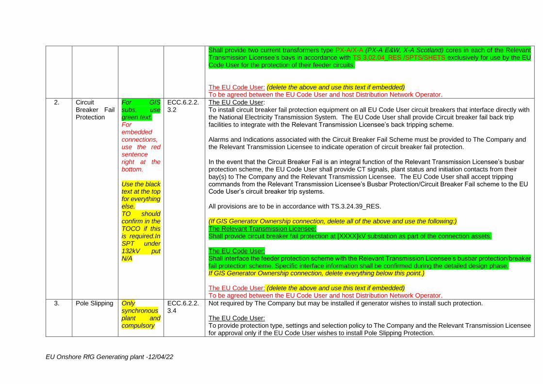
Shall provide two current transformers type PX-A/X-A (PX-A E&W, X-A Scotland) cores in each of the Relevant Transmission Licensee’s bays in accordance with TS 3.02.04_RES /SPTS/SHETS exclusively for use by the EU Code User for the protection of their feeder circuits. The EU Code User: (delete the above and use this text if embedded) To be agreed between the EU Code User and host Distribution Network Operator.
2. Circuit Breaker Fail Protection
For GIS subs, use green text. For embedded connections, use the red sentence right at the bottom. Use the black text at the top for everything else. TO should confirm in the TOCO if this is required.In SPT under 132kV put N/A
ECC.6.2.2.3.2
The EU Code User: To install circuit breaker fail protection equipment on all EU Code User circuit breakers that interface directly with the National Electricity Transmission System. The EU Code User shall provide Circuit breaker fail back trip facilities to integrate with the Relevant Transmission Licensee’s back tripping scheme. Alarms and Indications associated with the Circuit Breaker Fail Scheme must be provided to The Company and the Relevant Transmission Licensee to indicate operation of circuit breaker fail protection. In the event that the Circuit Breaker Fail is an integral function of the Relevant Transmission Licensee’s busbar protection scheme, the EU Code User shall provide CT signals, plant status and initiation contacts from their bay(s) to The Company and the Relevant Transmission Licensee. The EU Code User shall accept tripping commands from the Relevant Transmission Licensee’s Busbar Protection/Circuit Breaker Fail scheme to the EU Code User’s circuit breaker trip systems. All provisions are to be in accordance with TS.3.24.39_RES. (If GIS Generator Ownership connection, delete all of the above and use the following:) The Relevant Transmission Licensee: Shall provide circuit breaker fail protection at [XXXX]kV substation as part of the connection assets. The EU Code User: Shall interface the feeder protection scheme with the Relevant Transmission Licensee’s busbar protection/breaker fail protection scheme. Specific interface information shall be confirmed during the detailed design phase. If GIS Generator Ownership connection, delete everything below this point.) The EU Code User: (delete the above and use this text if embedded) To be agreed between the EU Code User and host Distribution Network Operator.
3. Pole Slipping Only synchronous plant and compulsory
ECC.6.2.2.3.4
Not required by The Company but may be installed if generator wishes to install such protection. The EU Code User: To provide protection type, settings and selection policy to The Company and the Relevant Transmission Licensee for approval only if the EU Code User wishes to install Pole Slipping Protection.
EU Onshore RfG Generating plant -12/04/22
for embedded
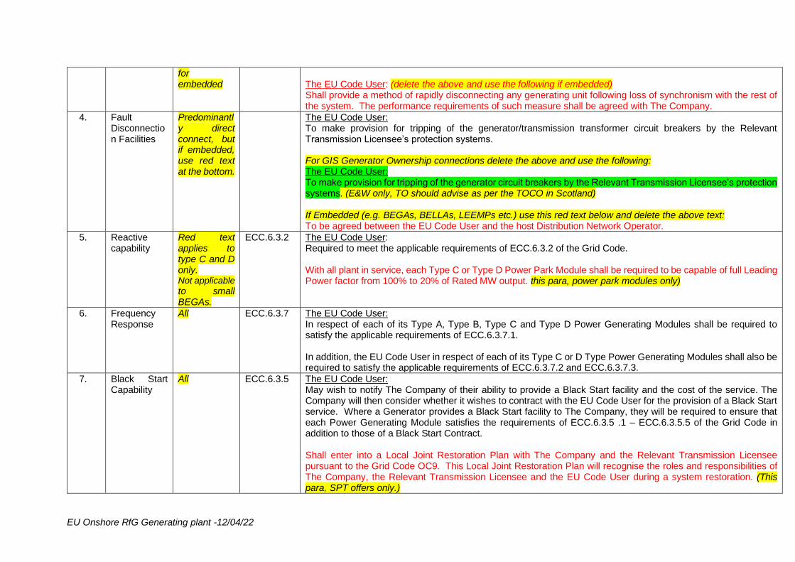
The EU Code User: (delete the above and use the following if embedded) Shall provide a method of rapidly disconnecting any generating unit following loss of synchronism with the rest of the system. The performance requirements of such measure shall be agreed with The Company.
4. Fault Disconnection Facilities
Predominantly direct connect, but if embedded, use red text at the bottom.
The EU Code User: To make provision for tripping of the generator/transmission transformer circuit breakers by the Relevant Transmission Licensee’s protection systems. For GIS Generator Ownership connections delete the above and use the following: The EU Code User: To make provision for tripping of the generator circuit breakers by the Relevant Transmission Licensee’s protection systems. (E&W only, TO should advise as per the TOCO in Scotland) If Embedded (e.g. BEGAs, BELLAs, LEEMPs etc.) use this red text below and delete the above text: To be agreed between the EU Code User and the host Distribution Network Operator.
5. Reactive capability
Red text applies to type C and D only. Not applicable to small BEGAs.
ECC.6.3.2 The EU Code User: Required to meet the applicable requirements of ECC.6.3.2 of the Grid Code. With all plant in service, each Type C or Type D Power Park Module shall be required to be capable of full Leading Power factor from 100% to 20% of Rated MW output. this para, power park modules only)
6. Frequency Response
All ECC.6.3.7 The EU Code User: In respect of each of its Type A, Type B, Type C and Type D Power Generating Modules shall be required to satisfy the applicable requirements of ECC.6.3.7.1. In addition, the EU Code User in respect of each of its Type C or D Type Power Generating Modules shall also be required to satisfy the applicable requirements of ECC.6.3.7.2 and ECC.6.3.7.3.
7. Black Start Capability
All ECC.6.3.5 The EU Code User: May wish to notify The Company of their ability to provide a Black Start facility and the cost of the service. The Company will then consider whether it wishes to contract with the EU Code User for the provision of a Black Start service. Where a Generator provides a Black Start facility to The Company, they will be required to ensure that each Power Generating Module satisfies the requirements of ECC.6.3.5 .1 – ECC.6.3.5.5 of the Grid Code in addition to those of a Black Start Contract. Shall enter into a Local Joint Restoration Plan with The Company and the Relevant Transmission Licensee pursuant to the Grid Code OC9. This Local Joint Restoration Plan will recognise the roles and responsibilities of The Company, the Relevant Transmission Licensee and the EU Code User during a system restoration. (This para, SPT offers only.)
EU Onshore RfG Generating plant -12/04/22
8. Quick Resynchronisation Capability
All except LEEMPs
ECC.6.3.5.6
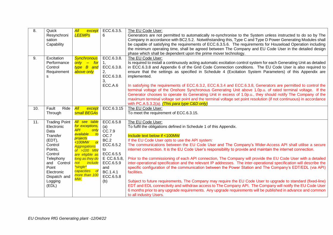
The EU Code User: Generators are not permitted to automatically re-synchronise to the System unless instructed to do so by The Company in accordance with BC2.5.2. Notwithstanding this, Type C and Type D Power Generating Modules shall be capable of satisfying the requirements of ECC.6.3.5.6. The requirements for Houseload Operation including the minimum operating time, shall be agreed between The Company and EU Code User in the detailed design phase which shall be dependent upon the prime mover technology.
9. Excitation Performance Control Requirements
Synchronous only – for type B and above only
ECC.6.3.8.1, ECC.6.3.8.2, ECC.6.3.8.3, ECC.A.6
The EU Code User: Is required to install a continuously acting automatic excitation control system for each Generating Unit as detailed in ECC.6.3.8 and Appendix 6 of the Grid Code Connection conditions. The EU Code User is also required to ensure that the settings as specified in Schedule 4 (Excitation System Parameters) of this Appendix are implemented. In satisfying the requirements of ECC.6.3.2, ECC.6.3.4 and ECC.6.3.8, Generators are permitted to control the terminal voltage of the Onshore Synchronous Generating Unit above 1.0p.u. of rated terminal voltage. If the Generator chooses to operate its Generating Unit in excess of 1.0p.u., they should notify The Company of the maximum terminal voltage set point and the terminal voltage set point resolution (if not continuous) in accordance with PC.A.5.3.2(a). (This para type C&D only)
10. Fault Ride Through
All except small BEGAs
ECC.6.3.15 The EU Code User: To meet the requirement of ECC.6.3.15.
11. Trading Point Electronic Data Transfer (EDT), Control Points, Control Telephony and Control Point Electronic Dispatch and Logging (EDL)
All see table for exceptions, API only available to projects <100MW or Aggregations of >100 MW are eligible as long as they do not include *single* capacities of more than 100 MW.
ECC.6.5.8 (a) CC.7.9 OC.7 BC.2 ECC.6.5.2 to ECC.6.5.5 E CC.6.5.8, ECC.6.5.9 and BC.1.4.1 ECC.6.5.8 (b)
The EU Code User: To fulfil the obligations defined in Schedule 1 of this Appendix. Include text below if <100MW If the EU Code User opts to use the API system: The communications between the EU Code User and The Company’s Wider-Access API shall utilise a secure internet connection. It is the EU Code User’s responsibility to provide and maintain the internet connection. Prior to the commissioning of each API connection, The Company will provide the EU Code User with a detailed inter-operational specification and the relevant IP addresses. The inter-operational specification will describe the specific configuration of the communication between the Power Station and The Company’s EDT/EDL (via API) facilities. Subject to future requirements, The Company may require the EU Code User to upgrade to standard (fixed-line) EDT and EDL connectivity and withdraw access to The Company API. The Company will notify the EU Code User 6 months prior to any upgrade requirements. Any upgrade requirements will be published in advance and common to all industry Users.
EU Onshore RfG Generating plant -12/04/22
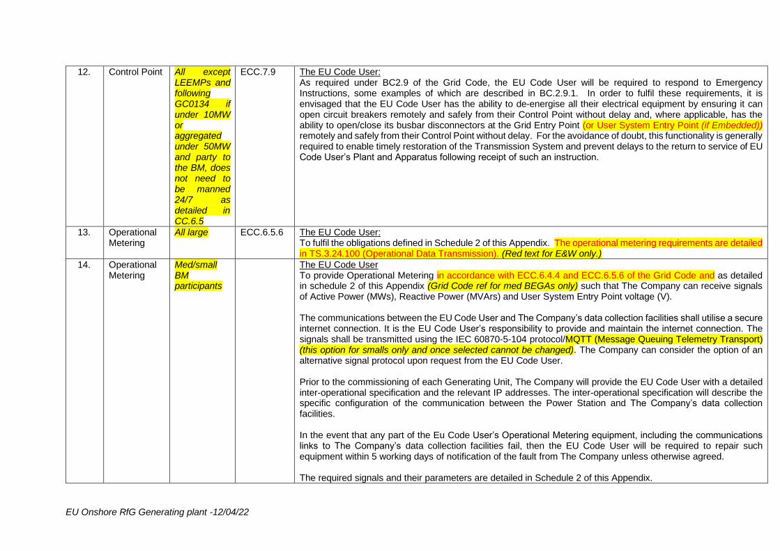
12. Control Point All except LEEMPs and following GC0134 if under 10MW or aggregated under 50MW and party to the BM, does not need to be manned 24/7 as detailed in CC.6.5
ECC.7.9 The EU Code User: As required under BC2.9 of the Grid Code, the EU Code User will be required to respond to Emergency Instructions, some examples of which are described in BC.2.9.1. In order to fulfil these requirements, it is envisaged that the EU Code User has the ability to de-energise all their electrical equipment by ensuring it can open circuit breakers remotely and safely from their Control Point without delay and, where applicable, has the ability to open/close its busbar disconnectors at the Grid Entry Point (or User System Entry Point (if Embedded)) remotely and safely from their Control Point without delay. For the avoidance of doubt, this functionality is generally required to enable timely restoration of the Transmission System and prevent delays to the return to service of EU Code User’s Plant and Apparatus following receipt of such an instruction.
13. Operational Metering
All large ECC.6.5.6 The EU Code User: To fulfil the obligations defined in Schedule 2 of this Appendix. The operational metering requirements are detailed in TS.3.24.100 (Operational Data Transmission). (Red text for E&W only.)
14. Operational Metering
Med/small BM participants
The EU Code User To provide Operational Metering in accordance with ECC.6.4.4 and ECC.6.5.6 of the Grid Code and as detailed in schedule 2 of this Appendix (Grid Code ref for med BEGAs only) such that The Company can receive signals of Active Power (MWs), Reactive Power (MVArs) and User System Entry Point voltage (V). The communications between the EU Code User and The Company’s data collection facilities shall utilise a secure internet connection. It is the EU Code User’s responsibility to provide and maintain the internet connection. The signals shall be transmitted using the IEC 60870-5-104 protocol/MQTT (Message Queuing Telemetry Transport) (this option for smalls only and once selected cannot be changed). The Company can consider the option of an alternative signal protocol upon request from the EU Code User. Prior to the commissioning of each Generating Unit, The Company will provide the EU Code User with a detailed inter-operational specification and the relevant IP addresses. The inter-operational specification will describe the specific configuration of the communication between the Power Station and The Company’s data collection facilities. In the event that any part of the Eu Code User’s Operational Metering equipment, including the communications links to The Company’s data collection facilities fail, then the EU Code User will be required to repair such equipment within 5 working days of notification of the fault from The Company unless otherwise agreed. The required signals and their parameters are detailed in Schedule 2 of this Appendix.
EU Onshore RfG Generating plant -12/04/22
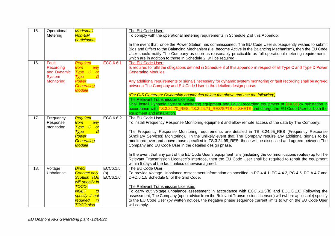
15. Operational Metering
Med/small Non-BM participants
The EU Code User: To comply with the operational metering requirements in Schedule 2 of this Appendix. In the event that, once the Power Station has commissioned, The EU Code User subsequently wishes to submit Bids and Offers to the Balancing Mechanism (i.e. become Active in the Balancing Mechanism), then the EU Code User should notify The Company as soon as reasonably practicable as full operational metering requirements, which are in addition to those in Schedule 2, will be required.
16. Fault Recording and Dynamic System Monitoring
Required from any Type C or Type D Power Generating Module
ECC.6.6.1 The EU Code User: Is required to fulfil the obligations defined in Schedule 3 of this appendix in respect of all Type C and Type D Power Generating Modules. Any additional requirements or signals necessary for dynamic system monitoring or fault recording shall be agreed between The Company and EU Code User in the detailed design phase. (For GIS Generator Ownership boundaries delete the above and use the following:) The Relevant Transmission Licensee: Shall install Dynamic System Monitoring equipment and Fault Recording equipment at [XXXX]kV substation in accordance with TS.3.24.70_RES, TS.3.24.71_RES/SPTS or SHETS and charge the EU Code User for both the equipment and installation.
17. Frequency Response monitoring
Required from any Type C or Type D Power Generating Module
ECC.6.6.2 The EU Code User: To install Frequency Response Monitoring equipment and allow remote access of the data by The Company. The Frequency Response Monitoring requirements are detailed in TS 3.24.95_RES (Frequency Response (Ancillary Services) Monitoring). In the unlikely event that The Company require any additional signals to be monitored over and above those specified in TS.3.24.95_RES, these will be discussed and agreed between The Company and EU Code User in the detailed design phase. In the event that any part of the EU Code User’s equipment fails (including the communications routes) up to The Relevant Transmission Licensee’s interface, then the EU Code User shall be required to repair the equipment within 5 days of the fault unless otherwise agreed.
18. Voltage Unbalance
Direct Connect only Scottish TOs will specify in TOCO. NGET to specify if not required in TOCO also
ECC6.1.5 (b) ECC6.1.6
The EU Code User: To provide Voltage Unbalance Assessment information as specified in PC.4.4.1, PC.4.4.2, PC.4.5, PC.A.4.7 and DRC.6.1.5 Schedule 5, of the Grid Code. The Relevant Transmission Licensee: To carry out voltage unbalance assessment in accordance with ECC.6.1.5(b) and ECC.6.1.6. Following the assessment, The Company (upon advice from the Relevant Transmission Licensee) will (where applicable) specify to the EU Code User (by written notice), the negative phase sequence current limits to which the EU Code User will comply.
EU Onshore RfG Generating plant -12/04/22
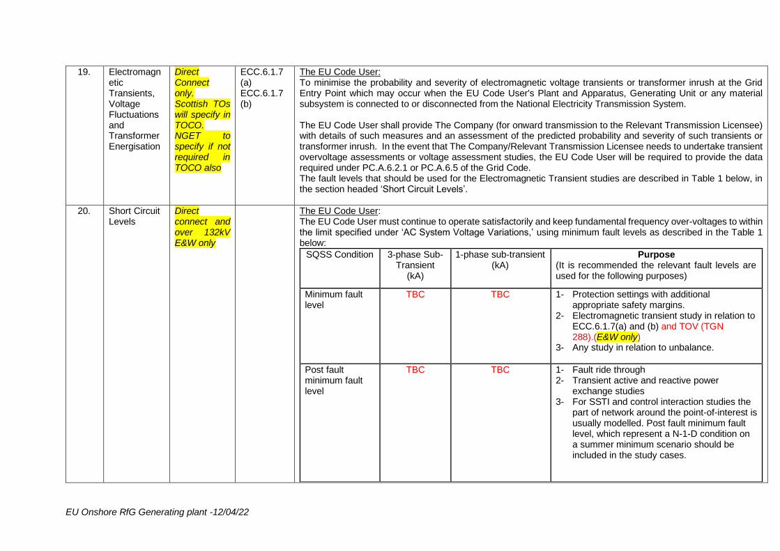
19. Electromagnetic Transients, Voltage Fluctuations and Transformer Energisation
Direct Connect only. Scottish TOs will specify in TOCO. NGET to specify if not required in TOCO also
ECC.6.1.7 (a) ECC.6.1.7 (b)
The EU Code User: To minimise the probability and severity of electromagnetic voltage transients or transformer inrush at the Grid Entry Point which may occur when the EU Code User's Plant and Apparatus, Generating Unit or any material subsystem is connected to or disconnected from the National Electricity Transmission System. The EU Code User shall provide The Company (for onward transmission to the Relevant Transmission Licensee) with details of such measures and an assessment of the predicted probability and severity of such transients or transformer inrush. In the event that The Company/Relevant Transmission Licensee needs to undertake transient overvoltage assessments or voltage assessment studies, the EU Code User will be required to provide the data required under PC.A.6.2.1 or PC.A.6.5 of the Grid Code. The fault levels that should be used for the Electromagnetic Transient studies are described in Table 1 below, in the section headed ‘Short Circuit Levels’.
20. Short Circuit Levels
Direct connect and over 132kV E&W only
The EU Code User: The EU Code User must continue to operate satisfactorily and keep fundamental frequency over-voltages to within the limit specified under ‘AC System Voltage Variations,’ using minimum fault levels as described in the Table 1 below:
SQSS Condition 3-phase Sub-Transient
(kA)
1-phase sub-transient (kA)
Purpose (It is recommended the relevant fault levels are used for the following purposes)
Minimum fault level
TBC
TBC
1- Protection settings with additional appropriate safety margins.
2- Electromagnetic transient study in relation to ECC.6.1.7(a) and (b) and TOV (TGN 288).(E&W only)
3- Any study in relation to unbalance.
Post fault minimum fault level
TBC
TBC
1- Fault ride through 2- Transient active and reactive power
exchange studies 3- For SSTI and control interaction studies the
part of network around the point-of-interest is usually modelled. Post fault minimum fault level, which represent a N-1-D condition on a summer minimum scenario should be included in the study cases.
EU Onshore RfG Generating plant -12/04/22
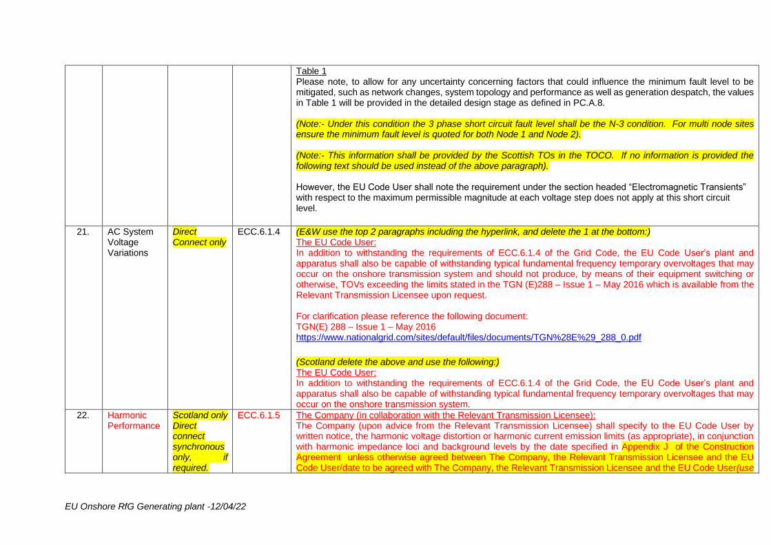
Table 1 Please note, to allow for any uncertainty concerning factors that could influence the minimum fault level to be mitigated, such as network changes, system topology and performance as well as generation despatch, the values in Table 1 will be provided in the detailed design stage as defined in PC.A.8. (Note:- Under this condition the 3 phase short circuit fault level shall be the N-3 condition. For multi node sites ensure the minimum fault level is quoted for both Node 1 and Node 2). (Note:- This information shall be provided by the Scottish TOs in the TOCO. If no information is provided the following text should be used instead of the above paragraph). However, the EU Code User shall note the requirement under the section headed “Electromagnetic Transients” with respect to the maximum permissible magnitude at each voltage step does not apply at this short circuit level.
21. AC System
Voltage Variations
Direct Connect only
ECC.6.1.4 (E&W use the top 2 paragraphs including the hyperlink, and delete the 1 at the bottom:) The EU Code User: In addition to withstanding the requirements of ECC.6.1.4 of the Grid Code, the EU Code User’s plant and apparatus shall also be capable of withstanding typical fundamental frequency temporary overvoltages that may occur on the onshore transmission system and should not produce, by means of their equipment switching or otherwise, TOVs exceeding the limits stated in the TGN (E)288 – Issue 1 – May 2016 which is available from the Relevant Transmission Licensee upon request. For clarification please reference the following document: TGN(E) 288 – Issue 1 – May 2016 https://www.nationalgrid.com/sites/default/files/documents/TGN%28E%29_288_0.pdf
(Scotland delete the above and use the following:) The EU Code User: In addition to withstanding the requirements of ECC.6.1.4 of the Grid Code, the EU Code User’s plant and apparatus shall also be capable of withstanding typical fundamental frequency temporary overvoltages that may occur on the onshore transmission system.
22. Harmonic Performance
Scotland only Direct connect synchronousonly, if required.
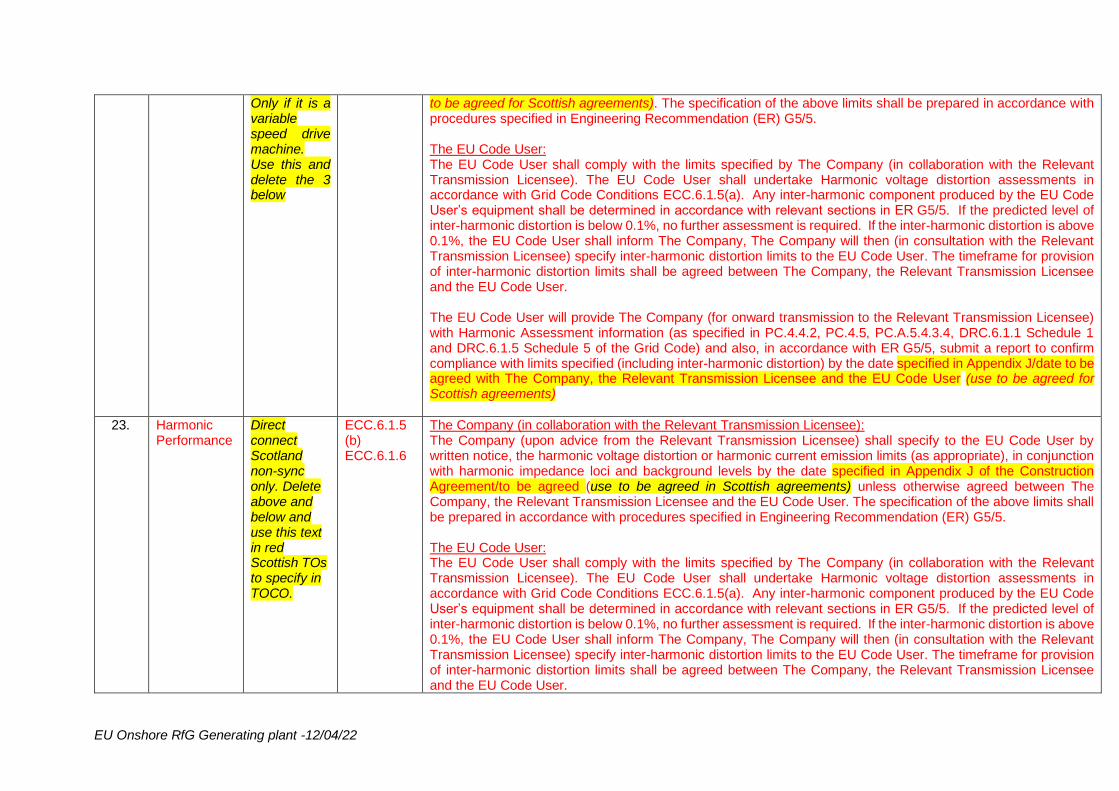
ECC.6.1.5 The Company (in collaboration with the Relevant Transmission Licensee): The Company (upon advice from the Relevant Transmission Licensee) shall specify to the EU Code User by written notice, the harmonic voltage distortion or harmonic current emission limits (as appropriate), in conjunction with harmonic impedance loci and background levels by the date specified in Appendix J of the Construction Agreement unless otherwise agreed between The Company, the Relevant Transmission Licensee and the EU Code User/date to be agreed with The Company, the Relevant Transmission Licensee and the EU Code User(use
EU Onshore RfG Generating plant -12/04/22
Only if it is a variable speed drive machine. Use this and delete the 3 below
to be agreed for Scottish agreements). The specification of the above limits shall be prepared in accordance with procedures specified in Engineering Recommendation (ER) G5/5. The EU Code User: The EU Code User shall comply with the limits specified by The Company (in collaboration with the Relevant Transmission Licensee). The EU Code User shall undertake Harmonic voltage distortion assessments in accordance with Grid Code Conditions ECC.6.1.5(a). Any inter-harmonic component produced by the EU Code User’s equipment shall be determined in accordance with relevant sections in ER G5/5. If the predicted level of inter-harmonic distortion is below 0.1%, no further assessment is required. If the inter-harmonic distortion is above 0.1%, the EU Code User shall inform The Company, The Company will then (in consultation with the Relevant Transmission Licensee) specify inter-harmonic distortion limits to the EU Code User. The timeframe for provision of inter-harmonic distortion limits shall be agreed between The Company, the Relevant Transmission Licensee and the EU Code User. The EU Code User will provide The Company (for onward transmission to the Relevant Transmission Licensee) with Harmonic Assessment information (as specified in PC.4.4.2, PC.4.5, PC.A.5.4.3.4, DRC.6.1.1 Schedule 1 and DRC.6.1.5 Schedule 5 of the Grid Code) and also, in accordance with ER G5/5, submit a report to confirm compliance with limits specified (including inter-harmonic distortion) by the date specified in Appendix J/date to be agreed with The Company, the Relevant Transmission Licensee and the EU Code User (use to be agreed for Scottish agreements)
23. Harmonic Performance
Direct connect Scotland non-sync only. Delete above and below and use this text in red Scottish TOs to specify in TOCO.
ECC.6.1.5 (b) ECC.6.1.6
The Company (in collaboration with the Relevant Transmission Licensee): The Company (upon advice from the Relevant Transmission Licensee) shall specify to the EU Code User by written notice, the harmonic voltage distortion or harmonic current emission limits (as appropriate), in conjunction with harmonic impedance loci and background levels by the date specified in Appendix J of the Construction Agreement/to be agreed (use to be agreed in Scottish agreements) unless otherwise agreed between The Company, the Relevant Transmission Licensee and the EU Code User. The specification of the above limits shall be prepared in accordance with procedures specified in Engineering Recommendation (ER) G5/5. The EU Code User: The EU Code User shall comply with the limits specified by The Company (in collaboration with the Relevant Transmission Licensee). The EU Code User shall undertake Harmonic voltage distortion assessments in accordance with Grid Code Conditions ECC.6.1.5(a). Any inter-harmonic component produced by the EU Code User’s equipment shall be determined in accordance with relevant sections in ER G5/5. If the predicted level of inter-harmonic distortion is below 0.1%, no further assessment is required. If the inter-harmonic distortion is above 0.1%, the EU Code User shall inform The Company, The Company will then (in consultation with the Relevant Transmission Licensee) specify inter-harmonic distortion limits to the EU Code User. The timeframe for provision of inter-harmonic distortion limits shall be agreed between The Company, the Relevant Transmission Licensee and the EU Code User.
EU Onshore RfG Generating plant -12/04/22
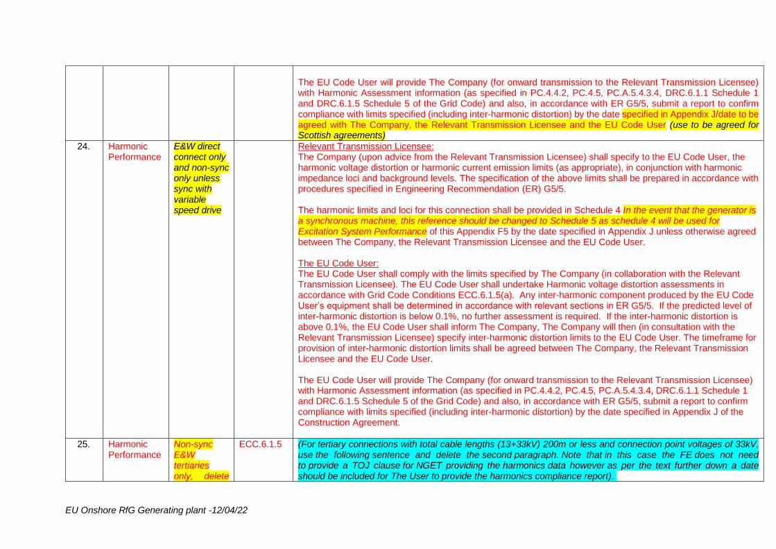
The EU Code User will provide The Company (for onward transmission to the Relevant Transmission Licensee) with Harmonic Assessment information (as specified in PC.4.4.2, PC.4.5, PC.A.5.4.3.4, DRC.6.1.1 Schedule 1 and DRC.6.1.5 Schedule 5 of the Grid Code) and also, in accordance with ER G5/5, submit a report to confirm compliance with limits specified (including inter-harmonic distortion) by the date specified in Appendix J/date to be agreed with The Company, the Relevant Transmission Licensee and the EU Code User (use to be agreed for Scottish agreements)
24. Harmonic Performance
E&W direct connect only and non-sync only unless sync with variable speed drive
Relevant Transmission Licensee: The Company (upon advice from the Relevant Transmission Licensee) shall specify to the EU Code User, the harmonic voltage distortion or harmonic current emission limits (as appropriate), in conjunction with harmonic impedance loci and background levels. The specification of the above limits shall be prepared in accordance with procedures specified in Engineering Recommendation (ER) G5/5. The harmonic limits and loci for this connection shall be provided in Schedule 4 In the event that the generator is a synchronous machine, this reference should be changed to Schedule 5 as schedule 4 will be used for Excitation System Performance of this Appendix F5 by the date specified in Appendix J unless otherwise agreed between The Company, the Relevant Transmission Licensee and the EU Code User. The EU Code User: The EU Code User shall comply with the limits specified by The Company (in collaboration with the Relevant Transmission Licensee). The EU Code User shall undertake Harmonic voltage distortion assessments in accordance with Grid Code Conditions ECC.6.1.5(a). Any inter-harmonic component produced by the EU Code User’s equipment shall be determined in accordance with relevant sections in ER G5/5. If the predicted level of inter-harmonic distortion is below 0.1%, no further assessment is required. If the inter-harmonic distortion is above 0.1%, the EU Code User shall inform The Company, The Company will then (in consultation with the Relevant Transmission Licensee) specify inter-harmonic distortion limits to the EU Code User. The timeframe for provision of inter-harmonic distortion limits shall be agreed between The Company, the Relevant Transmission Licensee and the EU Code User. The EU Code User will provide The Company (for onward transmission to the Relevant Transmission Licensee) with Harmonic Assessment information (as specified in PC.4.4.2, PC.4.5, PC.A.5.4.3.4, DRC.6.1.1 Schedule 1 and DRC.6.1.5 Schedule 5 of the Grid Code) and also, in accordance with ER G5/5, submit a report to confirm compliance with limits specified (including inter-harmonic distortion) by the date specified in Appendix J of the Construction Agreement.
25. Harmonic Performance
Non-sync E&W tertiaries only, delete
ECC.6.1.5 (For tertiary connections with total cable lengths (13+33kV) 200m or less and connection point voltages of 33kV, use the following sentence and delete the second paragraph. Note that in this case the FE does not need to provide a TOJ clause for NGET providing the harmonics data however as per the text further down a date should be included for The User to provide the harmonics compliance report).

EU Onshore RfG Generating plant -12/04/22
the 2 above and use only this section
The harmonic limits and loci for this connection are provided in Schedule 5 of this Appendix F5. The specification of the above limits has been prepared in accordance with procedures specified in Engineering Recommendation (ER) G5/5. (For tertiary connections with total cable lengths (13+33kV) greater than 200m, or connections at voltages at 13kV (i.e. without a transformer) (or other non-33kV POC), use the following paragraph and delete the sentence above. Note that in this case the FE should provide a TOJ clause for NGET providing the harmonics data as well as a date for The User to provide the harmonics compliance report). Because it is not relevant, Schedule 5 should also be deleted in this case. The Relevant Transmission Licensee: The Company (upon advice from the Relevant Transmission Licensee) shall specify to the EU Code User by written notice, the harmonic voltage distortion or harmonic current emission limits (as appropriate), in conjunction with harmonic impedance loci and background levels by the date specified in Appendix J of the Construction Agreement unless otherwise agreed between The Company, the Relevant Transmission Licensee and the EU Code User. The specification of the above limits shall be prepared in accordance with procedures specified in Engineering Recommendation (ER) G5/5. The EU Code User: The EU Code User shall comply with the limits specified by The Company (in collaboration with the Relevant Transmission Licensee). The EU Code User shall undertake Harmonic voltage distortion assessments in accordance with Grid Code Conditions ECC.6.1.5(a). Any inter-harmonic component produced by the EU Code User’s equipment shall be determined in accordance with relevant sections in ER G5/5. If the predicted level of inter-harmonic distortion is below 0.1%, no further assessment is required. If the inter-harmonic distortion is above 0.1%, the EU Code User shall inform The Company, who will then (in consultation with the Relevant Transmission Licensee) specify inter-harmonic distortion limits to the EU Code User. The timeframe for provision of inter-harmonic distortion limits shall be agreed between The Company, the Relevant Transmission Licensee and the EU Code User. The EU Code User will provide The Company (for onward transmission to the Relevant Transmission Licensee) with Harmonic Assessment information (as specified in PC.4.4.2, PC.4.5, PC.A.5.4.3.4, DRC.6.1.1 Schedule 1 and DRC.6.1.5 Schedule 5 of the Grid Code) and also, in accordance with ER G5/5, submit a report to confirm compliance with limits specified (including inter-harmonic distortion) by the date specified in Appendix J of the Construction Agreement. Note: when providing harmonic emissions data for equipment, the EU Code User is required to provide details of any emissions at inter-harmonic frequencies.
EU Onshore RfG Generating plant -12/04/22
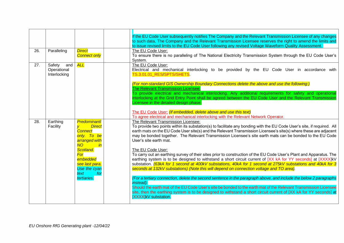
If the EU Code User subsequently notifies The Company and the Relevant Transmission Licensee of any changes to such data, The Company and the Relevant Transmission Licensee reserves the right to amend the limits and to issue revised limits to the EU Code User following any revised Voltage Waveform Quality Assessment.
26. Paralleling Direct Connect only
The EU Code User: To ensure there is no paralleling of The National Electricity Transmission System through the EU Code User’s System.
27. Safety and Operational Interlocking
ALL The EU Code User: Electrical and mechanical interlocking to be provided by the EU Code User in accordance with TS.3.01.01_RES/SPTS/SHETS. (For non-standard GIS Ownership Boundary Connections delete the above and use the following:) The Relevant Transmission Licensee: To provide electrical and mechanical interlocking. Any additional requirements for safety and operational interlocking at the Grid Entry Point shall be agreed between the EU Code User and the Relevant Transmission Licensee in the detailed design phase. The EU Code User: (if embedded, delete above and use this text) To agree electrical and mechanical interlocking with the Relevant Network Operator.
28. Earthing Facility
Predominantly Direct Connect only. To be arranged with NO in Scotland. For embedded see last para. Use the cyan text for tertiaries.
The Relevant Transmission Licensee: To provide two points within its substation(s) to facilitate any bonding with the EU Code User’s site, if required. All earth mats on the EU Code User site(s) and the Relevant Transmission Licensee’s site(s) where these are adjacent may be bonded together. The Relevant Transmission Licensee’s site earth mats can be bonded to the EU Code User’s site earth mat. The EU Code User: To carry out an earthing survey of their sites prior to construction of the EU Code User’s Plant and Apparatus. The earthing system is to be designed to withstand a short circuit current of [XX kA for YY seconds] at [XXXX]kV substation. (63kA for 1 second at 400kV substations, 40kA for 1 second at 275kV substations and 40kA for 3 seconds at 132kV substations) (Note this will depend on connection voltage and TO area). (For a tertiary connection, delete the second sentence in the paragraph above, and include the below 2 paragraphs instead): Should the earth mat of the EU Code User’s site be bonded to the earth mat of the Relevant Transmission Licensee site, then the earthing system is to be designed to withstand a short circuit current of [XX kA for YY seconds] at [XXXX]kV substation.
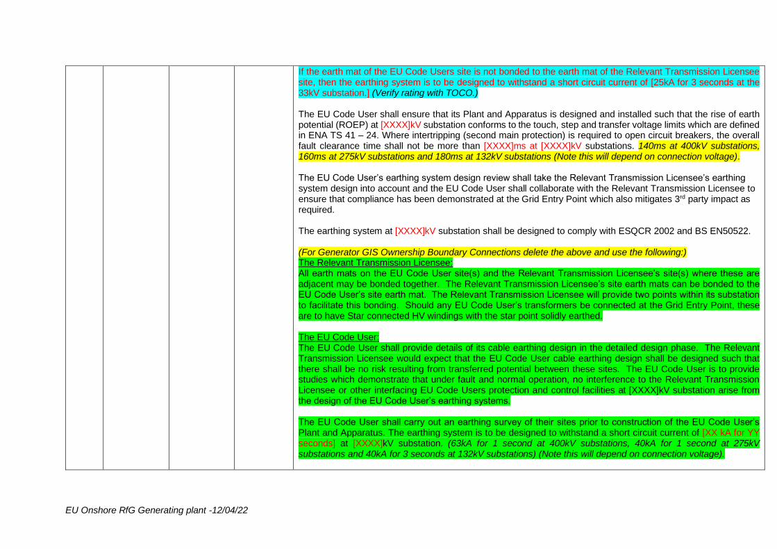
EU Onshore RfG Generating plant -12/04/22
If the earth mat of the EU Code Users site is not bonded to the earth mat of the Relevant Transmission Licensee site, then the earthing system is to be designed to withstand a short circuit current of [25kA for 3 seconds at the 33kV substation.] (Verify rating with TOCO.) The EU Code User shall ensure that its Plant and Apparatus is designed and installed such that the rise of earth potential (ROEP) at [XXXX]kV substation conforms to the touch, step and transfer voltage limits which are defined in ENA TS 41 – 24. Where intertripping (second main protection) is required to open circuit breakers, the overall fault clearance time shall not be more than [XXXX]ms at [XXXX]kV substations. 140ms at 400kV substations, 160ms at 275kV substations and 180ms at 132kV substations (Note this will depend on connection voltage). The EU Code User’s earthing system design review shall take the Relevant Transmission Licensee’s earthing system design into account and the EU Code User shall collaborate with the Relevant Transmission Licensee to ensure that compliance has been demonstrated at the Grid Entry Point which also mitigates 3rd party impact as required. The earthing system at [XXXX]kV substation shall be designed to comply with ESQCR 2002 and BS EN50522. (For Generator GIS Ownership Boundary Connections delete the above and use the following:) The Relevant Transmission Licensee: All earth mats on the EU Code User site(s) and the Relevant Transmission Licensee’s site(s) where these are adjacent may be bonded together. The Relevant Transmission Licensee’s site earth mats can be bonded to the EU Code User’s site earth mat. The Relevant Transmission Licensee will provide two points within its substation to facilitate this bonding. Should any EU Code User’s transformers be connected at the Grid Entry Point, these are to have Star connected HV windings with the star point solidly earthed. The EU Code User: The EU Code User shall provide details of its cable earthing design in the detailed design phase. The Relevant Transmission Licensee would expect that the EU Code User cable earthing design shall be designed such that there shall be no risk resulting from transferred potential between these sites. The EU Code User is to provide studies which demonstrate that under fault and normal operation, no interference to the Relevant Transmission Licensee or other interfacing EU Code Users protection and control facilities at [XXXX]kV substation arise from the design of the EU Code User’s earthing systems. The EU Code User shall carry out an earthing survey of their sites prior to construction of the EU Code User’s Plant and Apparatus. The earthing system is to be designed to withstand a short circuit current of [XX kA for YY seconds] at [XXXX]kV substation. (63kA for 1 second at 400kV substations, 40kA for 1 second at 275kV substations and 40kA for 3 seconds at 132kV substations) (Note this will depend on connection voltage).
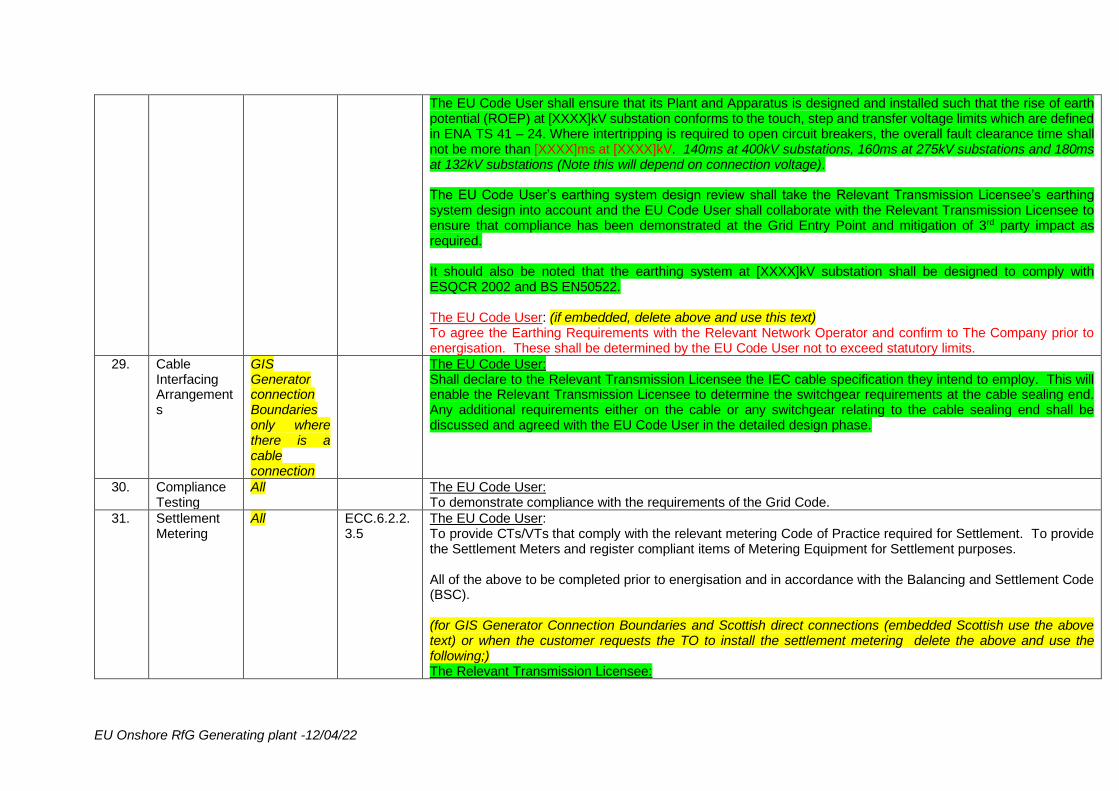
EU Onshore RfG Generating plant -12/04/22
The EU Code User shall ensure that its Plant and Apparatus is designed and installed such that the rise of earth potential (ROEP) at [XXXX]kV substation conforms to the touch, step and transfer voltage limits which are defined in ENA TS 41 – 24. Where intertripping is required to open circuit breakers, the overall fault clearance time shall not be more than [XXXX]ms at [XXXX]kV. 140ms at 400kV substations, 160ms at 275kV substations and 180ms at 132kV substations (Note this will depend on connection voltage). The EU Code User’s earthing system design review shall take the Relevant Transmission Licensee’s earthing system design into account and the EU Code User shall collaborate with the Relevant Transmission Licensee to ensure that compliance has been demonstrated at the Grid Entry Point and mitigation of 3rd party impact as required. It should also be noted that the earthing system at [XXXX]kV substation shall be designed to comply with ESQCR 2002 and BS EN50522. The EU Code User: (if embedded, delete above and use this text) To agree the Earthing Requirements with the Relevant Network Operator and confirm to The Company prior to energisation. These shall be determined by the EU Code User not to exceed statutory limits.
29. Cable Interfacing Arrangements
GIS Generator connection Boundaries only where there is a cable connection
The EU Code User: Shall declare to the Relevant Transmission Licensee the IEC cable specification they intend to employ. This will enable the Relevant Transmission Licensee to determine the switchgear requirements at the cable sealing end. Any additional requirements either on the cable or any switchgear relating to the cable sealing end shall be discussed and agreed with the EU Code User in the detailed design phase.
30. Compliance Testing
All The EU Code User: To demonstrate compliance with the requirements of the Grid Code.
31. Settlement Metering
All ECC.6.2.2.3.5
The EU Code User: To provide CTs/VTs that comply with the relevant metering Code of Practice required for Settlement. To provide the Settlement Meters and register compliant items of Metering Equipment for Settlement purposes. All of the above to be completed prior to energisation and in accordance with the Balancing and Settlement Code (BSC). (for GIS Generator Connection Boundaries and Scottish direct connections (embedded Scottish use the above text) or when the customer requests the TO to install the settlement metering delete the above and use the following;) The Relevant Transmission Licensee:
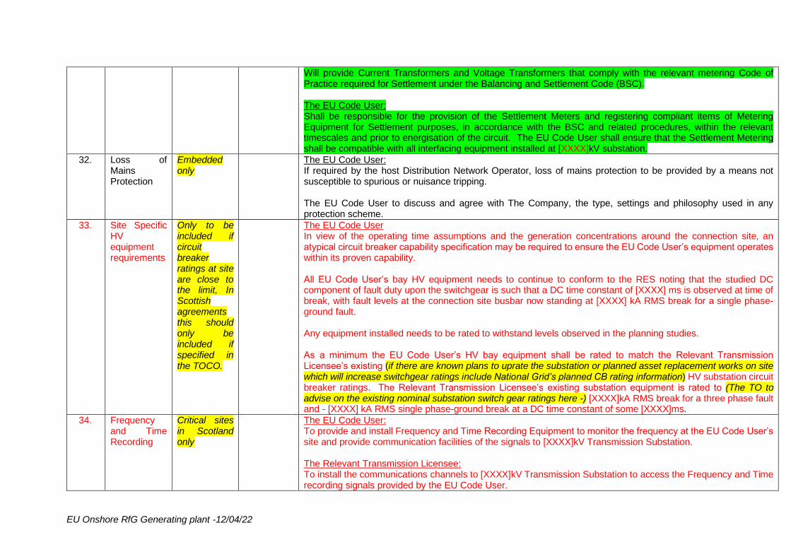
EU Onshore RfG Generating plant -12/04/22
Will provide Current Transformers and Voltage Transformers that comply with the relevant metering Code of Practice required for Settlement under the Balancing and Settlement Code (BSC). The EU Code User: Shall be responsible for the provision of the Settlement Meters and registering compliant items of Metering Equipment for Settlement purposes, in accordance with the BSC and related procedures, within the relevant timescales and prior to energisation of the circuit. The EU Code User shall ensure that the Settlement Metering shall be compatible with all interfacing equipment installed at [XXXX]kV substation.
32. Loss of Mains Protection
Embedded only
The EU Code User: If required by the host Distribution Network Operator, loss of mains protection to be provided by a means not susceptible to spurious or nuisance tripping. The EU Code User to discuss and agree with The Company, the type, settings and philosophy used in any protection scheme.
33. Site Specific HV equipment requirements
Only to be included if circuit breaker ratings at site are close to the limit, In Scottish agreements this should only be included if specified in the TOCO.
The EU Code User In view of the operating time assumptions and the generation concentrations around the connection site, an atypical circuit breaker capability specification may be required to ensure the EU Code User’s equipment operates within its proven capability. All EU Code User’s bay HV equipment needs to continue to conform to the RES noting that the studied DC component of fault duty upon the switchgear is such that a DC time constant of [XXXX] ms is observed at time of break, with fault levels at the connection site busbar now standing at [XXXX] kA RMS break for a single phase-ground fault. Any equipment installed needs to be rated to withstand levels observed in the planning studies. As a minimum the EU Code User’s HV bay equipment shall be rated to match the Relevant Transmission Licensee’s existing (if there are known plans to uprate the substation or planned asset replacement works on site which will increase switchgear ratings include National Grid’s planned CB rating information) HV substation circuit breaker ratings. The Relevant Transmission Licensee’s existing substation equipment is rated to (The TO to advise on the existing nominal substation switch gear ratings here -) [XXXX]kA RMS break for a three phase fault and - [XXXX] kA RMS single phase-ground break at a DC time constant of some [XXXX]ms.
34. Frequency and Time Recording
Critical sites in Scotland only
The EU Code User: To provide and install Frequency and Time Recording Equipment to monitor the frequency at the EU Code User’s site and provide communication facilities of the signals to [XXXX]kV Transmission Substation. The Relevant Transmission Licensee: To install the communications channels to [XXXX]kV Transmission Substation to access the Frequency and Time recording signals provided by the EU Code User.
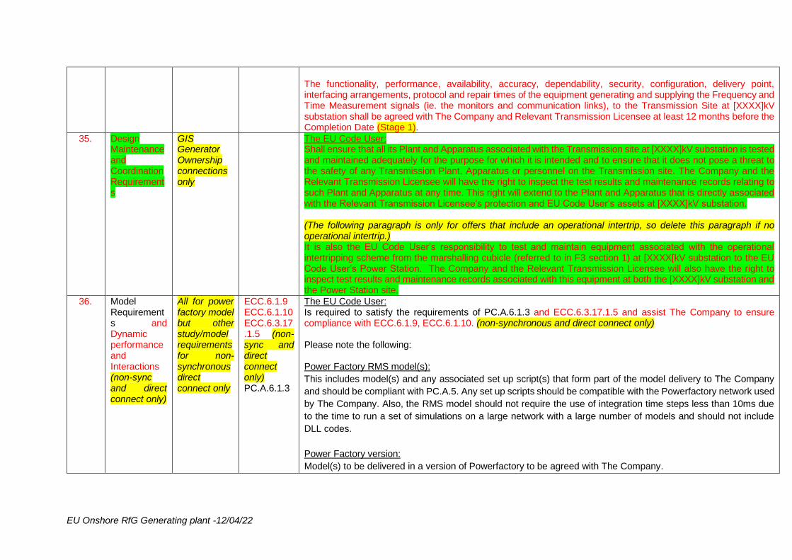
EU Onshore RfG Generating plant -12/04/22
The functionality, performance, availability, accuracy, dependability, security, configuration, delivery point, interfacing arrangements, protocol and repair times of the equipment generating and supplying the Frequency and Time Measurement signals (ie. the monitors and communication links), to the Transmission Site at [XXXX]kV substation shall be agreed with The Company and Relevant Transmission Licensee at least 12 months before the Completion Date (Stage 1).
35. Design Maintenance and Coordination Requirements
GIS Generator Ownership connections only
The EU Code User: Shall ensure that all its Plant and Apparatus associated with the Transmission site at [XXXX]kV substation is tested and maintained adequately for the purpose for which it is intended and to ensure that it does not pose a threat to the safety of any Transmission Plant, Apparatus or personnel on the Transmission site. The Company and the Relevant Transmission Licensee will have the right to inspect the test results and maintenance records relating to such Plant and Apparatus at any time. This right will extend to the Plant and Apparatus that is directly associated with the Relevant Transmission Licensee’s protection and EU Code User’s assets at [XXXX]kV substation. (The following paragraph is only for offers that include an operational intertrip, so delete this paragraph if no operational intertrip.) It is also the EU Code User’s responsibility to test and maintain equipment associated with the operational intertripping scheme from the marshalling cubicle (referred to in F3 section 1) at [XXXX[kV substation to the EU Code User’s Power Station. The Company and the Relevant Transmission Licensee will also have the right to inspect test results and maintenance records associated with this equipment at both the [XXXX]kV substation and the Power Station site.
36. Model Requirements and Dynamic performance and Interactions (non-sync and direct connect only)
All for power factory model but other study/model requirements for non-synchronous direct connect only
ECC.6.1.9 ECC.6.1.10 ECC.6.3.17.1.5 (non-sync and direct connect only) PC.A.6.1.3
The EU Code User: Is required to satisfy the requirements of PC.A.6.1.3 and ECC.6.3.17.1.5 and assist The Company to ensure compliance with ECC.6.1.9, ECC.6.1.10. (non-synchronous and direct connect only) Please note the following: Power Factory RMS model(s):
This includes model(s) and any associated set up script(s) that form part of the model delivery to The Company
and should be compliant with PC.A.5. Any set up scripts should be compatible with the Powerfactory network used
by The Company. Also, the RMS model should not require the use of integration time steps less than 10ms due
to the time to run a set of simulations on a large network with a large number of models and should not include
DLL codes.
Power Factory version:
Model(s) to be delivered in a version of Powerfactory to be agreed with The Company.
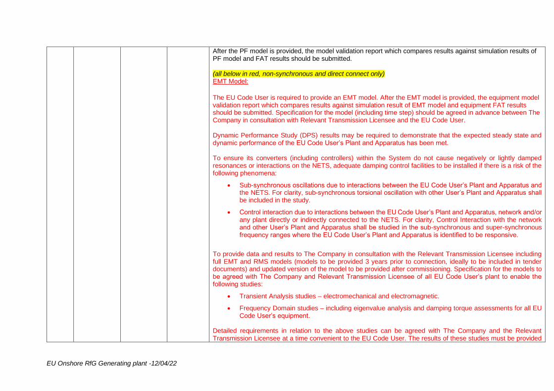
EU Onshore RfG Generating plant -12/04/22
After the PF model is provided, the model validation report which compares results against simulation results of PF model and FAT results should be submitted. (all below in red, non-synchronous and direct connect only) EMT Model:
The EU Code User is required to provide an EMT model. After the EMT model is provided, the equipment model validation report which compares results against simulation result of EMT model and equipment FAT results should be submitted. Specification for the model (including time step) should be agreed in advance between The Company in consultation with Relevant Transmission Licensee and the EU Code User. Dynamic Performance Study (DPS) results may be required to demonstrate that the expected steady state and dynamic performance of the EU Code User’s Plant and Apparatus has been met. To ensure its converters (including controllers) within the System do not cause negatively or lightly damped resonances or interactions on the NETS, adequate damping control facilities to be installed if there is a risk of the following phenomena:
• Sub-synchronous oscillations due to interactions between the EU Code User’s Plant and Apparatus and the NETS. For clarity, sub-synchronous torsional oscillation with other User’s Plant and Apparatus shall be included in the study.
• Control interaction due to interactions between the EU Code User’s Plant and Apparatus, network and/or any plant directly or indirectly connected to the NETS. For clarity, Control Interaction with the network and other User’s Plant and Apparatus shall be studied in the sub-synchronous and super-synchronous frequency ranges where the EU Code User’s Plant and Apparatus is identified to be responsive.
To provide data and results to The Company in consultation with the Relevant Transmission Licensee including full EMT and RMS models (models to be provided 3 years prior to connection, ideally to be included in tender documents) and updated version of the model to be provided after commissioning. Specification for the models to be agreed with The Company and Relevant Transmission Licensee of all EU Code User’s plant to enable the following studies:
• Transient Analysis studies – electromechanical and electromagnetic.
• Frequency Domain studies – including eigenvalue analysis and damping torque assessments for all EU Code User’s equipment.
Detailed requirements in relation to the above studies can be agreed with The Company and the Relevant Transmission Licensee at a time convenient to the EU Code User. The results of these studies must be provided
EU Onshore RfG Generating plant -12/04/22
to The Company and the Relevant Transmission Licensee by the date defined in the Appendix J/date to be agreed with The Company, the Relevant Transmission Licensee and the EU Code User. (use to be agreed in Scottish agreements) The EU Code User shall provide The Company with any relevant information required in the above assessments. Additional Note Both The Company and the EU Code User endeavour to revise and update as applicable the contents of this clause before Completion date, unless otherwise agreed, in accordance with the Grid Code applicable at the time. The Company To outline the detailed requirements and the extent of the studies to be performed, and the criteria to demonstrate compliance with (depending on the static and dynamic models of the transmission network) other relevant Users before the Completion date. The results of these studies must be provided to The Company and the Relevant Transmission Licensee by the date defined in the Appendix J/date to be agreed with The Company, the Relevant Transmission Licensee and the EU Code User (use to be agreed in Scottish agreements), unless otherwise agreed.
37. Sub-synchronous Resonance
All, except if red section in DPI applies
ECC.6.1.9 ECC.6.1.10
The EU Code User: Shall supply each Generating Unit's mechanical parameters and mechanical frequencies in accordance with PC.A.5.3.2(g) of the Grid Code and to assess the risk of Sub-Synchronous Resonance and related conditions to ensure that no existing or new modes of interaction are present, or ensure where such modes occur they are positively damped. (Synchronous only) The EU Code User shall agree the details with The Company and the Relevant Transmission Licensee of this/the assessment of existing and new modes of interaction (use second option for PPMs) during the detailed design phase. The Company (in coordination with the Relevant Transmission Licensee) reserves the right to review the nature of any mitigation measures presented and will require models to be provided to represent the effect of any applicable design measures to mitigate the risk. (red text below type C&D only) The Relevant Transmission Licensee: The Relevant Transmission Licensee (in coordination with The Company) may specify to the EU Code User a set of characteristics depicting the electrical damping (synch)/ the network resistance and reactance (PPM) as seen by the EU Code User’s Generating Unit(s)/Power park Module(s) are expected to experience over the sub-
EU Onshore RfG Generating plant -12/04/22
synchronous frequency range. The EU Code User shall inform The Company and the Relevant Transmission Licensee of any Sub-Synchronous Oscillations that it believes to be insufficiently damped (“Unacceptable Sub-Synchronous Oscillations.”) Where a risk of Unacceptable Sub-Synchronous Oscillations has been identified, the EU Code User and The Company (upon advice from the Relevant Transmission Licensee) shall agree the site specific requirements and the works, including any Transmission Reinforcement Works and/or EU Code User Works, required to ensure that all Sub-Synchronous Oscillations are sufficiently damped. Neither the EU Code User, The Company, nor the Relevant Transmission Licensee shall unreasonably withhold their agreement to these works. The Company (upon advice from the Relevant Transmission Licensee) shall provide the EU Code User with an updated set of electrical damping (synch)/ network resistance and reactance (PPM) characteristics reflecting the effect of the agreed Transmission Reinforcement Works. The Company and the Relevant Transmission Licensee reserve the rights to review the designs and request the models of any measures the EU Code User implements in order to prevent Unacceptable Sub-Synchronous Oscillations. Where necessary, The Company may also require that the EU Code User to install Sub-Synchronous Oscillations monitoring equipment. There is no requirement on the EU Code User to install any Sub-Synchronous Oscillations protection.
38. All of the below
PPM only
39. Voltage Control Performance Requirements
All PPMs except small BEGAs
ECC.6.3.8.4 and ECC.A.7
The EU Code User: To install a continuously acting automatic control system to provide control of the voltage at the Grid Entry Point (or EU Code User System Entry Point if embedded) as detailed in ECC.6.3.8.4 of the Grid Code. The performance requirements of this control system are detailed in Appendix E7 of the Grid Code Connection Conditions. To declare to The Company, the ability of each Power Park Module to contribute to voltage control below 20% of Rated MW output. As a minimum and as specified in ECC.6.3.8(a)(iii) of the Grid Code, if voltage control is not being provided below 20% of Rated MW output, the EU Code User shall ensure that the control system of each Power Park Module shall be designed to ensure a smooth transition between the shaded area and the non-shaded area in Figure ECC.6.3.2.4(c) of the Grid Code. For the avoidance of doubt each Power Generating Module control system is not required to be fitted with Reactive Power Control or Power Factor Control. If such facilities have been installed within the voltage control system they should be disabled.
EU Onshore RfG Generating plant -12/04/22
40. Power Oscillation Damping
(Guidance is within box, otherwise it’s a bit difficult to read.)
BC.2.11.2 (PSS is required if: Cat. D and it is synchronous – so remove this row. For PPMs, remove this para if SO or TO studies state that PSS is required. Synchronous cat B or C, use 2nd para wording if TO or SO studies require a PSS. PSS is not required for small size/cat A connections. Embedded: PSS only required if TO/DNO studies determine this requirement. Use 2nd para if studies say PSS required.) The EU Code User: There is no requirement for the voltage control system to be fitted with a Power System Stabiliser (PSS). However if the Generator chooses to install a PSS within the Power Park Module voltage control system, its settings and performance shall be agreed with The Company and the Relevant Transmission Licensee and commissioned in accordance with BC.2.11.2 of the Grid Code. Studies have determined that a Power System Stabiliser (PSS) is required for this connection. The settings and performance of the PSS shall be agreed with The Company and the Relevant Transmission Licensee and commissioned in accordance with BC.2.11.2 of the Grid Code. (Use this para for cat B or C synchronous, if TO or DNO studies determine that a PSS is required.)
41. Reactive Power Limiters
Only if required and specified in the TOCO.
42. Power Quality Monitoring
Direct connect only. The TO will specify in the TOCO if Quality of Supply Monitoring is required.
The EU Code User: To provide three phase voltage transducers of suitable accuracy which are appropriately sited at the Point of Common Coupling to enable continuous power quality voltage monitoring whether or not the Power Park Module is energised. Examples of suitable voltage transducers are detailed in TS 3.02.05_RES “Voltage Transformers” (with particular reference to Section 1.3) or, alternatively, in TS 3.02.12_RES “Voltage Dividers.” To provide three phase current transducers of suitable accuracy on the EU Code User’s feeders at the Relevant Transmission Licensee’s [XXXX]kV substation at the Grid Entry Point to enable continuous power quality current monitoring. The current transducers on the EU Code User’s feeders shall be sited such that the monitored currents include any contribution from reactive power compensation and/or harmonic mitigation equipment. The transducer is required to meet TS 3.02.04_RES (Current Transformers for Protection and General Use). A current transducer is suitable for power quality monitoring if it is also compliant with IEC 61869-1 and IEC 61869-2. The EU Code User to provide the output signal of these voltage and current transducers to the Relevant Transmission Licensee.
EU Onshore RfG Generating plant -12/04/22
The Relevant Transmission Licensee: To install permanent, Class A power quality monitors as defined in IEC 61000-4-30 at the Grid Entry Point in order to check compliance against the specified limits. (for GIS Generator Connections delete all of the above and replace with the following:) The Relevant Transmission Licensee: To provide three phase voltage transducers of suitable accuracy which are appropriately sited at the Point of Common Coupling to enable continuous power quality voltage monitoring whether or not the Power Park Module is energised. (The following para to be included for all, irrespective of GIS arrangements:) To undertake a four week period (unless otherwise agreed) of continuous power quality voltage measurements using the above facilities immediately prior to the energisation of the EU Code User’s feeders to establish a baseline for compliance with the Grid Code. Continuous power quality monitoring shall then be performed during and after commissioning.
43. Switching Groups
All PPMs PC.A.3.2.2 (k) PC.A.3.2.4 OC2.4.2.1 (f)
The EU Code User: To notify The Company of any change to the number, type or configuration of Power Park Units within each Power Park Module. To ensure that each Power Park Module is capable of meeting the full requirements of the Grid Code and this Bilateral Agreement (including but not limited to matters of quality of supply requirements, fault infeed and reactive capability) irrespective of the connection configuration of each Power Park Unit within each Power Park Module.
44. Additional data for new types of Power Stations and configurations
Tidal, and any new technology, except if an SPT offer, in which case put it in for all technology types.
PC.A.7 The EU Code User: Should be aware that The Company may reasonably require additional data to correctly represent the performance of the EU Code User’s Plant and Apparatus where the present data submissions would prove insufficient for the purpose of producing meaningful studies.
45. Power Export Tidal and SPT PPM offers NB SPT PPM offers, first para only
The EU Code User: Shall ensure that the total output from each Power Park Module does not exceed its Transmission Entry Capacity (TEC) and Connection Entry Capacity (CEC) to prevent unacceptable overloads on the National Electricity Transmission System. The standard deviation of generation output over a 30 minute period must not exceed 2.5 percent of the power park module’s registered capacity.
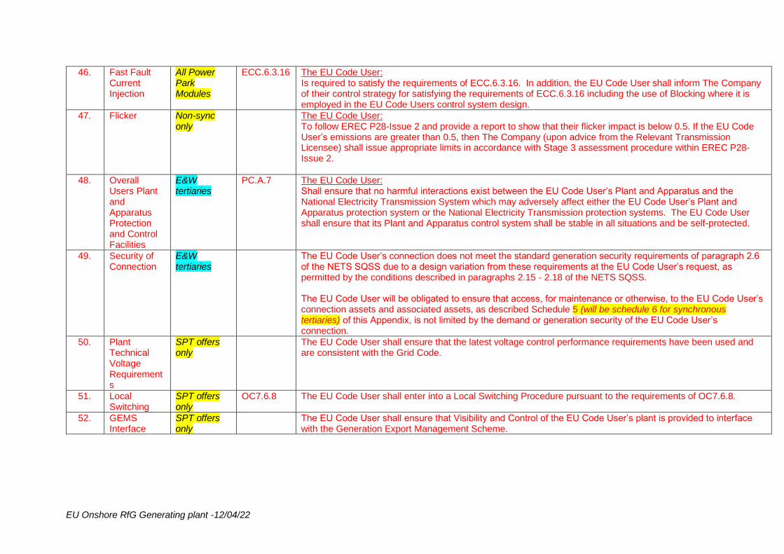
EU Onshore RfG Generating plant -12/04/22
46. Fast Fault Current Injection
All Power Park Modules
ECC.6.3.16 The EU Code User: Is required to satisfy the requirements of ECC.6.3.16. In addition, the EU Code User shall inform The Company of their control strategy for satisfying the requirements of ECC.6.3.16 including the use of Blocking where it is employed in the EU Code Users control system design.
47. Flicker Non-sync only
The EU Code User: To follow EREC P28-Issue 2 and provide a report to show that their flicker impact is below 0.5. If the EU Code User’s emissions are greater than 0.5, then The Company (upon advice from the Relevant Transmission Licensee) shall issue appropriate limits in accordance with Stage 3 assessment procedure within EREC P28-Issue 2.
48. Overall Users Plant and Apparatus Protection and Control Facilities
E&W tertiaries
PC.A.7 The EU Code User: Shall ensure that no harmful interactions exist between the EU Code User’s Plant and Apparatus and the National Electricity Transmission System which may adversely affect either the EU Code User’s Plant and Apparatus protection system or the National Electricity Transmission protection systems. The EU Code User shall ensure that its Plant and Apparatus control system shall be stable in all situations and be self-protected.
49. Security of Connection
E&W tertiaries
The EU Code User’s connection does not meet the standard generation security requirements of paragraph 2.6 of the NETS SQSS due to a design variation from these requirements at the EU Code User’s request, as permitted by the conditions described in paragraphs 2.15 - 2.18 of the NETS SQSS. The EU Code User will be obligated to ensure that access, for maintenance or otherwise, to the EU Code User’s connection assets and associated assets, as described Schedule 5 (will be schedule 6 for synchronous tertiaries) of this Appendix, is not limited by the demand or generation security of the EU Code User’s connection.
50. Plant Technical Voltage Requirements
SPT offers only
The EU Code User shall ensure that the latest voltage control performance requirements have been used and are consistent with the Grid Code.
51. Local Switching
SPT offers only
OC7.6.8 The EU Code User shall enter into a Local Switching Procedure pursuant to the requirements of OC7.6.8.
52. GEMS Interface
SPT offers only
The EU Code User shall ensure that Visibility and Control of the EU Code User’s plant is provided to interface with the Generation Export Management Scheme.

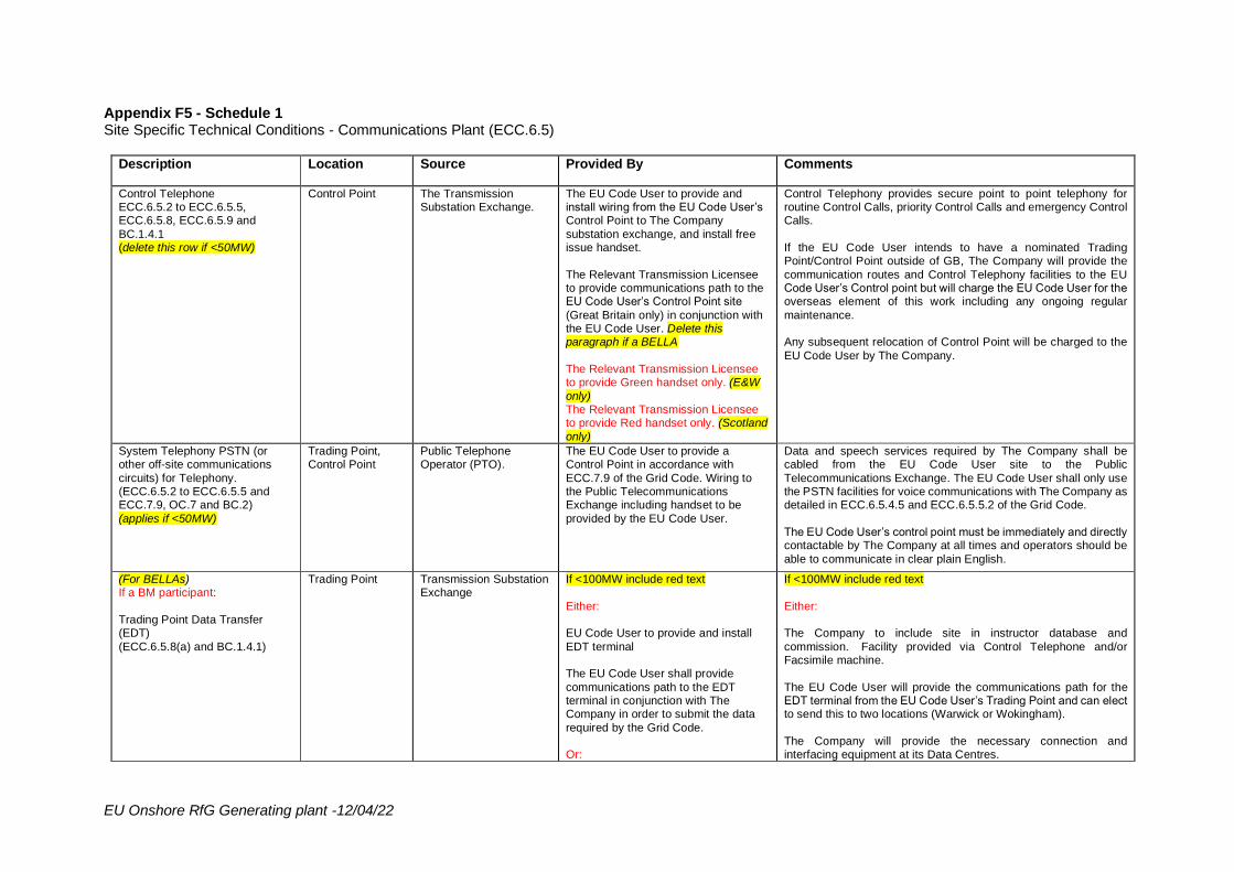
EU Onshore RfG Generating plant -12/04/22
Appendix F5 - Schedule 1 Site Specific Technical Conditions - Communications Plant (ECC.6.5)
Description Location Source Provided By Comments
Control Telephone ECC.6.5.2 to ECC.6.5.5, ECC.6.5.8, ECC.6.5.9 and
BC.1.4.1 (delete this row if <50MW)
Control Point The Transmission Substation Exchange.
The EU Code User to provide and install wiring from the EU Code User’s Control Point to The Company
substation exchange, and install free issue handset.
The Relevant Transmission Licensee to provide communications path to the EU Code User’s Control Point site
(Great Britain only) in conjunction with the EU Code User. Delete this paragraph if a BELLA
The Relevant Transmission Licensee to provide Green handset only. (E&W
only) The Relevant Transmission Licensee to provide Red handset only. (Scotland
only)
Control Telephony provides secure point to point telephony for routine Control Calls, priority Control Calls and emergency Control Calls.
If the EU Code User intends to have a nominated Trading Point/Control Point outside of GB, The Company will provide the
communication routes and Control Telephony facilities to the EU Code User’s Control point but will charge the EU Code User for the overseas element of this work including any ongoing regular
maintenance. Any subsequent relocation of Control Point will be charged to the
EU Code User by The Company.
System Telephony PSTN (or other off-site communications
circuits) for Telephony. (ECC.6.5.2 to ECC.6.5.5 and ECC.7.9, OC.7 and BC.2)
(applies if <50MW)
Trading Point, Control Point
Public Telephone Operator (PTO).
The EU Code User to provide a Control Point in accordance with
ECC.7.9 of the Grid Code. Wiring to the Public Telecommunications Exchange including handset to be
provided by the EU Code User.
Data and speech services required by The Company shall be cabled from the EU Code User site to the Public
Telecommunications Exchange. The EU Code User shall only use the PSTN facilities for voice communications with The Company as detailed in ECC.6.5.4.5 and ECC.6.5.5.2 of the Grid Code.
The EU Code User’s control point must be immediately and directly contactable by The Company at all times and operators should be
able to communicate in clear plain English.
(For BELLAs) If a BM participant:
Trading Point Data Transfer (EDT)
(ECC.6.5.8(a) and BC.1.4.1)
Trading Point Transmission Substation Exchange
If <100MW include red text
Either: EU Code User to provide and install
EDT terminal The EU Code User shall provide
communications path to the EDT terminal in conjunction with The Company in order to submit the data
required by the Grid Code. Or:
If <100MW include red text
Either: The Company to include site in instructor database and
commission. Facility provided via Control Telephone and/or Facsimile machine.
The EU Code User will provide the communications path for the EDT terminal from the EU Code User’s Trading Point and can elect to send this to two locations (Warwick or Wokingham).
The Company will provide the necessary connection and interfacing equipment at its Data Centres.
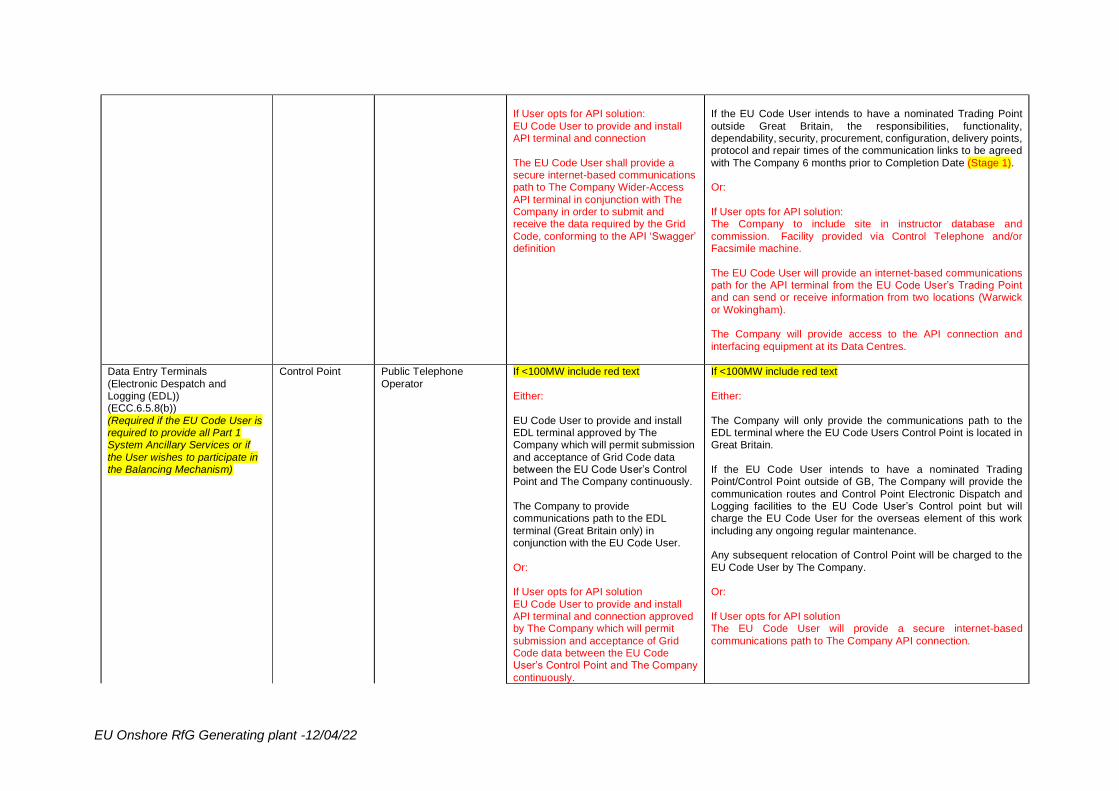
EU Onshore RfG Generating plant -12/04/22
If User opts for API solution:
EU Code User to provide and install API terminal and connection
The EU Code User shall provide a secure internet-based communications path to The Company Wider-Access
API terminal in conjunction with The Company in order to submit and receive the data required by the Grid
Code, conforming to the API ‘Swagger’ definition
If the EU Code User intends to have a nominated Trading Point
outside Great Britain, the responsibilities, functionality, dependability, security, procurement, configuration, delivery points, protocol and repair times of the communication links to be agreed
with The Company 6 months prior to Completion Date (Stage 1). Or:
If User opts for API solution: The Company to include site in instructor database and
commission. Facility provided via Control Telephone and/or Facsimile machine.
The EU Code User will provide an internet-based communications path for the API terminal from the EU Code User’s Trading Point and can send or receive information from two locations (Warwick
or Wokingham). The Company will provide access to the API connection and
interfacing equipment at its Data Centres.
Data Entry Terminals
(Electronic Despatch and Logging (EDL)) (ECC.6.5.8(b))
(Required if the EU Code User is required to provide all Part 1 System Ancillary Services or if
the User wishes to participate in the Balancing Mechanism)
Control Point Public Telephone
Operator
If <100MW include red text
Either:
EU Code User to provide and install EDL terminal approved by The Company which will permit submission
and acceptance of Grid Code data between the EU Code User’s Control Point and The Company continuously.
The Company to provide communications path to the EDL
terminal (Great Britain only) in conjunction with the EU Code User.
Or: If User opts for API solution
EU Code User to provide and install API terminal and connection approved by The Company which will permit
submission and acceptance of Grid Code data between the EU Code User’s Control Point and The Company
continuously.
If <100MW include red text
Either:
The Company will only provide the communications path to the EDL terminal where the EU Code Users Control Point is located in Great Britain.
If the EU Code User intends to have a nominated Trading Point/Control Point outside of GB, The Company will provide the
communication routes and Control Point Electronic Dispatch and Logging facilities to the EU Code User’s Control point but will charge the EU Code User for the overseas element of this work
including any ongoing regular maintenance. Any subsequent relocation of Control Point will be charged to the
EU Code User by The Company. Or:
If User opts for API solution The EU Code User will provide a secure internet-based
communications path to The Company API connection.
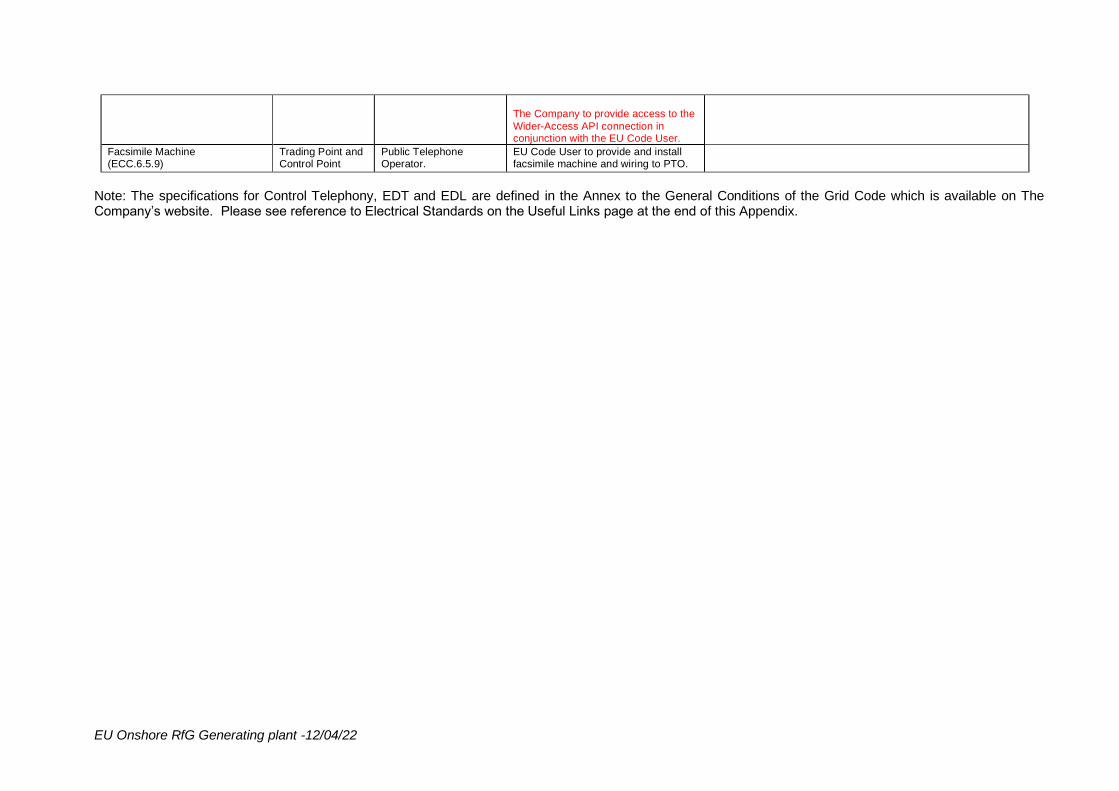
EU Onshore RfG Generating plant -12/04/22
The Company to provide access to the
Wider-Access API connection in conjunction with the EU Code User.
Facsimile Machine (ECC.6.5.9)
Trading Point and Control Point
Public Telephone Operator.
EU Code User to provide and install facsimile machine and wiring to PTO.
Note: The specifications for Control Telephony, EDT and EDL are defined in the Annex to the General Conditions of the Grid Code which is available on The Company’s website. Please see reference to Electrical Standards on the Useful Links page at the end of this Appendix.
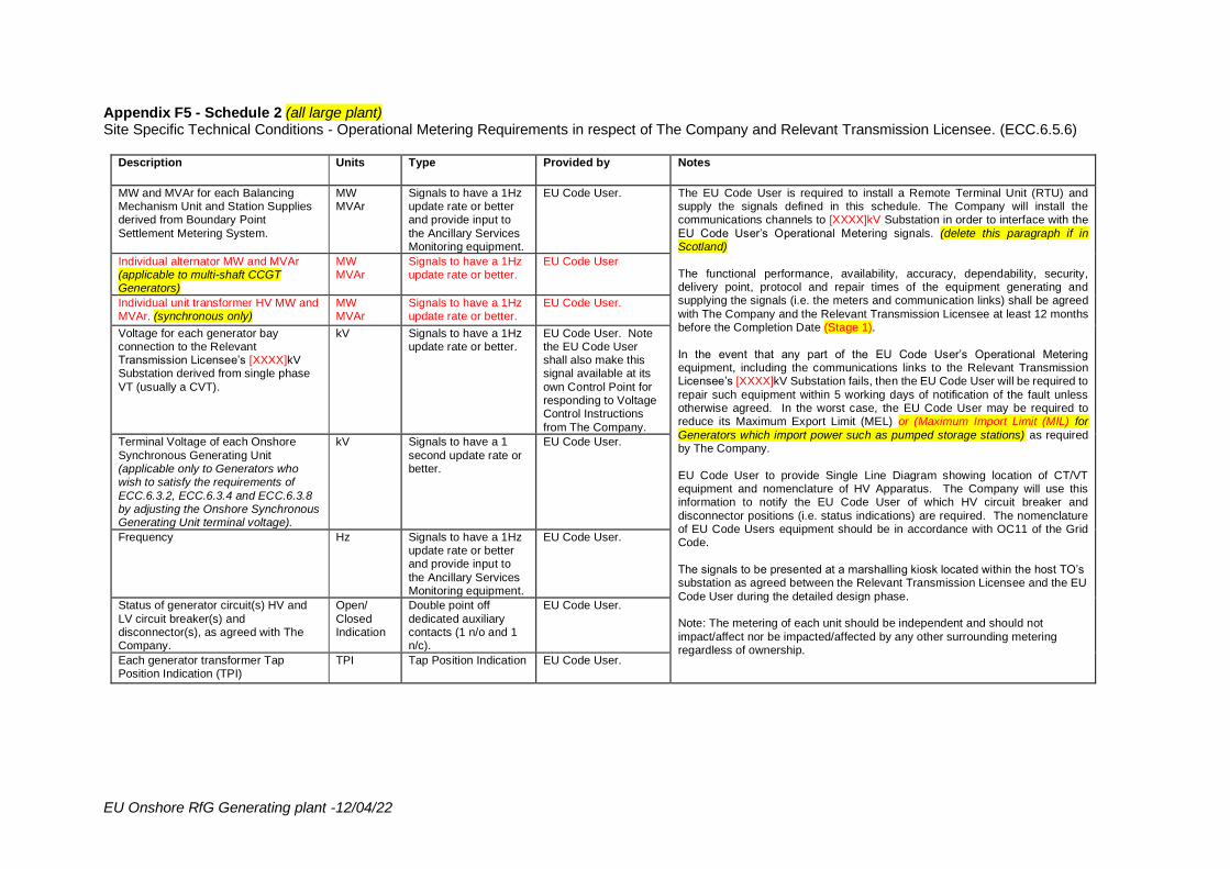
EU Onshore RfG Generating plant -12/04/22
Appendix F5 - Schedule 2 (all large plant) Site Specific Technical Conditions - Operational Metering Requirements in respect of The Company and Relevant Transmission Licensee. (ECC.6.5.6)
Description Units Type Provided by Notes
MW and MVAr for each Balancing Mechanism Unit and Station Supplies derived from Boundary Point
Settlement Metering System.
MW MVAr
Signals to have a 1Hz update rate or better and provide input to
the Ancillary Services Monitoring equipment.
EU Code User. The EU Code User is required to install a Remote Terminal Unit (RTU) and supply the signals defined in this schedule. The Company will install the communications channels to [XXXX]kV Substation in order to interface with the
EU Code User’s Operational Metering signals. (delete this paragraph if in Scotland)
The functional performance, availability, accuracy, dependability, security, delivery point, protocol and repair times of the equipment generating and supplying the signals (i.e. the meters and communication links) shall be agreed
with The Company and the Relevant Transmission Licensee at least 12 months before the Completion Date (Stage 1).
In the event that any part of the EU Code User’s Operational Metering equipment, including the communications links to the Relevant Transmission Licensee’s [XXXX]kV Substation fails, then the EU Code User will be required to
repair such equipment within 5 working days of notification of the fault unless otherwise agreed. In the worst case, the EU Code User may be required to reduce its Maximum Export Limit (MEL) or (Maximum Import Limit (MIL) for
Generators which import power such as pumped storage stations) as required by The Company.
EU Code User to provide Single Line Diagram showing location of CT/VT equipment and nomenclature of HV Apparatus. The Company will use this information to notify the EU Code User of which HV circuit breaker and
disconnector positions (i.e. status indications) are required. The nomenclature of EU Code Users equipment should be in accordance with OC11 of the Grid Code.
The signals to be presented at a marshalling kiosk located within the host TO’s substation as agreed between the Relevant Transmission Licensee and the EU
Code User during the detailed design phase. Note: The metering of each unit should be independent and should not
impact/affect nor be impacted/affected by any other surrounding metering regardless of ownership.
Individual alternator MW and MVAr (applicable to multi-shaft CCGT Generators)
MW MVAr
Signals to have a 1Hz update rate or better.
EU Code User
Individual unit transformer HV MW and MVAr. (synchronous only)
MW MVAr
Signals to have a 1Hz update rate or better.
EU Code User.
Voltage for each generator bay connection to the Relevant Transmission Licensee’s [XXXX]kV Substation derived from single phase
VT (usually a CVT).
kV Signals to have a 1Hz update rate or better.
EU Code User. Note the EU Code User shall also make this signal available at its
own Control Point for responding to Voltage Control Instructions
from The Company.
Terminal Voltage of each Onshore
Synchronous Generating Unit (applicable only to Generators who wish to satisfy the requirements of
ECC.6.3.2, ECC.6.3.4 and ECC.6.3.8 by adjusting the Onshore Synchronous Generating Unit terminal voltage).
kV Signals to have a 1
second update rate or better.
EU Code User.
Frequency Hz Signals to have a 1Hz update rate or better and provide input to
the Ancillary Services Monitoring equipment.
EU Code User.
Status of generator circuit(s) HV and
LV circuit breaker(s) and disconnector(s), as agreed with The Company.
Open/
Closed Indication
Double point off
dedicated auxiliary contacts (1 n/o and 1 n/c).
EU Code User.
Each generator transformer Tap Position Indication (TPI)
TPI Tap Position Indication EU Code User.
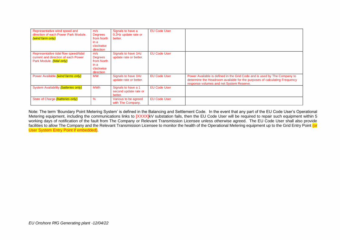
EU Onshore RfG Generating plant -12/04/22
Representative wind speed and direction of each Power Park Module.
(wind farm only)
m/s Degrees
from North in a clockwise
direction
Signals to have a 0.2Hz update rate or
better.
EU Code User
Representative tidal flow speed/tidal
current and direction of each Power Park Module. (tidal only)
m/s
Degrees from North in a
clockwise direction
Signals to have 1Hz
update rate or better.
EU Code User
Power Available (wind farms only) MW Signals to have 1Hz
update rate or better.
EU Code User Power Available is defined in the Grid Code and is used by The Company to
determine the Headroom available for the purposes of calculating Frequency response volumes and net System Reserve.
System Availability (batteries only) MWh Signals to have a 1
second update rate or better.
EU Code User
State of Charge (batteries only) % Various to be agreed with The Company.
EU Code User
Note: The term ‘Boundary Point Metering System’ is defined in the Balancing and Settlement Code. In the event that any part of the EU Code User’s Operational Metering equipment, including the communications links to [XXXX]kV substation fails, then the EU Code User will be required to repair such equipment within 5 working days of notification of the fault from The Company or Relevant Transmission Licensee unless otherwise agreed. The EU Code User shall also provide facilities to allow The Company and the Relevant Transmission Licensee to monitor the health of the Operational Metering equipment up to the Grid Entry Point (or User System Entry Point if embedded).
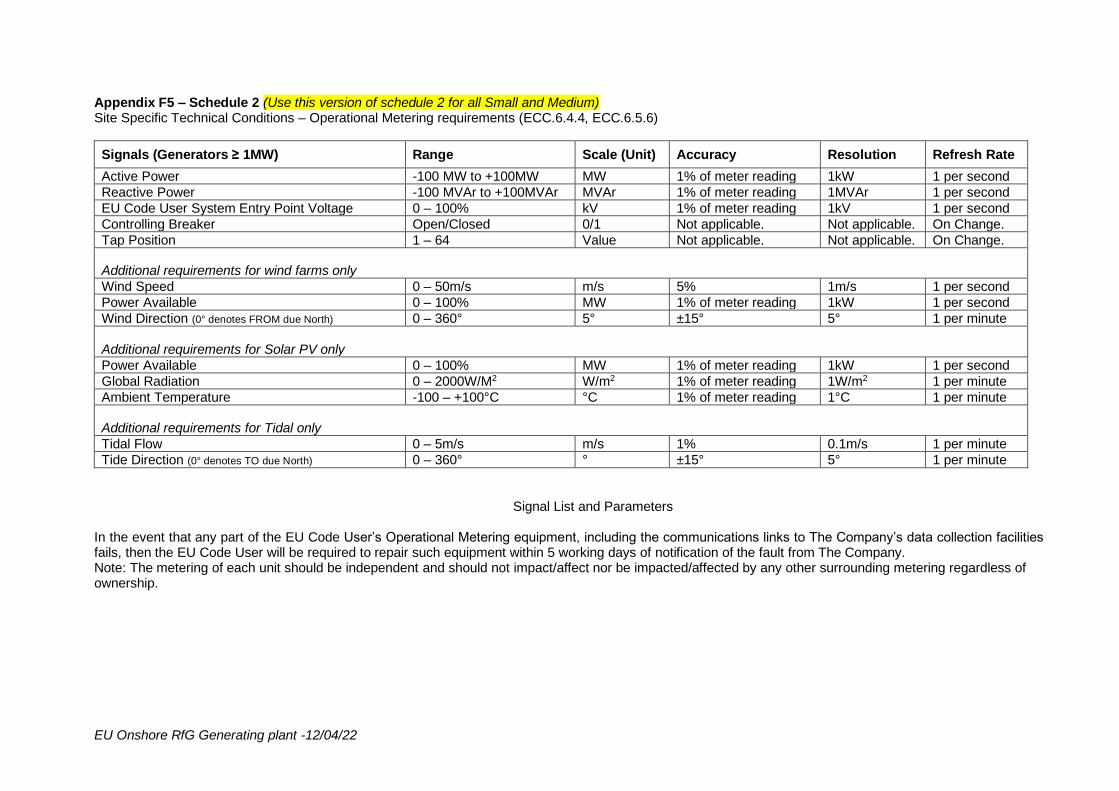
EU Onshore RfG Generating plant -12/04/22
Appendix F5 – Schedule 2 (Use this version of schedule 2 for all Small and Medium) Site Specific Technical Conditions – Operational Metering requirements (ECC.6.4.4, ECC.6.5.6)
Signals (Generators ≥ 1MW) Range Scale (Unit) Accuracy Resolution Refresh Rate
Active Power -100 MW to +100MW MW 1% of meter reading 1kW 1 per second
Reactive Power -100 MVAr to +100MVAr MVAr 1% of meter reading 1MVAr 1 per second
EU Code User System Entry Point Voltage 0 – 100% kV 1% of meter reading 1kV 1 per second
Controlling Breaker Open/Closed 0/1 Not applicable. Not applicable. On Change.
Tap Position 1 – 64 Value Not applicable. Not applicable. On Change.
Additional requirements for wind farms only
Wind Speed 0 – 50m/s m/s 5% 1m/s 1 per second
Power Available 0 – 100% MW 1% of meter reading 1kW 1 per second
Wind Direction (0° denotes FROM due North) 0 – 360° 5° ±15° 5° 1 per minute
Additional requirements for Solar PV only
Power Available 0 – 100% MW 1% of meter reading 1kW 1 per second
Global Radiation 0 – 2000W/M2 W/m2 1% of meter reading 1W/m2 1 per minute
Ambient Temperature -100 – +100°C °C 1% of meter reading 1°C 1 per minute
Additional requirements for Tidal only
Tidal Flow 0 – 5m/s m/s 1% 0.1m/s 1 per minute
Tide Direction (0° denotes TO due North) 0 – 360° ° ±15° 5° 1 per minute
Signal List and Parameters In the event that any part of the EU Code User’s Operational Metering equipment, including the communications links to The Company’s data collection facilities fails, then the EU Code User will be required to repair such equipment within 5 working days of notification of the fault from The Company. Note: The metering of each unit should be independent and should not impact/affect nor be impacted/affected by any other surrounding metering regardless of ownership.
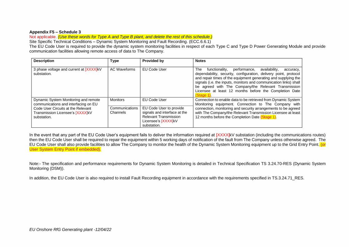
EU Onshore RfG Generating plant -12/04/22
Appendix F5 – Schedule 3 Not applicable. (Use these words for Type A and Type B plant, and delete the rest of this schedule.) Site Specific Technical Conditions – Dynamic System Monitoring and Fault Recording. (ECC.6.6.1) The EU Code User is required to provide the dynamic system monitoring facilities in respect of each Type C and Type D Power Generating Module and provide communication facilities allowing remote access of data to The Company.
Description Type Provided by Notes
3 phase voltage and current at [XXXX]kV substation.
AC Waveforms EU Code User The functionality, performance, availability, accuracy, dependability, security, configuration, delivery point, protocol and repair times of the equipment generating and supplying the signals (i.e. the inputs, monitors and communication links) shall be agreed with The Company/the Relevant Transmission Licensee at least 12 months before the Completion Date (Stage 1).
Dynamic System Monitoring and remote communications and interfacing on EU Code User Circuits at the Relevant Transmission Licensee’s [XXXX]kV substation.
Monitors EU Code User Connection to enable data to be retrieved from Dynamic System Monitoring equipment. Connection to The Company with connection, monitoring and security arrangements to be agreed with The Company/the Relevant Transmission Licensee at least 12 months before the Completion Date (Stage 1).
Communications Channels
EU Code User to provide signals and interface at the Relevant Transmission Licensee’s [XXXX]kV substation.
In the event that any part of the EU Code User’s equipment fails to deliver the information required at [XXXX]kV substation (including the communications routes) then the EU Code User shall be required to repair the equipment within 5 working days of notification of the fault from The Company unless otherwise agreed. The EU Code User shall also provide facilities to allow The Company to monitor the health of the Dynamic System Monitoring equipment up to the Grid Entry Point. (or User System Entry Point if embedded). Note:- The specification and performance requirements for Dynamic System Monitoring is detailed in Technical Specification TS 3.24.70-RES (Dynamic System Monitoring (DSM)). In addition, the EU Code User is also required to install Fault Recording equipment in accordance with the requirements specified in TS.3.24.71_RES.
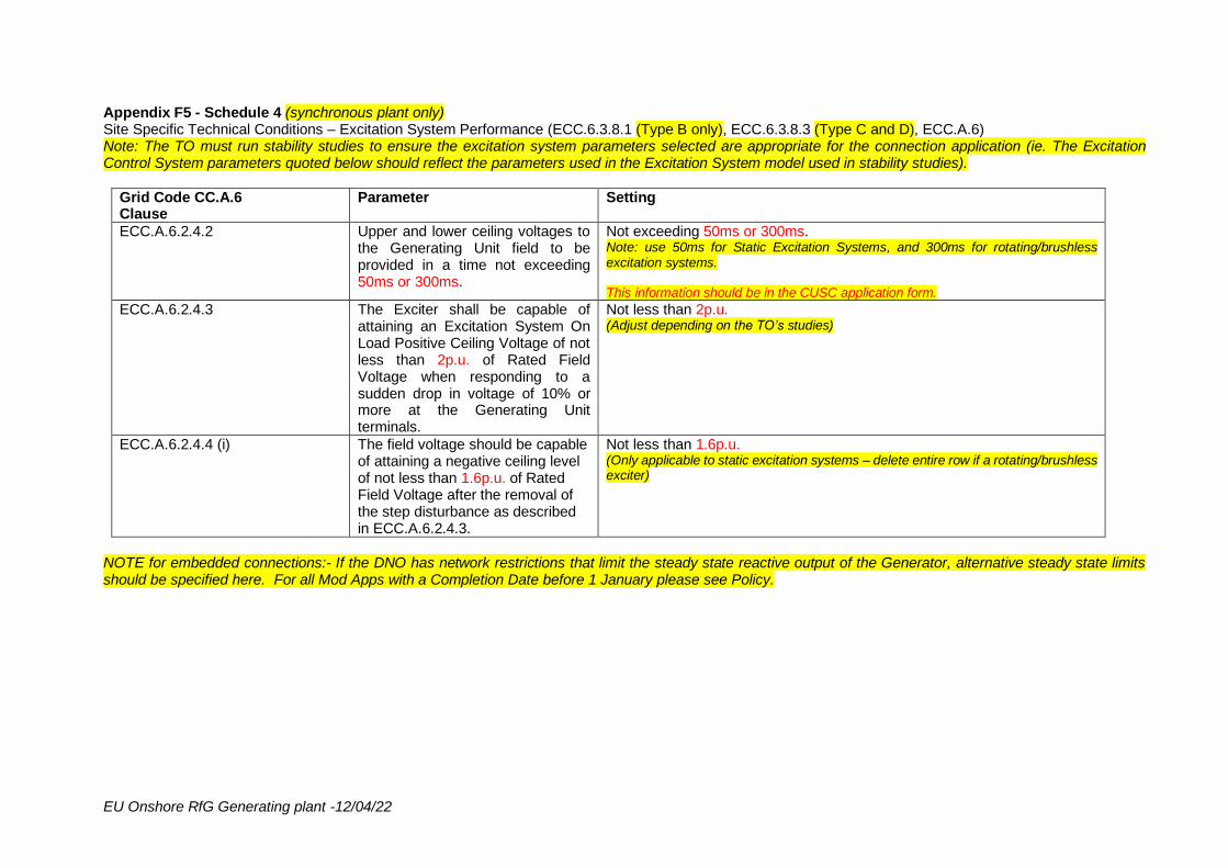
EU Onshore RfG Generating plant -12/04/22
Appendix F5 - Schedule 4 (synchronous plant only) Site Specific Technical Conditions – Excitation System Performance (ECC.6.3.8.1 (Type B only), ECC.6.3.8.3 (Type C and D), ECC.A.6) Note: The TO must run stability studies to ensure the excitation system parameters selected are appropriate for the connection application (ie. The Excitation Control System parameters quoted below should reflect the parameters used in the Excitation System model used in stability studies).
Grid Code CC.A.6 Clause
Parameter Setting
ECC.A.6.2.4.2 Upper and lower ceiling voltages to the Generating Unit field to be provided in a time not exceeding 50ms or 300ms.
Not exceeding 50ms or 300ms. Note: use 50ms for Static Excitation Systems, and 300ms for rotating/brushless excitation systems. This information should be in the CUSC application form.
ECC.A.6.2.4.3 The Exciter shall be capable of attaining an Excitation System On Load Positive Ceiling Voltage of not less than 2p.u. of Rated Field Voltage when responding to a sudden drop in voltage of 10% or more at the Generating Unit terminals.
Not less than 2p.u. (Adjust depending on the TO’s studies)
ECC.A.6.2.4.4 (i) The field voltage should be capable of attaining a negative ceiling level of not less than 1.6p.u. of Rated Field Voltage after the removal of the step disturbance as described in ECC.A.6.2.4.3.
Not less than 1.6p.u. (Only applicable to static excitation systems – delete entire row if a rotating/brushless exciter)
NOTE for embedded connections:- If the DNO has network restrictions that limit the steady state reactive output of the Generator, alternative steady state limits should be specified here. For all Mod Apps with a Completion Date before 1 January please see Policy.
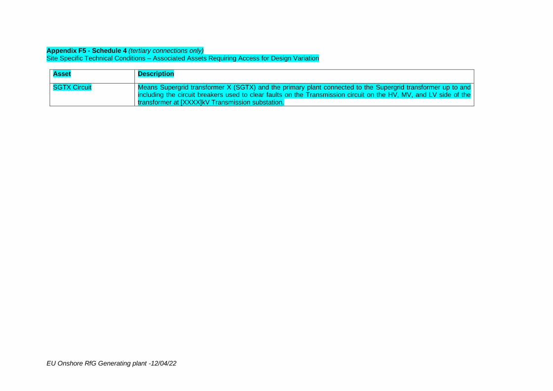
EU Onshore RfG Generating plant -12/04/22
Appendix F5 - Schedule 4 (tertiary connections only) Site Specific Technical Conditions – Associated Assets Requiring Access for Design Variation
Asset Description
SGTX Circuit Means Supergrid transformer X (SGTX) and the primary plant connected to the Supergrid transformer up to and including the circuit breakers used to clear faults on the Transmission circuit on the HV, MV, and LV side of the transformer at [XXXX]kV Transmission substation.
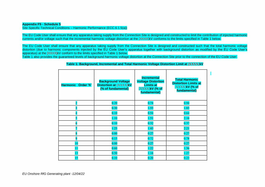
EU Onshore RfG Generating plant -12/04/22
Appendix F5 - Schedule 5 Site Specific Technical Conditions – Harmonic Performance (ECC.6.1.5(a)) The EU Code User shall ensure that any apparatus taking supply from the Connection Site is designed and constructed to limit the contribution of injected harmonic currents and/or voltage such that the incremental harmonic voltage distortion at the [XXXX]kV conforms to the limits specified in Table 1 below. The EU Code User shall ensure that any apparatus taking supply from the Connection Site is designed and constructed such that the total harmonic voltage distortion (due to harmonic components injected by the EU Code User’s apparatus together with background distortion as modified by the EU Code User’s apparatus) at the [XXXX]kV conform to the limits specified in Table 1 below. Table 1 also provides the guaranteed levels of background harmonic voltage distortion at the Connection Site prior to the connection of the EU Code User.
Table 1: Background, Incremental and Total Harmonic Voltage Distortion Limit at [XXXX]kV
Harmonic Order ‘h’ Background Voltage
Distortion at [XXXX]kV (% of fundamental)
Incremental Voltage Distortion
Limits at [XXXX]kV (% of
fundamental)
Total Harmonic Distortion Limits at
[XXXX]kV (% of fundamental)
2 0.20 0.74 0.94
3 0.30 1.55 1.85
4 0.10 0.54 0.64
5 1.10 1.51 2.16
6 0.10 0.32 0.37
7 1.25 1.43 2.21
8 0.00 0.27 0.27
9 0.15 0.72 0.78
10 0.00 0.27 0.27
11 0.60 1.22 1.36
13 0.50 1.16 1.27
15 0.10 0.20 0.23
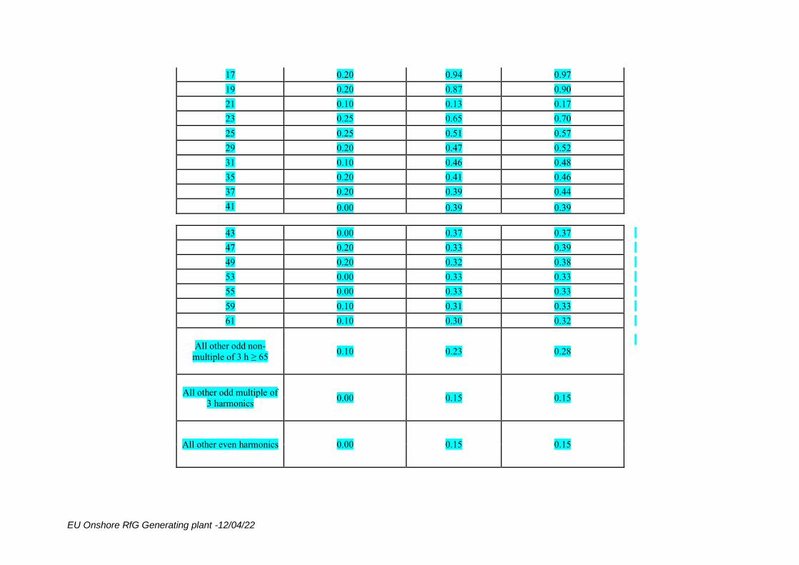
EU Onshore RfG Generating plant -12/04/22
17 0.20 0.94 0.97
19 0.20 0.87 0.90
21 0.10 0.13 0.17
23 0.25 0.65 0.70
25 0.25 0.51 0.57
29 0.20 0.47 0.52
31 0.10 0.46 0.48
35 0.20 0.41 0.46
37 0.20 0.39 0.44
41 0.00 0.39 0.39
43 0.00 0.37 0.37
47 0.20 0.33 0.39
49 0.20 0.32 0.38
53 0.00 0.33 0.33
55 0.00 0.33 0.33
59 0.10 0.31 0.33
61 0.10 0.30 0.32
All other odd non-
multiple of 3 h ≥ 65 0.10 0.23 0.28
All other odd multiple of
3 harmonics 0.00 0.15 0.15
All other even harmonics 0.00 0.15 0.15
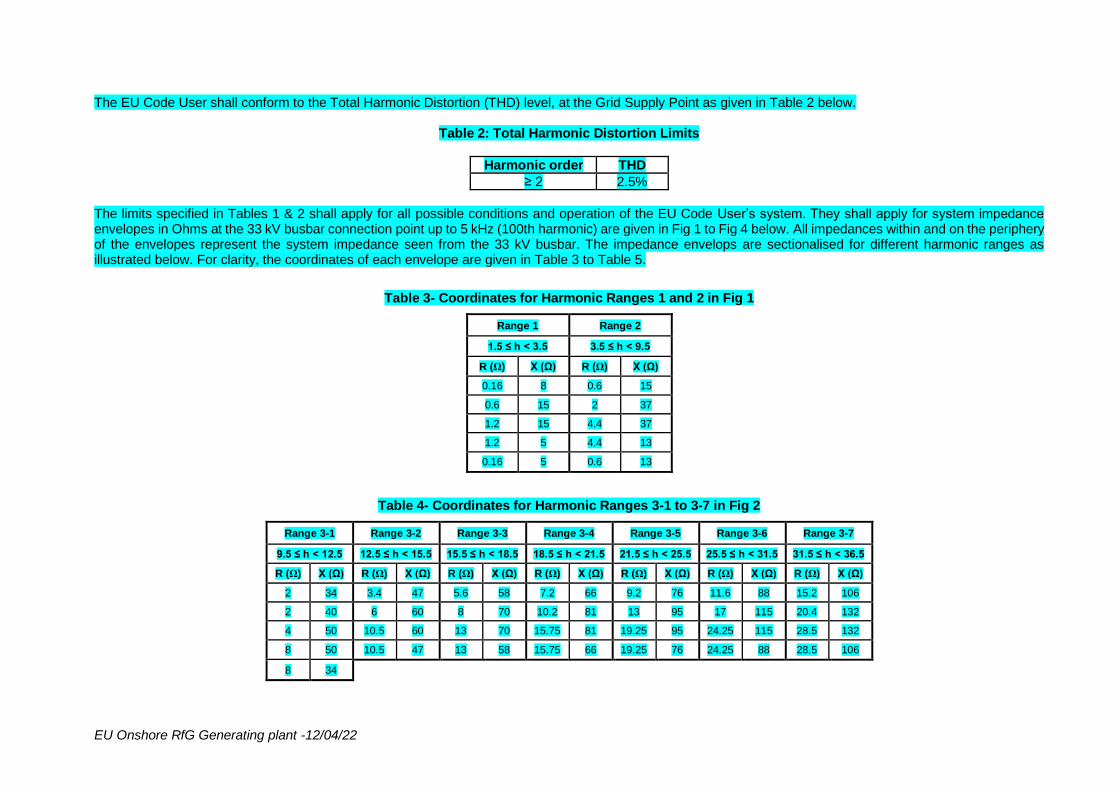
EU Onshore RfG Generating plant -12/04/22
The EU Code User shall conform to the Total Harmonic Distortion (THD) level, at the Grid Supply Point as given in Table 2 below.
Table 2: Total Harmonic Distortion Limits
Harmonic order THD
≥ 2 2.5%
The limits specified in Tables 1 & 2 shall apply for all possible conditions and operation of the EU Code User’s system. They shall apply for system impedance envelopes in Ohms at the 33 kV busbar connection point up to 5 kHz (100th harmonic) are given in Fig 1 to Fig 4 below. All impedances within and on the periphery of the envelopes represent the system impedance seen from the 33 kV busbar. The impedance envelops are sectionalised for different harmonic ranges as illustrated below. For clarity, the coordinates of each envelope are given in Table 3 to Table 5.
Table 3- Coordinates for Harmonic Ranges 1 and 2 in Fig 1
Range 1 Range 2
1.5 ≤ h < 3.5 3.5 ≤ h < 9.5
R (Ω) X (Ω) R (Ω) X (Ω)
0.16 8 0.6 15
0.6 15 2 37
1.2 15 4.4 37
1.2 5 4.4 13
0.16 5 0.6 13
Table 4- Coordinates for Harmonic Ranges 3-1 to 3-7 in Fig 2
Range 3-1 Range 3-2 Range 3-3 Range 3-4 Range 3-5 Range 3-6 Range 3-7
9.5 ≤ h < 12.5 12.5 ≤ h < 15.5 15.5 ≤ h < 18.5 18.5 ≤ h < 21.5 21.5 ≤ h < 25.5 25.5 ≤ h < 31.5 31.5 ≤ h < 36.5
R (Ω) X (Ω) R (Ω) X (Ω) R (Ω) X (Ω) R (Ω) X (Ω) R (Ω) X (Ω) R (Ω) X (Ω) R (Ω) X (Ω)
2 34 3.4 47 5.6 58 7.2 66 9.2 76 11.6 88 15.2 106
2 40 6 60 8 70 10.2 81 13 95 17 115 20.4 132
4 50 10.5 60 13 70 15.75 81 19.25 95 24.25 115 28.5 132
8 50 10.5 47 13 58 15.75 66 19.25 76 24.25 88 28.5 106
8 34
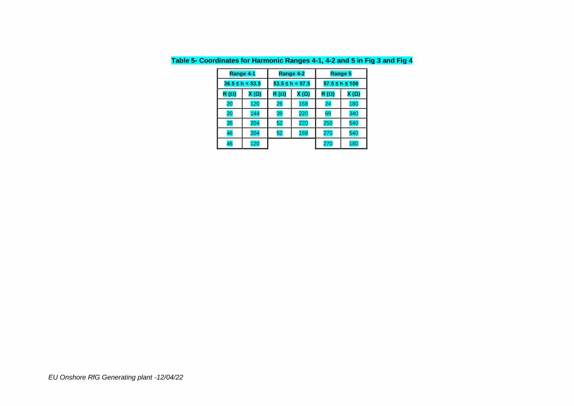
EU Onshore RfG Generating plant -12/04/22
Table 5- Coordinates for Harmonic Ranges 4-1, 4-2 and 5 in Fig 3 and Fig 4
Range 4-1 Range 4-2 Range 5
36.5 ≤ h < 53.5 53.5 ≤ h < 57.5 57.5 ≤ h ≤ 100
R (Ω) X (Ω) R (Ω) X (Ω) R (Ω) X (Ω)
20 120 26 168 24 180
20 144 39 220 69 340
35 204 52 220 250 540
46 204 52 168 270 540
46 120 270 180
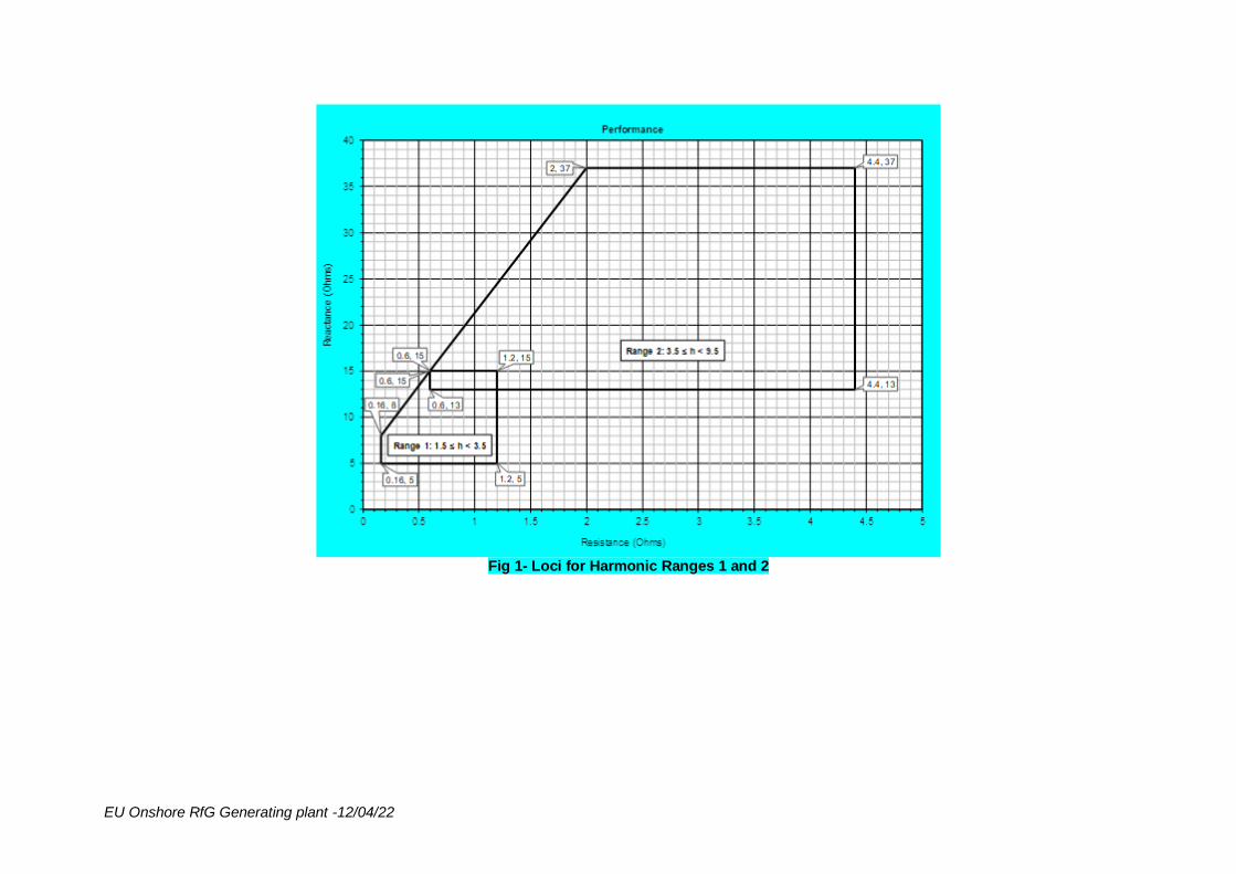
EU Onshore RfG Generating plant -12/04/22
Fig 1- Loci for Harmonic Ranges 1 and 2
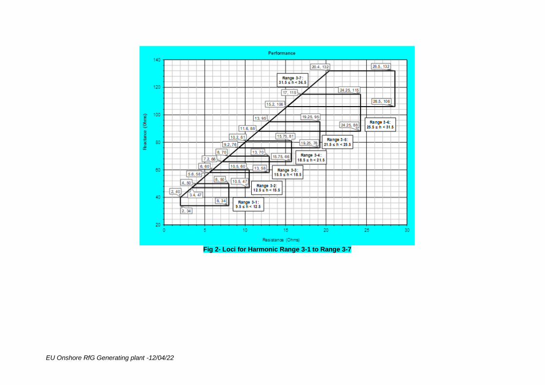
EU Onshore RfG Generating plant -12/04/22
Fig 2- Loci for Harmonic Range 3-1 to Range 3-7
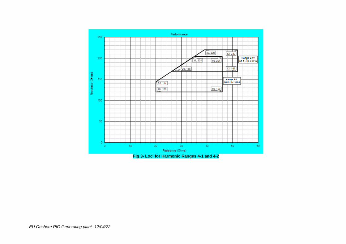
EU Onshore RfG Generating plant -12/04/22
Fig 3- Loci for Harmonic Ranges 4-1 and 4-2
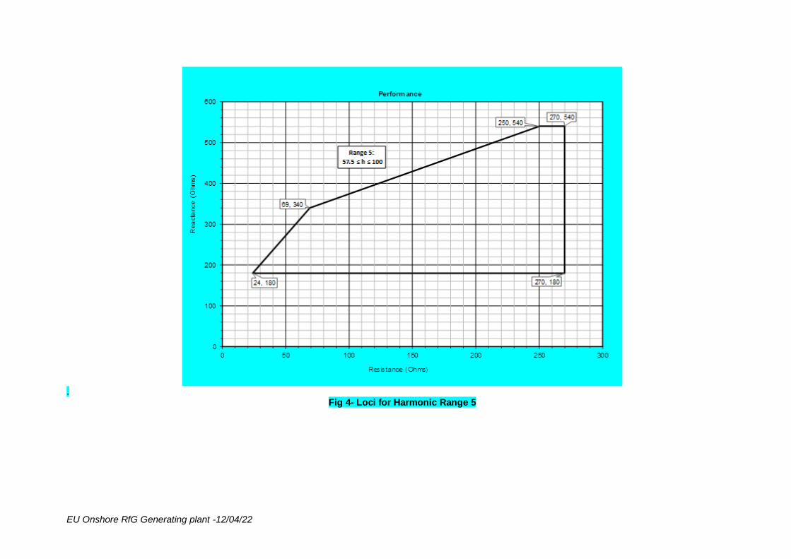
EU Onshore RfG Generating plant -12/04/22
.
Fig 4- Loci for Harmonic Range 5
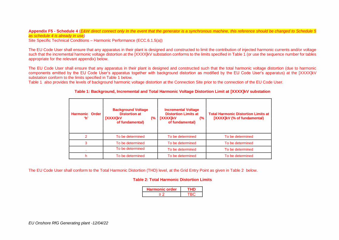
EU Onshore RfG Generating plant -12/04/22
Appendix F5 - Schedule 4 (E&W direct connect only In the event that the generator is a synchronous machine, this reference should be changed to Schedule 5 as schedule 4 is already in use) Site Specific Technical Conditions – Harmonic Performance (ECC.6.1.5(a)) The EU Code User shall ensure that any apparatus in their plant is designed and constructed to limit the contribution of injected harmonic currents and/or voltage such that the incremental harmonic voltage distortion at the [XXXX]kV substation conforms to the limits specified in Table 1 (or use the sequence number for tables appropriate for the relevant appendix) below. The EU Code User shall ensure that any apparatus in their plant is designed and constructed such that the total harmonic voltage distortion (due to harmonic components emitted by the EU Code User’s apparatus together with background distortion as modified by the EU Code User’s apparatus) at the [XXXX]kV substation conform to the limits specified in Table 1 below. Table 1 also provides the levels of background harmonic voltage distortion at the Connection Site prior to the connection of the EU Code User.
Table 1: Background, Incremental and Total Harmonic Voltage Distortion Limit at [XXXX]kV substation
Harmonic Order ‘h’
Background Voltage Distortion at
[XXXX]kV (% of fundamental)
Incremental Voltage Distortion Limits at
[XXXX]kV (% of fundamental)
Total Harmonic Distortion Limits at [XXXX]kV (% of fundamental)
2 To be determined To be determined To be determined
3 To be determined To be determined To be determined
. To be determined To be determined To be determined
h To be determined To be determined To be determined
The EU Code User shall conform to the Total Harmonic Distortion (THD) level, at the Grid Entry Point as given in Table 2 below.
Table 2: Total Harmonic Distortion Limits
Harmonic order THD
≥ 2 TBC
EU Onshore RfG Generating plant -12/04/22
The limits specified in Tables 1 & 2 shall apply for all possible conditions and operation of the EU Code User’s system. They shall apply for system impedance envelopes at the [XXXX]kV busbar connection point up to 5 kHz (100th harmonic) that are shown below. All impedances within and on the periphery of the envelopes represent the system impedance seen from the [XXXX]kV busbar. The impedance envelopes are sectionalised for different harmonic ranges as illustrated below. NB: Graphs will be provided once limits have been determined

EU Onshore RfG Generating plant -12/04/22
USEFUL LINKS The Grid Code: https://www.nationalgrideso.com/uk/electricity/codes/grid-code Electrical Standards: https://www.nationalgrideso.com/uk/electricity/codes/grid-code/electrical-standards-documents-including-specifications-electronic Extranet (ID and password required, email [email protected] to request access): https://extranet.nationalgrid.com/ (delete this link if in Scotland) Connection Policies and Guidance: https://www.nationalgrideso.com/connections/registers-reports-and-guidance Procurement Guidelines and Balancing Principles: https://www.nationalgrideso.com/uk/electricity/market-operations-and-data/transmission-licence-c16-statements-and-consultations
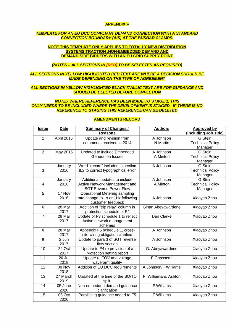
APPENDIX F
TEMPLATE FOR AN EU DCC COMPLIANT DEMAND CONNECTION WITH A STANDARD CONNECTION BOUNDARY (AIS) AT THE BUSBAR CLAMPS.
NOTE THIS TEMPLATE ONLY APPLIES TO TOTALLY NEW DISTRIBUTION
SYSTEMS,TRACTION ,NON-EMBEDDED DEMAND AND DEMAND SIDE BIDDERS WITH AN EU GRID SUPPLY POINT
(NOTES – ALL SECTIONS IN [RED] TO BE SELECTED AS REQUIRED)
ALL SECTIONS IN YELLOW HIGHLIGHTED RED TEXT ARE WHERE A DECISION SHOULD BE
MADE DEPENDING ON THE TYPE OF AGREEMENT
ALL SECTIONS IN YELLOW HIGHLIGHTED BLACK ITALLIC TEXT ARE FOR GUIDANCE AND SHOULD BE DELETED BEFORE COMPLETION
NOTE:- WHERE REFERENCE HAS BEEN MADE TO STAGE 1, THIS
ONLY NEEDS TO BE INCLUDED WHERE THE DEVELOPMENT IS STAGED. IF THERE IS NO REFERENCE TO STAGING THIS REFERENCE CAN BE DELETED
AMENDMENTS RECORD
Issue Date
Summary of Changes / Reasons
Authors Approved by (including Job Title)
1 April 2015 Update and revision from comments received in 2014
A Johnson N Martin
G Stein Technical Policy
Manager
2 May 2015
Updated to include Embedded Generation Issues
A Johnson A Minton
G Stein Technical Policy
Manager
3
January 2016
Word “record” included in section 8.2 to correct typographical error
A Johnson
G Stein Technical Policy
Manager
4
January 2016
Additional updates to include Active Network Management and
SGT Reverse Power Flow
A Johnson A Minton
G Stein Technical Policy
Manager
5
17 Nov 2016
Operational Metering sampling rate change to 1s or 1Hz following
customer feedback
A Johnson
Xiaoyao Zhou
6
28 Mar 2017
Addition of “trip relay” column in protection schedule of F4
Gihan Abeyawardene Xiaoyao Zhou
7 28 Mar 2017
Update of F3 schedule 1 to reflect Active network management
schemes
Dan Clarke Xiaoyao Zhou
8 28 Mar 2017
Appendix F5 schedule 1, cross-site wiring obligation clarified
A Johnson Xiaoyao Zhou
9 2 Jun 2017
Update to para 3 of SGT reverse flow section
A Johnson Xiaoyao Zhou
10 24 Oct 2017
Update to F4 re provision of a protection setting report
G. Abeyawardene Xiaoyao Zhou
11 20 Jul 2018
Update re TOV and voltage waveform quality
F Ghassemi Xiaoyao Zhou
12 08 Nov 2018
Addition of EU DCC requirements A Johnson/F Williams Xiaoyao Zhou
13 27 March 2019
Updated at the time of the SO/TO split.
F. Williams/E. Ashton Xiaoyao Zhou
14 05 June 2020
Non-embedded demand guidance clarification
F.Williams Xiaoyao Zhou
15 05 Oct 2020
Paralleling guidance added to F5 F Williams Xiaoyao Zhou

16 23 Nov 2020
EMT requirement added for all non-DNO agreements
D. Clarke/F Williams Xiaoyao Zhou
17 23 Nov 2020
Requirement to register settlement metering added
D. Clarke/F Williams Xiaoyao Zhou
18 11 June 2021
Flicker requirement added F Ghassemi Xiaoyao Zhou
19 16 Dec 2021
F5 Schedule 2, metering interaction clarification
Oliver Garfield Xiaoyao Zhou
Customer Techical Policy Manager
(Please delete this page once it has been checked)
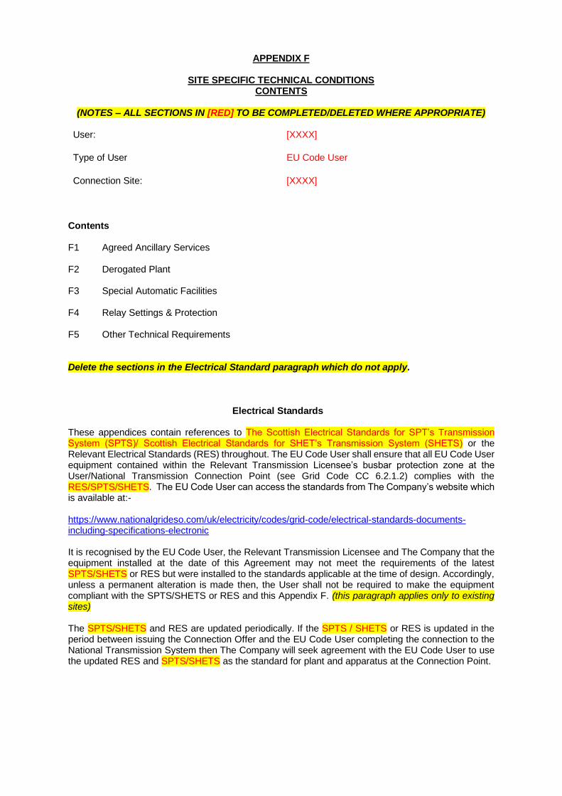
APPENDIX F
SITE SPECIFIC TECHNICAL CONDITIONS CONTENTS
(NOTES – ALL SECTIONS IN [RED] TO BE COMPLETED/DELETED WHERE APPROPRIATE)
User: [XXXX]
Type of User EU Code User
Connection Site: [XXXX]
Contents F1 Agreed Ancillary Services F2 Derogated Plant F3 Special Automatic Facilities F4 Relay Settings & Protection F5 Other Technical Requirements Delete the sections in the Electrical Standard paragraph which do not apply.
Electrical Standards These appendices contain references to The Scottish Electrical Standards for SPT’s Transmission System (SPTS)/ Scottish Electrical Standards for SHET’s Transmission System (SHETS) or the Relevant Electrical Standards (RES) throughout. The EU Code User shall ensure that all EU Code User equipment contained within the Relevant Transmission Licensee’s busbar protection zone at the User/National Transmission Connection Point (see Grid Code CC 6.2.1.2) complies with the RES/SPTS/SHETS. The EU Code User can access the standards from The Company’s website which is available at:- https://www.nationalgrideso.com/uk/electricity/codes/grid-code/electrical-standards-documents-including-specifications-electronic It is recognised by the EU Code User, the Relevant Transmission Licensee and The Company that the equipment installed at the date of this Agreement may not meet the requirements of the latest SPTS/SHETS or RES but were installed to the standards applicable at the time of design. Accordingly, unless a permanent alteration is made then, the User shall not be required to make the equipment compliant with the SPTS/SHETS or RES and this Appendix F. (this paragraph applies only to existing sites) The SPTS/SHETS and RES are updated periodically. If the SPTS / SHETS or RES is updated in the period between issuing the Connection Offer and the EU Code User completing the connection to the National Transmission System then The Company will seek agreement with the EU Code User to use the updated RES and SPTS/SHETS as the standard for plant and apparatus at the Connection Point.
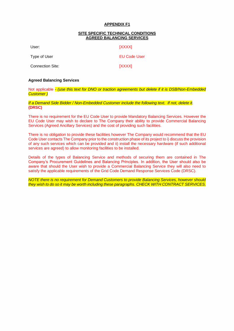
APPENDIX F1
SITE SPECIFIC TECHNICAL CONDITIONS AGREED BALANCING SERVICES
User: [XXXX]
Type of User EU Code User
Connection Site: [XXXX]
Agreed Balancing Services Not applicable - (use this text for DNO or traction agreements but delete if it is DSB/Non-Embedded Customer ) If a Demand Side Bidder / Non-Embedded Customer include the following text. If not, delete it. (DRSC) There is no requirement for the EU Code User to provide Mandatory Balancing Services. However the EU Code User may wish to declare to The Company their ability to provide Commercial Balancing Services (Agreed Ancillary Services) and the cost of providing such facilities. There is no obligation to provide these facilities however The Company would recommend that the EU Code User contacts The Company prior to the construction phase of its project to i) discuss the provision of any such services which can be provided and ii) install the necessary hardware (if such additional services are agreed) to allow monitoring facilities to be installed. Details of the types of Balancing Service and methods of securing them are contained in The Company’s Procurement Guidelines and Balancing Principles. In addition, the User should also be aware that should the User wish to provide a Commercial Balancing Service they will also need to satisfy the applicable requirements of the Grid Code Demand Response Services Code (DRSC). NOTE there is no requirement for Demand Customers to provide Balancing Services, however should they wish to do so it may be worth including these paragraphs. CHECK WITH CONTRACT SERVICES.

APPENDIX F2
SITE SPECIFIC TECHNICAL CONDITIONS DEROGATED PLANT
User: [XXXX]
Type of User EU Code User
Connection Site: [XXXX]
Derogated Plant Not applicable.
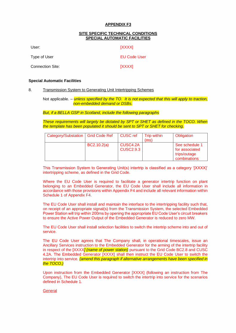
APPENDIX F3
SITE SPECIFIC TECHNICAL CONDITIONS SPECIAL AUTOMATIC FACILITIES
User: [XXXX]
Type of User EU Code User
Connection Site: [XXXX]
Special Automatic Facilities 8. Transmission System to Generating Unit Intertripping Schemes
Not applicable. – unless specified by the TO. It is not expected that this will apply to traction,
non-embedded demand or DSBs. But, if a BELLA GSP in Scotland, include the following paragraphs These requirements will largely be dictated by SPT or SHET as defined in the TOCO. When the template has been populated it should be sent to SPT or SHET for checking.
Category/Substation Grid Code Ref CUSC ref Trip within (ms)
Obligation
BC2.10.2(a) CUSC4.2A CUSC2.9.3
See schedule 1 for associated trips/outage combinations
This Transmission System to Generating Unit(s) intertrip is classified as a category ‘[XXXX]’ intertripping scheme, as defined in the Grid Code. Where the EU Code User is required to facilitate a generator intertrip function on plant belonging to an Embedded Generator, the EU Code User shall include all information in accordance with those provisions within Appendix F4 and include all relevant information within Schedule 1 of Appendix F4. The EU Code User shall install and maintain the interface to the intertripping facility such that, on receipt of an appropriate signal(s) from the Transmission System, the selected Embedded Power Station will trip within 200ms by opening the appropriate EU Code User’s circuit breakers to ensure the Active Power Output of the Embedded Generator is reduced to zero MW. The EU Code User shall install selection facilities to switch the intertrip scheme into and out of service. The EU Code User agrees that The Company shall, in operational timescales, issue an Ancillary Services instruction to the Embedded Generator for the arming of the intertrip facility in respect of the [XXXX] (name of power station) pursuant to the Grid Code BC2.8 and CUSC 4.2A. The Embedded Generator [XXXX] shall then instruct the EU Code User to switch the intertrip into service. (amend this paragraph if alternative arrangements have been specified in the TOCO.) Upon instruction from the Embedded Generator [XXXX] (following an instruction from The Company), The EU Code User is required to switch the intertrip into service for the scenarios defined in Schedule 1. General
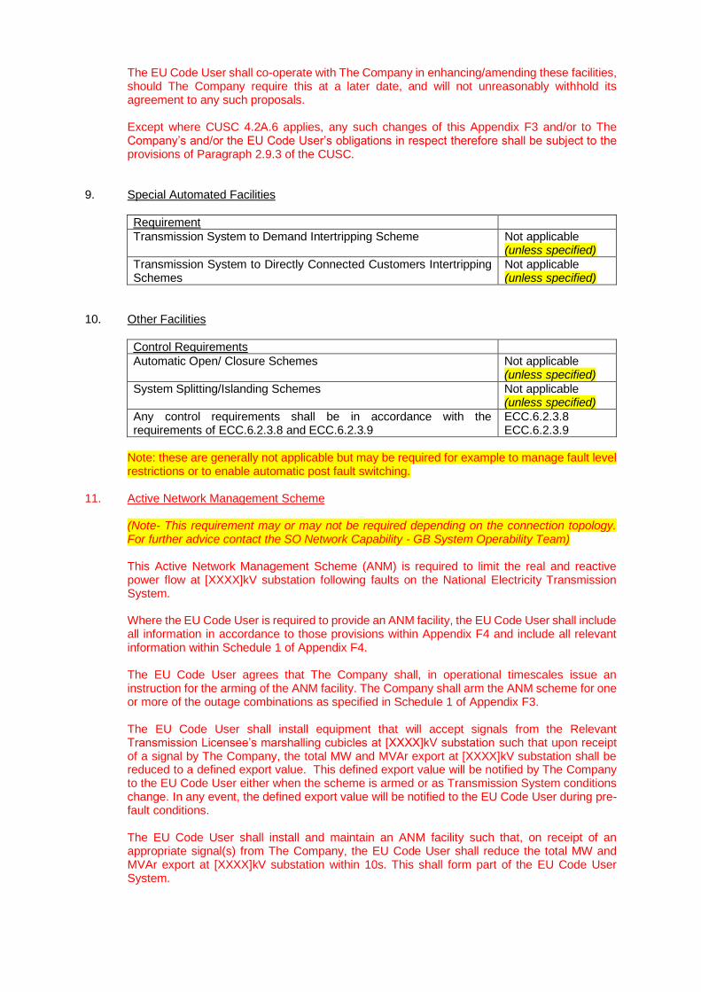
The EU Code User shall co-operate with The Company in enhancing/amending these facilities, should The Company require this at a later date, and will not unreasonably withhold its agreement to any such proposals. Except where CUSC 4.2A.6 applies, any such changes of this Appendix F3 and/or to The Company’s and/or the EU Code User’s obligations in respect therefore shall be subject to the provisions of Paragraph 2.9.3 of the CUSC.
9. Special Automated Facilities
Requirement
Transmission System to Demand Intertripping Scheme Not applicable (unless specified)
Transmission System to Directly Connected Customers Intertripping Schemes
Not applicable (unless specified)
10. Other Facilities
Control Requirements
Automatic Open/ Closure Schemes Not applicable (unless specified)
System Splitting/Islanding Schemes Not applicable (unless specified)
Any control requirements shall be in accordance with the requirements of ECC.6.2.3.8 and ECC.6.2.3.9
ECC.6.2.3.8 ECC.6.2.3.9
Note: these are generally not applicable but may be required for example to manage fault level restrictions or to enable automatic post fault switching.
11. Active Network Management Scheme (Note- This requirement may or may not be required depending on the connection topology. For further advice contact the SO Network Capability - GB System Operability Team) This Active Network Management Scheme (ANM) is required to limit the real and reactive power flow at [XXXX]kV substation following faults on the National Electricity Transmission System. Where the EU Code User is required to provide an ANM facility, the EU Code User shall include all information in accordance to those provisions within Appendix F4 and include all relevant information within Schedule 1 of Appendix F4. The EU Code User agrees that The Company shall, in operational timescales issue an instruction for the arming of the ANM facility. The Company shall arm the ANM scheme for one or more of the outage combinations as specified in Schedule 1 of Appendix F3. The EU Code User shall install equipment that will accept signals from the Relevant Transmission Licensee’s marshalling cubicles at [XXXX]kV substation such that upon receipt of a signal by The Company, the total MW and MVAr export at [XXXX]kV substation shall be reduced to a defined export value. This defined export value will be notified by The Company to the EU Code User either when the scheme is armed or as Transmission System conditions change. In any event, the defined export value will be notified to the EU Code User during pre-fault conditions. The EU Code User shall install and maintain an ANM facility such that, on receipt of an appropriate signal(s) from The Company, the EU Code User shall reduce the total MW and MVAr export at [XXXX]kV substation within 10s. This shall form part of the EU Code User System.
The ANM scheme will be monitored to ensure it is healthy at all times and provide indications to The Company. The functionality, performance, availability, accuracy, dependability, security and repair times of the communications links, trip facilities and monitoring facilities provided by the EU Code User from the Relevant Transmission Licensee’s marshalling cubicles located in [XXXX]kV substation to the EU Code User’s interface shall be agreed with The Company at least 24 months before the Completion Date.. (if quicker connection then this should be flexible on a case by case basis please refer to the J) In the event that the ANM is not healthy, The Company shall instruct the course of action to be taken. In the worst case, the EU Code User may be required to reduce the MW and MVAr export capacity at [XXXX]kV substation as required by The Company. No single hardware, software, system, communication, interface or power supply failure or depletion of facility shall result in failure to trip within the specified time or an incorrect control action. The EU Code User shall install isolation facilities to locally switch the ANM facility out of service. The EU Code User shall not isolate the intertripping facility unless otherwise agreed with the Company. For the avoidance of doubt, the Relevant Transmission Licensee will provide the necessary signals at the marshalling cubicle within [XXXX]kV substation. The EU Code User is responsible for the installation and maintenance of the cabling between the marshalling cubicle and the EU Code User’s interface equipment.
12. SGT Reverse Power Flow Control Scheme In order to protect the Relevant Transmission Licensee’s Supergrid Transformers (SGTs) from the risk of trip as a result of excessive overloads from the Embedded Generation installed within the [XXXX] group, the EU Code User is required to design, own, operate and install an SGT Reverse Power Flow Control Scheme (referred to in this technical appendix as “the Scheme”). The Scheme will be required to control the pre-fault loading on the Grid Supply Point as well as provide the means in effect to intertrip embedded generation in the case of an SGT fault. It is the EU Code User’s responsibility to design the SGT Reverse Power Flow Control Scheme to manage the embedded generation levels such that the total export limit at [XXXX]kV Substation is limited to the values defined in Schedule 2 of Appendix F3 under both intact and planned outage conditions. The scheme must be permanently armed and meet the following requirements. The EU Code User shall ensure that the Scheme is capable of maintaining the pre-fault loading on each of the SGTs [XXXX] kV Substation within the limits specified by The Company as detailed in Schedule 2 of Appendix F3. In addition, the EU Code User’s scheme shall ensure that the post fault export across each of the SGTs at [XXXX]kV Substation remain in the time dependant values specified in Schedule 2 of Appendix F3 and are reduced to the post fault steady state values specified in Schedule 2 of Appendix F3 within the time specified in the table. The EU Code User may choose to use either the short term overload values specified in column 3 or column 4 of Schedule 2 of Appendix F3, but it is not permissible to use both in succession. This shall form part of the EU Code User System. The Scheme will be monitored to ensure it is healthy at all times. The EU Code User shall inform The Company and the Relevant Transmission Licensee of any issues related to the scheme that impact on the operation of the Transmission System. In the event that the scheme is not healthy, the EU Code User will take measures to ensure the Connection Asset Reverse Power Limit defined in Appendix G Schedule 1 part 5 is met. The Relevant Transmission Licensee will provide the necessary SGT signals (CT, VT and plant status) at a marshalling cubicle within [XXXX] kV substation (ie the Grid Supply Point).
The EU Code User shall be responsible for taking these signals from the Grid Supply Point to the EU Code User’s Scheme. Any additional equipment required to adapt the above signals to the EU Code User’s scheme requirements shall be supplied, installed, commissioned and maintained by the EU Code User. The scheme and associated interface engineering shall be jointly agreed between The Company, the Relevant Transmission Licensee, and the EU Code User at least [XXXX] months before the Completion Date (Stage 1). The EU Code User shall demonstrate the suitability of the scheme to The Company through engagement at the detailed design phase, factory tests and on site performance validation tests. The requirements shall be agreed with The Company at least [XXXX] months before the Completion Date (Stage 1). In addition, the EU Code User is also required to supply the additional information as detailed below for agreement with The Company and the Relevant Transmission Licensee at least [XXXX] months before the Completion Date (Stage 1). The EU Code User shall be responsible for the installation, maintenance and overall costs of the Scheme. For the avoidance of doubt this scheme does not and will not replace the existing SGT Transformer protection. SGT Reverse Power Flow Control Design Settings As part of the design of the SGT Reverse Power Flow Control Scheme the EU Code User is required to provide The Company and the Relevant Transmission Licensee with details of the following:- • SGT overload response profiles • Automatic response times • Deload / trip Settings • Failure detection times • Number of preselected de-load settings • Additional information as may reasonably be required by The Company and the Relevant
Transmission Licensee during the detailed design phase. The above information is required to be submitted by the EU Code User and supplied to The Company and the Relevant Transmission Licensee as part of the Compliance Process at least [XXXX] months before the Completion Date (Stage 1).
13. Synchronising (ECC.6.2.3.10) (England and Wales) NOTE:- Where National Grid owns the LV busbars, use the following paragraph and delete all others. In addition to the requirements of ECC.6.2.3.10 the EU Code User will be required to provide measurement of the voltage on the EU Code User’s incoming feeders (on circuits where there is a possibility of back feed) to the Relevant Transmission Licensee’s voltage selection scheme in accordance with TS.3.24.60_RES. NOTE:- Where National Grid does not own the LV busbars, delete other paragraphs and use the following: In addition to the requirements of ECC.6.2.3.10 the EU Code User will be required to provide measurement of the busbar voltage references in accordance with TS.3.24.60_RES via a voltage selection scheme to enable the Relevant Transmission Licensee to carry out
synchronising of its circuits. The Relevant Transmission Licensee will also contribute to the EU Code User’s voltage selection scheme. (Scotland) NOTE:- for all Scottish demand agreements use the following paragraph. In addition to the requirements of ECC.6.2.3.10 the EU Code User will be required to provide measurement of the busbar voltage in accordance with the SPTS/SHETS as part of the synchronising facility, and for use as part of the Automatic Control Scheme employed on the transformer circuits (where such a facility is installed). There is no requirement for a synchronising facility between the Embedded Generator and the Transmission System. (this para for BELLAs only) For traction agreements, use the following paragraph and delete all others, if there is a possibility of a back feed further information should be sought from Asset Engineering/Core Construction: In addition to the requirements of ECC.6.2.3.10, the EU Code User shall ensure that an interlocking scheme is provided to prevent the risk of back feeding the National Electricity Transmission System. NOTE:- For a DSB/non-embedded customer, delete the above paragraphs and use the following (this assumes the User owns the busbar): In addition to the requirements of ECC.6.2.3.10, the EU Code User will be required to provide measurement of the busbar voltage in accordance with TS.3.24.60_RES/SPTS/SHETS as part of the synchronising facility. The details of such an arrangement will be discussed and agreed in the detailed design phase. This will be no longer than 12 months before the Completion Date (Stage 1).
14. Automatic Voltage Control Not applicable for BELLAs, and for traction agreements, in most traction agreements it is likely that a HV ATCC will be specified and no User requirement will be necessary. The exception to this rule would be in the event of a non-standard ownership or connection agreement (eg where the owner owns the Transformer). This should be advised by the relevant TO. Not less than 3 months before the Commissioning Programme Commencement Date for the agreed works, the EU Code User will agree settings for the Automatic Tap Change Control (ATCC) with The Company and Relevant Transmission Licensee. Any subsequent alterations to the ATCC settings shall be agreed between The Company, the Relevant Transmission Licensee and the EU Code User. It is envisaged that the new SGT(s) will be integrated into the existing SGT Automatic Voltage Control System. (this para where applicable) The EU Code User must also provide switchgear status relevant to busbar topology and voltage references to The Company and Relevant Transmission Licensee to enable The Company in coordination with the Relevant Transmission Licensee to implement ATCC to control the 132kV/66kV/33kV/11kV busbar voltage. (this para E&W DNO only and not relevant if NG owns the 132kV busbar (unless specified in the TOCO)) (Select voltage based on point of connection)

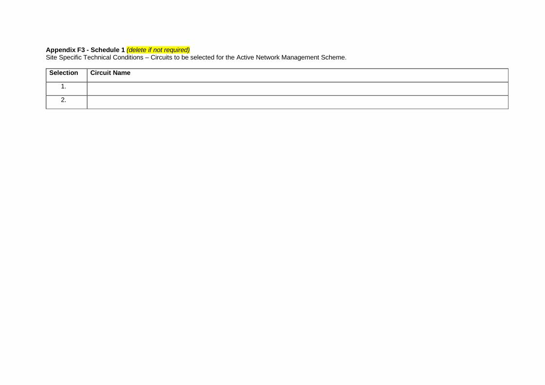
Appendix F3 - Schedule 1 (delete if not required) Site Specific Technical Conditions – Circuits to be selected for the Active Network Management Scheme.
Selection Circuit Name
1.
2.

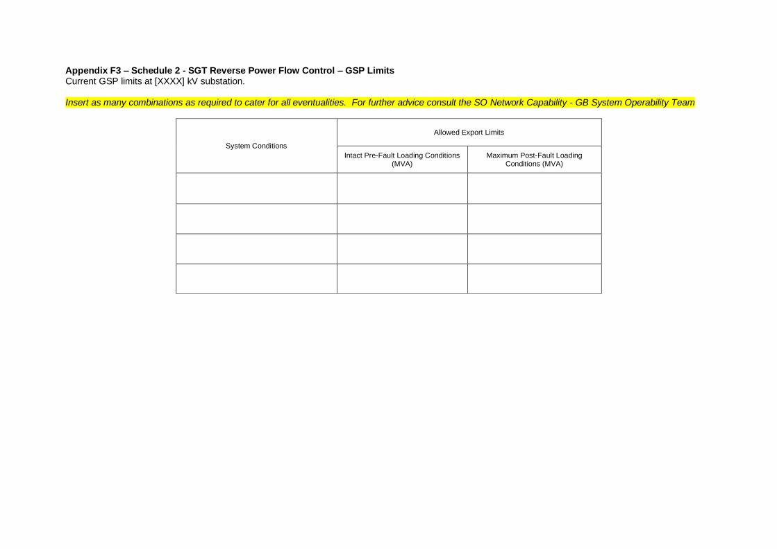
Appendix F3 – Schedule 2 - SGT Reverse Power Flow Control – GSP Limits Current GSP limits at [XXXX] kV substation. Insert as many combinations as required to cater for all eventualities. For further advice consult the SO Network Capability - GB System Operability Team
System Conditions
Allowed Export Limits
Intact Pre-Fault Loading Conditions (MVA)
Maximum Post-Fault Loading Conditions (MVA)

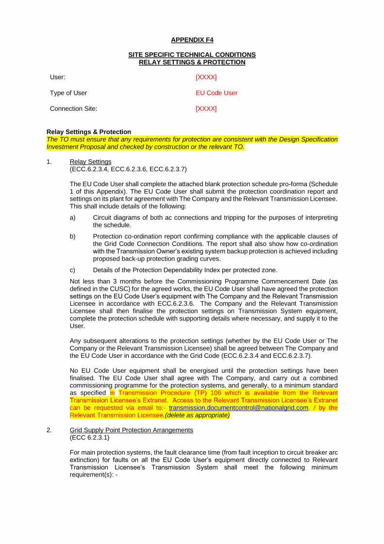
APPENDIX F4
SITE SPECIFIC TECHNICAL CONDITIONS RELAY SETTINGS & PROTECTION
User: [XXXX]
Type of User EU Code User
Connection Site: [XXXX]
Relay Settings & Protection The TO must ensure that any requirements for protection are consistent with the Design Specification Investment Proposal and checked by construction or the relevant TO. 1. Relay Settings
(ECC.6.2.3.4, ECC.6.2.3.6, ECC.6.2.3.7) The EU Code User shall complete the attached blank protection schedule pro-forma (Schedule 1 of this Appendix). The EU Code User shall submit the protection coordination report and settings on its plant for agreement with The Company and the Relevant Transmission Licensee. This shall include details of the following:
a) Circuit diagrams of both ac connections and tripping for the purposes of interpreting the schedule.
b) Protection co-ordination report confirming compliance with the applicable clauses of the Grid Code Connection Conditions. The report shall also show how co-ordination with the Transmission Owner’s existing system backup protection is achieved including proposed back-up protection grading curves.
c) Details of the Protection Dependability Index per protected zone.
Not less than 3 months before the Commissioning Programme Commencement Date (as defined in the CUSC) for the agreed works, the EU Code User shall have agreed the protection settings on the EU Code User’s equipment with The Company and the Relevant Transmission Licensee in accordance with ECC.6.2.3.6. The Company and the Relevant Transmission Licensee shall then finalise the protection settings on Transmission System equipment, complete the protection schedule with supporting details where necessary, and supply it to the User. Any subsequent alterations to the protection settings (whether by the EU Code User or The Company or the Relevant Transmission Licensee) shall be agreed between The Company and the EU Code User in accordance with the Grid Code (ECC.6.2.3.4 and ECC.6.2.3.7). No EU Code User equipment shall be energised until the protection settings have been finalised. The EU Code User shall agree with The Company, and carry out a combined commissioning programme for the protection systems, and generally, to a minimum standard as specified in Transmission Procedure (TP) 106 which is available from the Relevant Transmission Licensee’s Extranet. Access to the Relevant Transmission Licensee’s Extranet can be requested via email to:- [email protected]. / by the Relevant Transmission Licensee.(delete as appropriate)
2. Grid Supply Point Protection Arrangements (ECC 6.2.3.1) For main protection systems, the fault clearance time (from fault inception to circuit breaker arc extinction) for faults on all the EU Code User’s equipment directly connected to Relevant Transmission Licensee’s Transmission System shall meet the following minimum requirement(s): -
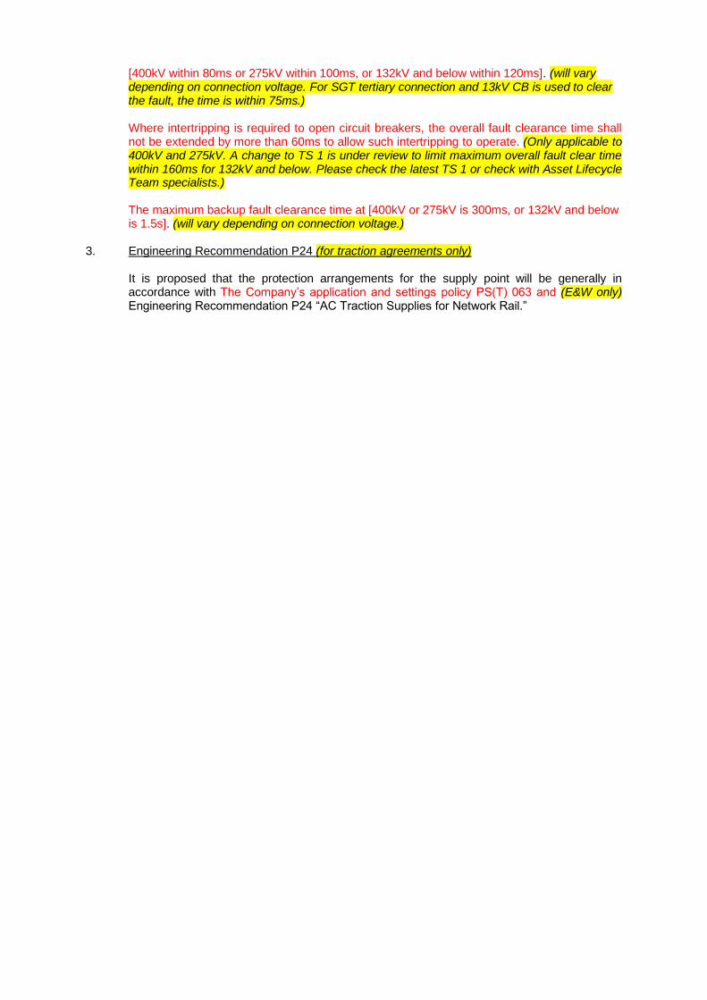
[400kV within 80ms or 275kV within 100ms, or 132kV and below within 120ms]. (will vary depending on connection voltage. For SGT tertiary connection and 13kV CB is used to clear the fault, the time is within 75ms.) Where intertripping is required to open circuit breakers, the overall fault clearance time shall not be extended by more than 60ms to allow such intertripping to operate. (Only applicable to 400kV and 275kV. A change to TS 1 is under review to limit maximum overall fault clear time within 160ms for 132kV and below. Please check the latest TS 1 or check with Asset Lifecycle Team specialists.) The maximum backup fault clearance time at [400kV or 275kV is 300ms, or 132kV and below is 1.5s]. (will vary depending on connection voltage.)
3. Engineering Recommendation P24 (for traction agreements only) It is proposed that the protection arrangements for the supply point will be generally in accordance with The Company’s application and settings policy PS(T) 063 and (E&W only) Engineering Recommendation P24 “AC Traction Supplies for Network Rail.”
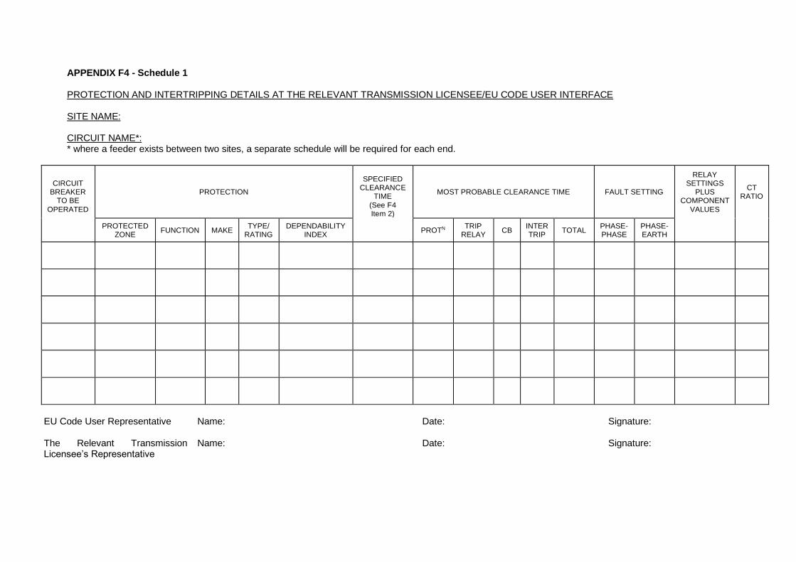
APPENDIX F4 - Schedule 1 PROTECTION AND INTERTRIPPING DETAILS AT THE RELEVANT TRANSMISSION LICENSEE/EU CODE USER INTERFACE SITE NAME: CIRCUIT NAME*: * where a feeder exists between two sites, a separate schedule will be required for each end.
CIRCUIT
BREAKER TO BE
OPERATED
PROTECTION
SPECIFIED CLEARANCE
TIME
(See F4 Item 2)
MOST PROBABLE CLEARANCE TIME FAULT SETTING
RELAY SETTINGS
PLUS COMPONENT
VALUES
CT RATIO
PROTECTED ZONE
FUNCTION MAKE TYPE/
RATING DEPENDABILITY
INDEX PROTN
TRIP RELAY
CB INTER TRIP
TOTAL PHASE- PHASE
PHASE- EARTH
EU Code User Representative Name: Date: Signature: The Relevant Transmission Licensee’s Representative
Name: Date: Signature:
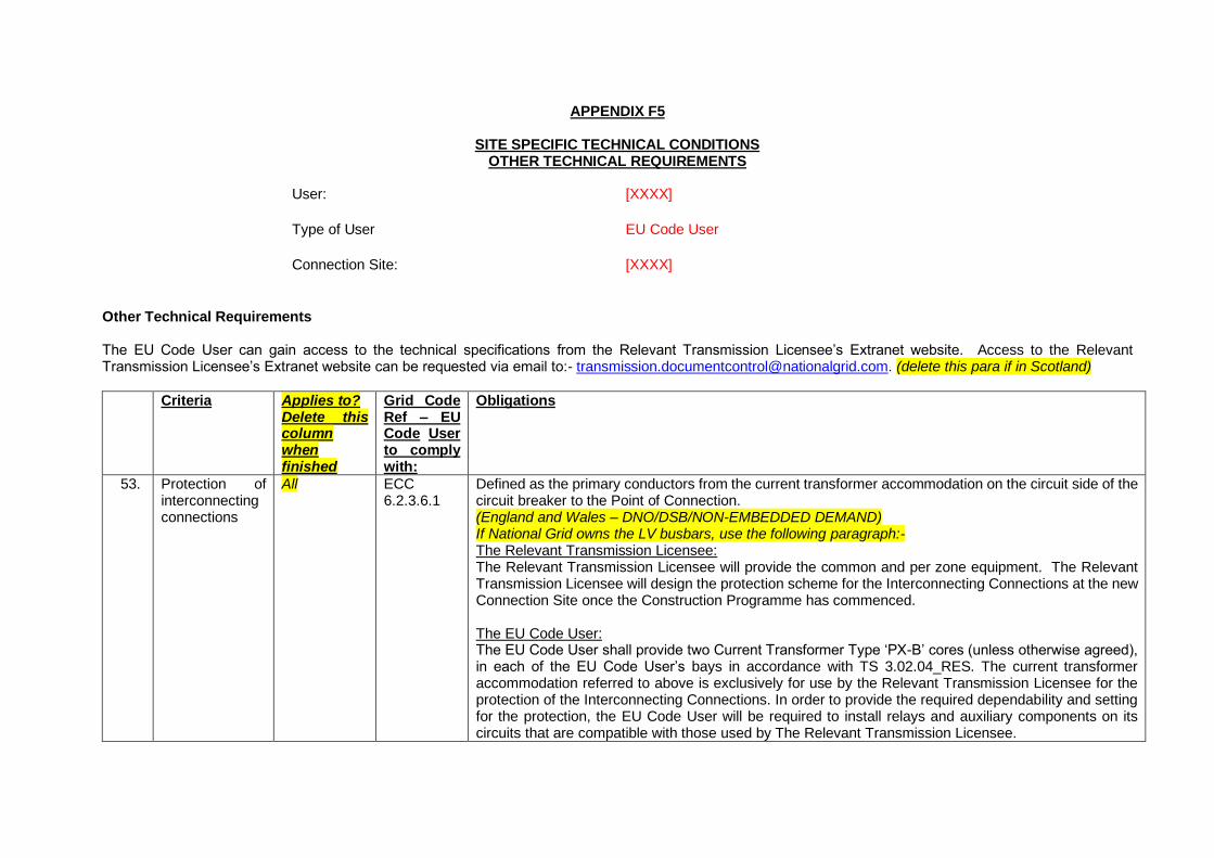
APPENDIX F5
SITE SPECIFIC TECHNICAL CONDITIONS OTHER TECHNICAL REQUIREMENTS
User: [XXXX]
Type of User EU Code User
Connection Site: [XXXX]
Other Technical Requirements The EU Code User can gain access to the technical specifications from the Relevant Transmission Licensee’s Extranet website. Access to the Relevant Transmission Licensee’s Extranet website can be requested via email to:- [email protected]. (delete this para if in Scotland)
Criteria Applies to? Delete this column when finished
Grid Code Ref – EU Code User to comply with:
Obligations
53. Protection of interconnecting connections
All ECC 6.2.3.6.1
Defined as the primary conductors from the current transformer accommodation on the circuit side of the circuit breaker to the Point of Connection. (England and Wales – DNO/DSB/NON-EMBEDDED DEMAND) If National Grid owns the LV busbars, use the following paragraph:- The Relevant Transmission Licensee: The Relevant Transmission Licensee will provide the common and per zone equipment. The Relevant Transmission Licensee will design the protection scheme for the Interconnecting Connections at the new Connection Site once the Construction Programme has commenced. The EU Code User: The EU Code User shall provide two Current Transformer Type ‘PX-B’ cores (unless otherwise agreed), in each of the EU Code User’s bays in accordance with TS 3.02.04_RES. The current transformer accommodation referred to above is exclusively for use by the Relevant Transmission Licensee for the protection of the Interconnecting Connections. In order to provide the required dependability and setting for the protection, the EU Code User will be required to install relays and auxiliary components on its circuits that are compatible with those used by The Relevant Transmission Licensee.
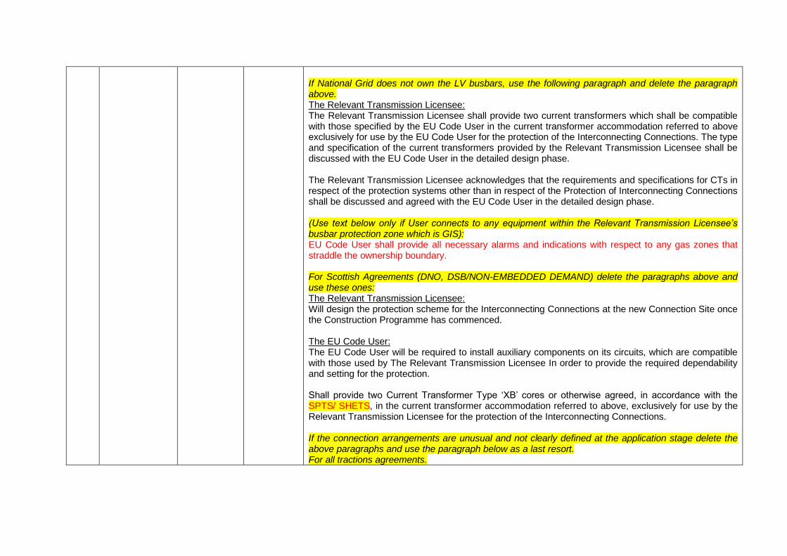
If National Grid does not own the LV busbars, use the following paragraph and delete the paragraph above. The Relevant Transmission Licensee: The Relevant Transmission Licensee shall provide two current transformers which shall be compatible with those specified by the EU Code User in the current transformer accommodation referred to above exclusively for use by the EU Code User for the protection of the Interconnecting Connections. The type and specification of the current transformers provided by the Relevant Transmission Licensee shall be discussed with the EU Code User in the detailed design phase. The Relevant Transmission Licensee acknowledges that the requirements and specifications for CTs in respect of the protection systems other than in respect of the Protection of Interconnecting Connections shall be discussed and agreed with the EU Code User in the detailed design phase. (Use text below only if User connects to any equipment within the Relevant Transmission Licensee’s busbar protection zone which is GIS): EU Code User shall provide all necessary alarms and indications with respect to any gas zones that straddle the ownership boundary. For Scottish Agreements (DNO, DSB/NON-EMBEDDED DEMAND) delete the paragraphs above and use these ones: The Relevant Transmission Licensee: Will design the protection scheme for the Interconnecting Connections at the new Connection Site once the Construction Programme has commenced. The EU Code User: The EU Code User will be required to install auxiliary components on its circuits, which are compatible with those used by The Relevant Transmission Licensee In order to provide the required dependability and setting for the protection. Shall provide two Current Transformer Type ‘XB’ cores or otherwise agreed, in accordance with the SPTS/ SHETS, in the current transformer accommodation referred to above, exclusively for use by the Relevant Transmission Licensee for the protection of the Interconnecting Connections. If the connection arrangements are unusual and not clearly defined at the application stage delete the above paragraphs and use the paragraph below as a last resort. For all tractions agreements.
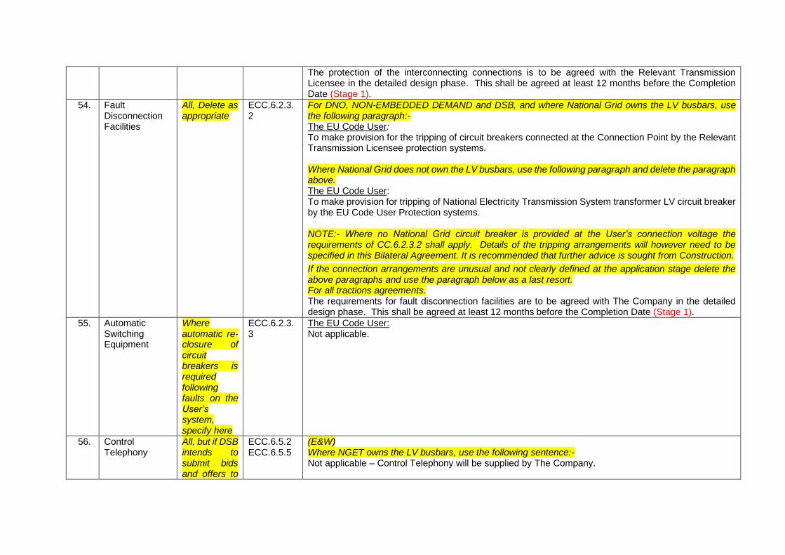
The protection of the interconnecting connections is to be agreed with the Relevant Transmission Licensee in the detailed design phase. This shall be agreed at least 12 months before the Completion Date (Stage 1).
54. Fault Disconnection Facilities
All, Delete as appropriate
ECC.6.2.3.2
For DNO, NON-EMBEDDED DEMAND and DSB, and where National Grid owns the LV busbars, use the following paragraph:- The EU Code User: To make provision for the tripping of circuit breakers connected at the Connection Point by the Relevant Transmission Licensee protection systems. Where National Grid does not own the LV busbars, use the following paragraph and delete the paragraph above. The EU Code User: To make provision for tripping of National Electricity Transmission System transformer LV circuit breaker by the EU Code User Protection systems. NOTE:- Where no National Grid circuit breaker is provided at the User’s connection voltage the requirements of CC.6.2.3.2 shall apply. Details of the tripping arrangements will however need to be specified in this Bilateral Agreement. It is recommended that further advice is sought from Construction.
If the connection arrangements are unusual and not clearly defined at the application stage delete the above paragraphs and use the paragraph below as a last resort. For all tractions agreements. The requirements for fault disconnection facilities are to be agreed with The Company in the detailed design phase. This shall be agreed at least 12 months before the Completion Date (Stage 1).
55. Automatic Switching Equipment
Where automatic re-closure of circuit breakers is required following faults on the User’s system, specify here
ECC.6.2.3.3
The EU Code User: Not applicable.
56. Control Telephony
All, but if DSB intends to submit bids and offers to
ECC.6.5.2 ECC.6.5.5
(E&W) Where NGET owns the LV busbars, use the following sentence:- Not applicable – Control Telephony will be supplied by The Company.
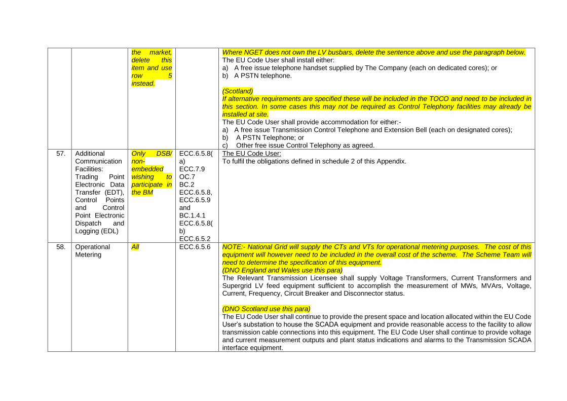
the market, delete this item and use row 5 instead.
Where NGET does not own the LV busbars, delete the sentence above and use the paragraph below. The EU Code User shall install either: a) A free issue telephone handset supplied by The Company (each on dedicated cores); or b) A PSTN telephone. (Scotland) If alternative requirements are specified these will be included in the TOCO and need to be included in this section. In some cases this may not be required as Control Telephony facilities may already be installed at site. The EU Code User shall provide accommodation for either:- a) A free issue Transmission Control Telephone and Extension Bell (each on designated cores); b) A PSTN Telephone; or c) Other free issue Control Telephony as agreed.
57. Additional Communication Facilities: Trading Point Electronic Data Transfer (EDT), Control Points and Control Point Electronic Dispatch and Logging (EDL)
Only DSB/ non-embedded wishing to participate in the BM
ECC.6.5.8(a) ECC.7.9 OC.7 BC.2 ECC.6.5.8, ECC.6.5.9 and BC.1.4.1 ECC.6.5.8(b) ECC.6.5.2
The EU Code User: To fulfil the obligations defined in schedule 2 of this Appendix.
58. Operational Metering
All ECC.6.5.6 NOTE:- National Grid will supply the CTs and VTs for operational metering purposes. The cost of this equipment will however need to be included in the overall cost of the scheme. The Scheme Team will need to determine the specification of this equipment. (DNO England and Wales use this para) The Relevant Transmission Licensee shall supply Voltage Transformers, Current Transformers and Supergrid LV feed equipment sufficient to accomplish the measurement of MWs, MVArs, Voltage, Current, Frequency, Circuit Breaker and Disconnector status. (DNO Scotland use this para) The EU Code User shall continue to provide the present space and location allocated within the EU Code User’s substation to house the SCADA equipment and provide reasonable access to the facility to allow transmission cable connections into this equipment. The EU Code User shall continue to provide voltage and current measurement outputs and plant status indications and alarms to the Transmission SCADA interface equipment.
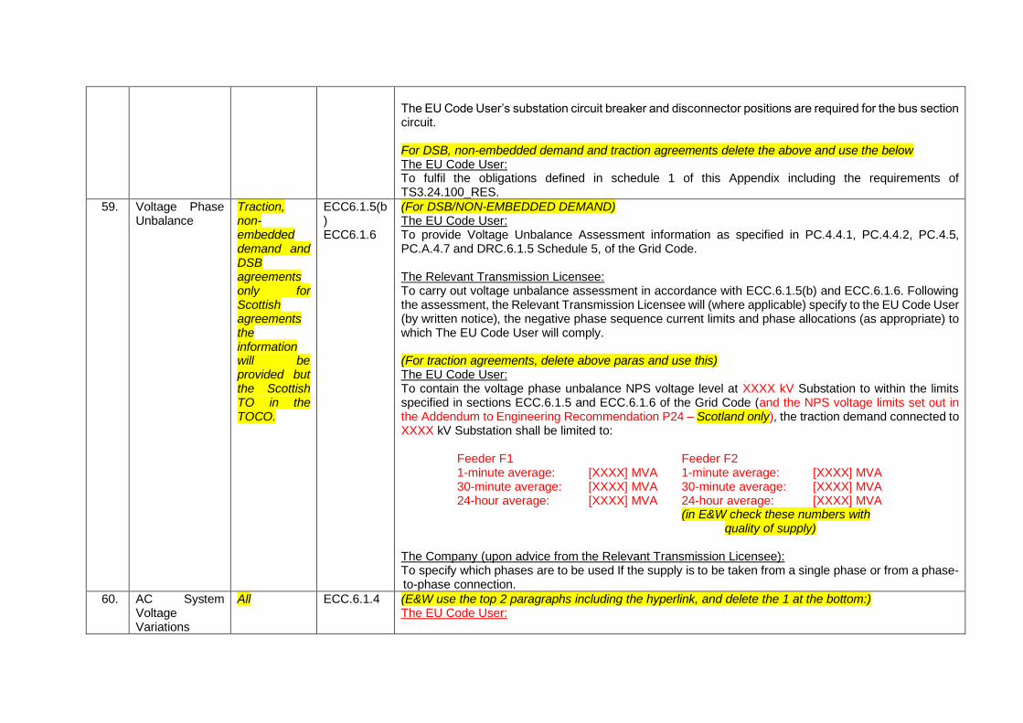
The EU Code User’s substation circuit breaker and disconnector positions are required for the bus section circuit. For DSB, non-embedded demand and traction agreements delete the above and use the below The EU Code User: To fulfil the obligations defined in schedule 1 of this Appendix including the requirements of TS3.24.100_RES.
59. Voltage Phase Unbalance
Traction, non-embedded demand and DSB agreements only for Scottish agreements the information will be provided but the Scottish TO in the TOCO.
ECC6.1.5(b) ECC6.1.6
(For DSB/NON-EMBEDDED DEMAND) The EU Code User: To provide Voltage Unbalance Assessment information as specified in PC.4.4.1, PC.4.4.2, PC.4.5, PC.A.4.7 and DRC.6.1.5 Schedule 5, of the Grid Code. The Relevant Transmission Licensee: To carry out voltage unbalance assessment in accordance with ECC.6.1.5(b) and ECC.6.1.6. Following the assessment, the Relevant Transmission Licensee will (where applicable) specify to the EU Code User (by written notice), the negative phase sequence current limits and phase allocations (as appropriate) to which The EU Code User will comply. (For traction agreements, delete above paras and use this) The EU Code User: To contain the voltage phase unbalance NPS voltage level at XXXX kV Substation to within the limits specified in sections ECC.6.1.5 and ECC.6.1.6 of the Grid Code (and the NPS voltage limits set out in the Addendum to Engineering Recommendation P24 – Scotland only), the traction demand connected to XXXX kV Substation shall be limited to:
Feeder F1 Feeder F2 1-minute average: [XXXX] MVA 30-minute average: [XXXX] MVA 24-hour average: [XXXX] MVA
1-minute average: [XXXX] MVA 30-minute average: [XXXX] MVA 24-hour average: [XXXX] MVA (in E&W check these numbers with
quality of supply) The Company (upon advice from the Relevant Transmission Licensee): To specify which phases are to be used If the supply is to be taken from a single phase or from a phase-to-phase connection.
60. AC System Voltage Variations
All ECC.6.1.4 (E&W use the top 2 paragraphs including the hyperlink, and delete the 1 at the bottom:) The EU Code User:
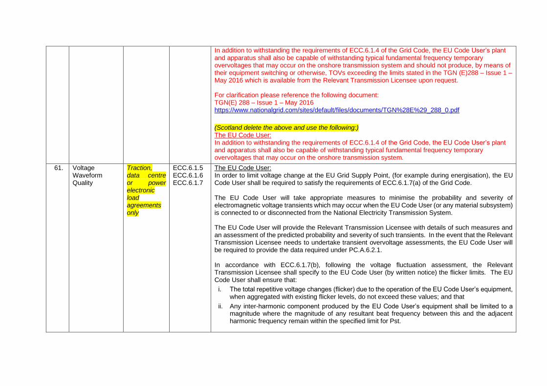
In addition to withstanding the requirements of ECC.6.1.4 of the Grid Code, the EU Code User’s plant and apparatus shall also be capable of withstanding typical fundamental frequency temporary overvoltages that may occur on the onshore transmission system and should not produce, by means of their equipment switching or otherwise, TOVs exceeding the limits stated in the TGN (E)288 – Issue 1 – May 2016 which is available from the Relevant Transmission Licensee upon request. For clarification please reference the following document: TGN(E) 288 – Issue 1 – May 2016 https://www.nationalgrid.com/sites/default/files/documents/TGN%28E%29_288_0.pdf
(Scotland delete the above and use the following:) The EU Code User: In addition to withstanding the requirements of ECC.6.1.4 of the Grid Code, the EU Code User’s plant and apparatus shall also be capable of withstanding typical fundamental frequency temporary overvoltages that may occur on the onshore transmission system.
61. Voltage Waveform Quality
Traction, data centre or power electronic load agreements only
ECC.6.1.5 ECC.6.1.6 ECC.6.1.7
The EU Code User: In order to limit voltage change at the EU Grid Supply Point, (for example during energisation), the EU Code User shall be required to satisfy the requirements of ECC.6.1.7(a) of the Grid Code. The EU Code User will take appropriate measures to minimise the probability and severity of electromagnetic voltage transients which may occur when the EU Code User (or any material subsystem) is connected to or disconnected from the National Electricity Transmission System. The EU Code User will provide the Relevant Transmission Licensee with details of such measures and an assessment of the predicted probability and severity of such transients. In the event that the Relevant Transmission Licensee needs to undertake transient overvoltage assessments, the EU Code User will be required to provide the data required under PC.A.6.2.1. In accordance with ECC.6.1.7(b), following the voltage fluctuation assessment, the Relevant Transmission Licensee shall specify to the EU Code User (by written notice) the flicker limits. The EU Code User shall ensure that:
i. The total repetitive voltage changes (flicker) due to the operation of the EU Code User’s equipment, when aggregated with existing flicker levels, do not exceed these values; and that
ii. Any inter-harmonic component produced by the EU Code User’s equipment shall be limited to a magnitude where the magnitude of any resultant beat frequency between this and the adjacent harmonic frequency remain within the specified limit for Pst.
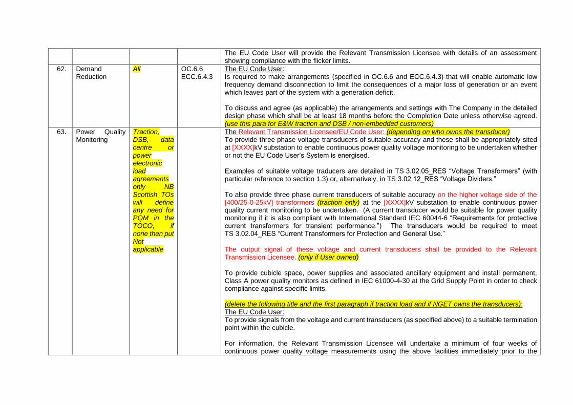
The EU Code User will provide the Relevant Transmission Licensee with details of an assessment showing compliance with the flicker limits.
62. Demand Reduction
All OC.6.6 ECC.6.4.3
The EU Code User: Is required to make arrangements (specified in OC.6.6 and ECC.6.4.3) that will enable automatic low frequency demand disconnection to limit the consequences of a major loss of generation or an event which leaves part of the system with a generation deficit. To discuss and agree (as applicable) the arrangements and settings with The Company in the detailed design phase which shall be at least 18 months before the Completion Date unless otherwise agreed. (use this para for E&W traction and DSB / non-embedded customers)
63. Power Quality Monitoring
Traction, DSB, data centre or power electronic load agreements only NB Scottish TOs will define any need for PQM in the TOCO, if none then put Not applicable
The Relevant Transmission Licensee/EU Code User: (depending on who owns the transducer) To provide three phase voltage transducers of suitable accuracy and these shall be appropriately sited at [XXXX]kV substation to enable continuous power quality voltage monitoring to be undertaken whether or not the EU Code User’s System is energised. Examples of suitable voltage traducers are detailed in TS 3.02.05_RES “Voltage Transformers” (with particular reference to section 1.3) or, alternatively, in TS 3.02.12_RES “Voltage Dividers.” To also provide three phase current transducers of suitable accuracy on the higher voltage side of the [400/25-0-25kV] transformers (traction only) at the [XXXX]kV substation to enable continuous power quality current monitoring to be undertaken. (A current transducer would be suitable for power quality monitoring if it is also compliant with International Standard IEC 60044-6 “Requirements for protective current transformers for transient performance.”) The transducers would be required to meet TS 3.02.04_RES “Current Transformers for Protection and General Use.” The output signal of these voltage and current transducers shall be provided to the Relevant Transmission Licensee. (only if User owned) To provide cubicle space, power supplies and associated ancillary equipment and install permanent, Class A power quality monitors as defined in IEC 61000-4-30 at the Grid Supply Point in order to check compliance against specific limits. (delete the following title and the first paragraph if traction load and if NGET owns the transducers): The EU Code User: To provide signals from the voltage and current transducers (as specified above) to a suitable termination point within the cubicle. For information, the Relevant Transmission Licensee will undertake a minimum of four weeks of continuous power quality voltage measurements using the above facilities immediately prior to the
energisation of the EU Code User’s feeders to establish a baseline for compliance with the Grid Code. Continuous power quality monitoring will then be performed during and after commissioning. The current transducers in each EU Code User’s feeder shall be sited such that the monitored currents include any contribution from reactive power compensation and/or harmonic mitigation equipment. (traction only)
64. Harmonic Content
Traction, DSB, data centre or power electronic load agreements only
ECC.6.1.5(a)
The EU Code User: Shall provide The Company and Relevant Transmission Licensee with Harmonic Assessment information (as specified in PC.4.4.1, PC.4.4.2, PC.4.5, PC.A.4.7, DRC.6.1.5 Schedule 5, DRC.6.1.7 Schedule 7 of the Grid Code) so that the Relevant Transmission Licensee can carry out an harmonic voltage distortion assessment in accordance with Grid Code Conditions ECC.6.1.5(a). If regenerative braking is to be employed, this shall be explicitly stated in the Harmonic Assessment information and the effect of it shall be included in the data provided to The Company and Relevant Transmission Licensee. (this para for traction agreements only) The Company (upon advice from the Relevant Transmission Licensee): Following the above assessment, will specify to the EU Code User (by written notice), the harmonic voltage distortion or harmonic current emission limits (as appropriate). The EU Code User shall comply with the above limits. The specification of the above limits will normally be calculated using the data provided by the EU Code User. If the EU Code User subsequently notifies The Company (who in turn will notify the Relevant Transmission Licensee) of any changes to this data, The Company (upon advice from the Relevant Transmission Licensee) reserves the right to amend the limits and to issue revised limits to the EU Code User following any revised Voltage Waveform Quality Assessment. (delete this para if it is a Scottish agreement)
65. Load Characteristics at the Grid Supply Point
DNO and data centres or power electronic load agreements only
The Relevant Transmission Licensee in coordination with The Company: Reserves the right to conduct detailed demand assessments on the [XXXX] kV substation load and offer advice on any special measures required. The Relevant Transmission Licensee does not envisage the need to undertake such an assessment but will monitor the connection point load characteristics through Technical Planning Meetings and any other means available. (for E&W DNO agreements only, use the following para) Power Factor: To ensure the network can be operated within statutory voltage limits, The Company will from time to time compare historic MW and MVAr flow data at the GSP interface across a year of operation with the
EU Code User’s week 24 submission. Where a discrepancy exists the EU Code User will co-operate with The Company and the Relevant Transmission Licensee to satisfactory resolve any resulting operational compliance issues.
66. Reactive Capability Limits
Applicable only to Non-Embedded Customers and totally new Distribution Systems who are classified as EU Code Users with EU Grid Supply Points
ECC.6.4.5 The EU Code User at its EU Grid Supply Point is required to satisfy the requirements of ECC.6.4.5. (Note – Where there is a requirement for specific reactive capability limits these need to be specified in this section but will need to be justified and agreed with the EU Code User).
67. Reactive Capability Limits
Existing Scottish DNO agreements only
In order to prevent the risk of high or low voltages occurring at [XXXX]kV substation and on adjacent [XXXX]kV Transmission circuits, the EU Code User shall be required to ensure that the connection of any Embedded Generation within the Network Operator’s System does not increase the current levels of reactive power exported or imported to [XXXX]kV substation beyond a maximum of +/-[XXXX]MVArs. (only to be used if there is a risk of high or low system volts as a result of the uncontrolled spill of MVArs from a DNO connection point
68. Paralleling Direct Connect only, all but DNO agreements
The EU Code User: To ensure there is no paralleling of The National Electricity Transmission System through the EU Code User’s System.
69. Safety and Operational Interlocking
All The EU Code User: Electrical and mechanical interlocking to be provided by the EU Code User in accordance with TS.3.01.01_RES/SPTS/SHETS. Scottish TOs will define in the TOCO, if not use this text
70. Earthing Facility All (For DNO, non-embedded demand and DSB) The Relevant Transmission Licensee: (DNO, non-embedded demand and DSB, delete this para if a traction agreement) Will provide at least two points within its substation(s) to facilitate any bonding with the EU Code User’s site if required.
All earth mats on the EU Code User site(s) and the Relevant Transmission Licensee’s site(s) where these are adjacent may be bonded together. The Relevant Transmission Licensee’s site earth mats can be bonded to the EU Code User’s site earth mat. (next 3 paras for traction agreements only) At this stage the earthing system appropriate to the Relevant Transmission Licensee and the EU Code User sites has not been fully established. The Relevant Transmission Licensee’s site earth mat would be expected in this instance to be bonded to the EU Code User’s site earth mat, excepting any equipment that the EU Code User installs at the Relevant Transmission Licensee’s site at [XXXX] kV substation. The Relevant Transmission Licensee can provide at least two points within its substation(s) to facilitate any bonding should this be required. Should the EU Code User’s site not be bonded to the Relevant Transmission Licensee’s Earthing mat, then the Earthing requirements will need to be discussed and agreed with The Company and Relevant Transmission Licensee in the detailed design phase. The earthing arrangements of the EU Code User’s [XXXX] kV Substation shall comply with ENA ER P24 (section 11) and an agreement of the connections between the Relevant Transmission Licensee’s substation earthing system and the supply return conductor side of the 25kV winding of the 400/25kV transformers shall also be finalised and agreed in the detailed design phase. (All) The EU Code User: To carry out an earthing survey of their sites prior to construction of the EU Code User’s Plant and Apparatus. The earthing system is to be designed to withstand a short circuit current of [XX kA for YY seconds]. (63 kA for 1 second at 400 kV substations, 40kA for 1 second at 275 kV substations and 40kA for 3 seconds at 132 kV substations) (Note this will depend on connection voltage and TO area). The EU Code User shall ensure that it’s Plant and Apparatus is designed and installed such that the rise of earth potential (ROEP) at [XXXX] kV substation conforms to the touch, step and transfer voltage limits which are defined in ENA TS 41 – 24. Where intertripping (second main protection) is required to open circuit breakers, the overall fault clearance time shall not be more than [XX]ms at [XXX]kV substations. The EU Code User’s earthing system design review shall take the Relevant Transmission Licensee’s earthing system design into account and the EU Code User shall collaborate with the Relevant Transmission Licensee to ensure that compliance has been demonstrated at the Grid Supply Point which also mitigates 3rd party impact as required.
The earthing system at [XXXX] kV substation shall be designed to comply with ESQCR 2002 and BS EN50522.
71. Settlement Metering
For DNO, new templates only and DSB, non-embedded demand or traction agreement,
ECC.6.2.2.3.5
The EU Code User: To provide CTs/VTs that comply with the relevant metering Code of Practice required for Settlement. To provide the Settlement Meters and register compliant items of Metering Equipment for Settlement purposes. Shall be responsible for registering compliant items of Metering Equipment for Settlement purposes, in accordance with the BSC and related procedures, with the relevant timescales and prior to energisation of the circuit. The EU Code User shall ensure that the Settlement Metering shall be compatible with all interfacing equipment installed by the Relevant Transmission Licensee at [XXXX]kV substation. All of the above to be completed prior to energisation and in accordance with the Balancing and Settlement Code (BSC).
72. Voltage Regulation at the Grid Supply Point
Only for DNO agreements with Embedded generation where a statement of works process has been instigated **!Ensure that the DNO is in agreement before adding this item!**
The EU Code User should be aware that Embedded Large and Embedded Medium Power Stations are required to satisfy the reactive capability and voltage control requirements of ECC.6.3.2, ECC.6.3.8 Grid Code. For Small Embedded Power Stations as defined in Appendix G Parts 2, 3 and 4 of this Connection Agreement, the EU Code User shall ensure that each Generating Unit or Power Park Module within each Embedded Small Power Station shall have a reactive capability of between 0.95 Power Factor Lead to 0.95 Power Factor Lag at Rated MW Output at the EU Code User System Entry Point. Subject to the provisions of 11.2.2 of this Connection Agreement, during the operational timeframe, the EU Code User shall instruct each Generating Unit or Power Park Module within each Embedded Small Power Station of its required operating Power Factor which shall be within the capability range of each Embedded Small Power Station defined in Appendix G Parts 2, 3 and 4 of this Connection Agreement. There is no restriction on the EU Code User if they wish to employ an alternative method to manage MVAr transfers at the Grid Supply Point, for example through the installation of reactive compensation equipment, intertripping Embedded Generation or the application of other suitable control schemes.
73. Emergency Instructions
Only for DNO agreements with Embedded generation where a
In accordance with the requirements of BC2.9.1.4, using the principles set out in OC6.7.1 the EU Code User shall maintain a facility such that under emergency conditions on the National Electricity Transmission System, the EU Code User shall have the ability to de-energise the Embedded Generation detailed in section 11.3 and Appendix G Parts 2, 3 and 4 of this Connection Agreement, upon instruction from The Company.
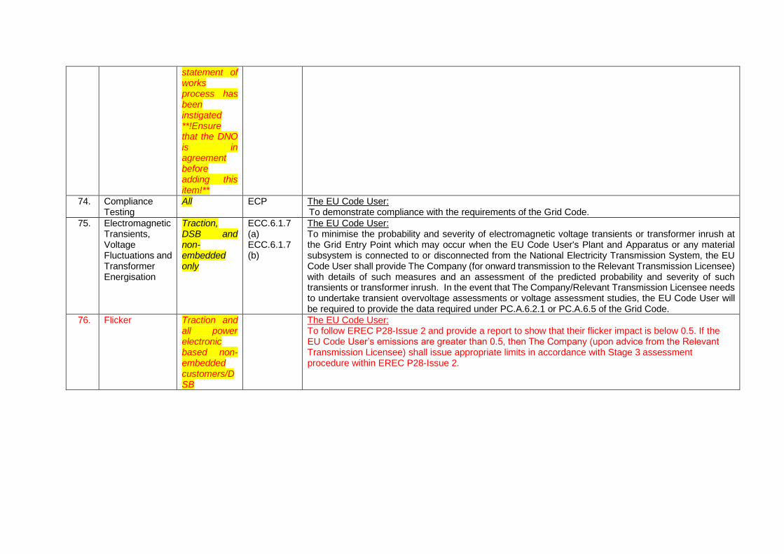
statement of works process has been instigated **!Ensure that the DNO is in agreement before adding this item!**
74. Compliance Testing
All ECP The EU Code User: To demonstrate compliance with the requirements of the Grid Code.
75. Electromagnetic Transients, Voltage Fluctuations and Transformer Energisation
Traction, DSB and non-embedded only
ECC.6.1.7 (a) ECC.6.1.7 (b)
The EU Code User: To minimise the probability and severity of electromagnetic voltage transients or transformer inrush at the Grid Entry Point which may occur when the EU Code User's Plant and Apparatus or any material subsystem is connected to or disconnected from the National Electricity Transmission System, the EU Code User shall provide The Company (for onward transmission to the Relevant Transmission Licensee) with details of such measures and an assessment of the predicted probability and severity of such transients or transformer inrush. In the event that The Company/Relevant Transmission Licensee needs to undertake transient overvoltage assessments or voltage assessment studies, the EU Code User will be required to provide the data required under PC.A.6.2.1 or PC.A.6.5 of the Grid Code.
76. Flicker Traction and all power electronic based non-embedded customers/DSB
The EU Code User: To follow EREC P28-Issue 2 and provide a report to show that their flicker impact is below 0.5. If the EU Code User’s emissions are greater than 0.5, then The Company (upon advice from the Relevant Transmission Licensee) shall issue appropriate limits in accordance with Stage 3 assessment procedure within EREC P28-Issue 2.
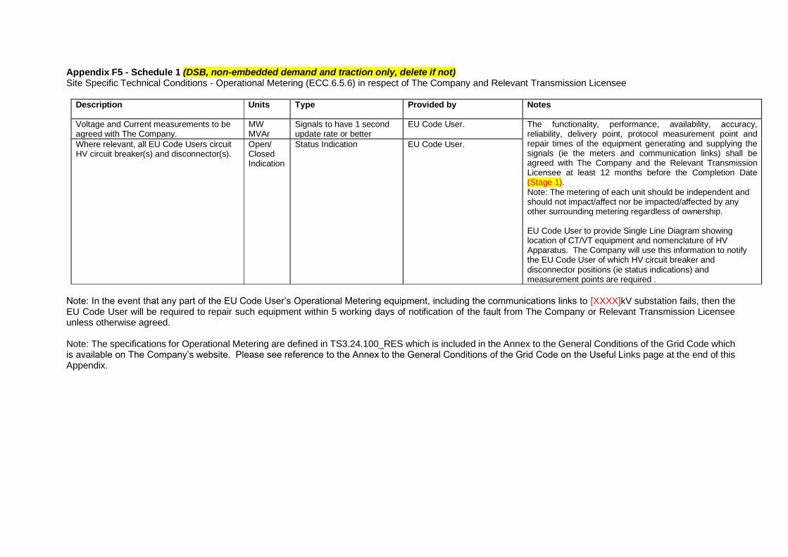
Appendix F5 - Schedule 1 (DSB, non-embedded demand and traction only, delete if not) Site Specific Technical Conditions - Operational Metering (ECC.6.5.6) in respect of The Company and Relevant Transmission Licensee
Description Units Type Provided by Notes
Voltage and Current measurements to be agreed with The Company.
MW MVAr
Signals to have 1 second update rate or better
EU Code User. The functionality, performance, availability, accuracy, reliability, delivery point, protocol measurement point and repair times of the equipment generating and supplying the signals (ie the meters and communication links) shall be agreed with The Company and the Relevant Transmission Licensee at least 12 months before the Completion Date (Stage 1). Note: The metering of each unit should be independent and should not impact/affect nor be impacted/affected by any other surrounding metering regardless of ownership. EU Code User to provide Single Line Diagram showing location of CT/VT equipment and nomenclature of HV Apparatus. The Company will use this information to notify the EU Code User of which HV circuit breaker and disconnector positions (ie status indications) and measurement points are required .
Where relevant, all EU Code Users circuit HV circuit breaker(s) and disconnector(s).
Open/ Closed Indication
Status Indication EU Code User.
Note: In the event that any part of the EU Code User’s Operational Metering equipment, including the communications links to [XXXX]kV substation fails, then the EU Code User will be required to repair such equipment within 5 working days of notification of the fault from The Company or Relevant Transmission Licensee unless otherwise agreed. Note: The specifications for Operational Metering are defined in TS3.24.100_RES which is included in the Annex to the General Conditions of the Grid Code which is available on The Company’s website. Please see reference to the Annex to the General Conditions of the Grid Code on the Useful Links page at the end of this Appendix.
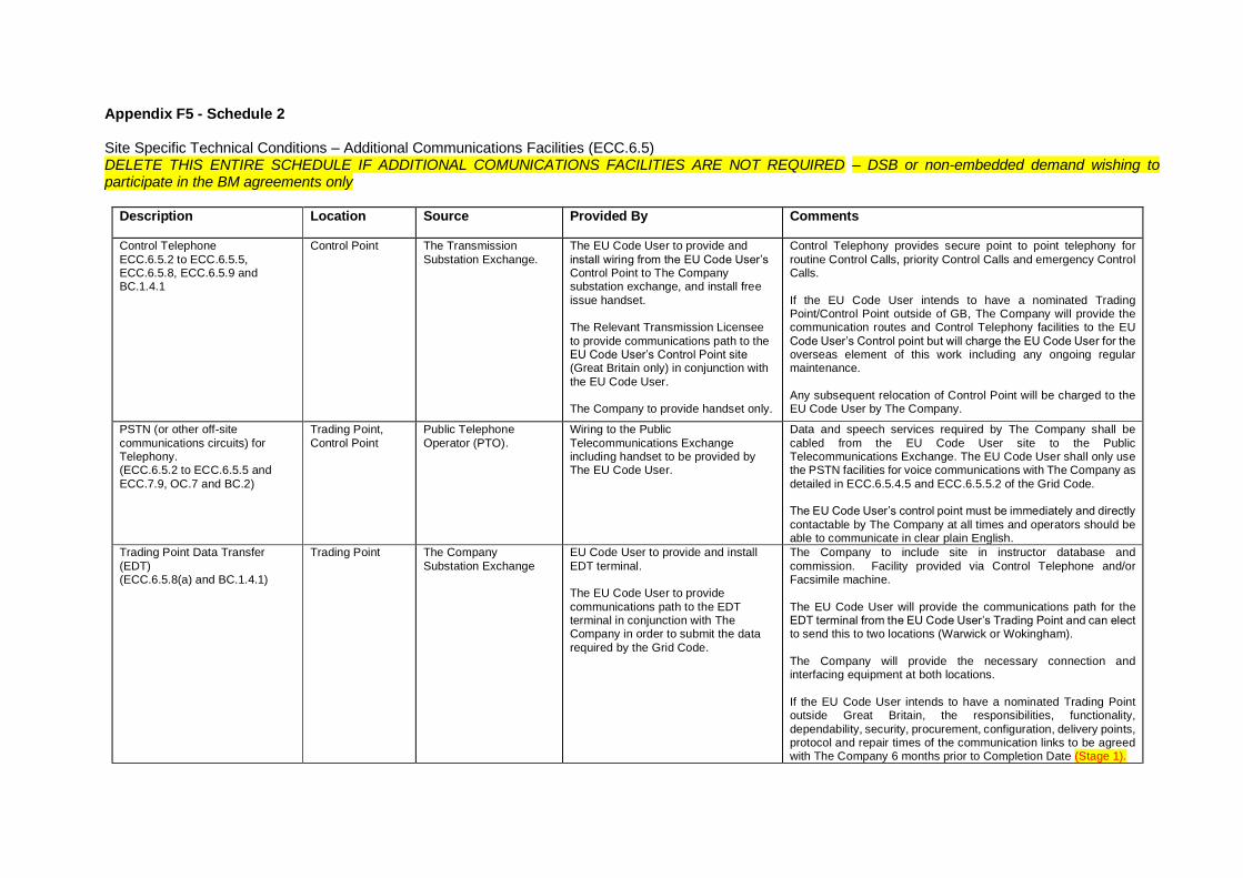
Appendix F5 - Schedule 2 Site Specific Technical Conditions – Additional Communications Facilities (ECC.6.5) DELETE THIS ENTIRE SCHEDULE IF ADDITIONAL COMUNICATIONS FACILITIES ARE NOT REQUIRED – DSB or non-embedded demand wishing to participate in the BM agreements only
Description Location Source Provided By Comments
Control Telephone
ECC.6.5.2 to ECC.6.5.5, ECC.6.5.8, ECC.6.5.9 and BC.1.4.1
Control Point The Transmission
Substation Exchange.
The EU Code User to provide and
install wiring from the EU Code User’s Control Point to The Company substation exchange, and install free
issue handset. The Relevant Transmission Licensee
to provide communications path to the EU Code User’s Control Point site (Great Britain only) in conjunction with
the EU Code User. The Company to provide handset only.
Control Telephony provides secure point to point telephony for
routine Control Calls, priority Control Calls and emergency Control Calls.
If the EU Code User intends to have a nominated Trading Point/Control Point outside of GB, The Company will provide the communication routes and Control Telephony facilities to the EU
Code User’s Control point but will charge the EU Code User for the overseas element of this work including any ongoing regular maintenance.
Any subsequent relocation of Control Point will be charged to the EU Code User by The Company.
PSTN (or other off-site
communications circuits) for Telephony. (ECC.6.5.2 to ECC.6.5.5 and
ECC.7.9, OC.7 and BC.2)
Trading Point,
Control Point
Public Telephone
Operator (PTO).
Wiring to the Public
Telecommunications Exchange including handset to be provided by The EU Code User.
Data and speech services required by The Company shall be
cabled from the EU Code User site to the Public Telecommunications Exchange. The EU Code User shall only use the PSTN facilities for voice communications with The Company as
detailed in ECC.6.5.4.5 and ECC.6.5.5.2 of the Grid Code. The EU Code User’s control point must be immediately and directly
contactable by The Company at all times and operators should be able to communicate in clear plain English.
Trading Point Data Transfer
(EDT) (ECC.6.5.8(a) and BC.1.4.1)
Trading Point The Company
Substation Exchange
EU Code User to provide and install
EDT terminal. The EU Code User to provide
communications path to the EDT terminal in conjunction with The Company in order to submit the data
required by the Grid Code.
The Company to include site in instructor database and
commission. Facility provided via Control Telephone and/or Facsimile machine.
The EU Code User will provide the communications path for the EDT terminal from the EU Code User’s Trading Point and can elect to send this to two locations (Warwick or Wokingham).
The Company will provide the necessary connection and interfacing equipment at both locations.
If the EU Code User intends to have a nominated Trading Point outside Great Britain, the responsibilities, functionality,
dependability, security, procurement, configuration, delivery points, protocol and repair times of the communication links to be agreed with The Company 6 months prior to Completion Date (Stage 1).
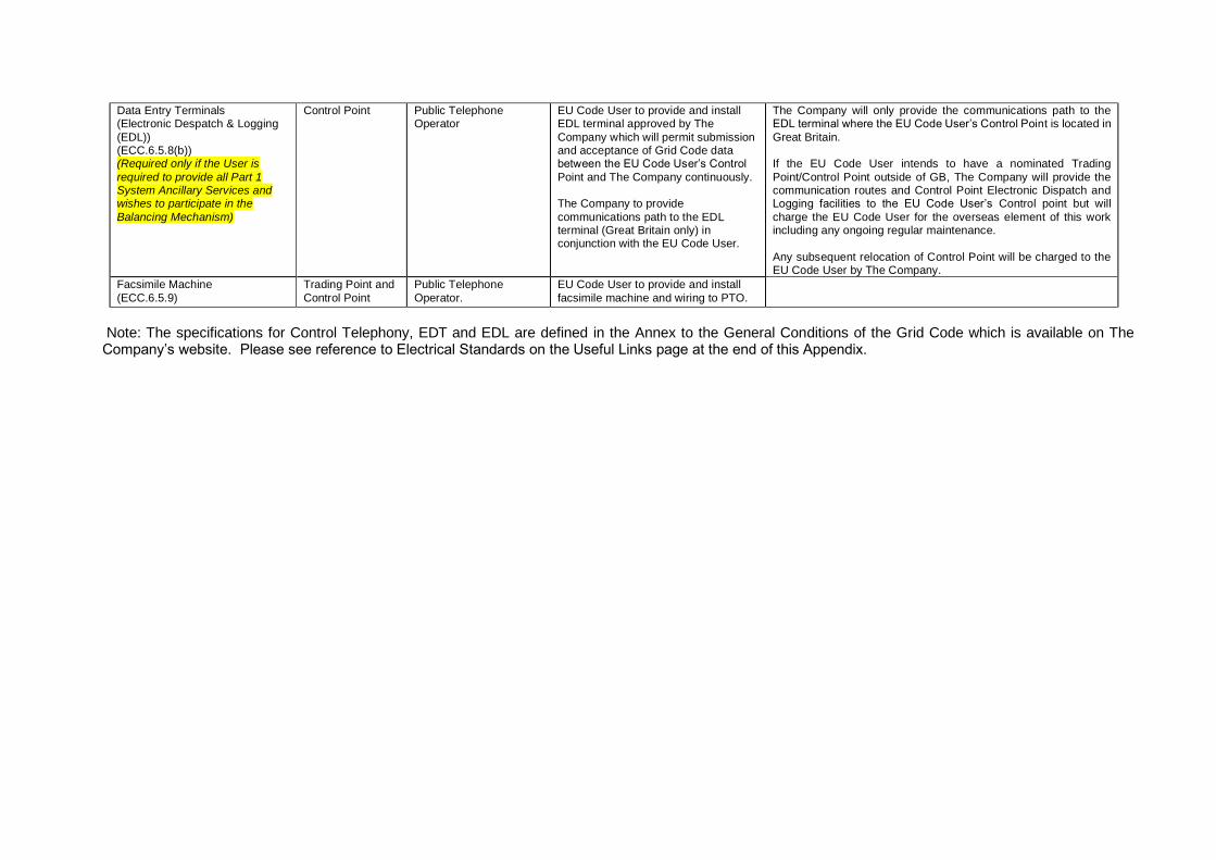
Data Entry Terminals (Electronic Despatch & Logging
(EDL)) (ECC.6.5.8(b)) (Required only if the User is
required to provide all Part 1 System Ancillary Services and wishes to participate in the
Balancing Mechanism)
Control Point
Public Telephone Operator
EU Code User to provide and install EDL terminal approved by The
Company which will permit submission and acceptance of Grid Code data between the EU Code User’s Control
Point and The Company continuously. The Company to provide
communications path to the EDL terminal (Great Britain only) in conjunction with the EU Code User.
The Company will only provide the communications path to the EDL terminal where the EU Code User’s Control Point is located in
Great Britain. If the EU Code User intends to have a nominated Trading
Point/Control Point outside of GB, The Company will provide the communication routes and Control Point Electronic Dispatch and Logging facilities to the EU Code User’s Control point but will
charge the EU Code User for the overseas element of this work including any ongoing regular maintenance.
Any subsequent relocation of Control Point will be charged to the EU Code User by The Company.
Facsimile Machine
(ECC.6.5.9)
Trading Point and
Control Point
Public Telephone
Operator.
EU Code User to provide and install
facsimile machine and wiring to PTO.
Note: The specifications for Control Telephony, EDT and EDL are defined in the Annex to the General Conditions of the Grid Code which is available on The Company’s website. Please see reference to Electrical Standards on the Useful Links page at the end of this Appendix.
USEFUL LINKS The Grid Code: https://www.nationalgrideso.com/codes/grid-code Electrical Standards: https://www.nationalgrideso.com/codes/grid-code/electrical-standards-documents-including-specifications-electronic-data Extranet (ID and password required, email transmission [email protected] to request access): https://extranet.nationalgrid.com/ (delete this sentence if in Scotland) Connection Policies and Guidance: https://www.nationalgrideso.com/connections/registers-reports-and-guidance Procurement Guidelines and Balancing Principles: https://www.nationalgrideso.com/balancing-services/c16-statements-and-consultations Annex to the General Conditions of the Grid Code (this includes TS3.24.100_RES): https://www.nationalgrideso.com/sites/eso/files/documents/TS_3.24.100_RES_i1.pdf
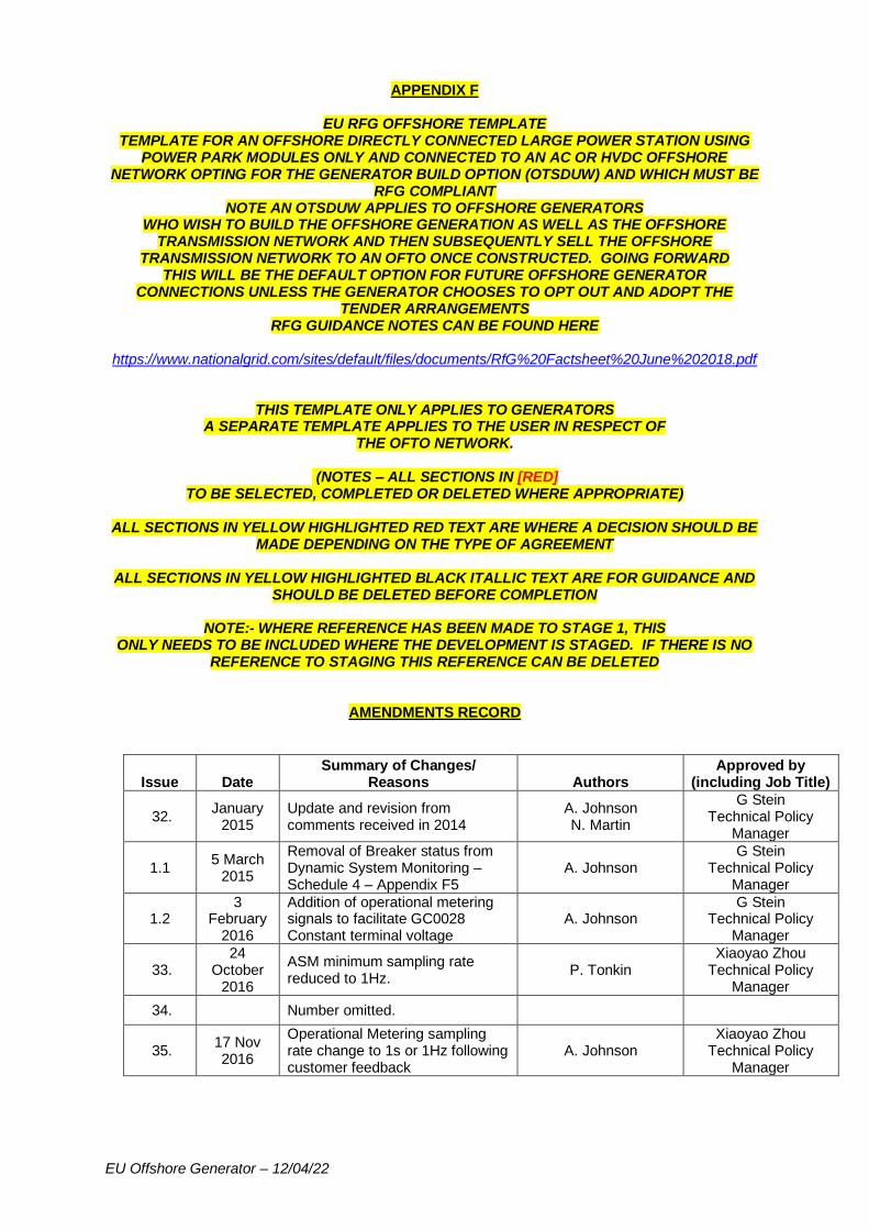
EU Offshore Generator – 12/04/22
APPENDIX F
EU RFG OFFSHORE TEMPLATE TEMPLATE FOR AN OFFSHORE DIRECTLY CONNECTED LARGE POWER STATION USING
POWER PARK MODULES ONLY AND CONNECTED TO AN AC OR HVDC OFFSHORE NETWORK OPTING FOR THE GENERATOR BUILD OPTION (OTSDUW) AND WHICH MUST BE
RFG COMPLIANT NOTE AN OTSDUW APPLIES TO OFFSHORE GENERATORS
WHO WISH TO BUILD THE OFFSHORE GENERATION AS WELL AS THE OFFSHORE TRANSMISSION NETWORK AND THEN SUBSEQUENTLY SELL THE OFFSHORE
TRANSMISSION NETWORK TO AN OFTO ONCE CONSTRUCTED. GOING FORWARD THIS WILL BE THE DEFAULT OPTION FOR FUTURE OFFSHORE GENERATOR
CONNECTIONS UNLESS THE GENERATOR CHOOSES TO OPT OUT AND ADOPT THE TENDER ARRANGEMENTS
RFG GUIDANCE NOTES CAN BE FOUND HERE
https://www.nationalgrid.com/sites/default/files/documents/RfG%20Factsheet%20June%202018.pdf
THIS TEMPLATE ONLY APPLIES TO GENERATORS A SEPARATE TEMPLATE APPLIES TO THE USER IN RESPECT OF
THE OFTO NETWORK.
(NOTES – ALL SECTIONS IN [RED] TO BE SELECTED, COMPLETED OR DELETED WHERE APPROPRIATE)
ALL SECTIONS IN YELLOW HIGHLIGHTED RED TEXT ARE WHERE A DECISION SHOULD BE
MADE DEPENDING ON THE TYPE OF AGREEMENT
ALL SECTIONS IN YELLOW HIGHLIGHTED BLACK ITALLIC TEXT ARE FOR GUIDANCE AND SHOULD BE DELETED BEFORE COMPLETION
NOTE:- WHERE REFERENCE HAS BEEN MADE TO STAGE 1, THIS
ONLY NEEDS TO BE INCLUDED WHERE THE DEVELOPMENT IS STAGED. IF THERE IS NO REFERENCE TO STAGING THIS REFERENCE CAN BE DELETED
AMENDMENTS RECORD
Issue Date Summary of Changes/
Reasons Authors Approved by
(including Job Title)
32. January
2015 Update and revision from comments received in 2014
A. Johnson N. Martin
G Stein Technical Policy
Manager
1.1 5 March
2015
Removal of Breaker status from Dynamic System Monitoring – Schedule 4 – Appendix F5
A. Johnson G Stein
Technical Policy Manager
1.2 3
February 2016
Addition of operational metering signals to facilitate GC0028 Constant terminal voltage
A. Johnson G Stein
Technical Policy Manager
33. 24
October 2016
ASM minimum sampling rate reduced to 1Hz.
P. Tonkin Xiaoyao Zhou
Technical Policy Manager
34. Number omitted.
35. 17 Nov 2016
Operational Metering sampling rate change to 1s or 1Hz following customer feedback
A. Johnson Xiaoyao Zhou
Technical Policy Manager
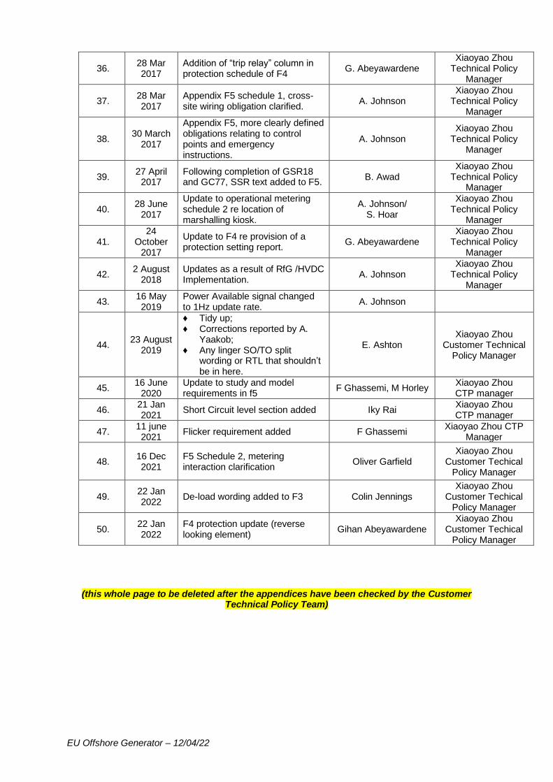
EU Offshore Generator – 12/04/22
36. 28 Mar 2017
Addition of “trip relay” column in protection schedule of F4
G. Abeyawardene Xiaoyao Zhou
Technical Policy Manager
37. 28 Mar 2017
Appendix F5 schedule 1, cross-site wiring obligation clarified.
A. Johnson Xiaoyao Zhou
Technical Policy Manager
38. 30 March
2017
Appendix F5, more clearly defined obligations relating to control points and emergency instructions.
A. Johnson Xiaoyao Zhou
Technical Policy Manager
39. 27 April
2017 Following completion of GSR18 and GC77, SSR text added to F5.
B. Awad Xiaoyao Zhou
Technical Policy Manager
40. 28 June
2017
Update to operational metering schedule 2 re location of marshalling kiosk.
A. Johnson/ S. Hoar
Xiaoyao Zhou Technical Policy
Manager
41. 24
October 2017
Update to F4 re provision of a protection setting report.
G. Abeyawardene Xiaoyao Zhou
Technical Policy Manager
42. 2 August
2018 Updates as a result of RfG /HVDC Implementation.
A. Johnson Xiaoyao Zhou
Technical Policy Manager
43. 16 May 2019
Power Available signal changed to 1Hz update rate.
A. Johnson
44. 23 August
2019
♦ Tidy up; ♦ Corrections reported by A.
Yaakob; ♦ Any linger SO/TO split
wording or RTL that shouldn’t be in here.
E. Ashton Xiaoyao Zhou
Customer Technical Policy Manager
45. 16 June
2020 Update to study and model requirements in f5
F Ghassemi, M Horley Xiaoyao Zhou CTP manager
46. 21 Jan 2021
Short Circuit level section added Iky Rai Xiaoyao Zhou CTP manager
47. 11 june 2021
Flicker requirement added F Ghassemi Xiaoyao Zhou CTP
Manager
48. 16 Dec 2021
F5 Schedule 2, metering interaction clarification
Oliver Garfield Xiaoyao Zhou
Customer Techical Policy Manager
49. 22 Jan 2022
De-load wording added to F3 Colin Jennings Xiaoyao Zhou
Customer Techical Policy Manager
50. 22 Jan 2022
F4 protection update (reverse looking element)
Gihan Abeyawardene Xiaoyao Zhou
Customer Techical Policy Manager
(this whole page to be deleted after the appendices have been checked by the Customer Technical Policy Team)
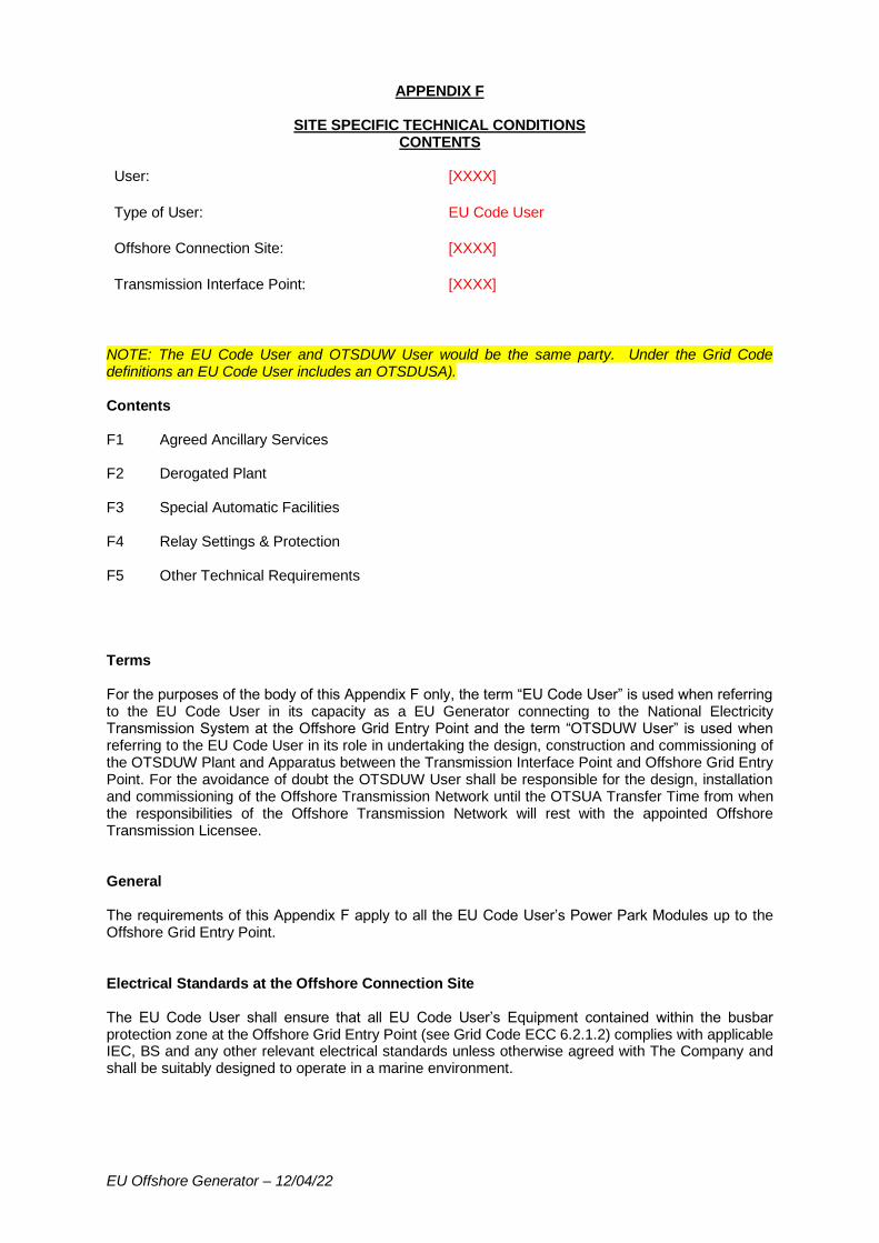
EU Offshore Generator – 12/04/22
APPENDIX F
SITE SPECIFIC TECHNICAL CONDITIONS CONTENTS
User: [XXXX]
Type of User: EU Code User
Offshore Connection Site: [XXXX]
Transmission Interface Point: [XXXX]
NOTE: The EU Code User and OTSDUW User would be the same party. Under the Grid Code definitions an EU Code User includes an OTSDUSA). Contents F1 Agreed Ancillary Services F2 Derogated Plant F3 Special Automatic Facilities F4 Relay Settings & Protection F5 Other Technical Requirements Terms For the purposes of the body of this Appendix F only, the term “EU Code User” is used when referring to the EU Code User in its capacity as a EU Generator connecting to the National Electricity Transmission System at the Offshore Grid Entry Point and the term “OTSDUW User” is used when referring to the EU Code User in its role in undertaking the design, construction and commissioning of the OTSDUW Plant and Apparatus between the Transmission Interface Point and Offshore Grid Entry Point. For the avoidance of doubt the OTSDUW User shall be responsible for the design, installation and commissioning of the Offshore Transmission Network until the OTSUA Transfer Time from when the responsibilities of the Offshore Transmission Network will rest with the appointed Offshore Transmission Licensee. General The requirements of this Appendix F apply to all the EU Code User’s Power Park Modules up to the Offshore Grid Entry Point. Electrical Standards at the Offshore Connection Site The EU Code User shall ensure that all EU Code User’s Equipment contained within the busbar protection zone at the Offshore Grid Entry Point (see Grid Code ECC 6.2.1.2) complies with applicable IEC, BS and any other relevant electrical standards unless otherwise agreed with The Company and shall be suitably designed to operate in a marine environment.
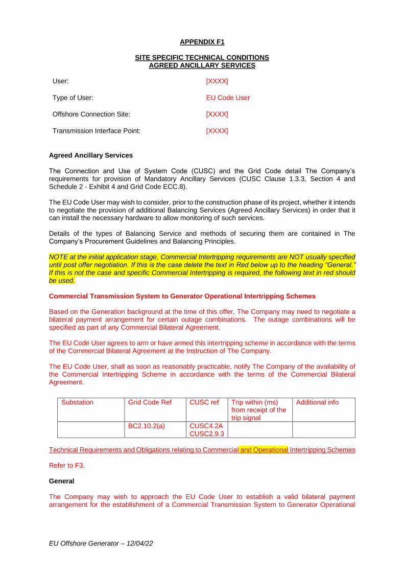
EU Offshore Generator – 12/04/22
APPENDIX F1
SITE SPECIFIC TECHNICAL CONDITIONS AGREED ANCILLARY SERVICES
User: [XXXX]
Type of User: EU Code User
Offshore Connection Site: [XXXX]
Transmission Interface Point: [XXXX]
Agreed Ancillary Services The Connection and Use of System Code (CUSC) and the Grid Code detail The Company’s requirements for provision of Mandatory Ancillary Services (CUSC Clause 1.3.3, Section 4 and Schedule 2 - Exhibit 4 and Grid Code ECC.8). The EU Code User may wish to consider, prior to the construction phase of its project, whether it intends to negotiate the provision of additional Balancing Services (Agreed Ancillary Services) in order that it can install the necessary hardware to allow monitoring of such services. Details of the types of Balancing Service and methods of securing them are contained in The Company’s Procurement Guidelines and Balancing Principles. NOTE at the initial application stage, Commercial Intertripping requirements are NOT usually specified until post offer negotiation. If this is the case delete the text in Red below up to the heading “General.” If this is not the case and specific Commercial Intertripping is required, the following text in red should be used. Commercial Transmission System to Generator Operational Intertripping Schemes Based on the Generation background at the time of this offer, The Company may need to negotiate a bilateral payment arrangement for certain outage combinations. The outage combinations will be specified as part of any Commercial Bilateral Agreement. The EU Code User agrees to arm or have armed this intertripping scheme in accordance with the terms of the Commercial Bilateral Agreement at the Instruction of The Company. The EU Code User, shall as soon as reasonably practicable, notify The Company of the availability of the Commercial Intertripping Scheme in accordance with the terms of the Commercial Bilateral Agreement.
Substation Grid Code Ref CUSC ref Trip within (ms) from receipt of the trip signal
Additional info
BC2.10.2(a) CUSC4.2A CUSC2.9.3
Technical Requirements and Obligations relating to Commercial and Operational Intertripping Schemes Refer to F3. General The Company may wish to approach the EU Code User to establish a valid bilateral payment arrangement for the establishment of a Commercial Transmission System to Generator Operational

EU Offshore Generator – 12/04/22
Intertripping Scheme in the future. This approach would be made at such time that The Company has established certainty in the local generation background. (Delete if intertrip specified above) The EU Code User shall co-operate with The Company in enhancing/amending these facilities and will not unreasonably withhold its agreement to any such proposals should The Company require this at a later date. Any changes to this Appendix F1 and/or to The Company’s and/or EU Code User’s obligations shall be subject to the provisions of Paragraph 2.9.3 of the CUSC which states that if either party wishes to modify, alter or change the site specific technical conditions it shall be deemed to be a Modification for the purposes of the CUSC unless CUSC 4.2B.3 (Agreed Ancillary Services) applies. CUSC 4.2B.3 states that if both parties have failed to reach agreement within a reasonable period then The Company is entitled to initiate the procedure for resolution as an “Other Dispute.” This does not apply in the case of Max Generation or System to Generator Operational Intertripping.
EU Offshore Generator – 12/04/22
APPENDIX F2
SITE SPECIFIC TECHNICAL CONDITIONS DEROGATED PLANT
User: [XXXX]
Type of User: EU Code User
Offshore Connection Site: [XXXX]
Transmission Interface Point: [XXXX]
Derogated Plant Not applicable.
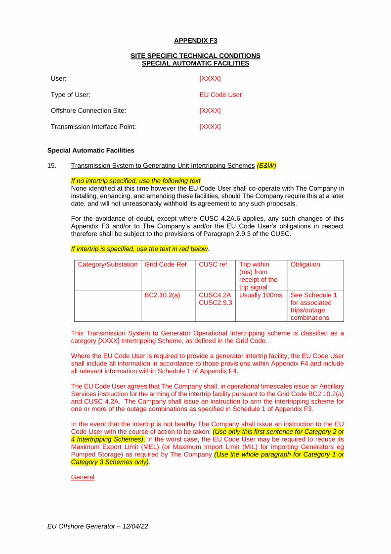
EU Offshore Generator – 12/04/22
APPENDIX F3
SITE SPECIFIC TECHNICAL CONDITIONS SPECIAL AUTOMATIC FACILITIES
User: [XXXX]
Type of User: EU Code User
Offshore Connection Site: [XXXX]
Transmission Interface Point: [XXXX]
Special Automatic Facilities 15. Transmission System to Generating Unit Intertripping Schemes (E&W)
If no intertrip specified, use the following text None identified at this time however the EU Code User shall co-operate with The Company in installing, enhancing, and amending these facilities, should The Company require this at a later date, and will not unreasonably withhold its agreement to any such proposals. For the avoidance of doubt, except where CUSC 4.2A.6 applies, any such changes of this Appendix F3 and/or to The Company’s and/or the EU Code User’s obligations in respect therefore shall be subject to the provisions of Paragraph 2.9.3 of the CUSC. If intertrip is specified, use the text in red below.
Category/Substation Grid Code Ref CUSC ref Trip within (ms) from receipt of the trip signal
Obligation
BC2.10.2(a) CUSC4.2A CUSC2.9.3
Usually 100ms See Schedule 1 for associated trips/outage combinations
This Transmission System to Generator Operational Intertripping scheme is classified as a category [XXXX] Intertripping Scheme, as defined in the Grid Code. Where the EU Code User is required to provide a generator intertrip facility, the EU Code User shall include all information in accordance to those provisions within Appendix F4 and include all relevant information within Schedule 1 of Appendix F4. The EU Code User agrees that The Company shall, in operational timescales issue an Ancillary Services instruction for the arming of the intertrip facility pursuant to the Grid Code BC2.10.2(a) and CUSC 4.2A. The Company shall issue an instruction to arm the intertripping scheme for one or more of the outage combinations as specified in Schedule 1 of Appendix F3. In the event that the intertrip is not healthy The Company shall issue an instruction to the EU Code User with the course of action to be taken. (Use only this first sentence for Category 2 or 4 Intertripping Schemes). In the worst case, the EU Code User may be required to reduce its Maximum Export Limit (MEL) (or Maximum Import Limit (MIL) for importing Generators eg Pumped Storage) as required by The Company (Use the whole paragraph for Category 1 or Category 3 Schemes only). General
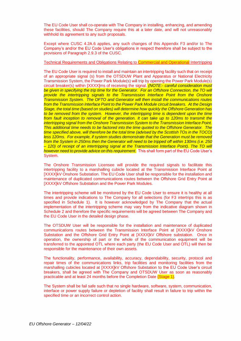
EU Offshore Generator – 12/04/22
The EU Code User shall co-operate with The Company in installing, enhancing, and amending these facilities, should The Company require this at a later date, and will not unreasonably withhold its agreement to any such proposals. Except where CUSC 4.2A.6 applies, any such changes of this Appendix F3 and/or to The Company’s and/or the EU Code User’s obligations in respect therefore shall be subject to the provisions of Paragraph 2.9.3 of the CUSC. Technical Requirements and Obligations Relating to Commercial and Operational Intertripping The EU Code User is required to install and maintain an intertripping facility such that on receipt of an appropriate signal (s) from the OTSDUW Plant and Apparatus or National Electricity Transmission System, the Power Park Module(s) will trip by opening the Power Park Module(s) circuit breaker(s) within [XXXX]ms of receiving the signal. (NOTE:- careful consideration must be given in specifying the trip time for the Generator. For an Offshore Connection, the TO will provide the intertripping signals to the Transmission Interface Point from the Onshore Transmission System. The OFTO and Generator will then install the communications routes from the Transmission Interface Point to the Power Park Module circuit breakers. At the Design Stage, the total time (based on studies) will determine how quickly the Offshore Generation has to be removed from the system. However, the intertripping time is dependent upon the time from fault inception to removal of the generation. It can take up to 120ms to transmit the intertripping signal from the Onshore Transmission System to the Transmission Interface Point. This additional time needs to be factored into the time quoted to the Offshore Generator. The time specified above, will therefore be the total time (advised by the Scottish TOs in the TOCO) less 120ms. For example, if system studies demonstrate that the Generation must be removed from the System in 250ms then the Generator will need to be tripped off within 130ms (i.e. 250 – 120) of receipt of an intertripping signal at the Transmission Interface Point). The TO will however need to provide advice on this requirement. This shall form part of the EU Code User’s System. The Onshore Transmission Licensee will provide the required signals to facilitate this intertripping facility to a marshalling cubicle located at the Transmission Interface Point at [XXXX]kV Onshore Substation. The EU Code User shall be responsible for the installation and maintenance of duplicated communications routes between the Offshore Grid Entry Point at [XXXX]kV Offshore Substation and the Power Park Modules. The intertripping scheme will be monitored by the EU Code User to ensure it is healthy at all times and provide indications to The Company for all selections (for F3 intertrips this is as specified in Schedule 1). It is however acknowledged by The Company that the actual implementation of the intertripping scheme may vary from the indicative diagram shown in Schedule 2 and therefore the specific requirements will be agreed between The Company and the EU Code User in the detailed design phase. The OTSDUW User will be responsible for the installation and maintenance of duplicated communications routes between the Transmission Interface Point at [XXXX]kV Onshore Substation and the Offshore Grid Entry Point at [XXXX]kV Offshore substation. Once in operation, the ownership of part or the whole of the communication equipment will be transferred to the appointed OTL where each party (the EU Code User and OTL) will then be responsible for the maintenance of their own assets. The functionality, performance, availability, accuracy, dependability, security, protocol and repair times of the communications links, trip facilities and monitoring facilities from the marshalling cubicles located at [XXXX]kV Offshore Substation to the EU Code User’s circuit breakers, shall be agreed with The Company and OTSDUW User as soon as reasonably practicable and at least 24 months before the Completion Date (Stage 1). The System shall be fail safe such that no single hardware, software, system, communication, interface or power supply failure or depletion of facility shall result in failure to trip within the specified time or an incorrect control action.
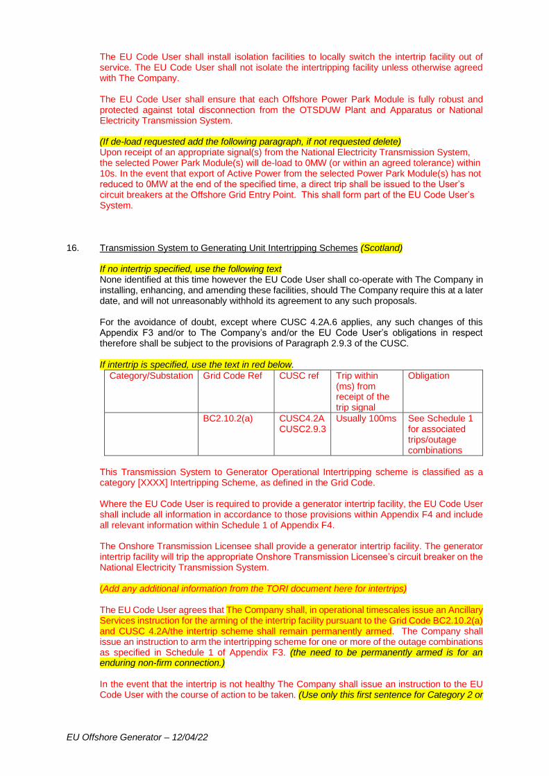
EU Offshore Generator – 12/04/22
The EU Code User shall install isolation facilities to locally switch the intertrip facility out of service. The EU Code User shall not isolate the intertripping facility unless otherwise agreed with The Company. The EU Code User shall ensure that each Offshore Power Park Module is fully robust and protected against total disconnection from the OTSDUW Plant and Apparatus or National Electricity Transmission System. (If de-load requested add the following paragraph, if not requested delete) Upon receipt of an appropriate signal(s) from the National Electricity Transmission System, the selected Power Park Module(s) will de-load to 0MW (or within an agreed tolerance) within 10s. In the event that export of Active Power from the selected Power Park Module(s) has not reduced to 0MW at the end of the specified time, a direct trip shall be issued to the User’s circuit breakers at the Offshore Grid Entry Point. This shall form part of the EU Code User’s System.
16. Transmission System to Generating Unit Intertripping Schemes (Scotland) If no intertrip specified, use the following text None identified at this time however the EU Code User shall co-operate with The Company in installing, enhancing, and amending these facilities, should The Company require this at a later date, and will not unreasonably withhold its agreement to any such proposals. For the avoidance of doubt, except where CUSC 4.2A.6 applies, any such changes of this Appendix F3 and/or to The Company’s and/or the EU Code User’s obligations in respect therefore shall be subject to the provisions of Paragraph 2.9.3 of the CUSC. If intertrip is specified, use the text in red below.
Category/Substation Grid Code Ref CUSC ref Trip within (ms) from receipt of the trip signal
Obligation
BC2.10.2(a) CUSC4.2A CUSC2.9.3
Usually 100ms See Schedule 1 for associated trips/outage combinations
This Transmission System to Generator Operational Intertripping scheme is classified as a category [XXXX] Intertripping Scheme, as defined in the Grid Code. Where the EU Code User is required to provide a generator intertrip facility, the EU Code User shall include all information in accordance to those provisions within Appendix F4 and include all relevant information within Schedule 1 of Appendix F4. The Onshore Transmission Licensee shall provide a generator intertrip facility. The generator intertrip facility will trip the appropriate Onshore Transmission Licensee’s circuit breaker on the National Electricity Transmission System. (Add any additional information from the TORI document here for intertrips) The EU Code User agrees that The Company shall, in operational timescales issue an Ancillary Services instruction for the arming of the intertrip facility pursuant to the Grid Code BC2.10.2(a) and CUSC 4.2A/the intertrip scheme shall remain permanently armed. The Company shall issue an instruction to arm the intertripping scheme for one or more of the outage combinations as specified in Schedule 1 of Appendix F3. (the need to be permanently armed is for an enduring non-firm connection.) In the event that the intertrip is not healthy The Company shall issue an instruction to the EU Code User with the course of action to be taken. (Use only this first sentence for Category 2 or
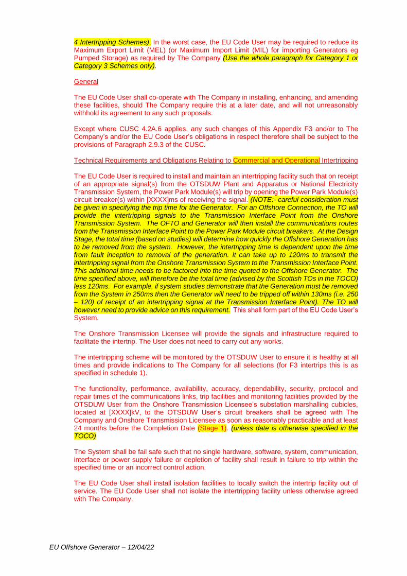
EU Offshore Generator – 12/04/22
4 Intertripping Schemes). In the worst case, the EU Code User may be required to reduce its Maximum Export Limit (MEL) (or Maximum Import Limit (MIL) for importing Generators eg Pumped Storage) as required by The Company (Use the whole paragraph for Category 1 or Category 3 Schemes only). General The EU Code User shall co-operate with The Company in installing, enhancing, and amending these facilities, should The Company require this at a later date, and will not unreasonably withhold its agreement to any such proposals. Except where CUSC 4.2A.6 applies, any such changes of this Appendix F3 and/or to The Company’s and/or the EU Code User’s obligations in respect therefore shall be subject to the provisions of Paragraph 2.9.3 of the CUSC. Technical Requirements and Obligations Relating to Commercial and Operational Intertripping The EU Code User is required to install and maintain an intertripping facility such that on receipt of an appropriate signal(s) from the OTSDUW Plant and Apparatus or National Electricity Transmission System, the Power Park Module(s) will trip by opening the Power Park Module(s) circuit breaker(s) within [XXXX]ms of receiving the signal. (NOTE:- careful consideration must be given in specifying the trip time for the Generator. For an Offshore Connection, the TO will provide the intertripping signals to the Transmission Interface Point from the Onshore Transmission System. The OFTO and Generator will then install the communications routes from the Transmission Interface Point to the Power Park Module circuit breakers. At the Design Stage, the total time (based on studies) will determine how quickly the Offshore Generation has to be removed from the system. However, the intertripping time is dependent upon the time from fault inception to removal of the generation. It can take up to 120ms to transmit the intertripping signal from the Onshore Transmission System to the Transmission Interface Point. This additional time needs to be factored into the time quoted to the Offshore Generator. The time specified above, will therefore be the total time (advised by the Scottish TOs in the TOCO) less 120ms. For example, if system studies demonstrate that the Generation must be removed from the System in 250ms then the Generator will need to be tripped off within 130ms (i.e. 250 – 120) of receipt of an intertripping signal at the Transmission Interface Point). The TO will however need to provide advice on this requirement. This shall form part of the EU Code User’s System. The Onshore Transmission Licensee will provide the signals and infrastructure required to facilitate the intertrip. The User does not need to carry out any works. The intertripping scheme will be monitored by the OTSDUW User to ensure it is healthy at all times and provide indications to The Company for all selections (for F3 intertrips this is as specified in schedule 1). The functionality, performance, availability, accuracy, dependability, security, protocol and repair times of the communications links, trip facilities and monitoring facilities provided by the OTSDUW User from the Onshore Transmission Licensee’s substation marshalling cubicles, located at [XXXX]kV, to the OTSDUW User’s circuit breakers shall be agreed with The Company and Onshore Transmission Licensee as soon as reasonably practicable and at least 24 months before the Completion Date (Stage 1). (unless date is otherwise specified in the TOCO) The System shall be fail safe such that no single hardware, software, system, communication, interface or power supply failure or depletion of facility shall result in failure to trip within the specified time or an incorrect control action. The EU Code User shall install isolation facilities to locally switch the intertrip facility out of service. The EU Code User shall not isolate the intertripping facility unless otherwise agreed with The Company.
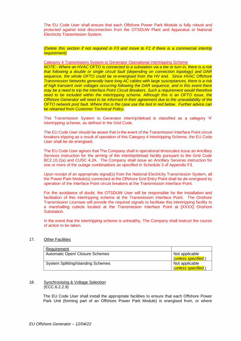
EU Offshore Generator – 12/04/22
The EU Code User shall ensure that each Offshore Power Park Module is fully robust and protected against total disconnection from the OTSDUW Plant and Apparatus or National Electricity Transmission System. (Delete this section if not required in F3 and move to F1 if there is a commercial intertrip requirement) Category 4 Transmission System to Generator Operational Intertripping Scheme NOTE:- Where an HVAC OFTO is connected to a substation via a tee or turn in, there is a risk that following a double or single circuit fault (depending on connection topology) and DAR sequence, the whole OFTO could be re-energised from the HV end. Since HVAC Offshore Transmission Networks generally have long AC cables with large susceptances, there is a risk of high transient over voltages occurring following the DAR sequence, and in this event there may be a need to trip the Interface Point Circuit Breakers. Such a requirement would therefore need to be included within the intertripping scheme. Although this is an OFTO issue, the Offshore Generator will need to be informed in their agreement due to the unavailability of the OFTO network post fault. Where this is the case use the text in red below. Further advice can be obtained from Customer Technical Policy. This Transmission System to Generator intertrip/deload is classified as a category ‘4’ intertripping scheme, as defined in the Grid Code. The EU Code User should be aware that in the event of the Transmission Interface Point circuit breakers tripping as a result of operation of this Category 4 Intertripping Scheme, the EU Code User shall be de-energised. The EU Code User agrees that The Company shall in operational timescales issue an Ancillary Services instruction for the arming of the intertrip/deload facility pursuant to the Grid Code BC2.10.2(a) and CUSC 4.2A. The Company shall issue an Ancillary Services instruction for one or more of the outage combinations as specified in Schedule 3 of Appendix F3. Upon receipt of an appropriate signal(s) from the National Electricity Transmission System, all the Power Park Module(s) connected at the Offshore Grid Entry Point shall be de-energised by operation of the Interface Point circuit breakers at the Transmission Interface Point. For the avoidance of doubt, the OTSDUW User will be responsible for the installation and facilitation of this intertripping scheme at the Transmission Interface Point. The Onshore Transmission Licensee will provide the required signals to facilitate this intertripping facility to a marshalling cubicle located at the Transmission Interface Point at [XXXX] Onshore Substation. In the event that the intertripping scheme is unhealthy, The Company shall instruct the course of action to be taken.
17. Other Facilities
Requirement
Automatic Open/ Closure Schemes Not applicable (unless specified.)
System Splitting/Islanding Schemes Not applicable (unless specified.)
18. Synchronising & Voltage Selection (ECC.6.2.2.9) The EU Code User shall install the appropriate facilities to ensure that each Offshore Power Park Unit (forming part of an Offshore Power Park Module) is energised from, or where
EU Offshore Generator – 12/04/22
appropriate synchronised to, the EU Code User’s system in a safe and secure manner. Where installed, any synchronising facilities shall be in accordance with ECC.6.2.2.9. There is no requirement for synchronising facilities to be installed at the Offshore Grid Entry Point between the EU Code User’s generating equipment and the OTSDUW Plant and Apparatus. However the EU Code User’s System (i.e. between the Offshore Power Park Units and Offshore Grid Entry Point) must always be de-energised prior to closure of the EU Code User’s circuit breakers at the Offshore Grid Entry Point. The EU Code User shall ensure that appropriate provisions are made to prevent the EU Code User’s circuit breakers at the Offshore Grid Entry Point from being closed when the Power Park Strings are energised. The EU Code User's Plant and Apparatus will be required to interface with the OTSDUW Plant and Apparatus voltage selection scheme at the Offshore Grid Entry Point.
In the case of DC connected Power Park Modules, the EU Code User shall also provide synchronisation signals specified via The Company as required by the Offshore Transmission Licensee. In addition, during synchronisation of a DC connected Power Park Module it shall have the capability to limit any voltage changes to a Steady State Level specified via The Company as required by the Offshore Transmission Licensee. This shall not exceed 5% of the pre-synchronisation voltage. Any additional limits including magnitude, duration and transient over-voltage requirements will be specified via The Company as required by the Offshore Transmission Licensee. (DC connected PPM only)
19. Control Schemes and Settings (ECC.6.2.2.7) Where the EU Code User installs any equipment which may have an impact on the National Electricity Transmission System, they shall be discussed and agreed with The Company and the Onshore Transmission Licensee during the detailed design phase. Once the EU Code Users Plant and Apparatus has been commissioned, any changes to the EU Code User’s control system or settings shall be discussed and agreed with The Company and the Onshore Transmission Licensee prior to any change being made.

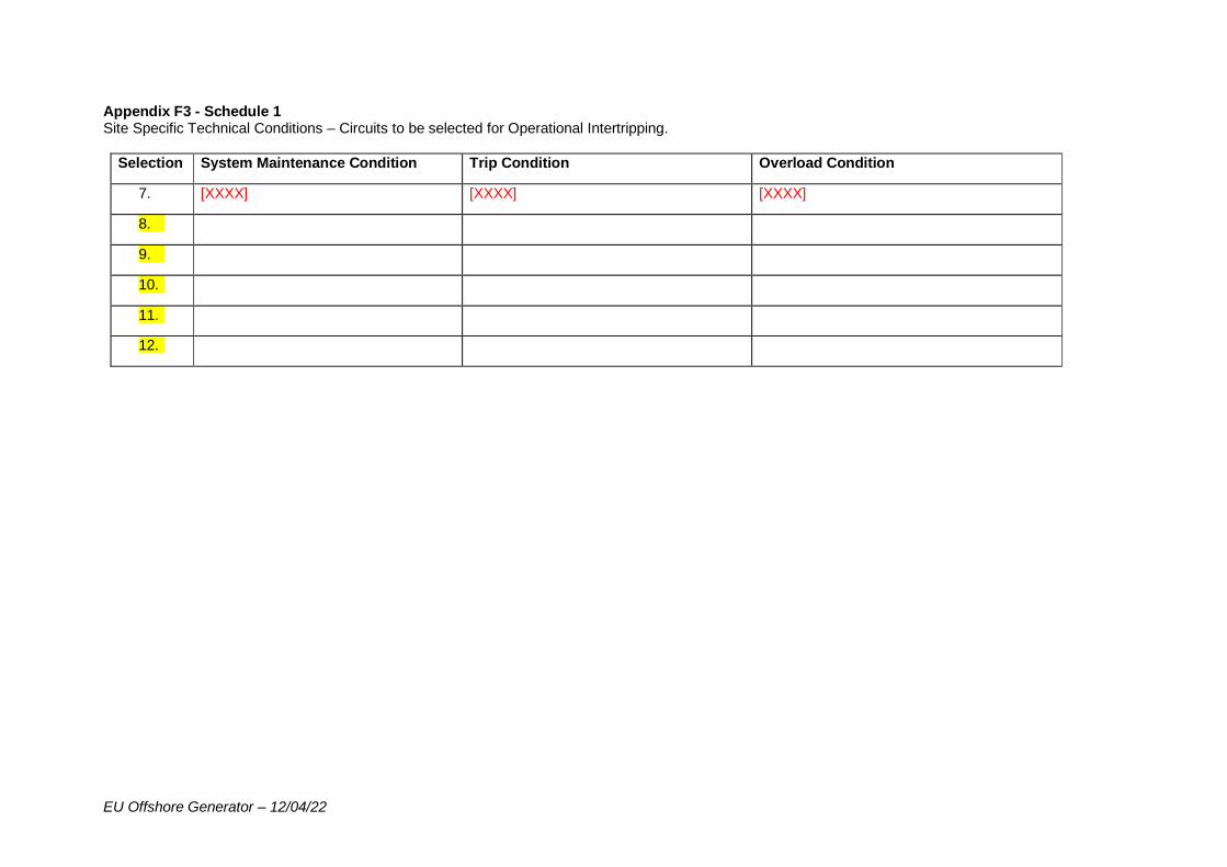
EU Offshore Generator – 12/04/22
Appendix F3 - Schedule 1 Site Specific Technical Conditions – Circuits to be selected for Operational Intertripping.
Selection System Maintenance Condition Trip Condition Overload Condition
7. [XXXX] [XXXX] [XXXX]
8.
9.
10.
11.
12.
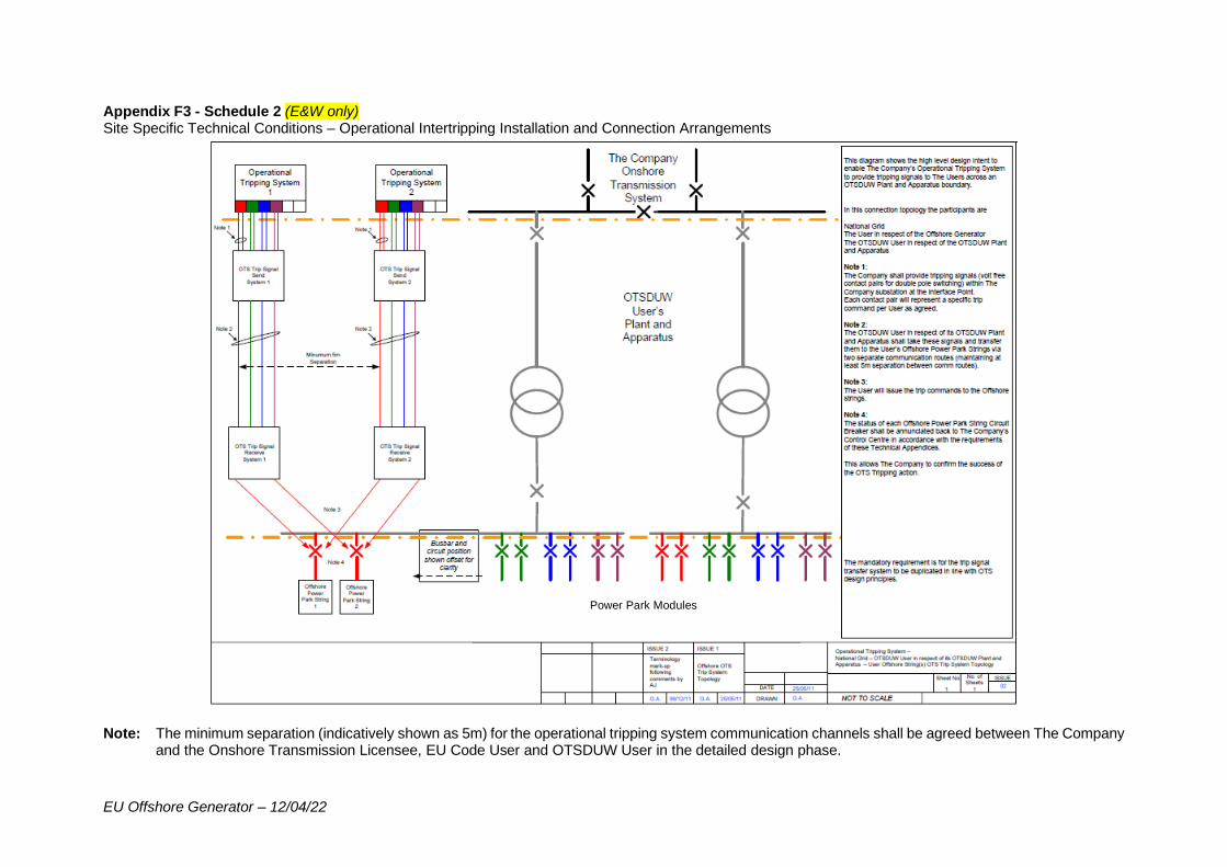
EU Offshore Generator – 12/04/22
Appendix F3 - Schedule 2 (E&W only) Site Specific Technical Conditions – Operational Intertripping Installation and Connection Arrangements
Note: The minimum separation (indicatively shown as 5m) for the operational tripping system communication channels shall be agreed between The Company
and the Onshore Transmission Licensee, EU Code User and OTSDUW User in the detailed design phase.
Power Park Modules
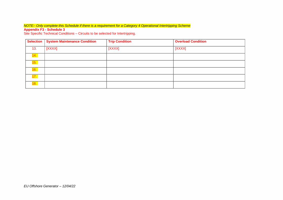
EU Offshore Generator – 12/04/22
NOTE:- Only complete this Schedule if there is a requirement for a Category 4 Operational Intertripping Scheme Appendix F3 - Schedule 3 Site Specific Technical Conditions – Circuits to be selected for Intertripping.
Selection System Maintenance Condition Trip Condition Overload Condition
13. [XXXX] [XXXX] [XXXX]
14.
15.
16.
17.
18.

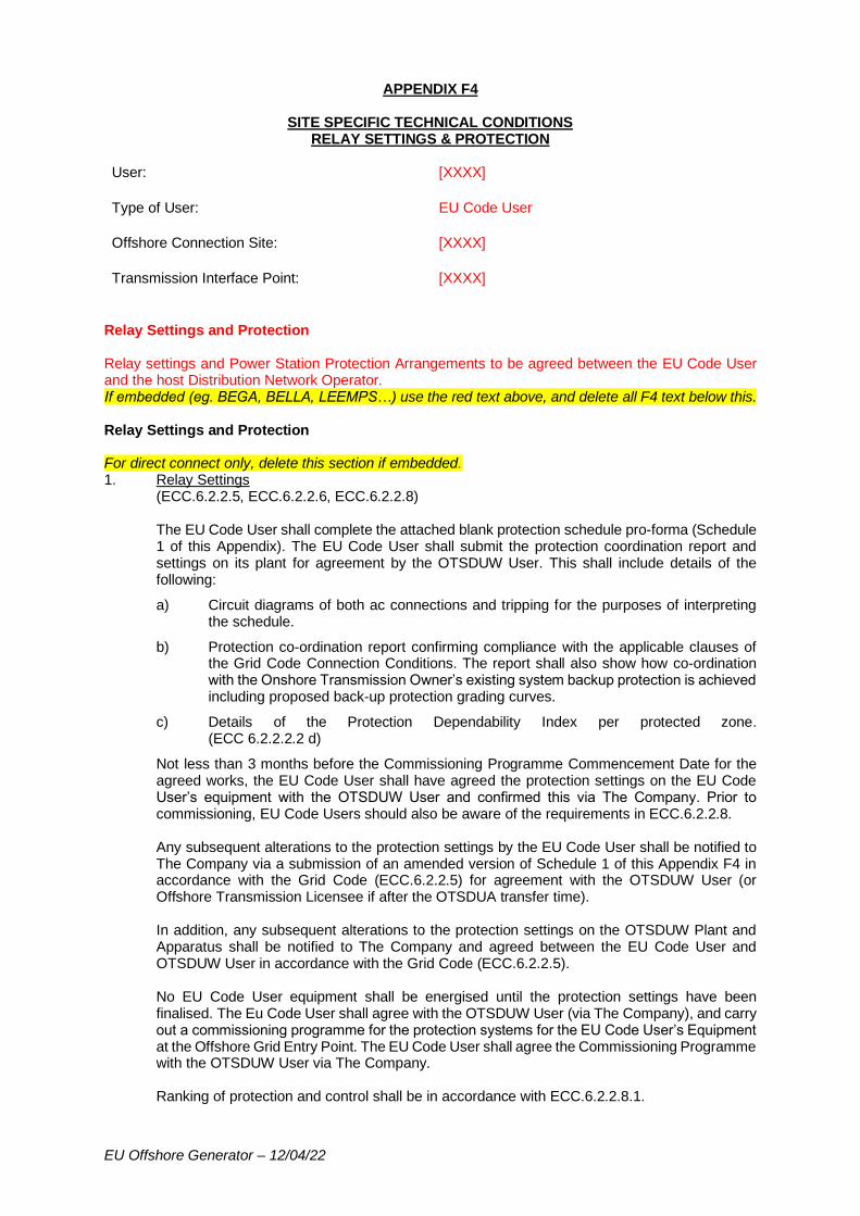
EU Offshore Generator – 12/04/22
APPENDIX F4
SITE SPECIFIC TECHNICAL CONDITIONS RELAY SETTINGS & PROTECTION
User: [XXXX]
Type of User: EU Code User
Offshore Connection Site: [XXXX]
Transmission Interface Point: [XXXX]
Relay Settings and Protection Relay settings and Power Station Protection Arrangements to be agreed between the EU Code User and the host Distribution Network Operator. If embedded (eg. BEGA, BELLA, LEEMPS…) use the red text above, and delete all F4 text below this. Relay Settings and Protection For direct connect only, delete this section if embedded. 1. Relay Settings
(ECC.6.2.2.5, ECC.6.2.2.6, ECC.6.2.2.8)
The EU Code User shall complete the attached blank protection schedule pro-forma (Schedule 1 of this Appendix). The EU Code User shall submit the protection coordination report and settings on its plant for agreement by the OTSDUW User. This shall include details of the following:
a) Circuit diagrams of both ac connections and tripping for the purposes of interpreting the schedule.
b) Protection co-ordination report confirming compliance with the applicable clauses of the Grid Code Connection Conditions. The report shall also show how co-ordination with the Onshore Transmission Owner’s existing system backup protection is achieved including proposed back-up protection grading curves.
c) Details of the Protection Dependability Index per protected zone. (ECC 6.2.2.2.2 d)
Not less than 3 months before the Commissioning Programme Commencement Date for the agreed works, the EU Code User shall have agreed the protection settings on the EU Code User’s equipment with the OTSDUW User and confirmed this via The Company. Prior to commissioning, EU Code Users should also be aware of the requirements in ECC.6.2.2.8. Any subsequent alterations to the protection settings by the EU Code User shall be notified to The Company via a submission of an amended version of Schedule 1 of this Appendix F4 in accordance with the Grid Code (ECC.6.2.2.5) for agreement with the OTSDUW User (or Offshore Transmission Licensee if after the OTSDUA transfer time). In addition, any subsequent alterations to the protection settings on the OTSDUW Plant and Apparatus shall be notified to The Company and agreed between the EU Code User and OTSDUW User in accordance with the Grid Code (ECC.6.2.2.5). No EU Code User equipment shall be energised until the protection settings have been finalised. The Eu Code User shall agree with the OTSDUW User (via The Company), and carry out a commissioning programme for the protection systems for the EU Code User’s Equipment at the Offshore Grid Entry Point. The EU Code User shall agree the Commissioning Programme with the OTSDUW User via The Company. Ranking of protection and control shall be in accordance with ECC.6.2.2.8.1.
EU Offshore Generator – 12/04/22
2. Generating Unit and Power Park Module Protection Arrangements (ECC 6.2.2.2) The fault clearance time (from fault inception to circuit breaker arc extinction) for faults on all the EU Code User’s Equipment (i.e. from the Offshore Grid Entry Point to each Power Park String) directly connected to the Offshore Grid Entry Point shall be agreed with the OTSDUW User (via The Company) in the detailed design phase. At the very least this shall be 18 months before the Completion Date (Stage 1), unless otherwise agreed with The Company and OTSDUW User.
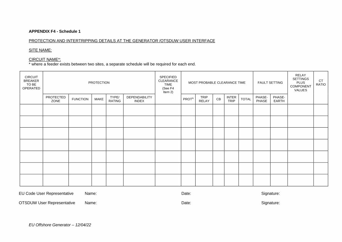
EU Offshore Generator – 12/04/22
APPENDIX F4 - Schedule 1 PROTECTION AND INTERTRIPPING DETAILS AT THE GENERATOR /OTSDUW USER INTERFACE SITE NAME: CIRCUIT NAME*: * where a feeder exists between two sites, a separate schedule will be required for each end.
CIRCUIT BREAKER
TO BE
OPERATED
PROTECTION
SPECIFIED CLEARANCE
TIME
(See F4 Item 2)
MOST PROBABLE CLEARANCE TIME FAULT SETTING
RELAY SETTINGS
PLUS COMPONENT
VALUES
CT RATIO
PROTECTED ZONE
FUNCTION MAKE TYPE/
RATING DEPENDABILITY
INDEX PROTN
TRIP RELAY
CB INTER TRIP
TOTAL PHASE- PHASE
PHASE- EARTH
EU Code User Representative Name: Date: Signature: OTSDUW User Representative Name: Date: Signature:
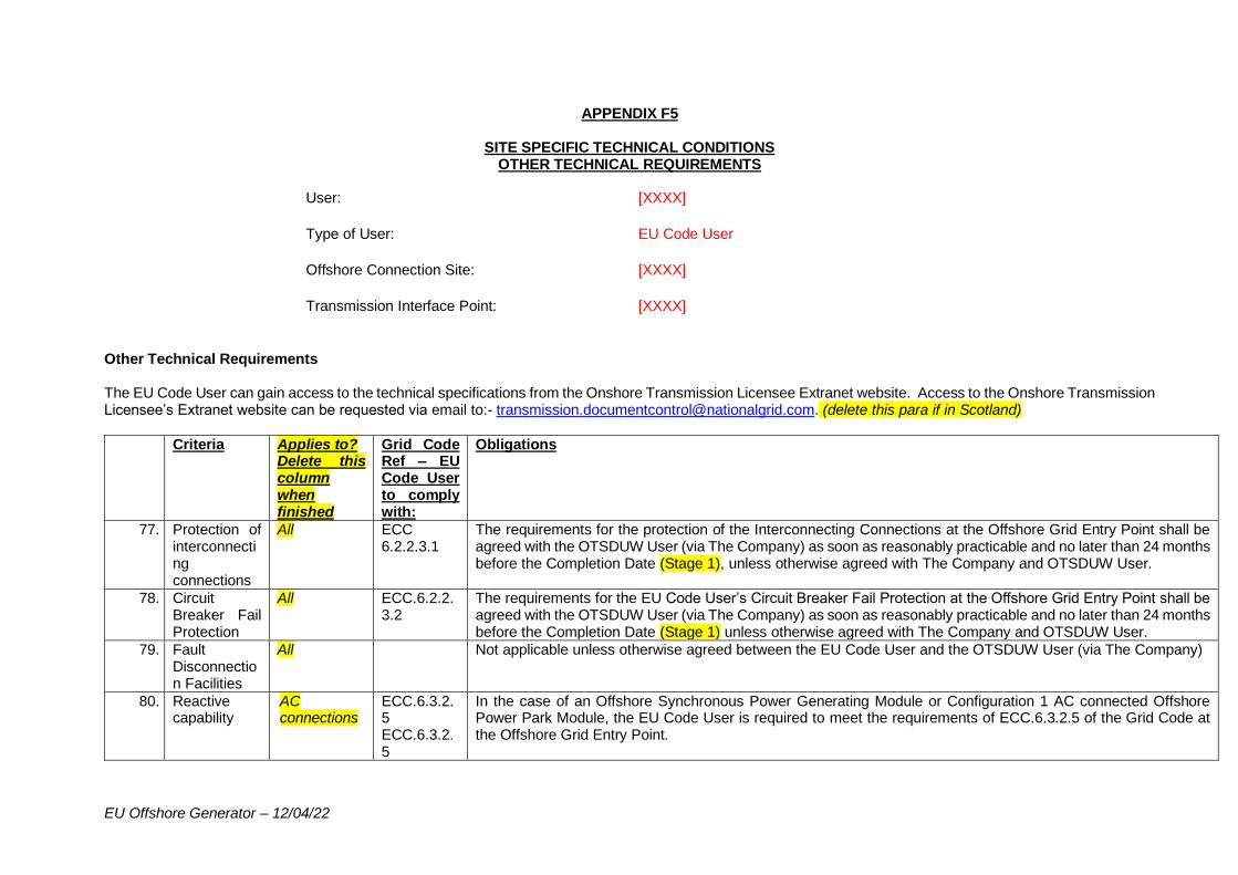
EU Offshore Generator – 12/04/22
APPENDIX F5
SITE SPECIFIC TECHNICAL CONDITIONS OTHER TECHNICAL REQUIREMENTS
User: [XXXX]
Type of User: EU Code User
Offshore Connection Site: [XXXX]
Transmission Interface Point: [XXXX]
Other Technical Requirements The EU Code User can gain access to the technical specifications from the Onshore Transmission Licensee Extranet website. Access to the Onshore Transmission Licensee’s Extranet website can be requested via email to:- [email protected]. (delete this para if in Scotland)
Criteria Applies to? Delete this column when finished
Grid Code Ref – EU Code User to comply with:
Obligations
77. Protection of interconnecting connections
All ECC 6.2.2.3.1
The requirements for the protection of the Interconnecting Connections at the Offshore Grid Entry Point shall be agreed with the OTSDUW User (via The Company) as soon as reasonably practicable and no later than 24 months before the Completion Date (Stage 1), unless otherwise agreed with The Company and OTSDUW User.
78. Circuit Breaker Fail Protection
All ECC.6.2.2.3.2
The requirements for the EU Code User’s Circuit Breaker Fail Protection at the Offshore Grid Entry Point shall be agreed with the OTSDUW User (via The Company) as soon as reasonably practicable and no later than 24 months before the Completion Date (Stage 1) unless otherwise agreed with The Company and OTSDUW User.
79. Fault Disconnection Facilities
All Not applicable unless otherwise agreed between the EU Code User and the OTSDUW User (via The Company)
80. Reactive capability
AC connections
ECC.6.3.2.5 ECC.6.3.2.5
In the case of an Offshore Synchronous Power Generating Module or Configuration 1 AC connected Offshore Power Park Module, the EU Code User is required to meet the requirements of ECC.6.3.2.5 of the Grid Code at the Offshore Grid Entry Point.
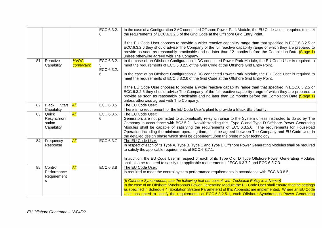
EU Offshore Generator – 12/04/22
ECC.6.3.2.6
In the case of a Configuration 2 AC connected Offshore Power Park Module, the EU Code User is required to meet the requirements of ECC.6.3.2.6 of the Grid Code at the Offshore Grid Entry Point. If the EU Code User chooses to provide a wider reactive capability range than that specified in ECC.6.3.2.5 or ECC.6.3.2.6 they should advise The Company of the full reactive capability range of which they are prepared to provide as soon as reasonably practicable and no later than 12 months before the Completion Date (Stage 1) unless otherwise agreed with The Company.
81. Reactive Capability
HVDC connection
ECC.6.3.2.5 ECC.6.3.2.6
In the case of an Offshore Configuration 1 DC connected Power Park Module, the EU Code User is required to meet the requirements of ECC.6.3.2.5 of the Grid Code at the Offshore Grid Entry Point. In the case of an Offshore Configuration 2 DC connected Power Park Module, the EU Code User is required to meet the requirements of ECC.6.3.2.6 of the Grid Code at the Offshore Grid Entry Point. If the EU Code User chooses to provide a wider reactive capability range than that specified in ECC.6.3.2.5 or ECC.6.3.2.6 they should advise The Company of the full reactive capability range of which they are prepared to provide as soon as reasonably practicable and no later than 12 months before the Completion Date (Stage 1) unless otherwise agreed with The Company.
82. Black Start Capability
All ECC.6.3.5 The EU Code User: There is no requirement for the EU Code User’s plant to provide a Black Start facility.
83. Quick Resynchronisation Capability
All ECC.6.3.5.6
The EU Code User: Generators are not permitted to automatically re-synchronise to the System unless instructed to do so by The Company in accordance with BC2.5.2. Notwithstanding this, Type C and Type D Offshore Power Generating Modules shall be capable of satisfying the requirements of ECC.6.3.5.6. The requirements for Houseload Operation including the minimum operating time, shall be agreed between The Company and EU Code User in the detailed design phase which shall be dependent upon the prime mover technology.
84. Frequency Response
All ECC.6.3.7 The EU Code User: In respect of each of its Type A, Type B, Type C and Type D Offshore Power Generating Modules shall be required to satisfy the applicable requirements of ECC.6.3.7.1. In addition, the EU Code User in respect of each of its Type C or D Type Offshore Power Generating Modules shall also be required to satisfy the applicable requirements of ECC.6.3.7.2 and ECC.6.3.7.3.
85. Control Performance Requirements
All ECC.6.3.8 The EU Code User: Is required to meet the control system performance requirements in accordance with ECC.6.3.8.5. (If Offshore Synchronous, use the following text but consult with Technical Policy in advance) In the case of an Offshore Synchronous Power Generating Module the EU Code User shall ensure that the settings as specified in Schedule 4 (Excitation System Parameters) of this Appendix are implemented. Where an EU Code User has opted to satisfy the requirements of ECC.6.3.2.5.1, each Offshore Synchronous Power Generating
EU Offshore Generator – 12/04/22
Module shall also be capable of controlling the Reactive Power at the Grid Entry Point in accordance with the requirements of ECC.6.3.8.1.2 with the additional control system requirements being discussed and agreed between The EU Code User and The Company which would be contingent upon the site connection arrangements. Where an EU Code User in respect of its Offshore Synchronous Power Generating Module has opted to satisfy the reactive capability requirements of ECC.6.3.2.5.2 each Offshore Synchronous Power Generating Unit shall be required to satisfy the control system requirements specified in Appendix E6 of the Grid Code European Connection Conditions. Where an EU Code User has opted to satisfy the requirements of ECC.6.3.2.5.1 in respect of a Configuration 1 AC connected Offshore Power Park Module, then each Configuration 1 AC connected Offshore Power Park Module shall be required to satisfy the requirements of ECC.A.7.3. Where an EU Code User has opted to satisfy the requirements of ECC.6.3.2.5.2 in respect of a Configuration 1 AC connected Offshore Power Park Module, then each Configuration 1 AC connected Offshore Power Park Module shall be required to satisfy the requirements of ECC.A.7 (excluding ECC.A.7.3 and ECC.A.7.4) with appropriate adjustments made to the reactive capability limits. Where an EU Code User has opted to satisfy the requirements of ECC.6.3.2.6.1 in respect of a Configuration 2 AC connected Offshore Power Park Module, then each Configuration 2 AC connected Offshore Power Park Module shall be required to satisfy the requirements of ECC.A.8. Where an EU Code User has opted to satisfy the requirements of ECC.6.3.2.6.3 in respect of a Configuration 2 AC connected Offshore Power Park Module, then each Configuration 2 AC connected Offshore Power Park Module shall be required to satisfy the requirements of ECC.A.7 (excluding ECC.A.7.3 and ECC.A.7.4) with appropriate adjustments made to the reactive capability limits. (AC connected only, use these 2 paras and delete below) Where an EU Code User has opted to satisfy the requirements of ECC.6.3.2.5.1 in respect of a Configuration 1 DC connected Offshore Power Park Module, then each Configuration 1 DC connected Offshore Power Park Module shall be required to satisfy the requirements of ECC.A.7.3. Where an EU Code User has opted to satisfy the requirements of ECC.6.3.2.5.2 in respect of a Configuration 1 DC connected Offshore Power Park Module, then each Configuration 1 DC connected Offshore Power Park Module shall be required to satisfy the requirements of ECC.A.7 (excluding ECC.A.7.3 and ECC.A.7.4) with appropriate adjustments made to the reactive capability limits. Where an EU Code User has opted to satisfy the requirements of ECC.6.3.2.6.1 in respect of a Configuration 2 DC connected Offshore Power Park Module, then each Configuration 2 DC connected Offshore Power Park Module shall be required to satisfy the requirements of ECC.A.8. Where an EU Code User has opted to satisfy the requirements of ECC.6.3.2.6.3 in respect of a Configuration 2 DC connected Offshore Power Park Module, then each Configuration 2 DC connected Offshore Power Park Module shall be required to satisfy the requirements of ECC.A.7 (excluding ECC.A.7.3 and ECC.A.7.4) with appropriate adjustments made to the reactive capability limits. (HVDC only, delete ac paras and use these 2)
EU Offshore Generator – 12/04/22
86. Power Oscillation Damping
PSS Not required - Customer choice
BC.2.11.2 The EU Code User: There is no requirement for the automatic control system of each Power Park Module to be fitted with a Power System Stabiliser (PSS). However, if the EU Code User chooses to install a PSS within the Power Park Module control system, its settings and performance shall be agreed with The Company and commissioned in accordance with BC.2.11.2 of the Grid Code. Where the EU Code user opts to install a PSS, the OTSDUW User to supply maximum and is at the Transmission Interface Point and any other data which may reasonably be required for the above analysis.
87. Dynamic performance and Interactions
All ECC.6.1.9 ECC.6.1.10 ECC.6.3.17.1.5 PC.A.6.1.3
The EU Code User: Is required to satisfy the requirements of PC.A.6.1.3 and ECC.6.3.17.1.5 and assist The Company to ensure compliance with ECC.6.1.9, ECC.6.1.10. Please note the following: Power Factory RMS model(s):
This includes model(s) and any associated set up script(s) that form part of the model delivery to The Company
and should be compliant with PC.A.5. Any set up scripts should be compatible with the Powerfactory network used
by The Company. Also, the RMS model should not require the use of integration time steps less than 10ms due
to the time to run a set of simulations on a large network with a large number of models and should not include
DLL codes.
Power Factory version:
Model(s) to be delivered in a version of Powerfactory to be agreed with The Company.
After the PF model is provided, the model validation report which compares results against simulation results of PF model and FAT results should be submitted. Dynamic Performance Study (DPS) results may be required to demonstrate that the expected steady state and dynamic performance of the EU Code User’s Plant and Apparatus has been met. To ensure its converters (including controllers) within the System do not cause negatively or lightly damped resonances or interactions on the NETS, adequate damping control facilities to be installed if there is a risk of the following phenomena:
• Sub-synchronous oscillations due to interactions between the EU Code User’s Plant and Apparatus and the NETS. For clarity, sub-synchronous torsional oscillation with other User’s Plant and Apparatus shall be included in the study.
EU Offshore Generator – 12/04/22
• Control interaction due to interactions between the EU Code User’s Plant and Apparatus, network and/or any plant directly or indirectly connected to the NETS. For clarity, Control Interaction with the network and other User’s Plant and Apparatus shall be studied in the sub-synchronous and super-synchronous frequency ranges where the EU Code User’s Plant and Apparatus is identified to be responsive.
To provide data and results to The Company in consultation with the Relevant Transmission Licensee including full EMT and RMS models (models to be provided 3 years prior to connection, ideally to be included in tender documents) and updated version of the model to be provided after commissioning. Specification for the models to be agreed with The Company and Relevant Transmission Licensee of all EU Code User’s plant to enable the following studies:
• Transient Analysis studies – electromechanical and electromagnetic.
• Frequency Domain studies – including eigenvalue analysis and damping torque assessments for all EU Code User’s equipment.
Detailed requirements in relation to the above studies can be agreed with The Company and the Relevant Transmission Licensee at a time convenient to the EU Code User. The results of these studies must be provided to The Company and the Relevant Transmission Licensee by the date defined in the Appendix J/date to be agreed with The Company, the Onshore Transmission Licensee and the EU Code User.(use to be agreed in Scottish agreements) The EU Code User shall provide The Company with any relevant information required in the above assessments. EMT Model:
After the EMT model is provided, the equipment model validation report which compares results against simulation result of EMT model and equipment FAT results should be submitted. Specification for the model (including time step) should be agreed in advance between The Company in consultation with Relevant Transmission Licensee and the EU Code User. Additional Note Both The Company and the EU Code User endeavour to revise and update as applicable the contents of this clause before Completion date, unless otherwise agreed, in accordance with the Grid Code applicable at the time. The Company
EU Offshore Generator – 12/04/22
To outline the detailed requirements and the extent of the studies to be performed, and the criteria to demonstrate compliance with (depending on the static and dynamic models of the transmission network) other relevant Users before the Completion date. The results of these studies must be provided to The Company and the Relevant Transmission Licensee by the date defined in the Appendix J/date to be agreed with The Company, the Onshore Transmission Licensee and the EU Code User (use to be agreed in Scottish agreements), unless otherwise agreed.
88. Fault Ride Through
All ECC.6.3.15 The EU Code User: To meet the requirements of ECC.6.3.15. In the case of a DC connected Power Park Module any site specific requirements including short circuit levels at the Offshore Grid Entry Point shall be provided via The Company from the Offshore Transmission Licensee. (DC connected only)
89. Fast Fault Current Injection
Offshore Power Park Modules
ECC.6.3.16 The EU Code User: Is required to satisfy the requirements of ECC.6.3.16. Where the EU Code User identifies the need for blocking, the EU Code User shall advise and agree the control strategy employed with The Company which shall be at least 36 months before the Completion Date (Stage 1) which must also include the approach to de-blocking.
90. Trading Point Electronic Data Transfer (EDT), Control Points, Control Telephony and Control Point Electronic Dispatch and Logging (EDL)
All ECC.6.5.8(a) ECC.7.9 OC.7 BC.2 ECC.6.5.2 to ECC.6.5.5 ECC.6.5.8, ECC.6.5.9 and BC.1.4.1 ECC.6.5.8(b)
The EU Code User: To fulfil the obligations defined in Schedule 1 of this Appendix.
91. Control Point All directly connected and those
ECC.7.9 The EU Code User: As required under BC2.9 of the Grid Code, the EU Code User will be required to respond to Emergency Instructions, some examples of which are described in BC.2.9.1. In order to fulfil these requirements, it is
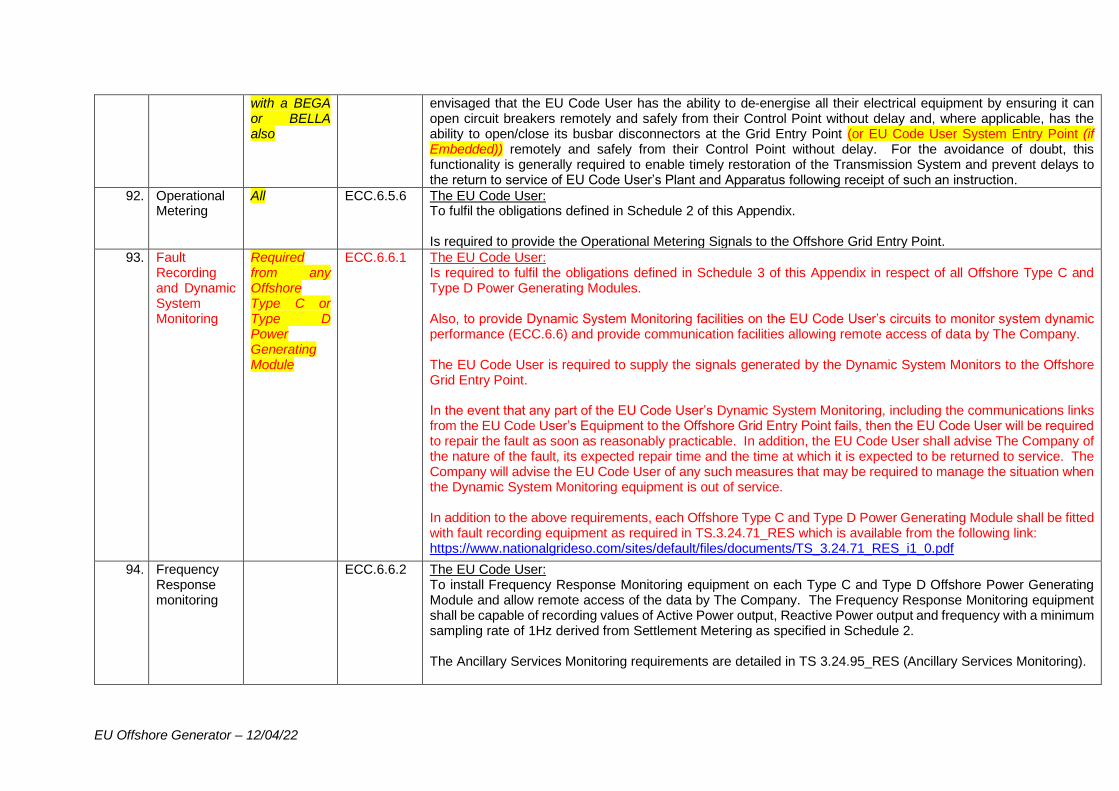
EU Offshore Generator – 12/04/22
with a BEGA or BELLA also
envisaged that the EU Code User has the ability to de-energise all their electrical equipment by ensuring it can open circuit breakers remotely and safely from their Control Point without delay and, where applicable, has the ability to open/close its busbar disconnectors at the Grid Entry Point (or EU Code User System Entry Point (if Embedded)) remotely and safely from their Control Point without delay. For the avoidance of doubt, this functionality is generally required to enable timely restoration of the Transmission System and prevent delays to the return to service of EU Code User’s Plant and Apparatus following receipt of such an instruction.
92. Operational Metering
All ECC.6.5.6 The EU Code User: To fulfil the obligations defined in Schedule 2 of this Appendix. Is required to provide the Operational Metering Signals to the Offshore Grid Entry Point.
93. Fault Recording and Dynamic System Monitoring
Required from any Offshore Type C or Type D Power Generating Module
ECC.6.6.1 The EU Code User: Is required to fulfil the obligations defined in Schedule 3 of this Appendix in respect of all Offshore Type C and Type D Power Generating Modules. Also, to provide Dynamic System Monitoring facilities on the EU Code User’s circuits to monitor system dynamic performance (ECC.6.6) and provide communication facilities allowing remote access of data by The Company. The EU Code User is required to supply the signals generated by the Dynamic System Monitors to the Offshore Grid Entry Point. In the event that any part of the EU Code User’s Dynamic System Monitoring, including the communications links from the EU Code User’s Equipment to the Offshore Grid Entry Point fails, then the EU Code User will be required to repair the fault as soon as reasonably practicable. In addition, the EU Code User shall advise The Company of the nature of the fault, its expected repair time and the time at which it is expected to be returned to service. The Company will advise the EU Code User of any such measures that may be required to manage the situation when the Dynamic System Monitoring equipment is out of service. In addition to the above requirements, each Offshore Type C and Type D Power Generating Module shall be fitted with fault recording equipment as required in TS.3.24.71_RES which is available from the following link: https://www.nationalgrideso.com/sites/default/files/documents/TS_3.24.71_RES_i1_0.pdf
94. Frequency Response monitoring
ECC.6.6.2 The EU Code User: To install Frequency Response Monitoring equipment on each Type C and Type D Offshore Power Generating Module and allow remote access of the data by The Company. The Frequency Response Monitoring equipment shall be capable of recording values of Active Power output, Reactive Power output and frequency with a minimum sampling rate of 1Hz derived from Settlement Metering as specified in Schedule 2. The Ancillary Services Monitoring requirements are detailed in TS 3.24.95_RES (Ancillary Services Monitoring).
EU Offshore Generator – 12/04/22
The signals should be compatible with any equipment installed or being installed by the Onshore Transmission Licensee at the Transmission Interface Point. The EU Code User is required to supply the signals generated by the Ancillary Services Monitors to the Offshore Grid Entry Point. In addition, the EU Code User shall also provide facilities to allow The Company to monitor the health of the Ancillary Services Monitoring equipment up to the Offshore Grid Entry Point. In the event that any part of the EU Code User’s Ancillary Services Monitoring equipment including the communications links from the EU Code User’s Equipment to the Offshore Grid Entry Point fails, then the EU Code User will be required to repair the fault as soon as reasonably practicable. In addition, the EU Code User shall advise The Company of the nature of the fault, its expected repair time and the time at which it is expected to be returned to service. The Company will advise the EU Code User of any such measures that may be required to manage the situation when the Ancillary Services Monitoring equipment is out of service. For the avoidance of doubt, the OTSDUW User will be responsible for the installation of the communications routes from the Offshore Grid Entry Point to the Transmission Interface Point in order to facilitate this requirement. Once in operation, the ownership of part or the whole of the communication equipment will be transferred to the appointed Offshore Transmission Licensee following the OTSUA Transfer Time when each party (EU Code User and Offshore Transmission Licensee) will then be responsible for the maintenance and monitoring of their own assets. The Company will provide facilities at the Transmission Interface Point within [XXXX]kV Onshore Substation in order to receive the Ancillary Services Monitoring data.
95. Voltage Waveform Quality
All ECC.6.1.5 (b) ECC.6.1.6
The EU Code User: To provide The Company with Voltage Quality Assessment information as specified in PC.4.4.1, PC.4.4.2, PC4.5, PC.A.5.42(h), DRC.6.1.1 Schedule 1 and DRC.6.1.5 Schedule 5 of the Grid Code to enable the OTSDUW User to carry out assessments of harmonic voltage distortion and voltage fluctuation in accordance with Grid Code conditions ECC.6.1.5(a) and ECC.6.1.7 respectively (equivalent to Section K paragraph 7 of the STC). These requirements apply at the Offshore Grid Entry Point and shall include all Offshore Power Park Modules and associated EU Code User’s Equipment up to the Offshore Grid Entry Point. Following this assessment, the Onshore Transmission Licensee may specify to the EU Code User (by written notice via The Company), the harmonic voltage distortion or harmonic current emission limits (as appropriate) in conjunction with impedance loci and background levels, and voltage fluctuation (flicker) limits. The Company (upon advice from the OTSDUW User) will specify any additional requirements to the EU Code User in the detailed design phase. The requirement (if any) for Power Quality emission limits at the Offshore Grid Entry Point will be notified by The Company but specified by the OTSDUW User.
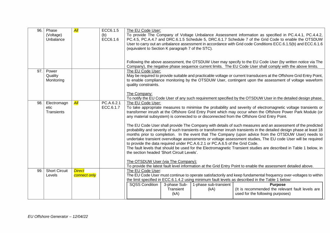
EU Offshore Generator – 12/04/22
96. Phase (Voltage) Unbalance
All ECC6.1.5 (b) ECC6.1.6
The EU Code User: To provide The Company of Voltage Unbalance Assessment information as specified in PC.4.4.1, PC.4.4.2, PC.4.5, PC.A.4.7 and DRC.6.1.5 Schedule 5, DRC.6.1.7 Schedule 7 of the Grid Code to enable the OTSDUW User to carry out an unbalance assessment in accordance with Grid code Conditions ECC.6.1.5(b) and ECC.6.1.6 (equivalent to Section K paragraph 7 of the STC). Following the above assessment, the OTSDUW User may specify to the EU Code User (by written notice via The Company), the negative phase sequence current limits. The EU Code User shall comply with the above limits.
97. Power Quality Monitoring
The EU Code User: May be required to provide suitable and practicable voltage or current transducers at the Offshore Grid Entry Point, to enable compliance monitoring by the OTSDUW User, contingent upon the assessment of voltage waveform quality constraints. The Company: To notify the EU Code User of any such requirement specified by the OTSDUW User in the detailed design phase.
98. Electromagnetic Transients
All PC.A.6.2.1 ECC.6.1.7
The EU Code User: To take appropriate measures to minimise the probability and severity of electromagnetic voltage transients or transformer inrush at the Offshore Grid Entry Point which may occur when the Offshore Power Park Module (or any material subsystem) is connected to or disconnected from the Offshore Grid Entry Point. The EU Code User shall provide The Company with details of such measures and an assessment of the predicted probability and severity of such transients or transformer inrush transients in the detailed design phase at least 18 months prior to completion. In the event that The Company (upon advice from the OTSDUW User) needs to undertake transient overvoltage assessments or voltage assessment studies, The EU code User will be required to provide the data required under PC.A.6.2.1 or PC.A.6.5 of the Grid Code. The fault levels that should be used for the Electromagnetic Transient studies are described in Table 1 below, in the section headed ‘Short Circuit Levels’. The OTSDUW User (via The Company): To provide the latest fault level information at the Grid Entry Point to enable the assessment detailed above.
99. Short Circuit Levels
Direct connect only
The EU Code User: The EU Code User must continue to operate satisfactorily and keep fundamental frequency over-voltages to within the limit specified in ECC.6.1.4.2 using minimum fault levels as described in the Table 1 below:
SQSS Condition 3-phase Sub-Transient
(kA)
1-phase sub-transient (kA)
Purpose (It is recommended the relevant fault levels are used for the following purposes)
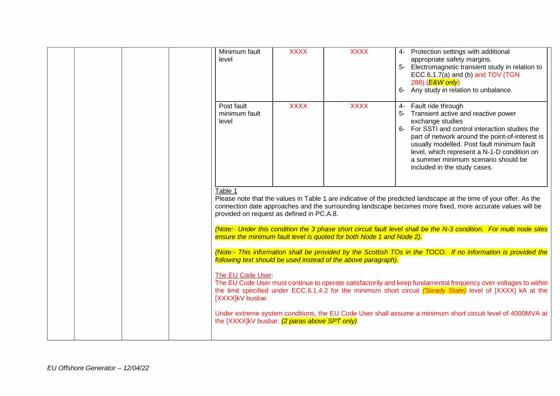
EU Offshore Generator – 12/04/22
Minimum fault level
XXXX
XXXX
4- Protection settings with additional appropriate safety margins.
5- Electromagnetic transient study in relation to ECC.6.1.7(a) and (b) and TOV (TGN 288).(E&W only)
6- Any study in relation to unbalance.
Post fault minimum fault level
XXXX
XXXX
4- Fault ride through 5- Transient active and reactive power
exchange studies 6- For SSTI and control interaction studies the
part of network around the point-of-interest is usually modelled. Post fault minimum fault level, which represent a N-1-D condition on a summer minimum scenario should be included in the study cases.
Table 1 Please note that the values in Table 1 are indicative of the predicted landscape at the time of your offer. As the connection date approaches and the surrounding landscape becomes more fixed, more accurate values will be provided on request as defined in PC.A.8. (Note:- Under this condition the 3 phase short circuit fault level shall be the N-3 condition. For multi node sites ensure the minimum fault level is quoted for both Node 1 and Node 2). (Note:- This information shall be provided by the Scottish TOs in the TOCO. If no information is provided the following text should be used instead of the above paragraph). The EU Code User: The EU Code User must continue to operate satisfactorily and keep fundamental frequency over-voltages to within the limit specified under ECC.6.1.4.2 for the minimum short circuit (Steady State) level of [XXXX] kA at the [XXXX]kV busbar. Under extreme system conditions, the EU Code User shall assume a minimum short circuit level of 4000MVA at the [XXXX]kV busbar. (2 paras above SPT only)
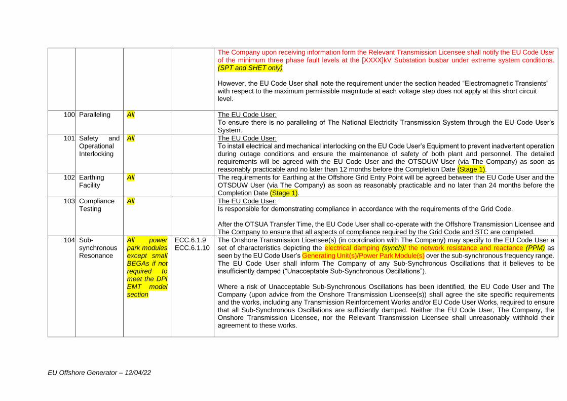
EU Offshore Generator – 12/04/22
The Company upon receiving information form the Relevant Transmission Licensee shall notify the EU Code User of the minimum three phase fault levels at the [XXXX]kV Substation busbar under extreme system conditions. (SPT and SHET only) However, the EU Code User shall note the requirement under the section headed “Electromagnetic Transients” with respect to the maximum permissible magnitude at each voltage step does not apply at this short circuit level.
100. Paralleling All The EU Code User: To ensure there is no paralleling of The National Electricity Transmission System through the EU Code User’s System.
101. Safety and Operational Interlocking
All The EU Code User: To install electrical and mechanical interlocking on the EU Code User’s Equipment to prevent inadvertent operation during outage conditions and ensure the maintenance of safety of both plant and personnel. The detailed requirements will be agreed with the EU Code User and the OTSDUW User (via The Company) as soon as reasonably practicable and no later than 12 months before the Completion Date (Stage 1).
102. Earthing Facility
All The requirements for Earthing at the Offshore Grid Entry Point will be agreed between the EU Code User and the OTSDUW User (via The Company) as soon as reasonably practicable and no later than 24 months before the Completion Date (Stage 1).
103. Compliance Testing
All The EU Code User: Is responsible for demonstrating compliance in accordance with the requirements of the Grid Code. After the OTSUA Transfer Time, the EU Code User shall co-operate with the Offshore Transmission Licensee and The Company to ensure that all aspects of compliance required by the Grid Code and STC are completed.
104. Sub-synchronous Resonance
All power park modules except small BEGAs if not required to meet the DPI EMT model section
ECC.6.1.9 ECC.6.1.10
The Onshore Transmission Licensee(s) (in coordination with The Company) may specify to the EU Code User a set of characteristics depicting the electrical damping (synch)/ the network resistance and reactance (PPM) as seen by the EU Code User’s Generating Unit(s)/Power Park Module(s) over the sub-synchronous frequency range. The EU Code User shall inform The Company of any Sub-Synchronous Oscillations that it believes to be insufficiently damped (“Unacceptable Sub-Synchronous Oscillations”). Where a risk of Unacceptable Sub-Synchronous Oscillations has been identified, the EU Code User and The Company (upon advice from the Onshore Transmission Licensee(s)) shall agree the site specific requirements and the works, including any Transmission Reinforcement Works and/or EU Code User Works, required to ensure that all Sub-Synchronous Oscillations are sufficiently damped. Neither the EU Code User, The Company, the Onshore Transmission Licensee, nor the Relevant Transmission Licensee shall unreasonably withhold their agreement to these works.
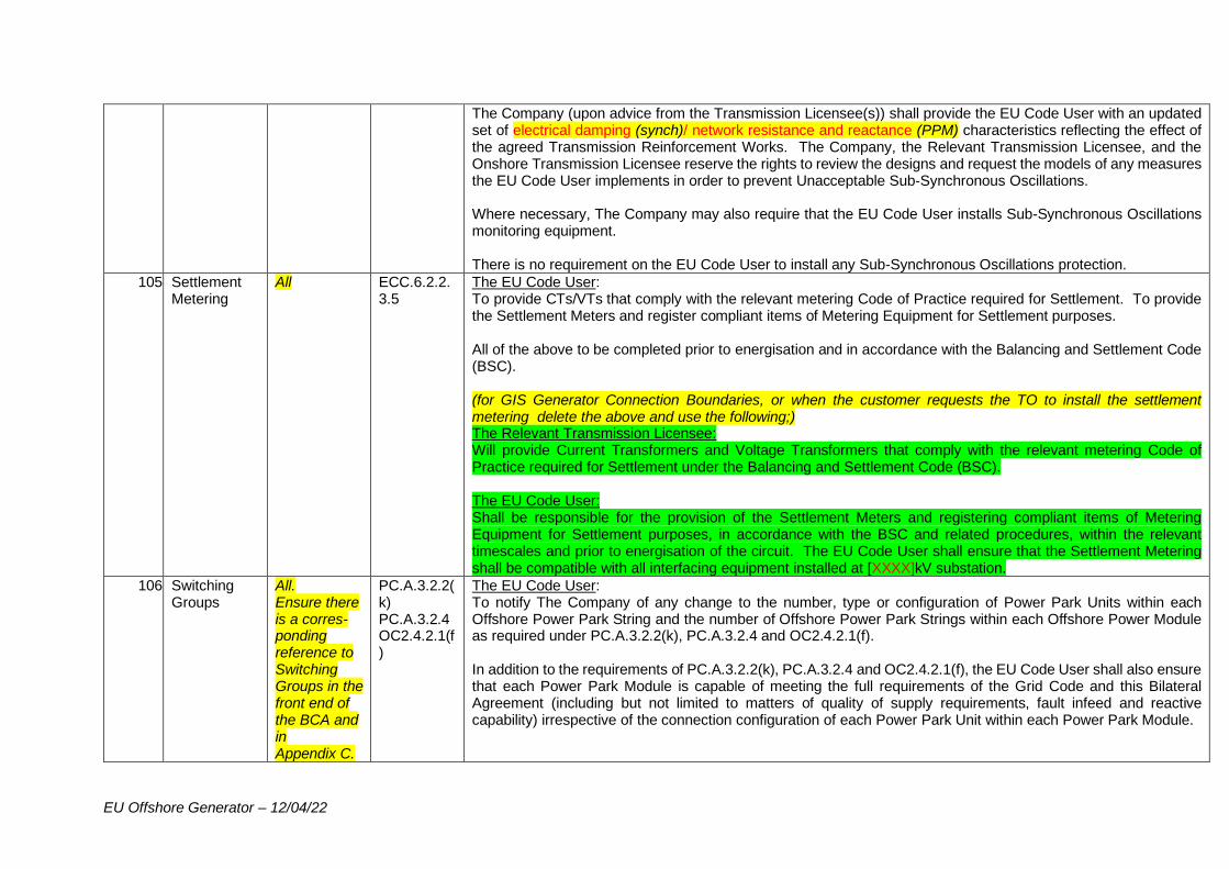
EU Offshore Generator – 12/04/22
The Company (upon advice from the Transmission Licensee(s)) shall provide the EU Code User with an updated set of electrical damping (synch)/ network resistance and reactance (PPM) characteristics reflecting the effect of the agreed Transmission Reinforcement Works. The Company, the Relevant Transmission Licensee, and the Onshore Transmission Licensee reserve the rights to review the designs and request the models of any measures the EU Code User implements in order to prevent Unacceptable Sub-Synchronous Oscillations. Where necessary, The Company may also require that the EU Code User installs Sub-Synchronous Oscillations monitoring equipment. There is no requirement on the EU Code User to install any Sub-Synchronous Oscillations protection.
105. Settlement Metering
All
ECC.6.2.2.3.5
The EU Code User: To provide CTs/VTs that comply with the relevant metering Code of Practice required for Settlement. To provide the Settlement Meters and register compliant items of Metering Equipment for Settlement purposes. All of the above to be completed prior to energisation and in accordance with the Balancing and Settlement Code (BSC). (for GIS Generator Connection Boundaries, or when the customer requests the TO to install the settlement metering delete the above and use the following;) The Relevant Transmission Licensee: Will provide Current Transformers and Voltage Transformers that comply with the relevant metering Code of Practice required for Settlement under the Balancing and Settlement Code (BSC). The EU Code User: Shall be responsible for the provision of the Settlement Meters and registering compliant items of Metering Equipment for Settlement purposes, in accordance with the BSC and related procedures, within the relevant timescales and prior to energisation of the circuit. The EU Code User shall ensure that the Settlement Metering shall be compatible with all interfacing equipment installed at [XXXX]kV substation.
106. Switching Groups
All. Ensure there is a corres- ponding reference to Switching Groups in the front end of the BCA and in Appendix C.
PC.A.3.2.2(k) PC.A.3.2.4 OC2.4.2.1(f)
The EU Code User: To notify The Company of any change to the number, type or configuration of Power Park Units within each Offshore Power Park String and the number of Offshore Power Park Strings within each Offshore Power Module as required under PC.A.3.2.2(k), PC.A.3.2.4 and OC2.4.2.1(f). In addition to the requirements of PC.A.3.2.2(k), PC.A.3.2.4 and OC2.4.2.1(f), the EU Code User shall also ensure that each Power Park Module is capable of meeting the full requirements of the Grid Code and this Bilateral Agreement (including but not limited to matters of quality of supply requirements, fault infeed and reactive capability) irrespective of the connection configuration of each Power Park Unit within each Power Park Module.
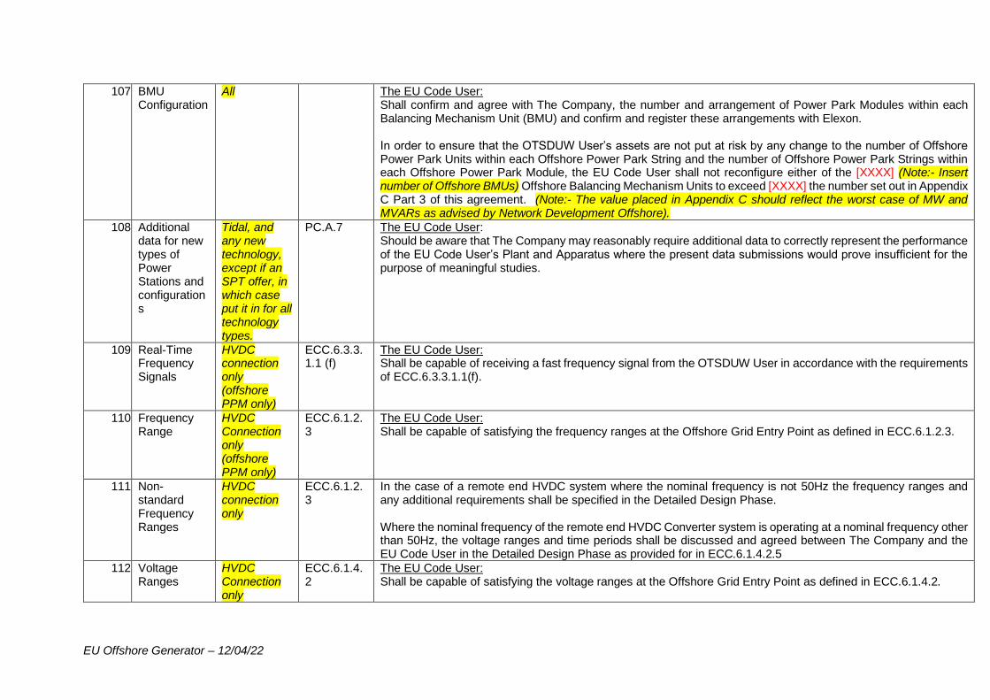
EU Offshore Generator – 12/04/22
107. BMU Configuration
All The EU Code User: Shall confirm and agree with The Company, the number and arrangement of Power Park Modules within each Balancing Mechanism Unit (BMU) and confirm and register these arrangements with Elexon. In order to ensure that the OTSDUW User’s assets are not put at risk by any change to the number of Offshore Power Park Units within each Offshore Power Park String and the number of Offshore Power Park Strings within each Offshore Power Park Module, the EU Code User shall not reconfigure either of the [XXXX] (Note:- Insert number of Offshore BMUs) Offshore Balancing Mechanism Units to exceed [XXXX] the number set out in Appendix C Part 3 of this agreement. (Note:- The value placed in Appendix C should reflect the worst case of MW and MVARs as advised by Network Development Offshore).
108. Additional data for new types of Power Stations and configurations
Tidal, and any new technology, except if an SPT offer, in which case put it in for all technology types.
PC.A.7 The EU Code User: Should be aware that The Company may reasonably require additional data to correctly represent the performance of the EU Code User’s Plant and Apparatus where the present data submissions would prove insufficient for the purpose of meaningful studies.
109. Real-Time Frequency Signals
HVDC connection only (offshore PPM only)
ECC.6.3.3.1.1 (f)
The EU Code User: Shall be capable of receiving a fast frequency signal from the OTSDUW User in accordance with the requirements of ECC.6.3.3.1.1(f).
110. Frequency Range
HVDC Connection only (offshore PPM only)
ECC.6.1.2.3
The EU Code User: Shall be capable of satisfying the frequency ranges at the Offshore Grid Entry Point as defined in ECC.6.1.2.3.
111. Non-standard Frequency Ranges
HVDC connection only
ECC.6.1.2.3
In the case of a remote end HVDC system where the nominal frequency is not 50Hz the frequency ranges and any additional requirements shall be specified in the Detailed Design Phase. Where the nominal frequency of the remote end HVDC Converter system is operating at a nominal frequency other than 50Hz, the voltage ranges and time periods shall be discussed and agreed between The Company and the EU Code User in the Detailed Design Phase as provided for in ECC.6.1.4.2.5
112. Voltage Ranges
HVDC Connection only
ECC.6.1.4.2
The EU Code User: Shall be capable of satisfying the voltage ranges at the Offshore Grid Entry Point as defined in ECC.6.1.4.2.
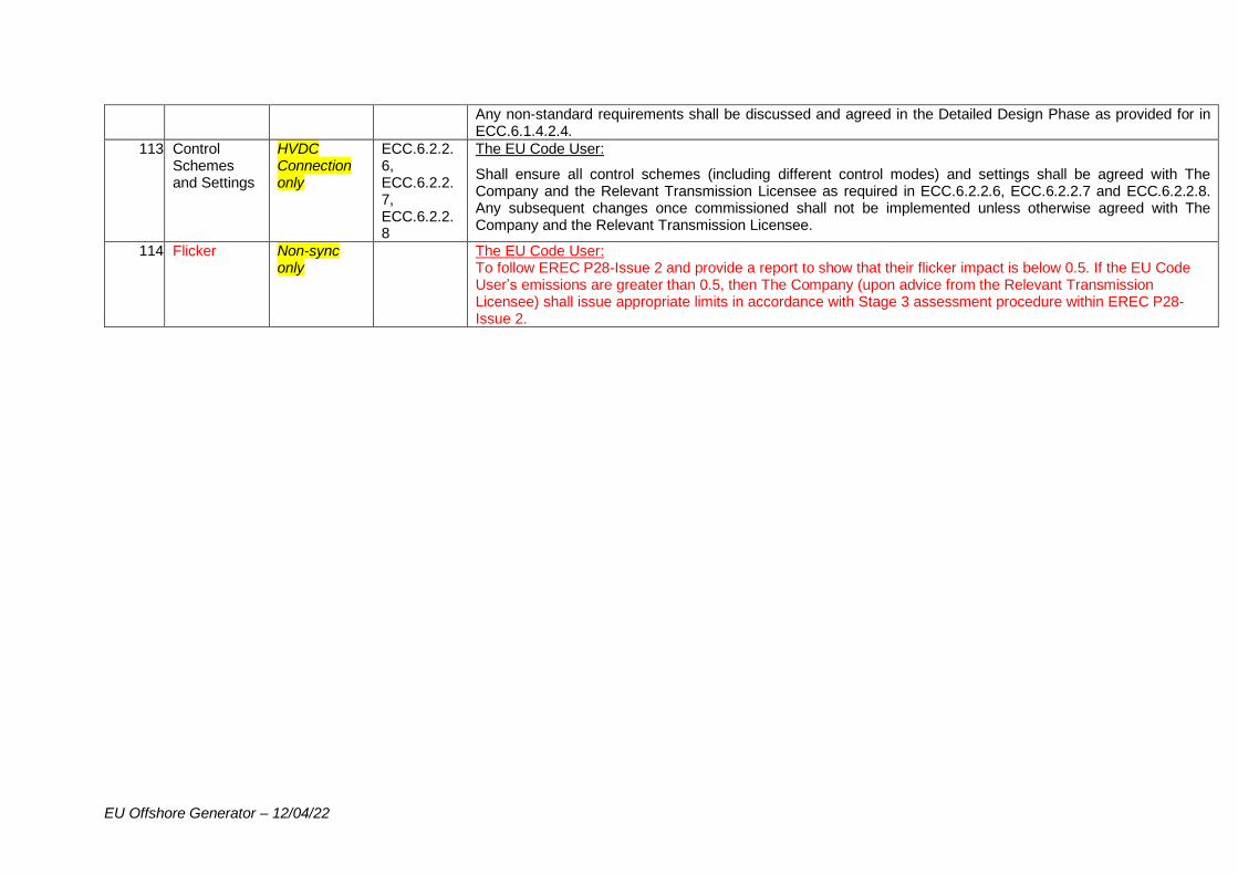
EU Offshore Generator – 12/04/22
Any non-standard requirements shall be discussed and agreed in the Detailed Design Phase as provided for in ECC.6.1.4.2.4.
113. Control Schemes and Settings
HVDC Connection only
ECC.6.2.2.6, ECC.6.2.2.7, ECC.6.2.2.8
The EU Code User:
Shall ensure all control schemes (including different control modes) and settings shall be agreed with The Company and the Relevant Transmission Licensee as required in ECC.6.2.2.6, ECC.6.2.2.7 and ECC.6.2.2.8. Any subsequent changes once commissioned shall not be implemented unless otherwise agreed with The Company and the Relevant Transmission Licensee.
114. Flicker Non-sync only
The EU Code User: To follow EREC P28-Issue 2 and provide a report to show that their flicker impact is below 0.5. If the EU Code User’s emissions are greater than 0.5, then The Company (upon advice from the Relevant Transmission Licensee) shall issue appropriate limits in accordance with Stage 3 assessment procedure within EREC P28-Issue 2.

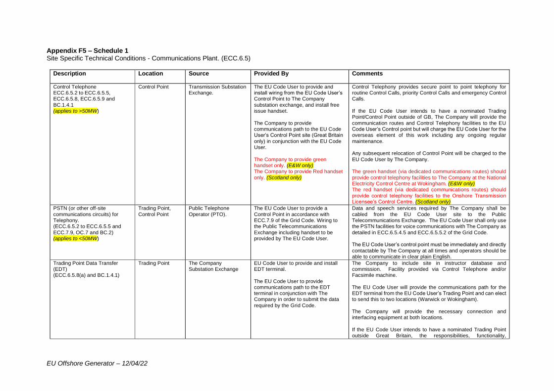
EU Offshore Generator – 12/04/22
Appendix F5 – Schedule 1 Site Specific Technical Conditions - Communications Plant. (ECC.6.5)
Description Location Source Provided By Comments
Control Telephone ECC.6.5.2 to ECC.6.5.5, ECC.6.5.8, ECC.6.5.9 and
BC.1.4.1 (applies to >50MW)
Control Point Transmission Substation Exchange.
The EU Code User to provide and install wiring from the EU Code User’s Control Point to The Company
substation exchange, and install free issue handset.
The Company to provide communications path to the EU Code User’s Control Point site (Great Britain
only) in conjunction with the EU Code User.
The Company to provide green handset only. (E&W only) The Company to provide Red handset
only. (Scotland only)
Control Telephony provides secure point to point telephony for routine Control Calls, priority Control Calls and emergency Control Calls.
If the EU Code User intends to have a nominated Trading Point/Control Point outside of GB, The Company will provide the
communication routes and Control Telephony facilities to the EU Code User’s Control point but will charge the EU Code User for the overseas element of this work including any ongoing regular
maintenance. Any subsequent relocation of Control Point will be charged to the
EU Code User by The Company. The green handset (via dedicated communications routes) should
provide control telephony facilities to The Company at the National Electricity Control Centre at Wokingham. (E&W only) The red handset (via dedicated communications routes) should
provide control telephony facilities to the Onshore Transmission Licensee’s Control Centre. (Scotland only)
PSTN (or other off-site
communications circuits) for Telephony. (ECC.6.5.2 to ECC.6.5.5 and
ECC.7.9, OC.7 and BC.2) (applies to <50MW)
Trading Point,
Control Point
Public Telephone
Operator (PTO).
The EU Code User to provide a
Control Point in accordance with ECC.7.9 of the Grid Code. Wiring to the Public Telecommunications
Exchange including handset to be provided by The EU Code User.
Data and speech services required by The Company shall be
cabled from the EU Code User site to the Public Telecommunications Exchange. The EU Code User shall only use the PSTN facilities for voice communications with The Company as
detailed in ECC.6.5.4.5 and ECC.6.5.5.2 of the Grid Code. The EU Code User’s control point must be immediately and directly
contactable by The Company at all times and operators should be able to communicate in clear plain English.
Trading Point Data Transfer (EDT) (ECC.6.5.8(a) and BC.1.4.1)
Trading Point
The Company Substation Exchange
EU Code User to provide and install EDT terminal.
The EU Code User to provide communications path to the EDT terminal in conjunction with The Company in order to submit the data
required by the Grid Code.
The Company to include site in instructor database and commission. Facility provided via Control Telephone and/or Facsimile machine.
The EU Code User will provide the communications path for the EDT terminal from the EU Code User’s Trading Point and can elect to send this to two locations (Warwick or Wokingham).
The Company will provide the necessary connection and interfacing equipment at both locations.
If the EU Code User intends to have a nominated Trading Point outside Great Britain, the responsibilities, functionality,
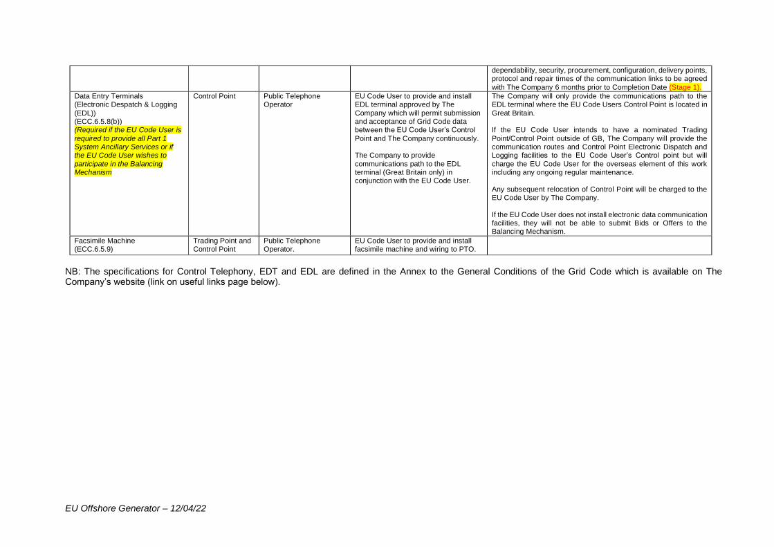
EU Offshore Generator – 12/04/22
dependability, security, procurement, configuration, delivery points, protocol and repair times of the communication links to be agreed
with The Company 6 months prior to Completion Date (Stage 1).
Data Entry Terminals (Electronic Despatch & Logging
(EDL)) (ECC.6.5.8(b)) (Required if the EU Code User is
required to provide all Part 1 System Ancillary Services or if the EU Code User wishes to
participate in the Balancing Mechanism
Control Point Public Telephone Operator
EU Code User to provide and install EDL terminal approved by The
Company which will permit submission and acceptance of Grid Code data between the EU Code User’s Control
Point and The Company continuously. The Company to provide
communications path to the EDL terminal (Great Britain only) in conjunction with the EU Code User.
The Company will only provide the communications path to the EDL terminal where the EU Code Users Control Point is located in
Great Britain. If the EU Code User intends to have a nominated Trading
Point/Control Point outside of GB, The Company will provide the communication routes and Control Point Electronic Dispatch and Logging facilities to the EU Code User’s Control point but will
charge the EU Code User for the overseas element of this work including any ongoing regular maintenance.
Any subsequent relocation of Control Point will be charged to the EU Code User by The Company.
If the EU Code User does not install electronic data communication facilities, they will not be able to submit Bids or Offers to the Balancing Mechanism.
Facsimile Machine (ECC.6.5.9)
Trading Point and Control Point
Public Telephone Operator.
EU Code User to provide and install facsimile machine and wiring to PTO.
NB: The specifications for Control Telephony, EDT and EDL are defined in the Annex to the General Conditions of the Grid Code which is available on The Company’s website (link on useful links page below).
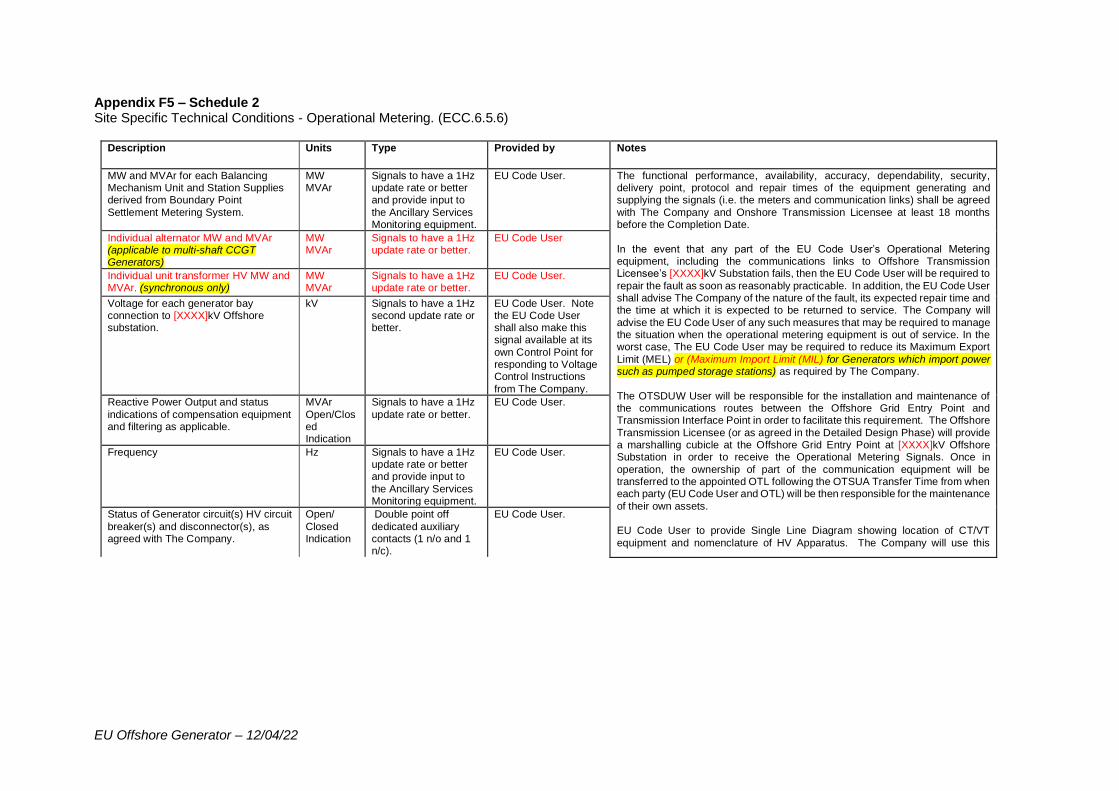
EU Offshore Generator – 12/04/22
Appendix F5 – Schedule 2 Site Specific Technical Conditions - Operational Metering. (ECC.6.5.6)
Description Units Type Provided by Notes
MW and MVAr for each Balancing Mechanism Unit and Station Supplies derived from Boundary Point
Settlement Metering System.
MW MVAr
Signals to have a 1Hz update rate or better and provide input to
the Ancillary Services Monitoring equipment.
EU Code User. The functional performance, availability, accuracy, dependability, security, delivery point, protocol and repair times of the equipment generating and supplying the signals (i.e. the meters and communication links) shall be agreed
with The Company and Onshore Transmission Licensee at least 18 months before the Completion Date.
In the event that any part of the EU Code User’s Operational Metering equipment, including the communications links to Offshore Transmission Licensee’s [XXXX]kV Substation fails, then the EU Code User will be required to
repair the fault as soon as reasonably practicable. In addition, the EU Code User shall advise The Company of the nature of the fault, its expected repair time and the time at which it is expected to be returned to service. The Company will
advise the EU Code User of any such measures that may be required to manage the situation when the operational metering equipment is out of service. In the worst case, The EU Code User may be required to reduce its Maximum Export
Limit (MEL) or (Maximum Import Limit (MIL) for Generators which import power such as pumped storage stations) as required by The Company.
The OTSDUW User will be responsible for the installation and maintenance of the communications routes between the Offshore Grid Entry Point and Transmission Interface Point in order to facilitate this requirement. The Offshore
Transmission Licensee (or as agreed in the Detailed Design Phase) will provide a marshalling cubicle at the Offshore Grid Entry Point at [XXXX]kV Offshore Substation in order to receive the Operational Metering Signals. Once in
operation, the ownership of part of the communication equipment will be transferred to the appointed OTL following the OTSUA Transfer Time from when each party (EU Code User and OTL) will be then responsible for the maintenance
of their own assets. EU Code User to provide Single Line Diagram showing location of CT/VT
equipment and nomenclature of HV Apparatus. The Company will use this
Individual alternator MW and MVAr (applicable to multi-shaft CCGT Generators)
MW MVAr
Signals to have a 1Hz update rate or better.
EU Code User
Individual unit transformer HV MW and MVAr. (synchronous only)
MW MVAr
Signals to have a 1Hz update rate or better.
EU Code User.
Voltage for each generator bay connection to [XXXX]kV Offshore substation.
kV Signals to have a 1Hz second update rate or better.
EU Code User. Note the EU Code User shall also make this signal available at its
own Control Point for responding to Voltage Control Instructions
from The Company.
Reactive Power Output and status
indications of compensation equipment and filtering as applicable.
MVAr
Open/Closed Indication
Signals to have a 1Hz
update rate or better.
EU Code User.
Frequency Hz Signals to have a 1Hz update rate or better and provide input to
the Ancillary Services Monitoring equipment.
EU Code User.
Status of Generator circuit(s) HV circuit
breaker(s) and disconnector(s), as agreed with The Company.
Open/
Closed Indication
Double point off
dedicated auxiliary contacts (1 n/o and 1 n/c).
EU Code User.
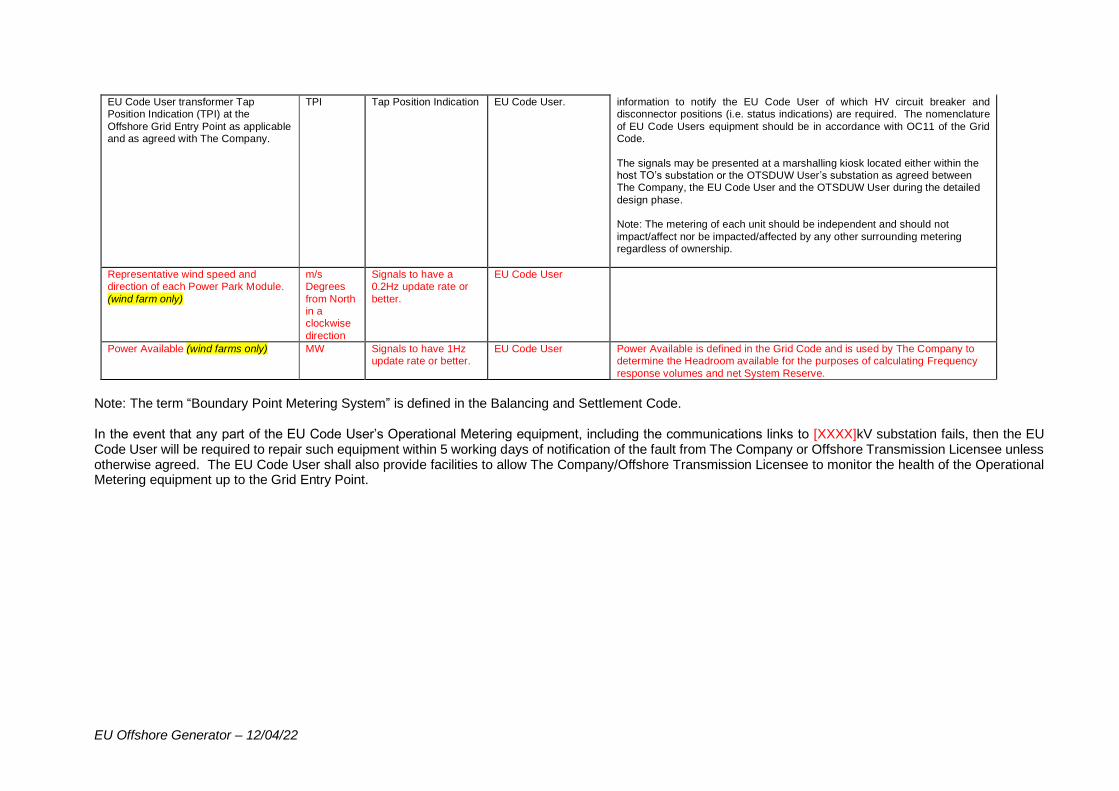
EU Offshore Generator – 12/04/22
EU Code User transformer Tap Position Indication (TPI) at the
Offshore Grid Entry Point as applicable and as agreed with The Company.
TPI Tap Position Indication EU Code User. information to notify the EU Code User of which HV circuit breaker and disconnector positions (i.e. status indications) are required. The nomenclature
of EU Code Users equipment should be in accordance with OC11 of the Grid Code.
The signals may be presented at a marshalling kiosk located either within the host TO’s substation or the OTSDUW User’s substation as agreed between The Company, the EU Code User and the OTSDUW User during the detailed
design phase. Note: The metering of each unit should be independent and should not
impact/affect nor be impacted/affected by any other surrounding metering regardless of ownership.
Representative wind speed and direction of each Power Park Module.
(wind farm only)
m/s Degrees
from North in a clockwise
direction
Signals to have a 0.2Hz update rate or
better.
EU Code User
Power Available (wind farms only) MW Signals to have 1Hz update rate or better.
EU Code User Power Available is defined in the Grid Code and is used by The Company to determine the Headroom available for the purposes of calculating Frequency
response volumes and net System Reserve.
Note: The term “Boundary Point Metering System” is defined in the Balancing and Settlement Code. In the event that any part of the EU Code User’s Operational Metering equipment, including the communications links to [XXXX]kV substation fails, then the EU Code User will be required to repair such equipment within 5 working days of notification of the fault from The Company or Offshore Transmission Licensee unless otherwise agreed. The EU Code User shall also provide facilities to allow The Company/Offshore Transmission Licensee to monitor the health of the Operational Metering equipment up to the Grid Entry Point.
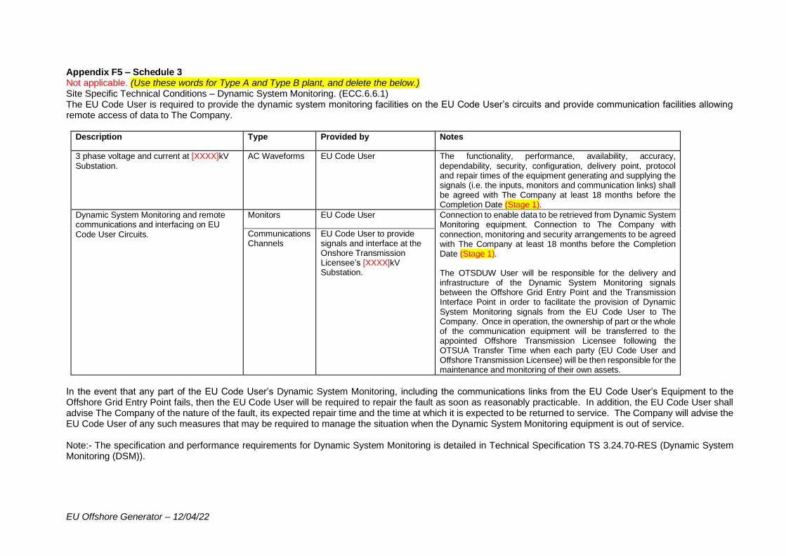
EU Offshore Generator – 12/04/22
Appendix F5 – Schedule 3 Not applicable. (Use these words for Type A and Type B plant, and delete the below.) Site Specific Technical Conditions – Dynamic System Monitoring. (ECC.6.6.1) The EU Code User is required to provide the dynamic system monitoring facilities on the EU Code User’s circuits and provide communication facilities allowing remote access of data to The Company.
Description Type Provided by Notes
3 phase voltage and current at [XXXX]kV Substation.
AC Waveforms EU Code User The functionality, performance, availability, accuracy, dependability, security, configuration, delivery point, protocol and repair times of the equipment generating and supplying the signals (i.e. the inputs, monitors and communication links) shall be agreed with The Company at least 18 months before the Completion Date (Stage 1).
Dynamic System Monitoring and remote communications and interfacing on EU Code User Circuits.
Monitors EU Code User Connection to enable data to be retrieved from Dynamic System Monitoring equipment. Connection to The Company with connection, monitoring and security arrangements to be agreed with The Company at least 18 months before the Completion Date (Stage 1). The OTSDUW User will be responsible for the delivery and infrastructure of the Dynamic System Monitoring signals between the Offshore Grid Entry Point and the Transmission Interface Point in order to facilitate the provision of Dynamic System Monitoring signals from the EU Code User to The Company. Once in operation, the ownership of part or the whole of the communication equipment will be transferred to the appointed Offshore Transmission Licensee following the OTSUA Transfer Time when each party (EU Code User and Offshore Transmission Licensee) will be then responsible for the maintenance and monitoring of their own assets.
Communications Channels
EU Code User to provide signals and interface at the Onshore Transmission Licensee’s [XXXX]kV Substation.
In the event that any part of the EU Code User’s Dynamic System Monitoring, including the communications links from the EU Code User’s Equipment to the Offshore Grid Entry Point fails, then the EU Code User will be required to repair the fault as soon as reasonably practicable. In addition, the EU Code User shall advise The Company of the nature of the fault, its expected repair time and the time at which it is expected to be returned to service. The Company will advise the EU Code User of any such measures that may be required to manage the situation when the Dynamic System Monitoring equipment is out of service. Note:- The specification and performance requirements for Dynamic System Monitoring is detailed in Technical Specification TS 3.24.70-RES (Dynamic System Monitoring (DSM)).
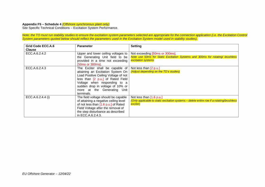
EU Offshore Generator – 12/04/22
Appendix F5 – Schedule 4 (Offshore synchronous plant only) Site Specific Technical Conditions – Excitation System Performance. Note: the TO must run stability studies to ensure the excitation system parameters selected are appropriate for the connection application (i.e. the Excitation Control System parameters quoted below should reflect the parameters used in the Excitation System model used in stability studies).
Grid Code ECC.A.6 Clause
Parameter Setting
ECC.A.6.2.4.2 Upper and lower ceiling voltages to the Generating Unit field to be provided in a time not exceeding [50ms or 300ms].
Not exceeding [50ms or 300ms]. Note use 50ms for Static Excitation Systems and 300ms for rotating/ brushless excitation systems
ECC.A.6.2.4.3 The Exciter shall be capable of attaining an Excitation System On Load Positive Ceiling Voltage of not less than [2 p.u.] of Rated Field Voltage when responding to a sudden drop in voltage of 10% or more at the Generating Unit terminals.
Not less than [2 p.u.] (Adjust depending on the TO’s studies)
ECC.A.6.2.4.4 (i) The field voltage should be capable of attaining a negative ceiling level of not less than [1.6 p.u.] of Rated Field Voltage after the removal of the step disturbance as described in ECC.A.6.2.4.3.
Not less than [1.6 p.u.] (Only applicable to static excitation systems – delete entire row if a rotating/brushless exciter)
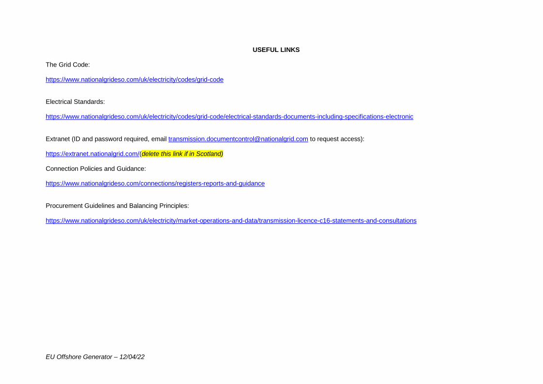
EU Offshore Generator – 12/04/22
USEFUL LINKS The Grid Code: https://www.nationalgrideso.com/uk/electricity/codes/grid-code Electrical Standards: https://www.nationalgrideso.com/uk/electricity/codes/grid-code/electrical-standards-documents-including-specifications-electronic Extranet (ID and password required, email [email protected] to request access): https://extranet.nationalgrid.com/(delete this link if in Scotland) Connection Policies and Guidance: https://www.nationalgrideso.com/connections/registers-reports-and-guidance Procurement Guidelines and Balancing Principles: https://www.nationalgrideso.com/uk/electricity/market-operations-and-data/transmission-licence-c16-statements-and-consultations
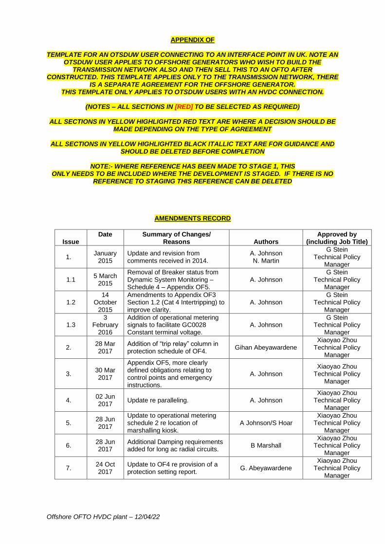
Offshore OFTO HVDC plant – 12/04/22
APPENDIX OF
TEMPLATE FOR AN OTSDUW USER CONNECTING TO AN INTERFACE POINT IN UK. NOTE AN OTSDUW USER APPLIES TO OFFSHORE GENERATORS WHO WISH TO BUILD THE
TRANSMISSION NETWORK ALSO AND THEN SELL THIS TO AN OFTO AFTER CONSTRUCTED. THIS TEMPLATE APPLIES ONLY TO THE TRANSMISSION NETWORK, THERE
IS A SEPARATE AGREEMENT FOR THE OFFSHORE GENERATOR. THIS TEMPLATE ONLY APPLIES TO OTSDUW USERS WITH AN HVDC CONNECTION.
(NOTES – ALL SECTIONS IN [RED] TO BE SELECTED AS REQUIRED)
ALL SECTIONS IN YELLOW HIGHLIGHTED RED TEXT ARE WHERE A DECISION SHOULD BE
MADE DEPENDING ON THE TYPE OF AGREEMENT
ALL SECTIONS IN YELLOW HIGHLIGHTED BLACK ITALLIC TEXT ARE FOR GUIDANCE AND SHOULD BE DELETED BEFORE COMPLETION
NOTE:- WHERE REFERENCE HAS BEEN MADE TO STAGE 1, THIS
ONLY NEEDS TO BE INCLUDED WHERE THE DEVELOPMENT IS STAGED. IF THERE IS NO REFERENCE TO STAGING THIS REFERENCE CAN BE DELETED
AMENDMENTS RECORD
Issue Date
Summary of Changes/
Reasons Authors Approved by
(including Job Title)
1. January
2015 Update and revision from comments received in 2014.
A. Johnson N. Martin
G Stein Technical Policy
Manager
1.1 5 March
2015
Removal of Breaker status from Dynamic System Monitoring – Schedule 4 – Appendix OF5.
A. Johnson G Stein
Technical Policy Manager
1.2 14
October 2015
Amendments to Appendix OF3 Section 1.2 (Cat 4 Intertripping) to improve clarity.
A. Johnson G Stein
Technical Policy Manager
1.3 3
February 2016
Addition of operational metering signals to facilitate GC0028 Constant terminal voltage.
A. Johnson G Stein
Technical Policy Manager
2. 28 Mar 2017
Addition of “trip relay” column in protection schedule of OF4.
Gihan Abeyawardene Xiaoyao Zhou
Technical Policy Manager
3. 30 Mar 2017
Appendix OF5, more clearly defined obligations relating to control points and emergency instructions.
A. Johnson Xiaoyao Zhou
Technical Policy Manager
4. 02 Jun 2017
Update re paralleling. A. Johnson Xiaoyao Zhou
Technical Policy Manager
5. 28 Jun 2017
Update to operational metering schedule 2 re location of marshalling kiosk.
A Johnson/S Hoar Xiaoyao Zhou
Technical Policy Manager
6. 28 Jun 2017
Additional Damping requirements added for long ac radial circuits.
B Marshall Xiaoyao Zhou
Technical Policy Manager
7. 24 Oct 2017
Update to OF4 re provision of a protection setting report.
G. Abeyawardene Xiaoyao Zhou
Technical Policy Manager
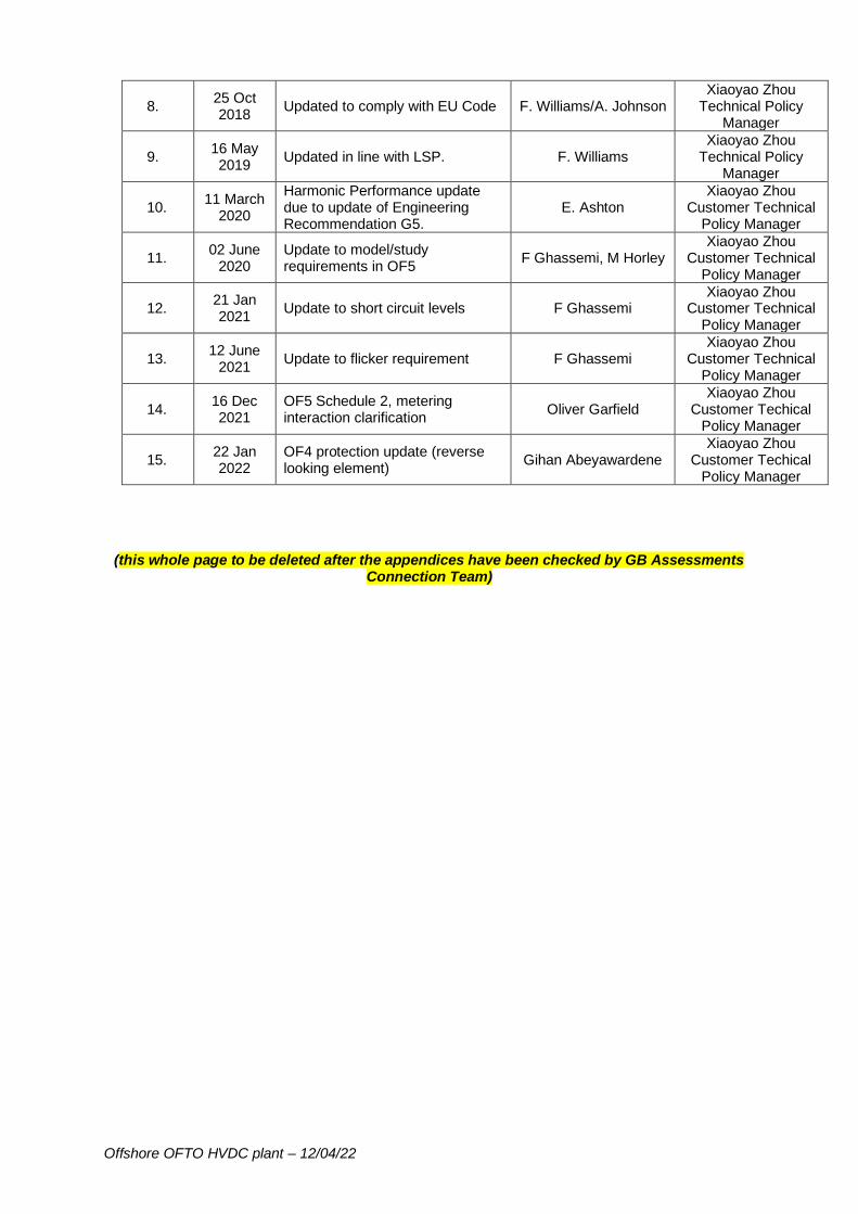
Offshore OFTO HVDC plant – 12/04/22
8. 25 Oct 2018
Updated to comply with EU Code F. Williams/A. Johnson Xiaoyao Zhou
Technical Policy Manager
9. 16 May 2019
Updated in line with LSP. F. Williams Xiaoyao Zhou
Technical Policy Manager
10. 11 March
2020
Harmonic Performance update due to update of Engineering Recommendation G5.
E. Ashton Xiaoyao Zhou
Customer Technical Policy Manager
11. 02 June
2020 Update to model/study requirements in OF5
F Ghassemi, M Horley Xiaoyao Zhou
Customer Technical Policy Manager
12. 21 Jan 2021
Update to short circuit levels F Ghassemi Xiaoyao Zhou
Customer Technical Policy Manager
13. 12 June
2021 Update to flicker requirement F Ghassemi
Xiaoyao Zhou Customer Technical
Policy Manager
14. 16 Dec 2021
OF5 Schedule 2, metering interaction clarification
Oliver Garfield Xiaoyao Zhou
Customer Techical Policy Manager
15. 22 Jan 2022
OF4 protection update (reverse looking element)
Gihan Abeyawardene Xiaoyao Zhou
Customer Techical Policy Manager
(this whole page to be deleted after the appendices have been checked by GB Assessments Connection Team)

Offshore OFTO HVDC plant – 12/04/22
APPENDIX OF
SITE SPECIFIC TECHNICAL CONDITIONS CONTENTS
(NOTES – ALL SECTIONS IN [RED] TO BE COMPLETED/DELETED WHERE APPROPRIATE)
OTSDUW User: [XXXX]
EU Code User: [XXXX]
Transmission Interface Point: [XXXX]
Offshore Connection Site: [XXXX]
Contents OF1 Agreed Ancillary Services OF2 Derogated Plant OF3 Special Automatic Facilities OF4 Relay Settings & Protection OF5 Other Technical Requirements Terms For the purposes of the body of this Appendix OF only, the term “ ” is used when referring to the EU Code User in its capacity as a Generator connecting to the Offshore Transmission Network at the Offshore Grid Entry Point and the term “OTSDUW User” (where OTSDUW stands for Offshore Transmission System Developer User Works) is used when referring to the User in its role in undertaking the design, construction and commissioning of the OTSDUW Plant and Apparatus between the Transmission Interface Point and Offshore Grid Entry Point. The OTSDUW User shall be responsible for the design, installation and commissioning of the Offshore Transmission Network until the OTSUA (Offshore Transmission System User Assets) Transfer Time from when the responsibilities of the Offshore Transmission Network will rest with the appointed Relevant Transmission Licensee (RTL). For the purpose of this Agreement it is assumed that the OTSDUW Plant and Apparatus (which includes the Offshore Transmission System) comprises one or more Transmission DC Converter(s). For the purposes of this agreement the EU Code User would be considered to own or operate either DC Connected Power Park Modules or Synchronous Power Generating Modules. General The requirements of this Appendix OF apply to all OTSDUW Plant and Apparatus which utilise a Transmission DC Converter from the Transmission Interface Point to the Offshore Grid Entry Point. Standards (PC.1, PC.2.1, PC.6.4, PC.6.5, PC.6.6, PC.6.7, PC Appendix E, PC Appendix OF, ECC.6.2.1.2) Note: This shall include steady state, fault level, dynamic and transient analysis including insulation co-ordination together with voltage waveform quality assessment.
Offshore OFTO HVDC plant – 12/04/22
The OTSDUW User shall inform The Company of the standards used in designing the OTSDUW Plant and Apparatus and shall ensure that it is suitably designed to operate in a marine environment. These appendices contain references to the [The Scottish Electrical Standards for SPT’s Transmission System (SPTS)/ Scottish Electrical Standards (SHETS) for SHET’s Transmission System (SHETS)] and the Relevant Electrical Standards (RES) throughout. The OTSDUW Plant and Apparatus contained within the Transmission busbar protection zone at the Transmission Interface Point (see Grid Code ECC 6.2.1.2) is required to comply with the RES/SPTS/ SHETS. The OTSDUW User can access this document from The Company’s website which is available at:- https://www.nationalgrideso.com/uk/electricity/codes/grid-code/electrical-standards-documents-including-specifications-electronic The SPTS / SHETS and RES are updated periodically. If the SPTS / SHETS or RES is updated in the period between issuing the Connection Offer and the OTSDUW Plant and Apparatus being connected to the Onshore Transmission System, then The Company and Onshore Transmission Licensee will seek agreement with the OTSDUW User to use the updated SPTS/SHETS and RES at the Transmission Interface Point in respect of the OTSDUW Plant and Apparatus. Data Submission (DRC.6.1.18) The Company and Onshore Transmission Licensee will need to model the OTSDUW Plant and Apparatus. To enable this process to take place, the OTSDUW User shall submit data in accordance with the applicable requirements of the Grid Code which shall include but is not limited to PC.4.4, PC.8 and DRC.6.1.18.
Offshore OFTO HVDC plant – 12/04/22
APPENDIX OF1
SITE SPECIFIC TECHNICAL CONDITIONS AGREED ANCILLARY SERVICES
OTSDUW User: [XXXX]
EU Code User: [XXXX]
Transmission Interface Point: [XXXX]
Offshore Connection Site: [XXXX]
Agreed Ancillary Services NOTE at the initial application stage, Commercial Intertripping requirements on a User are NOT usually specified until post offer negotiation. Where no Commercial Intertripping has been specified in Appendix OF1, use the paragraph below. No Commercial Transmission System to Generator Operational Intertripping Schemes have been identified at this time. However, should such a requirement be identified prior to the OTSUA Transfer Time, the OTSDUW User shall co-operate with The Company in developing these facilities, and will not unreasonably withhold its agreement to any such proposals. If however a requirement has been specified in the OF1 at the application stage the following text in red should be used as it states the requirements upon the OTSDUW User in order to facilitate the commercial intertripping scheme. Appendix OF1 of this Agreement may place commercial requirements on the EU Code User to trip under certain Transmission outage conditions. The OTSDUW User shall include communication routes and monitoring between the Transmission Interface Point at [XXXX]kV Onshore Substation and the Offshore Grid Entry Point at [XXXX]kV Offshore Substation in order to facilitate this intertripping scheme. The Onshore Transmission Licensee will provide the required signals to facilitate this intertripping facility to a marshalling cubicle located at the Transmission Interface Point. The OTSDUW User will provide for the installation and maintenance of duplicated communications routes between the Offshore Grid Entry Point at [XXXX]kV Offshore Substation and the Onshore Transmission Licensee’s marshalling cubicle at the Transmission Interface Point. Once installed, the intertripping scheme will also have the facility to be monitored to ensure it is healthy at all times and provide indications to The Company for all selections specified. The functionality, performance, availability, accuracy, dependability, security, protocol and repair times of the communications links, trip facilities and monitoring facilities, from the marshalling cubicles located at the Transmission Interface Point to the Offshore Grid Entry Point shall be agreed between The Company, the Onshore Transmission Licensee and the OTSDUW User at least 24 months before the Completion Date (Stage 1). No single hardware, software, system, communication, interface or power supply failure or depletion of facility shall result in failure to trip within the specified time or an incorrect control action. The OTSDUW User shall ensure that the OTSDUW Plant and Apparatus is fully robust and protected against total disconnection from the National Electricity Transmission System. General

Offshore OFTO HVDC plant – 12/04/22
The OTSDUW User shall co-operate with The Company in enhancing/amending these facilities, should The Company require this prior to the OTSUA Transfer Time, and will not unreasonably withhold its agreement to any such proposals.
Offshore OFTO HVDC plant – 12/04/22
APPENDIX OF2
SITE SPECIFIC TECHNICAL CONDITIONS DEROGATED PLANT
OTSDUW User: [XXXX]
EU Code User: [XXXX]
Transmission Interface Point: [XXXX]
Offshore Connection Site: [XXXX]
Derogated Plant Not applicable.
Offshore OFTO HVDC plant – 12/04/22
APPENDIX OF3
SITE SPECIFIC TECHNICAL CONDITIONS SPECIAL AUTOMATIC FACILITIES
OTSDUW User: [XXXX]
EU Code User: [XXXX]
Transmission Interface Point: [XXXX]
Offshore Connection Site: [XXXX]
Special Automatic Facilities If no Intertripping requirements have been specified in Appendix F then delete the text below and state “Not applicable.” However, the “General” text should be left in. 1 Operational Intertripping Schemes 1.1 Facilitation of Transmission System to Generating Unit Intertripping Schemes
Appendix OF3 of this Bilateral Connection Agreement places obligations on the EU Code User to trip under certain Transmission outage conditions. The OTSDUW User shall provide communication routes and monitoring facilities between the Transmission Interface Point at [XXXX]kV Onshore Substation and the Offshore Grid Entry Point at [XXXX]kV Offshore Substation in order to facilitate this intertripping scheme. The Onshore Transmission Licensee will provide the required signals to facilitate this intertripping facility to a marshalling cubicle located at the Transmission Interface Point. The OTSDUW User will provide for the installation and maintenance of duplicated communications routes between the Offshore Grid Entry Point at [XXXX]kV Offshore Substation and the Onshore Transmission Licensee’s marshalling cubicle at the Transmission Interface Point. Once in operation (after the OTSUA Transfer Time), the ownership of part or the whole of the communication equipment will be transferred to the appointed Offshore Transmission Licensee from when each party (EU Code User and Offshore Transmission Licensee) will then be responsible for the maintenance of their own assets. Once installed, the intertripping scheme will be monitored to ensure it is healthy at all times and provide indications to The Company for all selections as specified in Schedule 2 of this OF3. Specific requirements to be agreed in the detailed design phase. The functionality, performance, availability, accuracy, dependability, security, protocol and repair times of the communications links, trip facilities and monitoring facilities, from the marshalling cubicles located at the Transmission Interface Point to the Offshore Grid Entry Point shall be agreed between the Onshore Transmission Licensee, The Company and the OTSDUW User at least 24 months before the Completion Date (Stage 1) unless otherwise agreed. These requirements shall apply up to the OTSUA Transfer Time from when these responsibilities shall lie with the Offshore Transmission Licensee. No single hardware, software, system, communication, interface or power supply failure or depletion of facility shall result in failure to trip within the specified time or an incorrect control action. The OTSDUW User shall ensure that the OTSDUW Plant and Apparatus is fully robust and protected against total disconnection from the National Electricity Transmission System.
1.2 Intertripping requirements on the Transmission Interface Point circuit breakers
Offshore OFTO HVDC plant – 12/04/22
NOTE:- Where an OFTO is connected to a substation via a tee or turn in, there is a risk that following a double or single circuit fault (depending on connection topology) and DAR sequence, the whole OFTO could be re-energised from the HV end resulting in high transient over voltages and islanding occurring. In this event, there may be a need to trip the Interface Point Circuit Breakers. Such a requirement would therefore need to be included within the intertripping scheme but this should be advised by the Scottish TO in the TOCO. Although this is an OFTO issue, the Offshore Generator will need to be informed in their agreement (via a Category 4 Intertrip) due to the unavailability of the OFTO network post fault. If such an arrangement exists then the following text in red below (and Schedule 2 of Appendix OF3) should be used although the Scottish TO will need to specify the exact requirements in the TOCO. For further advice the Scottish TO should be consulted
Following one of the outage combinations as detailed in Schedule 2 of Appendix OF3 which would island the OTSDUW User’s Plant and Apparatus and in order to prevent the risk of high transient overvoltages following a Delayed Auto Reclose sequence on the Onshore Transmission System, an automatic Operational Intertripping Scheme is required to open the OTSDUW User’s Plant and Apparatus Transmission Interface Point circuit breakers. The Onshore Transmission Licensee will provide the required signals to facilitate this intertripping facility to a marshalling cubicle located at the Transmission Interface Point. The OTSDUW User will provide for the installation and maintenance of duplicated communications routes between the Onshore Transmission Licensee’s marshalling cubicles and the OTSDUW User’s circuit breakers at the Transmission Interface Point. In addition, and if necessary, the OTSDUW User shall also ensure a duplicated signal is provided to the OTSDUW User’s DC Converter to enable it to be shut down in a controlled manner. Once in operation (after the OTSUA Transfer Time), the ownership of part or the whole of the communication equipment will be transferred to the appointed Offshore Transmission Licensee from when each party (EU Code User and Offshore Transmission Licensee) will then be responsible for the maintenance of their own assets. The functionality, performance, availability, accuracy, dependability, security, protocol and repair times of the communications links, trip facilities and monitoring facilities, from the Onshore Transmission Licensee’s marshalling cubicles to the OTSDUW User’s circuit breakers at the Transmission Interface Point shall be agreed between The Company, the Onshore Transmission Licensee and OTSDUW User at least 24 months before the Completion Date (Stage 1) unless otherwise agreed. No single hardware, software, system, communication, interface or power supply failure or depletion of facility shall result in failure to trip within the specified time or an incorrect control action The OTSDUW User acknowledges that operation of this scheme will have the effect of de-energising the OTSDUW Plant and Apparatus from the Main Interconnected Transmission System, which shall continue until such time as the Onshore Transmission System is re-energised.
1.3 General
The EU Code User and OTSDUW User shall co-operate with The Company and Onshore Transmission Licensee in enhancing/amending these facilities, should The Company or Onshore Transmission Licensee require this prior to the OTSUA Transfer Time, and will not unreasonably withhold its agreement to any such proposals.
Other Facilities
Requirement
Automatic Open/ Closure Schemes Not applicable (unless specified.)
Offshore OFTO HVDC plant – 12/04/22
System Splitting/Islanding Schemes Not applicable (unless specified.)
2 Synchronising 2.1 Synchronising requirements at the Transmission Interface Point
The OTSDUW User will be required to interface with the National Electricity Transmission System substation synchronising system in accordance with the TS.3.24.60_RES /SPTS/SHETS. In circumstances where the OTSDUW User does not synchronise at the Transmission Interface Point, the OTSDUW User is required to participate in the Onshore Transmission Licensee’s voltage selection scheme. In addition the OTSDUW User is required to meet the requirements of ECC.6.2.2.9.
2.2 Synchronising requirements at the Offshore Grid Entry Point
The OTSDUW User will be required to satisfy the requirements of ECC.6.2.2.9.4 at the Offshore Grid Entry Point and ensure that the OTSDUW User’s Plant and Apparatus interfaces with the Voltage Selection Scheme. The voltage selection scheme is defined as the voltage signal information (e.g. magnitude, phase and angle) derived from a suitable voltage transformer (VT) across the boundary at the Offshore Grid Entry Point for the purposes of safe synchronising or energisation between the OTSDUW User and EU Code User.

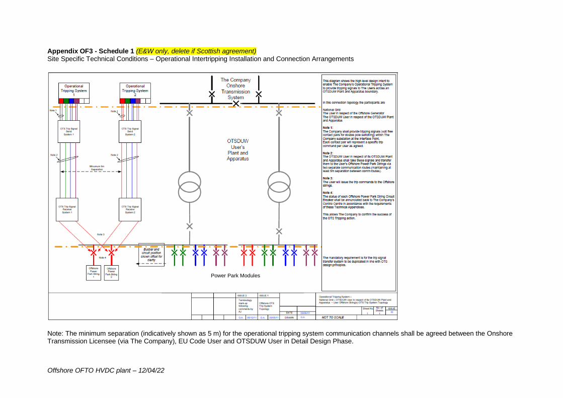
Offshore OFTO HVDC plant – 12/04/22
Appendix OF3 - Schedule 1 (E&W only, delete if Scottish agreement) Site Specific Technical Conditions – Operational Intertripping Installation and Connection Arrangements
Note: The minimum separation (indicatively shown as 5 m) for the operational tripping system communication channels shall be agreed between the Onshore Transmission Licensee (via The Company), EU Code User and OTSDUW User in Detail Design Phase.
Power Park Modules
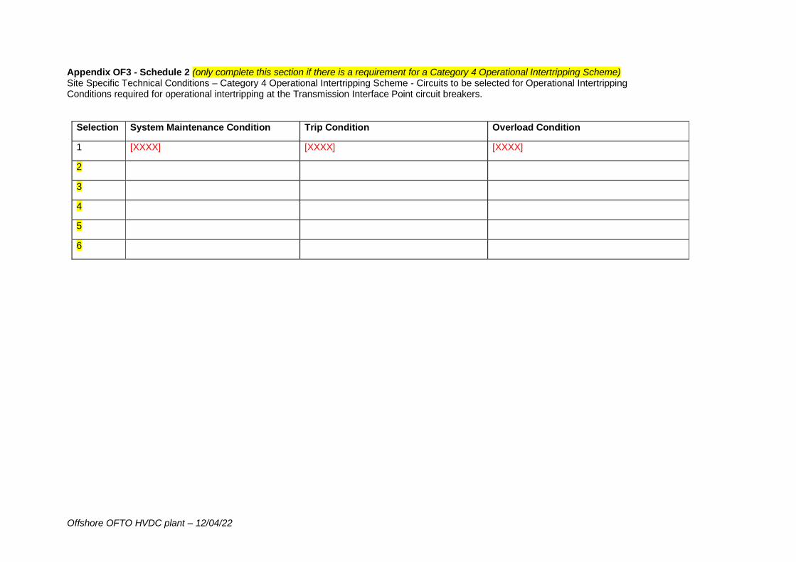
Offshore OFTO HVDC plant – 12/04/22
Appendix OF3 - Schedule 2 (only complete this section if there is a requirement for a Category 4 Operational Intertripping Scheme) Site Specific Technical Conditions – Category 4 Operational Intertripping Scheme - Circuits to be selected for Operational Intertripping Conditions required for operational intertripping at the Transmission Interface Point circuit breakers.
Selection System Maintenance Condition Trip Condition Overload Condition
1 [XXXX] [XXXX] [XXXX]
2
3
4
5
6
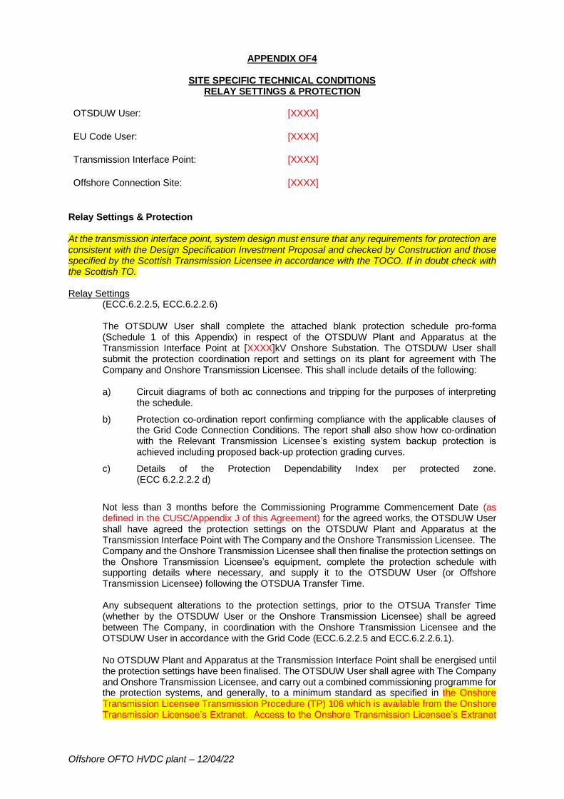
Offshore OFTO HVDC plant – 12/04/22
APPENDIX OF4
SITE SPECIFIC TECHNICAL CONDITIONS RELAY SETTINGS & PROTECTION
OTSDUW User: [XXXX]
EU Code User: [XXXX]
Transmission Interface Point: [XXXX]
Offshore Connection Site: [XXXX]
Relay Settings & Protection At the transmission interface point, system design must ensure that any requirements for protection are consistent with the Design Specification Investment Proposal and checked by Construction and those specified by the Scottish Transmission Licensee in accordance with the TOCO. If in doubt check with the Scottish TO. Relay Settings
(ECC.6.2.2.5, ECC.6.2.2.6) The OTSDUW User shall complete the attached blank protection schedule pro-forma (Schedule 1 of this Appendix) in respect of the OTSDUW Plant and Apparatus at the Transmission Interface Point at [XXXX]kV Onshore Substation. The OTSDUW User shall submit the protection coordination report and settings on its plant for agreement with The Company and Onshore Transmission Licensee. This shall include details of the following: a) Circuit diagrams of both ac connections and tripping for the purposes of interpreting
the schedule.
b) Protection co-ordination report confirming compliance with the applicable clauses of the Grid Code Connection Conditions. The report shall also show how co-ordination with the Relevant Transmission Licensee’s existing system backup protection is achieved including proposed back-up protection grading curves.
c) Details of the Protection Dependability Index per protected zone. (ECC 6.2.2.2.2 d)
Not less than 3 months before the Commissioning Programme Commencement Date (as defined in the CUSC/Appendix J of this Agreement) for the agreed works, the OTSDUW User shall have agreed the protection settings on the OTSDUW Plant and Apparatus at the Transmission Interface Point with The Company and the Onshore Transmission Licensee. The Company and the Onshore Transmission Licensee shall then finalise the protection settings on the Onshore Transmission Licensee’s equipment, complete the protection schedule with supporting details where necessary, and supply it to the OTSDUW User (or Offshore Transmission Licensee) following the OTSDUA Transfer Time. Any subsequent alterations to the protection settings, prior to the OTSUA Transfer Time (whether by the OTSDUW User or the Onshore Transmission Licensee) shall be agreed between The Company, in coordination with the Onshore Transmission Licensee and the OTSDUW User in accordance with the Grid Code (ECC.6.2.2.5 and ECC.6.2.2.6.1). No OTSDUW Plant and Apparatus at the Transmission Interface Point shall be energised until the protection settings have been finalised. The OTSDUW User shall agree with The Company and Onshore Transmission Licensee, and carry out a combined commissioning programme for the protection systems, and generally, to a minimum standard as specified in the Onshore Transmission Licensee Transmission Procedure (TP) 106 which is available from the Onshore Transmission Licensee’s Extranet. Access to the Onshore Transmission Licensee’s Extranet
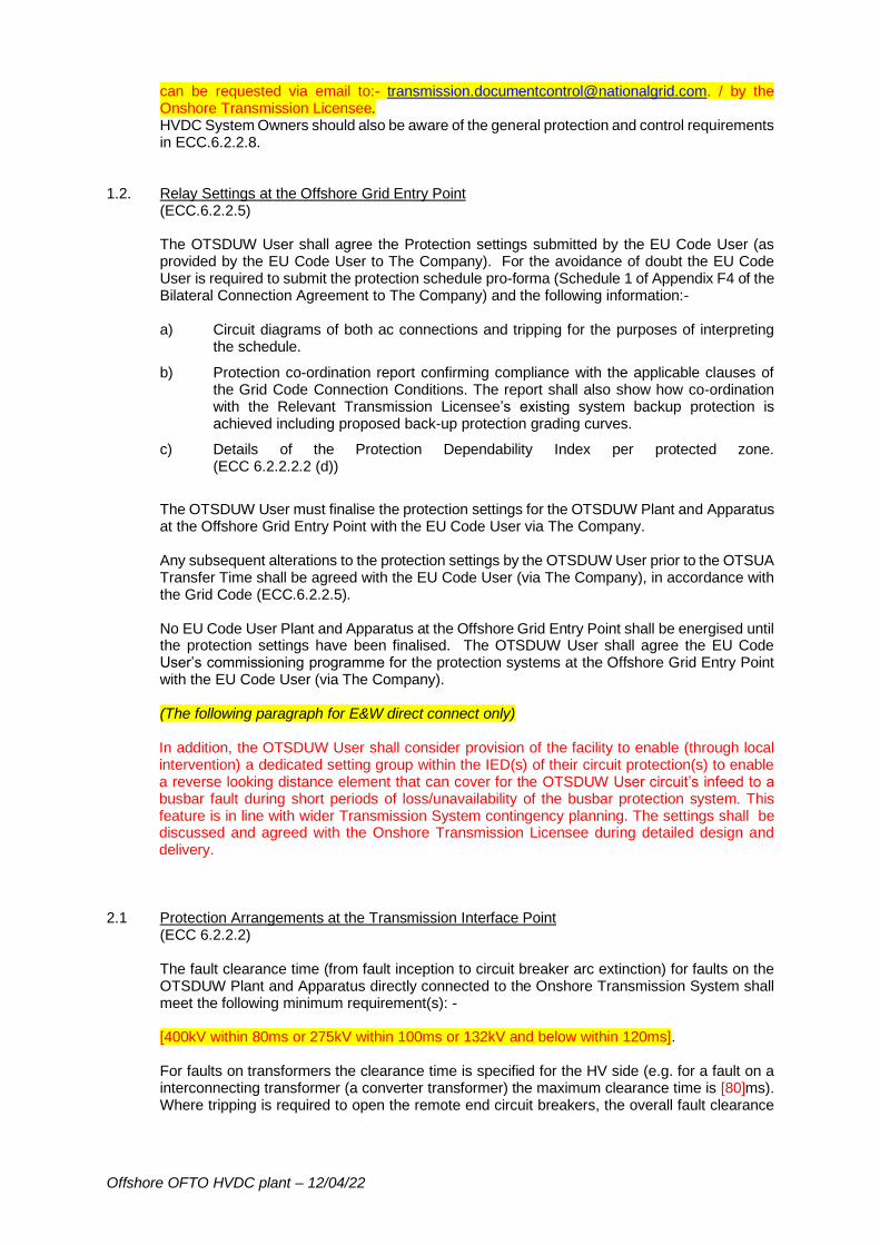
Offshore OFTO HVDC plant – 12/04/22
can be requested via email to:- [email protected]. / by the Onshore Transmission Licensee. HVDC System Owners should also be aware of the general protection and control requirements in ECC.6.2.2.8.
1.2. Relay Settings at the Offshore Grid Entry Point (ECC.6.2.2.5) The OTSDUW User shall agree the Protection settings submitted by the EU Code User (as provided by the EU Code User to The Company). For the avoidance of doubt the EU Code User is required to submit the protection schedule pro-forma (Schedule 1 of Appendix F4 of the Bilateral Connection Agreement to The Company) and the following information:- a) Circuit diagrams of both ac connections and tripping for the purposes of interpreting
the schedule.
b) Protection co-ordination report confirming compliance with the applicable clauses of the Grid Code Connection Conditions. The report shall also show how co-ordination with the Relevant Transmission Licensee’s existing system backup protection is achieved including proposed back-up protection grading curves.
c) Details of the Protection Dependability Index per protected zone. (ECC 6.2.2.2.2 (d))
The OTSDUW User must finalise the protection settings for the OTSDUW Plant and Apparatus at the Offshore Grid Entry Point with the EU Code User via The Company. Any subsequent alterations to the protection settings by the OTSDUW User prior to the OTSUA Transfer Time shall be agreed with the EU Code User (via The Company), in accordance with the Grid Code (ECC.6.2.2.5). No EU Code User Plant and Apparatus at the Offshore Grid Entry Point shall be energised until the protection settings have been finalised. The OTSDUW User shall agree the EU Code User’s commissioning programme for the protection systems at the Offshore Grid Entry Point with the EU Code User (via The Company). (The following paragraph for E&W direct connect only) In addition, the OTSDUW User shall consider provision of the facility to enable (through local intervention) a dedicated setting group within the IED(s) of their circuit protection(s) to enable a reverse looking distance element that can cover for the OTSDUW User circuit’s infeed to a busbar fault during short periods of loss/unavailability of the busbar protection system. This feature is in line with wider Transmission System contingency planning. The settings shall be discussed and agreed with the Onshore Transmission Licensee during detailed design and delivery.
2.1 Protection Arrangements at the Transmission Interface Point (ECC 6.2.2.2) The fault clearance time (from fault inception to circuit breaker arc extinction) for faults on the OTSDUW Plant and Apparatus directly connected to the Onshore Transmission System shall meet the following minimum requirement(s): - [400kV within 80ms or 275kV within 100ms or 132kV and below within 120ms]. For faults on transformers the clearance time is specified for the HV side (e.g. for a fault on a interconnecting transformer (a converter transformer) the maximum clearance time is [80]ms). Where tripping is required to open the remote end circuit breakers, the overall fault clearance
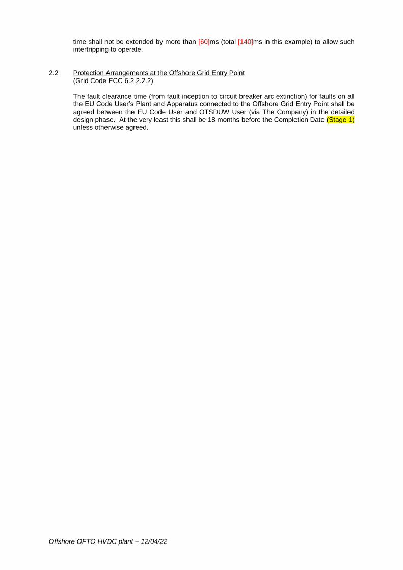
Offshore OFTO HVDC plant – 12/04/22
time shall not be extended by more than [60]ms (total [140]ms in this example) to allow such intertripping to operate.
2.2 Protection Arrangements at the Offshore Grid Entry Point (Grid Code ECC 6.2.2.2.2) The fault clearance time (from fault inception to circuit breaker arc extinction) for faults on all the EU Code User’s Plant and Apparatus connected to the Offshore Grid Entry Point shall be agreed between the EU Code User and OTSDUW User (via The Company) in the detailed design phase. At the very least this shall be 18 months before the Completion Date (Stage 1) unless otherwise agreed.

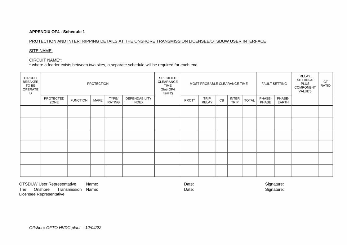
Offshore OFTO HVDC plant – 12/04/22
APPENDIX OF4 - Schedule 1 PROTECTION AND INTERTRIPPING DETAILS AT THE ONSHORE TRANSMISSION LICENSEE/OTSDUW USER INTERFACE SITE NAME: CIRCUIT NAME*: * where a feeder exists between two sites, a separate schedule will be required for each end.
CIRCUIT BREAKER
TO BE
OPERATED
PROTECTION
SPECIFIED CLEARANCE
TIME
(See OF4 Item 2)
MOST PROBABLE CLEARANCE TIME FAULT SETTING
RELAY SETTINGS
PLUS COMPONENT
VALUES
CT RATIO
PROTECTED ZONE
FUNCTION MAKE TYPE/
RATING DEPENDABILITY
INDEX PROTN
TRIP RELAY
CB INTER TRIP
TOTAL PHASE- PHASE
PHASE- EARTH
OTSDUW User Representative Name: Date: Signature:
The Onshore Transmission Licensee Representative
Name: Date: Signature:
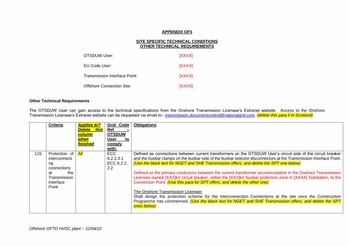
Offshore OFTO HVDC plant – 12/04/22
APPENDIX OF5
SITE SPECIFIC TECHNICAL CONDITIONS OTHER TECHNICAL REQUIREMENTS
OTSDUW User: [XXXX]
EU Code User: [XXXX]
Transmission Interface Point: [XXXX]
Offshore Connection Site: [XXXX]
Other Technical Requirements The OTSDUW User can gain access to the technical specifications from the Onshore Transmission Licensee’s Extranet website. Access to the Onshore Transmission Licensee’s Extranet website can be requested via email to:- [email protected]. (delete this para if in Scotland)
Criteria Applies to? Delete this column when finished
Grid Code Ref – OTSDUW User to comply with:
Obligations
115. Protection of interconnecting connections at the Transmission Interface Point
All ECC 6.2.2.3.1 ECC.6.2.2.2.2
Defined as connections between current transformers on the OTSDUW User’s circuit side of the circuit breaker and the busbar clamps on the busbar side of the busbar selector disconnectors at the Transmission Interface Point. (Use the black text for NGET and SHE Transmission offers, and delete the SPT one below) Defined as the primary conductors between the current transformer accommodation in the Onshore Transmission Licensee-owned [XXX]kV circuit breaker, within the [XXX]kV busbar protection zone in [XXXX] Substation, to the Connection Point. (Use this para for SPT offers, and delete the other one) The Onshore Transmission Licensee: Shall design the protection scheme for the Interconnection Connections at the site once the Construction Programme has commenced. (Use the black text for NGET and SHE Transmission offers, and delete the SPT ones below)
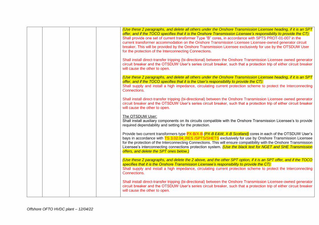
Offshore OFTO HVDC plant – 12/04/22
(Use these 2 paragraphs, and delete all others under the Onshore Transmission Licensee heading, if it is an SPT offer, and if the TOCO specifies that it is the Onshore Transmission Licensee’s responsibility to provide the CT): Shall provide one set of current transformer Type “B” cores, in accordance with SPTS PROT-01-007 in the current transformer accommodation on the Onshore Transmission Licensee Licensee-owned generator circuit breaker. This will be provided by the Onshore Transmission Licensee exclusively for use by the OTSDUW User for the protection of the Interconnecting Connections. Shall install direct-transfer tripping (bi-directional) between the Onshore Transmission Licensee owned generator circuit breaker and the OTSDUW User’s series circuit breaker, such that a protection trip of either circuit breaker will cause the other to open. (Use these 2 paragraphs, and delete all others under the Onshore Transmission Licensee heading, if it is an SPT offer, and if the TOCO specifies that it is the User’s responsibility to provide the CT): Shall supply and install a high impedance, circulating current protection scheme to protect the Interconnecting Connections. Shall install direct-transfer tripping (bi-directional) between the Onshore Transmission Licensee owned generator circuit breaker and the OTSDUW User’s series circuit breaker, such that a protection trip of either circuit breaker will cause the other to open. The OTSDUW User: Shall install auxiliary components on its circuits compatible with the Onshore Transmission Licensee’s to provide required dependability and setting for the protection. Provide two current transformers type PX-B/X-B (PX-B E&W, X-B Scotland) cores in each of the OTSDUW User’s bays in accordance with TS 3.02.04_RES /SPTS/SHETS exclusively for use by Onshore Transmission Licensee for the protection of the Interconnecting Connections. This will ensure compatibility with the Onshore Transmission Licensee’s interconnecting connections protection system. (Use the black text for NGET and SHE Transmission offers, and delete the SPT ones below.) (Use these 2 paragraphs, and delete the 2 above, and the other SPT option, if it is an SPT offer, and if the TOCO specifies that it is the Onshore Transmission Licensee’s responsibility to provide the CT): Shall supply and install a high impedance, circulating current protection scheme to protect the Interconnecting Connections. Shall install direct-transfer tripping (bi-directional) between the Onshore Transmission Licensee-owned generator circuit breaker and the OTSDUW User’s series circuit breaker, such that a protection trip of either circuit breaker will cause the other to open.
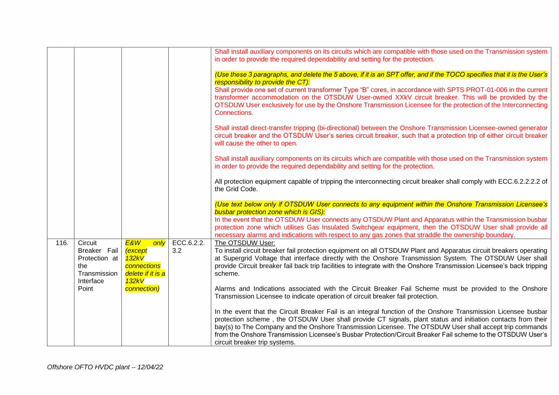
Offshore OFTO HVDC plant – 12/04/22
Shall install auxiliary components on its circuits which are compatible with those used on the Transmission system in order to provide the required dependability and setting for the protection. (Use these 3 paragraphs, and delete the 5 above, if it is an SPT offer, and if the TOCO specifies that it is the User’s responsibility to provide the CT): Shall provide one set of current transformer Type “B” cores, in accordance with SPTS PROT-01-006 in the current transformer accommodation on the OTSDUW User-owned XXkV circuit breaker. This will be provided by the OTSDUW User exclusively for use by the Onshore Transmission Licensee for the protection of the Interconnecting Connections. Shall install direct-transfer tripping (bi-directional) between the Onshore Transmission Licensee-owned generator circuit breaker and the OTSDUW User’s series circuit breaker, such that a protection trip of either circuit breaker will cause the other to open. Shall install auxiliary components on its circuits which are compatible with those used on the Transmission system in order to provide the required dependability and setting for the protection. All protection equipment capable of tripping the interconnecting circuit breaker shall comply with ECC.6.2.2.2.2 of the Grid Code. (Use text below only if OTSDUW User connects to any equipment within the Onshore Transmission Licensee’s busbar protection zone which is GIS): In the event that the OTSDUW User connects any OTSDUW Plant and Apparatus within the Transmission busbar protection zone which utilises Gas Insulated Switchgear equipment, then the OTSDUW User shall provide all necessary alarms and indications with respect to any gas zones that straddle the ownership boundary.
116. Circuit Breaker Fail Protection at the Transmission Interface Point
E&W only (except 132kV connections delete if it is a 132kV connection)
ECC.6.2.2.3.2
The OTSDUW User: To install circuit breaker fail protection equipment on all OTSDUW Plant and Apparatus circuit breakers operating at Supergrid Voltage that interface directly with the Onshore Transmission System. The OTSDUW User shall provide Circuit breaker fail back trip facilities to integrate with the Onshore Transmission Licensee’s back tripping scheme. Alarms and Indications associated with the Circuit Breaker Fail Scheme must be provided to the Onshore Transmission Licensee to indicate operation of circuit breaker fail protection. In the event that the Circuit Breaker Fail is an integral function of the Onshore Transmission Licensee busbar protection scheme , the OTSDUW User shall provide CT signals, plant status and initiation contacts from their bay(s) to The Company and the Onshore Transmission Licensee. The OTSDUW User shall accept trip commands from the Onshore Transmission Licensee’s Busbar Protection/Circuit Breaker Fail scheme to the OTSDUW User’s circuit breaker trip systems.
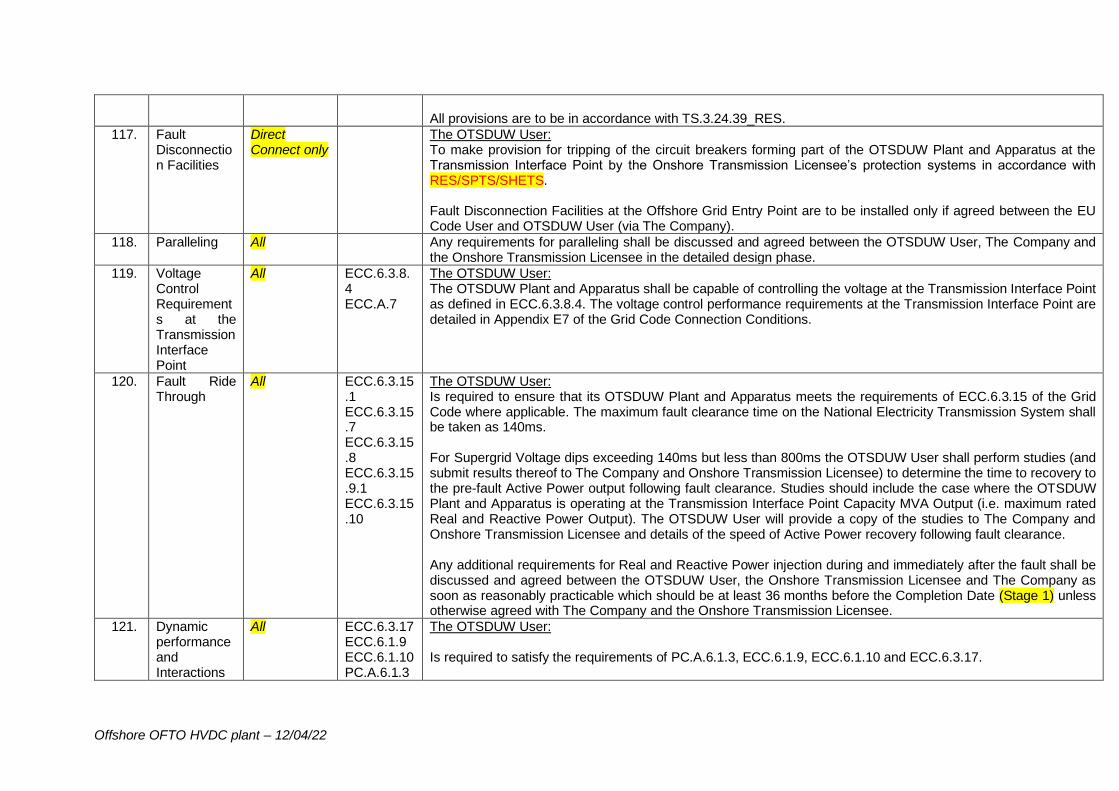
Offshore OFTO HVDC plant – 12/04/22
All provisions are to be in accordance with TS.3.24.39_RES.
117. Fault Disconnection Facilities
Direct Connect only
The OTSDUW User: To make provision for tripping of the circuit breakers forming part of the OTSDUW Plant and Apparatus at the Transmission Interface Point by the Onshore Transmission Licensee’s protection systems in accordance with RES/SPTS/SHETS. Fault Disconnection Facilities at the Offshore Grid Entry Point are to be installed only if agreed between the EU Code User and OTSDUW User (via The Company).
118. Paralleling All Any requirements for paralleling shall be discussed and agreed between the OTSDUW User, The Company and the Onshore Transmission Licensee in the detailed design phase.
119. Voltage Control Requirements at the Transmission Interface Point
All ECC.6.3.8.4 ECC.A.7
The OTSDUW User: The OTSDUW Plant and Apparatus shall be capable of controlling the voltage at the Transmission Interface Point as defined in ECC.6.3.8.4. The voltage control performance requirements at the Transmission Interface Point are detailed in Appendix E7 of the Grid Code Connection Conditions.
120. Fault Ride Through
All ECC.6.3.15.1 ECC.6.3.15.7 ECC.6.3.15.8 ECC.6.3.15.9.1 ECC.6.3.15.10
The OTSDUW User: Is required to ensure that its OTSDUW Plant and Apparatus meets the requirements of ECC.6.3.15 of the Grid Code where applicable. The maximum fault clearance time on the National Electricity Transmission System shall be taken as 140ms. For Supergrid Voltage dips exceeding 140ms but less than 800ms the OTSDUW User shall perform studies (and submit results thereof to The Company and Onshore Transmission Licensee) to determine the time to recovery to the pre-fault Active Power output following fault clearance. Studies should include the case where the OTSDUW Plant and Apparatus is operating at the Transmission Interface Point Capacity MVA Output (i.e. maximum rated Real and Reactive Power Output). The OTSDUW User will provide a copy of the studies to The Company and Onshore Transmission Licensee and details of the speed of Active Power recovery following fault clearance. Any additional requirements for Real and Reactive Power injection during and immediately after the fault shall be discussed and agreed between the OTSDUW User, the Onshore Transmission Licensee and The Company as soon as reasonably practicable which should be at least 36 months before the Completion Date (Stage 1) unless otherwise agreed with The Company and the Onshore Transmission Licensee.
121. Dynamic performance and Interactions
All ECC.6.3.17 ECC.6.1.9 ECC.6.1.10 PC.A.6.1.3
The OTSDUW User: Is required to satisfy the requirements of PC.A.6.1.3, ECC.6.1.9, ECC.6.1.10 and ECC.6.3.17.
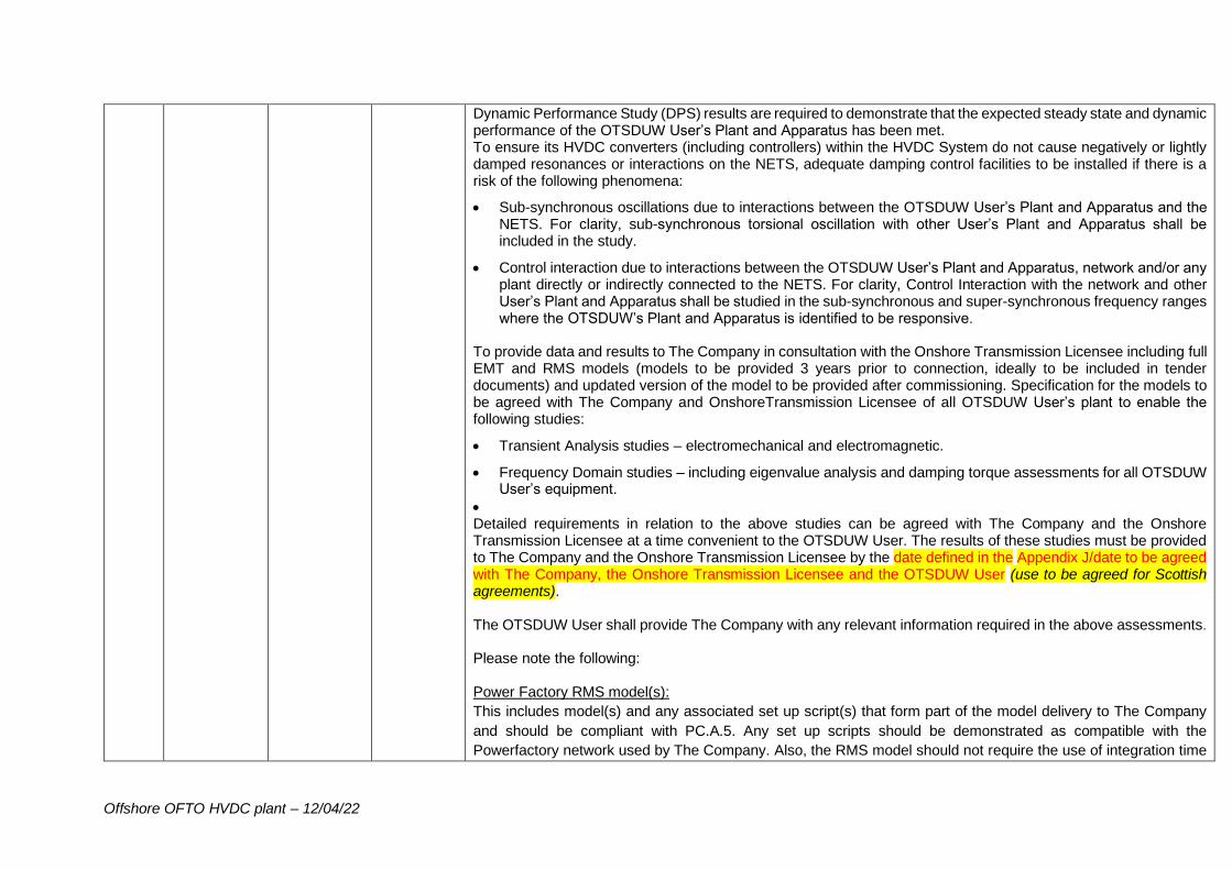
Offshore OFTO HVDC plant – 12/04/22
Dynamic Performance Study (DPS) results are required to demonstrate that the expected steady state and dynamic performance of the OTSDUW User’s Plant and Apparatus has been met. To ensure its HVDC converters (including controllers) within the HVDC System do not cause negatively or lightly damped resonances or interactions on the NETS, adequate damping control facilities to be installed if there is a risk of the following phenomena:
• Sub-synchronous oscillations due to interactions between the OTSDUW User’s Plant and Apparatus and the NETS. For clarity, sub-synchronous torsional oscillation with other User’s Plant and Apparatus shall be included in the study.
• Control interaction due to interactions between the OTSDUW User’s Plant and Apparatus, network and/or any plant directly or indirectly connected to the NETS. For clarity, Control Interaction with the network and other User’s Plant and Apparatus shall be studied in the sub-synchronous and super-synchronous frequency ranges where the OTSDUW’s Plant and Apparatus is identified to be responsive.
To provide data and results to The Company in consultation with the Onshore Transmission Licensee including full EMT and RMS models (models to be provided 3 years prior to connection, ideally to be included in tender documents) and updated version of the model to be provided after commissioning. Specification for the models to be agreed with The Company and OnshoreTransmission Licensee of all OTSDUW User’s plant to enable the following studies:
• Transient Analysis studies – electromechanical and electromagnetic.
• Frequency Domain studies – including eigenvalue analysis and damping torque assessments for all OTSDUW User’s equipment.
• Detailed requirements in relation to the above studies can be agreed with The Company and the Onshore Transmission Licensee at a time convenient to the OTSDUW User. The results of these studies must be provided to The Company and the Onshore Transmission Licensee by the date defined in the Appendix J/date to be agreed with The Company, the Onshore Transmission Licensee and the OTSDUW User (use to be agreed for Scottish agreements). The OTSDUW User shall provide The Company with any relevant information required in the above assessments. Please note the following: Power Factory RMS model(s):
This includes model(s) and any associated set up script(s) that form part of the model delivery to The Company
and should be compliant with PC.A.5. Any set up scripts should be demonstrated as compatible with the
Powerfactory network used by The Company. Also, the RMS model should not require the use of integration time
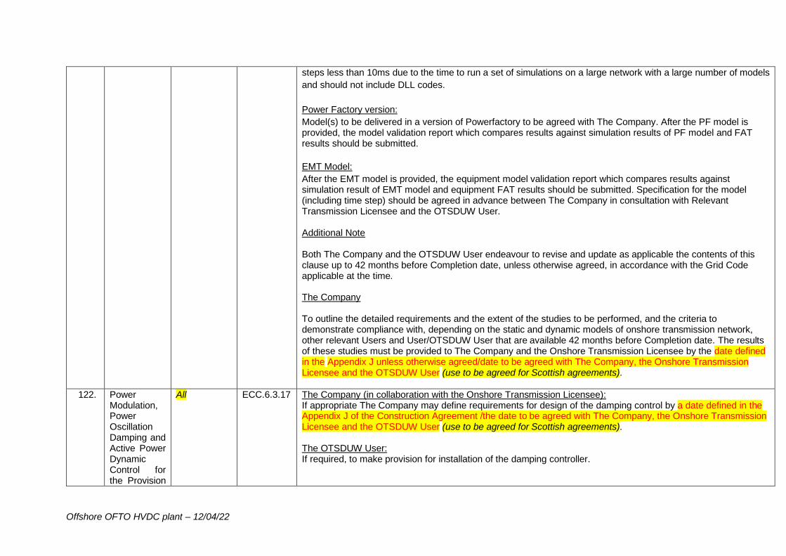
Offshore OFTO HVDC plant – 12/04/22
steps less than 10ms due to the time to run a set of simulations on a large network with a large number of models
and should not include DLL codes.
Power Factory version:
Model(s) to be delivered in a version of Powerfactory to be agreed with The Company. After the PF model is provided, the model validation report which compares results against simulation results of PF model and FAT results should be submitted.
EMT Model:
After the EMT model is provided, the equipment model validation report which compares results against simulation result of EMT model and equipment FAT results should be submitted. Specification for the model (including time step) should be agreed in advance between The Company in consultation with Relevant Transmission Licensee and the OTSDUW User. Additional Note Both The Company and the OTSDUW User endeavour to revise and update as applicable the contents of this clause up to 42 months before Completion date, unless otherwise agreed, in accordance with the Grid Code applicable at the time. The Company To outline the detailed requirements and the extent of the studies to be performed, and the criteria to demonstrate compliance with, depending on the static and dynamic models of onshore transmission network, other relevant Users and User/OTSDUW User that are available 42 months before Completion date. The results of these studies must be provided to The Company and the Onshore Transmission Licensee by the date defined in the Appendix J unless otherwise agreed/date to be agreed with The Company, the Onshore Transmission Licensee and the OTSDUW User (use to be agreed for Scottish agreements).
122. Power Modulation, Power Oscillation Damping and Active Power Dynamic Control for the Provision
All ECC.6.3.17 The Company (in collaboration with the Onshore Transmission Licensee): If appropriate The Company may define requirements for design of the damping control by a date defined in the Appendix J of the Construction Agreement /the date to be agreed with The Company, the Onshore Transmission Licensee and the OTSDUW User (use to be agreed for Scottish agreements). The OTSDUW User: If required, to make provision for installation of the damping controller.
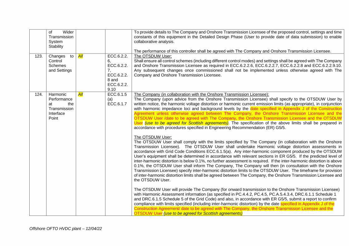
Offshore OFTO HVDC plant – 12/04/22
of Wider Transmission System Stability
To provide details to The Company and Onshore Transmission Licensee of the proposed control, settings and time constants of this equipment in the Detailed Design Phase (User to provide date of data submission) to enable collaborative analysis. The performance of this controller shall be agreed with The Company and Onshore Transmission Licensee.
123. Changes to Control Schemes and Settings
All ECC.6.2.2.6, ECC.6.2.2.7, ECC.6.2.2.8 and ECC.6.2.2.9.10
The OTSDUW User: Shall ensure all control schemes (including different control modes) and settings shall be agreed with The Company and Onshore Transmission Licensee as required in ECC.6.2.2.6, ECC.6.2.2.7, ECC.6.2.2.8 and ECC.6.2.2.9.10. Any subsequent changes once commissioned shall not be implemented unless otherwise agreed with The Company and Onshore Transmission Licensee.
124. Harmonic Performance at the Transmission Interface Point
All ECC.6.1.5 (a) ECC.6.1.7
The Company (in collaboration with the Onshore Transmission Licensee): The Company (upon advice from the Onshore Transmission Licensee) shall specify to the OTSDUW User by written notice, the harmonic voltage distortion or harmonic current emission limits (as appropriate), in conjunction with harmonic impedance loci and background levels by the date specified in Appendix J of the Construction Agreement unless otherwise agreed between The Company, the Onshore Transmission Licensee and the OTSDUW User /date to be agreed with The Company, the Onshore Transmission Licensee and the OTSDUW User (use to be agreed for Scottish agreements). The specification of the above limits shall be prepared in accordance with procedures specified in Engineering Recommendation (ER) G5/5. The OTSDUW User: The OTSDUW User shall comply with the limits specified by The Company (in collaboration with the Onshore Transmission Licensee). The OTSDUW User shall undertake Harmonic voltage distortion assessments in accordance with Grid Code Conditions ECC.6.1.5(a). Any inter-harmonic component produced by the OTSDUW User’s equipment shall be determined in accordance with relevant sections in ER G5/5. If the predicted level of inter-harmonic distortion is below 0.1%, no further assessment is required. If the inter-harmonic distortion is above 0.1%, the OTSDUW User shall inform The Company, The Company will then (in consultation with the Onshore Transmission Licensee) specify inter-harmonic distortion limits to the OTSDUW User. The timeframe for provision of inter-harmonic distortion limits shall be agreed between The Company, the Onshore Transmission Licensee and the OTSDUW User. The OTSDUW User will provide The Company (for onward transmission to the Onshore Transmission Licensee) with Harmonic Assessment information (as specified in PC.4.4.2, PC.4.5, PC.A.5.4.3.4, DRC.6.1.1 Schedule 1 and DRC.6.1.5 Schedule 5 of the Grid Code) and also, in accordance with ER G5/5, submit a report to confirm compliance with limits specified (including inter-harmonic distortion) by the date specified in Appendix J of the Construction Agreement/ date to be agreed with The Company, the Onshore Transmission Licensee and the OTSDUW User (use to be agreed for Scottish agreements)
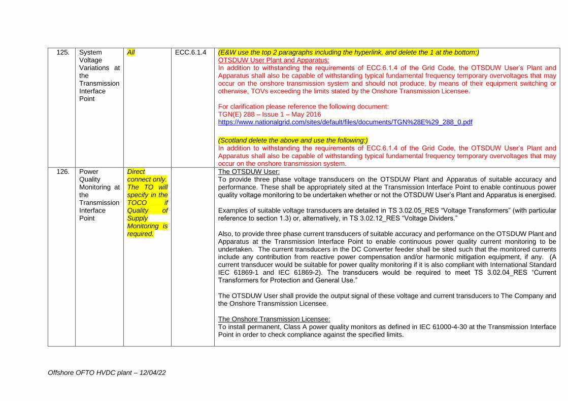
Offshore OFTO HVDC plant – 12/04/22
125. System Voltage Variations at the Transmission Interface Point
All ECC.6.1.4 (E&W use the top 2 paragraphs including the hyperlink, and delete the 1 at the bottom:) OTSDUW User Plant and Apparatus: In addition to withstanding the requirements of ECC.6.1.4 of the Grid Code, the OTSDUW User’s Plant and Apparatus shall also be capable of withstanding typical fundamental frequency temporary overvoltages that may occur on the onshore transmission system and should not produce, by means of their equipment switching or otherwise, TOVs exceeding the limits stated by the Onshore Transmission Licensee. For clarification please reference the following document: TGN(E) 288 – Issue 1 – May 2016 https://www.nationalgrid.com/sites/default/files/documents/TGN%28E%29_288_0.pdf
(Scotland delete the above and use the following:) In addition to withstanding the requirements of ECC.6.1.4 of the Grid Code, the OTSDUW User’s Plant and Apparatus shall also be capable of withstanding typical fundamental frequency temporary overvoltages that may occur on the onshore transmission system.
126. Power Quality Monitoring at the Transmission Interface Point
Direct connect only. The TO will specify in the TOCO if Quality of Supply Monitoring is required.
The OTSDUW User: To provide three phase voltage transducers on the OTSDUW Plant and Apparatus of suitable accuracy and performance. These shall be appropriately sited at the Transmission Interface Point to enable continuous power quality voltage monitoring to be undertaken whether or not the OTSDUW User’s Plant and Apparatus is energised. Examples of suitable voltage transducers are detailed in TS 3.02.05_RES “Voltage Transformers” (with particular reference to section 1.3) or, alternatively, in TS 3.02.12_RES “Voltage Dividers.” Also, to provide three phase current transducers of suitable accuracy and performance on the OTSDUW Plant and Apparatus at the Transmission Interface Point to enable continuous power quality current monitoring to be undertaken. The current transducers in the DC Converter feeder shall be sited such that the monitored currents include any contribution from reactive power compensation and/or harmonic mitigation equipment, if any. (A current transducer would be suitable for power quality monitoring if it is also compliant with International Standard IEC 61869-1 and IEC 61869-2). The transducers would be required to meet TS 3.02.04_RES “Current Transformers for Protection and General Use.” The OTSDUW User shall provide the output signal of these voltage and current transducers to The Company and the Onshore Transmission Licensee. The Onshore Transmission Licensee: To install permanent, Class A power quality monitors as defined in IEC 61000-4-30 at the Transmission Interface Point in order to check compliance against the specified limits.
Offshore OFTO HVDC plant – 12/04/22
Also, to provide cubicle space, power supplies, and ancillary equipment within [XXX]kV Substation, and the OTSDUW User shall provide CT and VT signals (as specified above) to a suitable termination point within the cubicle. The Onshore Transmission Licensee shall undertake a four week period of continuous power quality voltage measurements using the above facilities immediately prior to the energisation of the OTSDUW Plant and Apparatus feeders to establish a baseline for compliance with the Grid Code. Continuous power quality monitoring shall then be performed during and after commissioning of the OTSDUW Plant and Apparatus both with and without the connection of any Offshore Generation. Note:- If it is unclear at the time of the offer where the exact Transmission Interface Point Boundary is located, there may be a need to include the following wording. If in doubt check with CTP (and Quality of Supply – NGET only) for advice. There may be a need to change the above requirements depending upon the exact boundary between the Onshore Transmission Licensee and the OTSDUW User. When the Transmission Interface Point boundary has been defined, the Onshore Transmission Licensee will define the exact requirements for Quality of Supply Monitoring which shall be agreed between the OTSDUW User, The Company and the Onshore Transmission Licensee in the detailed design phase.
127. Voltage Phase Unbalance
All ECC.6.1.5 (b) ECC.6.1.6
The OTSDUW User: To provide Voltage Unbalance Assessment information as specified in PC.4.4.1, PC.4.4.2, PC.4.5, PC.A.4.7 and DRC.6.1.5 Schedule 5, of the Grid Code. The HVDC System shall be designed for a negative phase sequence component of 1.5% of the National Electricity Transmission System voltage for the determination of the HVDC System performance. The HVDC System shall be designed for continuous operation with a Phase (Voltage) Unbalance of up to 2%, which can prevail on the transmission system. (Note: The Phase Unbalance is calculated from the ratio of root mean square (rms) of negative phase sequence voltage to rms of positive phase sequence voltage, based on 10-minute average values, in accordance with IEC 61000 4-30). Onshore Transmission Licensee: Required to carry out an unbalance assessment in accordance with Grid Code Conditions ECC.6.1.5(b) and ECC.6.1.6. Following the assessment, The Company (upon advice from the Onshore Transmission Licensee) will specify to the OTSDUW User by written notice, the negative phase sequence current limits to which the OTSDUW User will comply. The results of this assessment shall be published as a formal statement of compliance.
128. Short Circuit Levels at the
The OTSDUW User:
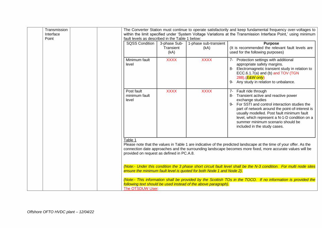
Offshore OFTO HVDC plant – 12/04/22
Transmission Interface Point
The Converter Station must continue to operate satisfactorily and keep fundamental frequency over-voltages to within the limit specified under ‘System Voltage Variations at the Transmission Interface Point,’ using minimum fault levels as described in the Table 1 below:
SQSS Condition 3-phase Sub-Transient
(kA)
1-phase sub-transient (kA)
Purpose (It is recommended the relevant fault levels are used for the following purposes)
Minimum fault level
XXXX
XXXX
7- Protection settings with additional appropriate safety margins.
8- Electromagnetic transient study in relation to ECC.6.1.7(a) and (b) and TOV (TGN 288).(E&W only)
9- Any study in relation to unbalance.
Post fault minimum fault level
XXXX
XXXX
7- Fault ride through 8- Transient active and reactive power
exchange studies 9- For SSTI and control interaction studies the
part of network around the point-of-interest is usually modelled. Post fault minimum fault level, which represent a N-1-D condition on a summer minimum scenario should be included in the study cases.
Table 1 Please note that the values in Table 1 are indicative of the predicted landscape at the time of your offer. As the connection date approaches and the surrounding landscape becomes more fixed, more accurate values will be provided on request as defined in PC.A.8. (Note:- Under this condition the 3 phase short circuit fault level shall be the N-3 condition. For multi node sites ensure the minimum fault level is quoted for both Node 1 and Node 2). (Note:- This information shall be provided by the Scottish TOs in the TOCO. If no information is provided the following text should be used instead of the above paragraph). The OTSDUW User:
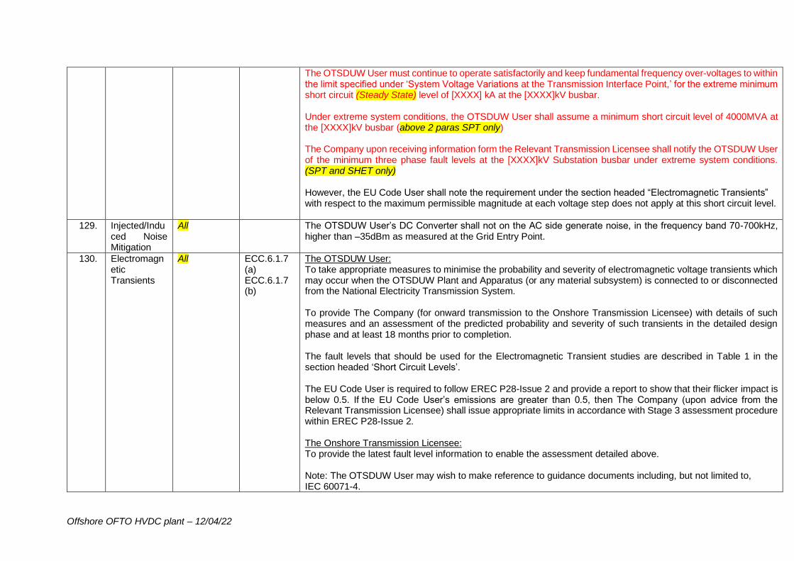
Offshore OFTO HVDC plant – 12/04/22
The OTSDUW User must continue to operate satisfactorily and keep fundamental frequency over-voltages to within the limit specified under ‘System Voltage Variations at the Transmission Interface Point,’ for the extreme minimum short circuit (Steady State) level of [XXXX] kA at the [XXXX]kV busbar. Under extreme system conditions, the OTSDUW User shall assume a minimum short circuit level of 4000MVA at the [XXXX]kV busbar (above 2 paras SPT only) The Company upon receiving information form the Relevant Transmission Licensee shall notify the OTSDUW User of the minimum three phase fault levels at the [XXXX]kV Substation busbar under extreme system conditions. (SPT and SHET only) However, the EU Code User shall note the requirement under the section headed “Electromagnetic Transients” with respect to the maximum permissible magnitude at each voltage step does not apply at this short circuit level.
129. Injected/Induced Noise Mitigation
All The OTSDUW User’s DC Converter shall not on the AC side generate noise, in the frequency band 70-700kHz, higher than –35dBm as measured at the Grid Entry Point.
130. Electromagnetic Transients
All ECC.6.1.7 (a) ECC.6.1.7 (b)
The OTSDUW User: To take appropriate measures to minimise the probability and severity of electromagnetic voltage transients which may occur when the OTSDUW Plant and Apparatus (or any material subsystem) is connected to or disconnected from the National Electricity Transmission System. To provide The Company (for onward transmission to the Onshore Transmission Licensee) with details of such measures and an assessment of the predicted probability and severity of such transients in the detailed design phase and at least 18 months prior to completion. The fault levels that should be used for the Electromagnetic Transient studies are described in Table 1 in the section headed ‘Short Circuit Levels’. The EU Code User is required to follow EREC P28-Issue 2 and provide a report to show that their flicker impact is below 0.5. If the EU Code User’s emissions are greater than 0.5, then The Company (upon advice from the Relevant Transmission Licensee) shall issue appropriate limits in accordance with Stage 3 assessment procedure within EREC P28-Issue 2. The Onshore Transmission Licensee: To provide the latest fault level information to enable the assessment detailed above. Note: The OTSDUW User may wish to make reference to guidance documents including, but not limited to, IEC 60071-4.
Offshore OFTO HVDC plant – 12/04/22
In the event that the Onshore Transmission Licensee needs to undertake transient overvoltage assessments, the OTSDUW User will be required to provide the data required under PC.A.6.2.1. In order to limit voltage change at the Transmission Interface Point, (for example during energisation), the OTSDUW User shall also be required to satisfy the requirements of ECC.6.1.7(a) and ECC.6.1.7(b) of the Grid Code. Following the voltage fluctuation assessment, The Company (upon advice from the Onshore Transmission Licensee) shall specify to the OTSDUW User (by written notice) the flicker limits. The OTSDUW User shall ensure that the total repetitive voltage changes (flicker) due to the operation of the OTSDUW User’s DC Converter Station and any associated equipment, when aggregated with existing flicker levels, do not exceed these values.
131. Overall OTSDUW Plant and Apparatus Protection and Control Facilities
All The OTSDUW User: To ensure that no harmful interactions exist between the OTSDUW Plant and Apparatus and the National Electricity Transmission System which may adversely affect either the OTSDUW Plant and Apparatus protection system or the National Electricity Transmission protection systems. The OTSDUW User shall ensure that its OTSDUW Plant and Apparatus control systems shall be stable in all situations and be self-protected. Where applicable, the OTSDUW Plant and Apparatus control systems shall co-ordinate with the Dynamic VAr Compensation Equipment for the purpose of Reactive Compensation and/or Voltage control. The OTSDUW User shall declare the control strategy which shall be discussed and agreed with The Company as soon as reasonably practicable. In any event this shall be no later than 18 months before the Completion Date (Stage 1) unless otherwise agreed with The Company or Onshore Transmission Licensee. In satisfying these requirements, the OTSDUW User should be aware of and comply with the applicable sections of TS 3.24.90_RES (Protection and Control for HVDC Systems). (E&W only) SPTS/SHETS (Fill in the Scottish Standard that is equivalent to National Grid Technical Specification TS.3.24.90 (Protection and Control for HVDC Systems) – this should be specified by the Scottish TO in the TOCO. If no standard is specified in the TOCO delete this paragraph and use the following paragraph instead). In satisfying these requirements the OTSDUW User should be aware of and comply with minimum technical specifications. These technical specifications shall be notified to the OTSDUW User upon receiving information from the Onshore Transmission Licensee at a later stage (use this paragraph if the Scottish TO does not reference the appropriate technical specification in the TOCO).
132. Operational Metering Requirements in respect of The
All In Scotland, National Grid will install one main
ECC.6.5.6 ECC.6.5.6.5 – ECC.6.5.6.8
The OTSDUW User: To fulfil the metering obligations defined in Schedule 2 of this appendix in respect of The Company and the Onshore Transmission Licensee.
Offshore OFTO HVDC plant – 12/04/22
Company and the Onshore Transmission Licensee
dedicated communications route directly to the Transmission Interface Point and rely on ICCP links via the Scottish TO (under the BETTA Arrangements) as a backup.
Required to install a Remote Terminal Unit (RTU) and (Scotland only) supply the signals defined in Schedule 2 to [XXXX]kV substation (i.e. the Transmission Interface Point Substation). The Onshore Transmission Licensee will install the communications channels to [XXXX]kV Substation.(Scotland only). The functionality, performance, availability, accuracy, dependability, security, protocol and repair times of the equipment generating and supplying the signals (i.e. the meters and communication links) shall be agreed with The Company and Onshore Transmission Licensee at least 12/18 (18 E&W, 12 Scotland) months before the Completion Date (Stage 1). The OTSDUW User will also be responsible for the installation, delivery, infrastructure, maintenance and monitoring of the Operational Metering signals from the Offshore Grid Entry Point to the Transmission Interface Point in order to facilitate the transfer of the Offshore Generator’s operational metering signals. For the avoidance of doubt, once in operation (after the OTSUA Transfer Time), the ownership of part or the whole of the communication equipment will be transferred to the appointed Offshore Transmission Licensee from when each party (Eu Code User and Offshore Transmission Licensee) will then be responsible for the maintenance of their own assets. The Onshore Transmission Licensee will provide a marshalling cubicle at the Transmission Interface Point within [XXXX]kV Onshore Substation in order to receive the Operational Metering Signals. In the event that any part of the OTSDUW User’s Operational Metering equipment, including the communications links to [XXXX]kV substation fails (i.e. the Transmission Interface Point Substation), then the OTSDUW User will be required to repair such equipment within 5 working days of notification of the fault from The Company unless otherwise agreed. In addition to the above requirements, the OTSDUW User shall also be required to satisfy the requirements of ECC.6.5.6.5 to ECC.6.5.6.8 and TS_3.24.100 (Operational Data Transmission).
133. Safety and Operational Interlocking at the Transmission Interface Point
All Unless Scottish TO specifies something different
The OTSDUW User: To provide electrical and mechanical interlocking on the OTSDUW Plant and Apparatus located within the zone covered by the Onshore Transmission Licensee’s substation busbar protection at the Transmission Interface Site in accordance with TS.3.01.01_RES/SPTS/SHETS.
134. Earthing Requirements at the Transmission Interface Point
All Unless Scottish TO specifies something different
Earth Mats: All earth mats on the OTSDUW User’s site(s) and the Onshore Transmission Licensee’s site(s) where these are adjacent may be bonded together. The Onshore Transmission Licensee’s site earth mats can be bonded to the OTSDUW User’s site earth mat. The Onshore Transmission Licensee will provide at least two points within its substation(s) to facilitate any bonding with the User’s site if required. The OTSDUW User: Shall carry out an earthing survey of their sites prior to construction of the OTSDUW User’s Plant and Apparatus. The earthing system is to be designed to withstand a short circuit current of [XX kA for YY seconds] (63kA for 1
Offshore OFTO HVDC plant – 12/04/22
second at 400kV substations, 40kA for 1 second at 275kV substations and 40kA for 3 seconds at 132kV substations) Also shall ensure that it’s Plant and Apparatus is designed and installed such that the rise of earth potential (ROEP) at [XXXX]kV substation conforms to the touch, step and transfer voltage limits which are defined in ENA TS 41 – 24. Where intertripping (second main protection) is required to open circuit breakers, the overall fault clearance time shall not be more than 140ms at 400kV substations, 160ms at 275kV substations and 180ms at 132kV substations (Note this will depend on connection voltage and TO area). The OTSDUW User’s earthing system design review shall take the Onshore Transmission Licensee’s earthing system design into account and the OTSDUW User shall collaborate with the Onshore Transmission Licensee to ensure that compliance has been demonstrated at the Transmission Interface Point and mitigation of 3rd party impact as required. It should also be noted that the earthing system at [XXXX]kV substation shall be designed to comply with ESQCR 2002 and BS EN50522. Any necessary data or characteristics as requested by The Company or Onshore Transmission Licensee of the OTSDUW Plant and Apparatus shall be provided to allow assessment of the risks arising from transfer of potentials and/or currents from the OTSDUW’s Plant and Apparatus earthing system to the Onshore Transmission Licensee’s earthing system (either steady state or transient). The OTSDUW User shall recompense the Onshore Transmission Licensee (through advice provided by The Company) for any additional risk mitigation measures required as a consequence of these transferred potentials and/or currents. (Scottish HVDC only)
135. Direct Current Injection into the Onshore Transmission Licensee’s Earthing System and Corrosion
All The OTSDUW User: To design the earthing of the OTSDUW DC Converter in such a way as to avoid DC stray current flowing through the earthing system during normal operation and to minimise earth current during faulty or unbalanced load conditions. In order to minimise corrosion issues, the requirements for HVDC earthing is specified under BS EN 50162, BS EN 12954 and regarding safe touch voltage threshold for the DC current path, it is defined in IEC/TS 60479-1 which is referenced under BS EN 50522. The entire HVDC system design shall consider the possible maximum level of DC stray currents to which buried or immersed metal structures may be exposed even at a substation distance from the terminal earths of the OTSDUW’s DC Converter.
136. OTSDUW Plant and Apparatus Compliance Process
All The OTSDUW User: To demonstrate compliance with the requirements of the Grid Code as required in the European Compliance Processes.
Offshore OFTO HVDC plant – 12/04/22
After the OTSUA Transfer Time, the Offshore Transmission Licensee will cooperate with the EU Code User, the Onshore Transmission Licensee and The Company to ensure that all aspects of compliance required by the Grid Code and STC are completed.
137. Site Specific HV equipment requirements
Only to be included if circuit breaker ratings at site are close to the limit, In Scottish agreements this should only be included if specified in the TOCO.
The OTSDUW User: In view of the operating time assumptions and the generation concentrations around the connection site, an atypical circuit breaker capability specification may be required to ensure the OTSDUW User’s equipment operates within its proven capability. All OTSDUW User’s bay HV equipment needs to continue to conform to the RES noting that the studied DC component of fault duty upon the switchgear is such that a DC time constant of [XXXX]ms is observed at time of break, with fault levels at the connection site busbar now standing at [XXXX] kA RMS break for a single phase-ground fault. Any equipment installed needs to be rated to withstand levels observed in the planning studies. As a minimum the User’s HV bay equipment shall be rated to match the Onshore Transmission Licensee’s existing (if there are known plans to uprate the substation or planned asset replacement works on site which will increase switchgear ratings include National Grid’s planned CB rating information) HV substation circuit breaker ratings. The Onshore Transmission Licensee’s existing substation equipment is rated to (TO’s engineer to add the existing substation switch gear ratings here -) [XXXX]kA RMS break for a three phase fault and -[XXXX] kA RMS single phase-ground break at a DC time constant of some [XXXX]ms.
138. Real-Time Frequency Signals
All ECC.6.3.3.1.1 (f)
The OTSDUW User shall be capable of providing a fast frequency signal to the EU Code User in accordance with the requirements of ECC.6.3.3.1.1(f).
139. Non-standard Frequency Ranges
All ECC.6.1.2.2.4
In the case of a remote end HVDC system where the nominal frequency is not 50Hz the frequency ranges and any additional requirements shall be specified in the Detailed Design Phase.
140. Protection of interconnecting connections at the Offshore Grid Entry Point
All ECC 6.2.2.3.1
The OTSDUW User: To agree the requirements for the protection of the Interconnecting Connections at the Offshore Grid Entry Point with the EU Code User (via The Company) as soon as reasonably practicable and no later than 24 months before the Completion Date (Stage 1) unless otherwise agreed.
141. Circuit Breaker Fail Protection at
All ECC.6.2.2.3.2
The OTSDUW User:
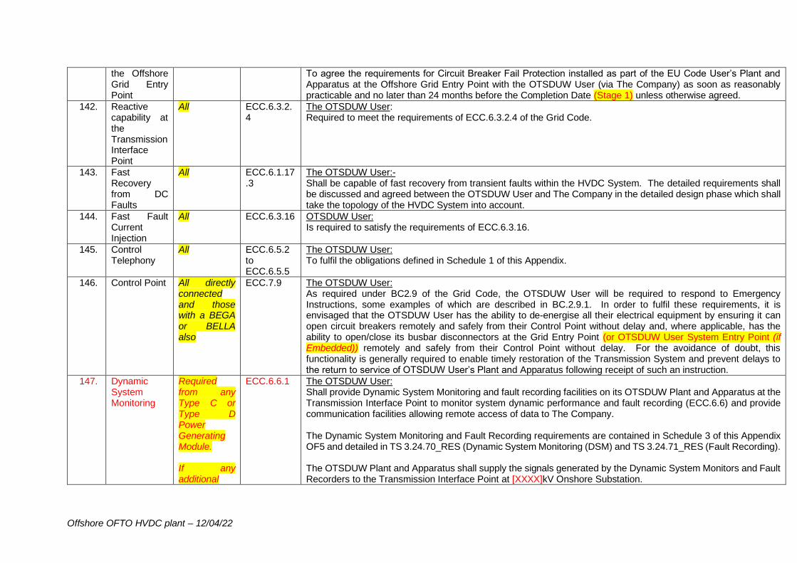
Offshore OFTO HVDC plant – 12/04/22
the Offshore Grid Entry Point
To agree the requirements for Circuit Breaker Fail Protection installed as part of the EU Code User’s Plant and Apparatus at the Offshore Grid Entry Point with the OTSDUW User (via The Company) as soon as reasonably practicable and no later than 24 months before the Completion Date (Stage 1) unless otherwise agreed.
142. Reactive capability at the Transmission Interface Point
All ECC.6.3.2.4
The OTSDUW User: Required to meet the requirements of ECC.6.3.2.4 of the Grid Code.
143. Fast Recovery from DC Faults
All ECC.6.1.17.3
The OTSDUW User:- Shall be capable of fast recovery from transient faults within the HVDC System. The detailed requirements shall be discussed and agreed between the OTSDUW User and The Company in the detailed design phase which shall take the topology of the HVDC System into account.
144. Fast Fault Current Injection
All ECC.6.3.16 OTSDUW User: Is required to satisfy the requirements of ECC.6.3.16.
145. Control Telephony
All ECC.6.5.2 to ECC.6.5.5
The OTSDUW User: To fulfil the obligations defined in Schedule 1 of this Appendix.
146. Control Point All directly connected and those with a BEGA or BELLA also
ECC.7.9 The OTSDUW User: As required under BC2.9 of the Grid Code, the OTSDUW User will be required to respond to Emergency Instructions, some examples of which are described in BC.2.9.1. In order to fulfil these requirements, it is envisaged that the OTSDUW User has the ability to de-energise all their electrical equipment by ensuring it can open circuit breakers remotely and safely from their Control Point without delay and, where applicable, has the ability to open/close its busbar disconnectors at the Grid Entry Point (or OTSDUW User System Entry Point (if Embedded)) remotely and safely from their Control Point without delay. For the avoidance of doubt, this functionality is generally required to enable timely restoration of the Transmission System and prevent delays to the return to service of OTSDUW User’s Plant and Apparatus following receipt of such an instruction.
147. Dynamic System Monitoring
Required from any Type C or Type D Power Generating Module. If any additional
ECC.6.6.1 The OTSDUW User: Shall provide Dynamic System Monitoring and fault recording facilities on its OTSDUW Plant and Apparatus at the Transmission Interface Point to monitor system dynamic performance and fault recording (ECC.6.6) and provide communication facilities allowing remote access of data to The Company. The Dynamic System Monitoring and Fault Recording requirements are contained in Schedule 3 of this Appendix OF5 and detailed in TS 3.24.70_RES (Dynamic System Monitoring (DSM) and TS 3.24.71_RES (Fault Recording). The OTSDUW Plant and Apparatus shall supply the signals generated by the Dynamic System Monitors and Fault Recorders to the Transmission Interface Point at [XXXX]kV Onshore Substation.
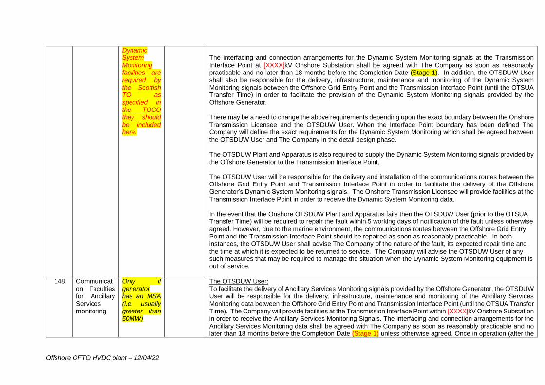
Offshore OFTO HVDC plant – 12/04/22
Dynamic System Monitoring facilities are required by the Scottish TO as specified in the TOCO they should be included here.
The interfacing and connection arrangements for the Dynamic System Monitoring signals at the Transmission Interface Point at [XXXX]kV Onshore Substation shall be agreed with The Company as soon as reasonably practicable and no later than 18 months before the Completion Date (Stage 1). In addition, the OTSDUW User shall also be responsible for the delivery, infrastructure, maintenance and monitoring of the Dynamic System Monitoring signals between the Offshore Grid Entry Point and the Transmission Interface Point (until the OTSUA Transfer Time) in order to facilitate the provision of the Dynamic System Monitoring signals provided by the Offshore Generator. There may be a need to change the above requirements depending upon the exact boundary between the Onshore Transmission Licensee and the OTSDUW User. When the Interface Point boundary has been defined The Company will define the exact requirements for the Dynamic System Monitoring which shall be agreed between the OTSDUW User and The Company in the detail design phase. The OTSDUW Plant and Apparatus is also required to supply the Dynamic System Monitoring signals provided by the Offshore Generator to the Transmission Interface Point. The OTSDUW User will be responsible for the delivery and installation of the communications routes between the Offshore Grid Entry Point and Transmission Interface Point in order to facilitate the delivery of the Offshore Generator’s Dynamic System Monitoring signals. The Onshore Transmission Licensee will provide facilities at the Transmission Interface Point in order to receive the Dynamic System Monitoring data. In the event that the Onshore OTSDUW Plant and Apparatus fails then the OTSDUW User (prior to the OTSUA Transfer Time) will be required to repair the fault within 5 working days of notification of the fault unless otherwise agreed. However, due to the marine environment, the communications routes between the Offshore Grid Entry Point and the Transmission Interface Point should be repaired as soon as reasonably practicable. In both instances, the OTSDUW User shall advise The Company of the nature of the fault, its expected repair time and the time at which it is expected to be returned to service. The Company will advise the OTSDUW User of any such measures that may be required to manage the situation when the Dynamic System Monitoring equipment is out of service.
148. Communication Faculties for Ancillary Services monitoring
Only if generator has an MSA (i.e. usually greater than 50MW)
The OTSDUW User: To facilitate the delivery of Ancillary Services Monitoring signals provided by the Offshore Generator, the OTSDUW User will be responsible for the delivery, infrastructure, maintenance and monitoring of the Ancillary Services Monitoring data between the Offshore Grid Entry Point and Transmission Interface Point (until the OTSUA Transfer Time). The Company will provide facilities at the Transmission Interface Point within [XXXX]kV Onshore Substation in order to receive the Ancillary Services Monitoring Signals. The interfacing and connection arrangements for the Ancillary Services Monitoring data shall be agreed with The Company as soon as reasonably practicable and no later than 18 months before the Completion Date (Stage 1) unless otherwise agreed. Once in operation (after the
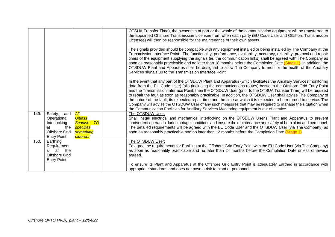
Offshore OFTO HVDC plant – 12/04/22
OTSUA Transfer Time), the ownership of part or the whole of the communication equipment will be transferred to the appointed Offshore Transmission Licensee from when each party (EU Code User and Offshore Transmission Licensee) will then be responsible for the maintenance of their own assets. The signals provided should be compatible with any equipment installed or being installed by The Company at the Transmission Interface Point. The functionality, performance, availability, accuracy, reliability, protocol and repair times of the equipment supplying the signals (ie. the communication links) shall be agreed with The Company as soon as reasonably practicable and no later than 18 months before the Completion Date (Stage 1). In addition, the OTSDUW Plant and Apparatus shall be designed to allow The Company to monitor the health of the Ancillary Services signals up to the Transmission Interface Point. In the event that any part of the OTSDUW Plant and Apparatus (which facilitates the Ancillary Services monitoring data from the EU Code User) fails (including the communications routes) between the Offshore Grid Entry Point and the Transmission Interface Point, then the OTSDUW User (prior to the OTSUA Transfer Time) will be required to repair the fault as soon as reasonably practicable. In addition, the OTSDUW User shall advise The Company of the nature of the fault, its expected repair time and the time at which it is expected to be returned to service. The Company will advise the OTSDUW User of any such measures that may be required to manage the situation when the Communication Facilities for Ancillary Services Monitoring equipment is out of service.
149. Safety and Operational Interlocking at the Offshore Grid Entry Point
All Unless Scottish TO specifies something different
The OTSDUW User: Shall install electrical and mechanical interlocking on the OTSDUW User’s Plant and Apparatus to prevent inadvertent operation during outage conditions and ensure the maintenance and safety of both plant and personnel. The detailed requirements will be agreed with the EU Code User and the OTSDUW User (via The Company) as soon as reasonably practicable and no later than 12 months before the Completion Date (Stage 1).
150. Earthing Requirements at the Offshore Grid Entry Point
The OTSDUW User: To agree the requirements for Earthing at the Offshore Grid Entry Point with the EU Code User (via The Company) as soon as reasonably practicable and no later than 24 months before the Completion Date unless otherwise agreed. To ensure its Plant and Apparatus at the Offshore Grid Entry Point is adequately Earthed in accordance with appropriate standards and does not pose a risk to plant or personnel.

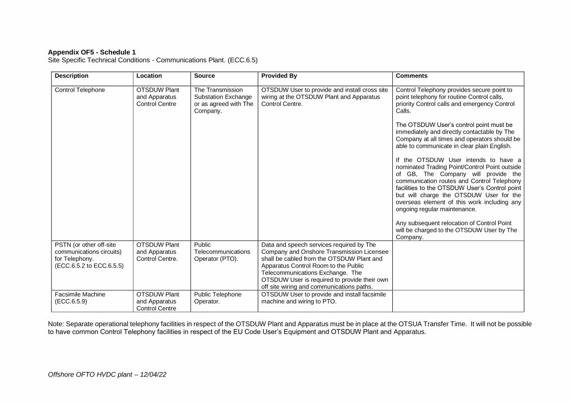
Offshore OFTO HVDC plant – 12/04/22
Appendix OF5 - Schedule 1 Site Specific Technical Conditions - Communications Plant. (ECC.6.5)
Description Location Source Provided By Comments
Control Telephone OTSDUW Plant and Apparatus Control Centre
The Transmission Substation Exchange or as agreed with The Company.
OTSDUW User to provide and install cross site wiring at the OTSDUW Plant and Apparatus Control Centre.
Control Telephony provides secure point to point telephony for routine Control calls, priority Control calls and emergency Control Calls. The OTSDUW User’s control point must be immediately and directly contactable by The Company at all times and operators should be able to communicate in clear plain English. If the OTSDUW User intends to have a nominated Trading Point/Control Point outside of GB, The Company will provide the communication routes and Control Telephony facilities to the OTSDUW User’s Control point but will charge the OTSDUW User for the overseas element of this work including any ongoing regular maintenance. Any subsequent relocation of Control Point will be charged to the OTSDUW User by The Company.
PSTN (or other off-site communications circuits) for Telephony. (ECC.6.5.2 to ECC.6.5.5)
OTSDUW Plant and Apparatus Control Centre.
Public Telecommunications Operator (PTO).
Data and speech services required by The Company and Onshore Transmission Licensee shall be cabled from the OTSDUW Plant and Apparatus Control Room to the Public Telecommunications Exchange. The OTSDUW User is required to provide their own off site wiring and communications paths.
Facsimile Machine (ECC.6.5.9)
OTSDUW Plant and Apparatus Control Centre
Public Telephone Operator.
OTSDUW User to provide and install facsimile machine and wiring to PTO.
Note: Separate operational telephony facilities in respect of the OTSDUW Plant and Apparatus must be in place at the OTSUA Transfer Time. It will not be possible to have common Control Telephony facilities in respect of the EU Code User’s Equipment and OTSDUW Plant and Apparatus.
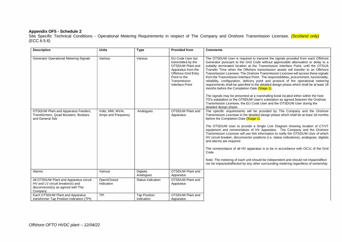
Offshore OFTO HVDC plant – 12/04/22
Appendix OF5 - Schedule 2 Site Specific Technical Conditions - Operational Metering Requirements in respect of The Company and Onshore Transmission Licensee. (Scotland only) (ECC.6.5.6)
Description Units Type Provided from Comments
Generator Operational Metering Signals Various Various EU Code User but transmitted by the OTSDUW Plant and
Apparatus from the Offshore Grid Entry Point to the
Transmission Interface Point
The OTSDUW User is required to transmit the signals provided from each Offshore Generator pursuant to the Grid Code without appreciable attenuation or delay to a suitably terminated location at the Transmission Interface Point, until the OTSUA
Transfer Time when the Offshore transmission assets will transfer to an Offshore Transmission Licensee. The Onshore Transmission Licensee will access these signals from the Transmission Interface Point. The responsibilities, procurement, functionality,
reliability, configuration, delivery point and protocol of the operational metering requirements shall be specified in the detailed design phase which shall be at least 18 months before the Completion Date (Stage 1).
The signals may be presented at a marshalling kiosk located either within the host TO’s substation or the OTSDUW User’s substation as agreed between the Onshore
Transmission Licensee, the EU Code User and the OTSDUW User during the detailed design phase.
OTSDUW Plant and Apparatus Feeders,
Transformers, Quad Boosters, Busbars and General Site
Volts, MW, MVAr,
Amps and Frequency
Analogues OTSDUW Plant and
Apparatus
The specific requirements will be provided by The Company and the Onshore
Transmission Licensee in the detailed design phase which shall be at least 18 months before the Completion Date (Stage 1).
The OTSDUW User to provide a Single Line Diagram showing location of CT/VT equipment and nomenclature of HV Apparatus. The Company and the Onshore Transmission Licensee will use this information to notify the OTSDUW User of which
HV circuit breaker, disconnector positions (i.e. status indications), analogues, digitals and alarms are required.
The nomenclature of all HV apparatus is to be in accordance with OC11 of the Grid Code.
Note: The metering of each unit should be independent and should not impact/affect nor be impacted/affected by any other surrounding metering regardless of ownership.
Alarms Various Digitals Analogues
OTSDUW Plant and Apparatus
All OTSDUW Plant and Apparatus circuit HV and LV circuit breaker(s) and disconnector(s) as agreed with The
Company
Open/Closed Indication
Status Indication OTSDUW Plant and Apparatus
Each OTSDUW Plant and Apparatus transformer Tap Position Indication (TPI)
TPI Tap Position Indication
OTSDUW Plant and Apparatus
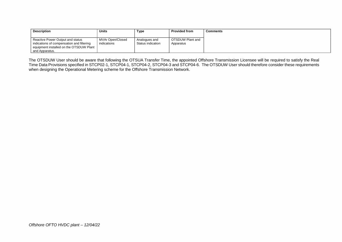
Offshore OFTO HVDC plant – 12/04/22
Description Units Type Provided from Comments
Reactive Power Output and status indications of compensation and filtering
equipment installed on the OTSDUW Plant and Apparatus.
MVAr Open/Closed indications
Analogues and Status indication
OTSDUW Plant and Apparatus
The OTSDUW User should be aware that following the OTSUA Transfer Time, the appointed Offshore Transmission Licensee will be required to satisfy the Real Time Data Provisions specified in STCP02-1, STCP04-1, STCP04-2, STCP04-3 and STCP04-6. The OTSDUW User should therefore consider these requirements when designing the Operational Metering scheme for the Offshore Transmission Network.
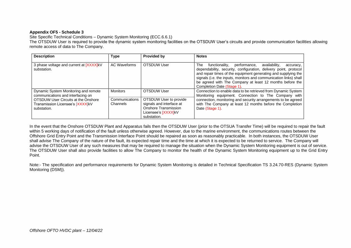
Offshore OFTO HVDC plant – 12/04/22
Appendix OF5 - Schedule 3 Site Specific Technical Conditions – Dynamic System Monitoring (ECC.6.6.1) The OTSDUW User is required to provide the dynamic system monitoring facilities on the OTSDUW User’s circuits and provide communication facilities allowing remote access of data to The Company.
Description Type Provided by Notes
3 phase voltage and current at [XXXX]kV substation.
AC Waveforms OTSDUW User The functionality, performance, availability, accuracy, dependability, security, configuration, delivery point, protocol and repair times of the equipment generating and supplying the signals (i.e. the inputs, monitors and communication links) shall be agreed with The Company at least 12 months before the Completion Date (Stage 1).
Dynamic System Monitoring and remote communications and interfacing on OTSDUW User Circuits at the Onshore Transmission Licensee’s [XXXX]kV substation.
Monitors OTSDUW User Connection to enable data to be retrieved from Dynamic System Monitoring equipment. Connection to The Company with connection, monitoring and security arrangements to be agreed with The Company at least 12 months before the Completion Date (Stage 1).
Communications Channels
OTSDUW User to provide signals and interface at Onshore Transmission Licensee’s [XXXX]kV substation.
In the event that the Onshore OTSDUW Plant and Apparatus fails then the OTSDUW User (prior to the OTSUA Transfer Time) will be required to repair the fault within 5 working days of notification of the fault unless otherwise agreed. However, due to the marine environment, the communications routes between the Offshore Grid Entry Point and the Transmission Interface Point should be repaired as soon as reasonably practicable. In both instances, the OTSDUW User shall advise The Company of the nature of the fault, its expected repair time and the time at which it is expected to be returned to service. The Company will advise the OTSDUW User of any such measures that may be required to manage the situation when the Dynamic System Monitoring equipment is out of service. The OTSDUW User shall also provide facilities to allow The Company to monitor the health of the Dynamic System Monitoring equipment up to the Grid Entry Point. Note:- The specification and performance requirements for Dynamic System Monitoring is detailed in Technical Specification TS 3.24.70-RES (Dynamic System Monitoring (DSM)).

Offshore OFTO HVDC plant – 12/04/22
USEFUL LINKS The Grid Code: https://www.nationalgrideso.com/uk/electricity/codes/grid-code Electrical Standards: https://www.nationalgrideso.com/uk/electricity/codes/grid-code/electrical-standards-documents-including-specifications-electronic Extranet (ID and password required, email [email protected] to request access): https://extranet.nationalgrid.com/(delete this link if in Scotland) Connection Policies and Guidance: https://www.nationalgrideso.com/uk/electricity/connections/applying-connection Procurement Guidelines and Balancing Principles: https://www.nationalgrideso.com/uk/electricity/market-operations-and-data/transmission-licence-c16-statements-and-consultations
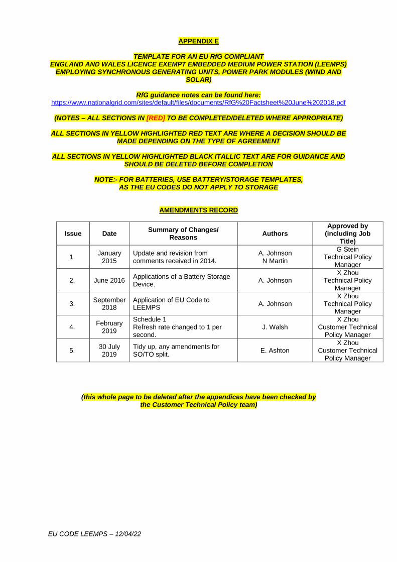
EU CODE LEEMPS – 12/04/22
APPENDIX E
TEMPLATE FOR AN EU RfG COMPLIANT ENGLAND AND WALES LICENCE EXEMPT EMBEDDED MEDIUM POWER STATION (LEEMPS)
EMPLOYING SYNCHRONOUS GENERATING UNITS, POWER PARK MODULES (WIND AND SOLAR)
RfG guidance notes can be found here:
https://www.nationalgrid.com/sites/default/files/documents/RfG%20Factsheet%20June%202018.pdf
(NOTES – ALL SECTIONS IN [RED] TO BE COMPLETED/DELETED WHERE APPROPRIATE)
ALL SECTIONS IN YELLOW HIGHLIGHTED RED TEXT ARE WHERE A DECISION SHOULD BE MADE DEPENDING ON THE TYPE OF AGREEMENT
ALL SECTIONS IN YELLOW HIGHLIGHTED BLACK ITALLIC TEXT ARE FOR GUIDANCE AND
SHOULD BE DELETED BEFORE COMPLETION
NOTE:- FOR BATTERIES, USE BATTERY/STORAGE TEMPLATES, AS THE EU CODES DO NOT APPLY TO STORAGE
AMENDMENTS RECORD
Issue Date Summary of Changes/
Reasons Authors
Approved by (including Job
Title)
1. January
2015 Update and revision from comments received in 2014.
A. Johnson N Martin
G Stein Technical Policy
Manager
2. June 2016 Applications of a Battery Storage Device.
A. Johnson X Zhou
Technical Policy Manager
3. September
2018 Application of EU Code to LEEMPS
A. Johnson X Zhou
Technical Policy Manager
4. February
2019
Schedule 1 Refresh rate changed to 1 per second.
J. Walsh X Zhou
Customer Technical Policy Manager
5. 30 July 2019
Tidy up, any amendments for SO/TO split.
E. Ashton X Zhou
Customer Technical Policy Manager
(this whole page to be deleted after the appendices have been checked by the Customer Technical Policy team)
EU CODE LEEMPS – 12/04/22
APPENDIX E
SITE SPECIFIC TECHNICAL REQUIREMENTS User: [XXXX]
Type of User: User
Grid Supply Point/Connection Site: [XXXX]
Type: Exit
Embedded Generator/Storage User: [XXXX]
1. Generator Plant Performance Requirements
As required under the Grid Code, the User shall ensure that the Embedded Generator/Storage User meets those requirements of the Grid Code as applicable to Embedded Medium Power Stations (which comprise of any combination of a Type A, Type B, Type C or Type D Power Generating Module) which are not subject to a Bilateral Agreement with The Company.
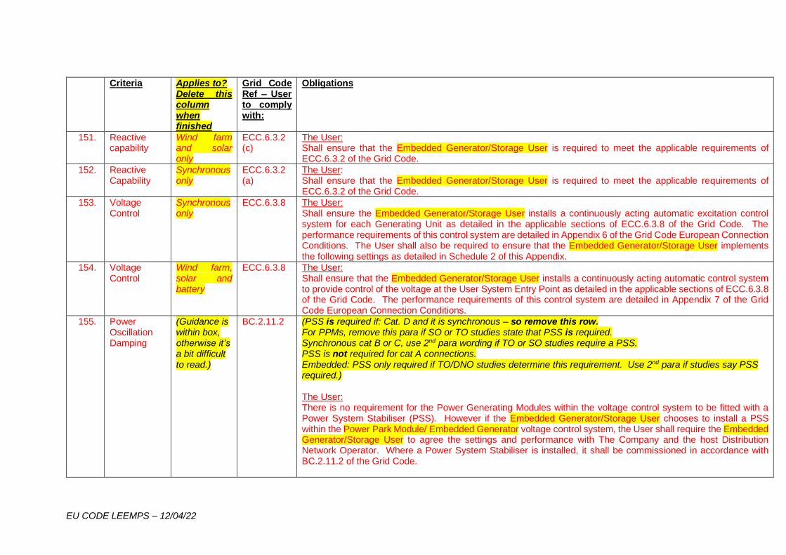
EU CODE LEEMPS – 12/04/22
Criteria Applies to? Delete this column when finished
Grid Code Ref – User to comply with:
Obligations
151. Reactive capability
Wind farm and solar only
ECC.6.3.2 (c)
The User: Shall ensure that the Embedded Generator/Storage User is required to meet the applicable requirements of ECC.6.3.2 of the Grid Code.
152. Reactive Capability
Synchronous only
ECC.6.3.2 (a)
The User: Shall ensure that the Embedded Generator/Storage User is required to meet the applicable requirements of ECC.6.3.2 of the Grid Code.
153. Voltage Control
Synchronous only
ECC.6.3.8
The User: Shall ensure the Embedded Generator/Storage User installs a continuously acting automatic excitation control system for each Generating Unit as detailed in the applicable sections of ECC.6.3.8 of the Grid Code. The performance requirements of this control system are detailed in Appendix 6 of the Grid Code European Connection Conditions. The User shall also be required to ensure that the Embedded Generator/Storage User implements the following settings as detailed in Schedule 2 of this Appendix.
154. Voltage Control
Wind farm, solar and battery
ECC.6.3.8 The User: Shall ensure that the Embedded Generator/Storage User installs a continuously acting automatic control system to provide control of the voltage at the User System Entry Point as detailed in the applicable sections of ECC.6.3.8 of the Grid Code. The performance requirements of this control system are detailed in Appendix 7 of the Grid Code European Connection Conditions.
155. Power Oscillation Damping
(Guidance is within box, otherwise it’s a bit difficult to read.)
BC.2.11.2 (PSS is required if: Cat. D and it is synchronous – so remove this row. For PPMs, remove this para if SO or TO studies state that PSS is required. Synchronous cat B or C, use 2nd para wording if TO or SO studies require a PSS. PSS is not required for cat A connections. Embedded: PSS only required if TO/DNO studies determine this requirement. Use 2nd para if studies say PSS required.) The User: There is no requirement for the Power Generating Modules within the voltage control system to be fitted with a Power System Stabiliser (PSS). However if the Embedded Generator/Storage User chooses to install a PSS within the Power Park Module/ Embedded Generator voltage control system, the User shall require the Embedded Generator/Storage User to agree the settings and performance with The Company and the host Distribution Network Operator. Where a Power System Stabiliser is installed, it shall be commissioned in accordance with BC.2.11.2 of the Grid Code.
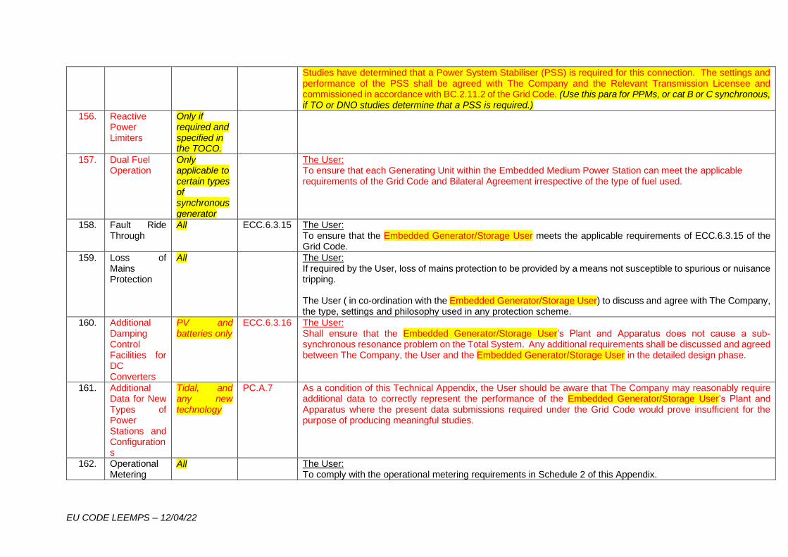
EU CODE LEEMPS – 12/04/22
Studies have determined that a Power System Stabiliser (PSS) is required for this connection. The settings and performance of the PSS shall be agreed with The Company and the Relevant Transmission Licensee and commissioned in accordance with BC.2.11.2 of the Grid Code. (Use this para for PPMs, or cat B or C synchronous, if TO or DNO studies determine that a PSS is required.)
156. Reactive Power Limiters
Only if required and specified in the TOCO.
157. Dual Fuel Operation
Only applicable to certain types of synchronous generator
The User: To ensure that each Generating Unit within the Embedded Medium Power Station can meet the applicable requirements of the Grid Code and Bilateral Agreement irrespective of the type of fuel used.
158. Fault Ride Through
All ECC.6.3.15 The User: To ensure that the Embedded Generator/Storage User meets the applicable requirements of ECC.6.3.15 of the Grid Code.
159. Loss of Mains Protection
All The User: If required by the User, loss of mains protection to be provided by a means not susceptible to spurious or nuisance tripping. The User ( in co-ordination with the Embedded Generator/Storage User) to discuss and agree with The Company, the type, settings and philosophy used in any protection scheme.
160. Additional Damping Control Facilities for DC Converters
PV and batteries only
ECC.6.3.16 The User: Shall ensure that the Embedded Generator/Storage User’s Plant and Apparatus does not cause a sub-synchronous resonance problem on the Total System. Any additional requirements shall be discussed and agreed between The Company, the User and the Embedded Generator/Storage User in the detailed design phase.
161. Additional Data for New Types of Power Stations and Configurations
Tidal, and any new technology
PC.A.7 As a condition of this Technical Appendix, the User should be aware that The Company may reasonably require additional data to correctly represent the performance of the Embedded Generator/Storage User’s Plant and Apparatus where the present data submissions required under the Grid Code would prove insufficient for the purpose of producing meaningful studies.
162. Operational Metering
All The User: To comply with the operational metering requirements in Schedule 2 of this Appendix.
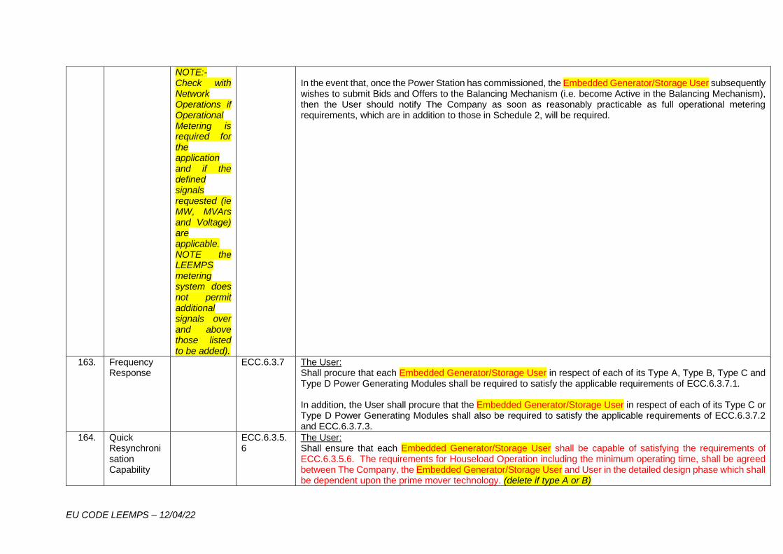
EU CODE LEEMPS – 12/04/22
NOTE:- Check with Network Operations if Operational Metering is required for the application and if the defined signals requested (ie MW, MVArs and Voltage) are applicable. NOTE the LEEMPS metering system does not permit additional signals over and above those listed to be added).
In the event that, once the Power Station has commissioned, the Embedded Generator/Storage User subsequently wishes to submit Bids and Offers to the Balancing Mechanism (i.e. become Active in the Balancing Mechanism), then the User should notify The Company as soon as reasonably practicable as full operational metering requirements, which are in addition to those in Schedule 2, will be required.
163. Frequency Response
ECC.6.3.7 The User: Shall procure that each Embedded Generator/Storage User in respect of each of its Type A, Type B, Type C and Type D Power Generating Modules shall be required to satisfy the applicable requirements of ECC.6.3.7.1. In addition, the User shall procure that the Embedded Generator/Storage User in respect of each of its Type C or Type D Power Generating Modules shall also be required to satisfy the applicable requirements of ECC.6.3.7.2 and ECC.6.3.7.3.
164. Quick Resynchronisation Capability
ECC.6.3.5.6
The User: Shall ensure that each Embedded Generator/Storage User shall be capable of satisfying the requirements of ECC.6.3.5.6. The requirements for Houseload Operation including the minimum operating time, shall be agreed between The Company, the Embedded Generator/Storage User and User in the detailed design phase which shall be dependent upon the prime mover technology. (delete if type A or B)
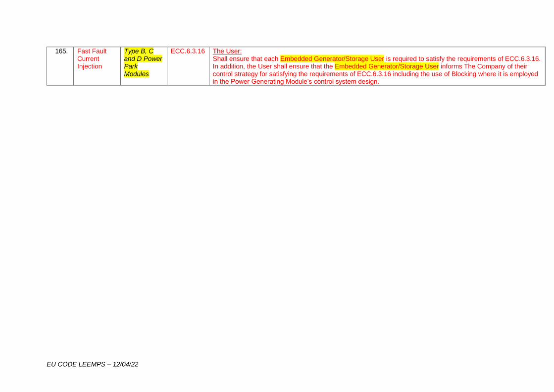
EU CODE LEEMPS – 12/04/22
165. Fast Fault Current Injection
Type B, C and D Power Park Modules
ECC.6.3.16 The User: Shall ensure that each Embedded Generator/Storage User is required to satisfy the requirements of ECC.6.3.16. In addition, the User shall ensure that the Embedded Generator/Storage User informs The Company of their control strategy for satisfying the requirements of ECC.6.3.16 including the use of Blocking where it is employed in the Power Generating Module’s control system design.

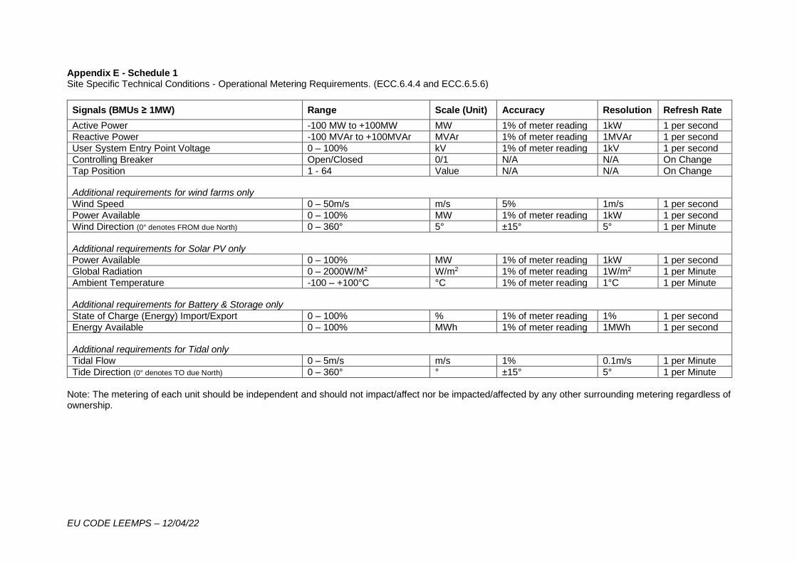
EU CODE LEEMPS – 12/04/22
Appendix E - Schedule 1 Site Specific Technical Conditions - Operational Metering Requirements. (ECC.6.4.4 and ECC.6.5.6)
Signals (BMUs ≥ 1MW) Range Scale (Unit) Accuracy Resolution Refresh Rate
Active Power -100 MW to +100MW MW 1% of meter reading 1kW 1 per second
Reactive Power -100 MVAr to +100MVAr MVAr 1% of meter reading 1MVAr 1 per second
User System Entry Point Voltage 0 – 100% kV 1% of meter reading 1kV 1 per second
Controlling Breaker Open/Closed 0/1 N/A N/A On Change
Tap Position 1 - 64 Value N/A N/A On Change
Additional requirements for wind farms only
Wind Speed 0 – 50m/s m/s 5% 1m/s 1 per second
Power Available 0 – 100% MW 1% of meter reading 1kW 1 per second
Wind Direction (0° denotes FROM due North) 0 – 360° 5° ±15° 5° 1 per Minute
Additional requirements for Solar PV only
Power Available 0 – 100% MW 1% of meter reading 1kW 1 per second
Global Radiation 0 – 2000W/M2 W/m2 1% of meter reading 1W/m2 1 per Minute
Ambient Temperature -100 – +100°C °C 1% of meter reading 1°C 1 per Minute
Additional requirements for Battery & Storage only
State of Charge (Energy) Import/Export 0 – 100% % 1% of meter reading 1% 1 per second
Energy Available 0 – 100% MWh 1% of meter reading 1MWh 1 per second
Additional requirements for Tidal only
Tidal Flow 0 – 5m/s m/s 1% 0.1m/s 1 per Minute
Tide Direction (0° denotes TO due North) 0 – 360° ° ±15° 5° 1 per Minute
Note: The metering of each unit should be independent and should not impact/affect nor be impacted/affected by any other surrounding metering regardless of ownership.
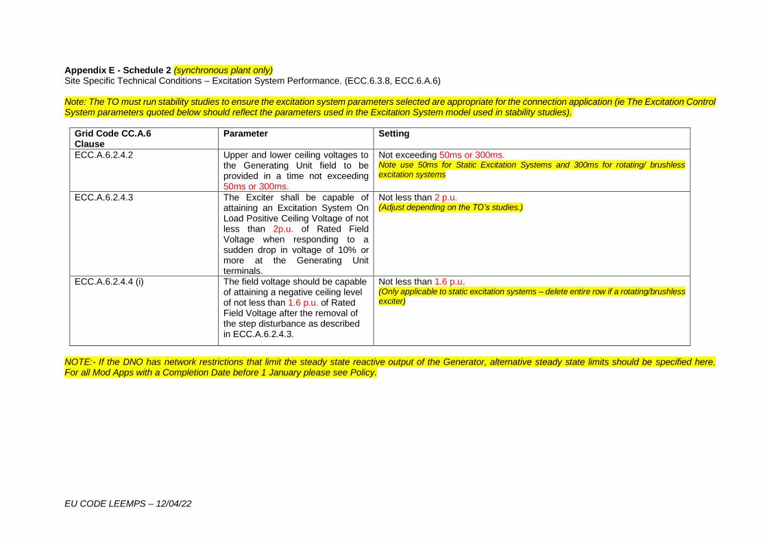
EU CODE LEEMPS – 12/04/22
Appendix E - Schedule 2 (synchronous plant only) Site Specific Technical Conditions – Excitation System Performance. (ECC.6.3.8, ECC.6.A.6) Note: The TO must run stability studies to ensure the excitation system parameters selected are appropriate for the connection application (ie The Excitation Control System parameters quoted below should reflect the parameters used in the Excitation System model used in stability studies).
Grid Code CC.A.6 Clause
Parameter Setting
ECC.A.6.2.4.2 Upper and lower ceiling voltages to the Generating Unit field to be provided in a time not exceeding 50ms or 300ms.
Not exceeding 50ms or 300ms. Note use 50ms for Static Excitation Systems and 300ms for rotating/ brushless excitation systems
ECC.A.6.2.4.3 The Exciter shall be capable of attaining an Excitation System On Load Positive Ceiling Voltage of not less than 2p.u. of Rated Field Voltage when responding to a sudden drop in voltage of 10% or more at the Generating Unit terminals.
Not less than 2 p.u. (Adjust depending on the TO’s studies.)
ECC.A.6.2.4.4 (i) The field voltage should be capable of attaining a negative ceiling level of not less than 1.6 p.u. of Rated Field Voltage after the removal of the step disturbance as described in ECC.A.6.2.4.3.
Not less than 1.6 p.u. (Only applicable to static excitation systems – delete entire row if a rotating/brushless exciter)
NOTE:- If the DNO has network restrictions that limit the steady state reactive output of the Generator, alternative steady state limits should be specified here. For all Mod Apps with a Completion Date before 1 January please see Policy.
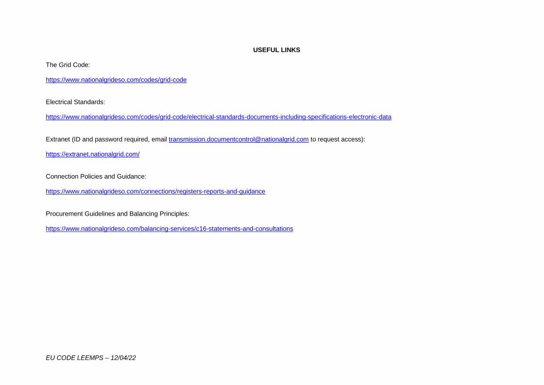
EU CODE LEEMPS – 12/04/22
USEFUL LINKS The Grid Code: https://www.nationalgrideso.com/codes/grid-code Electrical Standards: https://www.nationalgrideso.com/codes/grid-code/electrical-standards-documents-including-specifications-electronic-data Extranet (ID and password required, email [email protected] to request access): https://extranet.nationalgrid.com/ Connection Policies and Guidance: https://www.nationalgrideso.com/connections/registers-reports-and-guidance Procurement Guidelines and Balancing Principles: https://www.nationalgrideso.com/balancing-services/c16-statements-and-consultations
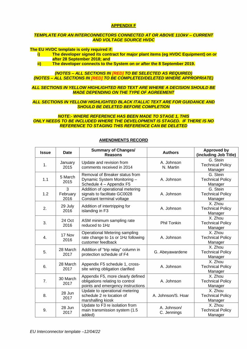
EU Interconnector template –12/04/22
APPENDIX F
TEMPLATE FOR AN INTERCONNECTORS CONNECTED AT OR ABOVE 11OkV – CURRENT AND VOLTAGE SOURCE HVDC
The EU HVDC template is only required if:
i) The developer signed its contract for major plant items (eg HVDC Equipment) on or after 28 September 2018; and
ii) The developer connects to the System on or after the 8 September 2019.
(NOTES – ALL SECTIONS IN [RED] TO BE SELECTED AS REQUIRED) (NOTES – ALL SECTIONS IN [RED] TO BE COMPLETED/DELETED WHERE APPROPRIATE)
ALL SECTIONS IN YELLOW HIGHLIGHTED RED TEXT ARE WHERE A DECISION SHOULD BE
MADE DEPENDING ON THE TYPE OF AGREEMENT
ALL SECTIONS IN YELLOW HIGHLIGHTED BLACK ITALLIC TEXT ARE FOR GUIDANCE AND SHOULD BE DELETED BEFORE COMPLETION
NOTE:- WHERE REFERENCE HAS BEEN MADE TO STAGE 1, THIS
ONLY NEEDS TO BE INCLUDED WHERE THE DEVELOPMENT IS STAGED. IF THERE IS NO REFERENCE TO STAGING THIS REFERENCE CAN BE DELETED
AMENDMENTS RECORD
Issue Date Summary of Changes/
Reasons Authors
Approved by (including Job Title)
1. January
2015 Update and revision from comments received in 2014
A. Johnson N. Martin
G. Stein Technical Policy
Manager
1.1 5 March
2015
Removal of Breaker status from Dynamic System Monitoring – Schedule 4 – Appendix F5
A. Johnson G. Stein
Technical Policy Manager
1.2 3
February 2016
Addition of operational metering signals to facilitate GC0028 Constant terminal voltage
A. Johnson G. Stein
Technical Policy Manager
2. 29 July 2016
Addition of intertripping for islanding in F3
A. Johnson X. Zhou
Technical Policy Manager
3. 24 Oct 2016
ASM minimum sampling rate reduced to 1Hz
Phil Tonkin X. Zhou
Technical Policy Manager
4. 17 Nov 2016
Operational Metering sampling rate change to 1s or 1Hz following customer feedback
A. Johnson X. Zhou
Technical Policy Manager
5. 28 March
2017 Addition of “trip relay” column in protection schedule of F4
G. Abeyawardene X. Zhou
Technical Policy Manager
6. 28 March
2017 Appendix F5 schedule 1, cross-site wiring obligation clarified
A. Johnson X. Zhou
Technical Policy Manager
7. 30 March
2017
Appendix F5, more clearly defined obligations relating to control points and emergency instructions
A. Johnson X. Zhou
Technical Policy Manager
8. 28 Jun 2017
Update to operational metering schedule 2 re location of marshalling kiosk
A. Johnson/S. Hoar X. Zhou
Technical Policy Manager
9. 28 Jun 2017
Update to F3 re isolation from main transmission system (1.5 added)
A. Johnson/ C. Jennings
X. Zhou Technical Policy
Manager
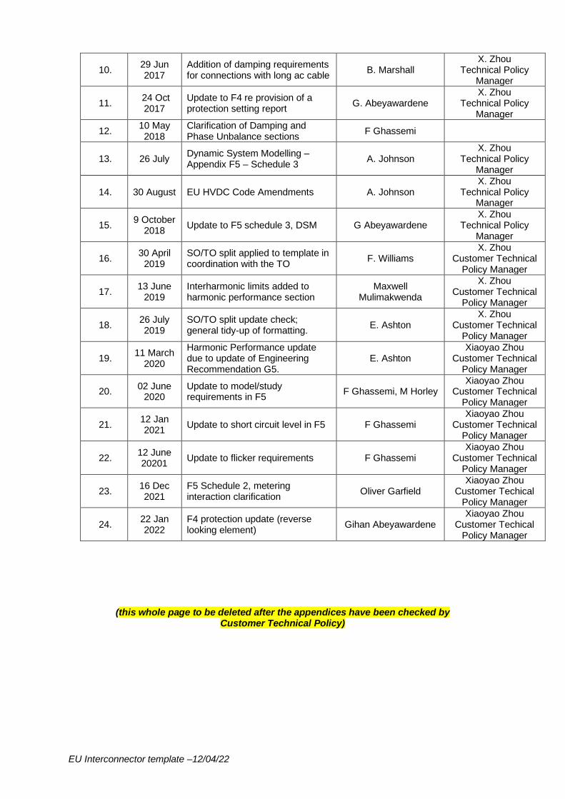
EU Interconnector template –12/04/22
10. 29 Jun 2017
Addition of damping requirements for connections with long ac cable
B. Marshall X. Zhou
Technical Policy Manager
11. 24 Oct 2017
Update to F4 re provision of a protection setting report
G. Abeyawardene X. Zhou
Technical Policy Manager
12. 10 May 2018
Clarification of Damping and Phase Unbalance sections
F Ghassemi
13. 26 July Dynamic System Modelling – Appendix F5 – Schedule 3
A. Johnson X. Zhou
Technical Policy Manager
14. 30 August EU HVDC Code Amendments A. Johnson X. Zhou
Technical Policy Manager
15. 9 October
2018 Update to F5 schedule 3, DSM G Abeyawardene
X. Zhou Technical Policy
Manager
16. 30 April
2019 SO/TO split applied to template in coordination with the TO
F. Williams X. Zhou
Customer Technical Policy Manager
17. 13 June
2019 Interharmonic limits added to harmonic performance section
Maxwell Mulimakwenda
X. Zhou Customer Technical
Policy Manager
18. 26 July 2019
SO/TO split update check; general tidy-up of formatting.
E. Ashton X. Zhou
Customer Technical Policy Manager
19. 11 March
2020
Harmonic Performance update due to update of Engineering Recommendation G5.
E. Ashton Xiaoyao Zhou
Customer Technical Policy Manager
20. 02 June
2020 Update to model/study requirements in F5
F Ghassemi, M Horley Xiaoyao Zhou
Customer Technical Policy Manager
21. 12 Jan 2021
Update to short circuit level in F5 F Ghassemi Xiaoyao Zhou
Customer Technical Policy Manager
22. 12 June 20201
Update to flicker requirements F Ghassemi Xiaoyao Zhou
Customer Technical Policy Manager
23. 16 Dec 2021
F5 Schedule 2, metering interaction clarification
Oliver Garfield Xiaoyao Zhou
Customer Techical Policy Manager
24. 22 Jan 2022
F4 protection update (reverse looking element)
Gihan Abeyawardene Xiaoyao Zhou
Customer Techical Policy Manager
(this whole page to be deleted after the appendices have been checked by Customer Technical Policy)
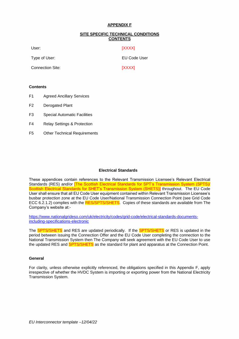
EU Interconnector template –12/04/22
APPENDIX F
SITE SPECIFIC TECHNICAL CONDITIONS CONTENTS
User: [XXXX]
Type of User: EU Code User
Connection Site: [XXXX]
Contents F1 Agreed Ancillary Services F2 Derogated Plant F3 Special Automatic Facilities F4 Relay Settings & Protection F5 Other Technical Requirements
Electrical Standards These appendices contain references to the Relevant Transmission Licensee’s Relevant Electrical Standards (RES) and/or [The Scottish Electrical Standards for SPT’s Transmission System (SPTS)/ Scottish Electrical Standards for SHET’s Transmission System (SHETS)] throughout. The EU Code User shall ensure that all EU Code User equipment contained within Relevant Transmission Licensee’s busbar protection zone at the EU Code User/National Transmission Connection Point (see Grid Code ECC 6.2.1.2) complies with the RES/SPTS/SHETS. Copies of these standards are available from The Company’s website at:- https://www.nationalgrideso.com/uk/electricity/codes/grid-code/electrical-standards-documents-including-specifications-electronic The SPTS/SHETS and RES are updated periodically. If the SPTS/SHETS or RES is updated in the period between issuing the Connection Offer and the EU Code User completing the connection to the National Transmission System then The Company will seek agreement with the EU Code User to use the updated RES and SPTS/SHETS as the standard for plant and apparatus at the Connection Point. General For clarity, unless otherwise explicitly referenced, the obligations specified in this Appendix F, apply irrespective of whether the HVDC System is importing or exporting power from the National Electricity Transmission System.
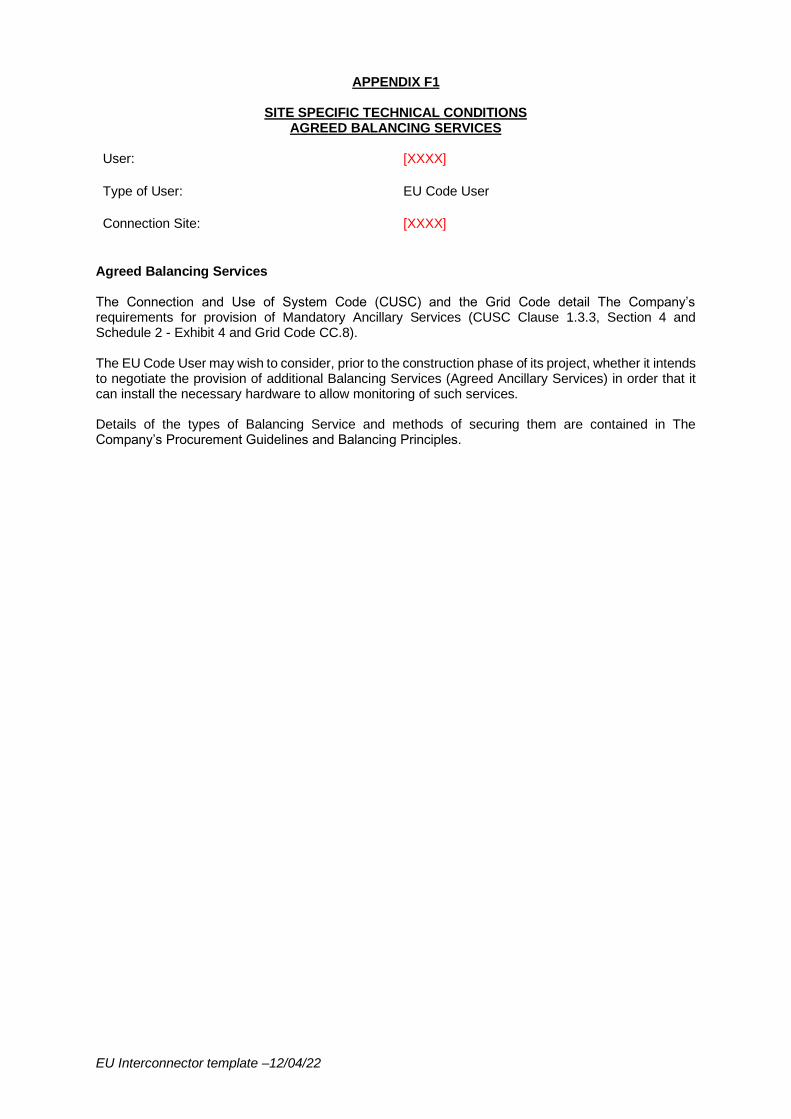
EU Interconnector template –12/04/22
APPENDIX F1
SITE SPECIFIC TECHNICAL CONDITIONS AGREED BALANCING SERVICES
User: [XXXX]
Type of User: EU Code User
Connection Site: [XXXX]
Agreed Balancing Services The Connection and Use of System Code (CUSC) and the Grid Code detail The Company’s requirements for provision of Mandatory Ancillary Services (CUSC Clause 1.3.3, Section 4 and Schedule 2 - Exhibit 4 and Grid Code CC.8). The EU Code User may wish to consider, prior to the construction phase of its project, whether it intends to negotiate the provision of additional Balancing Services (Agreed Ancillary Services) in order that it can install the necessary hardware to allow monitoring of such services. Details of the types of Balancing Service and methods of securing them are contained in The Company’s Procurement Guidelines and Balancing Principles.
EU Interconnector template –12/04/22
APPENDIX F2
SITE SPECIFIC TECHNICAL CONDITIONS DEROGATED PLANT
User: [XXXX]
Type of User: EU Code User
Connection Site: [XXXX]
Derogated Plant Not applicable.
EU Interconnector template –12/04/22
APPENDIX F3
SITE SPECIFIC TECHNICAL CONDITIONS SPECIAL AUTOMATIC FACILITIES
User: [XXXX]
Type of User: EU Code User
Connection Site: [XXXX]
Special Automatic Facilities
Note System Design must ensure that any requirements for Operational Intertripping are consistent with the Design Specification Investment proposal and checked by Construction/Alliances. In Scotland these requirements will be specified by SPT or SHET in the TOCO, after the template is populated it should be sent to SPT or SHET for checking.
1.0 Transmission System to HVDC System Intertripping Schemes
Where the EU Code User is required to provide an HVDC System intertrip facility, the EU Code User shall include all information in accordance to those provisions within Appendix F4 and include all relevant information within Schedule 1 of Appendix F4. The EU Code User agrees that The Company shall, in operational timescales, issue an instruction for the arming of the intertrip facility pursuant to the Grid Code BC2.10.2(a) and as described below. The Company also reserves the right to use such functionality during system emergency conditions as an effective Emergency De-energisation instruction as described within the Grid Code and CUSC. The EU Code User shall install and maintain equipment that will accept signals from The National Electricity Transmission System’s marshalling cubicles at [XXXX] kV substation to the EU Code User’s Plant and Apparatus to facilitate the operation of the System to HVDC System Intertripping/De-load Scheme. The Company shall arm the intertripping/de-load scheme for one or more of the outage combinations as specified in section [1.1, 1.2 and 1.3 ….] (amend number of sections depending upon requirements (ie 1.1 may be for thermal reasons and 1.2 may be for voltage or stability or insert not applicable) below. This shall form part of the EU Code User System. The specified MW value will be instructed to the EU Code User by The Company in the operational time frame, the value could be reduction up to 0MW. The MW reduction as a result of an OTS operation must not result in a change in direction of flow.
The intertripping scheme will be monitored to ensure it is healthy at all times and provide indications to The Company. The functionality, performance, availability, accuracy, dependability, security, protocol and repair times of the communications links, trip facilities and monitoring facilities provided by the EU Code User from the Relevant Transmission Licensee’s marshalling cubicles located in [XXXX] kV substation to the EU Code User’s circuit breakers shall be agreed with The Company and Relevant Transmission Licensee at least 24 months before the Completion Date (Stage 1). In the event that the intertripping system is not healthy The Company shall instruct the course of action to be taken. No single hardware, software, system, communication, interface or power supply failure or depletion of facility shall result in failure to trip within the specified time or an incorrect control action. The EU Code User shall install isolation facilities to locally switch the intertrip facility out of service. The EU Code User shall not isolate the intertripping facility unless otherwise agreed with The Company.
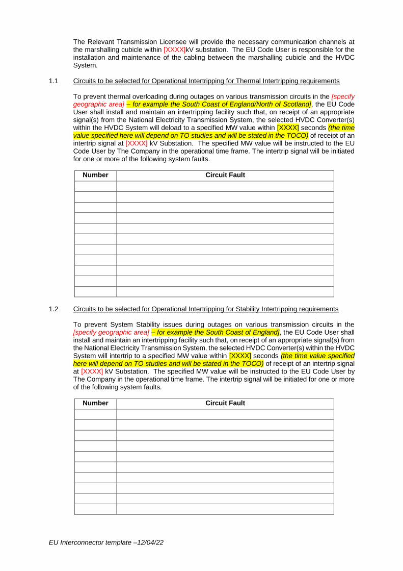
EU Interconnector template –12/04/22
The Relevant Transmission Licensee will provide the necessary communication channels at the marshalling cubicle within [XXXX]kV substation. The EU Code User is responsible for the installation and maintenance of the cabling between the marshalling cubicle and the HVDC System.
1.1 Circuits to be selected for Operational Intertripping for Thermal Intertripping requirements To prevent thermal overloading during outages on various transmission circuits in the [specify geographic area] – for example the South Coast of England/North of Scotland], the EU Code User shall install and maintain an intertripping facility such that, on receipt of an appropriate signal(s) from the National Electricity Transmission System, the selected HVDC Converter(s) within the HVDC System will deload to a specified MW value within [XXXX] seconds (the time value specified here will depend on TO studies and will be stated in the TOCO) of receipt of an intertrip signal at [XXXX] kV Substation. The specified MW value will be instructed to the EU Code User by The Company in the operational time frame. The intertrip signal will be initiated for one or more of the following system faults.
Number Circuit Fault
1.2 Circuits to be selected for Operational Intertripping for Stability Intertripping requirements
To prevent System Stability issues during outages on various transmission circuits in the [specify geographic area] – for example the South Coast of England], the EU Code User shall install and maintain an intertripping facility such that, on receipt of an appropriate signal(s) from the National Electricity Transmission System, the selected HVDC Converter(s) within the HVDC System will intertrip to a specified MW value within [XXXX] seconds (the time value specified here will depend on TO studies and will be stated in the TOCO) of receipt of an intertrip signal at [XXXX] kV Substation. The specified MW value will be instructed to the EU Code User by The Company in the operational time frame. The intertrip signal will be initiated for one or more of the following system faults.
Number Circuit Fault
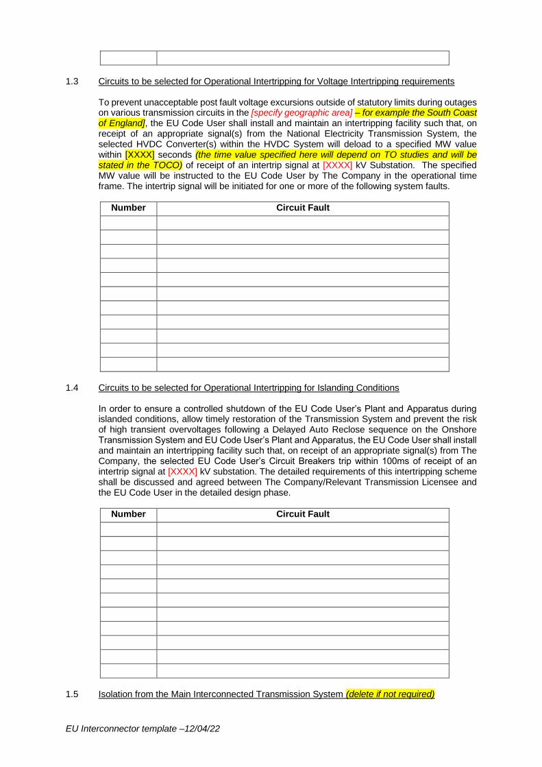
EU Interconnector template –12/04/22
1.3 Circuits to be selected for Operational Intertripping for Voltage Intertripping requirements
To prevent unacceptable post fault voltage excursions outside of statutory limits during outages on various transmission circuits in the [specify geographic area] – for example the South Coast of England], the EU Code User shall install and maintain an intertripping facility such that, on receipt of an appropriate signal(s) from the National Electricity Transmission System, the selected HVDC Converter(s) within the HVDC System will deload to a specified MW value within [XXXX] seconds (the time value specified here will depend on TO studies and will be stated in the TOCO) of receipt of an intertrip signal at [XXXX] kV Substation. The specified MW value will be instructed to the EU Code User by The Company in the operational time frame. The intertrip signal will be initiated for one or more of the following system faults.
Number Circuit Fault
1.4 Circuits to be selected for Operational Intertripping for Islanding Conditions
In order to ensure a controlled shutdown of the EU Code User’s Plant and Apparatus during islanded conditions, allow timely restoration of the Transmission System and prevent the risk of high transient overvoltages following a Delayed Auto Reclose sequence on the Onshore Transmission System and EU Code User’s Plant and Apparatus, the EU Code User shall install and maintain an intertripping facility such that, on receipt of an appropriate signal(s) from The Company, the selected EU Code User’s Circuit Breakers trip within 100ms of receipt of an intertrip signal at [XXXX] kV substation. The detailed requirements of this intertripping scheme shall be discussed and agreed between The Company/Relevant Transmission Licensee and the EU Code User in the detailed design phase.
Number Circuit Fault
1.5 Isolation from the Main Interconnected Transmission System (delete if not required)
EU Interconnector template –12/04/22
In the event that the EU Code User’s HVDC Converters at its HVDC System are disconnected from the Main Interconnected Transmission System either at [XXXX]kV substation or as a result of an unplanned outage which leaves the EU Code User’s Plant and Apparatus feeding an islanded part of the Transmission System between [XXXX]kV Substation and [XXXX]kV Substation, The Company shall provide a signal to the marshalling cubicle within [XXXX]kV substation to enable the EU Code User to protect its Plant and Apparatus from damage. In addition (and where applicable), The Company shall trip circuit breaker BBB(GIS with generator ownership boundary) simultaneously. General The EU Code User shall co-operate with The Company and the Relevant Transmission Licensee, should the Relevant Transmission Licensee notify The Company of any change/ enhancement/amendment of these facilities, should The Company require this at a later date, and will not unreasonably withhold its agreement to any such proposals. For the avoidance of doubt, except where CUSC 4.2A.6 applies, any such changes of this Appendix F3 and/or to The Company’s and/or the EU Code User’s obligations in respect therefore shall be subject to the provisions of Paragraph 2.9.3 of the CUSC.
2. Other Facilities
Requirement
Automatic Open/Closure Schemes Not applicable (unless specified.)
System Splitting/Islanding Schemes Not applicable (unless specified.)
3. Synchronising & Voltage Selection (ECC.6.2.2.9.4) The EU Code User will be required to interface with the National Electricity Transmission System substation synchronising system in accordance with the TS.3.24.60_RES /SPTS/SHETS. In circumstances where the EU Code User does not synchronise at the Grid Entry Point, the EU Code User is required to participate in the Relevant Transmission Licensee’s voltage selection scheme. HVDC System Owners should also be aware of the requirements of ECC.6.2.2.9.
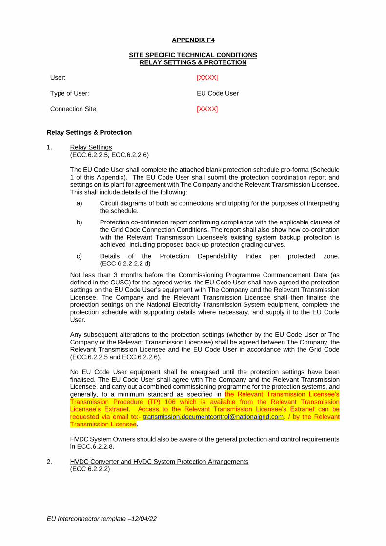
EU Interconnector template –12/04/22
APPENDIX F4
SITE SPECIFIC TECHNICAL CONDITIONS RELAY SETTINGS & PROTECTION
User: [XXXX]
Type of User: EU Code User
Connection Site: [XXXX]
Relay Settings & Protection 1. Relay Settings
(ECC.6.2.2.5, ECC.6.2.2.6) The EU Code User shall complete the attached blank protection schedule pro-forma (Schedule 1 of this Appendix). The EU Code User shall submit the protection coordination report and settings on its plant for agreement with The Company and the Relevant Transmission Licensee. This shall include details of the following:
a) Circuit diagrams of both ac connections and tripping for the purposes of interpreting the schedule.
b) Protection co-ordination report confirming compliance with the applicable clauses of the Grid Code Connection Conditions. The report shall also show how co-ordination with the Relevant Transmission Licensee’s existing system backup protection is achieved including proposed back-up protection grading curves.
c) Details of the Protection Dependability Index per protected zone. (ECC 6.2.2.2.2 d)
Not less than 3 months before the Commissioning Programme Commencement Date (as defined in the CUSC) for the agreed works, the EU Code User shall have agreed the protection settings on the EU Code User’s equipment with The Company and the Relevant Transmission Licensee. The Company and the Relevant Transmission Licensee shall then finalise the protection settings on the National Electricity Transmission System equipment, complete the protection schedule with supporting details where necessary, and supply it to the EU Code User. Any subsequent alterations to the protection settings (whether by the EU Code User or The Company or the Relevant Transmission Licensee) shall be agreed between The Company, the Relevant Transmission Licensee and the EU Code User in accordance with the Grid Code (ECC.6.2.2.5 and ECC.6.2.2.6). No EU Code User equipment shall be energised until the protection settings have been finalised. The EU Code User shall agree with The Company and the Relevant Transmission Licensee, and carry out a combined commissioning programme for the protection systems, and generally, to a minimum standard as specified in the Relevant Transmission Licensee’s Transmission Procedure (TP) 106 which is available from the Relevant Transmission Licensee’s Extranet. Access to the Relevant Transmission Licensee’s Extranet can be requested via email to:- [email protected]. / by the Relevant Transmission Licensee. HVDC System Owners should also be aware of the general protection and control requirements in ECC.6.2.2.8.
2. HVDC Converter and HVDC System Protection Arrangements (ECC 6.2.2.2)
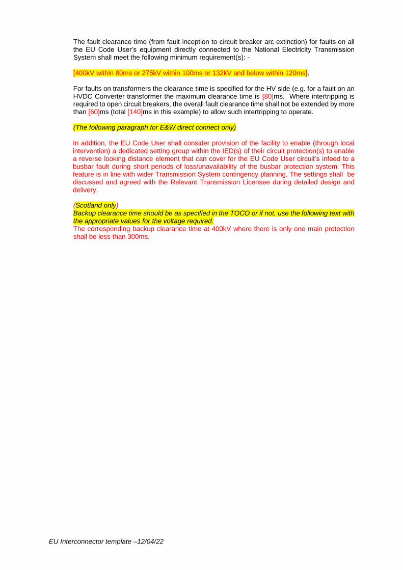
EU Interconnector template –12/04/22
The fault clearance time (from fault inception to circuit breaker arc extinction) for faults on all the EU Code User’s equipment directly connected to the National Electricity Transmission System shall meet the following minimum requirement(s): - [400kV within 80ms or 275kV within 100ms or 132kV and below within 120ms]. For faults on transformers the clearance time is specified for the HV side (e.g. for a fault on an HVDC Converter transformer the maximum clearance time is [80]ms. Where intertripping is required to open circuit breakers, the overall fault clearance time shall not be extended by more than [60]ms (total [140]ms in this example) to allow such intertripping to operate. (The following paragraph for E&W direct connect only) In addition, the EU Code User shall consider provision of the facility to enable (through local intervention) a dedicated setting group within the IED(s) of their circuit protection(s) to enable a reverse looking distance element that can cover for the EU Code User circuit’s infeed to a busbar fault during short periods of loss/unavailability of the busbar protection system. This feature is in line with wider Transmission System contingency planning. The settings shall be discussed and agreed with the Relevant Transmission Licensee during detailed design and delivery. (Scotland only) Backup clearance time should be as specified in the TOCO or if not, use the following text with the appropriate values for the voltage required. The corresponding backup clearance time at 400kV where there is only one main protection shall be less than 300ms.
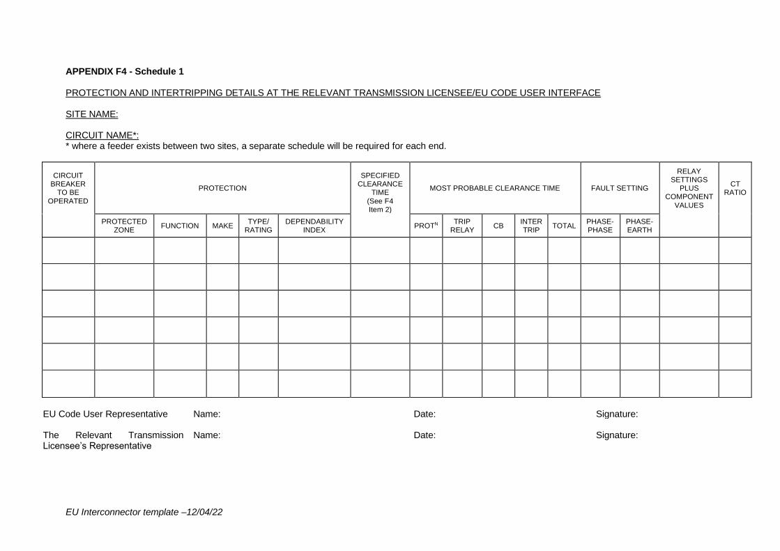
EU Interconnector template –12/04/22
APPENDIX F4 - Schedule 1 PROTECTION AND INTERTRIPPING DETAILS AT THE RELEVANT TRANSMISSION LICENSEE/EU CODE USER INTERFACE SITE NAME: CIRCUIT NAME*: * where a feeder exists between two sites, a separate schedule will be required for each end.
CIRCUIT BREAKER
TO BE
OPERATED
PROTECTION
SPECIFIED CLEARANCE
TIME
(See F4 Item 2)
MOST PROBABLE CLEARANCE TIME FAULT SETTING
RELAY SETTINGS
PLUS COMPONENT
VALUES
CT RATIO
PROTECTED ZONE
FUNCTION MAKE TYPE/
RATING DEPENDABILITY
INDEX PROTN
TRIP RELAY
CB INTER TRIP
TOTAL PHASE- PHASE
PHASE- EARTH
EU Code User Representative Name: Date: Signature: The Relevant Transmission Licensee’s Representative
Name: Date: Signature:
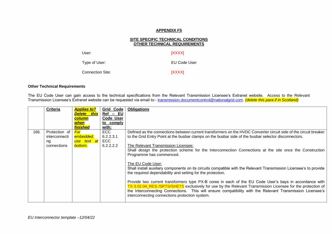
EU Interconnector template –12/04/22
APPENDIX F5
SITE SPECIFIC TECHNICAL CONDITIONS OTHER TECHNICAL REQUIREMENTS
User: [XXXX]
Type of User: EU Code User
Connection Site: [XXXX]
Other Technical Requirements The EU Code User can gain access to the technical specifications from the Relevant Transmission Licensee’s Extranet website. Access to the Relevant Transmission Licensee’s Extranet website can be requested via email to:- [email protected]. (delete this para if in Scotland)
Criteria Applies to? Delete this column when finished
Grid Code Ref – EU Code User to comply with:
Obligations
166. Protection of interconnecting connections
For embedded, use text at bottom.
ECC 6.2.2.3.1 ECC 6.2.2.2.2
Defined as the connections between current transformers on the HVDC Converter circuit side of the circuit breaker to the Grid Entry Point at the busbar clamps on the busbar side of the busbar selector disconnectors. The Relevant Transmission Licensee: Shall design the protection scheme for the Interconnection Connections at the site once the Construction Programme has commenced. The EU Code User: Shall install auxiliary components on its circuits compatible with the Relevant Transmission Licensee’s to provide the required dependability and setting for the protection. Provide two current transformers type PX-B cores in each of the EU Code User’s bays in accordance with TS 3.02.04_RES /SPTS/SHETS exclusively for use by the Relevant Transmission Licensee for the protection of the Interconnecting Connections. This will ensure compatibility with the Relevant Transmission Licensee’s interconnecting connections protection system.
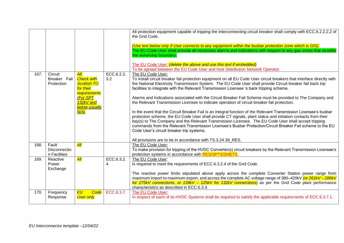
EU Interconnector template –12/04/22
All protection equipment capable of tripping the interconnecting circuit breaker shall comply with ECC.6.2.2.2.2 of the Grid Code. (Use text below only if User connects to any equipment within the busbar protection zone which is GIS): The EU Code User shall provide all necessary alarms and indications with respect to any gas zones that straddle the ownership boundary. The EU Code User: (delete the above and use this text if embedded) To be agreed between the EU Code User and host Distribution Network Operator.
167. Circuit Breaker Fail Protection
All. Check with Scottish TO for their requirements(For SPT 132kV and below usually N/A)
ECC.6.2.2.3.2
The EU Code User: To install circuit breaker fail protection equipment on all EU Code User circuit breakers that interface directly with the National Electricity Transmission System. The EU Code User shall provide Circuit breaker fail back trip facilities to integrate with the Relevant Transmission Licensee ‘s back tripping scheme. Alarms and Indications associated with the Circuit Breaker Fail Scheme must be provided to The Company and the Relevant Transmission Licensee to indicate operation of circuit breaker fail protection. In the event that the Circuit Breaker Fail is an integral function of the Relevant Transmission Licensee’s busbar protection scheme, the EU Code User shall provide CT signals, plant status and initiation contacts from their bay(s) to The Company and the Relevant Transmission Licensee. The EU Code User shall accept tripping commands from the Relevant Transmission Licensee’s Busbar Protection/Circuit Breaker Fail scheme to the EU Code User’s circuit breaker trip systems. All provisions are to be in accordance with TS.3.24.39_RES.
168. Fault Disconnection Facilities
All The EU Code User: To make provision for tripping of the HVDC Converter(s) circuit breakers by the Relevant Transmission Licensee‘s protection systems in accordance with RES/SPTS/SHETS.
169. Reactive Power Exchange
All ECC.6.3.2.4
The EU Code User: Is required to meet the requirements of ECC.6.3.2.4 of the Grid Code. The reactive power limits stipulated above apply across the complete Converter Station power range from maximum import to maximum export, and across the complete AC voltage range of 380–420kV (or 261kV – 289kV for 275kV connections, or 139kV – 125kV for 132kV connections) as per the Grid Code plant performance characteristics as described in ECC.6.3.4.
170. Frequency Response
EU Code User only
ECC.6.3.7 The EU Code User: In respect of each of its HVDC Systems shall be required to satisfy the applicable requirements of ECC.6.3.7.1.
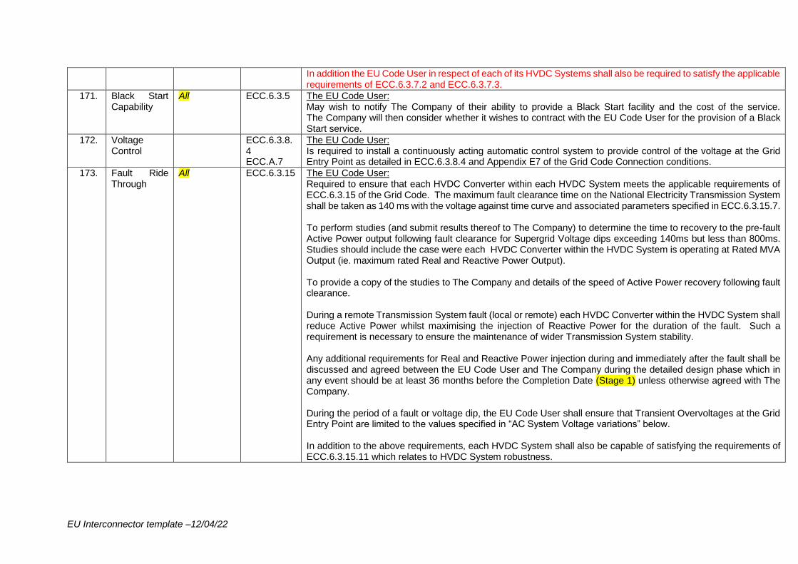
EU Interconnector template –12/04/22
In addition the EU Code User in respect of each of its HVDC Systems shall also be required to satisfy the applicable requirements of ECC.6.3.7.2 and ECC.6.3.7.3.
171. Black Start Capability
All ECC.6.3.5 The EU Code User: May wish to notify The Company of their ability to provide a Black Start facility and the cost of the service. The Company will then consider whether it wishes to contract with the EU Code User for the provision of a Black Start service.
172. Voltage Control
ECC.6.3.8.4 ECC.A.7
The EU Code User: Is required to install a continuously acting automatic control system to provide control of the voltage at the Grid Entry Point as detailed in ECC.6.3.8.4 and Appendix E7 of the Grid Code Connection conditions.
173. Fault Ride Through
All ECC.6.3.15 The EU Code User: Required to ensure that each HVDC Converter within each HVDC System meets the applicable requirements of ECC.6.3.15 of the Grid Code. The maximum fault clearance time on the National Electricity Transmission System shall be taken as 140 ms with the voltage against time curve and associated parameters specified in ECC.6.3.15.7. To perform studies (and submit results thereof to The Company) to determine the time to recovery to the pre-fault Active Power output following fault clearance for Supergrid Voltage dips exceeding 140ms but less than 800ms. Studies should include the case were each HVDC Converter within the HVDC System is operating at Rated MVA Output (ie. maximum rated Real and Reactive Power Output). To provide a copy of the studies to The Company and details of the speed of Active Power recovery following fault clearance. During a remote Transmission System fault (local or remote) each HVDC Converter within the HVDC System shall reduce Active Power whilst maximising the injection of Reactive Power for the duration of the fault. Such a requirement is necessary to ensure the maintenance of wider Transmission System stability. Any additional requirements for Real and Reactive Power injection during and immediately after the fault shall be discussed and agreed between the EU Code User and The Company during the detailed design phase which in any event should be at least 36 months before the Completion Date (Stage 1) unless otherwise agreed with The Company. During the period of a fault or voltage dip, the EU Code User shall ensure that Transient Overvoltages at the Grid Entry Point are limited to the values specified in “AC System Voltage variations” below. In addition to the above requirements, each HVDC System shall also be capable of satisfying the requirements of ECC.6.3.15.11 which relates to HVDC System robustness.
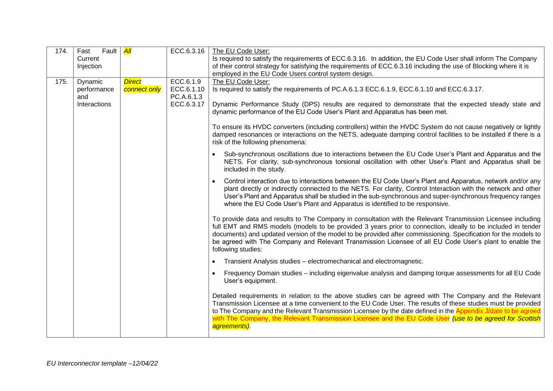
EU Interconnector template –12/04/22
174. Fast Fault Current Injection
All ECC.6.3.16 The EU Code User: Is required to satisfy the requirements of ECC.6.3.16. In addition, the EU Code User shall inform The Company of their control strategy for satisfying the requirements of ECC.6.3.16 including the use of Blocking where it is employed in the EU Code Users control system design.
175. Dynamic performance and Interactions
Direct connect only
ECC.6.1.9 ECC.6.1.10 PC.A.6.1.3 ECC.6.3.17
The EU Code User: Is required to satisfy the requirements of PC.A.6.1.3 ECC.6.1.9, ECC.6.1.10 and ECC.6.3.17. Dynamic Performance Study (DPS) results are required to demonstrate that the expected steady state and dynamic performance of the EU Code User’s Plant and Apparatus has been met. To ensure its HVDC converters (including controllers) within the HVDC System do not cause negatively or lightly damped resonances or interactions on the NETS, adequate damping control facilities to be installed if there is a risk of the following phenomena:
• Sub-synchronous oscillations due to interactions between the EU Code User’s Plant and Apparatus and the NETS. For clarity, sub-synchronous torsional oscillation with other User’s Plant and Apparatus shall be included in the study.
• Control interaction due to interactions between the EU Code User’s Plant and Apparatus, network and/or any plant directly or indirectly connected to the NETS. For clarity, Control Interaction with the network and other User’s Plant and Apparatus shall be studied in the sub-synchronous and super-synchronous frequency ranges where the EU Code User’s Plant and Apparatus is identified to be responsive.
To provide data and results to The Company in consultation with the Relevant Transmission Licensee including full EMT and RMS models (models to be provided 3 years prior to connection, ideally to be included in tender documents) and updated version of the model to be provided after commissioning. Specification for the models to be agreed with The Company and Relevant Transmission Licensee of all EU Code User’s plant to enable the following studies:
• Transient Analysis studies – electromechanical and electromagnetic.
• Frequency Domain studies – including eigenvalue analysis and damping torque assessments for all EU Code User’s equipment.
Detailed requirements in relation to the above studies can be agreed with The Company and the Relevant Transmission Licensee at a time convenient to the EU Code User. The results of these studies must be provided to The Company and the Relevant Transmission Licensee by the date defined in the Appendix J/date to be agreed with The Company, the Relevant Transmission Licensee and the EU Code User (use to be agreed for Scottish agreements).
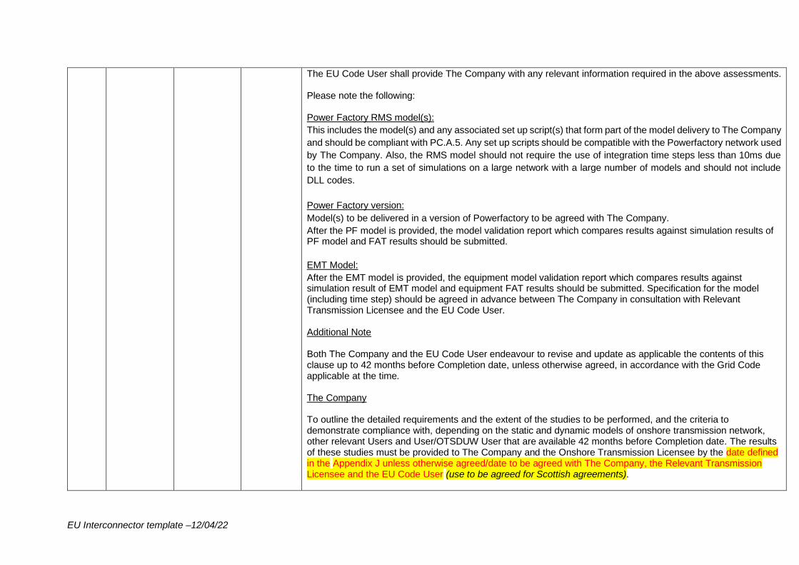
EU Interconnector template –12/04/22
The EU Code User shall provide The Company with any relevant information required in the above assessments. Please note the following: Power Factory RMS model(s):
This includes the model(s) and any associated set up script(s) that form part of the model delivery to The Company
and should be compliant with PC.A.5. Any set up scripts should be compatible with the Powerfactory network used
by The Company. Also, the RMS model should not require the use of integration time steps less than 10ms due
to the time to run a set of simulations on a large network with a large number of models and should not include
DLL codes.
Power Factory version:
Model(s) to be delivered in a version of Powerfactory to be agreed with The Company.
After the PF model is provided, the model validation report which compares results against simulation results of PF model and FAT results should be submitted.
EMT Model:
After the EMT model is provided, the equipment model validation report which compares results against simulation result of EMT model and equipment FAT results should be submitted. Specification for the model (including time step) should be agreed in advance between The Company in consultation with Relevant Transmission Licensee and the EU Code User. Additional Note Both The Company and the EU Code User endeavour to revise and update as applicable the contents of this clause up to 42 months before Completion date, unless otherwise agreed, in accordance with the Grid Code applicable at the time. The Company To outline the detailed requirements and the extent of the studies to be performed, and the criteria to demonstrate compliance with, depending on the static and dynamic models of onshore transmission network, other relevant Users and User/OTSDUW User that are available 42 months before Completion date. The results of these studies must be provided to The Company and the Onshore Transmission Licensee by the date defined in the Appendix J unless otherwise agreed/date to be agreed with The Company, the Relevant Transmission Licensee and the EU Code User (use to be agreed for Scottish agreements).
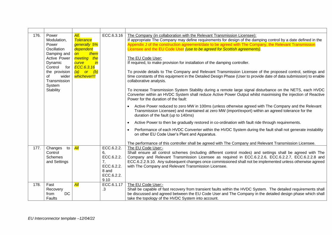
EU Interconnector template –12/04/22
176. Power Modulation, Power Oscillation Damping and Active Power Dynamic Control for the provision of wider Transmission System Stability
All. Tolerance generally 5% dependent on them meeting the curve in ECC.6.3.16 (a) or (b) whichever!!!
ECC.6.3.16 The Company (in collaboration with the Relevant Transmission Licensee): If appropriate The Company may define requirements for design of the damping control by a date defined in the Appendix J of the construction agreement/date to be agreed with The Company, the Relevant Transmission Licensee and the EU Code User (use to be agreed for Scottish agreements). The EU Code User: If required, to make provision for installation of the damping controller. To provide details to The Company and Relevant Transmission Licensee of the proposed control, settings and time constants of this equipment in the Detailed Design Phase (User to provide date of data submission) to enable collaborative analysis. To increase Transmission System Stability during a remote large signal disturbance on the NETS, each HVDC Converter within an HVDC System shall reduce Active Power Output whilst maximising the injection of Reactive Power for the duration of the fault:
• Active Power reduced to zero MW in 100ms (unless otherwise agreed with The Company and the Relevant Transmission Licensee) and maintained at zero MW (import/export) within an agreed tolerance for the duration of the fault (up to 140ms)
• Active Power to then be gradually restored in co-ordination with fault ride through requirements.
• Performance of each HVDC Converter within the HVDC System during the fault shall not generate instability on other EU Code User’s Plant and Apparatus.
The performance of this controller shall be agreed with The Company and Relevant Transmission Licensee.
177. Changes to Control Schemes and Settings
All ECC.6.2.2.6, ECC.6.2.2.7, ECC.6.2.2.8 and ECC.6.2.2.9.10
The EU Code User:- Shall ensure all control schemes (including different control modes) and settings shall be agreed with The Company and Relevant Transmission Licensee as required in ECC.6.2.2.6, ECC.6.2.2.7, ECC.6.2.2.8 and ECC.6.2.2.9.10. Any subsequent changes once commissioned shall not be implemented unless otherwise agreed with The Company and Relevant Transmission Licensee.
178. Fast Recovery from DC Faults
All ECC.6.1.17.3
The EU Code User:- Shall be capable of fast recovery from transient faults within the HVDC System. The detailed requirements shall be discussed and agreed between the EU Code User and The Company in the detailed design phase which shall take the topology of the HVDC System into account.
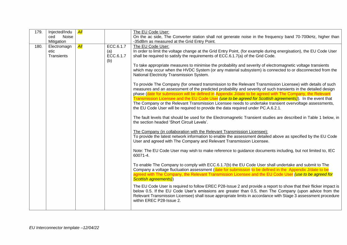
EU Interconnector template –12/04/22
179. Injected/Induced Noise Mitigation
All The EU Code User: On the ac side, The Converter station shall not generate noise in the frequency band 70-700kHz, higher than -35dBm as measured at the Grid Entry Point.
180. Electromagnetic Transients
All ECC.6.1.7 (a) ECC.6.1.7 (b)
The EU Code User: In order to limit the voltage change at the Grid Entry Point, (for example during energisation), the EU Code User shall be required to satisfy the requirements of ECC.6.1.7(a) of the Grid Code. To take appropriate measures to minimise the probability and severity of electromagnetic voltage transients which may occur when the HVDC System (or any material subsystem) is connected to or disconnected from the National Electricity Transmission System. To provide The Company (for onward transmission to the Relevant Transmission Licensee) with details of such measures and an assessment of the predicted probability and severity of such transients in the detailed design phase (date for submission will be defined in Appendix J/date to be agreed with The Company, the Relevant Transmission Licensee and the EU Code User (use to be agreed for Scottish agreements)). In the event that The Company or the Relevant Transmission Licensee needs to undertake transient overvoltage assessments, the EU Code User will be required to provide the data required under PC.A.6.2.1. The fault levels that should be used for the Electromagnetic Transient studies are described in Table 1 below, in the section headed ‘Short Circuit Levels’. The Company (in collaboration with the Relevant Transmission Licensee): To provide the latest network information to enable the assessment detailed above as specified by the EU Code User and agreed with The Company and Relevant Transmission Licensee. Note: The EU Code User may wish to make reference to guidance documents including, but not limited to, IEC 60071-4. To enable The Company to comply with ECC.6.1.7(b) the EU Code User shall undertake and submit to The Company a voltage fluctuation assessment (date for submission to be defined in the Appendix J/date to be agreed with The Company, the Relevant Transmission Licensee and the EU Code User (use to be agreed for Scottish agreements))
The EU Code User is required to follow EREC P28-Issue 2 and provide a report to show that their flicker impact is below 0.5. If the EU Code User’s emissions are greater than 0.5, then The Company (upon advice from the Relevant Transmission Licensee) shall issue appropriate limits in accordance with Stage 3 assessment procedure within EREC P28-Issue 2.
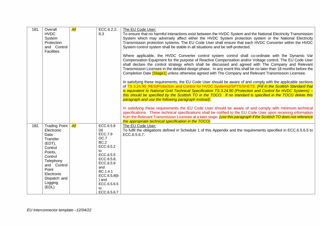
EU Interconnector template –12/04/22
181. Overall HVDC System Protection and Control Facilities
All ECC.6.2.2.8.3
The EU Code User: To ensure that no harmful interactions exist between the HVDC System and the National Electricity Transmission System which may adversely affect either the HVDC System protection system or the National Electricity Transmission protection systems. The EU Code User shall ensure that each HVDC Converter within the HVDC System control system shall be stable in all situations and be self-protected. Where applicable, the HVDC Converter control system control shall co-ordinate with the Dynamic Var Compensation Equipment for the purpose of Reactive Compensation and/or Voltage control. The EU Code User shall declare the control strategy which shall be discussed and agreed with The Company and Relevant Transmission Licensee in the detailed design phase. In any event this shall be no later than 18 months before the Completion Date [Stage1] unless otherwise agreed with The Company and Relevant Transmission Licensee. In satisfying these requirements, the EU Code User should be aware of and comply with the applicable sections of TS 3.24.90_RES(Protection and Control for HVDC Systems)/SPTS/SHETS. (Fill in the Scottish Standard that is equivalent to National Grid Technical Specification TS.3.24.90 (Protection and Control for HVDC Systems) – this should be specified by the Scottish TO in the TOCO. If no standard is specified in the TOCO delete this paragraph and use the following paragraph instead). In satisfying these requirements the EU Code User should be aware of and comply with minimum technical specifications. These technical specifications shall be notified to the EU Code User upon receiving information from the Relevant Transmission Licensee at a later stage. (use this paragraph if the Scottish TO does not reference the appropriate technical specification in the TOCO)
182. Trading Point Electronic Data Transfer (EDT), Control Points, Control Telephony and Control Point Electronic Dispatch and Logging (EDL)
All ECC.6.5.8 (a) ECC.7.9 OC.7 BC.2 ECC.6.5.2 to ECC.6.5.5 ECC.6.5.8, ECC.6.5.9 and BC.1.4.1 ECC.6.5.8(b) and ECC.6.5.6.5 to ECC.6.5.6.7
The EU Code User: To fulfil the obligations defined in Schedule 1 of this Appendix and the requirements specified in ECC.6.5.6.5 to ECC.6.5.6.7.
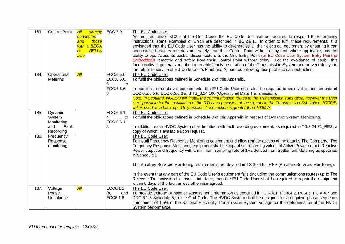
EU Interconnector template –12/04/22
183. Control Point All directly connected and those with a BEGA or BELLA also
ECC.7.9 The EU Code User: As required under BC2.9 of the Grid Code, the EU Code User will be required to respond to Emergency Instructions, some examples of which are described in BC.2.9.1. In order to fulfil these requirements, it is envisaged that the EU Code User has the ability to de-energise all their electrical equipment by ensuring it can open circuit breakers remotely and safely from their Control Point without delay and, where applicable, has the ability to open/close its busbar disconnectors at the Grid Entry Point (or EU Code User System Entry Point (if Embedded)) remotely and safely from their Control Point without delay. For the avoidance of doubt, this functionality is generally required to enable timely restoration of the Transmission System and prevent delays to the return to service of EU Code User’s Plant and Apparatus following receipt of such an instruction.
184. Operational Metering
All ECC.6.5.6 ECC.6.5.6.5 to ECC.6.5.6.8
The EU Code User: To fulfil the obligations defined in Schedule 2 of this Appendix. In addition to the above requirements, the EU Code User shall also be required to satisfy the requirements of ECC.6.5.6.5 to ECC.6.5.6.8 and TS_3.24.100 (Operational Data Transmission). Note: In Scotland, NGESO will install the communication routes to the Transmission substation, however the User is responsible for the installation of the RTU and provision of the signals to the Transmission Substation. ICCP/Pi link is used as a back-up. Only applies if connection is greater than 100MW.
185. Dynamic System Monitoring and Fault Recording
ECC.6.6.1.4 to ECC.6.6.1.8
The EU Code User: To fulfil the obligations defined in Schedule 3 of this Appendix in respect of Dynamic System Monitoring. In addition, each HVDC System shall be fitted with fault recording equipment, as required in TS.3.24.71_RES, a copy of which is available upon request.
186. Frequency Response monitoring
The EU Code User: To install Frequency Response Monitoring equipment and allow remote access of the data by The Company. The Frequency Response Monitoring equipment shall be capable of recording values of Active Power output, Reactive Power output and frequency with a minimum sampling rate of 1Hz derived from Settlement Metering as specified in Schedule 2. The Ancillary Services Monitoring requirements are detailed in TS 3.24.95_RES (Ancillary Services Monitoring). In the event that any part of the EU Code User’s equipment fails (including the communications routes) up to The Relevant Transmission Licensee’s interface, then the EU Code User shall be required to repair the equipment within 5 days of the fault unless otherwise agreed.
187. Voltage Phase Unbalance
All ECC6.1.5 (b) and ECC6.1.6
The EU Code User: To provide Voltage Unbalance Assessment information as specified in PC.4.4.1, PC.4.4.2, PC.4.5, PC.A.4.7 and DRC.6.1.5 Schedule 5, of the Grid Code. The HVDC System shall be designed for a negative phase sequence component of 1.5% of the National Electricity Transmission System voltage for the determination of the HVDC System performance.
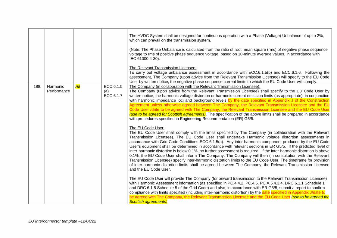
EU Interconnector template –12/04/22
The HVDC System shall be designed for continuous operation with a Phase (Voltage) Unbalance of up to 2%, which can prevail on the transmission system. (Note: The Phase Unbalance is calculated from the ratio of root mean square (rms) of negative phase sequence voltage to rms of positive phase sequence voltage, based on 10-minute average values, in accordance with IEC 61000 4-30). The Relevant Transmission Licensee: To carry out voltage unbalance assessment in accordance with ECC.6.1.5(b) and ECC.6.1.6. Following the assessment, The Company (upon advice from the Relevant Transmission Licensee) will specify to the EU Code User by written notice, the negative phase sequence current limits to which the EU Code User will comply.
188. Harmonic Performance
All ECC.6.1.5 (a) ECC.6.1.7
The Company (in collaboration with the Relevant Transmission Licensee): The Company (upon advice from the Relevant Transmission Licensee) shall specify to the EU Code User by written notice, the harmonic voltage distortion or harmonic current emission limits (as appropriate), in conjunction with harmonic impedance loci and background levels by the date specified in Appendix J of the Construction Agreement unless otherwise agreed between The Company, the Relevant Transmission Licensee and the EU Code User /date to be agreed with The Company, the Relevant Transmission Licensee and the EU Code User (use to be agreed for Scottish agreements). The specification of the above limits shall be prepared in accordance with procedures specified in Engineering Recommendation (ER) G5/5. The EU Code User: The EU Code User shall comply with the limits specified by The Company (in collaboration with the Relevant Transmission Licensee). The EU Code User shall undertake Harmonic voltage distortion assessments in accordance with Grid Code Conditions ECC.6.1.5(a). Any inter-harmonic component produced by the EU Code User’s equipment shall be determined in accordance with relevant sections in ER G5/5. If the predicted level of inter-harmonic distortion is below 0.1%, no further assessment is required. If the inter-harmonic distortion is above 0.1%, the EU Code User shall inform The Company, The Company will then (in consultation with the Relevant Transmission Licensee) specify inter-harmonic distortion limits to the EU Code User. The timeframe for provision of inter-harmonic distortion limits shall be agreed between The Company, the Relevant Transmission Licensee and the EU Code User. The EU Code User will provide The Company (for onward transmission to the Relevant Transmission Licensee) with Harmonic Assessment information (as specified in PC.4.4.2, PC.4.5, PC.A.5.4.3.4, DRC.6.1.1 Schedule 1 and DRC.6.1.5 Schedule 5 of the Grid Code) and also, in accordance with ER G5/5, submit a report to confirm compliance with limits specified (including inter-harmonic distortion) by the date specified in Appendix J/date to be agreed with The Company, the Relevant Transmission Licensee and the EU Code User (use to be agreed for Scottish agreements)
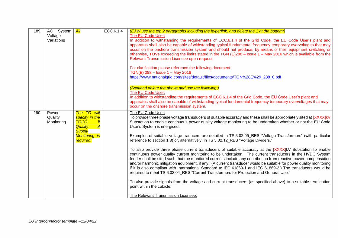
EU Interconnector template –12/04/22
189. AC System Voltage Variations
All ECC.6.1.4 (E&W use the top 2 paragraphs including the hyperlink, and delete the 1 at the bottom:) The EU Code User: In addition to withstanding the requirements of ECC.6.1.4 of the Grid Code, the EU Code User’s plant and apparatus shall also be capable of withstanding typical fundamental frequency temporary overvoltages that may occur on the onshore transmission system and should not produce, by means of their equipment switching or otherwise, TOVs exceeding the limits stated in the TGN (E)288 – Issue 1 – May 2016 which is available from the Relevant Transmission Licensee upon request. For clarification please reference the following document: TGN(E) 288 – Issue 1 – May 2016 https://www.nationalgrid.com/sites/default/files/documents/TGN%28E%29_288_0.pdf
(Scotland delete the above and use the following:) The EU Code User: In addition to withstanding the requirements of ECC.6.1.4 of the Grid Code, the EU Code User’s plant and apparatus shall also be capable of withstanding typical fundamental frequency temporary overvoltages that may occur on the onshore transmission system.
190. Power Quality Monitoring
The TO will specify in the TOCO if Quality of Supply Monitoring is required.
The EU Code User: To provide three phase voltage transducers of suitable accuracy and these shall be appropriately sited at [XXXX]kV Substation to enable continuous power quality voltage monitoring to be undertaken whether or not the EU Code User’s System is energised. Examples of suitable voltage traducers are detailed in TS 3.02.05_RES “Voltage Transformers” (with particular reference to section 1.3) or, alternatively, in TS 3.02.12_RES “Voltage Dividers.” To also provide three phase current transducers of suitable accuracy at the [XXXX]kV Substation to enable continuous power quality current monitoring to be undertaken. The current transducers in the HVDC System feeder shall be sited such that the monitored currents include any contribution from reactive power compensation and/or harmonic mitigation equipment, if any. (A current transducer would be suitable for power quality monitoring if it is also compliant with International Standard to IEC 61869-1 and IEC 61869-2.) The transducers would be required to meet TS 3.02.04_RES “Current Transformers for Protection and General Use.” To also provide signals from the voltage and current transducers (as specified above) to a suitable termination point within the cubicle. The Relevant Transmission Licensee:
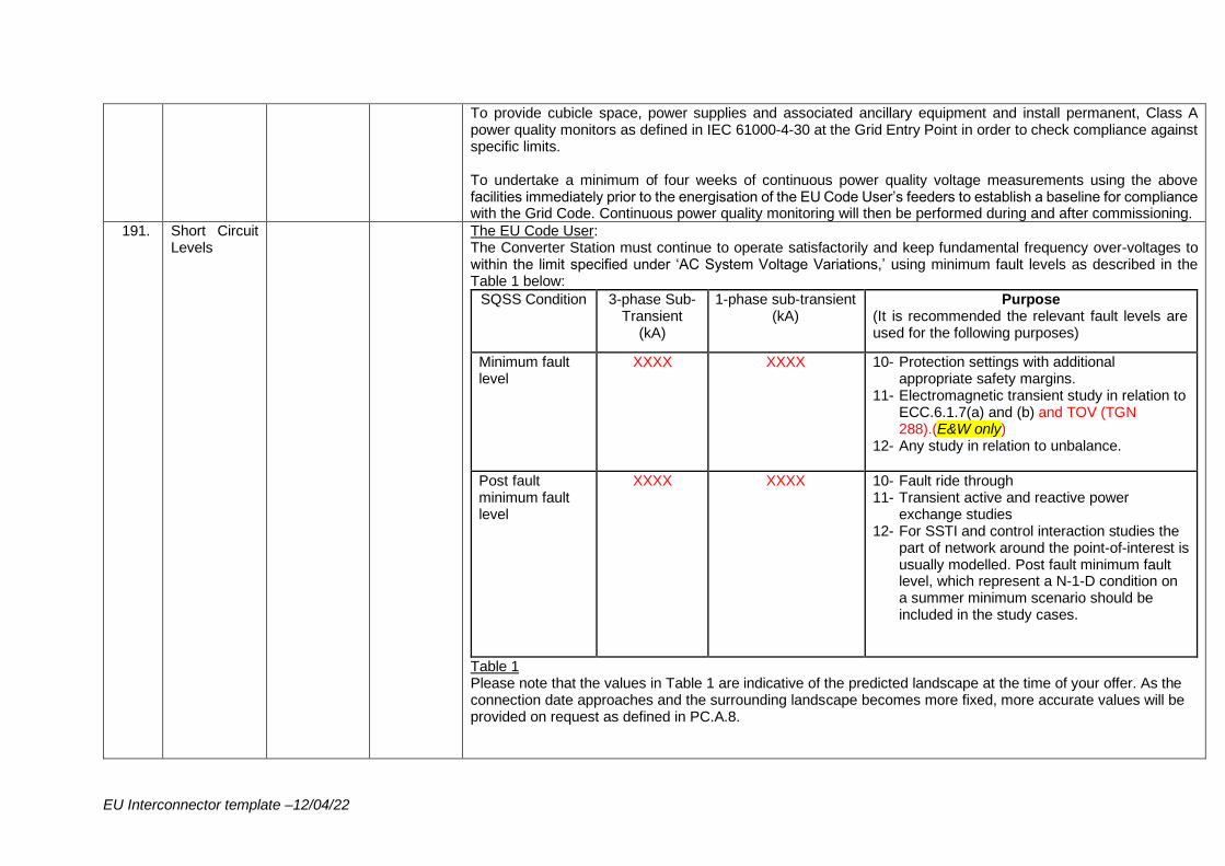
EU Interconnector template –12/04/22
To provide cubicle space, power supplies and associated ancillary equipment and install permanent, Class A power quality monitors as defined in IEC 61000-4-30 at the Grid Entry Point in order to check compliance against specific limits. To undertake a minimum of four weeks of continuous power quality voltage measurements using the above facilities immediately prior to the energisation of the EU Code User’s feeders to establish a baseline for compliance with the Grid Code. Continuous power quality monitoring will then be performed during and after commissioning.
191. Short Circuit Levels
The EU Code User: The Converter Station must continue to operate satisfactorily and keep fundamental frequency over-voltages to within the limit specified under ‘AC System Voltage Variations,’ using minimum fault levels as described in the Table 1 below:
SQSS Condition 3-phase Sub-Transient
(kA)
1-phase sub-transient (kA)
Purpose (It is recommended the relevant fault levels are used for the following purposes)
Minimum fault level
XXXX
XXXX
10- Protection settings with additional appropriate safety margins.
11- Electromagnetic transient study in relation to ECC.6.1.7(a) and (b) and TOV (TGN 288).(E&W only)
12- Any study in relation to unbalance.
Post fault minimum fault level
XXXX
XXXX
10- Fault ride through 11- Transient active and reactive power
exchange studies 12- For SSTI and control interaction studies the
part of network around the point-of-interest is usually modelled. Post fault minimum fault level, which represent a N-1-D condition on a summer minimum scenario should be included in the study cases.
Table 1 Please note that the values in Table 1 are indicative of the predicted landscape at the time of your offer. As the connection date approaches and the surrounding landscape becomes more fixed, more accurate values will be provided on request as defined in PC.A.8.
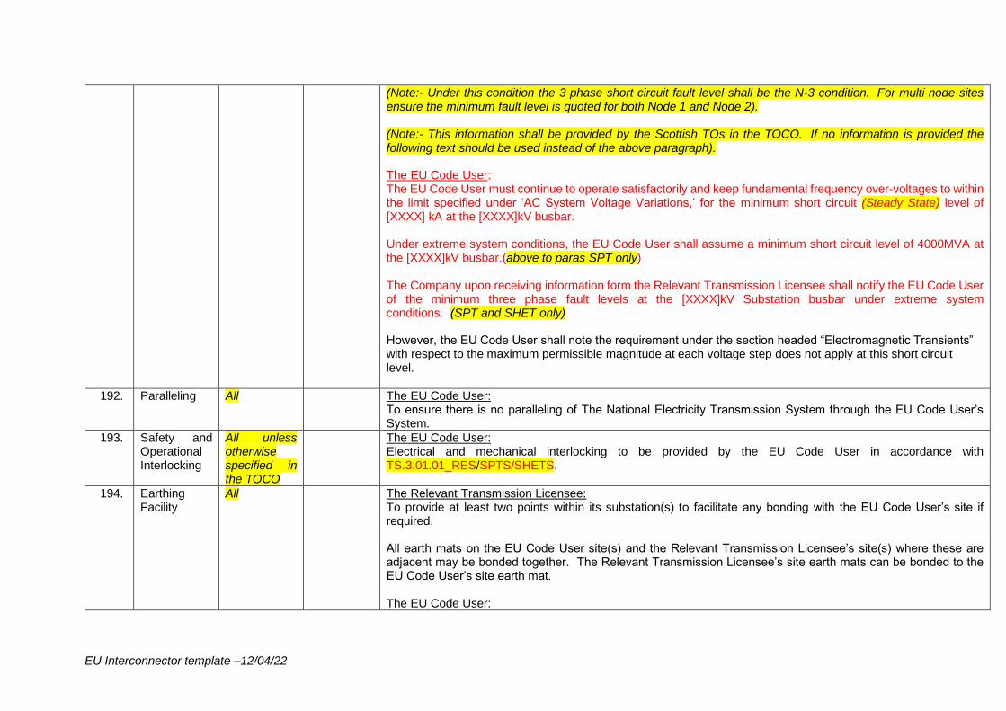
EU Interconnector template –12/04/22
(Note:- Under this condition the 3 phase short circuit fault level shall be the N-3 condition. For multi node sites ensure the minimum fault level is quoted for both Node 1 and Node 2). (Note:- This information shall be provided by the Scottish TOs in the TOCO. If no information is provided the following text should be used instead of the above paragraph). The EU Code User: The EU Code User must continue to operate satisfactorily and keep fundamental frequency over-voltages to within the limit specified under ‘AC System Voltage Variations,’ for the minimum short circuit (Steady State) level of [XXXX] kA at the [XXXX]kV busbar. Under extreme system conditions, the EU Code User shall assume a minimum short circuit level of 4000MVA at the [XXXX]kV busbar.(above to paras SPT only) The Company upon receiving information form the Relevant Transmission Licensee shall notify the EU Code User of the minimum three phase fault levels at the [XXXX]kV Substation busbar under extreme system conditions. (SPT and SHET only) However, the EU Code User shall note the requirement under the section headed “Electromagnetic Transients” with respect to the maximum permissible magnitude at each voltage step does not apply at this short circuit level.
192. Paralleling All The EU Code User: To ensure there is no paralleling of The National Electricity Transmission System through the EU Code User’s System.
193. Safety and Operational Interlocking
All unless otherwise specified in the TOCO
The EU Code User: Electrical and mechanical interlocking to be provided by the EU Code User in accordance with TS.3.01.01_RES/SPTS/SHETS.
194. Earthing Facility
All The Relevant Transmission Licensee: To provide at least two points within its substation(s) to facilitate any bonding with the EU Code User’s site if required. All earth mats on the EU Code User site(s) and the Relevant Transmission Licensee’s site(s) where these are adjacent may be bonded together. The Relevant Transmission Licensee’s site earth mats can be bonded to the EU Code User’s site earth mat. The EU Code User:
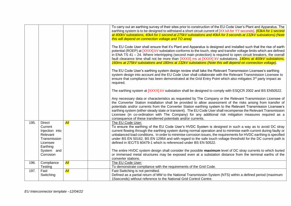
EU Interconnector template –12/04/22
To carry out an earthing survey of their sites prior to construction of the EU Code User’s Plant and Apparatus. The earthing system is to be designed to withstand a short circuit current of [XX kA for YY seconds]. (63kA for 1 second at 400kV substations, 40kA for 1 second at 275kV substations and 40kA for 3 seconds at 132kV substations) (Note this will depend on connection voltage and TO area) The EU Code User shall ensure that it’s Plant and Apparatus is designed and installed such that the rise of earth potential (ROEP) at [XXXX] kV substation conforms to the touch, step and transfer voltage limits which are defined in ENA TS 41 – 24. Where intertripping (second main protection) is required to open circuit breakers, the overall fault clearance time shall not be more than [XXXX] ms at [XXXX] kV substations. 140ms at 400kV substations, 160ms at 275kV substations and 180ms at 132kV substations (Note this will depend on connection voltage). The EU Code User’s earthing system design review shall take the Relevant Transmission Licensee’s earthing system design into account and the EU Code User shall collaborate with the Relevant Transmission Licensee to ensure that compliance has been demonstrated at the Grid Entry Point which also mitigates 3rd party impact as required. The earthing system at [XXXX] kV substation shall be designed to comply with ESQCR 2002 and BS EN50522. Any necessary data or characteristics as requested by The Company or the Relevant Transmission Licensee of the Converter Station installation shall be provided to allow assessment of the risks arising from transfer of potentials and/or currents from the Converter Station earthing system to the Relevant Transmission Licensee’s earthing system (either steady state or transient). The EU Code User shall recompense the Relevant Transmission Licensee (in co-ordination with The Company) for any additional risk mitigation measures required as a consequence of these transferred potentials and/or currents.
195. Direct Current Injection into Relevant Transmission Licensee Earthing System and Corrosion
All The EU Code User: To ensure the earthing of the EU Code User’s HVDC System is designed in such a way as to avoid DC stray current flowing through the earthing system during normal operation and to minimise earth current during faulty or unbalanced load conditions. In order to minimise corrosion issues, the requirements for HVDC earthing is specified under BS EN 50162, BS EN 12954 and with regard to the safe touch voltage threshold for the DC current path is defined in IEC/TS 60479-1 which is referenced under BS EN 50522. The entire HVDC system design shall consider the possible maximum level of DC stray currents to which buried or immersed metal structures may be exposed even at a substation distance from the terminal earths of the converter stations.
196. Compliance Testing
All The EU Code User: To demonstrate compliance with the requirements of the Grid Code.
197. Fast Switching
All Fast Switching is not permitted. Defined as a partial return of MW to the National Transmission System (NTS) within a defined period (maximum 15seconds) without reference to the National Grid Control Centre.
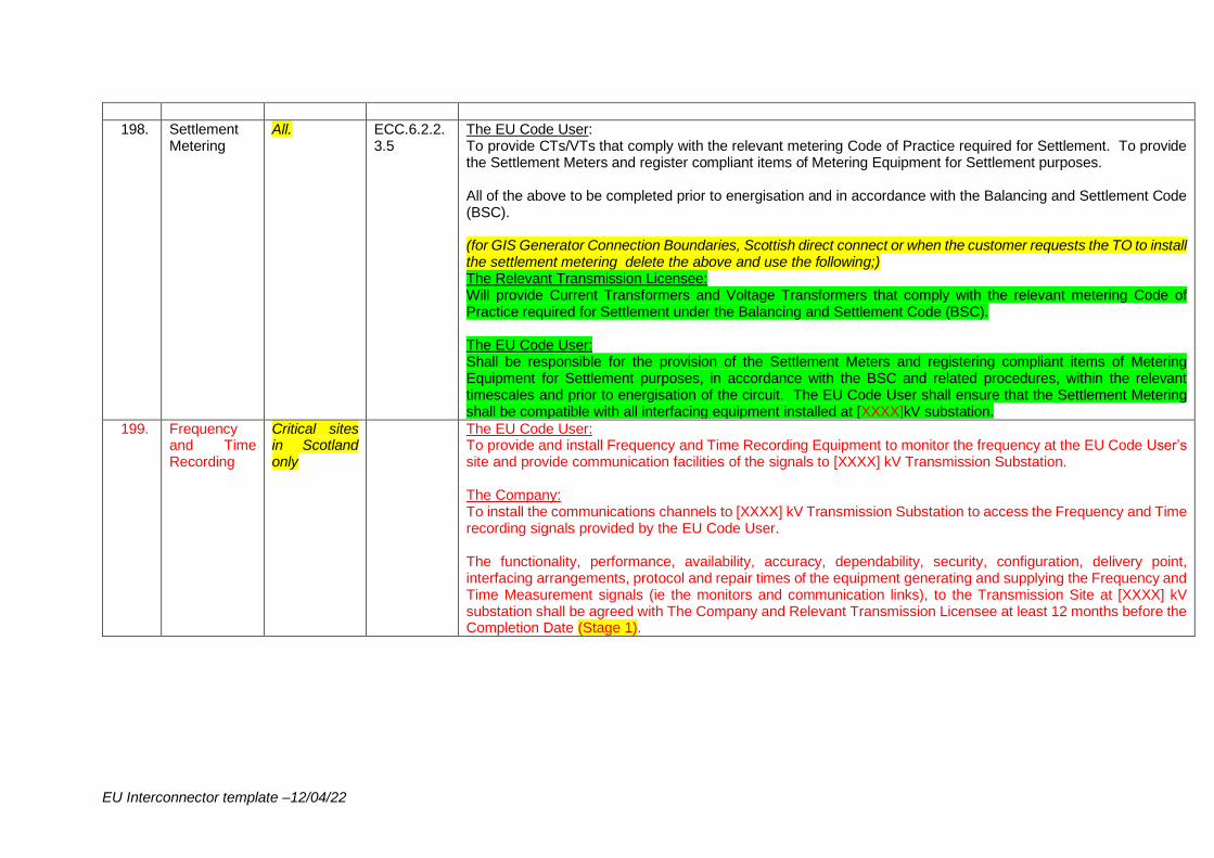
EU Interconnector template –12/04/22
198. Settlement Metering
All.
ECC.6.2.2.3.5
The EU Code User: To provide CTs/VTs that comply with the relevant metering Code of Practice required for Settlement. To provide the Settlement Meters and register compliant items of Metering Equipment for Settlement purposes. All of the above to be completed prior to energisation and in accordance with the Balancing and Settlement Code (BSC). (for GIS Generator Connection Boundaries, Scottish direct connect or when the customer requests the TO to install the settlement metering delete the above and use the following;) The Relevant Transmission Licensee: Will provide Current Transformers and Voltage Transformers that comply with the relevant metering Code of Practice required for Settlement under the Balancing and Settlement Code (BSC). The EU Code User: Shall be responsible for the provision of the Settlement Meters and registering compliant items of Metering Equipment for Settlement purposes, in accordance with the BSC and related procedures, within the relevant timescales and prior to energisation of the circuit. The EU Code User shall ensure that the Settlement Metering shall be compatible with all interfacing equipment installed at [XXXX]kV substation.
199. Frequency and Time Recording
Critical sites in Scotland only
The EU Code User: To provide and install Frequency and Time Recording Equipment to monitor the frequency at the EU Code User’s site and provide communication facilities of the signals to [XXXX] kV Transmission Substation. The Company: To install the communications channels to [XXXX] kV Transmission Substation to access the Frequency and Time recording signals provided by the EU Code User. The functionality, performance, availability, accuracy, dependability, security, configuration, delivery point, interfacing arrangements, protocol and repair times of the equipment generating and supplying the Frequency and Time Measurement signals (ie the monitors and communication links), to the Transmission Site at [XXXX] kV substation shall be agreed with The Company and Relevant Transmission Licensee at least 12 months before the Completion Date (Stage 1).
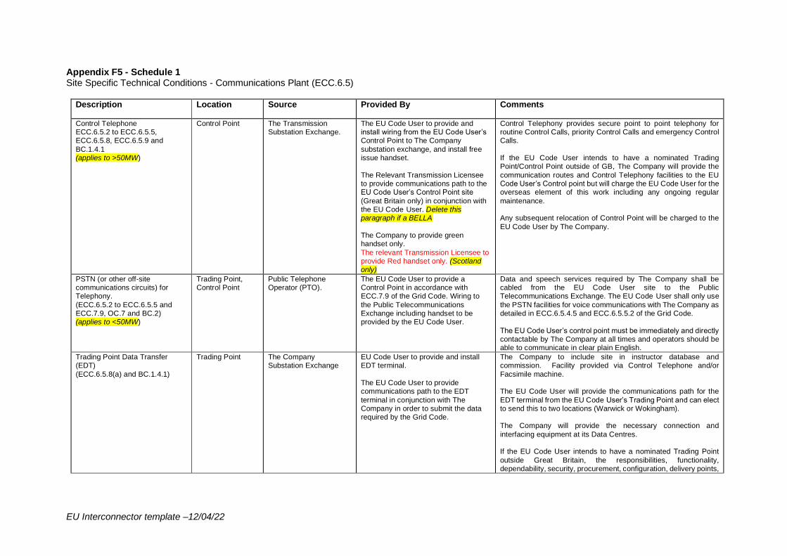
EU Interconnector template –12/04/22
Appendix F5 - Schedule 1 Site Specific Technical Conditions - Communications Plant (ECC.6.5)
Description Location Source Provided By Comments
Control Telephone ECC.6.5.2 to ECC.6.5.5, ECC.6.5.8, ECC.6.5.9 and
BC.1.4.1 (applies to >50MW)
Control Point The Transmission Substation Exchange.
The EU Code User to provide and install wiring from the EU Code User’s Control Point to The Company
substation exchange, and install free issue handset.
The Relevant Transmission Licensee to provide communications path to the EU Code User’s Control Point site
(Great Britain only) in conjunction with the EU Code User. Delete this paragraph if a BELLA
The Company to provide green handset only.
The relevant Transmission Licensee to provide Red handset only. (Scotland only)
Control Telephony provides secure point to point telephony for routine Control Calls, priority Control Calls and emergency Control Calls.
If the EU Code User intends to have a nominated Trading Point/Control Point outside of GB, The Company will provide the
communication routes and Control Telephony facilities to the EU Code User’s Control point but will charge the EU Code User for the overseas element of this work including any ongoing regular
maintenance. Any subsequent relocation of Control Point will be charged to the
EU Code User by The Company.
PSTN (or other off-site communications circuits) for Telephony.
(ECC.6.5.2 to ECC.6.5.5 and ECC.7.9, OC.7 and BC.2) (applies to <50MW)
Trading Point, Control Point
Public Telephone Operator (PTO).
The EU Code User to provide a Control Point in accordance with ECC.7.9 of the Grid Code. Wiring to
the Public Telecommunications Exchange including handset to be provided by the EU Code User.
Data and speech services required by The Company shall be cabled from the EU Code User site to the Public Telecommunications Exchange. The EU Code User shall only use
the PSTN facilities for voice communications with The Company as detailed in ECC.6.5.4.5 and ECC.6.5.5.2 of the Grid Code.
The EU Code User’s control point must be immediately and directly contactable by The Company at all times and operators should be able to communicate in clear plain English.
Trading Point Data Transfer (EDT)
(ECC.6.5.8(a) and BC.1.4.1)
Trading Point The Company Substation Exchange
EU Code User to provide and install EDT terminal.
The EU Code User to provide communications path to the EDT
terminal in conjunction with The Company in order to submit the data required by the Grid Code.
The Company to include site in instructor database and commission. Facility provided via Control Telephone and/or
Facsimile machine. The EU Code User will provide the communications path for the
EDT terminal from the EU Code User’s Trading Point and can elect to send this to two locations (Warwick or Wokingham). The Company will provide the necessary connection and
interfacing equipment at its Data Centres. If the EU Code User intends to have a nominated Trading Point
outside Great Britain, the responsibilities, functionality, dependability, security, procurement, configuration, delivery points,
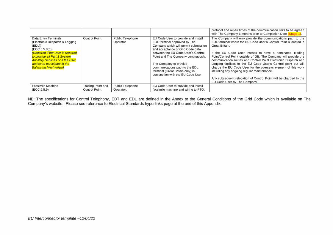
EU Interconnector template –12/04/22
protocol and repair times of the communication links to be agreed with The Company 6 months prior to Completion Date (Stage 1).
Data Entry Terminals (Electronic Despatch & Logging
(EDL)) (ECC.6.5.8(b)) (Required if the User is required
to provide all Part 1 System Ancillary Services or if the User wishes to participate in the
Balancing Mechanism)
Control Point Public Telephone Operator
EU Code User to provide and install EDL terminal approved by The
Company which will permit submission and acceptance of Grid Code data between the EU Code User’s Control
Point and The Company continuously. The Company to provide
communications path to the EDL terminal (Great Britain only) in conjunction with the EU Code User.
The Company will only provide the communications path to the EDL terminal where the EU Code User’s Control Point is located in
Great Britain. If the EU Code User intends to have a nominated Trading
Point/Control Point outside of GB, The Company will provide the communication routes and Control Point Electronic Dispatch and Logging facilities to the EU Code User’s Control point but will
charge the EU Code User for the overseas element of this work including any ongoing regular maintenance.
Any subsequent relocation of Control Point will be charged to the EU Code User by The Company.
Facsimile Machine
(ECC.6.5.9)
Trading Point and
Control Point
Public Telephone
Operator.
EU Code User to provide and install
facsimile machine and wiring to PTO.
NB: The specifications for Control Telephony, EDT and EDL are defined in the Annex to the General Conditions of the Grid Code which is available on The Company’s website. Please see reference to Electrical Standards hyperlinks page at the end of this Appendix.
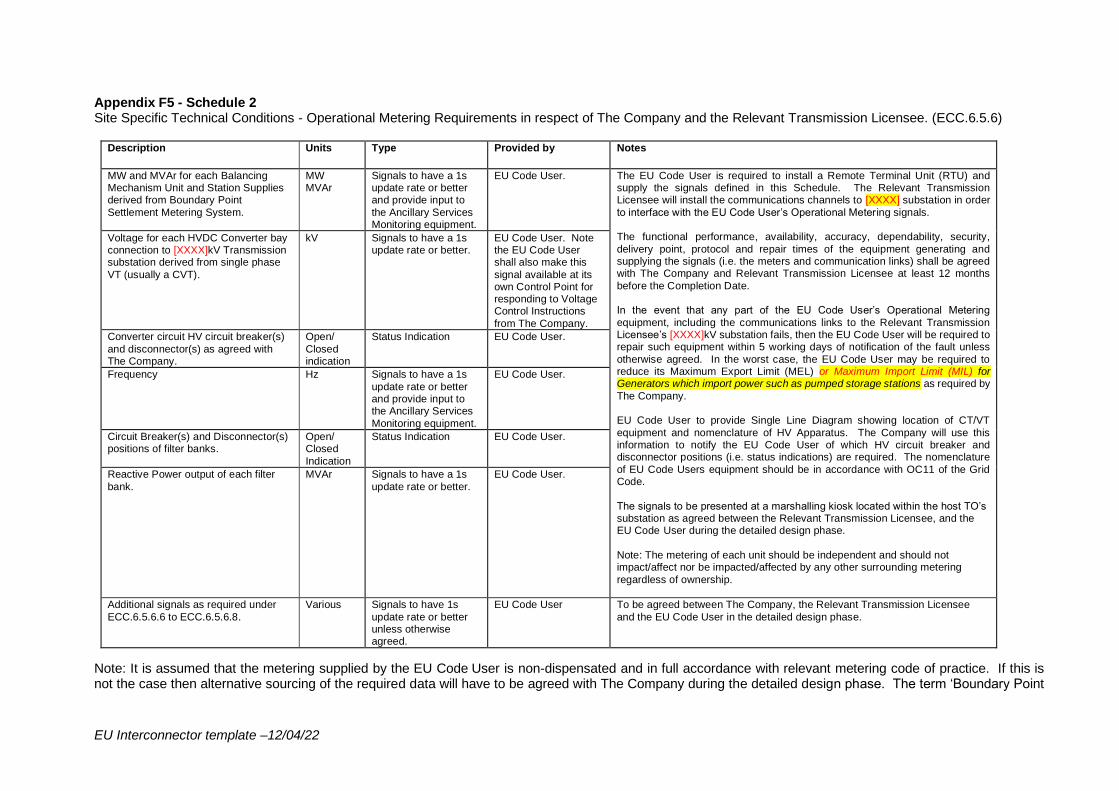
EU Interconnector template –12/04/22
Appendix F5 - Schedule 2 Site Specific Technical Conditions - Operational Metering Requirements in respect of The Company and the Relevant Transmission Licensee. (ECC.6.5.6)
Description Units Type Provided by Notes
MW and MVAr for each Balancing Mechanism Unit and Station Supplies derived from Boundary Point
Settlement Metering System.
MW MVAr
Signals to have a 1s update rate or better and provide input to
the Ancillary Services Monitoring equipment.
EU Code User. The EU Code User is required to install a Remote Terminal Unit (RTU) and supply the signals defined in this Schedule. The Relevant Transmission Licensee will install the communications channels to [XXXX] substation in order
to interface with the EU Code User’s Operational Metering signals. The functional performance, availability, accuracy, dependability, security,
delivery point, protocol and repair times of the equipment generating and supplying the signals (i.e. the meters and communication links) shall be agreed with The Company and Relevant Transmission Licensee at least 12 months
before the Completion Date. In the event that any part of the EU Code User’s Operational Metering
equipment, including the communications links to the Relevant Transmission Licensee’s [XXXX]kV substation fails, then the EU Code User will be required to repair such equipment within 5 working days of notification of the fault unless
otherwise agreed. In the worst case, the EU Code User may be required to reduce its Maximum Export Limit (MEL) or Maximum Import Limit (MIL) for Generators which import power such as pumped storage stations as required by
The Company. EU Code User to provide Single Line Diagram showing location of CT/VT
equipment and nomenclature of HV Apparatus. The Company will use this information to notify the EU Code User of which HV circuit breaker and disconnector positions (i.e. status indications) are required. The nomenclature
of EU Code Users equipment should be in accordance with OC11 of the Grid Code.
The signals to be presented at a marshalling kiosk located within the host TO’s substation as agreed between the Relevant Transmission Licensee, and the EU Code User during the detailed design phase.
Note: The metering of each unit should be independent and should not impact/affect nor be impacted/affected by any other surrounding metering
regardless of ownership.
Voltage for each HVDC Converter bay connection to [XXXX]kV Transmission substation derived from single phase
VT (usually a CVT).
kV Signals to have a 1s update rate or better.
EU Code User. Note the EU Code User shall also make this
signal available at its own Control Point for responding to Voltage Control Instructions
from The Company.
Converter circuit HV circuit breaker(s)
and disconnector(s) as agreed with The Company.
Open/
Closed indication
Status Indication EU Code User.
Frequency Hz Signals to have a 1s
update rate or better and provide input to the Ancillary Services
Monitoring equipment.
EU Code User.
Circuit Breaker(s) and Disconnector(s) positions of filter banks.
Open/ Closed
Indication
Status Indication EU Code User.
Reactive Power output of each filter
bank.
MVAr Signals to have a 1s
update rate or better.
EU Code User.
Additional signals as required under
ECC.6.5.6.6 to ECC.6.5.6.8.
Various Signals to have 1s
update rate or better unless otherwise agreed.
EU Code User To be agreed between The Company, the Relevant Transmission Licensee
and the EU Code User in the detailed design phase.
Note: It is assumed that the metering supplied by the EU Code User is non-dispensated and in full accordance with relevant metering code of practice. If this is not the case then alternative sourcing of the required data will have to be agreed with The Company during the detailed design phase. The term ‘Boundary Point
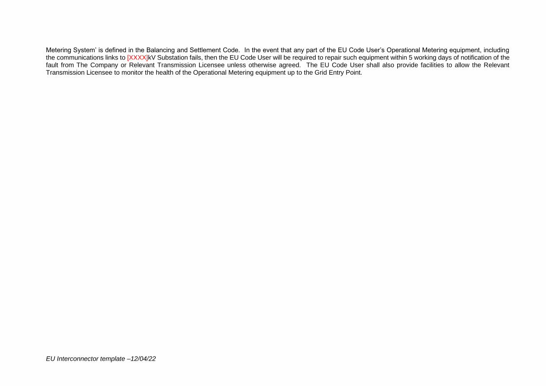
EU Interconnector template –12/04/22
Metering System’ is defined in the Balancing and Settlement Code. In the event that any part of the EU Code User’s Operational Metering equipment, including the communications links to [XXXX]kV Substation fails, then the EU Code User will be required to repair such equipment within 5 working days of notification of the fault from The Company or Relevant Transmission Licensee unless otherwise agreed. The EU Code User shall also provide facilities to allow the Relevant Transmission Licensee to monitor the health of the Operational Metering equipment up to the Grid Entry Point.
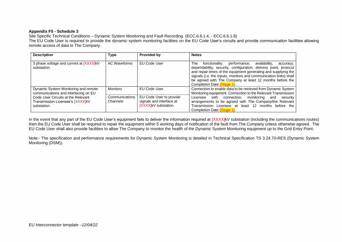
EU Interconnector template –12/04/22
Appendix F5 - Schedule 3 Site Specific Technical Conditions – Dynamic System Monitoring and Fault Recording. (ECC.6.6.1.4, - ECC.6.6.1.8) The EU Code User is required to provide the dynamic system monitoring facilities on the EU Code User’s circuits and provide communication facilities allowing remote access of data to The Company.
Description Type Provided by Notes
3 phase voltage and current at [XXXX]kV substation.
AC Waveforms EU Code User The functionality, performance, availability, accuracy, dependability, security, configuration, delivery point, protocol and repair times of the equipment generating and supplying the signals (i.e. the inputs, monitors and communication links) shall be agreed with The Company at least 12 months before the Completion Date (Stage 1).
Dynamic System Monitoring and remote communications and interfacing on EU Code User Circuits at the Relevant Transmission Licensee’s [XXXX]kV substation.
Monitors EU Code User Connection to enable data to be retrieved from Dynamic System Monitoring equipment. Connection to the Relevant Transmission Licensee with connection, monitoring and security arrangements to be agreed with The Company/the Relevant Transmission Licensee at least 12 months before the Completion Date (Stage 1).
Communications Channels
EU Code User to provide signals and interface at [XXXX]kV substation.
In the event that any part of the EU Code User’s equipment fails to deliver the information required at [XXXX]kV substation (including the communications routes) then the EU Code User shall be required to repair the equipment within 5 working days of notification of the fault from The Company unless otherwise agreed. The EU Code User shall also provide facilities to allow The Company to monitor the health of the Dynamic System Monitoring equipment up to the Grid Entry Point. Note:- The specification and performance requirements for Dynamic System Monitoring is detailed in Technical Specification TS 3.24.70-RES (Dynamic System Monitoring (DSM)).
EU Interconnector template –12/04/22
USEFUL LINKS The Grid Code: https://www.nationalgrideso.com/uk/electricity/codes/grid-code Electrical Standards: https://www.nationalgrideso.com/uk/electricity/codes/grid-code/electrical-standards-documents-including-specifications-electronic Extranet (ID and password required, email [email protected] to request access): https://extranet.nationalgrid.com/ (delete this link if in Scotland) Connection Policies and Guidance: https://www.nationalgrideso.com/connections/registers-reports-and-guidance Procurement Guidelines and Balancing Principles: https://www.nationalgrideso.com/uk/electricity/market-operations-and-data/transmission-licence-c16-statements-and-consultations
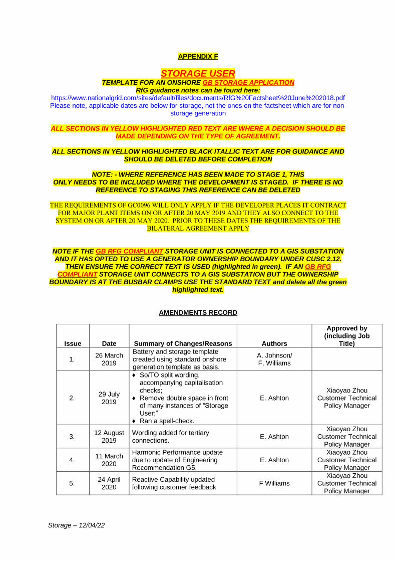
Storage – 12/04/22
APPENDIX F
STORAGE USER TEMPLATE FOR AN ONSHORE GB STORAGE APPLICATION
RfG guidance notes can be found here: https://www.nationalgrid.com/sites/default/files/documents/RfG%20Factsheet%20June%202018.pdf Please note, applicable dates are below for storage, not the ones on the factsheet which are for non-
storage generation
ALL SECTIONS IN YELLOW HIGHLIGHTED RED TEXT ARE WHERE A DECISION SHOULD BE MADE DEPENDING ON THE TYPE OF AGREEMENT.
ALL SECTIONS IN YELLOW HIGHLIGHTED BLACK ITALLIC TEXT ARE FOR GUIDANCE AND
SHOULD BE DELETED BEFORE COMPLETION
NOTE: - WHERE REFERENCE HAS BEEN MADE TO STAGE 1, THIS ONLY NEEDS TO BE INCLUDED WHERE THE DEVELOPMENT IS STAGED. IF THERE IS NO
REFERENCE TO STAGING THIS REFERENCE CAN BE DELETED
THE REQUIREMENTS OF GC0096 WILL ONLY APPLY IF THE DEVELOPER PLACES IT CONTRACT
FOR MAJOR PLANT ITEMS ON OR AFTER 20 MAY 2019 AND THEY ALSO CONNECT TO THE
SYSTEM ON OR AFTER 20 MAY 2020. PRIOR TO THESE DATES THE REQUIREMENTS OF THE
BILATERAL AGREEMENT APPLY
NOTE IF THE GB RFG COMPLIANT STORAGE UNIT IS CONNECTED TO A GIS SUBSTATION AND IT HAS OPTED TO USE A GENERATOR OWNERSHIP BOUNDARY UNDER CUSC 2.12.
THEN ENSURE THE CORRECT TEXT IS USED (highlighted in green). IF AN GB RFG COMPLIANT STORAGE UNIT CONNECTS TO A GIS SUBSTATION BUT THE OWNERSHIP
BOUNDARY IS AT THE BUSBAR CLAMPS USE THE STANDARD TEXT and delete all the green highlighted text.
AMENDMENTS RECORD
Issue Date Summary of Changes/Reasons Authors
Approved by (including Job
Title)
1. 26 March
2019
Battery and storage template created using standard onshore generation template as basis.
A. Johnson/ F. Williams
2. 29 July 2019
♦ So/TO split wording, accompanying capitalisation checks;
♦ Remove double space in front of many instances of “Storage User;”
♦ Ran a spell-check.
E. Ashton Xiaoyao Zhou
Customer Technical Policy Manager
3. 12 August
2019 Wording added for tertiary connections.
E. Ashton Xiaoyao Zhou
Customer Technical Policy Manager
4. 11 March
2020
Harmonic Performance update due to update of Engineering Recommendation G5.
E. Ashton Xiaoyao Zhou
Customer Technical Policy Manager
5. 24 April
2020 Reactive Capability updated following customer feedback
F Williams Xiaoyao Zhou
Customer Technical Policy Manager
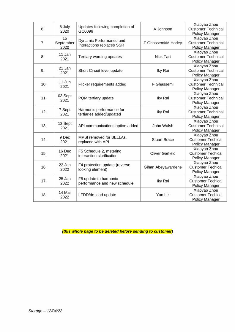
Storage – 12/04/22
6. 6 July 2020
Updates following completion of GC0096
A Johnson Xiaoyao Zhou
Customer Technical Policy Manager
7. 15
September 2020
Dynamic Performance and Interactions replaces SSR
F Ghassemi/M Horley Xiaoyao Zhou
Customer Technical Policy Manager
8. 11 Jan 2021
Tertiary wording updates Nick Tart Xiaoyao Zhou
Customer Technical Policy Manager
9. 21 Jan 2021
Short Circuit level update Iky Rai Xiaoyao Zhou
Customer Technical Policy Manager
10. 11 Jun 2021
Flicker requirements added F Ghassemi Xiaoyao Zhou
Customer Technical Policy Manager
11. 03 Sept
2021 PQM tertiary update Iky Rai
Xiaoyao Zhou Customer Technical
Policy Manager
12. 7 Sept 2021
Harmonic performance for tertiaries added/updated
Iky Rai Xiaoyao Zhou
Customer Technical Policy Manager
13. 13 Sept
2021 API communications option added John Walsh
Xiaoyao Zhou Customer Technical
Policy Manager
14. 9 Dec 2021
MPSI removed for BELLAs, replaced with API
Stuart Brace Xiaoyao Zhou
Customer Techical Policy Manager
15. 16 Dec 2021
F5 Schedule 2, metering interaction clarification
Oliver Garfield Xiaoyao Zhou
Customer Techical Policy Manager
16. 22 Jan 2022
F4 protection update (reverse looking element)
Gihan Abeyawardene Xiaoyao Zhou
Customer Techical Policy Manager
17. 25 Jan 2022
F5 update to harmonic performance and new schedule
Iky Rai Xiaoyao Zhou
Customer Techical Policy Manager
18. 14 Mar 2022
LFDD/de-load update Yun Lei Xiaoyao Zhou
Customer Techical Policy Manager
(this whole page to be deleted before sending to customer)
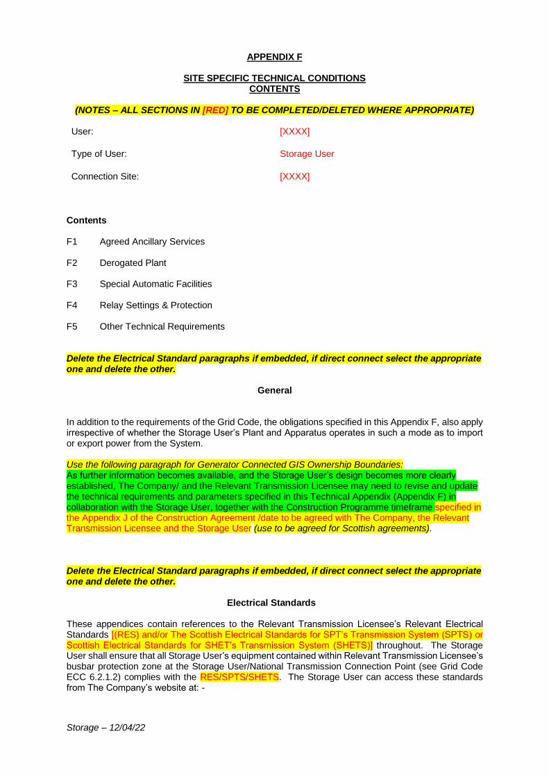
Storage – 12/04/22
APPENDIX F
SITE SPECIFIC TECHNICAL CONDITIONS CONTENTS
(NOTES – ALL SECTIONS IN [RED] TO BE COMPLETED/DELETED WHERE APPROPRIATE)
User: [XXXX]
Type of User: Storage User
Connection Site: [XXXX]
Contents F1 Agreed Ancillary Services F2 Derogated Plant F3 Special Automatic Facilities F4 Relay Settings & Protection F5 Other Technical Requirements Delete the Electrical Standard paragraphs if embedded, if direct connect select the appropriate one and delete the other.
General In addition to the requirements of the Grid Code, the obligations specified in this Appendix F, also apply irrespective of whether the Storage User’s Plant and Apparatus operates in such a mode as to import or export power from the System. Use the following paragraph for Generator Connected GIS Ownership Boundaries: As further information becomes available, and the Storage User’s design becomes more clearly established, The Company/ and the Relevant Transmission Licensee may need to revise and update the technical requirements and parameters specified in this Technical Appendix (Appendix F) in collaboration with the Storage User, together with the Construction Programme timeframe specified in the Appendix J of the Construction Agreement /date to be agreed with The Company, the Relevant Transmission Licensee and the Storage User (use to be agreed for Scottish agreements). Delete the Electrical Standard paragraphs if embedded, if direct connect select the appropriate one and delete the other.
Electrical Standards These appendices contain references to the Relevant Transmission Licensee’s Relevant Electrical Standards [(RES) and/or The Scottish Electrical Standards for SPT’s Transmission System (SPTS) or Scottish Electrical Standards for SHET’s Transmission System (SHETS)] throughout. The Storage User shall ensure that all Storage User’s equipment contained within Relevant Transmission Licensee’s busbar protection zone at the Storage User/National Transmission Connection Point (see Grid Code ECC 6.2.1.2) complies with the RES/SPTS/SHETS. The Storage User can access these standards from The Company’s website at: -
Storage – 12/04/22
https://www.nationalgrideso.com/uk/electricity/codes/grid-code/electrical-standards-documents-including-specifications-electronic The SPTS/SHETS/RES are updated periodically. If the SPTS/SHETS/RES is updated in the period between issuing the Connection Offer and the Storage User completing the connection to the National Transmission System, then The Company will seek agreement with the Storage User to use the updated RES/SPTS/SHETS as the standard for plant and apparatus at the Connection Point.
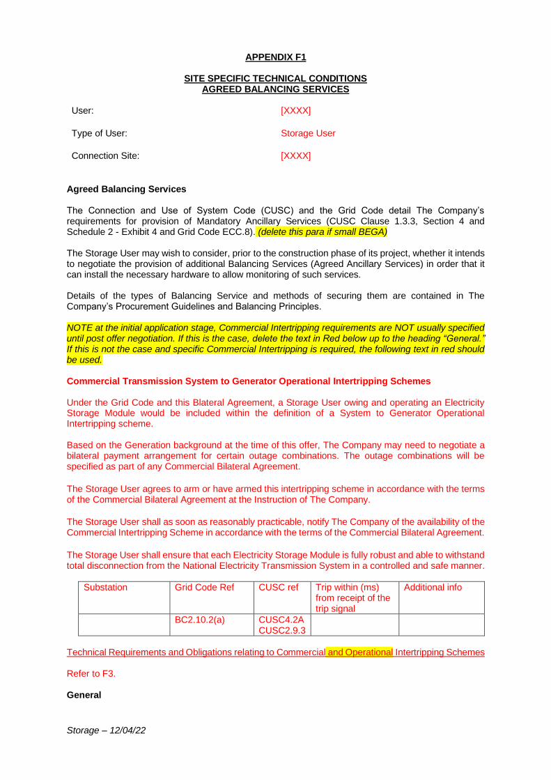
Storage – 12/04/22
APPENDIX F1
SITE SPECIFIC TECHNICAL CONDITIONS AGREED BALANCING SERVICES
User: [XXXX]
Type of User: Storage User
Connection Site: [XXXX]
Agreed Balancing Services The Connection and Use of System Code (CUSC) and the Grid Code detail The Company’s requirements for provision of Mandatory Ancillary Services (CUSC Clause 1.3.3, Section 4 and Schedule 2 - Exhibit 4 and Grid Code ECC.8). (delete this para if small BEGA) The Storage User may wish to consider, prior to the construction phase of its project, whether it intends to negotiate the provision of additional Balancing Services (Agreed Ancillary Services) in order that it can install the necessary hardware to allow monitoring of such services. Details of the types of Balancing Service and methods of securing them are contained in The Company’s Procurement Guidelines and Balancing Principles. NOTE at the initial application stage, Commercial Intertripping requirements are NOT usually specified until post offer negotiation. If this is the case, delete the text in Red below up to the heading “General.” If this is not the case and specific Commercial Intertripping is required, the following text in red should be used. Commercial Transmission System to Generator Operational Intertripping Schemes Under the Grid Code and this Blateral Agreement, a Storage User owing and operating an Electricity Storage Module would be included within the definition of a System to Generator Operational Intertripping scheme. Based on the Generation background at the time of this offer, The Company may need to negotiate a bilateral payment arrangement for certain outage combinations. The outage combinations will be specified as part of any Commercial Bilateral Agreement. The Storage User agrees to arm or have armed this intertripping scheme in accordance with the terms of the Commercial Bilateral Agreement at the Instruction of The Company.
The Storage User shall as soon as reasonably practicable, notify The Company of the availability of the Commercial Intertripping Scheme in accordance with the terms of the Commercial Bilateral Agreement. The Storage User shall ensure that each Electricity Storage Module is fully robust and able to withstand total disconnection from the National Electricity Transmission System in a controlled and safe manner.
Substation Grid Code Ref CUSC ref Trip within (ms) from receipt of the trip signal
Additional info
BC2.10.2(a) CUSC4.2A CUSC2.9.3
Technical Requirements and Obligations relating to Commercial and Operational Intertripping Schemes Refer to F3. General
Storage – 12/04/22
The Company may wish to approach the Storage User to establish a valid bilateral payment arrangement for the establishment of a Commercial Transmission System to Generator Operational Intertripping Scheme in the future. This approach would be made at such time that The Company has established certainty in the local generation background. (Delete if intertrip specified above) The Storage User shall co-operate with The Company in enhancing/amending these facilities and will not unreasonably withhold its agreement to any such proposals should The Company require this at a later date. Any changes to this Appendix F1 and/or to The Company’s and/or Storage User’s obligations shall be subject to the provisions of Paragraph 2.9.3 of the CUSC which states that if either party wishes to modify, alter or change the site specific technical conditions it shall be deemed to be a Modification for the purposes of the CUSC unless CUSC 4.2B.3 (Agreed Ancillary Services) applies. CUSC 4.2B.3 states that if both parties have failed to reach agreement within a reasonable period then The Company is entitled to initiate the procedure for resolution as an “Other Dispute.” This does not apply in the case of Max Generation or System to Generator Operational Intertripping.
Storage – 12/04/22
APPENDIX F2
SITE SPECIFIC TECHNICAL CONDITIONS DEROGATED PLANT
User: [XXXX]
Type of User: Storage User
Connection Site: [XXXX]
Derogated Plant Not applicable.
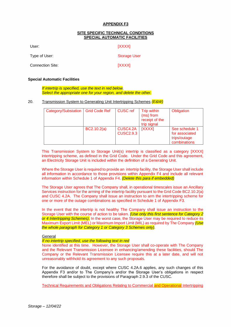
Storage – 12/04/22
APPENDIX F3
SITE SPECIFIC TECHNICAL CONDITIONS SPECIAL AUTOMATIC FACILITIES
User: [XXXX]
Type of User: Storage User
Connection Site: [XXXX]
Special Automatic Facilities
If intertrip is specified, use the text in red below. Select the appropriate one for your region, and delete the other.
20. Transmission System to Generating Unit Intertripping Schemes (E&W)
Category/Substation Grid Code Ref CUSC ref Trip within (ms) from receipt of the trip signal
Obligation
BC2.10.2(a) CUSC4.2A CUSC2.9.3
[XXXX] See schedule 1 for associated trips/outage combinations
This Transmission System to Storage Unit(s) intertrip is classified as a category [XXXX] intertripping scheme, as defined in the Grid Code. Under the Grid Code and this agreement, an Electricity Storage Unit is included within the definition of a Generating Unit. Where the Storage User is required to provide an intertrip facility, the Storage User shall include all information in accordance to those provisions within Appendix F4 and include all relevant information within Schedule 1 of Appendix F4. (Delete this para if embedded) The Storage User agrees that The Company shall, in operational timescales issue an Ancillary Services instruction for the arming of the intertrip facility pursuant to the Grid Code BC2.10.2(a) and CUSC 4.2A. The Company shall issue an instruction to arm the intertripping scheme for one or more of the outage combinations as specified in Schedule 1 of Appendix F3. In the event that the intertrip is not healthy The Company shall issue an instruction to the Storage User with the course of action to be taken. (Use only this first sentence for Category 2 or 4 Intertripping Schemes). In the worst case, the Storage User may be required to reduce its Maximum Export Limit (MEL) or Maximum Import Limit (MIL) as required by The Company (Use the whole paragraph for Category 1 or Category 3 Schemes only). General If no intertrip specified, use the following text in red None identified at this time. However, the Storage User shall co-operate with The Company and the Relevant Transmission Licensee in enhancing/amending these facilities, should The Company or the Relevant Transmission Licensee require this at a later date, and will not unreasonably withhold its agreement to any such proposals. For the avoidance of doubt, except where CUSC 4.2A.6 applies, any such changes of this Appendix F3 and/or to The Company’s and/or the Storage User’s obligations in respect therefore shall be subject to the provisions of Paragraph 2.9.3 of the CUSC. Technical Requirements and Obligations Relating to Commercial and Operational Intertripping
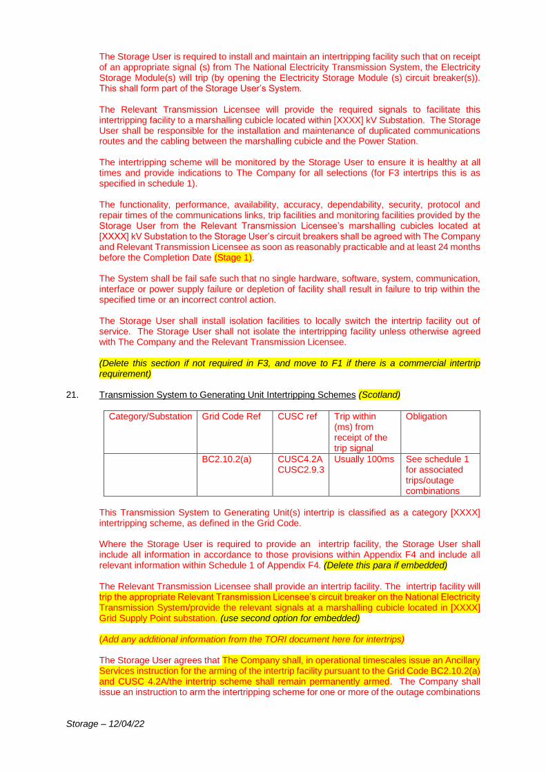
Storage – 12/04/22
The Storage User is required to install and maintain an intertripping facility such that on receipt of an appropriate signal (s) from The National Electricity Transmission System, the Electricity Storage Module(s) will trip (by opening the Electricity Storage Module (s) circuit breaker(s)). This shall form part of the Storage User’s System. The Relevant Transmission Licensee will provide the required signals to facilitate this intertripping facility to a marshalling cubicle located within [XXXX] kV Substation. The Storage User shall be responsible for the installation and maintenance of duplicated communications routes and the cabling between the marshalling cubicle and the Power Station. The intertripping scheme will be monitored by the Storage User to ensure it is healthy at all times and provide indications to The Company for all selections (for F3 intertrips this is as specified in schedule 1). The functionality, performance, availability, accuracy, dependability, security, protocol and repair times of the communications links, trip facilities and monitoring facilities provided by the Storage User from the Relevant Transmission Licensee’s marshalling cubicles located at [XXXX] kV Substation to the Storage User’s circuit breakers shall be agreed with The Company and Relevant Transmission Licensee as soon as reasonably practicable and at least 24 months before the Completion Date (Stage 1). The System shall be fail safe such that no single hardware, software, system, communication, interface or power supply failure or depletion of facility shall result in failure to trip within the specified time or an incorrect control action. The Storage User shall install isolation facilities to locally switch the intertrip facility out of service. The Storage User shall not isolate the intertripping facility unless otherwise agreed with The Company and the Relevant Transmission Licensee. (Delete this section if not required in F3, and move to F1 if there is a commercial intertrip requirement)
21. Transmission System to Generating Unit Intertripping Schemes (Scotland)
Category/Substation Grid Code Ref CUSC ref Trip within (ms) from receipt of the trip signal
Obligation
BC2.10.2(a) CUSC4.2A CUSC2.9.3
Usually 100ms See schedule 1 for associated trips/outage combinations
This Transmission System to Generating Unit(s) intertrip is classified as a category [XXXX] intertripping scheme, as defined in the Grid Code. Where the Storage User is required to provide an intertrip facility, the Storage User shall include all information in accordance to those provisions within Appendix F4 and include all relevant information within Schedule 1 of Appendix F4. (Delete this para if embedded) The Relevant Transmission Licensee shall provide an intertrip facility. The intertrip facility will trip the appropriate Relevant Transmission Licensee’s circuit breaker on the National Electricity Transmission System/provide the relevant signals at a marshalling cubicle located in [XXXX] Grid Supply Point substation. (use second option for embedded) (Add any additional information from the TORI document here for intertrips) The Storage User agrees that The Company shall, in operational timescales issue an Ancillary Services instruction for the arming of the intertrip facility pursuant to the Grid Code BC2.10.2(a) and CUSC 4.2A/the intertrip scheme shall remain permanently armed. The Company shall issue an instruction to arm the intertripping scheme for one or more of the outage combinations
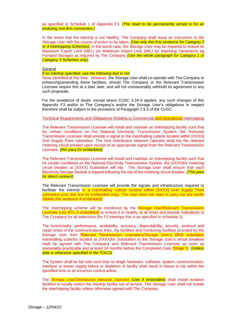
Storage – 12/04/22
as specified in Schedule 1 of Appendix F3. (The need to be permanently armed is for an enduring non-firm connection.) In the event that the intertrip is not healthy, The Company shall issue an instruction to the Storage User with the course of action to be taken. (Use only this first sentence for Category 2 or 4 Intertripping Schemes). In the worst case, the Storage User may be required to reduce its Maximum Export Limit (MEL) (or Maximum Import Limit (MIL) for importing Generators eg Pumped Storage) as required by The Company (Use the whole paragraph for Category 1 or Category 3 Schemes only). General If no intertrip specified, use the following text in red None identified at this time. However, the Storage User shall co-operate with The Company in enhancing/amending these facilities, should The Company or the Relevant Transmission Licensee require this at a later date, and will not unreasonably withhold its agreement to any such proposals. For the avoidance of doubt, except where CUSC 4.2A.6 applies, any such changes of this Appendix F3 and/or to The Company’s and/or the Storage User’s obligations in respect therefore shall be subject to the provisions of Paragraph 2.9.3 of the CUSC. Technical Requirements and Obligations Relating to Commercial and Operational Intertripping The Relevant Transmission Licensee will install and maintain an intertripping facility such that for certain conditions on the National Electricity Transmission System, the Relevant Transmission Licensee shall provide a signal to the marshalling cubicle located within [XXXX] Grid Supply Point substation. The host Distribution Network Operator shall trip the relevant metering circuit breaker upon receipt of an appropriate signal from the Relevant Transmission Licensee. (this para for embedded) The Relevant Transmission Licensee will install and maintain an intertripping facility such that for certain conditions on the National Electricity Transmission System, the [XXXX]kV metering circuit breaker at [XXXX] Substation will trip. The Storage User shall ensure that each Electricity Storage Module is tripped following the trip of the metering circuit breaker. (This para for direct connect) The Relevant Transmission Licensee will provide the signals and infrastructure required to facilitate the intertrip to a marshalling cubicle located within [XXXX] Grid Supply Point substation (use this text for embedded only). The User does not need to carry out any works (delete this sentence if embedded). The intertripping scheme will be monitored by the Storage User/Relevant Transmission Licensee (use RTL if embedded) to ensure it is healthy at all times and provide indications to The Company for all selections (for F3 intertrips this is as specified in schedule 1). The functionality, performance, availability, accuracy, dependability, security, protocol and repair times of the communications links, trip facilities and monitoring facilities provided by the Storage User from Relevant Transmission Licensee’s/Storage User’s DNO substation marshalling cubicles located at [XXXX]kV Substation to the Storage User’s circuit breakers shall be agreed with The Company and Relevant Transmission Licensee as soon as reasonably practicable and at least 24 months before the Completion Date (Stage 1). (Unless date is otherwise specified in the TOCO) The System shall be fail safe such that no single hardware, software, system, communication, interface or power supply failure or depletion of facility shall result in failure to trip within the specified time or an incorrect control action. The Storage User/Distribution Network Operator (Use if embedded) shall install isolation facilities to locally switch the intertrip facility out of service. The Storage User shall not isolate the intertripping facility unless otherwise agreed with The Company.
Storage – 12/04/22
(Delete this section if not required in F3 and move to F1 if there is a commercial intertrip requirement)
22. Special Automated Facilities (delete this table if embedded) (ECC.6.2.2.7)
Requirement
Disconnection from the Transmission System with or without Storage User Demand
Not applicable (unless specified)
Transmission System to Demand Intertripping Scheme Not applicable (unless specified)
Transmission System to Directly Connected Customers Intertripping Schemes
Not applicable (unless specified)
Restricted Entry Capacity Not applicable (unless specified)
23. Other Facilities (ECC.6.2.2.7)
Requirement
Automatic Open/Closure Schemes Not applicable (unless specified)
System Splitting/Islanding Schemes Not applicable (unless specified)
24. Synchronising & Voltage Selection (ECC.6.2.2.9) The Storage User will be required to interface with the National Electricity Transmission System substation synchronising system in accordance with the TS.3.24.60_RES /SPTS/SHETS. In circumstances where the Storage User does not synchronise at the Grid Entry Point the Storage User is required to participate in Relevant Transmission Licensee’s voltage selection scheme. The Storage User will be required to provide The Company with a “dead bus” signal to enable a voltage based interlock to be provided to the Relevant Transmission Licensee’s energising circuit breaker. The Relevant Transmission Licensee’s energising circuit breaker can only be used to energise the “dead” Storage User’s busbar ie no synchronising facilities will be provided. (tertiaries only) Synchronising and voltage selection facilities will be provided by the Relevant Transmission Licensee. Any additional requirements necessary to support these facilities will be agreed with the Storage User in the detailed design phase. (for Generator Connected GIS Ownership Boundaries, delete paragraph above and use this one) (delete the above if embedded and use the following:)
25. Synchronising To be agreed between the Storage User and host Distribution Network Operator. (SPT offers only:)
26. Transmission System to Generating Unit Active Network Management Scheme In order to ensure the transmission system is operated in accordance with the NETS SQSS, Chapter 5, the Storage User shall ensure that the Storage User’s equipment is capable of providing Operational Visibility and Commercial Control of the Storage User’s Power Station,

Storage – 12/04/22
via GEMS, to The Company. The detailed interfaces, specifications and other arrangements required to meet this Site Specific Condition shall be developed and agreed with the Storage User. GEMS local Intelligent Electronic Device (IED) shall be installed by the Relevant Transmission Licensee at the local substation. This will interface to the Storage User’s equipment. The local GEMS IED will have a direct communications connection to interface equipment located at the Storage User’s site. Both the local and remote IED’s would need to be capable of transmitting analogue and digital signals and would require communication modules to be installed for transmitting information from end to end. Details of the interface will be determined between the Relevant Transmission Licensee and the Storage User.

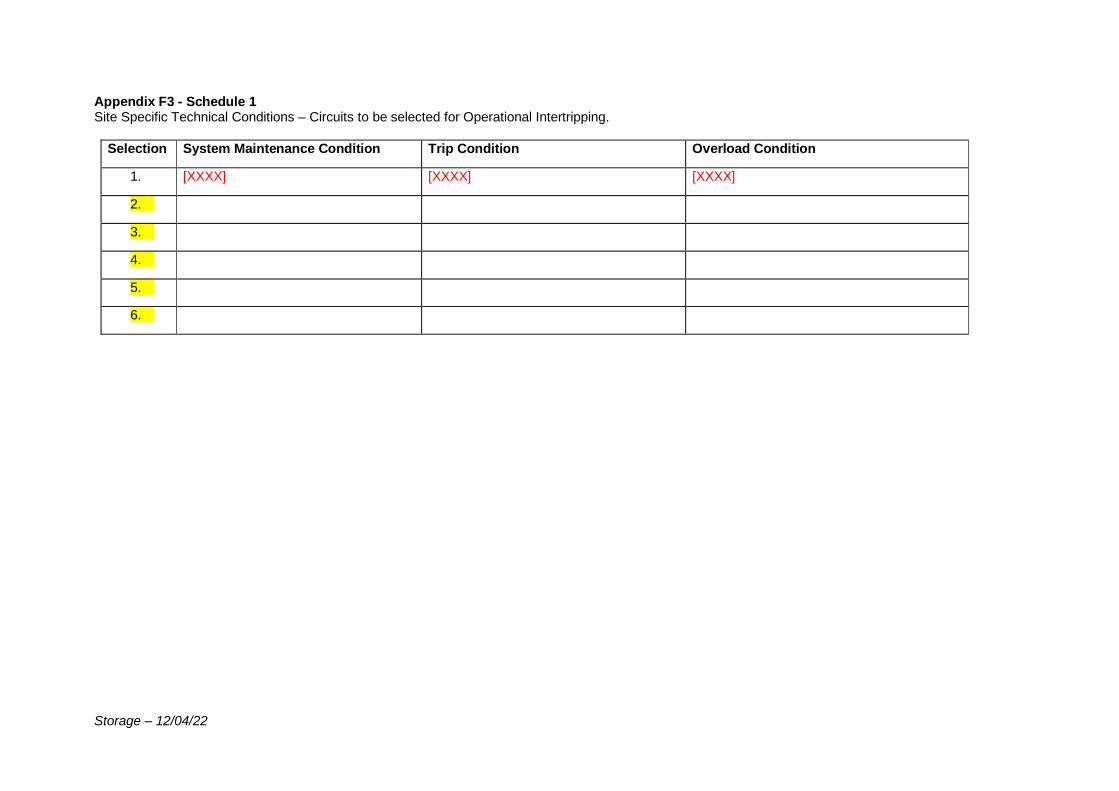
Storage – 12/04/22
Appendix F3 - Schedule 1 Site Specific Technical Conditions – Circuits to be selected for Operational Intertripping.
Selection System Maintenance Condition Trip Condition Overload Condition
1. [XXXX] [XXXX] [XXXX]
2.
3.
4.
5.
6.

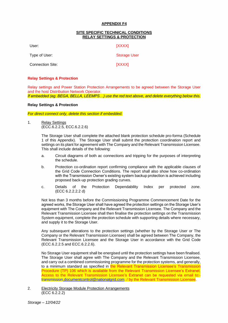
Storage – 12/04/22
APPENDIX F4
SITE SPECIFIC TECHNICAL CONDITIONS RELAY SETTINGS & PROTECTION
User: [XXXX]
Type of User: Storage User
Connection Site: [XXXX]
Relay Settings & Protection Relay settings and Power Station Protection Arrangements to be agreed between the Storage User and the host Distribution Network Operator. If embedded (eg. BEGA, BELLA, LEEMPS…) use the red text above, and delete everything below this. Relay Settings & Protection For direct connect only, delete this section if embedded. 1. Relay Settings
(ECC.6.2.2.5, ECC.6.2.2.6) The Storage User shall complete the attached blank protection schedule pro-forma (Schedule 1 of this Appendix). The Storage User shall submit the protection coordination report and settings on its plant for agreement with The Company and the Relevant Transmission Licensee. This shall include details of the following:
a. Circuit diagrams of both ac connections and tripping for the purposes of interpreting the schedule.
b. Protection co-ordination report confirming compliance with the applicable clauses of the Grid Code Connection Conditions. The report shall also show how co-ordination with the Transmission Owner’s existing system backup protection is achieved including proposed back-up protection grading curves.
c. Details of the Protection Dependability Index per protected zone. (ECC 6.2.2.2.2 d)
Not less than 3 months before the Commissioning Programme Commencement Date for the agreed works, the Storage User shall have agreed the protection settings on the Storage User’s equipment with The Company and the Relevant Transmission Licensee. The Company and the Relevant Transmission Licensee shall then finalise the protection settings on the Transmission System equipment, complete the protection schedule with supporting details where necessary, and supply it to the Storage User. Any subsequent alterations to the protection settings (whether by the Storage User or The Company or the Relevant Transmission Licensee) shall be agreed between The Company, the Relevant Transmission Licensee and the Storage User in accordance with the Grid Code (ECC.6.2.2.5 and ECC.6.2.2.6). No Storage User equipment shall be energised until the protection settings have been finalised. The Storage User shall agree with The Company and the Relevant Transmission Licensee, and carry out a combined commissioning programme for the protection systems, and generally, to a minimum standard as specified in the Relevant Transmission Licensee’s Transmission Procedure (TP) 106 which is available from the Relevant Transmission Licensee’s Extranet. Access to the Relevant Transmission Licensee’s Extranet can be requested via email to:- [email protected]. / by the Relevant Transmission Licensee.
2. Electricity Storage Module Protection Arrangements (ECC 6.2.2.2)

Storage – 12/04/22
The fault clearance time (from fault inception to circuit breaker arc extinction) for faults on all the Storage User’s equipment directly connected to the Transmission System shall meet the following minimum requirement(s): - [400kV within 80ms or 275kV within 100ms or 132kV and below within 120ms]. For faults on transformers the clearance time is specified for the HV side (e.g. for a fault on a [400/33]kV interconnecting transformer the maximum clearance time is [80]ms. Where intertripping is required to open circuit breakers, the overall fault clearance time shall not be extended by more than [60]ms (total [140]ms in this example) to allow such intertripping to operate. The maximum backup fault clearance time at 400/275/132kV and below is 300ms/300ms/1.5s. (tertiaries only) (The following paragraph for E&W direct connect only) In addition, the Storage User shall consider provision of the facility to enable (through local intervention) a dedicated setting group within the IED(s) of their circuit protection(s) to enable a reverse looking distance element that can cover for the Storage User circuit’s infeed to a busbar fault during short periods of loss/unavailability of the busbar protection system. This feature is in line with wider Transmission System contingency planning. The settings shall be discussed and agreed with the Relevant Transmission Licensee during detailed design and delivery. (Scotland only) Backup clearance time should be as specified in the TOCO or if not, use the following text with the appropriate values for the voltage required. The corresponding backup clearance time at 400kV where there is only one main protection shall be less than 300ms. (For Generator Ownership boundary GIS Connections delete all of section 2 so far and replace with the following:) The overall feeder protection scheme shall be designed to the Relevant Transmission Licensee’s standards and all equipment used in the protection scheme shall be Type Registered to the Relevant Transmission Licensee’s standards, as per Transmission Procedure TP183(E&W only). Any additional requirements will be discussed and agreed with the Storage User in the detailed design phase. The Storage User shall design, install, own and supply the feeder protection equipment at [XXXX]kV substation in respect of the Storage User’s incoming feeders. The relay protection and operating times shall be in accordance with National Grid Technical Specification (NGTS) 1 – Issue 7 section 2.5, NGTS.3.24.07 and other relevant NGTS which are part of the NGTS.3.24.XX series/the Relevant Transmission Licensee’s SPTS/SHETS. The Relevant Transmission Licensee will assist and advise the Storage User on which Technical Specifications are relevant for this project. Any dispensations relating to compliance with the Relevant Transmission Licensee’s Technical Specifications and Policies applicable to the feeder protection shall be agreed between the Storage User and The Company and the Relevant Transmission Licensee in the detailed design phase.
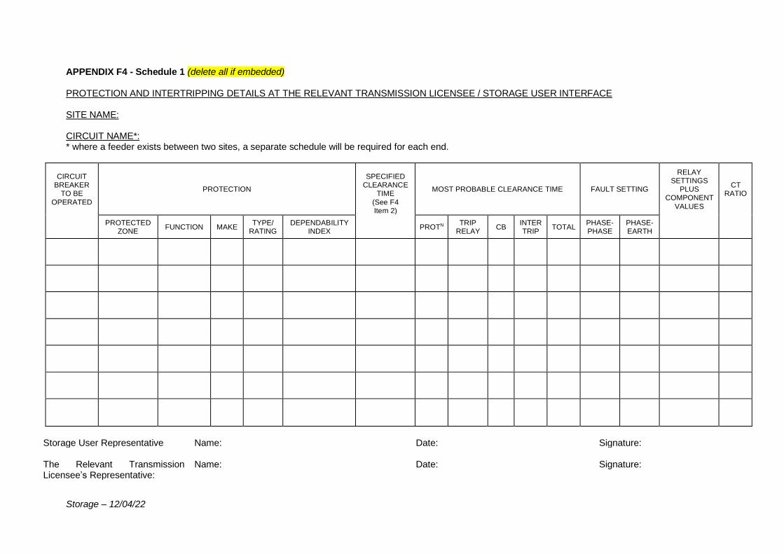
Storage – 12/04/22
APPENDIX F4 - Schedule 1 (delete all if embedded) PROTECTION AND INTERTRIPPING DETAILS AT THE RELEVANT TRANSMISSION LICENSEE / STORAGE USER INTERFACE SITE NAME: CIRCUIT NAME*: * where a feeder exists between two sites, a separate schedule will be required for each end.
CIRCUIT BREAKER
TO BE
OPERATED
PROTECTION
SPECIFIED CLEARANCE
TIME
(See F4 Item 2)
MOST PROBABLE CLEARANCE TIME FAULT SETTING
RELAY SETTINGS
PLUS COMPONENT
VALUES
CT RATIO
PROTECTED ZONE
FUNCTION MAKE TYPE/
RATING DEPENDABILITY
INDEX PROTN
TRIP RELAY
CB INTER TRIP
TOTAL PHASE- PHASE
PHASE- EARTH
Storage User Representative Name: Date: Signature: The Relevant Transmission Licensee’s Representative:
Name: Date: Signature:
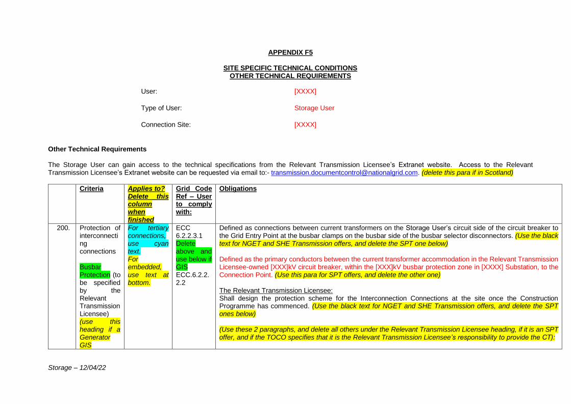
Storage – 12/04/22
APPENDIX F5
SITE SPECIFIC TECHNICAL CONDITIONS OTHER TECHNICAL REQUIREMENTS
User: [XXXX]
Type of User: Storage User
Connection Site: [XXXX]
Other Technical Requirements The Storage User can gain access to the technical specifications from the Relevant Transmission Licensee’s Extranet website. Access to the Relevant Transmission Licensee’s Extranet website can be requested via email to:- [email protected]. (delete this para if in Scotland)
Criteria Applies to? Delete this column when finished
Grid Code Ref – User to comply with:
Obligations
200. Protection of interconnecting connections Busbar Protection (to be specified by the Relevant Transmission Licensee) (use this heading if a Generator GIS
For tertiary connections, use cyan text. For embedded, use text at bottom.
ECC 6.2.2.3.1 Delete above and use below if GIS ECC.6.2.2.2.2
Defined as connections between current transformers on the Storage User’s circuit side of the circuit breaker to the Grid Entry Point at the busbar clamps on the busbar side of the busbar selector disconnectors. (Use the black text for NGET and SHE Transmission offers, and delete the SPT one below) Defined as the primary conductors between the current transformer accommodation in the Relevant Transmission Licensee-owned [XXX]kV circuit breaker, within the [XXX]kV busbar protection zone in [XXXX] Substation, to the Connection Point. (Use this para for SPT offers, and delete the other one) The Relevant Transmission Licensee: Shall design the protection scheme for the Interconnection Connections at the site once the Construction Programme has commenced. (Use the black text for NGET and SHE Transmission offers, and delete the SPT ones below) (Use these 2 paragraphs, and delete all others under the Relevant Transmission Licensee heading, if it is an SPT offer, and if the TOCO specifies that it is the Relevant Transmission Licensee’s responsibility to provide the CT):
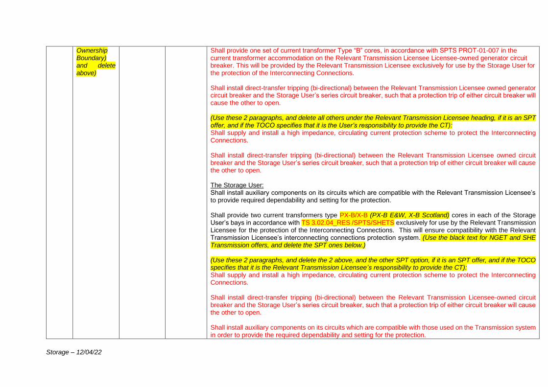
Storage – 12/04/22
Ownership Boundary) and delete above)
Shall provide one set of current transformer Type “B” cores, in accordance with SPTS PROT-01-007 in the current transformer accommodation on the Relevant Transmission Licensee Licensee-owned generator circuit breaker. This will be provided by the Relevant Transmission Licensee exclusively for use by the Storage User for the protection of the Interconnecting Connections. Shall install direct-transfer tripping (bi-directional) between the Relevant Transmission Licensee owned generator circuit breaker and the Storage User’s series circuit breaker, such that a protection trip of either circuit breaker will cause the other to open. (Use these 2 paragraphs, and delete all others under the Relevant Transmission Licensee heading, if it is an SPT offer, and if the TOCO specifies that it is the User’s responsibility to provide the CT): Shall supply and install a high impedance, circulating current protection scheme to protect the Interconnecting Connections. Shall install direct-transfer tripping (bi-directional) between the Relevant Transmission Licensee owned circuit breaker and the Storage User’s series circuit breaker, such that a protection trip of either circuit breaker will cause the other to open. The Storage User: Shall install auxiliary components on its circuits which are compatible with the Relevant Transmission Licensee’s to provide required dependability and setting for the protection. Shall provide two current transformers type PX-B/X-B (PX-B E&W, X-B Scotland) cores in each of the Storage User’s bays in accordance with TS 3.02.04_RES /SPTS/SHETS exclusively for use by the Relevant Transmission Licensee for the protection of the Interconnecting Connections. This will ensure compatibility with the Relevant Transmission Licensee’s interconnecting connections protection system. (Use the black text for NGET and SHE Transmission offers, and delete the SPT ones below.) (Use these 2 paragraphs, and delete the 2 above, and the other SPT option, if it is an SPT offer, and if the TOCO specifies that it is the Relevant Transmission Licensee’s responsibility to provide the CT): Shall supply and install a high impedance, circulating current protection scheme to protect the Interconnecting Connections. Shall install direct-transfer tripping (bi-directional) between the Relevant Transmission Licensee-owned circuit breaker and the Storage User’s series circuit breaker, such that a protection trip of either circuit breaker will cause the other to open. Shall install auxiliary components on its circuits which are compatible with those used on the Transmission system in order to provide the required dependability and setting for the protection.
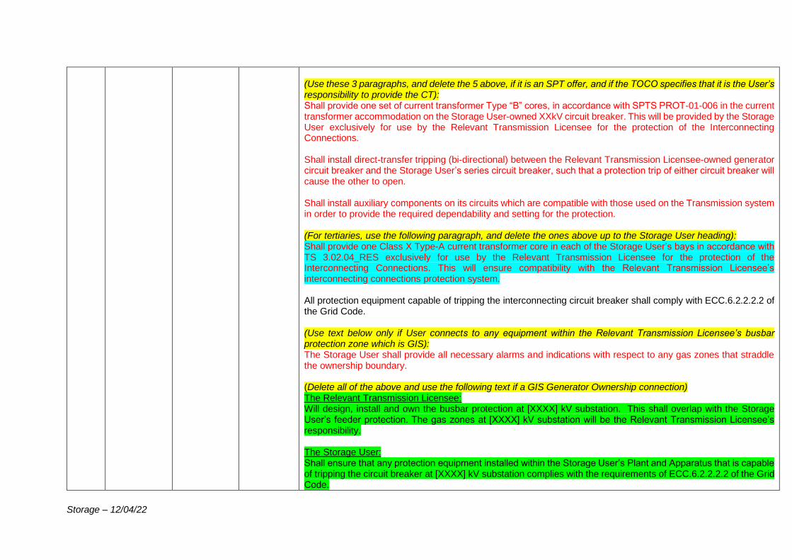
Storage – 12/04/22
(Use these 3 paragraphs, and delete the 5 above, if it is an SPT offer, and if the TOCO specifies that it is the User’s responsibility to provide the CT): Shall provide one set of current transformer Type “B” cores, in accordance with SPTS PROT-01-006 in the current transformer accommodation on the Storage User-owned XXkV circuit breaker. This will be provided by the Storage User exclusively for use by the Relevant Transmission Licensee for the protection of the Interconnecting Connections. Shall install direct-transfer tripping (bi-directional) between the Relevant Transmission Licensee-owned generator circuit breaker and the Storage User’s series circuit breaker, such that a protection trip of either circuit breaker will cause the other to open. Shall install auxiliary components on its circuits which are compatible with those used on the Transmission system in order to provide the required dependability and setting for the protection. (For tertiaries, use the following paragraph, and delete the ones above up to the Storage User heading): Shall provide one Class X Type-A current transformer core in each of the Storage User’s bays in accordance with TS 3.02.04_RES exclusively for use by the Relevant Transmission Licensee for the protection of the Interconnecting Connections. This will ensure compatibility with the Relevant Transmission Licensee’s interconnecting connections protection system. All protection equipment capable of tripping the interconnecting circuit breaker shall comply with ECC.6.2.2.2.2 of the Grid Code. (Use text below only if User connects to any equipment within the Relevant Transmission Licensee’s busbar protection zone which is GIS): The Storage User shall provide all necessary alarms and indications with respect to any gas zones that straddle the ownership boundary. (Delete all of the above and use the following text if a GIS Generator Ownership connection) The Relevant Transmission Licensee: Will design, install and own the busbar protection at [XXXX] kV substation. This shall overlap with the Storage User’s feeder protection. The gas zones at [XXXX] kV substation will be the Relevant Transmission Licensee’s responsibility. The Storage User: Shall ensure that any protection equipment installed within the Storage User’s Plant and Apparatus that is capable of tripping the circuit breaker at [XXXX] kV substation complies with the requirements of ECC.6.2.2.2.2 of the Grid Code.
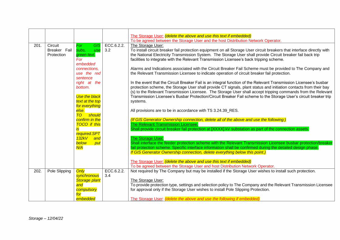
Storage – 12/04/22
The Storage User: (delete the above and use this text if embedded) To be agreed between the Storage User and the host Distribution Network Operator.
201. Circuit Breaker Fail Protection
For GIS subs, use green text. For embedded connections, use the red sentence right at the bottom. Use the black text at the top for everything else. TO should confirm in the TOCO if this is required.SPT 132kV and below put N/A
ECC.6.2.2.3.2
The Storage User: To install circuit breaker fail protection equipment on all Storage User circuit breakers that interface directly with the National Electricity Transmission System. The Storage User shall provide Circuit breaker fail back trip facilities to integrate with the Relevant Transmission Licensee’s back tripping scheme. Alarms and Indications associated with the Circuit Breaker Fail Scheme must be provided to The Company and the Relevant Transmission Licensee to indicate operation of circuit breaker fail protection. In the event that the Circuit Breaker Fail is an integral function of the Relevant Transmission Licensee’s busbar protection scheme, the Storage User shall provide CT signals, plant status and initiation contacts from their bay (s) to the Relevant Transmission Licensee. The Storage User shall accept tripping commands from the Relevant Transmission Licensee’s Busbar Protection/Circuit Breaker Fail scheme to the Storage User’s circuit breaker trip systems. All provisions are to be in accordance with TS 3.24.39_RES. (If GIS Generator Ownership connection, delete all of the above and use the following:) The Relevant Transmission Licensee: Shall provide circuit breaker fail protection at [XXXX] kV substation as part of the connection assets. The Storage User: Shall interface the feeder protection scheme with the Relevant Transmission Licensee busbar protection/breaker fail protection scheme. Specific interface information shall be confirmed during the detailed design phase. If GIS Generator Ownership connection, delete everything below this point.) The Storage User: (delete the above and use this text if embedded) To be agreed between the Storage User and host Distribution Network Operator.
202. Pole Slipping Only synchronous Storage plant and compulsory for embedded
ECC.6.2.2.3.4
Not required by The Company but may be installed if the Storage User wishes to install such protection. The Storage User: To provide protection type, settings and selection policy to The Company and the Relevant Transmission Licensee for approval only if the Storage User wishes to install Pole Slipping Protection. The Storage User: (delete the above and use the following if embedded)
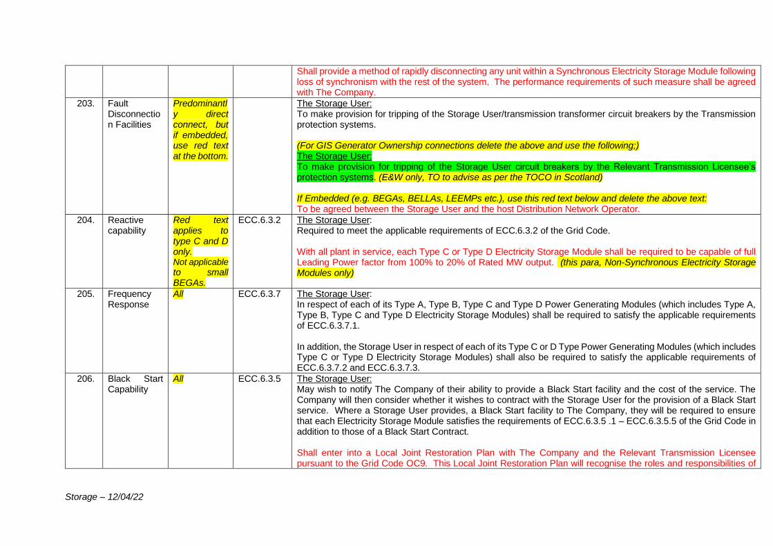
Storage – 12/04/22
Shall provide a method of rapidly disconnecting any unit within a Synchronous Electricity Storage Module following loss of synchronism with the rest of the system. The performance requirements of such measure shall be agreed with The Company.
203. Fault Disconnection Facilities
Predominantly direct connect, but if embedded, use red text at the bottom.
The Storage User: To make provision for tripping of the Storage User/transmission transformer circuit breakers by the Transmission protection systems. (For GIS Generator Ownership connections delete the above and use the following;) The Storage User: To make provision for tripping of the Storage User circuit breakers by the Relevant Transmission Licensee’s protection systems. (E&W only, TO to advise as per the TOCO in Scotland) If Embedded (e.g. BEGAs, BELLAs, LEEMPs etc.), use this red text below and delete the above text: To be agreed between the Storage User and the host Distribution Network Operator.
204. Reactive capability
Red text applies to type C and D only. Not applicable to small BEGAs.
ECC.6.3.2 The Storage User: Required to meet the applicable requirements of ECC.6.3.2 of the Grid Code. With all plant in service, each Type C or Type D Electricity Storage Module shall be required to be capable of full Leading Power factor from 100% to 20% of Rated MW output. (this para, Non-Synchronous Electricity Storage Modules only)
205. Frequency Response
All ECC.6.3.7 The Storage User: In respect of each of its Type A, Type B, Type C and Type D Power Generating Modules (which includes Type A, Type B, Type C and Type D Electricity Storage Modules) shall be required to satisfy the applicable requirements of ECC.6.3.7.1. In addition, the Storage User in respect of each of its Type C or D Type Power Generating Modules (which includes Type C or Type D Electricity Storage Modules) shall also be required to satisfy the applicable requirements of ECC.6.3.7.2 and ECC.6.3.7.3.
206. Black Start Capability
All ECC.6.3.5 The Storage User: May wish to notify The Company of their ability to provide a Black Start facility and the cost of the service. The Company will then consider whether it wishes to contract with the Storage User for the provision of a Black Start service. Where a Storage User provides, a Black Start facility to The Company, they will be required to ensure that each Electricity Storage Module satisfies the requirements of ECC.6.3.5 .1 – ECC.6.3.5.5 of the Grid Code in addition to those of a Black Start Contract. Shall enter into a Local Joint Restoration Plan with The Company and the Relevant Transmission Licensee pursuant to the Grid Code OC9. This Local Joint Restoration Plan will recognise the roles and responsibilities of
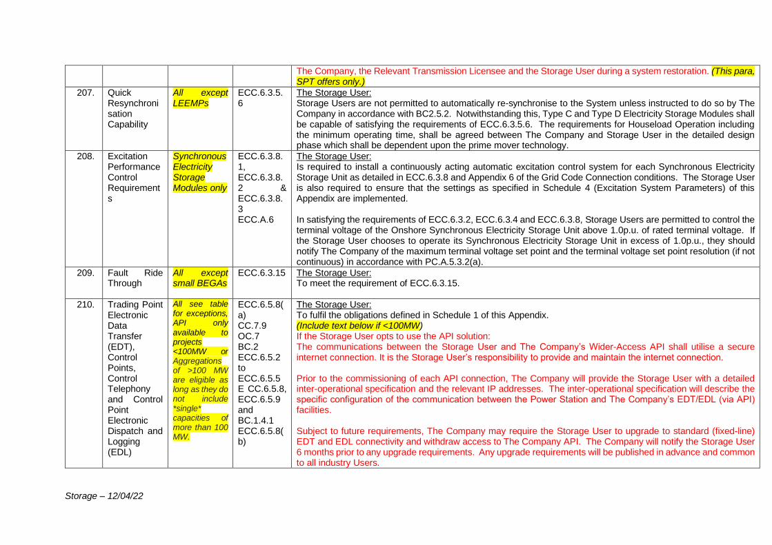
Storage – 12/04/22
The Company, the Relevant Transmission Licensee and the Storage User during a system restoration. (This para, SPT offers only.)
207. Quick Resynchronisation Capability
All except LEEMPs
ECC.6.3.5.6
The Storage User: Storage Users are not permitted to automatically re-synchronise to the System unless instructed to do so by The Company in accordance with BC2.5.2. Notwithstanding this, Type C and Type D Electricity Storage Modules shall be capable of satisfying the requirements of ECC.6.3.5.6. The requirements for Houseload Operation including the minimum operating time, shall be agreed between The Company and Storage User in the detailed design phase which shall be dependent upon the prime mover technology.
208. Excitation Performance Control Requirements
Synchronous Electricity Storage Modules only
ECC.6.3.8.1, ECC.6.3.8.2 & ECC.6.3.8.3 ECC.A.6
The Storage User: Is required to install a continuously acting automatic excitation control system for each Synchronous Electricity Storage Unit as detailed in ECC.6.3.8 and Appendix 6 of the Grid Code Connection conditions. The Storage User is also required to ensure that the settings as specified in Schedule 4 (Excitation System Parameters) of this Appendix are implemented. In satisfying the requirements of ECC.6.3.2, ECC.6.3.4 and ECC.6.3.8, Storage Users are permitted to control the terminal voltage of the Onshore Synchronous Electricity Storage Unit above 1.0p.u. of rated terminal voltage. If the Storage User chooses to operate its Synchronous Electricity Storage Unit in excess of 1.0p.u., they should notify The Company of the maximum terminal voltage set point and the terminal voltage set point resolution (if not continuous) in accordance with PC.A.5.3.2(a).
209. Fault Ride Through
All except small BEGAs
ECC.6.3.15 The Storage User: To meet the requirement of ECC.6.3.15.
210. Trading Point Electronic Data Transfer (EDT), Control Points, Control Telephony and Control Point Electronic Dispatch and Logging (EDL)
All see table for exceptions, API only available to projects <100MW or Aggregations of >100 MW are eligible as long as they do not include *single* capacities of more than 100 MW.
ECC.6.5.8(a) CC.7.9 OC.7 BC.2 ECC.6.5.2 to ECC.6.5.5 E CC.6.5.8, ECC.6.5.9 and BC.1.4.1 ECC.6.5.8(b)
The Storage User: To fulfil the obligations defined in Schedule 1 of this Appendix. (Include text below if <100MW) If the Storage User opts to use the API solution: The communications between the Storage User and The Company’s Wider-Access API shall utilise a secure internet connection. It is the Storage User’s responsibility to provide and maintain the internet connection. Prior to the commissioning of each API connection, The Company will provide the Storage User with a detailed inter-operational specification and the relevant IP addresses. The inter-operational specification will describe the specific configuration of the communication between the Power Station and The Company’s EDT/EDL (via API) facilities. Subject to future requirements, The Company may require the Storage User to upgrade to standard (fixed-line) EDT and EDL connectivity and withdraw access to The Company API. The Company will notify the Storage User 6 months prior to any upgrade requirements. Any upgrade requirements will be published in advance and common to all industry Users.
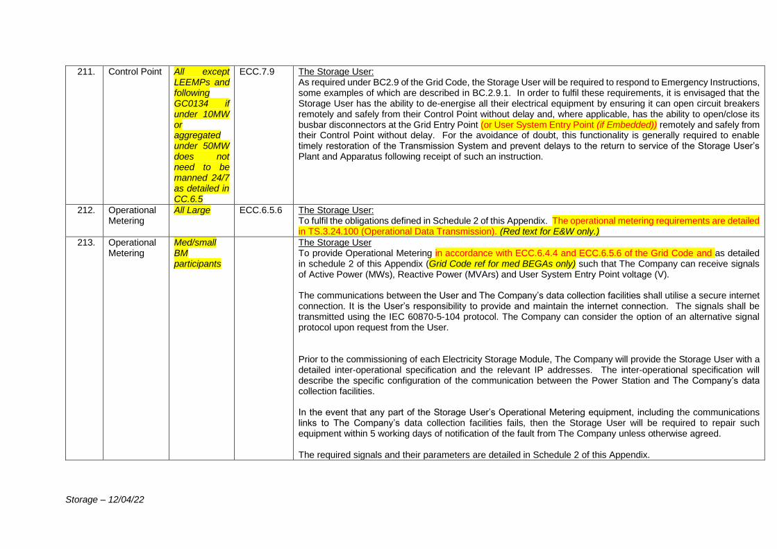
Storage – 12/04/22
211. Control Point All except LEEMPs and following GC0134 if under 10MW or aggregated under 50MW does not need to be manned 24/7 as detailed in CC.6.5
ECC.7.9 The Storage User: As required under BC2.9 of the Grid Code, the Storage User will be required to respond to Emergency Instructions, some examples of which are described in BC.2.9.1. In order to fulfil these requirements, it is envisaged that the Storage User has the ability to de-energise all their electrical equipment by ensuring it can open circuit breakers remotely and safely from their Control Point without delay and, where applicable, has the ability to open/close its busbar disconnectors at the Grid Entry Point (or User System Entry Point (if Embedded)) remotely and safely from their Control Point without delay. For the avoidance of doubt, this functionality is generally required to enable timely restoration of the Transmission System and prevent delays to the return to service of the Storage User’s Plant and Apparatus following receipt of such an instruction.
212. Operational Metering
All Large ECC.6.5.6 The Storage User: To fulfil the obligations defined in Schedule 2 of this Appendix. The operational metering requirements are detailed in TS.3.24.100 (Operational Data Transmission). (Red text for E&W only.)
213. Operational Metering
Med/small BM participants
The Storage User To provide Operational Metering in accordance with ECC.6.4.4 and ECC.6.5.6 of the Grid Code and as detailed in schedule 2 of this Appendix (Grid Code ref for med BEGAs only) such that The Company can receive signals of Active Power (MWs), Reactive Power (MVArs) and User System Entry Point voltage (V). The communications between the User and The Company’s data collection facilities shall utilise a secure internet connection. It is the User’s responsibility to provide and maintain the internet connection. The signals shall be transmitted using the IEC 60870-5-104 protocol. The Company can consider the option of an alternative signal protocol upon request from the User. Prior to the commissioning of each Electricity Storage Module, The Company will provide the Storage User with a detailed inter-operational specification and the relevant IP addresses. The inter-operational specification will describe the specific configuration of the communication between the Power Station and The Company’s data collection facilities. In the event that any part of the Storage User’s Operational Metering equipment, including the communications links to The Company’s data collection facilities fails, then the Storage User will be required to repair such equipment within 5 working days of notification of the fault from The Company unless otherwise agreed. The required signals and their parameters are detailed in Schedule 2 of this Appendix.
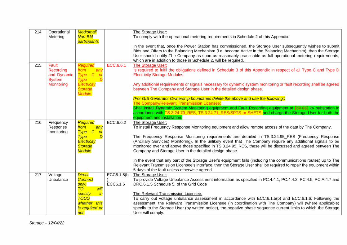
Storage – 12/04/22
214. Operational Metering
Med/small Non-BM participants
The Storage User: To comply with the operational metering requirements in Schedule 2 of this Appendix. In the event that, once the Power Station has commissioned, the Storage User subsequently wishes to submit Bids and Offers to the Balancing Mechanism (i.e. become Active in the Balancing Mechanism), then the Storage User should notify The Company as soon as reasonably practicable as full operational metering requirements, which are in addition to those in Schedule 2, will be required.
215. Fault Recording and Dynamic System Monitoring
Required from any Type C or Type D Electricity Storage Module.
ECC.6.6.1 The Storage User: Is required to fulfil the obligations defined in Schedule 3 of this Appendix in respect of all Type C and Type D Electricity Storage Modules. Any additional requirements or signals necessary for dynamic system monitoring or fault recording shall be agreed between The Company and Storage User in the detailed design phase. (For GIS Generator Ownership boundaries delete the above and use the following:) The Company/Relevant Transmission Licensee: Shall install Dynamic System Monitoring equipment and Fault Recording equipment at [XXXX] kV substation in accordance with TS.3.24.70_RES, TS.3.24.71_RES/SPTS or SHETS and charge the Storage User for both the equipment and installation.
216. Frequency Response monitoring
Required from any Type C or Type D Electricity Storage Module
ECC.6.6.2 The Storage User: To install Frequency Response Monitoring equipment and allow remote access of the data by The Company. The Frequency Response Monitoring requirements are detailed in TS 3.24.95_RES (Frequency Response (Ancillary Services) Monitoring). In the unlikely event that The Company require any additional signals to be monitored over and above those specified in TS.3.24.95_RES, these will be discussed and agreed between The Company and Storage User in the detailed design phase. In the event that any part of the Storage User’s equipment fails (including the communications routes) up to The Relevant Transmission Licensee’s interface, then the Storage User shall be required to repair the equipment within 5 days of the fault unless otherwise agreed.
217. Voltage Unbalance
Direct Connect only. TO will specify in TOCO whether this is required or not.
ECC6.1.5(b) ECC6.1.6
The Storage User: To provide Voltage Unbalance Assessment information as specified in PC.4.4.1, PC.4.4.2, PC.4.5, PC.A.4.7 and DRC.6.1.5 Schedule 5, of the Grid Code The Relevant Transmission Licensee: To carry out voltage unbalance assessment in accordance with ECC.6.1.5(b) and ECC.6.1.6. Following the assessment, the Relevant Transmission Licensee (in coordination with The Company) will (where applicable) specify to the Storage User (by written notice), the negative phase sequence current limits to which the Storage User will comply.
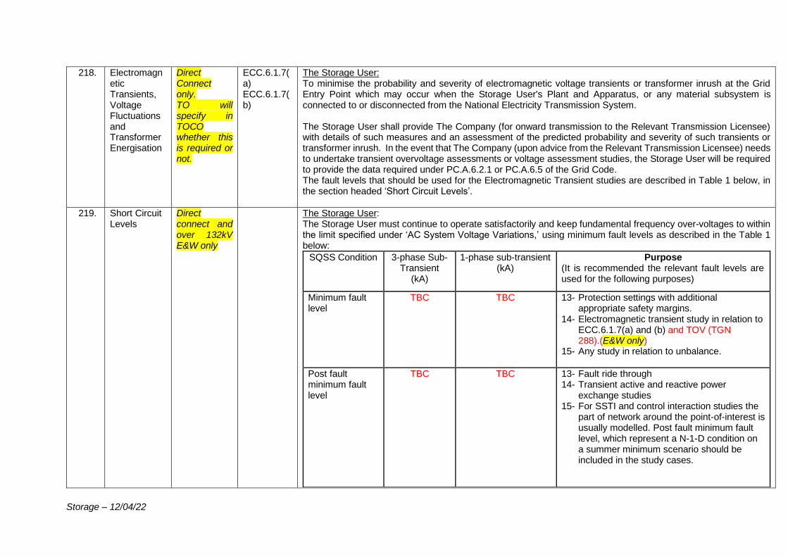
Storage – 12/04/22
218. Electromagnetic Transients, Voltage Fluctuations and Transformer Energisation
Direct Connect only. TO will specify in TOCO whether this is required or not.
ECC.6.1.7(a) ECC.6.1.7(b)
The Storage User: To minimise the probability and severity of electromagnetic voltage transients or transformer inrush at the Grid Entry Point which may occur when the Storage User's Plant and Apparatus, or any material subsystem is connected to or disconnected from the National Electricity Transmission System. The Storage User shall provide The Company (for onward transmission to the Relevant Transmission Licensee) with details of such measures and an assessment of the predicted probability and severity of such transients or transformer inrush. In the event that The Company (upon advice from the Relevant Transmission Licensee) needs to undertake transient overvoltage assessments or voltage assessment studies, the Storage User will be required to provide the data required under PC.A.6.2.1 or PC.A.6.5 of the Grid Code. The fault levels that should be used for the Electromagnetic Transient studies are described in Table 1 below, in the section headed ‘Short Circuit Levels’.
219. Short Circuit Levels
Direct connect and over 132kV E&W only
The Storage User: The Storage User must continue to operate satisfactorily and keep fundamental frequency over-voltages to within the limit specified under ‘AC System Voltage Variations,’ using minimum fault levels as described in the Table 1 below:
SQSS Condition 3-phase Sub-Transient
(kA)
1-phase sub-transient (kA)
Purpose (It is recommended the relevant fault levels are used for the following purposes)
Minimum fault level
TBC
TBC
13- Protection settings with additional appropriate safety margins.
14- Electromagnetic transient study in relation to ECC.6.1.7(a) and (b) and TOV (TGN 288).(E&W only)
15- Any study in relation to unbalance.
Post fault minimum fault level
TBC
TBC
13- Fault ride through 14- Transient active and reactive power
exchange studies 15- For SSTI and control interaction studies the
part of network around the point-of-interest is usually modelled. Post fault minimum fault level, which represent a N-1-D condition on a summer minimum scenario should be included in the study cases.
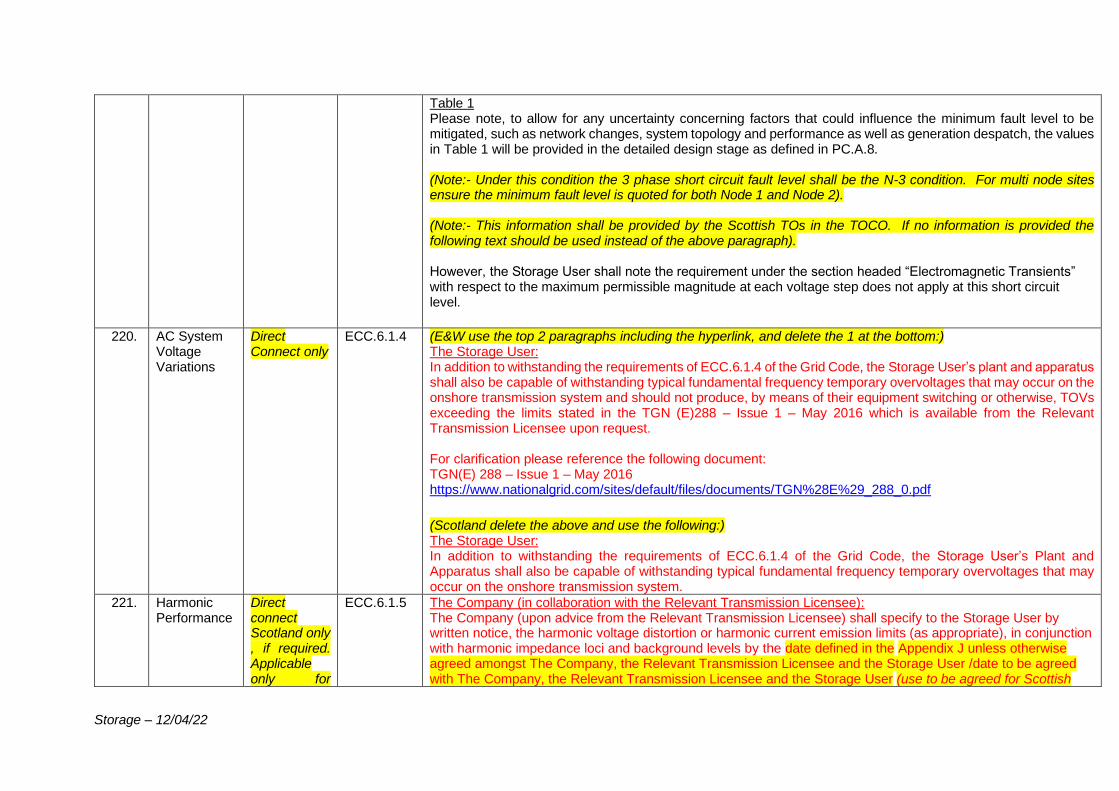
Storage – 12/04/22
Table 1 Please note, to allow for any uncertainty concerning factors that could influence the minimum fault level to be mitigated, such as network changes, system topology and performance as well as generation despatch, the values in Table 1 will be provided in the detailed design stage as defined in PC.A.8. (Note:- Under this condition the 3 phase short circuit fault level shall be the N-3 condition. For multi node sites ensure the minimum fault level is quoted for both Node 1 and Node 2). (Note:- This information shall be provided by the Scottish TOs in the TOCO. If no information is provided the following text should be used instead of the above paragraph). However, the Storage User shall note the requirement under the section headed “Electromagnetic Transients” with respect to the maximum permissible magnitude at each voltage step does not apply at this short circuit level.
220. AC System
Voltage Variations
Direct Connect only
ECC.6.1.4 (E&W use the top 2 paragraphs including the hyperlink, and delete the 1 at the bottom:) The Storage User: In addition to withstanding the requirements of ECC.6.1.4 of the Grid Code, the Storage User’s plant and apparatus shall also be capable of withstanding typical fundamental frequency temporary overvoltages that may occur on the onshore transmission system and should not produce, by means of their equipment switching or otherwise, TOVs exceeding the limits stated in the TGN (E)288 – Issue 1 – May 2016 which is available from the Relevant Transmission Licensee upon request. For clarification please reference the following document: TGN(E) 288 – Issue 1 – May 2016 https://www.nationalgrid.com/sites/default/files/documents/TGN%28E%29_288_0.pdf
(Scotland delete the above and use the following:) The Storage User: In addition to withstanding the requirements of ECC.6.1.4 of the Grid Code, the Storage User’s Plant and Apparatus shall also be capable of withstanding typical fundamental frequency temporary overvoltages that may occur on the onshore transmission system.
221. Harmonic Performance
Direct connect Scotland only , if required. Applicable only for
ECC.6.1.5 The Company (in collaboration with the Relevant Transmission Licensee): The Company (upon advice from the Relevant Transmission Licensee) shall specify to the Storage User by written notice, the harmonic voltage distortion or harmonic current emission limits (as appropriate), in conjunction with harmonic impedance loci and background levels by the date defined in the Appendix J unless otherwise agreed amongst The Company, the Relevant Transmission Licensee and the Storage User /date to be agreed with The Company, the Relevant Transmission Licensee and the Storage User (use to be agreed for Scottish
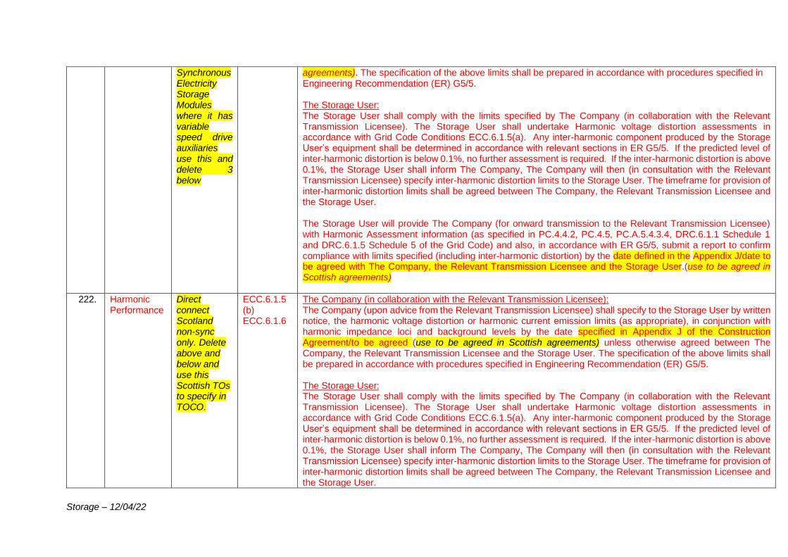
Storage – 12/04/22
Synchronous Electricity Storage Modules where it has variable speed drive auxiliaries use this and delete 3 below
agreements). The specification of the above limits shall be prepared in accordance with procedures specified in Engineering Recommendation (ER) G5/5. The Storage User: The Storage User shall comply with the limits specified by The Company (in collaboration with the Relevant Transmission Licensee). The Storage User shall undertake Harmonic voltage distortion assessments in accordance with Grid Code Conditions ECC.6.1.5(a). Any inter-harmonic component produced by the Storage User’s equipment shall be determined in accordance with relevant sections in ER G5/5. If the predicted level of inter-harmonic distortion is below 0.1%, no further assessment is required. If the inter-harmonic distortion is above 0.1%, the Storage User shall inform The Company, The Company will then (in consultation with the Relevant Transmission Licensee) specify inter-harmonic distortion limits to the Storage User. The timeframe for provision of inter-harmonic distortion limits shall be agreed between The Company, the Relevant Transmission Licensee and the Storage User. The Storage User will provide The Company (for onward transmission to the Relevant Transmission Licensee) with Harmonic Assessment information (as specified in PC.4.4.2, PC.4.5, PC.A.5.4.3.4, DRC.6.1.1 Schedule 1 and DRC.6.1.5 Schedule 5 of the Grid Code) and also, in accordance with ER G5/5, submit a report to confirm compliance with limits specified (including inter-harmonic distortion) by the date defined in the Appendix J/date to be agreed with The Company, the Relevant Transmission Licensee and the Storage User.(use to be agreed in Scottish agreements)
222. Harmonic Performance
Direct connect Scotland non-sync only. Delete above and below and use this Scottish TOs to specify in TOCO.
ECC.6.1.5 (b) ECC.6.1.6
The Company (in collaboration with the Relevant Transmission Licensee): The Company (upon advice from the Relevant Transmission Licensee) shall specify to the Storage User by written notice, the harmonic voltage distortion or harmonic current emission limits (as appropriate), in conjunction with harmonic impedance loci and background levels by the date specified in Appendix J of the Construction Agreement/to be agreed (use to be agreed in Scottish agreements) unless otherwise agreed between The Company, the Relevant Transmission Licensee and the Storage User. The specification of the above limits shall be prepared in accordance with procedures specified in Engineering Recommendation (ER) G5/5. The Storage User: The Storage User shall comply with the limits specified by The Company (in collaboration with the Relevant Transmission Licensee). The Storage User shall undertake Harmonic voltage distortion assessments in accordance with Grid Code Conditions ECC.6.1.5(a). Any inter-harmonic component produced by the Storage User’s equipment shall be determined in accordance with relevant sections in ER G5/5. If the predicted level of inter-harmonic distortion is below 0.1%, no further assessment is required. If the inter-harmonic distortion is above 0.1%, the Storage User shall inform The Company, The Company will then (in consultation with the Relevant Transmission Licensee) specify inter-harmonic distortion limits to the Storage User. The timeframe for provision of inter-harmonic distortion limits shall be agreed between The Company, the Relevant Transmission Licensee and the Storage User.
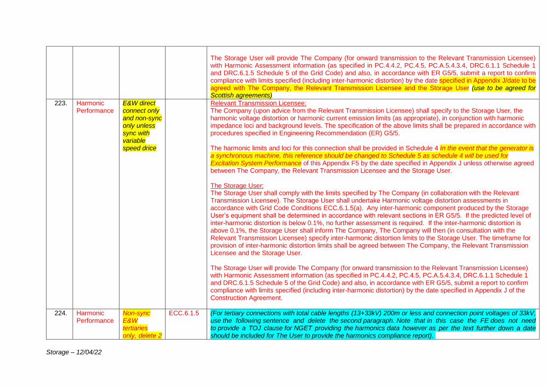
Storage – 12/04/22
The Storage User will provide The Company (for onward transmission to the Relevant Transmission Licensee) with Harmonic Assessment information (as specified in PC.4.4.2, PC.4.5, PC.A.5.4.3.4, DRC.6.1.1 Schedule 1 and DRC.6.1.5 Schedule 5 of the Grid Code) and also, in accordance with ER G5/5, submit a report to confirm compliance with limits specified (including inter-harmonic distortion) by the date specified in Appendix J/date to be agreed with The Company, the Relevant Transmission Licensee and the Storage User (use to be agreed for Scottish agreements)
223. Harmonic Performance
E&W direct connect only and non-sync only unless sync with variable speed drice
Relevant Transmission Licensee: The Company (upon advice from the Relevant Transmission Licensee) shall specify to the Storage User, the harmonic voltage distortion or harmonic current emission limits (as appropriate), in conjunction with harmonic impedance loci and background levels. The specification of the above limits shall be prepared in accordance with procedures specified in Engineering Recommendation (ER) G5/5. The harmonic limits and loci for this connection shall be provided in Schedule 4 In the event that the generator is a synchronous machine, this reference should be changed to Schedule 5 as schedule 4 will be used for Excitation System Performance of this Appendix F5 by the date specified in Appendix J unless otherwise agreed between The Company, the Relevant Transmission Licensee and the Storage User. The Storage User: The Storage User shall comply with the limits specified by The Company (in collaboration with the Relevant Transmission Licensee). The Storage User shall undertake Harmonic voltage distortion assessments in accordance with Grid Code Conditions ECC.6.1.5(a). Any inter-harmonic component produced by the Storage User’s equipment shall be determined in accordance with relevant sections in ER G5/5. If the predicted level of inter-harmonic distortion is below 0.1%, no further assessment is required. If the inter-harmonic distortion is above 0.1%, the Storage User shall inform The Company, The Company will then (in consultation with the Relevant Transmission Licensee) specify inter-harmonic distortion limits to the Storage User. The timeframe for provision of inter-harmonic distortion limits shall be agreed between The Company, the Relevant Transmission Licensee and the Storage User. The Storage User will provide The Company (for onward transmission to the Relevant Transmission Licensee) with Harmonic Assessment information (as specified in PC.4.4.2, PC.4.5, PC.A.5.4.3.4, DRC.6.1.1 Schedule 1 and DRC.6.1.5 Schedule 5 of the Grid Code) and also, in accordance with ER G5/5, submit a report to confirm compliance with limits specified (including inter-harmonic distortion) by the date specified in Appendix J of the Construction Agreement.
224. Harmonic Performance
Non-sync E&W tertiaries only, delete 2
ECC.6.1.5 (For tertiary connections with total cable lengths (13+33kV) 200m or less and connection point voltages of 33kV, use the following sentence and delete the second paragraph. Note that in this case the FE does not need to provide a TOJ clause for NGET providing the harmonics data however as per the text further down a date should be included for The User to provide the harmonics compliance report).
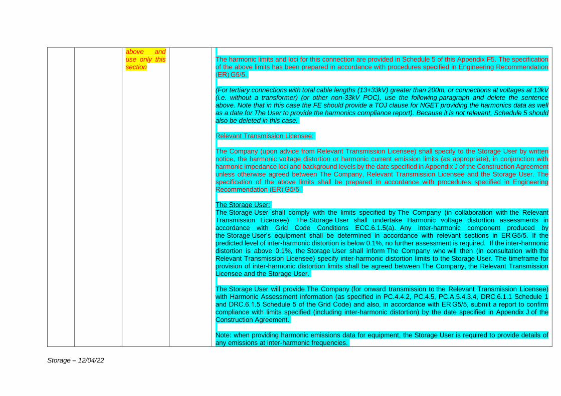
Storage – 12/04/22
above and use only this section
The harmonic limits and loci for this connection are provided in Schedule 5 of this Appendix F5. The specification of the above limits has been prepared in accordance with procedures specified in Engineering Recommendation (ER) G5/5. (For tertiary connections with total cable lengths (13+33kV) greater than 200m, or connections at voltages at 13kV (i.e. without a transformer) (or other non-33kV POC), use the following paragraph and delete the sentence above. Note that in this case the FE should provide a TOJ clause for NGET providing the harmonics data as well as a date for The User to provide the harmonics compliance report). Because it is not relevant, Schedule 5 should also be deleted in this case. Relevant Transmission Licensee: The Company (upon advice from Relevant Transmission Licensee) shall specify to the Storage User by written notice, the harmonic voltage distortion or harmonic current emission limits (as appropriate), in conjunction with harmonic impedance loci and background levels by the date specified in Appendix J of the Construction Agreement unless otherwise agreed between The Company, Relevant Transmission Licensee and the Storage User. The specification of the above limits shall be prepared in accordance with procedures specified in Engineering Recommendation (ER) G5/5. The Storage User: The Storage User shall comply with the limits specified by The Company (in collaboration with the Relevant Transmission Licensee). The Storage User shall undertake Harmonic voltage distortion assessments in accordance with Grid Code Conditions ECC.6.1.5(a). Any inter-harmonic component produced by the Storage User’s equipment shall be determined in accordance with relevant sections in ER G5/5. If the predicted level of inter-harmonic distortion is below 0.1%, no further assessment is required. If the inter-harmonic distortion is above 0.1%, the Storage User shall inform The Company who will then (in consultation with the Relevant Transmission Licensee) specify inter-harmonic distortion limits to the Storage User. The timeframe for provision of inter-harmonic distortion limits shall be agreed between The Company, the Relevant Transmission Licensee and the Storage User. The Storage User will provide The Company (for onward transmission to the Relevant Transmission Licensee) with Harmonic Assessment information (as specified in PC.4.4.2, PC.4.5, PC.A.5.4.3.4, DRC.6.1.1 Schedule 1 and DRC.6.1.5 Schedule 5 of the Grid Code) and also, in accordance with ER G5/5, submit a report to confirm compliance with limits specified (including inter-harmonic distortion) by the date specified in Appendix J of the Construction Agreement. Note: when providing harmonic emissions data for equipment, the Storage User is required to provide details of any emissions at inter-harmonic frequencies.
Storage – 12/04/22
If the Storage User subsequently notifies The Company and the Relevant Transmission Licensee of any changes to such data, The Company and the Relevant Transmission Licensee reserves the right to amend the limits and to issue revised limits to the Storage User following any revised Voltage Waveform Quality Assessment.
225. Paralleling Direct Connect only
The Storage User: To ensure there is no paralleling of The National Electricity Transmission System through the Storage User’s System.
226. Safety and Operational Interlocking
ALL The Storage User: Electrical and mechanical interlocking to be provided by the Storage User in accordance with TS.3.01.01_RES/SPTS/SHETS. (For GIS Ownership Boundary Connections delete the above and use the following:) The Relevant Transmission Licensee: To provide electrical and mechanical interlocking. Any additional requirements for safety and operational interlocking at the Grid Entry Point shall be agreed between the Storage User and the Relevant Transmission Licensee (via The Company in the detailed design phase). The Storage User: (if embedded, delete above and use this text) To agree electrical and mechanical interlocking with the Relevant Distribution Network Operator.
227. Earthing Facility
Predominantly Direct Connect. To be arranged with NO in Scotland. For embedded see last para. Use the cyan text for tertiaries.
The Relevant Transmission Licensee: To provide two point’s within its substation(s) to facilitate any bonding with the Storage User’s site if required. All earth mats on the Storage User site(s) and the Relevant Transmission Licensee’s site(s) where these are adjacent may be bonded together. The Relevant Transmission Licensee’s site earth mats can be bonded to the Storage User’s site earth mat. The Storage User: To carry out an earthing survey of their sites prior to construction of the Storage User’s Plant and Apparatus. The earthing system is to be designed to withstand a short circuit current of [XX kA for YY seconds] at [XXXX]kV substation. (63kA for 1 second at 400kV substations, 40kA for 1 second at 275kV substations and 40kA for 3 seconds at 132kV substations) (Note this will depend on connection voltage and TO area). (For a tertiary connection, delete the second sentence in the paragraph above, and include the below 2 paragraphs instead): Should the earth mat of the Storage User’s site be bonded to the earth mat of the Relevant Transmission Licensee site, then the earthing system is to be designed to withstand a short circuit current of [XX kA for YY seconds] at [XXXX]kV substation.
Storage – 12/04/22
If the earth mat of the Storage Users site is not bonded to the earth mat of the Relevant Transmission Licensee site, then the earthing system is to be designed to withstand a short circuit current of [25kA for 3 seconds at the 33kV substation.] (Verify rating with TOCO.) The Storage User shall ensure that its Plant and Apparatus is designed and installed such that the rise of earth potential (ROEP) at [XXXX] kV substation conforms to the touch, step and transfer voltage limits which are defined in ENA TS 41 – 24. Where intertripping (second main protection) is required to open circuit breakers, the overall fault clearance time shall not be more than [XXXX] ms at [XXXX] kV substations. 140ms at 400kV substations, 160ms at 275kV substations and 180ms at 132kV substations (Note this will depend on connection voltage). The Storage User’s earthing system design review shall take the Relevant Transmission Licensee’s earthing system design into account and the Storage User shall collaborate with the Relevant Transmission Licensee to ensure that compliance has been demonstrated at the Grid Entry Point which also mitigates 3rd party impact as required. The earthing system at [XXXX] kV substation shall be designed to comply with ESQCR 2002 and BS EN50522. (For GIS Ownership Boundary Connections delete the above and use the following:) The Relevant Transmission Licensee: All earth mats on the Storage User site(s) and the Relevant Transmission Licensee’s site(s) where these are adjacent may be bonded together. The Relevant Transmission Licensee’s site earth mats can be bonded to the Storage User’s site earth mat. The Relevant Transmission Licensee will provide two points within its substation to facilitate this bonding. Should any Storage User’s transformers be connected at the Grid Entry Point, these are to have Star connected HV windings with the star point solidly earthed. The Storage User: The Storage User shall provide details of its cable earthing design in the detailed design phase. The Relevant Transmission Licensee would expect that the Storage User cable earthing design shall be designed such that there shall be no risk resulting from transferred potential between these sites. The Storage User is to provide studies which demonstrate that under fault and normal operation, no interference to the Relevant Transmission Licensee or other interfacing Storage Users protection and control facilities at [XXXX] kV substation arise from the design of the Storage User’s earthing systems. The Storage User shall carry out an earthing survey of their sites prior to construction of the Storage User’s Plant and Apparatus. The earthing system is to be designed to withstand a short circuit current of [XX kA for YY seconds] at [XXXX]kV substation. (63 kA for 1 second at 400 kV substations, 40kA for 1 second at 275 kV substations and 40kA for 3 seconds at 132 kV substations) (Note this will depend on connection voltage).
Storage – 12/04/22
The Storage User shall ensure that its Plant and Apparatus is designed and installed such that the rise of earth potential (ROEP) at [XXXX]kV substation conforms to the touch, step and transfer voltage limits which are defined in ENA TS 41 – 24. Where intertripping is required to open circuit breakers, the overall fault clearance time shall not be more than [XXXX] ms at [XXXX] kV. 140ms at 400kV substations, 160ms at 275kV substations and 180ms at 132kV substations (Note this will depend on connection voltage). The Storage User’s earthing system design review shall take the Relevant Transmission Licensee’s earthing system design into account and the Storage User shall collaborate with the Relevant Transmission Licensee to ensure that compliance has been demonstrated at the Grid Entry Point and mitigation of 3rd party impact as required. It should also be noted that the earthing system at [XXXX] kV substation shall be designed to comply with ESQCR 2002 and BS EN50522. If Embedded (e.g. BEGAs, BELLAs, LEEMPs etc.) use this red text below and delete the above text: The Storage User: To agree the Earthing Requirements with the Relevant Distribution Network Operator and confirm to The Company prior to energisation. These shall be determined by the Storage User not to exceed statutory limits.
228. Cable Interfacing Arrangements
GIS Generator Connection Boundaries only where there is a cable connection
The Storage User: Shall declare to the Relevant Transmission Licensee the IEC cable specification they intend to employ. This will enable the Relevant Transmission Licensee to determine the switchgear requirements at the cable sealing end. Any additional requirements either on the cable or any switchgear relating to the cable sealing end shall be discussed and agreed with the Storage User in the detailed design phase.
229. Compliance Testing
All The Storage User: To demonstrate compliance with the requirements of the Grid Code.
230. Settlement Metering
All ECC.6.2.2.3.5
The Storage User: To provide CTs/VTs that comply with the relevant metering Code of Practice required for Settlement. To provide the Settlement Meters and register compliant items of Metering Equipment for Settlement purposes. All of the above to be completed prior to energisation and in accordance with the Balancing and Settlement Code (BSC). (for GIS Generator Connection Boundaries and Scottish direct connections (embedded Scottish use the above text) or if the customer has elected for the TO to install delete the above and use the following;) The Relevant Transmission Licensee:
Storage – 12/04/22
Will provide Current Transformers and Voltage Transformers that comply with the relevant metering Code of Practice required for Settlement under the Balancing and Settlement Code (BSC). The Storage User: Shall be responsible for the provision of the Settlement Meters and registering compliant items of Metering Equipment for Settlement purposes, in accordance with the BSC and related procedures, within the relevant timescales and prior to energisation of the circuit. The Storage User shall ensure that the Settlement Metering shall be compatible with all interfacing equipment installed by the Relevant Transmission Licensee at [XXXX]kV substation.
231. Loss of Mains Protection
Embedded only
The Storage User: If required by the host Distribution Network Operator, loss of mains protection to be provided by a means not susceptible to spurious or nuisance tripping. The Storage User to discuss and agree with The Company, the type, settings and philosophy used in any protection scheme.
232. Site Specific HV equipment requirements
Only to be included if circuit breaker ratings at site are close to the limit, In Scottish agreements this should only be included if specified in the TOCO.
The Storage User In view of the operating time assumptions and the generation concentrations around the connection site, an atypical circuit breaker capability specification may be required to ensure the Storage User’s equipment operates within its proven capability. All Storage User’s bay HV equipment needs to continue to conform to the RES noting that the studied DC component of fault duty upon the switchgear is such that a DC time constant of [XXXX] ms is observed at time of break, with fault levels at the connection site busbar now standing at [XXXX] kA RMS break for a single phase-ground fault. Any equipment installed needs to be rated to withstand levels observed in the planning studies. As a minimum the Storage User’s HV bay equipment shall be rated to match the Relevant Transmission Licensee’s existing (if there are known plans to uprate the substation or planned asset replacement works on site which will increase switchgear ratings include National Grid’s planned CB rating information) HV substation circuit breaker ratings. The Company’s existing substation equipment is rated to (TO to advise on the existing nominal substation switch gear ratings here -) [XXXX] kA RMS break for a three phase fault and - [XXXX] kA RMS single phase-ground break at a DC time constant of some [XXXX]ms.
233. Model Requirements and Dynamic performance and
All for power factory model but other study/model requirements for non-
ECC.6.1.9 ECC.6.1.10 ECC.6.3.17.1.5 (non-sync and direct
The Storage User: Is required to satisfy the requirements of PC.A.6.1.3 and ECC.6.3.17.1.5 and assist The Company to ensure compliance with ECC.6.1.9, ECC.6.1.10 (non-synchronous and direct connect only) Please note the following:
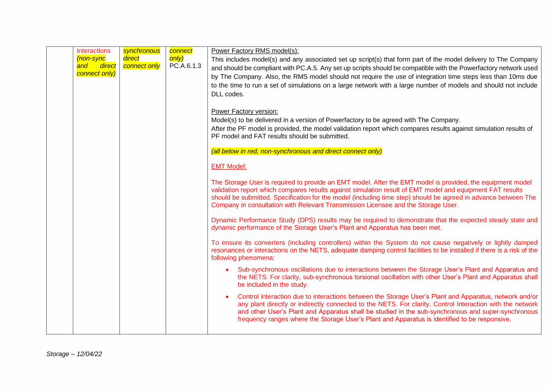
Storage – 12/04/22
Interactions (non-sync and direct connect only)
synchronous direct connect only
connect only) PC.A.6.1.3
Power Factory RMS model(s):
This includes model(s) and any associated set up script(s) that form part of the model delivery to The Company
and should be compliant with PC.A.5. Any set up scripts should be compatible with the Powerfactory network used
by The Company. Also, the RMS model should not require the use of integration time steps less than 10ms due
to the time to run a set of simulations on a large network with a large number of models and should not include
DLL codes.
Power Factory version:
Model(s) to be delivered in a version of Powerfactory to be agreed with The Company.
After the PF model is provided, the model validation report which compares results against simulation results of PF model and FAT results should be submitted. (all below in red, non-synchronous and direct connect only) EMT Model:
The Storage User is required to provide an EMT model. After the EMT model is provided, the equipment model validation report which compares results against simulation result of EMT model and equipment FAT results should be submitted. Specification for the model (including time step) should be agreed in advance between The Company in consultation with Relevant Transmission Licensee and the Storage User. Dynamic Performance Study (DPS) results may be required to demonstrate that the expected steady state and dynamic performance of the Storage User’s Plant and Apparatus has been met. To ensure its converters (including controllers) within the System do not cause negatively or lightly damped resonances or interactions on the NETS, adequate damping control facilities to be installed if there is a risk of the following phenomena:
• Sub-synchronous oscillations due to interactions between the Storage User’s Plant and Apparatus and the NETS. For clarity, sub-synchronous torsional oscillation with other User’s Plant and Apparatus shall be included in the study.
• Control interaction due to interactions between the Storage User’s Plant and Apparatus, network and/or any plant directly or indirectly connected to the NETS. For clarity, Control Interaction with the network and other User’s Plant and Apparatus shall be studied in the sub-synchronous and super-synchronous frequency ranges where the Storage User’s Plant and Apparatus is identified to be responsive.
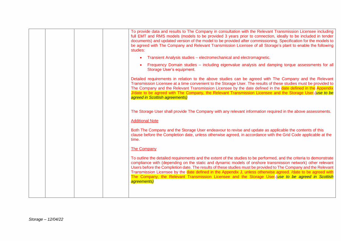
Storage – 12/04/22
To provide data and results to The Company in consultation with the Relevant Transmission Licensee including full EMT and RMS models (models to be provided 3 years prior to connection, ideally to be included in tender documents) and updated version of the model to be provided after commissioning. Specification for the models to be agreed with The Company and Relevant Transmission Licensee of all Storage’s plant to enable the following studies:
• Transient Analysis studies – electromechanical and electromagnetic.
• Frequency Domain studies – including eigenvalue analysis and damping torque assessments for all Storage User’s equipment.
Detailed requirements in relation to the above studies can be agreed with The Company and the Relevant Transmission Licensee at a time convenient to the Storage User. The results of these studies must be provided to The Company and the Relevant Transmission Licensee by the date defined in the date defined in the Appendix J/date to be agreed with The Company, the Relevant Transmission Licensee and the Storage User.(use to be agreed in Scottish agreements) The Storage User shall provide The Company with any relevant information required in the above assessments. Additional Note Both The Company and the Storage User endeavour to revise and update as applicable the contents of this clause before the Completion date, unless otherwise agreed, in accordance with the Grid Code applicable at the time. The Company To outline the detailed requirements and the extent of the studies to be performed, and the criteria to demonstrate compliance with (depending on the static and dynamic models of onshore transmission network) other relevant Users before the Completion date. The results of these studies must be provided to The Company and the Relevant Transmission Licensee by the date defined in the Appendix J, unless otherwise agreed. /date to be agreed with The Company, the Relevant Transmission Licensee and the Storage User.(use to be agreed in Scottish agreements)
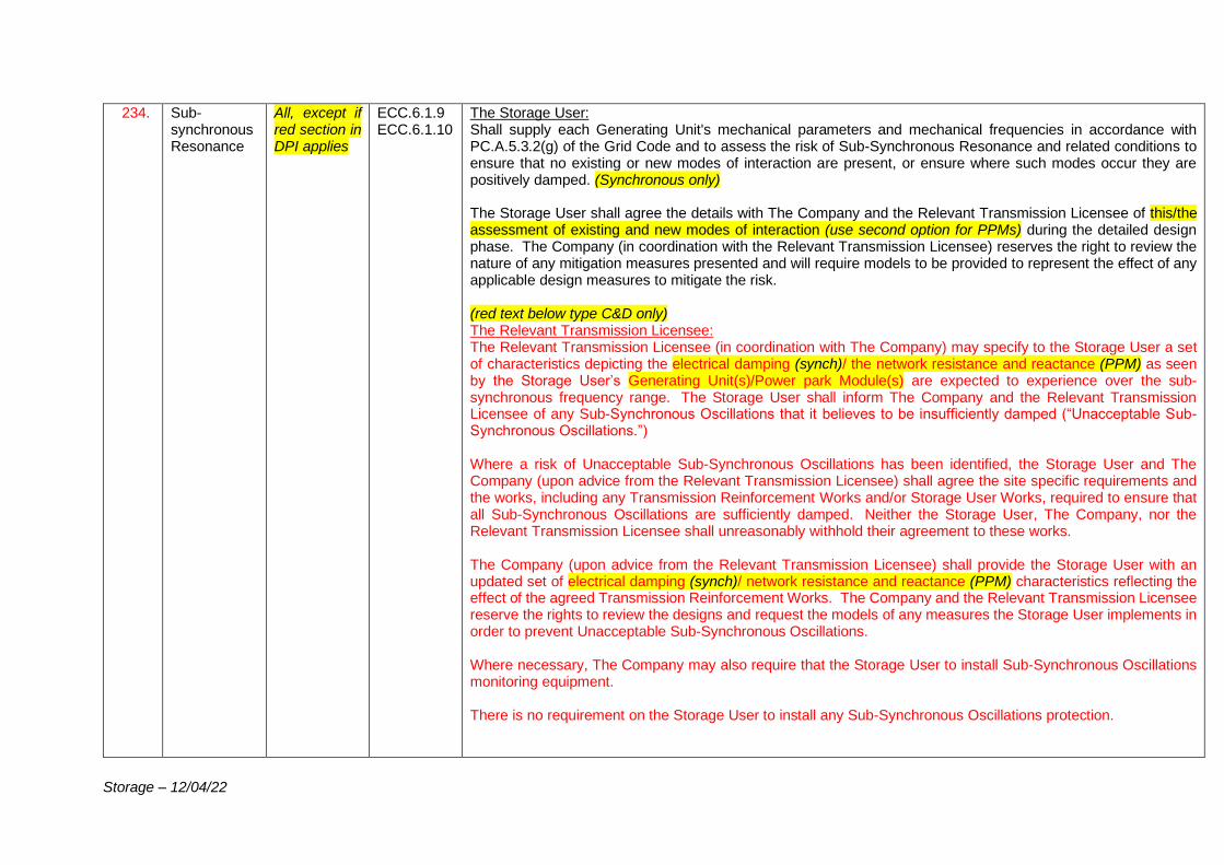
Storage – 12/04/22
234. Sub-synchronous Resonance
All, except if red section in DPI applies
ECC.6.1.9 ECC.6.1.10
The Storage User: Shall supply each Generating Unit's mechanical parameters and mechanical frequencies in accordance with PC.A.5.3.2(g) of the Grid Code and to assess the risk of Sub-Synchronous Resonance and related conditions to ensure that no existing or new modes of interaction are present, or ensure where such modes occur they are positively damped. (Synchronous only) The Storage User shall agree the details with The Company and the Relevant Transmission Licensee of this/the assessment of existing and new modes of interaction (use second option for PPMs) during the detailed design phase. The Company (in coordination with the Relevant Transmission Licensee) reserves the right to review the nature of any mitigation measures presented and will require models to be provided to represent the effect of any applicable design measures to mitigate the risk. (red text below type C&D only) The Relevant Transmission Licensee: The Relevant Transmission Licensee (in coordination with The Company) may specify to the Storage User a set of characteristics depicting the electrical damping (synch)/ the network resistance and reactance (PPM) as seen by the Storage User’s Generating Unit(s)/Power park Module(s) are expected to experience over the sub-synchronous frequency range. The Storage User shall inform The Company and the Relevant Transmission Licensee of any Sub-Synchronous Oscillations that it believes to be insufficiently damped (“Unacceptable Sub-Synchronous Oscillations.”) Where a risk of Unacceptable Sub-Synchronous Oscillations has been identified, the Storage User and The Company (upon advice from the Relevant Transmission Licensee) shall agree the site specific requirements and the works, including any Transmission Reinforcement Works and/or Storage User Works, required to ensure that all Sub-Synchronous Oscillations are sufficiently damped. Neither the Storage User, The Company, nor the Relevant Transmission Licensee shall unreasonably withhold their agreement to these works. The Company (upon advice from the Relevant Transmission Licensee) shall provide the Storage User with an updated set of electrical damping (synch)/ network resistance and reactance (PPM) characteristics reflecting the effect of the agreed Transmission Reinforcement Works. The Company and the Relevant Transmission Licensee reserve the rights to review the designs and request the models of any measures the Storage User implements in order to prevent Unacceptable Sub-Synchronous Oscillations. Where necessary, The Company may also require that the Storage User to install Sub-Synchronous Oscillations monitoring equipment. There is no requirement on the Storage User to install any Sub-Synchronous Oscillations protection.
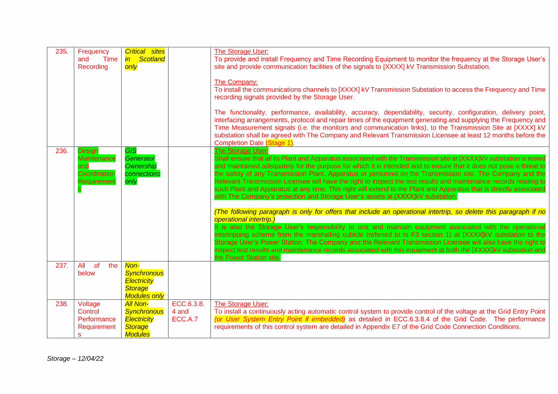
Storage – 12/04/22
235. Frequency and Time Recording
Critical sites in Scotland only
The Storage User: To provide and install Frequency and Time Recording Equipment to monitor the frequency at the Storage User’s site and provide communication facilities of the signals to [XXXX] kV Transmission Substation. The Company: To install the communications channels to [XXXX] kV Transmission Substation to access the Frequency and Time recording signals provided by the Storage User. The functionality, performance, availability, accuracy, dependability, security, configuration, delivery point, interfacing arrangements, protocol and repair times of the equipment generating and supplying the Frequency and Time Measurement signals (i.e. the monitors and communication links), to the Transmission Site at [XXXX] kV substation shall be agreed with The Company and Relevant Transmission Licensee at least 12 months before the Completion Date (Stage 1).
236. Design Maintenance and Coordination Requirements
GIS Generator Ownership connections only
The Storage User: Shall ensure that all its Plant and Apparatus associated with the Transmission site at [XXXX]kV substation is tested and maintained adequately for the purpose for which it is intended and to ensure that it does not pose a threat to the safety of any Transmission Plant, Apparatus or personnel on the Transmission site. The Company and the Relevant Transmission Licensee will have the right to inspect the test results and maintenance records relating to such Plant and Apparatus at any time. This right will extend to the Plant and Apparatus that is directly associated with The Company’s protection and Storage User’s assets at [XXXX]kV substation. (The following paragraph is only for offers that include an operational intertrip, so delete this paragraph if no operational intertrip.) It is also the Storage User’s responsibility to test and maintain equipment associated with the operational intertripping scheme from the marshalling cubicle (referred to in F3 section 1) at [XXXX[kV substation to the Storage User’s Power Station. The Company and the Relevant Transmission Licensee will also have the right to inspect test results and maintenance records associated with this equipment at both the [XXXX]kV substation and the Power Station site.
237. All of the below
Non- Synchronous Electricity Storage Modules only
238. Voltage Control Performance Requirements
All Non-Synchronous Electricity Storage Modules
ECC.6.3.8.4 and ECC.A.7
The Storage User: To install a continuously acting automatic control system to provide control of the voltage at the Grid Entry Point (or User System Entry Point if embedded) as detailed in ECC.6.3.8.4 of the Grid Code. The performance requirements of this control system are detailed in Appendix E7 of the Grid Code Connection Conditions.
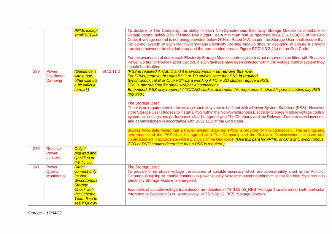
Storage – 12/04/22
PPMs except small BEGAs
To declare to The Company, the ability of each Non-Synchronous Electricity Storage Module to contribute to voltage control below 20% of Rated MW output. As a minimum and as specified in ECC.6.3.8(a)(iii) of the Grid Code, if voltage control is not being provided below 20% of Rated MW output, the Storage User shall ensure that the control system of each Non-Synchronous Electricity Storage Module shall be designed to ensure a smooth transition between the shaded area and the non-shaded area in Figure ECC.6.3.2.4(c) of the Grid Code. For the avoidance of doubt each Electricity Storage Module control system is not required to be fitted with Reactive Power Control or Power Factor Control. If such facilities have been installed within the voltage control system they should be disabled.
239. Power Oscillation Damping
(Guidance is within box, otherwise it’s a bit difficult to read.)
BC.2.11.2 (PSS is required if: Cat. D and it is synchronous – so remove this row. For PPMs, remove this para if SO or TO studies state that PSS is required. Synchronous cat B or C, use 2nd para wording if TO or SO studies require a PSS. PSS is not required for small size/cat A connections. Embedded: PSS only required if TO/DNO studies determine this requirement. Use 2nd para if studies say PSS required.) The Storage User: There is no requirement for the voltage control system to be fitted with a Power System Stabiliser (PSS). However if the Storage User chooses to install a PSS within the Non-Synchronous Electricity Storage Module voltage control system, its settings and performance shall be agreed with The Company and the Relevant Transmission Licensee, and commissioned in accordance with BC.2.11.2 of the Grid Code. Studies have determined that a Power System Stabiliser (PSS) is required for this connection. The settings and performance of the PSS shall be agreed with The Company and the Relevant Transmission Licensee and commissioned in accordance with BC.2.11.2 of the Grid Code. (Use this para for PPMs, or cat B or C synchronous, if TO or DNO studies determine that a PSS is required.)
240. Reactive Power Limiters
Only if required and specified in the TOCO.
241. Power Quality Monitoring
Direct connect only for Non-Synchronous Storage Check with the Scheme Team Rep to see if Quality
The Storage User: To provide three phase voltage transducers of suitable accuracy which are appropriately sited at the Point of Common Coupling to enable continuous power quality voltage monitoring whether or not the Non-Synchronous Electricity Storage Module is energised. Examples of suitable voltage transducers are detailed in TS 3.02.05_RES “Voltage Transformers” (with particular reference to Section 1.3) or, alternatively, in TS 3.02.12_RES “Voltage Dividers.”
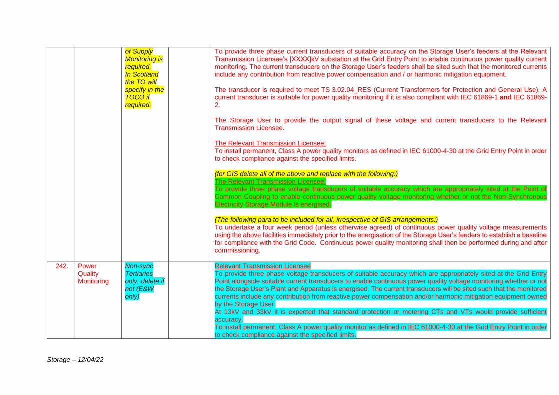
Storage – 12/04/22
of Supply Monitoring is required. In Scotland the TO will specify in the TOCO if required.
To provide three phase current transducers of suitable accuracy on the Storage User’s feeders at the Relevant Transmission Licensee’s [XXXX]kV substation at the Grid Entry Point to enable continuous power quality current monitoring. The current transducers on the Storage User’s feeders shall be sited such that the monitored currents include any contribution from reactive power compensation and / or harmonic mitigation equipment. The transducer is required to meet TS 3.02.04_RES (Current Transformers for Protection and General Use). A current transducer is suitable for power quality monitoring if it is also compliant with IEC 61869-1 and IEC 61869-2. The Storage User to provide the output signal of these voltage and current transducers to the Relevant Transmission Licensee. The Relevant Transmission Licensee: To install permanent, Class A power quality monitors as defined in IEC 61000-4-30 at the Grid Entry Point in order to check compliance against the specified limits. (for GIS delete all of the above and replace with the following:) The Relevant Transmission Licensee: To provide three phase voltage transducers of suitable accuracy which are appropriately sited at the Point of Common Coupling to enable continuous power quality voltage monitoring whether or not the Non-Synchronous Electricity Storage Module is energised. (The following para to be included for all, irrespective of GIS arrangements:) To undertake a four week period (unless otherwise agreed) of continuous power quality voltage measurements using the above facilities immediately prior to the energisation of the Storage User’s feeders to establish a baseline for compliance with the Grid Code. Continuous power quality monitoring shall then be performed during and after commissioning.
242. Power Quality Monitoring
Non-sync Tertiaries only, delete if not (E&W only)
Relevant Transmission Licensee To provide three phase voltage transducers of suitable accuracy which are appropriately sited at the Grid Entry Point alongside suitable current transducers to enable continuous power quality voltage monitoring whether or not the Storage User’s Plant and Apparatus is energised. The current transducers will be sited such that the monitored currents include any contribution from reactive power compensation and/or harmonic mitigation equipment owned by the Storage User. At 13kV and 33kV it is expected that standard protection or metering CTs and VTs would provide sufficient accuracy. To install permanent, Class A power quality monitor as defined in IEC 61000-4-30 at the Grid Entry Point in order to check compliance against the specified limits.
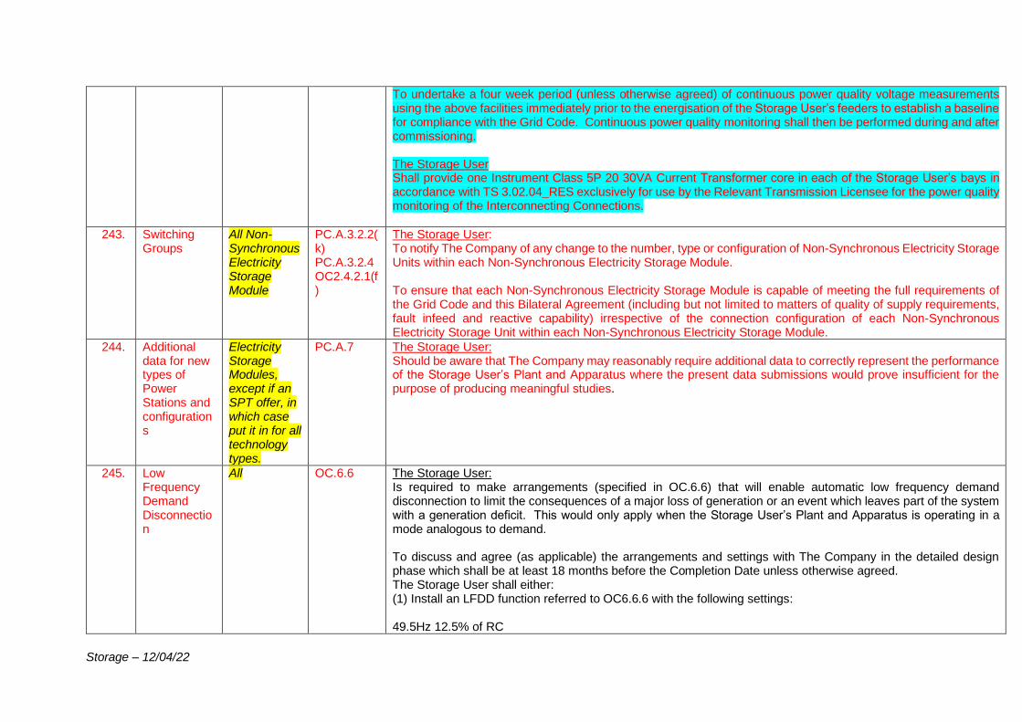
Storage – 12/04/22
To undertake a four week period (unless otherwise agreed) of continuous power quality voltage measurements using the above facilities immediately prior to the energisation of the Storage User’s feeders to establish a baseline for compliance with the Grid Code. Continuous power quality monitoring shall then be performed during and after commissioning. The Storage User Shall provide one Instrument Class 5P 20 30VA Current Transformer core in each of the Storage User’s bays in accordance with TS 3.02.04_RES exclusively for use by the Relevant Transmission Licensee for the power quality monitoring of the Interconnecting Connections.
243. Switching Groups
All Non-Synchronous Electricity Storage Module
PC.A.3.2.2(k) PC.A.3.2.4 OC2.4.2.1(f)
The Storage User: To notify The Company of any change to the number, type or configuration of Non-Synchronous Electricity Storage Units within each Non-Synchronous Electricity Storage Module. To ensure that each Non-Synchronous Electricity Storage Module is capable of meeting the full requirements of the Grid Code and this Bilateral Agreement (including but not limited to matters of quality of supply requirements, fault infeed and reactive capability) irrespective of the connection configuration of each Non-Synchronous Electricity Storage Unit within each Non-Synchronous Electricity Storage Module.
244. Additional data for new types of Power Stations and configurations
Electricity Storage Modules, except if an SPT offer, in which case put it in for all technology types.
PC.A.7 The Storage User: Should be aware that The Company may reasonably require additional data to correctly represent the performance of the Storage User’s Plant and Apparatus where the present data submissions would prove insufficient for the purpose of producing meaningful studies.
245. Low Frequency Demand Disconnection
All OC.6.6 The Storage User: Is required to make arrangements (specified in OC.6.6) that will enable automatic low frequency demand disconnection to limit the consequences of a major loss of generation or an event which leaves part of the system with a generation deficit. This would only apply when the Storage User’s Plant and Apparatus is operating in a mode analogous to demand. To discuss and agree (as applicable) the arrangements and settings with The Company in the detailed design phase which shall be at least 18 months before the Completion Date unless otherwise agreed. The Storage User shall either: (1) Install an LFDD function referred to OC6.6.6 with the following settings: 49.5Hz 12.5% of RC
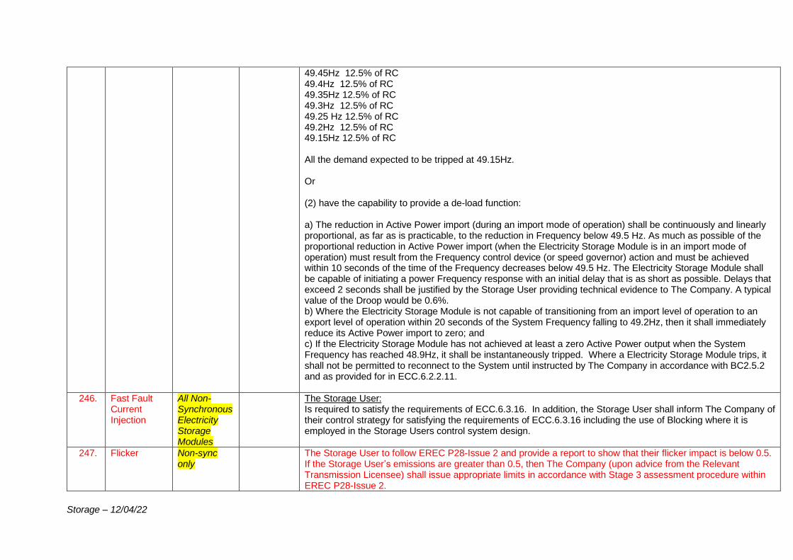
Storage – 12/04/22
49.45Hz 12.5% of RC 49.4Hz 12.5% of RC 49.35Hz 12.5% of RC 49.3Hz 12.5% of RC 49.25 Hz 12.5% of RC 49.2Hz 12.5% of RC 49.15Hz 12.5% of RC All the demand expected to be tripped at 49.15Hz. Or (2) have the capability to provide a de-load function: a) The reduction in Active Power import (during an import mode of operation) shall be continuously and linearly proportional, as far as is practicable, to the reduction in Frequency below 49.5 Hz. As much as possible of the proportional reduction in Active Power import (when the Electricity Storage Module is in an import mode of operation) must result from the Frequency control device (or speed governor) action and must be achieved within 10 seconds of the time of the Frequency decreases below 49.5 Hz. The Electricity Storage Module shall be capable of initiating a power Frequency response with an initial delay that is as short as possible. Delays that exceed 2 seconds shall be justified by the Storage User providing technical evidence to The Company. A typical value of the Droop would be 0.6%. b) Where the Electricity Storage Module is not capable of transitioning from an import level of operation to an export level of operation within 20 seconds of the System Frequency falling to 49.2Hz, then it shall immediately reduce its Active Power import to zero; and c) If the Electricity Storage Module has not achieved at least a zero Active Power output when the System Frequency has reached 48.9Hz, it shall be instantaneously tripped. Where a Electricity Storage Module trips, it shall not be permitted to reconnect to the System until instructed by The Company in accordance with BC2.5.2 and as provided for in ECC.6.2.2.11.
246. Fast Fault Current Injection
All Non-Synchronous Electricity Storage Modules
The Storage User: Is required to satisfy the requirements of ECC.6.3.16. In addition, the Storage User shall inform The Company of their control strategy for satisfying the requirements of ECC.6.3.16 including the use of Blocking where it is employed in the Storage Users control system design.
247. Flicker Non-sync only
The Storage User to follow EREC P28-Issue 2 and provide a report to show that their flicker impact is below 0.5. If the Storage User’s emissions are greater than 0.5, then The Company (upon advice from the Relevant Transmission Licensee) shall issue appropriate limits in accordance with Stage 3 assessment procedure within EREC P28-Issue 2.
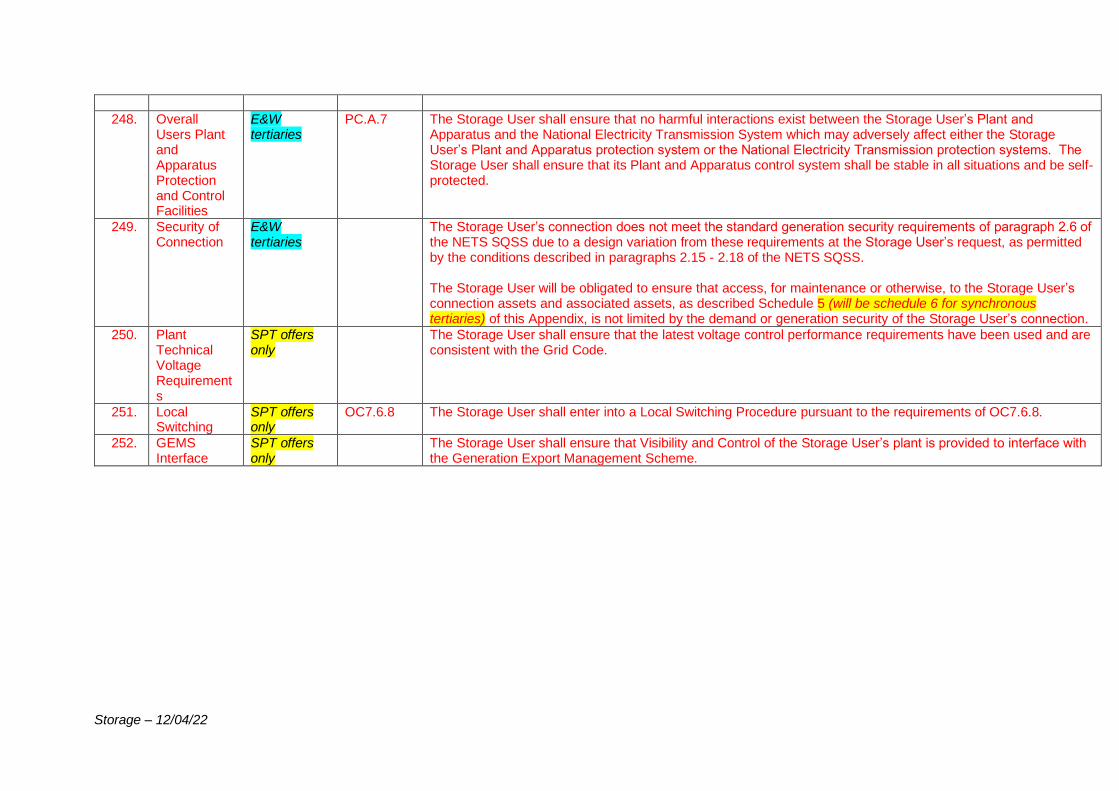
Storage – 12/04/22
248. Overall Users Plant and Apparatus Protection and Control Facilities
E&W tertiaries
PC.A.7 The Storage User shall ensure that no harmful interactions exist between the Storage User’s Plant and Apparatus and the National Electricity Transmission System which may adversely affect either the Storage User’s Plant and Apparatus protection system or the National Electricity Transmission protection systems. The Storage User shall ensure that its Plant and Apparatus control system shall be stable in all situations and be self-protected.
249. Security of Connection
E&W tertiaries
The Storage User’s connection does not meet the standard generation security requirements of paragraph 2.6 of the NETS SQSS due to a design variation from these requirements at the Storage User’s request, as permitted by the conditions described in paragraphs 2.15 - 2.18 of the NETS SQSS. The Storage User will be obligated to ensure that access, for maintenance or otherwise, to the Storage User’s connection assets and associated assets, as described Schedule 5 (will be schedule 6 for synchronous tertiaries) of this Appendix, is not limited by the demand or generation security of the Storage User’s connection.
250. Plant Technical Voltage Requirements
SPT offers only
The Storage User shall ensure that the latest voltage control performance requirements have been used and are consistent with the Grid Code.
251. Local Switching
SPT offers only
OC7.6.8 The Storage User shall enter into a Local Switching Procedure pursuant to the requirements of OC7.6.8.
252. GEMS Interface
SPT offers only
The Storage User shall ensure that Visibility and Control of the Storage User’s plant is provided to interface with the Generation Export Management Scheme.

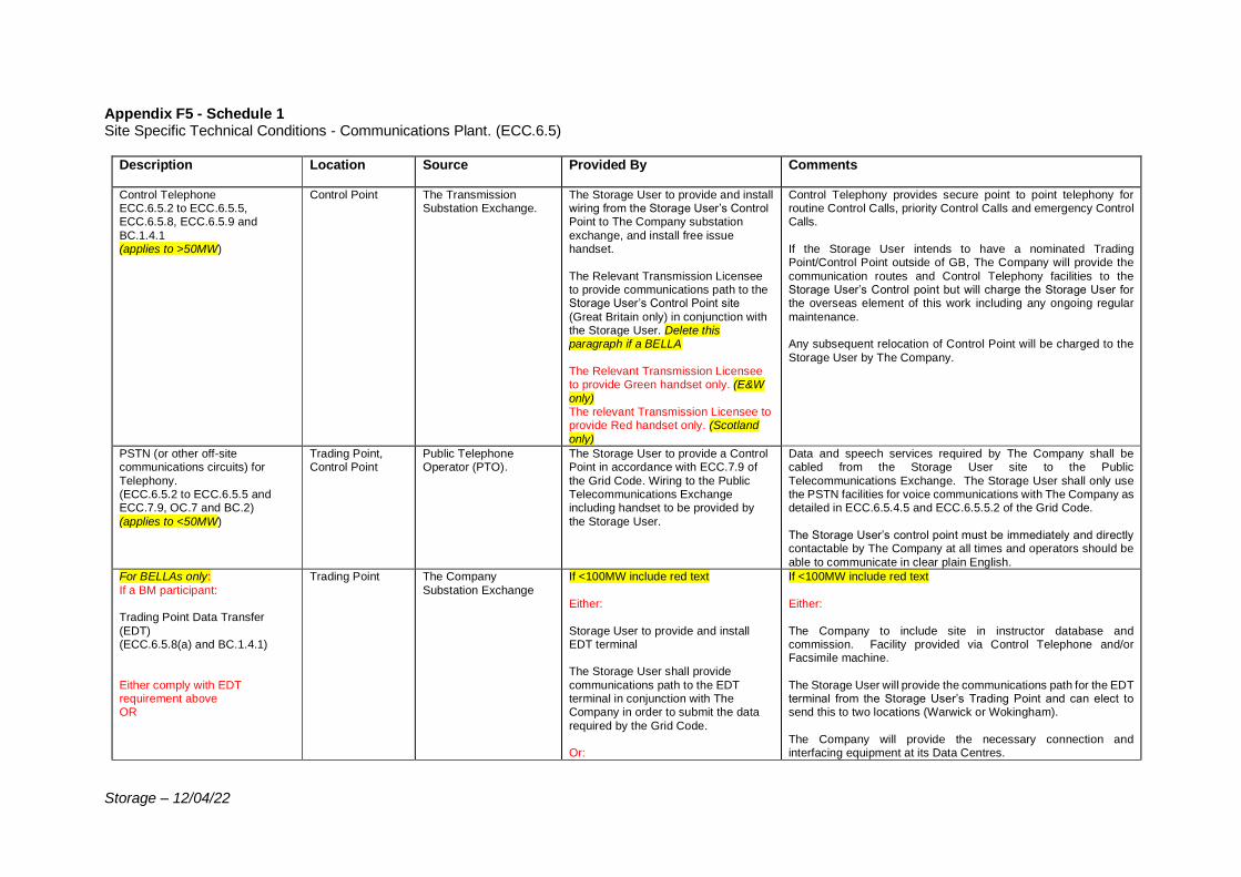
Storage – 12/04/22
Appendix F5 - Schedule 1 Site Specific Technical Conditions - Communications Plant. (ECC.6.5)
Description Location Source Provided By Comments
Control Telephone ECC.6.5.2 to ECC.6.5.5, ECC.6.5.8, ECC.6.5.9 and
BC.1.4.1 (applies to >50MW)
Control Point The Transmission Substation Exchange.
The Storage User to provide and install wiring from the Storage User’s Control Point to The Company substation
exchange, and install free issue handset.
The Relevant Transmission Licensee to provide communications path to the Storage User’s Control Point site
(Great Britain only) in conjunction with the Storage User. Delete this paragraph if a BELLA
The Relevant Transmission Licensee to provide Green handset only. (E&W
only) The relevant Transmission Licensee to provide Red handset only. (Scotland
only)
Control Telephony provides secure point to point telephony for routine Control Calls, priority Control Calls and emergency Control Calls.
If the Storage User intends to have a nominated Trading Point/Control Point outside of GB, The Company will provide the
communication routes and Control Telephony facilities to the Storage User’s Control point but will charge the Storage User for the overseas element of this work including any ongoing regular
maintenance. Any subsequent relocation of Control Point will be charged to the
Storage User by The Company.
PSTN (or other off-site communications circuits) for
Telephony. (ECC.6.5.2 to ECC.6.5.5 and ECC.7.9, OC.7 and BC.2)
(applies to <50MW)
Trading Point, Control Point
Public Telephone Operator (PTO).
The Storage User to provide a Control Point in accordance with ECC.7.9 of
the Grid Code. Wiring to the Public Telecommunications Exchange including handset to be provided by
the Storage User.
Data and speech services required by The Company shall be cabled from the Storage User site to the Public
Telecommunications Exchange. The Storage User shall only use the PSTN facilities for voice communications with The Company as detailed in ECC.6.5.4.5 and ECC.6.5.5.2 of the Grid Code.
The Storage User’s control point must be immediately and directly contactable by The Company at all times and operators should be
able to communicate in clear plain English.
For BELLAs only:
If a BM participant: Trading Point Data Transfer
(EDT) (ECC.6.5.8(a) and BC.1.4.1)
Either comply with EDT requirement above OR
Trading Point The Company
Substation Exchange
If <100MW include red text
Either:
Storage User to provide and install EDT terminal The Storage User shall provide
communications path to the EDT terminal in conjunction with The Company in order to submit the data
required by the Grid Code. Or:
If <100MW include red text
Either:
The Company to include site in instructor database and commission. Facility provided via Control Telephone and/or Facsimile machine.
The Storage User will provide the communications path for the EDT terminal from the Storage User’s Trading Point and can elect to send this to two locations (Warwick or Wokingham).
The Company will provide the necessary connection and interfacing equipment at its Data Centres.
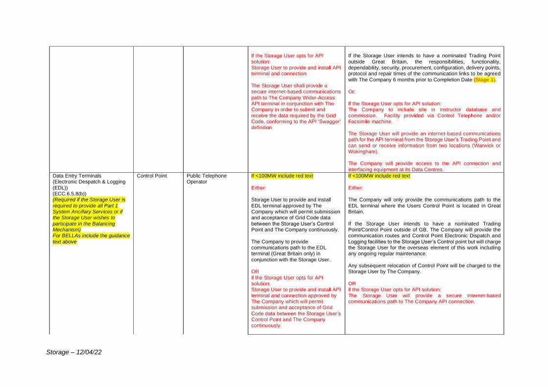
Storage – 12/04/22
If the Storage User opts for API
solution: Storage User to provide and install API terminal and connection
The Storage User shall provide a secure internet-based communications
path to The Company Wider-Access API terminal in conjunction with The Company in order to submit and
receive the data required by the Grid Code, conforming to the API ‘Swagger’ definition
If the Storage User intends to have a nominated Trading Point
outside Great Britain, the responsibilities, functionality, dependability, security, procurement, configuration, delivery points, protocol and repair times of the communication links to be agreed
with The Company 6 months prior to Completion Date (Stage 1). Or:
If the Storage User opts for API solution: The Company to include site in instructor database and
commission. Facility provided via Control Telephone and/or Facsimile machine.
The Storage User will provide an internet-based communications path for the API terminal from the Storage User’s Trading Point and can send or receive information from two locations (Warwick or
Wokingham). The Company will provide access to the API connection and
interfacing equipment at its Data Centres.
Data Entry Terminals (Electronic Despatch & Logging
(EDL)) (ECC.6.5.8(b)) (Required if the Storage User is
required to provide all Part 1 System Ancillary Services or if the Storage User wishes to
participate in the Balancing Mechanism) For BELLAs include the guidance
text above
Control Point Public Telephone Operator
If <100MW include red text
Either: Storage User to provide and install
EDL terminal approved by The Company which will permit submission and acceptance of Grid Code data
between the Storage User’s Control Point and The Company continuously.
The Company to provide communications path to the EDL terminal (Great Britain only) in
conjunction with the Storage User. OR
if the Storage User opts for API solution: Storage User to provide and install API
terminal and connection approved by The Company which will permit submission and acceptance of Grid
Code data between the Storage User’s Control Point and The Company continuously.
If <100MW include red text
Either: The Company will only provide the communications path to the
EDL terminal where the Users Control Point is located in Great Britain.
If the Storage User intends to have a nominated Trading Point/Control Point outside of GB, The Company will provide the communication routes and Control Point Electronic Dispatch and
Logging facilities to the Storage User’s Control point but will charge the Storage User for the overseas element of this work including any ongoing regular maintenance.
Any subsequent relocation of Control Point will be charged to the Storage User by The Company.
OR if the Storage User opts for API solution:
The Storage User will provide a secure internet-based communications path to The Company API connection.
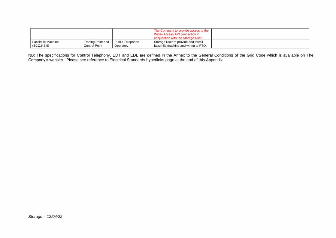
Storage – 12/04/22
The Company to provide access to the Wider-Access API connection in
conjunction with the Storage User.
Facsimile Machine
(ECC.6.5.9)
Trading Point and
Control Point
Public Telephone
Operator.
Storage User to provide and install
facsimile machine and wiring to PTO.
NB: The specifications for Control Telephony, EDT and EDL are defined in the Annex to the General Conditions of the Grid Code which is available on The Company’s website. Please see reference to Electrical Standards hyperlinks page at the end of this Appendix.
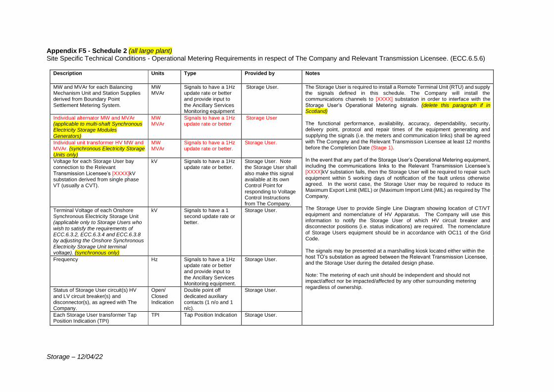
Storage – 12/04/22
Appendix F5 - Schedule 2 (all large plant) Site Specific Technical Conditions - Operational Metering Requirements in respect of The Company and Relevant Transmission Licensee. (ECC.6.5.6)
Description Units Type Provided by Notes
MW and MVAr for each Balancing Mechanism Unit and Station Supplies derived from Boundary Point
Settlement Metering System.
MW MVAr
Signals to have a 1Hz update rate or better and provide input to
the Ancillary Services Monitoring equipment
Storage User. The Storage User is required to install a Remote Terminal Unit (RTU) and supply the signals defined in this schedule. The Company will install the communications channels to [XXXX] substation in order to interface with the
Storage User’s Operational Metering signals. (delete this paragraph if in Scotland)
The functional performance, availability, accuracy, dependability, security, delivery point, protocol and repair times of the equipment generating and supplying the signals (i.e. the meters and communication links) shall be agreed
with The Company and the Relevant Transmission Licensee at least 12 months before the Completion Date (Stage 1).
In the event that any part of the Storage User’s Operational Metering equipment, including the communications links to the Relevant Transmission Licensee’s [XXXX]kV substation fails, then the Storage User will be required to repair such
equipment within 5 working days of notification of the fault unless otherwise agreed. In the worst case, the Storage User may be required to reduce its Maximum Export Limit (MEL) or (Maximum Import Limit (MIL) as required by The
Company. The Storage User to provide Single Line Diagram showing location of CT/VT
equipment and nomenclature of HV Apparatus. The Company will use this information to notify the Storage User of which HV circuit breaker and disconnector positions (i.e. status indications) are required. The nomenclature
of Storage Users equipment should be in accordance with OC11 of the Grid Code.
The signals may be presented at a marshalling kiosk located either within the host TO’s substation as agreed between the Relevant Transmission Licensee, and the Storage User during the detailed design phase.
Note: The metering of each unit should be independent and should not impact/affect nor be impacted/affected by any other surrounding metering
regardless of ownership.
Individual alternator MW and MVAr (applicable to multi-shaft Synchronous Electricity Storage Modules
Generators)
MW MVAr
Signals to have a 1Hz update rate or better
Storage User
Individual unit transformer HV MW and MVAr. (synchronous Electricity Storage
Units only)
MW MVAr
Signals to have a 1Hz update rate or better.
Storage User.
Voltage for each Storage User bay connection to the Relevant
Transmission Licensee’s [XXXX]kV substation derived from single phase VT (usually a CVT).
kV Signals to have a 1Hz update rate or better.
Storage User. Note the Storage User shall
also make this signal available at its own Control Point for
responding to Voltage Control Instructions from The Company.
Terminal Voltage of each Onshore Synchronous Electricity Storage Unit (applicable only to Storage Users who
wish to satisfy the requirements of ECC.6.3.2, ECC.6.3.4 and ECC.6.3.8 by adjusting the Onshore Synchronous
Electricity Storage Unit terminal voltage). (synchronous only)
kV Signals to have a 1 second update rate or better.
Storage User.
Frequency Hz Signals to have a 1Hz update rate or better and provide input to
the Ancillary Services Monitoring equipment.
Storage User.
Status of Storage User circuit(s) HV
and LV circuit breaker(s) and disconnector(s), as agreed with The Company.
Open/
Closed Indication
Double point off
dedicated auxiliary contacts (1 n/o and 1 n/c).
Storage User.
Each Storage User transformer Tap Position Indication (TPI)
TPI Tap Position Indication Storage User.
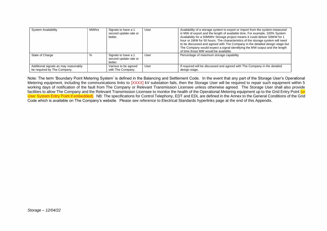
Storage – 12/04/22
System Availability MWhrs Signals to have a 1 second update rate or
better.
User Availability of a storage system to export or import from the system measured in MW of export and the length of available time. For example, 100% System
Availability for a 50MWhr Storage project means it could deliver 50MW for 1 hour or 1MW for 50 hours. The characteristics of the storage system will need to be discussed and agreed with The Company in the detailed design stage but
The Company would expect a signal identifying the MW output and the length of time those MW would be available.
State of Charge % Signals to have a 1 second update rate or better.
User Percentage of maximum storage capability
Additional signals as may reasonably be required by The Company.
Various to be agreed with The Company.
User If required will be discussed and agreed with The Company in the detailed design stage.
Note: The term ‘Boundary Point Metering System’ is defined in the Balancing and Settlement Code. In the event that any part of the Storage User’s Operational Metering equipment, including the communications links to [XXXX] kV substation fails, then the Storage User will be required to repair such equipment within 5 working days of notification of the fault from The Company or Relevant Transmission Licensee unless otherwise agreed. The Storage User shall also provide facilities to allow The Company and the Relevant Transmission Licensee to monitor the health of the Operational Metering equipment up to the Grid Entry Point (or User System Entry Point if embedded). NB: The specifications for Control Telephony, EDT and EDL are defined in the Annex to the General Conditions of the Grid Code which is available on The Company’s website. Please see reference to Electrical Standards hyperlinks page at the end of this Appendix.
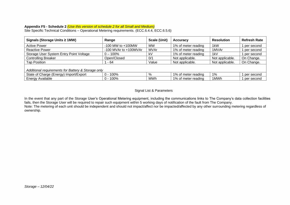
Storage – 12/04/22
Appendix F5 - Schedule 2 (Use this version of schedule 2 for all Small and Medium) Site Specific Technical Conditions – Operational Metering requirements. (ECC.6.4.4, ECC.6.5.6)
Signals (Storage Units ≥ 1MW) Range Scale (Unit) Accuracy Resolution Refresh Rate
Active Power -100 MW to +100MW MW 1% of meter reading 1kW 1 per second
Reactive Power -100 MVAr to +100MVAr MVAr 1% of meter reading 1MVAr 1 per second
Storage User System Entry Point Voltage 0 – 100% kV 1% of meter reading 1kV 1 per second
Controlling Breaker Open/Closed 0/1 Not applicable. Not applicable. On Change.
Tap Position 1 - 64 Value Not applicable. Not applicable. On Change.
Additional requirements for Battery & Storage only
State of Charge (Energy) Import/Export 0 - 100% % 1% of meter reading 1% 1 per second
Energy Available 0 - 100% MWh 1% of meter reading 1MWh 1 per second
Signal List & Parameters
In the event that any part of the Storage User’s Operational Metering equipment, including the communications links to The Company’s data collection facilities fails, then the Storage User will be required to repair such equipment within 5 working days of notification of the fault from The Company. Note: The metering of each unit should be independent and should not impact/affect nor be impacted/affected by any other surrounding metering regardless of ownership.
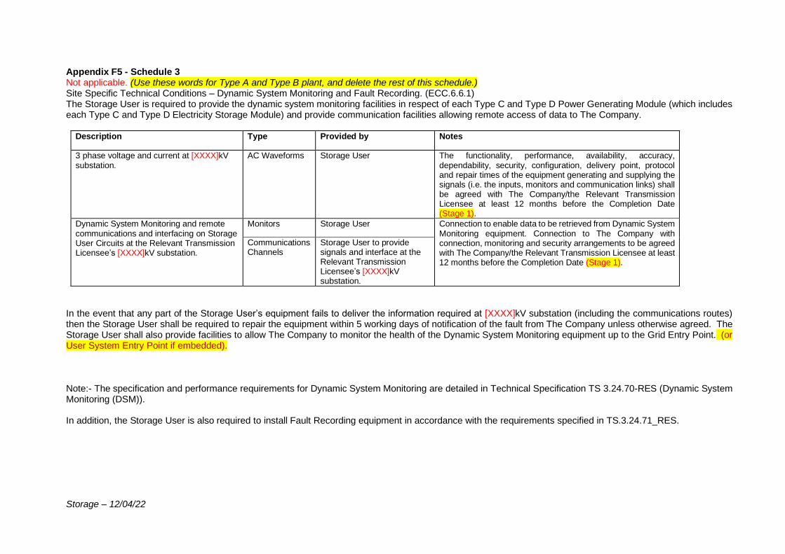
Storage – 12/04/22
Appendix F5 - Schedule 3 Not applicable. (Use these words for Type A and Type B plant, and delete the rest of this schedule.) Site Specific Technical Conditions – Dynamic System Monitoring and Fault Recording. (ECC.6.6.1) The Storage User is required to provide the dynamic system monitoring facilities in respect of each Type C and Type D Power Generating Module (which includes each Type C and Type D Electricity Storage Module) and provide communication facilities allowing remote access of data to The Company.
Description Type Provided by Notes
3 phase voltage and current at [XXXX]kV substation.
AC Waveforms Storage User The functionality, performance, availability, accuracy, dependability, security, configuration, delivery point, protocol and repair times of the equipment generating and supplying the signals (i.e. the inputs, monitors and communication links) shall be agreed with The Company/the Relevant Transmission Licensee at least 12 months before the Completion Date (Stage 1).
Dynamic System Monitoring and remote communications and interfacing on Storage User Circuits at the Relevant Transmission Licensee’s [XXXX]kV substation.
Monitors Storage User Connection to enable data to be retrieved from Dynamic System Monitoring equipment. Connection to The Company with connection, monitoring and security arrangements to be agreed with The Company/the Relevant Transmission Licensee at least 12 months before the Completion Date (Stage 1).
Communications Channels
Storage User to provide signals and interface at the Relevant Transmission Licensee’s [XXXX]kV substation.
In the event that any part of the Storage User’s equipment fails to deliver the information required at [XXXX]kV substation (including the communications routes) then the Storage User shall be required to repair the equipment within 5 working days of notification of the fault from The Company unless otherwise agreed. The Storage User shall also provide facilities to allow The Company to monitor the health of the Dynamic System Monitoring equipment up to the Grid Entry Point. (or User System Entry Point if embedded). Note:- The specification and performance requirements for Dynamic System Monitoring are detailed in Technical Specification TS 3.24.70-RES (Dynamic System Monitoring (DSM)). In addition, the Storage User is also required to install Fault Recording equipment in accordance with the requirements specified in TS.3.24.71_RES.
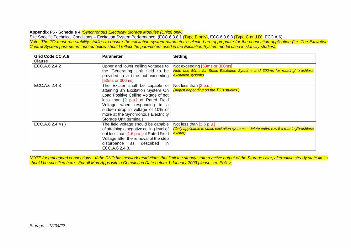
Storage – 12/04/22
Appendix F5 - Schedule 4 (Synchronous Electricity Storage Modules (Units) only) Site Specific Technical Conditions – Excitation System Performance. (ECC.6.3.8.1 (Type B only), ECC.6.3.8.3 (Type C and D), ECC.A.6) Note: The TO must run stability studies to ensure the excitation system parameters selected are appropriate for the connection application (i.e. The Excitation Control System parameters quoted below should reflect the parameters used in the Excitation System model used in stability studies).
Grid Code CC.A.6 Clause
Parameter Setting
ECC.A.6.2.4.2 Upper and lower ceiling voltages to the Generating Unit field to be provided in a time not exceeding [50ms or 300ms].
Not exceeding [50ms or 300ms] Note use 50ms for Static Excitation Systems and 300ms for rotating/ brushless excitation systems
ECC.A.6.2.4.3 The Exciter shall be capable of attaining an Excitation System On Load Positive Ceiling Voltage of not less than [2 p.u.] of Rated Field Voltage when responding to a sudden drop in voltage of 10% or more at the Synchronous Electricity Storage Unit terminals.
Not less than [2 p.u.] (Adjust depending on the TO’s studies.)
ECC.A.6.2.4.4 (i) The field voltage should be capable of attaining a negative ceiling level of not less than [1.6 p.u.] of Rated Field Voltage after the removal of the step disturbance as described in ECC.A.6.2.4.3.
Not less than [1.6 p.u.] (Only applicable to static excitation systems – delete entire row if a rotating/brushless exciter)
NOTE for embedded connections:- If the DNO has network restrictions that limit the steady state reactive output of the Storage User, alternative steady state limits should be specified here. For all Mod Apps with a Completion Date before 1 January 2009 please see Policy.
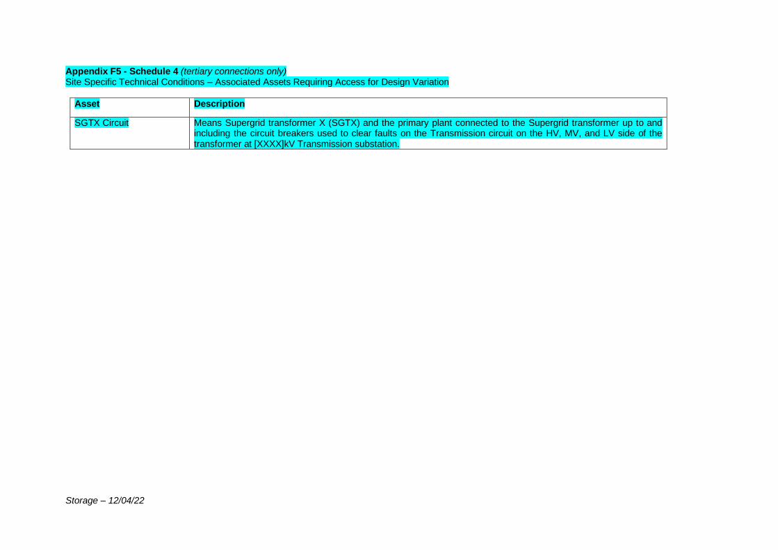
Storage – 12/04/22
Appendix F5 - Schedule 4 (tertiary connections only) Site Specific Technical Conditions – Associated Assets Requiring Access for Design Variation
Asset Description
SGTX Circuit Means Supergrid transformer X (SGTX) and the primary plant connected to the Supergrid transformer up to and including the circuit breakers used to clear faults on the Transmission circuit on the HV, MV, and LV side of the transformer at [XXXX]kV Transmission substation.
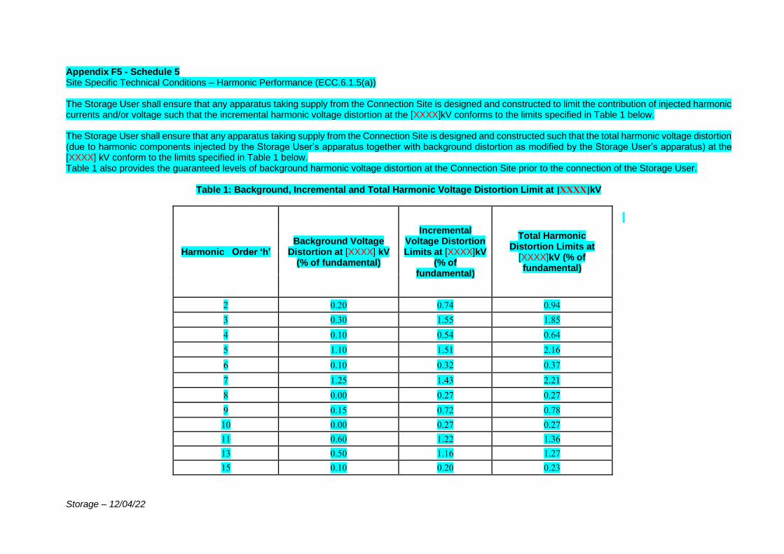
Storage – 12/04/22
Appendix F5 - Schedule 5 Site Specific Technical Conditions – Harmonic Performance (ECC.6.1.5(a)) The Storage User shall ensure that any apparatus taking supply from the Connection Site is designed and constructed to limit the contribution of injected harmonic currents and/or voltage such that the incremental harmonic voltage distortion at the [XXXX]kV conforms to the limits specified in Table 1 below. The Storage User shall ensure that any apparatus taking supply from the Connection Site is designed and constructed such that the total harmonic voltage distortion (due to harmonic components injected by the Storage User’s apparatus together with background distortion as modified by the Storage User’s apparatus) at the [XXXX] kV conform to the limits specified in Table 1 below. Table 1 also provides the guaranteed levels of background harmonic voltage distortion at the Connection Site prior to the connection of the Storage User.
Table 1: Background, Incremental and Total Harmonic Voltage Distortion Limit at [XXXX]kV
Harmonic Order ‘h’ Background Voltage
Distortion at [XXXX] kV (% of fundamental)
Incremental Voltage Distortion Limits at [XXXX]kV
(% of fundamental)
Total Harmonic Distortion Limits at
[XXXX]kV (% of fundamental)
2 0.20 0.74 0.94
3 0.30 1.55 1.85
4 0.10 0.54 0.64
5 1.10 1.51 2.16
6 0.10 0.32 0.37
7 1.25 1.43 2.21
8 0.00 0.27 0.27
9 0.15 0.72 0.78
10 0.00 0.27 0.27
11 0.60 1.22 1.36
13 0.50 1.16 1.27
15 0.10 0.20 0.23

Storage – 12/04/22
17 0.20 0.94 0.97
19 0.20 0.87 0.90
21 0.10 0.13 0.17
23 0.25 0.65 0.70
25 0.25 0.51 0.57
29 0.20 0.47 0.52
31 0.10 0.46 0.48
35 0.20 0.41 0.46
37 0.20 0.39 0.44
41 0.00 0.39 0.39
43 0.00 0.37 0.37
47 0.20 0.33 0.39
49 0.20 0.32 0.38
53 0.00 0.33 0.33
55 0.00 0.33 0.33
59 0.10 0.31 0.33
61 0.10 0.30 0.32
All other odd non-
multiple of 3 h ≥ 65 0.10 0.23 0.28
All other odd multiple of
3 harmonics 0.00 0.15 0.15
All other even harmonics 0.00 0.15 0.15

Storage – 12/04/22
The Storage User shall conform to the Total Harmonic Distortion (THD) level, at the Grid Supply Point as given in Table 2 below.
Table 2: Total Harmonic Distortion Limits
Harmonic order THD
≥ 2 2.5%
The limits specified in Tables 1 & 2 shall apply for all possible conditions and operation of the Storage User’s system. They shall apply for system impedance envelopes in Ohms at the 33 kV busbar connection point up to 5 kHz (100th harmonic) are given in Fig 1 to Fig 4 below. All impedances within and on the periphery of the envelopes represent the system impedance seen from the 33 kV busbar. The impedance envelops are sectionalised for different harmonic ranges as illustrated below. For clarity, the coordinates of each envelope are given in Table 3 to Table 5.
Table 3- Coordinates for Harmonic Ranges 1 and 2 in Fig 1
Range 1 Range 2
1.5 ≤ h < 3.5 3.5 ≤ h < 9.5
R (Ω) X (Ω) R (Ω) X (Ω)
0.16 8 0.6 15
0.6 15 2 37
1.2 15 4.4 37
1.2 5 4.4 13
0.16 5 0.6 13
Table 4- Coordinates for Harmonic Ranges 3-1 to 3-7 in Fig 2
Range 3-1 Range 3-2 Range 3-3 Range 3-4 Range 3-5 Range 3-6 Range 3-7
9.5 ≤ h < 12.5 12.5 ≤ h < 15.5 15.5 ≤ h < 18.5 18.5 ≤ h < 21.5 21.5 ≤ h < 25.5 25.5 ≤ h < 31.5 31.5 ≤ h < 36.5
R (Ω) X (Ω) R (Ω) X (Ω) R (Ω) X (Ω) R (Ω) X (Ω) R (Ω) X (Ω) R (Ω) X (Ω) R (Ω) X (Ω)
2 34 3.4 47 5.6 58 7.2 66 9.2 76 11.6 88 15.2 106
2 40 6 60 8 70 10.2 81 13 95 17 115 20.4 132
4 50 10.5 60 13 70 15.75 81 19.25 95 24.25 115 28.5 132
8 50 10.5 47 13 58 15.75 66 19.25 76 24.25 88 28.5 106
8 34
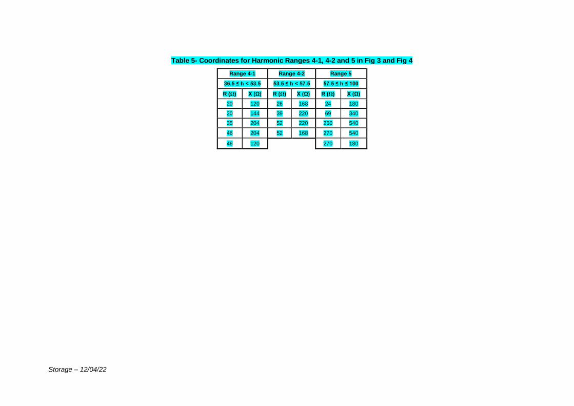
Storage – 12/04/22
Table 5- Coordinates for Harmonic Ranges 4-1, 4-2 and 5 in Fig 3 and Fig 4
Range 4-1 Range 4-2 Range 5
36.5 ≤ h < 53.5 53.5 ≤ h < 57.5 57.5 ≤ h ≤ 100
R (Ω) X (Ω) R (Ω) X (Ω) R (Ω) X (Ω)
20 120 26 168 24 180
20 144 39 220 69 340
35 204 52 220 250 540
46 204 52 168 270 540
46 120 270 180
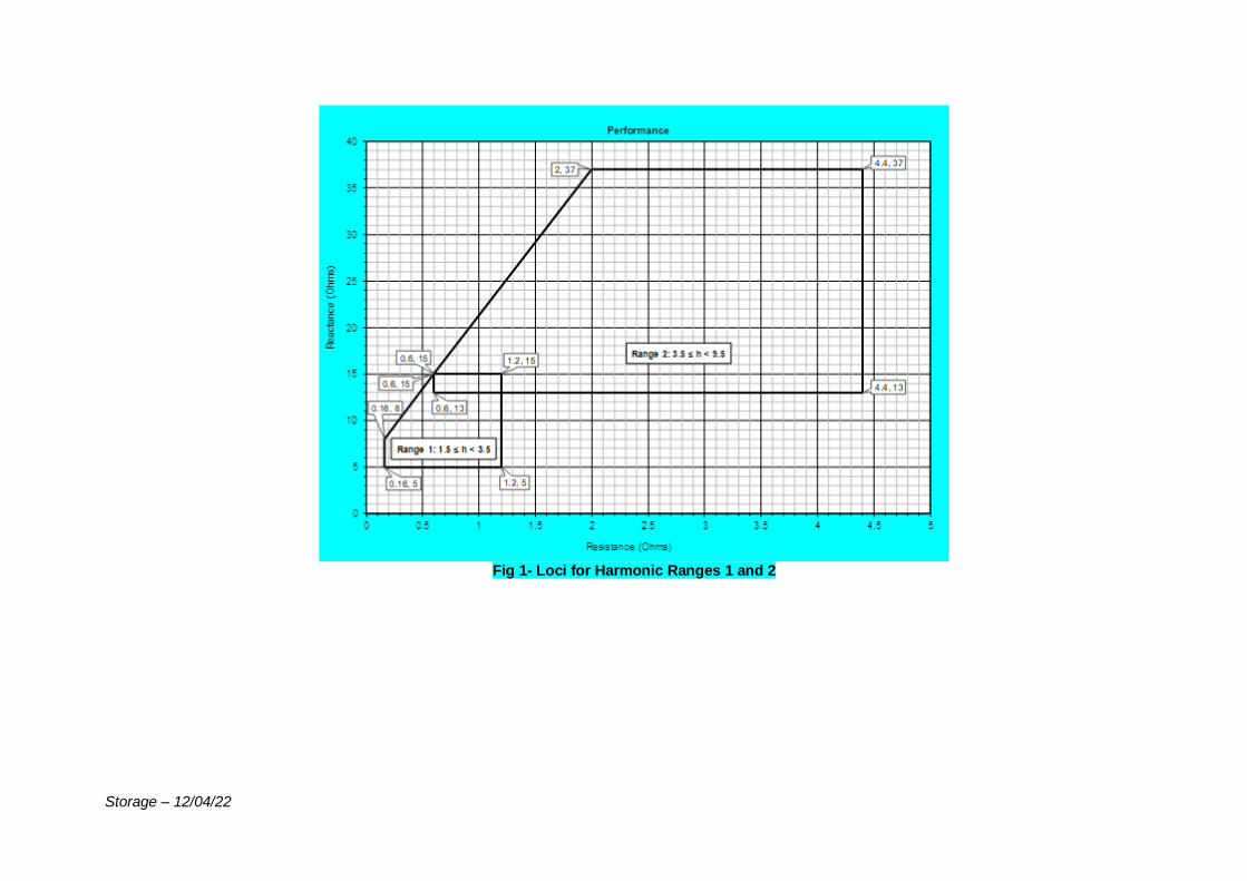
Storage – 12/04/22
Fig 1- Loci for Harmonic Ranges 1 and 2
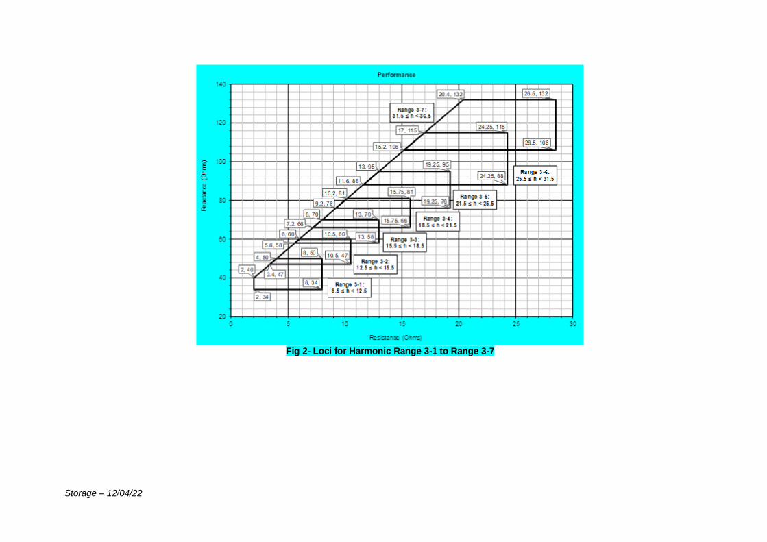
Storage – 12/04/22
Fig 2- Loci for Harmonic Range 3-1 to Range 3-7
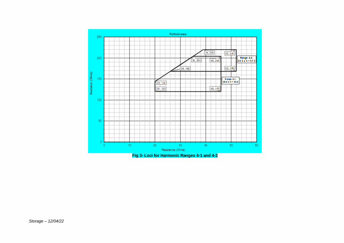
Storage – 12/04/22
Fig 3- Loci for Harmonic Ranges 4-1 and 4-2
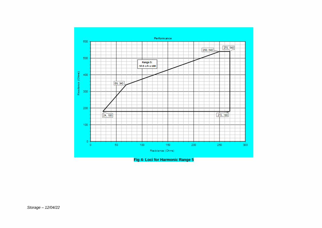
Storage – 12/04/22
Fig 4- Loci for Harmonic Range 5
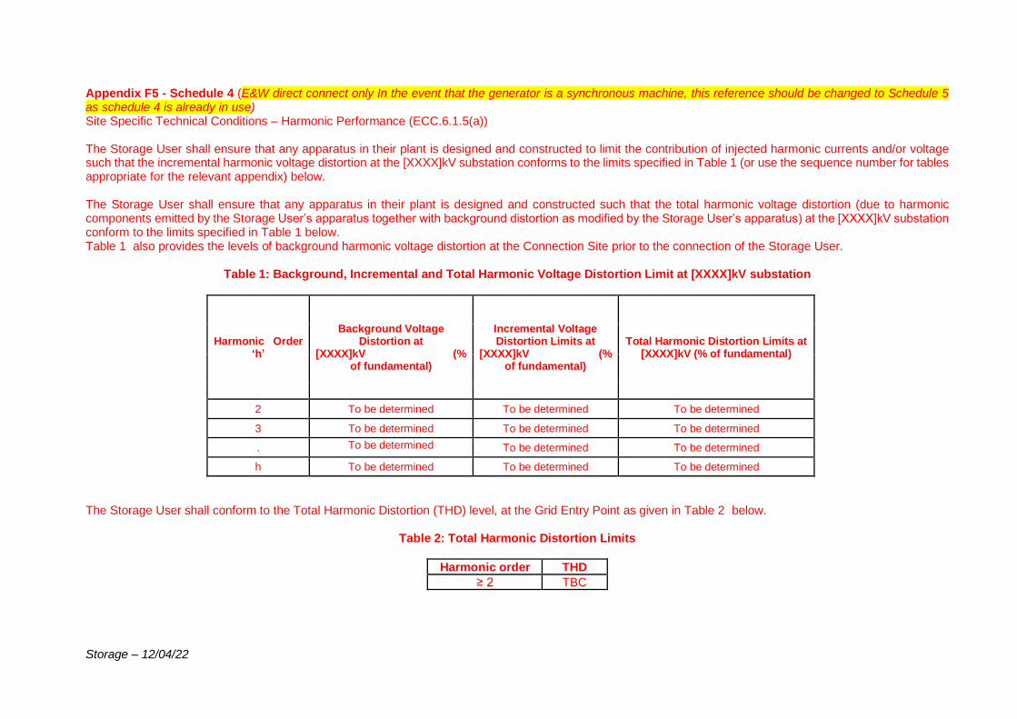
Storage – 12/04/22
Appendix F5 - Schedule 4 (E&W direct connect only In the event that the generator is a synchronous machine, this reference should be changed to Schedule 5 as schedule 4 is already in use) Site Specific Technical Conditions – Harmonic Performance (ECC.6.1.5(a)) The Storage User shall ensure that any apparatus in their plant is designed and constructed to limit the contribution of injected harmonic currents and/or voltage such that the incremental harmonic voltage distortion at the [XXXX]kV substation conforms to the limits specified in Table 1 (or use the sequence number for tables appropriate for the relevant appendix) below. The Storage User shall ensure that any apparatus in their plant is designed and constructed such that the total harmonic voltage distortion (due to harmonic components emitted by the Storage User’s apparatus together with background distortion as modified by the Storage User’s apparatus) at the [XXXX]kV substation conform to the limits specified in Table 1 below. Table 1 also provides the levels of background harmonic voltage distortion at the Connection Site prior to the connection of the Storage User.
Table 1: Background, Incremental and Total Harmonic Voltage Distortion Limit at [XXXX]kV substation
Harmonic Order ‘h’
Background Voltage Distortion at
[XXXX]kV (% of fundamental)
Incremental Voltage Distortion Limits at
[XXXX]kV (% of fundamental)
Total Harmonic Distortion Limits at [XXXX]kV (% of fundamental)
2 To be determined To be determined To be determined
3 To be determined To be determined To be determined
. To be determined To be determined To be determined
h To be determined To be determined To be determined
The Storage User shall conform to the Total Harmonic Distortion (THD) level, at the Grid Entry Point as given in Table 2 below.
Table 2: Total Harmonic Distortion Limits
Harmonic order THD
≥ 2 TBC
Storage – 12/04/22
The limits specified in Tables 1 & 2 shall apply for all possible conditions and operation of the Storageode User’s system. They shall apply for system impedance envelopes at the [XXXX]kV busbar connection point up to 5 kHz (100th harmonic) that are shown below. All impedances within and on the periphery of the envelopes represent the system impedance seen from the [XXXX]kV busbar. The impedance envelopes are sectionalised for different harmonic ranges as illustrated below.
NB: Graphs will be provided once limits have been determined

Storage – 12/04/22
Storage – 12/04/22
USEFUL LINKS The Grid Code: https://www.nationalgrideso.com/codes/grid-code Electrical Standards: https://www.nationalgrideso.com/codes/grid-code/electrical-standards-documents-including-specifications-electronic-data Extranet (ID and password required, email transmission [email protected] to request access): https://extranet.nationalgrid.com/(delete if in Scotland) Connection Policies and Guidance: https://www.nationalgrideso.com/connections/registers-reports-and-guidance Procurement Guidelines and Balancing Principles: https://www.nationalgrideso.com/balancing-services/c16-statements-and-consultations
Related Documents