5-1 Example Problem No. 5 This example demonstrates the application of support displacement load (commonly known as sinking support) on a space frame structure.

Welcome message from author
This document is posted to help you gain knowledge. Please leave a comment to let me know what you think about it! Share it to your friends and learn new things together.
Transcript
5-1
Example Problem No. 5
This example demonstrates the application of support displacementload (commonly known as sinking support) on a space framestructure.
�
������
�
�
�
�
�
�
��
�
�����
�����
=
<
;
5-2
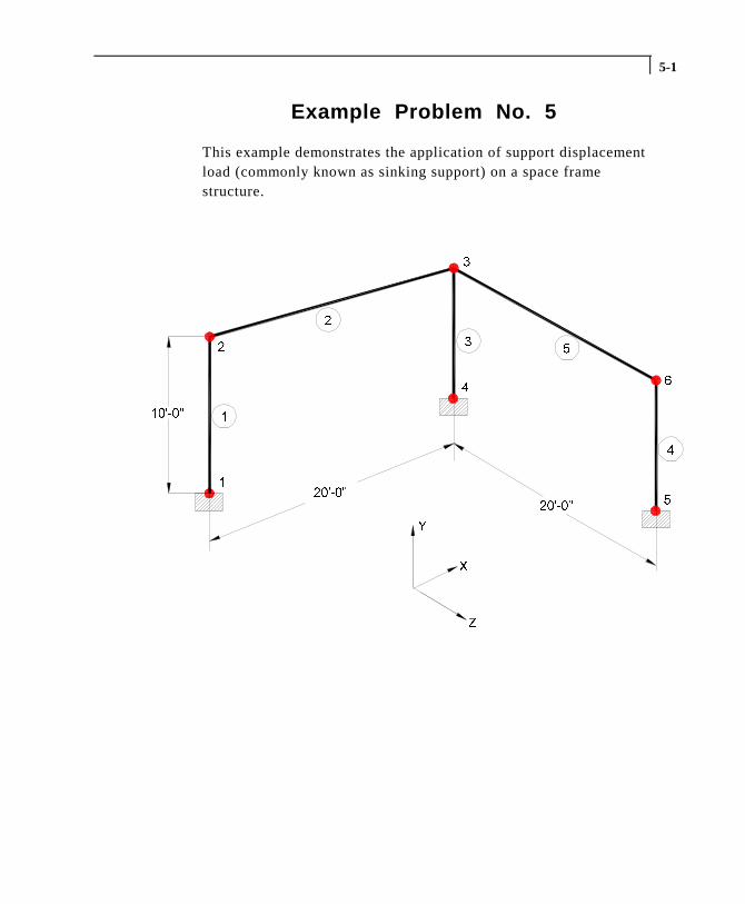
1. Select the STAAD.Pro icon from the STAAD.Pro 2001 programgroup.
Figure 5. 1
The STAAD.Pro Graphical Environment will be invoked.
5-3
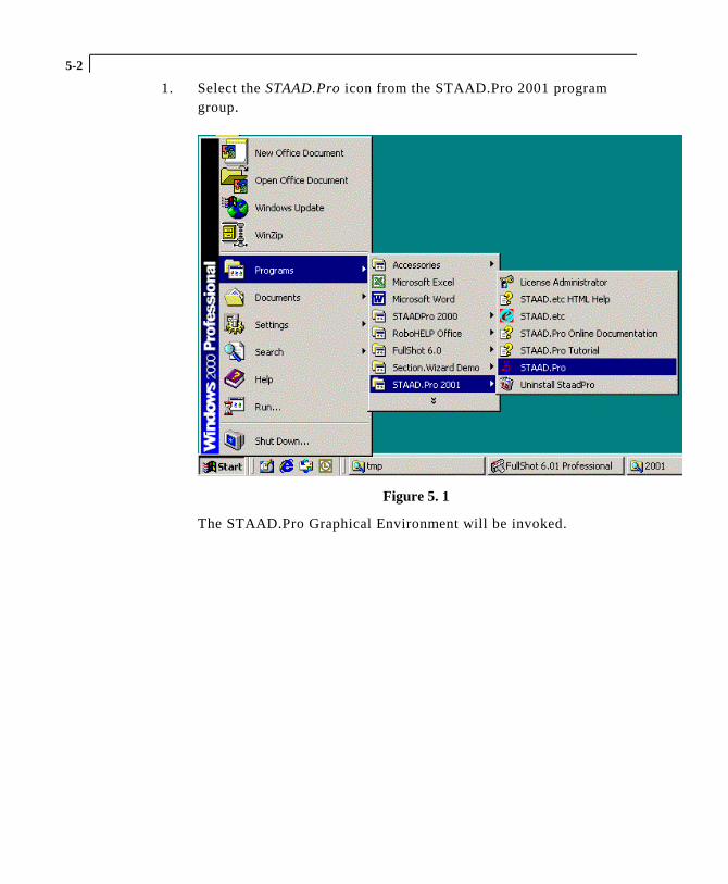
2. The units in which we wish to create this model are the Englishunits. (feet, kip, etc.) The default unit system setting is whateverwe chose during the installation of the program. If you had chosenMetric at the time of installation, you may want to change it toEnglish. To do so, click on the File | Configure menu option (seeFigure 5.2) and choose the appropriate one (English for our case).Then, click on the Accept button.
Figure 5. 2
Figure 5. 3

5-4
3. To create a new structure, click on the File | New option in theSTAAD.Pro screen that opens (as shown in Figure 5.4).
Figure 5. 4
4. In the New File Setup dialog box, choose Space as the StructureType and specify an optional Title (EXAMPLE PROBLEM NO. 5).Then click on the Next button as shown in Figure 5.5.
Figure 5. 5
5-5
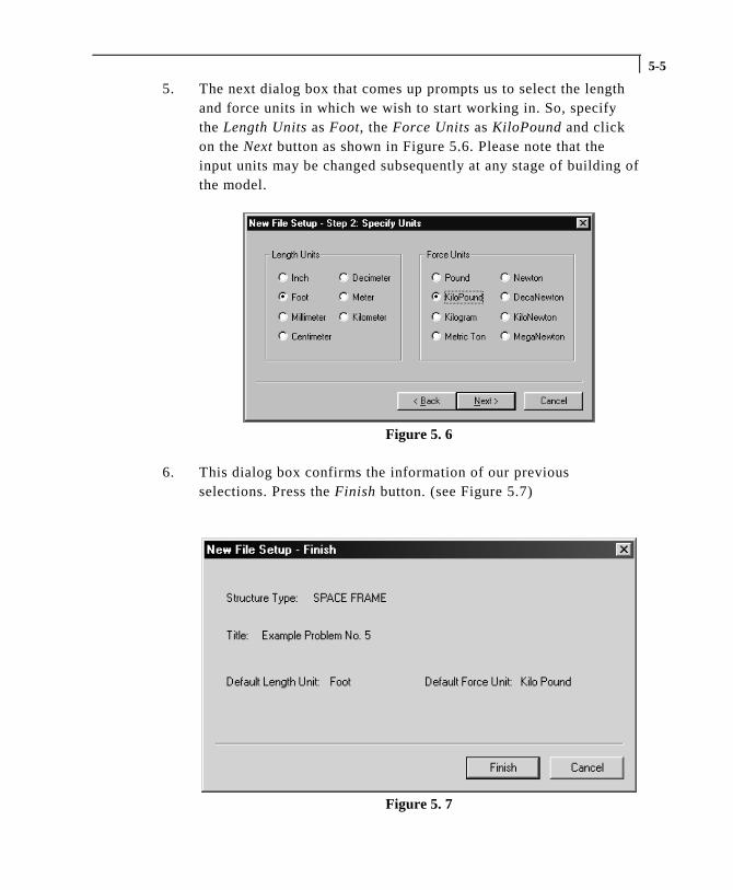
5. The next dialog box that comes up prompts us to select the lengthand force units in which we wish to start working in. So, specifythe Length Units as Foot, the Force Units as KiloPound and clickon the Next button as shown in Figure 5.6. Please note that theinput units may be changed subsequently at any stage of building ofthe model.
Figure 5. 6
6. This dialog box confirms the information of our previousselections. Press the Finish button. (see Figure 5.7)
Figure 5. 7
5-6
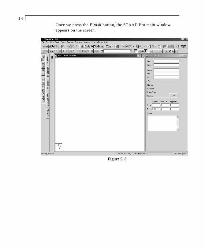
Once we press the Finish button, the STAAD.Pro main windowappears on the screen.
Figure 5. 8
5-7
Creating Nodes 1 to 4 And Beams 1 to 3
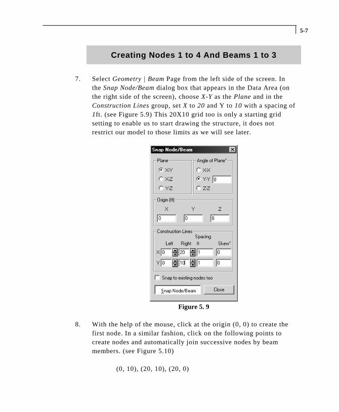
7. Select Geometry | Beam Page from the left side of the screen. Inthe Snap Node/Beam dialog box that appears in the Data Area (onthe right side of the screen), choose X-Y as the Plane and in theConstruction Lines group, set X to 20 and Y to 10 with a spacing of1ft. (see Figure 5.9) This 20X10 grid too is only a starting gridsetting to enable us to start drawing the structure, it does notrestrict our model to those limits as we will see later.
Figure 5. 9
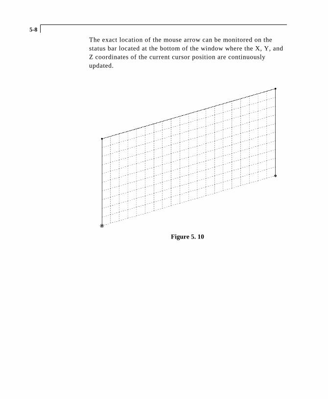
8. With the help of the mouse, click at the origin (0, 0) to create thefirst node. In a similar fashion, click on the following points tocreate nodes and automatically join successive nodes by beammembers. (see Figure 5.10)
(0, 10), (20, 10), (20, 0)
5-8
The exact location of the mouse arrow can be monitored on thestatus bar located at the bottom of the window where the X, Y, andZ coordinates of the current cursor position are continuouslyupdated.
Figure 5. 10
5-9
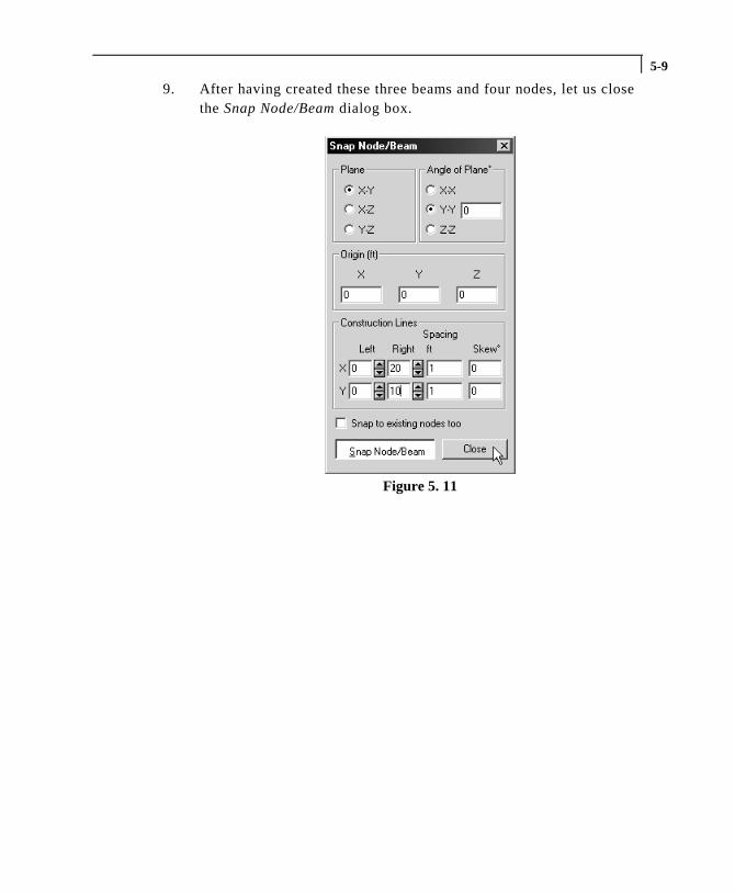
9. After having created these three beams and four nodes, let us closethe Snap Node/Beam dialog box.
Figure 5. 11
5-10
Switching On Node And Beam Labels
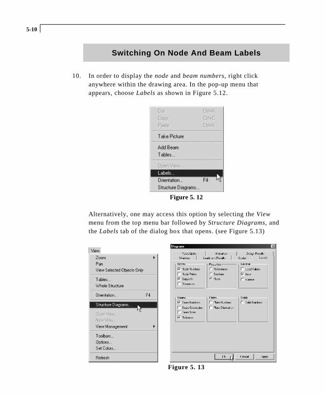
10. In order to display the node and beam numbers, right clickanywhere within the drawing area. In the pop-up menu thatappears, choose Labels as shown in Figure 5.12.
Figure 5. 12
Alternatively, one may access this option by selecting the Viewmenu from the top menu bar followed by Structure Diagrams, andthe Labels tab of the dialog box that opens. (see Figure 5.13)
Figure 5. 13
5-11
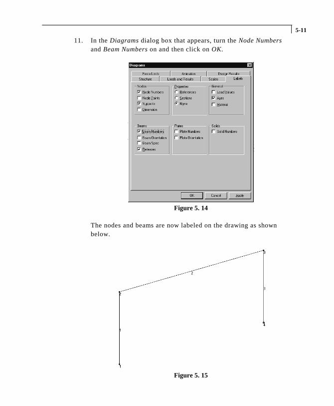
11. In the Diagrams dialog box that appears, turn the Node Numbersand Beam Numbers on and then click on OK.
Figure 5. 14
The nodes and beams are now labeled on the drawing as shownbelow.
Figure 5. 15
5-12
Creating Members 4 and 5
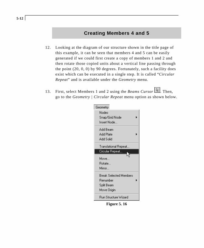
12. Looking at the diagram of our structure shown in the title page ofthis example, it can be seen that members 4 and 5 can be easilygenerated if we could first create a copy of members 1 and 2 andthen rotate those copied units about a vertical line passing throughthe point (20, 0, 0) by 90 degrees. Fortunately, such a facility doesexist which can be executed in a single step. It is called “CircularRepeat” and is available under the Geometry menu.
13. First, select Members 1 and 2 using the Beams Cursor . Then,go to the Geometry | Circular Repeat menu option as shown below.
Figure 5. 16
5-13
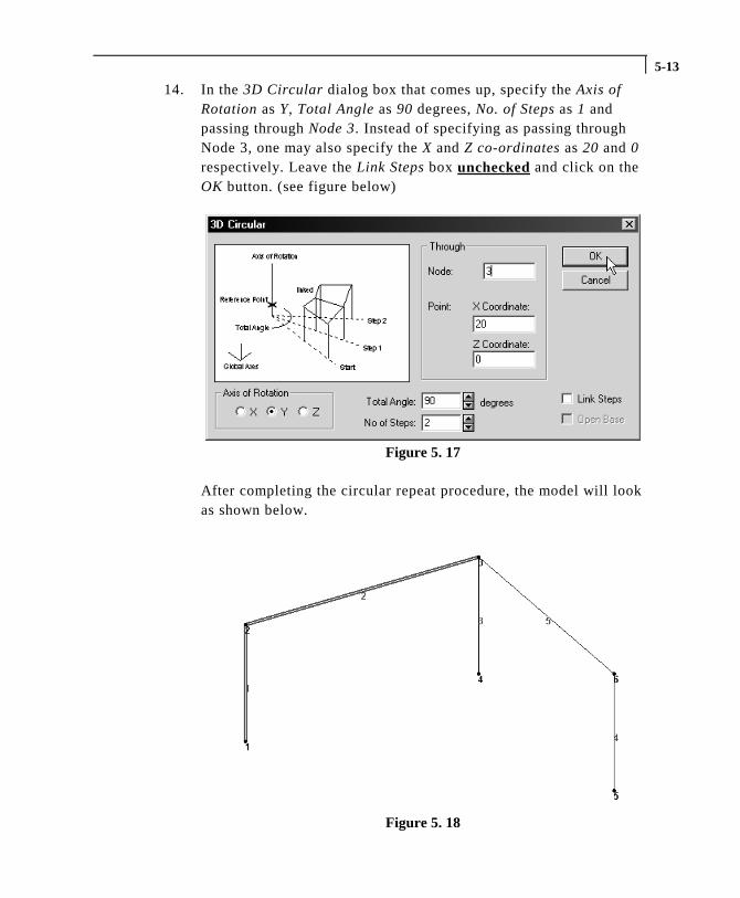
14. In the 3D Circular dialog box that comes up, specify the Axis ofRotation as Y, Total Angle as 90 degrees, No. of Steps as 1 andpassing through Node 3. Instead of specifying as passing throughNode 3, one may also specify the X and Z co-ordinates as 20 and 0respectively. Leave the Link Steps box unchecked and click on theOK button. (see figure below)
Figure 5. 17
After completing the circular repeat procedure, the model will lookas shown below.
Figure 5. 18
5-14
Changing The Input Units Of Length
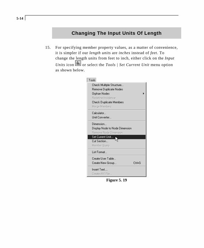
15. For specifying member property values, as a matter of convenience,it is simpler if our length units are inches instead of feet. Tochange the length units from feet to inch, either click on the Input
Units icon or select the Tools | Set Current Unit menu optionas shown below.
Figure 5. 19
5-15
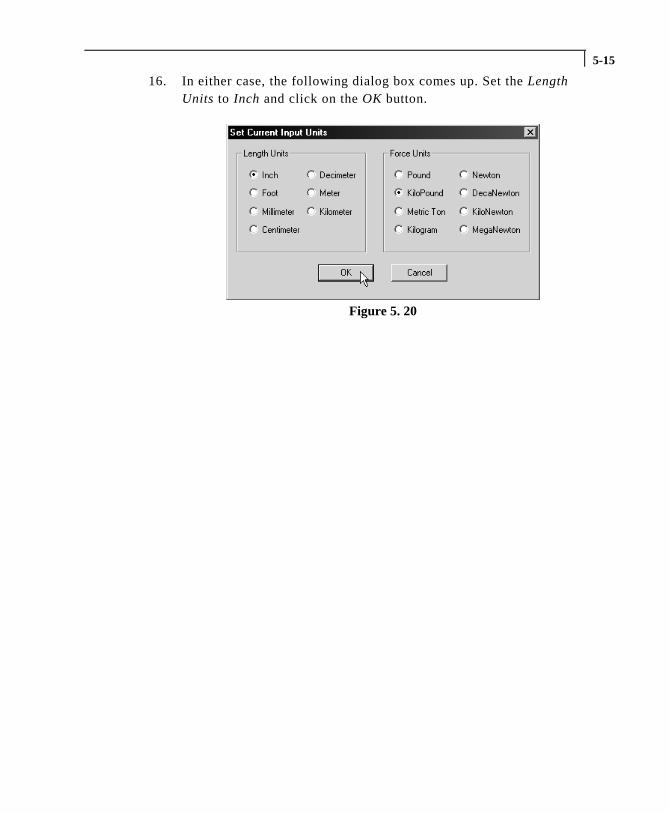
16. In either case, the following dialog box comes up. Set the LengthUnits to Inch and click on the OK button.
Figure 5. 20
5-16
Assigning Member Properties
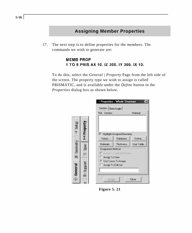
17. The next step is to define properties for the members. Thecommands we wish to generate are:
0(0% 3523
� 72 � 35,6 $; ��� ,= ���� ,< ���� ,; ���
To do this, select the General | Property Page from the left side ofthe screen. The property type we wish to assign is calledPRISMATIC, and is available under the Define button in theProperties dialog box as shown below.
Figure 5. 21
5-17
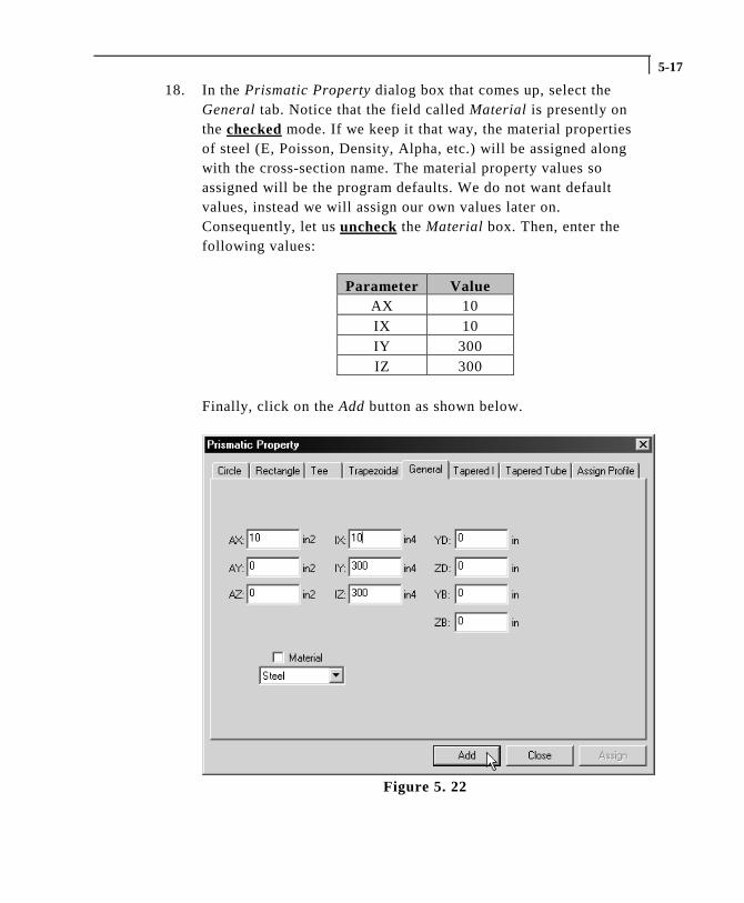
18. In the Prismatic Property dialog box that comes up, select theGeneral tab. Notice that the field called Material is presently onthe checked mode. If we keep it that way, the material propertiesof steel (E, Poisson, Density, Alpha, etc.) will be assigned alongwith the cross-section name. The material property values soassigned will be the program defaults. We do not want defaultvalues, instead we will assign our own values later on.Consequently, let us uncheck the Material box. Then, enter thefollowing values:
Parameter ValueAX 10IX 10IY 300IZ 300
Finally, click on the Add button as shown below.
Figure 5. 22
5-18
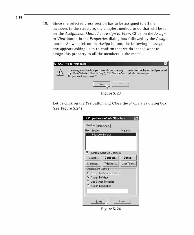
19. Since the selected cross section has to be assigned to all themembers in the structure, the simplest method to do that will be toset the Assignment Method as Assign to View. Click on the Assignto View button in the Properties dialog box followed by the Assignbutton. As we click on the Assign button, the following messagebox appears asking us to re-confirm that we do indeed want toassign this property to all the members in the model.
Figure 5. 23
Let us click on the Yes button and Close the Properties dialog box.(see Figure 5.24)
Figure 5. 24
5-19
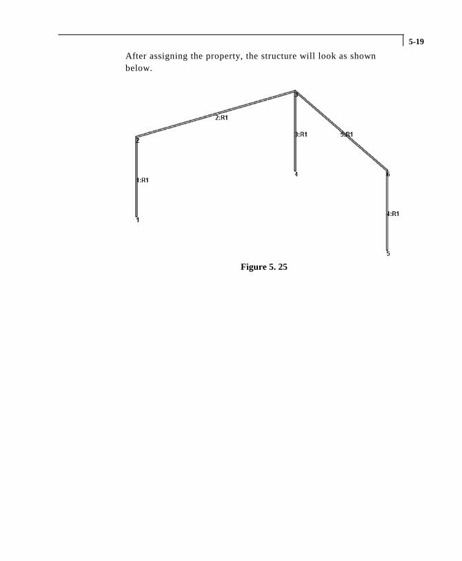
After assigning the property, the structure will look as shownbelow.
Figure 5. 25
5-20
Specifying Material Constants
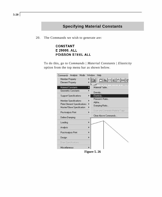
20. The Commands we wish to generate are:
&2167$17
( ������ $//
32,6621 67((/ $//
To do this, go to Commands | Material Constants | Elasticityoption from the top menu bar as shown below.
Figure 5. 26
5-21
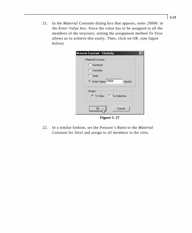
21. In the Material Constant dialog box that appears, enter 29000. inthe Enter Value box. Since the value has to be assigned to all themembers of the structure, setting the assignment method To Viewallows us to achieve this easily. Then, click on OK. (see figurebelow)
Figure 5. 27
22. In a similar fashion, set the Poisson’s Ratio to the MaterialConstant for Steel and assign to all members in the view.
5-22
Assigning Supports
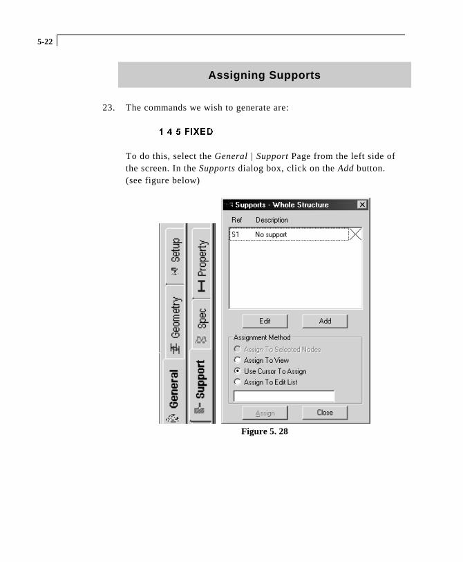
23. The commands we wish to generate are:
� � � ),;('
To do this, select the General | Support Page from the left side ofthe screen. In the Supports dialog box, click on the Add button.(see figure below)
Figure 5. 28
5-23
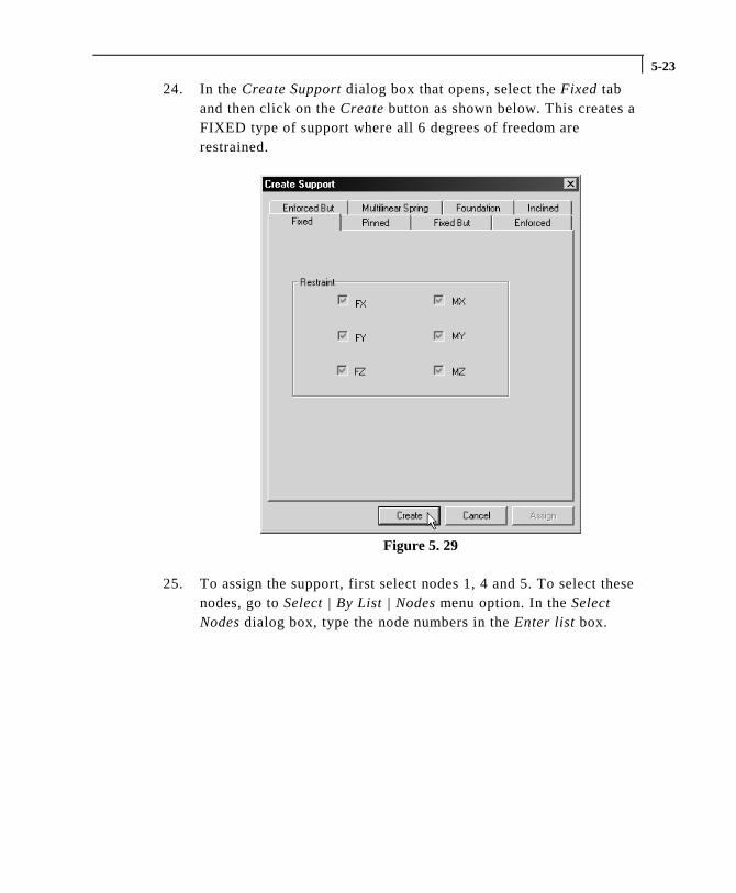
24. In the Create Support dialog box that opens, select the Fixed taband then click on the Create button as shown below. This creates aFIXED type of support where all 6 degrees of freedom arerestrained.
Figure 5. 29
25. To assign the support, first select nodes 1, 4 and 5. To select thesenodes, go to Select | By List | Nodes menu option. In the SelectNodes dialog box, type the node numbers in the Enter list box.

5-24
26. Then, make sure that the Support 2 (Fixed) parameter is selected inthe Supports dialog box.
Figure 5. 30
27. Notice that the Assignment Method becomes automatically set toAssign to Selected Nodes. Click on the Assign button in theSupports dialog box. (see figure below)
Figure 5. 31
5-25
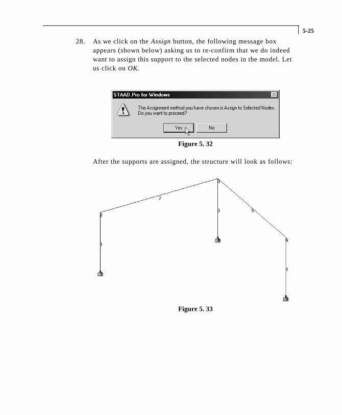
28. As we click on the Assign button, the following message boxappears (shown below) asking us to re-confirm that we do indeedwant to assign this support to the selected nodes in the model. Letus click on OK.
Figure 5. 32
After the supports are assigned, the structure will look as follows:
Figure 5. 33
5-26
Specifying Loads
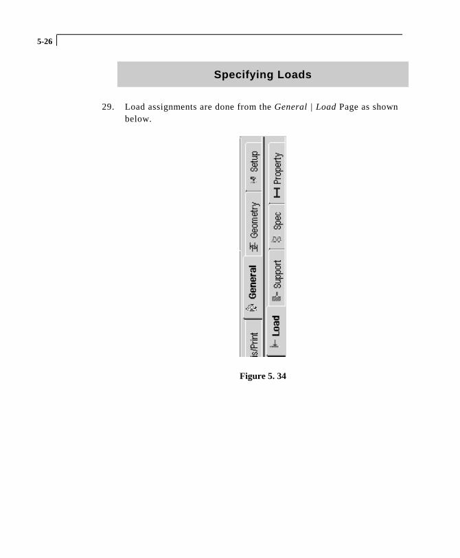
29. Load assignments are done from the General | Load Page as shownbelow.
Figure 5. 34
5-27
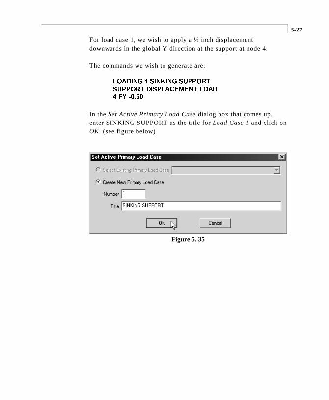
For load case 1, we wish to apply a ½ inch displacementdownwards in the global Y direction at the support at node 4.
The commands we wish to generate are:
/2$',1* � 6,1.,1* 6833257
6833257 ',63/$&(0(17 /2$'
� )< �����
In the Set Active Primary Load Case dialog box that comes up,enter SINKING SUPPORT as the title for Load Case 1 and click onOK. (see figure below)
Figure 5. 35
5-28
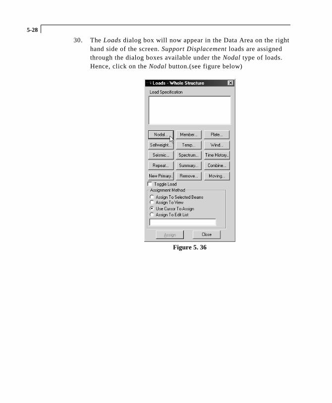
30. The Loads dialog box will now appear in the Data Area on the righthand side of the screen. Support Displacement loads are assignedthrough the dialog boxes available under the Nodal type of loads.Hence, click on the Nodal button.(see figure below)
Figure 5. 36

5-29
31. In the Node Loads dialog box, select the Support Displacementtab. Enter -0.50 as the Displacement value, set the Direction to Fyand click on the Add button.
Figure 5. 37
32. This load is to be applied on node 4 of the model. We shall use amethod of assignment called Use Cursor to Assign. To do so, firstselect the load from the Loads dialog box (it will becomehighlighted).
Figure 5. 38
5-30
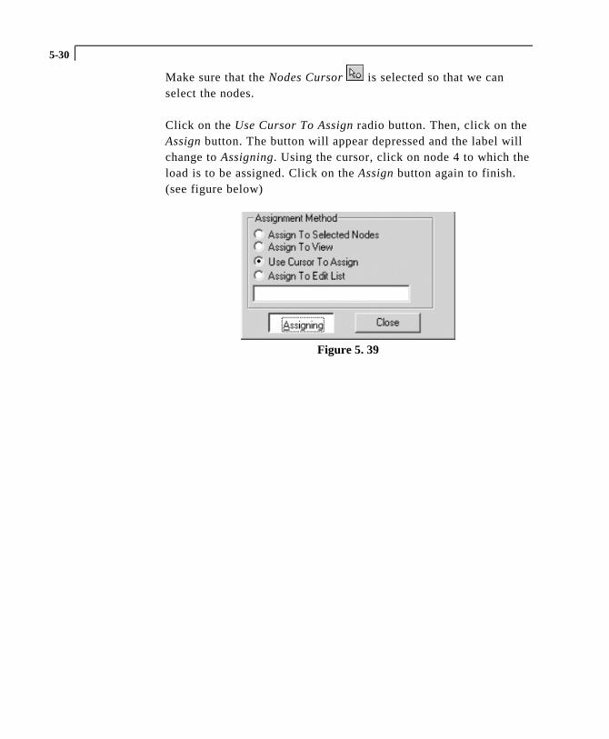
Make sure that the Nodes Cursor is selected so that we canselect the nodes.
Click on the Use Cursor To Assign radio button. Then, click on theAssign button. The button will appear depressed and the label willchange to Assigning. Using the cursor, click on node 4 to which theload is to be assigned. Click on the Assign button again to finish.(see figure below)
Figure 5. 39
5-31
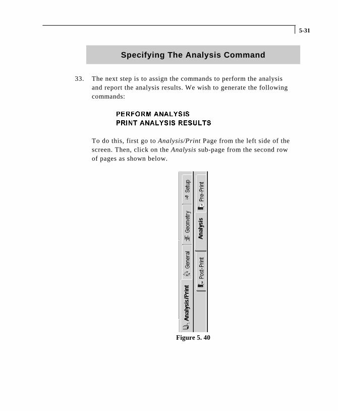
Specifying The Analysis Command
33. The next step is to assign the commands to perform the analysisand report the analysis results. We wish to generate the followingcommands:
3(5)250 $1$/<6,6
35,17 $1$/<6,6 5(68/76
To do this, first go to Analysis/Print Page from the left side of thescreen. Then, click on the Analysis sub-page from the second rowof pages as shown below.
Figure 5. 40
5-32
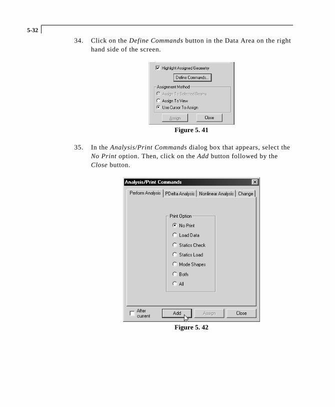
34. Click on the Define Commands button in the Data Area on the righthand side of the screen.
Figure 5. 41
35. In the Analysis/Print Commands dialog box that appears, select theNo Print option. Then, click on the Add button followed by theClose button.
Figure 5. 42
5-33
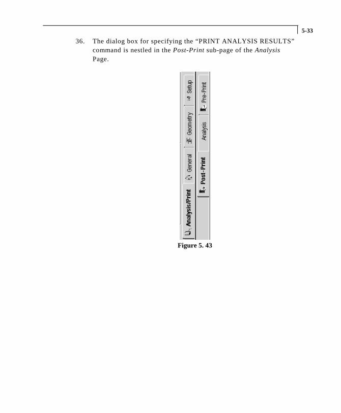
36. The dialog box for specifying the “PRINT ANALYSIS RESULTS”command is nestled in the Post-Print sub-page of the AnalysisPage.
Figure 5. 43
5-34
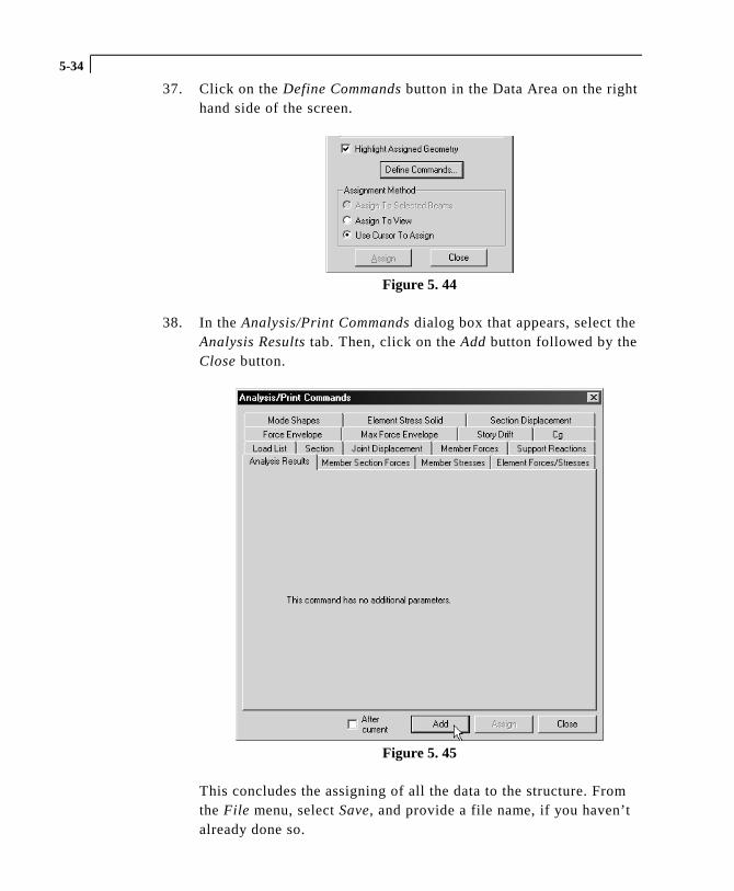
37. Click on the Define Commands button in the Data Area on the righthand side of the screen.
Figure 5. 44
38. In the Analysis/Print Commands dialog box that appears, select theAnalysis Results tab. Then, click on the Add button followed by theClose button.
Figure 5. 45
This concludes the assigning of all the data to the structure. Fromthe File menu, select Save, and provide a file name, if you haven’talready done so.
Related Documents