Examination of Pump Cavitation, Gear Mesh and Blade Performance using External Vibration Characteristics Technical Paper 249 By John S. Mitchell

Welcome message from author
This document is posted to help you gain knowledge. Please leave a comment to let me know what you think about it! Share it to your friends and learn new things together.
Transcript

Examination of Pump Cavitation, Gear Meshand Blade Performance using External
Vibration Characteristics
Technical Paper 249By John S. Mitchell

TP 249

EXAMINATION OF PUMP CAVITATION, GEAR MESH AND BLADE PERFORMANCE
USING EXTERNAL VIBRATION CHARACTERISTICS
by
John S. Mitchell Technical Services Manager
Endevco-MHM Division
San Juan Capistrano, California
John S. Mitchell holds a B.S. in Engineering from the U.S. Nacol Academy. While in the Navy he was primarily associated tvith the operation, maintenance and repair of shipboard machinery. He served as Chief Engineer on a diesel electric submarine and also as 1\Jachinery Officer aboard a nttclear sttbmarine.
As Technical Services Manager, Mr. Mitchell is responsible for industrial consulting and worldwide service for
Endevco's line of industrial vibration monitoring systems. He previously organized and managed a consulting busi
ness providing turbomachinery predictive and diagnostic vibration analysis and optical alignment service to the petrochemical and electric power generation industries. Prior experience includes responsibility for rotating machinery startup and maintenance engineering during construction, commissioning and operation of a new 72,000 BBL/day oil refinery.
Mr. Mitchell holds a patent for optical tooling scale fixtures used in machinery alignment and has authored articles on vibration analysis and monitoring, condition maintenance and optical alignment. He is a member of ASME.
ABSTRACT
Whereas the interpretation of the low frequency vibration characteristics generated by operating machinery is relatively well understood, the use of the high frequencies, sonic and above, to predict conditions such as blade and gear tooth performance is in its infancy. With the vast amount of data available the basic problem becomes one of identifying, correlating and isolating individual characteristics so that small changes can be recognized in sufficient time to take corrective action. Demodulation followed by spectrum analysis as well as spectrum analysis by itself are two data reduction techniques discussed. The former provides a convenient way of examining individual events occurring in rapid repetitive succession such as gear tooth engagement. Observations concerning harmonic patterns are similarly discussed along with some presumed physical generating mechanisms.
INTRODUCTION
The continuing trend toward higher speeds and power on industrial rotating machinery has resulted in a corresponding escalation in the costs of downtime and repair as well as magnifying the risk to personnel, hazard to adjacent equipment and the financial impact of an unexpected failure. Taken together, these factors have all provided the incentives for increasing the emphasis on condition monitoring, diagnostics and failure prediction.
39
Over the years vibration has emerged as one of the key a,:cessible parameters with which to judge the condition of operating machinery and has been utilized in distinct but interrelated ways to monitor, predict and diagnose mechanical performance. Although the requirements for detailed analysis are often in excess of the requirements for monitoring it is becoming increasingly apparent that properly applied, the knowledge gained in analysis can result in greatly improved protection at a significant reduction in cost.
Expanding the knowledge of vibration characteristics to include the condition of individual components such as bearings, gear teeth, blading and impellers generally involved several distinct steps or stages. First, vibration characteristics are collected over a wide frequency range and displayed in a convenient form to facilitate detailed observation, comparison and study. Next the vibration characteristics are searched for components or patterns thought to have a common origin, related interpretation or connection through some other shared factor or dynamic interaction.
Selecting an optimum method of analysis and presentation usually requires sampling similar machinery or evaluating implanted failures in order to determine which technique offers the most positive differentiation between normal and abnormal conditions. Quite often it becomes necessary to try several different methods in order to isolate or enhance segments or characteristics of the vibration signal for more detailed study. In addition to spectrum analysis, techniques such as time averaging, envelope detection, average to peak ratioing. pulse counting and various types of demodulation have all been used successfully to emphasize a specific characteristic:
Once an effective means of analysis has been devised and the characteristics obtained correlated to mechanical events, a continuous monitoring scheme can be designed to accomplish the same task. Ideally, the resulting system will have the ability to recognize small changes in vibration as indicative of discrete definable variations in mechanical condition. The analysis of rolling element bearings has advanced the farthest in this direction and a large amount of literature is available describing various analytical methods as well as the results obtained. Although a great deal of work remains, current investigations into the dynamic performance of gears, pumps and axial compressor blading likewise show a great deal of promise. Since much of the work described herein is preliminary in nature and in some cases little more than observations which may not repeat under all circumstances, it is hoped that the thoughts, conclusions and areas for future investigation outlined in the following paragraphs will prove useful to those involved in machinery analysis.
GEARS
For purposes of explanation, the vibration characteristics generated by a typical industrial double helical gear, illustrated
TP 249

TP 249

EXAMINATION OF PUMP CAVITATIO:'-, GEAR �!ESH & BLADE PERFOR�IANCE
USING EXTERNAL VIBRATION CHARACTERISTICS 41
Whereas the preceeding is one example of amplitude modulation, fluctuations in load, varying tooth stiffness, profile or spacing errors as well as vibration or runout at rotational frequencies or their multiples are some other phenomena likely to produce combinations of frequency and amplitude modulation of the mesh frequency.
Figure 3 illustrates how demodulation can be utilized to examine gear characteristics. The lower acceleration spectrum contains the gear mesh frequency surrounded by several sidebands. Directly above, a low frequency velocity signature is pictured to show the position and relative amplitude of the rotational frequency components and their multiples. The top two signatures contain the spectral components obtained by amplitude and frequency demodulation of the gear mesh frequency and contain, as expected, the rotational frequencies as well as multiples. It is quite interesting to observe that the three most prominent components in the frequency modulated spectrum are at the high speed shaft rotational frequency and its 4th and 6th order harmonics whereas two of the three most prominent components in the amplitude modulated spectrum are at the high speed shaft rotational frequency and its 2nd order.
I ,..
LOW S,U.D SHAFT NLS
I , ...
I ...
FREQUENCY MOPUlATED SPECTRUM
AMPLITUOE MODULATED SPECTRUM
I I I
900 BOO 1000
CASING 1/EI.OCITY SPECTRUM
/ GEAR fi/llE.SH FREQUENCY
I
-
I ....
FREQUENCY HERTZ
CASING ACCELEAAnON SPECTRUM
I 8000
I 10000
Figure 3. Speed Increasing Gear Casing and Demodulated Signatures.
In addition to the likely possibility that demodulation of the gear mesh frequency will yield valuable information, the number and appearance of the harmonics of gear mesh are likewise promising as indicators of mechanical condition. Referring back to Figure 2 it can be seen that both the second and third harmonics of gear mesh vary significantly with applied load. In this particular case the relationship of harmonics to the fundamental infers a tooth engagement resembling a square wave at 9.5 MW which becomes more sinusoidal with load.
In evaluating harmonics it is well to examine the physical characteristics which might be involved. The possibility of a non-sinusoidal occurrence has been discussed in the pre\·ious paragraph. !'.ext and perhaps more obvious is the presence of some factor, perhaps a discontinuity, capable of producing a multiple event. Distortion, caused by non linear response is a third mechanism capable of generating harmonics. The latter phenomena can be easily observed by overdriving an electronic amplifier. As the input amplitude exceeds the amplifiers linear range the output becomes progressively truncated producing a string of harmonics whose number and amplitude is proportional in some fashion to the strength of the input.
Recognizing that the mechanical response of most machinery is likewise non linear it seems reasonable that above some point increasing the applied exciting force will result in a similar truncation and harmonics in the frequency domain. If this is a correct assumption it may be possible to interpret the absence of harmonics as a relatively low applied exciting force where the mechanical response is essentially linear, whereas, the presence of harmonics may mean an exciting force large enough to produce a non-linear mechanical response.
The reasoning outlined above is vastly oversimplified and does not account for combinations and interactions between generating mechanisms or the response of the transmission path, all of which may add or possibly subtract from observed patterns. However, it may well be possible to obtain an order of magnitude estimate of material stresses by comparing harmonic patterns to the measured response of a component subjected to increasing excitation.
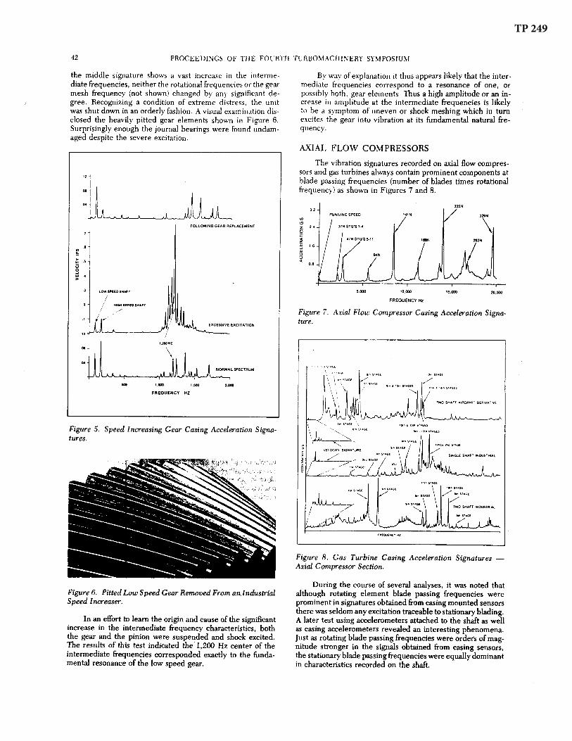
In addition to the characteristics discussed thus far, Figures 1-3 each contain spectral components in the vicinity of 1,500 Hz. Observed at varying amplitudes, roughly equivalent to the rotational frequencies, these components typically appear at multiples of the rotational frequencies between 1/3 and 1/2 of gear mesh and hence do not correlate to any obvious mechanical event. During one analysis, an order of magnitude increase was noted in the amplitudes of the intermediate frequencies compared to those recorded approximately six months earlier. Based strictly on the changes noted in the signature, a visual inspection was ordered which disclosed the damaged bearing pictured in Figure 4.
Figure 4. Damaged Pinion Bearing Removed From an Industrial Speed Increasing Gear.
A similar incident on the second gear is illustrated in Figure 5. The normal signature shown at the bottom contains both rotational and intermediate frequencies at amplitudes which are about average for this type equipment. Although
(
TP 249
TP 249

EXAMINATION OF PUMP CAVITATION. GEAR MESH & BLADE PERFORMANCE
USING EXTERNAL VIBRATION CHAR:\CTERISTICS 43
A possible explanation for this observation can be developed assuming the observed blade passing frequencies are generated by a wake or pressure pulse trailing each blade. As the pressure pulse impinges on adjacent structure the structure is excited at a frequency corresponding to the number of incident pulses in a given period of time. It thus follows that the stationary blading should be excited at rotor blade passing frequencies while rotor blading will be excited at stationary blade passing frequencies.
Since the stator is mechanically attached to the casing, stator excitation, at rotor blade passing frequency, is transmitted to a casing mounted sensor and attenuated depending on the mechanical impedance of the intervening structure. Based on the observations noted earlier it would appear that the impedance of the oil film far exceeds the dynamic range of the analysis equipment and thus rotor excitation, at stator blade passing frequencies, is lost into the background noise. If the latter supposition is correct the reported cases of rotating blade resonant frequencies or stator characteristics appearing in the signals obtained from casing mounted sensors must either involve extremely high excitation or a different path into the casing.
A second curiosity noted during studies of axial flow compressors is the amplitude variation at blade passing frequencies in response to speed, pressure ratio and angle of stator blading. Figure 9 illustrates a typical response at various stator blade angles with speed and pressure ratio held constant. Note that the highest amplitude, which in this case corresponds to twice
10
-20
$TATOR BLADE PI\SSING FUNDAMENTAL FREQUENCY
/
ROTOR BLADE PASSING 2nd HARMONIC
/
ROTOR Bl,.AOE PASSING FUNDAMEN�NCV
�
-10
STATOR BLADE A"4GLE - DEGREES
Figure 9. Amplitude Variations at Blade Passing Frequency and Multiples as a Function of Stator Blade Position.
the rotor blade passing frequency, occurs with the stator blades in the maximum closed position (large negative angles). As the stators open all the amplitudes decrease, particularly the previously mentioned t'"ice rotor blade passing until a minimum point is reached. Following the point of minimum excitation opening the blades further produces a corresponding increase in amplitude.
The significance of the above response may be in the ability to detect blade anomalies such as damage or an incorrect angle once the normal characteristics of a given machine are known. To test this theory a gas turbine, known to have blade damage in the first stage turbine, was located, recorded and the sonic vibration signatures compared against a group of signatures recorded at the same location on similar units. Interestingly enough there was no measurable difference. This observation was quite puzzling until it was realized that the turbine had been derated to keep exhaust temperature within safe limits and the data was being compared against blade characteristics recorded at a significantly higher power level. Based on the earlier study with axial flow compressors it seemed reasonable to assume that a decreased mass flow through the turbine at the lower power should have produced a corresponding reduction in the amplitude at the first stage blade passing frequency. Hence, although the blade characteristics appeared normal compared to amplitudes recorded at a higher power they might be clearly abnormal when compared to characteristics recorded from a turbine in satisfactory condition at the lower power level.
This theory was checked by recording the turbine blade characteristics on a similar gas turbine, first at rated power to establish agreement with normal amplitudes, then at the reduced power at which the data was recorded on the damaged turbine. Sure enough a significant reduction in amplitude was observed which then made the characteristics recorded on the damaged turbine appear abnormal by comparison.
Although the tests and observations described in the preceeding paragraphs are but the first steps and a large amount of work remains to quantify these characteristics into a useful analytical tool, some clear points have emerged. Perhaps most important is the observation that components generated by blade passing may vary significantly in response to normal variations in flow or speed. As a result it is extremely important to consistently record data under the same operating conditions in order to assure maximum repeatability of results unless one has access to an envelope showing characteristics over the machines entire operating range.
CENTRIFUGAL PUMPS AND COMPRESSORS
In addition to the familiar low frequency characteristics which have been well documented in a number of excellent papers on the subject essentially all centrifugal equipment will generate prominent vibration components at the vane passing frequency (number of vanes times shaft speed). Viewed in velocity units the amplitude of this component is generally equal to or less than the running speed component, however, several have been recorded at much larger amplitudes including the vane passing frequency recorded on a centrifugal pump known to be operating with insufficient suction head. Signatures recorded on centrifugal compressors have indicated the likelihood of a similar increase in amplitude at the vane passing frequency when approaching surge.
Figure 10 illustrates the prominent vane passing frequencies recorded on a group of centrifugal pumps. Within this group the CO2 Solution Pump was confirmed by calculations
TP 249

TP 249

EXAMINATION OF PUMP CAVITATION, GEAR MESH & BLADE PERFORMANCE
USING EXTERNAL VIBRATION CHARACTERISTICS 45
So where does that leave us; well, we continue searching, probing and trying different approaches until finally the right key or combination has been identified to make life a little easier for ourselves and the machinery entrusted to our care.
REFERENCES
1. Miller, T. D., "Machine Noise Analysis and Reduction."Sound and Vibration, March, 1967.
2. White, C. J., "Detection of Gearbox Failures." Paper presented to the Symposium on the Science and Technology
of Condition Monitoring, Southampton University, January 5 and 6, 1975.
3. Drosjack, M. J., Houser, D. J., and Tinney, A. C., "Investigation of Gear Dynamics Signal Analysis."USAAMRDL TR-75-1, January, 1975.
4. Sohre, J. S., "Operating Problems with High Speed Turbomachinery." ASME Paper presented at the ASMEPetroleum Mechanical Engineering Conference, September 23, 1968.
TP 249

10869 NC Highway 903, Halifax, NC 27839 USA endevco.com | [email protected] | 866 363 3826
© 2022 PCB Piezotronics - all rights reserved. PCB Piezotronics is a wholly-owned subsidiary of Amphenol Corporation. Endevco is an assumed name of PCB Piezotronics of North Carolina, Inc., which is a wholly-owned subsidiary of PCB Piezotronics, Inc. Accumetrics, Inc. and The Modal Shop, Inc. are wholly-owned subsidiaries of PCB Piezotronics, Inc. IMI Sensors and Larson Davis are Divisions of PCB Piezotronics, Inc. Except for any third party marks for which attribution is provided herein, the company names and product names used in this document may be the registered trademarks or unregistered trademarks of PCB Piezotronics, Inc., PCB Piezotronics of North Carolina, Inc. (d/b/a Endevco), The Modal Shop, Inc. or Accumetrics, Inc. Detailed trademark ownership information is available at www.pcb.com/trademarkownership.
TP249-012522
Related Documents


![Numerical Study on Cavitation Noise of Symmetrical Blade … 2018... · 2018-09-05 · Figure 1: The frequency ranges of cavitation noise for marine propellers (Seol, 2005)[12]. 2.2.Symmetrical](https://static.cupdf.com/doc/110x72/5e3799c97446173dbf3be229/numerical-study-on-cavitation-noise-of-symmetrical-blade-2018-2018-09-05.jpg)