INSTRUCTION MANUAL and WARRANTY REGISTRATION CARD INSTRUCTION MANUAL and WARRANTY REGISTRATION CARD NO POSTAGE REQUIRED IF POSTED IN AUSTRALIA Ph 61 7 5491 6988 web: www.latronics.com email: [email protected] A NEW WORLD POWER ® A NEW WORLD POWER ® REPLY PAID MB 1 LATRONICS PTY LTD P.O. BOX 73 MOFFAT BEACH QLD 4551 AUSTRALIA Latronics P.O. Box 73 Moffat Beach Qld 4551 AUSTRALIA

Welcome message from author
This document is posted to help you gain knowledge. Please leave a comment to let me know what you think about it! Share it to your friends and learn new things together.
Transcript

INSTRUCTION MANUALand
WARRANTY REGISTRATION CARD
INSTRUCTION MANUALand
WARRANTY REGISTRATION CARD
NO
PO
STA
GE
RE
QU
IRE
DIF
PO
ST
ED
INA
US
TR
AL
IA
Ph
61
75
49
16
98
8
web:
ww
w.la
tronic
s.c
om
em
ail:
technic
al@
latro
nic
s.c
om
A N E W W O R L D P O W E R
®
AN
EW
WO
RL
DP
OW
ER
®
RE
PLY
PA
IDM
B1
LA
TR
ON
ICS
PT
YLT
DP.O
.B
OX
73
MO
FFA
TB
EA
CH
QL
D4551
AU
ST
RA
LIA
Latro
nic
sP.O
.B
ox
73
Mo
ffat
Beach
Qld
4551
AU
ST
RA
LIA

WELCOME
Latronics
Latronics
Latronics
Latronics
products are all proudly designed, engineered andmanufactured in Australia. As a specialist sine wave inverter companywe produce Inverters for a diverse range of applications such as;mining, railways, telecommunications, marine, remote power, motorhomes, and other industrial or commercial installations.
In order to produce the most reliable products available,Inverters have been designed to endure the most rugged terrain andthe harshest conditions across the Australian continent.
All products are engineered using the latest high quality componentsand manufactured to stringent quality standards, thus ensuring
customers all enjoy many years of trouble free operation.
It is important to us at , that our clients enjoy the maximumbenefits from our Inverters in a safe and productive environment. Sowe strongly advise that you read through the next few pages of thismanual, which explains all the modes of operation and relevant safetyprecautions for your new Power Inverter.
Please remember to complete and return your registration cardon the last page of this manual to validate your warranty.Please retain your receipt as proof of purchase.
If your Inverter requires service or repair please complete theWarranty Repair Form on page 20.
LATRONICS
PO BOX 73
MOFFAT BEACH Q 4551
PH: 61 7 5491 6988 FAX: 61 7 5491 6792
EMAIL:
WEB: www.latronics.com
ria
lN
o....................................
Da
tec
ard
retu
rne
d..............................
IMPO
RTA
NT
!Ple
ase
co
mp
lete
an
dre
turn
this
Re
gis
tra
tio
nC
ard
to
va
lid
ate
yo
ur
Wa
rra
nty
RE
GIS
TR
AT
ION
CA
RD
Your
warr
anty
isonly
valid
ifth
iscard
iscom
ple
ted
&re
turn
ed
within
3m
onth
softh
edate
ofpurc
hase.
Nam
e:...................................................................................
.SerialN
o:.................................................
Date
ofP
urc
hase:............................................S
upplie
r:............................................................
....................................................
?R
esid
ential
Com
merc
ial
Sola
rB
atteries
Win
dO
ther
Featu
res
Valu
efo
rM
oney
Appeara
nce
Recom
mendation
Warr
anty
Austr
alia
nM
ade
Fair
Good
Very
Good
Excelle
nt
Above
Expecta
tions
Yes
No
Com
ments
:...........................................................................
................................................................................................................................
.......................................................................
*W
here
isyour
Invert
er
bein
gused
....................................
*W
as
your
decis
ion
made
because
of?
*H
ow
do
you
rate
the
serv
ice
from
your
supplie
r?
*D
idyour
new
Invert
er
meetyour
expecta
tions?
.Postcode:......................
Em
ail
(optional):...............................................................................
*W
hatE
nerg
yS
ourc
eis
connecte
dto
your
Invert
er?
Copyright Latronics. Doc No M70 08/08 Version 5

TABLE OF CONTENTS PAGE
A N E W W O R L D P O W E R
®
WARRANTY REPAIR FORM
Your Name ......................................................Phone.................................
Email............................................................................................................
Your Delivery Address ................................................................................
Your Postal Address ..................................................................................
nverter Serial No ..................................................................................
Have you contacted your system installer?
Do you have a battery bank
What is the capacity of your Battery Bank? ..............Amp hrs
Do you have Battery fuses installed?
Have these Battery fuses been checked?
Was the Inverter case hot when it failed?
Which lights came on when Inverter failed?
What time did your Inverter fail?
What were the weather conditions?
Have you disconnected the battery,
then tried to turn on your Inverter?
Please call *61 7 5491 6988 or email [email protected] to obtain
the address of your nearest service center and your RMA Number which is
essential for efficient processing.
RMA Number........................
Have you attached proof of purchase
We thank you for your time and patience. This information will help us
determining the cause of failure and possible prevention methods.
I
yes no
yes no
yes no
yes no
yes no
100% Overload
(please tick) 75% AC Grid
50% AC Fault
25%
Day night
sunny overcast rainy stormy
yes no
yes no
INSTALLATION
DC WIRING / DC EARTHING
WIRING DIAGRAMS
SPECIAL FEATURES
DIP SWITCH SETTINGS
INVERTER OPERATION
SOLAR INPUT CONFIGURATION
FAULT FINDING
RADIO FREQUENCY INTERFERENCE
WARRANTY CONDITIONS
TECHNICAL SPECIFICATIONS
WARRANTY CARD 20
18
17
16
15
14
13
12
10
7
3
2
20
AC WIRING 5

INSTALLATION
BEFORE INSTALLATION
�
�
Grid Interactive Solar Systems have become increasingly popular in recentyears. These systems do not necessarily require batteries for storage andtherefore can have a very simple configuration.
Ensure the Inverter has not been damaged in transit.
The unit must be placed in a well ventilated and protected area, not exposed
to the open environment, and free from contaminates (i.e. exhaust gases,
sea air, dust etc.).
The PV edge is designed for indoor installation in a suitable location where
ambient temperature will not exceed rated values.
As the PV edge has a wall mountable enclosure, ensure proper air circulation
for cooling of the Inverter.
Safety- DC solar input and AC grid are electrically and galvanically isolated
via the Toroidal Transformer.
It is important that all wiring in the installation complies with the relevant
standards (AS4777) .
�
�
�
�
Any work carried out is to be preformed by
Qualified and Licensed personnel.
1.
2 19
Photovoltaic Cells
Mains
PV Edge
STATEMENT OF QUALITY ASSURANCE
The whole of the supplies have been subjected to the QualitySystem Requirements in accordance with the conditions of
AS/NZS ISO 9002: 1994.
All items are manufactured with full traceability.All PV Edge Inverters conform to the C-Tick mark for the EMC
emission standard EN55014.

3
DC WIRING
Check solar array does not exceed inverter’s maximum voltage rating!
If other sources of DC input are required e.g wind turbines, micro hydroturbines etc, a battery bank or Latronics Turbine Controller (see pg 9) willbe required with the Maximum Power Point Tracking (MPPT) disabled(see pg 13).
The DC input voltage is stated on the PV Edge compliance label and thetechnical specifications sheet within this manual. Check that the inputvoltage is within the required limits and does not exceed the maximumlimit (see pg 18).
Recommended cable size for the DC Input is 6sqmm with an insulationrating of 0.6/1KV.
The Inverter is fitted with DC circuit breakers for the positive andnegative DC Input connections.
Ensure the DC breakers are switched OFF when connecting ordisconnecting the DC leads.
The PV Edge inverter is suitable for use with solar arrays that require positiveor negative earthing. Due to the inverter’s galvanic isolation between AC andDC inputs no additional modifications are required. Simply connect thepositive or negative of the solar array to the system earth.
Observe Polarity.
* The inverter is designed to operate with a 48V solar panel array(PVE1200) or 96V solar panel array (PVE2500).
* A 48V solar array will have an open circuit panel voltage of about 87Vdc.
* A 96V solar array will have an open circuit panel voltage of about 174Vdc.
*
*
*
*
*
*
POSITIVE/NEGATIVE EARTHING
18
TECHNICAL SPECIFICATIONS
Maximum DC 1200W 2500WMaximum DC Input Current 22A 22AMaximum DC Input Voltage 100V 200VMaximum Power Point 54VDC - 100VDCTracking RangeAutomatic Turn ON 70VDC 140VDCAutomatic TurnStarting Operation 10W 10WNumber of Modules 4x 12V modules or 8 x 12V modulesPer String 2 X 24V modules 4 X 24V modulesReverse PolarityProtection
(MPPT - ON)
Input Power
108VDC - 200VDC
ON 54VDC 108VDC
Short Circuit Diode Across Short Circuit Diode AcrossDC Input Terminals DC Input Terminals
Output Power 1000W cont. (1100W Max) 2100W cont. (2200W Max)Output Voltage Range 205 -265 Vac 205- 265 VacOutput Frequency 50Hz tolerance +/- 1Hz 50Hz tolerance +/- 1HzPeak Efficiency 93 % 93 %Night Time Power NIL Automatically NIL AutomaticallyConsumption Disconnects from AC Grid Disconnects from AC GridInput/Output Isolation 3500V via Toroidal 3500V via Toroidal
Transformer TransformerOperating Temperature - 10 C to 50 C - 10 C to 50 CAnti islanding Protection Over/under voltage Over/under voltage
Over/under frequency Over/under frequencyActive phase shift Active phase shift
Status Indicators Output power in 25% Increments Output power in 25% IncrementsGrid Monitoring - Stability check Grid Monitoring - Stability checkSolar Input ON Solar Input ONGrid Fault Grid FaultOverload OverloadTotal Energy Output kWh Total Energy Output kWh
Wall Mount Enclosure Powder Coated Aluminum Powder Coated AluminumDimensions 330mm x 296mm x 150mm 370mm x 386mm x 180mmWeight 11 kg 22 kgConnections Hardwire Junction Box Hardwire Junction BoxWarranty 3 years / Upgradeable 5 years 3 years / Upgradeable 5 years
CE, C-Tick CE, C-TickA 3100, AS4777 A 3100, AS4777E 55014 E 55014Certificate of Suitability Certificate of Suitability
(MPPT - OFF)
o o o o
H W D H W D
S SN N
Output Data
General Data
Standards

MC4 CONNECTOR WIRING
The inverter comes with two MC4 connectors panel mounted on the case. Toassemble the connecting partner, take a male and female MC4 connector andfollow the instructions below.
1. Strip back 10mm of cable (Recommended Cable: 6sqmm or bigger).
2. Check correct cable is partnered to correct connector. Insert the strippedcable into the metal insert and crimp shut.
3. Solder the crimped cable to the metal insert to ensure a solid connection.
4. Unscrew the pressure ring and insert the cable through.
5. Push cable into main body until clipped in.
6. Repeat procedure for the other connector.
MC4 connectors are purchasable in short male to female links,which can be cut in half and used to save time.Handy Hint:
MC Do not disconnect
under load
Pressure Ring
MC
Pressure Ring
MC
MC Do not disconnect
under load
WARRANTY CONDITIONS
All conditions and warranties expressed or implied by stature, common law,equity, trade, custom, usage, or otherwise howsoever are hereby expresslyexcluded to the maximum extent permitted by law. Where so permitted theliability of Latronics for a breach of condition or warranty that cannot beexcluded is limited (at Latronics option) to the replacement or repair of thegoods or of acquiring equivalent goods or the cost of replacing or repairing thegoods or of acquiring equivalent goods. Latronics shall not be liable in any waywhatsoever for indirect or consequential loss or damage whatsoever (whetherbased on tort or contract or otherwise)
�
�
�
�
�
�
�
�
�
Damage caused by unauthorised repair, alteration or substitution of non-standard parts, incorrect installation, misuse, negligence, accident orsimilar cause, or usage other than in accordance with the operatinginstructions, is not covered under warranty.
Unauthorised opening of the goods will render the Warranty invalid.
The company may, at its discretion, agree to act as agent for the ownerwhere delivery is requested and all costs for cartage and insurance willbe for the owners account
The replacement of any part or labour involved will not have the effect ofextending the period of the warranty of the goods.
Any faulty part replaced under Warranty becomes the property of theCompany for purposed of examination and claim under proprietaryWarranty.
Registration Card must be returned within 30 days from date of purchaseto validate your warranty.
Keep your receipt as proof of purchase, should any difficulties ariseconcerning the return of the registration card.
Inverters are supplied by the manufacturer, or the manufactures agents,under the express condition that no responsibility is implied or acceptedby the above parties for any damage to any appliance, equipment orproperty associated with the correct or otherwise operation of theInverter.
If service is required contact your local supplier/installer, or contactLatronics direct. Please ensure that you have completed the warrantyrepair form on page 18 to enable prompt processing.
. All warranty work is ex-factory.
174
Crimp Shut and solder

AC WIRING
Both models require an external 10A circuit breaker for protection ofinverter’s AC input. Usually mounted in main switchboard. The active andneutral of the AC output are electrically isolated from the DC inputs and earthconnections.
Latronics Inverters have the AC output (active and neutral) floating withrespect to the DC and Earth. This configuration provides the highest safetyand most flexibility for installation wiring. The earth is connected internallyto the Inverter case and is suitable for wiring.
The unit is supplied with both male and female 20Amp Wieland Gesislockable AC connectors that
To install connectors read the following procedure.
1. Make sure Inverter is switched OFF before working on mains wiring. Turnexternal AC Circuit Breaker switch into OFF position andmake sure it cannot be switched back on.
2. Test the wiring with a voltmeter to make sure no voltage is present.
3. Peel back 30mm of cable jacket and cut Active and Neutral cables5mm shorter than Earth.
4. Strip 5mm off all three cables.
5. Take the Wieland Gesis connector, disassemble into three main sectionsand insert stripped wire through as shown below.
E
can be disconnected under full load andcomplies with AS4777 standards for an isolator at the inverter.
MEN
30mm
Earth
Pressure RingMain Body
Socket
Round 2.5sqmm Twin & Earth Cable
RADIO FREQUENCY INTERFERENCE
Radio Frequency Interference (RFI) is a phenomenon that exists in modernsociety and is a problem in many areas of electronics. For Inverter users,RFI normally presents itself in the form of static and/or interference whenlistening to an AM radio and in unusual cases may interfere with TV reception.
Over the years Latronics has continued to invest significant time and effort inthe reduction of RFI related emissions from the entire product range, so thatthey comply with the appropriate International and/or Australian Standards.
Even with this compliance, there are situations where RFI may still be a causefor concern, and can differ greatly from installation to installation. Accordingly,the following is a list of recommendations made to assist in the overallreduction of RFI.
1. Avoid running DC and AC cables in thesame conduits and/or cable trenches. It is strongly recommended thatDC and AC wiring be separated by the greatest distance possible. Inextreme cases, the use of shielded conduit may be necessary.
2. . DC cables can act as an aerial,therefore all such cables should be kept as short as is practicable. Forbest performance minimize DC cable length to Inverter and Batteries andif possible avoid the use of auxiliary DC loads.
3. . For household installations, it is recommended that a“good” Earth Stake is located as nearby the Inverter as is possible.
4. These types of radio equipment inherently sufferfrom all forms of RFI, especially when the received signal level is weak.In such cases reception can sometimes be improved by relocation of theradio itself, alternatively the use of an appropriate external antenna andco-axial cable may be necessary. External antennas should be locatedin a manner that ensures maximum signal strength whilst affording thegreatest possible distance away from the Inverter and Batteries.
5. TV signals are transmitted as FM waveforms. This type ofsignal fundamentally reduces the effects of RFI, therefore the use of agood antenna and feeder cable is normally sufficient to ensure qualityreception. Locating the television as far as possible from the Inverter mayalso improve picture clarity.
Separate DC and AC wiring.
Minimize length of DC cabling
240Vac Earth
AM and HF Radios.
Televisions.
16 5

6. Connect the Active, Neutral and Earth cables as per diagram below.
7. Push the socket back into the Main Body until it clips in.
8. Screw the Pressure Ring back in to form a tight seal.
9. Plug into PV Edge.
To disconnect the plug, simply push the clip in and unplug.
Note: The clip section can be completely taken out if a lockable connectoris not desired.
N L
E
Neutral Active
Earth
Socket
15
FAULT FINDING
HELPFUL HINTS
Should the Inverter appear to be malfunctioning we suggest the following toeliminate any external problems.
Turn the Inverter OFF by switching the DC & external AC CircuitBreakers OFF. Leave OFF for 60 seconds.
Reconnect the DC Solar Input by switching DC breaker ON. All lightson the Inverter should come ON for 1 second at power up and then goOFF. The 75% light should remain ON to indicate the Solar Input isavailable. Solar Input voltage needs to be above the automatic turn ONvoltage, see pg 18, for the light to turn ON. If the light does notilluminate check Solar Input for correct operation.
Next reconnect the AC grid by switching the external AC breaker ON.After 20 seconds the 75% light should begin flashing to indicate Inverterreconnecting to the AC grid. The light will flash for 60 seconds while thePV Edge checks that the mains voltage and frequency are stable.Should the light not begin flashing check if the AC grid is present.
After the 75% light stops flashing the Inverter will begin feeding powerinto the AC Grid.
�
�
�
�
�
�
�
�
Make certain that you understand the operation of the Inverter.
Remember that it has automatic reconnection to the AC grid.
Make sure leads and terminals are not corroded, loose or faulty in anyway.
Make sure Circuit Breakers or switches are reset properly. If unsureswitch OFF and ON again.
6
Push to release

7
Battery
Back-U
pS
yste
m
10
A
Leg
end
PV
Ed
ge
LS
Inv
erte
r
So
lar
Pan
els
AC
Tra
nsf
erS
wit
ch
(AC
TS
-2)
Reg
ula
tor
(Op
tio
nal
)
Sw
itch
bo
ard
Po
wer
Po
wer
Lig
hts
Lig
hts
Ho
tW
ater
Sto
ve
PV
Ed
ge
Air
Co
n
(Ex
amp
leo
nly
)
Mai
nS
wit
ch
PV
E1
20
0–
48
V(m
in2
00
Ah
rs)
PV
E2
50
0–
96
V(m
in2
00
Ah
rs)
Bat
teri
es
=C
ircu
itB
reak
er
AC
DC
10
A
Ex
po
rtM
eter
Imp
ort
Met
erG
rid
Mai
ns
14
Note 1:
Note 2
The DC input is suitable for connection to solar modulesonly, when MPPT is enabled.
: Do not exceed recommended Maximum DC Input Power.
Note 3: All solar modules should be of the same type and brand.Therefore the maximum power point and voltage variation withtemperature are consistent for all modules, which will ensuremaximum system output.
SOLAR INPUT CONFIGURATION
Panel Power
At 25 Co
75W
90W
100W
125W
140W
150W
165W
175W
Module
Type
12V
12V
12V
12V
24V
24V
24V
24V
Number of Panels
Per String
4
4
4
4
2
2
22
Solar Input
Power
1200W
1080W
1200W
1000W
1120W
1200W
1320W
1400W
No. of Strings
4
3
3
2
4
4
4
4
PVE 1200 (Max Solar Input: 1400Wp)
PVE 2500 (Max Solar Input: 2800Wp)
Panel Power
At 25 Co
90W
100W
110W
125W
140W
150W
160W
165W
175W
Module
Type
12V
12V
12V
12V
24V
24V
24V
24V
24V
Number of Panels
Per String
8
8
8
8
4
4
4
4
4
Solar Input
Power
2160W
2400W
2640W
2000W
2240W
2400W
2560W
1980W
2800W
Number
of Strings
3
3
3
2
4
4
4
3
4

8
Sta
nd
ard
Gri
dC
on
nect
Syste
m
WA
RN
ING
:T
he
Invert
er
outp
utis
connecte
dto
main
sele
ctr
icity,
thus
itis
import
antth
atall
AC
wirin
gcom
plie
sw
ith
the
requirem
ents
ofth
ere
levantw
irin
gsta
ndard
s,(A
S3000,A
S4777).
An
yw
ork
carr
ied
ou
to
nA
C/M
ain
sw
irin
gis
tob
ep
erf
orm
ed
by
Qu
alifi
ed
An
dL
icen
sed
pers
on
nelo
nly
.
PV
Ed
ge
So
lar
Pan
els
Grid
Mai
ns
Sw
itch
bo
ard
Po
wer
Po
wer
Lig
hts
Lig
hts
Ho
tW
ater
Sto
ve
Air
Co
n
(Exam
ple
only
)
10
A
Leg
end
=C
ircu
itB
reak
er
Ex
po
rtM
eter
Imp
ort
Met
er
DIP SWITCH SETTINGSSwitch 1 -MPPT / Battery mode
Switch 2 - 50/60 Hz
Switch 4
Switch 5
Switch 6
In the ON position the Maximum Power Point Tracking is enabled.This is required when the DC input is Photovoltaic Solar Modules only.In the OFF position the Maximum Power Point Tracking is disabled and thevoltage tracking will operate at a fixed voltage of 54V (PVE1200) or 108V(PVE2500). This setting is required in a system where a 48V (PVE1200) or96V (PVE2500) Battery Bank is required on the DC input.
In the ON position the Inverter is set for 60Hz operation.In the OFF position the Inverter is set for 50Hz operation.
Must be in OFF position for normal operation. The ON position isa factory AC test setting.
Must be in the OFF position for normal operation. The ON positionis a factory DC test setting.
Not used.
(default)
(default)
(default)
(default)
(default)
Switch 3
Battery type selector not used if switch 1 is ON.ON = Gel/SLA battery.OFF = Flooded battery.
13
DIP SWITCH LOCATION
MAIN PCB
DIP Switch located on Main PCB1 2 3 4 5 6
OFF
ON
WARNING:Due to dangerous voltages existing inside the unit, make sure
the DC circuit breaker and AC solar isolator are turned offbefore opening the unit. Only are
permitted to adjust these settings.qualified Trades Persons

12
SPECIAL FEATURESCircuit Breakers
Digital KwH Meter
Night Time Disconnect
Parallel Operation
Note:
Maximum Power Point Tracking
Protection
Maintenance Cycle
There is one double pole DC circuit breaker isolating both DC positive & DCnegative.
The KwH meter shows an accumulative reading of the total power generatedand allows the user to monitor their green power production. LCD displaywith 5 digits and 2 decimal places (i.e. 99999.99kwh).
After dark when the solar input is no longer available the Inverter willautomatically disconnect from the AC grid. This feature ensures that duringthe night, the Inverter cannot consume any power whatsoever whileremaining idle. Upon sunrise the next morning when solar input becomesavailable again, the PV edge will automatically reconnect to the AC grid andbegin generating power.
The PV edge automatically synchronizes to the AC grid, therefore the outputof multiple units can all be connected together, and they will all besynchronized by the AC grid.
The optimum power level from the solar input depends on the available solarmodules. Even in cloudy weather with fluctuations in the solar radiationlevel, the PV Edge constantly monitors and tracks the optimum operatingpoint to ensure maximum power from the solar modules is achieved.
The AC grid supply is constantly monitored for under and over voltage, overand under frequency, and anti islanding conditions via active phase shifts.The DC input is protected against over voltage, reverse polarity and overcurrent via very fast current limit control. Isolation between the DC input andAC output is achieved via the Toroidal Transformer. The temperature of thetransformer and switching devices are continuously monitored. The Inverteris fitted with a cooling fan, which is temperature controlled and only operateswhen required.
When in Battery mode ( MPPT disabled) a maintenance cycle is performedevery 30 days. This is a short boost cycle for sealed batteries or an equalizecharge for flooded cells. In this mode the bottom LED will flash slowly untilthe cycle is completed.
The Solar inputs of multiple unit Inverters are not to be paralleled.
9
PV
Ed
ge
Grid
Inve
rte
r
Turb
ine
Co
ntro
ller
Turb
ine
3-P
ha
seRe
ctif
ier
(Ma
yb
eb
uilt
into
turb
ine
)
Batt
ery
less
Tu
rbin
e
Grid
Ma
ins
The
Latr
onic
sT
urb
ine
Contr
olle
rutiliz
es
the
late
stin
mic
ro-c
ontr
olle
rdesig
nto
deliv
er
asta
ble
and
safe
supply
ofpow
er
toth
egrid
connectin
vert
er.
Desig
ned
specific
ally
toin
tegra
tew
ith
the
PV
Edge
line
ofLatr
onic
sin
vert
ers
,it
allo
ws
battery
-less
grid
connection
ofw
ind
and
wate
rtu
rbin
es.
NO
TE
:P
VE
dge
mustbe
inB
attery
Mode.
(See
pg
13)
10 11
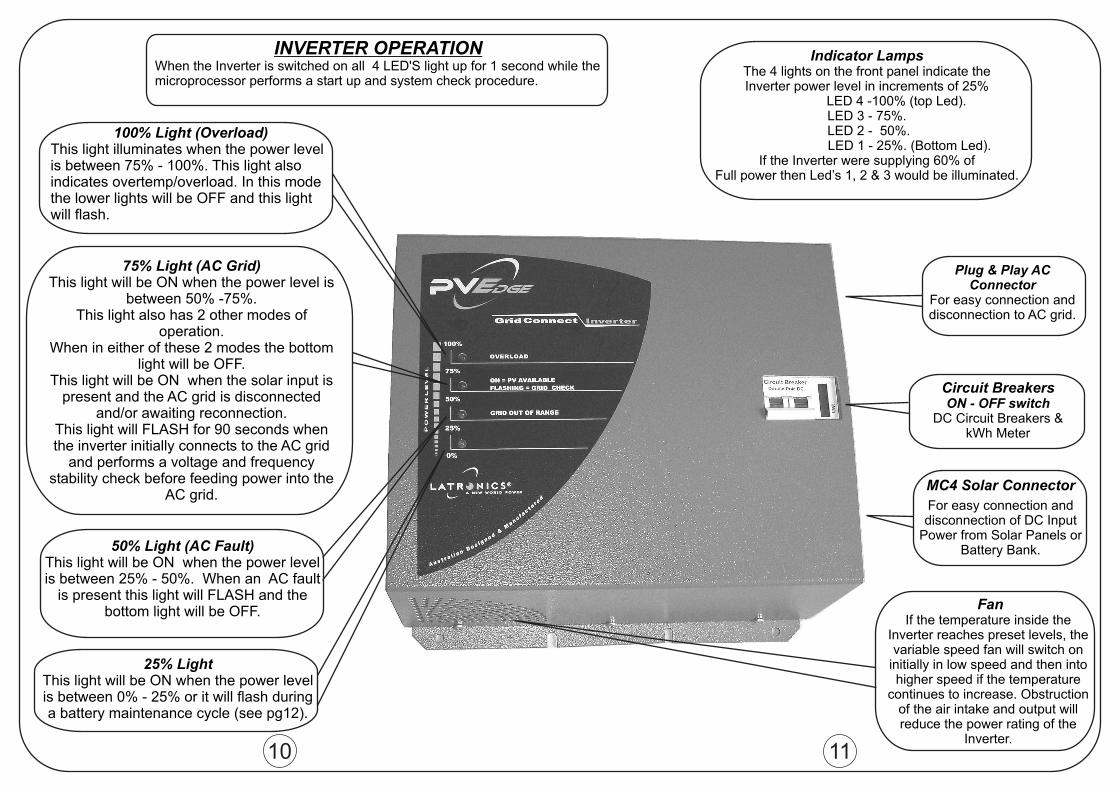
MC4 Solar Connector
For easy connection anddisconnection of DC Input
Power from Solar Panels orBattery Bank.
FanIf the temperature inside the
Inverter reaches preset levels, thevariable speed fan will switch on
initially in low speed and then intohigher speed if the temperature
continues to increase. Obstructionof the air intake and output willreduce the power rating of the
Inverter.
Circuit BreakersON - OFF switch
DC Circuit Breakers &kWh Meter
Plug & Play ACConnector
For easy connection anddisconnection to AC grid.
INVERTER OPERATIONWhen the Inverter is switched on all 4 LED'S light up for 1 second while themicroprocessor performs a start up and system check procedure.
100% Light (Overload)This light illuminates when the power levelis between 75% - 100%. This light alsoindicates overtemp/overload. In this modethe lower lights will be OFF and this lightwill flash.
75% Light (AC Grid)This light will be ON when the power level is
between 50% -75%.This light also has 2 other modes of
operation.When in either of these 2 modes the bottom
light will be OFF.This light will be ON when the solar input is
present and the AC grid is disconnectedand/or awaiting reconnection.
This light will FLASH for 90 seconds whenthe inverter initially connects to the AC grid
and performs a voltage and frequencystability check before feeding power into the
AC grid.
50% Light (AC Fault)This light will be ON when the power levelis between 25% - 50%. When an AC fault
is present this light will FLASH and thebottom light will be OFF.
25% LightThis light will be ON when the power levelis between 0% - 25% or it will flash duringa battery maintenance cycle (see pg12).
Indicator LampsThe 4 lights on the front panel indicate theInverter power level in increments of 25%
LED 4 -100% (top Led).LED 3 - 75%.LED 2 - 50%.LED 1 - 25%. (Bottom Led).
If the Inverter were supplying 60% ofFull power then Led’s 1, 2 & 3 would be illuminated.
Related Documents


![UR24C Operation Manual€¦ · Panel Controls and Terminals UR24C Operation Manual 3 Panel Controls and Terminals Front Panel 1[INPUT 1 HI-Z] switch Switches the input impedance (on](https://static.cupdf.com/doc/110x72/6022c8d5b0122b00243edec8/ur24c-operation-manual-panel-controls-and-terminals-ur24c-operation-manual-3-panel.jpg)


