EWEC 2011, 16 th March 2011 Universal Foundation A novel wide-ranging substructure installation concept 1 MBD introduction The Universal Foundation Framework The prototypes The supply chain Conclusion Søren A. Nielsen, MBD, CPO. Lars Bo Ibsen, Aalborg University, Research Professor.

EWEC 2011, 16 th March 2011 Universal Foundation A novel wide-ranging substructure installation concept 1 MBD introduction The Universal Foundation Framework.
Dec 16, 2015
Welcome message from author
This document is posted to help you gain knowledge. Please leave a comment to let me know what you think about it! Share it to your friends and learn new things together.
Transcript

EW
EC
201
1, 1
6th M
arc
h 2
011
Universal FoundationA novel wide-ranging substructure installation concept
1
MBD introduction
The Universal Foundation Framework
The prototypes
The supply chain
Conclusion
Søren A. Nielsen, MBD, CPO. Lars Bo Ibsen, Aalborg University, Research Professor.

EW
EC
201
1, 1
6th M
arc
h 2
011
2
MBD Offshore Power A/S
R&D company founded in 2001Shareholders:• DONG Energy, >50%• Aalborg University• Novasion
Primary cooperation:• Aalborg University • Dong Energy• NearshoreLAB • Fred. Olsen Group
EW
EC
201
1, 1
6th M
arc
h 2
011
3
Universal Foundation Concept: A framework for industrialization
• The optimal foundation for each turbine position
• Design is parameter driven
• Structure based on scaleable modules and elements
• Production based on series or mass production
• Installation in widest possible weather window
• Installation based on common available vessels
A concurrent process, adding new processes and experiences to a database, used by a configuration methodology to produce the required documentation in each step of the wind farm projects focusing on:
Principles,
methodes,
procedures,
expirences
Pro
du
ct c
on
fig
ura
tio
n
Feasibility studies
Tender design
Detail design
Conseptual design
Operation documentation
Construction documentation
Feed back
Ris
k / c
ost
ass
esm
ent
DatabaseConfigu-
rator Standard
output
Site data
OwnerConstruc
-tionConsul-
tantInstallati
on
Feedback Feedback FeedbackFeedback
Feedback
Sales
Development
Engineering InstallationProduction
EW
EC
201
1, 1
6th M
arc
h 2
011
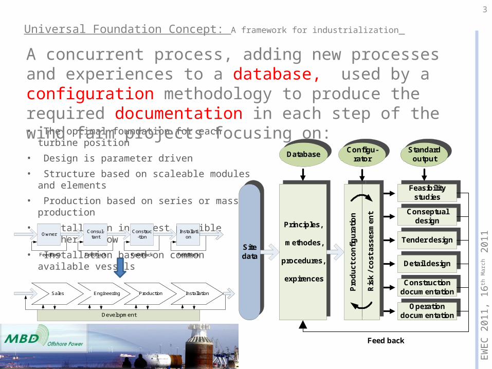
Main focus area: The bucket foundation technology as large diameter monopile
4
Concept advantages:• Reduced use of steel compared to any other substructure solution. • Use of simple geometric welded steel structures. The structure is omni-
directional symmetrical with respect to the vertical axis. • Few offshore operations, with utilizing smaller equipment/vessels during
installation. • No seabed preparation and no or reduced need for scour protection.• Adjusting the upper part of the shaft to fit the standard wind turbine tower. • Simple decommissioning.
Installation advantages:• Minimum noise impact. No pile driving hammers or drill drives are used.• No grouted connections. • Minimum disturbance to the existing seabed. • The use of excess material for scour protection is reduced or not necessary.• All steel materials can be recovered from the seabed and reused / recycled
when the foundation is decommissioned
EW
EC
201
1, 1
6th M
arc
h 2
011
5
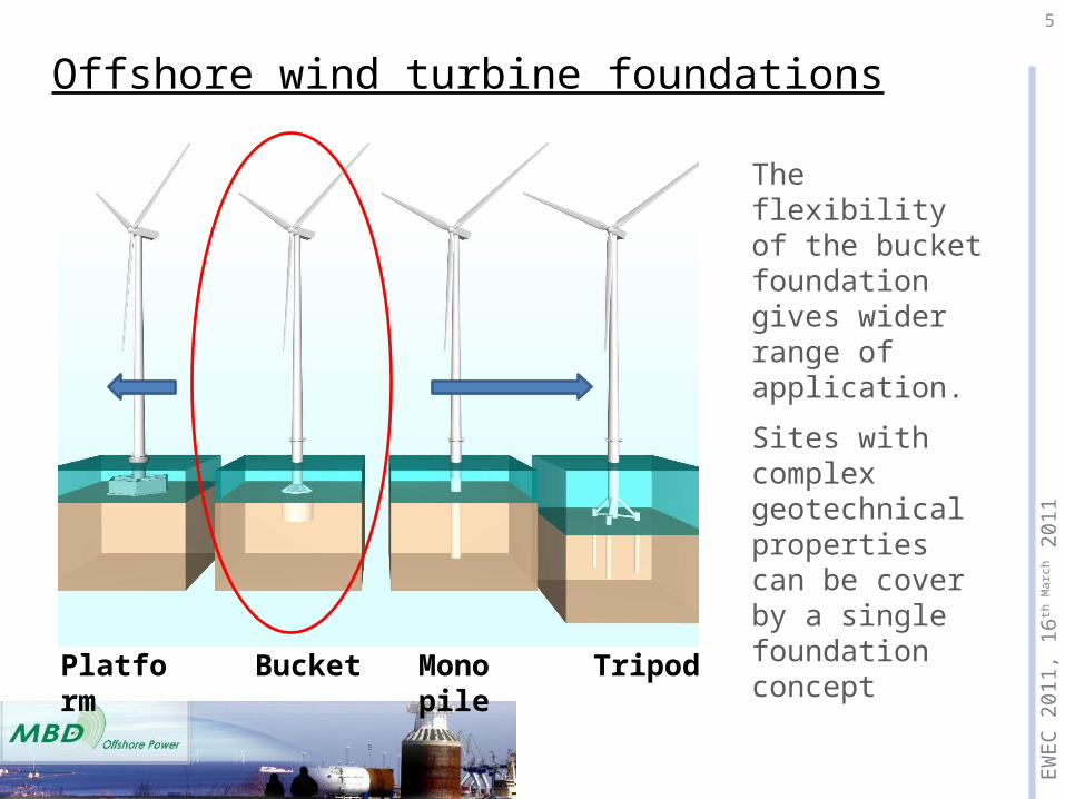
Offshore wind turbine foundations
Platform Bucket Mono pile Tripod
The flexibility of the bucket foundation gives wider range of application.
Sites with complex geotechnical properties can be cover by a single foundation concept
EW
EC
201
1, 1
6th M
arc
h 2
011
6
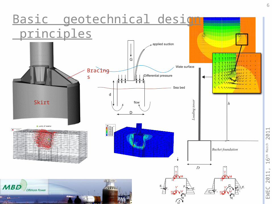
Skirt
Bracings
Basic geotechnical design principles
EW
EC
201
1, 1
6th M
arc
h 2
011
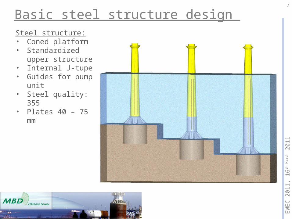
Basic steel structure design 7
Steel structure:• Coned platform• Standardized upper
structure• Internal J-tupe• Guides for pump unit• Steel quality: 355• Plates 40 – 75 mm

EW
EC
201
1, 1
6th M
arc
h 2
011
8
Basic steel structure design Structure analyzes:• Ultimate load• Fatigue load• Eigenfrequen

EW
EC
201
1, 1
6th M
arc
h 2
011
9
The Ø12x6 m prototype bucket foundation was designed for a Vestas V90 3MW turbine placed on 4 m of water. The design is certified by DNV. The bucket was installed in late 2002 and is in normal operation. The structure/soil interaction has been investigated with sophisticated modal analyse equipment.
The prototype for Pos. 1, Frederikshavn

EW
EC
201
1, 1
6th M
arc
h 2
011
10
The Mobile Met-Mast"The Mobile Met Mast" is a prototype of a bucket foundation designed as support structure for a met-mast.
Purpose: To gain confidence that
a monopod bucket foundation can be successfully installed offshore.
To obtain a movable met-mast, which can be used in several offshore wind farms.
Specification
Total height: 34 m Weight: 165 tones Skirt length: 6 m Skirt diameter: 12 m
Fabricated in Aalborg in August 2008.
Installed at Horns Rev 2 Offshore wind farm in March 2009.

EW
EC
201
1, 1
6th M
arc
h 2
011
11
Installation A penetration velocity of 2
m/hour was obtained. After 2.5 m penetration, the
foundation started tilting. At 4 m penetration, the process was reversed until 3 m penetration. Then the penetration process was repeated without tilting problems. The tilt problem was properly caused by a stone along the skirt circumference.
The flow induced in the soil was blocked, indicating that a clay layer was present. Installation continued.
The foundation was successfully installed with a 0.1 degree inclination out of vertical.

EW
EC
201
1, 1
6th M
arc
h 2
011
12
Universal foundation solutions
Variation in water depth0 - 60 m
Variation in seabed propertiesHard clay, soft clay, sand, silt
EW
EC
201
1, 1
6th M
arc
h 2
011
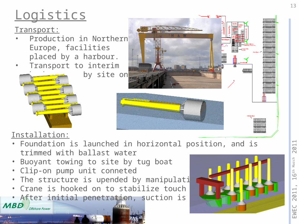
13
LogisticsTransport:• Production in Northern Europe,
facilities placed by a harbour.• Transport to interim harbour
nearby site on barge
Installation:• Foundation is launched in horizontal position, and is trimmed with ballast water• Buoyant towing to site by tug boat• Clip-on pump unit conneted• The structure is upended by manipulating ballast water• Crane is hooked on to stabilize touch down• After initial penetration, suction is applied

EW
EC
201
1, 1
6th M
arc
h 2
011
14
Supply Chain
• The implementation of the concept is conducted by a facilitator organization (solution provider) with access to the IP-rights of the bucket concept.
• Close cooperation with the project developer/owner of the wind farm project.
• The functions of the facilitator are to the ensure that the technology, methodologies and procedures is optimized throughout the entire supply chain as well as ensure that the contract relations in-between the different stakeholder is managed to utilize the full potential of the concept.

EW
EC
201
1, 1
6th M
arc
h 2
011
15
ConclusionUniversal Foundation is found to be:
• Applicable in a wide range of offshore conditions water depth / soil conditions• A focused concept development and design procedures• A cost effective fabrication / installation concept -> reduced cost of energy • Environmental feasible - no noise impact and seabed disturbance
Plan for commercialization and further development:One package complying of:
• Geotechnical calculation / design manual• Production basis• Transport concepts• Installation manual• Decommission concepts• Concurrent concept development
Next step:•Prototype reference full scale implementation•2 Ph.D.s working on steel/concrete composites and soil/structure
interaction in clay•Development of click-on pump unit and soil investigating equipment
Related Documents