Evolution of the conceptual hydrogeologic and ground-water flow model for Las Vegas Valley, Clark County, Nevada David J. Donovan Southern Nevada Water Authority Geological Society of America Annual Meeting November 14, 2000

Welcome message from author
This document is posted to help you gain knowledge. Please leave a comment to let me know what you think about it! Share it to your friends and learn new things together.
Transcript

Evolution of the conceptual hydrogeologic and ground-water flow
model for Las Vegas Valley, Clark County, Nevada
David J. Donovan
Southern Nevada Water Authority
Geological Society of America Annual Meeting
November 14, 2000

Outline
• Model development
• Improvement in geologic understanding

Conceptual Model DevelopmentHydrologic Parameters
• Location, timing and value of:– Water levels– Ground water production / injection– Spring, creek flow– Major and minor wash flow– Water usage by bare-soil and pheatophytes– Natural recharge– Secondary recharge– Interbasin flow

Conceptual Model DevelopmentHydrogeologic Parameters
• Location, and value of:– Transmissivity - Horizontal permeability– Leakance - Vertical permeability– Storativity - Ability to store water
• Spatial distribution determined by a combination of geology and hydrology
• Assigned value primarily determined by hydrologic analysis (aquifer tests / modeling)

1981 MSS Image (2,3,1)

> 5,000 meters of fill
Me
ters
ab
ove
me
an
se
a l
eve
l
Topography of Las Vegas Valley

Major structures and lithologies in Las Vegas Valley

Hydrologic flow system and Hydrogeologic setting
-1000
-4000
-3000
-2000
-5000
2000
3000
0
1000LowerPaleozoicCarbonate Rocks
Carbonates ?PaleozoicLower
UpperPaleozoicTransitionalMesozic
SliciclasiticRocks
&Rocks Rocks
CratonalCambrian
Mesozoic to
?
pre-Cambrian
Basement
SPRING MOUNTAINS
Frenchman Mtn.Las Vegas
WashSpringsLas VegasMountain
La Madre
Alluvial FanRed Rock
Las Vegas Boulevard (Strip)
West EastEdge of Las Vegas Valley Hydrographic Basin
Ground water flow directions
0
-5000Hydrogeologic cross-section. Vertical exaggeration: 4 to 1
025005,0007,500
10,00012,500
-2,500-5,000-7,500
-10,000-12,500-15,000
??
UTM meters east (NAD 27)
Hydrologic flow system. Vertical exaggeration: 1 to 1
ToColorado
River
ToPahrump

High permeability area inLas Vegas Valley
High permeability area

Maxey and Jameson cross-section
East
INTERBEDDED SANDY GRAVELS
SILTY CLAYS
CALICHE WITH SAND AND GRAVEL
DISTRICTMAIN WELL FIELD
NEW WELLS
Generalized geologic cross-section of Las Vegas Valley
EXPLANATION
Modified from Maxey and Jameson (1948)
Vertical Exageration ~ 17.5U D
U D U D
500
250
(m)
West
0 5
KILOMETERS
CARBONATE BEDROCK
500
250
750
1000(m)
"Near-surface water""Shallow aquifer""Middle aquifer""Deep aquifer"

Concept of allostratigraphic units
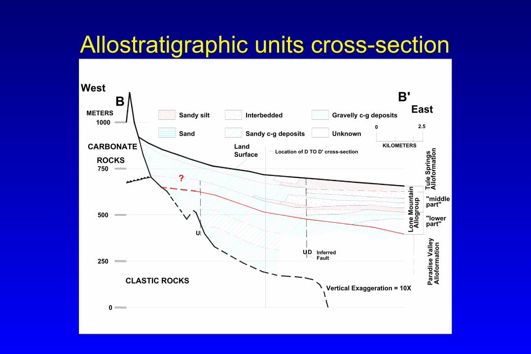
Allostratigraphic units cross-section
"middle
0
250
500
Fault
CLASTIC ROCKS
UD Inferred
U
part""lower
part"
CARBONATE
750
West
1000
METERS
B
?
Surface Location of D TO D' cross-section
Vertical Exaggeration = 10X
B'
Land
Sand Sandy c-g deposits
KILOMETERS
Gravelly c-g depositsInterbeddedSandy silt
2.50
ROCKS
Unknown
East

Hydrostratigraphic units cross-section
24A
0
250
500
Fault
5
6 6B?
UD Inferred
U
4
4B
3B
750
West
1000METERS
B
(aquifer)
(aquifer)(aquitard)
3A1B
2
1A
1X
East
Surface Location of D TO D' cross-section
Vertical Exaggeration = 10X
B'
Land
Very high permeability
Low permeability Moderate permeability
KILOMETERS
Unknown
2.50
EXPLANATION
CarbonateRocks
Clastic Rocks

Hydrostratigraphic unit fence Diagram
1X1A
1B
1B
1A
1X
1X
4
4
4B
4B3A
2
5
66
5
3B 2
2
3A
2A
2B
4
6B?
3B
0 1 2 3 4 5
N
W
S
E
0
0
100
100
200
200
300
300
400
400
500
500
600
600
700
0
250
500
750
750
1000
Meters above
6?
Area OfInvestigationBoundary
D
D'
B
B'
Low Permeability
ModeratePermeability
HighPermeability
CarbonateBedrockClasticBedrock
PotentiometricSurface
Wells usedto create fence diagram
PotentiometricSurface
1A
1B
1X
2
2A
3A
3B
4
4A
4B
5
6
6B
2B
mean sea level
Elevation
Duck CreekAquifer
Las VegasSprings
Las VegasWash
Aquifer
Aquitard

Relationship between allostratigraphic and hydrostratigraphic units
Increase in sorting
Increasing distance from source
Locally cemented
Poorly sorted, cementedcoarse-graineddeposits
Well sortedlightly cemented
moderately coarse-graineddeposits
fine-grained deposits


Hydrostratigraphic Units
shallow geochemical zone
aquitard
aquitard
aquitard
aquitard
primary aquifer fornon-municipal wells
primary aquifer formunicipal wells
aquifer ?
aquifer ?
Las VegasWash
Aquitard
Las VegasSpringsAquifer
DuckCreekAquifer
(confiningunit)
Very Simplified diagram ofthe ground-water systemin the central part ofLas Vegas Valley
0
25
50
75
100
125
150
175
200
225
250
275
300
325
350
375
400
425
450

Model Layers - Gross Simplification
Layer 1 - Las Vegas Wash Aquitard
Leakance Boundary - Las Vegas Creek Aquifer Plus Twin Lakes Aquitard
Layer 2 - La Madre Mountain Aquifer
Leakance Boundary - Unnamed Aquitard at the Top of the Duck Creek Aquifer
Layer 3 - Duck Creek Aquifer
1
2
3

Transmissivity map Layer 1
8 Transmissivity Zones
Range of Values:
100 to 5,000 ft2/d

Upper Leakance layer
8 Leakance Zones
Range of Values:
1.0E-8 to 1.6E-4 ft2/d

Transmissivity map Layer 2
11 Transmissivity Zones
Range of Values:
50 to 30,000 ft2/d

Lower Leakance layer
6 Leakance Zones
Range of Values:
1.0E-8 to 1.0E-3 ft2/d

Transmissivity map Layer 3
6 Transmissivity Zones
Range of Values:
50 to 1,000 ft2/d

Table - TransmissivityTransmissivity
code Type Layer 1 Layer 2 Layer 30 Inactive 0 0 01 Carbonate Rock 101 551 1,0002 Clastic Rock 102 252 1003 Igneous/Metamorphic Rock 103 53 504 Cemented Alluvial Fan gravel 1,500 1,0045 U/F U/C Alluvial Fan Gravel/Sand 2,500 8,0056 Faulted Sands/Silts/Gravel 1,001 6,0067 Unfaulted/Undiff. Silts/Sands/Clays 1,000 307 5008 Local moderately permeable areas 5,000 12,6009 Very permeable areas 50,000 30,009
10 N/A11 Faulted Carbonate Rock 50112 Faulted Clastic Rock 5213 Faulted Igneous/Metamorphic Rock14 Local odd unit 1,214

Table - Leakance
Leakance L 1-2 L 2-3code Type
0 Inactive 0 01 Carbonate Rock 1.1E-06 1.0E-062 Clastic Rock 2.0E-08 2.0E-083 Igneous/Metamorphic Rock 1.0E-08 1.0E-084 Cemented Alluvial Fan gravel 1.5E-065 Alluvial Fan Gravel/Sand 1.6E-04 1.0E-046 Faulted Sands/Silts/Gravel 1.3E-05 1.0E-037 Unfaulted/Undiff. Silts/Sands/Clays 1.0E-07 1.0E-078 Local moderately permeable areas 1.5E-069 Very permeable areas
10 N/A11 Faulted Carbonate Rock12 Faulted Clastic Rock13 Faulted Igneous/Metamorphic Rock14 Local odd unit

Conclusions
• Hydrologeologic models primarily test geologic concepts
• Geologic understanding has increased in the last two decades
• Hydrologic data is the compilation of causes and effects on the ground-water system
• Most observed ground-water system changes are a result of multiple causes

Artesian wells in Las Vegas Valley
1912 1998

Table - StorativityStorage Layer 1 Layer 2 Layer 3
code Type0 Inactive1 Carbonate Rock 1.0E-01 1.001E-02 1.1E-032 Clastic Rock 1.0E-01 1.002E-02 1.2E-033 Igneous/Metamorphic Rock 1.0E-01 1.003E-02 1.3E-034 Cemented Alluvial Fan gravel 2.5E-01 1.004E-025 Alluvial Fan Gravel/Sand 8.050E-036 Faulted Sands/Silts/Gravel 1.006E-027 Unfaulted/Undiff. Silts/Sands/Clays 1.5E-01 1.070E-03 1.7E-038 Local moderately permeable areas 1.001E-019 Very permeable areas 5.009E-02
10 N/A11 Faulted Carbonate Rock12 Faulted Clastic Rock13 Faulted Igneous/Metamorphic Rock14 Local odd unit 1.101E-0115 Local odd unit 2 4.015E-02

Location of Las Vegas Valley

Allostratigraphic units
shallow geochemical zone
Tule SpringsAlloformation
Lone MountainAllogroup
ParadiseValley
Alloformation
silt
Very Simplified diagramof the basin-fill inthe central part ofLas Vegas Valley
0
25
50
75
100
125
150
175
200
225
250
275
300
325
350
375
400
425
450
gravel
silt
gravel with
silt
gravel
silt
gravel
caliche
(Las Vegas Fm.)

Major lithic types: Las Vegas Valley
Related Documents