254 Int. J. Electronic Business, Vol. 10, No. 3, 2013 Copyright © 2013 Inderscience Enterprises Ltd. Evolution mechanisms for goal-driven pattern families used in business process modelling Saeed Ahmadi Behnam and Daniel Amyot* School of Electrical Engineering and Computer Science (EECS), University of Ottawa, 800 King Edward Avenue, Ottawa, ON, K1N 6N5, Canada E-mail: [email protected] E-mail: [email protected] *Corresponding author Abstract: Reusability is important when modelling business processes and patterns are known to increase reusability. A pattern-based framework that lays down a foundation for capturing knowledge about business goals and processes and customising it for specific organisations in a given domain is hence valuable. For many reasons however, the problems and solutions within a business domain are constantly changing. Consequently, such framework can be useful only if it provides mechanisms for evolving pattern families over time. In this paper, we propose and formalise four mechanisms for evolving a goal-driven pattern family targeting the modelling of business goals, business processes, and traceability links between these two views. We demonstrate the feasibility of the evolution algorithms with examples from the patient safety domain. We also illustrate how the framework is used to extract relevant business goals and processes in a specific healthcare context. Keywords: business process modelling; context; evolution; goal modelling; healthcare; pattern family; User Requirements Notation; URN. Reference to this paper should be made as follows: Behnam, S.A. and Amyot, D. (2013) ‘Evolution mechanisms for goal-driven pattern families used in business process modelling’, Int. J. Electronic Business, Vol. 10, No. 3, pp.254–291. Biographical notes: Saeed Ahmadi Behnam is a Researcher at the University of Ottawa. His interests include requirements engineering, goal modelling, business process modelling and healthcare informatics. He received his PhD in Computer Science from the University of Ottawa (2012), as well as his MSc in Systems Engineering and his BSc in Software Engineering from Amirkabir University of Technology (2003 and 2000). Daniel Amyot is a Professor at the University of Ottawa, which he joined in 2002 after working for Mitel Networks as a Senior Researcher. His research interests include scenario-based software engineering, requirements engineering, business process modelling, aspect-oriented modelling, and healthcare informatics. He is an Associate Rapporteur for requirements languages at the International Telecommunication Union, where he leads the evolution of the User Requirements Notation. He received his PhD and an MSc from the University of Ottawa (2001 and 1994), as well as a BSc from Laval University (1992).

Welcome message from author
This document is posted to help you gain knowledge. Please leave a comment to let me know what you think about it! Share it to your friends and learn new things together.
Transcript

254 Int. J. Electronic Business, Vol. 10, No. 3, 2013
Copyright © 2013 Inderscience Enterprises Ltd.
Evolution mechanisms for goal-driven pattern families used in business process modelling
Saeed Ahmadi Behnam and Daniel Amyot* School of Electrical Engineering and Computer Science (EECS), University of Ottawa, 800 King Edward Avenue, Ottawa, ON, K1N 6N5, Canada E-mail: [email protected] E-mail: [email protected] *Corresponding author
Abstract: Reusability is important when modelling business processes and patterns are known to increase reusability. A pattern-based framework that lays down a foundation for capturing knowledge about business goals and processes and customising it for specific organisations in a given domain is hence valuable. For many reasons however, the problems and solutions within a business domain are constantly changing. Consequently, such framework can be useful only if it provides mechanisms for evolving pattern families over time. In this paper, we propose and formalise four mechanisms for evolving a goal-driven pattern family targeting the modelling of business goals, business processes, and traceability links between these two views. We demonstrate the feasibility of the evolution algorithms with examples from the patient safety domain. We also illustrate how the framework is used to extract relevant business goals and processes in a specific healthcare context.
Keywords: business process modelling; context; evolution; goal modelling; healthcare; pattern family; User Requirements Notation; URN.
Reference to this paper should be made as follows: Behnam, S.A. and Amyot, D. (2013) ‘Evolution mechanisms for goal-driven pattern families used in business process modelling’, Int. J. Electronic Business, Vol. 10, No. 3, pp.254–291.
Biographical notes: Saeed Ahmadi Behnam is a Researcher at the University of Ottawa. His interests include requirements engineering, goal modelling, business process modelling and healthcare informatics. He received his PhD in Computer Science from the University of Ottawa (2012), as well as his MSc in Systems Engineering and his BSc in Software Engineering from Amirkabir University of Technology (2003 and 2000).
Daniel Amyot is a Professor at the University of Ottawa, which he joined in 2002 after working for Mitel Networks as a Senior Researcher. His research interests include scenario-based software engineering, requirements engineering, business process modelling, aspect-oriented modelling, and healthcare informatics. He is an Associate Rapporteur for requirements languages at the International Telecommunication Union, where he leads the evolution of the User Requirements Notation. He received his PhD and an MSc from the University of Ottawa (2001 and 1994), as well as a BSc from Laval University (1992).

Evolution mechanisms for goal-driven pattern families 255
This paper is a revised and expanded version of a paper entitled ‘Evolution of goal-driven pattern families for business process modeling’ presented at Fifth MCETech Conference on e-Technologies in Les Diablerets, Switzerland, February 2011.
1 Introduction
Most companies and other types of organisations develop or use software systems and applications. Yet, the value of such applications to the organisation is based on how well business goals are satisfied through their use. When developing such software systems and applications, organisations often have difficulties in properly identifying and documenting their goals, their business processes, and the links between these two views (Alencar et al., 2009). While the gap between business processes and software development is generally understood, the gap between business goals and business processes has received far less attention. Many software development projects yield disappointing results or are simply cancelled because software applications and business processes are not aligned properly with business goals. For instance, Berg (2001) notices that in healthcare software applications, there are more failure stories than success stories as a result of the above difficulties.
Modelling business goals and processes separately is not sufficient to bridge the gap between them. Traceability must also be taken into consideration. In addition, as defining such models from scratch is challenging, it is becoming increasingly difficult to ignore the benefits of knowledge reusability (Ostadzadeh et al., 2008). Reusing domain knowledge captured in the form of patterns can often help address this issue. For instance, design patterns from Gamma et al. (1995) have been quite successful in the construction of software applications. However, patterns that span business goals and processes are far less common, and reusing the existing knowledge in this context remains an open problem (Čiukšys and Čaplinskas, 2007).
Motivated by the above challenges, we have introduced a pattern-based framework based on the User Requirements Notation (URN) (ITU-T, 2008) for reusing domain knowledge in the form of goal models and business process models (Behnam et al., 2010). In this framework, pattern families are collections of related patterns used for capturing and reusing domain knowledge. Patterns capture business goals and business processes along with links that define the realisation relationships between them. These links indicate which business processes alternatively realise particular business goals. Capturing such links in models facilitates the discovery and selection of known solutions in the context of conditions and requirements of a specific organisation. Hence, such links help bridging the gap between requirements of a particular organisation and corresponding (existing) solutions.
Domain knowledge about business goals and processes is volatile and changes over time at a more rapid pace than for design patterns. Therefore, pattern families in a business modelling context can be useful only if they can adapt to the changes that happen in the domain and reflect the respective solutions for emerging problems. Introducing evolution mechanisms that systematically help evolving pattern families is hence a necessity. Inspired from the concept of evolution, these mechanisms should

256 S.A. Behnam and D. Amyot
enable a gradual and iterative development where a pattern family changes into a different and better form that more accurately represent the knowledge about the current problems and solutions within a domain. Adding new patterns, removing obsolete ones, modifying patterns, and combining pattern families are core aspects of such gradual development. It is important that evolving a pattern family not be limited to evolving individual patterns but that it also involves the family itself, to preserve its integrity.
In previous work, we have introduced the foundations and basic usage of the goal-oriented pattern family framework, or simply GoPF (Behnam et al., 2010). In another paper (Behnam and Amyot, 2011), we have suggested a simple extension mechanism for evolving pattern families. This paper integrates and further extends those two previous papers by contributing four mechanisms (i.e., an enhanced version of the extension mechanism as well as new modification, elimination, and combination mechanisms) for evolving pattern families. These evolution mechanisms empower the creators and users of pattern families to maintain them in various contexts. We illustrate how these mechanisms work by applying them on real life examples in the healthcare domain. In order to ensure the evolution mechanisms are feasible, we have also created a prototype Java application that evolves pattern families through the proposed mechanisms. Finally, it is shown how pattern families can be reused to create business goals and processes for individual healthcare organisations while taking into consideration the specifics of their context, including their own organisational goals and capabilities.
The paper is organised as follows. Section 2 presents background information on URN and patterns. Then, Section 3 gives an overview of the framework and how it is formalised with the help of URN. Sections 4 to 7 describe the four evolution mechanisms, provide related algorithms, and describe their application through illustrative examples. Section 8 then demonstrates how a pattern family can be used to extract a new patient safety business process in the context of a specific hospital. Section 9 follows with a discussion of related work, and Section 10 with our conclusions and ideas for future work.
2 Background
In this section, we review the related work used as the foundation of this paper. First, URN is briefly introduced. Then, we recall how patterns are currently helping to improve reusability in the software development process. Finally, we introduce the patient safety domain in healthcare that is used as an example throughout the remaining sections of this paper.
2.1 User Requirements Notation
URN, a standard of the International Telecommunication Union (ITU-T, 2008), is intended for the elicitation, analysis, specification, and validation of requirements (Amyot and Mussbacher, 2011). URN is also suitable for the modelling and analysis of business goals and processes (Weiss and Amyot, 2006). This standard contains two complementary modelling languages: the goal-oriented requirement language (GRL) for goals and use case maps (UCMs) for scenarios and processes. GRL supports the

Evolution mechanisms for goal-driven pattern families 257
graphical modelling of business goals, non-functional requirements (NFRs), alternatives, and rationales. Modelling goals and NFRs of stakeholders with GRL makes it possible to understand the problem that ought to be solved. GRL enables business analysts and IT architects to model strategic goals and concerns using various types of intentional elements and relationships, as well as their stakeholders called actors ( ). Core intentional elements include goals ( ) for functional requirements, softgoals ( ) for qualities and NFRs, and tasks ( ) for activities and alternative solutions. GRL also enables analysts to represent descriptive hierarchies of goals and the way goals impact each other. Intentional elements can be associated in actors ( ). They can also influence each other through AND/OR decomposition ( ), contribution/correlation (→/ ), and dependency ( ) links. Various qualitative positive and negative contribution levels exist in the language, as well as quantitative contribution levels on a [–100, 100] scale. Correlations are similar to contributions but depict side-effects rather than desired impact. Figure 1(a) presents a GRL goal model that shows how the goal Increase Patient Safety can be achieved by accomplishing sub-goals, each of which having different quantitative contributions to the top-level goal as well as side-effects or dependencies on other softgoals. Other goal models may further refine each of the two sub-goals shown here.
Figure 1 URN overview with (a) GRL and (b) UCM
25
Making SafetyDecision
AdoptingDecision
Deploy Advanced Infrastructure
GenerateInformative Outcome
Information
AdoptDecision
CollectingData
Generating InformativeOutcome Information
URN linkIncrease Quality ofCare in Long Term
Increase Patient Safety
50 50
75
System
X Xstart end[done]
[!done]
System
(a) (b)
The UCM notation is a visual process modelling language for specifying causal scenarios and optionally binding their activities to an underlying structure of components. UCMs are used to model scenarios and processes in the form of causal relationships, linking together responsibilities ( ) that may be assigned to components ( ). Responsibilities represent activities performed in a process whereas components represent actors, systems, and system parts. UCMs support most of the concepts used in common workflow modelling notations including start points ( ), end points (|) as well as guarded alternative and concurrent flows. Stubs ( ) are containers for sub-maps and can be used to organise a complex model in a hierarchical structure. Furthermore, URN allows typed links to be established between modelling elements (e.g., goal and scenario model elements). These links are called URN links. Figure 1(b) illustrates a UCM diagram that depicts the process that leads to Increase Patient Safety by providing the sequencing between relevant stubs and responsibilities. In this figure, a URN link is used to trace the

258 S.A. Behnam and D. Amyot
Adopt Decision goal in the GRL view to the corresponding stub in the UCM view. Finally, jUCMNav (2012) is an open source Eclipse plug-in used for creating, analysing, and managing URN models. It also supports the definition of URN profiles, which tailor URN to specific domains (Amyot et al., 2009).
2.2 Patterns
Patterns are rules that express a relation between a problem, a solution, and a certain context (Alexander et al., 1977). They have been proposed to capture and categorise knowledge of recurring problems and give advice on possible solutions to those problems (Gamma et al., 1995). A pattern can be thought of as a reusable model that describes a need and solves a problem, which may occur at different levels of abstraction. Patterns have been used in the area of software engineering with design patterns (Hoffman, 1999), in conceptual modelling with analysis patterns (Fowler, 2000), and in information system architectures with architecture patterns (Buschmann et al., 1996).
Patterns also provide a description of the forces at play. Forces typically discuss the reasons for using the suggested solution for the given problem in the given context. The most significant contribution of patterns is perhaps describing forces and clarifying the trade-off among them. Because patterns modularise problems and solutions, pattern-based software applications are often robust when changes happen.
Reusable knowledge in patterns enables efficient transfer of skills and expertise in the domain. However, many pattern descriptions tend to focus on the solution to a problem and not so much on the problem and forces that are involved (Mussbacher et al., 2007). In addition, conventional pattern descriptions are mostly expressed textually. In other words, in most pattern languages, there is no support for formal models that clearly represent the problems that patterns are addressing. Thus, it is difficult for pattern users to find reusable solutions to the problems they are facing.
In our framework, patterns are described with URN by formalising
a the description of the problem and the forces that are involved with GRL’s intentional elements as well as contribution and correlation links
b the solution with UCM models that provide a more detailed description of the behaviour and structure of the solution
c the links between the problem depicted with GRL and solutions represented with UCM diagrams
d the links between individual patterns when one refines the other.
The capability of the GRL notation to hierarchically represent the goals of organisations (and their interactions) enables us to capture the relevant reusable parts of this hierarchy within the patterns. Furthermore, we also formalise the pattern with URN in a way such that one pattern groups similar solutions that address a recurring problem, with their trade-offs. URN is equipped to model goals (GRL) and processes (UCM) in a hierarchical way, hence making it a suitable choice for capturing the problems and solution aspects of problems.

Evolution mechanisms for goal-driven pattern families 259
2.3 Patient safety domain
Healthcare institutions, which manage hundreds of clinical and other types of business processes, strive to improve the safety of their patients. Yet, every year, thousands of patients suffer from adverse events, which are defined as undesirable outcomes caused by healthcare business processes. Decreasing adverse events by improving these processes forms the scope of our patient safety domain. In Behnam et al. (2009), we showed that goal and business process modelling with URN can be used effectively in this domain in order to capture problems and their solutions. We also discussed how these models were used to create an adverse event management system, a software application that supports the documentation of potential healthcare adverse events through prospective surveillance done by specialised observer nurses and the classification and analysis of events by a committee of physicians. Through the use of this system in many different units of the hospital, a collection of 32 patterns, grouped into a pattern family, were discovered and documented.
The primary beneficiaries of our approach are intermediary organisations (e.g., healthcare consulting firms) in charge of developing applications for improving patient safety in hospitals. Intermediary organisations are in a position to maintain their own pattern families through experience gained solving similar issues in different target organisations. They can also develop specific solutions for specific target organisations based on these pattern families. Reusing domain knowledge hence facilitates their development efforts. End users of a domain (in our case, hospitals and patients) will reap the benefits of applications developed by intermediary organisations using our approach but they are not considered as direct beneficiaries of our GoPF.
We use the patient safety domain throughout this paper for providing examples that highlight the architecture and usage of the GoPF framework for intermediary organisations. In particular, we take advantage of such examples to show respectively how pattern families are maintained (Sections 4 through 7) and used (Section 8) through GoPF processes.
3 GoPF framework
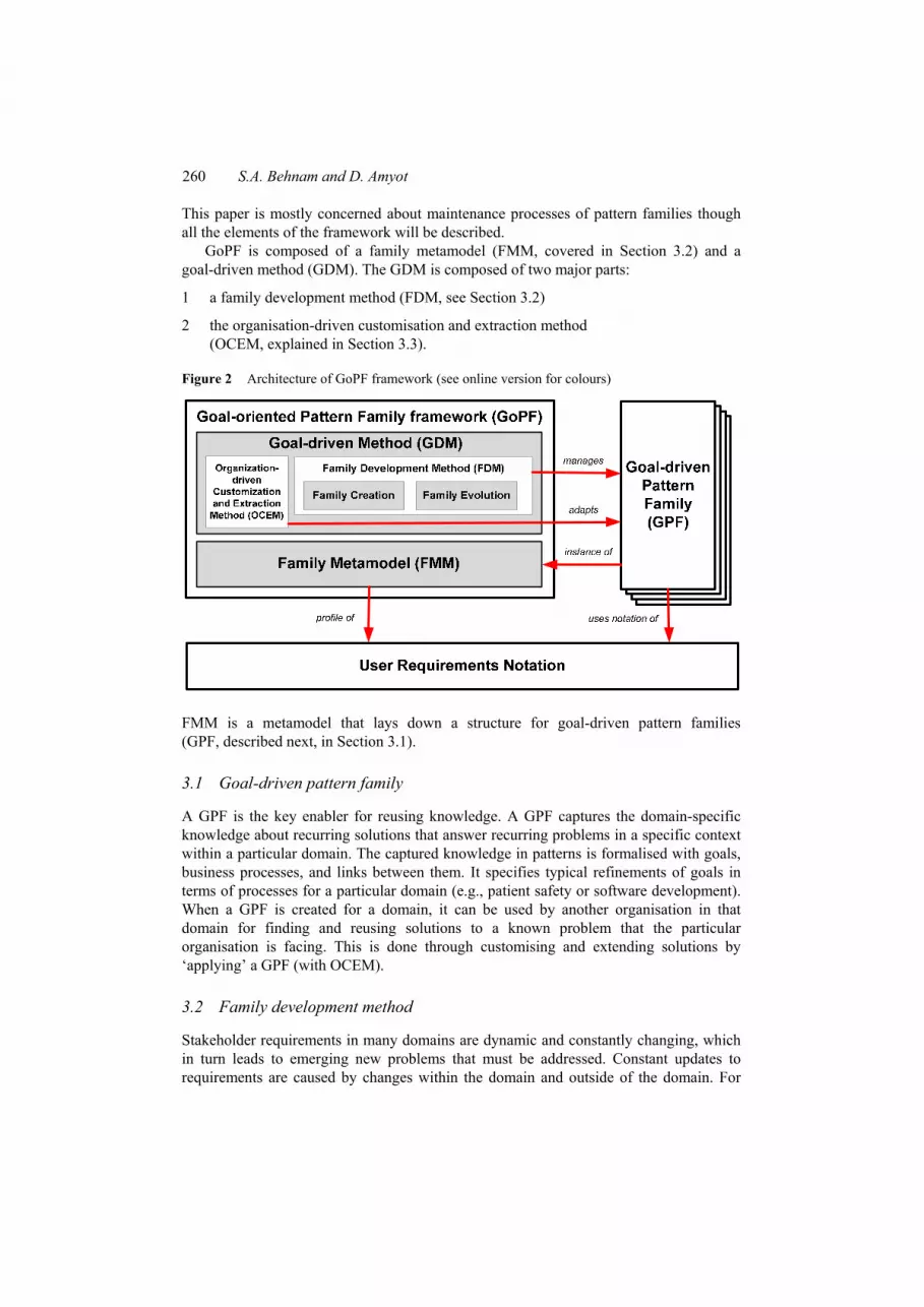
In our previous work (Behnam et al., 2010), we introduced a pattern-based framework and described how patterns that span goals and business processes can be useful for capturing and reusing knowledge in a business domain. In this paper, we propose an enhanced GoPF framework, to facilitate finding, documenting, maintaining, and reusing problems and solutions that recur in a given domain. Figure 2 represents GoPF’s architecture. This architecture provides
1 a formalised foundation for pattern families (FMM)
2 algorithms for creating and maintaining pattern families (FDM)
3 algorithms for using pattern families for particular organisations (OCED).
260 S.A. Behnam and D. Amyot
This paper is mostly concerned about maintenance processes of pattern families though all the elements of the framework will be described.
GoPF is composed of a family metamodel (FMM, covered in Section 3.2) and a goal-driven method (GDM). The GDM is composed of two major parts:
1 a family development method (FDM, see Section 3.2)
2 the organisation-driven customisation and extraction method (OCEM, explained in Section 3.3).
Figure 2 Architecture of GoPF framework (see online version for colours)
FMM is a metamodel that lays down a structure for goal-driven pattern families (GPF, described next, in Section 3.1).
3.1 Goal-driven pattern family
A GPF is the key enabler for reusing knowledge. A GPF captures the domain-specific knowledge about recurring solutions that answer recurring problems in a specific context within a particular domain. The captured knowledge in patterns is formalised with goals, business processes, and links between them. It specifies typical refinements of goals in terms of processes for a particular domain (e.g., patient safety or software development). When a GPF is created for a domain, it can be used by another organisation in that domain for finding and reusing solutions to a known problem that the particular organisation is facing. This is done through customising and extending solutions by ‘applying’ a GPF (with OCEM).
3.2 Family development method
Stakeholder requirements in many domains are dynamic and constantly changing, which in turn leads to emerging new problems that must be addressed. Constant updates to requirements are caused by changes within the domain and outside of the domain. For

Evolution mechanisms for goal-driven pattern families 261
instance, when a government introduces new obligatory legislation to improve patient safety in the healthcare domain, healthcare organisations must change their processes to comply. Consequently, this compliance can affect the current way of dealing with a particular problem in the domain. Furthermore, when new successful practices gain recognition in the healthcare domain, stakeholders of other healthcare organisations will ask for these new practices to be integrated to their own. Thus, in the long term, a GPF can remain useful only if it can be evolved to comply with ongoing changes.
The FDM provides algorithms for creating a GPF and evolving it over time. Our focus in this paper is on introducing evolution mechanism that enables gradual change of GPFs, which leads to accuracy and overall quality of knowledge within the patterns.
Family evolution is a collection of four mechanisms for evolving pattern families. This is an important part of the FDM, which enables ongoing development and improvement of a GPF over the life span of such pattern families.
In our approach, the GPF analyst is a domain-specialised modeller who is interested in creating and evolving a GPF for a particular domain. The GPF analyst observes the goals and business processes of the organisations in the domain in order to discover recurring problems and solutions (Figure 3). When new observed patterns are related to a particular GPF, family evolution mechanisms will help evolving this GPF. On the other hand, when the GPF analyst observes many new and unrelated patterns, then creating a new GPF may be considered. Creating GPFs is a special case of evolution in which Family Evolution mechanisms are used repeatedly on an initially empty GPF.
Figure 3 Overview of a process for creating, evolving and applying GPFs
Extension, modification, elimination, and combination are four types of evolution mechanisms that keep GPFs up-to-date. They evolve the usefulness of a GPF by increasing the quality and accuracy of its patterns and their interrelationships. They can address current problems and solutions that stakeholders within the domain are facing. These mechanisms respectively change a GPF by

262 S.A. Behnam and D. Amyot
1 adding a new pattern
2 modifying a current pattern
3 eliminating an obsolete pattern
4 combining two GPFs that represent problems of the same domain.
Each of these mechanisms keeps the integrity of the changing GPF in addition to evolving individual patterns. We have developed a Java application that implements these algorithms in order to assess the feasibility of evolving pattern families by using these mechanisms.
3.3 Organisation-driven customisation and extraction method
OCEM, described in Behnam et al. (2010), includes algorithms that help adapting instances of solutions that are most appropriate for particular organisations within the domain. OCEM uses a GPF as an input and assesses the impact of alternative solutions for achieving the high-level goals of a given organisation in a step-by-step, top-down approach. Another input is a partial business goal model where only some of the high-level goals of an organisation need to be identified. OCEM’s main output is a more complete goal model combined with business processes aligned with the identified goals, as well as additional traceability links between the two views.
3.4 Family metamodel
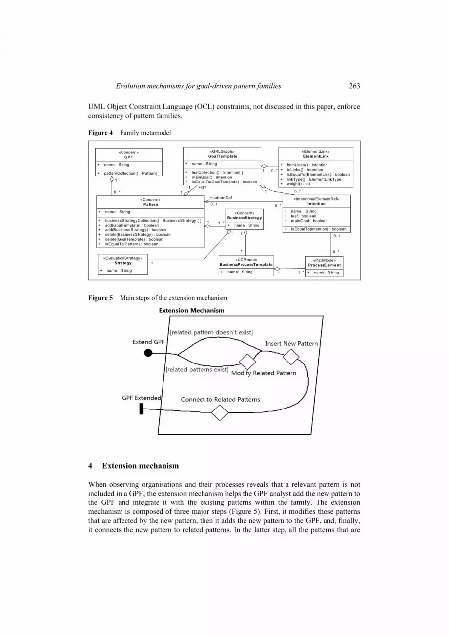
The FMM formalises the concepts of GPF as a profile of URN, as shown in Figure 4. The names between guillemets refer to corresponding metaclasses from the URN standard metamodel (ITU-T, 2008). In URN, a concern is a model element that groups other model elements, including other concerns. URN metadata is used to associate stereotypes to model elements in a URN model that are part of this framework, as specified in Figure 4 (e.g., a concern may be stereotyped as a «pattern»).
A GPF contains patterns, each of which includes one goal template (that formulates a problem and elements of its solutions) and at least one business strategy (that captures the arrangement of a solution along with its effect on the problem). Each goal template is essentially a GRL graph, and hence includes intentions (e.g., goals, tasks, and softgoals), and element links between them. The goal intentions contributing to the main goal of such a template can themselves be refined by other patterns, through the patternDef relationship. Business strategies contain two main parts: a strategy (i.e., a regular GRL evaluation strategy, used for the evaluation of a goal model) and a corresponding business process template (i.e., a UCM map describing the process that specifies among other things the ordering of the goals selected by the strategy). In addition, goals and tasks in the goal template can be realised by process elements (e.g., stubs and responsibilities) in the business process template. Such realisation links are supported with URN links. Further realisation links between goals and business process templates are derived from existing associations (from Intention to BusinessProcessTemplate via patternDef). The decomposition of patterns into goal template and corresponding strategies enables organising the problem and its solutions in a reusable manner. Depending on the complexity of the system, decompositions can recur to form a hierarchy of problems and solutions in a particular GPF. FMM, together with additional
Evolution mechanisms for goal-driven pattern families 263
UML Object Constraint Language (OCL) constraints, not discussed in this paper, enforce consistency of pattern families.
Figure 4 Family metamodel class Framew or...
«Concern»GPF
+ name: String
+ patternCollection() : Pattern[ ]
«GRLGraph»GoalTemplate
+ name: String
+ leafCollection() : Intention[ ]+ mainGoal() : Intention+ isEqualTo(GoalTemplate) : boolean
«Concern»BusinessStra tegy
+ name: String
«EvaluationStrategy»Stra tegy
+ name: String
«UCMmap»BusinessProcessTemplate
+ name: String
«IntentionalElementRef»Intention
+ name: String+ leaf: boolean+ mainGoal: boolean
+ isEqualTo(Intention) : boolean
«PathNode»ProcessElement
+ name: String
«ElementLink»ElementLink
+ fromLinks() : Intention+ toLinks() : Intention+ isEqualTo(ElementLink) : boolean+ linkType() : ElementLinkType+ weight() : int
«Concern»Pattern
+ name: String
+ businessStrategyCollection() : BusinessStrategy [ ]+ add(GoalTemplate) : boolean+ add(BusinessStrategy) : boolean+ delete(BusinessStrategy) : boolean+ delete(GoalTemplate) : boolean+ isEqualTo(Pattern) : boolean
0..*1
0..1
0..*
1..*1
0..*
+patternDef0..1
0..*1
1
1
1
1
+GT11
1..*1
0..*
1
Figure 5 Main steps of the extension mechanism
4 Extension mechanism
When observing organisations and their processes reveals that a relevant pattern is not included in a GPF, the extension mechanism helps the GPF analyst add the new pattern to the GPF and integrate it with the existing patterns within the family. The extension mechanism is composed of three major steps (Figure 5). First, it modifies those patterns that are affected by the new pattern, then it adds the new pattern to the GPF, and, finally, it connects the new pattern to related patterns. In the latter step, all the patterns that are

264 S.A. Behnam and D. Amyot
refined by the new pattern are first connected to the extending pattern and then the new pattern is also connected to those patterns that refine it.
In the following, the extension algorithm is described and illustrated through examples.
4.1 Extension algorithm
Algorithm 1 provides inputs, outputs, and steps of the extension algorithm. Algorithm keywords and constants are in boldface whereas types (from the metamodel) are italicised. Comments are shown between /* and */. Algorithm 1 Extension of GPF
Inputs: I1. pf :GPF /* initial pattern family */ I2. xp:Pattern /* the new extension pattern */ I3. modifications: ordered set of (rp:Pattern, link:ElementLink, action ∈ {Add, Delete},
bst:BusinessStrategy, oldbst:BusinessStrategy) where link.toLinks.isEqualTo(rp.mainGoal()) ∧ (action == Add ⇒ link.fromLinks.isEqualTo(xp.GT.mainGoal()))
Output: O1. modified pf:GPF /* the original pattern family extended with xp */
Steps: S1. mg:Intention = xp.GT.mainGoal() /* mg is the main Intention of xp */ S2. if (not modifications.isEmpty()) then S3. modification (pf, modifications) /* related patterns are modified by using
the Modification Mechanism, see Section 5 */ S4. endif S5. pf.insert (xp) /* xp is added to pf */ S6. relatedIntentions:set of (ri:Intention) where ∃ op ∈ pf.patternCollection() ∧
not op.isEqualTo(xp) ∧ ri ∈ op.GT.leafCollection() ∧ ri.isEqualTo(mg) /* relatedIntentions represents those intentions in other patterns which are refined by xp */
S7. leafIntentions: set of (Intention) = xp.GT.leafCollection() S8. foreach (i:Intention in relatedIntentions)
S8.1. i.patternDef = xp S9. foreach (i:Intention in leafIntentions)
S9.1. foreach (p:Pattern in pf.patternCollection() where not p.isEqualTo(xp)) 9.1.1. if (i.isEqualTo(p.GT.mainGoal())) then 9.1.2. i.patternDef = p 9.1.3. endif
This algorithm takes three inputs: pf is an initial GPF, xp is a pattern used to extend the initial GPF, and the modifications set (Table 1) highlights the effects that extending pf with xp has on other patterns of the family. The GPF analyst prepares the second and third inputs based on recurrences. As different types of modifications may be necessary, the second, forth, and fifth elements of modifications set may be null. The toLinks side of the link must always point to the main goal of rp. If the action is Add then the fromLinks side must point to an intention, which is refined by xp. These two preconditions prevent using the extension algorithm for merely changing an unrelated pattern in pf. Isolated modifications of patterns must use the modification algorithm, described in Section 5.

Evolution mechanisms for goal-driven pattern families 265
Table 1 Elements of the modifications ordered set in the extension algorithm
Element Description
rp A related pattern that is affected and must be modified link A link between two intentions that highlights the part of the
goal template that must be modified action An indicator of what must be done to the link bst A new business strategy that represents a new solution oldbst An old business strategy that must be eliminated from rp
Steps S1 to S9 carry out the three major activities illustrated in Figure 5. Step S1 initialises mg with the main goal of xp’s goal template. Steps S2 to S4 take the modifications set and invokes the modification algorithm (Algorithm 2) to modify related patterns in pf. This captures the possible effects of adding xp on other patterns in GPF. In Step S5, the new pattern, xp, is added to pf. Although this is conceptually a simple insertion of a pattern, it is in fact an in-depth copy in which every element of xp is copied into pf. In Step S6, a set of leaf intentions (without any incoming links) of other patterns in pf that are equal to the main goal of xp is assigned to relatedIntentions. This is the set of intentions that are refined by xp. In S7, the set of leaf intentions of xp’s goal template is assigned to leafIntentions. Elements of leafIntentions may be refined by other patterns in pf. In Step S8, the related intentions are linked to xp by assigning xp to patternDef of intentions in relatedIntentions. Finally, in Step S9, intentions of xp’s goal template that can be refined with other patterns in pf are linked to the appropriate pattern by setting their patternDef accordingly.
4.2 First example: extension of an empty GPF
Extending an empty GPF is a special case of extension that initiates a new GPF. In this section, we illustrate how to use the extension algorithm for creating a new GPF in the patient safety domain. When observing the patterns underscore the need for a new pattern family, the GPF analyst creates the inputs for the extension algorithm: pf is an empty GPF (I1), xp is the new pattern recognised that must be added to pf (I2), and modifications is an empty set because no pattern in pf needs to be modified (I3).
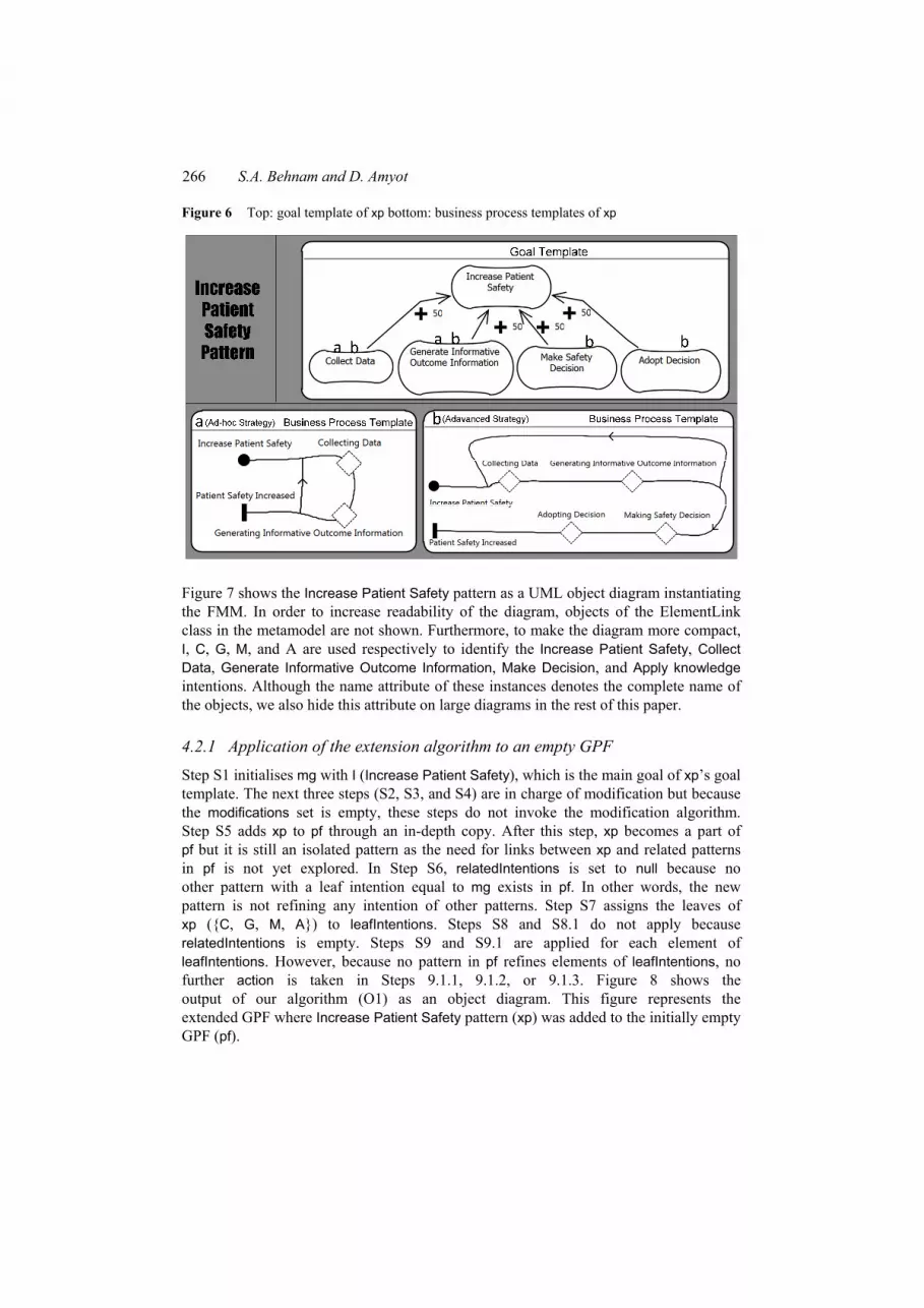
The top half of Figure 6 represents the goal template and business processes templates of the Increase Patient Safety pattern. The goal template (in GRL form) depicts a recurring problem (Increase Patient Safety) and elements of solutions that influence its satisfaction (Collect Data, Generate Informative Outcome Information, Make Safety Decision, and Adopt Decision). Business process templates (in UCM form) capture the process of achieving Increase Patient Safety. In the bottom half of Figure 6, the business process templates of two strategies in the pattern are provided. Strategy A represents a solution in which collecting data and generating informative outcome information increase the patient safety by ad hoc improvement of process brought to light by the collected data and the processing of such data. Strategy B, on the other hand, uses Making Safety Decision and Adopt Decision in addition to the other two elements. Consequently, it improves the quality of care by systematically changing the underlying procedures in the hospital.
266 S.A. Behnam and D. Amyot
Figure 6 Top: goal template of xp bottom: business process templates of xp
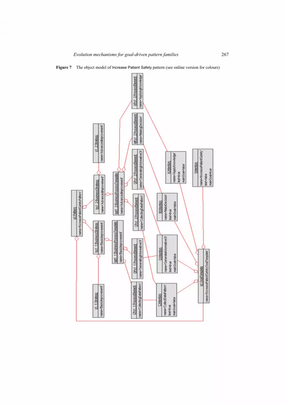
Figure 7 shows the Increase Patient Safety pattern as a UML object diagram instantiating the FMM. In order to increase readability of the diagram, objects of the ElementLink class in the metamodel are not shown. Furthermore, to make the diagram more compact, I, C, G, M, and A are used respectively to identify the Increase Patient Safety, Collect Data, Generate Informative Outcome Information, Make Decision, and Apply knowledge intentions. Although the name attribute of these instances denotes the complete name of the objects, we also hide this attribute on large diagrams in the rest of this paper.
4.2.1 Application of the extension algorithm to an empty GPF
Step S1 initialises mg with I (Increase Patient Safety), which is the main goal of xp’s goal template. The next three steps (S2, S3, and S4) are in charge of modification but because the modifications set is empty, these steps do not invoke the modification algorithm. Step S5 adds xp to pf through an in-depth copy. After this step, xp becomes a part of pf but it is still an isolated pattern as the need for links between xp and related patterns in pf is not yet explored. In Step S6, relatedIntentions is set to null because no other pattern with a leaf intention equal to mg exists in pf. In other words, the new pattern is not refining any intention of other patterns. Step S7 assigns the leaves of xp ({C, G, M, A}) to leafIntentions. Steps S8 and S8.1 do not apply because relatedIntentions is empty. Steps S9 and S9.1 are applied for each element of leafIntentions. However, because no pattern in pf refines elements of leafIntentions, no further action is taken in Steps 9.1.1, 9.1.2, or 9.1.3. Figure 8 shows the output of our algorithm (O1) as an object diagram. This figure represents the extended GPF where Increase Patient Safety pattern (xp) was added to the initially empty GPF (pf).
Evolution mechanisms for goal-driven pattern families 267
Figure 7 The object model of Increase Patient Safety pattern (see online version for colours)

268 S.A. Behnam and D. Amyot
Figure 8 The object model of an empty GPF extended to include the Increase Patient Safety pattern (see online version for colours)
The p
atte
rn fa
mily
th
at n
ow in
clude
s “In
crea
se P
atien
t Sa
fety
Pat
tern
”

Evolution mechanisms for goal-driven pattern families 269
4.3 Second example: extension of non-empty GPF
In this section, we use the extension algorithm for evolving a GPF that is already established and has some patterns in it.
In our patient safety case study, we originally created a pattern family comprised of 32 interrelated patterns (Behnam et al., 2009). These patterns are mostly focused on the problem of improving patient safety by highlighting processes that can be improved. The patterns in this family do not use the data collected along the way for taking immediate actions to prevent an adverse event for a particular patient. Over time, it was observed that some hospitals use such collected data not only for a posteriori analysis but also for preventing the potential adverse events that may happen. Consequently, the GPF analyst creates a new pattern (xp) that captures the problem of taking action to prevent predictable adverse events and its alternative solutions. The recurring excerpt of the observed goal model that formulates the main observed goal, Take Action, forms the goal template of xp [Figure 9(a)]. In this goal template, we have chosen not to show the side effects of alternative business strategies to simplify the example. The goal template is composed of the main high-level goal, i.e., Take Action, and the elements of solution, i.e., Prioritise Outcome and Prevent Outcome. The alternative solutions are captured in the form of business strategies that are composed of business process templates and strategies. The two business process templates of the new pattern are shown in Figure 9(b).
Figure 9 (a) Goal template of xp (b) Business process templates of xp
(a) (b)
The extension algorithm (Algorithm 1) changes the patient safety GPF to include Take Action pattern. The analyst prepares and provides the following inputs: pf as the initial GPF that must be extended (I1), xp as the new pattern (I2), and modifications as a set that represents the needed modifications on other patterns in pf (I3).
The left part of Figure 12 (with dark grey objects) illustrates the initial pf as an FMM-based UML object diagram, with only three out of the 32 patterns, for brevity. In this example, the Increases Patient Safety pattern (p1) is the only pattern affected by the extension because Take Action positively contributes to Increases Patient Safety goal. Therefore, modifications is set to {(p1, link_I_T, Add, bs1_3, null)}, indicating the new goal that must be added to p1’s business goal template. It also indicates the new business

270 S.A. Behnam and D. Amyot
strategy that represents an alternative solution that must be added to p1. Figure 10 shows the business processes template of bs1_3 business strategy as a UCM diagram. As shown in this figure, the collected data and generated information about the current outcome and potential outcome may be used to prevent outcomes by taking immediate actions. Finally, because none of the existing business strategies is being eliminated, the last element of modifications set is null.
Figure 11 illustrates xp as an FMM-based UML object diagram (objects of the ElementLink class are not shown in favour of readability). In this diagram T, V, and Z respectively identify intention objects for Take Action, Prevent Outcome, and Prioritise Outcome.
4.3.1 Application of the extension algorithm to a non-empty GPF
Step S1 initialises mg with T (Take action), which is the main goal of xp’s goal template. Steps S2, S3, and S4 invoke the modification algorithm with pf and the modifications set as its inputs. The modification algorithm (Section 5) applies these changes to the related patterns, i.e., p1, as it is the only related pattern in pf. Figure 12 shows the modified pf, where the area encapsulated within the dashed box (bottom right) represents the modifications. The details of T2 (Taking Action) at p1 level are dismissed so when the users of pf choose a solution at p1’s level that includes T2, the solution will be refined by using the new pattern. Step S5 adds xp to pf. This is an in-depth copy of all elements of xp into pf. After this step, xp becomes a part of pf but it is still an isolated pattern as the links between xp and related patterns in pf are not yet established. Step S6 finds those intentions that are
1 leaves of other patterns in pf
2 equal to the main goal of xp’s goal template.
Figure 10 Business process template bpt1_3, from business strategy bs1_3

Evolution mechanisms for goal-driven pattern families 271
Figure 11 Object model of the new xp pattern (see online version for colours)

272 S.A. Behnam and D. Amyot
Figure 12 The object model of the extended GPF pf that includes the xp pattern (see online version for colours)
Orig
inal
Patie
nt
Safe
ty G
PF
(Dar
k Gre
y Ob
jects
)
Take
Act
ion
Patte
rn (x
p)
Modi
ficat
ions
of
p1
Incr
ease
Pat
ient
Safe
ty P
atte
rn (p
1)

Evolution mechanisms for goal-driven pattern families 273
In this example, T2 (Take Action) is a leaf intention in p1 and is equal to mg. Therefore, relatedIntentions is set to {T2}. Step S7 assigns the leaves of xp’s goal template ({V, Z}) to leafIntentions. Steps S8 and S8.1 set the patternDef of T2, which is the only member of relatedIntentions, to xp. This captures the fact that xp is refining the T2 intention in the goal template of p1. Steps S9 and S9.1 are applied to each element of leafIntentions. However because no pattern in pf refines either V or Z, no action takes place in Steps 9.1.1, 9.1.2, or 9.1.3. Figure 12 shows the output of our algorithm (O1). It represents the extended GPF after the new pattern xp (top-right) was added and integrated with the patterns in the initial GPF (pf).
5 Modification mechanism
This section describes the algorithm for evolving a GPF by modifying its patterns within a GPF. Such evolution is needed when:
1 changes in a domain indicate that the goal template or business strategy of a pattern must be updated
2 the GPF is being extended with a new pattern and introducing the new pattern affects a particular pattern (i.e., the way it is used within Algorithm 1)
3 another pattern in the GPF is eliminated and a particular pattern is affected.
The algorithm modifies the goal template to update the problem, elements of solutions, and the contributions between the elements. Similarly, the modification of business strategies enables the modification of solutions and their effects.
A modification is composed of three main optional and possibly cyclic steps (see Figure 13): first, it modifies the goal template of a pattern, then it removes the old business strategy (if available), and, finally, a new business strategy is added (if available). In the following sections, we provide the details of the modification algorithm. Then, an application of the algorithm is described. Finally, we present how the modification algorithm works with an example from our case study.
Figure 13 Main steps of the modification mechanism
5.1 Modification algorithm
Algorithm 2 provides steps for modifying a GPF.

274 S.A. Behnam and D. Amyot
Algorithm 2 Modification of GPF
Inputs: I1. pf:GPF /* initial pattern family */ I2. modifications: ordered set of (p:Pattern, link:ElementLink, action ∈ {Add,Delete},
bst:BusinessStrategy, oldbst:BusinessStrategy) where link.toLinks.isEqualTo(p.GT.mainGoal())
Output: O1. modified pf:GPF /* the modified pattern family */
Steps: S1. for each m in modifications: S2. mp:Pattern = a pattern in pf.patternCollection() where pattern.isEqualTo (m.p)
/* m.p is the first element of the modification m */ S3. if (m.action == Delete) then S4. mp.GT.delete(m.link) S5. elseif (m.action == Add) then S6. mp.GT.add(m.link) S7. endif /* if no action is provided then the GoalTemplate is unchanged */ S8. if (m.oldbst ≠ null) then S9. pbst:BusinessStrategy = businessStrategy ∈ mp.businessStrategyCollection()
where businessStrategy.isEqualTo(m.oldbst) S10. mp.delete(pbst) S11. endif S12. if (m.bst ≠ null) then S13. mp.add(m.bst) S14. endif
As different types of modifications may be necessary, the second, forth, and fifth elements of modifications set (see Table 2) may be null. The toLinks side of the link must always point to the main goal of p. This precaution prevents using the modification algorithm for modifying unrelated patterns. The output of the algorithm represents the modified pf (O1). Table 2 Elements of the modifications ordered set in the modification algorithm
Element Description p A pattern that is affected and must be modified link A link between two intentions that highlights the part of the goal template that must
be modified action An indicator of what must be done on the link bst A new business strategy that represents a new solution oldbst An old business strategy that must be eliminated from p
Steps S2 to S14 must be taken for each element of the modifications set. Step S2 initialises mp with the pattern of the active member m of the modifications set. Next, in Steps S3 to S7, depending on the type of action, the link will be either added to (Steps S3, S4) or deleted from (Steps S5, S6, S7) mp’s goal template. Then, if m.oldbst is not null, it

Evolution mechanisms for goal-driven pattern families 275
will be deleted from mp in Steps S8 to S11. Finally, if m.bst contains a new business strategy, then it is added to mp (Steps S12 to S14).
5.2 Example: modification of a pattern family
The modification mechanism can be used as standalone mechanism for modifying a pattern within the family or it can be used through other mechanisms to update the family. This example illustrates the details of how the modification algorithm modifies the GPF when it is used through the Extension Mechanism in the example of Section 4.3.
The inputs of modification algorithm in this example are:
I1 pf which is the initial GPF. This input is provided to modification algorithm from Step S3 of the extension algorithm in Section 4.3. The left part of Figure 12 (with dark grey objects) represents this input.
I2 modifications set is the second input provided in S3 of the extension algorithm in Section 4.3, which is equal to {(p1, link_I_T, Add, bs1_3, Null)}.
5.2.1 Applying the modification algorithm
The steps (S2–S14) must be taken for all elements of the modifications set, which in this case has only one member (which we call m). S2 initialises mp with p1, i.e., the first element of m. Because m.action is equal to Add, Steps S5 to S7 add link_I_T to the goal template of p1. No action is taken in Steps S8, S9, S10, S11 because m.oldbst is null (there is no old business strategy to be deleted). The underlying object model at this point is illustrated in Figure 14. Figure 14 The object model of pattern p1 after modification of its goal template (see online
version for colours)

276 S.A. Behnam and D. Amyot
Steps S12 to S14 add the new business strategy in m.bst to p1. This business strategy represents another solution to the problem (Increase Patient Safety) in p1. This solution contains T2 (Take Action) along with other intentions for improving the underlying procedures. Figure 10 illustrates the business process template of this solution. Figure 15 represents p1 after the whole modification. Figure 12 shows the complete output of the modification algorithm (O1). In this particular example, the modified GPF is returned to Step S3 of the extension algorithm in Section 4.3, which initially invoked the modification algorithm. Figure 15 The object model of p1 pattern after modification (see online version for colours)
To modify the pattern, the goal template is modified
and a new business strategy is added
6 Elimination mechanism
When the GPF analyst observes that a pattern in the GPF is no longer needed by the GPF users and does not solve current problems of the stakeholders, it is considered obsolete. Consequently, it must be removed from the pattern family. This section describes the algorithm for evolving a GPF by eliminating its obsolete patterns. Elimination is composed of three steps (Figure 16). First, all pattern refinement (patternDef) links from those patterns that were refined by the obsolete pattern are removed. Next, related patterns in the family that are being affected by elimination are modified. Then, the

Evolution mechanisms for goal-driven pattern families 277
obsolete pattern is deleted from the family. The elimination algorithm uses the modification algorithm for modifying the related patterns in the family. The elimination mechanism does not propagate elimination of patterns, so if another pattern becomes obsolete as a result of removing one pattern from the family, the GPF analyst must explicitly use the elimination mechanism to eliminate the other obsolete pattern.
Figure 16 Main steps of the eliminating mechanism
6.1 Elimination algorithm
Algorithm 3 provides inputs, output, and steps of the elimination mechanism. Algorithm 3 Elimination of GPF
Inputs: I1. pf:GPF I2. op:Pattern /* an obsolete pattern that must be eliminated from pf */ I3. modifications: ordered set of (rp:Pattern, link:ElementLink, action ∈ {Add,Delete},
bst:BusinessStrategy , oldbst:BusinessStrategy) where (link.toLinks.isEqualTo(rp.GT.mainGoal()) ∧ (action == Delete ⇒ link.fromLinks.isEqualTo(op.GT.mainGoal()) )
Output: O1. modified pf:GPF /* the original pattern family from which op is eliminated */
Steps: S1. foreach (p:Pattern in pf.patternCollection() where not p.isEqualTo(op) )
S1.1. foreach (i:Intention in p.GT.leafCollection()) 1.1.1. if (i.patternDef .isEqualTo(op)) 1.1.2. i.patternDef = null 1.1.3. endif
S2. if (not modifications.isEmpty()) then S3. modify (pf, modifications) /* related patterns that will be affected are modified */ S4. endif S5. pf.delete(op) /* op is removed from pf */
This algorithm takes three inputs: pf is an initial GPF (I1), op is an obsolete pattern that must be removed from the initial GPF (I2), and the modifications set (Table 3) highlights the effects that eliminating op from pf has on other patterns in the family (I3). The GPF analyst locates the obsolete pattern by observing pattern usage of GPF users in a specific domain and by using their feedback about patterns in the GPF. She then analyses and determines the effects of this elimination, which in turn, leads to the creation of a modifications set.

278 S.A. Behnam and D. Amyot
Table 3 Elements of the modifications set in the elimination algorithm
Element Description
rp A related pattern that is affected by elimination of obsolete pattern and must be modified
link A link between two intentions that highlights the part of the goal template that must be modified
action An indicator of what must be done on the link bst A new business strategy that represents a new solution oldbst An old business strategy that must be eliminated from rp
As different types of modifications may be necessary, the second, forth, and fifth elements of modifications set (see Table 3) may be null. The toLinks side of the link must always point to the main goal of rp. If the action is Delete then the fromLinks side must point to an intention that is refined by op. These two preconditions prevent using the elimination algorithm for merely changing an unrelated pattern in pf. Isolated modifications of patterns must use the modification algorithm described in Section 5. pf is the modified pattern family in which the obsolete pattern is eliminated (O1).
Through Steps S1 to S5, this algorithm carries out the three major activities illustrated in Figure 16. Step S1 and its sub-steps remove those refinement links in the family that are pointing to the obsolete pattern. Steps S2 to S4 modify those patterns that are affected by elimination of the obsolete pattern. Finally, Step S5 deletes the obsolete pattern from the pattern family.
6.2 Example: elimination of an obsolete pattern
This example illustrates how the elimination algorithm eliminates an obsolete pattern from GPF. In order to use the elimination mechanism, the GPF analyst prepares and provides pf (I1), op (I2), and modifications set (I3).
For the purpose of simplicity, we use the pf created in Section 4.3 and eliminate the Action Taking pattern with which the GPF in that section was extended. Figure 17 illustrates the FMM-based UML object diagram of the mentioned pf (I1). In this GPF, the Action Taking pattern is considered obsolete (I2). In this example, the Increases Patient Safety pattern (p1) is the only pattern affected by the elimination because the GPF analyst considers Take Action as an element that does not contribute to Increases Patient Safety. Therefore, modifications is set to {(p1, link_I_T, Delete, null, bs1_3)}. link_I_T indicates the obsolete goal (Take Action) and its contributions that must be removed from p1’s business goal template. It also indicates the old business strategy that represents an alternative solution that must be removed from p1.
6.2.1 Applying the elimination algorithm
Step S1 and its sub-steps set patternDef of T2 to null. This removes the refinement link between T2 and op (see Figure 17). The next three steps (S2, S3, and S4) invoke the modification algorithm with pf and the modifications set as its inputs. The modification algorithm (Section 5) applies these changes to the related patterns, i.e., p1, as it is the only related pattern in pf. Finally, S5 removes op from the pf. The modified pf will be equal to the pattern family illustrated in the left part of Figure 12 (with dark grey objects).

Evolution mechanisms for goal-driven pattern families 279
Figure 17 The object model of initial GPF with an obsolete pattern (op) (see online version for colours)
patte
rnD
ef li
nk th
at
A g
oal t
empl
ate
that
m
ust b
e m
odifi
ed
op is an o
bsol
ete
patte
rn th
at m
ust
beel
imin
ated

280 S.A. Behnam and D. Amyot
7 Combination mechanism
This section describes the combination mechanism, which targets the combination (merging) of two pattern families. When GPF analysts observe that two pattern families describe similar areas of a domain, they may use this algorithm to merge the two families. The output of this algorithm is a pattern family that includes the patterns from both initial GPFs. This algorithm also maintains the integrity of patterns and their relationships in the output. The GPF analyst can then further modify the resulting GPF with the extension, elimination, and modification mechanisms.
The combination mechanism empowers the GPF analyst to define the starting point of the combination of two pattern families. This feature makes it possible to use the algorithm for two distinct purposes. First, selecting the highest-level common pattern as starting point will lead to creating a pattern family that includes all the patterns that refine the start point. Second, by selecting a common pattern in the middle of pattern family hierarchy, this algorithm creates a common subset of both pattern families. The latter, less apparent usage of this algorithm is particularly useful to create a pattern family from a common subset of patterns in two GPF that would otherwise have little similarities.
7.1 Combination algorithm
Algorithm 4 provides inputs, output, and steps of the combination mechanism. In order to use the combination mechanism, the GPF analyst prepares and provides
two pattern families, pf1 (I1) and pf2 (I2), along with the starting point startPattern (I3). The output of the algorithm represents the new pf (O1). The combination algorithm assumes that common patterns (i.e., patterns with the same name) are the same in both GPFs. In those cases where patterns are slightly different but can be combined into one common pattern, the analyst must first use the modification mechanism (Section 5) in order to eliminate the differences among patterns that must be considered as equivalent.
Step S1 defines pf as an empty pattern family. After the complete execution of the algorithm, pf will contain the combined pattern family. Step S2 inserts the pattern from startPattern into pf. Step S3 defines toMerge as an ordered set of patterns and initiates it with startPattern as its first element. Steps S4 defines allPatterns as a set of patterns and initialises it with the patterns in pf1 union those in pf2. Step S5 is a loop that adds patterns from the toMerge list to the combined pattern family. Step S5.1 assigns the first element of toMerge list to nextPattern. Step S5.2 then assigns all the leaf intentions of the nextPatten’s goal template to nextLeafGoals. These intentions may potentially be refined with other patterns in the allPatterns set. Step S5.3 and its sub-steps form a nested loop that checks all the patterns in the allPatterns set to find patterns that refine intentions in nextLeafGoals. Once a refining pattern is found, Steps 5.3.3 to 5.3.5 add that pattern to pf, connect it to the relevant intention in nextLeafGoals, and add it the toMerge list. After all iterations of S5.3, the pattern in nextPattern is connected to all those patterns from both pf1 and pf2 that could refine its leaf intentions. Next, Step S5.4 removes this pattern from the toMerge list. Subsequent iterations of Step S5 examine the next patterns in toMerge for finding their refining patterns and adding them to pf. The iterations of Step S5 will continue until all the refining patterns in both pf1 and pf2 are included in pf.

Evolution mechanisms for goal-driven pattern families 281
Algorithm 4 Combination of GPFs
Inputs: I1. pf1:GPF /* this GPF is the first pattern family */ I2. pf2:GPF /* this GPF is the second pattern family */ I3. startPattern:Pattern /* this is a common pattern in both pf1 and pf2 that is used as the
starting point for combination*/
Output: O1. pf:GPF /* a pattern family that contains the patterns from both pf1 and pf2 */
Steps: S1. pf = new GPF /* initialize pf */ S2. pf.insert(startPattern) S3. toMerge: ordered set of (Pattern)= {startPattern} S4. allPatterns: set of (Pattern) = pf1.patternCollection() ∪ pf2.patternCollection() S5. while (toMerge is not empty)
S5.1. nextPattern:Pattern = toMerge.nextElement() S5.2. nextLeafGoals:set of (Intention) = nextPattern.GT.leafCollection() S5.3. foreach (g:Intention in nextLeafGoals)
5.3.1. foreach (p:Pattern in allPatterns) 5.3.2. if (p.GT.mainGoal().isEqualTo(g)) then 5.3.3. pf.insert(p) 5.3.4. g.patternDef = p 5.3.5. toMerge.append(p) 5.3.6. endif
S5.4. toMerge.removeElement(nextPattern)
7.2 Example: combination of two pattern families
In this section, we illustrate the application of combination algorithm by combining two patterns families that cover part of the case study’s patient safety domain (i.e., prospective surveillance). In order to avoid complexity, unlike the examples in previous sections, we represent patterns in a more abstract and compact way using stereotyped UML packages. Figure 18 shows the Increase Patient Safety pattern in this format and illustrates how it hides the details of this pattern.
Some of the patterns in these two families are common, yet each of them contains unique patterns that are not included in the other family. Figure 19 illustrates pf1, which is the first input of algorithm (I1). This pattern family includes patterns for improving the patient safety in ad hoc approaches for patient safety improvement. Figure 20 presents pf2, which is the second input of algorithm (I2). pf2 includes needed patterns for systematic approaches but it does not include the detailed refinement patterns included in pf1.
In this example, the GPF analyst sets startPattern (I3) to Increase Patient Safety pattern. This input indicates the common pattern, which will be the highest-level pattern of the output pattern family (O1).

282 S.A. Behnam and D. Amyot
Figure 18 Using stereotyped UML package to represent the Increase Patient Safety pattern (see online version for colours)
«Pattern»IncreasePatientSafety
«GoalTemplate»Increase Patient Safety
«BusinessStrateg...Adhoc Im provem ent
«BusinessPr...Adhoc Process
«BusinessStrategy»Advanced Im provem ent
«Strategy»Adhoc Effect Evaluation
«BusinessProces...Advanced Process
«Strategy»Advanced Effect Evaluation
Figure 19 pf1 is a GPF that contains patterns for ad-hoc approaches for improving patient safety
«Pattern»Incre as e Patie ntSafe ty
«Pattern»DataColle ction
«Pattern»Oucom e DataColle ction
«Pattern»Proce s s DataColle ction
«Pattern»Inform ationGe ne ration
«patternDef» «patternDef»
«patternDef»«patternDef»

Evolution mechanisms for goal-driven pattern families 283
Figure 20 pf2 is a GPF that contains patterns for both ad-hoc and systematic approaches for improving patient safety
«Pattern»KnowledgeApplication
«Pattern»DataCollection
«Pattern»InformationGeneration
«Pattern»KnowledgeGeneration
«Pattern»IncreasePatientSafety
«pattern»ActionTaking
«patternDef»«patternDef» «patternDef»«patternDef» «patternDef»
7.2.1 Applying the combination algorithm
Step S1 creates pf, which is an empty GPF that eventually will contain the combined pattern family. Step S2 inserts Increase Patient Safety pattern into the pf. Step S3 defines toMerge as an ordered set of patterns and initiates it with startPattern. Therefore, the Increase Patient Safety pattern is set as the first element of toMerge. Steps S4 defines allPatterns and assigns to it all the patterns of pf1 union those of pf2, that is: {Increase Patient Safety, Data Collection, Information Generation, OutcomeData Collection, ProcessData Collection, Knowledge Generation, Knowledge Application, Action Taking}.
In the first iteration of Step S5, toMerge is equal to {Increase Patient Safety}. Consequently Step S5.1 assigns Increase Patient Safety pattern to nextPattern. Step S5.2 assigns to nextLeafGoals the set of all of nextPattern’s intentions. After this step, nextLeafGoals is set to {Collect Data, Generate Informative Outcome Information, Make Safety Decision, Adopt Decision, Take Action}. This set contains all the leaf intentions of Increase Patient Safety pattern. Step S5.3 compares each intention in the nextLeafGoals to the main goal of all the patterns in allPatterns set. In the first iteration of S5.3, the algorithm will find that the main goal of Data Collection pattern is Collect Data from nextLeafGoals. This implies that the Data Collection pattern refines the Collect Data goal in Increase Patient Safety pattern. Therefore, Steps 5.3.3 to 5.3.5 add the Data Collection pattern to pf, connect Collect Data from Increase Patient Safety pattern to Data Collection pattern through patternDef refinement link, and finally add Data Collection pattern to toMerge list. In the subsequent iterations of S5.3, the following actions take place:
• Information Generation, Knowledge Generation, Knowledge Application, Action Taking patterns are inserted in pf.
• Generate Informative Outcome Information, Make Safety Decision, Adopt Decision, Take Action goal from the Increase Patient Safety pattern are connected to relevant inserted patterns through patternDef link.
• Information Generation, Knowledge Generation, Knowledge Application, Action Taking patterns are appended to toMerge list.
• Step S5.4 then removes Increase Patient Safety pattern from toMerge list. At the end of first iteration of Step S5, toMerge is equal to {Data Collection, Information

284 S.A. Behnam and D. Amyot
Generation, Knowledge Generation, Knowledge Application, Action Taking}. Figure 21 shows the pf at the end of this step.
Figure 21 pf after first iteration of Step S5
«Pattern»KnowledgeApplication
«Pattern»DataCollection
«Pattern»InformationGeneration
«Pattern»KnowledgeGeneration
«Pattern»IncreasePatientSafety
«pattern»ActionTaking
«patternDef»«patternDef» «patternDef»«patternDef» «patternDef»
Because toMerge is not empty, Step S5 will be executed a second time. Step S5.1 sets nextPattern to Data Collection pattern. Step S5.2 sets nextLeafGoals to {Collect Outcome Data, Collect Process Data}. Iterations of Step S5.3 and its sub-steps insert Outcome Data Collection and Process Data Collection patterns into pf, set them as refining patterns of Collect Outcome Data and Collect Process Data goals of Data Collection pattern, and add them to toMerge list. Step S5.4 removes the Data Collection pattern from toMerge list. Figure 22 represents pf at the end of second iteration of S5. At this point, toMerge is equal to {Data Collection, Information Generation, Knowledge Generation, Knowledge Application, Action Taking, OutcomeData Collection, ProcessData Collection}.
Figure 22 Combined pattern family
«Pattern»KnowledgeApplication
«Pattern»OucomeDataCollection
«Pattern»ProcessDataCollection
«Pattern»DataCollection
«Pattern»InformationGeneration
«Pattern»KnowledgeGeneration
«Pattern»IncreasePatientSafety
«pattern»ActionTaking
«patternDef»
«patternDef» «patternDef»
«patternDef»«patternDef»«patternDef»«patternDef»
Because toMerge is not empty, execution of Step S5 will continue. However, in these iterations, no refining pattern can be found and Step S5 removes the patterns from

Evolution mechanisms for goal-driven pattern families 285
toMerge a teach iteration until it is empty. After complete execution, pf represents a GPF that contains the combination of pf1 and pf2. Figure 22 illustrates this GPF.
8 Extraction of a goal-driven business process with OCEM
Once the GPF analyst is done evolving a goal-driven pattern family through the mechanisms defined in the four previous sections, this GPF can be used to extract and customise business goals and processes for a particular organisation. The OCEM algorithm (Behnam et al., 2010) uses an organisational goal model for adapting the appropriate goal and business process models of a given GPF to the organisation where this GPF is applied.
The organisational goal model of Hospital A, shown in the righthalf of Figure 23, identifies the main goal (Increase Patient Safety) and three high-level softgoals related to quality, cost, and research concerns. Importance values are added to some of these intentional elements in the organisational goal model (e.g., the importance of Increase Patient Safety to its containing actor is deemed to be 100 while the importance of Decrease Cost is 25, which means that decreasing cost is less of an issue to Hospital A than increasing care and safety). Furthermore, Figure 23 depicts the current evaluation strategy of the organisation, describing the as-is situation. Initial satisfaction levels, shown by the presence of a star (*), are provided: 60 to the task, indicating that although some advanced infrastructure is available, there is still room for improvement, and 40 to describe the current level of support to research on adverse events at that hospital. Colour feedback is provided to show the satisfaction level of the intentions (the greener the better, and the redder the worst).
With OCEM, we establish links between the initial organisational goal model and the goal template of the pattern (left half of Figure 23): a contribution with weight 100 is added from the Increase Patient Safety goal in the pattern to the Increase Patient Safety of the organisation (showing the equivalence between these two goals, which could have had different names too), two contributions with weight 100 are added from the quality/cost softgoals in the pattern to the quality/cost softgoals of the organisational model, and finally a contribution with weight 100 is added from the task in the organisational model to the softgoal with the dependencies in the pattern. Not all intentional elements from the organisation goal model need to be linked to an element of the pattern (e.g., support research on adverse events is not addressed by the current pattern).
Next, all alternative strategies are compared automatically for finding the best solution. Two strategies have been defined for this pattern, as shown in the left half of Figure 24. The first one (A) includes only the sub-goals Collect Data and Generate Informative Outcome Information. The second strategy (B) includes also the two other sub-goals, Make Safety Decision and Adopt Decision and adds corresponding activities to its business process template. UCM models represent these two strategies as business process templates, which describe the ordering of the activities (that are further refined in other patterns of the goal-driven pattern family, not shown here).

286 S.A. Behnam and D. Amyot
Figure 23 Using OCEM: linking goal templates to the organisational goal model, with evaluations (see online version for colours)
Figure 24 Using OCEM: business process templates, with strategy ‘B’ being selected
Figure 23 shows the result of the second strategy (B) because it yields better results than the first strategy (A), given that the organisational goal model places more value on quality than on cost and already has some advanced infrastructure available. A different healthcare institute with more focus on cost than quality and no advanced infrastructure available would see the first strategy (A) win over the second strategy (B). This evaluation is automated with OCEM, as it builds on GRL’s quantitative evaluation algorithm, which propagates the known satisfaction levels to other intentional elements in the GRL models through their links.
The goals in the pattern and the links are then added to the organisational goal model, while the business process template related to the chosen strategy is added as a sub-model to the Increase Patient Safety stub (indicated by the long-dash-dot-dotted line in the right half of Figure 24). Figures 23 and 24 together represent the output of applying the OCEM method: a refined GRL model of the organisation with a model of the chosen business process options, together with the rationale for their selection. Applying the patterns in the GPF can further refine the four sub-goals and linked stubs of Increase Patient Safety pattern. In order to support satisfactory level of details, the patterns of our patient safety family include ten layers of hierarchical goal decomposition (of which only the top one is discussed here).
Evolution mechanisms for goal-driven pattern families 287
9 Comparison with related work
There exist contributions that intend to address the problems caused by the gap between goals and business processes. Lapouchnian et al. (2007) provide a requirement-driven approach based on annotations that enrich goal models to capture information about business processes and ordering. These goal models are then transformed semi-automatically to generate executable business processes in BPEL. The executable model can be configured at runtime based on stakeholders’ preferences. Consequently, if the variability in the executable business process is preserved, stakeholders can change the behaviour of the application by changing their high-level goals. However, combining goal models and business processes in such a way makes the models specific to the organisation, which hurts reusability. In our framework, we formalise patterns in a way that keeps goal models and business process models separate while the traceability links between these models are created and preserved in the patterns. The suggested patterns make it possible to reuse solutions in contexts where goals and the forces at play are compatible. Keeping goal templates and business process templates separate also increases their maintainability when there is need to change any of them.
Rimassa and Burmeister (2007) presented another approach that leverages agent technology to bridge the gap between business goals and process. This approach includes a goal-oriented business process modelling notation (GO-BPMN), which is a visual language for specifying business processes. GO-BPMN essentially enriches BPMN with explicit goal modelling. However, the relationships between goals and business process are limited, e.g., business processes are not linked to goal models at different levels of abstraction.
Bubenko et al. (2001) proposed enterprise knowledge patterns (EKP), a systematic approach for documenting, analysing, and capturing patterns. Their patterns are described with interrelated models such as goal, business process, and concepts models. These models are used to describe reusable solutions for enterprise problems. However, this approach does not provide a formal semantics for links between goal models and business processes. This prevents an automated transformation of goal models to business process models. Furthermore, the lack of formal definitions for patterns makes it difficult to evolve the patterns when the underlying problems and solutions in the domain change. Our framework, on the other hand, is built upon a metamodel expressed as a profile of the URN standard, along with a method that enables automated transformations. Moreover, using family evolution mechanisms help keeping GPFs up-to-date so that they represent the current domain knowledge.
Markovic and Kowalkiewicz (2008) have provided a business process ontology, a goal modelling notation, and a modelling pattern for linking goals and business processes. The ontology captures the knowledge of conceptual models. The links then enable the integration of the intentional perspective into the business process ontology. This ontology is used to perform automated analysis on goal specifications, i.e., by identifying inconsistencies, redundancies, and conflicts. The ontology has been used as a basis for querying the knowledge embedded in the conceptual model. This is also feasible in our framework (e.g., by creating OCL queries on the URN model). However, unlike our suggested framework, no method is provided to enable the creation and reuse of the patterns as solutions to recurring problems. In addition, the concept of business strategies
288 S.A. Behnam and D. Amyot
in our framework enable different variations of a solution to be grouped within the same pattern depending on the forces and goals of the target organisation.
Iida (1999) described an early attempt at capturing process elements with patterns, for the software development domain. Through transformations applied to a primitive process, customisation to a particular organisation was possible, which is similar in spirit to our OCEM method. However, their approach considered only roles, products and activities (process definitions at the level of UCM), and not goals of the patterns or of the organisation. The selection of patterns to apply during transformations is hence done in an ad hoc way. In addition, there is no mechanism in place to evolve the patterns themselves.
In his thesis, Tran (2007) reviewed many pattern-based process modelling approaches that suffer from the same weaknesses. His approach however is interesting in that it formalises the process patterns with a metamodel and provides algorithms to apply them successively to processes for their evolution. The technique hence shares some common objectives with our own, except that we focus on the evolution of patterns, and we also consider goals in addition to processes.
Zhao et al. suggested an approach for the evolution of pattern-based designs (Zhao et al., 2007b) and of design patterns (Zhao et al., 2007a). They propose a graph transformation method at the pattern level for evolving and validating patterns and pattern-based designs. Likewise, Dong et al. (2007, 2010) proposed a transformation based on two levels (primitive and pattern) to formulate the evolution process of design patterns. However, these approaches are limited because
1 they are focused on design patterns and are mostly fine-tuned toward evolving UML class diagrams
2 evolution is limited to variations of the initial pattern, i.e., the evolved pattern must be reducible to the initial graph.
For instance, an abstract factory pattern can evolve to a new variation of the abstract factory pattern, which must be based on the principles of abstract factory patterns. In our approach, we consider evolutions of the patterns at a more abstract level that captures the knowledge about the goals and requirements of stakeholders. Furthermore, patterns can evolve beyond their initial versions, without a need for some equivalence.
Kobayashi and Saeki (1999) studied the evolution of patterns from a different viewpoint. They consider software development as pattern instantiation (i.e., applying a pattern to an actual problem) and pattern evolution. In their work, the evolution of patterns is about creating new artefacts from artefacts found in earlier stages, which finally results in the creation of a software application as the ultimate artefact in the chain of artefacts. Therefore, the ‘evolution’ is not used for adapting to changes at a pattern level. This is different from our objective for pattern maintenance, where we try to keep the knowledge in the pattern up-to-date.
10 Conclusions and future work
We have provided a framework that lays down a foundation for capturing knowledge about business goals and processes in the form of patterns and for reusing this knowledge. This is valuable for bridging the gap between business goals and business

Evolution mechanisms for goal-driven pattern families 289
process as well as capturing traceability links between these views. However changes in the stakeholder’s requirements are unavoidable and therefore the problems and solutions within a domain are always evolving. One benefit of using patterns for capturing knowledge in our framework is that they encapsulate recurring problems and solutions into modules. This is valuable because patterns are less subject to changes than software in general, and hence organisations that use the proposed pattern-based framework become more robust to changes. Nevertheless, rapid pace of changes in technology, business environments, and concerns of stakeholder has highlighted the need for evolving patterns and pattern families in order to accurately reflect current domain-specific knowledge. Otherwise changes in the domain may compromise the usefulness of patterns over time.
In this paper, we presented GoPF, a goal-oriented pattern-based framework that formalises families of patterns (GPFs). The framework metamodel (FMM) lays down the foundation of GPFs and formalises the patterns that capture the knowledge about business goals and processes. FMM is formalised as a profile of the standard URN modelling notation, which combines goals, processes, and links between them. Patterns are captured as goal templates and business strategies, which enable the selection of appropriate solutions in the context of a particular organisation (e.g., with the OCEM method). We equipped GoPF with four new evolution mechanisms (extension, modification, elimination, and combination) for evolving GPFs to reflect the changes in a particular domain. When combined, these mechanisms can address all kinds of maintenance needs. We demonstrated the feasibility of these mechanisms with the help of a real-life example, i.e., the evolution of a patient safety GPF. We also developed a Java prototype application that implements the four evolution algorithms and that was used to test the algorithms against various manipulations of our patient safety GPF. To our knowledge, this is the first attempt at describing and formalising evolution mechanisms for patterns that integrate business goals and processes.
The lack of a tool that would help modellers create GPFs currently limits the usability of GoPF framework. Our framework can benefit from being integrated in current modelling tools (e.g., in the jUCMNav tool for URN modelling and analysis). One challenge here will be to make the creation of the modifications set (required by Algorithm 1) simple for modellers. Another limitation of our framework is that GPFs are restricted only by a metamodel (FMM), which might be too permissive. We are planning to better enforce consistency of pattern families by adding OCL rules to FMM. Also, since key performance indicators were added to URN by Pourshahid et al. (2009) as another type of GRL intentional element, they could be included in GPF descriptions, hence allowing the reuse of relevant indicators for measuring the goals found in the patterns. This could improve reuse in the context of performance management of business processes such as the palliative care processes recently documented by Kuziemsky et al. (2010), which include indicators. We plan to research opportunities, on the pattern selection side (i.e., OCEM), of using a constraint-oriented solving approach (Luo and Amyot, 2011) that will find a ‘globally optimal’ process in the context of the organisation based on the various strategies. Finally, we intend to use GoPF on a very different application domain, namely aviation security.

290 S.A. Behnam and D. Amyot
Acknowledgements
This work was supported by NSERC and CIHR through their joint collaborative health research project programme.
References Alencar, F., Marín, B., Giachetti, G., Pastor, O., Castro, J. and Pimentel, J.H. (2009) ‘From
i* requirements models to conceptual models of a model driven development process’, in A. Persson and J. Stirna (Eds.): PoEM 2009, LNBIP, Vol. 39, pp.99–114, Springer.
Alexander, C., Ishikawa, S. and Silverstein, M. (1977) A Pattern Language: Towns, Buildings, Construction, Oxford University Press, USA.
Amyot, D. and Mussbacher, G. (2011) ‘User Requirements Notation: the first ten years, the next ten years’, Invited paper, Journal of Software (JSW), Vol. 6, No. 5, pp.747–768, Academy Publisher.
Amyot, D., Horkoff, J., Gross, D. and Mussbacher, G. (2009) ‘A lightweight GRL profile for i* modeling’, in C.A. Heuser and G. Pernul (Eds.): ER 2009 Workshops, LNCS, Vol. 5833, pp.254–264, Springer.
Behnam, S.A. and Amyot, D. (2011) ‘Evolution of goal-driven pattern families for business process modeling’, 5th International MCETECH Conference on eTechnologies (MCeTech2011), LNBIP, Springer, Vol. 78, pp.46–61.
Behnam, S.A., Amyot, D. and Mussbacher, G. (2010) ‘Towards a pattern-based framework for goal-driven business process modeling’, 8th Int. Conf. on Software Engineering Research, Management and Applications (SERA2010), IEEE CS, pp.137–145.
Behnam, S.A., Amyot, D., Forster, A.J., Peyton, L. and Shamsaei, A. (2009) ‘Goal-driven development of a patient surveillance application for improving patient safety’, in G. Babin, P. Kropf and M. Weiss (Eds.): MCETECH 2009, LNBIP, Vol. 26, pp.65–76, Springer.
Berg, M. (2001) ‘Implementing information systems in health care organizations: myths and challenges’, Int. J. of Med. Info., December, Vol. 64, Nos. 2–3, pp.143–156.
Bubenko, J.A., Persson, A. and Stirna, J. (2001) ‘User guide of the knowledge management approach using enterprise knowledge patterns’, deliverable D3, IST Programme project HyperKnowledge-Hypermedia and Pattern Based Knowledge Management for Smart Organisations, Stockholm, Sweden.
Buschmann, F., Meunier, R., Rohnert, H., Sommerlad, P. and Stal, M. (1996) Pattern-Oriented Software Architecture Volume 1: A System of Patterns, John Viley & Sons Ltd., Chirchester, England.
Čiukšys, D. and Čaplinskas, A. (2007) ‘Ontology-based approach to reuse of business process knowledge’, Informacijos mokslai, Vols. 42–43, pp.168–174.
Dong, J., Yang, S. and Sun, Y. (2007) ‘A classification of design pattern evolutions’, Int. J. of Object Technology, Vol. 6, No. 10, pp.95–109.
Dong, J., Zhao, Y. and Sun, Y. (2010) ‘Design pattern evolutions in QVT’, Software Quality Journal, Vol. 18, No. 2, pp.269–297.
Fowler, M. (2000) Analysis Patterns: Reusable Object Models, Addison-Wesley, Indianapolis, USA.
Gamma, E., Helm, R., Johnson, R. and Vlissides, J. (1995) Design Patterns: Elements of Reusable Object-Oriented Software, Addison-Wesley, Upper Saddle River, USA.
Hoffman, T. (1999) ‘Study: 85% of IT departments fail to meet biz needs’, Computer World, October, Vol. 11, p.24.
Iida, H. (1999) ‘Pattern-oriented approach to software process evolution’, Proc. Int. Workshop on the Principles of Software Evolution (IWPSE ‘99), Japan, pp.55–59.

Evolution mechanisms for goal-driven pattern families 291
ITU-T (2008) ‘User Requirements Notation (URN) – language definition’, International Telecommunications Union, Recommendation Z.151 (11/08), Geneva, Switzerland.
jUCMNav (2012) v. 5.2.0 [online] http:// softwareengineering.ca/jucmnav/ (accessed 17 October 2002).
Kobayashi, T. and Saeki, M. (1999) ‘Software development based on software pattern evolution’, SixthAsia-Pacific Software Engineering Conference, Japan, IEEE CS, pp.18–27.
Kuziemsky, C., Liu, X. and Peyton, L. (2010) ‘Leveraging goal models and performance indicators to assess health care information systems’, QUATIC 2010, pp.222–227, IEEE CS.
Lapouchnian, A., Yu, Y. and Mylopoulos, J. (2007) ‘Requirements-driven design and configuration management of business processes’, BPM 2007, LNCS, Springer, Vol. 4714, pp.246–261.
Luo, H. and Amyot, D. (2011) ‘Towards a declarative, constraint-oriented semantics with a generic evaluation algorithm for GRL’, 5th Int. i* Workshop, CEUR-WS, Vol. 766, pp.26–31.
Markovic, I. and Kowalkiewicz, M. (2008) ‘Linking business goals to process models in semantic business process modeling’, Proc. 12th Intl. IEEE Enterprise Distributed Object Computing Conference, IEEE CS, Vol. 00, pp.332–338.
Mussbacher, G., Amyot, D. and Weiss, M. (2007) ‘Formalizing patterns with the User Requirements Notation. Design pattern formalization techniques’, Design Pattern Formalization Techniques, IGI Global, pp.304–325.
Ostadzadeh, S.S., Aliee, F.S. and Ostadzadeh, S.A. (2008) ‘An MDA-based generic framework to address various aspects of enterprise architecture’, Advances in Computer and Information Sciences and Engineering, Springer, pp.455–460.
Pourshahid, A., Chen, P., Amyot, D., Peyton, L., Ghanavati, S., Weiss, M. and Forster, A. (2009) ‘Business process management with user requirement notation’, Electronic Commerce Research, Springer, Vol. 9, No. 4, pp.269–316.
Rimassa, G. and Burmeister, B. (2007) ‘Achieving business process agility in engineering change management with agent technology’, DagliOggettiagliAgenti 8th AI*IA/TABOO Joint Workshop “From Objects to Agents”, Genova, Italy, pp.1–7.
Tran, H. (2007) Modélisation de Procédés Logiciels à Base de Patrons Réutilisables, PhD thesis, Université de Toulouse-le-Mirail, France.
Weiss, M. and Amyot, D. (2006) ‘Business process modeling with URN’, International Journal of E-Business Research, Vol. 1, No. 3, pp.63–90.
Zhao, C., Kong, J. and Zhang, K. (2007a) ‘Design pattern evolution and verification using graph transformation’, 40th HICCS, IEEE CS, p.290a.
Zhao, C., Kong, J., Dong, J. and Zhang, K. (2007b) ‘Pattern-based design evolution using graph transformation’, J. of Visual Languages and Computing, Vol. 18, No. 4, pp.378–398.
Related Documents


![Review Article Genetics of Keratoconus: Where Do …downloads.hindawi.com/journals/joph/2014/641708.pdfby genetic mechanisms exhibiting Mendelian inheritance pattern [ , ]. Studies](https://static.cupdf.com/doc/110x72/5aa2b04f7f8b9a46238d5ffb/review-article-genetics-of-keratoconus-where-do-genetic-mechanisms-exhibiting.jpg)