materials Article Evaluation of Workpiece Temperature during Drilling of GLARE Fiber Metal Laminates Using Infrared Techniques: Effect of Cutting Parameters, Fiber Orientation and Spray Mist Application Khaled Giasin 1, * and Sabino Ayvar-Soberanis 2 1 Composite Systems Innovation Centre, Department of Mechanical Engineering, University of Sheffield, Sheffield S1 3JD, UK 2 Advanced Manufacturing Research Centre, Wallis Way, Catcliffe, Rotherham S60 5TZ, UK; s.ayvar@sheffield.ac.uk * Correspondence: meq11kg@sheffield.ac.uk; Tel.: +44-754-213-8643 Academic Editor: Redouane Zitoune Received: 30 June 2016; Accepted: 22 July 2016; Published: 28 July 2016 Abstract: The rise in cutting temperatures during the machining process can influence the final quality of the machined part. The impact of cutting temperatures is more critical when machining composite-metal stacks and fiber metal laminates due to the stacking nature of those hybrids which subjects the composite to heat from direct contact with metallic part of the stack and the evacuated hot chips. In this paper, the workpiece surface temperature of two grades of fiber metal laminates commercially know as GLARE is investigated. An experimental study was carried out using thermocouples and infrared thermography to determine the emissivity of the upper, lower and side surfaces of GLARE laminates. In addition, infrared thermography was used to determine the maximum temperature of the bottom surface of machined holes during drilling GLARE under dry and minimum quantity lubrication (MQL) cooling conditions under different cutting parameters. The results showed that during the machining process, the workpiece surface temperature increased with the increase in feed rate and fiber orientation influenced the developed temperature in the laminate. Keywords: drilling; GLARE; minimum quantity lubrication; infra-red; temperature; fiber metal laminates; coolant; machining 1. Introduction Fiber metal laminates (FMLs) are hybrid materials made up of alternating layers of metals and composites bonded together using an adhesive epoxy. Some of the most commonly known fiber metal laminates include Aramid Reinforced Aluminum Laminate (ARALL) and GLass Aluminum Reinforced Epoxy (GLARE). The latter is currently used in parts of the commercial Airbus A380 fuselage structure [1]. The manufacturing and installation of those aerospace structural parts usually require machining operations, such as milling and drilling [1,2]. A limited number of studies have been reported on the machinability of FMLs [3–9]. Table 1 summarizes some of the most work carried out on drilling those FMLs of which several studies looked into the effect of tool type, size and coating on the hole quality [9,10]. While other studies looked into the impact of coolants, workpiece thickness and fiber orientation on the hole quality [6–8,11]. Other studies reported that the thickness of the laminate can influence the heat generation and the milling edge condition in terms of increased delamination, deformation and chip adhesion to the cutting tool [1], while semi-dry milling was found to improve the edge quality when milling thin GLARE laminates [1]. Materials 2016, 9, 622; doi:10.3390/ma9080622 www.mdpi.com/journal/materials

Welcome message from author
This document is posted to help you gain knowledge. Please leave a comment to let me know what you think about it! Share it to your friends and learn new things together.
Transcript

materials
Article
Evaluation of Workpiece Temperature duringDrilling of GLARE Fiber Metal Laminates UsingInfrared Techniques: Effect of Cutting Parameters,Fiber Orientation and Spray Mist Application
Khaled Giasin 1,* and Sabino Ayvar-Soberanis 2
1 Composite Systems Innovation Centre, Department of Mechanical Engineering, University of Sheffield,Sheffield S1 3JD, UK
2 Advanced Manufacturing Research Centre, Wallis Way, Catcliffe, Rotherham S60 5TZ, UK;[email protected]
* Correspondence: [email protected]; Tel.: +44-754-213-8643
Academic Editor: Redouane ZitouneReceived: 30 June 2016; Accepted: 22 July 2016; Published: 28 July 2016
Abstract: The rise in cutting temperatures during the machining process can influence the finalquality of the machined part. The impact of cutting temperatures is more critical when machiningcomposite-metal stacks and fiber metal laminates due to the stacking nature of those hybridswhich subjects the composite to heat from direct contact with metallic part of the stack and theevacuated hot chips. In this paper, the workpiece surface temperature of two grades of fibermetal laminates commercially know as GLARE is investigated. An experimental study was carriedout using thermocouples and infrared thermography to determine the emissivity of the upper,lower and side surfaces of GLARE laminates. In addition, infrared thermography was used todetermine the maximum temperature of the bottom surface of machined holes during drillingGLARE under dry and minimum quantity lubrication (MQL) cooling conditions under differentcutting parameters. The results showed that during the machining process, the workpiece surfacetemperature increased with the increase in feed rate and fiber orientation influenced the developedtemperature in the laminate.
Keywords: drilling; GLARE; minimum quantity lubrication; infra-red; temperature; fiber metallaminates; coolant; machining
1. Introduction
Fiber metal laminates (FMLs) are hybrid materials made up of alternating layers of metals andcomposites bonded together using an adhesive epoxy. Some of the most commonly known fibermetal laminates include Aramid Reinforced Aluminum Laminate (ARALL) and GLass AluminumReinforced Epoxy (GLARE). The latter is currently used in parts of the commercial Airbus A380fuselage structure [1]. The manufacturing and installation of those aerospace structural parts usuallyrequire machining operations, such as milling and drilling [1,2]. A limited number of studies have beenreported on the machinability of FMLs [3–9]. Table 1 summarizes some of the most work carried outon drilling those FMLs of which several studies looked into the effect of tool type, size and coating onthe hole quality [9,10]. While other studies looked into the impact of coolants, workpiece thickness andfiber orientation on the hole quality [6–8,11]. Other studies reported that the thickness of the laminatecan influence the heat generation and the milling edge condition in terms of increased delamination,deformation and chip adhesion to the cutting tool [1], while semi-dry milling was found to improvethe edge quality when milling thin GLARE laminates [1].
Materials 2016, 9, 622; doi:10.3390/ma9080622 www.mdpi.com/journal/materials

Materials 2016, 9, 622 2 of 17
Table 1. Summary of the reported studies on machining fiber metal laminates [11].
Machiningprocess Cutting Tools Used Workpiece
Description Objectives Ref
AWJM
Orifice: Sapphire, diameter 0.381 mmNozzle Length 76.2 mm, diameter 1.016 mm, Grit
type Garnet, Mesh 80 Impact angle 90˝
Titanium/Graphite(Ti/Gr) Mrr K [5]
Diamond orifice, diameter of 0.3 mmInsert diameter of 1.1 mm, length 51 mm and 90˝
impact angle, Garnet: olivine abrasive, Mesh 60
GLARE 2–3/2–0.2GLARE 2–3/2–0.3GLARE 4–5/4–0.3
B D Ke [4]
Milling Not reported GLARE D F M [3]
Drilling
5 mm HSS TiN coated drill, HSS with 8% Codrill, carbide tipped HSS drill
5 and 5.5 mm solid carbide drill4.8 mm diamond tipped HSS drill
GLARE 3–3/2–0.3GLARE 3–2/1–0.3GLARE3–4/3–0.3
B C Z [9]
6 mm uncoated carbide drillGLARE-like made of
Al2024 sheets andfiberglass type R
C Z [8]
6.35 solid carbide drills GLARE 5 3/2–0.3GLARE 6 3/2–0.3 C Z F D B Ae [10]
6 mm TiAlN coated carbide drillGLARE 2B 11/10–0.4GLARE 2B 8/7–0.4GLARE 3 8/7–0.4
C R Q B Z Y O [6,7,11,12]
SymbolsÑ C: Cutting forces, D: Delamination, M: Cutting mechanisms R: surface roughness, B: Burr formation,W: Tool wear, Z: Hole Size, T: Drilling Temperature, Y: Circularity, H: Hardness, F: Chip formation, A: Acousticemission, Q: Stacking sequence, O: Coolants, Ae: Absolute energy. AWM: Abrasive Water Jet Machining K: Kerfquality Mrr: Material removal rate Ke: Kerf taper.
During the machining process, the heat generation occurs due to the continuous friction betweenthe workpiece and the cutting tool. Approximately 98% of the energy in machining is convertedinto heat [13]. The rise in the temperature can adversely affect the properties of the workpiece andcutting tool materials, induce thermal damage to the workpiece causing dimensional changes, andaccelerate tool wear or result in chemical changes in the tool-workpiece materials reducing the qualityof the machined parts [14]. Moreover, the rise of cutting temperatures in composites can lead tomatrix burnout, acceleration of fiber pull-out and can cause a reduction in the shear strength of thelaminate [15]. The use of coolants during the machining process proved to be a powerful method forreducing the associated cutting temperatures. Nevertheless, the impact of machining temperaturesremains a major challenge, especially in dry and high-speed machining environments. One of the mostimportant factors which govern the temperature build up during the machining process is the thermalconductivity of the workpiece material [16]. Materials with a low thermal conductivity are subjectto higher increase in temperature during machining due to their inability to rapidly dissipate heat.In addition, the alloy content in the material can also affect the machining temperatures, Ozek et al. [17]previously reported that when drilling different aluminum alloys (A5083, A6061, A7075-T651, A1050),the temperature of the workpiece can reach as high as 242 ˝C in A5083 and 164 ˝C in A1050 usingthe same cutting conditions due to the difference in their alloying content. The heat generatedwhen machining composites is distributed differently than when machining metals [18]. In metals,approximately 75% of the heat is generated at the shear zone, 20% at the chip sliding on the tool face andabout 5% is produced due to plastic deformation in the metallic workpiece [16] and between 80%–85%of the thermal energy generated is carried away by the evacuated chips [19]. Indeed, the relativelyhigher ductility of most metals compared to composites means that extensive plastic deformation ofthe chip takes place during cutting, which increases heat generation and temperature [20]. The drillingof composites is limited by the softening temperature of the matrix system despite fibers having highmelting temperatures. Nevertheless, the temperatures generated in the machining process shouldnot exceed the softening temperature of the matrix [21]. In addition, the lack of ductility required forplastic deformation produces very small fragments of chip coupled with a low thermal conductivity ofcomposites, means that a large amount of the heat is dissipated by the workpiece and cutting tool.

Materials 2016, 9, 622 3 of 17
The cutting temperature in drilling is strongly dependent on cutting speed and feed rate [18].Fliescher et al. [22] previously reported that the workpiece takes a large share of the heat distributionduring the drilling process which could be anything between 10%–35% compared to turning andmilling operations in which the workpiece takes around 1.1%–20% and 1.3%–25% of the heat,respectively. The rise in the workpiece temperature during the machining process becomes criticalwhen machining composite metal stacks and fiber metal laminates (FMLs) as it could adversely affectthe integrity of the composite part in the stack due to poor thermal conductivity in comparison withthe metal part, making it more susceptible to thermal damage. Wang et al. [23] reported that theheat loss from the composite metal stack occurs faster when the metal workpiece is placed on the topof the composite workpiece due to better chip evacuation, and the fact that the developed drillingtemperatures are higher in the composite than the aluminum due to poor thermal conductivity. Placingthe metal workpiece beneath the composite will cause the evacuated metallic chips to be in contactwith the composite surface, therefore, increasing the chance for chip clogging and surface damage inthe composite part [23].
The measurement of the temperature during machining process has been the main objective ofmany studies in milling and turning operations, and to a less extent in drilling operations especially incomposite metal stacks and FMLs. Some of the most common methods for measuring the temperatureduring drilling process were summarised by Taskesen et al. [24] using either contact methods byembedding thermocouples in the workpiece or the cutting tool, or by using non-contact methodssuch as infrared pyrometers and infrared cameras. Previous studies on machining aluminum alloysreported that the workpiece temperatures can reach up to 271 ˝C during dry drilling and up to 440 ˝Cduring dry turning [25]. While for composites, the workpiece temperature can be as low as 128 ˝Cand up to 580 ˝C when drilling composite metal stacks [23,26]. The use of coolants can considerablyreduce the machining temperature, previous studies reported that turning Inconel 718 steel usingcryogenic and MQL cooling method resulted in drastic reduction in workpiece temperature comparedto drilling at room temperature with cryogenic cooling being more effective than MQL [27]. Similarresults in temperature reduction were reported when grinding stainless steel 318 using wet andcryogenic cooling [28]. Dhar et al. [29] showed that using MQL when turning AISI 1040 steel resultedin a reduction of 125 ˝C compared to drilling at room temperature. Shetty et al. [25] reported thatusing oil–water emulsion, compressed air, and steam reduced the workpiece temperature of anAA6061-15 vol % SiC alloy by 40, 120 and 280 ˝C, respectively.
There has been a significant amount of studies which looked into the effect of cutting parametersand coolants on the maximum temperature during machining process for various metals includingsteel [27–39], aluminum alloys [17,25,34,40–44], titanium mainly Ti6Al64 alloy [43,45,46] and, to a lesserextent, other material, such as magnesium alloy [47]. While studies on temperature measurementsof composite [15,23,48–59] and composite metal stacks machining [23,50,60] have surged in the pastfew years, there have been no reported studies on temperature measurements on machining FMLs.The introduction of heat affected zones into the cutting tool and the edges of the laminate werepreviously reported to influence the quality of machined FMLs [1] and, therefore, it is considereda particular area of interest, which should be further investigated. In this research, the drillingtemperatures of the bottom surface of machined holes in two grades of GLARE fiber metal laminateswere compared to determine the impact of fiber orientation. The study also looks into the impactof using minimum quantity lubrication on the developed temperatures compared to dry drilling atroom temperature on the exit surface temperature of the laminate. In addition, the study reportsthe emissivity values of GLARE surfaces, which can be used in other studies that might requiretemperature analysis using infrared techniques.

Materials 2016, 9, 622 4 of 17
2. Materials and Methods
2.1. Workpiece and Cutting Tool
The workpiece materials used in this study were unidirectional GLARE fiber metal laminates.This investigation considered two grades of GLARE panels: GLARE 2B and GLARE 3. Figure 1illustrates the configuration of GLARE 2B and GLARE 3 laminates. The samples were supplied bythe Fiber Metal Laminate Centre (FMLC) in Delft, the Netherlands. Each GLARE sample consisted oflayers of Al2024-T3 having a nominal thickness of 0.4064 mm and prepregs of S2-glass fibers embeddedin an FM94 adhesive having an approximate thickness of 0.133 mm [1], as shown in Table 2.
Materials 2016, 9, 622 4 of 17
grades of GLARE panels: GLARE 2B and GLARE 3. Figure 1 illustrates the configuration of GLARE
2B and GLARE 3 laminates. The samples were supplied by the Fiber Metal Laminate Centre (FMLC)
in Delft, the Netherlands. Each GLARE sample consisted of layers of Al2024‐T3 having a nominal
thickness of 0.4064 mm and prepregs of S2‐glass fibers embedded in an FM94 adhesive having an
approximate thickness of 0.133 mm [1], as shown in Table 2.
Figure 1. Schematic illustrations of GLARE laminates: (a) GLARE 2B with the unidirectional fiber
coinciding with the rolling direction; and (b) GLARE 3 with the cross‐plied fiber layers (c) Front view
of GLARE 2B 11/10‐0.4 and GLARE 3 8/7‐0.4 specimens used in the drilling trials [6].
Table 2. GLARE grades used in the drilling experiments and their properties [6,7,11].
Material Glare 3 8/7‐0.4 Glare 2B 8/7‐0.4 Glare 2B 11/10‐0.4
Thickness of Aluminum layer (mm) 0.4064 0.4064 0.4064
Thickness of S2 glass fiber layer (mm) 0.266 0.266 0.266
Total thickness (mm) 5.113 5.113 7.130
Metal Volume Fraction % (M.V.F.) 63.58% 63.58% 62.69%
Workpiece dimensions (mm) 200 × 150 200 × 150 200 × 150
Each fiber layer consisted of two unidirectional prepregs oriented at [90°/90°] in GLARE 2B and
[0/90°] in GLARE 3 [6,7,11], where the rolling direction in aluminum sheets is defined as (0°) (see
Figure 1). Table 3 depicts some of the mechanical properties of S2‐Glass fiber prepreg and Al2024‐T3
considered in the experimental work. The samples were cured in an autoclave for around 300 min at
elevated temperatures of 120 °C and under a pressure of 6 bars [6,7,11,61]. The aluminum sheets
surface are pre‐treated and degreased followed by chromic or phosphoric acid anodising and
subsequent priming with BR‐127 corrosion inhibiting bond primer [1]. The fibers are delivered as a
prepreg, including the FM94 adhesive system from Cytec in the UK [1]. The cutting tool considered
in this work was OSG HYP‐HP‐3D ϕ6 mm TiAlN coated carbide twist drills with the point angle of
140° and the helix angle of 30° [6,7,11].
Figure 1. Schematic illustrations of GLARE laminates: (a) GLARE 2B with the unidirectional fibercoinciding with the rolling direction; and (b) GLARE 3 with the cross-plied fiber layers (c) Front viewof GLARE 2B 11/10-0.4 and GLARE 3 8/7-0.4 specimens used in the drilling trials [6].
Table 2. GLARE grades used in the drilling experiments and their properties [6,7,11].
Material Glare 3 8/7-0.4 Glare 2B 8/7-0.4 Glare 2B 11/10-0.4
Thickness of Aluminum layer (mm) 0.4064 0.4064 0.4064
Thickness of S2 glass fiber layer (mm) 0.266 0.266 0.266
Total thickness (mm) 5.113 5.113 7.130
Metal Volume Fraction % (M.V.F.) 63.58% 63.58% 62.69%
Workpiece dimensions (mm) 200 ˆ 150 200 ˆ 150 200 ˆ 150
Each fiber layer consisted of two unidirectional prepregs oriented at [90˝/90˝] in GLARE 2Band [0/90˝] in GLARE 3 [6,7,11], where the rolling direction in aluminum sheets is defined as (0˝)(see Figure 1). Table 3 depicts some of the mechanical properties of S2-Glass fiber prepreg andAl2024-T3 considered in the experimental work. The samples were cured in an autoclave for around300 min at elevated temperatures of 120 ˝C and under a pressure of 6 bars [6,7,11,61]. The aluminum

Materials 2016, 9, 622 5 of 17
sheets surface are pre-treated and degreased followed by chromic or phosphoric acid anodising andsubsequent priming with BR-127 corrosion inhibiting bond primer [1]. The fibers are delivered as aprepreg, including the FM94 adhesive system from Cytec in the UK [1]. The cutting tool considered inthis work was OSG HYP-HP-3D φ6 mm TiAlN coated carbide twist drills with the point angle of 140˝
and the helix angle of 30˝ [6,7,11].
Table 3. Mechanical Properties of S2-Glass fiber prepreg and Al2024-T3 [11,62–65].
Mechanical PropertyUD S2
Glass/FM 94 Epoxy PrepregVF “ 60%
Al2024-T3 Units
Young Modulus (E) L 54–55 72.2GPa
T 9.4–9.5 -
Ultimate tensile strength (σ) L 2640 455MPa
T 57 448
Ultimate strain % (ε) L 3.5–4.7 19 -T 0.6 -
Shear Modulus (G) L 5.55 27.6GPa
T 3 -
Poisson’s ratio (ν) L 0.33 0.33 -T 0.0575 -
Density (ρ) - 1980 2770 kg/m3
Thermal expansion coefficient (α) L 3.9–6.1 23.4(1/˝C) 10´6
T 26.2–55.2 23.4
Thermal conductivity (K) L 1.1–1.4 121W/m-K
T 0.43–0.53 -
The symbols L and T stand for longitudinal (the rolling direction for the metal) and transversedirections, respectively.
2.2. Determining the Emissivity of the Surfaces GLARE Fiber Metal Laminate
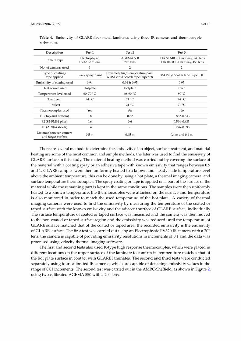
The emissivity can be described as the amount of thermal energy, which a material radiates in theform of infrared energy, the value of emissivity for materials ranges between 0 (material that does notemit infrared energy) to 1 (black body), which completely radiates thermal energy. Different materialshave different emissivities, several factors can affect the emissivity of an object such as its temperaturesand the ambient temperature, material size and shape. Since it was previously reported that the heataffected zone at the edges of machined laminates is a phenomenon, which deserves to be consideredduring machining operations, an attempt is made to evaluate the developed temperature around thehole edges at the exit side of the laminate when the cutting tool is exiting the workpiece. In the currentresearch, the material heating method was used to find the emissivity of GLARE’s upper and lowersurfaces and its edges. The outer aluminum sheets of GLARE are usually coated with a thin cladlayer to improve surface corrosion resistance; in addition, all aluminum sheets are also sometimesanodized and coated with a corrosion inhibiting primer [1]. The chemical processing of the aluminumsheet gives its surface a varying level of color intensity resulting in a range of emissivity rather thana constant value. The emissivity of GLARE was determined by conducting three emissivity tests,as shown in Table 4. Each test was carried out using different infrared (IR) cameras and different typesof coating/tapes, which have known emissivity values.
Materials 2016, 9, 622 6 of 17
Table 4. Emissivity of GLARE fiber metal laminates using three IR cameras and thermocoupletechniques.
Description Test 1 Test 2 Test 3
Camera type ElectrophysicPV320 20˝ lens
AGEMA 55020˝ lens
FLIR SC640: 0.4 m away, 24˝ lensFLIR B400: 0.1 m away, 45˝ lens
No. of cameras used 1 2 2
Type of coating/tape applied Black spray paint Extremely high-temperature paint
& 3M Vinyl Scotch tape Super 88 3M Vinyl Scotch tape Super 88
Emissivity of coating used 0.94 0.94 & 0.95 0.95
Heat source used Hotplate Hotplate Oven
Temperature level used 60–70 ˝C 60–90 ˝C 90˝C
T ambient 24 ˝C 24 ˝C 24 ˝C
T reflect - 21 ˝C 21 ˝C
Thermocouples used Yes Yes No
E1 (Top and Bottom) 0.8 0.82 0.832–0.843
E2 (S2-FM94 plies) 0.6 0.6 0.594–0.683
E3 (Al2024 sheets) 0.4 - 0.276–0.395
Distance between cameraand target surface 0.5 m 0.45 m 0.4 m and 0.1 m
There are several methods to determine the emissivity of an object, surface treatment, and materialheating are some of the most common and simple methods, the later was used to find the emissivity ofGLARE surface in this study. The material heating method was carried out by covering the surface ofthe material with a coating spray or an adhesive tape with known emissivity that ranges between 0.9and 1. GLARE samples were then uniformly heated to a known and steady state temperature levelabove the ambient temperature, this can be done by using a hot plate, a thermal imaging camera, andsurface temperature thermocouples. The spray coating or tape is applied on a part of the surface of thematerial while the remaining part is kept in the same conditions. The samples were then uniformlyheated to a known temperature, the thermocouples were attached on the surface and temperatureis also monitored in order to match the used temperature of the hot plate. A variety of thermalimaging cameras were used to find the emissivity by measuring the temperature of the coated ortaped surface with the known emissivity and the adjacent surface of GLARE surface, individually.The surface temperature of coated or taped surface was measured and the camera was then movedto the non-coated or taped surface region and the emissivity was reduced until the temperature ofGLARE surface matched that of the coated or taped area, the recorded emissivity is the emissivityof GLARE surface. The first test was carried out using an Electrophysic PV320 IR camera with a 20˝
lens, the camera is capable of providing emissivity resolutions in increments of 0.1 and the data wasprocessed using velocity thermal imaging software.
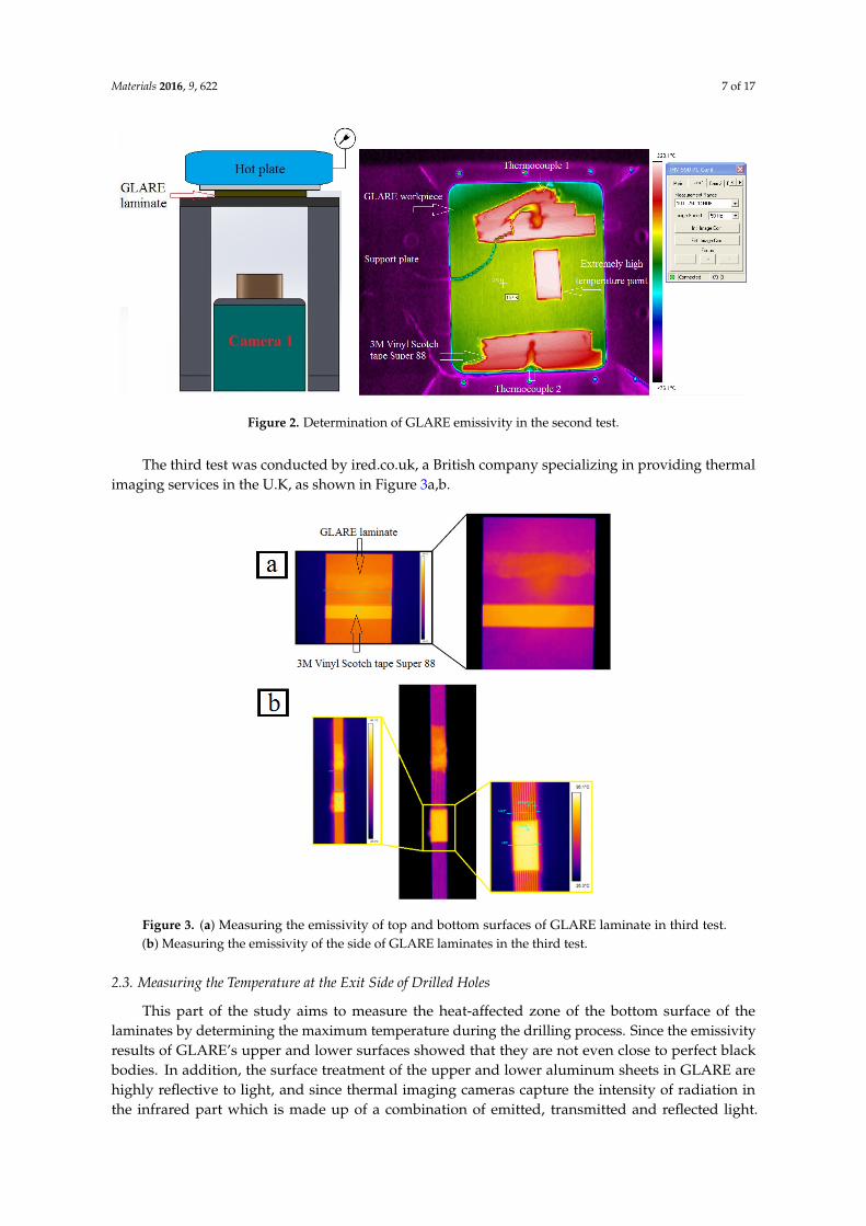
The first and second tests also used K-type high response thermocouples, which were placed indifferent locations on the upper surface of the laminate to confirm its temperature matches that ofthe hot plate surface in contact with GLARE laminates. The second and third tests were conductedseparately using four calibrated IR cameras, which are capable of detecting emissivity values in therange of 0.01 increments. The second test was carried out in the AMRC-Sheffield, as shown in Figure 2,using two calibrated AGEMA 550 with a 20˝ lens.
Materials 2016, 9, 622 7 of 17
Materials 2016, 9, 622 6 of 17
temperature of GLARE surface matched that of the coated or taped area, the recorded emissivity is
the emissivity of GLARE surface. The first test was carried out using an Electrophysic PV320 IR
camera with a 20° lens, the camera is capable of providing emissivity resolutions in increments of 0.1
and the data was processed using velocity thermal imaging software.
Table 4. Emissivity of GLARE fiber metal laminates using three IR cameras and thermocouple techniques.
Description Test 1 Test 2 Test 3
Camera type Electrophysic
PV320 20° lens
AGEMA 550
20° lens
FLIR SC640: 0.4 m
away, 24° lens
FLIR B400: 0.1 m
away, 45° lens
No. of cameras used 1 2 2
Type of coating/
tape applied Black spray paint
Extremely high‐
temperature paint
& 3M Vinyl Scotch
tape Super 88
3M Vinyl Scotch tape
Super 88
Emissivity of coating used 0.94 0.94 & 0.95 0.95
Heat source used Hotplate Hotplate Oven
Temperature level used 60–70 °C 60–90 °C 90°C
T ambient 24 °C 24 °C 24 °C
T reflect ‐ 21 °C 21 °C
Thermocouples used Yes Yes No
E1 (Top and Bottom) 0.8 0.82 0.832–0.843
E2 (S2‐FM94 plies) 0.6 0.6 0.594–0.683
E3 (Al2024 sheets) 0.4 ‐ 0.276–0.395
Distance between camera
and target surface 0.5 m 0.45 m 0.4 m and 0.1 m
The first and second tests also used K‐type high response thermocouples, which were placed in
different locations on the upper surface of the laminate to confirm its temperature matches that of the
hot plate surface in contact with GLARE laminates. The second and third tests were conducted
separately using four calibrated IR cameras, which are capable of detecting emissivity values in the
range of 0.01 increments. The second test was carried out in the AMRC‐Sheffield, as shown in Figure
2, using two calibrated AGEMA 550 with a 20° lens.
Figure 2. Determination of GLARE emissivity in the second test. Figure 2. Determination of GLARE emissivity in the second test.
The third test was conducted by ired.co.uk, a British company specializing in providing thermalimaging services in the U.K, as shown in Figure 3a,b.
Materials 2016, 9, 622 7 of 17
The third test was conducted by ired.co.uk, a British company specializing in providing thermal
imaging services in the U.K, as shown in Figure 3a,b.
Figure 3. (a) Measuring the emissivity of top and bottom surfaces of GLARE laminate in third test.
(b) Measuring the emissivity of the side of GLARE laminates in the third test.
2.3. Measuring the Temperature at the Exit Side of Drilled Holes
This part of the study aims to measure the heat‐affected zone of the bottom surface of the
laminates by determining the maximum temperature during the drilling process. Since the emissivity
results of GLARE’s upper and lower surfaces showed that they are not even close to perfect black
bodies. In addition, the surface treatment of the upper and lower aluminum sheets in GLARE are
highly reflective to light, and since thermal imaging cameras capture the intensity of radiation in the
infrared part which is made up of a combination of emitted, transmitted and reflected light. The
measured temperature will result from a combination of emitted, transmitted and reflected radiation,
which would turn to be inaccurate. Therefore, in order to eliminate the reflectivity of the surfaces, a
black spray coating with known emissivity—previously used to determine the emissivity of
GLARE—is applied on the lower surface of the samples, as shown in Figure 4. Spraying the back of
the plate with a black paint provides a high emissivity value, which is closer to black body definition.
This means that the surface will absorb most of the heat and light, and will reflect a minimum amount
away from its surface. The commercial name of the paint is E‐TECH black extremely high‐
temperature paint designed for surfaces that are exposed to extremely high temperatures, which
provide a high quality finish. The paint is easy to apply with fast curing time and strong adhesion
and has a maximum operating temperature rating of 650 °C.
Figure 3. (a) Measuring the emissivity of top and bottom surfaces of GLARE laminate in third test.(b) Measuring the emissivity of the side of GLARE laminates in the third test.
2.3. Measuring the Temperature at the Exit Side of Drilled Holes
This part of the study aims to measure the heat-affected zone of the bottom surface of thelaminates by determining the maximum temperature during the drilling process. Since the emissivityresults of GLARE’s upper and lower surfaces showed that they are not even close to perfect blackbodies. In addition, the surface treatment of the upper and lower aluminum sheets in GLARE arehighly reflective to light, and since thermal imaging cameras capture the intensity of radiation inthe infrared part which is made up of a combination of emitted, transmitted and reflected light.

Materials 2016, 9, 622 8 of 17
The measured temperature will result from a combination of emitted, transmitted and reflectedradiation, which would turn to be inaccurate. Therefore, in order to eliminate the reflectivity of thesurfaces, a black spray coating with known emissivity—previously used to determine the emissivityof GLARE—is applied on the lower surface of the samples, as shown in Figure 4. Spraying the back ofthe plate with a black paint provides a high emissivity value, which is closer to black body definition.This means that the surface will absorb most of the heat and light, and will reflect a minimum amountaway from its surface. The commercial name of the paint is E-TECH black extremely high-temperaturepaint designed for surfaces that are exposed to extremely high temperatures, which provide a highquality finish. The paint is easy to apply with fast curing time and strong adhesion and has a maximumoperating temperature rating of 650 ˝C.Materials 2016, 9, 622 8 of 17
Figure 4. GLARE sample coated with black spray paint.
The temperature measurement trials were carried out on a MORI SEIKI SV 500 milling machine
which has a maximum spindle speed of 10,000 rpm, previously used in our previous works on
machining GLARE [6,7,11,66]. Figure 5 shows how the workpiece and camera are set inside the CNC
machine. The infrared camera utilized in this study was a calibrated FLIR AGEMA thermovision 550
camera with a built‐in 20° lens and 320 × 240 pixels optical resolution. The camera has an operating
measuring range of −20 °C to 250 °C and up to 1500 °C with a standard filter. The camera has a
spectral range 3.6 to 5 μm and 50 frames per second (fps). The camera is operated using a FLIR tools
software, which was also used to process the recorded data from IR camera. The camera was placed
vertically with the lenses facing towards the backside surface of the GLARE sample. The fixture was
then covered with a thick non‐transparent cover to reduce the amount of light entering the chamber
to a minimum.
The drilling parameters (spindle speed and feed rate) used in GLARE 2B and GLARE 3 under
dry and MQL conditions are shown in Table 5. For each cutting condition, a set of 10 holes were
drilled in a row on the workpiece and temperature was measured continuously at the exit and the
highest temperature recorded from the last seven holes was taken as the maximum temperature.
Figure 5. Details of the temperature measurement setup using the IR camera.
Figure 4. GLARE sample coated with black spray paint.
The temperature measurement trials were carried out on a MORI SEIKI SV 500 milling machinewhich has a maximum spindle speed of 10,000 rpm, previously used in our previous works onmachining GLARE [6,7,11,66]. Figure 5 shows how the workpiece and camera are set inside the CNCmachine. The infrared camera utilized in this study was a calibrated FLIR AGEMA thermovision550 camera with a built-in 20˝ lens and 320 ˆ 240 pixels optical resolution. The camera has an operatingmeasuring range of ´20 ˝C to 250 ˝C and up to 1500 ˝C with a standard filter. The camera has aspectral range 3.6 to 5 µm and 50 frames per second (fps). The camera is operated using a FLIR toolssoftware, which was also used to process the recorded data from IR camera. The camera was placedvertically with the lenses facing towards the backside surface of the GLARE sample. The fixture wasthen covered with a thick non-transparent cover to reduce the amount of light entering the chamber toa minimum.
The drilling parameters (spindle speed and feed rate) used in GLARE 2B and GLARE 3 under dryand MQL conditions are shown in Table 5. For each cutting condition, a set of 10 holes were drilledin a row on the workpiece and temperature was measured continuously at the exit and the highesttemperature recorded from the last seven holes was taken as the maximum temperature.

Materials 2016, 9, 622 9 of 17
Materials 2016, 9, 622 8 of 17
Figure 4. GLARE sample coated with black spray paint.
The temperature measurement trials were carried out on a MORI SEIKI SV 500 milling machine
which has a maximum spindle speed of 10,000 rpm, previously used in our previous works on
machining GLARE [6,7,11,66]. Figure 5 shows how the workpiece and camera are set inside the CNC
machine. The infrared camera utilized in this study was a calibrated FLIR AGEMA thermovision 550
camera with a built‐in 20° lens and 320 × 240 pixels optical resolution. The camera has an operating
measuring range of −20 °C to 250 °C and up to 1500 °C with a standard filter. The camera has a
spectral range 3.6 to 5 μm and 50 frames per second (fps). The camera is operated using a FLIR tools
software, which was also used to process the recorded data from IR camera. The camera was placed
vertically with the lenses facing towards the backside surface of the GLARE sample. The fixture was
then covered with a thick non‐transparent cover to reduce the amount of light entering the chamber
to a minimum.
The drilling parameters (spindle speed and feed rate) used in GLARE 2B and GLARE 3 under
dry and MQL conditions are shown in Table 5. For each cutting condition, a set of 10 holes were
drilled in a row on the workpiece and temperature was measured continuously at the exit and the
highest temperature recorded from the last seven holes was taken as the maximum temperature.
Figure 5. Details of the temperature measurement setup using the IR camera. Figure 5. Details of the temperature measurement setup using the IR camera.
Table 5. Cutting parameters used in drilling temperature measurements in dry and MQL trials.
Spindle Speed (rpm)
Feed rate (mm/min) 3000 6000 9000
300 A,B C,D C,D
600 A,B C,D C,D
900 A,B C,D C,D
A: G2B 8/7 B: G3 8/7 C: G2B 11/10 D: G2B 11/10 MQL.
3. Results and Discussion
3.1. The Effect of Fiber Orientation on Drilling Workpiece Temperature
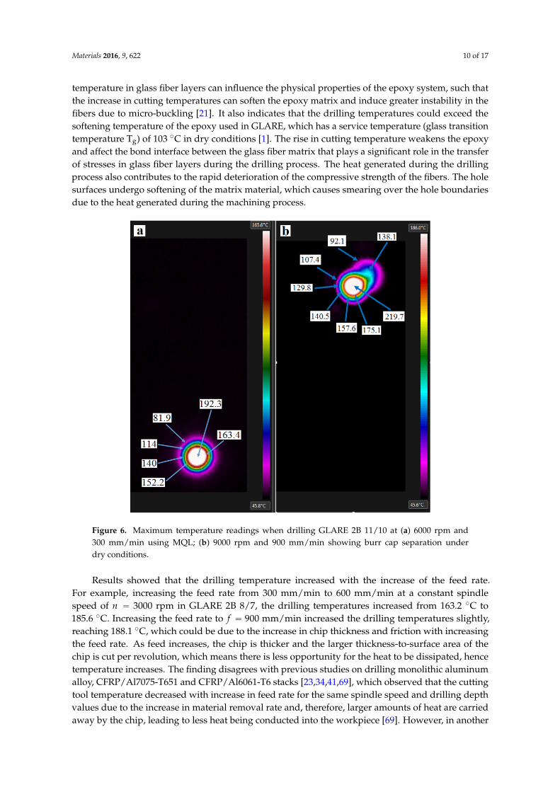
Figure 6 shows the maximum temperature readings of two holes drilled in GLARE 2B 11/10.Figure 6a shows the temperature profiles for the last aluminum sheets just before it separates fromthe workpiece. Figure 6b shows the maximum temperature profiles of a burr cap separating from theworkpiece. The temperature contour profile of the hole in each figure shows that different regions oftemperature forms uniformly around the hole periphery during the drilling process. It was foundthat the temperature decreases when moving away from the hole center (see Figure 6a) the center ofthe hole, and up to its edges, showed the highest temperature readings with maximum temperaturerecorded to be around 192.3 ˝C in this case, and with an average reading of 176.1 ˝C up to the holevicinity. Figure 6b shows an aluminum burr cap prior separating from the bottom surface of thehole, which gives an estimation of the temperature of the evacuated chips during the drilling processindicating that it can also reach high-temperature levels similar to those observed on the machinedhole surface.
It was observed that the maximum temperature reading decays rapidly, which could be dueto the high thermal conductivity of aluminum sheets leading to quick heat dissipation beforeallowing a sufficient time for heat built-up in the workpiece. The thermal conductivity of S2/FM94adhesive epoxy system is 1.1–1.4 W/m.K (1.45 W/m.K for S2 glass fibers) while Al2024-T3 alloy is121 W/m.K [67,68]. Solid carbide drills are around 110 W/m.K, which means that glass fiber layersin GLARE are poor conductors of heat. During the drilling process, the heat accumulates in glassfiber layers and is then conducted to the adjacent aluminum sheets and the cutting tool. The rise of
Materials 2016, 9, 622 10 of 17
temperature in glass fiber layers can influence the physical properties of the epoxy system, such thatthe increase in cutting temperatures can soften the epoxy matrix and induce greater instability in thefibers due to micro-buckling [21]. It also indicates that the drilling temperatures could exceed thesoftening temperature of the epoxy used in GLARE, which has a service temperature (glass transitiontemperature Tg) of 103 ˝C in dry conditions [1]. The rise in cutting temperature weakens the epoxyand affect the bond interface between the glass fiber matrix that plays a significant role in the transferof stresses in glass fiber layers during the drilling process. The heat generated during the drillingprocess also contributes to the rapid deterioration of the compressive strength of the fibers. The holesurfaces undergo softening of the matrix material, which causes smearing over the hole boundariesdue to the heat generated during the machining process.Materials 2016, 9, 622 10 of 17
Figure 6. Maximum temperature readings when drilling GLARE 2B 11/10 at (a) 6000 rpm and 300
mm/min using MQL; (b) 9000 rpm and 900 mm/min showing burr cap separation under dry conditions.
Results showed that the drilling temperature increased with the increase of the feed rate. For
example, increasing the feed rate from 300 mm/min to 600 mm/min at a constant spindle speed of
3000 rpm in GLARE 2B 8/7, the drilling temperatures increased from 163.2 °C to 185.6 °C.
Increasing the feed rate to 900 mm/min increased the drilling temperatures slightly, reaching
188.1 °C, which could be due to the increase in chip thickness and friction with increasing the feed
rate. As feed increases, the chip is thicker and the larger thickness‐to‐surface area of the chip is cut
per revolution, which means there is less opportunity for the heat to be dissipated, hence temperature
increases. The finding disagrees with previous studies on drilling monolithic aluminum alloy,
CFRP/Al7075‐T651 and CFRP/Al6061‐T6 stacks [23,34,41,69], which observed that the cutting tool
temperature decreased with increase in feed rate for the same spindle speed and drilling depth values
due to the increase in material removal rate and, therefore, larger amounts of heat are carried away
by the chip, leading to less heat being conducted into the workpiece [69]. However, in another study
on drilling titanium alloys, increasing the feed rate increased the drilling temperatures for the same
spindle speed and drilling depth [43]. This could be also due to the different cutting parameters and
tools used for each study, which could adversely affect the temperature measurement process and
results.
The results also showed that the maximum drilling temperatures in GLARE 3 8/7 were lower
than in GLARE 2B 8/7, which indicates that the fiber orientation can influence the workpiece
temperature during the machining process. Zitoune et al. [55] previously reported that the cutting
temperature depends on the fiber orientation such that it is higher when drilling with 90° fiber
orientation than with 0° due to higher failure stresses. At 90° the fibers are bent then cut by shearing
in bulk while at 0°, the chip is formed following a failure in compression. The failure stresses in
bending fibers are higher than those in compression and therefore require larger energies (cutting
forces) which increase the friction as the tool tip passes through the fibers thus increasing the heating.
For example, when drilling at 900 mm/min feed rate and 3000 rpm spindle speed, the
maximum drilling temperature recorded was 188.1 °C in GLARE 2B 8/7 and 179.9 °C in GLARE 3.
Figure 6. Maximum temperature readings when drilling GLARE 2B 11/10 at (a) 6000 rpm and300 mm/min using MQL; (b) 9000 rpm and 900 mm/min showing burr cap separation underdry conditions.
Results showed that the drilling temperature increased with the increase of the feed rate.For example, increasing the feed rate from 300 mm/min to 600 mm/min at a constant spindlespeed of n “ 3000 rpm in GLARE 2B 8/7, the drilling temperatures increased from 163.2 ˝C to185.6 ˝C. Increasing the feed rate to f “ 900 mm/min increased the drilling temperatures slightly,reaching 188.1 ˝C, which could be due to the increase in chip thickness and friction with increasingthe feed rate. As feed increases, the chip is thicker and the larger thickness-to-surface area of thechip is cut per revolution, which means there is less opportunity for the heat to be dissipated, hencetemperature increases. The finding disagrees with previous studies on drilling monolithic aluminumalloy, CFRP/Al7075-T651 and CFRP/Al6061-T6 stacks [23,34,41,69], which observed that the cuttingtool temperature decreased with increase in feed rate for the same spindle speed and drilling depthvalues due to the increase in material removal rate and, therefore, larger amounts of heat are carriedaway by the chip, leading to less heat being conducted into the workpiece [69]. However, in another

Materials 2016, 9, 622 11 of 17
study on drilling titanium alloys, increasing the feed rate increased the drilling temperatures for thesame spindle speed and drilling depth [43]. This could be also due to the different cutting parametersand tools used for each study, which could adversely affect the temperature measurement processand results.
Figure 7 shows the maximum temperature readings of holes drilled in GLARE 2B and GLARE 3under the same cutting parameters. The results showed that the maximum drilling temperaturesin GLARE 3 8/7 were lower than in GLARE 2B 8/7, which indicates that the fiber orientation caninfluence the workpiece temperature during the machining process. Zitoune et al. [55] previouslyreported that the cutting temperature depends on the fiber orientation such that it is higher whendrilling with 90˝ fiber orientation than with 0˝ due to higher failure stresses. At 90˝ the fibers arebent then cut by shearing in bulk while at 0˝, the chip is formed following a failure in compression.The failure stresses in bending fibers are higher than those in compression and therefore requirelarger energies (cutting forces) which increase the friction as the tool tip passes through the fibers thusincreasing the heating. For example, when drilling at f “ 900 mm/min feed rate and n “ 3000 rpmspindle speed, the maximum drilling temperature recorded was 188.1 ˝C in GLARE 2B 8/7 and179.9 ˝C in GLARE 3. Fibers oriented at different directions have different values of thermalconductivity exhibited by the matrix and the fiber, which affect the temperature rise during thedrilling process. The rise in temperature with the feed rate increase may also be taken accounted forin burr formation, as temperature and thrust force increase, the bottom aluminum sheet experiencesan increased ductility, which increases the size of the formed burrs. The results agree with thefindings of Ghafarizadeh et al. [51], who previously reported that the fiber orientation has significanteffects on the cutting forces and cutting temperature when milling unidirectional CFRPs, such thatthe maximum and minimum values are obtained at fiber orientations of 90˝ and 0˝, respectively.The difference in drilling temperatures did not exceed 10 ˝C in the tested cutting parameters, whichcould be due to the small thickness of glass fiber layers in GLARE. As reported in one of our previousstudies, the cutting force results showed a minor difference in thrust force between GLARE 2B andGLARE 3, arising from the difference in fiber orientation for the same thickness [7]. However, it wasobserved that the torque in GLARE 2B was higher than in GLARE 3 at same tested cutting parameters,which could have led to higher frictions between the cutting tool and the workpiece, causing agreater temperature rise in GLARE 2B. In addition, the relatively small thickness of the fiber layersmight not be enough to promote a significant temperature rise due to difference in fiber orientation.The recorded temperatures are within the range obtained in previous studies on drilling aluminumalloys, such as Al2024-T3, Al6061-T6 and Al7075-T6, which showed that maximum temperaturesranged between 131 ˝C and 360 ˝C when drilling monolithic aluminum, and up to 199 ˝C in compositemetal stacks [23,34,40,41,43,50].
Materials 2016, 9, 622 11 of 17
Fibers oriented at different directions have different values of thermal conductivity exhibited by the
matrix and the fiber, which affect the temperature rise during the drilling process. The rise in
temperature with the feed rate increase may also be taken accounted for in burr formation, as
temperature and thrust force increase, the bottom aluminum sheet experiences an increased ductility,
which increases the size of the formed burrs. The results agree with the findings of Ghafarizadeh et
al. [51], who previously reported that the fiber orientation has significant effects on the cutting forces
and cutting temperature when milling unidirectional CFRPs, such that the maximum and minimum
values are obtained at fiber orientations of 90° and 0°, respectively. The difference in drilling
temperatures did not exceed 10 °C in the tested cutting parameters, which could be due to the small
thickness of glass fiber layers in GLARE. As reported in one of our previous studies, the cutting force
results showed a minor difference in thrust force between GLARE 2B and GLARE 3, arising from the
difference in fiber orientation for the same thickness [7]. However, it was observed that the torque in
GLARE 2B was higher than in GLARE 3 at same tested cutting parameters, which could have led to
higher frictions between the cutting tool and the workpiece, causing a greater temperature rise in
GLARE 2B. In addition, the relatively small thickness of the fiber layers might not be enough to
promote a significant temperature rise due to difference in fiber orientation. The recorded
temperatures are within the range obtained in previous studies on drilling aluminum alloys, such as
Al2024‐T3, Al6061‐T6 and Al7075‐T6, which showed that maximum temperatures ranged between
131 °C and 360 °C when drilling monolithic aluminum, and up to 199 °C in composite metal stacks
[23,34,40,41,43,50].
Figure 7. Maximum drilling temperature and the influence of fiber orientation in GLARE.
3.2. The Effect of MQL Coolant on Workpiece Temperature
Figure 8 shows a comparison of hole temperature at exit between dry and MQL tests. The MQL
tests were carried out using 20 mL/h flow rate coolant and an air pressure of 3 bars since they proved
to give best results among all other tested flow rates and air pressures in one of our previous studies.
Results showed that the application of MQL coolant can reduce machining temperatures when
drilling at high feed rates of 900 mm/min. This could be due to the lubrication effect, which
reduces friction around hole walls during drill‐workpiece contact. Drilling at feed rates of 300 mm/min and spindle speeds of 6000 rpm gave similar results to those obtained under dry cutting,
which could be due to rapid evaporation of lubricant before having sufficient time to lubricate the
cutting tool and workpiece. Under the same feed rate but at higher spindle speeds of 9000 rpm,
the application of MQL reduced the temperature by approximately 22 °C, and increased by
approximately 10 °C when drilling at feed rate of 600 mm/min, which indicate that the
combination of spindle speed and feed rate plays a significant role in developed temperature in
GLARE. When drilling GLARE using spindle speeds of 6000 and 9000 rpm, increasing the feed
rate tended to decrease the cutting temperature which indicates that MQL becomes more effective
163.2
185.6 188.1
152.2
181.8 179.9
0
20
40
60
80
100
120
140
160
180
200
3000/300 3000/600 3000/900
Max
imum
dri
lling
tem
pera
ture
(°
C)
Spindle speed (rpm)/Feed rate (mm/min)GLARE 2B 8/7 GLARE 3 8/7
Figure 7. Maximum drilling temperature and the influence of fiber orientation in GLARE.

Materials 2016, 9, 622 12 of 17
3.2. The Effect of MQL Coolant on Workpiece Temperature
Figure 8 shows a comparison of hole temperature at exit between dry and MQL tests. The MQLtests were carried out using 20 mL/h flow rate coolant and an air pressure of 3 bars since they provedto give best results among all other tested flow rates and air pressures in one of our previous studies.Results showed that the application of MQL coolant can reduce machining temperatures when drillingat high feed rates of f “ 900 mm/min. This could be due to the lubrication effect, which reducesfriction around hole walls during drill-workpiece contact. Drilling at feed rates of f “ 300 mm/minand spindle speeds of n “ 6000 rpm gave similar results to those obtained under dry cutting, whichcould be due to rapid evaporation of lubricant before having sufficient time to lubricate the cutting tooland workpiece. Under the same feed rate but at higher spindle speeds of n “ 9000 rpm, the applicationof MQL reduced the temperature by approximately 22 ˝C, and increased by approximately 10 ˝C whendrilling at feed rate of f “ 600 mm/min, which indicate that the combination of spindle speed and feedrate plays a significant role in developed temperature in GLARE. When drilling GLARE using spindlespeeds of n “ 6000 and 9000 rpm, increasing the feed rate tended to decrease the cutting temperaturewhich indicates that MQL becomes more effective when the drilling time is reduced (i.e., when thefeed rate increases). This could be due to the small amounts of lubricant used in MQL, which tend toevaporate rapidly, thus, limiting its ability to lubricate the cutting tool-workpiece properly.
Materials 2016, 9, 622 12 of 17
when the drilling time is reduced (i.e., when the feed rate increases). This could be due to the small
amounts of lubricant used in MQL, which tend to evaporate rapidly, thus, limiting its ability to
lubricate the cutting tool‐workpiece properly.
Figure 8. Comparison of the exit temperature of holes drilling under MQL and dry conditions.
The use of MQL cooling was found to reduce the amount of waste formed on the machined
surfaces of the laminate, especially when drilling at high spindle speeds and low feed rates, as shown
in Figure 9. The MQL lubricant reduces the friction between the workpiece and cutting tool while the
air pressure assists in transporting the chips and waste material away from the cutting zone.
Increasing the spindle speed increased the workpiece temperature due to increased rubbing between
the cutting tool and the borehole surface per unit of time, which causes higher friction, thus raising
the machining temperatures. Increasing the feed rate showed somewhat different results depending
on the spindle speed used. The reduction in cutting temperatures with the increase of the feed rate is
due to reduced tool‐workpiece contact time. Although no comparison was made to determine the
impact of laminate thickness on developed temperatures, it is speculated that a larger laminate
thickness gives a larger contact area that produces more heat, while chip evacuation in thinner
laminates is easier and, therefore, the heat produced is lower due to smaller contact area, which also
reduced the chip adherence to the cutting tool [1]. At higher spindle speeds, a higher temperature is
generated, which increases the tendency of chip and fibers to adhere to the cutting tool and then be
forced into the laminate edges and machined surfaces and is known as a waste material causing
delamination and deformations [1].
191.
2
224.
2
189.
5
245.
1
217.
2
221.
7
192.
3
167.
9
108.
2
223.
8
226.
6
130.
5
0
50
100
150
200
250
300
300 600 900 300 600 900
6000 9000
Max
imum
dri
lling
tem
pera
ture
(°
C)
Spindle speed (rpm)/Feed rate (mm/min)
Dry MQL
Figure 8. Comparison of the exit temperature of holes drilling under MQL and dry conditions.
The use of MQL cooling was found to reduce the amount of waste formed on the machinedsurfaces of the laminate, especially when drilling at high spindle speeds and low feed rates, as shownin Figure 9. The MQL lubricant reduces the friction between the workpiece and cutting tool whilethe air pressure assists in transporting the chips and waste material away from the cutting zone.Increasing the spindle speed increased the workpiece temperature due to increased rubbing betweenthe cutting tool and the borehole surface per unit of time, which causes higher friction, thus raising themachining temperatures. Increasing the feed rate showed somewhat different results depending onthe spindle speed used. The reduction in cutting temperatures with the increase of the feed rate is dueto reduced tool-workpiece contact time. Although no comparison was made to determine the impactof laminate thickness on developed temperatures, it is speculated that a larger laminate thicknessgives a larger contact area that produces more heat, while chip evacuation in thinner laminates iseasier and, therefore, the heat produced is lower due to smaller contact area, which also reduced thechip adherence to the cutting tool [1]. At higher spindle speeds, a higher temperature is generated,which increases the tendency of chip and fibers to adhere to the cutting tool and then be forced intothe laminate edges and machined surfaces and is known as a waste material causing delamination anddeformations [1].

Materials 2016, 9, 622 13 of 17Materials 2016, 9, 622 13 of 17
Figure 9. SEM images of the upper borehole surface condition of holes under (a) MQL and (b) dry.
4. Conclusions
The drilling process of GLARE fiber metal laminates was experimentally evaluated using non‐
contact infrared techniques to determine the impact of cutting parameters (spindle speed and feed
rate), fiber orientation and the use of coolants on the maximum developed temperature at the bottom
surface of the machined hole in GLARE laminates. The following results can be concluded:
The temperature of the bottom surface of the workpiece increased as drilling progress. The
investigation indicated that both drilling parameters, i.e., spindle speed and feed rate,
influence the cutting temperature during machining.
The maximum temperature at the bottom surface when drilling GLARE fiber metal laminates
was measured by employing infrared temperature techniques. The measured temperature
reached up to 245.1 °C at a spindle speed of 9000 rpm and a feed rate of 300 mm/min
when drilling at room temperature and up to 192.3 °C when drilling under minimum
quantity lubrication cooling.
In GLARE 2B 8/7 and GLARE 3 8/7, the maximum temperature was found to increase with
the increase of the feed rate when drilling at spindle speed 3000 rpm under dry conditions (room temperature). Increasing the feed rate from 300 mm/min to 900 mm/min increased the temperature by 15.2% in GLARE 2B 8/7 and by 18.2% in GLARE 3 8/7.
The difference in maximum drilling temperature between GLARE 2B and GLARE 3 ranged
from 4 to 10 °C under the tested cutting parameters.
Figure 9. SEM images of the upper borehole surface condition of holes under (a) MQL and (b) dry.
The use of MQL cooling was found to reduce the amount of waste formed on the machinedsurfaces of the laminate, especially when drilling at high spindle speeds and low feed rates, as shownin Figure 9. The MQL lubricant reduces the friction between the workpiece and cutting tool whilethe air pressure assists in transporting the chips and waste material away from the cutting zone.Increasing the spindle speed increased the workpiece temperature due to increased rubbing betweenthe cutting tool and the borehole surface per unit of time, which causes higher friction, thus raising themachining temperatures. Increasing the feed rate showed somewhat different results depending onthe spindle speed used. The reduction in cutting temperatures with the increase of the feed rate is dueto reduced tool-workpiece contact time. Although no comparison was made to determine the impactof laminate thickness on developed temperatures, it is speculated that a larger laminate thicknessgives a larger contact area that produces more heat, while chip evacuation in thinner laminates iseasier and, therefore, the heat produced is lower due to smaller contact area, which also reduced thechip adherence to the cutting tool [1]. At higher spindle speeds, a higher temperature is generated,which increases the tendency of chip and fibers to adhere to the cutting tool and then be forced intothe laminate edges and machined surfaces and is known as a waste material causing delamination anddeformations [1].

Materials 2016, 9, 622 14 of 17
4. Conclusions
The drilling process of GLARE fiber metal laminates was experimentally evaluated usingnon-contact infrared techniques to determine the impact of cutting parameters (spindle speed and feedrate), fiber orientation and the use of coolants on the maximum developed temperature at the bottomsurface of the machined hole in GLARE laminates. The following results can be concluded:
‚ The temperature of the bottom surface of the workpiece increased as drilling progress.The investigation indicated that both drilling parameters, i.e., spindle speed and feed rate,influence the cutting temperature during machining.
‚ The maximum temperature at the bottom surface when drilling GLARE fiber metal laminates wasmeasured by employing infrared temperature techniques. The measured temperature reached upto 245.1 ˝C at a spindle speed of n “ 9000 rpm and a feed rate of f “ 300 mm/min when drilling atroom temperature and up to 192.3 ˝C when drilling under minimum quantity lubrication cooling.
‚ In GLARE 2B 8/7 and GLARE 3 8/7, the maximum temperature was found to increase withthe increase of the feed rate when drilling at spindle speed n “ 3000 rpm under dry conditions(room temperature). Increasing the feed rate from f “ 300 mm/min to f “ 900 mm/min increasedthe temperature by 15.2% in GLARE 2B 8/7 and by 18.2% in GLARE 3 8/7.
‚ The difference in maximum drilling temperature between GLARE 2B and GLARE 3 ranged from4 to 10 ˝C under the tested cutting parameters.
‚ The fiber orientation in GLARE laminates influences the maximum drilling temperature, such thatGLARE laminates with same fiber orientation as GLARE 2B (90˝/90˝) will be susceptible to higherdrilling temperatures than laminates with different fiber orientation, such as GLARE 3 (0˝/90˝).
‚ In GLARE 2B 11/10, the maximum temperature was found to depend on the level of the feedrate when drilling at spindle speed n “ 6000 and 9000 rpm under dry (room temperature) andMQL conditions, increasing the feed rate from f “ 300 mm/min to f “ 600 mm/min increasedthe temperature by 17.2% under dry and decreased it by 14.5% using MQL.
‚ The application of MQL cooling can considerably reduce the machining temperatures in GLARE,the efficiency of MQL increase with the increase of the feed rate due to improved lubrication andreduced drilling time.
‚ The largest reduction in workpiece temperature when using MQL compared to dry drilling wasachieved when drilling at spindle speed n “ 6000 and 9000 rpm and feed rates of f “ 900 mm/min.The reduction in maximum drilling temperature reached 75%.
‚ The infrared thermos vision techniques used in the current study suggests the possibility of usingthose methods to measure the temperatures fields in the machining processes, which can bealso used as an effective tool for temperature monitoring. The emissivity of GLARE found inthe current study can be used as an input for future studies for the purpose of monitoring themachining temperature of GLARE laminates.
Acknowledgments: The author would like to thank the Advanced Manufacturing Research Centre (AMRC) atThe University of Sheffield for the permission to use their facilities in this research project. The author wouldalso like to thank the Fiber Metal Laminates Centre (FMLC) and DELFT University in Netherlands for providingGLARE samples and their technical support. The author would also like to thank Dr. Peter J. Kortbeek fromFMLC and Professor Jose Sinke from DELFT University for their support on machining GLARE and materialsupply. Authors gratefully acknowledge Mr. Ravi Bilkhu for providing the infrared camera and technical support.Authors also acknowledge the support from ired ltd and Mr. Tim Mammatt for their assistance with emissivitytests. Last but not least, the first author would like to thank the Department of Mechanical Engineering atThe University of Sheffield for a PhD scholarship.
Author Contributions: Khaled Giasin designed and performed the experimental work including drilling trialsand temperature measurements. Sabino Ayvar Soberanis supervised the machining trials and arranged for theCNC machine/ operator bookings at the AMRC.
Conflicts of Interest: The authors declare no conflicts of interest.

Materials 2016, 9, 622 15 of 17
References
1. Vlot, A.; Gunnink, J.W. Fibre Metal Laminates: An Introduction; Springer: Berlin/Heidelberg, Germany, 2001.2. Sinke, J. Manufacturing of glare parts and structures. Appl. Compos. Mater. 2003, 10, 293–305. [CrossRef]3. Brinksmeier, E. Machinability of carbon-fiber-reinforced and glare materials. CIRP Encycl. Prod. Eng. 2014.
[CrossRef]4. Paul, S.; Hoogstrate, A.; Van Praag, R. Abrasive water jet machining of glass fibre metal laminates.
Proc. Inst. Mech. Eng. Part B J. Eng. Manuf. 2002, 216, 1459–1469. [CrossRef]5. Ramulu, M.; Pahuja, R.; Hashish, M.; Isvilonanda, V. Abrasive waterjet machining effects on kerf quality
in thin fiber metal laminate. In 2015 WJTA-IMCA Conference and Expo; WJTA®-IMCA®: New Orleans, LA,USA, 2015.
6. Giasin, K.; Ayvar-Soberanis, S.; Hodzic, A. The effects of minimum quantity lubrication and cryogenicliquid nitrogen cooling on drilled hole quality in glare fibre metal laminates. Mater. Des. 2016, 89, 996–1006.[CrossRef]
7. Giasin, K.; Ayvar-Soberanis, S.; Hodzic, A. An experimental study on drilling of unidirectional glare fibremetal laminates. Compos. Struct. 2015, 133, 794–808. [CrossRef]
8. Tyczynski, P.; Lemanczyk, J.; Ostrowski, R. Drilling of CFRP, GFRP, glare type composites. Aircr. Eng.Aerosp. Technol. 2014, 86, 312–322.
9. Coesel, J.F.W. Drilling of Fibre-Metal Laminates. Master Thesis, Delft University of Technology, Delft,The Netherlands, 1994.
10. Pawar, O.A.; Gaikhe, Y.S.; Tewari, A.; Sundaram, R.; Joshi, S.S. Analysis of hole quality in drilling glare fibermetal laminates. Compos. Struct. 2015, 123, 350–365. [CrossRef]
11. Giasin, K.; Ayvar-Soberanis, S.; Hodzic, A. Evaluation of cryogenic cooling and minimum quantitylubrication effects on machining glare laminates using design of experiments. J. Clean. Prod. 2016,135, 533–548. [CrossRef]
12. Giasin, K.; Ayvar-Soberanis, S.; French, T.; Phadnis, V. 3d finite element modelling of cutting forces in drillingfibre metal laminates and experimental hole quality analysis. Appl. Compos. Mater. 2016. [CrossRef]
13. Groover, M.P. Fundamentals of Modern Manufacturing: Materials Processes, and Systems; Wiley: Weinheim,Germany, 2007.
14. Parashar, B.N.; Mittal, R. Elements of Manufacturing Processes; PHI Learning Pvt. Ltd.: Delhi, India, 2002.15. Rawat, S.; Attia, H. Wear mechanisms and tool life management of WC–CO drills during dry high speed
drilling of woven carbon fibre composites. Wear 2009, 267, 1022–1030. [CrossRef]16. El-Hofy, H.A.-G. Fundamentals of Machining Processes: Conventional and Nonconventional Processes; CRC Press:
Boca Raton, FL, USA, 2013.17. Ozek, C.; Demir, Z. Investigate the friction drilling of aluminium alloys according to the thermal conductivity.
Tem J. Technol. Educ. Manag. Inf. 2013, 2, 93–101.18. Sheikh-Ahmad, J.Y. Machining of Polymer Composites; Springer: Berlin, Germany, 2009.19. Davim, J.P. Tribology in Manufacturing Technology; Springer: Berlin/Heidelberg, Germany, 2012.20. DeGarmo, E.P.; Black, J.T.; Kohser, R.A. Materials and Processes in Manufacturing; Wiley: Weinheim,
Germany, 2003.21. Khan, Z.M. A Study of the Drilling of Advanced Carbon Fibre Composites. Ph.D. Thesis, University of
Salford, Salford, UK, 1991.22. Fleischer, J.; Pabst, R.; Kelemen, S. Heat flow simulation for dry machining of power train castings.
CIRP Ann. - Manuf. Technol. 2007, 56, 117–122. [CrossRef]23. Wang, C.-Y.; Chen, Y.-H.; An, Q.-L.; Cai, X.-J.; Ming, W.-W.; Chen, M. Drilling temperature and hole quality in
drilling of CFRP/aluminum stacks using diamond coated drill. Int. J. Precis. Eng. Manuf. 2015, 16, 1689–1697.[CrossRef]
24. Taskesen, A.; Kutukde, K. Non-contact measurement and multi-objective analysis of drilling temperaturewhen drilling B4C reinforced aluminum composites. Trans. Nonferrous Metals Soc. China 2015, 25, 271–283.[CrossRef]
25. Shetty, R.; Pai, R.; Kamath, V.; Rao, S.S. Steam as coolant and lubricant in turning of metal matrix composites.J. Zhejiang Univ. Sci. A 2008, 9, 1245–1250. [CrossRef]

Materials 2016, 9, 622 16 of 17
26. Kolesnyk, V.; Zajac, J.; Radchenko, S.; Adamian, M. The effect of cutting temperature on hole quality whendrilling CFRP/metal stack. Biсник НТУ 2015, 4, 138–141.
27. Kaynak, Y. Evaluation of machining performance in cryogenic machining of inconel 718 and comparisonwith dry and mql machining. Int. J. Adv. Manuf. Technol. 2014, 72, 919–933. [CrossRef]
28. Manimaran, G.; Venkatasamy, R. Influence of cryogenic cooling on surface grinding of stainless steel 316.Cryogenics 2014, 59, 76–83. [CrossRef]
29. Dhar, N.R.; Ahmed, M.T.; Islam, S. An experimental investigation on effect of minimum quantity lubricationin machining AISI 1040 steel. Int. J. Mach. Tools Manuf. 2007, 47, 748–753. [CrossRef]
30. Abhang, L.; Hameedullah, M. Chip-tool interface temperature prediction model for turning process.Int. J. Eng. Sci. Technol. 2010, 2, 382–393.
31. Kitagawa, T.; Kubo, A.; Maekawa, K. Temperature and wear of cutting tools in high-speed machining ofinconel 718 and Ti-6Al-6V-2Sn. Wear 1997, 202, 142–148. [CrossRef]
32. Nedic, B.P.; Eric, M.D. Cutting temperature measurement and material machinability. Therm. Sci. 2014,18, 259–268.
33. Bono, M.; Ni, J. A method for measuring the temperature distribution along the cutting edges of a drill.J. Manuf. Sci. Eng. 2002, 124, 921–923. [CrossRef]
34. Bagci, E.; Ozcelik, B. Investigation of the effect of drilling conditions on the twist drill temperature duringstep-by-step and continuous dry drilling. Mater. Des. 2006, 27, 446–454.
35. El-Wardany, T.I.; Mohammed, E.; Elbestawi, M.A. Cutting temperature of ceramic tools in high speedmachining of difficult-to-cut materials. Int. J. Mach. Tools Manuf. 1996, 36, 611–634. [CrossRef]
36. Ueda, T.; Sato, M.; Hosokawa, A.; Ozawa, M. Development of infrared radiation pyrometer with opticalfibers—two-color pyrometer with non-contact fiber coupler. CIRP Ann.-Manuf. Technol. 2008, 57, 69–72.[CrossRef]
37. Sato, M.; Aoki, T.; Tanaka, H.; Takeda, S. Variation of temperature at the bottom surface of a hole duringdrilling and its effect on tool wear. Int. J. Mach. Tools Manuf. 2013, 68, 40–47. [CrossRef]
38. Ueda, T.; Nozaki, R.; Hosokawa, A. Temperature measurement of cutting edge in drilling -effect of oil mist.CIRP Ann. - Manuf. Technol. 2007, 56, 93–96. [CrossRef]
39. Aramcharoen, A.; Chuan, S.K. An experimental investigation on cryogenic milling of inconel 718 and itssustainability assessment. Procedia CIRP 2014, 14, 529–534. [CrossRef]
40. Rivero, A.; Aramendi, G.; Herranz, S.; de Lacalle, L.L. An experimental investigation of the effect of coatingsand cutting parameters on the dry drilling performance of aluminium alloys. Int. J. Adv. Manuf. Technol.2006, 28, 1–11. [CrossRef]
41. Dandekar, C.; Orady, E.; Mallick, P. Drilling characteristics of an e-glass fabric-reinforced polypropylenecomposite and an aluminum alloy: A comparative study. J. Manuf. Sci. Eng. 2007, 129, 1080–1087. [CrossRef]
42. Kalidas, S.; DeVor, R.E.; Kapoor, S.G. Experimental investigation of the effect of drill coatings on hole qualityunder dry and wet drilling conditions. Surf. Coat. Technol. 2001, 148, 117–128. [CrossRef]
43. Le Coz, G.; Marinescu, M.; Devillez, A.; Dudzinski, D.; Velnom, L. Measuring temperature of rotating cuttingtools: Application to MQL drilling and dry milling of aerospace alloys. Appl. Thermal Eng. 2012, 36, 434–441.[CrossRef]
44. Vernaza-Pena, K.; Mason, J.; Li, M. Experimental study of the temperature field generated during orthogonalmachining of an aluminum alloy. Exp. Mech. 2002, 42, 221–229. [CrossRef]
45. Li, R.; Shih, A.J. Tool temperature in titanium drilling. Ann. Arbor 2007, 1001, 48109–42125. [CrossRef]46. Li, R.; Shih, A.J. Spiral point drill temperature and stress in high-throughput drilling of titanium. Int. J. Mach.
Tools Manuf. 2007, 47, 2005–2017. [CrossRef]47. Fang, F.; Lee, L.; Liu, X. Mean flank temperature measurement in high speed dry cutting of magnesium alloy.
J. Mater. Process. Technol. 2005, 167, 119–123. [CrossRef]48. Weinert, K.; Kempmann, C. Cutting temperatures and their effects on the machining behaviour in drilling
reinforced plastic composites. Adv. Eng. Mater. 2004, 6, 684–689. [CrossRef]49. Krishna, A.S.R.; Reddy, P.R. Temperature prediction in orthogonal machining of A1/SICP composites.
Int. J. Emerg. Technol. Adv. Eng. 2012, 2, 223–229.50. Brinksmeier, E.; Fangmann, S.; Rentsch, R. Drilling of composites and resulting surface integrity.
CIRP Ann. - Manuf. Technol. 2011, 60, 57–60. [CrossRef]

Materials 2016, 9, 622 17 of 17
51. Ghafarizadeh, S.; Lebrun, G.; Chatelain, J.-F. Experimental investigation of the cutting temperature andsurface quality during milling of unidirectional carbon fiber reinforced plastic. J. Compos. Mater. 2015.[CrossRef]
52. Merino-Pérez, J.; Royer, R.; Ayvar-Soberanis, S.; Merson, E.; Hodzic, A. On the temperatures developedin CFRP drilling using uncoated WC-CO tools part I: Workpiece constituents, cutting speed and heatdissipation. Compos. Struct. 2015, 123, 161–168.
53. Takeyama, H.; Iijima, N. Machinability of glassfiber reinforced plastics and application of ultrasonicmachining. CIRP Ann. - Manuf. Technol. 1988, 37, 93–96. [CrossRef]
54. Sreejith, P.; Krishnamurthy, R.; Malhotra, S.; Narayanasamy, K. Evaluation of pcd tool performance duringmachining of carbon/phenolic ablative composites. J. Mater. Process. Technol. 2000, 104, 53–58. [CrossRef]
55. Zitoune, R.; Collombet, F.; Lachaud, F.; Piquet, R.; Pasquet, P. Experiment–calculation comparison of thecutting conditions representative of the long fiber composite drilling phase. Compos. Sci. Technol. 2005,65, 455–466. [CrossRef]
56. Abhishek, K.; Datta, S.; Mahapatra, S.S. Response surface modeling on machining of CFRP composites:Effect of process variables on surface roughness, MRR and tool-tip temperature. Int. J. Mechan. Eng. Res.2013, 3, 407–414.
57. Haddad, M.; Zitoune, R.; Bougherara, H.; Eyma, F.; Castanié, B. Study of trimming damages ofCFRP structures in function of the machining processes and their impact on the mechanical behavior.Compos. Part B Eng. 2014, 57, 136–143. [CrossRef]
58. Saleem, M.; Toubal, L.; Zitoune, R.; Bougherara, H. Investigating the effect of machining processes onthe mechanical behavior of composite plates with circular holes. Compos. Part A Appl. Sci. Manuf. 2013,55, 169–177. [CrossRef]
59. Haddad, M.; Zitoune, R.; Eyma, F.; Castanie, B. Study of the surface defects and dust generatedduring trimming of CFRP: Influence of tool geometry, machining parameters and cutting speed range.Compos. Part A Appl. Sci. Manuf. 2014, 66, 142–154. [CrossRef]
60. Wang, B.; Gao, H.; Cao, B.; Zhuang, Y.; Zhao, Z. Mechanism of damage generation during drilling ofcarbon/epoxy composites and titanium alloy stacks. Proc. Inst. Mech. Eng. Part B J. Eng. Manuf. 2014,228, 698–706. [CrossRef]
61. Alderliesten, R.C. Fatigue Crack Propagation and Delamination Growth in Glare; DUP Science: Lyngby,Danmark, 2005.
62. De Vries, T.J. Blunt and Sharp Notch Behaviour of Glare Laminates; TU Delft, Delft University of Technology:Delft, The Netherlands, 2001.
63. Mohit, G.; Frank, A.; Michael, F.; Galib, A. Predicting bearing strength of fiber metal laminates via progressivefailure analysis. In 52nd aiaa/asme/asce/ahs/asc Structures, Structural Dynamics and Materials Conference;American Institute of Aeronautics and Astronautics: Reston, VA, USA, 2011.
64. Yaghoubi, A.S.; Liaw, B. Damage assessments of ballistic impact behaviors of glare 5 (3/2) beams withvarious stacking sequences. In Dynamic Behavior of Materials; Springer: Berlin/Heidelberg, Germany, 2013;Volume 1, pp. 503–512.
65. Hagenbeek, M. Characterisation of Fibre Metal Laminates under Thermomechanical Loadings; TU Delft,Delft University of Technology: Delft, The Netherlands, 2005.
66. Giasin, K.; Hodzic, A.; Phadnis, V.; Ayvar-Soberanis, S. Assessment of cutting forces and hole qualityin drilling Al2024 aluminium alloy: Experimental and finite element study. Int. J. Adv. Manuf. Technol.2016, 1–21. [CrossRef]
67. De Vries, T.J. Blunt and Sharp Notch Behaviour of Glare Laminates; Delft University Press: Delft,The Netherlands, 2001.
68. Seo, H. Damage Tolerance and Durability of Glare Laminates; ProQuest: Ann Arbor, MI, USA, 2008.69. O’Sullivan, D.; Cotterell, M. Workpiece temperature measurement in machining. Proc. Inst. Mech. Eng.
Part B J. Eng. Manuf. 2002, 216, 135–139. [CrossRef]
© 2016 by the authors; licensee MDPI, Basel, Switzerland. This article is an open accessarticle distributed under the terms and conditions of the Creative Commons Attribution(CC-BY) license (http://creativecommons.org/licenses/by/4.0/).
Related Documents