1/17 Application Note This sheet contains tentative information; we may change the contents without notice. Light Emitting Diode SE-AP00012C Dec.2, 2015 Evaluation of Coating Materials Contents 1 Introduction 2 Evaluation Items for Coating Materials 3 Evaluation Test with 5 Coating Materials 4 Evaluation Test with 7 Coating Materials 5 Evaluation Test with 9 Coating Materials 6 Summary 7 Request

Welcome message from author
This document is posted to help you gain knowledge. Please leave a comment to let me know what you think about it! Share it to your friends and learn new things together.
Transcript

1/17
Application Note
This sheet contains tentative information; we may change the contents without notice.
Ligh
t Em
ittin
g D
iode
SE-AP00012C Dec.2, 2015
Evaluation of Coating Materials
Contents
1 Introduction
2 Evaluation Items for Coating Materials
3 Evaluation Test with 5 Coating Materials
4 Evaluation Test with 7 Coating Materials
5 Evaluation Test with 9 Coating Materials
6 Summary
7 Request

2/17
Application Note
This sheet contains tentative information; we may change the contents without notice.
Ligh
t Em
ittin
g D
iode
SE-AP00012C Dec.2, 2015
a A
b B
c C Olefin Resin
D
E
Synthetic resin obtained bypolymerizing Olefin containingFluorine
Resin made by finely dispersingEthylene-Propylene rubber inPolypropylene
Supplier
d
Fluorine Resin
Silicone Resin
Coating Material No. Main Ingredient
Organic silicone compound mainlyconsisting of siloxane bond
Details
Concerns Evaluation Method- Impact on the optical characteristics suchas decrease in the luminous flux and colorshift- Impact on the shape of an assembledproduct/LED and coating thickness
- Optical characteristics measurement before and aftercoating the material- Optical characteristics measurement with various amountsof the material
Migration between the leads and on thecircuit, and deterioration of eachcomponent material
- Water proof test- Moisture permeability test- Water submersion test'- Salt spray test
CoatingMethod
Uneven coating and space between thematerial and the package, which can affectthe optical characteristics and theproperties such as moisture proof, waterrepellency, and gas barrier
- External observation for space- External observation for the coating thickness
Others Impact of corrosive gas Sulfuration test
- Degradation under the influence of thecircumstances such as ultraviolet rays andhigh temperatures or the light and the heatgenerated from the LEDs
DegradationCoating
Performance
Evaluation Item
- Weatherability test'- Aging test'- Confirm the glass-transition temperature of the coatingmaterial
Moisture Proof / Water Repellency
Coating Property
Gas Barrier Property
Permeability Characteristics
1. Introduction
This application note provides evaluation items/methods for coating materials to support customers
when they select the best coating materials for their product with Nichia’s LEDs. For reference, we’ll
show the resin coating materials’ evaluation results in each section.
2. Evaluation Items for Coating Materials
We use coating materials for insulation, dust prevention, water/moisture proofing, water repellent finish,
and to enhance the gas barrier property, etc.
Inappropriate coating materials can affect the optical characteristics of the LEDs due to the permeability
characteristics and deterioration of the materials.
It is important to select coating materials after evaluating the compatibility with assembled products and
the environment. Even when the coating thickness is increased, allowing for insulation, dust prevention,
water/moisture proofing, water repellency, and better weatherability and the gas barrier property, the
optical characteristics of LEDs are impaired.
Table 1 summarizes the evaluation items/methods for coating materials.
Table 1 Evaluation Items/Methods of Coating Materials
3. Evaluation Test with 5 Coating Materials
We’ll provide the evaluation methods/results of the 5 items below.
Table 2 shows the description of the coating materials used herein.
- Light Transmission Characteristics
- Degradation
- Moisture Proof / Water Repellency
- Coating Property
- Gas Barrier Property
Table 2 Coating Material Information

3/17
Application Note
This sheet contains tentative information; we may change the contents without notice.
Ligh
t Em
ittin
g D
iode
SE-AP00012C Dec.2, 2015
Item
Appearance
Chromaticity
Luminous Flux
NS6W183ANSSW157A
Outline Dimensions: 3.0×1.4×0.52mm Outline Dimensions: 6.5×5.0×1.35mm
3-1. Light Transmission Characteristics
The light transmission characteristics of the coating materials affect the optical characteristics such as
the decrease in the LEDs’ luminous flux and color shift. The degree of the adverse effects varies
depending on the shape/kind of the assembled products/LEDs and the coating thickness. Therefore,
it is necessary to evaluate the impact of the light transmission characteristics on a finished product.
For reference, Table 3 shows the evaluation results of the luminous flux and the chromaticity of
NSSW157A and NS6W183A, according to the 5 coating materials.
* Brush coating (1 time)
As shown in the data, the characteristics change increased in the following order:
Silicone Resin (D and E) > Olefin Resin (C) > Fluorine Resin (A and B)
This might be related to the coating thickness; the thicker the film is, the larger the change.
There were some differences in the characteristics change between NSSW157A and NS6W183A.
This might be because of the size/shape of the emitting surface.
Table 3 Evaluation Results of Optical Characteristics of NSSW157A and NS6W183A Ta=25°C
* Coating thickness: Silicone Resin (D and E) > Olefin Resin (C) > Fluorine Resin (A and B)

4/17
Application Note
This sheet contains tentative information; we may change the contents without notice.
Ligh
t Em
ittin
g D
iode
SE-AP00012C Dec.2, 2015
Discoloration Minor Discoloration
Before Test
After Test
No No Major Discoloration No
3-2. Degradation (Weatherability)
Coating materials may be deteriorated by some factors surrounding them such as ultraviolet rays and
high temperatures or under the influence of the light and the heat generated from assembled
products.
Therefore, it is important to evaluate coating materials, considering the estimated operating time, the
usage environments, and the construction of the assembled product.
Table 4 shows the accelerated weather resistance test results of LEDs with the 5 coating materials.
Test Method
Light Source: Metal halide lamp
Illuminance: 500 W/m2 (300 – 400 nm)
Board Surface Temperature: 63°C
Operating Time: 200 hrs.
Test Result
The LED with Material C was significantly deteriorated.
As shown in the test results, the LEDs with the individual materials are unsusceptible to degradation
in the following order:
Fluorine Resin (A and B) > Silicone Resin (D and E) > Olefin Resin (C)
Thus, fluorine resins are more resistant to climate conditions; chemically more stable to the light such
as ultraviolet, etc.
3-3. Water Repellency
It is important to evaluate the water repellency of coating materials, considering the usage
environments of the assembled product. For example, we should evaluate the moisture proof property
and the water repellency; “water repellency” refers to the ability to resist wetting and “moisture proof”
refers to the ability to create a barrier that blocks moisture from passing through the barrier.
Coating materials have different properties. Therefore, the coating material which is fully compatible
with the assembled product should be selected to achieve the desired performance.
Table 4 Accelerated Weather Resistance Test Result
* Brush coating (1 time)
A
B
D
D
E
E
B C
CA

5/17
Application Note
This sheet contains tentative information; we may change the contents without notice.
Ligh
t Em
ittin
g D
iode
SE-AP00012C Dec.2, 2015
塗布なし コーティング剤B Coating Material Contact AngleNo Coating 77°
A 117°B 110°C 77°D 104°E 104°
3-3-1. Water Repellency Test
Test Method:
1) Coat the board with each coating material with a brush once.
2) Cure the coating material and place several droplets of water on the board.
3) Measure the contact angle of the droplets on the board.
The larger the contact angle, the more highly hydrophobic and water repellent the material is.
Test Result
The water repellency of the 5 materials is as follows:
Fluorine Resin (A and B) > Silicone Resin (D and E) > Olefin Resin (C)
The more repellent to water, the smaller the surface tension and the more resistant to water.
3-3-2. Moisture Proof Test
Test Method:
In accordance with JIS-Z-0208; “Testing methods for the determination of the water vapor
transmission rate of moisture-proof packaging materials (cup method)” or JIS-Z-7129; “the
moisture sensor method, the infrared sensor method, and the gas chromatography method”
The specimen with lower transmission rate has a better moisture proof property.
Table 7 Moisture Proof Test Result
Material Test Conditions In accordance withFilm Thickness
[µm] Moisture Permeability
[g/m2/24h] Coating Material A Ta=25°C, RH90% JIS-Z-0208 30 220 Coating Material B Ta=40°C, RH90% JIS-Z-7129 20 200 Coating Material C Ta=40°C, RH90% JIS-Z-0208 41.7 13.3
Silicone Elastomer * Ta=25°C, RH90% JIS-Z-7129 25 820
* The moisture permeability of the silicone elastomer is from the database literature.
Test Result
The order of the moisture proof property of the 5 materials is as follows:
Olefin Resin (C) > Fluorine Resin (A and B) > Silicone Resin (D and E)
Olefin resin is superior to any other material. We suspect that the low density/film thickness after
the resin curing process results in low moisture permeability.
77° 110°
Table 6 Water Repellency Test Result Table 5 Contact Angle of Water Droplet on the Board
Coating Material B No Coating Material

6/17
Application Note
This sheet contains tentative information; we may change the contents without notice.
Ligh
t Em
ittin
g D
iode
SE-AP00012C Dec.2, 2015
Coating Material ACoating Material B From an Angle Close up
3-4. Coating Property
Depending on the coating property of the coating material, it cannot be uniformly applied on the
assembled product, or space is left between the material and the LED/board. In such cases, the
assembled product cannot achieve the properties desired for water repellency and gas barrier,
affecting the optical characteristics.
Please be advised that the coating property of a coating material depends on some factors such as
the coating object/method. As examples, we’ll show the evaluation results of these properties in
Tables 8 and 9, using the Coating Material B.
3-5. Gas Barrier Property
Nichia uses silver plating for the lead frames of some of our LEDs. The property of the silver plating is
changed, resulting in degradation of the optical characteristics, when exposed to corrosive gas
containing sulfur and halogen substances.
We conducted a sulfuration test for LEDs coated with each material to evaluate the gas barrier
property.
Please refer to Table 10 and Figure 1 (Page 7) for the sulfuration test results.
Test Conditions
Corrosive Gas: Hydrogen Sulfide (H2S)
Gas Density: 15 [ppm]
Temperature & Humidity: Ta=40°C, RH90%
Storage Period: 96 hrs. & 192 hrs.
Space between the
LED and the board
More uniformly coated
Table 8 External Observation for the Emitting Surface Table 9 External Observation for the Side Surface
* Brush coating (1 time)

7/17
Application Note
This sheet contains tentative information; we may change the contents without notice.
Ligh
t Em
ittin
g D
iode
SE-AP00012C Dec.2, 2015
Before Test After Test
None
B
D
AppearanceCoating Material
* We didn’t use Material C during the sulfuration test; however, we confirmed during another test that
the gas barrier property of the LEDs with Material C was similar as that of the LEDs without any
coating material.
Test Result
The gas barrier property decreases in the following order:
Fluorine Resin (A and B) > Silicone Resin (D and E)
Silicone resin is less dense and it has larger spaces throughout its molecular structure, resulting
in the worse gas barrier property.
4. Evaluation Test with 7 Coating Materials (Added in Mar.’14)
There is a large variety of coating materials to apply to the board with electrical components mounted
on.
As stated in Section 2, the permeability characteristics and deterioration of the coating materials can
affect the LEDs’ optical characteristics.
Nichia evaluated the coating materials to select the compatible one with the boards. For example,
here are the verification results of the following aspects, demonstrating the outdoor application:
- Deterioration
- Water repellency
We used NS6W183B for the verification tests. Please refer to Table 11 for the appearance of
NS6W183B and Table 12 for the main ingredients of each coating material (Page 8).
Table 10 NS6W183B Sulfuration Test Result (External Observation)
Discolored
Discolored
Minor Discoloration
Figure 1 Sulfuration Test Result
(Optical Characteristics Change) * Brush coating (1 time)

8/17
Application Note
This sheet contains tentative information; we may change the contents without notice.
Ligh
t Em
ittin
g D
iode
SE-AP00012C Dec.2, 2015
Supplier Coating Material Main Ingredient Details
a A(*1)
b B(*1)
D(*1)
E(*1)
e F AcrylicAmorphous resin obtained by polymerizing acrylic
ester
f G Vinyl ButyralAmorphous resin obtained by polymerizing polyvinyl
butyral and butylaldehyde
g H Glass Coating Inorganic coating material containing glass fiber
Fluorine Thermoplastic resin containing fluorine
d SiliconeOrganic silicone compound mainly consisting of
siloxane bond
4-1. Degradation
We performed the aging test and the weatherability test for the LEDs using each coating material.
4-1-1. Aging Test
We sprayed the LEDs (NS6W183B) mounted on the aluminum board with each coating material and
operated them at 25°C for 100 hours. We evaluated how the LEDs would be deteriorated under the
influence of the light and the heat for a short time.
Figures 2 and 3 show how much the optical characteristics were changed during the aging test. Table
13 (Page 9) shows the external observation results of the LEDs coated with Materials B, F, G, and H.
Test Condition
Board: Aluminum (t=1.6mm)
Ambient Temperature: Ta=25°C
Duration: 100 hours
Input Current: 350 mA
Board
FR-4
Alluminum
Appearance
*1 Coating Materials A, B, D, and E are the same ones as in Table 2 (Page 2).
*2 Brush coating (1 time), 1 spray for Material G
Table 11 NS6W183B Mounted on Boards Table 12 Description of Coating Materials
Figure 2
Aging Test Result (Relative Luminous Flux) Figure 3
Aging Test Result (Chromaticity)

9/17
Application Note
This sheet contains tentative information; we may change the contents without notice.
Ligh
t Em
ittin
g D
iode
SE-AP00012C Dec.2, 2015
Before Test
After Test
Fluorine Resin B Acrylic Resin F Vinylbutyral Resin G Glass Coating H
Before Test
After Test
Acrylic Resin F Vinylbutyral Resin G Glass Coating H
The luminous flux of the LED coated with Material G (Vinyl Butyral Resin) was reduced due to the
discoloration. We suspect that the material was deteriorated and discolored under the influence of the
light and the heat generated from the LED die. The LED coated with Material H was cracked and the
coating material was aggregated on the emitting surface. This must have been caused by the same
symptom as seen in Material G.
4-1-2. Weatherability Test
We sprayed the LEDs (NS6W183B) mounted on the aluminum board with each coating material and
operated them at the following conditions. Please refer to Section 3-2 for Materials A, B, D, and E.
Test Conditions
Light Source: Metal halide lamp
Illuminance: 500 W/m2 (300 to 400 nm)
Board Surface Temperature: 63°C/50%RH
Duration: 200 hrs.
Table 14 Weatherability Test Result
All the coating materials were significantly deteriorated probably due to the disconnection of the
molecular bonds under the influence of the ultraviolet rays.
Aggregated
CrackedDiscolored
Table 13 External Observation Result
Cracked
Discolored Discolored

10/17
Application Note
This sheet contains tentative information; we may change the contents without notice.
Ligh
t Em
ittin
g D
iode
SE-AP00012C Dec.2, 2015
Coating Material Lighting Inspection
No Abnormality
No Abnormality
Current Leakage
No Abnormality
Current Leakage
No Abnormality
None
H(Glass Coating)
Before Test
D(Silicone Resin)
After Test
B(Fluorine Resin)
G(Vinylbutyral Resin)
F(Acrylic Resin)
Coating Material Lighting Inspection
None Current Leakage
H(Glass Coating)
No Abnormality
F(Acrylic Resin)
G(Vinylbutyral Resin)
D(Silicone Resin)
Before Test After Test
B(Fluorine Resin)
No Abnormality
No Abnormality
No Abnormality
No Abnormality
Coating Material Main Ingredient Water Immersion Test Salt Spray TestB Fluorine Resin Little Difference Little DifferenceD Silicone Resin Minor corrosion Little DifferenceF Acrylic Resin Little Difference Minor corrosionG Vinylbutyral Resin No difference Minor corrosionH Glass Coating Little Difference No difference
4-2. Water Repellency Test (Water Immersion Test and Salt Spray Test)
We sprayed the LEDs (NS6W183B) mounted on the FR-4 with each coating material and operated
them during the following tests:
- Water Immersion Test
- Salt Spray Test
Please refer to Figures 4 and 5 for the test methods and Tables 15 and 16 (Page 10) for the external
observation results before/after the tests. We skipped the tests for Materials A and E.
Test Conditions
Board: FR-4 (t=1.6mm)
Temperature: Ta=25°C
Duration: 8 hrs.
Input Current: 100 mA
Water Immersion Test: The LED mounted on the FR-4 is immersed in water and operated.
Salt Spray Test: Salt water (3% density) is sprayed on the LED mounted on the FR-4
every 30 minutes.
Table 15 Water Immersion Test Result
Fig.5 Salt Spray Test Fig.4 Water Immersion Test
Corroded
Corroded
Corroded
Table 17 Water Immersion / Salt Spray Test Results
Corroded
Corroded
Cracked
Corroded
○: No significant corrosion
△: Minor Corrosion, compared with the LED without any coating
×: Little difference, compared with the LED without any coating
Table 16 Salt Spray Test Results

11/17
Application Note
This sheet contains tentative information; we may change the contents without notice.
Ligh
t Em
ittin
g D
iode
SE-AP00012C Dec.2, 2015
Appearance
NF2W757DR‐V1
Size: 3.0×3.0×0.52 mm
Material Main Ingredient ViscosityPulling Speed
[ mm/sec ]Layer Thickness
(*) [ μm ]
I Middle 50 10
J Low 10 1~2
K Low 10 < 1
L Low 10 < 1
E High 300 160
M High 300 160
N Polyurethane Resin Middle 50 30
C Olefin Resin Middle 50 20
O Acrylic Resin Middle 50 30
Fluorine Resin
Silicone Resin
Supplier Coating Material Main Ingredient Details
b I
J
K
L
d E (*)
i M
N Polyurethane Resin Resin containing urethane bond
C (*) Olefin Resin Synthetic resin obtained from polymerized olefin
O Acrylic ResinAmorphous resin obtained by polymerizing acrylic ester
Silicone ResinOrganic silicone compound mainly consisting of siloxane bond
c
hFluorine Resin
Synthetic resin obtained by polymerizing Olefin containing Fluorine
5. Evaluation Test with 9 Coating Materials (Added in Nov.’15)
Nichia evaluated 9 coating materials: refer to Table 18 for the description of the 9 materials.
Table 18 Description of Coating Materials
* C, E: The same materials as described in Table 2 in Section 3
5-1. Applying Method of Coating Materials
Nichia used an automatic dip coating method for Section 5 to evaluate these materials. It’s a highly
reproducible method; the LED-mounted board was dipped into each coating material, and the layer
thickness was adjusted by changing the removing speed. Refer to Table 19 for the sample LED and
Table 20 for the conditions for each material.
Table 19 External Appearance Table 20 Conditions for each material
* The above layer thickness is the average of the thickness values at some given
points on the layer of each material.
12/17
Application Note
This sheet contains tentative information; we may change the contents without notice.
Ligh
t Em
ittin
g D
iode
SE-AP00012C Dec.2, 2015
5-2. Light Transmission Characteristics
Each coating material was applied to the LED-mounted (NF2W757DR-V1) aluminum board as
described in Table 20. Refer to Figure 6 for the luminous flux change and Figure 7 for the chromaticity
change.
There was little difference in the luminous flux after the sample was coated with each material; on the
other hand, we found a significant color shift in the LED coated with E and M. This is because their
coating layers were much thicker than the others’.
5-3. Degradation
We performed the weatherability test and the aging test for the LEDs using each coating material.
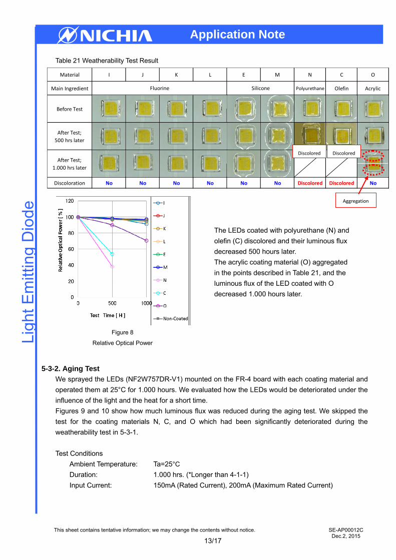
5-3-1. Weatherability Test
We sprayed the LEDs (NF2W757DR-V1) mounted on the aluminum board with each coating material
and operated them at the following conditions, assuming that they were operated outdoors. Refer to
Table 21 for the external observation results and Figure 8 for the relative luminous flux change (Page
13).
Test Conditions
Light Source: Metal halide lamp
Illuminance: 500 W/m2 (300 to 400 nm)
Board Surface Temperature: 63°C/50%RH
Duration: 500, 1.000 hrs. (*Longer than 3-2 and 4-1-2)
Figure 6
Optical Characteristics (Relative Luminous Flux)
Figure 7
Optical Characteristics (Chromaticity)
13/17
Application Note
This sheet contains tentative information; we may change the contents without notice.
Ligh
t Em
ittin
g D
iode
SE-AP00012C Dec.2, 2015
Material I J K L E M N C O
Main Ingredient Polyurethane Olefin Acrylic
Before Test
After Test;
500 hrs later
After Test;
1.000 hrs later
Discoloration No No No No No No Discolored Discolored No
Fluorine Silicone
Table 21 Weatherability Test Result
5-3-2. Aging Test
We sprayed the LEDs (NF2W757DR-V1) mounted on the FR-4 board with each coating material and
operated them at 25°C for 1.000 hours. We evaluated how the LEDs would be deteriorated under the
influence of the light and the heat for a short time.
Figures 9 and 10 show how much luminous flux was reduced during the aging test. We skipped the
test for the coating materials N, C, and O which had been significantly deteriorated during the
weatherability test in 5-3-1.
Test Conditions
Ambient Temperature: Ta=25°C
Duration: 1.000 hrs. (*Longer than 4-1-1)
Input Current: 150mA (Rated Current), 200mA (Maximum Rated Current)
Discolored Discolored
Aggregation
Figure 8
Relative Optical Power
The LEDs coated with polyurethane (N) and
olefin (C) discolored and their luminous flux
decreased 500 hours later.
The acrylic coating material (O) aggregated
in the points described in Table 21, and the
luminous flux of the LED coated with O
decreased 1.000 hours later.

14/17
Application Note
This sheet contains tentative information; we may change the contents without notice.
Ligh
t Em
ittin
g D
iode
SE-AP00012C Dec.2, 2015
There was little difference in the relative optical power among the LEDs coated with the fluorine (I, J,
K, L) / silicone (E, M) materials and the non-coated LED at either of the input current values (150 and
200mA). None of the LEDs coated with the materials was deteriorated during the aging test.
5-4. Gas Barrier Property
We mounted a different type of LEDs (NF2W757A-V1*) on an aluminum board and coated them with
each material to conduct a sulfuration test. (* NF2W757A-V1 (Table 22, Page 15) is more susceptible
to sulfur than NF2W757DR-V1.)
Please refer to Table 23 for the external observation results and Figures 11 and 12 for the optical
characteristics measurement results (Page 15). We skipped the test for the coating materials N, C,
and O.
Figure 9
Relative Optical Power (150mA)
Figure 10
Relative Optical Power (200mA)

15/17
Application Note
This sheet contains tentative information; we may change the contents without notice.
Ligh
t Em
ittin
g D
iode
SE-AP00012C Dec.2, 2015
Appearance
NS2W757A‐V1
3.0×3.0×0.52mm
Test Conditions
Corrosive Gas: Hydrogen Sulfide (H2S): 2ppm + Nitrogen Oxide (Nx): 4ppm
Temperature & Humidity: Ta=40°C, RH75%
Storage Period: 42 hrs. & 84 hrs.
As described in 3-5, the fluorine resin was superior to the silicone resin in the gas barrier property. As
shown in Table 23, Figures 11 and 12, the fluorine coating materials I and J were less susceptible to
sulfur. The other fluorine coating materials K and L were found to be more susceptible to sulfur than
the silicone ones; this is because of their thinner layers, resulting in the worse gas barrier property.
Table 23 External Observation Result
Table 22 Appearance of NS2W757A-V1
Figure 11
Optical Characteristics Measurement Result
(Relative Optical Power)
Figure 12
Optical Characteristics Measurement Result
(Chromaticity)
L E
Major Discoloration
Before Test
After Test42 hours later
After Test84 hours later
Discoloration NoMinor
Discoloration
M Non-Coated
Resin Fluorine Silicone -
Material I J K

16/17
Application Note
This sheet contains tentative information; we may change the contents without notice.
Ligh
t Em
ittin
g D
iode
SE-AP00012C Dec.2, 2015
Coating Method OthersCoating Property Gas Barrier property
Weatherability Aging Water Repellency Moisture Proof Water Immersion Salt Spray Test External Observation Sulfuration Test
3. 15. 2
3. 24. 1. 25. 3. 1
4. 1. 15. 3. 2 3. 3. 1 3. 3. 2 3. 4 3. 5
5. 4
a A ○ ○ ○ ○ ○ ○ ○B ○ ○ ○ ○ ○ ○ ○ ○ ○I ○ ○ ○ ○J ○ ○ ○ △K ○ ○ ○ ×L ○ ○ ○ ×C Olefin ○ × × ○N Polyurethane ○ ×O Acrylic ○ ×D △ ○ ○ ○ △ △ ○ ×E △ ○ ○ ○ △ ×
i M △ ○ ○ ×e F Acrylic × ○ ○ △f G Vinylbutyral × × × △g H Glass Coating × × ○ ×
Fluorine
b
h
c
dSilicone
SupplierCoating Material Main Ingredient
Coating Performance
Light Transmission
Degradation Water Repellency
4. 2
6. Summary
Judging from the evaluation results so far, the fluorine coating materials have the least impact on the
LED-mounted board and achieve sufficient coating performance. The silicone resin doesn’t have
significant adverse effects on the coating performances, although its gas barrier property is inferior to
the fluorine resin. The silicone resin features its easy coating and its inexpensive price; it is effective
depending on the purposes. Table 24 summarizes the evaluation results of each coating material.
Table 24 Summary of Evaluation Results of Coating Materials
○: Excellent / No significant degradation/adverse effects on the characteristics
△:Good / Insignificant degradation/adverse effects on the characteristics
×: Bad / Significant degradation / adverse effects on the characteristics

17/17
Application Note
This sheet contains tentative information; we may change the contents without notice.
Ligh
t Em
ittin
g D
iode
SE-AP00012C Dec.2, 2015
7. Request
Coating materials can help to achieve insulation and to improve the properties for moisture proof, water
repellency, and gas barrier; however, the incompatibility between a coating material and an
LED-assembled product impairs the performance, or even worse, it shortens the operating life.
Please evaluate coating materials according to the usage purpose and environment, considering the
impact on/from the LED-assembled product.
Please use the evaluation results of some of these coating materials only as reference.
Related Documents