EVAL-ADAS1000SDZ User Guide UG-426 One Technology Way • P.O. Box 9106 • Norwood, MA 02062-9106, U.S.A. • Tel: 781.329.4700 • Fax: 781.461.3113 • www.analog.com Evaluating the ADAS1000 ECG Front End for Demonstration and Development PLEASE SEE THE LAST PAGE FOR AN IMPORTANT WARNING AND LEGAL TERMS AND CONDITIONS. Rev. B | Page 1 of 44 FEATURES Biopotential signals in; digitized signals out 6 electrodes (5 acquisition channels and 1 driven lead) 2 × ADAS1000 (master/slave) for 1 to 12 lead electrode measurements AC and dc lead off detection Pace detection Optional thoracic impedance measurement (internal/external) Selectable reference lead Lead or electrode data available Calibration features (DAC and 1 mV square/sinewave) Low or high speed data output rates Serial interface SPI®-/QSPI™-/DSP-compatible CUSTOMER INTERFACING OPTIONS Direct access to ADAS1000 serial interface (J4) USB interface via Analog Devices, Inc., Blackfin®-based SDP-B controller board and GUI APPLICATIONS ECG Patient monitor Holter monitor Cardiac defibrillators GENERAL DESCRIPTION The primary function of the EVAL-ADAS1000SDZ evaluation board is to demonstrate the ADAS1000 integrated electrocardiogram (ECG) device for medical instrumentation. A full description of the ADAS1000 is available in the data sheet, and should be consulted when utilizing this user guide. This evaluation board is used to evaluate the ADAS1000 and all variants. The evaluation board is ideal for exploring concepts and adopting the ADAS1000 into advanced medical systems. The board can be operated as part of an end user’s system via the ADAS1000 serial peripheral interface (SPI), or as a standalone evaluation of the ADAS1000 using the support of the Analog Devices system demonstration platform controller board (SDP-B), and a standard PC (running Windows® Vista, Windows 7 32-bit and 64-bit, or Windows 8) to run the Analog Devices evaluation software. The SDP-B board, which is a DSP-based controller board is separate from the evaluation board, is required to run the Analog Devices evaluation software, and is used for data transfer from evaluation board to PC via USB interface. It does not come as part of the evaluation kit and can be ordered separately (EVAL-SDP-CB1Z). The SDP-B board can be reused with many other Analog Devices evaluation modules. For more information, visit the Analog Devices healthcare home page.

Welcome message from author
This document is posted to help you gain knowledge. Please leave a comment to let me know what you think about it! Share it to your friends and learn new things together.
Transcript

EVAL-ADAS1000SDZ User Guide UG-426
One Technology Way • P.O. Box 9106 • Norwood, MA 02062-9106, U.S.A. • Tel: 781.329.4700 • Fax: 781.461.3113 • www.analog.com
Evaluating the ADAS1000 ECG Front End
for Demonstration and Development
PLEASE SEE THE LAST PAGE FOR AN IMPORTANT WARNING AND LEGAL TERMS AND CONDITIONS. Rev. B | Page 1 of 44
FEATURES Biopotential signals in; digitized signals out 6 electrodes (5 acquisition channels and 1 driven lead) 2 × ADAS1000 (master/slave) for 1 to 12 lead electrode
measurements AC and dc lead off detection Pace detection Optional thoracic impedance measurement
(internal/external) Selectable reference lead Lead or electrode data available Calibration features (DAC and 1 mV square/sinewave) Low or high speed data output rates Serial interface SPI®-/QSPI™-/DSP-compatible
CUSTOMER INTERFACING OPTIONS Direct access to ADAS1000 serial interface (J4) USB interface via Analog Devices, Inc., Blackfin®-based
SDP-B controller board and GUI
APPLICATIONS ECG Patient monitor Holter monitor Cardiac defibrillators
GENERAL DESCRIPTION The primary function of the EVAL-ADAS1000SDZ evaluation board is to demonstrate the ADAS1000 integrated electrocardiogram (ECG) device for medical instrumentation. A full description of the ADAS1000 is available in the data sheet, and should be consulted when utilizing this user guide. This evaluation board is used to evaluate the ADAS1000 and all variants.
The evaluation board is ideal for exploring concepts and adopting the ADAS1000 into advanced medical systems. The board can be operated as part of an end user’s system via the ADAS1000 serial peripheral interface (SPI), or as a standalone evaluation of the ADAS1000 using the support of the Analog Devices system demonstration platform controller board (SDP-B), and a standard PC (running Windows® Vista, Windows 7 32-bit and 64-bit, or Windows 8) to run the Analog Devices evaluation software.
The SDP-B board, which is a DSP-based controller board is separate from the evaluation board, is required to run the Analog Devices evaluation software, and is used for data transfer from evaluation board to PC via USB interface. It does not come as part of the evaluation kit and can be ordered separately (EVAL-SDP-CB1Z). The SDP-B board can be reused with many other Analog Devices evaluation modules.
For more information, visit the Analog Devices healthcare home page.

UG-426 EVAL-ADAS1000SDZ User Guide
Rev. B | Page 2 of 44
TABLE OF CONTENTS Features .............................................................................................. 1 Customer Interfacing Options ........................................................ 1 Applications ....................................................................................... 1 General Description ......................................................................... 1 Revision History ............................................................................... 2
Conditions Regarding the Use of This Product in Healthcare Applications ................................................................................... 3 Evaluation Kit Contents............................................................... 3 Hardware Requirements .............................................................. 3
Evalution Board Software ................................................................ 5 Installing the Software: Overview .............................................. 5 Installing the Software: Details ................................................... 5 Connecting to the Board ............................................................. 6 Running the Software .................................................................. 6
Evaluation Board Hardware ............................................................ 7 Key Features .................................................................................. 7 Connectors .................................................................................... 7 Connecting an ECG Signal ......................................................... 8 RESET Buttons .............................................................................. 8 LED ................................................................................................. 8 Jumpers .......................................................................................... 9
ADAS1000 Software Operation.................................................... 10 Quick Operation of ADAS1000 Software ............................... 10 Detailed Description of Main Control Panel .......................... 10 Control of all Registers .............................................................. 12 ECG Capture ............................................................................... 14 ECG Capture with Digital Post Processing............................. 15 Leads OFF Control ..................................................................... 16 Respiration .................................................................................. 17 Pace .............................................................................................. 18 Understanding Pace in the ADAS1000 ................................... 19 Write to a File .............................................................................. 20 Test Tones .................................................................................... 23 Common-Model Level/Wilson Central Terminal ................. 25
Detailed Description ...................................................................... 26 Overview of Schematics ............................................................ 26 Pace Interface (Optional) .......................................................... 26 Power............................................................................................ 26 Flexible Respiration Feature on Master ADAS1000 .............. 27 Troubleshooting.......................................................................... 33
Evaluation Board Schematics........................................................ 35
REVISION HISTORY 11/2018—Rev. A to Rev. B
Changes to General Description Section ...................................... 1 Deleted Clamp Section ............................................................................. 34 Deleted Figure 45; Renumbered Sequentially ..................................... 34
3/2014—Rev. 0 to Rev. A
Changed ADAS1000SDZ to EVAL-ADAS1000 SDZ Throughout ......................................................................... Universal Change to Title .................................................................................. 1 Changes to Figure 46 ...................................................................... 35 Changes to Figure 52 ...................................................................... 41 Changes to Figure 53 ...................................................................... 42
8/2012—Revision 0: Initial Version

EVAL-ADAS1000SDZ User Guide UG-426
Rev. B | Page 3 of 44
INPUTRC COMPONENT SPACE
FOR CABLE MODEL, FILTER MODEL
4.5V TO 5.5V GND
ON BOARD REGULATOR AND LDOSAVDD: 3.3VIOVDD: 3.3V
SDP CONNECTOR
ADAS1000 DIRECTSPI CONNECTOR
(OPTIONAL)(J4)
EXT_RESP_RA
EXT_RESP_LLEXT_RESP_LA
ECG1 (LA)ECG 2 (LL)
ECG 4 (V1)ECG 5 (V2)
RLD
ECG 3 (RA)
ECG 6 (V3)ECG 7 (V4)
ECG 8 (V5)ECG 9 (V6)
ECG 10 (SPARE)
CIRCUIT/LINK AREAFOR ENHANCEDRESPIRATION
ADAS1000 DIRECTMASTER INTERFACE
FOR FASTPACE CONNECTOR
(OPTIONAL)(J6)
ADAS1000RESET
SDPRESET
CRYSTAL
WALL POWER, BENCH SUPPLY OR BATTERY (J7 OR J9)
DB15 CONNECTORFOR ECG
(J1)
HEADER CONNECTORFOR RESPIRATION (EXT)
(J8)
ADJUSTABLE RLDGAIN SETTINGCOMPONENTS
ADAS1000MASTER
RA, LA, LL, V1, V2, RLD
ADAS1000SLAVE
V3, V4, V5, V6, SPARE
1081
0-00
1
OPTIONAL
Figure 1. Functional Block Diagram
CONDITIONS REGARDING THE USE OF THIS PRODUCT IN HEALTHCARE APPLICATIONS In addition to the terms found at the end of this document, the following shall also apply to your use of the board and design:
This evaluation board design is being provided “as is” without any expressed or implied representations or warranties of any kind and the use of this board or design shall impose no legal obligation on Analog Devices, Inc., and its subsidiaries, employees, directors, officers, servants and agents. In addition, it is understood and agreed to that the evaluation board or design is not authorized for use in safety critical healthcare applications (such as life support) where malfunction or failure of a product can be expected to result in personal injury or death. This board must not be used for diagnostic purposes and must not be connected to a human being or animal. It must not be used with a defibrillator or other equip-ment that produces high voltages in excess of the supply rails on the board.
This evaluation board is provided for evaluation and development purposes only. It is not intended for use or as part of an end product. Any use of the evaluation board or design in such applications is at your own risk and you shall fully
indemnify Analog Devices, Inc., its subsidiaries, employees, directors, officers, servants and agents for all liability and expenses arising from such unauthorized usage. You are solely responsible for compliance with all legal and regulatory requirements connected to such use.
EVALUATION KIT CONTENTS
• EVAL-ADAS1000SDZ board • Medical-grade universal ac-to-dc wall adaptor (+5 V) • CD that includes
• Self-installing graphical user interface (GUI) software that allows users to read/write to ADAS1000 and to stream data
• Electronic version of the ADAS1000 data sheet • Electronic version of the EVAL-ADAS1000SDZ
documentation
HARDWARE REQUIREMENTS
• Power supply: +5 V (ac-dc adaptor provided) • Patient simulator or similar device • SDP board, a controller board for data transfer to PC. This
can be ordered separately (EVAL-SDP-CB1Z)
UG-426 EVAL-ADAS1000SDZ User Guide
Rev. B | Page 4 of 44
EXTRA LINKS/CIRCUIT RELATEDTO EXTERNAL RESPIRATION
MEASUREMENTS
OPTIONAL BENCHSUPPLY FOR ADAS
CHIPS (J6)
OPTIONAL BENCHSUPPLY (5V)
(J7)
ON BOARDDC-DC
REGULATORS
RESET FORADAS CIRCUIT
RESET BUTTONFOR SDP BOARD
ADAS1000 SPIINTERFACE(J4)
ADAS1000 SLAVEELECTRODES V3,V4, V5, V6 SPARE
SPACE FORCABLE/ESISMODELLING
RLD EXTCOMPONENTS
POWERCONNECTOR,
5V (J9)
EXTERNAL RESPIRATIONCONNECTOR (J8)
ELECTRODE CONNECTORDB15 (J1)
ADAS1000 MASTERELECTRODES LA, RA, LL, V1, V2, RLD
PATIENT CABLE
ADAS1000EVALUATION BOARD
5V WALLADAPTOR
SDP BOARD
USBCABLETO PC
USBCONNECTOR
1081
0-00
2
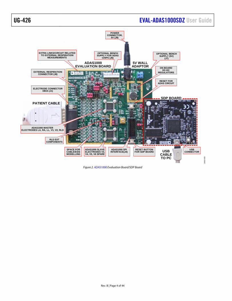
Figure 2. ADAS1000 Evaluation Board/SDP Board
EVAL-ADAS1000SDZ User Guide UG-426
Rev. B | Page 5 of 44
EVALUTION BOARD SOFTWARE INSTALLING THE SOFTWARE: OVERVIEW The EVAL-ADAS1000SDZ kit includes self-installing software on CD.
Install the software prior to connecting the SDP board to the USB port of the PC. This ensures that the SDP board is recognized when it connects to the PC.
1. Start the Windows operating system and insert the CD.
2. The installation software should launch automatically. If it does not, run the setup.exe file from the CD.
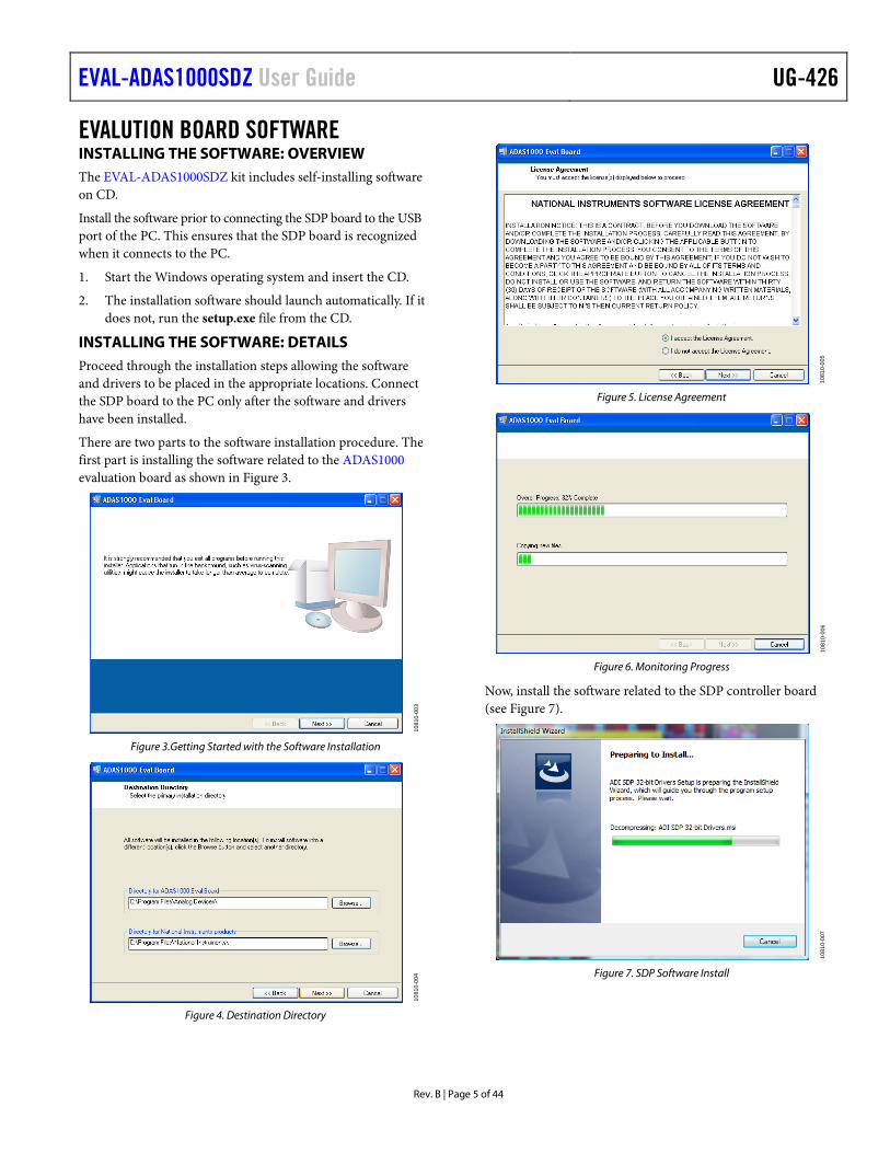
INSTALLING THE SOFTWARE: DETAILS Proceed through the installation steps allowing the software and drivers to be placed in the appropriate locations. Connect the SDP board to the PC only after the software and drivers have been installed.
There are two parts to the software installation procedure. The first part is installing the software related to the ADAS1000 evaluation board as shown in Figure 3.
1081
0-00
3
Figure 3.Getting Started with the Software Installation
1081
0-00
4
Figure 4. Destination Directory
1081
0-00
5
Figure 5. License Agreement
1081
0-00
6
Figure 6. Monitoring Progress
Now, install the software related to the SDP controller board (see Figure 7).
1081
0-00
7
Figure 7. SDP Software Install
UG-426 EVAL-ADAS1000SDZ User Guide
Rev. B | Page 6 of 44
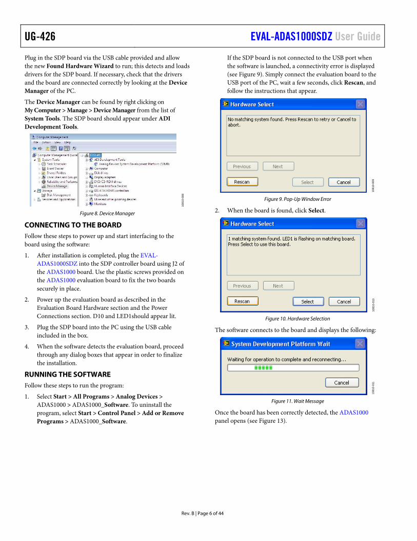
Plug in the SDP board via the USB cable provided and allow the new Found Hardware Wizard to run; this detects and loads drivers for the SDP board. If necessary, check that the drivers and the board are connected correctly by looking at the Device Manager of the PC.
The Device Manager can be found by right clicking on My Computer > Manage > Device Manager from the list of System Tools. The SDP board should appear under ADI Development Tools.
1081
0-00
8
Figure 8. Device Manager
CONNECTING TO THE BOARD Follow these steps to power up and start interfacing to the board using the software:
1. After installation is completed, plug the EVAL-ADAS1000SDZ into the SDP controller board using J2 of the ADAS1000 board. Use the plastic screws provided on the ADAS1000 evaluation board to fix the two boards securely in place.
2. Power up the evaluation board as described in the Evaluation Board Hardware section and the Power Connections section. D10 and LED1should appear lit.
3. Plug the SDP board into the PC using the USB cable included in the box.
4. When the software detects the evaluation board, proceed through any dialog boxes that appear in order to finalize the installation.
RUNNING THE SOFTWARE Follow these steps to run the program:
1. Select Start > All Programs > Analog Devices > ADAS1000 > ADAS1000_Software. To uninstall the program, select Start > Control Panel > Add or Remove Programs > ADAS1000_Software.
If the SDP board is not connected to the USB port when the software is launched, a connectivity error is displayed (see Figure 9). Simply connect the evaluation board to the USB port of the PC, wait a few seconds, click Rescan, and follow the instructions that appear.
1081
0-00
9
Figure 9. Pop-Up Window Error
2. When the board is found, click Select.
1081
0-01
0
Figure 10. Hardware Selection
The software connects to the board and displays the following:
1081
0-01
1
Figure 11. Wait Message
Once the board has been correctly detected, the ADAS1000 panel opens (see Figure 13).

EVAL-ADAS1000SDZ User Guide UG-426
Rev. B | Page 7 of 44
EVALUATION BOARD HARDWARE KEY FEATURES
• 5 or 10 ECG electrode paths capable of demonstrating 1 lead to 12 leads of ECG data
• AC and DC lead off detection • Respiration and pace measurement and display • Calibration features and display • Test tones • Real-time ECG electrode or lead display on PC screen via
Analog Devices ADAS1000 GUI (lead calculation available).
• Recording of ECG data for offline review
Power Connections
There are a number of options for supplying power to the board. The simplest is directly from the J9 dc jack connector with the wall adapter which is provided as part of the kit.
Choose one of the following:
• J9: dc jack–requires 5 V at 250 mA. Note that this provides power to the SDP board in addition to the ADAS1000 related circuitry.
• J7: screw terminal (2 inputs)–requires 5 V at 250 mA. Provides power to the on-board dc-dc convertors which supply all circuitry on board and also powers the SDP board.
Alternatively, choose
• J5: screw terminal (6 inputs). These inputs are optional supply inputs for the ADAS1000 devices and the remainder of the circuitry on the board • AVDD = 3 V to 5.5 V • IOVDD = 1.65 V to 3.6 V • AGND = DGND = 0 V • ADCVDD and DVDD are optional supplies. They can
be supplied from the ADAS1000 on-chip regulators. Alternatively, the regulators can be disabled and the user can drive ADCVDD and DVDD directly via J5. If ADCVDD and DVDD are driven directly, then the following supplies are required. • ADCVDD (optional) = 1.8 V • DVDD (optional) = 1.8 V
Table 1. Power Supply Connection (Choose Only One) Supply Requirement Parameter Supply Range Primary Supply (J7 or J9)
+5 V 4.5 V to 5.5 V (may be supplied from wall adaptor, battery or bench supply). If applied, this is the only supply rail required by the board.
Alternative Supplies (J5)
AVDD +3 V to +5.5 V
IOVDD 1.65 V to 3.6 V ADCVDD 1.8 V ±5% DVDD 1.8 V ±5%
CONNECTORS Electrode Connector–J1
This connector provides the primary analog input interface to which customer proprietary lead sets are connected.
1081
0-01
2
Figure 12. J1, DB15 Connector
Connector J1 is a DB15 female connector and mates with a D-SUB plug. All ADAS1000 electrode connections are made available here for both master and slave devices in addition to the Right Leg Drive (RLD_OUT) and Shield Drive (SHIELD) pins.
Note that every effort was made to supply input protection to the electrode pins sufficient for the application; however, the intent was not to offer this module as a true medical solution. Therefore, no defibrillation pulses or voltages outside the ADAS1000 operating range should be applied to the input connector/board.

UG-426 EVAL-ADAS1000SDZ User Guide
Rev. B | Page 8 of 44
CONNECTING AN ECG SIGNAL The user needs to connect a signal source to the evaluation board connector J1 for measurement purposes. Ideally, this would be a patient simulator. In demonstrations at Analog Devices, the PS420 patient simulator (from Fluke Biomedical Division of Fluke Electronics Corporation) is used.
Note that the board is not designed for direct connection to patients or animals for testing.
Users should connect the appropriate signal to the ECG electrode inputs and RLD_OUT electrode.
Table 2. Electrode Connector, J1 Pin No. Mnemonic Description 1 V2 Analog input, Master ECG5_V2 2 V3 Analog input, Slave ECG1_V3 3 V4 Analog input, Slave ECG2_V4 4 V5 Analog input, Slave ECG3_V5 5 V6 Analog input, Slave ECG4_V6 6 SHIELD Output of shield driver 7 CE Common electrode, Master CM_IN 8 NC Not connected 9 RA Analog input, right arm, Master
ECG3_RA 10 LA Analog input, left arm, Master ECG1_LA 11 LL Analog input, left leg, Master ECG2_LL 12 V1 Analog input, Master ECG4_V1 13 Spare Analog input, chest electrode or
auxiliary bio-potential input, Slave ECG5 14 RLD Right leg drive, RLD_OUT 15 NC Not connected
SDP Interface Connector, J2
The purpose of this connector is to facilitate interfacing with the Analog Devices SDP1Z control board which is USB controlled. This control board is specific to the operation of this module as a standalone evaluation and learning platform. This connector is not intended for customer-specific interfacing.
Main ADAS SPI, J4
This connector provides the ADAS1000 digital interface pins so that the device may be used in standalone mode (without the SDP control board). The user may use this connecter to interface to the device in order to develop their own code and evaluate the ADAS1000 directly.
Note that on the board, the /CS, SDI, and SDO paths for each device are separate for ultimate flexibility in control of the devices. When controlled via the SDP board, the /CS line is shared (LK12 inserted). When using multiple devices, the SDI and SDO paths can be shared, and each device can be controlled via its own /CS line, allowing for easy control with minimum wires.
Table 3. SPI Connector, J4 Pin No. Mnemonic Device Description 1 PD both Power down, active low
2 RESET both Device reset, active low
3 SDI_1 slave Serial data input 4 SDI_0 master Serial data input 5 SDO_1 slave Serial data output 6, 12, 13, 14 DGND both Digital ground 7 SDO_0 master Serial data output 8 CS_0 master Chip select master
9 CS_1 slave Chip select slave
10 SCLK both Clock input 11 DRDY master Data ready, active low
Timing Characteristics
Refer to the ADAS1000 product data sheet for information regarding the required waveforms and behavior of the SPI interface pins when preparing to interface directly to the ADAS1000 SPI interface.
Pace Interface/GPIO Connector, J6
This connector provides the optional secondary interface available from the master device for the purposes of the customer-based digital pace detection algorithm. It is a master interface providing MSCLK, MSDO, and MCS outputs to be read by a host controller. It provides ECG data captured at 128 kHz data rate.
Pin No. Mnemonic Description 1 GPIO3 Reconfigurable IO 2 GPIO2/MSDO Reconfigurable IO/master
interface MSDO 3 GPIO1/MSCK Reconfigurable IO/master
interface MSCK 4 GPIO0/MCS Reconfigurable IO/master
interface MCS
5, 6 DGND Digital ground
RESET BUTTONS There are two reset buttons on the board. SDP reset is used for a reset of the SDP board and ADAS reset is used for reset of ADAS1000 devices to default/power-on configuration.
LED There is one LED (D10) on the board, which is lit when the board is powered from J7 (+5 V connector).

EVAL-ADAS1000SDZ User Guide UG-426
Rev. B | Page 9 of 44
JUMPERS There are a number of jumpers included on this board for flexibility and ease of configuration. These jumpers allow the user to easily drive the main ADAS1000 SPI interface directly without concern about other SPI-controlled components. On receipt of the board, the jumpers are in the default state as described in Table 4.
Table 4. Default State of Jumpers Jumper Jumper Description Condition Respiration LK1 External Respiration Measurement. LK1 is used to connect the EXT_RESP_XX paths to
the ECG channels external to the device (requires that LK4 be connected if using the external paths).
A, B, C inserted
LK2 External Respiration Measurement. LK2 is used when using external capacitors for the respiration circuit; LK1 needs to be closed also (and, optionally, LK4).
A, B, C inserted
LK3 External Respiration Measurement. LK3 is used to bring either of the ECG channels (LA or LL) to the input of the AD8226 in-amp (part of an optional respiration circuit).
Inserted (A)
LK4 External Respiration Measurement. LK4 connects the external respiration paths to the respiration header or, alternatively, to the ECG paths via LK1.
Open
LK19 External Respiration Measurement. Connect (A) when using external respiration circuit (AD8226 and AD8606). Can be disconnected for all other respiration options.
Inserted (A)
LK15 For External Respiration Using an External Instrumentation Amplifier (Optional Circuit). The evaluation board uses the AD8226 along with a buffer, AD8606. This arrangement allows the output of the amplifier to drive the EXT_RESP_RA input. Use with LK16.
Closed
LK16 For External Respiration Using an External Instrumentation Amplifier (Optional Circuit). The evaluation board uses the AD8226 along with a buffer, AD8606. This arrangement allows the output of the amplifier to drive the EXT_RESP_LA input. Use with LK15.
Closed
Power Supply LK6 AVDD Path from On-Board LDO (ADP151). Open if powering the board from J5 screw terminals. Closed if supply board from either wall adaptor input or J7 (5 V) supply input.
Closed
LK7 AVDD Path to MASTER ADAS1000. Use to measure supply current in AVDD path to MASTER ADAS1000.
Closed
LK8 IOVDD Path from On-Board LDO (ADP151). Open if powering the board from J5 screw terminals. Closed if supply board from either wall adaptor input or J7 (5 V) supply input.
Closed
VREG EN LK9 VREG_EN–ADAS1000 On-Chip Regulators (DVDD, ADCVDD). They are enabled when VREG_EN is high, disabled when low, and may be overdriven. If overdriving, close LK9 and use J5 to supply DVDD and ADCVDD supply rails (1.8 V).
Open
LK17 ADCVDD net is shared to both MASTER and SLAVE. This allows an external ADCVDD to be applied. Each ADAS1000 has its own on-chip regulator for ADCVDD. If both MASTER and SLAVE are inserted on board and LK9 is open, then LK17 should be open.
Open
LK18 Each ADAS1000 has its Own On-Chip Regulator for DVDD. If both MASTER and SLAVE are inserted on board and LK9 is open, then LK18 should be open (to stop the regulators trying to fight each other).
Open
Shield LK10 Link in Shield Path. The Shield pin is a shared pin with the external respiration drive for LA. Therefore, when using the SHIELD drive directly, the user can connect LK10 to Link A. Alternatively, if using external respiration feature, the user can connect the shield of the patient cable directly to GND by inserting LK10 in Position B.
Inserted (B)
Reset Function LK11 Link in Reset Path. Closed Interface LK12 When using the SDP board, both MASTER and SLAVE are driven with the same CSB
(LK12 inserted). If driving the MASTER and SLAVE from J4, open LK12.
Closed
LK13 When using the SDP board, both MASTER and SLAVE drive different SD0 paths (LK13 open).
Open
LK14 When using the SDP board, both MASTER and SLAVE are driven with different SDI paths (LK14 open). If driving the MASTER and SLAVE from J4 and the same SDI path, close LK14.
Open

UG-426 EVAL-ADAS1000SDZ User Guide
Rev. B | Page 10 of 44
ADAS1000 SOFTWARE OPERATION QUICK OPERATION OF ADAS1000 SOFTWARE 1. Launch the ADAS1000 software. The main panel shown in
Figure 13 opens. 2. Click Default Settings to power up the ADAS1000,
configuring the device into a known condition. 3. To start streaming ECG data, go to Stream ECG and a
pop-up window (see Figure 18) opens and the GUI automatically starts reading ECG data from the board.
DETAILED DESCRIPTION OF MAIN CONTROL PANEL When the software is launched, the main window of the EVAL-ADAS1000SDZ software opens, as shown in Figure 13.
The evaluation board automatically detects if LK12 is inserted, so it knows if it needs to read from a single device (master, LK12 = open) or from both devices (master and slave, LK12 = inserted).
On the main panel, the user can access pop-up windows which allow access to all register controls, streaming (ECG, respiration, pace, and lead off), and the write to file window.
The ADAS1000 powers up with channels disabled and in power-down mode. A number of writes are required to different registers to start the device up and begin streaming data from the device.
Within the main window, there is a Default Settings button which allows quick configuration of the device. This configures
the ECGCTL, CMREFCTL, and FRMCTL registers as shown in Table 5. All other registers remain at their power-on default settings.
When finished using the software, click QUIT to close the window.
Table 5. Commands Sent to Master Device by Default Settings Button Register Word Conditions ECGCTL 0xF800BE All ECG channels enabled.
Single-ended input. Gain setting, GAIN 0 = 1.4. VREF buffer enabled. Low noise/high performance mode. Convert enabled.
CMREFCTL 0xE0000A LA, LL, RA are selected to contribute to VCM. Reference drive is enabled and applied to RLD_OUT electrode. Internal common mode is used and driven out on CM_OUT. Shield drive is enabled.
FRMCTRL 0x079000 Frame includes: all ECG words, pace detect, respiration magnitude, leads off, GPIO, and CRC. Data format is vector mode. Every frame is output at frame rate of 2 kHz.

EVAL-ADAS1000SDZ User Guide UG-426
Rev. B | Page 11 of 44
ACCESS ALLREGISTERS
DEFAULT SETTINGS—WHENLAUNCHING SOFTWARE—HITTHIS BUTTON TO POWER UPTHE ADAS1000 INTO KNOWNCONDITION
THESE BUTTONSOPEN POP-UPWINDOWS FOREACH FUNCTION
EXIT ANDCLOSE GUI
CHECKS IF MASTERAND SLAVE DEVICES
ARE PRESENT
1081
0-01
3
Figure 13. Main Evaluation Board Control Window

UG-426 EVAL-ADAS1000SDZ User Guide
Rev. B | Page 12 of 44
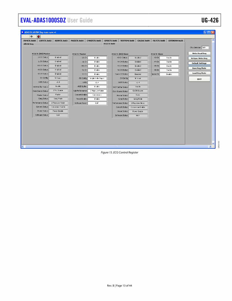
CONTROL OF ALL REGISTERS To delve further into the register control, click Program All RW Reg from the main control panel. This produces a pop-up window giving access to different tabs for each control register.
When moving back and forth between tabs, note that each time you click on a tab, the device reads the appropriate register and updates the Read register listing accordingly.
A Write Read Reg writes the data in the write panel and reads back all the registers to confirm the write. Caution: the write panel may not match the contents of the ADAS1000 registers, so if using this panel to update particular registers,
quickly do a ReSync Write Reg first to ensure that the write and read panels match, and then proceed to make your changes. Update the register contents with any changes. Click Default Settings to return the part to the default state. Save a register setting for reload and reuse later using the Save Reg State and Load Reg State. When finished with this window, click QUIT to close the window.
MASTER WRITE CONTROL SLAVE WRITE CONTROL UPDATE THE REGISTER WITHTHE WRITE CONTENTS
1081
0-01
4
Figure 14. Read/Write Control Register Overview
Within the tabs of this window all the individual control registers can be accessed. The ECG control register is shown in Figure 15, giving access to master and slave control. Note that for certain conditions, the slave device must match the master device configuration. As a result, the software locks out some of the slave control to ensure that the settings of the master and slave will always match (for example, gain setting, high performance mode, clock source, and so on).
EVAL-ADAS1000SDZ User Guide UG-426
Rev. B | Page 13 of 44
1081
0-01
5
Figure 15. ECG Control Register
UG-426 EVAL-ADAS1000SDZ User Guide
Rev. B | Page 14 of 44
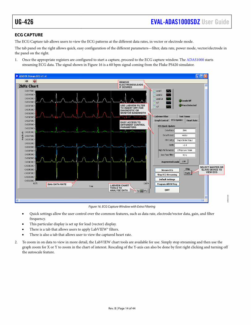
ECG CAPTURE The ECG Capture tab allows users to view the ECG patterns at the different data rates, in vector or electrode mode.
The tab panel on the right allows quick, easy configuration of the different parameters—filter, data rate, power mode, vector/electrode in the panel on the right.
1. Once the appropriate registers are configured to start a capture, proceed to the ECG capture window. The ADAS1000 starts streaming ECG data. The signal shown in Figure 16 is a 60 bpm signal coming from the Fluke PS420 simulator.
REMOVEELECTRODES/LEADSIF DESIRED
2kHz DATA RATE LABVIEW CHARTTOOLS TOANALYSE DATA
USE LABVIEW FILTERTO INSERT HPF FORDIAGNOSTIC ORMONITOR BANDWIDTH
EASY ACCESS TODIFFERENT CONTROLPARAMETERS
SELECT MASTER ORSLAVE DEVICE TO
VIEW ECG
1081
0-01
6
Figure 16. ECG Capture Window with Extra Filtering
• Quick settings allow the user control over the common features, such as data rate, electrode/vector data, gain, and filter frequency.
• This particular display is set up for lead (vector) display. • There is a tab that allows users to apply LabVIEW® filters. • There is also a tab that allows user to view the captured heart rate.
2. To zoom in on data to view in more detail, the LabVIEW chart tools are available for use. Simply stop streaming and then use the graph zoom for X or Y to zoom in the chart of interest. Rescaling of the Y-axis can also be done by first right clicking and turning off the autoscale feature.
EVAL-ADAS1000SDZ User Guide UG-426
Rev. B | Page 15 of 44
ECG CAPTURE WITH DIGITAL POST PROCESSING The ECG capture window allows the user to use a LabVIEW filter (0.05 Hz) to view diagnostic bandwidth in addition to ac coupling the signal (using LabVIEW VI).
1. Insert a LabVIEW HPF for ac coupling. (ADAS1000 is a dc coupled design). 2. Insert a LabVIEW HPF or 0.5 Hz or 0.05 Hz.
1081
0-01
7
Figure 17. Different Tabs Providing Differing Controls Within the ECG Capture Window. Controls include: LabVIEW filters,
the test tone feature, and graph control, respectively.
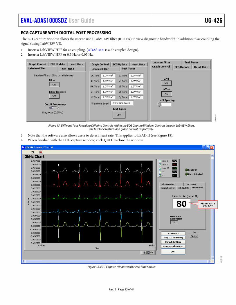
3. Note that the software also allows users to detect heart rate. This applies to LEAD II (see Figure 18). 4. When finished with the ECG capture window, click QUIT to close the window.
HEART RATEDISPLAY
1081
0-01
8
Figure 18. ECG Capture Window with Heart Rate Shown

UG-426 EVAL-ADAS1000SDZ User Guide
Rev. B | Page 16 of 44
LEADS OFF CONTROL The lead off tab allows the user to control which lead off feature is operating (ac or dc) and programs the current and threshold levels. For dc lead off, remember the VCM is 1.3 V; therefore the upper threshold should be in excess of 1.3 V to ensure capture of a lead off event.
For ac lead off, the threshold levels are represented in terms of amplitude by multiplying π/2. Note that the levels may need to be adjusted to find the appropriate levels to detect ac leads amplitude.
1. Configure the mode of lead off detection (either ac or dc). 2. Set the current levels. 3. Program the threshold levels of the detection circuitry (applies to ac lead off). 4. Write the changes to the register by clicking Update, which is available within the LOFF Threshold Levels tab. 5. When finished, click QUIT to close the window.
PROGRAM THE THRESHOLDSFOR DETECTION
CHOOSE ACOR DC
PROGRAM THE APPROPRIATECURRENT LEVELSAC : 0nA TO 100nADC : 0nA TO 70nA
QUICK SETUP—DCLEAD OFF
1081
0-01
9
Figure 19. Leads Off Control and Display Chart
EVAL-ADAS1000SDZ User Guide UG-426
Rev. B | Page 17 of 44
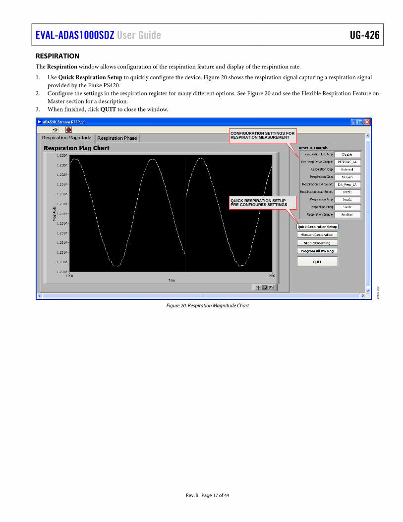
RESPIRATION The Respiration window allows configuration of the respiration feature and display of the respiration rate.
1. Use Quick Respiration Setup to quickly configure the device. Figure 20 shows the respiration signal capturing a respiration signal provided by the Fluke PS420.
2. Configure the settings in the respiration register for many different options. See Figure 20 and see the Flexible Respiration Feature on Master section for a description.
3. When finished, click QUIT to close the window.
CONFIGURATION SETTINGS FORRESPIRATION MEASUREMENT
QUICK RESPIRATION SETUP—PRE-CONFIGURES SETTINGS
1081
0-02
0
Figure 20. Respiration Magnitude Chart

UG-426 EVAL-ADAS1000SDZ User Guide
Rev. B | Page 18 of 44
PACE The Pace register control offers a number of different features. The pace algorithm is three instances of a digital algorithm, therefore it can run on 3 leads at one time. The algorithm is designed to detect pace widths that range from 100 µs to 2 ms and amplitudes of 400 µV to 1000 mV. For pace capture, the software is streaming data at the chosen data rate. The data rate chosen does not have an effect on the ability of the pace detection algorithm to detect a pulse since the pace algorithm always processes the 128 kHz frame rate.
1. Choose which lead each pace algorithm analyses. 2. Configure the different threshold levels for the desired ranges. 3. Use Quick Pace Setup to program the pace control and thresholds to default levels, and to start to stream pace data.
When a pace signal is detected, the frame header flags it. The pace algorithm makes a measure of the height and width of the detected pace and provides that information for readback. There are two ways of returning the width and height information from the register reads, one from within the frame and another from a direct read of the pace height/width register which is a more accurate result. Pace Validation Filter 1 and Filter 2 are for noise and MV pulse filtering. The pace width filter rejects signals <100 µs and >2 ms.
4. If using the 2 kHz data rate, the pace signal may be filtered out by the programmable LPF available in this data rate. Adjust the Low Pass Filter setting to allow the pace signal to be more visible. Note there are three pace algorithms and three pace windows to view. Each algorithm has its own threshold register settings.
5. When finished, click QUIT to close the window.
3 PACE WINDOWS TO VIEW PACE LEVELS CONTROL
CHOOSE THELEADS
HEIGHT
WIDTH
FILTERENABLES
FLAGS PACEDETECTED
SCREEN CAPTURE OF PACE ONPACE 1 LEAD II
1081
0-02
1
Figure 21. Pace Window
EVAL-ADAS1000SDZ User Guide UG-426
Rev. B | Page 19 of 44
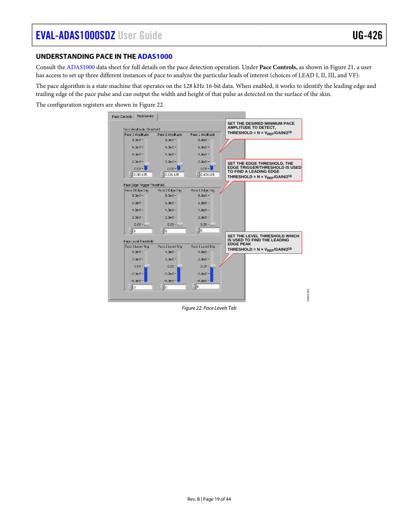
UNDERSTANDING PACE IN THE ADAS1000 Consult the ADAS1000 data sheet for full details on the pace detection operation. Under Pace Controls, as shown in Figure 21, a user has access to set up three different instances of pace to analyze the particular leads of interest (choices of LEAD I, II, III, and VF).
The pace algorithm is a state machine that operates on the 128 kHz 16-bit data. When enabled, it works to identify the leading edge and trailing edge of the pace pulse and can output the width and height of that pulse as detected on the surface of the skin.
The configuration registers are shown in Figure 22.
SET THE DESIRED MINIMUM PACEAMPLITUDE TO DETECT,THRESHOLD = N × VREF/GAIN/216
SET THE EDGE THRESHOLD, THEEDGE TRIGGER/THRESHOLD IS USEDTO FIND A LEADING EDGETHRESHOLD = N × VREF/GAIN/216
SET THE LEVEL THRESHOLD WHICHIS USED TO FIND THE LEADINGEDGE PEAKTHRESHOLD = N × VREF/GAIN/216
1081
0-02
2
Figure 22. Pace Levels Tab

UG-426 EVAL-ADAS1000SDZ User Guide
Rev. B | Page 20 of 44
WRITE TO A FILE A Write to File tab allows storage of a data capture over a period of time. Select either raw (date read back and provided in decimal format), voltages (software calculates the corresponding voltage of each lead/electrode), or parsed (where parsed breaks out the header word and the remaining words are provided in decimal format) file for offline processing.
CHOOSE FORMATTO SAVE
CHOOSE HOW MANYSECONDS OF CAPTURETO SAVE
1081
0-02
4
Figure 23. Write to File Tab
1. When you click Write to File, a Choose file to write window opens (see Figure 24). 2. Select the appropriate location and name the file with the name of your choice. Using an extension like .dat or .xls works well here.
The data is formatted tab delimited as shown in Figure 24. This data can be copied into Microsoft® Excel® and processed offline.
CHOOSE THE LOCATIONAND NAME THE FILE
1081
0-02
5
Figure 24. Choose the Location and Name the File
EVAL-ADAS1000SDZ User Guide UG-426
Rev. B | Page 21 of 44
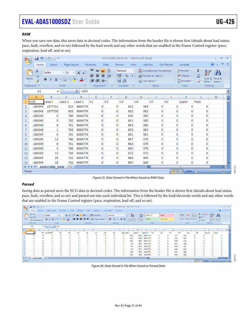
RAW
When you save raw data, this saves data in decimal codes. The information from the header file is shown first (details about lead status, pace, fault, overflow, and so on) followed by the lead words and any other words that are enabled in the Frame Control register (pace, respiration, lead off, and so on).
1081
0-02
6
Figure 25. Data Stored in File When Saved as RAW Data
Parsed
Saving data as parsed saves the ECG data in decimal codes. The information from the header file is shown first (details about lead status, pace, fault, overflow, and so on) and parsed out into each individual bit. This is followed by the lead/electrode words and any other words that are enabled in the Frame Control register (pace, respiration, lead off, and so on).
1081
0-02
7
Figure 26. Data Stored in File When Saved as Parsed Data

UG-426 EVAL-ADAS1000SDZ User Guide
Rev. B | Page 22 of 44
Voltage
Voltage processes the electrode data and provides the equivalent voltage level of each electrode. The header and other words within the frame are stripped out of this data capture.
1081
0-02
8
Figure 27. Data Stored in File When Saved as Voltage

EVAL-ADAS1000SDZ User Guide UG-426
Rev. B | Page 23 of 44
TEST TONES The ADAS1000 has built-in test tones that can put out a 10 Hz or 150 Hz 1 mV sinewave, in addition to a 1 mV calibration pulse.
1. Configure the ADAS1000 for electrode mode in the ECGCTL register (see Figure 15) to be able to see these signals correctly. If the ADAS1000 is configured for vector/lead mode, then the test tone signals are subtracted from each other. Also, in the CMREFCTL register, none of the electrodes should be configured to contribute to the common-mode signal.
2. Use the Test Tone tab to configure this data.
A 10 Hz sine wave is shown in Figure 28. Applying an offset of 2 mV helps to enable viewing.
1081
0-02
9
Figure 28. Viewing the Internal 10 Hz Sine Wave Test Tone Applied to the Master Device ECG Channels
UG-426 EVAL-ADAS1000SDZ User Guide
Rev. B | Page 24 of 44
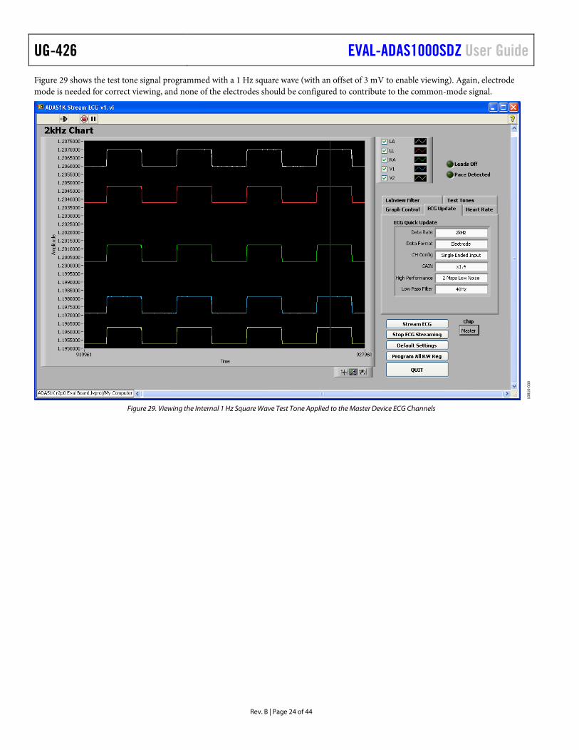
Figure 29 shows the test tone signal programmed with a 1 Hz square wave (with an offset of 3 mV to enable viewing). Again, electrode mode is needed for correct viewing, and none of the electrodes should be configured to contribute to the common-mode signal.
1081
0-03
0
Figure 29. Viewing the Internal 1 Hz Square Wave Test Tone Applied to the Master Device ECG Channels

EVAL-ADAS1000SDZ User Guide UG-426
Rev. B | Page 25 of 44
COMMON-MODEL LEVEL/WILSON CENTRAL TERMINAL Common-Mode Level/Wilson Central Terminal
The ADAS1000 allows flexible configuration of the common-mode signal, in that any of the electrodes can be used to generate the common-mode level VCM. When no electrodes are selected to contribute to the common mode level, then the VCM = VCM_REF which is the internal 1.3 V level.
• The Wilson central terminal of (RA + LA + LL)/3 can be configured here also as shown in Figure 30. • The VCM can be brought out to the CM_OUT pin. • The VCM level used internally can come from the internal VCM level (as arranged by the selection of electrodes). Alternatively, it
can be sourced externally from the CM_IN pin (for example, if using multiple ADAS1000 devices and wishing to share the VCM across them–the master device could provide the CM_OUT to the slave devices CM_IN pin, so they are all referenced to the same common-mode level).
WILSON CENTRAL TERMINALCONFIGURATION
ENABLE THE VCM TOAPPEAR ON CM_OUT PIN
SELECT WHERE CM ISCOMING FROM
1081
0-03
1
Figure 30. CMREFCTL 0x05 Table
UG-426 EVAL-ADAS1000SDZ User Guide
Rev. B | Page 26 of 44
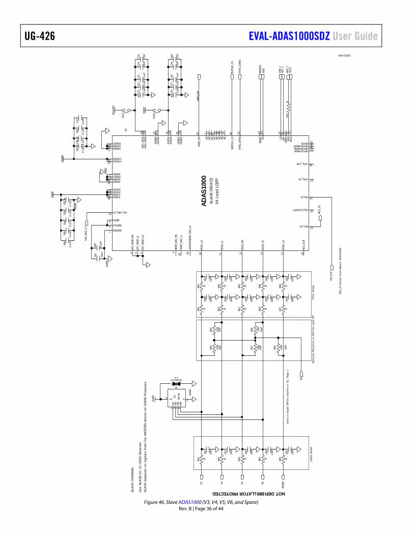
DETAILED DESCRIPTION OVERVIEW OF SCHEMATICS Refer to Figure 46 for schematics related to the master device. The master device provides ECG electrodes RA, LA, LL, V1, V2, and RLD (see Figure 45) while the slave device services ECG electrodes V3, V4, V5, V6, and a spare channel.
ECG Protection
The ADAS1000 device has standard ESD cells on board. In addition, SP724 SCR/diode protection arrays are used on the ECG input paths; however, they are not provided for defib protection purposes.
Optional Component Space on ECG path
Optional component space is provided for user-supplied cable and filter modelling in addition to pull-down resistors to RLD. Note that these limit the detection of dc leads of function because, if used, any off electrode would then be sitting at the RLD level and, thus, may no longer be detectable by the dc lead off circuit, particular at low current levels).
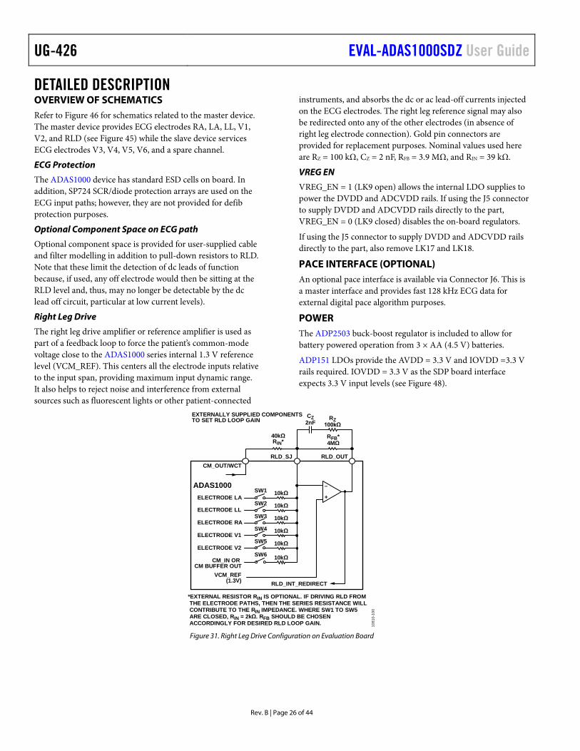
Right Leg Drive
The right leg drive amplifier or reference amplifier is used as part of a feedback loop to force the patient’s common-mode voltage close to the ADAS1000 series internal 1.3 V reference level (VCM_REF). This centers all the electrode inputs relative to the input span, providing maximum input dynamic range. It also helps to reject noise and interference from external sources such as fluorescent lights or other patient-connected
instruments, and absorbs the dc or ac lead-off currents injected on the ECG electrodes. The right leg reference signal may also be redirected onto any of the other electrodes (in absence of right leg electrode connection). Gold pin connectors are provided for replacement purposes. Nominal values used here are RZ = 100 kΩ, CZ = 2 nF, RFB = 3.9 MΩ, and RIN = 39 kΩ.
VREG EN
VREG_EN = 1 (LK9 open) allows the internal LDO supplies to power the DVDD and ADCVDD rails. If using the J5 connector to supply DVDD and ADCVDD rails directly to the part, VREG_EN = 0 (LK9 closed) disables the on-board regulators.
If using the J5 connector to supply DVDD and ADCVDD rails directly to the part, also remove LK17 and LK18.
PACE INTERFACE (OPTIONAL) An optional pace interface is available via Connector J6. This is a master interface and provides fast 128 kHz ECG data for external digital pace algorithm purposes.
POWER The ADP2503 buck-boost regulator is included to allow for battery powered operation from 3 × AA (4.5 V) batteries.
ADP151 LDOs provide the AVDD = 3.3 V and IOVDD =3.3 V rails required. IOVDD = 3.3 V as the SDP board interface expects 3.3 V input levels (see Figure 48).
ELECTRODE LA
ELECTRODE LL
ELECTRODE RA
ELECTRODE V1
ELECTRODE V2
+
–
SW2
CM_IN ORCM BUFFER OUT
SW3
SW6
SW5
SW4
SW1
EXTERNALLY SUPPLIED COMPONENTSTO SET RLD LOOP GAIN
CZ2nF
40kΩRIN*
RFB*4MΩ
RZ100kΩ
VCM_REF(1.3V)
RLD_OUTRLD_SJ
ADAS1000
10kΩ
10kΩ
10kΩ
10kΩ
10kΩ
10kΩ
RLD_INT_REDIRECT
CM_OUT/WCT
*EXTERNAL RESISTOR RIN IS OPTIONAL. IF DRIVING RLD FROM THE ELECTRODE PATHS, THEN THE SERIES RESISTANCE WILL CONTRIBUTE TO THE RIN IMPEDANCE. WHERE SW1 TO SW5 ARE CLOSED, RIN = 2kΩ. RFB SHOULD BE CHOSEN ACCORDINGLY FOR DESIRED RLD LOOP GAIN. 10
810-
100
Figure 31. Right Leg Drive Configuration on Evaluation Board

EVAL-ADAS1000SDZ User Guide UG-426
Rev. B | Page 27 of 44
FLEXIBLE RESPIRATION FEATURE ON MASTER ADAS1000 Respiration measurement is made in the master device. The respiration path is equipped with much flexibility for evaluation purpose. Figure 32 and Figure 33 illustrate the different methods of respiration measurement via different paths.
The control of the respiration function is described in the ADAS1000 data sheet.
Internal Drive/Measure via the ECG Paths
The primary respiration method uses internal respiration drive and measure. In some applications, this will require no external components and uses the standard ECG electrodes. In the evaluation board, a number of links are used to allow a user to evaluate different respiration configurations. For this instance, LK1, LK2, LK3, LK4, and LK19 can be open.
1. Configure the RESPCTL register (0x3) as follows: RESPCAP = 0 (internal).
2. Choose a relevant lead for measurement (RESPSEL), drive frequency (RESPFREQ), measurement gain (RESPGAIN), and so on.
1081
0-03
3
Figure 32. RESPCTL Controls–Respiration Cap
Configuring the Links
Note that the ADAS1000 respiration measurement is only made on one lead at any one time. However, the choice of lead is programmable: choose either LEAD I, LEAD II, or LEAD III.
For simplicity, Figure 33 allows the flexibility of programming the ADAS1000 respiration register to measure on all 3 leads (again, only 1 lead at any one time). This may not be the practice in end applications, therefore if a user is only interested in one particular lead during evaluation of the respiration function, adjust the links accordingly.
Note that Figure 33 shows RC components which may represent input filtering or cable model.
EXT_RESP_RA
EXT_RESP_LL
EXT_RESP_LA
SHIELD/RESP_DAC_LA
LA
LL
RA
LK2LK1
LK4
A B CABC
RESP_DAC_RARESP_DAC_LL
A
B
C
SHIELD
RA
LL
LA
ADAS1000
RESPIRATION PATHFROM ECG ELECTRODES
LK1, LK2, LK3, LK4, LK19 OPEN
FILTERCABLE
EXT_RESP_RA
EXT_RESP_LL
EXT_RESP_LA
1081
0-03
4
Figure 33. Respiration Drive Using Internal Capacitor, Respiration Measurement Using ECG Path

UG-426 EVAL-ADAS1000SDZ User Guide
Rev. B | Page 28 of 44
Internal Drive/Measure via the ECG/EXT_RESP Paths
This configuration allows the user to potentially bypass any ESIS filtering in the ECG path. Note that the input range of the EXT_RESP_XX pins must not be exceeded.
1. Configure the RESPCTL register (0x3) as follows: RESPCAP = 0 (internal capacitor), RESPSEL = 11 (EXT_RESP path selected).
2. Choose which path to measure on RESPSELEXT. 3. Choose the appropriate drive frequency (RESPFREQ),
measurement gain (RESPGAIN), and so on.
1081
0-03
5
Figure 34. RESPCTL Controls–Respiration Lead Select
Configuring the Links
Note that the ADAS1000 respiration measurement is only made on one lead at any one time. In the ext_resp path, the EXT_RESP_RA is always enabled internally and the user has a choice of EXT_RESP_LA or EXT_RESP_LL giving options of LEAD 1 or LEAD III.
For simplicity, Figure 35 allows the flexibility of programming the ADAS1000 respiration register to measure on these 2 leads (again, only 1 lead at any one time). This may not be the prac-tice in the end application, therefore if you are only interested in one particular lead during evaluation of the respiration function, adjust the links accordingly.
In this example, LK4 and LK1 would be inserted and LK2 would be open. Note that Figure 35 shows RC components which may represent input filtering or cable model.
EXT_RESP_RA
EXT_RESP_LL
EXT_RESP_LA
SHIELD/RESP_DAC_LA
LA
LL
RA
LK2LK1
LK4
A B CABC
RESP_DAC_RARESP_DAC_LL
A
B
C
SHIELD
RA
LL
LA
ADAS1000
RESPIRATION PATHFROM ECG ELECTRODESUSING EXT_RESP PATH
LK1, LK4, CLOSEDLK2, LK3, LK19 OPEN
FILTERCABLE
EXT_RESP_LA
EXT_RESP_LL
EXT_RESP_RA
DRIVE/MEASURE (J1)
1081
0-03
6
Figure 35. Respiration Drive Using Internal Capacitor, Respiration Measurement Using ECG Paths via the EXT_RESP Path

EVAL-ADAS1000SDZ User Guide UG-426
Rev. B | Page 29 of 44
Internal Drive/Measure via the EXT_RESP Path
This configuration allows the user to measure directly from the respiration connector provided on the board (J8).
1. Configure the RESPCTL register (0x3) as follows: RESPCAP = 0 (internal capacitor), RESPSEL = 11 (EXT_RESP path selected).
2. Choose which path to measure on RESPSELEXT. 3. Choose the appropriate drive frequency (RESPFREQ),
measurement gain (RESPGAIN), and so on.
1081
0-03
7
Figure 36. RESPCTL Controls–Respiration Lead Select
Configuring the Links
Note that the ADAS1000 respiration measurement is only made on one lead at any one time. In the ext_resp path, the EXT_RESP_RA is always enabled internally and the user has a choice of EXT_RESP_LA or EXT_RESP_LL giving options of LEAD 1 or LEAD III.
For simplicity, Figure 37 allows the flexibility of programming the ADAS1000 respiration register to measure on these 2 leads (again, only 1 lead at any one time). This may not be the prac-tice in the end application, therefore if you are only interested in one particular lead during evaluation of the respiration function, adjust the links accordingly.
In this example, LK4 would be inserted and LK1 and LK2 would be open. Note that Figure 37 shows RC components which may represent input filtering or cable model.
EXT_RESP_RA
EXT_RESP_LL
EXT_RESP_LA
SHIELD/RESP_DAC_LA
LA
LL
RA
LK2LK1
LK4
A B CABC
RESP_DAC_RARESP_DAC_LL
A
B
C
SHIELD
RA
LL
LA
ADAS1000
RESPIRATION PATHFROM EXT_RESP CONNECTOR
(J8) USING EXT_RESP PATHLK4, CLOSED
LK1, LK2, LK3, LK19 OPEN
FILTERCABLE
EXT_RESP_LA
EXT_RESP_LL
EXT_RESP_RA
DRIVE/MEASURE (J8)
1081
0-03
8
Figure 37. Respiration Drive Using Internal Capacitor, Respiration Measurement via EXT_RESP Path

UG-426 EVAL-ADAS1000SDZ User Guide
Rev. B | Page 30 of 44
External Drive/Measure via the ECG Path
This configuration allows the user to drive via external capacitors provided on the board and measure back through the ECG path. This mode requires external capacitors in the RESPDAC_XX paths. Note that when this mode is enabled, RESPDAC_RA is always enabled.
1. Configure the RESPCTL register (0x3) as follows: RESPOUT = 0/1 (0 = RESPDAC_LL, 1 = RESPDAC_LA), RESPCAP = 1 (external capacitor), RESPSEL = XX (Lead I, II, III).
2. Choose appropriate drive frequency (RESPFREQ), measurement gain (RESPGAIN), and so on.
1081
0-03
9
Figure 38. RESPCTL Controls–Respiration Cap
Configuring the Links
Note that the ADAS1000 respiration measurement is only made on one lead at any one time. However, the choice of lead is programmable, choose either LEAD I, LEAD II or LEAD III.
For simplicity, the drawing that follows allows the flexibility of programming the ADAS1000 respiration register to measure on all 3 leads (again, only 1 lead at any one time). This may not be the practice in the end application, therefore if you are only interested in one particular lead during evaluation of the respiration function, adjust the links accordingly.
In this example, LK4 would be open and LK1 and LK2 would be inserted.
EXT_RESP_RA
EXT_RESP_LL
EXT_RESP_LA
SHIELD/RESP_DAC_LA
LA
LL
RA
LK2LK1
LK4
A B CABC
RESP_DAC_RARESP_DAC_LL
A
B
C
SHIELD
RA
LL
LA
ADAS1000
EXTERNAL RESPIRATION DRIVEUSING EXTERNAL CAPACITOR
MEASURE ON ECG PATHS.
LK1, 2 CLOSEDLK3, 4, 19 OPEN
FILTERCABLE
EXT_RESP_LA
EXT_RESP_LL
EXT_RESP_RA
DRIVE
MEASURE
1081
0-04
0
Figure 39. Respiration Drive Using External Capacitor, Respiration Measurement Using ECG Paths

EVAL-ADAS1000SDZ User Guide UG-426
Rev. B | Page 31 of 44
External Drive/Measure via the EXT_RESP Path This configuration allows the user to drive via external capa-citors provided on the board and measure back through the EXT_RESP path. Note that when this mode is enabled, RESPDAC_RA is always enabled.
1. Configure the RESPCTL register (0x3) as follows: RESPOUT = 0/1 (0 = RESPDAC_LL, 1 = RESPDAC_LA), RESPCAP = 1, (external capacitor), RESPSEL = 11 (external respiration path), RESPEXTSEL = 0/1 (0 = EXT_RESP_LL, 1 = EXT_RESP_LA).
2. Choose the appropriate drive frequency (RESPFREQ), measurement gain (RESPGAIN), and so on.
Note that the selected RESPDAC_LL or RESPDAC_LA need to match the selected EXT_RESP_LL/LA selected when measuring on the external range. The example for register settings in Figure 41 shows RESPDAC_LA and EXT_RESP_LA selected, therefore LK2AC, LK4AC and LK1AC need to be inserted.
1081
0-04
1
Figure 40. RESPCTL Controls–Respiration Cap and
Respiration Lead Select
Configuring the Links
Note that the ADAS1000 respiration measurement is only made on one lead at any one time. In the ext_resp path, the EXT_RESP_RA is always enabled internally and a user has a choice of EXT_RESP_LA or EXT_RESP_LL giving options of LEAD 1 or LEAD III.
For simplicity, Figure 41 allows the flexibility of programming the ADAS1000 respiration register to measure on these 2 leads (again, only 1 lead at any one time). This may not be the practice in the end application, therefore if you are only interested in one particular lead during evaluation of the respiration function, adjust the links accordingly.
EXT_RESP_RA
EXT_RESP_LL
EXT_RESP_LA
SHIELD/RESP_DAC_LA
LA
LL
RA
LK2LK1
LK4
A B CABC
RESP_DAC_RARESP_DAC_LL
A
B
C
SHIELD
RA
LL
LA
ADAS1000
EXTERNAL RESPIRATION DRIVEUSING EXTERNAL CAPACITOR
MEASURE ON EXT RESP PATHS.
LK1, LK2, LK4 CLOSEDLK3, LK19 OPEN
FILTERCABLE
EXT_RESP_LA
EXT_RESP_LL
EXT_RESP_RA
DRIVE
MEASURE
1081
0-04
2
Figure 41. Respiration Drive Using External Capacitor, Respiration Measurement Using ECG Paths via the EXT_RESP Path

UG-426 EVAL-ADAS1000SDZ User Guide
Rev. B | Page 32 of 44
External Drive/Measure Using External Instrumentation Amplifier Stage Bypassing Internal ADAS1000 Respiration In-Amp
This configuration allows the user to drive via external capa-citors provided on the board and measure back through the EXT_RESP path.
1. Configure the RESPCTL register (0x3) as follows: RESPAMP = 1 (enabled), RESPOUT = 1 (RESPDAC_P1), RESPCAP = 1 (external capacitor), RESPSEL = 11 (external respiration path), RESPEXTSEL = 1 (EXT_RESP3).
2. Choose the appropriate drive frequency (RESPFREQ) and measurement gain (RESPGAIN) as required.
For simplicity, the AD8226 instrumentation amplifier, operating from a 3.3 V supply rail, was used for this example. The noise performance of the AD8226 does not provide significant improvement over that of the ADAS1000, therefore any evaluations with this instrumentation amplifier may not provide appreciable respiration performance improvements.
An alternative instrumentation amplifier with lower noise performance or operated from a higher supply rail may achieve improved performance in a similar arrangement. Note that the RG value in the AD8226 circuit is open, setting a gain of 1 in this circuit. There is a resistor location (R79) available to adjust
the gain as desired. The range of gain needs to be limited such that the input range <±0.7 V.
Note that this configuration of ADAS1000 respiration measurement is only made on one lead. (LEAD I).
1081
0-04
3
Figure 42. RESPCTL Controls–Respiration Ext Amp and
Respiration Lead Select
Configuring the Links
In this example, LK1AC, LK2AC, LK15, and LK16 are all inserted; LK4 is open. LK3A and LK19A allow a user to choose a lead.

EVAL-ADAS1000SDZ User Guide UG-426
Rev. B | Page 33 of 44
EXT_RESP_RA
EXT_RESP_LL
EXT_RESP_LA
SHIELD/RESP_DAC_LA
LA
LL
RA
LK2LK1
LK4
A B CABC
RESP_DAC_RARESP_DAC_LL
A
B
C
SHIELD
RA
LL
LA
ADAS1000
EXTERNAL RESPIRATION DRIVEUSING EXTERNAL CAPACITOR ONTO
ECG PATHSMEASURE ON ECG PATHS USING
EXTERNAL INAMP DIRECTLYINTO EXT_RESP MEASURE PATH
LK1ac, LK2ac, LK15, LK16 CLOSEDLK4 OPEN
LK3a, LK19a CHOOSE LEAD
FILTERCABLE
EXT_RESP_LA
EXT_RESP_LL
EXT_RESP_RA
REFOUT
DRIVE
MEASURE
AD8226
1/2 AD8606
REF
LK15
LK16
10kΩ
10kΩ
A B A BL3 L19
RLD
1/2 AD8606VREF/2 = 0.9V
RLD
100kΩ
100kΩ
1081
0-04
4
Figure 43. Respiration Drive Using External Capacitor, Respiration Measurement with External Amplifier
TROUBLESHOOTING Hardware
The following procedure can help detect if there are issues connecting to the evaluation board or reading data.
1. Connect the ADAS1000 J2 to the SDP board connector. 2. Apply power to the ADAS1000 J9 connector, and then
connect the USB cable to SDP J1. D10 should appear lit on the ADAS1000 board; LED1 should appear lit on the SDP board.
3. Confirm that the SDP board is seen in the Device Manager as shown in Figure 8.
4. Measure voltages at IOVDD and AVDD. Both these voltages should measure approximately 3.3 V.
5. Launch the software.
6. From the Main Front Panel, one should be able to read/write from the device and start streaming data. The ADAS1000 device powers up “powered down”, therefore, a number of writes are needed to configure the device. This can be quickly done by clicking the Default Setup on the front panel. This action writes a number of codes to the device to power it on, thus enabling channels to read and to capture ECG data.
7. Confirm the contents of the registers by clicking on Program All RW reg from the front panel.
8. If the read/write is not operating correctly, power down the board and check that the ADAS1000 chip is correctly inserted and that the clamp is used to hold the ADAS1000 to the board is not overly tight.
9. If required, replace the ADAS1000 chip.

UG-426 EVAL-ADAS1000SDZ User Guide
Rev. B | Page 34 of 44
Software
The default folder for the install is C:\Program Files\Analog Devices\ADAS1000
This folder contains the files shown in Figure 44.
1. Confirm these files are present. If they are not present, then reinstall the software from the CD. A reboot may be required after the installation process.
1081
0-04
5
Figure 44. Files Installed in Analog Devices Folder
2. Always install the software prior to first connecting the evaluation board/SDP to the PC.

EVAL-ADAS1000SDZ User Guide UG-426
Rev. B | Page 35 of 44
EVALUATION BOARD SCHEMATICS
10810-047
MAS
TER
CHAN
NE
L
SLAV
Ede
pend
son
sign
als
from
the
MAS
TER
devi
ce f
orG
ANG
Purp
oses
Use
MAS
TER
CHAN
NE
L fo
r3/
5LE
ADSo
luti
ons
Use
MAS
TER
AND
SLAV
ECH
ANNE
LCO
MBI
NAT
ION
for
12LE
ADSo
luti
on
Use
soft
war
eD
RD
Yb
Fed
from
outp
utof
Opt
iona
lEx
tern
alR
esp
Cir
cuit
Inse
rtLK
6if
usin
gon
boar
dLD
Oan
d
Use
LK7
tom
easu
re
Inse
rtLK
8if
usin
gon
Inse
rtLK
5if
usin
gEx
tern
al
goes
to
Slav
eA
DA
S100
0
Use
SMB
1to
driv
ew
ith
ext
cloc
k
NOTDEFIBRILLATORPROTECTED
Opt
iona
lC
able
Mod
el
Cab
leM
odel
Opt
iona
lFi
lter
Mod
elO
ptio
nal
Res
isto
rsto
RLD
for
Lead
Off
RESP
IRAT
ION
Inte
rnal
Driv
e:R
ecei
veon
ECG
Cha
nnel
s:O
pen
LK1
-LK
4
Inte
rnal
Driv
e,R
ecei
veon
EXT
Res
pC
hann
els
(Use
ECG
Cab
les)
:O
pen
LK2
,3.
Clo
seLK
1,
4
Inte
rnal
Driv
e,R
ecei
veon
EXT
Res
pC
hann
els
(Use
RES
PC
able
s):
Ope
nLK
1,
2,3,
Clo
seLK
4
Exte
rnal
Driv
e,R
ecei
veon
ECG
Cha
nnel
s(U
seEC
GC
able
s):
Ope
nLK
3,
4,C
lose
LK1
,2
Exte
rnal
Driv
e,R
ecei
veon
EXT
Res
pC
hann
els
(Use
ECG
Cab
les)
:O
pen
LK3
,C
lose
LK1
,2,
4
Exte
rnal
Driv
e,R
ecei
vew
ith
ext
in-a
mp
(Use
ECG
Cab
les)
:O
pen
LK4
,C
lose
LK1
,2,
3C&
(3A
or3B
)
Inse
rtLK
9to
disa
ble
inte
rnal
volt
age
regu
lato
rs f
orA
DC
VDD
&D
VD
DU
ser
then
nee
dsto
supp
lyA
DC
VDD
&D
VDD
exte
rnal
lyvi
aJ5
Shie
ldca
nbe
driv
enby
Inte
rnal
Am
p(L
K10
A)or
ifus
ing
EXT_
Res
pira
tion
Driv
e,th
enco
nnec
tLK
10B
Wal
lA
dapt
or f
orsu
pply
rail
boar
dLD
Oan
dW
all
Ada
ptor
for
supp
lyra
ilA
DA
S100
0AV
DDC
urre
nt
resp
irat
ion
Am
ppa
th
64Le
adLQ
FP1
NC
2 AGND1
3RE
SP_D
AC_R
A
4EX
T_RE
SP_R
A5
EXT_
RESP
_LL
6EX
T_RE
SP_L
A
7 REFGND8 REFOUT9 REFIN
10EC
G1_
LA
11EC
G2_
LL
12EC
G3_
RA
13EC
G4_
V1
14EC
G5_
V2
15 AGND2
16NC
17NC
18 AVDD1 19CM_IN
20RL
D_O
UT
21RLD_SJ
22CM_OUT/WCT
23 AVDD2
24 AGND3
25AG
ND5
26AD
C_VD
D1
27XTAL_IN
28XTAL_OUT
29BU
FCLK
_IO
30DVD
D1
31DGND2
32NC
33NC
34 DGND3
35 IOVDD1
36GPIO0/MCSB 37GPIO1/MSCK
38GPIO2/MSDO39GPIO3
40 DGND3
41CS
42DRD
Y43
SDI
44SC
LK45
SDO
46 IOVDD2
47 DGND4
48NC
49NC
50DGND1
51DVD
D2
52SY
NC_
GAN
G
53PD
54RE
SET
55AD
C_VD
D2
56AG
ND6
57 AGND4
58 AVDD4
59VR
EG_E
N
60SH
IELD
/RES
P_DAC
_LA
61 CAL_DAC_IO
62RE
SP_D
AC_L
L
63 AVDD3
64NC
U1
ADAS
1000
C2 0.1u
F
C4
0.1u
F
T1
RIN
RZ
RFB
C5
0.1u
F
C6
0.1u
F
C7
0.1u
F
+C3
4.7u
F
LK5
+C1
7
2.2u
F
LK6
+C1
2
2.2u
F
LK8
C13
0.1u
F
C14
0.1u
F
C18
0.1u
F
C19
0.1u
F
C10
0.1u
F
C11
0.1u
F
EXT_
CLK
LK7
T9
+C8
4.7u
F
C25
DNP
C26
DNP
C27
DNP
C28
DNP
C29
DNP
C30
DNP
C32
DNP
C33
DNP
C37
DNP
C38
DNP
C39
DNP
C40
DNP
C41
DNP
C42
DNP
C43
DNP
C44
DNP
C45
DNP
C46
DNP
T8
LK9
R9 0r
R22
22M
C31
DNP
R11
470k
1IN
1
2V-
3IN
24
IN3
5 V+
6IN
4
D2
SP72
4
1IN
1
2V-
3IN
24
IN3
5 V+
6IN
4
D1
SP72
4
1IN
1
2V-
3IN
24
IN3
5 V+
6IN
4
D3
SP72
4
C35
1n
R21
22M
R23
22M
R24
22M
R25
22M
R10 0rR8 0r
R7 0rR5 0r
R6 0rR4 0r
R3 0rR1 0r
R2 0r
R12 0rR15 0rR16 0rR17 0rR18 0rR19 0rR20 0r
C1 10uF
C36
1n
C34
1n
+C9
4.7u
F
C22
10pF
R13 0rR14 0r
ABC
LK1
C23
10pF
R86
10k
R29
0r
CZ
Y1
8.19
2M
Hz
ABC
LK2
ABCLK4
BA
LK19
R87 0r
R88 0r
BA
LK3
BA
LK10
R38
100k
C15
DNP
C16
DNP
C20
DNP
C21
DNP
R27
DN
P
C56
DNP
R39
100k
C59
DNP
C110
DNP
C111
DNP
R73 0r
R74
22M
R75 0r
R90 0r
R30
0r
R31
0r
R34
0rR3
50r
R32 0r
D4
P6SMB6.8CA6.8V
D5
P6SMB6.8CA6.8V
D6
P6SMB6.8CA6.8V
EXT_
RESP
_RA
EXT_
RESP
_LL
EXT_
RESP
_LA
SHIE
LD LA LL V2 RLD
ADCV
DD
DVD
D
SYNC_
GAN
G
RESE
TB
AGND
AGND
AGND
CAL_
DAC
_IO
GPI
O3
GPI
O2/
MSD
O
GPI
O0/
MCS
B
GPI
O1/
MSC
K
SDI_
0
SDO
_0SC
LK
AVDD
_3.3
V
IOVD
D_3
.3V
PDB
CSB_
0
AVDD
DRD
YB
IOVD
D
RESP
_INPU
T1RE
SP_I
NPU
T2
AVDD
AVDD AG
ND
AGND
SPAR
E
AVDD AG
ND
BUFC
LK_I
O
VREG
_EN
V1RA
RESP
_MEA
S1RE
SP_M
EAS2
RL
AVDD
CM_O
UT
0.9V
REF
CE
RLD
_SJ
DNP
DNP
DNP
DNP
DNP
DNP
Figure 45. Master ADAS1000 (RA, LA, LL, V1, V2, and RLD)
UG-426 EVAL-ADAS1000SDZ User Guide
Rev. B | Page 36 of 44
10810-048
SLAV
ECH
ANN
EL
SLAV
Ede
pend
son
sign
als
from
the
MAS
TER
devi
ce f
orG
ANG
Purp
oses
Use
SLAV
E fo
r12
LEAD
Solu
tion
CM_I
NCo
mes
fro
mM
aste
rAD
AS10
00
NOTDEFIBRILLATORPROTECTED
Cabl
eM
odel
Filter
Mod
elO
ptio
nalR
esis
tors
toRL
D f
orLe
adO
ff
Goe
sto
Spar
eSP
724
chan
neli
nD1,
Page
1
SLAV
E D
EVIC
E64
Lead
LQFP
1NC
2 AGND1
3RE
SP_D
AC_R
A
4EX
T_RE
SP_R
A5
EXT_
RESP
_LL
6EX
T_RE
SP_L
A
7 REFGND8 REFOUT9 REFIN
10EC
G1_L
A
11EC
G2_L
L
12EC
G3_R
A
13EC
G4_V
1
14EC
G5_V
2
15 AGND2
16NC
17NC
18 AVDD1 19CM_IN
20RL
D_O
UT
21RLD_SJ
22CM_OUT/WCT
23 AVDD2
24 AGND3
25AG
ND5
26AD
C_VD
D1
27XTAL_IN
28XTAL_OUT
29BU
FCLK
_IO
30DV
DD1
31DG
ND2
32NC
33NC
34 DGND3
35 IOVDD1
36GPIO0/MCSB 37GPIO1/MSCK
38GPIO2/MSDO39GPIO3
40 DGND3
41CS
42DR
DY43
SDI
44SC
LK45
SDO
46 IOVDD2
47 DGND4
48NC
49NC
50DG
ND1
51DV
DD2
52SY
NC_G
ANG
53PD
54RE
SET
55AD
C_VD
D2
5 6AG
ND6
57 AGND4
58 AVDD4
59VR
EG_E
N
60SH
IELD
/RES
P_DA
C_LA
61 CAL_DAC_IO
62RE
SP_D
AC_L
L
63 AVDD3
64NC
U2
ADAS
1000
C60
0.1u
F
C63
0.1u
F
C64
0.1u
F
C65
0.1u
F
C66
0.1u
F
+C6
2
4.7u
F
+C7
6
2.2u
F
+C7
1
2.2u
F
C72
0.1u
F
C73
0.1u
F
C77
0.1u
F
C78
0.1u
F
C69
0.1u
F
C70
0.1u
F
+C6
7
4.7u
F
C81
DNP
C82
DNP
C84
DNP
C85
DNP
C86
DNP
C88
DNP
C90
DNP
C92
DNP
C94
DNP
C87
DNP
C89
DNP
C91
DNP
C93
DNP
C95
DNP
R55 0r
R58
22M
C83
DNP
1IN
1
2V-
3IN
24
IN3
5 V+
6IN
4
D7SP
724
R53 0r R51 0r R49 0r R47 0r
R46 0rR48 0rR50 0rR52 0rR54 0r
R61 0r R62 0r R63 0r R64 0r R65 0r
R57
22M
R56
22M
R59
22M
R60
22M
C61
10uF
+C6
8
4.7u
F
LK17
LK18
C79
DNP
C80
DNP
C74
DNP
C75
DNP
R70
0r
V3 V4 V5 V6
SPAR
E
ADCV
DD
DVDD
SYNC
_GAN
G
RESE
TB
AGND
AGND
AGND
SDI_
1
SDO_
1SC
LK
PDB
CSB_
1
BUFC
LK_I
O
VREG
_EN
AVDD
IOVD
D
RL
CAL_
DAC_
IO
AVDD
AGND
CM_O
UT
RLD_
SJ
DNP
DNP
DNP
DNP
DNP
D8
P6SMB6.8CA6.8V
Figure 46. Slave ADAS1000 (V3, V4, V5, V6, and Spare)

EVAL-ADAS1000SDZ User Guide UG-426
Rev. B | Page 37 of 44
1081
0-04
9
DSub CONNECTOR- DB15 - ECG ELECTRODE CONNECTOR: (socket)
ADAS1000 SPI DIRECT CONNECTOR
PACE INTERFACE FROM ADAS1000 #1
STANDARD SPI INTERFACE
Decoupling for U6
Reset circuit for ADAS1000 /RESET : Combines reset button & SDP signal
NO
TD
EFIB
RILL
ATO
RPR
OTE
CTED
When using the SDP board, both ADAS1000devices are driven with the same /CS (LK12 inserted)
Connector for External Respiration Inputs
Header connector
J1-1
J1-2
J1-3
J1-4
J1-5
J1-6
J1-7
J1-8
J1-9
J1-10
J1-11
J1-12
J1-13
J1-14
J1-15
J4-1
J4-2
J4-3
J4-4
J4-5
J4-6
J4-7
J4-8
J4-9
J4-10
ADAS_RESET
1
24U3
NC7S08
R43100k
LK11
T10
R44100k
J4-11
J4-12
J4-13
J4-14
LK12
LK14
LK13
D11
J8-1
J8-2
J8-3
J8-4
C480.1uF
C470.1uF
R4510k
1 23 45 6
J6
J1-16
J1-17
V2
V3
V4
V6
RA
LA
V5
PDB
RESETB
SDI_1
SDO_1
SDO_0CSB_0
GPIO3 GPIO2/MSDOGPIO1/MSCK GPIO0/MCSB
RESETB_SW
IOVDD
RESETB
IOVDD
IOVDD
SDI_0
SCLK
DRDYB
CSB_1
LL
V1
RLD
SHIELD
EXT_RESP_RA
EXT_RESP_LL
EXT_RESP_LA
SPARE
CE
Figure 47. Connectors

UG-426 EVAL-ADAS1000SDZ User Guide
Rev. B | Page 38 of 44
1081
0-05
0
Screw Terminals for External Power Supply
POWER SUPPLY OPTIONS:1. Wall Adaptor
3. Battery Powered
4. External Bench Supply for individual power raiils
2. 5V bench supply2 pin screw terminal for bench +5V
SMD DC POWER JACK
1 VIN
2GND
3 EN
5VOUT
U8ADP151AUJZ-3.3
J5-1
C51
10uF
C50
10uF
C53
10uF
C54
10uF
C104
10uF
C102
10uF
C100
10uF
C98
10uF
C96
10uF
C49
0.1uF
1 VIN
2GND
3 EN
5VOUT
U6ADP151AUJZ-3.3
AVDD
T12 AGND
IOVDD
J3-3
J3-2
J3-1
J3-4
C52
0.1uF
C55
0.1uF
C103
0.1uF
C101
0.1uF
C99
0.1uF
C97
0.1uF
R76 10k
R80 10k
J7-1
J7-2
J5-2
J5-3
J5-4
J5-5
J5-6
31D9
BAT54FILM 4 SW15 PVIN8 VIN7 SYNC/MODE
2SW21VOUT10FB3PGND
6EN
9AGND
U9ADP2503
C24
22uF
L1
1.5uH
C106
0.1uF
L2
10uH
C107
0.1uFR831k
D10
GREEN
R26
0r
AGND1 AGND2
AGND3 AGND4
+5V AVDD_3.3V
+5V IOVDD_3.3V
AGND
AVDD
IOVDD
DVDD
ADCVDD
AGND
+5V
Figure 48. On-Board Power Options (LDOs On-Board to Supply Power to ADAS1000 and Other Component)

EVAL-ADAS1000SDZ User Guide UG-426
Rev. B | Page 39 of 44
1081
0-05
1VIN: Use this pin to power the SDP requires 5V 200mAVIO: USE to set IO voltage max draw 20mA
Board ID EEPROM (24LC32) must be on I2C bus 0,
Main I2C bus (Connected to blackfin TWI - Pull up resistors not required)
SDP Board Manual Reset
CONNECTORSTANDARD
SDP
PARALLELPORT
SPORT
SPI
I2C
GENERALINPUT/OUTPUT
TIMERS
**
**
*
****
****
*NC on BLACKFIN SDP 120NC
119NC
118GND
117GND
116VIO(+3.3V)
115GND
114PAR_D22
113PAR_D20
112PAR_D18
111PAR_D16
110PAR_D15
109GND
108PAR_D12
107PAR_D10
106PAR_D8
105PAR_D6
104GND
103PAR_D4
102PAR_D2
101PAR_D0
100PAR_WR
99PAR_INT
98GND
97PAR_A2
96PAR_A0
95PAR_FS2
94PAR_CLK
93GND
92SPORT_RSCLK
91SPORT_DR0
90SPORT_RFS
89SPORT_TFS
88SPORT_DT0
87SPORT_TSCLK
86GND
85SPI_SEL_A
84SPI_MOSI
83SPI_MISO
82SPI_CLK
81GND
80SDA_0
79SCL_0
78GPIO1
77GPIO3
76GPIO5
75GND
74GPIO7
73TMR_B
72TMR_D
71NC
70NC
69GND
68NC
67NC
66NC
65NC
64NC
63GND
62UART_TX
61BMODE160 RESET_IN59 UART_RX58 GND57 NC56 EEPROM_A055 NC54 NC53 NC52 GND51 NC50 NC49 TMR_C48 TMR_A47 GPIO646 GND45 GPIO444 GPIO243 GPIO042 SCL_141 SDA_140 GND39 SPI_SEL1/SPI_SS38 SPI_SEL_C37 SPI_SEL_B36 GND35 SPORT_INT34 SPORT_DT333 SPORT_DT232 SPORT_DT131 SPORT_DR130 SPORT_DR229 SPORT_DR328 GND27 PAR_FS126 PAR_FS325 PAR_A124 PAR_A323 GND22 PAR_CS21 PAR_RD20 PAR_D119 PAR_D318 PAR_D517 GND16 PAR_D715 PAR_D914 PAR_D1113 PAR_D1312 PAR_D1411 GND10 PAR_D179 PAR_D198 PAR_D217 PAR_D236 GND5 USB_VBUS4 GND3 GND2 NC1 VIN
J2
R68 DNP
R91 100K
R67 100K
SDP_RESET
T2T3T4T5
T7 T6
1 A02 A13 A24 VSS
8VCC 7WP 6SCL 5SDA
U7
24LC32A-I/MS
VIOVIO
SCLKSDI_0CSB_0
SDO_1SDO_0
SDI_1
RESETB_SWPDB
+5V
VIO
Figure 49. SDP Connector Schematic

UG-426 EVAL-ADAS1000SDZ User Guide
Rev. B | Page 40 of 44
1081
0-05
2
OPTIONAL: External Amplifer Cicuit for Respiration Circuit
Gain = 1 with no R79 (RG) resistor inserted.G = 1 +(49.4k/RG)
1 -IN2
RG
5
-VS3RG
7OUT
8+VS
6REF
4 +IN
U4AD8226
LK15
LK16
R840r
R850r
C58
0.1uF
C57
0.1uF
R811M
R7710k
R7810k
C1051n
C108
100pF
C109
100pF
R821M
R79
R280r
R400r
5 +6 -
7
U5-B
AD8606ARMZ
3 +2 -
1
U5-A
AD8606ARMZ
8V+
4V-U5-C
AD8606ARMZ
T11
T13
AVDD
AVDD
RESP_MEAS1
RESP_MEAS2
RL
RESP_INPUT2
RESP_INPUT1
0.9VREF
+VS
-VS
+VS
-VS
Figure 50. Optional Respiration Circuit for Increased Respiration Resolution Measurement
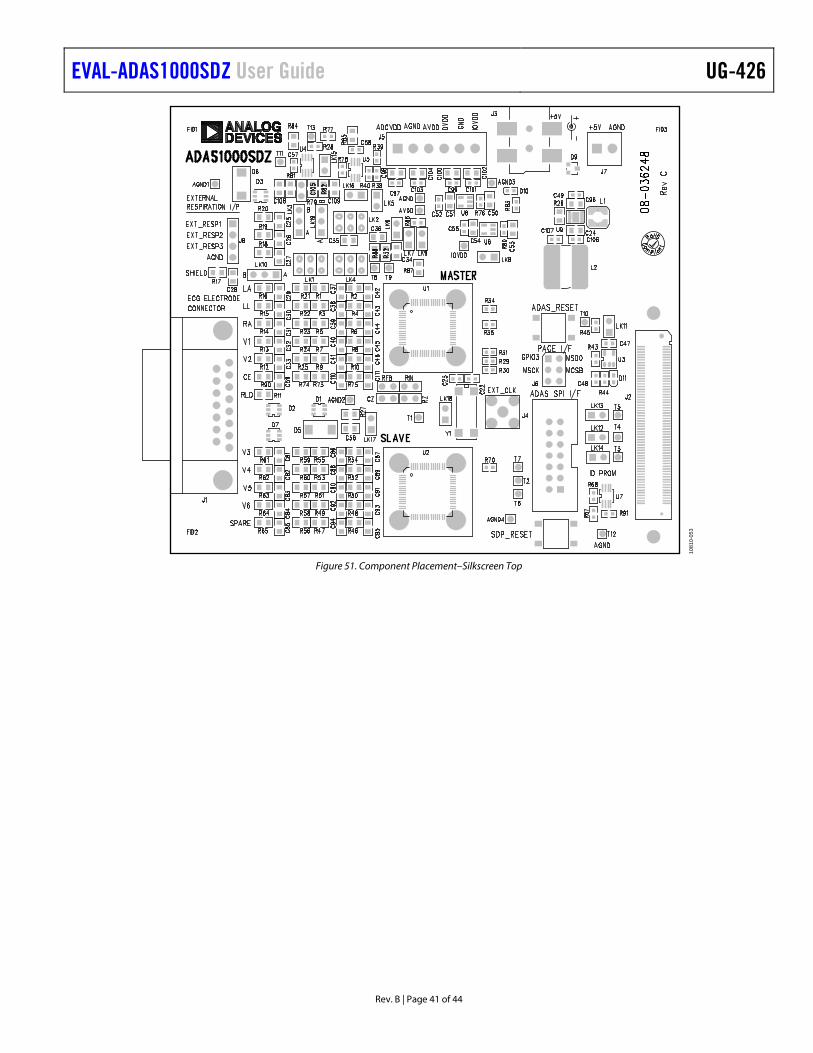
EVAL-ADAS1000SDZ User Guide UG-426
Rev. B | Page 41 of 44
1081
0-05
3
Figure 51. Component Placement–Silkscreen Top

UG-426 EVAL-ADAS1000SDZ User Guide
Rev. B | Page 42 of 44
1081
0-05
4
Figure 52. Component Placement–Bottom

EVAL-ADAS1000SDZ User Guide UG-426
Rev. B | Page 43 of 44
NOTES

UG-426 EVAL-ADAS1000SDZ User Guide
Rev. B | Page 44 of 44
NOTES
ESD Caution ESD (electrostatic discharge) sensitive device. Charged devices and circuit boards can discharge without detection. Although this product features patented or proprietary protection circuitry, damage may occur on devices subjected to high energy ESD. Therefore, proper ESD precautions should be taken to avoid performance degradation or loss of functionality.
Legal Terms and Conditions By using the evaluation board discussed herein (together with any tools, components documentation or support materials, the “Evaluation Board”), you are agreeing to be bound by the terms and conditions set forth below (“Agreement”) unless you have purchased the Evaluation Board, in which case the Analog Devices Standard Terms and Conditions of Sale shall govern. Do not use the Evaluation Board until you have read and agreed to the Agreement. Your use of the Evaluation Board shall signify your acceptance of the Agreement. This Agreement is made by and between you (“Customer”) and Analog Devices, Inc. (“ADI”), with its principal place of business at One Technology Way, Norwood, MA 02062, USA. Subject to the terms and conditions of the Agreement, ADI hereby grants to Customer a free, limited, personal, temporary, non-exclusive, non-sublicensable, non-transferable license to use the Evaluation Board FOR EVALUATION PURPOSES ONLY. Customer understands and agrees that the Evaluation Board is provided for the sole and exclusive purpose referenced above, and agrees not to use the Evaluation Board for any other purpose. Furthermore, the license granted is expressly made subject to the following additional limitations: Customer shall not (i) rent, lease, display, sell, transfer, assign, sublicense, or distribute the Evaluation Board; and (ii) permit any Third Party to access the Evaluation Board. As used herein, the term “Third Party” includes any entity other than ADI, Customer, their employees, affiliates and in-house consultants. The Evaluation Board is NOT sold to Customer; all rights not expressly granted herein, including ownership of the Evaluation Board, are reserved by ADI. CONFIDENTIALITY. This Agreement and the Evaluation Board shall all be considered the confidential and proprietary information of ADI. Customer may not disclose or transfer any portion of the Evaluation Board to any other party for any reason. Upon discontinuation of use of the Evaluation Board or termination of this Agreement, Customer agrees to promptly return the Evaluation Board to ADI. ADDITIONAL RESTRICTIONS. Customer may not disassemble, decompile or reverse engineer chips on the Evaluation Board. Customer shall inform ADI of any occurred damages or any modifications or alterations it makes to the Evaluation Board, including but not limited to soldering or any other activity that affects the material content of the Evaluation Board. Modifications to the Evaluation Board must comply with applicable law, including but not limited to the RoHS Directive. TERMINATION. ADI may terminate this Agreement at any time upon giving written notice to Customer. Customer agrees to return to ADI the Evaluation Board at that time. LIMITATION OF LIABILITY. THE EVALUATION BOARD PROVIDED HEREUNDER IS PROVIDED “AS IS” AND ADI MAKES NO WARRANTIES OR REPRESENTATIONS OF ANY KIND WITH RESPECT TO IT. ADI SPECIFICALLY DISCLAIMS ANY REPRESENTATIONS, ENDORSEMENTS, GUARANTEES, OR WARRANTIES, EXPRESS OR IMPLIED, RELATED TO THE EVALUATION BOARD INCLUDING, BUT NOT LIMITED TO, THE IMPLIED WARRANTY OF MERCHANTABILITY, TITLE, FITNESS FOR A PARTICULAR PURPOSE OR NONINFRINGEMENT OF INTELLECTUAL PROPERTY RIGHTS. IN NO EVENT WILL ADI AND ITS LICENSORS BE LIABLE FOR ANY INCIDENTAL, SPECIAL, INDIRECT, OR CONSEQUENTIAL DAMAGES RESULTING FROM CUSTOMER’S POSSESSION OR USE OF THE EVALUATION BOARD, INCLUDING BUT NOT LIMITED TO LOST PROFITS, DELAY COSTS, LABOR COSTS OR LOSS OF GOODWILL. ADI’S TOTAL LIABILITY FROM ANY AND ALL CAUSES SHALL BE LIMITED TO THE AMOUNT OF ONE HUNDRED US DOLLARS ($100.00). EXPORT. Customer agrees that it will not directly or indirectly export the Evaluation Board to another country, and that it will comply with all applicable United States federal laws and regulations relating to exports. GOVERNING LAW. This Agreement shall be governed by and construed in accordance with the substantive laws of the Commonwealth of Massachusetts (excluding conflict of law rules). Any legal action regarding this Agreement will be heard in the state or federal courts having jurisdiction in Suffolk County, Massachusetts, and Customer hereby submits to the personal jurisdiction and venue of such courts. The United Nations Convention on Contracts for the International Sale of Goods shall not apply to this Agreement and is expressly disclaimed.
©2012–2018 Analog Devices, Inc. All rights reserved. Trademarks and registered trademarks are the property of their respective owners. UG10810-0-11/18(B)
Related Documents