Proceeding of the 12-th ASAT Conference, 29-31 May 2007 THS-01 1 Military Technical College Kobry El-Kobba Cairo, Egypt 12-th International Conference on Aerospace Sciences & Aviation Technology EVALUATING THE ABLATIVE THERMAL PROTECTION AGAINST AERODYNAMIC HEATING FOR A CONICAL FOREBODY Ahmed M.Y. Zayed A-N. Said M.K. ABSTRACT As a consequence of viscous flow characteristics in the vicinity of a flying body, thermal stresses generate heating of the body. In some cases, when these thermal stresses become significantly high, body wall temperature reaches high enough values to cause failure of wall material, or at least, damage of on-board equipment. In such cases thermal protection becomes a vital precautionary measure. This paper illustrates the various thermal protection techniques commonly used with missiles. Focus is made on a widely used technique namely, ablative thermal protection. A complete calculation procedure was developed for the evaluation of shield effectiveness and ablative thickness for a conical forebody. A computer code was developed as a tool for easy, fast, and accurate calculation of shield thickness and the net wall temperature distribution along a conical forebody during a complete flight at zero incidence. The code was applied to a number of real missiles with a variety of flight conditions, results were confirmed. KEY WORDS: Aerodynamic heating, Thermal protection, Ablation NOMENCLATURES a :temperature flow coefficient, sec m 2 1 δ : thickness of insulation, m c :specific heat, K . kg J t δ :thermally ablating thickness, m p c :specific heat at constant pressure, K . kg J m δ :mechanically ablating thickness, m h :heat transfer coefficient, K . m W 2 p ε :relative temperature gradient i :enthalpy, kg J ρ :density, 3 m kg v i :enthalpy of ablation, kg J σ :Stephan-Boltzmann constant, 4 2 K m W m :mass, kg φ :Fourier criterion v m :rate of ablation, sec . m kg 2 β :Bio’s criterion, kg sec . m 2 M :Mach number ε :emissivity P , p :pressure, Pa γ :specific heat ratio q :heat transfer rate, 2 m W λ :thermal conductivity, K . m W t :time, . sec δ :thickness, m T :temperature, K

Welcome message from author
This document is posted to help you gain knowledge. Please leave a comment to let me know what you think about it! Share it to your friends and learn new things together.
Transcript
Proceeding of the 12-th ASAT Conference, 29-31 May 2007 THS-01 1
Military Technical CollegeKobry El-Kobba
Cairo, Egypt
12-th International Conference on
Aerospace Sciences & Aviation Technology
EVALUATING THE ABLATIVE THERMAL PROTECTION AGAINST
AERODYNAMIC HEATING FOR A CONICAL FOREBODY
Ahmed M.Y. Zayed A-N. Said M.K. ABSTRACT As a consequence of viscous flow characteristics in the vicinity of a flying body, thermal stresses generate heating of the body. In some cases, when these thermal stresses become significantly high, body wall temperature reaches high enough values to cause failure of wall material, or at least, damage of on-board equipment. In such cases thermal protection becomes a vital precautionary measure. This paper illustrates the various thermal protection techniques commonly used with missiles. Focus is made on a widely used technique namely, ablative thermal protection. A complete calculation procedure was developed for the evaluation of shield effectiveness and ablative thickness for a conical forebody. A computer code was developed as a tool for easy, fast, and accurate calculation of shield thickness and the net wall temperature distribution along a conical forebody during a complete flight at zero incidence. The code was applied to a number of real missiles with a variety of flight conditions, results were confirmed. KEY WORDS: Aerodynamic heating, Thermal protection, Ablation NOMENCLATURES
a :temperature flow coefficient, secm2 1δ : thickness of insulation, m c :specific heat, K.kgJ tδ :thermally ablating thickness,m
pc :specific heat at constant pressure, K.kgJ mδ :mechanically ablating thickness,m h :heat transfer coefficient, K.mW 2 pε :relative temperature gradient i :enthalpy, kgJ ρ :density, 3mkg vi :enthalpy of ablation, kgJ σ :Stephan-Boltzmann constant, 42 KmW m :mass, kg φ :Fourier criterion
vm :rate of ablation, sec.mkg 2 β :Bio’s criterion, kgsec.m2 M :Mach number ε :emissivity
P,p :pressure, Pa γ :specific heat ratio q :heat transfer rate, 2mW λ :thermal conductivity, K.mW t :time, .sec δ :thickness, mT :temperature, K
Proceeding of the 12-th ASAT Conference, 29-31 May 2007 THS-01 2
Subscripts w :wall o :stagnation, sea level δ :free stream i :ablating material Superscripts in :interior * :Effective p :permissible o :in absence of radiation r, rad :radiation
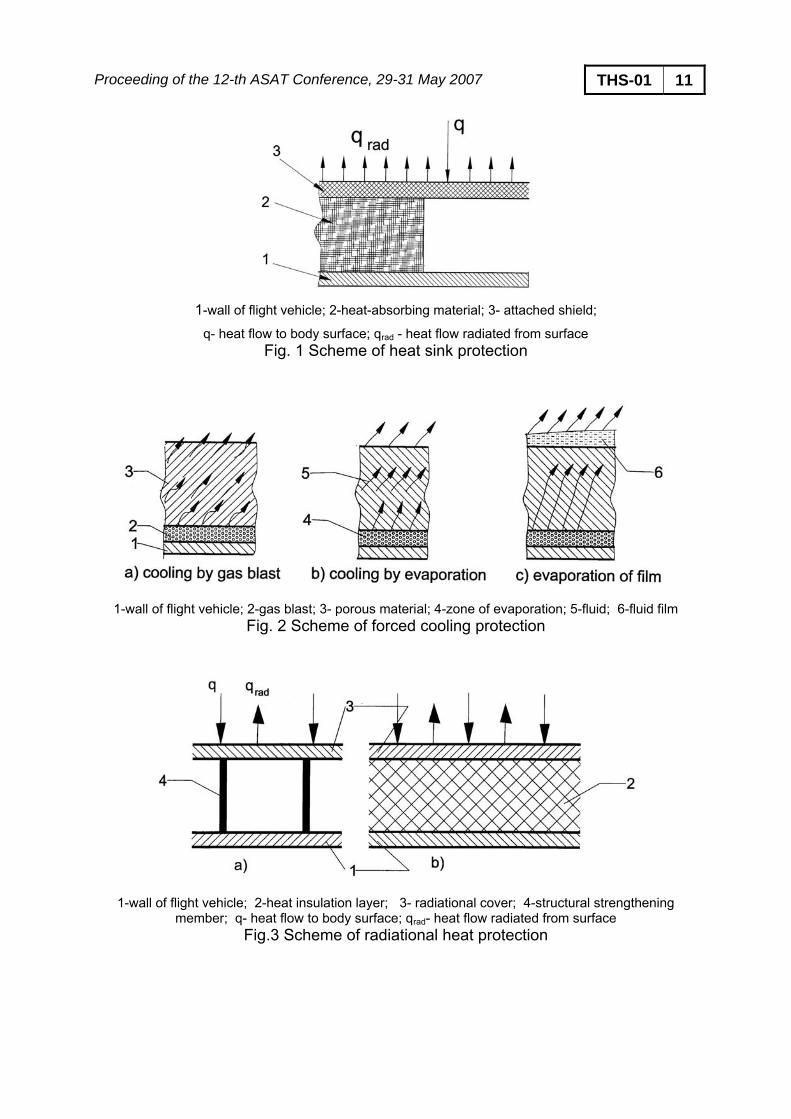
1. INTRODUCTION The design of missiles has been witnessing great advances in the recent years. The demands for longer range, higher altitude and velocity, greater accuracy, and other design factors made the problem of missile design a lot more complicated. One of the modern topics in missile design is the aerodynamic heating. In some cases when aerodynamic heating becomes of a considerable value and a destructive effect on the vehicle structure and/ or its onboard equipment could be expected, a thermal protection to the missile body becomes a vital procedure. There are several methods of thermal protection. The choice of a specific method depends upon several factors such as the design of the missile itself and its flight conditions. The right selection of thermal protection mode provides considerable economy in missile total weight and is an important factor determining this choice. The present work illustrates a survey over the main methods of thermal protection used in modern rocket construction, namely heat absorption by heat sink, forced cooling, radiation, and use of ablative shield. This work focused on ablative thermal protection (based on judged reasons). A mathematical model was developed to evaluate the effectiveness of the ablative shield. The model, based on closed form relations, estimates the missile net heat flux allowed to the missile wall, the temperature profile over the surface, and the total thickness of shield needed for protection of a conical forebody during a certain flight. A computer code was developed as a design tool. It is used to estimate the temperature profile over a missile conical forebody with/ without ablative shielding and evaluate the net shield thickness needed for a complete flight. 2. METHODS OF THERMAL PROTECTION 2.1 Heat Sink In protection of the vehicle by means of heat sink, a thick layer of indestructible material that covers the wall of the flight vehicle absorbs the aerodynamic heat flow as shown in figure 1. Copper and other materials with high heat conductivity are used for this purpose. A thin layer of material of low heat conductivity may be used on the external surface of the heat-absorbing layer.
The presence of a coating of this material appreciably increases radiation from the surface. However, the heat absorptive capacity of available materials is not that high and therefore the weight of such heat-protection systems is excessive. Therefore the technique of the heat sink may be used for thermal protection of flight vehicles encountering only moderately high heat flows in flight [1].
Proceeding of the 12-th ASAT Conference, 29-31 May 2007 THS-01 3 2.2. Forced Cooling The method of forced cooling, figure 2, works in the following mechanism: a gas under pressure is blown through a perforated or porous wall of the flight vehicle to the boundary layer, absorbs part of the heat and in the process heats up. It is better to use a light gas of low molecular weight for this purpose, for example Helium. Air, nitrogen and other gases can be used in practice. Other types of forced cooling include evaporation and film cooling in which a fluid is blown through a porous wall and evaporates either in the wall (evaporation cooling) or on its surface (film cooling). The fluid must have a maximum heat of evaporation at a comparatively low temperature. Due to the required weight characteristics for a fluid or gas flow this device is very complicated from point of view of manufacture [1].
2.3. Radiation Cooling The radiational method of heat protection, figure 3, differs by marked simplicity of its construction. The basic element of this device is a radiational screen that is a thin plate of metal (molybdenum, tungsten, etc.) or a film of oxides (for example: ZrO2, SiO2). The screen is located either over the structure to be protected or directly on it. In the latter case, material of low heat conductivity, for example porous ceramic or glass is spread between the structure and the screen to reduce heat flow inside the apparatus. During heating part of the heat is spent on radiation and over-heating of the structure of the vehicle does not take place. Experiments [1] show that the strength of the heat-resistant materials and oxides is not maintained under high temperatures. Hence the method of radiational thermal protection can be used only under the impact of low heat flows. Thus the range of application of this method of thermal protection is limited to comparatively low heat flows. However their endurance is fairly high. It must be noted that films of oxides or ceramic happen to be very fragile and easily peel off during heating and impact loading. Therefore the use of oxide or ceramic isolation is still out of question in cases where such impact loads are expected, for example, during redistribution or variation of the strength of shock waves depending on the value of the angle of attack [1]. 2.4. Ablation The use of heat protection shields is quite effective for vehicles undergoing the action of intense heat flows of short duration (ballistic launching) and for vehicles undergoing the impact of comparatively low heat flows of long duration. The application of this device is quite simple. A layer of material of low thermal conductivity is attached, fixed or built up on the surface of the flight vehicle structure. This is heated up and begins to erode under the action of the heat flow. The detached particles are carried away from the surface by gas flow past it, thereby
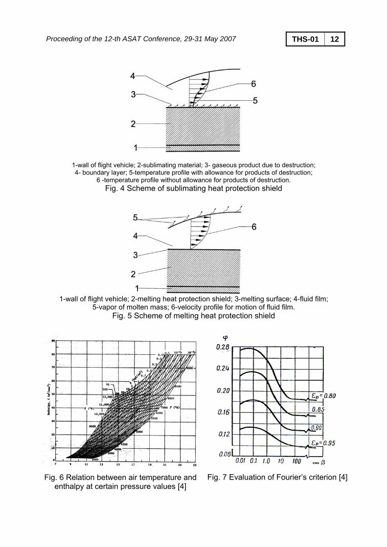
Proceeding of the 12-th ASAT Conference, 29-31 May 2007 THS-01 4 absorbing and dissipating to surrounding space a large part of the heat created by this flow. Thus erosion of the mass of the shield material should be considered as an important mode of thermal protection of a vehicle to be launched. As a result of erosion the thickness of the heat protection material diminishes. With estimating the appropriate value of this thickness, it is possible to design a structure for the required temperature range. This method, along with high effectiveness, has high reliability. The remainder of the present work is devoted for the details of ablative thermal protection. 3. ABLATIVE THERMAL PROTECTION The materials of thermal-protection shields are subdivided into two groups, namely sublimating and melting, depending on the type of erosion. The selection of the minimum thickness of heat protection shield depends on mode of its erosion. The sublimating materials for thermal shields, Fig. 4, are the ones that are destroyed by heating and reduced to the gaseous state. The most typical case in this group is floroplast and graphite. The gaseous products formed by erosion flow into the boundary layer, reducing the heat flow [1]. The group of melting heat protection coverings includes the ones that turn to fluid during heating, figure 5. Materials based on glass or quartz and also polymers (e.g., organic glass, polyethylene, etc.). The fluid film formed as a result of heat flows under the action of the forces of aerodynamic friction is carried away from the surface, reducing the heating effect. Meanwhile part of this melt evaporates. This evaporation increases the effectiveness of such coverings because a considerable part of the heat is dissipated in the form of the latent heat of evaporation. The above division of heat protection shields is quite provisional because, for example, part of the material that melts, evaporates and thereby increases the cooling effect. If in the meantime the heat flows are very high and the forces due to aerodynamic friction are insignificant the whole of the melt evaporates and the melting material virtually becomes sublimating material by its transfer behavior. On the other hand, given minor heat flows and high frictional stress a sublimating material may condense and flow like a melting material. It should be noted carefully that for shielding materials, as the aerodynamic heating starts, the surface temperature of the thermal protection shield material begins to rise until it reaches the sublimation (or melting) point. The surface temperature then keeps that fixed value in spite of further increase of aerodynamic heating inflow. Once the net heat flux to the wall becomes less than or equal to zero, the wall temperature decreases below the ablation temperature and the ablation process stops immediately, i.e., for ablation to take place two conditions must be true simultaneously: the wall temperature reaches the ablation value and the heat flux is positive. 4. MATHEMATICAL MODEL 4.1 Heat of Ablation
Proceeding of the 12-th ASAT Conference, 29-31 May 2007 THS-01 5 Stagnation temperature To; is evaluated as a function of free stream temperature as [1,2,5]
⎟⎠⎞
⎜⎝⎛ −γ+= ∞∞
2o M
211TT (1)
where γ is the specific heat ratio and is the free stream Mach number. ∞M Stagnation enthalpy io; is then calculated from stagnation temperature as illustrated in the chart, Fig. 6 [4]. Wall enthalpy ipiw Tci = (2)
where cpi is the specific heat of the ablating material and Ti is its sublimating (melting) temperature Effective heat of ablation in absence of radiation
( ) ( )wovipi* iiiTcq
o
−β++= for sublimating materials (3)
( ) ipi* Tcq
o
= for melting materials (4) where iv is the enthalpy of ablation and β is a coefficient of heat loss during ablation which depends on the material and type of flow [3]. Radiation heat flux (5) 4
iri Tq εσ= The ratio ( ori qq ) must be less than unity, where qo is the value of heat influx to a bare “unprotected” wall.
Effective heat of ablation ( )ori
o**
qq1qq
−= (6)
Rate of mass loss during ablation *o
v qq
m = (7)
Net heat of ablation ( ) rivipivi qiTcmq ++= (8) Net heat rate allowed to the missile wall and interior
io qqq −=Δ (9)
This amount of heat is the sole parameter responsible for heating the missile walls and the missile interior cavity. Under the thin wall assumption, the change in wall temperature during a time interval Δt under this amount of heat has the value of ΔTw, where
Proceeding of the 12-th ASAT Conference, 29-31 May 2007 THS-01 6
δρΔΔ
=Δ..c
t.qTw (10)
and the wall temperature at any instant (t + Δt) is related to the wall temperature at the instant t as
( ) ( ) www TtTttT Δ+=Δ+ (11)
4.2 Shield Thickness The enough amount “thickness” of coating material should satisfy the thermal and mechanical erosion and a remaining amount must be reserved to act as an insulator.
• Thickness of thermally ablating shield
The thickness of thermally ablating material; ρΔ
=δt.mv
t (12)
where mv is calculated from equation (7), ρ is the density of the ablating material, during a time interval of Δt.
• Thickness of mechanically ablating shield
The amount of “mechanically” ablating material is
( ) tm %4030 δ÷=δ (13)
δm and δt are the mechanical and thermal ablating thickness, respectively [1].
• Thickness of insulating shield
This thickness is added to the thickness of eroded part from the moment of launch and is meant to endure unchanged during the whole mission so as to ensure a maximum temperature inside the missile interior and to avoid damage of on-board equipment.
Bio’s criterion λδ
=β 1h (14)
where λ is the thermal conductivity of the coating material, 1δ is the thickness of the insulation layer, is the local heat transfer coefficient for an unprotected wall. h Relative temperature gradient εp; across the thickness of the covering
w
pp T
T1
Δ
Δ−=ε (15)
where ΔTp is the difference between the maximum allowable temperature inside the missile interior and the atmospheric temperature; ΔTp = Tin – T∞ . and ΔTw is the difference between wall and the atmospheric temperatures; ΔTw = Tw – T∞ .
Proceeding of the 12-th ASAT Conference, 29-31 May 2007 THS-01 7 Fourier’s criterion φ; is evaluated from charts (see Fig. 7) according to the value of β and εp . Coefficient of temperature flow a; is a parameter of the insulator material and is evaluated as
ρλ
=c
a (16)
where c and ρ are the specific heat and density of the ablative material, respectively. Thickness of the insulator δ1; for a certain exposure time interval Δt is then improved from the relation
ϕΔ
=δt.a
1 (17)
The calculation of insulator part has an iterative nature, the value of insulator thickness δ1 is first assumed to evaluate Bio’s criterion, equation 14. Depending on the nature of the problem, a single iteration step seemed to be accurate enough in improving the value of δ1 [1]. By the end of the trajectory, one can estimate the total amount of coating material needed to compensate both thermal and mechanical erosion and to retain enough amount to act as a thermal insulator, i.e.,
( ) ( 1
impact
launch
impact
launchmt MAXmaterialcoatingofthickness δ+δ+δ= ∑ )
5. CASE STUDIES The calculation procedure above was added as a subroutine in a trajectory program and the whole program was applied on a number of real missiles. A typical sublimating ablative material, namely Teflon, was adopted in the different runs. Teflon has the following characteristics:
– Density 2280.0 Kg/m3 – Specific heat 106.66 J/Kg. K – Ablation temperature 445.0 K – Ablation enthalpy 177486.09 J/Kg
For a complete evaluation of the thickness of coating material, the maximum allowable temperature inside the nose interior is suggested to be 50ºC (323 K). Sample outputs of the code are illustrated below: 5.1. Missile1 A long range, single stage, liquid propelled ballistic missile. A typical flight of this missile consists mainly of a short vertical rise path, a gravity turn path, a constant attitude path, and a passive part. Cone semi apex angle 21.9o
Proceeding of the 12-th ASAT Conference, 29-31 May 2007 THS-01 8 Mean thrust 133.0 KN Total mass 5686.5 Kg Propellant mass 3612.5 Kg Shut-off time 59.00 s Range 300.0 Km Maximum altitude 89.0 Km Maximum Mach number 5.3 5.2. Missile 2 A single stage, unguided re-entry ballistic missile that is required to deliver a payload of at least 200 Kg to an apogee of about 300 Km. Cone semi apex angle 6.8o
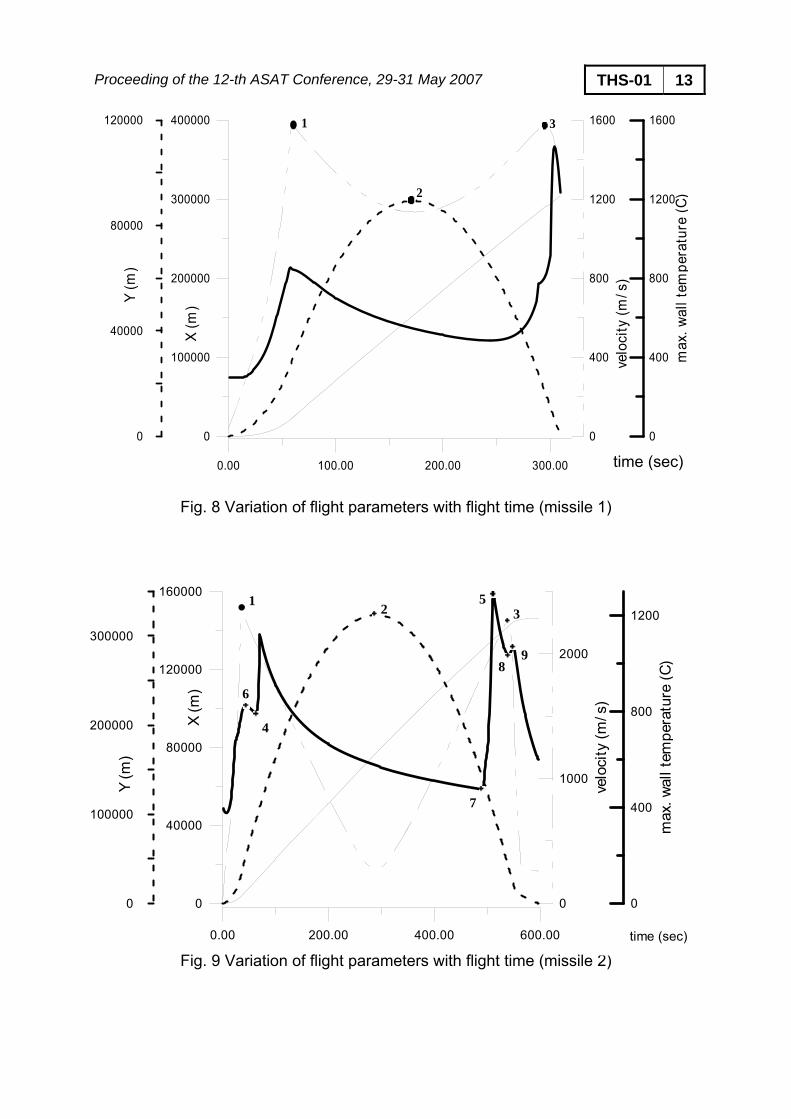
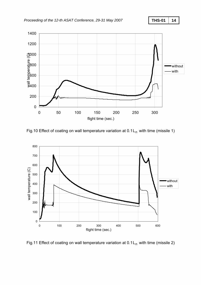
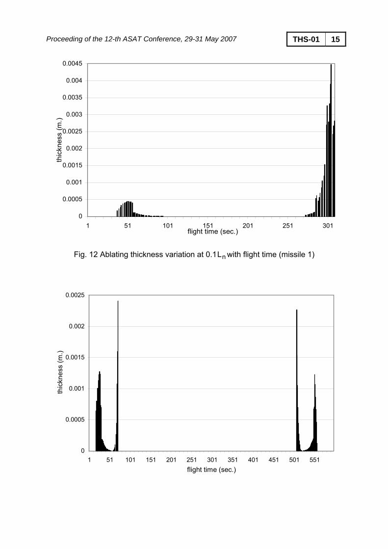
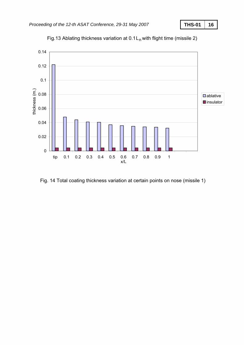
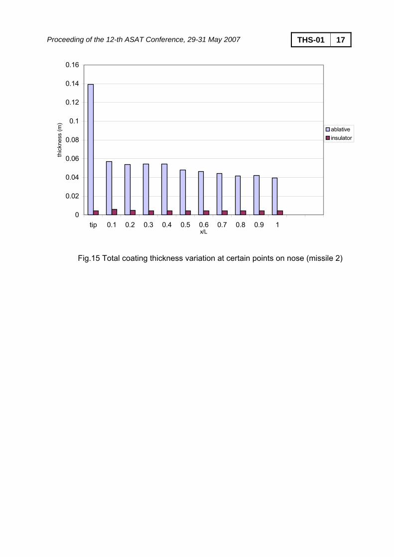
Mean thrust 238.7 KN Total mass 4043.6 Kg Propellant mass 2900 Kg Burning time 36.00 s Range 147.0 Km Maximum altitude 312.0 Km Maximum Mach number 8 6. RESULTS AND DISCUSSIONS: 6.1. Factors affecting the unprotected wall temperature: Figure 8 illustrates the variation of flight parameters and wall temperature at 0.1 of nose length against flight time for missile 1. As flight velocity increases, the wall temperature increases until the velocity attains a maximum value near burnout. After burnout, the velocity decreases under the action of drag and gravity forces till the summit. During this phase of trajectory, the wall temperature starts to decrease simultaneously. In the return phase, the velocity starts to increase under the action of gravity. The wall temperature continues decreasing with a lower decreasing rate. After a certain period during the return phase, the slope of wall temperature curve becomes positive with a small value that gets larger by time. Simultaneously, the velocity increases to a local maximum. The velocity starts to decrease again under the effect of drag force that gets more significant and more effective as the altitude decreases. The wall temperature starts to decrease again till impact. The behavior of wall temperature lags behind that of the velocity with a short time. This can be explained since the temperature has an accumulative rather than an instantaneous nature. Figure 9 illustrates the variation of flight parameters and wall temperature at 0.1 of nose length against flight time for missile 2. The behavior of wall temperature is nearly the same as that of missile 1. However, a sudden drop in wall temperature takes place at altitudes of around 85.0 Km while a sharp rise in wall temperature occurs at nearly the same altitudes. At this altitude, the wall temperature starts to deviate from its “expected” behavior. The drop in wall temperature due to a decreased heat transfer rate occurs as the missile "exits" the dense atmosphere, while the sharp rise in wall temperature due to excessive heating rate takes place as the missile "re-enters" the atmosphere. It should be noted that most of the trajectory
Proceeding of the 12-th ASAT Conference, 29-31 May 2007 THS-01 9 of missile 2 takes place in the low-density atmosphere. Recall that the trajectory of missile 1 takes place almost completely in the dense atmosphere (up to 70: 80 Km above sea level). It can be concluded that both flight altitude and flight velocity dictate the amount of heat, hence the temperature, on the missile wall. Ignoring the large variations in air density, flight velocity is the major factor influencing the wall temperature. Other parameters such as forebody shape, degree of turbulence, angle of attack, … etc. also influence the wall temperature. 6.2. Effect of ablative coating on the net wall temperature: Figures 10 and 11 illustrate the wall temperature at 0.1 of nose length missile1 and 2, respectively, in cases of protected and unprotected wall. In case of thermal protection, the wall temperature is limited to the ablation temperature of coating material. 6.3. Variation of ablating thickness with flight time: Figures 12 and 13 illustrate the variation of thickness of material that ablates with flight time. As it was stated earlier, ablation takes place under a positive net heat flux when the surface temperature reaches the ablation value. The total thickness of ablating material at a specific location on the body is the integration of ablating thickness with time. 6.2. Variation of coating thickness along the body: Figures 14 and 15 illustrate the total amount of coating needed to account for thermal and mechanical ablation and to ensure a prescribed interior temperature at given points on missile 1 and 2, respectively. A relatively large thickness is needed at the stagnation point; a material with better ablating characteristics such as graphite [9] can be used at the nose tip to give a much reasonable thickness. 7. CONCLUSIONS A complete computer code was developed based on the general governing equations for thermal protection. The code provides an easy, reliable tool for the estimation of required shield thickness, mass transfer rate, and the overall wall temperature distribution along a conical forebody of a missile in a complete flight. REFERENCES [1] N.F.Krasnov, “Aerodynamics”, Amerind Publishing, New Delhi 1978. [2] N.F.Krasnov, “Aerodynamics of Bodies of Revolution”, second edition, Elsevier,
New York 1970. [3] James R.Hayes and Richard D. Neumann, “Introduaction to Aerodynamic Heating
Analysis of Suprsonic Missiles”, “Tactical Missile Aerodynamics: Prediction Methodology”, AIAA Tactical Missile Series, Volume 142, ISBN 1-56347-016-0, 1991.
Proceeding of the 12-th ASAT Conference, 29-31 May 2007 THS-01 10 [4] Dubin. M. et al., U. S. Standard Atmosphere 1962, U. S. Government Printing
Office, Washington, D. C., 1962. [5] John D. Anderson, “Fundamentals of Aerodynamics”, second edition, McGraw-
Hill International Editions, Aerospace Science Series, ISBN 0-07-100767-9, 1991. [6] A. R. El-Ashmawi, “Drag Prediction Methodology for Missiles at Subsonic,
Transonic, and Supersonic Speeds”, M. Sc. Thesis, Military Technical college, Cairo, Egypt, 1983.
[7] A. H. Helmy and H. Hosny, “Re-entry Performance”, Diplom course, Military Technical College, Cairo, Egypt, 1979.
[8] Heinz Schulte, “Pershing II”, international defence review magazine,1983. [9] K. E. Wurster and H. W. Stone, "Aerodynamic Heating Environment Definition /
Thermal Protection System Selection for the HL-20", Journal of Spacecraft and Rockets, Vol. 30, No. 5, 1993.
[10] P.K. Swaminathan and Jeff C. Taylor, "Transition Regime Aerodynamic Heating of Missiles", Journal of Spacecraft and Rockets, Vol. 33, No. 5, 1996.
Proceeding of the 12-th ASAT Conference, 29-31 May 2007 THS-01 11
1-wall of flight vehicle; 2-heat-absorbing material; 3- attached shield;
q- heat flow to body surface; qrad - heat flow radiated from surface Fig. 1 Scheme of heat sink protection
1-wall of flight vehicle; 2-gas blast; 3- porous material; 4-zone of evaporation; 5-fluid; 6-fluid film Fig. 2 Scheme of forced cooling protection
1-wall of flight vehicle; 2-heat insulation layer; 3- radiational cover; 4-structural strengthening member; q- heat flow to body surface; qrad- heat flow radiated from surface
Fig.3 Scheme of radiational heat protection
Proceeding of the 12-th ASAT Conference, 29-31 May 2007 THS-01 12
1-wall of flight vehicle; 2-sublimating material; 3- gaseous product due to destruction; 4- boundary layer; 5-temperature profile with allowance for products of destruction;
6 -temperature profile without allowance for products of destruction. Fig. 4 Scheme of sublimating heat protection shield
1-wall of flight vehicle; 2-melting heat protection shield; 3-melting surface; 4-fluid film;
5-vapor of molten mass; 6-velocity profile for motion of fluid film. Fig. 5 Scheme of melting heat protection shield
Fig. 6 Relation between air temperature and enthalpy at certain pressure values [4]
Fig. 7 Evaluation of Fourier’s criterion [4]
Proceeding of the 12-th ASAT Conference, 29-31 May 2007 THS-01 13
0.00 100.00 200.00 300.00
0
100000
200000
300000
400000
X (m
)
0
40000
80000
120000Y
(m)
0
400
800
1200
1600
velo
city
(m/s
)
0
400
800
1200
1600
max
. wal
l tem
pera
ture
(C)
1
2
3
time (sec)
Fig. 8 Variation of flight parameters with flight time (missile 1)
0.00 200.00 400.00 600.00
0
40000
80000
120000
160000
X (m
)
0
100000
200000
300000
Y (m
)
0
1000
2000
velo
city
(m/s
)
0
400
800
1200
max
. wal
l tem
pera
ture
(C)
1
4
6
25
3
98
7
Fig. 9 Variation of flight parameters with flight time (missile 2)
time (sec)
Proceeding of the 12-th ASAT Conference, 29-31 May 2007 THS-01 14
0
200
400
600
800
1000
1200
1400
0 50 100 150 200 250 300flight time (sec.)
wal
l tem
pera
ture
(C)
withoutwith
Fig.10 Effect of coating on wall temperature variation at 0.1 with time (missile 1) nL
0
100
200
300
400
500
600
700
800
0 100 200 300 400 500 600flight time (sec.)
wal
l tem
pera
ture
(C)
withoutwith
Fig.11 Effect of coating on wall temperature variation at 0.1 with time (missile 2) nL
Proceeding of the 12-th ASAT Conference, 29-31 May 2007 THS-01 15
0
0.0005
0.001
0.0015
0.002
0.0025
0.003
0.0035
0.004
0.0045
1 51 101 151 201 251 301flight time (sec.)
thic
knes
s (m
.)
Fig. 12 Ablating thickness variation at 0.1 with flight time (missile 1) nL
0
0.0005
0.001
0.0015
0.002
0.0025
1 51 101 151 201 251 301 351 401 451 501 551flight time (sec.)
thic
knes
s (m
.)
Proceeding of the 12-th ASAT Conference, 29-31 May 2007 THS-01 16
Fig.13 Ablating thickness variation at 0.1 with flight time (missile 2) nL
0
0.02
0.04
0.06
0.08
0.1
0.12
0.14
tip 0.1 0.2 0.3 0.4 0.5 0.6 0.7 0.8 0.9 1x/L
thic
knes
s (m
.)
ablativeinsulator
Fig. 14 Total coating thickness variation at certain points on nose (missile 1)
Proceeding of the 12-th ASAT Conference, 29-31 May 2007 THS-01 17
0
0.02
0.04
0.06
0.08
0.1
0.12
0.14
0.16
tip 0.1 0.2 0.3 0.4 0.5 0.6 0.7 0.8 0.9 1x/L
thic
knes
s (m
)
ablativeinsulator
Fig.15 Total coating thickness variation at certain points on nose (missile 2)
Related Documents