JSC-48024-114 EVA Checklist STS-114 Flight Supplement Mission Operations Directorate EVA, Robotics, and Crew Systems Operations Division Final, Rev A August 19, 2004 National Aeronautics and Space Administration Lyndon B. Johnson Space Center Houston, Texas Verify this is the correct version for the pending operation (training, simulation or flight). Electronic copies of FDF books are available. URL: http://mod.jsc.nasa.gov/do3/FDF/index.html NOTE This supplement is to be integrated into the generic edition to provide a complete document for the specific flight. Some pages in the generic edition may be replaced with supplemental pages identified as ‘TEMP’. These generic pages, if any, must be retained for use on future flights.

Welcome message from author
This document is posted to help you gain knowledge. Please leave a comment to let me know what you think about it! Share it to your friends and learn new things together.
Transcript

JSC-48024-114
EVA Checklist
STS-114 Flight Supplement
Mission Operations Directorate EVA, Robotics, and Crew Systems Operations Division
Final, Rev A August 19, 2004
National Aeronautics and Space Administration
Lyndon B. Johnson Space Center Houston, Texas
Verify this is the correct version for the pending operation (training, simulation or flight). Electronic copies of FDF books are available. URL: http://mod.jsc.nasa.gov/do3/FDF/index.html
NOTE This supplement is to be integrated into the generic edition to provide a complete document for the specific flight. Some pages in the generic edition may be replaced with supplemental pages identified as ‘TEMP’. These generic pages, if any, must be retained for use on future flights.


FS ii EVA/114/FIN A
Incorporates the following: 482#: None – Establishes baseline
AREAS OF TECHNICAL RESPONSIBILITY
Book Manager DX32/M. Myers 281-483-7501
Alternate Book Manager DX32/C. Begley 281-483-7495

FS v EVA/114/FIN A
EVA CHECKLIST STS-114 FLIGHT SUPPLEMENT
LIST OF EFFECTIVE PAGES
FINAL 12/06/02 REV A 08/19/04
Sign Off ........................... * 114/FIN A FS ii ................................. * 114/FIN A iii...................................... * generic iv ..................................... * generic FS v................................. * 114/FIN A FS vi ................................ * 114/FIN A FS vii ............................... * 114/FIN A FS viii .............................. * 114/FIN A FS ix................................ 114/FIN A FS x................................. 114/FIN A FS xi ................................ 114/FIN A FS xii ............................... 114/FIN A FS xiii .............................. 114/FIN A FS xiv .............................. 114/FIN A 1-1................................... generic 1-2................................... generic 1-3................................... generic 1-4................................... generic 1-5................................... generic 1-6................................... generic 1-7................................... generic 1-8................................... generic 1-9................................... generic 1-10................................. generic 2-1................................... generic 2-2................................... generic 2-3................................... generic 2-4................................... generic 2-5................................... generic 2-6................................... generic 3-1................................... generic 3-2................................... generic 3-3................................... generic 3-4................................... generic 3-5................................... generic 3-6................................... generic 3-7................................... generic 3-8................................... generic CC 3-9............................. generic CC 3-10........................... generic 3-11................................. generic 3-12................................. generic TEMP FS 4-1 .................. 114/FIN A TEMP FS 4-2 .................. ALL/FIN A 4-3................................... generic
4-4 ................................... generic 4-5 ................................... generic 4-6 ................................... generic 4-7 ................................... generic 4-8 ................................... generic 4-9 ................................... generic 4-10 ................................. generic FS CC 4-11...................... 114/FIN A FS CC 4-12...................... 114/FIN A 5-1 ................................... generic 5-2 ................................... generic 5-3 ................................... generic 5-4 ................................... generic A6-1................................. generic CC A6-2........................... generic 6-3 ................................... generic CC 6-4 ............................. generic FS 7-1.............................. 114/FIN A FS 7-2.............................. 114/FIN A FS 7-3.............................. 114/FIN A FS 7-4.............................. 114/FIN A FS 7-5.............................. 114/FIN A FS 7-6.............................. 114/FIN A FS 7-7.............................. 114/FIN A FS 7-8.............................. 114/FIN A FS 7-9.............................. 114/FIN A FS 7-10............................ 114/FIN A FS 7-11............................ 114/FIN A FS 7-12............................ 114/FIN A FS 7-13............................ 114/FIN A FS 7-14............................ 114/FIN A FS 7-15............................ 114/FIN A FS 7-16............................ 114/FIN A FS 7-17............................ 114/FIN A FS 7-18............................ 114/FIN A FS 7-19............................ 114/FIN A FS 7-20............................ 114/FIN A FS 7-21............................ 114/FIN A FS 7-22............................ 114/FIN A FS 7-23............................ 114/FIN A FS 7-24............................ 114/FIN A FS 7-25............................ 114/FIN A FS 7-26............................ 114/FIN A FS 7-27............................ 114/FIN A FS 7-28............................ 114/FIN A
* – Omit from flight book

FS vi EVA/114/FIN A
FS 7-29 ........................... 114/FIN A FS 7-30 ........................... 114/FIN A FS 7-31 ........................... 114/FIN A FS 7-32 ........................... 114/FIN A FS 7-33 ........................... 114/FIN A FS 7-34 ........................... 114/FIN A FS 7-35 ........................... 114/FIN A FS 7-36 ........................... 114/FIN A 8-1................................... generic 8-2................................... generic 8-3................................... generic 8-4................................... generic 8-5................................... generic 8-6................................... generic 9-1................................... generic 9-2................................... generic 9-3................................... generic 9-4................................... generic 9-5................................... generic 9-6................................... generic 10-1................................. generic 10-2................................. generic 10-3................................. generic 10-4................................. generic 10-5................................. generic 10-6................................. generic 10-7................................. generic 10-8................................. generic 10-9................................. generic 10-10............................... generic 11-1................................. generic 11-2................................. generic 11-3................................. generic 11-4................................. generic 12-i .................................. generic 12-ii ................................. generic 12-1................................. generic 12-2................................. generic 12-3................................. generic 12-4................................. generic 12-5................................. generic 12-6................................. generic 12-7................................. generic 12-8................................. generic 12-9................................. generic 12-10............................... generic 12-11............................... generic 12-12............................... generic 12-13............................... generic 12-14............................... generic 12-15............................... generic 12-16............................... generic
12-17 ............................... generic 12-18 ............................... generic 13-1 ................................. generic 13-2 ................................. generic 13-3 ................................. generic 13-4 ................................. generic 14-1 ................................. generic 14-2 ................................. generic 14-3 ................................. generic 14-4 ................................. generic 14-5 ................................. generic 14-6 ................................. generic 14-7 ................................. generic 14-8 ................................. generic 14-9 ................................. generic 14-10 ............................... generic 14-11 ............................... generic 14-12 ............................... generic 14-13 ............................... generic 14-14 ............................... generic 14-15 ............................... generic 14-16 ............................... generic 14-17 ............................... generic 14-18 ............................... generic 14-19 ............................... generic 14-20 ............................... generic 14-21 ............................... generic 14-22 ............................... generic 15-1 ................................. generic 15-2 ................................. generic 15-3 ................................. generic 15-4 ................................. generic 15-5 ................................. generic 15-6 ................................. generic 15-7 ................................. generic 15-8 ................................. generic 15-9 ................................. generic 15-10 ............................... generic 15-11 ............................... generic 15-12 ............................... generic 15-13 ............................... generic 15-14 ............................... generic 16-i .................................. generic 16-ii.................................. generic TEMP FS 16-1................. 114/FIN A TEMP FS 16-2................. ALL/FIN A FS 16-3............................ 114/FIN A FS 16-4............................ 114/FIN A FS 16-5............................ 114/FIN A FS 16-6............................ 114/FIN A FS 16-7............................ 114/FIN A FS 16-8............................ 114/FIN A

FS vii EVA/114/FIN A
FS 16-9 ........................... 114/FIN A FS 16-10 ......................... 114/FIN A FS 16-11 ......................... 114/FIN A FS 16-12 ......................... 114/FIN A FS 16-13 ......................... 114/FIN A FS 16-14 ......................... 114/FIN A FS 16-15 ......................... 114/FIN A FS 16-16 ......................... 114/FIN A FS 16-17 ......................... 114/FIN A FS 16-18 ......................... 114/FIN A FS 16-19 ......................... 114/FIN A FS 16-20 ......................... 114/FIN A 17-1................................. * generic 17-2................................. * generic FS 18-1 ........................... 114/FIN A FS 18-2 ........................... 114/FIN A FS 18-3 ........................... 114/FIN A FS 18-4 ........................... 114/FIN A FS 18-5 ........................... 114/FIN A FS 18-6 ........................... 114/FIN A FS 18-7 ........................... 114/FIN A FS 18-8 ........................... 114/FIN A FS 18-9 ........................... 114/FIN A FS 18-10 ......................... 114/FIN A FS 18-11 ......................... 114/FIN A FS 18-12 ......................... 114/FIN A FS 18-13 ......................... 114/FIN A FS 18-14 ......................... 114/FIN A FS 18-15 ......................... 114/FIN A FS 18-16 ......................... 114/FIN A FS 18-17 ......................... 114/FIN A FS 18-18 ......................... 114/FIN A FS 18-19 ......................... 114/FIN A FS 18-20 ......................... 114/FIN A FS 18-21 ......................... 114/FIN A FS 18-22 ......................... 114/FIN A FS 18-23 ......................... 114/FIN A FS 18-24 ......................... 114/FIN A FS 18-25 ......................... 114/FIN A FS 18-26 ......................... 114/FIN A FS 18-27 ......................... 114/FIN A FS 18-28 ......................... 114/FIN A FS 18-29 ......................... 114/FIN A FS 18-30 ......................... 114/FIN A FS 18-31 ......................... 114/FIN A FS 18-32 ......................... 114/FIN A FS 18-33 ......................... 114/FIN A FS 18-34 ......................... 114/FIN A FS 18-35 ......................... 114/FIN A FS 18-36 ......................... 114/FIN A FS 18-37 ......................... 114/FIN A FS 18-38 ......................... 114/FIN A
FS 18-39.......................... 114/FIN A FS 18-40.......................... 114/FIN A FS 18-41.......................... 114/FIN A FS 18-42.......................... 114/FIN A FS 18-43.......................... 114/FIN A FS 18-44.......................... 114/FIN A FS 18-45.......................... 114/FIN A FS 18-46.......................... 114/FIN A 19-i .................................. generic 19-ii.................................. generic 19-1 ................................. generic 19-2 ................................. generic 19-3 ................................. generic 19-4 ................................. generic 19-5 ................................. generic 19-6 ................................. generic 19-7 ................................. generic 19-8 ................................. generic 19-9 ................................. generic 19-10 ............................... generic 20-1 .................................* generic 20-2 .................................* generic
* – Omit from flight book

FS viii EVA/114/FIN A
EVA CUE CARDS
Title Ref. Page Card No.
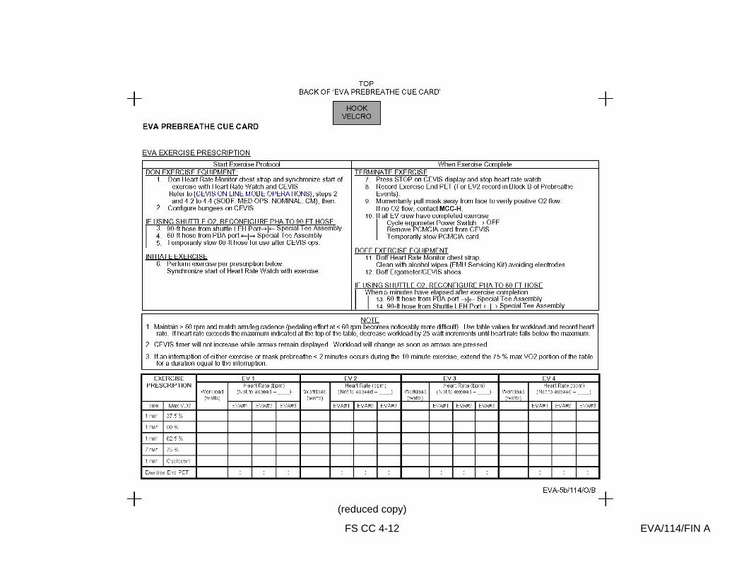
SAFER CHECKOUT RESULTS (Front)....................... CC 3-9 generic SAFER STATUS TROUBLESHOOTING (Back) ......... CC 3-10 generic EVA PREBREATHE CUE CARD (Front) ..................... FS CC 4-11 EVA-5a/114/O/B EVA PREBREATHE CUE CARD (Back) ..................... FS CC 4-12 EVA-5b/114/O/B DEPRESS/REPRESS
Nominal Configuration (Front)................................................................... CC A6-2 generic
FAILED LEAK CHECK (Back of DEPRESS/REPRESS)............................. CC 6-4 generic
FS ix EVA/114/FIN A
CONTENTS PAGE
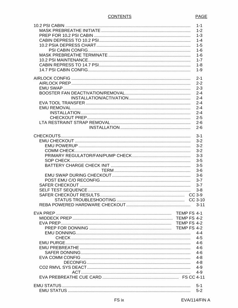
10.2 PSI CABIN ......................................................................................................... 1-1 MASK PREBREATHE INITIATE ........................................................................... 1-2 PREP FOR 10.2 PSI CABIN ................................................................................. 1-3 CABIN DEPRESS TO 10.2 PSI............................................................................. 1-4 10.2 PSIA DEPRESS CHART............................................................................... 1-5 10.2 PSI CABIN CONFIG...................................................................................... 1-6 MASK PREBREATHE TERMINATE ..................................................................... 1-6 10.2 PSI MAINTENANCE...................................................................................... 1-7 CABIN REPRESS TO 14.7 PSI............................................................................. 1-8 14.7 PSI CABIN CONFIG...................................................................................... 1-9
AIRLOCK CONFIG .................................................................................................... 2-1
AIRLOCK PREP.................................................................................................... 2-2 EMU SWAP........................................................................................................... 2-3 BOOSTER FAN DEACTIVATION/REMOVAL....................................................... 2-4 BOOSTER FAN INSTALLATION/ACTIVATION.................................................... 2-4 EVA TOOL TRANSFER ........................................................................................ 2-4 EMU REMOVAL.................................................................................................... 2-4 EMU INSTALLATION............................................................................................ 2-4 EMU CHECKOUT PREP....................................................................................... 2-5 LTA RESTRAINT STRAP REMOVAL................................................................... 2-6 LTA RESTRAINT STRAP INSTALLATION ........................................................... 2-6
CHECKOUTS............................................................................................................. 3-1
EMU CHECKOUT ................................................................................................. 3-2 EMU POWERUP .............................................................................................. 3-2 COMM CHECK................................................................................................. 3-2 PRIMARY REGULATOR/FAN/PUMP CHECK................................................. 3-3 SOP CHECK..................................................................................................... 3-5 BATTERY CHARGE CHECK INIT ................................................................... 3-5 BATTERY CHARGE CHECK TERM ................................................................ 3-6 EMU SWAP DURING CHECKOUT.................................................................. 3-6 POST EMU C/O RECONFIG............................................................................ 3-7
SAFER CHECKOUT ............................................................................................. 3-7 SELF TEST SEQUENCE ...................................................................................... 3-8 SAFER CHECKOUT RESULTS....................................................................... CC 3-9 SAFER STATUS TROUBLESHOOTING ......................................................... CC 3-10 REBA POWERED HARDWARE CHECKOUT ...................................................... 3-11
EVA PREP ................................................................................................. TEMP FS 4-1
MIDDECK PREP .................................................................................... TEMP FS 4-2 EVA PREP............................................................................................. TEMP FS 4-2
PREP FOR DONNING ..................................................................... TEMP FS 4-2 EMU DONNING................................................................................................ 4-4 EMU CHECK .................................................................................................... 4-5
EMU PURGE......................................................................................................... 4-6 EMU PREBREATHE ............................................................................................. 4-6
SAFER DONNING............................................................................................ 4-6 EVA COMM CONFIG............................................................................................ 4-8 EVA COMM DECONFIG....................................................................................... 4-8 CO2 RMVL SYS DEACT....................................................................................... 4-9 CO2 RMVL SYS ACT............................................................................................ 4-9 EVA PREBREATHE CUE CARD ................................................................ FS CC 4-11
EMU STATUS ............................................................................................................ 5-1
EMU STATUS ....................................................................................................... 5-2

FS x EVA/114/FIN A
DEPRESS/REPRESS............................................................................................... A6-1 DEPRESS/REPRESS (NOM A/L) .................................................................. CC A6-2
FAILED LEAK CHECK............................................................................................... 6-3 FAILED LEAK CHECK (5 PSI) ......................................................................... CC 6-4 FAILED LEAK CHECK (14.7/10.2 PSI) ............................................................ CC 6-4
TIMELINES ........................................................................................................... FS 7-1
EVA 1 (TBD)..................................................................................................... FS 7-3 EVA 2
EVA 2 INHIBIT PAD .................................................................................... FS 7-5 NOTES, CAUTIONS, AND WARNINGS ..................................................... FS 7-6 EVA 2 BRIEFING CARD ............................................................................. FS 7-7 EVA 2 SUMMARY TIMELINE...................................................................... FS 7-8 EVA 2 TOOL CONFIG................................................................................. FS 7-9 EVA 2 EGRESS/SETUP.............................................................................. FS 7-10 CMG R&R (HC) ........................................................................................... FS 7-12 CLEANUP/INGRESS................................................................................... FS 7-17
EVA 3 EVA 3 INHIBIT PAD .................................................................................... FS 7-19 NOTES, CAUTIONS, AND WARNINGS ..................................................... FS 7-20 EVA 3 BRIEFING CARD ............................................................................. FS 7-21 EVA 3 SUMMARY TIMELINE...................................................................... FS 7-22 EVA 3 TOOL CONFIG................................................................................. FS 7-23 EVA 3 EGRESS/SETUP.............................................................................. FS 7-24 ESPAD INSTALL (HC) ................................................................................ FS 7-25 PRIMARY CABLE ROUTING ...................................................................... FS 7-28 MISSE 1 AND 2 RETRIEVAL ...................................................................... FS 7-29 MISSE 5 INSTALL ....................................................................................... FS 7-30 SECONDARY CABLE ROUTING................................................................ FS 7-31 ESP2 INSTALLATION ................................................................................. FS 7-33 ESP2 FRGF REMOVE AND STOW............................................................ FS 7-35 CLEANUP/INGRESS................................................................................... FS 7-36
TOOLS AND STOWAGE ........................................................................................... 8-1
PGT CHECKOUT.................................................................................................. 8-3 760XD PGSC-PGT CONNECTION....................................................................... 8-4 PROGRAM PGT SETTINGS................................................................................. 8-4 DOWNLOAD/ERASE EVENT LOG....................................................................... 8-5 PGT CONTINGENCIES ........................................................................................ 8-6
POST EVA ................................................................................................................. 9-1
POST EVA............................................................................................................. 9-2 SUIT DOFFING ................................................................................................ 9-2 SAFER DOFFING............................................................................................. 9-2 EMU WATER RECHARGE .............................................................................. 9-3 SAFER STOW .................................................................................................. 9-4 SUIT DRYING/SEAL WIPE .............................................................................. 9-4 OXYGEN RECHARGE VERIFICATION........................................................... 9-4 WATER FILL VERIFICATION .......................................................................... 9-4 EMU POWERDOWN........................................................................................ 9-5
EMU MAINT/RECHARGE.......................................................................................... 10-1
WATER RECHARGE ............................................................................................ 10-2 EMU POWERUP .............................................................................................. 10-2 WATER FILL..................................................................................................... 10-2 OXYGEN RECHARGE VERIFICATION........................................................... 10-3 WATER FILL VERIFICATION .......................................................................... 10-3

FS xi EVA/114/FIN A
EMU LiOH CHANGEOUT ..................................................................................... 10-4 MIDDECK EMU BATTERY RECHARGE/LiOH REPLACEMENT......................... 10-5
INITIATE ........................................................................................................... 10-5 TERMINATE ..................................................................................................... 10-5
IN-SUIT EMU BATTERY RECHARGE/CHARGE VERIFICATION ....................... 10-6 INITIATE ........................................................................................................... 10-6 TERMINATE ..................................................................................................... 10-6
EMU POWERDOWN............................................................................................. 10-6 HELMET LIGHT/PGT BATTERY RECHARGE..................................................... 10-7
INITIATE ........................................................................................................... 10-7 TERMINATE ..................................................................................................... 10-7
REBA BATTERY INSTALLATION......................................................................... 10-8 EMU BATTERY REMOVAL/INSTALL................................................................... 10-8 HELMET LIGHT BULB CHANGEOUT.................................................................. 10-9 REBA BATTERY RECHARGE.............................................................................. 10-10
INITIATE ........................................................................................................... 10-10 TERMINATE ..................................................................................................... 10-10
POST EVA ENTRY PREP ......................................................................................... 11-1
POST EVA ENTRY PREP..................................................................................... 11-2 SAFER ENTRY STOW..................................................................................... 11-2
POST ISS EVA ENTRY PREP.............................................................................. 11-3 SAFER ENTRY STOW..................................................................................... 11-3
OFF-NOMINAL PROCEDURES..................................................................................... 12-i
EMU CONTINGENCY PROCS.................................................................................. 12-1 DISPLAY LOSS DURING POWER TRANSFER (WARM RESTART) ............................................................................................. 12-2
VACUUM H2O RECHARGE (MANNED) .............................................................. 12-2 LIOH REPLACEMENT (MANNED) ....................................................................... 12-3 BATTERY REPLACEMENT (MANNED) ............................................................... 12-4 WATER DUMP...................................................................................................... 12-5 SCU SWAP (UNMANNED) ................................................................................... 12-6 SCU SWAP (MANNED) ........................................................................................ 12-6 EMU COLD RESTART (MANNED)....................................................................... 12-6 12.1 CHEMICAL CHECK/DECONTAMINATION ................................................ 12-7 CONTAMINATION TEST ...................................................................................... 12-10 SAFER BATTERY CHANGEOUT......................................................................... 12-11 BENDS TREATMENT ADAPTER (BTA) INSTALLATION (IN-SUIT).................... 12-12
BTA PREP ........................................................................................................ 12-12 BTA TREATMENT............................................................................................ 12-12
BENDS TREATMENT ADAPTER (BTA) INSTALLATION (POST SUIT DOFFING) ...................................................................................... 12-14
BTA PREP ........................................................................................................ 12-14 BTA TREATMENT............................................................................................ 12-14
EMU RESIZE......................................................................................................... 12-17 DAP/EVA RESCUE/RETRIEVE ..................................................................................... 13-1
EVA ORBITER CONFIGURATION............................................................................ 13-2 EVA RESCUE/RETRIEVE ......................................................................................... 13-4
ORBITER CONTINGENCY EVA .................................................................................... 14-1
PAYLOAD BAY EVA NOMENCLATURE................................................................... 14-2 RMS/PRLA CONTINGENCY EVA ............................................................................. 14-3 96 BOLT PRE-EVA TOOL CONFIG .......................................................................... 14-13 96 BOLT EVA TIMELINE ........................................................................................... 14-14 CAPTURE LATCH MANUAL RELEASE (ODS/PMA)................................................ 14-19 96 BOLT EVA LAYOUT ............................................................................................. 14-21
FS xii EVA/114/FIN A
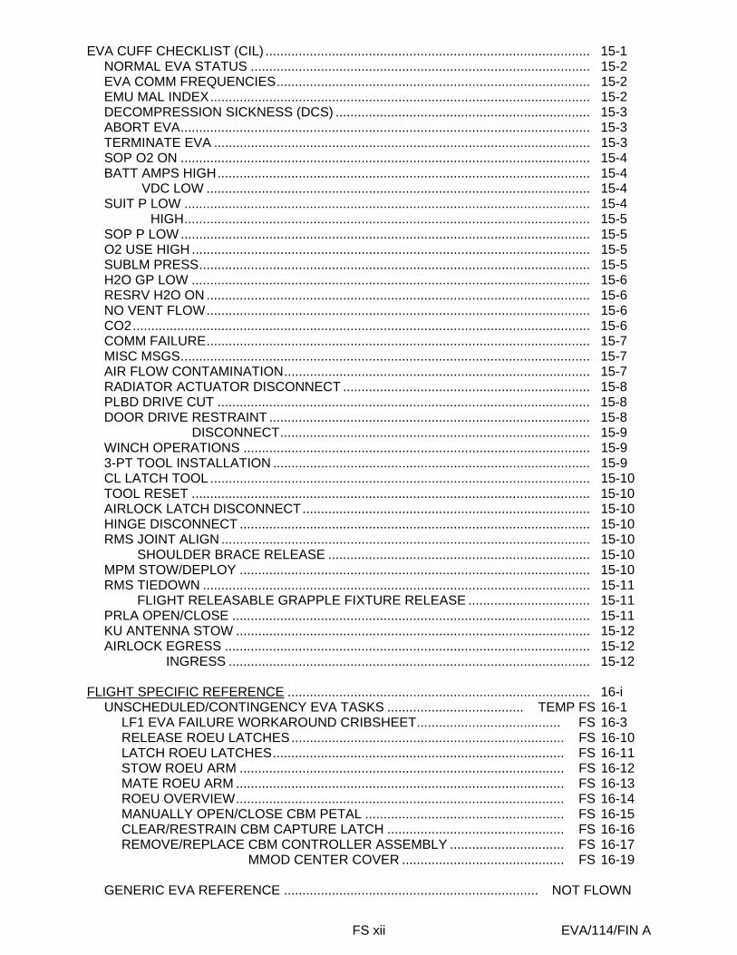
EVA CUFF CHECKLIST (CIL) ........................................................................................ 15-1 NORMAL EVA STATUS ............................................................................................ 15-2 EVA COMM FREQUENCIES..................................................................................... 15-2 EMU MAL INDEX....................................................................................................... 15-2 DECOMPRESSION SICKNESS (DCS) ..................................................................... 15-3 ABORT EVA............................................................................................................... 15-3 TERMINATE EVA ...................................................................................................... 15-3 SOP O2 ON ............................................................................................................... 15-4 BATT AMPS HIGH..................................................................................................... 15-4 BATT VDC LOW ........................................................................................................ 15-4 SUIT P LOW .............................................................................................................. 15-4 SUIT P HIGH.............................................................................................................. 15-5 SOP P LOW ............................................................................................................... 15-5 O2 USE HIGH ............................................................................................................ 15-5 SUBLM PRESS.......................................................................................................... 15-5 H2O GP LOW ............................................................................................................ 15-6 RESRV H2O ON ........................................................................................................ 15-6 NO VENT FLOW........................................................................................................ 15-6 CO2............................................................................................................................ 15-6 COMM FAILURE........................................................................................................ 15-7 MISC MSGS............................................................................................................... 15-7 AIR FLOW CONTAMINATION................................................................................... 15-7 RADIATOR ACTUATOR DISCONNECT ................................................................... 15-8 PLBD DRIVE CUT ..................................................................................................... 15-8 DOOR DRIVE RESTRAINT ....................................................................................... 15-8 DOOR DRIVE DISCONNECT.................................................................................... 15-9 WINCH OPERATIONS .............................................................................................. 15-9 3-PT TOOL INSTALLATION ...................................................................................... 15-9 CL LATCH TOOL ....................................................................................................... 15-10 TOOL RESET ............................................................................................................ 15-10 AIRLOCK LATCH DISCONNECT.............................................................................. 15-10 HINGE DISCONNECT ............................................................................................... 15-10 RMS JOINT ALIGN .................................................................................................... 15-10 RMS SHOULDER BRACE RELEASE ....................................................................... 15-10 MPM STOW/DEPLOY ............................................................................................... 15-10 RMS TIEDOWN ......................................................................................................... 15-11 RMS FLIGHT RELEASABLE GRAPPLE FIXTURE RELEASE ................................. 15-11 PRLA OPEN/CLOSE ................................................................................................. 15-11 KU ANTENNA STOW ................................................................................................ 15-12 AIRLOCK EGRESS ................................................................................................... 15-12 AIRLOCK INGRESS .................................................................................................. 15-12
FLIGHT SPECIFIC REFERENCE .................................................................................. 16-i
UNSCHEDULED/CONTINGENCY EVA TASKS ..................................... TEMP FS 16-1 LF1 EVA FAILURE WORKAROUND CRIBSHEET....................................... FS 16-3 RELEASE ROEU LATCHES.......................................................................... FS 16-10 LATCH ROEU LATCHES............................................................................... FS 16-11 STOW ROEU ARM ........................................................................................ FS 16-12 MATE ROEU ARM ......................................................................................... FS 16-13 ROEU OVERVIEW......................................................................................... FS 16-14 MANUALLY OPEN/CLOSE CBM PETAL ...................................................... FS 16-15 CLEAR/RESTRAIN CBM CAPTURE LATCH ................................................ FS 16-16 REMOVE/REPLACE CBM CONTROLLER ASSEMBLY ............................... FS 16-17 REMOVE/REPLACE MMOD CENTER COVER ............................................ FS 16-19
GENERIC EVA REFERENCE ..................................................................... NOT FLOWN

FS xiii EVA/114/FIN A
FLIGHT SPECIFIC EVA REFERENCE .............................................................. FS 18-1 STS-114 PAYLOAD BAY LAYOUT................................................................ FS 18-3 ESP2 LAUNCH CONFIGURATION (TOP VIEW) .......................................... FS 18-4 ESP2 LAUNCH CONFIGURATION (BOTTOM VIEW) .................................. FS 18-5 ESPAD COMPONENTS................................................................................. FS 18-6 ACTIVE ESPAD ............................................................................................. FS 18-7 ESPAD LAUNCH BOLTS............................................................................... FS 18-8 EUTAS COMPLIANT BOLTS......................................................................... FS 18-9 ESPAD INSTALL............................................................................................ FS 18-10 EUTAS............................................................................................................ FS 18-11 ESPAD STRUT .............................................................................................. FS 18-12 ESPAD STRUT DEPLOY............................................................................... FS 18-13 ESPAD V-GUIDE ........................................................................................... FS 18-14 ESPAD V-GUIDE CLOSEUP ......................................................................... FS 18-15 ESP2 INSTALL............................................................................................... FS 18-16 ESP2 POWER FROM ESP2 TO ORBITER................................................... FS 18-17 ESP2 ORBITER POWER CABLE STOWED ................................................. FS 18-18 ESP2 POWER CABLES................................................................................. FS 18-19 ESP2 FLIGHT CABLES ................................................................................. FS 18-20 ESP2 CABLE TIES......................................................................................... FS 18-21 PRIMARY POWER CABLE ROUTING .......................................................... FS 18-22 SECONDARY CABLE INSTALL – PANEL A119 ........................................... FS 18-23 SECONDARY CABLE ROUTING .................................................................. FS 18-24 ACTIVE ESPAD HR LABELS......................................................................... FS 18-26 PASSIVE ESPAD HR LABELS ...................................................................... FS 18-27 HR AND WIF LAYOUT (ZENITH) .................................................................. FS 18-28 HR AND WIF LAYOUT (NADIR) .................................................................... FS 18-29 MISSE LOCATIONS....................................................................................... FS 18-30 ESP2 FRGF.................................................................................................... FS 18-31 LMC WITH CMG ............................................................................................ FS 18-32 CMG NOMENCLATURE................................................................................ FS 18-33 CMG LOCATION............................................................................................ FS 18-34 AFT Z1 PRE-LAUNCH WITH BLANKET........................................................ FS 18-35 CMG ON Z1.................................................................................................... FS 18-36 CMG SHIMS AT Z1........................................................................................ FS 18-37 BLANKET CLOSED ON CMG IN FSE........................................................... FS 18-38 NEW CMG WITH BLANKET .......................................................................... FS 18-39 CMG IN FSE WITH MLI ................................................................................. FS 18-40 CMG SHIMS ON FSE .................................................................................... FS 18-41 CMG FSE WITHOUT MLI OR CMG............................................................... FS 18-42 CMG SWAP IN PLB ....................................................................................... FS 18-43
EVA EMERGENCY......................................................................................................... 19-i
EMERGENCY PROCEDURES.................................................................................. 19-1 EMERGENCY AIRLOCK REPRESS .................................................................... 19-3
EMERGENCY AIRLOCK REPRESS................................................................ 19-4 POST EMERGENCY AIRLOCK REPRESS..................................................... 19-4
SAFER RESCUE................................................................................................... 19-5 SAFER RESCUE.............................................................................................. 19-6
19.1 DCS TREATMENT...................................................................................... 19-7
CUE CARD CONFIGURATION ................................................................................. 20-1

FS xiv EVA/114/FIN A
This Page Intentionally Blank

TEMP FS 4-1 EVA/114/FIN A
EV
A P
RE
P
EVA PREP
MIDDECK PREP........................................................................................... TEMP FS 4-2 EVA PREP.................................................................................................... TEMP FS 4-2
PREP FOR DONNING............................................................................. TEMP FS 4-2 EMU DONNING.......................................................................................................... 4-4 CHECK.............................................................................................................. 4-5
EMU PURGE .................................................................................................................. 4-6 EMU PREBREATHE....................................................................................................... 4-6
SAFER DONNING ..................................................................................................... 4-6 EVA COMM CONFIG...................................................................................................... 4-8 DECONFIG................................................................................................. 4-8 CO2 RMVL SYS DEACT ................................................................................................ 4-9 ACT ..................................................................................................... 4-9 EVA PREBREATHE CUE CARD...................................................................... FS CC 4-11
114

TEMP FS 4-2 EVA/114/FIN A
EV
A P
RE
P
WARNING Payload bay floods exceed EMU thermal limits during operation. If EVA crew will be operating in vicinity of PLB floods, floods must be turned off now. Cooldown time may be as long as 6 hr
MIDDECK PREP (30 min)
AW18A 1. LTG FLOOD (four) – ON 2. √EVA Bag installed in airlock 3. √REBA sw – OFF
If EMU TV: 4. Demate EMU TV power cable; connect ground plug 5. Disconnect helmets; Velcro to lockers HUT 6. Remove Drink Bag restraint bag 7. Fill Drink Bag from galley, remove gas and insert Drink Bag in restraint
bag 8. Install Drink Bag restraint bag in HUT and dispose of fill tool in wet trash 9. Apply anti-fog (EMU Servicing Kit), wipe off:
Helmets (not Fresnel lens) EV glasses, attach to comm cap
10. Stow EMU Servicing Kit 11. Install Helmets; lock 12. Attach Cuff C/L to EMUs EVA PREP (90 min)
MET / : MET / : MET / :
PREP FOR DONNING (30 min)
If internal airlock: ML31C 1. √VAC VENT ISOL VLV CNTL tb – OP
√NOZ HTR – ON If external airlock:
BOTH DCM 2. Retrieve, position SCU; remove DCM cover 3. Connect SCU to DCM, √locked AW82B 4. EV-1,EV-2 O2 vlv (two) – op MO13Q 5. √ARLK H2O S/O VLV – OP (tb-OP) MD(flr) 6. √EMU O2 ISOL VLV – OP ML86B:C 7. √cb MNC EXT ARLK HTR ZN 1,2 (two) – op L2 8. √O2 XOVR SYS 1,2 (two) – OP BOTH DCM 9. PWR – BATT
CAUTION EMU must be on BATT pwr when airlock power supply turned on
AW18H 10. PWR/BATT CHGR EMU 1,2 MODE (two) – PWR
BUS SEL (two) – MNA(MNB) DCM 11. PWR – SCU 12. Verify panels as shown next page
114EVA/ALL/FIN A

FS CC 4-11 EVA/114/FIN A
(reduced copy)
FS CC 4-12 EVA/114/FIN A
(reduced copy)
FS 7-1 EVA/114/FIN A
TIM
EL
INE
S
TIMELINES EVA 1 (TBD) ............................................................................................................ FS 7-3 EVA 2
EVA 2 INHIBIT PAD............................................................................................ FS 7-5 NOTES, CAUTIONS, AND WARNINGS............................................................. FS 7-6 EVA 2 BRIEFING CARD..................................................................................... FS 7-7 EVA 2 SUMMARY TIMELINE ............................................................................. FS 7-8 EVA 2 TOOL CONFIG ........................................................................................ FS 7-9 EVA 2 EGRESS/SETUP ..................................................................................... FS 7-10 CMG R&R (HC)................................................................................................... FS 7-12 CLEANUP/INGRESS .......................................................................................... FS 7-17
EVA 3 EVA 3 INHIBIT PAD............................................................................................ FS 7-19 NOTES, CAUTIONS, AND WARNINGS............................................................. FS 7-20 EVA 3 BRIEFING CARD..................................................................................... FS 7-21 EVA 3 SUMMARY TIMELINE ............................................................................. FS 7-22 EVA 3 TOOL CONFIG ........................................................................................ FS 7-23 EVA 3 EGRESS/SETUP ..................................................................................... FS 7-24 ESPAD INSTALL (HC)........................................................................................ FS 7-25 PRIMARY CABLE ROUTING ............................................................................. FS 7-28 MISSE 1 AND 2 RETRIEVAL ............................................................................. FS 7-29 MISSE 5 INSTALL .............................................................................................. FS 7-30 SECONDARY CABLE ROUTING ....................................................................... FS 7-31 ESP2 INSTALLATION ........................................................................................ FS 7-33 ESP2 FRGF REMOVE AND STOW ................................................................... FS 7-35 CLEANUP/INGRESS .......................................................................................... FS 7-36

FS 7-2 EVA/114/FIN A
TIM
EL
INE
S
This Page Intentionally Blank

FS 7-3 EVA/114/FIN A
EV
A 1
EVA 1
TBD

FS 7-4 EVA/114/FIN A
EV
A 1
This Page Intentionally Blank

EVA 2 INHIBIT PAD
FS 7-5 EVA/114/FIN A
MCS MCC-M 1. √FGB Main Engine Thruster Valves (4) – closed 2. √FGB Manifold Valves (18) – closed 3. √FGB MCS unpowered 4. √SOYUZ manifolds (ten) closed 5. √SOYUZ MCS unpowered
RCS If EV crew < 27 ft from FRCS: IV 1. √DAP: √FREE, LO Z O14,15,16 2. √RJDF F1, F2, F3, F4 MANF DRIVER (four) – OFF MCC 3. √Above RCS config
Orbiter Antennas
NOTE Possible loss of comm when forced LL FWD antenna
IV If EV crew < 1.6 ft from S-Band antenna: A1R 1. S-BAND FM ANT – XMIT LOWER/RCVR UPPER O14,15,16 2. √MCC, lower antenna selected If no comm, or on MCC call: C3 3. S-BAND PM ANT – LL FWD When EVA crewmember at least 1.6 ft away from all S-Band upper antennas: C3 4. S-BAND PM ANT – GPC MCC-H 5. √KU-BAND Mask active
LAB Window IV If EV crew near window, close window shutter
FGB Antennas MCC-M 1. √TORU [TOPY] – Deactivate 2. √TV System [TBC] – Deactivate 3. √KURS P [Kurs] – Deactivate 4. √KURS A [Kurs] – Deactivate 5. √Sirius – Deactivate SOYUZ Antennas MCC-M 1. √KURS – Deactivate
SM Antennas (MCC-M) MCC-M 1. Global Timing Sys 1 & 2 [GTS] – Deactivate
PCU
NOTE PCUs may require up to 1 hr warm-up period before they are operational
MCC-H 1. √PCUs (two) operational, in discharge mode OR √1 PCU operational in discharge mode OR √One solar arrays oriented at least 105 deg from velocity vector
USOS Antennas MCC-H 1. SGANT (KU) – Mask for EVA Worksites
CMG Inhibits MCC-H 1. Verify EA Power Removal and Inhibit S0:EPS:RPCM S01A D: RPC 17 RPCM S01A D RPC 17 √RPC Position – Op √Close Cmd – Inh 2. Verify THA Power Removal and Inhibit Z1:EPS:RPCM Z13B B: RPC 10 RPCM Z13B B RPC 10 √RPC Position – Op √Close Cmd – Inh
NOTE: EV crew should not go more zenith than the IEA bulkhead to avoid S-band antenna high gain keep-out zone (3.6 ft in high gain, 1.3 ft in low gain)
EVA 2

NOTES, CAUTIONS, AND WARNINGS EVA 2
FS 7-6 EVA/114/FIN A
NOTES
Verify connectors for debris, bent pins, and cable bend radii
CAUTION
Avoid inadvertent contact with: Grapple fixture shafts (have coating)
Grapple fixture target pin SVS Targets SSRMS/MBS operating cameras & lights (heat
source) MBSVDU, MCU, CRPCMs & Cameras (silver
Teflon tape radiative surface) Passive UMA Deployed TUS cable PMA1 MDM sunshade PMA2 TCS Reflector EVA crane APAS hardware Deployed MISSEs (A/L) CID Switches Z1 PCU Cathode Ports Z1 heat pipe radiators/coldplates SASA – Antenna and Z-93 paint (Z1 & P6) P6 FPP S0 Radiators (silver Teflon tape)
Avoid inadvertent contact with: S0 GPS Antenna (Z-93 paint) Lights (Z-93 paint)
CAUTION (Cont)
EVA connectors may become hot if left uncovered. Limited handling may be needed PMA handrails may be hot. Handling may need to be limited Keepout zone: EVA UHF PLB Antenna (stbd sill) Low power = 0.5 ft (nominal) High power = 2.3 ft above 1.3 ft sides Keepout zone: WVS Antenna (stbd sill) – none For structural reasons: Avoid vigorous body motions, quick grabs, and kickoff tether restraints Avoid performing shaking motions (sinusoidal functions) more than four cycles If any of these occur, wait 2-5 min to allow structural response to dissipate Avoid contact with ROEU power connectors that are below the payload bay sill. Low impact force or contact can cause hardware damage
WARNING PMA umbilical launch restraints have exposed bolt threads (sharp) EVA connectors present a pinch hazard. Caution should be used when mating/locking connectors Fuse tether buckles stowed in Node bag may have sharp edges During Lab window shutter operations, the EV crew must be clear of the Lab window EV side of crew lock hatch is a potential pinch point and snag hazard during hatch operations Avoid inner edges of WIF sockets due to potential sharp edges TBD PRLA grounding wiper is a sharp edge hazard
EVA 2

FS 7-7 EVA/114/FIN A
EVA 2 BRIEFING CARD
EV1 – Soichi EV2 – Steve IV – Andy SSRMS: M1 – Wendy M2 – Vegas EVA Prep start MET: ____ / ____ ____ : ____ ____ Start dressing at MET: ____ / ____ ____ : ____ ____ i.e., _____ hours after wake up EVA Prep Get-up plan – Clothing and WCS usage in post-sleep period Food/Drink in A/L ? IDB fills (night before) Equipment lock activities – Overall big picture Prebreathe protocol review Suit donning plan – any special requests ? Boot Bladder Manipulation ? SAFER, MWS, tools, CL positions, bag stowage – any deviations from standard ? Airlock depress review EV/IV comm protocol SRMS/SSRMS initial position – any deviations from training ? Crib sheet review – only big ticket items (CMG rapid-safing, CIPAA gun safing) EV Crew Procedure Review Overall Timeline – just talk big picture, initial tether config, critical ops Any deviations from trained plan ? Any late additions from the Ground ? Any unplanned constraints ? Any get ahead tasks ? RMS operations – comm protocol/clearances – any off-nominal operations ? Specific Items to remember (clearances, tether ops, interference opportunities, photos, etc) Unplanned Activities Any late requests from ISS expected ? Emergencies Review Lost comm. – check location, show cuff C/L in WVS or bend backwards EMU malfunctions – call it out, all get on same page Lost tools – don’t rush, don’t chase unless easy reach Lost crewmember – Call Code L, IV to give location directions etc. SAFER ops reminders DCS procedures – Call Cuff Checklist, or potential Cuff Checklist Incapacitated crewmember – work slow, bring him in, safe site Post EVA Suit doffing responsibilities Post EVA plan Any special food/drink requests ? Make sure WCS and galley are available to EV crew Any lessons learned from prior EVA’s:

EVA 2 SUMMARY TIMELINE
FS 7-8 EVA/114/FIN A
PET EVA 2 TIME
(HR : MIN) IV/SSRMS EV1 (SSRMS) EV2 (FF) 00:00 ---SSRMS: APFR INGRESS EVA 2 EGRESS/SETUP (01:15) EVA 2 EGRESS/SETUP (01:15)
- ■ POST DEPRESS and EGRESS (00:15) ■ POST DEPRESS and EGRESS (00:15) - ■ SETUP (01:00) ■ SETUP (01:00)
--SSRMS: NODE LIGHT REMOVAL SSRMS APFR setup and ingress Node gap spanner install - - Temp stow Node Light Stanchion
01:00 ---SSRMS: Z1 ACCESS (GCA) CMG shroud removal - - CMG R & R (04:15) CMG R & R (04:15)
-- ■ REMOVE FAILED CMG (00:40) ■ REMOVE FAILED CMG (00:40) - Demate connectors Unbolt CMG, shims - Unbolt CMG, shims, remove from soft dock
02:00 ---SSRMS: MANEUVERING TO PAYLOAD BAY ■ REMOVE NEW CMG (01:30) ■ REMOVE NEW CMG (01:30) - SSRMS translation to PLB TPS durometer test - Ballstack setup
-- Temp stow failed CMG Temp stow failed CMG - Unbolt new CMG, temp stow Unbolt new CMG, temp stow -
03:00 --- - -
-- ■ INSTALL FAILED CMG (01:00) ■ INSTALL FAILED CMG (01:00) - Retrieve failed CMG Retrieve failed CMG - Bolt failed CMG to FSE Bolt failed CMG to FSE
04:00 --- Retrieve new CMG -SSRMS: MANEUVERING TO Z1 SSRMS translation to Z1 CMG PLB tool cleanup -
-- ■ INSTALL NEW CMG (00:45) ■ INSTALL NEW CMG (00:45) - Bolt new CMG to Z1 Bolt new CMG to Z1 - Mate CMG connectors Mate CMG connectors
05:00 --- - ■ REPLACE THERMAL SHROUD (00:20) ■ REPLACE THERMAL SHROUD (00:20) -
--SSRMS: NODE LIGHT STANCHION INSTALLATION CLEANUP/INGRESS (01:00) CLEANUP/INGRESS (01:00) - ■ CLEANUP (00:35) ■ CLEANUP (00:35) -SSRMS: APFR EGRESS Install node light stanchion Install node light stanchion
06:00 --- SSRMS APFR cleanup - ■ INGRESS and PRE REPRESS (00:25) ■ INGRESS and PRE REPRESS (00:25) -
--EVA Time 6:30

EVA 2 TOOL CONFIG
FS 7-9 EVA/114/FIN A
Pre-EVA 2 Tool Configuration Post-EVA 2 Tool Configuration
AIRLOCK
! Fuse Tether ! Spare PGT ! WIF Extender w/Adj Tether ! (zenith HR) ! F5 Camera ! Digital Camera ! Crewlock EVA Bag #1 (Aft UIA D-ring) ! 11/16” box end wrench ! Durometer ! Ball Stack ! MUT EE (2) ! Trash Bag ! Gap Spanner (72-in) (2) ! Gap Spanner (21-in) ! RET (lg-sm) (2) ! Adj Tether (2) ! Safety Tether ! AL D-ring Extender ! RET
Crewlock Endcone Bags
Staging Bag ! Connector Cleaner Tool Kit ! MUT EE ! Wire Tie Caddy (long and short) IV Bag ! ISS Contamination Sampler (2) ! Draeger Tubes (6) ! Gold Salt Kit ! Socket Caddy ! Socket, 6-in ext ! Socket, 1/2 in drive, 8-in ext ! GP Caddy (2) ! Thermal Mitten pairs (2) ! EVA Ratchet ! DCM plug ! Ziplock bag w/2 towels
PMA1-WIF 02
! Ballstack (on tool stanchion)
SSRMS
! APFR w/WIF adapter
EV1
! MWS ! Right Swing Arm ! PGT, RET ! T-Bar w/wire ties (2) Trash Bag (sm) ! Socket Caddy ! Socket, 12-in ext ! RAD, 2-in ext ! Socket, 6-in ext ! RET Tether (2) ! Adj Tether (2) ! BRT w/2 wire ties, RET ! RET (sm/lg) ! Adj Tether (2, each wrist) ! Waist Tether (2) ! D-ring Extenders (2) ! Safety Tether (L) ! Safety Tether (R) ! Ingress Aid
EV2
! MWS ! Right Swing Arm ! PGT w/6-in ext, RET ! T-Bar w/wire tie (2) ! Socket Caddy ! RET Tether (2) ! Adj Tether (2) ! BRT w/2 wire ties, RET ! Adj Tether (left wrist) ! Waist Tether (2) ! D-ring Extenders (2) ! Safety tether (85 ft) (R) Record: Spare PGT (serial ______, bat # ______) EV1 PGT (serial ______, bat # ______) EV2 PGT (serial ______, bat # ______) RAD (serial # _______)
AIRLOCK
! Fuse Tether ! Spare PGT ! Wire Tie Caddy ! F5 Camera (2) ! MUT EE ! Crewlock EVA Bag #1 ! Durometer ! 11/16” box end wrench ! F5 Camera ! Adj Tether (2) ! MUT EE (2) ! Ball stack ! RET tether (lg/sm) (2)
PMA1-WIF 02
! Ballstack (on tool stanchion)
AIRLOCK TOOLBOX #1
! APFR
EV1
! MWS ! Right Swing Arm ! PGT, RET Tether ! T-Bar w/wire ties (2) ! Trash Bag (sm) ! Socket Caddy ! Socket, 12-in ext ! RAD, 2-in ext ! Socket, 6-in ext ! WIF Adapter, RET Tether (sm/lg) ! RET Tether (sm-sm) (2) ! Adj Tether (3) ! BRT w/2 wire ties, RET Tether ! Adj Tether (2) ! Waist Tether (2) ! D-ring Extenders (2) ! Safety Tether
EV2
! MWS ! Right Swing Arm ! PGT w/6-in ext, RET Tether ! T-Bar w/wire tie (2) ! Socket Caddy ! Trash Bag (sm) ! RET Tether (sm-sm) (2) ! Adj Tether (2) ! BRT w/1 Wire Tie, RET Tether ! Adj Tether (1 left wrist) ! Waist Tether (2) ! D-ring Extenders (2) ! Safety tether (85 ft) ! Safety tether

EVA 2 EGRESS/SETUP
FS 7-10 EVA/114/FIN A
IV/RMS EV1 (SSRMS) EV2 (FF)
1. SSRMS: APFR INGRESS (ROBOTICS FS, EVA 2) 2. ISS views for Egress/Setup: PLB C, D
EV2
EV1
A/L D-Ring Extender
Waist Tether
Safety Tether (85 ft)
Waist Tether
D-Ring Extender
D-Ring Extender
Safety Tether
3. ISS view for EV1 Ingress: PLB A, B 4. MCC-H: perform CMG Power Inhibits 5. SSRMS: NODE LIGHT REMOVAL (ROBOTICS FS, EVA 2)
Initial Configuration: Waist tether (L) to EV2 Safety Tether (R)
POST DEPRESS (00:05)
Perform POST DEPRESS (EVA, DEPRESS/REPRESS)
EGRESS (00:10)
1. Open A/L thermal cover 2. Egress airlock 3. Check SAFER valves (down) 4. Attach right safety tether to fwd external A/L D-ring, verify
hook locked 5. Attach EV2 safety tether to aft external A/L D-ring, verify
hook locked 6. Give EV2 GO for egress
SETUP (01:00)
7. Translate to SSRMS setup worksite (port Z1, via fwd A/L translation path)
8. Perform Safety tether swap to SSRMS, verify hook locked 9. Remove A/L safety tether from EV1 D-ring extender, stow
on Node HR 6013 10. Configure SSRMS APFR[12,PP,F,4] 11. Install Ingress aid 12. Ingress APFR 13. Assist EV2 with Node stanchion light removal; light’s white
paint is no touch area 14. GCA SSRMS to shroud removal worksite
Initial Configuration: Waist tether (L) to A/L D-ring extender. Safety Tether (R) to EV1 Waist tether (L)
POST DEPRESS (00:05)
Perform POST DEPRESS (EVA, DEPRESS/REPRESS)
EGRESS (00:10)
1. Hold for EV1 GO 2. Release left waist tether from A/L D-ring extender 3. Retrieve Crewlock bag 4. Egress A/L w/Crewlock bag on BRT 5. Check SAFER valves (down) 6. Close hatch thermal cover
SETUP (01:00)
7. Verify Crewlock bag on BRT 8. Translate to Z1 worksite (via aft translation path) 9. Watch all SSRMS clearances at Z1 worksite as required 10. Temp stow Crewlock bag on Node HR 0122 11. Remove box end wrench from Crewlock bag; stow on
Node HR 0122 w/RET from MWS 12. Remove gap spanners/trash bag from Crewlock bag; stow
on MWS 13. Install gap spanners in series on Node HRs 0122 (aft
standoff) and 0121 (aft standoff), adj. end towards middle. Rotate buckle of gap spanner 90 degrees to ensure tension load is not too great
14. Remove Node light stanchion, light’s white paint is no touch area
15. PGT[B6, CCW2, 30.5]-6Ext-7/16: Release stanchion bolt, 11 turns, fold stanchion towards Node, tether stanchion to Node HR 0106 away from Z1 worksite

EVA 2 EGRESS/SETUP (Cont)
FS 7-11 EVA/114/FIN A
IV/RMS EV1 (SSRMS) EV2 (FF)
SSRMS: Z1 ACCESS (ROBOTICS FS, EVA 2) 15. Remove Velcro and peel back Z1 CMG thermal shroud to gain access to CMG 1. Attach adj equip tether to MLI. Hand off to EV2
16. Perform WVS survey of failed CMG on Z1 ! WVS complete
16. Restrain CMG thermal shroud by attaching adj equip tether to Z1 short HR 6002. Attach 2nd adj equip tether to MLI and stbd IAPFR
17. Retrieve ball stack from TS on PMA1, WIF02, stow in crewlock bag. Inspect ball stack sleeve and report if the sleeve is torn; ball stack will be NO GO

CMG R&R
FS 7-12 EVA/114/FIN A
IV/RMS EV1 (SSRMS) EV2 (FF)
1. IV: Verify with MCC inhibits for CMG 1 prior to EV1 action 2. MCC: Confirm CMG EA/THA Power Removal and Inhibits
from CMG R & R Task Data Sheet
3. SSRMS: On EVA GO, MANEUVERING TO PAYLOAD
BAY (ROBOTICS FS, EVA 2) 4. ISS views while in PLB: PLB A, B, no big picture needed 5. Record STA-54 Hardness Check Results:
Reading # Reading 1
2
3
REMOVE FAILED CMG (00:40)
1. On IV GO, demate connector: !J6 – tuck behind CMG #2 HR
2. Demate connectors: !J1 !J2 !J3
3. Temp stow connectors (3) with wire tie to Z1 HR 6021 4. PGT[B7, CCW2, 30.5] –12Ext-7/16: Loosen CMG bolts (4),
2 turns each, any order: !3 !4 !1 !2
5. PGT[A6, CCW2, 10.5] –12Ext-7/16: Remove shims (2), place in trash bag, expect 10-14 turns, any order
!3c !3d 6. Tether to CMG HR using lg/sm RET equip tether before
removing last bolt 7. PGT[B7, CCW2, 30.5] –12Ext-7/16: Remove CMG bolts
(4), expect 9-13 turns, any order: !3 !4 !1 !2
8. Remove CMG from soft dock. Expect 16 lb force 9. Replace CMG into soft dock and remove to verify alignment 10. Give SSRMS GO to translate to LMC
REMOVE NEW CMG (01:30)
REMOVE FAILED CMG (00:40)
1. Assist EV1 as required 2. BRT to CMG HR 3. PGT[B7, CCW2, 30.5] –6Ext-7/16: Loosen CMG bolts (2),
2 turns each, any order: !5 !6
4. When all 6 bolts loosened, wiggle CMG 5. PGT[A6, CCW2, 10.5] –6Ext-7/16: Remove shims (2),
place in trash bag, expect 10-14 turns, any order !6c !6d
6. Release BRT from CMG HR 7. PGT[B7, CCW2, 30.5] –6Ext-7/16: Remove CMG bolts (2),
expect 9-13 turns, any order: !5 !6
8. Assist EV1 until CMG clear of structure, verify EV1 has good EMU boot to APFR bootplate mate
9. Perform WVS survey of CMG location after removal of
failed CMG ! WVS survey complete
REMOVE NEW CMG (01:30)
10. Retrieve Crewlock bag from Node HR 0102, stow on BRT 11. Translate to shuttle ODS truss, via stbd ISS 12. Remove spare safety tether from Crewlock bag, attach to
ODS truss, verify hook locked 13. Attach spare safety tether to EMU D-ring extender, verify
hook locked 14. Remove A/L 85 ft safety tether from D-ring, stow on PMA
structure 15. Translate to LMC, fairlead safety tether on sill 16. Temp stow Crewlock bag on LMC, retrieve durometer 17. Remove pip pins (2) and open test port on DTO box 18. Measure TPS repair hardness (3 readings)
19. Close test port, install pip pins (2) 20. Stow durometer in Crewlock bag

CMG R & R (Cont)
FS 7-13 EVA/114/FIN A
IV/RMS EV1 (SSRMS) EV2 (FF)
11. Hold failed CMG on lower inboard ball stack/MUT EE 12. GCA SSRMS to new CMG 13. PGT[B7, CCW2, 30.5] –12Ext-7/16: Loosen CMG bolts
(4), 2 turns each, any order: !3 !4 !2
14. PGT[A6, CCW2, 10.5] –12Ext-7/16: Remove shims (2), place in trash bag, expect 10-14 turns, any order
!3c !3d 15. Tether to CMG HR using lg/sm RET equip tether before
last bolt 16. PGT[B7, CCW2, 30.5] –12Ext-7/16: Remove CMG bolts
(4), expect 9-13 turns, any order: !3 !4 !2
17. Remove CMG 3 in from soft dock. Expect 16 lb force 18. Replace CMG into soft dock and remove to verify
alignment 19. GCA SSRMS to temp stow location 20. Hold new CMG on upper ball stack/MUT EE 21. Remove tether from new CMG INSTALL FAILED CMG (01:00)
22. GCA to failed CMG 23. Tether to failed CMG 24. Remove failed CMG from ball stack/MUT EE after EV2
releases MUT EE 25. Insert CMG into FSE soft dock position on LMC, expect
16 lb force 26. PGT[B7, CW2, 30.5] – 12Ext-7/16: Install CMG bolts (3),
2 turns each: !3 !4 !2
27. Remove RET tether from CMG
21. Install ball stack and MUT EE to upper outboard LMC ECOM, attach lg/sm RET to LMC HR standoff, position ball stack 15 degrees to port
22. Route safety tether over lower ball stack 23. Install 2nd ball stack and MUT EE to lower inboard LMC
ECOM, attach lg/sm RET to LMC HR standoff 24. Assist EV1 with CMG temp stow, attach MUT EE to CMG,
attach lg hook of RET to CMG 25. Open CMG FSE thermal shroud, restrain as required 26. PGT[B7, CCW2, 30.5] –6Ext-7/16: Loosen CMG bolts (2),
2 turns each, any order: !1 !5 !6
27. PGT[A6, CCW2, 10.5] –6Ext-7/16: Remove shims (2), place in trash bag, expect 10-14 turns, any order
!6c !6d 28. PGT[B7, CCW2, 30.5] –6Ext-7/16: Remove CMG bolts (2),
expect 9-13 turns, any order: !1 !5 !6
CAUTION Avoid CMG contact with orbiter aft bulkhead WVS antenna
29. GCA EV1 to avoid WVS antenna 30. BRT to LMC, turn on left side, feet to sill 31. Assist EV1 with CMG temp stow, attach MUT EE to CMG,
attach lg hook of RET to CMG 32. Release BRT, slide feet down on port side PLB
INSTALL FAILED CMG (01:00)
33. Release failed CMG RET tether from failed CMG after EV1
tether to CMG 34. Release CMG from MUT EE 35. Route safety tether under ballstack, translate to FSE 36. GCA EV1 to avoid WVS antenna 37. Assist EV1 as required 38. PGT[B7, CW2, 30.5] –6Ext-7/16: Install CMG bolts (3),
2 turns each: !1 !5 !6

CMG R & R (Cont)
FS 7-14 EVA/114/FIN A
IV/RMS EV1 (SSRMS) EV2 (FF)
6. IV: Record Installation values:
Bolt Turns Torque
CMG02 Bolt 3
CMG02 Bolt 4
CMG02 Bolt 5
CMG02 Bolt 6
CMG02 Bolt 1
CMG02 Bolt 2
ADJ SHIM 3A
ADJ SHIM 6A
ADJ SHIM 3B
ADJ SHIM 6B
7. SSRMS: On EVA GO, MANEUVER TO Z1 (ROBOTICS FS,
EVA 2) 8. ISS views while moving to Z1: PLB A, B
28. PGT[B7, CW2, 30.5] –12Ext-7/16: Torque CMG bolts (3),
expect 9-13 turns to a torque stall: !3 !4 !2
Report torque/turns
29. PGT: Swap 12Ext-7/16 to RAD, 2Ext-7/16 30. PGT[A1, CCW1, 5.5] –RAD,2Ext-7/16: Drive adjustable
shim bolts bolts (2) to contact or torque stall, no pattern: !3a !3b
Report torque/turns
31. GCA to new CMG 32. Tether to new CMG 33. Give EV2 GO for ballstack release 34. Retrieve new CMG (MUT EE/Ballstack w/RET remain on
CMG) after EV2 releases ball stack from LMC 35. Give SSRMS GO for Z1 install position
INSTALL NEW CMG (00:45)
36. Hold CMG for EV2 to remove ball stack/MUT EE 37. Insert CMG into soft dock position on Z1. Expect 16 lb
force 38. PGT[B7, CW2, 30.5] –12Ext-7/16: Install CMG bolts (4),
2 turns each: !3 !4 !1 !2
39. Remove tether from CMG
21. PGT[B7, CW2, 30.5] –6Ext-7/16: Torque CMG bolts (3),
expect 9-13 turns to a torque stall: !1 !5 !6
Report torque/turns
22. PGT[A1, CCW1, 5.5] –6Ext-7/16: Drive adjustable shim
bolts bolts (2) to contact or torque stall, no pattern: !6a !6b
Report torque/turns
23. Move lg/sm RET from LMC HR to ball stack on new CMG 24. Release new CMG w/ball stack from LMC on EV1 GO 25. Verify EV1 has good EMU boot to APFR bootplate mate 26. Retrieve lower LMC ball stack/MUT EE and lg/sm RET, stow
in Crewlock bag 27. Stow Crewlock bag on BRT 28. Survey worksite for tool inventory, retrieve sill fairlead
INSTALL NEW CMG (00:45)
29. Translate to PMA, retrieve A/L 85ft safety tether, attach to EMU D-ring extender, verify locked
30. Remove spare safety tether from ODS truss and EMU D-ring, stow in Crewlock bag
31. Translate to Z1 worksite 32. Watch all SSRMS clearances at Z1 worksite as required 33. Temp stow Crewlock bag on Node HR 0122 34. Remove Ballstack/MUT EE/RET from CMG. Temp stow 35. Check for FOD in CMG receptacle before installation 36. Assist EV1 with CMG soft dock 37. PGT[B7, CW2, 30.5] –6Ext-7/16: Install CMG bolts (2),
2 turns each: !5 !6

CMG R & R (Cont)
FS 7-15 EVA/114/FIN A
IV/RMS EV1 (SSRMS) EV2 (FF)
9. IV: Record installation values
Bolt Turns Torque
CMG05 Bolt 3
CMG05 Bolt 4
CMG05 Bolt 5
CMG05 Bolt 6
CMG05 Bolt 1
CMG05 Bolt 2
10. IV: Give MCC-H GO for THA power-up 11. If MCC-H unable, ISS crew perform VERIFYING CMG
THERMAL HOUSING ASSEMBLY (THA) CONNECTOR MATE (ASSY OPS, CMG 1 On Orbit Checkout, Steps 1-2)
12. IV: Give MCC-H GO for EA power-up 13. If MCC-H unable, ISS crew perform VERIFYING CMG
ELECTRONICS ASSEMBLY (EA) CONNECTOR MATE (ASSY OPS, CMG 1 On Orbit Checkout, Step 3)
14. IV: Report CMG R & R complete to MCC
40. PGT[B7, CW2, 30.5] –12Ext-7/16: Torque CMG bolts (4), expect 9-13 turns to a torque stall:
!3 !4 !1 !2
Report torque/turns
41. De-configure PGT socket 42. Demate connector caps (1), stow in trash bag:
!J6 43. Mate connector:
!J6 44. Confirm J6 complete, GO for THA power-up
45. Demate connector caps (3), stow in trash bag: !J1 !J2 !J3
46. Mate connectors: !J1 !J2 !J3
47. Confirm J1, J2, J3 complete, GO for EA power-up
48. Perform WVS survey of final CMG configuration
! WVS survey complete
REPLACE Z1 THERMAL SHROUD (00:20)
49. Replace Z1 thermal shroud and attach Velcro 50. Give IV CMG INSTALL COMPLETE
38. PGT[B7, CW2, 30.5] –6Ext-7/16: Torque CMG bolts (2), expect 9-13 turns to a torque stall:
!5 !6 Report torque/turns
39. Stow ball stack on PMA TS, MUT EE, and sm/lg RET in
Crewlock bag 40. Assist EV1 if required 41. Retrieve 11/16” box end wrench from Node HR 0122
REPLACE Z1 THERMAL SHROUD (00:20)
42. Replace Z1 thermal shroud and attach Velcro (use box end wrench as required)

CMG R & R – TASK DATA
FS 7-16 EVA/114/FIN A
Tools: EV1 (SSRMS) EV2 (FF)
PGT PGT 7/16 (wobble) socket-12 ext 7/16 (wobble) socket-6 ext RAD
EVA Fasteners:
Fastener Name
Label Head Size
Qty Install Torque (ft-lb)
Release Torque (ft-lb)
Failure Torque (ft-lb)
Turns
CMG at Z1 Bolts
7/16 6 22.92 21.7 26.7 10
CMG Shims (fixed, Z1)
7/16 4 5.0 8.0 9.17 10.9
CMG Shims (fixed, FSE)
7/16 4 5.0 8.0 9.17 10.9
CMG at FSE Bolts
7/16 6 22.92 21.7 26.7 10
CMG Shims (adjustable)
7/16 4 2.5 N/A 5.6 2-5
Node Light Stanchion Bolt
7/16 1 23.0 22.5 37.5 10, 16.5
EVA Connectors:
Harness From To Conn Size
Function
CMG J6 Failed CMG, P6 New CMG, P6 15 PWR to THA CMG J1 Failed CMG, P1 New CMG, P1 15 PWR to EA CMG J2 Failed CMG, P2 New CMG, P2 15 Primary Data Bus, LB
GNC-1, Channel A CMG J3 Failed CMG, P3 New CMG, P3 15 Secondary Data Bus,
LB GNC-1, Channel B Foot Restraints:
Task WIF APFR Setting ALL SSRMS 12, PP, F, 4
Warnings: 1. The pop-up spring on the CMG captive EVA fasteners (CMG Bolts
1-6) presents a puncture hazard Cautions:
1. Avoid inadvertent contact with CMG 2. CMG Shims must be removed within 2 hrs of CMG powerdown on
Z1 3. Equal force should be exerted by crew in order to prevent binding
when removing/installing the CMG from its mounting on Z1 and the FSE
4. CMG may have oily residue around the Torque Module Assembly, avoid contact (may cause damage to other ORUs through cross-contamination)
5. Avoid contact with Optical Solar Reflector Tiles on Z1 heat pipe radiators at the DDCU-HP and RPDAs. These items can be damaged by kick loads
CMG Inhibits: MCC-H 1. Verify EA Power Removal and Inhibit S0:EPS:RPCM S01A D: RPC 17 RPCM S01A D RPC 17 √RPC Position – Op √Close Cmd – Inh 2. Verify THA Power Removal and Inhibit Z1:EPS:RPCM Z13B B: RPC 10 RPCM Z13B B RPC 10 √RPC Position – Op √Close Cmd – Inh

CLEANUP/INGRESS
FS 7-17 EVA/114/FIN A
IV/RMS EV1 EV2
1. SSRMS: NODE LIGHT STANCHION INSTALLATION (ROBOTICS FS, EVA 2)
Bolt Turns Torque
Node Light
2. SSRMS: APFR EGRESS (ROBOTICS FS, EVA 2) 3. IV: Record WIF # where WIF extender is stowed:
Item WIF
WIF Extender
4. IV: Perform tool inventory
CLEANUP (00:35)
1. Assist EV2 with node light install. Position stanchion as required
2. Egress SSRMS 3. Perform tether swap to A/L tether 4. Configure APFR[6, XX,L,2] to low profile 5. Receive WIF extender from EV2 6. Stow WIF extender in WIF ____
INGRESS (00:20)
7. Translate to Airlock 8. Perform tool inventory 9. Remove spare left safety tether, stow on aft external A/L
D-ring and aft A/L HR, verify locked 10. After EV2 GO, remove EV2 85 ft safety tether from aft
external A/L D-ring, attach to EV1 left waist tether 11. Remove EV1 right safety tether from EMU D-ring extender
and stow on fwd A/L HR 12. √Reels unlocked, retract cable slack 13. Ingress A/L 14. Connect SCU to DCM; check SCU locked 15. Water – OFF 16. Close thermal cover, attach Velcro strap
CAUTION Do not close hatch until EMU water off for 2 min
17. EV Hatch – close and lock 18. Go to PRE REPRESS portion of {CREWLOCK
DEPRESS/REPRESS CUE CARD} (SODF: ISS EVA SYS: EVA PREP/POST)
CLEANUP (00:35)
1. Stow 11/16” box end wrench in Crewlock bag 2. Install Node light stanchion: Release tether from HR 0106.
Hand off stanchion to EV1 to posn 3. PGT[B5, CW2 30.5]-6Ext-7/16: Install stanchion bolt, 11
turns to a torque stall – if required: PGT[B2, CW2 30.5]-RAD-6Ext-7/16: Install stanchion bolt, 11 turns to a torque stall
4. Perform WVS survey of final Node Light configuration ! WVS survey complete
5. Retrieve Crewlock bag from Node HR 0102
INGRESS (00:20)
6. Translate to Airlock 7. Perform tool inventory 8. Open thermal cover 9. Ingress A/L 10. Retrieve WIF extender from A/L, hand to EV1 11. Attach left waist tether to A/L D-ring extender 12. Give EV1 GO for tether ops 13. Connect SCU to DCM; check SCU locked 14. Water – OFF 15. Go to PRE REPRESS portion of {CREWLOCK
DEPRESS/REPRESS CUE CARD} (SODF: ISS EVA SYS: EVA PREP/POST)

FS 7-18 EVA/114/FIN A
This Page Intentionally Blank

EVA 3 INHIBIT PAD
FS 7-19 EVA/114/FIN A
MCS MCC-M 1. √FGB Main Engine Thruster Valves (4) – closed 2. √FGB Manifold Valves (18) – closed 3. √FGB MCS unpowered 4. √SOYUZ manifolds (ten) closed 5. √SOYUZ MCS unpowered
RCS If EV crew < 27 ft from FRCS: IV 1. √DAP: √FREE, LO Z O14,15,16 2. √RJDF F1, F2, F3, F4 MANF DRIVER (four) – OFF MCC 3. √Above RCS config
Orbiter Antennas
NOTE Possible loss of comm when forced LL FWD antenna
IV If EV crew < 1.6 ft from S-Band antenna: A1R 1. S-BAND FM ANT – XMIT LOWER/RCVR UPPER O14,15,16 2. √MCC, lower antenna selected If no comm, or on MCC call: C3 3. S-BAND PM ANT – LL FWD When EVA crewmember at least 1.6 ft away from all S-Band upper antennas: C3 4. S-BAND PM ANT – GPC MCC-H 5. √KU-BAND Mask active
LAB Window IV If EV crew near window, close window shutter
FGB Antennas MCC-M 1. √TORU [TOPY] – Deactivate 2. √TV System [TBC] – Deactivate 3. √KURS P [Kurs] – Deactivate 4. √KURS A [Kurs] – Deactivate 5. √Sirius – Deactivate SOYUZ Antennas MCC-M 1. √KURS – Deactivate
SM Antennas (MCC-M) MCC-M 1. Global Timing Sys 1 & 2 [GTS] – Deactivate
PCU
NOTE PCUs may require up to 1 hr warm-up period before they are operational
MCC-H 1. √PCUs (two) operational, in discharge mode OR √1 PCU operational in discharge mode OR √One solar arrays oriented at least 105 deg from velocity vector
ESP2 Primary Power MCC-H √RPCM N1RS2 B RPC 1 – Open √RPCM N1RS2 B RPC 10 – Open √RPCM N1RS2 B RPC 2 – Open √RPCM N1RS2 B RPC 11 – Open √RPCM N1RS2 B RPC 3 – Open √RPCM N1RS2 B RPC 12 – Open √RPCM N1RS2 B RPC 4 – Open √RPCM N1RS2 B RPC 13 – Open √RPCM N1RS2 B RPC 5 – Open √RPCM N1RS2 B RPC 14 – Open √RPCM N1RS2 B RPC 6 – Open √RPCM N1RS2 B RPC 15 – Open √RPCM N1RS2 B RPC 7 – Open √RPCM N1RS2 B RPC 16 – Open
ESP2 Secondary Power MCC-H √RPCM S04B F RPC 10 – Open √RPCM S04B F RPC 11 – Open √RPCM S04B F RPC 12 – Open √RPCM S04B F RPC 13 – Open √RPCM S04B F RPC 14 – Open
NOTE: EV crew should not go more zenith than the IEA bulkhead to avoid S-band antenna high gain keep-out zone (3.6 ft in high gain, 1.3 ft in low gain)
EVA 3

NOTES, CAUTIONS, AND WARNINGS EVA 3
FS 7-20 EVA/114/FIN A
NOTES
Verify connectors for debris, bent pins, and cable bend radii. If EV crewmember within 10 ft of lab window, window shutter must be closed
CAUTION
Avoid inadvertent contact with: Grapple fixture shafts (have coating)
Grapple fixture target pin SVS Targets SSRMS/MBS operating cameras & lights (heat
source) MBSVDU, MCU, CRPCMs & Cameras (silver
Teflon tape radiative surface) Passive UMA Deployed TUS cable PMA1 MDM sunshade PMA2 TCS Reflector EVA crane APAS hardware Deployed MISSEs (A/L) CID Switches Z1 PCU Cathode Ports Z1 heat pipe radiators/coldplates SASA – Antenna and Z-93 paint (Z1 & P6) P6 FPP S0 Radiators (silver Teflon tape)
Avoid inadvertent contact with: S0 GPS Antenna (Z-93 paint) Lights (Z-93 paint)
CAUTION (Cont)
EVA connectors may become hot if left uncovered. Limited handling may be needed PMA handrails may be hot. Handling may need to be limited Keepout zone: EVA UHF PLB Antenna (stbd sill) Low power = 0.5 ft (nominal) High power = 2.3 ft above 1.3 ft sides Keepout zone: WVS Antenna (stbd sill) – none For structural reasons: Avoid vigorous body motions, quick grabs, and kickoff tether restraints Avoid performing shaking motions (sinusoidal functions) more than four cycles If any of these occur, wait 2-5 min to allow structural response to dissipate Avoid contact with ROEU power connectors that are below the payload bay sill. Low impact force or contact can cause hardware damage
WARNING PMA umbilical launch restraints have exposed bolt threads (sharp) EVA connectors present a pinch hazard. Caution should be used when mating/locking connectors Fuse tether buckles stowed in Node bag may have sharp edges During Lab window shutter operations, the EV crew must be clear of the Lab window EV side of crew lock hatch is a potential pinch point and snag hazard during hatch operations Avoid inner edges of WIF sockets due to potential sharp edges TBD PRLA grounding wiper is a sharp edge hazard
EVA 3

FS 7-21 EVA/114/FIN A
EVA 3 BRIEFING CARD
EV1 – Soichi EV2 – Steve IV – Andy SSRMS: M1 – Wendy M2 – Vegas EVA Prep start MET: ____ / ____ ____ : ____ ____ Start dressing at MET: ____ / ____ ____ : ____ ____ i.e., _____ hours after wake up EVA Prep Get-up plan – Clothing and WCS usage in post-sleep period Food/Drink in A/L ? IDB fills (night before) Equipment lock activities – Overall big picture Prebreathe protocol review Suit donning plan – any special requests ? Boot Bladder Manipulation ? SAFER, MWS, tools, CL positions, bag stowage – any deviations from standard ? Airlock depress review EV/IV comm protocol SRMS/SSRMS initial position – any deviations from training ? Crib sheet review – only big ticket items (CMG rapid-safing, CIPAA gun safing) EV Crew Procedure Review Overall Timeline – just talk big picture, initial tether config, critical ops Any deviations from trained plan ? Any late additions from the Ground ? Any unplanned constraints ? Any get ahead tasks ? RMS operations – comm protocol/clearances – any off-nominal operations ? Specific Items to remember (clearances, tether ops, interference opportunities, photos, etc) Unplanned Activities Any late requests from ISS expected ? Emergencies Review Lost comm. – check location, show cuff C/L in WVS or bend backwards EMU malfunctions – call it out, all get on same page Lost tools – don’t rush, don’t chase unless easy reach Lost crewmember – Call Code L, IV to give location directions etc. SAFER ops reminders DCS procedures – Call Cuff Checklist, or potential Cuff Checklist Incapacitated crewmember – work slow, bring him in, safe site Post EVA Suit doffing responsibilities Post EVA plan Any special food/drink requests ? Make sure WCS and galley are available to EV crew Any lessons learned from prior EVA’s:
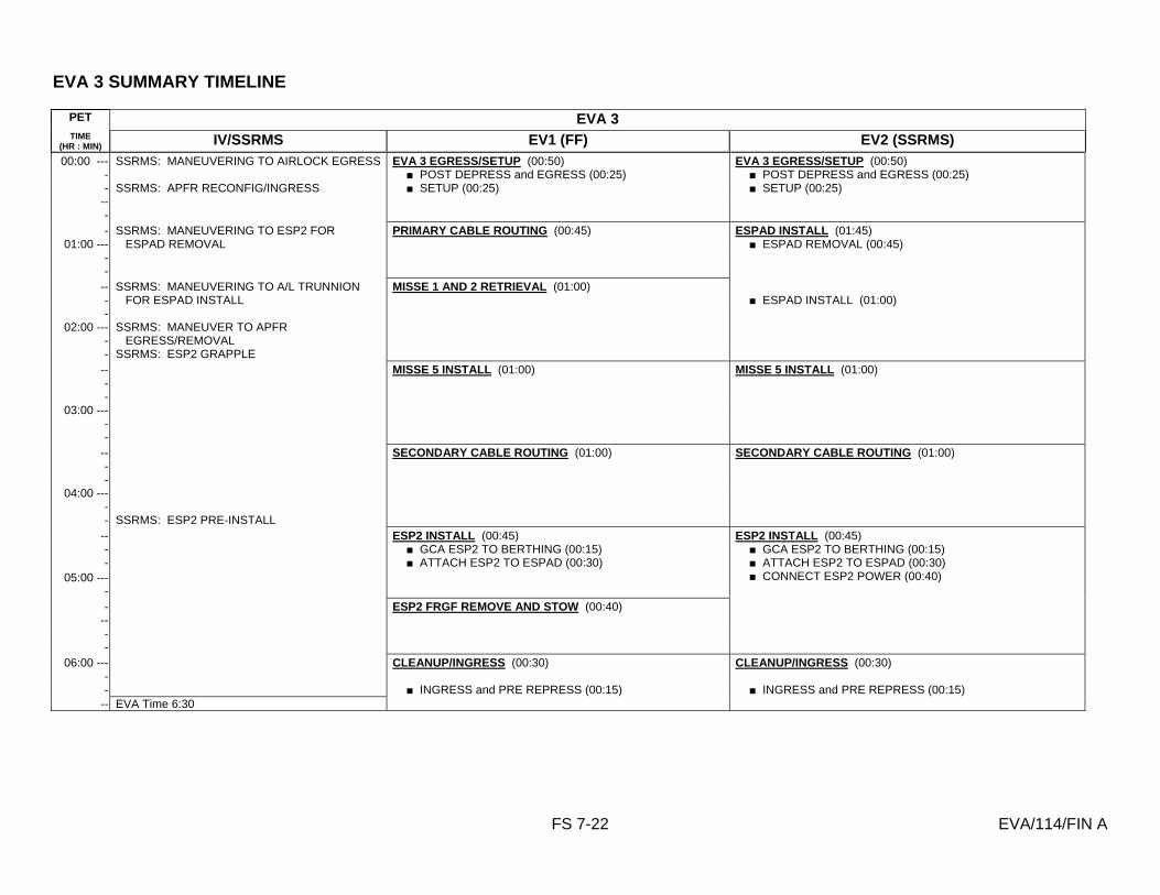
EVA 3 SUMMARY TIMELINE
FS 7-22 EVA/114/FIN A
PET EVA 3 TIME
(HR : MIN) IV/SSRMS EV1 (FF) EV2 (SSRMS) 00:00 --- SSRMS: MANEUVERING TO AIRLOCK EGRESS EVA 3 EGRESS/SETUP (00:50) EVA 3 EGRESS/SETUP (00:50)
- ■ POST DEPRESS and EGRESS (00:25) ■ POST DEPRESS and EGRESS (00:25) - SSRMS: APFR RECONFIG/INGRESS ■ SETUP (00:25) ■ SETUP (00:25)
-- - - SSRMS: MANEUVERING TO ESP2 FOR PRIMARY CABLE ROUTING (00:45) ESPAD INSTALL (01:45)
01:00 --- ESPAD REMOVAL ■ ESPAD REMOVAL (00:45) - -
-- SSRMS: MANEUVERING TO A/L TRUNNION MISSE 1 AND 2 RETRIEVAL (01:00) - FOR ESPAD INSTALL ■ ESPAD INSTALL (01:00) -
02:00 --- SSRMS: MANEUVER TO APFR - EGRESS/REMOVAL - SSRMS: ESP2 GRAPPLE
-- MISSE 5 INSTALL (01:00) MISSE 5 INSTALL (01:00) - -
03:00 --- - -
-- SECONDARY CABLE ROUTING (01:00) SECONDARY CABLE ROUTING (01:00) - -
04:00 --- - - SSRMS: ESP2 PRE-INSTALL
-- ESP2 INSTALL (00:45) ESP2 INSTALL (00:45) - ■ GCA ESP2 TO BERTHING (00:15) ■ GCA ESP2 TO BERTHING (00:15) - ■ ATTACH ESP2 TO ESPAD (00:30) ■ ATTACH ESP2 TO ESPAD (00:30)
05:00 --- ■ CONNECT ESP2 POWER (00:40) - - ESP2 FRGF REMOVE AND STOW (00:40)
-- - -
06:00 --- CLEANUP/INGRESS (00:30) CLEANUP/INGRESS (00:30) - - ■ INGRESS and PRE REPRESS (00:15) ■ INGRESS and PRE REPRESS (00:15)
-- EVA Time 6:30

EVA 3 TOOL CONFIG
FS 7-23 EVA/114/FIN A
Pre-EVA 3 Tool Configuration Post-EVA 3 Tool Configuration
AIRLOCK
! Fuse Tether #2 (Fwd W-bungee) ! Spare PGT ! Wire Tie Caddy (with long and short) ! Fuse Tether #1 (Aft UIA D-ring, aft UIA HR) ! F5 Camera (2, 28mm) ! Ratchet ! 2-in ext ! Wire tie caddy ! MISSE PEC 5 on Stbd zenith bungee ! RET ! Adj ! MISSE Clamp Assembly # 3 ! Adj ! D-ring extender ! ESP2 Power cables (2) ! Adj Tether (2) ! Wire Ties (4) ! IV Bag ! ISS Contamination Sampler (2) ! Drager Tubes (6) ! Gold Salt Kit ! Socket Caddy ! Socket, 6-in ext ! Socket, 1/2 in drive, 8-in ext ! GP Caddy (2) ! Thermal Mitten pairs (2) ! EVA Ratchet ! DCM plug ! Ziplock bag w/2 towels Record: Spare PGT (serial # _______, bat # ______) EV1 PGT (serial # ________, bat # ______) EV2 PGT (serial # ________, bat # ______) RAD (serial # _______)
EV1
! MWS ! Right Swing Arm ! PGT w/6-in ext, RET ! Trash Bag ! T-Bar w/wire tie (2) ! Socket Caddy ! RAD ! Adj Tether (2) ! RET (2) (one to D-ring extender) ! BRT w/wire ties (2) w/RET, adj ! D-ring Extender (2) ! Waist Tether (2) ! Adj Tether (2) (1 each wrist) ! Safety tether (85 ft)
EV2
! MWS ! Right Swing Arm ! PGT w/6-in ext, RET ! T-Bar w/wire tie (2) w/RET to wire tie ! Trash bag ! Socket Caddy ! Adj Tether (2) ! RET (2) ! BRT w/wire ties (2) w/RET ! D-ring Extender (2) ! Waist Tether (2) ! Safety Tether (R)
SSRMS
! APFR [6,XX,L,2] ! WIF Adapter
AIRLOCK
! Fuse Tether #2 ! Spare PGT ! Wire Tie Caddy ! Fuse Tether #1 ! F5 Camera (2, 28mm) ! WIF Adapter ! A/L trunnion thermal covers (2) ! Wire Tie Caddy ! PEC 1, 2 ! RET ! D-ring extender with crew hook lock
EV1
! MWS ! Right Swing Arm ! PGT w/6-in ext, RET ! T-Bar w/wire tie (2) ! Round Scoop ! Trash Bag ! Socket Caddy ! RAD ! Adj Tether (2) ! RET (2) ! BRT w/wire ties (2) w/RET ! D-ring Extender (2) ! Waist Tether (2) ! Adj Tether (2) (1 each wrist)
EV2
! MWS ! Right Swing Arm ! PGT w/6-in ext, RET ! Trash Bag ! T-Bar w/wire tie (2) ! Socket Caddy ! BRT w/wire ties (2) w/RET ! RET (sm-sm) (3) ! Adj Tether (2) ! D-ring Extender (2) ! Waist Tether (2) ! Safety Tether

EVA 3 EGRESS/SETUP
FS 7-24 EVA/114/FIN A
IV/RMS EV1 (FF) EV2 (SSRMS)
1. SSRMS: MANEUVERING TO AIRLOCK EGRESS (ROBOTICS FS, EVA 3)
2. ISS views: PLB B on monitor 2, focus on ESPAD PLB C on downlink, focus at A/L
EV2
EV1
A/L D-Ring Extender
Waist Tether
Safety Tether (R)
Waist Tether
D-Ring Extender
D-Ring Extender
3. IV: When EV1 complete with step 5, give SSRMS GO for
APFR RECONFIG/INGRESS maneuver 4. SSRMS: After EVA GO, APFR RECONFIG/INGRESS
(ROBOTICS FS, EVA 3) 5. SSRMS: After EVA GO, MANEUVERING TO ESP2 FOR
ESPAD REMOVAL (ROBOTICS FS, EVA 3)
Initial Configuration: Waist tether (L) to EV2 Safety tether
POST DEPRESS (00:05)
Perform POST DEPRESS (DEPRESS/REPRESS Cue Card)
EGRESS (00:20)
1. Open A/L thermal cover 2. Egress airlock 3. Check SAFER valves down 4. Attach safety tether (85 ft) to A/L ring, verify hook locked 5. Attach EV2 Safety Tether to SSRMS, verify locked 6. Give EV2 GO for EV2 step 2 7. Receive fuse tether #1 and primary and secondary ESP2
cables (2) from EV2; temp stow at A/L HR 0554
SETUP (00:25)
8. Remove A/L trunnion covers (2). Temp stow covers on fuse tether
9. Retrieve ESP2 primary cable 10. Translate to primary cable worksite on Node endcone,
connector J602
Initial Configuration: Waist tether (L) to A/L D-ring extender, Safety tether (R) to EV1 Waist tether (L)
POST DEPRESS (00:05)
Perform POST DEPRESS (DEPRESS/REPRESS Cue Card)
EGRESS (00:20)
1. Hold for EV1 GO 2. Release Waist tether from A/L D-ring 3. Hand out fuse tether #1 and primary and secondary ESP2
cables (2) to EV1 4. Egress A/L 5. Check SAFER valves down 6. Close thermal hatch
SETUP (00:25)
7. Verify/configure SSRMS APFR[12,PP, F, 6] 8. Ingress SSRMS 9. Verify feet in APFR 10. Give SSRMS GO for motion to ESPAD REMOVAL

ESPAD INSTALL
FS 7-25 EVA/114/FIN A
IV/RMS EV2 (SSRMS)
1. IV: Verify orbiter ESP 2 power cable inhibited L12U √APCU 1, 2 CONV (two) – OFF (tb-bp) √OUTPUT RLY tb (two) – bp √OUTPUT RLY (two) – OP
2. ISS views: PLB B for ESPAD Removal 3. SSRMS: MANEUVERING TO A/L TRUNNION FOR
ESPAD INSTALL (ROBOTICS FS, EVA 3), confirm in position hold prior to ESPAD soft docking
4. ISS views: PLB C for ESPAD Install 5. IV: Record final torque values:
Bolt Turns Torque Port EUTAS
Port EUTAS lock bolt
Stbd EUTAS
Stbd EUTAS lock bolt
ESPAD REMOVAL (00:45)
1. GCA SSRMS to ESP2 pwr cable 2. On IV GO, demate orbiter power cable from ESP2
! P1 from J1 3. Mate connector to dummy panel on KYA, stow cable slack
on bracket ! P1 to dummy panel J3
4. Verify ESPAD claw open 5. GCA SSRMS to ESPAD 6. Deploy ESPAD strut clear of launch bolt A. Remove wire
ties (2) and stow in trash bag. Remove pip pin from strut FSE
7. PGT[B7, CCW2, 30.5] –6Ext-7/16: Release Launch Bolt A. Expect 9 turns
8. Stow ESPAD strut, insert pip pin 9. PGT[B7, CCW2, 30.5] –6Ext-7/16: Release EUTAS
primary compliant mount lock release. Expect approx 25 turns
10. PGT[B7, CCW2, 30.5] –6Ext-7/16: Release Launch Bolt C. Expect 9 turns
11. Tether to active ESPAD HR 8032 inboard using ret 12. PGT[B7,CCW2,30.5] –6Ext-7/16: Release EUTAS
secondary compliant mount lock release. Expect approx 7 turns
13. PGT[B7, CCW2, 30.5] –6Ext-7/16: Release Launch Bolt B. Expect 9 turns
14. Remove active ESPAD from passive ESPAD. Expect to overcome 8 lb of soft dock force
15. Positively control ESPAD and give GO to IV/SSRMS 16. Flip ESPAD into A/L mating position 17. If required, fold down MWS
ESPAD INSTALL (01:00)
18. On SSRMS GO, soft dock ESPAD into A/L trunnion. Expect soft dock force of 46 lb
19. Hand tighten port and starboard EUTAS center bolts with hand knobs
Report torque and turns
20. PGT[B7, CW2, 30.5] –6Ext-7/16: Torque down port EUTAS
bolt to a torque stall 21. PGT[B7, CW2, 30.5] –6Ext-7/16: Torque down stbd
EUTAS bolt to a torque stall 22. PGT[A6, CW2, 10.5] –6Ext-7/16: Lock down stbd EUTAS
lock bolt to a torque stall
Strut
Pip Pin
Launch Bolt A (under strut)
Launch Bolt C
Launch Bolt B
Locking Bolt
EUTAS Bolt
Compliant Bolts

ESPAD INSTALL (Cont)
FS 7-26 EVA/114/FIN A
IV/RMS EV2 (SSRMS)
6. SSRMS: On EVA GO, maneuver to APFR
EGRESS/REMOVAL (ROBOTICS FS, EVA 3) 7. SSRMS: On EVA GO, CLEAR STRUCTURE and perform
ESP2 GRAPPLE (ROBOTICS FS, EVA 3)
23. PGT[A6, CW2, 10.5] –6Ext-7/16: Lock down port EUTAS lock bolt to a torque stall
24. Open starboard and port V guide latches 25. Perform WVS survey of ESPAD
! WVS survey complete 26. Give SSRMS GO to APFR EGRESS/RECONFIG 27. Egress APFR 28. Verify A/L toolbox # 2 WIF is [6, GG] 29. Tether to APFR, remove from SSRMS 30. Stow APFR in A/L Toolbox # 2 WIF[6, PP, C, 12] 31. Remove WIF adapter from SSRMS 32. Place waist tether on A/L HR, verify hook locked 33. Remove safety tether from SSRMS, attach to A/L HR,
verify hook locked 34. Remove waist tether from A/L HR 35. Give SSRMS GO for ESP2 GRAPPLE 36. Stow WIF adapter on fuse tether 37. Open socket access flap on A/L FRGF thermal cover 38. Deploy ESPAD strut and connect to A/L FRGF. Move
slidelocks into locked position (2) 39. Close MLI flap around strut and A/L FRGF 40. Open nadir V guide latch

ESPAD INSTALL – TASK DATA
FS 7-27 EVA/114/FIN A
Estimated Task Duration: With
SSRMS Without SSRMS
Two EV Crew 1:45 N/A Tools:
EV1 (FF) EV2 (SSRMS)
PGT 7/16 (wobble) socket-6 ext
EVA Fasteners:
Fastener Name Head Size
Qty Install Torque (ft-lb)
Release Torque (ft-lb)
Failure Torque (ft-lb)
Turns
ESPAD Launch Bolts
7/16 3 20.8 21.6 9
ESPAD Comp. Bolt (primary)
7/16 1 8.3 12.5 7
ESPAD Comp. Bolt (secondary)
7/16 1 8.3 12.5 25
ESPAD EUTAS Bolts
7/16 2 25.5 25.0 101.7 7.5
EUTAS lock down bolts
7/16 2 8.3 8.3 23.6 2.6
ESPAD Claw 7/16 1 20.8 20.8 60
EVA Connectors:
Harness From To Conn Size
Function
ESP2 Shuttle Pwr ESP2 ICC Keel 25 ESP2 Orbiter Power ESP2 Primary Power Cable
Dust Cap Node J602 21 ESP2 Prime Power
Foot Restraints:
Task WIF APFR Setting ALL SSRMS 12, PP, F, 6
ESPAD / ESP2
ESPAD/ESP2

PRIMARY CABLE ROUTING
FS 7-28 EVA/114/FIN A
IV/RMS EV1 (FF)
1. IV: Verify with MCC-H ISS ESP2 power inhibits in place per EVA Inhibit pad
ESP2 ISS power, primary and secondary inhibits
PRIMARY CABLE ROUTING (00:30)
1. Translate to Node J602 2. Remove dust covers, stow in trash bag
! P602 (ESP2 cable) ! J602 (Node) 3. On IV GO, mate connector:
! ESP2 P602 to Node J602 4. Wire tie J602 pig tail as required, route primary cable
using wire ties as required ! Node 0134 ! Node 0135 ! A/L 0519
5. Temp stow cable bundle on A/L 0531
PRIMARY CABLE ROUTING – TASK DATA
Tools: EV1 (FF)
Wire ties Trash Bag
EVA Connectors:
Harness From To Conn Size
Function
ESP2 P602 Dust Cap Node J602 Power ESP2 J602 Dust Cap Node HR (wire tie) Future Use
ESP2 Primary Cable

MISSE 1 AND 2 RETRIEVAL
FS 7-29 EVA/114/FIN A
IV/RMS EV1 (FF)
MISSE #1 RETRIEVE
1. Translate to MISSE #1 on ONTO #2 (equipment lock nadir)
2. Provide WVS survey of MISSE #1 3. Release pip pins (2) securing MISSE #1 open 4. Close MISSE #1; reinsert pip pins (2) to secure MISSE #1
closed 5. Tether to MISSE #1 6. Release probe pip pins (2) on handrail clamp 7. Remove MISSE #1 from HR clamp 8. Translate to airlock hatch; temp stow
MISSE #2 RETRIEVE
9. Translate to MISSE #2 on C-Lk endcone 10. Provide WVS survey of MISSE #2 11. Release pip pins (2) securing MISSE #2 open 12. Close MISSE #2; reinsert pip pins (2) to secure MISSE #2
closed 13. Tether to MISSE #2 14. Release probe pip pins (2) on handrail clamp 15. Remove MISSE #2 from HR clamp 16. Translate to airlock, open thermal cover 17. Stow MISSE (2) in A/L
MISSE 1 AND 2 RETRIEVAL – TASK DATA
EVA Fasteners (contingency bolts only): Fastener Name Head
Size Qty Install
Torque (ft-lb)
Release Torque (ft-lb)
Failure Torque (ft-lb)
Turns
MISSE Stem Contingency Bolt
7/16 2 1.7 2.1 6.0 16

MISSE 5 INSTALL
FS 7-30 EVA/114/FIN A
IV/RMS EV1 (FF) EV2 (FF)
MISSE CLAMP ASSEMBLY
MISSE #5 INSTALL
1. Retrieve MISSE clamp assembly #3 from A/L, hand to EV2 2. Retrieve MISSE 5 3. Place MISSE 5 in BRT 4. Egress A/L, close thermal cover 5. Retrieve safety tether from A/L ring 6. Translate to P6 handrail 5312 7. Perform safety tether swap 8. Attach extra safety tether to HR 5312 and right D-ring
extender; verify both hooks locked 9. Temp stow airlock safety tether on HR 5312 10. Translate to P6 aft trunnion HR 5389 11. Install MISSE #5 into handrail clamp pointer; check
alignment 12. Insert probe pip pins (2) 13. Release pip pins (2) securing MISSE #5 closed 14. Open MISSE #5; reinsert pip pins (2) to secure MISSE open 15. Install grounding strap into handrail standoff 16. Release antenna Velcro restraints; deploy antennas 17. Verify electronics switch – OFF 18. Swap MISSE safe and arm plugs 19. Move electronics switch to ON 20. Provide WVS survey of MISSE #5 and clamp assy 21. Translate to P6 handrail 5312 22. Perform safety tether swap to airlock safety tether; verify
hook locked 23. Remove spare safety tether from HR 24. Translate to joint airlock; stow spare safety tether
MISSE #5 INSTALL
1. Translate to A/L 2. Retrieve safety tether from A/L ring 3. Receive MISSE clamp assembly #3 4. Stow clamp and safety tether on MWS 5. Translate to P6 handrail 5309 6. Perform safety tether swap 7. Attach extra safety tether to HR 5309 and right D-ring
extender; verify both hooks locked 8. Temp stow airlock safety tether on HR 5309 9. Translate to P6 aft trunnion HR 5389 10. Verify clamp assy handle in UNLOCK 11. Release capture plate (1 pip pin); open 12. Install clamp pointer around HR 5389 13. Verify capture plate pip pin installed 14. Push LEVER LOCK; place clamp assy lever to LOCK 15. Pull MISSE probe latching pip pins (2) 16. Assist EV1 w/MISSE deploy 17. Translate to P6 handrail 5309 18. Perform safety tether swap onto airlock safety tether; verfiy
hook locked 19. Remove spare safety tether from HR 20. Translate to joint airlock; stow spare safety tether
MISSE 5 INSTALL – TASK DATA
EVA Fasteners (contingency bolts only): Fastener Name Head
Size Qty Install
Torque (ft-lb)
Release Torque (ft-lb)
Failure Torque (ft-lb)
Turns
MISSE Stem contingency Bolts
7/16 2 1.7 2.1 6.0 16

SECONDARY CABLE ROUTING
FS 7-31 EVA/114/FIN A
IV/RMS EV1 (FF) EV2 (FF)
SECONDARY CABLE ROUTING (01:00)
1. Translate to S0 face 1, bay 3 (stbd) 2. Uncouple CETA cart from MT 3. Reposition CETA carts for bay 3 ingress, set brake 4. Enter bay 3, BRT to HR 3421 5. Receive pigtail cable from EV2; temp stow 6. Verify enough slack for connector operations, give EV2
GO for cable routing 7. Release TA clamps on P59 and P57 if required 8. Remove dust caps from ESP2 cable P57A and J57A and
stow in trash bag 9. On IV GO, demate connector:
! S0 P57 from S0 panel J64 10. Mate connectors:
! ESP2 J57A to S0 P57 ! ESP2 P57A to S0 panel J64
11. Restow P59 and P57 in TA clamps if required 12. Restrain remaining slack and perform WVS closeout
! WVS survey complete 13. Egress bay and replace CETA carts. Confirm brakes
released 14. Assist EV2 as required, watch for helmet and PLSS
clearance, stay stbd on CETA spur
SECONDARY CABLE ROUTING (01:00)
1. Retrieve wire tie caddy from fuse tether 2. Retrieve secondary power cable bundle from A/L 3. Fair lead at A/L end of CETA spur, stay port on CETA spur 4. Translate to S0 face 6, bay 3, near HR 3423 5. Feed cable with pigtail end to EV1 6. Route secondary power cable. Restrain with wire ties as
required ! Keel strut HR (stbd end) ! S0 3437 (stbd end) ! MTS strut very short HR (stbd end) ! MTS strut long HR (stbd end) ! MTS strut short HR (port end) ! Very short HR on Lab at port end of MTS strut ! Lab 0215 (zenith end) ! A/L 0519 (zenith end)
7. Temp stow remaining cable at A/L HR 0519
S0 Panel J64

SECONDARY CABLE ROUTING – TASK DATA
FS 7-32 EVA/114/FIN A
With SSRMS
Without SSRMS
Two EV Crew N/A 1:00 Tools:
EV1 (FF) EV2 (FF)
Wire ties Wire ties Trash Bag
EVA Fasteners: EVA Connectors:
Harness From To Conn Size
Function
ESP2 P57A Dust Cap S0 panel J64 15 Power ESP2 J57A Dust Cap S0 P57 15 Power S0 P59 S0 J59 S0 panel J65 15 Power S0 P57 S0 panel J57 ESP2 J57A 15 Power
Foot Restraints:
Task WIF APFR Setting S0 connector mates (if required) S0- 12, YY, G, 12
J64
Pre LF-1
P57
S0 Cable
J64
Post LF-1
P57 J57A
P57A
ESP2 Cable
S0 Cable

ESP2 INSTALLATION
FS 7-33 EVA/114/FIN A
IV/RMS EV1 (FF) EV2 (FF)
1. SSRMS: When 10 min from ESP2 PRE-INSTALL, give EVA a ten-min warning
2. ISS views: PLB C for ESP2 Install 3. SSRMS: Give IV GO to close capture claw to capture bar
contact 4. IV: Record number of turns: _______ 5. IV: Give SSRMS GO for limp mode after capture claw
contact and EV1 and EV2 verifications 6. SSRMS: On IV GO, go to limp mode, give IV GO for final
capture claw close, remind EV1 to stop if SSRMS calls brakes on
7. Comm protocol: EV1 “Comm check”; “IV GO”; “M1 GO” 8. IV: Record number of turns: ________ 9. SSRMS: On IV GO, apply brakes, give IV GO for guide
vanes 10. Give EV GO for guide vanes 11. IV: Record final torque values: _______
12. Record number of turns: _______ 13. IV: Give SSRMS GO for ESP2 ungrapple when
torque/turn values are recorded Bolt Turns Torque
Stbd Guide Vane
Port Guide Vane
Nadir Guide Vane
GCA ESP2 BERTHING (00:15)
1. Translate to A/L HR 0502 location for ESP2 berthing (stbd nadir of the ESPAD)
2. Confirm in position and safety tethers clear, verify ESPAD claw and latches open
3. Provide GCA to SSRMS, verify nadir RTL indicators
ATTACH ESP2 TO ESPAD (00:30)
4. BRT to A/L HR 0503 5. PGT[B7, CW2, 30.5] –6Ext-7/16: On IV GO, close
capture claw to contact, inform IV GO for limp mode Report Turns
6. Verify ESP2 still within V-guides 7. PGT[A3, CW1, 30.5] –6Ext-7/16: On SSRMS GO, close
capture claw to hard stop, using pulses of 1.5 turns and verify comm after each pulse (EV1 “Comm check”, “IV GO”, “M1 GO”)
Report Turns
8. Give IV GO for brakes 9. On IV GO, manually close nadir guide vane lock down bar 10. PGT[B7, CW2, 30.5] –6Ext-7/16: Torque down nadir
guide vane lock down bar to a hard stop, lock knob Report Torque and Turns
11. PGT[B1, CCW2, 30.5] –6Ext-7/16: After EV2 GO, back off ESPAD capture claw 30 turns
Report Turns
12. Perform WVS survey of ESPAD/ESP2 ! WVS survey complete
GCA ESP2 BERTHING (00:15)
1. Translate to MT strut HR location for ESP2 berthing (ESPAD port zenith, on Lab)
2. Confirm in position and safety tethers clear, verify ESPAD claw and latches open
3. Provide GCA to SSRMS, verify port and stbd RTL indicators (2)
ATTACH ESP2 TO ESPAD (00:30)
4. Verify ESP2 still within V-guides 5. On IV GO, manually close port guide vane lock down bar 6. Manually close starboard guide vane lock down bar 7. PGT[B7, CW2, 30.5] –6Ext-7/16: Torque starboard guide
vane lock down bar to a hard stop, lock knob Report Torque and Turns
8. PGT[B7, CW2, 30.5] –6Ext-7/16: Torque port guide vane lock down bar to a hard stop, lock knob
9. Give EV1 GO for claw ops
CONNECT ESP2 POWER
10. Retrieve and route primary and secondary ESP2 cables (2) to ESPAD HR
11. Remove dust covers ! P1 (Pri Cable) !P2 (Sec Cable) !J2 (ESP2)
12. Mate connectors: ! P1 (Cable) to J1 (ESP2) ! P2 (Cable) to J2 (ESP2)
13. Perform WVS closeout of connectors ! WVS survey complete
14. Cleanup, coil remaining cable at HR 8032 15. Retrieve adj tethers, stow on fuse tether 16. Give IV GO for ESP2 power

ESP2 INSTALLATION – TASK DATA
FS 7-34 EVA/114/FIN A
Estimated Task Duration: With
SSRMS Without SSRMS
Two EV Crew 0:45 N/A Tools:
EV1 (FF) EV2 (FF)
PGT PGT 7/16 (wobble) socket-6 ext 7/16 (wobble) socket-6 ext Wire ties Wire ties
EVA Fasteners:
Fastener Name
Head Size
Qty Install Torque (ft-lb)
Failure Torque (ft-lb)
Turns
ESPAD Lock down bolts
7/16 3 25.0 N/A
ESPAD Claw 7/16 1 10.0 10 EVA Connectors:
Harness From To Conn Size
Function
ESP2 cable P1 Dust cover ESP2 J1 25 Power (prime) ESP2 cable P2 Dust cover ESP2 J2 25 Power (secondary)
ESPAD Components
Active ESPAD
Passive ESPAD
Lock Down Bolt
EVA GCA Capture Indicator V-Guide
Knob Lock

ESP2 FRGF REMOVE AND STOW
FS 7-35 EVA/114/FIN A
IV/RMS EV1 (FF)
1. IV: Record number of turns RAD is used:
Bolt Turns
FRGF 1
FRGF 2
FRGF 3
FRGF 4
ESP2 FRGF REMOVE
1. Retrieve ratchet w/2-in ext from A/L fuse tether 2. Translate to ESP2 FRGF 3. BRT to ESP2 HR 8011 4. Ratchet: Break torque on ESP2 FRGF stbd bolts (2).
Expect 10 turns 5. PGT[B1, CCW2, 30.5] –RAD-2Ext-7/16: Release ESP2
FRGF stbd bolts (2). Expect 12 turns Report # of RAD turns
6. BRT to ESP2 HR 8012 7. Tether to ESP2 FRGF 8. Ratchet: Break torque on ESP2 port FRGF bolts (2) 9. PGT[B1, CCW2, 30.5] –RAD-2Ext-7/16: Release ESP2
FRGF port bolts (2). Expect 12 turns Report # of RAD turns
10. Temp stow ratchet on ESP2 HR 11. Place FRGF in BRT 12. Translate to stbd TSA
ESP2 FRGF STOW
13. Open stbd TSA latches (4) 14. Stow FRGF 15. Close TSA latches (4) 16. Translate to A/L
ESP2 FRGF REMOVE AND STOW – TASK DATA
EVA Fasteners: Fastener Name Head
Size Qty Install
Torque (ft-lb)
Release Torque (ft-lb)
Failure Torque (ft-lb)
Turns
FRGF Bolts 7/16 4 12

CLEANUP/INGRESS
FS 7-36 EVA/114/FIN A
IV/RMS EV1 (FF) EV2 (FF)
1. Perform EV1 and EV2 tool inventory
CLEANUP (00:15)
1. Photo ops
INGRESS (00:15)
2. Translate to hatch 3. Perform tool inventory 4. Hand in fuse tether 5. On EV2 GO, remove EV2 safety tether, attach to left waist
tether 6. Remove safety tether from A/L ring and stow on MWS 7. Ingress A/L 8. Connect SCU to DCM; check SCU locked 9. Water – OFF 10. Close thermal cover, attach Velcro strap
CAUTION Do not close hatch until EMU water off for 2 min
11. EV Hatch – close and lock 12. Go to PRE REPRESS portion of {CREWLOCK
DEPRESS/REPRESS CUE CARD} (SODF: ISS EVA SYS: EVA PREP/POST)
CLEANUP (00:15)
1. Photo ops
INGRESS (00:15)
2. Translate to hatch 3. Open thermal cover 4. Perform tool inventory 5. Ingress A/L 6. Attach left waist tether to A/L D-ring 7. Give EV1 GO for tether ops 8. Connect SCU to DCM; check SCU locked 9. Water – OFF 10. Go to PRE REPRESS portion of {CREWLOCK
DEPRESS/REPRESS CUE CARD} (SODF: ISS EVA SYS: EVA PREP/POST)
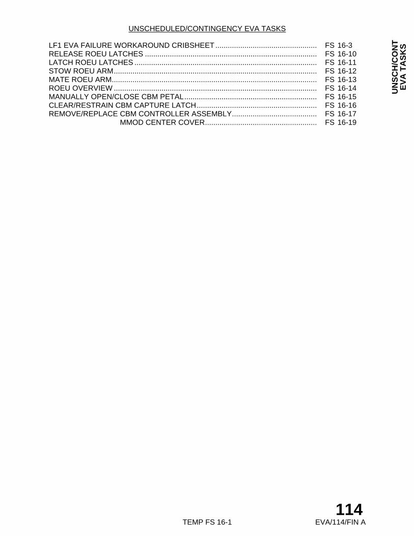
TEMP FS 16-1 EVA/114/FIN A
UN
SC
H/C
ON
T
EV
A T
AS
KS
UNSCHEDULED/CONTINGENCY EVA TASKS
LF1 EVA FAILURE WORKAROUND CRIBSHEET ................................................. FS 16-3 RELEASE ROEU LATCHES ................................................................................... FS 16-10 LATCH ROEU LATCHES ........................................................................................ FS 16-11 STOW ROEU ARM.................................................................................................. FS 16-12 MATE ROEU ARM................................................................................................... FS 16-13 ROEU OVERVIEW .................................................................................................. FS 16-14 MANUALLY OPEN/CLOSE CBM PETAL................................................................ FS 16-15 CLEAR/RESTRAIN CBM CAPTURE LATCH.......................................................... FS 16-16 REMOVE/REPLACE CBM CONTROLLER ASSEMBLY......................................... FS 16-17 REMOVE/REPLACE MMOD CENTER COVER...................................................... FS 16-19
114

TEMP FS 16-2 EVA/114/FIN A
UN
SC
H/C
ON
T
EV
A T
AS
KS
This Page Intentionally Blank
114EVA/ALL/FIN A

LF1 EVA FAILURE WORKAROUND CRIBSHEET
FS 16-3 EVA/114/FIN A
Procedure Failure Work-Around Steps Comments I. GENERIC A. TA clamps fail to release Use tether hook for additional leverage to open clamp B. Connector fails to mate Detach from soft dock and inspect, cycle disengaged
connector: ! Bent pins ! FOD ! EMI band ! Cable bend radius ! Bail linkages/rivets (both passive and active
connector sides) ! Soft dock spring ! O-ring seal on non-active side ! Connector keying features
1. Describe bent pin location to MCC ! Rotate connector to bail up position, describe
pin condition ! If possible, obtain WVS view of interface
C. Connector pin bent
2. On MCC GO, Obtain connector pin straightener (16,21,22 gage) or needle nose pliers. Attempt pin repair
MCC determine if repair is necessary. Repair may damage other pins
D. Connector FOD On MCC GO, obtain connector cleaner tool from A/L staging bag. Attempt removal of FOD
MCC determine necessity of time to retrieve tools
E. Connector EMI band bent On MCC GO, obtain needle nose pliers or forceps. Remove EMI band from connector
MCC determine necessity of time to retrieve tools
F. Connector bail linkage failure
On MCC GO, re-attempt connector mate with broken bail. Vice grips may be used for additional leverage
MCC determine potential safety hazards and necessity of time to retrieve tools
G. Connector soft dock spring bent
On MCC GO, obtain needle nose pliers. Attempt to remove bent spring
MCC determine necessity of time to retrieve tools. Low probability of success
1. Remove seal with tether hook Common occurrence
H. Connector O-ring seal loose 2. On MCC GO, obtain needle nose pliers. Attempt to
remove seal MCC determine necessity of time to retrieve tools

LF1 EVA FAILURE WORKAROUND CRIBSHEET (Cont)
FS 16-4 EVA/114/FIN A
Procedure Failure Work-Around Steps Comments I. MMOD shield fastener fails
to release On MCC GO,
WARNING Do not touch back side of MMOD Shields or handle any fastener fragments due to sharp edges Fastener and Shield/Tool interface must be covered to avoid potential projectiles
! Retrieve ISS prybar from Node Bag and RPCM MLI ! Release all other fasteners on MMOD shield ! Assess clearance between the MMOD shield and
the tools ! If possible, rotate fastener to position tangs off of
wire (unlock) ! Place MLI cover over MMOD shield and tool
interface ! Insert tool under MMOD shield by failed fastener
and pry the shield away from the structure until the fastener is freed
! If required, place tape over the failed fastener
Concurrence obtained post 5A via EVA AIT
J. MMOD shield fastener doesn’t engage
Use alternate fastener(s). Two total fasteners per shield should be engaged. For non-overlapping shields, fasteners should be diagonally opposite. Overlapping shields should use fasteners opposite of the overlapping end
1. Remove adjacent fasteners, attempt reinstallation of tool into shield
K. T-handle tool fails to engage shield for handling
2. Use only one shield tool for handling 1. Verify knob in release position
L. PAD release knob fails to rotate to close 2. Stow PAD, retrieve backup PAD from Node bag
M. PAD release knob fails to 1. Verify knob in release position rotate to open 2. Attempt to rotate release knob using 7/16” ratchet on
knob’s 7/16” hex stud
3. To remove PAD from SRMS, release contingency release bar by rotating 7/16” captive release bolts (2) ccw
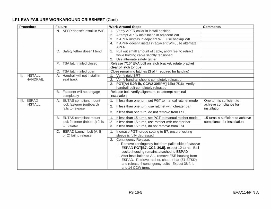
LF1 EVA FAILURE WORKAROUND CRIBSHEET (Cont)
FS 16-5 EVA/114/FIN A
Procedure Failure Work-Around Steps Comments 1. Verify APFR collar in install position 2. Attempt APFR installation in adjacent WIF 3. If APFR installs in adjacent WIF, use backup WIF
N. APFR doesn’t install in WIF
4. If APFR doesn’t install in adjacent WIF, use alternate APFR
1. Pull out small amount of cable, allow reel to retract while holding cable slightly tensioned
O. Safety tether doesn’t tend
2. Use alternate safety tether P. TSA latch failed closed Release 7/16” EVA bolt on latch bracket, rotate bracket
clear of latch tongue
Q. TSA latch failed open Close remaining latches (3 of 4 required for landing) 1. Verify rigid BRT 2. Verify handrail shoe is completely released
A. Handrail will not install in seat track
3. PGT[A4 5.0ft-lb, CCW2 30RPM]-6Ext-7/16: Verify handrail bolt completely released
II. INSTALL HANDRAIL
B. Fastener will not engage completely
Release bolt, verify alignment, re-attempt nominal installation
1. If less than one turn, set PGT to manual ratchet mode
2. If less than one turn, use ratchet with cheater bar
III. ESPAD INSTALL
A. EUTAS compliant mount lock fastener (outboard) fails to release
3. If less than one turn, do not remove from FSE
One turn is sufficient to achieve compliance for installation
1. If less than 15 turns, set PGT to manual ratchet mode 2. If less than 15 turns, use ratchet with cheater bar
B. EUTAS compliant mount lock fastener (inboard) fails to release 3. If less than 15 turns, do not remove from FSE
15 turns is sufficient to achieve compliance for installation
1. Increase PGT torque setting to B7, ensure locking sleeve is fully depressed
C. ESPAD Launch bolt (A, B or C) fail to release
2. Contingency Release: � Remove contingency bolt from pallet side of passive
ESPAD PGT[B7, CC2, 30.5], expect 12 turns. Ball socket housing remains attached to ESPAD
� After installation to A/L, remove FSE housing from ESPAD. Retrieve ratchet, cheater bar (Z1 ETSD) and release 4 contingency bolts. Expect 38 ft-lb and 14 CCW turns

LF1 EVA FAILURE WORKAROUND CRIBSHEET (Cont)
FS 16-6 EVA/114/FIN A
Procedure Failure Work-Around Steps Comments 1. Back off and reattempt. Confirm ESPAD compliant
bolts release and no jamming has occurred
2. Manipulate/rotate EUTAS by hand to push over trunnion
EUTAS has 3 shear pins that engage with mating holes in the tip of the trunnion. EUTAS is mounted on a compliant mount which allows for 5 degrees of rotational freedom as well as 6 degrees of coning angle provided by the EUTAS gimbal mount
3. Allow 5-10 minute thermal equalization ESPAD my require thermal dwell time
D. Unable to mate ESPAD to A/L
4. Retrieve PRDs (2) and strap down ESPAD to engage EUTAS:
Stbd: PRD strap from A/L HR 0501 to ESPAD HR 8033 nadir under ESPAD HR 8031 through the opening in ESPAD then back to A/L HR 0502, hook the ends of the PRD together
Port: PRD box hook to A/L HR 0531 then strap nadir over front of ESPAD in between 8036 and port EUTAS then nadir to hook (strap end) on A/L HR 0530
1. Verify both wire ties are released Wire ties installed at CEIT E. Unable to deploy strut 2. Release hinge bolt: PGT[B7, CCW2, 30.5] Expect
14 ft-lb and 21 turns
F. Unable to engage EUTAS locking bolt
1. Install wire ties: ESPAD HR 8036 (port) or 8035 (stbd) attach 2 wire ties together then attach to lock nut
F. Unable to mate strut to A/L Adjust strut length: Open MLI Disengage two slide locks at end of adjustment handle Rotate CW to extend, CCW to retract Engage locks and replace MLI
G. Unable to open V-guides Loosen tie down pin: PGT[B7, CCW2, 30.5] Expect 22 turns. After installation of ESP2, V-guide will be attached in reverse order: PGT[B7, CW2, 30.5] 22 turns

LF1 EVA FAILURE WORKAROUND CRIBSHEET (Cont)
FS 16-7 EVA/114/FIN A
Procedure Failure Work-Around Steps Comments A. ESP2 PRLAs will not
release Perform contingency override on PRLA. Refer to generic PRLA release procedure 1. Close PRLAs (IV) then EVA perform:
Release Lock Bolt, PGT[B5(21 ft-lb), CCW1, 30.5] 8 turns
Turn shaft bolt from ENGAGE to DISENGAGE: PGT[B7(25 ft-lb), CCW1, 30.5] ¼ turn
Lock down Lock Bolt, PGT[B5(21 ft-lb), CW2, 30.5] 8 turns
Open PRLAs
IV. ESP2 DEPLOY
B. ESP2 will not release from KYA
2. Close PRLAs (IV) then EVA perform: Release Fork Bearing Release PGT[B2(13.5 ft-lb),
CCW2, 30.5] 9.5 turns Open PRLAs, fwd aft sequence, release ESP2
(SSRMS) Release fork bearing protection cover from KYA
and secure fork bearing on shaft
1. Back off and reattempt 2. TBD other method
A. Unable to achieve capture envelope
3. Return ESP2 to PLB. EVA required to verify ESP2 within capture envelope using marks on the keel yoke assembly
1. If possible, close V guide latches 2. GCA SSRMS to full capture
B. ESPAD claw fails to close
3. Retrieve PRD: PRD box hook to A/L HR 0502 over capture bar to port A/L 0534 (inside diagonal HR on ESPAD 8031 and 8000)
C. Unable to close V-guide latch 1. Nadir: PRD from ESPAD HR 8029 to ESPAD HR 8030 Stbd: around the pin near ESPD HR 8033, box aft of
ESPAD on back face, hooks together Port: around the pin under ESPAD HR 8032, box aft of
ESPAD on aft face, hooks together D. Unable to close V-guide
locks 1. If J-slot lock fails to engage, torque down report to
MCC
1. Increase torque setting to PGT[B7(25.5), CCW2, 30.5]
V. ESP2 BERTHING
D. ESPAD claw fails to open 2. Tether to and loosen capture bar, 10 to 12 turns on
each passive ESPAD capture bar contingency release bolt (2)
Bar may or may not come free
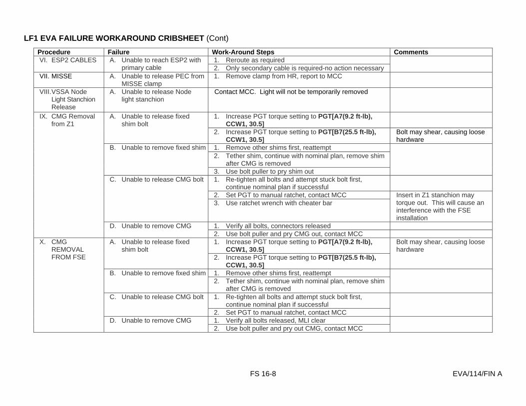
LF1 EVA FAILURE WORKAROUND CRIBSHEET (Cont)
FS 16-8 EVA/114/FIN A
Procedure Failure Work-Around Steps Comments 1. Reroute as required VI. ESP2 CABLES A. Unable to reach ESP2 with
primary cable 2. Only secondary cable is required-no action necessary
VII. MISSE A. Unable to release PEC from MISSE clamp
1. Remove clamp from HR, report to MCC
VIII. VSSA Node Light Stanchion Release
A. Unable to release Node light stanchion
Contact MCC. Light will not be temporarily removed
1. Increase PGT torque setting to PGT[A7(9.2 ft-lb), CCW1, 30.5]
A. Unable to release fixed shim bolt
2. Increase PGT torque setting to PGT[B7(25.5 ft-lb), CCW1, 30.5]
Bolt may shear, causing loose hardware
1. Remove other shims first, reattempt 2. Tether shim, continue with nominal plan, remove shim
after CMG is removed
B. Unable to remove fixed shim
3. Use bolt puller to pry shim out
1. Re-tighten all bolts and attempt stuck bolt first, continue nominal plan if successful
2. Set PGT to manual ratchet, contact MCC
C. Unable to release CMG bolt
3. Use ratchet wrench with cheater bar Insert in Z1 stanchion may torque out. This will cause an interference with the FSE installation
1. Verify all bolts, connectors released
IX. CMG Removal from Z1
D. Unable to remove CMG 2. Use bolt puller and pry CMG out, contact MCC 1. Increase PGT torque setting to PGT[A7(9.2 ft-lb),
CCW1, 30.5] A. Unable to release fixed
shim bolt 2. Increase PGT torque setting to PGT[B7(25.5 ft-lb),
CCW1, 30.5]
Bolt may shear, causing loose hardware
1. Remove other shims first, reattempt B. Unable to remove fixed shim 2. Tether shim, continue with nominal plan, remove shim
after CMG is removed
1. Re-tighten all bolts and attempt stuck bolt first, continue nominal plan if successful
C. Unable to release CMG bolt
2. Set PGT to manual ratchet, contact MCC
1. Verify all bolts released, MLI clear
X. CMG REMOVAL FROM FSE
D. Unable to remove CMG 2. Use bolt puller and pry out CMG, contact MCC

LF1 EVA FAILURE WORKAROUND CRIBSHEET (Cont)
FS 16-9 EVA/114/FIN A
Procedure Failure Work-Around Steps Comments 1. If 5 of 6 bolts complete, notify MCC and continue 2. Verify alignment, release other bolts, reattempt bolt
first 3. Remove CMG and verify no obstruction, reinstall
A. Unable to drive CMG bolt
4. Contact MCC
1. Increase torque setting to PGT[B7 (25.5 ft-lb), CCW1, 30.5] ½ turn only, return to nominal setting
B. Unable to drive adjustable shim bolt
2. Contact MCC, TBD temp stow
XI. CMG INSTALL AT THE FSE
C. Unable to release ball stack from LMC
1. PGT[TBD] remove contingency bolts (4) from LMC ECOM will release from LMC
1. If 4 of 6 bolts complete, notify MCC and continue 2. Verify alignment, release other bolts, reattempt bolt first 3. Remove CMG and verify no obstruction, reinstall
XII. CMG INSTALL AT Z1
A. Unable to drive CMG bolt
4. Contact MCC
A. Unable to reattach shroud XIII. Z1 THERMAL SHROUD INSTALL
1. Notify MCC of condition and continue
1. Ratchet collar to RCCW, apply manual torque XVIII. ESP2 FRGF REMOVE
A. Unable to release bolt 2. Retrieve cheater bar and ratchet from Z1 ETSD,
manually break torque

FS 16-10 EVA/114/FIN A
RELEASE ROEU LATCHES
IV EV 1. √MPLM ROEU DEACT complete (TBD book) 2. ROEU SAFING R13L √PL BAY MECH PWR SYS 1,2 (two) – OFF A6U √RETEN LOGIC PWR SYS 1,SYS 2 (two) – OFF
PL SEL – 3 √LAT 1,2,3 (three) – OFF √1 tb – REL (LAT) √2 tb – bp
Give EV GO to release ROEU
3. VERIFY TALKBACKS A6U √PL RETEN LAT 1 tb – REL
√2 tb – bp √3 tb – REL
Tools reqd: Ratchet with 3-in Ext (Airlock)
WARNING For release, do not close access cover until ROEU stowed. Latches may not snap back to closed posn
1. On IV GO, open latch drive access cover:
Break safety cord, release access cover (3/4 turn ccw) Open access cover (~120°)
Manual drive to RELEASE: Rotate control lever to RELEASE Rotate latch drive cw (~9 ft-lb) to hard stop (~3/4 turn) Remove drive ratchet, clear worksite
4. DEMATE ROEU R13L PL BAY MECH PWR SYS 1,2 (two) – ON A6U PL RETEN LOGIC PWR SYS 1,SYS 2 (two) – ON
PL RETEN LAT 2 – REL (tb-REL, 36 sec max) PL RETEN LAT 3 – OFF PL RETEN LOGIC PWR SYS 1, SYS 2 (two) – OFF
R13L PL BAY MECH PWR SYS 1,2 (two) – OFF
WARNING For release, remain clear of latches during access cover closing. Latches may snap back to closed posn
2. Reengage latch actuator:
Rotate control lever to neutral posn Close, secure access cover (3/4 turn cw) Clear worksite

FS 16-11 EVA/114/FIN A
LATCH ROEU LATCHES
IV EV 1. √MPLM ROEU DEACT complete (TBD book) 2. MATE ROEU R13L √PL BAY MECH PWR SYS 1,2 (two) – OFF A6U PL RETEN LOGIC PWR SYS 1, SYS 2 (two) – ON
PL RETEN PL SEL – 2 PL RETEN PL LAT 2 – LAT (tb-LAT, 60 sec max) PL RETEN PL LAT 2 – OFF
3. ROEU SAFING R13L PL BAY MECH PWR SYS 1,2 (two) – OFF A6U PL RETEN LOGIC PWR SYS 1, SYS 2 (two) – OFF
√LAT 1,2,3 (three) – OFF √1 tb – bp √2 tb – LAT
Give EV GO to release ROEU
4. VERIFY TALKBACKS A6U √PL RETEN LAT 1 tb – bp
√2 tb – LAT √3 tb – LAT √RDY 3 tb – gray
Tools reqd: Ratchet with 3-in Ext (Airlock) 1. On IV GO, open latch drive access cover:
Break safety cord, release access cover (3/4 turn ccw) Open access cover (~120°)
Manual drive to LATCH: Rotate control lever to LATCH Rotate latch drive ccw (~9 ft-lb) to hard stop (~3/4 turn) Remove drive ratchet, clear worksite
5. RELAX ROEU R13L PL BAY MECH PWR SYS 1,2 (two) – ON A6U PL RETEN LOGIC PWR SYS 1,SYS 2 (two) – ON
PL RETEN LAT 1 – REL (tb-REL, 24 sec max) PL RETEN LAT 1 – OFF √2 tb – bp PL RETEN LOGIC PWR SYS 1,2 (two) – OFF
R13L PL BAY MECH PWR SYS 1,2 (two) – OFF
2. Reengage latch actuator:
Rotate control lever to neutral posn Close, secure access cover (3/4 turn cw) Clear worksite

FS 16-12 EVA/114/FIN A
STOW ROEU ARM
IV EV 1. √MPLM ROEU DEACT complete (TBD book) 2. RELEASE ROEU LATCHES R13L √PL BAY MECH PWR SYS 1,2 (two) – ON A6U PL RETEN LOGIC PWR SYS 1, SYS 2 (two) – ON
PL RETEN PL SEL – 2 PL RETEN PL LAT 3 – REL (tb-REL, 40 sec max) PL RETEN PL LAT 2 – OFF
3. ROEU SAFING R13L PL BAY MECH PWR SYS 1,2 (two) – OFF A6U PL RETEN LOGIC PWR SYS 1, SYS 2 (two) – OFF
√LAT 1,2,3 (three) – OFF √1 tb – REL √2 tb – bp √3 tb – REL
Give EV GO to stow ROEU
Tools reqd: Ratchet with 3-in Ext (Airlock)
1. On IV GO, open latch drive access cover: Break safety cord, release access cover (3/4 turn ccw) Open access cover (~120°)
Manual drive to STOW: Rotate control lever to STOW Rotate arm drive ccw (~23 ft-lb) to hard stop and pull arm inboard to verify Remove drive ratchet
4. VERIFY TALKBACKS A6U √PL RETEN LAT 1 tb – REL
√2 tb – bp √3 tb – REL
2. Reengage arm actuator: Rotate control lever to neutral posn Close, secure access cover (3/4 turn cw) Clear worksite

FS 16-13 EVA/114/FIN A
MATE ROEU ARM
IV EV 1. MPLM ROEU DEACT complete (TBD book) 2. ROEU SAFING R13L √PL BAY MECH PWR SYS 1,2 (two) – OFF A6U √RETEN LOGIC PWR SYS 1,SYS 2 (two) – OFF
PL SEL – 2 √LAT 1,2,3 (three) – OFF √1 tb – REL √2 tb – REL (bp) √3 tb – REL
Give EV GO to mate ROEU
Tools reqd: Ratchet with 3-in Ext (Airlock)
1. On IV GO, open arm drive access cover: Break safety cord, release access cover (3/4 turn ccw) Open access cover (~120°)
Manual drive to MATE: Rotate control lever to MATE Ratchet arm drive cw (~25 ft-lb) until “READY TO LATCH” posn indicated on
interface guide Remove drive ratchet Clear worksite (for latching)
3. VERIFY TALKBACKS A6U √PL RETEN LAT 1 tb – bp
√2 tb – LAT √3 tb – REL
4. LATCH ROEU LATCHES R13L PL BAY MECH PWR SYS 1,2 (two) – ON A6U PL RETEN LOGIC PWR SYS 1,SYS 2 (two) – ON
PL RETEN LAT 3 – LAT (tb-LAT, 40 sec max) PL RETEN LAT 3 – OFF √RDY 3 tb – gray PL RETEN LOGIC PWR SYS 1,SYS 2 (two) – OFF
R13L PL BAY MECH PWR SYS 1,2 (two) – OFF
5. RELAX ROEU (EVA) Monitor PL RETEN LAT 1 tb Give EV GO to STOW arm, halt once LAT 1 tb – REL
2. RELAX ROEU (EVA) On IV GO, Rotate control lever to STOW:
Ratchet arm drive ccw until IV receives LAT 1 tb – REL. Remove drive ratchet 3. Reengage arm actuator:
Rotate control lever to neutral posn Close, secure access cover (3/4 turn cw)
Clear worksite

FS 16-14 EVA/114/FIN A
ROEU OVERVIEW

FS 16-15 EVA/114/FIN A
MANUALLY OPEN/CLOSE CBM PETAL (00:30)
TIME (HR:MN)
IV/RMS EV1 EV2
00:00
CAUTION
During any CBM operation, avoid contact with sealing surface
Tools reqd: PGT (or EVA ratchet) w/6-in ext
PETAL OPEN PETAL OPEN
NOTE
For stbd, nadir, or zenith CBM, EV1 will operate from RMS: CBM ACCESS (PDRS OPS, CONTINGENCY EVA). For port CBM, EV1 will operate from APFR, using following settings:
For fwd half of CBM use WIF: NOD1/03-05, C=11:00, P=RR, R=G, Y=12:00
For aft half of CBM use WIF: NOD1/03-03, C=11:00, P=QQ, R=G, Y=1:00
1. Configure/set up APFR, TS, tools as reqd; transfer to worksite
1. Configure/set up APFR, TS, tools as reqd; transfer to worksite
2. √Launch restraints (two) for failed petal locked (button pushed in)
2. √Launch restraints (two) for failed petal locked (button pushed in)
3. Disengage petal mechanism from capture latch: Turn innermost bolt (one going thru petal) w/PGT
ccw until capture latch disengaged (~6-8 turns) Turn innermost bolt cw to retighten
3. Assist EV1 as reqd
4. While holding petal, release launch restraint 4. While holding petal, release 2nd launch restraint 5. Slowly, allow petal to open 5. Slowly, allow petal to open
00:20 6. Clean up worksite 6. Clean up worksite 00:00 PETAL CLOSE PETAL CLOSE
7. Close petal, hold 7. Close petal, hold 8. Reengage launch restraint (push in button) 8. Reengage 2nd launch restraint (push in button)
00:10
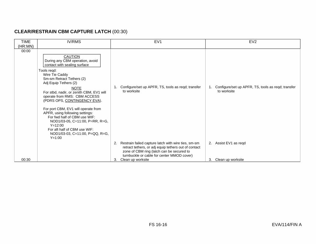
FS 16-16 EVA/114/FIN A
CLEAR/RESTRAIN CBM CAPTURE LATCH (00:30)
TIME (HR:MN)
IV/RMS EV1 EV2
00:00
CAUTION
During any CBM operation, avoid contact with sealing surface
Tools reqd: Wire Tie Caddy Sm-sm Retract Tethers (2) Adj Equip Tethers (2)
NOTE For stbd, nadir, or zenith CBM, EV1 will operate from RMS: CBM ACCESS (PDRS OPS, CONTINGENCY EVA). For port CBM, EV1 will operate from APFR, using following settings:
For fwd half of CBM use WIF: NOD1/03-05, C=11:00, P=RR, R=G, Y=12:00
For aft half of CBM use WIF: NOD1/03-03, C=11:00, P=QQ, R=G, Y=1:00
1. Configure/set up APFR, TS, tools as reqd; transfer to worksite
1. Configure/set up APFR, TS, tools as reqd; transfer to worksite
2. Restrain failed capture latch with wire ties, sm-sm retract tethers, or adj equip tethers out of contact zone of CBM ring (latch can be secured to turnbuckle or cable for center MMOD cover)
2. Assist EV1 as reqd
00:30 3. Clean up worksite 3. Clean up worksite

FS 16-17 EVA/114/FIN A
REMOVE/REPLACE CBM CONTROLLER ASSEMBLY (02:00)
TIME (HR:MN)
IV/RMS EV1 EV2
00:00
CAUTION
During any CBM operation, avoid contact with sealing surface
Tools reqd: Airlock: PGT RAD 6-in ext 5/32-in Allen Driver Seat Track Tether Points (2) Connector Tool TSA: EVA Ratchet
CONTROLLER REMOVAL CONTROLLER REMOVAL
NOTE
For stbd, nadir, or zenith CBM, EV1 will operate from the RMS: CBM ACCESS (PDRS OPS, CONTINGENCY EVA). For Lab stbd, zenith, nadir CBM, EV1 will operate from RMS. LAB FWD CBM ACCESS (PDRS OPS, EVA CONTINGENCY). For port CBM, EV1 will operate from APFR, using following settings:
For fwd half of CBM use WIF: NOD1/03-05, C=11:00, P=RR, R=G, Y=12:00
For aft half of CBM use WIF: NOD1/03-03, C=11:00, P=QQ, R=G, Y=1:00.
For Lab, port CBM, EV1 will operate from APFR using following settings:
WIF: LAB-13, C=2, P=XX, R=F, Y=12
1. Configure/set up APFR, TS, tools as reqd; transfer to worksite
1. Configure/set up APFR, TS, tools as reqd; transfer to worksite

FS 16-18 EVA/114/FIN A
REMOVE/REPLACE CBM CONTROLLER ASSEMBLY (02:00) (Cont)
TIME (HR:MN)
IV/RMS EV1 EV2
2. Remove MMOD center cover as reqd: REMOVE/REPLACE MMOD CENTER COVER
(EVA, ISS EVA CONTINGENCIES), COVER REMOVAL, steps 1-6
2. Assist EV1 as reqd
3. Attach tether point to seat track on failed controller 4. Disconnect cable connectors J1-J9 on controller
(use connector tool as reqd)
5. Disconnect grounding straps (two) from controller with EVA ratchet, 5/32-in Allen Driver
6. Tether to tether point on controller 7. Release fasteners (five) on controller assembly with
PGT, 5/32-in Allen Driver (15 ft-lb, 7-8 turns ccw; PGT: A5,CCW2,15.5); detach from bulkhead
01:00 8. Stow controller 00:00 CONTROLLER REPLACE CONTROLLER REPLACE
9. Install new controller; tighten fasteners (five) on controller assembly with PGT, 5/32-in Allen Driver (10 ft-lb, 7-8 turns cw, PGT: A5,CW2,10.5)
3. Assist EV1 as reqd
10. Remove tether point 11. Connect grounding straps (two) to controller
assembly with EVA ratchet, 5/32-in Allen Driver
12. Mate cable connectors J1-J9 to controller (use connector tool as reqd)
13. Reinstall MMOD center cover as reqd: REMOVE/REPLACE MMOD CENTER COVER (EVA, ISS EVA CONTINGENCIES), COVER REINSTALL, steps 1-7
01:00 14. Clean up worksite 4. Clean up worksite
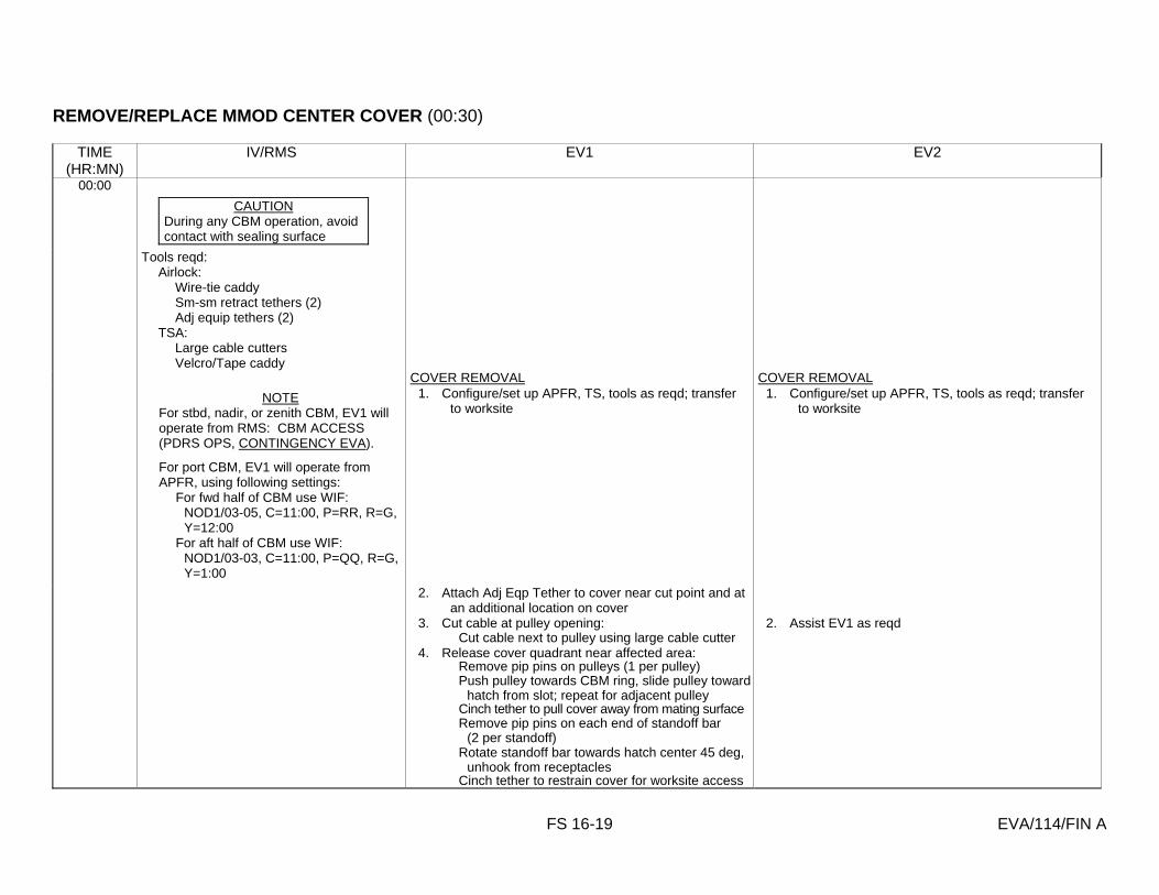
FS 16-19 EVA/114/FIN A
REMOVE/REPLACE MMOD CENTER COVER (00:30)
TIME (HR:MN)
IV/RMS EV1 EV2
00:00
CAUTION
During any CBM operation, avoid contact with sealing surface
Tools reqd: Airlock: Wire-tie caddy Sm-sm retract tethers (2) Adj equip tethers (2) TSA: Large cable cutters Velcro/Tape caddy
COVER REMOVAL COVER REMOVAL
NOTE
For stbd, nadir, or zenith CBM, EV1 will operate from RMS: CBM ACCESS (PDRS OPS, CONTINGENCY EVA). For port CBM, EV1 will operate from APFR, using following settings:
For fwd half of CBM use WIF: NOD1/03-05, C=11:00, P=RR, R=G, Y=12:00
For aft half of CBM use WIF: NOD1/03-03, C=11:00, P=QQ, R=G, Y=1:00
1. Configure/set up APFR, TS, tools as reqd; transfer to worksite
1. Configure/set up APFR, TS, tools as reqd; transfer to worksite
2. Attach Adj Eqp Tether to cover near cut point and at an additional location on cover
3. Cut cable at pulley opening: Cut cable next to pulley using large cable cutter
2. Assist EV1 as reqd
4. Release cover quadrant near affected area: Remove pip pins on pulleys (1 per pulley) Push pulley towards CBM ring, slide pulley toward
hatch from slot; repeat for adjacent pulley Cinch tether to pull cover away from mating surface Remove pip pins on each end of standoff bar
(2 per standoff) Rotate standoff bar towards hatch center 45 deg,
unhook from receptacles Cinch tether to restrain cover for worksite access

FS 16-20 EVA/114/FIN A
REMOVE/REPLACE MMOD CENTER COVER (00:30) (Cont)
TIME (HR:MN)
IV/RMS EV1 EV2
5. Repeat step 6 as reqd for other CBM quadrants; restrain cover open with sm-sm retract tethers or adj equip tethers
00:15 00:00 COVER REINSTALL COVER REINSTALL
6. Release/stow tethers used to restrain cover 3. Assist EV1 as reqd 7. Reinstall cover quadrant:
Reattach standoff bar, rotate outward 45 deg; reinstall pip pins if time permits (2 per standoff)
Insert pullies (two) back into slots (two); reinstall pip pins if times permits (1 per pulley)
8. Repeat step 3 as reqd for other removed CBM quadrants
9. Secure cover using tethers or wire ties as reqd 00:30 10. Clean up worksite 4. Clean up worksite

FS 18-1 EVA/114/FIN A
FL
IGH
T S
PE
CIF
IC
EV
A R
EF
FLIGHT SPECIFIC EVA REFERENCE
STS-114 PAYLOAD BAY LAYOUT ........................................................................ FS 18-3 ESP2 LAUNCH CONFIGURATION (TOP VIEW)................................................... FS 18-4 ESP2 LAUNCH CONFIGURATION (BOTTOM VIEW)........................................... FS 18-5 ESPAD COMPONENTS......................................................................................... FS 18-6 ACTIVE ESPAD...................................................................................................... FS 18-7 ESPAD LAUNCH BOLTS ....................................................................................... FS 18-8 EUTAS COMPLIANT BOLTS ................................................................................. FS 18-9 ESPAD INSTALL .................................................................................................... FS 18-10 EUTAS.................................................................................................................... FS 18-11 ESPAD STRUT....................................................................................................... FS 18-12 ESPAD STRUT DEPLOY ....................................................................................... FS 18-13 ESPAD V-GUIDE.................................................................................................... FS 18-14 ESPAD V-GUIDE CLOSEUP.................................................................................. FS 18-15 ESP2 INSTALL ....................................................................................................... FS 18-16 ESP2 POWER FROM ESP2 TO ORBITER ........................................................... FS 18-17 ESP2 ORBITER POWER CABLE STOWED.......................................................... FS 18-18 ESP2 POWER CABLES......................................................................................... FS 18-19 ESP2 FLIGHT CABLES.......................................................................................... FS 18-20 ESP2 CABLE TIES................................................................................................. FS 18-21 PRIMARY POWER CABLE ROUTING................................................................... FS 18-22 SECONDARY CABLE INSTALL – PANEL A119.................................................... FS 18-23 SECONDARY CABLE ROUTING........................................................................... FS 18-24 ACTIVE ESPAD HR LABELS................................................................................. FS 18-26 PASSIVE ESPAD HR LABELS............................................................................... FS 18-27 HR AND WIF LAYOUT (ZENITH)........................................................................... FS 18-28 HR AND WIF LAYOUT (NADIR)............................................................................. FS 18-29 MISSE LOCATIONS............................................................................................... FS 18-30 ESP2 FRGF............................................................................................................ FS 18-31 LMC WITH CMG..................................................................................................... FS 18-32 CMG NOMENCLATURE ........................................................................................ FS 18-33 CMG LOCATION .................................................................................................... FS 18-34 AFT Z1 PRE-LAUNCH WITH BLANKET ................................................................ FS 18-35 CMG ON Z1............................................................................................................ FS 18-36 CMG SHIMS AT Z1 ................................................................................................ FS 18-37 BLANKET CLOSED ON CMG IN FSE ................................................................... FS 18-38 NEW CMG WITH BLANKET................................................................................... FS 18-39 CMG IN FSE WITH MLI.......................................................................................... FS 18-40 CMG SHIMS ON FSE............................................................................................. FS 18-41 CMG FSE WITHOUT MLI OR CMG....................................................................... FS 18-42 CMG SWAP IN PLB................................................................................................ FS 18-43

FS 18-2 EVA/114/FIN A
FL
IGH
T S
PE
CIF
IC
EV
A R
EF
This Page Intentionally Blank
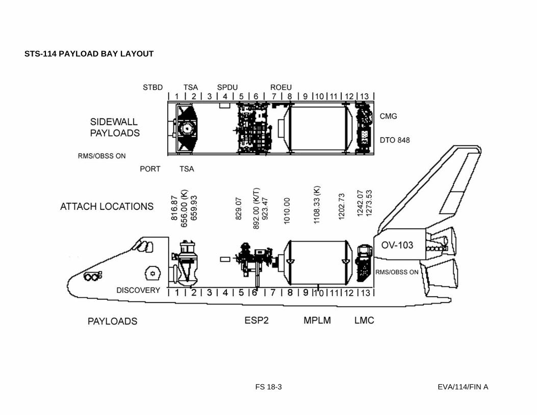
FS 18-3 EVA/114/FIN A
STS-114 PAYLOAD BAY LAYOUT

FS 18-4 EVA/114/FIN A
ESP2 LAUNCH CONFIGURATION (TOP VIEW)
KYA
Staged UCP
ESPAD
VSSA

FS 18-5 EVA/114/FIN A
ESP2 LAUNCH CONFIGURATION (BOTTOM VIEW)
KYA
FHRC
KYA
UTA
ESPAD
Empty FRAM Site
Staged UCP

FS 18-6 EVA/114/FIN A
ESPAD COMPONENTS
Active ESPAD
Passive ESPAD

FS 18-7 EVA/114/FIN A
ACTIVE ESPAD
3X Guide Vane Assy with Lock Down and Ready to Latch Indicator
EVA Deployable Strut, Interfaces with Airlock Girth Ring
Mechanical Berthing Claw Assy
2X 5/8” UTAS on Compliant Mount
EVA Handrails
3X Active FSE
Handrails
Handrails
Compliant Mount Launch Lock Interface

FS 18-8 EVA/114/FIN A
ESPAD LAUNCH BOLTS
Launch Bolt A, under strut
Launch Bolt B
Launch Bolt C
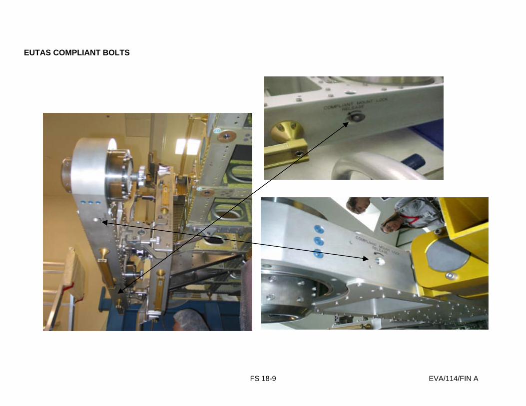
FS 18-9 EVA/114/FIN A
EUTAS COMPLIANT BOLTS
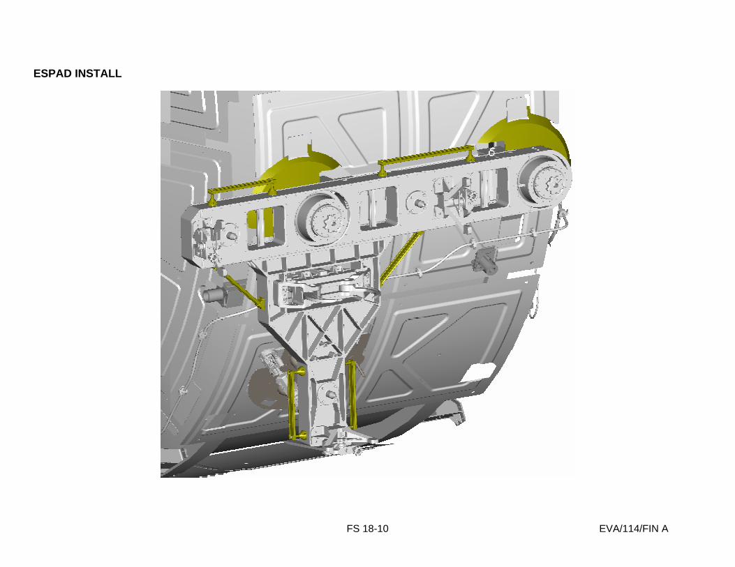
FS 18-10 EVA/114/FIN A
ESPAD INSTALL

FS 18-11 EVA/114/FIN A
EUTAS
EUTAS Bolt
Lock Bolt
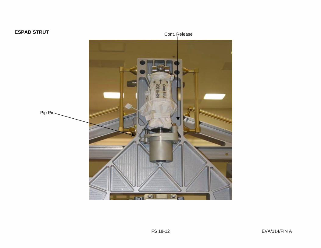
FS 18-12 EVA/114/FIN A
ESPAD STRUT
Pip Pin
Cont. Release
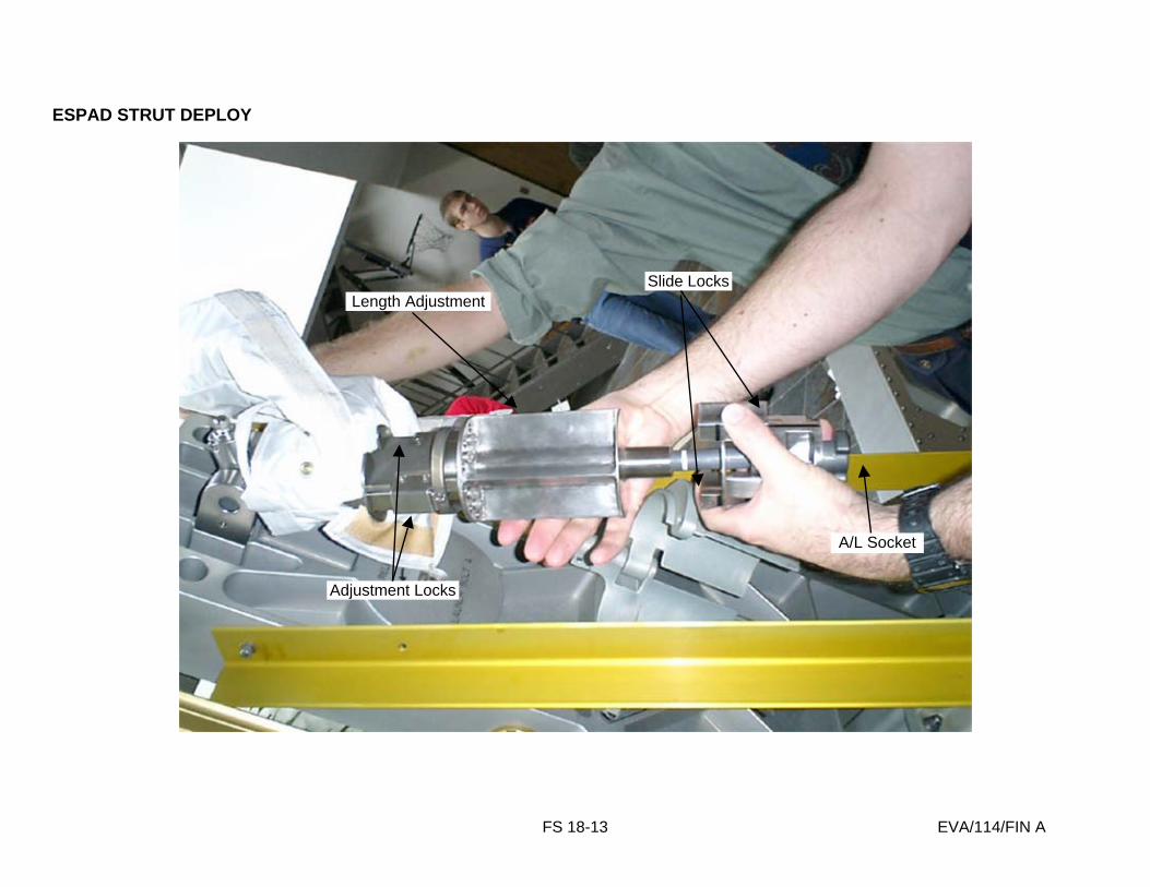
FS 18-13 EVA/114/FIN A
ESPAD STRUT DEPLOY
Slide Locks
A/L Socket
Length Adjustment
Adjustment Locks

FS 18-14 EVA/114/FIN A
ESPAD V-GUIDE
V-guide
RTL Indicator Bar
RTL Indicator
Latch closed, should be open for berthing

FS 18-15 EVA/114/FIN A
ESPAD V-GUIDE CLOSEUP
Knob Lock
Lock Down Bolt
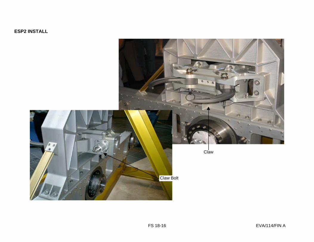
FS 18-16 EVA/114/FIN A
ESP2 INSTALL
Claw Bolt
Claw

FS 18-17 EVA/114/FIN A
ESP2 POWER FROM ESP2 TO ORBITER
Launch Configuration Landing Configuration

FS 18-18 EVA/114/FIN A
ESP2 ORBITER POWER CABLE STOWED

FS 18-19 EVA/114/FIN A
ESP2 POWER CABLES
S0 Truss
J57A
J602
P2 44.5 ft
18”
P1
17.1 ft
40”
Node-1
P57A
ISS Power
Power out to PMA-3 Shell Heaters
Plug to J64 deadfacing connector for future user
ISS Power
Primary Power to
ESP-2
Secondary Power to
ESP-2
ESP2-W1
ESP2-W2
8 splices
8 splices
44”
32”
ESP2
P602 Primary Power Cable
Secondary Power Cable
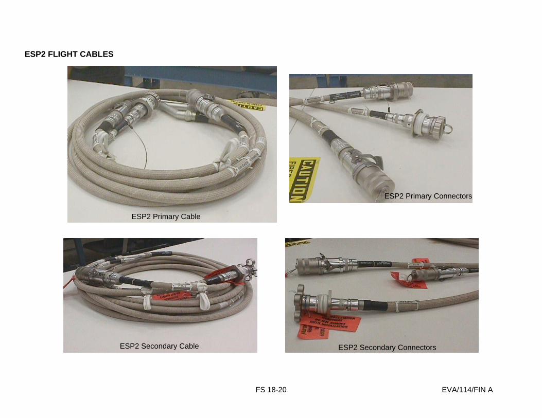
FS 18-20 EVA/114/FIN A
ESP2 FLIGHT CABLES
ESP2 Primary Cable
ESP2 Secondary Cable
ESP2 Primary Connectors
ESP2 Secondary Connectors

FS 18-21 EVA/114/FIN A
ESP2 CABLE TIES
Release Tab
20” - 37”
1.5”
Crew Label Area SS
Buckle
Tether Loop
Loop Velcro with Indicator Frame
Hook Velcro with Indicator Frame
Cable Tie ID Label

FS 18-22 EVA/114/FIN A
PRIMARY POWER CABLE ROUTING
N1-J602

FS 18-23 EVA/114/FIN A
SECONDARY CABLE INSTALL – PANEL A119
Panel A119
J64
P57

FS 18-24 EVA/114/FIN A
SECONDARY CABLE ROUTING
Keel Strut HR S0 HR 3437
MTS Strut Very Short HR
MTS Strut Long HR
MTS Strut Short HR
Very Short Lab HR
Lab HR 0215

FS 18-25 EVA/114/FIN A
SECONDARY CABLE ROUTING (Cont)
MTS Strut Short HR
Very Short Lab HR
Lab HR 0215
A/L HR 0519
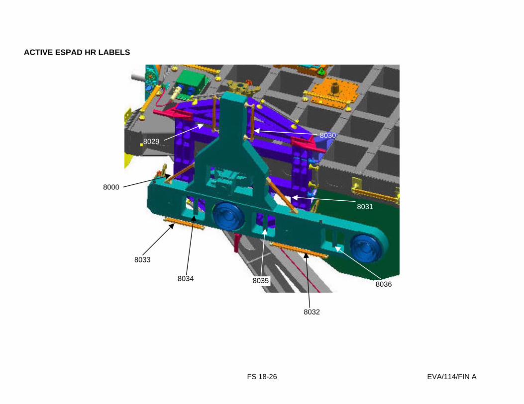
FS 18-26 EVA/114/FIN A
ACTIVE ESPAD HR LABELS
8033
8000
8032
8031
8030 8029
8034 8035 8036
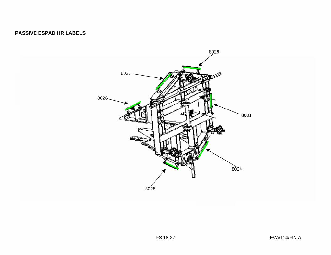
FS 18-27 EVA/114/FIN A
PASSIVE ESPAD HR LABELS
8025
8026
8024
8001
8027
8028
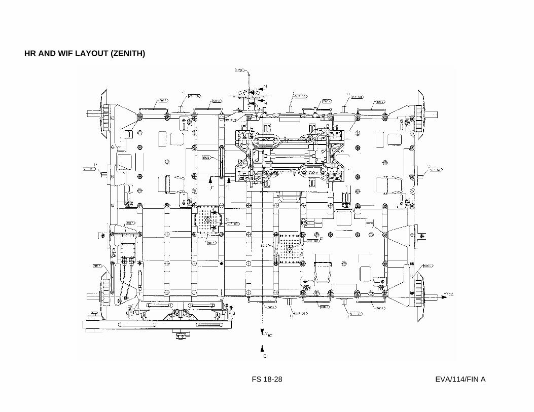
FS 18-28 EVA/114/FIN A
HR AND WIF LAYOUT (ZENITH)

FS 18-29 EVA/114/FIN A
HR AND WIF LAYOUT (NADIR)

FS 18-30 EVA/114/FIN A
MISSE LOCATIONS
PEC # 1
PEC # 2
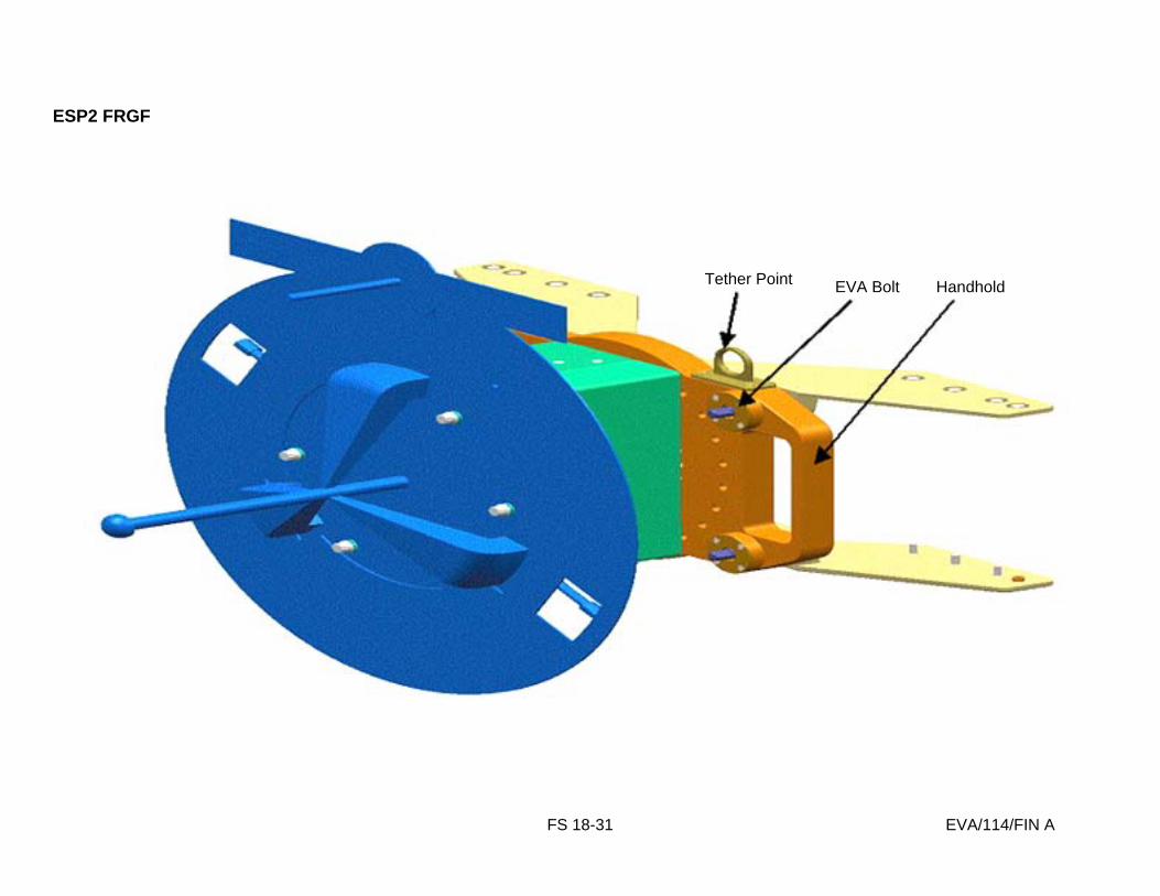
FS 18-31 EVA/114/FIN A
ESP2 FRGF
Tether Point EVA Bolt Handhold

FS 18-32 EVA/114/FIN A
LMC WITH CMG

FS 18-33 EVA/114/FIN A
CMG NOMENCLATURE

FS 18-34 EVA/114/FIN A
CMG LOCATION
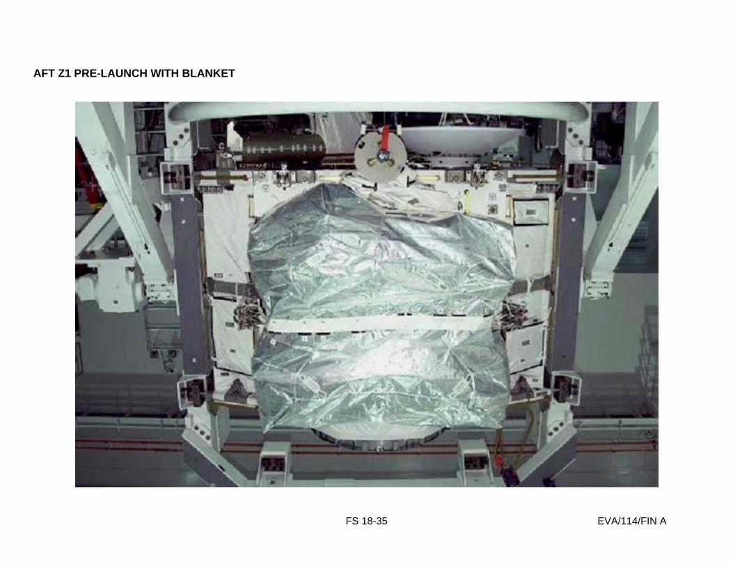
FS 18-35 EVA/114/FIN A
AFT Z1 PRE-LAUNCH WITH BLANKET

FS 18-36 EVA/114/FIN A
CMG ON Z1

FS 18-37 EVA/114/FIN A
CMG SHIMS AT Z1
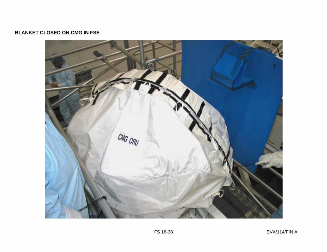
FS 18-38 EVA/114/FIN A
BLANKET CLOSED ON CMG IN FSE
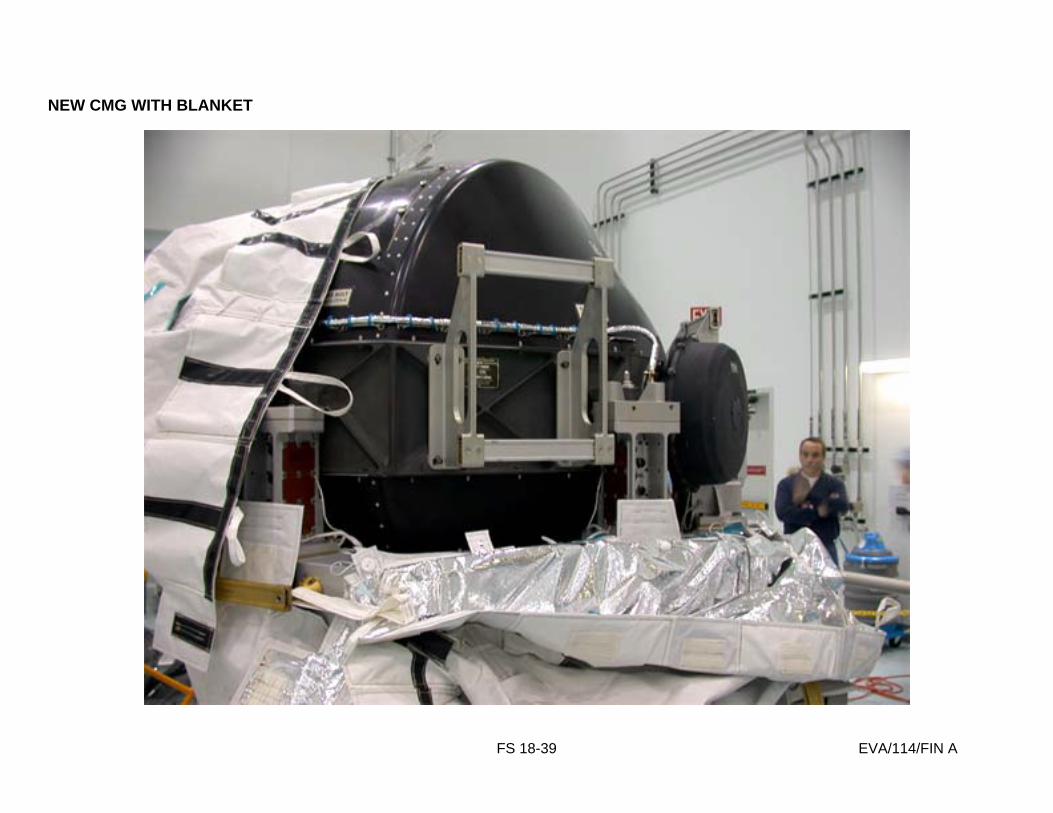
FS 18-39 EVA/114/FIN A
NEW CMG WITH BLANKET
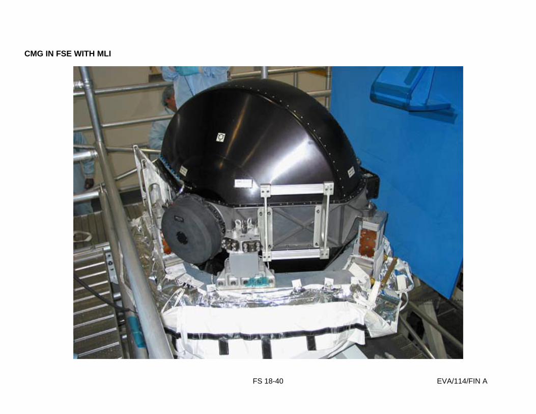
FS 18-40 EVA/114/FIN A
CMG IN FSE WITH MLI

FS 18-41 EVA/114/FIN A
CMG SHIMS ON FSE

FS 18-42 EVA/114/FIN A
CMG FSE WITHOUT MLI OR CMG

FS 18-43 EVA/114/FIN A
CMG SWAP IN PLB
Old
New

FS 18-44 EVA/114/FIN A
This Page Intentionally Blank

Flight Cover (trim bottom to expose tabs)
JSC-48024-114 FINAL, REV A
EVA CHECKLIST
STS
114
Related Documents