e r u t c e t i h c r A e v i t i d d A d e s a B - d e e p S e u q i n h c e T g n i r u t c a f u n a M f o l a i t n e t o P n g i s e D f o n o i t a r o l p x E d n a y r e v o c s i D g n i r u t c a f u n a M e v i t i d d A n i n o i t i s o p e D f o d e e p S e t i h o M o a r d n a n A h s i h s A L A R O T C O D S N O I T A T R E S S I D

Welcome message from author
This document is posted to help you gain knowledge. Please leave a comment to let me know what you think about it! Share it to your friends and learn new things together.
Transcript
-otl
aA
DD
0
8/
12
02
+dabea
e*GMFTSH
9
NBSI 3-0140-46-259-879 )detnirp(
NBSI 0-1140-46-259-879 )fdp(
NSSI 4394-9971 )detnirp(
NSSI 2494-9971 )fdp(
ytisrevinU otlaA
erutcetihcrA dna ngiseD ,strA fo loohcS
erutcetihcrA
fi.otlaa.www
+ SSENISUB YMONOCE
+ TRA
+ NGISED ERUTCETIHCRA
+ ECNEICS
YGOLONHCET
REVOSSORC
LAROTCOD SNOITATRESSID
eti
ho
M oa
rdna
nA
hsi
hsA
eu
qinh
ceT
g
nir
utca
fu
naM
evit
id
dA
des
aB-
de
ep
S y
tisr
evi
nU
otla
A
1202
erutcetihcrA
evitiddA desaB-deepS euqinhceT gnirutcafunaM
fo laitnetoP ngiseD fo noitarolpxE dna yrevocsiD gnirutcafunaM evitiddA ni noitisopeD fo deepS
etihoM oardnanA hsihsA
LAROTCOD SNOITATRESSID
Printed matter4041-0619
NO
RDIC
SWAN ECOLABE
L

1
Acknowledgements
First and foremost, I would like to dedicate this thesis to Mariia Kochneva, my partner in life and research. This work would not be possible without her insight and support.
I thank my supervising professors Toni Kotnik and Jouni Partanen for guiding the development of the thesis and my supervisor at Addlab Mika Salmi for let-ting me use Addlab’s resources to further my work.
Over the last nine years I have had a privilege of working in Addlab with Roy, Meng, Jukka and Oldouz who were always kind enough to help me tackle an unruly print or give a brilliant advice. I am also fortunate to be a part of ADS group and I owe a debt of gratitude to Luka and Kane for sharing their knowledge of computation and digital fabrication and along with my former stu-dent Porus helping me solve some particularly sticky scripting problems. I would also like to thank Tomi from ceramics studio who was an invaluable help in material design and Manuel from 3D print lab for accommodating my need to use studio machines for great many hours at a time.
I am also grateful to my research colleagues from AM group Inigo, Eero, Kirsi, Jan, Siddharth, Tuomas, Afshin, Niklas, Sergei and Jukka for providing a stim-ulating research environment.
I would like to thank my pre-examiners Associate Professor Negar Kalantar and Assistant Professor Benay Gursoy for their valuable feedback and recom-mendations on how to improve my thesis and Associate Professor Malgorzata Zboinska for generously agreeing to act as my opponent.
I would like to thank Kivi and Tuuli Sotamaa for believing in me and giving me an opportunity to come to Finland and start my research journey into 3D printing.
Finally, I thank my parents Kalpana and Anandrao and my sister Apeksha for being with me every step of the way. Espoo, 5 January 2021 Ashish Anandrao Mohite

3
Contents
1. Introduction .................................................................................. 9
2. Theoretical and practical background ......................................... 13
2.1 Technology and architecture ................................................... 13
2.1.1 Additive Manufacturing (AM) ................................................. 16
2.1.2 Large-scale AM ..................................................................... 16
2.1.3 Small scale AM .....................................................................18
2.1.4 The problem of geometric printability ................................ 20
2.2 Digital Craft ............................................................................. 22
2.2.1 Current discourse on craft in general, definitions and main themes 22
2.2.2 Digital craft in architectural theory, practice and research 24
2.2.3 Continuity of authorship ..................................................... 25
2.2.4 Skill ...................................................................................... 25
2.2.5 The object is a process model .............................................. 26
2.2.6 Digital Materiality ............................................................... 27
2.2.7 Control and risk ................................................................... 28
2.2.8 Surface variation ................................................................. 30
2.3 Practical precedents ................................................................ 34
2.4 Formulation of theoretical framework .................................... 41
3. Methodology ............................................................................... 44
3.1 Research by design .................................................................. 47
3.1.1 Tactics: Computational design and its artefacts ..................... 50
3.1.2 Small-scale AM as a research technique .............................. 51
3.1.3 Printing instructions - G-code ............................................. 53
3.2 System design ......................................................................... 55
3.2.1 Machine ............................................................................... 58
3.2.2 Material ................................................................................ 61
3.2.3 The digital process model .................................................... 63
4. Results and contribution to knowledge ...................................... 68

4
5
List of Abbreviations and Symbols
AEC architecture, engineering & construction
AM additive manufacturing.
API application programming interface
BIM building information modelling
BJ binder jetting
CAD computer aided design
CAM computer aided manufacturing
CNC computer numerical controlled
FDM fused deposition modelling
G-code stands for “Geometric Code”, it is the most widely used CNC pro- gramming language
IDE integrated development environment
NURBS non-uniform rational Bezier spline
PEM paste extrusion method
SLA stereo lithographic apparatus
SLS selective laser sintering
WAAM wire arc additive manufacturing
6
List of Publications
This doctoral dissertation consists of a summary and of the following publica-tions which are referred to in the text by their numerals. 1. Mohite, A., Kochneva, M. & Kotnik, T., The Making of Undesignable Tex-tural Effects, In: DIALECTIC a refereed journal of the School of Architecture. 4 in the year 2018
2. Mohite, A., Kochneva, M. & Kotnik, T., 2018, Material Agency in CAM of Undesignable Textural Effects - The study of correlation between material properties and textural formation engendered by experimentation with G-code of 3D printer. Kepczynska-Walczak, A. & Bialkowski, S. (eds.). 1 ed. Lodz: eCAADe, Vol. 2. p. 293-300 8 p.
3. Mohite, A. & Kotnik, T., 1 Sep 2019, Speed of Deposition: Vehicle for struc-tural and aesthetic expression in CAM. Architecture in the Age of the 4th In-dustrial Revolution: Proceedings of the 37th eCAADe and 23rd SIGraDi Con-ference. Sousa, JP., Xavier, JP. & Castro Henriques, G. (eds.). Porto, Portugal: eCAADe, Vol. 1. p. 729-738 10 p.

7
Author’s Contribution
The author is the sole author of the present Thesis and main author of Publica-tions 1–3.

9
1. Introduction
This doctoral thesis is a compilation of three published papers, preceded by an introductory chapter. The overarching topic of this research is generative po-tential of manipulating fabrication parameters in Additive Manufacturing(AM).
The research questions are: what architectural implications are latent in AM fabrication parameters, such as speed of movement? How can such parameters be instrumentalized to produce specific effects?
The parameters’ values and relationships are designed in G-code (computer numerical controlled (CNC) programming language) that controls automated machine tool and determines where and how it moves. Three appended papers present an explorative journey, dedicated to discovery, conceptualization and testing of a novel AM method. It is named Speed-Based AM technique because the main variable under study is speed of material deposition comprising speed of printer movement, material flow rate and geometry of print path.
The research is predicated upon theoretical and practical context of adoption of AM into architectural practice. From the point of view of research on inter-preting this technology for architecture it is in its early stages: workflows, ma-chine and material design, G-code are full of blank spots. Filling them with knowledge could change design and architecture in yet unforeseeable ways. Be-sides potential benefits in efficiency, sustainability, speed, it has a potential to expand architecture to fully embrace the material aspects of building. Material as building matter; how that matter is assembled or formed, its multiplicity and heterogeneity, its behaviour during and after structuring procedures, how small changes in its composition percolate throughout the whole design. Due to its simplicity and continuity, AM production process gives a chance to architects to get involved with the process of making itself, extending the realm of design from generation of notational digital model to executable process model. This extended field of design is where the research is located with focus on basic prin-ciples.
The basis of AM is layer-by-layer sequential massing. Conventionally, AM is used for precise reproduction of a digital model designated for manufacturing, so amount and distribution of mass directly corresponds to the digital counter-part. However, AM technology implies that massing can be affected by how the printer moves and how fast and where it extrudes. The slower extruder/tool-head moves and extrudes - the more matter it deposits, the faster – the less. In G-code it is possible to determine not only geometry of a toolpath and sequence of layers but also to assign specific speeds to specific print regions, and therefore
Introduction
10
change their massing. Massing has a range of important architectural functions depending on its scale. Large addition or removal of mass has tectonic, mereo-logical, morphological effects. Small-scale, surface level effects confined to an architectural element are mostly phenomenologically engaged, providing orna-mental, textural qualities. However, it could be argued that an accumulation of local differentiation in mass distribution can affect overall structural perfor-mance. Manipulation of G-code allows maker to adjust massing virtually at any scale of the object. In order to maintain control over results and to keep the de-gree of deviation from the original digital model within a moderate range mostly surface-scale variation is the object of investigation.
The general aim of the thesis is: to develop an essential structure for Speed-Based AM technique by determining most prominent relationships, causalities, and dependencies within speed of deposition and between it and other elements of the production system.
The objectives are: -To design a generic production system consisting of a material, AM fabrica-
tion machine and G-code. All elements must be interdependent. Each element must contribute to generation of mass variation, detectable on the printed ob-ject.
-To experiment with the process model (G-code) by iteratively changing pa-rameters that constitute speed of deposition: movement speed, printpath geom-etry, order, density and distribution of affected points or segments of the printpath, material flowrate. Determine relationships between them when ma-nipulating mass distribution.
-To test the performance of the system when other main elements, material and the machine are replaced. Compare several variations in terms of printed results, and necessary adjustments to the system and production process itself.
-To design and execute a series of experiments to determine possible architec-tural applications of the technique. Select an issue that is empirically measura-ble, design and print a series of objects to test the performance of Speed-Based technique. Introduce minimal formal variation and increase scale to boost spec-ificity. Connect the model of interdependencies within the process model to ma-terial expressions of specific formal tectonic scenarios.
This research finds its theoretical and practical background in the work on principles and problems of Additive Manufacturing (AM), specifically in the field of design and architecture and in the discourse on digital craft’s main prin-ciples, procedures, and outcomes. In a larger context research is positioned within an area dedicated to discussion on a relationship between technology and architecture, as the space of investigation is an extension of design towards making through technological means of digital fabrication. Concepts associated with digital craft guide utilization of the technology of AM, provide a theoretical framework for constructing Speed-Based technique and explain the effects which are present in the printed models. The gap, identified during literature review concerns lack of data on rigorously using printer’s speed of deposition as a driver for design. Outlining its functions and relationships, properties and ca-
Introduction
11
pacities may contribute to theory by discussing the connection between tech-nical parameters and design and to practice by adding a tool to the digital maker’s design apparatus.
In terms of ontological/epistemological stand this research is designed to be part testable, part exploratory interpretive theory. Following the principles of research by design methodology, series of experiments were constructed to test specific propositions and draw empirical conclusions from results, while overall approach positions the study as an interpretation of practice. From the start, the problem was not strictly defined, the research was conducted in an iterative manner gathering data and forming loose hypotheses on generative potential of speed of deposition. Abstracted principles of digital craft form the theoretical framework. Continuity of authorship and logic and experimental essence of dig-ital craft determined the choice of methodology of research by design. Focus on the process and material aspects of making contribute to the tactics of printing a series of models. Their small scale is determined by lack of resources and by a hypothesis that once Speed-Based technique is resolved, it would be possible to scale it in a rather straightforward manner. That hypothesis was tested at a two-week workshop that I led at the University of Southern Denmark in August 2020 (see Appendix 1). At the start, an explanation and a demonstration of the tech-nique was provided to the students. During the workshop they were able to use the Speed-Based technique in large scale concrete robotic 3d printing and achieve results that were consistent with the ones presented in this thesis. That first foray towards testing repeatability of the research and applicability of the technique at an architectural scale provides a tentative validation of the research and its results. As at this stage, the research attempts to create only foundations of the technique, small-scale iterative modelling is deemed sufficient. Printed prototypes serve as the materialization of an instance generated by a system, thus allowing to observe undesignable material behaviour. On the other hand, they guide the course of the research development by providing concrete feed-back used for further system editing.
Overall, the operational system within which Speed-Based technique is per-forming consists of material, machine and fabrication instructions, or G-code. Each is treated as a super-variable (assuming there are variables within them) and a space for experimentation. When possible, material and machine are modified or built. G-code is the main digital product of the research, consisting of families of process models specified or abstracted to various degrees. As there is no intention to design a specific object for concrete conditions, but rather to develop a tool for design, the digital process model stays relatively abstract, al-most uninformed by formal, functional, contextual parameters. However, it is iteratively designed to contain information about fabrication and to depend on material properties. It is developed to encapsulate the tacit knowledge formed through many experiments. The failures, where a predetermined level of con-trol was lost, contributed to the design, by determining values or ranges of cer-tain parameters or revealing unanticipated dependencies.
In three published papers, which follow this introduction, the exact process of building Speed-Based technique through experimental, iterative making is
Introduction
12
described in detail. Each paper corresponds to a certain phase of the research: discovery, exploration, and testing for application. Discovery phase, docu-mented in “The Making of Undesignable Textural Effects” consisted of estab-lishing the primary principles of Speed-Based technique through experimenta-tion with FDM in plastic. “The Material Agency in CAM of Undesignable Tex-tural Effects” deals with the question of change of super-variable, such as fabri-cation machine or material. This stage is explorative, attempting to gain data on the production system as a whole. “Speed of Deposition: Vehicle for Structural and Textural Expression in CAM” paper is dedicated to tackling the issue of printability of cantilever and bridging geometry and attempts to build an argu-ment on potential applications of the Speed-Based technique in architecture. To summarize, the design of experimental setup starts from generic, and becomes more and more informed. That transition can be traced throughout the papers.
In this introduction, the research is positioned within the existing discussion on challenges of exploration and application of Additive Manufacturing tech-nology within current computational practices in architecture. Methodological and theoretical frameworks are established. Materials, attempting to articulate gained knowledge, are presented with emphasis on synthesizing tacit aspects into explicit data.
Theoretical and practical background
13
2. Theoretical and practical background
Following sections focus on Additive Manufacturing technology and princi-ples of digital craft within larger discourse on impact of digital technologies on architecture. A brief history of AM and its applications in architecture is pro-vided, challenges specific to the technology are discussed. Then, main concepts relating to contemporary interpretation of craft are determined, forming a framework, within which principles of digital craft in architecture are con-structed. An interpretation of digital craft for this research is established. To form epistemological and ontological guidelines, several practical precedents are presented. As a conclusion, gaps in existing knowledge are presented, and a theoretical framework for defining methods of data production and analysis is constructed in relation to research aims and objectives.
2.1 Technology and architecture
Architecture depends upon its time. It is the crystallization of its inner structure, the slow unfolding of its form. That is the reason why technology and architecture are so closely related. Our real
hope is that they will grow together, that someday the one will be the expression of the other. Only then will we have an architecture
worthy of its name: architecture as a true symbol of our time.
Mies van der Rohe (Mies van der Rohe and Puente 2008, 9)
Architecture, as a discipline that is primarily concerned with activities of de-signing and building is inexorably entwined with its modes of representation and construction. Pre-digital dichotomy between the two-dimensional space of notational drawings and three-dimensional, material territory of a built struc-ture is mused upon by Robin Evans. “The two options, one emphasizing the cor-poreal properties of things made, the other concentrating on the disembodied properties in the drawing, are diametrically opposed: in the one corner, involve-ment, substantiality, tangibility, presence, immediacy, direct action; in the other, disengagement, obliqueness, abstraction, mediation and action at a dis-tance. They are opposed but not necessarily incompatible…”(Evans 1997, 160-161). In “Translations from Drawing to Building” Robin Evans is uncertain of the way to unite them; now, permeation of digital technology throughout both design and construction facets of architecture provides opportunities for that unification.
Theoretical and practical background
14
For a long time, Mario Carpo argues in The Second Digital Turn, architecture has been dragging behind the technology, not quite able to adopt it in a mean-ingful way (Carpo 2018). Rapid expansion of digital technologies into the field of architecture has brought along an ubiquitous shift in thinking and making. In the last 30 years, building design has become a highly digitized practice, from concept modeling and digital sketching to Building Information Modelling (BIM) and performance simulations. In commercial practices the preoccupation has been with optimization and reduction of unpredictability throughout the whole process, which aligned harmoniously with 2D digital drawing and infor-mation module management (Gourdoukis and Alberti 2017).
More innovation oriented institutions and practitioners have explored inscru-table aspects of CAD and dove into NURBS modeling, which became a flagship technique of the Avant-garde digital architecture in the 1990s-early 2000s (The First Digital Wave)(Carpo 2018). The weightlessness and absolute disembodi-ment encouraged freeform exploration into what could be modeled (not built) in a given software, and mathematics of Bezier curves now available to archi-tects in an encapsulated, easy to use, instrumental format has given the world blob architecture. Curvilinearity has eventually become simply one of the stylis-tic options, but what remained and became the foundation for digital paramet-ricism was the original principle of digital customized variation - “a deep-rooted ambition of architects and designers, craftsmen and engineers of all times and places” (Carpo 2018, 3). Building a digital model that interweaves a diverse range of data driven by parameters is a widespread practice now. Its origin re-sides in the work of Gilles Deleuze and his former student Bernard Cache on industrial means of producing non-standard objects (Klinger, 2001). Objectiles are “repeatable variations on a theme, such as a family of curves declining the same mathematical model; objects in flux, inflected like the signal modulating a carrier wave; or lines and surfaces of variable curve, such as the folds of ba-roque sculpture or the decorative bands of plant motifs” (Bernard Cache 2011, 20). This procedural principle of making a generic parametric notation implies a possibility of distributed authorship and contextual adaptability in architec-tural production. A generic algorithm devoid of specificity is only a potential, in a given context parameters are adjusted by specialized authors to achieve cer-tain performative goals. Participatory logic of designing has found its most op-timized expression in BIM, where all design, construction and management agents operate within one information model, producing a design by committee model of authorship. Defining principles of BIM are compromise and consen-sus, which often mean preference for safe and bland solutions. Nevertheless, Carpo argues that the true open participatory model of aggregation, following the example of open-source software is perhaps never to be realized, for archi-tects of the second digital wave are hardly interested in letting go of creative control (Carpo 2013).
Initially, CAD tools brought a further disconnect between the architect and the actual building by providing them with an ability to practice geometric dex-terity on a screen utterly disconnected from the real-world construction. Once, however, digital design fully embraced its corresponding production partner -
Theoretical and practical background
15
digital fabrication, the trajectory has changed. The most commonly used tech-nique is 2D fabrication or CNC cutting of planar materials with various technol-ogies. They require the 3D model to be made into flat components. First adopted 3D manufacturing technology was subtractive fabrication, CNC multi-axis mill-ing used to remove pre-specified volume of material from solids. Already in the late 1980s milling machines were employed in making construction parts and prototypes, later focusing more on making formwork for concrete and glass casting (Kolarevic 2004). Additive manufacturing (AM) of layer-by-layer form-ing of 3D objects became widespread much later in the late 2000s with an in-troduction of affordable 3D printers to the market. Mario Carpo argues that ad-ditive manufacturing is the dominant production method of the current digital age for two reasons. First is its informational logic, for AM to produce anything it needs information about each consecutive locality, nothing within printing resolution can be left blank. The other reason is that with 3D printing designers have no incentive whatsoever to make copies of the same object, the same vol-ume of material, no matter how geometrically organized will always cost the same (Carpo 2018). Variation, previously exercised at the scale of formal con-figuration can now be generated at the level of surface ornament. On the one hand, that implies an unprecedented ability to design the minutest of scales and on the other, a potential for design agency of machine-material intricate mech-anisms of mutual feedback.
Timeless questions about space and form can now be rethought through ma-terial behaviour and performance; they can be translated into a system of inde-terminate physical relationships. However, that means that suddenly, an archi-tect becomes a maker of machining instructions. Consisting of codes, scripts, protocols, both hardware and software programming languages, patterns, rou-tines, the instructions eventually become actuated in a specific material system. A practice like that requires a retooling of architectural thinking as Carpo notes: “as the digital revolution of the 1990s (new machines, same old science) begot a new way of making, today’s computational revolution, or The Second Digital Turn (same machines, but a brand-new science) is begetting a new way of think-ing” (Carpo 2018, 7). This shift in perspective on how a digital maker approaches design has challenged the long-established paradigm of architect as a maker of drawings, not buildings. Digital fabrication practices “have a potential to narrow the gap between representation and building, affording a hypothetically seam-less connection between design and making” (Iwamoto 2009, 5). The gap cer-tainly remains, for making machining instructions still involves a level of ab-straction, specifics of which are determined by exact information processing techniques at designer’s disposal. What remains unchanged is that architecture is “a promiscuous mixture of the real and the abstract: at once a collection of activities characterized by a high degree of abstraction, and at the same time directed towards the production of materials and products that are undeniably real”(Allen 2012, XXI). The tools are never neutral; and designing for making is affected not by a specific drawing technique but by a multiplicity of interwoven procedures (Allen, 1999). Material properties and behaviours need to be para-
Theoretical and practical background
16
metrisized, converted into numerical notations and variables, become ab-stracted into data. That tension between abstracting the material and actuating the digital is the process that attempts to reconcile drawing and building.
The almost rhetorical nature of the question, posed by Robin Evans about the possibility of continuity between designing and building has become dialectic. Now the questions that theoreticians and practitioners work on have traversed from potentialities of ‘what if’ towards specificities of ‘how’. The digital crafts-men of The Second Digital Turn experiment with CAM to build a solid bridge between discrete, intractable matter and digital notation.
2.1.1 Additive Manufacturing (AM)
Digital fabrication is a general term that lies at the intersection of CAD (com-puter-aided design) and CAM (computer-aided manufacturing) and describes production processes that employ computer-controlled machines. Many addi-tive, subtractive, formative techniques fall under the umbrella of digital fabrica-tion. Additive manufacturing (AM) (Wohlers et al. 2020), previously referred to as rapid prototyping (Gibson, Rosen, and Stucker 2010, 2), is based on the prin-ciple of adding material in layer-by-layer manner (Kolarevic 2004), each layer is a section of a CAD model, turned into instructions and transferred to the pro-cessing head of the machine (Jacobs and Reid 1992). One of the instigating fac-tors for the development of AM technology was that subtractive technology (CNC machining) was slow and difficult to operate (Gibson et al. 2010). One of AM’s defining characteristics is that a model can be fabricated within a much simplified (compared to other manufacturing processes) framework of process planning. At its core, AM requires a very basic geometry, machine and material understanding (Gibson et al. 2010). The crucial factor is the height of each layer, the thinner they are the higher fidelity to the digital model is achieved. Additive manufacturing technologies encompass a wide range of machines, differenti-ated by the materials that can be used and how layers are attached to each other. The first commercial use of AM by 3D Systems in 1988 was based on Stereo-lithography (SLA), a process that uses UV light-sensitive liquid polymers, cured by a laser. There are many ways to classify AM technologies, there are taxono-mies based on the underlying technology (Wohlers et al. 2020), type of the raw material used (Ritter 2019). Ian Gibson et al. amend a matrix-like classification proposed by Pham that considers both the raw material and the number and distribution of printing heads (Gibson et al. 2010). For the purposes of this re-search, it suffices to describe the few technologies, which are currently used in the field of architecture.
AM in architecture
2.1.2 Large-scale AM
Currently there are two AM techniques for producing buildings or large-scale building elements. These two experimental approaches are Wire and Arc Addi-tive Manufacturing (WAAM) for metal and Paste Extrusion Modeling (PEM)
Theoretical and practical background
17
and Binder Jetting(BJ) for concrete like materials. They are still in their nascent stages, far from full adoption by the AEC industry.
Titanium, aluminium, steel and other materials can be deposited in large quantities using WAAM, which involves melting metal wire by arc welding and applied locally in layers to make large near-net-shape metal structures (Wil-liams et al. 2016). The motion is usually accomplished by a robotic system or a CNC gantry. WAAM has a higher deposition rate than other metal AM pro-cesses, it is also relatively cheap to build and operate (Marinelli et al. 2019). However, it is a process that is replete with variables and it will take much fur-ther research to arrive at full comprehension of all dependencies, so that the material, production equipment and process parameters can be chosen for each specific case (Feucht and Lange, 2019). The most prominent to date project is a stainless-steel bridge installed in February 2020 in Amsterdam, printed by a Dutch company MX3D and designed by Joris Laarman Lab in collaboration with Arup ("MX3D Bridge | MX3D" 2020).
The terms for most developed concrete AM techniques are Contour Crafting (Khoshnevis 2002) and Concrete Printing (Lim et al. 2012), both are based on extruding a cement-based paste by a deposition head mounted on a robotic sys-tem, crane or gantry. The main difference is that with Contour Crafting due to the trowel, attached to the printing head against which deposition occurs the resulting prints are smoother and layer demarcations are not as prominent. Both are wet processes that produce objects that require curing and they both have to work around the over-hang issue by either avoiding it through design or printing in parts, or by employing a secondary material as scaffolding deposited during printing that is easy to remove afterwards (Lim et al. 2012). Making con-crete structures without the need for any formwork offers unprecedented op-portunities for innovation in formal language, construction process manage-ment and design, at the same time, free flowing concrete has to be shaped, re-inforced, evaluated all at the same stage, which presents significant challenges for wide-scale adoption (Anton et al. 2019).
Advantages of using concrete 3D printing in AEC are increase in sustainabil-ity, decrease in production times and labour costs (Starr 2015), potentially greater formal freedom in commercial architecture (Marijnissen and van Der Zee 2017). Notable examples of large-scale concrete 3D printed structures in-clude Arup’s and CLS Architetti’s prototype 3D printed house for Milan Design week in 2018 (Morris 2020), two-storey office building in Dubai by Apis Core (Block 2020) and a pedestrian bridge in Shanghai designed by Tsinghua Uni-versity School of Architecture's Zoina Land Joint Research Center for Digital Architecture (JCDA) and built by Shanghai Wisdom Bay Investment Manage-ment Company (Ravenscroft 2020). In Apis Core’s case a single, crane-moved robot with an extruder head was used to print walls on-site. Reinforcement oc-curred after the printing with metal rebars. Roofs, floors, lintels were cast and placed, thus avoiding the challenge of printing cantilever geometry. The bridge in Shanghai is made from 176 printed units and does not have any reinforce-ment at all.
Theoretical and practical background
18
Overall, at this stage printed examples’ main objective appears to be adoption of the technology by the AEC market. The structures are designed and executed to demonstrate mostly financial benefits of large-scale concrete 3D printing. At the same time, many universities are experimenting with the technology. For example, TU Eindhoven established a 3D Concrete Printing research group that is dedicated to working through various aspects of the process in order to estab-lish it as a viable construction method (Engineeri... and Printing 2020).
2.1.3 Small scale AM
Until recently, the use of additive manufacturing techniques was rather lim-ited because of the size of the objects that they were able to produce and the time it took to make them. Machines were mostly commercial 3D polymer printers, generally based on SLA, selective laser sintering (SLS) and fused deposition modeling (FDM). These machines are used during the design process to con-ceptualize and test massing and formal arrangements as well as generate de-monstrator models of the overall shape at the end of the design process. Plastic small scale prints are also used to fabricate building component prototypes, while final objects are manufactured by more traditional moulding and casting techniques (Dunn 2012).
Selective laser sintering (SLS) from DTM (now a part of 3D Systems) uses a laser to selectively fuse thermoplastic powder. In 1991, Stratasys patented Fused Deposition Modeling (FDM) that involves extrusion of thermoplastic filament along a predetermined path that solidifies upon cooling. FDM printers are wide-spread in large part due to their low cost, which makes this technology particularly well-suited for prototyping. Some of the characteristics of FDM are that the objects are fabricated from bottom up and that while it can print slight overhangs, any significant shift between the layers requires intervention. It could be printed by using support structures, makeshift scaffolding, or specific manipulations of the printing parameters.
In commercial as well as architectural school settings, a typical relationship between an architect and a plastic 3D printer is one of convenience of default settings and blank remoteness. The printer is often perceived as a black box, doing something intractable. Lack of technical knowledge results in models mysteriously failing, and designers progressing further on the path towards an absolute divorce between designing and making. Even if the model is deemed successful (faithful to the digital parent), the very workflow of predictability, au-tomatic slicing into layers, translation into G-Code (the standard machine pro-gramming language), resorting to optimal settings prevent the user from ques-tioning in what way the model is successful and continuing experimentation.
Whereas plastic printed objects are usually used in architectural practice as process models or prototypes, clay 3D printed objects are usually either a final assembly piece or a research model. Ceramic tiles and clay bricks are some of the most traditional structural and ornamental elements, produced with AM their geometry can be parametrically variated, the mass - porous, the shape - designed to interlock, the material – performative (Rael and Fratello 2018). At
Theoretical and practical background
19
the same time, more research oriented architects, designers, artists are experi-menting with clay printing (Gürsoy 2018; Seppala et al. 2017) because unlike plastic it offers a large field for manipulation before, during and after printing. Clay’s properties are sufficiently volatile to serve as actual variables; printing instructions affect the outcome in often unpredictable ways, after printing the clay is moist and will alter shape and size when air-dried or fired in a kiln (Gürsoy 2018). All these uncertainties present a compelling space for working out potentials and determining dependencies.
There are two wide-spread techniques for clay 3D printing: Paste Extrusion Modeling (PEM), suitable for any pasty material, and Binder Jetting (BJ), mostly used with sand or gypsum. BJ, invented in MIT in 1993 is a technology of spraying liquid binder material on a powder substrate, thus selectively solid-ifying it (Rael and Fratello 2018). Then the next layer of powder is rolled out on top of the previous layer, and binder is sprayed again. This sequence is repeated until the part is printed, then it is excavated from the unbound, loose powder, cleaned, and possibly coated with wax, glue or epoxy. It is important to note, that in BJ process, the model’s overhangs (cantilevers, holes) are supported by the surrounding powder, so there is no need for any arrangements of supports. Also, there is no clear demarcation of layers in the resulting object, so the fidelity to digital model is very high. While such precision has its undoubtful advantages for the production of assembly elements, the research potential is somewhat limited. PEM, on the other hand, is a process of simple squeezing of the paste from the nozzle onto a build platform (Formnext 2019). The extrusion is per-formed by air pressure or ram pressure, so it can work with any material that can maintain paste-like consistency for a sufficient amount of time, for example cement or chocolate. This method requires understanding of the overhangs and working out techniques for handling them. Objects printed with PEM have vis-ible layer marks, which means that if the toolpath is manipulated, the printed model will exhibit traces of that manipulation. The tool leaves an imprint. In general, PEM printers are very affordable and relatively easy to make, which opens the technology to a wide audience of designers and makers, fostering in-novation and unexpected approaches.
Small-scale models are not directly scalable to architectural dimensions, sim-ple geometric scaling would not faithfully represent or rigorously explore the complexities of architectural spatial configurations, surface ornamentation, structural relationships, all the data and matter that constitute a building. For many practitioners small scale models are only a quick way of 3D material sketching, the model is matter, yet it remains an abstract representation of shape (Sass and Oxman 2006). There are however some considerations in favor of using small scale models for highly specified and scalable explorations. If the interest lies in understanding performance of a several or more materials trans-lated through a specific AM technology(ies), determining how to work in a cer-tain medium, finding out affordances and constraints immanent to the process, then small scale models, printed and reprinted in batches and series is a valid technique. It is so for Ronald Rael and Viginia San Fratello from Emergent Ob-
Theoretical and practical background
20
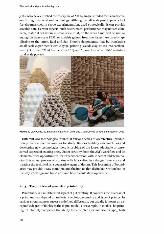
jects, who have enriched the discipline of AM by single-minded focus on discov-ery through material and technology. Although small scale prototype is a tool for circumscribed in scope experimentation, used strategically, it can provide scalable data. Certain aspects, such as structural performance may not scale lin-early, material behaviour in small scale PEM, on the other hand, will be similar enough in large scale PEM, so insights gained from the former are directly ap-plicable to the latter. Rael and San Fratello demonstrate that by translating small-scale experiments with clay 3D printing (Gcode.clay, 2016) into earthen-ware 3D printed “Mud frontiers” in 2019 and “Casa Covida” in 2020 architec-tural scale projects.
Figure 1. Clay.Code, by Emerging Objects in 2016 and Casa Covida by rael-sanfratello in 2020
Different AM technologies utilized at various scales of architectural produc-tion provide numerous avenues for study. Besides building new machines and developing new technologies there is probing of the loose, adaptable or unre-solved aspects of existing ones. Under scrutiny, both the AM’s workflow and its elements offer opportunities for experimentation with inherent indetermina-cies. It is a dual process of working with fabrication in a design framework and treating the technical as a generative agent of design. This loosening of bound-aries may provide a way to understand the impact that digital fabrication has on the way we design and build now and how it could develop in time.
2.1.4 The problem of geometric printability
Printability is a multifaceted aspect of 3D printing. It concerns the ‘success’ of a print and can depend on material rheology, geometry and type of printer. In various circumstances success is defined differently, but usually it means an ac-ceptable degree of fidelity to the digital model. For example, in medical bioprint-ing, printability comprises the ability to be printed (for material, shape), high
Theoretical and practical background
21
resolution of detail and shape fidelity and reproducibility (Kyle et al. 2017). The parameters that affect printability are numerous and concern various parts of the printing setup. Material composition and rheology, printing parameters such as layer height, geometry of sharp angles and many others have an impact on the gap between the design file and the printed part. Printability is therefore context-dependent and relates to specific make-up of attributes within each de-sign.
Until now, the research related to printability in AM was focused mainly on understanding factors that improve connectivity between layers of the print or adjusting material to control flowability and therefore extrudability and curing time to control during and post-print deformation. For example, in FDM print-ing, how extrusion temperature and print speeds affect inter-layer weld strength (Seppala et al. 2017), or a study of Popescu et al. on how different settings of printing parameters affect the mechanical performance of the products (Popescu et al. 2018). In PEM, research is done on designing material composi-tions that facilitate interlayer adhesion (Nguyen, Bowland, and Naskar 2018) and ways of determining extrudability of cementitious materials (Nerella et al. 2019). In large scale slurry AM, Ketel et al. devise a way to examine the printed object in relation to its digital model using laser triangulation-based 3D-scan-ning, and by adjusting rheology of the slurry they generate data on the relation-ship between material composition and printability (Ketel et al. 2019).
In many cases of geometrical issues of sharp angles, concave and convex shapes, overhangs, hollow parts adjustment of material composition or design of infill or variation of layer height can be a solution (Kain et al. 2020). However, when specifically the printability of overhanging geometry is a concern, there are not many options. The very nature of putting material layer by layer means that cantilever or bridging geometries have to be printed over a void, with no support. In certain types of printing, for example in FDM this problem is solved by creating very thin supports, designed in G-code, which are later removed from the printed part (Vantyghem et al. 2019). The problem of printing hollow objects, where infill is undesirable and supplemental supports are difficult to remove is usually solved by partitioning the object into several parts and then joining them together (Wei, Zhang, and Geng 2016). In BJ, where dry, powder material is laid on the print bed and then binder droplets are selectively applied locally, sticking the powder together, the remaining powder acts as a support structure for all overhanging parts.
However, in PEM printing, makers resort to supporting their overhangs with make-shift foam blocks, or like in FDM, printing the model in parts. Currently, there is no literature on solving the problem of geometric printability by system-atic manipulation of printing parameters. Unlike flowability of material, geo-metric printability is directly related to design. There is a gap in conceptualizing this problem for architecture as a problem of buildability, and in providing in-trinsic to the technology solutions for it.
Theoretical and practical background
22
2.2 Digital Craft
2.2.1 Current discourse on craft in general, definitions and main themes
Digital craft, as a set of practices and discourses evolved in the last twenty
years, is a modern version or a digital age interpretation of the traditional con-cept of craft. Recently there have been a number of books, articles, exhibitions on the topic of craft, which with the advent of post-industrialism has re-emerged as a once again relevant framework for design and production. In this research on the relationship between design and digital fabrication, craft as a way of mak-ing is a natural construct to explore and utilize. This and following sections pro-vide an overview of contemporary thought on craft in general and then focus on digital craft in architecture, attempting to highlight its most pertinent aspects. The selection of the following and admittedly diverse in scope positions on how to reformulate the notion of traditional craft and position it within contempo-rary reality is rooted in the intention to employ it as a guiding principle both in conceptual structure and methodology of the research.
Malcom McCullough in Abstracting Craft investigates the possibility of craft practices re-emerging in the digital realm. In attempts to distill its immutable essence, McCullough states: “[craft] is habitual skilled practice with particular tools, materials, or media, for the purpose of making increasingly well executed artefacts. Craft is the application of personal knowledge to the giving of form. It is the condition in which the inherent qualities and economies of the media are encouraged to shape both process and products” (McCullough 1998, 22). Rich-ard Sennett presents traditional craftsmanship as an almost ineffable activity that is a dialogue between the analytic and inquisitive head and the skilled hand; tacit knowledge about concrete practices entwined with mental processes of problem localization, questioning and probing, and shifting the action to a new form. This iterative cycle of problem finding and problem solving is trained through repetitive, hands-on making (Sennett 2009). The techniques develop through tension between an optimal way to do something and an experimental itch to discover what else is possible. And as the skill grows so does the realm of possible. Glenn Adamson suggests to look and define craft as a process, an ap-proach, an attitude. “It is a way of doing things. It is also a multiple: an amal-gamation of interrelated core principles, which are put into relation with one another through the overarching idea of craft” (Adamson 2019, 3-4). These principles are: the work of craft is supplemental, it is organized around material experience, skill is an embodiment of craft as an active, relational concept; the pastoral (the value of an object is twofold: value in itself and commentary about larger context in which it was made (Adamson 2019, 104)) and the amateur (a rhetorical device characterized by lack of critical distance from the object (Ad-amson 2019, 139)) are the two ideological frameworks within which craft is structured. While Adamson is mainly concerned with artistic production, his arguments are just as relevant for positioning the notion of craft within archi-tectural practice.
Theoretical and practical background
23
Adamson outlines two possible avenues in which craft may reveal its supple-mental nature by building upon writings of Theodor Adorno (Adorno 2020), Jacques Derrida (Derrida, Spivak, and Butler 2016) and Gottfried Semper (Semper, Mallgrave and Robinson 2004). Craft may be that which stands next to the work, propping it up, pointing to the essence of the object. This idea be-gins to formulate craft as a process that may include a physical manifestation of that process. To consider that an object may be crafted because of how it was made and what role it plays converges with the question of ornament, which will be expounded below. The other way that craft is a supplement, is that it provides a qualitative, supporting element to the original work while effacing itself in the process, by self-elimination craft allows the primary object to be autonomous. That effacement requires skill.
Adamson structures his argument on skill by referring to David Pye, whose seminal work The Nature and Art of Workmanship has influenced greatly all contemporary discourse on craft in general as well as on digital craft in archi-tecture. Pye identifies two main types of production: workmanship of risk and workmanship of certainty. “[workmanship of risk] means simply workmanship using any kind of technique or apparatus, in which the quality of the result is not predetermined, but depends on the judgement, dexterity and care which the maker exercises as he works. The essential idea is that the quality of the result is continually at risk during the process of making…” (Pye 1968, 20). He admits that workmanship of risk is not always valuable, it is expensive, it can produce bad quality results. He points out that apparatus we use for workmanship of certainty – tools, jigs, prototypes are all “made first and singly” (preparatory workmanship of risk). Workmanship of risk’s value is not in quality, but in that it has “an immensely vast range of [aesthetic] qualities” (Pye 1968, 23) For ex-ample, diversity – the irregular surface treatments, texture – a controlled free-dom of workmanship. While disliking the actual term skill, Pye does list a set of regulatory mechanisms which would counteract the risk (the approximation be-tween design and result is decided by the workman, beyond that - failure) – dexterity, gradualness of gesture, shape-determining tools. For Pye, skill is not exactly a constraint, but a mediation between design and result, not a line, but an area of continuously negotiated tensions. Adamson emphasizes that skill is not “applying a technique that has already been mastered” (Adamson 2019, 75), but a process of learning through doing. Skill is a matter of continuous growth of knowledge and ability to apply it to making something out of specific mate-rial(s).
Materials and materiality are inalienable components of craft. Material, as something manipulated is another place where constraints and affordances are discovered. The meeting point of matter and tool is a space of skill application and articulation of design intention. “Substance mediates action. To mediate is not only to shape but also to communicate. Because a medium shapes the way a tool conducts an author's intent, it provides a locus for expression, and becomes subject to interpretation” (McCullough 1998, 194).
Theoretical and practical background
24
Adamson identifies several ways in which materiality may be a locus of explo-ration in craft practice. Craftsman may attune the work to the character of ma-terial, where “the properties of particular materials…[are] means of making form” (Adamson 2019, 63). ‘Natural’ properties and behaviours of materials be-come active forces of formation. On the other hand, material behaviour when material is put in extreme conditions or handled in an unexpected way demon-strates the limits of its potential. Finally, referring to the work of Process Artists, Adamson demonstrates that the process of making leaves material traces. The work becomes a material embodiment of the way it was made, which includes physical forces affecting it, aspects of a specific material, tools and techniques used in a particular way.
To summarize, craft is a practice characterized by constant development of skill to master materials and tools in order to produce an object, whose function is to point to something beyond itself and whose value is variation. For the pur-poses of this research, the main principle of digital craft is that it constructs the process of making and what remains after completion is a trace of negotiation between digital and physical.
2.2.2 Digital craft in architectural theory, practice and research
To approach the question of what the relationship between architecture and craft is, let us return to the discussion on the chasm between drawing and build-ing. Mario Carpo argues that contemporary view of architecture as an art of drawing was established by Humanists during Renaissance, among whom the most influential was Leon Battista Alberti. They, according to Carpo, are respon-sible for the complete separation between thinkers and makers in architecture. Architects are to make a drawing or a physical scale model, which functions ei-ther as a perspectival representational device, or a projectival set of instructions, and builders are to build according to those notations without deviation (Carpo 2013). That divide insists on the difference between architecture and craft, allo-cating all creative authorship to the making of the drawing and assuming that the process of building and the built object add no value. In this paradigm, ar-chitecture is a paradoxical discipline “that operates to organize and transform material reality, but must do so at a distance, and through highly abstract means” (Allen 1999, xxii). It could be argued that in a way, architecture of draw-ing inevitably revolves around the technology of drawing and not building. If any technology were to become a space of discursive exploration, critique and invention, for such architecture it would be tools, techniques, procedures asso-ciated with production of drawing (Evans 1997).
The change came with and through technological progress. In the last thirty years, adoption of CAD and CAM has profoundly affected architecture by chal-lenging all aspects of the design and construction process. Computer, as a tool (or hundreds of tools: spectrum of hardware equipment, in software tools are interaction strategies and organizational schema, data itself can be a tool in ob-ject-oriented programming (McCullough 1998, 79)) has streamlined and opti-mized commercial architecture and revolutionized architectural avant-garde.
Theoretical and practical background
25
Sheer enormity of personal computing’s potential has encouraged experimen-tation in every possible direction: geometry, materiality, structure, automation in construction, computational thinking in design. And the availability of open fabrication tools and increasing expertise in operating them and with them has brought the idea of craft back into architecture and endowed the architect with an ability to build, thus breaching the gap between designing and building.
In architecture, digital craft’s tools and materials are those of CAM, however principles that govern how they are employed, such as focus on materiality, skill and others are shared with digital craft in other disciplines and traditional craft itself. The following sections discuss these principles in more detail and attempt to lay the groundwork for what will become the theoretical framework of this study.
2.2.3 Continuity of authorship
In the Albertian paradigm an architect makes 2D projections, which then get passed to the builders to interpret. Overall, creative engagement of an architect ends there. What changes in digital design and manufacturing framework is ex-actly the space and bounds of architect’s involvement. CAM implies a certain continuity between design and making, and as described above, now it is possi-ble for one person to be integrally involved throughout the whole process of making a large-scale architectural element or an object. Mario Carpo says: “in this seamless digital process the designer is also the maker, and this digital de-signer-and-maker is de facto a digitally empowered craftsman, who, using the same digital tools, can design and make at the same time. Today, a 3D printer can fabricate almost any one-piece object that a computer screen can represent with images. Designers can then manipulate the physical object and send the changes back to the digital file, if necessary, by scanning it in 3D, and so on ad libitum” (Carpo 2007, 19). Digital designer-and-maker still makes notations; however they are meant for a fabrication machine, a machine that will execute instructions exactly, and it is in purview of the digital designer to understand its procedures, set it up and monitor it. When the code is executed and the result is undesirable, the digital maker reacts and changes the code or augments the ma-chine.
2.2.4 Skill
Skill development through trial and error applies to architectural digital craft in terms of overall spirit of experimentation and exploration, however the object of practice resides in CAD/CAM. The advent and swift dissemination of compu-tation has instigated a certain shift in epistemological structures of architecture. Andrew Witt outlines architectural knowledge as a combination of design knowledge and instrumental knowledge. Design knowledge is a general under-standing of spatial, organizational, material principles whereas instrumental is a more specialized mastery of specific production technologies (Witt 2010). In digital craft the focus often lies in discovering and developing virtuosity in op-erating the means of architectural production (computer, software, machine).
Theoretical and practical background
26
“Instrumental questions are an object of study” (Witt 2011, 47), the multitude of tools that are encapsulated in a computer and fabrication machine become a source of expanded architectural knowledge. Previously considered to be strictly engineering aspects of construction, non-Euclidean geometries, mechatronics, material design and many other areas of interest have become available to ar-chitects to delve into; inevitably this massive expansion of possibilities enriches and extends architectural knowledge.
The framework of the design process is defined by iterative simulation and parametric variation. In many branches of digital design (material, form-find-ing, performance optimization) the search for an optimal solution or a more open-ended exploration is organized around a generic parametrically driven model which is then tested in specific contexts, iterated upon and tested again. “The final outcome is carefully crafted through cyclical interactions between the conceptual and representational articulation of geometry, its performative di-mensions and material manifestation, and the economic and technological re-alities of manufacturing and assembly” (Kolarevic 2008, 120). The power of computation and speed of fabrication allow to test many variations (as digital simulations and physical prototypes) in a heuristic process (Carpo 2018), and eventually find the one that shows most promise. The skill lies in the designer's ability to tweak the underlying system of parametrically driven relationships, by adjusting numerical values and knowing what qualitative effect that would pro-duce (Kolarevic 2008).
2.2.5 The object is a process model
Processing of data in a computer program and manufacturing of an artefact are sequential, each step building on top of the last. All steps interrelated in a complex hierarchy similarly to the building construction where individual pieces are put together in a certain order (Gramazio and Kohler 2012). Whereas a traditional craftsman applied his skill to a specific material system, digital ar-chitectural craftsman creates, manipulates, abstracts, expands and contextual-izes, shares, encodes and decodes information about materialization (Kolarevic and Klinger 2013). The forming and structuring of material has been replaced by flow of information, and its control is the space of making. In this system, craft moves from the space of pure production to a ubiquitous condition that determines all aspects of design (Kolarevic 2008).
Kevin Klinger describes an ideal master model, as a “three-dimensional rep-resentation of a project and all of its individual components. Value is added by evolving iterations of the model, as each agent in design and production weighs in with knowledge, expertise, and decision-making. The master model contains important design and production information related to geometry, material properties, simulation, performance, fabrication, and assembly” (Klinger 2008, 29). Simplified versions, or partial interpretations of that model are widely used in all branches of architecture. In avant-guard and research circles on the CAD side, the information about general organizational principles is made specific by contextual variables, be it a parametric performance script, an evolutionary solver or an aggregation simulation. Growing from the parametric model of the
Theoretical and practical background
27
First Digital Turn these algorithms strive to master complexity of the world in all its unruly fuzziness, for the speed of processing is now sufficient for it (Carpo 2013). In the First Digital Turn, the parametric model’s structure was defined by “calculus-based, spline-driven continuous lines and surfaces” (Carpo 2013, 133). These smooth operations were the organizing principle for generation of infinite range of possibilities, from which a specific geometric embodiment of relational dependencies is automatically or manually selected (Kolarevic 2004). Currently, the dependencies are exceedingly complex and non-linear, and the system is multiplicitous and heterogeneous.
On the side of commercial (or, perhaps built) architecture multiple agents col-laborate in building a shareable information model that contains all aspects of all stages of project development.
In CAM there is a readily available opportunity and instrumentality to design fabrication with varying degrees of control within multiple levels of production information. Fabio Gramazio and Matthias Kohler argue that “we are no longer designing the form that will ultimately be produced, but the design process it-self.” (Gramazio and Kohler 2012, 7-11) By virtue of continuity of algorithmic logic from CAD to CAM with affordances and constraints of technologies acting as the basis for variation, geometric models are converted into explicit machin-ing instructions and conversely, the geometric models are informed by machin-ing parameters. In this tightening between conception and execution, design and fabrication, geometry and procedural logic of making become entwined and interdependent allowing for a seamless flow of information (McCullough 1998).
It is important to note that the reciprocity between design knowledge and in-strumental knowledge means that ontologically design production is exceed-ingly contingent on the tools and techniques. A digital model gets informed by its building environment, a specific software or an IDE, that defines data types, their properties and possible operations that are then assembled into hierar-chies. A manufactured prototype or building element while still being deter-mined by the software its digital counterpart was designed in, gets further in-formed by the API of a manufacturing machine and particular parameters of that machine and then proceeds to be materialized in an actual material with its extensive and intensive qualities. All these operations leading to actualization are affected by the grain of mechanisms of data structuring and translation in-trinsic to the construction frameworks (McCullough 1998). These influences do not only determine the logic of assembly of the process model, but imbue the artefact with concrete and discernible traces, attributes and behaviours.
2.2.6 Digital Materiality
In architectural digital craft, similarly to craft in more general terms, materi-ality is viewed as generative. In contrast to the Aristetolian view on matter as a receptacle of form, material is seen as an active agent in the design/production process, “an origin of form and structure” (DeLanda 2004, 21). Active material-ity, introduced by philosophy of new materialism is a combination of material’s properties and capacities which define immanent patterns of material for-
Theoretical and practical background
28
mation. Material’s properties – always actual attributes and behaviours and ca-pacities – potential ones, which are triggered in specific circumstances (DeLanda 2015). In order to augment, edit, or even create a material system, the craftsman needs to understand its potential tendencies to switch phases, its sta-ble states and its transitions from quantitative to qualitative change.
Various material systems are studied with an intention to understand patterns of performance in relation to geometric formations, techniques of fabrication, and structural schemes. A widespread approach is to incorporate natural mate-rial behaviours in the design process; on the more advanced end of the research spectrum, the work is carried out on material augmentation and creation of ma-terial composites. Materials with continuously variegated tendencies allow the design of highly heterogeneous structures to each locality of which a specific facet of a non-isotropic material is turned (DeLanda 2004). Manuel DeLanda argues that the use of homogeneous material came hand in hand with mechani-zation, and in order to operate with complex, continuously variable behaviour of composite materials practitioners need to develop empirical know-how of fabrication techniques, just like craftsmen of the past have done.
Drawing from the idea of active materiality and the works of Frei Otto, Josef Albers, Miguel Fisac, Antonio Gaudi, who routinely used analogue computing to find form practitioners explore material computation as the synthesis of dig-ital and material. Despite widespread use of the digital workflows in design, it is only now, with the permeation of CAM throughout the discipline that compu-tation is becoming a primary interface for engagement with materiality at a fun-damentally new level (Kwinter 2003, 211-15). Leading figure in architectural material design, Neri Oxman defines material computation as “design ap-proach, a methodology, and a technical framework, by which to model, simulate and fabricate material organizations with varying properties designed to corre-spond to multiple and continuously varying functional constraints. Such a framework includes processes of modelling, analysis and fabrication. Within each process, certain methods have been identified which carry the potential to rethink design not as form-driven, but rather as a behavioural-driven paradigm” (Oxman and Rosenberg 2012, 94). Oxman’s approach focuses on applying de-sign thinking within a synthetic growth framework. Achim Menges is inclined to draw attention to morphogenesis - evolutionary systemic processes of self-organization as a form finding cyber-digital workflow. He puts an emphasis on material computation’s ability to bring forward material’s latent multiplicity, thus eliminating linear typecasting of material to structure. Furthermore, he sees the true potential of merging physical and digital being realized by produc-tion machines, which through the evolution of AI related technologies are in-creasingly being able to sense and react in real time and communicate with each other (Menges 2015).
2.2.7 Control and risk
It is important to note that the digital craft approach to design is a relatively marginal branch of contemporary architecture. In mainstream adoption of com-putation, questions which are discussed here are illuminated not in the light of
Theoretical and practical background
29
experimental zeal but in rigid requirements for control, optimization and effi-ciency. Santiago Perez argues that computation has “exaggerated the broad so-cial and cultural tendency toward knowledge leading to predetermined out-comes” (Pérez 2017 , 165) and despite efforts of more unorthodox theoreticians and practitioners, has reinforced the notion of ideal, pre-existing form and exact relationship between an actualized object and its design model.
However, in digital craft, the iterative process of assembling a parametrically driven, generative master model often hinges upon trial and error. The results of the process are not predetermined, for many versions and alternatives are produced, evaluated, edited or discarded. The resistance of matter, that grain of reality is incorporated into the process model at the early stages of design. Branko Kolarevic in “The Risky Craft of Digital Making” makes a connection between Pye’s craftsmanship of risk and contemporary digital design practices. He describes the process of digital making within the context of architecture as an “iterative, cyclical development based on feedback loops between the para-metric definition of the geometry and the digital fabrication of material artifacts. The discoveries are in most cases directly dependent on unanticipated outcomes and are anything but ascertained” (Kolarevic 2008, 121). The crux of the uncer-tainty lies in the continuous learning to negotiate unexpected affordances and constraints of material, production method, geometry, physical forces, various requirements and feeding all that information to ever-changing model. His stress lies in the premise that digital craft is inseparable from glitch, error and unexpected results, perhaps because this particular mode of architectural pro-duction is still in its nascent, explorative stages and has not been sufficiently regulated and institutionalized. Another reason is that the cyclical and continu-ous in authorship process of iteration implies the lack of predetermined at the minutest detail objective to execute, the object and its specifications at the onset are only loosely defined to get constructed in width and depth during digital making.
Therefore, for Kolarevic risk factor has generative potential to transform the space of making into the space of discovery, whereas for Pye, who discusses tra-ditional practice, in which craftsman would receive a design specification to fol-low meticulously, the risk would lie in the potential widening of the gap between design and execution (Pye 1968). In workmanship of risk that danger is con-stantly mitigated by craftsman’s expertise and care. Allowable deviation from design information is usually small-scale surface articulations, which imbue the work with qualitative traces of making. Pye considers them to be the great value of workmanship of risk, therefore the constant risk to breach the limits of allow-able diversity within the object and lose in quality is a catalyst for qualitative gain
Digital craftsperson’s agenda is far from creating an ideal design model, which is then translated in some way into a physical form, it is rather, as said by McCullough to “apply standard technological means to unanticipated or inde-scribable ends” (McCullough 1998 , 311), while continuously shifting from data to matter. The risk lies in the constant possibility of losing cohesive and com-prehensive knowledge of the whole system of systems, losing track of causality.
Theoretical and practical background
30
Pushing material to its limits, instructing fabrication machine to behave in un-intended ways, combining irreconcilable structures of data are pure experimen-tation for the purpose of observing, detecting, identifying and understanding, or developing a knowledge base.
2.2.8 Surface variation
The topic of ornament in architecture has a rich history and there are many diverse theories on its current ontological status (Gleiter 2012), its relationship to other building elements and its function (Moussavi and Kubo 2006). In this research however, the intention is to look at it from a very specific perspective: what are main ideas and concepts on the relationship between ornament and the practice of making (craft)? The intention is to suggest that while not every-thing crafted is ornamental and vice versa, there is an essential bond between them. And ornamental figuration may be seen as not necessarily the object of craft, but as an interface between its regulatory principles and its more intrac-table, tacit manifestations.
Arguably there is a strong ontological relationship between craft and orna-ment. Glenn Adamson ventures a thesis on that – “decorated objects may or may not be crafted, and objects that are crafted may or may not be decora-tive…We may hazard that it is a distinction between means and ends: whereas craft is a supplemental kind of making, decoration is a supplemental kind of form”(Adamson 2019, 12). In architecture, whereas the craft of making was re-placed by craft of drawing, ornament has been a supplemental form applied on a structural surface. Leon Battista Alberti is not only responsible for establishing an idea of an architect as someone who creates drawings but also for positioning ornament in opposition to structure. In De Re Aedificatoria he distinguishes be-tween beauty and ornament. Beauty is concinnitas, “the harmony and concord of all parts achieved in such a manner that nothing could be added or taken away or altered except for the worse” (Wittkower 1940, 2), it is a quality that arises from intrinsic relationships between elements of the building. Ornament is “a kind of additional brightness and improvement to Beauty. Beauty is something lovely which is proper and innate and diffuses throughout the whole, whilst or-nament is something added and fastened on rather than proper and innate ” (Wittkower 1940, 2).
This view has persisted in architectural discourse and practice until the middle of 19th century, when Industrial Revolution has brought radical changes to tools, methods and modes of production; hand has been replaced by machine. John Ruskin in The Stones of Venice, published in 1851 introduces a concept of wall veil, a theory on surface articulation drawn from an analogy with processes of geological formation of the Matterhorn mountain. Wall veil is expressive of a combination of the physical inner forces of construction and outer forces of ero-sion, an embodied trace of making. It is a theory that binds mass and surface variation in a process similar to analogue computing.
From 1860 to 1862, Gottfried Semper publishes Style in the Technical and Tectonic Arts, in which he attempts to build a unifying theory of style (orna-
Theoretical and practical background
31
ment) in architecture, emphasizing its origin in technical methods of produc-tion, and its nature as “as a unity, as a product or a result, not as a sum or a series. It looks for the constituent parts of form that are not form itself but rather the idea, the force, the material, and the means - in other words, the basic pre-conditions of form (Semper, Mallgrave and Robinson 2004, 72). The technical arts of production are textiles, ceramics, tectonics (carpentry) and stereot-omy(masonry), associated with the four basic elements of architecture: wall, hearth, roof and mound and loosely tied with four main materials: fabrics, clay, wood, stone. In Semper’s Style… semi-anthropological , semi-genealogical op-erations are viewed in their abstract form, most distilled essence, that in specific local, historical conditions get realized in a non-predetermined by the technique material. Certain formal motives are shaped by the way they are made, however the material of execution changes, coloring the motive, transforming it, and when multiple changes of material [Stoffwechsel] occur, the form becomes a composite of all the preceding states. To Semper the techniques migrate through materials, maturing and changing on the way, but they are always visible, be-cause it is through that visibility that architecture can refer back to its basic con-structional logics and at the same time demonstrate their interpretations in a given time and place.
In the case of the wall, the associated technique is textile, whose origin is an enclosure formed by handing rugs in a primeval Caribbean hut, and that tech-nique defines the basic idea of the vertical surface. From it stems Semper’s Bekleidungstheorie, or «theory of dressing», «clothing», or «covering». Orna-ment is something that reaffirms the textile driven idea of the wall and its prop-erties should derive “from the manner in which fabrics are made” (Semper, Mallgrave and Robinson 2004, 113) Even a solid masonry wall, according to Semper has to be adorned in woven patterns, in order to create spatial enclosure and separation, because only logic of interlacing is suitable for it. Similarly, to Ruskin’s romanticized naturalistic traces of surface formation, Semper’s Stoffwechsel process through engagement with a surface leaves discernible markings of the previous stages of making, its materiality and treatments, “giv-ing clearer visibility to a law of nature that resides within the object being deco-rated” (Semper, Mallgrave and Robinson 2004, 128).
When trying to position ornament in relationship to craft as materiality-ori-ented practice, the question of surface texture immediately presents itself. There are not many theoretical explorations of texture in architecture, especially in conjunction with contemporary craft practices. Disparate yet similar built ex-amples of interest include Le Corbusier’s La Tourette (1956) and Peter Zumthor’s Bruder Klaus Chapel (2007). Le Corbusier searches for appropriate to modernism material ornamentality in La Tourette (Fig.2). The workings of wind, rain, sun, and time are both additive and subtracting, they carve the mat-ter out of the surface of the building and they implant it with aberrant and for-eign detritus. La Tourette is not only a bearer of traces of the design process, but also of time progression and building’s resistance to it, condensed on a surface.
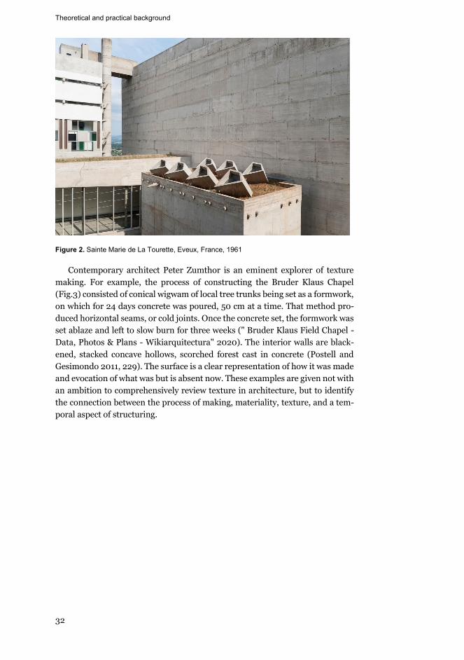
Theoretical and practical background
32
Figure 2. Sainte Marie de La Tourette, Eveux, France, 1961
Contemporary architect Peter Zumthor is an eminent explorer of texture making. For example, the process of constructing the Bruder Klaus Chapel (Fig.3) consisted of conical wigwam of local tree trunks being set as a formwork, on which for 24 days concrete was poured, 50 cm at a time. That method pro-duced horizontal seams, or cold joints. Once the concrete set, the formwork was set ablaze and left to slow burn for three weeks (" Bruder Klaus Field Chapel - Data, Photos & Plans - Wikiarquitectura" 2020). The interior walls are black-ened, stacked concave hollows, scorched forest cast in concrete (Postell and Gesimondo 2011, 229). The surface is a clear representation of how it was made and evocation of what was but is absent now. These examples are given not with an ambition to comprehensively review texture in architecture, but to identify the connection between the process of making, materiality, texture, and a tem-poral aspect of structuring.
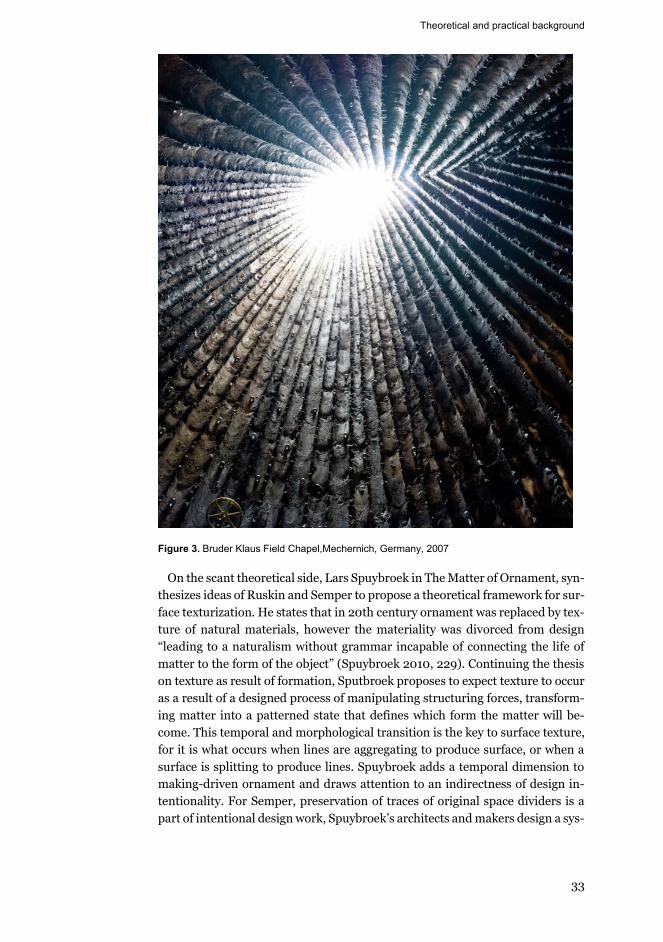
Theoretical and practical background
33
Figure 3. Bruder Klaus Field Chapel,Mechernich, Germany, 2007
On the scant theoretical side, Lars Spuybroek in The Matter of Ornament, syn-thesizes ideas of Ruskin and Semper to propose a theoretical framework for sur-face texturization. He states that in 20th century ornament was replaced by tex-ture of natural materials, however the materiality was divorced from design “leading to a naturalism without grammar incapable of connecting the life of matter to the form of the object” (Spuybroek 2010, 229). Continuing the thesis on texture as result of formation, Sputbroek proposes to expect texture to occur as a result of a designed process of manipulating structuring forces, transform-ing matter into a patterned state that defines which form the matter will be-come. This temporal and morphological transition is the key to surface texture, for it is what occurs when lines are aggregating to produce surface, or when a surface is splitting to produce lines. Spuybroek adds a temporal dimension to making-driven ornament and draws attention to an indirectness of design in-tentionality. For Semper, preservation of traces of original space dividers is a part of intentional design work, Spuybroek’s architects and makers design a sys-
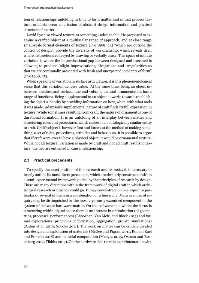
Theoretical and practical background
34
tem of relationships unfolding in time to form matter and in that process tex-tural artefacts occur as a fusion of abstract design information and physical structure of matter.
David Pye also viewed texture as something undesignable. He proposed to ex-amine a crafted object at a multiscalar range of approach, and at close range small-scale formal elements of texture (Pye 1968, 23) “which are outside the control of design”, provide the diversity of workmanship, which reveals itself where instructions conveyed by drawing or verbally cease. This space of minute variation is where the improvisational gap between designed and executed is allowing to produce “slight improvisations, divagations and irregularities so that we are continually presented with fresh and unexpected incidents of form” (Pye 1968, 25).
When speaking of variation in surface articulation, it is in a phenomenological sense that this variation delivers value. At the same time, being an object in-between architectural surface, line and volume, textural ornamentation has a range of functions. Being supplemental to an object, it works towards establish-ing the object’s identity by providing information on how, when, with what tools it was made. Adamson’s supplemental nature of craft finds its full expression in texture. While sometimes resulting from craft, the nature of ornament is one of durational formation. It is an unfolding of an interplay between matter and structuring rules and procedures, which makes it an ontologically similar entity to craft. Craft’s object is however first and foremost the method of making some-thing, a set of rules, procedures, attitudes and behaviours. It is possible to argue that if craft were ever to have a physical object, it would be ornamental texture. While not all textural variation is made by craft and not all craft results in tex-ture, the two are entwined in causal relationship.
2.3 Practical precedents
To specify the exact position of this research and its roots, it is necessary to briefly outline its most direct precedents, which are similarly constructed within a semi-experimental framework guided by the principles of research by design. There are many directions within the framework of digital craft in which archi-tectural research or practice could go. It may concentrate on one aspect in par-ticular or several of them in a combination or a hierarchy. Main avenues of in-quiry may be distinguished by the most vigorously examined component in the system of software-hardware-matter. On the software side where the focus is structuring within digital space there is an interest in optimization (of geome-tries, processes, performances) (Bhooshan, Van Mele, and Block 2015) and for-mal explorations (principles of formation, aggregation, growth simulations) (Anton et al. 2019; Snooks 2011). The work on matter can be crudely divided into design and exploration of materials (McGee and Pigram 2011; Ronald Rael and Fratello 2018) and material computation (Menges 2015; Oxman and Ros-enberg 2012; Tibbits 2017). On the hardware side there is experimentation with
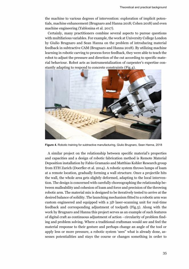
Theoretical and practical background
35
the machine to various degrees of intervention: exploration of implicit poten-tials, machine enhancement (Brugnaro and Hanna 2018; Cohen 2018) and even machine engineering (Yablonina et al. 2017).
Certainly, many practitioners combine several aspects to pursue questions with multifarious variables. For example, the work at University College London by Giulio Brugnaro and Sean Hanna on the problem of introducing material feedback in subtractive CAM (Brugnaro and Hanna 2018). By utilizing machine learning in robotic carving to process force feedback, they were able to teach the robot to adjust the pressure and direction of the cut according to specific mate-rial behaviour. Robot acts as instrumentalization of carpenter’s expertise con-stantly adapting to respond to concrete constraints (Fig.4).
Figure 4. Robotic training for subtractive manufacturing, Giulio Brugnaro, Sean Hanna, 2018
A similar project on the relationship between specific material’s properties and capacities and a design of robotic fabrication method is Remote Material Deposition installation by Fabio Gramazio and Matthias Kohler Research group from ETH Zurich (Doerfler et al. 2014). A robotic system throws lumps of loam at a remote location, gradually forming a wall structure. Once a projectile hits the wall, the whole area gets slightly deformed, adapting to the local interven-tion. The design is concerned with carefully choreographing the relationship be-tween malleability and cohesion of loam and force and precision of the throwing robotic arm. The material mix is designed to be iteratively tested to arrive at the desired balance of solidity. The launching mechanism fitted to a robotic arm was custom engineered and equipped with a 3D laser-scanning unit for real-time feedback and corresponding adjustment of toolpath (Fig.5). Along with the work by Brugnaro and Hanna this project serves as an example of such features of digital craft as continuous adjustment of action - circularity of problem find-ing and problem solving. Where a traditional craftsman would see and feel the material response to their gesture and perhaps change an angle of the tool or apply less or more pressure, a robotic system ‘sees'’ what is already done, as-sesses potentialities and stays the course or changes something in order to
Theoretical and practical background
36
achieve a result within a predetermined range. The tacit knowledge of a maker is abstracted and engineered into a matrix of parameters and constraints.
Concurrently the noisy surfaces of the wall structure present a way of thinking of surface articulation as a result of a myriad of small exchanges between differ-ent parts of the system. A loam aggregate is a collection of undesignable locali-ties, where the robotically performed impact of projectiles is translated through matter and offset through various uncertain factors such as air pressure, projec-tile weight, robot positioning repeatability, etc. These projects demonstrate po-tential future development of this research which would include more in-depth material design and a system of feedback.
Figure 5. Remote Material Deposition Installation, Sitterwerk, St. Gallen, Gramazio&Kohler Re-search, 2014
At this stage, the research is located in the investigative space of exploration of implicit potentials in a fabrication machine, or machine tinkering. It is look-ing to develop a 3D printing technique and test it in several material/machine systems. The intention is to provide a solution to some of the overhang scenarios and a method of arriving at surface articulation as a result of digital making. General practice of working with a 3D printer is linear and predominantly con-cerned with efficiency and precision, paradoxically leading back to unrelent-ingly controlled standardization despite allowing some architects to reconnect with the intractable materiality of making (Gourdoukis and Alberti 2017). How-ever, there are indeterminacies in the process of 3D printing in general and in its specific types. These localities of uncertainty concern the exact dependencies between material, machine settings, G-code, geometry and the space of transi-tion from code to matter. However perfect the digital master model is, friction always arises in that transition. These spaces where linearity between digital and physical breaks down could be looked at as potential design drives. In “De-sign Hacking”, Andrew Witt theorizes that through experimentation with va-guer regions of design and production we “interrogate a combinatorial range of visual possibilities latent in a system, finding the truth in the system itself”(Witt
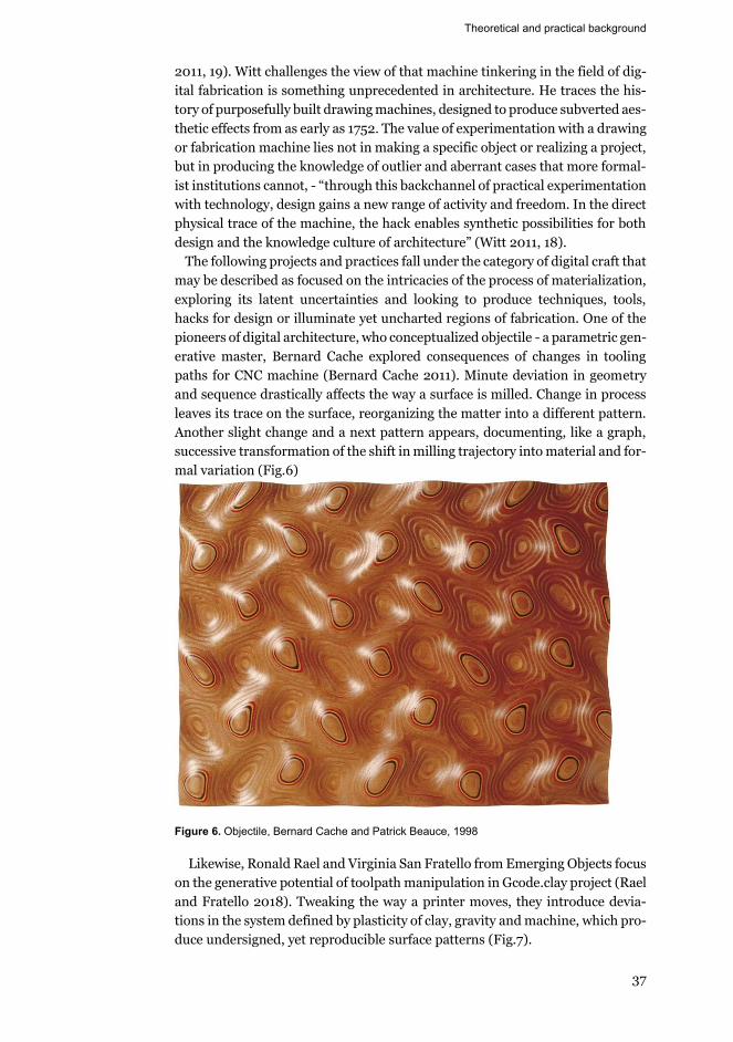
Theoretical and practical background
37
2011, 19). Witt challenges the view of that machine tinkering in the field of dig-ital fabrication is something unprecedented in architecture. He traces the his-tory of purposefully built drawing machines, designed to produce subverted aes-thetic effects from as early as 1752. The value of experimentation with a drawing or fabrication machine lies not in making a specific object or realizing a project, but in producing the knowledge of outlier and aberrant cases that more formal-ist institutions cannot, - “through this backchannel of practical experimentation with technology, design gains a new range of activity and freedom. In the direct physical trace of the machine, the hack enables synthetic possibilities for both design and the knowledge culture of architecture” (Witt 2011, 18).
The following projects and practices fall under the category of digital craft that may be described as focused on the intricacies of the process of materialization, exploring its latent uncertainties and looking to produce techniques, tools, hacks for design or illuminate yet uncharted regions of fabrication. One of the pioneers of digital architecture, who conceptualized objectile - a parametric gen-erative master, Bernard Cache explored consequences of changes in tooling paths for CNC machine (Bernard Cache 2011). Minute deviation in geometry and sequence drastically affects the way a surface is milled. Change in process leaves its trace on the surface, reorganizing the matter into a different pattern. Another slight change and a next pattern appears, documenting, like a graph, successive transformation of the shift in milling trajectory into material and for-mal variation (Fig.6)
Figure 6. Objectile, Bernard Cache and Patrick Beauce, 1998
Likewise, Ronald Rael and Virginia San Fratello from Emerging Objects focus on the generative potential of toolpath manipulation in Gcode.clay project (Rael and Fratello 2018). Tweaking the way a printer moves, they introduce devia-tions in the system defined by plasticity of clay, gravity and machine, which pro-duce undersigned, yet reproducible surface patterns (Fig.7).
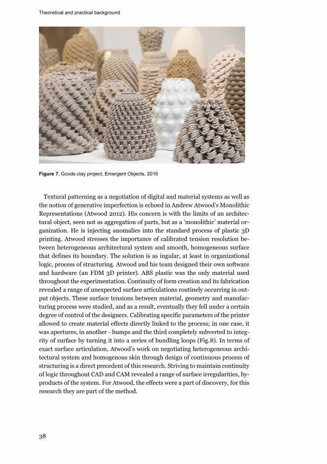
Theoretical and practical background
38
Figure 7. Gcode.clay project, Emergent Objects, 2016
Textural patterning as a negotiation of digital and material systems as well as
the notion of generative imperfection is echoed in Andrew Atwood’s Monolithic Representations (Atwood 2012). His concern is with the limits of an architec-tural object, seen not as aggregation of parts, but as a ‘monolithic’ material or-ganization. He is injecting anomalies into the standard process of plastic 3D printing. Atwood stresses the importance of calibrated tension resolution be-tween heterogeneous architectural system and smooth, homogeneous surface that defines its boundary. The solution is as ingular, at least in organizational logic, process of structuring. Atwood and his team designed their own software and hardware (an FDM 3D printer). ABS plastic was the only material used throughout the experimentation. Continuity of form creation and its fabrication revealed a range of unexpected surface articulations routinely occurring in out-put objects. These surface tensions between material, geometry and manufac-turing process were studied, and as a result, eventually they fell under a certain degree of control of the designers. Calibrating specific parameters of the printer allowed to create material effects directly linked to the process; in one case, it was apertures, in another - bumps and the third completely subverted to integ-rity of surface by turning it into a series of bundling loops (Fig.8). In terms of exact surface articulation, Atwood’s work on negotiating heterogeneous archi-tectural system and homogenous skin through design of continuous process of structuring is a direct precedent of this research. Striving to maintain continuity of logic throughout CAD and CAM revealed a range of surface irregularities, by-products of the system. For Atwood, the effects were a part of discovery, for this research they are part of the method.
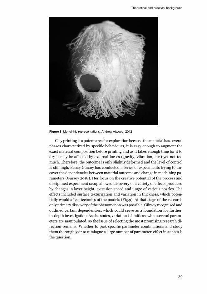
Theoretical and practical background
39
Figure 8. Monolithic representations, Andrew Atwood, 2012
Clay printing is a potent area for exploration because the material has several phases characterized by specific behaviours, it is easy enough to augment the exact material composition before printing and as it takes enough time for it to dry it may be affected by external forces (gravity, vibration, etc.) yet not too much. Therefore, the outcome is only slightly deformed and the level of control is still high. Benay Gürsoy has conducted a series of experiments trying to un-cover the dependencies between material outcome and change in machining pa-rameters (Gürsoy 2018). Her focus on the creative potential of the process and disciplined experiment setup allowed discovery of a variety of effects produced by changes in layer height, extrusion speed and usage of various nozzles. The effects included surface texturization and variation in thickness, which poten-tially would affect tectonics of the models (Fig.9). At that stage of the research only primary discovery of the phenomenon was possible. Gürsoy recognized and outlined certain dependencies, which could serve as a foundation for further, in-depth investigation. As she states, variation is limitless, when several param-eters are manipulated, so the issue of selecting the most promising research di-rection remains. Whether to pick specific parameter combinations and study them thoroughly or to catalogue a large number of parameter-effect instances is the question.
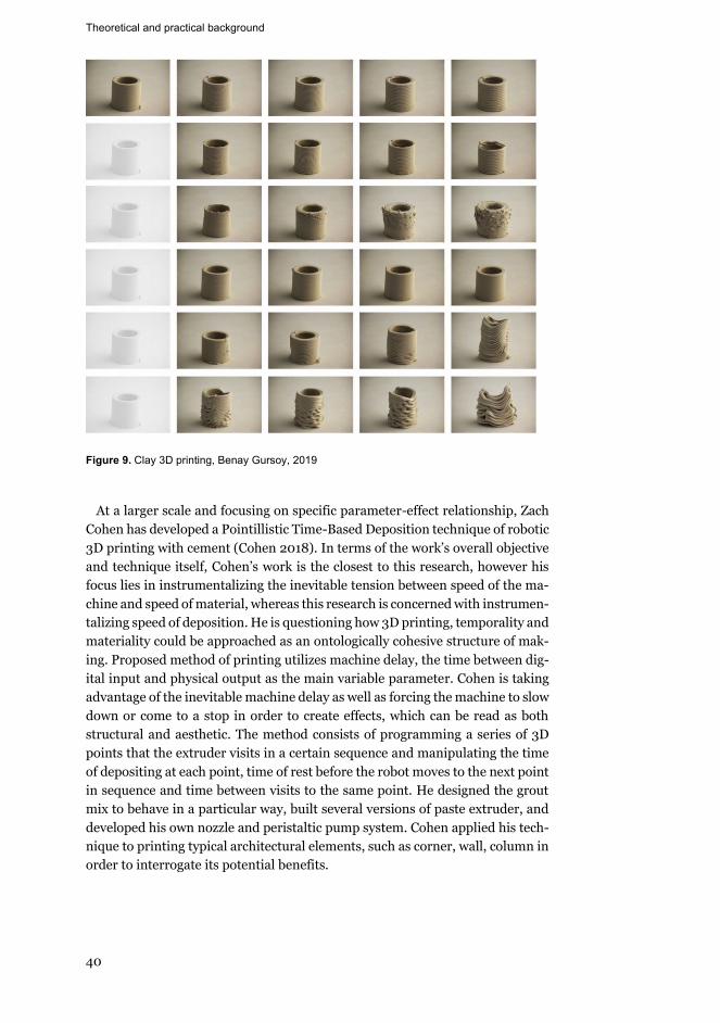
Theoretical and practical background
40
Figure 9. Clay 3D printing, Benay Gursoy, 2019
At a larger scale and focusing on specific parameter-effect relationship, Zach
Cohen has developed a Pointillistic Time-Based Deposition technique of robotic 3D printing with cement (Cohen 2018). In terms of the work’s overall objective and technique itself, Cohen’s work is the closest to this research, however his focus lies in instrumentalizing the inevitable tension between speed of the ma-chine and speed of material, whereas this research is concerned with instrumen-talizing speed of deposition. He is questioning how 3D printing, temporality and materiality could be approached as an ontologically cohesive structure of mak-ing. Proposed method of printing utilizes machine delay, the time between dig-ital input and physical output as the main variable parameter. Cohen is taking advantage of the inevitable machine delay as well as forcing the machine to slow down or come to a stop in order to create effects, which can be read as both structural and aesthetic. The method consists of programming a series of 3D points that the extruder visits in a certain sequence and manipulating the time of depositing at each point, time of rest before the robot moves to the next point in sequence and time between visits to the same point. He designed the grout mix to behave in a particular way, built several versions of paste extruder, and developed his own nozzle and peristaltic pump system. Cohen applied his tech-nique to printing typical architectural elements, such as corner, wall, column in order to interrogate its potential benefits.
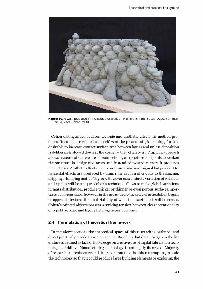
Theoretical and practical background
41
Figure 10. A wall, produced in the course of work on Pointillistic Time-Based Deposition tech-nique, Zach Cohen, 2018
Cohen distinguishes between tectonic and aesthetic effects his method pro-
duces. Tectonic are related to specifics of the process of 3D printing, for it is desirable to increase contact surface area between layers and unless deposition is deliberately slowed down at the corner – they often twist. Dripping approach allows increase of surface area of connections, can produce cold joints to weaken the structure in designated areas and instead of twisted corners it produces melted ones. Aesthetic effects are textural variation, undesigned but guided. Or-namental effects are produced by tuning the rhythm of G-code to the sagging, dripping, slumping matter (Fig.10). However exact minute variation of wrinkles and ripples will be unique. Cohen’s technique allows to make global variations in mass distribution, produce thicker or thinner or even porous surfaces, aper-tures of various sizes, however in the areas where the scale of articulation begins to approach texture, the predictability of what the exact effect will be ceases. Cohen’s printed objects possess a striking tension between clear intentionality of repetitive logic and highly heterogeneous outcome.
2.4 Formulation of theoretical framework
In the above sections the theoretical space of this research is outlined, and direct practical precedents are presented. Based on that data, the gap in the lit-erature is defined as lack of knowledge on creative use of digital fabrication tech-nologies. Additive Manufacturing technology is not highly theorized. Majority of research in architecture and design on that topic is either attempting to scale the technology so that it could produce large building elements or exploring the
Theoretical and practical background
42
role of 3D printed models in the design process. In general practice CAM, and specifically AM exclude “unpredictability and emergence that are inherent in processes that are harnessing materiality” (Gourdoukis and Alberti 2017, 50). While there are a number of makers who explore various generative aspects of the AM technology, there is no extensive research on rigorously using speed as a driver for design. Speed of deposition, defined in this research as a combina-tion of mainly speed of movement with flowrate is central to PEM, because it controls the amount of material deposition. On the other hand, in terms of re-search on AM technology itself, to this date there are no solutions for printability with PEM of overhanging geometries exist. This research attempts to contribute to knowledge by addressing these gaps by building upon principles of Additive Manufacturing and Digital Craft and translating them into guidelines for meth-odology.
The thesis is that manipulation of manufacturing parameters could lead to various architectural facets being informed by the process of making. The re-search question is to find out what effect speed of deposition has on a 3D printed model. The aim is to begin building mechanisms of control that could be prac-ticed by designers in order to utilize the full potential of existing and developing digital fabrication systems to be generative actants in the design process. Prin-ciples of AM, digital craft and digital ornament inform the choice of research methods to generate data, analytical framework used to organize it and analytic tools to evaluate it. This research uses AM as the area of investigation and the main tool for generating data. AM is uniquely suited for controlled, yet low-cost and fast production. Its basic production workflow has been adopted as a pro-cedure to make numerous artefacts that provide data for the next iteration. Evaluation is based on potential to enrich digital maker’s design apparatus. On a more granular level, principles of printability act as selection criteria in data organization and analysis.
Digital craft provided key concepts (described in detail in the preceding sec-tions) that guided all operations, for example the role of risk and experimenta-tion is essential. Instead of using optimal printing parameters the experiments are exploring lowest and highest values. This exploration of the boundary of the range is defined by approaching the range of printability. Hence, questions of imprecision and uncertainty are essential. Speed-Based technique feeds on fric-tion and imperfection. It is designed to make unprintable and undesignable. However, using extreme means for unintended results leaves its deformational trace. The gap between digital model and fabricated one is allowed to be larger than it would be in an environment guided by smooth efficient transition from bit to matter. In this research that transition is seen not as a linear sequence of homogeneous operations but a space for exploration, and materiality from inert receptacle is transformed into an active design force. Throughout, I have main-tained continuity of authorship, by designing pre-processing stage, overseeing and guiding build stage and finishing the models in post-processing. At the same time, the digital process model is designed as a flexible platform open for in-crease in universality, applicability in various contexts, therefore submitting to

Theoretical and practical background
43
the principle of distributed authorship. The process model is the object of de-sign, containing multiple types of information, organized into a structure of re-lationships. Concurrently, it is an apparatus for training skill, which lies in abil-ity to employ the causality between parameter change and material deviation for design purposes. An adjacent to digital craft concept of digital ornament provided a way to analyse the results, first of all as an immanent to the technol-ogy trace of making and as a tool for future development.
Methodology
44
3. Methodology
The area of research is Additive Manufacturing, a process that involves algo-rithmic design of machining instructions translated through a specific material in a specific fabrication system. The process, that is bound to materiality and production. Approached as a design apparatus, AM necessitates that the strat-egy and tactics involve both physical and digital making with the focus on the process itself. Potential methodologies suitable for such an inquiry are experi-mental research and research through design. During the research proceedings it was noted that a certain degree of free exploration was needed in order to arrive at a more comprehensive outline of techniques’ properties and potentials. It was impossible not to be personally involved in the phenomenon (Borgdorff 2006), thus compromising the distance between the investigator and the object, required by classical experimental methodology. In addition, it was clear that due to lack of technical resources it was highly problematic to follow the exper-imental setup aimed at producing explicit and objective data. Therefore, it was decided to align the study to research by design methodology, which allowed for more creative latitude and embraced the non-objective nature of findings (Archer 1995). After initial discovery of the design potential in manipulating speed of movement, it was clear that building of the Speed-Based AM technique would require an iterative, experimental yet fairly open-ended and loosely structured strategic and tactical approach, as many scenarios and possible com-positions of constituent elements were both possible and indeterminate in ef-fect. The value of the results lies less in the ability to generalize them inductively as they remain situation specific but more in providing primary material for fur-ther studies.
In order to achieve the research, aim of producing foundations for Speed-Based AM technique, the study is methodologically grounded in the framework of research by design. The overall strategy of linking theory and practice, utili-zation of tools immanent to design and various modes of reflection was further informed by principles outlining digital craft. Specifically, continuity of author-ship and structuring logic throughout all stages of designing and making, mate-rial agency and experimental, explorative tactics. These characteristics were di-rectly operationalized in the design of the study, becoming fundamental princi-ples of its methodology. Tactics comprised iterative prototyping, that was car-ried out by simultaneous development of series of digital process models and series of physical additively manufactured objects. Printed prototypes are seen as material instances of the process model and serve as objects for reflection,
Methodology
45
evaluation; and provide data for next iteration. Iterative prototyping, which in-cludes reflection before, during and after making was the main tool for both gathering data and analysing it.
In the section on theoretical and practical background two gaps in the existing knowledge were found. Lack of research dedicated to tackling geometric print-ability issues and absence of studies on architectural effects of speed of deposi-tion in AM. These gaps are addressed through treating them as research objec-tive and research aim respectively. While this study does not entirely fill the la-cunae, it attempts to contribute relevant data.
While AM as an area of research and a design technique as its object call for the chosen methodology, its looseness of definitions presents challenges. There is a lack of studies on various types of reflection as analytic tools. In many in-stances research by design produces a unique artefact, and the knowledge lies in the verbalized reflection on the decision making. However, in other cases the objective is to study manipulation of a certain design system, so gained knowledge is more general, it is about how to accomplish certain tasks. This crucial difference is not sufficiently discussed in existing literature and which tools and techniques are appropriate to each of them is not determined. This research belongs to the second type striving to produce knowledge for design, therefore, produced data needs to be encapsulated and instrumentalized to a certain degree. It is challenging to separate objective and subjective knowledge and to structure results into a format that allows dissemination. The practice of experimental 3D printing, however controlled, implies, in allegiance with craft tradition, that many decisions are instinctual, and many insights resist articula-tion and remain tacit. In order to counteract these shortcomings of the chosen methodology, all variables of the system are recorded along with observations, conclusions and decisions made throughout the research. Documentation con-sists of written observations on various aspects of the system performance and design, printed models materializing it and a family of iterative digital process models that are developed to include more and more variables and be applicable for more and more contexts.
It is however clear, that in order to completely encapsulate the gained knowledge into practical instructions, containing all pertinent states of the sys-tem would require more work, perhaps organized in a more rigorous methodol-ogy. That would achieve full replicability of the research. More in-depth study on manipulation of viscosity, that affects flowability and therefore flowrate would be beneficial for the material aspect of the system. That would take the argument on material agency further. On the other hand, if the intention were to create a fully operational design tool in a format of plugin or extension of, for example, Silkworm, again, more work in the vein of digital product development framework would be needed. As of now, the methodology itself forces the re-search to remain an open-ended exploration.
The main research question revolves around discovery of potential architec-tural applications, benefits and shortcomings of a devised technique for manip-ulating speed of deposition of an AM machine. The aims were to question the technique in various lanes: material, tectonic, constructional, ornamental.
Methodology
46
Overall, research can be split into three phases: (Fig.11) 1.Discovery of Speed-Based technique through open-ended experimentation
with a plastic FDM 3D printing system, observation and interpretation of the results. Details are presented in the published paper - “The Making of Unde-signable Textural Effects”.
2.Exploring Speed-Based technique by creating a digital algorithm that is then used to drive a series of rapid prototyping tests in three different fabrication setups (FDM, PEM, WAAM), attempting to understand relationships between technique, machine and material. Critical evaluation of the scale models, inter-pretation of the outcomes in the framework of research question. Iterative edit-ing of the system and technique. Details are presented in the published paper – “Material Agency in CAM of Undesignable Textural Effects”.
3.Testing Speed-Based for design applications in a ceramic PEM 3D printing system, specifically its potential in resolving certain printability issues, such as printing of tall thin objects, cantilever geometries, bridging geometries. Reflect-ing on performance of the system in terms of ornamental effects and printability improvements. Results of reflection encapsulated in the design of the digital process model with guiding intention of increase in universality of system ap-plication. Details are presented in the published paper – “Speed of Deposition: Vehicle for Structural and Textural Expression in CAM”.
Phase 3 had a cyclic structure: -posing a specific question -creation/editing of digital process model -printing of material prototypes. Increasing scale, geometric complexity. -evaluation of prototypes in relation to the question. Determining whether
and how to iterate or to change the direction. Synthetic reflection not only allows to chart the course, plan future actions but
also to reconsider past artefacts, see them in a new light. If carefully recorded, it can provide the necessary bridge between practice and theory. Throughout the process, both digital and physical models were reflected upon during mak-ing and retrospectively to see if they satisfied the following criteria:
-Can the model be reproduced? -Is there variation from instance to instance? -Does variation fall within the effective range of texture? Or in case of printa-
bility series, does variation contribute to printability, while deforming the initial model within pre-determined range.
The following sections provide data on research by design as a methodology and redefines rapid prototyping as a research tool. The necessity of including these sections is based on the lack of well-defined, detailed and universally ac-cepted structure of research by design and specificity of producing small-scale AM prototypes as both representing design outcome and as a vehicle of itera-tion.
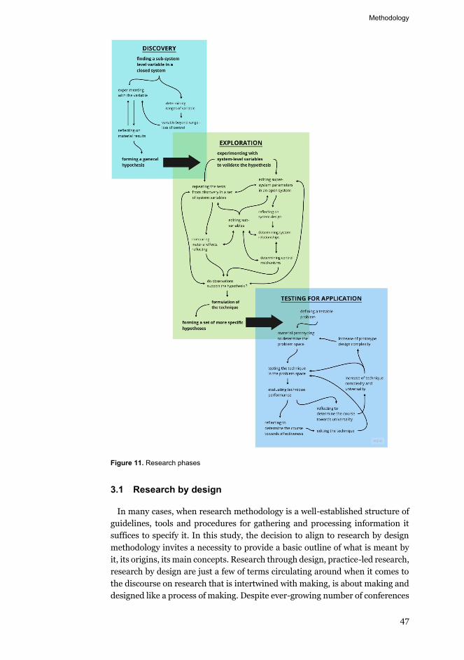
Methodology
47
Figure 11. Research phases
3.1 Research by design
In many cases, when research methodology is a well-established structure of guidelines, tools and procedures for gathering and processing information it suffices to specify it. In this study, the decision to align to research by design methodology invites a necessity to provide a basic outline of what is meant by it, its origins, its main concepts. Research through design, practice-led research, research by design are just a few of terms circulating around when it comes to the discourse on research that is intertwined with making, is about making and designed like a process of making. Despite ever-growing number of conferences
Methodology
48
(‘Changes of Paradigms in the Basic Understanding of Architectural Research’ (2008), ‘Communicating (by) Design’ (2009), ‘Knowing by Designing’ (2013), ‘Research through Design’ (2019), etc.) and publications on the topic, the exact parameters, features that qualify a study to be a research by design and at the same time meet the requirements of producing communicable, novel and sig-nificant contribution to knowledge are still being determined. That is why it is important to indicate which lines of thought this research follows.
The movement to establish certain design practices, tools and procedures as a valid research method has been gradually gaining momentum since the 1950s, starting with Michael Polanyi’s Personal Knowledge. To attack the rigid tradi-tion of detachment of the researcher from the researched as unsustainable, he is pointing out the pervasive and necessary subjective influences that subsume any acquisition of knowledge. The value of tacit knowledge, the social constructs that inevitably affect the problem formulation and problem solving, creative and unpredictable aspects of the process of gaining knowledge are brought to the forefront and used to reformulate episteme (Polanyi 2015). The elimination of a distance between subject and object became an essential component of the later thinking on research by design (Borgdorff 2006).
In 1983, The Reflective Practitioner by David Schön introduced reflective practice as research methodology. In disciplines, where doing and making are essential, the knowledge is produced through the action itself balanced by con-tinuous reflection on that action followed by evaluation. The alert awareness throughout the process allows for implicit, tacit knowledge to become com-municable (Schön 2017). Overall, Schön is challenging a positivist epistemolog-ical position by making a case for ‘other’ types of knowledge. The ‘other’ knowledge is for example a ‘knowledge for’ coined by Ranulph Glanville, an un-derstanding of how to act in the specific circumstances of the creative process. It is not describing what is, it is about how to change it (Glanville 2007). A de-signer does research to know how to perform better in the world, not just to know more about it. That line of thinking brings into focus the question of what should be researched in design research? And according to Glanville it is design itself, that is the subject of inquiry, and its processes, routines, relationships and delicate balances are to become an inalienable base of the research approach. Architecture as a design activity can be investigated through itself, not just through history, philosophy, social sciences (Van Schaik et al. 2011), but through the making process of design itself into explicit and openly communi-cated knowledge (Verbeke 2013).
Jorgen Hauberg argues that “research by design is research that produces knowledge through the architect’s tools and working methods. It investigates the research inquiry from the practitioner’s methods and acknowledges practice as a means of gaining new knowledge” (Hauberg 2011, 52).
Slightly different terminology is used by Christopher Frayling, who schemati-cally outlines particulars of research in art and design research and defines ‘re-search through art and design’ as one of its categories. It is characterized by its orientation towards material studies and action research. It involves practical experimentation, its faithful documentation and clarity of what is being
Methodology
49
achieved (Frayling 1993). In particular, development work, a study into manip-ulation of a certain system, a production of knowledge about how to accomplish certain tasks within the design process.
There is no unassailable definition of research by design, the discourse is still in flux. To present one, which has the most official standing, however imperma-nent, we turn to the text prepared by the Research Committee of the European Association for Architectural Education (EAAE) (the working group consisted of: Jorgen Hauberg, Pieter Versteegh, Johan Verbeke, David Vanderburgh, Jo-han De Walsche) as a part of Research Chapter in 2012:
“In architecture, design is the essential feature. Any kind of inquiry in which design is a substantial constituent of the research process is referred to as research by design…In research by design, the ar-chitectural design process forms a pathway through which new in-sights, knowledge, practices or products come into being. It gener-
ates critical inquiry through design work. Therefore research re-sults are obtained by, and consistent with experience in practice”
(Verbeke, 2013, 144).
Another important aspect of research by design is its emphasis on exploration (Verbeke 2013), in some cases the research question is something that gets dis-tilled in the process of inquiry (Hauberg 2011), which is strikingly opposed to traditional research, which starts with a question. Exploration involves finding new answers as much as learning to ask new questions.
Reflection and evaluation are integral parts of research, they allow to make introspection explicit and therefore to support the authority of study through explication of all the decisions made.
Reflection and evaluation are integral parts of research, they allow to make introspection explicit and therefore to support the authority of study through explication of all the decisions made.
RMIT has a well-developed programme of reflective practice-based approach to research (Van Schaik et al. 2011). Reflective aspect of it is loosely based on David Schön’s ideas of reflection-in-action and reflection action. Richard Blythe describes several types of reflection that accompany research by design:
-Retrospective reflection – reflection on completed work. -Reflection in action – “Reflection takes place in the activity of making…this
becomes the ‘scene’ of the reflection: temporally and contextually synthesised.” (Blythe and van Schaik 2013, 62)
-Reflection for future action – as decisions are made on the current work, the future work begins to emerge and get informed by the present.
-Reflection on earlier work – remembering past work as moves are made on the present project, which leads to reconstructing a version of an earlier in-stance.
Blythe suggests a ‘synthesized reflection model’ that involves simultaneous ex-ercise of all types of reflection during the process of making, which allows to avoid disconnectedness between reflection and design (Blythe and van Schaik 2013).
Methodology
50
To qualify as a valid research method, research by design “needs to meet gen-eral criteria of originality, significance and rigour. It produces forms of output and discourse proper to disciplinary practice, to make it discussable, communi-cable, and useful to peers and others. It is validated through panels of experts who collectively cover the range of disciplinary competences covered by the work.” (EAAE Charter on Architectural Research - European Association for Ar-chitectural Education, 2012)
To summarise: research by design is a research approach that aims at creation of knowledge by extending methods immanent to design as a means to link the-ory and practice.
Hence, the design activities are primary and essential, they are main means of generating insight: design itself is an object of research, tactics and tools are immanent to design. In order to make design explicit, different modes of reflec-tion are engaged throughout the process. And as design itself is a search for new potentials, solutions, relationships of and in architecture, so is research by de-sign a less straightforward, logical journey to an answer and more of cyclical probing in many directions.
3.1.1 Tactics: Computational design and its artefacts
The connection between CAD and CAM as ‘a bridge between designing and producing’ (Mitchell and McCullough 1995) is the space which provides an on-tological basis for this inquiry. In order to explore an aspect of automated fab-rication, it is important to utilize tools and procedures that correspond with its logic. The intention of this research is to study a specific way of 3D printing, therefore the method of study is a type of computational design – an algorithm (G-code that defines the relationships between datasets) and series of 3D printed small-scale objects.
Computation is understood as “the processing of information and interactions between elements which constitute a specific environment; it provides a frame-work for negotiating and influencing the interrelations of datasets of infor-mation, with the capacity to generate complex order, form, and structure” (Ahlquist and Menges 2011, 13). In architectural design it can be used for form-finding, computing energy flows, calculating environmental adaptivity, simulat-ing structural performance, design of parametric families of components (Pe-ters 2013), and in digital fabrication.
Generically, computational design/digital design is concerned with building relationships between diverse data sets, concurrent with or followed by con-struction of representational forms, all within the space of CAD/CAM. In the architectural design process, making representational artefacts, such as sketches, drawings, models, prototypes is a crucial part of the journey towards a building. The artefacts of computational design are digital: algorithms, simu-lations, information models, process models; and physical: scale prototypes, prototypes of building elements, building elements, augmented fabrication ma-chines and eventually, perhaps, complete buildings. Digital process models usu-ally contain not only geometrical data, but also information about specific per-formances, instructions for fabrication, material behaviours. The very richness
Methodology
51
of an artefact changes its role from merely representational to generative. The algorithmic, procedural logic organizes dynamic flows of information into a pro-ductive structure that forms solutions dependent on input variables (Klinger 2008).
Mette Ramsgard Thomsen and Martin Tamke have been leading the work at CITA on how digital technologies change and challenge architecture design practice. As a rule, research projects are carried out as practice-led research. Based on their significant experience of guiding research of that type, they put forward a system of material representations that feed each other in serial cycles and allow for continuous increase of both geometrical and problematic scales (Thomsen and Tamke 2009). The first artefact is ‘design probe’, an explorative inquiry through physical and digital modelling into the problem space; it evalu-ates promising directions, incorporates feedback from the previous cycle and outlines design criteria. Then, a ‘material prototype’ takes the work into a spe-cific framework of fabrication, so it is concerned with machining instructions, materiality, techniques of production, the mastering and innovating of the ma-chine. Finally, the ‘demonstrator’, a full-scale prototype that tests geometrical scaling, begins to play a communicative role, and is evaluated based on archi-tectural criteria.
This research utilizes an explorative tool similar to Thomsen and Tamke’s ‘ma-terial prototype’, consisting of a parametrically driven, continuously evolving G-code additively manufactured in a setup of material and machine into a series of physical artefacts. Printed models are used to test and inform the digital pro-cess model. Dissimilarity, however, lies in the level of complexity of produced structures, as the research strives to devise an AM technique and not to produce specific formal arrangements. Therefore, objects remain formally simple.
3.1.2 Small-scale AM as a research technique
In case of this research, the interest lies in manufacturing small-scale proto-types using Additive Manufacturing technology. In the section on theoretical and practical background, main aspects of utilizing AM for making scale mod-els, building parts and building-scale structures are discussed. In this section, the question of small-scale, rapid iterative AM is examined as a valid research tactic.
The technique used is similar to what is called rapid prototyping (RP) in prod-uct development and IT development. It consists of iterative making of simpli-fied models of a feature or a system in order to answer a specific question that informs future development. Prototypes are usually interactive. In software and web development workflows prototypes they are used for usability tests, where a user is asked to perform a certain action with the prototype. The results are analyzed and used for iteration or next, higher-resolution prototype. In product development context, RP was used to mean technologies which produced phys-ical models directly from digital data (Gibson et al. 2010). RP is a rather contro-versial term, used in multiple professional fields differently. It used to be a more informal term for Additive Manufacturing, digital fabrication in which proto-types are additively manufactured (Kolarevic and Klinger 2013; Volpato 2007)
Methodology
52
through deposition of layers of material (originally stereolithography). How-ever, in other sources the term is used for any quick production of prototypes with any computer numerically controlled (CNC) fabrication process, even sub-tractive (CNC milling) and 2D (CNC cutting)(Lennings 2000). Ryder et. al. pro-pose the term ‘layered manufacturing’(LM) instead of rapid prototyping, as ar-gue that RP no longer adequately describes all additive manufacturing tech-niques (Ryder et al. 2002).
In architecture, rapid prototyping in its technological variant was first dis-cussed by Bernd Streich in 1991, specifically stereolithography as a way to bring model making to the same space of computation as digital models (Streich 1991). In 2002, Ryder et al. outlined three types of architectural models accord-ing to the stage of architectural process in relation to the additive manufacturing techniques attempting to provide an overview of LM applications in the archi-tectural design process (Ryder et al. 2002). However, they approach scale mod-eling of feasibility, planning and final project models, differing by the level of detailing only as a vehicle for representation. Considering the year of publica-tion, it is also clear why they refrain from making any arguments about suitabil-ity or challenges of any of the AM techniques in relation to model making. Same year, an attempt was made to connect AM and digital design practices by Wang and Duarte. They built a software that generates early stage design models based on parametrically controlled shape grammar. Then, models were printed with STL, FDM and 3DP; authors discuss advantages and disadvantages of each tech-nique and argue that the physical models present not only an opportunity for visualization but also for evaluation. Wang and Duarte discuss the process of iterative, cyclical iteration of both digital and physical models, ‘until the final solution is obtained’ (Wang and Duarte 2002).
The fact that CAM has become almost commonplace in the architectural in-dustry suggests that the discipline itself is being reformulated into a more ho-listic endeavour, reconnecting the craft of spatial design with materiality and production (Hauberg 2011). An important transition from externalized ab-stracted descriptions (drawings) towards direct digital instructions for making is taking place. Despite that new architect’s proximity to the actual building, the physical products of digital design are largely 3D printed scale models. Some-times called prototypes, they combine iteration with focus on investigating spe-cific questions about materiality and performance. Widely used in product de-sign, engineering, interaction design, scale prototypes are only gaining momen-tum in architecture as an object made to test a specific solution and learn about machine and material behaviour. They differ from traditional scale models by their purpose – they are not purely or completely non-representational of the final building, instead they are explorative and/or generative (Camburn et al. 2015).
Iteration in research on architectural production method means continuous shifting between problem and solution, producing artefacts repeatedly with slight shift of focus, reframing the question in multiple levels of inquiry (Thom-sen and Tamke 2009). What characterizes the architectural design process is
Methodology
53
certain continuity of inquiry, the solution is not right or wrong, instead it is bet-ter or worse suited for a specific context. Similarly to iteration techniques, well developed in product design, engineering, interaction design, it not only allows for testing and probing of possible solutions, it helps to identify errors (Zemke 2012), and gradually improve the design (Moe, Jensen, and Wood 2004).
A unique quality of prototyping in the setting of architectural digital craft is that it promotes a more direct engagement with machine and making. 3D print-ing eliminates some of the translational phases of other production processes. It allows direct fabrication from a 3D model generated in a CAD system. Direct-ness in this case means significant simplification of the process planning. Other manufacturing processes require an analysis of the part in order to determine sequence of production, tools and procedures, ancillary elements (for example moulds) that have to be made, etc (Gibson et al. 2010). AM in comparison is streamlined and simplified; the CAD model still has to be analysed, but only in order to determine its printability issues: size, proportions, tectonic arrange-ments, cantilever geometry. Then it is sliced into layers, and depending on the exact technology of printing, such auxiliary elements as supports, infill are added. For most cases, after this step, the production planning is done. How-ever, it is also possible to change the material composition and control various printing parameters, creating opportunities for discovery.
Small scale prototypes can be utilized for research purposes as an investigative tool because they are fast to make and low-cost, they answer a specific question (Otto and Wood n.d. 2001) and they are explorative (Hess and Summers 2013). Through small-scale parameter-driven, disciplined and iterative prototyping a researcher can build a valid experimentation space (Camburn et al. 2015).
3.1.3 Printing instructions - G-code
There can be no 3D printed object without a digital model and machining in-structions. In CAD and CAM, the design of the fabrication process is a feedback loop between geometric models and machining parameters (McCullough 1998). Instructions for making do not follow the design of an object, digital and physi-cal artefacts are developed in parallel; “rather than understanding the process of creation as single path leading from digital to physical, the physical prototype is understood as an integrated tool which tests and informs the digital” (Thom-sen and Tamke 2016, 51). In Abstracting Craft, Malcolm McCullough suggests that this feedback loop between conception and execution allows seamless flow of controllable information: “design prototypes become design specifications, then process models, then machine instructions.” In AM the digital component consists of a CAD model that fully describes external geometry. It can be a mesh or a NURBS model with thickness. That model is then translated into the CNC programming language G-code, which in CAM is used to command the fabrica-tion machine to perform a certain movement or an action ("What Is G-Code?" 2020). G-code contains instructions for the machine controller on how much material to extrude, how fast to move, which printpath to take ("G-Code" 2020). In non-robotic setups, the printpath consists of a stack of horizontal slices (lay-ers), which are printed from bottom up. A typical G-code of the printer consists
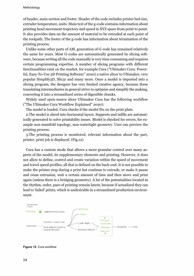
Methodology
54
of header, main section and footer. Header of the code includes printer bed size, extruder temperature, units. Main text of the g-code contains information about printing head movement trajectory and speed in XYZ space from point to point. It also provides data on the amount of material to be extruded at each point of the toolpath. The footer of the g-code has information about termination of the printing process.
Unlike some other parts of AM, generation of G-code has remained relatively the same for years. Most G-codes are automatically generated by slicing soft-ware, because writing all the code manually is very time consuming and requires certain programming expertise. A number of slicing programs with different functionalities exist on the market, for example Cura ("Ultimaker Cura: Power-ful, Easy-To-Use 3D Printing Software" 2020) a native slicer to Ultimaker, very popular Simplify3D, Slic3r and many more. Once a model is imported into a slicing program, the designer has very limited creative agency, because these translating intermediaries in general strive to optimize and simplify the making, converting it into a streamlined series of digestible chunks.
Widely used open-source slicer Ultimaker Cura has the following workflow ("The Ultimaker Cura Workflow Explained" 2020):
The model is loaded. Cura checks if the model fits on the print plate. 2.The model is sliced into horizontal layers. Supports and infills are automat-
ically generated to solve printability issues. Model is checked for errors, for ex-ample non-manifold topology, non-watertight geometry. User can preview the printing process.
3.The printing process is monitored, relevant information about the part, printer, print job is displayed. (Fig.12)
Cura has a custom mode that allows a more granular control over many as-
pects of the model, its supplementary elements and printing. However, it does not allow to define, control and create variation within the speed of movement and travel speed profiles, all that is defined on the back-end. It is not possible to make the printer stop during a print but continue to extrude, or make it pause and cease extrusion, wait a certain amount of time and then move and print again (unless there is a bridging geometry). A lot of the potentialities located in the rhythm, order, pace of printing remain latent, because if actualized they can lead to ‘failed’ prints, which is undesirable in a streamlined production environ-ment.
Figure 12. Cura workflow
Methodology
55
In this workflow the maker is not designing the fabrication, they are led on a linear path towards a predetermined outcome of a frictionless, ‘successful’ print. This traces back to the argument made earlier about the connection between extreme popularity of AM, its widespread adoption by the general public and its direction of development towards smooth usability. The convoluted path of a digital maker, however, requires control over the translation phase from model to matter and seeks to build interdependency between the two.
A compromise between predetermination of slicing solutions and total open-endedness of manually writing G-code is a Silkworm plugin for Grasshopper. Developed by Adam Holloway, Arthur Mamou-Mani and Karl Kjelstrup-John-son is an open source project Silkworm ("About - Silkworm" 2020), it translates Grasshopper and Rhinoceros 3D geometry into G-code. What it allows to do is to control the printer's movement, while remaining in the ecosystem of CAD. Exact geometry and sequence of a toolpath, speed profile, control over the flow of the material are editable and manageable. In a computational design frame-work, it is beneficial to contain both geometrical information and production model in the same space, because not only it allows to avoid technical difficulties and losses inevitable in migration from one operational environment to an-other, but also it facilitates logical continuity between all stages of making.
3.2 System design
In this research rapid prototyping term is used to describe the iterative process of slicing digital models into 2-dimensional layers, defining G-code parameters and then manufacturing a series of small-scale objects with an AM process. Spe-cifically, Fused Deposition modelling (FDM), Paste Extrusion Modelling (PEM), Wire and Arc Additive Manufacturing (WAAM) were used. Parametric process model that contains fabrication instructions is instantiated by the prototypes. Together, the digital and the physical comprise the technique. The G-code alone cannot be iterated upon and cannot be fully comprehended by others. Proto-types are necessary for communicating structure and performance of the G-code. They also have independent, qualitative value, being a materialization of a unique instance of part-material, part-machine, part-programming system.
Iteration and gradual increase in complexity is located in the pre-processing stage of the printing process. The digital product is a family of G-codes, the evo-lution of its design demonstrates gradual incorporation of knowledge gained. Research attempts to introduce the principle of universality as a guideline for the development of the code, so that eventually the technique could be suffi-ciently encapsulated and applicable in a wide range of contexts.
Before research was started, the available technical resources had been as-sessed and the limits had become clear. Without scaling the experimentation to concrete 3D printing of building elements, it is problematic to attempt general-ization of the results, which would be necessary to build a comprehensive and universal printing technique. That has informed the research question and scope, and combined with the research aim of laying only the groundwork for
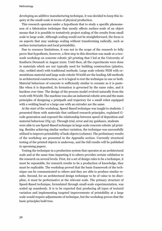
Methodology
56
developing an additive manufacturing technique, it was decided to keep this in-quiry at the small-scale in terms of physical production.
This research operates under a hypothesis that to study a specific phenome-non of a fabrication technique that mostly affects surface-scale of an object means that it is possible to tentatively project scaling of the results from small scale to large scale. Although scaling would not be straightforward, the focus is on aspects that may undergo scaling without transforming radically, such as surface texturization and local printability.
Due to resource limitations, it was not in the scope of the research to fully prove that hypothesis, however, a first step in this direction was made at a two-week workshop on concrete robotic 3D printing that I led at the University of Southern Denmark in August 2020. Until then, all the experiments were done in materials which are not typically used for building construction (plastics, clay, welded steel) with traditional methods. Large scale robotic PEM with ce-mentitious material and large scale robotic WAAM are the leading AM methods in architectural construction, so it is logical to test the technique in one or both. Material behaviour of concrete is sufficiently similar to ceramic as it is paste-like when it is deposited, its formation is governed by the same rules, and it hardens over time. The design of the process model evolved naturally from the work with WAAM. The machine was also an industrial robotic arm and the main principles of designing a printpath and trajectory for a small robot equipped with a welding head or a large one with an extruder are the same.
At the start of the workshop, Speed-Based technique was taught to students. I presented them with materials that outlined research principles, explained G-code generation and exposed the relationship between speed of deposition and material behaviour (Fig 13). Through trial, error and my guidance, students were able to use Speed-Based technique in large scale concrete robotic 3d print-ing. Besides achieving similar surface variation, the technique was successfully utilized to improve printability of lank objects (column). The preliminary results of the workshop are presented in the Appendix section. Currently structural testing of the printed objects is underway, and the full results will be published in upcoming papers.
Testing the technique in a production system that operates at an architectural scale and at the same time imparting it to others provides certain validation to the research on several levels. First, for a set of design rules to be a technique, it must be repeatable, for research results to be a production of knowledge, they must be replicable. The workshop proved that the basic framework of the tech-nique can be communicated to others and they are able to produce similar re-sults. Second, for an architectural design technique to be of value to its disci-pline, it must be performative at the relevant scale. The primary structure of Speed-Based technique, formulated through small-scale experimentation, was scaled up seamlessly. It is to be expected that producing all types of textural variation and implementing targeted improvements of printability at a large scale would require adjustments of technique, but the workshop proves that the basic principles hold true.
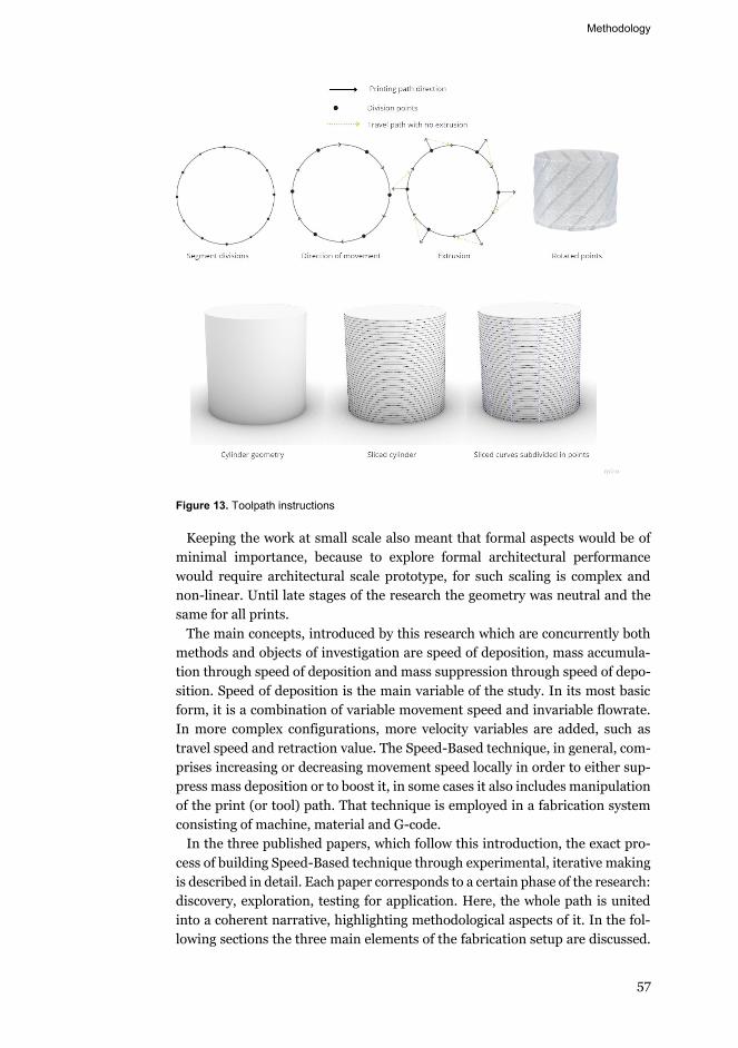
Methodology
57
Figure 13. Toolpath instructions
Keeping the work at small scale also meant that formal aspects would be of minimal importance, because to explore formal architectural performance would require architectural scale prototype, for such scaling is complex and non-linear. Until late stages of the research the geometry was neutral and the same for all prints.
The main concepts, introduced by this research which are concurrently both methods and objects of investigation are speed of deposition, mass accumula-tion through speed of deposition and mass suppression through speed of depo-sition. Speed of deposition is the main variable of the study. In its most basic form, it is a combination of variable movement speed and invariable flowrate. In more complex configurations, more velocity variables are added, such as travel speed and retraction value. The Speed-Based technique, in general, com-prises increasing or decreasing movement speed locally in order to either sup-press mass deposition or to boost it, in some cases it also includes manipulation of the print (or tool) path. That technique is employed in a fabrication system consisting of machine, material and G-code.
In the three published papers, which follow this introduction, the exact pro-cess of building Speed-Based technique through experimental, iterative making is described in detail. Each paper corresponds to a certain phase of the research: discovery, exploration, testing for application. Here, the whole path is united into a coherent narrative, highlighting methodological aspects of it. In the fol-lowing sections the three main elements of the fabrication setup are discussed.
Methodology
58
That scale of reflection was beyond the scope of published papers and is there-fore taking place in this introduction. The following material, machine and G-code sections are descriptive in nature because of the methodological frame-work of research by design and theoretical framework of digital craft. Both are process oriented, in that the way one collects data is generative in terms of actual products and in terms of answering the research questions. Even if the questions are formed prior to design work, they are subject to reformulation as the process unfolds. In both frameworks, the process is as important as results for knowledge generation. The tacit intelligence is externalized through cyclic mak-ing and reflecting. It was attempted to encapsulate as much of the intangible principles that direct formation into the process model design, however some data remains outside of it. The three sections below while presented in a se-quence form a compound entity. Machine, material and G-code are treated as variable super-parameters, each contributing a specific value to the research at both data gathering and data analysing stages.
3.2.1 Machine
During this research, the experimentation was conducted with three different machine systems. For plastic FDM printing - of the shelf 3D printer Ultimaker 2. For clay PEM there were several systems, for smaller models a homemade clay delta printer Arra and Delta Wasp 2040 ("Clay 3D Printer | Delta WASP 2040 Clay" 2020) and for larger models Delta Wasp 40100 ("Ceramic 3D Printer | Delta WASP 40100 Clay | 3D Printers | WASP" 2020). For metal – a WAAM setup of six-axis Kuka industrial robot with a welding toolhead. The aims and objectives of this research do not include full-fledged machine making, rather, the intention is to gain full understanding of machine constraints and affordances and be able to drive the manufacturing in desired direction by con-trolling it through the G-code. Therefore it was decided to use mostly commer-cial printers at all stages.
Ultimaker 2 ("Ultimaker 2+ Connect: Start 3D Printing The Ultimaker Way" 2020) is an affordable, desktop, easy to use 3D printer, featuring an open fila-ment system used to print with PLA (poly lactic acid) plastic. It is possible to control printer movement speed, extrusion speed, extrusion amount. The layer height is only 0.1 mm, meaning both increase in time required to print a part compared to printing with a clay printer (layer height is 1.4 mm) and increase in both amount and variation of minute artefacts. The disadvantage of such ex-cellent resolution for this research lies in the fact that when printing cantilever geometries the slowness and thinness of layers causes the preceding layer to so-lidify before the next is deposited. Except for extreme bridging geometrical sce-narios, the problem of overhangs does not exist in FDM printing with Ulti-maker. Furthermore, it is rather difficult for a maker, who is not in possession of advanced material science knowledge and specialized equipment to edit the material composition or make their own.
For the experiments with metal (steel wire) a six axis Kuka robot with an arc welding feeding tool head developed by Fronius ("FCH 3-21 / 3-38 / 6-76 / 9-114 Welding Heads" 2020) was used. Robot movement is controlled by a robot
Methodology
59
controller and the wire feeding is controlled by Fronius controller. Both the movement speed of the robot and feeding speed of the wire have to be adjusted and matched before the printing process can start. While movement speed can be controlled, the extrusion speed is defined by external Fronius setups and can-not be altered. That lack of freedom is detrimental to objectives of this research, and, coupled with inability to modify material composition, led to a decision to use WAAM setup in a minor portion of the work, dedicated to understanding differences and similarities of employing Speed-Based technique in different AM fabrication contexts.
During the exploratory phases of the study it became evident that PEM with clay presents unique possibilities for manipulation of the material. Unlike FDM printing with plastic filament or WAAM with welding steel wire, ceramic com-position editing allows experimentation with rheology, which in fabrication af-fects flowrate. Also, keeping in mind potential scaling of the research to archi-tectural dimensions, the possibility of transplanting the system from clay 3D printing to concrete 3D printing is seen as a feasible avenue. In view of potential discoveries and having no access to a commercial clay printer at the time, a Delta printer was handmade. In alignment with the theoretical framework derived from the discourse on digital craft, constructing a fabrication machine allowed for gaining more comprehensive knowledge about the system in its entirety.
Due to its relative simplicity and unique popularity of clay among makers, ce-ramic 3D printing is widespread among designers, artists, independent practi-tioners. As so many are experimenting with it, the process and the machine de-sign are becoming democratized. One of the first open-source clay 3D printers was developed as a modification of existing plastic extrusion RepRap machine by Belgian Unfold (Unfold 2020). Jonathan Keep (Keep 2020) built upon that design by developing a delta-style clay 3D printer as an open-source project.
Keep’s design served as a base for Arra printer. Mainframe design was kept the same, while carriage, effector (extruder) were redesigned and 3D printed in plastic. In Arra, material flow is implemented through air pressure. A print car-tridge tube, manually filled with porcelain is both the material carrier and the extruder. Cartridge is fitted with an extruder nozzle tip, through which material is deposited and pushed by external air pressure regulated by a valve. While cheap to make, easy to maintain and suitable for quick printing, Arra has a few shortcomings: flow of the material cannot be regulated in the printing code, print volume is dependent on the size of the cartridge, material flow has to be adjusted manually from time to time. During printing with Arra setup, constant monitoring was required. It was not possible to fill the cartridge with material completely, so periodically an air bubble occurred, which would cause complete failure of the print. In order to avoid that, it was necessary to continuously ob-serve the semi-transparent tube and turn off the air pressure if a bubble was detected. Consequently, ceramic printing was continued on commercial Delta Wasp printers, once they became available. As mentioned before, the research does not strive to innovate on the AM machines but to be able to master fabri-cation environments. Delta Wasp 2040 and 40100 clay printers are superbly tractable, allowing for great level of control over the whole process.
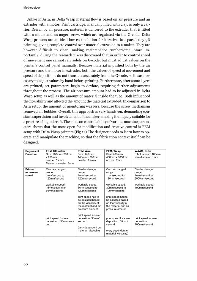
Methodology
60
Unlike in Arra, in Delta Wasp material flow is based on air pressure and an extruder with a motor. Print cartridge, manually filled with clay, is only a car-rier. Driven by air pressure, material is delivered to the extruder that is fitted with a motor and an auger screw, which are regulated via the G-code. Delta Wasp printers are an ideal low-cost solution for iterative, fast-paced clay 3D printing, giving complete control over material extrusion to a maker. They are however difficult to clean, making maintenance cumbersome. More im-portantly, during the research it was discovered that in order to control speed of movement one cannot rely solely on G-code, but must adjust values on the printer’s control panel manually. Because material is pushed both by the air pressure and the motor in extruder, both the values of speed of movement and speed of depositions do not translate accurately from the G-code, so it was nec-essary to adjust values by hand before printing. Furthermore, after some layers are printed, set parameters begin to deviate, requiring further adjustments throughout the process. The air pressure amount had to be adjusted in Delta Wasp setup as well as the amount of material inside the tube. Both influenced the flowability and affected the amount the material extruded. In comparison to Arra setup, the amount of monitoring was less, because the screw mechanism removed air bubbles. Overall, this approach is very hands-on, demanding con-stant supervision and involvement of the maker, making it uniquely suitable for a practice of digital craft. The table on controllability of various machine param-eters shows that the most open for modification and creative control is PEM setup with Delta Wasp printers (Fig.12).The designer needs to learn how to op-erate and manipulate the machine, so that the fabrication context itself can be designed.
Degrees of Freedom
FDM, Ultimaker Size: 200mmx 200mm x 200mm nozzle : 0.4mm filament diameter: 3mm
PEM, Arra Size: 140mmx 140mm x 200mm nozzle : 1.4mm
PEM, Wasp Size: 400mmx 400mm x 1000mm nozzle : 2mm
WAAM, Kuka robot radius: 1400mm wire diameter: 1mm
Printer movement speed
Can be changed range: 1mm/second to 120mm/second workable speed: 15mm/second to 60mm/second print speed for even deposition: 30mm/ sec-ond
Can be changed range: 1mm/second to 120mm/second workable speed: 30mm/second to 120mm/second print speed had to be adjusted based on the viscosity of the material and air pressure amount print speed for even deposition: 30mm/ second (very dependent on material viscosity)
Can be changed range: 1mm/second to 120mm/second workable speed: 30mm/second to 120mm/second print speed had to be adjusted based on the viscosity of the material and air pressure amount print speed for even deposition: 30mm/ second (very dependent on material viscosity)
Can be changed range: 1mm/second to 3000mm/second workable speed: 100mm/second print speed for even deposition: 100mm/second
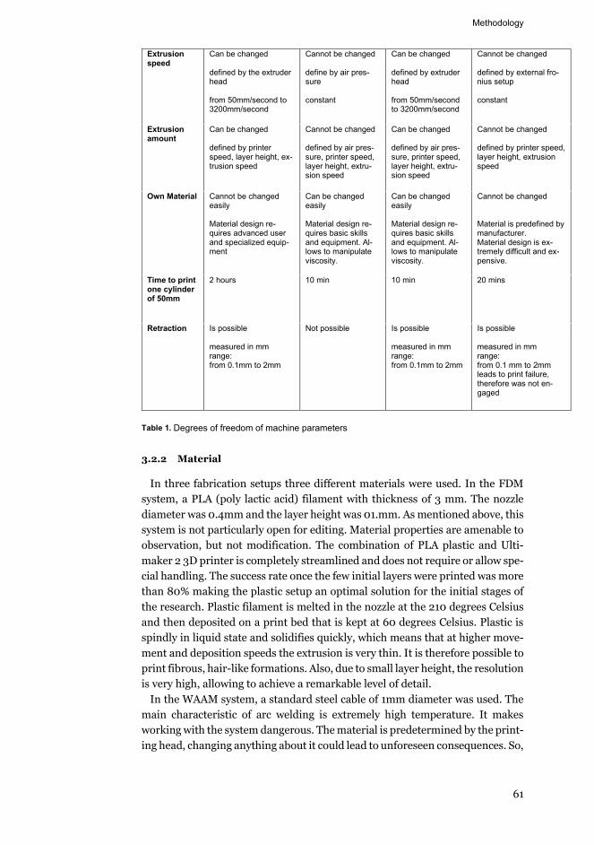
Methodology
61
Extrusion speed
Can be changed defined by the extruder head from 50mm/second to 3200mm/second
Cannot be changed define by air pres-sure constant
Can be changed defined by extruder head from 50mm/second to 3200mm/second
Cannot be changed defined by external fro-nius setup constant
Extrusion amount
Can be changed defined by printer speed, layer height, ex-trusion speed
Cannot be changed defined by air pres-sure, printer speed, layer height, extru-sion speed
Can be changed defined by air pres-sure, printer speed, layer height, extru-sion speed
Cannot be changed defined by printer speed, layer height, extrusion speed
Own Material Cannot be changed easily Material design re-quires advanced user and specialized equip-ment
Can be changed easily Material design re-quires basic skills and equipment. Al-lows to manipulate viscosity.
Can be changed easily Material design re-quires basic skills and equipment. Al-lows to manipulate viscosity.
Cannot be changed Material is predefined by manufacturer. Material design is ex-tremely difficult and ex-pensive.
Time to print one cylinder of 50mm
2 hours 10 min 10 min 20 mins
Retraction Is possible measured in mm range: from 0.1mm to 2mm
Not possible Is possible measured in mm range: from 0.1mm to 2mm
Is possible measured in mm range: from 0.1 mm to 2mm leads to print failure, therefore was not en-gaged
Table 1. Degrees of freedom of machine parameters
3.2.2 Material
In three fabrication setups three different materials were used. In the FDM system, a PLA (poly lactic acid) filament with thickness of 3 mm. The nozzle diameter was 0.4mm and the layer height was 01.mm. As mentioned above, this system is not particularly open for editing. Material properties are amenable to observation, but not modification. The combination of PLA plastic and Ulti-maker 2 3D printer is completely streamlined and does not require or allow spe-cial handling. The success rate once the few initial layers were printed was more than 80% making the plastic setup an optimal solution for the initial stages of the research. Plastic filament is melted in the nozzle at the 210 degrees Celsius and then deposited on a print bed that is kept at 60 degrees Celsius. Plastic is spindly in liquid state and solidifies quickly, which means that at higher move-ment and deposition speeds the extrusion is very thin. It is therefore possible to print fibrous, hair-like formations. Also, due to small layer height, the resolution is very high, allowing to achieve a remarkable level of detail.
In the WAAM system, a standard steel cable of 1mm diameter was used. The main characteristic of arc welding is extremely high temperature. It makes working with the system dangerous. The material is predetermined by the print-ing head, changing anything about it could lead to unforeseen consequences. So,
Methodology
62
manipulating material composition in the context of available tools and re-sources would be unsafe. Furthermore, the nature of WAAM forestalls any di-rect observation during the printing process. All the observations had to be made after the process of printing had finished and metal had cooled down. Be-ing restricted in the attempts to open up the system, the research concentrated on manipulating the G-code. Material variation, however, naturally occurred as the steel prototypes patinaed, providing an opportunity to inspect a case of sur-face quality generation from Speed-Based technique, material behaviour and external forces (oxygen).
In the PEM clay system, porcelain material was used because of availability of the ingredients and because it could be manufactured in the controlled environ-ment of a ceramic studio at the Aalto University. A recipe was developed by trial and error and with the help of the ceramic studio master. The main ingredients were: kaolin 50% , feltspar 25%, and 25% quartz. A range of water to volume ratios was tested from 18% to 21% to get a relatively pliable mix, which could be pushed from the tube easily under 5 bars of pressure. Any mix which required more than 5 bars of pressure to be extruded through a 1mm nozzle was dis-carded as it would continuously clog the cartridge or the extruder and produce uncontrollable deformations. In addition, the tube was rated for maximum pressure of 6 bars.
Once the acceptable ratio of the dry material and water was determined., the material was mixed using an industrial mixer for 40-60 minutes to achieve a homogenous mix. Depending on the temperature and moisture conditions the amount of water had to be adjusted throughout the year. Another important as-pect was plasticity of the material. In order to achieve the right plasticity of the clay material, a plasticizer (bentonite) was used in very small quantities - ap-proximately 0.5% of the volume. Plastisizer’s effect on the mix is drastic, small increase results in extreme decrease in viscosity. Bentonite also increases shrinkage during drying and it slows down the drying rate.
The material was stored in the controlled environment, so the moisture con-tent remained constant and viscosity was not affected. However, the printing environment could not be controlled, so the mix had to be adjusted and fine-tuned, depending on the temperature and moisture conditions. In order to de-termine the right diameter of the nozzle and the ratio of nozzle diameter to layer height to printability a series of experiments were performed. Once a range of suitable setups was determined, small test models were printed and then fired in a kiln to evaluate shrinkage and cracking.
When the printer was switched from Arra to Delta Wasp, the material mix had to be changed again. The Wasp printer has an additional step before the mate-rial comes out of the nozzle. There is a motor extruder, within which is a screw that regulates the flow of material. This added step dries the clay material due to friction in the screw mechanism. To avoid drying of the material which would negatively affect printability of an object, the amount of water in the porcelain mixture was increased by 1-2%.
In longer and larger prints, a constant spraying of water was required to keep the printed part moistened. If the part dried during the printing process it would
Methodology
63
shrink by 2-3 % and this would diminish the printability of the above layers. This was even more essential in the larger prints, where print time spanned not over a few hours but over a few days. After each day of printing, the part had to be carefully covered to keep the moisture in, so as to avoid shrinking. Prior to resuming, the part printed on the previous day had to be thoroughly sprayed with water to insure the adhesion on the new layers. The moisture in the printed object was required to be monitored all the time. In the post-processing stage, the models are fired in a kiln, which results in 4-5% shrinkage. That is the final action of materiality, that completes the process of making. The artefact is so-lidified and left to be affected by external forces of time and environment.
Clay is particularly well suited for explorations in 3D printing as it allows for significant alteration before, during and after 3D printing. Layer-by-layer extru-sion of clay leaves visible traces on the 3D printed surfaces, which are not pre-sent in the digital master model. This way, 3D printing with clay is ripe with potential for experimentation and discovery. This shifts the focus from result to the process and ensures designer’s involvement at all stages of making. The knowledge gained expands technical repertoire and extends discipline’s pur-view simultaneously towards material science and craftsmanship. Different ma-terials ensure undesignable variations between printed objects that have the same geometry and G-code. Minimal manipulation of material composition al-lows to encourage uncertainty in the processing of the matter, which is valued more than seamless accuracy. The transformations and transitions of material are primary in the process of formation. Some of them are codified and instru-mentalized in the G-code, and some remain intractable.
3.2.3 The digital process model
For prototypes with the Speed-Based technique applied, the digital model consisted of Rhinoceros or Grasshopper geometry, sliced and segmented in Grasshopper and translated into a G-code with Silkworm plugin for Grasshop-per. In WAAM, KUKA PRC ("Association For Robots In Architecture | KUKA|Prc" 2020) was used instead of Silkworm. KUKA PRC is a set of Grass-hopper components that allows to control movement of the robotic arm. For control prototypes in ceramic, to which the technique was not applied, the workflow was more straightforward: geometry, built in Rhinoceros was sliced and converted into G-code by Repetier-Host ("- Repetier Software" 2020) for Arra setup or by Ultimaker Cura for Delta Wasp setup.
As mentioned before, the shape was not an object of research, therefore throughout the study it served either as virtually neutral receptacle of effects or a tectonically specific, yet contextually uninformed geometric scenario to test the performance of Speed-Based technique.
The design of the process model is based on variables and invariables and strives to systematically build and test relationships between them, resulting in a Speed-Based variation throughout the print path. It is constructed to have the potential to be contextually configured to a vast range of situations.
For the first, discovery phase, a series of cylinders was printed in an FDM fabrication setup. A typical slicing software takes an input of a 3D geometry
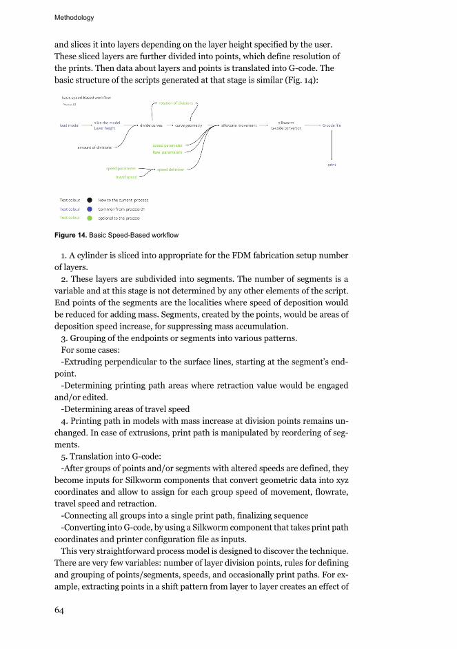
Methodology
64
and slices it into layers depending on the layer height specified by the user. These sliced layers are further divided into points, which define resolution of the prints. Then data about layers and points is translated into G-code. The basic structure of the scripts generated at that stage is similar (Fig. 14):
Figure 14. Basic Speed-Based workflow
1. A cylinder is sliced into appropriate for the FDM fabrication setup number of layers.
2. These layers are subdivided into segments. The number of segments is a variable and at this stage is not determined by any other elements of the script. End points of the segments are the localities where speed of deposition would be reduced for adding mass. Segments, created by the points, would be areas of deposition speed increase, for suppressing mass accumulation.
3. Grouping of the endpoints or segments into various patterns. For some cases: -Extruding perpendicular to the surface lines, starting at the segment’s end-
point. -Determining printing path areas where retraction value would be engaged
and/or edited. -Determining areas of travel speed 4. Printing path in models with mass increase at division points remains un-
changed. In case of extrusions, print path is manipulated by reordering of seg-ments.
5. Translation into G-code: -After groups of points and/or segments with altered speeds are defined, they
become inputs for Silkworm components that convert geometric data into xyz coordinates and allow to assign for each group speed of movement, flowrate, travel speed and retraction.
-Connecting all groups into a single print path, finalizing sequence -Converting into G-code, by using a Silkworm component that takes print path
coordinates and printer configuration file as inputs. This very straightforward process model is designed to discover the technique.
There are very few variables: number of layer division points, rules for defining and grouping of points/segments, speeds, and occasionally print paths. For ex-ample, extracting points in a shift pattern from layer to layer creates an effect of
Methodology
65
oblique ribs. Extracting points with the same xy coordinates creates vertical ribs. At that stage, multiple groupings were tested in order to collect data on the nature of the relationship between variable point configurations and variable speeds.
For the second, explorative phase of printing in three different AM systems, the geometry was also a hollow cylinder. Having gained basic knowledge on how to structure the use of technique and effects it produces in the first phase, the sequence and content of steps in the process models of the second phase have not been altered substantially, but rather adapted to the ceramic Arra and steel Kuka fabrication setups. With Arra, Grasshopper and Silkworm were used, with Kuka, Grasshopper and Kuka PRC. Notably, it was not possible to engage and control retraction parameters in both Arra and Kuka. Due to low ductility of porcelain mix and molten steel, and without retraction the increase in speed of deposition alone could not produce noticeable suppression of mass, or in terms of effects - holes. The thinning of the surface was possible to accomplish, but only by using absolute maximum movement speed. Input data for Silkworm components can be both curves and points, which means that it is possible to change the speed of deposition at a non-dimensional location and to print cur-vilinear geometry. In Kuka PRC, the input can only be points converted into planes, so the higher the curvature the more points one needs to define it. Also segments with travel speed had to be defined as series of printable points, in order to be able to control deposition at those locations. During printing, in WAAM the welding arc has to be always grounded, therefore the configuration of extruded lines had to be designed in a way to ensure a connection between extrusions of consecutive layers. Overall, that phase of the research was focused on determining affordances, constraints and generative capacities of specific materialities and machines in combination with a basic version of the Speed-Based process model. The design was continuously adapted to tease out the most promising overall system.
The third phase, dedicated to compiling test data on potential application of the Speed-Based technique as a solution for particular printability issues, was carried out in clay Delta Wasp fabrication setup, with G-code designed in Grass-hopper and Silkworm. At this stage, the research began to include less neutral formal arrangement, specified by requirements of the problem space. The print-ability issues in question were overhangs, cantilevers, bridging geometries, ob-jects characterized by high ratio of height to footprint. Therefore, among others, arboreous, arch-based shapes were introduced.
Arch-based geometry, with a variable number of vertical supports necessitated an addition of extra steps to the process model. After geometry is sliced into layers of curves, these curves need to be checked for continuity and their seams have to be aligned. If there are more than two vertical supports, the curves at each layer need to be ordered. These operations control the order in which the machine moves from one vertical element to another and how they come to-gether and/or split apart again. While this control could be designed in many different ways, for current purposes it sufficed to arrange the legs in clockwise
Methodology
66
order and make seams continuous. If that order becomes a variable parameter, then the model would need further refinement.
Overall, at that stage, the work on the process model began to utilize gained knowledge of the underlying principles of formation with Speed-Based tech-nique and started to form the foundations for a more universal and at the same time more specific G-code. The analytic and correction operations described above contributed to universality along with other inspection snippets for other portions of the model. Concurrently, previously uninformed application of the technique was replaced by a color-based system derived from structural analysis models from Karamba plugin for Grasshopper. Utilization and displacement maps allow to determine in which areas mass needs to be increased and de-creased and where operations related to constructing unsupported geometry are needed. Furthermore, the initial curve division is informed by exact dimensions of the model at each layer and the information from Karamba structural maps. Both points mass addition (ribs) and segments of thinning are curves with var-iable length depending on overall tectonic arrangement of the geometry, built through the use of multiple attractors.
Overall workflow of the process models maintains the following initial se-quence:
1. basic geometrical, parametric model is made in Rhinoceros or Grasshopper 2. slicing 3. topology and order of layer curves is checked and fixed 4. application of technique: subdivision, grouping and ordering 5. translating into G-code with Silkworm However, each stage has become more sophisticated, equipped with control
mechanisms, conditional forks and more variables (Fig 15). There are still many latent avenues for further refinement, for example design of extrusions that sup-port cantilever mass could gain more precision in application and resolution by forming a tighter relationship with material. Restrictions of a limited repertoire of shapes could be challenged. One potential development in particular – mech-anisms for integration of the technique into a wide range of design systems war-rants urgent attention, if dissemination of the technique were to become an ob-jective.
In discussing all three aspects of AM the aim is to show that the design process continues until the object is built. The exact morphology emerges along with surface treatment through materialization. Even a simple shape of cylinder, fab-ricated using different profiles of speed variation is continuously locally or glob-ally transformed. Concreteness is arrived upon, not designed beforehand. The product and process are entwined, making fabrication a generative operation. In this research it is studied by abandoning optimization and turning to subver-sion. Instead of striving for a ‘successful’ print by making the shortest printpath and optimizing speed, the path is unnecessarily longer, and the speed is too fast or too slow.
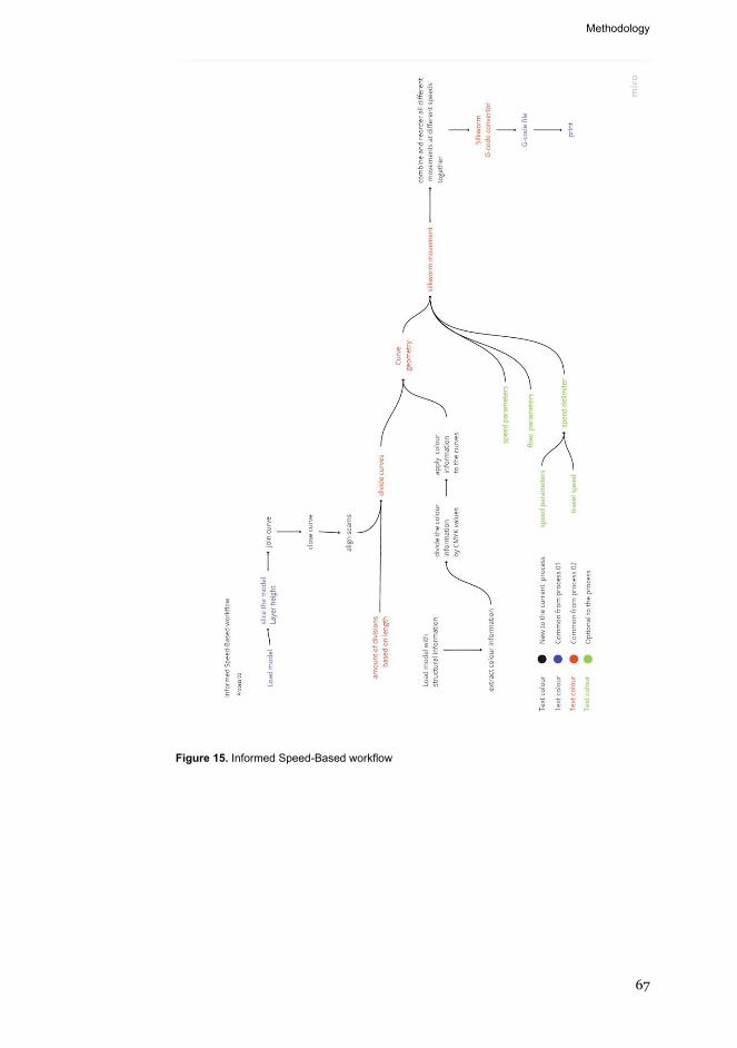
Methodology
67
Figure 15. Informed Speed-Based workflow
Results and contribution to knowledge
68
4. Results and contribution to knowledge
The results of the research follow from the research question. The main archi-tectural implications of using Speed-Based technique are undesignable textural variation and improvement of geometrical printability. Ornamental variation can be utilized for making phenomenologically unique facades, where the sur-face itself is a tangible product of the construction method. Printability improve-ments may be beneficial in the process of the AEC adoption of large scale AM, especially PEM with concrete. Guided by principles of digital craft, Speed-Based technique allows design to retain logical continuity from stage to stage. Addi-tively manufactured shapes and structures could thus follow the grain of the technology, instead of resisting it or artificially augmenting it in order to print unprintable forms. However, the hypothesis of scaling the technique to a build-ing element size with minor alterations is only tested in limited capacity. Com-prehensive examination of technique’s performance at a large scale remains an object for future studies.
The results of this research are consistent with its theoretical and methodo-logical frameworks. Looseness of research by design methodology is beneficial for exploration and detrimental for concreteness of the outcome. Certain open-endedness is intrinsic and while the process is thoroughly explained, it is not necessarily directly replicable. And while as much as possible the insights are articulated in this introduction and following papers as well as embedded into the design of the process model, a portion of it remains tacit. Speed-Based tech-nique requires very careful control, a delicate balance between mass excess and scarcity. In deposition, addition of mass or its suppression deforms the geome-try of an object. In some cases, deformation remains within surface scale, in others the morphology of an entire object is altered. Designer needs to have a pre-established range of acceptable deviation based on concrete data. The skill of managing the technique develops gradually and requires unmediated prac-tice. However comprehensively informed the digital process model may become in the future research, to master it, a designer would have to explore it through practice.
According to stated objectives, following results were achieved. A production system, comprising of machine, material and process model (defines where and how printer moves and deposits) is constructed as a platform for Speed-Based technique deployment. The system is treated as a set of parameters, capacities and properties. By interacting, they form secondary, performative aspects of the system, which affect material deposition in printed models. For example, the
Results and contribution to knowledge
69
amount of mass generated at a given location is determined by material viscos-ity, machine nozzle diameter, value and continuity of speed of movement and geometry of print path. Figure 16 attempts to illustrate the interconnectivity of discrete elements within the system and chart the paths of causality between committing to certain decisions about printing process and morphological phe-nomena of material artefacts. While a typical AM production setup would in-clude a lesser set of operational parameters, on the other hand, in a more so-phisticated system, more elements could be included to increase complexity and control. In Figure 16, the focus is on parameters, which were actively manipu-lated or were of significant importance in Speed-Based technique. Dependen-cies and causalities between various attributes, shown as arrows, are necessarily a simplified and abstracted representation of actual interactions taking place within the system. They are rarely as straightforward, because very few of the parameters are ontologically equivalent. Therefore, numerical values coalesce with material behaviour to form a complex tendency or capacity, which would perform differently in different contexts. Figure 17 provides more detail on some of the dependencies between system attributes that can be expressed through numbers. It shows how each parameter requires reduction or increase of others in order to produce varied yet controlled deposition, which is the aim of application of Speed-Based technique.
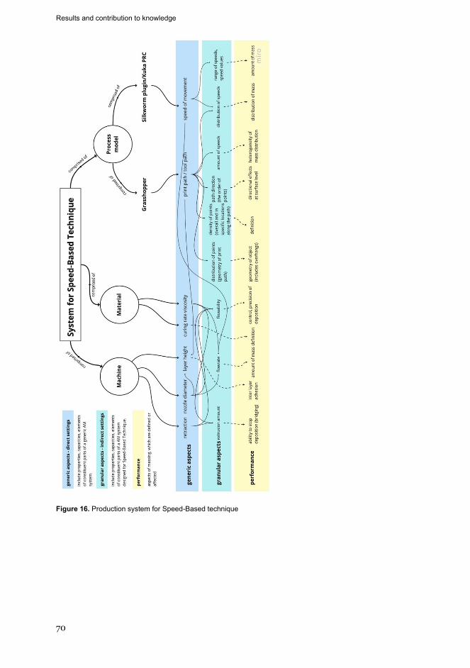
Results and contribution to knowledge
70
Figure 16. Production system for Speed-Based technique
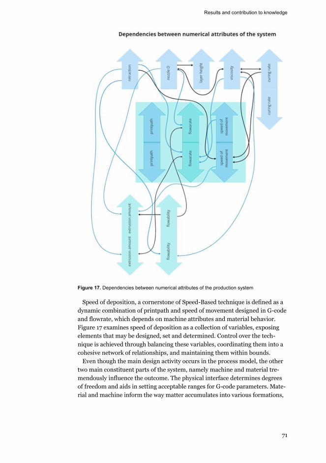
Results and contribution to knowledge
71
Figure 17. Dependencies between numerical attributes of the production system
Speed of deposition, a cornerstone of Speed-Based technique is defined as a dynamic combination of printpath and speed of movement designed in G-code and flowrate, which depends on machine attributes and material behavior. Figure 17 examines speed of deposition as a collection of variables, exposing elements that may be designed, set and determined. Control over the tech-nique is achieved through balancing these variables, coordinating them into a cohesive network of relationships, and maintaining them within bounds.
Even though the main design activity occurs in the process model, the other two main constituent parts of the system, namely machine and material tre-mendously influence the outcome. The physical interface determines degrees of freedom and aids in setting acceptable ranges for G-code parameters. Mate-rial and machine inform the way matter accumulates into various formations,
Results and contribution to knowledge
72
such as slumping, looping, stringing. Figure 18 and Figure 19 show which ma-chine and material attributes are variable and how by changing them it is pos-sible to achieve specific effects.
Figure 18. Speed of deposition
Results and contribution to knowledge
73
Figure 19. Effects of applying Speed-Based technique in three different material-machine sys-tems
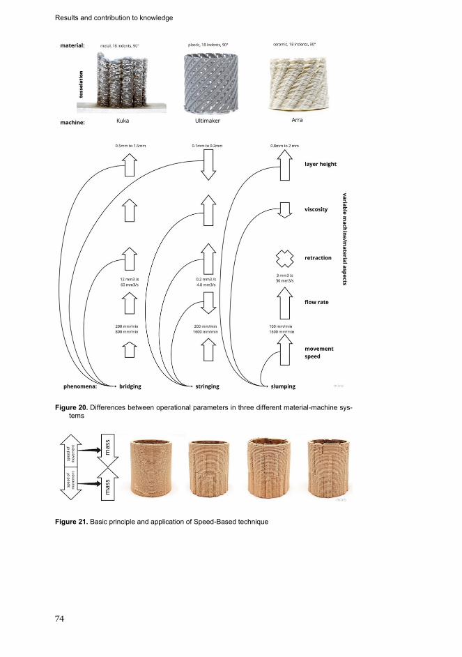
Results and contribution to knowledge
74
Figure 20. Differences between operational parameters in three different material-machine sys-tems
Figure 21. Basic principle and application of Speed-Based technique
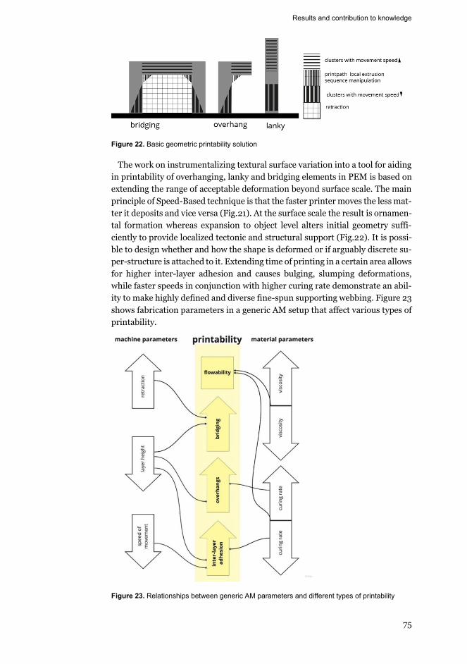
Results and contribution to knowledge
75
Figure 22. Basic geometric printability solution
The work on instrumentalizing textural surface variation into a tool for aiding in printability of overhanging, lanky and bridging elements in PEM is based on extending the range of acceptable deformation beyond surface scale. The main principle of Speed-Based technique is that the faster printer moves the less mat-ter it deposits and vice versa (Fig.21). At the surface scale the result is ornamen-tal formation whereas expansion to object level alters initial geometry suffi-ciently to provide localized tectonic and structural support (Fig.22). It is possi-ble to design whether and how the shape is deformed or if arguably discrete su-per-structure is attached to it. Extending time of printing in a certain area allows for higher inter-layer adhesion and causes bulging, slumping deformations, while faster speeds in conjunction with higher curing rate demonstrate an abil-ity to make highly defined and diverse fine-spun supporting webbing. Figure 23 shows fabrication parameters in a generic AM setup that affect various types of printability.
Figure 23. Relationships between generic AM parameters and different types of printability
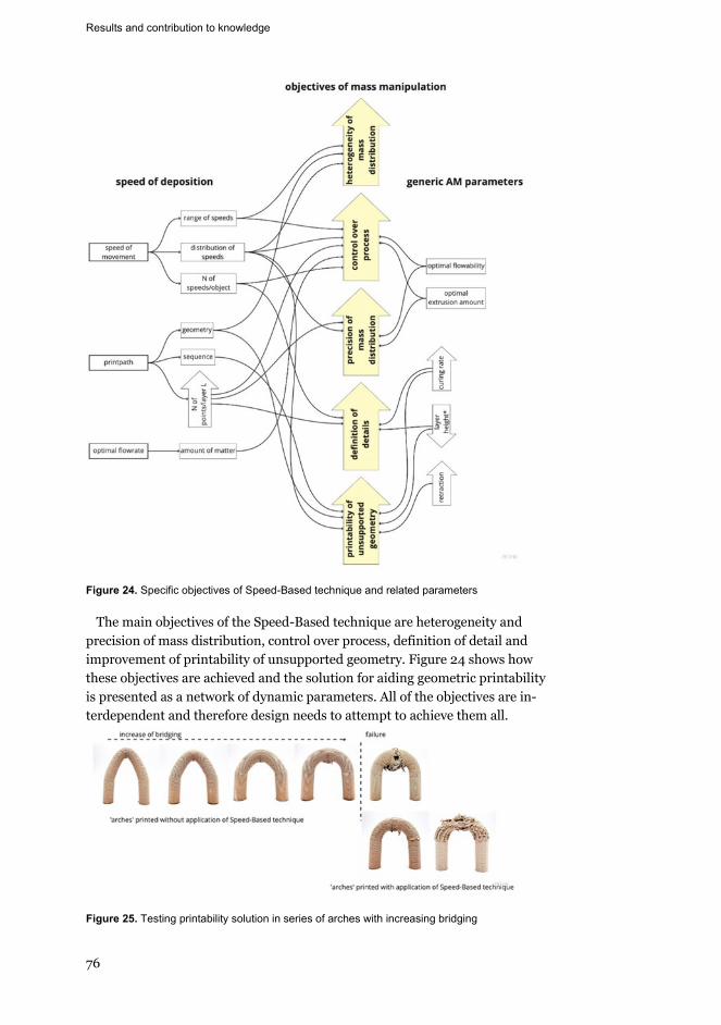
Results and contribution to knowledge
76
Figure 24. Specific objectives of Speed-Based technique and related parameters
The main objectives of the Speed-Based technique are heterogeneity and precision of mass distribution, control over process, definition of detail and improvement of printability of unsupported geometry. Figure 24 shows how these objectives are achieved and the solution for aiding geometric printability is presented as a network of dynamic parameters. All of the objectives are in-terdependent and therefore design needs to attempt to achieve them all.
Figure 25. Testing printability solution in series of arches with increasing bridging
p g p
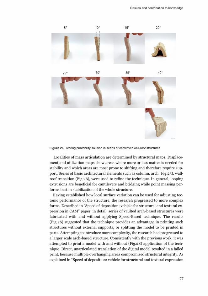
Results and contribution to knowledge
77
Figure 26. Testing printability solution in series of cantilever wall-roof structures
Localities of mass articulation are determined by structural maps. Displace-ment and utilization maps show areas where more or less matter is needed for stability and which areas are most prone to shifting and therefore require sup-port. Series of basic architectural elements such as column, arch (Fig.25), wall-roof transition (Fig.26), were used to refine the technique. In general, looping extrusions are beneficial for cantilevers and bridging while point massing per-forms best in stabilization of the whole structure.
Having established how local surface variation can be used for adjusting tec-tonic performance of the structure, the research progressed to more complex forms. Described in “Speed of deposition: vehicle for structural and textural ex-pression in CAM” paper in detail, series of vaulted arch-based structures were fabricated with and without applying Speed-Based technique. The results (Fig.26) suggested that the technique provides an advantage in printing such structures without external supports, or splitting the model to be printed in parts. Attempting to introduce more complexity, the research had progressed to a larger scale arch-based structure. Consistently with the previous work, it was attempted to print a model with and without (Fig.28) application of the tech-nique. Direct, unarticulated translation of the digital model resulted in a failed print, because multiple overhanging areas compromised structural integrity. As explained in “Speed of deposition: vehicle for structural and textural expression
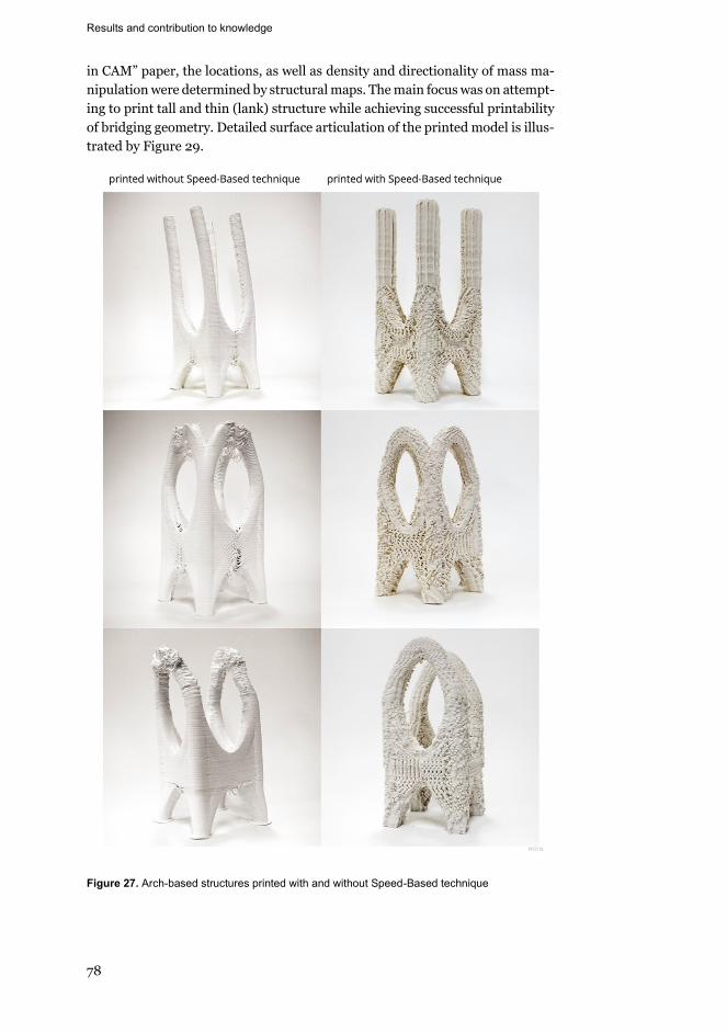
Results and contribution to knowledge
78
in CAM” paper, the locations, as well as density and directionality of mass ma-nipulation were determined by structural maps. The main focus was on attempt-ing to print tall and thin (lank) structure while achieving successful printability of bridging geometry. Detailed surface articulation of the printed model is illus-trated by Figure 29.
Figure 27. Arch-based structures printed with and without Speed-Based technique
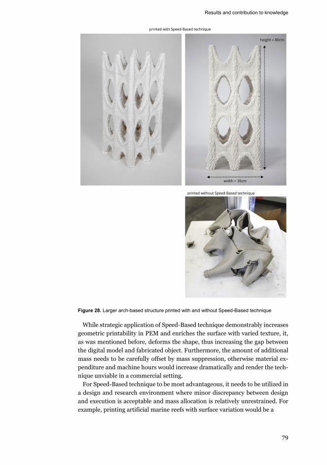
Results and contribution to knowledge
79
Figure 28. Larger arch-based structure printed with and without Speed-Based technique
While strategic application of Speed-Based technique demonstrably increases geometric printability in PEM and enriches the surface with varied texture, it, as was mentioned before, deforms the shape, thus increasing the gap between the digital model and fabricated object. Furthermore, the amount of additional mass needs to be carefully offset by mass suppression, otherwise material ex-penditure and machine hours would increase dramatically and render the tech-nique unviable in a commercial setting.
For Speed-Based technique to be most advantageous, it needs to be utilized in a design and research environment where minor discrepancy between design and execution is acceptable and mass allocation is relatively unrestrained. For example, printing artificial marine reefs with surface variation would be a
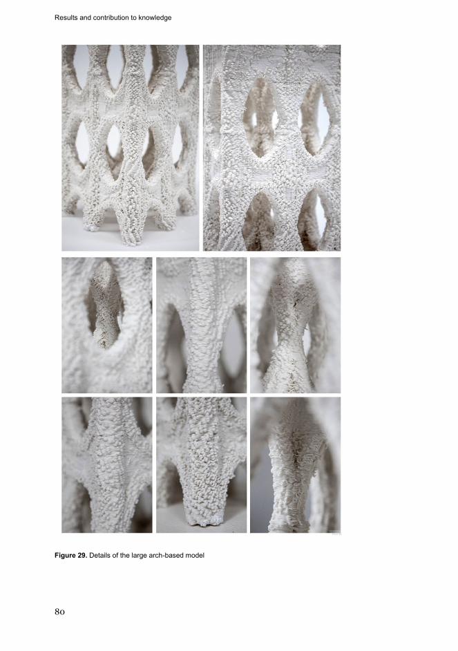
Results and contribution to knowledge
80
Figure 29. Details of the large arch-based model
Results and contribution to knowledge
81
perfect utilization of the technique. To promote biodiversity, artificial reefs re-
quire as much surface relief as possible, so the benefits provided by the tech-nique would outweigh the lack of seamless translation from digital to physical.
As to what could be interpreted as negative results, it was discovered that cy-lindrical ceramic models with the technique applied perform worse in pure com-pression than models without the technique. The reason is that the technique creates discontinuities in the outline of the cylinder slice, so instead of the pres-sure being equally distributed it is concentrated in certain areas. However, it is reasonable to assume that in a more complex structural scenario, the applica-tion of Speed-Based technique would demonstrate benefits. That assumption could be tested in the future research with a large-scale PEM with concrete fab-rication setup.
The main contribution of this research to the knowledge is that it provides the foundations of an apparatus to practice AM in a generative and meaningful way. The technology itself is engaged as a design driver. Surface variation is an in-trinsic expression of making and while having an aesthetic value it is also a way to strengthen or weaken a structure locally, increase or decrease the surface area between layers, and print unsupported parts without any extraneous contriv-ances.

83
References
Adamson, G. 2019. Thinking Through Craft. Bloomsbury Academic. Adorno, T. W. A. 2020. Aesthetic Theory. University of Minnesota Press. Ahlquist, Sean, and Achim Menges. 2011. “Behavior-Based Computational Design
Methodologies: Integrative Processes for Force Defined Material Structures.” Alberti, Leon Battista. 1988. On the Art of Building in Ten Books. Mit Press. Allen, Stan. 2012. Practice: Architecture, Technique and Representation. Taylor &
Francis. Allen, Stan. 1999. “PRACTICE vs PROJECT.” PRAXIS: Journal of Writing + Building
1(0):112–25. Anton, Ana, Angela Yoo, Patrick Bedarf, Lex Reiter, Timothy Wangler, and Benjamin
Dillenburger. 2019. Vertical Modulations: Computational Design for Concrete 3D Printed Columns.
Archer, Bruce. 1995. “The Nature of Research.” Co-Design Journal 2(11):6–13. Atwood, W. Andrew. 2012. “Monolithic Representations.” Pp. 199–205 in Matter: Ma-
terial Processes in Architectural Production. Routledge. Bernard Cache. 2011. Projectiles. London: Architectural Association. Bhooshan, Shajay, Tom Van Mele, and Philippe Block. 2015. “Discrete Funicular
Structures with Curve-Crease-Folded Moulds.” in of the International Associa-tion for Shell and Spatial Structures (IASS) Symposium.
Blythe, Richard, and Leon van Schaik. 2013. “What If Design Practice Matters?” Borgdorff, Henk. 2006. The Debate on Research in the Arts. Vol. 2. Kunsthøgskolen i
Bergen Bergen, Norway. Brugnaro, Giulio, and Sean Hanna. 2018. “Adaptive Robotic Carving.” Pp. 336–48 in
Robotic Fabrication in Architecture, Art and Design. Springer. Camburn, Bradley A., Karen H. Sng, K. Blake Perez, Kevin Otto, Kristin L. Wood, Dan-
iel Jensen, and Richard Crawford. 2015. “The Way Makers Prototype: Principles of DIY Design.” P. V007T06A004 in International Design Engineering Tech-nical Conferences and Computers and Information in Engineering Conference. Vol. 57175. American Society of Mechanical Engineers.
Carpo, Mario. 2013. “The Art of Drawing.” Architectural Design 83(5):128–33. doi: 10.1002/ad.1646.
Carpo, Mario. 2018. The Second Digital Turn: Design beyond Intelligence. Cohen, Zach. 2018. “Hold up: Machine Delay in Architectural Design.” Pp. 126–38 in
Robotic Fabrication in Architecture, Art and Design. Springer. DeLanda, Manuel. 2004. “Material Complexity.” Digital Tectonics 14:21. DeLanda, Manuel. 2015. “The New Materiality.” Architectural Design 85(5):16–21. Derrida, J., G. C. Spivak, and J. Butler. 2016. Of Grammatology. Johns Hopkins Uni-
versity Press. Doerfler, Kathrin, Sebastian Ernst, Luka Piškorec, Jan Willmann, Volker Helm, Fabio
Gramazio, and Matthias Kohler. 2014. “Remote Material Deposition.” Pp. 101–7 in International Conference, COAC, ETSAB, ETSAV.
Dunn, N. 2012. Digital Fabrication in Architecture. Laurence King Publishing. Evans, R., and Architectural Association (Great Britain). 1997. Translations from
Drawing to Building and Other Essays. Architectural Association.
References
84
Feucht, Thilo, and Jörg Lange. 2019. 3-D-Printing with Steel: Additive Manufacturing of Connection Elements and Beam Reinforcements.
Frayling, Christopher. 1993. “Research in Art and Design.” Gibson, Ian, David Rosen, and Brent Stucker. 2010. Additive Manufacturing Technol-
ogies – Rapid Prototyping to Direct Digital Manufacturing. Vol. 5. Glanville, Ranulph. 2007. “Design Prepositions.” The Unthinkable Doctorate 115–26. Gleiter, Jörg H. 2012. Ornament Today: Digital Material Structural. Bozen-Bolzano
University Press. Gourdoukis, Dimitris, and L. Alberti. 2017. “Digital Craftsmanship: From the Arts and
Crafts to Digital Fabrication.” Gramazio, Fabio, and Matthias Kohler. 2012. “Digital Materiality in Architecture.”
Space 537:100–107. Gürsoy, Benay. 2018. “From Control to Uncertainty in 3D Printing with Clay.” Harry Francis Mallgrave, G. S. M. R., G. Semper, H. F. Mallgrave, M. Robinson, Getty
Research Institute, and Getty Research Institute Staff. 2004. Style in the Tech-nical and Tectonic Arts, Or, Practical Aesthetics. Getty Research Institute.
Hauberg, Jørgen. 2011. “Research by Design–a Research Strategy.” Revista Lusófona de Arquitectura e Educação (5):46–56.
Hess, Tim, and Joshua David Summers. 2013. “Case Study: Evidence of Prototyping Roles in Conceptual Design.” in DS 75-1: Proceedings of the 19th International Conference on Engineering Design (ICED13), Design for Harmonies, Vol. 1: De-sign Processes, Seoul, Korea, 19-22.08. 2013.
Iwamoto, L. 2009. Digital Fabrications: Architectural and Material Techniques. Princeton Architectural Press.
Jacobs, P. F., D. T. Reid, and Computer and Automated Systems Association of S. M. E. 1992. Rapid Prototyping & Manufacturing: Fundamentals of Stereolithogra-phy. Society of Manufacturing Engineers.
Kain, S., J. V. Ecker, A. Haider, M. Musso, and A. Petutschnigg. 2020. “Effects of the Infill Pattern on Mechanical Properties of Fused Layer Modeling (FLM) 3D Printed Wood/Polylactic Acid (PLA) Composites.” European Journal of Wood and Wood Products 78(1):65–74. doi: 10.1007/s00107-019-01473-0.
Ketel, Sabrina, Gabriel Falzone, Bu Wang, Newell Washburn, and Gaurav Sant. 2019. “A Printability Index for Linking Slurry Rheology to the Geometrical Attributes of 3D-Printed Components.” Cement and Concrete Composites 101:32–43. doi: 10.1016/j.cemconcomp.2018.03.022.
Khoshnevis, B., G. Bekey, and National Institute of Standards and Technology. 2002. Automated Construction Using Contour Crafting: Applications on Earth and Be-yond.
Klinger, K. R. 2008. “Relations: Information Exchange in Designing and Making Ar-chitecture.” Manufacturing Material Effects: Rethinking Design and Making in Architecture, Routledge, New York 25–36.
Klinger, Kevin R. 2001. “Making Digital Architecture: Historical, Formal, and Struc-tural Implications of Computer Controlled Fabrication and Expressive Form.”
Kolarevic, B. 2004. Architecture in the Digital Age: Design and Manufacturing. Taylor & Francis.
Kolarevic, B., and K. Klinger. 2013. Manufacturing Material Effects: Rethinking De-sign and Making in Architecture. Taylor & Francis.
Kolarevic, Branko. 2008. “The (Risky) Craft of Digital Making.” Manufacturing Mate-rial Effects: Rethinking Design and Making in Architecture 119–28.
Kwinter, Sanford. 2003. “The Computational Fallacy.” Thresholds 90–92.
References
85
Kyle, Stuart, Zita M. Jessop, Ayesha Al-Sabah, and Iain S. Whitaker. 2017. “‘Printabil-ity’’ of Candidate Biomaterials for Extrusion Based 3D Printing: State-of-the-Art.’” Advanced Healthcare Materials 6(16).
Lennings, Lex. 2000. “Selecting Either Layered Manufacturing or CNC Machining to Build Your Prototype.” SME Technical Paper, Rapid Prototyping Association, PE00-171 1–10.
Lim, S., R. A. Buswell, T. T. Le, S. A. Austin, A. G. F. Gibb, and T. Thorpe. 2012. “De-velopments in Construction-Scale Additive Manufacturing Processes.” Automa-tion in Construction 21(1):262–68. doi: 10.1016/j.autcon.2011.06.010.
Marijnissen, M., and Aant van Der Zee. 2017. “3D Concrete Printing in Architecture.” A Research on the Potential Benefits of 3D Concrete Printing in Architecture. Material Studies–Methodologies (2):299–308.
Marinelli, G., F. Martina, S. Ganguly, and S. Williams. 2019. “Development of Wire + Arc Additive Manufacture for the Production of Large-Scale Unalloyed Tung-sten Components.” International Journal of Refractory Metals and Hard Materi-als 82:329–35. doi: https://doi.org/10.1016/j.ijrmhm.2019.05.009.
McCullough, M. 1998. Abstracting Craft: The Practiced Digital Hand. MIT Press. McGee, Wes, and Dave Pigram. 2011. “Matter and Making.” FABRICATE: Making Dig-
ital Architecture. Menges, Achim. 2015. “Towards a Novel Material Culture.” Material Synthesis: Fusing
the Physical and the Computational. Londres: Architectural Design 9–15. Mies van der Rohe, Ludwig, and Moisés Puente. 2008. Conversations With Mies Van
Der Rohe. New York: Princeton Architectural Press. Mitchell, William J., and Malcolm McCullough. 1995. Digital Design Media. John
Wiley & Sons. Moe, R. E., Daniel D. Jensen, and Kristin L. Wood. 2004. “Prototype Partitioning
Based on Requirement Flexibility.” Pp. 65–77 in International Design Engineer-ing Technical Conferences and Computers and Information in Engineering Con-ference. Vol. 46962.
Moussavi, Farshid, and Michael Kubo. 2006. The Function of Ornament. Actar Barce-lona.
Nerella, V. N., M. Näther, A. Iqbal, M. Butler, and V. Mechtcherine. 2019. “Inline Quantification of Extrudability of Cementitious Materials for Digital Construc-tion.” Cement and Concrete Composites 95:260–70. doi: 10.1016/j.cemcon-comp.2018.09.015.
Nguyen, Ngoc A., Christopher C. Bowland, and Amit K. Naskar. 2018. “A General Method to Improve 3D-Printability and Inter-Layer Adhesion in Lignin-Based Composites.” Applied Materials Today 12:138–52. doi: 10.1016/j.apmt.2018.03.009.
Otto, K., and K. Wood. n.d. “Product Design: Techniques in Reverse Engineering, Sys-tematic Design, and New Product Development. 2001.”
Oxman, Neri, and J. Rosenberg. 2012. “Material Computation.” Manufacturing the Be-spoke: Making and Prototyping Architecture 256–65.
Pérez, Santiago R. 2017. “Loss of Control: Error, Glitch, and Imperfection in Architec-ture.” Pp. 156–74 in Lineament: Material, Representation and the Physical Fig-ure in Architectural Production. Routledge.
Peters, Brady. 2013. “Computation Works: The Building of Algorithmic Thought.” Ar-chitectural Design 2(83):8–15.
Philip Johnson. 1950. Mies van Der Rohe. New York: Museum of Modern Art. Polanyi, Michael. 2015. Personal Knowledge: Towards a Post-Critical Philosophy. Uni-
versity of Chicago Press.
References
86
Popescu, Diana, Aurelian Zapciu, Catalin Amza, Florin Baciu, and Rodica Marinescu. 2018. “FDM Process Parameters Influence over the Mechanical Properties of Polymer Specimens: A Review.” Polymer Testing 69:157–66.
Postell, Jim, and Nancy Gesimondo. 2011. Materiality and Interior Construction. John Wiley & Sons.
Pye, D., and E. Shales. 2008. The Nature and Art of Workmanship. Bloomsbury USA. Rael, R, and V. S. Fratello. 2018. Printing Architecture: Innovative Recipes for 3D
Printing. Princeton Architectural Press. Rael, Ronald, and Virginia San Fratello. 2018. “Cabin of 3D Printed Curiosities
Emerging Objects.” Retrieved (http://www.emergingobjects.com/pro-ject/cabin-of-3d-printed-curiosities/).
Ritter, Steffen. 2019. “Formnext AM FIELD GUIDE Compact : Entdecke Die Welt Der Additiven Fertigung.” https://formnext.mesago.com/content/dam/messefrank-furt-mesago/formnext/2019/documents/pdf/Formnext_AMFieldGuideCom-pact.pdf.
Ryder, Gerard, Bill Ion, Graham Green, David Harrison, and Bruce Wood. 2002. “Rapid Design and Manufacture Tools in Architecture.” Automation in Con-struction 11(3):279–90. doi: https://doi.org/10.1016/S0926-5805(00)00111-4.
Sass, Larry, and Rivka Oxman. 2006. “Materializing Design: The Implications of Rapid Prototyping in Digital Design.” Design Studies 27(3):325–55.
Van Schaik, Leon, Anna Johnson, Richard Blythe, Peter Downton, and Johan Verbeke. 2011. By Practice, by Invitation: Design Practice Research in Architecture and Design at RMIT, 1986-2011. Onepointsixone.
Schön, D. A. 2017. The Reflective Practitioner: How Professionals Think in Action. Taylor & Francis.
Semper, Gottfried, Harry Francis Mallgrave, and Michael Robinson. 2004. Style In The Technical And Tectonic Arts, Or, Practical Aesthetics. Los Angeles: Getty Research Institute.
Sennett, R. 2009. The Craftsman. Penguin Books Limited. Seppala, Jonathan E., Seung Hoon Han, Kaitlyn E. Hillgartner, Chelsea S. Davis, and
Kalman B. Migler. 2017. “Weld Formation during Material Extrusion Additive Manufacturing.” Soft Matter 13(38):6761–69. doi: 10.1039/c7sm00950j.
Snooks, Roland. 2011. “Encoding Behavioral Matter.” in Proceedings of the Interna-tional Symposium on Algorithmic Design for Architecture and Urban Design. ALGODE.
Spuybroek, Lars. 2010. “The Matter of Ornament.” Starr, Michelle. 2015. “World’s First 3D-Printed Apartment Building Constructed in
China.” CNet, Www. Cnet. Com/News/Worlds-First-3d-Printed-Apartment-Building-Constructed-in-China.
Streich, Bernd. 1991. “Creating Architecture Models by Computer-Aided Prototyping.” Thomsen, Mette Ramsgaard, and Martin Tamke. 2009. “Narratives of Making: Think-
ing Practice Led Research in Architecture.” Pp. 1–8 in Communicating (by) De-sign 2009.
Thomsen, Mette Ramsgaard, and Martin Tamke. 2016. “Prototyping Practice: Merging Digital and Physical Enquiries.” Pp. 49–62 in Rethink! Prototyping. Springer.
Tibbits, Skylar. 2017. Active Matter. Vantyghem, Gieljan, Wouter De Corte, Marijke Steeman, and Veerle Boel. 2019. “Den-
sity-Based Topology Optimization for 3D-Printable Building Structures.” Struc-tural and Multidisciplinary Optimization 60(6):2391–2403. doi: 10.1007/s00158-019-02330-7.
References
87
Verbeke, Johan. 2013. “This Is Research by Design.” Pp. 137–59 in Design Research in Architecture. Ashgate.
Volpato, Neri. 2007. Prototipagem Rápida: Tecnologias e Aplicações. Editora Blucher. Wang, Yufei, and Jose Pinto Duarte. 2002. “Automatic Generation and Fabrication of
Designs.” Automation in Construction 11(3):291–302. Wei, Xiao Ran, Yu He Zhang, and Guo Hua Geng. 2016. “No-Infill 3D Printing.” 3D
Research 7(3). doi: 10.1007/s13319-016-0098-3. Williams, S. W., F. Martina, A. C. Addison, J. Ding, G. Pardal, and P. Colegrove. 2016.
“Wire + Arc Additive Manufacturing.” Materials Science and Technology 32(7):641–47. doi: 10.1179/1743284715Y.0000000073.
Witt, Andrew. 2011. “Design Hacking: The Machinery of Visual Combinatorics.” Log (23):17–25.
Witt, Andrew J. 2010. “A Machine Epistemology in Architecture.” Encapsulated Knowledge and the Instrumentation of Design. Candide J Archit Knowl 3(3):37–88.
Wohlers, T., Wohlers Associates, R. I. Campbell, O. Diegel, R. Huff, and J. Kowen. 2020. Wohlers Report 2020: 3D Printing and Additive Manufacturing : Global State of the Industry. Wohlers Associates.
Yablonina, Maria, Marshall Prado, Ehsan Baharlou, Tobias Schwinn, and ACHIM Menges. 2017. “Mobile Robotic Fabrication System for Filament Structures.” Fabricate: Rethinking Design and Construction 3.
Zemke, S. C. 2012. “Student Learning in Multiple Prototype Cycles.” in ASEE annual Conference and Exposition. Vol. 3.
"MX3D Bridge | MX3D". 2020. MX3D. https://mx3d.com/projects/mx3d-bridge/. (accessed June 1, 2020)
Morris, Ali. 2020. "CLS Architetti And Arup Use A Portable Robot To 3D Print A House In Milan". Dezeen. https://www.dezeen.com/2018/04/20/cls-architetti-arup-use-portable-robot-3d-print-house-milan/. (accessed June 1, 2020)
Block, India. 2020. "World's Largest 3D-Printed Building Completes In Dubai". Dezeen. https://www.dezeen.com/2019/12/22/apis-cor-worlds-largest-3d-printed-building-dubai/.
Ravenscroft, Tom. 2020. "World's Longest 3D-Printed Concrete Bridge Opens In Shanghai". Dezeen. https://www.dezeen.com/2019/02/05/worlds-longest-3d-printed-concrete-bridge-shanghai/.(accessed June 1, 2020)
Engineeri..., Structural, and 3D Printing. 2020. "3D Concrete Printing". Tue.Nl. https://www.tue.nl/en/research/research-groups/3d-concrete-printing/. (ac-cessed June 1, 2020)
2020. Formnext.Mesago.Com. https://formnext.mesago.com/con-tent/dam/messefrankfurt-mesago/formnext/2019/documents/pdf/Form-next_AMFieldGuideCompact.pdf. (accessed June 1, 2020)
"Bruder Klaus Field Chapel - Data, Photos & Plans - Wikiarquitectura". 2020. Wikiar-quitectura. https://en.wikiarquitectura.com/building/bruder-klaus-field-chapel/.(accessed June 1, 2020)
"What Is G-Code?". 2020. Ultimaker Support. https://support.ultimaker.com/hc/en-us/articles/360012733080-What-is-g-code-.(accessed June 1, 2020)
"G-Code". 2020. En.Wikipedia.Org. https://en.wikipedia.org/wiki/G-code. (accessed June 1, 2020)
"Ultimaker Cura: Powerful, Easy-To-Use 3D Printing Software". 2020. Ulti-maker.Com. https://ultimaker.com/software/ultimaker-cura. (accessed June 1, 2020)
References
88
"The Ultimaker Cura Workflow Explained". 2020. Ultimaker Support. https://sup-port.ultimaker.com/hc/en-us/articles/360011733980-The-Ultimaker-Cura-workflow-explained. (accessed June 1, 2020)
"About - Silkworm". 2020. Silkworm. https://projectsilkworm.com/about/.(accessed June 1, 2020)
"Clay 3D Printer | Delta WASP 2040 Clay". 2020. 3Dwasp.Com. https://www.3dwasp.com/en/clay-3d-printer-delta-wasp-2040-clay/.(accessed June 1, 2020)
"Ceramic 3D Printer | Delta WASP 40100 Clay | 3D Printers | WASP". 2020. 3Dwasp.Com. https://www.3dwasp.com/en/ceramic-3d-printer-delta-wasp-40100-clay/.(accessed June 1, 2020)
"Ultimaker 2+ Connect: Start 3D Printing The Ultimaker Way". 2020. Ultimaker.Com. https://ultimaker.com/3d-printers/ultimaker-2-plus. (accessed June 1, 2020)
"FCH 3-21 / 3-38 / 6-76 / 9-114 Welding Heads". 2020. Fronius.Com. https://www.fronius.com/en/welding-technology/products/automation/sys-tems/orbital-systems/fch-3-21-3-38-6-76-9-114-welding-heads/fch-3-21-3-38-6-76-9-114-welding-heads. (accessed June 1, 2020)
Unfold. 2020. http://unfold.be/pages/ceramic-3d-printing 2009. (accessed June 1, 2020)
Keep. 2020. "Jonathan Keep, Self Build Delta 3D Printer". Keep-Art.Co.Uk. http://www.keep-art.co.uk/Self_build.html. (accessed June 1, 2020)
"- Repetier Software". 2020. Repetier Software. https://www.repetier.com/.(accessed June 1, 2020)
"Association For Robots In Architecture | KUKA|Prc". 2020. Robotsinarchitec-ture.Org. https://www.robotsinarchitecture.org/kuka-prc. (accessed June 1, 2020)
Figures references
89
Figures references
1. Rael, R. and San Fratello, V., 2016. Gcode.Clay. [image] Available at: <http://emergingobjects.com/wp-content/uploads/2016/04/gcode_clay2.jpg> [Accessed 3 January 2021] And Rael, R. and San Fratello, V., 2020. Casa Covida. [image] Available at: < https://www.rael-sanfratello.com/made/casa-covida> [Accessed 3 January 2021].
2.Eduardo Souza. "AD Classics: Convent of La Tourette / Le Corbuiser" 15 Dec 2010. ArchDaily. Accessed 5 Jan 2021. <https://www.archdaily.com/96824/ad-clas-sics-convent-of-la-tourette-le-corbuiser> ISSN 0719-8884
2.Megan Sveiven. "Bruder Klaus Field Chapel / Peter Zumthor" 26 Jan 2011. Arch-Daily. Accessed 5 Jan 2021. <https://www.archdaily.com/106352/bruder-klaus-field-chapel-peter-zumthor> ISSN 0719-8884
4.Brugnaro, G., 2018. Adaptive Robotic Carving - Innochain. [image] Available at: <https://www.ucl.ac.uk/bartlett/architecture/people/mphil-phd/giulio-brugnaro> [Accessed 5 January 2021].
5.Gramazio Kohler Research, ETH Zurich, 2014. Remote Material Deposition Installa-tion. [image] Available at: <https://gramazi-okohler.arch.ethz.ch/web/e/lehre/276.html> [Accessed 5 January 2021].
6.Cache, B. and Beaucé, P., 1998. Objectile. [image] Available at: <https://www.frac-centre.fr/_en/art-and-architecture-collection/objectile/sans-titre-317.html?au-thID=134&ensembleID=348> [Accessed 3 January 2021].
7.Rael, R. and San Fratello, V., 2016. Gcode.Clay. [image] Available at: <http://emerg-ingobjects.com/wp-content/uploads/2016/04/gcode_clay2.jpg> [Accessed 3 January 2021].
8.Atwood, A., 2012. Monolith. [image] Available at: <http://firstoff.net/projects/Ma-chines/> [Accessed 3 January 2021].
9.Gürsoy, B., 2018. From Control to Uncertainty in 3D Printing with Clay. In: Compu-ting for a better tomorrow. [online] Lodz: Proceedings of the 36th eCAADe Con-ference, pp.21-30. Available at: <http://papers.cumincad.org/cgi-bin/works/paper/ecaade2018_104> [Accessed 3 January 2021].
10.Cohen, Zach. 2018. “Hold up: Machine Delay in Architectural Design.” Pp. 126–38 in Robotic Fabrication in Architecture, Art and Design. Springer.Author, N. (2013).

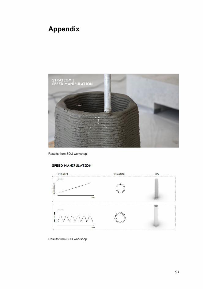
91
Appendix
Results from SDU workshop
Results from SDU workshop
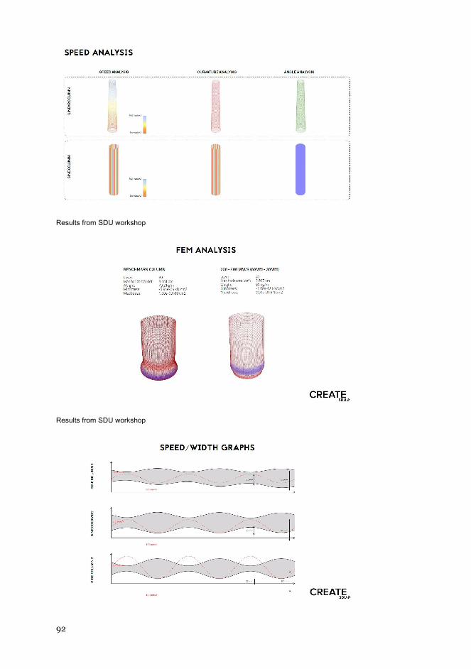
92
Results from SDU workshop
Results from SDU workshop
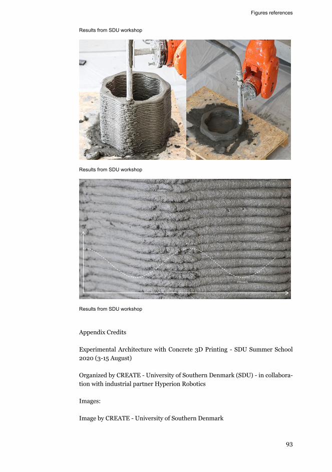
Figures references
93
Results from SDU workshop
Results from SDU workshop
Results from SDU workshop
Appendix Credits Experimental Architecture with Concrete 3D Printing - SDU Summer School 2020 (3-15 August) Organized by CREATE - University of Southern Denmark (SDU) - in collabora-tion with industrial partner Hyperion Robotics Images: Image by CREATE - University of Southern Denmark


-otl
aA
DD
0
8/
12
02
+dabea
e*GMFTSH
9
NBSI 3-0140-46-259-879 )detnirp(
NBSI 0-1140-46-259-879 )fdp(
NSSI 4394-9971 )detnirp(
NSSI 2494-9971 )fdp(
ytisrevinU otlaA
erutcetihcrA dna ngiseD ,strA fo loohcS
erutcetihcrA
fi.otlaa.www
+ SSENISUB YMONOCE
+ TRA
+ NGISED ERUTCETIHCRA
+ ECNEICS
YGOLONHCET
REVOSSORC
LAROTCOD SNOITATRESSID
eti
ho
M oa
rdna
nA
hsi
hsA
eu
qinh
ceT
g
nir
utca
fu
naM
evit
id
dA
des
aB-
de
ep
S y
tisr
evi
nU
otla
A
1202
erutcetihcrA
evitiddA desaB-deepS euqinhceT gnirutcafunaM
fo laitnetoP ngiseD fo noitarolpxE dna yrevocsiD gnirutcafunaM evitiddA ni noitisopeD fo deepS
etihoM oardnanA hsihsA
LAROTCOD SNOITATRESSID
Related Documents


![=.lm[l]~~.iti~~~D · =.lm[l]~~.iti~~~D r1f{l' ~ ato gn tern ation a( ri{~ ~ 0 cia t ion .:. *,; ~ ~qT.:. =~m OO~x iJTE ith~.:. 1Jf%fiD .:. =~m q)t FJT 1i1)(1~~*i*J 1" 341 -8501 =~m:{t:flJ](https://static.cupdf.com/doc/110x72/600151fa18fc751996431164/lmlitid-lmlitid-r1fl-ato-gn-tern-ation-a-ri-0-cia-t.jpg)