European Organisation for Technical Approvals Evropská organizace pro technické schvalování TECHNICKÝ A ZKUŠEBNÍ ÚSTAV STAVEBNÍ PRAHA, s.p. Prosecká 811/76a CZ-190 00 Praha 9 Tel.: +420 286 019 458 Internet: www.tzus.cz Authorised and notified according to Article 10 of the Council Directive 89/106/EC of 21 December 1988 on the approximation of laws, regulations and administrative provisions of Member States relating to construction products MEMBER OF EOTA European Technical Approval ETA-13/0326 (English language translation, the original version is in Czech language) Obchodní název Trade name M50-PLUS Držitel schválení Holder of approval Sympafix 5 Rue Pierre Curie 59810 Lesquin France Typ a použití výrobku Generic type and use of construction product Injektážní systém o velikosti M8, M10, M12 a M16 pro kotvení ve zdivu Injection system with sizes M8, M10, M12 and M16 for use in masonry Platnost od Validity from 25.06.2013 do to 14.10.2017 Výrobna Manufacturing plant Sympafix Plant 2 Germany Toto evropské technické schválení obsahuje This European technical approval contains 18 stran včetně 11 příloh 18 pages including 11 annexes Toto evropské technické schválení nahrazuje This European Technical Approval replaces ETA-13/0326 platné od 02.05.2013 do 14.10.2017 ETA-13/0326 valid from 02.05.2013 to 14.10.2017

Welcome message from author
This document is posted to help you gain knowledge. Please leave a comment to let me know what you think about it! Share it to your friends and learn new things together.
Transcript
European Organisation for Technical Approvals Evropská organizace pro technické schvalování
TECHNICKÝ A ZKUŠEBNÍ ÚSTAV STAVEBNÍ PRAHA, s.p. Prosecká 811/76a CZ-190 00 Praha 9 Tel.: +420 286 019 458 Internet: www.tzus.cz
Authorised and
not if ied according to Article 10 of the Council
Directive 89/106/EC of 21 De ce mb er 19 88 on the a pp r ox i m at i on o f l aw s, regulations and administrative prov i s ion s of Mem ber
S ta te s r el a t i n g t o c o n s t r u c t i o n
products
MEMBER OF EOTA
European Technical Approval ETA-13/0326 (English language translation, the original version is in Czech language)
Obchodní název Trade name
M50-PLUS
Držitel schválení Holder of approval
Sympafix 5 Rue Pierre Curie 59810 Lesquin France
Typ a použití výrobku Generic type and use of construction product
Injektážní systém o velikosti M8, M10, M12 a M16 pro kotvení ve zdivu Injection system with sizes M8, M10, M12 and M16 for use in masonry
Platnost od Validity from 25.06.2013 do to
14.10.2017
Výrobna Manufacturing plant
Sympafix Plant 2 Germany
Toto evropské technické schválení obsahuje This European technical approval contains
18 stran včetně 11 příloh 18 pages including 11 annexes
Toto evropské technické schválení nahrazuje This European Technical Approval replaces
ETA-13/0326 platné od 02.05.2013 do 14.10.2017 ETA-13/0326 valid from 02.05.2013 to 14.10.2017
Page 2 of 18 of ETA-13/0326, issued on 25.06.2013 with validity till 14.10.2017 English translation by TZÚS Prague
090-029392
I. LEGAL BASES AND GENERAL CONDITIONS
1. This European Technical Approval is issued by the Technical and Test Institute for Construction Prague (Technický a zkušební ústav stavební Praha, s.p.) in accordance with:
• Council Directive 89/106/EEC of 21 December 1988 on the approximation of laws, regulations and administrative provisions of Member States relating to construction products1, modified by the Council Directive 93/68/EEC2; and Regulation (EC) No.1882/2003 of the European Parliament and of the Council3
• the Government Decree No. 190/2002 Collection of Laws 4, as amended
• Common Procedural Rules for Requesting, Preparing and the Granting of European Technical Approvals set out in the Annex to Commission Decision 94/23/EC5;
• Guideline for European Technical Approval of „Metal Injection Anchors for use in Masonry“, ETAG 029.
2. Technický a zkušební ústav stavební Praha, s.p. is authorised to check whether the provisions of this European Technical Approval are met. Checking may take place in the manufacturing plant. Nevertheless, the responsibility for the conformity of the products to the European Technical Approval and for their fitness for the intended use remains with the holder of the European Technical Approval.
3. This European Technical Approval is not to be transferred to manufacturers or agents of manufacturers other than those indicated on page 1, or manufacturing plants other than those indicated on page 1 of this European Technical Approval.
4. This European Technical Approval may be withdrawn by the Technical and Test Institute for Construction Prague in particular pursuant to information by the Commission according to Article 5.1 of the Council Directive 89/106/EEC.
5. Reproduction of this European Technical Approval including transmission by electronic means shall be in full. However, partial reproduction can be made with the written consent of the Technical and Test Institute for Construction Prague. In this case, partial reproduction has to be designated as such. Texts and drawings of advertising brochures shall not contradict or misuse the European Technical Approval.
6. The European Technical Approval is issued by the approval body in its official language. This version corresponds to the version circulated within EOTA. Translations into other languages have to be designated as such.
1 Official Journal of the European Communities No L 40, 11.02.1989, p. 12 2 Official Journal of the European Communities No L 220, 30.08.1993, p. 1 3 Official Journal of the European Union no. L 284, 31.10.2003, p. 1 4 Collection of Law of the Czech Republic Vol.79 No190 , 21.5.2002 5 Official Journal of the European Communities No L 17, 20.01.1994, p. 34
Page 3 of 18 of ETA-13/0326, issued on 25.06.2013 with validity till 14.10.2017 English translation by TZÚS Prague
090-029392
II. SPECIFIC CONDITIONS OF THE EUROPEAN TECHNICAL APPROVAL
1 Definition of product and intended use
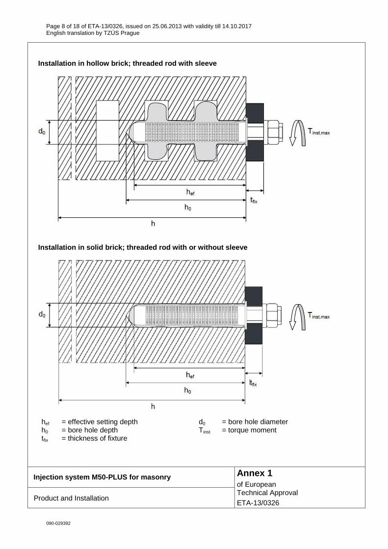
1.1 Definition of product The M50-PLUS polyester resin styrene-free for masonry is bonded anchor consisting of cartridge with injection mortar, a steel element and a plastic sieve sleeve. The steel elements are the commercial threaded rods in the sizes M8 to M16 with hexagon nut and washer. The steel elements are made of galvanized steel or stainless steel. The anchor can by installed in solid and hollow masonry. The installation of the anchor with the sizes M8 and M10 in solid masonry can be done with or without sieve sleeve. The installation of the anchor with the sizes M12 and M16 in solid masonry is done without sieve sleeve. The sieve sleeve is pushed into a drilled hole and filled with injection mortar. Then the threaded rod is placed in the sieve sleeve. The steel element is anchored via the bond between metal part, injection mortar and masonry. The installed anchor is shown in Annex 1.
1.2 Intended use
The anchor is intended to be used for anchorages for which requirements for mechanical resistance and stability and safety in use in sense of the Essential Requirements 1 and 4 of Council Directive 89/106/EEC shall be fulfilled and failure of anchorages made with these products would compromise the stability of the works, cause risk to human life and/or lead to considerable economic consequence.
The anchor is to be used only for anchorages subject to static or quasistatic loading in solid masonry (use category b) or hollow or perforated masonry (use category c) according Annex 7. The mortar strength class of the masonry has to be M 2,5 with a strength ≤ 5 N/mm2 at minimum. The anchor may be installed and use in dry or wet structures (category w/w). The anchor may be used in the following temperature ranges: -40°C to +40°C (max long term temperature +24°C,
max short term temperature +40°C)
Elements made of galvanized steel: The element made of galvanized steel may only be used in structures subject to dry internal conditions.
Elements made of stainless steel:
The element made of stainless steel may be used in structures subject to dry internal conditions and also in structures subject to external atmospheric exposure (including industrial and marine environmental), or exposure to permanently damp internal conditions, if no particular aggressive conditions exist. Such particular aggressive conditions are e.g. permanent, alternating immersion in seawater or the splash zone of seawater, chloride atmosphere of indoor swimming pools or atmosphere with extreme chemical pollution (e.g. in desulphurization plants or road tunnels where deicing materials are used).
The provisions made in this European Technical Approval are based on an assumed working life of the anchor of 50 years. The indications given on the working life cannot be interpreted as a guarantee given by the producer, but are to be regarded only as a means for choosing the products in relation to the expected economically reasonable working life of the works.
Page 4 of 18 of ETA-13/0326, issued on 25.06.2013 with validity till 14.10.2017 English translation by TZÚS Prague
090-029392
2 Characteristics of the product and methods of ver ification
2.1 Characteristics of the product
The anchors correspond to the drawings and information given in Annexes. The characteristic material values, dimensions and tolerances of the anchor not indicated in Annexes shall correspond to the respective values laid down in the technical documentation6 of this European Technical Approval. The characteristic values of M50-PLUS for the design of the anchorages are given in Annex 9. The anchor is assumed to satisfy the requirements for class A1 of the characteristic reaction to fire. Regarding resistance to fire no performance is determined.
2.2 Methods of verification
The assessment of the fitness of the anchor for the intended use in relation to the requirements for safety in use in the sense of Essential Requirement 1 and 4 has been made in compliance with the Guideline for European Technical Approval of “Metal Injection Anchors for use in Masonry“, ETAG 029, based on the Use Categories b and c in respect of the base material and Category w/w in respect of installation and use. In addition to the specific clauses relating to dangerous substances contained in this European Technical Approval, there may be other requirements applicable to the products falling within its scope (e.g. transposed European legislation and national laws, regulations and administrative provisions). In order to meet the provisions of the Construction Products Directive, these requirements need also to be complied with, when and where they apply.
3 Evaluation of conformity of the product and CE ma rking
3.1 System of attestation of conformity
The system of attestation of conformity is the system 1 described in Council Directive 89/106/EEC Annex lll, 2 (i), as follows:
Certification of conformity of the product by a notified body based on:
(a) Tasks of the manufacturer: (1) factory production control, (2) testing of samples taken at the factory by the manufacturer in accordance
with a prescribed control plan. (b) Tasks of the notified body:
(3) initial type-testing of the product, (4) initial inspection of factory and of factory production control, (5) continuous surveillance, assessment and approval of factory production control.
3.2 Responsibility
3.2.1 Tasks of the manufacturer
3.2.1.1 Factory production control
The manufacturer shall exercise permanent internal control of production. All the elements, requirements and provisions adopted by the manufacturer shall be documented in a systematic manner in the form of written policies and procedures, including records of results performed. This production control system shall insure that the product is in conformity with this European Technical Approval. The manufacturer may only use raw materials stated in the technical documentation of this European Technical Approval.
6 The technical documentation of this European Technical Approval is deposited at the Technický a zkušební ústav
stavební Praha, s.p, as far as relevant for the tasks of the approved bodies involved in the attestation of conformity producer, is handed over to the approved bodies.
Page 5 of 18 of ETA-13/0326, issued on 25.06.2013 with validity till 14.10.2017 English translation by TZÚS Prague
090-029392
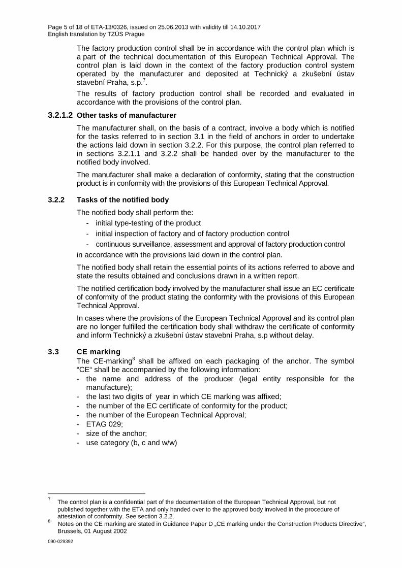
The factory production control shall be in accordance with the control plan which is a part of the technical documentation of this European Technical Approval. The control plan is laid down in the context of the factory production control system operated by the manufacturer and deposited at Technický a zkušební ústav stavební Praha, s.p.7.
The results of factory production control shall be recorded and evaluated in accordance with the provisions of the control plan.
3.2.1.2 Other tasks of manufacturer
The manufacturer shall, on the basis of a contract, involve a body which is notified for the tasks referred to in section 3.1 in the field of anchors in order to undertake the actions laid down in section 3.2.2. For this purpose, the control plan referred to in sections 3.2.1.1 and 3.2.2 shall be handed over by the manufacturer to the notified body involved.
The manufacturer shall make a declaration of conformity, stating that the construction product is in conformity with the provisions of this European Technical Approval.
3.2.2 Tasks of the notified body
The notified body shall perform the: - initial type-testing of the product - initial inspection of factory and of factory production control - continuous surveillance, assessment and approval of factory production control
in accordance with the provisions laid down in the control plan.
The notified body shall retain the essential points of its actions referred to above and state the results obtained and conclusions drawn in a written report.
The notified certification body involved by the manufacturer shall issue an EC certificate of conformity of the product stating the conformity with the provisions of this European Technical Approval.
In cases where the provisions of the European Technical Approval and its control plan are no longer fulfilled the certification body shall withdraw the certificate of conformity and inform Technický a zkušební ústav stavební Praha, s.p without delay.
3.3 CE marking The CE-marking8 shall be affixed on each packaging of the anchor. The symbol “CE“ shall be accompanied by the following information: - the name and address of the producer (legal entity responsible for the
manufacture); - the last two digits of year in which CE marking was affixed; - the number of the EC certificate of conformity for the product; - the number of the European Technical Approval; - ETAG 029; - size of the anchor; - use category (b, c and w/w)
7 The control plan is a confidential part of the documentation of the European Technical Approval, but not
published together with the ETA and only handed over to the approved body involved in the procedure of attestation of conformity. See section 3.2.2.
8 Notes on the CE marking are stated in Guidance Paper D „CE marking under the Construction Products Directive“, Brussels, 01 August 2002
Page 6 of 18 of ETA-13/0326, issued on 25.06.2013 with validity till 14.10.2017 English translation by TZÚS Prague
090-029392
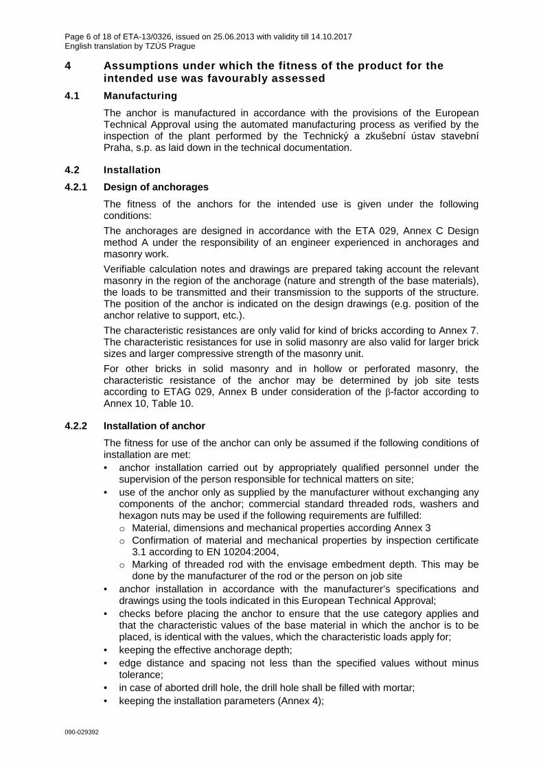
4 Assumptions under which the fitness of the produc t for the intended use was favourably assessed
4.1 Manufacturing
The anchor is manufactured in accordance with the provisions of the European Technical Approval using the automated manufacturing process as verified by the inspection of the plant performed by the Technický a zkušební ústav stavební Praha, s.p. as laid down in the technical documentation.
4.2 Installation
4.2.1 Design of anchorages
The fitness of the anchors for the intended use is given under the following conditions:
The anchorages are designed in accordance with the ETA 029, Annex C Design method A under the responsibility of an engineer experienced in anchorages and masonry work.
Verifiable calculation notes and drawings are prepared taking account the relevant masonry in the region of the anchorage (nature and strength of the base materials), the loads to be transmitted and their transmission to the supports of the structure. The position of the anchor is indicated on the design drawings (e.g. position of the anchor relative to support, etc.).
The characteristic resistances are only valid for kind of bricks according to Annex 7. The characteristic resistances for use in solid masonry are also valid for larger brick sizes and larger compressive strength of the masonry unit.
For other bricks in solid masonry and in hollow or perforated masonry, the characteristic resistance of the anchor may be determined by job site tests according to ETAG 029, Annex B under consideration of the β-factor according to Annex 10, Table 10.
4.2.2 Installation of anchor
The fitness for use of the anchor can only be assumed if the following conditions of installation are met: • anchor installation carried out by appropriately qualified personnel under the
supervision of the person responsible for technical matters on site; • use of the anchor only as supplied by the manufacturer without exchanging any
components of the anchor; commercial standard threaded rods, washers and hexagon nuts may be used if the following requirements are fulfilled: o Material, dimensions and mechanical properties according Annex 3 o Confirmation of material and mechanical properties by inspection certificate
3.1 according to EN 10204:2004, o Marking of threaded rod with the envisage embedment depth. This may be
done by the manufacturer of the rod or the person on job site • anchor installation in accordance with the manufacturer’s specifications and
drawings using the tools indicated in this European Technical Approval; • checks before placing the anchor to ensure that the use category applies and
that the characteristic values of the base material in which the anchor is to be placed, is identical with the values, which the characteristic loads apply for;
• keeping the effective anchorage depth; • edge distance and spacing not less than the specified values without minus
tolerance; • in case of aborted drill hole, the drill hole shall be filled with mortar; • keeping the installation parameters (Annex 4);

Page 7 of 18 of ETA-13/0326, issued on 25.06.2013 with validity till 14.10.2017 English translation by TZÚS Prague
090-029392
• hole cleaning and anchor installation in accordance with manufacturer’s installation instructions (Annexes 5 and 6)
• marking and keeping the effective anchorage depth; • during curing of the injection mortar the temperature of the masonry must not fall
below -5°C; • observing the curing time according to Annex 6, Table 5 until the anchor may be
loaded; • application of the torque moment given in Annex 4 table 3 or 4 using calibrated
torque wrench.
4.2.3 Responsibility of the manufacturer
It is in the responsibility of the manufacturer to ensure that the information on the specific conditions according to (1) and (2) including Annexes referred to 4.2.1, 4.2.2 is given to those who are concerned. This information may be made by reproduction of the respective parts of the European Technical Approval. In addition, all installation data shall be shown clearly on the packaging and/or on an enclosed instruction sheet, preferably using illustration(s).
The minimum data required for manual are: - installation parameters according to Annex 4, - material and property class of metal parts according to Annex 3, Table 1, - information on the installation procedure, including cleaning of the hole with the
cleaning equipments, preferably by means of an illustration, - exact volume of injection mortar depend on the relevant installation, - storage temperature of anchor components, minimum and maximum temperature
of the base material, processing time (open time) of the mortar and curing time until the anchor may be loaded according to Annex 6,
- identification of the manufacturing batch,
All data shall be presented in a clear and explicit form.
5 Recommendations for the manufacturer
5.1 Recommendations on packaging, transportation an d storage
The mortar cartridges shall be protected against sun radiation and shall be stored according to the manufacturer's instructions in dry conditions.
M50-PLUS shall be stored at temperatures of at least +5°C to not more than +25°C.
Mortar cartridges with expired shelf life must no longer be used.
The original Czech version is signed by
Ing. Jozef Pôbiš Head of the Approval Body
Page 8 of 18 of ETA-13/0326, issued on 25.06.2013 with validity till 14.10.2017 English translation by TZÚS Prague
090-029392
Installation in hollow brick; threaded rod with sle eve
Installation in solid brick; threaded rod with or w ithout sleeve
hef = effective setting depth d0 = bore hole diameter h0 = bore hole depth Tinst = torque moment tfix = thickness of fixture
Injection system M50-PLUS for masonry
Product and Installation
Annex 1 of European Technical Approval ETA-13/0326
Page 9 of 18 of ETA-13/0326, issued on 25.06.2013 with validity till 14.10.2017 English translation by TZÚS Prague
090-029392
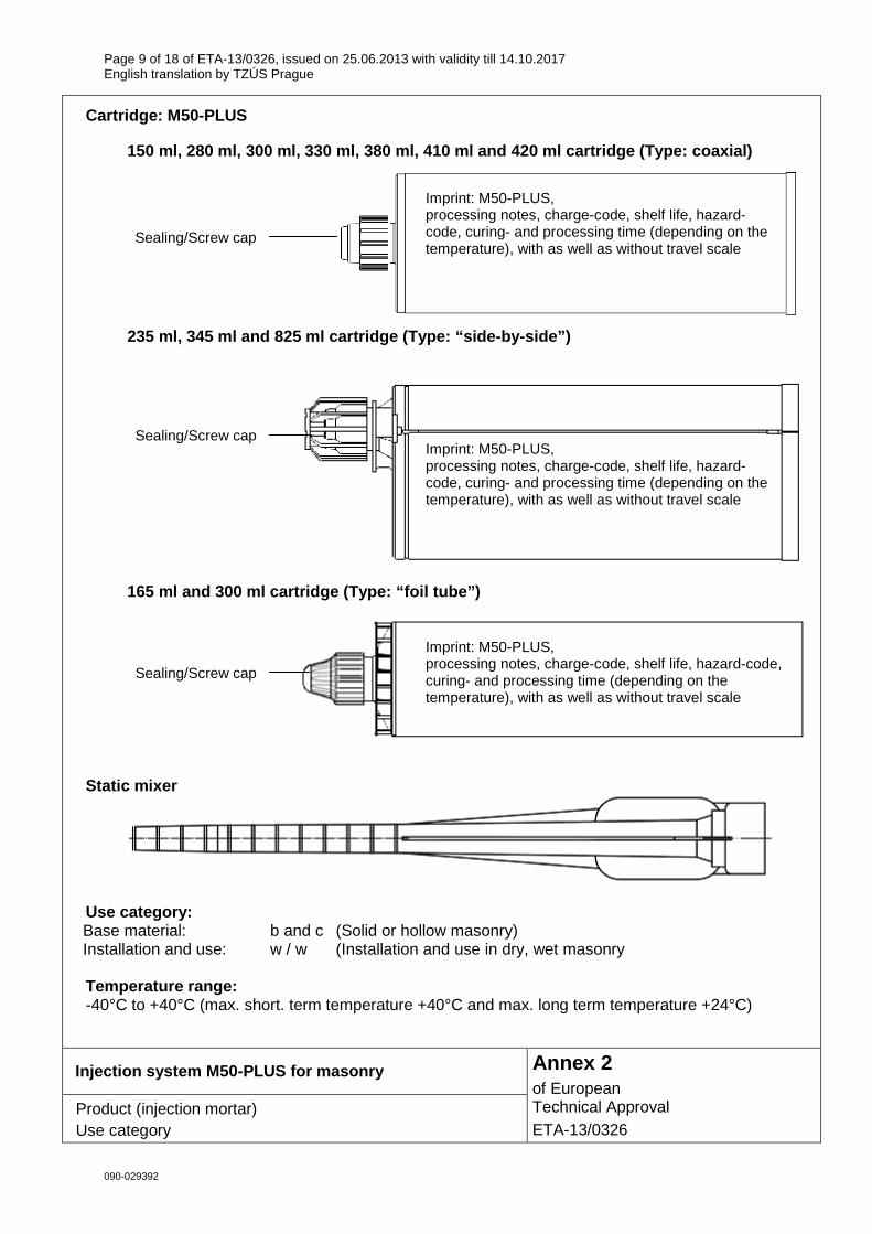
Cartridge: M50-PLUS
150 ml, 280 ml, 300 ml, 330 ml, 380 ml, 410 ml and 420 ml cartridge (Type: coaxial)
235 ml, 345 ml and 825 ml cartridge (Type: “side-by -side”)
165 ml and 300 ml cartridge (Type: “foil tube”)
Static mixer
Use category: Base material: b and c (Solid or hollow masonry) Installation and use: w / w (Installation and use in dry, wet masonry Temperature range: -40°C to +40°C (max. short. term temperature +40°C and max. long term temperature +24°C)
Injection system M50-PLUS for masonry
Product (injection mortar) Use category
Annex 2 of European Technical Approval ETA-13/0326
Imprint: M50-PLUS, processing notes, charge-code, shelf life, hazard-code, curing- and processing time (depending on the temperature), with as well as without travel scale
Sealing/Screw cap
Imprint: M50-PLUS, processing notes, charge-code, shelf life, hazard-code, curing- and processing time (depending on the temperature), with as well as without travel scale
Sealing/Screw cap
Imprint: M50-PLUS, processing notes, charge-code, shelf life, hazard-code, curing- and processing time (depending on the temperature), with as well as without travel scale
Sealing/Screw cap

Page 10 of 18 of ETA-13/0326, issued on 25.06.2013 with validity till 14.10.2017 English translation by TZÚS Prague
090-029392
Threaded rod M8, M10, M12, M16
Table 1: Materials Part Designation Material Steel, zinc plated ≥ 5 µm acc. to EN ISO 4042 or Steel, Hot-dip galvanized ≥ 40 µm acc. to EN ISO 1461 and EN ISO 10684
1 Anchor rod Steel, EN 10087 or EN 10263 Property class 4.8, 5.8, EN ISO 898-1:1999
2 Hexagon nut, EN ISO 4032 EN 20898-2
3 Washer, EN ISO 887, EN ISO 7089, EN ISO 7093 or EN ISO 7094
Steel, zinc plated or hot-dip galvanised
Stainless steel
1 Anchor rod Material: A4-70, A4-80, EN ISO 3506
2 Hexagon nut, EN ISO 4032 Material: A4-70, A4-80, EN ISO 3506
3 Washer, EN ISO 887, EN ISO 7089, EN ISO 7093 or EN ISO 7094
Material: A4-70, A4-80, EN ISO 3506
Injection system M50-PLUS for masonry
Materials (threaded rod)
Annex 3 of European Technical Approval ETA-13/0326
Page 11 of 18 of ETA-13/0326, issued on 25.06.2013 with validity till 14.10.2017 English translation by TZÚS Prague
090-029392
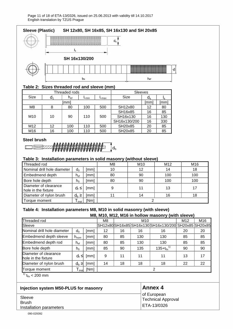
Sleeve (Plastic) SH 12x80, SH 16x85, SH 16x13 0 and SH 20x85
SH 16x130/200
Table 2: Sizes threaded rod and sleeve (mm)
Threaded rods Sleeves Size d1 hef Lmin Lmax Size ds ls
[mm] [mm] [mm] M8 8 80 100 500 SH12x80 12 80
SH16x85 16 85 SH16x130 16 130 M10 10 90 110 500
SH16x130/200 16 330 M12 12 100 110 500 SH20x85 20 85 M16 16 100 110 500 SH20x85 20 85
Steel brush
Table 3: Installation parameters in solid masonry (without s leeve) Threaded rod M8 M10 M12 M16 Nominal drill hole diameter d0 [mm] 10 12 14 18
Embedmend depth hef [mm] 80 90 100 100
Bore hole depth h0 [mm] 80 90 100 100 Diameter of clearance hole in the fixture df ≤ [mm] 9 11 13 17
Diameter of nylon brush db ≥ [mm] 11 14 16 18 Torque moment Tinst [Nm] 2
Table 4: Installation parameters M8, M10 in solid masonry (w ith sleeve) M8, M10, M12, M16 in hollow masonry (with sleeve)
Threaded rod M8 M10 M12 M16 Sleeve SH12x80 SH16x85 SH16x130 SH16x130/200 SH20x85 SH20x85 Nominal drill hole diameter d0 [mm] 12 16 16 16 20 20
Embedmend depth sleeve hnom [mm] 80 85 130 130 85 85
Embedmend depth rod hef [mm] 80 85 130 130 85 85
Bore hole depth h0 [mm] 85 90 135 135+tfix1) 90 90
Diameter of clearance hole in the fixture df ≤ [mm] 9 11 11 11 13 17
Diameter of nylon brush db ≥ [mm] 14 18 18 18 22 22
Torque moment Tinst [Nm] 2 1) tfix < 200 mm
Injection system M50-PLUS for masonry
Sleeve Brush Installation parameters
Annex 4 of European Technical Approval ETA-13/0326
db
Page 12 of 18 of ETA-13/0326, issued on 25.06.2013 with validity till 14.10.2017 English translation by TZÚS Prague
090-029392
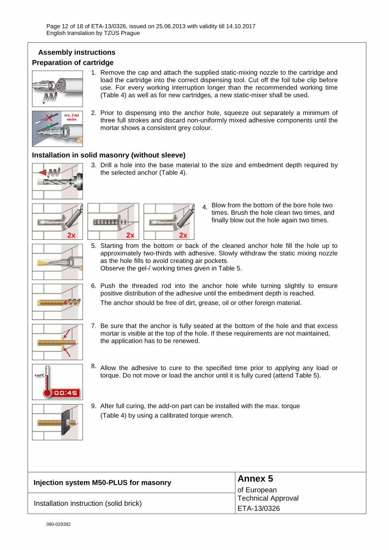
Assembly instructions Preparation of cartridge
1. Remove the cap and attach the supplied static-mixing nozzle to the cartridge and load the cartridge into the correct dispensing tool. Cut off the foil tube clip before use. For every working interruption longer than the recommended working time (Table 4) as well as for new cartridges, a new static-mixer shall be used.
2. Prior to dispensing into the anchor hole, squeeze out separately a minimum of three full strokes and discard non-uniformly mixed adhesive components until the mortar shows a consistent grey colour.
Installation in solid masonry (without sleeve)
3. Drill a hole into the base material to the size and embedment depth required by the selected anchor (Table 4).
4. Blow from the bottom of the bore hole two times. Brush the hole clean two times, and finally blow out the hole again two times.
5. Starting from the bottom or back of the cleaned anchor hole fill the hole up to approximately two-thirds with adhesive. Slowly withdraw the static mixing nozzle as the hole fills to avoid creating air pockets. Observe the gel-/ working times given in Table 5.
6. Push the threaded rod into the anchor hole while turning slightly to ensure positive distribution of the adhesive until the embedment depth is reached.
The anchor should be free of dirt, grease, oil or other foreign material.
7. Be sure that the anchor is fully seated at the bottom of the hole and that excess mortar is visible at the top of the hole. If these requirements are not maintained, the application has to be renewed.
8. Allow the adhesive to cure to the specified time prior to applying any load or torque. Do not move or load the anchor until it is fully cured (attend Table 5).
9. After full curing, the add-on part can be installed with the max. torque
(Table 4) by using a calibrated torque wrench.
Injection system M50-PLUS for masonry
Installation instruction (solid brick)
Annex 5 of European Technical Approval ETA-13/0326
2x 2x 2x
Page 13 of 18 of ETA-13/0326, issued on 25.06.2013 with validity till 14.10.2017 English translation by TZÚS Prague
090-029392
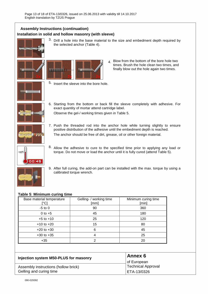
Assembly Instructions (continuation)
Installation in solid and hollow masonry (with slee ve)
3. Drill a hole into the base material to the size and embedment depth required by the selected anchor (Table 4).
4. Blow from the bottom of the bore hole two times. Brush the hole clean two times, and finally blow out the hole again two times.
5. Insert the sleeve into the bore hole.
6. Starting from the bottom or back fill the sleeve completely with adhesive. For exact quantity of mortar attend cartridge label.
Observe the gel-/ working times given in Table 5.
7. Push the threaded rod into the anchor hole while turning slightly to ensure positive distribution of the adhesive until the embedment depth is reached.
The anchor should be free of dirt, grease, oil or other foreign material.
8. Allow the adhesive to cure to the specified time prior to applying any load or torque. Do not move or load the anchor until it is fully cured (attend Table 5).
9. After full curing, the add-on part can be installed with the max. torque by using a calibrated torque wrench.
Table 5 : Minimum curing time
Base material temperature [°C]
Gelling- / working time [mm]
Minimum curing time [min]
-5 to 0 90 360
0 to +5 45 180
+5 to +10 25 120
+10 to +20 15 80
+20 to +30 6 45
+30 to +35 4 25
+35 2 20
Injection system M50-PLUS for masonry
Assembly instructions (hollow brick) Gelling and curing time
Annex 6 of European Technical Approval ETA-13/0326
2x 2x 2x
Page 14 of 18 of ETA-13/0326, issued on 25.06.2013 with validity till 14.10.2017 English translation by TZÚS Prague
090-029392
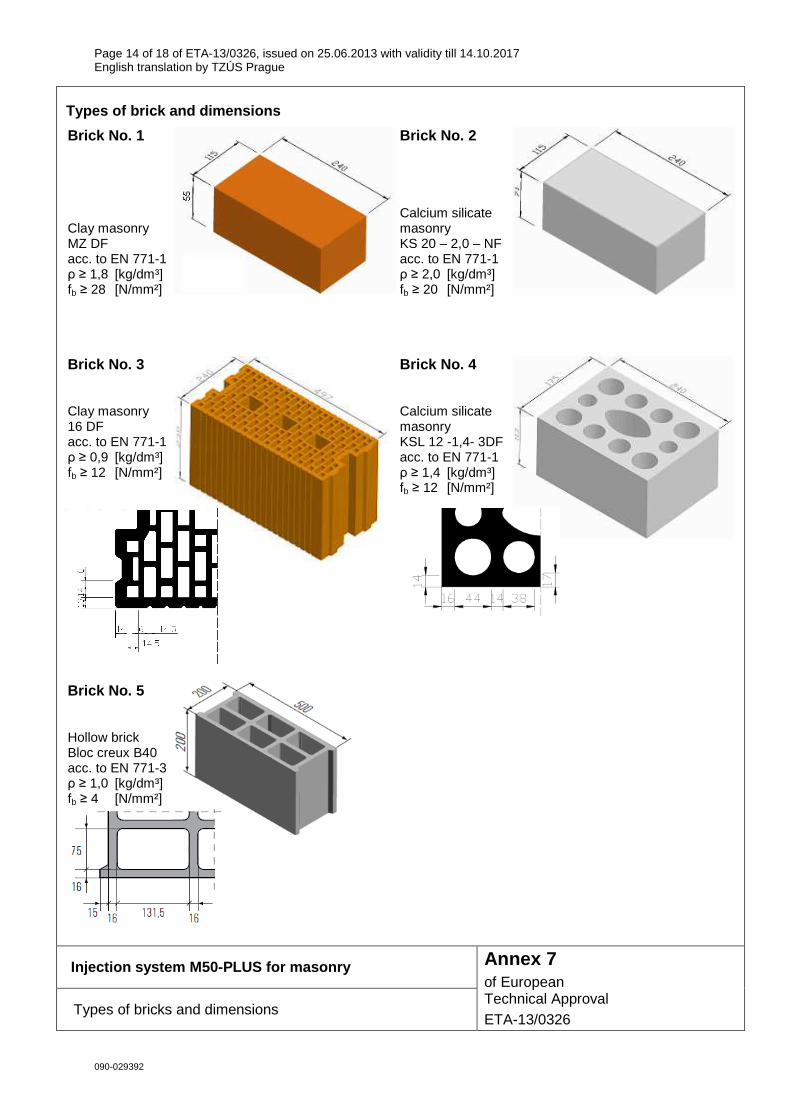
Types of brick and dimensions
Brick No. 1 Clay masonry MZ DF acc. to EN 771-1 ρ ≥ 1,8 [kg/dm³] fb ≥ 28 [N/mm²]
Brick No. 2 Calcium silicate masonry KS 20 – 2,0 – NF acc. to EN 771-1 ρ ≥ 2,0 [kg/dm³] fb ≥ 20 [N/mm²]
Brick No. 3 Clay masonry 16 DF acc. to EN 771-1 ρ ≥ 0,9 [kg/dm³] fb ≥ 12 [N/mm²]
Brick No. 4 Calcium silicate masonry KSL 12 -1,4- 3DF acc. to EN 771-1 ρ ≥ 1,4 [kg/dm³] fb ≥ 12 [N/mm²]
Brick No. 5 Hollow brick Bloc creux B40 acc. to EN 771-3 ρ ≥ 1,0 [kg/dm³] fb ≥ 4 [N/mm²]
Injection system M50-PLUS for masonry
Types of bricks and dimensions
Annex 7 of European Technical Approval ETA-13/0326
Page 15 of 18 of ETA-13/0326, issued on 25.06.2013 with validity till 14.10.2017 English translation by TZÚS Prague
090-029392
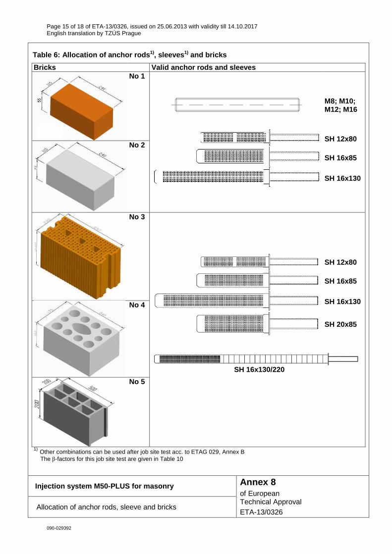
Table 6: Allocation of anchor rods 1), sleeves 1) and bricks
Bricks Valid anchor rods and sleeves
No 1
No 2
M8; M10; M12; M16
SH 12x80 SH 16x85
SH 16x130
No 3
SH 12x80 SH 16x85
SH 16x130
SH 20x85
No 4
No 5
SH 16x130/220
1) Other combinations can be used after job site test acc. to ETAG 029, Annex B The β-factors for this job site test are given in Table 10
Injection system M50-PLUS for masonry
Allocation of anchor rods, sleeve and bricks
Annex 8 of European Technical Approval ETA-13/0326
Page 16 of 18 of ETA-13/0326, issued on 25.06.2013 with validity till 14.10.2017 English translation by TZÚS Prague
090-029392
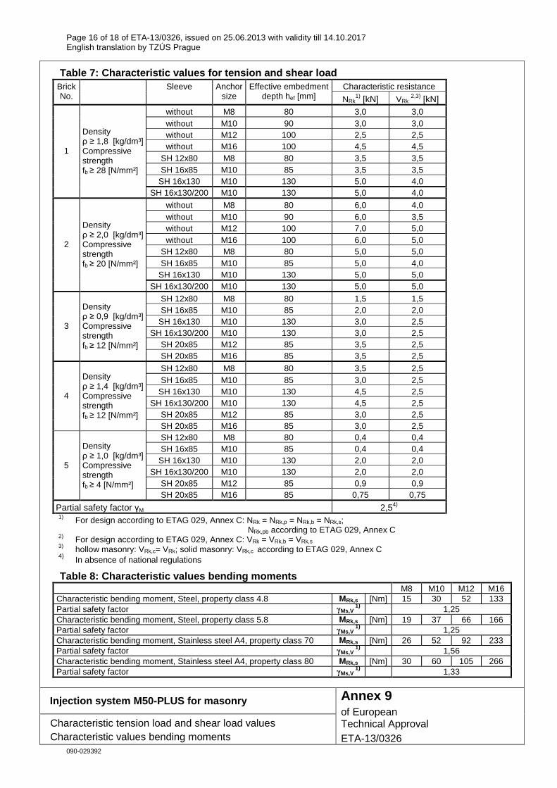
Table 7: Characteristic values for tension and shea r load Characteristic resistance Brick
No. Sleeve Anchor
size Effective embedment
depth hef [mm] NRk1) [kN] VRk
2,3) [kN] without M8 80 3,0 3,0 without M10 90 3,0 3,0 without M12 100 2,5 2,5 without M16 100 4,5 4,5
SH 12x80 M8 80 3,5 3,5 SH 16x85 M10 85 3,5 3,5
SH 16x130 M10 130 5,0 4,0
1
Density ρ ≥ 1,8 [kg/dm³] Compressive strength fb ≥ 28 [N/mm²]
SH 16x130/200 M10 130 5,0 4,0
without M8 80 6,0 4,0 without M10 90 6,0 3,5 without M12 100 7,0 5,0 without M16 100 6,0 5,0
SH 12x80 M8 80 5,0 5,0 SH 16x85 M10 85 5,0 4,0
SH 16x130 M10 130 5,0 5,0
2
Density ρ ≥ 2,0 [kg/dm³] Compressive strength fb ≥ 20 [N/mm²]
SH 16x130/200 M10 130 5,0 5,0
SH 12x80 M8 80 1,5 1,5 SH 16x85 M10 85 2,0 2,0
SH 16x130 M10 130 3,0 2,5 SH 16x130/200 M10 130 3,0 2,5
SH 20x85 M12 85 3,5 2,5
3
Density ρ ≥ 0,9 [kg/dm³] Compressive strength fb ≥ 12 [N/mm²]
SH 20x85 M16 85 3,5 2,5
SH 12x80 M8 80 3,5 2,5 SH 16x85 M10 85 3,0 2,5
SH 16x130 M10 130 4,5 2,5 SH 16x130/200 M10 130 4,5 2,5
SH 20x85 M12 85 3,0 2,5
4
Density ρ ≥ 1,4 [kg/dm³] Compressive strength fb ≥ 12 [N/mm²]
SH 20x85 M16 85 3,0 2,5 SH 12x80 M8 80 0,4 0,4 SH 16x85 M10 85 0,4 0,4
SH 16x130 M10 130 2,0 2,0 SH 16x130/200 M10 130 2,0 2,0
SH 20x85 M12 85 0,9 0,9
5
Density ρ ≥ 1,0 [kg/dm³] Compressive strength fb ≥ 4 [N/mm²]
SH 20x85 M16 85 0,75 0,75
Partial safety factor γM 2,54) 1) For design according to ETAG 029, Annex C: NRk = NRk,p = NRk,b = NRk,s;
NRk,pb according to ETAG 029, Annex C 2) For design according to ETAG 029, Annex C: VRk = VRk,b = VRk,s 3) hollow masonry: VRk,c= VRk; solid masonry: VRk,c according to ETAG 029, Annex C 4) In absence of national regulations
Table 8: Characteristic values bending moments M8 M10 M12 M16
Characteristic bending moment, Steel, property class 4.8 MRk,s [Nm] 15 30 52 133 Partial safety factor γMs,V
1) 1,25 Characteristic bending moment, Steel, property class 5.8 MRk,s [Nm] 19 37 66 166 Partial safety factor γMs,V
1) 1,25 Characteristic bending moment, Stainless steel A4, property class 70 MRk,s [Nm] 26 52 92 233 Partial safety factor γMs,V
1) 1,56 Characteristic bending moment, Stainless steel A4, property class 80 MRk,s [Nm] 30 60 105 266 Partial safety factor γMs,V
1) 1,33
Injection system M50-PLUS for masonry
Characteristic tension load and shear load values Characteristic values bending moments
Annex 9 of European Technical Approval ETA-13/0326

Page 17 of 18 of ETA-13/0326, issued on 25.06.2013 with validity till 14.10.2017 English translation by TZÚS Prague
090-029392
Table 9: Displacement under shear and tension load Tension Shear
Load Displacement Load Displacement Brick No. Sleeve
Anchor size F δNO δN∞ F δVO δV∞
[kN] [mm] [kN] [mm] without M8 0,1 0,2 0,4 0,6 without M10 0,1 0,2 0,7 1,1 without M12 0,2 0,4 0,4 0,7 without M16 0,2 0,3 0,5 0,7
SH 12x80 M8 0,2 0,3 2,3 3,4 SH 16x85 M10 0,2 0,3 0,5 0,7
SH 16x130 M10 0,2 0,3 1,1 1,6
1
SH 16x130/200 M10 0,2 0,3 1,1 1,6
without M8 0,2 0,3 1,6 2,4 without M10 0,2 0,5 1,5 2,3 without M12 0,2 0,3 1,1 1,6 without M16 0,2 0,3 1,1 1,6
SH 12x80 M8 0,2 0,3 3,1 4,6 SH 16x85 M10 0,2 0,3 1,5 2,2
SH 16x130 M10 0,2 0,3 1,2 1,8
2
SH 16x130/200 M10 0,2 0,3 1,2 1,8
SH 12x80 M8 0,3 0,6 1,1 1,6 SH 16x85 M10 0,6 1,1 1,6 2,4
SH 16x130 M10 0,2 0,4 0,9 1,3 SH 16x130/200 M10 0,2 0,4 0,9 1,3
SH 20x85 M12 0,2 0,4 1,6 2,4
3
SH 20x85 M16 0,1 0,2 1,7 2,6
SH 12x80 M8 0,6 1,2 0,9 1,3 SH 16x85 M10 0,7 1,4 1,3 1,9
SH 16x130 M10 1,7 3,4 2,0 3,0 SH 16x130/200 M10 1,7 3,4 2,0 3,0
SH 20x85 M12 1,5 2,9 1,3 2,0
4
SH 20x85 M16 1,6 3,3 0,6 0,9
SH 12x80 M8 0,2 0,3 0,3 0,4 SH 16x85 M10 0,2 0,4 0,1 0,1
SH 16x130 M10 0,5 1,0 0,6 0,9 SH 16x130/200 M10 0,5 1,0 0,6 0,9
SH 20x85 M12 0,5 0,9 0,1 0,2
5
SH 20x85 M16
M
RkN
γ⋅4,1
0,3 0,5
M
RkV
γ⋅4,1
0,2 0,3
Table 10: β-factors for job side tests according to ETAG 029, Annex B Brick-No. Installation & use β-factor
1 2 3 4 5
w/w (incl. w/d) 0,72
Injection system M50-PLUS for masonry
Displacement under shear and tension load β-factors for job side tests
Annex 10 of European Technical Approval ETA-13/0326
Page 18 of 18 of ETA-13/0326, issued on 25.06.2013 with validity till 14.10.2017 English translation by TZÚS Prague
090-029392
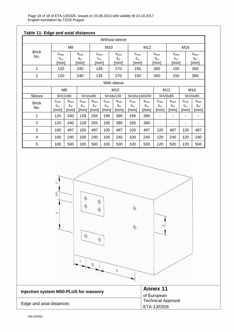
Table 11: Edge and axial distances
WIthout sleeve
M8 M10 M12 M16 Brick No.
cmin ccr
[mm]
smin scr
[mm]
cmin ccr
[mm]
smin scr
[mm]
cmin ccr
[mm]
smin scr
[mm]
cmin ccr
[mm]
smin scr
[mm]
1 120 240 135 270 150 300 150 300
2 120 240 135 270 150 300 150 300
With sleeve
M8 M10 M12 M16
Sleeve SH12x80 SH16x85 SH16x130 SH16x130/200 SH20x85 SH20x85
Brick No.
cmin ccr
[mm]
smin scr
[mm]
cmin ccr
[mm]
smin scr
[mm]
cmin ccr
[mm]
smin scr
[mm]
cmin ccr
[mm]
smin scr
[mm]
cmin ccr
[mm]
smin scr
[mm]
cmin ccr
[mm]
smin scr
[mm]
1 120 240 128 255 195 390 195 390 - - - -
2 120 240 128 255 195 390 195 390 - - - -
3 100 497 100 497 100 497 100 497 120 497 120 497
4 100 240 100 240 100 240 100 240 120 240 120 240
5 100 500 100 500 100 500 100 500 120 500 120 500
Injection system M50-PLUS for masonry
Edge and axial distances
Annex 11 of European Technical Approval ETA-13/0326
Related Documents


![SAM Proof of License Guide 0326[1]](https://static.cupdf.com/doc/110x72/577d26221a28ab4e1ea059e4/sam-proof-of-license-guide-03261.jpg)


