European Committee for drawing up Standards in the field of Inland Navigation (CESNI) European Standard laying down technical requirements for Inland Navigation vessels (ES-TRIN) Edition 2015/1 European Committee for drawing up Standards in the field of Inland Navigation (CESNI) Edition 2015/1 European Standard laying down Technical Requirements for Inland Navigation vessels (ES-TRIN)

Welcome message from author
This document is posted to help you gain knowledge. Please leave a comment to let me know what you think about it! Share it to your friends and learn new things together.
Transcript
European Committee for drawing up Standards in the field of Inland Navigation (CESNI) European Standard laying down technical requirements for Inland Navigation vessels (ES-TRIN)
Edition 2015/1
European Committee for drawing up Standards in the field of Inland Navigation
(CESNI)
Edition 2015/1
European Standard laying down
Technical Requirements for
Inland Navigation vessels
(ES-TRIN)

European Committee for drawing up Standards in the field of Inland Navigation (CESNI) European Standard laying down technical requirements for Inland Navigation vessels (ES-TRIN)
Edition 2015/1 Page ii
European Committee for drawing up Standards in the field of Inland Navigation (CESNI) European Standard laying down technical requirements for inland navigation vessels (ES-TRIN) Table of contents
Edition 2015/1 Page iii
TABLE OF CONTENTS
PART I GENERAL .................................................................................................................................. 1
CHAPTER 1 GENERAL ................................................................................................................................... 1 Article 1.01 Definitions ............................................................................................................................. 1 Article 1.02 Instructions on the application of the European Standard ................................................... 9
CHAPTER 2 PROCEDURE ............................................................................................................................ 11
PART II PROVISIONS REGARDING SHIPBUILDING, FITTING OUT AND EQUIPMENT ................ 13
CHAPTER 3 SHIPBUILDING REQUIREMENTS .................................................................................................. 13 Article 3.01 Basic rules .......................................................................................................................... 13 Article 3.02 Strength and stability .......................................................................................................... 13 Article 3.03 Hull ..................................................................................................................................... 14 Article 3.04 Engine and boiler rooms, bunkers ..................................................................................... 16
CHAPTER 4 SAFETY CLEARANCE, FREEBOARD AND DRAUGHT MARKS ............................................................ 17 Article 4.01 Safety clearance ................................................................................................................. 17 Article 4.02 Freeboard ........................................................................................................................... 17 Article 4.03 Minimum freeboard ............................................................................................................ 19 Article 4.04 Draught marks .................................................................................................................... 19 Article 4.05 Maximum loaded draught of vessels whose holds are not always closed so as to be spray-proof and weathertight ............................................................................................................ 21 Article 4.06 Draught scales .................................................................................................................... 21 Article 4.07 Specific requirements applicable to vessels navigating on zone 4 waterways .................. 21
CHAPTER 5 MANOEUVRABILITY ................................................................................................................... 23 Article 5.01 General ............................................................................................................................... 23 Article 5.02 Navigation tests .................................................................................................................. 23 Article 5.03 Test area ............................................................................................................................ 23 Article 5.04 Degree of loading of vessels and convoys during navigation tests ................................... 23 Article 5.05 Use of on-board facilities for navigation test ...................................................................... 24 Article 5.06 Prescribed (forward) speed ................................................................................................ 24 Article 5.07 Stopping capacity ............................................................................................................... 24 Article 5.08 Capacity for going astern ................................................................................................... 24 Article 5.09 Capacity for taking evasive action ...................................................................................... 25 Article 5.10 Turning capacity ................................................................................................................. 25
CHAPTER 6 STEERING SYSTEM ................................................................................................................... 27 Article 6.01 General requirements ......................................................................................................... 27 Article 6.02 Steering apparatus drive unit ............................................................................................. 27 Article 6.03 Hydraulic steering apparatus drive unit .............................................................................. 28 Article 6.04 Power source ...................................................................................................................... 28 Article 6.05 Manual drive ....................................................................................................................... 28 Article 6.06 Rudder-propeller, water-jet, cycloidal-propeller and bow-thruster systems ....................... 29 Article 6.07 Indicators and monitoring devices ...................................................................................... 29 Article 6.08 Rate-of-turn regulators ....................................................................................................... 29 Article 6.09 Testing ................................................................................................................................ 30
CHAPTER 7 WHEELHOUSE .......................................................................................................................... 31 Article 7.01 General ............................................................................................................................... 31 Article 7.02 Unobstructed view .............................................................................................................. 31
European Committee for drawing up Standards in the field of Inland Navigation (CESNI) European Standard laying down technical requirements for inland navigation vessels (ES-TRIN) Table of contents
Edition 2015/1 Page iv
Article 7.03 General requirements concerning control, indicating and monitoring equipment .............. 32 Article 7.04 Specific requirements concerning control, indicating and monitoring equipment of main engines and steering system ........................................................................................................ 33 Article 7.05 Navigation lights, light signals and sound signals .............................................................. 34 Article 7.06 Navigation and information equipment ............................................................................... 35 Article 7.07 Radio telephony systems for vessels with wheelhouses designed for radar navigation by one person ...................................................................................................................... 35 Article 7.08 Internal communication facilities on board ......................................................................... 36 Article 7.09 Alarm system ...................................................................................................................... 36 Article 7.10 Heating and ventilation ....................................................................................................... 36 Article 7.11 Stern-anchor operating equipment ..................................................................................... 36 Article 7.12 Retractable wheelhouses ................................................................................................... 37 Article 7.13 Entry in the inland navigation vessel certificate for vessels with wheelhouses designed for radar navigation by one person ........................................................................................ 37
CHAPTER 8 ENGINE DESIGN ........................................................................................................................ 39 Article 8.01 General ............................................................................................................................... 39 Article 8.02 Safety equipment ............................................................................................................... 39 Article 8.03 Propulsion systems ............................................................................................................ 40 Article 8.04 Engine exhaust system ...................................................................................................... 40 Article 8.05 Fuel tanks, pipes and accessories ..................................................................................... 41 Article 8.06 Storage of lubricating oil, pipes and accessories ............................................................... 42 Article 8.07 Storage of oils used in power transmission systems, control and activating systems and heating systems, pipes and accessories ......................................................................... 43 Article 8.08 Bilge pumping and drainage systems ................................................................................ 44 Article 8.09 Oily water and used oil stores ............................................................................................ 45 Article 8.10 Noise emitted by vessels .................................................................................................... 46
CHAPTER 9 EMISSION OF GASEOUS AND PARTICULATE POLLUTANTS FROM DIESEL ENGINES ........................... 47 Article 9.00 Definitions ........................................................................................................................... 47 Article 9.01 General provisions ............................................................................................................. 48 Article 9.03 Installation test and intermediate test and special test ...................................................... 49 Article 9.04 Technical services .............................................................................................................. 51
CHAPTER 10 ELECTRICAL EQUIPMENT ......................................................................................................... 53 Article 10.01 General ............................................................................................................................. 53 Article 10.02 Electricity supply systems ................................................................................................ 53 Article 10.03 Protection against physical contact, intrusion of solid objects and the ingress of water ...................................................................................................................................................... 54 Article 10.04 Protection from explosion ................................................................................................. 54 Article 10.05 Earthing ............................................................................................................................ 55 Article 10.06 Maximum permissible voltages ........................................................................................ 56 Article 10.07 Distribution systems ......................................................................................................... 57 Article 10.08 Connection to shore or other external networks .............................................................. 57 Article 10.09 Power supply to other craft ............................................................................................... 58 Article 10.10 Generators and motors .................................................................................................... 58 Article 10.11 Accumulators .................................................................................................................... 58 Article 10.12 Switchgear installations .................................................................................................... 59 Article 10.13 Emergency circuit breakers .............................................................................................. 61 Article 10.14 Installation fittings ............................................................................................................. 61 Article 10.15 Cables .............................................................................................................................. 61 Article 10.16 Lighting installations ......................................................................................................... 62 Article 10.17 Navigation lights ............................................................................................................... 62 Article 10.18 Alarm and safety systems for mechanical equipment ...................................................... 63 Article 10.19 Electronic equipment ........................................................................................................ 63 Article 10.20 Electromagnetic compatibility ........................................................................................... 65

European Committee for drawing up Standards in the field of Inland Navigation (CESNI) European Standard laying down technical requirements for inland navigation vessels (ES-TRIN) Table of contents
Edition 2015/1 Page v
CHAPTER 11 ELECTRICAL INSTALLATIONS .................................................................................................... 67
CHAPTER 12 ELECTRONIC EQUIPMENT AND SYSTEMS ................................................................................... 69
CHAPTER 13 EQUIPMENT ............................................................................................................................ 71 Article 13.01 Anchor equipment ............................................................................................................ 71 Article 13.02 Other equipment ............................................................................................................... 73 Article 13.03 Portable fire extinguishers ................................................................................................ 75 Article 13.04 Permanently installed firefighting systems for protecting accommodation spaces, wheelhouses and passenger rooms ...................................................................................................... 76 Article 13.05 Permanently installed firefighting systems for protecting engine rooms, boiler rooms and pump rooms ......................................................................................................................... 77 Article 13.06 Permanently installed firefighting systems for protecting objects .................................... 82 Article 13.07 Ship's boats ...................................................................................................................... 82 Article 13.08 Lifebuoys and lifejackets .................................................................................................. 83
CHAPTER 14 SAFETY AT WORK STATIONS .................................................................................................... 85 Article 14.01 General ............................................................................................................................. 85 Article 14.02 Protection against falling .................................................................................................. 85 Article 14.03 Dimensions of work stations ............................................................................................. 86 Article 14.04 Side decks ........................................................................................................................ 86 Article 14.05 Access to work stations .................................................................................................... 86 Article 14.06 Exits and emergency exits ............................................................................................... 87 Article 14.07 Ladders, steps and similar devices .................................................................................. 87 Article 14.08 Interior rooms ................................................................................................................... 87 Article 14.09 Protection against noise and vibration ............................................................................. 88 Article 14.10 Hatch covers..................................................................................................................... 88 Article 14.11 Winches ............................................................................................................................ 89 Article 14.12 Cranes .............................................................................................................................. 89 Article 14.13 Storing flammable liquids ................................................................................................. 90
CHAPTER 15 ACCOMMODATION .................................................................................................................. 91 Article 15.01 General ............................................................................................................................. 91 Article 15.02 Special design requirements for accommodation ............................................................ 91 Article 15.03 Sanitary installations ........................................................................................................ 92 Article 15.04 Galleys .............................................................................................................................. 93 Article 15.05 Potable water installations ................................................................................................ 93 Article 15.06 Heating and ventilation ..................................................................................................... 94 Article 15.07 Other accommodation installations .................................................................................. 94
CHAPTER 16 FUEL-FIRED HEATING, COOKING AND REFRIGERATING EQUIPMENT ............................................. 95 Article 16.01 General ............................................................................................................................. 95 Article 16.02 Use of liquid fuels, oil-fired equipment ............................................................................. 95 Article 16.03 Vaporising oil burner stoves and atomising oil burner heating appliances ...................... 95 Article 16.04 Vaporising oil burner stoves ............................................................................................. 96 Article 16.05 Atomising oil burner heating appliances .......................................................................... 96 Article 16.06 Forced-air heating appliances .......................................................................................... 97 Article 16.07 Solid fuel heating .............................................................................................................. 97
CHAPTER 17 LIQUEFIED GAS INSTALLATIONS FOR DOMESTIC PURPOSES ....................................................... 99 Article 17.01 General ............................................................................................................................. 99 Article 17.02 Installations ....................................................................................................................... 99 Article 17.03 Receptacles ...................................................................................................................... 99 Article 17.04 Location and arrangement of supply units ....................................................................... 99 Article 17.05 Spare and empty receptacles ......................................................................................... 100 Article 17.06 Pressure regulators ........................................................................................................ 100 Article 17.07 Pressure ......................................................................................................................... 101

European Committee for drawing up Standards in the field of Inland Navigation (CESNI) European Standard laying down technical requirements for inland navigation vessels (ES-TRIN) Table of contents
Edition 2015/1 Page vi
Article 17.08 Piping and flexible tubes ................................................................................................ 101 Article 17.09 Distribution system ......................................................................................................... 101 Article 17.10 Gas-consuming appliances and their installation ........................................................... 102 Article 17.11 Ventilation and evacuation of combustion gases ........................................................... 102 Article 17.12 Operating instructions .................................................................................................... 103 Article 17.13 Acceptance test .............................................................................................................. 103 Article 17.14 Test conditions ............................................................................................................... 103 Article 17.15 Attestation ....................................................................................................................... 104
CHAPTER 18 ON-BOARD SEWAGE TREATMENT PLANTS ............................................................................... 105 Article 18.00 Definitions ....................................................................................................................... 105 Article 18.01 General provisions ......................................................................................................... 106 Article 18.02 Application for type approval .......................................................................................... 108 Article 18.03 Type approval procedure ............................................................................................... 108 Article 18.04 Amendment of type approvals ........................................................................................ 109 Article 18.05 Conformity of the type-approval ..................................................................................... 110 Article 18.06 Checking of serial numbers ............................................................................................ 110 Article 18.07 Conformity of production ................................................................................................ 111 Article 18.08 Non-conformity with the type-approved on-board sewage treatment plant type ........... 111 Article 18.09 Random sample measurement / Special test ................................................................ 112 Article 18.10 Competent authorities and technical services ................................................................ 113
PART III SPECIAL PROVISIONS ....................................................................................................... 115
CHAPTER 19 SPECIAL PROVISIONS APPLICABLE TO PASSENGER VESSELS .................................................... 115 Article 19.01 General provisions ......................................................................................................... 115 Article 19.02 Hull ................................................................................................................................. 115 Article 19.03 Stability ........................................................................................................................... 117 Article 19.04 Safety clearance and freeboard ..................................................................................... 123 Article 19.05 Maximum permitted number of passengers ................................................................... 123 Article 19.06 Passenger rooms and areas .......................................................................................... 124 Article 19.07 Propulsion system .......................................................................................................... 128 Article 19.08 Safety devices and equipment ....................................................................................... 128 Article 19.09 Life-saving equipment .................................................................................................... 129 Article 19.10 Electrical Equipment ....................................................................................................... 131 Article 19.11 Fire protection ................................................................................................................ 133 Article 19.12 Fire-fighting ..................................................................................................................... 138 Article 19.13 Safety organisation ......................................................................................................... 139 Article 19.14 Waste water collection and disposal facilities ................................................................ 141 Article 19.15 Derogations for certain passenger vessels .................................................................... 141
CHAPTER 20 SPECIAL PROVISIONS APPLICABLE TO PASSENGER SAILING VESSELS NOT NAVIGATING ON
THE RHINE (ZONE R) ................................................................................................................................ 143 Article 20.01 Application of Parts II and III .......................................................................................... 143 Article 20.02 Exceptions for certain passenger sailing vessels ........................................................... 143 Article 20.03 Stability requirements for vessels under sail .................................................................. 143 Article 20.04 Shipbuilding and mechanical requirements ................................................................... 144 Article 20.05 Rigging in general .......................................................................................................... 144 Article 20.06 Masts and spars in general ............................................................................................ 145 Article 20.07 Special provisions for masts ........................................................................................... 145 Article 20.08 Special provisions for topmasts ...................................................................................... 146 Article 20.09 Special provisions for bowsprits ..................................................................................... 147 Article 20.10 Special provisions for jib-booms..................................................................................... 147 Article 20.11 Special provisions for main booms ................................................................................ 148 Article 20.12 Special provisions for gaffs ............................................................................................ 148 Article 20.13 General provisions for standing and running rigging...................................................... 149 Article 20.14 Special provisions for standing rigging ........................................................................... 149 Article 20.15 Special provisions for running rigging ............................................................................ 150

European Committee for drawing up Standards in the field of Inland Navigation (CESNI) European Standard laying down technical requirements for inland navigation vessels (ES-TRIN) Table of contents
Edition 2015/1 Page vii
Article 20.16 Fittings and parts of the rigging ...................................................................................... 151 Article 20.17 Sails ................................................................................................................................ 152 Article 20.18 Equipment ...................................................................................................................... 152 Article 20.19 Testing ............................................................................................................................ 152
CHAPTER 21 SPECIAL PROVISIONS APPLICABLE TO CRAFT INTENDED TO FORM PART OF A PUSHED OR
TOWED CONVOY OR OF A SIDE-BY-SIDE FORMATION .................................................................................... 153 Article 21.01 Craft suitable for pushing ............................................................................................... 153 Article 21.02 Craft suitable for being pushed ...................................................................................... 153 Article 21.03 Craft suitable for propelling side-by-side formations ...................................................... 154 Article 21.04 Craft suitable for being propelled in convoys ................................................................. 154 Article 21.05 Craft suitable for towing .................................................................................................. 154 Article 21.06 Navigation tests on convoys ........................................................................................... 154 Article 21.07 Entries on the inland navigation vessel certificate ......................................................... 155
CHAPTER 22 SPECIAL PROVISIONS APPLICABLE TO FLOATING EQUIPMENT ................................................... 157 Article 22.01 General ........................................................................................................................... 157 Article 22.02 Derogations .................................................................................................................... 157 Article 22.03 Additional requirements .................................................................................................. 158 Article 22.04 Residual safety clearance .............................................................................................. 158 Article 22.05 Residual freeboard ......................................................................................................... 158 Article 22.06 Heeling test ..................................................................................................................... 159 Article 22.07 Proof of stability .............................................................................................................. 159 Article 22.08 Proof of stability in the case of reduced residual freeboard ........................................... 161 Article 22.09 Draught marks and draught scales ................................................................................ 162 Article 22.10 Floating equipment without proof of stability .................................................................. 162
CHAPTER 23 SPECIAL PROVISIONS APPLICABLE TO WORKSITE CRAFT .......................................................... 163 Article 23.01 Operating conditions ...................................................................................................... 163 Article 23.02 Application of Part II ....................................................................................................... 163 Article 23.03 Derogations .................................................................................................................... 163 Article 23.04 Safety clearance and freeboard ..................................................................................... 164 Article 23.05 Ship's boats .................................................................................................................... 164
CHAPTER 24 SPECIAL PROVISIONS APPLICABLE TO TRADITIONAL CRAFT ...................................................... 165
CHAPTER 25 SPECIAL PROVISIONS APPLICABLE TO SEA-GOING VESSELS ..................................................... 167 Article 25.01 Provisions for the Rhine (Zone R) .................................................................................. 167
CHAPTER 26 SPECIAL PROVISIONS APPLICABLE TO RECREATIONAL CRAFT ................................................... 169 Article 26.01 Application of Part II ....................................................................................................... 169
CHAPTER 27 SPECIAL PROVISIONS APPLICABLE TO VESSELS CARRYING CONTAINERS................................... 171 Article 27.01 General ........................................................................................................................... 171 Article 27.02 Limit conditions and method of calculation for proof of stability for the transport of non-secured containers ....................................................................................................................... 171 Article 27.03 Limit conditions and method of calculation for proof of stability for the transport of secured containers .............................................................................................................................. 174 Article 27.04 Procedure for assessing stability on board .................................................................... 175
CHAPTER 28 SPECIAL PROVISIONS APPLICABLE TO CRAFT LONGER THAN 110 M .......................................... 177 Article 28.01 Application of Part II ....................................................................................................... 177 Article 28.02 Strength .......................................................................................................................... 177 Article 28.03 Buoyancy and stability .................................................................................................... 177 Article 28.04 Additional requirements .................................................................................................. 180
CHAPTER 29 SPECIAL PROVISIONS APPLICABLE TO HIGH-SPEED VESSELS ................................................... 183 Article 29.01 General ........................................................................................................................... 183 Article 29.02 Application of Parts II and III .......................................................................................... 183 Article 29.03 Seats and safety belts .................................................................................................... 184

European Committee for drawing up Standards in the field of Inland Navigation (CESNI) European Standard laying down technical requirements for inland navigation vessels (ES-TRIN) Table of contents
Edition 2015/1 Page viii
Article 29.04 Freeboard ....................................................................................................................... 184 Article 29.05 Buoyancy, stability and subdivision ................................................................................ 184 Article 29.06 Wheelhouse .................................................................................................................... 184 Article 29.07 Additional equipment ...................................................................................................... 185 Article 29.08 Enclosed areas ............................................................................................................... 185 Article 29.09 Exits and escape routes ................................................................................................. 186 Article 29.10 Fire protection and fire-fighting....................................................................................... 186
CHAPTER 30 SPECIAL PROVISIONS APPLICABLE TO CRAFT EQUIPPED WITH PROPULSION OR AUXILIARY
SYSTEMS OPERATING ON FUELS WITH A FLASHPOINT EQUAL TO OR LOWER THAN 55 °C ................................ 187 Article 30.01 General ........................................................................................................................... 187 Article 30.02 Testing ............................................................................................................................ 188 Article 30.03 Safety organisation ......................................................................................................... 188 Article 30.04 Environmental requirements .......................................................................................... 189 Article 30.05 Marking ........................................................................................................................... 189 Article 30.06 Independent propulsion .................................................................................................. 189 Article 30.07 Technical services .......................................................................................................... 190
CHAPTER 31 SPECIAL PROVISIONS APPLICABLE TO VESSELS SAILING WITH MINIMUM CREW .......................... 191 Article 31.01 Vessels' equipment ........................................................................................................ 191 Article 31.02 Standard S1.................................................................................................................... 191 Article 31.03 Standard S2.................................................................................................................... 192
PART IV TRANSITIONAL PROVISIONS ........................................................................................... 193
CHAPTER 32 TRANSITIONAL PROVISIONS FOR CRAFT NAVIGATING ON THE RHINE (ZONE R) .......................... 193 Applicability of transitional provisions to craft which are already in service ..................................... 193
Article 32.02 ......................................................................................................................................... 193 Transitional provisions for craft which are already in service ........................................................... 193
Article 32.03 ......................................................................................................................................... 219 Additional transitional provisions for craft which were laid down on or before 1 April 1976 ............ 219
Article 32.04 ......................................................................................................................................... 222 Other transitional provisions ............................................................................................................. 222
Article 32.05 ......................................................................................................................................... 223 Transitional provisions for craft not covered by Article 32.01 .......................................................... 223
CHAPTER 33 TRANSITIONAL PROVISIONS FOR CRAFT OPERATING EXCLUSIVELY ON WATERWAYS
OUTSIDE THE RHINE (ZONE R) .................................................................................................................. 239 Applicability of transitional provisions to craft which are already in service ..................................... 239
Article 33.02 ......................................................................................................................................... 239 Transitional provisions for craft which are already in service ........................................................... 239
Article 33.03 ......................................................................................................................................... 257 Additional transitional provisions for craft which were laid down before 1 January 1985 ................ 257
PART I VESSEL IDENTIFICATION AND REGISTER ....................................................................... 263
ANNEX 1 MODEL OF THE UNIQUE EUROPEAN VESSEL IDENTIFICATION NUMBER (ENI) ................................... 263
ANNEX 2 DATA FOR THE IDENTIFICATION OF A VESSEL ................................................................................ 265
ANNEX 3 MODELS OF INLAND NAVIGATION VESSEL CERTIFICATES AND MODEL OF REGISTER OF INLAND
NAVIGATION VESSEL CERTIFICATES ............................................................................................................ 267 Section I ............................................................................................................................................... 267
Model of inland navigation vessel certificate .................................................................................... 267

European Committee for drawing up Standards in the field of Inland Navigation (CESNI) European Standard laying down technical requirements for inland navigation vessels (ES-TRIN) Table of contents
Edition 2015/1 Page ix
Section II .............................................................................................................................................. 281 Model of provisional inland navigation vessel certificate ................................................................. 281
Section III ............................................................................................................................................. 283 Model of supplementary Union inland navigation certificate ............................................................ 283
Section IV ............................................................................................................................................ 285 Model of certificate for sea-going vessel operating on the Rhine .................................................... 285
Section V ............................................................................................................................................. 287 Model of certificate for traditional vessels according to chapter 24 ................................................. 287
Section VI ............................................................................................................................................ 289 Model of register of inland navigation vessel certificates ................................................................. 289
PART II ADDITIONAL REQUIREMENTS FOR SPECIFIC EQUIPEMENT USED ON BOARD ....... 293
ANNEX 4 SAFETY SIGNS ........................................................................................................................... 293
ANNEX 5 NAVIGATION AND INFORMATION EQUIPMENT ................................................................................. 297 Section I ............................................................................................................................................... 299
Minimum requirements and test conditions for navigational radar installations in inland navigation ................................................................................................................................. 299
Section II .............................................................................................................................................. 303 Minimum requirements and test conditions for rate-of-turn indicators in inland navigation ............. 303
Section III ............................................................................................................................................. 313 Requirements for installation and performance tests for navigational radar installations and
rate-of-turn indicators in inland navigation ............................................................................... 313 Section IV ............................................................................................................................................ 317
Minimum requirements, requirements for installation and performance tests for Inland AIS equipment in inland navigation ................................................................................................. 317
Section V ............................................................................................................................................. 319 Minimum requirements, requirements for installation and performance tests for tachographs
in inland navigation ................................................................................................................... 319 Section VI ............................................................................................................................................ 323
Installation and performance certificate for navigational radar installations, rate-of-turn indicators, for Inland AIS equipment and for tachographs in inland navigation ....................... 323
Section VII ........................................................................................................................................... 325 Lists of competent authorities, approved equipment and approved specialist firms ........................ 325
ANNEX 6 ENGINE PARAMETER PROTOCOL .................................................................................................. 327
ANNEX 7 ON-BOARD SEWAGE TREATMENT PLANTS ..................................................................................... 331 Section I ............................................................................................................................................... 333
Supplementary provisions ................................................................................................................ 333 Section II .............................................................................................................................................. 337
Information Document No … relating to type approval of on-board sewage treatment plants intended for installation in inland waterway vessels ................................................................. 337
Section III ............................................................................................................................................. 339 Type approval certificate .................................................................................................................. 339
Section IV ............................................................................................................................................ 345 Type approvals numbering system .................................................................................................. 345
Section V ............................................................................................................................................. 347 Summary of type approvals for on-board sewage treatment plant types ........................................ 347
Section VI ............................................................................................................................................ 349 Summary of on-board sewage treatment plants manufactured ....................................................... 349
Section VII ........................................................................................................................................... 351 Data sheet for on-board sewage treatment plants with type approval ............................................. 351
Section VIII .......................................................................................................................................... 353 On-board sewage treatment plant parameters record for special test ............................................. 353

European Committee for drawing up Standards in the field of Inland Navigation (CESNI) European Standard laying down technical requirements for inland navigation vessels (ES-TRIN) Table of contents
Edition 2015/1 Page x
Section IX ............................................................................................................................................ 357 Test procedure ................................................................................................................................. 357
ANNEX 8 SUPPLEMENTARY PROVISIONS APPLICABLE TO CRAFT OPERATING ON FUELS WITH A
FLASHPOINT EQUAL TO OR LOWER THAN 55 °C ........................................................................................... 369 Section I ............................................................................................................................................... 369
Liquefied Natural Gas (LNG) ............................................................................................................ 369 INSTRUCTIONS FOR THE APPLICATION OF THE TECHNICAL STANDARD ......................... 387 PART I: GENERAL ........................................................................................................................ 389 ESI-I-1 Completion of the inland navigation vessel certificates ................................................ 389 ESI-I-2 Experts and Competent Persons ................................................................................. 395 PART II: PROVISIONS REGARDING SHIPBUILDING, FITTING OUT AND EQUIPMENT ........ 397 ESI-II-1 Minimum hull thickness of barges ................................................................................ 397 ESI-II-2 Installation of doubler plates to the hull ........................................................................ 399 ESI-II-3 Prescribed forward speed, stopping capacity and capacity for going astern ............... 401 ESI-II-4 Capacity for taking evasive action and turning capacity .............................................. 425 ESI-II-5 Noise measurements .................................................................................................... 431 ESI-II-6 Appropriate auxiliary means for observing the area of obstructed vision .................... 435 ESI-II-7 Used oil collection facilities ........................................................................................... 437 ESI-II-8 Engine application covered by the appropriate type approval ..................................... 439 ESI-II-9 Special anchors with reduced mass ............................................................................. 441 ESI-II-10 Automatic pressurised water sprinklers ........................................................................ 447 ESI-II-11 Steerageway under vessel’s own power ...................................................................... 449 ESI-II-12 Appropriate fire alarm system ....................................................................................... 451 ESI-II-13 Electric cables .............................................................................................................. 457 PART III: SPECIAL PROVISIONS ................................................................................................ 459 ESI-III-1 Application of Chapter 19 requirements ....................................................................... 459 ESI-III-2 Specific safety needs of persons with reduced mobility ............................................... 461 ESI-III-3 Strength of watertight windows .................................................................................... 465 ESI-III-4 Safety guidance system ............................................................................................... 467 ESI-III-5 Suitable gas warning equipment .................................................................................. 471 ESI-III-6 Coupling systems and coupling devices for craft suitable for propelling or being
propelled in a rigid assembly ........................................................................................ 475 ESI-III-7 Fuel tanks on floating equipment ................................................................................. 479 ESI-III-8 Recreational craft ......................................................................................................... 481 ESI-III-9 Proof of buoyancy, trim and stability of the separated parts of a vessel ...................... 483 ESI-III-10 Equipment for vessels to be operated according to standards S1 or S2 ..................... 485 PART IV: TRANSITIONAL PROVISIONS ..................................................................................... 489 ESI-IV-1 Application of transitional provisions ............................................................................ 489

ES-TRIN Chapter 1 General
Edition 2015/1 Page 1
PART I GENERAL
CHAPTER 1 GENERAL
Article 1.01 Definitions
For the purposes of this Standard, the following definitions shall apply 1. Types of craft 1.1 ‘craft’: a vessel or item of floating equipment; 1.2 ‘vessel’: an inland waterway vessel or sea-going ship; 1.3 ‘inland waterway vessel’: a vessel intended solely or mainly for navigation on inland waterways; 1.4 ‘sea-going ship’: a vessel approved and intended primarily for sea-going or coastal navigation; 1.5 ‘motor vessel’: a motor cargo vessel or a motor tanker; 1.6 ‘motor tanker’: a vessel intended for the carriage of goods in fixed tanks and built to navigate
independently under its own motive power; 1.7 ‘motor cargo vessel’: a vessel, other than a motor tanker, intended for the carriage of goods and
built to navigate independently under its own motive power; 1.8 ‘canal barge’: an inland waterway vessel not exceeding 38,5 m in length and 5,05 m in breadth; 1.9 ‘tug’: a vessel specially built to perform towing operations; 1.10 ‘pusher’: a vessel specially built to propel a pushed convoy; 1.11 ‘barge’: a dumb barge or tank barge; 1.12 ‘tank barge’: a vessel intended for the carriage of goods in fixed tanks and built to be towed,
either having no motive power of its own or having only sufficient motive power to perform restricted manoeuvres;
1.13 ‘dumb barge’: a vessel, other than a tank barge, intended for the carriage of goods and built to
be towed, either having no motive power of its own or having only sufficient motive power to perform restricted manoeuvres;
1.14 ‘lighter’: a tank lighter, cargo lighter or ship-borne lighter;
ES-TRIN Chapter 1 General
Edition 2015/1 Page 2
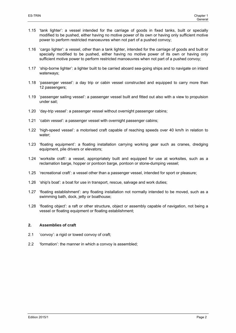
1.15 ‘tank lighter’: a vessel intended for the carriage of goods in fixed tanks, built or specially modified to be pushed, either having no motive power of its own or having only sufficient motive power to perform restricted manoeuvres when not part of a pushed convoy;
1.16 ‘cargo lighter’: a vessel, other than a tank lighter, intended for the carriage of goods and built or
specially modified to be pushed, either having no motive power of its own or having only sufficient motive power to perform restricted manoeuvres when not part of a pushed convoy;
1.17 ‘ship-borne lighter’: a lighter built to be carried aboard sea-going ships and to navigate on inland
waterways; 1.18 ‘passenger vessel’: a day trip or cabin vessel constructed and equipped to carry more than
12 passengers; 1.19 ‘passenger sailing vessel’: a passenger vessel built and fitted out also with a view to propulsion
under sail; 1.20 ‘day-trip vessel’: a passenger vessel without overnight passenger cabins; 1.21 ‘cabin vessel’: a passenger vessel with overnight passenger cabins; 1.22 ‘high-speed vessel’: a motorised craft capable of reaching speeds over 40 km/h in relation to
water; 1.23 ‘floating equipment’: a floating installation carrying working gear such as cranes, dredging
equipment, pile drivers or elevators; 1.24 ‘worksite craft’: a vessel, appropriately built and equipped for use at worksites, such as a
reclamation barge, hopper or pontoon barge, pontoon or stone-dumping vessel; 1.25 ‘recreational craft’: a vessel other than a passenger vessel, intended for sport or pleasure; 1.26 ‘ship's boat’: a boat for use in transport, rescue, salvage and work duties; 1.27 ‘floating establishment’: any floating installation not normally intended to be moved, such as a
swimming bath, dock, jetty or boathouse; 1.28 ‘floating object’: a raft or other structure, object or assembly capable of navigation, not being a
vessel or floating equipment or floating establishment; 2. Assemblies of craft 2.1 ‘convoy’: a rigid or towed convoy of craft; 2.2 ‘formation’: the manner in which a convoy is assembled;
ES-TRIN Chapter 1 General
Edition 2015/1 Page 3
2.3 ‘rigid convoy’: a pushed convoy or side-by-side formation; 2.4 ‘pushed convoy’: a rigid assembly of craft of which at least one is positioned in front of the craft
providing the power for propelling the convoy, known as the ‘pusher(s)’; a convoy composed of a pusher and a pushed craft coupled so as to permit guided articulation is also considered as rigid;
2.5 ‘side-by-side formation’: an assembly of craft coupled rigidly side by side, none of which is
positioned in front of the craft propelling the assembly; 2.6 ‘towed convoy’: an assembly of one or more craft, floating establishments or floating objects
towed by one or more self-propelled craft forming part of the convoy; 3. Particular areas on board 3.1 ‘main engine room’: space where the propulsion engines are installed; 3.2 ‘engine room’: space where combustion engines are installed; 3.3 ‘boiler room’: a space housing a fuel-operated installation designed to produce steam or heat a
thermal fluid; 3.4 (left void); 3.5 ‘enclosed superstructure’: a watertight, rigid, continuous structure with rigid walls joined to the
deck in a permanent and watertight manner; 3.6 ‘wheelhouse’: the area which houses all the control and monitoring instruments necessary for
manoeuvring the vessel; 3.7 ‘accommodation’: a space intended for the use of persons normally living on board, including
galleys, storage space for provisions, toilets and washing facilities, laundry facilities, passageways, but not the wheelhouse;
3.8 ‘passenger room’: rooms on board intended for passengers and enclosed areas such as
lounges, offices, shops, hairdressing salons, drying rooms, laundries, saunas, toilets, washrooms, passageways, connecting passages and stairs not encapsulated by walls;
3.9 ‘control centre’: a wheelhouse, an area which contains an emergency electrical power plant or
parts thereof or an area with a centre permanently occupied by shipboard personnel or crew members, such as for fire alarm equipment, remote controls of doors or fire dampers;
3.10 ‘stairwell’: the well of an internal staircase or of a lift; 3.11 ‘lounge’: a room of an accommodation or a passenger room. On board passenger vessels,
galleys are not regarded as lounges;
ES-TRIN Chapter 1 General
Edition 2015/1 Page 4
3.12 ‘galley’: a room with a stove or a similar cooking appliance; 3.13 ‘store room’: a room for the storage of flammable liquids or a room with an area of over 4 m2 for
storing supplies; 3.14 ‘hold’: part of the vessel, bounded fore and aft by bulkheads, opened or closed by means of
hatch covers, intended for the carriage of goods, whether packaged or in bulk, or for housing tanks not forming part of the hull;
3.15 ‘fixed tank’: a tank joined to the vessel, the walls of the tank consisting either of the hull itself or
of a casing separate from the hull; 3.16 ‘work station’: an area where members of the crew carry out their duties, including the gangway,
derrick and ship's boat; 3.17 ‘passageway’: an area intended for the normal movement of persons and goods; 3.18 ‘safe area’: the area which is externally bounded by a vertical surface running at a distance of
1/5 parallel to the course of the hull in the line of maximum draught; 3.19 ‘muster areas’: areas of the vessel which are specially protected and in which persons muster in
the event of danger; 3.20 ‘evacuation areas’: part of muster areas of the vessel from which evacuation of persons can be
carried out; 4. Marine engineering terms 4.1 ‘plane of maximum draught’: the water plane corresponding to the maximum draught at which
the craft is authorised to navigate; 4.2 ‘safety clearance’: the distance between the plane of maximum draught and the parallel plane
passing through the lowest point above which the craft is no longer deemed to be watertight; 4.3 ‘residual safety clearance’: the vertical clearance available, in the event of the vessel heeling
over, between the water level and the lowest point of the immersed side, beyond which the vessel is no longer regarded as watertight;
4.4 ‘freeboard’ or ‘ ’: the distance between the plane of maximum draught and a parallel plane
passing through the lowest point of the gunwale or, in the absence of a gunwale, the lowest point of the upper edge of the ship's side;
4.5 ‘residual freeboard’: the vertical clearance available, in the event of the vessel heeling over,
between the water level and the upper surface of the deck at the lowest point of the immersed side or, if there is no deck, the lowest point of the upper surface of the fixed ship's side;

ES-TRIN Chapter 1 General
Edition 2015/1 Page 5
4.6 ‘margin line’: an imaginary line drawn on the side plating not less than 10 cm below the bulkhead deck and not less than 10 cm below the lowest non-watertight point of the side plating. If there is no bulkhead deck, a line drawn not less than 10 cm below the lowest line up to which the outer plating is watertight shall be used;
4.7 ‘water displacement’ or ‘∀’: the immersed volume of the vessel, in m³; 4.8 ‘displacement’ or ‘∆’: the total weight of the vessel, inclusive of cargo, in t; 4.9 ‘block coefficient’ or ‘ ’: the ratio between the water displacement and the product of length
, breadth and draught ; 4.10 ‘lateral plane above water’ or ‘ ’: lateral plane of the vessel above the waterline in m2; 4.11 ‘bulkhead deck’: the deck to which the required watertight bulkheads are taken and from which
the freeboard is measured; 4.12 ‘bulkhead’: a wall of a given height, usually vertical, partitioning the vessel and bounded by the
bottom of the vessel, the plating or other bulkheads; 4.13 ‘transverse bulkhead’: a bulkhead extending from one side of the vessel to the other; 4.14 ‘wall’: a dividing surface, usually vertical; 4.15 ‘partition wall’: a non-watertight wall; 4.16 ‘length’ or ‘ ’: the maximum length of the hull in m, excluding rudder and bowsprit; 4.17 ‘length overall’ or ‘ ’: the maximum length of the craft in m, including all fixed installations such
as parts of the steering system or power plant, mechanical or similar devices; 4.18 ‘length of waterline’ or ‘ ’: the length of the hull in m, measured at the maximum draught; 4.19 ‘breadth’ or ‘ ’: the maximum breadth of the hull in m, measured to the outer edge of the shell
plating (excluding paddle wheels, rub rails, and similar); 4.20 ‘breadth overall’ or ‘ ’: the maximum breadth of the craft in m, including all fixed equipment
such as paddle wheels, rub rails, mechanical devices or similar; 4.21 ‘breadth of waterline’ or ‘ ’: breadth of the hull in m, measured from the outside of the side
plating at the maximum draught line; 4.22 ‘height’ or ‘ ’: the shortest vertical distance in m between the lowest point of the hull or the keel
and the lowest point of the deck on the side of the vessel;

ES-TRIN Chapter 1 General
Edition 2015/1 Page 6
4.23 ‘draught’ or ‘ ’: the vertical distance in m between the lowest point of the hull without taking into account the keel or other fixed attachments and the maximum draught line;
4.24 ‘draught overall or ‘ ’: the vertical distance in m between the lowest point of the hull including
the keel or other fixed attachments and the maximum draught line; 4.25 ‘forward perpendicular’: the vertical line at the forward point of the intersection of the hull with
the maximum draught line; 4.26 ‘clear width of side deck’: the distance between the vertical line passing through the most
prominent part of the hatch coaming on the side deck side and the vertical line passing through the inside edge of the slip guard (guard-rail, foot rail) on the outer side of the side deck;
5. Steering system 5.1 ‘steering system’: all the equipment necessary for steering the vessel, such as to ensure the
manoeuvrability laid down in Chapter 5; 5.2 ‘rudder’: the rudder or rudders, with shaft, including the rudder quadrant and the components
connecting with the steering apparatus; 5.3 ‘steering apparatus’: the part of the steering system which produces the movement of the
rudder; 5.4 ‘drive unit’: the steering-apparatus drive, between the power source and the steering apparatus; 5.5 ‘power source’: the power supply to the steering drive unit and the steering apparatus produced
by an on-board network, batteries or an internal combustion engine; 5.6 ‘steering control’: the component parts and the circuitry for the operation of a power-driven
steering control; 5.7 ‘steering apparatus drive unit’: the control for the steering apparatus, its drive unit and its power
source; 5.8 ‘manual drive’: a system whereby manual operation of the hand wheel moves the rudder by
means of a mechanical transmission, without any additional power source; 5.9 ‘manually-operated hydraulic drive’: a manual control actuating a hydraulic transmission; 5.10 ‘rate-of-turn regulator’: equipment which automatically produces and maintains a given rate of
turn of the vessel in accordance with preselected values; 5.11 ‘wheelhouse designed for radar navigation by one person’: a wheelhouse arranged in such a
way that, during radar navigation, the vessel can be manoeuvred by one person;

ES-TRIN Chapter 1 General
Edition 2015/1 Page 7
6. Properties of structural components and materials 6.1 ‘watertight’: a structural component or device so fitted as to prevent any ingress of water; 6.2 ‘spray-proof and weathertight’: a structural component or device so fitted that in normal
conditions it allows only a negligible quantity of water to penetrate; 6.3 ‘gastight’: a structural component or device so fitted as to prevent the ingress of gas and
vapours; 6.4 ‘non-combustible’: a substance which neither burns nor produces flammable vapours in such
quantities that they ignite spontaneously when heated to approximately 750 °C; 6.5 ‘flame-retardant’: material which does not readily catch fire, or whose surface at least restricts
the spread of flames pursuant to the test procedure referred to in Article 19.11(1)(c); 6.6 ‘fire-resistance’: the property of structural components or devices as certified by the test
procedure referred to in Article 19.11(1)(d); 6.7 ‘Code for Fire Test Procedures’: the International Code for the Application of Fire Test
Procedures (FTP code) adopted under Resolution MSC.61(67)1 by the Maritime Safety Committee of the International Maritime Organisation (IMO);
7. Navigation lights, navigation and information equipment 7.1 'navigation lights': light from signal lamps to indicate vessels; 7.2 'light signals': light used to supplement visual or acoustic signals; 7.3 ‘navigational radar installation’: an electronic navigational aid for detecting and displaying the
surroundings and traffic; 7.4 ‘Inland ECDIS’: a system used within the meaning of the current “Electronic Chart Display and
Information System for Inland Navigation” Standard for displaying electronic navigational charts for inland waters and associated information, that displays selected information from proprietary electronic navigational charts for inland waters and optionally information from other sensors of the craft;
7.5 ‘Inland ECDIS equipment’: an installation for displaying electronic navigational charts for inland
waters that can be operated in two different modes: information mode and navigation mode; 7.6 ‘information mode’: use of Inland ECDIS for information purposes only without radar overlay; 7.7 ‘navigation mode’: use of Inland ECDIS with radar overlay for navigating a craft;
1 MSC.61(67) adopted on 5 December 1996 - International Code for Application of Fire Test Procedures.
ES-TRIN Chapter 1 General
Edition 2015/1 Page 8
7.8 ’Inland AIS equipment’ equipment fitted aboard a vessel and used within the meaning of the current “Vessel Tracking and Tracing Standard for Inland Navigation”;
8. Engines
(left void) 9. On-board sewage treatment plants
(left void) 10. Classification societies, experts, and competent persons 10.1 'recognised classification society': a classification society that has been recognised in
accordance with CCNR or EU procedures respectively. 10.2 ‘highest class’: the highest class is allocated to a vessel where
- the hull, including the steering and manoeuvring apparatus as well as the anchors and anchor chains, comply with the rules established by a recognised classification society and has been built and tested under its supervision.
- the propulsion machinery as well as the auxiliary engines, the mechanical and electrical equipment, required for shipboard services, have been manufactured and tested in accordance with the classification society's rules and have been installed under its supervision; the unit as a whole will have successfully undergone post installation testing.
10.3 'expert': a person recognised by the competent authority or by an authorised institution, having
specialist knowledge in the relevant area on the basis of his or her professional training and experience, fully conversant with the relevant rules and regulations and the generally accepted technical rules (e.g. EN Standards, relevant legislation, technical rules), and able to examine and give an expert assessment of the relevant systems and equipment;
10.4 'competent person': a person who has acquired sufficient knowledge in the relevant area on the
basis of his or her professional training and experience and is sufficiently conversant with the relevant rules and regulations and the generally accepted technical rules (such as EN Standards, relevant legislation, technical rules) to be able to assess the operational safety of the relevant systems and equipment;
11. Other terms 11.1 ‘shipboard personnel’: all employees on board a passenger vessel who are not members of the
crew; 11.2 ‘persons with reduced mobility’: persons facing particular problems when using public transport,
such as the elderly and the handicapped and persons with sensory disabilities, persons in wheelchairs, pregnant women and persons accompanying young children;

ES-TRIN Chapter 1 General
Edition 2015/1 Page 9
11.3 ‘ADN’: the Regulations annexed to The European Agreement concerning the International
Carriage of Dangerous Goods by Inland Waterways (ADN) in its current version; 11.4 ‘inland navigation vessel certificate’: Union certificate for inland navigation vessels or Rhine
vessel inspection certificate, issued by the competent authority and which confirms compliance with the technical requirements.
Article 1.02 Instructions on the application of the European Standard
The instructions annexed to this Standard aim to facilitate and standardise its application.

ES-TRIN Chapter 1 General
Edition 2015/1 Page 10

ES-TRIN Chapter 2 Procedure
Edition 2015/1 Page 11
CHAPTER 2 PROCEDURE
(left void)

ES-TRIN Chapter 2 Procedure
Edition 2015/1 Page 12
ES-TRIN Chapter 3 Shipbuilding requirements
Edition 2015/1 Page 13
PART II PROVISIONS REGARDING SHIPBUILDING, FITTING OUT AND
EQUIPMENT
CHAPTER 3 SHIPBUILDING REQUIREMENTS
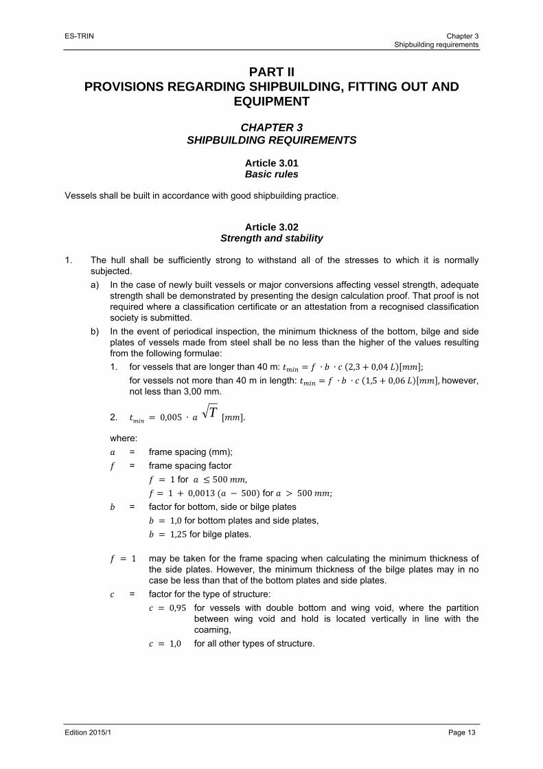
Article 3.01 Basic rules
Vessels shall be built in accordance with good shipbuilding practice.
Article 3.02 Strength and stability
1. The hull shall be sufficiently strong to withstand all of the stresses to which it is normally
subjected.
a) In the case of newly built vessels or major conversions affecting vessel strength, adequate strength shall be demonstrated by presenting the design calculation proof. That proof is not required where a classification certificate or an attestation from a recognised classification society is submitted.
b) In the event of periodical inspection, the minimum thickness of the bottom, bilge and side plates of vessels made from steel shall be no less than the higher of the values resulting from the following formulae:
1. for vessels that are longer than 40 m: ∙ ∙ 2,3 0,04 ;
for vessels not more than 40 m in length: ∙ ∙ 1,5 0,06 ,however, not less than 3,00 mm.
2. 0,005 ∙ .
where:
= frame spacing (mm);
= frame spacing factor
1 for 500 ,
1 0,0013 500 for 500 ;
= factor for bottom, side or bilge plates
1,0 for bottom plates and side plates,
1,25 for bilge plates.
1 may be taken for the frame spacing when calculating the minimum thickness of the side plates. However, the minimum thickness of the bilge plates may in no case be less than that of the bottom plates and side plates.
= factor for the type of structure:
0,95 for vessels with double bottom and wing void, where the partition between wing void and hold is located vertically in line with the coaming,
1,0 for all other types of structure.
T
ES-TRIN Chapter 3 Shipbuilding requirements
Edition 2015/1 Page 14
c) In longitudinally framed vessels with double bottom and wing voids, the minimum value calculated for the plate thickness in accordance with the formulae in (b) may be reduced to a calculated value certified by a recognised classification society for sufficient hull strength (longitudinal, lateral and local strength).
Plates shall be renewed if bottom, bilge or side plates are below the permissible value laid down in this way.
The minimum values calculated in accordance with the method are limit values taking account of normal, uniform wear, and provided that shipbuilding steel is used and that the internal structural components such as frames, frame floor, main longitudinal and transverse structural members are in a good state and that the hull shows no indication of any overloading of the longitudinal strength.
As soon as these values are no longer achieved, the plates in question shall be repaired or replaced. However, lesser thicknesses, of not more than 10 % reduction from calculated values, are acceptable locally for small areas.
2. Where a material other than steel is used for the construction of the hull, it shall be proved by
calculation that the hull strength (longitudinal, lateral and local strength) equals at least the strength that would result from the use of steel under the assumption of minimum thickness in accordance with (1). If a certificate of class or a declaration issued by a recognised classification society is presented, a proof by calculation may be dispensed with.
3. The stability of vessels shall correspond to their intended use.
Article 3.03 Hull
1. Bulkheads rising up to the deck or, where there is no deck, up to the gunwale, shall be installed
at the following points:
a) A collision bulkhead at a suitable distance from the bow in such a way that the buoyancy of the laden vessel is ensured, with a residual safety clearance of 100 mm if water enters the watertight compartment ahead of the collision bulkhead.
As a general rule, the requirement referred to in (1) shall be considered to have been met if the collision bulkhead has been installed at a distance of between 0,04 and 0,04 2 measured from the forward perpendicular in the plane of maximum draught.
If this distance exceeds 0,04 2 , the requirement set out in (1) shall be proved by calculation.
The distance may be reduced to 0,03 . In that case the requirement referred to in (1) shall be proved by calculation on the assumption that the compartment ahead of the collision bulkhead and those adjacent have all been filled with water.
ES-TRIN Chapter 3 Shipbuilding requirements
Edition 2015/1 Page 15
b) An aft-peak bulkhead at a suitable distance from the stern where the vessel length exceeds 25 m in such a way that the buoyancy of the laden vessel is ensured, with a residual safety clearance of 100 mm if water enters the watertight compartment aft of the aft peak bulkhead.
As a general rule, the requirement referred to in the first subparagraph shall be considered to have been met if the aft peak bulkhead has been installed at a distance of between 1,4 m and 0,04 2 measured from the aft point of the intersection of the hull with the maximum draught line.
If this distance is greater than 0,04 2 , the requirement referred to in the first subparagraph must be proved by calculation.
The distance may be decreased to 1 m. In this case, the requirement referred to in the first subparagraph must be substantiated by calculation on the assumption that the compartment aft of the aft peak bulkhead and the immediately adjacent compartments have been filled with water.
2. No accommodation or installations needed for vessel safety or operation may be located ahead
of the plane of the collision bulkhead or aft of the aft-peak bulkhead. This requirement shall not apply to anchor gear or steering apparatus.
3. The accommodation, engine rooms and boiler rooms, and the workspaces forming part of these
shall be separated from the holds by watertight transverse bulkheads that extend up to the deck.
4. The accommodation shall be separated from engine rooms, boiler rooms and holds in a gastight
manner and shall be directly accessible from the deck. If no such access has been provided an emergency exit shall also lead directly to the deck.
5. The bulkheads specified in (1) and (3) and the separation of areas specified in (4) shall not
contain any openings.
However, doors in the aft-peak bulkhead and penetrations, in particular for shafts and pipework, shall be permitted where they are so designed that the effectiveness of those bulkheads and of the separation of areas is not impaired. Doors in the aft-peak bulkhead shall be permitted only if it can be determined by remote monitoring in the wheelhouse whether they are open or closed and shall bear the following readily legible instruction on both sides:
‘Door to be closed immediately after use’.
6. The water inlets and discharges, and the pipework connected to these, shall be such that no
unintentional ingress of water into the vessel is possible. 7. The fore-sections of vessels shall be built in such a way that the anchors neither wholly nor
partly protrude beyond the side plating.
ES-TRIN Chapter 3 Shipbuilding requirements
Edition 2015/1 Page 16
Article 3.04 Engine and boiler rooms, bunkers
1. Engine or boiler rooms shall be arranged in such a way that the equipment therein can be
operated, serviced and maintained easily and safely. 2. The liquid-fuel or lubricant bunkers and passenger rooms and accommodation may not have
any common surfaces which are under the static pressure of the liquid when in normal service. 3. Walls, ceilings and doors of engine rooms, boiler rooms and bunkers shall be made of steel or
another equivalent non-combustible material.
Insulation material used in engine rooms shall be protected against the intrusion of fuel and fuel vapours. All openings in walls, ceilings, and doors of engine rooms, boiler rooms, and bunker rooms shall be such that they can be closed from outside the room. The locking devices shall be made from steel or an equivalent non-combustible material.
4. Engine and boiler rooms and other premises in which flammable or toxic gases can escape
shall be capable of being adequately ventilated. 5. Companionways and ladders providing access to engine and boiler rooms and bunkers shall be
firmly attached and be made of steel or another shock-resistant and non-combustible material. 6. Engine and boiler rooms shall have two exits of which one may be an emergency exit.
The second exit may be dispensed with if:
a) the total floor area (average length × average width at the level of the floor plating) of the engine or boiler room does not exceed 35 m2; and
b) the path between each point where servicing or maintenance operations are to be carried out and the exit, or foot of the companionway near the exit providing access to the outside, is not longer than 5 m; and
c) a fire extinguisher is located at the servicing point that is furthest removed from the exit door and also, by way of derogation from Article 13.03(1)(e), where the installed power of the engines does not exceed 100 kW.
7. The permissible sound pressure level in the engine rooms shall not exceed 110 dB(A). The
measuring points shall be selected as a function of the maintenance work needed during normal operation of the plant located therein.

ES-TRIN Chapter 4 Safety clearance, freeboard and draught marks
Edition 2015/1 Page 17
CHAPTER 4 SAFETY CLEARANCE, FREEBOARD AND DRAUGHT MARKS
Article 4.01
Safety clearance 1. The safety clearance shall be at least 300 mm. 2. The safety clearance in the case of vessels whose openings cannot be closed by spray-proof
and weathertight devices, and for vessels sailing with their holds uncovered, shall be increased in such a way that each of those openings shall be at least 500 mm from the plane of maximum draught.
Article 4.02 Freeboard
1. The freeboard of vessels with a continuous deck, without sheer and superstructures, shall be
150 mm. 2. The freeboard of vessels with sheer and superstructures shall be calculated using the following
formula:
150 1 ∙ ∙
15 mm
where:
is a correction coefficient that takes account of all of the superstructures involved;
is a coefficient for correcting the effect of the forward sheer resulting from the presence of superstructures in the forward quarter of length of the vessel;
is a coefficient correcting the effect of the aft sheer resulting from the presence of superstructures in the aft quarter of length of the vessel;
is the effective forward sheer in mm;
is the effective aft sheer in mm.
3. The coefficient is calculated using the following formula:
∑ ∑ ∑
L
where:
is the effective length, in m, of a superstructure located in the median part corresponding to half of length of the vessel;
is the effective length, in m, of a superstructure in the forward quarter of vessel length ;
is the effective length, in m, of a superstructure in the aft quarter of vessel length .
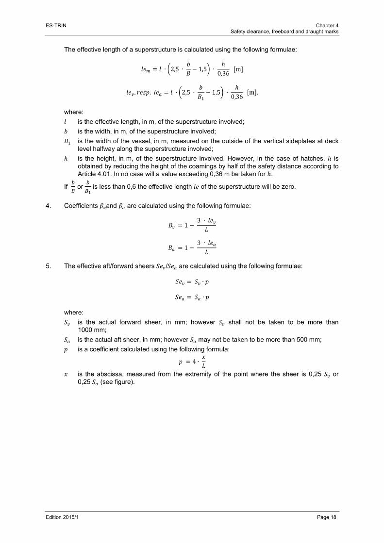
ES-TRIN Chapter 4 Safety clearance, freeboard and draught marks
Edition 2015/1 Page 18
The effective length of a superstructure is calculated using the following formulae:
∙ 2,5 ∙ 1,5 ∙ 0,36
m
, . ∙ 2,5 ∙ 1,5 ∙ 0,36
m .
where:
is the effective length, in m, of the superstructure involved;
is the width, in m, of the superstructure involved;
is the width of the vessel, in m, measured on the outside of the vertical sideplates at deck level halfway along the superstructure involved;
is the height, in m, of the superstructure involved. However, in the case of hatches, is obtained by reducing the height of the coamings by half of the safety distance according to Article 4.01. In no case will a value exceeding 0,36 m be taken for .
If or is less than 0,6 the effective length of the superstructure will be zero.
4. Coefficients and are calculated using the following formulae:
1 3 ∙
1 3 ∙
5. The effective aft/forward sheers / are calculated using the following formulae:
∙ ∙
where:
is the actual forward sheer, in mm; however shall not be taken to be more than 1000 mm;
is the actual aft sheer, in mm; however may not be taken to be more than 500 mm;
is a coefficient calculated using the following formula:
4 ∙
is the abscissa, measured from the extremity of the point where the sheer is 0,25 or 0,25 (see figure).
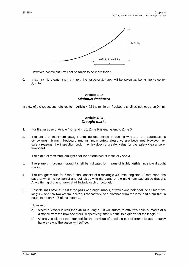
ES-TRIN
Edition 201
Ho
6. If
In view o
1. Fo 2. Th
cosafre
Th
3. Th
m 4. Th
baAn
5. Ve
leeq
Ho
a)
b)
15/1
owever, coef
∙ is g∙ .
of the reducti
or the purpos
he plane of oncerning mafety reasonseeboard.
he plane of m
he plane of marks.
he draught mase of whichny differing d
essels shall ngth and tqual to rough
owever,
) where a vdistance f
) where vehalfway a
fficient will
greater than
ions referred
se of Article 4
maximum dminimum free
s, the inspec
maximum dra
maximum dr
marks for Zoh is horizontadraught mark
have at leasthe two othehly 1/6 of the
vessel is lesfrom the bow
essels are noalong the ves
not be taken
∙ , th
AMinim
d to in Article
ADr
4.04 and 4.0
draught shaeboard and ction body m
aught shall b
raught shall
ne 3 shall coal and coincks shall includ
t three pairs ers located, r
length .
ss than 40 mw and stern,
ot intended fossel will suffic
n to be more
he value of
Article 4.03imum freeb
4.02 the min
Article 4.04raught mar
05, Zone R is
ll be determminimum sa
may lay dow
be determine
be indicated
onsist of a rcides with thede such a re
of draught mrespectively,
m in length respectively,
for the carriace.
Safety
e than 1.
∙ will
3 board
nimum freeb
4 rks
s equivalent t
mined in sucafety clearann a greater
d at least for
d by means o
rectangle 300e plane of th
ectangle.
marks, of what a distanc
it will suffic, that is equa
age of goods
y clearance, fre
be taken as
oard shall be
to Zone 3.
ch a way thnce are botvalue for the
r Zone 3.
of highly visi
0 mm long ahe maximum
hich one pair ce from the b
e to affix twoal to a quarte
s, a pair of m
eeboard and dra
s being the
e not less tha
hat the specth met. Howe safety clea
ible, indelible
and 40 mm dm authorised
r shall be at 1bow and ste
o pairs of mer of the leng
marks located
Chapter 4 aught marks
Page 19
value for
an 0 mm.
cifications wever, for arance or
e draught
deep, the draught.
1/2 of the ern that is
marks at a th ;
d roughly

ES-TRIN
Edition 201
6. Mmsh
7. W
Mrem
8. Fo
bosuadm
Thtohig
15/1
arks or indicarked as bei
hould disapp
Where a veseasurement
equirements arks; this sh
or vessels opow and sterupplementeddditional drauark for Zone
his vertical liwards the bogh × 40 mm
cations whiching no longeear, it may o
ssel has beof inland naof this Stanall be mentio
perating on zrn pairs of
d by adding ught lines 15 3.
ine and the ow of the vedeep (see F
h cease to br valid under
only be replac
en measureavigation vesndard, the moned in the in
zones of inladraught maa vertical lin
50 mm long s
horizontal linssel, the rele
Figure 1).
be valid follor the superviced under th
ed in implessels and the
measurementnland naviga
nd waterwayarks relevanne to this linshall be affix
ne shall be 3evant zone n
Figure 1
Safety
owing a furthsion of the in
he supervisio
mentation oe plane of tht marks sha
ation vessel c
ys other thannt to this zone or, in thexed towards t
30 mm thicknumbers sha
y clearance, fre
her inspectionspection bon of an inspe
of the 1966 he measuremall take the pcertificate.
n Zone 3 (i.e.one referrede case of sethe bow, in re
k. In additionall be indicate
eeboard and dra
on shall be dody. If a drauection body.
Conventionment marks place of the
. Zones 1, 2 d to in (4) everal zonesrelation to the
n to the draued in letterin
Chapter 4 aught marks
Page 20
deleted or ught mark
n on the meet the
e draught
or 4), the shall be
s, several e draught
ught mark ng 60 mm
ES-TRIN Chapter 4 Safety clearance, freeboard and draught marks
Edition 2015/1 Page 21
Article 4.05 Maximum loaded draught of vessels whose holds are not always closed so as to be
spray-proof and weathertight If the plane of maximum draught for Zone 3 of a vessel is determined by assuming that the holds may be closed in such a way as to make them spray-proof and weathertight, and if the distance between the plane of maximum draught and the upper edge of the coamings is less than 500 mm, the maximum draught for sailing with uncovered holds shall be determined. The following statement shall be entered on the inland navigation vessel certificate:
’Where the hold hatches are totally or partly uncovered the vessel may only be loaded up to ... mm below the draught marks for Zone 3 / Zone R.’
Article 4.06 Draught scales
1. Vessels whose draught may exceed 1 m shall bear a draught scale on each of their sides
towards the stern; they may bear additional draught scales. 2. The zero points on each draught scale shall be taken vertically to this within the plane running
parallel to the plane of maximum draught passing through the lowest point of the hull or of the keel where such exists. The vertical distance above the zero point shall be graduated in decimetres. That graduation shall be located on each scale, from the unladen water line up to 100 mm above the maximum draught by means of punched or chiselled marks, and shall be painted in the form of a highly-visible band in two alternating colours. That graduation shall be identified by figures at a distance of every five decimetres marked next to the scale as well as at the top of the scale.
3. The two stern measurement scales affixed pursuant to the Convention referred to in
Article 4.04(7), may replace the draught scales, provided that they include a graduation that meets the requirements plus, where appropriate, figures indicating the draught.
Article 4.07 Specific requirements applicable to vessels navigating on zone 4 waterways
1. By way of derogation from Article 4.01(1) and (2), the safety clearance of doors and openings
other than hold hatches for vessels navigating on Zone 4 waterways is reduced as follows:
a) for openings which can be closed spray-proof and weathertight, to 150 mm;
b) for openings which cannot be closed spray-proof and weathertight, to 200 mm. 2. By way of derogation from Article 4.02, the minimum freeboard of vessels navigating on Zone 4
waterways is 0 mm, if the safety clearance according to (1) is respected.

ES-TRIN Chapter 4 Safety clearance, freeboard and draught marks
Edition 2015/1 Page 22

ES-TRIN Chapter 5 Manoeuvrability
Edition 2015/1 Page 23
CHAPTER 5 MANOEUVRABILITY
Article 5.01
General 1. Vessels and convoys shall display adequate navigability and manoeuvrability. 2. Unpowered vessels intended to be towed shall meet the specific requirements laid down by the
inspection body. 3. Powered vessels and convoys shall meet the requirements set out in Articles 5.02 to 5.10.
Article 5.02 Navigation tests
1. Navigability and manoeuvrability shall be checked by means of navigation tests. Compliance
with the requirements of Articles 5.06 to 5.10 shall, in particular, be examined. 2. The inspection body may dispense with all or part of the tests where compliance with the
navigability and manoeuvrability requirements is proven in another manner.
Article 5.03 Test area
1. The navigation tests referred to in Article 5.02 shall be carried out on areas of inland waterways
that have been designated by the competent authorities. 2. Those test areas shall be situated on a stretch of flowing or standing water that is if possible
straight, at least 2 km long and sufficiently wide and is equipped with highly-distinctive marks for determining the position of the vessel.
3. It shall be possible for the inspection body to plot the hydrological data such as depth of water,
width of navigable channel and average speed of the current in the navigation area as a function of the various water levels.
Article 5.04 Degree of loading of vessels and convoys during navigation tests
During navigation tests, vessels and convoys intended to carry goods shall be loaded to at least 70 % of their tonnage and loading, distributed in such a way as to ensure a horizontal attitude as far as possible. If the tests are carried out with a lesser load the approval for downstream navigation shall be restricted to that loading.

ES-TRIN Chapter 5 Manoeuvrability
Edition 2015/1 Page 24
Article 5.05 Use of on-board facilities for navigation test
1. During the navigation test, all of the equipment referred to in items 34 and 52 of the inland
navigation vessel certificate which may be actuated from the wheelhouse may be used, apart from anchors.
2. However, during the test involving turning into the current referred to in Article 5.10, bow
anchors may be used.
Article 5.06 Prescribed (forward) speed
1. Vessels and convoys shall achieve a speed in relation to the water of at least 13 km/h. That
condition is not mandatory where pushers are operating solo. 2. The inspection body may allow derogations to vessels and convoys operating solely in estuaries
and ports. 3. The inspection body shall check if the unladen vessel is capable of exceeding a speed of
40 km/h in relation to water. If this can be confirmed, the following entry shall be entered in item 52 of the inland navigation vessel certificate:
‘The vessel is capable of exceeding a speed of 40 km/h in relation to water.’
Article 5.07 Stopping capacity
1. Vessels and convoys shall be able to stop facing downstream in good time while remaining
adequately manoeuvrable. 2. Where vessels and convoys with a lenghth of not more than 86 m and with a breadth of not
more than 22,90 m the stopping capacity mentioned above may be replaced by turning capacity.
3. The stopping capacity shall be proved by means of stopping manoeuvres carried out within a
test area as referred to in Article 5.03 and the turning capacity by turning manoeuvres in accordance with Article 5.10.
Article 5.08 Capacity for going astern
Where the stopping manoeuvre required by Article 5.07 is carried out in standing water it shall be followed by a navigation test while going astern.

ES-TRIN Chapter 5 Manoeuvrability
Edition 2015/1 Page 25
Article 5.09 Capacity for taking evasive action
Vessels and convoys shall be able to take evasive action in good time. That capacity shall be proven by means of evasive manoeuvres carried out within a test area as referred to in Article 5.03.
Article 5.10 Turning capacity
Vessels and convoys with a length of not more than 86 m or with a breadth of not more than 22,90 m shall be able to turn in good time. That turning capacity may be replaced by the stopping capacity referred to in Article 5.07. The turning capacity shall be proven by means of turning manoeuvres against the current.

ES-TRIN Chapter 5 Manoeuvrability
Edition 2015/1 Page 26

ES-TRIN Chapter 6 Steering system
Edition 2015/1 Page 27
CHAPTER 6 STEERING SYSTEM
Article 6.01
General requirements 1. Vessels shall be fitted with a reliable steering system which provides at least the manoeu-
vrability required by Chapter 5. 2. Powered steering systems shall be designed in such a way that the rudder cannot change
position unintentionally. 3. The steering system as a whole shall be designed for permanent lists of up to 15° and ambient
temperatures from - 20 °C to + 50 °C. 4. The component parts of the steering system shall be rugged enough to always be able to
withstand the stresses to which they may be subjected during normal operation. No external forces applied to the rudder shall impair the operating capacity of the steering apparatus and its drive unit.
5. The steering system shall incorporate a powered drive unit if so required by the forces needed
to actuate the rudder. 6. A steering apparatus with powered drive unit shall be protected against overloads by means of
a system that restricts the torque applied by the drive unit. 7. The penetrations for the rudder stocks shall be so designed as to prevent the spread of water-
polluting lubricants.
Article 6.02 Steering apparatus drive unit
1. If the steering apparatus has a powered drive unit, a second independent drive unit or an addi-
tional manual drive shall be present. In case of failure or malfunction of the drive unit of the rudder system, the second independent drive unit or the manual drive has to be in operation within 5 seconds.
2. If the second drive unit or manual drive is not placed in service automatically, it shall be possible
to do so immediately by means of a single operation by the helmsman that is both simple and quick.
3. The second drive unit or manual drive shall ensure the manoeuvrability required by Chapter 5
as well.

ES-TRIN Chapter 6 Steering system
Edition 2015/1 Page 28
Article 6.03 Hydraulic steering apparatus drive unit
1. No other power consumers may be connected to the hydraulic steering apparatus drive unit. 2. Hydraulic tanks shall be equipped with a warning system that monitors a dropping of the oil
level below the lowest content level needed for safe operation. 3. The dimensions, design and arrangement of the pipework shall as far as possible exclude
mechanical damage or damage resulting from fire. 4. Hydraulic hoses are:
a) only permissible, if vibration absorption or freedom of movement of components makes their use inevitable;
b) to be designed for at least the maximum service pressure;
c) to be renewed at the latest every eight years. 5. Hydraulic cylinders, hydraulic pumps and hydraulic motors as well as electric motors shall be
examined at the latest every eight years by a specialised firm and repaired if required.
Article 6.04 Power source
1. Steering systems fitted with two powered drive units shall have at least two power sources. 2. If the second power source for the powered steering apparatus is not constantly available while
the vessel is under way, a buffer device carrying adequate capacity shall provide back-up during the period needed for start-up.
3. In the case of electrical power sources, no other power consumers may be supplied by the main
power source for the steering system.
Article 6.05 Manual drive
1. The manual wheel shall not be driven by a powered drive unit. 2. Regardless of rudder position, a kick-back of the wheel shall be prevented when the manual
drive is engaged automatically.

ES-TRIN Chapter 6 Steering system
Edition 2015/1 Page 29
Article 6.06 Rudder-propeller, water-jet, cycloidal-propeller and bow-thruster systems
1. Where the thrust vectoring of rudder-propeller, water-jet, cycloidal-propeller or bow thruster
installations is remotely actuated by electric, hydraulic or pneumatic means, there shall be two steering controls, each independent of the other, between the wheelhouse and the propeller- or thruster-installation which, mutatis mutandis, meet the requirements of Articles 6.01 to 6.05.
Such systems are not subject to this paragraph if they are not needed in order to achieve the manoeuvrability required by Chapter 5 or if they are only needed for the stopping test.
2. Where there are two or more rudder-propeller, water-jet or cycloidal-propeller installations that
are independent of each other the second actuation system is not necessary if the vessel retains the manoeuvrability required by Chapter 5 if one of the systems fails.
Article 6.07 Indicators and monitoring devices
1. The rudder position shall be clearly displayed at the steering position. If the rudder-position
indicator is electric it shall have its own power supply. 2. An optical and acoustic alarm shall be present at the steering position to signal the following:
a) oil level of the hydraulic tanks falling under the lowest content level in accordance with Article 6.03(2) and decrease of service pressure of the hydraulic system;
b) failure of the electrical supply for the steering control;
c) failure of the electrical supply for the drive units;
d) failure of the rate-of-turn regulator;
e) failure of the required buffer devices.
Article 6.08 Rate-of-turn regulators
1. Rate-of-turn regulators and their components shall meet the requirements laid down in
Article 10.20. 2. The proper functioning of the rate-of-turn regulator shall be displayed at the steering position by
means of a green indicating light.
Any lack of or unacceptable variations in the supply voltage and an unacceptable decrease in the speed of rotation of the gyroscope shall be monitored.
ES-TRIN Chapter 6 Steering system
Edition 2015/1 Page 30
3. Where, in addition to the rate-of-turn regulator, there are other steering systems, it shall be possible to clearly distinguish at the steering position which of these systems has been activated. It shall be possible to shift from one system to another immediately. The rate-of-turn regulator shall not have any influence on the steering systems.
4. The electricity supply to the rate-of-turn regulator shall be independent of other power
consumers. 5. The gyroscopes, detectors and rate-of-turn indicators used in the rate-of-turn regulators shall
meet the minimum requirements of the minimum specifications and test conditions concerning rate-of-turn displays for inland waterways, as laid down in Section II of Annex 5.
Article 6.09 Testing
1. The correct installation of the steering system shall be inspected by an inspection body. For this
purpose the inspection body can require the following documents:
a) description of the steering system;
b) drawings of and information on the steering apparatus drive units and the steering control;
c) information concerning the steering apparatus;
d) electrical wiring diagram;
e) description of the rate-of-turn regulator;
f) operating and maintenance instructions for the steering system. 2. Operation of the entire steering system shall be checked by means of a navigation test. If a
rate-of-turn regulator is installed it shall be checked that a predetermined course can be reliably maintained and that bends can be negotiated safely.
3. Power-driven steering systems shall be inspected by a competent person:
a) before being put into service;
b) after a failure;
c) after any modification or repair;
d) regularly at least every three years. 4. The inspection has to cover at least:
a) a check of conformity with the approved drawings and at periodical inspections whether alterations in the steering system were made;
b) a functional test of the steering system for all operational possibilities;
c) a visual check and a tightness check of the hydraulic components, in particular valves, pipelines, hydraulic hoses, hydraulic cylinders, hydraulic pumps, and hydraulic strainers;
d) a visual check of the electrical components, in particular relays, electric motors and safety devices;
e) a check of the optical and acoustic control devices. 5. An inspection attestation, signed by the competent person, shall be issued, showing the date of
inspection.

ES-TRIN Chapter 7 Wheelhouse
Edition 2015/1 Page 31
CHAPTER 7 WHEELHOUSE
Article 7.01
General 1. Wheelhouses shall be arranged in such a way that the helmsman may at all times perform his
task while the vessel is under way. 2. Under normal operating conditions, sound pressure generated by the vessel and measured at
the level of the helmsman's head at the steering position shall not exceed 70 dB(A). 3. Where a wheelhouse has been designed for radar navigation by one person, the helmsman
shall be able to accomplish his task while seated and all of the display or monitoring instruments and all of the controls needed for operation of the vessel shall be arranged in such a way that the helmsman may use them comfortably while the vessel is under way without leaving his position or losing sight of the radar screen.
Article 7.02 Unobstructed view
1. There shall be an adequately unobstructed view in all directions from the steering position. 2. The area of obstructed vision for the helmsman ahead of the vessel in an unladen state with
half of its supplies but without ballast shall not exceed 250 m.
To further reduce any area of obstructed vision, only appropriate auxiliary means shall be used.
Auxiliary means for reducing the area of obstructed vision may not be taken into account during the inspection.
3. The helmsman's field of unobstructed vision at his normal position shall be at least 240° of the
horizon and at least 140° within the forward semicircle. No window frame, post or superstructure shall lie within the helmsman's usual axis of vision. Even in the case where a field of unobstructed vision of at least 240° of the horizon is provided, the inspection body may require other measures and in particular the installation of appropriate auxiliary means if no sufficiently unobstructed view is provided towards the rear. The lower edge of the side windows must be located as low as possible and the upper edge of the side and rear windows must be located as high as possible. In determining whether the requirements in this Article for visibility from the wheelhouse are met, the helmsman shall be assumed to have a height of eye of 1,65 m above the wheelhouse floor at the steering position.

ES-TRIN Chapter 7 Wheelhouse
Edition 2015/1 Page 32
4. The upper edge of the forward facing windows of the wheelhouse shall be high enough to allow a person at the steering position a clear forward view. This requirement shall have been fulfilled when a person at the steering position with height of eye of 1,80 m have a clear forward view to at least 10° above the horizontal at eye-level height.
5. There shall in all weathers be appropriate means of providing a clear view through the front
windows. 6. The glazing used in wheelhouses shall be made of safety glass and have a light transmission of
at least 75 %.
To avoid reflections, the wheelhouse front windows must be glare-free or fitted so as to exclude reflections effectively. The requirement of the second sentence shall have been fulfilled when the windows are inclined from the vertical plane at an angle of not less than 10° and not more than 25°.
Article 7.03 General requirements concerning control, indicating and monitoring equipment
1. Control equipment needed to operate the vessel shall be brought into its operating position
easily. That position shall be unambiguously clear. 2. Monitoring instruments shall be easily legible. It shall be possible to dim their lighting down to
their extinction. Light sources shall be neither intrusive nor impair the legibility of the monitoring instruments.
3. There shall be a system for testing the warning and indicating lights. 4. It shall be possible to clearly establish whether a system is in operation. If its functioning is
indicated by means of an indicating light, this shall be green. 5. Any malfunctioning or failure of systems that require monitoring shall be indicated by means of
red warning lights. 6. An audible warning shall sound at the same time that a red warning light lights up. Audible
warnings may be given by a single, collective signal. The sound pressure level of that signal shall exceed the maximum sound pressure level of the ambient noise at the steering position by at least 3 dB(A).
7. The audible warning shall be capable of being switched off after a malfunction or failure has
been acknowledged. Such shutdown shall not prevent the alarm signal from being triggered by other malfunctions. The red warning lights shall only go out when the malfunction has been corrected.
8. The monitoring and indicating devices shall be automatically switched to an alternative power
supply if their own power supply fails.

ES-TRIN Chapter 7 Wheelhouse
Edition 2015/1 Page 33
Article 7.04 Specific requirements concerning control, indicating and monitoring equipment of
main engines and steering system 1. It shall be possible to control and monitor the main engines and steering systems from the
steering position. Main engines fitted with a clutch which can be actuated from the steering position, or driving a controllable pitch propeller which can be controlled from the steering position, need only to be capable of being started up and shut down from the engine room.
2. The control for each main engine shall take the form of a single lever which prescribes an arc
within a vertical plane that is approximately parallel to the longitudinal axis of the vessel. Movement of that lever towards the bow of the vessel shall cause forward motion, whereas movement of the lever towards the stern shall cause the vessel to go astern. Clutch engagement and reversal of the direction of motion shall take place about the neutral position of that lever. The lever shall catch in the neutral position.
3. The direction of the propulsion thrust imparted to the vessel and the rotational speed of the
propeller or main engines shall be displayed. 4. The indicating and monitoring devices required by Article 6.07(2), Article 8.03(2), and
Article 8.05(13), shall be located at the steering position. 5. Vessels with wheelhouses designed for radar navigation by one person shall be steered by
means of a lever. It shall be possible to move that lever easily by hand. The position of the lever in relation to the longitudinal axis of the vessel shall correspond precisely to the position of the rudder blades. It shall be possible to release hold of the lever in any given position without that of the rudder blades changing. The neutral position of the lever shall be clearly perceptible.
6. Where the vessel is fitted with bow rudders or special rudders, particularly for going astern,
these shall be actuated in wheelhouses designed for radar navigation by one person by special levers which, mutatis mutandis, meet the requirements set out in (5).
That requirement shall also apply where, in convoys, the steering system fitted to craft other than those powering the convoy is used.
7. Where rate-of-turn regulators are used, it shall be possible for the rate-of-turn control to be
released in any given position without altering the speed selected.
The control shall turn through a wide enough arc to guarantee adequately precise positioning. The neutral position shall be clearly perceptible from the other positions. It shall be possible to increase or decrease the level of illumination.
8. The remote-control equipment for the entire steering system shall be installed in a permanent
manner and be arranged in such a way that the course selected is clearly visible. If the remote control equipment can be disengaged, it shall be equipped with an indicating device displaying the respective operational conditions ‘in service’ or ‘out of service’. The disposition and manipulation of the controls shall be functional.
ES-TRIN Chapter 7 Wheelhouse
Edition 2015/1 Page 34
For systems that are subsidiary to the steering system, such as active bow thrusters, remote-control equipment not permanently installed shall be acceptable provided that such a subsidiary installation can be activated by means of an override at any time within the wheelhouse.
9. In the case of rudder-propeller, water-jet, cycloidal-propeller and bow-thruster systems,
equivalent devices shall be acceptable as control, indicating and monitoring devices. The requirements set out in (1) to (8) shall apply, mutatis mutandis, in view of the specific characteristics and arrangements selected for the abovementioned active steering and propulsion units. In analogy to (2), each unit shall be controlled by a lever which moves in the form of an arc within a vertical plane that is approximately parallel to the direction of the thrust of the unit. From the position of the lever the direction of the thrust acting on the vessel shall be clear If rudder propeller or cycloidal-propeller systems are not controlled by means of levers, the inspection body may allow derogations from (2). These derogations shall be entered in item 52 of the inland navigation vessel certificate.
Article 7.05 Navigation lights, light signals and sound signals
1. Navigation lights, their casings and accessories shall bear the approval mark prescribed by
Council Directive 96/68/CE1, as amended. 2. Current indicating lights or other equivalent devices, such as repeater lights, for monitoring the
navigation lights shall be installed in the wheelhouse unless that monitoring can be performed direct from the wheelhouse.
3. In wheelhouses designed for radar navigation by one person, repeater lights shall be installed
on the control panel in order to monitor the navigation lights and the light signals. Switches of navigation lights shall be included in the repeater lights or be adjacent to these and shall be clearly assigned to them.
The arrangement and colour of the repeater lights for the navigation lights and light signals shall correspond to the actual position and colour of those lights and signals. The failure of a navigation light or light signal to function shall cause the corresponding repeater light either to go out or to provide a signal in another manner.
4. In wheelhouses designed for radar navigation by one person it shall be possible to activate the
sound signals by a foot operated switch. That requirement shall not apply to the ‘do not approach’ signal in accordance with the applicable navigational authority regulations of the Member States.
1 Council Directive 96/98/EC of 20 December 1996 on marine equipment (OJ L 46 , 17/02/1997).
ES-TRIN Chapter 7 Wheelhouse
Edition 2015/1 Page 35
Article 7.06 Navigation and information equipment
1. Navigational radar installation and rate-of-turn indicators shall fulfil the requirements laid down
in Annex 5. Compliance with these requirements shall be determined by a type-approval issued by the competent authority.
2. Inland ECDIS equipment which can be operated in navigation mode shall be regarded as
navigational radar installation. The requirements of the current Inland ECDIS Standard shall be met. The requirements of Annex 5 must be complied with.
3. Inland AIS equipment shall meet the requirements of the current “Vessel Tracking and Tracing
Standard for Inland Navigation”. The requirements of Annex 5 must be complied with.
4. The rate-of-turn indicator shall be located ahead of the helmsman and within his field of vision. 5. In wheelhouses designed for radar navigation by one person:
a) the radar screen shall not be shifted significantly out of the helmsman's axis of view in its normal position;
b) the radar image shall continue to be perfectly visible, without a mask or screen, whatever the lighting conditions outside the wheelhouse;
c) the rate-of-turn indicator shall be installed directly above or below the radar image or be incorporated into this.
Article 7.07 Radio telephony systems for vessels with wheelhouses designed for radar navigation
by one person 1. Where vessel wheelhouses have been designed for radar navigation by one person, reception
from the vessel to vessel networks and that of nautical information shall be via a loudspeaker, and outgoing communications via a fixed microphone. Send/receive shall be selected by means of a push-button.
It shall not be possible to use the microphones of those networks for the public correspondence network.
2. Where vessel wheelhouses designed for radar navigation by one person are equipped with a
radio telephone system for the public correspondence network, reception shall be possible from the helmsman's seat.
ES-TRIN Chapter 7 Wheelhouse
Edition 2015/1 Page 36
Article 7.08 Internal communication facilities on board
There shall be internal communication facilities on board vessels with a wheelhouse designed for radar navigation by one person. It shall be possible to establish communication links from the steering position:
a) with the bow of the vessel or convoy;
b) with the stern of the vessel or convoy if no direct communication is possible from the steering position;
c) with the crew accommodation;
d) with the boatmaster's cabin. Reception at all positions of these internal communication links shall be via loudspeaker, and transmission shall be via a fixed microphone. The link with the bow and stern of the vessel or convoy may be of the radio-telephone type.
Article 7.09 Alarm system
1. There shall be an independent alarm system enabling the accommodation, engine rooms and,
where appropriate, the separate pump rooms to be reached. 2. The helmsman shall have within reach an on/off switch controlling the alarm signal; switches
which automatically return to the off position when released are not acceptable. 3. The sound pressure level for the alarm signal shall be at least 75 dB(A) within the
accommodation area.
In engine rooms and pump rooms the alarm signal shall take the form of a flashing light that is visible on all sides and clearly perceptible at all points.
Article 7.10 Heating and ventilation
Wheelhouses shall be equipped with an effective heating and ventilation system that can be regulated.
Article 7.11 Stern-anchor operating equipment
On board vessels and convoys whose wheelhouse has been designed for radar navigation by one person and exceeding 86 m in length or 22,90 m in breadth it shall be possible for the helmsman to drop the stern anchors from his position.

ES-TRIN Chapter 7 Wheelhouse
Edition 2015/1 Page 37
Article 7.12 Retractable wheelhouses
Retractable wheelhouses shall be fitted with an emergency lowering system. All lowering operations shall automatically trigger a clearly audible acoustic warning signal. That requirement shall not apply if the risk of injury which may result from the lowering is prevented by appropriate design features. It shall be possible to leave the wheelhouse safely whatever its position.
Article 7.13 Entry in the inland navigation vessel certificate for vessels with wheelhouses
designed for radar navigation by one person Where a vessel complies with the special provisions for wheelhouses designed for radar navigation by one person as set out in Articles 7.01(3), 7.04(5) and (6), 7.05(3) and (4), 7.06(2), 7.07, 7.08 and 7.11, the following entry shall be made in the inland navigation vessel certificate:
‘The vessel has a wheelhouse designed for radar navigation by one person’.

ES-TRIN Chapter 7 Wheelhouse
Edition 2015/1 Page 38

ES-TRIN Chapter 8 Engine design
Edition 2015/1 Page 39
CHAPTER 8 ENGINE DESIGN
Article 8.01
General 1. Engines and their ancillaries shall be designed, built and installed in accordance with best
practice. 2. Pressure vessels dedicated for the operation of the vessel shall be checked by an expert to
verify that they are safe for operation:
a) before being put into service for the first time;
b) before being put back into service after any modification or repair; and
c) regularly, at least every five years.
The inspection shall involve an internal and an external inspection. Compressed-air vessels the interior of which cannot be properly inspected, or the condition of which cannot be clearly established during the internal inspection, are required to undergo additional non-destructive testing or a hydraulic pressure test. An inspection attestation shall be issued, signed by the expert and showing the date of the inspection. Other installations requiring regular inspection, particularly steam boilers, other pressure vessels and their accessories, and lifts, shall meet the regulations applying in one of the Member States.
3. Only internal-combustion engines burning fuels having a flashpoint of more than 55 °C may be installed.
Article 8.02 Safety equipment
1. Engines shall be installed and fitted in such a way as to be adequately accessible for operation
and maintenance and shall not endanger the persons assigned to those tasks. It shall be possible to make them secure against unintentional starting.
2. Main engines, auxiliaries, boilers and pressure vessels, and their accessories, shall be fitted
with safety devices. 3. In case of emergency, it shall also be possible to shut down the motors driving the blower and
suction fans from outside the space in which they are located, and from outside the engine room.
4. Where necessary, connections of pipes which carry fuel oil, lubricating oil, and oils used in
power transmission systems, control and activating systems and heating systems shall be screened or otherwise suitably protected to avoid oil spray or leakages onto hot surfaces, into machinery air intakes, or other sources of ignition. The number of connections in such piping systems shall be kept to a minimum.
ES-TRIN Chapter 8 Engine design
Edition 2015/1 Page 40
5. External high pressure fuel delivery pipes of diesel engines, between the high pressure fuel pumps and fuel injectors, shall be protected with a jacketed piping system capable of containing fuel from a high pressure pipe failure. The jacketed piping system shall include a means for collection of leakages and arrangements shall be provided for an alarm to be given of a fuel pipe failure, except that an alarm is not required for engines with no more than two cylinders. Jacketed piping systems need not be applied to engines on open decks operating windlasses and capstans.
6. Insulation of engine parts shall meet the requirements of Article 3.04(3), second subparagraph.
Article 8.03 Propulsion systems
1. It shall be possible to start, stop or reverse the ship's propulsion reliably and quickly. 2. The following areas shall be monitored by suitable devices which trigger an alarm once a critical
level has been reached:
a) the temperature of the cooling water of the main engines;
b) the lubricating-oil pressure for the main engines and transmissions;
c) the oil and air pressure of the reversing units of the main engines, reversible transmissions or propellers.
3. Where vessels have only one propulsion engine, that engine shall not be shut down
automatically except in order to protect against overspeed. 4. Where vessels have only one propulsion engine, that engine may be equipped with an
automatic device for the reduction of the engine speed only if an automatic reduction of the engine speed is indicated both optically and acoustically in the wheelhouse and the device for the reduction of the engine speed can be switched off from the helmsman's position.
5. Shaft bushings shall be designed in such a way as to prevent the spread of water-polluting lubri-
cants.
Article 8.04 Engine exhaust system
1. The exhaust gases shall be completely ducted out of the vessel. 2. All suitable measures shall be taken to avoid ingress of the exhaust gases into the various
compartments. Exhaust pipes passing through accommodation or the wheelhouse shall, within these, be covered by protective gas-tight sheathing. The gap between the exhaust pipe and this sheathing shall be open to the outside air.
3. The exhaust pipes shall be arranged and protected in such a way that they cannot cause a fire. 4. The exhaust pipes shall be suitably insulated or cooled in the engine rooms. Protection against
physical contact may suffice outside the engine rooms.
ES-TRIN Chapter 8 Engine design
Edition 2015/1 Page 41
Article 8.05 Fuel tanks, pipes and accessories
1. Liquid fuels shall be stored in steel tanks which are either an integral part of the hull or which
are firmly attached to the hull. If so required by the design of the vessel, an equivalent material in terms of fire-resistance may be used. These requirements shall not apply to tanks having a capacity of no more than 12 litres that have been incorporated in auxiliaries during their manufacture. Fuel tanks shall not have common partitions with drinking-water tanks.
2. Fuel tanks and their pipework and other accessories shall be laid out and arranged in such a
way that neither fuel nor fuel vapours may accidentally reach the inside of the vessel. Tank valves intended for fuel sampling or water drainage shall close automatically.
3. No fuel tanks may be located forward of the collision bulkhead or aft of the aft-peak bulkhead. 4. Fuel tanks and their fittings shall not be located directly above engines or exhaust pipes. 5. The filler orifices for fuel tanks shall be marked distinctly. 6. The orifice for the fuel tank filler necks shall be on the deck, except for the daily-supply tanks.
The filler neck shall be fitted with a connection piece in accordance with European Standard EN 12827 : 1999.
Such tanks shall be fitted with a breather pipe terminating in the open air above the deck and arranged in such a way that no water ingress is possible. The cross-section of the breather pipe shall be at least 1,25 times the cross-section of the filler neck. If tanks are interconnected, the cross-section of the connecting pipe shall be at least 1,25 times the cross-section of the filler neck.
7. Directly at tank outlets the pipework for the distribution of fuels shall be fitted with a quick-
closing valve that can be operated from the deck, even when the rooms in question are closed.
If the operating device is concealed, the lid or cover shall not be lockable. The operating device shall be marked in red. If the device is concealed it shall be marked with a symbol for the ’quick-closing valve on the tank‘ in accordance with Figure 9 of Annex 4 with a side length of at least 10 cm.
The first subparagraph shall not apply to fuel tanks mounted directly on the engine.
8. Fuel pipes, their connections, seals and fittings shall be made of materials that are able to
withstand the mechanical, chemical and thermal stresses to which they are likely to be subjected. The fuel pipes shall not be subjected to any adverse influence of heat and it shall be possible to inspect them throughout their length.

ES-TRIN Chapter 8 Engine design
Edition 2015/1 Page 42
9. Fuel tanks shall be provided with a suitable capacity-gauging device. Capacity-gauging devices shall be legible right up to the maximum filling level. Glass gauges shall be effectively protected against impacts, shall be fitted with an automatic closing device at their base and their upper end shall be connected to the tanks above their maximum filling level. The material used for glass gauges shall not deform under normal ambient temperatures. Sounding pipes shall not terminate in accommodation spaces. Sounding pipes terminating in an engine or boiler room shall be fitted with suitable self-closing devices.
10. a) Fuel tanks shall be safeguarded against fuel spills during bunkering by means of
appropriate onboard technical devices which shall be entered in item 52 of the inland navigation vessel certificate.
b) If fuel is taken on from bunkering stations with their own technical devices to prevent fuel spills on board during bunkering, the equipment requirements in (a) and (11) shall no longer apply.
11. If fuel tanks are fitted with an automatic shut-off device, the sensors shall stop fuelling when the
tank is 97 % full; this equipment shall meet the ‘failsafe’ requirements.
If the sensor activates an electrical contact, which can break the circuit provided by the bunkering station by a binary signal, it shall be possible to transmit the signal to the bunkering station by means of a watertight connection plug meeting the requirements of International Standard IEC 60309-1 : 1999 for 40 to 50 V DC, housing colour white, earthing contact position ten o'clock.
12. Fuel tanks shall be provided with openings having leak-proof closures that are intended to
permit cleaning and inspection. 13. Fuel tanks directly supplying the main engines and engines needed for safe operation of the
vessel shall be fitted with a device emitting both visual and audible signals in the wheelhouse if their level of filling is not sufficient to ensure further safe operation.
Article 8.06 Storage of lubricating oil, pipes and accessories
1. Lubricating oil shall be stored in steel tanks which are either an integral part of the hull or which
are firmly attached to the hull. If so required by the design of the vessel, an equivalent material in terms of fire-resistance may be used. These requirements shall not apply to tanks having a capacity of no more than 25 litres. Lubricating oil tanks shall not have common partitions with drinking-water tanks.
2. Lubricating oil tanks and their pipework and other accessories shall be laid out and arranged in
such a way that neither lubricating oil nor lubricating oil vapour may accidentally reach the inside of the vessel.
3. No lubricating oil tanks may be located forward of the collision bulkhead.
ES-TRIN Chapter 8 Engine design
Edition 2015/1 Page 43
4. Lubricating oil tanks and their fittings shall not be located directly above engines or exhaust pipes.
5. The filler orifices for lubricating oil tanks shall be marked distinctly. 6. Lubricating oil pipes, their connections, seals and fittings shall be made of materials that are
able to withstand the mechanical, chemical and thermal stresses to which they are likely to be subjected. The pipes shall not be subjected to any adverse influence of heat and it shall be possible to inspect them throughout their length.
7. Lubricating oil tanks shall be provided with a suitable capacity-gauging device. Capacity-
gauging devices shall be legible right up to the maximum filling level. Glass gauges shall be effectively protected against impacts, shall be fitted with an automatic closing device at their base and their upper end shall be connected to the tanks above their maximum filling level. The material used for glass gauges shall not deform under normal ambient temperatures. Sounding pipes shall not terminate in accommodation spaces. Sounding pipes terminating in an engine or boiler room shall be fitted with suitable self-closing devices.
Article 8.07 Storage of oils used in power transmission systems, control and activating systems
and heating systems, pipes and accessories 1. Oils used in power transmission systems, control and activating systems and heating systems
shall be stored in steel tanks which are either an integral part of the hull or which are firmly attached to the hull. If so required by the design of the vessel, an equivalent material in terms of fire-resistance may be used. These requirements shall not apply to tanks having a capacity of no more than 25 litres. Oil tanks according to sentence (1) shall not have common partitions with drinking-water tanks.
2. Oil tanks according to (1) and their pipework and other accessories shall be laid out and
arranged in such a way that neither such oil nor such oil vapour may accidentally reach the inside of the vessel.
3. No oil tanks according to (1) may be located forward of the collision bulkhead. 4. Oil tanks according to (1) and their fittings shall not be located directly above engines or
exhaust pipes. 5. The filler orifices for oil tanks according to (1) shall be marked distinctly. 6. Oil pipes according to (1), their connections, seals and fittings shall be made of materials that
are able to withstand the mechanical, chemical and thermal stresses to which they are likely to be subjected. The pipes shall not be subjected to any adverse influence of heat and it shall be possible to inspect them throughout their length.
ES-TRIN Chapter 8 Engine design
Edition 2015/1 Page 44
7. Oil tanks according to (1) shall be provided with a suitable capacity-gauging device. Capacity-gauging devices shall be legible right up to the maximum filling level. Glass gauges shall be effectively protected against impacts, shall be fitted with an automatic closing device at their base and their upper end shall be connected to the tanks above their maximum filling level. The material used for glass gauges shall not deform under normal ambient temperatures. Sounding pipes shall not terminate in accommodation spaces. Sounding pipes terminating in an engine or boiler room shall be fitted with suitable self-closing devices.
Article 8.08 Bilge pumping and drainage systems
1. It shall be possible to pump out each watertight compartment separately. However, that
requirement shall not apply to watertight compartments that are normally sealed hermetically during operation.
2. Vessels requiring a crew shall be equipped with two independent bilge pumps which shall not
be installed within the same space. At least one of these shall be motor driven. However, for vessels with a power of less than 225 kW or with a deadweight of less than 350 t, or where vessels not intended for the carriage of goods have a displacement of less than 250 m3, one pump will suffice which can be either manually-operated or motor-driven.
Each of the required pumps shall be capable of use in each watertight compartment.
3. The minimum pumping capacity of the first bilge pump shall be calculated using the following
formula: 0,1 ∙ /
is calculated via the formula:
1,5 ∙ 25 The minimum pumping capacity of the second bilge pump shall be calculated using the following formula:
0,1 ∙ /
is calculated using the formula:
2 ∙ 25
However, the value need not exceed value .
For the calculation of shall be taken to be the length of the longest watertight compartment.
In these formulae:
is the length of the watertight compartment in question, in [m];
is the calculated internal diameter of the main drainage pipe, in [mm];
is the calculated internal diameter of the branch pipe, in [mm].
ES-TRIN Chapter 8 Engine design
Edition 2015/1 Page 45
4. Where the bilge pumps are connected to a drainage system the drainage pipes shall have an internal diameter of at least , in mm, and the branch pipes an internal diameter of at least , in mm.
Where the vessels length is less than 25 m the values and may be reduced to 35 mm.
5. Only self-priming bilge pumps are permitted. 6. There shall be at least one suction on both the starboard and port sides of all flat-bottomed,
drainable compartments that are wider than 5 m. 7. It may be possible to drain the aft peak via the main engine room by means of an easily
accessible, automatically closable fitting. 8. Branch pipes of single compartments shall be connected to the main drainage pipe by means of
a lockable non-return valve.
Compartments or other spaces that are capable of carrying ballast need to be connected to the drainage system only by means of a simple closing device. That requirement shall not apply to holds that are capable of carrying ballast. Such holds shall be filled with ballast water by means of ballast piping that is permanently installed and independent of the drainage pipes, or by means of branch pipes that can be connected to the main drainage pipe by flexible pipes or flexible adaptors. Water intake valves located in the bottom of the hold shall not be permitted for this purpose.
9. Hold bilges shall be fitted with gauging devices. 10. Where a drainage system incorporates permanently installed pipework the bilge-bottom
drainage pipes intended to extract oily water shall be equipped with closures that have been sealed in position by an inspection body. The number and position of those closures shall be entered on the inland navigation vessel certificate.
11. Locking the closures in position shall be regarded as equivalent to sealing in accordance with
(10). The key or keys for the locking of the closures shall be indicated accordingly and kept in a marked and easily accessible location in the engine room.
Article 8.09 Oily water and used oil stores
1. It shall be possible to store, on board, oily water accumulated during operation. The engine-
room bilge is considered to be a store for this purpose. 2. In order to store used oils there shall, in the engine room, be one or several specific receptacles
whose capacity corresponds to at least 1,5 times the quantity of the used oils from the sumps of all of the internal combustion engines and transmissions installed, together with the hydraulic fluids from the hydraulic-fluid tanks.
The connections used in order to empty the receptacles referred to above shall comply with European Standard EN 1305 : 1996.
3. Where vessels are only used on short-haul operation the inspection body may grant exceptions
from the requirements of (2).

ES-TRIN Chapter 8 Engine design
Edition 2015/1 Page 46
Article 8.10 Noise emitted by vessels
1. The noise produced by a vessel under way, and in particular the engine air intake and exhaust
noises, shall be damped by using appropriate means. 2. The noise generated by a vessel under way shall not exceed 75 dB(A) at a lateral distance of
25 m from the ship's side. 3. Apart from transhipment operations the noise generated by a stationary vessel shall not exceed
65 dB(A) at a lateral distance of 25 m from the ship's side.

ES-TRIN Chapter 9 Emission of gaseous and particulate pollutants from diesel engines
Edition 2015/1 Page 47
CHAPTER 9 EMISSION OF GASEOUS AND PARTICULATE POLLUTANTS FROM DIESEL
ENGINES
Article 9.00 Definitions
In this Chapter: 8.1 ‘engine’: an engine which works on the compression-ignition principle (diesel engine); 8.2 ‘propulsion engine’: an engine for the propulsion of a craft; 8.3 ‘auxiliary engine’: an engine for use in applications other than the propulsion of a craft; 8.4 ‘exchange engine’: a used, overhauled engine which is intended to replace a currently
operational engine and which is of the same design (in-line engine, V-engine) as the engine to be replaced, which has the same number of cylinders and whose power output and speed do not differ by more than 10 % from the power output and speed of the engine to be replaced;
8.5 ‘type-approval’: the procedure whereby the competent authority certifies that an engine type or
an engine family satisfies the relevant technical requirements with regard to the levels of gaseous and particulate pollutants emitted by the engine(s);
8.6 ‘installation test’: the procedure whereby the competent authority makes sure that, even where
an engine fitted to a craft has undergone, since the issuing of the type-approval, any modifications or adaptations with regard to the level of emission of gaseous and particulate pollutants, that engine still complies with the technical requirements;
8.7 ‘intermediate test’: the procedure whereby the competent authority makes sure that, even where
a craft’s engine has undergone, since the installation test, any modifications or any adaptations with regard to the level of emission of gaseous and particulate pollutants, that engine still complies with the technical requirements;
8.8 ‘special test’: the procedure whereby the competent authority makes sure that, after each
significant modification to a craft’s engine with regard to the level of emission of gaseous and particulate pollutants, that engine still complies with the technical requirements;
8.9 ‘engine type’: a grouping of identical engines as regards those engines' essential
characteristics; 8.10 ‘engine family’: a manufacturer’s grouping of engines which through their design, are expected
to have similar exhaust emission characteristics of gaseous and particulate pollutants; 8.11 ‘rated power output’: the engine's net power at rated speed and under full load;

ES-TRIN Chapter 9 Emission of gaseous and particulate pollutants from diesel engines
Edition 2015/1 Page 48
8.12 ‘manufacturer’: as defined in Article 2 of Directive 97/68/EC1, as amended, means the person or body who is responsible to the approval authority for all aspects of the type-approval process and for ensuring conformity of production. It is not essential that the person or body is directly involved in all stages of the construction of the engine;
8.13 ‘engine parameter protocol’: the document pursuant to Annex 6, in which all the parameters,
together with changes, and including components and engine settings which affect the level of emission of gaseous and particulate pollutants from the engine are duly recorded;
8.14 ‘engine manufacturer’s instructions on monitoring the components and engine parameters of
relevance in an exhaust gas context’: the document produced for the purpose of implementing the installation test and the intermediate or special tests.
Article 9.01 General provisions
1. Without prejudice to the requirements of Directive 97/68/EC or of the Rhine Vessel Inspection
Regulations, the provisions of this Chapter shall apply to all engines with a rated power output more than 19 kW installed in inland waterway vessels or in machinery on board such vessels.
2. The engines shall comply with the requirements of Directive 97/68/EC or the Rhine Vessel
Inspection Regulations. This compliance is established by means of a type approval certificate. 3. (left void) 4. A copy of the type approval certificate, the engine manufacturer's instructions and the engine
parameter protocol shall be kept on board. 5. Installation tests
a) After the installation of the engine on board, but before it is brought into service, an installation test shall be carried out. This test, which forms part of the initial inspection of the craft, or of a special inspection by virtue of the relevant engine having been installed, shall result either in the registration of the engine in the inland navigation vessel certificate to be issued for the first time or in the modification of the existing inland navigation vessel certificate.
b) The inspection body may dispense with an installation test pursuant to (a), if an engine having a rated power output of less than 130 kW is replaced by an engine covered by the same type-approval. As a pre-condition, the inspection body shall be notified of the engine’s replacement and shall be provided with a copy of the type-approval document and details of the identification number of the newly installed engine. The inspection body shall make the appropriate amendments to item 52 of the inland navigation vessel certificate.
6. Intermediate tests on the engine shall be carried out in the context of the periodical inspection. 7. After each significant modification to an engine, where such modifications have the potential to
affect the emission of gaseous and particulate pollutants from the engine, a special test must invariably be carried out.
1 Directive 97/68/EC of the European Parliament and of the Council of 16 December 1997 on the approximation of the laws of
the Member States relating to measures against the emission of gaseous and particulate pollutants from internal combustion engines to be installed in non-road mobile machinery (OJ L 59, 27.2.1998)
ES-TRIN Chapter 9 Emission of gaseous and particulate pollutants from diesel engines
Edition 2015/1 Page 49
8. The results of the tests pursuant to Article 9.00(8.6) to (8.8) shall be registered in the engine parameter protocol.
9. The inspection body shall enter in item 52 of the inland navigation vessel certificate the type-
approval numbers and identification numbers of all the engines that are installed on board the vessel and that are subject to the requirements of this Chapter.
10. For the purpose of discharging tasks pursuant to this Chapter, the competent authority may
employ a technical service.
Article 9.03 Installation test and intermediate test and special test
1. At the time of the installation test pursuant to Article 9.00(8.6) and in the event of intermediate
tests pursuant to Article 9.00(8.7) and special tests pursuant to Article 9.00(8.8), the competent authority will inspect the current state of the engine with reference to the components, adjustments and parameters specified in the instructions.
If the installation and intermediate tests show that, in relation to their parameters, components and adjustable features, the engines installed on board comply with the specifications set out in the instructions pursuant to Article 9.00(8.14), then it may be assumed that the exhaust gas and particulate emissions from the engines likewise comply with the basic limit values.
If the authority finds that the engine does not comply with the approved engine type or the approved engine family, it may:
a) require that
aa) steps are taken to re-establish engine conformity,
bb) require appropriate modifications to the type-approval document, or
b) order the actual emissions to be measured.
Failing the re-establishment of engine conformity or in the absence of appropriate modifications to the type-approval document or in the event that the measurements indicate non-compliance with the emission limit values, the competent authority shall refuse to issue an inland navigation vessel certificate or shall revoke any inland navigation vessel certificate that has already been issued.
2. In the case of engines with exhaust gas after treatment systems, checks shall be carried out to
establish that these systems are functioning properly in the context of the installation test and the intermediate or special tests.

ES-TRIN Chapter 9 Emission of gaseous and particulate pollutants from diesel engines
Edition 2015/1 Page 50
3. The tests according to (1) are made on the basis of the engine manufacturer’s instruction on monitoring the components and engine parameters of relevance in an exhaust gas emission context. The instruction, to be drawn up by the manufacturer and to be approved by a competent authority, shall specify the exhaust relevant components as well as adjustments and parameters, whereby continuous compliance with the exhaust gas emission limit values can be assumed. The instruction contains at least the following details:
a) type of engine and, where appropriate, engine family with an indication of the rated output and rated speed;
b) list of the components and engine parameters of relevance in an exhaust gas emission context;
c) unambiguous features to identify the permitted components of relevance in an exhaust gas emission context (e.g. part numbers appearing on the components);
d) engine parameters of relevance in an exhaust gas emission context such as setting ranges for the injection timing, permitted cooling water temperature, maximum exhaust gas backpressure.
In the case of engines fitted with exhaust gas after treatment systems, the instruction shall also include procedures to check that the exhaust gas after treatment installation is operating efficiently.
4. The installation of engines in craft shall comply with the restrictions set out in the scope of the
type approval. In addition, the intake under pressure and the exhaust gas back pressure shall not exceed the values indicated for the approved engine.
5. If the engines being installed on board belong to an engine family, no readjustments or
modifications which could adversely affect exhaust gas and particulate emissions or which lie outside the proposed adjustment range may be carried out.
6. If, after type-approval, permissible readjustments or modifications to the engine need to be
made, these should be accurately entered in the engine parameter protocol. 7. Where an engine has obtained type-approval, the competent authority may, at its own
discretion, reduce the installation test or intermediate test pursuant to these provisions. However, the full test shall be carried out in respect of at least one cylinder or one engine of an engine family and may only be reduced if there is reason to believe that all other cylinders or engines behave similarly to the cylinder or engine under investigation.
ES-TRIN Chapter 9 Emission of gaseous and particulate pollutants from diesel engines
Edition 2015/1 Page 51
Article 9.04 Technical services
1. The technical services shall comply with the European Standard on general requirements for
the competence of testing and calibration laboratories (EN ISO/IEC 17025 : 2005), having due regard to the following conditions:
a) engine manufacturers cannot be recognised as technical services;
b) for the purposes of this Chapter, a technical service may, with permission of the competent authority, use facilities outside its own test laboratory;
c) if requested to do so by the competent authority, technical services shall demonstrate that they are recognised in a Member State to perform the type of activities referred to in this paragraph.

ES-TRIN Chapter 9 Emission of gaseous and particulate pollutants from diesel engines
Edition 2015/1 Page 52

ES-TRIN Chapter 10 Electrical equipment
Edition 2015/1 Page 53
CHAPTER 10 ELECTRICAL EQUIPMENT
Article 10.01
General 1. Where there are no specific requirements concerning certain parts of an installation the safety
level shall be considered satisfactory where those parts have been produced in accordance with a European Standard in force or in accordance with the requirements of a recognised classification society.
The relevant documents shall be submitted to the inspection body.
2. Documents containing the following, and duly stamped by the inspection body, shall be kept on
board:
a) general drawings concerning the entire electrical installation;
b) switching diagrams for the main switchboard, the emergency switchboard and the distribution switchboard, together with the most important technical data such as the amperage and rated current of the protection and control devices;
c) power data concerning the electrical machinery and equipment;
d) types of cable and information on conductor cross-sections. It is not necessary to keep such documents on board unmanned craft, but they shall be available at all times from the owner.
3. The equipment shall be designed for permanent lists of up to 15° and ambient inside tempera-
tures of between 0 and + 40 °C, and on the deck between - 20 °C and + 40 °C. It shall function perfectly within those limits.
4. The electrical and electronic equipment and appliances shall be fully accessible and easy to
maintain.
Article 10.02 Electricity supply systems
1. Where craft are fitted with an electrical system, that system shall in principle have at least two
power sources in such a way that where one power source fails the remaining source is able to supply the power consumers needed for safe navigation for at least 30 minutes.
2. Adequate rating of the power supply shall be demonstrated by means of a power balance. An
appropriate utilisation factor may be taken into account. 3. Independently of (1), Article 6.04 shall apply to the power source for the steering system (rudder
installations).

ES-TRIN Chapter 10 Electrical equipment
Edition 2015/1 Page 54
Article 10.03 Protection against physical contact, intrusion of solid objects and the ingress of water The type of minimum protection for permanently installed parts of an installation shall be as set out in the following table:
Location
Type of minimum protection (in accordance with International Standard IEC 60529 : 1992)
Generators Motors Trans-formers
Panels Generators Motors
Operation rooms, engine rooms, steering-gear compartments ...............................
IP 22
IP 22
2)
IP 22 1)2)
IP 22
IP 44
IP 22
Holds .................................................... IP 55 IP 55
Battery and paint lockers ....................... IP 44
et (Ex)3)
Free decks and open steering positions IP 55 IP 55 IP 55 IP 55
Wheelhouse ................................................ IP 22 IP 22 IP 22 IP 22 IP 22
Accommodation apart from sanitaryfacilities and washrooms ....................... IP 22 IP 20 IP 20
Sanitary facilities and washrooms ......... IP 44 IP 44 IP 44 IP 55 IP 44
Remarks: 1) Where appliances release large amounts of heat: IP 12. 2) Where appliances or panels do not have this type of protection their location shall meet the conditions applying to that type of
protection. 3) Electrical equipment of the certified safety type as in accordance with
a) European Standards EN 50014 : 1997; 50015 : 1998; 50016 : 2002; 50017 : 1998; 50018 : 2000; 50019 : 2000 and 50020 : 2002; or
b) International Standard IEC 60079 as of 1 October 2003.
Article 10.04 Protection from explosion
Only explosion-proof electrical equipment (certified safe) may be installed in spaces where potentially explosive gases or mixtures of gases are likely to accumulate, such as compartments dedicated for accumulators or the storage of highly inflammable products. No light switches or switches for other electrical appliances shall be installed in these spaces. The protection from explosion shall take account of the characteristics of the potentially explosive gases or mixtures of gases that are likely to arise (explosion-potential group, temperature class).

ES-TRIN Chapter 10 Electrical equipment
Edition 2015/1 Page 55
Article 10.05 Earthing
1. Systems under a voltage of more than 50 V need to be earthed. 2. Metal parts that are open to physical contact and which, during normal operation, are not electri-
cally live, such as engine frames and casings, appliances and lighting equipment, shall be earthed separately where they are not in electrical contact with the hull as a result of their installation
3. The casings of mobile power consumers and portable devices shall, during normal use, be
earthed by means of an additional earthing conductor that is incorporated into the power cable.
That provision shall not apply where a protective circuit-separation transformer is used, nor to appliances fitted with protective insulation (double insulation).
4. The cross-sections of the earthing conductors shall be not less than given in the following table.
Cross-section of outside conductors
Minimum cross-section of earthing conductors
[mm2] within insulated cables
[mm2] fitted separately
[mm2]
from 0,5 to 4 same cross-section as that of the
outside conductor 4
more than 4 to 16 same cross-section as that of the
outside conductor same cross-section as that of the
outside conductor
more than 16 to 35 16 16
more than 35 to 120 half of the cross-section of the
outside conductor half of the cross-section of the
outside conductor
more than 120 70 70
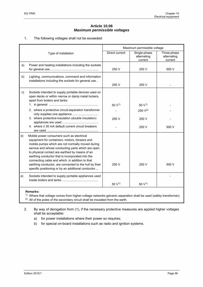
ES-TRIN Chapter 10 Electrical equipment
Edition 2015/1 Page 56
Article 10.06 Maximum permissible voltages
1. The following voltages shall not be exceeded:
Type of installation
Maximum permissible voltage
Direct current Single-phase alternating
current
Three-phase alternating
current
a) Power and heating installations including the sockets for general use ........................................................
250 V
250 V
500 V
b) Lighting, communications, command and information installations including the sockets for general use ..
250 V 250 V -
c) Sockets intended to supply portable devices used on open decks or within narrow or damp metal lockers, apart from boilers and tanks:
1. in general ......................................................... 50 V1) 50 V1) -
2. where a protective circuit-separation transformer only supplies one appliance ..............................
- 250 V2) -
3. where protective-insulation (double insulation) appliances are used ..........................................
250 V 250 V -
4. where ≤ 30 mA default current circuit breakers are used. ...........................................................
- 250 V 500 V
d) Mobile power consumers such as electrical equipment for containers, motors, blowers and mobile pumps which are not normally moved during service and whose conducting parts which are open to physical contact are earthed by means of an earthing conductor that is incorporated into the connecting cable and which, in addition to that earthing conductor, are connected to the hull by their specific positioning or by an additional conductor ...
250 V
250 V
500 V
e) Sockets intended to supply portable appliances used inside boilers and tanks ..........................................
50 V1)
50 V1)
-
Remarks: 1) Where that voltage comes from higher-voltage networks galvanic separation shall be used (safety transformer). 2) All of the poles of the secondary circuit shall be insulated from the earth.
2. By way of derogation from (1), if the necessary protective measures are applied higher voltages
shall be acceptable:
a) for power installations where their power so requires;
b) for special on-board installations such as radio and ignition systems.

ES-TRIN Chapter 10 Electrical equipment
Edition 2015/1 Page 57
Article 10.07 Distribution systems
1. The following distribution systems are allowed for direct current and single-phase alternating
current:
a) two-conductor systems of which one is earthed (L1/N/PE);
b) single-conductor systems using the hull return principle, only for local installations (for example, starting gear for combustion engines, cathodic protection) (L1/PEN);
c) two-conductor systems that are insulated from the hull (L1/L2/PE). 2. The following distribution systems are allowed for three-phase alternating current:
a) four-conductor systems with earthing of the neutral point, not using the hull return principle (L1/L2/L3/N/PE) = (network TN-S) or (network TT);
b) three-conductor systems insulated from the hull (Ll/L2/L3/PE) = (network IT);
c) three-conductor systems with earthing of the neutral point using the hull return principle, however, that shall not be allowed for terminal circuits (L1/L2/L3/PEN).
3. The inspection body may allow the use of other systems.
Article 10.08 Connection to shore or other external networks
1. Incoming supply lines from shore networks or other external networks to the installations of the
onboard network shall have a permanent connection on board in the form of fixed terminals or fixed plug sockets. The cable connections shall not be subjected to any pulling load.
2. The hull shall be capable of being earthed effectively when the connection voltage exceeds
50 V. The earthing connection shall be specially marked. 3. The switching devices for the connection shall be arranged such as to prevent the concurrent
operation of the onboard network generators and the shore network or another external network. A brief period of concurrent operation shall be permitted when changing from one system to another without a break in voltage.
4. The connection shall be protected against short circuiting and overload. 5. The main switchboard shall indicate whether the connection is live. 6. Indicator devices shall be installed to enable comparison of polarity in the case of direct current
and phase sequence in the case of three-phase alternating current, between the connection and the onboard network.
7. A panel adjacent to the connection shall indicate:
a) the measures required to establish the connection;
b) the type of current and the nominal voltage and, for alternating current, the frequency.
ES-TRIN Chapter 10 Electrical equipment
Edition 2015/1 Page 58
Article 10.09 Power supply to other craft
1. When power is supplied to other craft, a separate connection shall be used. If power sockets
rated at more than 16 A are used to supply current to other craft, devices (such as switches or interlocks) shall be provided to ensure that connection and disconnection can take place only when the line is dead.
2. Cable connections shall not be subjected to any pulling load. 3. Article 10.08(3) to (7) shall apply mutatis mutandis.
Article 10.10 Generators and motors
1. Generators, motors and their terminal boxes shall be accessible for inspections, measurements
and repairs. The type of protection shall correspond to their location (see Article 10.03). 2. Generators driven by the main engine, the propeller shaft or by an auxiliary set intended for
other purposes shall be designed with respect to the range of rotational speeds which can occur during normal operation.
Article 10.11 Accumulators
1. Accumulators shall be accessible and so arranged as not to shift due to movements of the craft.
They shall not be placed where they will be exposed to excessive heat, extreme cold, spray, steam or vapour.
They shall not be installed in the wheelhouse, accommodation or holds. This requirement shall not apply to accumulators for portable appliances, or to accumulators requiring a charging power of less than 0,2 kW.
2. Accumulators requiring a charging power of more than 2,0 kW (calculated on the basis of the
maximum charging current and the nominal voltage of the accumulator and taking into account the characteristic charging curve of the charging appliance) shall be installed in a special room. If placed on deck enclosing them in a cabinet will suffice.
Accumulators requiring a charging power not exceeding 2,0 kW may be installed in a cabinet or chest not only if placed on deck but also below decks. They may also be installed in an engine room or any other well-ventilated space provided that they are protected against falling objects and dripping water.
3. The interior surfaces of all rooms, cabinets or boxes, shelving or other built-in features intended
for accumulators shall be protected against the harmful effects of electrolytes.
ES-TRIN Chapter 10 Electrical equipment
Edition 2015/1 Page 59
4. Provision shall be made for effective ventilation when accumulators are installed in a closed compartment, cabinet or chest. Forced-draught ventilation shall be provided for nickel-cadmium accumulators requiring a charging power of more than 2 kW and for lead-acid accumulators requiring more than 3 kW.
The air shall enter at the bottom and be discharged at the top so as to ensure total gas extraction. Ventilation ducts shall not include any devices which obstruct the air flow, such as stop valves.
5. The required air throughput shall be calculated using the following formula:
0,11 ∙ ∙ /
Where:
= 1/4 of the maximum current, in , provided by the charging device;
= the number of cells.
In the case of buffer accumulators within the onboard network other methods of calculation taking into account the characteristic charging curve of the charging device may be accepted by the inspection body, provided that these methods are based on the provisions of recognised classification societies or on relevant standards.
6. Where natural ventilation is used the cross-section of the ducts shall be sufficient for the
required air throughput on the basis of an air-flow velocity of 0,5 m/s. However, the cross-section shall be at least 80 cm2 for lead-acid accumulators and 120 cm2 for nickel-cadmium accumulators.
7. Where forced-draught ventilation is used a fan shall be provided, preferably of the suction type,
whose motor shall be clear of the gas or air stream.
Fans shall be so designed as to preclude the generation of sparks through contact between a blade and the fan casing and to avoid any electrostatic charges.
8. ‘Fire, naked flame and smoking prohibited’ signs according to Figure 2 of Annex 4 having a
minimum diameter of 10 cm shall be affixed to the doors or covers of compartments, cabinets and chests containing accumulators.
Article 10.12 Switchgear installations
1. Electrical switchboards
a) Appliances, switches, fuses and switchboard instruments shall be clearly arranged and shall be accessible for maintenance and repair.
Terminals for voltages up to 50 V, and those for voltages higher than 50 V, shall be kept separate and marked appropriately.
b) For all switches and appliances marker plates identifying the circuit shall be affixed to the switchboards.
The nominal amperage and the circuit for fuses shall be identified.

ES-TRIN Chapter 10 Electrical equipment
Edition 2015/1 Page 60
c) When appliances with an operating voltage greater than 50 V are installed behind doors the live components of those appliances shall be protected against accidental contact while the doors are open.
d) The materials of switchboards shall have suitable mechanical strength and be durable, flame-retardant and self-extinguishing; they shall not be hygroscopic.
e) If high rupture capacity (HRC)-fuses are installed in electrical switchboards, accessories and personal protective equipment shall be available for installing and removing such fuses.
2. Switches, protective devices
a) Generator circuits and power consumer circuits shall be protected against short circuiting and overload on all non-earthed conductors. Fuses and switching devices triggered by short-circuiting and overload may be used for this purpose.
Circuits supplying the electric motors of drive units (steering system) and their control circuits shall only be protected against short circuiting. Where circuits include thermal circuit-breakers these shall be neutralised or set at not less than twice the nominal amperage.
b) Outputs from the main switchboard to power consumers operating at more than 16 A shall include a load or power switch.
c) Power consumers for the propulsion of the craft, the steering system, the rudder position indicator, navigation or safety systems, and power consumers with a nominal amperage greater than 16 A shall be supplied by separate circuits.
d) The circuits of power consumers required for propelling and manoeuvring the vessel shall be supplied directly by the main switchboard.
e) Circuit-breaking equipment shall be selected on the basis of nominal amperage, thermal or dynamic strength, and breaking capacity. Switches shall simultaneously cut off all live conductors. The switching position shall be identifiable.
f) Fuses shall be of the enclosed-melt type and be made of ceramic or an equivalent material. It shall be possible to change them without any danger of physical contact for the operator.
3. Measuring and monitoring devices
a) Generator, accumulator and distribution circuits shall be equipped with measuring and monitoring devices where the safe operation of the installation so requires.
b) Non-earthed networks with a voltage of more than 50 V shall be equipped with an earthing detection device capable of giving both visual and audible alarm. In secondary installations such as control circuits, this device may be dispensed with.
4. Location of electrical switchboards
a) Switchboards shall be located in accessible and well-ventilated spaces and be protected against water and mechanical damage.
Piping and air ducts shall be so arranged that in the event of leakage the switchboards cannot be damaged. If their installation near electrical switchboards is inevitable, pipes shall not have detachable connections nearby.
ES-TRIN Chapter 10 Electrical equipment
Edition 2015/1 Page 61
b) Cabinets and wall recesses in which unprotected switching devices are installed shall be of a flame-retardant material or be protected by a metal or other flame-retardant sheathing.
c) When the voltage is greater than 50 V, insulating gratings or mats shall be placed at the operator's position in front of the main switchboard.
Article 10.13 Emergency circuit breakers
Emergency circuit breakers for oil burners, fuel pumps, fuel separators and engine-room ventilators shall be installed centrally outside the rooms containing the equipment.
Article 10.14 Installation fittings
1. Cable entries shall be sized as a function of the cables to be connected and be appropriate to
the types of cable used. 2. Sockets for distribution circuits at different voltages or frequencies shall be impossible to
confuse. 3. Switches shall simultaneously switch all non-earthed conductors within a circuit. However,
single-pole switches within non-earthed circuitry shall be permitted in accommodation-lighting circuits apart from in laundries, bathrooms, washrooms and other rooms with wet facilities.
4. Where amperage exceeds 16 A it shall be possible to lock the sockets by means of a switch in
such a way that the plug can only be inserted and withdrawn with the power switched off.
Article 10.15 Cables
1. Cables shall be flame-retardant, self-extinguishing and resistant to water and oil.
In accommodation, other types of cable may be used, provided that they are effectively protected, have flame-retardant characteristics and are self-extinguishing. Flame-retardant standards of electric cables shall be in accordance with:
a) International Standard IEC 60332-1 : 1993, 60332-3 : 2000; or
b) equivalent regulations recognised by one of the Members States. 2. Conductors of cables used for power and lighting circuits shall have a minimum cross-section of
1,5 mm2. 3. Metal armouring, shielding and sheathing of cables shall not, under normal operating condit-
ions, be used as conductors or for earthing. 4. Metal shielding and sheathing of cables in power and lighting installations shall be earthed at
least at one end.

ES-TRIN Chapter 10 Electrical equipment
Edition 2015/1 Page 62
5. The cross-section of conductors shall take account of their maximum permissible end-tempe-rature (current-carrying capacity) and of the permissible voltage drop. The voltage drop between the main switchboard and the least favourable point of the installation shall not be more than 5 % for lighting or more than 7 % for power or heating circuits, referred to the nominal voltage.
6. Cables shall be protected against mechanical damage. 7. The means of fixing the cables shall ensure that any pulling load remains within the permissible
limits. 8. When cables pass through bulkheads or decks, the mechanical strength, watertightness and
fire resistance of these bulkheads and decks shall not be affected by the penetrations. 9. Terminations and joints in all conductors shall be so made as to retain the original electrical,
mechanical, flame-retardant and, where necessary, fire resistant properties. The number of cable joints shall be kept to a minimum.
10. Cables connected to retractable wheelhouses shall be sufficiently flexible and shall have
insulation with sufficient flexibility down to – 20 °C and resistance to steam and vapour, ultraviolet rays and ozone.
Article 10.16 Lighting installations
1. Lighting appliances shall be so installed that the heat they emit cannot set fire to nearby
inflammable objects or components. 2. Lighting appliances on open decks shall be so installed as not to impede the recognition of
navigation lights. 3. When two or more lighting appliances are installed in an engine room or boiler room, they shall
be supplied by at least two different circuits. This requirement shall also apply to spaces where cooling machinery, hydraulic machinery, or electric motors are installed.
Article 10.17 Navigation lights
1. Switchboards for navigation lights shall be installed in the wheelhouse. They shall be supplied
by a separate feeder from the main switchboard or by two independent secondary distributions. 2. Navigation lights shall be supplied, protected and switched separately from the navigation lights
switchboard. 3. No fault in the monitoring installation, as provided for in Article 7.05(2), shall affect the operation
of the light which it monitors.

ES-TRIN Chapter 10 Electrical equipment
Edition 2015/1 Page 63
4. Several lights forming a functional unit and installed together at the same point may be jointly supplied, switched and monitored. The monitoring installation shall be capable of identifying the failure of any one of these lights. However, it shall not be possible to use both light sources in a double light (two lights mounted one above the other or in the same housing) simultaneously.
Article 10.18 Alarm and safety systems for mechanical equipment
The alarm and safety systems for monitoring and protecting mechanical equipment shall meet the following requirements: a) Alarm systems
The alarm systems shall be so designed that no failure in the alarm system can result in failure of the apparatus or installation being monitored. Binary transmitters shall be designed on the quiescent-current principle or on the monitored load-current principle. Visual alarms shall remain visible until the fault has been remedied; an alarm that has been acknowledged shall be distinguishable from an alarm that has not yet been acknowledged. Each alarm shall also comprise an audible warning. It shall be possible to switch off acoustic alarms. Switching off one acoustic alarm shall not prevent another signal from being set off by another cause. Exceptions can be permitted in the case of alarm systems comprising less than five measure-ment points.
b) Safety systems Safety systems shall be designed to halt or slow down the operation of the affected equipment, or to warn a permanently-manned station to do so before a critical state is reached. Binary transmitters shall be designed according to the load-current principle. If safety systems are not designed to be self-monitoring it shall be possible to check that they are operating correctly. Safety systems shall be independent of other systems.
Article 10.19
Electronic equipment 1. General
The test conditions in (2) shall apply only to electronic devices that are necessary for the steering system and the craft's power plants, including their ancillaries.
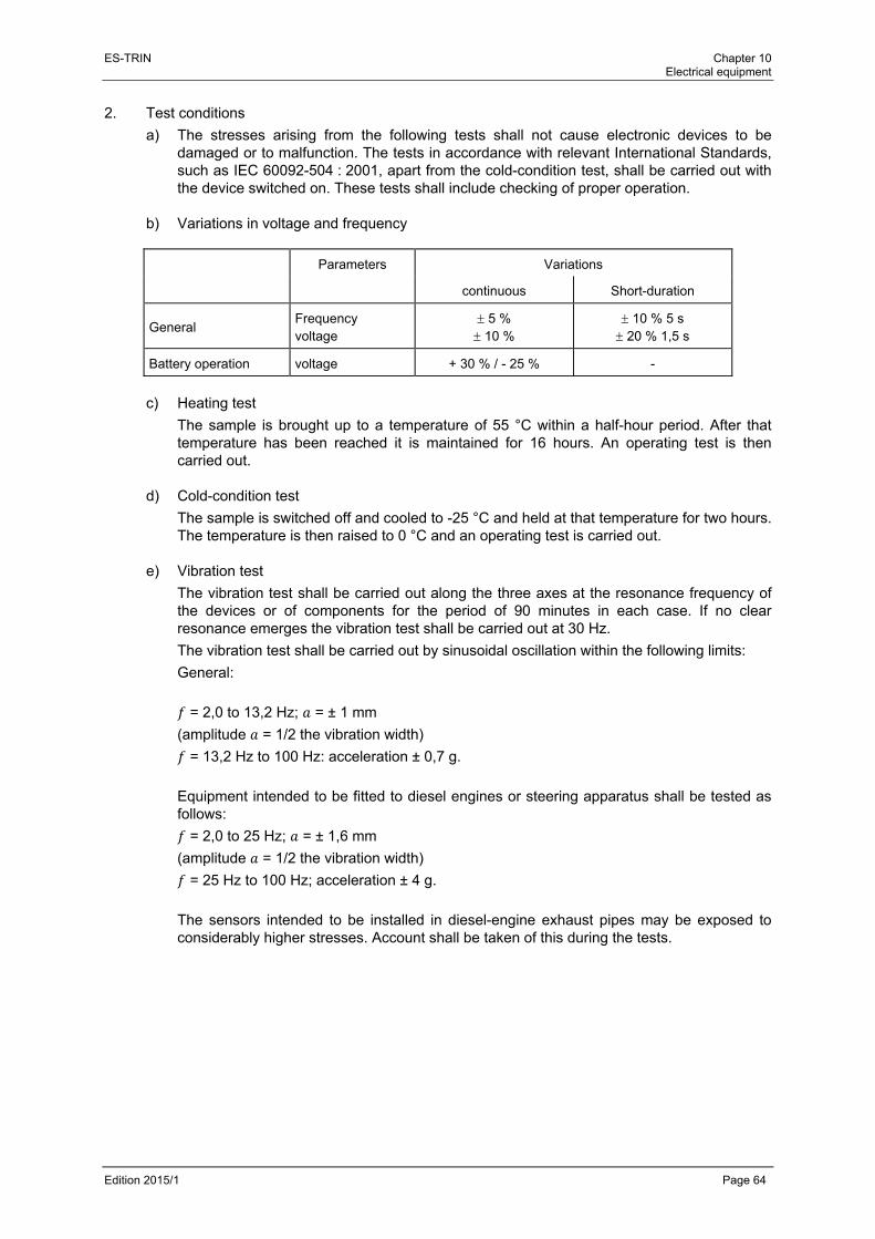
ES-TRIN Chapter 10 Electrical equipment
Edition 2015/1 Page 64
2. Test conditions
a) The stresses arising from the following tests shall not cause electronic devices to be damaged or to malfunction. The tests in accordance with relevant International Standards, such as IEC 60092-504 : 2001, apart from the cold-condition test, shall be carried out with the device switched on. These tests shall include checking of proper operation.
b) Variations in voltage and frequency
Parameters Variations
continuous Short-duration
General Frequency voltage
5 % 10 %
10 % 5 s 20 % 1,5 s
Battery operation voltage + 30 % / - 25 % -
c) Heating test
The sample is brought up to a temperature of 55 °C within a half-hour period. After that temperature has been reached it is maintained for 16 hours. An operating test is then carried out.
d) Cold-condition test
The sample is switched off and cooled to -25 °C and held at that temperature for two hours. The temperature is then raised to 0 °C and an operating test is carried out.
e) Vibration test
The vibration test shall be carried out along the three axes at the resonance frequency of the devices or of components for the period of 90 minutes in each case. If no clear resonance emerges the vibration test shall be carried out at 30 Hz.
The vibration test shall be carried out by sinusoidal oscillation within the following limits:
General:
= 2,0 to 13,2 Hz; = ± 1 mm
(amplitude = 1/2 the vibration width)
= 13,2 Hz to 100 Hz: acceleration ± 0,7 g.
Equipment intended to be fitted to diesel engines or steering apparatus shall be tested as follows:
= 2,0 to 25 Hz; = ± 1,6 mm
(amplitude = 1/2 the vibration width)
= 25 Hz to 100 Hz; acceleration ± 4 g.
The sensors intended to be installed in diesel-engine exhaust pipes may be exposed to considerably higher stresses. Account shall be taken of this during the tests.

ES-TRIN Chapter 10 Electrical equipment
Edition 2015/1 Page 65
f) The electromagnetic compatibility test shall be carried out on the basis of International Standards IEC 61000-4-2 : 1995, 61000-4-3 : 2002, 61000-4-4 : 1995, at test degree number 3.
g) Proof that the electronic equipment is adequate for these test conditions shall be provided
by their manufacturer. A certificate by a recognised classification society shall likewise be considered to be proof.
Article 10.20 Electromagnetic compatibility
The operation of the electric and electronic systems shall not be impaired by electromagnetic interference. General measures shall, with equal importance, extend to:
a) disconnection of the transmission paths between the source of interference and affected devices;
b) reducing the causes of disturbance at their source;
c) reducing the sensitivity of affected devices to interference.

ES-TRIN Chapter 10 Electrical equipment
Edition 2015/1 Page 66

ES-TRIN Chapter 11 Electrical installations
Edition 2015/1 Page 67
CHAPTER 11 ELECTRICAL INSTALLATIONS
(left void)

ES-TRIN Chapter 11 Electrical installations
Edition 2015/1 Page 68

ES-TRIN Chapter 12 Electronic equipment and systems
Edition 2015/1 Page 69
CHAPTER 12 ELECTRONIC EQUIPMENT AND SYSTEMS
(left void)

ES-TRIN Chapter 12 Electronic equipment and systems
Edition 2015/1 Page 70

ES-TRIN Chapter 13 Equipment
Edition 2015/1 Page 71
CHAPTER 13 EQUIPMENT
Article 13.01
Anchor equipment 1. Vessels intended for the carriage of goods, apart from ship-borne lighters whose length does
not exceed 40 m, shall be equipped with bow anchors whose total mass is obtained using the following formula:
∙ ∙
where
is a coefficient that takes account of the relationship between length and beam , and of the type of vessel:
8 ∙
for lighters, however, will be taken;
is an empirical coefficient given in the following table:
Dead-weight tonnage [t] Coefficient
up to 400 inclusive 45
from 400 to 650 inclusive 55
from 650 to 1000 inclusive 65
more than 1000 70
On vessels whose dead-weight tonnage is not greater than 400 t and which, owing to their design and intended purpose, are used only on predetermined short-haul sections, the inspection body may accept that only two-thirds of total mass is required for the bow anchors.
2. a) Passenger vessels and vessels not intended for the carriage of goods, apart from pushers, shall be fitted with bow anchors whose total mass is obtained using the following formula:
∙ ∙
b) By way of derogation from (a) and having regard to the applicable navigational authority regulations for certain areas of navigation in the Member States, for passenger vessels, for whose bow anchors the total mass has been obtained by the following formula it shall be entered in item 52 of the inland navigation certificate that the total mass of the bow anchors meets the requirements set out in Article 13.01(2)(b):
∙ ∙ 4

ES-TRIN Chapter 13 Equipment
Edition 2015/1 Page 72
where:
is the coefficient corresponding to (1), but where in order to obtain the value of the empirical coefficient the water displacement in m3 entered in the inland navigation vessel certificate shall be taken instead of the deadweight tonnage.
is the frontal projected area exposed to the wind, in m2. 3. Vessels referred to in (1) whose length does not exceed 86 m shall be equipped with stern
anchors whose total mass is equal to 25 % of mass .
Vessels whose length exceeds 86 m shall be equipped with stern anchors whose total mass is equal to 50 % of mass calculated in accordance with (1) or (2). Stern anchors are not required for:
a) vessels for which the stern anchor mass will be less than 150 kg; in the case of vessels referred to in (1), final subparagraph, the reduced mass of the bow anchors shall be taken into account;
b) lighters. 4. Vessels intended to propel rigid convoys which do not exceed 86 m in length shall be equipped
with stern anchors whose total mass is equal to 25 % of maximum mass calculated in accordance with (1) for the formations (considered to be a nautical unit) permitted and entered in the inland navigation vessel certificate.
Vessels intended to propel rigid convoys which exceed 86 m in length downstream shall be equipped with stern anchors whose total mass is equal to 50 % of the maximum mass calculated in accordance with (1) for the formations (considered to be a nautical unit) permitted and entered in the inland navigation vessel certificate.
5. The anchor masses established in accordance with (1) to (4) may be reduced for certain special
anchors. 6. The total mass specified for bow anchors may be distributed between one or two anchors. It
may be reduced by 15 % where the vessel is equipped with only a single bow anchor and the hawse pipe is located amidships.
The total mass required for stern anchors for pushers and vessels whose maximum length exceeds 86 m may be distributed between one or two anchors.
The mass of the lightest anchor shall not be less than 45 % of that total mass.
7. Cast iron anchors shall not be permitted. 8. On anchors their mass shall be indicated in characters which stand out in relief in a durable
manner. 9. Anchors having a mass in excess of 50 kg shall be equipped with windlasses. 10. Each bow anchor chain shall have a minimum length of:
a) 40 m for vessels whose length does not exceed 40 m;
b) at least 10 m longer than the length of the vessel where this is between 30 and 50 m;
c) 60 m for vessels whose length exceeds 50 m.
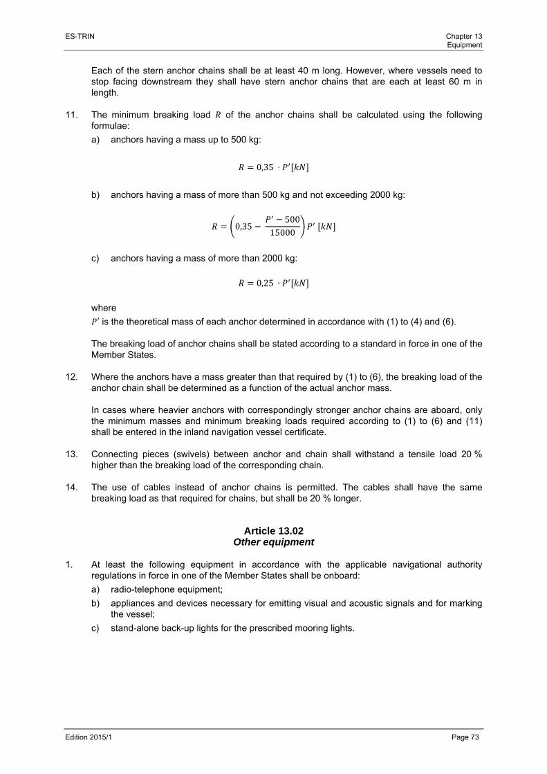
ES-TRIN Chapter 13 Equipment
Edition 2015/1 Page 73
Each of the stern anchor chains shall be at least 40 m long. However, where vessels need to stop facing downstream they shall have stern anchor chains that are each at least 60 m in length.
11. The minimum breaking load of the anchor chains shall be calculated using the following
formulae:
a) anchors having a mass up to 500 kg:
0,35 ∙
b) anchors having a mass of more than 500 kg and not exceeding 2000 kg:
0,35 500
15000
c) anchors having a mass of more than 2000 kg:
0,25 ∙
where
′ is the theoretical mass of each anchor determined in accordance with (1) to (4) and (6).
The breaking load of anchor chains shall be stated according to a standard in force in one of the Member States.
12. Where the anchors have a mass greater than that required by (1) to (6), the breaking load of the
anchor chain shall be determined as a function of the actual anchor mass.
In cases where heavier anchors with correspondingly stronger anchor chains are aboard, only the minimum masses and minimum breaking loads required according to (1) to (6) and (11) shall be entered in the inland navigation vessel certificate.
13. Connecting pieces (swivels) between anchor and chain shall withstand a tensile load 20 %
higher than the breaking load of the corresponding chain. 14. The use of cables instead of anchor chains is permitted. The cables shall have the same
breaking load as that required for chains, but shall be 20 % longer.
Article 13.02 Other equipment
1. At least the following equipment in accordance with the applicable navigational authority
regulations in force in one of the Member States shall be onboard:
a) radio-telephone equipment;
b) appliances and devices necessary for emitting visual and acoustic signals and for marking the vessel;
c) stand-alone back-up lights for the prescribed mooring lights.
ES-TRIN Chapter 13 Equipment
Edition 2015/1 Page 74
2. The following receptacles must also be present:
a) a marked receptacle for domestic waste;
b) separate, marked receptacles, with sealing covers, made of steel or another sturdy, non-flammable material, of adequate size but holding at least 10 litres, for the collection of
aa) oily cleaning cloths;
bb) hazardous or pollutant solid wastes;
cc) hazardous or pollutant liquid wastes;
and, inasmuch as they may arise, for the collection of
dd) slops;
ee) other oily or greasy waste. 3. In addition, the equipment shall include at least:
a) mooring cables;
Vessels shall be equipped with three mooring cables. Their minimum lengths shall be at least the following:
first cable: 20 but not more than 100 m,
second cable: 2/3 of the first cable,
third cable: 1/3 of the first cable.
The shortest cable is not required on board vessels whose is less than 20 m.
The cables shall have a breaking load that is calculated using the following formulae;
for ∙ ∙ up to 1000 m3: 60 ∙ ∙
;
for ∙ ∙ exceeding 1000 m3: 150 ∙ ∙
. For the required cables a certificate in accordance with European Standard EN 10204 : 1991, under No 3.1, shall be on board.
These cables may be replaced by ropes having the same length and breaking load. The minimum breaking load of these ropes shall be indicated in a certificate.
b) towing cables;
Tugs shall be equipped with a number of cables that are suitable for their operation.
However, the main cable shall be at least 100 m long and have a breaking load, in kN, not less than one third of the total power, in kW, of the main engine(s).
Motor vessels and pushers that are also able to tow shall be equipped with a towing cable that is at least 100 m long and whose breaking load, in kN, is not less than one quarter of the total power, in kW, of the main engine(s).
c) a heaving line;
d) a boarding gangway at least 0,40 m wide and 4 m long whose side edges are defined by a brightly-coloured strip; that gangway shall be equipped with a handrail. The inspection body may permit shorter gangways for small vessels;
e) a gaff hook;
ES-TRIN Chapter 13 Equipment
Edition 2015/1 Page 75
f) an appropriate first-aid kit with a content in accordance with a relevant standard of a Member State. The first-aid kit shall be kept in an accommodation room or in the wheelhouse and be stored in such a way that it is easily and safely accessible if necessary. If first-aid kits are stored under cover, the cover shall be marked by a symbol for first-aid kit according to Figure 8 of Annex 4, having a side length of at least 10 cm;
g) a pair of binoculars, 7 × 50 or with larger lens diameter;
h) a notice concerning the rescue and revival of persons overboard;
i) a searchlight that can be operated from the wheelhouse. 4. There shall be an embarkation stairway or ladder on vessels whose side height above the
unladen waterline exceeds 1,50 m.
Article 13.03 Portable fire extinguishers
1. There shall be at least one portable fire extinguisher in accordance with the European
Standards EN 3-7 : 2007 and EN 3-8 : 2007 at each of the following places:
a) in the wheelhouse;
b) close to each entrance from the deck to accommodation spaces;
c) close to each entrance to service spaces which are not accessible from the accommodation spaces and which contain heating, cooking or refrigeration equipment using solid or liquid fuels or liquefied gas;
d) at each entrance to engine rooms and boiler rooms;
e) at suitable points below deck in engine rooms and boiler rooms such that no position in the space is more than 10 metres walking distance away from an extinguisher.
2. For the portable fire extinguishers required by (1), only powder type extinguishers with a content
of at least 6 kg or other portable extinguishers with the same extinguishing capacity may be used. They shall be suitable for Class A, B and C fires.
By way of derogation on vessels with no liquefied gas installations, spray foam fire extinguishers using aqueous film-forming foam (AFFF-AR) frost proof to -20 °C are permissible even if they are unsuitable for Class C fires. These fire extinguishers shall have a minimum capacity of 9 litres.
All extinguishers shall be suitable to extinguish fires in electrical systems of up to 1000 V.
3. In addition powder, water or foam fire extinguishers may be used which are suitable at least for
the class of fire most likely to occur in the room for which they are intended. 4. Portable fire extinguishers with CO2 as the extinguishing agent may be used only for
extinguishing fires in galleys and electrical installations. The content of these fire extinguishers shall be no more than 1 kg per 15 m3 of the room in which they are made available for use.

ES-TRIN Chapter 13 Equipment
Edition 2015/1 Page 76
5. Portable fire extinguishers shall be checked at least every two years by a competent person. An inspection label shall be affixed to the fire extinguisher, signed by the competent person and showing the date of the inspection.
6. If portable fire extinguishers are installed in such a way that they are out of sight, the panel
covering them shall be identified by a symbol for fire extinguishers as shown in Figure 3 of Annex 4, and having a side length of at least 10 cm.
Article 13.04 Permanently installed firefighting systems for protecting accommodation
spaces, wheelhouses and passenger rooms 1. For protecting accommodation spaces, wheelhouses and passenger rooms, only suitable
automatic pressurised water sprinklers are admitted as permanently installed fire-fighting systems.
2. Installation or conversion of the systems shall be carried out only by specialised firms. 3. The systems shall be made of steel or equivalent non-combustible materials. 4. The systems shall be able to spray water at a rate of at least 5 l/m2 per minute over the area of
the largest room to be protected. 5. Systems spraying smaller quantities of water shall have a type-approval pursuant to IMO
Resolution A.800 (19)1 or another Standard recognised by one of the Member States. Type-approval shall be carried out by a recognised classification society or an accredited testing institution. The accredited testing institution shall comply with the European Standard for general requirements for the competence of testing and calibrating laboratories (EN ISO/IEC 17025 : 2005).
6. The systems shall be checked by an expert:
a) before being put into service for the first time;
b) before being put back into service after they have been triggered;
c) before being put back into service after any major modification or repair; and
d) regularly, at least every two years.
Inspections as referred to in (d) may also be carried out by a competent person from a competent firm specialising in fire extinguishing systems.
7. When carrying out the check in accordance with (6), the expert or competent person shall verify
whether the systems meet the requirements of this Article.
The check shall at least include:
a) external inspection of the entire system;
b) functional testing of the safety systems and nozzles;
c) functional testing of the pressure tanks and pumping system.
1 IMO Resolution A.800 (19) adopted on 23 November 1995 - Revised Guidelines for Approval of Sprinkler Systems
Equivalent to that referred to in SOLAS Regulation II-2/12.

ES-TRIN Chapter 13 Equipment
Edition 2015/1 Page 77
8. An inspection attestation, signed by the expert or competent person, shall be issued, showing the date of inspection.
9. The number of installed systems shall be entered in the inland navigation vessel certificate.
Article 13.05 Permanently installed firefighting systems for protecting engine rooms, boiler rooms
and pump rooms 1. Extinguishing agents
For protecting engine rooms, boiler rooms and pump rooms, the following extinguishing agents may be used in permanently installed fire-fighting systems:
a) CO2 (carbon dioxide);
b) HFC 227 ea (heptafluoropropane);
c) IG-541 (52 % nitrogen, 40 % argon, 8 % carbon dioxide);
d) FK-5-1-12 (Dodecafluoro-2-methylpentane-3-on). 2. Ventilation, air intake
a) Combustion air for the propulsion engines shall not be extracted from rooms that are to be protected by permanently installed fire-fighting systems. This shall not apply where there are two mutually independent and hermetically separated main engine rooms or if next to the main engine room there is a separate engine room with a bow thruster, ensuring that the vessel is able to make way under its own power in the event of fire in the main engine room.
b) Any forced ventilation present in the room to be protected shall switch off automatically if the fire-fighting system is triggered.
c) There shall be devices available with which all apertures which can allow air to enter or gas to escape from the room to be protected can be quickly closed. It shall be clearly recognisable whether they are open or closed.
d) The air escaping from pressure relief valves in the compressed-air tanks installed in engine rooms shall be conveyed to the open air.
e) Over- or under-pressure resulting from the inflow of extinguishing agent shall not destroy the components of the surrounding partitions of the room to be protected. It shall be possible for the pressure to equalise without danger.
f) Protected rooms shall have a facility for extracting the extinguishing agent and the combustion gases. Such facilities shall be capable of being operated from positions outside the protected rooms and which must not be made inaccessible by a fire within such spaces. If there are permanently installed extractors, it shall not be possible for these to be switched on while the fire is being extinguished.
3. Fire alarm system
The room to be protected shall be monitored by means of an appropriate fire alarm system. The alarm shall be noticeable in the wheelhouse, the accommodation spaces and the room to be protected.
ES-TRIN Chapter 13 Equipment
Edition 2015/1 Page 78
4. Piping system
a) The extinguishing agent shall be conveyed to the room to be protected and distributed there by means of a fixed piping system. Inside the room to be protected the piping and associated fittings shall be made of steel. Tank connecting pipes and expansion joints shall be exempt from this provided the materials used have equivalent properties in case of fire. Pipes shall be both internally and externally protected against corrosion.
b) Outlet nozzles shall be dimensioned and fitted such that the extinguishing agent is evenly distributed. In particular the extinguishing agent shall also be effective beneath the floor plates.
5. Triggering device
a) Fire-fighting systems with automatic triggering shall not be permissible.
b) It shall be possible to trigger the fire-fighting system from a suitable place outside the room to be protected.
c) Triggering devices shall be installed in such a way that they can be operated even in case of a fire and in the event of damage by fire or explosion in the room to be protected the necessary quantity of extinguishing agent can still be conveyed.
Non-mechanical triggering devices shall be powered from two different mutually independent energy sources. These energy sources shall be located outside the room to be protected. Control lines in the room to be protected shall be designed so as to remain functional for at least 30 minutes in the event of fire. This requirement shall be fulfilled in the case of electric wiring if it complies with the International Standard IEC 60331-21 : 1999.
If triggering devices are installed in such a way that they are out of sight the panel covering them shall be identified by the ‘fire-fighting installation’ symbol as shown in Figure 6 of Annex 4, having a side length of at least 10 cm, and the following text in red lettering on a white background:
’Feuerlöscheinrichtung
Installation d'extinction
Brandblusinstallatie
Fire-fighting installation’.
d) If the fire-fighting system is intended for the protection of several rooms, the triggering devices for each room have to be separate and clearly identified.
e) Next to each triggering device operating instructions in one of the languages of the Member States shall be posted up visibly and indelibly. They shall contain, in particular, instructions regarding:
aa) triggering of the fire-fighting system;
bb) the need for checking to ensure that all persons have left the room to be protected;
cc) action to be taken by the crew when the firefighting system is triggered and when accessing the protected room after triggering or flooding, in particular with regard to the possible presence of dangerous substances;
dd) action to be taken by the crew in the case of failure of the fire-fighting system.
f) The operating instructions shall point out that before the fire-fighting system is triggered combustion engines drawing air from the room to be protected are to be shut down.

ES-TRIN Chapter 13 Equipment
Edition 2015/1 Page 79
6. Warning system
a) Permanently installed fire-fighting systems shall be provided with acoustic and optical warning systems.
b) The warning system shall be set off automatically as soon as the fire-fighting system is first triggered. The warning signal shall sound for an appropriate time before the extinguishing agent is released and it shall not be possible to switch it off.
c) Warning signals shall be clearly visible in the rooms to be protected and outside the accesses to them and clearly audible even under operating conditions producing the loudest inherent noise. They shall be clearly distinct from all other acoustic and optical signals in the room to be protected.
d) The acoustic warning signals shall be clearly audible in the adjacent rooms even when connecting doors are closed and under operating conditions producing the loudest inherent noise.
e) If the warning system is not self-monitoring as regards short-circuits, wire breaks and voltage drops, it shall be possible to check that it is working properly.
f) At every entrance to a room that can be supplied with extinguishing agent, a clearly visible notice shall be put up bearing the following text in red lettering on a white background:
‘Vorsicht, Feuerlöscheinrichtung! Bei Ertönen des Warnsignals (Beschreibung des Signals) den Raum sofort verlassen!
Attention, installation d'extinction d'incendie !
Quitter immédiatement ce local au signal (description du signal) !
Let op, brandblusinstallatie! Bij het in werking treden van het alarmsignaal (omschrijving van het signaal) deze ruimte onmiddellijk
verlaten!
Warning, fire-fighting installation! Leave the room as soon as the warning signal sounds (description of signal)!’
7. Pressure tanks, fittings and pressure pipes
a) Pressure tanks, fittings and pressure pipes shall comply with the provisions in force in one of the Member States.
b) Pressure tanks shall be installed in accordance with the manufacturer's instructions.
c) Pressure tanks, fittings and pressure pipes are not to be installed in accommodation spaces.
d) The temperature in cabinets and installation spaces containing pressure tanks shall not exceed 50 °C.
e) Cabinets or installation spaces on deck shall be firmly fixed in place and have air vents which are to be arranged in such a way that in the event of a leak in the pressure tank no gas can escape into the interior of the vessel. Direct connections to other rooms are not permitted.

ES-TRIN Chapter 13 Equipment
Edition 2015/1 Page 80
8. Quantity of extinguishing agent If the quantity of extinguishing agent is intended for protecting more than one room, the total amount of extinguishing agent available does not need to be greater than the quantity necessary for the largest room to be protected.
9. Installation, inspection and documentation
a) The system shall be installed or converted only by a firm specialising in fire-fighting systems. The requirements specified by the extinguishing agent manufacturer and the system manufacturer (product data sheet, safety data sheet) are to be complied with.
b) The system shall be checked by an expert:
aa) before being put into service for the first time;
bb) before being put back into service after it has been triggered;
cc) before being put back into service after any major modification or repair; and
dd) regularly, at least every two years.
Inspections as referred to in (dd) may also be carried out by a competent person from a competent firm specialising in fire extinguishing systems.
c) In the inspection the expert or competent person shall check whether the system meets the requirements of this Article.
d) The inspection shall cover at least the following:
aa) external inspection of the entire installation;
bb) tightness check on pipes;
cc) functional checking of control and triggering systems;
dd) checking of tank pressure and content;
ee) checking of tightness and facilities for locking the room to be protected;
ff) checking the fire alarm system;
gg) checking the warning system.
e) An inspection attestation shall be issued, signed by the expert and showing the date of the inspection.
f) The number of permanently installed fire-fighting systems shall be entered in the inland navigation vessel certificate.
10. CO2 fire-fighting systems
Fire-fighting systems using CO2 as the extinguishing agent shall comply with the following provisions in addition to the requirements under (1) to (9):
a) CO2 containers shall be housed outside the room to be protected in a space or cabinet hermetically separated from other rooms. The doors to these installation spaces and cabinets shall open outwards, be lockable and bear on the outside a symbol for ‘General danger warning’ in accordance with Figure 4 of Annex 4, at least 5 cm in height, together with the marking ‘CO2’ in the same colour and with the same height.
b) Installation spaces below decks for CO2 containers shall be accessible only from the open air. These spaces shall have their own adequate artificial ventilation system with extraction ducts, completely separate from other ventilation systems on board.

ES-TRIN Chapter 13 Equipment
Edition 2015/1 Page 81
c) The CO2 containers shall not be filled to more than 0,75 kg/l. The specific volume of unpressurised CO2 gas is to be taken as 0,56 m3/kg.
d) The volume of CO2 for the room to be protected shall be at least 40 % of its gross volume. It shall be possible to supply this volume within 120 seconds, and to check whether supply has been completed.
e) Opening the container valves and operating the flood valve shall be by separate control operations.
f) The appropriate time mentioned under (6)(b) shall be at least 20 seconds. There shall be a reliable device to ensure the delay before delivery of the CO2 gas.
11. HFC-227ea — fire-fighting systems
Fire-fighting systems using HFC-227ea as the extinguishing agent shall comply with the following provisions in addition to the requirements under (1) to (9):
a) If there are several rooms to be protected, each with a different gross volume, each room shall be provided with its own fire-fighting system.
b) Each container of HFC-227ea that is installed in the room to be protected shall be equipped with a pressure relief valve. This shall harmlessly release the contents of the container into the room to be protected if the container is exposed to the effects of fire and the fire-fighting system has not been triggered.
c) Each container shall be fitted with a device for checking the gas pressure.
d) The containers shall not be filled to more than 1,15 kg/l. The specific volume of the unpressurised HFC-227ea is to be taken as 0,1374 m3/kg.
e) The volume of HFC-227ea for the room to be protected shall be at least 8 % of the room's gross volume. This volume shall be supplied within 10 seconds.
f) The HFC-227ea containers shall be provided with a pressure monitor which triggers an acoustic and optical alarm signal in the wheelhouse in the event of an unauthorised loss of propellant. If there is no wheelhouse, this alarm signal shall be given outside the room to be protected.
g) After flooding, the concentration in the room to be protected shall not exceed 10,5 %.
h) The fire-fighting system shall not contain any parts made of aluminium. 12. IG-541 — fire-fighting systems
Fire-fighting systems using IG-541 as the extinguishing agent shall comply with the following provisions in addition to the requirements under (1) to (9):
a) If there are several rooms to be protected, each with a different gross volume, each room shall be provided with its own fire-fighting system.
b) Each container of IG-541 that is installed in the room to be protected shall be equipped with a pressure relief valve. This shall harmlessly release the contents of the container into the room to be protected if the container is exposed to the effects of fire and the fire-fighting system has not been triggered.
c) Each container shall be fitted with a device for checking the contents.
ES-TRIN Chapter 13 Equipment
Edition 2015/1 Page 82
d) the filling pressure of the container shall not exceed 200 bar at + 15 °C.
e) the volume of IG-541 for the room to be protected shall be at least 44 % and no more than 50 % of the room's gross volume. This volume shall be supplied within 120 seconds.
13. FK-5-1-12 — firefighting systems
Firefighting systems using FK-5-1-12 as the extinguishing agent shall comply with the following provisions in addition to the requirements under (1) to (9):
a) If there are several rooms to be protected, each with a different gross volume, each room shall be provided with its own firefighting system.
b) Each container of FK-5-1-12 installed in the room to be protected shall be equipped with an overpressure relief valve. The pressure relief valve shall harmlessly release the contents of the container into the room to be protected if the container is exposed to the effects of fire and the fire-fighting system has not been triggered.
c) Each container shall be fitted with a device for checking the gas pressure.
d) The containers shall not be filled to more than 1,00 kg/l. The specific volume of the unpressurised FK-5-1-12 is to be taken as 0,0719 m3/kg.
e) The volume of FK-5-1-12 for the room to be protected shall be at least 5,5 % of the room’s gross volume. This volume shall be supplied within 10 seconds.
f) The FK-5-1-12 containers shall be provided with a pressure monitor which triggers an acoustic and optical alarm signal in the wheelhouse in the event of an unauthorised loss of propellant. If there is no wheelhouse, this alarm signal shall be given outside the room to be protected.
g) After flooding, the concentration in the room to be protected shall not exceed 10,0 %.
Article 13.06 Permanently installed firefighting systems for protecting objects
Permanently installed firefighting systems for protecting objects are prohibited.
Article 13.07 Ship's boats
1. The following craft shall carry a ship's boat according to European Standard EN 1914 : 1997:
a) motor vessels and barges exceeding 150 t deadweight;
b) tugs and pushers with a water displacement of more than 150 m3;
c) floating equipment;
d) passenger vessels. 2. It shall be possible for one person to launch such ship's boats safely within five minutes from the
first manual action necessary. If a powered launching device is used this shall be such that safe, quick launching shall not be impaired if its power supply fails.
3. Inflatable ship's boats shall be inspected according to manufacturer's instructions.

ES-TRIN Chapter 13 Equipment
Edition 2015/1 Page 83
Article 13.08 Lifebuoys and lifejackets
1. On board craft there shall be at least three lifebuoys:
- in accordance with European Standard EN 14144 : 2003; or
- in accordance with the 1974 International Convention for the Safety of Life at Sea (SOLAS 1974), Chapter III, Regulation 7.1, and the International Life-Saving Appliance (LSA) Code, sub-section 2.1.
They shall be ready for use and attached to the deck at appropriate points without being attached to their mounting. At least one lifebuoy shall be in the immediate vicinity of the wheelhouse and shall be equipped with a self-igniting, battery-powered light that will not be extinguished in water.
2. A personalised, automatically inflatable life jacket shall be within reach of every person who is
regularly on board a craft. Such life jackets shall conform to:
- European Standards EN ISO 124022 : 2006, EN ISO 124023 : 2006, EN ISO 124024 : 2006; or
- The 1974 International Convention for the Safety of Life at Sea (SOLAS 1974), Chapter III, Regulation 7.2, and the International Life-Saving Appliance (LSA) Code, sub-section 2.2.
Non-inflatable lifejackets in accordance with these Standards shall also be admissible for children.
3. Lifejackets shall be inspected in accordance with the manufacturer's instructions.

ES-TRIN Chapter 13 Equipment
Edition 2015/1 Page 84

ES-TRIN Chapter 14 Safety at work stations
Edition 2015/1 Page 85
CHAPTER 14 SAFETY AT WORK STATIONS
Article 14.01
General 1. Vessels shall be built, arranged and equipped in such a way as to enable persons to work and
move about in safety in passageways. 2. Permanently installed facilities that are necessary for working on board shall be arranged, laid
out and secured in such a way as to permit safe and easy operation, use and maintenance. If necessary, mobile or high-temperature components shall be fitted with protective devices.
Article 14.02 Protection against falling
1. Decks and side decks shall be flat and at no point be likely to cause tripping; it shall be
impossible for puddles to form. 2. Decks, side decks, engine-room floors, landings, stairways and the tops of side deck bollards
shall have non-slip surfaces. 3. The tops of side deck bollards and obstacles in passageways, such as the edges of steps, shall
be painted in a colour contrasting with the surrounding deck. 4.1 The outer edges of decks and side decks, as well as work stations where persons might fall
more than 1 m, shall be fitted with bulwarks or coamings that are at least 0,90 m high or with a continuous guard rail in accordance with European Standard EN 711 : 1995. Where the shipside guard rails are retractable,
a) a continuous handrail 0,02 to 0,04 m in diameter shall additionally be secured to the coaming at a height of 0,7 to 1,1 m; and
b) signs in accordance with Annex 4, Figure 10, at least 15 cm in diameter, shall be affixed in clearly visible positions at the point where the side deck begins.
5.1 By way of derogation from (4), in the case of lighters and barges without accommodation,
bulwarks or guard rails shall not be required where:
a) foot rails have been fitted to the outer edges of the decks and side decks;
b) handrails in accordance with (4)(a) have been fitted to the coamings; and
c) signs in accordance with Annex 4, Figure 10, at least 15 cm in diameter, have been affixed in clearly visible positions on deck.
6.1 By way of derogation from (4), in the case of vessels with flush- or trunk-decks it shall not be
required that guard rails be fitted directly on the outer edges of those decks, or on side decks where:
a) the passageways run over those decks;
1 Article 14.02(4), (5) and (6) are orders of a provisional nature that are valid until 30 November 2017. The following
regulations were in force prior to 1 December 2011: “The outer edges of the decks, as well as work stations where persons might fall more than 1 m, shall be fitted with bulwarks or coamings that are at least 0.70 m height or with continuous guard rails in accordance with European Standard EN 711 : 1995, comprising a handrail, intermediate rail at knee height and foot rail. Side decks shall be fitted with a foot rail and continuous handrail that is secured to the coaming. Coaming handrails shall not be required where sidedecks are fitted with non-retractable shipside guard rails.
ES-TRIN Chapter 14 Safety at work stations
Edition 2015/1 Page 86
b) the passageways and work stations on those decks are surrounded by fixed guard rails in accordance with EN 711 : 1995; and
c) signs in accordance with Annex 4, Figure 10, at least 15 cm in diameter, have been affixed in clearly visible positions at the transitions to areas unprotected by guard rails.
7. At work stations where there is danger of falling more than 1 m the inspection body may require
appropriate fittings and equipment to ensure safe working.
Article 14.03 Dimensions of work stations
Work stations shall be large enough to provide every person working in them with adequate freedom of movement.
Article 14.04 Side decks
1. The clear width of a side deck shall be at least 0,60 m. That figure may be reduced to 0,50 m at
certain points that are necessary for the operation of the vessel such as deck-washing valves. It may be reduced to 0,40 m at bollards and cleats.
2.1 Up to a height of 0,90 m above the side deck, the clear width of the side deck may be reduced
to 0,50 m provided that the clear width above, between the outer edge of the hull and the inner edge of the hold, is not less than 0,65 m.
3. The requirements of (1) and (2) shall apply up to a height of 2,00 m above the side deck.
Article 14.05 Access to work stations
1. Points of access and passageways for the movement of persons and objects shall be of
sufficient size and so arranged that:
a) in front of the access opening, there is sufficient room not to impede movement;
b) the clear width of the passageway shall be appropriate for the intended use of the working space and shall be not less than 0,60 m, except in the case of craft less than 8 m wide, where it may be reduced to 0,50 m;
c) the clear height of the passageway including the sill is not less than 1,90 m. 2. Doors shall be so arranged that they can be opened and closed safely from either side. They
shall be protected against accidental opening or closing.
1 Article 14.04(2) is a temporary requirement valid until 30 November 2017. The following regulation was in force prior to
1 December 2011: “Up to a height of 0,90 m above the side deck, the clear width of the side deck may be reduced to 0,54 m provided that the clear width above, between the outer edge of the hull and the inner edge of the hold, is not less than 0,65 m. In this case, the clear width of the side deck may be reduced to 0,50 m if the outer edge of the side deck is fitted with a guard rail in accordance with European standards EN 711 : 1995 to prevent falling. In the event of vessels not exceeding 55 m in length with stern accommodation only, the guardrails may be dispensed with.”

ES-TRIN Chapter 14 Safety at work stations
Edition 2015/1 Page 87
3. Appropriate stairs, ladders or steps shall be installed in accesses, exits and passageways where there is more than a 0,50 m difference in floor level.
4. Work stations which are manned continuously shall be fitted with stairs if there is a difference in
floor level of more than 1,00 m. This requirement shall not apply to emergency exits. 5. Vessels with holds shall have at least one permanently installed means of access at each end
of each hold.
By way of derogation from the first sentence the permanently installed means of access may be dispensed with if at least two movable ladders are provided which reach at least 3 rungs over the hatch coaming at an angle of inclination of 60°.
Article 14.06 Exits and emergency exits
1. The number, arrangement and dimensions of exits, including emergency exits, shall be in
keeping with the purpose and dimensions of the relevant space. Where one of the exits is an emergency exit, it shall be clearly marked as such.
2. Emergency exits or windows or the covers of skylights to be used as emergency exits shall
have a clear opening of not less than 0,36 m2, and the smallest dimension shall be not less than 0,50 m.
Article 14.07
Ladders, steps and similar devices 1. Stairs and ladders shall be securely fixed. Stairs shall be not less than 0,60 m wide and the
clear width between handrails shall be not less than 0,60 m; steps shall be not less than 0,15 m deep; steps shall have non-slip surfaces and stairs with more than three steps shall be fitted with handrails.
2. Ladders and separately attached rungs shall have a clear width of not less than 0,30 m; rungs
shall be not more than 0,30 m apart and the distance between rungs and structures shall be not less than 0,15 m.
3. Ladders and separately attached rungs shall be clearly recognisable from above and shall be
equipped with safety handles above exit openings. 4. Movable ladders shall be at least 0,40 m wide, and at least 0,50 m wide at the base; it shall be
possible to ensure that they will not topple or skid; the rungs shall be securely fixed in the uprights.
Article 14.08 Interior rooms
1. The dimensions, arrangement and layout of interior work stations shall be in keeping with the
work to be carried out and shall meet the health and safety requirements. They shall be equipped with sufficient non-dazzle lighting and with sufficient ventilation arrangements. If necessary, they shall be fitted with heating appliances capable of maintaining an adequate temperature.

ES-TRIN Chapter 14 Safety at work stations
Edition 2015/1 Page 88
2. The floors of interior working spaces shall be solid and durable, and shall be designed not to cause tripping or slipping. Openings in decks and floors shall, when open, be secured against the danger of falling. Windows and skylights shall be so arranged and fitted that they can be operated and cleaned safely.
Article 14.09 Protection against noise and vibration
1. Working spaces shall be so situated, equipped and designed that employees are not exposed
to harmful vibrations. 2. Permanent working spaces shall, in addition, be so constructed and sound-proofed that the
health and safety of employees are not affected by noise. 3. For employees who are likely to be exposed to noise levels exceeding 85 dB(A) every day,
individual acoustic protection devices shall be available. In working spaces where noise levels exceed 90 dB(A) it shall be indicated that wearing of acoustic protection devices is mandatory by a symbol ‘Wear acoustic protection device‘ with a diameter of at least 10 cm in accordance with Figure 7 of Annex 4.
Article 14.10 Hatch covers
1. Hatch covers shall be easily accessible and safe to handle. Hatch-cover components weighing
more than 40 kg shall be designed to slide or pivot or be fitted with mechanical opening devices. Hatch covers operated by lifting gear shall be fitted with adequate and easily accessible attachment devices. Non-interchangeable hatch covers and upper sills shall be clearly marked to show the hatches to which they belong and their correct position on those hatches.
2. Hatch covers shall be secured against being tilted by the wind or by loading gear. Sliding covers
shall be fitted with catches to prevent accidental horizontal movement of more than 0,40 m; they shall be capable of being locked in their final position. Appropriate devices shall be fitted to hold stacked hatch covers in position.
3. The power supply for mechanically operated hatch covers shall be cut off automatically when
the control switch is released. 4. Hatch covers shall be capable of bearing the loads to which they are likely to be subjected:
Hatch covers designed to be walked on shall be capable of bearing concentrated loads of at least 75 kg. Hatch covers not designed to be walked on shall be marked as such. Hatch covers designed to receive deck cargo shall have the permissible load in t/m2 marked on them. Where supports are needed to achieve the maximum permissible load this shall be indicated in an appropriate place; in this case the relevant drawings shall be kept on board.
ES-TRIN Chapter 14 Safety at work stations
Edition 2015/1 Page 89
Article 14.11 Winches
1. Winches shall be designed in such a way as to enable work to be carried out safely. They shall
be fitted with devices that prevent unintentional load release. Winches that do not lock automatically shall be fitted with a brake that is adequate to deal with their tractive force.
2. Hand-operated winches shall be fitted with devices to prevent kickback of the crank. Winches
that are both power- and manually driven shall be designed in such a way that the motive-power control cannot actuate the manual control.
Article 14.12 Cranes
1. Cranes shall be built in accordance with best practice. The forces arising during their operation
shall be safely transmitted into the vessel's structure; they shall not impair its stability. 2. A manufacturer's plate containing the following information shall be affixed to cranes:
a) manufacturer's name and address;
b) the CE marking, together with the year of manufacture;
c) series or type reference;
d) where applicable, serial number. 3. The maximum permissible loadings shall be permanently marked in a clearly legible manner on
cranes.
Where a crane's safe working load does not exceed 2000 kg, it will be sufficient if the safe working load at the maximum reach is permanently marked in a clearly legible manner on the crane.
4. There shall be devices to protect against crushing or shearing accidents. The outer parts of the
crane shall leave a safety clearance of 0,5 m upwards, downwards and to the sides, between them and all surrounding objects. The safety clearance to the sides shall not be required outside work stations and passageways.
5. It shall be possible to protect power driven cranes against unauthorised use. It shall only be
possible to start these up from the crane's driving position. The control shall be of the automatic-return type (buttons without stops); their operating direction shall be unambiguously clear.
If the motive power fails, it shall not be possible for the load to drop in an uncontrolled manner. Unintentional crane movements shall be prevented. Any upward movement of the hoisting device and any exceeding of the safe working load shall be limited by an appropriate device. Any downward movement of the hoisting device shall be limited if under any envisaged operating conditions at the moment of attaching the hook there can be less than two cable windings on the drum. The corresponding counter movement shall still be possible after the automatic limiting devices have been actuated.

ES-TRIN Chapter 14 Safety at work stations
Edition 2015/1 Page 90
The breaking load of the cables for running rigging shall correspond to five times the cable's permissible loading. The cable construction shall be faultless and the design shall be suitable for use on cranes.
6. Cranes shall be inspected by an expert:
a) before being put into service for the first time;
b) before being put back into service after any major modification or repair, and
c) regularly, at least every ten years.
In this inspection proof of adequate strength and stability shall be provided by calculations and an on-board load test. Where a crane’s safe working load does not exceed 2000 kg the expert may decide that the proof by calculation may be fully or partly replaced by a test with a load 1.25 times the safe working load carried out over the full working range. An inspection attestation shall be issued, signed by the expert and showing the date of the inspection.
7. Cranes shall be checked regularly and in any case at least every year, by a competent person.
During that inspection the safe working condition of the crane shall be determined by a visual check and an operating check.
An inspection attestation shall be issued, signed by the competent person and showing the date of the inspection.
8. Cranes with a safe working load exceeding 2000 kg, or which are used for transhipment of
cargo, or which are mounted on board lifting jacks, pontoons and other floating equipment or worksite craft shall in addition meet the requirements of one of the Member States.
9. The crane manufacturer's operating instructions shall be kept on board. These shall include at
least the following information:
a) operating range and function of the controls;
b) maximum permissible safe working load as a function of the reach;
c) maximum permissible inclination of the crane;
d) assembly and maintenance instructions;
e) general technical data.
Article 14.13 Storing flammable liquids
To store flammable liquids with a flash point of less than 55 °C there shall be a ventilated cupboard made of non-combustible material on deck. On its outside there shall be a symbol ‘Fire, naked flame and smoking prohibited’ with a diameter of at least 10 cm in accordance with Figure 2 of Annex 4.

ES-TRIN Chapter 15 Accommodation
Edition 2015/1 Page 91
CHAPTER 15 ACCOMMODATION
Article 15.01
General 1. Vessels shall have accommodation for the persons lodging habitually on board, and at least for
the minimum crew. 2. Accommodation shall be so designed, arranged and fitted out as to meet the health, safety and
comfort needs of those on board. It shall be of safe and easy access and adequately insulated against heat and cold.
3. The inspection body may authorise exceptions to the provisions of this Chapter if the health and
safety of those on board are ensured by other means. 4. The inspection body shall enter on the inland navigation vessel certificate any restrictions on the
vessel's daily operating periods and its operating mode resulting from the exceptions referred to in (3).
Article 15.02 Special design requirements for accommodation
1. It shall be possible to ventilate accommodation adequately even when the doors are closed; in
addition, communal living quarters shall receive adequate daylight and, as far as possible, provide a view out.
2. Where there is no deck-level access to the accommodation and the difference in level is 0,30 m
or more the accommodation shall be accessible by means of stairs. 3. In the fore-section of the vessel no floor shall be more than 1,20 m below the plane of maximum
draught. 4. Communal living quarters and sleeping cabins shall have at least two exits which are as far apart
from each other as possible and which serve as escape routes. One exit may be designed as an emergency exit. This does not apply to rooms with an exit leading directly onto the deck or into a corridor which serves as an escape route, provided the corridor has two exits apart from each other leading to port and starboard. Emergency exits, which may include skylights and windows, shall have a clear opening of at least 0,36 m2 and a shortest side no less than 0,50 m and permit rapid evacuation in an emergency. Insulation and cladding of escape routes shall be made of flame-retardant materials and the usability of escape routes shall be guaranteed at all times by appropriate means such as ladders or separately attached rungs.
5. Accommodation shall be protected against inadmissible noise and vibration. Sound pressure
levels shall not exceed:
a) 70 dB(A) in communal living quarters;
b) 60 dB(A) in sleeping cabins. This provision shall not apply to vessels operating exclusively outside the rest periods of the crew as laid down by Member States' national regulations.
The restriction of the daily operating period mentioned in (b) shall be entered on the inland navigation vessel certificate.

ES-TRIN Chapter 15 Accommodation
Edition 2015/1 Page 92
6. Headroom in the accommodation shall be not less than 2,00 m. 7. As a general rule, vessels shall have at least one communal living room partitioned off from the
sleeping cabins. 8. The free floor area of communal living quarters shall be not less than 2 m2 per person, and in
any event not less than 8 m2 in total (not counting furniture, except tables and chairs). 9. The cubic capacity of private living quarters and sleeping cabin shall be not less than 7 m3 each. 10. The volume of airspace per person shall be at least 3,5 m3 in private living quarters. In sleeping
cabins it shall be at least 5 m3 for the first occupant and at least 3 m3 for each additional occupant (not counting volume of furniture). Sleeping cabins shall, as far as possible, be intended for no more than two persons. Berths shall be not less than 0,30 m above the floor. Where one berth is placed over another, the headroom above each berth shall be not less than 0,60 m.
11. Doors shall have an opening whose upper edge is at least 1,90 m above deck or above the floor
and a clear width of at least 0,60 m. The prescribed height may be achieved by means of sliding or hinged covers or flaps. Doors shall open to the outside and it shall be possible to open them from either side. Sills shall not be more than 0,40 m high, but shall nonetheless comply with the provisions of other safety regulations.
12 Stairways shall be permanently fixed and safely negotiable. They shall be deemed to be so
when:
a) they are at least 0,60 m wide;
b) the tread is at least 0,15 m deep;
c) the steps are non-slip; and
d) stairways with more than three steps are fitted with at least one handrail or handle. 13. Pipes carrying dangerous gases or liquids, and particularly those under such a high pressure
that a leak could pose a danger to persons, shall not be located in the accommodation or in corridors leading to the accommodation. This does not apply for the pipes of liquefied gas installations for domestic purposes, and to steam pipes and hydraulic system pipes, provided they are fitted in metal sleeves
Article 15.03 Sanitary installations
1. At least the following sanitary installations shall be provided in vessels with accommodation:
a) one toilet per accommodation unit or per six crew members; it shall be possible to ventilate these with fresh air;
b) one washbasin with waste pipe and connected up to hot and cold potable water per accommodation unit or per four crew members;
c) one shower or bath connected up to hot and cold potable water per accommodation unit or per six crew members.

ES-TRIN Chapter 15 Accommodation
Edition 2015/1 Page 93
2. The sanitary installations shall be in close proximity to the accommodation. Toilets shall not have direct access to galleys, mess rooms or combined communal living quarters/galleys.
3. Toilet compartments shall have a floor space of at least 1 m2, not less than 0,75 m wide and not
less than 1,10 m long. Toilet compartments in sleeping cabins for no more than two persons may be smaller. Where a toilet contains a wash basin and/or shower, the floor space shall be increased at least by the floor space occupied by the wash basin and/or shower (or bath).
Article 15.04 Galleys
1. Galleys may be combined with communal living quarters. 2. Galleys shall comprise:
a) a cooker;
b) a sink with waste connection;
c) a supply of potable water;
d) a refrigerator;
e) sufficient storage and working space. 3. The eating area of combined galleys/communal living quarters shall be large enough to
accommodate the number of crew normally using it at the same time. Seats shall be not less than 0,60 m wide.
Article 15.05 Potable water installations
1. Vessels with accommodation shall have a potable water installation. Potable water tank filling
apertures and potable water hoses shall be marked as being intended exclusively for potable water. Potable water filler necks shall be installed above the deck.
2. Potable water installations shall:
a) on their inner surfaces be made of a material which resists corrosion and poses no physiological danger;
b) be free of pipe sections where a regular flow of water is not guaranteed, and
c) be protected against excessive heating. 3. In addition to (2), potable water tanks shall:
a) have a capacity of at least 150 litres per person normally living on board, and at least per crew member;
b) have a suitable, lockable opening to enable the inside to be cleaned;
c) have a water level indicator;
d) have ventilation pipes which lead to the open air or are fitted with appropriate filters.

ES-TRIN Chapter 15 Accommodation
Edition 2015/1 Page 94
4. Potable water tanks shall not share walls with other tanks. Potable water pipes shall not pass through tanks containing other liquids. Connections are not permitted between the potable water supply system and other pipes. Pipes carrying gas or liquids other than potable water shall not pass through potable water tanks.
5. Potable water pressure vessels shall operate only on uncontaminated compressed air. Where it
is produced by means of compressors, appropriate air filters and oil separators shall be installed directly in front of the pressure vessel unless the water and the air are separated by a diaphragm.
Article 15.06 Heating and ventilation
1. It shall be possible to heat accommodation in accordance with its intended use. Heating
installations shall be appropriate for the weather conditions which may arise. 2. It shall be possible to ventilate the communal living quarters and sleeping cabins adequately
even when the doors are closed. Ventilation shall ensure adequate air circulation in all climatic conditions.
3. The accommodation shall be so designed and arranged as to prevent as far as possible the
entry of foul air from other areas of the vessel such as engine rooms or holds; where forced-air ventilation is used, the intake vents shall be so placed as to satisfy the above requirements.
Article 15.07 Other accommodation installations
1. Each crew member living on board shall have an individual berth and an individual clothes
locker fitted with a lock. The internal measurements of the berth shall be not less than 2,00 m long and 0,90 m wide.
2. Suitable places for storing and drying work clothes shall be provided, but not in the sleeping
quarters. 3. All accommodation areas shall be fitted with electric lighting. Additional lamps using gas or
liquid fuel may only be used in communal living quarters. Lighting devices using liquid fuel shall be made of metal and shall burn only fuels with a flash point above 55 °C or commercial paraffin oil. They shall be placed or attached so as not to constitute a fire hazard.

ES-TRIN Chapter 16 Fuel-fired heating, cooking and refrigerating equipment
Edition 2015/1 Page 95
CHAPTER 16 FUEL-FIRED HEATING, COOKING AND REFRIGERATING EQUIPMENT
Article 16.01
General 1. Heating, cooking and refrigeration equipment running on liquefied gas shall meet the
requirements of Chapter 17. 2. Heating, cooking and refrigeration equipment, together with its accessories, shall be so
designed and installed that it is not dangerous even in the event of overheating. It shall be so installed that it cannot overturn or be moved accidentally.
3. The equipment referred to in (2) shall not be installed in areas in which substances with a flash
point below 55 °C are used or stored. No flues from these installations may pass through such areas.
4. The supply of air necessary for combustion shall be ensured. 5. Heating appliances shall be securely connected to flues, which shall be fitted with suitable cowls
or devices affording protection against the wind. They shall be arranged in such a manner as to permit cleaning.
Article 16.02 Use of liquid fuels, oil-fired equipment
1. Heating, cooking and refrigeration equipment which uses liquid fuel may be operated only with
fuels whose flash point is above 55 °C. 2. By way of derogation from (1), cooking appliances and heating and refrigeration appliances
fitted with burners with wicks and running on commercial paraffin oil may be permitted in the accommodation and wheelhouse provided the capacity of the fuel tank does not exceed 12 litres.
3. Appliances fitted with burners with wicks shall be:
a) fitted with a metal fuel tank whose filling aperture may be locked and which has no soft-solder joints below the maximum filling level, and shall be designed and installed in such a way that the fuel tank cannot be opened or emptied accidentally;
b) capable of being lit without the aid of another liquid fuel; and
c) so installed as to ensure the safe evacuation of combustion gases.
Article 16.03 Vaporising oil burner stoves and atomising oil burner heating appliances
1. Vaporising oil burner stoves and atomising oil burner heating appliances shall be built in
accordance with best practice.

ES-TRIN Chapter 16 Fuel-fired heating, cooking and refrigerating equipment
Edition 2015/1 Page 96
2. Where a vaporising oil burner stove or an atomising oil burner heating appliance is installed in an engine room, the air supply to the heating appliance and the engines shall be so designed that the heating appliance and the engines can operate properly and safely independently of one another. Where necessary, there shall be a separate air supply. The equipment shall be installed in such a way that no flame from the burner can reach other parts of the engine room installations.
Article 16.04 Vaporising oil burner stoves
1. It shall be possible to light vaporising oil burner stoves without the aid of another combustible
liquid. They shall be fixed above a metal drip pan which encompasses all the fuel-carrying parts, whose sides are at least 20 mm high and which has a capacity of at least 2 litres.
2. For vaporising oil burner stoves installed in an engine room, the sides of the metal drip pan
prescribed in (1) shall be at least 200 mm high. The lower edge of the vaporising burner shall be located above the edge of the drip pan. In addition, the upper edge of the drip pan shall extend at least 100 mm above the floor.
3. Vaporising oil burner stoves shall be fitted with a suitable regulator which, at all settings,
ensures a virtually constant flow of fuel to the burner and which prevents any fuel leak should the flame go out. Regulators shall be considered suitable which function properly even when exposed to vibration and inclined up to 12° and which, in addition to a level-regulating float, have
a) a second float which closes off the fuel supply safely and reliably when the permitted level is exceeded, or
b) an overflow pipe, but only if the drip pan has sufficient capacity to accommodate at least the contents of the fuel tank.
4. Where the fuel tank of a vaporising oil burner stove is installed separately:
a) the drop between the tank and the burner feed may not exceed that laid down in the manufacturer's operating instructions;
b) it shall be so installed as to be protected from unacceptable heating;
c) it shall be possible to interrupt the fuel supply from the deck. 5. The flues of vaporising oil burner stoves shall be fitted with a device to prevent draught
inversion.
Article 16.05 Atomising oil burner heating appliances
Atomising oil burner heating appliances shall in particular meet the following requirements:
a) adequate ventilation of the burner shall be ensured before the fuel is supplied;
b) the fuel supply shall be regulated by a thermostat;
c) the fuel shall be ignited by an electric device or by a pilot flame;
ES-TRIN Chapter 16 Fuel-fired heating, cooking and refrigerating equipment
Edition 2015/1 Page 97
d) a flame monitoring device shall cut off the fuel supply when the flame goes out;
e) the main switch shall be placed at an easily accessible point outside the installation room.
Article 16.06 Forced-air heating appliances
Forced-air heating appliances consisting of a combustion chamber around which the heating air is conducted under pressure to a distribution system or to a room shall meet the following requirements:
a) If the fuel is atomised under pressure the combustion air shall be supplied by a blower;
b) The combustion chamber shall be well ventilated before the burner can be lit. Ventilation may be considered complete when the combustion air blower continues to operate after the flame has gone out;
c) The fuel supply shall be automatically cut off if:
the fire goes out;
the supply of combustion air is not sufficient;
the heated air exceeds a previously set temperature; or
the power supply of the safety devices fails;
In the above cases the fuel supply shall not be re-established automatically after being cut off;
d) It shall be possible to switch off the combustion air and heating air blowers from outside the room where the heating appliance is located;
e) Where heating air is drawn from outside, the intake vents shall be located as far as possible above the deck. They shall be installed in such a manner that rain and spray water cannot enter;
f) Heating air pipes shall be made of metal;
g) It shall not be possible to close the heating air outlet apertures completely;
h) It shall not be possible for any leaking fuel to reach the heating air pipes;
i) It shall not be possible for forced-air heating appliances to draw their heating air from an engine room.
Article 16.07 Solid fuel heating
1. Solid fuel heating appliances shall be placed on a metal plate with raised edges such that no
burning fuel or hot cinders fall outside the plate.
This requirement does not apply to appliances installed in compartments built of non-combustible materials and intended solely to house boilers.
2. Solid fuel boilers shall be fitted with thermostatic controls to regulate the flow of combustion air. 3. A means by which cinders can be quickly doused shall be placed in the vicinity of each heating
appliance.

ES-TRIN Chapter 16 Fuel-fired heating, cooking and refrigerating equipment
Edition 2015/1 Page 98
ES-TRIN Chapter 17 Liquefied gas installations for domestic purposes
Edition 2015/1 Page 99
CHAPTER 17 LIQUEFIED GAS INSTALLATIONS FOR DOMESTIC PURPOSES
Article 17.01
General 1. Liquefied gas installations consist essentially of a supply unit comprising one or more gas
receptacles, and of one or more pressure regulators, a distribution system and a number of gas-consuming appliances.
Spare and empty receptacles not in the supply unit shall not be considered part of the installation. Article 17.05 shall apply to them mutatis mutandis.
2. Installations may be operated only with commercial propane.
Article 17.02 Installations
1. Liquefied gas installations shall be suitable throughout for use with propane and shall be built
and installed in accordance with best practice. 2. Liquefied gas installations may be used only for domestic purposes in the accommodation and
the wheelhouse, and for corresponding purposes on passenger vessels. 3. There may be a number of separate installations on board. A single installation shall not be
used to serve accommodation areas separated by a hold or a fixed tank. 4. No part of a liquefied gas installation shall be located in the engine room.
Article 17.03 Receptacles
1. Only receptacles with an approved content of between 5 and 35 kg are permitted. In the case of
passenger vessels, the inspection body may approve the use of receptacles with a larger content.
2. The receptacles must satisfy the current requirements in one of the Member States.
These receptacles shall bear the official stamp certifying that they have been accepted following the required tests.
Article 17.04 Location and arrangement of supply units
1. Supply units shall be installed on deck in a freestanding or wall cupboard located outside the
accommodation in a position such that it does not interfere with movement on board. They shall not, however, be installed against the fore or aft bulwark. The cupboard may be a wall cupboard set into the superstructure provided that it is gastight and can only be opened from outside the superstructure. It shall be so located that the distribution pipes leading to the gas consumption points are as short as possible.

ES-TRIN Chapter 17 Liquefied gas installations for domestic purposes
Edition 2015/1 Page 100
No more receptacles may be in operation simultaneously than are necessary for the functioning of the installation. Several receptacles may be connected only if a reversing coupler is used. Up to four receptacles may be connected per supply unit. The number of receptacles on board, including spare receptacles, shall not exceed six per installation. Up to six receptacles may be connected on passenger vessels with galleys or canteens for passengers. The number of receptacles on board, including spare receptacles, shall not exceed nine per installation. Pressure regulators, or in case of two-stage regulation the first pressure regulator, shall be fitted to a wall in the same cupboard as the receptacles.
2. Supply units shall be so installed that any leaking gas can escape from the cupboard into the open without any risk of it penetrating inside the vessel or coming into contact with a source of ignition.
3. Cupboards shall be constructed of flame-retardant materials and shall be sufficiently ventilated
by apertures in the top and bottom. Receptacles shall be placed upright in the cupboards in such a way that they cannot overturn.
4. Cupboards shall be so built and placed that the temperature of the receptacles cannot exceed
50 °C. 5. The words ‘Liquefied gas’ and a ‘Fire, naked flame and smoking prohibited’ symbol at least 10
cm in diameter in accordance with Figure 2 of Annex 4 shall be affixed to the outer wall of the cupboard.
Article 17.05 Spare and empty receptacles
Spare and empty receptacles not located in the supply unit shall be stored outside the accommodation and the wheelhouse in a cupboard built in accordance with Article 17.04.
Article 17.06 Pressure regulators
1. Gas-consuming appliances may be connected to receptacles only through a distribution system
fitted with one or more pressure regulators to bring the gas pressure down to the utilisation pressure. The pressure may be reduced in one or two stages. All pressure regulators shall be set permanently at a pressure determined in accordance with Article 17.07.
2. The final pressure regulators shall be either fitted with or immediately followed by a device to
protect the pipe automatically against excess pressure in the event of a malfunctioning of the pressure regulator. It shall be ensured that in the event of a leak in the protection device any leaking gas can escape into the open without any risk of it penetrating inside the vessel or coming into contact with a source of ignition; if necessary, a special pipe shall be fitted for this purpose.
3. The protection devices and vents shall be protected against the entry of water.

ES-TRIN Chapter 17 Liquefied gas installations for domestic purposes
Edition 2015/1 Page 101
Article 17.07 Pressure
1. Where two-stage regulating systems are used, the mean pressure shall be not more than
2,5 bar above atmospheric pressure. 2. The pressure at the outlet from the last pressure regulator shall be not more than 0,05 bar
above atmospheric pressure, with a tolerance of 10 %.
Article 17.08 Piping and flexible tubes
1. Pipes shall consist of permanently installed steel or copper tubing.
However, pipes connecting with the receptacles shall be high-pressure flexible tubes or spiral tubes suitable for propane. Gas-consuming appliances may, if not permanently installed, be connected by means of suitable flexible tubes not more than 1 m long.
2. Pipes shall be able to withstand any stresses, in particular regarding corrosion and strength,
which may occur under normal operating conditions on board and their characteristics and layout shall be such that they ensure a satisfactory flow of gas at the appropriate pressure to the gas-consuming appliances.
3. Pipes shall have as few joints as possible. Both pipes and joints shall be gastight and shall
remain gastight despite any vibration or expansion to which they may be subjected. 4. Pipes shall be readily accessible, properly fixed and protected at every point where they might
be subject to impact or friction, particularly where they pass through steel bulkheads or metal walls. The entire surface of steel pipes shall be treated against corrosion.
5. Flexible pipes and their joints shall be able to withstand any stresses which may occur under
normal operating conditions on board. They shall be installed in such a way that they are free of tension, cannot be heated excessively and can be inspected over their entire length.
Article 17.09 Distribution system
1. It shall be possible to shut off the entire distribution system by means of a main valve which is at
all times easily and rapidly accessible. 2. Each gas-consuming appliance shall be supplied by a separate branch of the distribution
system, and each branch shall be controlled by a separate closing device.
ES-TRIN Chapter 17 Liquefied gas installations for domestic purposes
Edition 2015/1 Page 102
3. Valves shall be fitted at points where they are protected from the weather and from impact. 4. An inspection connection shall be fitted after each pressure regulator. It shall be ensured using
a closing device that in pressure tests the pressure regulator is not exposed to the test pressure.
Article 17.10 Gas-consuming appliances and their installation
1. The only appliances that may be installed are propane-consuming appliances approved in one
of the Member States and equipped with devices that effectively prevent the escape of gas in the event of either the flame or the pilot light being extinguished.
2. Appliances shall be so placed and connected that they cannot overturn or be accidentally
moved and any risk of accidental wrenching of the connecting pipes is avoided. 3. Heating and water-heating appliances and refrigerators shall be connected to a flue for
evacuating combustion gases into the open air. 4. The installation of gas-consuming appliances in the wheelhouse is permitted only if the
wheelhouse is so constructed that no leaking gas can escape into the lower parts of the craft, in particular through the penetrations for control lines to the engine room.
5. Gas-consuming appliances may be installed in sleeping quarters only if combustion is
independent of ambient air in the quarters. 6. Gas-consuming appliances in which combustion depends on ambient air shall be installed in
rooms which are sufficiently large.
Article 17.11 Ventilation and evacuation of combustion gases
1. In rooms containing gas-consuming appliances in which combustion depends on ambient air,
fresh air shall be supplied and combustion gases evacuated by means of ventilation apertures of adequate dimensions, with a clear section of at least 150 cm2 per aperture.
2. Ventilation apertures shall not have any closing device and shall not lead to sleeping quarters. 3. Evacuation devices shall be so designed as to ensure the safe evacuation of combustion gases.
They shall be reliable in operation and made of non-combustible materials. Their operation shall not be affected by forced ventilation.

ES-TRIN Chapter 17 Liquefied gas installations for domestic purposes
Edition 2015/1 Page 103
Article 17.12 Operating instructions
An operating instruction shall be affixed on board in a suitable place. It shall contain at least the following:
’The valves of receptacles not connected to the distribution system shall be closed, even if the receptacles are presumed empty’;
’Flexible pipes shall be replaced as soon as their condition so requires’;
’All gas-consuming appliances shall be connected or the corresponding connecting pipes shall be
sealed’.
Article 17.13 Acceptance test
Liquefied gas installations shall be checked by an expert, in order to verify whether the installation conforms to the requirements of this Chapter:
a) before being put into service for the first time;
b) before being put back into service after any major modification or repair; and
c) on every renewal of the attestation referred to in Article 17.15. An inspection attestation shall be issued, signed by the expert and showing the date of the inspection. A copy of the inspection attestation shall be submitted to the inspection body.
Article 17.14 Test conditions
Tests on the installation shall be carried out under the following conditions: 1. Medium-pressure pipes between the closing device, referred to in Article 17.09 (4), of the first
pressure regulator and the valves fitted before the final pressure regulator:
a) pressure test, carried out with air, an inert gas or a liquid at a pressure 20 bar above atmospheric pressure;
b) tightness test, carried out with air or an inert gas at a pressure 3,5 bar above atmospheric pressure.
2. Pipes at the service pressure between the closing device, referred to in Article 17.09 (4), of the
only pressure regulator or the final pressure regulator and the valves fitted before the gas-consuming appliances:
tightness test, carried out with air or an inert gas at a pressure of 1 bar above atmospheric pressure.
3. Pipes situated between the closing device, referred to in Article 17.09 (4), of the only pressure
regulator or the final pressure regulator and the controls of gas-consuming appliances:
tightness test at a pressure of 0,15 bar above atmospheric pressure.

ES-TRIN Chapter 17 Liquefied gas installations for domestic purposes
Edition 2015/1 Page 104
4. In the tests referred to in (1)(b), (2) and (3), the pipes are deemed gastight if, after sufficient time to allow for equalisation with ambient temperature, no decrease in the test pressure is observed during a further 10 minute test period.
5. Receptacle connectors, pipe joints and other fittings subjected to the pressure in the
receptacles, and joints between pressure regulators and the distribution pipe:
tightness test, carried out with a foaming substance, at the service pressure. 6. All gas-consuming appliances shall be brought into service at the nominal capacity and shall be
tested for satisfactory and undisturbed combustion at different capacity settings. Flame failure devices shall be checked to ensure that they operate satisfactorily.
7. After the test referred to in (6), it shall be verified for each gas-consuming appliance connected
to a flue, whether, after five minutes' operation at the nominal capacity, with windows and doors closed and the ventilation devices in operation, any combustion gases are escaping into the room through the air intake.
If there is a more than momentary escape of such gases, the cause shall immediately be detected and remedied. The appliance shall not be approved for use until all defects have been eliminated.
Article 17.15 Attestation
1. The inland navigation vessel certificate shall include an attestation to the effect that all liquefied
gas installations conform to the requirements of this Chapter. 2. The attestation will be issued by the inspection body following the acceptance test referred to in
Article 17.13. 3. The attestation shall be valid for a period not exceeding three years. It may be renewed only
after a further acceptance test carried out in accordance with Article 17.13.
Exceptionally, where the owner of a vessel or his representative submits a reasoned request, the inspection body may extend the validity of the attestation for not more than three months without carrying out the acceptance test referred to in Article 17.13. Such extension shall be entered in the inland navigation vessel certificate.

ES-TRIN Chapter 18 On-board sewage treatment plants
Edition 2015/1 Page 105
CHAPTER 18 ON-BOARD SEWAGE TREATMENT PLANTS
Article 18.00 Definitions
In this Chapter: 9.1 'on-board sewage treatment plant': a sewage treatment plant of compact design for treating the
quantities of domestic waste water accruing on board; 9.2 ‘type approval': the decision whereby the competent authority confirms that an on-board sewage
treatment plant satisfies the technical requirements of Chapter 18; 9.3 'special test': the procedure carried in accordance with Article 18.09 whereby the competent
authority ensures that the on-board sewage treatment plant operated in a craft satisfies the requirements of Chapter 18;
9.4 'manufacturer': the person or body who is responsible to the competent authority for all aspects
of the type approval procedure and for ensuring conformity of production. This person or body does not have to be involved in all stages of the construction of the on-board sewage treatment plant. If the on-board sewage treatment plant is converted by modifications or retrofitting after its original manufacture for use on a craft for the purposes of the Chapter 18, the person or body having carried out the modifications or retrofitting is considered as the manufacturer;
9.5 'information document': the document set out in Annex 7, Section II that lists the information to
be supplied by an applicant; 9.6 'information folder': the complete set of data, drawings, photographs or other documents
supplied by the applicant to the technical service or the competent authority as prescribed in the information document;
9.7 'information package': the information folder plus any test reports or other documents that the
technical service or the competent authority have added to the information folder in the course of their duties;
9.8 'type approval certificate' the document drawn up in accordance with Annex 7, Section III with
which the competent authority certifies the type approval; 9.9 'on-board sewage treatment plant parameters record': the document drawn up in accordance
with Annex 7, Section VIII which records all parameters, including components of and adjustments to the on-board sewage treatment plant having an effect on the level of sewage treatment, including modifications thereto;
9.10 'manufacturer's guide to checking the components and parameters relevant to sewage
treatment': the document compiled in accordance with Article 18.09(4) for the purpose of implementing the special test;
9.11 'domestic waste water': waste water from galleys, dining rooms, washrooms and laundries and
faecal water; 9.12 'sewage sludge': residues accruing from operation of a sewage treatment plant on board a craft.
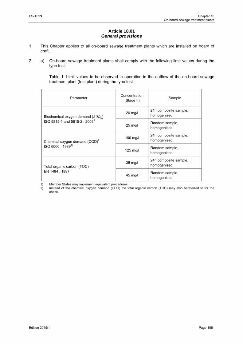
ES-TRIN Chapter 18 On-board sewage treatment plants
Edition 2015/1 Page 106
Article 18.01 General provisions
1. This Chapter applies to all on-board sewage treatment plants which are installed on board of
craft. 2. a) On-board sewage treatment plants shall comply with the following limit values during the
type test:
Table 1: Limit values to be observed in operation in the outflow of the on-board sewage treatment plant (test plant) during the type test
Parameter Concentration
(Stage II) Sample
Biochemical oxygen demand ( ) ISO 5815-1 and 5815-2 : 20031
20 mg/l 24h composite sample, homogenised
25 mg/l Random sample, homogenised
Chemical oxygen demand (COD)2 ISO 6060 : 19891)
100 mg/l 24h composite sample, homogenised
125 mg/l Random sample, homogenised
Total organic carbon (TOC) EN 1484 : 19971
35 mg/l 24h composite sample, homogenised
45 mg/l Random sample, homogenised
1) Member States may implement equivalent procedures. 2) Instead of the chemical oxygen demand (COD) the total organic carbon (TOC) may also bereferred to for the
check.
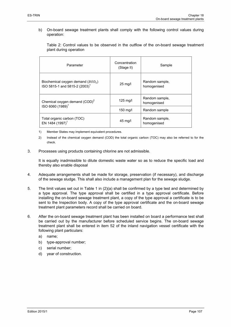
ES-TRIN Chapter 18 On-board sewage treatment plants
Edition 2015/1 Page 107
b) On-board sewage treatment plants shall comply with the following control values during operation:
Table 2: Control values to be observed in the outflow of the on-board sewage treatment plant during operation
Parameter Concentration
(Stage II) Sample
Biochemical oxygen demand ( ) ISO 5815-1 and 5815-2 (2003)1 25 mg/l
Random sample, homogenised
Chemical oxygen demand (COD)2
ISO 6060 (1989)1
125 mg/l Random sample, homogenised
150 mg/l Random sample
Total organic carbon (TOC) EN 1484 (1997)1 45 mg/l
Random sample, homogenised
1) Member States may implement equivalent procedures.
2) Instead of the chemical oxygen demand (COD) the total organic carbon (TOC) may also be referred to for the
check.
3. Processes using products containing chlorine are not admissible.
It is equally inadmissible to dilute domestic waste water so as to reduce the specific load and thereby also enable disposal
4. Adequate arrangements shall be made for storage, preservation (if necessary), and discharge
of the sewage sludge. This shall also include a management plan for the sewage sludge. 5. The limit values set out in Table 1 in (2)(a) shall be confirmed by a type test and determined by
a type approval. The type approval shall be certified in a type approval certificate. Before installing the on-board sewage treatment plant, a copy of the type approval a certificate is to be sent to the Inspection body. A copy of the type approval certificate and the on-board sewage treatment plant parameters record shall be carried on board.
6. After the on-board sewage treatment plant has been installed on board a performance test shall
be carried out by the manufacturer before scheduled service begins. The on-board sewage treatment plant shall be entered in item 52 of the inland navigation vessel certificate with the following plant particulars:
a) name;
b) type-approval number;
c) serial number;
d) year of construction.
ES-TRIN Chapter 18 On-board sewage treatment plants
Edition 2015/1 Page 108
7. Any significant modification to an on-board sewage treatment plant that has an effect on the sewage treatment shall always be followed by a special test in accordance with Article 18.09(3).
8. For the purpose of discharging tasks pursuant to this Chapter, the competent authority may
employ a technical service. 9. The on-board sewage treatment plant shall be regularly maintained in accordance with the
manufacturer's instructions in order to ensure that it is in perfect working order. A maintenance log corroborating such maintenance shall be carried on board.
Article 18.02 Application for type approval
1. An application for type approval for an on-board sewage treatment plant type shall be submitted
by the manufacturer to the competent authority. An information folder in accordance with Article 18.00(9.6) and the draft of an on-board sewage treatment plant parameters record in accordance with Article 18.00(9.9), as well as the draft of a manufacturer's guide to checking the components and parameters relevant to sewage treatment for that on-board sewage treatment plant type in accordance with Article 18.00(9.10) shall be enclosed with the application. For the type test the manufacturer shall demonstrate a prototype of the on-board sewage treatment plant.
2. If, in a particular application for type approval for an on-board sewage treatment plant type, the
competent authority finds that the application submitted with regard to the presented plant prototype is not representative of the characteristics of this type of on-board sewage treatment plant as described in Annex 7, Section II, Appendix 1 another, if necessary additional, prototype, to be designated by the competent authority, shall be supplied for approval in accordance with (1).
3. No application for type approval for an on-board sewage treatment plant type may be submitted
to more than one competent authority. A separate application shall be submitted for each on-board sewage treatment plant type to be approved.
Article 18.03 Type approval procedure
1. The competent authority to which the application is submitted shall issue the type approval for
the on-board sewage treatment plant type which corresponds to the descriptions in the information folder and satisfies the requirements of this Chapter. The fulfilling of these requirements will be examined in accordance with Annex 7, Section IX.
2. For each on-board sewage treatment plant type that it type-approves, the competent authority
shall complete all relevant parts of the type approval certificate, the model for which is to be found in Annex 7, Section III, and shall compile or verify the contents of the index to the information package. Type approval certificates shall be numbered in accordance with the method described in Annex 7, Section IV. The completed type approval certificate and its Annexes shall be delivered to the applicant.
ES-TRIN Chapter 18 On-board sewage treatment plants
Edition 2015/1 Page 109
3. If the on-board sewage treatment plant to be approved can only fulfil its function or only has specific properties in conjunction with other components of the craft in which it is to be installed and if for this reason compliance with one or more requirements can only be checked if the on-board sewage treatment plant to be approved is operated together with other real or simulated components of the craft, the scope of the type approval for this on-board sewage treatment plant shall be limited accordingly. In such cases, all restrictions on use and all installation requirements shall be detailed in the type approval certificate for that plant type.
Article 18.04 Amendment of type approvals
1. The competent authority which issued the type approval shall make the necessary
arrangements to ensure that it is informed of any change in the particulars appearing in the information package.
2. The application for amendment or extension of a type approval shall be made exclusively to the
competent authority which issued the original type approval. 3. Should characteristics of the on-board sewage treatment plant as described in the information
package have been modified, the competent authority shall:
a) issue revised pages of the information package as necessary, marking each revised page to show clearly the nature of the change and the date of re-issue. Whenever revised pages are issued, the index to the information package which is attached to the type approval certificate shall also be updated accordingly;
b) issue a revised type approval certificate (with an extension number) if any information on it (excluding its annexes) has changed or if the minimum requirements of this Chapter have changed since the original approval date. The revised type approval certificate shall clearly show the reason for its modification and the date of the re-issue
Should the competent authority which issued the type approval find that new trials or tests are justified owing to a modification made to the information package, it shall notify the manufacturer of this fact and issue the documents specified above only after new trials or tests have been successfully completed

ES-TRIN Chapter 18 On-board sewage treatment plants
Edition 2015/1 Page 110
Article 18.05 Conformity of the type-approval
1. The manufacturer shall affix to each on-board sewage treatment plant manufactured in
conformity with the type approval the markings as defined in Annex 7, Section I, including the type approval number.
2. Should the type approval contain limitations of usage in accordance with Article 18.03(3), the
manufacturer shall enclose detailed information on these limitations and all installation requirements with each unit manufactured.
3. If requested by the competent authority which issued the type approval, the manufacturer shall
provide a list of the serial numbers of all on-board sewage treatment plants which have been manufactured in accordance with the requirements set out in this Chapter since the last report, or since the point at which these provisions first came into force, within 45 days after the end of each calendar year, and immediately after each additional date specified by the competent authority. The list shall set out the correlations between the serial numbers, the corresponding on-board sewage treatment plant types and the type approval numbers. Furthermore, the list shall also include particular information for those cases where the manufacturer discontinues production of a type-approved on-board sewage treatment plant type. Should the competent authority not demand the regular provision of such a list from the manufacturer, the manufacturer shall retain the data recorded for a period of at least 40 years.
Article 18.06 Checking of serial numbers
1. The competent authority issuing a type approval shall ensure that the serial numbers of the on-
board sewage treatment plants manufactured in conformity with the requirements of this Chapter are registered and checked. It may collaborate with other authorities as defined in this Chapter and with the competent authorities of the Member States.
2. An additional check of the serial numbers may take place in conjunction with the check on
conformity of production with requirements laid down in Article 18.07. 3. In relation to the checking of the serial numbers, the manufacturer or their authorised
representatives located in the Member States shall, if requested, promptly supply the competent authority with all necessary information relating to their direct purchasers as well as the serial numbers of those on-board sewage treatment plants which have been reported as manufactured in accordance with Article 18.05(3).
4. Should a manufacturer be unable to comply with the requirements set out in Article 18.05 when
requested to do so by the competent authority, the approval for the on-board sewage treatment plant type concerned may be withdrawn. In such a case the notification procedure specified in Article 18.08(4) shall be used.
ES-TRIN Chapter 18 On-board sewage treatment plants
Edition 2015/1 Page 111
Article 18.07
Conformity of production 1. The competent authority issuing a type approval shall ascertain in advance that suitable
arrangements have been made to ensure effective checking of conformity of production in respect of the requirements of Annex 7, Section I. It may collaborate with other authorities as defined in this Chapter and with the competent authorities of the Member States.
2. The competent authority which has issued a type approval shall ascertain that the
arrangements specified in (1) in respect of the provisions of Annex 7, Section I continue to be sufficient and that every on-board sewage treatment plant provided with a type approval number in accordance with the requirements of this Chapter continues to correspond to the description in the type approval certificate and its annexes for the type-approved on-board sewage treatment plant type. It may collaborate with other authorities as defined in this Chapter and with the competent authorities of the Member States.
3. The competent authority may recognise comparable tests carried out by other competent
authorities as equivalent to the provisions of (1) and (2).
Article 18.08 Non-conformity with the type-approved on-board sewage treatment plant type
1. Non-conformity with the type-approved on-board sewage treatment plant type shall be deemed
to exist when there are deviations from the characteristics in the type approval certificate or, as the case may be, from the information package which have not been approved in accordance with Article 18.04(3) by the competent authority which issued the type approval.
2. Should the competent authority which has issued a type approval find that on-board sewage
treatment plants do not conform with the on-board sewage treatment plant type for which it issued the approval, it shall take the necessary measures to ensure that on-board sewage treatment plants in production again conform with the type-approved on-board sewage treatment plant type. The competent authority which found the non-conformity shall inform the other competent authorities of the measures taken, which may extend to withdrawal of the type approval.
3. If a competent authority is able to demonstrate that on-board sewage treatment plants provided
with a type approval number do not conform with the type-approved on-board sewage treatment plant type, it may require the competent authority which issued the type approval to have the on-board sewage treatment plant type that is in production checked for conformity with the type-approved on-board sewage treatment plant type. Such action shall be taken within six months of the date of the request.

ES-TRIN Chapter 18 On-board sewage treatment plants
Edition 2015/1 Page 112
Article 18.09 Random sample measurement / Special test
1. No later than three months after the commissioning of the craft or, in the case of retrofitting of
the on-board sewage treatment plant, after it has been installed and the appropriate performance test has been carried out, the competent authority shall take a random sample during operation of the craft in order to check the values set out in Article 18.01(2), Table 2. At irregular intervals the competent authority shall carry out functionality checks on the on-board sewage treatment plant by means of random sample measurements to check the values set out in Article 18.01(2), Table 2. Should the competent authority find that the values of the random sample measurements do not conform with the values set out in Article 18.01(1), Table 2, it may demand:
a) that the defects in the on-board sewage treatment plant be remedied so as to ensure that it runs properly;
b) that the on-board sewage treatment plant be made to conform with the type approval again; or
c) that a special test be carried out in accordance with (3).
Once the non-conformities have been remedied and the on-board sewage treatment plant has been made to conform with the type approval again, the competent authority may carry out new random sample measurements. If the defects are not remedied or the conformity of the on-board sewage treatment plant with the specifications of the type approval is not restored, the competent authority shall seal the on-board sewage treatment plant and inform the inspection body to make an entry to that effect in item 52 of the inland navigation vessel certificate.
2. The random samples shall be measured in accordance with the specifications of Article
Article 18.01(2), Table 2. 3. Should the competent authority find any discrepancies in the on-board sewage treatment plant
indicating a deviation from the type approval, the competent authority shall carry out a special test to determine the present state of the on-board sewage treatment plant in relation to the components specified in the on-board sewage treatment plant parameters record, the calibration and the setting of the parameters of the on-board sewage treatment plant.
Should the competent authority come to the conclusion that the on-board sewage treatment plant is not in conformity with the type-approved on-board sewage treatment plant type, it may take the following actions:
a) demand that
aa) the conformity of the on-board sewage treatment plant be restored; or
bb) the type approval in accordance with Article 18.04 be amended accordingly; or
b) order measurement in accordance with the test procedure as set out in Annex 7, Section IX.
If conformity is not restored or the type approval is not amended accordingly, or if it becomes apparent from the measurements made in accordance with (b) that the limit values laid down in Article 18.01(2)(a), Table 1 are not complied with, the competent authority shall seal the on-board sewage treatment plant and inform the inspection body to make an entry to that effect in item 52 of the inland navigation vessel certificate.

ES-TRIN Chapter 18 On-board sewage treatment plants
Edition 2015/1 Page 113
4. The tests in accordance with (3) shall be carried out on the basis of the manufacturer's guide to checking the components and parameters of the on-board sewage treatment plant relevant to sewage treatment. This guide, which shall be compiled by the manufacturer and approved by a competent authority, shall specify the treatment-relevant components as well as settings, dimensioning criteria and parameters to be applied in order to ensure that the values set out in Article 18.01(2), Tables 1 and 2 are continuously maintained. It shall include at least the following information:
a) a specification of the on-board sewage treatment plant type with a process description and an indication of whether waste-water storage tanks are to be installed upstream of the on-board sewage treatment plant;
b) a list of the components specific to sewage treatment;
c) the design and dimensioning criteria, dimensioning specifications and regulations applied.
d) a schematic representation of the on-board sewage treatment plant with identifying features of the approved treatment-relevant components (e.g. part numbers on the components).
5. An on-board sewage treatment plant that has been sealed in accordance with (3) 3rd sentence
may be brought back into service only after a special test in accordance with (3), first subparagraph.
Article 18.10 Competent authorities and technical services
The technical services responsible for carrying out the functions outlined in this Chapter shall satisfy the European Standard on general requirements for the competence of testing and calibration laboratories (EN ISO/IEC 17025 : 2005), taking the following conditions into account:
a) manufacturers of on-board sewage treatment plants cannot be recognised as technical services;
b) for the purposes of this Chapter a technical service may, with the agreement of the competent authority, make use of facilities external to its own laboratory.

ES-TRIN Chapter 18 On-board sewage treatment plants
Edition 2015/1 Page 114
ES-TRIN Chapter 19 Special provisions applicable to passenger vessels
Edition 2015/1 Page 115
PART III SPECIAL PROVISIONS
CHAPTER 19
SPECIAL PROVISIONS APPLICABLE TO PASSENGER VESSELS
Article 19.01 General provisions
1. The following provisions shall not apply:
a) Article 3.02(1)(b);
b) Articles 4.01 to 4.03;
c) Article 8.08(2), second sentence, and (7);
d) Article 10.14(3), second sentence, for rated voltages of over 50V. 2. The following items of equipment are prohibited on passenger vessels:
a) lamps powered by liquefied gas or liquid fuel according to Article 15.07(3) 2nd sentence;
b) devices fitted with wick burners according to Article 16.02(2) and (3),
c) vaporising oil-burner stoves according to Article 16.04;
d) solid fuel heating appliances and boilers according to 16.07;
e) liquefied gas devices according to Chapter 17. 3. Vessels without their own power cannot be licensed for passenger transport. 4. On passenger vessels, areas shall be provided for use by persons with reduced mobility,
according to the provisions of this Chapter. 5. By way of derogation from Article 7.02(2) first sentence, the area of obstructed vision for the
helmsman ahead of the vessel in an unladen state with half of its supplies but without ballast shall not exceed two vessel lengths or 250 m, whichever is less.
6. By way of derogation from article 7.02(3) third subparagraph, a passenger vessel shall be
equipped with appropriate auxiliary means when no sufficiently unobstructed view is provided towards the rear. If these auxiliary means do not allow unobstructed view at night, a corresponding restriction shall be entered in item 52 of the inland navigation vessel certificate.
Article 19.02 Hull
1 In the course of the periodical inspections, the thickness of the outside plating of steel
passenger vessels shall be determined as follows:
a) the minimum thickness of the bottom, bilge and side plating of the outer hull of passenger vessels is determined in accordance with the larger value of the following formulae:
0,006 ∙ ∙ √ ;
∙ 0,55 ∙ .

ES-TRIN Chapter 19 Special provisions applicable to passenger vessels
Edition 2015/1 Page 116
In these formulae:
1 0,0013 ∙ 500 ;
= longitudinal or transverse frame spacing (mm), and where the frame spacing is less than 400 mm, 400 should be entered;
b) it is permissible to fall short of the minimum value determined in accordance with (a) above for the plate thickness in cases where the permitted value has been determined and certified on the basis of a mathematical proof for the sufficient strength (longitudinal, transverse and local) of the vessel's hull;
c) at no point of the outside plating shall the thickness calculated in accordance with (a) or (b) above be less than 3 mm;
d) plate renewals shall be carried out when bottom, bilge or side plate thicknesses have fallen short of the minimum value determined in accordance with (a) or (b), in conjunction with (c) above.
2. The number and position of bulkheads shall be selected such that, in the event of flooding, the
vessel remains buoyant according to Article 19.03(7) to (13). Every portion of the internal structure which affects the efficiency of the subdivision of such vessels shall be watertight, and shall be of a design which will maintain the integrity of the subdivision.
3. For determining the positioning of the collision bulkhead and aft-peak bulkhead, the provisions
of Article 3.03(1) shall apply, but the reference value to be used shall be the length of waterline rather than the length.
4. A transverse bulkhead may be fitted with a bulkhead recess, if all parts of this recess lie within
the safe area. 5. The bulkheads, which are taken into account in the damage stability calculation according to
Article 19.03(7) to (13), shall be watertight and be installed up to the bulkhead deck. Where there is no bulkhead deck, these bulkheads shall extend to a height at least 0,20 m above the margin line.
6. The number of openings in these bulkheads shall be kept as low as is consistent with the type
of construction and normal operation of the vessel. Openings and penetrations shall not have a detrimental effect on the watertight function of the bulkheads.
7. Collision bulkheads shall have no openings and no doors. 8. Bulkheads separating the engine rooms from passenger rooms or crew and shipboard
personnel accommodation shall have no doors. 9. Manually operated doors without remote control in bulkheads referred to in (5), are permitted
only in areas not accessible to passengers. They shall:
a) remain closed at all times and be opened only temporarily to allow access;
b) be fitted with suitable devices to enable them to be closed quickly and safely;
c) display the following notice on both sides of the doors:
‘Close door immediately after passing through’. 10. Doors in bulkheads referred to in (5) that are open for long periods shall comply with the
following requirements:
a) they shall be capable of being closed from both sides of the bulkhead and from an easily accessible point above the bulkhead deck;

ES-TRIN Chapter 19 Special provisions applicable to passenger vessels
Edition 2015/1 Page 117
b) after being closed by remote control the door shall be such that it can be opened again locally and closed safely. Closure shall not be impeded by carpeting, foot rails or other obstructions;
c) the time taken for the remote-controlled closure process shall be at least 30 seconds but not more than 60 seconds;
d) during the closure procedure an automatic acoustic alarm shall sound by the door;
e) the door drive and alarm shall also be capable of operating independently of the on-board power supply. There shall be a device at the location of the remote control that displays whether the door is open or closed.
11. Doors in bulkheads referred to in (5), and their actuators shall be located in the safe area. 12. There shall be a warning system in the wheelhouse to indicate which of the doors in bulkheads
referred to in (5) are open. 13. Open-ended piping and ventilation ducts shall be offset in such a way that, in any conceivable
flooding, no additional spaces or tanks are flooded through them.
a) If several compartments are openly connected by piping or ventilation ducts, such piping and ducts shall, in an appropriate place, be lead above the waterline corresponding to the worst possible flooding.
b) Piping need not meet the requirement under (a) if shut-off devices are fitted in the piping where it passes through the bulkheads and which can be remotely controlled from a point above the bulkhead deck.
c) Where a pipework system has no open outlet in a compartment, the pipework shall be regarded as intact in the event of this compartment being damaged, if it runs within the safe area and is more than 0,50 m from the bottom of the vessel.
14. Remote controls of bulkhead doors according to (10) and shut-off devices according to (13)(b)
above the bulkhead deck shall be clearly indicated as such. 15. Where double bottoms are fitted, their height shall be at least 0,60 m, and where wing voids are
fitted, their width shall be at least 0,60 m. 16. Windows may be situated below the margin line if they are watertight, cannot be opened,
possess sufficient strength and conform to Article 19.06(14).
Article 19.03 Stability
1. The applicant shall prove by a calculation based on the results from the application of a
standard for intact stability that the intact stability of the vessel is appropriate. All calculations shall be carried out free to trim and sinkage. The lightship data taken into account for the stability calculation shall be determined by means of a heeling test.
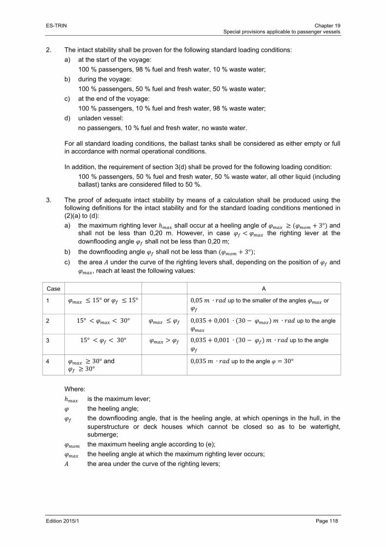
ES-TRIN Chapter 19 Special provisions applicable to passenger vessels
Edition 2015/1 Page 118
2. The intact stability shall be proven for the following standard loading conditions:
a) at the start of the voyage:
100 % passengers, 98 % fuel and fresh water, 10 % waste water;
b) during the voyage:
100 % passengers, 50 % fuel and fresh water, 50 % waste water;
c) at the end of the voyage:
100 % passengers, 10 % fuel and fresh water, 98 % waste water;
d) unladen vessel:
no passengers, 10 % fuel and fresh water, no waste water. For all standard loading conditions, the ballast tanks shall be considered as either empty or full in accordance with normal operational conditions. In addition, the requirement of section 3(d) shall be proved for the following loading condition:
100 % passengers, 50 % fuel and fresh water, 50 % waste water, all other liquid (including ballast) tanks are considered filled to 50 %.
3. The proof of adequate intact stability by means of a calculation shall be produced using the
following definitions for the intact stability and for the standard loading conditions mentioned in (2)(a) to (d):
a) the maximum righting lever shall occur at a heeling angle of 3° and shall not be less than 0,20 m. However, in case the righting lever at the downflooding angle shall not be less than 0,20 m;
b) the downflooding angle shall not be less than 3° ;
c) the area under the curve of the righting levers shall, depending on the position of and , reach at least the following values:
Case A
1 15° or 15° 0,05 ∙ up to the smaller of the angles or
2 15° 30° 0,035 0,001 ∙ 30 ∙ up to the angle
3 15° 30° 0,035 0,001 ∙ 30 ∙ up to the angle
4 30° and 30°
0,035 ∙ up to the angle 30°
Where:
is the maximum lever;
the heeling angle;
the downflooding angle, that is the heeling angle, at which openings in the hull, in the superstructure or deck houses which cannot be closed so as to be watertight, submerge;
the maximum heeling angle according to (e);
the heeling angle at which the maximum righting lever occurs;
the area under the curve of the righting levers;

ES-TRIN Chapter 19 Special provisions applicable to passenger vessels
Edition 2015/1 Page 119
d) the initial metacentric height, , corrected by the effect of the free surfaces in liquid tanks, shall not be less than 0,15 m;
e) in each of the following two cases the heeling angle shall not exceed 12°:
aa) in application of the heeling moment due to persons and wind according to sections 4 and 5;
bb) in application of the heeling moment due to persons and turning according to sections 4 and 6;
f) for a heeling moment resulting from moments due to persons, wind and turning according to (4), (5) and (6), the residual freeboard shall be not less than 0,20 m;
g) for vessels with windows or other openings in the hull located below the bulkhead decks and not closed watertight, the residual safety clearance shall be at least 0,10 m on the application of the three heeling moments resulting from subparagraph (f).
4. The heeling moment due to one-sided accumulation of persons shall be calculated
according to the following formula:
∙ ∙ ∙ ∙
= total mass of persons on board in [t], calculated by adding up the maximum permitted number of passengers and the maximum number of shipboard personnel and crew under normal operating conditions, assuming an average mass per person of 0,075 t;
= lateral distance of centre of gravity of total mass of persons from centre line in [m];
= acceleration of gravity 9,81 / ;
= mass of persons accumulated on area ;
∙ 0,075 ∙ where
= area occupied by persons in [m2];
= number of persons per square meter:
= 3,75 for free deck areas and deck areas with movable furniture; for deck areas with fixed seating furniture such as benches, shall be calculated by assuming an area of 0,50 m in width and 0,75 m in seat depth per person;
= lateral distance of geometrical centre of area from centre line in [m].
The calculation shall be carried out for an accumulation of persons both to starboard and to port. The distribution of persons shall correspond to the most unfavourable one from the point of view of stability. Cabins shall be assumed unoccupied for the calculation of the persons' moment. For the calculation of the loading cases, the centre of gravity of a person shall be taken as 1 m above the lowest point of the deck at 0,5 , ignoring any deck curvature and assuming a mass of 0,075 t per person.
ES-TRIN Chapter 19 Special provisions applicable to passenger vessels
Edition 2015/1 Page 120
A detailed calculation of deck areas which are occupied by persons may be dispensed with if the following values are used:
1,1 ∙ ∙ 0,075 for day trip vessels
1,5 ∙ ∙ 0,075 for cabin vessels
where
= maximum permitted number of passengers on board
/2 in [m]. 5. The heeling moment due to wind pressure shall be calculated as follows:
∙ ∙2
where:
= the specific wind pressure of 0,25 kN/m²;
= lateral plane of the vessel above the plane of draught according to theconsidered loading condition in [m²];
= distance of the centre of gravity of the lateral plane from the plane of draught according to the considered loading condition in [m].
In calculating the lateral plane, account shall be taken of the intended enclosure of the deck by awnings and similar mobile installations.
6. The moment due to centrifugal force , caused by the turning of the vessel, shall be
calculated as follows:
∙ ∙ ∙ ∙2
where
= a coefficient of 0,45;
= block coefficient (if not known, taken as 1,0);
= maximum speed of the vessel in [m/s];
= distance between the centre of gravity and the keel line in [m].
For passenger vessels with propulsion systems according to Article 6.06, shall be derived from full-scale or model tests or else from corresponding calculations.
7. The applicant shall prove by a calculation that the damage stability of the vessel is appropriate.
The calculation of the final state of flooding should be based on the method of “lost buoyancy” and the interim states of flooding should be calculated on the basis of the method of “added mass”. All calculations shall be carried out free to trim and sinkage.
8. Buoyancy of the vessel in the event of flooding shall be proven for the standard loading
conditions specified in (2). Accordingly, mathematical proof of sufficient stability shall be determined for the three intermediate stages of flooding (25, 50 and 75 % of flood build-up) and for the final stage of flooding.
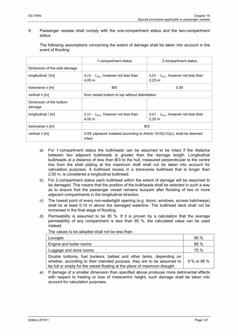
ES-TRIN Chapter 19 Special provisions applicable to passenger vessels
Edition 2015/1 Page 121
9. Passenger vessels shall comply with the one-compartment status and the two-compartment status.
The following assumptions concerning the extent of damage shall be taken into account in the event of flooding:
1-compartment status 2-compartment status
Dimension of the side damage
longitudinal [m] 0,10 ∙ , however not less than 4,00 m
0,05 ∙ , however not less than 2,25 m
transverse [m] B/5 0,59
vertical [m] from vessel bottom to top without delimitation
Dimension of the bottom damage
longitudinal [m] 0,10 ∙ , however not less than 4,00 m
0,05 ∙ , however not less than 2,25 m
transverse [m] B/5
vertical [m] 0,59; pipework installed according to Article 19.02(13)(c), shall be deemed intact
a) For 1-compartment status the bulkheads can be assumed to be intact if the distance between two adjacent bulkheads is greater than the damage length. Longitudinal bulkheads at a distance of less than B/3 to the hull, measured perpendicular to the centre line from the shell plating at the maximum draft shall not be taken into account for calculation purposes. A bulkhead recess in a transverse bulkhead that is longer than 2,50 m, is considered a longitudinal bulkhead.
b) For 2-compartment status each bulkhead within the extent of damage will be assumed to be damaged. This means that the position of the bulkheads shall be selected in such a way as to ensure that the passenger vessel remains buoyant after flooding of two or more adjacent compartments in the longitudinal direction.
c) The lowest point of every non-watertight opening (e.g. doors, windows, access hatchways) shall lie at least 0,10 m above the damaged waterline. The bulkhead deck shall not be immersed in the final stage of flooding.
d) Permeability is assumed to be 95 %. If it is proven by a calculation that the average permeability of any compartment is less than 95 %, the calculated value can be used instead.
The values to be adopted shall not be less than:
Lounges 95 %
Engine and boiler rooms 85 %
Luggage and store rooms 75 %
Double bottoms, fuel bunkers, ballast and other tanks, depending on whether, according to their intended purpose, they are to be assumed to be full or empty for the vessel floating at the plane of maximum draught
0 % or 95 %
e) If damage of a smaller dimension than specified above produces more detrimental effects with respect to heeling or loss of metacentric height, such damage shall be taken into account for calculation purposes.

ES-TRIN
Edition 201
10. Fo
a)
b)
c)
d)
11. Du
he
a)
b)
15/1
or all interme
) The heelinot excee
) Beyond tpositive p0,02 beis reache
Non-wateof the inte
) The calcubased on
uring the fineeling mome
) The heeli
) Beyond trighting levalues foany case
Where:
is tacc
is timm
is tmo
is t
ediate stages
ing angle ed 15°.
the heel in part of the efore the firstd.
ertight openinermediate sta
ulation of th the gross su
nal stage of ent in accorda
ng angle
he equilibriuever value o
or stability shbefore reach
the heeling acordance wit
the angle of merses or 25
the remaininoment in acco
the heeling le
s of flooding
at the equili
the equilibririghting lev
t unprotected
ngs shall notage in quest
e free surfaurface area o
flooding, theance with (4)
shall not exc
m position thof 0,0hall be met uhing a heelin
angle in the th section 4;
vanishing st5°; whicheve
ng righting leordance with
ever resulting
referred to in
brium positio
ium positionver curve shd opening be
t be immersion has been
ace effect in of the damag
e following c):
ceed 10°.
he positive p02 with anuntil the immng angle of 2
final stage o
tability or theer is less is to
ever in the fih section 4;
g from the m
Special p
n (8), the follo
on of the inte
n of the intehall display ecomes imm
ed before thn reached.
all intermedged compartm
criteria shall
part of the rin area mersion of th5°.
of flooding ta
e angle at who be used;
inal stage of
moment in acc
provisions applic
owing criteria
ermediate st
ermediate staa righting lersed or a h
he heel in the
diate stagesments.
be met tak
ghting lever 0,0025 ∙
he first unpro
aking into ac
hich the first
f flooding tak
cordance wit
cable to passen
a shall be me
tage in ques
age in quesever value
heeling angle
e equilibrium
s of flooding
king into acc
curve shall . These
otected open
ccount the m
unprotected
king into acc
th section 4.
Chapter 19 ger vessels
Page 122
et:
stion shall
stion, the of
e of 25°
m position
shall be
count the
display a minimum
ning or in
moment in
d opening
count the
ES-TRIN Chapter 19 Special provisions applicable to passenger vessels
Edition 2015/1 Page 123
c) Non-watertight openings shall not be immersed before the equilibrium position has been reached. If such openings are immersed before this point, the rooms affording access are deemed to be flooded for damage stability calculation purposes.
12. The shut-off devices which shall be able to be closed watertight shall be marked accordingly. 13. If cross-flood openings to reduce asymmetrical flooding are provided, they shall meet the
following conditions:
a) for the calculation of cross-flooding, IMO Resolution A.266 (VIII)1 shall be applied;
b) they shall be self-activating;
c) they shall not be equipped with shut-off devices;
d) the total time allowed for compensation shall not exceed 15 minutes.
Article 19.04 Safety clearance and freeboard
1. The safety clearance shall be at least equal to the sum of:
a) the additional lateral immersion, which, measured on the outside plating, is resulting from the permissible heeling angle according to Article 19.03(3)(e); and
b) the residual safety clearance according to Article 19.03(3)(g).
For vessels without a bulkhead deck, the safety clearance shall be at least 0,50 m. 2. The freeboard shall be at least equal to the sum of:
a) the additional lateral immersion, which, measured on the outside plating, is resulting from the heeling angle according to Article 19.03(3)(e); and
b) the residual freeboard according to Article 19.03(3)(f). However, the freeboard shall be at least 0,30 m.
3. The plane of maximum draught is to be set so as to ensure compliance with the safety
clearance according to (1), and the freeboard according to (2) and Articles 19.02 and 19.03. 4. For safety reasons, the inspection body may stipulate a greater safety clearance or a greater
freeboard.
Article 19.05 Maximum permitted number of passengers
1. The inspection body shall set the maximum permitted number of passengers and shall enter
this number on the inland navigation vessel certificate. 2. The maximum permitted number of passengers shall not exceed any of the following values:
a) number of passengers for whom the existence of an evacuation area according to Article 19.06(8), has been proven;
1 IMO Resolution A.266 (VIII) adopted on 20 November 1973 - Recommendation on a Standard Method for Establishing
Compliance with the Requirements for Cross-Flooding Arrangements in Passenger Ships.
ES-TRIN Chapter 19 Special provisions applicable to passenger vessels
Edition 2015/1 Page 124
b) number of passengers that has been taken into account for the stability calculation according to Article 19.03;
c) number of available berths for passengers on cabin vessels used for voyages including overnight stays.
3. For cabin vessels which are also used as day trip vessels, the number of passengers shall be
calculated for use both as a day trip vessel and as a cabin vessel and entered on the inland navigation vessel certificate.
4. The maximum permitted number of passengers shall be displayed on clearly legible and
prominently positioned notices on board the vessel.
Article 19.06 Passenger rooms and areas
1. Passenger rooms shall:
a) on all decks, be located aft of the level of the collision bulkhead and, if they are below the bulkhead deck, forward of the level of the aft-peak bulkhead; and
b) be separated from the engine and boiler rooms in a gas-tight manner.
Deck areas which are enclosed by awnings or similar mobile installations not only above but also fully or partially to the side must satisfy the same requirements as enclosed passenger rooms.
2. Cupboards and rooms referred to in Article 14.13 and intended for the storage of flammable
liquids shall be outside the passenger area. 3. The number and width of the exits of passenger rooms shall comply with the following
requirements:
a) Rooms or groups of rooms designed or arranged for 30 or more passengers or including berths for 12 or more passengers shall have at least two exits. On day trip vessels one of these two exits can be replaced by two emergency exits; rooms, with the exception of cabins, and groups of rooms that have only one exit, shall have at least one emergency exit.
b) If rooms are located below the bulkhead deck, one of the exits can be a watertight bulkhead door, according to Article 19.02(10), leading into an adjacent compartment from which the upper deck can be reached directly. The other exit shall lead directly or, if permitted in accordance with (a), as an emergency exit into the open air, or to the bulkhead deck. This requirement does not apply to individual cabins.
c) Exits according to (a) and (b) shall be suitably arranged and shall have a clear width of at least 0,80 m and also a clear height of at least 2,00 m. For doors of passenger cabins and other small rooms, the clear width can be reduced to 0,70 m.
d) In the case of rooms or groups of rooms intended for more than 80 passengers the sum of the widths of all exits intended for passengers and which shall be used by them in an emergency shall be at least 0,01 m per passenger.
e) If the total width of the exits is determined by the number of passengers, the width of each exit shall be at least 0,005 m per passenger.

ES-TRIN Chapter 19 Special provisions applicable to passenger vessels
Edition 2015/1 Page 125
f) Emergency exits shall have a shortest side at least 0,60 m long or a minimum diameter of 0,70 m. They shall open in the direction of escape and be marked on both sides.
g) Exits of rooms intended for use by persons with reduced mobility shall have a clear width of at least 0,90 m. Exits normally used for embarking and disembarking people with reduced mobility shall have a clear width of at least 1,50 m.
4. Doors of passenger rooms shall comply with the following requirements:
a) With the exception of doors leading to connecting corridors, they shall be capable of opening outwards or be constructed as sliding doors.
b) Cabin doors shall be made in such a way that they can also be unlocked from the outside at any time.
c) Powered doors shall open easily in the event of failure of the power supply to this mechanism.
d) For doors intended for use by persons with reduced mobility, there shall be from the direction from which the door opens, a minimum clearance of 0,60 m between the inner edge of the doorframe on the lock side and an adjacent perpendicular wall.
5. Connecting corridors shall comply with the following requirements:
a) They shall have a clear width of at least 0,80 m. If they lead to rooms used by more than 80 passengers, they shall comply with the provisions mentioned in (3)(d) and (e) regarding the width of the exits leading to connecting corridors.
b) Their clear height shall be not less than 2,00 m.
c) Connecting corridors intended for use by persons with reduced mobility shall have a clear width of 1,30 m. Connecting corridors more than 1,50 m wide shall have handrails on either side.
d) Where a part of the vessel or a room intended for passengers is served by a single connecting corridor, the clear width thereof shall be at least 1,00 m.
e) Connecting corridors shall be free of steps.
f) They shall lead only to open decks, rooms or staircases.
g) Dead ends in connecting corridors shall be not longer than two meters. 6. In addition to the provisions of (5), escape routes shall also comply with the following
requirements:
a) Stairways, exits and emergency exits shall be so disposed that, in the event of a fire in any given area, the other areas may be evacuated safely.
b) The escape routes shall lead by the shortest route to evacuation areas according to (8).
c) Escape routes shall not lead through engine rooms or galleys.
d) There shall be no rungs, ladders or the like installed at any point along the escape routes.
e) Doors to escape routes shall be constructed in such a way as not to reduce the minimum width of the escape route referred to in (5)(a) or (d).
f) Escape routes and emergency exits shall be clearly signed. The signs shall be lit by the emergency lighting system.
7. Escape routes and emergency exits shall have a suitable safety guidance system.

ES-TRIN Chapter 19 Special provisions applicable to passenger vessels
Edition 2015/1 Page 126
8. For all persons on board, there shall be muster areas available which satisfy the following requirements:
a) The total area of the muster areas shall correspond to at least the following value:
Day trip vessels: 0,35 ∙
Cabin vessels: 0,45 ∙
where
= maximum permitted number of passengers on board.
b) Each individual muster or evacuation area shall be larger than 10 m2.
c) The muster areas shall be clear of furniture, whether movable or fixed.
d) If movable furniture is located in a room in which muster areas are defined, it shall be secured appropriately to avoid slipping.
e) If fixed seats or benches are located in a room in which muster areas are defined the corresponding number of persons need not be taken into account when calculating the total area of muster areas according to (a). However, the number of persons for whom fixed seats or benches in a certain room are taken into account must not exceed the number of persons for whom muster areas are available in this room.
f) Life-saving appliances shall be easily accessible from the evacuation areas.
g) It shall be possible to evacuate people safely from these evacuation areas, using either side of the vessel.
h) The muster areas shall lie above the margin line.
i) The muster and evacuation areas are to be shown as such in the safety plan and signposted on board the vessel.
j) The provisions of (d) and (e) shall also apply to free decks on which muster areas are defined.
k) If collective life-saving appliances complying with Article 19.09(5), are available on board, the number of persons for whom such appliances are available may be disregarded when calculating the total surface area of the muster areas referred to in (a).
l) However, in all cases where reductions according to (e), (j) and (k) are applied, the total area according to (a) shall be sufficient for at least 50 % of the maximum permitted number of passengers.
9. Stairs and their landings in the passenger areas shall comply with the following requirements:
a) They shall be constructed in accordance with European Standard EN 13056 : 2000.
b) They shall have a clear width of at least 0,80 m or, if they lead to connecting corridors or areas used by more than 80 passengers, at least 0,01 m per passenger.
c) They shall have a clear width of at least 1,00 m if they provide the only means of access to a room intended for passengers.
d) Where there is not at least one staircase on each side of the vessel in the same room, they shall lie in the safe area.
e) In addition, stairs intended for use by persons with reduced mobility shall comply with the following requirements:
aa) the gradient of the stairs shall not exceed 38°;
bb) the stairs shall have a clear width of at least 0,90 m;

ES-TRIN Chapter 19 Special provisions applicable to passenger vessels
Edition 2015/1 Page 127
cc) spiral staircases are not allowed;
dd) the stairs shall not run in a direction transverse to the vessel;
ee) the handrails of the stairs shall extend approximately 0,30 m beyond the top and bottom of the stairs without restricting traffic routes;
ff) handrails, front sides of at least the first and the last step as well as the floor coverings at the ends of the stairs shall be colour highlighted.
Lifts intended for persons with reduced mobility, and lifting equipment, like stairlifts or lifting platforms, shall be constructed according to a relevant standard or a regulation of a Member State.
10. Parts of the deck intended for passengers, and which are not enclosed, shall comply with the
following requirements:
a) They shall be surrounded by a fixed bulwark or guard rail at least 1,00 m high or a railing according to the European Standard EN 711 : 1995, construction type PF, PG or PZ. Bulwarks and railings of decks intended for use by persons with reduced mobility shall be at least 1,10 m high.
b) Openings and equipment for embarking or disembarking and also openings for loading or unloading shall be such that they can be secured and have a clear width of at least 1,00 m. Openings, used normally for the embarking or disembarking of persons with reduced mobility, shall have a clear width of at least 1,50 m.
c) If the openings and equipment for embarking or disembarking cannot be observed from the wheelhouse, appropriate auxiliary means shall be provided.
11. The parts of the vessel not intended for passengers, in particular access to the wheelhouse, to
the winches and to the engine rooms, shall be such that they can be secured against unauthorised entry. At any such access, a symbol corresponding to Figure 1 in Annex 4 shall be displayed in a prominent position.
12. Gangways shall be constructed in accordance with European Standard EN 14206 : 2003. By
way of derogation from Article 13.02(3)(d), their length can be less than 4 m. 13. Passageways intended for use by persons with reduced mobility shall have a clear width of
1,30 m and be free of doorsteps and sills more than 0,025 m high. Walls in passageways intended for use by persons with reduced mobility shall be equipped with handrails at a height of 0,90 m above the floor.
14. Glass doors and walls in passageways and also window panes shall be manufactured from pre-
stressed glass or laminated glass. They may also be made from a synthetic material, provided this is authorised for use in a fire-protection context.
Transparent doors and transparent walls extending as far as the floor in passageways shall be prominently marked.
ES-TRIN Chapter 19 Special provisions applicable to passenger vessels
Edition 2015/1 Page 128
15. Superstructures (or their roofs) consisting entirely of panoramic panes, shelters created by awnings, or similar mobile installations, together with their substructures, may only be constructed in such a manner that the way in which they are built and the materials employed pose no risk of injury to persons on board in the event of damage.
16. Potable water systems shall, at least, comply with the requirements of Article 15.05. 17. There shall be toilets available for passengers. At least one toilet shall be fitted for use by
persons with reduced mobility according to a relevant standard or a regulation of a Member State and shall be accessible from areas intended for use by persons with reduced mobility.
18. Cabins without an opening window shall be connected to a ventilation system. 19. Mutatis mutandis, rooms in which crew members or shipboard personnel are accommodated
shall comply with the provisions of this Article.
Article 19.07 Propulsion system
1. In addition to the main propulsion system, vessels shall be equipped with a second independent
propulsion system so as to ensure that, in the event of a breakdown affecting the main propulsion system, the vessel can continue to make steerageway under its own power.
2. The second independent propulsion system shall be placed in a separate engine room. If both
engine rooms have common partitions, these shall be built according to Article 19.11(2).
Article 19.08 Safety devices and equipment
1. All passenger vessels shall have internal communication facilities according to Article 7.08.
Such facilities shall also be available in the operation rooms and, where there is no direct communication from the steering position, in the access and muster areas for passengers as referred to in Article 19.06(8).
2. All passenger areas shall be reachable via a loudspeaker system. The system shall be
designed in such a way as to ensure that the information transmitted can be clearly distinguished from background noise. Loudspeakers are optional where direct communication between the wheelhouse and the passenger area is possible.
3. The vessel shall be equipped with an alarm system. The system shall include:
a) an alarm system enabling passengers, crew members and shipboard personnel to alert the vessel's command and crew.
This alarm should be given only in areas assigned to the vessel's command and to the crew; it should only be possible for the vessel's command to stop the alarm. The alarm shall be capable of being triggered from at least the following places:
aa) in each cabin;
ES-TRIN Chapter 19 Special provisions applicable to passenger vessels
Edition 2015/1 Page 129
bb) in the corridors, lifts and stairwells, with the distance to the nearest trigger not exceeding 10 m and with at least one trigger per watertight compartment;
cc) in lounges, dining rooms and similar recreation rooms;
dd) in toilets, intended for use by persons with reduced mobility;
ee) in engine rooms, galleys and similar rooms where there is a fire risk;
ff) in the cold-storage rooms and other store rooms.
The alarm triggers shall be installed at a height above the floor of 0,85 m to 1,10 m;
b) an alarm system enabling the vessel's command to alert passengers.
This alarm shall be clearly and unmistakably audible in all rooms accessible to passengers. It shall be capable of being triggered from the wheelhouse and from a location that is permanently staffed;
c) an alarm system enabling the vessel's command to alert the crew and shipboard personnel, referred to in Article 7.09(1).
The alarm system shall also reach the recreation rooms for the shipboard personnel, the cold-storage rooms and other store rooms.
Alarm triggers shall be protected against unintentional use.
4. Each watertight compartment shall be fitted with a bilge level alarm. 5. Two motor-driven bilge pumps shall be provided. 6. A bilge pumping system with permanently installed pipe work shall be available. 7. Cold-storage room doors, even when locked, shall also be capable of being opened from the
inside. 8. Where CO2 bar-systems are situated in rooms below deck these rooms shall be fitted with an
automatic ventilation system which turns itself on automatically when the door or hatch to the room is opened. The ventilation ducts shall run down to 0,05 m from the floor of this room.
9. In addition to the first-aid kit according to Article 13.02(2)(f), further first-aid kits shall be
provided in sufficient number. The first-aid kits and their storage shall comply with the requirements set out in Article 13.02(2)(f).
Article 19.09 Life-saving equipment
1. In addition to the lifebuoys specified in Article 13.08(1), all parts of the deck intended for
passengers and not enclosed shall be equipped with suitable lifebuoys, which shall be positioned on both sides of the vessel not more than 20 m apart. Lifebuoys shall be considered as suitable if they comply with
- the European Standard EN 14144 : 2003; or
- the International Convention for the Safety of Life at Sea (SOLAS 1974) Chapter III Regulation 7.1 and the International Life-Saving Appliance (LSA) Code, (2.1).

ES-TRIN Chapter 19 Special provisions applicable to passenger vessels
Edition 2015/1 Page 130
Half of all the prescribed lifebuoys shall be fitted with a buoyant cord at least 30 m long with a diameter of 8 to 11 mm. The other half of the prescribed lifebuoys shall be fitted with a self-igniting, battery-powered light which will not be extinguished in water.
2. In addition to the lifebuoys referred to in (1), individual life-saving equipment according to
Article 13.08(2) shall be within reach for all shipboard personnel. For shipboard personal not responsible for undertaking duties according to the safety rota non-inflatable or semi-automatically inflatable lifejackets according to the Standards mentioned in Article 13.08(2) are allowed.
3. Passenger vessels shall have appropriate equipment to enable persons to be transferred safely
to shallow water, to the bank or to another craft. 4. In addition to the life-saving equipment referred to in (1) and (2), individual life-saving equipment
according to Article 13.08(2), shall be available for 100 % of the maximum permitted number of passengers. Non-inflatable or semi-automatically inflatable lifejackets according to the Standards mentioned in Article 13.08(2), are also allowed.
5. The term ‘collective life-saving appliances’ covers ship's boats according to Article 13.07 and life
rafts.
Life rafts shall:
a) bear a notice indicating their purpose and the number of persons for whom they are approved;
b) offer adequate seating space for the permitted number of persons;
c) provide a buoyancy of at least 750 N per person in fresh water;
d) be provided with a rope linked to the passenger vessel to prevent them drifting away;
e) be made of suitable materials and be resistant to oil, oil products and temperatures up to 50 °C;
f) assume and maintain a stable trim and, in this respect, be fitted with appropriate devices enabling them to be grabbed by the indicated number of persons;
g) be fluorescent orange in colour or have fluorescent surfaces, visible from all sides, of at least 100 cm2;
h) be such that they can be released from their stowed position and put overboard quickly and safely by one person, or can float free from their stowed position;
i) be provided with appropriate means of evacuation from the evacuation areas referred to in Article 19.06(8), onto the life rafts if the vertical distance between the deck of the evacuation areas and the plane of maximum draught is greater than 1 m.
6. Additional collective life-saving appliances are items of life-saving equipment which ensure the
buoyancy of several persons in the water. These shall:
a) bear a notice indicating their purpose and the number of persons for whom they are approved;
b) provide a buoyancy of at least 100 N per person in fresh water;
c) be made of suitable materials and be resistant to oil, oil products and to temperatures of up to 50 °C;

ES-TRIN Chapter 19 Special provisions applicable to passenger vessels
Edition 2015/1 Page 131
d) assume and maintain a stable trim and, in this respect, be fitted with appropriate devices enabling them to be grabbed by the indicated number of persons;
e) be fluorescent orange in colour or have fluorescent surfaces, visible from all sides, of at least 100 cm2;
f) be such that they can be released from their stowed position and put overboard quickly and safely by one person, or can float free from their stowed position.
7. Inflatable collective life-saving appliances shall in addition:
a) comprise at least two separate air compartments;
b) inflate automatically or by manual command when launched;
c) assume and maintain a stable trim irrespective of the load to be supported, even when only half the air compartments are inflated.
8. The life-saving appliances shall be stowed on board in such a way that they can be reached
easily and safely when required. Concealed storage places shall be clearly marked. 9. Life-saving equipment shall be inspected according to the manufacturer's instructions. 10. The ship's boat shall be equipped with an engine and a searchlight. 11. A suitable stretcher shall be available.
Article 19.10 Electrical Equipment
1. Only electrical equipment shall be permitted for lighting. 2. Article 10.16(3), shall also apply additionally for passenger rooms. 3. For the following rooms and locations, adequate lighting and emergency lighting shall be
provided:
a) locations where life-saving equipment is stored and where such equipment is normally prepared for use;
b) escape routes, access for passengers, including gangways, entrances and exits, connecting corridors, lifts and accommodation area companionways, cabin areas and accommodation areas;
c) markings on the escape routes and emergency exits;
d) in other areas intended for use by persons with reduced mobility;
e) operation rooms, engine rooms, steering equipment rooms and their exits;
f) wheelhouse;
g) emergency power supply room;
h) points at which extinguishers and fire extinguishing equipment controls are located;
i) areas in which passengers, shipboard personnel and crew muster in the event of danger.
ES-TRIN Chapter 19 Special provisions applicable to passenger vessels
Edition 2015/1 Page 132
4. There shall be an emergency power plant, consisting of an emergency power source and emergency switchboard, which, in the event of a failure of the supply to the following electrical equipment, can immediately take over as their replacement supply, where the equipment does not have its own power source:
a) signal lights;
b) audible warning devices;
c) emergency lighting in accordance with (3);
d) radiotelephone installations;
e) alarm, loudspeaker and on-board message communications systems;
f) searchlights according to Article 13.02(2)(i);
g) fire alarm system;
h) other safety equipment such as automatic pressurised sprinkler systems or fire extinguishing pumps;
i) lifts and lifting equipment within the meaning of Article 19.06(9), second sentence. 5. The light fittings for the emergency lighting shall be marked as such. 6. The emergency power plant shall be installed outside the main engine room, outside the rooms
housing the power sources referred to in Article 10.02(1), and outside the room where the main switchboard is located; it shall be separated from these rooms by partitions according to Article 19.11(2).
Cables feeding the electrical installations in the event of an emergency shall be installed and routed in such a way as to maintain the continuity of supply of these installations in the event of fire or flooding. These cables shall never be routed through the main engine room, galleys or rooms where the main power source and its connected equipment is installed, except insofar as it is necessary to provide emergency equipment in such areas. The emergency power plant shall be installed either above the margin line or as far away as possible from the power sources according to Article 10.02(1), so as to ensure that, in the event of flooding in accordance with Article 19.03(9), it is not flooded at the same time as these power sources.
7. The following are admissible for use as an emergency power source:
a) auxiliary generator sets with their own independent fuel supply and independent cooling system which, in the event of a power failure, turn on and take over the supply of power within 30 seconds automatically or, if they are located in the immediate vicinity of the wheelhouse or any other location permanently manned by crew members, can be turned on manually; or
b) accumulator batteries, which, in the event of a power failure, turn on automatically or, if they are located in the immediate vicinity of the wheelhouse or any other location permanently manned by crew members, can be turned on manually. They shall be capable of powering the abovementioned power consumers throughout the prescribed period without recharging and without an unacceptable voltage reduction.

ES-TRIN Chapter 19 Special provisions applicable to passenger vessels
Edition 2015/1 Page 133
8. The projected operating period for the emergency power supply is to be defined according to the purpose of the passenger vessel. It shall not be less than 30 minutes.
9. The insulation resistances and the earthing for electrical systems shall be tested on the
occasion of periodical inspections. 10. The power sources according to Article 10.02(1), shall be independent of each other. 11. A failure of the main or emergency power equipment shall not mutually affect the operational
safety of the installations.
Article 19.11 Fire protection
1. The suitability for fire protection of materials and components shall be established by an
accredited test institution on the basis of appropriate test methods.
a) The test institution shall satisfy:
aa) the Code for Fire Test Procedures; or
bb) European Standard EN ISO/IEC 17025 : 2005 concerning the general requirements for the competence of testing and calibration laboratories.
b) The recognised test methods for determining the non-flammability of materials are:
aa) Annex 1, Part 1, of the Code for Fire Test Procedures; and
bb) the equivalent regulations of one of the Member States.
c) The recognised test methods for determining that a material is flame-retardant are:
aa) the respective requirements laid down in Annex 1, Parts 5 (Surface flammability test), 6 (Test for the deck coverings), 7 (Test for hanging textiles and plastics), 8 (Test for upholstered furniture) and 9 (Test for components of bedding) of the Code for Fire Test Procedures; and
bb) the equivalent regulations of one of the Member States.
d) The recognised test methods for determining fire resistance are:
aa) Annex 1, Part 3, of the Code for Fire Test Procedures, and
bb) the equivalent regulations of one of the Member States.
e) The inspection body may, in accordance with the Code for Fire Test Procedures, prescribe a test on a sample partition in order to ensure compliance with the provisions of(2) on resistivity and temperature increase.

ES-TRIN Chapter 19 Special provisions applicable to passenger vessels
Edition 2015/1 Page 134
2. Partitions
a) between rooms shall be designed in accordance with the following tables:
aa) Table for partitions between rooms, in which no pressurised sprinkler systems according to Article 13.04 are installed
Rooms Control centres
Stairwells Muster areas
Lounges Engine rooms
Galleys Store rooms
Control centres - A0 A0/B151) A30 A60 A60 A30/A605)
Stairwells - A0 A30 A60 A60 A30
Muster areas - A30/B152) A60 A60 A30/A605)
Lounges -/A0/B153) A60 A60 A30
Engine rooms A60/A04) A60 A60
Galleys A0 A30/B156)
Store rooms -
bb) Table for partitions between rooms, in which pressurised sprinkler systems according to Article 13.04 are installed
Rooms Control centres
Stairwells Muster areas
Lounges Engine rooms
Galleys Store rooms
Control centres - A0 A0/ B15 1) A0 A60 A30 A0/A305)
Stairwells - A0 A0 A60 A30 A0
Muster areas - A30/B15 2) A60 A30 A0/A305)
Lounges -/B15/B03) A60 A30 A0
Engine rooms A60/A0 4) A60 A60
Galleys - A0/B156)
Store rooms -
1) Partitions between control centres and internal muster areas shall correspond to Type A0, but external muster areas only to Type B15.
2) Partitions between lounges and internal muster areas shall correspond to Type A30, but external muster areas only to Type B15.
3) Partitions between cabins, partitions between cabins and corridors and vertical partitions separating lounges according to (10) shall comply with Type B15, for rooms that are fitted with pressurised sprinkler systems, they shall comply with type B0. Partitions between cabins and saunas shall comply with Type A0, for rooms that are fitted with pressurised sprinkler systems, they shall comply with type B15.
4) Partitions between engine rooms according to Articles 19.07 and 19.10 (6) shall comply with Type A60; in other cases they shall comply with Type A0.
5) Partitions between store rooms for the storage of flammable liquids and control centres and muster areas shall comply with Type A60, for rooms fitted with pressurised sprinkler systems A30.
6) B15 is sufficient for partitions between galleys, on the one hand, and cold-storage rooms and food store rooms, on the other.

ES-TRIN Chapter 19 Special provisions applicable to passenger vessels
Edition 2015/1 Page 135
b) Type A partitions are bulkheads, walls and decks which satisfy the following requirements:
aa) They are made of steel or of another equivalent material;
bb) They are appropriately stiffened;
cc) They are insulated with an approved non-combustible material such that the average temperature on the side facing away from the fire rises to not more than 140 °C above the initial temperature and at no point, including the gaps at the joints, does a temperature increase of more than 180 °C above the initial temperature occur within the following specified periods:
Type A60 60 minutes
Type A30 30 minutes
Type A0 0 minutes;
dd) they are constructed in such a way as to prevent the transmission of smoke and flames until the end of the one-hour standard fire test;
c) Type B partitions are bulkheads, walls, decks, ceilings or facings that meet the following requirements:
aa) they are made of an approved non-combustible material. Furthermore, all materials used in the manufacture and assembly of partitions shall be non-combustible, except for the facing, which shall be at least flame retardant;
bb) they demonstrate an insulation value such that the average temperature on the side facing away from the fire rises to not more than 140 °C above the initial temperature and at no point, including the gaps at the joints, does a temperature increase of more than 225 °C above the initial temperature occur within the following specified periods:
Type B15 15 minutes
Type B0 0 minutes;
cc) they are constructed in such a way as to prevent the transmission of flames until the end of the first half hour of the standard fire test.
3. Paints, lacquers and other surface treatment products as well as deck coverings used in rooms
except engine rooms and store rooms shall be flame-retardant. Carpets, fabrics, curtains and other hanging textile materials as well as upholstered furniture and components of bedding shall be flame-retardant if the rooms in which they are located are not equipped with a pressurised sprinkler system according to Article 13.04.
4. Lounge ceilings and wall claddings, including their substructures, shall, where these lounges do
not have a pressurised sprinkler system in accordance with Article 13.04, be manufactured from non-combustible materials with the exception of their surfaces, which shall be at least flame-retardant. The first sentence shall not apply to saunas.
5. Furniture and fittings in lounges which serve as muster areas shall, where the rooms do not
have a pressurised sprinkler system according to Article 13.04, be manufactured from non-combustible materials.

ES-TRIN Chapter 19 Special provisions applicable to passenger vessels
Edition 2015/1 Page 136
6. Paints, lacquers and other materials used on exposed internal surfaces shall not produce excessive amounts of smoke or toxic substances. This shall be proven in accordance with the Code for Fire Test Procedures.
7. Insulation materials in lounges shall be non-combustible. This does not apply to insulations
used on coolant-carrying pipes. The surfaces of the insulation materials used on these pipes shall be at least flame-retardant.
8. Awnings and similar mobile installations with which deck areas are fully or partially enclosed
and their substructures shall be at least flame-retardant. 9. Doors in partitions according to (2) shall satisfy the following requirements:
a) they shall satisfy the same requirements set out in (2) as the partitions themselves;
b) they shall be self-closing in the case of doors in partition walls according to (10) or in the case of enclosures around engine rooms, galleys and stairwells;
c) self-closing doors which remain open in normal operation shall be such that they can be closed from a location permanently occupied by shipboard personnel or crew members; Once a door has been remotely closed, it shall be possible to reopen and close it safely on the spot;
d) watertight doors according to Article 19.02 need not be insulated. 10. Walls according to (2) shall be continuous from deck to deck or end at continuous ceilings,
which satisfy the same requirements as referred to in (2). 11. The following passenger areas shall be divided by vertical partitions as referred to in(2):
a) passenger areas with a total surface area of more than 800 m2;
b) passenger areas in which there are cabins, at intervals of not more than 40 m.
The vertical partitions shall be smoke-tight under normal operating conditions and shall be continuous from deck to deck.
12. Hollows above ceilings, beneath floors and behind wall claddings shall be separated at intervals
of not more than 14 m by non-combustible draught stops which, even in the event of fire, provide an effective fireproof seal.
13. Stairs shall be made of steel or another equivalent non-combustible material. 14. Internal stairs and lifts shall be encapsulated at all levels by walls according to (2). The following
exceptions are permissible:
a) a staircase connecting only two decks does not need to be encapsulated, if on one of the decks the staircase is enclosed according to (2);
ES-TRIN Chapter 19 Special provisions applicable to passenger vessels
Edition 2015/1 Page 137
b) in a lounge, stairs need not be encapsulated if they are located entirely within the interior of this room, and
aa) if this room extends over only two decks, or
bb) if there is a pressurised sprinkler system according to Article 13.04 installed in this room on all decks, this room has a smoke extraction system according to (16) and the room has access on all decks to a stairwell.
15. Ventilation systems and air supply systems shall satisfy the following requirements:
a) they shall be designed in such a way as to ensure that they themselves do not cause the spread of fire and smoke;
b) openings for air intake and extraction and air supply systems shall be such that they can be closed off;
c) ventilation ducts shall be made from steel or an equivalent non-combustible material and be securely connected to each other and to the superstructure of the vessel;
d) when ventilation ducts with a cross-section of more than 0,02 m2 are passed through partitions according to (2) of Type A or partitions according to (10), they shall be fitted with automatic fire dampers which can be operated from a location permanently manned by shipboard personnel or crew members;
e) ventilation systems for galleys and engine rooms shall be separated from ventilation systems which supply other areas;
f) air extraction ducts shall be provided with lockable openings for inspection and cleaning. These openings shall be located close to the fire dampers;
g) built-in ventilators shall be such that they can be switched off from a central location outside the engine room.
16. Galleys shall be fitted with ventilation systems and stoves with extractors. The air extraction
ducts of the extractors shall satisfy the requirements according to (14) and, additionally, be fitted with manually operated fire dampers at the inlet openings.
17. Control centres, stairwells and internal muster areas shall be fitted with natural or mechanical
smoke extraction systems. Smoke extraction systems shall satisfy the following requirements:
a) they shall offer sufficient capacity and reliability;
b) they shall comply with the operating conditions for passenger vessels;
c) if smoke extraction systems also serve as general ventilators for the rooms, this shall not hinder their function as smoke extraction systems in the event of a fire;
d) smoke extraction systems shall have a manually operated triggering device;
e) mechanical smoke extraction systems shall additionally be such that they can be operated from a location permanently occupied by shipboard personnel or crew members;
f) natural smoke extraction systems shall be fitted with an opening mechanism, operated either manually or by a power source inside the extraction system;
g) manually operated triggering devices and opening mechanisms shall be accessible from inside or outside the room being protected.

ES-TRIN Chapter 19 Special provisions applicable to passenger vessels
Edition 2015/1 Page 138
18. Lounges not constantly supervised by shipboard personnel or crew members, galleys, engine rooms and other rooms presenting a fire risk shall be connected to an appropriate fire alarm system. The existence of a fire and its exact whereabouts shall be automatically displayed at a location permanently manned by shipboard personnel or crew members.
Article 19.12 Fire-fighting
1. In addition to the portable extinguishers according to Article 13.03, at least the following
portable extinguishers shall be available on board:
a) one portable extinguisher for every 120 m2 of gross floor area in passenger rooms;
b) one portable extinguisher per group of 10 cabins, rounded upwards;
c) one portable extinguisher in each galley and in the vicinity of any room in which flammable liquids are stored or used. In galleys the extinguishing agent shall also be suitable for fighting fat fires.
These additional fire extinguishers shall meet the requirements laid down in Article 13.03 (2), and be installed and distributed on the vessel so that, in the event of a fire starting at any point and at any time, a fire extinguisher can be reached immediately. In every galley and also in hairdressing salons and perfumeries, there shall be a fire blanket to hand.
2. Passenger vessels shall be provided with a hydrant system consisting of:
a) two motor-driven fire extinguishing pumps of sufficient capacity, at least one of which is permanently installed;
b) one fire extinguisher line with a sufficient number of hydrants with permanently connected fire hoses at least 20 m in length and fitted with a nozzle capable of producing both a mist and a jet of water and incorporating a shut-off facility.
3. Hydrant systems shall be designed and dimensioned in such a way that:
a) any point of the vessel can be reached from at least two hydrants in different places, each with a single hose length of not more than 20 m;
b) the pressure at the hydrants is at least 300 kPa; and
c) on all decks a water jet length of at least 6 m can be attained.
If a hydrant cupboard is provided, an ‘extinguisher hose’ symbol similar to that shown in Figure 5 in Annex 4, of at least 10 cm side length, shall be affixed to the outside of the cupboard.
4. Hydrant valves with screw threads or cocks shall be such that they can be set so that each of
the fire hoses can be separated and removed during operation of the fire extinguishing pumps. 5. Fire extinguisher hoses in the internal area shall be rolled up on an axially connected reel. 6. Materials for fire-fighting equipment shall either be heat-resistant or shall be suitably protected
against failure to work when subjected to high temperatures. 7. Pipes and hydrants shall be arranged in such a way that the risk of freezing is avoided.

ES-TRIN Chapter 19 Special provisions applicable to passenger vessels
Edition 2015/1 Page 139
8. The fire extinguishing pumps shall:
a) be installed or housed in separate rooms;
b) be such that they can be operated independently of each other;
c) each be capable, on all decks, of maintaining the necessary pressure at the hydrants and achieving the requisite length of water jet;
d) be installed forward of the aft-peak bulkhead.
Fire extinguishing pumps may also be used for general purposes. 9. Engine rooms shall be fitted with a permanently fitted fire extinguishing system according to
Article 13.05. 10. On cabin vessels there shall be:
a) two self-contained breathing apparatus sets corresponding to European Standard EN 137 : 1993 with full-face masks corresponding to European Standard EN 136 : 1998;
b) two sets of equipment consisting of at least a protective suit, helmet, boots, gloves, axe, crowbar, torch and safety-line,
c) four smoke hoods.
Article 19.13 Safety organisation
1. A safety rota shall be provided on board passenger vessels. The safety rota describes the
duties of the crew and the shipboard personnel in the following eventualities:
a) breakdown;
b) fire on board;
c) evacuation of passengers;
d) person overboard.
Specific safety measures for persons with reduced mobility shall be taken into consideration. The crew members and shipboard personnel designated in the safety rota should be assigned their various duties, depending on the posts they occupy. Special instructions to the crew shall ensure that, in the event of danger, all doors and openings in the watertight bulkheads referred to in Article 19.02 will be hermetically closed immediately.
2. The safety rota includes a safety plan, in which at least the following are clearly and precisely
designated:
a) areas intended for use by persons with reduced mobility;
b) escape routes, emergency exits and muster and evacuation areas;
c) life-saving equipment and ship's boats;
d) fire extinguishers and fire extinguishing and pressurised sprinkler systems;
e) other safety equipment;
f) the alarm system referred to in Article 19.08(3)(a);
ES-TRIN Chapter 19 Special provisions applicable to passenger vessels
Edition 2015/1 Page 140
g) the alarm system referred to in Article 19.08(3)(b) and (c);
h) the bulkhead doors referred to in Article 19.02(5), and the position of their controls, as well as the other openings referred to in Article 19.02(9), (10) and (13), and Article 19.03(12);
i) doors referred to in Article 19.11(9);
j) fire dampers;
k) fire alarm system;
l) emergency power plant;
m) ventilation system control units;
n) shore connections;
o) fuel line shut-offs;
p) liquefied gas installations;
q) public address systems;
r) radiotelephone equipment;
s) first-aid kits. 3. The safety rota according to (1) and the safety plan according to (2) shall:
a) be duly stamped by the inspection body, and
b) be prominently displayed at an appropriate point on each deck. 4. A code of conduct for passengers shall be posted up in each cabin and also a simplified safety
plan containing only the information referred to in (2)(a) to (f). This code of conduct shall include at least:
a) designation of emergencies:
aa) fire;
bb) flooding;
cc) general hazard;
b) description of the various alarm signals;
c) instructions concerning the following:
aa) escape routes;
bb) what to do;
cc) need to keep calm;
d) instructions concerning the following:
aa) smoking;
bb) use of fire and naked flame;
cc) opening windows;
dd) use of certain items of equipment. These details shall be posted up in Dutch, English, French and German.

ES-TRIN Chapter 19 Special provisions applicable to passenger vessels
Edition 2015/1 Page 141
Article 19.14 Waste water collection and disposal facilities
1. Passenger vessels shall be equipped with collection tanks for domestic waste water in
accordance with (2) of this Article or appropriate on-board sewage treatment plants in accordance with Chapter 18.
2. Waste water collection tanks shall have sufficient capacity. Tanks shall be fitted with a device to
indicate their content level. There shall be on-board pumps and pipes for emptying the tanks, whereby waste water can be passed from both sides of the vessel. It shall be possible to pass waste water from other vessels onwards.
The pipes shall be fitted with a discharge connection according to European Standard EN 1306 : 1996.
Article 19.15 Derogations for certain passenger vessels
1. Passenger vessels authorised to carry up to a maximum of 50 passengers and with a length
of not more than 25 m shall prove adequate stability after damage according to Article 19.03 (7 to 13) or, as an alternative, prove that they comply with the following criteria after symmetrical flooding:
a) the immersion of the vessel shall not exceed the margin line and
b) the residual metacentric height shall not be less than 0,10 m.
The necessary residual buoyancy shall be assured through the appropriate choice of material used for the construction of the hull or by means of highly cellular foam floats, solidly attached to the hull. In the case of vessels with a length of more than 15 m, residual buoyancy can be ensured by a combination of floats and subdivision complying with the 1-compartment status according to in Article 19.03.
2. For passenger vessels in accordance with (1) the inspection body may permit minor
derogations from the clear height required in Article 19.06(3)(c) and (5)(b). The derogation shall not be more than 5 %. In the case of derogations the relevant parts shall be indicated by colour.
3. By way of derogation from Article 19.03(9), passenger vessels with a length of not more than
45 m and authorised to carry up to a maximum of 250 passengers do not need to have 2-compartment status.
4. The inspection body may waive the application of Article 13.07 in the case of passenger vessels
authorised to carry up to a maximum of 250 passengers and with a length of not more than 25 m, provided they are equipped with a platform, accessible from each side of the vessel, directly above the line of flotation, so as to enable persons to be recovered from the water. Passenger vessels may be equipped with a comparable installation, subject to the following conditions:
a) one person alone shall be able to operate the installation;
b) mobile installations are allowed;
c) the installations shall be outside the danger area of the propulsion systems; and
d) effective communication shall be possible between the boatmaster and the person in charge of the installation.

ES-TRIN Chapter 19 Special provisions applicable to passenger vessels
Edition 2015/1 Page 142
5. The inspection body may waive the application of Article 13.07 in the case of passenger vessels authorised to carry up to a maximum of 600 passengers and with a length of not more than 45 m, provided they are equipped with a platform according to (4), first sentence, or with an equivalent installation according to (4), second sentence. In addition, the passenger vessel shall have:
a) a rudder propeller, a cycloidal propeller or a water jet as main propulsion, or
b) a main propulsion system with two propulsion units, or
c) a main propulsion system and a bow-thruster. 6. By way of derogation from Article 19.02(9), passenger vessels with a length of not more than
45 m and authorised to carry at most a number of passengers corresponding to the length of the vessel in metres are allowed to have on board, in the passenger area, a manually controlled bulkhead door without remote control according to Article 19.02(5), if:
a) the vessel has only one deck;
b) this door is accessible directly from the deck and is not more than 10 m away from the deck;
c) the lower edge of the door opening lies at least 30 cm above the floor of the passenger area, and
d) each of the compartments divided by the door is fitted with a bilge level alarm. 7. On passenger vessels in accordance with (7), by way of derogation from Article 19.06(6)(c), one
escape route may lead through a galley, as long as there is a second escape route available. 8. For passenger vessels with a length of not more than 45 m the following shall not apply:
Article 19.01(2)(e), when the liquefied gas installations are fitted with suitable gas warning equipment for CO concentrations posing a health risk and for potentially explosive mixtures of gas and air.
9. The following provisions shall not apply to passenger vessels with a length of not more than
25 m:
a) Article 19.04(1), last sentence;
b) Article 19.06(6)(c), for the galleys, as long as a second escape route is available;
c) Article 19.07. 10. For cabin vessels with a length of not more than 45 m, Article 19.12(10), shall not apply,
provided smoke-hoods in a number corresponding to the number of berths are readily accessible in each cabin.

ES-TRIN Chapter 20 Special provisions applicable to passenger sailing vessels not navigating on the Rhine (Zone R)
Edition 2015/1 Page 143
CHAPTER 20 SPECIAL PROVISIONS APPLICABLE TO PASSENGER SAILING VESSELS NOT
NAVIGATING ON THE RHINE (ZONE R)
Article 20.01 Application of Parts II and III
In addition to the provisions of Parts II and III, the requirements in this Chapter shall apply to passenger sailing vessels not navigating on the Rhine (Zone R).
Article 20.02 Exceptions for certain passenger sailing vessels
1. For passenger sailing vessels having an not exceeding 45 m and a maximum permissible
number of passengers not exceeding in whole meters, the following provisions shall not apply:
a) Article 3.03(7), provided that anchors are not stored in hawse pipes;
b) Article 13.02(2)(d), with regard to length;
c) Article 19.08(3)(a);
d) Article 19.15(8). 2. By way of derogation from (1), the number of passengers may be raised to 1,5 times the in
whole meters, if sails, rigging and deck fittings so permit.
Article 20.03 Stability requirements for vessels under sail
1. For the calculation of the heeling moment according to Article 19.03(3), the furled sails shall be
taken into account when determining the centre of gravity of the vessel. 2. Taking into consideration all loading conditions according to Article 19.03(2), and using a
standard arrangement of sails, the heeling moment caused by wind pressure shall not be so high as to exceed a heeling angle of 20°. At the same time
a) a constant wind pressure of 0,07 kN/m2 shall be applied for the calculation;
b) the residual safety clearance shall be at least 100 mm, and
c) the residual freeboard shall not be negative. 3. The righting lever of static stability shall:
a) reach its maximum value at a heeling angle of 25° or over;
b) amount to at least 0,20 m at a heeling angle of 30° or over;
c) be positive at a heeling angle of up to 60°. 4. The area A under the curve of the righting levers shall not be less than
a) 0,055 ∙ up to 30°;
b) 0,09 ∙ up to 40° or at the angle at which an unprotected opening reaches the water surface and which is less than 40°.
ES-TRIN Chapter 20 Special provisions applicable to passenger sailing vessels not navigating on the Rhine (Zone R)
Edition 2015/1 Page 144
Between
c) 30° and 40°, or
d) 30° and the angle at which an unprotected opening reaches the water surface and which is less than 40°,
this area shall not be less than 0,03 ∙ .
Article 20.04 Shipbuilding and mechanical requirements
1. By way of derogation from Article 6.01(3), and Article 10.01(3), the equipment must be designed
for permanent lists of up to 20°. 2. By way of derogation from Article 19.06(5)(a) and Article 19.06(9)(b), the inspection body may,
in the case of passenger sailing vessels not more than 25 m long, authorise a clear width of less than 0,80 m for connecting corridors and companionways. However, the clear width shall be at least 0,60 m.
3. By way of derogation from Article 19.06(10)(a), the inspection body may, in specific cases,
authorise the use of removable guard rails in areas where this is necessary for controlling the sails.
4. Within the meaning of Article 19.07, sails rank as a main propulsion system. 5. By way of derogation from Article 19.15(6)(c), the height of the lower edge of the door opening
may be reduced to 0,20 m above the floor of the passenger area. Once opened, the door shall close and lock automatically.
6. If there is a possibility of the propeller idling while the vessel is under sail, any endangered parts
of the propulsion system shall be protected against potential damage.
Article 20.05 Rigging in general
1. The parts of the rigging shall be arranged in such a way as to prevent unacceptable chafing. 2. If a material other than wood is used or if special types of rigging are used, such a design shall
guarantee equivalent levels of safety with the dimensions and strength values laid down in this Chapter. As proof of sufficient strength:
a) a strength calculation shall be carried out; or
b) a certificate has been obtained from a recognised classification society; or
c) dimensioning shall be based on the procedures set out in a recognised regulatory frame-work (e.g. Middendorf, Kusk-Jensen).
The proof shall be presented to the inspection body.
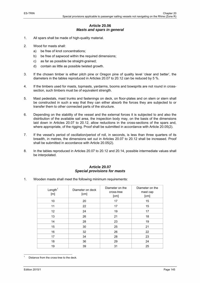
ES-TRIN Chapter 20 Special provisions applicable to passenger sailing vessels not navigating on the Rhine (Zone R)
Edition 2015/1 Page 145
Article 20.06 Masts and spars in general
1. All spars shall be made of high-quality material. 2. Wood for masts shall:
a) be free of knot concentrations;
b) be free of sapwood within the required dimensions;
c) as far as possible be straight-grained;
d) contain as little as possible twisted growth. 3. If the chosen timber is either pitch pine or Oregon pine of quality level ‘clear and better’, the
diameters in the tables reproduced in Articles 20.07 to 20.12 can be reduced by 5 %. 4. If the timbers used for masts, topmasts, yardarms, booms and bowsprits are not round in cross-
section, such timbers must be of equivalent strength. 5. Mast pedestals, mast trunks and fastenings on deck, on floor-plates and on stem or stern shall
be constructed in such a way that they can either absorb the forces they are subjected to or transfer them to other connected parts of the structure.
6. Depending on the stability of the vessel and the external forces it is subjected to and also the
distribution of the available sail area, the inspection body may, on the basis of the dimensions laid down in Articles 20.07 to 20.12, allow reductions in the cross-sections of the spars and, where appropriate, of the rigging. Proof shall be submitted in accordance with Article 20.05(2).
7. If the vessel’s period of oscillation/period of roll, in seconds, is less than three quarters of its
breadth, in metres, the dimensions set out in Articles 20.07 to 20.12 shall be increased. Proof shall be submitted in accordance with Article 20.05(2).
8. In the tables reproduced in Articles 20.07 to 20.12 and 20.14, possible intermediate values shall
be interpolated.
Article 20.07 Special provisions for masts
1. Wooden masts shall meet the following minimum requirements:
Length1 [m]
Diameter on deck [cm]
Diameter on the cross-tree
[cm]
Diameter on the mast cap
[cm]
10 20 17 15
11 22 17 15
12 24 19 17
13 26 21 18
14 28 23 19
15 30 25 21
16 32 26 22
17 34 28 23
18 36 29 24
19 39 31 25
1 Distance from the cross-tree to the deck.

ES-TRIN Chapter 20 Special provisions applicable to passenger sailing vessels not navigating on the Rhine (Zone R)
Edition 2015/1 Page 146
Length1 [m]
Diameter on deck [cm]
Diameter on the cross-tree
[cm]
Diameter on the mast cap
[cm]
20 41 33 26
21 43 34 28
22 44 35 29
23 46 37 30
24 49 39 32
25 51 41 33
If a mast has two yards, the diameters shall be increased by at least 10 %. If a mast has more than two yards, the diameters shall be increased by at least 15 %. In the case of masts fitted through the deck, the diameter at the mast foot shall be at least 75 % of the diameter of the mast at deck level.
2. Mast fittings, mast bands, cross-trees and mast caps shall be sufficiently strongly dimensioned
and attached.
Article 20.08 Special provisions for topmasts
1. Wooden topmasts shall meet the following minimum requirements:
Length1 [m]
Diameter at the foot[cm]
Half-length diameter[cm]
Diameter at fitting2 [cm]
4 8 7 6
5 10 9 7
6 13 11 8
7 14 13 10
8 16 15 11
9 18 16 13
10 20 18 15
11 23 20 16
12 25 22 17
13 26 24 18
14 28 25 20
15 31 27 21
If square sails are attached to a topmast, the dimensions set out in the table shall be increased by 10 %.
1 Total length of the topmast, without the masthead. 2 Diameter of the topmast at the level of the masthead fitting.

ES-TRIN Chapter 20 Special provisions applicable to passenger sailing vessels not navigating on the Rhine (Zone R)
Edition 2015/1 Page 147
2. The overlap between the topmast and the mast shall be at least 10 times the required foot diameter of the topmast.
Article 20.09 Special provisions for bowsprits
1. Wooden bowsprits shall meet the following minimum requirements:
Length1 [m]
Diameter at stem [cm]
Half-length diameter [cm]
4 14,5 12,5
5 18 16
6 22 19
7 25 23
8 29 25
9 32 29
10 36 32
11 39 35
12 43 39
2. The inboard section of the bowsprit shall have a length of at least four times the diameter of the
bowsprit at the stem. 3. The diameter of the bowsprit at its head shall be at least 60 % of the diameter of the bowsprit at
the stem.
Article 20.10 Special provisions for jib-booms
1. Wooden jib-booms shall meet the following minimum requirements:
Length2 [m] 2 3 4 5 6 7 8 9 10
Diameter at the stem [cm] 7 10 14 17 21 24 28 31 35
2. The diameter of the jib-boom at its head shall be at least 60 % of the diameter at the stem.
1 Total length of the bowsprit. 2 Total length of the jib-boom.

ES-TRIN Chapter 20 Special provisions applicable to passenger sailing vessels not navigating on the Rhine (Zone R)
Edition 2015/1 Page 148
Article 20.11 Special provisions for main booms
1. Wooden main booms shall meet the following minimum requirements:
Length1 [m] 5 6 7 8 9 10 11 12 13 14 15 16
Diameter [cm] 14 15 16 17 18 20 21 23 24 25 26 27
2. The diameter at the swivel pin shall be at least 72 % of the diameter specified in the table. 3. The diameter at the clew shall be at least 85 % of the diameter specified in the table. 4. Measured from the mast, the greatest diameter shall be at two thirds of the length. 5. Where:
a) there is an angle of less than 65° between the main boom and the after leech and the main sheet is attached to the end of the boom, or
b) the attachment point of the sheet is not abreast of the clew,
The inspection body may, according to Article 20.05(2), require a greater diameter. 6. For sail areas of less than 50 m2, the inspection body may authorise reductions in the dimen-
sions set out in the table.
Article 20.12 Special provisions for gaffs
1. Wooden gaffs shall meet the following minimum requirements:
Length2 [m] 4 5 6 7 8 9 10
Diameter [cm] 10 12 14 16 17 18 20
2. The unsupported length of the gaff shall be not more than 75 %. 3. The breaking strength of the crowfoot shall be at least equal to 1,2 times the breaking strength
of the peak halyard. 4. The top angle of the crowfoot shall be a maximum of 60°. 5. If, by way of derogation from (4), the top angle of the crowfoot is greater than 60°, the tensile
strength shall be adjusted to accommodate the forces that will then occur. 6. For sail areas of less than 50 m2, the inspection body may authorise reductions in the
dimensions set out in the table.
1 Total length of the main boom. 2 Total length of the gaff.
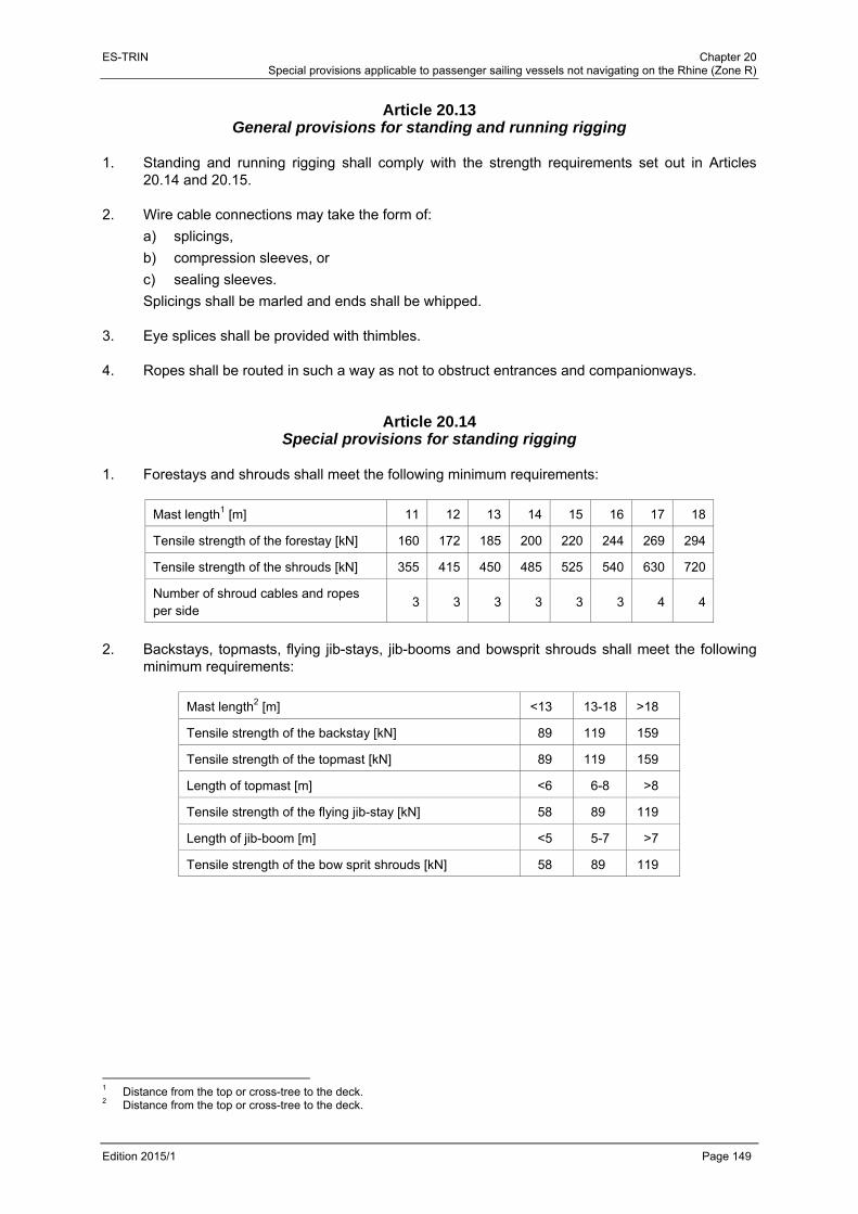
ES-TRIN Chapter 20 Special provisions applicable to passenger sailing vessels not navigating on the Rhine (Zone R)
Edition 2015/1 Page 149
Article 20.13 General provisions for standing and running rigging
1. Standing and running rigging shall comply with the strength requirements set out in Articles
20.14 and 20.15. 2. Wire cable connections may take the form of:
a) splicings,
b) compression sleeves, or
c) sealing sleeves.
Splicings shall be marled and ends shall be whipped. 3. Eye splices shall be provided with thimbles. 4. Ropes shall be routed in such a way as not to obstruct entrances and companionways.
Article 20.14 Special provisions for standing rigging
1. Forestays and shrouds shall meet the following minimum requirements:
Mast length1 [m] 11 12 13 14 15 16 17 18
Tensile strength of the forestay [kN] 160 172 185 200 220 244 269 294
Tensile strength of the shrouds [kN] 355 415 450 485 525 540 630 720
Number of shroud cables and ropes per side
3 3 3 3 3 3 4 4
2. Backstays, topmasts, flying jib-stays, jib-booms and bowsprit shrouds shall meet the following
minimum requirements:
Mast length2 [m] <13 13-18 >18
Tensile strength of the backstay [kN] 89 119 159
Tensile strength of the topmast [kN] 89 119 159
Length of topmast [m] <6 6-8 >8
Tensile strength of the flying jib-stay [kN] 58 89 119
Length of jib-boom [m] <5 5-7 >7
Tensile strength of the bow sprit shrouds [kN] 58 89 119
1 Distance from the top or cross-tree to the deck. 2 Distance from the top or cross-tree to the deck.

ES-TRIN Chapter 20 Special provisions applicable to passenger sailing vessels not navigating on the Rhine (Zone R)
Edition 2015/1 Page 150
3. The preferred rope design shall be based on Rope Construction Method 6 × 7 FE in the strength class 1550 N/mm2. Alternatively, at the same strength class, Construction Method 6 × 36 SE or 6 × 19 FE may be used. Because of the higher elasticity of Construction Method 6 × 19, the tensile strengths given in the table shall be increased by 10 %. Use of a different rope design shall be permitted provided it has comparable properties.
4. If rigid rigging is used, the tensile strengths shown in the table shall be increased by 30 %. 5. For rigging, only approved forks, round eyes and bolts may be used. 6. Bolts, forks, round eyes and turnbuckles shall be capable of being properly secured. 7. The tensile strength of the bobstay shall be at least 1,2 times the tensile strength of the
respective jib-stay and flying jib-stay. 8. For vessels with less than 30 m3 water displacement, the inspection body may permit the
reductions in tensile strengths shown in the table set out below:
Water displacement divided by the number of masts [m3] Reduction [%]
>20 to 30 20
10 to 20 35
< 10 60
Article 20.15 Special provisions for running rigging
1. For running rigging, fibre ropes or steel wire ropes shall be used. The minimum tensile strength
and the diameter for running rigging shall, in relation to the sail area, meet the following minimum requirements:
Type of running rigging Rope material Sail area [m2] Minimum tensile
strength [kN] Diameter of rope
[mm]
Staysail halyards
Steel wire
up to 35 20 6
> 35 38 8
Fibre (poly-propylene - PP)
Rope diameter of at least 14 mm and one rope sheave for every 25 m2 or part thereof
Gaff sail halyards Top sail halyards
Steel wire
up to 50 20 6
> 50 to 80 30 8
> 80 to 120 60 10
>120 to 160 80 12
Fibre (PP) Rope diameter of at least 18 mm and one rope sheave for every 30 m2 or part thereof

ES-TRIN Chapter 20 Special provisions applicable to passenger sailing vessels not navigating on the Rhine (Zone R)
Edition 2015/1 Page 151
Type of running rigging Rope material Sail area [m2] Minimum tensile
strength [kN] Diameter of rope
[mm]
Staysail sheets
Fibre (PP) up to 40 14
> 40 18
For sail areas of more than 30 m2, the sheet shall take the form of a tackle or shall be capable of being operated by a winch
Gaff-/Top-sail sheets
Steel wire
< 100 60 10
100 to 150 85 12
> 150 116 14
For top sail sheets, elastic connection elements (fore runners) are necessary.
Fibre (PP) Rope diameter of at least 18 mm and at least three rope sheaves. Where the sail area is greater than 60 m2, one rope sheave per 20 m2
2. Running rigging forming part of the staying shall have a tensile strength which corresponds to
that of the respective stay or shrouds. 3. If materials other than those stated in (1) are used, the strength values given in the table in (1)
shall be complied with.
Fibre ropes of polyethylene shall not be used.
Article 20.16 Fittings and parts of the rigging
1. If steel wire ropes or fibre ropes are used, the diameters of the rope sheaves (measured from
centre of rope to centre of rope) shall meet the following minimum requirements:
Steel wire [mm] 6 7 8 9 10 11 12
Fibre [mm] 16 18 20 22 24 26 28
Rope sheave [mm] 100 110 120 130 145 155 165
2. By way of derogation from (1), the diameter of the rope sheaves may be equal to six times the
diameter of the steel wire, provided that the steel wire does not constantly run over sheaves. 3. The tensile strength of the fittings (e.g. forks, round eyes, turnbuckles, eye-plates, bolts, rings
and shackles) shall be compatible with the tensile strength of the standing or running rigging that is attached to them.
4. The fastenings of stay and shroud futtocks shall be designed to take up the forces they are
subjected to. 5. Only one shackle, along with the relevant stay or shroud, may be attached to each eye. 6. Blocks of halyards and topping lifts shall be securely fastened to the mast, and the revolving
crowfeet used for this purpose shall be in good condition. 7. Attachments of eye-bolts, cleats, belaying pins and fife-rails shall be designed to cope with the
forces they are subjected to.

ES-TRIN Chapter 20 Special provisions applicable to passenger sailing vessels not navigating on the Rhine (Zone R)
Edition 2015/1 Page 152
Article 20.17 Sails
1. It shall be ensured that sails can be taken in simply, swiftly and safely. 2. The sail area shall be appropriate for the type of vessel and the water displacement.
Article 20.18 Equipment
1. Vessels that are fitted with a jib-boom or a bowsprit shall have a jib-net and an adequate
number of appropriate holding and tensioning devices. 2. The equipment according to (1) may be dispensed with if the jib-boom or bowsprit is equipped
with a hand becket and a foot rope adequately dimensioned to allow for the attachment of a safety harness to be carried on board.
3. For work on the rigging, a boatswain’s chair shall be provided.
Article 20.19 Testing
1. The rigging shall be tested by the inspection body every 2,5 years. As a minimum, the test shall
cover the following:
a) the sails, including leeches, clews and reef eyes;
b) the state of the masts and spars;
c) the state of the standing and running rigging together with cable wire connections;
d) facilities for taking in the sail swiftly and safely;
e) the secure fastening of blocks of halyards and topping lifts;
f) the fastening of mast trunks and other fastening points for standing and running rigging that are attached to the vessel;
g) the winches for operating the sails;
h) other facilities fitted for the purposes of sailing, such as lee-boards and the fittings for operating them;
i) the measures taken to prevent the chafing of the spars, the running and standing rigging and the sails;
(j) the equipment according to Article 20.18. 2. That part of the wooden mast passing through the deck and located below the deck shall be re-
examined at intervals to be determined by the inspection body, but at the very least on the occasion of each periodical inspection. The mast shall be extracted for this purpose.
3. A certificate of the last inspection carried out in accordance with (1) and issued, dated and
signed by the inspection body, shall be carried on board.

ES-TRIN Chapter 21 Special provisions applicable to craft intended to form part of a pushed or towed convoy or of a side-by-side formation
Edition 2015/1 Page 153
CHAPTER 21 SPECIAL PROVISIONS APPLICABLE TO CRAFT INTENDED TO FORM PART OF A
PUSHED OR TOWED CONVOY OR OF A SIDE-BY-SIDE FORMATION
Article 21.01 Craft suitable for pushing
1. Craft which are to be used for pushing purposes shall incorporate a suitable pushing device.
They shall be designed and equipped in such a way as to:
a) enable crews easily and safely to cross over to the pushed craft with the coupling devices connected;
b) enable them to occupy a fixed position in relation to the coupled craft and
c) prevent relative movement between the craft themselves. 2. If the craft are joined together with cables the pusher craft shall be equipped with at least two
special winches or equivalent coupling devices for tensioning the cables. 3. The coupling devices shall enable a rigid assembly to be formed with the pushed craft.
Where convoys consist of a pusher craft and a single pushed craft the coupling devices may permit controlled articulation. The necessary drive units shall easily absorb the forces to be transmitted and shall be capable of being controlled easily and safely. Articles 6.02 to 6.04 shall apply mutatis mutandis to such drive units.
4. The collision bulkhead referred to in Article 3.03(1)(a), can be dispensed with for pushers.
Article 21.02 Craft suitable for being pushed
1. The following shall not apply to lighters without steering system, accommodation, engine or
boiler rooms:
a) Chapters 5 to 7 and 15;
b) Article 8.08(2) to (8), Article 13.02 and Article 13.08(1).
If steering systems, accommodation, engine or boiler rooms are present the relevant requirements of this Standard shall apply to them.
2. In addition, ship-borne lighters whose length does not exceed 40 m shall meet the following
requirements:
a) collision bulkheads referred to in Article 3.03(1), can be dispensed with if their front faces are able to bear a load at least 2,5 times that set for the collision bulkheads on inland waterway vessels with the same draught and built in accordance with the requirements of a recognised classification society;
b) by way of derogation from Article 8.08(1), compartments of the double bottom to which access is difficult do not have to be drainable unless their volume exceeds 5 % of the water displacement of the ship-borne lighter at the maximum authorised loaded draught.
3. Craft intended for being pushed shall be fitted with coupling devices ensuring a safe connection
to other craft.

ES-TRIN Chapter 21 Special provisions applicable to craft intended to form part of a pushed or towed convoy or of a side-by-side formation
Edition 2015/1 Page 154
Article 21.03 Craft suitable for propelling side-by-side formations
Craft intended to propel side-by-side formations shall be equipped with bollards or equivalent devices which, as a result of their number and arrangement, enable the formation to be coupled in a safe manner.
Article 21.04 Craft suitable for being propelled in convoys
Craft intended to be propelled in convoys shall be equipped with coupling devices, bollards or equivalent devices which, as a result of their number and arrangement, ensure a safe connection to other craft in the convoy.
Article 21.05 Craft suitable for towing
1. Craft intended for towing shall meet the following requirements:
a) The towing devices shall be arranged in such a way that their use does not compromise the safety of the craft, crew or cargo.
b) Tugging and towing craft shall be fitted with a tow hook which shall be capable of being released safely from the wheelhouse; this shall not apply if the design or other fittings prevent capsizing.
c) Towing devices shall consist of winches or a tow hook. The towing devices shall be located ahead of the propeller plane. This requirement shall not apply to craft that are steered by their propulsion units such as rudder propellers or cycloidal propellers.
d) By way of derogation from the requirements of (c), for craft solely giving — in accordance with the applicable navigational authority regulations of the Member States — towing assistance to motorised craft, a towing device such as a bollard or an equivalent device shall suffice. (b) shall apply mutatis mutandis.
e) Where the towing cables could snag on the stern of the vessel, deflector hoops with cable catchers shall be provided.
2. Craft of length exceeding 86 m shall not be authorised for towing downstream.
Article 21.06 Navigation tests on convoys
1 In order to authorise a pusher or motor vessel to propel a rigid convoy, and to enter this on the
inland navigation vessel certificate, the inspection body shall decide which formations are to be presented and shall conduct the navigation tests referred to in Article 5.02 with the convoy in the formation(s) applied for, which the inspection body regards to be the least favourable one(s). The requirements set out in Articles 5.02 to 5.10 shall be met by this convoy.
The inspection body shall check that the rigid connection of all craft in the convoy is maintained during the manoeuvres required by Chapter 5.

ES-TRIN Chapter 21 Special provisions applicable to craft intended to form part of a pushed or towed convoy or of a side-by-side formation
Edition 2015/1 Page 155
2 If during the navigation tests referred to in (1) there are specific installations on board the craft that are being either pushed or propelled side-by-side, such as the steering system, propulsion units or manoeuvring equipment, or articulated couplings in order to meet the requirements set out in Articles 5.02 to 5.10, the following shall be entered on the inland navigation vessel certificate for the craft propelling the convoy: formation, position, name and unique European vessel identification number of those craft which are fitted with the specific installations used.
Article 21.07 Entries on the inland navigation vessel certificate
1 If a craft is intended to propel a convoy, or be propelled in a convoy, its compliance with the
relevant requirements as set out in Articles 21.01 to 21.06 shall be entered on the inland navigation vessel certificate.
2 The following information shall be entered on the inland navigation vessel certificate for the
propelling craft:
a) the convoys and formations that have been accepted;
b) the types of coupling;
c) the maximum coupling forces determined, and
d) where appropriate, the minimum breaking load of the coupling cables for the longitudinal connection and also the number of cable windings.

ES-TRIN Chapter 21 Special provisions applicable to craft intended to form part of a pushed or towed convoy or of a side-by-side formation
Edition 2015/1 Page 156
ES-TRIN Chapter 22 Special provisions applicable to floating equipment
Edition 2015/1 Page 157
CHAPTER 22 SPECIAL PROVISIONS APPLICABLE TO FLOATING EQUIPMENT
Article 22.01
General For construction and equipment of floating equipment Chapters 3, 7 to 17 and 21 shall apply. Floating equipment with its own means of propulsion shall also meet the requirements of Chapters 5 and 6. Propulsion units permitting only short-haul operation shall not constitute own means of propulsion.
Article 22.02 Derogations
1.
a) Article 3.03(1) and (2), shall apply mutatis mutandis;
b) Article 7.02 shall apply mutatis mutandis;
c) the maximum sound pressure levels prescribed by Article 15.02 (5), second sentence, may be exceeded while the floating equipment's working gear is operating, provided that, during service, nobody sleeps on board at night;
d) the inspection body may grant exceptions to the other requirements concerning shipbuilding, fitting out and equipment provided that equivalent safety is proven in every case.
2. The inspection body may dispense with the application of the following requirements:
a) Article 13.01(1), shall not apply if during operation of floating equipment that equipment can be securely anchored by means of a working anchor or piles. However, floating equipment with its own means of propulsion shall have at least one anchor meeting the requirements in Article 13.01 (1), where an empirical coefficient is taken to be equal to 45, and is taken to be equal to the height ;
b) Article 15.02(1), second part of sentence, if the accommodation can be adequately lit by means of electricity.
3. In addition, the following shall apply:
a) for Article 8.08(2), second sentence, the bilge pump shall be motor driven;
b) for Article 8.10(3), the noise may exceed 65 dB(A) at a lateral distance of 25 m from the ship's side of any stationary floating equipment while its working gear is operating;
c) for Article 13.03(1), at least one further portable extinguisher is required if working gear not permanently attached to the craft is placed on the deck;
d) for Article 17.02(2), in addition to the liquefied-gas equipment for domestic use, there may also be other liquefied-gas facilities. Those facilities and their accessories shall meet the requirements of one of the Member States.
ES-TRIN Chapter 22 Special provisions applicable to floating equipment
Edition 2015/1 Page 158
Article 22.03 Additional requirements
1. Floating equipment on which persons are present during operation shall be fitted with a general
alarm system. The alarm signal shall be clearly distinguishable from other signals and, within accommodation and at all work stations, shall produce a sound pressure level that is at least 5 dB(A) higher than the maximum local sound pressure level. It shall be possible to actuate the alarm system from the wheelhouse and the main operating stations.
2. Working equipment shall have sufficient strength to withstand the loads it is subjected to and
shall meet the requirements of one of the Member States of the CCNR or of Directive 98/37/EC1.
3. The stability and strength of working equipment and, where appropriate, its attachments, shall
be sufficient to withstand the forces resulting from the expected heel, trim and movement of the floating equipment.
4. If loads are lifted by means of hoists the maximum authorised load deriving from stability and
strength shall be prominently displayed on panels on deck and at the operating stations. If the lifting capacity can be increased by connecting additional floats the values authorised both with and without these additional floats shall be clearly stated.
Article 22.04 Residual safety clearance
1. For the purposes of this Chapter and by way of derogation from Article 1.01, residual safety
clearance means the shortest vertical distance between surface of the water and the lowest part of the floating equipment beyond which it is no longer watertight, taking into account trim and heel resulting from the moments referred to in Article 22.07(4) to (9).
2. The residual safety clearance is sufficient according to Article 22.07(1), for any spray-proof and
weathertight aperture if it is at least 300 mm. 3. At an aperture that is not spray-proof and weathertight the residual safety clearance shall be at
least 400 mm.
Article 22.05 Residual freeboard
1. For the purposes of this Chapter and by way of derogation from Article 1.01, residual freeboard
means the smallest vertical distance between the surface of the water and the upper surface of the deck at its edge taking into account trim and heel resulting from the moments referred to in Article 22.07 (4) to (9).
2. The residual freeboard is sufficient according to Article 22.07(1), if it is at least 300 mm. 3. The residual freeboard may be reduced if it is proven that the requirements of Article 22.08
have been met.
1 Directive 98/37/EC of the European Parliament and of the Council of 22 June 1998 on the approximation of the laws of the
Member States relating to machinery (OJ L 207, 23.7.1998).

ES-TRIN Chapter 22 Special provisions applicable to floating equipment
Edition 2015/1 Page 159
4. Where the shape of a floating object differs perceptibly from that of a pontoon, as in the case of a cylindrical floating object, or where the cross-section of a floating object has more than four sides, the inspection body may require or authorise a residual freeboard that differs from (2). This shall also apply to floating equipment consisting of several floating objects.
Article 22.06 Heeling test
1. The proof of stability according to Articles 22.07 and 22.08 shall be based on a heeling test that
has been carried out in a proper manner. 2. If during a heeling test it is not possible to achieve adequate heeling angles, or if the heeling
test causes unreasonable technical difficulties, this may be replaced by a calculation of the craft's centre of gravity and weight. The result of the weight calculation shall be checked by measuring the draught, and the difference shall not exceed ± 5 %.
Article 22.07 Proof of stability
1. It shall be confirmed that, when taking into account the loads applied during operation of the
working gear and whilst under way, the residual freeboard and the residual safety clearance are sufficient. For that purpose the sum of the trim and heeling angles shall not exceed 10° and the bottom of the float shall not emerge.
2. The proof of stability shall include the following data and documents:
a) scale drawings of floating objects and working gear and the detailed data relating to these that are needed to provide proof of stability, such as content of the tanks, openings providing access to the inside of the vessel;
b) hydrostatic data or curves;
c) righting lever curves for static-stability to the extent required in accordance with (5) below or Article 22.08;
d) description of the operating conditions together with the corresponding data concerning weight and centre of gravity, including its unladen state and the equipment situation as regards transport;
e) calculation of the heeling, trimming and righting moments, with a specification of the trim and heeling angles and the corresponding residual freeboard and residual safety clearances;
f) a compilation of the results of the calculation with a specification of the limits for operation and the maximum loads.
3. The proof of stability shall be based on at least the following load assumptions:
a) specific mass of the dredging products for dredgers:
sands and gravels: 1,5 t/m3,
very wet sands: 2,0 t/m3,
soil, on average: 1,8 t/m3,
mixture of sand and water in the ducts: 1,3 t/m3;

ES-TRIN Chapter 22 Special provisions applicable to floating equipment
Edition 2015/1 Page 160
b) for clamshell dredgers, the values given under (a) shall be increased by 15 %;
c) for hydraulic dredgers the maximum lifting power shall be considered. 4. The proof of stability shall take account of the moments resulting from:
a) load;
b) asymmetric structure;
c) wind pressure;
d) turning whilst under way of self-propelled floating equipment;
e) cross current, if necessary;
f) ballast and provisions;
g) deck loads and, where appropriate, cargo;
h) free surfaces of liquids;
i) inertia forces;
j) other mechanical equipment.
The moments which may act simultaneously shall be added up. 5. The moment caused by the wind pressure shall be calculated in accordance with the following
formula:
∙ ∙ ∙2
where:
= shape-dependent coefficient of resistance
For frameworks 1,2 and for solid-section beams 1,6. Both values take account of gusts of wind.
The whole area encompassed by the contour line of the framework shall be taken to be the surface area exposed to the wind.
= specific wind pressure; this shall uniformly be taken to be 0,25 kN/m2;
= lateral plane of the vessel above the plane of draught according to the considered loading condition in [m²];
= distance of the centre of gravity of the lateral plane from the plane of draught according to the considered loading condition in [m].
6. In order to determine the moments due to turning whilst under way according to (4)(d) for self-
propelled floating equipment, the formula set out in Article 19.03(6) shall be used. 7. The moment resulting from cross current according to (4)(e) shall be taken into account only for
floating equipment which is anchored or moored across the current while operating. 8. The least favourable extent of tank filling from the point of view of stability shall be determined
and the corresponding moment introduced into the calculation when calculating the moments resulting from liquid ballast and liquid provisions according to (4)(f).
9. The moment resulting from inertia forces according to (4)(i) shall be given due consideration if
the movements of the load and the working gear are likely to affect stability.
ES-TRIN Chapter 22 Special provisions applicable to floating equipment
Edition 2015/1 Page 161
10. The righting moments for floating objects with vertical side walls may be calculated using the following formula
10 ∙ ∙ ∙ sin
where:
= metacentric height, in m;
= heeling angle in degrees. That formula shall apply up to heeling angles of 10° or up to a heeling angle corresponding to immersion of the edge of the deck or emergence of the edge of the bottom; the smallest angle shall be decisive. The formula may be applied to slanting side walls up to heeling angles of 5°; the limit conditions set out in (3) to (9) shall also apply. If the particular shape of the floating object(s) does not permit such simplification the righting lever curves according to (2)(c) shall be required.
Article 22.08 Proof of stability in the case of reduced residual freeboard
If a reduced residual freeboard according to Article 22.05(3), is used, it shall be proven for all operating conditions that:
a) after correction for the free surfaces of liquids, the metacentric height is not less than 0,15 m;
b) for heeling angles between 0° and 30°, there is a righting lever of at least
0,30 0,28 ∙
being the heeling angle from which the righting lever curve displays negative values (range of stability); it shall not be less than 20° or 0,35 rad and shall not be introduced into the formula for more than 30° or 0,52 rad, taking the radian (rad) (1° = 0,01745 rad) for the unit of ;
c) the sum of the trim and heeling angles does not exceed 10°;
d) a residual safety clearance meeting the requirements in Article 22.04 remains;
e) a residual freeboard of at least 0,05 m remains;
f) for heeling angles between 0° and 30°, a residual righting lever of at least
0,20 0,23 ∙
remains, where is the heeling angle from which the righting lever curve displays negative values; it shall not be introduced into the formula for more than 30° or 0,52 rad.
Residual righting lever means the maximum difference existing between 0° and 30° of heel between the righting lever curve and the heeling lever curve. If an opening towards the inside of the vessel is reached by the water at a heeling angle less than that corresponding to the maximum difference between the lever curves, the lever corresponding to that heeling angle shall be taken into account.

ES-TRIN Chapter 22 Special provisions applicable to floating equipment
Edition 2015/1 Page 162
Article 22.09 Draught marks and draught scales
Draught marks and draught scales shall be affixed in accordance with Articles 4.04 and 4.06.
Article 22.10 Floating equipment without proof of stability
1. The application of Articles 22.04 to 22.08 may be dispensed with for floating equipment:
a) whose working gear can in no way alter their heeling or trim, and
b) where any displacement of the centre of gravity can be absolutely excluded. 2. However,
a) at maximum load the safety clearance shall be at least 300 mm and the freeboard at least 150 mm; and
b) for apertures which cannot be closed spray-proof and weathertight the safety clearance shall be at least 500 mm.
ES-TRIN Chapter 23 Special provisions applicable to worksite craft
Edition 2015/1 Page 163
CHAPTER 23 SPECIAL PROVISIONS APPLICABLE TO WORKSITE CRAFT
Article 23.01
Operating conditions Worksite craft designated as such in the inland navigation vessel certificate may navigate outside worksites only when unladen. That restriction shall be entered on the inland navigation vessel certificate. For this purpose worksite craft shall have an attestation issued by the competent authority indicating the duration of works and the geographical boundaries of the worksite in which the craft may be operated.
Article 23.02 Application of Part II
Unless otherwise specified in this Chapter, the construction and equipment of worksite craft shall be in line with Chapters 3 to 17 of Part II.
Article 23.03 Derogations
1. a) Article 3.03(1), shall apply mutatis mutandis;
b) Chapters 5 and 6 shall apply mutatis mutandis where the craft is self-propelled;
c) Article 13.02(2)(a) and (b), shall apply mutatis mutandis;
d) the inspection body may grant exceptions to the other requirements concerning shipbuiling, fitting out and equipment provided that equivalent safety is proven in every case.
2. The inspection body may dispense with the following provisions:
a) Article 8.08(2) to (8), if no crew is required;
b) Article 13.01(1) and (3), if the worksite craft can be securely anchored by means of working anchors or piles. However, self-propelled worksite craft shall be equipped with at least one anchor meeting the requirements set out in Article 13.01(1), where an empirical coefficient
is taken to be equal to 45, and is taken to be equal to the height ;
c) Article 13.02(1)(c), if the worksite craft is not self-propelled.

ES-TRIN Chapter 23 Special provisions applicable to worksite craft
Edition 2015/1 Page 164
Article 23.04 Safety clearance and freeboard
1. If a worksite craft is used as a reclamation barge or a hopper barge the safety clearance outside
the hold area shall be at least 300 mm and the freeboard at least 150 mm. The inspection body may permit a smaller freeboard if proof by calculation is provided that stability is sufficient for a cargo having a specific mass of 1,5 t/m3 and that no side of the deck reaches the water. The effect of liquefied cargo shall be taken into account.
2. The provisions of Articles 4.01 and 4.02 shall apply mutatis mutandis to worksite craft not
covered by (1). The inspection body may determine values departing from the above for safety clearance and freeboard.
Article 23.05 Ship's boats
Worksite craft shall not be required to have a ship's boat where:
a) they are not self-propelled or
b) a ship's boat is available elsewhere on the worksite. That derogation shall be entered on the inland navigation vessel certificate.

ES-TRIN Chapter 24 Special provisions applicable to traditional craft
Edition 2015/1 Page 165
CHAPTER 24 SPECIAL PROVISIONS APPLICABLE TO TRADITIONAL CRAFT
(left void)

ES-TRIN Chapter 24 Special provisions applicable to traditional craft
Edition 2015/1 Page 166
ES-TRIN Chapter 25 Special provisions applicable to sea-going vessels
Edition 2015/1 Page 167
CHAPTER 25 SPECIAL PROVISIONS APPLICABLE TO SEA-GOING VESSELS
Article 25.01
Provisions for the Rhine (Zone R) 1. Seagoing vessels navigating on the Rhine shall comply with the relevant national and
international provisions concerning technical requirements as regards construction, equipment and the seagoing vessels' environment and must be able to corroborate this by means of the necessary certificates.
2. Seagoing vessels shall comply with the the following provisions of this Standard in addition to
the requirements specified in (1):
a) Chapter 5;
b) to Chapter 6:
Article 6.01(1) and Article 6.02(1) and (2);
c) to Chapter 7:
Article 7.01(2), Article 7.02(1) and (3), (1) and (3), Article 7.05(2),
Article 7.13 for sea-going vessels designed for radar navigation by one person;
d) to Chapter 8
Article 8.03(3) for sea-going vessels when an automatic shut-off device can be switched off from the steering position; Article 8.05(13), Article 8.08(10), Article 8.09(1) and (2) and Article 8.10.
Locking the closures in position prescribed in Article 8.08(10) shall be regarded as equivalent to sealing the closures of the bilge system through which the oily water can be pumped out of the vessel. The required key or keys must be kept in a central location which shall be marked accordingly.
An oil discharge monitoring and control system complying with Regulation 16 of MARPOL 73/78 shall be deemed equivalent to locking the closures in position prescribed in Article 8.08(10). The existence of the monitoring and control system must be attested by an international oil pollution prevention (IOPP) certificate that complies with MARPOL 73/78.
If the IOPP attestation reveals that the vessel is equipped with collecting tanks enabling all the oily water and oily residues to be retained on board, Article 8.09(2) must be deemed to have been complied with;
e) to Chapter 10:
Article 10.17;
f) to Chapter 13:
Articles 13.01 and 13.02(1);
g) Chapter 21,
for sea-going vessels permitted to form part of a convoy;
h) Chapter 27:
Chapter 27 shall be deemed to have been complied with when stability complies with current IMO Resolutions, the corresponding stability-related documents have been endorsed by the competent authority and the containers are secured in the customary maritime navigation manner.

ES-TRIN Chapter 25 Special provisions applicable to sea-going vessels
Edition 2015/1 Page 168
ES-TRIN Chapter 26 Special provisions applicable to recreational craft
Edition 2015/1 Page 169
CHAPTER 26 SPECIAL PROVISIONS APPLICABLE TO RECREATIONAL CRAFT
Article 26.01
Application of Part II 1. Recreational craft shall meet the following requirements:
a) from Chapter 3:
Article 3.01, Article 3.02(1)(a) and (2), Article 3.03(1)(a) and (6), and Article 3.04(1);
b) Chapter 5;
c) from Chapter 6:
Article 6.01(1), and Article 6.08;
d) from Chapter 7:
Article 7.01(1) and (2), Article 7.02, Article 7.03(1) and (2), Article 7.04(1), Article 7.05(2),
Article 7.13 if there is a wheelhouse designed for radar navigation by one person;
e) from Chapter 8:
Article 8.01(1) and (2), Article 8.02(1) and (2), Article 8.03(1) and (3), Article 8.04, Article 8.05(1) to (10) and (13), Article 8.06, Article 8.07, Article 8.08 (1), (2), (5), (7) and (10), Article 8.09(1), and Article 8.10;
f) from Chapter 10:
Article 10.01(1), mutatis mutandis;
g) from Chapter 13:
Article 13.01(2), (3) and (5) to (14), Article 13.02(1)(a) to (c), and (3)(a) and (e) to h), Article 13.03(1)(a), (b) and (d): however, there shall be at least two fire extinguishers on board; Article 13.03(2) to (6), Article 13.04, Articles 13.05, 13.07, and 13.08;
h) Chapter 16;
i) Chapter 17. 2. For recreational craft subject to Directive 2013/53/EC1, initial inspection and periodical
inspections only extend to:
a) Article 6.08, if there is a rate-of-turn regulator;
b) Article 7.01(2), Article 7.02, Article 7.03(1), and Article 7.13, if there is a wheelhouse designed for radar navigation by one person;
c) Article 8.01(2), Article 8.02(1), Article 8.03(3), Article 8.05(5), Article 8.08(2), and Article 8.10;
1 Directive 2013/53/EU of the European Parliament and of the Council of 20 November 2013 on recreational craft and
personal watercraft and repealing Directive 94/25/EC (OJ L 354, 28.12.2013).

ES-TRIN Chapter 26 Special provisions applicable to recreational craft
Edition 2015/1 Page 170
d) Article 13.01(2), (3), (6) and (14), Article 13.02(1)(b) and (c), (3)(a) and (e) to (h), Article 13.03 (1)(b) and (d) and (2) to (6), and Article 13.08;
e) Chapter 16;
f) from Chapter 17:
aa) Article 17.12;
bb) Article 17.13; the acceptance test after putting into service of the liquefied gas installation shall be carried out in accordance with the requirements of Directive 2013/53/EC, and an inspection attestation shall be submitted to the inspection body;
cc) Articles 17.14 and 17.15; the liquefied gas installation shall be in accordance with the requirements of Directive 2013/53/EC;
dd) Chapter 17 entirely, if the liquefied gas installation is fitted after placing on the market of the recreational craft.

ES-TRIN Chapter 27 Special provisions applicable to vessels carrying containers
Edition 2015/1 Page 171
CHAPTER 27 SPECIAL PROVISIONS APPLICABLE TO VESSELS CARRYING CONTAINERS
Article 27.01
General 1. The provisions of this Chapter shall apply to vessels carrying containers where stability
documents are required in accordance with applicable navigational authority regulations of the Member States
Stability documents shall be checked, or submitted elsewhere for checking, and duly stamped by an inspection body.
2. Stability documents shall provide the boatmaster with comprehensible information on vessel
stability for each loading condition.
Stability documents shall include at least the following:
a) information on the permissible stability coefficients, the permissible - values or the permissible heights for the centre of gravity of the cargo;
b) data concerning spaces that can be filled with ballast water;
c) forms for checking stability;
d) instructions for use or an example of a calculation for use by the boatmaster. 3. For vessels where it is optional whether containers are carried non-secured or secured,
separate calculation methods shall be applied for proof of stability both for transport of non-secured and secured cargoes of containers.
4. A cargo of containers shall only be considered to be secured if each individual container is
firmly attached to the hull of the vessel by means of container guides or securing equipment and its position cannot alter during the voyage.
Article 27.02 Limit conditions and method of calculation for proof of stability
for the transport of non-secured containers 1. All methods of calculating vessel stability in the case of non-secured containers shall meet the
following limit conditions:
a) Metacentric height shall be not less than 1,00 m.
b) Under the joint action of the centrifugal force resulting from the vessel's turning, wind pressure and the free surfaces of liquids, the heeling angle shall not exceed 5° and the edge of the deck shall not be immersed.
c) The heeling lever resulting from the centrifugal force caused by the vessel's turning shall be determined in accordance with the following formula:
∙ ∙ 2

ES-TRIN Chapter 27 Special provisions applicable to vessels carrying containers
Edition 2015/1 Page 172
where:
parameter 0,04 [s2/m];
the maximum speed of the vessel in relation to the water [m/s];
height of centre of gravity of the laden vessel above its base [m];
′ draught of the laden vessel [m].
d) The heeling lever resulting from the wind pressure shall be determined in accordance with the following formula:
∙ ∙ 2
where:
parameter 0,025 [t/m2];
′ lateral plane above water with the vessel laden [m2];
′ displacement of the laden vessel [t];
height of the centre of gravity of the lateral plane A' above the respective waterline [m];
′ draught of the laden vessel [m].
e) The heeling lever resulting from the free surfaces of rainwater and residual water within the hold or the double bottom shall be determined in accordance with the following formula:
′ ∙ ∙ ∙ 0,55√
where:
parameter 0,015 [t/m2];
width of hold or section of the hold in question [m];*
length of hold or section of the hold in question [m];*
′ displacement of the laden vessel [t].
f) Half of the fuel and fresh water supply shall be taken into account for each loading condition.
2. The stability of a vessel carrying non-secured containers shall be considered to be sufficient if
the effective does not exceed the resulting from the following formulae. The shall be calculated for various displacements covering the entire range of draughts:
* The hold sections providing free surfaces that are exposed to water arise from the longitudinal and/or tranverse water-tight
compartmentalisation that forms independent sections.

ES-TRIN Chapter 27 Special provisions applicable to vessels carrying containers
Edition 2015/1 Page 173
a)
2 ∙ ∙ 2
2 ∙ 1
No value less than 11,5 (11,5 = 1/tan5°) shall be taken for
b) 1,00
The lowest value of in accordance with formula (a) or (b) shall be decisive.
Within the formulae:
maximum permissible height of the laden vessel's centre of gravity above its base [m];
height of the metacentre above the base [m] in accordance with the approximation formula in (3);
respective effective freeboard at [m];
parameter for the centrifugal force resulting from turning
0,7 ∙
9,81 ∙ 1,250,04 ∙
maximum speed of the vessel in relation to the water [m/s];
respective average draught [m];
heeling lever resulting from lateral wind pressure according to (1)(d) [m];
sum of the heeling levers resulting from the free surfaces of liquids according to (1)(e) [m].
3. Approximation formula for :
Where no sheet of hydrostatic curves is available the value for the calculation in accordance with (2) and Article 27.03 (2), may be determined by the following approximation formulae:
a) for vessels in the shape of a pontoon
12,5 ∙
2
b) for other vessels
12,7 1,2 ∙ ∙
2

ES-TRIN Chapter 27 Special provisions applicable to vessels carrying containers
Edition 2015/1 Page 174
Article 27.03 Limit conditions and method of calculation for proof of stability
for the transport of secured containers 1. All methods of calculating vessel stability in the case of secured containers shall meet the
following limit conditions:
a) Metacentric height shall be not less than 0,50 m.
b) Under the joint action of the centrifugal force resulting from the vessel's turning, wind pressure and the free surfaces of liquids, no hull opening shall be immersed.
c) The heeling levers resulting from the centrifugal force due to the vessel's turning, the wind pressure and the free surfaces of liquids shall be determined in accordance with the formulae referred to in Article 27.02(1)(c) to (e).
d) Half of the fuel and fresh water supply shall be taken into account for each loading condition.
2. The stability of a vessel carrying secured containers shall be considered to be sufficient if the
effective does not exceed resulting from the following formulae that has been calculated for various displacements covering the entire range of draughts.
a) ∀ , , ∙
, ∙ ∙
No value less than 6,6 shall be taken for and
no value less than 0 for ∀ ∙ 1 1,5
b) 0,50
The lowest value for in accordance with formula (a) or (b) shall be decisive.
Within these formulae, apart from the terms defined previously:
transverse moment of inertia of water line area at [m4] (for the approximation formula see (3));
transverse moment of inertia of the water line area parallel to the base, at height
23
∀ water displacement of the vessel at [m3];
′ ideal freeboard
or ∙
∙ , the lowest value shall be decisive;
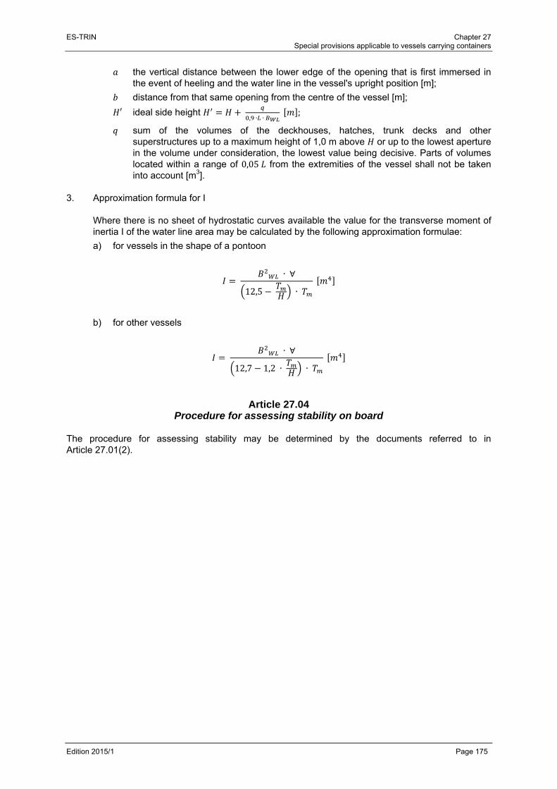
ES-TRIN Chapter 27 Special provisions applicable to vessels carrying containers
Edition 2015/1 Page 175
the vertical distance between the lower edge of the opening that is first immersed in the event of heeling and the water line in the vessel's upright position [m];
distance from that same opening from the centre of the vessel [m];
′ ideal side height , ∙ ∙
;
sum of the volumes of the deckhouses, hatches, trunk decks and other superstructures up to a maximum height of 1,0 m above or up to the lowest aperture in the volume under consideration, the lowest value being decisive. Parts of volumes located within a range of 0,05 from the extremities of the vessel shall not be taken into account [m3].
3. Approximation formula for I
Where there is no sheet of hydrostatic curves available the value for the transverse moment of inertia I of the water line area may be calculated by the following approximation formulae:
a) for vessels in the shape of a pontoon
∙ ∀
12,5 ∙
b) for other vessels
∙ ∀
12,7 1,2 ∙ ∙
Article 27.04 Procedure for assessing stability on board
The procedure for assessing stability may be determined by the documents referred to in Article 27.01(2).

ES-TRIN Chapter 27 Special provisions applicable to vessels carrying containers
Edition 2015/1 Page 176
ES-TRIN Chapter 28 Special provisions applicable to craft longer than 110 m
Edition 2015/1 Page 177
CHAPTER 28 SPECIAL PROVISIONS APPLICABLE TO CRAFT LONGER THAN 110 M
Article 28.01
Application of Part II In addition to Part II and III, Articles 28.02 to 28.04 shall apply to craft whose length exceeds 110 m.
Article 28.02 Strength
Sufficient hull strength in accordance with Article 3.02(1)(a) (longitudinal, lateral and local strength) shall be verified by a attestation issued by a recognised classification society.
Article 28.03 Buoyancy and stability
1. (2) to (10) shall apply to craft whose lentgh exceeds 110 m, with the exception of passenger
vessels. 2. The basic values for the stability calculation, the vessel's lightweight and the location of the
centre of gravity, shall be determined by means of a heeling test carried out in accordance with Annex 1 to IMO Resolution MSC.267 (85)1.
3. The applicant shall prove by a calculation that the damage stability of the vessel is appropriate.
The calculation of the final state of flooding should be based on the method of ’lost buoyancy‘ and the intermediate states of flooding should be calculated on the basis of the method of "added mass". All calculations shall be carried out free to trim and sinkage. Sufficient buoyancy and stability of the vessel in the event of flooding shall be proven with a cargo corresponding to its maximum draught and evenly distributed among all the holds and with maximum supplies and fully fuelled. For diversified cargo, the stability calculation shall be performed for the most unfavourable loading condition. This stability calculation shall be carried on board. For this purpose, mathematical proof of sufficient stability shall be determined for the intermediate stages of flooding (25 %, 50 % and 75 % of final stage of flooding, and, where appropriate, for the stage immediately prior to transverse equilibrium) and for the final stage of flooding, in the loading conditions specified above.
4. The following assumptions shall be taken into consideration for the damaged condition:
a) Extent of side damage:
longitudinal extent: at least 0,10 ,
transverse extent: 0,59 m,
vertical extent: from the bottom upwards without limit.
1 MSC.267(85) adopted on 4 December 2008 - International Code on Intact Stability.
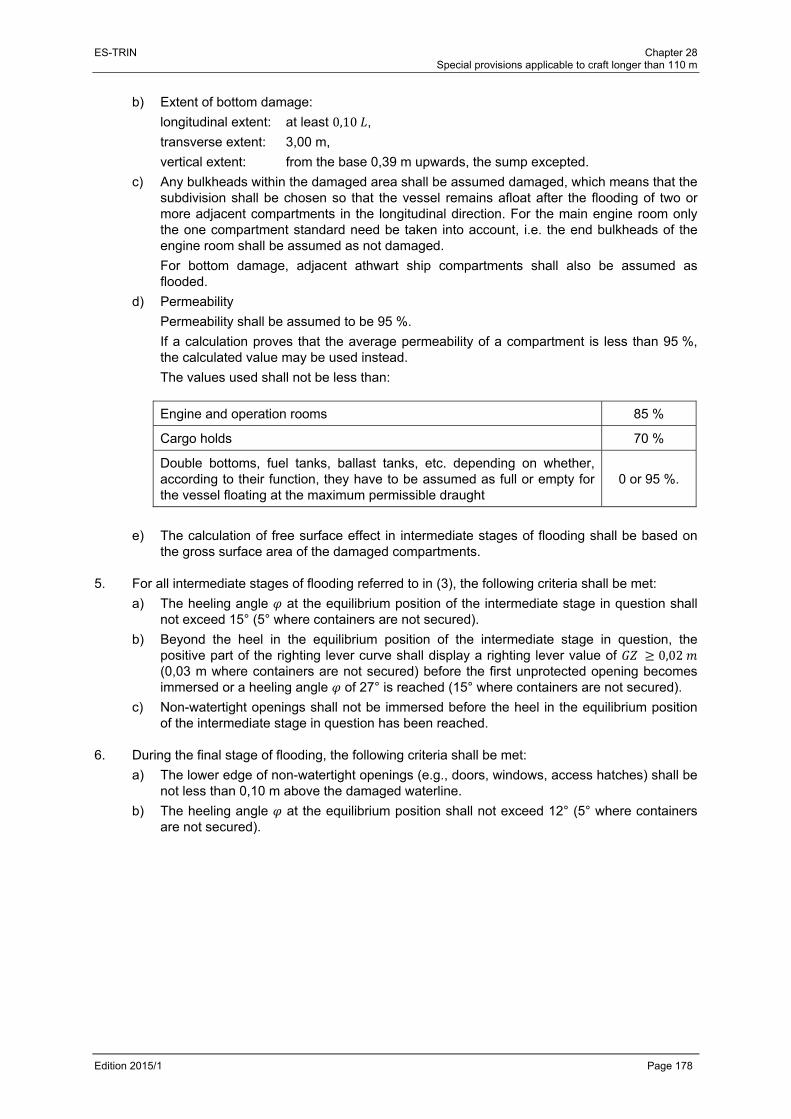
ES-TRIN Chapter 28 Special provisions applicable to craft longer than 110 m
Edition 2015/1 Page 178
b) Extent of bottom damage:
longitudinal extent: at least 0,10 ,
transverse extent: 3,00 m,
vertical extent: from the base 0,39 m upwards, the sump excepted.
c) Any bulkheads within the damaged area shall be assumed damaged, which means that the subdivision shall be chosen so that the vessel remains afloat after the flooding of two or more adjacent compartments in the longitudinal direction. For the main engine room only the one compartment standard need be taken into account, i.e. the end bulkheads of the engine room shall be assumed as not damaged.
For bottom damage, adjacent athwart ship compartments shall also be assumed as flooded.
d) Permeability
Permeability shall be assumed to be 95 %.
If a calculation proves that the average permeability of a compartment is less than 95 %, the calculated value may be used instead.
The values used shall not be less than:
Engine and operation rooms 85 %
Cargo holds 70 %
Double bottoms, fuel tanks, ballast tanks, etc. depending on whether, according to their function, they have to be assumed as full or empty for the vessel floating at the maximum permissible draught
0 or 95 %.
e) The calculation of free surface effect in intermediate stages of flooding shall be based on the gross surface area of the damaged compartments.
5. For all intermediate stages of flooding referred to in (3), the following criteria shall be met:
a) The heeling angle at the equilibrium position of the intermediate stage in question shall not exceed 15° (5° where containers are not secured).
b) Beyond the heel in the equilibrium position of the intermediate stage in question, the positive part of the righting lever curve shall display a righting lever value of 0,02 (0,03 m where containers are not secured) before the first unprotected opening becomes immersed or a heeling angle of 27° is reached (15° where containers are not secured).
c) Non-watertight openings shall not be immersed before the heel in the equilibrium position of the intermediate stage in question has been reached.
6. During the final stage of flooding, the following criteria shall be met:
a) The lower edge of non-watertight openings (e.g., doors, windows, access hatches) shall be not less than 0,10 m above the damaged waterline.
b) The heeling angle at the equilibrium position shall not exceed 12° (5° where containers are not secured).
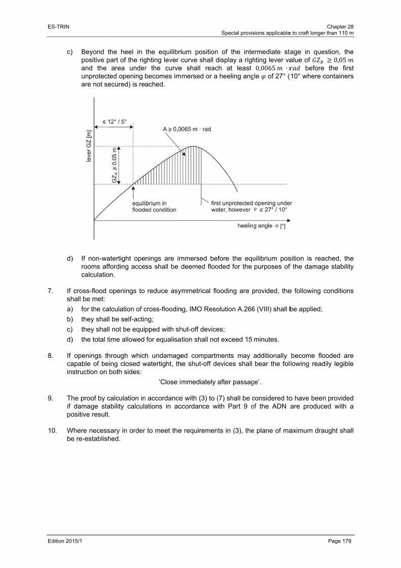
ES-TRIN
Edition 201
c)
d)
7. If
sh
a)
b)
c)
d) 8. If
cains
9. Th
if po
10. W
be
15/1
Beyond tpositive pand the unprotectare not se
) If non-warooms affcalculatio
cross-flood hall be met:
) for the ca
) they shal
they shal
) the total t
openings thapable of bestruction on
he proof by cdamage sta
ositive result
Where necesse re-establish
the heel in part of the rig
area underted opening ecured) is re
atertight opefording acce
on.
openings to
alculation of c
l be self-actin
l not be equi
time allowed
hrough whicing closed wboth sides:
calculation inability calcula.
sary in orderhed.
the equilibrighting lever cr the curvebecomes imached.
nings are imess shall be d
reduce asy
cross-floodin
ng;
pped with sh
for equalisa
h undamagewatertight, th
’Close i
n accordanceations in ac
r to meet the
ium positioncurve shall d
e shall reacmersed or a
mmersed bedeemed floo
ymmetrical flo
ng, IMO Reso
hut-off device
tion shall no
ed compartmhe shut-off de
mmediately
e with (3) to (ccordance w
e requiremen
Special provis
n of the intedisplay a righch at least
heeling ang
fore the equoded for the
ooding are p
olution A.266
es;
t exceed 15
ments may evices shall
after passag
(7) shall be cwith Part 9 o
nts in (3), the
sions applicable
ermediate stahting lever va0,0065 ∙le of 27° (
uilibrium pospurposes of
provided, the
6 (VIII) shall b
minutes.
additionally bear the fol
ge’.
considered toof the ADN
e plane of ma
e to craft longer
age in quesalue of
before (10° where c
sition is reacf the damage
e following c
be applied;
become floolowing readi
o have been are produce
aximum drau
Chapter 28 than 110 m
Page 179
stion, the 0,05
the first ontainers
ched, the e stability
conditions
oded are ily legible
provided ed with a
ught shall

ES-TRIN Chapter 28 Special provisions applicable to craft longer than 110 m
Edition 2015/1 Page 180
Article 28.04 Additional requirements
1. Craft whose length exceeds 110 m shall:
a) be fitted with a multi-propeller propulsion system, with at least two independent engines of equal power and a bow thruster that is controlled from the wheelhouse and is also effective when the craft is in an unladen state;
or
have a single-propeller propulsion system and a bow thruster that is controlled from the wheelhouse with its own power supply and which is also effective when the craft is in an unladen state and makes it possible for the craft to proceed under its own power in the event of a breakdown of the main propulsion system;
b) be fitted with a navigational radar installation, together with a rate-of-turn indicator in accordance with Article 7.06(1);
c) have a permanently-installed bilge pumping system in accordance with Article 8.08;
d) meet the requirements of Article 31.09(1.1). 2. By way of derogation from (1) and having regard to the applicable navigational authority
regulations for certain areas of navigation in the Member States, for craft, except passenger vessels, with a length of more than 110 m, which:
a) comply with (1)(a) to (d);
b) are capable of being separated, in the event of an accident, in the middle third of the craft without the use of heavy salvage equipment while the separated parts of the craft shall remain afloat after separation;
b) are provided with a certificate that shall be carried on board and which is issued by a recognised classification society regarding the buoyancy, trim position and stability of the separate parts of the craft, indicating the degree of loading above which buoyancy of the two parts is no longer ensured;
c) are built as double-hull vessels in accordance with the ADN, where for motor vessels sections 9.1.0.91 to 9.1.0.95, and for motor tankers paragraph 9.3.2.11.7 and sections 9.3.2.13 to 9.3.2.15 of Part 9 of the ADN shall apply;
d) are fitted with a multi-propeller propulsion system in accordance with (1)(a), first half sentence;
it shall be entered in item 52 of the inland navigation vessel certificate that they comply with all the requirements of (a) to (e).
3. By way of derogation from (1) and having regard to the applicable navigational authority
regulations for certain areas of navigation in the Member States, for passenger vessels with a length of more than 110 m which:
a) comply with (1)(a) to (d);
b) are built or converted for their highest class under the supervision of a recognised classification society, in which case compliance shall be confirmed by means of a attestation issued by the classification society. Maintaining class is not necessary;

ES-TRIN Chapter 28 Special provisions applicable to craft longer than 110 m
Edition 2015/1 Page 181
c) have a double bottom with a height of at least 600 mm and subdivision to ensure that, in the event of flooding of any two adjacent watertight compartments, the vessel does not immerse lower than the margin line and a residual safety clearance of 100 mm remains,
or
have a double bottom with a height of at least 600 mm and a double hull with a distance of at least 800 mm between the side wall of the vessel and the longitudinal bulkhead;
d) be fitted with a multi-propeller propulsion system with at least two independent engines of equal power and a bow thruster system which can be operated from the wheelhouse and which operates longitudinally as well as transversely;
e) allow the stern anchors to be operated directly from the wheelhouse; it shall be entered in item 52 of the inland navigation vessel certificate that they comply with all the requirements of (a) to (e).

ES-TRIN Chapter 28 Special provisions applicable to craft longer than 110 m
Edition 2015/1 Page 182
ES-TRIN Chapter 29 Special provisions applicable to high-speed vessels
Edition 2015/1 Page 183
CHAPTER 29 SPECIAL PROVISIONS APPLICABLE TO HIGH-SPEED VESSELS
Article 29.01
General 1. High-speed vessels shall not be constructed as cabin vessels. 2. The following installations are prohibited on board high-speed vessels:
a) appliances fitted with wick burners according to Article 16.02;
b) vaporising oil burner stoves according to Articles 16.03 and 16.04;
c) solid-fuel heating appliances according Article 16.07;
d) liquefied gas installations according to Chapter 17. 3. High-speed vessels shall be constructed and classified under the supervision and in
accordance with the applicable rules of a recognised classification society which has special rules for high-speed vessels. The class shall be maintained.
Article 29.02 Application of Parts II and III
1. Notwithstanding (2), Chapters 3 to 19 shall apply to high-speed vessels, with the exception of
the following provisions:
a) Article 3.04(6), second subparagraph;
b) Article 8.08(2), second sentence;
c) Article 14.02(4), second and third sentences;
d) Article 15.02(4), second sentence;
e) Article 19.06(3)(a), second sentence. 2. By way of derogation from Article 19.02(9), and Article 19.15(7), all doors in watertight
bulkheads shall be capable of being remotely controlled. 3. By way of derogation from Article 6.02(1), in case of failure or malfunctioning of the steering
apparatus drive unit a second independent steering apparatus drive unit or a manually operated drive unit shall come into operation without time delay.
4. In addition to the requirements of (1) to (3), high-speed vessels shall meet the requirements of
Articles 29.03 to 29.10.

ES-TRIN Chapter 29 Special provisions applicable to high-speed vessels
Edition 2015/1 Page 184
Article 29.03 Seats and safety belts
Seats shall be available for the maximum number of passengers permitted on board. Seats shall be fitted with safety belts. Safety belts may be dispensed with where suitable impact protection is provided or where they are not required under Chapter 4, part 6, of the HSC Code 2000.
Article 29.04 Freeboard
By way of derogation from Articles 4.02 and 4.03, the freeboard shall be at least 500 mm.
Article 29.05 Buoyancy, stability and subdivision
For high-speed vessels, sufficient proof shall be provided for:
a) buoyancy and stability characteristics adequate for safety where the craft is operated in the displacement mode, both when intact and when damaged;
b) stability characteristics and stabilising systems adequate for safety where the craft is operated in the dynamic buoyancy phase and the transition phase;
c) stability characteristics adequate for safety where the craft is operated in the dynamic buoyancy phase and the transitional phase, and allow to transfer the craft safely to displacement mode in case of any system malfunction.
Article 29.06 Wheelhouse
1. Arrangement
a) By way of derogation from Article 7.01(1), wheelhouses shall be arranged in such a way that the helmsman and a second member of the crew may at all times perform their tasks while the vessel is under way.
b) The steering position shall be arranged so as to accommodate work stations for the persons mentioned in (a). The instruments for navigation, manoeuvring, monitoring and communication and other important operating controls shall be sufficiently close together to allow a second member of the crew as well as the helmsman to obtain the necessary information and to operate the controls and installations as necessary while seated. The following requirements shall apply in all cases:
aa) the steering position for the helmsman shall be arranged so as to allow radar navigation by one person;
bb) the second member of the crew shall have his own radar screen (slave) at his work station and shall be able to intervene from his work station to transmit information and control the propulsion of the vessel.
c) The persons mentioned in (a) shall be able to operate the installations mentioned in (b) without any hindrance, including when safety belts are properly worn.

ES-TRIN Chapter 29 Special provisions applicable to high-speed vessels
Edition 2015/1 Page 185
2. Unobstructed view
a) By way of derogation from Article 7.02(2), the area of obstructed vision for the helmsman in a seated position ahead of the vessel shall not exceed one vessel length, irrespective of the loading conditions.
b) By way of derogation from Article 7.02(3), the sum of the blind sector arcs from dead ahead to 22,5° abaft the beam, on either side, shall not exceed 20°. Each individual blind sector shall not exceed 5°. The sector of visibility between two blind sectors shall not be less than 10°.
3. Instruments
Panels of control and monitoring instruments for the installations mentioned in Article 29.10 shall be in separate and clearly marked positions in the wheelhouse. This shall also apply, where appropriate, to controls for launching collective life-saving equipment.
4. Lighting
Red light shall be used for areas or pieces of equipment which shall be lit during use.
5. Windows
Reflections shall be avoided. A means for avoiding dazzle by sunlight shall be provided.
6. Surface materials
The use of reflective surface materials in the wheelhouse shall be avoided.
Article 29.07 Additional equipment
High-speed craft shall have the following equipment:
a) a navigational radar installation and rate-of-turn indicator according to Article 7.06(1); and
b) readily accessible individual life-saving equipment installed conforming to Article 19.09(4).
Article 29.08 Enclosed areas
1. General
Public rooms and accommodation and the equipment they contain shall be designed so that any person making proper use of those facilities will not suffer injury during a normal and emergency start or stop, or during manoeuvring in normal cruise and in failure or malfunction conditions.
ES-TRIN Chapter 29 Special provisions applicable to high-speed vessels
Edition 2015/1 Page 186
2. Communication
a) For the purpose of informing passengers of safety measures, all passenger vessels shall be fitted with optic and acoustic installations visible and audible to everyone on board.
b) The installations described under (a) shall enable the boatmaster to give instructions to passengers.
c) Every passenger shall have access to instructions for emergency situations close to their seat, including a plan of the vessel showing all exits, escape routes, emergency equipment, life-saving equipment and instructions for the use of lifejackets.
Article 29.09 Exits and escape routes
Exits and escape routes shall satisfy the following requirements:
a) There shall be easy, safe and quick access from the steering position to rooms and accommodation accessible to the public.
b) Escape routes leading to emergency exits shall be clearly and permanently marked.
c) All exits shall be properly marked. The operation of the opening mechanism shall be obvious from the outside and the inside.
d) The escape routes and emergency exits shall have a suitable safety guidance system.
e) Sufficient space for a member of the crew shall be left next to exits.
Article 29.10 Fire protection and fire-fighting
1. Corridors, rooms and accommodation accessible to the public and also galleys and engine
rooms shall be connected to an appropriate fire alarm system. Any fire and its location shall be indicated automatically in a place permanently manned by shipboard personnel or crew members.
2. Engine rooms shall be equipped with a permanently installed fire-fighting system according to
Article 13.05. 3. Rooms and accommodation accessible to the public and their escape routes shall be equipped
with a pressurised water sprinkler system according to Article 13.04. It shall be possible to drain the used water rapidly and directly to the outside.
ES-TRIN Chapter 30 Special provisions applicable to CRAFT equipped with propulsion or auxiliary systems operating on fuels with a flashpoint equal
to or lower than 55 C
Edition 2015/1 Page 187
CHAPTER 30 SPECIAL PROVISIONS APPLICABLE TO CRAFT EQUIPPED WITH
PROPULSION OR AUXILIARY SYSTEMS OPERATING ON FUELS WITH A FLASHPOINT EQUAL TO OR LOWER THAN 55 °C
Article 30.01
General 1. For the purpose of this chapter “propulsion and auxiliary systems” means any system using fuel,
including:
a) fuel tanks, and tank connections,
b) gas preparation systems,
c) piping and valves,
d) engines and turbines,
e) control, monitoring and safety systems. 2. By way of derogation from Article 8.01(3) and Article 8.05(1), (6), (9), (11) and (12) and the
provisions of chapter 9 propulsion and auxiliary systems operating on fuels with a flashpoint equal to or lower than 55 °C may be installed on craft provided that the requirements for these fuels laid down in this Chapter and Annex 8 have been complied with.
3. Propulsion and auxiliary systems according to (2) shall be constructed and installed under the
supervision of the inspection body. 4. For the purpose of discharging tasks pursuant to this chapter, the inspection body may employ
a technical service in accordance with Article 30.07. 5. Before commissioning of a propulsion or auxiliary system according to (2), the following
documents shall be submitted to the inspection body:
a) a risk assessment according to Annex 8,
b) a description of the propulsion or auxiliary system,
c) drawings of the propulsion or auxiliary system,
d) a diagram of the pressure and temperature within the system,
e) an operating manual containing all applicable procedures, intended for practical use of the system,
f) a safety rota according to Article 30.03,
g) a copy of the inspection certificate referred to in article 30.02(4). 6. A copy of the documents mentioned in (5) shall be carried on board.
ES-TRIN Chapter 30 Special provisions applicable to CRAFT equipped with propulsion or auxiliary systems operating on fuels with a flashpoint equal
to or lower than 55 C
Edition 2015/1 Page 188
Article 30.02 Testing
1. Propulsion and auxiliary systems operating on fuels with a flashpoint equal to or lower than
55 °C shall be inspected by an inspection body:
a) before commissioning,
b) after any modification or repair,
c) regularly, at least once a year. The relevant instructions of the manufacturers shall be taken into account in the process.
2. The inspections referred to in (1)(a) and (c), have to cover at least:
a) a check of conformity of the propulsion and auxiliary systems with the approved drawings and in the case of subsequent checks, whether alterations in the propulsion or auxiliary system were made,
b) if necessary a functional test of the propulsion and auxiliary systems for all operational possibilities,
c) a visual check and a tightness check of all system components, in particular valves, pipelines, hoses, pistons, pumps and filters,
d) a visual check of the electrical and electronic appliances of the installation,
e) a check of the control, monitoring, and safety systems. 3. The inspections referred to in (1)(b) shall include the concerned parts of (2). 4. For each inspection according to (1), an inspection attestation shall be issued showing the date
of inspection.
Article 30.03 Safety organisation
1. A safety rota shall be provided on board craft equipped with propulsion or auxiliary systems
operating on fuel with a flashpoint equal to or lower than 55 °C. The safety rota shall include safety instructions according to (2) and a safety plan according to (3) of the craft.
2. These safety instructions shall include at least the following information:
a) emergency shutdown of the system,
b) measures to be taken in the event of accidental release of liquid or gaseous fuel, for instance during bunkering,
c) measures to be taken in the event of fire or other incidents on board,
d) measures to be taken in the event of collision,
e) use of safety equipment,
f) raising the alert,
g) evacuation procedures.

ES-TRIN Chapter 30 Special provisions applicable to CRAFT equipped with propulsion or auxiliary systems operating on fuels with a flashpoint equal
to or lower than 55 C
Edition 2015/1 Page 189
3. The safety plan shall include at least the following information:
a) hazardous areas,
b) escape routes, emergency exits and gastight rooms,
c) life-saving equipment and ship’s boats,
d) fire extinguishers, fire-fighting systems and sprinkler systems,
e) alarm systems,
f) emergency circuit breakers’ controls,
g) fire dampers,
h) emergency power sources,
i) ventilation system controls,
j) controls for fuel supply lines,
k) safety equipment. 4. The safety rota shall:
a) be duly stamped by the inspection body, and
b) be prominently displayed at one or more appropriate points on board.
Article 30.04 Environmental requirements
1. The emissions from engines or turbines shall not exceed the applicable limit values specified in
the Article 7a or in the Annex XV of the directive 97/68/EC. 2. In the case of propulsion and auxiliary systems operating on natural gas, the values apply to
hydrocarbons, except to methane (CH4.). 3. Compliance with (1) shall be demonstrated by submitting a report to the inspection body on
test-bed measurement of gaseous and particulate exhaust emissions in accordance with International Standard ISO 8178-1 : 2006.
4. Appropriate measures shall be taken to minimise greenhouse gas emissions. The measures
shall be mentioned in the documents covered by Article 30.01(5)(b).
Article 30.05 Marking
Operation rooms and system components shall be appropriately marked so that it is clear for what fuels they are being used.
Article 30.06 Independent propulsion
In the event of an automatic shutdown of the propulsion system or parts of the propulsion system, the craft shall be able to make steerageway under its own power.

ES-TRIN Chapter 30 Special provisions applicable to CRAFT equipped with propulsion or auxiliary systems operating on fuels with a flashpoint equal
to or lower than 55 C
Edition 2015/1 Page 190
Article 30.07
Technical services 1. The technical services shall satisfy the European Standard EN ISO 17020 : 2012. 2. Manufacturers and distributors of propulsion or auxiliary systems, or parts of these systems,
cannot be recognised as technical services. 3. The technical service's expertise must comply with the relevant requirements from Annex 8. 4. The monitoring and testing according to Articles 30.01 and 30.02 may be performed by different
technical services provided that all the expertise described in (3) is taken into account in the process.

ES-TRIN Chapter 31 Special provisions applicable to vessels sailing with minimum crew
Edition 2015/1 Page 191
CHAPTER 31 SPECIAL PROVISIONS APPLICABLE TO VESSELS SAILING WITH MINIMUM CREW
Article 31.01
Vessels' equipment For motor vessels, pushers, pushed convoys and passenger vessels, compliance with, or failure to comply with, the provisions of Article 31.02 or Article 31.03 shall be entered in item 47 of the inland navigation vessel certificate by the inspection body.
Article 31.02 Standard S1
1. The propulsion systems shall be arranged in such a way that speed can be changed and the
direction of the propeller thrust reversed from the steering position.
It shall be possible for the auxiliary engines needed for operational purposes to be switched on or off from the steering position, unless this is done automatically or the engines run continuously during each voyage.
2. In the critical areas of,
- the temperature of the main-engine cooling water,
- the lubricating-oil pressure for the main engines and transmissions,
- the oil and air pressure of the main-engine reversing units, reversible transmissions or propellers,
- the bilge levels in the main engine room,
there shall be monitoring by means of instruments which set off optical and acoustic signals in the wheelhouse in the event of malfunction. The acoustic alarm signals may be combined in one audible warning device. They may be switched off as soon as the malfunction has been acknowledged. The visual alarm signals may only be switched off when the malfunctions which set them off have been corrected.
3. The fuel shall be supplied and main engines cooled automatically. 4. The steering system shall be able to be operated by one person, even in maximum draught,
without requiring particular force. 5. It shall be possible to give the optical and acoustic signals in accordance with the applicable
navigational authority regulations of the Member States, as appropriate, from the steering position of vessels under way.
6. Where there is no direct communication between the steering position and the fore-section, the
aft, the accommodation and the engine rooms, a voice communication system shall be provided. For communication with the engine rooms, this may be in the form of an optical or acoustic signal.
7. The operation of cranks and similar revolving parts of lifting devices shall not require a force of
more than 160 N.

ES-TRIN Chapter 31 Special provisions applicable to vessels sailing with minimum crew
Edition 2015/1 Page 192
8. The towing winches entered in the inland navigation vessel certificate shall be motorised. 9. The bilge and deck-wash pumps shall be motorised. 10. The principal control units and monitoring instruments shall be ergonomically arranged. 11. The equipment required under Article 6.01(1), shall be capable of being remotely operated from
the steering position.
Article 31.03 Standard S2
Standard S1 and additionally equipped with: 1. For motor vessels operating seperately:
a bow thruster which can be operated from the steering position; 2. For motor vessels propelling in side-by-side formation:
a bow thruster which can be operated from the steering position; 3. For motor vessels propelling pushed convoys made up of the motor vessel itself and a craft in
front:
hydraulic or electrically operated coupling winches. This equipment is, however, not required if the foremost vehicle in the pushed convoy is equipped with a bow thruster which can be operated from the steering position of the pushing motor vessel;
4. For pushers propelling a pushed convoy:
hydraulic or electric coupling winches. This equipment is, however, not required if the foremost craft in the pushed convoy is equipped with a bow thruster which can be operated from the steering position of the pusher;
5. For passenger vessels:
a bow thruster which can be operated from the steering position. This equipment is, however, not required if the propulsion system and steering system of the passenger vessel guarantee equal manoeuvrability.
ES-TRIN Chapter 32 Transitional provisions for craft navigating on the Rhine (zone R) -Article 32.01 - Article 32.02
Edition 2015/1 Seite 193
PART IV TRANSITIONAL PROVISIONS
CHAPTER 32
TRANSITIONAL PROVISIONS FOR CRAFT NAVIGATING ON THE RHINE (ZONE R)
Article 32.01 Applicability of transitional provisions to craft which are already in service
1. The provisions of Articles 32.02 to 32.04 apply only to craft in possession of a valid Rhine vessel inspection certificate:
a) first issued according to the Rhine Vessel Inspection Regulations in force on 31 December 1994, or
b) renewed at least once before the 31 December 1994, or
c) which were under construction or undergoing conversion on 31 December 1994.
2. For craft not covered by (1), the provisions of Article 32.05 apply.
Article 32.02 Transitional provisions for craft which are already in service
1. Craft that do not fully comply with the requirements of this Standard shall:
a) be adapted to comply with those provisions in accordance with the transitional provisions listed in the table below, and
b) until their adaptation, comply with the Rhine Vessel Inspection Regulations in force on 31 December 1994.
In the event of a new inland navigation vessel certificate being issued to a craft as defined in Article 32.01(1), the Rhine vessel inspection certificate shall be submitted as corroboration, the Rhine vessel inspection certificate shall be withdrawn and the date the Rhine vessel inspection certificate was issued according to the Rhine Vessel Inspection Regulations in force on 31 December 1994 shall be entered in item 52 of the new inland navigation vessel certificate as follows:
“A Rhine vessel inspection certificate according to the Rhine Vessel Inspection Regulations in force on 31 December 1994 was issued on: …”
ES-TRIN Chapter 32 Transitional provisions for craft navigating on the Rhine (Zone R) - Article 32.02
Edition 2015/1 Page 194
2. The following definitions apply in the table below:
‘NRC’: the provision does not apply to craft which are already operating, unless the parts concerned are replaced or converted, i.e. the provision applies only to Newly-built craft and to the Replacement or Conversion of the parts or areas concerned. If existing parts are replaced by replacement parts using the same technology and of the same type, this does not constitute replacement ‘R’ within the meaning of the transitional provisions. ‘Issue or renewal of the inland navigation vessel certificate’: the provision must be complied with the time of the next issue or renewal of the inland navigation vessel certificate after the date indicated.
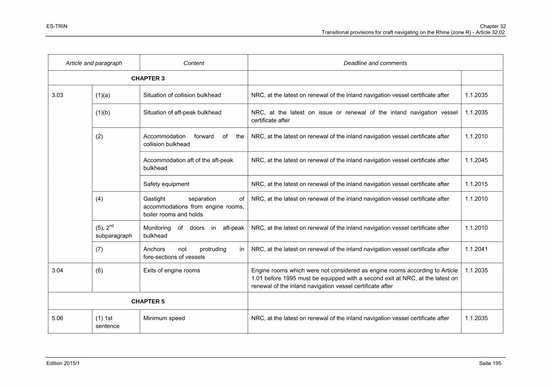
ES-TRIN Chapter 32 Transitional provisions for craft navigating on the Rhine (zone R) - Article 32.02
Edition 2015/1 Seite 195
Article and paragraph Content Deadline and comments
CHAPTER 3
3.03 (1)(a) Situation of collision bulkhead NRC, at the latest on renewal of the inland navigation vessel certificate after 1.1.2035
(1)(b) Situation of aft-peak bulkhead NRC, at the latest on issue or renewal of the inland navigation vessel certificate after
1.1.2035
(2) Accommodation forward of the collision bulkhead
NRC, at the latest on renewal of the inland navigation vessel certificate after 1.1.2010
Accommodation aft of the aft-peak bulkhead
NRC, at the latest on renewal of the inland navigation vessel certificate after 1.1.2045
Safety equipment NRC, at the latest on renewal of the inland navigation vessel certificate after 1.1.2015
(4) Gastight separation of accommodations from engine rooms, boiler rooms and holds
NRC, at the latest on renewal of the inland navigation vessel certificate after 1.1.2010
(5), 2nd subparagraph
Monitoring of doors in aft-peak bulkhead
NRC, at the latest on renewal of the inland navigation vessel certificate after 1.1.2010
(7) Anchors not protruding in fore-sections of vessels
NRC, at the latest on renewal of the inland navigation vessel certificate after 1.1.2041
3.04 (6) Exits of engine rooms Engine rooms which were not considered as engine rooms according to Article 1.01 before 1995 must be equipped with a second exit at NRC, at the latest on renewal of the inland navigation vessel certificate after
1.1.2035
CHAPTER 5
5.06 (1) 1st sentence
Minimum speed NRC, at the latest on renewal of the inland navigation vessel certificate after 1.1.2035

ES-TRIN Chapter 32 Transitional provisions for craft navigating on the Rhine (Zone R) - Article 32.02
Edition 2015/1 Page 196
Article and paragraph Content Deadline and comments
CHAPTER 6
6.01 (1) Manoeuvrability required by Chapter 5 NRC, at the latest on renewal of the inland navigation vessel certificate after 1.1.2035
(3) Permanent lists and ambient temperatures
NRC, at the latest on renewal of the inland navigation vessel certificate after 1.1.2010
(7) Design of rudder stocks NRC, at the latest on renewal of the inland navigation vessel certificate after 1.1.2015
6.02 (1) Presence of separate hydraulic tanks NRC, at the latest on renewal of the inland navigation vessel certificate after 1.1.2010
Duplicated pilot valves in case of hydraulic drive units
NRC, at the latest on renewal of the inland navigation vessel certificate after 1.1.2020
Separated pipework for the second drive unit in case of hydraulic drive units
NRC, at the latest on renewal of the inland navigation vessel certificate after 1.1.2020
(2) Separated pipework for the second drive unit in case of hydraulic drive units
NRC, at the latest on renewal of the inland navigation vessel certificate after 1.1.2010
(3) Manoeuvrability required by Chapter 5 ensured by second drive unit or manual drive
NRC, at the latest on renewal of the inland navigation vessel certificate after 1.1.2035
6.03 (1) Connection of other consumers to hydraulic steering apparatus drive unit.
NRC, at the latest on renewal of the inland navigation vessel certificate after 1.1.2010
6.05 (1) Wheel of manual drive not driven by powered drive unit
NRC, at the latest on renewal of the inland navigation vessel certificate after 1.1.2010
6.06 (1) Two independent steering controls NRC, at the latest on renewal of the inland navigation vessel certificate after 1.1.2015

ES-TRIN Chapter 32 Transitional provisions for craft navigating on the Rhine (Zone R) - Article 32.02
Edition 2015/1 Page 197
Article and paragraph Content Deadline and comments
6.07 (2)(a) Level alarm of the hydraulic tanks and alarm of the service pressure
NRC, at the latest on renewal of the inland navigation vessel certificate after 1.1.2010
(2) (e) Monitoring of buffer devices NRC, at the latest on renewal of the inland navigation vessel certificate.
6.08 (1) Requirements for electrical equipment according to Article 9.20
NRC, at the latest on renewal of the inland navigation vessel certificate after 1.1.2015
CHAPTER 7
7.02 (3) 2nd subparagraph
Unobstructed view in the helmsman's usual axis of vision
NRC, at the latest on renewal of the inland navigation vessel certificate after 1.1.2015
(6) Minimal light transmission NRC, at the latest on renewal of the inland navigation vessel certificate after 1.1.2010
NRC for vessels with tinted windows satisfying the following conditions:
- The windows are tinted green and exhibit a minimum light transmission of 60 %,
- The wheelhouse ceiling is so designed as to preclude reflections on the windows,
- Light sources in the wheelhouse must be steplessly dimmable or capable of being switched off,
- All reasonable measures to avoid other reflections have been taken.
(6) Safety glass design NRC
7.03 (7) Shutdown of alarms NRC, at the latest on renewal of the inland navigation vessel certificate, unless the wheelhouse has been designed for radar navigation by one person
(8) Automatic switch to another power supply
NRC, at the latest on renewal of the inland navigation vessel certificate after 1.1.2010

ES-TRIN Chapter 32 Transitional provisions for craft navigating on the Rhine (Zone R) - Article 32.02
Edition 2015/1 Page 198
Article and paragraph Content Deadline and comments
7.04 (1) Control of main engines and steering systems
NRC, at the latest on renewal of the inland navigation vessel certificate.
(2) Control of each main engine Unless wheelhouses have been designed for radar navigation by one person: NRC, at the latest on renewal of the inland navigation vessel certificate after
1.1.2035 if the direction of motion can be achieved directly 1.1.2010 for other engines
(3) Display Unless wheelhouses have been designed for radar navigation by one person: NRC, at the latest on renewal of the inland navigation vessel certificate after
1.1.2010
(9) 3rd sentence
Control by a lever NRC, at the latest on renewal of the inland navigation vessel certificate after 1.1.2010
(4) 4th sentence
Clearly show the direction of the thrust NRC, at the latest on renewal of the inland navigation vessel certificate after 1.1.2010
7.05 (1) Navigation lights, their casings, accessories and light sources
Navigation lights, their casings, accessories, and light sources that fulfill the requirements for color and light intensity of navigation lights, and for the admission of signal lights for navigation on the Rhine, as of 30 November 2009 may still be used
7.06 (1) Rate-of-turn indicators, which have received an approval before 1.1.1990
Rate-of-turn indicators, which have received an approval before 1.1.1990 and have been installed before 1.1.2000, may be installed and used until renewal of the Union inland navigation certificate after 1.1.2015, if there is a valid installation certificate pursuant to Directive 2006/87/EC1 or Resolution CCNR 1989-II-35.
1 Directive 2006/87/EC of the European Parliament and of the Council of 12 December 2006 laying down technical requirements for inland waterway vessels and repealing Council Directive
82/714/EEC (OJ L 389, 30.12.2006).

ES-TRIN Chapter 32 Transitional provisions for craft navigating on the Rhine (Zone R) - Article 32.02
Edition 2015/1 Page 199
Article and paragraph Content Deadline and comments
(1) Radar navigation equipment and rate-of-turn indicators which have received an approval after 1.1.1990
Radar navigation equipment and rate-of-turn indicators which have received an approval on or after 1.1.1990 pursuant to the minimum requirements and test conditions for navigational radar installations used for navigation in inland waterway navigation on the Rhine and the minimum requirements and test conditions for rate-of-turn indicators used in inland waterway navigation on the Rhine may continue to be installed and operated if there is a valid installation certificate pursuant to Directive 2006/87/EC or Resolution CCNR 1989-II-35.
(3) Inland AIS equipment Inland AIS equipment with a type approval according to Edition 1.0 and 1.01 of the Test Standard may continue to installed until 30.11.2015 and may be operated beyond this date.
7.09 Alarm system NRC, at the latest on renewal of the inland navigation vessel certificate after 1.1.2010
7.12 1st subpara-graph
Retractable wheelhouses NRC, at the latest on renewal of the inland navigation vessel certificate.
Without hydraulic lowering system, NRC, at the latest on renewal of the inland navigation vessel certificate after
1.1.2035
2nd and 3rd subparagraphs
NRC, at the latest on renewal of the inland navigation vessel certificate.
CHAPTER 8
8.01 (3) Only internal-combustion engines burning fuels having a flashpoint of more than 55 °C
NRC, at the latest on renewal of the inland navigation vessel certificate after 1.1.2015
8.02 (1) Securing of engines against unintentional starting
NRC, at the latest on renewal of the inland navigation vessel certificate after 1.1.2010
(4) Screening of pipe NRC, at the latest on renewal of the inland navigation vessel certificate after 1.1.2025
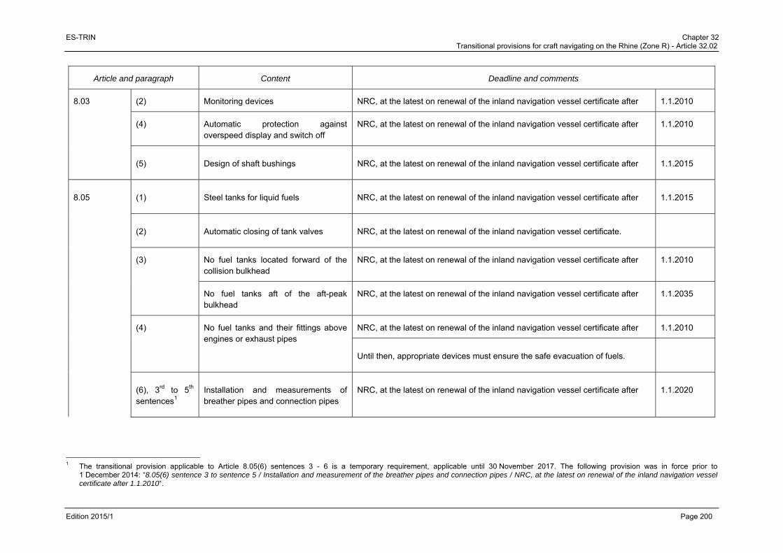
ES-TRIN Chapter 32 Transitional provisions for craft navigating on the Rhine (Zone R) - Article 32.02
Edition 2015/1 Page 200
Article and paragraph Content Deadline and comments
8.03 (2) Monitoring devices NRC, at the latest on renewal of the inland navigation vessel certificate after 1.1.2010
(4) Automatic protection against overspeed display and switch off
NRC, at the latest on renewal of the inland navigation vessel certificate after 1.1.2010
(5) Design of shaft bushings NRC, at the latest on renewal of the inland navigation vessel certificate after 1.1.2015
8.05 (1) Steel tanks for liquid fuels NRC, at the latest on renewal of the inland navigation vessel certificate after 1.1.2015
(2) Automatic closing of tank valves NRC, at the latest on renewal of the inland navigation vessel certificate.
(3) No fuel tanks located forward of the collision bulkhead
NRC, at the latest on renewal of the inland navigation vessel certificate after 1.1.2010
No fuel tanks aft of the aft-peak bulkhead
NRC, at the latest on renewal of the inland navigation vessel certificate after 1.1.2035
(4) No fuel tanks and their fittings above engines or exhaust pipes
NRC, at the latest on renewal of the inland navigation vessel certificate after 1.1.2010
Until then, appropriate devices must ensure the safe evacuation of fuels.
(6), 3rd to 5th sentences1
Installation and measurements of breather pipes and connection pipes
NRC, at the latest on renewal of the inland navigation vessel certificate after 1.1.2020
1 The transitional provision applicable to Article 8.05(6) sentences 3 - 6 is a temporary requirement, applicable until 30 November 2017. The following provision was in force prior to
1 December 2014: “8.05(6) sentence 3 to sentence 5 / Installation and measurement of the breather pipes and connection pipes / NRC, at the latest on renewal of the inland navigation vessel certificate after 1.1.2010“.

ES-TRIN Chapter 32 Transitional provisions for craft navigating on the Rhine (Zone R) - Article 32.02
Edition 2015/1 Page 201
Article and paragraph Content Deadline and comments
(7), 1st sentence
Quick-closing valve on the tank operated from deck, even when the rooms in question are closed
NRC, at the latest on renewal of the inland navigation vessel certificate after 1.1.2015
(9), 2nd sentence
Capacity-gauging devices to be legible up to maximum filling level
NRC, at the latest on renewal of the inland navigation vessel certificate after 1.1.2010
(13) Filling level control not only for main engines but also other engines needed for safe operation of the vessel
NRC, at the latest on renewal of the inland navigation vessel certificate after 1.1.2015
8.06 Tanks for lubricating oil, pipes and accessories
NRC, at the latest on renewal of the inland navigation vessel certificate after 1.1.2045
8.07 Tanks for oils in power transmission systems, control and activating systems and heating systems, pipes and accessories
NRC, at the latest on renewal of the inland navigation vessel certificate after 1.1.2045
8.08 (8) Simple closing device not sufficient for connection of ballast spaces to drainage pipes for holds capable of carrying ballast
NRC, at the latest on renewal of the inland navigation vessel certificate after 1.1.2010
(9) Gauging devices in hold bilges NRC, at the latest on renewal of the inland navigation vessel certificate after 1.1.2010

ES-TRIN Chapter 32 Transitional provisions for craft navigating on the Rhine (Zone R) - Article 32.02
Edition 2015/1 Page 202
Article and paragraph Content Deadline and comments
8.09 (2) Installations for the collection of oily water and used oil stores
NRC, at the latest on renewal of the inland navigation vessel certificate after 1.1.2010
8.10 (3) 1 Emission limit of 65 dB(A) for stationary vessels
NRC, at the latest on renewal of the inland navigation vessel certificate after 1.1.2020
CHAPTER 9
Compliance with the requirements of exhaust gas emission limit values
The regulations do not apply:
(a) for engines, which were installed before 1.1.2003; and
(b) for replacement engines2, which up to 31.12.2011 are installed on board craft which were in operation on 1.1.2002.
For engines which were installed:
(a) in craft between 1.1.2003 and 1.7.2007 the exhaust gas limit values as referred to in Annex XIV of Directive 97/68 apply;
(b) in craft or in on-board machinery after 30.6.2007 the exhaust gas limit values as referred to in Annex XV of Directive 97/68 apply.
The requirements for the categories:
(aa) V for propulsion engines and for auxiliary engines above 560 kW; and
(bb) D, E, F, G, H, I, J, K for auxiliary engines of Directive 97/68/EC apply as equivalent
1 The transitional provision applicable to Article 8.10(3) is a temporary requirement, applicable until 30 November 2017. The following transitional provision was in force prior to 01 December 2014:
“8.10(3) / Emission limit of 65 dB(A) for stationary vessels / NRC, at the latest on renewal of the inland navigation vessel certificate after 1.1.2015”. 2 A replacement engine is an overhauled second-hand engine, similar to the engine it replaces as regards power, speed and installation conditions.

ES-TRIN Chapter 32 Transitional provisions for craft navigating on the Rhine (Zone R) - Article 32.02
Edition 2015/1 Page 203
Article and paragraph Content Deadline and comments
CHAPTER 10
10.01 (1) 2nd sentence
Relevant documents to be submitted to the inspection body
NRC, at the latest on renewal of the inland navigation vessel certificate after 1.1.2035
(2)(b) Switching diagrams for main, emergency and distribution switchboard to be kept on board
NRC, at the latest on renewal of the inland navigation vessel certificate after 1.1.2010
(3) Ambient inside and deck temperatures NRC, at the latest on renewal of the inland navigation vessel certificate after 1.1.2010
10.02 (1) to (3) Electricity supply systems NRC, at the latest on renewal of the inland navigation vessel certificate after 1.1.2010
10.05 (4) Cross-section of the earthing conductors
NRC, at the latest on renewal of the inland navigation vessel certificate after 1.1.2015
10.11 (4) Effective ventilation when accumulators are installed in a closed compartment, cabinet or chest
NRC, at the latest on renewal of the inland navigation vessel certificate after
10.12 (2)(d) Direct supply of power consumers required for propelling and manoeuvring
NRC, at the latest on renewal of the inland navigation vessel certificate after 1.1.2015
(3)(b) Earth detection device capable of giving both visual and audible alarm
NRC, at the latest on renewal of the inland navigation vessel certificate after 1.1.2010
10.13 Emergency circuit breakers NRC, at the latest on renewal of the inland navigation vessel certificate after 1.1.2010
10.14 (3) 2nd sentence
Prohibition of single-pole switches in laundries, bathrooms, washrooms and other rooms with wet facilities
NRC, at the latest on renewal of the inland navigation vessel certificate after 1.1.2010
10.15 (2) Minimum cross-section of 1,5 mm2 per cable
NRC, at the latest on renewal of the inland navigation vessel certificate after 1.1.2010
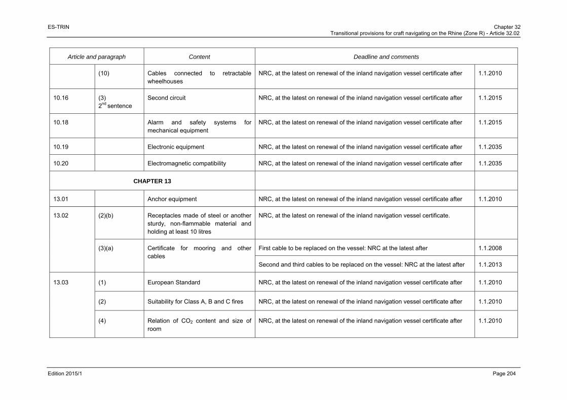
ES-TRIN Chapter 32 Transitional provisions for craft navigating on the Rhine (Zone R) - Article 32.02
Edition 2015/1 Page 204
Article and paragraph Content Deadline and comments
(10) Cables connected to retractable wheelhouses
NRC, at the latest on renewal of the inland navigation vessel certificate after 1.1.2010
10.16 (3) 2nd sentence
Second circuit NRC, at the latest on renewal of the inland navigation vessel certificate after 1.1.2015
10.18 Alarm and safety systems for mechanical equipment
NRC, at the latest on renewal of the inland navigation vessel certificate after 1.1.2015
10.19 Electronic equipment NRC, at the latest on renewal of the inland navigation vessel certificate after 1.1.2035
10.20 Electromagnetic compatibility NRC, at the latest on renewal of the inland navigation vessel certificate after 1.1.2035
CHAPTER 13
13.01 Anchor equipment NRC, at the latest on renewal of the inland navigation vessel certificate after 1.1.2010
13.02 (2)(b) Receptacles made of steel or another sturdy, non-flammable material and holding at least 10 litres
NRC, at the latest on renewal of the inland navigation vessel certificate.
(3)(a) Certificate for mooring and other cables
First cable to be replaced on the vessel: NRC at the latest after 1.1.2008
Second and third cables to be replaced on the vessel: NRC at the latest after 1.1.2013
13.03 (1) European Standard NRC, at the latest on renewal of the inland navigation vessel certificate after 1.1.2010
(2) Suitability for Class A, B and C fires NRC, at the latest on renewal of the inland navigation vessel certificate after 1.1.2010
(4) Relation of CO2 content and size of room
NRC, at the latest on renewal of the inland navigation vessel certificate after 1.1.2010

ES-TRIN Chapter 32 Transitional provisions for craft navigating on the Rhine (Zone R) - Article 32.02
Edition 2015/1 Page 205
Article and paragraph Content Deadline and comments
13.04 Permanently installed fire-fighting systems in accommodation spaces, wheelhouses and passenger rooms
NRC, at the latest on renewal of the inland navigation vessel certificate after 1.1.2035
13.05 Permanently installed fire-fighting systems in engine rooms, boiler rooms and pump rooms
NRC, at the latest on renewal of the inland navigation vessel certificate after 1
13.072 Application of the European Standard to dinghies
NRC, at the latest on renewal of the inland navigation vessel certificate after 1.1.2020
13.08 (2) Inflatable life jackets NRC, at the latest on renewal of the inland navigation vessel certificate after 1.1.2010
Life jackets which have been on board on 30.9.2003 may be used until the issue or renewal of the inland navigation vessel certificate after
1.1.2010
CHAPTER 14
14.02 (4)3 Equipping of the outer edges of decks, side decks and other work stations
NRC, at the latest on renewal of the inland navigation vessel certificate after 1.1.2020
1 a) Permanent CO2 fire-fighting systems installed before 1 October 1980 may remain in use until the renewal of the inland navigation certificate after 1.1.2035, if they comply with the
requirements of Article 7.03(5) of the Rhine Vessel Inspection Regulations in force on 1 April 1976 (Protocol CCNR 1975-I-23).
b) Permanent CO2 fire-fighting systems installed between 1 April 1992 and 31 December 1994 may remain in use until the renewal of the inland navigation certificate vessel after 1.1.2035, if they comply with the requirements of Article 7.03(5) of the Rhine Vessel Inspection Regulations in force on 31 December 1994.
c) Recommendations of the CCNR issued between 1 April 1992 and 31 December 1994 with regard to Article 7.03(5) of the Rhine Vessel Inspection Regulations in force on 31 December 1994 remain valid until renewal of the inland navigation vessel certificate after after 1.1.2035.
d) Article 13.05(2)(a) is only applicable until the renewal of the inland navigation vessel certificate after 1.1.2035 if those installations have been installed in vessels laid down after 1 October 1992.
2 The transitional provision applicable to Article 13.07 is a temporary requirement, applicable until 30 November 2017. The following transitional provision was in force prior to 1 December 2014: “13.07 / Application of the European standard to dinghies / NRC, at the latest on renewal of the inland navigation vessel certificate after 1.1.2015”.
3 Article 14.02(4) is a temporary requirement valid until 30 November 2017. The following transitional provision was in force prior to 1 December 2011: “14.02(4) / Equipping of the outer edges of decks, side decks and other work stations / NRC, at the latest on renewal of the inland navigation vessel certificate after 1.1.2015”.
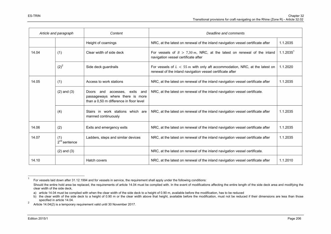
ES-TRIN Chapter 32 Transitional provisions for craft navigating on the Rhine (Zone R) - Article 32.02
Edition 2015/1 Page 206
Article and paragraph Content Deadline and comments
Height of coamings NRC, at the latest on renewal of the inland navigation vessel certificate after 1.1.2035
14.04 (1) Clear width of side deck For vessels of 7,30 , NRC, at the latest on renewal of the inland navigation vessel certificate after
1.1.20351
(2)2 Side deck guardrails For vessels of 55 with only aft accommodation, NRC, at the latest on renewal of the inland navigation vessel certificate after
1.1.2020
14.05 (1) Access to work stations NRC, at the latest on renewal of the inland navigation vessel certificate after 1.1.2035
(2) and (3) Doors and accesses, exits and passageways where there is more than a 0,50 m difference in floor level
NRC, at the latest on renewal of the inland navigation vessel certificate.
(4) Stairs in work stations which are manned continuously
NRC, at the latest on renewal of the inland navigation vessel certificate after 1.1.2035
14.06 (2) Exits and emergency exits NRC, at the latest on renewal of the inland navigation vessel certificate after 1.1.2035
14.07 (1) 2nd sentence
Ladders, steps and similar devices NRC, at the latest on renewal of the inland navigation vessel certificate after 1.1.2035
(2) and (3) NRC, at the latest on renewal of the inland navigation vessel certificate.
14.10 Hatch covers NRC, at the latest on renewal of the inland navigation vessel certificate after 1.1.2010
1 For vessels laid down after 31.12.1994 and for vessels in service, the requirement shall apply under the following conditions:
Should the entire hold area be replaced, the requirements of article 14.04 must be complied with. In the event of modifications affecting the entire length of the side deck area and modifying the clear width of the side deck,
a) article 14.04 must be complied with when the clear width of the side deck to a height of 0.90 m, available before the modification, has to be reduced b) the clear width of the side deck to a height of 0.90 m or the clear width above that height, available before the modification, must not be reduced if their dimensions are less than those
specified in article 14.04. 2 Article 14.04(2) is a temporary requirement valid until 30 November 2017.

ES-TRIN Chapter 32 Transitional provisions for craft navigating on the Rhine (Zone R) - Article 32.02
Edition 2015/1 Page 207
Article and paragraph Content Deadline and comments
14.11 Winches NRC, at the latest on renewal of the inland navigation vessel certificate after 1.1.2010
14.12 (2), (4), (5) and (9) 1
Manufacturer’s plate, protection devices, shipboard documents
NRC, at the latest on renewal of the inland navigation vessel certificate after 1.1.2020
14.13 Storing of flammable liquids NRC, at the latest on renewal of the inland navigation vessel certificate.
CHAPTER 15
15.01 (1) Accommodation for the persons lodging habitually on board
NRC, at the latest on renewal of the inland navigation vessel certificate after 1.1.2035
15.02 (3) Situation of floors NRC, at the latest on renewal of the inland navigation vessel certificate after 1.1.2035
(4) Communal living quarters and sleeping cabins
NRC, at the latest on renewal of the inland navigation vessel certificate after 1.1.2035
(6) Headroom in the accommodation NRC, at the latest on renewal of the inland navigation vessel certificate after 1.1.2035
(8) Free floor area of communal living quarters
NRC, at the latest on renewal of the inland navigation vessel certificate after 1.1.2035
(9) Cubic capacity of rooms NRC, at the latest on renewal of the inland navigation vessel certificate after 1.1.2035
(10) Volume of airspace per person NRC, at the latest on renewal of the inland navigation vessel certificate after 1.1.2035
1 The transitional provision applicable to Article 14.12(2), (4), (5) and (9) is a temporary requirement, applicable until 30 November 2017. The following transitional provision was in force prior to
1 December 2014: “14.12 / Manufacturer's plate, protection devices, shipboard documentation / NRC, no later than after the first renewal of the inland navigation vessel certificate after 1.1.2015”.

ES-TRIN Chapter 32 Transitional provisions for craft navigating on the Rhine (Zone R) - Article 32.02
Edition 2015/1 Page 208
Article and paragraph Content Deadline and comments
(11) Size of doors NRC, at the latest on renewal of the inland navigation vessel certificate after 1.1.2035
(12)(a) and (b) Situation of stairs NRC, at the latest on renewal of the inland navigation vessel certificate after 1.1.2035
(13) Pipes carrying dangerous gases or liquids
NRC, at the latest on renewal of the inland navigation vessel certificate after 1.1.2035
15.03 Sanitary installations NRC, at the latest on renewal of the inland navigation vessel certificate after 1.1.2035
15.04 Galleys NRC, at the latest on renewal of the inland navigation vessel certificate after 1.1.2035
15.06 Heating and ventilation NRC, at the latest on renewal of the inland navigation vessel certificate after 1.1.2035
15.07 (1) 2nd sentence
Other accommodation installations NRC, at the latest on renewal of the inland navigation vessel certificate after 1.1.2035
CHAPTER 18
18.01 (2) Tables 1 and 2, and (5)
Limit/control values and type approvals
NRC, as long as
a) the limit and control values do not exceed the values according to Article 18.01 by more than the factor 2,
b) the on-board sewage treatment plant has a manufacturer's or expert's certificate confirming that it can cope with the typical loading patterns on board the craft and
c) a system of sewage sludge management is in place for it which is appropriate to the conditions of operating a sewage treatment plant aboard a passenger vessel.

ES-TRIN Chapter 32 Transitional provisions for craft navigating on the Rhine (Zone R) - Article 32.02
Edition 2015/1 Page 209
Article and paragraph Content Deadline and comments
CHAPTER 19
19.01 (1)(d) Non-application of Article 10.14(3) second sentence for rated voltages of over 50 V
NRC, at the latest on renewal of the inland navigation vessel certificate after 1.1.2010
(2)(d) Prohibition of solid fuel heaters according to Article 16.07
NRC, at the latest on renewal of the inland navigation vessel certificate after 1.1.2010
The provision does not apply to craft with solid fuel engines (steam engines).
(2)(e) Prohibition of liquefied gas installations according to Chapter 17
NRC, at the latest on renewal of the inland navigation vessel certificate after 1.1.2045
The transitional provision applies only if alarm systems are fitted in accordance with Article 19.15(8).
(5) and (6) Obstructed vision ahead of the vessel 2 vessel lengths if less than 250 m Sufficient view astern
NRC, at the latest on renewal of the inland navigation vessel certificate 1.1.2045
19.02 (2) Number and position of bulkheads NRC, at the latest on renewal of the inland navigation vessel certificate after 1.1.2045
(3) Situation of aft-peak bulkhead NRC, at the latest on renewal of the inland navigation vessel certificate after 1.1.2035
This requirement does not apply to passenger vessels that due to the compliance with the basic requirements for the two-compartment status set out in article 19.03(9) or comply with the requirements of article 19.07 achieve an equivalent level of safety and manoeuvrability.
(5) 2nd sentence
Margin line if no bulkhead deck For passenger vessels which have been laid down before 1.1.1996, NRC, at the latest on renewal of the inland navigation vessel certificate after
1.1.2045
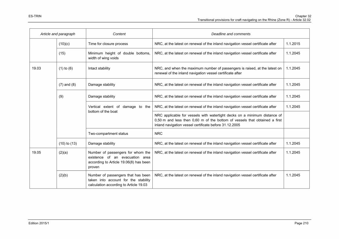
ES-TRIN Chapter 32 Transitional provisions for craft navigating on the Rhine (Zone R) - Article 32.02
Edition 2015/1 Page 210
Article and paragraph Content Deadline and comments
(10)(c) Time for closure process NRC, at the latest on renewal of the inland navigation vessel certificate after 1.1.2015
(15) Minimum height of double bottoms, width of wing voids
NRC, at the latest on renewal of the inland navigation vessel certificate after 1.1.2045
19.03 (1) to (6) Intact stability NRC, and when the maximum number of passengers is raised, at the latest on renewal of the inland navigation vessel certificate after
1.1.2045
(7) and (8) Damage stability NRC, at the latest on renewal of the inland navigation vessel certificate after 1.1.2045
(9) Damage stability NRC, at the latest on renewal of the inland navigation vessel certificate after 1.1.2045
Vertical extent of damage to the bottom of the boat
NRC, at the latest on renewal of the inland navigation vessel certificate after 1.1.2045
NRC applicable for vessels with watertight decks on a minimum distance of 0,50 m and less then 0,60 m of the bottom of vessels that obtained a first inland navigation vessel certificate before 31.12.2005
Two-compartment status NRC
(10) to (13) Damage stability NRC, at the latest on renewal of the inland navigation vessel certificate after 1.1.2045
19.05 (2)(a) Number of passengers for whom the existence of an evacuation area according to Article 19.06(8) has been proven
NRC, at the latest on renewal of the inland navigation vessel certificate after 1.1.2045
(2)(b) Number of passengers that has been taken into account for the stability calculation according to Article 19.03
NRC, at the latest on renewal of the inland navigation vessel certificate after 1.1.2045

ES-TRIN Chapter 32 Transitional provisions for craft navigating on the Rhine (Zone R) - Article 32.02
Edition 2015/1 Page 211
Article and paragraph Content Deadline and comments
19.06 (1) 1st sentence Passenger rooms on all decks aft of the collision bulkhead and, as long as they are below the bulkhead deck, forward of the aft peak bulkhead
NRC, at the latest on renewal of the inland navigation vessel certificate after 1.1.2045
(1) 2nd
sentence Enclosures NRC, at the latest on renewal of the inland navigation vessel certificate.
(3)(c) 1st sentence
Clear height of exits NRC, at the latest on renewal of the inland navigation vessel certificate after 1.1.2045
(3)(2) 2nd sentence
Clear width of doors of passenger cabins and other small rooms
NRC, at the latest on renewal of the inland navigation vessel certificate after 1.1.2045
(3) f) 1st sentence
Size of emergency exits NRC, at the latest on renewal of the inland navigation vessel certificate after 1.1.2045
(3)(g) Exits intended for use by persons with reduced mobility
NRC, at the latest on renewal of the inland navigation vessel certificate after 1.1.2045
(4)(d) Doors intended for use by persons with reduced mobility
NRC, at the latest on renewal of the inland navigation vessel certificate after 1.1.2045
(5) Requirements for connecting corridors NRC, at the latest on renewal of the inland navigation vessel certificate after 1.1.2045
(6)(b) Escape routes to evacuation areas NRC, at the latest on renewal of the inland navigation vessel certificate after 1.1.2045
(6)(c) 1 No escape routes through galleys NRC, at the latest on renewal of the inland navigation vessel certificate after 1.1.2020
1 The transitional provision applicable to Article 19.06(6)(c) is a temporary requirement, applicable until 30 November 2017. The following transitional provision was in force prior to
1 December 2014: “19.06(6)(c) / No Escape routes through galleys / NRC, at the latest on renewal of the inland navigation vessel certificate after 1.1.2015”.

ES-TRIN Chapter 32 Transitional provisions for craft navigating on the Rhine (Zone R) - Article 32.02
Edition 2015/1 Page 212
Article and paragraph Content Deadline and comments
(6)(d) No rungs, ladders or the like installed along the escape routes
NRC, at the latest on renewal of the inland navigation vessel certificate after 1.1.2045
(7) Suitable safety guidance system NRC, at the latest on renewal of the inland navigation vessel certificate after 1.1.2015
(8) Requirements for muster areas NRC, at the latest on renewal of the inland navigation vessel certificate after 1.1.2045
(9) Requirements for stairs and their landings in the passenger areas
NRC, at the latest on renewal of the inland navigation vessel certificate after 1.1.2045
(10)(a) 1st sentence
Railing according to European Standard EN 711 : 1995
NRC, at the latest on renewal of the inland navigation vessel certificate after 1.1.2045
(10)(a) 2nd sentence
Height of bulwarks and railings of decks intended for use by persons with reduced mobility
NRC, at the latest on renewal of the inland navigation vessel certificate after 1.1.2045
(10)(b) 2nd sentence
Clear width of openings used normally for the embarking or disembarking of persons with reduced mobility
NRC, at the latest on renewal of the inland navigation vessel certificate after 1.1.2045
(13) Passageways and walls in passageways intended for use by persons with reduced mobility
NRC, at the latest on renewal of the inland navigation vessel certificate after 1.1.2045
(14) 1st sentence
Design of glass doors and walls in passageways and window panes
NRC, at the latest on renewal of the inland navigation vessel certificate after 1.1.2045
(15) Requirements for superstructures that consist totally or partly of panoramic windows
NRC, at the latest on renewal of the inland navigation vessel certificate after 1.1.2045
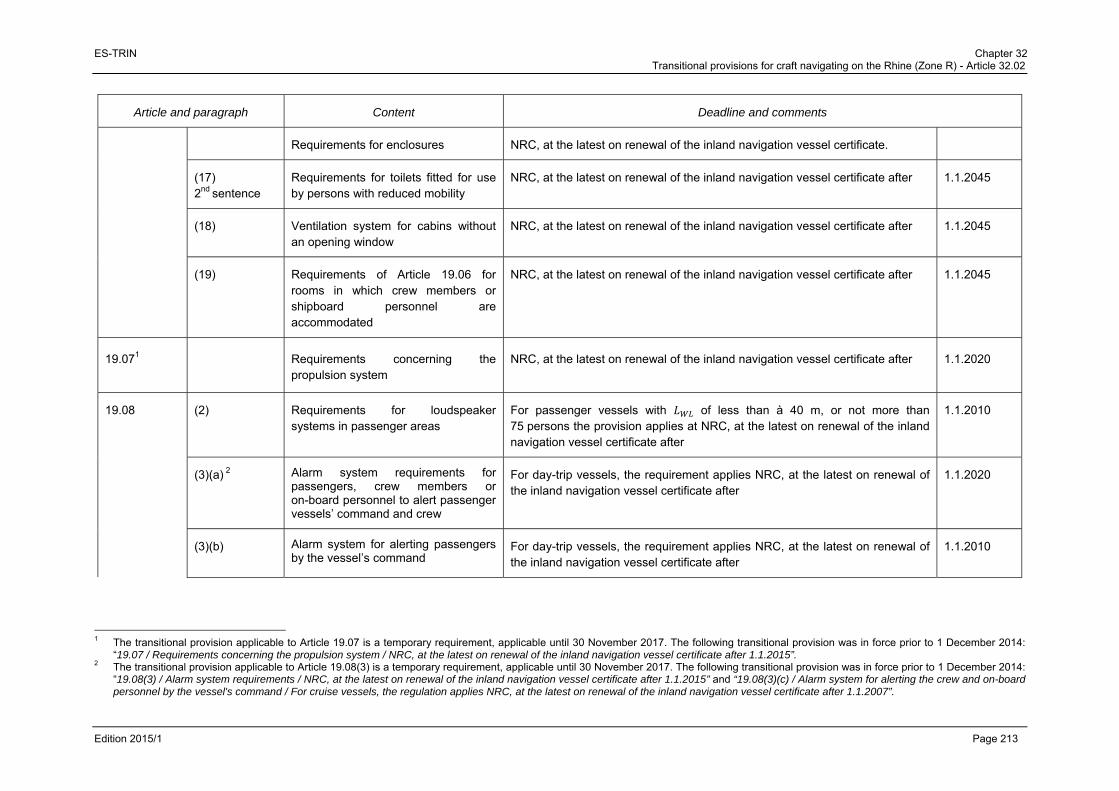
ES-TRIN Chapter 32 Transitional provisions for craft navigating on the Rhine (Zone R) - Article 32.02
Edition 2015/1 Page 213
Article and paragraph Content Deadline and comments
Requirements for enclosures NRC, at the latest on renewal of the inland navigation vessel certificate.
(17) 2nd sentence
Requirements for toilets fitted for use by persons with reduced mobility
NRC, at the latest on renewal of the inland navigation vessel certificate after 1.1.2045
(18) Ventilation system for cabins without an opening window
NRC, at the latest on renewal of the inland navigation vessel certificate after 1.1.2045
(19) Requirements of Article 19.06 for rooms in which crew members or shipboard personnel are accommodated
NRC, at the latest on renewal of the inland navigation vessel certificate after 1.1.2045
19.071 Requirements concerning the propulsion system
NRC, at the latest on renewal of the inland navigation vessel certificate after 1.1.2020
19.08 (2) Requirements for loudspeaker systems in passenger areas
For passenger vessels with of less than à 40 m, or not more than 75 persons the provision applies at NRC, at the latest on renewal of the inland navigation vessel certificate after
1.1.2010
(3)(a) 2 Alarm system requirements for passengers, crew members or on-board personnel to alert passenger vessels’ command and crew
For day-trip vessels, the requirement applies NRC, at the latest on renewal of the inland navigation vessel certificate after
1.1.2020
(3)(b) Alarm system for alerting passengers by the vessel’s command
For day-trip vessels, the requirement applies NRC, at the latest on renewal of the inland navigation vessel certificate after
1.1.2010
1 The transitional provision applicable to Article 19.07 is a temporary requirement, applicable until 30 November 2017. The following transitional provision was in force prior to 1 December 2014:
“19.07 / Requirements concerning the propulsion system / NRC, at the latest on renewal of the inland navigation vessel certificate after 1.1.2015”. 2 The transitional provision applicable to Article 19.08(3) is a temporary requirement, applicable until 30 November 2017. The following transitional provision was in force prior to 1 December 2014:
“19.08(3) / Alarm system requirements / NRC, at the latest on renewal of the inland navigation vessel certificate after 1.1.2015” and “19.08(3)(c) / Alarm system for alerting the crew and on-board personnel by the vessel's command / For cruise vessels, the regulation applies NRC, at the latest on renewal of the inland navigation vessel certificate after 1.1.2007”.
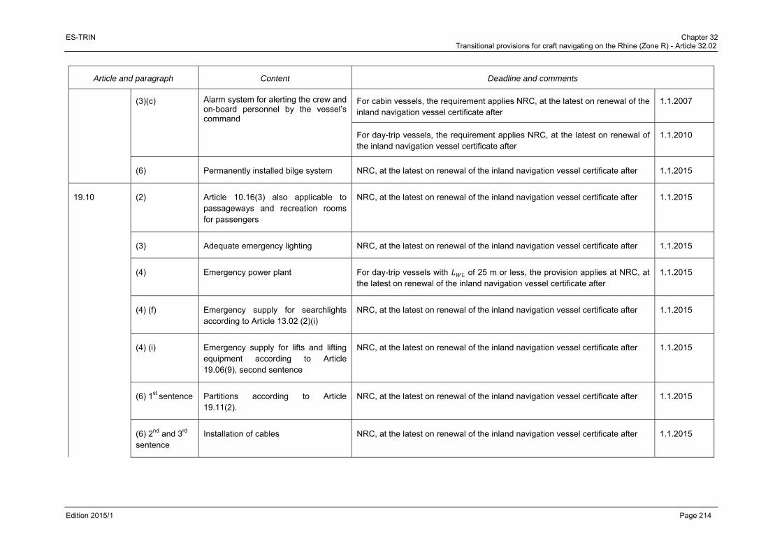
ES-TRIN Chapter 32 Transitional provisions for craft navigating on the Rhine (Zone R) - Article 32.02
Edition 2015/1 Page 214
Article and paragraph Content Deadline and comments
(3)(c) Alarm system for alerting the crew and on-board personnel by the vessel’s command
For cabin vessels, the requirement applies NRC, at the latest on renewal of the inland navigation vessel certificate after
1.1.2007
For day-trip vessels, the requirement applies NRC, at the latest on renewal of the inland navigation vessel certificate after
1.1.2010
(6) Permanently installed bilge system NRC, at the latest on renewal of the inland navigation vessel certificate after 1.1.2015
19.10 (2) Article 10.16(3) also applicable to passageways and recreation rooms for passengers
NRC, at the latest on renewal of the inland navigation vessel certificate after 1.1.2015
(3) Adequate emergency lighting NRC, at the latest on renewal of the inland navigation vessel certificate after 1.1.2015
(4) Emergency power plant For day-trip vessels with of 25 m or less, the provision applies at NRC, at the latest on renewal of the inland navigation vessel certificate after
1.1.2015
(4) (f) Emergency supply for searchlights according to Article 13.02 (2)(i)
NRC, at the latest on renewal of the inland navigation vessel certificate after 1.1.2015
(4) (i) Emergency supply for lifts and lifting equipment according to Article 19.06(9), second sentence
NRC, at the latest on renewal of the inland navigation vessel certificate after 1.1.2015
(6) 1st sentence Partitions according to Article 19.11(2).
NRC, at the latest on renewal of the inland navigation vessel certificate after 1.1.2015
(6) 2nd and 3rd sentence
Installation of cables NRC, at the latest on renewal of the inland navigation vessel certificate after 1.1.2015

ES-TRIN Chapter 32 Transitional provisions for craft navigating on the Rhine (Zone R) - Article 32.02
Edition 2015/1 Page 215
Article and paragraph Content Deadline and comments
(6) 4th sentence Emergency power plant above the margin line
NRC, at the latest on renewal of the inland navigation vessel certificate after 1.1.2015
19.11 (1) Suitability for fire protection of materials and components
NRC, at the latest on renewal of the inland navigation vessel certificate after 1.1.2045
(2) Design of partitions NRC, at the latest on renewal of the inland navigation vessel certificate after 1.1.2045
(3) Paints, lacquers and other surface treatment products as well as deck coverings used in rooms except engine rooms and store rooms shall be flame-retardant
NRC, at the latest on renewal of the inland navigation vessel certificate after 1.1.2015
(4) Lounge ceilings and wall claddings manufactured from non-combustible material
NRC, at the latest on renewal of the inland navigation vessel certificate after 1.1.2045
(5) Furniture and fittings in muster areas manufactured from non-combustible material
NRC, at the latest on renewal of the inland navigation vessel certificate after 1.1.2045
(6) Tested according to Code NRC, at the latest on renewal of the inland navigation vessel certificate after 1.1.2045
(7) Insulation materials in lounges NRC, at the latest on renewal of the inland navigation vessel certificate after 1.1.2045
(8) Enclosures NRC, at the latest on renewal of the inland navigation vessel certificate.
(9) Requirements for doors in partitions NRC, at the latest on renewal of the inland navigation vessel certificate after 1.1.2045

ES-TRIN Chapter 32 Transitional provisions for craft navigating on the Rhine (Zone R) - Article 32.02
Edition 2015/1 Page 216
Article and paragraph Content Deadline and comments
(10) Walls according to (2) On cabin vessels without automatic pressurised-water spraying systems, ends of walls between cabins: NRC, at the latest on renewal of the inland navigation vessel certificate after
1.1.2010
(11) Partitions NRC, at the latest on renewal of the inland navigation vessel certificate after 1.1.2045
(12) Draught stops NRC, at the latest on renewal of the inland navigation vessel certificate after 1.1.2045
(13) Stairs made of steel or another equivalent non-combustible material
NRC, at the latest on renewal of the inland navigation vessel certificate after 1.1.2045
(14) Internal stairs encapsulated at all levels by walls according to (2).
NRC, at the latest on renewal of the inland navigation vessel certificate after 1.1.2045
(15) Ventilation systems and air supply systems
NRC, at the latest on renewal of the inland navigation vessel certificate after 1.1.2045
(16) Ventilation systems in galleys and stoves with extractors
NRC, at the latest on renewal of the inland navigation vessel certificate after 1.1.2045
(17) Control centres, stairwells, muster areas and smoke extraction systems
NRC, at the latest on renewal of the inland navigation vessel certificate after 1.1.2045
(18) Fire alarm system For day-trip vessels: NRC, at the latest on renewal of the inland navigation vessel certificate after
1.1.2010
19.12 (8)(d) Installation of fire extinguishing pumps Both pumps: NRC, at the latest on renewal of the inland navigation vessel certificate after
1.1.2035
(9) Fire-extinguishing system in engine rooms
NRC, at the latest on renewal of the inland navigation vessel certificate after 1.1.2015

ES-TRIN Chapter 32 Transitional provisions for craft navigating on the Rhine (Zone R) - Article 32.02
Edition 2015/1 Page 217
Article and paragraph Content Deadline and comments
19.14 (1) Waste water collection tanks and disposal facilities
For cabin vessels with no more than 50 berths and for day-trip vessels: NRC, at the latest on renewal of the inland navigation vessel certificate after
1.1.2045
(2) Requirements for waste water collection tanks
For cabin vessels with no more than 50 berths and for day-trip vessels with no more than 50 passengers: NRC, at the latest on renewal of the inland navigation vessel certificate after
1.1.2045
19.15 (1) Damage stability NRC, at the latest on renewal of the inland navigation vessel certificate after 1.1.2045
CHAPTER 21
21.01 (2) Special winches or equivalent coupling devices to be used for pushing purposes
For craft certified before 1.1.1995 for pushing without proper securing equipment: NRC, at the latest on renewal of the inland navigation vessel certificate after
1.1.2035
(3) last sentence
Requirements for drive units NRC, at the latest on renewal of the inland navigation vessel certificate after 1.1.2035
CHAPTER 22
22.02 (3) Additional requirements The same transitional provisions as those indicated under the relevant article apply.
22.03 (1) General alarm system NRC, at the latest on renewal of the inland navigation vessel certificate.
(4) Maximum authorised load NRC, at the latest on renewal of the inland navigation vessel certificate.
22.04 (2) and 3 Residual safety clearance NRC, at the latest on renewal of the inland navigation vessel certificate.
22.06 Heeling test NRC, at the latest on renewal of the inland navigation vessel certificate.
22.07 Proof of stability NRC, at the latest on renewal of the inland navigation vessel certificate.

ES-TRIN Chapter 32 Transitional provisions for craft navigating on the Rhine (Zone R) - Article 32.02
Edition 2015/1 Page 218
Article and paragraph Content Deadline and comments
22.08 Proof of stability in the case of reduced residual freeboard
NRC, at the latest on renewal of the inland navigation vessel certificate.
22.09 Draught marks and draught scales NRC, at the latest on renewal of the inland navigation vessel certificate.
CHAPTER 25
25.01 Application of Articles 7.01(2), 8.05(13) and 8.10
For seagoing vessels not intended for the carriage of substances referred to in the ADN and the keel of which was laid before 1.10.1987: NRC, at the latest on renewal of the inland navigation vessel certificate after
1.1.2015
Application of Article 8.09(2) NRC, at the latest on renewal of the inland navigation vessel certificate after 1.1.2010
CHAPTER 26
26.01 For recreational craft built before 1.1.1995: NRC, at the latest on renewal of the inland navigation vessel certificate after
1.1.2035
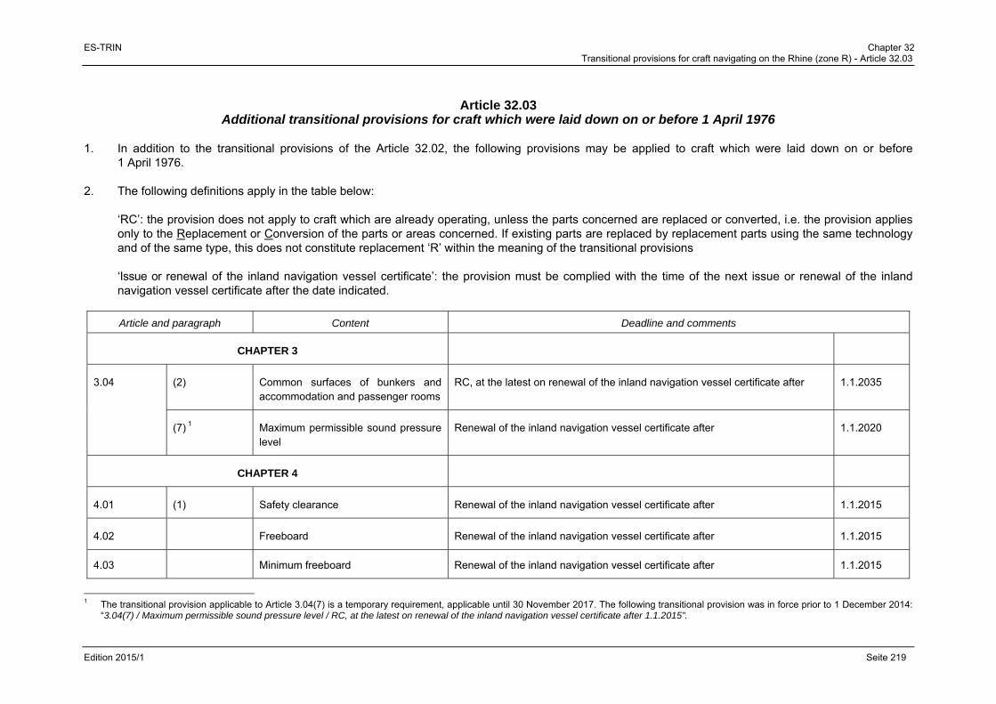
ES-TRIN Chapter 32 Transitional provisions for craft navigating on the Rhine (zone R) - Article 32.03
Edition 2015/1 Seite 219
Article 32.03
Additional transitional provisions for craft which were laid down on or before 1 April 1976 1. In addition to the transitional provisions of the Article 32.02, the following provisions may be applied to craft which were laid down on or before
1 April 1976. 2. The following definitions apply in the table below:
‘RC’: the provision does not apply to craft which are already operating, unless the parts concerned are replaced or converted, i.e. the provision applies only to the Replacement or Conversion of the parts or areas concerned. If existing parts are replaced by replacement parts using the same technology and of the same type, this does not constitute replacement ‘R’ within the meaning of the transitional provisions ‘Issue or renewal of the inland navigation vessel certificate’: the provision must be complied with the time of the next issue or renewal of the inland navigation vessel certificate after the date indicated.
Article and paragraph Content Deadline and comments
CHAPTER 3
3.04 (2) Common surfaces of bunkers and accommodation and passenger rooms
RC, at the latest on renewal of the inland navigation vessel certificate after 1.1.2035
(7) 1 Maximum permissible sound pressure level
Renewal of the inland navigation vessel certificate after 1.1.2020
CHAPTER 4
4.01 (1) Safety clearance Renewal of the inland navigation vessel certificate after 1.1.2015
4.02 Freeboard Renewal of the inland navigation vessel certificate after 1.1.2015
4.03 Minimum freeboard Renewal of the inland navigation vessel certificate after 1.1.2015
1 The transitional provision applicable to Article 3.04(7) is a temporary requirement, applicable until 30 November 2017. The following transitional provision was in force prior to 1 December 2014:
“3.04(7) / Maximum permissible sound pressure level / RC, at the latest on renewal of the inland navigation vessel certificate after 1.1.2015”.
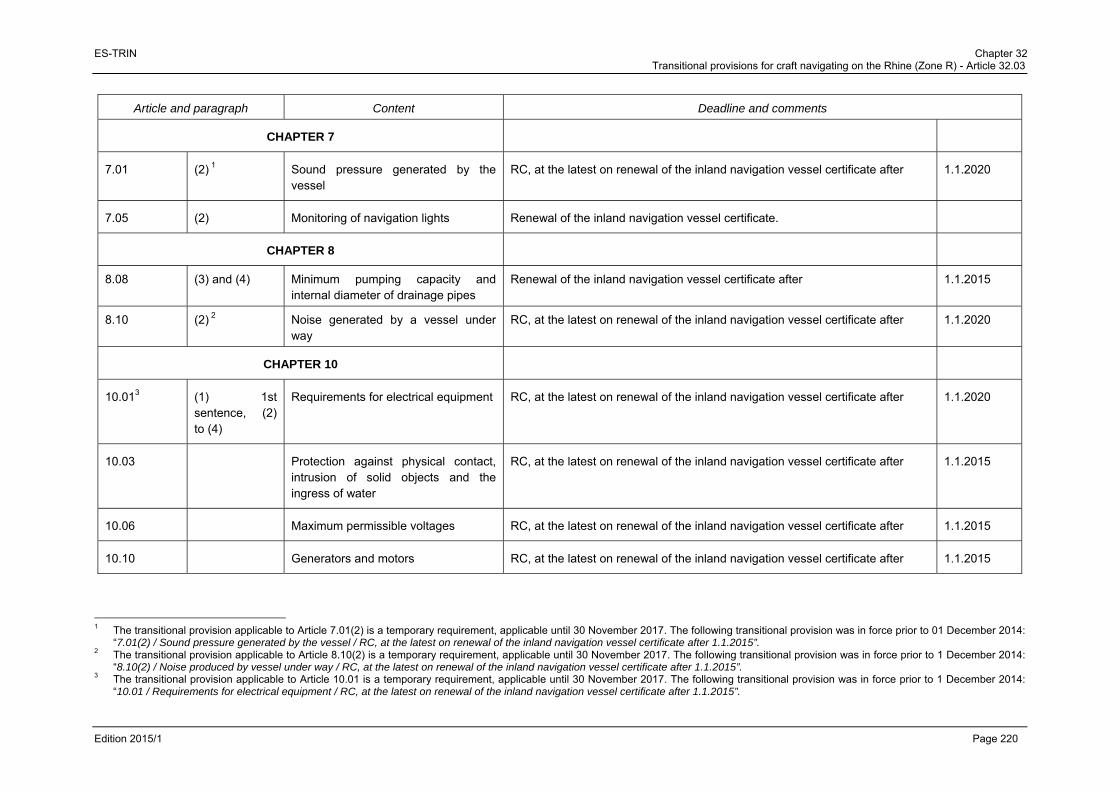
ES-TRIN Chapter 32 Transitional provisions for craft navigating on the Rhine (Zone R) - Article 32.03
Edition 2015/1 Page 220
Article and paragraph Content Deadline and comments
CHAPTER 7
7.01 (2) 1 Sound pressure generated by the vessel
RC, at the latest on renewal of the inland navigation vessel certificate after 1.1.2020
7.05 (2) Monitoring of navigation lights Renewal of the inland navigation vessel certificate.
CHAPTER 8
8.08 (3) and (4) Minimum pumping capacity and internal diameter of drainage pipes
Renewal of the inland navigation vessel certificate after 1.1.2015
8.10 (2) 2 Noise generated by a vessel under way
RC, at the latest on renewal of the inland navigation vessel certificate after 1.1.2020
CHAPTER 10
10.013 (1) 1st sentence, (2) to (4)
Requirements for electrical equipment RC, at the latest on renewal of the inland navigation vessel certificate after 1.1.2020
10.03 Protection against physical contact, intrusion of solid objects and the ingress of water
RC, at the latest on renewal of the inland navigation vessel certificate after 1.1.2015
10.06 Maximum permissible voltages RC, at the latest on renewal of the inland navigation vessel certificate after 1.1.2015
10.10 Generators and motors RC, at the latest on renewal of the inland navigation vessel certificate after 1.1.2015
1 The transitional provision applicable to Article 7.01(2) is a temporary requirement, applicable until 30 November 2017. The following transitional provision was in force prior to 01 December 2014:
“7.01(2) / Sound pressure generated by the vessel / RC, at the latest on renewal of the inland navigation vessel certificate after 1.1.2015”. 2 The transitional provision applicable to Article 8.10(2) is a temporary requirement, applicable until 30 November 2017. The following transitional provision was in force prior to 1 December 2014:
“8.10(2) / Noise produced by vessel under way / RC, at the latest on renewal of the inland navigation vessel certificate after 1.1.2015”. 3 The transitional provision applicable to Article 10.01 is a temporary requirement, applicable until 30 November 2017. The following transitional provision was in force prior to 1 December 2014:
“10.01 / Requirements for electrical equipment / RC, at the latest on renewal of the inland navigation vessel certificate after 1.1.2015”.

ES-TRIN Chapter 32 Transitional provisions for craft navigating on the Rhine (Zone R) - Article 32.03
Edition 2015/1 Page 221
Article and paragraph Content Deadline and comments
10.11 (2) Installation of accumulators RC, at the latest on renewal of the inland navigation vessel certificate after 1.1.2015
10.12 Switchgear installations RC, at the latest on renewal of the inland navigation vessel certificate after 1.1.2015
10.14 Installation fittings RC, at the latest on renewal of the inland navigation vessel certificate after 1.1.2015
10.15 Cables RC, at the latest on renewal of the inland navigation vessel certificate after 1.1.2015
10.17 Navigation lights RC, at the latest on renewal of the inland navigation vessel certificate after 1.1.2015
CHAPTER 15
15.02 (5) 1 Noise and vibration in accommodations
RC, at the latest on renewal of the inland navigation vessel certificate after 1.1.2020
CHAPTER 19
19.02 (3) Situation of collision and aft-peak bulkheads
RC, at the latest on renewal of the inland navigation vessel certificate after 1.1.2045
(5), (6) 1st sentence, (7) to (11), and (13)
Margin line if no bulkhead deck RC, at the latest on renewal of the inland navigation vessel certificate after 1.1.2045
(16) Watertight windows RC, at the latest on renewal of the inland navigation vessel certificate after 1.1.2045
19.04 Safety clearance, freeboard, immersion measures
RC, at the latest on renewal of the inland navigation vessel certificate after 1.1.2045
19.05 Number of passengers Renewal of the inland navigation vessel certificate after 1.1.2045
1 The transitional provision applicable to Article 15.02(5) is a temporary requirement, applicable until 30 November 2017. The following transitional provision was in force prior to 1 December 2014:
“15.02 (5) / Noise and vibration in accommodations / Renewal of the inland navigation vessel certificate after 1.1.2015”.
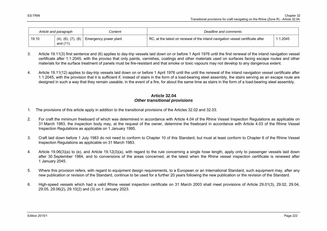
ES-TRIN Chapter 32 Transitional provisions for craft navigating on the Rhine (Zone R) - Article 32.04
Edition 2015/1 Page 222
Article and paragraph Content Deadline and comments
19.10 (4), (6), (7), (8) and (11)
Emergency power plant RC, at the latest on renewal of the inland navigation vessel certificate after 1.1.2045
3. Article 19.11(3) first sentence and (6) applies to day-trip vessels laid down on or before 1 April 1976 until the first renewal of the inland navigation vessel
certificate after 1.1.2045, with the proviso that only paints, varnishes, coatings and other materials used on surfaces facing escape routes and other materials for the surface treatment of panels must be fire-resistant and that smoke or toxic vapours may not develop to any dangerous extent.
4. Article 19.11(12) applies to day-trip vessels laid down on or before 1 April 1976 until the until the renewal of the inland navigation vessel certificate after
1.1.2045, with the provision that it is sufficient if, instead of stairs in the form of a load-bearing steel assembly, the stairs serving as an escape route are designed in such a way that they remain useable, in the event of a fire, for about the same time as stairs in the form of a load-bearing steel assembly.
Article 32.04 Other transitional provisions
1. The provisions of this article apply in addition to the transitional provisions of the Articles 32.02 and 32.03. 2. For craft the minimum freeboard of which was determined in accordance with Article 4.04 of the Rhine Vessel Inspection Regulations as applicable on
31 March 1983, the inspection body may, at the request of the owner, determine the freeboard in accordance with Article 4.03 of the Rhine Vessel Inspection Regulations as applicable on 1 January 1995.
3. Craft laid down before 1 July 1983 do not need to conform to Chapter 10 of this Standard, but must at least conform to Chapter 6 of the Rhine Vessel
Inspection Regulations as applicable on 31 March 1983. 4. Article 19.06(3)(a) to (e), and Article 19.12(3)(a), with regard to the rule concerning a single hose length, apply only to passenger vessels laid down
after 30 September 1984, and to conversions of the areas concerned, at the latest when the Rhine vessel inspection certificate is renewed after 1 January 2045.
5. Where this provision refers, with regard to equipment design requirements, to a European or an International Standard, such equipment may, after any
new publication or revision of the Standard, continue to be used for a further 20 years following the new publication or the revision of the Standard. 6. High-speed vessels which had a valid Rhine vessel inspection certificate on 31 March 2003 shall meet provisions of Article 29.01(3), 29.02, 29.04,
29.05, 29.06(2), 29.10(2) and (3) on 1 January 2023.

ES-TRIN Chapter 32 Transitional provisions for craft navigating on the Rhine (Zone R) - Article 32.05
Edition 2015/1 Page 223
Article 32.05 Transitional provisions for craft not covered by Article 32.01
1. The following provisions apply:
a) to craft for which a Rhine vessel inspection certificate in accordance with the Rhine Vessel Inspection Regulations was issued for the first time from 1 January 1995, provided they were not under construction or undergoing conversion on 31 December 1994,
b) to craft which have obtained another traffic licence between 1 January 1995 and 30 December 2008,
c) to craft for which a Community certificate valid for Zone R in accordance with Directive 2006/87/EC was issued for the first time between 30 December 2008 and XX XX 2018 (-1 day),
d) to craft for which a Union certificate valid for Zone R in accordance with Directive 2016/XX/UE was issued for the first time from XX XX 2018. 2. It must be proved that those craft comply:
a) with the Rhine Vessel Inspection Regulations, as applicable on the date on which their Rhine vessel inspection certificate or the other traffic licence has been granted, or
b) with the provisions of directive 2006/87/EC applicable for Zone R, as applicable on the date on which their Community certificate has been granted, or
c) with the provisions of directive 2016/XX/UE applicable for Zone R, as applicable on the date on which their Union certificate has been granted. 3. Craft must be adapted to comply with this Standard in accordance with the transitional provisions set out in the table below. 4. Article 32.04(4) and (5) apply mutatis mutandis. 5. The following definitions apply in the table below:
‘NRC’: the provision does not apply to craft which are already operating, unless the parts concerned are replaced or converted, i.e. the provision applies only to Newly-built craft and to the Replacement or Conversion of the parts or areas concerned. If existing parts are replaced by replacement parts using the same technology and of the same type, this does not constitute replacement ‘R’ within the meaning of the transitional provisions. ‘Issue or renewal of the inland navigation vessel certificate’: the provision must be complied with the time of the next issue or renewal of the inland navigation vessel certificate after the date indicated.
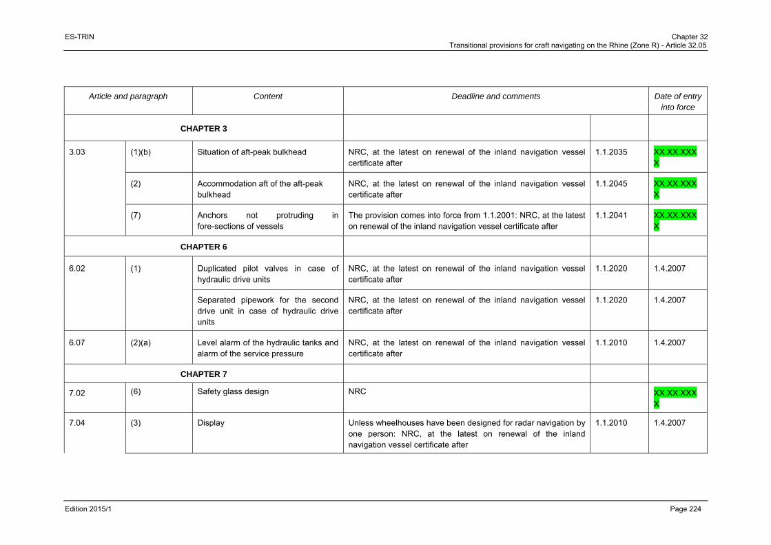
ES-TRIN Chapter 32 Transitional provisions for craft navigating on the Rhine (Zone R) - Article 32.05
Edition 2015/1 Page 224
Article and paragraph Content Deadline and comments Date of entry into force
CHAPTER 3
3.03 (1)(b) Situation of aft-peak bulkhead NRC, at the latest on renewal of the inland navigation vessel certificate after
1.1.2035 XX.XX.XXXX
(2) Accommodation aft of the aft-peak bulkhead
NRC, at the latest on renewal of the inland navigation vessel certificate after
1.1.2045 XX.XX.XXXX
(7) Anchors not protruding in fore-sections of vessels
The provision comes into force from 1.1.2001: NRC, at the latest on renewal of the inland navigation vessel certificate after
1.1.2041 XX.XX.XXXX
CHAPTER 6
6.02 (1) Duplicated pilot valves in case of hydraulic drive units
NRC, at the latest on renewal of the inland navigation vessel certificate after
1.1.2020 1.4.2007
Separated pipework for the second drive unit in case of hydraulic drive units
NRC, at the latest on renewal of the inland navigation vessel certificate after
1.1.2020 1.4.2007
6.07 (2)(a) Level alarm of the hydraulic tanks and alarm of the service pressure
NRC, at the latest on renewal of the inland navigation vessel certificate after
1.1.2010 1.4.2007
CHAPTER 7
7.02 (6) Safety glass design NRC XX.XX.XXXX
7.04 (3) Display Unless wheelhouses have been designed for radar navigation by one person: NRC, at the latest on renewal of the inland navigation vessel certificate after
1.1.2010 1.4.2007

ES-TRIN Chapter 32 Transitional provisions for craft navigating on the Rhine (Zone R) - Article 32.05
Edition 2015/1 Page 225
Article and paragraph Content Deadline and comments Date of entry into force
(9) 3rd sentence Control by a lever NRC, at the latest on renewal of the inland navigation vessel certificate after
1.1.2010 1.4.2007
(9) 4th sentence
Clearly show the direction of the thrust NRC, at the latest on renewal of the inland navigation vessel certificate after
1.1.2010 1.4.2007
7.05 (1) Navigation lights, their casings, accessories and light sources
Navigation lights, their casings, accessories, and light sources that fulfill the requirements for colour and light intensity of navigation lights, and for the admission of signal lights for navigation on the Rhine, as of 30 November 2009 may still be used.
1.1.2009
7.06 (1) Rate-of-turn indicators, which have received an approval before 1.1.1990
Rate-of-turn indicators, which have received an approval before 1.1.1990 and have been installed before 1.1.2000, may be installed and used until renewal of the Union inland navigation certificate after 1.1.2015, if there is a valid installation certificate pursuant to Directive 2006/87/EC or Resolution CCNR 1989-II-35.
1.12.2009
(1) Installation and use of radar navigation equipment and rate-of-turn indicators which have received an approval after 1.1.1990
Radar navigation equipment and rate-of-turn indicators which have received an approval on or after 1.1.1990 pursuant to the minimum requirements and test conditions for navigational radar installations used for navigation in inland waterway navigation on the Rhine and the minimum requirements and test conditions for rate-of-turn indicators used in inland waterway navigation on the Rhine may continue to be installed and operated if there is a valid installation certificate pursuant to Directive 2006/87/EC or Resolution CCNR 1989-II-35.
1.12.2009
(3) Inland AIS equipment Inland AIS equipment with a type approval according to Edition 1.0 and 1.01 of the Test Standard may continue to installed until 30.11.2015 and may be operated beyond this date.
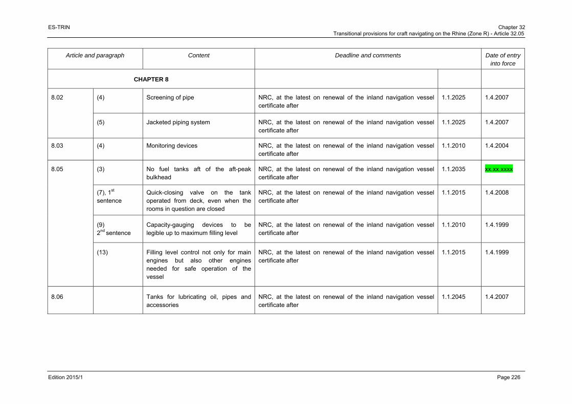
ES-TRIN Chapter 32 Transitional provisions for craft navigating on the Rhine (Zone R) - Article 32.05
Edition 2015/1 Page 226
Article and paragraph Content Deadline and comments Date of entry into force
CHAPTER 8
8.02 (4) Screening of pipe NRC, at the latest on renewal of the inland navigation vessel certificate after
1.1.2025 1.4.2007
(5) Jacketed piping system NRC, at the latest on renewal of the inland navigation vessel certificate after
1.1.2025 1.4.2007
8.03 (4) Monitoring devices NRC, at the latest on renewal of the inland navigation vessel certificate after
1.1.2010 1.4.2004
8.05 (3) No fuel tanks aft of the aft-peak bulkhead
NRC, at the latest on renewal of the inland navigation vessel certificate after
1.1.2035 xx.xx.xxxx
(7), 1st sentence
Quick-closing valve on the tank operated from deck, even when the rooms in question are closed
NRC, at the latest on renewal of the inland navigation vessel certificate after
1.1.2015 1.4.2008
(9) 2nd sentence
Capacity-gauging devices to be legible up to maximum filling level
NRC, at the latest on renewal of the inland navigation vessel certificate after
1.1.2010 1.4.1999
(13) Filling level control not only for main engines but also other engines needed for safe operation of the vessel
NRC, at the latest on renewal of the inland navigation vessel certificate after
1.1.2015 1.4.1999
8.06 Tanks for lubricating oil, pipes and accessories
NRC, at the latest on renewal of the inland navigation vessel certificate after
1.1.2045 1.4.2007
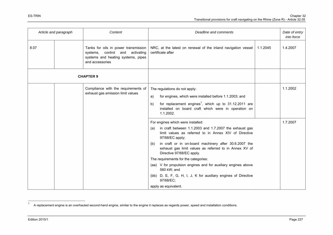
ES-TRIN Chapter 32 Transitional provisions for craft navigating on the Rhine (Zone R) - Article 32.05
Edition 2015/1 Page 227
Article and paragraph Content Deadline and comments Date of entry into force
8.07 Tanks for oils in power transmission systems, control and activating systems and heating systems, pipes and accessories
NRC, at the latest on renewal of the inland navigation vessel certificate after
1.1.2045 1.4.2007
CHAPTER 9
Compliance with the requirements of exhaust gas emission limit values
The regulations do not apply:
a) for engines, which were installed before 1.1.2003; and
b) for replacement engines1, which up to 31.12.2011 are installed on board craft which were in operation on 1.1.2002.
1.1.2002
For engines which were installed:
(a) in craft between 1.1.2003 and 1.7.2007 the exhaust gas limit values as referred to in Annex XIV of Directive 97/68/EC apply;
(b) in craft or in on-board machinery after 30.6.2007 the exhaust gas limit values as referred to in Annex XV of Directive 97/68/EC apply.
The requirements for the categories:
(aa) V for propulsion engines and for auxiliary engines above 560 kW; and
(bb) D, E, F, G, H, I, J, K for auxiliary engines of Directive 97/68/EC;
apply as equivalent.
1.7.2007
1 A replacement engine is an overhauled second-hand engine, similar to the engine it replaces as regards power, speed and installation conditions.
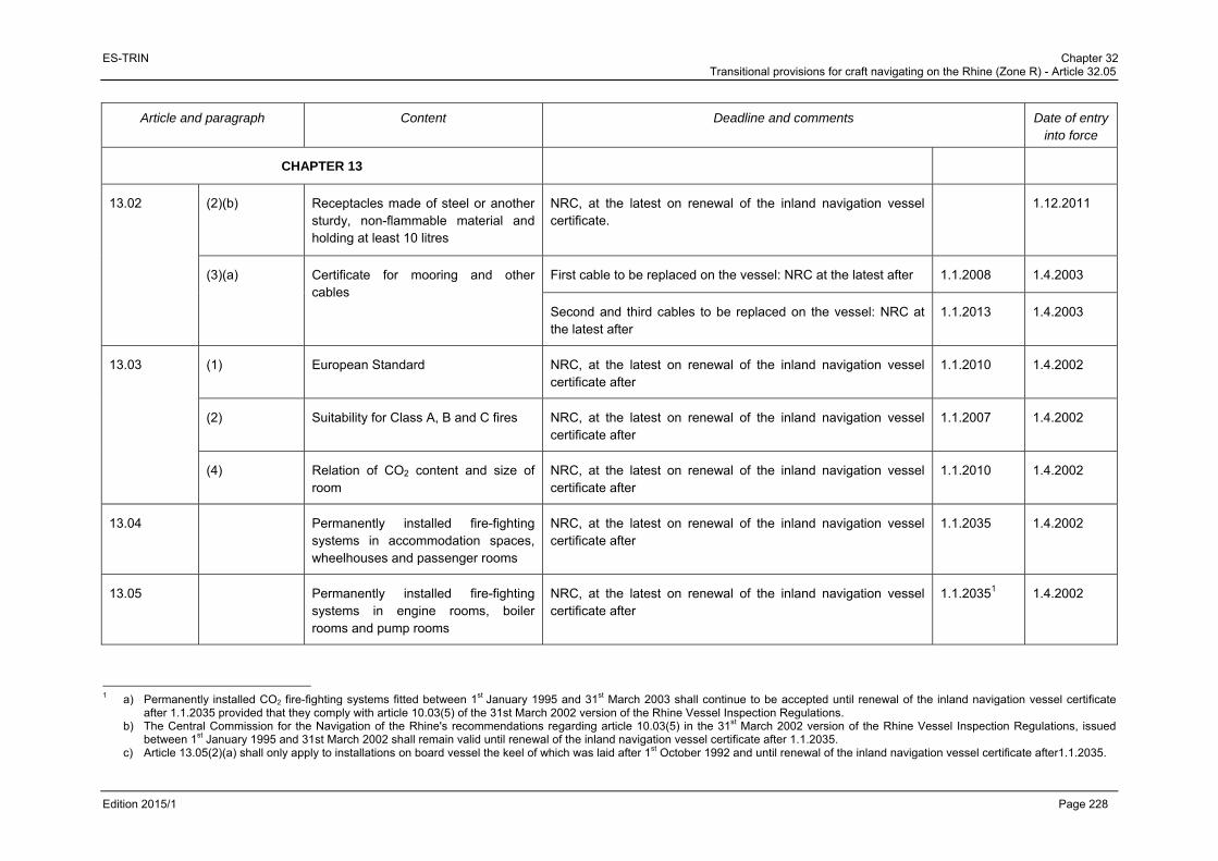
ES-TRIN Chapter 32 Transitional provisions for craft navigating on the Rhine (Zone R) - Article 32.05
Edition 2015/1 Page 228
Article and paragraph Content Deadline and comments Date of entry into force
CHAPTER 13
13.02 (2)(b) Receptacles made of steel or another sturdy, non-flammable material and holding at least 10 litres
NRC, at the latest on renewal of the inland navigation vessel certificate.
1.12.2011
(3)(a) Certificate for mooring and other cables
First cable to be replaced on the vessel: NRC at the latest after 1.1.2008 1.4.2003
Second and third cables to be replaced on the vessel: NRC at the latest after
1.1.2013 1.4.2003
13.03 (1) European Standard NRC, at the latest on renewal of the inland navigation vessel certificate after
1.1.2010 1.4.2002
(2) Suitability for Class A, B and C fires NRC, at the latest on renewal of the inland navigation vessel certificate after
1.1.2007 1.4.2002
(4) Relation of CO2 content and size of room
NRC, at the latest on renewal of the inland navigation vessel certificate after
1.1.2010 1.4.2002
13.04 Permanently installed fire-fighting systems in accommodation spaces, wheelhouses and passenger rooms
NRC, at the latest on renewal of the inland navigation vessel certificate after
1.1.2035 1.4.2002
13.05 Permanently installed fire-fighting systems in engine rooms, boiler rooms and pump rooms
NRC, at the latest on renewal of the inland navigation vessel certificate after
1.1.20351 1.4.2002
1 a) Permanently installed CO2 fire-fighting systems fitted between 1st January 1995 and 31st March 2003 shall continue to be accepted until renewal of the inland navigation vessel certificate
after 1.1.2035 provided that they comply with article 10.03(5) of the 31st March 2002 version of the Rhine Vessel Inspection Regulations. b) The Central Commission for the Navigation of the Rhine's recommendations regarding article 10.03(5) in the 31st March 2002 version of the Rhine Vessel Inspection Regulations, issued
between 1st January 1995 and 31st March 2002 shall remain valid until renewal of the inland navigation vessel certificate after 1.1.2035. c) Article 13.05(2)(a) shall only apply to installations on board vessel the keel of which was laid after 1st October 1992 and until renewal of the inland navigation vessel certificate after1.1.2035.

ES-TRIN Chapter 32 Transitional provisions for craft navigating on the Rhine (Zone R) - Article 32.05
Edition 2015/1 Page 229
Article and paragraph Content Deadline and comments Date of entry into force
13.071 Application of the European Standard to dinghies
NRC, at the latest on renewal of the inland navigation vessel certificate after
1.1.2020 1.10.2003
13.08 (2) Inflatable life jackets NRC, at the latest on renewal of the inland navigation vessel certificate after
1.1.2010 1.10.2003
Life jackets which have been on board on 30.9.2003 may be used until the issue or renewal of the inland navigation vessel certificate after
1.1.2010 1.10.2003
CHAPTER 14
14.02 (4)2 Height of the bulwarks and coamings and side deck guardrails
NRC, at the latest on renewal of the inland navigation vessel certificate after
1.1.2020 1.12.2011
Height of coamings NRC, at the latest on renewal of the inland navigation vessel certificate after
1.1.2035 1.12.2011
14.04 (2)3 Side deck guardrails For vessels of 55 with only aft accommodation, NRC, at the latest on renewal of the inland navigation vessel certificate after
1.1.2020 1.12.2011
14.12 (2), (4), (5) and (9) 1
Manufacturer’s plate, protection devices, shipboard documents
NRC, at the latest on renewal of the inland navigation vessel certificate after
1.1.2020 1.12.2011
1 The transitional provision applicable to Article 13.07 is a temporary requirement, applicable until 30 November 2017. The following transitional provision was in force prior to 1 December 2014:
“13.07 / Application of the European standard to dinghies / NRC, at the latest on renewal of the inland navigation vessel certificate after 1.1.2015 / 1.10.2003”. 2 Article 14.02 (4) is a temporary requirement valid until 30 November 2017. 3 Article 14.04 (2) is a temporary requirement valid until 30 November 2017.

ES-TRIN Chapter 32 Transitional provisions for craft navigating on the Rhine (Zone R) - Article 32.05
Edition 2015/1 Page 230
Article and paragraph Content Deadline and comments Date of entry into force
CHAPTER 18
18.01 (2) Tables 1 and 2, and (5)
Limit/control values and type approvals
NRC, as long as
a) the limit and control values do not exceed the values according to Article 18.01 by more than the factor 2,
b) the on-board sewage treatment plant has a manufacturer's or expert's certificate confirming that it can cope with the typical loading patterns on board the craft and
c) a system of sewage sludge management is in place for it which is appropriate to the conditions of operating a sewage treatment plant aboard a passenger vessel.
1.12.2011
CHAPTER 19
19.01 (2) (e) Prohibition of liquefied gas installations according to Chapter 17
NRC, at the latest on renewal of the inland navigation vessel certificate after
1.1.2045 1.1.2006
The transitional provision applies only if alarm systems are fitted in accordance with Article 19.15(8).
1.1.2006
(5) and (6) Obstructed vision ahead of the vessel 2 vessel lengths if less than 250 m Sufficient view astern
NRC, at the latest on renewal of the inland navigation vessel certificate after
1.1.2045 xx.xx.xxxx
19.02 (2) Number and position of bulkheads NRC, at the latest on renewal of the inland navigation vessel certificate after
1.1.2045 1.1.2006
(3) Situation of aft-peak bulkhead NRC, at the latest on renewal of the inland navigation vessel certificate after
1.1.2035 xx.xx.xxxx
1 The transitional provision applicable to Article 14.12(2), (4), (5) and (9) is a temporary requirement, applicable until 30 November 2017. The following transitional provision was in force prior to
1 December 2014: “14.12 / Manufacturer's plate, protection devices, shipboard documentation / NRC, no later than after the first renewal of the inland navigation vessel certificate after 1.1.2015 / 1.12.2011”.

ES-TRIN Chapter 32 Transitional provisions for craft navigating on the Rhine (Zone R) - Article 32.05
Edition 2015/1 Page 231
Article and paragraph Content Deadline and comments Date of entry into force
This requirement does not apply to passenger vessels that due to the compliance with the basic requirements for the two-compartment status set out in article 19.03(9) or comply with the requirements of article 19.07 achieve an equivalent level of safety and manoeuvrability.
xx.xx.xxxx
(5) 2th sentence
Margin line if no bulkhead deck For passenger vessels which have been laid down before 1.1.1996, NRC, at the latest on renewal of the inland navigation vessel certificate after
1.1.2045 1.1.2006
(15) Minimum height of double bottoms, width of wing voids
NRC, at the latest on renewal of the inland navigation vessel certificate after
1.1.2045 1.1.2006
19.03 (1) to (6) Intact stability NRC, and when the maximum number of passengers is raised, at the latest on renewal of the inland navigation vessel certificate after
1.1.2045 1.1.2006
(7) and (8) Damage stability NRC, at the latest on renewal of the inland navigation vessel certificate after
1.1.2045 1.1.2006
(9) Damage stability NRC, at the latest on renewal of the inland navigation vessel certificate after
1.1.2045 1.1.2006
Vertical extent of damage to the bottom of the boat
NRC, at the latest on renewal of the inland navigation vessel certificate after
1.1.2045 1.1.2006
NRC applicable for vessels with watertight decks on a minimum distance of 0,50m and less then 0,60 m of the bottom of vessels that obtained a first inland navigation vessel certificate before 31.12.2005
1.12.2011
Two-compartment status NRC 1.1.2006
(10) to (13) Damage stability NRC, at the latest on renewal of the inland navigation vessel certificate after
1.1.2045 1.1.2006

ES-TRIN Chapter 32 Transitional provisions for craft navigating on the Rhine (Zone R) - Article 32.05
Edition 2015/1 Page 232
Article and paragraph Content Deadline and comments Date of entry into force
19.05 (2)(a) Number of passengers for whom the existence of an evacuation area according to Article 19.06(8) has been proven
NRC, at the latest on renewal of the inland navigation vessel certificate after
1.1.2045 1.1.2006
(2)(b) Number of passengers that has been taken into account for the stability calculation according to Article 19.03
NRC, at the latest on renewal of the inland navigation vessel certificate after
1.1.2045 1.1.2006
19.06 (1) 1st sentence Passenger rooms as long as they are below the bulkhead deck, forward of the aft-peak bulkhead
NRC, at the latest on renewal of the inland navigation vessel certificate after
1.1.2045 xx.xx.xxxx
(1) 2nd sentence
Enclosures NRC, at the latest on renewal of the inland navigation vessel certificate.
1.12.2011
(3) c) 1st sentence
Clear height of exits NRC, at the latest on renewal of the inland navigation vessel certificate after
1.1.2045 1.1.2006
(3) c) 2nd sentence
Clear width of doors of passenger cabins and other small rooms
NRC, at the latest on renewal of the inland navigation vessel certificate after
1.1.2045 1.1.2006
(3) f) 1st sentence
Size of emergency exits NRC, at the latest on renewal of the inland navigation vessel certificate after
1.1.2045 1.1.2006
(3)(g) Exits intended for use by persons with reduced mobility
NRC, at the latest on renewal of the inland navigation vessel certificate after
1.1.2045 1.1.2006
(4)(d) Doors intended for use by persons with reduced mobility
NRC, at the latest on renewal of the inland navigation vessel certificate after
1.1.2045 1.1.2006
(5) Requirements for connecting corridors NRC, at the latest on renewal of the inland navigation vessel certificate after
1.1.2045 1.1.2006

ES-TRIN Chapter 32 Transitional provisions for craft navigating on the Rhine (Zone R) - Article 32.05
Edition 2015/1 Page 233
Article and paragraph Content Deadline and comments Date of entry into force
(6)(b) Escape routes to evacuation areas NRC, at the latest on renewal of the inland navigation vessel certificate after
1.1.2045 1.1.2006
(6)(c) 1 No escape routes through galleys NRC, at the latest on renewal of the inland navigation vessel certificate after
1.1.2020 1.1.2006
(6)(d) No rungs, ladders or the like installed along the escape routes
NRC, at the latest on renewal of the inland navigation vessel certificate after
1.1.2045 1.1.2006
(7) Suitable safety guidance system NRC, at the latest on renewal of the inland navigation vessel certificate after
1.1.2015 1.1.2006
(8) Requirements for muster areas NRC, at the latest on renewal of the inland navigation vessel certificate after
1.1.2045 1.1.2006
(9)(a), (b), (c), (e), and last sentence
Requirements for stairs and their landings in the passenger areas
NRC, at the latest on renewal of the inland navigation vessel certificate after
1.1.2045 1.1.2006
(10)(a) 1st sentence
Railing according to European Standard EN 711 : 1995
NRC, at the latest on renewal of the inland navigation vessel certificate after
1.1.2045 1.1.2006
(10)(a) 2nd sentence
Height of bulwarks and railings of decks intended for use by persons with reduced mobility
NRC, at the latest on renewal of the inland navigation vessel certificate after
1.1.2045 1.1.2006
(10)(b) 2nd sentence
Clear width of openings used normally for the embarking or disembarking of persons with reduced mobility
NRC, at the latest on renewal of the inland navigation vessel certificate after
1.1.2045 1.1.2006
1 The transitional provision applicable to Article 19.06(6)(c) is a temporary requirement, applicable until 30 November 2017. The following transitional provision was in force prior to 1 December
2014: “19.06(6)(c) / No escape routes through galleys / NRC, no later than after the first renewal of the inland navigation vessel certificate after 1.1.2015 / 1.1.2006”.

ES-TRIN Chapter 32 Transitional provisions for craft navigating on the Rhine (Zone R) - Article 32.05
Edition 2015/1 Page 234
Article and paragraph Content Deadline and comments Date of entry into force
(13) Passageways and walls in passageways intended for use by persons with reduced mobility
NRC, at the latest on renewal of the inland navigation vessel certificate after
1.1.2045 1.1.2006
(14) 1st sentence
Design of glass doors and walls in passageways and window panes
NRC, at the latest on renewal of the inland navigation vessel certificate after
1.1.2045 1.1.2006
(15) Requirements for superstructures that consist totally or partly of panoramic windows
NRC, at the latest on renewal of the inland navigation vessel certificate after
1.1.2045 1.1.2006
Requirements for enclosures NRC, at the latest on renewal of the inland navigation vessel certificate.
1.1.2006
(17) 2nd sentence
Requirements for toilets fitted for use by persons with reduced mobility
NRC, at the latest on renewal of the inland navigation vessel certificate after
1.1.2045 1.1.2006
(18) Ventilation system for cabins without an opening window
NRC, at the latest on renewal of the inland navigation vessel certificate after
1.1.2045 1.1.2006
19.071 Requirements concerning the propulsion system
NRC, at the latest on renewal of the inland navigation vessel certificate after
1.1.2020 1.1.2006
19.08 (3)(a) 2 Alarm system requirements for passengers, crew members or on-board personnel to alert passenger vessels’ command and crew
For day-trip vessels, the requirement applies NRC, at the latest on renewal of the inland navigation vessel certificate after
1.1.2020 1.1.2006
1 The transitional provision applicable to Article 19.07 is a temporary requirement, applicable until 30 November 2017. The following transitional provision was in force prior to 1 December 2014:
“19.07 / Requirements concerning the propulsion system / NRC, at the latest on renewal of the inland navigation vessel certificate after 1.1.2015 /1.1.2006”. 2 The transitional provision applicable to Article 19.08(3) is a temporary requirement, applicable until 30 November 2017. The following transitional provision was in force prior to 1 December 2014:
“19.08(3) / Alarm system requirements / NRC, at the latest on renewal of the inland navigation vessel certificate after 1.1.2015 / 1.1.2006” and “19.08(3)(c) / Alarm system for alerting the crew and on-board personnel by the vessel's command / For cruise vessels, the regulation applies NRC, at the latest on renewal of the inland navigation vessel certificate after 1.1.2007 / 1.1.2006”.
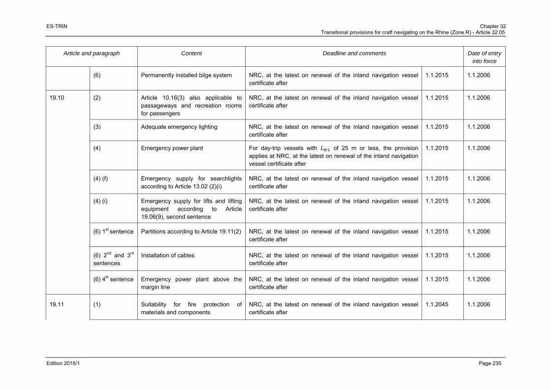
ES-TRIN Chapter 32 Transitional provisions for craft navigating on the Rhine (Zone R) - Article 32.05
Edition 2015/1 Page 235
Article and paragraph Content Deadline and comments Date of entry into force
(6) Permanently installed bilge system NRC, at the latest on renewal of the inland navigation vessel certificate after
1.1.2015 1.1.2006
19.10 (2) Article 10.16(3) also applicable to passageways and recreation rooms for passengers
NRC, at the latest on renewal of the inland navigation vessel certificate after
1.1.2015 1.1.2006
(3) Adequate emergency lighting NRC, at the latest on renewal of the inland navigation vessel certificate after
1.1.2015 1.1.2006
(4) Emergency power plant For day-trip vessels with of 25 m or less, the provision applies at NRC, at the latest on renewal of the inland navigation vessel certificate after
1.1.2015 1.1.2006
(4) (f) Emergency supply for searchlights according to Article 13.02 (2)(i)
NRC, at the latest on renewal of the inland navigation vessel certificate after
1.1.2015 1.1.2006
(4) (i) Emergency supply for lifts and lifting equipment according to Article 19.06(9), second sentence
NRC, at the latest on renewal of the inland navigation vessel certificate after
1.1.2015 1.1.2006
(6) 1st sentence Partitions according to Article 19.11(2) NRC, at the latest on renewal of the inland navigation vessel certificate after
1.1.2015 1.1.2006
(6) 2nd and 3rd sentences
Installation of cables NRC, at the latest on renewal of the inland navigation vessel certificate after
1.1.2015 1.1.2006
(6) 4th sentence Emergency power plant above the margin line
NRC, at the latest on renewal of the inland navigation vessel certificate after
1.1.2015 1.1.2006
19.11 (1) Suitability for fire protection of materials and components
NRC, at the latest on renewal of the inland navigation vessel certificate after
1.1.2045 1.1.2006
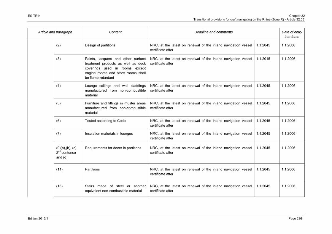
ES-TRIN Chapter 32 Transitional provisions for craft navigating on the Rhine (Zone R) - Article 32.05
Edition 2015/1 Page 236
Article and paragraph Content Deadline and comments Date of entry into force
(2) Design of partitions NRC, at the latest on renewal of the inland navigation vessel certificate after
1.1.2045 1.1.2006
(3) Paints, lacquers and other surface treatment products as well as deck coverings used in rooms except engine rooms and store rooms shall be flame-retardant
NRC, at the latest on renewal of the inland navigation vessel certificate after
1.1.2015 1.1.2006
(4) Lounge ceilings and wall claddings manufactured from non-combustible material
NRC, at the latest on renewal of the inland navigation vessel certificate after
1.1.2045 1.1.2006
(5) Furniture and fittings in muster areas manufactured from non-combustible material
NRC, at the latest on renewal of the inland navigation vessel certificate after
1.1.2045 1.1.2006
(6) Tested according to Code NRC, at the latest on renewal of the inland navigation vessel certificate after
1.1.2045 1.1.2006
(7) Insulation materials in lounges NRC, at the latest on renewal of the inland navigation vessel certificate after
1.1.2045 1.1.2006
(9)(a),(b), (c) 2nd sentence and (d)
Requirements for doors in partitions NRC, at the latest on renewal of the inland navigation vessel certificate after
1.1.2045 1.1.2006
(11) Partitions NRC, at the latest on renewal of the inland navigation vessel certificate after
1.1.2045 1.1.2006
(13) Stairs made of steel or another equivalent non-combustible material
NRC, at the latest on renewal of the inland navigation vessel certificate after
1.1.2045 1.1.2006

ES-TRIN Chapter 32 Transitional provisions for craft navigating on the Rhine (Zone R) - Article 32.05
Edition 2015/1 Page 237
Article and paragraph Content Deadline and comments Date of entry into force
(14) Internal stairs encapsulated at all levels by walls according to (2).
NRC, at the latest on renewal of the inland navigation vessel certificate after
1.1.2045 1.1.2006
(15) Ventilation systems and air supply systems
NRC, at the latest on renewal of the inland navigation vessel certificate after
1.1.2045 1.1.2006
(16) Ventilation systems in galleys and stoves with extractors
NRC, at the latest on renewal of the inland navigation vessel certificate after
1.1.2045 1.1.2006
(17) Control centres, stairwells, muster areas and smoke extraction systems
NRC, at the latest on renewal of the inland navigation vessel certificate after
1.1.2045 1.1.2006
19.12 (8)(d) Installation of fire extinguishing pumps NRC, at the latest on renewal of the inland navigation vessel certificate after
1.1.2020 xx.xx.xxxx
(9) Fire-extinguishing system in engine rooms
NRC, at the latest on renewal of the inland navigation vessel certificate after
1.1.2015 1.1.2006
The transitional provision does not apply to passenger vessels which have been laid down after 31.12.1995, the hull of which is made of wood, aluminium or plastic and the engine rooms of which are not made of a material according to Article 3.04(3) and (4).
19.14 (1) Waste water collection tanks and disposal facilities
For cabin vessels with no more than 50 berths and for day-trip vessels: NRC, at the latest on renewal of the inland navigation vessel certificate after
1.1.2045 1.1.2006
(2) Requirements for waste water collection tanks
For cabin vessels with no more than 50 berths and for day-trip vessels with no more than 50 passengers: NRC, at the latest on renewal of the inland navigation vessel certificate after
1.1.2045 1.1.2006

ES-TRIN Chapter 32 Transitional provisions for craft navigating on the Rhine (Zone R) - Article 32.05
Edition 2015/1 Page 238
Article and paragraph Content Deadline and comments Date of entry into force
19.15 (1) Damage stability NRC, at the latest on renewal of the inland navigation vessel certificate after
1.1.2045 1.1.2006
CHAPTER 29
29.02 (3) Second independent steering apparatus drive unit or a manually operated drive unit come into operation
NRC, at the latest on renewal of the inland navigation vessel certificate after
1.1.2025 1.4.2005
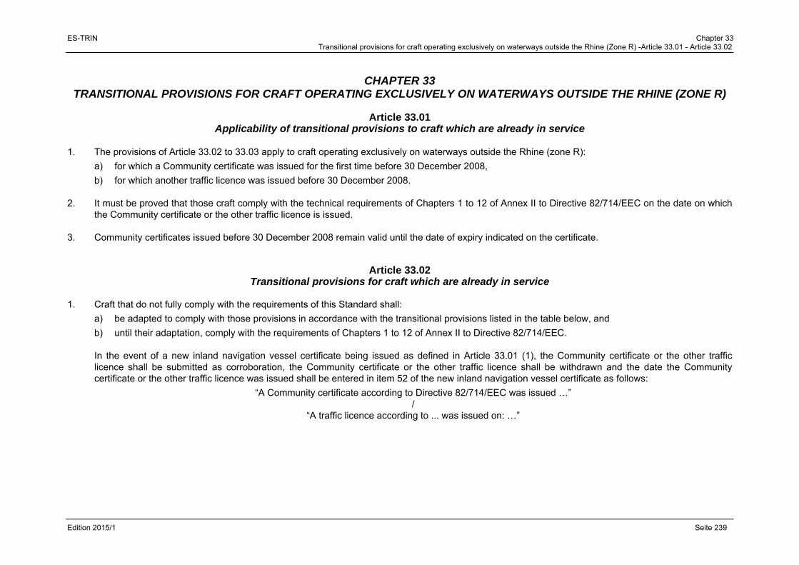
ES-TRIN Chapter 33 Transitional provisions for craft operating exclusively on waterways outside the Rhine (Zone R) -Article 33.01 - Article 33.02
Edition 2015/1 Seite 239
CHAPTER 33 TRANSITIONAL PROVISIONS FOR CRAFT OPERATING EXCLUSIVELY ON WATERWAYS OUTSIDE THE RHINE (ZONE R)
Article 33.01
Applicability of transitional provisions to craft which are already in service 1. The provisions of Article 33.02 to 33.03 apply to craft operating exclusively on waterways outside the Rhine (zone R):
a) for which a Community certificate was issued for the first time before 30 December 2008,
b) for which another traffic licence was issued before 30 December 2008. 2. It must be proved that those craft comply with the technical requirements of Chapters 1 to 12 of Annex II to Directive 82/714/EEC on the date on which
the Community certificate or the other traffic licence is issued. 3. Community certificates issued before 30 December 2008 remain valid until the date of expiry indicated on the certificate.
Article 33.02 Transitional provisions for craft which are already in service
1. Craft that do not fully comply with the requirements of this Standard shall:
a) be adapted to comply with those provisions in accordance with the transitional provisions listed in the table below, and
b) until their adaptation, comply with the requirements of Chapters 1 to 12 of Annex II to Directive 82/714/EEC.
In the event of a new inland navigation vessel certificate being issued as defined in Article 33.01 (1), the Community certificate or the other traffic licence shall be submitted as corroboration, the Community certificate or the other traffic licence shall be withdrawn and the date the Community certificate or the other traffic licence was issued shall be entered in item 52 of the new inland navigation vessel certificate as follows:
“A Community certificate according to Directive 82/714/EEC was issued …” /
“A traffic licence according to ... was issued on: …”

ES-TRIN Chapter 33 Transitional provisions for craft operating exclusively on waterways outside the Rhine (Zone R) - Article 33.02
Edition 2015/1 Page 240
2. The following definitions apply in the table below:
‘NRC’: the provision does not apply to craft which are already operating, unless the parts concerned are replaced or converted, i.e. the provision applies only to Newly-built craft and to the Replacement or Conversion of the parts or areas concerned. If existing parts are replaced by replacement parts using the same technology and of the same type, this does not constitute replacement ‘R’ within the meaning of the transitional provisions. ‘Issue or renewal of the inland navigation vessel certificate’: the provision must be complied with the time of the next issue or renewal of the inland navigation vessel certificate after the date indicated.

ES-TRIN Chapter 33 Transitional provisions for craft operating exclusively on waterways outside the Rhine (Zone R) - Article 33.02
Edition 2015/1 Page 241
Article and paragraph Content Deadline and comments
CHAPTER 3
3.03 (1)(a) Situation of collision bulkhead NRC, at the latest on renewal of the inland navigation vessel certificate after 30.12.2049
(1)(b) Situation of aft-peak bulkhead NRC, at the latest on renewal of the inland navigation vessel certificate after 30.12.2049
(2) Accommodation forward of the collision bulkhead
NRC, at the latest on renewal of the inland navigation vessel certificate after 30.12.2024
Accommodation aft of the aft-peak bulkhead
NRC, at the latest on renewal of the inland navigation vessel certificate after 30.12.2059
Safety equipment NRC, at the latest on renewal of the inland navigation vessel certificate after 30.12.2029
(4) Gastight separation of accommodations from engine rooms, boiler rooms and holds
NRC, at the latest on renewal of the inland navigation vessel certificate after 30.12.2024
(5), 2nd subparagraph
Monitoring of doors in aft-peak bulkhead
NRC, at the latest on renewal of the inland navigation vessel certificate after 30.12.2024
(7) Anchors not protruding in fore-sections of vessels
NRC, at the latest on renewal of the inland navigation vessel certificate after 30.12.2049
3.04 (3) 2nd sentence
Insulation in engine rooms NRC, at the latest on renewal of the inland navigation vessel certificate.
(3) 3rd and 4th sentences
Openings and locking devices NRC, at the latest on renewal of the inland navigation vessel certificate.
(6) Exits of engine rooms NRC, at the latest on renewal of the inland navigation vessel certificate after 30.12.2049
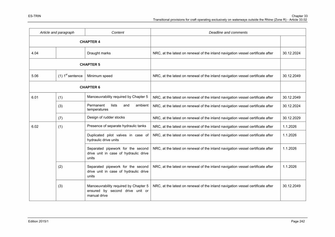
ES-TRIN Chapter 33 Transitional provisions for craft operating exclusively on waterways outside the Rhine (Zone R) - Article 33.02
Edition 2015/1 Page 242
Article and paragraph Content Deadline and comments
CHAPTER 4
4.04 Draught marks NRC, at the latest on renewal of the inland navigation vessel certificate after 30.12.2024
CHAPTER 5
5.06 (1) 1st sentence Minimum speed NRC, at the latest on renewal of the inland navigation vessel certificate after 30.12.2049
CHAPTER 6
6.01 (1) Manoeuvrability required by Chapter 5 NRC, at the latest on renewal of the inland navigation vessel certificate after 30.12.2049
(3) Permanent lists and ambient temperatures
NRC, at the latest on renewal of the inland navigation vessel certificate after 30.12.2024
(7) Design of rudder stocks NRC, at the latest on renewal of the inland navigation vessel certificate after 30.12.2029
6.02 (1) Presence of separate hydraulic tanks NRC, at the latest on renewal of the inland navigation vessel certificate after 1.1.2026
Duplicated pilot valves in case of hydraulic drive units
NRC, at the latest on renewal of the inland navigation vessel certificate after 1.1.2026
Separated pipework for the second drive unit in case of hydraulic drive units
NRC, at the latest on renewal of the inland navigation vessel certificate after 1.1.2026
(2) Separated pipework for the second drive unit in case of hydraulic drive units
NRC, at the latest on renewal of the inland navigation vessel certificate after 1.1.2026
(3) Manoeuvrability required by Chapter 5 ensured by second drive unit or manual drive
NRC, at the latest on renewal of the inland navigation vessel certificate after 30.12.2049
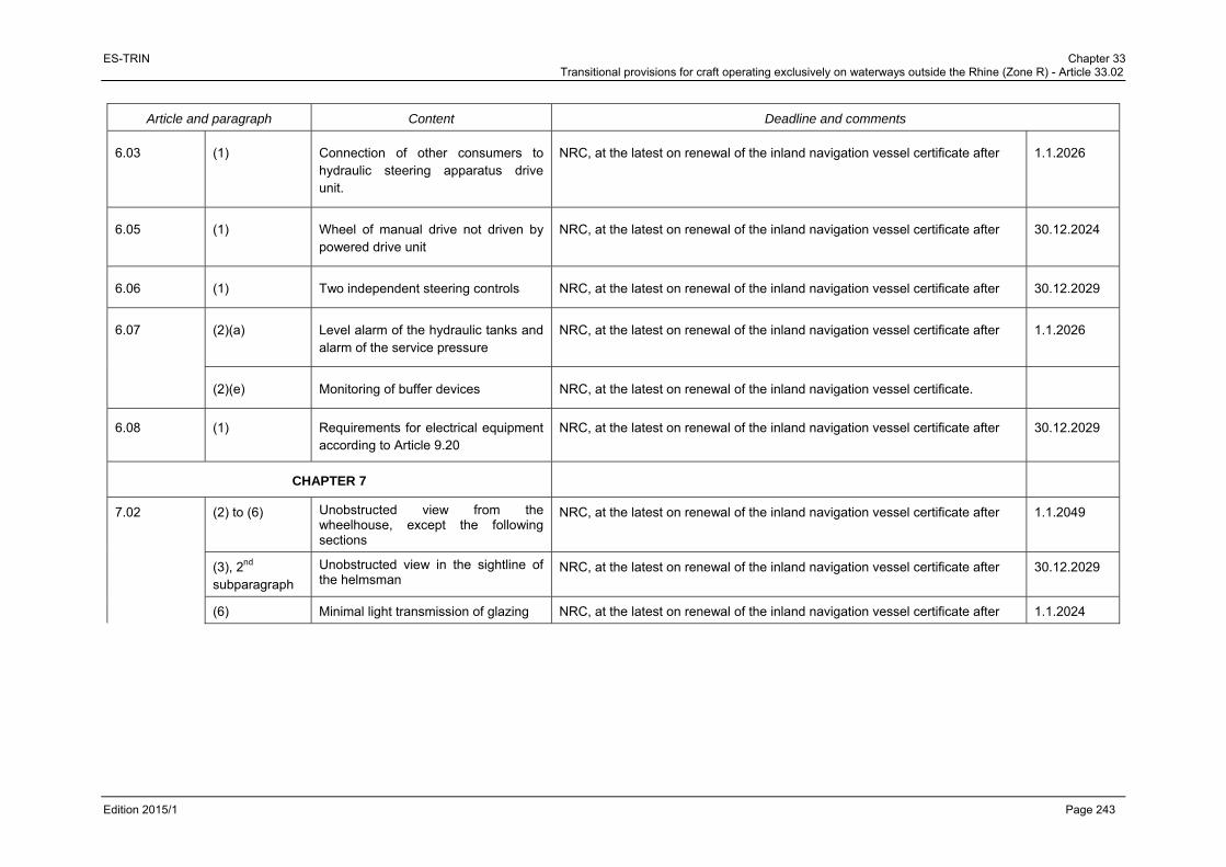
ES-TRIN Chapter 33 Transitional provisions for craft operating exclusively on waterways outside the Rhine (Zone R) - Article 33.02
Edition 2015/1 Page 243
Article and paragraph Content Deadline and comments
6.03 (1) Connection of other consumers to hydraulic steering apparatus drive unit.
NRC, at the latest on renewal of the inland navigation vessel certificate after 1.1.2026
6.05 (1) Wheel of manual drive not driven by powered drive unit
NRC, at the latest on renewal of the inland navigation vessel certificate after 30.12.2024
6.06 (1) Two independent steering controls NRC, at the latest on renewal of the inland navigation vessel certificate after 30.12.2029
6.07 (2)(a) Level alarm of the hydraulic tanks and alarm of the service pressure
NRC, at the latest on renewal of the inland navigation vessel certificate after 1.1.2026
(2)(e) Monitoring of buffer devices NRC, at the latest on renewal of the inland navigation vessel certificate.
6.08 (1) Requirements for electrical equipment according to Article 9.20
NRC, at the latest on renewal of the inland navigation vessel certificate after 30.12.2029
CHAPTER 7
7.02 (2) to (6) Unobstructed view from the wheelhouse, except the following sections
NRC, at the latest on renewal of the inland navigation vessel certificate after 1.1.2049
(3), 2nd subparagraph
Unobstructed view in the sightline of the helmsman
NRC, at the latest on renewal of the inland navigation vessel certificate after 30.12.2029
(6) Minimal light transmission of glazing NRC, at the latest on renewal of the inland navigation vessel certificate after 1.1.2024

ES-TRIN Chapter 33 Transitional provisions for craft operating exclusively on waterways outside the Rhine (Zone R) - Article 33.02
Edition 2015/1 Page 244
Article and paragraph Content Deadline and comments
NRC for vessels with tinted windows satisfying the following conditions:
- The windows are tinted green and exhibit a minimum light transmission of 60 %,
- The wheelhouse ceiling is so designed as to preclude reflections on the windows,
- Light sources in the wheelhouse must be steplessly dimmable or capable of being switched off.
- All reasonable measures to avoid other reflections have been take
(6) Safety glass design NRC
7.03 (7) Shutdown of alarms NRC, at the latest on renewal of the inland navigation vessel certificate after
(8) Automatic switch to another power supply
NRC, at the latest on renewal of the inland navigation vessel certificate after 30.12.2024
7.04 (1) Control of main engines and steering systems
NRC, at the latest on renewal of the inland navigation vessel certificate.
(2) Control of each main engine Unless wheelhouses have been designed for radar navigation by one person: NRC, at the latest on renewal of the inland navigation vessel certificate after
30.12.2049
if the direction of motion can be achieved directly
30.12.2024
for other engines
(3) Display Unless wheelhouses have been designed for radar navigation by one person: NRC, at the latest on renewal of the inland navigation vessel certificate after
30.12.2024

ES-TRIN Chapter 33 Transitional provisions for craft operating exclusively on waterways outside the Rhine (Zone R) - Article 33.02
Edition 2015/1 Page 245
Article and paragraph Content Deadline and comments
(9) 3th sentence
Control by a lever NRC, at the latest on renewal of the inland navigation vessel certificate after 30.12.2024
(9) 4th sentence Clearly show the direction of the thrust NRC, at the latest on renewal of the inland navigation vessel certificate after 30.12.2024
7.05 (1) Navigation lights, their casings, accessories and light sources
Navigation lights, their casings, accessories, and light sources that fulfill
- the requirements for color and light intensity of navigation lights and for the admission of signal lights for navigation on the Rhine as of 30 November 2009
or
- the respective requirements of a Member State as of 30 November 2009
may still be used.
7.06 (1) Navigational radar installation and rate-of-turn indicators which have received an approval before 31.12.2012
Radar navigation systems and rate-of-turn indicators, which have been approved and installed pursuant to a Member State’s regulations before 31.12.2012 may continue to be installed and operated until the renewal of the inland navigation vessel certificate after
31.12.2018
These systems must be entered in item 52 of the inland navigation vessel certificate.
Radar navigation equipment and rate-of-turn indicators which have received an approval after 1.1.1990
Radar navigation equipment and rate-of-turn indicators which have received an approval on or after 1.1.1990 pursuant to the minimum requirements and test conditions for navigational radar installations used for navigation in inland waterway navigation on the Rhine and the minimum requirements and test conditions for rate-of-turn indicators used in inland waterway navigation on the Rhine may continue to be installed and operated if there is a valid installation certificate pursuant to Directive 2006/87/EC or Resolution CCNR 1989-II-35.
(3) Inland AIS equipment NRC
7.09 Alarm system NRC, at the latest on renewal of the inland navigation vessel certificate after 30.12.2024

ES-TRIN Chapter 33 Transitional provisions for craft operating exclusively on waterways outside the Rhine (Zone R) - Article 33.02
Edition 2015/1 Page 246
Article and paragraph Content Deadline and comments
7.12 1st subpara-graph
Retractable wheelhouses NRC, at the latest on renewal of the inland navigation vessel certificate.
Without hydraulic lowering system, NRC, at the latest on renewal of the inland navigation vessel certificate after
30.12.2049
2nd and 3rd subpara-graphs
NRC, at the latest on renewal of the inland navigation vessel certificate.
CHAPTER 8
8.01 (3) Only internal-combustion engines burning fuels having a flashpoint of more than 55 °C
NRC, at the latest on renewal of the inland navigation vessel certificate after 30.12.2029
8.02 (1) Securing of engines against unintentional starting
NRC, at the latest on renewal of the inland navigation vessel certificate after 30.12.2024
(4) Screening of pipe NRC, at the latest on renewal of the inland navigation vessel certificate after 30.12.2024
(5) Jacketed piping system NRC, at the latest on renewal of the inland navigation vessel certificate after 30.12.2024
(6) Insulation of engine parts NRC, at the latest on renewal of the inland navigation vessel certificate.
8.03 (2) Monitoring devices NRC, at the latest on renewal of the inland navigation vessel certificate after 30.12.2024
(4) Automatic protection against overspeed display and switch off
NRC, at the latest on renewal of the inland navigation vessel certificate after 30.12.2024
(5) Design of shaft bushings NRC, at the latest on renewal of the inland navigation vessel certificate after 30.12.2029
8.05 (1) Steel tanks for liquid fuels NRC, at the latest on renewal of the inland navigation vessel certificate after 30.12.2029

ES-TRIN Chapter 33 Transitional provisions for craft operating exclusively on waterways outside the Rhine (Zone R) - Article 33.02
Edition 2015/1 Page 247
Article and paragraph Content Deadline and comments
(2) Automatic closing of tank valves NRC, at the latest on renewal of the inland navigation vessel certificate.
(3) No fuel tanks located forward of the collision bulkhead
NRC, at the latest on renewal of the inland navigation vessel certificate after 30.12.2024
No fuel tanks aft of the aft-peak bulkhead
NRC, at the latest on renewal of the inland navigation vessel certificate after 30.12.2049
(4) No fuel tanks and their fittings above engines or exhaust pipes
NRC, at the latest on renewal of the inland navigation vessel certificate after 30.12.2024
Until then, appropriate devices must ensure the safe evacuation of fuels.
(6), 3rd to 5th sentences
Installation and measurements of breather pipes and connection pipes
NRC, at the latest on renewal of the inland navigation vessel certificate after 30.12.2024
(7), 1st sentence
Quick-closing valve on the tank operated from deck, even when the rooms in question are closed
NRC, at the latest on renewal of the inland navigation vessel certificate after 1.1.2029
(9), 2nd sentence
Capacity-gauging devices to be legible up to maximum filling level
NRC, at the latest on renewal of the inland navigation vessel certificate after 30.12.2029
(13) Filling level control not only for main engines but also other engines needed for safe operation of the vessel
NRC, at the latest on renewal of the inland navigation vessel certificate after 30.12.2029
8.06 Tanks for lubricating oil, pipes and accessories
NRC, at the latest on renewal of the inland navigation vessel certificate after 30.12.2049
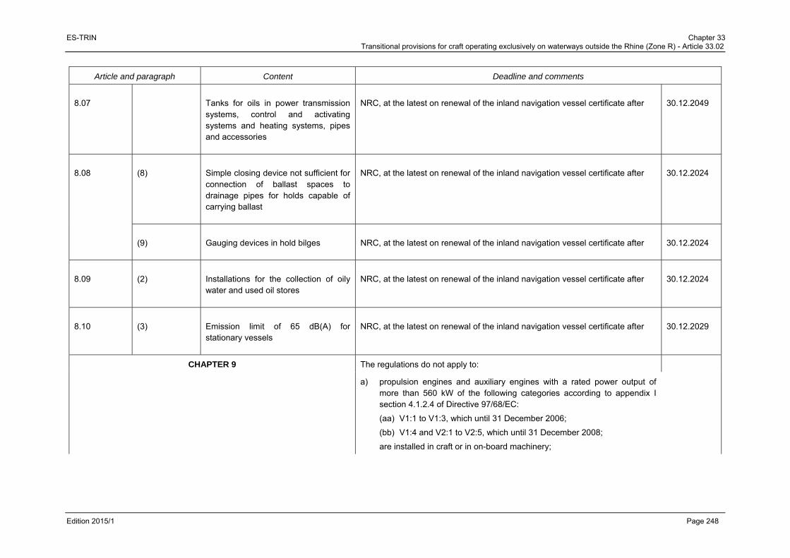
ES-TRIN Chapter 33 Transitional provisions for craft operating exclusively on waterways outside the Rhine (Zone R) - Article 33.02
Edition 2015/1 Page 248
Article and paragraph Content Deadline and comments
8.07 Tanks for oils in power transmission systems, control and activating systems and heating systems, pipes and accessories
NRC, at the latest on renewal of the inland navigation vessel certificate after 30.12.2049
8.08 (8) Simple closing device not sufficient for connection of ballast spaces to drainage pipes for holds capable of carrying ballast
NRC, at the latest on renewal of the inland navigation vessel certificate after 30.12.2024
(9) Gauging devices in hold bilges NRC, at the latest on renewal of the inland navigation vessel certificate after 30.12.2024
8.09 (2) Installations for the collection of oily water and used oil stores
NRC, at the latest on renewal of the inland navigation vessel certificate after 30.12.2024
8.10 (3) Emission limit of 65 dB(A) for stationary vessels
NRC, at the latest on renewal of the inland navigation vessel certificate after 30.12.2029
CHAPTER 9 The regulations do not apply to:
a) propulsion engines and auxiliary engines with a rated power output of more than 560 kW of the following categories according to appendix I section 4.1.2.4 of Directive 97/68/EC:
(aa) V1:1 to V1:3, which until 31 December 2006;
(bb) V1:4 and V2:1 to V2:5, which until 31 December 2008;
are installed in craft or in on-board machinery;
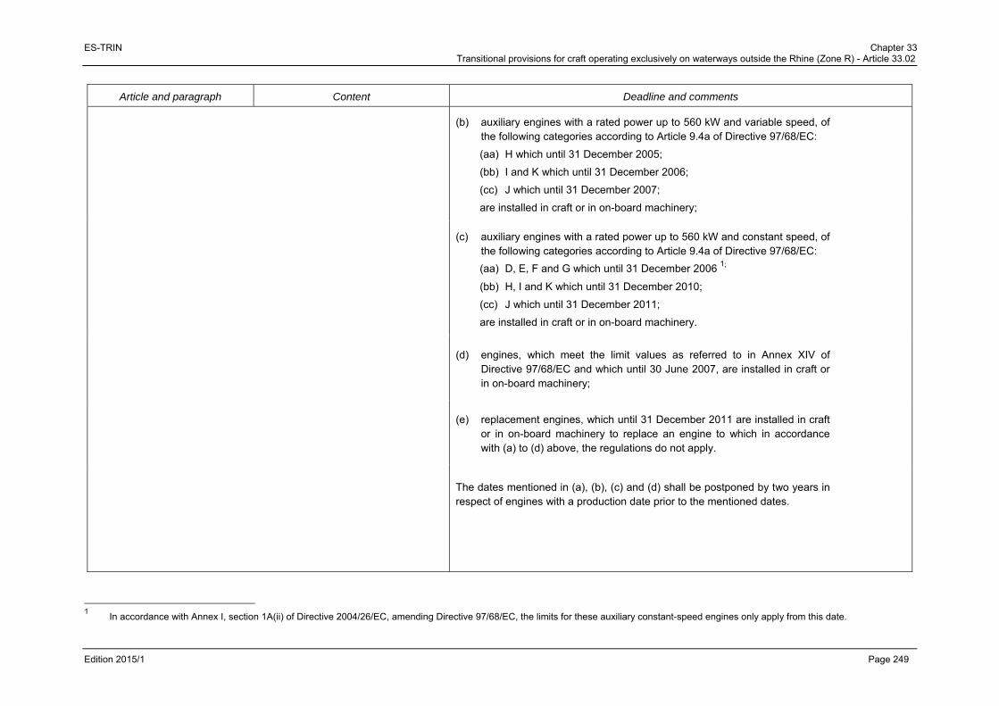
ES-TRIN Chapter 33 Transitional provisions for craft operating exclusively on waterways outside the Rhine (Zone R) - Article 33.02
Edition 2015/1 Page 249
Article and paragraph Content Deadline and comments
(b) auxiliary engines with a rated power up to 560 kW and variable speed, of the following categories according to Article 9.4a of Directive 97/68/EC:
(aa) H which until 31 December 2005;
(bb) I and K which until 31 December 2006;
(cc) J which until 31 December 2007;
are installed in craft or in on-board machinery;
(c) auxiliary engines with a rated power up to 560 kW and constant speed, of the following categories according to Article 9.4a of Directive 97/68/EC:
(aa) D, E, F and G which until 31 December 2006 1;
(bb) H, I and K which until 31 December 2010;
(cc) J which until 31 December 2011;
are installed in craft or in on-board machinery.
(d) engines, which meet the limit values as referred to in Annex XIV of Directive 97/68/EC and which until 30 June 2007, are installed in craft or in on-board machinery;
(e) replacement engines, which until 31 December 2011 are installed in craft or in on-board machinery to replace an engine to which in accordance with (a) to (d) above, the regulations do not apply.
The dates mentioned in (a), (b), (c) and (d) shall be postponed by two years in respect of engines with a production date prior to the mentioned dates.
1 In accordance with Annex I, section 1A(ii) of Directive 2004/26/EC, amending Directive 97/68/EC, the limits for these auxiliary constant-speed engines only apply from this date.

ES-TRIN Chapter 33 Transitional provisions for craft operating exclusively on waterways outside the Rhine (Zone R) - Article 33.02
Edition 2015/1 Page 250
Article and paragraph Content Deadline and comments
CHAPTER 10
10.01 (1) 2nd sentence
Relevant documents to be submitted to the inspection body
NRC, at the latest on renewal of the inland navigation vessel certificate after 30.12.2049
(2)(b) Switching diagrams for main, emergency and distribution switchboard to be kept on board
NRC, at the latest on renewal of the inland navigation vessel certificate after 30.12.2024
(3) Ambient inside and deck temperatures NRC, at the latest on renewal of the inland navigation vessel certificate after 30.12.2024
10.02 (1) to (3) Electricity supply systems NRC, at the latest on renewal of the inland navigation vessel certificate after 30.12.2024
10.03 Protection against physical contact, intrusion of solid objects and the ingress of water
NRC, at the latest on renewal of the inland navigation vessel certificate after 30.12.2029
10.05 (4) Cross-section of the earthing conductors
NRC, at the latest on renewal of the inland navigation vessel certificate after 30.12.2029
10.11 (4) Effective ventilation when accumulators are installed in a closed compartment, cabinet or chest
NRC, at the latest on renewal of the inland navigation vessel certificate.
10.12 (1), (2), (3) a), (4) to (10)
Switchgear installations NRC, at the latest on renewal of the inland navigation vessel certificate after 30.12.2029
(3)(b) Earth detection device capable of giving both visual and audible alarm
NRC, at the latest on renewal of the inland navigation vessel certificate after 30.12.2024
10.13 Emergency circuit breakers NRC, at the latest on renewal of the inland navigation vessel certificate after 30.12.2029
10.14 (3) 2nd sentence
Prohibition of single-pole switches in laundries, bathrooms, washrooms and other rooms with wet facilities
NRC, at the latest on renewal of the inland navigation vessel certificate after 30.12.2024

ES-TRIN Chapter 33 Transitional provisions for craft operating exclusively on waterways outside the Rhine (Zone R) - Article 33.02
Edition 2015/1 Page 251
Article and paragraph Content Deadline and comments
10.15 (2) Minimum cross-section of 1,5 mm2 per cable
NRC, at the latest on renewal of the inland navigation vessel certificate after 30.12.2024
(10) Cables connected to retractable wheelhouses
NRC, at the latest on renewal of the inland navigation vessel certificate after 30.12.2024
10.16 (3) 2nd sentence
Second circuit NRC, at the latest on renewal of the inland navigation vessel certificate after 30.12.2029
10.18 Alarm and safety systems for mechanical equipment
NRC, at the latest on renewal of the inland navigation vessel certificate after 30.12.2029
10.19 Electronic equipment NRC, at the latest on renewal of the inland navigation vessel certificate after 30.12.2049
10.20 Electromagnetic compatibility NRC, at the latest on renewal of the inland navigation vessel certificate after 30.12.2049
CHAPTER 13
13.01 Anchor equipment NRC, at the latest on renewal of the inland navigation vessel certificate after 30.12.2024
13.02 (3)(a) Certificate for mooring and other cables
First cable to be replaced on the vessel: NRC at the latest after 30.12.2024
Second and third cables to be replaced on the vessel: NRC at the latest after 30.12.2029
13.03 (1) European Standard NRC, at the latest on renewal of the inland navigation vessel certificate after 30.12.2024
(2) Suitability for Class A, B and C fires NRC, at the latest on renewal of the inland navigation vessel certificate after 30.12.2024
(4) Relation of CO2 content and size of room
NRC, at the latest on renewal of the inland navigation vessel certificate after 30.12.2024
13.04 Permanently installed fire-fighting systems in accommodation spaces, wheelhouses and passenger rooms
NRC, at the latest on renewal of the inland navigation vessel certificate after 30.12.2049

ES-TRIN Chapter 33 Transitional provisions for craft operating exclusively on waterways outside the Rhine (Zone R) - Article 33.02
Edition 2015/1 Page 252
Article and paragraph Content Deadline and comments
13.05 Permanently installed fire-fighting systems in engine rooms, boiler rooms and pump rooms
CO2 fire-fighting systems permanently installed before 1 October 1985, if they comply with the requirements of Article 16.03 of this Standard, may remain in use until the renewal of the inland navigation vessel certificate after
30.12.2049
13.07 Application of the European Standard to dinghies
NRC, at the latest on renewal of the inland navigation vessel certificate after 30.12.2029
13.08 (2) Inflatable life jackets NRC, at the latest on renewal of the inland navigation vessel certificate after 30.12.2024
Life jackets which have been on board on 29.12.2008 may be used until the issue or renewal of the inland navigation vessel certificate after
30.12.2024
CHAPTER 14
14.02 (4)1 Equipping of the outer edges of decks, side decks and other work stations
NRC, at the latest on renewal of the inland navigation vessel certificate after 1.1.2020
Height of coamings NRC, at the latest on renewal of the inland navigation vessel certificate after 1.1.2035
14.04 (1) Clear width of side deck For vessels of 7,30 , NRC, at the latest on renewal of the inland navigation vessel certificate after
1.1.20352
1 Article 14.02(4) is a temporary requirement valid until 30 November 2017. The following transitional provision applied prior to 1 December 2011: “14.02(4) / Equipping of the outer edges of decks,
side decks and other work stations / NRC, at the latest on renewal of the inland navigation vessel certificate after 1.1.2015”. 2 For vessel laid down after 30.12.2010 and for vessel in service, the requirement shall apply under the following conditions:
Should the entire hold area be replaced, the requirements of article 14.04 must be complied with. In the event of modifications affecting the entire length of the side deck area and modifying the clear width of the side deck,
a) article 14.04 must be complied with when the clear width of the side deck to a height of 0.90 m, available before the modification, has to be reduced b) the clear width of the side deck to a height of 0.90 m or the clear width above, available before the modification, must not be reduced if their dimensions are less than those specified in article
14.04.

ES-TRIN Chapter 33 Transitional provisions for craft operating exclusively on waterways outside the Rhine (Zone R) - Article 33.02
Edition 2015/1 Page 253
Article and paragraph Content Deadline and comments
(2)1 Shipside guard rails For vessels of 55 with only aft accommodation, NRC, at the latest on renewal of the inland navigation vessel certificate after
1.1.2020
14.05 (1) Access to work stations NRC, at the latest on renewal of the inland navigation vessel certificate after 30.12.2049
(2) and (3) Doors and accesses, exits and passageways where there is more than a 0,50 m difference in floor level
NRC, at the latest on renewal of the inland navigation vessel certificate.
(4) Stairs in work stations which are manned continuously
NRC, at the latest on renewal of the inland navigation vessel certificate after 30.12.2049
14.06 (2) Exits and emergency exits NRC, at the latest on renewal of the inland navigation vessel certificate after 30.12.2049
14.07 (1) 2nd sentence
Ladders, steps and similar devices NRC, at the latest on renewal of the inland navigation vessel certificate after 30.12.2049
(2) and (3) NRC, at the latest on renewal of the inland navigation vessel certificate.
14.10 Hatch covers NRC, at the latest on renewal of the inland navigation vessel certificate after 30.12.2024
14.11 Winches NRC, at the latest on renewal of the inland navigation vessel certificate after 30.12.2024
14.12 (2) to (6) and (8) to (10)
Cranes: Manufacturer’s plate, plaque du fabricant, maximum permissible loadings, protection devices, proof by calculation, expert inspection, shipboard documents
NRC, at the latest on renewal of the inland navigation vessel certificate after 30.12.2029
14.13 Storing of flammable liquids NRC, at the latest on renewal of the inland navigation vessel certificate.
1 Article 14.04(2) is a temporary requirement valid until 30 November 2017.

ES-TRIN Chapter 33 Transitional provisions for craft operating exclusively on waterways outside the Rhine (Zone R) - Article 33.02
Edition 2015/1 Page 254
Article and paragraph Content Deadline and comments
CHAPTER 15
15.01 (1) Accommodation for the persons lodging habitually on board
NRC, at the latest on renewal of the inland navigation vessel certificate after 30.12.2049
15.02 (3) Situation of floors NRC, at the latest on renewal of the inland navigation vessel certificate after 30.12.2049
(4) Communal living quarters and sleeping cabins
NRC, at the latest on renewal of the inland navigation vessel certificate after 30.12.2049
(5) Noise and vibration in accommodations
NRC, at the latest on renewal of the inland navigation vessel certificate after 30.12.2029
(6) Headroom in accommodations NRC, at the latest on renewal of the inland navigation vessel certificate after 30.12.2049
(8) Free floor area of communal living quarters
NRC, at the latest on renewal of the inland navigation vessel certificate after 30.12.2049
(9) Cubic capacity of rooms NRC, at the latest on renewal of the inland navigation vessel certificate after 30.12.2049
(10) Volume of airspace per person NRC, at the latest on renewal of the inland navigation vessel certificate after 30.12.2049
(11) Size of doors NRC, at the latest on renewal of the inland navigation vessel certificate after 30.12.2049
(12)(a) and (b) Situation of stairs NRC, at the latest on renewal of the inland navigation vessel certificate after 30.12.2049
(13) Pipes carrying dangerous gases or liquids
NRC, at the latest on renewal of the inland navigation vessel certificate after 30.12.2049

ES-TRIN Chapter 33 Transitional provisions for craft operating exclusively on waterways outside the Rhine (Zone R) - Article 33.02
Edition 2015/1 Page 255
Article and paragraph Content Deadline and comments
15.03 Sanitary installations NRC, at the latest on renewal of the inland navigation vessel certificate after 30.12.2049
15.04 Galleys NRC, at the latest on renewal of the inland navigation vessel certificate after 30.12.2049
15.05 Potable water installations NRC, at the latest on renewal of the inland navigation vessel certificate.
15.06 Heating and ventilation NRC, at the latest on renewal of the inland navigation vessel certificate after 30.12.2049
15.07 (1), 2nd sentence
Other accommodation installations NRC, at the latest on renewal of the inland navigation vessel certificate after 30.12.2049
CHAPTER 18
18.01 (2) Tables 1 and 2, and (5)
Limit/control values and type approvals
NRC, as long as
a) the limit and control values do not exceed the values according to Article 18.01 by more than the factor 2,
b) the on-board sewage treatment plant has a manufacturer's or expert's certificate confirming that it can cope with the typical loading patterns on board the craft and
c) a system of sewage sludge management is in place for it which is appropriate to the conditions of operating a sewage treatment plant aboard a passenger vessel.
CHAPTER 19
Passengers vessels See the provisions laid down in the regulations for vessels excluded from the scope of Directive 82/714/EEC: “Absence of manifest danger” Applies to all provisions of Chapter 19 except for those mentioned below.

ES-TRIN Chapter 33 Transitional provisions for craft operating exclusively on waterways outside the Rhine (Zone R) - Article 33.02
Edition 2015/1 Page 256
Article and paragraph Content Deadline and comments
19.01 (5) and (6) Obstructed vision ahead of the vessel 2 vessel lengths if less than 250 m Sufficient view astern
NRC, at the latest on renewal of the inland navigation vessel certificate 1.1.2049
CHAPTER 20
Passenger sailing vessels See the provisions laid down in the regulations for vessels excluded from the scope of Directive 82/714/EEC: “Absence of manifest danger”
CHAPTER 21
21.01 (2) Special winches or equivalent coupling devices to be used for pushing purposes
NRC, at the latest on renewal of the inland navigation vessel certificate after 30.12.2049
(3) last sentence
Requirements for drive units NRC, at the latest on renewal of the inland navigation vessel certificate after 30.12.2049
CHAPTER 22
Floating equipment See the provisions laid down in the regulations for vessels excluded from the scope of Directive 82/714/EEC: “Absence of manifest danger”
CHAPTER 26
Recreational craft See the provisions laid down in the regulations for vessels excluded from the scope of Directive 82/714/EEC: “Absence of manifest danger”
CHAPTER 29
29.02 (3) Second independent steering apparatus drive unit or a manually operated drive unit come into operation
NRC, at the latest on renewal of the inland navigation vessel certificate after 30.12.2029
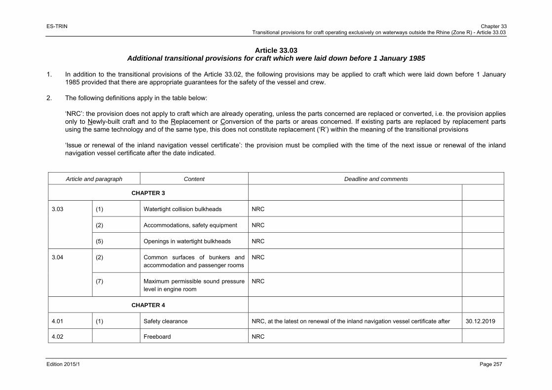
ES-TRIN Chapter 33 Transitional provisions for craft operating exclusively on waterways outside the Rhine (Zone R) - Article 33.03
Edition 2015/1 Page 257
Article 33.03 Additional transitional provisions for craft which were laid down before 1 January 1985
1. In addition to the transitional provisions of the Article 33.02, the following provisions may be applied to craft which were laid down before 1 January
1985 provided that there are appropriate guarantees for the safety of the vessel and crew. 2. The following definitions apply in the table below:
‘NRC’: the provision does not apply to craft which are already operating, unless the parts concerned are replaced or converted, i.e. the provision applies only to Newly-built craft and to the Replacement or Conversion of the parts or areas concerned. If existing parts are replaced by replacement parts using the same technology and of the same type, this does not constitute replacement (‘R’) within the meaning of the transitional provisions ‘Issue or renewal of the inland navigation vessel certificate’: the provision must be complied with the time of the next issue or renewal of the inland navigation vessel certificate after the date indicated.
Article and paragraph Content Deadline and comments
CHAPTER 3
3.03 (1) Watertight collision bulkheads NRC
(2) Accommodations, safety equipment NRC
(5) Openings in watertight bulkheads NRC
3.04 (2) Common surfaces of bunkers and accommodation and passenger rooms
NRC
(7) Maximum permissible sound pressure level in engine room
NRC
CHAPTER 4
4.01 (1) Safety clearance NRC, at the latest on renewal of the inland navigation vessel certificate after 30.12.2019
4.02 Freeboard NRC

ES-TRIN Chapter 33 Transitional provisions for craft operating exclusively on waterways outside the Rhine (Zone R) - Article 33.03
Edition 2015/1 Page 258
Article and paragraph Content Deadline and comments
CHAPTER 6
6.01 (3) Requirements of steering system NRC
CHAPTER 7
7.01 (2) Sound pressure generated by the vessel
NRC
7.05 (2) Monitoring of navigation lights Renewal of the inland navigation vessel certificate after
7.12 Retractable wheelhouses NRC
CHAPTER 8
8.01 (3) Prohibition of certain liquid fuels NRC
8.04 Engine exhaust system NRC, at the latest on renewal of the inland navigation vessel certificate.
8.05 (1)3 Control for level of fuel filling NRC
8.08 (2) Equipment with bilge pumps NRC
8.08 (3) and (4) Diameter and minimum pumping capacity of bilge pumps
NRC
8.08 (5) Self-priming bilge pumps NRC
8.08 (6) Equipment with strainers NRC
8.08 (7) Automatically closable fitting NRC
8.10 (2) Noise generated by a vessel under way
NRC
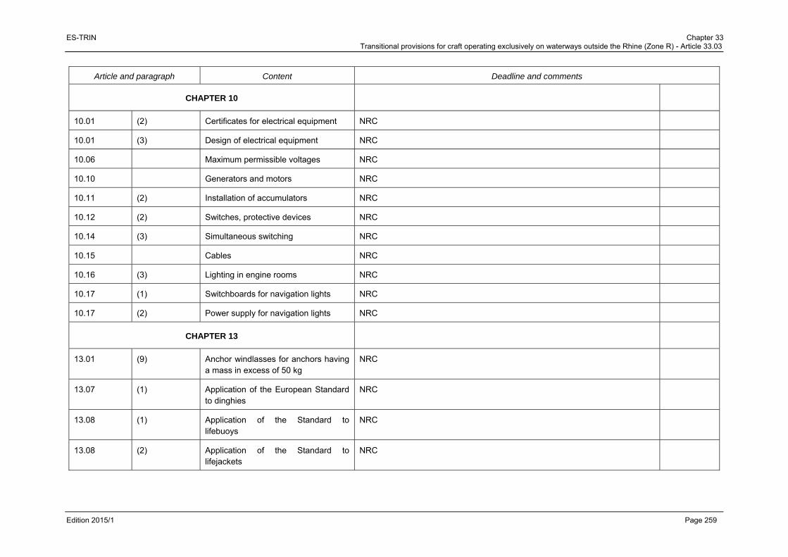
ES-TRIN Chapter 33 Transitional provisions for craft operating exclusively on waterways outside the Rhine (Zone R) - Article 33.03
Edition 2015/1 Page 259
Article and paragraph Content Deadline and comments
CHAPTER 10
10.01 (2) Certificates for electrical equipment NRC
10.01 (3) Design of electrical equipment NRC
10.06 Maximum permissible voltages NRC
10.10 Generators and motors NRC
10.11 (2) Installation of accumulators NRC
10.12 (2) Switches, protective devices NRC
10.14 (3) Simultaneous switching NRC
10.15 Cables NRC
10.16 (3) Lighting in engine rooms NRC
10.17 (1) Switchboards for navigation lights NRC
10.17 (2) Power supply for navigation lights NRC
CHAPTER 13
13.01 (9) Anchor windlasses for anchors having a mass in excess of 50 kg
NRC
13.07 (1) Application of the European Standard to dinghies
NRC
13.08 (1) Application of the Standard to lifebuoys
NRC
13.08 (2) Application of the Standard to lifejackets
NRC
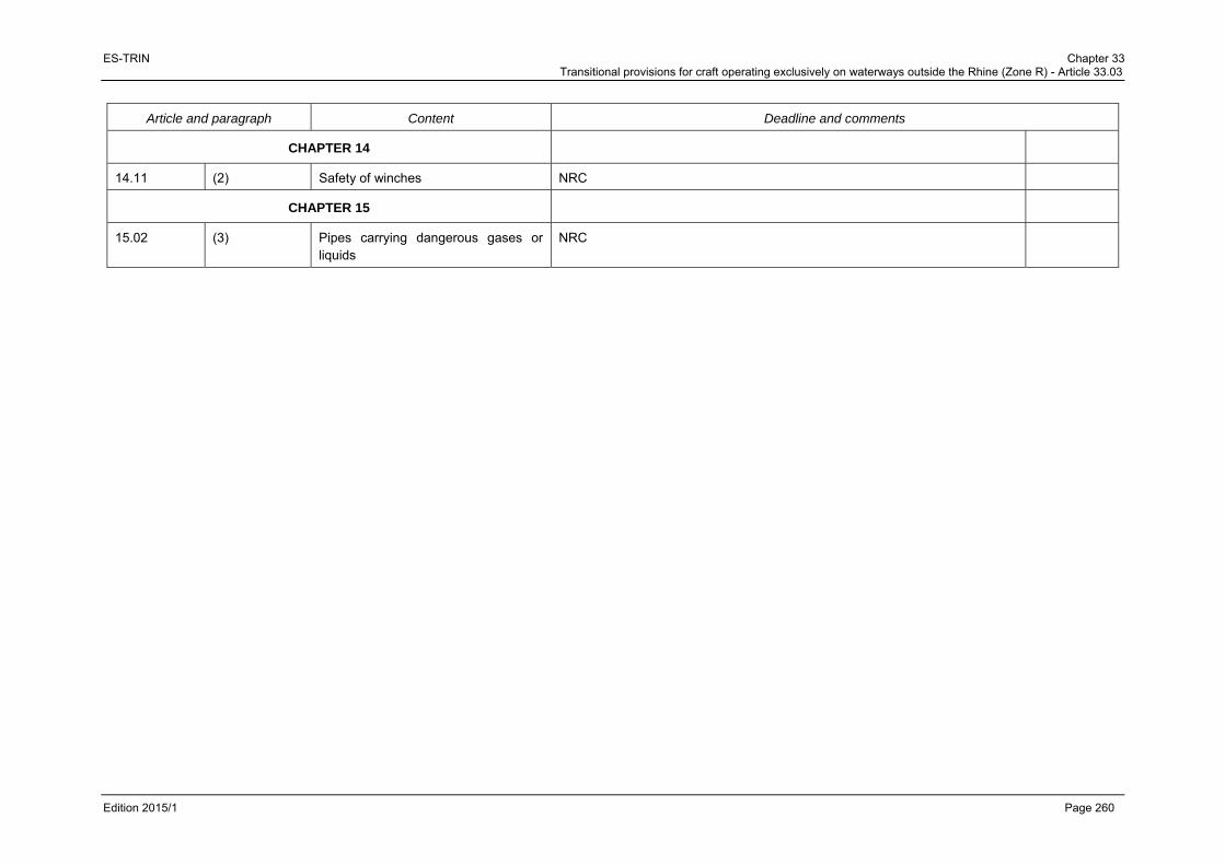
ES-TRIN Chapter 33 Transitional provisions for craft operating exclusively on waterways outside the Rhine (Zone R) - Article 33.03
Edition 2015/1 Page 260
Article and paragraph Content Deadline and comments
CHAPTER 14
14.11 (2) Safety of winches NRC
CHAPTER 15
15.02 (3) Pipes carrying dangerous gases or liquids
NRC

ES-TRIN European standard annexes
Edition 2015/1 Page 261
EUROPEAN STANDARD ANNEXES

ES-TRIN European standard annexes
Edition 2015/1 Page 262

ES-TRIN Annex 1 Model of the unique European vessel identification number (ENI)
Edition 2015/1 Page 263
PART I VESSEL IDENTIFICATION AND REGISTER
ANNEX 1
MODEL OF THE UNIQUE EUROPEAN VESSEL IDENTIFICATION NUMBER (ENI)
A A A x x x x x
Code of the competent authority that assigns the unique European vessel identification number
Serial Number
In the model, “AAA” represents the three digit code given by the competent authority assigning the unique European vessel identification number according to the following number ranges: 001 – 019 France 020 – 039 Netherlands 040 – 059 Germany 060 – 069 Belgium 070 – 079 Switzerland 080 – 099 reserved for craft from countries that are not party to the Mannheim Convention and
for which a Rhine Vessel Certificate has been issued before 1 April 2007. 100 – 119 Norway 120 – 139 Denmark 140 – 159 United Kingdom 160 – 169 Iceland 170 – 179 Ireland 180 – 189 Portugal 190 – 199 reserved 200 – 219 Luxembourg 220 – 239 Finland 240 – 259 Poland 260 – 269 Estonia 270 – 279 Lithuania 280 – 289 Latvia 290 – 299 reserved 300 – 309 Austria 310 – 319 Liechtenstein 320 – 329 Czech Republic 330 – 339 Slovakia 340 – 349 reserved 350 – 359 Croatia 360 – 369 Serbia 370 – 379 Bosnia and Herzegovina

ES-TRIN Annex 1 Model of the unique European vessel identification number (ENI)
Edition 2015/1 Page 264
380 – 399 Hungary 400 – 419 Russian Federation 420 – 439 Ukraine 440 – 449 Belarus 450 – 459 Republic of Moldova 460 – 469 Romania 470 – 479 Bulgaria 480 – 489 Georgia 490 – 499 reserved 500 – 519 Turkey 520 – 539 Greece 540 – 549 Cyprus 550 – 559 Albania 560 – 569 former Yugoslav Republic of Macedonia 570 – 579 Slovenia 580 – 589 Montenegro 590 – 599 reserved 600 – 619 Italia 620 – 639 Spain 640 – 649 Andorra 650 – 659 Malta 660 – 669 Monaco 670 – 679 San Marino 680 – 699 reserved 700 – 719 Sweden 720 – 739 Canada 740 – 759 United States of America 760 – 769 Israel 770 – 799 reserved 800 – 809 Azerbaijan 810 – 819 Kazakhstan 820 – 829 Kyrgyzstan 830 – 839 Tadjikistan 840 – 849 Turkmenistan 850 – 859 Uzbekistan 860 – 869 Iran 870 – 999 reserved ‘xxxxx’ represents the five-digit serial number given by the competent authority.

ES-TRIN Annex 2 Data for the identification of a vessel
Edition 2015/1 Page 265
ANNEX 2 DATA FOR THE IDENTIFICATION OF A VESSEL
A. All vessels:
1. Unique European Vessel Identification Number (Annex 3, Section I, item 3 of the model, and Section VI, fifth column)
2. Name of the craft/vessel (Annex 3, Section I, item 1 of the model, and Section VI, fourth column)
3. Type of craft as defined in Article 1.01 (1.1) to (1.28) (Annex 3, Section I, item 2 of the model)
4. Length over all as defined in Article 1.01 (4.17) (Annex 3, Section I, item 17a)
5. Breadth over all as defined in Article 1.01 (4.20) (Annex 3, Section I, item 18a)
6. Draught as defined in Article 1.01 (4.23) (Annex 3, Section I, item 19a)
7. Source of data (= Rhine vessel inspection certificate / Union inland navigation certificate)
8. Deadweight (Annex 3, Section I, item 21 and Section VI, 13th column) for cargo vessels
9. Displacement as defined in Article 1.01 (4.7) (Annex 3, Section I, item 21 and Section VI, 13th column) for vessels other than cargo vessels
10. Operator (owner or his representative)
11. Inspection body / Issuing Authority (Annex 3, Sections I and VI)
12. Number of Rhine vessel inspection certificate / Union Inland Navigation Certificate (Annex 3, Section I, and Section VI, first column)
13. Expiration date (Annex 3, Section I, item 11 of the model, and Section VI, 17th column)
14. Creator of dataset. B. Where available:
1. National number
2. Type of craft in accordance with the Technical Specification for Electronic Ship Reporting in inland navigation
3. Single or double hull in accordance with ADN/ADNR
4. Height as defined in Article 1.01 (4.22)
5. Gross tonnage (for maritime vessels)
6. IMO number (for maritime vessels)
7. Call sign (for maritime vessels)
8. MMSI number
9. ATIS code
10. Type, number, issuing authority and expiration date of other certificates.

ES-TRIN Annex 2 Data for the identification of a vessel
Edition 2015/1 Page 266
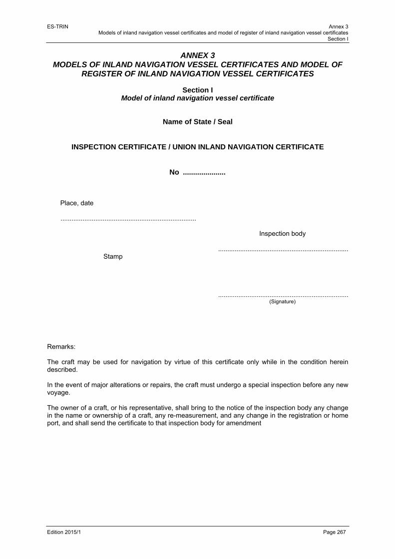
ES-TRIN Annex 3 Models of inland navigation vessel certificates and model of register of inland navigation vessel certificates
Section I
Edition 2015/1 Page 267
ANNEX 3
MODELS OF INLAND NAVIGATION VESSEL CERTIFICATES AND MODEL OF REGISTER OF INLAND NAVIGATION VESSEL CERTIFICATES
Section I
Model of inland navigation vessel certificate
Name of State / Seal
INSPECTION CERTIFICATE / UNION INLAND NAVIGATION CERTIFICATE
No ..................... Place, date .......................................................................... Inspection body ....................................................................... Stamp ....................................................................... (Signature) Remarks: The craft may be used for navigation by virtue of this certificate only while in the condition herein described. In the event of major alterations or repairs, the craft must undergo a special inspection before any new voyage. The owner of a craft, or his representative, shall bring to the notice of the inspection body any change in the name or ownership of a craft, any re-measurement, and any change in the registration or home port, and shall send the certificate to that inspection body for amendment
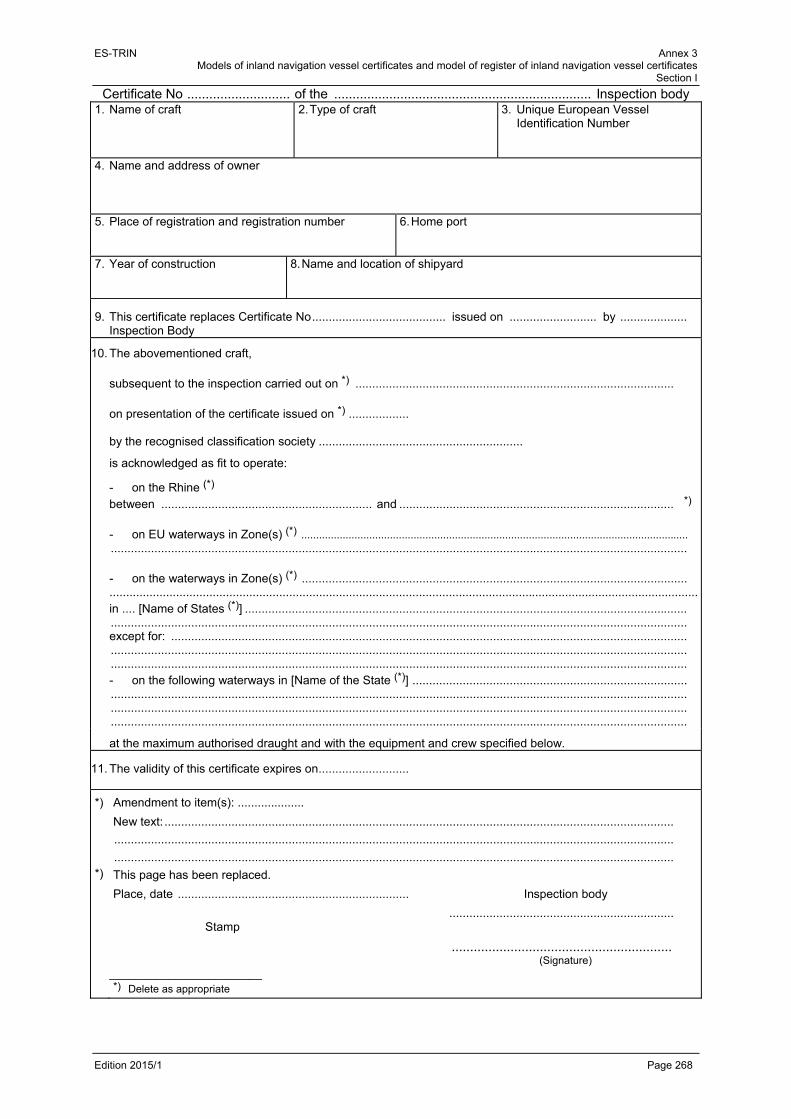
ES-TRIN Annex 3 Models of inland navigation vessel certificates and model of register of inland navigation vessel certificates
Section I
Edition 2015/1 Page 268
Certificate No ............................ of the ...................................................................... Inspection body 1. Name of craft
2. Type of craft 3. Unique European Vessel Identification Number
4. Name and address of owner
5. Place of registration and registration number
6. Home port
7. Year of construction
8. Name and location of shipyard
9. This certificate replaces Certificate No ........................................ issued on .......................... by .................... Inspection Body
10. The abovementioned craft, subsequent to the inspection carried out on *) ............................................................................................... on presentation of the certificate issued on *) .................. by the recognised classification society .............................................................
is acknowledged as fit to operate:
- on the Rhine (*)
between ............................................................... and .................................................................................. *)
- on EU waterways in Zone(s) (*) ...................................................................................................................................
............................................................................................................................................................................ - on the waterways in Zone(s) (*) ................................................................................................................... .................................................................................................................................................................................in .... [Name of States (*)] .................................................................................................................................... ............................................................................................................................................................................ except for: .......................................................................................................................................................... ............................................................................................................................................................................ ............................................................................................................................................................................ - on the following waterways in [Name of the State (*)] .................................................................................. ............................................................................................................................................................................ ............................................................................................................................................................................ ............................................................................................................................................................................
at the maximum authorised draught and with the equipment and crew specified below.
11. The validity of this certificate expires on ...........................
*)
*)
Amendment to item(s): ....................
New text: ........................................................................................................................................................
.......................................................................................................................................................................
.......................................................................................................................................................................
This page has been replaced.
Place, date ..................................................................... Inspection body
................................................................... Stamp
............................................................ (Signature) _______________________ *) Delete as appropriate

ES-TRIN Annex 3 Models of inland navigation vessel certificates and model of register of inland navigation vessel certificates
Section I
Edition 2015/1 Page 269
Certificate No ............................ of the ...................................................................... Inspection body
12. The certificate number (1), unique European vessel identification number (2), registration number (3) and measurement number (4) are affixed with the corresponding signs at the following locations on the craft 1 ................................................................................................................................................................. 2 ................................................................................................................................................................. 3 ................................................................................................................................................................. 4 .................................................................................................................................................................
13. The maximum authorised draught is indicated on each side of the craft
- by two - ......................................... – draught marks*).
- by the upper measurement plates *). Two draught scales have been applied *). The rear measurement scales serve as draught scales: they have been supplemented for that purpose by figures indicating the draughts*).
14. Without prejudice to the restrictions *) mentioned in items 15 and 52, the craft is fit to
1. push *) 4. be propelled in a side-by-side formation*)
1.1 in rigid formation *) 5. tow *)
1.2 with controlled articulation *) 5.1 craft having no motive power of their own*)
2. be pushed *) 5.2 motorised craft *)
2.1 in rigid formation *) 5.3 upstream only *)
2.2 at the head of a rigid formation *) 6. be towed *)
2.3 with controlled articulation *) 6.1 as a motorised craft *)
3. propel a side-by-side formation *) 6.2 as a craft with no motive power of its own*)
*)
*)
Amendment to item(s): ....................
New text: ........................................................................................................................................................
.......................................................................................................................................................................
.......................................................................................................................................................................
This page has been replaced.
Place, date ..................................................................... Inspection body
................................................................... Stamp
............................................................ (Signature) _______________________ *) Delete as appropriate
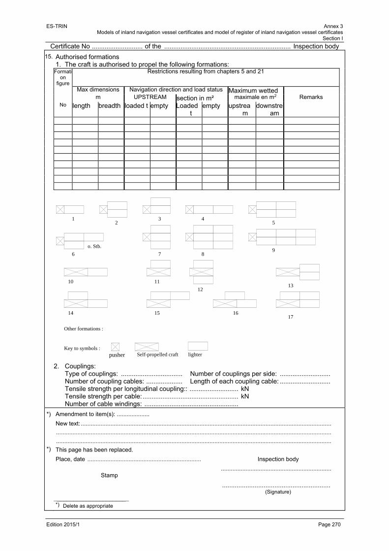
ES-TRIN Annex 3 Models of inland navigation vessel certificates and model of register of inland navigation vessel certificates
Section I
Edition 2015/1 Page 270
Certificate No ............................ of the ...................................................................... Inspection body
15. Authorised formations 1. The craft is authorised to propel the following formations:
Formation
figure
Restrictions resulting from chapters 5 and 21
Max dimensions Navigation direction and load status Maximum wetted m UPSTREAM section in m² maximale en m2 Remarks No length breadth loaded t empty Loaded
t empty upstrea
m downstre
am
2. Couplings: Type of couplings: .................................. Number of couplings per side: ............................ Number of coupling cables: .................... Length of each coupling cable: ............................ Tensile strength per longitudinal coupling:: ........................... kN Tensile strength per cable: ..................................................... kN Number of cable windings: ....................................................
*)
*)
Amendment to item(s): ....................
New text: ........................................................................................................................................................
.......................................................................................................................................................................
.......................................................................................................................................................................
This page has been replaced.
Place, date ..................................................................... Inspection body
................................................................... Stamp
............................................................ (Signature) _______________________ *) Delete as appropriate
Key to symbols :
12
3 45
6 7 89
10 11
1213
14 15 1617
Other formations :
o. Stb.
pusher Self-propelled craft lighter

ES-TRIN Annex 3 Models of inland navigation vessel certificates and model of register of inland navigation vessel certificates
Section I
Edition 2015/1 Page 271
Certificate No ............................ of the ...................................................................... Inspection body
16. Measurement certificate No ......... of the ............................................................ Measurement office dated .........................................
17a.
17b. Length overall m Length L m
18a. Breadth overall m 18b. Breadth B m
19a. Draught overall m 19b. Draught T m
20. Freeboard cm
21. Dead weight/Displacement *) t/m3*)
22. Number of passengers: 23. Number of passenger berths:
24. Number of watertight compartments
25. Number of holds 26. Type of hatch cover
27. Number of main propulsion engines
28. Total power rating of main means of propulsion kW
29. Number of main propellers
30. Number of bow windlasses
of which .....................powered
31. Number of stern windlasses
of which ........................powered
32. Number of towing hooks
33. Number of towing winches of which
of which ......................................
34. Steering gear Number of rudder
blades on main rudder
Main rudder drive
- manual *) - electric*)
- electric/hydraulic*) - hydraulic*)
Other installations: yes/no*) Type:
Flanking rudder: yes/no *)
Flanking rudder drive:
- manual *) - electrice*)
- electric/hydraulic*) - hydraulic*)
Bow rudder installation - bow rudder*) - Remote control Remote activation yes/no*)
- bow thruster*) - other installation*)
yes/no*)
Yes/no*)
35. Bilge and drainage system Number of bilge pumps .................... , of which power driven .......... Minimum pumping capacity first bilge pump l/min second bilge pump l/min
*)
*)
Amendment to item(s): ....................
New text: .......................................................................................................................................................
.......................................................................................................................................................................
.......................................................................................................................................................................
This page has been replaced.
Place, date ..................................................................... Inspection body
................................................................... Stamp
............................................................ (Signature) _______________________ *) Delete as appropriate
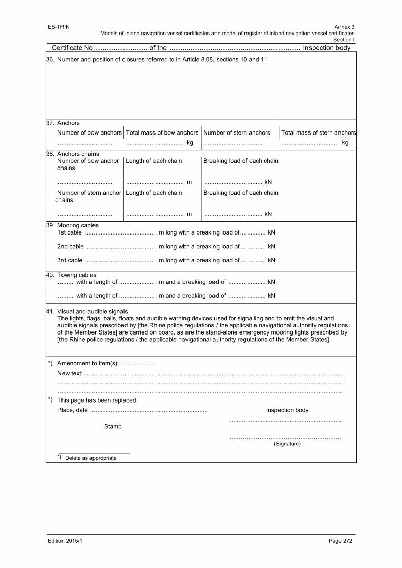
ES-TRIN Annex 3 Models of inland navigation vessel certificates and model of register of inland navigation vessel certificates
Section I
Edition 2015/1 Page 272
Certificate No ............................ of the ...................................................................... Inspection body
36. Number and position of closures referred to in Article 8.08, sections 10 and 11
37. Anchors Number of bow anchors Total mass of bow anchors Number of stern anchors Total mass of stern anchors
................................ .................................. kg .................................. .................................. kg
38. Anchors chains Number of bow anchor
chains
Length of each chain
Breaking load of each chain
................................ .................................. m .................................. kN
Number of stern anchor chains
Length of each chain
Breaking load of each chain
................................ .................................. m .................................. kN
39. Mooring cables 1st cable .......................................... m long with a breaking load of ............... kN
2nd cable ......................................... m long with a breaking load of ............... kN
3rd cable .......................................... m long with a breaking load of ............... kN
40. Towing cables ......... with a length of ...................... m and a breaking load of ...................... kN
......... with a length of ...................... m and a breaking load of ...................... kN
41. Visual and audible signals The lights, flags, balls, floats and audible warning devices used for signalling and to emit the visual and audible signals prescribed by [the Rhine police regulations / the applicable navigational authority regulations of the Member States] are carried on board, as are the stand-alone emergency mooring lights prescribed by [the Rhine police regulations / the applicable navigational authority regulations of the Member States].
*)
*)
Amendment to item(s): ....................
New text: ........................................................................................................................................................
.......................................................................................................................................................................
.......................................................................................................................................................................
This page has been replaced.
Place, date ..................................................................... Inspection body
................................................................... Stamp
............................................................ (Signature) _______________________ *) Delete as appropriate
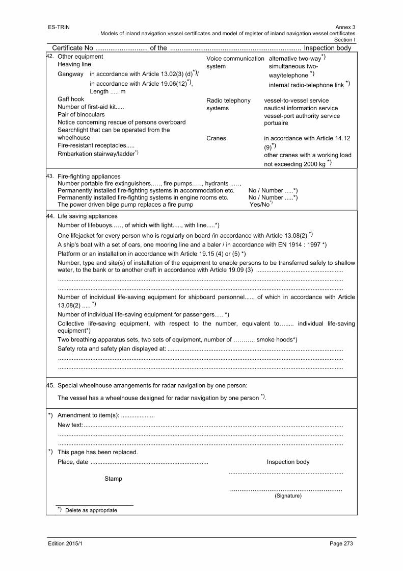
ES-TRIN Annex 3 Models of inland navigation vessel certificates and model of register of inland navigation vessel certificates
Section I
Edition 2015/1 Page 273
Certificate No ............................ of the ...................................................................... Inspection body 42. Other equipment
Heaving line
Gangway in accordance with Article 13.02(3) (d)*)/
in accordance with Article 19.06(12)*), Length ..... m Gaff hook Number of first-aid kit..... Pair of binoculars Notice concerning rescue of persons overboard Searchlight that can be operated from the wheelhouse Fire-resistant receptacles..... Rmbarkation stairway/ladder*)
Voice communication alternative two-way*) system simultaneous two-
way/telephone *)
internal radio-telephone link *) Radio telephony vessel-to-vessel service systems nautical information service vessel-port authority service
portuaire Cranes in accordance with Article 14.12
(9)*) other cranes with a working load
not exceeding 2000 kg *)
43.
Fire-fighting appliances Number portable fire extinguishers..…, fire pumps.…., hydrants ..…, Permanently installed fire-fighting systems in accommodation etc. No / Number .....*) Permanently installed fire-fighting systems in engine rooms etc. No / Number .....*) The power driven bilge pump replaces a fire pump Yes/No*)
44. Life saving appliances
Number of lifebuoys..…, of which with light....., with line.....*)
One lifejacket for every person who is regularly on board /in accordance with Article 13.08(2) *)
A ship's boat with a set of oars, one mooring line and a baler / in accordance with EN 1914 : 1997 *)
Platform or an installation in accordance with Article 19.15 (4) or (5) *)
Number, type and site(s) of installation of the equipment to enable persons to be transferred safely to shallow water, to the bank or to another craft in accordance with Article 19.09 (3) ...................................................
.......................................................................................................................................................................
.......................................................................................................................................................................
Number of individual life-saving equipment for shipboard personnel....., of which in accordance with Article 13.08(2) ..... *)
Number of individual life-saving equipment for passengers..... *)
Collective life-saving equipment, with respect to the number, equivalent to…..... individual life-saving equipment*)
Two breathing apparatus sets, two sets of equipment, number of ……….. smoke hoods*) Safety rota and safety plan displayed at: .......................................................................................................
.......................................................................................................................................................................
.......................................................................................................................................................................
45. Special wheelhouse arrangements for radar navigation by one person:
The vessel has a wheelhouse designed for radar navigation by one person *).
*)
*)
Amendment to item(s): ....................
New text: ........................................................................................................................................................
.......................................................................................................................................................................
.......................................................................................................................................................................
This page has been replaced.
Place, date ..................................................................... Inspection body
................................................................... Stamp
............................................................ (Signature) _______________________ *) Delete as appropriate

ES-TRIN Annex 3 Models of inland navigation vessel certificates and model of register of inland navigation vessel certificates
Section I
Edition 2015/1 Page 274
Certificate No ............................ of the ...................................................................... Inspection body
46. Operating modes meeting [A1*), A2*), B*). / the requirements of national or international law concerning the crew]
47. Vessel equipment in accordance with Article 31.01. The vessel complies *) / does not comply *) with Article 31.02 (Standard S1)*) / Article 31.03 (Standard S2)*). [In accordance with article 3.18 of the Regulations for Rhine navigation personnel / In accordance with national or international requirements], the minimum crew needs to be increased as follows*) / does not need to be increased:*):
Operating modes1
...................... ..................... .....................
...................... ..................... .....................
Observations and special conditions:
.......................................................................................................................................................................
.......................................................................................................................................................................
.......................................................................................................................................................................
48. Minimum crew [according to article 3.19 of the Regulations for Rhine navigation personnel / in accordance with national or international requirements]2
Operating modes
...................... ..................... .....................
...................... ..................... .....................
...................... ..................... .....................
...................... ..................... .....................
...................... ..................... .....................
...................... ..................... .....................
...................... ..................... .....................
...................... ..................... .....................
Observations and special conditions:
.......................................................................................................................................................................
.......................................................................................................................................................................
.......................................................................................................................................................................
.......................................................................................................................................................................
*)
*)
Amendment to item(s): ....................
New text: ........................................................................................................................................................
.......................................................................................................................................................................
.......................................................................................................................................................................
This page has been replaced.
Place, date ..................................................................... Inspection body
................................................................... Stamp
............................................................ (Signature) _______________________ *) Delete as appropriate
1 The Rhine inspection certificate will refer to: boatman, boatman replaced by an engine-minder; operating modes A1, A2 and
B. 2 The Rhine inspection certificate will refer to: Boatmaster, helmsman, able boatman, boatman, apprentice, engine-minder,
engineer: operating modes A1, A2 and B.

ES-TRIN Annex 3 Models of inland navigation vessel certificates and model of register of inland navigation vessel certificates
Section I
Edition 2015/1 Page 275
Certificate No ............................ of the ...................................................................... Inspection body
49. Extension/confirmation *) of certificate validity*) Periodical - special*) inspection
The Inspection Body inspected the vessel on ............................ *).
A certificate dated .......................................... from the recognised classification society ..........................
....................................................................................................................................................................... was presented to the Inspection Body*).
Reason for the inspection/certificate*): .............................................................................................................................................................................................
.............................................................................................................................................................................................
In view of – the inspection result - certificate - *), the period of validity of the certificate is maintained – extended -*)
until ................................... .
............................................................................. , .......................................... (Place) (date)
........................................................................ Stamp Inspection Body
........................................................................ ______________________ (Signature)
*) Delete as appropriate
49. Extension/confirmation *) of certificate validity*) Periodical - special*) inspection
The Inspection Body inspected the vessel on ............................ *).
A certificate dated .......................................... from the recognised classification society ............................
....................................................................................................................................................................... was presented to the Inspection Body*).
Reason for the inspection/certificate*): .............................................................................................................................................................................................
.............................................................................................................................................................................................
In view of – the inspection result - certificate - *), the period of validity of the certificate is maintained – extended -*)
until ................................... .
............................................................................. , .......................................... (Place) (date)
........................................................................ Stamp Inspection Body
........................................................................ ______________________ (Signature)
*) Delete as appropriate
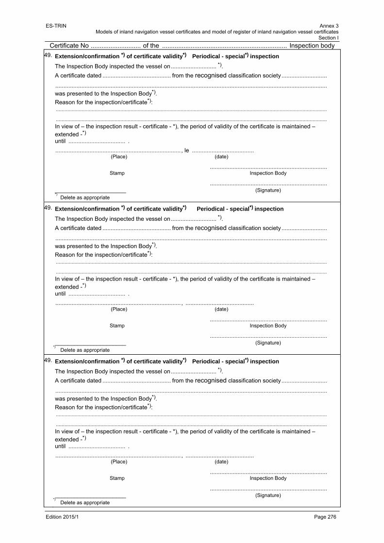
ES-TRIN Annex 3 Models of inland navigation vessel certificates and model of register of inland navigation vessel certificates
Section I
Edition 2015/1 Page 276
Certificate No ............................ of the ...................................................................... Inspection body
49. Extension/confirmation *) of certificate validity*) Periodical - special*) inspection
The Inspection Body inspected the vessel on ............................ *).
A certificate dated .......................................... from the recognised classification society ............................
....................................................................................................................................................................... was presented to the Inspection Body*).
Reason for the inspection/certificate*): .............................................................................................................................................................................................
.............................................................................................................................................................................................
In view of – the inspection result - certificate - *), the period of validity of the certificate is maintained – extended -*)
until ................................... .
............................................................................. , le ...................................... (Place) (date)
........................................................................ Stamp Inspection Body
........................................................................ ______________________ (Signature) *) Delete as appropriate
49. Extension/confirmation *) of certificate validity*) Periodical - special*) inspection
The Inspection Body inspected the vessel on ............................ *).
A certificate dated .......................................... from the recognised classification society ............................
....................................................................................................................................................................... was presented to the Inspection Body*).
Reason for the inspection/certificate*): .............................................................................................................................................................................................
.............................................................................................................................................................................................
In view of – the inspection result - certificate - *), the period of validity of the certificate is maintained – extended -*)
until ................................... .
............................................................................. , .......................................... (Place) (date)
........................................................................ Stamp Inspection Body
........................................................................ ______________________ (Signature)
*) Delete as appropriate

ES-TRIN Annex 3 Models of inland navigation vessel certificates and model of register of inland navigation vessel certificates
Section I
Edition 2015/1 Page 277
Certificate No ............................ of the ...................................................................... Inspection body
50. Attestation relating to liquefied gas installation(s)
The liquefied gas installation(s) on board the craft has/have been inspected by the expert*) ........................
........................................................................................................................................................................
and according to his inspection attestation dated ....................... *) fulfil(s) the conditions laid down.
The plant(s) include(s) the following gas-consuming appliances
Plant Serial No Model Make Type Position
This attestation is valid until ............................................................................................................................
.............................................................................. , .......................................... (Place) (Date)
.................................................................................................... Inspection body
Stamp .................................................................................................................. (Signature)
*)
*)
Amendment to item(s): ....................
New text: ........................................................................................................................................................
.......................................................................................................................................................................
.......................................................................................................................................................................
This page has been replaced.
Place, date ..................................................................... Inspection body
................................................................... Stamp
............................................................ (Signature) _______________________ *) Delete as appropriate

ES-TRIN Annex 3 Models of inland navigation vessel certificates and model of register of inland navigation vessel certificates
Section I
Edition 2015/1 Page 278
Certificate No ............................ of the ...................................................................... Inspection body
51. Extension of the attestation relating to liquefied gas installation(s)
The period covered by the attestation relating to liquefied gas installation(s)
dated ............................................................................. valid until ................................................................
is extended
- following the periodical inspection by the expert .........................................................................................
- on presentation of the inspection attestation dated .........
until ...........................................................................................
............................................................................ , ..........................................
(Place) (Date)
........................................................................ Inspection body
Stamp
........................................................................ (Signature)
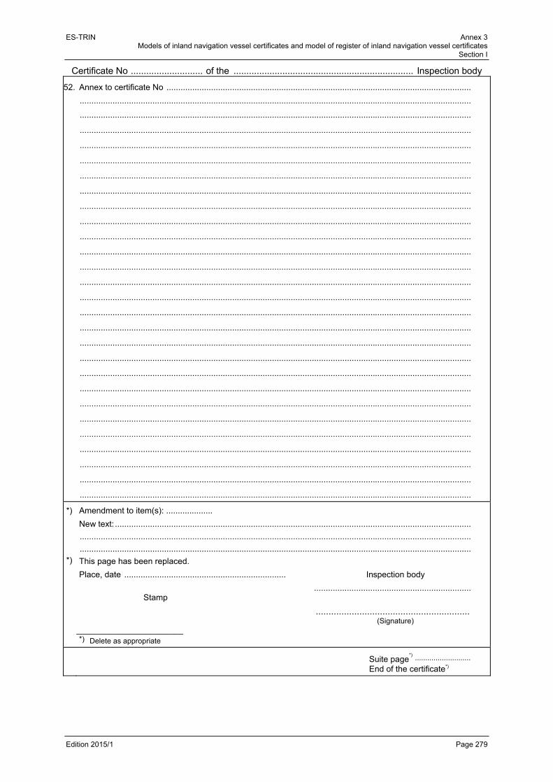
ES-TRIN Annex 3 Models of inland navigation vessel certificates and model of register of inland navigation vessel certificates
Section I
Edition 2015/1 Page 279
Certificate No ............................ of the ...................................................................... Inspection body
52. Annex to certificate No ..................................................................................................................................
.......................................................................................................................................................................
.......................................................................................................................................................................
.......................................................................................................................................................................
.......................................................................................................................................................................
.......................................................................................................................................................................
.......................................................................................................................................................................
.......................................................................................................................................................................
.......................................................................................................................................................................
.......................................................................................................................................................................
.......................................................................................................................................................................
.......................................................................................................................................................................
.......................................................................................................................................................................
.......................................................................................................................................................................
.......................................................................................................................................................................
.......................................................................................................................................................................
.......................................................................................................................................................................
.......................................................................................................................................................................
.......................................................................................................................................................................
.......................................................................................................................................................................
.......................................................................................................................................................................
.......................................................................................................................................................................
.......................................................................................................................................................................
.......................................................................................................................................................................
.......................................................................................................................................................................
.......................................................................................................................................................................
.......................................................................................................................................................................
.......................................................................................................................................................................
*)
*)
Amendment to item(s): ....................
New text: ........................................................................................................................................................
.......................................................................................................................................................................
.......................................................................................................................................................................
This page has been replaced.
Place, date ..................................................................... Inspection body
................................................................... Stamp
............................................................ (Signature) _______________________ *) Delete as appropriate
Suite page*) ...........................
End of the certificate*)

ES-TRIN Annex 3 Models of inland navigation vessel certificates and model of register of inland navigation vessel certificates
Section I
Edition 2015/1 Page 280
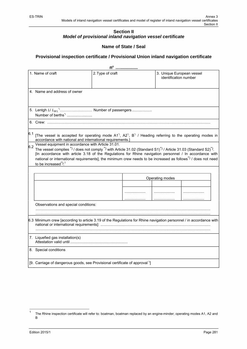
ES-TRIN Annex 3 Models of inland navigation vessel certificates and model of register of inland navigation vessel certificates
Section II
Edition 2015/1 Page 281
Section II Model of provisional inland navigation vessel certificate
Name of State / Seal
Provisional inspection certificate / Provisional Union inland navigation certificate
n …..............
1. Name of craft
2. Type of craft 3. Unique European vessel identification number
4. Name and address of owner
5. Lentgh / *) ................................... Number of passengers ................... Number of berths*) ........................
6. Crew: ............................................................................................................................................................
6.1 [The vessel is accepted for operating mode A1*), A2*), B*) / Heading referring to the operating modes in accordance with national and international requirements.]
6.2 Vessel equipment in accordance with Article 31.01. The vessel complies *) / does not comply *) with Article 31.02 (Standard S1)*) / Article 31.03 (Standard S2)*). [In accordance with article 3.18 of the Regulations for Rhine navigation personnel / In accordance with national or international requirements], the minimum crew needs to be increased as follows*) / does not need to be increased*):1
Operating modes
.................... .................... ....................
.................... .................... ....................
Observations and special conditions: ....................................................................................................................................................................... .......................................................................................................................................................................
6.3 Minimum crew [according to article 3.19 of the Regulations for Rhine navigation personnel / in accordance with national or international requirements]: ......................................................................................................... .......................................................................................................................................................................
7. Liquefied gas installation(s) Attestation valid until .......................................................
8. Special conditions
[9. Carriage of dangerous goods, see Provisional certificate of approval *)]
1 The Rhine inspection certificate will refer to: boatman, boatman replaced by an engine-minder; operating modes A1, A2 and
B
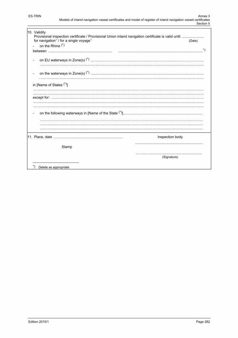
ES-TRIN Annex 3 Models of inland navigation vessel certificates and model of register of inland navigation vessel certificates
Section II
Edition 2015/1 Page 282
10. Validity Provisional inspection certificate / Provisional Union inland navigation certificate is valid until ...................... for navigation*) / for a single voyage*) (Date)
- on the Rhine (*)
between ............................................................... .................................................................................... *)
- on EU waterways in Zone(s) (*) ...............................................................................................................................
.................................................................................................................................................................. - on the waterways in Zone(s) (*) ................................................................................................................ . ..................................................................................................................................................................
in [Name of States (*)] ......................................................................................................................................................................... ......................................................................................................................................................................... except for: ....................................................................................................................................................... ......................................................................................................................................................................... .........................................................................................................................................................................
- on the following waterways in [Name of the State (*)]...............................................................................
................................................................................................................................................................. ................................................................................................................................................................. .................................................................................................................................................................
11. Place, date ..................................................................... Inspection body
................................................................... Stamp
............................................................ (Signature) _______________________
*) Delete as appropriate

ES-TRIN Annex 3 Models of inland navigation vessel certificates and model of register of inland navigation vessel certificates
Section III
Edition 2015/1 Page 283
Section III Model of supplementary Union inland navigation certificate
Annex to inspection certificate No ……………………….
Supplementary Union inland navigation certificate
Name of State / Seal
Name and address of the competent authority issuing the supplementary certificate
1. Name of vessel: ..............................................................................................................................
2. Unique European vessel identification number: .............................................................................
3. Place of registration and registration number: ................................................................................
4. Country of registration and/or home port: (1) ...................................................................................
5. Having regard to the Rhine vessel inspection certificate / Union certificate for inland navigation
vessels No .......................................................................................................
dated …………….………………….. valid until ...............................................................................
6. Having regard to the result of the inspection ..................................................................................
.......................................................... on ....................................................................................
7. the abovementioned vessel is deemed fit to operate on the EU waterways of Zone(s)
.........................................................................................................................................................
8. This supplementary certificate expires on ......................................................................................
9. Issued in ................................................ , on ..................................................................................
10.
…………………………………….
(Inspection body)
Stamp …………………………………….
(Signature)
_________________
(1) Delete as appropriate.

ES-TRIN Annex 3 Models of inland navigation vessel certificates and model of register of inland navigation vessel certificates
Section III
Edition 2015/1 Page 284
Annex to inspection certificate No ……………………….
11.
Zone and / or waterways (1)
4 3 2 1
Freeboard (cm)
with hold closed
with hold open
12. Derogations from inspection certificate for the Rhine No ……………………….
......................................................................................................................................................
......................................................................................................................................................
......................................................................................................................................................
......................................................................................................................................................
......................................................................................................................................................
......................................................................................................................................................
13. The entries concerning the number of crew members in the inspection certificate for the Rhine do
not apply.
14. Having regard to inspection certificate for the Rhine No .........................
dated ................................................ valid until ..........................................................................
Having regard to the result of the inspection .............................................................................. ,
on ………………………….,
This supplementary certificate is extended/renewed (1) until .......................................................
.........................................................................................................................................................
.................................................. , (Place) (Date)
……………………………………. (Inspection body)
Stamp ……………………………………. (Signature)
_________________
(1) Delete as appropriate.

ES-TRIN Annex 3 Models of inland navigation vessel certificates and model of register of inland navigation vessel certificates
Section IV
Edition 2015/1 Page 285
Section IV Model of certificate for sea-going vessel operating on the Rhine
Name of State / Seal
Certificate for sea-going vessel operating on the Rhine
n ........................ The inspection body ......................................................................... hereby certifies that the seagoing vessel Name: ........................................................................................................................................................
Vessel registration number or letters: ........................................................................................................
Place of registration: ..................................................................................................................................
Year of construction: ..................................................................................................................................
Vessel length: ............................................................................................................................................
once the inspection has been carried out, the ........ is recognised as fit to navigate the Rhine and is authorised to do so subject to the special conditions stipulated below.
Special conditions: ..................................................................................................................................... .................................................................................................................................................................... .................................................................................................................................................................... ....................................................................................................................................................................
This certificate is only valid on condition that the vessel is in possession of valid maritime or coastal navigation certificates and shall not not valid later than ............................................................................ .................................................. , ........................................................... (Place) (Date) .......................................................................
Stamp (Inspection body) ....................................................................... (Signature)

ES-TRIN Annex 3 Models of inland navigation vessel certificates and model of register of inland navigation vessel certificates
Section IV
Edition 2015/1 Page 286

ES-TRIN Annex 3 Models of inland navigation vessel certificates and model of register of inland navigation vessel certificates
Section V
Edition 2015/1 Page 287
Section V Model of certificate for traditional vessels according to chapter 24
(left void)

ES-TRIN Annex 3 Models of inland navigation vessel certificates and model of register of inland navigation vessel certificates
Section V
Edition 2015/1 Page 288

ES-TRIN Annex 3 Models of inland navigation vessel certificates and model of register of inland navigation vessel certificates
Section VI
Edition 2015/1 Page 289
Section VI Model of register of inland navigation vessel certificates
Register of inland navigation vessel certificates
Competent authority/Inspection body ...........................................
Register of certificates
Year .....................

ES-TRIN Annex 3 Models of inland navigation vessel certificates and model of register of inland navigation vessel certificates
Section VI
Edition 2015/1 Page 290
(Left-hand page)
Inland navigation vessel certificates
Name of vessel Unique European vessel identification
Owner Vessel register Type of vessel
No Day Month number Name Address Place No

ES-TRIN Annex 3 Models of inland navigation vessel certificates and model of register of inland navigation vessel certificates
Section VI
Edition 2015/1 Page 291
(right-hand page)
Deadweight according to measurement certificate or displacement*)
Zones or stretch of inland waterway, where appropriate
Endorsements concerning periodical or special inspections, withdrawal
and annulment
Certificate
Other comments
date du certificat
signe de jauge
t ou m
3
entre et of the certificate valid until
*) If no measurement certificate is available, estimate the deadweight or displacement.
ES-TRIN Annex 3 Models of inland navigation vessel certificates and model of register of inland navigation vessel certificates
Section VI
Edition 2015/1 Page 292

ES-TRIN Annex 4 Safety Signs
Edition 2015/1 Page 293
PART II ADDITIONAL REQUIREMENTS FOR SPECIFIC EQUIPEMENT
USED ON BOARD
ANNEX 4 SAFETY SIGNS
Figure 1 No entry for unauthorised persons
Colour: red / white / black
Figure 2 Fire, naked flame and smoking prohibited
Colour: red / white / black
Figure 3 Fire extinguisher
Colour: red / white
Figure 4 General danger warning
Colour: black / yellow

ES-TRIN
Edition 201
Figure 5Extinguis
Figure 6Fire-figh
Figure 7Wear ac
Figure 8First-aid
Figure 9Quick-clo
15/1
sher hose
ting installati
coustic protec
kit
osing valve o
ion
ction device
on the tank
Co
Co
Co
Co
Co
olour: red / w
olour: red / w
olour: blue / w
olour: green /
olour: brown /
S
white
white
white
/ white
/ white
Annex 4 Safety Signs
Page 294

ES-TRIN
Edition 201
Figure 1Wear life
Figure 1LNG wa
The symrepresendo not re
15/1
0 e jacket
1 rning
mbols actuantations in thender the me
ally used mhis Annex, preaning incom
may slightly rovided the mmprehensible
differ frommeaning is ne.
Co
Co
or be moot changed a
olour: blue / w
olour: black /
ore detailed and differenc
S
white
yellow
than the ces and mod
Annex 4 Safety Signs
Page 295
graphical difications

ES-TRIN Annex 4 Safety Signs
Edition 2015/1 Page 296

ES-TRIN Annex 5 Navigation and information equipment
Edition 2015/1 Page 297
ANNEX 5 NAVIGATION AND INFORMATION EQUIPMENT
Contents
Definitions Section I Minimum requirements and test conditions for navigational radar installations in inland
navigation Section II Minimum requirements and test conditions for rate-of-turn indicators in inland navigation
Chapter 1 General
Chapter 2 General minimum requirements for rate-of-turn indicators
Chapter 3 Minimum operational requirements for rate-of-turn indicators
Chapter 4 Minimum technical requirements for rate-of-turn indicators
Chapter 5 Test conditions and procedures for rate-of-turn indicators
Appendix: Maximum tolerances for indication errors of rate-of-turn indicators
Section III Requirements for installation and performance tests for navigational radar installations
and rate-of-turn indicators in inland navigation Section IV Minimum requirements, requirements for installation and performance tests for Inland AIS
equipment in inland navigation Section V Minimum requirements, requirements for installation and performance tests for
tachographs in inland navigation Section VI Installation and performance certificate for navigational radar installations and rate-of-turn
indicators, for Inland AIS equipment and for tachographs in inland navigation Section VII Lists of competent authorities, approved equipment and approved specialist firms
Definitions 1. 'Type test' means the test procedure as referred to in Section I Article 4 or Section II Article 1.03
which the technical service uses to test for compliance with the requirements according to this Annex. The type test forms an integral part of the type approval.
2. 'Type approval' means the administrative procedure according, by which a Member State
confirms that equipment complies with the requirements of this Annex.

ES-TRIN Annex 5 Navigation and information equipment
Edition 2015/1 Page 298
3. 'Test certificate' means the document in which the type testing results are laid down. 4. 'Applicant' or 'manufacturer' means any legal or natural person under whose name, trademark or
any other form of identification the equipment submitted for testing is manufactured or marketed and who is responsible for all matters as regards the type testing and type approval procedure in respect of the technical service and the approval authority.
5. 'Technical service' means the institution, authority or organisation that does the type testing. 6. 'Manufacturer's declaration' means the declaration by which a manufacturer gives the assurance
that the equipment meets the prevailing minimum requirements and that is identical in every respect to the type submitted for testing.
7. 'Declaration of conformity according to Directive 1999/5/EC1’ means the declaration according to
Directive 1999/5/EC Annex II(1), by which the manufacturer confirms that the products in question meet the applicable requirements of the Directive.
1 Directive 1999/5/EC of the European Parliament and of the Council of 9 March 1999 on radio equipment and
telecommunications terminal equipment and the mutual recognition of their conformity (OJ L 91 of 7.4.1999).
ES-TRIN Annex 5 Navigation and information equipment
Section I
Edition 2015/1 Page 299
Section I
Minimum requirements and test conditions for navigational radar installations in inland navigation
Article 1
Scope These provisions set out the minimum requirements for navigational radar installations used in inland navigation as well as the conditions for testing conformity with these minimum requirements.
Article 2 Purpose of the navigational radar installation
The navigational radar installations shall facilitate the navigation of the vessel by providing an intelligible radar picture of its position in relation to buoys shorelines and navigational structures, as well as permitting the reliable and timely recognition of other vessels and obstructions protruding above the surface of the waterway.
Article 3 Minimum requirements
1. Navigational radar installations shall meet the requirements of Directive 1999/5/EC. 2. Navigational radar installations shall also meet the requirements of the European Standard
EN 302 194-1 : 2006 Electromagnetic compatibility and Radio spectrum Matters (ERM); Navigational radar used on inland waterways: Part 1: Technical characteristics and methods of measurement.
Article 4 Type tests
Compliance with the minimum requirements as specified in Article 3(1) and (2) shall be established by means of a type test If the equipment passes the type test the technical service shall issue a test certificate. If the equipment fails to meet the minimum requirements, the applicant shall be notified in writing of the reasons for its rejection.
Article 5 Application for a type test
1. Applications for a type test of the navigational radar installation shall be submitted to a competent
technical service.

ES-TRIN Annex 5 Navigation and information equipment
Section I
Edition 2015/1 Page 300
2. Each application shall be accompanied by the following documents
a) Two detailed technical descriptions;
b) two complete sets of installation and service documents;
c) two detailed operator’s manuals;
d) two short operator’s manual; and
e) where applicable, evidence of previously completed tests. 3. In case it is not intended by the applicant to have the Declaration of Conformity pursuant to
Directive 1999/5/EC established concurrently with the type-approval, a Declaration of Conformity shall be submitted together with the application for a type test.
Article 6 Type-approval
1. Type-approval shall be granted by the competent authority pursuant to the test certificate.
2. Each competent authority or the technical service designated by the competent authority shall be
entitled to select equipment from the production series at any time for inspection If this inspection reveals defects in the equipment, type-approval may be withdrawn. The type-approval shall be withdrawn by the authority that issued it.
Article 7 Marking of the equipment and type approval number
1. Each component of the equipment shall be marked indelibly with the name of the manufacturer,
the trade designation of the equipment, the type of equipment and the serial number. 2. The type-approval number assigned by the competent authority shall be affixed indelibly to the
display unit in such a way that it remains clearly visible after the equipment has been installed. Composition of a type-approval number: R-NN-NNN or e-NN-NNN
R = Rhine
e = European Union
NN = number for the country of type-approval, where
01 = Germany 19 = Romania
02 = France 20 = Poland
03 = Italy 21 = Portugal
04 = Netherlands 23 = Greece
05 = Sweden 24 = Ireland
06 = Belgium 25 = Croatia
07 = Hungary 26 = Slovenia
08 = Czech Republic 27 = Slovakia
09 = Spain 29 = Estonia
ES-TRIN Annex 5 Navigation and information equipment
Section I
Edition 2015/1 Page 301
11 = United Kingdom 32 = Latvia
12 = Austria 34 = Bulgaria
13 = Luxembourg 36 = Lithuania
14 = Switzerland 49 = Cyprus
17 = Finland 50 = Malta
18 = Denmark
NNN = three-digit number, to be determined by the competent authority.
3. The type-approval number shall be used only in conjunction with the associated type-approval.
It shall be the responsibility of the applicant to produce and affix the type-approval number.
Article 8 Manufacturer’s declaration
Each unit of equipment shall be accompanied by a manufacturer's declaration.
Article 9 Modifications to type-approved equipment
1. Any modification made to equipment already approved shall cause the type-approval to be forfeit.
Whenever modifications are planned, details shall be sent in writing to the competent technical service.
2. The competent authority shall decide following consultation with the technical service whether the
type-approval still applies or whether an inspection or new type test is necessary If a new type test is granted, a new type-approval number shall be assigned.

ES-TRIN Annex 5 Navigation and information equipment
Section I
Edition 2015/1 Page 302
ES-TRIN Annex 5 Navigation and information equipment
Section II
Edition 2015/1 Page 303
Section II Minimum requirements and test conditions for rate-of-turn indicators in inland
navigation
Chapitre 1 General
Article 1.01
Scope These provisions set out the minimum requirements for rate-of-turn indicators in inland navigation, as well as the conditions for testing conformity with these minimum requirements.
Article 1.02 Purpose of the rate-of-turn indicator
The rate-of-turn indicator is intended to facilitate radar navigation, and to measure and indicate the rate of turn of the vessel to port or starboard.
Article 1.03 Type test
1. Compliance with the minimum requirements for rate-of-turn indicators pursuant to Chapters 2 to 4
shall be established by means of a type test. 2. If the equipment passes the type test the technical service shall issue a test certificate. If the
equipment fails to meet the minimum requirements, the applicant shall be notified in writing of the reasons for its rejection.
Article 1.04 Application for a type test
1. Applications for a type test of a rate-of-turn indicator shall be submitted to a competent technical
service. 2. Each application shall be accompanied by the following documents:
a) two detailed technical descriptions;
b) two complete sets of installation and service documents
c) two operating instructions. 3. By means of tests, the applicant shall establish or have it established that the equipment meets
the minimum requirements of these provisions.
The results of the test and the measurement reports shall be attached to the application. These documents and the information obtained during testing shall be kept by the competent authority.
ES-TRIN Annex 5 Navigation and information equipment
Section II
Edition 2015/1 Page 304
Article 1.05 Type approval
1. Type approval shall be granted by the competent authority pursuant to the test certificate.
2. Each competent authority or the technical service designated by the competent authority shall be
entitled to select equipment from the production series at any time for inspection.
If this inspection reveals defects in the equipment, type approval may be withdrawn. The type-approval shall be withdrawn by the authority that issued it.
Article 1.06 Marking of the equipment and type approval number
1. Each component of the equipment shall be marked indelibly with the name of the manufacturer,
the trade designation of the equipment, the type of equipment and the serial number. 2. The type-approval number assigned by the competent authority shall be affixed indelibly to the
control unit in such a way that it remains clearly visible after the equipment has been installed.
Composition of a type-approval number: R-NN-NNN or e-NN-NNN
R = Rhine e = European Union NN = number for the country of type-approval, where
01 = Germany 19 = Romania
02 = France 20 = Poland
03 = Italy 21 = Portugal
04 = Netherlands 23 = Greece
05 = Sweden 24 = Ireland
06 = Belgium 25 = Croatia
07 = Hungary 26 = Slovenia
08 = Czech Republic 27 = Slovakia
09 = Spain 29 = Estonia
11 = United Kingdom 32 = Latvia
12 = Austria 34 = Bulgaria
13 = Luxembourg 36 = Lithuania
14 = Switzerland 49 = Cyprus
17 = Finland 50 = Malta
18 = Denmark
NNN = three-digit number, to be determined by the competent authority
3. The type-approval number shall be used only in conjunction with the associated type-approval.
It shall be the responsibility of the applicant to produce and affix the type-approval number.

ES-TRIN Annex 5 Navigation and information equipment
Section II
Edition 2015/1 Page 305
Article 1.07
Manufacturer's declaration Each unit of equipment shall be accompanied by a manufacturer's declaration.
Article 1.08 Modifications to type-approved equipment
1. Any modification made to equipment already approved shall cause the type-approval to be forfeit.
Whenever modifications are planned, details shall be sent in writing to the competent technical service.
2. The competent authority shall decide following consultation with the technical service whether the
type-approval still applies or whether an inspection or new type test is necessary. If a new type test is granted, a new type approval number shall be assigned.
Chapter 2 General minimum requirements for rate-of-turn indicators
Article 2.01
Construction, design
1. Rate-of-turn indicators shall be suitable for operation on board inland navigation vessels. 2. The construction and design of the equipment shall be in accordance with current good
engineering practice, both mechanically and electrically. 3. In the absence of any specific provision in this Standard, the requirements and test methods
contained in European Standard EN 60945 : 2002 shall apply to power supply, safety, mutual interference of ship borne equipment, compass safe distance, resistance to climatic influences, mechanical strength, environmental influences, audible noise emission and equipment markings. The equipment shall satisfy all requirements of this Annex at ambient temperatures between 0 °C and + 40 °C.
ES-TRIN Annex 5 Navigation and information equipment
Section II
Edition 2015/1 Page 306
Article 2.02 Spurious emissions and electromagnetic compatibility
1. General requirements
Rate-of-turn indicators shall meet the requirements of Directive 2004/108/EC1. 2. Spurious emissions
In the frequency ranges of 156-165 MHz, 450-470 MHz and 1,53-1,544 GHz, the field strength shall not exceed a value of 15 μV/m. These field strengths shall apply at a test distance of 3 metres from the equipment under test.
Article 2.03 Operation
1. The equipment shall not have more control units than are necessary for its correct operation.
The design, markings and manipulation of the control units shall be such as to permit their simple, unambiguous and fast operation. Their arrangement shall be such as to prevent operational mistakes as far as possible Control units that are not necessary for normal operation shall not be immediately accessible.
2. All controls and indicators shall be provided with symbols and/or markings in English. Symbols
shall meet the requirements of European Standard EN 60417 : 1998 (graphical symbols for use on electrical equipment).
All numerals and letters shall be at least 4 mm high. If it can be demonstrated that, for technical reasons, numerals and letters 4 mm high are not possible and if for the purposes of operation smaller numerals and letters are acceptable, a reduction to 3 mm shall be allowed..
3. The equipment shall be designed in such a way that operating mistakes cannot cause its failure. 4. Any functions over and above the minimum requirements, such as facilities for connection to
other equipment, shall be provided in such a way that the equipment meets the minimum requirements under all conditions.
Article 2.04 Operator’s manual
A detailed operator's manual shall be supplied with each unit. It shall be available in Dutch, English, French and German and shall contain at least the following information:
a) activation and operation;
b) maintenance and servicing;
c) general safety provisions.
1 Directive 2004/108/EC of the European Parliament and of the Council of 15 December 2004 on the approximation of the
laws of the Member States relating to electromagnetic compatibility and repealing Directive 89/336/EEC (OJ L 390, 31.12.2004).

ES-TRIN Annex 5 Navigation and information equipment
Section II
Edition 2015/1 Page 307
Article 2.05 Installation of the sensor
The direction of installation in relation to the keel line shall be indicated on the rate-of-turn indicator's sensor unit. Installation instructions shall be provided to ensure maximum insensitivity to other normal movements of the vessel.
Chapter 3 Minimum operational requirements for rate-of-turn indicators
Article 3.01
Operational readiness of the rate-of-turn indicator
1. From a cold start, the rate-of-turn indicator shall be fully operational within 4 minutes and shall operate to within the required accuracy tolerances.
2. A warning signal shall indicate that the indicator is switched on. It shall be possible to observe
and operate the rate-of-turn indicator simultaneously. 3. Cordless remote controls shall not be permitted.
Article 3.02 Indication of the rate of turn
1. The rate of turn shall be indicated on a linear graduated scale having the zero point situated in
the middle. It shall be possible to read the direction and extent of the rate of turn with the necessary accuracy. Indicators other than needle indicators and bar-graphs shall not be permitted.
2. The indicator scale shall be at least 20 cm long and may be circular or rectilinear. Rectilinear scales may be arranged horizontally only. 3. Digital-only indicators will not be accepted.
Article 3.03 Measuring ranges
Rate-of-turn indicators may be provided with one or more measuring ranges. The following measuring ranges are recommended: 30°/min 60°/min 90°/min 180°/min 300°/min.
ES-TRIN Annex 5 Navigation and information equipment
Section II
Edition 2015/1 Page 308
Article 3.04 Accuracy of the indicated rate of turn
The indicated rate of turn shall not differ by more than 2 % from the measurable maximum value or by more than 10 % from the actual value; whichever is the greater (see Appendix).
Article 3.05 Sensitivity
The operating threshold shall be less than or equal to a change in angular speed equivalent to 1 % of the indicated value.
Article 3.06 Monitoring of operation
1. If the rate-of-turn indicator does not operate within the required accuracy range, this shall be
indicated. 2. If a gyroscope is used, any critical fall in the rate of rotation of the gyroscope shall be signalled by
an indicator. A critical fall in the rate of rotation of the gyroscope is one which lowers accuracy by 10 %.
Article 3.07 Insensitivity to normal movements of the vessel
1. Rolling of the vessel of up to 10° at a rate of turn of up to 4°/s shall not give rise to measurement
errors in excess of the stipulated tolerances. 2. Impacts such as those that may occur during berthing shall not give rise to measurement errors in
excess of the stipulated tolerances.
Article 3.08 Insensitivity to magnetic fields
The rate-of-turn indicator shall be insensitive to magnetic fields which typically occur on board the vessel.
Article 3.09 Slave indicators
Slave indicators shall comply with all requirements applicable to rate-of-turn indicators
ES-TRIN Annex 5 Navigation and information equipment
Section II
Edition 2015/1 Page 309
Chapitre 4 Minimum technical requirements for rate-of-turn indicators
Article 4.01 Operation
1. All controls shall be so arranged that during their operation no information is concealed from view
and radar navigation remains unimpaired. 2. All control units and indicators shall be provided with a dazzle-free source of lighting appropriate
for all ambient lighting conditions and adjustable down to zero by means of an independent control.
3. Adjustment of control units shall be such that movements to the right or upwards have a positive
effect on the variable and movements to the left or downwards a negative effect. 4. If push-buttons are used, it shall be possible to locate and operate them by touch. They shall also
have clearly perceptible contact release. If pushbuttons have multiple functions, it must be apparent which hierarchical level is active.
Article 4.02 Damping devices
1. The sensor system shall be damped for critical values. The damping constant (63 % of the limit
value) shall not exceed 0,4 seconds. 2. The indicator shall be damped for critical values.
Control units for increasing damping shall be permitted. Under no circumstances shall the damping constant exceed 5 seconds.
Article 4.03 Connection of additional equipment
1. If the rate-of-turn indicator can be connected to slave indicators or similar equipment, the
rate-of-turn indication shall remain usable as an analogue electric signal. In addition, the rate-of-turn indicator may possess a digital interface in accordance with (2).
The rate of turn shall continue to be indicated with galvanic earth insulation and the equivalent to an analogue voltage of 20 mV/°/min ± 5 % and a maximum internal resistance of 100 . Polarity shall be positive when the vessel is turning to starboard and negative when it is turning to port.

ES-TRIN Annex 5 Navigation and information equipment
Section II
Edition 2015/1 Page 310
The operating threshold shall not exceed 0,3°/min. Zero error shall not exceed 1°/min at temperatures from 0 °C to 40 °C. With the indicator switched on and the sensor not exposed to the effects of movement, the spurious voltage at the output signal measured with a 10 Hz pass-band low-pass filter shall not exceed 10 mV. The rate-of-turn signal shall be received without additional damping beyond the limits referred to in Article 4.02(1).
2. A digital interface shall be designed pursuant to European Standards EN 61162-1 : 2008,
EN 61162-2 : 1998 and EN 61162-3 : 2008. 3. An external alarm switch shall be provided. The switch shall be installed as a galvanic insulation
break-switch for the indicator. The external alarm shall be triggered by contact closure:
a) if the rate-of-turn indicator is disconnected; or
b) if the rate-of-turn indicator is not in operation; or
c) if the operating control has reacted following an excessive error (Article 3.06).
Chapter 5 Test conditions and procedures for rate-of-turn indicators
Article 5.01
Safety, load capacity and electromagnetic compatibility Power supply, safety, mutual interference of ship borne equipment, compass safe distance, resistance to climatic influences, mechanical strength, environmental impact, audible noise emission and electromagnetic compatibility shall be tested in accordance with European Standard EN 60945 : 2002.
Article 5.02 Spurious emissions
Spurious emissions shall be measured in accordance with European Standard EN 60945 : 2002 in the frequency range of 30 to 2000 MHz. The requirements of Article 2.02(2) shall be met.
Article 5.03 Test procedure
1. Rate-of-turn indicators shall be tested under nominal and boundary conditions. In this regard, the
influence of the operating voltage and of the ambient temperature shall be tested as far as the prescribed limit value. In addition, radio transmitters shall be used to set up the maximum magnetic fields in the vicinity of the indicators.

ES-TRIN
Edition 201
2. Undin th All m
15/1
der the condhe Appendix
minimum req
itions describ.
quirements o
Figure 1
bed in (1), in
of Chapters 2
: Maximum of rate
ndicator error
2 to 4 shall be
Appendixtolerances
e-of-turn ind
rs shall rema
e met.
for indicatiodicators
Navigation a
ain within the
on errors
and information
e tolerances
Annex 5 n equipment
Section II
Page 311
indicated

ES-TRIN Annex 5 Navigation and information equipment
Section II
Edition 2015/1 Page 312

ES-TRIN Annex 5 Navigation and information equipment
Section III
Edition 2015/1 Page 313
Section III Requirements for installation and performance tests for navigational radar
installations and rate-of-turn indicators in inland navigation
Article 1 General
1. Installation and performance tests of navigational radar installations and rate-of-turn indicator
systems must take place according to the following provisions. 2. Only equipment with a type approval according to Section I Article 6 or Section II Article 1.05, or
with a type approval recognised as equivalent shall be authorised for installation.
Article 2 Approved specialist firms
1. The installation, replacement, repair or maintenance of navigational radar installations and rate-
of-turn indicators shall be carried out only by specialist firms approved by the competent authority.
2. Approval may be withdrawn by the competent authority.
Article 3 Requirements for on-board power supply
All power supply leads for navigational radar installations and rate-of-turn indicators shall have their own separate safety device and, if possible, be fail-safe.
Article 4 Installation of the radar antenna
1. The radar antenna shall be installed as close as possible to the fore-and-aft-line. There shall be
no obstruction in the vicinity of the antenna causing false echoes or unwanted shadows; if necessary, the antenna shall be mounted on the forecastle. The mounting and attachment of the radar antenna in its operational position shall be sufficiently stable to enable the navigational radar installation to perform within the required accuracy limits.
2. After the angular error in the mounting has been corrected and the equipment has been switched
on, the difference between lubber line and fore-and-aft-line shall not be greater than 1°.

ES-TRIN Annex 5 Navigation and information equipment
Section III
Edition 2015/1 Page 314
Article 5 Installation of the display unit and the control unit
1. The display unit and control unit shall be installed in the wheelhouse in such a way that the
evaluation of the radar image and the operation of the navigational radar installation present no difficulty. The azimuthal orientation of the radar image shall be in accordance with the normal situation of the surroundings. Holders and adjustable consoles shall be constructed in a way that they can be fixed in each position free of vibration.
2. During radar navigation, artificial lighting shall not be reflected in the direction of the radar
operator. 3. When the control unit is not part of the display unit, it shall be located in housing within 1 metre of
the display unit. Cordless remote controls shall not be permitted. 4. If slave indicators are installed, they shall satisfy the requirements which apply to navigational
radar installations.
Article 6 Installation of the rate-of-turn indicator
1. The rate-of-turn indicator shall be located ahead of the helmsman and within their field of vision. 2. The sensor system shall be installed as far as possible amidships, horizontal and aligned with the
ship's fore-and aft-line. The installation site shall as far as possible be free of vibration and be liable only to modest temperature variations. The indicator unit shall if possible be installed directly above the radar display.
3. If slave indicators are installed, they shall satisfy the requirements which apply to rate-of-turn
indicators.
Article 7 Installation of the position sensor
For inland ECDIS equipment which is operated in navigation mode, the position sensor (e.g. DGPS antenna) must be installed in such a way as to ensure that it operates with the greatest possible degree of accuracy and is not adversely affected by superstructures and transmitting equipment on board ship.
Article 8 Installation and performance test
Before the equipment is switched on for the first time after installation, in case of periodical inspection in order to extend the validity of the inland navigation certificate, as well as after each modification of the vessel likely to affect the operating conditions of the equipment, an installation and performance test shall be carried out by the competent authority or by a specialist firm authorised in accordance with Article 2. For this purpose, the following conditions shall be fulfilled:
a) the power supply shall have a separate safety device;
b) the operating voltage shall be within the tolerance;
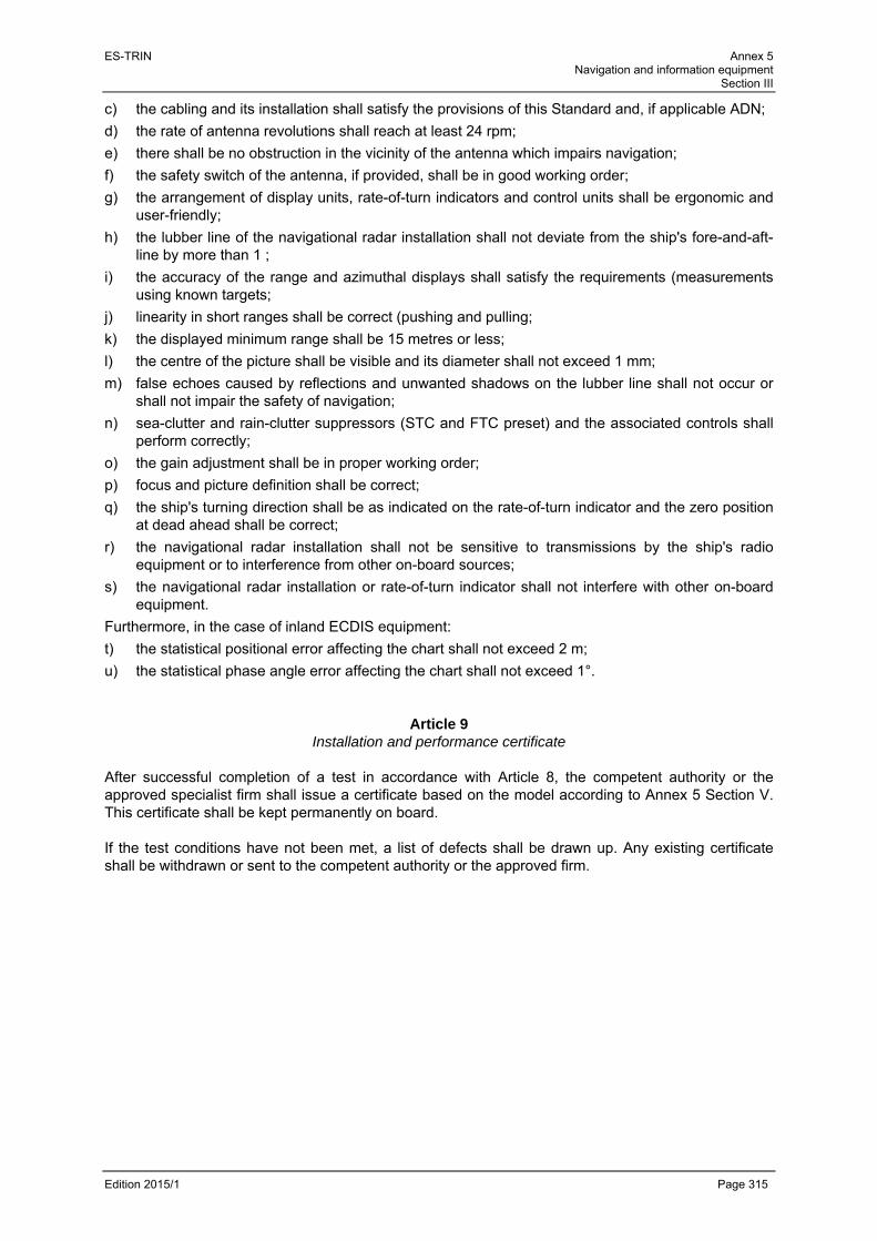
ES-TRIN Annex 5 Navigation and information equipment
Section III
Edition 2015/1 Page 315
c) the cabling and its installation shall satisfy the provisions of this Standard and, if applicable ADN;
d) the rate of antenna revolutions shall reach at least 24 rpm;
e) there shall be no obstruction in the vicinity of the antenna which impairs navigation;
f) the safety switch of the antenna, if provided, shall be in good working order;
g) the arrangement of display units, rate-of-turn indicators and control units shall be ergonomic and user-friendly;
h) the lubber line of the navigational radar installation shall not deviate from the ship's fore-and-aft-line by more than 1 ;
i) the accuracy of the range and azimuthal displays shall satisfy the requirements (measurements using known targets;
j) linearity in short ranges shall be correct (pushing and pulling;
k) the displayed minimum range shall be 15 metres or less;
l) the centre of the picture shall be visible and its diameter shall not exceed 1 mm;
m) false echoes caused by reflections and unwanted shadows on the lubber line shall not occur or shall not impair the safety of navigation;
n) sea-clutter and rain-clutter suppressors (STC and FTC preset) and the associated controls shall perform correctly;
o) the gain adjustment shall be in proper working order;
p) focus and picture definition shall be correct;
q) the ship's turning direction shall be as indicated on the rate-of-turn indicator and the zero position at dead ahead shall be correct;
r) the navigational radar installation shall not be sensitive to transmissions by the ship's radio equipment or to interference from other on-board sources;
s) the navigational radar installation or rate-of-turn indicator shall not interfere with other on-board equipment.
Furthermore, in the case of inland ECDIS equipment:
t) the statistical positional error affecting the chart shall not exceed 2 m;
u) the statistical phase angle error affecting the chart shall not exceed 1°.
Article 9 Installation and performance certificate
After successful completion of a test in accordance with Article 8, the competent authority or the approved specialist firm shall issue a certificate based on the model according to Annex 5 Section V. This certificate shall be kept permanently on board. If the test conditions have not been met, a list of defects shall be drawn up. Any existing certificate shall be withdrawn or sent to the competent authority or the approved firm.

ES-TRIN Annex 5 Navigation and information equipment
Section III
Edition 2015/1 Page 316

ES-TRIN Annex 5 Navigation and information equipment
Section IV
Edition 2015/1 Page 317
Section IV Minimum requirements, requirements for installation and performance tests for Inland
AIS equipment in inland navigation
This part is only applicable in Zone R.
Article 1 Approval of Inland AIS equipment
Inland AIS equipment must comply with the requirements of the Test Standard, edition 2.0, to be found in the CCNR resolution 2007-I-15. Compliance is certified by an examination of type approval by a competent authority.
Article 2
Installation and performance tests of shipborne Inland AIS equipment The following conditions are to be complied with when installing shipborne Inland AIS equipment: 1. Shipboard Inland AIS equipment can only be installed by specialist firms approved by the
competent authority. 2. The Inland AIS equipment must be installed in the wheelhouse or other readily accessible
location. 3. The functionality of an MKD (integrated capture and display device) must be accessible to the
boatmaster. The warning and Inland AIS equipment status information must be located within the helmsman's direct field of view. Other devices used for navigation purposes may however take priority as regards their direct visibility. All warning indicator lights must remain visible after installation.
4. It must be possible to establish visually whether the equipment is operating. The equipment must
be permanently supplied with electric power by means of an uninterrupted power supply circuit with its own fuse protection and connected directly to this power supply.
5. Inland AIS equipment antennas must be installed and connected to the stations so as to ensure
that these stations operate reliably under all normal conditions of use. Other equipment may only be connected if the interfaces of the two equipment are compatible.
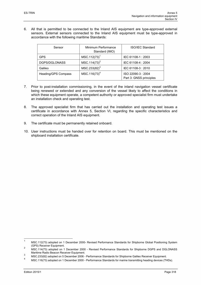
ES-TRIN Annex 5 Navigation and information equipment
Section IV
Edition 2015/1 Page 318
6. All that is permitted to be connected to the Inland AIS equipment are type-approved external
sensors. External sensors connected to the Inland AIS equipment must be type-approved in accordance with the following maritime Standards:
Sensor Minimum Performance Standard (IMO)
ISO/IEC Standard
GPS MSC.112(73)1 IEC 61108-1 : 2003
DGPS/DGLONASS MSC.114(73)2 IEC 61108-4 : 2004
Galileo MSC.233(82)3 IEC 61108-3 : 2010
Heading/GPS Compass MSC.116(73)4 ISO 22090-3 : 2004 Part 3: GNSS principles
7. Prior to post-installation commissioning, in the event of the inland navigation vessel certificate
being renewed or extended and any conversion of the vessel likely to affect the conditions in which these equipment operate, a competent authority or approved specialist firm must undertake an installation check and operating test.
8. The approved specialist firm that has carried out the installation and operating test issues a
certificate in accordance with Annex 5, Section VI, regarding the specific characteristics and correct operation of the Inland AIS equipment.
9. The certificate must be permanently retained onboard. 10. User instructions must be handed over for retention on board. This must be mentioned on the
shipboard installation certificate.
1 MSC.112(73) adopted on 1 December 2000- Revised Performance Standards for Shipborne Global Positioning System
(GPS) Receiver Equipment. 2 MSC.114(73) adopted on 1 December 2000 - Revised Performance Standards for Shipborne DGPS and DGLONASS
Maritime Radio Beacon Receiver Equipment. 3 MSC.233(82) adopted on 5 December 2006 - Performance Standards for Shipborne Galileo Receiver Equipment. 4 MSC.116(73) adopted on 1 December 2000 - Performance Standards for marine transmitting heading devices (THDs).

ES-TRIN Annex 5 Navigation and information equipment
Section V
Edition 2015/1 Page 319
Section V Minimum requirements, requirements for installation and performance tests for
tachographs in inland navigation This part is only applicable in Zone R.
Article 1 Requirements to be complied with by tachographs
1. Ascertaining the vessel's navigation time
To determine navigation according to the criterion yes/no, the rotation of the propeller must be measured at an appropriate place. Where propulsion is other than by propeller, the vessel's movement must be ascertained in an equivalent manner at appropriate place. Where there are two or more propeller shafts, it must be ensured that recording will operate even if only one of the shafts is turning.
2. Vessel identification
The unique European vessel identification number or official vessel number must be indelibly recorded on the data medium and be readable from it.
3. Recording on the data medium
The following items of information must be recorded on the data medium such as to be tamper-proof and readable from it: the vessel's operating mode, the date and time at which the tachograph was operating and ceased operating, the insertion and removal of the data medium and other actions performed on the device. The tachograph must automatically record the time, insertion and removal of the data medium, the opening and closure of the device as well as any interruption to its power supply.
4. Recording time per day
The date and time at which the shaft starts and stops rotating must be continuously recorded daily between 00.00 and 24.00.
5. Reading the recording The recording must be unequivocal, easy to read and clearly comprehensible. It must be possible to read the recording at any moment without any special auxiliary devices.
6. Printing the recording
It must be possible for the recordings to be provided at any time as a readily transparent printout.
7. Security of the recording
The rotation of the propeller must be recorded in a way that cannot be tampered with.
8. Accuracy of the recording
The rotation of the propeller must be recorded in a way that is accurate in time. The recording must be readable with an accuracy of 5 minutes.

ES-TRIN Annex 5 Navigation and information equipment
Section V
Edition 2015/1 Page 320
9. Operating voltages Voltage fluctuations of up to 10 % of the nominal value must not hinder the proper functioning of the device. Moreover, the installation must be capable of withstanding a 25 % increase in the supply voltage relative to the nominal voltage without its serviceability being impaired in any way.
10. Operating conditions
The devices or device components must operate faultlessly under the following conditions:
- ambient temperature: 0 C to + 40 C
- humidity: up to 85 % relative air humidity
- type of electrical protection: IP 54 in accordance with the International Standard IEC 529
- oil resistance: although intended to be installed in the engine room, the devices or device components must be oil resistant
- permissible time recording tolerances: 2 minutes per 24 hours.
Article 2 Requirements for installing shipboard tachographs
The following conditions are to be complied with when installing shipboard tachographs: 1. Shipboard tachographs can only be installed by specialist firms approved by the competent
authority. 2. The tachograph must be installed in the wheelhouse or other readily accessible location. 3. It must be possible to establish visually whether the device is operating. The device must be
permanently supplied with electric power by means of an uninterrupted power supply circuit with its own fuse protection and connected directly to this power supply.
4. Information concerning the vessel's movement, namely whether the vessel is “underway” or “not
underway” is derived from the movement of the propulsion system. The corresponding signal must originate from the rotation of the propeller, from the propeller shaft or from the operation of the propulsion machinery. In the case of different propulsion systems, an equivalent solution must be achieved.
5. The technical equipment for capturing the movement of the vessel must be installed so as to be
as operationally reliable as possible and immune from unauthorised interventions. To this end, the signal transmission circuit (including the signal generator and device inlet terminal), from the propulsion system to the device must be protected by appropriate means with monitoring to detect any interruption of the circuit. Appropriate for this purpose are for example seals bearing identification markings and visible cable runs or monitoring circuits.

ES-TRIN Annex 5 Navigation and information equipment
Section V
Edition 2015/1 Page 321
6. Upon completion of the installation, the specialist firm which has carried out or supervised the
installation carries out an operating test. It issues a certificate attesting to the characteristics of the installation (in particular the location and type of seals and their markings, location and type of monitoring equipment) and that it is operating correctly; the certificate must also provide information on the type of approved device. A new operating test is required after any replacement, modification or repair; this test must be referred to on the certificate.
The certificate must at a minimum comprise the following data:
- name, address and unique reference of the approved specialist firm that has carried out or supervised the installation;
- name, address and telephone number of the competent authority that approved the company;
- unique European vessel identification number of the vessels or official number of the vessel;
- tachograph type and serial number;
- date of the operating test. The certificate is valid for 5 years. The purpose of the certificate is to prove that the device is approved, installed by an approved specialist firm and has been tested for correct operation.
7. The vessel's command must be trained in the use of the device by the approved company and user
instructions must be handed over for retention on board. This must be mentioned on the shipboard installation certificate.

ES-TRIN Annex 5 Navigation and information equipment
Section V
Edition 2015/1 Page 322

ES-TRIN Annex 5 Navigation and information equipment
Section VI
Edition 2015/1 Page 323
Section VI Installation and performance certificate for navigational radar installations, rate-of-turn
indicators, for Inland AIS equipment and for tachographs in inland navigation (Model)
Vessel name/type: .....................................................................................................................................
Unique European vessel identification number: ........................................................................................
Vessel owner:
Name: .....................................................................
Address: .....................................................................................................................................................
Telephone: ..................................... Navigational radar installations: Number: ....................
Item No Type Manufacturer Type-approval number Serial number
Rate-of-turn indicators: Number: ....................
Item No Type Manufacturer Type-approval number Serial number
Inland AIS equipment:
Item No Type Manufacturer Type-approval number Serial number
Tachographs … It is hereby certified that the vessel's navigational radar installations, rate-of-turn indicators and Inland AIS equipment, referred to above, comply with the requirements of Annex 5 of the European Standard laying down technical requirements for inland navigation vessels (ES-TRIN) for the installation and performance testing of navigational radar installations, rate-of-turn indicators and Inland AIS equipment for inland navigation . Approved specialist firm
Name: ................................................................................
Address: .....................................................................................................................................................
Telephone: ..........................................
Stamp Place .............................. Date .....................................
Signature Competent authority for the approval of the specialist firm
Name: ................................................................................
Address: .....................................................................................................................................................
Telephone: ..........................................

ES-TRIN Annex 5 Navigation and information equipment
Section VI
Edition 2015/1 Page 324

ES-TRIN Annex 5 Navigation and information equipment
Section VII
Edition 2015/1 Page 325
Section VII Lists of competent authorities, approved equipment and approved specialist firms
1. List of authorities with competence for approving navigational radar installations and rate-of-turn
indicators in accordance with the ES-TRIN Standard 2. List of navigational radar installations and rate-of-turn indicators approved in accordance with the
ES-TRIN Standard 3. List of navigational radar installations and rate-of-turn indicators approved in accordance with the
ES-TRIN Standard based on equivalent type approvals 4. List of specialist forms certified to install or replace navigational radar installations and rate-of-turn
indicators in accordance with the ES-TRIN Standard 5. List of authorities with competence to approve Inland AIS equipment in accordance with the
ES-TRIN Standard 6. List of Inland AIS equipment approved in accordance with the ES-TRIN Standard
List of Inland AIS equipment approved between 1st April 2008 and 18 October 2012 based on type approvals awarded in accordance with the Test Standard, edition 1.0 and 1.01 The installation of Inland AIS equipment, type approval of which is based on edition 1.0 and 1.01 of the Test Standard, continues to be permitted until 30.11.2015 and their use continues to be permitted beyond this date. List of Inland AIS equipment approved from 19 October 2012 onward based on type approvals awarded in accordance with the Test Standard, edition 2.0
7. List of Inland AIS equipment approved in accordance with the ES-TRIN Standard based on
equivalent type approvals
List of Inland AIS equipment approved between 1st April 2008 and 18 October 2012 based on type approvals awarded in accordance with the Test Standard, edition 1.0 and 1.01 The installation of Inland AIS equipment, type approval of which is based on edition 1.0 and 1.01 of the Test Standard, continues to be permitted until 30.11.2015 and their use continues to be permitted beyond this date. List of Inland AIS equipment approved from 19 October 2012 onward based on type approvals awarded in accordance with the Test Standard, edition 2.0
8. List of specialist firms certified to install or replace Inland AIS equipment in accordance with the ES-TRIN Standard
The list of specialist firms certified to install or replace tachographs is defined by the Regulations for Rhine navigation personnel.

ES-TRIN Annex 5 Navigation and information equipment
Section VII
Edition 2015/1 Page 326

ES-TRIN Annex 6 Engine parameter protocol
Edition 2015/1 Page 327
ANNEX 6
ENGINE PARAMETER PROTOCOL (Model)
0 General
0.1 Engine information
0.1.1 Make: ..........................................................................................................................................
0.1.2 Manufacturer’s description: ........................................................................................................
0.1.3 Type-approval number: ..............................................................................................................
0.1.4 Engine identification number: ..................................................................................................... 0.2 Documentation
The engine parameters should be tested and the test results documented. The documentation should consist of separate sheets, individually numbered, signed by the controller and attached to this protocol.
0.3 Test
The test should be carried out on the basis of the Engine manufacturer's instructions on monitoring the components and engine parameters of relevance in an exhaust gas context. In duly motivated cases controllers may, at their own discretion, dispense with checks on certain engine parameters.
0.4 This engine parameter protocol, including the accompanying chart readings, comes to a total of … * pages.
1. Engine parameters
This is to certify that the engine under test does not deviate excessively from the prescribed parameters.
1.1 Installation inspection Name and address of the technical service: .............................................................................. .................................................................................................................................................... .................................................................................................................................................... Name of the controller: ................................................................................................................ Place and date: ........................................................................................................................... Signature: .................................................................................................................................... Test recognised by competent authority: .................................................................................... .................................................................................................................................................... .................................................................................................................................................... Place and date: ................................................................. Seal of the competent Signature: .......................................................................... authority ----------------- * To be filled in by the controller.

ES-TRIN Annex 6 Engine parameter protocol
Edition 2015/1 Page 328
1.2 Intermediate test Special test1 Name and address of the technical service: .............................................................................. .................................................................................................................................................... .................................................................................................................................................... Name of the controller: ............................................................................................................... Place and date: .......................................................................................................................... Signature: ................................................................................................................................... Test recognised by competent authority: ................................................................................... .................................................................................................................................................... .................................................................................................................................................... Place and date: ................................................................ Seal of the competent
Signature: ......................................................................... authority
1.2 Intermediate test Special test Name and address of the technical service: .............................................................................. .................................................................................................................................................... .................................................................................................................................................... Name of the controller: ............................................................................................................... Place and date: .......................................................................................................................... Signature: ................................................................................................................................... Test recognised by competent authority: ................................................................................... .................................................................................................................................................... .................................................................................................................................................... Place and date: ................................................................ Seal of the competent
Signature: ......................................................................... authority
1.2 Intermediate test Special test Name and address of the the technical service: ........................................................................ .................................................................................................................................................... .................................................................................................................................................... Name of the controller: ............................................................................................................... Place and date: .......................................................................................................................... Signature: ................................................................................................................................... Test recognised by competent authority: ................................................................................... .................................................................................................................................................... .................................................................................................................................................... Place and date: ................................................................ Seal of the competent
Signature: ......................................................................... authority
1 Place a cross in the appropriate box

ES-TRIN Annex 6 Engine parameter protocol
Edition 2015/1 Page 329
Appendix 1 Annex to the engine parameter protocol
(Model)
Craft name: ………………………………. Unique European vessel identification number:
…………………………
Installation inspection 1) Intermediate test
1) Special test 1)
Manufacturer: ………………………………………… Engine type: ………………………………………. (Trade name/trade mark/trade name of the manufacturer) (Engine family/manufacturer’s description)
Rated power (kW): ………….. Rated speed (rpm): ……………. Number of cylinders: ………..
Use for which the engine is intended: ……………………………………………………………………….. (Craft main propulsion/Generator propulsion/forward beam propulsion/auxiliary engine, etc.)
Type approval number: …………………………………………… Year of engine construction:
…………………
Engine identification number: ……………………………………………. Place of installation:
……………………...
(Serial number/unique identification number)
The engine and engine components of relevance in an exhaust gas context have been identified on the basis of the data plate details. The test has been carried out on the basis of the Engine manufacturer's instructions on monitoring the components and engine parameters of relevance in an exhaust gas context.
A) Component test Additional components of relevance in an exhaust gas context and listed in the Engine manufacturer's instructions on monitoring the components and engine parameters of relevance in an exhaust gas context should be included in the table.
Component Component number recorded Conformity 1)
Camshaft/piston Yes No N/A
Injection valve Yes No N/A
Data set/software number Yes No N/A
Injection pump Yes No N/A
cylinder head Yes No N/A
Exhaust-gas turbocharger Yes No N/A
Charge air cooler Yes No N/A
Yes No N/A
Yes No N/A
Yes No N/A
B) Visual inspection of the adjustable features and engine parameters Parameter Value recorded Conformity1)
Injection timing, injection period Yes No
C) Inspection of the air intake and the exhaust system
Measurements have been taken in order to verify compliance with the authorised values Intake under pressure: ……….. kPa at rated speed and full load Exhaust gas back pressure: ……….. kPa at rated speed and full load
A visual inspection of the air intake and exhaust gas system has been carried out. No abnormalities were detected that would suggest non-compliance with the authorised values.
D) Comments: (The following divergent settings, modifications or changes to the installed engine were noted.)
Name of the controller: ………………………………………………………………...
Place and date: ……………………………….
Signature: 1) Place a cross in the appropriate box.

ES-TRIN Annex 6 Engine parameter protocol
Edition 2015/1 Page 330

ES-TRIN Annex 7 On-board sewage treatment plants
Edition 2015/1 Page 331
ANNEX 7 ON-BOARD SEWAGE TREATMENT PLANTS
Table of contents
Section I Supplementary provisions
1. Marking of on-board sewage treatment plants 2. Testing 3. Evaluation of conformity of production
Section II Information document No … relating to type approval of on-board sewage treatment
plants intended for installation in inland waterway vessels (model)
Appendix 1 - Main characteristics of the on-board sewage treatment plant type (model) Section III Type approval certificate (model)
Appendix 1 - Test results for type approval (model) Section IV Type approvals’ numbering system Section V Summary of type approvals for on-board sewage treatment plant types Section VI Summary of on-board sewage treatment plants manufactured (model) Section VII Data sheet for on-board sewage treatment plants with type approval (model) Section VIII On-board sewage treatment plant parameters record for special test (model)
Appendix 1 - Appendix to the on-board sewage treatment plant parameters record
Section IX Test procedure

ES-TRIN Annex 7 On-board sewage treatment plants
Edition 2015/1 Page 332
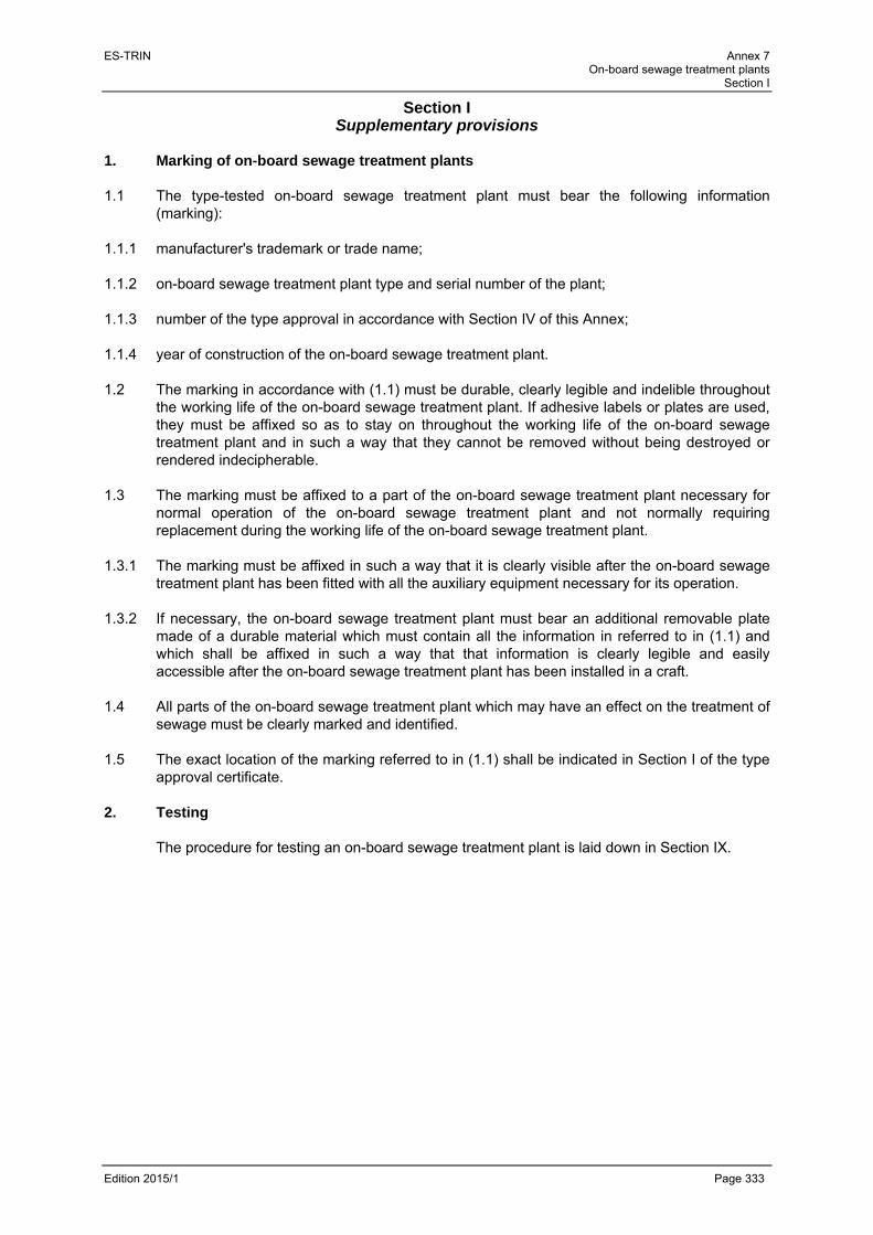
ES-TRIN Annex 7 On-board sewage treatment plants
Section I
Edition 2015/1 Page 333
Section I Supplementary provisions
1. Marking of on-board sewage treatment plants 1.1 The type-tested on-board sewage treatment plant must bear the following information
(marking): 1.1.1 manufacturer's trademark or trade name; 1.1.2 on-board sewage treatment plant type and serial number of the plant; 1.1.3 number of the type approval in accordance with Section IV of this Annex; 1.1.4 year of construction of the on-board sewage treatment plant. 1.2 The marking in accordance with (1.1) must be durable, clearly legible and indelible throughout
the working life of the on-board sewage treatment plant. If adhesive labels or plates are used, they must be affixed so as to stay on throughout the working life of the on-board sewage treatment plant and in such a way that they cannot be removed without being destroyed or rendered indecipherable.
1.3 The marking must be affixed to a part of the on-board sewage treatment plant necessary for
normal operation of the on-board sewage treatment plant and not normally requiring replacement during the working life of the on-board sewage treatment plant.
1.3.1 The marking must be affixed in such a way that it is clearly visible after the on-board sewage
treatment plant has been fitted with all the auxiliary equipment necessary for its operation. 1.3.2 If necessary, the on-board sewage treatment plant must bear an additional removable plate
made of a durable material which must contain all the information in referred to in (1.1) and which shall be affixed in such a way that that information is clearly legible and easily accessible after the on-board sewage treatment plant has been installed in a craft.
1.4 All parts of the on-board sewage treatment plant which may have an effect on the treatment of
sewage must be clearly marked and identified. 1.5 The exact location of the marking referred to in (1.1) shall be indicated in Section I of the type
approval certificate. 2. Testing
The procedure for testing an on-board sewage treatment plant is laid down in Section IX.
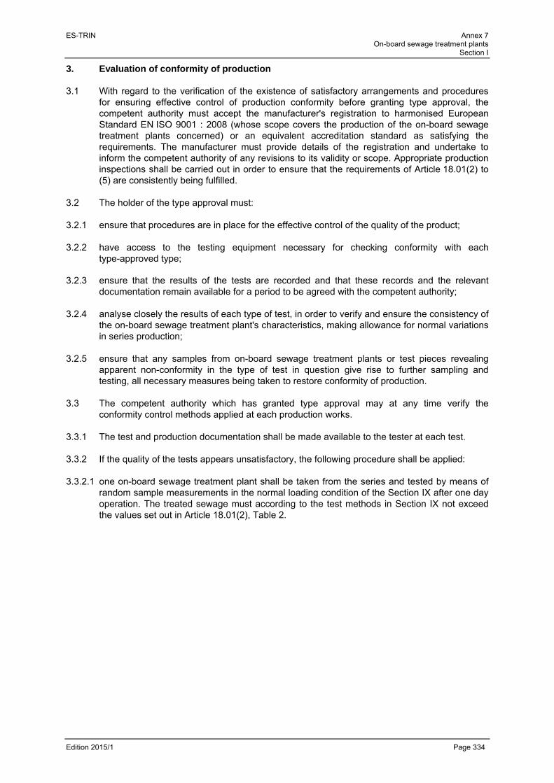
ES-TRIN Annex 7 On-board sewage treatment plants
Section I
Edition 2015/1 Page 334
3. Evaluation of conformity of production 3.1 With regard to the verification of the existence of satisfactory arrangements and procedures
for ensuring effective control of production conformity before granting type approval, the competent authority must accept the manufacturer's registration to harmonised European Standard EN ISO 9001 : 2008 (whose scope covers the production of the on-board sewage treatment plants concerned) or an equivalent accreditation standard as satisfying the requirements. The manufacturer must provide details of the registration and undertake to inform the competent authority of any revisions to its validity or scope. Appropriate production inspections shall be carried out in order to ensure that the requirements of Article 18.01(2) to (5) are consistently being fulfilled.
3.2 The holder of the type approval must: 3.2.1 ensure that procedures are in place for the effective control of the quality of the product; 3.2.2 have access to the testing equipment necessary for checking conformity with each
type-approved type; 3.2.3 ensure that the results of the tests are recorded and that these records and the relevant
documentation remain available for a period to be agreed with the competent authority; 3.2.4 analyse closely the results of each type of test, in order to verify and ensure the consistency of
the on-board sewage treatment plant's characteristics, making allowance for normal variations in series production;
3.2.5 ensure that any samples from on-board sewage treatment plants or test pieces revealing
apparent non-conformity in the type of test in question give rise to further sampling and testing, all necessary measures being taken to restore conformity of production.
3.3 The competent authority which has granted type approval may at any time verify the
conformity control methods applied at each production works. 3.3.1 The test and production documentation shall be made available to the tester at each test. 3.3.2 If the quality of the tests appears unsatisfactory, the following procedure shall be applied: 3.3.2.1 one on-board sewage treatment plant shall be taken from the series and tested by means of
random sample measurements in the normal loading condition of the Section IX after one day operation. The treated sewage must according to the test methods in Section IX not exceed the values set out in Article 18.01(2), Table 2.

ES-TRIN Annex 7 On-board sewage treatment plants
Section I
Edition 2015/1 Page 335
3.3.2.2 should any on-board sewage treatment plant taken from the series fail to satisfy the requirements laid down in (3.3.2.1) the manufacturer may ask for random sample measurements to be carried out on a number of on-board sewage treatment plants of the same specification taken from the series. This new sample must include the on-board sewage treatment plant originally taken.
The manufacturer shall determine the scope ′ ′ of the series in consultation with the competent authority. The on-board sewage treatment plants shall undergo testing by means of random sample measurement with the exception of the plant originally taken. The arithmetical mean of the results obtained with the random sample of the on-board sewage treatment plant must then be determined. The series production shall be regarded as conforming with requirements if the following condition is fulfilled:
∙
Where:
: is a statistical factor which is dependent on ′ ′ and is given in the following table:
2 3 4 5 6 7 8 9 10
0,973 0,613 0,489 0,421 0,376 0,342 0,317 0,296 0,279
11 12 13 14 15 16 17 18 19
0,265 0,253 0,242 0,233 0,224 0,216 0,210 0,203 0,198
sin 20, ,
√
∶ 1
where is any individual result obtained from the random sample : is the admissible limit value set out in Article 18.01(2), Table 2, for each pollutant studied;
3.3.3 if the values as set out in Article 18.01(2), Table 2 are not complied with, a new test shall be
carried out according to (3.3.2.1) and, in case that tests has no positive results, in accordance with (3.3.2.2) a full test is carried out, following the test procedure provided in Annex 9. The limit values as set out in Article 18.01(2), Table 1 may not be exceeded for either the composite sample or the random sample.
3.3.4 The competent authority must carry out the tests on on-board sewage treatment plants which
are partially or fully functional according to the information supplied by the manufacturer. 3.3.5 The normal frequency of tests of conformity of production which the competent authority is
entitled to conduct shall be one per year. In case of non-compliance with the requirements of (3.3.3) the competent authority shall ensure that all necessary steps are taken to restore production conformity without delay.

ES-TRIN Annex 7 On-board sewage treatment plants
Section I
Edition 2015/1 Page 336

ES-TRIN Annex 7 On-board sewage treatment plants
Section II
Edition 2015/1 Page 337
Section II Information Document No …1 relating to type approval of on-board sewage treatment
plants intended for installation in inland waterway vessels (Model)
On-board sewage treatment plant type: .................................................................................................... 0. General 0.1 Make (manufacturer’s company name): ......................................................................................... 0.2 Manufacturer’s designation for the on-board sewage treatment plant type: ...................................
.......................................................................................................................................................... 0.3 Manufacturer’s type code corresponding to the information given on the on-board sewage
treatment plant: ............................................................................................................................... ..........................................................................................................................................................
0.4 Manufacturer’s name and address: .................................................................................................
Name and address of manufacturer’s authorised representative, if any: ....................................... ..........................................................................................................................................................
0.5 Position, coding and method of attachment of the on-board sewage treatment plant's serial
number: ........................................................................................................................................... ..........................................................................................................................................................
0.6 Position and method of attachment of the type approval number: .................................................
.......................................................................................................................................................... 0.7 Address(es) of production works: ....................................................................................................
.......................................................................................................................................................... Appendixes 1. Main characteristics of the on-board sewage treatment plant type
2. Design and dimensioning criteria, dimensioning specifications and regulations applied
3. Schematic diagram of the on-board treatment plant with parts list
4. Schematic diagram of the test plant with parts list
5 Electrical wiring diagrams (P/I diagram)
6. Statement that all specifications regarding the mechanical, electrical and technical safety of sewage treatment plants and specifications concerning ship safety have been observed
7. Characteristics of any parts of the vessel that are connected with the on-board sewage treatment plant
8. Manufacturer's guide to checking the components and parameters of the on-board sewage treatment plant relevant to sewage treatment in accordance with Article 1.01 (9.10)
1 Information document reference number assigned by the competent authority.

ES-TRIN Annex 7 On-board sewage treatment plants
Section II
Edition 2015/1 Page 338
9. Photographs of the on-board sewage treatment plant
10. Operating concepts(1)
10.1 Instructions for manual operation of the on-board sewage treatment plant
10.2 Notes on excess sludge management (discharge intervals)
10.3 Notes on maintenance and repair
10.4 Notes on action necessary in the case of stand-by operation of the on-board sewage treatment plant
10.5 Notes on action necessary in the case of emergency operation of the on-board sewage treatment plant
10.6 Notes on run-down, standstill and restart operation of the on-board sewage treatment plant
10.7 Notes on requirements for pre-treatment of galley waste water
11. Other equipment (list here) Date, signature of on-board sewage treatment plant manufacturer …………………………………………… ………………………………………….
Appendix 1 Main characteristics of the on-board sewage treatment plant type
(Model) 1. Description of the on-board sewage treatment plant 1.1 Manufacturer: ............................................................................................................................. 1.2 Serial number of the plant: ......................................................................................................... 1.3 Mode of treatment: biological or mechanical/chemical (2) 1.4 Upstream waste water storage tank? Yes, … m³ / No(2) 2. Design and dimensioning criteria (including any special installation instructions or
restrictions on use) 2.1 .................................................................................................................................................... 2.2 .................................................................................................................................................... 3. Dimensioning of the on-board sewage treatment plant 3.1 Maximum daily volumetric flow rate of sewage (m³/d): ......................................................... 3.2 Daily pollution load (kg/d): ................................................................................................
1 Operating phases
The following operating phases shall be defined for testing: a) Stand-by operation is when the on-board sewage treatment plant is running but has not been fed with sewage for
more than a day. An on-board sewage treatment plant may be in stand-by operation when, for example, the passenger vessel is not in service for an extended period and sits idle at its mooring.
b) Emergency operation is when individual subassemblies of an on-board sewage treatment plant have malfunctioned, so that the sewage cannot be treated as intended.
c) Run-down, standstill and restart operation is when an on-board sewage treatment plant is taken out of service for an extended period (winter mooring) and the power supply is switched off, or when the on-board sewage treatment plant is started up again at the beginning of the season.
2 Specify as appropriate.

ES-TRIN Annex 7 On-board sewage treatment plants
Section III
Edition 2015/1 Page 339
Section III Type approval certificate
(Model)
Seal of the competent authority Type approval No.: .......................................... Extension No.: ....................................................... Notification of - issuance/extension/refusal/withdrawal1 of type approval for an on-board sewage treatment plant type in accordance with the European Standard laying down technical requirements for inland navigation vessels (ES-TRIN) Reason for extension, if applicable: .......................................................................................................... Section I 0. General
0.1 Make (manufacturer’s company name): .......................................................................................
0.2 Manufacturer’s designation for the on-board sewage treatment plant type: ................................
.......................................................................................................................................................
0.3 Manufacturer’s type code corresponding to the information affixed to the on-board treatment plant: .............................................................................................................................................
.......................................................................................................................................................
Position: ........................................................................................................................................
Method of attachment: ..................................................................................................................
0.4 Manufacturer’s name and address: ..............................................................................................
.......................................................................................................................................................
Name and address of manufacturer’s authorised representative, if any: .....................................
.......................................................................................................................................................
0.5 Position, coding and method of attachment of the serial number of the on-board sewage treatment plant: .............................................................................................................................
.......................................................................................................................................................
.......................................................................................................................................................
0.6 Position and method of attachment of the type approval number: ...............................................
.......................................................................................................................................................
0.7 Address(es) of production works: .................................................................................................
.......................................................................................................................................................
1 Specify as appropriate.

ES-TRIN Annex 7 On-board sewage treatment plants
Section III
Edition 2015/1 Page 340
Section II
1. Any restrictions on use: ................................................................................................................
1.1 Particularities to be observed when installing the on-board sewage treatment plant in a craft:
.......................................................................................................................................................
1.1.1 .......................................................................................................................................................
1.1.2 ....................................................................................................................................................... 2. Technical service responsible for carrying out the tests1: ............................................................
.......................................................................................................................................................
....................................................................................................................................................... 3. Date of test report: ........................................................................................................................ 4. Number of test report: ................................................................................................................... 5. The undersigned hereby certifies the accuracy of the manufacturer information in the annexed
information document for the above mentioned on-board sewage treatment plant in accordance with Annex 7 Section IX of the European Standard laying down technical requirements for inland navigation vessels (ES-TRIN) and the validity of the annexed test results in relation to the on-board sewage treatment plant type. The sample(s) has (have) been selected by the manufacturer with the agreement of the competent authority and submitted by the manufacturer as the design type of the on-board sewage treatment plant:
The type approval is issued/extended/refused/withdrawn2:
Place: ............................................................................................................................................
Date: .............................................................................................................................................
Signature: .....................................................................................................................................
Appendices: Information folder
Test results (see Appendix 1)
1 In case tests are made by the competent authority mark ’not relevant’. 2 Specify as appropriate.
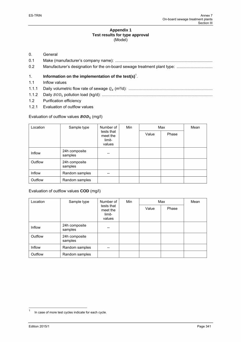
ES-TRIN Annex 7 On-board sewage treatment plants
Section III
Edition 2015/1 Page 341
Appendix 1 Test results for type approval
(Model) 0. General
0.1 Make (manufacturer’s company name): .......................................................................................
0.2 Manufacturer’s designation for the on-board sewage treatment plant type: ................................ 1. Information on the implementation of the test(s)1.
1.1 Inflow values
1.1.1 Daily volumetric flow rate of sewage (m³/d): ...........................................................................
1.1.2 Daily pollution load (kg/d): ...................................................................................................
1.2 Purification efficiency
1.2.1 Evaluation of outflow values Evaluation of outflow values (mg/l)
Location Sample type Number of tests that meet the
limit-values
Min Max Mean
Value Phase
Inflow 24h composite samples
--
Outflow 24h composite samples
Inflow Random samples --
Outflow Random samples
Evaluation of outflow values COD (mg/l)
Location Sample type Number of tests that meet the
limit-values
Min Max Mean
Value Phase
Inflow 24h composite samples
--
Outflow 24h composite samples
Inflow Random samples --
Outflow Random samples
1 In case of more test cycles indicate for each cycle.

ES-TRIN Annex 7 On-board sewage treatment plants
Section III
Edition 2015/1 Page 342
Evaluation of outflow values TOC (mg/l)
Location Sample type Number of tests that meet the
limit-values
Min Max Mean
Value Phase
Inflow 24h composite samples
--
Outflow 24h composite samples
Inflow Random samples --
Outflow Random samples
Evaluation of outflow values SRF (mg/l)
Location Sample type Number of tests that meet the
limit-values
Min Max Mean
Value Phase
Inflow 24h composite samples
--
Outflow 24h composite samples
Inflow Random samples --
Outflow Random samples

ES-TRIN Annex 7 On-board sewage treatment plants
Section III
Edition 2015/1 Page 343
1.2.2 Purification efficiency (elimination efficiency)
Parameter Sample type Min Max Mean
24h composite samples
Random samples
COD 24h composite samples
COD Random samples
TOC 24h composite samples
TOC Random samples
SRF 24h composite samples
SRF Random samples
1.3 Further parameters measured 1.3.1 Additional inflow and outflow parameters:
Parameter Inflow Outflow
pH
Conductivity
Temperature of liquid phases
1.3.2 The following operating parameters are – when available - to be recorded during sampling:
Concentration of dissolved oxygen in the bioreactor
Dry matter content in the bioreactor
Temperature in the bioreactor
Ambient temperature
1.3.3 Further operating parameters according to the manufacturer's operating instructions
.......................................................................................................................................................
.......................................................................................................................................................
.......................................................................................................................................................
....................................................................................................................................................... 1.4 Competent authority or Technical service: Place, date: ................................................. Signature: ........................................................................

ES-TRIN Annex 7 On-board sewage treatment plants
Section III
Edition 2015/1 Page 344
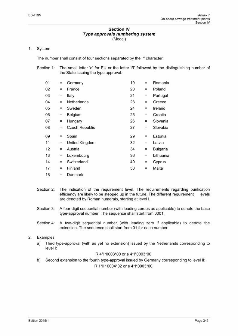
ES-TRIN Annex 7 On-board sewage treatment plants
Section IV
Edition 2015/1 Page 345
Section IV Type approvals numbering system
(Model) 1. System
The number shall consist of four sections separated by the '*' character. Section 1: The small letter 'e' for EU or the letter 'R' followed by the distinguishing number of
the State issuing the type approval:
01 = Germany 19 = Romania
02 = France 20 = Poland
03 = Italy 21 = Portugal
04 = Netherlands 23 = Greece
05 = Sweden 24 = Ireland
06 = Belgium 25 = Croatia
07 = Hungary 26 = Slovenia
08 = Czech Republic 27 = Slovakia
09 = Spain 29 = Estonia
11 = United Kingdom 32 = Latvia
12 = Austria 34 = Bulgaria
13 = Luxembourg 36 = Lithuania
14 = Switzerland 49 = Cyprus
17 = Finland 50 = Malta
18 = Denmark
Section 2: The indication of the requirement level. The requirements regarding purification efficiency are likely to be stepped up in the future. The different requirement levels are denoted by Roman numerals, starting at level I.
Section 3: A four-digit sequential number (with leading zeroes as applicable) to denote the base
type-approval number. The sequence shall start from 0001. Section 4: A two-digit sequential number (with leading zero if applicable) to denote the
extension. The sequence shall start from 01 for each number. 2. Examples
a) Third type-approval (with as yet no extension) issued by the Netherlands corresponding to level I:
R 4*I*0003*00 or e 4*I*0003*00
b) Second extension to the fourth type-approval issued by Germany corresponding to level II:
R 1*II* 0004*02 or e 4*I*0003*00

ES-TRIN Annex 7 On-board sewage treatment plants
Section IV
Edition 2015/1 Page 346

ES-TRIN Annex 7 On-board sewage treatment plants
Section V
Edition 2015/1 Page 347
Section V
Summary of type approvals for on-board sewage treatment plant types (Model)
Seal of the competent authority
List No.: ............................................... Period from ................................................... to ......................................................
1 2 3 4 5 6 7
Make (1) Manufacturer’s designation (1) Type approval number
Date of type approval
Extension/ refusal/
withdrawal 2)
Reason for extension/refusal/withdrawal
Date of extension/
refusal/ withdrawal 2)
1 According to the type approval cerfificate 2 Specify as appropriate

ES-TRIN Annex 7 On-board sewage treatment plants
Section V
Edition 2015/1 Page 348
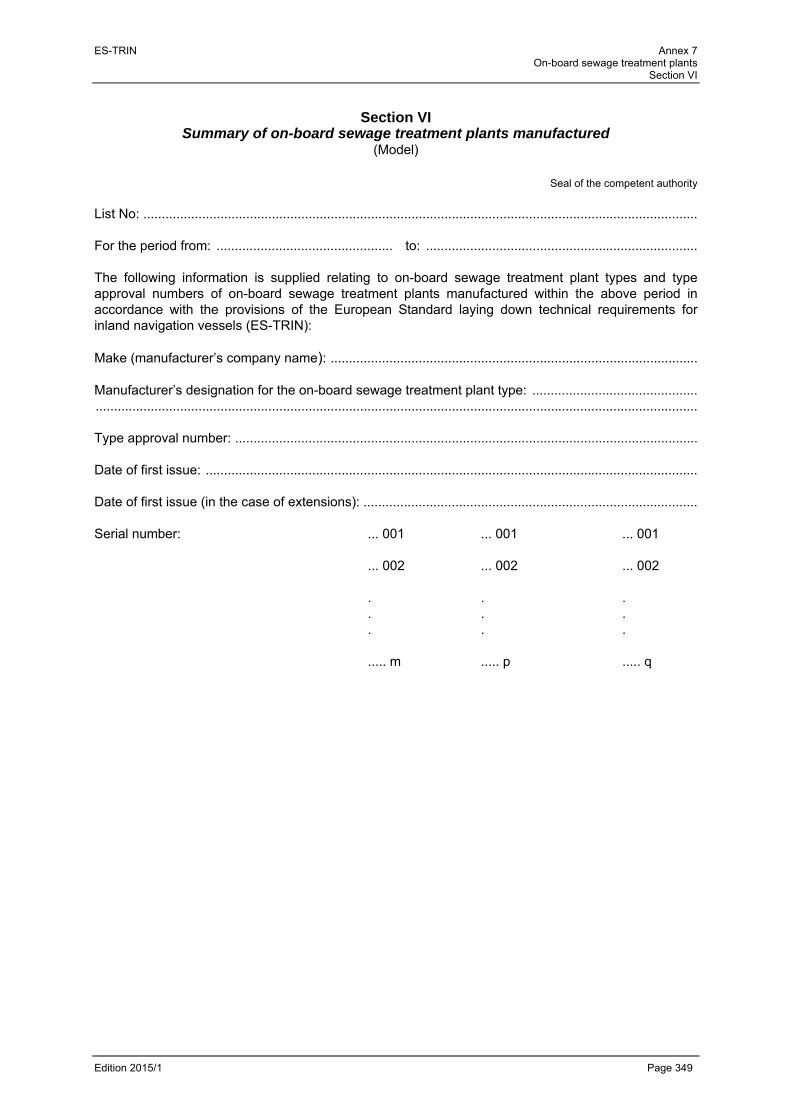
ES-TRIN Annex 7 On-board sewage treatment plants
Section VI
Edition 2015/1 Page 349
Section VI
Summary of on-board sewage treatment plants manufactured (Model)
Seal of the competent authority
List No: ....................................................................................................................................................... For the period from: ................................................ to: .......................................................................... The following information is supplied relating to on-board sewage treatment plant types and type approval numbers of on-board sewage treatment plants manufactured within the above period in accordance with the provisions of the European Standard laying down technical requirements for inland navigation vessels (ES-TRIN): Make (manufacturer’s company name): .................................................................................................... Manufacturer’s designation for the on-board sewage treatment plant type: ............................................. .................................................................................................................................................................... Type approval number: .............................................................................................................................. Date of first issue: ...................................................................................................................................... Date of first issue (in the case of extensions): ...........................................................................................
Serial number: ... 001 ... 001 ... 001
... 002 ... 002 ... 002 . . . . . . . . . ..... m ..... p ..... q

ES-TRIN Annex 7 On-board sewage treatment plants
Section VI
Edition 2015/1 Page 350

ES-TRIN Annex 7 On-board sewage treatment plants
Section VII
Edition 2015/1 Page 351
Section VII
Data sheet for on-board sewage treatment plants with type approval (Model)
Seal of the competent authority
On-board sewage treatment plant
characteristics Purification efficiency
No Date of
type
approval
Type
approval
number
Make On-board sewage
treatment plant type Daily vol. flow
rate of sewage
(m³/d)
Daily
pollution
load (kg/d)
COD TOC
24 h
composite
sample
Random
-sample
24 h
composite
sample
Ran-
dom-
sample
24 h
composite
sample
Ran-
dom-
sample

ES-TRIN Annex 7 On-board sewage treatment plants
Section VII
Edition 2015/1 Page 352
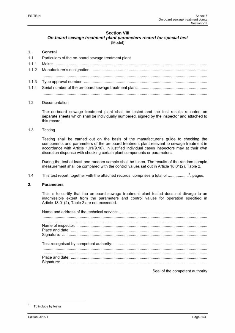
ES-TRIN Annex 7 On-board sewage treatment plants
Section VIII
Edition 2015/1 Page 353
Section VIII
On-board sewage treatment plant parameters record for special test (Model)
1. General
1.1 Particulars of the on-board sewage treatment plant
1.1.1 Make: ............................................................................................................................................
1.1.2 Manufacturer’s designation: .........................................................................................................
.......................................................................................................................................................
1.1.3 Type approval number: .................................................................................................................
1.1.4 Serial number of the on-board sewage treatment plant: ..............................................................
....................................................................................................................................................... 1.2 Documentation
The on-board sewage treatment plant shall be tested and the test results recorded on separate sheets which shall be individually numbered, signed by the inspector and attached to this record.
1.3 Testing
Testing shall be carried out on the basis of the manufacturer’s guide to checking the components and parameters of the on-board treatment plant relevant to sewage treatment in accordance with Article 1.01(9.10). In justified individual cases inspectors may at their own discretion dispense with checking certain plant components or parameters.
During the test at least one random sample shall be taken. The results of the random sample measurement shall be compared with the control values set out in Article 18.01(2), Table 2.
1.4 This test report, together with the attached records, comprises a total of ...................1..pages. 2. Parameters
This is to certify that the on-board sewage treatment plant tested does not diverge to an inadmissible extent from the parameters and control values for operation specified in Article 18.01(2), Table 2 are not exceeded. Name and address of the technical service: ................................................................................ ....................................................................................................................................................... ....................................................................................................................................................... Name of inspector: ........................................................................................................................ Place and date: ............................................................................................................................. Signature: ..................................................................................................................................... Test recognised by competent authority: ...................................................................................... ....................................................................................................................................................... ....................................................................................................................................................... Place and date: ............................................................................................................................. Signature: .....................................................................................................................................
Seal of the competent authority
1 To include by tester
ES-TRIN Annex 7 On-board sewage treatment plants
Section VIII
Edition 2015/1 Page 354
Name and address of the technical service: ................................................................................ ....................................................................................................................................................... ....................................................................................................................................................... Name of inspector: ........................................................................................................................ Place and date: ............................................................................................................................. Signature: ..................................................................................................................................... Test recognised by competent authority: ...................................................................................... ....................................................................................................................................................... ....................................................................................................................................................... Place and date: ............................................................................................................................. Signature: .....................................................................................................................................
Seal of the competent authority

ES-TRIN Annex 7 On-board sewage treatment plants
Section VIII
Edition 2015/1 Page 355
Appendix 1 Annex to the on-board sewage treatment plant parameters record
(Model) Name of vessel:
…………………… Unique European vessel identification number:
...................................
Manufacturer:
…………………………………………. Plant type: .............................................
(Make/trademark/manufacturer's trade name) (Manufacturer's designation)
Type approval No.: ……………………………………….. Year of construction of on-board sewage treatment plant:
...................................
Serial number of on-board sewage treatment plant:
……………………………………….. Site of installation:
........................................
(Serial number)
The on-board sewage treatment plant and its treatment-relevant components were identified from the data plate. The test was carried out on the basis of the manufacturer’s guide to checking the plant components and parameters relevant to sewage treatment. A. Component testing
Additional treatment-relevant components which are listed in the manufacturer’s guide to checking the plant components and parameters relevant to sewage treatment or Section II Appendix 4 are to be entered here.
Component Identified component number Conformity1
Yes No n/a
Yes No n/a
Yes No n/a
Yes No n/a
Yes No n/a
Yes No n/a
Yes No n/a
Yes No n/a
Yes No n/a
1 Specify as appropriate.

ES-TRIN Annex 7 On-board sewage treatment plants
Section VIII
Edition 2015/1 Page 356
B. Results of random sample measurement:
Parameter Value obtained Conformity(1)
Yes No
COD Yes No
TOC(2) Yes No
C. Comments:
(The following deviating settings, modifications or alterations to the installed on-board sewage treatment plant were found.)
Name of inspector:
Place and date: Signature:
1 Specify as appropriate. (2) The TOC will be monitored as of stage II of the maximum values in table 2 in article 18.01(2).
ES-TRIN Annex 7 On-board sewage treatment plants
Section IX
Edition 2015/1 Page 357
Section IX Test procedure
1. General 1.1 Basics
The test specification shall be used to verify the suitability of on-board sewage treatment plants on passenger vessels. In this procedure, the process and treatment technology used shall be examined and approved by means of a test plant. Conformity of the test plant with the treatment plants in service later is assured by applying identical design and dimensioning criteria.
1.2. Responsibility and test location The test plant for a range of on-board sewage treatment plant types shall be tested by a technical service. The test conditions at the test site are the responsibility of the technical service and must correspond to the conditions specified here.
1.3 Documents to be submitted
The test shall be carried out on the basis of the information document in accordance with Annex 7, Section II.
1.4 Plant dimensioning specifications The on-board sewage treatment plants shall be dimensioned and designed such that the limit values specified in Article 18.01(2), Tables 1 and 2 in their outflow are not exceeded in the course of their operation.
2. Measures preparatory to testing 2.1 General
Prior to commencement of the test the manufacturer shall supply the technical service with structural and process specifications of the test plant, to include a complete set of drawings and supporting calculations in accordance with Annex 7, Section II, and shall provide full information on the on-board sewage treatment plant’s requirements in terms of installation, operation and maintenance. The manufacturer shall supply the technical service with information on the mechanical, electrical and technical safety of the on-board sewage treatment plant to be tested.
2.2 Installation and putting into service For the purpose of the test, the manufacturer shall install the test plant in such a way as to correspond to the intended installation conditions on board passenger vessels. Prior to testing the manufacturer must assemble the on-board sewage treatment plant and put it into service. Start-up must be in accordance with the manufacturer’s operating instructions and shall be checked by the technical service.
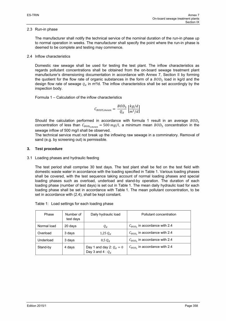
ES-TRIN Annex 7 On-board sewage treatment plants
Section IX
Edition 2015/1 Page 358
2.3 Run-in phase The manufacturer shall notify the technical service of the nominal duration of the run-in phase up to normal operation in weeks. The manufacturer shall specify the point where the run-in phase is deemed to be complete and testing may commence.
2.4 Inflow characteristics
Domestic raw sewage shall be used for testing the test plant. The inflow characteristics as regards pollutant concentrations shall be obtained from the on-board sewage treatment plant manufacturer’s dimensioning documentation in accordance with Annex 7, Section II by forming the quotient for the flow rate of organic substances in the form of a load in kg/d and the design flow rate of sewage in m³/d. The inflow characteristics shall be set accordingly by the inspection body. Formula 1 – Calculation of the inflow characteristics
, //
Should the calculation performed in accordance with formula 1 result in an average concentration of less than , 500 / , a minimum mean concentration in the
sewage inflow of 500 mg/l shall be observed. The technical service must not break up the inflowing raw sewage in a comminatory. Removal of sand (e.g. by screening out) is permissible.
3. Test procedure 3.1 Loading phases and hydraulic feeding
The test period shall comprise 30 test days. The test plant shall be fed on the test field with domestic waste water in accordance with the loading specified in Table 1. Various loading phases shall be covered, with the test sequence taking account of normal loading phases and special loading phases such as overload, underload and stand-by operation. The duration of each loading phase (number of test days) is set out in Table 1. The mean daily hydraulic load for each loading phase shall be set in accordance with Table 1. The mean pollutant concentration, to be set in accordance with (2.4), shall be kept constant.
Table 1: Load settings for each loading phase
Phase Number of test days
Daily hydraulic load Pollutant concentration
Normal load 20 days in accordance with 2.4
Overload 3 days 1,25 in accordance with 2.4
Underload 3 days 0,5 in accordance with 2.4
Stand-by 4 days Day 1 and day 2: 0 Day 3 and 4 :
in accordance with 2.4

ES-TRIN Annex 7 On-board sewage treatment plants
Section IX
Edition 2015/1 Page 359
The special load phases overload, underload and stand-by operation shall be carried out consecutively without interruption; the normal load phase shall be divided into several part phases. The test shall start and end with a normal load phase, of at least five days' duration in each case. Daily hydraulic feeding hydrographs shall be set, depending on the specified operation of the on-board sewage treatment plant. The daily hydraulic feeding hydrograph shall be selected in accordance with the plant operation concept for the on-board sewage treatment plant. A distinction shall be made according to whether the on-board treatment plant is to be operated with or without an upstream sewage storage tank. The feeding hydrographs (daily hydrographs) are shown in Figure 1 and Figure 2. Throughout the entire test period the hourly inflow must remain constant. The mean hourly volumetric flow rate of sewage , is equivalent to 1/24 of the daily hydraulic load according to Table 1. The inflow shall be measured continuously by the technical service. The daily hydrograph must keep within a ±5 % tolerance.
Figure 1: Daily hydrograph for feeding of on-board sewage treatment plant with upstream sewage storage tank
0
25
50
75
100
125
150
175
200
00
:00
- 0
1:0
0 0
1:0
0
- 0 0
02
:00
- 0 0
03
:00
- 0 0
04
:00
- 0 0
05
:00
- 0 0
06
:00
- 0 0
07
:00
- 0 0
08
:00
- 0 0
09
:00
- 1 0
10
:00
- 1
1:0
0 1
1:0
0
- 1 0
12
:00
- 1
3:0
0 1
3:0
0
- 1 0
14
:00
- 1 0
15
:00
- 1 0
16
:00
- 1 0
17
:00
- 1 0
18
:00
- 1 0
19
:00
- 2 0
20
:00
- 2 0
21
:00
- 2 0
22
:00
- 2 0
23
:00
- 0
0:0
0
HourPer
cen
tag
e sh
are
of
Qh
, me
an [
%]
On-board sewage treatment plant with upstream sewage storage tank

ES-TRIN Annex 7 On-board sewage treatment plants
Section IX
Edition 2015/1 Page 360
Figure 2: Daily hydrograph for feeding of on-board sewage treatment plant without upstream sewage storage tank
3.2 Interruption or cancellation of the test
It may be necessary to interrupt the test if the test plant can no longer be operated properly due to power failure or the malfunction of a subassembly. The test may be interrupted for the duration of the repair. In such cases it is not necessary to repeat the whole of the test, only the loading phase in which the subassembly malfunction took place. After the test is interrupted for a second time, the technical service shall decide whether the test may be continued or must be cancelled. The grounds for the decision must be stated and documented in the test report. Should the test be cancelled it must be repeated in full.
3.3 Examinations of purification efficiency and compliance with outflow limit values
The technical service shall take samples from the inflow to the test plant and analyse them in order to confirm conformity with the inflow characteristics. Sewage samples shall be taken from the outflow of the test plant and analysed to determine the purification efficiency and compliance with the required outflow limit values. Sampling carried out shall include both simple random samples and 24h composite samples. In the case of the 24h composite samples, either time-proportional or flow-proportional sampling may be carried out. The type of 24h composite sample shall be specified by the inspection body. Sampling in the inflow and outflow shall be carried out simultaneously and to the same degree.
0
50
100
150
200
250
00
:00
- 0 0
01
:00
- 0 0
02
:00
- 0 0
03
:00
- 0 0
04
:00
- 0 0
05
:00
- 0 0
06
:00
- 0 0
07
:00
- 0 0
08
:00
- 0 0
09
:00
- 1 0
10
:00
- 1 0
11
:00
- 1 0
12
:00
- 1 0
13
:00
- 1 0
14
:00
- 1 0
15
:00
- 1 0
16
:00
- 1 0
17
:00
- 1 0
18
:00
- 1 0
19
:00
- 2 0
20
:00
- 2 0
21
:00
- 2 0
22
:00
- 2 0
23
:00
- 0 0
Hour
Per
cen
tag
e sh
are
of
Qh
,me
an [%
]
On-board sewage treatment plant without upstream sewage storage tank

ES-TRIN Annex 7 On-board sewage treatment plants
Section IX
Edition 2015/1 Page 361
In addition to the control parameters , COD and TOC(1) the following parameters for inflow and outflow shall be measured in order to describe and represent the environmental and test conditions:
a) solids removable by filtration (SRF);
b) pH;
c) conductivity;
d) temperature of liquid phases.
The number of examinations varies according to the relevant loading phase and is set out in Table 2. The number of samplings relates to the inflow or outflow of the test plant.
Table 2: Specification of the number and timing of samplings in the inflow and outflow of the test plant
Loading phase
Number of test days
Number of samplings Specification of timing of samplings
Normal load 20 days 24h composite samples: 8Random samples: 8
Sampling at regular intervals throughout the period
Overload 3 days 24h composite samples: 2Random samples: 2
Sampling at regular intervals throughout the period
Underload 3 days 24h composite samples: 2Random samples: 2
Sampling at regular intervals throughout the period
Stand-by 4 days 24h composite samples: 2Random samples: 2
24h composite sample: Sampling after inflow switched on and 24h later. Random sample: 1 hour after inflow switched on and 24h later.
Total number of 24h composite samples: 14 Total number of random samples: 14
Where applicable, the following operating parameters shall also be measured from the random samples taken:
a) concentration of dissolved oxygen in the bioreactor;
b) dry matter content in the bioreactor;
c) temperature in the bioreactor;
d) ambient temperature;
e) other operating parameters in accordance with the manufacturer’s operating instructions.
(1) The TOC will be monitored as of stage II of the maximum values in table 2 in article 18.01(2).

ES-TRIN Annex 7 On-board sewage treatment plants
Section IX
Edition 2015/1 Page 362
3.4 Evaluation of examinations In order to document the determined purification efficiency and to check adherence to process limit values, the minimum sample value (Min), the maximum sample value (Max) and the arithmetical mean (Mean) shall be specified as well as the individual measurement results for control parameters , COD and TOC. The loading phase shall also be given for the maximum sample value. Evaluations shall be carried out for all loading phases jointly. The results shall be processed as shown in the following table:
Table 3a: Specification for the statistical processing of data gathered – evaluation to document compliance with outflow limit values
Parameter Sampling type
Number of test that meet the
limitvalues
Mean Min
Max
Value Phase
Inflow 24h composite samples --
Outflow 24h composite samples
Inflow random samples --
Outflow random samples
Inflow COD 24h composite samples --
Outflow COD 24h composite samples
Inflow COD random samples --
Outflow COD random samples
Inflow TOC 24h composite samples --
Outflow TOC 24h composite samples
Inflow TOC random samples --
Outflow TOC random samples
Inflow SRF 24h composite samples --
Outflow SRF 24h composite samples
Inflow SRF random samples --
Outflow SRF random samples

ES-TRIN Annex 7 On-board sewage treatment plants
Section IX
Edition 2015/1 Page 363
Table 3b: Specification for the statistical processing of data gathered – evaluation to document purification efficiency
Parameter Sampling type Mean Min Max
Elimination efficiency
24h composite samples
Elimination efficiency
Random samples
Elimination efficiency COD
24h composite samples
Elimination efficiency COD
Random samples
Elimination efficiency TOC
24h composite samples
Elimination efficiency TOC
Random samples
Elimination efficiency SRF
24h composite samples
Elimination efficiency SRF
Random samples
The remaining parameters in accordance with 3.3(b) to (d) and the operating parameters in accordance with 3.3 shall be summarised in a table specifying the minimum sample result (Min), the maximum sample result (Max) and the arithmetical mean (Mean).
3.5 Compliance with the requirements of Chapter 18
The limit values in accordance with Article 18.01(2) Tables 1 and 2 shall be deemed to be upheld, when each value for the parameters COD, and TOC:
a) the mean values of the total of 14 outflow samples, and
b) at least 10 of the total of 14 outflow samples do not exceed the specified limit values for 24h composite samples and random samples.
3.6 Operation and maintenance during testing
Throughout the testing the test plant shall be operated in accordance with the manufacturer’s specifications. Routine checks and maintenance work shall be carried out in compliance with the manufacturer’s operation and maintenance instructions. The excess sludge generated by the biological purification process may only be removed from the on-board sewage treatment plant if this is specified by the manufacturer in their operation and maintenance instructions. All maintenance work carried out shall be recorded by the technical service and documented in the test report. During the test no unauthorised persons may have access to the test plant.
ES-TRIN Annex 7 On-board sewage treatment plants
Section IX
Edition 2015/1 Page 364
3.7 Sample analysis / analysis method The parameters to be studied shall be analysed using approved standard procedures. The standard procedure applied shall be specified.
4 Test report 4.1 The technical service is required to compile a report on the type test carried out. The report shall
include at least the following information:
a) details on the plant tested, such as its type, information on the nominal daily pollutant load and the dimensioning principles applied by the manufacturer;
b) information on the conformity of the on-board sewage treatment plant tested with the documentation provided before the testing;
c) information on individual measurement results, as well as on the evaluation of the plant’s purification efficiency and compliance with the required outflow limit values;
d) details on the removal of excess sludge, such as the size of the volumes removed and the frequency of removal;
e) information on all operation, maintenance and repair work carried out during testing;
f) information on any deterioration in the quality of the on-board sewage treatment plant occurring during testing as well as any interruptions of testing;
g) information on any problems arising during testing;
h) a list of responsible persons involved in the type testing of the on-board sewage treatment plant, giving their names and job titles;
i) name and address of the laboratory which carried out the analysis of the waste water samples;
j) analysis methods applied.

ES-TRIN
Edition 201
Example
Example
Hyd
rau
lic lo
ad Q
d [
%]
Hyd
rau
lic lo
ad Q
d [
%]
15/1
e 1
e 2
Nolo
Nolo
ormal oad
ormal oad
Oveloa
Example
Normal load
O
Normaload
er- ad
Appendix 1es of test se
Over-load
Underload
Day
Day
al Under-load
1 equences
r-
Normal load
On-boar
Normal load
rd sewage treatm
Normload
Normal load
Annex 7 ment plants
Section IX
Page 365
al d

ES-TRIN Annex 7 On-board sewage treatment plants
Section IX
Edition 2015/1 Page 366

ES-TRIN Annex 7 On-board sewage treatment plants
Section IX
Edition 2015/1 Page 367
Appendix 2 Notes on determining biochemical oxygen demand after five days ( ) in 24h composite
samples The International Standards ISO 5815 and 5815-2 : 2003 stipulate that in order to carry out the analysis to determine biochemical oxygen demand after five days water samples should be stored immediately after sampling and up to the time of analysis in a brim-full, tightly sealed bottle at a temperature of 0–4 °C. The process of determining should be initiated as soon as possible or at least within twenty-four hours of completion of sampling. In order to prevent biochemical degradation processes starting in the 24h composite sample, in practice the water sample is cooled to a maximum of 4 °C while sampling continues, and is stored at this temperature once the sampling process is complete. Suitable sampling equipment is commercially available.

ES-TRIN Annex 7 On-board sewage treatment plants
Section IX
Edition 2015/1 Page 368

ES-TRIN Annex 8 Supplementary provisions applicable to craft operating
on fuels with a flashpoint equal to or lower than 55 C
Edition 2015/1 Page 369
ANNEX 8 SUPPLEMENTARY PROVISIONS APPLICABLE TO CRAFT OPERATING ON FUELS WITH A FLASHPOINT EQUAL TO OR LOWER THAN 55 °C
Section I
Liquefied Natural Gas (LNG)
Chapter 1 General
1.1 Application 1.1.1 The provisions of Section I apply to craft equipped with propulsion or auxiliary systems
operating on liquefied natural gas (LNG) according to (1.2.1) and address all areas that need special consideration for the usage of liquefied natural gas (LNG) as fuel.
1.2 Definitions
For the purposes of this Section, the following definitions shall apply:
1.2.1 Liquefied natural gas (LNG): natural gas that has been liquefied by cooling it to a temperature of - 161 °C.
1.2.2 LNG system: all parts of the craft that may contain liquefied natural gas (LNG) or Natural
Gas, such as engines, fuel tanks and bunkering piping. 1.2.3 LNG bunkering system: the arrangement for the bunkering of liquefied natural gas (LNG) on
board (bunkering station and bunkering piping). 1.2.4 Bunkering station: the area on board where all equipment used for bunkering are located,
such as manifolds, valves, survey instruments, safety equipment, monitoring station, tools, etc.
1.2.5 LNG containment system: the arrangement for the storage of liquefied natural gas (LNG)
including tank connections. 1.2.6 Gas supply system: the arrangement, including the gas preparation system, gas supply lines
and valves, to supply gas on board to all gas consuming equipment. 1.2.7 Gas preparation system: the unit used to convert liquefied natural gas (LNG) into Natural
Gas, its accessories and its piping. 1.2.8 Hazardous areas: zones 0, 1 and 2 as classified below: 1.2.8.1 Zone 0: area in which an explosive atmosphere consisting of a mixture with air of flammable
substances in the form of gas, vapour or mist is present continuously or for long periods or frequently,
1.2.8.2 Zone 1: area in which an explosive atmosphere consisting of a mixture with air of flammable
substances in the form of gas, vapour or mist is likely to occur in normal operation occasionally,
ES-TRIN Annex 8 Supplementary provisions applicable to craft operating
on fuels with a flashpoint equal to or lower than 55 C Section I
Edition 2015/1 Page 370
1.2.8.3 Zone 2: area in which an explosive atmosphere consisting of a mixture with air of flammable
substances in the form of gas, vapour or mist is not likely to occur in normal operation but, if it does occur, will persist for a short period only.
1.2.9 Enclosed room: any room within which, in the absence of forced ventilation, the ventilation
will be limited and any explosive atmosphere will not be dispersed naturally. 1.2.10 Semi-enclosed room: a room limited by decks or bulkheads in such manner that the natural
conditions of ventilation are notably different from those obtained on open deck. 1.2.11 Pressure Relief Valve (PRV): a spring-loaded device which is activated automatically by
pressure, the purpose of which is to protect the tank or piping against unacceptable excess internal pressure.
1.2.12 Dual fuel engines: engines using liquefied natural gas (LNG) combined with fuel with a
flashpoint above 55 °C. 1.2.13 ESD: emergency shutdown. 1.2.14 Master gas fuel valve: an automatic shut-off valve in gas supply lines to engines. 1.2.15 Secondary barrier: the outer element of an LNG containment system or piping designed to
afford temporary containment of any envisaged leakage through the primary barrier. 1.2.16 Maximum working pressure: the maximum pressure that is acceptable in an LNG fuel tank or
piping during operation. This pressure equals the opening pressure of pressure relief valves or devices.
1.2.17 Design pressure: the pressure on the basis of which the LNG fuel tank or piping has been
designed and built. 1.2.18 Double block and bleed valve: a set of two valves in series in a pipe and a third valve
enabling the pressure release from the pipe between those two valves. The arrangement may also consist of a two-way valve and a closing valve instead of three separate valves.
1.2.19 Air lock: a space enclosed by gastight steel bulkheads with two gastight doors, intended to
separate a non-hazardous area from a hazardous area. 1.2.20 Double wall piping: piping with a double wall design for which the space between the walls is
pressurized with inert gas and equipped to detect any leakage of one of the two walls. 1.2.21 System components: all components of the installation that may contain liquefied natural gas
(LNG) or Natural Gas (NG) (fuel tanks, pipelines, valves, hoses, pistons, pumps, filters, instrumentation, etc.).
ES-TRIN Annex 8 Supplementary provisions applicable to craft operating
on fuels with a flashpoint equal to or lower than 55 C Section I
Edition 2015/1 Page 371
1.2.22 Ventilated ducting: a gas pipe installed in a pipe or duct equipped with mechanical exhaust
ventilation. 1.2.23 Gas warning equipment: warning equipment to protect people and property from hazardous
gases and gas-air mixtures. It consists of gas detectors to identify gases, a control unit for processing the signals and a display/alarm unit for displaying the status and warning.
1.3 Risk assessment 1.3.1 A risk assessment shall be conducted on all concepts and configurations which are new or
have been significantly modified. The risks arising from the use of liquefied natural gas (LNG) affecting people on board including passengers, the environment, the structural strength and the integrity of the craft shall be addressed. Reasonable consideration shall be given to the hazards associated with physical layout, operation, and maintenance, following a failure.
1.3.2 The risks are to be determined and assessed using a risk analysis technique recognised by
the inspection body, such as International Standards ISO 31000 : 2009 and ISO 31010 : 2010. Loss of function, component damage, fire, explosion, tank room flooding, vessel sinking and electric overvoltage shall as a minimum be considered. The analysis must help to ensure that risks are eliminated wherever possible. Risks which cannot be eliminated entirely are to be mitigated to an acceptable level. The major scenarios and measures for eliminating or mitigating risks shall be described.
1.3.3 Classification of hazardous areas on board, divided into zones 0, 1 and 2, according to 1.2.8
shall be documented in the risk assessment. 1.4 General requirements 1.4.1 A single failure in the LNG system shall not lead to an unsafe situation. 1.4.2 The LNG system shall be designed, constructed, installed, maintained and protected to
ensure safe and reliable operation. 1.4.3 Components of the LNG system shall be protected against external damages. 1.4.4 Hazardous areas shall be restricted, as far as practicable, to minimize the potential risks that
might affect the safety of the craft, people on board, environment and equipment. In particular, hazardous areas are parts of the vessel not intended for passengers as referred to in Article 19.06(11).
1.4.5 Appropriate measures shall be taken to keep passengers away from hazardous areas. 1.4.6 Equipment installed in hazardous areas shall be minimized to that required for operational
purposes and shall be suitably and appropriately certified. 1.4.7 Unintended accumulation of explosive or flammable gas concentrations shall be prevented.

ES-TRIN Annex 8 Supplementary provisions applicable to craft operating
on fuels with a flashpoint equal to or lower than 55 C Section I
Edition 2015/1 Page 372
1.4.8 Sources of ignition in hazardous areas shall be excluded to reduce the probability of
explosions. 1.4.9 A detailed operating manual of the LNG system shall be provided on board craft using
liquefied natural gas (LNG) as fuel and which as minimum:
a) contains practical explanations about LNG bunkering system, LNG containment system, LNG piping system, Gas supply system, engine room, ventilation system, leakage prevention and control, monitoring and safety system,
b) describes the bunkering operations, especially valves operation, purging, inerting and gas freeing,
c) describes the relevant method of electrical insulation during bunkering operations,
d) describes the details of risks identified in the risk assessment as referred to in (1.3) and the means by which they are mitigated.
1.4.10 A fire or explosion caused by released gas in LNG containment systems and engine rooms
shall not render the essential machinery or equipment in other compartments inoperable. 1.5 Knowledge technical service
The knowledge of the technical service referred to in Article 30.01(4) shall cover at least the following areas:
a) fuel system including tanks, heat exchangers, pipelines,
b) strength (longitudinal and local) and stability of the craft,
c) electrical and control systems,
d) ventilation system,
e) fire safety,
f) gas warning equipment. 1.6 Marking
Doors to rooms where liquefied natural gas (LNG) is used shall bear on the outside a symbol for “LNG warning” in accordance with Figure 11 of Annex 4, at least 10 cm in height.
Chapter 2 Vessel Arrangements and System Design
2.1 LNG containment system 2.1.1 The LNG containment system shall be separated from engine rooms or other high fire risk
areas. 2.1.2 LNG fuel tanks shall be located as close as possible to the longitudinal centreline of the
vessel.
ES-TRIN Annex 8 Supplementary provisions applicable to craft operating
on fuels with a flashpoint equal to or lower than 55 C Section I
Edition 2015/1 Page 373
2.1.3 The distance between the ship’s wall of the craft and the LNG fuel tank shall not be less than
1,00 m. If LNG fuel tanks are located:
a) below deck, the craft shall have a double wall and a double bottom construction at the location of the LNG fuel tanks. The distance between the ship’s wall and the inner wall of the craft shall not be less than 0,60 m. The depth of the double bottoms shall not be less than 0,60 m.
b) on open deck, the distance shall be at least B/5 from the vertical planes defined by the ship’s sides of the craft.
2.1.4 The LNG fuel tank shall be an independent tank designed in accordance with the European
Standards EN 13530 : 2002, EN 13458-2 : 2002 in combination with dynamic loads, or the IGC-Code (type C tank). The inspection body can accept other equivalent standards of one of the Rhine riparian States and Belgium.
2.1.5 Tank connections shall be mounted above the highest liquid level in the tanks. The
inspection body can accept connections below the highest liquid level. 2.1.6 If tank connections are below the highest liquid level of the LNG fuel tanks, drip trays shall
be placed below the tanks that meet the following requirements:
a) the capacity of the drip tray shall be sufficient to contain the volume which could escape in the event of a pipe connection failure.
b) the material of the drip tray shall be suitable stainless steel.
c) the drip tray shall be sufficiently separated or insulated from the hull or deck structures, so that the hull or deck structures are not exposed to unacceptable cooling in case of leakage of liquefied natural gas (LNG).
2.1.7 The LNG containment system shall be provided with a secondary barrier. No secondary
barrier is required for the LNG containment systems where the probability for structural failures and leakages through the primary barrier is extremely low and can be neglected.
2.1.8 If the secondary barrier of the LNG containment system is part of the hull structure it may be
a boundary of the tank room subject to necessary precautions against leakage of cryogenic liquid.
2.1.9 The location and construction of the LNG containment system and the other equipment on
open deck shall assure sufficient ventilation. Accumulation of escaped natural gas shall be prevented.
2.1.10 If condensation and icing due to cold surfaces of LNG fuel tanks may lead to safety or
functional problems, appropriate preventive or remedial measures shall be taken. 2.1.11 Each LNG fuel tank is to be fitted with at least two pressure relief valves that can prevent an
overpressure if one of the valves is closed off due to malfunctioning, leakage or maintenance.

ES-TRIN Annex 8 Supplementary provisions applicable to craft operating
on fuels with a flashpoint equal to or lower than 55 C Section I
Edition 2015/1 Page 374
2.1.12 If fuel release into the vacuum space of a vacuum insulated LNG fuel tank cannot be
excluded, the vacuum space shall be protected by a suitable pressure relief valve. If LNG fuel tanks are located in enclosed or semi enclosed rooms, the pressure relief device shall be connected to a vent system.
2.1.13 The exhaust outlets of the pressure relief valves shall be located not less than 2,00 m above
the deck at a distance of not less than 6,00 m from the accommodation, passenger areas and work stations, which are located outside the hold or the cargo area. This height may be reduced when within a radius of 1,00 m round the pressure relief valves outlet there is no equipment, no work is being carried out, signs indicate the area and appropriate measures to protect the deck are being taken.
2.1.14 It shall be possible to safely empty the LNG fuel tanks, even if the LNG system is shut down. 2.1.15 It shall be possible to purge gas and vent LNG fuel tanks including gas piping systems. It
shall be possible to perform inerting with an inert gas (e.g. nitrogen or argon) prior to venting with dry air, to exclude an explosion hazardous atmosphere in LNG fuel tanks and gas piping.
2.1.16 LNG fuel tanks' pressure and temperature shall be maintained at all times within their design
range. 2.1.17 If the LNG system is switched off, the pressure in the LNG fuel tank, shall be maintained
below the maximum working pressure of the LNG fuel tank for a period of 15 days. It shall be assumed that LNG fuel tank was filled at filling limits according to 2.9 and that the craft remains in idle condition.
2.1.18 LNG fuel tanks shall be electrically bonded to the craft's structure. 2.2 Engine rooms 2.2.1 For engine rooms one of the following concepts shall be applied:
a) gas safe engine room,
b) explosion safe engine room or
c) ESD protected engine room. 2.2.2 Requirements for gas safe engine rooms 2.2.2.1 Gas safe engine rooms shall be gas safe under all conditions (“inherently gas safe”). A
single failure within the LNG system shall not lead to a leakage of gas into the engine room. All gas piping within engine room boundaries shall be enclosed in a gas tight enclosure, e.g. double wall piping or ventilated ducting.
2.2.2.2 In case one barrier fails, the gas supply to the relevant part of the LNG system shall be shut
down automatically.

ES-TRIN Annex 8 Supplementary provisions applicable to craft operating
on fuels with a flashpoint equal to or lower than 55 C Section I
Edition 2015/1 Page 375
2.2.2.3 The ventilation system of ventilated ducting shall:
a) guarantee a sufficient capacity to ensure that the gross volume of air inside the ventilated ducting can be changed at least 30 times per hour;
b) be equipped to detect gas presence continuously in the space between inner and outer pipes;
c) be independent of all other ventilation systems, in particular the ventilation system of the engine room.
2.2.2.4 A gas safe engine room shall be considered as a non-hazardous area, unless the risk
assessment according to (1.3) demonstrates otherwise. 2.2.3 Requirements for explosion safe engine rooms 2.2.3.1 Arrangements in explosion safe engine rooms shall be such that the rooms are considered
gas safe under normal conditions. A single failure within the LNG system shall not lead to a gas concentration over 20% of the lower explosive limit (LEL) into the engine room.
2.2.3.2 In the event of gas being detected or the ventilation system fails, the gas supply to the
relevant part of the LNG system shall be shut down automatically. 2.2.3.3 The ventilation system shall:
a) guarantee a sufficient capacity to maintain gas concentration below 20% of the LEL in the engine room, and to ensure that the gross volume of air inside the engine room can be changed at least 30 times per hour;
b) be independent of all other ventilation systems. 2.2.3.4 Under normal operation the engine room shall be permanently ventilated with at least
15 changes of the gross volume of air inside the engine room per hour. 2.2.3.5 Explosion safe engine rooms shall be designed to provide a geometrical shape that
minimizes the accumulation of gases or formation of gas pockets. A good air circulation shall be ensured.
2.2.3.6 An explosion safe engine room shall be considered as Zone 2, unless the risk assessment
according to (1.3) demonstrates otherwise. 2.2.4 Requirements for the ESD protected engine rooms 2.2.4.1 Arrangements in ESD protected engine rooms shall be such that the rooms are considered
gas safe under normal conditions, but under certain abnormal conditions may have the potential to become subject to gas hazards.
2.2.4.2 In the event of abnormal conditions involving gas hazards, emergency shutdown (ESD) of
non-safe equipment (ignition sources) and gas machinery shall be automatically executed, while equipment or machinery in use or active during these conditions shall be of a certified safe type.
ES-TRIN Annex 8 Supplementary provisions applicable to craft operating
on fuels with a flashpoint equal to or lower than 55 C Section I
Edition 2015/1 Page 376
2.2.4.3 The ventilation system shall:
a) guarantee a sufficient capacity to ensure that the gross volume of air inside the engine room can be changed at least 30 times per hour,
b) be designed to handle the probable maximum leakage scenario due to technical failures, and
c) be independent of all other ventilation systems. 2.2.4.4 Under normal operation the engine room shall be permanently ventilated with at least
15 changes of the gross volume of air inside the engine room per hour. If gas is detected in the engine room, the number of air changes shall automatically be increased to 30 changes per hour.
2.2.4.5 If the craft is equipped with more than one propulsion engine, these engines shall be located
in at least two separate engine rooms. These engine rooms shall have no common partitions. However common partitions may be accepted if it can be documented that consequences of a single failure will not affect both rooms.
2.2.4.6 Fixed gas warning equipment arranged to automatically shutdown the gas supply to the
engine room concerned and to disconnect all non-explosion protected equipment or installations shall be fitted.
2.2.4.7 ESD protected engine rooms shall be designed to provide a geometrical shape that
minimizes the accumulation of gases or formation of gas pockets. A good air circulation shall be ensured.
2.2.4.8 An ESD protected engine room shall be considered as Zone 1, unless the risk assessment
according to (1.3) demonstrates otherwise. 2.3 Liquefied Natural Gas (LNG) and Natural Gas piping systems 2.3.1 Liquefied Natural Gas (LNG) and Natural Gas piping through other engine rooms or non-
hazardous enclosed areas of the craft shall be enclosed in double wall piping or ventilated ducting.
2.3.2 Liquefied Natural Gas (LNG) and Natural Gas piping shall not be located less than 1,00 m
from the vessel’s side and 0,60 m from the bottom. 2.3.3 All piping and all components which can be isolated with valves from the LNG system in a
liquid full condition shall be provided with pressure relief valves. 2.3.4 Piping shall be electrically bonded to the vessel's structure. 2.3.5 Low temperature piping shall be thermally isolated from the adjacent hull structure, where
necessary. Protection against accidental contact shall be provided. 2.3.6 The design pressure of piping shall not be less than 150 % of the maximum working
pressure. The maximum working pressure of piping inside rooms shall not exceed 1000 kPa. The design pressure of the outer pipe or duct of gas piping systems shall not be less than the design pressure of the inner gas pipe.

ES-TRIN Annex 8 Supplementary provisions applicable to craft operating
on fuels with a flashpoint equal to or lower than 55 C Section I
Edition 2015/1 Page 377
2.3.7 Gas piping in ESD protected engine rooms shall be located as far away as practicable from
the electrical installations and tanks containing flammable liquids. 2.4 Drainage systems 2.4.1 Drainage systems for areas where liquefied natural gas (LNG) or Natural Gas can be
present shall:
a) be independent and separate from the drainage system of areas where liquefied natural gas (LNG) and Natural Gas cannot be present,
b) not lead to pumps in non-hazardous areas. 2.4.2 Where the LNG containment system does not require a secondary barrier, suitable drainage
arrangements for the tank rooms that are not connected to the engine rooms shall be provided. Means of detecting any liquefied natural gas (LNG) leakage shall be provided.
2.4.3 Where the LNG containment system requires a secondary barrier, suitable drainage
arrangements for dealing with any leakage of LNG into the interbarrier spaces shall be provided. Means of detecting such leakage shall be provided.
2.5 Drip trays 2.5.1 Suitable drip trays shall be fitted where leakage can cause damage to the craft’s structure or
where limitation of the area which is effected from a spill is necessary. 2.6 Arrangement of entrances and other openings 2.6.1 Entrances and other openings from a non-hazardous area to a hazardous area shall only be
permitted to the extent necessary for operational reasons. 2.6.2 For entrances and openings to a non-hazardous area within 6,00 m from the LNG
containment system, the gas preparation system or the outlet of a pressure relief valve, a suitable airlock shall be provided.
2.6.3 Air locks shall be mechanically ventilated at an overpressure relative to the adjacent
hazardous area. Doors shall be of self-closing type. 2.6.4 Air locks shall be designed in a way that no gas can be released to non-hazardous areas in
case of the most critical events in the hazardous areas separated by the air lock. The events shall be evaluated in the risk assessment according to (1.3).
2.6.5 Air locks shall be free of obstacles, shall provide easy passage and shall not be used for
other purposes. 2.6.6 An acoustic and optical alarm shall be given on both sides of the air lock if more than one
door is moved from the closed position or if gas is detected in the air lock. 2.7 Ventilation systems 2.7.1 Ventilators in hazardous areas shall be of a certified safe type.

ES-TRIN Annex 8 Supplementary provisions applicable to craft operating
on fuels with a flashpoint equal to or lower than 55 C Section I
Edition 2015/1 Page 378
2.7.2 Electric motors driving ventilators shall comply with the required explosion protection in the
installation area. 2.7.3 An acoustic and optical alarm shall be triggered at a permanently manned location (e.g.
wheelhouse) in the event of any loss of the required ventilating capacity. 2.7.4 Any ducting used for the ventilation of hazardous areas shall be separate from that used for
the ventilation of non-hazardous areas. 2.7.5 Required ventilation systems shall have at least two ventilators with independent power
supply, each of sufficient capacity, to avoid any gas accumulation. 2.7.6 Air for hazardous rooms shall be taken from non-hazardous areas. 2.7.7 Air for non-hazardous rooms shall be taken from non-hazardous areas at least 1,50 m away
from the boundaries of any hazardous area. 2.7.8 Where the inlet duct passes through a hazardous room, the duct shall have over-pressure
relative to this room. Overpressure shall not be required when structural measures on the duct ensure that gases will not leak into the duct.
2.7.9 Air outlets from hazardous rooms shall be located in an open area which is of the same or
less hazard than the ventilated room. 2.7.10 Air outlets from non-hazardous rooms shall be located outside hazardous areas. 2.7.11 In enclosed rooms the ventilation exhaust ducts shall be located at the top of these rooms.
Air inlets shall be located at the bottom. 2.8 LNG bunkering system 2.8.1 The LNG bunkering system shall be so arranged that no gas is discharged to the
atmosphere during filling of LNG fuel tanks. 2.8.2 The bunkering station and all valves used for bunkering, shall be located on open deck so
that sufficient natural ventilation is provided. 2.8.3 The bunkering station shall be so positioned and arranged that any damage to the gas piping
does not cause damage to the craft's LNG containment system. 2.8.4 Suitable means shall be provided to relieve the pressure and remove liquid contents from
pump suctions and bunker piping. 2.8.5 Hoses used for the bunkering of liquefied natural gas (LNG) shall be:
a) compatible with liquefied natural gas (LNG), in particular suitable for the liquefied natural gas (LNG) temperature,
b) designed for a bursting pressure not less than five times the maximum pressure they can be subjected to during bunkering.

ES-TRIN Annex 8 Supplementary provisions applicable to craft operating
on fuels with a flashpoint equal to or lower than 55 C Section I
Edition 2015/1 Page 379
2.8.6 The bunkering manifold shall be designed to withstand normal mechanical loads during
bunkering. The connections shall be of dry-disconnect type in accordance with European Standard EN 1474, equipped with appropriate additional safety dry break-away couplings.
2.8.7 It shall be possible to operate the master LNG bunkering valve during bunkering operations
from a safe control station on the craft. 2.8.8 Bunkering piping shall be arranged for inerting and gas freeing. 2.9 Filling limits of LNG fuel tanks 2.9.1 The level of liquefied natural gas (LNG) in the LNG fuel tank shall not exceed the filling limit
of 95 % full at the reference temperature. The reference temperature means the temperature corresponding to the vapour pressure of the fuel at the opening pressure of the pressure relief valves.
2.9.2 A filling limit curve for liquefied natural gas (LNG) filling temperatures shall be prepared from
the following formula: ∙ /
where:
= loading limit, maximum allowable liquid volume relative to the LNG fuel tank volume to which the tank may be loaded, expressed in per cent,
= filling limit expressed in per cent, here 95 %,
= relative density of fuel at the reference temperature,
= relative density of fuel at the loading temperature. 2.9.3 For craft exposed to significant wave heights or significant motion on account of operations,
the filling limit curve shall be adapted accordingly, based on the risk assessment according to (1.3).
2.10 Gas supply system 2.10.1 The gas supply system shall be so arranged that the consequences of any release of gas
will be minimized, while providing safe access for operation and inspection. 2.10.2 The parts of the gas supply system which are located outside the engine room shall be
designed in a way that a failure of one barrier cannot lead to a leak from the system into the surrounding area causing immediate danger to the people on board, the environment or the craft.
2.10.3 LNG fuel tank inlets and outlets shall be provided with valves located as close to the tank as
possible. 2.10.4 The gas supply system to each engine or set of engines shall be equipped with a master gas
fuel valve. The valves shall be situated as close as practicable to the gas preparation system but in any case outside the engine room.

ES-TRIN Annex 8 Supplementary provisions applicable to craft operating
on fuels with a flashpoint equal to or lower than 55 C Section I
Edition 2015/1 Page 380
2.10.5 The master gas fuel valve shall be operable
a) within and outside the engine room,
b) from the wheelhouse. 2.10.6 Each gas consuming equipment shall be provided with a set of double block and bleed
valves to assure safe isolation of the fuel supply system. The two block valves shall be of the fail-to-close type, while the ventilation valve shall be fail-to-open type.
2.10.7 For multi-engine installations, where a separate master gas fuel valve is provided for each
engine and for one-engine installation, the master gas fuel valve and the double block and bleed valve functions can be combined. One shutdown valve of the double block and bleed valves shall also be manually operated.
2.11 Exhaust system and gas supply shut down 2.11.1 The exhaust system shall be configured to keep accumulation of unburned gaseous fuel as
low as possible. 2.11.2 Unless designed with the strength to withstand the worst case overpressure due to ignited
gas leaks, engine components or systems that can contain an ignitable gas and air mixture shall be fitted with suitable pressure relief devices.
2.11.3 If the gas supply is not changed-over to gasoil before stopping, the gas supply system from
the master gas fuel valve to the engine, and the exhaust system shall be purged in order to discharge any residual gas which may be present.
2.11.4 A means shall be provided to monitor and detect incorrect operation of the ignition system,
poor combustion or mis-firing that may lead to unburned gaseous fuel in the exhaust system during operation.
2.11.5 If incorrect operation of the ignition system, poor combustion or mis-firing is detected, the
gas supply system shall be shut down automatically. 2.11.6 The exhaust pipes of gas or dual fuel engines shall not be connected to the exhaust pipes of
other engines or systems. 2.11.7 In case of a normal stop or an ESD, the gas supply system shall be shut off not later than the
ignition source. It shall not be possible to shut off the ignition source without first or simultaneously closing the gas supply to each cylinder or to the complete engine.
2.11.8 In case of shut-off of the gas supply system in a dual fuel engine, the engine shall be
capable of continuous operation on gasoil only without interruption.

ES-TRIN Annex 8 Supplementary provisions applicable to craft operating
on fuels with a flashpoint equal to or lower than 55 C Section I
Edition 2015/1 Page 381
Chapter 3 Fire Safety
3.1 General 3.1.1 Fire detection, protection and extinction measures appropriate to the hazards concerned
shall be provided. 3.1.2 The gas preparation system shall be regarded as an engine room for fire protection
purposes. 3.2 Fire alarm system 3.2.1 A suitable fixed fire alarm system shall be provided for all rooms of the LNG system where
fire cannot be excluded. 3.2.2 Smoke detectors alone are not sufficient for rapid detection of a fire. 3.2.3 The fire detection system shall have the means to identify each detector individually. 3.2.4 The gas safety system shall shut down the relevant parts of the gas supply system
automatically, upon fire detection in rooms containing gas installations. 3.3 Fire protection 3.3.1 Accommodation, passenger areas, engine rooms and escape routes shall be shielded with
Type A60 partitions, where the distance is less than 3,00 m to LNG fuel tanks and bunkering stations located on deck.
3.3.2 The boundaries of LNG fuel tank rooms and ventilation ducts to such rooms below the
bulkhead deck shall comply with Type A60. However, where the room is adjacent to tanks, voids, auxiliary engine rooms of little or no fire risk, sanitary and similar spaces, the insulation may comply with Type A0.
3.4 Fire prevention and cooling 3.4.1 A water spray system shall be installed for cooling and fire prevention to cover exposed parts
of LNG fuel tank(s) located on open deck. 3.4.2 If the water spray system is part of the firefighting systems mentioned in Articles 13.04 or
13.05, the required fire pump capacity and working pressure shall be sufficient to ensure the operation of both the required numbers of hydrants and hoses and the water spray system simultaneously. The connection between water spray system and the firefighting systems mentioned in Articles 13.04 or 13.05 shall be provided through a screw-down non-return valve.
ES-TRIN Annex 8 Supplementary provisions applicable to craft operating
on fuels with a flashpoint equal to or lower than 55 C Section I
Edition 2015/1 Page 382
3.4.3 If firefighting systems mentioned in Articles 13.04 or 13.05 are installed onboard a craft
where the LNG fuel tank is located on open deck, isolating valves shall be fitted in the firefighting systems in order to isolate damaged sections of the firefighting systems. Isolation of a section of firefighting systems shall not deprive the fire line ahead of the isolated section of water.
3.4.4 The water spray system shall also provide coverage for boundaries of the superstructures,
unless the tank is located 3,00 m or more from the boundaries. 3.4.5 The water spray system shall be designed to cover all areas as specified above with an
application rate of 10 l/min/m2 for horizontal projected surfaces and 4 l/min/m2 for vertical surfaces.
3.4.6 The water spray system shall be capable of being put into operation from the wheelhouse
and from the deck. 3.4.7 The nozzles shall be arranged to ensure an effective distribution of water throughout the
area being protected. 3.5 Fire extinguishing
In addition to the requirements of Article 13.03, two additional portable dry powder fire extinguishers of at least 12 kg capacity shall be located near the bunkering station. They shall be suitable for Class C fires.
Chapter 4 Electrical Systems
4.1 Equipment for hazardous areas shall be of an appropriate type according to zones where
such equipment is installed. 4.2 Electrical generation and distribution systems and associated control systems shall be
designed such that a single failure will not result in the release of gas. 4.3 The lighting system in hazardous areas shall be divided between at least two branch circuits.
All switches and protective devices shall interrupt all poles and phases and shall be located in a non-hazardous area.
4.4 Submerged gas pump motors and their supply cables may be fitted in LNG containment
systems. Arrangements shall be made to alarm in low liquid level and automatically shut down the motors in the event of low-low liquid level. The automatic shutdown may be accomplished by sensing low pump discharge pressure, low motor current, or low liquid level. This shutdown shall give an acoustic and optical alarm in the wheelhouse. Gas pump motors shall be capable of being isolated from their electrical supply during gas-freeing operations.
ES-TRIN Annex 8 Supplementary provisions applicable to craft operating
on fuels with a flashpoint equal to or lower than 55 C Section I
Edition 2015/1 Page 383
Chapter 5
Control, Monitoring and Safety Systems 5.1 General 5.1.1 Suitable control, alarm, monitoring and shutdown systems shall be provided to ensure safe
and reliable operation. 5.1.2 The gas supply system shall be fitted with its own set of independent gas control, gas
monitoring and gas safety systems. All elements of these systems shall be capable of being functionally tested.
5.1.3 The gas safety system shall shut down the gas supply system automatically, upon failure in
systems essential for the safety and upon fault conditions which may develop too fast for manual intervention.
5.1.4 The safety functions shall be arranged in a dedicated gas safety system that is independent
of the gas control system. 5.1.5 Instrumentation devices shall be fitted to allow a local and a remote reading of essential
parameters, where they are necessary to ensure a safe operation of the whole LNG system including bunkering.
5.2 LNG bunkering system and LNG containment system monitoring 5.2.1 Each LNG fuel tank shall be fitted with:
a) at least two liquid level indicators, which shall be arranged so that they can be maintained in an operational condition,
b) a pressure indicator capable of indicating throughout the operating pressure range and which is clearly marked with the maximum working pressure of the LNG fuel tank,
c) a high liquid level alarm operating independently of other liquid level indicators which shall give an acoustic and optical alarm when activated,
d) an additional sensor operating independently of the high liquid level alarm which shall automatically actuate the master LNG bunkering valve in a manner that will both avoid excessive liquid pressure in the bunkering piping and prevent the tank from becoming liquid full.
5.2.2 Each pump discharge line and each liquid and vapour gas shore connection shall be
provided with at least one local pressure indicator. In the pump discharge line, the indicator shall be placed between the pump and the first valve. The permissible maximum pressure or vacuum value shall be indicated on each indicator.
5.2.3 A high-pressure alarm shall be provided at the LNG containment system and at the pump.
Where vacuum protection is required, a low-pressure alarm shall be provided.
ES-TRIN Annex 8 Supplementary provisions applicable to craft operating
on fuels with a flashpoint equal to or lower than 55 C Section I
Edition 2015/1 Page 384
5.2.4 Control of the bunkering shall be possible from a safe control station remote from the
bunkering station. At this control station the LNG fuel tank pressure and level shall be monitored. Overfill alarm, high and low-pressure alarm and automatic shutdown shall be indicated at this control station.
5.2.5 If the ventilation in the ducting enclosing the bunkering lines stops, an acoustic and optical
alarm shall be actuated at the control station. 5.2.6 If gas is detected in the ducting enclosing the bunkering piping an acoustic and optical alarm
and emergency shut-down shall be actuated at the control station. 5.2.7 Appropriate and sufficient suitable protective clothing and equipment for bunkering
operations shall be available on board according to operating manual. 5.3 Engine operation monitoring 5.3.1 Indicators shall be fitted in the wheelhouse and the engine room for:
a) operation of the engine in case of a gas-only engine, or
b) operation and mode of operation of the engine in the case of a dual fuel engine. 5.4 Gas warning equipment 5.4.1 Gas warning equipment shall be designed, installed and tested in accordance with a
recognized standard, such as European Standard EN 60079-29-1 : 2007. 5.4.2 Permanently installed gas detectors shall be fitted in:
a) tank connection areas including fuel tanks, pipe connections and first valves,
b) ducts around gas piping,
c) engine rooms containing gas piping, gas equipment or gas consuming equipment,
d) the room containing the gas preparation system,
e) other enclosed rooms containing gas piping or other gas equipment without ducting,
f) other enclosed or semi-enclosed rooms where gas vapours may accumulate including interbarrier spaces and tank rooms of independent LNG fuel tanks other than type C,
g) air locks, and
h) ventilation inlets to rooms in which gas vapours may accumulate.

ES-TRIN Annex 8 Supplementary provisions applicable to craft operating
on fuels with a flashpoint equal to or lower than 55 C Section I
Edition 2015/1 Page 385
5.4.3 By derogation to (5.4.2), permanently installed sensors which detect gas by difference of
pressure can be used for interbarrier spaces in double wall piping. 5.4.4 The number and redundancy of gas detectors in each room shall be considered taking size,
layout and ventilation of the room into account. 5.4.5 Permanently installed gas detectors shall be located where gas may accumulate and in the
ventilation outlets of these rooms. 5.4.6 An acoustic and optical alarm shall be activated before the gas concentration reaches 20 %
of the lower explosive limit. The gas safety system shall be activated at 40 % of the lower explosive limit.
5.4.7 Acoustic and optical alarms from the gas warning equipment shall be actuated in the
wheelhouse. 5.5 Safety functions of gas supply systems 5.5.1 If the gas supply system is shut off due to activation of an automatic valve, it shall not be
opened until the reason for the disconnection is ascertained and the necessary actions taken. Instructions to this effect shall be placed at a prominent position at the control station for the shut-off valves in the gas supply lines.
5.5.2 If the gas supply system is shut off due to a gas leak, it shall not be opened until the leak has
been found and the necessary actions have been taken. Instructions to this effect shall be placed at a prominent position in the engine room.
5.5.3 The gas supply system shall be arranged for manual remote emergency stop from the
following locations as applicable:
a) wheelhouse,
b) control station of the bunkering station,
c) any permanently manned location.

ES-TRIN Annex 8 Supplementary provisions applicable to craft operating
on fuels with a flashpoint equal to or lower than 55 C
Edition 2015/1 Page 386

ES-TRIN Instructions for the application of the technical Standard
Edition 2015/1 Page 387
INSTRUCTIONS FOR THE APPLICATION OF THE TECHNICAL STANDARD

ES-TRIN Instructions for the application of the technical Standard
Edition 2015/1 Page 388

ES-TRIN ESI-I-1 Completion of the inland navigation vessel certificates
Edition 2015/1 Page 389
PART I GENERAL
ESI-I-1
COMPLETION OF THE INLAND NAVIGATION VESSEL CERTIFICATES 1. General 1.1 Forms
For completion of the inland navigation vessel certificate only forms authorised by the competent authority shall be used. Forms shall be filled in on one side only. When issuing a new inland navigation vessel certificate, all pages 1 to 13 shall be included, even if some pages have no entries.
1.2 Method of entry
Entries on the inland navigation vessel certificate shall be typewritten or computer-printed. Hand written entries may only be made in exceptional cases. The entries shall be indelible. Font colours shall be black or blue only. Deletions shall be made in red.
2. Entries 2.1 Deletion of alternatives
Where entries are marked with(*) those which are not appropriate shall be deleted.
2.2 Items without entry If, for any of the items 1 to 48, no entry is either necessary or possible, a line shall be drawn across the entire field.
2.3 Final page of the inland navigation vessel certificate If no additional pages are required after page 13 (see (3.2.3)), the words ‘continued on page’1 at the bottom of page 13 shall be deleted.
2.4 Amendments 2.4.1 First handwritten amendment on a page
A page can be amended once only, however, several amendments may be made at that time. A red line shall be drawn through any details to be amended. A previously deleted alternative (see (2.1)) or an item previously without entry (see (2.3)) shall be underlined in red. The new details shall not be entered in the amended field, but on the same page under the heading ‘Amendments’, the line ‘This page has been replaced’ shall be deleted.
1 Delete as appropriate.

ES-TRIN ESI-I-1 Completion of the inland navigation vessel certificates
Edition 2015/1 Page 390
2.4.2 Further handwritten amendments on a page For further amendments the page shall be replaced and the necessary amendments as well as any earlier amendments shall be entered directly under the appropriate items. Under the heading ‘Amendments’ the line ‘amendments to item(s)’ shall be deleted. The old page shall be retained by the inspection body which originally issued the inland navigation vessel certificate.
2.4.3 Amendments by electronic data processing In case of amendments by electronic data processing, the page shall be replaced and the necessary amendments as well as any earlier amendments shall be entered directly under the appropriate items. Under the heading ‘Amendments’ the line ‘amendments to item(s)’ shall be deleted. The old page shall be retained by the inspection body which originally issued the inland navigation vessel certificate.
2.5 Corrections by pasting over Pasting over of entries or pasting in further details added to an item is not allowed.
3. Replacing and adding pages 3.1 Replacing pages
Page 1 of the inland navigation vessel certificate shall never be replaced. For replacing other pages the procedures outlined in (2.4.2) or (2.4.3) shall be applied.
3.2 Adding pages If there is insufficient space for further entries on pages 10, 12 or 13 of the inland navigation vessel certificate, additional pages may be attached.
3.2.1 Extension/Confirmation of validity If further extension is necessary when the certificate has already been extended six times, the words ‘Continued on page 10a’ shall be added at the bottom of page 10, and a further page 10 shall be marked as page 10a and inserted after page 10. The respective entry is then made under item 49 at the top of page 10a. At the bottom of page 10a the entry ‘Continued on page 11’ shall be made.
3.2.2 Extension of the liquefied gas installation certificate A similar procedure to (3.2.1) shall be applied, with page 12a inserted after page 12.
3.2.3 Annex to the inland navigation vessel certificate At the bottom of page 13 the words ‘End of the inland navigation vessel certificate’ shall be deleted in red, the deleted words ‘Continued on page2’ shall be underlined in red and behind that the page number 13a shall be entered. This amendment shall carry an official stamp. A further page 13 shall be marked as page 13a and inserted after page 13. The provisions of (2.2) and (2.3) apply to page 13a mutatis mutandis. The same procedure shall be applied for any further annexes (pages 13b, 13c, etc.).
2 Delete as appropriate.
ES-TRIN ESI-I-1 Completion of the inland navigation vessel certificates
Edition 2015/1 Page 391
4. Explanations of individual items Self-explanatory items are not mentioned below. 2. If applicable, insert terms as per Article 1.01. Other vessel types shall be entered with
their commonly accepted designation. 3. When inland navigation vessel certificate is extended the wording “official number” as
well as this number shall be deleted, and in case of amendment, the wording “3. unique European vessel identification number” as well as that number shall be entered.
10. In respect of vessels with Union inland navigation certificate allowed to navigate on
the Rhine, i.e.
a) those which comply fully with requirements of this Standard including the transitional provisions for Chapter 32, and
b) those which make no use of the transitional provisions of Chapter 33 or the reductions provided for zone 4,
the following is to be added to the indent '- on EU waterways in zone(s)':
a) Rhine or
b) zone R.
12. When inland navigation vessel certificate is extended the wording “official number” shall be deleted, and in case of amendment, the wording “12. Unique European vessel identification number” as well as that number shall be entered.
15. This section shall only be completed for craft for which at least one of the properties
1.1 or 1.2 or 3 in item 14 is not deleted, otherwise the entire table shall be deleted. 15.1 In the column ‘formation figure’ of the table the number(s) of the formations depicted
shall be entered. Lines without entry shall be struck through.
Further formations may be drawn under ‘Other formations’ and shall be designated 18, 19, 20, etc. If it is not apparent from the property ‘fit to push’ in the previous ship certificate which formations are authorised, the entry from the previous inland navigation vessel certificate may be transferred to item 52. ‘See item 52’ shall be entered in line 1 of the table ‘Authorised formations’.
15.2 Couplings
Only the details of the coupling between the pushing craft and the pushed section of the convoy shall be entered.
17-20. Details according to the tonnage certificate items 17-19 to two decimal places and
item 20 without decimal places. Length overall and breadth overall give the maximum dimensions of the craft, including all projecting fixed parts. Length and Breadth give the maximum hull dimensions (see also Article 1.01 Definitions).

ES-TRIN ESI-I-1 Completion of the inland navigation vessel certificates
Edition 2015/1 Page 392
21. Dead weight tonnage for cargo vessels in t according to the measurement certificate for the maximum draught according to item 19. Displacement for all other craft in m3. If no measurement certificate is available, calculate the displacement from the product of the block coefficient and length , breadth and mean draught at maximum immersion.
23. Number of passenger berths available (including folding beds and similar). 24. Only watertight transverse bulkheads extending from one side of the vessel to the
other shall be taken into consideration. 26. If applicable, the following terms shall be used:
- manually operated hatch covers,
- manually operated rolling hatch covers,
- manually operated sliding hatch covers,
- mechanically operated sliding hatch covers,
- mechanically operated hatch covers.
Other types of hatch covers shall be entered with their commonly accepted designation. Any holds which do not have a hatch cover shall be listed, e.g. under item 52.
28. Figure without decimal place. 30, 31 and 33. Every winch housing shall be counted as one winch, regardless of the number of
anchors or towing cables connected to it. 34. Under ‘Other installations’ systems which do not use rudder blades (e.g. rudder-
propeller, cycloidal-propeller, bow-thruster systems) shall be entered. Enter also any electrical auxiliary engines for manual actuation. With bow-thruster systems, ‘remotely-controlled’ refers only to remote controls operated from the steering position in the wheelhouse.
35. Only the theoretical values according to Article 8.08(2) and (3), Article 19.01(1)(c), and
Article 19.08(5) shall be entered. For craft whose keels were laid on or before 1.4.1976, the first section is only to be completed in the event of the bilge pumps being replaced and in the event of the inland navigation vessel certificate being extended after 1.1.2015. For craft whose keels were laid down on or before 31.12.1984 and only operated outside zone R, the section can be left void.
36. A sketch may be necessary for clarification. 37. Only the theoretical values without reduction according to Article 13.01(1) to (4) shall
be entered.

ES-TRIN ESI-I-1 Completion of the inland navigation vessel certificates
Edition 2015/1 Page 393
38. Only the minimum lengths according to Article 13.01(10) and the minimum breaking load according to Article 13.01(11) shall be entered.
39. and 40. Only the minimum lengths and minimum breaking load values recalculated according
to Article 13.02(3) shall be entered. 42. The inspection body may add items to the list of necessary equipment. These shall be
justified as essential to ship safety for the respective vessel type or its operational area. Additions shall be entered under item 52. Left column, row 3 to 5: for passenger vessels the first mentioned item shall be crossed out and for all other vessels the second mentioned item shall be crossed out. The length of the gangway shall be entered if the inspection body has allowed a shorter length than what is foreseen by Article 13.02(3)(d) or by Article 19.06(12). Left column, row 7: here the number of the prescribed first aid kits according to Article 13.02(3)(f) and Article 19.08(9) shall be entered. Left column, row 11: here the number of the prescribed fire proof receptacles according to Article 13.02(2) shall be entered.
43. Portable fire extinguishers required by other safety regulations, e.g. and regulation,
are not included here. 44. Row 3: in inland navigation vessel certificates to be extended before 1.1.2010
(Chapter 32), or 1.1.2025 (Chapter 33), the item ‘according to EN 395 : 1998 or 396 : 1998’ shall be crossed if no life vests according to this Standard are onboard.
Row 4: when inland navigation vessel certificates are extended after 1.1.2015 (Chapter 32), or 1.1.2030 (Chapter 33), or if a new dinghy is taken onboard, the item ‘with a set of oars, one mooring line and a baler’ shall be crossed. The item ‘according to EN 1914 : 1997’ shall be crossed if no dinghy according to this Standard is onboard.
46. As a general rule, continuous operation shall not be inserted if there is a lack of berths
or if there are excessive noise levels. 50. The expert shall sign only if he has completed page 11 himself. 52. Here any additional restrictions, exemptions and explanations, or similar, applying to
entries under individual items can be given.

ES-TRIN ESI-I-1 Completion of the inland navigation vessel certificates
Edition 2015/1 Page 394
5. Transitional provisions for Union inland navigation vessel certificates 5.1 Existing Community certificates
With the exception of the exceptional 6 months extension, no further extensions to existing community certificates shall be granted.
5.2 Replacement after a periodical inspection
After a periodical inspection of a vessel which does not yet have a Union inland navigation certificate in line with the model in Annex 4, a Union inland navigation certificate shall be issued.

ES-TRIN ESI-I-2 Experts and Competent Persons
Edition 2015/1 Page 395
ESI-I-2 EXPERTS AND COMPETENT PERSONS
(Article 1.01, 10.3 and 10.4)
Experts Experts are required to carry out acceptance tests which call for specialist knowledge either on account of the complexity of the systems or on account of the safety level required. The following persons or institutions are among those authorised to carry out such acceptance tests:
- Classification societies which have the necessary in-house expertise or which bear responsibility, on the basis of their authorisation, for calling in external persons or institutions and have the necessary quality control systems in place in respect of the selection of these persons or institutions;
- Members of the inspection bodies or employees of the relevant authorities;
- Officially approved persons or institutions with recognised expertise for the scope of inspection in the relevant subject area, whereby the vessel inspection bodies can also issue this approval in their capacity as public agencies, ideally on the basis of a quality assurance system. A person or institution is also deemed to be approved if the latter has passed an official selection procedure which specifically assesses the possession of the required expertise and experience.
Competent persons Competent persons are required, for example, to conduct regular visual checks and operating checks on safety equipment. The following may be classed as competent persons:
- Persons who, on the basis of their professional training and experience, have sufficient expertise to be able to assess specific situations and circumstances, e.g. ship's masters, safety officers in shipping companies, crew members with relevant experience;
- Companies which have acquired sufficient specialist knowledge on the basis of their regular work, e.g. shipyards or installation firms;
- Manufacturers of special-purpose systems (e.g. fire extinguishing systems, control equipment). Terminology
German English French Dutch
Sachverständiger expert expert erkend deskundige
Sachkundiger competent person spécialiste deskundige
Fachfirma competent firm société spécialisée deskundig bedrijf

ES-TRIN ESI-I-2 Experts and Competent Persons
Edition 2015/1 Page 396
Acceptance tests
The table below summarises the schedule of acceptance tests, including their frequency and the type of inspector required to conduct them. This table is for information purposes only.
Rule Subject matter Maximum test interval Inspector
Article 6.03(5) Hydraulic cylinders, pumps and motors
8 years Competent firm
Article 6.09(3) Motor-driven control equipment 3 years Competent
person Article 8.01(2) Pressure vessels 5 years Expert
Article 13.03(5) Portable fire extinguishers 2 years Competent
person Article 13.04(6)(a) to (c)
Permanently installed firefighting systems
Expert
Article 13.04(6)(d) Permanently installed firefighting systems
2 years Competent person or
competent firm Article 13.05(9)(b) (aa) to (cc)
Permanently installed firefighting systems
Expert
Article 13.05(9)(b) (dd)
Permanently installed firefighting systems
2 years Competent person or
competent firm
Article 13.07(3) Inflatable ship’s boats As specified by the
manufacturer
Article 13.08(3) Lifejackets As specified by the
manufacturer
Article 14.12(6) Cranes 10 years Expert
Article 14.12(7) Cranes 1 year Competent
person Article 17.13 Liquefied gas installations 3 years Expert
Article 19.09(9) Life-saving equipment As specified by the
manufacturer
Article 19.10(9) Insulating resistance, earthing before expiry of validity of the
inland navigation vessel certificate
Instruction ESI-II-13 section 3.1(a) and (b)
Fire alarm systems Expert
Instruction ESI-II-13 section 3.1 (c)
Fire alarm systems 2 years Expert or
competent person
Instruction ESI-III-4 section 8.1 (a) and (b)
Safety guidance systems Expert
Instruction ESI-III-4 section 8.1 (c)
Safety guidance systems 5 years Expert or
competent person
Instruction ESI-III-5
Gaswarning equipment As specified by the
manufacturer
Expert or competent
person

ES-TRIN ESI-II-1 Minimum hull thickness of barges
Edition 2015/1 Page 397
PART II PROVISIONS REGARDING SHIPBUILDING, FITTING OUT AND
EQUIPMENT
ESI-II-1 MINIMUM HULL THICKNESS OF BARGES
(Article 3.02(1))
During periodical inspections of barges which are exclusively towed, the inspection body may allow minor deviations from Article 3.02(1)(b) with respect to the minimum thickness of the shell plating of the hull. The deviation shall not be more than 10 %, and the minimum hull thickness shall not be less than 3 mm. The deviations shall be entered in the inland navigation vessel certificate. Under item 14 of the inland navigation vessel certificate, only property under item 6.2 ‘Towed as a craft with no motive power of its own’ shall apply Properties under items 1 to 5.3 and 6.1 shall be deleted.

ES-TRIN ESI-II-1 Minimum hull thickness of barges
Edition 2015/1 Page 398
ES-TRIN ESI-II-2 Installation of doubler plates to the hull
Edition 2015/1 Page 399
ESI-II-2 INSTALLATION OF DOUBLER PLATES TO THE HULL
(Article 3.02(1) and Article 19.02(1)(d))
1. Purpose of the instruction
These instructions have been drawn up for the sake of clarity in the rules for maintaining the strength of the hull (Article 3.02(1)) and for replacing and repairing hull plating (Article 3.02(1)(c), last sentence and Article 19.02(1)(d)). This instruction is applicable for installation of new doubler plates.
2. Principals
There are two different types of doubler plates:
1. Doubler plates installed during newbuilding or conversion in accordance with good shipbuilding practice,
2. Doubler plates intended to delay wear or renewal of hull plating. Generally, these plates should be avoided or they should be installed only in particular cases.
3. Doubler plates installed during newbuilding or conversion 3.1 Doubler plates installed during newbuilding
Doubler plates installed during newbuilding are mainly in the following places:
a) Reinforcing plates around openings and penetrations on the hull and deck plating (manholes, passages for pipes, scuppers, etc.),
b) Plates at the corners of large hatches,
c) Longitudinal plate strips at sheer strake level,
d) Plate strips to protect against wear due to abrasion of the hull plating (at bow and stern and possibly on the bilge plating and the side plating at some height above the bottom),
e) Reinforcing plates at particular points of the structure under special equipment (for example: anchor windlasses, pumps, masts, cranes, winches, anchors, etc.).
3.2 Doubler plates installed as part of a conversion
If these doubler plates are installed as part of a conversion, they can be mounted only on plates which have not yet reached the minimum thickness, after conversion, and have a corrosion allowance of at least 0,7 mm remaining. Otherwise, the plates that are to carry the doubler plates must be renewed beforehand. In particular, the plate strips for reinforcing the longitudinal hull girder of the vessel in the case of lengthening must extend at least along the length of the cargo section except in case of justification supported by a calculations note.

ES-TRIN ESI-II-2 Installation of doubler plates to the hull
Edition 2015/1 Page 400
4. Doubler plates intended to delay wear or renewal of hull plating
4.1 Places, where the installation of doubler plates is permitted
These plates may be installed in the following places:
a) In case of damage (temporary repair – validity as per certificate),
b) In case of pitting corrosion, eventually with piercing, not affecting the structural strength (ie: below an engine room, in way of wind/water strake), excepted in way of bottom and bilge plates in cargo zones,
c) In case of surfaces exposed to abrasion, in order to stop wear of hull plates (may be mounted only on plates that have not yet reached the minimum thickness),
d) On bilge plating, the doubler plating will be, preferably, continuous for at least 70 % of the vessel length. Otherwise, doubler plates will have a minimum length and a minimum distance in between not less than (2,5 + L/40) m or extend at least along the length of three times the frame spacing for vessels with L not more than 45 m. They shall be extended at least along the length of twice the frame spacing forward of and behind the affected zone,
e) On riveted seams to assure watertightness,
f) Fore and aft of a vessel’s outside cargo zone.
4.2 Places, where the installation of doubler plates is not permitted
These plates cannot be installed at the following locations:
a) On plates the thickness of which is under the minimum allowable thickness,
b) On holes in plates due to corrosion on elements ensuring the watertightness of vessel,
c) Over large areas in cargo zone,
d) To cover transverse overlap weld seams,
e) On the bottom between fore bulkhead of fore hold and after bulkhead of after hold,
f) In the cargo area of motor tankers, tank lighters and tank barges for the transport of dangerous goods according to ADN,
g) Over bunkers containing flammable products except in abrasion areas,
h) On plates or seams showing buckling or fatigue phenomenon,
i) On existing doubler plates. 5. Installation of doubler plates
a) Doubler plates must be installed and welded in accordance with good shipbuilding practice.
b) Wear plates will have a width ranging between 200 and 300 mm-
c) Reinforcing plates of the longitudinal hull girder should not be more than 600 mm wide.
d) The thickness of the doubler plates shall be between 1 and 1,5 times the thickness of the plate on which it is mounted.
e) Doubler plates fitted to delay the wear or replacement of hull plates have to be replaced, when their thickness is less than 3 mm.
The presence of doubler plates must be stated on the thickness measurements report. When renewing the certificate, vessel areas where doubler plates are installed must be thoroughly examined in order to determine whether they can be kept in this state.

ES-TRIN ESI-II-3 Prescribed forward speed, stopping capacity and capacity for going astern
Edition 2015/1 Page 401
ESI-II-3 PRESCRIBED FORWARD SPEED, STOPPING CAPACITY AND CAPACITY FOR
GOING ASTERN
(Articles 5.06, 5.07 and 5.08 in conjunction with Articles 5.02(1), 5.03(1), 5.04 and 21.06)
1. Maximum prescribed (forward) speed in accordance with article 5.06
The speed in relation to the water is satisfactory in accordance with Article 5.06(1) when it reaches at least 13 km/h. During tests, the following conditions shall be met in the same way as for the stopping test:
a) the keel clearance set out in (2.1) shall be complied with;
b) the measuring, recording, registration and evaluation of test data shall be carried out according to the procedure described in Annex 1.
2. Stopping capacity and capacity for going astern prescribed in accordance with articles
5.07 and 5.08 2.1 Vessels and convoys are deemed able to stop facing downstream in good time in accordance
with Article 5.07(1) when this is proved during a test of stopping in relation to the ground facing downstream at an initial speed in relation to the water of 13 km/h, with a keel clearance equal to at least 20 % of the draught but not less than 0,50 m.
a) In flowing water (current velocity of 1,5 m/s), stopping in relation to the water shall be demonstrated over a maximum distance measured in relation to the ground of:
550 m for vessels and convoys of:
- length 110 or
- width 11,45 ,
or
480 m for vessels and convoys of:
- length 110 and
- width 11,45 .
The stopping manoeuvre is completed on coming to a stop in relation to the ground.
b) In standing water (current velocity of less than 0,2 m/s), stopping in relation to the water shall be demonstrated over a maximum distance, measured in relation to the ground of:
350 m for vessels and convoys of:
- length 110 or
- width 11,45 ,
or
305 m for vessels and convoys of:
- length 110 and
- width 11,45 .
In standing water, a test shall also be performed to demonstrate that a speed of not less than 6,5 km/h can be reached when going astern.
ES-TRIN ESI-II-3 Prescribed forward speed, stopping capacity and capacity for going astern
Edition 2015/1 Page 402
The measuring, recording and registration of the test data referred to in (a) or (b) shall be carried out in accordance with the procedure set out in Annex 1. Throughout the entire test, the vessel or the convoy shall have adequate manoeuvrability.
2.2 In accordance with Article 5.04, during the test, vessels shall be loaded as far as possible to
70 – 100 % of their deadweight. This loading condition shall be evaluated in accordance with Annex 2. When the vessel or the convoy is loaded to less than 70 % at the time of the test, the permitted maximum displacement in downstream navigation shall be set in accordance with the actual load, provided that the limit values of (2.1) are complied with.
2.3 If the actual values of the initial speed and current velocity at the time of the test do not meet the
conditions set out in (2.1), the results obtained shall be evaluated according to the procedure described in Annex 2.
The permitted deviation of the initial speed of 13 km/h shall be not more than 1 km/h, and the current velocity in flowing water shall be between 1,3 and 2,2 m/s, otherwise the tests shall be repeated.
2.4 The permitted maximum displacement or the respective maximum load or the maximum
immersed cross-section for vessels and convoys in downstream navigation shall be determined on the basis of the tests and entered in the inland navigation vessel certificate.
ES-TRIN ESI-II-3 Prescribed forward speed, stopping capacity and capacity for going astern - Annex 1 to instruction ESI-II-3
Edition 2015/1 Page 403
Annex 1 to instruction ESI-II-3
Measuring, recording and registration of data collected during stopping manoeuvre tests
1. Stopping manoeuvre
The vessels and convoys referred to in Chapter 5 shall carry out a test in flowing water or in standing water, in a test area, to prove that they are capable of stopping facing downstream only with their propulsion system without the use of anchors. The stopping manoeuvre shall, in principle, be carried out in accordance with figure 1. It begins when the vessel is travelling at a constant speed of as near as possible to 13 km/h in relation to the water by reversing the engines from ‘ahead’ to ‘astern’ (point of the order ‘stop’) and is completed when the vessel is stationary in relation to the ground (point : 0 in relation to the ground or point : point : 0 in relation to the water and in relation to the ground if the stopping manoeuvre is
carried out in standing water). When stopping manoeuvres are carried out in flowing water, the position and the moment of stopping in relation to the water shall also be recorded (the vessel moves at the speed of the current; point : 0 in relation to the water). The data measured shall be entered in a report as shown in the diagram of table 1. Before the stopping manoeuvre is carried out, the unchanging data shall be entered at the top of the form. The average current velocity ( ) in the fairway shall be determined, if available, based on the reading of an established water level gauge, or by measuring the movement of a floating body and shall be entered in the report. In principle, the use of current metres is permitted to determine the speed of the vessel in relation to the water during the stopping manoeuvre, if it is possible to record the movement and the required data in accordance with the procedure above.
2. Registration of the data measured and recording them in the report (table 1)
For the stopping manoeuvre, first of all the initial speed in relation to the water shall be determined. This can be done by measuring the time taken to travel between two markers on land. In flowing water, the average current velocity shall be taken into account. The stopping manoeuvre is initiated by the order ‘stop’ , given on passing a marker on land. Passing the land marker shall be recorded perpendicularly to the axis of the vessel and shall be entered in the report. Passing all other land markers during the stopping manoeuvre shall be similarly recorded and each marker (e.g. kilometre post) and the time of passing shall be noted in the report. The values measured shall, if possible, be recorded at intervals of 50 m. In each case, note should be taken of the time when points and — if possible — as well as when points and
are reached and the respective position shall be estimated. The data concerning the engine speed need not be recorded in the report, but should be noted to permit more accurate control of the initial speed.
ES-TRIN ESI-II-3 Prescribed forward speed, stopping capacity and capacity for going astern
Edition 2015/1 Page 404
3. Description of the stopping manoeuvre
The stopping manoeuvre according to figure 1 shall be presented in the form of a diagram. First of all, the time-traverse diagram shall be plotted using the measurements entered in the test report and points to shall be indicated. It will then be possible to determine the average speed between two measurement points and to plot the speed/time diagram. This is done as follows (see figure 1): By determining the quotient of the difference of position over the difference in time / , the average speed of the vessel for this period can be calculated. During the interval between 0 sec. and 10 sec., the distance from 0 m to 50 m is covered.
/ = 50 m/10 s = 5,0 m/s = 18,0 km/h
This value is entered as the average speed at the 5 sec. abscissa-position. During the second interval, from 10 sec. to 20 sec., a distance of 45 m is covered.
/ = 45 m/10 s = 4,5 m/s = 16,2 km/h At marker , the vessel has stopped in relation to the water i.e. current velocity is approximately 5 km/h.

ES-TRIN ESI-II-3 Prescribed forward speed, stopping capacity and capacity for going astern
Edition 2015/1 Page 405
Figure 1: Stopping manoeuvre
Key to symbols in figure 1
‘stop’ order speed of vessel
propeller stopped in relation to the ground
propeller in reverse distance covered in relation to the ground
0 in relation to the water measured time
0 in relation to the ground
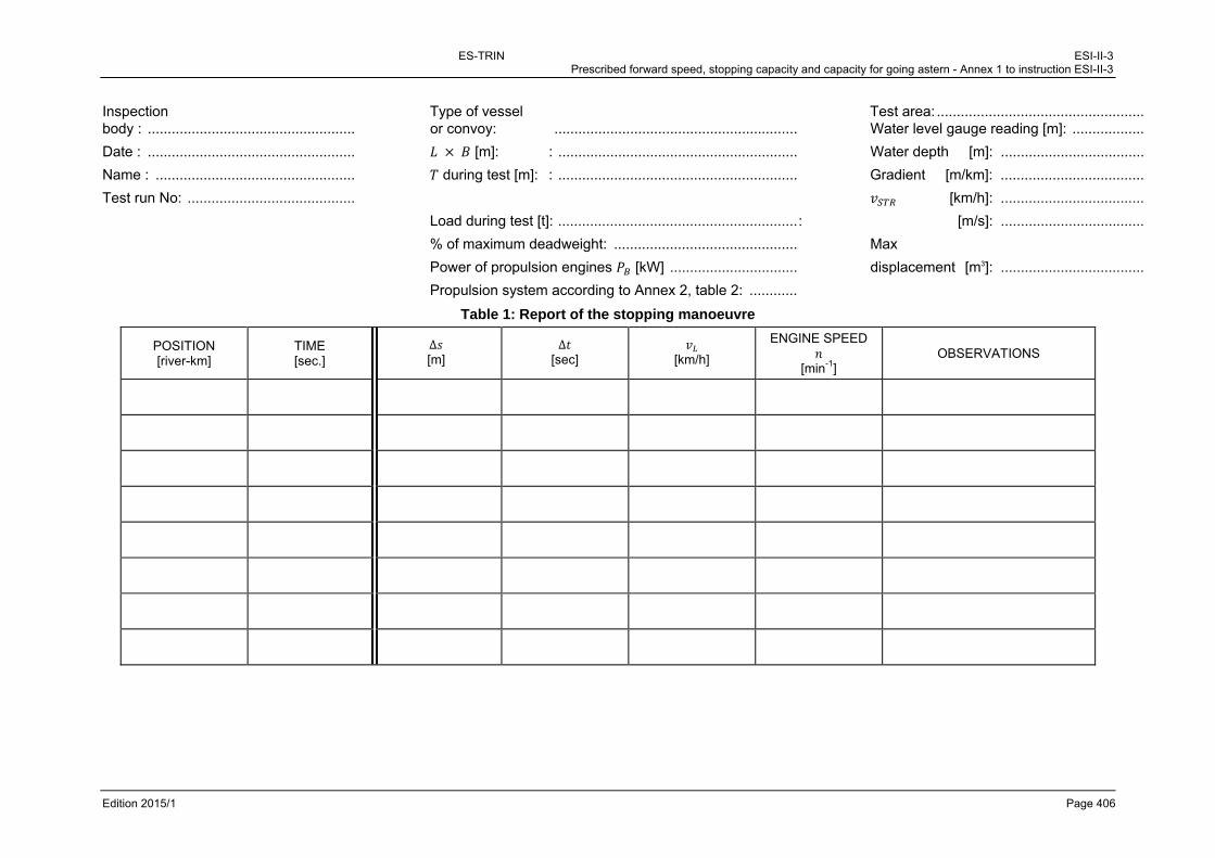
ES-TRIN ESI-II-3 Prescribed forward speed, stopping capacity and capacity for going astern - Annex 1 to instruction ESI-II-3
Edition 2015/1 Page 406
Inspection Type of vessel Test area: .................................................... body : .................................................... or convoy: ............................................................. Water level gauge reading [m]: ..................
Date : .................................................... [m]: : ............................................................ Water depth [m]: ....................................
Name : .................................................. during test [m]: : ............................................................ Gradient [m/km]: ....................................
Test run No: .......................................... [km/h]: ....................................
Load during test [t]: ............................................................ : [m/s]: ....................................
% of maximum deadweight: .............................................. Max
Power of propulsion engines [kW] ................................ displacement [m3]: ....................................
Propulsion system according to Annex 2, table 2: ............
Table 1: Report of the stopping manoeuvre
POSITION [river-km]
TIME [sec.]
∆ [m]
∆ [sec]
[km/h]
ENGINE SPEED
[min-1] OBSERVATIONS

ES-TRIN ESI-II-3 Prescribed forward speed, stopping capacity and capacity for going astern - Annex 2 to instruction ESI-II-3
Edition 2015/1 Page 407
Annex 2 to instruction ESI-II-3 Evaluation of the results of the stopping manoeuvre
1. On the basis of the values recorded compliance with the limit values in accordance with
Annex 1 shall be verified. If the conditions for the stopping manoeuvre deviate substantially from the standard conditions, or if there are doubts as to the compliance with the limit values, the results shall be evaluated. To that end the following procedure may be applied for calculating stopping manoeuvres.
2. Theoretical stopping distances are determined under the standard conditions ( ) of (2.1) of
this instruction and under stopping manoeuvre conditions ( ) and are compared with the stopping distance measured ( ). The corrected stopping distance of the stopping manoeuvre under standard conditions ( ) is calculated as follows:
Formula (2.1) ∙
in accordance with (2.1)(a) or (b) of this instruction.
When the stopping manoeuvre has been carried out with a load of 70 – 100 % of the maximum deadweight in accordance with (2.2) of this instruction in order to calculate the displacement ( ) corresponding to the load at the time of the test shall be used for the determination of and . When in determining according to formula (2.1), the limit value in question is exceeded or not reached, the value of shall be reduced or increased by variation of so that the limit value is complied with ( = limit value in question). The maximum displacement permitted in downstream navigation shall be set accordingly.
3. According to the limit values given in (2.1)(a) and (b) of this instruction, only the stopping
distances measured in
- Phase I (‘Full ahead’ reversed to ‘full astern’):
and
- Phase II (End of reversal until vessel stops in relation to the water):
shall be calculated (see figure 1). The total stopping distance is then:
Formula (3.1) 4. The particular stopping distances shall be calculated as follows:

ES-TRIN ESI-II-3 Prescribed forward speed, stopping capacity and capacity for going astern - Annex 2 to instruction ESI-II-3 - Example I
Edition 2015/1 Page 408
Calculation of the stopping manoeuvre
Figure 2: Diagram
Calculation Formulae: with the following coefficients 4.1 ∙ ∙ 20 - according to table 1
4.2 ∙ ∙ ∙
∙ ∙ - , , according to table 1
4.3 ∙ ∙ ∙ - , according to table 1
- / according to table 3 4.4 ∙ ∙ ∙ ∙ 10 4.5 ∙ - according to table 1 4.6 ∙ - according to table 2
4.7 ∙
- according to table 1

ES-TRIN ESI-II-3 Prescribed forward speed, stopping capacity and capacity for going astern - Annex 2 to instruction ESI-II-3 - Example I
Edition 2015/1 Page 409
In formulae 4.1 to 4.7:
Speed in relation to the ground at the start of reversal (m/s)
Reversal time (s)
Speed in relation to the water at the end of reversal (m/s)
Displacement (m3)
Bollard pull in reverse (kN)
Power of propulsion engine (kW)
Average resistance during phase II (kN)
Gradient resistance (kN)
Gradient in m/km (if missing to be taken as 0,16) (m/km)
Average current velocity (m/s)
Acceleration due to gravity (9,81) (m/s2)
Density of water, fresh water = 1000 (kg/m3)
Maximum draught (of vessel or convoy) (m)
Water depth (m)
Width (m)
Length (m)

ES-TRIN ESI-II-3 Prescribed forward speed, stopping capacity and capacity for going astern - Annex 2 to instruction ESI-II-3 - Example I
Edition 2015/1 Page 410
The coefficients for the formulae (4.1), (4.2), (4.3), (4.4), (4.5), (4.6) and (4.7) can be taken from the tables below.
Table 1: factors for:
a) MOTOR VESSELS and single file CONVOYS
b) Two-abreast CONVOYS
c) Three-abreast CONVOYS
a) b) c) Units
0,95 0,95 0,95 -
0,115 0,120 0,125 ∙
1,20 1,15 1,10 -
0,48 0,48 0,48 -
0,90 0,85 0,80 -
0,58 0,55 0,52 -
Table 2: Coefficient for ratio between bollard pull in reverse and the power of the propulsion engines
Propulsion system Units
Modern nozzles with rounded rear edge 0,118 kN/kW
Old nozzles with sharp rear edge 0,112 kN/kW
Propellers without nozzle 0,096 kN/kW
Rudder propellers with nozzles (generally sharp rear edge)
0,157 kN/kW
Rudder propellers without nozzles 0,113 kN/kW

ES-TRIN ESI-II-3 Prescribed forward speed, stopping capacity and capacity for going astern - Annex 2 to instruction ESI-II-3 - Example I
Edition 2015/1 Page 411
∙
Table 3: Diagram concerning the calculation of resistance to determine the value of / in relation to / 2 :
/ 2
/
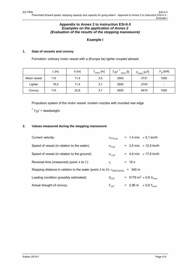
ES-TRIN ESI-II-3 Prescribed forward speed, stopping capacity and capacity for going astern - Appendix to Annex 2 to instruction ESI-II-3 -
Example I
Edition 2015/1 Page 412
Appendix to Annex 2 to instruction ESI-II-3 Examples on the application of Annex 2
(Evaluation of the results of the stopping manoeuvre)
Example I 1. Data of vessels and convoy
Formation: ordinary motor vessel with a (Europa IIa) lighter coupled abreast
[m] [m] [m] ∗
[t] [m3] [kW]
Motor vessel 110 11,4 3,5 2900 3731 1500
Lighter 76,5 11,4 3,7 2600 2743 -
Convoy 110 22,8 3,7 5500 6474 1500
Propulsion system of the motor vessel: modern nozzles with rounded rear edge * = deadweight. 2. Values measured during the stopping manoeuvre Current velocity: = 1,4 m/s 5,1 km/h Speed of vessel (in relation to the water): = 3,5 m/s 12,5 km/h Speed of vessel (in relation to the ground): = 4,9 m/s 17,6 km/h Reversal time (measured) (point to ): = 16 s Stopping distance in relation to the water (point to ): = 340 m Loading condition (possibly estimated): = 5179 m3 0,8 Actual draught of convoy: = 2,96 m 0,8

ES-TRIN ESI-II-3 Prescribed forward speed, stopping capacity and capacity for going astern - Appendix to Annex 2 to instruction ESI-II-3 -
Example I
Edition 2015/1 Page 413
3. Limit value according to (2.1)(a) or (b) to be compared with
Since 11,45 and since the convoy is in flowing water, the following is applicable for this convoy under (2.1)(a):
550
4. Determination of corrected stopping distance compared to standard conditions
- Measured value according to Annex 1 (see (2)): 340
- to be calculated:
as the sum of
(according to formula (4.1) of Annex 2 with ) and (according to formulae (4.2), (4.3), (4.4), (4.5) and (4.6) of
Annex 2 with actual speeds , , )
as the sum of
(according to formula (4.1) of Annex 2 with )
(according to formulae (4.2) to (4.6) of Annex 2 with the reference speeds according to (2.1) of the instruction and given that the loading condition is greater than 70 % of the maximum load (≈ 80 %): and
- to be checked:
∙ 550
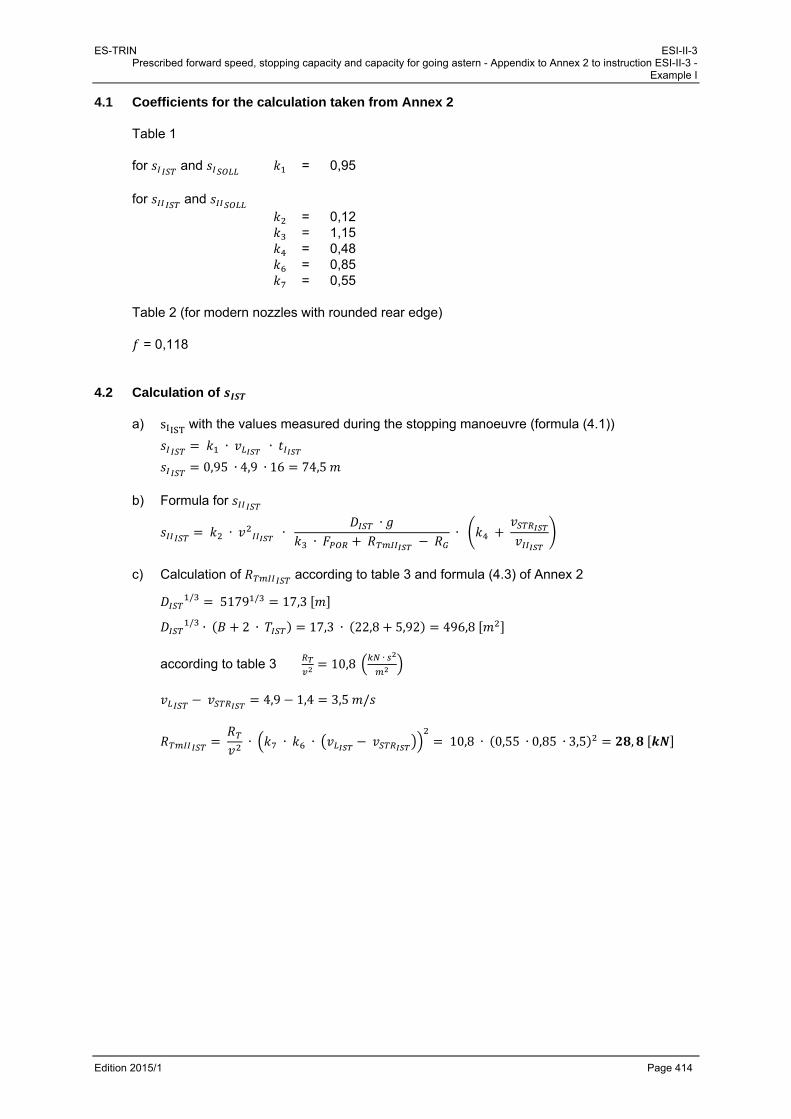
ES-TRIN ESI-II-3 Prescribed forward speed, stopping capacity and capacity for going astern - Appendix to Annex 2 to instruction ESI-II-3 -
Example I
Edition 2015/1 Page 414
4.1 Coefficients for the calculation taken from Annex 2 Table 1 for and = 0,95 for and
= 0,12 = 1,15 = 0,48 = 0,85 = 0,55
Table 2 (for modern nozzles with rounded rear edge)
= 0,118
4.2 Calculation of a) s with the values measured during the stopping manoeuvre (formula (4.1))
∙ ∙
0,95 ∙ 4,9 ∙ 16 74,5 b) Formula for
∙ ∙ ∙
∙ ∙
c) Calculation of according to table 3 and formula (4.3) of Annex 2
/ 5179 / 17,3
/ ∙ 2 ∙ 17,3 ∙ 22,8 5,92 496,8
according to table 3 10,8∙
4,9 1,4 3,5 /
∙ ∙ ∙ 10,8 ∙ 0,55 ∙ 0,85 ∙ 3,5 ,
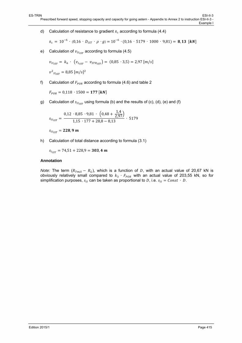
ES-TRIN ESI-II-3 Prescribed forward speed, stopping capacity and capacity for going astern - Appendix to Annex 2 to instruction ESI-II-3 -
Example I
Edition 2015/1 Page 415
d) Calculation of resistance to gradient according to formula (4.4)
10 6 ∙ 0,16 ∙ ∙ ∙ 10 6 ∙ 0,16 ∙5179 ∙ 1000 ∙ 9,81 ,
e) Calculation of according to formula (4.5)
∙ 0,85 ∙ 3,5 2,97 /
8,85 /
f) Calculation of according to formula (4.6) and table 2
0,118 ∙ 1500
g) Calculation of using formula (b) and the results of (c), (d), (e) and (f)
0,12 ∙ 8,85 ∙ 9,81 ∙ 0,48
1,42,97
1,15 ∙ 177 28,8 8,13 ∙ 5179
,
h) Calculation of total distance according to formula (3.1)
74,51 228,9 , Annotation Note: The term ( ), which is a function of , with an actual value of 20,67 kN is obviously relatively small compared to ∙ with an actual value of 203,55 kN, so for simplification purposes, can be taken as proportional to , i.e. ∙ .
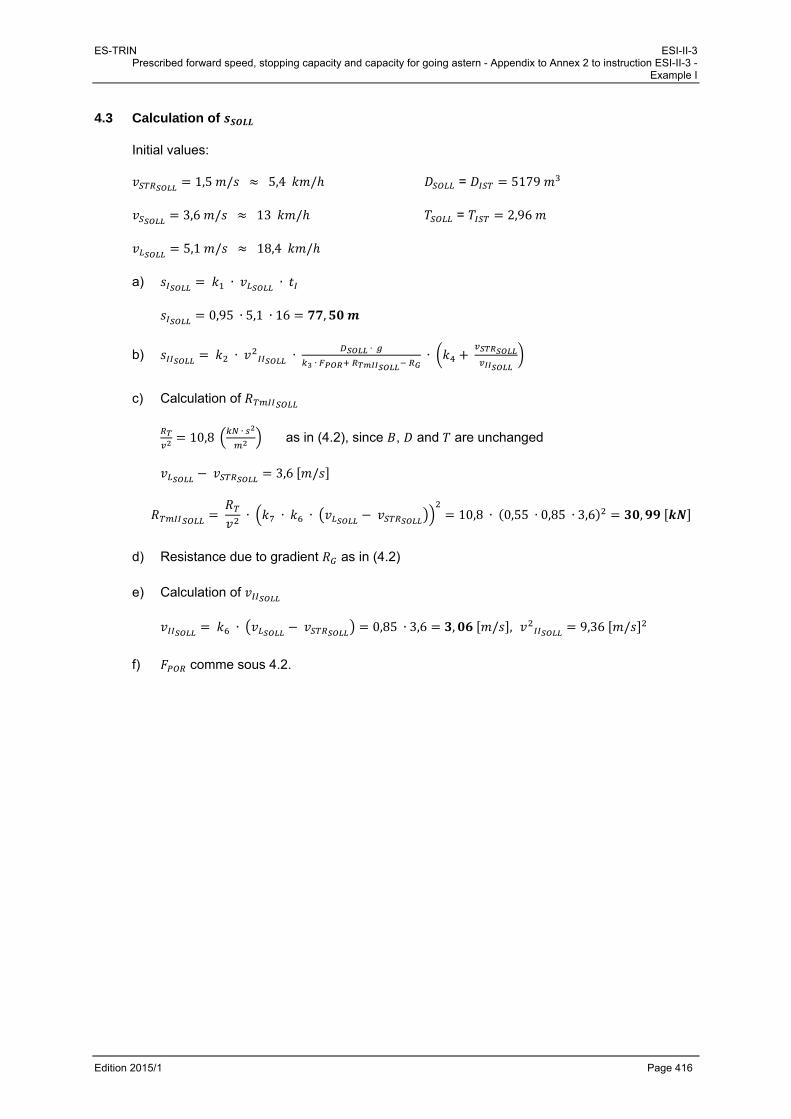
ES-TRIN ESI-II-3 Prescribed forward speed, stopping capacity and capacity for going astern - Appendix to Annex 2 to instruction ESI-II-3 -
Example I
Edition 2015/1 Page 416
4.3 Calculation of
Initial values:
1,5 / 5,4 / = 5179
3,6 / 13 / = 2,96
5,1 / 18,4 / a) ∙ ∙
0,95 ∙ 5,1 ∙ 16 ,
b) ∙ ∙ ∙
∙ ∙
c) Calculation of
10,8∙
as in (4.2), since , and are unchanged
3,6 /
∙ ∙ ∙ 10,8 ∙ 0,55 ∙ 0,85 ∙ 3,6 ,
d) Resistance due to gradient as in (4.2)
e) Calculation of
∙ 0,85 ∙ 3,6 , / , 9,36 /
f) comme sous 4.2.
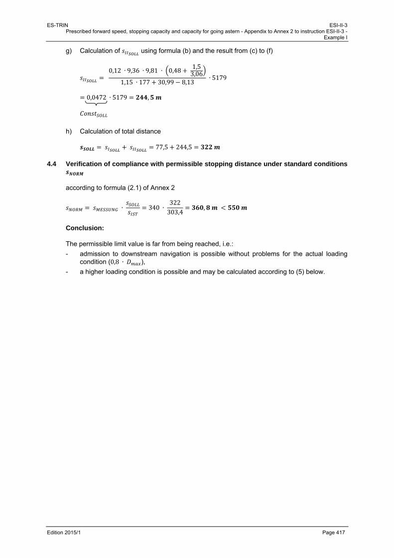
ES-TRIN ESI-II-3 Prescribed forward speed, stopping capacity and capacity for going astern - Appendix to Annex 2 to instruction ESI-II-3 -
Example I
Edition 2015/1 Page 417
g) Calculation of using formula (b) and the result from (c) to (f)
0,12 ∙ 9,36 ∙ 9,81 ∙ 0,48
1,53,06
1,15 ∙ 177 30,99 8,13 ∙ 5179
0,0472 ∙ 5179 ,
h) Calculation of total distance
77,5 244,5
4.4 Verification of compliance with permissible stopping distance under standard conditions
according to formula (2.1) of Annex 2
∙ 340 ∙ 322303,4
,
Conclusion:
The permissible limit value is far from being reached, i.e.:
- admission to downstream navigation is possible without problems for the actual loading condition (0,8 ∙ ),
- a higher loading condition is possible and may be calculated according to (5) below.

ES-TRIN ESI-II-3 Prescribed forward speed, stopping capacity and capacity for going astern - Appendix to Annex 2 to instruction ESI-II-3 -
Example I
Edition 2015/1 Page 418
5. Possible increase of in downstream navigation
∙ 550
550 ∙ 550 ∙ 303,4340
490,8
Avec ∙ according to the note under (4.2):
0,0472 ∙
Hence
0,0472490,8 77,50,0472
From this follows that:
Since 8756 6474 this formation (see (1)) may be permitted in downstream navigation with full load.

ES-TRIN ESI-II-3 Prescribed forward speed, stopping capacity and capacity for going astern - Appendix to Annex 2 to instruction ESI-II-3 -
Example II
Edition 2015/1 Page 419
Example II 1. Data of vessels and convoy
Formation: large motor vessel propelling 2 lighters side-by-side in front and 1 lighter coupled side-by-side.
[m] [m] [m] ∗
[t] [m3] PB [kW]
Motor vessel 110 11,4 3,5 2900 3731 1500
Each lighter 76,5 11,4 3,7 2600 2743 -
Convoy 186,5 22,8 3,7 10700 11960 1500
Propulsion system of the self-propelled vessel: modern nozzles with rounded rear edge. * = deadweight
2. Values measured during the stopping manoeuvre
Current velocity: = 1,4 m/s 5,1 km/h Speed of vessel (in relation to the water): = 3,5 m/s 12,5 km/h Speed of vessel (in relation to the bank): = 4,9 m/s 17,6 km/h Reversal time (measured) (point à ): = 16 s Stopping distance in relation to the water (point to ) : = 580 m Loading condition (possibly estimated): = 9568 m3 0,8 Actual draught of convoy: = 2,96 m 0,8
3. Limit value according to (2.1)(a) or (b) of the instruction to be compared with
Since 11,45 and the convoy is in flowing water, the following applies for this convoy under (2.1)(a):
550

ES-TRIN ESI-II-3 Prescribed forward speed, stopping capacity and capacity for going astern - Appendix to Annex 2 to instruction ESI-II-3 -
Example II
Edition 2015/1 Page 420
4. Determination of the corrected stopping distance compared with standard conditions
- Measured value:
580 - calculations to be made:
as the sum of
(according to formula (4.1) of Annex 2 with ) and (according to formulae (4.2), (4.3), (4.4), (4.5) and (4.6) of
Annex 2 with real speeds ), (see under 2 above) and ).
: sum (according to formulae (4.1) to (4.6) of Annex 2 with reference speeds and in conformity of Annex 2, because the loading condition > 70 % of maximum,
where and )
- to be verified:
∙ 550 otherwise
- calculate:
∗ = 550 m by reduction of to ∗.
4.1 Coefficients for the calculation according to Annex 2
Table 1
for and = 0,95 for and
= 0,12 = 1,15 = 0,48 = 0,85 = 0,55
Table 2 (for modern nozzles with rounded rear edge)
= 0,118

ES-TRIN ESI-II-3 Prescribed forward speed, stopping capacity and capacity for going astern - Appendix to Annex 2 to instruction ESI-II-3 -
Example II
Edition 2015/1 Page 421
4.2 Calculation of
a) Using the values measured during the stopping manoeuvres
∙ ∙
0,95 ∙ 4,8 ∙ 16 73
b) formula for
∙ ∙ ∙
∙ ∙
c) Calculation of according to table 3 and formula (4.3) of Annex 2
/ 9568 / 21,2
/ ∙ 2 ∙ 21,2 ∙ 22,8 5,92 609
from table 3 14∙
4,8 1,4 3,4 /
∙ ∙ ∙ 14 ∙ 0,55 ∙ 0,85 ∙ 3,4 ,
d) Calculation of resistance due to gradient according to formula (4.4) of Annex 2
10 6 ∙ 0,16 ∙ ∙ ∙ 10 6 ∙ 0,16 ∙9568 ∙ 1000 ∙ 9,81 ,
e) Calculation of according to formula (4.5) of Annex 2
∙ 2,89 /
8,35 /

ES-TRIN ESI-II-3 Prescribed forward speed, stopping capacity and capacity for going astern - Appendix to Annex 2 to instruction ESI-II-3 -
Example II
Edition 2015/1 Page 422
f) Calculation of acording to formula (4.6) and table 2
0,118 ∙ 1500
g) Calculation of using formula (b) and the result of (c), (d), (e) and (f)
0,12 ∙ 8,35 ∙ 9,81 ∙ 0,48
1,42,89
1,15 ∙ 177 35,4 15,02 ∙ 9568
h) Calculation of the total distance according to formula (3.1)
73 402
4.3 Calculation of
Initial values:
1,5 / 5,4 / = 9568
3,6 / 13 / = 2,96
5,1 / 18,4 /
a) ∙ ∙
0,95 ∙ 5,1 ∙ 16 ,
b) ∙ ∙ ∙
∙ ∙

ES-TRIN ESI-II-3 Prescribed forward speed, stopping capacity and capacity for going astern - Appendix to Annex 2 to instruction ESI-II-3 -
Example II
Edition 2015/1 Page 423
c) Calculation of
14,0∙
as under (4.2) since , and and unchanged
3,6 /
14,0 ∙ 0,55 ∙ 0,85 ∙ 3,6 ,
d) Resistance due to gradient as under (4.2)
e) Calculation of
0,85 ∙ 3,6 , / , 9,36 /
f) as under (4.2)
g) Calculation of using formula (b) and the result of (c) to (f)
0,12 ∙ 9,36 ∙ 9,81 ∙ 0,48
1,53,06
1,15 ∙ 177 39,6 15,02 ∙ 9568
0,04684 ∙ 9568
h) Calculation of the total distance
77,5 448 ,
4.4 Verification of compliance with permissible stopping distance under standard conditions
according to formula (2.1) of Annex 2
∙ 580 ∙ 525,5475

ES-TRIN ESI-II-3 Prescribed forward speed, stopping capacity and capacity for going astern - Appendix to Annex 2 to instruction ESI-II-3 -
Example II
Edition 2015/1 Page 424
Conclusion:
The limit value has clearly been exceeded; admission to downstream navigation is possible only with a load restriction. This restricted load can be determined in conformity with (5) below.
5. ∗ permissible in downstream navigation
according to formula (2.1) of Annex 2
∙ ∗
550
Therefore:
∗ 550 ∙ ∗
∗ ∙ ∗ 0,04684 ∙ ∗
∗ 550 ∙
475580 77,5
0,046847950
Consequence:
Since in downstream navigation the permissible displacement ∗ is only 7950 m3 (approximately)
.max .
∗
795011960
0,66
The permissible deadweight in this formation is (see (1)): 0,66 ∙ 10700

ES-TRIN ESI-II-4 Capacity for taking evasive action and turning capacity
Edition 2015/1 Page 425
ESI-II-4
CAPACITY FOR TAKING EVASIVE ACTION AND TURNING CAPACITY
(Articles 5.09 and 5.10 in conjunction with Articles 5.02(1), 5.03(1), 5.04 and 21.06) 1. General conditions and boundary conditions relating to the evasive action test 1.1 According to Article 5.09, vessels and convoys shall be able to take evasive action in good time
and the capacity for such action shall be proved by evasive action manoeuvres in the test area in accordance with Article 5.03. This shall be proved by simulated evasive action manoeuvres to port and starboard with prescribed values whereby for specific turning speeds of the vessel in response to putting across and then checking the helm a certain time limit shall be complied with.
During tests the requirements of Section 2 shall be complied with keeping a keel clearance of at least 20 % of the draught, but not less than 0,50 m.
2. Evasive action test procedure and recording of data
(Diagram in Annex 1) 2.1 Evasive action manoeuvres shall be performed as follows: With the vessel or convoy under way at a constant speed of = 13 km/h in relation to the
water, at the start of the manoeuvre (time = 0 s, turning speed = 0°/min, rudder angle = 0°, engine speed kept constant), evasive action to port or starboard is to be initiated by putting across the helm. The rudder shall be set to an angle , or the steering unit to an angle in the case of an active steering device, at the start of the manoeuvre, in accordance with the indications given in (2.3). The rudder angle (e.g. 20° to starboard) shall be maintained until the value of the turning speed referred to in (2.2) for the corresponding dimensions of the vessel or convoy is reached. When the turning speed is reached, the time shall be recorded and the rudder set to the same angle on the opposite side (e.g. 20° to port) so as to stop the turn and commence turning in the opposite direction, i.e., to reduce the turning speed to = 0 and let it to rise again to the value given in (2.2). When the turning speed = 0 is reached, the time
shall be recorded. When the turning speed given in (2.2) is reached, the rudder shall be set in the opposite direction to the same angle , so as to stop the turning movement. The time shall be recorded. When the turning speed = 0 is reached, the time shall be recorded and the vessel or convoy shall be returned to its original course.

ES-TRIN ESI-II-4 Capacity for taking evasive action and turning capacity
Edition 2015/1 Page 426
2.2 The following limit values shall be complied with to reach turning speed depending on the dimensions of the vessels or the convoys and on the water depth :
Dimensions of vessels or convoys
x Required turning speed
= [°/min] Limit values for the time (s) in shallow
and deep water
= 20° = 45° 1,2 h/T 1,4 1,4 < h/T 2 h/T > 2
1 All motor vessels; single-in-line convoys ≤ 110 × 11,45
20°/min 28°/min 150 s 110 s 110 s
2 Single-in-line convoys up to 193 × 11,45 or two-abreast convoys up to 110 × 22,90
12°/min 18°/min 180 s 130 s 110 s
3 Two-abreast convoys ≤ 193 × 22,90 8°/min 12°/min 180 s 130 s 110 s
4 Two-abreast convoys up to 270 × 22,90 or three-abreast convoys up to 193 × 34,35
6°/min 8°/min *) *) *)
*) In accordance with the decision of the nautical expert.
The times , , and required to reach turning speeds , , and shall be recorded in the measurements report in Annex 2. The values shall not exceed the limits given in the table.
2.3 At least four evasive action manoeuvres shall be carried out, namely:
- one to starboard with a rudder angle = 20°
- one to port with a rudder angle = 20°
- one to starboard with a rudder angle = 45°
- one to port with a rudder angle = 45°.
If necessary (e.g. in the case of uncertainty about the values measured or of unsatisfactory manoeuvres), the evasive action manoeuvres shall be repeated. The turning speeds given in (2.2) and the time limits shall be complied with. For active steering devices or special types of rudder, a position of the steering unit or rudder angle other than = 20° and = 45° may be selected, according to the expert’s assessment, depending on the type of steering system.
2.4 In order to determine the turning speed, a rate-of-turn indicator in accordance with
Article 7.06(1) shall be on board. 2.5 In accordance with Article 5.04, the loading condition during the evasive action manoeuvre shall
be between 70 % and 100 % of the maximum deadweight. If the test is carried out with a smaller load, approval for downstream and upstream navigation shall be restricted to that load limit.
The procedure for evasive action manoeuvres and the terms used are shown in a diagram in Annex 1.
3. Turning capacity
The turning capacity of vessels and convoys whose length ( ) does not exceed 86 m and width ( ) does not exceed 22,90 m shall be considered sufficient under Article 5.10, in conjunction with Article 5.02(1) when during an upstream turning manoeuvre with an initial speed in relation to the water of 13 km/h, the limit values for stopping facing downstream established in instruction ESI-II-3 are complied with. The keel clearance conditions according to Section 1.1 shall be complied with.

ES-TRIN ESI-II-4 Capacity for taking evasive action and turning capacity
Edition 2015/1 Page 427
4. Other requirements 4.1 Notwithstanding (1) to (3), the following requirements shall be met:
a) for manually controlled steering systems, a single turn of the wheel shall correspond to a rudder angle of at least 3°;
b) for powered steering systems, when the rudder is at maximum immersion, it shall be possible to achieve an average angular velocity of 4°/s over the rudder’s entire turning range.
This requirement shall also be checked, with the vessel at full speed, for moving the rudder over a range from 35° port to 35° starboard. In addition, it shall be checked whether the rudder keeps the position of maximum angle at maximum propulsion power. For active steering systems or special types of rudder, this provision applies mutatis mutandis.
4.2 If any of the additional equipment referred to in Article 5.05 is needed in order to reach the
required manoeuvring capacities, it shall comply with the requirements of chapter 6, and the following particulars shall be entered under item 52 of the inland navigation vessel certificate:
’Flanking rudders*)/ bow steering systems*/ other equipment* referred to under item 34 is*/are* necessary to comply with the manoeuvrability requirements of chapter 5.’
5. Recording of data and reports
The measurements, reports and recording of data shall be carried out according to the procedure set out in Annex 2.
*) Delete as appropriate

ES-TRIN ESI-II-4 Capacity for taking evasive action and turning capacity - Annex 1 to instruction ESI-II-4
Edition 2015/1 Page 428
Annex 1 to instruction ESI-II-4
Diagram of the evasive action manoeuvre
= Start of evasive action manoeuvre
= Time to reach turning speed
= Time to reach turning speed = 0
= Time to reach turning speed
= Time to reach turning speed = 0 (end of evasive action manoeuvre).
= Rudder angle [°]
= Turning speed [°/min]

ES-TRIN ESI-II-4 Capacity for taking evasive action and turning capacity - Annex 2 to instruction ESI-II-4
Edition 2015/1 Page 429
Annex 2 to instruction ESI-II-4 Report on evasive action manoeuvre and turning capacity
Inspection body: ........................................................................................................................................
Date: ..........................................................................................................................................................
Name: ........................................................................................................................................................ Name of craft: ............................................................................................................................................
Owner: ....................................................................................................................................................... Type of craft Test area: ......................................................
or convoy: ............................................................... Relevant water level [m] : ..............................
x [m x m] : ......................................................... Depth of water [m] : ....................................
during test [m] : ................................................... / : ..............................................................
Speed of the current [m/s] ............................. Load % of maximum (during test) [t] : ...................................................... deadweight: ................................................... Rate-of turn indicator
Type : ......................................................................................................................................................... Type of rudder construction: normal construction/special construction *) Active steering system: yes/no *) Results of evasive action manoeuvres:
Time to t4 required
Rudder angle or *) at which evasive action commences = Comments
for the evasive action
= 20° TB*) = .... TB*)
= 20° BB*) = .... BB*)
= 45° TB*) = ..... TB*)
= 45° BB*) = .... BB*)
= = ........ °/min = = ........ °/min
[s]
[s]
[s]
[s]
Limit value according to 2.2
Limit value = ....................... [s]
Turning capacity *)
Geographic position at start of turning manoeuvre: p.k. ..............................
Geographic position at end of turning manoeuvre: p.k. .............................. Steering apparatus
Type of operation: manual/powered*):
Rudder angle for each turn of the wheel*): ................................. °
Angular velocity of the rudder over the whole range*): ................................. °/s
Angular velocity of the rudder over the range 35° Port to 35° Starboard *): ................................. °/s
*) Delete as appropriate

ES-TRIN ESI-II-4 Capacity for taking evasive action and turning capacity - Annex 2 to instruction ESI-II-4
Edition 2015/1 Page 430
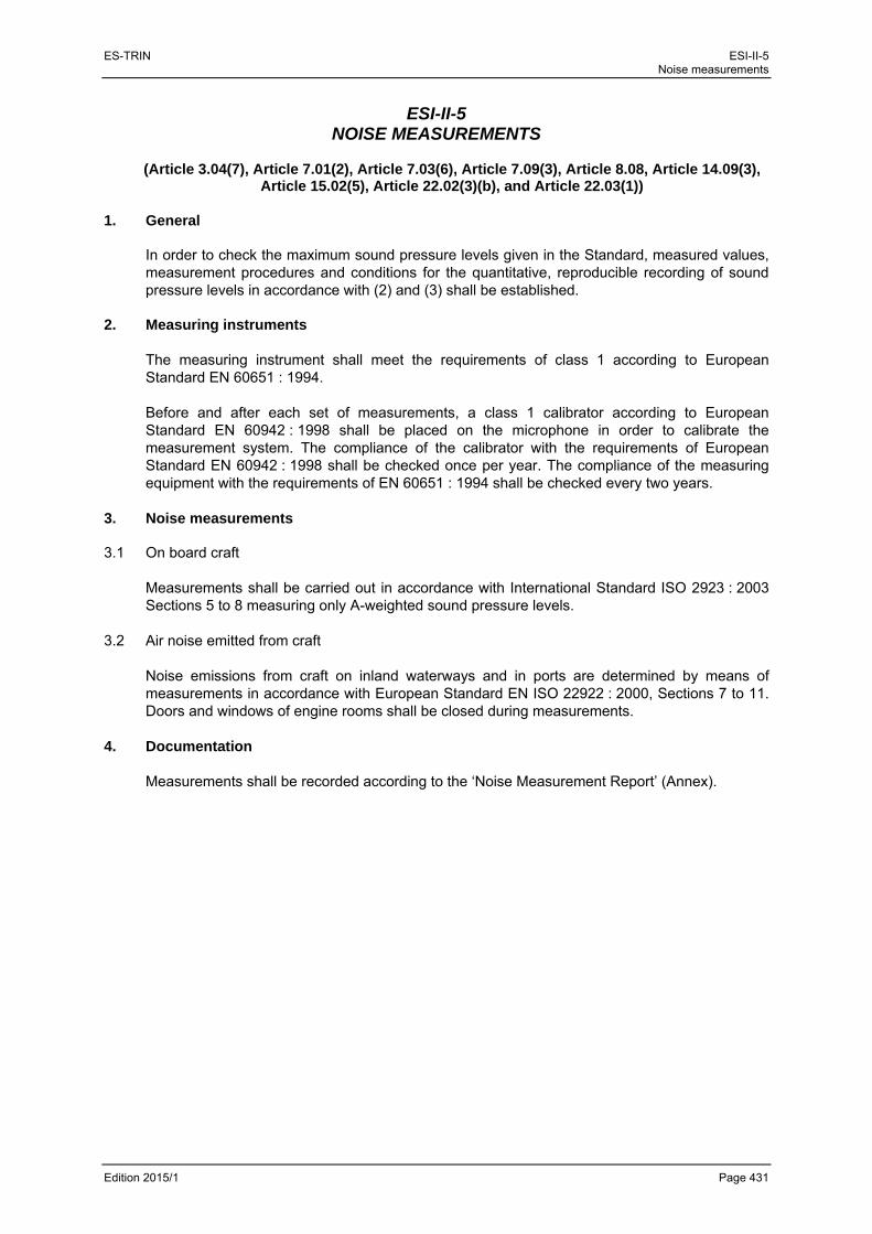
ES-TRIN ESI-II-5 Noise measurements
Edition 2015/1 Page 431
ESI-II-5 NOISE MEASUREMENTS
(Article 3.04(7), Article 7.01(2), Article 7.03(6), Article 7.09(3), Article 8.08, Article 14.09(3),
Article 15.02(5), Article 22.02(3)(b), and Article 22.03(1)) 1. General
In order to check the maximum sound pressure levels given in the Standard, measured values, measurement procedures and conditions for the quantitative, reproducible recording of sound pressure levels in accordance with (2) and (3) shall be established.
2. Measuring instruments
The measuring instrument shall meet the requirements of class 1 according to European Standard EN 60651 : 1994. Before and after each set of measurements, a class 1 calibrator according to European Standard EN 60942 : 1998 shall be placed on the microphone in order to calibrate the measurement system. The compliance of the calibrator with the requirements of European Standard EN 60942 : 1998 shall be checked once per year. The compliance of the measuring equipment with the requirements of EN 60651 : 1994 shall be checked every two years.
3. Noise measurements 3.1 On board craft
Measurements shall be carried out in accordance with International Standard ISO 2923 : 2003 Sections 5 to 8 measuring only A-weighted sound pressure levels.
3.2 Air noise emitted from craft Noise emissions from craft on inland waterways and in ports are determined by means of measurements in accordance with European Standard EN ISO 22922 : 2000, Sections 7 to 11. Doors and windows of engine rooms shall be closed during measurements.
4. Documentation Measurements shall be recorded according to the ‘Noise Measurement Report’ (Annex).

ES-TRIN ESI-II-5 Noise measurements
Edition 2015/1 Page 432
Noise Measurement Report
- on board craft in accordance with International Standard ISO 2923 : 2003 - air noise emitted from craft in accordance with European Standard
EN ISO 2922 : 2000*)
A Craft data
1. Craft type and name: .......................................................................................................................
Unique European vessel identification number: ..............................................................................
2. Owner: .............................................................................................................................................
..........................................................................................................................................................
3. Main propulsion system
3.1 Main engines
Number
Manufacturer Type Year of construction
Power (kW) Engine speed (min-1)
Two-stroke/four-
stroke
Turbo-charged yes/no
1
2
3.2 Transmission
Manufacturer: ................................ Type: ................................... Gear reduction: 1 ..................
3.3 Propellers
Number: .......... Number of blades: .......... Diameter: ................ mm Nozzle: yes/no*)
3.4 Steering system
Type : ..............................................................................................................................................
4. Auxiliaries:
Num-ber
Propulsion of Manufacturer Type Year of construction
Power (kW) Engine speed (min-1)
1
2
3
4
5
5. Noise reduction measures implemented: ........................................................................................
..........................................................................................................................................................
..........................................................................................................................................................
6. Observations: ..................................................................................................................................
..........................................................................................................................................................
..........................................................................................................................................................
*) Delete as appropriate

ES-TRIN ESI-II-5 Noise measurements
Edition 2015/1 Page 433
B Measuring instruments used
1. Sound pressure level meter
Manufacturer: ................................................... Type: .................... Latest check: ..................
2. Octave/Third octave band analyser
Manufacturer: .................................................. Type: .................... Latest check: ..................
3. Calibrator
Manufacturer: .................................................. Type: .................... Latest check: ..................
4. Accessories
..........................................................................................................................................................
5. Observations: ..................................................................................................................................
..........................................................................................................................................................
..........................................................................................................................................................
C Measurement conditions — craft
1. Formation during the measurements: .............................................................................................
2. Load/displacement: ............................................ t/m³ *) (approximately … % of maximum value)
3. Speed of main engine: ........................................ min-1 (approximately … % of maximum value)
4. Auxiliaries in service No ..........................................
5. Observations: ..................................................................................................................................
..........................................................................................................................................................
.......................................................................................................................................................... D Measurement conditions — surroundings
1. Area of measurement: ......................................................................... Upstream/downstream 1
2. Water depth: .................................. m (Relevant water level .................. = ................... m)
3. Weather: ........................................................... Temperature: ........ °C Wind strength: ....... BF
4. External noise interference: yes/no*), if yes, specify: ......................................................................
5. Observations: ..................................................................................................................................
..........................................................................................................................................................
.......................................................................................................................................................... E Recording of measurement
1. Measurement carried out by: ..........................................................................................................
2. Date: ....................
3. Observations : .................................................................................................................................
..........................................................................................................................................................
..........................................................................................................................................................
4. Signature : .............................................
1 Delete as appropriate

ES-TRIN ESI-II-5 Noise measurements
Edition 2015/1 Page 434
F.1 Measurement results
Noise measurements on board craft
Num-ber Measurement point Doors Windows Mea-
sured value
in dB(A)
Observations
open closed open closed
F.2 Measurement results
Measurement of air noise emitted from craft:
Num-ber
Measurement point Measured values in
dB(A)
Observations

ES-TRIN ESI-II-6 Appropriate auxiliary means for observing the area of obstructed vision
Edition 2015/1 Page 435
ESI-II-6 APPROPRIATE AUXILIARY MEANS FOR OBSERVING THE AREA OF
OBSTRUCTED VISION
(Article 7.02)
(left void)

ES-TRIN ESI-II-6 Appropriate auxiliary means for observing the area of obstructed vision
Edition 2015/1 Page 436

ES-TRIN ESI-II-7 Used oil collection facilities
Edition 2015/1 Page 437
ESI-II-7 USED OIL COLLECTION FACILITIES
(Article 8.09)
Existing vessels referred to in article 32.02(1), whose permanently installed bilge pumping and drainage systems and static oil separators have been removed from their engine rooms, no longer comply with article 5.07 of the RVIR in force as at 31.12.1994. In accordance with the transitional provisions, these vessels must be equipped with a used-oil collection tank referred to in article 8.09(2), with the exception of those cases referred to in article 8.09(3).

ES-TRIN ESI-II-7 Used oil collection facilities
Edition 2015/1 Page 438
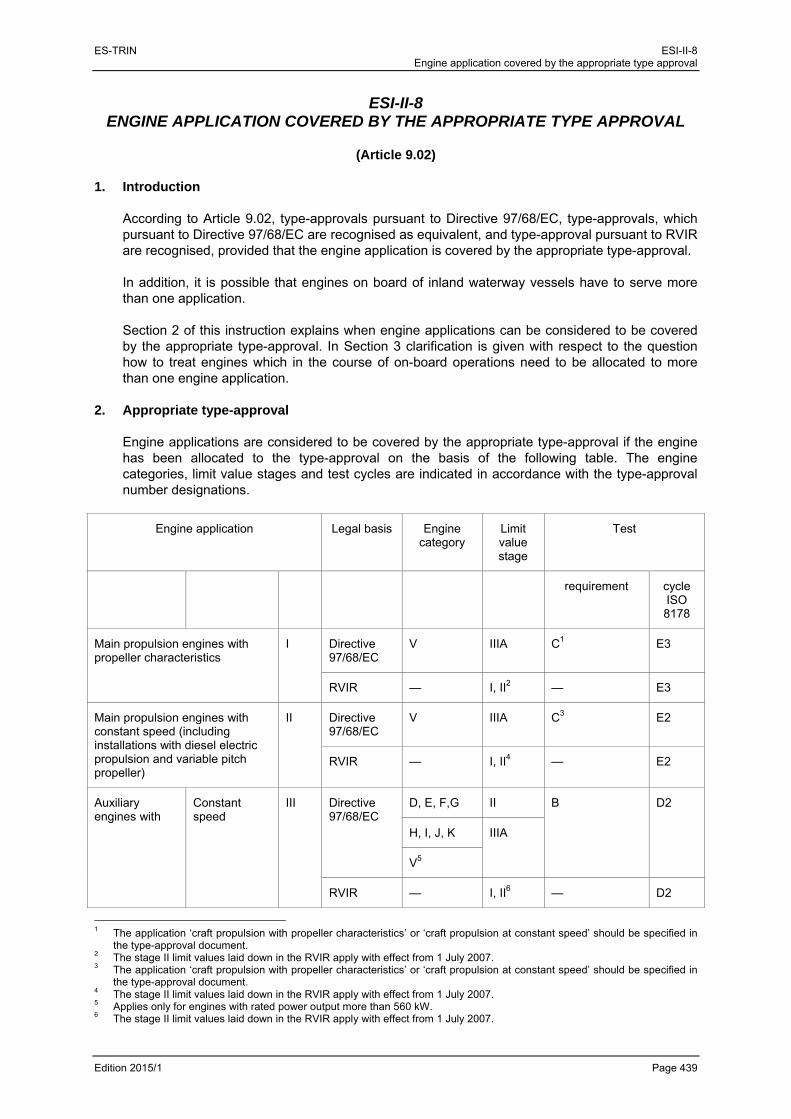
ES-TRIN ESI-II-8 Engine application covered by the appropriate type approval
Edition 2015/1 Page 439
ESI-II-8 ENGINE APPLICATION COVERED BY THE APPROPRIATE TYPE APPROVAL
(Article 9.02)
1. Introduction
According to Article 9.02, type-approvals pursuant to Directive 97/68/EC, type-approvals, which pursuant to Directive 97/68/EC are recognised as equivalent, and type-approval pursuant to RVIR are recognised, provided that the engine application is covered by the appropriate type-approval. In addition, it is possible that engines on board of inland waterway vessels have to serve more than one application. Section 2 of this instruction explains when engine applications can be considered to be covered by the appropriate type-approval. In Section 3 clarification is given with respect to the question how to treat engines which in the course of on-board operations need to be allocated to more than one engine application.
2. Appropriate type-approval Engine applications are considered to be covered by the appropriate type-approval if the engine has been allocated to the type-approval on the basis of the following table. The engine categories, limit value stages and test cycles are indicated in accordance with the type-approval number designations.
Engine application Legal basis Engine category
Limit value stage
Test
requirement cycle
ISO 8178
Main propulsion engines with propeller characteristics
I Directive 97/68/EC
V IIIA C1 E3
RVIR — I, II2 — E3
Main propulsion engines with constant speed (including installations with diesel electric propulsion and variable pitch propeller)
II Directive 97/68/EC
V IIIA C3 E2
RVIR — I, II4 — E2
Auxiliary engines with
Constant speed
III Directive 97/68/EC
D, E, F,G II B D2
H, I, J, K IIIA
V5
RVIR — I, II6 — D2
1 The application ‘craft propulsion with propeller characteristics’ or ‘craft propulsion at constant speed’ should be specified in
the type-approval document. 2 The stage II limit values laid down in the RVIR apply with effect from 1 July 2007. 3 The application ‘craft propulsion with propeller characteristics’ or ‘craft propulsion at constant speed’ should be specified in
the type-approval document. 4 The stage II limit values laid down in the RVIR apply with effect from 1 July 2007. 5 Applies only for engines with rated power output more than 560 kW. 6 The stage II limit values laid down in the RVIR apply with effect from 1 July 2007.

ES-TRIN ESI-II-8 Engine application covered by the appropriate type approval
Edition 2015/1 Page 440
Variable speed and variable load
IV Directive 97/68/EC
D,E,F,G II A C1
H, I, J, K IIIA
V1
L, M, N, P IIIB
Q, R IV
RVIR — I, II2 — C1
3. Special engine applications 3.1 Engines which in the course of on-board operations need to be allocated to more than one engine
application shall be treated as follows:
a) auxiliary engines which drive units or machinery which, pursuant to the table in Section 2, have to be allocated to applications III or IV need to have obtained type-approval for each of the respective applications provided for in this table;
b) main propulsion engines which drive additional units or machinery need only to have obtained the type-approval necessary for the relevant type of main propulsion pursuant to the table in Section 2, in so far as the engine’s main application is craft propulsion. If the time taken up by the sole auxiliary application exceeds 30 %, the engine will need to have obtained, in addition to type-approval for the main propulsion application, further type-approval in respect of the auxiliary application.
3.2 Engines driving bow thrusters, whether directly or by means of a generator at:
a) variable engine speed and load may be allocated to applications I or IV pursuant to the table in Section 2;
b) constant engine speed may be allocated to applications II or III pursuant to the table in Section 2.
3.3 The engines shall be installed with the power output as authorised under the type-approval and
indicated on the engine by means of identification of type. If such engines have to drive units or machinery of lower power consumption, power may be reduced only by measures external to the engine, in order to achieve the power level needed for the application.
1 Applies only for engines with rated power output more than 560 kW. 2 The stage II limit values laid down in the RVIR apply with effect from 1 July 2007.

ES-TRIN ESI-II-9 Special anchors with reduced mass
Edition 2015/1 Page 441
ESI-II-9 SPECIAL ANCHORS WITH REDUCED MASS
(Article 13.01(5))
Section 1 Authorised special anchors Special anchors with a reduced mass, authorised by competent authorities according to Article 13.01(5) are listed in the following table.
Anchor nr. Accepted reduction of the
anchormass (%) Competent Authority
1. HA-DU 30 % Germany
2. D'Hone Spezial 30 % Germany
3. Pool 1 (hol) 35 % Germany
4. Pool 2 (massief) 40 % Germany
5. De Biesbosch-Danforth 50 % Germany
6. Vicinay-Danforth 50 % France
7. Vicinay AC 14 25 % France
8. Vicinay Typ 1 45 % France
9. Vicinay Typ 2 45 % France
10. Vicinay Typ 3 40 % France
11. Stockes 35 % France
12. D'Hone-Danforth 50 % Germany
13. Schmitt high holding anchor 40 % Netherlands
14. SHI high holding anchor, type ST (standard)
30 % Netherlands
15. SHI high holding anchor, type FB (fully balanced)
30 % Netherlands
16. Klinsmann anchor 30 % Netherlands
17. HA-DU-POWER anchor 50 % Germany

ES-TRIN ESI-II-9 Special anchors with reduced mass
Edition 2015/1 Page 442
Section 2
Authorisation and test procedure of special anchors with reduced mass
Reduction of the anchor mass values determined in accordance with Article 13.01(1) to (4)
1. Chapter 1 — Authorisation procedure 1.1 Special anchors with reduced mass in accordance with Article 13.01(5) shall be authorised by
the competent authorities. The competent authority determines the authorised reduction of anchor mass for special anchors in accordance with the procedure outlined below.
1.2 Authorisation as special anchor is only possible if the reduction of anchor mass established is at
least 15 %. 1.3 Applications for the authorisation of a special anchor in accordance with (1.1) shall be submitted
to the competent authority of a Member State. Ten copies of the following documents shall be forwarded with each application:
a) an outline of the dimensions and mass of the special anchor, giving the main dimensions and type designation for each available anchor size;
b) a braking force diagram for the reference anchor (in accordance with (2.2)) and the special anchor to be authorised which has been prepared and assessed by an institution designated by the competent authority.
1.4 The competent authority notifies CESNI of any applications to reduce anchor mass which it
considers to authorise after testing. 2. Chapter 2 — Test Procedure 2.1 The braking force diagrams in accordance with (1.3) shall show the braking forces as a function
of speed for the reference anchor and the special anchor to be authorised on the basis of tests in accordance with (2.2) to (2.5) below. Annex 1 shows one possible braking force test.

ES-TRIN
Edition 201
2.2 Thco
A
ea 2.3 Th
thre
2.4 Br
(sthstfinfo
2.5 Fo
behe
15/1
he referenceorresponding
tolerance ofach fluke mu
he mass of te mass of
ecalculated p
raking force peed over ge reference retches of ri
ne sand. On r the coarse
or each testetween the peight of the c
e anchor g to the sketc
f ±5 % applist be at leas
the special athe referen
roportional to
diagrams shground). To t
anchor aver determinthe River Rhgravel tests
, the anchorpoints of connconnection po
used in thech and details
es to the dimt 0,15 m2.
anchor B usence anchor o mass.
hall give a linthis end, threand the specned by the chine the stretand the stre
r being testenection on thoint on the c
e tests shall s given below
mensions an
ed in the tes. If the to
near represeee tests shacial anchor
competent autch between
etch between
ed shall be he anchor anraft above th
be a convew, with a ma
nd mass give
sts shall not olerances a
entation of spall be carried
on an altuthority, one401-402 km
n 480-481 km
towed with nd on the towhe anchorage
Special a
entional foldiass of at leas
en. However
deviate by mre greater,
peed ( ) in thd out in an uernating baswith coarse
m can serve am for the fine
a steel wirewing craft or de ground.
anchors with red
ing stocklesst 400 kg.
r, the surfac
more than 10the forces
he range 0 tupstream diresis over eace gravel and as a referencsand tests.
e cable whosdevice is 10
ESI-II-9 duced mass
Page 443
s anchor
e area of
0 % from shall be
to 5 km/h ection for ch of two
one with ce stretch
se length times the

ES-TRIN
Edition 201
2.6 Th
où
2.7 Th
15/1
he percentag
ù
= therefe
= the
= the
= hol
= hol
= the
-
-
-
-
= samuse
he acceptabl
ge of reductio
e percentageerence anch
e mass of ref
e mass of spe
lding force of
lding force of
e surface are
the line pa
the line pa
the line pa
the braking
me definitioned.
(Det
le percentag
on of anchor
75 ∙ 1
e of reductioor ;
ference anch
ecial anchor
f reference a
f special anc
a on the bra
arallel to the y
arallel to the y
arallel to the x
g force curve
n as for e
Model bratermining th
e is the aver
r mass is calc
0,5
on of ancho
hor ;
;
anchor at
chor at =
king force di
y-axis at =
y-axis at =
x-axis at hold
e for referenc
except that th
anking forcehe surface a
rage of six va
culated by th
or mass of
= 0,5 km/h
0,5 km/h;
agram define
0
5 km/h
ding force
ce anchor ;
he braking fo
e diagram reas and
alues of ca
Special a
he following f
%
special anc
;
ed by
= 0
orce curve fo
d )
lculated in ac
anchors with red
formula:
chor in re
or special an
ccordance w
ESI-II-9 duced mass
Page 444
elation to
nchor is
with (2.6).
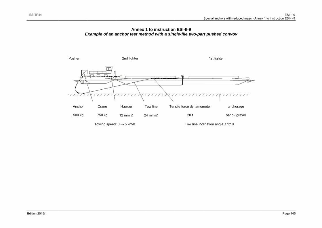
E
ES-TRIN
dition 2015/1
E
Pusher
Anchor
500 kg
Example of an a
Crane
750 kg
Towing speed:
Annex anchor test met
2nd lighter
Hawser T
12 mm 2
0 5 km/h
1 to instructionthod with a sing
Tow line Ten
24 mm
S
n ESI-II-9 gle-file two-par
nsile force dynamom
20 t
Tow line incl
Special anchors with r
rt pushed convo
1st lighter
meter anc
sand
ination angle 1:10
reduced mass - Annex
oy
chorage
d / gravel
0
ESI-Ix 1 to instruction ESI-I
Page 4
II-9 II-9
445

ES-TRIN ESI-II-9 Special anchors with reduced mass - Annex 1 to instruction ESI-II-9
Edition 2015/1 Page 446

ES-TRIN ESI-II-10 Automatic pressurised water sprinklers
Edition 2015/1 Page 447
ESI-II-10 AUTOMATIC PRESSURISED WATER SPRINKLERS
(Article 13.04(1) and (4))
Suitable automatic pressurised water sprinklers as in Article 13.04(1) and (4) shall meet the following requirements: 1. The automatic pressurised water sprinkler shall be ready for service at all times when there are
persons on board. No additional action by crew members shall be required to trigger operation. 2. The system shall be permanently maintained at the necessary pressure. The pipes shall be
filled with water up to the spray nozzles at all times. The system shall have a continuously working water supply. It shall not be possible for impurities harmful to operation to enter the system. Appropriate display instruments and test systems (e.g. pressure gauges, pressure-tank water level indicators, pump test piping) shall be installed for monitoring and checking the system. The pressurised water sprinkler systems located in the cold storage and freezer rooms should not be permanently filled with water. These rooms can be protected with dry sprinklers.
3. The pump for the water supply to the spray nozzles shall be activated automatically by a
pressure drop in the system. The pump shall be dimensioned so that it can continuously provide a sufficient water supply at the necessary pressure if all the spray nozzles necessary for covering the area of the largest room to be protected are activated simultaneously. The pump shall supply the automatic pressurised water sprinkler exclusively. In the event of pump failure, it shall be possible to provide the spray nozzles with a sufficient water supply from another on-board pump.
4. The system shall be divided into sections, each with no more than 50 spray nozzles. A larger
number of spray nozzles may be authorised by the inspection body with appropriate corroboration, in particular a hydraulic calculation.
5. The number and the layout of spray nozzles shall ensure effective distribution of water in the
rooms to be protected. 6. Spray nozzles shall be triggered at a temperature between 68 °C and 79 °C, in the galley areas
at a maximum of 93 °C and in the saunas at a maximum of 141 °C. 7. The installation of components of automatic pressurised water sprinklers within the rooms to be
protected shall be limited to the necessary minimum. No such system components shall be installed in main engine rooms.
8. Visual and acoustic indicators shall be provided in one or more suitable locations, at least one
of which must be permanently manned, displaying activation of automatic pressurised water sprinklers for each section.
9. The energy supply of the installation of automatic pressurised water sprinklers shall be provided
by two independent energy sources that shall not be installed in the same location. Each energy source shall be capable of supplying the entire system unassisted.

ES-TRIN ESI-II-10 Automatic pressurised water sprinklers
Edition 2015/1 Page 448
10. An installation plan of the automatic pressurised water sprinkler shall be presented to the inspection body for examination before installation of the system. The plan shall indicate the types and performance data of the machines and equipment used. An installation tested and certified by an approved classification society which complies at least with the above prescriptions can be authorised without further testing.
11. The presence of an automatic pressurised water sprinkler shall be entered in the inland
navigation vessel certificate under item 43.

ES-TRIN ESI-II-11 Steerageway under vessel’s own power
Edition 2015/1 Page 449
ESI-II-11 STEERAGEWAY UNDER VESSEL’S OWN POWER
(Article 13.05(2)(a), Article 19.07(1), Article 28.04(1)(a))
1. Minimum requirements for vessel’s steerageway
Steerageway under a vessel’s own power in accordance with Articles 13.05(2)(a), 19.07(1) and 28.04(1)(a) is deemed to be sufficient if — when using the bow thruster — the vessel or the formation propelled by the vessel attains a speed of 6,5 km/h in relation to the water and a rate-of-turn of 20°/min can be induced and maintained while under way at a speed of 6,5 km/h in relation to the water.
2. Navigation tests
On verifying the minimum requirements Articles 5.03 and 5.04 shall be complied with.

ES-TRIN ESI-II-11 Steerageway under vessel’s own power
Edition 2015/1 Page 450

ES-TRIN ESI-II-12 Appropriate fire alarm system
Edition 2015/1 Page 451
ESI-II-12 APPROPRIATE FIRE ALARM SYSTEM
(Article 13.05(3), Article 19.11(18), Article 29.10(1))
Fire alarm systems are considered to be appropriate if they meet the following conditions. 0. Components 0.1 Fire alarm systems consist of :
a) fire detection system,
b) fire indicator system,
c) control panel
as well as the external power supply. 0.2 The fire detection system may be divided into one or more fire zones 0.3 The fire indicator system may have one or more indicator devices. 0.4 The control panel is the central control unit of the fire alarm system. It also includes parts of
the fire indicator system (i.e. an indicator device). 0.5 A fire detection zone may have one or more fire detectors. 0.6 Fire detectors may be
a) heat detectors,
b) smoke detectors,
c) ion detectors,
d) flame detectors,
e) combination detectors (fire detectors combining two or more of the detectors listed in (a) to (d)).
Fire detectors which respond to other factors indicating the onset of a fire may be approved by the inspection body provided that they are no less sensitive than the detectors referred to under (a) to (e).
0.7 Fire detectors may be installed
a) with or
b) without
individual identification.
ES-TRIN ESI-II-12 Appropriate fire alarm system
Edition 2015/1 Page 452
1. Construction requirements 1.1 General 1.1.1 Compulsory fire alarm systems shall be operational at all times. 1.1.2 Fire detectors required in accordance with (2.2) shall be automatic. Additional manually
operated fire detectors may be installed.
1.1.3 The system and its components shall be able to withstand voltage fluctuations and surges, changes in ambient temperature, vibrations, humidity, shocks, impacts and corrosion such as commonly occur on vessels.
1.2 Energy supply
1.2.1 Energy sources and electric circuits necessary for the operation of the fire alarm system shall be self monitoring. Any fault occurring shall activate a visual and acoustic alarm signal on the control panel which can be distinguished from a fire alarm signal.
1.2.2 There shall be at least two power sources for the electrical part of the fire alarm system, one of which shall be an emergency power system (i.e. emergency power source and emergency switchboard). There shall be two separate power-feeds solely for this purpose. These shall lead to an automatic switch in or near the control panel of the fire alarm system. On day-trip vessels up to 25 m and on motor vessels a separate emergency power supply is sufficient.
1.3 Fire detection system
1.3.1 Fire detectors shall be grouped in fire detection zones.
1.3.2 Fire detection systems shall not be used for any other purpose. By way of derogation the closing of the doors in accordance with Article 19.11(9) and similar functions may be activated and indicated on the control panel.
1.3.3 Fire detection systems shall be designed in such a way that the first indicated fire alarm does
not prevent fire alarms set off by other detectors. 1.4 Fire detection zones 1.4.1 Where the fire detectors cannot be remotely identified individually, a fire detection zone shall
not monitor more than one deck. This does not apply to a fire detection zone which monitors an encapsulated stairwell.
In order to avoid delays in detecting the origin of the fire, the number of enclosed spaces included in each fire detection zone shall be limited. There shall not be more than fifty enclosed spaces in one fire detection zone.

ES-TRIN ESI-II-12 Appropriate fire alarm system
Edition 2015/1 Page 453
Where the fire detection system has remote identification of individual fire detectors, the fire detection zones may monitor several decks and any number of enclosed spaces.
1.4.2 On passenger vessels which do not have a fire detection system with remote identification of individual fire detectors, a fire detection zone shall not comprise more than the area constituted in accordance with Article 19.11(11). The activation of a fire detector in an individual cabin in this fire detection zone shall set off a visual and acoustic signal in the passageway outside that cabin.
1.4.3 Galleys, engine rooms and boiler rooms shall constitute separate fire detection zones.
1.5 Fire detectors 1.5.1 Only heat, smoke or ion detectors shall be used as fire detectors. Other types may only be
used as additional detectors. 1.5.2 Fire detectors shall be type-approved.
1.5.3 All automatic fire detectors shall be designed in such a way that they can be tested to ensure
that they are working properly and brought back into service without having to replace any components.
1.5.4 Smoke detectors shall be set so that they respond to a reduction in visibility per metre caused
by smoke of more than 2 % to 12,5 %. Smoke detectors fitted in galleys, engine rooms and boiler rooms shall respond within sensitivity limits meeting the requirements of the inspection body, whereby under-sensitivity or over-sensitivity of the detectors shall be avoided.
1.5.5 Heat detectors shall be set so that with temperature increase rates of less than 1 °C/min they
respond at temperatures of between 54 °C and 78 °C.
With higher rates of temperature increase, the heat detector shall respond within temperature limits where under- or over-sensitivity of the heat detector is avoided.
1.5.6 With the agreement of the inspection body, the permissible operating temperature of heat
detectors may be increased to 30 °C above the maximum temperature in the upper part of engine and boiler rooms.
1.5.7 The sensitivity of flame detectors shall be sufficient to detect flames against an illuminated
background. Flame detectors shall also be equipped with a system for identifying false alarms.
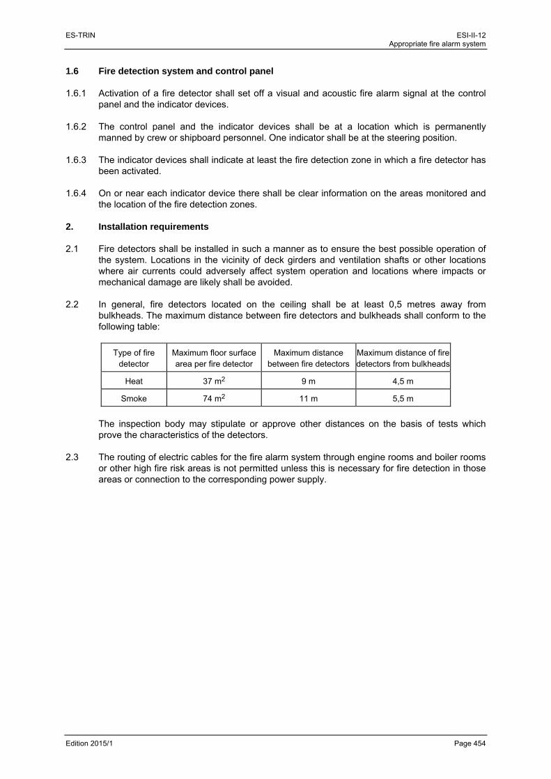
ES-TRIN ESI-II-12 Appropriate fire alarm system
Edition 2015/1 Page 454
1.6 Fire detection system and control panel 1.6.1 Activation of a fire detector shall set off a visual and acoustic fire alarm signal at the control
panel and the indicator devices. 1.6.2 The control panel and the indicator devices shall be at a location which is permanently
manned by crew or shipboard personnel. One indicator shall be at the steering position. 1.6.3 The indicator devices shall indicate at least the fire detection zone in which a fire detector has
been activated. 1.6.4 On or near each indicator device there shall be clear information on the areas monitored and
the location of the fire detection zones.
2. Installation requirements
2.1 Fire detectors shall be installed in such a manner as to ensure the best possible operation of the system. Locations in the vicinity of deck girders and ventilation shafts or other locations where air currents could adversely affect system operation and locations where impacts or mechanical damage are likely shall be avoided.
2.2 In general, fire detectors located on the ceiling shall be at least 0,5 metres away from
bulkheads. The maximum distance between fire detectors and bulkheads shall conform to the following table:
Type of fire detector
Maximum floor surface area per fire detector
Maximum distance between fire detectors
Maximum distance of fire detectors from bulkheads
Heat 37 m2 9 m 4,5 m
Smoke 74 m2 11 m 5,5 m
The inspection body may stipulate or approve other distances on the basis of tests which prove the characteristics of the detectors.
2.3 The routing of electric cables for the fire alarm system through engine rooms and boiler rooms
or other high fire risk areas is not permitted unless this is necessary for fire detection in those areas or connection to the corresponding power supply.

ES-TRIN ESI-II-12 Appropriate fire alarm system
Edition 2015/1 Page 455
3. Acceptance test
3.1 Fire alarm systems must be checked by an expert:
a) before being put into service for the first time,
b) before being put back into service after any major modification or repair,
c) regularly, at least every two years.
In the case of engine rooms and boiler rooms these checks shall be made under various machine operation conditions and under changing ventilation conditions. Inspections as referred to in subsection (c) above may also be carried out by a competent person from a competent firm specialising in fire extinguishing systems.
3.2 An inspection certificate shall be issued, signed by the expert or competent person and
showing the date of the inspection

ES-TRIN ESI-II-12 Appropriate fire alarm system
Edition 2015/1 Page 456
ES-TRIN ESI-II-13 Electric cables
Edition 2015/1 Page 457
ESI-II-13 ELECTRIC CABLES
(Article 10.15 and 19.10(6))
General (all vessels) — Article 10.15 1. When applying Article 10.15(5), reduced ventilation of shielded cables or cables in totally
enclosed trunks has to be taken into account. 2. In Article 10.15(9) the number of cable joints should be kept to a minimum. They may be used for
repair or replacement purposes as well as, exceptionally, for the simplification of installation. Cable joints made in accordance with 3.28 and Annex D to International Standard IEC 60092-352 : 2005, or equivalent regulations recognised by one of the Member States, will be considered acceptable.
Passenger vessels — Article 19.10(6) 1. On passenger vessels, cables and cable routing are considered to be satisfactory if they meet the
conditions in 2 and 3. 2. For cables providing power in an emergency to equipment listed in Article 19.10(4), compliance
with Article 19.10(6) second subparagraph will require that:
a) the cables are run in such a manner as to avoid being rendered unserviceable by heating of the bulkheads and decks that may be caused by a fire in an adjacent space;
b) where the cables supply equipment located within high fire risk areas, the cable runs within such areas must avoid routes which pass over or near the top of diesel engines and oil-fired equipment, or near to hot surfaces e.g. diesel engine exhaust systems. Where there is no alternative route, cables must be protected from heat and fire damage. Such fire protection could be in the form of a steel plate or trunk;
c) the cables and associated equipment supplied from the emergency source of power should, as far as practicable, be kept within the safe area;
d) cable systems are arranged so that fire in any area bounded by Type A partitions as shown in Article 19.11(2) will not interfere with services essential for safety in any other such area. This requirement will be met if main and emergency cables do not pass through the same area. If they pass through the same area, the requirement will be met if:
aa) they are separated as wide as is practicable; or
bb) the emergency cable is of the fire resistant type. 3. Consideration should be given to the arrangements of bunched cable runs to ensure that the
flame-retardant characteristics of the cables are not impaired. This requirement is met if the cables are in accordance with International Standard IEC 60332-3 : 2000. If compliance with International Standard IEC 60332-3 : 2000, or equivalent regulations recognised by one of the Member States, is not met, fire stops in long runs of bunched cables (over 6 m vertical and 14 m horizontal) should be considered, unless the cables are totally enclosed in cable trunks. The use of unsuitable paints, trunking and casings may significantly affect the fire propagation characteristics of cables and shall be avoided. The use of special types of cables such as radio frequency cables may be permitted without complying with the foregoing.

ES-TRIN ESI-II-13 Electric cables
Edition 2015/1 Page 458
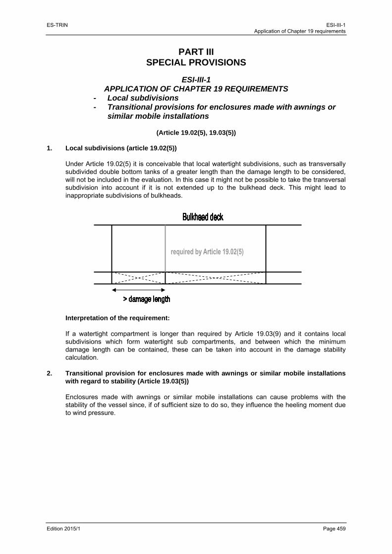
ES-TRIN ESI-III-1 Application of Chapter 19 requirements
Edition 2015/1 Page 459
PART III SPECIAL PROVISIONS
ESI-III-1
APPLICATION OF CHAPTER 19 REQUIREMENTS - Local subdivisions - Transitional provisions for enclosures made with awnings or
similar mobile installations
(Article 19.02(5), 19.03(5)) 1. Local subdivisions (article 19.02(5))
Under Article 19.02(5) it is conceivable that local watertight subdivisions, such as transversally subdivided double bottom tanks of a greater length than the damage length to be considered, will not be included in the evaluation. In this case it might not be possible to take the transversal subdivision into account if it is not extended up to the bulkhead deck. This might lead to inappropriate subdivisions of bulkheads.
Interpretation of the requirement: If a watertight compartment is longer than required by Article 19.03(9) and it contains local subdivisions which form watertight sub compartments, and between which the minimum damage length can be contained, these can be taken into account in the damage stability calculation.
2. Transitional provision for enclosures made with awnings or similar mobile installations
with regard to stability (Article 19.03(5)) Enclosures made with awnings or similar mobile installations can cause problems with the stability of the vessel since, if of sufficient size to do so, they influence the heeling moment due to wind pressure.

ES-TRIN ESI-III-1 Application of Chapter 19 requirements
Edition 2015/1 Page 460
Interpretation of the requirement:
In the case of passenger vessels for which a vessel certificate was issued for the first time before 1 January 2006 according to RVIR, or for which Article 32.05(2), second sentence, is invoked, after the erection of an enclosure made with awnings or similar mobile installations, a new stability calculation must be made according to Article 19.04 of this Standard, in so far as its lateral plane exceeds 5 % of the total lateral plane to be taken into account in each case.

ES-TRIN ESI-III-2 Specific safety needs of persons with reduced mobility
Edition 2015/1 Page 461
ESI-III-2 SPECIFIC SAFETY NEEDS OF PERSONS WITH REDUCED MOBILITY
(Article 1.01(12.2), article 19.01(4) , article 19.06(3) to (5), (9), (10), (13) and (17), article 19.08(3),
article 19.10(3), article 19.13(1) to (4)) 1. Introduction
Persons with reduced mobility have safety needs exceeding those of other passengers. These needs are taken into account in the requirements of Chapter 19, which are explained as follows. These requirements are intended to ensure that persons with reduced mobility can stay and move safely on board vessels. In addition, in an emergency such persons should have the same level of safety as other passengers. It is not necessary that all passenger areas fulfil the specific safety requirements of persons with reduced mobility. Therefore those requirements apply only to certain areas. However, the persons in question must be given the opportunity of being informed of the areas specially adapted for them in view of safety, so that they can organise their stay on board accordingly. It is the responsibility of the ship-owner to make the corresponding areas available, make them known and communicate them to persons with reduced mobility. The provisions concerning persons with reduced mobility make reference to:
Directive 2003/24/EC1 and
the guide for the adaptation of inland waterway passenger vessels to people with disabilities in accordance with Resolution No 25 of the United Nations Economic Commission for Europe.
The definition of the term ‘persons with reduced mobility’ used in the Standard is largely identical to that of the Directive and most of the technical requirements are based on the above mentionned guide. In cases of doubt, therefore, both can be referred to when taking decisions. In general, the requirements of the Directive and the guide go beyond those of this Standard. The requirements of the Standard do not concern berths and similar installations. These are subject to national provisions.
2. Article 1.01(12.2) – term ‘persons with reduced mobility’ ‘Persons with reduced mobility’ means anyone who, as a result of physical impairments, cannot
move or distinguish their surroundings in the same way as other passengers. This definition includes persons with impaired eyesight or hearing or persons accompanying children in buggies or being carried. However, for the purposes of these provisions, persons with reduced mobility do not include anyone with psychic impairments.
1 Directive 2003/24/EC of the European Parliament and of the Council of 14 April 2003 amending Council Directive
98/18/EC on safety rules and standards for passenger ships (OJ L 123, 17.5.2003).

ES-TRIN ESI-III-2 Specific safety needs of persons with reduced mobility
Edition 2015/1 Page 462
3. Article 19.15(4) — Areas provided for use by persons with reduced mobility
Areas provided for use by persons with reduced mobility range from, in the simplest case, the entrance area to the places from which an evacuation will take place in an emergency. They shall include:
a place where life-saving equipment is stowed or issued in an emergency,
seats,
a suitably-adapted toilet (see (10) of this instruction), and
connecting corridors.
The number of seats corresponds at least approximately to the number of persons with reduced mobility that — over a lengthy period — are most frequently onboard simultaneously. The number should be determined by the ship-owner on the basis of experience, as this is beyond the knowledge of the competent authority. On cabin vessels consideration shall also be given to connecting corridors to passenger cabins used by persons with reduced mobility. The number of such cabins is to be determined by the ship-owner in the same way as the number of seats. With the exception of the width of doors, no requirements are imposed for the special arrangement of cabins. It is the responsibility of the owner to make any further necessary arrangements.
4. Article 19.06(3)(g) — Exits of rooms
With regard to the requirements concerning the width of connecting corridors, exits and openings in bulwarks or guard rails intended for use by persons with reduced mobility or usually used for the embarkation or disembarkation of persons with reduced mobility, consideration shall be given to buggies and the fact that people may be dependent on various types of walking aids or wheelchairs. In the case of exits or openings for embarkation or disembarkation account shall also be taken of the additional space needed for any assisting staff.
5. Article 19.06(4)(d) — Doors
The requirements regarding the arrangement of the area surrounding doors intended for use by persons with reduced mobility shall ensure that persons dependent for example on walking aids can open such doors safely.
6. Article 19.06(5)(c) — Connecting corridors
See (4) of this instruction. 7. Article 19.06(9) — Stairways and elevators
The requirements for the arrangement of stairways shall, in addition to possible reduced mobility, also take into account eyesight impediments.
ES-TRIN ESI-III-2 Specific safety needs of persons with reduced mobility
Edition 2015/1 Page 463
8. Article 19.06(10)(a) and (b) — Bulwarks and guard rails
The requirements for bulwarks and guard rails of decks intended for use by persons with reduced mobility shall provide for a greater height since such persons are more likely to lose their balance or be unable to hold on by themselves. See also (4) of this instruction.
9. Article 19.06(13) — Passageways
For various reasons, persons with reduced mobility need to support themselves or hold on more frequently, so walls in passageways intended for use by persons with reduced mobility shall be equipped with handrails at an appropriate height. See also (4) of this instruction.
10. Article 19.06(17) — Toilets
Persons with reduced mobility shall also be able to stay and move safely in toilets, so at least one toilet shall be adapted accordingly.
11. Article 19.08(3)(a and b) — Alarm system
Persons with reduced mobility are more likely to encounter situations in which they are dependent on the help of others. In rooms in which, as a general rule, they cannot be seen by crew members, on-board personnel or passengers, the possibility of triggering an alarm should therefore be provided for. This applies to toilets intended for use by persons with reduced mobility. Persons with reduced mobility include persons with impaired eyesight or hearing. Consequently, at least in areas intended for use by persons with reduced mobility, the passenger alarm system shall provide suitable visual and audible alarms.
12. Article 19.10(3)(d) — Sufficient lighting
Persons with reduced mobility also include persons with impaired eyesight. Sufficient lighting in areas intended for use by persons with reduced mobility is therefore essential and shall meet higher requirements than lighting for other passenger areas.
13. Article 19.13(1) — Safety rota
The special safety measures necessary for persons with reduced mobility to be taken into consideration in the safety rota shall take into account both the possibility of reduced mobility and impaired hearing and eyesight. For such persons measures for normal operation shall be taken into account in addition to measures in the event of emergencies.
ES-TRIN ESI-III-2 Specific safety needs of persons with reduced mobility
Edition 2015/1 Page 464
14. Article 19.13(2) — Safety plan
The areas covered by (3) of this instruction shall be designated. 15. Article 19.13(3)(b) — Displaying the safety rota and the safety plan
At least the copies of the safety rota and the safety plan displayed in the areas intended for use by persons with reduced mobility shall be such that they can, where possible, also be read by persons with impaired eyesight. This can be achieved for example by appropriate use of contrast and character size. In addition, the plans shall be displayed at a height so that wheelchair users can read them as well.
16. Article 19.13(4) — Code of conduct for passengers
(15) of this instruction applies accordingly.

ES-TRIN ESI-III-3 Strength of watertight windows
Edition 2015/1 Page 465
ESI-III-3 STRENGTH OF WATERTIGHT WINDOWS
(Article 19.02(16))
1. General
According to Article 19.02(16), watertight windows may be situated below the margin line if they are watertight, cannot be opened, possess sufficient strength and conform to Article 19.06(14).
2. Construction of watertight windows
The requirements of Article 19.02(16) are deemed to be fulfilled if the construction of watertight windows complies with the following provisions.
2.1 Only pre-stressed glass complying with
ISO 614, published 04/94, shall be used.
2.2 Round windows shall comply with
ISO 1751, published 04/94, Series B: medium heavy-duty windows Type: non-opening window.
2.3 Angular windows shall comply with
ISO 3903, published 04/94, Series E: heavy-duty windows Type: non-opening window
2.4 ISO Standard windows may be replaced by windows whose construction is at least equivalent
to the requirements of (2.1) to (2.3).

ES-TRIN ESI-III-3 Strength of watertight windows
Edition 2015/1 Page 466
ES-TRIN ESI-III-4 Safety guidance system
Edition 2015/1 Page 467
ESI-III-4 SAFETY GUIDANCE SYSTEM
(Article 19.06(7); Article 29.09(d))
1. General 1.1 According to the abovementioned provisions, passenger vessels and high-speed vessels shall
have suitable guidance systems to clearly identify the escape routes and emergency exits when the normal emergency lighting is less effective due to smoke. Such guidance systems shall take the form of low-location lighting (LLL). This instruction covers the approval, installation and maintenance of such guidance systems.
1.2 In addition to the emergency lighting required by Article 19.10(3) the escape routes, including
stairways, exits and emergency exits, shall be marked by low-location lighting (LLL) throughout the whole of the escape route, particularly at corners and intersections.
1.3 The LLL system shall function for at least 30 minutes after its activation. 1.4 LLL products shall be neither radioactive nor toxic. 1.5 Instructions on the LLL system shall be displayed with the safety plan in accordance with
Article 19.13(2) and in every cabin. 2. Definitions 2.1 Low-location lighting (LLL) — Electrically powered lighting or photoluminescent indicators
placed along the escape routes so as to ensure that all such routes can be easily identified. 2.2 Photoluminescent (PL) system — An LLL system which uses PL material. Photoluminescent
material contains a chemical (example: zinc sulphide) that has the quality of storing energy when illuminated by visible light. The PL material emits light which becomes visible when the ambient light source is less effective. Without the light source to re-energise it, the PL material gives off the stored energy for a period of time with diminishing luminance.
2.3 Electrically powered (EP) system — An LLL system which requires electrical power for its
operation, such as systems using incandescent bulbs, light-emitting diodes, electroluminescent strips or lamps, electrofluorescent lamps, etc.
ES-TRIN ESI-III-4 Safety guidance system
Edition 2015/1 Page 468
3. Passageways and stairways 3.1 In all passageways, the LLL shall be continuous, except where interrupted by corridors and
cabin doors, in order to provide a visible delineation along the escape route. LLL systems in compliance with an International Standard having a visible delineation without being continuous shall also be acceptable. The LLL shall be installed at least on one side of the corridor, either on the wall no more than 0,3 m from the floor, or on the floor no more than 0,15 m from the wall. In corridors more than two metres wide, LLL shall be installed on both sides.
3.2 In dead-end corridors, the LLL shall have arrows placed at intervals of no more than 1 m, or
equivalent direction indicators, pointing in the direction of the escape route. 3.3 In all stairways, LLL shall be installed on at least one side at no more than 0,3 m above the
steps, which will make the location of each step readily identifiable to any person standing above and below that step. Low-location lighting shall be installed on both sides if the width of the stairway is 2 m or more. The top and bottom of each set of stairs shall be identified to show that there are no further steps.
4. Doors 4.1 Low-location lighting shall lead to the exit door handle. To prevent confusion, no other doors
shall be similarly marked. 4.2 Where sliding doors are fitted in partitions in accordance with Article 19.11(2) and in bulkheads
in accordance with Article 19.02(5), the direction of opening shall be indicated. 5. Signs and markings 5.1 All escape route signs shall be of photoluminescent material or marked by electric lighting. The
dimensions of such signs and markings shall be commensurate with the rest of the LLL system. 5.2 Low-location lighting exit signs shall be provided at all exits. The signs shall be located within
the prescribed area on the side of the exit doors where the handle is located. 5.3 All signs shall contrast in colour to the background (wall or floor) on which they are installed. 5.4 Standardised symbols (for example those described in IMO Decision A.760(18)) shall be used
for the LLL. 6. Photoluminescent systems 6.1 PL strips shall be no less than 0,075 m wide. Narrower strips may however be used if their
luminance is increased proportionally to compensate for their width. 6.2 Photoluminescent materials shall provide at least 15 mcd/m2 measured 10 minutes after the
removal of all external illuminating sources. The system shall then continue to provide luminance values greater than 2 mcd/m2 for 20 minutes.

ES-TRIN ESI-III-4 Safety guidance system
Edition 2015/1 Page 469
6.3 Any PL system materials shall be provided with not less than the minimum level of ambient light necessary to charge the PL material to meet the above luminance requirements.
7. Electrically powered systems 7.1 Electrically powered systems shall be connected to the emergency switchboard required by
Article 19.10(4) so as to be powered by the main source of electrical power under normal circumstances and also by the emergency source of electrical power when the latter is in operation. For the purpose of dimensioning the capacity of the emergency source of electrical power the EP systems shall be included in the list of emergency consumers.
7.2 Electrically powered systems shall either switch on automatically or be capable of being
activated by means of a single operation at the steering position. 7.3 Where electrically powered systems are installed, the following standards of luminance shall be
applied:
1. the active parts of electrically powered systems shall have a minimum luminance of 10 cd/m2;
2. the point sources of miniature incandescent lamps shall provide not less than 150 mcd mean spherical intensity with a spacing of not more than 0,1 m between lamps;
3. the point sources of light-emitting-diode systems shall have a minimum peak intensity of 35 mcd. The angle of half-intensity cone shall be appropriate to the likely track directions of approach and viewing. Spacing between lamps shall be no more than 0,3 m; and
4. for electroluminescent systems, these shall function for 30 minutes from the instant when the main power supply to which it was required to be connected by Section 7.1 fails.
7.4 All EP systems shall be arranged so that the failure of any single light, lighting strip, or battery
will not result in the marking being ineffective. 7.5 Electrically powered systems shall meet the requirements of Article 10.19 for vibration and heat
testing. By way of derogation from Article 10.19(2)(c) the heat test may be conducted at a reference ambient temperature of 40 °C.
7.6 Electrically powered systems shall meet the electromagnetic compatibility requirements laid
down in Article 10.20. 7.7 Electrically powered systems shall provide a type of minimum protection of IP 55 in accordance
with International Standard IEC 60529 : 1992.

ES-TRIN ESI-III-4 Safety guidance system
Edition 2015/1 Page 470
8. Acceptance test 8.1 The luminance of the LLL must be checked by an expert
a) before being put into service for the first time,
b) before being put back into service after any major modification or repair,
c) regularly, at least every five years,
Checks as referred to in subsection (c) above may also be carried out by a competent person trained in safety guidance systems.
8.2 An inspection certificate shall be issued, signed by the expert or competent person and showing
the date of the inspection. 8.3 If, after a single measurement, the luminance does not meet the requirements set out in this
instruction, measurements are to be taken at least ten equidistant points. If over 30 % of the measurements do not meet the requirements set out in this instruction, the safety guidance systems must be replaced. If 20 % to 30 % of the measurements do not meet the requirements set out in this instruction, the safety guidance systems are to be checked again within one year.

ES-TRIN ESI-III-5 Suitable gas warning equipment
Edition 2015/1 Page 471
ESI-III-5 SUITABLE GAS WARNING EQUIPMENT
(Article 19.15(8))
1. In accordance with Sections 32.02(2) and 32.05(5) (in each case transitional provision to
Article 19.01(2)(e)) liquefied gas installations for domestic purposes on board existing passenger vessels may only be operated until the first renewal of the inland navigation vessel certificate after 1 January 2045, on condition that a gas warning equipment in accordance with Article 19.15(8) is available. In accordance with Article 19.15(9), liquefied gas installations for domestic purposes may in the future also be installed on passenger vessels put into operation for the first time and of which the length does not exceed 45 m, if such warning equipment is installed at the same time.
2. In accordance with Articles 32.02(2) and 32.05(5) (in each case transitional provision to
Article 19.15(8)) this gas warning equipment shall be installed on the first renewal of the certificate in accordance with Article 17.15.
3. The gas warning equipment consists of sensors, equipment and pipes and shall be considered
suitable if it at least meets the following prescribed requirements: 3.1 Requirements to be met by the system (sensors, equipment, pipes): 3.1.1 Gas warning shall be given at the latest when reaching or exceeding one of the following
values:
a) 10 % lower explosion limit (LEL) of a propane-air mixture; and
b) 30 ppm CO (carbon monoxide). 3.1.2 The time until activation of the alarm for the whole system must not exceed 20 s. 3.1.3 The limit values mentioned in numbers 3.1.1 and 3.1.2 must not be adjustable. 3.1.4 The test gas production shall be so designed that any interruption or obstruction is detected.
Any falsification due to air admission or loss of test gas as a consequence of leakage shall be avoided or detected and reported.
3.1.5 The equipment shall be designed for temperatures ranging from –10 to 40 °C and an air
humidity ranging from 20 to 100 %. 3.1.6 The gas warning equipment must be self-monitoring. It shall be impossible to switch off the
equipment unauthorised. 3.1.7 Gas warning equipment supplied by the onboard power supply network shall be buffered
against power failure. Battery-powered appliances shall be provided with a warning device indicating a reduction of the battery voltage.

ES-TRIN ESI-III-5 Suitable gas warning equipment
Edition 2015/1 Page 472
3.2 Requirements to be met by the equipment: 3.2.1 The equipment shall consist of an evaluation and display unit. 3.2.2 The alarm indicating that the limit values in (3.1.1)(a) and (b) have been reached or exceeded
shall be given optically and acoustically, both in the room monitored and in the wheelhouse or at any other permanently manned location. It shall be clearly visible and audible even in operating conditions with the highest noise level. It shall be clearly distinguishable from any other acoustic and optical signals in the room to be protected. The acoustic alarm shall also be clearly audible with closed connecting doors at the entrances and in neighbouring rooms.
The acoustic alarm may be silenced after activation, the optical alarm may only be cancelled if the limit values fall below those given mentioned in (3.1.1).
3.2.3 It shall be possible to separately detect and clearly assign the reports indicating that the limit
values in (3.1.1)(a) and (b) have been reached or exceeded. 3.2.4 If the appliance has a special status (start-up, failure, calibration, parameterisation,
maintenance etc.), this shall be indicated. The failure of the whole system or one of the components shall be indicated by an alarm in analogy to (3.2.2). The acoustic alarm may be silenced after activation, the optical alarm may only be cancelled if the failure is removed.
3.2.5 If it is possible to issue different reports (limit values, special status) it shall also be possible to
discern them separately and to assign them clearly. If necessary, a collective signal shall be displayed indicating that it is not possible to issue all reports. In this case, the reports shall be issued by order of priority, beginning with the report with the highest safety relevance. The display of the reports which cannot be issued shall be possible by pressing a button. The order of priority shall be evident from the documentation of the appliance.
3.2.6 The equipment shall be so designed that unauthorised interference is not possible. 3.2.7 In all cases where detection and alarm equipment are used, the control alarm unit and
indicating device shall be operable from outside the spaces containing the gas storage and consuming appliances.
3.3 Requirements to be met by the sensors/sampling devices: 3.3.1 In every room with consuming appliances, sensors of the gas warning equipment shall be
provided in the vicinity of these appliances. The sensors/sampling devices shall be installed in such a way that gas accumulation is detected before the limit values mentioned in (3.1.1) are reached. Arrangement and installation of the sensors shall be documented. The selection of the locations shall be substantiated by the manufacturer or the specialised firm installing the equipment. The pipes of the sampling devices should be as short as possible.
3.3.2 The sensors shall be easily accessible in order to enable regular calibration, maintenance and
safety checks. 3.4 Requirements to be met by the installation: 3.4.1 The whole gas warning equipment shall be installed by a specialised firm.
ES-TRIN ESI-III-5 Suitable gas warning equipment
Edition 2015/1 Page 473
3.4.2 For the installation, the following aspects shall be taken into consideration:
a) local ventilation systems;
b) structural arrangements (design of walls, partitions etc.) facilitating or complicating the accumulation of gases; and
c) prevention of adverse effects due to mechanical damage, water or heat damage. 3.4.3 All pipes of the sampling devices shall be arranged in such a way that condensate formation is
not possible. 3.4.4 The installation shall be effected in such a way that any unauthorised tampering is not
possible. 4. Calibration and inspection of gas leak detectors, replacement of parts with limited service life. 4.1 Gas leak detectors shall be calibrated and inspected by an expert or a competent person as
directed by the manufacturer:
a) before being put into service for the first time,
b) before being put back into service after any major modification or repair,
c) regularly,
A calibration and inspection certificate shall be issued, signed by the expert or competent person and showing the date of the inspection.
4.2 Parts of the gas warning equipment which have a limited service life must be replaced before
expiry of their specified operational life. 5 Marking 5.1 All appliances shall at least show the following information in a clearly legible and indelible
form:
a) name and address of the manufacturer,
b) legal marking,
c) designation of series and type,
d) if possible, serial number,
e) if required, any advice indispensable for safe use; and
f) for each sensor the indication of the calibration gas. 5.2 Elements of the gas warning equipment with limited restricted lifespan shall be clearly marked
as such.

ES-TRIN ESI-III-5 Suitable gas warning equipment
Edition 2015/1 Page 474
6. Manufacturer’s details relating to the gas warning equipment:
a) complete instructions, drawings and diagrams concerning the safe and proper operation as well as the installation, starting-up and maintenance of the gas warning equipment;
b) operating instructions containing at least:
aa) measures to be taken in the case of an alarm or error indication;
bb) safety measures in the case of non-availability (e.g. calibration, inspection, interruption); and
cc) persons responsible for installation and maintenance,
c) instructions for calibration before the starting-up, and for routine calibration, including time intervals to be followed,
d) supply voltage,
e) type and meaning of the alarms and displays (e.g. special status),
f) information concerning the detection of operating difficulties and the removal of faults,
g) type and scope of the replacement of components with limited lifespan; and
h) type, scope and time interval of the inspections.

ES-TRIN ESI-III-6 Coupling systems and coupling devices for craft suitable for propelling or being propelled in a rigid assembly
Edition 2015/1 Page 475
ESI-III-6 COUPLING SYSTEMS AND COUPLING DEVICES FOR CRAFT SUITABLE FOR
PROPELLING OR BEING PROPELLED IN A RIGID ASSEMBLY
(Articles 21.01, 21.02, 21.06, 21.07)
In addition to the requirements of Chapter 21, the relevant provisions of the navigational authority regulations in force in the Member States shall be observed. 1. General requirements 1.1 Every coupling system shall guarantee the rigid coupling of all the craft in a convoy, i.e. under
foreseen operating conditions the coupling device shall prevent longitudinal or transversal movement between the vessels, so that the assembly can be seen as a ‘nautical unit’
1.2 The coupling system and its components shall be safe and easy to use, enabling craft to be
coupled rapidly without endangering personnel. 1.3 The forces arising from foreseen operating conditions shall be properly absorbed and safely
transmitted into the vessel’s structure by the coupling system and its components. 1.4 A sufficient number of coupling points shall be available. 2. Coupling forces and dimensioning of coupling devices The coupling devices of convoys and formations of vessels to be authorised shall be
dimensioned so as to guarantee sufficient safety levels. This condition is deemed to be fulfilled if the coupling forces determined according to (2.1), (2.2) or (2.3) are assumed to be the tensile strength for the dimensioning of the longitudinal coupling components.
2.1 Coupling points between pusher and pushed lighters or other craft:
270 ∙ ∙ ∙ 10
2.2 Coupling points between pushing motor vessel and pushed craft:
80 ∙ ∙ ∙ 10
2.3 Coupling points between pushed craft:
80 ∙ ∙ ′′ ∙ 10

ES-TRIN
Edition 201
Ace Fda
Coup
15/1
A value of 1craft at the even if formu
For the coudimensioningaccording to
ling systems an
200 kN is decoupling poiula in (2.3) pr
upling pointsg of the coformula in (2
pushin
pushin
nd coupling devi
eemed to bent between roduces a hi
s of all otheoupling devic2.3).
ng craft
g craft
ices for craft su
e sufficient fothe first pusgher value.
er longitudinces shall be
itable for propel
or the maximshed craft an
nal connectie based on
p
p
ling or being pro
mum couplingnd the craft
ons betwee the couplin
pushed craft
pushed craft
ropelled in a rigi
g force for acoupled ah
en pushed cng force de
ESI-III-6 d assembly
Page 476
a pushing ead of it,
craft, the etermined

ES-TRIN ESI-III-6 Coupling systems and coupling devices for craft suitable for propelling or being propelled in a rigid assembly
Edition 2015/1 Page 477
Where:
, , [kN] Coupling force of the longitudinal connection;
[kW] Installed power of the propulsion engine;
[m] Distance from the stern of the pusher or pushing craft to the coupling point;
′ [m] Distance from the stern of the pushing craft to the coupling point
between the first pushed craft and the craft coupled ahead of it;
, ′ [m] Respective lever arm of the longitudinal connection;
[m] Width of the pushing craft;
270 and 80 Empirically established values for the conversion of installed power
to thrust while ensuring adequate levels of safety. 2.4.1 For the longitudinal coupling of individual craft at least two coupling points shall be used. Each
coupling point shall be dimensioned for the coupling force determined according to (2.1), (2.2) or (2.3). If rigid coupling components are used, a single coupling point may be authorised if that point ensures secure connection of the craft.
The tensile strength of the cables shall be selected according to the foreseen number of
windings. There shall be no more than three windings at the coupling point. Cables shall be selected according to their intended use.
2.4.2 In the case of pushers with a single pushed lighter, formula in (2.2) can be used to determine
the coupling force if such pushers have been authorised to propel several such lighters. 2.4.3 Sufficient numbers of bollards or equivalent devices shall be available and be capable of
absorbing the coupling forces arising. 3. Special requirements for articulated couplings Articulated couplings shall be designed so as to also ensure a rigid coupling between craft.
Compliance with the requirements of Chapter 5 shall be checked during navigation tests with a rigid convoy in accordance with Article 21.06.
The drive unit of the articulated coupling shall enable a satisfactory return from the articulated
position. The requirements of Articles 6.02 to 6.04 shall be applied mutatis mutandis, hence when a powered drive unit is used, a second independent drive unit and energy source shall be available in the event of failure.
It shall be possible to operate and monitor the articulated coupling (its articulated movement,
at least) from the wheelhouse, the requirements of Articles 7.03 and 7.05 shall be applied mutatis mutandis.

ES-TRIN ESI-III-6 Coupling systems and coupling devices for craft suitable for propelling or being propelled in a rigid assembly
Edition 2015/1 Page 478

ES-TRIN ESI-III-7 Fuel tanks on floating equipment
Edition 2015/1 Page 479
ESI-III-7 FUEL TANKS ON FLOATING EQUIPMENT
(Article 8.05(1) and article 22.02(1)(d))
According to Article 8.05(1), fuel tanks shall form an integral part of the hull or shall be firmly attached to it. Fuel tanks for engines of working gear on floating equipment do not have to form an integral part of the hull or be firmly attached to it. Mobile tanks may be used, provided that they comply with the following conditions: 1. The capacity of these tanks shall not exceed 1000 litres. 2. It shall be possible to attach the tanks sufficiently firmly and to earth them. 3. The tanks shall be made from steel of a sufficient wall thickness and shall be installed in a drip
tray. The latter shall be designed to prevent leaking fuel contaminating the waterways. The drip tray may be dispensed with if double-skin tanks with a leak protection or leakage warning system are used and which are filled only via an automatic delivery valve. The provisions of (3) shall be deemed to be fulfilled if the construction of a tank has been certified and approved according to the regulations of a Member State.
An appropriate entry shall be made in the inland navigation vessel certificate.

ES-TRIN ESI-III-7 Fuel tanks on floating equipment
Edition 2015/1 Page 480

ES-TRIN ESI-III-8 Recreational craft
Edition 2015/1 Page 481
ESI-III-8 RECREATIONAL CRAFT
(Article 26.01(2) in conjunction with Article 7.02, Article 8.05(5), Article 8.08(2) and Article 8.10)
1. General
Recreational craft of up to 24 metres length, that are placed on the market, have to comply with the requirements of Directive 2013/53/UE. According to Article 3 in conjunction with Article 2 of this Directive, recreational craft having a length of 20 metres or more shall carry an inland navigation vessel certificate attesting the craft's compliance with the technical requirements of this Standard. Since double inspection or certification for certain equipment, arrangements and installations of newly built recreational craft which can result from certain provisions in Article 26.01 of Standard should be avoided, this Instruction gives information on those requirements listed in Article 26.01 that are already sufficiently covered under Directive 2013/53/UE.
2. Requirements in Article 26.01 which are already covered under Directive 2013/53/UE For recreational craft subject to Directive 2013/53/UE the inspection body shall as regards to the issuance of the inland navigation vessel certificate (initial inspection) not require further inspection or certification of the following requirements of Article 26.01(2), provided that the craft presented for inspection has been placed on the market no more than 3 years before the date of presentation to the inspection body and no modifications to the craft have been carried out, and the Declaration of Conformity refers to the following harmonised Standards or their equivalence:
Article 7.02 : EN ISO 11591 : 2000, (Unobstructed view)
Article 8.05(5) : EN ISO 10088 : 2001, (Fuel tanks and pipes)
Article 8.08(2) : EN ISO 15083 : 2003, (Bilge pumping)
Article 8.10 : EN ISO 14509, (Noise emission)

ES-TRIN ESI-III-8 Recreational craft
Edition 2015/1 Page 482
ES-TRIN ESI-III-9 Proof of buoyancy, trim and stability of the separated parts of a vessel
Edition 2015/1 Page 483
ESI-III-9 PROOF OF BUOYANCY, TRIM AND STABILITY OF THE SEPARATED PARTS
OF A VESSEL
(Article 28.04, in conjunction with Article 27.02 and Article 27.03) 1. When proving the buoyancy, trim and stability of the parts of a vessel which have been
separated in accordance with Article 28.04(2)(a), it shall be assumed that both parts were partly or fully unloaded beforehand or that containers extending beyond the hatch coaming were suitably protected from slipping.
2. For each of the two parts, the following requirements shall therefore be met when calculating
stability in accordance with Article 27.03 (Limit conditions and method of calculation for proof of stability for the transport of secured containers):
metacentric height shall be not less than 0,50 m,
there shall be a residual safety clearance of 100 mm
the speed to be taken into account shall be 7 km/h,
the wind pressure shall be taken to be 0,01 t/m2. 3. The heeling angle (≤ 5°) does not have to be complied with for the parts of the vessel separated
in accordance with Article 28.04(2) since this angle — derived from the coefficient of friction — was specified for non-secured containers.
The heeling lever resulting from the free surfaces of liquids shall be taken into account in accordance with the formula given in Article 27.02(1)(e).
4. The requirements set out in (2) and (3) shall also be deemed to have been met if, for each of
the two parts, the stability requirements set out in Section 9.1.0.95.2 of ADN regulation are met. 5. The proof of stability of separated parts of the ship can be based on the assumption that they
are homogeneously loaded because - if not already the case - this can be achieved prior to separation, or else because the vessel is going to be largely unloaded

ES-TRIN ESI-III-9 Proof of buoyancy, trim and stability of the separated parts of a vessel
Edition 2015/1 Page 484

ES-TRIN ESI-III-10 Equipment for vessels to be operated according to standards S1 or S2
Edition 2015/1 Page 485
ESI-III-10 EQUIPMENT FOR VESSELS TO BE OPERATED ACCORDING TO STANDARDS
S1 OR S2
(Articles 31.01, 31.02 and 31.03) 1. General introduction
According to Article 31.01, vessels which are intended to be operated according to standards S1 and S2 shall comply with the provisions of Chapter 31. The inspection body shall confirm in the inland navigation vessel certificate that the vessel complies with these provisions. These provisions are supplementary equipment requirements which apply in addition to the requirements with which a vessel has to comply for the inland navigation vessel certificate to be issued. Provisions of Chapter 31 which might be interpreted in different ways will be clarified in this instruction.
2. Article 31.02 – Standard S1 2.1 (1) – Arrangement of the propulsion system If a vessel is fitted with a directly reversible main engine, the compressed air system which is
required to reverse the direction of thrust shall:
a) be kept permanently pressurised by an automatically adjusting compressor; or
b) when an alarm is triggered in the wheelhouse be pressurised by means of an auxiliary engine which can be started from the steering position. If the auxiliary engine has its own fuel tank, there shall — in accordance with Article 8.05(13) — be a warning device in the wheelhouse to indicate if the level of filling is not sufficient to ensure further safe operation.
2.2 (2) – Bilge levels in the main engine room If a bow steering system is necessary to comply with the manoeuvring requirements of
Chapter 5, the room containing the bow steering system shall be deemed to be a main engine room.
2.3 (3) – Automatic fuel supply 2.3.1 If the propulsion system has a daily-supply tank,
a) its contents shall be sufficient to ensure an operation period of the propulsion system of 24 hours, assuming a consumption of 0,25 litres per kW per hour;
b) the fuel supply pump for refilling the daily-supply tank shall be operated continuously; or
c) the fuel supply pump shall be fitted with:
a switch that automatically switches on the fuel supply pump when the daily-supply tank reaches a certain low level, and
a switch that automatically switches off the fuel supply pump when the daily-supply tank is full.
ES-TRIN ESI-III-10 Equipment for vessels to be operated according to standards S1 or S2
Edition 2015/1 Page 486
2.3.2 The daily-supply tank shall have a level alarm device which meets the requirements of Article 8.05(13).
2.4. (4) – No particular force required for the steering system
Hydraulically operated steering systems fulfil this requirement. Manually operated steering systems shall not require a force of more than 160 N in order to be operated.
2.5 (5) – Visual and acoustic signals required under way Visual signs do not include cylinders, balls, cones or double cones required under national or
international navigational authority regulations. 2.6 (6) – Direct communication and communication with the engine room 2.6.1 Direct communication shall be deemed to be ensured if:
a) direct visual contact is possible between the wheelhouse and the control positions for the winches and bollards on the fore section or the stern of the vessel and in addition the distance from the wheelhouse to these control positions is not more than 35 m; and
b) the accommodation is directly accessible from the wheelhouse. 2.6.2 Communication with the engine room shall be deemed to be ensured if the signal referred to in
Article 7.09(3) second sentence, can be operated independently from the switch referred to in Article 7.09(2).
2.7 (7) – Cranks and similar rotating means of operation
These include:
a) manually operated anchor winches (the maximum force required shall be deemed to be that when the anchors are hanging freely);
b) cranks for lifting hatches;
c) cranks on mast and funnel winches. These do not include:
a) warping and coupling winches;
b) cranks on cranes, unless intended for ship’s boats. 2.8 (10) – Ergonomic arrangement
The provisions are deemed to be fulfilled if:
a) the wheelhouse is arranged in accordance with European Standard EN 1864 : 2008; or
b) the wheelhouse is designed for radar navigation by one person; or
c) the wheelhouse meets the following requirements:
aa) the control units and monitoring instruments are in the forward field of vision and within an arc of not more than 180° (90° to starboard and 90° to port), including the floor and ceiling. They shall be clearly legible and visible from the normal position of the helmsman;
ES-TRIN ESI-III-10 Equipment for vessels to be operated according to standards S1 or S2
Edition 2015/1 Page 487
bb) the main control units such as the steering wheel or steering lever, the engine controls, the radio controls, and the controls for the acoustic signals and the warning and manoeuvring signals required under national or international navigational authority regulations, as appropriate, shall be arranged in such a way that the distance between the controls on the starboard side and those on the port side is not more than 3 m. The helmsman shall be able to operate the engines without letting go of the controls for the steering system and while still being able to operate the other controls such as the radio system, the controls for the acoustic signals and the warning and manoeuvring signals required under national or international navigational authority regulations, as appropriate;
cc) the warning and manoeuvring signals required under national or international navigational authority regulations, as appropriate, are operated electrically, pneumatically, hydraulically or mechanically. By way of derogation, it may be operated by means of a tension wire only if safe operation from the steering position is possible in this way.
3. Article 31.03 – Standard S2 3.1 (1) – Motor vessel operating separately
Motor vessels which according to the inland navigation vessel certificate are also suitable for pushing but which:
a) do not have hydraulically or electrically operated coupling winches; or
b) whose hydraulically or electrically operated coupling winches do not meet the requirements of (3.3) of this instruction,
shall be given the standard S2 as motor vessel operating separately. The entry ‘Standard S2 does not apply to the motor vessel when pushing’ shall be entered under item 47 of the inland navigation vessel certificate.
3.2 (3) – Pushed convoys Motor vessels which according to their inland navigation vessel certificate are suitable for
pushing and are fitted with hydraulically or electrically operated coupling winches that fulfil the requirements of (3.3) of this instruction but which do not have their own bow thruster shall be given the standard S2 as motor vessel pushing a convoy. The entry ‘Standard S2 does not apply to the motor vessel when operating separately’ shall be entered under item 47 of the inland navigation vessel certificate.
3.3 (3), first sentence, and (4)(d), first sentence — Special winches or equivalent devices for
tensioning the cables (coupling devices) The coupling devices required are the minimum equipment specified in accordance with Article
21.01(2) which, according to (2.1) and (2.2) of instruction ESI-III-6 (longitudinal connections), serve to take up the coupling forces and which meet the following requirements:
a) the device shall provide the tensioning force required for the coupling only by mechanical means;
b) the controls for the device shall be located on the device itself. By way of derogation, remote control is permitted provided that:
the person operating the device has an unobstructed direct view of the device from the control position,
ES-TRIN ESI-III-10 Equipment for vessels to be operated according to standards S1 or S2
Edition 2015/1 Page 488
there is a device at the control position to prevent unintentional operation,
the device has an emergency stop;
c) the device shall have a braking device which acts immediately if the controls are released or the motive force fails;
d) it shall be possible for the coupling cable to be released manually if the motive force fails. 3.4 (3), second sentence, and (4)(d), second sentence — Operating the bow thruster The control for operating the bow thruster shall be permanently installed in the wheelhouse. The
requirements of Article 7.04(8) shall be complied with. The electric cabling to operate the bow thruster shall be permanently installed up to the fore section of the pushing motor vessel or the pusher.
3.5 (4) – Equivalent manoeuvrability
Equivalent manoeuvrability is ensured by a propulsion system consisting of:
a) a multi-propeller drive and at least two independent propulsion systems with similar power output;
b) at least one cycloidal propeller;
c) at least one rudder propeller; or
d) at least one 360° water-jet propulsion system.
ES-TRIN ESI-IV-1 Application of transitional provisions
Edition 2015/1 Page 489
PART IV TRANSITIONAL PROVISIONS
ESI-IV-1
APPLICATION OF TRANSITIONAL PROVISIONS
(Chapters 19 to 30, Chapter 32 and Chapter 33) 1. Application of transitional provisions in joining together parts of craft 1.1 Principles
Where parts of different vessels are joined together, status quo protection shall be granted only for the parts which belong to the vessel which retains its inland navigation vessel certificate. Transitional provisions may therefore be invoked only for those parts. Other parts shall be treated as a newly built vessel.
1.2 Application of the transitional provisions in detail 1.2.1 Where parts of different vessels are joined together, transitional provisions may be invoked only
for those parts which belong to the vessel which retains its inland navigation vessel certificate. 1.2.2 Parts which do not belong to the vessel which retains its vessel certificate shall be treated as a
newly built craft. 1.2.3 After a vessel has had part of another vessel added to it, the former shall receive the ENI
number of the craft, which retains its inland navigation vessel certificate as the converted craft. 1.2.4 Where an existing inland navigation vessel certificate is retained or a new inland navigation
vessel certificate is issued for a craft after a conversion, the year of construction of the oldest part of the craft shall additionally be entered in the inland navigation vessel certificate.
1.2.5 If a new fore section is attached to a craft, the engine for the bow thruster system installed in the
fore section shall also comply with the current requirements. 1.2.6 If a new stern section is attached to a vessel, the engines installed in the stern section shall also
comply with the current requirements. 1.3 Examples 1.3.1 A vessel is put together from two older vessels (vessel 1 year of construction 1968; vessel
2 year of construction 1972). The whole of vessel 1 apart from the fore section is used; of vessel 2, the fore section is used. The assembled vessel receives vessel 1's inland navigation vessel certificate. The fore section of the assembled vessel must now be fitted inter alia with anchor niches.
ES-TRIN ESI-IV-1 Application of transitional provisions
Edition 2015/1 Page 490
1.3.2 A vessel is put together from two older vessels (vessel 1 year of construction 1975; vessel 2 year of construction 1958, oldest component 1952). The whole of vessel 1 apart from the fore section is used; of vessel 2, the fore section is used. The assembled vessel receives vessel 1's inland navigation vessel certificate. The fore section of the assembled vessel must now be fitted inter alia with anchor niches. The oldest component from the original vessel 2, with year of construction 1952, is additionally entered in the inland navigation vessel certificate.
1.3.3 The stern section of a vessel of year of construction 2001 is attached to a vessel of year of
construction 1988. The engine of the vessel of year of construction 1988 is to remain in the vessel. In this case, the engine has to be type approved. The engine would also have to be type approved if it was the engine in the 2001 stern section.
2. Application of transitional provisions in the case of a change in the type of craft
(intended use of the craft) 2.1 Principles 2.1.1 In any decision on the application of transitional provisions in the case of change of the type of
craft (vessel type; intended use of the vessel), as regards to this Standard safety considerations shall be key.
2.1.2 It shall constitute a change in the type of craft if the safety requirements applying to the new
type of craft are different from those for the old type; this is so if special provisions of Chapters 19 to 30 of this Standard are applicable to the new type which were not applicable to the old type.
2.1.3 In the case of a change in the type of craft, all special provisions and all requirements specific to
this type of craft shall be complied with fully; transitional provisions may not be invoked for these requirements. This also applies to parts which are taken over from the existing craft and come under these special requirements.
2.1.4 The conversion of a tanker into a dry cargo vessel shall not constitute a change in the type of
craft as defined in 2.1.2. 2.1.5 In the case of conversion of a cabin vessel into a day-trip vessel, all new parts shall comply fully
with the current requirements. 2.2 Application of the transitional provisions in detail 2.2.1 Article 32.02(2) (NRC), resp. Article 33.02(2) applies to the parts of the craft that are renewed;
hence new parts of the craft cannot be subject to the transitional provisions. 2.2.2 For the parts of the craft that are not converted, the transitional provisions shall continue to be
applicable with the exception of parts according to 2.1.3, second sentence. 2.2.3 If the dimensions of the craft are modified, the transitional provisions no longer apply to those
parts of the craft that are connected with this modification (e.g. distance of collision bulkhead, freeboard and anchor).

ES-TRIN ESI-IV-1 Application of transitional provisions
Edition 2015/1 Page 491
2.2.4 In the case of a change in the type of craft, the special requirements that only apply to the new type of craft shall be applicable. All parts and items of equipment that are affected by the conversion of the craft must satisfy the current requirements Part II and III of this Standard.
2.2.5 The craft shall then be granted a new or amended inland navigation vessel certificate and a
note shall be made in fields 7 and 8 of the certificate both of the original construction and of the conversion.
2.3 Examples
2.3.1 A cargo vessel (year of construction 1996) is converted into a passenger vessel. Chapter 19 of
this Standard then applies to the whole vessel, without invoking transitional provisions. If the fore section is not modified either according to the conversion plans or in accordance with Chapter 19, the vessel does not need to present any anchor niches in accordance with Article 3.03.
2.3.2 A tug (year of construction 1970) is converted into a pusher. The physical conversion consists
solely of changing the deck equipment and installing a pushing device. All transitional provisions for a 1970 vessel remain applicable, except for the Chapters 5, 7 (in part), Article 13.01 and Article 21.01.
2.3.3 A motor tanker (year of construction 1970) is converted into a pusher. The physical conversion
consists of separating off the fore section and the cargo section, as well as changing the deck equipment and installing a pushing device. All transitional provisions for a 1970 vessel remain applicable, except for the provisions of Chapters 5, 7 (in part), Article 13.01 and Article 21.01.
2.3.4 A motor tanker is converted into a motor cargo vessel. The motor cargo vessel must comply
with current workplace safety requirements, particularly those referred to in Article 14.04 of Chapter 14 of this Standard.
3. Application of transitional provisions in the case of conversion of passenger vessels 3.1 Application of the transitional provisions
3.1.1 Conversion measures that are necessary in order to comply with requirements of Chapter 19,
no matter when they are carried out, shall not constitute conversion 'C' within the meaning of Article 32.02(2), Article 32.03(1) or Article 32.05(5), resp. Article 33.02 and Article 33.03, of this Standard.
3.1.2 In the case of conversion of a cabin vessel into a day-trip vessel, all new parts shall comply fully
with the current requirements. 3.2 Examples
3.2.1 A passenger vessel (year of construction 1995) must have a second independent propulsion
system installed by 1 January 2015 at the latest. If no other voluntary conversions are made on this passenger vessel, it is not necessary to carry out a stability calculation in accordance with the new requirements, but if there is an objective need for one, a stability calculation may be carried out in accordance with the original stability requirements of the RVIR or a Member State.

ES-TRIN ESI-IV-1 Application of transitional provisions
Edition 2015/1 Page 492
3.2.2 A passenger vessel (year of construction 1994, inland navigation vessel certificate last renewed 2012) will be extended by 10 m in 2016. In addition, this craft must be given a second independent propulsion system. Also, a new stability calculation will be necessary, which must be carried out in accordance with Chapter 19 for the one-compartment status and the two-compartment status.
3.2.3 A passenger vessel (year of construction 1988) receives a more powerful propulsion system
including propellers. This is such a major conversion that a stability calculation is required. This must be carried out in accordance with current requirements.
Related Documents