EUROPEAN ETS 300 417-6-1 TELECOMMUNICATION August 1998 STANDARD Source: TM Reference: DE/TM-01015-6-1 ICS: 33.020 Key words: transmission, SDH, synchronization Transmission and Multiplexing (TM); Generic requirements of transport functionality of equipment; Part 6-1: Synchronization layer functions ETSI European Telecommunications Standards Institute ETSI Secretariat Postal address: F-06921 Sophia Antipolis CEDEX - FRANCE Office address: 650 Route des Lucioles - Sophia Antipolis - Valbonne - FRANCE Internet: [email protected] - http://www.etsi.fr - http://www.etsi.org Tel.: +33 4 92 94 42 00 - Fax: +33 4 93 65 47 16 Copyright Notification: No part may be reproduced except as authorized by written permission. The copyright and the foregoing restriction extend to reproduction in all media. © European Telecommunications Standards Institute 1998. All rights reserved.

Welcome message from author
This document is posted to help you gain knowledge. Please leave a comment to let me know what you think about it! Share it to your friends and learn new things together.
Transcript

EUROPEAN ETS 300 417-6-1
TELECOMMUNICATION August 1998
STANDARD
Source: TM Reference: DE/TM-01015-6-1
ICS: 33.020
Key words: transmission, SDH, synchronization
Transmission and Multiplexing (TM);Generic requirements of transport functionality of equipment;
Part 6-1: Synchronization layer functions
ETSI
European Telecommunications Standards Institute
ETSI Secretariat
Postal address: F-06921 Sophia Antipolis CEDEX - FRANCEOffice address: 650 Route des Lucioles - Sophia Antipolis - Valbonne - FRANCEInternet: [email protected] - http://www.etsi.fr - http://www.etsi.org
Tel.: +33 4 92 94 42 00 - Fax: +33 4 93 65 47 16
Copyright Notification: No part may be reproduced except as authorized by written permission. The copyright and theforegoing restriction extend to reproduction in all media.
© European Telecommunications Standards Institute 1998. All rights reserved.
Page 2ETS 300 417-6-1: August 1998
Whilst every care has been taken in the preparation and publication of this document, errors in content,typographical or otherwise, may occur. If you have comments concerning its accuracy, please write to"ETSI Standards Making Support Dept." at the address shown on the title page.

Page 3ETS 300 417-6-1: August 1998
Contents
Foreword .......................................................................................................................................................7
1 Scope ..................................................................................................................................................9
2 Normative references..........................................................................................................................9
3 Definitions, abbreviations and symbols .............................................................................................103.1 Definitions ..........................................................................................................................103.2 Abbreviations .....................................................................................................................113.3 Symbols and diagrammatic conventions ...........................................................................123.4 Introduction ........................................................................................................................12
4 Synchronization principles.................................................................................................................124.1 Network synchronization....................................................................................................124.2 Synchronization distribution trails.......................................................................................144.3 Synchronization interfaces.................................................................................................14
4.3.1 Synchronous Transport Module, level N (STM-N) ........................................154.3.2 2 Mbit/s..........................................................................................................154.3.3 2 MHz ............................................................................................................154.3.4 34 Mbit/s and 140 Mbit/s with 125 µs frame structure...................................15
4.4 Clock-Source Quality-Level ...............................................................................................154.4.1 Clock-Source Quality- Level Definitions ........................................................154.4.2 Hierarchy of Clock-Sources Quality Level or (CS_QL) .................................164.4.3 Forcing of Clock-Source Quality-Levels ........................................................16
4.5 SSM and TM channels.......................................................................................................164.5.1 SSM and TM message sets ..........................................................................174.5.2 SSM and TM code word generation..............................................................174.5.3 SSM and TM code word interpretation..........................................................18
4.6 Selection process...............................................................................................................194.7 Signal fail ...........................................................................................................................194.8 Hold-off time ......................................................................................................................204.9 WTR time...........................................................................................................................204.10 Synchronization source priorities .......................................................................................204.11 External commands (EXTCMD) ........................................................................................21
4.11.1 EXTCMDs per nominated synchronization source........................................214.11.1.1 Set_Lockout#p command....................................................214.11.1.2 Clear_Lockout#p command ................................................21
4.11.2 EXTCMDs per selection process ..................................................................214.11.2.1 CLR command.....................................................................214.11.2.2 Forced switch #p command.................................................224.11.2.3 Manual switch #p command ................................................22
4.12 Automatic reference selection process..............................................................................224.12.1 QL-enabled mode..........................................................................................224.12.2 QL-disabled mode.........................................................................................23
4.13 Timing loop prevention.......................................................................................................234.13.1 Station clock input used as a source for station clock output........................234.13.2 Between NEs with SEC type clocks ..............................................................234.13.3 Between NEs with a SEC clock and a NE or SASE with a SSU clock and
only one link...................................................................................................244.13.3.1 QL/SSM processing supported between SASE and NE......244.13.3.2 QL/SSM processing not supported between SASE and
NE........................................................................................264.13.4 Between NEs with a SEC clock and a NE or SASE with a SSU clock and
several links...................................................................................................284.14 Delay times for NEs with SEC ...........................................................................................284.15 Delay times for NEs with SSU or for SASE .......................................................................294.16 Synchronization layer functions .........................................................................................29

Page 4ETS 300 417-6-1: August 1998
4.17 Overview of the processes performed within the atomic functions ................................... 30
5 Synchronization distribution layer atomic functions .......................................................................... 315.1 SD Connection function (SD_C) ....................................................................................... 325.2 SD Trail Termination (TT) functions.................................................................................. 33
5.2.1 SD TT source function (SD_TT_So) ............................................................ 335.2.2 SD TT sink function (SD_TT_Sk) ................................................................. 34
5.3 SD adaptation functions .................................................................................................... 365.3.1 SD layer to NS layer SEC quality adaptation source function (SD/NS-
SEC-A_So) ................................................................................................... 365.3.2 SD layer to NS layer SEC quality adaptation sink function (SD/NS-
SEC_A_Sk)................................................................................................... 395.3.3 SD layer to NS layer SSU quality adaptation source function (SD/NS-
SSU-A_So) ................................................................................................... 405.3.4 SD layer to NS layer SSU quality adaptation sink function (SD/NS-
SSU_A_Sk)................................................................................................... 405.3.5 SD layer to NS layer PRC quality adaptation source function (SD/NS-
PRC-A_So) ................................................................................................... 405.3.6 SD layer to NS layer adaptation source function (SD/NS_A_So) ................. 40
6 NS layer atomic functions ................................................................................................................. 416.1 NS_connection functions (NS_C) ..................................................................................... 42
7 TL to SD layer atomic function.......................................................................................................... 447.1 STM-1 multiplex section adaptation functions................................................................... 44
7.1.1 STM-1 multiplex section to sd adaptation source (MS1/SD_A_So) ............. 447.1.2 STM-1 multiplex section to SD adaptation sink (MS1/SD_A_Sk)................. 45
7.2 STM-4 multiplex section adaptation functions................................................................... 467.2.1 STM-4 multiplex section to SD adaptation source (MS4/SD_A_So) ............ 467.2.2 STM-4 multiplex section to SD adaptation sink (MS4/SD_A_Sk)................. 48
7.3 STM-16 multiplex section adaptation functions................................................................. 497.3.1 STM-16 multiplex section to SD adaptation source (MS16/SD_A_So) ........ 497.3.2 STM-16 multiplex section to SD adaptation sink (MS16/SD_A_Sk)............. 50
7.4 P31s adaptation functions................................................................................................. 517.4.1 P31s to SD adaptation source (P31s/SD_A_So).......................................... 517.4.2 P31s to SD adaptation sink (P31s/SD_A_Sk) .............................................. 53
7.5 P4s adaptation functions................................................................................................... 557.5.1 P4s to SD adaptation source (P4s/SD_A_So).............................................. 557.5.2 P4s to SD adaptation sink (P4s/SD_A_Sk) .................................................. 57
7.6 P12s layer adaptation functions ........................................................................................ 587.6.1 P12s layer adaptation source functions........................................................ 58
7.6.1.1 Type 1 P12s to SD adaptation source for station clockoutput supporting SSM (P12s/SD-sc-1_A_So) ................... 58
7.6.1.2 Type 2 P12s to SD adaptation source for station clockoutput port not supporting SSM (P12s/SD-sc-2_A_So)...... 60
7.6.2 P12s layer adaptation sink functions ............................................................ 617.6.2.1 Type 1 P12s to SD adaptation sink for traffic input port
(P12s/SD-tf_A_Sk).............................................................. 627.6.2.2 Type 2 P12s to SD adaptation sink for station clock input
port (P12s/SD-sc_A_Sk)..................................................... 637.7 T12 layer adaptation functions .......................................................................................... 64
7.7.1 T12 to SD adaptation source (T12/SD_A_So) ............................................. 647.7.2 T12 to SD adaptation sink (T12/SD_A_Sk) .................................................. 66
8 Equipment clock to TLs clock adaptation functions.......................................................................... 678.1 STM-N layer ...................................................................................................................... 67
8.1.1 STM-1 Layer Clock (LC) adaptation source (MS1-LC_A_So)...................... 678.1.2 STM-4 LC adaptation source (MS4-LC_A_So) ............................................ 688.1.3 STM-16 LC adaptation source (MS16-LC_A_So) ........................................ 69
8.2 VC layers........................................................................................................................... 708.2.1 VC-4 LC adaptation source (S4-LC_A_So) .................................................. 708.2.2 VC-3 LC adaptation source (S3-LC_A_So) .................................................. 718.2.3 VC-2 LC adaptation source (S2-LC_A_So) .................................................. 72

Page 5ETS 300 417-6-1: August 1998
8.2.4 VC-12 LC adaptation source (S12-LC_A_So)...............................................738.2.5 VC-11 LC adaptation source (S11-LC_A_So)...............................................74
8.3 Pxx layers ..........................................................................................................................758.3.1 P4s LC adaptation source (P4s-LC_A_So)...................................................758.3.2 P31s LC adaptation source (P31s-LC_A_So)...............................................768.3.3 P12s LC adaptation source (P12s-LC_A_So)...............................................77
8.4 T12 layer ............................................................................................................................788.4.1 T12 LC adaptation source (T12-LC_A_So)...................................................78
Annex A (normative): Synchronization selection process .....................................................................79
Annex B (informative): TL models for synchronization information.........................................................90
Annex C (informative): Examples of synchronization functionality in the NE ..........................................93
Annex D (informative): Delay time allocation ..........................................................................................96
D.1 Delay and processing times for the synchronization selection process ............................................96
D.2 Non switching message delay TNSM................................................................................................97
D.3 Switching message delay TSM .........................................................................................................97
D.4 Holdover message delay THM..........................................................................................................98
D.5 Wait to restore time TWTR ...............................................................................................................99
Annex E (informative): Overview of inputs/outputs to the atomic functions ..........................................100
History........................................................................................................................................................101

Page 6ETS 300 417-6-1: August 1998
Blank page

Page 7ETS 300 417-6-1: August 1998
Foreword
This European Telecommunication Standard (ETS) has been produced by the Transmission andMultiplexing (TM) Technical Committee of the European Telecommunications Standards Institute (ETSI).
This ETS has been produced in order to provide inter-vendor and inter-operator compatibility ofSynchronous Digital Hierarchy (SDH) equipment.
This ETS consists of 8 parts as follows:
Part 1: "Generic processes and performance" (ETS 300 417-1-1 [1]);
Part 2: "SDH and PDH physical section layer functions" (ETS 300 417-2-1 [6]);
Part 3: "STM-N regenerator and multiplex section layer functions" (ETS 300 417-3-1 [7]);
Part 4: "SDH path layer functions" (ETS 300 417-4-1 [8]);
Part 5: "PDH path layer functions" (ETS 300 417-5-1 [9]);
Part 6: "Synchronization layer functions" (ETS 300 417-6-1);
Part 7: "Auxiliary layer functions" (ETS 300 417-7-1);
Part 8: "Compound and major compound functions" (ETS 300 417-8-1).
Transposition dates
Date of adoption of this ETS: 24 July 1998
Date of latest announcement of this ETS (doa): 30 November 1998
Date of latest publication of new National Standardor endorsement of this ETS (dop/e): 31 May 1999
Date of withdrawal of any conflicting National Standard (dow): 31 May 1999

Page 8ETS 300 417-6-1: August 1998
Blank page

Page 9ETS 300 417-6-1: August 1998
1 Scope
This ETS specifies a library of basic Synchronization Distribution (SD) building blocks, referred to as"atomic functions" and a set of rules by which they are combined in order to describe a digital transmissionequipment. The library defined in this ETS forms part of the set of libraries defined in ETS 300 417 series.The library comprises the functional building blocks needed to completely specify the generic functionalstructure of the European digital transmission hierarchy. Equipment that is compliant with this ETS shouldbe describable as an interconnection of a subset of these functional blocks contained within this ETS. Theinterconnection of these blocks should obey the combination rules given in ETS 300 417. The genericfunctionality is described in ETS 300 417-1-1 [1].
This ETS assumes that there are only two types of Synchronization Supply Units (SSUs), transit and local,as currently defined in ITU-T Recommendation G.812 [18]. However, STC TM3 has approved inSeptember 1996 a new SSU with enhanced characteristics. The inclusion of such an SSU in this ETS isfor further study.
This ETS does not specify the atomic functions that are specific to SSU and Primary Reference Clock(PRC); the Synchronization Status Message (SSM) selection algorithm specified in the present documentapplies only to SEC’s.
2 Normative references
This ETS incorporates by dated or undated reference, provisions from other publications. Thesenormative references are cited at the appropriate places in the text and the publications are listedhereafter. For dated references subsequent amendments to, or revisions of, any of these publicationsapply to this ETS only when incorporated in it by amendments or revisions. For undated references thelatest edition of the publication referred to applies.
[1] ETS 300 417-1-1 (1996): "Transmission and Multiplexing (TM); Genericfunctional requirements for Synchronous Digital Hierarchy (SDH) equipment;Part 1-1: Generic processes and performance".
[2] ETS 300 147: "Transmission and Multiplexing (TM); Synchronous DigitalHierarchy (SDH); Multiplexing structure".
[3] ETS 300 166 (1993): "Transmission and Multiplexing (TM); Physical andelectrical characteristics of hierarchical digital interfaces for equipment using the2 048 kbit/s - based plesiochronous or synchronous digital hierarchies".
[4] ITU-T Recommendation G.707 (1996): "Network node interface for thesynchronous digital hierarchy (SDH)".
[5] ITU-T Recommendation G.783: "Characteristics of synchronous digital hierarchy(SDH) equipment functional blocks".
[6] ETS 300 417-2-1: "Transmission and Multiplexing (TM); Generic requirementsof transport functionality of equipment; Part 2-1: Synchronous Digital Hierarchy(SDH) and Plesiochronous Digital Hierarchy (PDH) physical section layerfunctions".
[7] ETS 300 417-3-1: "Transmission and Multiplexing (TM); Generic requirementsof transport functionality of equipment; Part 3-1: Synchronous TransportModule-N (STM-N) regenerator and multiplex section layer functions".
[8] ETS 300 417-4-1: "Transmission and Multiplexing (TM); Generic requirementsof transport functionality of equipment; Part 4-1: Synchronous Digital Hierarchy(SDH) path layer functions".
[9] ETS 300 417-5-1: "Transmission and Multiplexing (TM); Generic requirementsof transport functionality of equipment; Part 5-1: Plesiochronous DigitalHierarchy (PDH) path layer functions".

Page 10ETS 300 417-6-1: August 1998
[10] ETS 300 462-2: "Transmission and Multiplexing (TM); Generic requirements forsynchronization networks; Part 2: Synchronization network architecture".
[11] ETS 300 462-4: "Transmission and Multiplexing (TM); Generic requirements forsynchronization networks; Part 4: Timing characteristics of slave clocks suitablefor synchronization supply to Synchronous Digital Hierarchy (SDH) andPlesiochronous Digital Hierarchy (PDH) equipment".
[12] ETS 300 462-5: "Transmission and Multiplexing (TM); Generic requirements forsynchronization networks; Part 5: Timing characteristics of slave clocks suitablefor operation in Synchronous Digital Hierarchy (SDH) equipment".
[13] ETS 300 462-6: "Transmission and Multiplexing (TM); Generic requirements forsynchronization networks; Part 6: Timing characteristics of primary referenceclocks".
[14] ITU-T Recommendation G.704 (1995): "Synchronous frame structures used at1 544, 6 312, 2 048, 8 488 and 44 736 kbit/s hierarchical levels".
[15] ETS 300 337 (1996): "Transmission and Multiplexing (TM); Generic framestructures for the transport of various signals (including Asynchronous TransferMode (ATM) cells and Synchronous Digital Hierarchy (SDH) elements) at theITU-T Recommendation G.702 hierarchical rates of 2 048 kbit/s, 34 368 kbit/sand 139 264 kbit/s".
[16] ETS 300 337 (1995): "Transmission and Multiplexing (TM); Generic framestructures for the transport of various signals (including Asynchronous TransferMode (ATM) cells and Synchronous Digital Hierarchy (SDH) elements) at theITU-T Recommendation G.702 hierarchical rates of 2 048 kbit/s, 34 368 kbit/sand 139 264 kbit/s".
[17] ITU-T Recommendation G.811 (1988): "Timing requirements at the outputs ofprimary reference clocks suitable for plesiochronous operation of internationaldigital links".
[18] ITU-T Recommendation G.812 (1988.): "Timing requirements at the outputs ofslave clocks suitable for plesiochronous operation of international digital links".
[19] ITU-T Recommendation G.813 (1996): "Timing characteristics of SDHequipment slave clocks (SEC)".
[20] ETS 300 167: "Transmission and Multiplexing (TM); Functional characteristics of2 048 kbit/s interfaces".
[21] ETS 300 462-1: "Transmission and Multiplexing (TM); Generic requirements forsynchronization networks; Part 1: Definitions and terminology forsynchronization networks".
3 Definitions, abbreviations and symbols
3.1 Definitions
For the purposes of this ETS, the following definition applies:
timing loop: This is a network condition where a slave clock providing synchronization becomes locked toits own timing signal. It is generally created when the slave clock Timing Information (TI) is looped back toits own input, either directly or via other network equipments. Timing loops should be prevented innetworks by careful network design.
QL minimum: QL_minimum is a configurable parameter used in the squelching of clock output signals. Ifthe Quality Level (QL) of the signal used to derive the output falls below QL_Minimum then the output willbe squelched (cut-off or set to Alarm Indication Signal (AIS)).

Page 11ETS 300 417-6-1: August 1998
Clock-Source Quality-Level: The clock-source quality-level of a SDH Equipment Clock (SEC) or StandAlone Synchronization Equipment (SASE) is defined as the grade of clock to which it is ultimatelytraceable; i.e. the grade-of-clock to which it is synchronized directly or indirectly via a chain of SEC’s, andSASE’s however long this chain of clocks is. For example, the clock-source quality-level may be a PRCcomplying with ETS 300 462-6 [13], or it may be a Slave Clock in holdover-mode, complying withETS 300 462-4 [11], or a ETS 300 462-5 [12] Clock in holdover or free-run.
The clock-source quality-level is essentially, therefore, an indication only of the long-term accuracy of theNetwork Element (NE) Clock.
Station Clock: This is a node clock as defined in ETS 300 462-1 [21].
The functional definitions are given in ETS 300 417-1-1 [1].
3.2 Abbreviations
For the purposes of this ETS, the following abbreviations apply:
AI Adaptation InformationAIS Alarm Indication SignalAP Access PointCI Characteristic InformationCK timing information - Clock signalCLR ClearCP Connection PointCS timing information - Clock SourceCSid Clock Source identifierDNU Do Not UseES1 STM-1 Electrical Section layerEXTCMD External CommandFS timing information - Frame StartFSw Forced SwitchHO Hold Over modeHO Hold Off timeID IDentifierINVx INValid xLC Layer ClockLO Lock OutLO Locked modeLOS Loss Of SignalLSB Least Significant BitLTI Loss of Timing InformationMA Maintenance and AdaptationMI Management InformationMON MONitoredMFP MultiFrame PresentMFS MultiFrame StartMS Multiplex SectionMSB Most Significant BitMSw Manual SwitchMTIE Maximum Time Interval ErrorNE Network ElementNS Network SynchronizationNSUPP Not supportedOSn STM-N Optical Section layerP12s 2 048 kbit/s PDH path layer with synchronous 125 µs frame structure according
to ETS 300 167 [20]P31s 34 368 kbit/s PDH path layer with synchronous 125 µs frame structure
according to ETS 300 337 [15]P4s 139 264 kbit/s PDH path layer with synchronous 125 µs frame structure
according to ETS 300 337 [15]PDH Plesiochronous Digital HierarchyPRC Primary Reference Clock
Page 12ETS 300 417-6-1: August 1998
QL Quality LevelRI Remote InformationRSn STM-N Regenerator Section layerSASE Stand Alone Synchronization EquipmentSD Synchronization DistributionSDH Synchronous Digital HierarchySDL Specification and Description LanguageSEC SDH Equipment ClockSF Signal FailSQLCH SquelchSSF Server Signal FailSSM Synchronization Status MessageSSU Synchronization Supply UnitSSUL Local SSUSSUT Transit SSUSTM-N Synchronous Transport Module, level NSk SinkSo SourceTCP Termination Connection PointTDEV Time DEViationTI Timing InformationTL Transport LayerTM Timing MarkerTT Trail TerminationTSF Trail Signal FailUNC UNConnectedVC-n Virtual Container, level nWTR Wait to Restore
3.3 Symbols and diagrammatic conventions
The symbols and diagrammatic conventions are given in ETS 300 417-1-1 [1].
3.4 Introduction
This subclause defines the atomic functions that are part of the 2 synchronization layers, the SD layer andthe Network Synchronization (NS) layer. It also defines some atomic functions, part of the Transport Layer(TL), which are related with synchronization.
These functions describe the synchronization of SDH NEs and how SDH NEs are involved in NS.
4 Synchronization principles
4.1 Network synchronization
Synchronization network architecture is specified in ETS 300 462-2 [10].
Synchronization information is transmitted through the network via synchronization network connections.These synchronization network connections can transport different synchronization levels. Eachsynchronization network connection is provided by one or more synchronization link connections, eachsupported by a synchronized primary or secondary rate Plesiochronous Digital Hierarchy (PDH) trail orSDH multiplex section trail (see clause 5 of ETS 300 462-2 [10]).
Some of these synchronized primary or secondary rate PDH trail or SDH multiplex section trail signalscontain a communication channel, the SSM or the Timing Marker (TM) transporting a quality Identifier(ID). This QL ID can be used to select the highest synchronization level incoming reference signal from aset of nominated synchronization references available at the NE.
Synchronization network connections are uni-directional and generally point to multipoint.ETS 300 462-2 [10] specifies a master-slave synchronization technique for synchronizing SDH networks(see subclause 4.1 of ETS 300 462-2 [10]). Figures 1 to 4 illustrate the synchronization networkconnection model.

Page 13ETS 300 417-6-1: August 1998
PRC level
SSU level
SEC level
Figure 1: General representation of a synchronization network
PRC synchronization network connection
Figure 2: Representation of the PRC network connection
PRC synchronization network connection
fault
SSU synchronization network connection
SEC synchronization network connection
Figure 3: Representation of the synchronization network connection in case of failure
fault
SSU synchronization network connectionPRC synchronization network connection
Figure 4: Example of restoration of the synchronization (see figure 7 of ETS 300 462-2 [10])

Page 14ETS 300 417-6-1: August 1998
4.2 Synchronization distribution trails
SD trails transport timing between two adjacent equipments.
From a synchronization view point, adjacent NEs are those NEs that are interconnected via sectionsignals. Between two such adjacent NEs a uni-directional SD trail exists.
A SD trail starts at the input of the SD_TT_So function and ends at the output of the SD_TT_Sk function.
A SD link connection transports synchronization TI between two adjacent Connection Points (CP) of theNS_C function.
A NS network connection transports synchronization TI over a series of synchronization link connection.
SDSD
NE 1 NE 2 NE 3 NE 4
SD SD
SD trail 1-2 SD trail 2-3
transportlayers
SD
PRC
SD
SD
SD trail 3-4SD SD
SD
SD
NS NS NSNS link conn 2-3 NS link conn 3-4
SD link conn 2-3SD link conn 1-2 SD link conn 3-4
NS network connection
Figure 5: Example of series of SD network connection transporting PRC quality timingreference information
4.3 Synchronization interfaces
Synchronization trails can be carried through the network by a number of interfaces. Currently, thefollowing signals are defined for such transport (refer also to figures B.1 to B.4):
- without traffic:
- 2 048 kHz (T12);- 2 048 kbit/s (E12+P12s);
- with traffic:
- 2 488 320 kbit/s (OS16+RS16+MS16);- 622 080 kbit/s (OS4+RS4+MS4);- 155 520 kbit/s (OS1 (or ES1)+RS1+MS1);- 139 264 kbit/s (E4+P4s);- 34 368 kbit/s (E31+P31s);- 2 048 kbit/s (E12+P12s).
Page 15ETS 300 417-6-1: August 1998
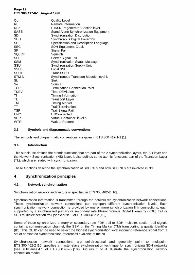
4.3.1 Synchronous Transport Module, level N (STM-N)
The STM-N transport signals carry (in addition to the payload) reference TI and an indication of the QL ofthe source generating this TI, via the SSM as defined in ETS 300 147 [2].
NOTE: Old equipment may not be able to support SSM via their STM-N interfaces.
4.3.2 2 Mbit/s
The 2 Mbit/s transport signals may carry (in addition to the payload) reference TI.
The 2 Mbit/s timing reference signals (without payload) carry reference TI to specific synchronizationports.
Both signals can carry an indication of the QL of the source generating the TI via the SSM as specified inITU-T Recommendation G.704 [14].
NOTE: Old equipment may not be able to support SSM on their 2 Mbit/s interfaces.
4.3.3 2 MHz
Synchronization can be carried through 2 MHz signals to specific synchronization ports (so called stationclock ports). This signal does not carry an indication of the QL of the source generating the TI.
4.3.4 34 Mbit/s and 140 Mbit/s with 125 µs frame structure
34 Mbit/s and 140 Mbit/s signals with 125 µs frame structure as defined in ETS 300 337 [15] carry a full4 bit SSM code.
NOTE: For interworking with equipments compliant with the initial edition of ETS 300 337 [15],new equipments should be able to be configured to recognize and generate the TMwhich is located in bit 8 of the Maintenance and Adaptation (MA) byte: the TM is set to"0" to indicate that the timing source is traceable to a PRC, and is otherwise set to "1".
4.4 Clock-Source Quality-Level
4.4.1 Clock-Source Quality- Level Definitions
The following Clock Source (CS) QLs are defined in the synchronization process of SDH networkcorresponding to 4 levels of synchronization quality (ETS 300 462-2 [10]).
QL-PRC: This synchronization trail transports a timing quality generated by a PRC that isdefined in ETS 300 462-6 [13].
QL-SSU T: This synchronization trail transports a timing quality generated by either a transitslave clock that is defined in ITU-T Recommendation G.812 [18] or a SSU that isdefined in ETS 300 462-4 [11].
QL-SSU L: This synchronization trail transports a timing quality generated by a localslave clock that is defined in ITU-T Recommendation G.812 [18].
QL-SEC: This synchronization trail transports a timing quality generated by a SEC that isdefined in ETS 300 462-5 [12].
QL-DNU: This signal should not be used for synchronization.
NOTE: The QL-unknown QL was defined to characterize the quality of existing network. ThisQL is no longer supported by the SSM algorithm.
Page 16ETS 300 417-6-1: August 1998
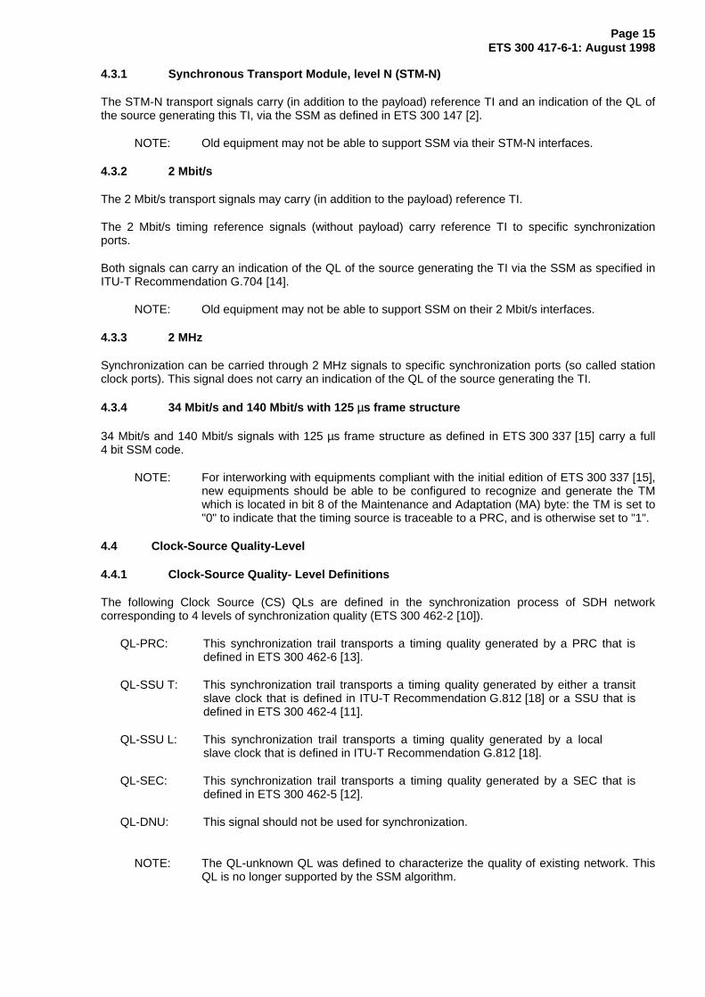
4.4.2 Hierarchy of Clock-Sources Quality Level or (CS_QL)
The following table defines the QL hierarchy.
Table 1: Hierarchy of quality levels
Quality Level (QL) OrderQL-PRC highestQL-SSU T |QL-SSU L |QL-SEC |QL-DNU |QL-INVx, -FAILED, -UNC, -NSUPP lowest
The QLs QL-INVx, QL-FAILED, QL- UNC and QL-NSUPP are internal QLs inside the NE and are nevergenerated at an output port.
QL-INVx is generated by the XX/SD_A_Sk function if an unallocated SSM value is received, where xrepresents the binary value of this SSM.
QL-NSUPP is generated by the XX/SD_A_Sk function when the function is not supporting the SSM TMprocessing.
QL-FAILED is generated by the SD_TT_Sk function when the terminated SD trail is in the Signal Fail (SF)state.
QL-UNC is generated by the SD_C or NS_C function when the output signal is not connected to an input,but instead to the internal unconnected signal generator.
4.4.3 Forcing of Clock-Source Quality-Levels
For synchronization source signals/interfaces not supporting SSM transport/processing, it is possible toforce the QL to a fixed provisioned value. This allows to use these signals/interfaces as synchronizationsources in an automatic reference selection process operating in QL-enabled mode.
Forcing of QLs is used for new equipment operating in QL-enabled mode in order to:
- interwork with old equipment not supporting SSM/TM generation;
- interwork with new equipment operating in QL-disabled mode;
- select interfaces not supporting SSM/TM processing;
- select signals for which SSM/TM is not defined in (2 MHz).
4.5 SSM and TM channels
The following signals have a four bit SSM channel defined:
- STM-N (N = 1, 4, 16): bits 5 to 8 of the byte S1 (called SSMB, SSM Byte) of the multiplex sectionoverhead as defined in ITU-T Recommendation G.707 [4].
- 2 Mbit/s octet structured according to ITU-T Recommendation G.704 [14]: bits Sax1 to Sax4(x = 4, 5, 6, 7, or 8) of TS0.
- 34 Mbit/s as defined in ETS 300 337 [15]: bit 8 of MA byte with a 4 frame multiframe.
- 140 Mbit/s as defined in ETS 300 337 [15]: bit 8 of MA byte with a 4 frame multiframe.
Page 17ETS 300 417-6-1: August 1998
The following signals may have a one bit TM channel:
- 34 Mbit/s with a 125 µs frame structure as defined in ETS 300 337 [16]: bit 8 of byte MA.
- 140 Mbit/s with a 125 µs frame structure as defined in ETS 300 337 [16]: bit 8 of byte MA.
4.5.1 SSM and TM message sets
Five SSM codes are defined to represent CS QL as listed below:
- code 0010 (Quality PRC) means that the source of the trail is a PRC clock (ETS 300 462-6 [13],ITU-T Recommendation G.811 [17]);
- code 0100 (Quality SSU-T), means that the source of the trail is a transit SSU clock(ITU-T Recommendation G.812-T [18]) or a SSU that is defined in ETS 300 462-4 [11];
- code 1000 (Quality SSU-L), means that the source of the trail is a SSU clock(ITU-T Recommendation G.812-L [18]);
- code 1011 (Quality SEC), means that the source of the trail is a SEC clock (ETS 300 462-5 [12],option 1 of ITU-T Recommendation G.813 [19]);
- code 1111 (quality DNU), means that the signal carrying this SSM shall not be used forsynchronization because a timing loop situation could result if it is used.
Two TM codes were defined in ETS 300 337 [15] and [16]:
- code 0 (Quality PRC), means that the source of the trail is a PRC clock (ETS 300 462-6 [13],ITU-T Recommendation G.811 [17]);
- code 1 (Quality less_than_PRC), means that the source of the trail is not a PRC clock.
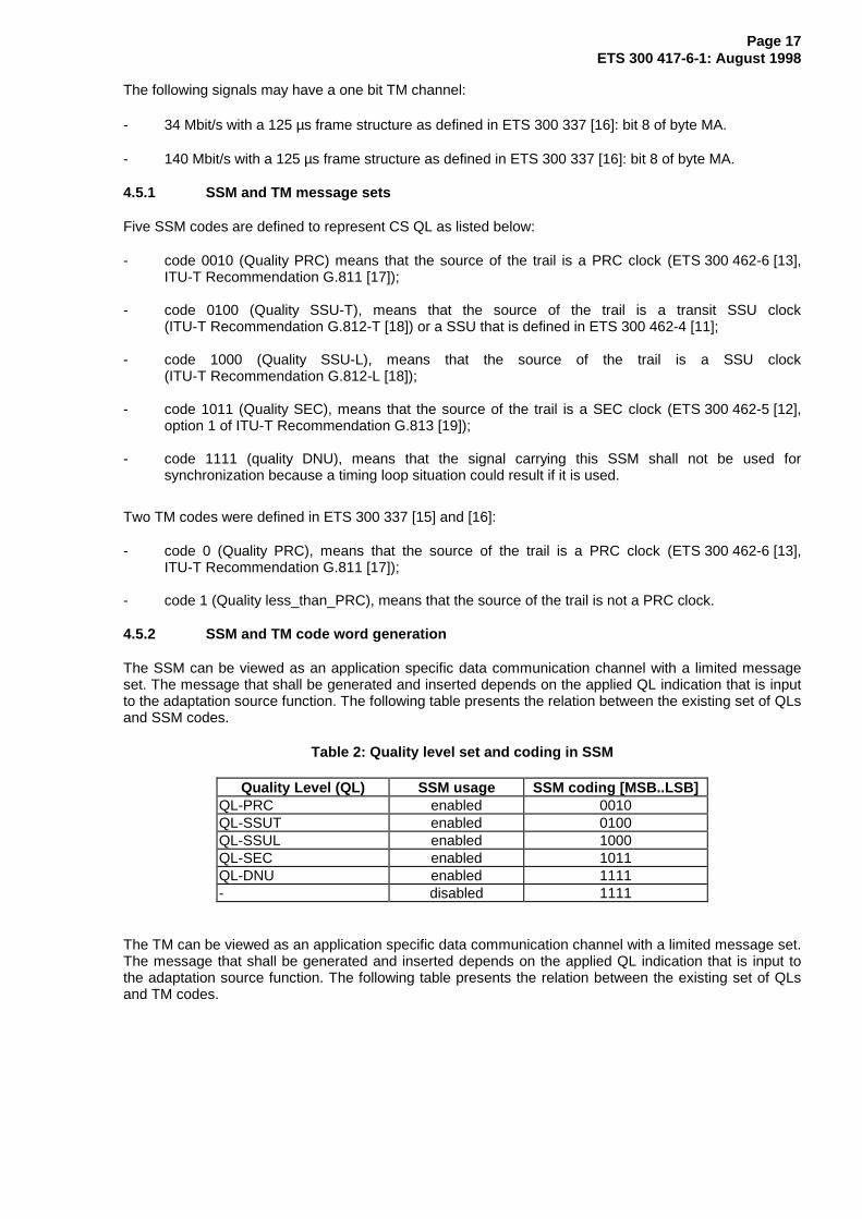
4.5.2 SSM and TM code word generation
The SSM can be viewed as an application specific data communication channel with a limited messageset. The message that shall be generated and inserted depends on the applied QL indication that is inputto the adaptation source function. The following table presents the relation between the existing set of QLsand SSM codes.
Table 2: Quality level set and coding in SSM
Quality Level (QL) SSM usage SSM coding [MSB..LSB]QL-PRC enabled 0010QL-SSUT enabled 0100QL-SSUL enabled 1000QL-SEC enabled 1011QL-DNU enabled 1111- disabled 1111
The TM can be viewed as an application specific data communication channel with a limited message set.The message that shall be generated and inserted depends on the applied QL indication that is input tothe adaptation source function. The following table presents the relation between the existing set of QLsand TM codes.

Page 18ETS 300 417-6-1: August 1998
Table 3: Quality level set and coding in TM
Quality Level (QL) TM usage TM codingQL-PRC enabled 0QL-SSUT enabled 1QL-SSUL enabled 1QL-SEC enabled 1QL-DNU enabled 1- disabled 1
At network boundaries, it should be possible to prevent synchronization information passing the interface.This can be achieved by disabling the SSM (TM) usage.
4.5.3 SSM and TM code word interpretation
At the receive side, the received SSM bits are to be validated by a persistency check and then interpretedto determine the QL.
Table 4: Interpretation of SSM codes
SSM code [MSB..LSB] QL interpretation0000 QL-INV00001 QL-INV10010 QL-PRC0011 QL-INV30100 QL-SSUT0101 QL-INV50110 QL-INV60111 QL-INV71000 QL-SSUL1001 QL-INV91010 QL-INV101011 QL-SEC1100 QL-INV121101 QL-INV131110 QL-INV141111 QL-DNU
Table 5: Interpretation of TM codes
TM code QL interpretation0 QL-PRC1 QL-DNU

Page 19ETS 300 417-6-1: August 1998
4.6 Selection process
The process of selecting a synchronization source from the set of physical ports is performed in threesteps.
physicalports
assigned
sources
nominated sync sources
selection process 1
automatic selected
source
123456:::N
14813
14
1813
nominated sync sources
selection process 2
4
8
(e.g. for internalclock)
(e.g. for stationclock output)
8
automatic selected
sourcefor station
clock output
synchronizationsynchronization synchronization
Figure 6: Visualization of the synchronization source selection process(es)
1) Assignment of a physical port to be a synchronization source: Select a (limited) set of interfacesignals (from the total set of interfaces) to act as synchronization sources.This is performed in the SD_C function by means of adding matrix connections between a group ofinputs (connected to the server layer) and outputs (connected to the SD_TT_Sk functions).
2) Nomination of a synchronization source for an automatic selection process: Select a (sub)set of thesynchronization sources to contribute to a selection process.This is performed in the NS_C function by means of assigning a priority to the synchronizationsource (see subclause 4.10).
3) Automatic Selection Process. Selects the "best" synchronization source of the set from nominatedsources according to the selection algorithm (see subclause 4.12).
NOTE: The specifications in this ETS allow a selection to be made between any set ofsynchronization interface signals input to a NE, independent of the actualsynchronization network architecture deployed in the network. It is the networkoperator’s responsibility to ensure that timing loops are not created.
4.7 Signal fail
SF for a synchronization source is activated in case of defects detected in the server layers. In addition anunconnected synchronization signal has also SF active in order to allow correct processing in the QLdisabled mode. Inclusion of specific synchronization failures (e.g. exceeded frequency deviation,exceeded wander limits) as SF criteria for SSU are for further study.
In order to avoid reactions on short pulses or intermittent SF information, the SF information is passedthrough a hold-off and Wait to Restore (WTR) processes before it is considered by the selection process.
NOTE 1: The delay of the SF information is only performed for the information passed to theselection process. The SF information for the main data path to the output of the NS_Cfunction is not delayed.
Page 20ETS 300 417-6-1: August 1998
In QL enabled mode the QL of a synchronization source with active SF is set to QL-FAILED. The selectionprocess will react to this QL value instead of the SF signal in this mode.
NOTE 2: Due to different persistence times for defect detection and the SSM acceptanceprocess, a defect leading to SF could also result in a change of the QL value shortlybefore SF is activated. The implementation has to ensure that the selection processdoes not select a new synchronization source based on this intermediate QL value.
4.8 Hold-off time
The hold-off time ensures that short activation of SF are not passed to the selection process.
In QL-disabled mode SF shall be active for the hold-off time before it is passed to the selection process.
In QL-enabled mode a QL value of QL-FAILED shall exist for the hold-off time before it is passed to theselection process. In the mean time the previous QL value is passed to the selection process.
NOTE: Other QL values than QL-FAILED will be passed to the selection process immediately.
Separate hold-off timers are used for each input to a selection process (nominated source).
The hold-off time is fixed in the range of 300 ms to 1 800 ms.
4.9 WTR time
The WTR time ensures that a previous failed synchronization source is only again considered as availableby the selection process if it is fault free for a certain time.
In QL-disabled mode after deactivation of SF, it shall be false for the WTR time before SF false is passedto the selection process. In the mean time SF true is passed to the selection process.
In QL-enabled mode after a change of the QL from QL-FAILED to any other value, the quality value shallbe different from QL-FAILED for the WTR time before the new QL value is passed to the selectionprocess. In the mean time the QL QL-FAILED is passed to the selection process.
Separate WTR timers are used for each input to a selection process (nominated source).
The WTR time is configurable in the range of 0 to 12 minutes in steps of 1 minute for all inputs of aselection process in common. The default value is 5 minutes.
Each WTR timer can be cleared with a separate Clear (CLR) command. If a WTR timer is cleared thenew QL value (in QL-enabled mode) or SF value (in QL-disabled mode) is immediately passed to theselection process.
4.10 Synchronization source priorities
In order to define a preferred NS flow, priority values are allocated to assigned synchronization sourceswithin a NE.
Different priorities reflect a preference of one synchronization source over the other. Equalsynchronization source priorities reflect that no preference exists between the synchronization sources.Within the group of synchronization sources with equal priorities the selection process has a non-revertivebehaviour.
A priority of "dis" (disabled) identifies that this assigned synchronization source is not nominated for theselection process.
Page 21ETS 300 417-6-1: August 1998
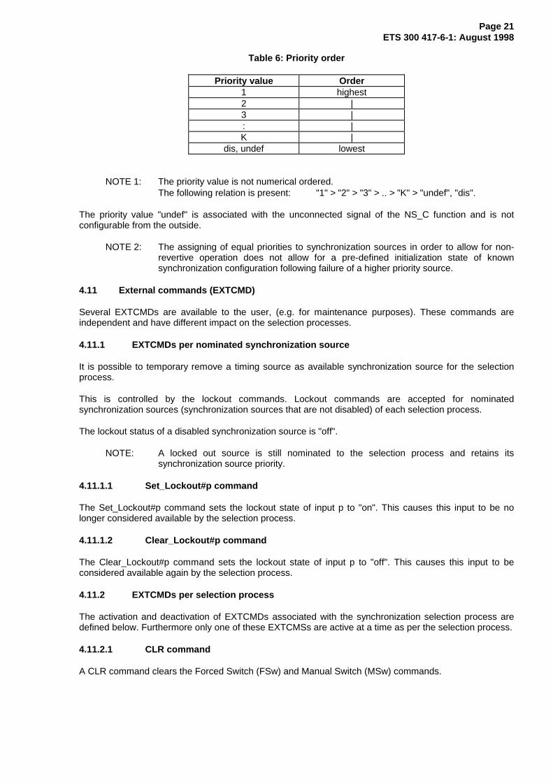
Table 6: Priority order
Priority value Order1 highest2 |3 |: |K |
dis, undef lowest
NOTE 1: The priority value is not numerical ordered.The following relation is present: "1" > "2" > "3" > .. > "K" > "undef", "dis".
The priority value "undef" is associated with the unconnected signal of the NS_C function and is notconfigurable from the outside.
NOTE 2: The assigning of equal priorities to synchronization sources in order to allow for non-revertive operation does not allow for a pre-defined initialization state of knownsynchronization configuration following failure of a higher priority source.
4.11 External commands (EXTCMD)
Several EXTCMDs are available to the user, (e.g. for maintenance purposes). These commands areindependent and have different impact on the selection processes.
4.11.1 EXTCMDs per nominated synchronization source
It is possible to temporary remove a timing source as available synchronization source for the selectionprocess.
This is controlled by the lockout commands. Lockout commands are accepted for nominatedsynchronization sources (synchronization sources that are not disabled) of each selection process.
The lockout status of a disabled synchronization source is "off".
NOTE: A locked out source is still nominated to the selection process and retains itssynchronization source priority.
4.11.1.1 Set_Lockout#p command
The Set_Lockout#p command sets the lockout state of input p to "on". This causes this input to be nolonger considered available by the selection process.
4.11.1.2 Clear_Lockout#p command
The Clear_Lockout#p command sets the lockout state of input p to "off". This causes this input to beconsidered available again by the selection process.
4.11.2 EXTCMDs per selection process
The activation and deactivation of EXTCMDs associated with the synchronization selection process aredefined below. Furthermore only one of these EXTCMSs are active at a time as per the selection process.
4.11.2.1 CLR command
A CLR command clears the Forced Switch (FSw) and Manual Switch (MSw) commands.

Page 22ETS 300 417-6-1: August 1998
4.11.2.2 Forced switch #p command
A FSw to #p command can be used to override the currently selected synchronization source, assumingthe synchronization source #p is enabled and not locked out.
The FSw overrides the MSw and a subsequent FSw pre-empts the previous FSw.
If the source selected by the FSw command (#p) is disabled or locked out, the FSw command isautomatically rejected.
The FSw command can be cleared by the CLR command.
NOTE: A FSw command to a synchronization source #p which is in the SF state or has a QLof DNU in QL enabled mode, will result in the NE entering holdover.
4.11.2.3 Manual switch #p command
A MSw to #p command selects the synchronization source #p, assuming it is enabled, not locked out, notin SF condition, and has a QL better than DNU in QL enabled mode. Furthermore in the QL enabledmode, a MSw can be performed only to a source which has the highest available QL. As such, theseconditions have the effect that manual switching can only be used to override the assignedsynchronization source priorities.
A MSw request overrides a previous MSw request.
If the source selected by the MSw command (#p) is disabled, locked out, in SF, or has a QL of DNU orlower than one of the other source signals, the MSw command is automatically rejected.
The MSw command can be cleared by the CLR command.
4.12 Automatic reference selection process
One or more reference selection processes are operating independently to select the reference signal forthe internal clock and, where present, the station clock output(s). However the SD connection functiondelivering SD_CI to the station clock output atomic functions (see figure 15) is only operated by operatorcommand and not by an automatic process.
The selection process(es) can work in two distinct modes: QL-enabled, QL-disabled. If multiple selectionprocesses are present in a NE, all processes work in the same mode.
The following is a brief description of the automatic reference selection process. The specific details(Specification and Description Language (SDL) diagrams) are defined in annex A.
4.12.1 QL-enabled mode
In QL-enabled mode the following parameters contribute to the selection process:
- QL;- SF via QL-failed;- priority;- EXTCMDs.
If no overriding EXTCMDs are active, the algorithm selects the reference with the highest QL, which is notexperiencing a SF condition. If multiple inputs have the same highest QL, the input with the highest priorityis selected. For the case that multiple inputs have the same highest priority and QL, the current existingselected reference is maintained if it belongs to this group, otherwise an arbitrary reference from thisgroup is selected.
If no input could be selected, the function outputs the unconnected signal.
Page 23ETS 300 417-6-1: August 1998
4.12.2 QL-disabled mode
In QL-disabled mode the following parameters contribute to the selection process:
- SF;- priority;- EXTCMDs.
If no overriding EXTCMDs are active, the algorithm selects the reference with the highest priority which isnot experiencing a SF condition. For the case that multiple inputs have the same highest priority, thecurrent existing selected reference is maintained if it belongs to this group, otherwise an arbitraryreference from this group is selected.
If no input could be selected, the function outputs the unconnected signal.
4.13 Timing loop prevention
4.13.1 Station clock input used as a source for station clock output
This specification allows the use of the station clock input as a source for the station clock output, eitherdirectly or via the SEC. When this functionality is present in a NE, the operator should be aware that thisfunctionality is intended for timing quality monitoring purposes and that its use for other purposes couldresult in timing loops being created. If a timing loop could be created, the operator should prevent that bya reconfiguration of the synchronization architecture.
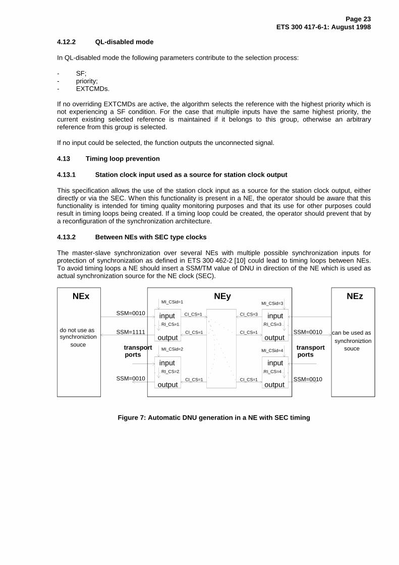
4.13.2 Between NEs with SEC type clocks
The master-slave synchronization over several NEs with multiple possible synchronization inputs forprotection of synchronization as defined in ETS 300 462-2 [10] could lead to timing loops between NEs.To avoid timing loops a NE should insert a SSM/TM value of DNU in direction of the NE which is used asactual synchronization source for the NE clock (SEC).
inputRI_CS=1
output
MI_CSid=1
CI_CS=1
CI_CS=1
inputRI_CS=2
output
MI_CSid=2
inputRI_CS=3
output
MI_CSid=3
inputRI_CS=4
output
MI_CSid=4
SSM=0010
SSM=0010 SSM=0010
SSM=0010SSM=1111
NEyNEx NEz
do not use assynchroniztion
can be used as
transportports
transportports
CI_CS=1 CI_CS=1
CI_CS=3
CI_CS=1
soucesynchroniztion
souce
Figure 7: Automatic DNU generation in a NE with SEC timing
Page 24ETS 300 417-6-1: August 1998
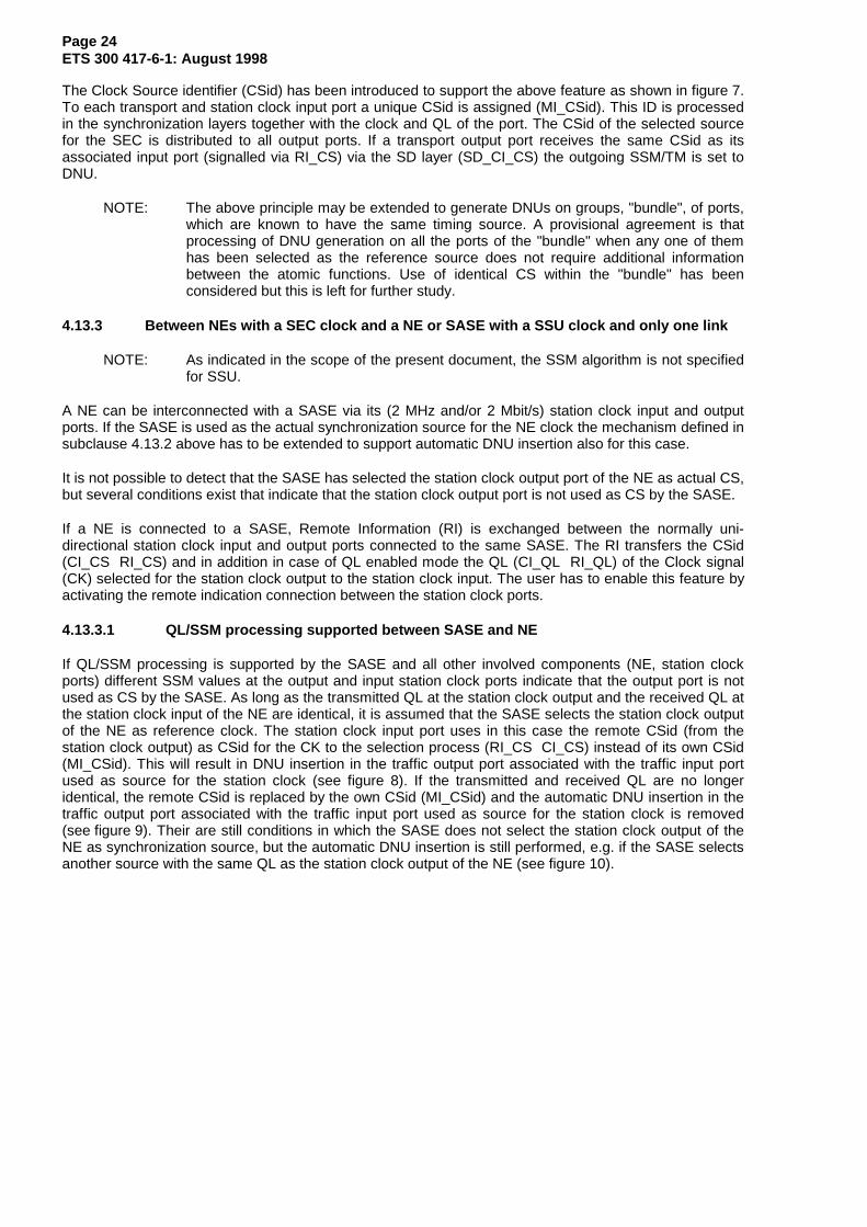
The Clock Source identifier (CSid) has been introduced to support the above feature as shown in figure 7.To each transport and station clock input port a unique CSid is assigned (MI_CSid). This ID is processedin the synchronization layers together with the clock and QL of the port. The CSid of the selected sourcefor the SEC is distributed to all output ports. If a transport output port receives the same CSid as itsassociated input port (signalled via RI_CS) via the SD layer (SD_CI_CS) the outgoing SSM/TM is set toDNU.
NOTE: The above principle may be extended to generate DNUs on groups, "bundle", of ports,which are known to have the same timing source. A provisional agreement is thatprocessing of DNU generation on all the ports of the "bundle" when any one of themhas been selected as the reference source does not require additional informationbetween the atomic functions. Use of identical CS within the "bundle" has beenconsidered but this is left for further study.
4.13.3 Between NEs with a SEC clock and a NE or SASE with a SSU clock and only one link
NOTE: As indicated in the scope of the present document, the SSM algorithm is not specifiedfor SSU.
A NE can be interconnected with a SASE via its (2 MHz and/or 2 Mbit/s) station clock input and outputports. If the SASE is used as the actual synchronization source for the NE clock the mechanism defined insubclause 4.13.2 above has to be extended to support automatic DNU insertion also for this case.
It is not possible to detect that the SASE has selected the station clock output port of the NE as actual CS,but several conditions exist that indicate that the station clock output port is not used as CS by the SASE.
If a NE is connected to a SASE, Remote Information (RI) is exchanged between the normally uni-directional station clock input and output ports connected to the same SASE. The RI transfers the CSid(CI_CS RI_CS) and in addition in case of QL enabled mode the QL (CI_QL RI_QL) of the Clock signal(CK) selected for the station clock output to the station clock input. The user has to enable this feature byactivating the remote indication connection between the station clock ports.
4.13.3.1 QL/SSM processing supported between SASE and NE
If QL/SSM processing is supported by the SASE and all other involved components (NE, station clockports) different SSM values at the output and input station clock ports indicate that the output port is notused as CS by the SASE. As long as the transmitted QL at the station clock output and the received QL atthe station clock input of the NE are identical, it is assumed that the SASE selects the station clock outputof the NE as reference clock. The station clock input port uses in this case the remote CSid (from thestation clock output) as CSid for the CK to the selection process (RI_CS CI_CS) instead of its own CSid(MI_CSid). This will result in DNU insertion in the traffic output port associated with the traffic input portused as source for the station clock (see figure 8). If the transmitted and received QL are no longeridentical, the remote CSid is replaced by the own CSid (MI_CSid) and the automatic DNU insertion in thetraffic output port associated with the traffic input port used as source for the station clock is removed(see figure 9). Their are still conditions in which the SASE does not select the station clock output of theNE as synchronization source, but the automatic DNU insertion is still performed, e.g. if the SASE selectsanother source with the same QL as the station clock output of the NE (see figure 10).

Page 25ETS 300 417-6-1: August 1998
output output
input
output
MI_CSid=1
CI_CS=1
input
input
output
input
SSM=0010
SSM=0010 SSM=0010
SSM=0010SSM=1111
NEy
NEx NEz
do not use as can be used as
outp
ut
inpu
t
SASE
SSM=0010 SSM=0010station clock
ports
transportports
transportports
MI_CSid=2 MI_CSid=4
MI_CSid=3
MI_CSid=5
CI_CS=1
CI_CS=1 CI_CS=1
CI_CS=1
CI_CS=3
CI_CS=1CI_CS=1
RI_CS=1
RI_CS=1
RI_CS=2
RI_CS=3
RI_CS=4
RI_QL=PRC
synchronizationsource
synchronizationsource
Figure 8: Automatic DNU generation in a NE with SASE timing (SSM/QL supported)
input
output
MI_CSid=1
CI_CS=1
input
output
input
output
input
output
SSM=1011
SSM=0010 SSM=0010
SSM=0010SSM=0010
NEy
NEx NEz
can be used as
outp
ut
inpu
t
SASE
SSM=1011 SSM=0010station clock
ports
transportports
transportports
MI_CSid=2 MI_CSid=4
MI_CSid=3
MI_CSid=5
CI_CS=5
CI_CS=5 CI_CS=5
CI_CS=5
CI_CS=3
CI_CS=5CI_CS=1
RI_CS=1
RI_CS=1
RI_CS=2
RI_CS=3
RI_CS=4
RI_QL=SEC
SSM=0010
can be used assynchronization
source sourcesynchronization
Figure 9: Removal of automatic DNU generation in a NE with SASE timing (SSM/QL supported)

Page 26ETS 300 417-6-1: August 1998
do not used as
synchronization
input
output
MI_CSid=1
CI_CS=1
input
output
input
output
input
output
SSM=0010
SSM=0010 SSM=0010
SSM=0010SSM=1111
NEy
NEx NEz
can be used as
outp
ut
inpu
t
SASE
SSM=0010 SSM=0010station clock
ports
transportports
transportports
MI_CSid=2 MI_CSid=4
MI_CSid=3
MI_CSid=5
CI_CS=1
CI_CS=1 CI_CS=1
CI_CS=1
CI_CS=3
CI_CS=1CI_CS=1
RI_CS=1
RI_CS=1
RI_CS=2
RI_CS=3
RI_CS=4
RI_QL=SEC
SSM=0010
source sourcesynchronization
Figure 10: Limitation of automatic DNU generation in a NE with SASE timing (SSM/QL supported)
4.13.3.2 QL/SSM processing not supported between SASE and NE
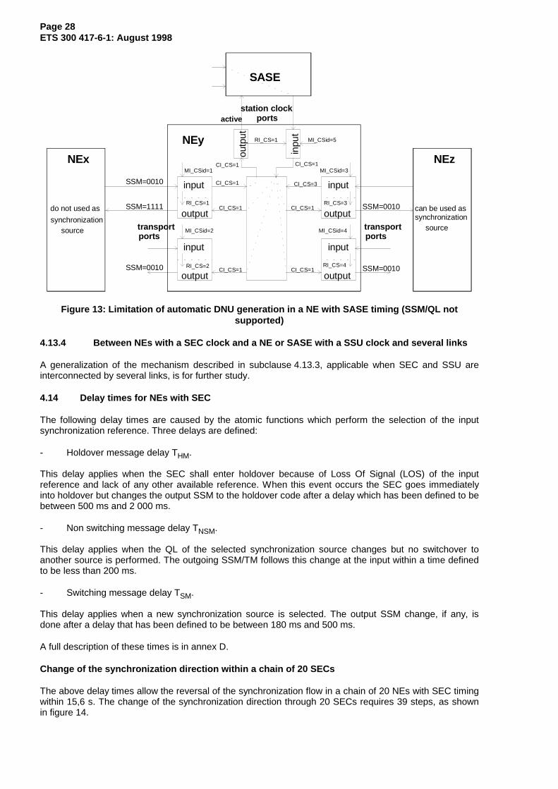
If QL/SSM processing is not supported by the SASE, station clock ports or NE, a squelched/AIS stationclock output port is the only criteria that indicates that the output port is not used as CS by the SASE. Aslong as the station clock output is not squelched (for 2 MHz station clock ports) or set to AIS (for 2 Mbit/sstation clock ports), it is assumed that the SASE selects the station clock output of the NE as referenceclock. The station clock input port uses in this case the remote CSid (from the station clock output) asCSid for the CK to the selection process (RI_CS CI_CS) instead of its own CSid (MI_CSid). This willresult in DNU insertion in the traffic output port associated with the traffic input port used as source for thestation clock (see figure 11). If the station clock output is squelched or set to AIS, the remote CSid isreplaced by the own CSid (MI_CSid) and the automatic DNU insertion in the traffic output port associatedwith the traffic input port used as source for the station clock is removed (see figure 12). Their are stillconditions in which the SASE does not select the station clock output of the NE as synchronizationsource, but the automatic DNU insertion is still performed, e.g. if the SASE selects another source if thestation clock output is still transmitting valid TI (see figure 13).

Page 27ETS 300 417-6-1: August 1998
input
output
MI_CSid=1
CI_CS=1
input
output
input
output
input
output
SSM=0010
SSM=0010 SSM=0010
SSM=0010SSM=1111
NEy
NEx NEz
do not use as can be used as
outp
ut
inpu
t
SASE
station clockports
transportports
transportports
MI_CSid=2 MI_CSid=4
MI_CSid=3
MI_CSid=5
CI_CS=1
CI_CS=1 CI_CS=1
CI_CS=1
CI_CS=3
CI_CS=1CI_CS=1
RI_CS=1
RI_CS=1
RI_CS=2
RI_CS=3
RI_CS=4
synchronizationsource
synchronizationsource
active
Figure 11: Automatic DNU generation in a NE with SASE timing (SSM/QL not supported)
input
output
MI_CSid=1
CI_CS=1
input
output
input
output
input
output
SSM=1011
SSM=0010 SSM=0010
SSM=0010SSM=0010
NEy
NEx NEz
can be used as
outp
ut
inpu
t
SASE
station clockports
transportports
transportports
MI_CSid=2 MI_CSid=4
MI_CSid=3
MI_CSid=5
CI_CS=5
CI_CS=5 CI_CS=5
CI_CS=5
CI_CS=3
CI_CS=5CI_CS=1
RI_CS=none
RI_CS=1
RI_CS=2
RI_CS=3
RI_CS=4
can be used assynchronization
source sourcesynchronization
squelched/AIS
Figure 12: Removal of automatic DNU generation in a NE with SASE timing (SSM/QL notsupported)
Page 28ETS 300 417-6-1: August 1998
input
output
MI_CSid=1
CI_CS=1
input
output
input
output
input
output
SSM=0010
SSM=0010 SSM=0010
SSM=0010SSM=1111
NEy
NEx NEz
can be used as
outp
ut
inpu
t
SASE
station clockports
transportports
transportports
MI_CSid=2 MI_CSid=4
MI_CSid=3
MI_CSid=5
CI_CS=1
CI_CS=1 CI_CS=1
CI_CS=1
CI_CS=3
CI_CS=1CI_CS=1
RI_CS=1
RI_CS=1
RI_CS=2
RI_CS=3
RI_CS=4
do not used as
synchronizationsource source
synchronization
active
Figure 13: Limitation of automatic DNU generation in a NE with SASE timing (SSM/QL notsupported)
4.13.4 Between NEs with a SEC clock and a NE or SASE with a SSU clock and several links
A generalization of the mechanism described in subclause 4.13.3, applicable when SEC and SSU areinterconnected by several links, is for further study.
4.14 Delay times for NEs with SEC
The following delay times are caused by the atomic functions which perform the selection of the inputsynchronization reference. Three delays are defined:
- Holdover message delay THM.
This delay applies when the SEC shall enter holdover because of Loss Of Signal (LOS) of the inputreference and lack of any other available reference. When this event occurs the SEC goes immediatelyinto holdover but changes the output SSM to the holdover code after a delay which has been defined to bebetween 500 ms and 2 000 ms.
- Non switching message delay TNSM.
This delay applies when the QL of the selected synchronization source changes but no switchover toanother source is performed. The outgoing SSM/TM follows this change at the input within a time definedto be less than 200 ms.
- Switching message delay TSM.
This delay applies when a new synchronization source is selected. The output SSM change, if any, isdone after a delay that has been defined to be between 180 ms and 500 ms.
A full description of these times is in annex D.
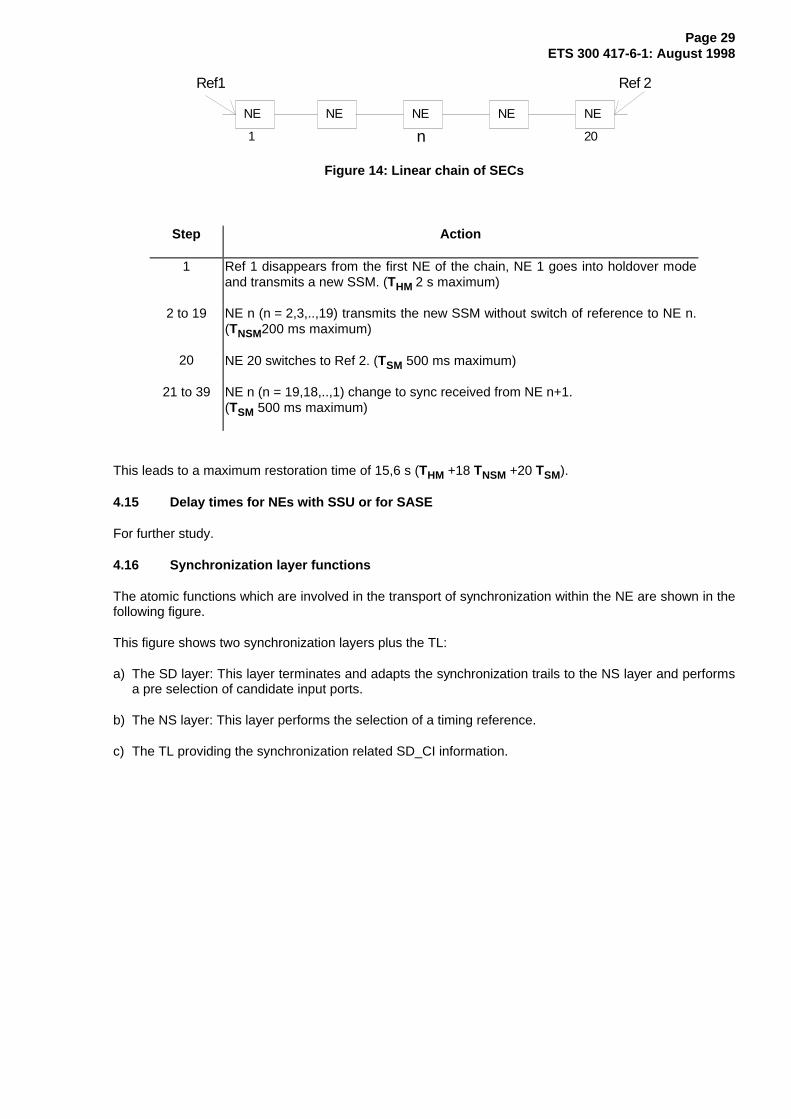
Change of the synchronization direction within a chain of 20 SECs
The above delay times allow the reversal of the synchronization flow in a chain of 20 NEs with SEC timingwithin 15,6 s. The change of the synchronization direction through 20 SECs requires 39 steps, as shownin figure 14.
Page 29ETS 300 417-6-1: August 1998
NE NENE NE NE
Ref1 Ref 2
201 n
Figure 14: Linear chain of SECs
Step Action
1 Ref 1 disappears from the first NE of the chain, NE 1 goes into holdover modeand transmits a new SSM. (THM 2 s maximum)
2 to 19 NE n (n = 2,3,..,19) transmits the new SSM without switch of reference to NE n.(TNSM200 ms maximum)
20 NE 20 switches to Ref 2. (TSM 500 ms maximum)
21 to 39 NE n (n = 19,18,..,1) change to sync received from NE n+1.(TSM 500 ms maximum)
This leads to a maximum restoration time of 15,6 s (THM +18 TNSM +20 TSM).
4.15 Delay times for NEs with SSU or for SASE
For further study.
4.16 Synchronization layer functions
The atomic functions which are involved in the transport of synchronization within the NE are shown in thefollowing figure.
This figure shows two synchronization layers plus the TL:
a) The SD layer: This layer terminates and adapts the synchronization trails to the NS layer and performsa pre selection of candidate input ports.
b) The NS layer: This layer performs the selection of a timing reference.
c) The TL providing the synchronization related SD_CI information.

Page 30ETS 300 417-6-1: August 1998
SD/NS
SD SD
SD/NS-SEC SD/NS-SSU
SD
SD
Network
layer
Distributionlayer
SD
NS
to stationclock output(s)
for internal NEsync distribution
SD/NS-SECSD/NS-SSU
SD_CISD_CI
SD_CI
SD_AI
NS_CI NS_CI
NS_CI NS_CINS_CI
SD_AI
SD_CI
SD_CI
SD_AI
MSn/SD P*s/SD MSn-LC P*s-LC Sn-LCTransport
Layers
MSn/SD P*s/SD P12s/SD
MSn_AI P*s_AI P12s_AI
P12s/SD T12/SD
P12s_AI T12_AI P*s_AIMSn_AI MSn_TI Sn_TIP*s_TI
to transportoutput(s)
layer timing
T12/SD
T12_AI
from stationclock input(s)
from trafficinputs(s)
SD_CI
SD-PRC
the position ofSD-PRC is forfurther study
T12-LC
T12_TI
P12s-LC
P12s_TI
Synchronization
Synchronization
Figure 15: SD and NS layer atomic functions
The relation between the current naming of synchronization signals in ITU-T Recommendation G.783 [5]and in ETS 300 417-1-1 [1] is shown on the following table.
Table 7: Naming of synchronization signals
ITU-T RecommendationG.783 [5] naming
ETS 300 417-1-1 [1] naming
T0 SD_CI signal for internal NE sync distributionT1 SD_CI signal derived from an STM-N (OSn/RSn/MSn) signalT2 SD_CI signal derived from a 2 Mbit/s (E12/P12s) traffic carrying signalT3 SD_CI signal derived from a 2 MHz station clock (T12) input signalT4 SD_CI signal towards a 2 MHz station clock (T12) output signalno name SD_CI signal derived from a 34 Mbit/s synchronous (E31/P31s) signalno name SD_CI signal derived from a 140 Mbit/s synchronous (E4/P4s) signalno name SD_CI signal towards a 2 Mbit/s station clock (E12/P12s) output signalno name SD_CI signal derived from a 2 Mbit/s station clock (E12/P12s) signal
4.17 Overview of the processes performed within the atomic functions
A list of the synchronization atomic functions and a short description of their functionality is given intable 8. For a more detailed description see clauses 5 to 8.

Page 31ETS 300 417-6-1: August 1998
Table 8: Functional overview of atomic functions
Atomic function FunctionalityXX-LC_A_So Generation of the layer timingXX/SD_A_Sk Access to reference clock.
SSM(TM) acceptance and extraction of QL.Generate QL-NotSupported if signal does not support SSM.Generation of CS.
XX/SD_A_So Insertion of QL into SSM(TM).Generate QL-DNU or Squelch to prevent timing loops.
SD_C Preselection of transport interfaces as possible synchronization sources.Selection of sources for the station clock outputs.
SD_TT_Sk Report of QL to management.Manual insertion of a fixed QL value.
SD_TT_So None.SD/NS-SEC_A_Sk None.SD/NS-SSU_A_Sk For further study.SD/NS_A_So Generation of the clock, for the station clock outputs from the selected
synchronization reference.SD/NS-SEC_A_So Generation of holdover, locked and free running modes timings.
Generation of the NE clock (SEC type), locked to the selectedsynchronization reference.
SD/NS-SSU_A_So Generation of the NE clock (SSU type), locked to the selectedsynchronization reference.The functionality and the position is for further study.
SD/NS-PRC_A_So Generation of the NE clock (PRC) type.The functionality and the position is for further study.
NS_C Selection of synchronization reference sources.
5 Synchronization distribution layer atomic functions
S D /N S
SD S D
S D /NS -S E C SD/N S -S SU S D -P R C
S D
S D
SD /NS -S ECS D /NS- SSU
S D_ CI S D _C I
SD_C I
S D _A I
NS _C I NS _C I N S _C I N S_ CINS _C I
S D _A I
S D_C I S D_C I
S D_A I
SD
Figure 16: SD layer atomic functions
SD Layer CP
The CI at this point is a CK with associated server SF, QL and CSid.
SD Layer Access Point (AP)
The Adaptation Information (AI) at this point is a CK with associated trail SF, QL and CSid.

Page 32ETS 300 417-6-1: August 1998
5.1 SD Connection function (SD_C)
Symbol:
SD
SD_CI
SD_C_MI
SD_CI
Figure 17: SD_C symbol
Interfaces:
Table 9: SD_C input and output signals
Input(s) Output(s)per SD_CI, n x for the function:SD_CI_CKSD_CI_QLSD_CI_SSFSD_CI_CSper input output CPSD_C_MI_ConnectionPortIds
per SD_CI, m x for the function:SD_CI_CKSD_CI_QLSD_CI_SSFSD_CI_CS
Processes:
In the SD_C function SD Layer CI is routed between input Termination Connection Points (TCPs) andoutput TCPs by means of matrix connections.
NOTE 1: Neither the number of input/output signals to the connection function, nor theconnectivity is specified in this ETS. That is a property of individual NEs.
Routing: The function shall be able to connect a specific input with a specific output by means ofestablishing a matrix connection between the specified input and output. It shall be able to remove anestablished matrix connection.
NOTE 2: Broadcast connections are handled as separate connections to the same input CP.
Unconnected SD signal generation: The function shall generate an unconnected SD signal, specified as:SSF true, CS value None, QL value QL-UNC and undefined clock.
NOTE 3: The unconnected signal is a logical signal defined for the purpose of this formalspecification; it is not observable at any of the NEs transport interfaces.
Defects: None.
Consequent actions:
If an output of this function is not connected to one of its inputs, the function shall connect theunconnected SD signal to the output.

Page 33ETS 300 417-6-1: August 1998
Defect correlations: None.
Performance monitoring: None.
5.2 SD Trail Termination (TT) functions
5.2.1 SD TT source function (SD_TT_So)
Symbol:
SD
SD_AI
SD_CI
Figure 18: SD_TT_So symbol
Interfaces:
Table 10: SD_TT_So input and output signals
Input(s) Output(s)SD_AI_CKSD_AI_QLSD_AI_CSSD_AI_TSF
SD_CI_CKSD_CI_QLSD_CI_CSSD_CI_SSF
Processes:
Output SD_CI_CK is derived from and locked to SD_AI_CK.
Defects: None.
Consequent actions:
aSSF ← AI_TSF
Defect correlations: None.
Performance monitoring: None.

Page 34ETS 300 417-6-1: August 1998
5.2.2 SD TT sink function (SD_TT_Sk)
Symbol:
SD
SD_AI
S D _C I
SD_TT_Sk_MI
Figure 19: SD_TT_Sk symbol
Interfaces:
Table 11: SD_TT_Sk input and output signals
Input(s) Output(s)SD_CI_CKSD_CI_QLSD_CI_SSFSD_CI_CSSD_TT_Sk_MI_QLoverwriteSD_TT_Sk_MI_QLfixedValueSD_TT_Sk_MI_QLmodeSD_TT_Sk_MI_TpmodeSD_TT_Sk_MI_SSF_Reported
SD_AI_CKSD_AI_QLSD_AI_TSFSD_AI_CSSD_TT_Sk_MI_cSSFSD_TT_Sk_MI_QL
Processes:
This function terminates a synchronization trail transmitted via one of the synchronization information’sTLs, processes and reports the incoming quality. It can operate in QL-enabled mode and QL-disabledmode.
QL-disabled mode:
In QL disabled mode the function shall report the status of the trail (MI_cSSF).
QL-enabled mode:
In QL-enabled mode the function shall report the status of the trail (MI_cSSF) and the incoming QL value(CI_QL) via MI_QL.
In QL-enabled mode AI_CS=CI_CS, in pass-through and overwrite operations.
The function shall support the ability to pass through or overwrite the incoming QL information.
Pass through:
The QL output (AI_QL) shall be related to the QL input (CI_QL) signal as specified in clause 4.
Page 35ETS 300 417-6-1: August 1998
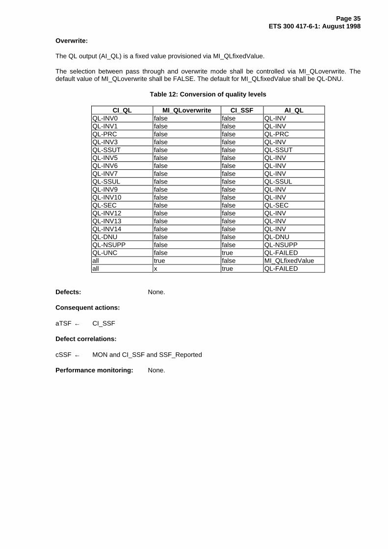
Overwrite:
The QL output (AI_QL) is a fixed value provisioned via MI_QLfixedValue.
The selection between pass through and overwrite mode shall be controlled via MI_QLoverwrite. Thedefault value of MI_QLoverwrite shall be FALSE. The default for MI_QLfixedValue shall be QL-DNU.
Table 12: Conversion of quality levels
CI_QL MI_QLoverwrite CI_SSF AI_QLQL-INV0 false false QL-INVQL-INV1 false false QL-INVQL-PRC false false QL-PRCQL-INV3 false false QL-INVQL-SSUT false false QL-SSUTQL-INV5 false false QL-INVQL-INV6 false false QL-INVQL-INV7 false false QL-INVQL-SSUL false false QL-SSULQL-INV9 false false QL-INVQL-INV10 false false QL-INVQL-SEC false false QL-SECQL-INV12 false false QL-INVQL-INV13 false false QL-INVQL-INV14 false false QL-INVQL-DNU false false QL-DNUQL-NSUPP false false QL-NSUPPQL-UNC false true QL-FAILEDall true false MI_QLfixedValueall x true QL-FAILED
Defects: None.
Consequent actions:
aTSF ← CI_SSF
Defect correlations:
cSSF ← MON and CI_SSF and SSF_Reported
Performance monitoring: None.
Page 36ETS 300 417-6-1: August 1998
5.3 SD adaptation functions
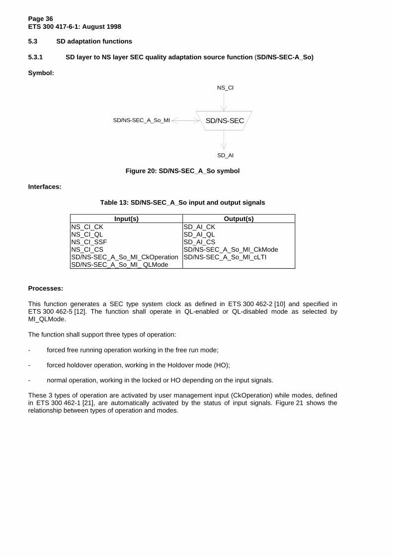
5.3.1 SD layer to NS layer SEC quality adaptation source function (SD/NS-SEC-A_So)
Symbol:
SD/NS-SEC
NS_CI
SD_AI
SD/NS-SEC_A_So_MI
Figure 20: SD/NS-SEC_A_So symbol
Interfaces:
Table 13: SD/NS-SEC_A_So input and output signals
Input(s) Output(s)NS_CI_CKNS_CI_QLNS_CI_SSFNS_CI_CSSD/NS-SEC_A_So_MI_CkOperationSD/NS-SEC_A_So_MI_ QLMode
SD_AI_CKSD_AI_QLSD_AI_CSSD/NS-SEC_A_So_MI_CkModeSD/NS-SEC_A_So_MI_cLTI
Processes:
This function generates a SEC type system clock as defined in ETS 300 462-2 [10] and specified inETS 300 462-5 [12]. The function shall operate in QL-enabled or QL-disabled mode as selected byMI_QLMode.
The function shall support three types of operation:
- forced free running operation working in the free run mode;
- forced holdover operation, working in the Holdover mode (HO);
- normal operation, working in the locked or HO depending on the input signals.
These 3 types of operation are activated by user management input (CkOperation) while modes, definedin ETS 300 462-1 [21], are automatically activated by the status of input signals. Figure 21 shows therelationship between types of operation and modes.

Page 37ETS 300 417-6-1: August 1998
Free-Runnin g
Hold-over
mode
Free-Runnin g
Locked-mode
Locked-mode
Hold-overmode
AUTO SELECTION
OPERATION
FORCED HOLDOVER
OPERATION
FORCED FREE-RUN
OPERATION
MI_CkOperat ion=forced_holdover
(reset holdovermemory)
MI_CkOperat ion=auto_select
MI_CkOperat ion=auto_select
MI_CkOperat ion=forced_freerun
MI_CkOperat ion=forced_freerun
Timeout(holdover acquisit ion t ime)
MI_CkOperat ion=forced_holdover
source_available
source_available
source_fail
(Holdover memoryacquired)
(acquiring holdovermemory)
source_fail
P ow er up
Figure 21: Operational types
Bandwidth, transients, pull in and pull out ranges, noise, input and output jitter for Locked Mode (LO)operation, holdover accuracy and output phase deviation for HO operation, frequency accuracy,transients, noise and output jitter for freerun mode operation shall be as specified in ETS 300 462-5 [12].
Forced Free-running operation:
This type of operation is activated by a management command, the equipment is in free run mode.
- Clock generation:
The outgoing clock (AI_CK) is not defined by an incoming reference or stored incoming referencedata in the holdover memory. The hold-over memory is reset to a default value.
- QL processing (in QL-enabled mode):
The outgoing QL of the free running mode is QL-SEC.
- CS processing:
The outgoing CS of the free running mode is None.
Page 38ETS 300 417-6-1: August 1998
Forced holdover operation:
This type of operation is activated by a management command, the equipment is in HO.
- Clock generation:
The outgoing clock (AI_CK) is defined by stored reference data in the holdover memory.
- QL processing (in QL-enabled mode):
The outgoing QL of the HO is QL-SEC.
- CS processing:
The outgoing CS of the HO is None.
Auto selection operation:
This type of operation is activated by a management command.
- Clock generation:
The auto selection operation works according two modes, locked and holdover:
- LO:
In the LO the outgoing clock (AI_CK) is locked to the incoming reference clock (CI_CK) andthe holdover memory is constantly updated with this reference clock.As shown on figure 21, some time is required before the holdover memory is acquired.
- HO:
The HO conforms to the HO defined above. The holdover memory is no longer updated bythe incoming reference clock.
The selection between the two modes is done automatically depending on the quality of theincoming reference signal and the selected QL Mode.
- QL-enabled mode:
The LO is selected if the incoming reference is not in the SF state and the QL of the incomingreference is better or equal to QL-SEC.
The HO is selected without delay when the incoming reference goes into the SF state or the QL ofthe incoming signal is lower than QL-SEC.
The HO is left when both the SF state and the QL of the incoming signal is equal or better than QL-SEC.
- QL-disabled mode:
The LO is selected if the incoming reference is not in the SF state.
The HO is selected when the incoming reference goes into the SF state.
The actual mode is reported to the management (MI_CkMode).
- QL processing (in QL-enabled mode):
If the function is in the LO the outgoing QL follows the incoming QL.
In case of a change of the selected synchronization source (which is detected by a change ofthe incoming CS), the outgoing QL shall be set to the new incoming QL after the settling timets, to allow the internal oscillator to adjust to a possible frequency change.

Page 39ETS 300 417-6-1: August 1998
If the incoming QL changes without a change of the selected synchronization source (nochange of the CI_CS), the outgoing QL shall follow without settling time.
If the function is in the HO, the outgoing QL shall be set to QL-SEC as soon as the incomingCS value is "None" or if the incoming QL is too low (NS_CI_QL<"QL-SEC").
After leaving the HO, the outgoing QL shall be set to the new incoming QL after the settlingtime ts.
The settling time ts shall be in the range of 180 ms to 300 ms.
- CS processing:
Normally the outgoing CS shall follow the incoming CS immediately.
If the function is in the HO due to a too low QL value of the selected source (NS_CI_QL<"QL-SEC"), the outgoing CS shall be set to "None".
Defects:
The function shall detect a Loss of Timing Inputs (dLTI) if a unconnected signal is present at its CP (noinput selected in NS_C) or if the input signal is failed (CI_SSF active). The defect is raised ifCI_SSF = "true" or CI_CS = "None" for at least X seconds. The defect is cleared if CI_SSF = "false" andCI_CS≠"None" for at least Y seconds. The values of X and Y are for further study.
Consequent actions: None.
Defect correlation:
cLTI ← dLTI
Performance monitoring: None.
5.3.2 SD layer to NS layer SEC quality adaptation sink function (SD/NS-SEC_A_Sk)
Symbol:
NS_CI
SD_AI
SD/NS-SEC
Figure 22: SD/NS-SEC_A_Sk symbol
Interfaces:
Table 14: SD/NS-SEC_A_Sk input and output signals
Input(s) Output(s)SD_AI_CKSD_AI_QLSD_AI_TSFSD_AI_CS
NS_CI_CKNS_CI_QLNS_CI_SSFNS_CI_CS

Page 40ETS 300 417-6-1: August 1998
Processes:
This function connects input with output only. Currently no processes are defined within this function.
Defects: None.
Consequent actions:
aSSF ← AI_TSF
Defect Correlation: None.
Performance monitoring: None.
5.3.3 SD layer to NS layer SSU quality adaptation source function (SD/NS-SSU-A_So)
This function is for further study.
5.3.4 SD layer to NS layer SSU quality adaptation sink function (SD/NS-SSU_A_Sk)
This function is for further study.
5.3.5 SD layer to NS layer PRC quality adaptation source function (SD/NS-PRC-A_So)
This function is for further study.
5.3.6 SD layer to NS layer adaptation source function (SD/NS_A_So)
Symbol:
SD/NS
NS_CI
SD_AI
SD/NS_A_So_MI
Figure 23: SD/NS_A_So symbol
Interfaces:
Table 15: SD/NS_A_So input and output signals
Input(s) Output(s)NS_CI_CKNS_CI_QLNS_CI_SSFNS_CI_CS
SD_AI_CKSD_AI_QLSD_AI_CSSD_AI_TSFSD/NS_A_So_MI_cLTI

Page 41ETS 300 417-6-1: August 1998
Processes:
This function produces the station output clock process.
Wander limitation: The wander at the output of this function shall be within the Maximum Time IntervalError (MTIE) mask specified in subclause 6.1 figure 2 of ETS 300 462-5 [12].
NOTE: There might be a need for an AIS generator, this is for further study.
Defects:
The function shall detect a Loss of Timing Inputs (dLTI) if a unconnected signal is present at its CP (noinput selected in NS_C) or if the input signal is failed (CI_SSF active). The defect is raised ifCI_SSF = "true" or CI_CS = "None" for at least X seconds. The defect is cleared if CI_SSF = "false" andCI_CS≠"None" for at least Y seconds. The values of X and Y are for further study.
Consequent actions:
aTSF ← CI_SSF
Defect Correlation:
cLTI ← dLTI
Performance monitoring: None.
6 NS layer atomic functions
Within this layer the same connection function is used for one or two independent selection processeswhich may have independent inputs:
- a single selection of an input reference for the NE SD;
- a single or no selection of an input reference for the station clock output.
The use of several independent selection processes for this station clock output is for further study.
These two processes shall work in the same QL mode.
N S
NS _C IN S _CI
Figure 24: NS layer atomic functions
NS Layer CP.
The CI at this point is a CK with associated server SF, QL and CSid.
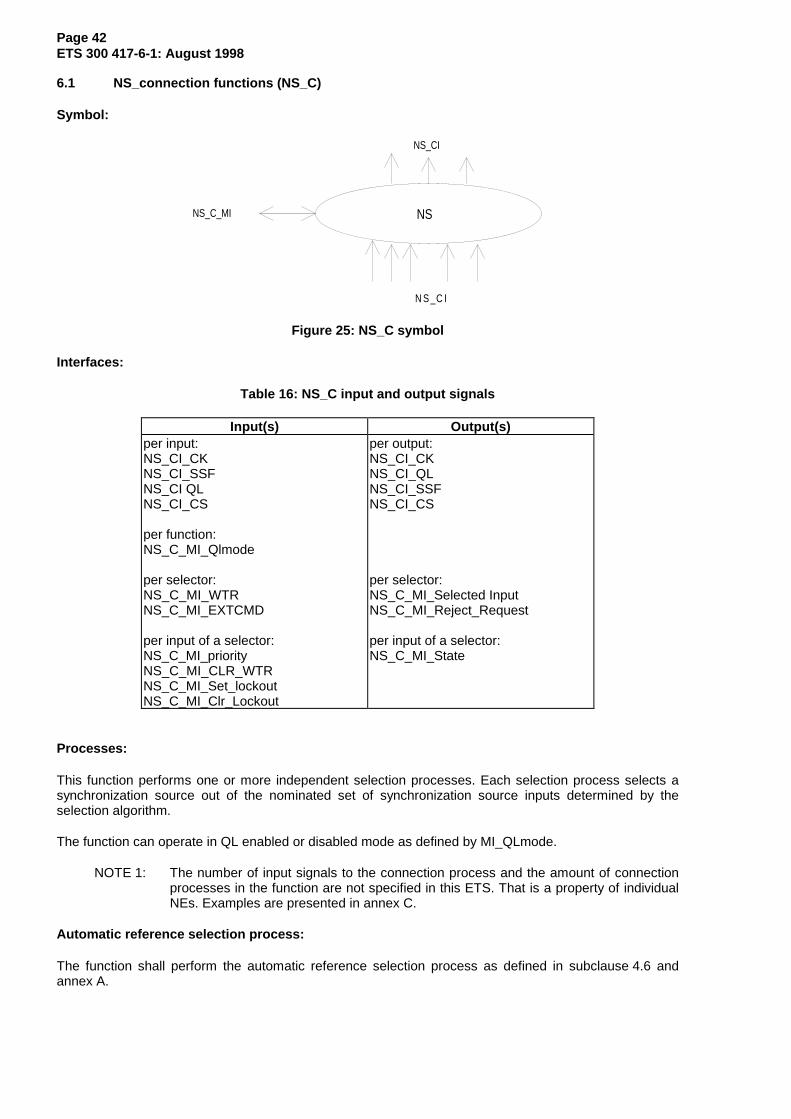
Page 42ETS 300 417-6-1: August 1998
6.1 NS_connection functions (NS_C)
Symbol:
NS
N S _C I
NS_C_MI
NS_CI
Figure 25: NS_C symbol
Interfaces:
Table 16: NS_C input and output signals
Input(s) Output(s)per input:NS_CI_CKNS_CI_SSFNS_CI QLNS_CI_CS
per function:NS_C_MI_Qlmode
per selector:NS_C_MI_WTRNS_C_MI_EXTCMD
per input of a selector:NS_C_MI_priorityNS_C_MI_CLR_WTRNS_C_MI_Set_lockoutNS_C_MI_Clr_Lockout
per output:NS_CI_CKNS_CI_QLNS_CI_SSFNS_CI_CS
per selector:NS_C_MI_Selected InputNS_C_MI_Reject_Request
per input of a selector:NS_C_MI_State
Processes:
This function performs one or more independent selection processes. Each selection process selects asynchronization source out of the nominated set of synchronization source inputs determined by theselection algorithm.
The function can operate in QL enabled or disabled mode as defined by MI_QLmode.
NOTE 1: The number of input signals to the connection process and the amount of connectionprocesses in the function are not specified in this ETS. That is a property of individualNEs. Examples are presented in annex C.
Automatic reference selection process:
The function shall perform the automatic reference selection process as defined in subclause 4.6 andannex A.

Page 43ETS 300 417-6-1: August 1998
EXTCMDs:
The function shall support the use of EXTCMDs as defined in subclause 4.11.
Priority:
The function shall support the use of synchronization source priorities as defined in subclause 4.10.
Holdoff time:
The function shall support a holdoff timer per input of a selection process (nominated source) as definedin subclause 4.8.
WTR time:
The function shall support a WTR timer per input of a selection process (nominated source) as defined insubclause 4.9.
Via MI_CLR_WTR the WTR timer can be cleared before the WTR time is expired.
Signal fail extension:
For each input to a selection process the SF information to the Selector is a combination (OR function) ofthe incoming SF information (CI_SSF) and the SF information delayed by the WTR and holdoff process.Detailed information is provided in annex A, figure A.1.
SF[m] = CI_SF[m] or WTR/HO[CI_SF[m]]
Status report:
The state of each input to a selection process (available, failed, WTR) shall be reported via MI_State.
The actual selected source of a selection process shall be reported via MI_SelectedInput.
Unconnected NS signal generator:
The function shall generate an unconnected NS signal. The unconnected NS signal has a undefinedclock, a QL of QL-UNC, a CS value of "None" and SF true.
NOTE 2: This signal is a logical signal defined for the purpose of this formal specification; it isnot observable as such at any of the NEs interfaces.
Defects: None.
Consequent actions:
If an output of this function is not connected to one of its inputs, the function shall connect theunconnected NS signal to the output.
Defect Correlations: None.
Performance monitoring: For further study.
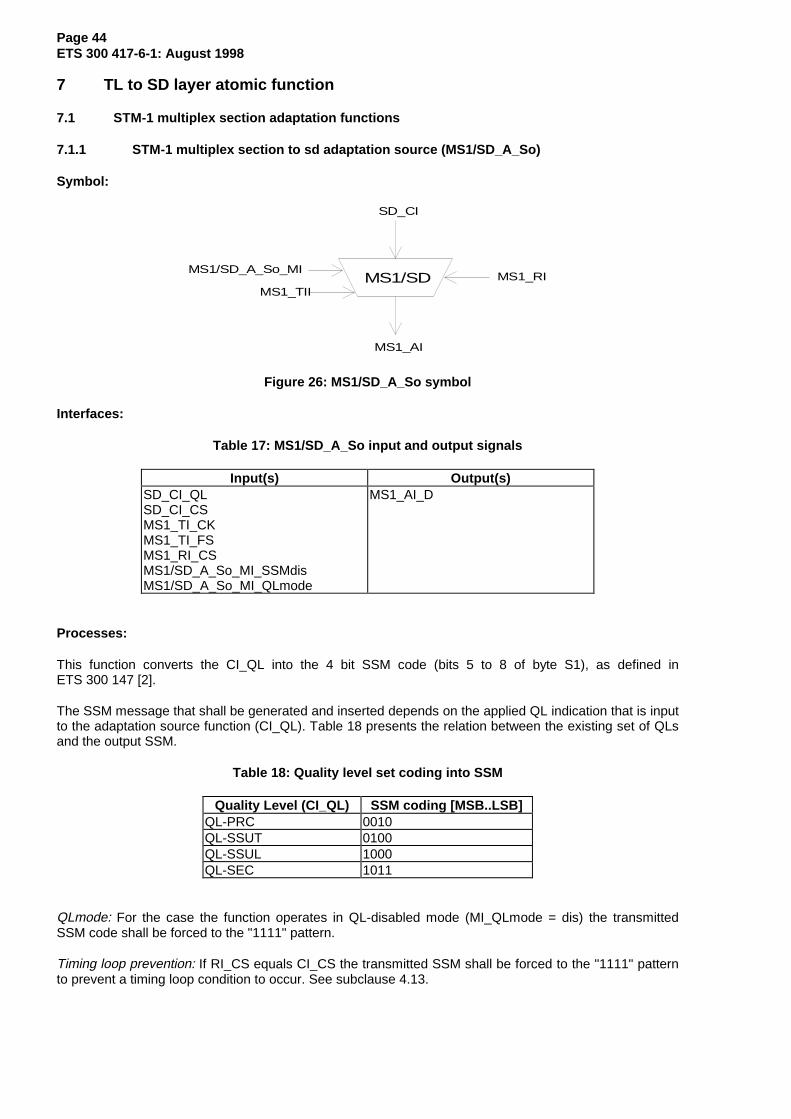
Page 44ETS 300 417-6-1: August 1998
7 TL to SD layer atomic function
7.1 STM-1 multiplex section adaptation functions
7.1.1 STM-1 multiplex section to sd adaptation source (MS1/SD_A_So)
Symbol:
MS1/SD
SD_CI
MS1_AI
MS1/SD_A_So_MIMS1_RI
MS1_TII
Figure 26: MS1/SD_A_So symbol
Interfaces:
Table 17: MS1/SD_A_So input and output signals
Input(s) Output(s)SD_CI_QLSD_CI_CSMS1_TI_CKMS1_TI_FSMS1_RI_CSMS1/SD_A_So_MI_SSMdisMS1/SD_A_So_MI_QLmode
MS1_AI_D
Processes:
This function converts the CI_QL into the 4 bit SSM code (bits 5 to 8 of byte S1), as defined inETS 300 147 [2].
The SSM message that shall be generated and inserted depends on the applied QL indication that is inputto the adaptation source function (CI_QL). Table 18 presents the relation between the existing set of QLsand the output SSM.
Table 18: Quality level set coding into SSM
Quality Level (CI_QL) SSM coding [MSB..LSB]QL-PRC 0010QL-SSUT 0100QL-SSUL 1000QL-SEC 1011
QLmode: For the case the function operates in QL-disabled mode (MI_QLmode = dis) the transmittedSSM code shall be forced to the "1111" pattern.
Timing loop prevention: If RI_CS equals CI_CS the transmitted SSM shall be forced to the "1111" patternto prevent a timing loop condition to occur. See subclause 4.13.

Page 45ETS 300 417-6-1: August 1998
SSM usage: The function supports the capability to prevent synchronization quality information to pass theinterface (see subclause 4.5.2). For the case MI_SSMdis is true, the function shall force the SSM to the"1111" pattern.
S1[5-8]: Bits 5 through 8 (bit 5 as MSB) of byte S1 shall transport the 4 bit SSM code.
Defects: None.
Consequent actions:
if (MI_QLmode== dis)then S1[5-8] = 1111else if (RI_CS == CI_CS) or (SSMdis == true) then S1[5-8] = 1111 else S1[5-8] = SSM[CI_QL] fifi
Defect Correlations: None.
Performance monitoring: None.
7.1.2 STM-1 multiplex section to SD adaptation sink (MS1/SD_A_Sk)
Symbol:
MS1/SD
SD_CI
MS1_AI
MS1/SD_A_Sk_MI MS1_RI
Figure 27: MS1/SD_A_Sk symbol
Interfaces:
Table 19: MS1/SD_A_Sk input and output signals
Input(s) Output(s)MS1_AI_DMS1_AI_CKMS1_AI_FSMS1_AI_TSFMS1/SD_A_Sk_MI_SSMsuppMS1/SD_A_Sk_MI_CSidMS1/SD_A_Sk_MI_QLmode
SD_CI_CKSD_CI_SSFSD_CI_CSSD_CI_QLMS1_RI_CS
Processes:
This functions extracts and accepts the 4 bit SSM, transmitted via bits 5 to 8 of byte S1 as defined inETS 300 147 [2]. It supplies the timing signal, recovered by the physical section layer, to the SD layer.
S1[5-8]: In QL-enabled mode and if SSMsupp is true, bits 5 to 8 of byte S1 shall be recovered andaccepted if the same code is present in three consecutive frames. The accepted code shall be convertedto a quality level QL[SSM] as specified in table 4 and output via CI_QL.

Page 46ETS 300 417-6-1: August 1998
QLmode: For the case the function operates in QL-disabled mode (MI_QLmode = dis) the received SSMcode shall be ignored and the CI_QL shall be forced to the QL-NSUPP.
SSM support: For the case MI_SSMsupp is false, the received SSM bit in the S1 byte should notinterpreted as a valid QL value and the CI_QL shall be forced to the QL-NSUPP.
Clock Source identifier: The function shall insert the CSid received via MI_CSid into CI_CS and RI_CS tosupport timing loop prevention as described in subclause 4.13.
Defects: None.
Consequent actions:
aSSF ← AI_TSF
if (MI_QLmode == disabled) or (MI_SSMsupp == false)then CI_QL = QL-NSUPPelse CI_QL = QL[SSM]fi
Defect Correlations: None.
Performance monitoring: None.
7.2 STM-4 multiplex section adaptation functions
7.2.1 STM-4 multiplex section to SD adaptation source (MS4/SD_A_So)
Symbol:
MS4/SD
SD_CI
MS4_AI
MS4/SD_A_So_MIMS4_RI
MS4_TI
Figure 28: MS4/SD_A_So symbol
Interfaces:
Table 20: MS4/SD_A_So input and output signals
Input(s) Output(s)SD_CI_QLSD_CI_CSMS4_TI_CKMS4_TI_FSMS4_RI_CSMS4/SD_A_So_MI_SSMdisMS4/SD_A_So_MI_QLmode
MS4_AI_D

Page 47ETS 300 417-6-1: August 1998
Processes:
This function converts the CI_QL into the 4 bit SSM code (bits 5 to 8 of byte S1), as defined inETS 300 147 [2].
The SSM message that shall be generated and inserted depends on the applied QL indication that is inputto the adaptation source function (CI_QL). The following table presents the relation between the existingset of QLs and the output SSM.
Table 21: Quality level set coding into SSM
Quality Level (CI_QL) SSMcoding [MSB..LSB]
QL-PRC 0010QL-SSUT 0100QL-SSUL 1000QL-SEC 1011
QLmode: For the case the function operates in QL-disabled mode (MI_QLmode = dis) the transmittedSSM code shall be forced to the "1111" pattern.
Timing loop prevention: If RI_CS equals CI_CS the transmitted SSM shall be forced to the "1111" patternto prevent a timing loop condition to occur. See subclause 4.13.
SSM usage: The function supports the capability to prevent synchronization quality information to pass theinterface (see subclause 4.5.2). For the case MI_SSMdis is true, the function shall force the SSM to the"1111" pattern.
S1[5-8]: Bits 5 through 8 (bit 5 as MSB) of byte S1 shall transport the 4 bit SSM code.
Defects: None.
Consequent actions:
if (MI_QLmode== dis)then S1[5-8] = 1111else if (RI_CS == CI_CS) or (SSMdis == true)then S1[5-8] = 1111 else S1[5-8] = SSM[CI_QL] fifi
Defect Correlations: None.
Performance monitoring: None.
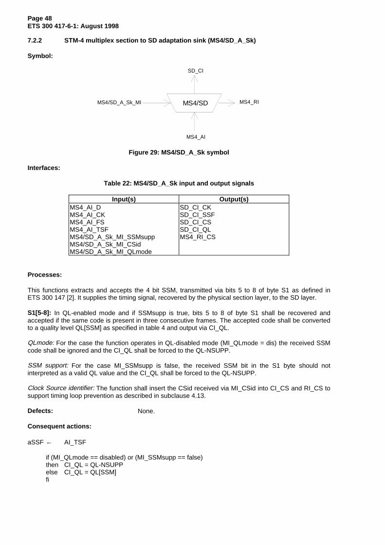
Page 48ETS 300 417-6-1: August 1998
7.2.2 STM-4 multiplex section to SD adaptation sink (MS4/SD_A_Sk)
Symbol:
MS4/SD
SD_CI
MS4_AI
MS4/SD_A_Sk_MI MS4_RI
Figure 29: MS4/SD_A_Sk symbol
Interfaces:
Table 22: MS4/SD_A_Sk input and output signals
Input(s) Output(s)MS4_AI_DMS4_AI_CKMS4_AI_FSMS4_AI_TSFMS4/SD_A_Sk_MI_SSMsuppMS4/SD_A_Sk_MI_CSidMS4/SD_A_Sk_MI_QLmode
SD_CI_CKSD_CI_SSFSD_CI_CSSD_CI_QLMS4_RI_CS
Processes:
This functions extracts and accepts the 4 bit SSM, transmitted via bits 5 to 8 of byte S1 as defined inETS 300 147 [2]. It supplies the timing signal, recovered by the physical section layer, to the SD layer.
S1[5-8]: In QL-enabled mode and if SSMsupp is true, bits 5 to 8 of byte S1 shall be recovered andaccepted if the same code is present in three consecutive frames. The accepted code shall be convertedto a quality level QL[SSM] as specified in table 4 and output via CI_QL.
QLmode: For the case the function operates in QL-disabled mode (MI_QLmode = dis) the received SSMcode shall be ignored and the CI_QL shall be forced to the QL-NSUPP.
SSM support: For the case MI_SSMsupp is false, the received SSM bit in the S1 byte should notinterpreted as a valid QL value and the CI_QL shall be forced to the QL-NSUPP.
Clock Source identifier: The function shall insert the CSid received via MI_CSid into CI_CS and RI_CS tosupport timing loop prevention as described in subclause 4.13.
Defects: None.
Consequent actions:
aSSF ← AI_TSF
if (MI_QLmode == disabled) or (MI_SSMsupp == false)then CI_QL = QL-NSUPPelse CI_QL = QL[SSM]fi

Page 49ETS 300 417-6-1: August 1998
Defect Correlations: None.
Performance monitoring: None.
7.3 STM-16 multiplex section adaptation functions
7.3.1 STM-16 multiplex section to SD adaptation source (MS16/SD_A_So)
Symbol:
MS16/SD
SD_CI
MS16_AI
MS16/SD_A_So_MIMS16_RI
MS16_TI
Figure 30: MS16/SD_A_So symbol
Interfaces:
Table 23: MS16/SD_A_So input and output signals
Input(s) Output(s)SD_CI_QLSD_CI_CSMS16_TI_CKMS16_TI_FSMS16_RI_CSMS16/SD_A_So_MI_SSMdisMS16/SD_A_So_MI_QLmode
MS16_AI_D
Processes:
This function converts the CI_QL into the 4 bit SSM code (bits 5 to 8 of byte S1), as defined inETS 300 147 [2].
The SSM message that shall be generated and inserted depends on the applied QL indication that is inputto the adaptation source function (CI_QL). The following table presents the relation between the existingset of QLs and the output SSM.
Table 24: Quality level set coding into SSM
Quality Level (CI_QL) SSM coding [MSB..LSB]QL-PRC 0010QL-SSUT 0100QL-SSUL 1000QL-SEC 1011
QLmode: For the case the function operates in QL-disabled mode (MI_QLmode = dis) the transmittedSSM code shall be forced to the "1111" pattern.
Timing loop prevention: If RI_CS equals CI_CS the transmitted SSM shall be forced to the "1111" patternto prevent a timing loop condition to occur. See subclause 4.13.

Page 50ETS 300 417-6-1: August 1998
SSM usage: The function supports the capability to prevent synchronization quality information to pass theinterface (see subclause 4.5.2). For the case MI_SSMdis is true, the function shall force the SSM to the"1111" pattern.
S1[5-8]: Bits 5 through 8 (bit 5 as MSB) of byte S1 shall transport the 4 bit SSM code.
Defects: None.
Consequent actions:
if (MI_QLmode== dis)then S1[5-8] = 1111else if (RI_CS == CI_CS) or (SSMdis == true)then S1[5-8] = 1111 else S1[5-8] = SSM[CI_QL] fifi
Defect correlations: None.
Performance monitoring: None.
7.3.2 STM-16 multiplex section to SD adaptation sink (MS16/SD_A_Sk)
Symbol:
MS16/SD
SD_CI
MS16_AI
MS16/SD_A_Sk_MI MS16_RI
Figure 31: MS16/SD_A_Sk symbol
Interfaces:
Table 25: MS16/SD_A_Sk input and output signals
Input(s) Output(s)MS16_AI_DMS16_AI_CKMS16_AI_FSMS16_AI_TSFMS16/SD_A_Sk_MI_SSMsuppMS16/SD_A_Sk_MI_CSidMS16/SD_A_Sk_MI_QLmode
SD_CI_CKSD_CI_SSFSD_CI_CSSD_CI_QLMS16_RI_CS
Processes:
This functions extracts and accepts the 4 bit SSM, transmitted via bits 5 to 8 of byte S1 as defined inETS 300 147 [2]. It supplies the timing signal, recovered by the physical section layer, to the SD layer.
S1[5-8]: In QL-enabled mode and if SSMsupp is true, bits 5 to 8 of byte S1 shall be recovered andaccepted if the same code is present in three consecutive frames. The accepted code shall be convertedto a quality level QL[SSM] as specified in table 4 and output via CI_QL.

Page 51ETS 300 417-6-1: August 1998
QLmode: For the case the function operates in QL-disabled mode (MI_QLmode = dis) the received SSMcode shall be ignored and the CI_QL shall be forced to the QL-NSUPP.
SSM support: For the case MI_SSMsupp is false, the received SSM bit in the S1 byte should notinterpreted as a valid QL value and the CI_QL shall be forced to the QL-NSUPP.
Clock Source identifier: The function shall insert the CSid received via MI_CSid into CI_CS and RI_CS tosupport timing loop prevention as described in subclause 4.13.
Defects: None.
Consequent actions:
aSSF ← AI_TSF
if (MI_QLmode == disabled) or (MI_SSMsupp == false)then CI_QL = QL-NSUPPelse CI_QL = QL[SSM]fi
Defect correlations: None.
Performance monitoring: None.
7.4 P31s adaptation functions
7.4.1 P31s to SD adaptation source (P31s/SD_A_So)
Symbol:
P31s/SD
SD_CI
P31s_AI
P31s/SD_A_So_MIP31s_RI
P31s_TI
Figure 32: P31s/SD_A_So symbol
Interfaces:
Table 26: P31s/SD_A_So input and output signals
Input(s) Output(s)SD_CI_QLSD_CI_CSP31s_TI_CKP31s_TI_FSP31s_TI_MFSP31s_RI_CSP31s/SD_A_So_MI_TMmodeP31s/SD_A_So_MI_SSMdisP31s/SD_A_So_MI_QLmode
P31s_AI_D

Page 52ETS 300 417-6-1: August 1998
Processes:
This function converts the CI_QL and CI_SSF information into the 4 bit SSM code (multiframed bit 8 ofbyte MA), or into the 1 bit TM code, as defined in subclause 4.3.4 of ETS 300 337 [15]. This is controlledby MI_TMmode.
TMmode: For the case TMmode is disabled the function shall generate the SSM code. For the caseTMmode is enabled the function shall generate the TM code.
MA[6-7]: If TMmode is disabled, the value of the multiframe indicator bits shall be set as specified byETS 300 337 [16], 500 µs TU multiframe sequence, and aligned with P31s_TI_MFS. Such multiframeindicator is available for SSM processing. If TMmode is enabled, the multiframe indicator is not requiredfor this mode of operation.
Multiframeindicator
1 2 3 4 5 6 7 8
Figure 33: Multiframe indicator bits in byte MA
The SSM or TM message that shall be generated and inserted depends on the applied QL indication thatis input to the adaptation source function (CI_QL). The following table presents the relation between theexisting set of QLs and the output SSM and TM codes.
NOTE: There may be another parallel adaptation function, e.g. P31s/TUG_A_So that alsogenerates multiframe sequence. The equipment should take care that the multiframesequences generated are the same from all adaptation function involved.
MA[8], MA[8][1-4]: For the case of TMmode is disabled, bit 8 of byte MA in a four frame multiframe (firstframe as MSB) shall transport the 4 bit SSM code. For the case of TMmode is enabled, bit 8 of byte MAshall transport the 1 bit TM code.
Table 27: Quality level set coding into SSM and TM
Quality Level (CI_QL) SSMcoding [MSB..LSB]
TM coding
QL-PRC 0010 0QL-SSUT 0100 1QL-SSUL 1000 1QL-SEC 1011 1
QLmode: For the case the function operates in QL-disabled mode (MI_QLmode = dis) the transmittedSSM code shall be forced to the "1111" pattern, while the transmitted TM code shall be forced to the "1"pattern.
Timing loop prevention: If RI_CS equals CI_CS the transmitted SSM [TM] shall be forced to the"1111" ["1"] pattern to prevent a timing loop condition to occur. See subclause 4.13.
SSM/TM usage: The function supports the capability to prevent synchronization quality information to passthe interface (see subclause 4.5.2). For the case MI_SSMdis is true, the function shall force the SSM [TM]to the "1111" ["1"] pattern.
Defects: None.
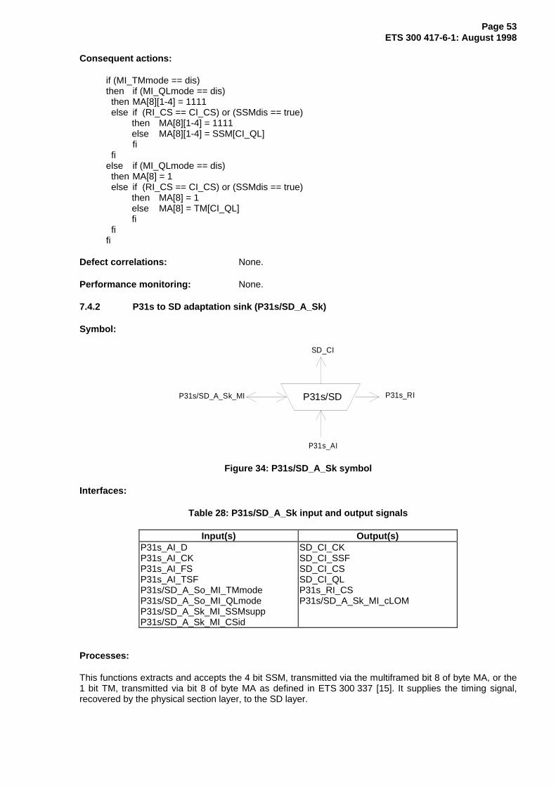
Page 53ETS 300 417-6-1: August 1998
Consequent actions:
if (MI_TMmode == dis)then if (MI_QLmode == dis) then MA[8][1-4] = 1111 else if (RI_CS == CI_CS) or (SSMdis == true) then MA[8][1-4] = 1111 else MA[8][1-4] = SSM[CI_QL]
fi fielse if (MI_QLmode == dis) then MA[8] = 1 else if (RI_CS == CI_CS) or (SSMdis == true) then MA[8] = 1 else MA[8] = TM[CI_QL] fi fifi
Defect correlations: None.
Performance monitoring: None.
7.4.2 P31s to SD adaptation sink (P31s/SD_A_Sk)
Symbol:
P31s/SD
SD_CI
P31s_AI
P31s/SD_A_Sk_MI P31s_RI
Figure 34: P31s/SD_A_Sk symbol
Interfaces:
Table 28: P31s/SD_A_Sk input and output signals
Input(s) Output(s)P31s_AI_DP31s_AI_CKP31s_AI_FSP31s_AI_TSFP31s/SD_A_So_MI_TMmodeP31s/SD_A_So_MI_QLmodeP31s/SD_A_Sk_MI_SSMsuppP31s/SD_A_Sk_MI_CSid
SD_CI_CKSD_CI_SSFSD_CI_CSSD_CI_QLP31s_RI_CSP31s/SD_A_Sk_MI_cLOM
Processes:
This functions extracts and accepts the 4 bit SSM, transmitted via the multiframed bit 8 of byte MA, or the1 bit TM, transmitted via bit 8 of byte MA as defined in ETS 300 337 [15]. It supplies the timing signal,recovered by the physical section layer, to the SD layer.

Page 54ETS 300 417-6-1: August 1998
TMmode: For the case TMmode is disabled the function shall interpret bit 8 of byte MA as the SSM code.For the case TMmode is enabled the function shall interpret bit 8 of byte MA as the TM code.
MA[6-7]: In QL-enabled mode and if TMmode is disabled and if SSMsupp is true, the function shallrecover the 500 µs (multi)frame start phase performing multiframe alignment on bits 6 and 7 of byte MA.Out-Of-Multiframe (OOM) shall be assumed once when an error is detected in the MA bit 6 and 7sequence. Multiframe alignment shall be assumed to be recovered, and the In-Multiframe (IM) state shallbe entered, when in four consecutive P31s frames an error free MA sequence is found.
MA[8][1-4]: In QL-enabled mode and if TMmode is disabled and SSMsupp is true, bit 8 of byte MA in afour frame multiframe (first frame as MSB) shall be recovered and accepted if the same code is present inthree consecutive 4 bit multiframes. The accepted code shall be converted to a quality level QL[SSM] asspecified in table 4 and output via CI_QL.
MA[8]: In QL-enabled mode and if TMmode is enabled and SSMsupp is true, bit 8 of byte MA shall berecovered and accepted if the same code is present in three consecutive frames. The accepted code shallbe converted to a quality level QL[TM] as specified in table 5 and output via CI_QL.
QLmode: For the case the function operates in QL-disabled mode (MI_QLmode = dis) the received SSMor TM code shall be ignored and the CI_QL shall be forced to the QL-NSUPP.
SSM/TM support: For the case MI_SSMsupp is false, the received SSM or TM code shall be ignored andthe CI_QL shall be forced to the QL-NSUPP.
Clock Source identifier: The function shall insert the CSid received via MI_CSid into CI_CS and RI_CS tosupport timing loop prevention as described in subclause 4.13.
Defects:
If the multiframe alignment process is in the OOM state and the MA[6-7] multiframe is not recoveredwithin X ms, a dLOM defect shall be declared. Once in a dLOM state, this state shall be exited when themultiframe is recovered (multiframe alignment process enter the IM state). X shall be a value in the range1 ms to 5 (ms). X is not configurable. dLOM shall be cleared when QLmode is disabled or SSMsupp isfalse or TMmode is enabled.
Consequent actions:
aSSF ← dLOM or AI_TSF
if (MI_QLmode == disabled) or (MI_SSMsupp == false)then CI_QL = QL-NSUPPelse if (MI_TMmode == disabled) thenCI_QL = QL[SSM] else CI_QL = QL[TM] fifi
Defect correlations:
cLOM ← dMFP and (not AI_TSF)
NOTE: There may be another parallel adaptation function, e.g. P31s/TUG_A_sk thatgenerates also cLOM. The EMF should take care that fLOM is reported only once.
Performance monitoring: None.

Page 55ETS 300 417-6-1: August 1998
7.5 P4s adaptation functions
7.5.1 P4s to SD adaptation source (P4s/SD_A_So)
Symbol:
P4s/SD
SD_CI
P4s_AI
P4s/SD_A_So_MIP4s_RI
P4s_TI
Figure 35: P4s/SD _A_So symbol
Interfaces:
Table 29: P4s/SD _A_So input and output signals
Input(s) Output(s)SD_CI_QLSD_CI_CSP4s_TI_CKP4s_TI_FSP4s_TI_MFSP4s_RI_CSP4s/SD_A_So_MI_TMmodeP4s/SD_A_So_MI_SSMdisP4s/SD_A_So_MI_QLmode
P4s_AI_D
Processes:
This function converts the CI_QL and CI_SSF information into the 4 bit SSM code (multiframed bit 8 ofbyte MA), or into the 1 bit TM code, as defined in subclause 4.3.4 of ETS 300 337 [15]. This is controlledby MI_TMmode.
TMmode: For the case TMmode is disabled the function shall generate the SSM code. For the caseTMmode is enabled the function shall generate the TM code.
MA[6-7]: If TMmode is disabled, the value of the multiframe indicator bits shall be set as specified byETS 300 337 [16], 500 µs TU multiframe sequence, and aligned with P4s_TI_MFS. Such multiframeindicator is available for SSM processing. If TMmode is enabled, the multiframe indicator is not requiredfor this mode of operation.
Multiframeindicator
1 2 3 4 5 6 7 8
Figure 36: Multiframe indicator bits in byte MA

Page 56ETS 300 417-6-1: August 1998
The SSM or TM message that shall be generated and inserted depends on the applied QL indication thatis input to the adaptation source function (CI_QL). The following table presents the relation between theexisting set of QLs and the output SSM and TM codes.
NOTE: There may be another parallel adaptation function, e.g. P31s/TUG_A_So that alsogenerates multiframe sequence. The equipment should take care that the multiframesequences generated are the same from all adaptation function involved.
MA[8], MA[8][1-4]: For the case of TMmode is disabled, bit 8 of byte MA in a four frame multiframe (firstframe as MSB) shall transport the 4 bit SSM code. For the case of TMmode is enabled, bit 8 of byte MAshall transport the 1 bit TM code.
Table 30: Quality level set coding into SSM and TM
Quality Level (CI_QL) SSMcoding [MSB..LSB]
TM coding
QL-PRC 0010 0QL-SSUT 0100 1QL-SSUL 1000 1QL-SEC 1011 1
QLmode: For the case the function operates in QL-disabled mode (MI_QLmode = dis) the transmittedSSM code shall be forced to the "1111" pattern, while the transmitted TM code shall be forced to the "1"pattern.
Timing loop prevention: If RI_CS equals CI_CS the transmitted SSM [TM] shall be forced to the"1111" ["1"] pattern to prevent a timing loop condition to occur. See subclause 4.13.
SSM/TM usage: The function supports the capability to prevent synchronization quality information to passthe interface (see subclause 4.5.2). For the case MI_SSMdis is true, the function shall force the SSM [TM]to the "1111" ["1"] pattern.
Defects: None.
Consequent actions:
if (MI_TMmode == dis)then if (MI_QLmode == dis) then MA[8][1-4] = 1111 else if (RI_CS == CI_CS) or (SSMdis == true) then MA[8][1-4] = 1111 else MA[8][1-4] = SSM[CI_QL]
fi fielse if (MI_QLmode == dis) then MA[8] = 1 else if (RI_CS == CI_CS) or (SSMdis == true) then MA[8] = 1 else MA[8] = TM[CI_QL] fi fifi
Defect correlations: None.
Performance monitoring: None.

Page 57ETS 300 417-6-1: August 1998
7.5.2 P4s to SD adaptation sink (P4s/SD_A_Sk)
Symbol:
P4s/SD
SD_CI
P4s_AI
P4s/SD_A_Sk_MI P4s_RI
Figure 37: P4s/SD_A_Sk symbol
Interfaces:
Table 31: P4s/SD_A_Sk input and output signals
Input(s) Output(s)P4s_AI_DP4s_AI_CKP4s_AI_FSP4s_AI_TSFP4s/SD_A_So_MI_TMmodeP4s/SD_A_So_MI_QLmodeP4s/SD_A_Sk_MI_SSMsuppP4s/SD_A_Sk_MI_Csid
SD_CI_CKSD_CI_SSFSD_CI_CSSD_CI_QLP4s_RI_CSP4s/SD_A_Sk_MI_cLOM
Processes:
This functions extracts and accepts the 4 bit SSM, transmitted via the multiframed bit 8 of byte MA, or the1 bit TM, transmitted via bit 8 of byte MA as defined in ETS 300 337 [15]. It supplies the timing signal,recovered by the physical section layer, to the SD layer.
TMmode: For the case TMmode is disabled the function shall interpret bit 8 of byte MA as the SSM code.For the case TMmode is enabled the function shall interpret bit 8 of byte MA as the TM code.
MA[6-7]: In QL-enabled mode and if TMmode is disabled and if SSMsupp is true, the function shallrecover the 500 µs (multi)frame start phase performing multiframe alignment on bits 6 and 7 of byte MA.Out-of-multiframe (OOM) shall be assumed once when an error is detected in the MA bit 6 and 7sequence. Multiframe alignment shall be assumed to be recovered, and the in-multiframe (IM) state shallbe entered, when in four consecutive P4s frames an error free MA sequence is found.
MA[8][1-4]: In QL-enabled mode and if TMmode is disabled and SSMsupp is true, bit 8 of byte MA in afour frame multiframe (first frame as MSB) shall be recovered and accepted if the same code is present inthree consecutive 4 bit multiframes. The accepted code shall be converted to a quality level QL[SSM] asspecified in table 4 and output via CI_QL.
MA[8]: In QL-enabled mode and if TMmode is enabled and SSMsupp is true, bit 8 of byte MA shall berecovered and accepted if the same code is present in three consecutive frames. The accepted code shallbe converted to a quality level QL[TM] as specified in table 5 and output via CI_QL.
QLmode: For the case the function operates in QL-disabled mode (MI_QLmode = dis) the received SSMor TM code shall be ignored and the CI_QL shall be forced to the QL-NSUPP.
SSM/TM support: For the case MI_SSMsupp is false, the received SSM or TM code shall be ignored andthe CI_QL shall be forced to the QL-NSUPP.

Page 58ETS 300 417-6-1: August 1998
Clock Source identifier: The function shall insert the CSid received via MI_CSid into CI_CS and RI_CS tosupport timing loop prevention as described in subclause 4.13.
Defects:
If the multiframe alignment process is in the OOM state and the MA[6-7] multiframe is not recoveredwithin X ms, a dLOM defect shall be declared. Once in a dLOM state, this state shall be exited when themultiframe is recovered (multiframe alignment process enter the IM state). X shall be a value in the range1 to 5 (ms). X is not configurable. dLOM shall be cleared when QLmode is disabled or SSMsupp is falseor TMmode is enabled.
Consequent actions:
aSSF ← dLOM or AI_TSF
if (MI_QLmode == disabled) or (MI_SSMsupp == false)then CI_QL = QL-NSUPPelse if (MI_TMmode == disabled) thenCI_QL = QL[SSM] else CI_QL = QL[TM] fifi
Defect correlations:
cLOM ← dLOM and (not AI_TSF)
NOTE: There may be another parallel function, e.g. P4s/TUG_A_sk function that generatesalso cLOM. The EMF should take care that fLOM is reported only once.
Performance monitoring: None.
7.6 P12s layer adaptation functions
7.6.1 P12s layer adaptation source functions
Two types of P12s/SD_A_So functions are defined:
- type 1 for a 2 Mbit/s station clock output supporting SSM: P12s/SD-sc-1_A_So;
- type 2 for a 2 Mbit/s station clock output not supporting SSM: P12s/SD-sc-2_A_So.
Other types are for further study.
7.6.1.1 Type 1 P12s to SD adaptation source for station clock output supporting SSM(P12s/SD-sc-1_A_So)
Symbol:
P12s/SD-sc-1
SD_CI
P12s_AI
P12s/SD-sc-1_A_So_MIP12s_RI
P12s_TI
Figure 38: P12s/SD-sc-1_A_So symbol

Page 59ETS 300 417-6-1: August 1998
Interfaces:
Table 32: P12s/SD-sc-1_A_So input and output signals
Input(s) Output(s)SD_CI_QLSD_CI_CSSD_CI_SSFP12s_TI_CKP12s_TI_FSP12s_TI_MFSP12s/SD-sc-1_A_So_MI_SelSaSSMP12s/SD-sc-1_A_So_MI_QLmodeP12s/SD-sc-1_A_So_MI_SSMsuppP12s/SD-sc-1_A_So_MI_QLminimum
P12s_AI_DP12s_AI_CKP12s_AI_FSP12s_AI_MFSP12s_AI_AISinsertP12s_RI_CSP12s_RI_QL
Processes:
This function converts the CI_QL and CI_SSF information into the 4 bit SSM code transmitted in one ofthe five Sa bits, as defined in ITU-T Recommendation G.704 [14], and an AISinsert control signal.
The SSM message that shall be generated and inserted depends on the applied QL indication that is inputto the adaptation source function (CI_QL). The following table presents the relation between the existingset of QLs and the output SSM codes.
Table 33: Quality level set coding into SSM
Quality Level (CI_QL) SSMcoding [MSB..LSB]
QL-PRC 0010QL-SSUT 0100QL-SSUL 1000QL-SEC 1011QL-UNC 1111
QLmode: For the case the function operates in QL-disabled mode (MI_QLmode = dis) the transmittedSSM code shall be forced to the "1111" pattern and AI_AISinsert shall be used to signal that nosynchronization source is available.
Sax: The 4 bit SSM code shall be inserted in one of the Sa bits (Sax, x = 4 to 8) as selected viaMI_SelSaSSM. The four bit SSM code shall be transported in alignment with the CRC-4 submultiframe.
Interworking: For interworking with old equipment not supporting SSM processing AIS insertion can beused instead of SSM insertion to pass synchronization quality information via the interface. For the caseMI_SSMsuppis true, the function shall force the SSM to the "1111" pattern and AI_AISinsert shall be usedto signal that no synchronization source is available or CI_QL is below MI_QLminimum.
Clock Source identifier & quality level: The function shall insert the CSid received via CI_CS into RI_CSand the clock QL received via CI_QL into RI_QL to support timing loop prevention as described underconsequent actions (see subclause 4.13).
Defects: None.
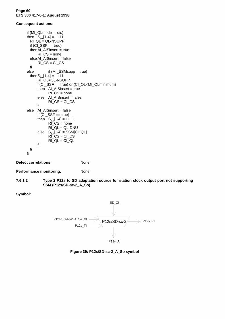
Page 60ETS 300 417-6-1: August 1998
Consequent actions:
if (MI_QLmode== dis)then Sax[1-4] = 1111 RI_QL = QL-NSUPP if (CI_SSF == true) thenAI_AISinsert = true
RI_CS = none else AI_AISinsert = false
RI_CS = CI_CS fielse if (MI_SSMsupp==true) thenSax[1-4] = 1111
RI_QL=QL-NSUPPif(CI_SSF == true) or (CI_QL<MI_QLminimum)then AI_AISinsert = true
RI_CS = noneelse AI_AISinsert = false
RI_CS = CI_CSfi
else AI_AISinsert = falseif (CI_SSF == true)then Sax[1-4] = 1111
RI_CS = noneRI_QL = QL-DNU
else Sax[1-4] = SSM[CI_QL]RI_CS = CI_CSRI_QL = CI_QL
fi fifi
Defect correlations: None.
Performance monitoring: None.
7.6.1.2 Type 2 P12s to SD adaptation source for station clock output port not supportingSSM (P12s/SD-sc-2_A_So)
Symbol:
P12s/SD-sc-2
SD_CI
P12s_AI
P12s/SD-sc-2_A_So_MIP12s_RI
P12s_TI
Figure 39: P12s/SD-sc-2_A_So symbol

Page 61ETS 300 417-6-1: August 1998
Interfaces:
Table 34: P12s/SD-sc-2_A_So input and output signals
Input(s) Output(s)SD_CI_QLSD_CI_CSSD_CI_SSFP12s_TI_CKP12s_TI_FSP12s_TI_MFSP12s/SD-sc-2_A_So_MI_QLminimumP12s/SD-sc-2_A_So_MI_QLmode
P12s_AI_CKP12s_AI_FSP12s_AI_MFSP12s_AI_AISinsertP12s_RI_CSP12s_RI_QL
Processes:
This function converts the CI_QL and CI_SSF information into an AISinsert control signal.
QLmode: For the case the function operates in QL-disabled mode (MI_QLmode = dis) AI_AISinsert shallbe activated if CI_SSF is true. For the case of QL-enabled mode, AI_AISinsert shall be activated ifCI_SSF is true or CI_QL is below MI_QLminimum.
Clock Source identifier & quality level: The function shall insert the CSid received via CI_CS into RI_CS tosupport timing loop prevention as described under consequent actions (see also subclause 4.13). RI_QLshall be fixed to QL-NSUPP.
Defects: None.
Consequent actions:
RI_QL = QL-NSUPPif (MI_QLmode == dis)then if (CI_SSF == true) thenAI_AISinsert = true
RI_CS = none else AI_AISinsert = false
RI_CS = CI_CS fielse if (CI_SSF == true) or (CI_QL < MI_QLminimum) thenAI_AISinsert = true
RI_CS = none else AI_AISinsert = false
RI_CS = CI_CS fifi
Defect correlations: None.
Performance monitoring: None.
7.6.2 P12s layer adaptation sink functions
Two types of P12s/SD_A_Sk functions are defined:
- type 1 for a 2 Mbit/s traffic input port: P12s/SD-tf_A_Sk;
- type 2 for a 2 Mbit/s station clock input port: P12s/SD-sc_A_Sk.

Page 62ETS 300 417-6-1: August 1998
7.6.2.1 Type 1 P12s to SD adaptation sink for traffic input port (P12s/SD-tf_A_Sk)
Symbol:
P12s/SD-tf
SD_CI
P12s_AI
P12s/SD_A_Sk_MI P12s_RI
Figure 40: P12s/SD-tf_A_Sk symbol
Interfaces:
Table 35: P12s/SD-tf_A_Sk input and output signals
Input(s) Output(s)P12s_AI_DP12s_AI_CKP12s_AI_FSP12s_AI_TSFP12s_AI_MFSP12s_AI_MFPP12s/SD-tf_A_Sk_MI_SSMsuppP12s/SD-tf_A_Sk_MI_SelSaSSMP12s/SD-tf_A_Sk_MI_QLmodeP12s/SD-tf_A_Sk_MI_CSid
SD_CI_CKSD_CI_SSFSD_CI_CSSD_CI_QLP12s_RI_CS (for further study)
Processes:
This functions extracts and accepts the 4 bit SSM, transmitted via one of the Sa bits as defined inITU-T Recommendation G.704 [14]. It supplies the timing signal, recovered by the physical section layer,to the SD layer.
Sax[1-4]: In QL-enabled mode and if SSMsupp is true, bits Sax[1] to Sax[4] (x = MI_SelSaSSM is avalue in the set [4, 5, 6, 7, 8]) shall be recovered and accepted if the same code is present in threeconsecutive frames. The accepted code shall be converted to a quality level QL[SSM] as specified intable 4 and output via CI_QL.
QLmode: For the case the function operates in QL-disabled mode (MI_QLmode = dis) the received SSMcode shall be ignored and the CI_QL shall be forced to the QL-NSUPP.
SSM support: For the case MI_SSMsupp is false, the received SSM code shall be ignored and the CI_QLshall be forced to the QL-NSUPP.
Clock Source identifier: The function shall insert the CSid received via MI_CSid into CI_CS to supporttiming loop prevention as described in subclause 4.13. RI_CS generation is for further study.
Defects: None.

Page 63ETS 300 417-6-1: August 1998
Consequent actions:
aSSF ← AI_TSF or (AI_ MFP==false and Qlmode==enabled and SSMsupp==true)
if (MI_QLmode == disabled) or (MI_SSMsupp == false)then CI_QL = QL-NSUPPelse CI_QL = QL[SSM]fi
Defect correlations: None.
Performance monitoring: None.
7.6.2.2 Type 2 P12s to SD adaptation sink for station clock input port (P12s/SD-sc_A_Sk)
Symbol:
P12s/SD-sc
SD_CI
P12s_AI
P12s/SD-sc_A_Sk_MI P12s_RI
Figure 41: P12s/SD-sc _A_Sk symbol
Interfaces:
Table 36: P12s/SD-sc_A_Sk input and output signals
Input(s) Output(s)P12s_AI_DP12s_AI_CKP12s_AI_FSP12s_AI_TSFP12s_AI_MFSP12s_AI_MFPP12s_RI_CSP12s_RI_QLP12s/SD-tf_A_Sk_MI_SSMsuppP12s/SD-tf_A_Sk_MI_SelSaSSMP12s/SD-tf_A_Sk_MI_CSidP12s/SD-sc_A_Sk_MI_QLmode
SD_CI_CKSD_CI_SSFSD_CI_CSSD_CI_QL
Processes:
This functions extracts and accepts the 4 bit SSM, transmitted via one of the Sa bits as defined inITU-T Recommendation G.704 [14]. It supplies the timing signal, recovered by the physical section layer,to the SD layer.
Sax: In QL-enabled mode and if SSMsupp is true, bits Sax[1] to Sax[4] (x = MI_SelSaSSM is a value inthe set [4, 5, 6, 7, 8]) shall be recovered and accepted if the same code is present in three consecutiveframes. The accepted code shall be converted to a quality level QL[SSM] as specified in table 4 andoutput via CI_QL.
QLmode: For the case the function operates in QL-disabled mode (MI_QLmode = dis) the received SSMcode shall be ignored and the CI_QL shall be forced to the QL-NSUPP.
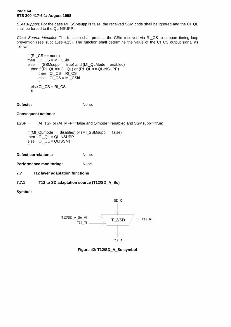
Page 64ETS 300 417-6-1: August 1998
SSM support: For the case MI_SSMsupp is false, the received SSM code shall be ignored and the CI_QLshall be forced to the QL-NSUPP.
Clock Source identifier: The function shall process the CSid received via RI_CS to support timing loopprevention (see subclause 4.13). The function shall determine the value of the CI_CS output signal asfollows:
if (RI_CS == none)then CI_CS = MI_CSidelse if (SSMsupp == true) and (MI_QLMode==enabled) thenif (RI_QL == CI_QL) or (RI_QL == QL-NSUPP)
then CI_CS = RI_CSelse CI_CS = MI_CSidfi
else CI_CS = RI_CS fifi
Defects: None.
Consequent actions:
aSSF ← AI_TSF or (AI_MFP==false and Qlmode==enabled and SSMsupp==true)
if (MI_QLmode == disabled) or (MI_SSMsupp == false)then CI_QL = QL-NSUPPelse CI_QL = QL[SSM]fi
Defect correlations: None.
Performance monitoring: None.
7.7 T12 layer adaptation functions
7.7.1 T12 to SD adaptation source (T12/SD_A_So)
Symbol:
T12/SD
SD_CI
T12_AI
T12/SD_A_So_MI T12_RIT12_TI
Figure 42: T12/SD_A_So symbol

Page 65ETS 300 417-6-1: August 1998
Interfaces:
Table 37: T12/SD_A_So input and output signals
Input(s) Output(s)SD_CI_QLSD_CI_CSSD_CI_SSFSD_CI_CKT12/SD_A_So_MI_QLminimumT12/SD_A_So_MI_QLmode
T12_AI_CKT12_AI_SQLCHT12_RI_CST12_RI_QL
Processes:
This function converts the CI_QL and CI_SSF information into an SQLCH control signal.
QLmode: For the case the function operates in QL-disabled mode (MI_QLmode = dis) AI_SQLCH shall beactivated if CI_SSF is true. For the case of QL-enabled mode, AI_SQLCH shall be activated if CI_SSF istrue or CI_QL is below MI_QLminimum.
Clock Source identifier & quality level: The function shall insert the CSid received via CI_CS into RI_CS tosupport timing loop prevention as described under consequent actions (see also subclause 4.13). RI_QLshall be fixed to QL-NSUPP.
Defects: None.
Consequent actions:
RI_QL = QL-NSUPPif (MI_QLmode == dis)then if (CI_SSF == true) then AI_SQLCH = true
RI_CS = none else AI_SQLCH = false
RI_CS = CI_CS fielse if (CI_SSF == true) or (CI_QL < MI_QLminimum) thenAI_SQLCH = true
RI_CS = none else AI_SQLCH = false
RI_CS = CI_CS fifi
Defect correlations: None.
Performance monitoring: None.

Page 66ETS 300 417-6-1: August 1998
7.7.2 T12 to SD adaptation sink (T12/SD_A_Sk)
Symbol:
T12/SD
T12_AI
T12/SD_A_Sk_MI
SD_CI
T12_RI
Figure 43: T12/SD_A_Sk symbol
Interfaces:
Table 38: T12/SD_A_Sk input and output signals
Input(s) Output(s)T12_AI_CKT12_AI_TSFT12_RI_CST12_RI_QLT12/SD_A_Sk_MI_Csid
SD_CI_CKSD_CI_SSFSD_CI_CSSD_CI_QL
Processes:
This function adapts the 2 048 kHz TI from an external reference to an equipment specific timing CI. Thisfunction regenerates the received CK and supplies the recovered timing signal to the SD layer.
Regeneration: The function shall output a valid CK when any combination of the following signalconditions exist at the input:
- An input electrical amplitude level with any value in the range specified by ETS 300 166 [3];- Jitter modulation applied to the input signal with any value defined in ETS 300 462-5 [12];- The input signal frequency has any value in the range 2 048 kHz ± 50 ppm.
NOTE: The frequency and jitter/wander tolerance is further constrained by the requirements ofthe client (SD) layer. For example in the MS SDH layer, the frequency offset should notexceed 4,6 ppm.
SSM support: CI_QL shall be forced to the QL-NSUPP.
Clock Source identifier: The function shall process the CSid received via RI_CS to support timing loopprevention (see subclause 4.13). The function shall determine the value of the CI_CS output signal asfollows:
if (RI_CS == none)then CI_CS = MI_CSidelse CI_CS = RI_CSfi
Defects: None.
Consequent actions:
aSSF ← AI_TSF

Page 67ETS 300 417-6-1: August 1998
Defect correlations: None.
Performance monitoring: None.
8 Equipment clock to TLs clock adaptation functions
8.1 STM-N layer
8.1.1 STM-1 Layer Clock (LC) adaptation source (MS1-LC_A_So)
Symbol:
MS1-LC
S TM 1_T I
SD_CI
Figure 44: MS1-LC_A_So symbol
Interfaces:
Table 39: MS1-LC_A_So input and output signals
Input(s) Output(s)SD_CI_CK MS_TI_CK
MS1_TI_FS
Processes:
This function performs the STM-1 clock and Frame Start (FS) signal generation locked to the NE CKSD_CI_CK, to time the adaptation source functions in this layer (and its server layers).
Clock generation: The function shall generate the clock (bit) reference signal STM1_TI_CK for the STM-1signal. The STM1_TI_CK frequency shall be 155 520 kHz locked to the input signal SD_CI_CK.
Jitter limiter: The function shall process the signal such that in the absence of input jitter at thesynchronization interface, the intrinsic jitter at the STM-1 output interface shall be as specified inETS 300 462-5 [12] for optical interfaces and ETS 300 417-2-1 [6] for electrical interface.
Frame Start signal generation: The function shall generate the FS reference signal STM1_TI_FS for theSTM-1 signal. The STM1_TI_FS signal shall be active once per 19 440 clock cycle.
Defects: None.
Consequent actions: None.
Defect correlations: None.
Performance monitoring: None.

Page 68ETS 300 417-6-1: August 1998
8.1.2 STM-4 LC adaptation source (MS4-LC_A_So)
Symbol:
MS4-LC
S TM 4_T I
SD_CI
Figure 45: MS4-LC_A_So symbol
Interfaces:
Table 40: MS4-LC_A_So input and output signals
Input(s) Output(s)SD_CI_CK MS4_TI_CK
MS4_TI_FS
Processes:
This function performs the STM-4 clock and FS signal generation locked to the NE CK SD_CI_CK, to timethe adaptation source functions in this layer (and its server layers).
Clock generation: The function shall generate the clock (bit) reference signal STM1_TI_CK for the STM-4signal. The STM4_TI_CK frequency shall be 622 080 kHz locked to the input signal SD_CI_CK.
Jitter limiter: The function shall process the signal such that in the absence of input jitter at thesynchronization interface, the intrinsic jitter at the STM-4 output interface shall be as specified inETS 300 462-5 [12].
Frame Start signal generation: The function shall generate the FS reference signal STM4_TI_FS for theSTM-4 signal. The STM4_TI_FS signal shall be active once per 77 760 clock cycles.
Defects: None.
Consequent actions: None.
Defect correlations: None.
Performance monitoring: None.

Page 69ETS 300 417-6-1: August 1998
8.1.3 STM-16 LC adaptation source (MS16-LC_A_So)
Symbol:
MS16-LC
S TM 16_T I
SD_CI
Figure 46: MS16-LC_A_So symbol
Interfaces:
Table 41: MS16-LC_A_So input and output signals
Input(s) Output(s)SD_CI_CK MS16_TI_CK
MS16_TI_FS
Processes:
This function performs the STM-16 clock and FS signal generation locked to the NE CK SD_CI_CK, totime the adaptation source functions in this layer (and its server layers).
Clock generation: The function shall generate the clock (bit) reference signal STM16_TI_CK for theSTM-16 signal. The STM16_TI_CK frequency shall be 2 488 320 kHz locked to the input signalSD_CI_CK.
Jitter limiter: The function shall process the signal such that in the absence of input jitter at thesynchronization interface, the intrinsic jitter at the STM-16 output interface shall be as specified inETS 300 462-5 [12].
Frame Start signal generation: The function shall generate the FS reference signal STM16_TI_FS for theSTM-16 signal. The STM16_TI_FS signal shall be active once per 311 040 clock cycles.
Defects: None.
Consequent actions: None.
Defect correlations: None.
Performance monitoring: None.

Page 70ETS 300 417-6-1: August 1998
8.2 VC layers
8.2.1 VC-4 LC adaptation source (S4-LC_A_So)
Symbol:
S4-LC
S 4_ TI
SD_CI
Figure 47: S4-LC A_So symbol
Interfaces:
Table 42: S4-LC_A_So input and output signals
Input(s) Output(s)SD_CI_CK S4_TI_CK
S4_TI_FSS4_TI_MFS
Processes:
This function performs the VC-4 clock and FS signal generation locked to the NE CK SD_CI_CK, to timethe adaptation source and connection functions in this layer.
Clock generation: The function shall generate the clock (bit) reference signal S4_TI_CK for the VC-4signal. The S4_TI_CK frequency shall be 150 336 kHz locked to the input signal SD_CI_CK.
Jitter limiter: For Further study
Frame Start signal generation: The function shall generate the FS reference signal S4_TI_FS for the VC-4signal. The S4_TI_FS signal shall be active once per 18 792 clock cycle and the multiframe referenceshall be active once every 4 frames.
Defects: None.
Consequent actions: None.
Defect correlations: None.
Performance monitoring: None.
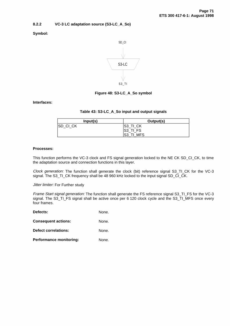
Page 71ETS 300 417-6-1: August 1998
8.2.2 VC-3 LC adaptation source (S3-LC_A_So)
Symbol:
S3-LC
S 3_T I
SD_CI
Figure 48: S3-LC_A_So symbol
Interfaces:
Table 43: S3-LC_A_So input and output signals
Input(s) Output(s)SD_CI_CK S3_TI_CK
S3_TI_FSS3_TI_MFS
Processes:
This function performs the VC-3 clock and FS signal generation locked to the NE CK SD_CI_CK, to timethe adaptation source and connection functions in this layer.
Clock generation: The function shall generate the clock (bit) reference signal S3_TI_CK for the VC-3signal. The S3_TI_CK frequency shall be 48 960 kHz locked to the input signal SD_CI_CK.
Jitter limiter: For Further study
Frame Start signal generation: The function shall generate the FS reference signal S3_TI_FS for the VC-3signal. The S3_TI_FS signal shall be active once per 6 120 clock cycle and the S3_TI_MFS once everyfour frames.
Defects: None.
Consequent actions: None.
Defect correlations: None.
Performance monitoring: None.

Page 72ETS 300 417-6-1: August 1998
8.2.3 VC-2 LC adaptation source (S2-LC_A_So)
Symbol:
S2-LC
S 2_ TI
SD_CI
Figure 49: S2-LC_A_So symbol
Interfaces:
Table 44: S2-LC_A_So input and output signals
Input(s) Output(s)SD_CI_CK S2_TI_CK
S2_TI_FS
Processes:
This function performs the VC-2 clock and FS signal generation locked to the NE CK SD_CI_CK, to timethe adaptation source and connection functions in this layer.
Clock generation: The function shall generate the clock (bit) reference signal S2_TI_CK for the VC-2signal. The S2_TI_CK frequency shall be 6 848 kHz locked to the input signal SD_CI_CK.
Jitter limiter: For further study.
Frame Start signal generation: The function shall generate the FS reference signal S2_TI_FS for the VC-2signal. The S2_TI_FS signal shall be active once per 856 clock cycles.
Defects: None.
Consequent actions: None.
Defect correlations: None.
Performance monitoring: None.

Page 73ETS 300 417-6-1: August 1998
8.2.4 VC-12 LC adaptation source (S12-LC_A_So)
Symbol:
S12-LC
S 12_T I
SD_CI
Figure 50: S12-LC_A_So symbol
Interfaces:
Table 45: S12-LC_A_So input and output signals
Input(s) Output(s)SD_CI_CK S12_TI_CK
S12_TI_FS
Processes:
This function performs the VC-12 clock and FS signal generation locked to the NE CK SD_CI_CK, to timethe adaptation source and connection functions in this layer.
Clock generation: The function shall generate the clock (bit) reference signal S12_TI_CK for the VC-12signal. The S12_TI_CK frequency shall be 2 240 kHz locked to the input signal SD_CI_CK.
Jitter limiter: For further study.
Frame Start signal generation: The function shall generate the FS reference signal S12_TI_FS for theVC-12 signal. The S12_TI_FS signal shall be active once per 280 clock cycles.
Defects: None.
Consequent actions: None.
Defect correlations: None.
Performance monitoring: None.

Page 74ETS 300 417-6-1: August 1998
8.2.5 VC-11 LC adaptation source (S11-LC_A_So)
Symbol:
S11-LC
S 11_T I
SD_CI
Figure 51: S3-LC_A_So symbol
Interfaces:
Table 46: S3-LC_A_So input and output signals
Input(s) Output(s)SD_CI_CK S11_TI_CK
S11_TI_FS
Processes:
This function performs the VC-11 clock and FS signal generation locked to the NE CK SD_CI_CK, to timethe adaptation source and connection functions in this layer.
Clock generation: The function shall generate the clock (bit) reference signal S11_TI_CK for the VC-11signal. The S11_TI_CK frequency shall be 1 664 kHz locked to the input signal SD_CI_CK.
Jitter limiter: For further study.
Frame Start signal generation: The function shall generate the FS reference signal S11_TI_FS for theVC-11 signal. The S11_TI_FS signal shall be active once per 208 clock cycles.
Defects: None.
Consequent actions: None.
Defect correlations: None.
Performance monitoring: None.

Page 75ETS 300 417-6-1: August 1998
8.3 Pxx layers
8.3.1 P4s LC adaptation source (P4s-LC_A_So)
Symbol:
P4s-LC
P 4s_T I
SD_CI
Figure 52: P4s-LC_A_So symbol
Interfaces:
Table 47: P4s-LC_A_So input and output signals
Input(s) Output(s)SD_CI_CK P4s_TI_CK
P4s_TI_FSP4s_TI_MFS
Processes:
This function performs the P4s clock and FS signal generation locked to the NE CK SD_CI_CK, to timethe adaptation source functions in this layer.
Clock generation: The function shall generate the clock (bit) reference signal P4s_TI_CK for the P4ssignal. The P4s_TI_CK frequency shall be 139 264 kHz locked to the input signal SD_CI_CK.
Jitter limiter: For further study.
Frame Start signal generation: The function shall generate the FS reference signal P4s_TI_FS for the P4ssignal. The P4s_TI_FS signal shall be active once per 17 408 clock cycles. P4s_TI_MFS shall be activeonce every 4 frames.
Defects: None.
Consequent actions: None.
Defect correlations: None.
Performance monitoring: None.
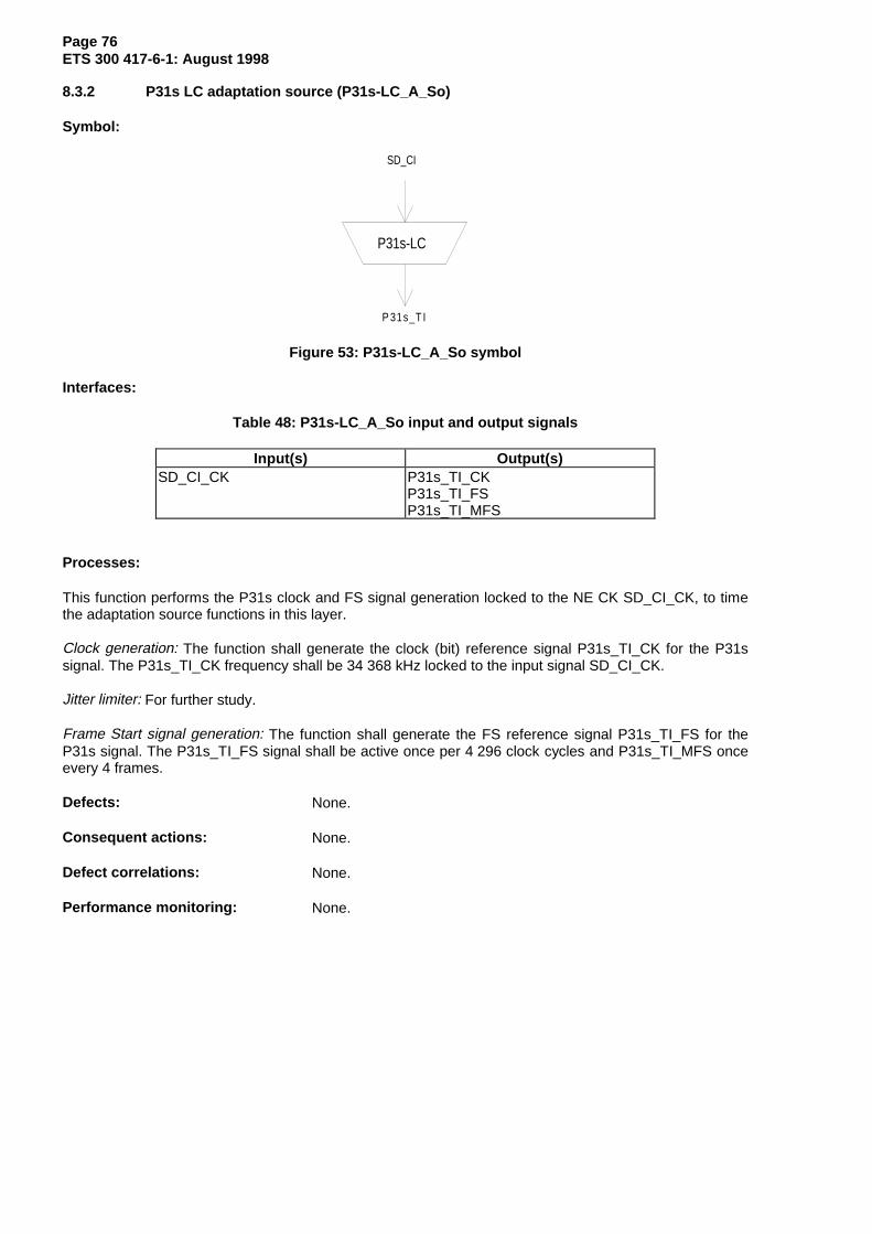
Page 76ETS 300 417-6-1: August 1998
8.3.2 P31s LC adaptation source (P31s-LC_A_So)
Symbol:
P31s-LC
P 31s_T I
SD_CI
Figure 53: P31s-LC_A_So symbol
Interfaces:
Table 48: P31s-LC_A_So input and output signals
Input(s) Output(s)SD_CI_CK P31s_TI_CK
P31s_TI_FSP31s_TI_MFS
Processes:
This function performs the P31s clock and FS signal generation locked to the NE CK SD_CI_CK, to timethe adaptation source functions in this layer.
Clock generation: The function shall generate the clock (bit) reference signal P31s_TI_CK for the P31ssignal. The P31s_TI_CK frequency shall be 34 368 kHz locked to the input signal SD_CI_CK.
Jitter limiter: For further study.
Frame Start signal generation: The function shall generate the FS reference signal P31s_TI_FS for theP31s signal. The P31s_TI_FS signal shall be active once per 4 296 clock cycles and P31s_TI_MFS onceevery 4 frames.
Defects: None.
Consequent actions: None.
Defect correlations: None.
Performance monitoring: None.

Page 77ETS 300 417-6-1: August 1998
8.3.3 P12s LC adaptation source (P12s-LC_A_So)
Symbol:
P12s-LC
P 12s_T I
SD_CI
Figure 54: P12s-LC_A_So symbol
Interfaces:
Table 49: P12s-LC_A_So input and output signals
Input(s) Output(s)SD_CI_CK P12s_TI_CK
P12s_TI_FSP12s_TI_MFS
Processes:
This function performs the P12s clock and FS signal generation locked to the CK SD_CI_CK, to time theadaptation source functions in this layer.
Clock generation: The function shall generate the clock (bit) reference signal P12s_TI_CK for the P12ssignal. The P12s_TI_CK frequency shall be 2 048 kHz locked to the input signal SD_CI_CK.
NOTE: If a SD_CI_SSF is present at the input of the function, it is also present at the input ofP12s/SD and an AIS is generated by P12_TT.
Jitter limiter: The function shall process the signal such that in the absence input jitter at thesynchronization interface, the intrinsic jitter at the E12 output interface is compatible withETS 300 462-5 [12].
Frame Start signal generation: The function shall generate the FS reference signal P12s_TI_FS for theP12s signal. The P12s_TI_FS signal shall be active once per 256 clock cycles and P12s_TI_MFS onceevery 16 frames.
Defects: None.
Consequent actions: None.
Defect correlations: None.
Performance monitoring: None.
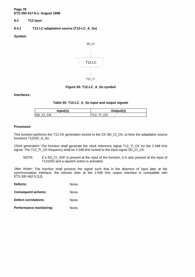
Page 78ETS 300 417-6-1: August 1998
8.4 T12 layer
8.4.1 T12 LC adaptation source (T12-LC_A_So)
Symbol:
T12-LC
T12_TI
SD_CI
Figure 55: T12-LC_A_So symbol
Interfaces:
Table 50: T12-LC_A_So input and output signals
Input(s) Output(s)SD_CI_CK T12_TI_CK
Processes:
This function performs the T12 CK generation locked to the CK SD_CI_CK, to time the adaptation sourcefunctions T12/SD_A_So.
Clock generation: The function shall generate the clock reference signal T12_TI_CK for the 2 048 kHzsignal. The T12_TI_CK frequency shall be 2 048 kHz locked to the input signal SD_CI_CK.
NOTE: If a SD_CI_SSF is present at the input of the function, it is also present at the input ofT12s/SD and a squelch action is activated.
Jitter limiter: The function shall process the signal such that in the absence of input jitter at thesynchronization interface, the intrinsic jitter at the 2 048 kHz output interface is compatible withETS 300 462-5 [12].
Defects: None.
Consequent actions: None.
Defect correlations: None.
Performance monitoring: None.
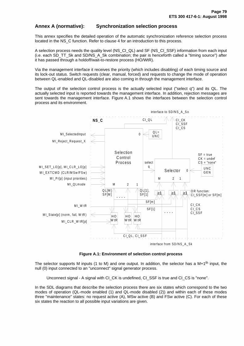
Page 79ETS 300 417-6-1: August 1998
Annex A (normative): Synchronization selection process
This annex specifies the detailed operation of the automatic synchronization reference selection processlocated in the NS_C function. Refer to clause 4 for an introduction to this process.
A selection process needs the quality level (NS_CI_QL) and SF (NS_CI_SSF) information from each input(i.e. each SD_TT_Sk and SD/NS_A_Sk combination; the pair is henceforth called a "timing source") afterit has passed through a holdoff/wait-to-restore process (HO/WtR).
Via the management interface it receives the priority (which includes disabling) of each timing source andits lock-out status. Switch requests (clear, manual, forced) and requests to change the mode of operationbetween QL-enabled and QL-disabled are also coming in through the management interface.
The output of the selection control process is the actually selected input ("select q") and its QL. Theactually selected input is reported towards the management interface. In addition, rejection messages aresent towards the management interface. Figure A.1 shows the interfaces between the selection controlprocess and its environment.
S e le c tio nC ontro lP roc ess
M I_Q Lm ode
M I_P r[p] (inpu t p r io r it ies )
M I_ E X T C M D (C LR /M S w /F S w )
M I_ S E T_L O [p] , M I_C LR _LO [p ]
M I_Re jec t_R eques t_X
S e le c to r
C I_Q L , C I_ S S F
C I_C KC I_C SC I_S S F
in terface f rom S D /N S _A _ S k
selec tq
M 2 1
12M
0U N CG E N
H OW tR
H OW tR
H OW tR
M I_S tate[p ] (n orm , fail, W tR )
M I_S elected Inpu t
in te rface to S D /N S _A _S o
C I_CKC I_S S FC I_CS
C I_Q LNS_C
Q L[1 ],S F [1 ]
Q L[M ]S F [M ]
S F = trueC K = undefC S = "non e"
M I_W tR
M I_ C L R _W tR[ p]
Q L =U N C0
≥1 ≥1 ≥1
S F [1 ]
S F [m ]
O R func tion :C I_S S F[m ] o r S F[m ]
Figure A.1: Environment of selection control process
The selector supports M inputs (1 to M) and one output. In addition, the selector has a M+1th input, thenull (0) input connected to an "unconnect" signal generator process.
Unconnect signal - A signal with CI_CK is undefined, CI_SSF is true and CI_CS is "none".
In the SDL diagrams that describe the selection process there are six states which correspond to the twomodes of operation (QL-mode enabled (1) and QL-mode disabled (2)) and within each of these modesthree "maintenance" states: no request active (A), MSw active (B) and FSw active (C). For each of thesesix states the reaction to all possible input variations are given.

Page 80ETS 300 417-6-1: August 1998
In the SDL diagrams "report q" is a MI_selected input information and QL_out equals CI_CL, as defined infigure A.1.
Table A.1: Notational conventions and parameters used in the SDL diagrams
Parameter Abbreviation Values (high to low)/ExplanationQuality Level [input] QL[p] PRC, SSU-T, SSU-L, SEC, DNU, INV, FAILED,
undef(ined)Quality Level [0] QL[0] UNConnectedPriority [input] Pr[p] 1, 2, ...., K, dis(abled)Priority [0] Pr[0] undef(ined)Signal Fail [input] SF[p] false, trueSignal Fail [0] SF[0] trueLock Out status [input] LO[p] on, offLock Out status [0] LO[0] offinput p 1, 2, ..., Mselected input q 0,1, 2, ..., MNumber of timing sources MNumber of different priorities K K = M
:= assignment symbol== equality test symbol<= less or equal test symbol
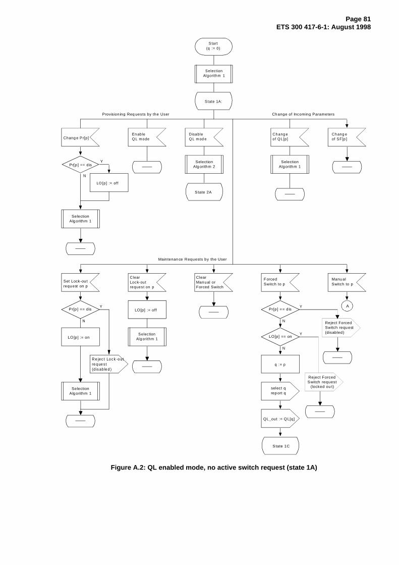
Page 81ETS 300 417-6-1: August 1998
Start(q := 0)
S tate 1A:
Ch ang eof Q L[p]
Ch ang e of SF[p ]Chang e P r[p ]
En ab leQ L m ode
DisableQ L m od e
Ch ange of Incoming ParametersProvision ing Req uests by the User
Maintenan ce Requests by the User
Pr[p ] == d is
LO [p] := off
Y
N
ClearManual orForced Switch
Manu alSwitch to p
F orced Switch to p
Set Lock-outrequ est on p
ClearLock- outreques t on p
State 2A
R e jec t Lo c k -o utre q ue s t(d is ab le d )
Pr[p ] == d is
S tate 1C
q := p
Pr[p ] == d is
LO[p] == on
select qrep ort q
QL_out := QL[q]
AY
N
Y
N
Y
N
SelectionAlgorithm 1
SelectionAlgorithm 1
SelectionAlg orithm 2
SelectionAlg orithm 1
Selec tionAlg orithm 1
SelectionAlg orithm 1
Reject ForcedSwitch requ est(disabled)
LO [p] := on
LO[p] := off
Reject ForcedSwitch request
(locked ou t)
Figure A.2: QL enabled mode, no active switch request (state 1A)
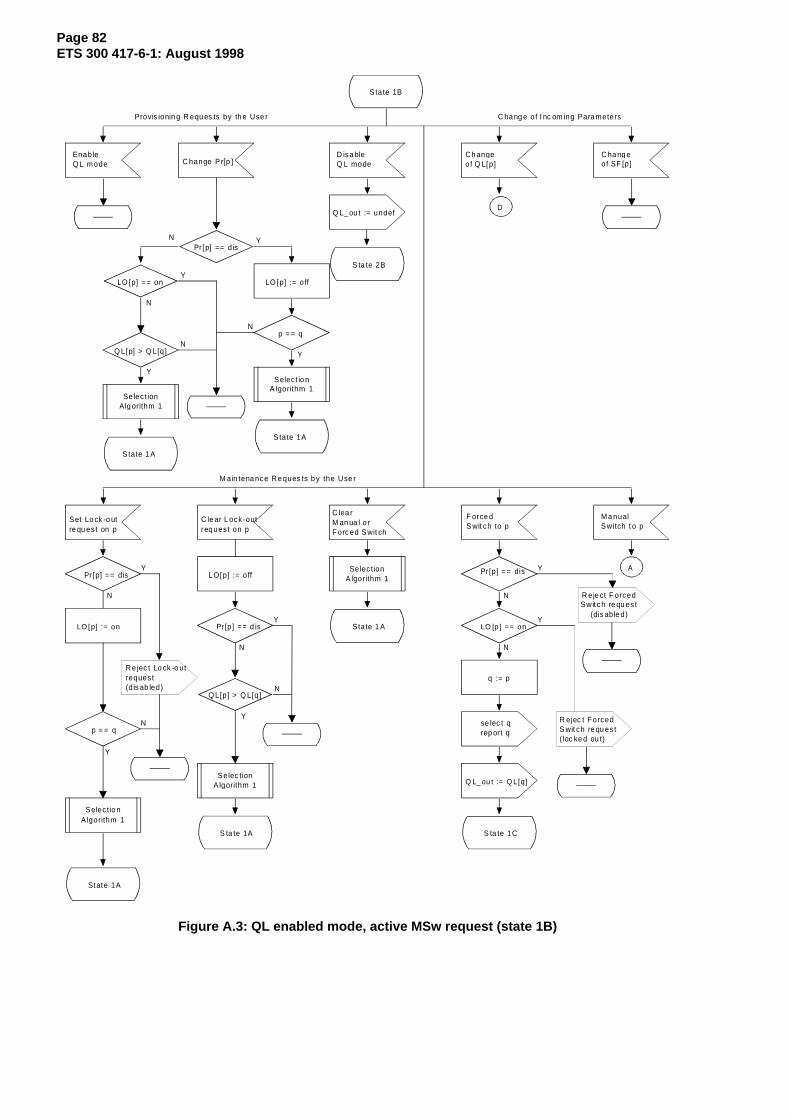
Page 82ETS 300 417-6-1: August 1998
State 1B
Ch angeof Q L[p]
C ha ng e of SF [p]C hange P r[p ]
EnableQ L m ode
D isa bleQ L mode
C ha ng e of I nc om ing Para metersProvis ionin g R equ es ts by th e Use r
M ain tena nce Re ques ts b y the Use r
Pr [p] == d isYN
C lea rM an ua l o rF orc ed Swit ch
M a nualSwitch t o p
F orce d S wit ch to p
Set Lo ck -o utre qu es t on p
C le ar L ock-outreq ues t on p
S ta te 2B
Pr[p] == dis
S ta te 1C
q := p
Pr [p ] == dis
LO [p ] == on
se lec t qrep or t q
Q L_ ou t := Q L[q]
R ejec t F orcedS wit ch re qu es t( loc ke d ou t)
AY
N
Y
N
Y
N
State 1 A
LO [p] == onY
N
Q L[p] > Q L[q]N
Y
State 1 A
p == qN
Y
State 1A
LO [p] := o ff
S ta te 1A
Pr[p] == d isY
N
Q L[p] > Q L[q]N
Y
Q L_ ou t := undef
Se lec t ionAlg orithm 1
Selec t io nA lgorithm 1
Selec tionA lgorithm 1
Selec tionA lgorithm 1L O[p] := o ff
LO [p] := on
Re jec t Lo ck -o utreques t(d is ab led)
p = = qN
Y
State 1A
Selec tio nA lgorithm 1
D
R eje ct F orcedSwit ch re qu es t
(dis able d)
Figure A.3: QL enabled mode, active MSw request (state 1B)

Page 83ETS 300 417-6-1: August 1998
S tate 1C
Ch angeof Q L[p]
C ha ng e of SF [p]C hange P r[p ]
EnableQ L m ode
D isa bleQ L mode
C ha ng e of I nc om ing Para metersProvis ionin g R equ es ts by th e Use r
M ain tena nce Re ques ts b y the Use r
Pr [p] == d isY
N
C learM anual orF orce d Sw itc h
M a nualSwitch t o p
Fo rced Switch to p
Set Lo ck -o utre qu es t on p
C le ar L ock-outreq ues t on p
S tate 2 C
Pr[p] == dis
S tate 1C
q := p
Pr[p] == dis
L O[p] == on
s elec t qrep ort q
QL _o ut := QL [q]
R ejec t F orcedS wit ch re ques t(dis ab led )
Y
N
Y
N
Y
N
State 1A
p == qN
Y
State 1A
LO [p] := o ff
R eject M a nua lSwitch req ue st(F Sw ac tive)
Q L_ ou t := undef
Selec t io nA lgorithm 1
Selec tionA lg orithm 1
Q L_ out := Q L[q]
L O[p] := o ff
L O[p] := on
Re jec t Lo ck -o utreques t(d is ab led)
p = = qN
Y
State 1A
Selec tio nA lgorithm 1
R ejec t F orcedS wit ch re ques t( loc ked ou t)
Figure A.4: QL mode enabled, active FSw (state 1C)
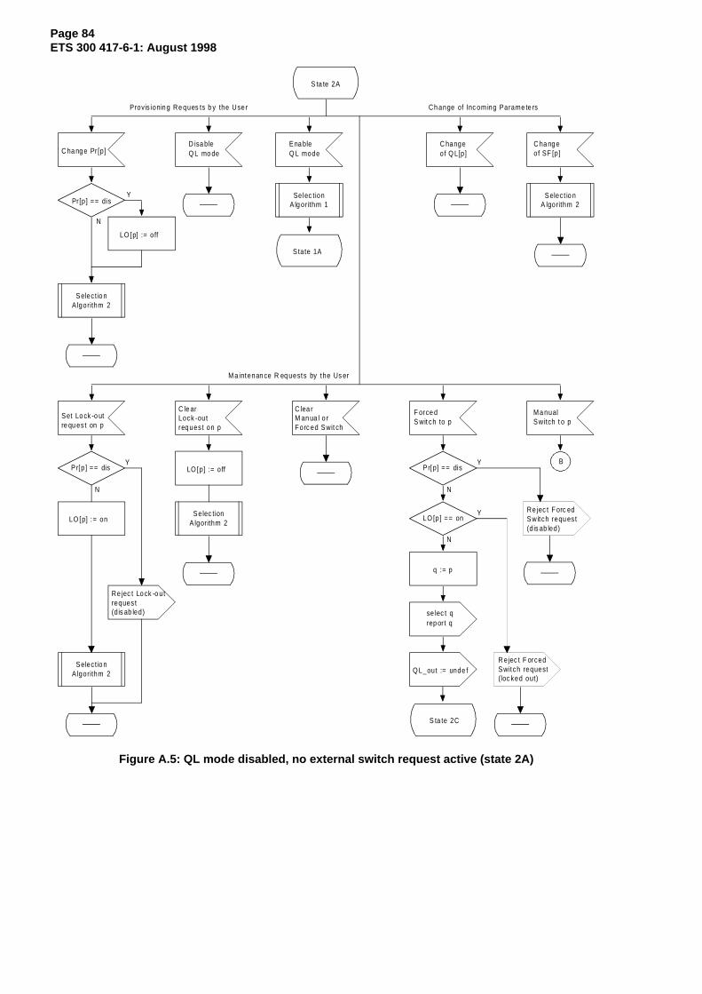
Page 84ETS 300 417-6-1: August 1998
S ta te 2A
C hangeof Q L[p]
C ha ng e of SF [p]C ha ng e Pr [p ]
Ena bleQ L mode
D isa bleQ L mo de
Ch ange of Inc om ing Parame te rsProvis ionin g Re ques ts b y the Use r
M a intenan ce R eq uests by the Us er
Pr [p ] == dis
LO [p] := o ff
Y
N
C lea rM an ua l o rF orc ed Swit ch
M a nualSwitch t o p
F orce d S wit ch to p
Set Lo ck -o utre qu es t on p
C le arLock -outreq ues t on p
S tate 1A
Re jec t Lo ck -o utreques t(d is ab led)
P r[p ] == dis
S ta te 2C
q := p
Pr[p] == dis
LO [p] == on
se lec t qrep or t q
Re jec t F orc edSwitch requ es t(d is ab led)
BY
N
Y
N
Y
N
Q L_out := unde f
Selec tionA lg orithm 1
Selec t io nA lgorithm 2
Selec tionA lgorithm 2
Selec tio nA lgorithm 2
Selec tio nA lgorithm 2
LO [p] := o ff
LO [p] := on
R ejec t F orcedSwitch request(loc ked out)
Figure A.5: QL mode disabled, no external switch request active (state 2A)
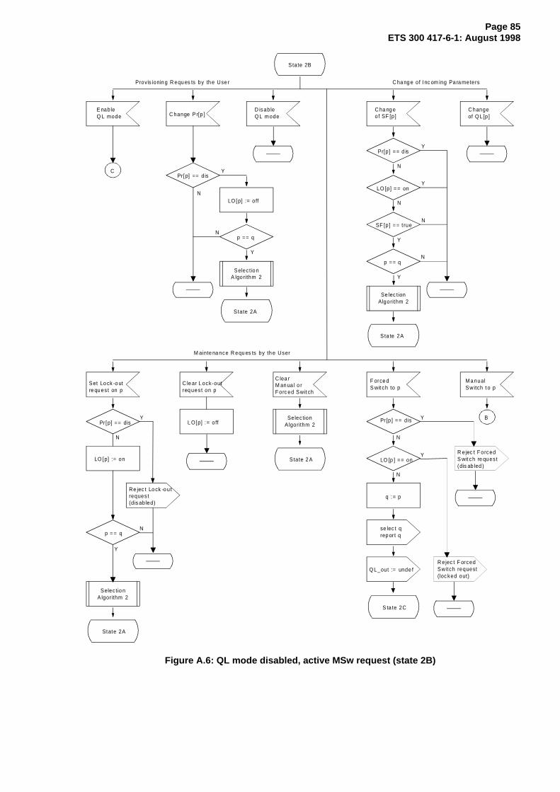
Page 85ETS 300 417-6-1: August 1998
State 2B
C hangeof Q L[p]
C ha ng e of SF [p]C hange P r[p ]
E nableQ L mode
D isableQ L m ode
C ha ng e of I nc om ing Para metersProvis ionin g R equ es ts by th e Use r
M ainte na nce R equ es ts by th e User
Pr [p] == d isY
N
C lea rM an ua l o rF orc ed Swit ch
M a nualSwitch t o p
F orce d S wit ch to p
Set Lo ck -o utre qu es t on p
C le ar L ock-outreq ues t on p
Re jec t Lo ck -o utreques t(d is ab led)
Pr [p] == dis
S ta te 2C
q := p
Pr [p ] == dis
LO [p ] == on
se lec t qrep or t q
R ejec t F orcedS wit ch re qu es t(dis ab led )
BY
N
Y
N
Y
N
State 2 A
p = = qN
Y
Pr[p] == d isY
N
LO [p] == onY
N
SF [p] == t rueN
Y
Sta te 2A
p == qN
Y
State 2A
LO [p] := o ff
C
p == qN
Y
State 2A
Q L_out := unde f
Selec t io nA lgorithm 2
Se lec tionAlgorithm 2
Selec tio nA lgorithm 2
Selec tionA lgorithm 2L O[p] := o ff
LO [p] := on
R ejec t F orcedSwitch request(loc ked out)
Figure A.6: QL mode disabled, active MSw request (state 2B)

Page 86ETS 300 417-6-1: August 1998
State 2C
Ch angeof Q L[p]
C ha ng e of SF [p]C hange P r[p ]
EnableQ L m ode
D isableQ L mo de
C ha ng e of I nc om ing Para metersProvis ionin g R equ es ts by th e Use r
M ain tena nce Re ques ts b y the Use r
Pr [p] == d isY
N
C learM anual orF orce d Sw itc h
M a nualSwitch t o p
Fo rced Switch to p
Set Lo ck -o utre qu es t on p
C le ar L ock-outreq ues t on p
State 1C
Re jec t Lo ck -o utreques t(d is ab led)
Pr [p] == dis
S tate 2C
q := p
Pr[p] == dis
L O[p] == on
s elec t qrep ort q
Q L_out := unde f
R e jec t F orc edSwitch reques t(disabled)
Y
N
Y
N
Y
N
State 2A
p = = qN
Y
State 2A
p == qN
Y
State 2A
LO [p] := o ff
Re jec t M an ualSwitch requ es t(F Sw ac tive )
Q L_out := Q L[q]
Selec t io nA lgorithm 2
Selec tio nA lgorithm 2
Selec tionA lg orithm 2L O[p] := o ff
LO [p] := on
R eje ct F orcedSw itch req ues t(lo ck ed o ut )
Figure A.7: QL mode disabled, active FSw request (state 2C)

Page 87ETS 300 417-6-1: August 1998
State 1B
C
Y
N
Y
N
Y
N
Y
N
Y
N
State 1 A
Q L[ q] <= D NU
p := 1
p := p + 1
Pr [p ] == d is
LO [p ] == on
Q L[p] > Q L[q]
p == M
R eques t to sw itchto Q L enabled modewhile a m anualsw itch is ac tive
A
Y
N
Y
N
Y
N
Y
N
Pr[p] == d is
LO [p] == on
QL[p] <= D NU
QL[p] < QL[q]
q : = p
selec t qrep ort q
Q L_ out := Q L[q]
R ejec t M an ua lSwitc h req ue st(Q L t oo lo w)
State 1B
Evalua tio n of M a nua lSwitc h Re qu es t inStates 1 A and 1 B
B
Y
N
Y
N
Y
N
Pr[p] == dis
L O[p] == on
S F [p] == t rue
q := p
se lec t qrep or t q
QL _out := undef
Sta te 2 B
E valuation o f M an ua lS wit ch R eq ue s t inS ta te s 2A a nd 2 B
QL _out := QL [q]
Se lec tionA lgo rithm 1
R eje c t M a nu alS witch re qu es t(d is ab led)
Re jec t M an ua lSwitc h req ue st(lock ed ou t)
R e jec t M an ua lSwit ch req ues t(QL is D NU )
R eje ct M a nua lSwitc h req ue st(d isa ble d)
Re jec t M an ualSwitch requ es t(lock ed ou t)
R ejec t M an ua lSwitc h req ue st(in SF )
Figure A.8: Continuations of previous states
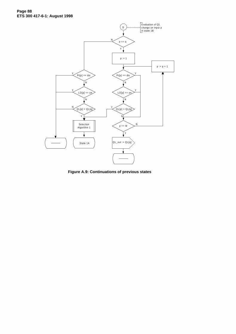
Page 88ETS 300 417-6-1: August 1998
D
Y
N
Y
N
Y
N
Y
N
Y
N
State 1A
p == q
p := 1
p := p + 1
Pr[p ] == d is
LO [p] == on
Q L[p] > Q L[q]
p == M
Evaluation of Q Lchange on input pin s ta te 1B
Q L_out := Q L[q]
Selec tionA lgorithm 1
Y
N
Y
N
Y
Pr[p] == d is
LO [p] == on
Q L[p] > Q L[q]N
Figure A.9: Continuations of previous states

Page 89ETS 300 417-6-1: August 1998
SelectionAlgorithm 1
SelectionAlgorithm 2
p := 1
p := p + 1
Pr[p] == dis
LO[p] == on
QL[p] <= DNU
QL[p] < QL[q]
QL[p] > QL[q]
Pr[p] > Pr[q]
q := p
p == M
select qreport q
Y
N
Y
N
Y
N
Y
N
Y
N
N
Y
p := 1
p := p + 1
Pr[p] == dis
LO[p] == on
SF[p] == true
Pr[p] > Pr[q]
q := p
p == M
select q
QL_out := undef
Y
N
Y
N
Y
N
N
Y
N
Y
N
Y
QL_out := QL[q]
N
Pr[q] == dis
LO[q] == on
Y
N
Y
Y
N
q := 0
QL[q] <= DNU
N
Pr[q] == dis
LO[q] == on
Y
N
Y
Y
N
q := 0
SF[q] == true
report q
Figure A.10: Synchronization selection algorithms for QL mode enabled (1) and QL modedisabled (2)

Page 90ETS 300 417-6-1: August 1998
Annex B (informative): TL models for synchronization information
This annex shows the interfaces (sink and source) - between NNI and SD_CP - that are able to transportsynchronization information using the atomic functions described in different parts of ETS 300 417.
T 12
P12s
E12/P12s
E12
2 048 kH zsync inpu t
2 048 kbit/ssync input
T 12/SD
P12s/SD -scSD _C I_C KSD _C I_ Q LSD _C I_SSFSD _C I_C S
sta tion c lock inpu t typesSD _C I_C KSD _C I_ Q LSD _C I_SSFSD _C I_C S
M I_C S id
M I_C S id
Figure B.1: Synchronization transport port models: station clock inputs
T 1 2
P 12s
E1 2/P 12s
E12
2 048 kH zsync o u tpu t
2 048 kb it/ssync o u tpu t
w ith S SM
T 12/SD
P 1 2s /S D -sc -1
M I_Q Lm in
SD _C I_Q LSD _C I_C S
SD _C I_SSF
sta tion c lock ou tpu t types
SD _C I_Q LSD _C I_C S
SD _C I_SSF
M I_Q Lm in
P 12s
E 12/P1 2s
E12
P 12 s /S D -sc -2
SD _C I_Q LSD _C I_C S
SD _C I_SSF
2 0 48 kb it/ssync o u tp u t
w itho u t S SM
SD _C I_C K
T 12_T I_C K
T 12-LC
P12s_T I_C KP12s_T I_F S
P12s-L C
SD _C I_C K
Figure B.2: Synchronization transport port models: station clock outputs

Page 91ETS 300 417-6-1: August 1998
P12
s/P
0P
4s/S
m
P4s
P12
s
E12
/P12
s
E12
2 04
8 kb
it/s
traf
fic &
sync
inpu
t
E4
E4/
P4s
139
264
kbit/
str
affic
&sy
nc in
put
P12
s/S
DP
4s/S
DM
Sn/
S4
MS
n/S
D
MS
n
RS
n
RS
n/M
Sn
OS
n
OS
n/R
Sn
ST
M-N
traf
fic &
sync
inpu
t
SD
_CI_
QL
SD
_CI_
SS
FS
D_C
I_C
KS
D_C
I_C
S
SD
_CI_
QL
SD
_CI_
SS
FS
D_C
I_C
KS
D_C
I_C
S
SD
_CI_
QL
SD
_CI_
SS
FS
D_C
I_C
KS
D_C
I_C
S
P31
s/S
12P
31s/
SD
P31
s
E31
E31
/P31
s
34 3
68 k
bit/s
traffi
c &
sync
inpu
t
SD
_CI_
QL
SD
_CI_
SS
FS
D_C
I_C
KS
D_C
I_C
S
traffi
c in
puts
car
ryin
g sy
nc in
form
atio
n
E12
2 04
8 kb
it/s
traf
fic &
sync
inpu
t
SD
_CI_
QL
SD
_CI_
SS
FS
D_C
I_C
KS
D_C
I_C
S
E12
/P12
x
P12
s/S
D-tf
P12
s
E12
/P12
s
MI_
CS
idM
I_C
Sid
MI_
CS
idM
I_C
Sid
MI_
CS
id
Figure B.3: Synchronization transport port models: traffic (line and tributary) inputs

Page 92ETS 300 417-6-1: August 1998
P12s
/P0
P4s/
Sm
P4s
P12s
E12/
P12s
E12
2 04
8 kb
it/s
traffi
c &
sync
out
put
E4E4/P
4s
139
264
kbit/
stra
ffic
&sy
nc o
utpu
t
P12s
/SD
-type
1P4
s/SD
MSn
/S4
MSn
/SD
MSn
RSn
RSn/
MSn
OSn
OSn
/RSn
STM
-Ntra
ffic
&sy
nc o
utpu
t
P4s_
TI_C
KP4
s_TI
_FS
P12s
_TI_
CKP1
2s_T
I_FS
MSn
_TI_
CKM
Sn_T
I_FS
SD_C
I_Q
LSD
_CI_
CSSD
_CI_
SSF
P31s
/S12
P31s
/SD
P31s
E31
E31/
P31s
34 3
68 k
bit/s
traffi
c &
sync
out
put
P31s
_TI_
CKP3
1s_T
I_FS
P4s-
LCP3
1s-L
CP1
2s-L
CM
Sn-L
C
SD_C
I_CK
SD_C
I_Q
LSD
_CI_
CSSD
_CI_
SSF
SD_C
I_Q
LSD
_CI_
CS
SD_C
I_SS
F
SD_C
I_Q
LSD
_CI_
CSSD
_CI_
SSF
SD_C
I_C
KSD
_CI_
CKSD
_CI_
CK
traffi
c ou
tput
s ca
rryin
g sy
nc in
form
atio
n
P12s
/P0
P12s
E12/
P12s
E12
2 04
8 kb
it/s
traffi
c &
sync
out
put
P12s
/SD
-type
2
P12s
_TI_
CK
P12s
_TI_
FS
P12s
-LC
SD_C
I_Q
LSD
_CI_
CS
SD_C
I_SS
F
SD_C
I_C
K
MI_
QLm
in
Figure B.4: Synchronization transport port models: traffic (line and tributary) outputs
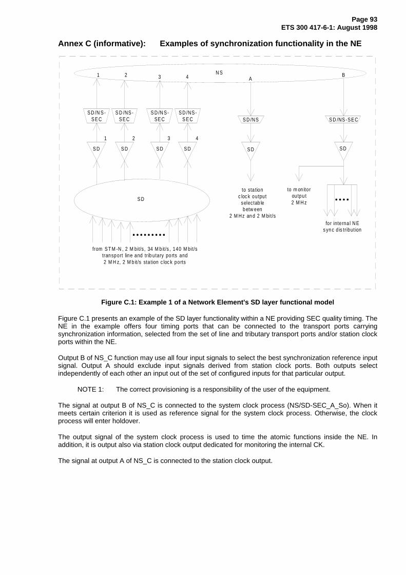
Page 93ETS 300 417-6-1: August 1998
Annex C (informative): Examples of synchronization functionality in the NE
S D
S D /NS -S E C
S D
S D /N S -SE C
S D
S D /N S -S E C
from S T M -N , 2 M bit/s , 34 M b it/s , 140 M bit/stransport line and tr ib utary po rts and2 M H z, 2 M b it/s sta tion c loc k ports
1 2 3
1 2
S D
S D /NS -S E C
4
43
S D
S D /NS
S D S D
S D /NS -SE C
N S
to sta tionc loc k output
selec tab leb etw een
2 M Hz an d 2 M bi t/sfor interna l N E
s yn c d is tr ibut ion
AB
to m on itorou tpu t2 M H z
Figure C.1: Example 1 of a Network Element's SD layer functional model
Figure C.1 presents an example of the SD layer functionality within a NE providing SEC quality timing. TheNE in the example offers four timing ports that can be connected to the transport ports carryingsynchronization information, selected from the set of line and tributary transport ports and/or station clockports within the NE.
Output B of NS_C function may use all four input signals to select the best synchronization reference inputsignal. Output A should exclude input signals derived from station clock ports. Both outputs selectindependently of each other an input out of the set of configured inputs for that particular output.
NOTE 1: The correct provisioning is a responsibility of the user of the equipment.
The signal at output B of NS_C is connected to the system clock process (NS/SD-SEC_A_So). When itmeets certain criterion it is used as reference signal for the system clock process. Otherwise, the clockprocess will enter holdover.
The output signal of the system clock process is used to time the atomic functions inside the NE. Inaddition, it is output also via station clock output dedicated for monitoring the internal CK.
The signal at output A of NS_C is connected to the station clock output.
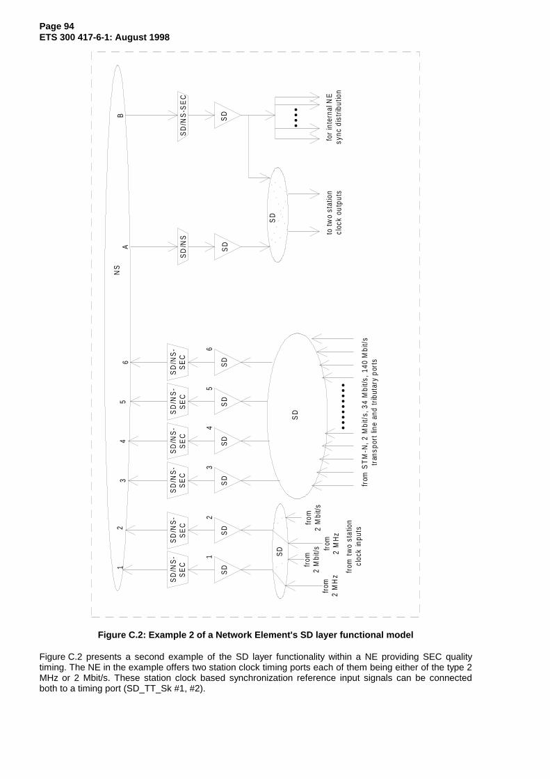
Page 94ETS 300 417-6-1: August 1998
SD
SD
/NS
-S
EC
SD
SD
/NS
-S
EC
SD
SD
/NS
-S
EC
from
ST
M-N
, 2 M
bit/
s, 3
4 M
bit/s
, 140
Mbi
t/s
tran
spor
t lin
e an
d tr
ibut
ary
port
s
12
3
12
SD
SD
/NS
-S
EC
4
SD
SD
/NS
-S
EC
5
SD
SD
/NS
-S
EC
6
65
43
from
tw
o st
atio
ncl
ock
inpu
ts
from
2 M
Hz
from
2 M
bit/s fr
om2
MH
z
from
2 M
bit/s
SD
SD
/NS
SD
SD
SD
/NS
-SE
C
SD
NS
to tw
o st
atio
ncl
ock
outp
uts
for
inte
rnal
NE
sync
dis
trib
utio
n
AB
SD
Figure C.2: Example 2 of a Network Element's SD layer functional model
Figure C.2 presents a second example of the SD layer functionality within a NE providing SEC qualitytiming. The NE in the example offers two station clock timing ports each of them being either of the type 2MHz or 2 Mbit/s. These station clock based synchronization reference input signals can be connectedboth to a timing port (SD_TT_Sk #1, #2).

Page 95ETS 300 417-6-1: August 1998
The NE offers furthermore four timing ports that can be connected to a number of transport ports carryingsynchronization information, selected from the set of line and tributary transport ports within the NE.Signals from timing ports within the range #3 to #6 that are not connected to a transport port will bedisconnected in the NS_C function.
Output B of NS_C function may use all six input signals to select the best synchronization reference inputsignal. Output A should exclude input signals #1 and #2. Both outputs select independently of each otheran input out of the set of configured inputs for that particular output.
The signal at output B of NS_C is connected to the system clock process (NS/SD-SEC_A_So). When itmeets certain criterion it is used as reference signal for the system clock process. Otherwise, the clockprocess will enter holdover.
The output signal of the system clock process is used to time the atomic functions inside the NE. As anoption it can be output also via one or both station clock outputs. The latter to support monitoring of theinternal CK, or to provide a synchronization signal to e.g. a small synchronous NE that is the last in thechain.
The signal at output A of NS_C is connected to the station clock output selector (SD_C). Depending onthe application in the network, station clock outputs #1 and #2 can operate as a protection pair bothsourced by the same input of SD_C, or as two independent outputs sourced by the same or different inputsignals (as appropriate for the application).
NOTE 2: Figure C.2 presents two instances of SD_C functions (the first connected toSD_TT_Sk functions #1 and #2 and the second connected to SD_TT_Sk functions #3to #6) to reflect explicitly the supported connectivity in the NE. The station clock inputsignals can be connect to timing ports 1, and 2 and not to timing ports 3 to 6. Similarly,the line and tributary input signals can be connected to timing ports 3 to 6, and not totiming ports 1 and 2.

Page 96ETS 300 417-6-1: August 1998
Annex D (informative): Delay time allocation
D.1 Delay and processing times for the synchronization selection process
The following delay and processing times are defined for a SEC using the QL enabled mode for thereference selection process. They are based on a ring configuration with 20 NEs. Delay and processingtimes for other applications (e.g. SSU) are for further study.
Three delay time values are defined for the synchronization selection process of the SEC. These are thenon-switching message delay TNSM, the switching message delay TSM and the holdover message delayTHM. These times are measurable at the interfaces of the NE.
These delay times are caused by internal delay and processing times of the SD atomic functions. Thehold off time th and processing time tp are part of the reference selection process of the NS_C function.The settling time ts is part of the SD/NS-SEC_A_So function. For a detailed description see clause 5.
S D /N S -S E C _A _ S o
N S _ C
S D /N S _A _ S k
S D _T T_S k
S D _TT_ S o
X X /S D _A _ S k
S D _C
X X /S D _A _ S ore fere nc esou rce A A
B
C
*
*
C I[A ]
C I[B ] C I[C ]
A I[C ]
N Ec loc k
re fere nc esou rce B
Figure D.1: Example configuration for clock selection
The timing diagrams in the following description are based on a configuration with two clock referencesources as shown in figure D.1.
The dotted functions in the figure do not contribute to delay and processing times. The persistence checkfor SSM acceptance in the XX/SD_A_Sk functions is also not considered in the following as it is smallcompared to the overall time.

Page 97ETS 300 417-6-1: August 1998
D.2 Non switching message delay T NSM
This delay applies when the QL of the selected reference signal changes and the sync source ismaintained. TNSM defines the maximum time between the change of the input QL and the change of theoutput QL.
CI[A]_QL
AI[C]_QL
Y
Y
t
X
X
reference source A
T NSM
p
NE clock
QL
QL
Figure D.2: T NSM
TNSM is due to the processing time tp of the reference selection process in the NS_C function.
A maximum value of 200 ms is defined for TNSM.
TNSM = tp = 0 ms to 200 ms.
D.3 Switching message delay T SM
This delay applies if a switch over to another reference source is performed with a different QL value. TSMdefines the time between the triggering of the new selection (e.g. change of the QL of a reference,EXTCMD, etc.) and the change of the QL at the output.
C I[A ]_Q L
A I[C ]_Q L
A I[C ]_C S
Y
A
Z
t
X
X
C I[C ]_ Q LZX
C I[B ]_Q LZ
B
t
T
s
p
S M
reference source A
reference source B
NE clock
QL
QL
QL
selectedsource
Figure D.3: T SM
TSM is due to the processing time tp of the selection process in the NS_C function and the settling time tsof the oscillator in the SD/NS-SEC_A_So function.
A range of 180 ms to 500 ms is defined for TSM.
TSM = (tp + ts) = 180 ms to 500 ms.
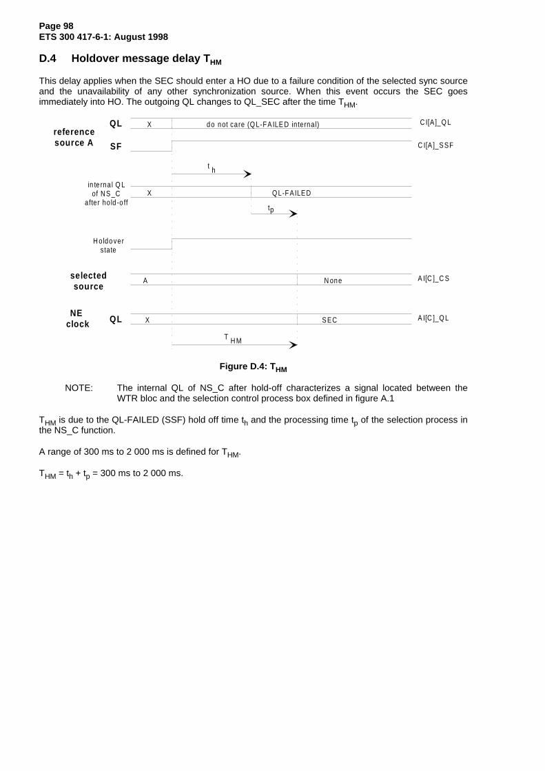
Page 98ETS 300 417-6-1: August 1998
D.4 Holdover message delay T HM
This delay applies when the SEC should enter a HO due to a failure condition of the selected sync sourceand the unavailability of any other synchronization source. When this event occurs the SEC goesimmediately into HO. The outgoing QL changes to QL_SEC after the time THM.
in te rna l Q Lof N S _C
after ho ld -o ff
H o ldo verstate
A I[C ]_Q L
A I[C ]_C S
X
N oneA
X S EC
t
t
Q L-F AILE D
C I[A ]_Q L
C I[A ]_S SF
X do not care (Q L-FA ILE D internal)
p
h
T H M
reference source A
QL
SF
NE clock QL
selectedsource
Figure D.4: T HM
NOTE: The internal QL of NS_C after hold-off characterizes a signal located between theWTR bloc and the selection control process box defined in figure A.1
THM is due to the QL-FAILED (SSF) hold off time th and the processing time tp of the selection process inthe NS_C function.
A range of 300 ms to 2 000 ms is defined for THM.
THM = th + tp = 300 ms to 2 000 ms.
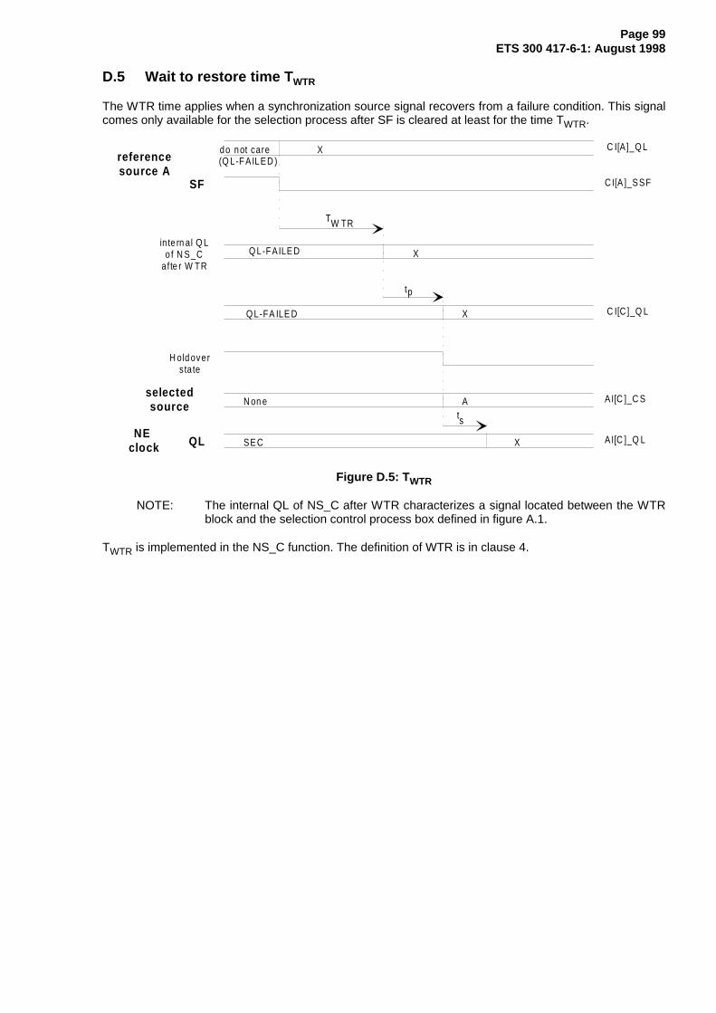
Page 99ETS 300 417-6-1: August 1998
D.5 Wait to restore time T WTR
The WTR time applies when a synchronization source signal recovers from a failure condition. This signalcomes only available for the selection process after SF is cleared at least for the time TWTR.
in te rn al Q Lo f N S_C
afte r W TR
H old oversta te
AI[C ]_Q L
AI[C ]_C S
X
N on e A
XSE C
T
t
Q L-FAILE D
C I[A ]_Q L
C I[A ]_S SF
Xdo not care(Q L-F AILED )
p
W TR
C I[C ]_Q LXQ L-FA ILE D
ts
reference source A
NE clock QL
selectedsource
SF
Figure D.5: T WTR
NOTE: The internal QL of NS_C after WTR characterizes a signal located between the WTRblock and the selection control process box defined in figure A.1.
TWTR is implemented in the NS_C function. The definition of WTR is in clause 4.

Page 100ETS 300 417-6-1: August 1998
Annex E (informative): Overview of inputs/outputs to the atomic functions
CK SSF CSQL
CKSSFCS QL CKSSFCS QL CKSSFCS QL
Selectioncontrol NS
Selector
MI_....
CKSSF
CSAcSSM
SD
SD/NS-SEC
SD MI_.......
MI_...
TL/SD
TL: Transport Layer
CK D FS TSF
MI_CSid (?)
CK SSFCS
AcSSM
MI_...MI_....MI_....
MI_....
SD/NS-SEC
CK CS
SSM
SD
CK CS QL
MI_...MI_...
TL_AI (Sk)
SD_CI (Sk)
SD_CI (Sk)
SD_AI (Sk)
NS_CI
NS_CI
SD_AI (So)
SD_CI (So)
TL_LC
CKFS TL_TIMI_...MI_...
MI_...MI_...
RI_SR/QL
UNC
0M21
SD
SD/NS
QL CKSSFCS
CSQLCK SSF
SD (#2)
TL/SD
SSM
MI_...
TL/SD MI_...
RI_CS
RI_CS
SSF(false,true)QL(INV0,INV1,PRC,INV3,SSUT,INV5,INV6,INV7,SSUL,INV9,INV10,SEC,INV12,INV13,INV14,DNU)
TSF(false,true)QL(PRC,SSUT,SSUL,SEC,DNU,FAILED)
TSF <- SSF or dUNC [or DNU][QL-FAILED <- SSF or dUNC][QL-DNU <- DNU and not SSF]
Holdoff & WtR on:QL-FAILED (in QL-ena mode)SSF (in QL-dis mode)
Holdover on:SSF [or QL<SEC] (start)notSSF [and QL>=SEC] (end)
the NSMD contains a periodfor alignment (guarding time)of QL / defects (races) -order of milliseconds
Figure E.1: Interconnection of atomic functions

Page 101ETS 300 417-6-1: August 1998
History
Document history
August 1997 Public Enquiry PE 9748: 1997-08-01 to 1997-11-28
May 1998 Vote V 9828: 1998-05-04 to 1998-07-17
August 1998 First Edition
ISBN 2-7437-2470-6Dépôt légal : Août 1998
Related Documents


![EUROPEAN ETS 300 742 TELECOMMUNICATION …This ETS mainly is based on ETS 300 300 [13], being responsible for the bit rates 155 520 kbit/s and 622 080 kbit/s and the ITU-T Recommendation](https://static.cupdf.com/doc/110x72/5f4931b4fc46f1542e025226/european-ets-300-742-telecommunication-this-ets-mainly-is-based-on-ets-300-300-13.jpg)