KfK 5429 November 1994 European DEMO BOT Solid Breeder Blanket Compiled by: Mario Dalle Donne Contributors: Helmut Albrecht, Lorenzo V. Boccaccini, F. Dammel, U. Fischer, H. Gerhardt, K. Kleefeldt, W. Nägele, P. Norajitra, G. Reimann, H. Reiser, 0. Romer, P. Ruatto, F. Scaffidi-Argentina, K. Schleisiek, H. Schnauder, G. Schumacher, H. Tsige-Tamirat, 8. Tellini, P. Weimar, A.· Weisenburger, H. Werle Association KfK-Euratom Projekt Kernfusion Kernforschungszentrum Karlsruhe . :' . ,', ... ,.,

Welcome message from author
This document is posted to help you gain knowledge. Please leave a comment to let me know what you think about it! Share it to your friends and learn new things together.
Transcript

KfK 5429 November 1994
European DEMO BOT Solid Breeder Blanket
Compiled by: Mario Dalle Donne Contributors: Helmut Albrecht, Lorenzo V. Boccaccini,
F. Dammel, U. Fischer, H. Gerhardt, K. Kleefeldt, W. Nägele, P. Norajitra, G. Reimann, H. Reiser, 0. Romer, P. Ruatto,
F. Scaffidi-Argentina, K. Schleisiek, H. Schnauder, G. Schumacher, H. Tsige-Tamirat, 8. Tellini, P. Weimar,
A.· Weisenburger, H. Werle Association KfK-Euratom
Projekt Kernfusion
Kernforschungszentrum Karlsruhe
. :' . ,',
... ,.,


KERNFORSCHUNGSZENTRUM KARLSRUHE
Association KfK - Euratom Projekt Kernfusion
KfK 5429
European DEMO BOT Solid Breeder Blanket
Compiled by: M. Dalle Donne
Contributors: H. Albrecht, L.V. Boccaccini, F. Dammel, U. Fischer, H. Gerhardt,
K. Kleefeldt, W. Nägele, P. Norajitra, G. Reimann, H. Reiser, 0. Romer, P. Ruatto,
F. Scaffidi-Argentina, K. Schleisiek, H. Schnauder, G. Schumacher, H. Tsige
Tamirat, 8. Tellini, P. Weimar, A. Weisenburger, H. Werte
Kernforschungszentrum Karlsruhe GmbH, Karlsruhe

Als Manuskript gedruckt Für diesen Bericht behalten wir uns alle Rechte vor
Kernforschungszentrum Karlsruhe GmbH Postfach 3640, 76021 Karlsruhe
ISSN 0303-4003
European DEMO BOT Solid Breeder Blanket
Abstract
The BOT (Breeder Outside Tube) Solid Breeder Blanket for a fusion DEMO reactor is presented. This is one of the four blanket concepts under development in the frame of the European fusion technology program with the aim to select in 1995 the two most promising ones for further development.
ln the paper the reference blanket design and external loops are described as weil as the results of the theoretical and experimental work in the fields of neutronics, thermohydraulics, mechanical stresses, tritium control and extraction, development and irradiation of the ceramic breeder material, beryllium development, ferromagnetic forces caused by disruptions, safety and reliability. An outlook is given on the remaining open questions and on the required R&D program.
"This work has been performed in the framework of the Nuclear Fusion Project of the Kernforschungszentrum Karlsruhe and is supported by the European Communities within the European Fusion Technology Program."
Europäisches DEMO BOT Feststoff-Brutblanket
Zusammenfassung
Es wird ein heliumgekühltes Feststoffbrutblanket für einen Demo-Fusionsreaktor mit Brutstoff außerhalb von Kühlrohren (BOT) vorgestellt. Dies ist eines der vier Blanket-Konzepte, welche im Rahmen des europäischen Fusions Technology Programms entwickelt werden mit dem Ziel, in 1995 die zwei aussichtsreichsten Konzepte für die weitere Entwicklung auszuwählen.
Im Bericht werden der Referenzentwurf für das Blanket und die dazugehörigen externen Kreisläufe beschrieben, und die Ergebnisse der theoretischen und experimentellen Arbeiten auf den Gebieten Neutronik, Thermohydraulik, mechanische Spannungen, Tritium-Handhabung und -Extraktion, Entwicklung und Bestrahlung des keramischen Brutstoffes, Berylliumentwicklung, elektromagnetische Kräfte verursacht durch Plasmazusammenbrüche, Sicherheit und Zuverlässigkeit aufgezeigt. Es wird ein Ausblick auf die noch verbleibenden offenen Fragen und das erforderliche F&E-Programm gegeben.
"Die vorliegende Arbeit wurde im Rahmen des Projekts Kernfusion des Kernforschungszentrums Karlsruhe durchgeführt und ist ein von den Europäischen Gemeinschaften geförderter Beitrag im Rahmen des Fusionstechnologieprogramms."

Table of Contents
1.
2.
3.
4.
5.
6.
lntroduction
Blanket Design
2.1 DEMO Specification
2.2 Design Description
2.3 Fabrication and Assembly
2.4 Neutronic Analysis
2.5 Thermomechanical Analysis
Main Helium Coolant and Helium Purification System
3.1 Main Helium Coolant System
3.2 Helium Purification System
Tritium Control
Tritium Extraction System (TES) for the Blanket Purge Gas
Li4Si04 Pebbles
6.1 lntroduction
6.2 Fabrication
6.3 Li4Si04 Pebble Characterisation
6.4 Properties
6.5 Tritium Release
6.6 Compatibility
6.7 Irradiation and High-temperature Behaviour,
Thermal Cycling Tests
6.8 Long-term Activation I Waste
1
3
3
4
11
13
20
25
25
27
28
31
34
34
35
36
36
37
37
37
39

7. Beryllium 40
7.1 Pebble Fabrication 40
7.2 Compatibility 41
7.3 Behaviour of Beryllium und er Irradiation 41
8. Mechanical Behaviour During Disruptions 44
8.1 Electromagnetic Analysis 45
8.2 Stress Analysis 47
8.3 An lmproved Design with First Wall Toroidal Connection 48
8.4 Conclusions 48
9. Safety and Environmentallmpact 49
9.1 Toxic lnventories 49
9.2 Energy Sources for Mobilisation 51
9.3 Fault Tolerances 52
9.4 Tritium and Activation Products Release 53
9.5 Waste Generation and Management 55
10. Reliability and Availability 56
10.1 Blanket Segments 56
10.2 Cooling System 59
10.3 Conclusions 60
11. Remaining Criticallssues. Required R&D Program 60
11.1 Behaviour of Beryllium Under Irradiation 61
11.2 Behaviour of the Li4Si04 Pebbles Und er Irradiation 61
11.3 Tritium Control 62
11.4 Design lmprovements and Validation 62
12. Conclusions 63
13. References 66

1. lntroduction
ln the framework of the European Community Fusion Technology Program four
blanket concepts for a DEMO reactor are being investigated. DEMO is the next
step after ITER. lt should ensure tritium selfsufficiency and operate at coolant
1emperatures high enough to have a reasonable plant efficiency. These investiga-
1ions, which include R. & D. work, aim at a weil founded choice among various
concepts in view of developing blanket modules to be tested in ITER only for the
most promising blankets.
lwo of the four blankets are based on the use of a liquid meta I breeder, the other
two on the use of a solid breeder. The latter have many features in common: both
use high pressure helium as coolant and helium to purge the tritium from the
breeder material, martensitic steel as structural material and beryllium as neutron
rnultiplier. The configurations of the two blankets are, however, different: in the
B.I.T. (Breeder Inside Tube) concept the breeder material is LiAI02 or Li2Zr03 in
the form of annular pellets contained in tubes surrounded by beryllium blocks,
the coolant helium being outside the tubes [1, 2], whereas in the B.O.T. (Breeder
Out of Tube) the breeder and multiplier material are Li4Si04 and beryllium peb
bles placed between plates containing channels where the coolant helium is flow
i ng. The present report deals with the BOT solid breeder concept.
The proposed solid breeder blanket materials have a high melting point, are not
very chemically active and, of course, do not present MHD problems. lf kept at
sufficiently high temperature they readily release the tritium produced, making
possible the tritium in-situ removal by a helium purge flow. Tritium extraction
from helium is of course much simpler than from water or a liquid meta I.
Helium is better suited than water as the coolant of a Iithium ceramic blanket.
Water reacts with lithiated ceramies producing Iithium hydroxide, which has a rel
atively high vapor pressure. This, besides affecting the integrity of the ceramic,
could cause unduly high Iithium transport due to the temperature gradients
present in the blanket. Furthermore, water at temperatures higher than 600 oc reacts also with beryllium producing hydrogen. ln case of porous beryllium the re
action is selfsustaining. Helium, on the contrary, is an inert gas and, as the exper
ience with helium cooled fission reactors shows, can be kept extremely pure (total
amount of impurities < 1 ppm) even in large and complex circuits. Unlike water,
helium can be kept at high temperatures without need to increase the pressure,
thus the problern of keeping the minimum temperature in the breeder material
above a certain Ievei, to ensure low tritium inventories in the breeder, becomes
-1-

much easier, asthermal insulating gaps between breeder and coolant arenot re
quired. A further advantage of helium is that leakages to the plasma chamber
have much less severe consequences than water leakages.
fhe present design has developed in various stages [3, 4, 5], which, essentially,
were improvements in view to solve the problems posed by the behavior of beryl
liumund er irradiation and to increase the availability of the system. The design is
based on the following principles:
a) The use of Iithium orthosilicate (Li4Si04) as breeder to have fast tritium re
lease (low tritium inventory), high Iithium density and low Iithium partial
pressure at high temperatures (low Iithium transport).
b) The use of small Li4Si04 pebbles to avoid thermal stress problems in the
breeder material and to provide a weil defined path for the helium purge
flow.
c) The use of pebble beds of relatively small dimensions, especially in the verti
cal direction, to avoid thermal ratcheting of the container walls or excessive
breaking up of the pebbles.
d) The use of a helium purge flow at atmospheric pressure to reduce the
amount and probability of tritium Iosses and to reduce the mass flow rate of
the purge gas system.
e) The use of the Breeder Out-of-Tube solution to keep the thickness of the
coolant channels within reasonable Iimits.
f) Cool the first wall with cold (in Iet) helium; keep the minimum temperature
of the breeder above 300- 350 oc to reduce the tritium inventory; keep the
beryllium temperature as low as possible (reduce beryllium swelling).
g) Use of radial toroidal modules, which allow a good filling with breeder and
multiplier of the space available in the blanket region and Subdivision of the
modules in submodules. This reduces the thermal stresses, makes precise
construction easier and gives the possibility of making significant tests start
ing from the smaller submodules. '
h) Use of a redundant convective cooling system and of a double containment
against tritium Iosses for safety improvement.
-2-

2. Blanket Design
2.1 DEMO Specification
The common basis for the blanket selection process is a DEMO-reactor specified
by a Test Blanket Advisory Group (TAG). This specification is not the result of a de
tailed reactor study but a set of boundary conditions and minimum requirements
for breeding blankets. Table 2.1 [6] shows the main parameters of DEMO, largely
derived from NET (Next European Torus).
Table 2.1 Selected DEMO specifications
Majorradius [m]
Minor radius [m]
Aspect ratio
Plasma current [MA]
Fusion power [MW]
Averageneutron wallloading [MW/m2)
Surface heat flux [MW/m2)
Reference operating mode
lmpurity control
Firstwall protection
Number of TF coils
Toroidal magnetic field on axis [T]
Number of segments
Blanket/shield thickness [m]
6.3
1.82
3.45
20
2200
2.2
0.4 average
0.5 peak
continuous
double-null
divertor
none
16
6
32 inboard,
48 outboard
0,86 (inboard)
1.86 (outboard)
The minimum requirements specified for all blanket concepts are:
tritium self-sufficiency (taking into account 10 horizontal ports of 3 m
height and 1 m width)
-3-

full power life-time 20000 h, resulting in 70 dpa maximum first wall dam
age.
coolant conditions sufficient for electricity generation with a thermal effi
ciency 11 ~ 30 % where 11 is defined as the ratio between the electricity pro
duction from the blankets to the sum of neutron power and surface heat
flux to the blankets.
blanket resistance to a major plasma disruption (current decay from 20 MA
to zero in 20 ms) suchthat segments may be non operational but still be re
movable by standard exchange procedures.
thermal and mechanicalloads acceptable for the martensitic steel MANET.
2.2 Design Description
Fig. 2.1 shows a vertical cross section of the Demo blanket surrounding the plas
ma. Various horizontal sections are shown as weil. The poloidal magnetic field
has two points where it equals zero, and thus it is called a double-null configura
tion. The blanket is divided into two parts: an outboard and an inboard blanket.
The DEMO torus has 16 toroidal field (TF) coils. On the outboard side there are
three blanket segments for each TF coil, two of them adjacent to the magnets
and one in the middle. On the inboard side there are two segments. Altogether
there are 48 outboard segments with an opening angle of 7.5 o in respect of the
torus axis of symmetry and 32 inboard segments with an opening angle of 11.25 °.
These arrangements facilitate the loading and unloading of the blanket seg
ments. ln order to increase the breeding capability, the blanket of the inboard
segment is extended to the area behind the divertors and the blanket of the out
board segment is prolonged by a vertical part arranged at the upper segment sec
tion on the opposite location to the upper divertor. This is in accordance with the
specifications of the European Test Blanket Advisory Group.
The radial shielding forms part of the blanket segments. The radial thickness at
the midplane of the inboard segment amounts to 856 mm and of the outboard
segment to 1856 mm. The total length of the blanket segments amounts to
approx. 16 m. The blanket segments except the lower part of the inboard seg
mentare suspended from the flange of the upper access port. This port serves for
the exchange of blanket segments. The following considerations concern a lateral
inboard and a central outboard blanket segment.
-4-

tn ~I I ·-~· .1\ /II ! 11111/
HE COOliNG GAS
A
l8J 0 ~
= 0'
'-,-~\1'1~\ \\ \ l8J \ ~.\! \\ \ \ I I " I
l8J
1856
~
SECTION B-B
0 ~ ,... ~
LATERAL OUTBOARD -1---+---l-lr\-BLANKET
CENTRAL OUTBOARD -I \ \ .,,, I F! BLANKET
INBOARD BLANKET --~-----t----t.J
VIEW A
Fig. 2.1: Vertical cross section of DEMO
blanket (dimensions in mm)
SECTION C-C
SECTION 0-0

2.2.1 The outboard blanket segment
The outer blanket segment is illustrated in Figs. 2.1 through 2.4 and exhibits the
following basic design features:
1. The ceramic breeder material (Li4Si04 pebbles} and the neutron multiplier
(beryllium pebbles} are contained in 10 poloidal sections (Fig. 2.1}
2. The whole arrangement of these sections is contained in a tightly closed box
called a blanket box (Fig. 2.2).
3. The plasma facing surface of the blanket box is called the first wall (F.W.).
The back side of the blanket box is formed by a plate which contains the
poloidal coolant helium feeding manifolds (Fig. 2.2}.
4. At the back of the blanket box there are the main coolant helium feeding
tubes. These are contained in a closed box which is welded to the back of
the blanket box. Blanket box plus feeding tubes box form the segmentbox
(Fig. 2.1, section B-B).
5. A helium cooled vertical radial shield is provided at the back of the segment
box (Fig. 2.1).
6. A horizontal shield is installed inside the segmentbox upper part above the
blanket (Fig. 2.1}.
7. The blanket box and blanket structure are cooled by helium at 8 MPa. The
coolant flows in series through the blanket box and the blanket structure.
8. The blanket structure consists of 8 mm thick cooling plates placed in
toroidal-radial planes. The plates are welded to the front and side walls of
the blanket box (Fig. 2.2 and 2.3}.
9. Alternatively between the plates there are slits of 11 mm thickness filled by
a bed of 0.3 to 0.6 mm diameter Li4Si04 pebbles, or of 45 mm thickness filled
by a binary bed of 1.5 to 2.3 mm and 0.08 to 0.18 mm beryllium pebbles (Fig.
2.3}.
10. Aseparate purge gas system at 0.1 MPa carries away the tritium generated
in breeding materialandin beryllium.
11. For safety reasons, the coolant flow is divided into two completely indepen
dent coolant systems, which feed in series the FW cooling channels and then
the coolant plates in alternating directions.
The general arrangement of the cooling systems is shown in Fig. 2.1. The blanket
box is formed by first wall I radial walls containing radial I toroidal I radial cool-
-6-
Helium Header / Manifold
Cooling Plates with Helium Channels ~·
Section X-X
·Pebble Bed
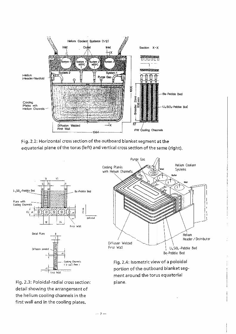
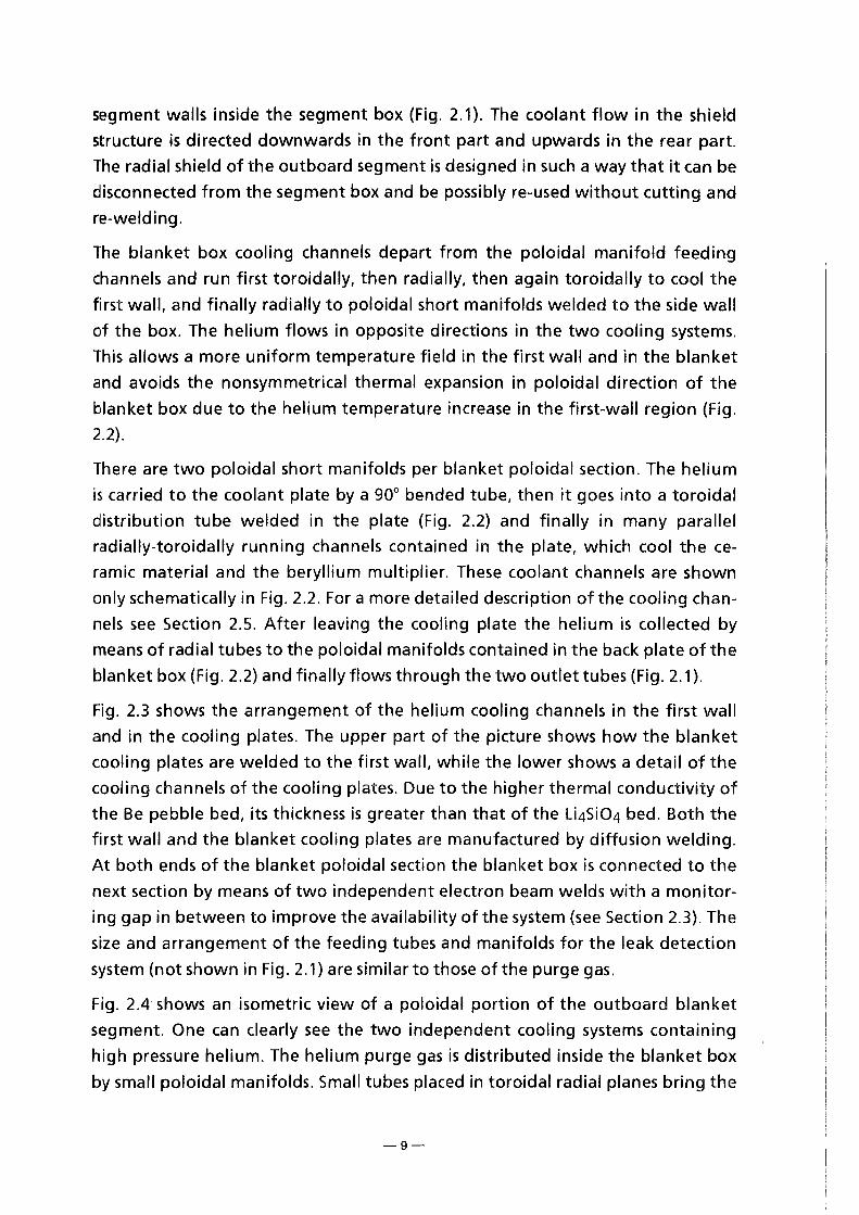
Fig. 2.2: Horizontalcross section of the outboard blanket segment at the equatorial plane of the torus (left) and vertical cross section of the same (right).
Purge Gas
Cool1ng Pliltes with Helium Channels
11 45
Helium Coolant Systems
~L
Oe1a1l Plare
01f fus1on bonded
F1rs1 Wall
Coolmg Channels I b ca.5-7mm I
'·.'•. ,, ·:
polo1dal
Fig. 2.3: Poloidal-radial cross section: detail showing the arrangement of the helium cooling channels in the firstwalland in the cooling plates.
-7-
01ffus1on Welded First Wall Li 4 Si01 -Pebble Bed
Be-Pebble Bed
Fig. 2.4: Isometrie view of a poloidal portion of the outboard blanket segmentaraund the torus equatorial
plane.

ing channels and the back wall with integrated poloidally running cooling gas
manifolds. lt is a closed box with helium-cooled cover plates at top and bottom.
The main coolant feeding tubes (A/D) are connected to the manifolds at the bot
tom, the main outlet tubes (B!C) at the top of the blanket. The purge gas inlet
and outlet lines are connected to the respective manifolds at the top of the blan
ket box. The cooling and the purge gas main tubes inside the segment box are
routed in such a way (e.g. with expansion bends) that stresses due to different
thermal expansionareweil below allowable Iimits.
The cooling gas feed tubes are fixed to the segment side walls by semi-fixed
points (clamps) to withstand forces from plasma disruptions and to keep the
stresses in the pipe walls within acceptable Iimits (see Fig. 2.1). To reduce the in
duced electrical currents in the structures caused by plasma disruptions, the
clamps are electrically insulated from the pipes. The piping outside the blanket
box is surrounded by the segment box, of which the first wall and the side walls
of the blanket box are an integral part.
The segment box side walls are helium-cooled by brazed poloidal cooling tubes.
The cooling gas inlet is at the bottomalso providing coolant to the bottom plate.
The outlet collectors are arranged at the segment top below the horizontal
shield. The segment box is stiffened by horizontal U-shaped stiffening plates to
provide stronger resistance against forces from plasma disruptions. The pipe fix
ing clamps are connected to the stiffening plates (Fig. 2.1 ).
A horizontal shield is installed inside the segment upper part above the blanket
to protect flange region and piping arrangement located there from neutron ir
radiation and to Iimit the radiation Ievei at the space above the flange. This shield
consists of a helium-cooled welded structure filled with granulated shielding ma
terial. Cooling is provided by embedded cooling tubes (Fig. 2.1 ).
The pipings for blanket cooling gas, purge gas and coolant for the segment walls
penetrate the horizontal shield, and are routed with expansion bends to the seg
ment flange. The penetration through the flange plate has to be a gas-tight
welded structure, also providing the fixing points for the supply lines (Fig. 2.1 ).
A radial shield is provided at the back of the segment box. The function of this
shield is to protect the vacuum vessel and the magnetic field coils from excessive
radiation. The radial shield is mechanically attached to, but, if needed, electrically
insulated from the back wall of the segment at the outside. lt is a welded steel
structure of 500 mm total thickness provided with poloidally running cooling
channels and helium cooling. The cooling gas inlet and outlet pipes are arranged
at the top of the shield and are connected in parallel to the cooling system of the
-8-
segment walls inside the segment box (Fig. 2.1 ). The coolant flow in the shield
structure is directed downwards in the front part and upwards in the rear part.
The radial shield of the outboard segment is designed in such a way that it can be
disconnected from the segmentbox and be possibly re-used without cutting and
re-welding.
The blanket box cooling channels depart from the poloidal manifold feeding
channels and run first toroidally, then radially, then again toroidally to cool the
first wall, and finally radially to poloidal short manifolds welded to the side wall
of the box. The helium flows in opposite directions in the two cooling systems.
This allows a more uniform temperature field in the first wall and in the blanket
and avoids the nonsymmetrical thermal expansion in poloidal direction of the
blanket box due to the helium temperature increase in the first-wall region (Fig.
2.2).
There are two poloidal short manifolds per blanket poloidal section. The helium
is carried to the coolant plate by a 90° bended tube, then it goes into a toroidal
distribution tube welded in the plate (Fig. 2.2) and finally in many parallel
radially-toroidally running channels contained in the plate, which cool the ce
ramic material and the beryllium multiplier. These coolant channels are shown
only schematically in Fig. 2.2. Foramore detailed description of the cooling chan
nels see Section 2.5. After leaving the cooling plate the helium is collected by
means of radial tubes to the poloidal manifolds contained in the back plate of the
blanket box (Fig. 2.2) and finally flows through the two outlet tubes (Fig. 2.1 ).
Fig. 2.3 shows the arrangement of the helium cooling channels in the first wall
and in the cooling plates. The upper part of the picture shows how the blanket
cooling plates are welded to the first wall, while the lower shows a detail of the
cooling channels of the cooling plates. Due to the higher thermal conductivity of
the Be pebble bed, its thickness is greater than that of the Li4Si04 bed. Both the
first wall and the blanket cooling plates are manufactured by diffusion welding.
At both ends of the blanket poloidal section the blanket box is connected to the
next section by means of two independent electron beam welds with a monitar
ing gap in between to improve the availability of the system (see Section 2.3). The
size and arrangement of the feeding tubes and manifolds for the leak detection
system (not shown in Fig. 2.1) are similar to those of the purge gas.
Fig. 2.4 shows an isometric view of a poloidal portion of the outboard blanket
segment. One can clearly see the two independent cooling systems containing
high pressure helium. The helium purge gas is distributed inside the blanket box
by small poloidal manifolds. Small tubes placed in toroidal radial planes bring the
-9-

IJUrge flow to the front of the blanket, near the first wall, in each pebble bed (be
;yllium or Li4Si04) slit. Then the gas exits the tube by small perforations and
moves in radial direction towards the back of the blanket. There it is collected in a
second small poloidal manifold (Fig. 2.2 and 2.4) and brought toward the top of
1he blanket box.
2.2.2 Theinboard blanket segment
lhe inboard blanket segment mainly consists of blanket box, piping and radial
shield, all contained in the segment box. A horizontal shield is installed in the up
per segment region to protect from neutron irradiation the TF-coils, the flange
region and the piping above (Fig. 2.1).
The inboard blanket segment is divided into a main part and a small part ar
ranged behind the lower divertor. The lower small blanket has the same Iayout as
the upper main part but is supplied with cooling and purge gas through the bot
tom of the vacuum vessel. However, it has tobe exchanged also through the up
per access port (Fig. 2.1).
The inboard blanket segment has the same general arrangement of blanket box
and shield as the outboard blanket segment. However, the radial shield of the in
board segment is integrated into the segment box. The back plate of the blanket
box contains the poloidally running manifolds for the twofold redundant coolant
system (Fig. 2.1, section C-C}.
Coolant and purge gas supply lines are connected at the top to the respective
manifolds. The supply lines penetrate the horizontal shield above the blanket
and exit the segment through bellows welded to the segment flange to allow
thermal expansion of the pipings (Fig. 2.1). Due to the small place available at the
neck in the upper region of the inboard boxes (see view A in Fig. 2.1}, the diame
ter of the coolant helium feeding tubes is relatively small (132 mm o.d.). How
ever, at variance to the previous case with helium cooling tubes [4], the consider
ably lower helium cooling pressure drop due to the use of many parallel channels
in the coolant plates, allows to maintain also with the inboard blanket the helium
pressure at the Ievei of 8 MPa.
The radial shield consists of steel blocks with cooling channels which are welded
together. The steel blocks should contain 10 + 20% zirconium hydride pellets to
reduce the neutron fluence in the vacuum vessel and in the magnets below
allovable Iimits (see Section 2.4). The radial shield is cooled by a bypass flow of he-
-10-

lium which is separated from the main coolant flow above the horizontal
shield.The downward flow is at the front part of the shield, turned at the bottom
into opposite direction and the upward flow is at the rear side. The lower shield
structure is extended below the blanket box to provide enough shielding at that
area (Fig.2.1).
2.3 Fabrication and Assembly
The fabrication and assembly of the blanket segments is performed in the follow
ing steps:
1. Fabrication of the first wall (FW) sections with a poloidallength of approxi
mately 1 meter: first the grooves forming the FW cooling channels are
milled and the two plates are bounded together by diffusion bonding (also
called diffusion welding). Afterwards the plates are bended to form the FW
and the side walls of the blanket box (Fig. 2.1 and 2.2).
2. Fabrication of the blanket cooling plates: also these plates are fabricated by
milling the cooling channels and bonding them by diffusion bonding. After
wards the toroidal manifolds are welded to the plates (Fig. 2.2).
3. Welding of the blanket cooling plates to the FW and side walls of the box
section (Fig. 2.4): filling of the slits between the plates with the Li4Si04 and
beryllium pebbles. Closing the slits at the back side with porous plates to al
low the passage of the helium purge flow (Fig. 2.2).
4. Welding of the short poloidal manifolds to the side walls of the box section.
Welding of the bended tubes between these manifolds and the plates (Fig.
2.2).
5. EB welding of the various poloidal sections (Fig. 2.1).
6. Welding of the straight tubes from the cooling plates to the central part of
the back plate containing the two outlet helium manifolds (Fig. 2.2).
7. Welding of side parts of the back plate to side walls of the box and to the
plate central part. Finally, welding of two longitudinal plates to the side
plates to close the box (Fig. 2.2).
8. After having closed the blanket box by welding the end plates at the top
and bottom, the connections to the feeding tubes can be made and the
back side ofthe segmentbox can be welded to the blanket box (Fig. 2.1).
9. Afterwards, the shield can be bolted to the back of the segment box and
connected by means offlanges to its helium feed tubes.
1 o. At the end the segment box is proofed with leak and pressured tests.
-11-

All the welds connecting the blanket box to the exterior aredouble welds with an
intermediate gap connected to the leak detection system. This of course improves
the availability of the blanket. The availability is also improved by the fact that no
high leak tightness is required between the parallel coolant channels of the blan
ket cooling plates. Furthermore, Operation with small leakages at the plate
boundaries is allowed, as the box can operate at the full helium coolant pressure
(see Section 2. 5).
The important aspects of this fabrication method are:
1. the diffusion bonding of the FW and of the cooling plates;
2. the U-bending of the blanket box walls;
3. the welding of the poloidal sections of the box walls and of the blanket
coolant plates to these walls.
Work is being performed and/or will be performed in collaboration with industry
and other organizations on these three points.
Diffusion bonding tests were performed on behalf of KfK by the Forschungs
institut für Kerntechnik und Energiewandlung, Stuttgart, with a view to develop
ing a technique by which MANET plate components equipped with coolant chan
nels are manufactured by diffusion bonding. By this bonding technique two
plates are pressed tagether in vacuo for a specified duration at mechanical pres
sure and temperatures up to approx. 1000 oc. On the faces to be joined material
diffusion occurs which producesfirm bonding of the parts.
ln a first test series involving small specimens, 80 mm in diameter, provided with
coolant and inspection channels the most favorable bonding parameters were
determined for conditioning of the surfaces of the faces tobe joined and for pres
sure and temperature. After heat treatment of the bonded specimens a leak test
was carried out at 10 bar internal pressure and, in addition, metallographic inves
tigations and bending tests were performed with specimens made of bonded ma
terial and- for comparison - with those made of the base material. All specimens
were found to be tight. The best bonding results have been obtained for speci
mens with finely ground surfaces - roughness ::; 3 !Jm - and bonding tempera
tures of 980 oc and 1050 oc. The pressure applied du ring bondingwas 30 MPa and
18 MPa, respectively, for one hour and thereafter 7 MPa. Bendingtests with these
specimens showed that the strength was nearly the sametothat of the base ma
terial.
-12-

ln a next step three specimen plates, 320 mm in diameter, with a coolant channel
geometry typical of the first wall, were bonded. Subsequent leak tests at 80 bar
C~nd 1 50 bar internal pressure provided evidence of tightness conforming to the
detection Iimit of the instrument used in the leak tests.
u-bending of the box walls appears in principle feasible as the diffusion wel d will
be positioned in the neutral plane of the double plate and the bending radii are
not too small (86° and 96° for the outboard and the inboard segments respec
tively). However, bending tests for representative diffusion bonded plates of MA
NETwill becarried out in 1995.
lhe EB welding of the poloidal sections of the box walls has been already studied
by industry on behalf of KfK [7, 8] for the FW of the Dual Coolant Blanket Con
cept [9]. This wall is quite similar to the present one and fabricated in the same
way, thus the positive results for this FW can be applied to the welding of the
poloidal sections for the present design. The welding of the blanket cooling
plates to the box walls, however, is quite different. Thus a similar study is re
quired. This will be performed during 1995.
2.4 Neutranies Analysis
The neutranies analysis is based on three-dimensional Monte Carlo calculations
with the MCNP-code [1 0] and nuclear cross-section data from the European Fu
sion File EFF [11]. A geometrical model has been set up for a 11.25° torus sector of
the DEMO-reactor (1 /32 of the torus) with one inboard and one and a half out
board segments. Reflecting boundary conditions are applied at the lateral walls
of the modelled torus sector. The model includes the vacuum chamber, first wall
and blanket segments, the vacuum vessel, top and bottom divertor as weil as a
bottom divertor exhaust chamber with a pumping duct entrance. A heteroge
neaus array of helium cooling plates, beryllium and ceramies pebble beds has
been integrated in the blanket boxes according to their technicallayout. Fig. 2.4-
1 shows a radial-poloidal cross-section of the MCNP torus sector model.
The spatial neutron source distribution is sampled in a special FORTRAN routine
linked to the MCNP-code, for details see U. Fischer [12]. The following plasma pa
rameters are used for the DEMO-reactor [3]: Majorplasma radius = 630 cm, mi
nor plasma radius = 182 cm, elongation = 2.17, excentricity = 16.2 cm, maxi
mum triangularity = 0.57.
-13-

Fig. 2.4.1: Radial-poloidal section o"f the 11.25° torus sector model.
-14-

2.4. 1 Tritium breeding ratio
The use of a beryllium neutron multiplier ensures a high tritium breeding poten
Hal for solid breeder blankets. ldeally it should be arranged with the breeding
material in a homogeneaus mixture at high volume fractions [13]. The drawbacks
that arise by using a heterogeneaus array of alternating beryllium and ceramies
ceramic pebble bed layers separated by helium cooling plates, however, can be
coped with, even at low 6Li-enrichments.
ln the present design a 6Li-enrichment of 25 at% is assumed for the breeding ma
terial Li4Si04 being contained as a pebble bed in radially-toroidally arranged
channels of 11 mm thickness at a packing factor of 64 %. The beryllium pebble
bed, being composed of double size beryllium pebbles, is contained in 45 mm
th ick channels at a packing factor of ab out 80 %. The total radial thickness of the
breeder zone amounts to 30 cm and 54 cm, inboard and outboard, respectively.
ln addition, the divertor region is utilised for breeding.
For calculating the global three-dimensional tritium breeding ratio (TBR) 120,000
source neutron histories have been followed in the Monte Carlo calculation. Ta
ble 2.4-1 shows the neutron balance and the associated statistical errors obtained
in the TBR-calculation. The large beryllium mass inventory of the blanket (about
300 tons in total) results in a high neutron multiplication factor which is necessary
to allow the low 6Li-enrichment. Note that the beryllium mass inventory can be
reduced without Iosses in the TBR by using a Li4Si04 pebble bed without beryl
lium in the divertor breeding region and the upper blanket segment boxes at the
outboard side [3].
Table 2.4-1 Neutronbalance
Neutron multiplication
Tritium breeding ratio
Outboard blanket segment
lnboard blanket segment
Divertor breeding region
Totaltritium breeding ratio
1.75 ± 0.1%
0.79 ± 0.4%
0.25 ± 0.7%
0.09 ± 1.1%
1.13 ± 0.3%
Tritium breeding will be affected by the presence of blanket ports for plasma
heating, remote handling, pellet injection, diagnostics etc .. Ten horizontal ports
-15-
cent .-ed at the equatorial plane of the outboard blanket segments are foreseen
for t he DEMO-reactor. Each blanket port covers an area of 340 cm height times
the -t=ull segment width. The impact on the breeding performance of both liquid
met.al and solid breeder blankets has been assessed previously [14]. Based on
these results, the global TBR is expected to decrease to about TBR = 1.07 in the
presence of ten ports.
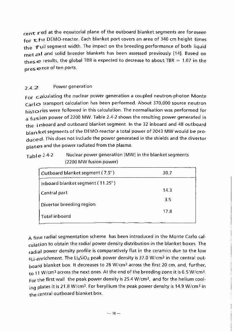
2.4.2 Powergeneration
For calculating the nuclear power generation a coupled neutron-photon Monte
Carl 0 transport calculation has been performed. About 370,000 source neutron
histories were followed in this calculation. The normalisation was performed for
a fusionpower of 2200 MW. Table 2.4-2 shows the resulting power generated in
the i nboard and outboard blanket segment. ln the 32 inboard and 48 outboard
blan ket segments of the DEMO-reactor a total power of 2043 MW would be pro
duced. This does not include the power generated in the shields and the divertor
plates and the power radiated from the plasma.
Tab I e 2.4-2 Nuclear power generation [MW] in the blanket segments
(2200 MW fusion power)
Outboard blanket segment ( 7.5°)
lnboard blanket segment ( 11.25°)
Central part
Divertor breeding region
Total inboard
30.7
14.3
3.5
17.8
A fine radial segmentation scheme has been introduced in the Monte Carlo cal
culation to obtain the radial power density distribution in the blanket boxes. The
radial power density profile is comparatively flat in the ceramies due to the low
6Li-enrichment. The Li4Si04 peakpower density is 37.0 W/cm3 in the central out
board blanket box. lt decreases to 28 W/cm3 across the first 20 cm, and, further,
to 11 W /cm3 across the next ones. At the end of the breeding zone it is 6. 5 W /cm3.
For the first wall the peakpower density is 25.4 W/cm3, and for the helium cool
ing plates it is 21.8 W/cm3. For beryllium the peakpower density is 14.9 W/cm3 in
the central outboard blanket box.
-16-

2.4.3 Afterheat generation
A detailed analysis of the afterheat generation has been performed [15] by com
bining three-dimensional Monte Carlo transport calculations with the MCNP
code and afterheat calculations with the FISPACT [16] inventory code. Neutron
spectra were calculated in 175 energy groups (VITAMIN-J structure) in the first
walll the breeding zone and the blanket back shield for the blanket segment
boxes at the outboard and inboard side and the divertor region. About 600 1000
source neutron histories were followed in the MCNP-calculation for the spectra to
assure a sufficient statistical accuracy. FISPACT inventory calculations were per
formed for the first walll the breeding zone and the blanket back shield of the
mentioned reactor components. The cross-section data of the European Activa
tion File EAF-3 [17] were used in the FISPACT-calculations.
Table 2.4-3 shows the total afterheat power calculated for the central outboard
blanket segment at reactor shut down (t = 0). An integral operation time of
20 1000 hours at a fusion power 2200 MW is assumed in this calculation. The decay
heat typically amounts to 2 % of the direct power generation. The rather large
afterheat generation in the divertor region is caused by the inclusion of the
divertor plates in the calculation. According to the specifications of the test blan
ket advisory group it consists of a 5 mm thick tungsten and a 30 mm thick copper
layer supported by a 40 mm thick steel plate. 8oth tungsten and copper give rise
to a I arge afterheat generation which amounts to 7 % of the direct heating pow
er in the divertor region.
When excluding the divertor platesl MANETI the breeding ceramies and beryllium
typically contribute to the afterheat power by 651 5 and 30 %I respectively. The
corresponding contributions to the direct power generation amount to 151 45
and 40 %I respectively. The afterheat generation in beryllium is decreasing very
fast (within a few seconds) to a low Ievei because it mainly originates from the
short-lived isotope 6He(T112 = 0.8 s). There is a large contribution to the
afterheat of the breeding ceramies of the short-lived activation product 28AI(T1/2
= 2.25 m) immediately after shutdown; afterwards the afterheat of the breed
ing ceramies is dominated by tritium. The decay heat generation for MANET is
roughly constant over the time period of a few minutes after shutdown. Accord
ing to the half life of the main contributor 56Mn (T112 = 2.58 h) it further de
creases by one order of magnitude after one day.
-17-

Table 2.4-3 Afterheat generation [MW] in the blanket segments at reactor
shutdown (2200 MW fusion power, 20000h irradiation)
Direct heating Decay heat power power
Outboard blanket segment (7 .5°)
Central part 28.9 0.588
Upper boxes 1.83 0.032
Totaloutboard 30.7 0.620
lnboard blanket segment (11.25°)
Central part 14.3 0.339
Divertor region (incl. divertor plates) 8.3 0.5917
Total inboard (incl. divertor plates) 22.6 1.21
The maximum afterheat power density at the equatorial plane amounts to 1.1
W /cm3 for the MANET at the first wall (4 % of the direct heating ), to 0.285
W/cm3 for beryllium (2 % of the direct heating) and to 0.396 W/cm3 for the
breeding ceramies ( 1.1 % of the direct heating).
2.4.4 Activation calculations
For calculating the activation the methodological approach developed for the
afterheat calculation has been followed. ln the activation calculation, however, it
is mandatory to take into account material impurities and tramp elements to
analyse their impact on the activation characteristics.
The following impurities have been used for beryllium [18] (in w%): 0.0512 0,
0.0435 Fe, 0.081 C, 0.025 Al, 0.025 Mg, 0.01 Si, 0.001 Zn, 0.006 Ni, 0.0085 Mn,
0.0005 Sc, 0.004 Cu, 0.0003 Ag, 0.004 Ti, 0.0004 Co, 0.002 Pb, 0.002 Ca, 0.001 W,
0.011 U, 0.002 Mo, 0.006 Cr, 0.038 N, 0.001 Zr. The NET material specification [19]
for MANET-1 was assumed in the activation calculation for the steel (in w% ): 0.13
C, 0.35 Si, 1.0 Mn, 0.005 P, 0.004 S, 10.5 Cr, 0.85 Ni, 0.75 Mo, 0.20 V, 0.15 Nb, 0.03
N, 0.05 Al, 0.008 B, 0.02 Co, 0.02 Cu, 0.09 Zr. For Li4Si04 the following impurities
were assumed [3] (w%): 0.158 Al, 0.104 C, 0.02 Ca, 0.008 Cr, 0.0005 Cu, 0.019 Fe,
0.020 K, 0.0049 Mg, 0.085 Na, 0.001 Ni, 0.01 S, 0.02 Pt, 0.0071 Ti, 0.0007 Zn, 0.0073
Cr. Numerical results of the activation analysis are given in Section 6. For detailed
results see H. Tsige-Tamirat and U. Fischer [15]. Only some outstanding features
are discussed in the following.
-18-

The activation behaviour of the MANET steel in the blanket is not significantly
affected by impurities. This holds for the activation inventory, the contact y- dose
rate and the radiological hazard potential. For both beryllium and Li4Si04, on the
other hand, the contact y - dose rate and the radiological hazard potential are
dominated by activation products of impurities, whereas the activation inventory
is dominated by the tritium content. ln addition, there is an impact of secondary
charged particle induced reactions on the activation properties of beryllium and
Li4Si04, see e. g. Tsige-Tamirat [20].
2.4. 5 Irradiation effects on blanket materials
Neutron induced radiation darnage was calculated for the MANET first wall, be
ryllium and Li4Si04 at the equatorial plane of the outboard side of the DEMO
reactor, i. e. at its highest loaded part. The SPECTER darnage code [21] along with
its ENDF/8-V based data library was applied for this purpose. For beryllium, more
advanced darnage cross-sections were used, based on ENDF/8-VI recoil spectra for
the contributing reaction channels and an irnproved method for calculating the
darnage energy [22]. The neutron spectra used to collapse the darnage cross
sections were provided by a three-dimensional MCNP calculation in the SPECTER
100 energy group structure. For an integral Operation time of 20000 hours the re
sulting rnaxirnum radiationdarnage arnounts to 69.5, 20.3 and 29 dpa for the MA
NET, Li4Si04 and berylliurn, respectively.
The rnaxirnurn heliurn production in beryllium is 16300 appm, and the rnaximum
tritiurn production 208 apprn. The peakfast neutron fluence (E > 1.0 MeV) is 2.55
x 1022 crn-2. The rnaximurn tritiurn production rate in Li4Si04 is 3.57 x 10¹³ atorns
cm-3s-1. The total tritiurn production is 382 and 3.14 g/d in Li4Si04 and in beryl
lium respectively. The peak 6Li burn-up is 7.25 at % referred to Litot· Due to the
low 6Li-enrichment of 25 at % the 6Li burn-up is nearly constant across the first
20 crn of the Li4Si04 pebble bed. The burn-up effect on the T8R has been assessed
by performing a Monte Carlo calculation with the proper end-of-life (20 000 h)
6Li-inventories. A T8R-reduction of 0,02 was obtained.
2.4.6 Shielding efficiency
The shielding performance of a breeding blanket in general is poor. Sufficient
shielding has to be provided by material components arranged between the
toroidal field (TF) coil and the blanket: the vacuurn vessel and the back of the
blanket segment. At the inboard side radiation shielding is most crucial. There
-19-

the totally available space amounts to 115 cm. The thickness of the vacuum vessel,
acting as major shielding component, is 30 cm; 85 cm are left for the blanket seg
ment. Actually 59 cm need to be used for the helium-cooled solid breeder blan
ket including 24 cm for the helium supply lines at the back of the blanket. There
fore, 26 cm of the space available for the blanket can be used for providing addi
tional shielding.
Detailed three-dimensional shielding calculations have been performed for the
previous version of the helium cooled solid breeder blanket [3]. lt has been
shown that the required radiation design Iimits for the TF-coil can be met for an
integral operationtime of 20.000 hours by applying different technical measures
for improving the shielding efficiency, e. g. by inserting an efficient neutron mod
erating material at low volume fractions (20% ZrH} into the blanket back shield.
ln order to meet the required radiation design Iimits for an integral operation
time of 10 years a larger volume fraction of an efficient neutron moderating ma
terial (e. g. ZrH or water} has to be inserted into the blanket back shield. Alterna
tively, the vacuum vessel itself can be optimised for ensuring a sufficient shielding
efficiency.
2.5 Thermomechanical Analysyis
Ref. [23] and [24] illustrate in detail the methods and the results of the
thermohydraulic and mechanical stress calculations. Here, it will suffice to recall
the groundrules used for the calculations and the obtained results.
2.5.1 Calculation groundrules
The groundrules can be summarized as follows:
1. The convective heat transfer coefficient between coolant channel walls
and flowing helium has been calculated using the correlation of Ref. [25].
The relevant thermohydraulic properties of helium are taken from the cor
relations proposed in Ref. [26].
2. The effective thermal conductivity of the bed of Li4Si04 pebbles has been
measured at KfK. For the bed of 0.3 - 0.6 mm Li4Si04 in helium the mea
sured effective thermal conductivity data may be correlated by the equa
tion ke [W/mK] = 0.708 + 4.51 x 10⁻⁴ T + 5.66 x 10⁻⁷ T2 with Tin degree
centigrades [27]. The heat transfer coefficient between pebble bed and
containment wall is equal to 0.6 W/cm2K according to the Schlünder corre
lation [28].
-20-

3. The effective thermal conductivity of the binary beryllium bed (1.5 - 2.3
mm and 0.08- 0.18 mm beryllium pebbles) has been obtained by interpo
lating the experimental results of similar beryllium and Li4Si04 pebble- beds
[27]. The used correlations are:
where: ke [W /mK] = effective thermal conductivity of the bed
a [W/m2K) = heat transfer coefficient between pebble bed and con
tainment wall
Tm [°C] = average temperature of the pebble bed
T 0 [°C] = temperature at which the bed filling operation has been
perfomed = room temp.
TMa [°C] = average temperature of the bed containing wall of MANET
Tw [°C] = local wall temperature
ase [K-1) =thermal expansion coefficient of beryllium at Tm [29]
OMa [K-1] = thermal expansion of MANETat T Ma [29]
ll V /V = volume swelling of berylliumund er neutron irradiation
For the present calculations the Beginning Of Life (BOL) situation has been
considered where the highest pebble bed temperatures are expected, thus
llV/V = 0. Section 7 shows howthe effect of llV/V has been evaluated. Fur··
thermore in the present calculation the term in T w for the calculation of
the wall heat transfer coefficient a has been neglected to simplify the cal
culations. This term has not a large effect on a and in any case it is pessimis
tic to neglect it.
4. The pressure drops in the helium systems have been calculated on the base
of Ref. [30].
5. The radial and poloidal power distribution has been obtained by the three
dimensional neutranie calculations (Section 2.4). To obtain a uniform he
lium outlet temperature, the helium mass flow per blanket poloidal sec
tion has been assumed proportional to the power produced in the section
itself. This means that the helium flow to each section should be controlled
-21-

by proper gagging. The same holds for the groups of parallel channels in
the cooling plates used to cool the pebble beds.
6. The temperature and stress calculations have been performed with the FE
computer code ABAQUS [31] and compared with the ASME code [32, 33].
The tridimensional FE mesh was generated using the CAD system BRAVO
3/GRAFEM. The properties of MANET are from Ref. [29] and [34].
2.5.2 Results
Detailed temperature and pressure drop calculations have been performed for
the part of the blanket where the highest power densities are expected. These oc
cur in the outboard blanket poloidal section at the equatorial plane of the torus.
Furthermore the heat flux from the plasma to the first wall (FW) has been taken
equal to the maximum specified value of 50 W /cm2 (Section 2.1 ).
The temperature calculations have been performed for a radial-toroidal section
with a poloidal height of six FW coolant channels corresponding to four blanket
coolant plates (Fig. 2.5.1). The opposite directions of the coolant helium flow and
the resulting helium temperature differences at the radial-toroidal boundary sur
faces of the model have been accounted for by an iterative adjustment of the
temperatures of these surfaces.
Fig. 2.5.1 shows a poloidal radial section of the F.W. and of the front part of the
breeding region with the highest temperatures. The maximum temperature in
the MANET structural material is 520 °C, which is lower than the recommended
Iimit of 550 °(, where the mechanical properties of MANET start to decrease con
siderably. The maximum temperature in the Li4Si04 pebble bed of 907 oc is weil
below the temperature Iimit of 1024 oc dictated by considerations of Iithium
transport (Section 6). ln any case, even if this Iimit were reached locally, this
would not have very severe consequences as this would entail that 1 %o of the Iith
ium is removed from the affected blanket region at 1024 oc du ring the total blan
ket life of 20 000 hours. The maximum temperatures at the interfaces beryl
lium/MANET and Li4Si04/MANET are 500 oc and 550 oc respectively, both weil be
low the compatibility Iimits (Section 7 and 6). The maximum BOL temperature in
beryllium is 637°C. The beryllium temperatures are important for the assessment
of the beryllium swelling (Section 7).
The pressure drop in the helium coolant system between the inlet and the outlet
at the top of the blanket segment is 0.3 MPa (Fig. 2.1) [23].
-22-

,.~n.U
He-l He-ll
0 ® 2 54°C 291°C
",n ;;-
\' ,0 /'
7 ~V '-----~
ZONE 1: 431°C 0 I / ---~
~ I '\
j0 ~ il
ZONE 2: 422"C II~
·~
1-,-
10 ~
Ir§ ZONE 3: 427"C ~
~
101 ll~ ~
I )._
I 'H
I I I
MAX. 50 W/cm2
~ ~ ~ MAX FW 516"C
He-l He-ll He-l
0 0 0 254°C 291°C 254"C
II
~ '· .o.l ::-...; 1"..., &:-
"' \ '<Y I \.:I 7 -L...,-J /
\ .n.l ~ / \ '<>'I
'-.-- ---~ ""' ~
'i;)
1/ 1\ :: "'-'
ll l® 11~
IE .---'--
Ion. ~' I'<>' ~ I
:1 '<g BER.
tJ. ~ '<Y
l.n. '0'
l.o. I'<>'
l.n. I'<>'
[;
COOLING PLATE, 8 mm IMANETI
10 L.--
l® ·~ .. , ~
I ~~ur
II fJfßlfl)" I
L14 SI04 PEBBLE BED, 11 mm
I
I
\
-soo• -kd-J
FIRST WALL 25 mm IMANETI
He-ll He-l
® 0 ...---HELIUM, 80 bar
291°C 254"C
~ 7-P----..... "' = I \ ®.
\ = ),
~
\ ~ I :I
\ l'<>'j
l.o. I"<>'
"-"
r! '0'
l.o.l y 1.,.
~
~
::;:( M ~ ~
-BERYLLIUM PEBBLEBED, 45mm
c He T
' 31 9"C
31 9°C
31 4"C
C ~COLD GAS
H =HOT GAS
TEMP. I"CI
L 900
K 850
J 800
I 750
H 700
G 650
F 600
E 550
0 500
c 450
8 400
A 350
DUMMY CHANNEL
Fig. 2.5.1: Radial-poloiclal section of the FW and blanket in the front part of the
outboard blanketat the torus equatorial plane.
COOLING PLA TE
Fig. 2.5.2: Isometrie view of a poloidal portion of the outboard blanket used for
the FE M calculations. -23-

The stress calculations have been also performed for poloidal sections of the blan
ket. For these calculations the generalized plane-strain condition in the poloidal
direction was applied to the model. This means that planes perpendicular to this
direction remain plane and parallel. This allows to calculate the stresses in all
1:hree dimensions with an essentially three dimensional computation.
The calculations were performed in two stages. ln the first stage, more detailed
<alculations were carried out for the poloidal section shown in Fig. 2.5.1 (however
ior the whole radiallength of the blanket}. ln the second stage, a poloidal section
with only one and half FW channel pitch was considered, however here also the
back part of the blanket box was accounted for (Fig. 2.5.2}. At the present stage,
<onsideration of the back of the segmentbox and of shields is not necessary be
<ause these are approximately at the same temperature as the back plate of the
blanket box, and the back plates are already much more rigid than the walls of
1he blanket box.
ln the firststage the calculations were performed for a} normal blanket operation
with 8 MPa pressure in the coolant channels and 0.1 MPa in the rest of the blan
ket region, b} operation with a leakage from a coolant channel, i.e. 8 MPa helium
pressure also in the rest of the blanket. ln the second stage only the case b} was
considered. The results of the stress calculations can be summarized as follows:
1} Firststage (primary stresses and local thermal stresses}: the maximumvon
Mises primary, and primary plus secondary stresses (both in the FW region}
are in normal operation 56 MPa (at 400 oq and 311 MPa (at 500 °C), while
in the operation with a coolant channelleak these values are 131 MPa (at
400 oq and 361 MPa (at 500 oq respectively. All these values are consider
ably lower than the ASME Iimits for MANET, i.e. 300 MPa (primary stress at
400 °C} and 494 MPa (primary plus secondary stress at 500 oq
2} Second stage (primary stresses and global plus local thermal stresses}: the
primary stresses in the FW are the same as in the previous stage. The maxi
mum primary stress of 258 MPa (at 300 °C} is located at the blanket side
wall near the short poloidal manifold (but not in the welded region}. This
value is lower than the ASME Iimit of 341 MPa. The maximum primary plus
secondary stresses in the FW andin the position of maximum primary stress
are 332 MPa (at 520 oq and 487 MPa at 300 °( respectively, against the
ASME Iimits of 452 MPa and 681 MPa respectively.
-24-

Calculations for the inboard blanket have not been performed so far, because
lower temperatures and stresses are expected, since the power densities and di
mensions are smaller and the cooling helium pressure is the same (see Section 3).
3. Main Helium Coolant and Helium Purification Systems
The main helium coolant system is relatively similar tothat of High Temperature
Helium Cooled Reactors (HTR) and even moretothat of a Gas Cooled Fast Reactor
(GCFR) due to the high pressure and lower temperature of the helium in compari
son of these values for the HTR, so that industrial experience is available for the
design of these systems. The present conceptual design has been performed in
collaboration between Siemens-KWU and KfK.
3.1 Main Helium Coolant System
The main helium coolant system and the reasons for the design choices are de
scribed in more detail in Ref. [35], here only a short description is given.
Fig. 3.1 shows a scheme of the helium cooling and of steam/water systems. The
helium cooling circuits from the 48 outboard segments are connected to two
headers to maintain the complete separation of the two independent cooling sys
tems. Six helium lines are connected to each of the headers, each line being pro
vided with its own biower and steam generator. Five of the lines are in operation
while one line is kept in reserve for the case a replacement of a malfunctioning
line is required. The same arrangement is adopted for the 32 inboard segments,
however here only three helium lines are departing from the headers of each re
dundancy: two in operation and one in reserve. This allows to have blowers and
steam generators of about the same size for the inboard and outboard lines. At
variance with Ref. [35] also the helium coolant pressure in the inboard blanket is
8 MPa rather than 10 MPa. This decrease has been made possible by the choice of
cooling plates in the blanket rather than tube coils, which reduces the pressure
drop considerably. Thus the total pressure drop in the inboard helium coolant cir
cuit is the same as in the outboard blanket, i.e. 0.4 MPa by an average helium
pressure of 8 MPa. This allows to maintain, as in the outboard blanket helium cir
cuit, the pressure head ratio in the blowers to 1.05, which is convenient for hav
ing singlestage blowers [35]. Table 3.1 shows the mean characteristics of the he
lium coolant systems.
-25-

rv 0'>
IN BOARD OUTBOARD
3x 6• Pressure Relief
3x II -- II I 111 ·- ~~-
Pressure Relief Discharge
He Purification He Feed
II
II • II ~ He Purification He Discharge Safety Valves
1
J X ~ 1·· 32-,c~ 111 III ~-"I~. 102,
3x
DN&OO -10160
6JC
Fig. 3.1: Scheme ofthe main helium cooling and ofthe water/steam loops.
( <J closing valve, [><] control valve)
Saturated Steam ... , .............. .~ ........ ~ to Turbine
Feedwater ..,.__
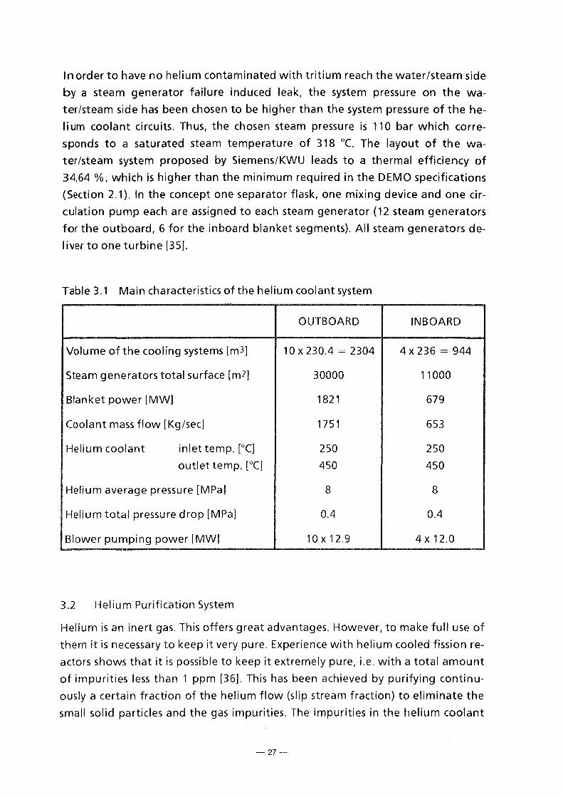
ln order to have no helium contaminated with tritium reach the water/steam side
by a steam generator failure induced leak, the system pressure on the wa
ter/steam side has been chosen to be higher than the system pressure of the he
lium coolant circuits. Thus, the chosen steam pressure is 110 bar which corre
sponds to a saturated steam temperature of 318 oc. The Iayout of the wa
ter/steam system proposed by Siemens/KWU Ieads to a thermal efficiency of
34,64 %, which is higher than the minimum required in the DEMO specifications
(Section 2.1 ). ln the concept one separator flask, one mixing device and one cir
culation pump each are assigned to each steam generator (12 steam generators
for the outboard, 6 for the inboard blanket segments). All steam generators de
liver to one turbine [35].
Table 3.1 Main characteristics of the helium coolant system
OUTBOARD INBOARD
Volu me of the cooling systems [m3] 10 X 230.4 = 2304 4 X 236 = 944
Steam generatorstotal surface [m2] 30000 11000
Blanket power [MW] 1821 679
Coolant mass flow [Kg/sec] 1751 653
Helium coolant inlet temp. [°C] 250 250
outlet temp. [°C] 450 450
Heliumaverage pressure [MPa] 8 8
Helium total pressure drop [MPa] 0.4 0.4
Biower pumping power [MW] 10x12.9 4 X 12.0
3.2 Helium Purification System
Helium is an inert gas. This offers great advantages. However, to make full use of
them it is necessary to keep it very pure. Experience with helium cooled fission re
actors shows that it is possible to keep it extremely pure, i.e. with a total amount
of impurities less than 1 ppm [36]. This has been achieved by purifying continu
ously a certain fraction of the helium flow (slip stream fraction) to eliminate the
small solid particles and the gas impurities. The impurities in the helium coolant
-27-

flow for the present blanket are expected to have less CO and more tritium than
for thermal fission reactors, however in principle the helium purification system
should be very similar. No attempt has been made so far to make a detailed de
sign for the present blanket, however a conceptual design has been made for a
test module of 3 MW power for a previous version of the present blanket [3],
which is of course much smaller than the present blanket. However, this study has
shown that purification is possible, without need of developing new techniques.
ln Ref. [3] it was assumed that the slip stream fraction is 0.1 % of the total coolant
helium ,The same assumption is made for the present design which means a slip
s1ream mass flow of 2.4 kg/sec.
4. Tritium Control
The tritium control and the evaluation of tritium inventories are particularly im
portant as the DEMO blanket has to show the capability of producing sufficient
tritium for a continuous plasma operation by keeping relatively low tritium in
ventories and acceptable low tritium Iosses to the ambient. The main objective of
the tritium control is to Iimit the tritium leakage from the helium coolant system
to the water/steam cycle by permeation through the steam generator. The po
tential sources of contamination of the helium are the tritium permeation
through the firstwalland the walls separating the ceramic breeder and the beryl
lium from the helium coolant.
ln the present design, the tritium control is based on a tritium purge flow system
using helium plus 0.1 % hydrogen at atmospheric pressure to extract the major
fraction of the tritium produced in the blanket. Furthermore, 0.1 % of the helium
mass flow is continuously extracted from the main helium coolant circuit and sent
to a helium purification plant for the extraction of the impurities and of the
tritium coming by permeation from the purge flow or directly injected by the
plasma into the firstwalland then permeating to the main helium coolant system
(Section 3.2).
The tritium permeation through the first wall and the tritium inventory in the
first wall have been estimated using the DIFFUSE code to be between 1 and 100
g/d and between 3 and 300 g respectively [37]. Clearly, the upper value of perme
ation would make the tritium extraction moreexpensive as it would imply the ex
traction of tritium from the relatively large helium mass flow of 2.4 kg/sec. of the
helium purification system (this problern would be much more severe with a wa
ter cooled first wall) and would cause a higher tritiumpartial pressure in the main
helium cooling system and consequently higher tritium Iosses through the steam
-28-
generators. ln any case, tritium in the helium purification system would not be
lost, as it would be convenient to recover it, especially in the case of large quanti-
1ies, with an extraction method similar tothat proposed for the purge flow sys
iem (Section 5).
The tritium permeation through the first wall, a problern common to all the blan
ket concepts, depends mainly on the surface state of the first wall [37]. lf, for in
stance, plasma sprayed beryllium, which at present appears to be the preferred
solution of first wall protection, would be used, the recycle rate to the plasma of
deuterium and tritium is very high and the resulting permeation to the coolant
should be small [38]. ln the present considerations the assumption is made that
the permeation Iosses from the first wall are 1 g/d. The consequences of higher
Iosses will be discussed.
The assessment of the tritium inventories and Iosses have been performed with
methods illustrated in Ref. [39] and [3]. The tritium production quantities have
been determined by neutronic calculations (Section 2.4). The permeation data for
MANET are based on the experimental results of Ref [40].
Table 4.1 shows the main results of these calculations. As in Ref. [3], the tritium in
ventory has been calculated from the measured tritium residence time 1 for the
Li4Si04 new reference pebbles (Section 6). The measured data can be approxi
mated by the following equation:
10835
1; [s] = 0.2556 x 10⁻² e T [K]
where T is the local Li4Si04 pebble temperature. The equation has been inte
grated between the maximum and the minimum temperature of the pebbles of
907 oc and 350 oc respectively applying the factor 1/3 [3] .. Due account was also
taken of the small pebble bed volume fraction (2 %o) at temperatures between
300 and 350 oc.
The greatest tritium inventory is in the beryllium at the end of the blanket life
(EOL). lt was determined by the neutronic calculations minus the tritium released
du ring the blanket operation, calculated with the code ANFIBE (Section 7).
The tritium purge system appears to be quite feasible. For the purge of the
Li4Si04 and of the beryllium pebble bed a helium flow velocity of 0.25 and 0.01
m/sec respectively have been assumed, which would imply a hydraulic resistance
of the porous plate containing the beryllium pebble bed higher than that of the
plate containing the Li4Si04 one. This is probably necessary, as part of the beryl
lium pebbles are smaller than the Li4Si04 ones and the pores in the plates have to
-29-
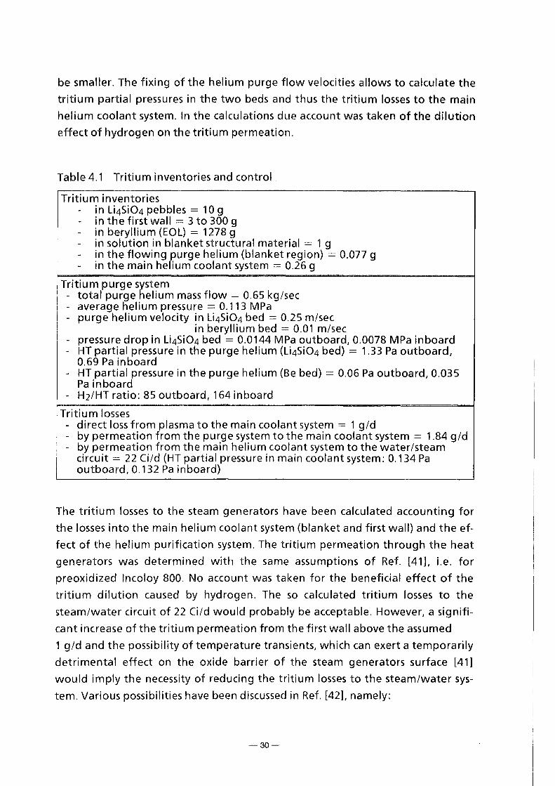
be smaller. The fixing of the helium purge flow velocities allows to calculate the
tritium partial pressures in the two beds and thus the tritium Iosses to the main
helium coolant system. ln the calculations due account was taken of the dilution
effect of hydrogen on the tritium permeation.
Table 4.1 Tritium inventories and control
Tritium inventories - in Li4Si04 pebbles = 10 g - in the first wall = 3 to 300 g - in beryllium (EOL) = 1278 g - in solution in blanket structural material = 1 g - in the flowing purge helium (blanket region) = 0.077 g - in the main helium coolant system = 0.26 g
Tritium purge system - total purge helium mass flow = 0.65 kg/sec - average helium pressure = 0.113 MPa - purge helium velocity in Li4Si04 bed = 0.25 rn/sec
in beryllium bed = 0.01 rn/sec - pressure drop in Li4Si04 bed = 0.0144 MPa outboard, 0.0078 MPa inboard - HT partial pressure in the purge helium (Li4Si04 bed) = 1.33 Pa outboard,
0.69 Pa inboard - HT partial pressure in the purge helium (Be bed) = 0.06 Pa outboard, 0.035
Pa inboard - H2/HT ratio: 85 outboard, 164 inboard
Tritium Iosses - direct loss from plasma to the main coolant system = 1 g/d - by permeation from the purge system to the main coolant system = 1.84 g/d - by permeation from the main helium coolant system to the water/steam
circuit = 22 Ci/d (HT partial pressure in main coolant system: 0.134 Pa outboard, 0.132 Pa inboard)
The tritium Iosses to the steam generators have been calculated accounting for
the Iosses into the main helium coolant system (blanket and first wall) and the ef
fect of the helium purification system. The tritium permeation through the heat
generators was determined with the same assumptions of Ref. [41], i.e. for
preoxidized lncoloy 800. No account was taken for the beneficial effect of the
tritium dilution caused by hydrogen. The so calculated tritium Iosses to the
steam/water circuit of 22 Ci/d would probably be acceptable. However, a signifi
cant increase of the tritium permeation from the first wall above the assumed
1 g/d and the possibility of temperature transients, which can exert a temporarily
detrimental effect on the oxide barrier of the steam generators surface [41]
would imply the necessity of reducing the tritium Iosses to the steam/water sys
tem. Various possibilities have been discussed in Ref. [42], namely:
-30-

a) Development of an aluminizing system to reduce the tritium permeation
through the walls of the helium/water-steam heat exchangers.
b) Development of an aluminizing system for the plates separating the breed
er and beryllium from the main coolant system. ln this case in-pile tests are
required to investigate a possible degradation of the AI203 layer under ir
radiation, especially in presence ofthermal stresses, and the compatibility
with lithiated ceramics.
c) Development of a permeation barrier for the inner surfaces of the MANET
first wall coolant channels.
d) lnvestigation of the necessity and/or possibility of maintaining an oxidiz
ing atmosphere in the main helium coolant system to allow the selfhealing
of the AI203 layer on the surface of the permeation barrier.
e) Development of catalyzers to promote the oxidation of HT to HTO in the
main helium coolant system.
f) lnvestigation of the possibility of diluting the amount of tritium in the
main helium coolant system with a certain amount of hydrogen and its ef
fects on reducing the tritium permeation through the steam generators.
This work should be part of the further R&D program.
5. Tritium Extraction System (TES) for the Blanket Purge Gas [43]
Tritium is expected to be released in two chemical forms (HT and HTO) from the
blanket zone. Therefore, two specific process steps are used for its recovery from
the purge gas: freezing out of 020 (0 = H,T) in a coolerat 173 K, and adsorption
of 02 on a molecular sieve (MS) bed at 78 K. This concept has been chosen after
reviewing several TES proposals published for a NET/ITER solid breeder blanket. lt
is characterized by two main advantages:
a) Only a few components are exposed to the high gas flow rates of the pri
mary purge gas loop; most of the gas processing and separation work is
carried out in secondary loops where much smaller flow rates are applied.
b) The technical feasibility of the concept has been investigated with a posi
tive result by an engineering company (Linde AG), who also provided a first
Iayout of the primary gas loop for two alternative purge gas pressures.
The main TES requirements and design parameters are summarized in Table 5.1.
-31--

fable 5.1: Requirements and Design Parameters of the Tritium Extraction System
Tritium Production Ratea) 383 g/d - 63 mole T2/d -
Mass Flow of Helium Purge Gas 0.65 kg/s - 5.8 X 1 os mole/h -
Average Helium Pressure p(He) - 110 kPa -
Swamping Ratio He: H2 - 1000 : 1 b) -
Mass Flows and Concentrations Purge Gas Component
TES lnlet TES Outlet
He 14 x 106 mole/d 14 x 106 mole/d
H2 14 x 103 mole/d 1400 mole/d
HTc) 101 mole/d < 10 mole/d
HTO + H2Qc) 25 mole/d 0.2 mole/d
lmpurities (N2, CO, CH4, ... ) < 5 mole/d < 1 mole/dd)
a) Production rate = removal rate
b) With respect to the capacity of the MS beds and the U getter beds it would
be desirable to have a ratio He : H 2 = 5000 :1 and a corresponding ratio
of H: T = 41.9
c) lt is assumed that tritium is released from the breedermaterial (Li4Si04) in
the form of gaseaus HTO; the releaserate is 126 mol HTO/day.
About 80 % of the tritiated water will be chemically reduced at the steel
walls of the blanket; thus one gets 25 mol HTO/day + 101 mol HT/day; in
addition, some of the HTO may be converted into H20 by isotopic ex
change
d) Some removal is necessary to avoid the accumulation of impurities
A simplified blockdiagram of the TES primary loop is shown in Fig. 5.1.
Aprecooler PC1 is used to cool the purge gas to 308K; the gas is then transferred
to the main cooler C1, where it is further cooled to 173K. At this temperature, the
Q20 content of the gas is almost completely condensed and frozen out at the sur
face ofthe cooling tubes; the residual concentration is <0.015ppm.
-32-

-~1 BLANKET ~....., _______ .......,.
Adsorber Heating Loop
Figure 5.1: Block Diagram of the Tritium Extraction System
ln order to prevent the accumulation of more than 1 OOg tritium in the cooler C1,
its operationtime will be about 32 hours. The purge gas is then directed to a sec
ond cooler C2, while the ice collected in the first one is thawed. Recovery of
tritium from the water molecules is carried out in a secondary loop (020-Loop) by
using the water gas shift reaction and a Pd/Ag diffusortoseparate the hydrogen
isotopes from helium and CO.
Further processing of the primary purge gas is carried out by using the second
precooler PC2 and three simultaneously operated SA molecular sieve beds (MS
beds); the operation cycle includes 3 steps:
1. Adsorption of hydrogen isotopes and gaseous impurities at 78 K,
2. Desorption of hydrogen isotopes and co-sorbed helium at T s; 160 K,
3. Re-cooling to 78 K.
To enable steps 2 and 3, the MS beds are connected to an Adsorber Heating Loop,
which additionally serves to separate 02 from He, and an Adsorber Recooling
Loop. The operation time of each step is 6 hours; thus, the tritium inventory of
the MS beds will remain below 100 g. Storage of the recovered HT/H2 is carried
out by using uranium getter beds in the 020-Loop as weil as in the Adsorber
Heating Loop.
-33--

6. li4Si04 Pebbles
6.1 lntroduction
u4si04 has been chosen as reference material for the KfK BOT concept because of
its high Iithium density and fast tritium release. To reduce thermal stresses and
thus to improve mechanical stability small pebbles are used. He + 0.1 vol% H2 is
used as reference purge gas to improve tritium release.
The blanket design imposes the following requirements:
1. Pebble density > 90% TD to achieve a sufficiently large breeding ratio
2. Thermal stability: vaporization Iosses < 1 %o (2 x 10⁴ h). This Iimits the
maximum pebble temperature to < 1020 oc.
3. Mechanical stability: fraction of dust ( < 10 !Jm) < 1 %o
4. Compatibility with
austenitic and martensitic steel (Iimits the contact temperature to < 800 °C}
beryllium (Iimits contact temperature to < 700 °C}
5. Tritium residence time < 10 d. This requires a minimum pebble tempera
ture ;:::.:: 300 oc.
These requirements must be satisfied for DEMO relevant irradiation conditions,
which are characterized by
• pu lsed operation (2 x 10⁴ cycles, temperature change 300 °C, temperature
rate of change of about 2-3 °C/s, in a few cases up to 30 °(/s)
e irradiationtime 2 x 10⁴ h
• Iithium burnup 5- 10%
e darnage 20 dpa
Very important parameters are the thermal conductivity of the pebble bed and
the heat transfer coefficients between the pebble bed and adjacent walls because
these determine the temperature distribution in the bed.
The data in the following are taken from the extensive status report prepared Oc
tober 1991 [3], if not otherwise specified. Only newer work not contained in [3] is
referenced.
-34-

6.2 Fabrication
6.2.1 Starting materials
Lithium orthosilicate (Li4Si04) is readily available. The cost of powder is about
60$/kg. Si02 is very widely used in the ceramies industry. The cost is about 5 $/kg
Typical purity Ieveis of the powders are:
Li4Si04: Al < 0.002, Na 0.070, K 0.028, C 0.564 wt%
Si02: Al < 0.021, Na 0.0026" K 0.002, C < 0.007 wt%
The used enriched Iithium was in form of Li2C03 with 95.56 % 6Li enrichment.
Typical purity Ieveis are: K 72, Na 123, Ca 507, Fe 20, Cu 35, Mg 30, Ba 10, Pb 4
(appm).
6. 2.2 Fabrication process
The reference pebbles are fabricated by Glaswerke Schott by melting a mixture of
Li4Si04 and Si02 powder (in case of 6Li enriched Li4Si04 , a mixture of Li4Si04,
Si02 and 6Li enriched Li2C03 is used) and then spraying the liquid material. This
procedure involves rapid quenching, thus some pebbles contain cracks and stress
es. The pebbles have been optimized by KfK with respect to mechanical stability,
but maintaining the excellent tritium release behaviour of Li4Si04. The reference
pebbles contain an excess of 2 wt% Si02 over the stochiometric composition. For
the larger (0.3 - 0.6 mm 0) pebbles the scatter in the mechanical stability is re
duced by annealing at 1030 oc for 5 min and slow cool-down afterwards. This
causes crystallization of Li4Si04 and the remaining Si02 rich phase to precipitate
thus filling the gaps at the grain boundaries and healing the microcracks. For the
small pebbles (0.1 - 0.2 mm 0) the mechanical stability is reduced by annealing,
therefore they are used as produced. With a wind-sifting machine unround and
hollow pebbles are separated.
The fabrication process is suited for a large-scale, reactor-relevant production. At
the moment the firm Schott can produce 5 kg in 8 hours. A plant for the produc
tion of 30- 40 tonnes per year is readily feasible. A detailed study with the aim to
avoid cracks and thus the necessity of annealing the pebbles in the large-scale
production is underway.
-35-

6.3 Li4Si04 Pebble Characterization
Composition
Purity
Shape
Density
Porosity
pebbles
bed
Pebble diameter (mm)
Grain size (!Jm)
Li4Si04 + 2 wt% Si02
Al 0.016, Ca 0.02, Fe 0.015, Na 0.011, C 0.1 wt%;
Cr 17, K 54, Ni 19, Ti 42, Zn 8 [!Jg/g]
Spherical
97-98% TD
1.49 g/cm3
= 100% open
0.3- 0.6
(annealed)
20-40
0.1 - 0.2
(not annealed)
< 1
Specific surface area (m2/g) 1.3
6.4 Properties
Physical, thermal and mechanical properties for a-Li4Si04, which is the relevant
phase for blanket applications, have been compiled previously [29, 44]. Only peb
ble characteristics of fundamental importance for the design are discussed below.
Thermal stability, vaporization. The total Iithium species vapor pressure is less
than 10-2 Pa below 1120 oc [45] and the LiOH pressure is less than 10-2 Pa below
963 oc at 1 Pa water vapor pressure [46]. Li4Si04 reacts with hydrogen under for
mation of water vapor and an oxygen-deficient surface layer. For the reference
purge gas (0.1 % H2) the total pressure of Iithium bearing species is less than
0.111 Pa below 1024 oc [47]. This suggests that Iithium transport is acceptably low
below ab out 1024 oc because at this temperature the maximum Iithium transport
over the 20000 hours of the DEMO blanket operationtime is less than 1 %o.
Mechanical properties (fracture Ioad). The fracture Ioad characterizes the me
chanical stability of the pebbles. lt is an important parameter for the optimiz
ation of the fabrication route with respect to mechanical stability and to test tem
perature or irradiation induced changes in mechanical stability (Section 6.7). The
conclusions concerning mechanical stability are mainly based on the results of
thermocycling tests (Section 6. 7).
Bed thermal conductivity and heat transfer coefficients. For all relevant bed con
figurations (Li4Si04 pebbles, beryllium pebbles and mixed beds), the bed thermal
conductivity and the heat transfer coefficients at the wall of the bed container
have been measured and the data have been correlated by analytical expressions,
-36-
t~king into account all important parameters [48, 27]. These experiments were
generally performed in vertical test sections with pebble beds of about 50 cm in
IEngth. Although many experiments with large temperature differences between
bed and container walls were performed, no fracture of pebbles, or indentations
o· thermal ratcheting effects on the container walls were observed.
6.5 Tritium Release
l~rge ( = 0.5 mm 0), annealed pebbles of essentially all produced charges have
been tested in purged inpile experiments. Small additions of Si02 and/or AI203
had only a minor influence on tritium release. Tritium residence times for these
pebbles and for the reference purge gas (He + 0.1 vol% H2) at 400 oc were 15 h
for the "old" reference materials (stoichiometric Li4Si04, Schott 86) (9], about 12
[50] and 7 h [51) for the "new" reference material (2 wt% Si02 surplus, Schott
89/3 and 90/6) and 24 h for Li4Si04 plus 2 wt% Si02 and 1 wt% AI203 [50]. There
is no indication that the residence time, i.e. tritium inventory increases with lith
i um burnup in the range up to 3 % [51].
A purged inpile test with small (0.1 - 0.2 mm 0), not annealed pebbles and with
mixed beds of small Li4Si04 and beryllium pebbles with low Iithium burnup has
been performed and is being evaluated (CORELLI-2), a second test up and beyond
to DEMO-relevant Iithium burnup (1 0 %) is und er irradiation (EXOTIC-7).
6.6 Compatibility
Out-of-pile tests of Li4Si04 with austenitic steel 316L and with martensitic steel
1.4914 in presence of NiO (oxygen source) and of water vapor up to 100 Pa partial
pressure (blanket purge gas = 0.1 Pa), indicate an upper temperature Iimit of 800
oc [52]. Out-of-pile tests also showed that the maximum allowable temperature
at the interface Li4Si04/beryllium should be :::; 700 oc [53].
The results of the purged SIBELIUS irradiation [54] are for Li4Si04/beryllium and
those of the closed capsule irradiation COMPLIMENT [55] are for Li4Si04/steel in
agreement with the out-of-pile tests.
6.7 Irradiation and High-temperature Behavior, Thermal Cycling Tests
Irradiation behavior. As mentioned, tritium release and compatibility are not af
fected by irradiation up to a Iithium burnup of 2-3 %. Concerning the mechani
cal integrity of the pebbles the available results are somewhat contradictory [56]:
-37-

whereas in ALICE-3 (600 oc, burnup 2.7 %), SIBELIUS (270- 470 °(, burnup 1 .8 %)
and in EXOTIC-6 (430- 640 oc, burnup 3.1 %), the pebbles were intact after irra
diation, in COMPLIMENT (400- 450 oc, burnup 1.8 %) about 50% decomposed in
to grain-size particles. This result, which was common to most of the other i rradi
ated lithiated ceramies was attributed to temperature shocks caused by scrams of
the OSIRIS reactor. Surprisingly the fracture Ioad of intact pebbles from COM
PLIMENT is essentially the sameasthat of unirradiated pebbles [57]. Irradiations
in the fast reactor FFTF (BEATRIX-1) indicated that the pebbles remain intact up
to 6 % Iithium burn-up (SO % of the peak DEMO value). The now running
EXOTIC-7 experimentwill allow to assess the effects on pebble mechanical i nteg
rity for Iithium burn-ups of 10 - 15 % which are considerably high er then the
DEMOpeak values.
High-temperature behavior. No decrease of fracture Ioad was observed after
heating dry, annealed large (0.3- 0.6 mm 0) pebbles at 800 oc for 1340 h [58] and
dry, not-annealed small (0.1 - 0.2 mm 0) pebbles at 650 oc for 1008 h. For pebbles
containing water, the fracture Ioad drops during the first hours of heating by 30-
50 % until all water is released and stays then constant. Contact with beryllium
did not influence the mechanical strength of the pebbles [27].
Thermal cycling tests. ln tests with up to 1000 thermal cycles with unirrad iated
U4Si04 and mixed Li4Si04/beryllium pebble beds no cracking of the beryllium
pebbles was observed. The Li4Si04 pebbles break independently of size only if the
temperature change over the time exceeds a critical value, which depends on the
pebble temperature [27, 59]. This Iimit is higher than the peak value expected for
the DEMO blanket, as has been shown for the design with cooling coils [59] as
weil as for the present design [60]. Another important result of these experi
mentswas that, although the bed was kept in place by a wire net with mesh size
of about 50 IJm, no broken particle was coming out of the bed although some
broken parts were assmallas 10 1Jm and the heliumwas flowing through the bed
at velocities considerably higher than those foreseen in the Demo-blanket. Tests
with Li4Si04 pebbles irradiated to DEMO relevant burnup ( = 10 %) are in prep
aration.
-38-

6.8 Long-term Activation/Waste
6.8.1 Activation
Calculations. The calculated y-activity of a pure silicate fusion blanket is about
one or several orders of magnitude less than that of aluminate or zirconate blan
kets, respectively [61].
Measu rements. Four years after the COMPLIMENT-HFR irradiation (Cd-screened,
178 FPD, Iithium burnup 0.28 %, neutrons 1.29 dpa, a+t 0.08 dpa) the contact
dose rate of Li4Si04 pellets (the purity of the starting material is similar tothat of
the pebbles) was 24 pSv/hg and the mostprominent y-activities were (in Bq/g):
Mn-54 2.7 x 10³, Co-60 1.2 x 10⁴ (both probably from capsule steel contamina
tions) and Zn-65 4.1 x 10³ [56].
6.8.2 Reprocessing (recovery of Li-6 from irradiated breeder) and waste manage
ment
Reprocessing of the irradiated pebbles by melting is considered to be feasible.
The process would consist in melting the irradiated pebbles with the proper
amounts of Li6 enriched Li2C03 and Si02 and producing the pebbles in the usual
way. The process should be considerably simpler and eheaper than in the case of
5; ntered pebbles where the formation of very fine powder for the sintering pro
cess is required [62]. The firm Schott has produced Li4Si04 pebbles by remelting
u4s;o4 pebbles (charge 90/6). These pebbles have practically the same mechani
cal properties and tritium release characteristics as the usual pebbles.
ßy the Schott production method a material efficiency of 85 % (ratio between
pebbles weight and initial powder weight) is achievable [631, so that, by every re
processing operation, about 15- 20% of the Li4Si04 would not be reused. This
quantity would require a disposal. The activity of this material would not be very
high, as the tritium would be eliminated during the melting process and the ac
tivation is extremely low. However, probably the reprocessing would require re
mote control [62]. The waste disposal aspect has not been so far investigated in
detail. lt should, in principle, not pose very difficult problems [62].
-39-

7. Beryllium
Beryllium is a very effective neutron multiplier. Solid breeder blankets with
lithiated ceramies as breeder and steel as structural material require beryllium to
obtain a tritium breeder ratio higher than one.
ln the present design the beryllium is used in form of small pebbles. This offers
vari ous advantages. Under neutron irradiation beryllium becomes brittle and
swells. Within small pebbles the temperature differences in the pebble are small,
thus the stresses caused by thermal gradients and by different swelling rates
(swelling is temperature dependent) are considerably smaller.
7.1 Pebbles Fabrication
Two kinds of beryllium pebbles form the pebble bed placed between two cooling
plates of the blanket (see Section 2.2). The main structure of pebble bed is given
by the I arger pebbles (1.5- 2.3 mm in diameter) with a packing factor of 63.3 %.
ln the space between the larger pebbles there are smaller beryllium pebbles
(0.08-0.18 mm in diameter) with a packing factor of 17.5%
Both kinds of pebbles are fabricated by melting. The !arger pebbles are a by
product in the metallic beryllium production method of the firm Brush-Welman
and thus relatively cheap. The smaller pebbles are produced by Brush-Welman ei
ther by the rotating electrode method (REP) or by melting and spraying with an
inert gas. Table 7.1 shows the main characteristics of the two kinds of pebbles.
Table7.1
Pebble Closed BeO Other impurities diameter [mm] porosity content [ppm]
Large pebbles 1.5-2.3 0.57% 0.3% Fe 520, Al 345, Mg 1200, Zn 85, Ni 85, Cu 25, Co 8, U 125, Cr 105, Zn 210, N 215
small pebbles 0.08- 0.018 0.86% 0.08% Al 250, Mg 250, Ni 60, (REP fabricat. Cu 40, U 110, Cr 60,
method) N 380, Fe 435
-40-
7.2 Compatibility
Out-of-pile tests show that the compatibility Iimit between beryllium and Li4Si04
is 700 oc [53], and for beryllium/316L steel and beryllium/MANET, the Iimits are
580 oc and 650 oc respectively [64]. The results of these out-of-pile experiments
have been confirmed by the SIBELIUS irradiation performed in a thermal reactor
at 550 oc for 200 hours with a He + 0.1 % H2 atmosphere [54].
7.3 Behavior of Beryllium under Irradiation
The behavior of beryllium und er irradiation, particularly with respect to swelling,
embrittlement and tritium release, is probably the key issue for the solid breeder
blankets. Swelling of the beryllium results from the helium produced by the (n,
2n) reaction while tritium is produced by secondary reactions.
7.3.1 Beryllium swelling
As the results of in-pile irradiations at high temperatures are rather scarce, irra
diations were performed in the thermal reactor SILOE /Grenoble, in the tempera
ture range 240 - 700 oc and for neutron fluences of 2 - 2.5 x 1021 cm-2 (En ;;:::= 1
MeV) corresponding to helium contents of 1100- 1400 appm (BEGONIA experi
ment) [65]. These fluences are of course considerably smaller than the peak values
expected in the present design (16300 appm helium), therefore irradiations are
planned in the fast reactor Phenix to begin at the end of 1994.
As the swelling data for the peak neutron fluences of the present blanket arenot
yet available, modeling work on helium behaviour in irradiated beryllium has
been initiated by KfK. A rather sophisticated computer code (ANFIBE) has been
developed. This code describes the precipitation of helium atoms into intra
granular bubbles, the migration of these bubbles to the grain boundaries to form
intergranular bubbles, the growth and coalescence of these bubbles and their
interlinkage with pores. The description of the helium behavior in beryllium ac
counting for the beryllium properties (mainly surface tension, temperature and
irradiation induced creep) allows to calculate the volume swelling. The compari
son of the ANFIBE calculations with the experiments available from the literature,
including the BEGONIA experiments, bothat low and at high temperatures shows
an excellent agreement [66]. The experimental data covers independently the
ranges of temperatures, fast neutron fluences and helium contents for the
present blanket. However, more data are required to qualify ANFIBE especially
-41-
.h I

from experiments in which irradiations to high fluences have been carried out at
high temperatures.
Fig. 7.1 shows the swelling of the beryllium pebbles calculated with the ANFIBE
code for various temperatures and neutron fluences. The swelling of the beryl
lium pebbles causes a strong increase of the bed thermal conductivity so that the
EOL peak beryllium temperature calculated by the ANFIBE-code is reduced from
the BOL value of 637 oc (Section 2.5) to 500 oc and the resulting EOL maximum
beryllium swelling is 8.3%. The initial space available for the helium flow to
purge the tritium released from the beryllium is 20% of the bed volume, so that
sufficient space is available up to the EOL situation as weil.
7.3.2 Beryllium embrittlement
Firstexperiments were performed with unirradiated beryllium pebbles at room
temperature. The larger pebbles were subjected to compressive tests. The pebble
diameter could be reduced of up to 13% without formation of cracks.
The irradiation-induced embrittlement is very difficult to model and irradiation
experiments are essential. However, contrary to swelling, beryllium embrittle
ment is produced at relatively low fluences which can be easily achieved in ther
mal test reactors. An European collaborative program to investigate the irradia
tion embrittlement of beryllium has been initiated; it involves the exposure of
tensile, disc compact tension and transmission electron microscope specimens to a
fluence of 1.5 x 1021 cm-2 (En > 1 MeV) at temperatures of 200°, 400° and 600 oc in the BR2 reactor at Mol.
The irradiation has been started in August 93 and has been terminated in March
1994. The results of the PIE work will be available at the beginning of 1995.
7.3.3 Tritiumrelease from beryllium
Work on out-of-pile tritium release from beryllium irradiated in the SIBELIUS ex
periment has been started at KfK [54]. Further work on out-of-pile tritium release
is being performed at KfK with beryllium irradiated at low temperatures and
high fluences (1 - 4 x 1022 cm-2, En ==: 1 MeV) in the BR2 reactor. Similar experi
mentswill be performed with beryllium from the BR2 embrittlement experiment,
from a recently started irradiation experiment in HFR and from the Phenix irra
diation.
-42--
.4 I

.:.. w
I
........
12,----------------------~--~--------------~ I Neutron Fluence : up to 2.5 ·10 22 n/cm 2 (E)1MeV) I Helium Content : up to 16300 appm
1 1
1 0 ..J Irradiation Time. : up to 20000 h
/\~--;;--g' 8
Q)
~ Vl 6 (.)
:s Q)
E 4 :::J
: .· ~: '.I . , •: I'~ .· I I \, ./f
/ I r'\.J / I /. ~ •·
- ... . ,,/ -1 ,,.".
0 >
2
~ ./ ; ....... "-' .. .. 1 ;· S.: / ........ / . _I '· ....,... . / I I. .
;.;.--::···/"" • / . I
0 f!i-;i-3.:2.~:.:~:;.:.::~<' 0 1 00 200 300 400 500 600 700 800
Irradiation Tempereture ("C)
Figure 7.1: Beryllium pebbles Volumetrie swelling versus temperature at various fast neutron fluences for the BOT DEMO blanket as predicted by ANFIBE .
1,200,-----------------------------------------~
lnventory affer irradiation: 1278 g
~1.000 ., "' c Q) 800 a;
0:::
E .2 600 ·;: I-
Q)
-~ 400 ö :::J
E 200 :::J
u
0
__... . .--·_.;- ....
".......-·
. sooac"....,.. /"....... . /' ___ .Jso•c··--------
/. ----/
. ,' ,'
,' ~·;:~-<··· ........ · .. ·· ..
700 ac ....
0 1 00 200 300 400 500 600 700 800 Time After the Transient (h)
Figure 7.3: Cumulative tritium release from the beryllium pebbles after a temperature increase in 3'0 sec. up to the shown temperature. Afterwards the temperature remains constant at this value.
100,----------------------------------------, Total Generated Tritium : 2616.6 g Irradiation Time : 20000 h
........ ~ ->....
80
.E 60 c:: Q)
> c::
E 40 • .:::! ....
1-20
0+---.----,---,---.---.----r---.-----~ 300 350 400 450 500 550 600 650 700 750
Irradiation Tempereture ( ° C)
Figure 7.2: Tritium inventory at the BOT blanket end of life (EOL) versus beryllium temperature.
200 ,-
........ 175 C'l -~ 150 c Q)
~ 125
E .2 100 ·;: I-
.~ 75 c :; 50 E :::J u 25
/ .,' I 7soac
goooc / ,/ /,-'-7oo•~
/,,' .·· /~- __ ... ··
/1 . h' .. ···
~~~~--~-- .·
o~~~~~~~~-r~~~~~~~~ 0 25 50 75 1 00 1 25 150 175 200
Time After the Transient (h) Figure 7.4: Cumulative tritium release by temperature increase. Detail for the first hours.

The results of these experiments cannot be directly applied to calculate the
tritium inventory in the DEMO blanket. Therefore it was decided to extend the
code ANFIBE for the calculation of the tritium release from beryllium. The
diffusivity of tritium in beryllium is much higher than that of helium, but the
tritium release is hindered by the helium bubbles {physical trapping) or by the be
ryllium oxide impurity (chemical trapping). The model describing the behavior of
tritium is formally identical tothat of helium, however, a rate-equation has been
added, which accounts for the chemical trapping of the tritium by the oxygen im
purities.
The comparison of the ANFIBE calculations with the experiments of Ref. [54] and
other experiments from the Iiterature [67, 68] shows a good agreement especially
at higher temperatures [69]. However, more extensive experimental data, par
ticularly with respect to in-pile tritium release, is required to qualify the code.
Fig. 7.2 shows the percentage tritium inventory remaining in the beryllium at the
blanket end of life as calculated with the ANFIBE code. Of the total tritium pro
duced in the blanket during its life, i.e. about 2600 g, the half is released and car
ried away by the helium purge flow. Figs. 7.3 and 7.4 show the tritium release
which could occur during an overheating accident at the end of the blanket life
when the tritium inventory in beryllium is the highest. After an initial burst re
lease of about 40 g of tritium, the release is relatively slow.
8. Mechanical Behaviour During Disruptions
One of the crucial problems in the blanket design is to demonstrate the capability
of the structure to withstand the mechanical effects of a major plasma disruption.
ln fact, in all operating tokamaks it has been observed that, under certain cir
cumstances, the plasma collapses and the plasma current decreases very rapidly to
zero. The rapid current variation produces induced eddy currents in the surround
ing metallic structures. These currents, in presence of the strong stationary mag
netic fields, produce large magnetic forces.
ln order to compare the performances of different designs, the Test Blanket Advi
sory Group (1990) gave the following specifications for a reference disruption in
DEMO: "a linear decay of the plasma current from 20MA to zero in 20ms" and
"one disruption during blanket segment life". The only mechanical requirement
was that "the blanket segment may be deformed but it must remain removable
through the port".
-44-

On the basis of these specifications an assessment of the blanket structure (out
board and inboard segment box) has been performed. Some results of this assess
ment have been already presented [70, 71, 72], but a detailed description of
methods and results will be published by the end of 1994 [73].
8.1 Electromagnetic Analysis
The electromagnetic calculation of the eddy currents and of the resulting mag
netic forces has been performed by means of a 3-D finite element method (FEM)
code commonly used for NET/ITER applications [74]. This code cannot take into
account the magnetic properties of the steel MANET; the magnetic permeability
of the material is assumed tobe the vacuum permeability.
As a FEM model of the Demo reactor has been achieved, all the most relevant
parts of the electromagnetic system can be taken into account in the calculation.
The vacuum vessel, the 48 outboard and 32 inboard blanket segments as weil as
the PF-coils are part of the developed model. Particularly, a fine discretization of
the outboard and inboard blanket segments has been realized to account for the
complex design of the components. The presence of a plasma stabilizer ("saddle
loop") attached to each outboard blanket box has been considered as weil.
Fig. 8.1 shows the time behaviour of the induced eddy currents by the reference
disruption. The vacuum vessel current flows in toroidal direction around the plas
ma torus. As each blanket segment is electrically insulated from the other seg
ments and components of the reactor, the blanket current flows inside the seg
ment closing a loop through first wall, side walland back wall. The maximum cur
rent is reached at the end of quench (20 ms), then it decays according to the time
constant of the different components (about 100 ms for the vacuum vessel and 10
ms for the blanket segments). The resultant forces acting on the blanket struc
tures show a similar time behaviour. Fig. 8.2 shows the resultant forces and
torques on the structure for different horizontal sections at end of quench. Very
strong moments (see bending in toroidal direction and torque with respect to the
torus axis on the section C) arise which are responsible for the highest Stresses.
The effect of the magnetic steel MANET on the forces has been investigated. Be
cause it is used as structural material in the region surrounding the plasma, the
magnetic flux distribution outside and inside the blanket structure can be signifi
cantly modified. When a plasma disruption occurs, as eddy currents are induced
in the structure, electromagnetic forces arise whose magnitude can be greater
than in the case without ferromagnetic structural material.
-45-

-;;: 2
'--../
+-' c: Q) '-'-:::1 u
25.0 -,------------~ G - - -o vacuum vessel (tor) G---o outbaard (loop) tr-- -ll upper inbaard (loop)
20.0 +-- -+ lower inboard (laop)
ILJ, I '
I 'Q 15.0 / 's_
I
p
10.0
5.0
Fig.8.1: Time behaviour of the eddy currents for vacuum vessel and blanket boxes.
max
box back wall
max=36 MPa
back wall
max=87 MPa
side wall first wall
max
max=137 MPa max=181 MPa
Fig.8.3: Von Mises stress distribution for the outboard blanket box.
A SEGMENTED DESIGN
Section A F, ~ -6.44 T, ~ 39.70
F, ~ -0,60 r, = 63.87
Fr= 0.09 T, = 4.95
Section B F, ~ -6.32 T, = 40.37
F, = -0.36 T, = 48,22
F,= 0.04 T, = 3.02
Sccti01t C
F, = -3.33 T, = 18.29
F = I 1.97 T, = 1.46
F, = -0.79 T, = -18.16
Force (F) in MN
Torque (T) in MNm
Fig.8.2: Load condition at quench end. Resultant forces and torques refer to the lower half in wich the structure is cutted by the reference P.lane (A,B or C). The torqueJare calculated on the geometrical center of each reference section.
-+--' c: Q) '':::1 u
15.0-,-------------,
12.5
10.0
7.5
5.0
2.5
o-- -o Segmented (loop) o-----e Continuous (tor) 13-------tl Continuous (loop)
- -G-0.0 -lll---==r~--,----.---...--==..:::..lfl 0.00 0.01 0.02 0.03 0.04 0.05
time (s)
Fig.8.4: Ed~y current in the continuous and segmented des1gn.
-46-

A computer code that allows electromagnetic calculations in presence of satu
rated magnetic materials, is being developed [75]. Analyses performed with this
new program for DEMO conditions show that forces in presence of magnetic
structural material mostly change only their module values but not their direc
tion. The largest increase of module values occurs for the box back wall and the
vertical shield. However, this increase is limited to 20% in the first wall of the
box, where the largest forces are acting and the highest stresses are expected.
These results justify a factor of 1.2 used at the moment to increase the calculated
magnetic forces accounting for the magnetic properties of MANET.
8.2 Stress Analysis
On the basis of the calculated force distribution, static and dynamic stress analy
ses of the outboard and inboard segments have been performed using the pro
gram ABAQUS [31 ]. Shell elements have been used to model the whole structure
with the exception of the vertical shield where solid elements have been used
(Fig. 8.3). As the firstwalland the side walls are plates with internal cooling chan
nels, anisotropic elastic material properties have been assigned for the corre
sponding FEM elements. The blanket boxes have been constrained (fully built-in)
on the flange region. As the vertical shields of the 48 outboard and 32 inboard
boxes are tied together to form two rigid toroidal shells, the support of
neighbouring segments has been simulated by means of suitable boundary con
ditions on the vertical shield. Furthermore, the outboard blanket box is stiffened
by 12 horizontal stiffening plates in order to provide stronger resistance against
typicalloads (bending and torque) due to plasma disruption.
Because of the mentioned constraints of the structure, the calculated displace
ments are relatively low. The maximum displacement (8mm) is less than the gap
between adjacent boxes and between each box and the vacuum vessel (20mm).
The maximum calculated von Mises stress lies considerably below the yield stress
of the structural material at high temperature (560 MPa at 350 °C}. Fig. 8.3 shows
the von Mises stress distribution calculated by the static analysis of the outboard
blanket box.
The results obtained by stress analysis have been assessed according to [32-33]
taking into account the presence of thermal, pressure and self-weight Ioads act
ing on the structure. The total Ioad caused by the reference disruption has been
classified into Category 2 ("unlikely and design faults"). The results show that the
outboard and inboard structures can withstand the mechanical stress caused by
the reference disruption remaining below the elastic Iimit.
-47-

The martensitic steel MANET-1 presents a degradation of the fracture toughness
properties at irradiation temperatures less than 400 oc [76]. As the operating tem
peratures of the blanket structure are mostly in the range between 300 oc and
400 oc, a large amount of structural material is damaged by neutron irradiation.
During the lifetime of the blanket, pre-existent cracks can grow due to cyclic
Ioads such asthermal Ioads. Hence, the crack dimension can reach a critical value
at which an unstable crack propagation is possible. Especially Ioads caused by
plasma disruptions- in which a large amount of mechanical energy is deposited in
few milliseconds into the structure - must be carefully considered in the calcula
tion of the fast fracture Iimits [77]. Work on this problern is underway.
8.3 An lmproved Design with First Wall Toroidal Connection
ln order to reduce the mechanical impact of plasma disruptions a modified design
concept ("continuous design") has been analysed [71].1n the continuous design, a
first wall electrical connection among neighbouring modules allows eddy cur
rents to flow in toroidal direction. As the plasma stabilizing function is now per
formed by the continuous first wall, the presence of saddle loops is no Ionger nec
essary.
Fig. 8.4 shows the currents which flow in the outboard box. ln the continuous de
sign (CD) a large toroidal current is induced in the first wall; on the other hand
the loop current remains relatively low due to the shielding effect of the toroidal
current. ln the case of the reference disruption, the loop current is reduced by a
factor 4 in comparison to the corresponding current in the segmented design
(SD). As the loop current is mostly responsible for the box structure Ioad, the
maximum stress is considerably reduced in the CD. On the other hand the toroidal
current- although large - has a relatively low impact because it cannot produce
large forces, due to the fact that the highest external fieldisalso toroidal.
The CD presents great advantages in case of faster disruptions. Further calcula
tions for disruption of 5 and 2ms show that the box structure can withstand the
mechanicalload produced in such events only in case of CD. ln fact, the increase
of the eddy current is limited by the greater time constant associated with the
connected structure in comparison with the time constant of the SD.
8.4 Conclusions
The electromagnetic calculations and the stress analysis performed for the Euro
pean B.O.T. Blanket demonstrate the capability of the inboard and outboard
-48-

blanket segments to meet the structural requirements for the Demo reference
plasma disruption.
ln this analysis a very detailed model of the electromagnetic system has been
u>ed. The magnetic properties of the steel MANET have been taken into account
in the calculation by means of a new developed computer code.
As the toughness properties of the martensitic steel MANET degrade under irra
diation, a fracture mechanics assessment for the components must be performed.
Finally, a continuous design has been analyzed. A comparison with the seg
mented design shows a better performance of the continuous design at least for
centered disruptions.
9. Safety and Environmentallmpact
This section presents the scope of hazard potential and accidents related to the
blanket system as outlined in [78] under the following topics: (1) toxic inven
tories, (2) energy sources for mobilization, (3) fault tolerance, (4) release of
radionuclides, and (5) waste management. The assessment includes the main
components of the primary coolant system according to [35] and of the tritium
purge gas system, but excludes auxiliary subsystems for storage, purification etc.
which arenot yet defined and will be subject to future analyses.
9.1 Toxic lnventories
Radioactive inventories in the different regions of the blanket (inboard, out
board, first wall, breeding zone, and manifolding plus shield region) as weil as in
the cooling systems have been assessed as described in Section 2.4 with supple
mental information given in [79] and Section 4, and are summerized in Table 9-1
in two categories, i.e., tritium and activation products.
The tritium inventory in the breeder (Li4Si04) has been calculated from the mea
sured tritium residence time for the Li4Si04 reference pebbles and issmall (1 0 g).
A considerable amount of tritium ( = 3 g/d) will permeate into the primary he
lium coolant. This is assumed tobe permanently removed via a 0.1 % by-pass flow
branching off from the main cooling system. The assessment yielded a partial
pressure of HT in the primary helium of approximately 0.13 Pa (corresponding to
0.3 g of tritium in 20000 kg of helium), provided that it is possible to extract con
tinuously in the helium purification plantat least 90% of tritium from the helium
slip stream fraction. The tritium Iosses to the steam circuit of 22 Ci/d were deter-
-49-

Tab. 9-1 Radioactive lnventories in Blanket and Related Systems
Activation Products
Tritium after decay times
Blanket region or system (Bq} (g)
Os 1 year
Breeder material (Li4Si04 w/o H-3} 10 4.8x1 018 5.4x10¹⁴
Neutronmultiplier (beryllium} 1278 4.8x10¹⁹ 1.2x10¹⁸
Primary coolant (helium) 0.3 negligible negligible
Purge gas (helium} 0.08 negligible negligible
Tritium extraction system 300 negligible negligible
Structural material (blanket segments) 12.1 1.4x1 020 3. 5x1 019
Firstwall 5.5 4.8x 1 Q19 1.6x1 Q19
Breeding zone 5.3 6.3x1 Q19 1. 5x 1 Q19
Manifold +shield region 1.3 2.8x 10¹⁹ 3.7x10¹⁸
mined with the same assumptions as in [41] (preoxidized incoloy 800 steam
generator tubes with a barrier factor of 400). This value is close to the acceptable
Iimit (Section 9.4). The Iosses would accumulate to 1.8 g of tritium in the entire
water/steam system after 20000 h operation. The tritium inventory in the beryl
lium multiplier is the largest amounting to 1278 g at the end of the blanket life
(Section 7). Release rates are discussed in Section 9.4. The tritium inventory in the
purge gas is very small (0.08 g}, however in the rest of the tritium extraction sys
tem the inventory amounts to 300 g. This is based on a preset Iimit of 100 g for
each of the main components in the extraction system, i.e., the cold trap, molecu
lar sieve, and uranium beds which seems tobe achievable [80]. For the structural
material the tritium build-up after 20000 h has been evaluated as 12.1 g, about
half of which being in the first wall. This figure does not account for tritium per
meating from the primary helium coolant and from the purge flow into the struc
ture which is assumed tobe benign.
Activation products inventories have been assessed for 20000 hours of full power
operation. Typical specific activities for the blanket materials involved are
compiled in Table 9-2 for different decay times. For the breeder the specific
activity is comparably low when ignoring the small amount of tritium trapped in
it. ln the first wall structural material (MANET) the specific activities range
-50-

Tab. 9-2 Typical Specific Activites in Blanket Materials (Outboard)
Specific activity in Bq/kg after decay times of
Material I zone
Os 1 h 1 d 1 1 yr 100 yr month
Breeder 9.2x10¹³ 6.8x10¹² 2.1x1Q11 3.9x1Q1D 1.0x10¹⁰ 3.0x1QB (Li4Si04 w/o H-3)
Multiplier (beryllium) 2.1x10¹⁴ 6.3x10¹² 6.3x10¹² 6.2x10¹² 5.9x1 012 2.2x10¹⁰
Structural material
Firstwall 6.4x1Q14 5.5x1Q14 3.8x10¹⁴ 3.3x1Q14 2.2x10¹⁴ 6.8x 1 Q9
Breeding zone 1.6x1Q14 1.3x10¹⁴ 7.7x1Q13 6.5x1Q13 4.1x10¹³ 2.2x10⁹
Shield 1.2x10¹³ 9.0x1Q12 3.3x10¹² 2.2x10¹² 1.3x10¹² 3.5x10B
between 2x1 014 and 6x1 Q14 Bq/kg in the first year after shutdown. After 1 year
the activitity in steel decays rapidly. ln the shield region the specific activity in
steel is two orders of magnitude less than in the first wall. The large amount of
Beryllium ( = 300 tons) startsoutat a high Ievei, but after 1 hour of decay the spe
cific activity drops by almost two orders of magnitude remaining stable there
after for a period of several years. Deliberate tritium removal could further re
duce the activation Ievei by 2 - 3 orders of magnitude. Activation products in the
primary helium coolant as weil as in the purge flow are introduced by corrosion
and sputtering. They have to be permanently removed, in order to avoid accu
mulation somewhere in the circuit components. Therefore, the contents are con
sidered tobe small.
9.2 Energy Sources for Mobilization
Potential energy sources in upset or accidental conditions are seen in (a) plasma
disruptions, (b) continued plasma operation after cooling disturbances, (c) decay
heat, (d) work potential of pressurized coolants, and (e) exotherrnie chemical re
actions.
(a) Plasma disruptions can cause local evaporation of first wall material or mobili
zation of adhesive dust. This isaproblern of first wall protection and dust process
ing that is common to all fusion reactors and not specific to a particular blanket
-51-

system. The energy source is essentially the energy stored in the plasma, typically
= 1 GJ. (b) Continued plasma operation after a sudden cooling disturbance will
bring any first wall to melt within tens of seconds. The energy source is simply the
time integral of fusion power from the cooling disturbance to complete shut
down. This time integral is inherently small (by plasma poisoning) or otherwise a
matter of plasma control and of hypothetical scenario conventions, and again not
peculiar to a specific blanket concept. (c) The decay heat is the governing feature
in managing cooling disturbances like LOCA, LOFA (see section 9.3) and, in par
ticular, loss of site power or loss of heat sink. The decay heat in the entire blanket
amounts to 44.3 MW aftershutdown and declines after 1 h, 1 d, 1 month, and 1 yr
to 21.4, 2.3, 1.8, 0.87 MW, respectively. (d) The blanket cooling system for the
outboard/inboard contains = 14000/6000 kg of helium at 8 MPa and an average
temperature of = 350 oc. The respective work potential relative to ambient con
ditions is = 22/10 GJ. Adiabatic expansion of the helium from five outboard cool
ing circuits ( = 7100 kg), which are connected within a subsystem (see Section 3.1 ),
would pressurize the vacuum vessel in the event of an in-vessel pipe rupture to =
1.1 MPa absolute. This is far above the expected design pressure ( = 0.2 MPa) and,
hence, would require a large expansion volume. (e) The largest chemical energy
potential results from the vast amount of beryllium multiplier ( = 300 tonnes).
The exotherrnie reaction per tonne of Be with water or oxygen generates 40 GJ or
67.4 GJ, respectively [81]. However, the vulnerability of the multiplier is low (see
9.3).
9.3 Fault Tolerance
The following analyses of electromagnetic forces, temperature transients, and
chemical reactions have been performed in order to show, whether the blanket
system is tolerant against conceivable transients and accidental conditions.
Electromagnetic forces and induced stresses caused by disruptions are described
in Section 8. Based on the assumptions made the effects are not considered as a
critical safety issue.
Temperature transients have been studied for a loss-of-coolant (LOCA) and for a
loss-of-flow (LOFA) scenario [82]. A LOCA means at most an instantaneous loss of
helium at t = 0 in one of the two primary cooling subsystems serving the out
board blanket, while the other subsystem remains intact. Plasma shutdown is as
sumed to occur at t = 1 s with a linear decrease of the surface heat flux to zero in
20 s. A 3-D model representing two adjacent first wall cooling channels (one be
ing operating and the other one failed) and part of the breeder/multiplier region
-52-

has been adopted in the FE analyses with FIDAP. Transient temperatures in the
first wall exceed the steady state values {::::; 520 oc) for a few seconds by up to 90
oc before they decline and stabilize at a low Ievei. For the LOFA case a linear de
crease in mass flow rate from nominal to 1 % of the nominal value {representing
the natural circulation flow rate) within 4 s of both cooling subsystems has been
postulated. Transient temperatures in the first wall exceed the steady state values
for a few seconds by only 65 oc and then decline to below steady state values. The
short-term temperature transients from LOCA and LOFA do not endanger the in
tegrity of the structure. Medium-term transients {up to several hours) considering
an appropriate decay heat history need to be analyzed. For long-term transients
the natural circulation is sufficient to keep the blanket temperatures below ac
ceptable Ieveis provided the helium pressure is maintained at the nominal value
and the center of the steam generators lays at least 5 m higher than the blanket
center. Credit can also be taken of the purge gas system which is capable of re
moving a thermal power of approximately 2 MW.
Significant chemical reactions of beryllium multiplier with oxidizing media are
only conceivable in case of a majorsegmentbox failure (e.g., as a consequence of
overpressurization or severe disruptions) accompanied by an ingress of air into
the vacuum vessel and/or a major in-vessel water/steam leak (e.g., from the
divertor or vacuum vessel cooling system unless they are also cooled by helium).
Such seenarios are extremely unlikely and have not been assessed so far. ßecause
of the large energy potential involved (see 9.2) and the subsequent tritium vola
tility (see 9.4) they need to be analyzed in terms of liberated beryllium masses,
dispersion, segregation in the torus, reaction kinetics, and heat balance including
decay heat.
9.4 Tritium and Activation Products Release
Radioactive effluents to the environment arise during normal operation and in
the course of accidents. ln normal operation they will be governed by tritium re
leases via the steam circuit for which a Iimit of 1 Tßq/d serves as a guideline [78].
The 22 Ci/d (0.81 Tßq/d) of tritium Iosses from the primary coolant to the water
steam system (see 9.1) are below this Iimit.
The release rates in accidental Situationsare hard to quantify at this stage of anal
yses. As a first approach one may take the radioactive inventories contained in
the largest amount of fluid within the blanket system (primary helium coolant
and purge gas) which could be liberated by a single failure (like a guillotine
break) into either the vacuum vessel or other compartments of the containment.
-53-

Table 9-3 Aceidental Tritium and Activation Products Release into Vacuum V esse I and Containment in Case of LOCA (after 20 000 hours of full power operation)
Total Fraction escaping Single Failure Release lnventory into Mobili- into
after zation shut- Vacuum Contain factor Vacuum Contain-down vessel ment vessel ment
Tritium (q) {g} (q)
Breeder material 10 0.015 0 1 0.15 0 (Li4Si04)
Neutronmultiplier 1278 0.015 0 1 19.2 0 (beryllium)
Primary coolant 0.3 0.24 0.24 1 0.07 0.07 (helium)
Purge gas 0.08 1 1 1 0.08 0.08 (helium)
Firstwall 5.5 1 0 10-2 0.055 0 structural material (MANET)
Activation (Bq) {Bg} (Ba) products
Breeder material 4.8x10¹⁸ 0.015 0 10-6 7.2x10¹⁰ 0 (Li4Si04 w/o H-3}
Neutronmultiplier 4.8x10¹⁹ 0.015 0 10-5 7.2x10¹² 0 (beryllium)
Primary coolant n.a. 0.24 0.24 1 n.a. n.a. (helium)
Purge gas n.a. 1 1 1 n.a. n.a. (helium)
Firstwall 4.8x10¹⁹ 1 0 10-5 4.8x10¹⁴ 0 structural material (MANET)
n.a. = not assessed
These escaped inventories will then have tobe multiplied by a mobilization factor
to obtain the potential gaseous or suspended release into the vacuum vessel or
containment. Table 9-3 summarizes the escape fractions, mobilization factors,
and the resulting single failure releases into the vacuum vessel or containment
which have been estimated for this blanket design.
-54-

According to an assessment of the effective dose equivalent (EDE) to the most ex
posed individual (at a distance of 1 km from the point of release) [83] the release
of 19.2 g of tritium from the neutron multiplier into the environment (which is
the largest single failure release into the vacuum vessel quoted in Table 9-3 with
out taking credit of any retention offered by the confinement system) would
cause an EDE of 35 mSv. This is below the 100 mSv Iimit recommended in [84] as a
safety goal for ITER. For the reactivity release of 4.8x10¹⁴ Bq from first wall struc
tural material (Table 9-3) into the vacuum vessel a confinement retention factor
on the order of < 0.1 would be needed to comply with the dose Iimit of 100 mSv.
lt should be noted that the assumptions made in [83] with respect to the release
duration (1 h) are very conservative and that, on the other hand, large uncertain
ties exist in quantifying the mobilization factors.
9. 5 Waste Generation and Management
Only the decommissioning waste (no operational waste) is considered here. The
masses, volumes, radioactivities, and decay heat are summarized in Table 9-4. The
total amount of radioactivity in the blanket structure (MANET) sums up to
Total Total Total radioactivity Decay heat
Blanket Mass Volume in Bq after decay times after 1 yr
region (103kg) (m3) 1 yr 100 yrs 1 os yrs (W/m3)
Breeder 75 31 5.4x10¹⁴ 1.6x1 013 1.3x10¹⁰ 0.5 material (Li4Si04)
Neutron 314 170 7.7x10¹⁵ 4.0x10¹² 9.9x10¹¹ 3 multiplier (beryllium)
Structual 2248 292 3.5x10¹⁹ 2.1x10¹⁵ 2.9x10¹³ 3000 material (total)
Firstwall 113 15 1.6x10¹⁹ 5.3x10¹⁴ 5.9x10¹² 18000 (MANET)
Breeding 597 78 1.5x10¹⁹ 9.2x10¹⁴ 1.3x10¹³ 5300 zone (MANET)
Manifold 1538 200 3.7x10¹⁸ 6.7x10¹⁴ 1.0x10¹³ 960 and shield (MANET)
'--·
-55-

1.4x1 08 TBq at shutdown for all inboard and outboard segments (Table 9-1 ). The
wntribution of each radionuclide has been calculated in [79] for different cooling
times. The dominating nuclides in the activation parameters vary with time and
activation parameter. For example, Fe-55 and Mn-54 dominate the specific activ
ity at a cooling time of 1 year, and Nb-91, Ni-63, Nb-93 after 100 years. The con
iact y-dose rate per kg of MANET in the first wall ranges up to 1.3 x 10⁵ Sv/h, de
clining slowly. The IAEA low Ievei waste (LLW) Iimit of 2x10⁻³ Sv/his reached after
about 105 years, and the hands-on Iimit of 2.5 x 10⁻⁵ Sv/h is met not sooner than
5x10⁵ years. The total amount of radioactivity in the breeder (Li4Si04) is 4.8 x 10⁶
TBq at shutdown but declines by four orders of magnitude within the first year
(Tab. 9-4).
10. Reliability and availability
The reliability of the blanket segments and the associated cooling circuits deter
mine the availability of the entire plant. A darnage of one blanket segment caus
es a plant shut down and results normally in an exchange of the relevant seg
ment. A failure in the cooling system is tolerable because of the redundancy in
the Iayout of the circuits. The reliability has been evaluated by fault tree analysis.
The TOP event is defined as the unavailability of the entire system when it ought
to be available. The basic events for the blanket segments are disturbances in the
coolability mainly caused by leakages of the coolant and for the cooling system
the failure of circuit components.
10.1 Blanket Segments
Tab. 10.1: Failure Modesand Failure Rates for the He-Cooled Solid Breeder
Blanket
Failure modes Failure rate MTTR Ref. [ 1 /h] [h]
Pipe failure (ex-vessel) 3.0·1 0-9 200 [85] SG failure 180 MV 3.0·1 0-5 1200 [85] Valve failure 3.0·10-6 200 [85] Biower failure 1.0·10-4 200 [85] Vessel failure 1.0·10-8 200 [85] EB weid [1 /m] 1.0·10-9 r [86] Diffusion weid [1 /m] 1.0·10-9 [86] Lingitudinal weid [1 /m] 1.0·10-8 based on [86] Butt weid [1/m] 5.0·10-9 ) [86] Pipe bend (assumed + 180°) 5.0·10-9 [86] Straightpipe [1/m] 7.0·1 0-11 \. [86]
-56-

Determining factors for the blanket availability are the conditions of the main
weid types which are 1) the longitudinal welds fixing the horizontal cooling
plates to the FW, 2) the EB-double-welds connecting the blanket sections and 3)
the diffusion welds between the two FW plates forming the FW cooling channels.
Based on different basic assumptions concerning these welds the analysis is clas
sified into three different cases.
Case 3 is the most conservative case and considered as the lower bond for the
availability. The following assumptions have been made: The specific failure rate
of 1·1 0-9/mh for the horizontal longitudinal welds is set by the factor 10 lower
than given in Tab. 1 0.1. The factor of ten accounts for the fact that a weid failure
by itself normally is not critical for the structural integrity, but it could be the initi
ation of larger failure and evolve into a darnage which may endanger the integ
rity of the FW. The result is a leak of the He to the vacuum.
ln [86] it is suggested that an EB-weld has a failure rate one order of magnitude
lower than a conventional nuclear weid. Furthermore there are two independent
EB-welds connecting FW sections with a monitaring gap between the two welds.
Nevertheless a failure rate of 1·1 0-8 /mh (the value for a single conventional weid)
has been used for the EB-double-weld to account for the high thermal and me
chanicalloading of the FW. A specialexperimental program for verifying the data
of this weid has been initiated in collaboration with an industrial partner. The
work is accompanied with theoretical investigations by KfK, first results are avail
able [87].
The blanket structure is designed to withstand the full He pressure (80 bar) [42],
therefore, small leakages are tolerable. This is taken into account by setting the
failure probability for a darnage in the area between the horizontal cooling
plates and the He manifolds by a factor of ten lower than for a smallleak.
The probability of a failure in the double weid system closing the flow channels in
the outer region of the He manifold is also very low and therefore negligible; a
darnage occurs only if two independent welds fail at the same time.
A leak of a diffusion weid is also tolerable. Therefore, a failure rate of 1·1 0-9 /mh
for the diffusion weid is a conservative assumption as the probability for a weid
failure in combination with a darnage of the FW structure is relatively low. Thein
clusion of all the diffusion welds in the analysis is an additional very conservative
assumption. For justifying the diffusion weid data a development program with
an industrial partner has been initiated. An alternative assumption is to consider
-57-

only those welds which are near the EB-double-welds. This has been donein Case
I_while all other assumptions are the same as in Case 3.
The assumption for structure damages in connection with the EB-double-welds is
very conservative. A plant shut down is only possible if both welds fail at the same
time. This is very unlikely, therefore the use of the specific failure rate according
to Tab. 10.1 with 1·1 0-9 /mh is more realistic, but still quite conservative. This case
is defined as Case 1. The main failure rates used in the analysis as weil as the mean
tim es torepair (MTIR) for the ex-vessel cooling system are listed in Tab. 1 0.1.
.e:;-. 0.8 +-----t-------"~-t---=---=~:::::------1
ß ~ 0.7 -j------+-----t-----=""--=--+-------l
~
0.5 +----+-----+--------+----4
The results of the analysis for
the blanket availability are giv
en in Fig. 1 0.1. The mean repair
time for blanket segments has
been varied between 720 and
2160 hours. The parameter is se
lected in order to account for
the large uncertainties existing
in the assumptions. The blanket
1440 2160 availability for the Case 3 is the Mean TimeloRepair (J;oursj lowest. The contribution to the
Fig. 10.1: Availability of the solid helium breeder complement, the unavailability, blanket depending on the MTIR is about 20% from the horizon
tal longitudinal welds fixing the cooling plates on the FW cooling system. 14%
are caused by the EB-double-welds connecting the blanket sections. 9% are the
contribution from the blanket inlet and outlet tubes and welds to the He mani
fold. 10% are initiated by the inlet and outlet flow leading system between the
horizontal cooling plates and FW and the He manifolds inside the blanket seg
ments. This contribution is mainly influenced by the 90° bends, the butt welds for
the tubes and the welds fixing the headers on the FW system. The largest part of
the remaining 45% comes from the diffusion welds inside the first wall cooling
system.
Case 2 shows an increase of the blanket availability. This improvement is the re
sult of the consideration of the diffusion welds only in neighbourhood of the EB
double-welds.
A further increase of the blanket availability is achieved in Case 1, which is consid
ered to be the most realistic case. ln Case 1 the dominating influence is trans
ferred from the diffusion welds (Case 3) to the longitudinal welds fixing the hori
zontal cooling plates. The contributions of the diffusion welds to the unavailabili-
-58-

ty is red'uced from 45 to 6%, and for the EB-double-welds from 14 to 3%. Thein
fluence of the longitudinal welds is increased from 20 to 48%, of the inlet and
outlet tube system from 9 to 22% and of the connections between the He mani
fold and the horizontal cooling plates from 10 to 21%. The increase of the values
means that the absolute contribution is constant while the overall result has been
adequately reduced.
INBOARD COOLING SYSTEM
(2/3)
OUTBOARD COOUNG SYSTEM At the present
state of develop
ment and de
pending on the
R&D results no
principal difficul
ties in improving
the availability
over the results
for Case 1 are ex
pected, because
of the conserva
tive tendency Fig. 10.2: Scheme of the cooling system of the He cooled solid which remains in
breeder blanket concept. Case 1.
10.2 Cooling System
The cooling system consists of two independent systems as shown in Fig. 10.2 (see
also Section 3). Each system is subdivided into two independent subsystems. The
figure contains only one of the two subsystem. The circuits of the subsystems for
the inboard blanket are arranged in a 2 out of 3 redundancy and the circuits of
the subsystems for the outboard blanket in a 2 out of 6 redundancy (two out of
six means, only if at least two out of the six circuits in a subsystem fail, the entire
systemwill fail). Altogether there are 18 cooling circuits with a thermal power of
180 MW each. That means every input and output collector (of the total number
of 8) provides about 48 or 32 input and output connections to the outboard and
inboard blanket segments, respectively.
The availability of the blanket cooling system is calculated > 96% [88]. This value
is considered adequate at the present stage of the project, all the more since the
underlying failure data are associated with high uncertainties. However, a certain
potential for improving the availability is ernerging already now. This could be an
-59-

i ncrease in the degree of redundancy by appropriately combining the inlet and
also the outlet collectors of the inboard and of the outboard cooling systems, re
spectively. This connection would be normally closed du ring Operation and open
when the need arises. ln this way, the two out of three redundancy of the inboard
systems would become a three out of six redundancy and the two out of six re
dundancy of the outboard systems would become a three out of twelve redun
dancy. Thus, the total availability could be increased to approximately > 99%.
10.3 Conclusions
The overall availability of the totality of all blanket segments according to Case 3
is based on very conservative assumptions and therefore considered as a lower
bound. The result is composed about 50 to 60% by the outboard blanket, 25 to
30% by the inboard blanket, depending on the MTIR of 720 to 2160 hours. The
Case 3 is based on the assumption that the EB-double-weld at the FW is classified
with the same specific failure rate as a conventional single weid, and in addition,
that a failure in the diffusion welds in the FW panel is set equal with a darnage of
the structure so that a blanket exchange is required. The consideration of the dif
fusion welds only in the region of the EB-double-welds according to Case 2 re
markably increases the overall availability. A reduction of the assumed failure
rate of the EB-double-welds by a factor of 10, would result in a further increase of
the overall availability as shown in Case 1. This Case is considered as the most re
alistic one. However, due to the importance of the EB-double welds, an experi
mental program in collaboration with an industrial partner and theoretical work
at KfK [87] have been initiated.
This parameter variation shows that a certain margin for improvements is avail
able dependent on the results of R&D, of design options for the blanket, and
changes in the degree of redundancy for the external cooling systems.
Difficulties and uncertainties in the reliability analysis arise mainly from the Iack
of completeness in the design and from the novel feature of components and sys
tems without adequate operating experience. The preliminary results from the
experimental verification so far support the assumptions which have been made.
But work must continue and ~urther R&D is necessary.
11. Remaining Critical lssues. Required R&D Program
The R&D work for the European martensitic steels, including MANET, which has
been chosen as a structural material for all four blanket concepts, is part of a so
-60-

far separate program within the EFTP (European Fusion Technology Program)
and will not be discussed here.
The design and R&D work for the BOT Solid Breeder Blanket has brought torward
an attractive concept, which appears to be feasible. There remain, however, still
critical issues which have a strong impact on the concept feasibility and its perfor
mance. Theseare shortly discussed in the following sections. The last section 11.5
describes the R&D work for the test modulestobe irradiated in ITER.
11.1 Behaviour of Beryllium Under Irradiation
The data on swelling, embrittlement and tritium release from modern beryllium
are not yet sufficient to cover the peak conditions in the DEMO blankets. The
computer code ANFIBE correlates weil the data on swelling and tritium release
available from the Iiterature and is able to extrapolate these data to the DEMO
conditions. However, more data is required from high temperature irradiations
to high fluences in fast reactors. A joint European irradiation experiment in the
fast reactor Phenix will start before the end of 1994 to achieve a peak fluence of
4600 appm helium, i.e. about 1/3 of the peak value in the BOT blanket. A further
irradiation in Phenix up to the peak fluence is thus required.
The irradiation experiment in the BR2 reactor in Mol has been terminated in
March 1994. The results of PIE examinations will be available at the beginning of
1995. These data will be probably sufficient to assess the beryllium embrittlement
issue for the two European Solid Breeder Blankets.
11.2 Behaviour of the Li4Si04 Pebbles Und er Irradiation
The irradiations performed so far have been encouraging. The tritium release,
mechanical stability and compatibility results were satisfactory. However, the
bulk of these data have been obtained for Iithium burn-ups of up to 3% and darn
age of up to 2-3 dpa, i.e. for conditions considerably lower than the peak values
for the DEMO blanket~Capsule irradiations in the fast reactor FFTF have shown
the good mechanical stability of the pebbles up to a burn-up of 6%. However,
they have not given information on tritium release behaviour. The European
EXOTIC-7 irradiation experimentwill be terminated at the beginning of 1995.
Here, burn ups of up to 10-15% and damages of 6-9 dpa will be obtained. How
ever, the peak dpa rates of the DEMO blankets are achievable in a reasonable
time only in a fast reactor. A jointinternational irradiation experiment is foreseen
for this purpose in the fast reactor Phenix. A further experiment (EXOTIC-8) is
-61-

planned to irradiate greater quantities of breeder material to allow out-of-pile
tests (thermal cycling, heat transfer) on irradiated material.
11.3 Tritium Control
The condition that only about 20 curield is permeating from the main helium
coolant circuit through the steam generators requires permeation barriers on the
dadding of the breedermaterial and I or on the steam generator surfaces, and I
or a tritium oxidation or a dilution with hydrogen in the main helium coolant sys
tem. The analysis of these various possibilites and possibly experimental work
should be part of the future European R&D work.
11.4 Design lmprovements and Validation
All the four European blanket concepts use a strong blanket box where diffusion
welding plays a major role. The fabrication of the first and side wall of the box
(diffusion welding, bending) should be further investigated tagether with exter
nal partners and industry. For the BOT solid breeder concept, also the fabricability
of the welds of the coolant plates and of the short manifolds to the box walls
should be investigated in collaboration with an industrial partner. ln general the
design should be improved in view of increasing further the blanket availability.
The analysis of the mechanical effects caused by plasma disruptions should be ex
tended to include the effects of the neutron irradiation on the structural mate
rial.
The safety analysis should be continued to include other important accidents as
the loss of coolant to the plasma region and others.
Out-of-pile tests of blanket submodules should be performed in the HEBLO loop
in Karlsruhe and subsequently, in a joint European experiment, in the bigger fa
cility HE-FUS3 in Brasimone. These experiments, which involve mainly the deter
mination of flow, temperature and pressure distributions in the blanket, and
thermal cycling tests, will be of fundamental importance also for the test modules
tobe irradiated in ITER.
11.5 Blanket Test ModulestoBe lrradiated in ITER
One of the main objectives of ITER is to test DEMO-relevant blankets. This re
quires a certain amount of design work for the foreseen test objects or modules
-62-
and their ancillary equipment. This work, which has tobe performed in close col
laboration with the ITER team, should help to identify the minimum require
ments posed by these tests on the ITER plasma operation (length of burn shots,
duty cycle, continuous operation time, integral burn time) and the space and lo
cation required by the ancillary equipment.
12. Conclusions
The European Demo BOT (Breeder Out of Tube) Solid Breeder Blanket is based on
the use of 0.3 - 0.6 mm Li4Si04 and beryllium pebbles placed between radial
toroidal cooling plates. The cooling is provided by helium at 8 MPa. Detailed
neutronics, thermohydraulics and stress calculations have been performed
Table 1 shows the main results of these calculations. The peak temperatures and
the calculated Stresses in the structural materialareweil within acceptable Iimits.
The design meets all the requirements specified for the blanket selection process.
The use of cooling plates in the blanket, rather than cooling coils, has simplified
the design and improved the availability.
The use of two separate independent helium cooling systems and of a strong
blanket box capable to sustain the full pressure of the helium coolant offer con
siderable advantages. An instantaneous total loss of the coolant from one system
or a fast loss of flow of both systems cause only temperature increases of 60 - 90
oc for a few seconds in localized parts of the blanket.
The li4Si04 pebbles can be fabricated by an industrial firm to the required speci
fications at the rate of 5 kg in 8 hours. A plant production of 30- 40 tonnes per
year is readily feasible. The reference li4Si04 + 2.2 % Si02 pebbles behave weil
und er irradiation. The irradiation experiments performed so far indicate that the
mechanical integrity of and the tritium release from the pebbles are unaffected
by Iithium burn-ups up to more than 80 % and 40 % of the DEMOpeak values re
spectively. Running irradiation experiments (EXOTIC-7) will allow in 1995 to as
sess the effects of Iithium burn-ups considerably higher than the peak DEMO val
ues.
The beryllium pebbles are readily available from the market. The developed com
puter code ANFIBE can predict the swelling and tritium retention data from the
beryllium experimental results available in the open literature. lts predictions for
the BOT DEMO blanket indicate that peak beryllium swelling would be limited to
8.7 %, thus it would not impede the flow of the tritium purge gas. Although the
total tritium inventory in beryllium would berather high at the end of the blan-
-63-
ket life (1.3 kg), only about 40 g would be released quickly by an overheating ac
cident and the subsequent release would be slow.
Li4Si04 and beryllium are low activation materials. ln both cases the pebbles can
be produced by melting and spraying. Thus the reprocessing is relatively easy and
efficient.
The tritium extraction from helium has been proved during the operation of the
helium cooled fission reactors (HTR). Even the extraction of large quantities of
tritium directly injected in the main helium coolant system from the plasma does
not pose feasibility problems. The calculated tritium Iosses through the steam
generators of about 20 Ci/d would probably be acceptable. However in case of
large quantities of tritium injected into the main helium coolant system and/or
temperature transients, which can exert adetrimental effect on the oxide barrier
of the steam generators surface, would imply the necessity of reducing the
tritium Iosses to the steam/water system. Various possibilities to do so will be in
vestigated within the European program.
The use of inert materials as helium and ceramic Li4Si04, the low activation and
the low Iithium burn-up required by Li4Si04 in comparison with other ternary
lithiated ceramics, the use of small pebbles with their advantages in reducing the
stresses and filling the available space in the optimum way, the use of two inde
pendent helium cooling systems and of a strong blanket box with their safety ad
vantages make the BOT solid breeder blanket an attractive concept for the DEMO
reactor.
The remaining issues:
• behavior of the beryllium pebbles under irradiation at high temperatures
up to the maximum neutronic fluences foreseen in the DEMO, and
effect of the Iithium burn-up and of the neutron darnage (dpa) on the
Li4Si04 pebbles up to the maximum DEMOvalues
are being and will be investigated in irradiation experiments in the fast reactor
Phenix and in HFR Petten.
Further work is also required to reduce the tritium Iosses through the steam gen
erators.
-64-

Table 1 Main characteristics of BOT DEMO Solid Breeder Blanket
Breeding and multipliermaterial Separated beds of Li4Si04 and beryllium pebbles
Li6 enrichment 25 at%
Total blanket power 2500 MW ( + 300 MW in divertors)
Coolant helium pressure outboard 8 MPa inboard 8 MPa
Coolant helium pressure drop (F.W., blanket, feeding tubes) outboard 0.30 MPa
inboard 0.30 MPa
Coolant helium temperature: inlet 250°( outlet 450°(
Plant thermal efficiency 34.6%
Max. steel temperature 520°(
Max. temp. in beryllium 640 oc (BOL) 500 °( (EOL)
Max. temp. in breedermaterial 900°( Min. temp. in breedermaterial 350°(
Real tridimensional tritium breeding ratio (without ports) 1.13(BOL) 1.11(EOL) Accounting for 10 outboard ports 1.07 (BOL) 1.05 (EOL)
Peak Iithium burn up 7.25 at%
Peak fluence in beryllium 16300 appm He
Tritium purge system pressure 0.1 MPa
Tritium inventory in breeder mat. 10 g
Tritium inventory in Beryllium (EOL) 1280 g
Tritium Iosses to steam/water system 22 curie/d
-65-

References
1. E. Proust, L. Anzidei et al., Status of the Design and Feasibility Assessment of
the European Helium Cooled Ceramic Breederinside Tube Test Blanket, Fus.
Techno!. 19 (1991} 944.
2. L. Petrizzi, L. Giancarli, V. Rado, C. Diop, Further Neutronic Analyses of the
European Ceramic BIT Blanket for DEMO, Proc. 17th SOFT Conf., p. 449,
Rome 14- 18. Sept. 1992.
3. M. Dalle Donne et al., DEMO-relevant Test blankets for NET/ITER. BOT He
lium Cooled Solid Breeder Blanket, Kernforschungszentrum Karlsruhe, Re
port KfK 4928 and 4929, Oct. 1991.
4. M. Dalle Donne et al., Conceptual Design of a Helium Cooled Solid Breeder
Blanket Based on the Use of a Mixed Bed of Beryllium and Li4Si04 Pebbles,
Proc. 17th SOFT, Rome, 14- 18. Sept. 1992, Vol2, 1326.
5. M. Dalle Donne, U. Fischer, P. Norajitra, G. Reimann, H. Reiser, European
DEMO BOT Solid Breeder Blanket: The Concept Basedon the Use of Cooling
Plates and Beds of Beryllium and Li4Si04 Pebbles, 18th SOFT, Karlsruhe, 22-
26 August 1994.
6. E. Proust, L. Anzidei, G. Casini, M. Dalle Donne, L. Giancarli, S. Malang,
Breeding Blanket for DEMO, Fusion Engrg. & Des. 22 (1993) 19-33.
7. Siemens Report, April1993
8. Siemens Contract on EB-Welding, 1994
9. S. Malang, E. Bojarski, L. Bühler, H. Deckers, U. Fischer, P. Norajitra, H. Reiser,
Dual-coolant Liquid Metal Breeder Blanket, Proc. 17th SOFT, Rome, 14- 18
Sept. 1992, Vol. 2, 1424.
10. J. F. Briesmeister (Ed.): MCNP- A General Monte Carlo Code for Neutron and
Photon Transport, Version 3A, Report LA-7396-M, Rev. 2, Sept. 1986
11. P. Vontobel: A NJOY Generated Neutron Data Library Basedon EFF-1 for the
Continuous Energy Monte Carlo Code MCNP, PSI-Bericht Nr. 107, September
1991
12. U. Fischer: Die neutronenphysikalische Behandlung eines {d,t}-Fusions
reaktors nach dem Tokamakprinzip (NET}, Bericht KfK-4790, Oktober 1990
13. U. Fischer: Optimal Use of Beryllium for Fusion Reactor Blankets, Fusion
Technology 13(1988}, 143-152
-66-

14. U. Fischer: Impact of Ports on the Breeding Performance of Liquid Metal
and Solid Breeder Blankets in the DEMONET Configuration, Fusion Engi
neering and Design 18 (1991), 323-329
15. H. Tsige-Tamirat, U. Fischer: Three-dimensional Activation and Afterheat
Analysis for the Helium Cooled Solid Breeder Blanket, KfK-Report (to ap
pear)
16. R. A Forrest, J.-Ch. Sublet: FISPACT3 - User Manual, AEA/FUS/227, April
1993
17. J. Kopecky, H. A. J. van der Kamp, H. Gruppelaar, D. Nierop: The European
Activation File EAF-3 with Neutron Activation and Transmutation Cross
Sections, ECN-C-92-058, September 1992
18. Brush-Wellman material specification for beryllium pebbles.
19. M. Schirra et al.: Untersuchungen zum Vergütungsverhalten, Umwand
lungsverhalten und der mechanischen Eigenschaften am martensitischen
Stahi1.4914(NET-Charge MANET-1), KfK-4561,Juni 1989
20. H. Tsige-Tamirat: Impact of Sequential Charged Partide Reactions on the
Activation Behaviour of Li4Si04, 18th Symposium on Fusion Technology,
Karlsruhe, Germany, August 22-26, 1994.
21. L. R. Greenwood, R. K. Smither: SPECTER- Neutron Darnage Calculations
for Material Irradiations, ANL/FPP/TM-197, January 1985
22. D. Hermanutz: Neutron lnduced Displacement Darnage in 9Be, 18th Sym-
posium on Fusion Technology, Karlsruhe, Germany, August 22-26, 1994.
23. P. Norajitra, Interna! KfK report, July 1994.
24. P. Norajitra, Interna! KfK report, Oct. 1994.
25. M. Dalle Donne and F.W. Bowditch, Experimental Local Heat Transfer and
Friction Coefficient for the Flow of Air or Helium in a Tube at High Tem
peratures, OECD Dragon Project, Report 184, Organization for Economic
Cooperation and Development (1963).
26. H.J. Pfriem, Der turbulente Wärmeübergang an Helium und Wasserstoff in
beheizten Rohren bei großen axial steigenden Temperaturdifferenzen und
das sich daraus ergebende Temperaturprofil, KfK 1860, Kernforschungs
zentrum Karlsruhe (1973).
--67-

27. M. Dalle Donne et al., Heat Transfer and Technologkai lnvestigations on
Mixed Beds of Beryllium and Li4Si04 Pebbles, Proc. ICFRM 6. Stresa, ltaly,
Sept. 27, - Oct. 1, 1993.
28. E.U. Schlünder, Partide Heat Transfer, Proc. 17th lnt. Heat Transfer Conf.
Munich, 1982, Vol. 1, RK 10, 195.
29. M. Küchle, Material Data Base for the NET Test BI anket Design Studies, Test
BI anket Advisory Group, KfK, February 1990.
30. W. Kalide, Einführung in die technische Strömungslehre, Carl Hansen
Verlag, München, 1971.
31. Hibbit, Karlsson, Sorensen, ABAQUS User's Manual Version 4.9, Providence,
R.l., U.S.A.
32. ASME Code III, Edition 1986.
33. E. Zolti et al., Interim Structural Design Criteria for Predesign of the NET
Plasma Facing Components, NET/IN/86-14, March 1986.
34. K. Ehrlich, Interna! KfK report, May 1986.
35. Siemens-KWU, Conceptual Design of the Cooling Systemsfora DEMO Fu
sion Reactor with Helium Cooled Solid Breeder Blanket and Calculation of
the Transient Temperature Behaviour in Accidents, KfK-Contract No.
315/03179710/0102, July 1992.
36. P.G. Chapman, Design Operating Experience, Proc. Gas Cooled Reactor In
formation Meeting, Oak Ridge, Tenn., CONF-700401, April27- 30, 1970.
37. X. Raepsaet et al., Some Considerations on Tritium Control for the Euro
pean Ceramic BIT DEMO Blanket, Fus. Eng. Design 17 (1991) 367.
38. G.R. Langhurst et al., Research of Beryllium Safety lssues, Workshop on Be
ryllium for Fusion Applications, Kernforschungszentrum Karlsruhe, Report
KFK 5271, Dec. 1993.
39. M. Dalle Donne and S. Dorner, Tritium Control in a Helium Cooled Ceramic
Blanket for a Fusion Reactor, Fus. Techno!. 9 (1986) 494.
40. K. Forcey, D. Ross, J. Simpson and D. Evans, Hydrogen Transport and
Solubility in 314L and 1.4914 Steels for Fusion Reactor Applications, J. Nucl.
Mat. 160 (1988) 117.
-68-

41. M. Futterer, X. Raepsaet, E. Proust, Tritium Permeation Through Helium
Heated Steam Generators of Ceramic Breeder Blankets for DEMO, ISFNT-3,
June 27- July 1, 1994, Los Angeles.
42. M. Dalle Donne, L. Anzidei, H. Kwast, F. Moons, E. Proust, Status of the EC
Solid Breeder Blanket Designsand R&D for DEMO Fusion Reactor, ICFRM-6,
Stresa, ltaly, Sept. 1993.
43. H. Albrecht, E. Hutter, Tritium Recovery from a Solid Breeder DEMO Blan
ket, 18. SOFT, Karlsruhe, Germany, Aug. 22-26, 1994
44. M.C. Billone, W. Dienst, T. Flament, P. Lorenzetto, K. Noda and N. Roux,
ITER Solid Breeder Blanket Materials Data Base, ANL/FPP/TM-263, Novem
ber 1993.
45. R.-D. Penzhorn, H.R. Ihle, S. Huber, P. Schuster, Free Evaporation from Lith
ium Orthosilicate Surfaces, Fusion Technology 1990, p. 832.
46. H.R.Ihle, R.-D. Penzhorn, P. Schuster, Interna! KfK report, 1991.
47. R.-D. Penzhorn, H.R. Ihle, P. Schuster, Thermodynamic Study of Gas/Solid
Reactors at the Surface of Li4Si04 in View of Blanket Sweep Gas Chemistry,
17th SOFT, Rome, 14-18 Sept. 1992, p. 1389.
48. M. Dalle Donne, A. Goraieb and G. Sordon, Measurements of the Effective
Thermal Conductivity of a Bed of Li4Si04 Pebbles of 0.35- 0.6 mm Diameter
and a Mixed Bed of Li4Si04 and Aluminum Pebbles, ICFRM-5, Clearwater,
1991.
49. H. Werle et al., The LISA-2 Experiment: ln-situ Tritium Release from Lithium
Orthosilicate (Li4Si04), J. Nucl. Mater. 155- 157 (1988) 538- 543.
50. W. Krug et al., lnpile Tritium Release from Ceramic Breeder Materials in
TRIDEX Experiments 1-6, Fusion Eng. Design 17 (1991) 65-71.
51. H. Kwast et al., The Behavior of Ceramic Breeder Materials with Respect to
Tritium Release and Pellet/Pebble Mechanicallntegrity, Report ECN-RX-93-
097, November 1993.
52. P. Hofmann, W. Dienst, Chemical Compatibility of Oxide Breeder Materials
with Cladding Steels, 17 SOFT, Vol. 2, 1374, Rome, Sept. 1992.
53. P. Hofmann, W. Dienst, Chemical lnteractions of Beryllium with Lithium
Based Oxidesand Stainless Steel, J. Nucl. Mat. 171 (1990) 203.
-69-

54. W. Dienst, D. Schild, H. Werle, Tritium Release of Li4Si04, Li20 and Beryl
lium and Chemical Compatibility of Beryllium with Li4Si04, Li20 and Steel
(SIBELIUS Irradiation), KfK 5109, Dec. 1992.
55. W. Dienst and H. Zimmermann, Strength Change and Chemical Reactivity
of Ceramic Breeder Materials near Operation Conditions, ICFRM-6, Stresa,
1993.
56. L. Dörr, D. Schild, H. Werle, Tritium Release and Gamma Activity of Various
Lithium Ceramies lrradiated by Fast and Thermal Neutrons (COMPLIMENT
Experiment), KfK 5355, June 1994.
57. P. Weimar, H. Steiner, H. Zimmermann, L. Dörr, Results of Post Irradiation
Examination of Breeder Pellet/Pebbles of the Irradiation Experiments
' COMPLIMENT and ALICE-3, SOFT-18, Karlsruhe, 1994.
58. H. Wedemeyer, E. Günther, R. Knitter, Proc. Jahrestagung Kerntechnik
1992, p. 445.
59. M. Dalle Donne, P.l Norajitra and A. Weisenburger, Thermal Cycling Tests
on Li4Si04 and Beryllium Pebbles, 18th SOFT, Karlsruhe, 1994.
60. H. Gerhardt, K. Schleisiek, KfK, unpublished.
61. G. Butterworth, Activation Characteristics and Waste Management Op
tions for Some Candidate Tritium Breeders, J. Nucl Mater. 184 (1991) 197.
62. S. Dorner, Herstellung, Wiederaufarbeitung und Entsorgung von Lithium
orthosilikat (Li4Si04)-Kügelchen für Fusionsreaktorblankets, unpulished,
May 1992.
63. P. Gierszewski et al., Ceramic Pebble Bed Development for Fusion Blankets,
ISFNT-3 Conference, Los Angel es, June 27- July 1, 1994.
64. A. Terlain et al., Compatibility Problems with Beryllium in Ceramic Blan
kets, 16th SOFT, Vol. 2, 1179, Utrecht, Sept. 1988.
65. V. Levy, Rapport final du Contrat SBB-BS 1, CEA Report, Centre d'Etudes de
Saclay, N.T. SRMA 92-1955, F.A. 3591-532 (1992).
66. M. Dalle Donne, F. Scaffidi-Argentina et al.: Modeling He-induced Swelling
in Beryllium du ring Fast Irradiation, in Proc. Beryllium Workshop, Karlsruhe
4-5 October 1993, Kernforschungszentrum Karlsruhe Report KfK 5271.
67. D.L. Baldwin and M.C. Billone, "Diffusion/Desorption of Tritium from lrra
diated Beryllium", ICFRM-6 Stresa, ltaly, Sept. 1993.
-70-

68. M.C. Billone et al., Fusion Technol. 19 (1991)1707.
69. M. Dalle Donne, F. Scaffidi-Argentina et al.: Computer Simulation of
Tritium Retention and Release in lrradiated beryllium, in Proc. Beryllium
Workshop, Karlsruhe 4-5 October 1993, Kernforschungszentrum Karlsruhe
Report KfK 5271.
70. LV. Boccaccini, Calculation of Electromagnetic Forcesand Stresses Caused
by a Major Disruption in the Karlsruhe Solid Breeder Blanket Design for the
DEMO Reactor, 17th Symp. Fusion Technology, 2 (1992) 1291-1295.
71. L.V. Boccaccini, P. Norajitra, P. Ruatto, Analysis of Mechanical Effects
Caused by Plasma Disruptions in the European BOT Solid Breeder Blanket
Design with MANET as Structural Material, 3rd ISFNT, Los Angeles 1994,
June 1994.
72. LV. Boccaccini, P. Ruatto, Mechanical Effects Caused by Plasma Disruptions
in the European BOT Solid Breeder Blanket Design, 18th SOFT, Karlsruhe,
August 1994.
73. L.V. Boccaccini, Mechanical Assessment of the European BOT Solid Breeder
Blanket for the Demo Reference Disruption, KfK report, tobe published.
74. R. Albanese, G. Rubinacci, lEE Proceedings, 135 (1988) 457-462.
75. P. Ruatto, Proc. 2nd lnt. Workshop on Electromagnetic Forcesand Related
Effects on Blankets and Other Structures Surrounding the Fusion Plasma
Torus, UTN L-R-0302, Tokai, Japan, Sept. 1993, pp.169-177.
76. M. Rieth, B. Dafferner, C. Wassilew, KfK 5243 (1993).
77. L.V. Boccaccini, Proc. 2nd lnt. Workshop on Electromagnetic Forcesand Re
lated Effects on Blankets and Other Structures Surrounding the Fusion Plas
ma Torus, UTNL-R-0302, Tokai, Japan, Sept. 1993, pp.189-200.
78. L. Giancarli, W. Kramer, C. Nardi: Safety Related Criteria for the Evaluation
of Different Blanket Concepts, Proposal for the DEMO Blanket Selection
Exercise, Working Group 6a: Safety, Feb. 25, 1993.
79. Tsige-Tamirat, Activation analysis, private communication, September
1994.
80. H. Albrecht, Interna! Note of 17.08.94.
81. I. Barin, Thermophysical Data of Pure Substances, VCH Weinheim, 1989.
82. F. Dammel, KfK internal report in preparation.
-71-

83. W. Raskob, Aceidental Release of Activation Products MANET and Pb-17 Li, unpublished note, August 1994.
84. International Atomic Energy Agency: ITER Safety, ITER Documentation Se
ries, No. 23, Vienna, 1991.
85. L. C. Cadwallader, S. J. Piet; 1988 Failure Rate Screening Data for Fusion Re
liability and Risk Analysis, EGG-FSP-7922, January 1988, ldaho National En
gineering Laboratory
86. R. Bünde, S. Fabritssiev, V. Rybin; Reliability of Welds and Brazed Joints in
Blankets and its lnfluence on Availability; Fusion Engineering and Design
16 (1991) 59-72, North-Holland
87. L. Cizelj, H. Riesch-Oppermann; An Analysis of Electron Beam Welds in a
Dual Liquid Metal Breeder Blanket, Institut für Materialforschung II, KfK
5360, in preparation
88. H. Schnauder; Reliability Analyses of the Cooling Systems of Two DEMO
Breeder Blanket Concepts, KfK/IRS, SOFT' 18, Karlsruhe, August 22,-26,
1994
-72-
Related Documents