1 KN2-PPCA1 European Concepts of First Generation Fusion Power Plants P. Sardain 1 , D. Maisonnier 1 , I. Cook 2 , L. Boccaccini 3 , L. Di Pace 4 , L. Giancarli 5 , P. Norajitra 3 , A. Pizzuto 4 and the PPCS team 1. EFDA CSU Garching, Boltzmannstr. 2, D-85748 Garching, Germany 2. Association Euratom-UKAEA, Culham Science Centre, UK 3. Association Euratom-FZK, Forschungszentrum Karlsruhe, Germany 4. Association Euratom-ENEA, ENEA CR Frascati, Italy 5. Association Euratom-CEA, CEA Saclay, France Corresponding author: [email protected] Abstract A Power Plant Conceptual Study (PPCS) has been carried out in Europe between 2001 and 2004, which aimed at the demonstration of the credibility, the safety and environmental advantages and the economic viability of fusion power. A set of requirements was issued by industry and utilities concerning safety, operational and economic aspects. In this framework, three “near term” reactors models have been studied, which were based on limited extrapolation on both physics and technology. The net electric power was set at about 1500 MWe. All models meet the overall objectives of the PPCS mentioned above (design, safety, economics) and it can be concluded that a first generation fusion power plant will be economically acceptable, with major safety and environmental advantages. Two key innovative concepts have been developed within the study. One is a scheme for the scheduled replacement of the blanket and divertor, which shows the potential for good overall plant availability (at least 75%). The other is a conceptual design for a helium-cooled divertor, which permits heat loads (10 MW/m 2 ) twice as high as those previously foreseen for helium-cooled concepts. The study has allowed to point out important R & D topics: the validation of suitable structural materials is one of the main concerns. The operating temperature windows and the behaviours under irradiation are among the most important points to be clarified. 1. Introduction A Power Plant Conceptual Study (PPCS) has been carried out in Europe between 2001 and 2004, which aimed at the demonstration of the credibility, the safety and environmental advantages and the economic viability of fusion power. In this framework, three “near term” reactors models have been studied, which were based on limited extrapolation on both physics and technology. As a compromise between economic requirements and the disadvantages for grid integration of large unit size, the net electrical output of all the Models was chosen to be around 1,500 MWe. The fusion power is then determined, primarily, by the thermodynamic efficiency and power amplification of the blanket concept, and the amount of gross electrical power recirculated for purposes including current drive: this in turn is determined by the plasma physics basis. 2. Reactors Models 2.1. Reactors parameters A small extrapolation from present-day knowledge is assumed [1] [2]; this allows to make use of the available database. The energy confinement scaling is based on the IPB98(y,2) scaling [3], assuming ELMy H-mode with an H factor up to 1.2 allowed. The discrepancy with the extended database induces an uncertainty on the H 98 factor (τ E /τ 98 ): 0.7 < H 98 < 1.3. The assumptions of the normalised β and the density normalised to the Greenwald density are the following: β N < 3.5, n/n GR < 1.2. The considered peaking of the density profile corresponds to the average value of the database. In order to maintain the steady state operation, current drive

Welcome message from author
This document is posted to help you gain knowledge. Please leave a comment to let me know what you think about it! Share it to your friends and learn new things together.
Transcript
1 KN2-PPCA1
European Concepts of First Generation Fusion Power Plants
P. Sardain1, D. Maisonnier1, I. Cook2, L. Boccaccini3, L. Di Pace4, L. Giancarli5, P. Norajitra3, A. Pizzuto4 and the PPCS team
1. EFDA CSU Garching, Boltzmannstr. 2, D-85748 Garching, Germany
2. Association Euratom-UKAEA, Culham Science Centre, UK 3. Association Euratom-FZK, Forschungszentrum Karlsruhe, Germany
4. Association Euratom-ENEA, ENEA CR Frascati, Italy 5. Association Euratom-CEA, CEA Saclay, France
Corresponding author: [email protected]
Abstract A Power Plant Conceptual Study (PPCS) has been carried out in Europe between 2001 and 2004, which aimed at the demonstration of the credibility, the safety and environmental advantages and the economic viability of fusion power. A set of requirements was issued by industry and utilities concerning safety, operational and economic aspects. In this framework, three “near term” reactors models have been studied, which were based on limited extrapolation on both physics and technology. The net electric power was set at about 1500 MWe. All models meet the overall objectives of the PPCS mentioned above (design, safety, economics) and it can be concluded that a first generation fusion power plant will be economically acceptable, with major safety and environmental advantages. Two key innovative concepts have been developed within the study. One is a scheme for the scheduled replacement of the blanket and divertor, which shows the potential for good overall plant availability (at least 75%). The other is a conceptual design for a helium-cooled divertor, which permits heat loads (10 MW/m2) twice as high as those previously foreseen for helium-cooled concepts. The study has allowed to point out important R & D topics: the validation of suitable structural materials is one of the main concerns. The operating temperature windows and the behaviours under irradiation are among the most important points to be clarified. 1. Introduction A Power Plant Conceptual Study (PPCS) has been carried out in Europe between 2001 and 2004, which aimed at the demonstration of the credibility, the safety and environmental advantages and the economic viability of fusion power. In this framework, three “near term” reactors models have been studied, which were based on limited extrapolation on both physics and technology. As a compromise between economic requirements and the disadvantages for grid integration of large unit size, the net electrical output of all the Models was chosen to be around 1,500 MWe. The fusion power is then determined, primarily, by the thermodynamic efficiency and power amplification of the blanket concept, and the amount of gross electrical power recirculated for purposes including current drive: this in turn is determined by the plasma physics basis. 2. Reactors Models 2.1. Reactors parameters A small extrapolation from present-day knowledge is assumed [1] [2]; this allows to make use of the available database. The energy confinement scaling is based on the IPB98(y,2) scaling [3], assuming ELMy H-mode with an H factor up to 1.2 allowed. The discrepancy with the extended database induces an uncertainty on the H98 factor (τE/τ98): 0.7 < H98 < 1.3. The assumptions of the normalised β and the density normalised to the Greenwald density are the following: βN < 3.5, n/nGR < 1.2. The considered peaking of the density profile corresponds to the average value of the database. In order to maintain the steady state operation, current drive

2 KN2-PPCA1
will be used. At high temperatures, high current drive efficiencies can be achieved using negative ion-based neutral beam injection; 60 % is considered for this study. With a relatively low value of the safety factor (about 3), the bootstrap current fraction is below 0.5, so a significant current drive power is required. The divertor peak load and the thermal efficiency are important parameters to be given as input for the PROCESS code. The design of in-vessel components and power conversion system is then done taking into account the results of PROCESS. If the thermal efficiency of the power conversion system is different from the input given to PROCESS, an iteration is necessary. The main parameters of the PPCS “near term” models are shown on the table 1.
Model A Model B Model AB Parameter Fusion Power (GW) 5.0 3.6 4.3 Blanket Gain 1.18 1.39 1.18 Plant Efficiency 0.31 0.37 0.35 Bootstrap Fraction 0.45 0.43 0.43 Padd (MW) 246 270 257 H&CD Efficiency 0.6 0.6 0.6 Divertor Peak load (MW/m-2) 15 10 10 Major Radius (m) 9.55 8.6 9.56 Blanket Structural material Eurofer Eurofer Eurofer
Water Helium Helium Coolant Tin/Tout (°C) 285/325 300/500 300/500
Breeder LiPb Li4SiO4 pebbles LiPb TBR 1.06 1.12 1.13 Divertor Structural material CuCrZr W alloy W alloy Armour material W W W
Water Helium Helium Coolant Tin/Tout (°C) 140/167 540/720 540/720
Power conversion Rankine cycle Rankine cycle Rankine cycle
Table 1: main parameters of the “near terms” reactor concepts 2.2. Model A 2.2.1. Blanket principle The WCLL (Water Cooled Lithium Lead) blanket uses low activation ferritic martensitic steel EUROFER as structural material, pressurized water as coolant and lithium-lead as breeder and neutron multiplier. The armour consists of a thin tungsten layer (1mm) which could be put on the first wall using plasma spray techniques. Each blanket module is essentially formed by a directly cooled steel box having the function of Pb-17Li container and by a double-walled C-shaped tube (DWT) bundle, immersed in the liquid metal, in which the water coolant circulates. The DWT are used in order to reduce the probability of leakage within the module. The module box is

3 KN2-PPCA1
reinforced by radial and toroidal stiffeners to withstand the disruption-induced forces and the full water-pressure under faulted condition [4]. The chosen steel grade is a low activation ferritic martensitic steel (EUROFER) at reduced level of impurities, whose operating temperature windows is 300°C-550°C and maximum interface temperature with Pb-17Li is 480°C, in order to limit corrosion. The relatively low chromium content (9%) is expected to improve the behaviour under irradiation, compared to the other ferritic martensitic steels. The hydraulic connections are located at the top of the modules for the water and the lithium-lead as well. The water flows downstream in the tubes, which are located near the first wall and upstream in the tubes, which are located near the back plate. An intermediate collector is located at the bottom of the module. The first wall is cooled by pressurized water flowing in horizontal channels. Each module is connected with 7 manifolds for first wall inlet, first wall outlet, breeder zone inlet, breeder zone outlet, LiPb inlet, LiPb outlet and LiPb draining (Fig. 1).
Fig.1: blanket concept of PPCS model A (WCLL)
Lithium-lead
Double Walled Tube
First Wall Tube
StiffenerBack plate
x
y
manifolds
Side view Cut view
2.2.2. Blanket segmentation The segmentation in large modules is considered. There are 6 types of modules in the poloidal direction. The toroidal distribution of the modules is done on the basis of 18 sectors. One sector out of two has an equatorial port. The maximum number of modules is 189. The modules are about 4 m-high, between 0.6 and 0.9 m-thick and between 1.5 to 2.3 m wide. The dimensions of the ports (1.8 m wide, 4.54 m high) allow the passage of all modules. The module which is located in front of a port is removed first by translation with the port. The equatorial modules can then be removed followed by the top and bottom modules. The attachment of the module to the shielding remains an open issue. The principle of this attachment has been defined: one fixed point and other attachment points allowing thermal expansion. Nevertheless the question of the access to the modules is of concern since for the design of the WCLL modules it is preferable to avoid front access.

4 KN2-PPCA1
2.2.3. Divertor principle A water-cooled divertor has been selected for model A because of the limited extrapolation required from the technology developed and tested for ITER divertor. The concept is therefore strongly based on the ITER divertor reference design and optimized in term of geometry and thermal-hydraulic parameters according to the model A boundary conditions [5]. In order to limit the extrapolations on plasma physics, the divertor must be designed to sustain about 15 MWm-2, thus copper alloy has been selected for use as heat sink material. In the present study, CuCrZr was chosen because of its better fracture toughness. Due to the degradation of both the strength and the thermal conductivity of this material under thermal cycles, it is important to ensure a maximum temperature under normal operation of < 400 °C. In PPCS-A, divertor targets are expected to be submitted to about 20 dpa for 2 years of continuous operation. The impact of irradiation on CuCrZr is still to be assessed. As far as armor is concerned, W alloy was chosen due to its low sputter yield and to its low tritium retention compared to CFC used in the ITER vertical target. Material toughness and behavior under irradiation are not so favourable for W-alloys. Neutron irradiation at low temperature (< 500°C) leads to severe embrittlement behaviour. Future improvement of the material characteristics could be envisaged by a substantial R&D aiming at modifying both the manufacturing routes (e.g., impact on sensitive material parameters such as grain orientation) and the alloy composition (e.g., addition of La2O or use of pure W). In order to limit the potential failure of the armor/structural material joints due to ions and heat flux hitting almost tangentially the divertor target surface, and the consequence of such a failure (e.g., fall down of armor pieces), a “monoblock” type concept has been preferred to a “tiles” type concept. The solution to the problem of the large mismatch in the coefficients of the thermal expansion has been found by using a soft intermediate copper layer between W and Cu-alloy heat sink. In the framework of the ITER R&D, various high heat flux components were fabricated and tested. A mock-up, in which low temperature HIP method was used for the manufacturing of the W monoblock, survived 1000 cycles at 18 MWm-2.
fig
Divertor cassette
Fig.2: the water-cooled divertor concepts of PPCS model A
5 KN2-PPCA1
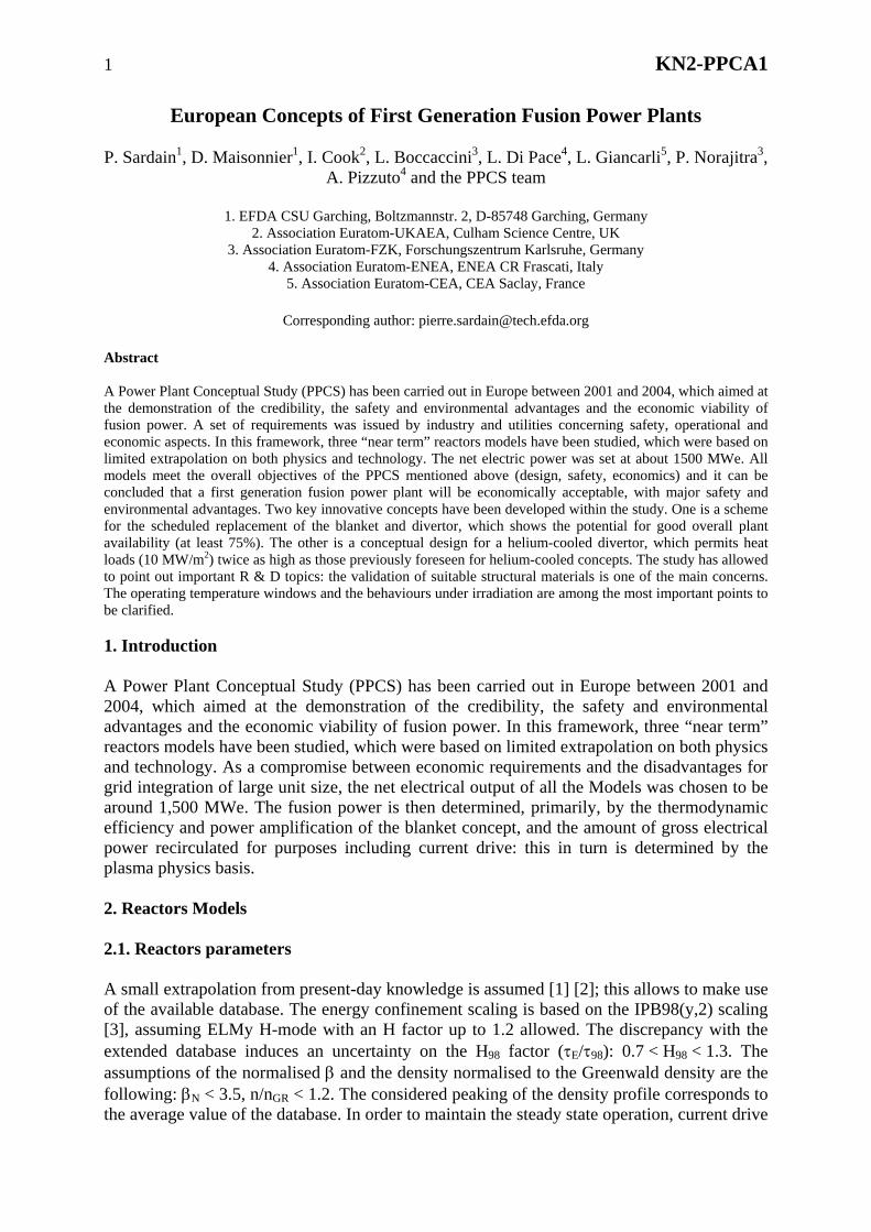
The concept is shown on the Fig. 2 W-alloy in monoblock geometry surrounds a CuCrZr tube able to withstand alone the water pressure. A swirl is included in the tube in order to enhance the maximum acceptable critical heat flux. OFHC (Oxygen Free High Conductivity) Cu is used as compliant layer. A thickness of 3.5 mm has been retained as sacrificial layer for erosion allowance. An alternative water-cooled divertor concept (Fig. 2) has been studied which should allow an operating temperature of water of about 300 °C [6] with an allowable peak flux of 15 MWm-2. This concept uses Eurofer as structural material and tungsten as armour material. A thermal barrier in pyrolitic graphite is used to obtain a better repartition of the flux. A thermal analysis shows that the maximal flux in structural material is limited to 13 MW/m2 instead of 20 MW/m2 without thermal barrier. In order to satisfy the critical heat flux criteria a swirl is provided. In these conditions, water local velocity is 20 m/s and critical heat flux is approximately 16.7 MW/m2. The expected gain on the thermal efficiency of the plant due to the increase of the water temperature is about 2 points. 2.2.4. Power conversion The primary heat transport system comprises 6 cooling loops for the blankets (Tin=285ºC, Tout=325ºC) and 2 cooling loops for the divertor (Tin=140ºC, Tout=167ºC). The steam generators are based on current PWR technology (Fig. 3). Reheater
Moisture separator
Blanket cooling loop
Steam Generator
The secondary heat trasteam from the steamreheater/moisture septaken to heat the feedheat exchanger), and moisture removed frofeedwater tank. The h
High Pressure Turbine
FeedwatTank
Fig.3 : power conversion system of mo
nsport system is assumed to be standard P generators goes to the high-pressure tuarator (R/MS). From the high-pressure water, in the first stage of the high-pressuthe rest is reheated before going to the lom the low-pressure steam in the mois
igh-pressure steam used to reheat the low
Low Pressure Turbine
DivertorPreheater
High
Divertor cooling loop
er
del A
WR technology. Most of the rbine and some to the steam turbine (HP), some steam is re heater (HP1 – condensing w-pressure turbine (LP). The ture separator is sent to the -pressure steam is condensed
6 KN2-PPCA1
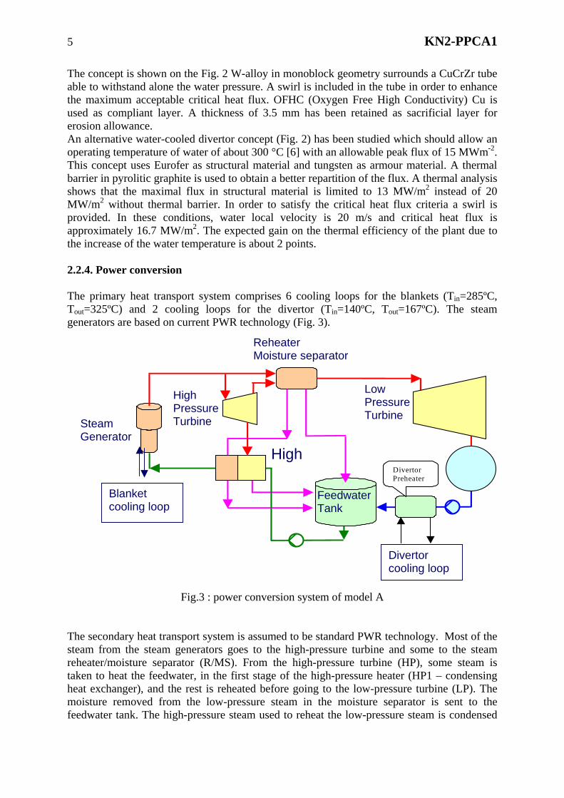
in the reheater and the condensate is used to provide the last stage of feedwater heating, in high-pressure heater (HP2). From there, it is sent to the feedwater tank (FT) where it does additional heating. The only difference from PWR is that there is only one low-pressure heater which receives heat from the divertor cooling system. The other low-pressure heater has to be eliminated due to the low outlet temperature of the divertor cooling loop. The use of a divertor concept working at the same temperature as the blanket/FW loop would change the layout of the secondary system, since the divertor loop could be connected to a steam generator. 2.3. Model B 2.3.1. Blanket principle The HCPB (Helium Cooled Pebble Beds) blanket is made by alternate layers of lithium ortho-silicate, which serves as a tritium-generating material, and pebbles of beryllium, which serves as a neutron multiplier [7]. Helium is used as coolant. In the blanket modules the helium average pressure is 8 MPa and the helium temperature is in the range 300ºC – 500ºC. The in-vessel neutron shield is in two sections: a “high-temperature” shield directly behind the blanket, of helium-cooled Eurofer, and a “low-temperature” shield behind that, which is helium-cooled zirconium hydride. The low-temperature shield receives a neutron dose low enough to make it a lifetime component of the plant. Fig. 4 shows a view of the radial module segregation of the tritium-generating zone (BZ), the high temperature shield (HTS), the low temperature shield (LTS), and a sketch of the coolant manifolding. For good maintenance characteristics, a segmentation of the blanket into large modules has been adopted.
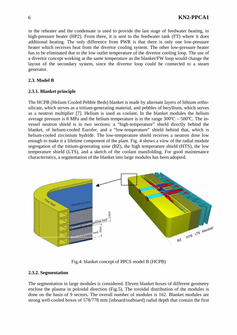
Fig.4: blanket concept of PPCS model B (HCPB) 2.3.2. Segmentation The segmentation in large modules is considered. Eleven blanket boxes of different geometry enclose the plasma in poloidal direction (Fig.5). The toroidal distribution of the modules is done on the basis of 9 sectors. The overall number of modules is 162. Blanket modules are strong well-cooled boxes of 578/778 mm (inboard/outboard) radial depth that contain the first
7 KN2-PPCA1
wall, the entire breeding region and a back wall that manifolds all cooling of the box. The box interface with the vessel is limited to coolant supply, the Tritium purge system and mechanical support.
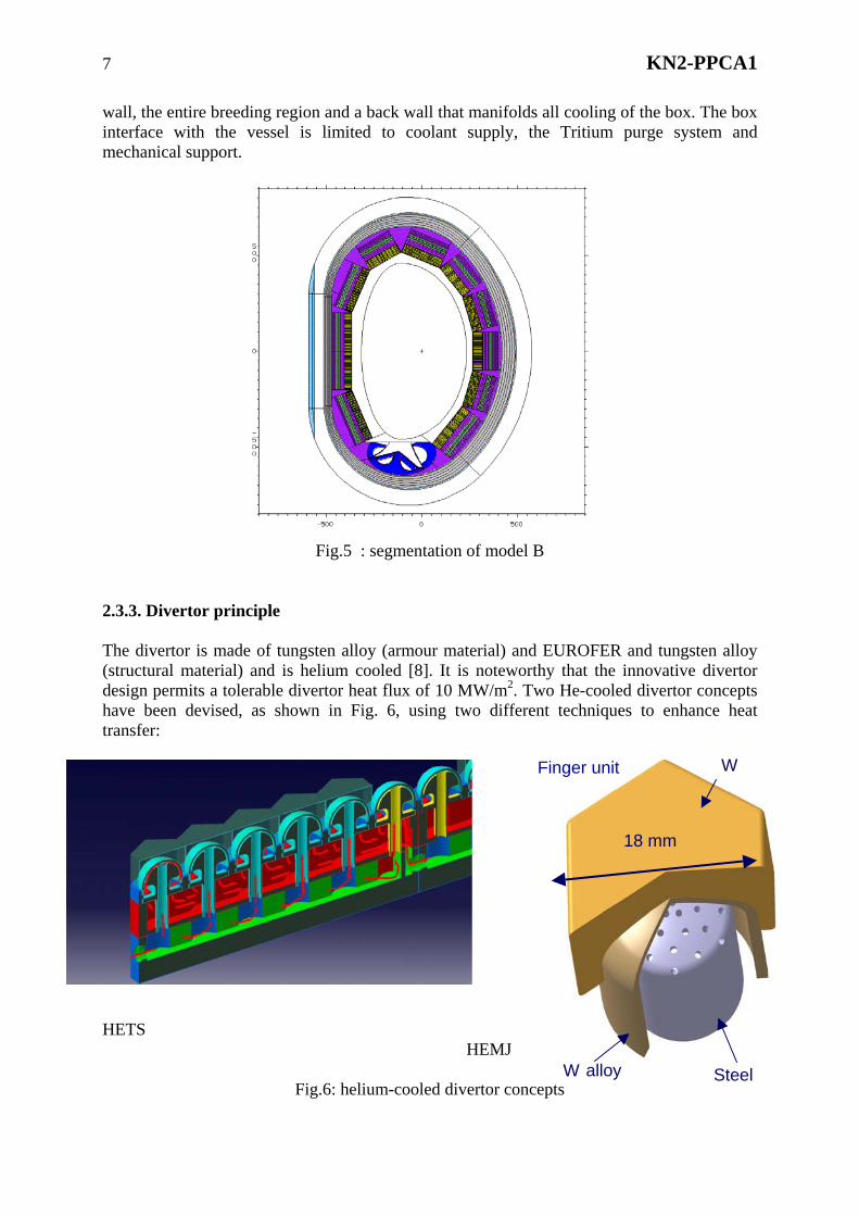
Fig.5 : segmentation of model B 2.3.3. Divertor principle The divertor is made of tungsten alloy (armour material) and EUROFER and tungsten alloy (structural material) and is helium cooled [8]. It is noteworthy that the innovative divertor design permits a tolerable divertor heat flux of 10 MW/m2. Two He-cooled divertor concepts have been devised, as shown in Fig. 6, using two different techniques to enhance heat transfer: HETS HEMJ
Fig.6: helium-cooled divertor concepts
W
W alloy
18 mm
Finger unit
Steel
8 KN2-PPCA1
• In the HETS (High Efficiency Thermal Shield) concept by the impingement effects on
the hemispherical surface and by the effects of centripetal acceleration (increase of turbulence) when the fluid moves on the inner side of the sphere.
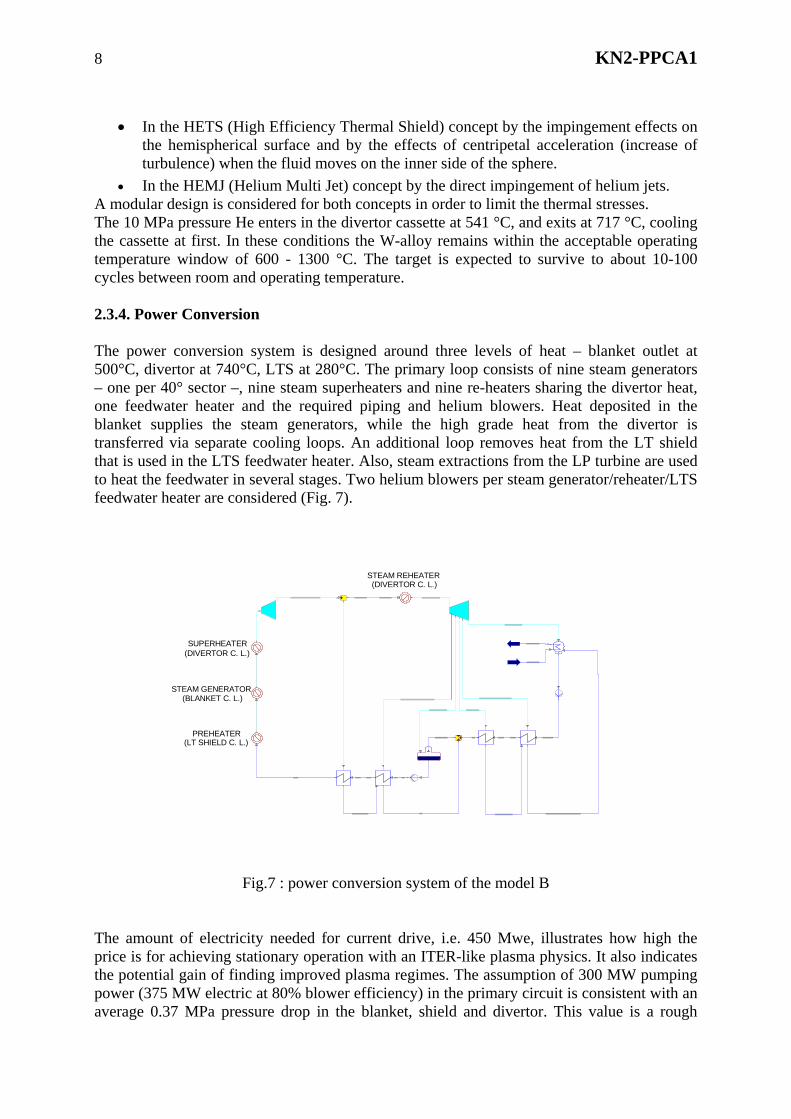
• In the HEMJ (Helium Multi Jet) concept by the direct impingement of helium jets. A modular design is considered for both concepts in order to limit the thermal stresses. The 10 MPa pressure He enters in the divertor cassette at 541 °C, and exits at 717 °C, cooling the cassette at first. In these conditions the W-alloy remains within the acceptable operating temperature window of 600 - 1300 °C. The target is expected to survive to about 10-100 cycles between room and operating temperature. 2.3.4. Power Conversion The power conversion system is designed around three levels of heat – blanket outlet at 500°C, divertor at 740°C, LTS at 280°C. The primary loop consists of nine steam generators – one per 40° sector –, nine steam superheaters and nine re-heaters sharing the divertor heat, one feedwater heater and the required piping and helium blowers. Heat deposited in the blanket supplies the steam generators, while the high grade heat from the divertor is transferred via separate cooling loops. An additional loop removes heat from the LT shield that is used in the LTS feedwater heater. Also, steam extractions from the LP turbine are used to heat the feedwater in several stages. Two helium blowers per steam generator/reheater/LTS feedwater heater are considered (Fig. 7).
SUPERHEATER(DIVERTOR C. L.)
STEAM GENERATOR(BLANKET C. L.)
PREHEATER(LT SHIELD C. L.)
STEAM REHEATER(DIVERTOR C. L.)
Fig.7 : power conversion system of the model B
The amount of electricity needed for current drive, i.e. 450 Mwe, illustrates how high the price is for achieving stationary operation with an ITER-like plasma physics. It also indicates the potential gain of finding improved plasma regimes. The assumption of 300 MW pumping power (375 MW electric at 80% blower efficiency) in the primary circuit is consistent with an average 0.37 MPa pressure drop in the blanket, shield and divertor. This value is a rough
9 KN2-PPCA1
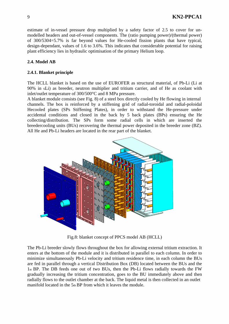
estimate of in-vessel pressure drop multiplied by a safety factor of 2.5 to cover for un-modelled headers and out-of-vessel components. The (ratio pumping power)/(thermal power) of 300/5304=5.7% is far beyond values for He-cooled fission plants that have typical, design-dependant, values of 1.6 to 3.6%. This indicates that considerable potential for raising plant efficiency lies in hydraulic optimisation of the primary Helium loop. 2.4. Model AB 2.4.1. Blanket principle The HCLL blanket is based on the use of EUROFER as structural material, of Pb-Li (Li at 90% in 6Li) as breeder, neutron multiplier and tritium carrier, and of He as coolant with inlet/outlet temperature of 300/500°C and 8 MPa pressure. A blanket module consists (see Fig. 8) of a steel box directly cooled by He flowing in internal channels. The box is reinforced by a stiffening grid of radial-toroidal and radial-poloidal Hecooled plates (SPs Stiffening Plates), in order to withstand the He-pressure under accidental conditions and closed in the back by 5 back plates (BPs) ensuring the He collecting/distribution. The SPs form some radial cells in which are inserted the breedercooling units (BUs) recovering the thermal power deposited in the breeder zone (BZ). All He and Pb-Li headers are located in the rear part of the blanket.
Fig.8: blanket concept of PPCS model AB (HCLL)
The Pb-Li breeder slowly flows throughout the box for allowing external tritium extraction. It enters at the bottom of the module and it is distributed in parallel to each column. In order to minimize simultaneously Pb-Li velocity and tritium residence time, in each column the BUs are fed in parallel through a vertical Distribution Box (DB) located between the BUs and the 1st BP. The DB feeds one out of two BUs, then the Pb-Li flows radially towards the FW gradually increasing the tritium concentration, goes to the BU immediately above and then radially flows to the outlet chamber at the back. The liquid metal is then collected in an outlet manifold located in the 5th BP from which it leaves the module.

10 KN2-PPCA1
The He cools in parallel the box and the SPs, then passes in the CPs of the BUs. The BZ thickness has been fixed, on the basis of neutronic analyses and reactor dimensions considerations, at 45 cm for the inboard side and 80 cm for the outboard one. 2.4.2. Segmentation The blanket segmentation has been defined using the “large modules maintenance” option. Vertical orientation has been assumedfor the modules (4 m high x 2 m width); as a consequence, the modules follows the plasma shape in the poloidal direction and are straight in the toroidal direction; a possible alternative proposal could be to have small modules 2mx2m installed on a banana-shaped back-plate and vertical maintenance. 2.4.3. Divertor principle The model AB uses the same divertor concept as model B. 2.4.4. Power conversion The power heat deposited on the blanket and HTS (4219 MWth) and in the divertor (926 MWth) is recovered and useful in terms of the energy conversion system. A thermodynamic Rankin cycle has been adopted in which the high temperature He of the divertor cooling loop is used to superheat the steam generated by the colder He coming from the blanket loop (Fig. 9).
Fig.9 : power conversion system of the model AB The cycle parameters (i.e. the mass flow repartition between the three stages of the turbine, etc.) have been optimised so leading to a gross efficiency (defined as the ratio between the total electric power generated and the total thermal charge of the VV) of about 43,7%. Although the high efficiency of the thermodynamic cycle, because of the high needed pumping power, amounting to a total of 400 MW for both the blanket and the divertor, the net efficiency (ratio between the power to the grid and the fusion power) goes down to 35 %.
11 KN2-PPCA1
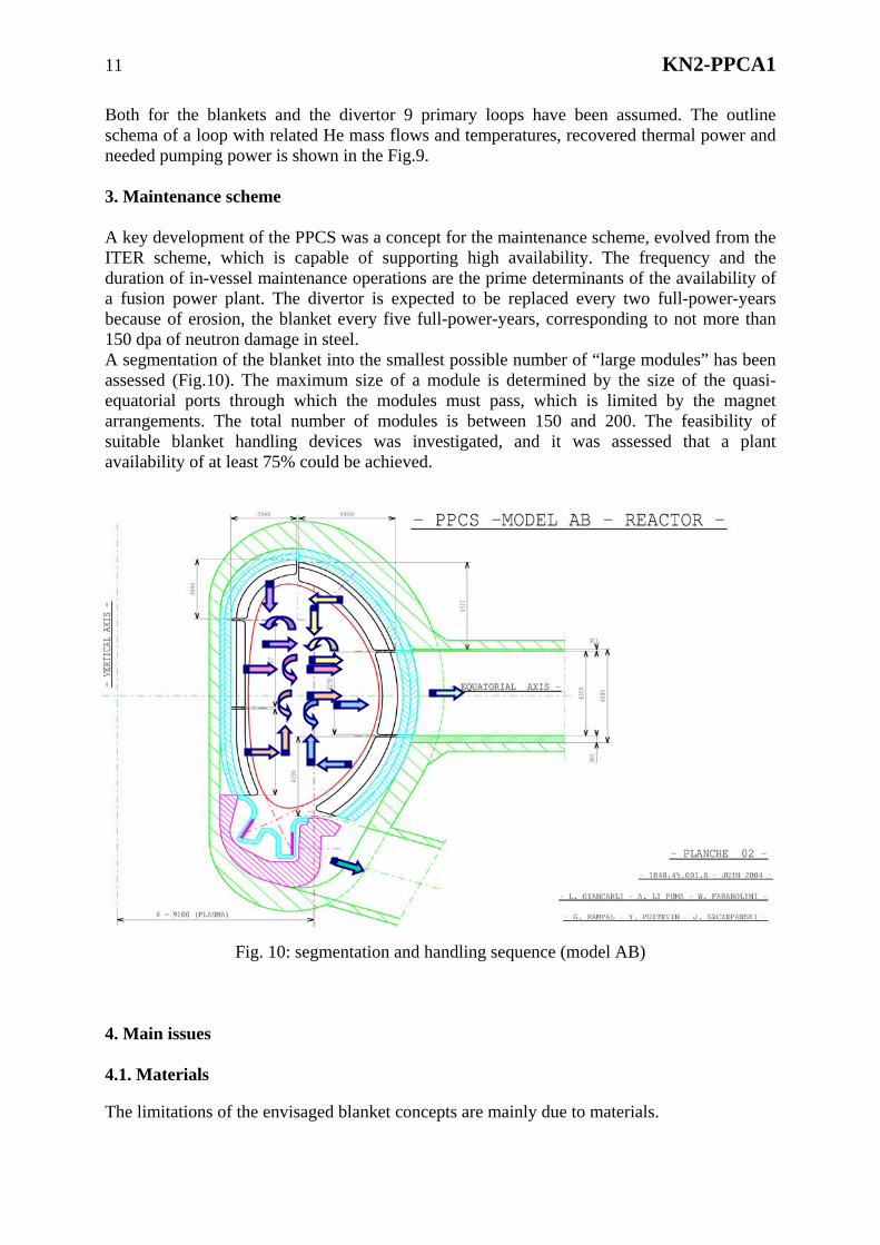
Both for the blankets and the divertor 9 primary loops have been assumed. The outline schema of a loop with related He mass flows and temperatures, recovered thermal power and needed pumping power is shown in the Fig.9. 3. Maintenance scheme A key development of the PPCS was a concept for the maintenance scheme, evolved from the ITER scheme, which is capable of supporting high availability. The frequency and the duration of in-vessel maintenance operations are the prime determinants of the availability of a fusion power plant. The divertor is expected to be replaced every two full-power-years because of erosion, the blanket every five full-power-years, corresponding to not more than 150 dpa of neutron damage in steel. A segmentation of the blanket into the smallest possible number of “large modules” has been assessed (Fig.10). The maximum size of a module is determined by the size of the quasi-equatorial ports through which the modules must pass, which is limited by the magnet arrangements. The total number of modules is between 150 and 200. The feasibility of suitable blanket handling devices was investigated, and it was assessed that a plant availability of at least 75% could be achieved.
Fig. 10: segmentation and handling sequence (model AB) 4. Main issues 4.1. Materials The limitations of the envisaged blanket concepts are mainly due to materials.

12 KN2-PPCA1
The temperature windows of materials limit the temperature of the coolant, and thus, directly impact the efficiency of the power conversion system. For example, the efficiencies of the HCLL and HCPB could be improved considering a Brayton conversion cycle using helium as working fluid; this would require to reach temperatures higher than 750 ºC, which is not compatible with EUROFER. It could be possible using Oxide Dispersion Strengthened (ODS) ferritic steels, which is not considered for “near term” reactors concepts. The consequences of irradiation (swelling, embrittlement) are still to be assessed. They should impact the lifetime of the internal components and, as a consequence, the availability of the reactor. 4.2 Maintenance The “large modules” concept, which has been considered in the frame of the PPCS study, has shown promising results in terms of availability. Nevertheless, some items are still to be investigated in more details. The impact of de-connections and re-connections of the modules to the manifolds on the availability should be thoroughly investigated for each reactor model, checking in particular the accessibility of the connections and the helium production at the welds joint location. 4.3 Tritium control A first analysis of the tritium control has been done for the HCLL concept. Because of its low solubility in the Pb-Li, which leads to significant partial pressure, part of the tritium permeates through the steel walls towards the He-coolant. The tritium extraction is thus foreseen also from the He. However, only a fraction of the flowing He will be derived to be processed in the Coolant Purification System (CPS). Considering the fugacity of the tritium, particular care should be applied in the Pb-Li and He cooling circuits design in order to maintain the tritium release to the environment below the allowable value, assumed to be 27Ci/day. The final tritium release rate will depend on the tritium permeation towards the He coolant in the blanket modules, the Pb-Li circulation rate, the TES efficiency, the tritium permeation in steam generator, the He coolant leak rate, the CPS flow rate and efficiency. Preliminary evaluations have indicated that the He purification plant should be able to process 27% of the total He mass flow. This figure could be reduced if a better control of He leakages was achieved or if a larger Pb-Li re-circulation rate was adopted, or if the tritium permeation could be reduced by using permeation barriers. 4.4 Power conversion The He-cooled PPCS concepts using helium at 300 °C – 500 °C have power conversion systems using standard Rankine cycles. Their gross efficiency is mainly limited by the moderate He output temperature whilst the net efficiency (approximately 35 %) is low, due to the high power required by the auxiliaries (mainly pumping and heating). The ways for optimisation are as follows:
• investigate possible improvements of the gross efficiency by using other types of conversion cycles: the indirect Brayton cycle using supercritical CO2 as working fluid and the supercritical steam Rankine cycle. The CO2 has interesting physical properties (critical temperature near room temperature, moderate value of critical pressure, stability under 1400 °C) and low intrinsic costs. Moreover, due to its sizeable
13 KN2-PPCA1
molecular weight, CO2 needs small turbines, compared to He and steam turbines. The supercritical steam Rankine cycle is already used in coal-fired power plants, so that the turbine technology can be assumed mature.
• investigate possible improvements of the net efficiency by reducing the recirculating power, mainly through an optimization of the pressure drops allowing a reduction of the pumping power.
.5. Conclusions The “near term” models, which have been considered in the frame of the PPCS, meet the general objectives of design, safety and economics. A plasma performance only marginally better than the design basis of ITER is sufficient for economic viability of fusion reactors. A maintenance concept has been identified, which seems to meet the availability target. First promising results have been obtained on divertor concepts. A first commercial fusion power plant will be economically acceptable with major safety and environmental advantages. The ways for improvement of these models are mainly related to materials developments, in particular the structural materials (ODS and tungsten alloys). Some other items, as the maintenance scheme, the tritium control and the power conversion system are still to be optimized. References [1] D. Maisonnier, R. Andreani, S. Hermsmeyer, G. Saibene, P. Sardain, D. Ward, "Power Plant Conceptual Study, Main Technological Issues", IAEA TCM on Steady State Operation of Fusion Magnetic Devices, April 2002. [2] U. Samm, E. Barbato, J.G. Cordey, J. Lister, D. Moreau, J. Ongena, H. Wobig, D. Bartlett, "Report of the Ad Hoc Group to Assess the Physics Assumptions Underlying the Power Plant Conceptual Study (PPCS), 2001. [3] ITER Physics basis, Nuclear Fusion 39 (1999) 2175 [4] Y. Poitevin, L. Giancarli, A. Li Puma, J. Szczepanski, "Status of the design and performances of the WCLL Test Blanket Module for ITER-FEAT”, to appear in Fus. Eng. & Des., Proc. ISFNT-5, April 7-13, 2002, San Diego (CA). [5] A. Li Puma, L. Giancarli, Y. Poitevin, J.F. Salavy, P. Sardain, J. Szczepanski, "Optimisation of a water cooled divertor for the European power plant conceptual study", to appear in Fus. Eng. & Des., Proc. ISFNT-5, April 7-13, 2002, San Diego (CA). [6] B. Michel, "New design of a high temperature water cooled divertor for the European Power Plant Conceptual Study", CEA Report SERI/LFEA 02/5020, 2002. [7] S. Hermsmeyer, et al., Lay-out of the He-cooled solid breeder model B in the European power plant conceptual study, Fus. Eng. & Des. 69 (2003) 281-287. [8] Norajitra et al., Development of a helium-cooled divertor concept: design-related requirements on materials and fabrication technology, Journal of Nuclear Materials 329-333 (2004) 1594-1598.
Related Documents