EURO 46 V10 Modem and Communications Guide RINS1944-2 Software Version >10

Welcome message from author
This document is posted to help you gain knowledge. Please leave a comment to let me know what you think about it! Share it to your friends and learn new things together.
Transcript

EURO 46 V10Modem and Communications Guide
RINS1944-2Software Version >10
2 EURO 46 V10 Communications Guide
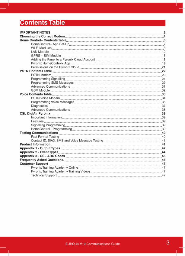
IMPORTANT NOTES
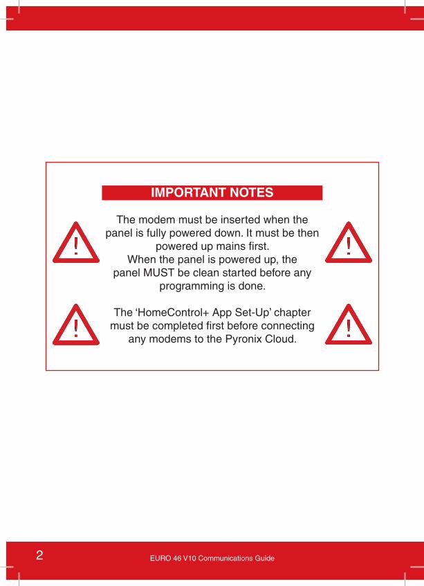
The modem must be inserted when the panel is fully powered down. It must be then
powered up mains first.When the panel is powered up, the
panel MUST be clean started before any programming is done.
The ‘HomeControl+ App Set-Up’ chapter must be completed first before connecting
any modems to the Pyronix Cloud.
3EURO 46 V10 Communications Guide
IMPORTANT NOTES 2Choosing the Correct Modem 4Home Control+ Contents Table 6
HomeControl+ App Set-Up 7Wi-Fi Modules 8LAN Module 12GPRS + SIM Module 15Adding the Panel to a Pyronix Cloud Account 18Pyronix HomeControl+ App 19Permissions on the Pyronix Cloud 21
PSTN Contents Table 22PSTN Modem 23Programming Signalling 24Programming SMS Messages 29Advanced Communications 31GSM Module 32
Voice Contents Table 33PSTN/Voice Modem 34Programming Voice Messages 35Diagnostics 37Advanced Communications 38
CSL DigiAir Pyronix 39Important Information 39Features 39Signalling Programming 39HomeControl+ Programming 39
Testing Communications 40Fast Format Testing 40Contact ID, SIA3, SMS and Voice Message Testing 41
Product Information 41Appendix 1 - Output Types 42Appendix 2 - Event Types 44Appendix 3 - CSL ARC Codes 45Frequently Asked Questions. 46Customer Support 47
Pyronix Training Academy Online 47Pyronix Training Academy Training Videos 47Technical Support 47
Contents Table
4 EURO 46 V10 Communications Guide
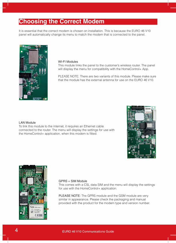
GPRS + SIM ModuleThis comes with a CSL data SIM and the menu will display the settings for use with the HomeControl+ application.
PLEASE NOTE: The GPRS module and the GSM module are very similar in appearance. Please check the packaging and manual provided with the product for the modem type and version number.
LAN ModuleTo link this module to the internet, it requires an Ethernet cable connected to the router. The menu will display the settings for use with the HomeControl+ application, when this modem is fitted.
WI-FI ModulesThis module links the panel to the customer’s wireless router. The panel will display the menu for compatibility with the HomeControl+ App.
PLEASE NOTE: There are two variants of this module. Please make sure that the module has the external antenna for use on the EURO 46 V10.
Choosing the Correct ModemIt is essential that the correct modem is chosen on installation. This is because the EURO 46 V10 panel will automatically change its menu to match the modem that is connected to the panel.
5EURO 46 V10 Communications Guide
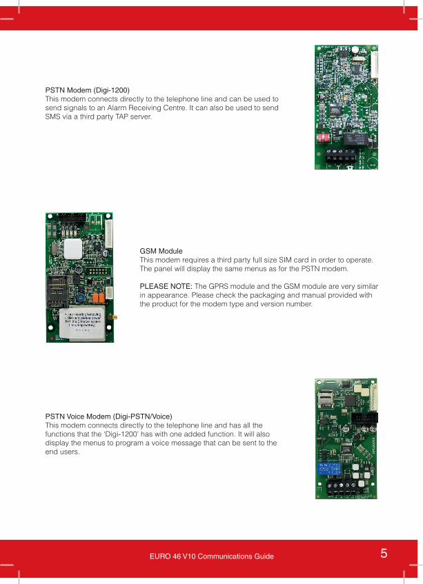
PSTN Modem (Digi-1200)This modem connects directly to the telephone line and can be used to send signals to an Alarm Receiving Centre. It can also be used to send SMS via a third party TAP server.
GSM ModuleThis modem requires a third party full size SIM card in order to operate. The panel will display the same menus as for the PSTN modem.
PLEASE NOTE: The GPRS module and the GSM module are very similar in appearance. Please check the packaging and manual provided with the product for the modem type and version number.
PSTN Voice Modem (Digi-PSTN/Voice)This modem connects directly to the telephone line and has all the functions that the ‘Digi-1200’ has with one added function. It will also display the menus to program a voice message that can be sent to the end users.
6 EURO 46 V10 Communications Guide
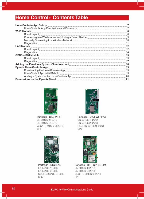
HomeControl+ App Set-Up 7HomeControl+ App Permissions and Passwords 7
Wi-Fi Module 8Board Layout 8Connecting to a Wireless Network Using a Smart Device 9Manually Connecting to a Wireless Network 10Diagnostics 11
LAN Module 12Board Layout 12Diagnostics 14
GPRS + SIM Module 15Board Layout 15Diagnostics 17
Adding the Panel to a Pyronix Cloud Account 18Pyronix HomeControl+ App 19
Downloading the HomeControl+ App 19HomeControl App Initial Set-Up 19Adding a System to the HomeControl+ App 20
Permissions on the Pyronix Cloud 21
Home Control+ Contents Table
Partcode - DIGI-WI-FIEN 50136-1: 2012EN 50136-2: 2013CLC/ TS 50136-9: 2013SP5
Partcode - DIGI-WI-FI/XAEN 50136-1: 2012EN 50136-2: 2013CLC/ TS 50136-9: 2013SP5
Partcode - DIGI-LANEN 50136-1: 2012EN 50136-2: 2013CLC/ TS 50136-9: 2013SP5
Partcode - DIGI-GPRS+SIMEN 50136-1: 2012EN 50136-2: 2013CLC/ TS 50136-9: 2013SP2
7EURO 46 V10 Communications Guide
HomeControl+ App Set-Up
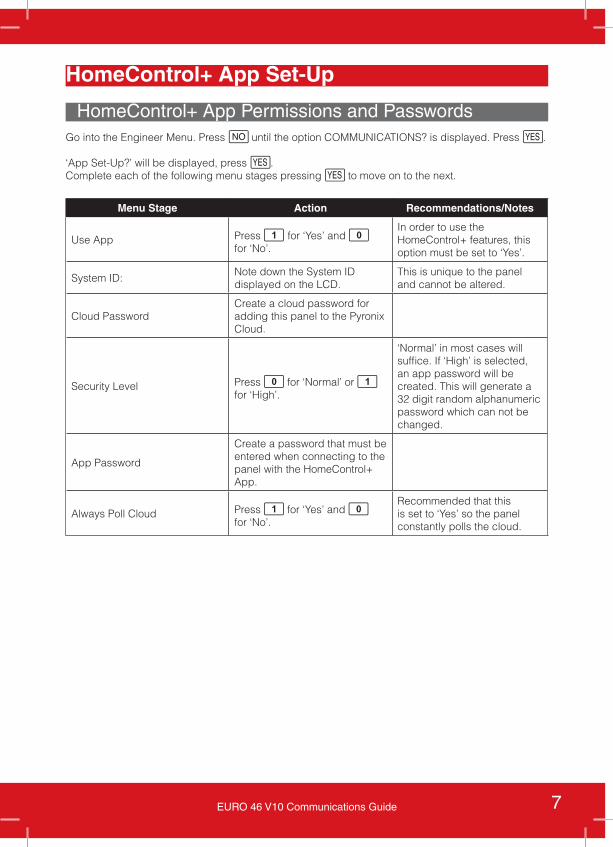
HomeControl+ App Permissions and PasswordsGo into the Engineer Menu. Press h until the option COMMUNICATIONS? is displayed. Press f.
‘App Set-Up?’ will be displayed, press f.Complete each of the following menu stages pressing f to move on to the next.
Menu Stage Action Recommendations/Notes
Use App Press 1 for ‘Yes’ and 0 for ‘No’.
In order to use the HomeControl+ features, this option must be set to ‘Yes’.
System ID:Note down the System ID displayed on the LCD.
This is unique to the panel and cannot be altered.
Cloud PasswordCreate a cloud password for adding this panel to the Pyronix Cloud.
Security Level Press 0 for ‘Normal’ or 1 for ‘High’.
‘Normal’ in most cases will suffice. If ‘High’ is selected, an app password will be created. This will generate a 32 digit random alphanumeric password which can not be changed.
App Password
Create a password that must be entered when connecting to the panel with the HomeControl+ App.
Always Poll Cloud Press 1 for ‘Yes’ and 0 for ‘No’.
Recommended that this is set to ‘Yes’ so the panel constantly polls the cloud.
8 EURO 46 V10 Communications Guide
Wi-Fi Modules
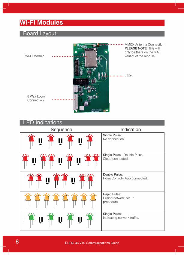
Board Layout
8 Way Loom Connection
WI-FI Module
LEDs
MMCX Antenna ConnectionPLEASE NOTE: This will only be there on the ‘XA’ variant of the module.
LED IndicationsSequence Indication
Single Pulse:No connection.
Single Pulse - Double Pulse:Cloud connected.
Double Pulse:HomeControl+ App connected.
Rapid Pulse:During network set up procedure.
Single Pulse:Indicating network traffic.
9EURO 46 V10 Communications Guide
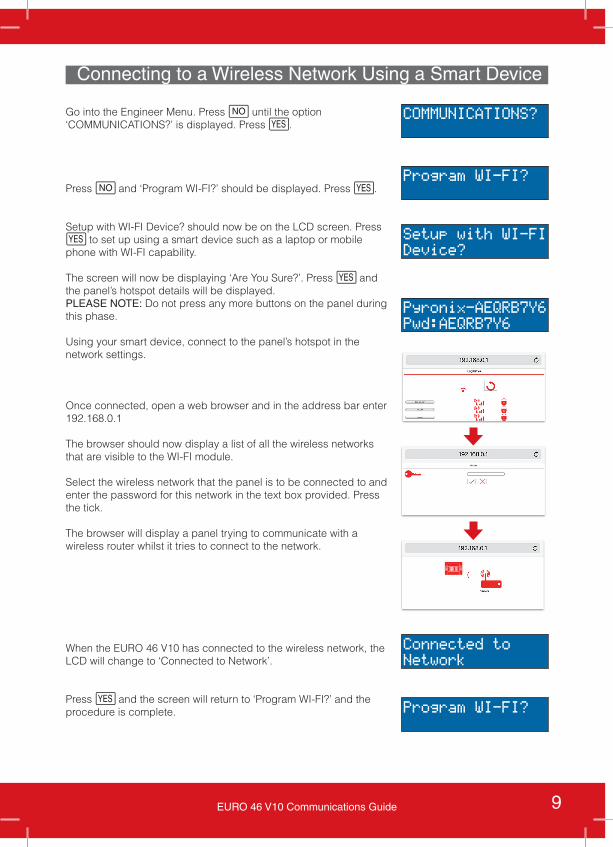
Connecting to a Wireless Network Using a Smart Device
Go into the Engineer Menu. Press h until the option ‘COMMUNICATIONS?’ is displayed. Press f.
Press h and ‘Program WI-FI?’ should be displayed. Press f.
Setup with WI-FI Device? should now be on the LCD screen. Press f to set up using a smart device such as a laptop or mobile phone with WI-FI capability.
The screen will now be displaying ‘Are You Sure?’. Press f and the panel’s hotspot details will be displayed. PLEASE NOTE: Do not press any more buttons on the panel during this phase.
Using your smart device, connect to the panel’s hotspot in the network settings.
Once connected, open a web browser and in the address bar enter 192.168.0.1
The browser should now display a list of all the wireless networks that are visible to the WI-FI module.
Select the wireless network that the panel is to be connected to and enter the password for this network in the text box provided. Press the tick.
The browser will display a panel trying to communicate with a wireless router whilst it tries to connect to the network.
When the EURO 46 V10 has connected to the wireless network, the LCD will change to ‘Connected to Network’.
Press f and the screen will return to ‘Program WI-FI?’ and the procedure is complete.
COMMUNICATIONS?
Program WI-FI?
Setup with WI-FIDevice?
Pyronix-AEQRB7Y6Pwd:AEQRB7Y6
Connected toNetwork
Program WI-FI?
10 EURO 46 V10 Communications Guide
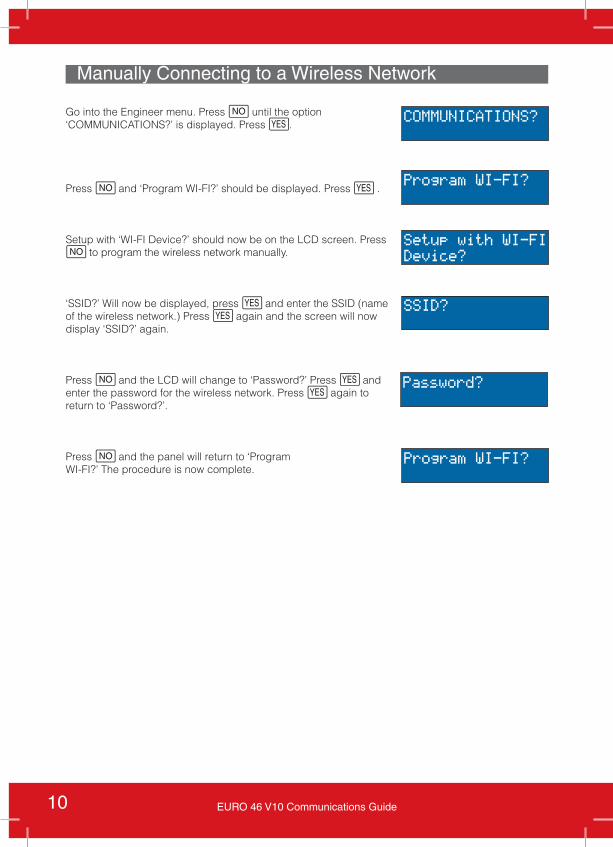
Manually Connecting to a Wireless Network
Go into the Engineer menu. Press h until the option ‘COMMUNICATIONS?’ is displayed. Press f.
Press h and ‘Program WI-FI?’ should be displayed. Press f .
Setup with ‘WI-FI Device?’ should now be on the LCD screen. Press h to program the wireless network manually.
‘SSID?’ Will now be displayed, press f and enter the SSID (name of the wireless network.) Press f again and the screen will now display ‘SSID?’ again.
Press h and the LCD will change to ‘Password?’ Press f and enter the password for the wireless network. Press f again to return to ‘Password?’.
Press h and the panel will return to ‘ProgramWI-FI?’ The procedure is now complete.
COMMUNICATIONS?
Program WI-FI?
Program WI-FI?
Setup with WI-FIDevice?
SSID?
Password?
11EURO 46 V10 Communications Guide
Diagnostics
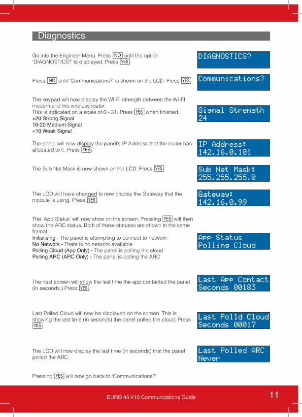
Go into the Engineer Menu. Press h until the option ‘DIAGNOSTICS?’ is displayed. Press f.
Press h until ‘Communications?’ is shown on the LCD. Press f.
The keypad will now display the WI-FI strength between the WI-FI modem and the wireless router.This is indicated on a scale of 0 - 31. Press f when finished.>20 Strong Signal 10-20 Medium Signal<10 Weak Signal
The panel will now display the panel’s IP Address that the router has allocated to it. Press f.
The Sub Net Mask is now shown on the LCD. Press f.
The LCD will have changed to now display the Gateway that the module is using. Press f.
The ‘App Status’ will now show on the screen. Pressing f will then show the ARC status. Both of these statuses are shown in the same format: Initialising - The panel is attempting to connect to networkNo Network - There is no network available Polling Cloud (App Only) - The panel is polling the cloudPolling ARC (ARC Only) - The panel is polling the ARC
The next screen will show the last time the app contacted the panel (in seconds.) Press f.
Last Polled Cloud will now be displayed on the screen. This is showing the last time (in seconds) the panel polled the cloud. Press f.
The LCD will now display the last time (in seconds) that the panel polled the ARC.
Pressing f will now go back to ‘Communications?’.
DIAGNOSTICS?
Communications?
Signal Strength24
IP Address:142.16.0.101
Sub Net Mask:255.255.255.0
Gateway:142.16.0.99
App StatusPolling Cloud
Last App ContactSeconds 00183
Last Polld CloudSeconds 00017
Last Polled ARCNever
12 EURO 46 V10 Communications Guide
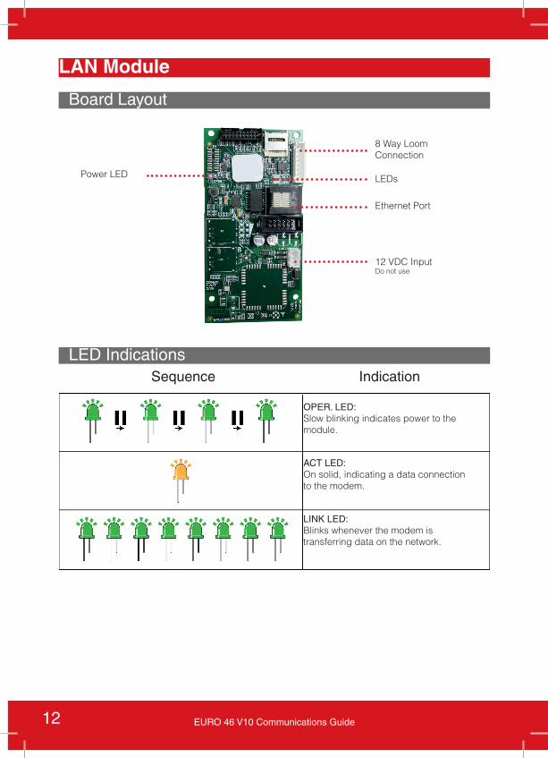
LAN Module
Board Layout
LED IndicationsSequence Indication
8 Way Loom Connection
LEDs
Ethernet Port
12 VDC Input Do not use
Power LED
OPER. LED:Slow blinking indicates power to the module.
ACT LED:On solid, indicating a data connection to the modem.
LINK LED:Blinks whenever the modem is transferring data on the network.
13EURO 46 V10 Communications Guide
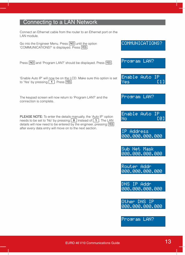
Connecting to a LAN Network
Connect an Ethernet cable from the router to an Ethernet port on the LAN module.
Go into the Engineer Menu. Press h until the option ‘COMMUNICATIONS?’ is displayed. Press f.
Press h and ‘Program LAN?’ should be displayed. Press f.
‘Enable Auto IP’ will now be on the LCD. Make sure this option is set to ‘Yes’ by pressing 1. Press f.
The keypad screen will now return to ‘Program LAN?’ and the connection is complete.
PLEASE NOTE: To enter the details manually, the ‘Auto IP’ option needs to be set to ‘No’ by pressing 0 instead of 1. The LAN details will now need to be entered by the engineer, pressing f after every data entry will move on to the next section.
COMMUNICATIONS?
Program LAN?
Program LAN?
Enable Auto IPYes [1]
Enable Auto IPNo [0]
IP Address000.000.000.000
Sub Net Mask000.000.000.000
Router Addr000.000.000.000
DNS IP Addr000.000.000.000
Other DNS IP000.000.000.000
Program LAN?
14 EURO 46 V10 Communications Guide
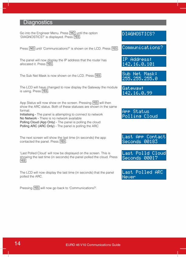
Diagnostics
Go into the Engineer Menu. Press h until the option ‘DIAGNOSTICS?’ is displayed. Press f.
Press h until ‘Communications?’ is shown on the LCD. Press f.
The panel will now display the IP address that the router has allocated it. Press f.
The Sub Net Mask is now shown on the LCD. Press f.
The LCD will have changed to now display the Gateway the module is using. Press f.
App Status will now show on the screen. Pressing f will then show the ARC status. Both of these statuses are shown in the same format: Initialising - The panel is attempting to connect to networkNo Network - There is no network available Polling Cloud (App Only) - The panel is polling the cloudPolling ARC (ARC Only) - The panel is polling the ARC
The next screen will show the last time (in seconds) the app contacted the panel. Press f.
‘Last Polled Cloud’ will now be displayed on the screen. This is showing the last time (in seconds) the panel polled the cloud. Press f.
The LCD will now display the last time (in seconds) that the panel polled the ARC.
Pressing f will now go back to ‘Communications?’.
DIAGNOSTICS?
Communications?
IP Address:142.16.0.101
Sub Net Mask:255.255.255.0
Gateway:142.16.0.99
App StatusPolling Cloud
Last App ContactSeconds 00183
Last Polld CloudSeconds 00017
Last Polled ARCNever
15EURO 46 V10 Communications Guide
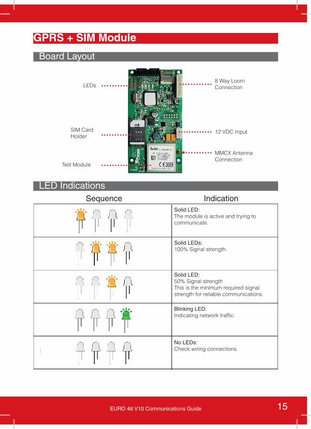
GPRS + SIM Module
Board Layout
LED IndicationsSequence Indication
LEDs
SIM Card Holder
Telit Module
12 VDC Input
MMCX AntennaConnection
8 Way Loom Connection
Solid LED:The module is active and trying to communicate.
Solid LEDs:100% Signal strength.
Solid LED:50% Signal strengthThis is the minimum required signal strength for reliable communications.
Blinking LED:Indicating network traffic.
No LEDs:Check wiring connections.
16 EURO 46 V10 Communications Guide
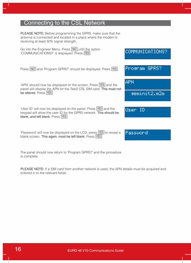
Connecting to the CSL Network
PLEASE NOTE: Before programming the GPRS, make sure that the antenna is connected and located in a place where the modem is receiving at least 50% signal strength.
Go into the Engineer Menu. Press h until the option ‘COMMUNICATIONS?’ is displayed. Press f.
Press h and ‘Program GPRS?’ should be displayed. Press f.
‘APN’ should now be displayed on the screen. Press f and the panel will display the APN for the Tele2 CSL SIM card. This must not be altered. Press f.
‘User ID’ will now be displayed on the panel. Press f and the keypad will show the user ID for the GPRS network. This should be blank, and left blank. Press f.
‘Password’ will now be displayed on the LCD, press f to reveal a blank screen. This again, must be left blank. Press f.
The panel should now return to ‘Program GPRS?’ and the procedure is complete.
COMMUNICATIONS?
Program GPRS?
User ID
Password
APN
geminit2.m2m
PLEASE NOTE: If a SIM card from another network is used, the APN details must be acquired and entered in to the relevant fields.
17EURO 46 V10 Communications Guide
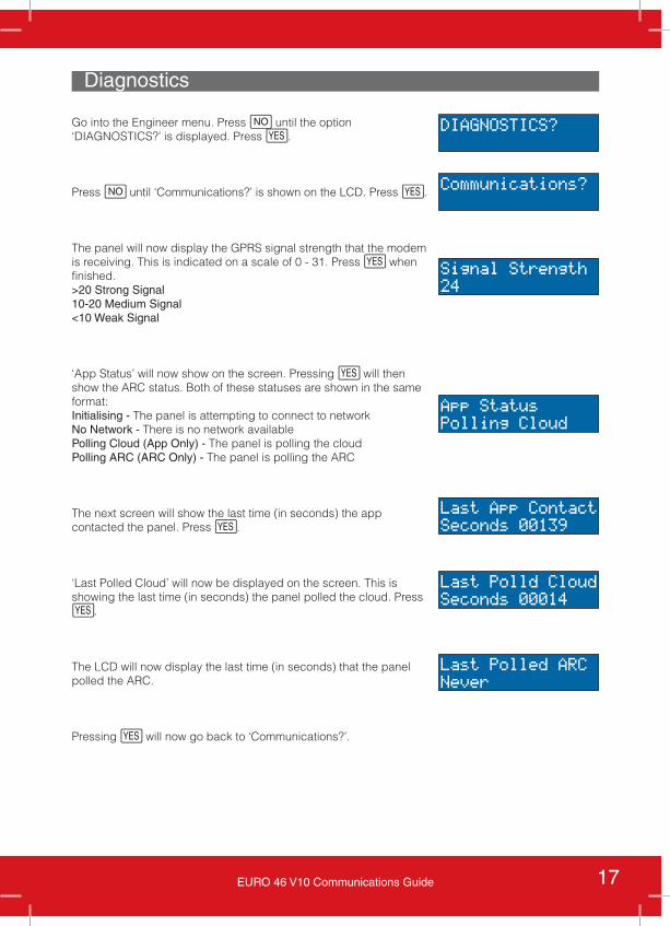
Diagnostics
Go into the Engineer menu. Press h until the option ‘DIAGNOSTICS?’ is displayed. Press f.
Press h until ‘Communications?’ is shown on the LCD. Press f.
The panel will now display the GPRS signal strength that the modem is receiving. This is indicated on a scale of 0 - 31. Press f when finished.>20 Strong Signal 10-20 Medium Signal<10 Weak Signal
‘App Status’ will now show on the screen. Pressing f will then show the ARC status. Both of these statuses are shown in the same format: Initialising - The panel is attempting to connect to networkNo Network - There is no network available Polling Cloud (App Only) - The panel is polling the cloudPolling ARC (ARC Only) - The panel is polling the ARC
The next screen will show the last time (in seconds) the app contacted the panel. Press f.
‘Last Polled Cloud’ will now be displayed on the screen. This is showing the last time (in seconds) the panel polled the cloud. Press f.
The LCD will now display the last time (in seconds) that the panel polled the ARC.
Pressing f will now go back to ‘Communications?’.
DIAGNOSTICS?
Communications?
Signal Strength24
App StatusPolling Cloud
Last App ContactSeconds 00139
Last Polld CloudSeconds 00014
Last Polled ARCNever
18 EURO 46 V10 Communications Guide
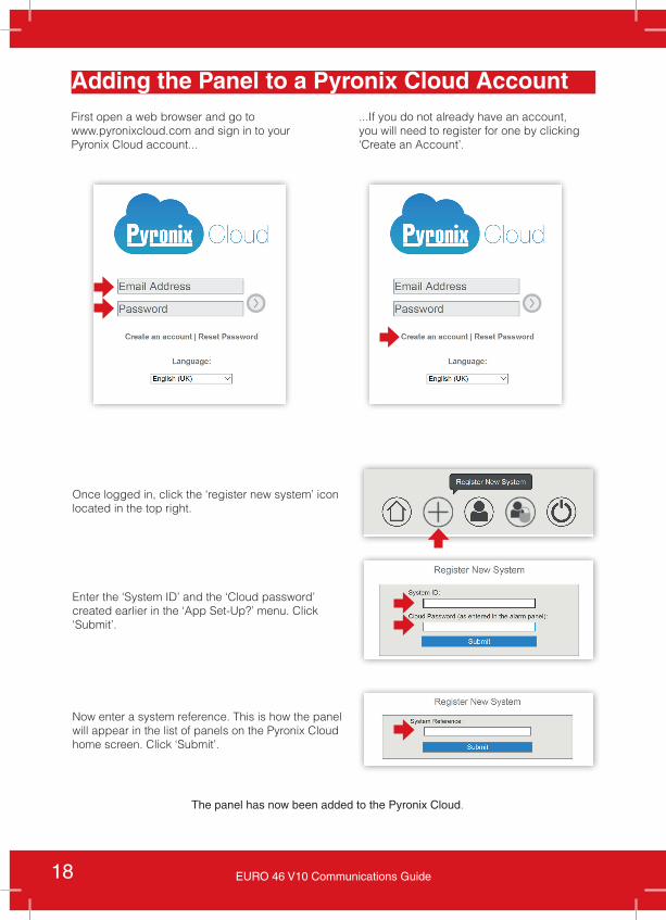
Adding the Panel to a Pyronix Cloud AccountFirst open a web browser and go towww.pyronixcloud.com and sign in to your Pyronix Cloud account...
...If you do not already have an account, you will need to register for one by clicking ‘Create an Account’.
Once logged in, click the ‘register new system’ icon located in the top right.
Enter the ‘System ID’ and the ‘Cloud password’ created earlier in the ‘App Set-Up?’ menu. Click ‘Submit’.
Now enter a system reference. This is how the panel will appear in the list of panels on the Pyronix Cloud home screen. Click ‘Submit’.
The panel has now been added to the Pyronix Cloud.
19EURO 46 V10 Communications Guide
Pyronix HomeControl+ App
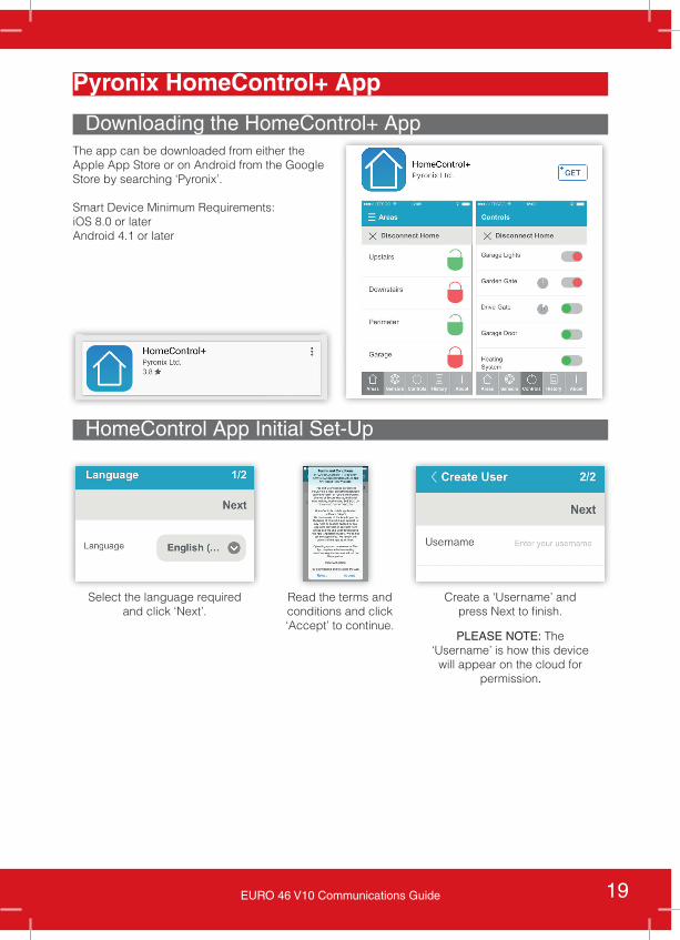
The app can be downloaded from either the Apple App Store or on Android from the Google Store by searching ‘Pyronix’.
Smart Device Minimum Requirements: iOS 8.0 or laterAndroid 4.1 or later
Downloading the HomeControl+ App
HomeControl App Initial Set-Up
Select the language required and click ‘Next’.
Create a ‘Username’ and press Next to finish.
PLEASE NOTE: The ‘Username’ is how this device
will appear on the cloud for permission.
Read the terms and conditions and click ‘Accept’ to continue.
20 EURO 46 V10 Communications Guide
Adding a System to the HomeControl+ App
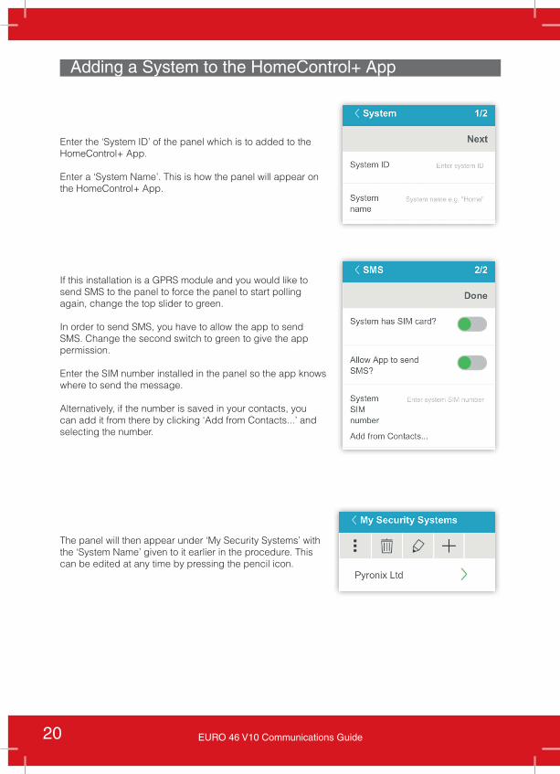
Enter the ‘System ID’ of the panel which is to added to the HomeControl+ App.
Enter a ‘System Name’. This is how the panel will appear on the HomeControl+ App.
If this installation is a GPRS module and you would like to send SMS to the panel to force the panel to start polling again, change the top slider to green.
In order to send SMS, you have to allow the app to send SMS. Change the second switch to green to give the app permission.
Enter the SIM number installed in the panel so the app knows where to send the message.
Alternatively, if the number is saved in your contacts, you can add it from there by clicking ‘Add from Contacts...’ and selecting the number.
The panel will then appear under ‘My Security Systems’ with the ‘System Name’ given to it earlier in the procedure. This can be edited at any time by pressing the pencil icon.
21EURO 46 V10 Communications Guide
Permissions on the Pyronix Cloud
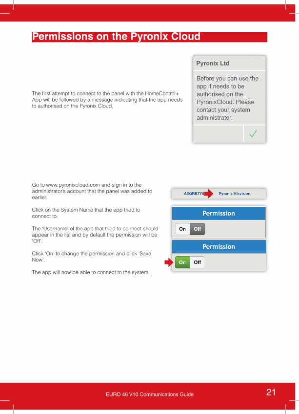
The first attempt to connect to the panel with the HomeControl+ App will be followed by a message indicating that the app needs to authorised on the Pyronix Cloud.
Go to www.pyronixcloud.com and sign in to the administrator’s account that the panel was added to earlier.
Click on the System Name that the app tried to connect to.
The ‘Username’ of the app that tried to connect should appear in the list and by default the permission will be ‘Off’.
Click ‘On’ to change the permission and click ‘Save Now’.
The app will now be able to connect to the system.
22 EURO 46 V10 Communications Guide
PSTN Modem 23Board Layout 23PSTN Connection Terminals 23
Programming Signalling 24Programming Fast Format Digi Channels 26SIA Level 1, SIA3 and Contact ID Signalling 27
Programming SMS Messages 29Advanced Communications 31GSM Module 32
Board Layout and LED Indications 32Signalling Menu Options 32GSM Signal Strength 32
PSTN Contents Table
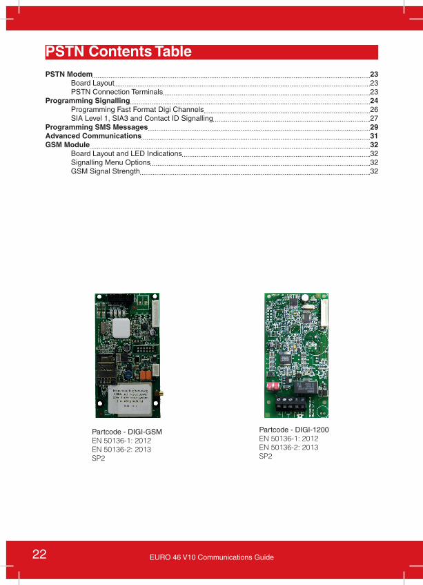
Partcode - DIGI-GSMEN 50136-1: 2012EN 50136-2: 2013SP2
Partcode - DIGI-1200EN 50136-1: 2012EN 50136-2: 2013SP2
23EURO 46 V10 Communications Guide
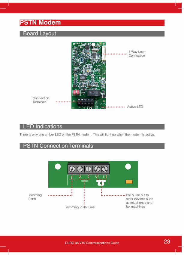
PSTN Modem
Board Layout
LED Indications
8 Way Loom Connection
Active LED
ConnectionTerminals
PSTN Connection Terminals
Incoming PSTN Line
PSTN line out to other devices such as telephones and fax machines
Incoming Earth
There is only one amber LED on the PSTN modem. This will light up when the modem is active.
24 EURO 46 V10 Communications Guide
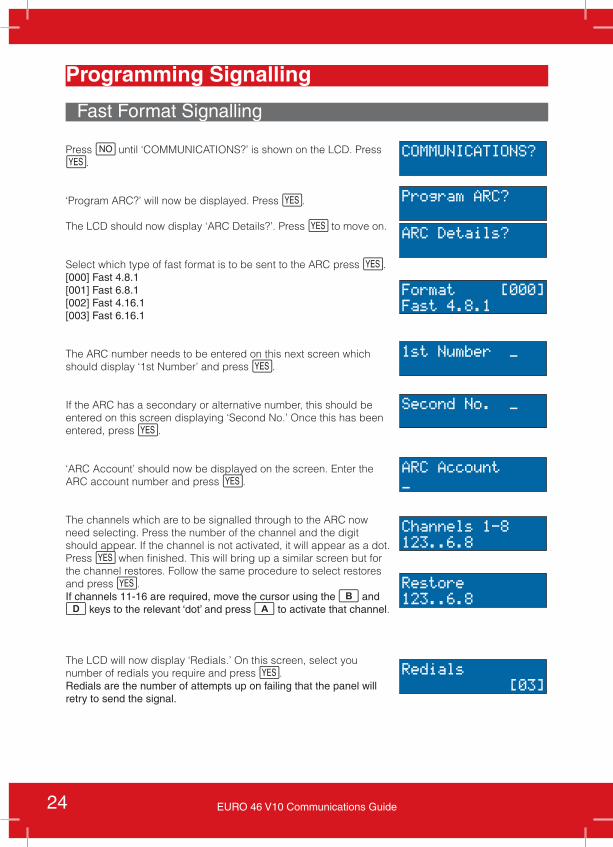
Programming Signalling
Press h until ‘COMMUNICATIONS?’ is shown on the LCD. Press f.
‘Program ARC?’ will now be displayed. Press f.
The LCD should now display ‘ARC Details?’. Press f to move on.
Select which type of fast format is to be sent to the ARC press f.[000] Fast 4.8.1[001] Fast 6.8.1[002] Fast 4.16.1[003] Fast 6.16.1
The ARC number needs to be entered on this next screen which should display ‘1st Number’ and press f.
If the ARC has a secondary or alternative number, this should be entered on this screen displaying ‘Second No.’ Once this has been entered, press f.
‘ARC Account’ should now be displayed on the screen. Enter the ARC account number and press f.
The channels which are to be signalled through to the ARC now need selecting. Press the number of the channel and the digit should appear. If the channel is not activated, it will appear as a dot. Press f when finished. This will bring up a similar screen but for the channel restores. Follow the same procedure to select restores and press f.If channels 11-16 are required, move the cursor using the b and d keys to the relevant ‘dot’ and press a to activate that channel.
The LCD will now display ‘Redials.’ On this screen, select you number of redials you require and press f. Redials are the number of attempts up on failing that the panel will retry to send the signal.
Fast Format Signalling
COMMUNICATIONS?
Program ARC?
ARC Details?
Format [000]Fast 4.8.1
1st Number _
Second No. _
ARC Account_
Channels 1-8123..6.8
Restore123..6.8
Redials [03]
25EURO 46 V10 Communications Guide
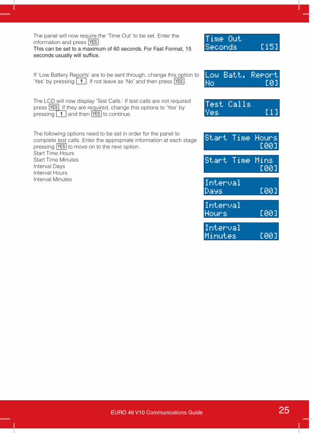
The panel will now require the ‘Time Out’ to be set. Enter the information and press f.This can be set to a maximum of 60 seconds. For Fast Format, 15 seconds usually will suffice.
If ‘Low Battery Reports’ are to be sent through, change this option to ‘Yes’ by pressing 1. If not leave as ‘No’ and then press f.
The LCD will now display ‘Test Calls.’ If test calls are not required press f. If they are required, change this options to ‘Yes’ by pressing 1 and then f to continue.
The following options need to be set in order for the panel to complete test calls. Enter the appropriate information at each stage pressing f to move on to the next option. Start Time Hours Start Time Minutes Interval DaysInterval HoursInterval Minutes
Time OutSeconds [15]
Low Batt. ReportNo [0]
Test CallsYes [1]
Start Time Hours [00]
Start Time Mins [00]
IntervalDays [00]
IntervalHours [00]
IntervalMinutes [00]
26 EURO 46 V10 Communications Guide
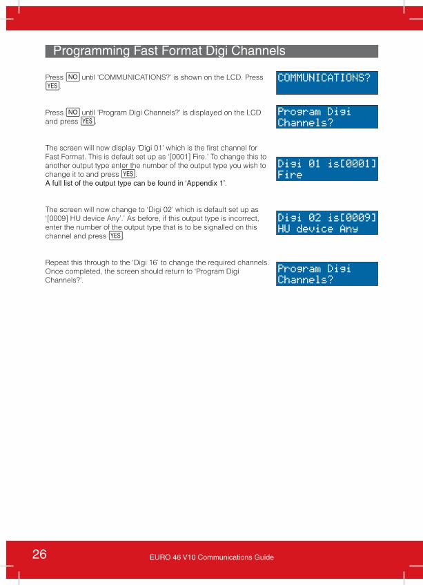
Press h until ‘COMMUNICATIONS?’ is shown on the LCD. Press f.
Press h until ‘Program Digi Channels?’ is displayed on the LCD and press f.
The screen will now display ‘Digi 01’ which is the first channel for Fast Format. This is default set up as ‘[0001] Fire.’ To change this to another output type enter the number of the output type you wish to change it to and press f.A full list of the output type can be found in ‘Appendix 1’.
The screen will now change to ‘Digi 02’ which is default set up as ‘[0009] HU device Any’.’ As before, if this output type is incorrect, enter the number of the output type that is to be signalled on this channel and press f.
Repeat this through to the ‘Digi 16’ to change the required channels. Once completed, the screen should return to ‘Program Digi Channels?’.
Programming Fast Format Digi Channels
COMMUNICATIONS?
Program DigiChannels?
Digi 01 is[0001]Fire
Digi 02 is[0009]HU device Any
Program DigiChannels?
27EURO 46 V10 Communications Guide
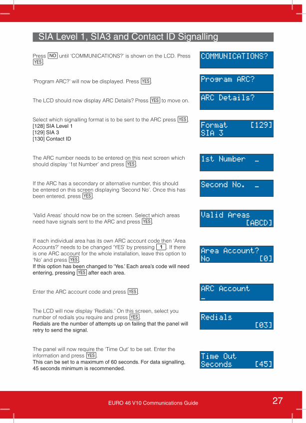
SIA Level 1, SIA3 and Contact ID Signalling
Press h until ‘COMMUNICATIONS?’ is shown on the LCD. Press f.
‘Program ARC?’ will now be displayed. Press f.
The LCD should now display ARC Details? Press f to move on.
Select which signalling format is to be sent to the ARC press f.[128] SIA Level 1[129] SIA 3[130] Contact ID
The ARC number needs to be entered on this next screen which should display ‘1st Number’ and press f.
If the ARC has a secondary or alternative number, this should be entered on this screen displaying ‘Second No’. Once this has been entered, press f.
‘Valid Areas’ should now be on the screen. Select which areas need have signals sent to the ARC and press f.
If each individual area has its own ARC account code then ‘Area Accounts?’ needs to be changed ‘YES’ by pressing 1. If there is one ARC account for the whole installation, leave this option to ‘No’ and press f.If this option has been changed to ‘Yes.’ Each area’s code will need entering, pressing f after each area.
Enter the ARC account code and press f.
The LCD will now display ‘Redials.’ On this screen, select you number of redials you require and press f. Redials are the number of attempts up on failing that the panel will retry to send the signal.
The panel will now require the ‘Time Out’ to be set. Enter the information and press f.This can be set to a maximum of 60 seconds. For data signalling, 45 seconds minimum is recommended.
COMMUNICATIONS?
Program ARC?
ARC Details?
Format [129]SIA 3
1st Number _
Second No. _
Valid Areas [ABCD]
Area Account?No [0]
ARC Account_
Redials [03]
Time OutSeconds [45]
28 EURO 46 V10 Communications Guide
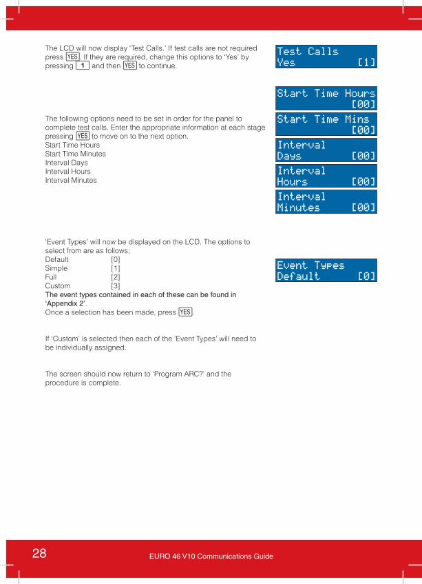
The LCD will now display ‘Test Calls.’ If test calls are not required press f. If they are required, change this options to ‘Yes’ by pressing 1 and then f to continue.
The following options need to be set in order for the panel to complete test calls. Enter the appropriate information at each stage pressing f to move on to the next option. Start Time Hours Start Time Minutes Interval DaysInterval HoursInterval Minutes
‘Event Types’ will now be displayed on the LCD. The options to select from are as follows;Default [0]Simple [1]Full [2]Custom [3]The event types contained in each of these can be found in ‘Appendix 2’.Once a selection has been made, press f.
If ‘Custom’ is selected then each of the ‘Event Types’ will need to be individually assigned.
The screen should now return to ‘Program ARC?’ and the procedure is complete.
Start Time Hours [00]
Start Time Mins [00]
IntervalDays [00]
IntervalHours [00]
IntervalMinutes [00]
Event TypesDefault [0]
Test CallsYes [1]
29EURO 46 V10 Communications Guide
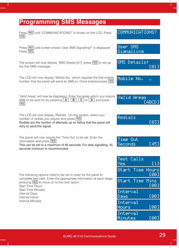
Programming SMS Messages
Press h until ‘COMMUNICATIONS?’ is shown on the LCD. Press f.
Press h until screen shows ‘User SMS Signalling?’ is displayed. Press f.
The screen will now display ‘SMS Details [01]’ press f to set up the first SMS message.
The LCD will now display ‘Mobile No.’ which requires the first mobile number that the panel will send an SMS to. Once entered press f.
‘Valid Areas’ will now be displayed. Enter the areas which you require SMS to be sent for by pressing a, b, c or d and press f.
The LCD will now display ‘Redials.’ On this screen, select you number of redials you require and press f. Redials are the number of attempts up on failing that the panel will retry to send the signal.
The panel will now require the ‘Time Out’ to be set. Enter the information and press f.This can be set to a maximum of 60 seconds. For data signalling, 45 seconds minimum is recommended.
The following options need to be set in order for the panel to complete test calls. Enter the appropriate information at each stage pressing f to move on to the next option. Start Time Hours Start Time Minutes Interval DaysInterval HoursInterval Minutes
COMMUNICATIONS?
Mobile No. _
User SMSSignalling
SMS Details: [01]
Time OutSeconds [45]
Start Time Hours [00]
Start Time Mins [00]
IntervalDays [00]
IntervalHours [00]
IntervalMinutes [00]
Test CallsYes [1]
Redials [03]
Valid Areas [ABCD]
30 EURO 46 V10 Communications Guide
SMS Details: [02]
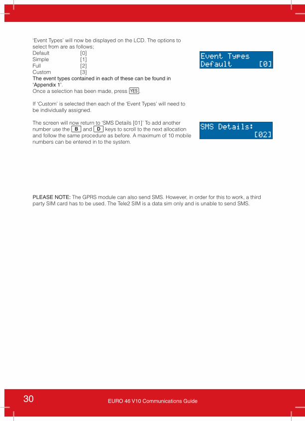
‘Event Types’ will now be displayed on the LCD. The options to select from are as follows;Default [0]Simple [1]Full [2]Custom [3]The event types contained in each of these can be found in ‘Appendix 1’.Once a selection has been made, press f.
If ‘Custom’ is selected then each of the ‘Event Types’ will need to be individually assigned.
The screen will now return to ‘SMS Details [01]’ To add another number use the b and d keys to scroll to the next allocation and follow the same procedure as before. A maximum of 10 mobile numbers can be entered in to the system.
Event TypesDefault [0]
PLEASE NOTE: The GPRS module can also send SMS. However, in order for this to work, a third party SIM card has to be used. The Tele2 SIM is a data sim only and is unable to send SMS.
31EURO 46 V10 Communications Guide
Advanced Communications
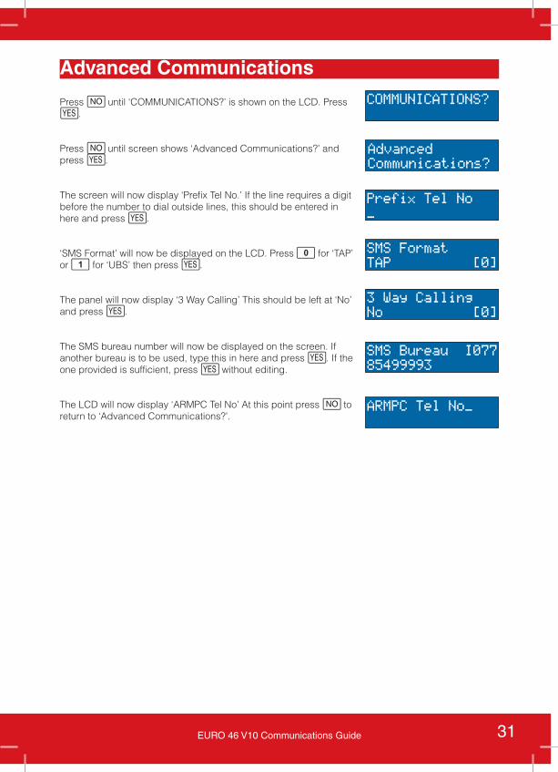
Press h until ‘COMMUNICATIONS?’ is shown on the LCD. Press f.
Press h until screen shows ‘Advanced Communications?’ and press f.
The screen will now display ‘Prefix Tel No.’ If the line requires a digit before the number to dial outside lines, this should be entered in here and press f.
‘SMS Format’ will now be displayed on the LCD. Press 0 for ‘TAP’ or 1 for ‘UBS’ then press f.
The panel will now display ‘3 Way Calling’ This should be left at ‘No’ and press f.
The SMS bureau number will now be displayed on the screen. If another bureau is to be used, type this in here and press f. If the one provided is sufficient, press f without editing.
The LCD will now display ‘ARMPC Tel No’ At this point press h to return to ‘Advanced Communications?’.
COMMUNICATIONS?
AdvancedCommunications?
Prefix Tel No_
SMS FormatTAP [0]
3 Way CallingNo [0]
SMS Bureau I07785499993
ARMPC Tel No_
32 EURO 46 V10 Communications Guide
Board Layout and LED Indications
GSM Module
Please refer to the GPRS module section for the board layout and the LED indications for the GSM module. The two modules are identical in these respects.
Signalling Menu OptionsThe GSM module is just an alternative method for sending the same data as the PSTN modem. Based on this, refer to the menu procedures described for the PSTN modem.
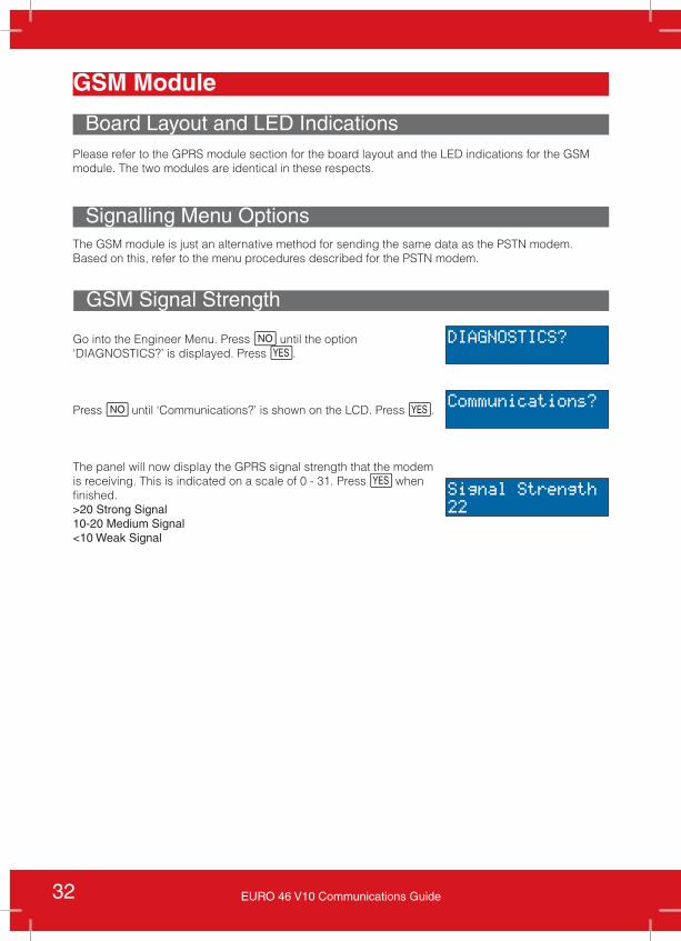
Go into the Engineer Menu. Press h until the option ‘DIAGNOSTICS?’ is displayed. Press f.
Press h until ‘Communications?’ is shown on the LCD. Press f.
The panel will now display the GPRS signal strength that the modem is receiving. This is indicated on a scale of 0 - 31. Press f when finished.>20 Strong Signal 10-20 Medium Signal<10 Weak Signal
DIAGNOSTICS?
Communications?
Signal Strength22
GSM Signal Strength
33EURO 46 V10 Communications Guide
Voice Contents TablePSTN/Voice Modem 34
Board Layout 34LED Indications 34PSTN Connection Terminals 34
Programming Voice Messages 35Diagnostics 37Advanced Communications 38
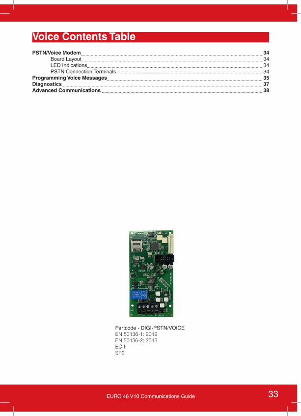
Partcode - DIGI-PSTN/VOICEEN 50136-1: 2012EN 50136-2: 2013EC IISP2
34 EURO 46 V10 Communications Guide
PSTN/Voice Modem
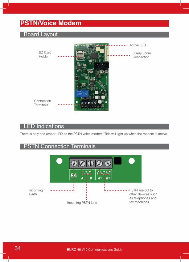
Board Layout
LED Indications
PSTN Connection Terminals
Incoming PSTN Line
PSTN line out to other devices such as telephones and fax machines
Incoming Earth
8 Way Loom Connection
Active LED
ConnectionTerminals
There is only one amber LED on the PSTN voice modem. This will light up when the modem is active.
SD Card Holder
35EURO 46 V10 Communications Guide
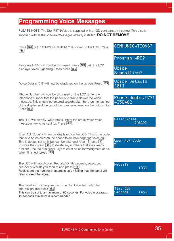
Programming Voice MessagesPLEASE NOTE: The Digi-PSTN/Voice is supplied with an SD card already inserted. This also is
supplied with all the software/messages already installed. DO NOT REMOVE
Press h until ‘COMMUNICATIONS?’ is shown on the LCD. Press f.
‘Program ARC?’ will now be displayed. Press h until the LCD displays ‘Voice Signalling?’ then press f.
‘Voice Details [01]’ will now be displayed on the screen. Press f.
‘Phone Numbe.’ will now be displayed on the LCD. Enter the telephone number that the panel is to dial to deliver the voice message. This should be entered straight after the ‘.’ on the top line of the display and the rest of the number entered on the bottom like. Press f.
The LCD will display ‘Valid Areas.’ Enter the areas which voice messages are to be sent for. Press f.
‘User Ack Code’ will now be displayed on the LCD, This is the code that is to be entered on the phone to acknowledge the voice call. This is default set to ‘5’ but can be changed. Use b and d to move the cursor, c to delete any numbers that are already present. Use the numerical keys to enter an acknowledgment code. When finished, press f.
The LCD will now display ‘Redials.’ On this screen, select you number of redials you require and press f. Redials are the number of attempts up on failing that the panel will retry to send the signal.
The panel will now require the ‘Time Out’ to be set. Enter the information and press f.This can be set to a maximum of 60 seconds. For voice messages, 45 seconds minimum is recommended.
COMMUNICATIONS?
Program ARC?
VoiceSignalling?
Voice Details[01]
Phone Numbe.07714358462
Valid Areas [ABCD]
Redials [03]
User Ack Code5
Time OutSeconds [45]
36 EURO 46 V10 Communications Guide
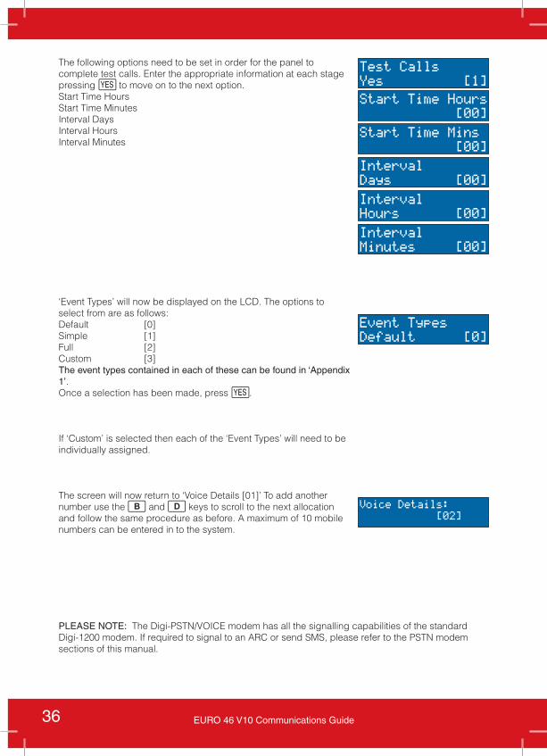
The following options need to be set in order for the panel to complete test calls. Enter the appropriate information at each stage pressing f to move on to the next option. Start Time Hours Start Time Minutes Interval DaysInterval HoursInterval Minutes
‘Event Types’ will now be displayed on the LCD. The options to select from are as follows:Default [0]Simple [1]Full [2]Custom [3]The event types contained in each of these can be found in ‘Appendix 1’.Once a selection has been made, press f.
If ‘Custom’ is selected then each of the ‘Event Types’ will need to be individually assigned.
The screen will now return to ‘Voice Details [01]’ To add another number use the b and d keys to scroll to the next allocation and follow the same procedure as before. A maximum of 10 mobile numbers can be entered in to the system.
Start Time Hours [00]
Start Time Mins [00]
IntervalDays [00]
IntervalHours [00]
IntervalMinutes [00]
Test CallsYes [1]
Voice Details: [02]
Event TypesDefault [0]
PLEASE NOTE: The Digi-PSTN/VOICE modem has all the signalling capabilities of the standard Digi-1200 modem. If required to signal to an ARC or send SMS, please refer to the PSTN modem sections of this manual.
37EURO 46 V10 Communications Guide
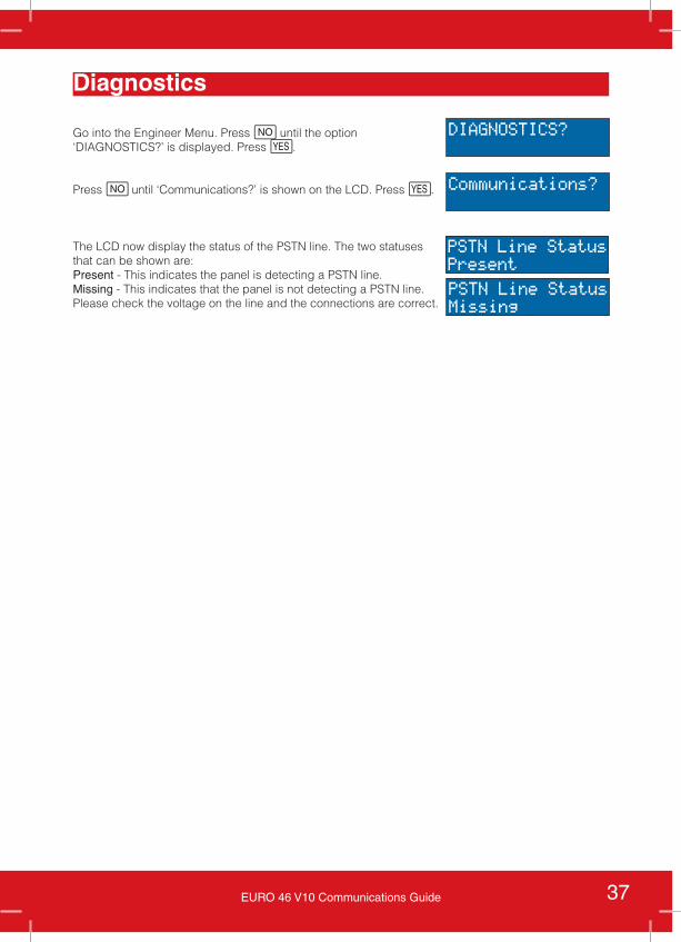
Diagnostics
Go into the Engineer Menu. Press h until the option ‘DIAGNOSTICS?’ is displayed. Press f.
Press h until ‘Communications?’ is shown on the LCD. Press f.
The LCD now display the status of the PSTN line. The two statuses that can be shown are:Present - This indicates the panel is detecting a PSTN line. Missing - This indicates that the panel is not detecting a PSTN line. Please check the voltage on the line and the connections are correct.
DIAGNOSTICS?
Communications?
PSTN Line StatusPresent
PSTN Line StatusMissing
38 EURO 46 V10 Communications Guide
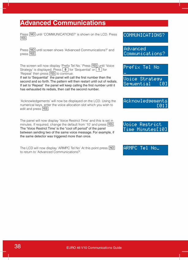
Advanced Communications
Press h until ‘COMMUNICATIONS?’ is shown on the LCD. Press f.
Press h until screen shows ‘Advanced Communications?’ and press f.
The screen will now display ‘Prefix Tel No.’ Press f until ‘Voice Strategy’ is displayed. Press 0 for ‘Sequential’ or 1 for ‘Repeat’ then press f to continue.If set to ‘Sequential’ the panel will call the first number then the second and so forth. The pattern will then restart until out of redials.If set to ‘Repeat’ the panel will keep calling the first number until it has exhausted its redials, then call the second number.
‘Acknowledgements’ will now be displayed on the LCD. Using the numerical keys, enter the voice allocation slot which you wish to edit and press f.
The panel will now display ‘Voice Restrict Time’ and this is set in minutes. If required, change the default from ‘10’ and press f.The ‘Voice Restrict Time’ is the “cool off period” of the panel between sending two of the same voice message. For example, if the same detector was triggered more than once.
The LCD will now display ‘ARMPC Tel No’ At this point press h to return to ‘Advanced Communications?’.
COMMUNICATIONS?
AdvancedCommunications?
Prefix Tel No_
Voice StrategySequential [0]
Acknowledgements [01]
Voice RestrictTime Minutes[10]
ARMPC Tel No_
39EURO 46 V10 Communications Guide
CSL DigiAir Pyronix
Important Information
Features
The CSL DigiAir Pyronix module comes in three variants, LAN, Wi-Fi and GPRS+SIM. The layouts and installation are the same as their standard counterparts however, the SIM card in the GPRS+SIM module is different. This SIM card has been specifically adapted so that it can access CSL’s Gemini Network enabling the panel to communicate with ARCs.
These modules must be purchased from an ARC or from CSL to ensure you have the correct module.
All three modules can send Fast Format, SIA 3 and Contact ID signalling formats to a central station whilst also connecting to the Pyronix cloud enabling full use of the SmartAlarm+ app from a smart device.
The CSL DigiAir Pyronix GPRS includes a roaming data SIM that should connect to the best network in the area.
PLEASE NOTE: This is a data SIM only and will not send SMS.
Signalling ProgrammingThe signalling programming for these modules is the same as the PSTN modem connecting to an ARC but with two minor changes. The ARC numbers are not needed therefore these steps are not visible however, an ‘ARC code’ will need entering at the end of the procedure. Enter the ARC code needed and press f. This will then connect to the ARC and enable the signals to be sent.
A full list of the ARC codes can be found in ‘Appendix 3’.
HomeControl+ ProgrammingThis programming is identical to the programming needed to connect the standard Digi-GPRS+SIM to the cloud. Please refer to this section for step by step instructions.
40 EURO 46 V10 Communications Guide
Testing Communications
Fast Format Testing
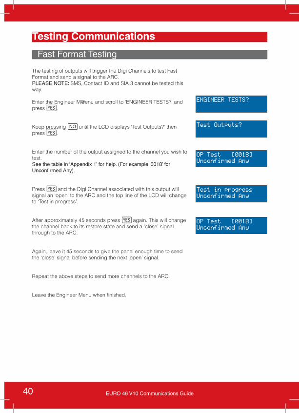
The testing of outputs will trigger the Digi Channels to test Fast Format and send a signal to the ARC.PLEASE NOTE: SMS, Contact ID and SIA 3 cannot be tested this way.
Enter the Engineer M@enu and scroll to ‘ENGINEER TESTS?’ and press f.
Keep pressing h until the LCD displays ‘Test Outputs?’ then press f.
Enter the number of the output assigned to the channel you wish to test. See the table in ‘Appendix 1’ for help. (For example ‘0018’ for Unconfirmed Any).
Press f and the Digi Channel associated with this output will signal an ‘open’ to the ARC and the top line of the LCD will change to ‘Test in progress’.
After approximately 45 seconds press f again. This will change the channel back to its restore state and send a ‘close’ signal through to the ARC.
Again, leave it 45 seconds to give the panel enough time to send the ‘close’ signal before sending the next ‘open’ signal.
Repeat the above steps to send more channels to the ARC.
Leave the Engineer Menu when finished.
ENGINEER TESTS?
Test Outputs?
OP Test [0018]Unconfirmed Any
OP Test [0018]Unconfirmed Any
Test in progressUnconfirmed Any
41EURO 46 V10 Communications Guide
Product Information
Contact ID, SIA3, SMS and Voice Message Testing
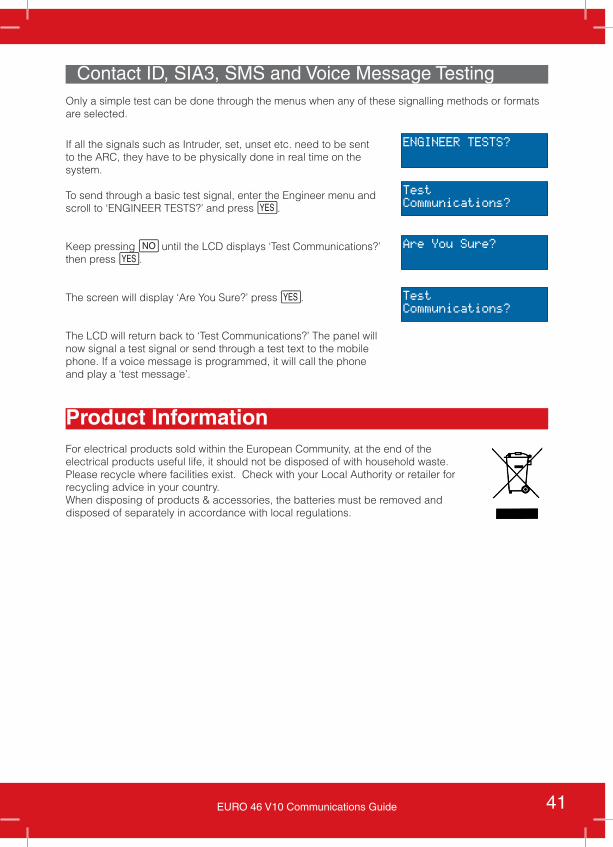
If all the signals such as Intruder, set, unset etc. need to be sent to the ARC, they have to be physically done in real time on the system.
To send through a basic test signal, enter the Engineer menu and scroll to ‘ENGINEER TESTS?’ and press f.
Keep pressing h until the LCD displays ‘Test Communications?’ then press f.
The screen will display ‘Are You Sure?’ press f.
The LCD will return back to ‘Test Communications?’ The panel will now signal a test signal or send through a test text to the mobile phone. If a voice message is programmed, it will call the phone and play a ‘test message’.
ENGINEER TESTS?
TestCommunications?
TestCommunications?
Are You Sure?
For electrical products sold within the European Community, at the end of the electrical products useful life, it should not be disposed of with household waste. Please recycle where facilities exist. Check with your Local Authority or retailer for recycling advice in your country. When disposing of products & accessories, the batteries must be removed and disposed of separately in accordance with local regulations.
Only a simple test can be done through the menus when any of these signalling methods or formats are selected.
42 EURO 46 V10 Communications Guide
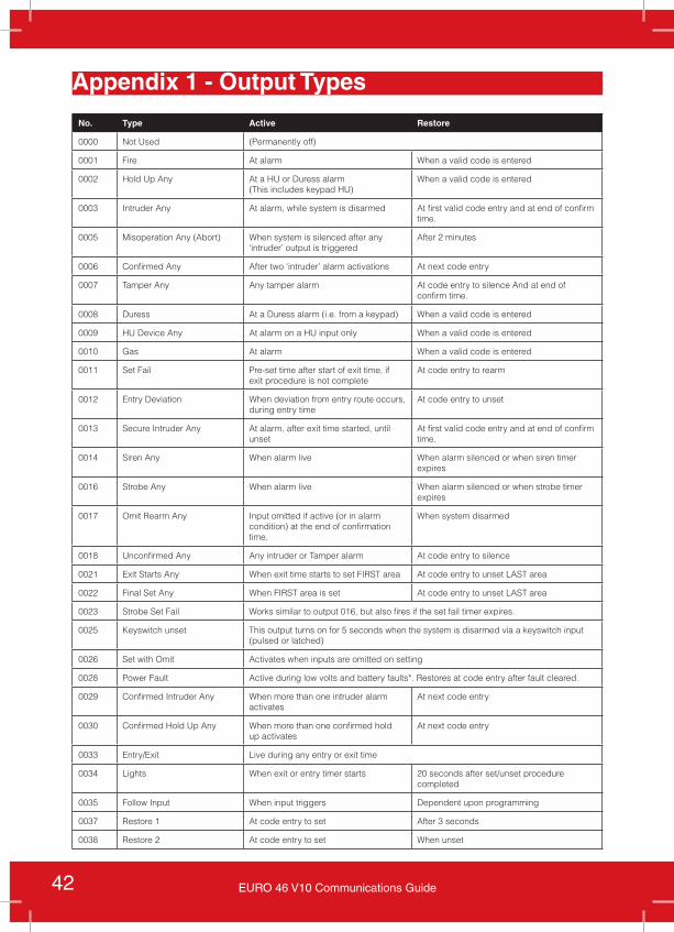
Appendix 1 - Output Types
No. Type Active Restore
0000 Not Used (Permanently off)
0001 Fire At alarm When a valid code is entered
0002 Hold Up Any At a HU or Duress alarm (This includes keypad HU)
When a valid code is entered
0003 Intruder Any At alarm, while system is disarmed At first valid code entry and at end of confirm time.
0005 Misoperation Any (Abort) When system is silenced after any ‘intruder’ output is triggered
After 2 minutes
0006 Confirmed Any After two ‘intruder’ alarm activations At next code entry
0007 Tamper Any Any tamper alarm At code entry to silence And at end of confirm time.
0008 Duress At a Duress alarm (i.e. from a keypad) When a valid code is entered
0009 HU Device Any At alarm on a HU input only When a valid code is entered
0010 Gas At alarm When a valid code is entered
0011 Set Fail Pre-set time after start of exit time, if exit procedure is not complete
At code entry to rearm
0012 Entry Deviation When deviation from entry route occurs, during entry time
At code entry to unset
0013 Secure Intruder Any At alarm, after exit time started, until unset
At first valid code entry and at end of confirm time.
0014 Siren Any When alarm live When alarm silenced or when siren timer expires
0016 Strobe Any When alarm live When alarm silenced or when strobe timer expires
0017 Omit Rearm Any Input omitted if active (or in alarm condition) at the end of confirmation time.
When system disarmed
0018 Unconfirmed Any Any intruder or Tamper alarm At code entry to silence
0021 Exit Starts Any When exit time starts to set FIRST area At code entry to unset LAST area
0022 Final Set Any When FIRST area is set At code entry to unset LAST area
0023 Strobe Set Fail Works similar to output 016, but also fires if the set fail timer expires.
0025 Keyswitch unset This output turns on for 5 seconds when the system is disarmed via a keyswitch input (pulsed or latched)
0026 Set with Omit Activates when inputs are omitted on setting
0028 Power Fault Active during low volts and battery faults*. Restores at code entry after fault cleared.
0029 Confirmed Intruder Any When more than one intruder alarm activates
At next code entry
0030 Confirmed Hold Up Any When more than one confirmed hold up activates
At next code entry
0033 Entry/Exit Live during any entry or exit time
0034 Lights When exit or entry timer starts 20 seconds after set/unset procedure completed
0035 Follow Input When input triggers Dependent upon programming
0037 Restore 1 At code entry to set After 3 seconds
0038 Restore 2 At code entry to set When unset
43EURO 46 V10 Communications Guide
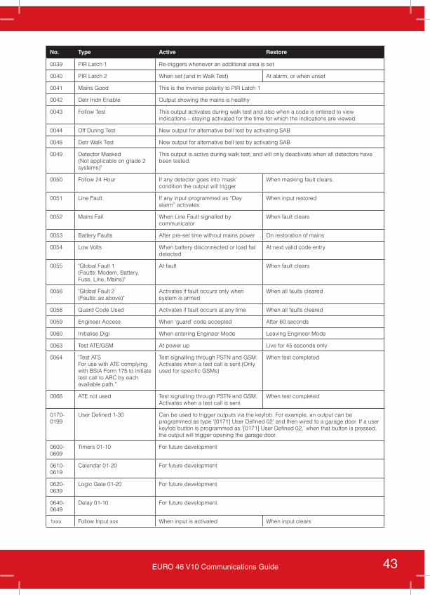
No. Type Active Restore
0039 PIR Latch 1 Re-triggers whenever an additional area is set
0040 PIR Latch 2 When set (and in Walk Test) At alarm, or when unset
0041 Mains Good This is the inverse polarity to PIR Latch 1
0042 Detr Indn Enable Output showing the mains is healthy
0043 Follow Test This output activates during walk test and also when a code is entered to view indications – staying activated for the time for which the indications are viewed.
0044 Off During Test New output for alternative bell test by activating SAB
0048 Detr Walk Test New output for alternative bell test by activating SAB
0049 Detector Masked (Not applicable on grade 2 systems)"
This output is active during walk test, and will only deactivate when all detectors have been tested.
0050 Follow 24 Hour If any detector goes into ‘mask’ condition the output will trigger
When masking fault clears.
0051 Line Fault If any input programmed as “Day alarm” activates
When input restored
0052 Mains Fail When Line Fault signalled by communicator
When fault clears
0053 Battery Faults After pre-set time without mains power On restoration of mains
0054 Low Volts When battery disconnected or load fail detected
At next valid code entry
0055 "Global Fault 1 (Faults: Modem, Battery, Fuse, Line, Mains)"
At fault When fault clears
0056 "Global Fault 2 (Faults: as above)"
Activates if fault occurs only when system is armed
When all faults cleared
0058 Guard Code Used Activates if fault occurs at any time When all faults cleared
0059 Engineer Access When ‘guard’ code accepted After 60 seconds
0060 Initialise Digi When entering Engineer Mode Leaving Engineer Mode
0063 Test ATE/GSM At power up Live for 45 seconds only
0064 "Test ATS For use with ATE complying with BSIA Form 175 to initiate test call to ARC by each available path."
Test signalling through PSTN and GSM. Activates when a test call is sent.(Only used for specific GSMs)
When test completed
0066 ATE not used Test signalling through PSTN and GSM. Activates when a test call is sent.
When test completed
0170- 0199
User Defined 1-30 Can be used to trigger outputs via the keyfob. For example, an output can be programmed as type ‘[0171] User Defined 02’ and then wired to a garage door. If a user keyfob button is programmed as ‘[0171] User Defined 02,’ when that button is pressed, the output will trigger opening the garage door.
0600- 0609
Timers 01-10 For future development
0610- 0619
Calendar 01-20 For future development
0620- 0639
Logic Gate 01-20 For future development
0640- 0649
Delay 01-10 For future development
1xxx Follow Input xxx When input is activated When input clears
44 EURO 46 V10 Communications Guide
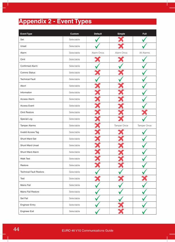
Event Type Custom Default Simple Full
Set Selectable
Unset Selectable
Alarm Selectable Alarm Once Alarm Once All Alarms
Omit Selectable
Confirmed Alarm Selectable
Comms Status Selectable
Technical Fault Selectable
Abort Selectable
Information Selectable
Access Alarm Selectable
Access Event Selectable
Omit Restore Selectable
Special Log Selectable
Tamper Alarms Selectable Tamper Once Tamper Once
Invalid Access Tag Selectable
Shunt Ward Set Selectable
Shunt Ward Unset Selectable
Shunt Ward Alarm Selectable
Walk Test Selectable
Restore Selectable
Technical Fault Restore Selectable
Test Selectable
Mains Fail Selectable
Mains Fail Restore Selectable
Set Fail Selectable
Engineer Entry Selectable
Engineer Exit Selectable
Appendix 2 - Event Types
45EURO 46 V10 Communications Guide
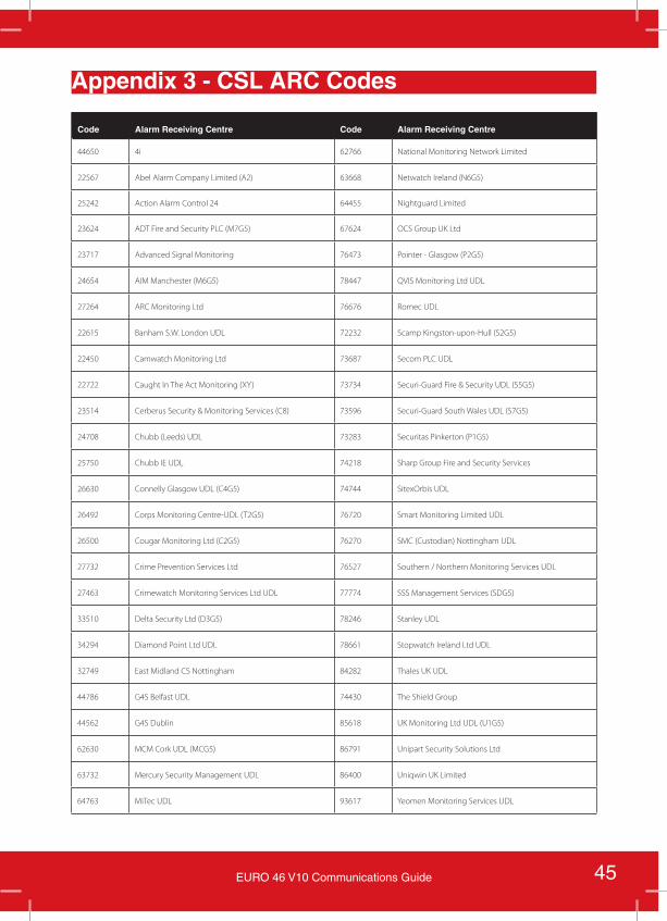
Appendix 3 - CSL ARC Codes
Code Alarm Receiving Centre Code Alarm Receiving Centre
44650 4i 62766 National Monitoring Network Limited
22567 Abel Alarm Company Limited (A2) 63668 Netwatch Ireland (N6G5)
25242 Action Alarm Control 24 64455 Nightguard Limited
23624 ADT Fire and Security PLC (M7G5) 67624 OCS Group UK Ltd
23717 Advanced Signal Monitoring 76473 Pointer - Glasgow (P2G5)
24654 AIM Manchester (M6G5) 78447 QVIS Monitoring Ltd UDL
27264 ARC Monitoring Ltd 76676 Romec UDL
22615 Banham S.W. London UDL 72232 Scamp Kingston-upon-Hull (S2G5)
22450 Camwatch Monitoring Ltd 73687 Secom PLC UDL
22722 Caught In The Act Monitoring (XY) 73734 Securi-Guard Fire & Security UDL (S5G5)
23514 Cerberus Security & Monitoring Services (C8) 73596 Securi-Guard South Wales UDL (S7G5)
24708 Chubb (Leeds) UDL 73283 Securitas Pinkerton (P1G5)
25750 Chubb IE UDL 74218 Sharp Group Fire and Security Services
26630 Connelly Glasgow UDL (C4G5) 74744 SitexOrbis UDL
26492 Corps Monitoring Centre-UDL (T2G5) 76720 Smart Monitoring Limited UDL
26500 Cougar Monitoring Ltd (C2G5) 76270 SMC (Custodian) Nottingham UDL
27732 Crime Prevention Services Ltd 76527 Southern / Northern Monitoring Services UDL
27463 Crimewatch Monitoring Services Ltd UDL 77774 SSS Management Services (SDG5)
33510 Delta Security Ltd (D3G5) 78246 Stanley UDL
34294 Diamond Point Ltd UDL 78661 Stopwatch Ireland Ltd UDL
32749 East Midland CS Nottingham 84282 Thales UK UDL
44786 G4S Belfast UDL 74430 The Shield Group
44562 G4S Dublin 85618 UK Monitoring Ltd UDL (U1G5)
62630 MCM Cork UDL (MCG5) 86791 Unipart Security Solutions Ltd
63732 Mercury Security Management UDL 86400 Uniqwin UK Limited
64763 MiTec UDL 93617 Yeomen Monitoring Services UDL
46 EURO 46 V10 Communications Guide
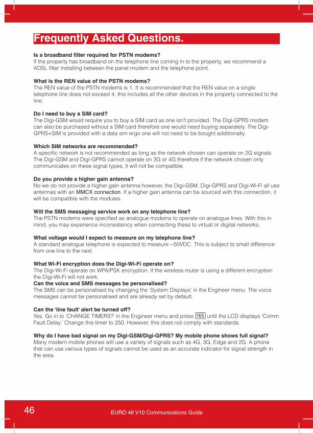
Frequently Asked Questions.Is a broadband filter required for PSTN modems?If the property has broadband on the telephone line coming in to the property, we recommend a ADSL filter installing between the panel modem and the telephone point.
What is the REN value of the PSTN modems?The REN value of the PSTN modems is 1. It is recommended that the REN value on a single telephone line does not exceed 4, this includes all the other devices in the property connected to the line.
Do I need to buy a SIM card?The Digi-GSM would require you to buy a SIM card as one isn’t provided. The Digi-GPRS modem can also be purchased without a SIM card therefore one would need buying separately. The Digi-GPRS+SIM is provided with a data sim ergo one will not need to be bought additionally.
Which SIM networks are recommended?A specific network is not recommended as long as the network chosen can operate on 2G signals. The Digi-GSM and Digi-GPRS cannot operate on 3G or 4G therefore if the network chosen only communicates on these signal types, it will not be compatible.
Do you provide a higher gain antenna?No we do not provide a higher gain antenna however, the Digi-GSM, Digi-GPRS and Digi-Wi-Fi all use antennas with an MMCX connection. If a higher gain antenna can be sourced with this connection, it will be compatible with the modules.
Will the SMS messaging service work on any telephone line?The PSTN modems were specified as analogue modems to operate on analogue lines. With this in mind, you may experience inconsistency when connecting these to virtual or digital networks.
What voltage would I expect to measure on my telephone line?A standard analogue telephone is expected to measure ~50VDC. This is subject to small difference from one line to the next.
What Wi-Fi encryption does the Digi-Wi-Fi operate on?The Digi-Wi-Fi operate on WPA/PSK encryption. If the wireless router is using a different encryption the Digi-Wi-Fi will not work.Can the voice and SMS messages be personalised?The SMS can be personalised by changing the ‘System Displays’ in the Engineer menu. The voice messages cannot be personalised and are already set by default.
Can the ‘line fault’ alert be turned off?Yes. Go in to ‘CHANGE TIMERS?’ in the Engineer menu and press f until the LCD displays ‘Comm Fault Delay.’ Change this timer to 250. However, this does not comply with standards.
Why do I have bad signal on my Digi-GSM/Digi-GPRS? My mobile phone shows full signal?Many modern mobile phones will use a variety of signals such as 4G, 3G, Edge and 2G. A phone that can use various types of signals cannot be used as an accurate indicator for signal strength in the area.

47EURO 46 V10 Communications Guide
Customer Support
Pyronix Training Academy Online
Pyronix Training Academy Training Videos
Technical Support
Connect to a whole host of exclusive training materials, including online weekly webinars and step-by-step training videos by joining the Pyronix Training Academy.
To start accessing an entire arsenal of training resources, simply email your full contact details and company name to [email protected] now. You will receive an email confirmation once your application has been approved.
PLEASE NOTE: It can take up to 2 working days to process your account.
Alternatively you can register online for one of our webinar sessions by going to the following address:www.pyronix.co.uk/help-and-support/installers-distributors/courses-and-training
Watch easy step by step setup and training videos on a large range of our security solutions. Available for you to watch at your leisure, you can access them on-the-go to learn new skills, refresh your knowledge or even watch the latest videos on our newest releases or updates.
Email your full contact details and company name to [email protected] now and you can watch, learn and install whenever you want. You will receive an email confirmation once your application has been approved.
PLEASE NOTE: It can take up to 2 working days to process your account.
If you are still experiencing issues with the installation, please call our UK technical support team.
PLEASE NOTE: In order to get your issue resolved quickly, please have the software revision of the panel ready to give to one of our engineers.
Alternatively if you do not require assistance straight away, you can always email the team who will reply to you as soon as possible.
Our office hours are: Monday to Friday 8:00 - 18:30.
*0333 444 1280( [email protected]

Related Documents