EUMETCast System Component details - Antenna Ben Maathuis, 19-02-2021 Dept. of Water Resources, Faculty ITC, University of Twente, Enschede, The Netherlands. Email: [email protected] © This work is licensed under the Creative Commons Attribution-NonCommercial 4.0 License. To view a copy of this license, visit https://creativecommons.org/licenses/by-nc/4.0/ or send a letter to Creative Commons, 444 Castro Street, Suite 900, Mountain View, California, 94041, USA.

Welcome message from author
This document is posted to help you gain knowledge. Please leave a comment to let me know what you think about it! Share it to your friends and learn new things together.
Transcript
EUMETCast System Component details - Antenna
Ben Maathuis, 19-02-2021 Dept. of Water Resources, Faculty ITC, University of Twente, Enschede, The Netherlands. Email: [email protected]
© This work is licensed under the Creative Commons Attribution-NonCommercial 4.0 License. To view a copy of this license, visit https://creativecommons.org/licenses/by-nc/4.0/ or send a letter to Creative Commons, 444 Castro Street, Suite 900, Mountain View, California, 94041, USA.

1
Contents
1 Introduction ............................................................................................................................................... 2
2 Antenna size and types .............................................................................................................................. 2
2.1 Antenna size ....................................................................................................................................... 2
2.2 Antenna type ...................................................................................................................................... 3
2.3 Low Noice Block (LNB) ............................................................................................................................... 3
2.4 Polarization ................................................................................................................................................ 4
3 Pointing of the antenna ............................................................................................................................. 6
4 Preparing and pointing antenna ................................................................................................................ 6
5 Installation and Configuration of Reception station software .................................................................. 7
6 References ................................................................................................................................................. 8
2
1 Introduction This document provides an introduction to the most common equipment, like antenna and LNB needed to receive EUMETCast C‐Band Africa Services. Some attention is given to the polarization and pointing of the antenna as well.
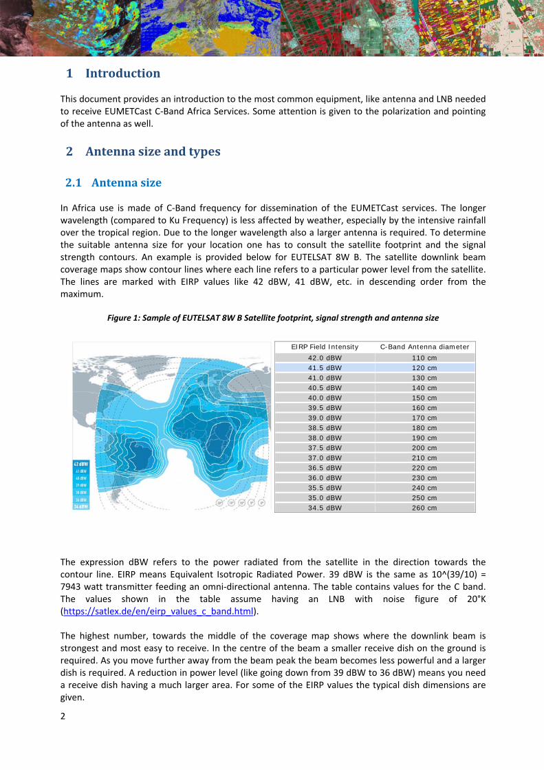
2 Antennasizeandtypes2.1 Antennasize In Africa use is made of C‐Band frequency for dissemination of the EUMETCast services. The longer wavelength (compared to Ku Frequency) is less affected by weather, especially by the intensive rainfall over the tropical region. Due to the longer wavelength also a larger antenna is required. To determine the suitable antenna size for your location one has to consult the satellite footprint and the signal strength contours. An example is provided below for EUTELSAT 8W B. The satellite downlink beam coverage maps show contour lines where each line refers to a particular power level from the satellite. The lines are marked with EIRP values like 42 dBW, 41 dBW, etc. in descending order from the maximum.
Figure 1: Sample of EUTELSAT 8W B Satellite footprint, signal strength and antenna size
The expression dBW refers to the power radiated from the satellite in the direction towards the contour line. EIRP means Equivalent Isotropic Radiated Power. 39 dBW is the same as 10^(39/10) = 7943 watt transmitter feeding an omni‐directional antenna. The table contains values for the C band. The values shown in the table assume having an LNB with noise figure of 20°K (https://satlex.de/en/eirp_values_c_band.html). The highest number, towards the middle of the coverage map shows where the downlink beam is strongest and most easy to receive. In the centre of the beam a smaller receive dish on the ground is required. As you move further away from the beam peak the beam becomes less powerful and a larger dish is required. A reduction in power level (like going down from 39 dBW to 36 dBW) means you need a receive dish having a much larger area. For some of the EIRP values the typical dish dimensions are given.
EIRP Field Intensity C-Band Antenna diameter 42.0 dBW 110 cm 41.5 dBW 120 cm 41.0 dBW 130 cm 40.5 dBW 140 cm 40.0 dBW 150 cm 39.5 dBW 160 cm 39.0 dBW 170 cm 38.5 dBW 180 cm 38.0 dBW 190 cm 37.5 dBW 200 cm 37.0 dBW 210 cm 36.5 dBW 220 cm 36.0 dBW 230 cm 35.5 dBW 240 cm 35.0 dBW 250 cm 34.5 dBW 260 cm
3
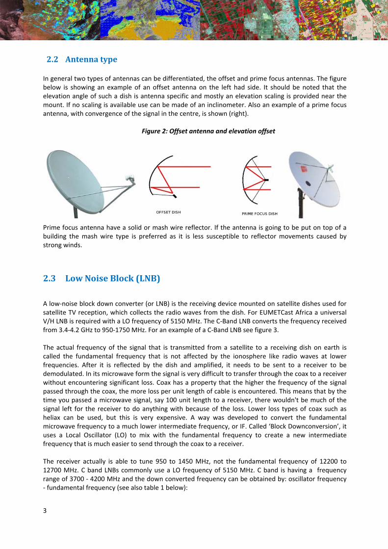
2.2 AntennatypeIn general two types of antennas can be differentiated, the offset and prime focus antennas. The figure below is showing an example of an offset antenna on the left had side. It should be noted that the elevation angle of such a dish is antenna specific and mostly an elevation scaling is provided near the mount. If no scaling is available use can be made of an inclinometer. Also an example of a prime focus antenna, with convergence of the signal in the centre, is shown (right).
Figure 2: Offset antenna and elevation offset
Prime focus antenna have a solid or mash wire reflector. If the antenna is going to be put on top of a building the mash wire type is preferred as it is less susceptible to reflector movements caused by strong winds.
2.3 LowNoiseBlock(LNB)
A low‐noise block down converter (or LNB) is the receiving device mounted on satellite dishes used for satellite TV reception, which collects the radio waves from the dish. For EUMETCast Africa a universal V/H LNB is required with a LO frequency of 5150 MHz. The C‐Band LNB converts the frequency received from 3.4‐4.2 GHz to 950‐1750 MHz. For an example of a C‐Band LNB see figure 3.
The actual frequency of the signal that is transmitted from a satellite to a receiving dish on earth is called the fundamental frequency that is not affected by the ionosphere like radio waves at lower frequencies. After it is reflected by the dish and amplified, it needs to be sent to a receiver to be demodulated. In its microwave form the signal is very difficult to transfer through the coax to a receiver without encountering significant loss. Coax has a property that the higher the frequency of the signal passed through the coax, the more loss per unit length of cable is encountered. This means that by the time you passed a microwave signal, say 100 unit length to a receiver, there wouldn't be much of the signal left for the receiver to do anything with because of the loss. Lower loss types of coax such as heliax can be used, but this is very expensive. A way was developed to convert the fundamental microwave frequency to a much lower intermediate frequency, or IF. Called ‘Block Downconversion’, it uses a Local Oscillator (LO) to mix with the fundamental frequency to create a new intermediate frequency that is much easier to send through the coax to a receiver. The receiver actually is able to tune 950 to 1450 MHz, not the fundamental frequency of 12200 to 12700 MHz. C band LNBs commonly use a LO frequency of 5150 MHz. C band is having a frequency range of 3700 ‐ 4200 MHz and the down converted frequency can be obtained by: oscillator frequency ‐ fundamental frequency (see also table 1 below):
4
5150 ‐ 4200 = 950 MHz. to 5150 ‐ 3400 = 1750 MHz.
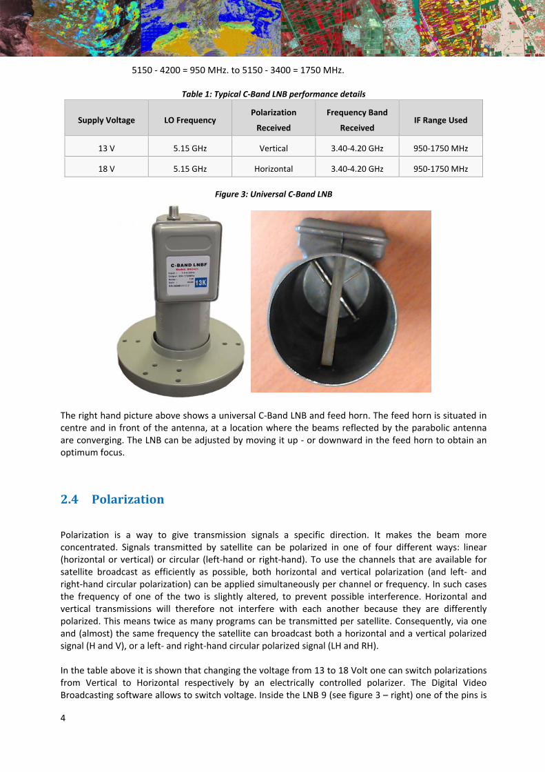
Table 1: Typical C‐Band LNB performance details
Supply Voltage LO Frequency Polarization
Received
Frequency Band
Received IF Range Used
13 V 5.15 GHz Vertical 3.40‐4.20 GHz 950‐1750 MHz
18 V 5.15 GHz Horizontal 3.40‐4.20 GHz 950‐1750 MHz
Figure 3: Universal C‐Band LNB
The right hand picture above shows a universal C‐Band LNB and feed horn. The feed horn is situated in centre and in front of the antenna, at a location where the beams reflected by the parabolic antenna are converging. The LNB can be adjusted by moving it up ‐ or downward in the feed horn to obtain an optimum focus.
2.4 Polarization
Polarization is a way to give transmission signals a specific direction. It makes the beam more concentrated. Signals transmitted by satellite can be polarized in one of four different ways: linear (horizontal or vertical) or circular (left‐hand or right‐hand). To use the channels that are available for satellite broadcast as efficiently as possible, both horizontal and vertical polarization (and left‐ and right‐hand circular polarization) can be applied simultaneously per channel or frequency. In such cases the frequency of one of the two is slightly altered, to prevent possible interference. Horizontal and vertical transmissions will therefore not interfere with each another because they are differently polarized. This means twice as many programs can be transmitted per satellite. Consequently, via one and (almost) the same frequency the satellite can broadcast both a horizontal and a vertical polarized signal (H and V), or a left‐ and right‐hand circular polarized signal (LH and RH). In the table above it is shown that changing the voltage from 13 to 18 Volt one can switch polarizations from Vertical to Horizontal respectively by an electrically controlled polarizer. The Digital Video Broadcasting software allows to switch voltage. Inside the LNB 9 (see figure 3 – right) one of the pins is
5
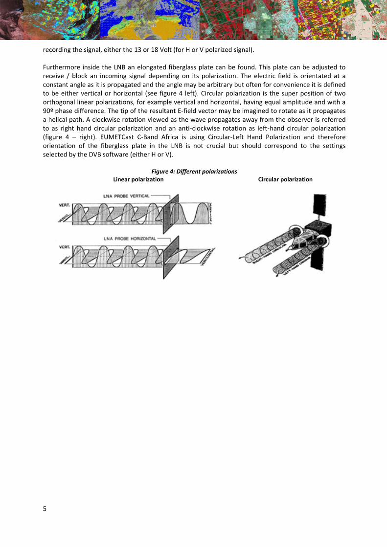
recording the signal, either the 13 or 18 Volt (for H or V polarized signal). Furthermore inside the LNB an elongated fiberglass plate can be found. This plate can be adjusted to receive / block an incoming signal depending on its polarization. The electric field is orientated at a constant angle as it is propagated and the angle may be arbitrary but often for convenience it is defined to be either vertical or horizontal (see figure 4 left). Circular polarization is the super position of two orthogonal linear polarizations, for example vertical and horizontal, having equal amplitude and with a 90º phase difference. The tip of the resultant E-field vector may be imagined to rotate as it propagates a helical path. A clockwise rotation viewed as the wave propagates away from the observer is referred to as right hand circular polarization and an anti-clockwise rotation as left-hand circular polarization (figure 4 – right). EUMETCast C‐Band Africa is using Circular‐Left Hand Polarization and therefore orientation of the fiberglass plate in the LNB is not crucial but should correspond to the settings selected by the DVB software (either H or V).
Figure 4: Different polarizations Linear polarization Circular polarization
6
3 Pointingoftheantenna
Use as pointing utility the online dish pointer (available at: http://www.dishpointer.com). The pointing of the parabolic antenna depends on the location of your site and the satellite to be selected. Provide your location details, select as satellite “8W EUTELSAT 8 W B” (at position: 5 degree west). Note the pointing details obtained. Table 2 is showing the satellite orientation details for the Faculty ITC, University of Twente in Enschede, The Netherlands as example. See also Figure 5 for the definition of elevation and azimuth.
Table 2: Satellite antenna pointing details
Address Hengelosestraat 99, Enschede, The Netherlands
Latitude 52.2237°
Longitude 6.8858°
Satellite 8W EUTELSAT 8 West B
Elevation 28.7°
Azimuth (true) 198.6°
Azimuth (magn.) 196.7°
LNB Skew 11.3°
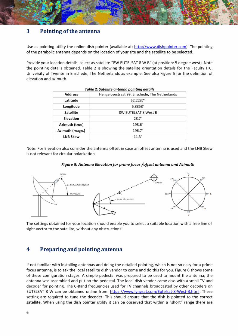
Note: For Elevation also consider the antenna offset in case an offset antenna is used and the LNB Skew is not relevant for circular polarization.
Figure 5: Antenna Elevation for prime focus /offset antenna and Azimuth
The settings obtained for your location should enable you to select a suitable location with a free line of sight vector to the satellite, without any obstructions!
4 Preparingandpointingantenna
If not familiar with installing antennas and doing the detailed pointing, which is not so easy for a prime focus antenna, is to ask the local satellite dish vendor to come and do this for you. Figure 6 shows some of these configuration stages. A simple pedestal was prepared to be used to mount the antenna, the antenna was assembled and put on the pedestal. The local dish vendor came also with a small TV and decoder for pointing. The C‐Band frequencies used for TV channels broadcasted by other decoders on EUTELSAT 8 W can be obtained online from: https://www.lyngsat.com/Eutelsat‐8‐West‐B.html. These setting are required to tune the decoder. This should ensure that the dish is pointed to the correct satellite. When using the dish pointer utility it can be observed that within a “short” range there are
7
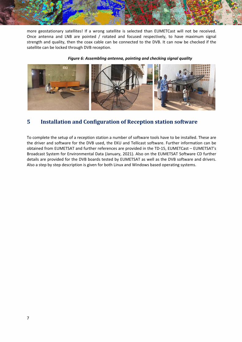
more geostationary satellites! If a wrong satellite is selected than EUMETCast will not be received. Once antenna and LNB are pointed / rotated and focused respectively, to have maximum signal strength and quality, then the coax cable can be connected to the DVB. It can now be checked if the satellite can be locked through DVB reception.
Figure 6: Assembling antenna, pointing and checking signal quality
5 InstallationandConfigurationofReceptionstationsoftware
To complete the setup of a reception station a number of software tools have to be installed. These are the driver and software for the DVB used, the EKU and Tellicast software. Further information can be obtained from EUMETSAT and further references are provided in the TD‐15, EUMETCast – EUMETSAT’s Broadcast System for Environmental Data (January, 2021). Also on the EUMETSAT Software CD further details are provided for the DVB boards tested by EUMETSAT as well as the DVB software and drivers. Also a step by step description is given for both Linux and Windows based operating systems.
8
6 References Various internet resources are used: EUM TD 15 (2021): TD15 ‐ EUMETCast, EUMETSAT’s Broadcast System for Environmental Data. Technical description, Issue v8F, 28 January, 2021. EUMETSAT, Darmstadt, Germany. https://www.eumetsat.int/media/44096 EUMETSAT: EUMETCast, Satellite Antenna Pointing Guide. Available from: https://eumetsatspace.atlassian.net/wiki/spaces/DSEC/pages/695763106/Reception+Station+Recommendations
EUMETSAT: http://www.eumetsat.int https://www.eumetsat.int/eumetcast
GEONETCast Product Navigator: http://navigator.eumetsat.int/
Earth Observation Portal: https://eoportal.eumetsat.int
Youtube: http://www.youtube.com/watch?v=Fu‐aYnRkUgg General: http://www.satsig.net/
Related Documents


![Design of Ionofree Micro Strip Quad Helix Antenna for ... · antenna, bifilar helices antenna, microstrip antenna, quadrafilar helix antenna. ... Helical antenna [1],[2] is broadband](https://static.cupdf.com/doc/110x72/5b9506e809d3f2ea5c8b5a04/design-of-ionofree-micro-strip-quad-helix-antenna-for-antenna-bifilar-helices.jpg)


