EU Directive 94/9/EC (ATEX 95) for Pneumatic Components EX-PROOF

Welcome message from author
This document is posted to help you gain knowledge. Please leave a comment to let me know what you think about it! Share it to your friends and learn new things together.
Transcript

EU Directive 94/9/EC (ATEX 95)
for Pneumatic Components
EX-PROOF
ATEX (Atmosphères explosibles)
The abbreviation ATEX covers two European Union Directives: 94/9/EC and 1999/92/EC.
Potentially explosiveatmospheres
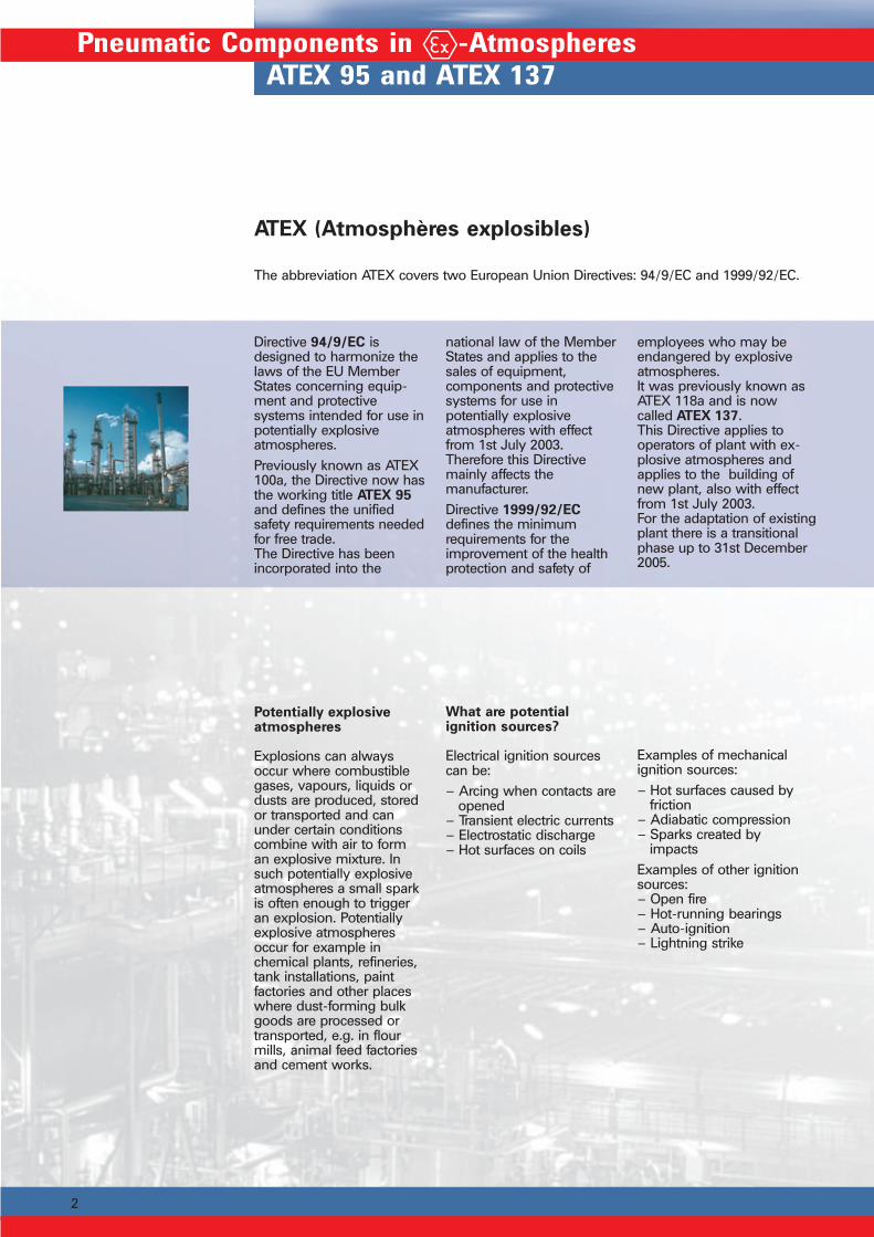
Explosions can alwaysoccur where combustiblegases, vapours, liquids ordusts are produced, storedor transported and canunder certain conditionscombine with air to forman explosive mixture. Insuch potentially explosiveatmospheres a small sparkis often enough to triggeran explosion. Potentiallyexplosive atmospheresoccur for example inchemical plants, refineries,tank installations, paintfactories and other placeswhere dust-forming bulkgoods are processed ortransported, e.g. in flourmills, animal feed factoriesand cement works.
What are potentialignition sources?
Electrical ignition sourcescan be:– Arcing when contacts are
opened– Transient electric currents– Electrostatic discharge– Hot surfaces on coils
2
Pneumatic Components in -AtmospheresATEX 95 and ATEX 137
Directive 94/9/EC isdesigned to harmonize thelaws of the EU MemberStates concerning equip-ment and protectivesystems intended for use inpotentially explosiveatmospheres.Previously known as ATEX100a, the Directive now hasthe working title ATEX 95and defines the unifiedsafety requirements neededfor free trade.The Directive has beenincorporated into the
national law of the MemberStates and applies to thesales of equipment,components and protectivesystems for use inpotentially explosiveatmospheres with effectfrom 1st July 2003.Therefore this Directivemainly affects themanufacturer.Directive 1999/92/ECdefines the minimumrequirements for theimprovement of the healthprotection and safety of
employees who may beendangered by explosiveatmospheres.It was previously known asATEX 118a and is nowcalled ATEX 137.This Directive applies tooperators of plant with ex-plosive atmospheres andapplies to the building ofnew plant, also with effectfrom 1st July 2003.For the adaptation of existingplant there is a transitionalphase up to 31st December2005.
Examples of mechanicalignition sources:– Hot surfaces caused by
friction– Adiabatic compression– Sparks created by
impactsExamples of other ignitionsources:– Open fire– Hot-running bearings– Auto-ignition– Lightning strike

3
The application of ATEXhas basically made thefollowing changes:– The Directive now also
applies to non-electricalequipment (e.g. pneu-matic drives) as well asto electrical equipment.
– It defines fundamentalsafety requirements andalso applies to completeprotective systems.
– Equipment is divided intoGroups and Categories.These are then related tocorresponding danger
All electrical equipment foruse in potentially explosiveatmospheres was alreadycovered by the existing lawon explosion protection.ATEX 95 howeveradditionally applies to non-
Application of ATEX to Manufacturers and Operators
With effect from 1st July 2003 the responsibility for newly built plant with potentially ex-plosive atmospheres lies not only with the manufacturer of explosion-proof equipmentbut also with the operator and builder of the plant.
What changes havWhat changes havWhat changes havWhat changes havWhat changes have been made be been made be been made be been made be been made by Ay Ay Ay Ay ATEX?TEX?TEX?TEX?TEX?
Zones which have to bedefined by the operatorin accordance withATEX 137.
– Depending on the Equip-ment Category, a typeapproval is required.
– Marking with the CEmark is now compulsory.
– A declaration of con-formity must accompanyeach product as well asthe operating instruc-tions.
electrical equipment, suchas piston rod cylinders,rodless cylinders andvalves.It therefore applies to allequipment for use inpotentially explosive
atmospheres which haveany intrinsic potentialsource of ignition, includingsources such as hotsurfaces or adiabaticcompression.
What prWhat prWhat prWhat prWhat products aroducts aroducts aroducts aroducts are affe affe affe affe affectectectectected bed bed bed bed by Ay Ay Ay Ay ATEX 95?TEX 95?TEX 95?TEX 95?TEX 95?
The following productexamples have no intrinsicsources of ignition andtherefore do not fall underATEX 95.
What prWhat prWhat prWhat prWhat products do not foducts do not foducts do not foducts do not foducts do not fall under Aall under Aall under Aall under Aall under ATEX 95?TEX 95?TEX 95?TEX 95?TEX 95?
– Pneumatic accessories– Mechanical accessories– Tubing– Fittings– Check/ flow control
valves
Such products can be usedin specified potentiallyexplosive atmospheres inaccordance with themanufacturer’s instructions.
– The Directive now alsoapplies to potential dustexplosion atmospheres.
– It now applies to under-ground mining opera-tions as well as to allother potentially explosiveatmospheres.
Application to Manufacturers and Operators

4
ATEX 95 for the Manufacturer
Under ATEX 95 the manufacturer has to evaluate his products and to mark themaccordingly:
- Division into Equipment Groups and Categories for use in different Zones- Division into Temperature Classes
- Division into Explosion Groups- Determination of permissible ambient temperatures
The Equipment Groups and Categories are defined as follows. You will findfurther information on the Temperature Classes and Explosion Groups on
page 7.
Equipment Group IEquipment in Group I is divided into Categories M1 and M2.
This equipment is used in mining, where there is the danger of explosions causedby firedamp or flammable dust.
HOERBIGER-ORIGA do not manufacture Group I Equipment
Equipment Group IIEquipment in Group II is divided into Categories 1, 2 and 3 according to its suitability foruse in the different Zones defined by ATEX 137.
Pneumatic Components in -AtmospheresATEX for Manufacturers and Operators
Category 1This equipment is designedto ensure a very high levelof safety. It must ensure therequired level of safetyeven in the event of rareequipment malfunctions.Therefore its explosionprotection system mustensure that:– in the event of the failure
of one means of protec-tion, at least one second,independent meansprovides the requiredlevel of protection
– or in the event of twofaults occurringindependently of eachother, the required levelof safety is still ensured.
Category 2This equipment is designedto ensure a high level ofsafety. Its explosionprotection system mustensure the required level ofsafety even in the event offrequently occurringincidents or equipmentmalfunctions whichnormally have to beexpected.
Category 3This equipment is designedto ensure a normal level ofsafety so that it providesthe requisite level of safetyin normal operation.
5
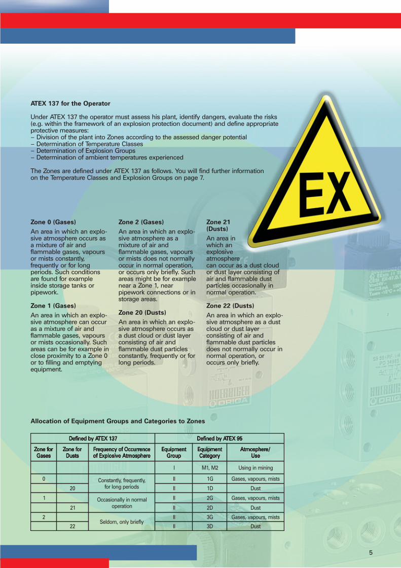
ATEX 137 for the Operator
Under ATEX 137 the operator must assess his plant, identify dangers, evaluate the risks(e.g. within the framework of an explosion protection document) and define appropriateprotective measures:– Division of the plant into Zones according to the assessed danger potential– Determination of Temperature Classes– Determination of Explosion Groups– Determination of ambient temperatures experienced
The Zones are defined under ATEX 137 as follows. You will find further informationon the Temperature Classes and Explosion Groups on page 7.
Allocation of Equipment Groups and Categories to Zones
Zone 0 (Gases)An area in which an explo-sive atmosphere occurs asa mixture of air andflammable gases, vapoursor mists constantly,frequently or for longperiods. Such conditionsare found for exampleinside storage tanks orpipework.
Zone 1 (Gases)An area in which an explo-sive atmosphere can occuras a mixture of air andflammable gases, vapoursor mists occasionally. Suchareas can be for example inclose proximity to a Zone 0or to filling and emptyingequipment.
Zone 2 (Gases)An area in which an explo-sive atmosphere as amixture of air andflammable gases, vapoursor mists does not normallyoccur in normal operation,or occurs only briefly. Suchareas might be for examplenear a Zone 1, nearpipework connections or instorage areas.
Zone 20 (Dusts)An area in which an explo-sive atmosphere occurs asa dust cloud or dust layerconsisting of air andflammable dust particlesconstantly, frequently or forlong periods.
Zone 21(Dusts)An area inwhich anexplosiveatmospherecan occur as a dust cloudor dust layer consisting ofair and flammable dustparticles occasionally innormal operation.
Zone 22 (Dusts)An area in which an explo-sive atmosphere as a dustcloud or dust layerconsisting of air andflammable dust particlesdoes not normally occur innormal operation, oroccurs only briefly.
731XETAybdenifeD 731XETAybdenifeD 731XETAybdenifeD 731XETAybdenifeD 731XETAybdenifeD 59XETAybdenifeD 59XETAybdenifeD 59XETAybdenifeD 59XETAybdenifeD 59XETAybdenifeD
rofenoZ rofenoZ rofenoZ rofenoZ rofenoZsesaG sesaG sesaG sesaG sesaG
rofenoZ rofenoZ rofenoZ rofenoZ rofenoZstsuD stsuD stsuD stsuD stsuD
ecnerruccOfoycneuqerF ecnerruccOfoycneuqerF ecnerruccOfoycneuqerF ecnerruccOfoycneuqerF ecnerruccOfoycneuqerFerehpsomtAevisolpxEfo erehpsomtAevisolpxEfo erehpsomtAevisolpxEfo erehpsomtAevisolpxEfo erehpsomtAevisolpxEfo
tnempiuqE tnempiuqE tnempiuqE tnempiuqE tnempiuqEpuorG puorG puorG puorG puorG
tnempiuqE tnempiuqE tnempiuqE tnempiuqE tnempiuqEyrogetaC yrogetaC yrogetaC yrogetaC yrogetaC
/erehpsomtA /erehpsomtA /erehpsomtA /erehpsomtA /erehpsomtAesU esU esU esU esU
I 2M,1M gninimnignisU
0 ,yltneuqerf,yltnatsnoCsdoirepgnolrof
II G1 stsim,sruopav,sesaG
02 II D1 tsuD
1 lamronniyllanoisaccOnoitarepo
II G2 stsim,sruopav,sesaG
12 II D2 tsuD
2ylfeirbylno,modleS
II G3 stsim,sruopav,sesaG
22 II D3 tsuD

6
Equipment in Potentially Explosive Atmospheres Intrinsic Safety, Encapsulation
Intrinsically SafeEquipmentIntrinsically safe equipmentis equipment in which allthe circuits are intrinsicallysafe (in conformity withEN 50020).
Protection Type„Intrinsic Safety“Intrinsic safety is basically atechnology in which verylow power consumption isused. It is thereforeespecially suitable forindustrial instrumentation.
Intrinsically Safe CircuitsAn intrinsically safe circuitis a electric circuit, in whichneither a spark still anotherthermal effect can cause anignition of a certain explo-sive atmosphere.
Intrinsic Safety „i“Intrinsic safety is one ofseveral usual methods ofavoiding explosions inpotentially explosiveatmospheres.In contrast to other types ofprotection, „intrinsic safety“relates not only to individu-al components but to thewhole circuit which isintrinsically safe.The protection here lies inthe circuit and not indesign features such ashousings or encapsulation.Intrinsically safe equipment/ circuits operate with verylow electrical energy whichis insufficient to ignite eventhe most flammableatmospheres mixtures.
For this reason there can beno spark creation or ther-mal effect in intrinsicallysafe circuits, i.e. ignition ofthe explosive atmospherecannot occur.Two different ignitionmechanisms are taken intoaccount:– ignition by electric sparks– ignition by surfacesheated by current.The potentially explosiveatmosphere can includevarious flammablesubstances such as gases,vapours, dust, fibres andairborne particles.Therefore the circuits andequipment are so designedthat safety is guaranteednot only in normaloperation but also in allpossible failure conditions.
Types of Protection
Protection Type„Encapsulation“““““
Encapsulation „m“In encapsulation, possibleignition sources in electricalequipment are enclosed ina casting compound, sothat the ignition of apotentially explosiveatmosphere is impossible.
� �
��
Conditions for trouble-freeoperation and also failureconditions are fixed in thestandard EN 50020.

Anwendung der ATEX durch Hersteller und Betreiber
7
Type Marking of Equipment for Use in -Atmospheres
Examples of type markings:Mechanical equipment: II 2 GD c T4 T135°C -10°C≤Ta≤+60°CElectrical equipment: II 2 GD E Ex ib IIC T5 T100°C -20°C≤Ta≤+75°C IP65
Pneumatic Components in -AtmospheresType Marking of Equipment
Mechanical Electrical DescriptionEquipment Equipment
Ex mark. Approved for use in potentially explosive atmospheresCE mark
II II Equipment Group I Use in miningII Use in all other Ex-atmospheres
2GD 2GD Equipment Category G = gas, D = dust2G Use in Zone 12GD Use in Zone 213G Use in Zone 23GD Use in Zone 22
E Equipment is approved to the CENELEC European StandardEx Equipment is explosion-proof
c ib Type of ignition protection ia Intrinsically safe, in normal operation will notcause ignition in the event of 1 or 2 faults inthe unit
ib Intrinsically safe, in normal operation will notcause ignition in the event of 1 fault in the unit
b Ignition source monitoring k Liquid encapsulationc Safe design m Cast encapsulationd Pressure-tight encapsulation o Oil encapsulatione Enhanced safety p Overpressure encapsulationfr Vapour-inhibiting encapsulation q Sand encapsulation
IIC Explosion Group Different gases have different ignitability:Group Typical gas Minimum
(example) ignition energyIIA Propane 180 µJIIB Ethylene 60 µJIIC Hydrogen, acetylene 20 µJ
T4 T5 Temperature Class Highest permissible surface temperature for use in(Gas) gas-explosion-protected atmospheres
^T-class Max. surface Min. ignition
temperature temperatureof the gasT1 450°C > 450°CT2 300°C > 300°C bis ≤ 450°CT3 200°C > 200°C bis ≤ 300°CT4 135°C > 135°C bis ≤ 200°CT5 100°C > 100°C bis ≤ 135°CT6 85°C > 85°C bis ≤ 100°C
T135°C T100°C Maximum surface temperature for use in dust-explosion-protected atmospheres.If no Temperature Class is specified (e.g. T5), this value also applies to gas-explosion-protected atmospheres
-10°C≤Ta≤+60°C -20°C≤Ta≤+75°C Permissible temperature range for the use of the equipment in explosion-protectedatmospheres
IP65 Housing protection system for electrical equipment (e.g. IP65 = dust-tight andwater-jet-proof from all directions)

8
Pneumatic Components in -AtmospheresHOERBIGER-ORIGA Products
HOERBIGER-ORIGA Products for -Atmospheres
Equipment Group II Category 2GD
Piston Rod Cylinders: II 2GD c T4 T135°C –10°C≤Ta≤+60°C
Series Size Stroke Range Accessories IllustrationAZ Series 5000 Ø32 – 100 1 – 2000 mm Mountings programme,
FEUG/FEHG/FEHK
DZ Series 5000 Ø125 – 250 10 – 2000 mm Mountings programme,
NZK Series 6000 Ø32 – 100 1 – 500 mm Mountings programme,FEUG/FEHG/FEHK
NZK Series 7000 Ø32 – 100 1 – 25 mm Mountings programme,FEUG/FEHG/FEHK
R Series 6000 Ø10 – 25 1 – 500 mm Mountings programme, FEUG
R Series 5000 Ø20 – 25 1 – 500 mm Mountings programme, FEUG
SZ Series 6000 Ø12 – 100 1 – 80 mm Mountings programme
SZ Series 7000 Ø32 – 100 1 – 25 mm Mountings programme
Magnetic S Magnetic S Magnetic S Magnetic S Magnetic Switwitwitwitwitches:ches:ches:ches:ches:
RS-K ATEX, cable length 5m II 3GD EEx nC IIC T3 T146°C –25°C II 3GD EEx nC IIC T3 T146°C –25°C II 3GD EEx nC IIC T3 T146°C –25°C II 3GD EEx nC IIC T3 T146°C –25°C II 3GD EEx nC IIC T3 T146°C –25°C≤TTTTTaaaaa≤+80°C+80°C+80°C+80°C+80°CRS-K ATEX, cable length 10m II 3GD EEx nC IIC T3 T146°C –25°C II 3GD EEx nC IIC T3 T146°C –25°C II 3GD EEx nC IIC T3 T146°C –25°C II 3GD EEx nC IIC T3 T146°C –25°C II 3GD EEx nC IIC T3 T146°C –25°C≤TTTTTaaaaa≤+80°C+80°C+80°C+80°C+80°C
ES-K ATEX, cable length 5m II 2GD EEx ib IIC T5 T100°C –20°C II 2GD EEx ib IIC T5 T100°C –20°C II 2GD EEx ib IIC T5 T100°C –20°C II 2GD EEx ib IIC T5 T100°C –20°C II 2GD EEx ib IIC T5 T100°C –20°C≤TTTTTaaaaa≤+75°C+75°C+75°C+75°C+75°CES-K ATEX, cable length 10m II 2GD EEx ib IIC T5 T100°C –20°C II 2GD EEx ib IIC T5 T100°C –20°C II 2GD EEx ib IIC T5 T100°C –20°C II 2GD EEx ib IIC T5 T100°C –20°C II 2GD EEx ib IIC T5 T100°C –20°C≤TTTTTaaaaa≤+75°C+75°C+75°C+75°C+75°C
V V V V Valvalvalvalvalveseseseses
S9 For dust-EX-atmospheres see page 13

Anwendung der ATEX durch Hersteller und Betreiber
9
Equipment Group II Category 2G
Rodless Cylinders: II 2G c T4 T135°C –10°C≤Ta≤+60°C
Series Size Stroke Range Accessories Illustration
OSP-P Ø10 – 80 1 – 6000 mm Mountings programme
Slideline Ø16 – 80 1 – 6000 mm
Valves: II 2G c T4 T135°C –10°C≤Ta≤+60°C
Series Size Accessories Illustration
S9 pneumatically G1/8, G1/4, G1/2 P-/RPS-manifoldsactuated
S9 manually G1/8, G1/4, G1/2 P-/RPS-manifoldsactuated
S9 electrically G1/8, G1/4, G1/2 P-/RPS-manifoldsactuated
Solenoids Category of Solenoid Comments
GS24V-3m-ATEX II 2G EEx m II T5 -20°C≤Ta≤+50°C Individual use
GS24V-5m-ATEX II 2G EEx m II T5 -20°C≤Ta≤+50°C Individual use
GS24V-10m-ATEX II 2G EEx m II T5 -20°C≤Ta≤+50°C Individual use
GS24V-1,2m-ATEX II 2G EEx m II T5 -20°C≤Ta≤+50°C Individual use
WS230V-3m-ATEX II 2G EEx m II T5 -20°C≤Ta≤+50°C Individual use
WS230V-1,2m-ATEX II 2G EEx m II T5 -20°C≤Ta≤+50°C Individual use
WS110V-1,2m-ATEX II 2G EEx m II T5 -20°C≤Ta≤+50°C Individual use
WS24V-1,2m-ATEX II 2G EEx m II T5 -20°C≤Ta≤+50°C Individual use
Ambienttemperature II 2G EEx m II T5 -20°C≤Ta≤+40°C Manifold mounting

10
Pneumatic Components in -AtmospheresHOERBIGER-ORIGA Products
HOERBIGER-ORIGA Products for -Atmospheres
Equipment Group II Category 2GAir Preparation Equipment: II 2G c II B X - Use in Zone 1, 2
Series Size Accessories Illustration
Filter-regulators G1/4MFRSairfit light
Pressure regulators G1/8, G1/4 Pressure gauges, mountings,MRS couplings
airfit swingShut-off valves G1/4, G3/8 Mountings, couplings, lockSDV
Filter-regulators G1/4, G3/8 Pressure gauges, mountings,SK couplings
Filter-water-separators G1/4, G3/8 Mountings, couplingsSF
Pressure regulators G1/4, G3/8 Pressure gauges, mountings,SR couplings
Pressure regulators G1/4, G3/8 Pressure gauges, mountings,with through-p1 couplingsSR-..T-
Oil mist lubricators G1/4, G3/8 Mountings, couplingsSL
Pressure regulators, G1/4, G3/8 Pressure gauges, mountings,pilot-operated couplingsSRV
Submicrofilters G1/4, G3/8 Mountings, couplingsMF012
Activated carbon filters G1/4, G3/8 Mountings, couplingsMC012
Soft start valves G1/4, G3/8 Mountings, couplingsSDA
Stop valves G1/4, G3/8 Mountings, couplingsSDR-PSDR-E ( II 2G EEx m II T5)
Equipment Group IIPneumatic Accessories: Use in Zone 1, 2, 21, 22
Check & flow control valvesLogic valvesFittingsTubing

Anwendung der ATEX durch Hersteller und Betreiber
11
Series Size Accessories Illustration
airfit comfortShut-off valves G3/8, G1/2 Mountings, couplings, lockCDV
Filter-water-separators G3/8, G1/2 Mountings, couplingsCF
Dust filter G3/8, G1/2 Mountings, couplingsCFD
Filter-regulators G3/8, G1/2 Pressure gauge, mountings,CK couplings
Pressure regulators G3/8, G1/2 Pressure gauge, mountings,CR couplings
Pressure regulators G3/8, G1/2 Pressure gauge, mountings,with through-p1 couplingsCR-..T-
Pressure regulators, G3/8, G1/2 Pressure gauge, mountings,pilot-operated couplingsCRV
Oil mist lubricators G3/8, G1/2 Mountings, couplingsCL
Submicrofilters G3/8, G1/2 Mountings, couplingsMF036
Activated carbon filters G3/8, G1/2 Mountings, couplingsMC036
Soft start valves G3/8, G1/2 Mountings, couplingsCDA
Stop valves G3/8, G1/2 Mountings, couplingsCDR, CDR-P,CDR-E ( II 2G EEx m II T5)
airfit prestigeShut-off valves G3/4, G1 Mountings, couplings, lockXDV
Filter-regulators G3/4, G1 Pressure gauge, mountings,XK couplings
Filter-water-separators G3/4, G1 Mountings, couplingsXF
Dust filters G3/4, G1 Mountings, couplingsXFD
Pressure regulators G3/4, G1 Pressure gauge, mountings,XR couplings
Pressure regulators G3/4, G1 Pressure gauge, mountings,pilot-operated couplingsXRV
discontinueddiscontinueddiscontinueddiscontinueddiscontinued
discontinueddiscontinueddiscontinueddiscontinueddiscontinued
discontinueddiscontinueddiscontinueddiscontinueddiscontinued
discontinueddiscontinueddiscontinueddiscontinueddiscontinued
discontinueddiscontinueddiscontinueddiscontinueddiscontinued
discontinueddiscontinueddiscontinueddiscontinueddiscontinued

12
Pneumatic Components in -AtmospheresHOERBIGER-ORIGA Products
Series Size Accessories Illustration
airfit prestigeOil mist lubricators G3/4, G1 Mountings, couplingsXL
Submicrofilters G3/4, G1 Mountings, couplingsMF110, MF185
Activated carbon filters G3/4, G1 Mountings, couplingsMC110, MC185
Start/stop valves G3/4, G1 Mountings, couplingsXDS
airfit A25Shut-off valves G3/4, G1 Mountings, couplingsA25DV
Filter-regulators G3/4, G1 Pressure gauge, mountings,A25K couplings
Filter-water-separators G3/4, G1 Mountings, couplingsA25F
Dust filters G3/4, G1 Mountings, couplingsA25FD
Pressure regulators G3/4, G1 Pressure gauge, mountings,A25R couplings
Pressure regulators G3/4, G1 Pressure gauge, mountings,pilot-operated couplingsA25RV
Oil mist lubricators G3/4, G1 Mountings, couplingsA25L
Submicrofilters G3/4, G1 Mountings, couplingsA25MF
Activated carbon filters G3/4, G1 Mountings, couplingsA25MC
Start/stop valves G3/4, G1 Mountings, couplingsA25DS
airfit A50Filter-water-separators G11/2, G2 Mountings, couplingsA50F
Pressure regulators G11/2, G2 Pressure gauge, mountings,A50R couplings
Submicrofilters G11/2, G2 Mountings, couplingsA50MF
Activated carbon filters G11/2, G2 Mountings, couplingsA50MC
Start/stop valves G11/2, G2 Mountings, couplingsA50DS
airfit dryMembrane dryers G1/4, G1/2, G1 Mountings, couplingsSDM, CDM, XDM
HOERBIGER-ORIGA Products for -Atmospheres
discontinueddiscontinueddiscontinueddiscontinueddiscontinued
discontinueddiscontinueddiscontinueddiscontinueddiscontinued
discontinueddiscontinueddiscontinueddiscontinueddiscontinued
discontinueddiscontinueddiscontinueddiscontinueddiscontinued

Anwendung der ATEX durch Hersteller und Betreiber
13
HOERBIGER-ORIGA Products for -Atmospheres „Intrinsic Safety “
Equipment Group II Category 1G
Valves: II 1G EEx ia IIC T4/T5/T6
Series Size Accessories IllustrationP8 385 Flange on request
Equipment Group II Category 2GD
Valves: II 2G EEx ia IIC T4/T5/T6Valves: II 2D Ex ia D21 T125
Series Size Accessories Illustration
P8 385 Flange P-manifolds M5M5 RPS-manifolds M5
Equipment Group II Category 2G
Valves: II 2G EEx ia IIC T4/T5/T6
Series Size Accessories Illustration
P20 381 Flange to CNOMO P-manifolds G1/8G1/8 RPS-manifolds G1/8
Equipment Group I Category MI
Valves: I M1 EEx ia I
Series Size Accessories IllustrationP8 385 Flange
Equipment Group II Category 2GD
Valves: II 2GD EEx c IIC T5/T6 TFR:03.41X (for use 2D-T125)
Series Size Accessories IllustrationS9 385 G1/8 P-manifoldsS9 585 RPS-manifolds
S9 385 G1/4 P-manifoldsS9 585 RPS-manifolds
S29 385 NAMURS29 585 Output G1/4
On ROn ROn ROn ROn Requestequestequestequestequest

14
Pneumatic Components in -AtmospheresDefinitions according to Directive 94/9/EC
Definitions according to Directive 94/9/EC
EquipmentEquipment meansmachines, apparatus, fixedor mobile devices, controlcomponents andinstrumentation thereof anddetection or preventionsystems which, separatelyor jointly, are intended forthe generation, transfer,storage, measurement,control and conversion ofenergy for the processingof material and which arecapable of causing anexplosion through theirown potential sources ofignition.
Protective SystemsProtective systems are alldevices with the exceptionof the components of theequipment defined abovewhich are designed to haltincipient explosionsimmediately and/or to limitthe area affected by theexplosion. They aremarketed separately asautonomous systems.
ComponentsComponents are itemswhich are essential for thesafe operation ofequipment and protectivesystems but which fulfil noautonomous function.
Explosive AtmosphereA mixture of air andflammable gases, vapours,mists or dusts underatmospheric conditions inwhich, after ignition hasoccurred, the combustionprocess spreads to theentire unburnt mixture.
Equipment Groups andCategoriesThe Equipment Groups andCategories define the levelof protection of a piece ofequipment and thus itspermissible use in poten-tially explosive atmosphe-res. You will find furtherinformation on page 4.
Potentially ExplosiveAtmosphereAn atmosphere whichcould become explosivedue to local andoperational conditions.
Intended UseThe use of equipment,protective systems anddevices in accordance withthe Equipment Group andCategory and incompliance with all themanufacturer’s informationrequired for the safeoperation of the products.
ZonesUnder Directive 1999/92/EC, potentially explosiveatmospheres must bedivided into Zones (Zones0, 1, 2), in accordance withthe requirements for safeoperation of explosion-proof equipment in theseatmospheres.You will find furtherinformation on page 5.

Anwendung der ATEX durch Hersteller und Betreiber
15
ATEX: Incorporation into National Law
Directives for the US Market
In the USA, potentially ex-plosive atmospheres aredivided into two Divisionsand combustible materialsare divided into threeClasses. In NEC Article 505the ATEX requirements forZones 0, 1 and 2 weretaken over for Class I.The following table showsa comparison of theclassification of potentiallyexplosive atmospheresaccording to the US andEuropean Directives.
Division 1Division 1Division 1Division 1Division 1An explosive atmosphereexists constantly, for longperiods or occasionally.
Division 2Division 2Division 2Division 2Division 2An explosive atmosphereexists only seldom orbriefly.
Class IClass IClass IClass IClass ICombustible gases,vapours and liquids.
Class IIClass IIClass IIClass IIClass IICombustible dusts.
Class IIIClass IIIClass IIIClass IIIClass IIISlightly combustibleparticles and materials.
Incorporation of ATEX into the National Lawof the EU Member States
All European Directiveshave to be incorporatedinto the national law of theEU Member States. InGermany the Directive94/9/EG was incorporatedinto law by the 11thOrdinance of theEquipment Safety Statute(Explosion ProtectionOrdinance - 11. GSGV) of12th December 1996.
The Directive 1999/92/EGwas incorporated intoGerman law by theOrdinance on Safety andHealth Protection in theConstruction and Operationof Equipment, Safety in theOperation of EquipmentRequiring Monitoring, and
Organisation of OperationalWork Protection (OperatingSafety Ordinance -BetrSichV) of27th September 2002.
foecneruccOevisolpxe
erehpsomta
731XETA )005CEN(ASU )505CEN(ASU
sesaG,sruopav
stsimstsuD ,sruopav,sesaG
sdiuqil stsuD sruopav,sesaG
,yltnatsnoCgnolrof,yltneuqerf
sdoirep0enoZ 02enoZ
1noisiviD,IssalC ,IIssalC1noisiviD
0enoZ,IssalC
niyllanoisaccOnoitarepolamron 1enoZ 12enoZ 1enoZ,IssalC
ylfeirb,modleS 2enoZ 22enoZ 2noisiviD,IssalC ,IIssalC2noisiviD 2enoZ,IssalC

A5P060E-December 2004 A5P061E61LAE20X
with global service and distribution
for more information visit the following web siteswww.hoerbiger-origa.comwww.airfit.comwww.hoerbiger.comor contact your local HOERBIGER-ORIGA company
The Strategic Business Units of the HOERBIGER Group
SBU AutomationTechnology
SBU DriveTechnology
Additional representatives can be found on the Internet
Your Contact
SBU CompressionTechnology
AE HOERBIGER SERVICE MIDDLE EAST FZE • Jebel Ali Free • P.O. Box 07153 • Dubai, United Arab Emirates • Tel. +971 +4 8814567 • Fax +971 +4 8817123 • e-mail: [email protected] HOERBIGER-ORIGA Pneumatik GmbH • Dr. Alexander-Schärf-Straße 12 • AT-2700 Wiener Neustadt • Tel. +43 +2622 26071-269 • Fax +43 +2622 26071-266 • e-mail: [email protected] HOERBIGER AUSTRALIA PTY.LTD. • 21 David Street • AU-3175 Dandenong, Victoria • Tel. +61 (0)3 9793 9488 • Fax +61 (0)3 9706 8152 • e-mail: [email protected] HOERBIGER-ORIGA AG • Industriestr. 30 • CH-8112 Otelfingen (Zürich) • Tel. +41 (0)1 846 6860 • Fax +41 (0)1 846 6870 • e-mail: [email protected] HOERBIGER (WUXI) AUTOMATION TECHNOLOGY CO., LTD. • A2-A, Machinery & Electronics Park • Wuxi National High-Tech Zone • Wuxi 214028, China • Tel. +86 510 520 3468 • Fax +86 510 520 3498 • e-mail: [email protected] HOERBIGER-ORIGA GmbH • Industriestr. 8 • DE-70794 Filderstadt • Tel. +49 (0)7158 1703-0 • Fax +49 (0)7158 64870 • e-mail: [email protected] HOERBIGER-ORIGA S.A. • Pol. Ind. El Nogal • c/Nogal 8 • ES-28110 Algete (Madrid) • Tel. +34 91 629 09 00 • Fax +34 91 629 24 08 • e-mail: [email protected] HOERBIGER-ORIGA S.A. • 11 avenue de Norvège • FR-91978 Courtaboeuf • Tel.+33 (0)1 69 29 22 00 • Fax +33 (0)1 69 29 22 10 • e-mail: [email protected] HOERBIGER-ORIGA Ltd. • Tewkesbury Industrial Estate • Tewkesbury GL 20 8 ND GB • Tel. +44 1684 85 00 00 • Fax +44 1684 85 05 55 • e-mail: [email protected] HOERBIGER-ORIGA S.R.L. • Via Martiri della Libertà 4/6 • IT-20060 Liscate (MI) • Tel. +39 02 95 35 03 07 • Fax +39 02 95 35 05 13 • e-mail: [email protected] HOERBIGER AUTOMATION Technology Representative Office Japan • 501, 2-17-11 Shin-Yokohama, Kohokuku • JP-222 -0033 Yokohama • Tel. +81 (0)45 4760 636 • Fax +81 (0)45 4760 637 • e-mail: [email protected] HOERBIGER-ORIGA B.V. • Plaza 11C • NL-4782 SL Moerdijk • Tel. +31 168 356 600 • Fax. +31 168 356 601 • e-mail: [email protected] HOERBIGER-ORIGA AS • Postboks 2173 Strømsø • NO-3003 Drammen • Tel. +47 3 288 08 40 • Fax +47 32 82 83 20 • e-mail: [email protected] HOERBIGER-ORIGA Sdn Bhd • No. 10 & 12 Lorong IKS Juru 3 • MY-14100 Juru, Simpang Ampat, Penang • Tel. +60 (0)4 508 10 11 • Fax +60 (0)4 508 21 22 • e-mail: [email protected] HOERBIGER-ORIGA S.A. • Rua Luz Soriano, 42 • P-4200-380 Porto • Tel. +35 1 22 550 71 79 • Fax. +35 1 22 509 22 51 • e-mail: [email protected] HOERBIGER-ORIGA AB • Kungsgatan 14, Box 67 • SE-73622 Kungsör • Tel. +46 227 411 00 • Fax +46 227 411 29 • e-mail: [email protected] HOERBIGER-ORIGA Corporation • 100 West Lake Drive • IL-60139 Glendale Heights, Illinois, USA • Tel. +1 630 871 830-0 • Fax +1 630 871 1515 • e-mail: [email protected] HOERBIGER-ORIGA (SA) (PTY) Ltd • P.O. Box 17846 • ZA-Randhart 1457 • Tel. +27 (0)11 908 13 10 • Fax +27 (0)11 908 13 12 • e-mail: [email protected]
HOERBIGER-ORIGA...your competent partner
The
right
to in
trodu
ce te
chni
cal
mod
ifica
tions
is re
serv
ed
Related Documents