ETSI ETR 186-2 TECHNICAL May 1998 REPORT Source: SPS Reference: DTR/SPS-03011-2 ICS: 33.020 Key words: IN, ISDN, CS2, interaction, signalling Intelligent Network (IN); Interaction between IN Application Protocol (INAP) and Integrated Services Digital Network (ISDN) signalling protocols; Part 2: Switching signalling requirements for IN Capability Set 2 (CS2) service support in a Narrowband ISDN (N-ISDN) environment ETSI European Telecommunications Standards Institute ETSI Secretariat Postal address: F-06921 Sophia Antipolis CEDEX - FRANCE Office address: 650 Route des Lucioles - Sophia Antipolis - Valbonne - FRANCE Internet: [email protected] - http://www.etsi.fr - http://www.etsi.org Tel.: +33 4 92 94 42 00 - Fax: +33 4 93 65 47 16 Copyright Notification: No part may be reproduced except as authorized by written permission. The copyright and the foregoing restriction extend to reproduction in all media. © European Telecommunications Standards Institute 1998. All rights reserved.

Welcome message from author
This document is posted to help you gain knowledge. Please leave a comment to let me know what you think about it! Share it to your friends and learn new things together.
Transcript

ETSI ETR 186-2
TECHNICAL May 1998
REPORT
Source: SPS Reference: DTR/SPS-03011-2
ICS: 33.020
Key words: IN, ISDN, CS2, interaction, signalling
Intelligent Network (IN);Interaction between IN Application Protocol (INAP) and
Integrated Services Digital Network (ISDN) signalling protocols;Part 2: Switching signalling requirements forIN Capability Set 2 (CS2) service support in a
Narrowband ISDN (N-ISDN) environment
ETSI
European Telecommunications Standards Institute
ETSI Secretariat
Postal address: F-06921 Sophia Antipolis CEDEX - FRANCEOffice address: 650 Route des Lucioles - Sophia Antipolis - Valbonne - FRANCEInternet: [email protected] - http://www.etsi.fr - http://www.etsi.org
Tel.: +33 4 92 94 42 00 - Fax: +33 4 93 65 47 16
Copyright Notification: No part may be reproduced except as authorized by written permission. The copyright and theforegoing restriction extend to reproduction in all media.
© European Telecommunications Standards Institute 1998. All rights reserved.
Page 2ETR 186-2: May 1998
Whilst every care has been taken in the preparation and publication of this document, errors in content,typographical or otherwise, may occur. If you have comments concerning its accuracy, please write to"ETSI Editing and Committee Support Dept." at the address shown on the title page.

Page 3ETR 186-2: May 1998
Contents
Foreword .......................................................................................................................................................5
1 Scope ..................................................................................................................................................7
2 References..........................................................................................................................................7
3 Abbreviations and definition ................................................................................................................83.1 Abbreviations .......................................................................................................................83.2 Definition ..............................................................................................................................9
4 General................................................................................................................................................9
5 Communication between an ISDN end-user and IN service logic ......................................................95.1 Signalling configurations ....................................................................................................105.2 Terminal types ...................................................................................................................13
5.2.1 Existing terminals ..........................................................................................135.2.2 Future terminals ............................................................................................14
5.3 Access signalling types......................................................................................................145.4 USI signalling requirements...............................................................................................14
5.4.1 IN service and IN service features applicable for user to servicecommunication ..............................................................................................145.4.1.1 Call related features.............................................................145.4.1.2 Call unrelated features.........................................................15
5.4.2 Signalling requirements to support an user to service communicationmechanism....................................................................................................165.4.2.1 Requirements for a call-related (bearer- related) transport
mechanism ..........................................................................165.4.2.2 Requirements for a call-unrelated (bearer-unrelated)
transport mechanism...........................................................175.4.3 Enhanced Call Unrelated Service Function (CUSF)-SCF operation set of
CS2 core INAP ..............................................................................................18
6 Support of mid-call events.................................................................................................................196.1 Signalling requirements .....................................................................................................19
7 Interworking between IN services/features and ISDN supplementary services................................217.1 Interworking with CCBS/CCNR..........................................................................................217.2 Limitations in case of follow-on..........................................................................................217.3 COnnected Line idendification Restriction (COLR) support for called IN number.............217.4 UID capability / UID action indicators.................................................................................22
8 Support of service/feature interaction handling IN-based to IN-based..............................................238.1 Transport of service compatibility indicator........................................................................23
9 Signalling requirements from CTM....................................................................................................23
10 Transport of display information........................................................................................................23
11 Transport of called IN number...........................................................................................................24
12 Signalling requirements from CPH....................................................................................................24
13 IN support of GVNS configuration #3................................................................................................25
14 Support of calling user number .........................................................................................................2614.1 Introduction of calling user number in INAP and ISUP ......................................................26

Page 4ETR 186-2: May 1998
14.2 Presentation of the calling party number to the called user .............................................. 26
15 Support of DP: Not_Reachable ........................................................................................................ 26
Annex A (informative): Functional structure of the USI information element ......................................... 28
Annex B (informative): Parameters mapping ......................................................................................... 29
Annex C (informative): Content and structure of the IN CS2 core INAP parameters............................. 40C.1 Content of the "ServiceInteractionIndicators" parameter .................................................. 40C.2 Content of the "INServiceCompatibilityIndication" parameter ........................................... 41
Annex D (informative): Proposal for mid-call processing........................................................................ 42D.1 Coding proposal for IE to request/withdrawal of the specific midcall events.................... 42D.2 Coding proposal for IE to transfer the detected midcall information ................................ 42
Annex E (informative): Message sequence charts for GVNS calls ........................................................ 44E.1 GVNS: Outgoing call ......................................................................................................... 44E.2 GVNS: Incoming call ......................................................................................................... 45
History ......................................................................................................................................................... 46

Page 5ETR 186-2: May 1998
Foreword
This ETSI Technical Report (ETR) has been produced by the Signalling Protocols and Switching (SPS),Technical Committee of the European Telecommunications Standards Institute (ETSI).
ETRs are informative documents resulting from ETSI studies which are not appropriate for EuropeanTelecommunication Standard (ETS) or Interim European Telecommunication Standard (I-ETS) status. AnETR may be used to publish material which is either of an informative nature, relating to the use or theapplication of ETSs or I-ETSs, or which is immature and not yet suitable for formal adoption as an ETS oran I-ETS.
This ETR is part 2 of a multi-part ETR covering the interactions between the Intelligent NetworkApplication Protocol (INAP) and Integrated Services Digital Network (ISDN) signalling protocols asdescribed below:
Part 1: "Switching signalling requirements for IN Capability Set 1 (CS1) service support in aNarrowband ISDN (N-ISDN) environment";
Part 2: "Switching signalling requirements for IN Capability Set 2 (CS2) service support in aNarrowband ISDN (N-ISDN) environment".
NOTE: Additional parts may cover further development in the IN area.
The standardization works in the fields of ISDN and IN have progressed as parallel, independent activities.Hence no consideration has been given to the provision of IN based services in an ISDN environment.The present document seeks to give guidance and clarification to the signalling requirements needed tofully support IN Capability Set 2 (CS2) services in a Narrowband ISDN (N-ISDN) environment.

Page 6ETR 186-2: May 1998
Blank page

Page 7ETR 186-2: May 1998
1 Scope
This second part of ETR 186 specifies the signalling requirements for the interaction between IntelligentNetwork (IN) Capability Set 2 (CS2) services and ISUP/DSS1 switched based services in an N-ISDNenvironment. It is based on the capabilities supported by the ETSI core Intelligent Network ApplicationProtocol (INAP) for CS2, EN 301 140-1 [2].
The aspects of private networks in this are limited to show the indirect ISDN TE access to the publicnetwork. In particular the aspect where the private network has access to the SCF of an IN-structurednetwork via an Intelligent Access Function (IAF) is out of scope of this ETR.
2 References
For the purposes of the present document, the following references apply:
[1] ETS 300 710: "Integrated Services Digital Network (ISDN); Public SwitchedTelephone Network (PSTN); Universal Access Number (UAN) service; Servicedescription".
[2] EN 301 140-1: "Intelligent Network (IN); Intelligent Network Application Protocol(INAP); Capability Set 2 (CS2); Part 1: Protocol specification".
[3] EN 301 144-1: "Integrated Services Digital Network (ISDN); Digital SubscriberSignalling System No. one (DSS1) and Signalling System No.7 protocols;Signalling application for the mobility management service on the alphainterface; Part 1: Protocol Specification".
[4] ETS 300 779: "Network Aspects (NA); Universal Personal Telecommunication(UPT); Phase 1; Service description".
[5] EN 301 175: "Cordless Terminal Mobility (CTM); Phase 1; Service Description".
[6] EN 301 070-1: "Integrated Services Digital Network (ISDN); Signalling SystemNo.7; ISDN User Part (ISUP) version 3 interactions with the Intelligent NetworkApplication Part (INAP); Part 1: Protocol specification [ITU-T RecommendationQ.1600 (1997), modified]".
[7] ETR 164: "Integrated Services Digital Network (ISDN); Intelligent Network (IN);Interaction between IN Application Protocol (INAP) and ISDN User Part (ISUP)version 2".
[8] ETS 300 374-1 (1994): "Intelligent Network (IN); Intelligent Network CapabilitySet 1 (CS1); Core Intelligent Network Application Protocol (INAP); Part 1:Protocol specification".
[9] ETS 300 710: "Integrated Services Digital Network (ISDN); Public SwitchedTelephone Network (PSTN); Universal Access Number (UAN) service; Servicedescription".
[10] ETS 300 712: "Integrated Services Digital Network (ISDN); Public SwitchedTelephone Network (PSTN); Premium Rate (PRM) service; Service description".
[11] ETS 300 779: "Network Aspects (NA); Universal Personal Telecommunication(UPT); Phase 1 - Service description".
[12] ETS 300 823: "Universal Personal Telecommunication (UPT); UPT phase 2;Functional specification of the interface of a UPT Integrated Circuit Card (ICC)and Public Switched Telephone Network (PSTN), Integrated Services DigitalNetwork (ISDN) and Global System for Mobile communications (GSM) terminals(one pass and multiple pass authentication)".
[13] ITU-T Recommendation I.112 (1988): "Vocabulary of terms for ISDNs".

Page 8ETR 186-2: May 1998
[14] ITU-T Recommendation Q.735: "Stage 3 description for community of interestsupplementary services using Signalling System No. 7".
[15] ITU-T Recommendation Q.763: "Signalling System No. 7 – ISDN User Partformats and codes".
[16] ITU-T Recommendation Q.1224 (1997): "Distributed Functional Plane for INCS2".
[17] ITU-T Recommendation Q.1228: "Interface Recommendation for IntelligentNetwork Capability Set 2".
[18] ITU-T Recommendation Q.1290 (1994): "Glossary of terms used in thedefinition of Intelligent Networks".
[19] EG 201 096-1: "Intelligent Network (IN); Cordless Terminal Mobility (CTM); INarchitecture and functionality for the support of CTM; Part 1: CTM phase 1 forsingle public network case".
3 Abbreviations and definition
3.1 Abbreviations
For the purposes of the present document, the following abbreviations apply:
ANM Answer Message (ISUP message)ASE Application Service ElementBCSM Basic Call State ModelBCUSM Basic Call Unrelated State ModelBRI Basic Rate InterfaceCCBS Completion of Calls to Busy SubscriberCCC Charge Card CallingCCF Call Control FunctionCCNR Completion of Calls on No ReplyCD Call DistributionCdINNo Called IN numberCLIP Calling Line Identification PresentationCLIR Calling Line Identification RestrictionCOLR COnnected Line idendification RestrictionCPH Call Party HandlingCS1 IN Capability Set 1CS2 IN Capability Set 2CTM Cordless Terminal MobilityCUG Closed User GroupCUSF Call Unrelated Service FunctionCURUI Call Unrelated User InteractionDP Detection PointDTMF Dual Tone Multi-FrequencyDSS1 Digital Subscriber Signalling System No. oneEDP Event Detection PointsFT Fixed TerminationGUG GVNS User GroupGVNS Global Virtual Network ServiceHLR Home Location RegisterIAF Intelligent Access FunctionIN Intelligent NetworkINAP Intelligent Network Application ProtocolIP Intelligent PeripheralISDN Integrated Services Digital NetworkISUP ISDN User PartLE Local ExchangeMCID Malicious Call IdentificationMSC Mobile Switching Centre

Page 9ETR 186-2: May 1998
NNI Node to Node InterfaceOCCRUI Out Channel Call Related User InteractionOPSP Originating Participating Service ProviderPIN Personal Identification NumberPINX Private Integrated Network ExchangePRI Premary Rate InterfacePRM Premium RatePSTN Public Switched Telephone NetworkPUI Personal User IdentityQUE QueuingREL Release Message (ISUP message)ROSE Remote Operations Service ElementSCF Service Control FunctionSCP Service Control PointSRF Specialized Resource FunctionSSF Service Switching FunctionSSP Service Switching PointSUI Service to User Information.TDP Trigger Detection PointsTE Terminal EquipmentTNRN Terminating Network Routing NumberUAN Universal Access NumberUPT Universal Personal TelecommunicationUNI User to Network InterfaceUSBS User Signalling Bearer ServiceUSI User to Service InformationVLR Visited Location Register
3.2 Definition
For the purposes of the present document, terminology is defined in ITU-T Recommendation I.112 [13]and ITU-T Recommendation Q.1290 [18].
4 General
The signalling requirements specified in the present document are related to the following subjects:
- communication between an Integrated Services Digital Network (ISDN) end-user and an IntelligentNetwork (IN) service;
- support of mid-call events;- interworking with ISDN supplementary services;- support of service/feature interaction handling IN-based to IN-based;- requirements from Cordless Terminal Mobility (CTM);- transport of display information;- transport of called IN number;- requirements from Call Party Handling (CPH);- support of Global Virtual Network Service (GVNS) configuration #3;- support of calling user number;- support of Detection Point (DP): Not_Reachable.
5 Communication between an ISDN end-user and IN service logic
The execution of an IN service or an IN service feature may require a communication between an ISDNend-user and the IN service logic. This communication may include transfer of information from theterminal of an ISDN end-user to the service logic as well as the provision of information to the ISDNend-user.
It is, as a general mechanism in the IN architecture, possible to send tones and announcements to anend-user and to receive additional information in-band, using Dual Tone Multi-Frequency (DTMF)signalling or speech, from an end-user. This user interaction phase is usually provided by an IntelligentPeripheral (IP). The user interaction phase with an IP is controlled by the IN service logic. The functionalentity in the IP is named Specialized Resource Function (SRF) which is controlled by the Service Control
Page 10ETR 186-2: May 1998
Function (SCF). In-band collected information is transferred via the Intelligent Network ApplicationProtocol (INAP) to the SCF.
IN Capability Set 1 (CS1) only supports in-band user interaction as described above. WithIN Capability Set 2 (CS2) it will be possible to support a User to Service Information (USI) communicationmechanism by using the out-of-band signalling capabilities supported in the ISDN. This mechanism willprovide an information transport between end-user and IN service logic which is transparent in the ISDNnetwork. The user terminal (ISDN Terminal Equipment (TE)) and the IN service logic run an end-to-endapplication protocol on top of the basic network transport mechanism. This end-to-end application protocolis service feature specific. For example, remote operation procedures Remote Operations ServiceElement (ROSE) may be used.
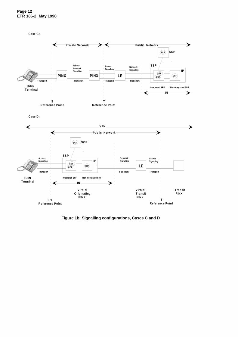
5.1 Signalling configurations
The interaction with an ISDN user should not put any requirements on the network architecture; e.g. itshould not be a requirement to equip the local exchanges with Service Switching Function (SSF) or SRF.As a consequence the signalling needs to support the following possible configurations for the access ofan ISDN TE to the IN entities in the network:
- Case A: The ISDN TE is connected direct to a local exchange with an SSF;
- Case B: The ISDN TE is connected to a local exchange without an SSF;
- Case C: The ISDN TE is connected to a private network (indirect TE access to the public network);
- Case D: The ISDN TE is within a VPN.
In case A only the Digital Subscriber Signalling System No. one (DSS1) protocol may be affected by therequirements to support a USI communication. In case B the ISDN User Part (ISUP) may also beaffected.
In case C the SSF functionality may also be located at the local exchange (as case A).
Case D is just an example signalling configuration for VPN; there are other possible permutations for theallocation of VPN functionality but these options are not discussed here.
As an example, figures 1a and 1b illustrate these signalling configurations for one of the SRF connectphysical scenarios described in ETS 300 374-1 [8], subclause 7.3.5.1.1, case i) in figure 25.

Page 11ETR 186-2: May 1998
TE
S/TReference
Point
S/TReference
Point
TE
Figure 1a: Signalling configurations, Cases A and B
Page 12ETR 186-2: May 1998
SCF
SSF
CCF SRFLEPINX PINX
Private Network Public Network
IN
TReference Point
SR eference Point
T rans port Trans port Trans port T rans port
PrivateNetworkSignallin g
Access Signallin g
Netw orkSignallin g
ISDNT erminal
Case C :
Inte grated SRF
IP
S CP
SSP
Non-Inte grated SRF
SCF
SSF
CCF SRF
V PN
IN
TReference Poin t
S /TReference Point
T rans port
ISDNT ermin al
Case D:
Integrated SRF
IP
SCP
SSP
Non-Inte grated SRF
Public Network
LE
V ir tualTransit PINX
Netw orkSignallin g
Access Signallin g
Access Signallin g
T rans port Trans port
Transit PINX
Vir tu alOriginating PINX
Figure 1b: Signalling configurations, Cases C and D

Page 13ETR 186-2: May 1998
5.2 Terminal types
Different ISDN terminal types have to be supported. The terminal type may vary from service to service,i.e. any particular terminal may support any or all of the following categories over a set of services:
a) Terminals supporting generic keypad protocol;
b) Legacy terminals supporting fixed service logic using the generic functional protocol;
c) Future terminals supporting a service independent generic functional protocol.
5.2.1 Existing terminals
ISDN terminals are already in the market place, and the services they use need to continue to besupported, whether the network operator chooses to support them in an IN environment or in a fixedimplementation environment. These terminals support a number of generic protocols, which may be usedin the support of any supplementary service. These generic protocols are defined either as stimulus orfunctional. They support different kinds of supplementary services, according to the following definitions:
- A stimulus supplementary service is one where the end terminal does not have knowledge of theservice being required. All protocol is transported to/from the human user with only serviceindependent control of the presentation/coding. No service logic is present within the terminalimplementation. Any service logic required to support the human user is provided in the network onbehalf of the terminal. In an IN environment, this service logic will reside in the SCF with the SRFproviding the user interaction under the control of the SCF. Two mechanisms of stimulus accessare provided, the generic keypad protocol and the feature key protocol.
NOTE 1: The feature key protocol, which is another stimulus protocol, is not supported in ETSIstandards.
- A functional supplementary service is one where the peer entity has knowledge of the service beingprovided. The terminal therefore provides service logic in order to support that supplementaryservice. As a result, where the peer entity is a terminal equipment, a more intelligent man-machineinterface can be provided.
NOTE 2: The functional protocol is also the only protocol that is applicable at the T referencepoint to support private ISDN exchanges and networks. The procedures used at the Treference point are defined in the individual supplementary service specifications, andcan be either identical to those for the coincident S and T reference point (supportingan ISDN terminal) or may be entirely different, dependent on the required functionalityof the service.
The generic protocols to be supported in an IN environment are as follows:
- Generic keypad protocol - this is a stimulus protocol which provides for the transfer of keypadfacility information elements in the user to network direction, representing primarily numeric valuesof a keypad being keyed by the human user. In the network to user direction, the protocol providesfor the transfer of display information elements, signal information elements and tones andannouncements in the bearer channel. The keypad protocol has affinity with the way thatsupplementary services are provided in the Public Switched Telephone Network (PSTN), andnetwork operators may require a consistent service offering between PSTN services and ISDNkeypad protocol support services.
- Generic functional protocol - this is a functional protocol consisting of a number of procedures forcontrol of access resources, suspend and resume, resource reservation and common informationelements (the various transport mechanisms).
Unless indicated otherwise, the requirements defined in this document apply to both stimulus andfunctional based terminals.
Page 14ETR 186-2: May 1998
5.2.2 Future terminals
From a terminal perspective, future mechanisms should be an evolution of the existing supplementaryservice mechanisms. For example, the keypad protocol, provides a means of supporting services using aterminal that is service independent. Therefore the existing legacy terminals supporting the keypadprotocol can continue to support new services (in an IN environment or fixed implementation environment)as and when such new services are designed.
Unlike the keypad protocol, the generic functional protocol is service specific. The IN environment will beused to create services that are not standardized, and this should be matched by a terminal where allsignalling information is also service independent. Therefore in an IN environment an enhanced genericfunctional protocol is required, where service dependence will only exist in the user application within theterminal.
5.3 Access signalling types
This clause discusses the signalling types applicable for communication between an ISDN end user andIN service logic in the context of the terminal types identified in the previous subclause.
The communication between an ISDN end-user and the IN service logic in the network is not necessarilyrelated to the establishment of a call/bearer. Two signalling types are to be distinguished:
a) Call related signalling (bearer related): The signalling procedure is tied to the procedures for basiccall control and tied to a bearer connection in progress, active or in the clearing phase. Therespective IN CS2 network aspect is named Out Channel Call Related User Interaction (OCCRUI);
b) Call unrelated signalling (bearer unrelated): The signalling procedure is independent of a bearerconnection. The respective IN CS2 network aspect is named Call Unrelated User Interaction(CURUI).
Both signalling types a) and b) are to be supported for the USI mechanism.
5.4 USI signalling requirements
The requirements defined in this subclause is only applicable for functional terminals, since the USIcommunication mechanism requires a functional protocol. According to subclause 5.2, USI requires futureterminals with an enhanced generic functional protocol.
5.4.1 IN service and IN service features applicable for user to service communication
This subclause provides a non-exhaustive list of IN services and IN service features that requirecommunication between an end-user and the IN service logic and which are applicable for USIcommunication.
5.4.1.1 Call related features
The following example features require an exchange of information between the end-user and the INservice logic which are associated with an IN call:
- Terminal authenticationFor the CTM service EN 301 175 [5] updating and terminal authentication may occur while the CTMuser is involved in an active call. In this case the Fixed Termination (FT) and the cordless terminalare temporarily involved in an information exchange with the CTM service logic. The informationbetween FT and CTM service logic should be exchanged out of band (refer to EG 201 096-1 [19]).
NOTE: The USI mechanism builds the general transport mechanism for the mobilitymanagement operations between FT and SCFmm/SCFsl, i.e. via the DSS1alpha-interface EN 301 144-1 [3] and INAP.

Page 15ETR 186-2: May 1998
- IdentificationSome IN services require the identification of the service user, e.g. via Personal User Identity (PUI)for Universal Personal Telecommunication (UPT) service ETS 300 779 [4] or card number forCharge Card Calling (CCC) service. The identification information is usually collected, during userinteraction phase, by the IN service logic. Based on an application residing in the terminal, theterminal itself may control the collection of the PUI and send the information to the IN service logic.
- AuthenticationSome IN services require the authentication of the service user, e.g. via Personal IdentificationNumber (PIN) for UPT phase 2 service or the CCC service. The authentication information isusually collected, during user interaction phase, by the IN service logic. Based on an applicationresiding in the terminal, the terminal itself may control the collection of the PIN and send theinformation to the IN service logic.
- Support of UPT smart cardSupport of UPT smart card is required, i.e. call related transport of respective information (e.g. anauthentication request and response) is required between terminal and network (refer toETS 300 823 [12]).
Using the USI communication mechanism would allow the inclusion of identification or authenticationinformation in the call setup messages. When the Service Switching Point (SSP) triggers the IN service,the identification/authentication information would be included by the SSP in the first query sent to the INservice logic. This would facilitate or even avoid an user interaction phase between an end-user and an IPduring service logic processing.
- Provision of information to the userA mechanism should be provided to allow transport of any information from the service logic to theend user as an uni-directional information transport. This may be provided by the USIcommunication mechanism. The treatment of this information in the ISDN TE depends on theservice application protocol, e.g. information may be displayed.In addition, functional operation may be completed by stimulus operation, e.g. display information(see clause 10).
5.4.1.2 Call unrelated features
The following example features require an exchange of information between the end-user and the INservice logic which are not associated with an established IN call:
- Terminal location registration and authenticationThe CTM service EN 301 175 [5] may require the terminal location registration information updatingand the terminal authentication while the CTM user or rather the cordless terminal is roamingwithout being involved in an active call (refer to EG 201 096-1 [19]). The location registrationprocedure is used whenever the cordless terminal roams in a new FT or when it registers without aprevious registration. The respective information should be exchanged between FT and CTMservice logic via a call unrelated user interaction.
NOTE 1: The CTM user is not aware of the terminal location updating procedure since it iscontrolled by the logic that resides in the CTM terminal.
NOTE 2: The USI mechanism builds the general transport mechanism for the mobilitymanagement operations between FT and SCFmm/SCFsl, i.e. via the DSS1alpha-interface EN 301 144-1 [3] and INAP.
- UPT outgoing call registrationOutgoing call registration is a core feature of UPT phase 2. The procedure provides that theterminal for which an UPT user has registered "becomes his own", i.e. UPT user is allowed to makeoutgoing calls from the registered terminal without any additional authentication. It shall be possibleto perform the outgoing call registration independent from a call, i.e. call unrelated user interactionbetween the UPT user and the UPT service logic shall be possible (e.g. transport of the respectiveinformation for identification and registration). Outgoing call registration via call unrelated userinteraction is the appropriate procedure since in UPT phase 2 the use of a smartcard and asmartcard reading terminal are considered as standard.

Page 16ETR 186-2: May 1998
- Support of UPT smart cardSupport of UPT smart card is required, i.e. call unrelated transport of respective information (e.g. anauthentication request and response) is required between terminal and network (refer toETS 300 823 [12]).
5.4.2 Signalling requirements to support an user to service communication mechanism
5.4.2.1 Requirements for a call-related (bearer- related) transport mechanism
A call-related (bearer-related) and a call-unrelated (bearer-unrelated) transport mechanism is required forUSI communication.
NOTE 1: The enhancements of the User to Network Interface (UNI) and Node to Node Interface(NNI) signalling procedures should be as generic as possible. Therefore otherrequirements than IN should be taken into account, e.g. for VPN new transportcapabilities are also required.
The ISDN signalling needs to support call-related (bearer-related) USI communication according to thefollowing requirements:
- The mechanism should provide the service independent exchange of information betweenend-users, i.e. ISDN TE, and IN service logic, i.e. Service Control Point (SCP).
- The mechanism should allow transparent information transport between user and SSP in the ISDN ,i.e. via UNI (DSS1) and NNI ISUP.
- The information elements functionally to be conveyed from the user to the service logic are namedUSI and from the service logic to the user Service to User Information (SUI).The information elements should contain an indication whether they are an USI or a SUI type, aservice indication and a transparent data container (annex A describes the functional structure ofthe USI information elements). The length of the data container has to be variable.
- Bi-directional information transport is required at any time during the call, in combination with basiccall control messages and at other times, e.g. during active and alerting phases of the call.
- At the UNI (DSS1), the mechanism should be the same regardless of whether the SSP is located inthe local exchange or in a transit exchange (refer to subclause 5.1, cases A and B).
- An indication of the terminal capabilities has to be conveyed to the service logic, e.g. whether DTMFis supported by the terminal. Since there are no means in DSS1 to inform the local exchange aboutthe capabilities of a connected terminal, this information needs to be administered in the localexchange. In case the SSP is located in the transit exchange, this information shall be conveyed viaNNI (ISUP). CS2 core INAP contains a parameter "terminalType" on which this information is to bemapped (refer to annex B).
- In the case where the SSP is located in the transit exchange, the mechanism at the NNI (ISUP)should allow the transparent information transport from local exchange to the SSP (refer tosubclause 5.1, case B).
NOTE 2: The USI mechanism is restricted to the ISDN network equipment (e.g. ISDN TE, smartcard reading terminals) which are enhancable to support USI signalling procedures,e.g. they have to support the appropriate service feature specific application protocol.
- Security mechanisms are required:
- In order to avoid overload in the ISDN network due to transmission of messages carrying USIcommunication information, it should be possible to control the maximum rate of signallingmessages, i.e. the rate of USI signalling events can be limited at the Local Exchange (LE). Inaddition the length of the data container needs to be limited to the maximum lengthsupported at the UNI (DSS1) or NNI (ISUP) respectively. the ISDN TE violates theselimitations, the LE should ignore the USI signalling event.
NOTE 3: It may also be applicable that USI signalling information is sent across network bordersvia network to network interface (ISUP). It is for further study whether additionalsecurity checks are required in an appropriate gateway exchange. In this case the USIservice indicator has global significance.

Page 17ETR 186-2: May 1998
The usage of the USI mechanism by unauthorized users has to be prevented at the LE. In INCS2 only the case supported is where USI signalling is allowed according to accesssubscription.The LE should ignore the USI signalling event when the security check is unsuccessful.The LE should ignore any SUI signalling event received from an ISDN TE.
For security checks the LE has to evaluate the USI/SUI indication (refer to annex A).
5.4.2.2 Requirements for a call-unrelated (bearer-unrelated) transport mechanism
The ISDN signalling shall support a call-unrelated (bearer-unrelated) USI communication according to thefollowing requirements:
- The mechanism should provide service independent exchange of information between end-users,i.e. ISDN TE, and IN service logic, i.e. SCP.
- The mechanism should allow transparent information transport between user and SSP in the ISDN,i.e. via UNI and NNI.
- The information elements functionally to be conveyed from the user to the service logic are namedUSI and from the service logic to the user SUI.The information elements should contain an indication whether it is an USI or a SUI type, a serviceindication and a transparent data container (refer to annex A). The length of the data container hasto be variable.
- Bi-directional information transport via call-unrelated (bearer-unrelated), connection-orientedsignalling is required. The call-unrelated (bearer-unrelated) transport of user to service informationshould be treated similarly to the call-related (bearer-related) transport in order to facilitate theprocedures. Therefore the USI and SUI information elements should be conveyed in the messagesused for a call-unrelated (bearer-unrelated) signalling connection.
NOTE 1: The enhancements of bearer-unrelated signalling messages in order to allow transportof user to service information should be considered in the context of similar activitiesfor UNI and NNI, i.e. introduction of a bearer-unrelated ISDN basic call for the supportof VPN or User Signalling Bearer Service (USBS). In principle, the USI communicationshould use the signalling messages of the bearer-unrelated ISDN basic call in thesame way as for the bearer-related ISDN basic call.
- At the UNI (DSS1) the mechanism should be the same regardless of whether the SSP is located inthe local exchange or in a transit exchange.
- Where the SSP is located in the transit exchange, the mechanism at the NNI (ISUP) should allowthe transparent information transport from local exchange to the SSP.
- Security mechanisms are required:
- In order to avoid overload in the ISDN due to transmission of messages carrying USIcommunication information, it should be possible to control the maximum rate of signallingmessages, i.e. the rate of USI signalling events can be limited at the Local Exchanges (LEs).In addition the length of the data container needs to be limited to the maximum lengthsupported at the UNI or NNI respectively. The ISDN TE violMSMO these limitations, the LEshould ignore the USI signalling event.
NOTE 2: It may also be applicable that USI signalling information is sent across network bordersvia network to network interfaces. It is for further study whether additional securitychecks are required in an appropriate gateway exchange. In this case the USI serviceindicator has global significance.
- The usage of the USI mechanism by unauthorized users has to be prevented at the LE. Ingeneral USI signalling is only allowed according to access subscription. The LE should ignorethe USI signalling event when the subscription check is unsuccessful.
- The LE should ignore any SUI signalling event received from an ISDN TE.For security checks the LE has to evaluate the USI/SUI indication (refer to annex A).
Page 18ETR 186-2: May 1998
5.4.3 Enhanced Call Unrelated Service Function (CUSF)-SCF operation set of CS2 core INAP
In order to support call-unrelated (bearer-unrelated) IN treatment, in IN CS2 a new functional entity wasintroduced in the SSP, i.e. the CUSF. Therefore also a new type of INAP interface is introduced in CS2core INAP EN 301 140-1 [2], i.e. the CUSF-SCF interface. This interface is enhanced with respect to theCUSF-SCF interface specified in IN CS2 ITU-T Recommendation Q.1228 [17].
The CUSF-SCF interface of CS2 core INAP supports two options:
Option 1: The service Application Service Element (ASE) is located in the CUSF and theCUSF acts as a relay function between the service ASE and the SCF. The SCFcan provide additional information for the connection processing.
The only interworking case with a switched based service which was studied indetail in the time frame of CS2 is the interworking with Completion of Calls toBusy Subscriber (CCBS)/Completion of Calls on No Reply (CCNR). TheCUSF-SCF interface provides the capability of triggering during the processingof the CCBS/CCNR ASE in the SSP and to send some parameter to the INservice logic. In the SCF to CUSF direction the IN service logic can provide newaddress information to be used in the further connection establishmentcontrolled by the CCBS/CCNR ASE.
NOTE 1: The same IN service logic controls the bearer-related call for which the busy or noanswer event applied.
Option 2: The service ASE is located in the SCF and the CUSF acts as a relay functionbetween the user and the SCF. The SCF receives and may send USIinformation.
The only service standardized in ETSI in the time frame of IN CS2 which will usethe USI mechanism is CTM. For CTM the mobility management ASE is locatedin the SCP and in the FT. USI mechanism will be used to convey the mobilitymanagement operations via INAP and DSS1, EN 301 144-1 [3].
NOTE 2: The options are mutually exclusive. This means, when the bearer unrelated INAPrelationship is established in order to exchange USI related information via theCUSF-SCF interface, the CUSF contains no service ASE which interworks with IN andno application specific parameters beside USI related parameter are exchanged viathis interface. On the other hand, whenthe CUSF contains a service ASE whichinterworks with IN (e.g. a CCBS/CCNR ASE), no USI related parameters areexchanged via this interface.
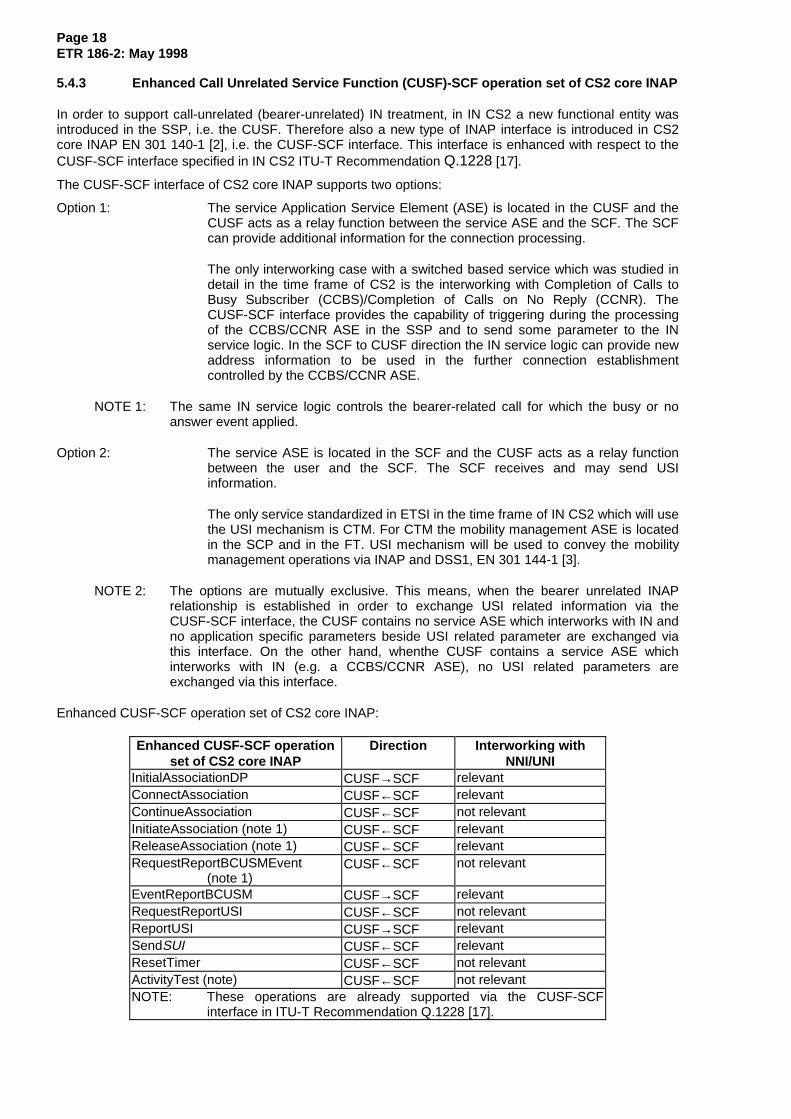
Enhanced CUSF-SCF operation set of CS2 core INAP:
Enhanced CUSF-SCF operationset of CS2 core INAP
Direction Interworking withNNI/UNI
InitialAssociationDP CUSF→SCF relevantConnectAssociation CUSF←SCF relevantContinueAssociation CUSF←SCF not relevantInitiateAssociation (note 1) CUSF←SCF relevantReleaseAssociation (note 1) CUSF←SCF relevantRequestReportBCUSMEvent
(note 1)CUSF←SCF not relevant
EventReportBCUSM CUSF→SCF relevantRequestReportUSI CUSF←SCF not relevantReportUSI CUSF→SCF relevantSendSUI CUSF←SCF relevantResetTimer CUSF←SCF not relevantActivityTest (note) CUSF←SCF not relevantNOTE: These operations are already supported via the CUSF-SCF
interface in ITU-T Recommendation Q.1228 [17].

Page 19ETR 186-2: May 1998
Where the third column identifies an interworking with NNI/UNI, the mapping of INAP CUSF-SCFoperations to NNI/UNI is described in annex B.
For the CUSF, a specific Basic Call Unrelated Service Model (BCUSM) is defined inITU-T Recommendation Q.1224 [16]. This BCUSM with all specified DP is fully applicable for CS2 coreINAP.
6 Support of mid-call events
Mid-call events are used as Trigger Detection Points (TDPs) to invoke an IN-service, and Event DetectionPoints (EDPs) to initiate certain actions during an IN call.
The following non-exhaustive list of example features require support of mid-call events via ISDNsignalling:
- CPH featuresIn IN CS2 the detection of midcall events is a basic requirement in order to support CPH, e.g. theuser may send a request to the service logic in order to initiate the manipulation of legs during anactive call.
- Follow-on callsThis procedure allows a service user, e.g. a UPT user, when terminating an outgoing UPT call,before disconnecting completely, to initiate a new UPT outgoing call without having to repeat theidentification and authentication procedures.
Two general procedures are possible for follow-on calls:
- Procedure 1: On detection of the termination of the outgoing call leg (event "Disconnect initiated byCalled Party") or in case of an unsuccessful call (events "Route Select Failure" "Called Party busy","No Answer from Called Party"), the connection between calling party and SSP is not released. Theservice logic prompts the user via user interaction procedures for the new address information toset up a new outgoing call.
- Procedure 2: During the alerting phase or the active call phase the calling party requests the servicelogic to disconnect the connection from the SSP to the called party (outgoing call leg). The follow-onrequest from the user is considered as a "mid-call" event. After performing the disconnection, theservice logic prompts the user via user interaction procedures for the new address information toset up a new outgoing call.
Procedure 1 is well supported by IN CS1 and the existing ISDN signalling, i.e. DSS1 and ISUP.Procedure 2 based on a mid-call event is not supported in IN CS1.
In general the ISDN signalling should support mid-call events for IN CS2, for both the case where the SSFis located at a transit exchange, and where the SSF is located at a local exchange. The Basic Call StateModel (BCSM) contains respective mid-call DPs which can be armed by an IN service logic similar to anyother DP.
6.1 Signalling requirements
This subclause defines the requirements for mid-call processing where the SSF is located at the transitlevel. For the case where the SSF is located at the LE, the requirements are a subset of these, i.e. noISUP interaction.
The SCF may dynamically request (or withdraw) the monitoring of midcall events to the SSF. TheSSF/Call Control Function (CCF) therefore sends the appropriate request to the LE to carry midcall eventsto the SSF/CCF. To simplify the information which is to be sent to the LE only the kind of the midcallrequest is sent:
1) specified code;
2) withdrawal of request.
Page 20ETR 186-2: May 1998
NOTE 1: Analogue terminals connected to an ISDN access (e.g. via a terminal adapter) mayinitiate a pure hookflash as a mid-call request.
In order to distinguish between the request to monitor for control codes and pure hookflash, the latter is identified by sending an empty list of control codes from SCF to SSFwhen arming a mid-call DP (in INAP "RequestReportBCSMEvent" operation).
For the case of control codes, the LE may use a pre-defined (possibly administered) list to decide whetherthe used code is valid for the IN (i.e. any service logic) at all.
If a mid-call event is received in the LE it is sent to the SSF/CCF including the possibly received controlcode.
The following general requirements need to be fulfilled for the handling of midcall EDPs when theSSF/CCF is located at transit level:
1) The request for a midcall EDP (including DP specific control information) may dynamically beperformed by the service logic in the SCF by sending an appropriate operation to the SSF/CCF.This request has to be conveyed from the SSF/CCF to the originating or destination local exchangeusing the basic network signalling to be processed there.See annex D for a proposal to enhance the ISUP for conveying this request. In this proposal adistinction between the request of a hookflash and of control codes is made. Which concretecontrol codes the SCF has requested is not conveyed to the local exchange.
2) The request for specific midcall events may be sent to the OLE during call set-up (at the earliestwith the first backward message) and the active call, to the DLE during active call.The request for specific midcall events received by the LE is valid until the call for which the EDPwas armed is released or if a withdrawal is received from the SCF.
3) The request for specific midcall events may be withdrawn by the service logic. The withdrawal hasto be conveyed in the underlying basic network from the SSF/CCF to the LE and to be processedthere. See annex D for a proposal to enhance the ISUP for conveying this withdrawal.
4) The underlying network must be able to process multiple requests for arming/disarming of EDPsduring one call resulting from either different SCFs (see clause 8) or the same SCF. If the LEreceives new requests for specific midcall events the previously received information will beoverwritten (i.e. it is no longer valid).
5) At a given time, a local exchange may either watch hook flash or control codes.
6) If the service user causes a midcall event the LE must check if the midcall event from the serviceuser matches the midcall event actually enabled by the SCF. If so, the underlying basic network hasto convey this event from the local exchange to the SSF/CCF at the transit exchange.For the case of control codes, the LE may use a pre-defined (possibly administered) list to decidewhether the used code is valid for the IN (i.e. any service logic) at all. Nevertheless, a control codemay be conveyed from the LE to the CCF/SSF which is not requested by the SCF. Events carryingsuch control codes should be ignored by the CCF/SSF.
7) A "temporary withdrawal" of a midcall EDP by the CCF/SSF (e.g. in PIC O/T_Mid_Call itself or aftera regress in the BCSM) should not be propagated to the LE for load reasons. In such situations(and in rare cases with a "normal" withdrawal) it may happen that unexpected midcall events arereceived by the CCF/SSF. Such events should be ignored.
8) In the case of IN-IN service interworking it may happen that more than one SCF request specificmidcall events occur simultaneously. In the following, a proposal how to handle these cases ismade for the CCFs/SSFs residing at transit level in different SSPs. For other cases the handlingshould be analogue.
− A CCF/SSF receiving a request/withdrawal for a midcall DP from another CCF/SSF willregister it but only pass through if its own SCF has not caused a request for a midcall DPbefore.
Page 21ETR 186-2: May 1998
− A CCF/SSF receiving a request for a midcall DP from its own SCF will send it to the LEregardless of a previous received request/withdrawal from another CCF/SSF.
− A CCF/SSF receiving a withdrawal for a midcall DP from its own SCF will send it to the LEonly if no request from another CCF/SSF has been received before.Otherwise, the requestfrom the other CCF/SSF will now be sent to the LE.
− A CCF/SSF releasing a leg or receiving a release indication from a leg will treat this like animplicit withdrawal for a midcall DP from another CCF/SSF if a previous request for a midcallDP was received on this leg.
NOTE 2: Superfluous orders of a CCF/SSF to an LE (e.g. request/withdrawal identical with theprevious one) may be suppressed of course.
− If a CCF/SSF receives a midcall event (provided the event is possible according to theBCSM) which its own SCF has not requested, it will forward the event to the next CCF/SSF ifit has received a request for this midcall event from that CCF/SSF before.
Following these rules, a midcall event will be processed (i.e. EDP O/T_Mid_Call is encountered) by thefirst reached CCF/SSF which has armed this DP with the matching criteria.
This enables several SCFs active in the same call to use midcall EDPs provided they use different sets offeature codes.
NOTE 3: It is assumed that the functionality of the detection of midcall events received from theuser (e.g. hookflash or specific code) is already available. Therefore no requirementexists in this point.
7 Interworking between IN services/features and ISDN supplementaryservices
7.1 Interworking with CCBS/CCNR
For the IN services Universal Access Number (UAN) ETS 300 710 [9] and Premium Rate (PRM)ETS 300 712 [10] interworking with the call completion supplementary services (CCBS/CCNR) is allowed.Nevertheless, for some optional features of the UAN and PRM services, e.g. Call Distribution (CD) orQueuing (QUE) the interworking with CCBS/CCNR has to be rejected in order to avoid degradation of thecall completion supplementary services. Therefore, based on a respective indication setup by an UAN orPRM service logic and transferred to the SSP by means of the serviceInteractionIndicators, CCBS/CCNRhas to be rejected in the ISDN.
7.2 Limitations in case of follow-on
IN CS2 provides additional options for follow-on calls, i.e. mid-call detection point processing (refer toclause 6). However, this only works if the calling user indicates that a follow-on call is required before thecalled party release is detected. If the mid-call event is not detected this means that CS1 method ofhandling follow-on calls will continue to be used. For CS1 several limitations for ISUP in supportingfollow-on calls exist (refer to EN 301 070-1 [6]). For IN CS2 support, it is required that solutions to theseproblems should be found, e.g. Charging/No_Charging Indicators and indicators for the support ofsupplementary service information (e.g. connected line identification, Closed User Group (CUG) etc.) andcontrol of echo suppresser devices when the call is established to consecutive called parties should alsobe resolved.
7.3 COnnected Line idendification Restriction (COLR) support for called IN number
It is required by IN to support that a called number can, on request from the SCF, be presented towardsthe calling party as the connected number with the "address presentation restricted indicator" set either to"presentation allowed" or "presentation restricted".
The service driver for this requirement is CTM EN 301 175 [5]. In this case the called IN number is theCTM number.

Page 22ETR 186-2: May 1998
It should be possible for the SCF to indicate that the called IN number is inserted as connected number inISDN with "address presentation restricted indicator" as defined in ISUP set to "presentation allowed" (butnot with the indication "presentation restricted"). This is supported in INAP by the"connectedNumberTreatmentInd" in the INAP parameter "ServiceInteractionIndicatorsTwo" (refer toannex C).
Support for "presentation restricted" is required when permanent mode of COLR is to be supported by theCTM service (refer to EN 301 175 [5]). In this case the called IN number (CTM number) is to be applied asconnected number with "address presentation restricted indicator" set to "presentation restricted". This issupported in INAP by the value "connectedNumberTreatmentInd=presentCalledINNumberRestricted" inthe INAP parameter "ServiceInteractionIndicatorsTwo" (refer to annex C).
7.4 UID capability / UID action indicators
ISUP version 3 allows flexible control of through connection of the signalling path and T9 timer by meansof the "UID capability indicators" (sent in forward direction) and "UID action indicators" (sent in backwarddirection) respectively (refer to EN 301 070-1[6]).
The appropriate parameters in INAP allowing an IN service logic to control these capabilities are the"bothwayThroughConnectionInd" and "userDialogueDurationInd" in the INAP parameter"ServiceInteractionIndicatorsTwo" (refer to annex C).
According the IN service logic programme, both indicators can be set and sent from the SCF to the SSF.Following the general principles for interworking, the SSP has to handle the interworking proceduresbased on generic indicators set by the SCP. Therefore only the indication whether through connection isrequired or not or whether the user interaction will be long or short is provided from the SCF to the SSFvia INAP. The capabilities supported in the signalling network which are indicated in the "UID capabilityindicators" are not sent via INAP from SSF to SCF. This means the mapping of the information receivedfrom the SCF to the respective ISUP "UID action indicators" has to be done in the SSP.
Tables 1 and 2 show the mapping of the INAP "ServiceInteractionIndicatorsTwo" parameter on the ISUP.
Table 1: Relation between ISUP:Through-connection instruction indicator andINAP:ServiceInteractionIndicatorTwo
ISUPforward direction
UID capability indicators:
Through-connection indicator
Core INAP:SCFÎSSF
ServiceInteractionIndicatorsTwo:
BothwayThroughConnectionInd
ISUPbackward direction
UID action indicators:
Through-connectioninstruction indicator
ISUP backwardmessage
not exist bothwayPathNotRequired
not exist -
not exist bothwayPathRequired not exist ANS
no indication bothwayPathNotRequired
not exist -
no indication bothwayPathRequired not exist ANS
through-connection
modification possible
bothwayPathNotRequired
not exist -
through-connection
modification possible
bothwayPathRequired through connect in
both directions
ACM/CPG

Page 23ETR 186-2: May 1998
Table 2: Interaction between ISUP:T9 instruction indicator andINAP:ServiceInteractionIndicatorTwo
ISUPforward direction
UID capability indicators:
T9 timer indicator
Core INAP:SCFÎSSF
ServiceInteractionIndicatorsTwo:
UserDialogueDurationInd
ISUPbackward direction
UID action indicators:
T9 instruction indicator
ISUP backwardmessage
not exist FALSE not exist -
not exist TRUE not exist ANS
no indication FALSE not exist -
no indication TRUE not exist ANS
stopping of timer possible FALSE not exist -
stopping of timer possible TRUE stop or
do not start T9
ACM/CPG
8 Support of service/feature interaction handling IN-based to IN-based
8.1 Transport of service compatibility indicator
With IN CS2 enhanced procedures in order to support service/feature interaction handling IN-based toIN-based are introduced. In general the interaction of simultaneously active service logics is restricted totwo. As a basic network functionality a service compatibility check will be added to the triggeringmechanisms in the SSF. This check will be based on a "Service Compatibility Indicator". It is setup by theSSF when the first service logic is triggered. When triggering, the second SSF will perform a genericcompatibility check for the received "Service Compatibility Id", using an exclusion matrix.
If these SSFs are located in different SSPs, transport of the "Service Compatibility Indicator" via NNI(ISUP) is required in the forward direction and in the backward direction. For the time being, this indicatoris only of relevance for IN services, there is no impact on existing ISDN supplementary services.
Annex B summarizes the ISUP requirements for the transport of the service compatibility indicator.Structure and content of the INAP parameter "iNServiceCompatibilityIndicator" is shown in annex C.
9 Signalling requirements from CTM
Refer to subclause 7.3 for the COLR support for the CTM Number.
No additional specific signalling requirements are identified for CTM Phase 1.
10 Transport of display information
In general the use of display information represents the stimulus approach.
CS1 core INAP already includes the capability of sending a display information, i.e. IA5 string, to thecalling party. These operations and the respective procedures are still valid for IN CS2.
- In case of call gapping (CallGap operation) or service filtering (ActivateServiceFiltering operation),the calling party should receive an indication before the filtered or gapped call is released. This

Page 24ETR 186-2: May 1998
indication may be a text information to be displayed to the calling party. CallGap andActivateServiceFiltering are SSF-SCF operations. The SSF is located at a transit exchange, thedisplayInformation parameter may be mapped to the ISUP display information parameter(EN 301 070-1 [6]). At the local exchange, and also when the SSF is located at the local exchange,the information may be mapped to the DSS1 display information element.
- In the case of an announcement to the calling party (PlayAnnouncement (PA) operation), theannouncement may be accompanied by display information. PA is an SRF-SCF operation. Ingeneral the SRF requires a bearer connection established to the resources managed by the SRF.Dependent on the interface used for the bearer connection, i.e. UNI or NNI, the SRF may map thedisplayInformation parameter to the ISUP display information parameter or to the DSS1 displayinformation element.
- In the case of user interaction (PromptAndCollectUserInformation (PAC) and PlayAnnouncement(PA) operation), the announcement may be accompanied by a display information. PAC and PA areSRF-SCF operations. In general the SRF requires a bearer connection established to the resourcesmanaged by the SRF. Similar to the case of an simple announcement as described above, in thecase of user interaction, prompting has to be done with PAC via an in-band announcementaccompanied by a PA with display information. Mapping of the displayInformation parameter is thesame as described above for PA. The calling party may provide the requested information in-band,e.g. as spoken text. In addition a stimulus approach in the direction user to SRF is not supported,i.e. a DSS1 keypad facility information element cannot be sent to an SRF attached to/collocatedwith an SSF on the transit level.
For IN CS2, display information can also be sent to the called party; therefore the display parameter hasbeen introduced into the connect operation. It has also been assumed that the display has the capability ofa standard ISDN UNI, although the IN is not explicitly aware of the terminal capabilities.
Annex B summarizes the ISUP requirements for the transport of the display information.
NOTE: At the access, multiple display information elements may be received in rapidsuccession and overwrite the previous displayed information. It is for further studywhether a co-ordination function for display information should be introduced, e.g. inthe local exchange.
11 Transport of called IN number
In general the called IN Number shall be available and registered for the ISDN supplementary serviceMCID. That is why the ISUP parameter Called IN Number (CdINNo) as specified in ETR 164 [7] is alwaysgenerated by the SSF, independent from the SCF. The calledPartyNumber parameter sent in the InitialDPoperation is transferred via ISUP in the CdINNo parameter to the succeeding exchange.
NOTE: Format and coding of the called IN number corresponds to the original called partynumber parameter according to ITU-T Recommendation Q.763 [15]. The default valueof the presentation restricted indicator included shall be set to "presentation notallowed".
For some services, as a special service feature, the SCF may want to specifically indicate whether theCdINNo shall be presented to the called party or not. As an example the UAN service ETS 300 710 [1]includes display of the called universal access number as an optional service requirement.
It IS possible that the IN service logic may control the presentation restricted indicator, e.g. set"presentation allowed" in order to allow the presentation to the called party. In any case, the called INnumber as available in the SSP needs to be transferred to the called party and may be registered forMCID. The INAP ServiceInteractionIndicator parameter is enhanced with the"allowCdINNoPresentationIndicator" (refer to annex C).
12 Signalling requirements from CPH
No specific signalling requirements are identified for CPH.

Page 25ETR 186-2: May 1998
13 IN support of GVNS configuration #3
The GVNS is a multi-network international service which provides private network functions to users atgeographically dispersed international locations while minimizing the need for dedicated networkresources. It may be offered to customers over the PSTN and/or ISDN. In principle it is based on VPNinterworking at the service providers' international gateways.
The ISUP procedures for GVNS configuration #3 are specified in ITU-T Recommendation Q.735 [14],clause 2:GVNS stage 3 description. ITU-T Recommendation Q.735 [14], specifies two new ISUPparameters for GVNS:
- Forward GVNS parameter, contained in the ISUP message IAM
The format of the GVNS Forward parameter includes following subfields:
- Originating Participating Service Provider (OPSP);- GVNS User Group (GUG);- Terminating Network Routing Number (TNRN).
Backward GVNS parameter, contained in the ISUP messages CON and Answer Message (ANM)The format of the GVNS Backward parameter includes following subfields:
- terminating access indicator.
Where GVNS configuration #3 is supported in a network with IN based VPN, these GVNS specificparameters have to be conveyed to/from the VPN service logic. Therefore the GVNS Forward and GVNSBackward parameter are included in following INAP messages:
InitialDP enhancements:InitialDPArg: forwardGVNS [xx] ForwardGVNS OPTIONAL,
ConnectArg enhancements:ConnectArg: forwardGVNS [xx] ForwardGVNS OPTIONAL,
backwardGVNS [xx] BackwardGVNS OPTIONAL,
Data Types enhancements:BackwardGVNS ::= OCTET STRING (SIZE (minBackwardGVNSLength..
maxBackwardGVNSLength))-- Indicates the GVNS Backward information. Refer to Q.735, §6 for encoding.ForwardGVNS ::= OCTET STRING (SIZE (minForwardGVNSLength..
maxForwardGVNSLength))-- Indicates the GVNS Forward information. Refer to Q.735, §6 for encoding.
minForwardGVNSLength INTEGER ::= -- to be specifiedmaxForwardGVNSLength INTEGER ::= -- to be specifiedminBackwardGVNSLength INTEGER ::= -- to be specifiedmaxBackwardGVNSLength INTEGER ::= -- to be specified
EventSpecificInformationBCSM ::= CHOICE { ....oAnswerSpecificInfo [4] SEQUENCE {
backwardGVNS [1] BackwardGVNS OPTIONAL...},
Two message sequence charts in annex E show an applicable information flow for an incoming andoutgoing GVNS call.

Page 26ETR 186-2: May 1998
14 Support of calling user number
14.1 Introduction of calling user number in INAP and ISUP
For IN CS2 there is no standardized interworking specified for how an IN provided calling party numbercan be mapped to an appropriate ISUP parameter. According the ISUP-INAP interworking standardEN 301 070-1 [6] this mapping is left open as a network operator specific mapping. EN 301 070-1 [6] onlyindicates that this network operator specific mapping should not jeopardise ISDN supplementary serviceslike MCID or Calling Line Identification Presentation (CLIP)/Calling Line Identification Restriction (CLIR).However this will be the case, since the IN provided calling party number can only mapped to existingISUP parameters, like "Generic number" or "Calling party number", which are used for these ISDNsupplementary services.
Therefore a new number parameter "callingUserNumber" is introduced in CS2 core INAP allowing theprovision of calling party number by IN without misusing existing ISUP number parameters. This INAPparameter should be mapped to an appropriate new ISUP parameter "Calling user number". Mapping ofthe INAP parameter "callingUserNumber" shall not affect the ISUP parameters "Generic number" or"Calling party number".
Introduction of this number parameter is required in order to fulfil following IN CS2 service requirements:
- The requirement (of Q.7 ITU-T SG11) to display the UPT calling party number independently of thealready transmitted calling party number to the called party.
- The functionality of the MCID supplementary service needs to be ensured. The current stage 3description of this service only requests registration of the calling party number. But as the callingparty number (in case of UPT calling user) definitely does not identify the UPT calling user, but onlythe physical equipment used by the UPT subscriber, there is need for an enhancement. Therefore,in order to distinguish between the calling UPT subscriber and the equipment currently used by theUPT subscriber, other parameter needs to be introduced. This is also required by EN 301 175 [5]and ETS 300 779 [11] subclause "8.4 MCID" where it is said "Both the CTM number and thenumber of the CTM user's currently registered location shall be registered".
- According to ETS 300 779 [11] subclause 7.5.1 "calling line identification presentation" the followingrequirement is given: "The called user shall not receive information pertaining to the UPT user'sregistered location but the UPT number of the calling user".
- Also according to EN 301 175 [5] subclause 8.1.1 "calling line identification presentation" the samerequirement is given with regard to CTM since it is stated "The called user shall not receiveinformation pertaining to the CTM user's registered location, but the CTM number of the callinguser"
Refer to annex B for mapping of INAP on ISUP for this parameter.
14.2 Presentation of the calling party number to the called user
According to the requirements given in ETS 300 779 [11] and EN 301 175 [5] it has to be possible for theservice logic to change the restrictions of the presentation restriction indicator of the calling party number.
Therefore a new sub-indicator to the ForwardServiceInteractionInd of the INAP parameter"ServiceInteractionIndicatorsTwo" is added (refer to annex C).
15 Support of DP: Not_Reachable
In general CS2 core INAP supports all DPs specified in the O-BCSM and T-BCSM in IN CS2 accordingITU-T Recommendation Q.1224 [16].
In addition, a new DP for "Not_Reachable" will be supported in O-BCSM and T-BSCM by CS2 core INAP,i.e. as "o_Not_Reachable" and "t_Not_Reachable". These additional DPs will be specified inEN 301 144-1 [3]. The new DP for "Not_Reachable" will be supported in order to meet the requirementsfor CTM EG 201 096-1 [19] and CAMEL Phase 2.

Page 27ETR 186-2: May 1998
Mobile subscriber "Not_Reachable" indication will be sent if:
- the mobile subscriber is detached;
- no page response is received;
- there is a congestion in radio resources (e.g. between the Mobile Switching Centre (MSC)/VisitedLocation Register (VLR) and the mobile station).
For mobile applications it is possible to have both an early determined or a late determined"Not_Reachable" event. The first event can be detected by a Home Location Register (HLR) before thecall is routed to the final destination. The latter event can be received by SSF/CCF via signalling as arelease event as response to the call connection setup request.
The DP can be either armed as static DP (TDP) or dynamic DP (EDP). The event to trigger the DP viasignalling (late determined event) is the receipt of a release cause "Subscriber_Absent" (refer also toannex B).

Page 28ETR 186-2: May 1998
Annex A (informative): Functional structure of the USI information element
The USI information element should be functionally defined as follows:
USI/SUIindication
serviceindication
data container
USI/SUI indication:
Transparent transport of the USI information element from the ISDN TE to the IN service logic and viceversa is required. This is achieved by two different types of information elements:
- in the user to service direction: USI User to Service Information;
- in the service to user direction: SUI Service to User Information.
The USI/SUI indication represents network knowledge, i.e. the LE has to evaluate this indication forsecurity checks.
Service indication:
The service indication represents SSF knowledge. It is evaluated in the IN capable exchanges (the SSPs).Based on the service indication, an SSF, prior to sending a USI information element to an SCF, checkswhether the SCF is prepared to receive a USI information element with that particular service indication. Ifthe USI information element is sent across a network boundary, the value of the service indication has tobe standardized or bilaterally agreed and may need to be checked by the gateway exchanges. Thedetailed handling of the service indication by an SSP is different for the call-related transport mechanismand for the call-unrelated transport mechanism.
Data container:
The data container is evaluated only by the ISDN TE and by the IN service logic. It represents servicelogic and user knowledge, i.e. the content is service dependent. The length of the container is variable.The maximum length is limited according to the maximum value which is supported on the UNI signalling(DSS1) and on the NNI signalling (ISUP).

Page 29ETR 186-2: May 1998
Annex B (informative): Parameters mapping
Table B.1: Modifications to IN CS1 (core INAP) operations: SSF-SCF
Operation Parameter Added Signalling Interworking RequirementsConnect displayInformation a) displayInformation
ISUP:The ISUP requirements are just to transport the parameter and can be summarized asfollows:Phase of Call: Call establishment Messages to carry
information : IAMAction at SSP: map parameter to appropriate ISUP messageAction at Local exchange: Sent to the terminal for displayAction at Transit exchange: pass information on unchangedDSS1:Display information shall be supported when received at the terminating exchange withthe IAM. It is to be sent to the terminal in order to display the information.At the access multiple display information elements may be received immediately oneafter the other and overwrite the previous displayed information. It is for further studywhether a co-ordination function for display information should be introduced, e.g. in thelocal exchange.
(continued)

Page 30ETR 186-2: May 1998
Table B.1 (continued): Modifications to IN CS1 (core INAP) operations: SSF-SCF
Operation Parameter Added Signalling Interworking RequirementsConnect forwardCallIndicators
genericNumber
iSDNAccessRelatedInformation
b) forwardCallIndicatorsISUP:ForwardCallIndicators are a mandatory part of the IAM and carried in the forwarddirection only. Should the information be returned in the backward direction also, if thisparameter is changed by IN since there may be a problem with end to end consistency?Guidance from SPS1 is sought on this point.Currently only one service specific requirement is identified: a VPN service logic mayrequire the explicit setting of "ISUP all the way".However it is proposed to sent the complete forwardCallIndicators parameter from SCFto SSF in order to have the possibility on controlling other subfields.DSS1: no additional requirementsc) genericNumberISUP:Each GenericNumber shall be mapped unchanged, to the ISUP Generic Numberparameter.DSS1: no additional requirementsd) iSDNAccessRelatedInformationISUP:This parameter shall be mapped on the ISUP parameter "Access transport".Note: Since the ISUP parameter "Access transport" includes some sub-parameterswhich have only end-to-end significance, some of these sub-parameters shall not bemodified by IN. Thus, as part of the ISUP/INAP interworking procedures an explicitindication shall be provided which sub-parameters shall not be modified when mappingthe INAP "iSDNAccessRelatedInformation" parameter on the ISUP parameter "Accesstransport".DSS1: No additional requirements. This parameter maybe changed by IN.
(continued)

Page 31ETR 186-2: May 1998
Table B.1 (continued): Modifications to IN CS1 (core INAP) operations: SSF-SCF
Operation Parameter Added Signalling Interworking Requirements
Connect carrier
forwardGVNSbackwardGVNS
iNServiceCompatibilityResponse
serviceInteractionIndicatorsTwo
locationNumber
callingUserNumber
d) carrierThe INAP parameter "carrier" shall be mapped on the INAP parameter "Transit NetworkSelection" (TNS). The INAP parameter is of type OCTET STRING and allows a flexiblelength.e) forwardGVNS / backwardGVNSISUP: INAP parameters "forwardGVNS" and "backwardGVNS" is mapped unchangedto the equivalent ISUP parameters.DSS1: No impact.
d) iNServiceCompatibilityResponseSee InitiateCallAttempt operation.
e) serviceInteractionIndicatorsTwoSee clause 7 and annex C.
f) locationNumberISUP: INAP parameter "locationNumber" is mapped unchanged to the equivalent ISUPparameter.DSS1: No impact.
g) callingUserNumberISUP: INAP parameter "callingUserNumber" is mapped unchanged to the equivalentISUP parameter.DSS1: No impact.
(continued)

Page 32ETR 186-2: May 1998
Table B.1 (continued): Modifications to IN CS1 (core INAP) operations: SSF-SCF
Operation Parameter Added Signalling Interworking RequirementsbearerCapability h) bearer capability
ISUP: If a bearer capabilities is already assigned to an existing party in the call then thisbearer capability will be used and any bearer capability provided by IN If a bearercapabilities is already assigned to an existing party in the call then this bearer capabilitywill be used and any bearer capability provided by IN will be ignored;If a bearer capability has not been assigned (i.e there is no party yet) and a bearercapability is provided by INAP then this bearer capability should be used;If neither the signalling or INAP provides a bearer capabilities value then the default of3,1kHz audio should be used.DSS1: No impact
(continued)
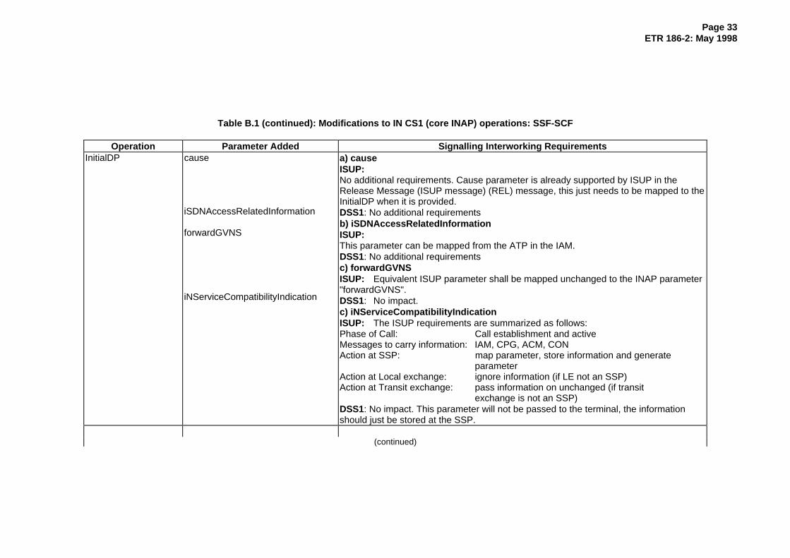
Page 33ETR 186-2: May 1998
Table B.1 (continued): Modifications to IN CS1 (core INAP) operations: SSF-SCF
Operation Parameter Added Signalling Interworking RequirementsInitialDP cause
iSDNAccessRelatedInformation
forwardGVNS
iNServiceCompatibilityIndication
a) causeISUP:No additional requirements. Cause parameter is already supported by ISUP in theRelease Message (ISUP message) (REL) message, this just needs to be mapped to theInitialDP when it is provided.DSS1: No additional requirementsb) iSDNAccessRelatedInformationISUP:This parameter can be mapped from the ATP in the IAM.DSS1: No additional requirementsc) forwardGVNSISUP: Equivalent ISUP parameter shall be mapped unchanged to the INAP parameter"forwardGVNS".DSS1: No impact.c) iNServiceCompatibilityIndicationISUP: The ISUP requirements are summarized as follows:Phase of Call: Call establishment and activeMessages to carry information: IAM, CPG, ACM, CONAction at SSP: map parameter, store information and generate
parameterAction at Local exchange: ignore information (if LE not an SSP)Action at Transit exchange: pass information on unchanged (if transit
exchange is not an SSP)DSS1: No impact. This parameter will not be passed to the terminal, the informationshould just be stored at the SSP.
(continued)

Page 34ETR 186-2: May 1998
Table B.1 (continued): Modifications to IN CS1 (core INAP) operations: SSF-SCF
Operation Parameter Added Signalling Interworking RequirementsInitialDP genericNumbers
terminalType
serviceInteractionIndicatorsTwo
carrier
d) genericNumbersISUP:If this parameter is present in the SSF it should be mapped unchanged to the INAPGenericNumbers parameter. If the Generic Number parameter just contains anadditional Calling Party number the INAP Additional Call Party number parameter shallbe used. Note that the INAP parameter GenericNumbers may convey several GenericNumbers.DSS1: No additional requirements.e) terminalTypeISUP: The ISUP requirements are summarized as follows:Phase of Call: Call establishmentMessages to carry information: IAM forward direction onlyAction at SSP: map parameter to InitialDPAction at Local exchange: retrieve informationAction at Transit exchange: pass information on unchangedDSS1: No additional requirements.Note: The values supported in "terminalType" are: unknown, dialPulse, dtmf, isdn,isdnNoDtmf.d) serviceInteractionIndicatorsTwoSee clause 7 and annex C.e) carrierSee connect operation.
(continued)

Page 35ETR 186-2: May 1998
Table B.1 (continued): Modifications to IN CS1 (core INAP) operations: SSF-SCF
Operation Parameter Added Signalling Interworking RequirementsInitiateCallAttempt carrier
alertingPatterniNServiceCompatibilityResponse
iSDNAccessRelatedInformation
locationNumber
serviceInteractionIndicatorsTwo
a) carrierSee connect operation.b) alertingPatternSee connect operation in table 3.c) iNServiceCompatibilityResponseISUP: The ISUP requirements are summarized as follows:Phase of Call: Call establishment and activeMessages to carry information: IAMAction at SSP: map parameter on a new ISUP parameter (same as for "iNServiceCompatibilityID"), store
information and generate parameterAction at Local exchange: ignore information (if LE not an SSP)Action at Transit exchange: pass information on unchanged (if transit
exchange is not an SSP)DSS1: No impact. This parameter will not be passed to the terminal, the informationshould just be stored at the SSP.d) iSDNAccessRelatedInformationISUP: This parameter shall be mapped on the ISUP parameter "Access transport".Note: Since the ISUP parameter "Access transport" includes some sub-parameterswhich have only end-to-end significance, some of these sub-parameters shall not bemodified by IN. Thus, the SCP can provide only some sub-parameters for the ISUPparameter "Access transport" in this INAP parameter. As part of the ISUP/INAPinterworking procedures it is necessary to describe which default setting of the othersub-parameters not provided by the SCP is to be supported by the SSP in the outgoingIAM message (see also the note for this INAP parameter in the connect operation).DSS1: No additional requirements. This parameter maybe changed by IN.e) locationNumberISUP: INAP parameter "locationNumber" shall be mapped unchanged to theequivalent ISUP parameter.DSS1: No impact.f) serviceInteractionIndicatorsTwoSee clause 7 and annex C.
(continued)

Page 36ETR 186-2: May 1998
Table B.1 (concluded): Modifications to IN CS1 (core INAP) operations: SSF-SCF
Operation Parameter Added Signalling Interworking RequirementsbearerCapability g) bearer capability
ISUP: If a bearer capabilities is already assigned to an existing party in the call then thisbearer capability will be used and any bearer capability provided by IN If a bearercapabilities is already assigned to an existing party in the call then this bearer capabilitywill be used and any bearer capability provided by IN will be ignored;If a bearer capability has not been assigned (i.e there is no party yet) and a bearercapability is provided by INAP then this bearer capability should be used;If neither the signalling or INAP provides a bearer capabilities value then the default of3,1kHz audio should be used.DSS1: No impact
EventReportBCSM backwardGVNS(in: EventSpecificInformationBCSM:oAnswerSpecificInfo)
a) backwardGVNSISUP: When the ISUP message ANM (or CON) are received from the terminatingGVNS network at the SSP, the "Backward GVNS" parameter is to be mapped on theINAP parameter "EventSpecificInformationBCSM: oAnswerSpecificInfo" (Prerequisite:The DP:oAnswer has been previously armed by the SCF).DSS1: No impact.
ConnectToResource serviceInteractionIndicatorsTwo a) serviceInteractionIndicatorsTwoSee clause 7 and annex C.
EstablishTemporaryConnection
serviceInteractionIndicatorsTwo a) serviceInteractionIndicatorsTwoSee clause 7 and annex C.
Table B.2: Parameters of CS1 (core INAP) operations which are not supported by ISUP, support required for IN CS2: SSF-SCF
Operation Parameter Signalling Interworking RequirementsConnect alertingPattern a) alertingPattern
ISUP: The ISUP requirements are summarized as follows:Phase of Call: Call establishmentMessages to carry information: IAM forward direction onlyAction at SSP: map parameter to appropriate ISUP messageAction at Local exchange: pass information to DSS1Action at Transit exchange: pass information on unchangedDSS1: No additional requirements.Note: This parameter is of type OCTET STRING with a length of three bytes. Onlythe trailing OCTET is used for carrying the alerting pattern information, i.e. only thetrailing OCTET is to be mapped to the appropriate ISUP parameter.

Page 37ETR 186-2: May 1998
Table B.3: New IN CS2 (core INAP) operations: SSF-SCF
Operation Parameter Signalling Interworking RequirementsReportUSI uSIServiceIndicator
legIduSIInformation
ISUP, DSS1: The requirements are described in detail in subclause 5.4.
SendUSI uSIServiceIndicatorlegIduSIInformation
ISUP, DSS1: The requirements are described in detail in subclause 5.4.
ContinueWithArgument
alertingPatterngenericName
a) alertingPatternSee connect operation in table 3.b) genericNameISUP: The ISUP requirements are summarized as follows:Phase of Call: Call establishmentMessages to carry information: IAM forward direction only (backwards
direction is for further study)Action at SSP: Carry information in the appropriate ISUP
messageAction at Local exchange: pass information to end user or access interfaceAction at Transit exchange: pass information on unchangedDSS1: The information in the INAP "genericName" parameter is coded as IA5 string.The parameter is of type OCTET STRING. The parameter is used to convey thecalling party name and is forwarded to the terminal for display to the called party.
ContinueWithArgument
iNServiceCompatibilityResponseforwardGVNSbackwardGVNSserviceInteractionIndicatorsTwolocationNumber
c) iNServiceCompatibilityResponseSee InitiateCallAttempt operation in table 2.
d) forwardGVNS / backwardGVNSSee connect operation in table 2.
e) serviceInteractionIndicatorsTwoSee clause 7 and annex C.f) locationNumberISUP: INAP parameter "locationNumber" is be mapped unchanged to the equivalentISUP parameter.DSS1: No impact.

Page 38ETR 186-2: May 1998
Table B.4: New IN CS2 (core INAP) operations: CUSF-SCF
Operation Parameter Signalling Interworking RequirementsInitialAssociationDP cUApplicationInd
calledPartyNumbercallingPartyNumbercallingPartySubAddresshighLayerCompatibilitybearerCapability
uSIServiceIndicatoruSIInformation
NNI, UNI: Parameters are mapped on INAP according the supported option (refer tosubclause 5.4). For Option 2 (USI ASE in SCF) only uSIServiceIndicator anduSIInformation are applicable. For Option 1 (ASE in CUSF) all other parameters areapplicable.Interworking with CCBS/CCNR (only option 1): Parameters calledPartyNumber,callingPartyNumber, callingPartySubAddress, highLayerCompatibility andbearerCapability are mapped on INAP from the appropriate parameter in the"cCBS_request". Parameter cUApplicationInd shall identify the object identifier ofCCBS/CCNR.
ConnectAssociation address NNI, UNI: This parameter contains a new called party number provided by the SCF.The parameter is to be mapped on the appropriate NNI/UNI parameter used in theapplication running in the SSP.Interworking with CCBS/CCNR: The called party number provided in the "address"parameter shall be mapped on the appropriate parameter in the "cCBS_request".
EventReportBCUSM EventSpecificInformationBCUSM:
- for DP:"Component_Received":componentReceivedSpecificInfo: - componentReceivedInfo
- for DP:"Association_Release_Requested":associationReleaseRequestedSpecificInfo: - associationReleaseInfo - releaseCause
NNI, UNI: Dependent on the armed DP, the appropriate parameters are mapped toINAP.For DP:"Component_Received" any type of application specific information may bemapped to the INAP parameter componentReceivedInfo which is of type OCTETSTRING.For DP: "Association_Release_Requested" any type of application specificinformation may be mapped to the INAP parameter associationReleaseInfo which isof type OCTET STRING. In addition, a release cause shall be mapped to the INAPparameter releaseCause - if available.Note: The INAP parameters componentReceivedInfo and associationReleaseInfomay contain explicit application specific parameters. They will not contain thecomplete application specific message. Since the ASEs which may be supported inthe CUSF are beyond the scope of CS2 core INAP, the detailed content of theseparameters is network operator specific.
ReleaseAssociation cause NNI, UNI: This parameter is mapped on the appropriate cause parameter of the NNIor UNI.
(continued)

Page 39ETR 186-2: May 1998
Table B.4 (concluded): New IN CS2 (core INAP) operations: CUSF-SCF
Operation Parameter Signalling Interworking RequirementsInitiateAssociation calledPartyNumber
uSIServiceIndicatoruSIInformation
NNI, UNI: Parameters are mapped to NNI/UNI according the supported option (referto subclause 5.4). For Option 2 (USI ASE in SCF) only uSIServiceIndicator anduSIInformation are applicable. For Option 1 (ASE in CUSF) all other parameters areapplicable.
ReportUSI uSIServiceIndicatorlegIduSIInformation
NNI, UNI: The requirements are described in detail in subclause 5.4.
SendUSI uSIServiceIndicatorlegIduSIInformation
NNI, UNI: The requirements are described in detail in subclause 5.4.
Table B.5: New IN CS2 (core INAP) DP
DP INAP support Signalling Interworking Requirementso_Not_Reachable TDP: InitialDP,
orEDP: EventReportBCSM
ISUP: The receipt of ISUP release cause "Subscriber Absent" will trigger the armedDP in the SSP (late determined event).DSS1: Not applicable.
t_Not_Reachable TDP: InitialDP,orEDP: EventReportBCSM
ISUP: The receipt of ISUP release cause "Subscriber Absent" will trigger the armedDP in the SSP (late determined event).DSS1: Not applicable.
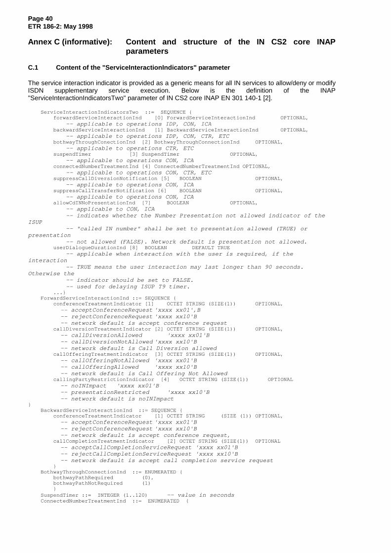
Page 40ETR 186-2: May 1998
Annex C (informative): Content and structure of the IN CS2 core INAPparameters
C.1 Content of the "ServiceInteractionIndicators" parameter
The service interaction indicator is provided as a generic means for all IN services to allow/deny or modifyISDN supplementary service execution. Below is the definition of the INAP"ServiceInteractionIndicatorsTwo" parameter of IN CS2 core INAP EN 301 140-1 [2].
ServiceInteractionIndicatorsTwo ::= SEQUENCE {forwardServiceInteractionInd [0] ForwardServiceInteractionInd OPTIONAL,
-- applicable to operations IDP, CON, ICAbackwardServiceInteractionInd [1] BackwardServiceInteractionInd OPTIONAL,
-- applicable to operations IDP, CON, CTR, ETCbothwayThroughConectionInd [2] BothwayThroughConnectionInd OPTIONAL,
-- applicable to operations CTR, ETCsuspendTimer [3] SuspendTimer OPTIONAL,
-- applicable to operations CON, ICAconnectedNumberTreatmentInd [4] ConnectedNumberTreatmentInd OPTIONAL,
-- applicable to operations CON, CTR, ETCsuppressCallDiversionNotification [5] BOOLEAN OPTIONAL,
-- applicable to operations CON, ICAsuppressCallTransferNotification [6] BOOLEAN OPTIONAL,
-- applicable to operations CON, ICAallowCdINNoPresentationInd [7] BOOLEAN OPTIONAL,
-- applicable to CON, ICA-- indicates whether the Number Presentation not allowed indicator of the
ISUP-- "called IN number" shall be set to presentation allowed (TRUE) or
presentation-- not allowed (FALSE). Network default is presentation not allowed.
userDialogueDurationInd [8] BOOLEAN DEFAULT TRUE-- applicable when interaction with the user is required, if the
interaction-- TRUE means the user interaction may last longer than 90 seconds.
Otherwise the-- indicator should be set to FALSE.-- used for delaying ISUP T9 timer.
...}ForwardServiceInteractionInd ::= SEQUENCE {
conferenceTreatmentIndicator [1] OCTET STRING (SIZE(1)) OPTIONAL, -- acceptConferenceRequest 'xxxx xx01',B -- rejectConferenceRequest 'xxxx xx10'B -- network default is accept conference requestcallDiversionTreatmentIndicator [2] OCTET STRING (SIZE(1)) OPTIONAL, -- callDiversionAllowed 'xxxx xx01'B -- callDiversionNotAllowed 'xxxx xx10'B -- network default is Call Diversion allowedcallOfferingTreatmentIndicator [3] OCTET STRING (SIZE(1)) OPTIONAL, -- callOfferingNotAllowed 'xxxx xx01'B -- callOfferingAllowed 'xxxx xx10'B -- network default is Call Offering Not AllowedcallingPartyRestrictionIndicator [4] OCTET STRING (SIZE(1)) OPTIONAL -- noINImpact 'xxxx xx01'B -- presentationRestricted 'xxxx xx10'B -- network default is noINImpact
}BackwardServiceInteractionInd ::= SEQUENCE {
conferenceTreatmentIndicator [1] OCTET STRING (SIZE (1)) OPTIONAL, -- acceptConferenceRequest 'xxxx xx01'B -- rejectConferenceRequest 'xxxx xx10'B -- network default is accept conference request,callCompletionTreatmentIndicator [2] OCTET STRING (SIZE(1)) OPTIONAL -- acceptCallCompletionServiceRequest 'xxxx xx01'B -- rejectCallCompletionServiceRequest 'xxxx xx10'B -- network default is accept call completion service request}
BothwayThroughConnectionInd ::= ENUMERATED {bothwayPathRequired (0),bothwayPathNotRequired (1)}
SuspendTimer ::= INTEGER (1..120) -- value in secondsConnectedNumberTreatmentInd ::= ENUMERATED {

Page 41ETR 186-2: May 1998
noINImpact (0),presentationRestricted (1),presentCalledINNumber (2),presentCalledINNumberRestricted (3)}
C.2 Content of the " INServiceCompatibilityIndication " parameter
The IN CS2 core INAP coding of the indicator is planned as follows:
INServiceCompatibilityIndication ::= SEQUENCESize (1 .. maxINServiceCompatibilityIndLength) of SEQUENCE
{agreements [0] SEQUENCE
Size (1 .. maxAgreementslength) of Entry OPTIONAL,networkSpecific [1] SEQUENCE
Size (1 .. maxNetworkSpecificlength) of Entry OPTIONAL }
Entry ::= INTEGER
One entry denotes one ServiceCompatibilityID. There may be more than oneServiceCompatibilityID carried within a message, the maximum number is for further study.

Page 42ETR 186-2: May 1998
Annex D (informative): Proposal for mid-call processing
D.1 Coding proposal for IE to request/withdrawal of the specific midcall events
A new "IN Service Control Request Indicators" is proposed to be introduced for request/ withdrawal of thespecific mid-call events. This information element can be sent backward in a CPG, ACM, ANM, CONmessage and in forward direction in an IAM and CPG (or new?) message to the local exchange. It is usedto transfer information concerning ISDN Basic Rate Interface (BRI), Premary Rate Interface (PRI) as wellas analogue user.
Coding proposal for "IN Service Control Request Indicators":
Byte Bits Explanation------ ----- ----------------
00 0-7 Parameter Namevalue = ??H
01 0-7 Length Indicator (=1)
02 0-1 IN Service Control Information0 - do not monitor midcall events1 - monitor hook-flash event2 - monitor control codes3 - spare
2-6 spare7 extension bit
D.2 Coding proposal for IE to transfer the detected midcall information
A new "IN Service Control Information Indicators" is introduced to transfer the detected mid-callinformation, if previously requested. This information element should be transferred in a CPG (or new?)message. Midcall events are initiated by keypad for BRI/PRI or hookflash for analogue users followed byadditional input of digits.
Coding proposal of "IN Service Control Information Indicators":
Byte Bits Explanation------ ----- ----------------
00 0-7 Parameter Namevalue = ??H
02 0-7 Length Indicator (variable)
03 IN Service Control Code Information0-2 Number of control code digits
Range (0:6)3-7 spare
04 IN Service Control Code0-3 1st digit
(Range 0:15)4-7 2nd digit
(Range 0:15)......k 0-3 nth digit
(Range 0:15)4-7 Filler

Page 43ETR 186-2: May 1998
The coding of the compatibility information for the new information elements is proposed as follows:
a) Nth upgraded parameter namexxxx xxxx IN Service Control Information Indicators
orxxxx xxxx IN Service Control Request Indicators
b) Instruction indicatorsbit A: Transit at intermediate exchange indicator0 transit interpretation
bit B: Release Call Indicator0 do not release call
bit C: Send notification indicator0 do not send notification
bit D: Discard message indicator0 do not discard message (pass on)
bit E: Discard parameter indicator0 do not discard parameter (pass on)
bit GF: Pass on not possible indicator10 discard parameter

Page 44ETR 186-2: May 1998
Annex E (informative): Message sequence charts for GVNS calls
E.1 GVNS: Outgoing call
SCP LE
TESSP
IAM
IDP
RRB(DP7)+CON
ACM IAM
ACM
ANM
CPG
ANM
RELREL
:
X
X
0
00
:
TANS
TACM
1
2X
ERB(DP7)
3
4
1) Call setup from local exchange (LE) and establishment of IN control relationship;
2) Response from SCP and continuation of call setup to transit exchange (TE, i.e. gateway exchange):
- outgoing ISUP:IAM contains Forward GVNS parameter as received in INAP:CON;
- DP7: o_Answer is armed (EDP-N) in the SSP in order to monitor the receipt of ISUP:ANM(and ISUP:CON respectively);
3) On receipt of ISUP:ANM (and ISUP:CON respectively) the service logic is informed via INAP:ERB.The ERB contains the Backward GVNS parameter as received in ISUP:ANM (and ISUP:CONrespectively);
4) Call release.
NOTE: Charging aspects are not considered in the information flow. Also arming of additionalEDPs or requests for reports (e.g. CIR) is not considered.

Page 45ETR 186-2: May 1998
E.2 GVNS: Incoming call
SCP LE
TESSP
IAM
IDP
CON
ACMIAM
ACM
ANM
CPG
ANM
RELREL
:
X
X
0
00
:
TANS
TACM
1
2X
3
4
1) Call setup from transit exchange (TE, i.e. gateway exchange) and establishment of IN controlrelationship:
INAP:IDP contains the Forward GVNS parameter as received in the incoming ISUP:IAM;
2) Response from SCP and continuation of call setup to local exchange (LE):
- INAP:CON contains the Backward GVNS parameter which is to be transferred to theoriginating network in the ISUP:ANM (and ISUP:CON respectively);
- outgoing ISUP:IAM contains no GVNS specific parameter;
3) SSP relays the ISUP:ANM (and ISUP:CON respectively) received from the LE to the TE includingthe Backward GVNS parameter as received from the service logic;
4) Call release.
NOTE: Charging aspects are not considered in the information flow. Also arming of additionalEDPs or requests for reports (e.g. CIR) is not considered.

Page 46ETR 186-2: May 1998
History
Document history
May 1998 First Edition
ISBN 2-7437-2173-1Dépôt légal : Mai 1998
Related Documents