Industrial Serial Device Server 1. Quick Start Guide This quick start guide describes how to install and use the Industrial Serial Device Server. Capable of operating at temperature extremes of -10 ℃ to +60℃, this is the Serial Device Server of choice for harsh environments constrained by space. 1.1. Physical Description 1.1.1. The Port Status LEDs and Power Inputs LED State Indication Steady Serial Device Server is not located by Xport utility yet. Status (Orange) Flashing Serial Device Server has been located by Xport utility. Ethernet port: 10/100Base-TX, 100Base-FX Steady A valid Ethernet network connection establishe d. LAN1, LAN2 (Yellow) Flashing Transmitting or receiving data. Two Serial ports Steady A valid serial connection established. Port1 TX Port2 TX

Welcome message from author
This document is posted to help you gain knowledge. Please leave a comment to let me know what you think about it! Share it to your friends and learn new things together.
Transcript

8/15/2019 EtherWAN SE5302-00B User Manual
http://slidepdf.com/reader/full/etherwan-se5302-00b-user-manual 1/105
Industrial Serial Device Server
1
1. Quick Start Guide
This quick start guide describes how to install and use the
Industrial Serial Device Server. Capable of operating attemperature extremes of -10℃ to +60℃, this is the Serial
Device Server of choice for harsh environments constrainedby space.
1.1. Physical Description
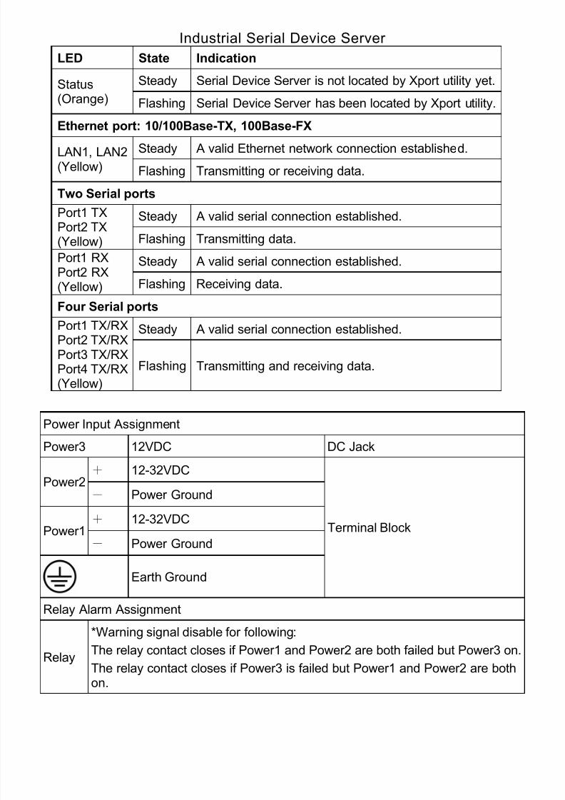
1.1.1. The Port Status LEDs and Power Inputs
LED State Indication
Steady Serial Device Server is not located by Xport utility yet.Status(Orange) Flashing Serial Device Server has been located by Xport utility.
Ethernet port: 10/100Base-TX, 100Base-FXSteady A valid Ethernet network connection established.LAN1, LAN2
(Yellow) Flashing Transmitting or receiving data.
Two Serial ports
Steady A valid serial connection established.Port1 TXPort2 TX(Yellow) Flashing Transmitting data.
Steady A valid serial connection established.Port1 RX
Port2 RX(Yellow) Flashing Receiving data.

8/15/2019 EtherWAN SE5302-00B User Manual
http://slidepdf.com/reader/full/etherwan-se5302-00b-user-manual 2/105
Industrial Serial Device Server
2
Four Serial ports
Steady A valid serial connection established.Port1 TX/RXPort2 TX/RXPort3 TX/RXPort4 TX/RX
(Yellow)
Flashing Transmitting and receiving data.
Power Input Assignment
Power3 12VDC DC Jack
+ 12-32VDCPower2
- Power Ground
+ 12-32VDCPower1
- Power Ground
Earth Ground
Terminal Block
Relay Alarm Assignment
Relay
*Warning signal disable for following:
The relay contact closes if Power1 and Power2 are both failed but Power3 on.
The relay contact closes if Power3 is failed but Power1 and Power2 are bothon.
There are Terminal Block and DC Jack power inputs can be
used to power up this device. Redundant power supplies
function is supported.

8/15/2019 EtherWAN SE5302-00B User Manual
http://slidepdf.com/reader/full/etherwan-se5302-00b-user-manual 3/105
Industrial Serial Device Server
3
1.1.2. DIN-Rail Kits and optional Panel MountingKits
8/15/2019 EtherWAN SE5302-00B User Manual
http://slidepdf.com/reader/full/etherwan-se5302-00b-user-manual 4/105
Industrial Serial Device Server
4
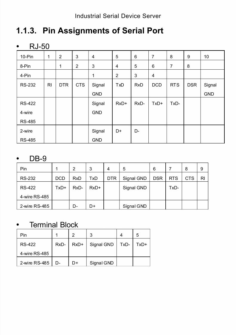
1.1.3. Pin Assignments of Serial Port
RJ-50
10-Pin 1 2 3 4 5 6 7 8 9 10
8-Pin 1 2 3 4 5 6 7 8
4-Pin 1 2 3 4
RS-232 RI DTR CTS Signal
GND
TxD RxD DCD RTS DSR Signal
GND
RS-422
4-wire
RS-485
Signal
GND
RxD+ RxD- TxD+ TxD-
2-wire
RS-485
Signal
GND
D+ D-
DB-9
Pin 1 2 3 4 5 6 7 8 9
RS-232 DCD RxD TxD DTR Signal GND DSR RTS CTS RI
RS-422
4-wire RS-485
TxD+ RxD- RxD+ Signal GND TxD-
2-wire RS-485 D- D+ Signal GND
Terminal Block
Pin 1 2 3 4 5
RS-422
4-wire RS-485
RxD- RxD+ Signal GND TxD- TxD+
2-wire RS-485 D- D+ Signal GND

8/15/2019 EtherWAN SE5302-00B User Manual
http://slidepdf.com/reader/full/etherwan-se5302-00b-user-manual 5/105
Industrial Serial Device Server
5
1.2. Functional Description
Flexible Serial Interface: DB9 and RJ50 for
RS-232/422/485 or Terminal Block for RS-422/485. Isolation: 2KV isolated RS-422/485. Dual LAN Ports: Support redundant function. Fiber Option: Support single-mode and multi-mode fiber
optical. Flexible Power Input: Including both Terminal Block and
DC Jack.
Latch: DC Jack with latch secures higher stability ofconnection.
Flexible Installation Method: Aluminum housing withpanel and DIN-Rail mounting.
Port Buffering: 64KB port buffer prevents data loss whenconnection fails.
Warning: Inform user by relay output and E-mail in case
of disconnection. Multiple Operation Mode: Support Virtual COM, TCP
Server, TCP Client, UDP, Pair Connection. Reset button:
Reboot device: Press Reset button for 0~10 secs,Status LED flashes every 500 msecs.
Default password: Press Reset button for 11~30
secs, Status LED flashes every 200 msecs. Factory default: Press Reset button for over 30
secs, Status LED flashes every 1 sec.

8/15/2019 EtherWAN SE5302-00B User Manual
http://slidepdf.com/reader/full/etherwan-se5302-00b-user-manual 6/105
Industrial Serial Device Server
6
1.3. Utility Configuration
Install Xport utility to the operating system of your
computer and follow the on-screen instructions to finishthe installation.
Double click the Xport icon on your computer screen to
launch the Xport utility.
Double click IP Address 192.168.1.10 on the Device List.
A web-based login window will be shown as below.

8/15/2019 EtherWAN SE5302-00B User Manual
http://slidepdf.com/reader/full/etherwan-se5302-00b-user-manual 7/105
Industrial Serial Device Server
7
1.4. Web Configuration
Login the Serial Device Server:
Specify the default IP address (192.168.1.10) of the SerialDevice Server in the web browser. A web-based login windowwill be shown as below:
Enter the factory default password: admin.
Then click on the “Submit” button to log on to the SerialDevice Server.
8/15/2019 EtherWAN SE5302-00B User Manual
http://slidepdf.com/reader/full/etherwan-se5302-00b-user-manual 8/105
Industrial Serial Device Server
8
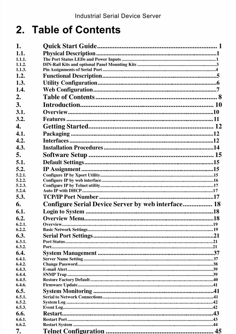
2. Table of Contents
1. Quick Start Guide..................................................................... 1 1.1.
Physical Description .................................................................................1
1.1.1. The Port Status LEDs and Power Inputs .....................................................................................1
1.1.2. DIN-Rail Kits and optional Panel Mounting Kits .......................................................................3
1.1.3
Pin Assignments of Serial Port ......................................................................................................4
.
1.2. Functional Description.............................................................................5
1.3. Utility Configuration................................................................................6
1.
Web Configuration...................................................................................7
4.
2. Table of Contents ...................................................................... 8
3. Introduction............................................................................. 10
3.1.
Overview..................................................................................................10
3.
Features ...................................................................................................11
2.
4.
Getting Started........................................................................ 12
4.1. Packaging ................................................................................................12
4.2.
Interfaces .................................................................................................12
4. Installation Procedures ..........................................................................14 3.
5.
Software Setup ........................................................................ 15
5.1. Default Settings.......................................................................................15
5.2.
IP Assignment .........................................................................................15
5.2.1. Configure IP by Xport Utility......................................................................................................15
5.2.2. Configure IP by web interface.....................................................................................................16
5.2.3. Configure IP by Telnet utility......................................................................................................17
5.2.4
Auto IP with DHCP......................................................................................................................17
.
5.3. TCP/IP Port Number .............................................................................17
6.
Configure Serial Device Server by web interface................. 18
6.1. Login to System ......................................................................................18
6.2.
Overview Menu.......................................................................................18
6.2.1. Overview........................................................................................................................................19
6.2.2 Basic Network Settings.................................................................................................................19 .
6.3.
Serial Port Settings.................................................................................21
6.3.1. Port Status.....................................................................................................................................21
6.3.2
Port.................................................................................................................................................21
.
6.4. System Management ..............................................................................37 6.4.1. Server Name Setting .....................................................................................................................37
6.4.2. Change Password..........................................................................................................................38
6.4.3. E-mail Alert ...................................................................................................................................39
6.4.4. SNMP Trap ...................................................................................................................................39
6.4.5. Restore Factory Default ...............................................................................................................40
6.4.6
Firmware Update..........................................................................................................................41
.
6.5.
System Monitoring .................................................................................41
6.5.1. Serial to Network Connections....................................................................................................41 6.5.2. System Log ....................................................................................................................................42
6.5.3
Event Log.......................................................................................................................................42
.
6.6. Restart......................................................................................................43 6.6.1. Restart Port ...................................................................................................................................43
6.6.2.
Restart System ..............................................................................................................................44
7. Telnet Configuration .............................................................. 45
7.1. Overview..................................................................................................46
7.2.
Basic Network Settings ..........................................................................46
7.3.
Serial Port Settings.................................................................................47
7.3.1. Port Status .....................................................................................................................................47
7.3.2. Operation Modes ..........................................................................................................................48
7.3.3.
Communication Parameters ........................................................................................................51

8/15/2019 EtherWAN SE5302-00B User Manual
http://slidepdf.com/reader/full/etherwan-se5302-00b-user-manual 9/105
Industrial Serial Device Server
9
7.3.4
Accessible IP List ..........................................................................................................................52
.
7.4. System Management ..............................................................................53 7.4.1. Server Name Setting .....................................................................................................................53
7.4.2. Change Password..........................................................................................................................54
7.4.3. E-mail Alert...................................................................................................................................54
7.4.4. SNMP Trap ...................................................................................................................................54
7.4.5 Restore Factory Default ...............................................................................................................54 .
7.5.
System Monitoring .................................................................................55 7.5.1. Serial to Network Connections ....................................................................................................55
7.5.2. System Log ....................................................................................................................................56
7.5.3 Event Log.......................................................................................................................................57 .
7.6.
Restart......................................................................................................57
7.6.1. Restart Port ...................................................................................................................................58
7.6.2. Restart System ..............................................................................................................................58
8.
Xport Utility ............................................................................ 59
8.1.
Xport Utility Introduction .....................................................................59
8.2.
Interface...................................................................................................59
8.3.
Device List ...............................................................................................59
8.3.1. Login to System by Web Interface ..............................................................................................59
8.3.2. Functions .......................................................................................................................................60
8.3.3. Serial port ......................................................................................................................................61
8.3.4 COM List.......................................................................................................................................66 .
8.4.
File............................................................................................................68
8.4.1. Logon .............................................................................................................................................68
8.4.2. Logoff.............................................................................................................................................69
8.4.3. Load utility setting........................................................................................................................69
8.4.4. Save utility setting.........................................................................................................................69
8.4.5
Exit .................................................................................................................................................70
.
8.5. Tools.........................................................................................................70 8.5.1. Auto-search ...................................................................................................................................71
8.5.2. Manual-search...............................................................................................................................71
8.5.3
Locate.............................................................................................................................................72
.
8.6. Setting ......................................................................................................72 8.6.1. Serial Port Settings .......................................................................................................................72
8.6.2. Basic Network Settings.................................................................................................................91
8.6.3. System Management.....................................................................................................................92
8.6.4 Utility Setting ................................................................................................................................94 .
8.7.
Monitoring...............................................................................................95
8.7.1. Port Status.....................................................................................................................................96
8.7.2 Logs ................................................................................................................................................96 .
8.8.
Restart......................................................................................................97
8.8.1. Restart Port ...................................................................................................................................98
8.8.2. Restart System ..............................................................................................................................98
8.8.3 Restart All Ports ...........................................................................................................................98 .
8.9.
COM ........................................................................................................99
8.9.1. Create a new COM port...............................................................................................................99
8.9.2. Remove all COM ports...............................................................................................................101
8.10.
Help ........................................................................................................101
9.
Specifications......................................................................... 103
9.1.
Hardware Specifications......................................................................103
9.2. Pin Assignments....................................................................................105
8/15/2019 EtherWAN SE5302-00B User Manual
http://slidepdf.com/reader/full/etherwan-se5302-00b-user-manual 10/105
Industrial Serial Device Server
10
3. Introduction
3.1. Overview
This Serial Device Server is a gateway between Ethernet(TCP/IP) and RS-232 / RS-422 / RS-485 communications. Itallows almost any serial device to be connected to a new orexisting Ethernet network. The information transmitted by thisSerial Device Server is transparent to both host computers (IPnetwork over Ethernet) and devices (RS-232 / RS-422 /
RS-485). Data from the Ethernet (TCP/IP) is transmitted tothe designated RS-232 / RS-422 / RS-485 port and data fromRS-232 / RS-422 / RS-485 port is transmitted to the Ethernet(TCP/IP) transparently.
In the computer integration manufacturing or industrialautomation area, Serial Device Server is used for field
devices to direct connect to network. Terminal Server (maincontrol program run in this Serial Device Server) transformswhatever data received from RS-232 / RS-422 / RS-485 toTCP/UDP port then connects devices to the IP network via asingle application program or multiple application programs.
Many control devices provide the ability to communicate with
hosts through RS-232 / RS-422 / RS-485 however RS-232 /RS-422 / RS-485 serial communication has its limitations. Forinstance, it is hard to transfer data through a long distance.With this Serial Device Server, it is possible to communicatewith a remote device in the Intranet environment or even inthe Internet and thus, increases the communication distancedramatically.
Flexible configuration options enable this unit to be setupremotely over IP network by Telnet, web browser, or Windowutility. Packed in a rugged DIN Rail mountable case and12~32V DC power input range, this Serial Device Server isideal for almost any industrial and manufacturing automation.

8/15/2019 EtherWAN SE5302-00B User Manual
http://slidepdf.com/reader/full/etherwan-se5302-00b-user-manual 11/105
Indu
3.2. Featuresstrial Serial Device Server
11
Flexible Serial Interface- Support 2 or 4 ports of RS-232 / 422 /485 or RS-422 / 485
Isolation- 2KV isolated RS-422 / 485 Dual LAN Ports- Support redundant function
The Ethernet port LAN1 will be the primary port andEthernet port LAN2 will be the backup port if bothEthernet port LAN1 and LAN2 are connected from SerialDevice Server to network when Serial Device Server ispowered on.
But the Ethernet port first connected from Serial Device
Server to network will remain the primary port if thisEthernet port is connected first before the other Ethernetport after Serial Device Server has been powered on.
Fiber Option- Support single-mode and multi-mode fiber opticsfor both LAN ports
Flexible Power Input- Including both terminal block and DC jack Latch- DC jack with latch secures a stable connection Flexible Installation Method- Aluminum housing with panel and
DIN-Rail mounting Port Buffering- 64KB port buffer prevents data loss when
connection fails Warning- Inform user by relay output and E-mail in case of
disconnection Multiple Operation Mode- Support Real COM, TCP server, TCP
client, UDP, Pair Connection
Reset button: Reboot device: Press Reset button for 0~10 secs, Status
LED flashes every 500 msecs. Default password: Press Reset button for 11~30 secs,
Status LED flashes every 200 msecs. Factory default: Press Reset button for over 30 secs,
Status LED flashes every 1 sec.
8/15/2019 EtherWAN SE5302-00B User Manual
http://slidepdf.com/reader/full/etherwan-se5302-00b-user-manual 12/105
Industrial Serial Device Server
12
4. Getting Started
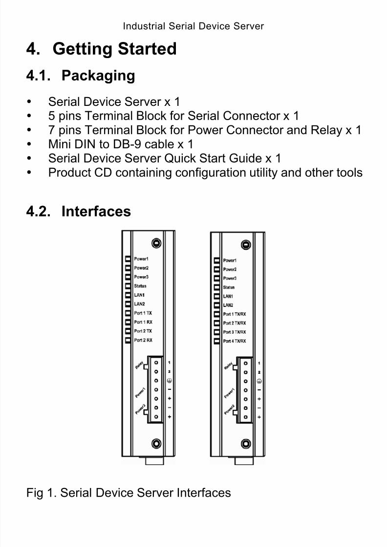
4.1. Packaging
Serial Device Server x 1 5 pins Terminal Block for Serial Connector x 1 7 pins Terminal Block for Power Connector and Relay x 1 Mini DIN to DB-9 cable x 1 Serial Device Server Quick Start Guide x 1 Product CD containing configuration utility and other tools
4.2. Interfaces
Fig 1. Serial Device Server Interfaces
8/15/2019 EtherWAN SE5302-00B User Manual
http://slidepdf.com/reader/full/etherwan-se5302-00b-user-manual 13/105
Industrial Serial Device Server
13
LED State Indication
Steady Serial Device Server is not located by Xport utility yet.Status(Orange) Flashing Serial Device Server has been located by Xport utility.
Ethernet port: 10/100Base-TX, 100Base-FX
Steady A valid Ethernet network connection established.LAN1, LAN2(Yellow) Flashing Transmitting or receiving data.
Two Serial ports
Steady A valid serial connection established.Port1 TXPort2 TX(Yellow) Flashing Transmitting data.
Steady A valid serial connection established.Port1 RXPort2 RX(Yellow) Flashing Receiving data.
Four Serial ports
Steady A valid serial connection established.Port1 TX/RXPort2 TX/RXPort3 TX/RXPort4 TX/RX(Yellow)
Flashing Transmitting and receiving data.
Power Input Assignment
Power3 12VDC DC Jack
+ 12-32VDCPower2
- Power Ground
+ 12-32VDCPower1
- Power Ground
Earth Ground
Terminal Block
Relay Alarm Assignment
Relay
*Warning signal disable for following:
The relay contact closes if Power1 and Power2 are both failed but Power3 on.
The relay contact closes if Power3 is failed but Power1 and Power2 are bothon.
8/15/2019 EtherWAN SE5302-00B User Manual
http://slidepdf.com/reader/full/etherwan-se5302-00b-user-manual 14/105
Industrial Serial Device Server
14
4.3. Installation Procedures
Prepare necessary cables, DC power adapter and serial
connector. Connect Serial Device Server to Ethernet cable with RJ45connector.
Connect serial port of Serial Device Server to serialdevice, make sure the connector and wiring of RS-232 iscorrect.
Plug in Serial Device Server to 12-32VDC power source
(3-pin terminal bock connector) or 12VDC power source(DC jack connector).
Use Xport utility on the product CD to check the status ofSerial Device Server. If it starts up successfully, user shallfind the IP and MAC address of Serial Device Server. Usercan change IP address, gateway IP address and subnet mask
networking parameters of Serial Device Server according touser networking configurations.
8/15/2019 EtherWAN SE5302-00B User Manual
http://slidepdf.com/reader/full/etherwan-se5302-00b-user-manual 15/105
Industrial Serial Device Server
15
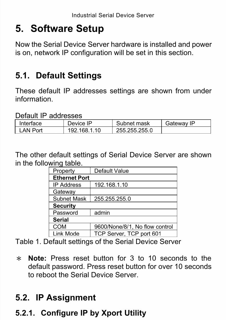
5. Software Setup
Now the Serial Device Server hardware is installed and power
is on, network IP configuration will be set in this section.
5.1. Default Settings
These default IP addresses settings are shown from underinformation.
Default IP addressesInterface Device IP Subnet mask Gateway IP
LAN Port 192.168.1.10 255.255.255.0
The other default settings of Serial Device Server are shownin the following table.
Property Default Value
Ethernet Port
IP Address 192.168.1.10
Gateway
Subnet Mask 255.255.255.0
Security
Password admin
Serial
COM 9600/None/8/1, No flow control
Link Mode TCP Server, TCP port 601
Table 1. Default settings of the Serial Device Server
* Note: Press reset button for 3 to 10 seconds to thedefault password. Press reset button for over 10 secondsto reboot the Serial Device Server.
5.2. IP Assignment
5.2.1. Configure IP by Xport Utility
Use Xport utility that comes with product CD or diskette to
configure the network parameters.
Find new device and IP assignment

8/15/2019 EtherWAN SE5302-00B User Manual
http://slidepdf.com/reader/full/etherwan-se5302-00b-user-manual 16/105
Industrial Serial Device Server
16
Use Xport Utility for finding new device IP address, getdevice’s current IP from Device List.
Re-assigned IP, network mask and gateway if need withXport Utility.
User can configure Password and Server Name withXport Utility.
Fig 2. IP settings for Xport Utility tool
5.2.2. Configure IP by web interface
Use common Web browser, ex. Microsoft Internet Explorer orMozilla Firefox, to configure the network parameters of SerialDevice Server. Open web browser, type in the IP address (default IP:
192.168.1.10) of Serial Device Server to be configured.Default password is admin.
Configure IP settings from web Network links page then
click “Submit” to save settings. Click on ”Restart” button to reboot the Serial Device
8/15/2019 EtherWAN SE5302-00B User Manual
http://slidepdf.com/reader/full/etherwan-se5302-00b-user-manual 17/105
Industrial Serial Device Server
17
Server.
5.2.3. Configure IP by Telnet utility
Use common Telnet utility, ex. Microsoft Command Prompt orHyper-terminal, to configure the network parameters of SerialDevice Server. Run command telnet “IP address” to telnet to Serial
Device Server. Default IP address is 192.168.1.10 anddefault password is admin.
Configure IP settings from Basic Network Settings menu,and restart system after saved settings.
5.2.4. Auto IP with DHCP
DHCP server will automatically supply an IP address,
gateway address, and subnet mask to Serial Device Server.By default, the DHCP client function on Serial Device Serveris disabled, user can activate the DHCP functions by thefollowing steps.
Execute Xport Utility Click on the IP address (of Serial Device Server)
Click “Basic Network Settings” from “Setting” to pop-upthe Network setting Window
Check ”DHCP” Click “Update” (The Serial Device Server will restart and
obtain the IP from the DHCP server automatically)
5.3. TCP/IP Port Number
Default Port number of Serial Device Server is 601 (1st port)
and it can be associated with the serial COM port of hostcomputer by using Xport utility. After the application programbeing connected to the TCP port 601 on the Serial DeviceServer, data of user’s application program are transmitted
transparently to Serial Device Server and vice versa.

8/15/2019 EtherWAN SE5302-00B User Manual
http://slidepdf.com/reader/full/etherwan-se5302-00b-user-manual 18/105
Industrial Serial Device Server
6. Configure Serial Device Server byweb interface
User has to assign IP address to Serial Device Server before
working on web configuration operations.
6.1. Login to System
Open one of the web browsers, ex. Microsoft IE or Firefox etc.Enter the IP address of Serial Device Server on the URL.
Example: http://192.168.1.10
The following authentication screen shall appear. Enterpassword then click on “Submit”. The default password is“admin”.
Fig 3. Authorization request for system securityThe overview screen shall appear (Fig. 4).
6.2. Overview Menu
18
This system overview window gives the general informationon Serial Device Server that includes Overview and Basic

8/15/2019 EtherWAN SE5302-00B User Manual
http://slidepdf.com/reader/full/etherwan-se5302-00b-user-manual 19/105
Industrial Serial Device Server
19
Network Settings.
Fig 4. Overview for system information by Web Interface
6.2.1. Overview
Serial Device Server’s system information includes model
name, Server Name, Serial No., Firmware version, IPaddress, MAC address, LAN speed, and Up time. Theinformation is read only and is attributed from another settingpage or system status.
Fig 5. Device Information from Overview web page
6.2.2. Basic Network Settings
There are two sections allowed to be changed on Basic
Network Settings page that includes Network Settings andTime Settings.
8/15/2019 EtherWAN SE5302-00B User Manual
http://slidepdf.com/reader/full/etherwan-se5302-00b-user-manual 20/105
Industrial Serial Device Server
20
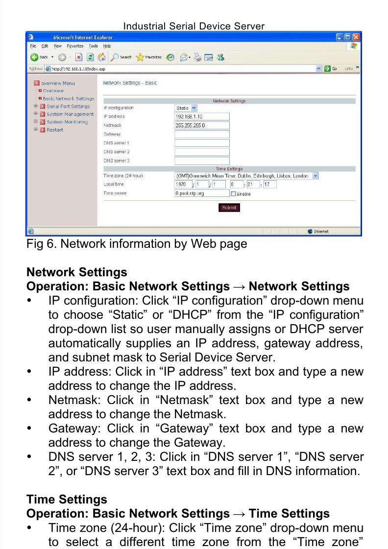
Fig 6. Network information by Web page
Network Settings
Operation: Basic Network Settings→ Network Settings IP configuration: Click “IP configuration” drop-down menu
to choose “Static” or “DHCP” from the “IP configuration”drop-down list so user manually assigns or DHCP serverautomatically supplies an IP address, gateway address,and subnet mask to Serial Device Server.
IP address: Click in “IP address” text box and type a new
address to change the IP address. Netmask: Click in “Netmask” text box and type a new
address to change the Netmask. Gateway: Click in “Gateway” text box and type a new
address to change the Gateway. DNS server 1, 2, 3: Click in “DNS server 1”, “DNS server
2”, or “DNS server 3” text box and fill in DNS information.
Time SettingsOperation: Basic Network Settings→ Time Settings Time zone (24-hour): Click “Time zone” drop-down menu
to select a different time zone from the “Time zone”drop-down list.
Local time: Click in “Local time” text box to set date andtime the Serial Device Server.
Time server: Click in “Time server” text box to enter Time

8/15/2019 EtherWAN SE5302-00B User Manual
http://slidepdf.com/reader/full/etherwan-se5302-00b-user-manual 21/105
Industrial Serial Device Server
21
server address for the Serial Device Server. And check“Enable” to enable this setting.
Click “Submit” button when you finished Basic Network
Settings.
6.3. Serial Port Settings
Here User can configure Serial Port Settings that includesPort Status and Port defined by user.
Fig 7. Port Status Web Page
6.3.1. Port Status
Click on the “Port Status” link from “Serial Port Settings” andthe Fig 7. screen will appear.
6.3.2. Port
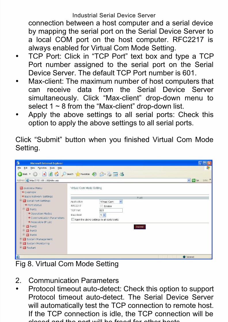
Virtual Com Mode SettingThe Xport utility map a serial port to a COM port on a PC.
1. Operation Modes Application: Click “Application” drop-down menu to select
“Virtual Com” from the “Application” drop-down list. RFC2217: RFC2217 is used to establish a transparent
8/15/2019 EtherWAN SE5302-00B User Manual
http://slidepdf.com/reader/full/etherwan-se5302-00b-user-manual 22/105
Industrial Serial Device Server
22
connection between a host computer and a serial deviceby mapping the serial port on the Serial Device Server toa local COM port on the host computer. RFC2217 isalways enabled for Virtual Com Mode Setting.
TCP Port: Click in “TCP Port” text box and type a TCPPort number assigned to the serial port on the SerialDevice Server. The default TCP Port number is 601.
Max-client: The maximum number of host computers thatcan receive data from the Serial Device Serversimultaneously. Click “Max-client” drop-down menu toselect 1 ~ 8 from the “Max-client” drop-down list.
Apply the above settings to all serial ports: Check thisoption to apply the above settings to all serial ports.
Click “Submit” button when you finished Virtual Com ModeSetting.
Fig 8. Virtual Com Mode Setting
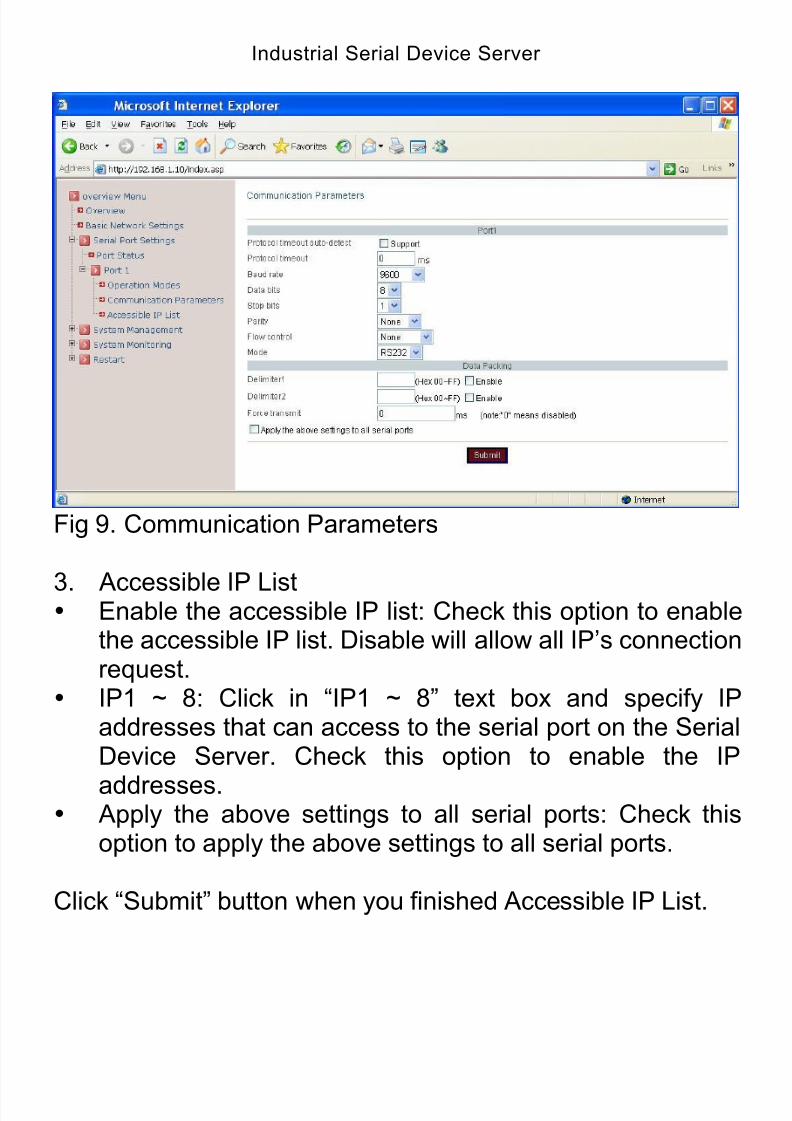
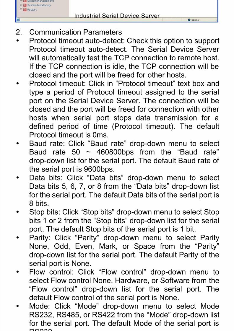
2. Communication Parameters Protocol timeout auto-detect: Check this option to support
Protocol timeout auto-detect. The Serial Device Serverwill automatically test the TCP connection to remote host.If the TCP connection is idle, the TCP connection will beclosed and the port will be freed for other hosts.
Protocol timeout: Click in “Protocol timeout” text box and
type a period of Protocol timeout assigned to the serialport on the Serial Device Server. The connection will beclosed and the port will be freed for connection with other

8/15/2019 EtherWAN SE5302-00B User Manual
http://slidepdf.com/reader/full/etherwan-se5302-00b-user-manual 23/105
Industrial Serial Device Server
23
hosts when serial port stops data transmission for adefined period of time (Protocol timeout). The defaultProtocol timeout is 0ms.
Baud rate: Click “Baud rate” drop-down menu to select
Baud rate 50 ~ 460800bps from the “Baud rate”drop-down list for the serial port. The default Baud rate ofthe serial port is 9600bps.
Data bits: Click “Data bits” drop-down menu to selectData bits 5, 6, 7, or 8 from the “Data bits” drop-down listfor the serial port. The default Data bits of the serial port is8 bits.
Stop bits: Click “Stop bits” drop-down menu to select Stopbits 1 or 2 from the “Stop bits” drop-down list for the serialport. The default Stop bits of the serial port is 1 bit.
Parity: Click “Parity” drop-down menu to select ParityNone, Odd, Even, Mark, or Space from the “Parity”drop-down list for the serial port. The default Parity of theserial port is None.
Flow control: Click “Flow control” drop-down menu toselect Flow control None, Hardware, or Software from the“Flow control” drop-down list for the serial port. Thedefault Flow control of the serial port is None.
Mode: Click “Mode” drop-down menu to select ModeRS232, RS485, or RS422 from the “Mode” drop-down list
for the serial port. The default Mode of the serial port isRS232. Delimiter1, 2: Click in “Delimiter1, 2” text box and
Delimiter1, 2 assigned to the serial port on the SerialDevice Server. Check this option to enable Delimiter1, 2.The data will be transmitted if the Delimiter1 is received orDelimiter1 and Delimiter2 are received.
Force transmit: Click in “Force transmit” text box andspecify Force transmit to the serial port on the SerialDevice Server. The data will be transmitted when theForce transmit is reached. The default Force transmit ofthe serial port is 0 to disable Force transmit.
Apply the above settings to all serial ports: Check thisoption to apply the above settings to all serial ports.
Click “Submit” button when you finished CommunicationParameters.
8/15/2019 EtherWAN SE5302-00B User Manual
http://slidepdf.com/reader/full/etherwan-se5302-00b-user-manual 24/105
Industrial Serial Device Server
24
Fig 9. Communication Parameters
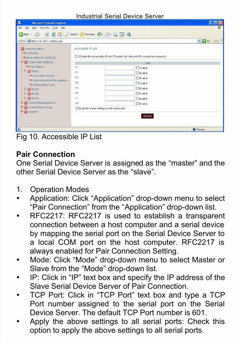
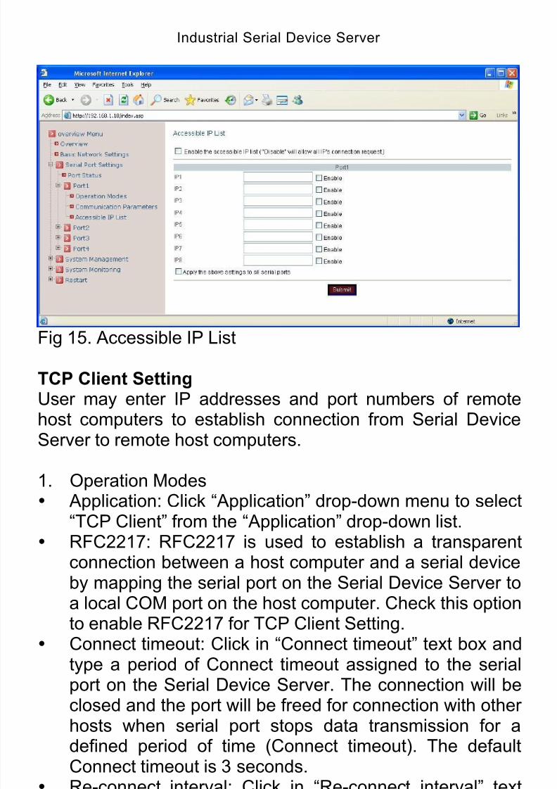
3. Accessible IP List Enable the accessible IP list: Check this option to enable
the accessible IP list. Disable will allow all IP’s connectionrequest.
IP1 ~ 8: Click in “IP1 ~ 8” text box and specify IPaddresses that can access to the serial port on the SerialDevice Server. Check this option to enable the IP
addresses. Apply the above settings to all serial ports: Check this
option to apply the above settings to all serial ports.
Click “Submit” button when you finished Accessible IP List.
8/15/2019 EtherWAN SE5302-00B User Manual
http://slidepdf.com/reader/full/etherwan-se5302-00b-user-manual 25/105
Industrial Serial Device Server
25
Fig 10. Accessible IP List
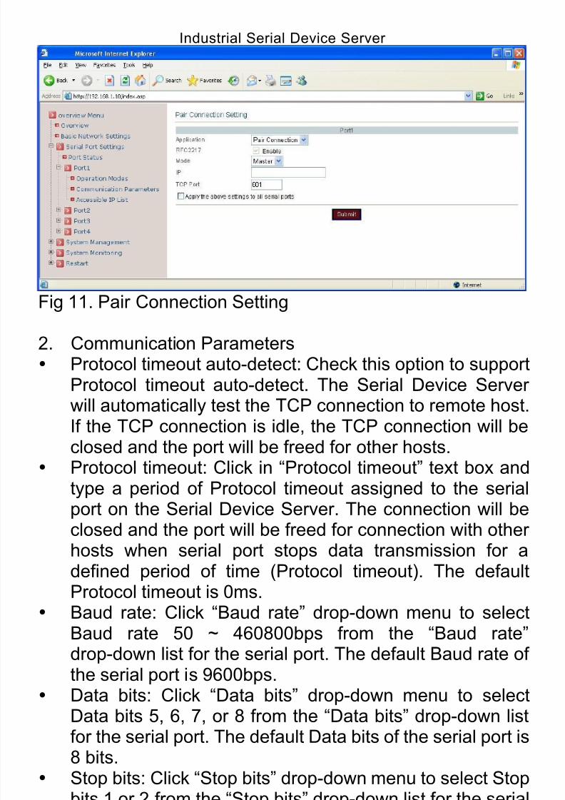
Pair ConnectionOne Serial Device Server is assigned as the “master” and theother Serial Device Server as the “slave”.
1. Operation Modes Application: Click “Application” drop-down menu to select
“Pair Connection” from the “Application” drop-down list. RFC2217: RFC2217 is used to establish a transparent
connection between a host computer and a serial deviceby mapping the serial port on the Serial Device Server toa local COM port on the host computer. RFC2217 isalways enabled for Pair Connection Setting.
Mode: Click “Mode” drop-down menu to select Master orSlave from the “Mode” drop-down list.
IP: Click in “IP” text box and specify the IP address of theSlave Serial Device Server of Pair Connection.
TCP Port: Click in “TCP Port” text box and type a TCPPort number assigned to the serial port on the Serial
Device Server. The default TCP Port number is 601. Apply the above settings to all serial ports: Check this
option to apply the above settings to all serial ports.
Click “Submit” button when you finished Pair Connection
Setting.
8/15/2019 EtherWAN SE5302-00B User Manual
http://slidepdf.com/reader/full/etherwan-se5302-00b-user-manual 26/105
Industrial Serial Device Server
26
Fig 11. Pair Connection Setting
2. Communication Parameters Protocol timeout auto-detect: Check this option to support
Protocol timeout auto-detect. The Serial Device Serverwill automatically test the TCP connection to remote host.
If the TCP connection is idle, the TCP connection will beclosed and the port will be freed for other hosts.
Protocol timeout: Click in “Protocol timeout” text box andtype a period of Protocol timeout assigned to the serialport on the Serial Device Server. The connection will beclosed and the port will be freed for connection with otherhosts when serial port stops data transmission for adefined period of time (Protocol timeout). The defaultProtocol timeout is 0ms.
Baud rate: Click “Baud rate” drop-down menu to selectBaud rate 50 ~ 460800bps from the “Baud rate”drop-down list for the serial port. The default Baud rate ofthe serial port is 9600bps.
Data bits: Click “Data bits” drop-down menu to selectData bits 5, 6, 7, or 8 from the “Data bits” drop-down list
for the serial port. The default Data bits of the serial port is8 bits.
Stop bits: Click “Stop bits” drop-down menu to select Stopbits 1 or 2 from the “Stop bits” drop-down list for the serialport. The default Stop bits of the serial port is 1 bit.
Parity: Click “Parity” drop-down menu to select ParityNone, Odd, Even, Mark, or Space from the “Parity”drop-down list for the serial port. The default Parity of the

8/15/2019 EtherWAN SE5302-00B User Manual
http://slidepdf.com/reader/full/etherwan-se5302-00b-user-manual 27/105
Industrial Serial Device Server
27
serial port is None. Flow control: Click “Flow control” drop-down menu to
select Flow control None, Hardware, or Software from the“Flow control” drop-down list for the serial port. The
default Flow control of the serial port is None. Mode: Click “Mode” drop-down menu to select Mode
RS232, RS485, or RS422 from the “Mode” drop-down listfor the serial port. The default Mode of the serial port isRS232.
Delimiter1, 2: Click in “Delimiter1, 2” text box andDelimiter1, 2 assigned to the serial port on the Serial
Device Server. Check this option to enable Delimiter1, 2.The data will be transmitted if the Delimiter1 is received orDelimiter1 and Delimiter2 are received.
Force transmit: Click in “Force transmit” text box andspecify Force transmit to the serial port on the SerialDevice Server. The data will be transmitted when theForce transmit is reached. The default Force transmit ofthe serial port is 0 to disable Force transmit.
Apply the above settings to all serial ports: Check thisoption to apply the above settings to all serial ports.
Click “Submit” button when you finished CommunicationParameters.
Fig 12. Communication Parameters
8/15/2019 EtherWAN SE5302-00B User Manual
http://slidepdf.com/reader/full/etherwan-se5302-00b-user-manual 28/105
Industrial Serial Device Server
28
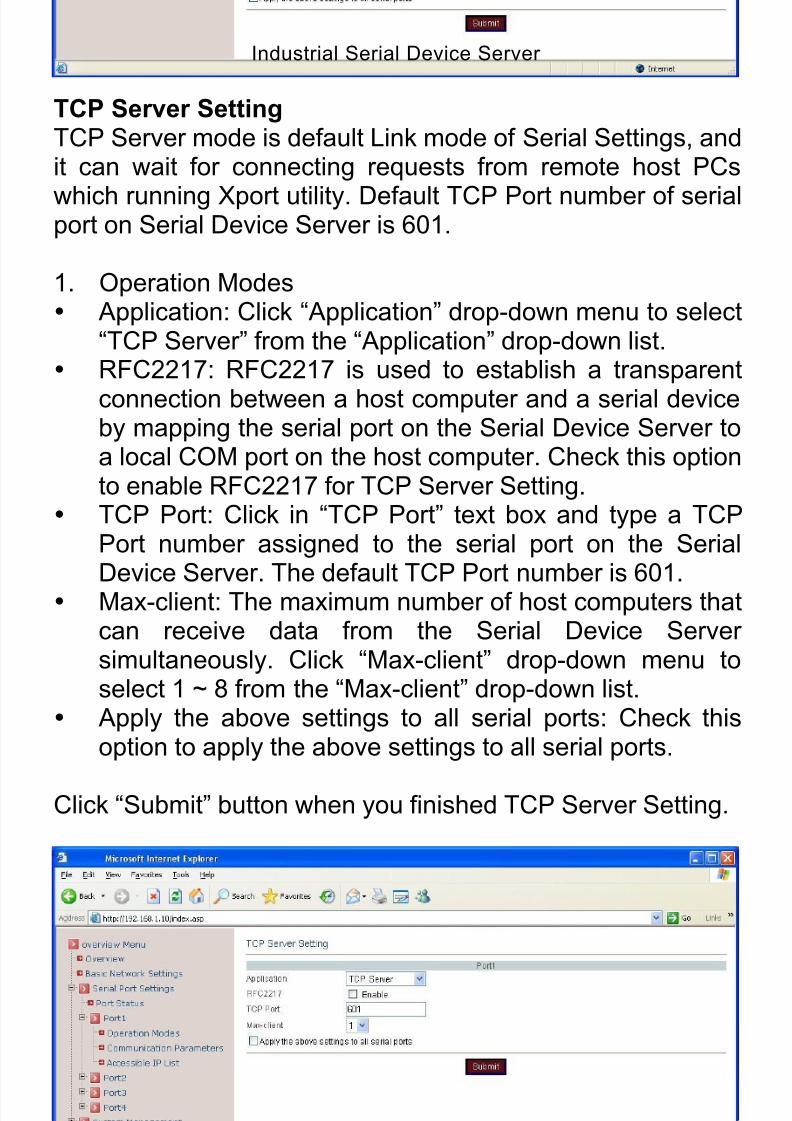
TCP Server SettingTCP Server mode is default Link mode of Serial Settings, andit can wait for connecting requests from remote host PCs
which running Xport utility. Default TCP Port number of serialport on Serial Device Server is 601.
1. Operation Modes Application: Click “Application” drop-down menu to select
“TCP Server” from the “Application” drop-down list. RFC2217: RFC2217 is used to establish a transparent
connection between a host computer and a serial deviceby mapping the serial port on the Serial Device Server toa local COM port on the host computer. Check this optionto enable RFC2217 for TCP Server Setting.
TCP Port: Click in “TCP Port” text box and type a TCPPort number assigned to the serial port on the SerialDevice Server. The default TCP Port number is 601.
Max-client: The maximum number of host computers thatcan receive data from the Serial Device Serversimultaneously. Click “Max-client” drop-down menu toselect 1 ~ 8 from the “Max-client” drop-down list.
Apply the above settings to all serial ports: Check thisoption to apply the above settings to all serial ports.
Click “Submit” button when you finished TCP Server Setting.
Fig 13. TCP Server Setting
8/15/2019 EtherWAN SE5302-00B User Manual
http://slidepdf.com/reader/full/etherwan-se5302-00b-user-manual 29/105
Industrial Serial Device Server
29
2. Communication Parameters Protocol timeout auto-detect: Check this option to support
Protocol timeout auto-detect. The Serial Device Server
will automatically test the TCP connection to remote host.If the TCP connection is idle, the TCP connection will beclosed and the port will be freed for other hosts.
Protocol timeout: Click in “Protocol timeout” text box andtype a period of Protocol timeout assigned to the serialport on the Serial Device Server. The connection will beclosed and the port will be freed for connection with other
hosts when serial port stops data transmission for adefined period of time (Protocol timeout). The defaultProtocol timeout is 0ms.
Baud rate: Click “Baud rate” drop-down menu to selectBaud rate 50 ~ 460800bps from the “Baud rate”drop-down list for the serial port. The default Baud rate ofthe serial port is 9600bps.
Data bits: Click “Data bits” drop-down menu to selectData bits 5, 6, 7, or 8 from the “Data bits” drop-down listfor the serial port. The default Data bits of the serial port is8 bits.
Stop bits: Click “Stop bits” drop-down menu to select Stopbits 1 or 2 from the “Stop bits” drop-down list for the serial
port. The default Stop bits of the serial port is 1 bit. Parity: Click “Parity” drop-down menu to select Parity
None, Odd, Even, Mark, or Space from the “Parity”drop-down list for the serial port. The default Parity of theserial port is None.
Flow control: Click “Flow control” drop-down menu toselect Flow control None, Hardware, or Software from the
“Flow control” drop-down list for the serial port. Thedefault Flow control of the serial port is None.
Mode: Click “Mode” drop-down menu to select ModeRS232, RS485, or RS422 from the “Mode” drop-down listfor the serial port. The default Mode of the serial port isRS232.
Delimiter1, 2: Click in “Delimiter1, 2” text box and
Delimiter1, 2 assigned to the serial port on the SerialDevice Server. Check this option to enable Delimiter1, 2.The data will be transmitted if the Delimiter1 is received or
8/15/2019 EtherWAN SE5302-00B User Manual
http://slidepdf.com/reader/full/etherwan-se5302-00b-user-manual 30/105
Industrial Serial Device Server
30
Delimiter1 and Delimiter2 are received. Force transmit: Click in “Force transmit” text box and
specify Force transmit to the serial port on the SerialDevice Server. The data will be transmitted when the
Force transmit is reached. The default Force transmit ofthe serial port is 0 to disable Force transmit.
Apply the above settings to all serial ports: Check thisoption to apply the above settings to all serial ports.
Click “Submit” button when you finished CommunicationParameters.
Fig 14. Communication Parameters
3. Accessible IP List Enable the accessible IP list: Check this option to enable
the accessible IP list. Disable will allow all IP’s connection
request. IP1 ~ 8: Click in “IP1 ~ 8” text box and specify IP
addresses that can access to the serial port on the SerialDevice Server. Check this option to enable the IPaddresses.
Apply the above settings to all serial ports: Check thisoption to apply the above settings to all serial ports.
Click “Submit” button when you finished Accessible IP List.
8/15/2019 EtherWAN SE5302-00B User Manual
http://slidepdf.com/reader/full/etherwan-se5302-00b-user-manual 31/105
Industrial Serial Device Server
31
Fig 15. Accessible IP List
TCP Client SettingUser may enter IP addresses and port numbers of remote
host computers to establish connection from Serial DeviceServer to remote host computers.
1. Operation Modes Application: Click “Application” drop-down menu to select
“TCP Client” from the “Application” drop-down list. RFC2217: RFC2217 is used to establish a transparent
connection between a host computer and a serial deviceby mapping the serial port on the Serial Device Server toa local COM port on the host computer. Check this optionto enable RFC2217 for TCP Client Setting.
Connect timeout: Click in “Connect timeout” text box andtype a period of Connect timeout assigned to the serial
port on the Serial Device Server. The connection will beclosed and the port will be freed for connection with otherhosts when serial port stops data transmission for adefined period of time (Connect timeout). The defaultConnect timeout is 3 seconds.
Re-connect interval: Click in “Re-connect interval” textbox and type a period of Re-connect interval assigned to
the serial port on the Serial Device Server. Theconnection will be reestablished with other hosts for adefined period of time (Re-connect interval). The default
8/15/2019 EtherWAN SE5302-00B User Manual
http://slidepdf.com/reader/full/etherwan-se5302-00b-user-manual 32/105
Industrial Serial Device Server
32
Re-connect interval is 3 seconds. IP1 ~ 8, Port: Click in “IP1 ~ 8” and “Port” text boxes to
specify IP addresses and Port numbers of remote hostcomputers.
Apply the above settings to all serial ports: Check thisoption to apply the above settings to all serial ports.
Click “Submit” button when you finished TCP Client Setting.
Fig 16. TCP Client Setting
2. Communication Parameters Protocol timeout auto-detect: Check this option to support
Protocol timeout auto-detect. The Serial Device Serverwill automatically test the TCP connection to remote host.If the TCP connection is idle, the TCP connection will beclosed and the port will be freed for other hosts.
Protocol timeout: Click in “Protocol timeout” text box andtype a period of Protocol timeout assigned to the serialport on the Serial Device Server. The connection will beclosed and the port will be freed for connection with otherhosts when serial port stops data transmission for adefined period of time (Protocol timeout). The default
Protocol timeout is 0ms. Baud rate: Click “Baud rate” drop-down menu to selectBaud rate 50 ~ 460800bps from the “Baud rate”
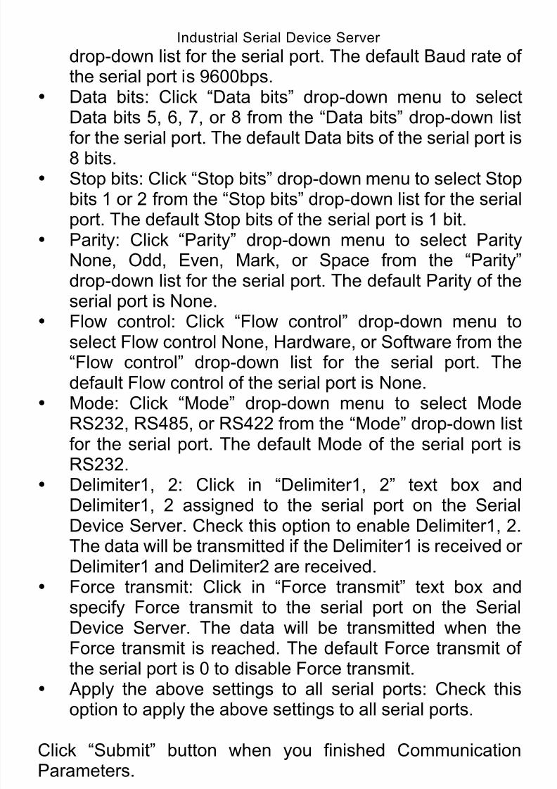
8/15/2019 EtherWAN SE5302-00B User Manual
http://slidepdf.com/reader/full/etherwan-se5302-00b-user-manual 33/105
Industrial Serial Device Server
33
drop-down list for the serial port. The default Baud rate ofthe serial port is 9600bps.
Data bits: Click “Data bits” drop-down menu to selectData bits 5, 6, 7, or 8 from the “Data bits” drop-down list
for the serial port. The default Data bits of the serial port is8 bits.
Stop bits: Click “Stop bits” drop-down menu to select Stopbits 1 or 2 from the “Stop bits” drop-down list for the serialport. The default Stop bits of the serial port is 1 bit.
Parity: Click “Parity” drop-down menu to select ParityNone, Odd, Even, Mark, or Space from the “Parity”
drop-down list for the serial port. The default Parity of theserial port is None.
Flow control: Click “Flow control” drop-down menu toselect Flow control None, Hardware, or Software from the“Flow control” drop-down list for the serial port. Thedefault Flow control of the serial port is None.
Mode: Click “Mode” drop-down menu to select ModeRS232, RS485, or RS422 from the “Mode” drop-down listfor the serial port. The default Mode of the serial port isRS232.
Delimiter1, 2: Click in “Delimiter1, 2” text box andDelimiter1, 2 assigned to the serial port on the SerialDevice Server. Check this option to enable Delimiter1, 2.
The data will be transmitted if the Delimiter1 is received orDelimiter1 and Delimiter2 are received. Force transmit: Click in “Force transmit” text box and
specify Force transmit to the serial port on the SerialDevice Server. The data will be transmitted when theForce transmit is reached. The default Force transmit ofthe serial port is 0 to disable Force transmit.
Apply the above settings to all serial ports: Check thisoption to apply the above settings to all serial ports.
Click “Submit” button when you finished CommunicationParameters.
8/15/2019 EtherWAN SE5302-00B User Manual
http://slidepdf.com/reader/full/etherwan-se5302-00b-user-manual 34/105
Industrial Serial Device Server
34
Fig 17. Communication Parameters
UDP Setting
Serial Device Server can be configured in a UDP mode toestablish connection using Unicast or Multicast data from theserial device to one or multiple host computers. Vice versa isalso true.
1. Operation Modes Application: Click “Application” drop-down menu to select
“UDP” from the “Application” drop-down list. Server1 ~ 8, Port: Click in “Server1 ~ 8” and “Port” text
boxes to specify IP addresses and Port numbers ofremote UDP Servers.
UDP Port: Click in “UDP Port” text box and type a UDPPort number assigned to the Source UDP Clients. Thedefault UDP Port number is 601.
Source IP 1 ~ 8: Click in “Source IP 1 ~ 8” text box tospecify IP addresses of Source UDP Clients.
Apply the above settings to all serial ports: Check thisoption to apply the above settings to all serial ports.
Click “Submit” button when you finished UDP Setting.
8/15/2019 EtherWAN SE5302-00B User Manual
http://slidepdf.com/reader/full/etherwan-se5302-00b-user-manual 35/105
Industrial Serial Device Server
35
Fig 18. UDP Setting
2. Communication Parameters Protocol timeout auto-detect: Check this option to support
Protocol timeout auto-detect. The Serial Device Serverwill automatically test the TCP connection to remote host.If the TCP connection is idle, the TCP connection will beclosed and the port will be freed for other hosts.
Protocol timeout: Click in “Protocol timeout” text box andtype a period of Protocol timeout assigned to the serialport on the Serial Device Server. The connection will be
closed and the port will be freed for connection with otherhosts when serial port stops data transmission for adefined period of time (Protocol timeout). The defaultProtocol timeout is 0ms.
Baud rate: Click “Baud rate” drop-down menu to selectBaud rate 50 ~ 460800bps from the “Baud rate”drop-down list for the serial port. The default Baud rate of
the serial port is 9600bps. Data bits: Click “Data bits” drop-down menu to select
Data bits 5, 6, 7, or 8 from the “Data bits” drop-down listfor the serial port. The default Data bits of the serial port is8 bits.
Stop bits: Click “Stop bits” drop-down menu to select Stopbits 1 or 2 from the “Stop bits” drop-down list for the serial
port. The default Stop bits of the serial port is 1 bit. Parity: Click “Parity” drop-down menu to select Parity
8/15/2019 EtherWAN SE5302-00B User Manual
http://slidepdf.com/reader/full/etherwan-se5302-00b-user-manual 36/105
Industrial Serial Device Server
36
None, Odd, Even, Mark, or Space from the “Parity”drop-down list for the serial port. The default Parity of theserial port is None.
Flow control: Click “Flow control” drop-down menu to
select Flow control None, Hardware, or Software from the“Flow control” drop-down list for the serial port. Thedefault Flow control of the serial port is None.
Mode: Click “Mode” drop-down menu to select ModeRS232, RS485, or RS422 from the “Mode” drop-down listfor the serial port. The default Mode of the serial port isRS232.
Delimiter1, 2: Click in “Delimiter1, 2” text box andDelimiter1, 2 assigned to the serial port on the SerialDevice Server. Check this option to enable Delimiter1, 2.The data will be transmitted if the Delimiter1 is received orDelimiter1 and Delimiter2 are received.
Force transmit: Click in “Force transmit” text box andspecify Force transmit to the serial port on the SerialDevice Server. The data will be transmitted when theForce transmit is reached. The default Force transmit ofthe serial port is 0 to disable Force transmit.
Apply the above settings to all serial ports: Check thisoption to apply the above settings to all serial ports.
Click “Submit” button when you finished CommunicationParameters.

8/15/2019 EtherWAN SE5302-00B User Manual
http://slidepdf.com/reader/full/etherwan-se5302-00b-user-manual 37/105
Industrial Serial Device Server
37
Fig 19. Communication Parameters
6.4. System Management
There are six sections for System Management that includesServer Name Setting, Change Password, E-mail Alert, SNMPTrap, Restore Factory Default, and Firmware Update.
Fig 20. System Management Web Interface
6.4.1. Server Name Setting
Server name: Click in “Server name” text box and specifyServer name to the Serial Device Server.
8/15/2019 EtherWAN SE5302-00B User Manual
http://slidepdf.com/reader/full/etherwan-se5302-00b-user-manual 38/105
Industrial Serial Device Server
38
Click “Submit” button when you finished Server Name Setting.
Fig 21. Server Name Setting web page
6.4.2. Change Password Old password: Click in “Old password” text box and enter
the Old password of the Serial Device Server. New password: Click in “New password” text box and
enter the New password for the Serial Device Server. Confirm password: Click in “Confirm password” text box
and enter the New password again for the Serial DeviceServer.
Click “Submit” button when you finished Change Password.
Fig 22. Change Password web page
8/15/2019 EtherWAN SE5302-00B User Manual
http://slidepdf.com/reader/full/etherwan-se5302-00b-user-manual 39/105
Industrial Serial Device Server
39
6.4.3. E-mail Alert
SMTP Host: SMTP (Simple Mail Transfer Protocol). Clickin “SMTP Host” text box and enter IP address of theSMTP Host.
SMTP Port: Click in “SMTP Port” text box and enter theSMTP Port number. The default SMTP Port number is 25.
From E-mail address: Click in “From E-mail address” textbox and specify the E-mail address to receive the E-mail
from. E-mail address1 ~ 4: Click in “E-mail address1 ~ 4” text
box and specify the E-mail addresses to receive theE-mail. Check this option to enable E-mail address1 ~ 4.
Click “Submit” button when you finished E-mail Alert.
Fig 22. E-mail Alert web page
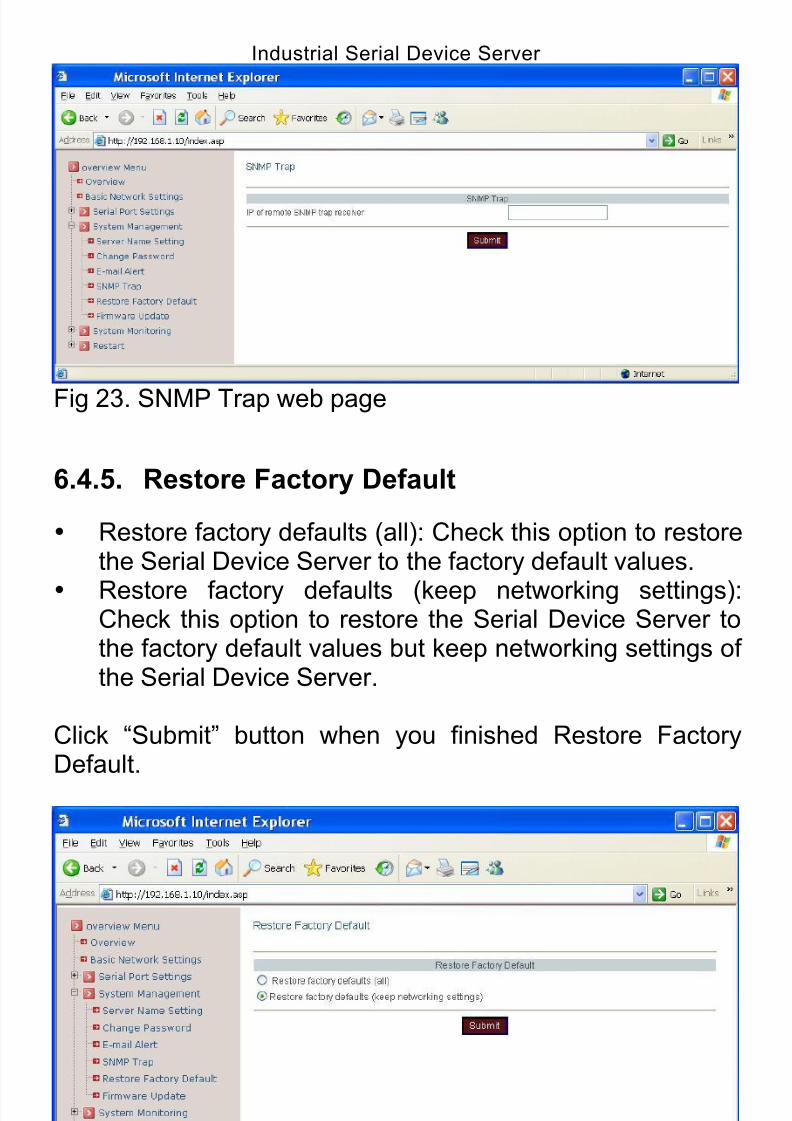
6.4.4. SNMP Trap
IP of remote SNMP trap receiver: Click in “IP of remoteSNMP trap receiver” text box and enter IP address of theremote SNMP trap receiver.
Click “Submit” button when you finished SNMP Trap.
8/15/2019 EtherWAN SE5302-00B User Manual
http://slidepdf.com/reader/full/etherwan-se5302-00b-user-manual 40/105
Industrial Serial Device Server
40
Fig 23. SNMP Trap web page
6.4.5. Restore Factory Default
Restore factory defaults (all): Check this option to restorethe Serial Device Server to the factory default values.
Restore factory defaults (keep networking settings):Check this option to restore the Serial Device Server tothe factory default values but keep networking settings ofthe Serial Device Server.
Click “Submit” button when you finished Restore FactoryDefault.
Fig 24. Restore Factory Default web page
8/15/2019 EtherWAN SE5302-00B User Manual
http://slidepdf.com/reader/full/etherwan-se5302-00b-user-manual 41/105
Industrial Serial Device Server
41
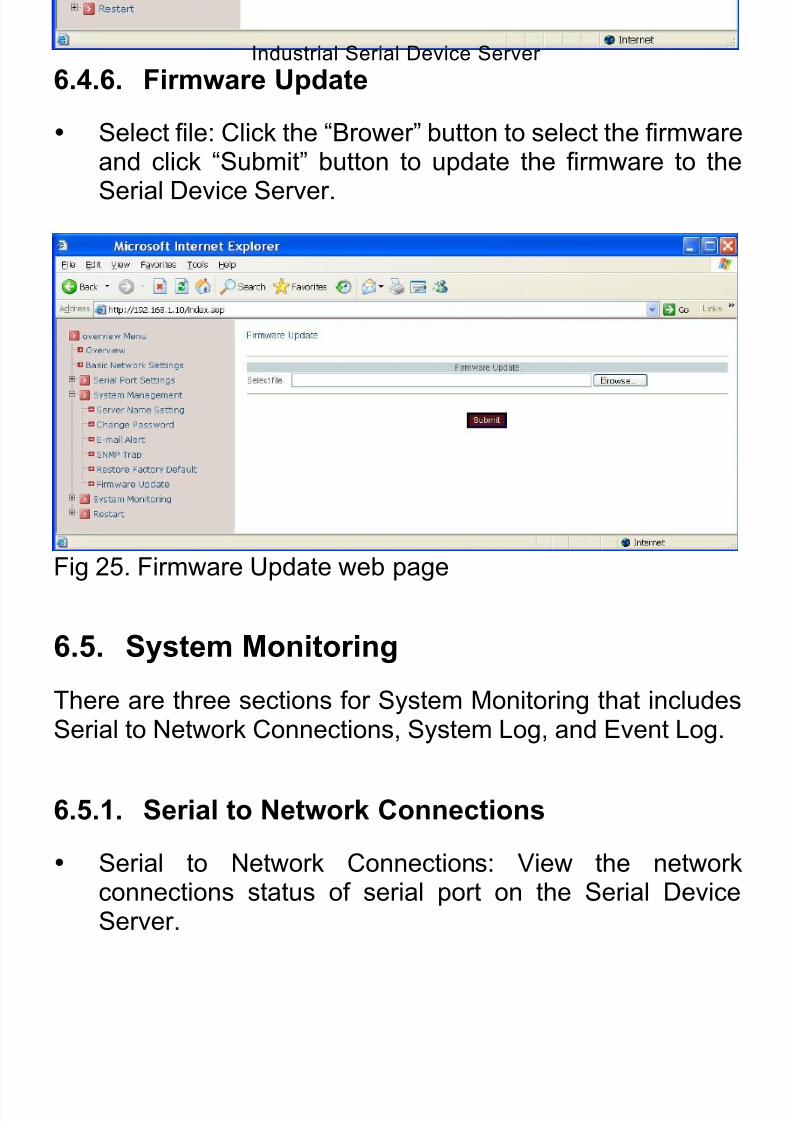
6.4.6. Firmware Update
Select file: Click the “Brower” button to select the firmwareand click “Submit” button to update the firmware to the
Serial Device Server.
Fig 25. Firmware Update web page
6.5. System Monitoring
There are three sections for System Monitoring that includesSerial to Network Connections, System Log, and Event Log.
6.5.1. Serial to Network Connections
Serial to Network Connections: View the networkconnections status of serial port on the Serial DeviceServer.

8/15/2019 EtherWAN SE5302-00B User Manual
http://slidepdf.com/reader/full/etherwan-se5302-00b-user-manual 42/105
Industrial Serial Device Server
42
Fig 26. Serial to Network Connections web page
6.5.2. System Log
System Log: Click the “Reload” button to reload theSystem Log of the Serial Device Server and click “Clean”button to clean the System Log of the Serial Device
Server.
Fig 27. System Log web page
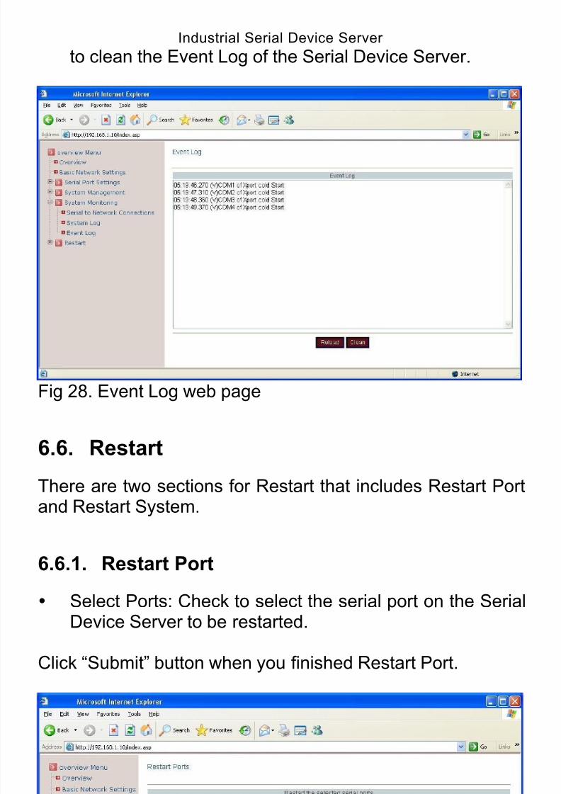
6.5.3. Event Log
Event Log: Click the “Reload” button to reload the EventLog of the Serial Device Server and click “Clean” button
8/15/2019 EtherWAN SE5302-00B User Manual
http://slidepdf.com/reader/full/etherwan-se5302-00b-user-manual 43/105
Industrial Serial Device Server
43
to clean the Event Log of the Serial Device Server.
Fig 28. Event Log web page
6.6. Restart
There are two sections for Restart that includes Restart Portand Restart System.
6.6.1. Restart Port
Select Ports: Check to select the serial port on the SerialDevice Server to be restarted.
Click “Submit” button when you finished Restart Port.

8/15/2019 EtherWAN SE5302-00B User Manual
http://slidepdf.com/reader/full/etherwan-se5302-00b-user-manual 44/105
Industrial Serial Device Server
44
Fig 29. Restart Port web page
6.6.2. Restart System
Select System: Click the “Restart” button to restart theSerial Device Server.
Fig 30. Restart System web page
8/15/2019 EtherWAN SE5302-00B User Manual
http://slidepdf.com/reader/full/etherwan-se5302-00b-user-manual 45/105
Industrial Serial Device Server
45
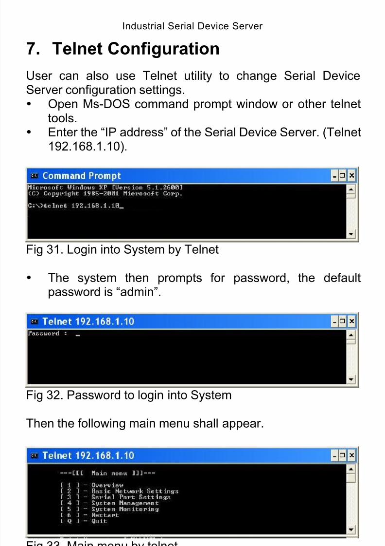
7. Telnet Configuration
User can also use Telnet utility to change Serial Device
Server configuration settings. Open Ms-DOS command prompt window or other telnettools.
Enter the “IP address” of the Serial Device Server. (Telnet192.168.1.10).
Fig 31. Login into System by Telnet
The system then prompts for password, the defaultpassword is “admin”.
Fig 32. Password to login into System
Then the following main menu shall appear.
Fig 33. Main menu by telnet
8/15/2019 EtherWAN SE5302-00B User Manual
http://slidepdf.com/reader/full/etherwan-se5302-00b-user-manual 46/105
Indu
7.1. Overviewstrial Serial Device Server
46
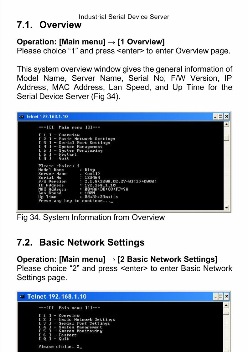
Operation: [Main menu]→ [1 Overview]Please choice “1” and press <enter> to enter Overview page.
This system overview window gives the general information ofModel Name, Server Name, Serial No, F/W Version, IP Address, MAC Address, Lan Speed, and Up Time for theSerial Device Server (Fig 34).
Fig 34. System Information from Overview
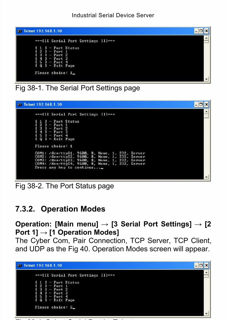
7.2. Basic Network SettingsOperation: [Main menu]→ [2 Basic Network Settings]Please choice “2” and press <enter> to enter Basic NetworkSettings page.
Fig 35. Basic Network Settings by Telnet
* Note: Enter “Q” and press <Enter> to return to the Main

8/15/2019 EtherWAN SE5302-00B User Manual
http://slidepdf.com/reader/full/etherwan-se5302-00b-user-manual 47/105
Industrial Serial Device Server
47
menu.
This section allows for changes in DHCP, IP address,Netmask address, Gateway address, DNS1 address, DNS2
address, DNS3 address, Time Server, Time Area, Year,Month, Day, Hour, Minute, and Second.
7.3. Serial Port Settings
User can configure serial parameters that includes Port
Status, Operation Modes, Communication Parameters, and Accessible IP List.
Fig 36. Select Serial Port Settings by Telnet
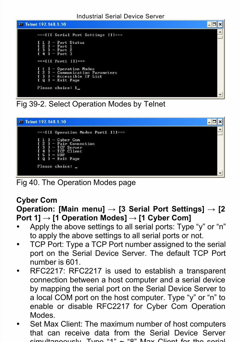
Fig 37. The Serial Port Settings page
7.3.1. Port Status
Operation: [Main menu] → [3 Serial Port Settings] → [1Port Status]The Port Name, Device, Parameters, Interface, and
Operation Mode as the Fig 38-2. Port Status screen willappear.
8/15/2019 EtherWAN SE5302-00B User Manual
http://slidepdf.com/reader/full/etherwan-se5302-00b-user-manual 48/105
Industrial Serial Device Server
48
Fig 38-1. The Serial Port Settings page
Fig 38-2. The Port Status page
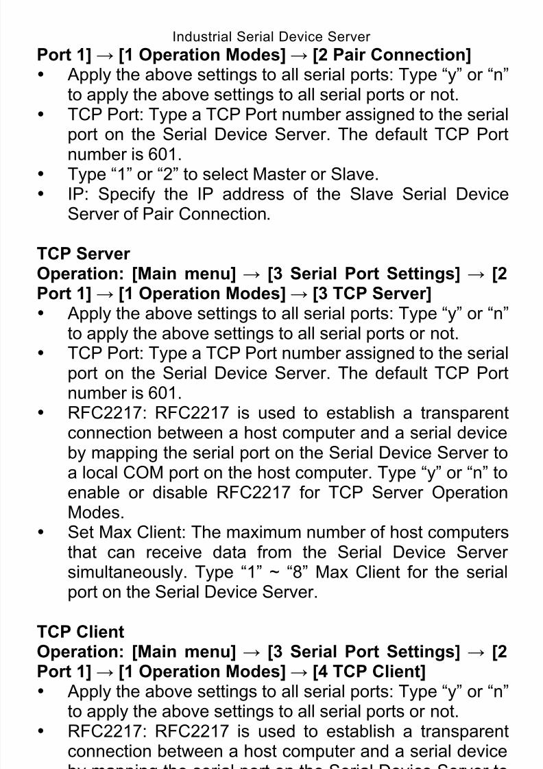
7.3.2. Operation Modes
Operation: [Main menu] → [3 Serial Port Settings] → [2Port 1]→ [1 Operation Modes]The Cyber Com, Pair Connection, TCP Server, TCP Client,and UDP as the Fig 40. Operation Modes screen will appear.
Fig 39-1. Select Serial Port by Telnet
8/15/2019 EtherWAN SE5302-00B User Manual
http://slidepdf.com/reader/full/etherwan-se5302-00b-user-manual 49/105
Industrial Serial Device Server
49
Fig 39-2. Select Operation Modes by Telnet
Fig 40. The Operation Modes page
Cyber ComOperation: [Main menu] → [3 Serial Port Settings] → [2Port 1]→ [1 Operation Modes]→ [1 Cyber Com] Apply the above settings to all serial ports: Type “y” or “n”
to apply the above settings to all serial ports or not. TCP Port: Type a TCP Port number assigned to the serialport on the Serial Device Server. The default TCP Portnumber is 601.
RFC2217: RFC2217 is used to establish a transparentconnection between a host computer and a serial deviceby mapping the serial port on the Serial Device Server to
a local COM port on the host computer. Type “y” or “n” toenable or disable RFC2217 for Cyber Com OperationModes.
Set Max Client: The maximum number of host computersthat can receive data from the Serial Device Serversimultaneously. Type “1” ~ “8” Max Client for the serialport on the Serial Device Server.
Pair ConnectionOperation: [Main menu] → [3 Serial Port Settings] → [2
8/15/2019 EtherWAN SE5302-00B User Manual
http://slidepdf.com/reader/full/etherwan-se5302-00b-user-manual 50/105
Industrial Serial Device Server
50
Port 1]→ [1 Operation Modes]→ [2 Pair Connection] Apply the above settings to all serial ports: Type “y” or “n”
to apply the above settings to all serial ports or not. TCP Port: Type a TCP Port number assigned to the serial
port on the Serial Device Server. The default TCP Portnumber is 601.
Type “1” or “2” to select Master or Slave. IP: Specify the IP address of the Slave Serial Device
Server of Pair Connection.
TCP Server
Operation: [Main menu] → [3 Serial Port Settings] → [2Port 1]→ [1 Operation Modes]→ [3 TCP Server] Apply the above settings to all serial ports: Type “y” or “n”
to apply the above settings to all serial ports or not. TCP Port: Type a TCP Port number assigned to the serial
port on the Serial Device Server. The default TCP Portnumber is 601.
RFC2217: RFC2217 is used to establish a transparentconnection between a host computer and a serial deviceby mapping the serial port on the Serial Device Server toa local COM port on the host computer. Type “y” or “n” toenable or disable RFC2217 for TCP Server OperationModes.
Set Max Client: The maximum number of host computersthat can receive data from the Serial Device Server
simultaneously. Type “1” ~ “8” Max Client for the serialport on the Serial Device Server.
TCP ClientOperation: [Main menu] → [3 Serial Port Settings] → [2
Port 1]→ [1 Operation Modes]→ [4 TCP Client] Apply the above settings to all serial ports: Type “y” or “n”
to apply the above settings to all serial ports or not. RFC2217: RFC2217 is used to establish a transparent
connection between a host computer and a serial deviceby mapping the serial port on the Serial Device Server toa local COM port on the host computer. Type “y” or “n” to
enable or disable RFC2217 for TCP Client OperationModes.
Re-Connect Interval: Type a period of Re-Connect
8/15/2019 EtherWAN SE5302-00B User Manual
http://slidepdf.com/reader/full/etherwan-se5302-00b-user-manual 51/105
Industrial Serial Device Server
51
Interval assigned to the serial port on the Serial DeviceServer. The connection will be reestablished with otherhosts for a defined period of time (Re-Connect Interval).The default Re-Connect Interval is 3 seconds.
Connect Timeout: Type a period of Connect Timeoutassigned to the serial port on the Serial Device Server.The connection will be closed and the port will be freedfor connection with other hosts when serial port stopsdata transmission for a defined period of time (ConnectTimeout). The default Connect Timeout is 3 seconds.
Remote IP1 ~ 8, Remote Port1 ~ 8: Specify IP addresses
and Port numbers of remote host computers.
UDPOperation: [Main menu] → [3 Serial Port Settings] → [2Port 1]→ [1 Operation Modes]→ [5 UDP] Apply the above settings to all serial ports: Type “y” or “n”
to apply the above settings to all serial ports or not. UDP Port: Type a UDP Port number assigned to the
Source UDP Clients. The default UDP Port number is601.
Source IP1 ~ 8: Specify IP addresses of Source UDPClients.
Server IP1 ~ 8, Server Port1 ~ 8: Specify IP addresses
and Port numbers of remote UDP Servers.
7.3.3. Communication Parameters
Operation: [Main menu] → [3 Serial Port Settings] → [2Port 1]→ [2 Communication Parameters] Apply the above settings to all serial ports: Type “y” or “n”
to apply the above settings to all serial ports or not. Protocol timeout auto-detect: Type “y” or “n” to enable or
disable Protocol timeout auto-detect. The Serial DeviceServer will automatically test the TCP connection toremote host. If the TCP connection is idle, the TCPconnection will be closed and the port will be freed for
other hosts. Set Protocol Timeout: Type a period of Protocol Timeout
(0 ~ 99ms) assigned to the serial port on the Serial
8/15/2019 EtherWAN SE5302-00B User Manual
http://slidepdf.com/reader/full/etherwan-se5302-00b-user-manual 52/105
Industrial Serial Device Server
52
Device Server. The connection will be closed and the portwill be freed for connection with other hosts when serialport stops data transmission for a defined period of time(Protocol Timeout). The default Protocol Timeout is 0ms.
Baud rate: Select Baud rate 50 ~ 460800bps for the serialport. The default Baud rate of the serial port is 9600bps.
Data bits: Select Data bits 5, 6, 7, or 8 for the serial port.The default Data bits of the serial port is 8 bits.
Stop bits: Select Stop bits 1 or 2 for the serial port. Thedefault Stop bits of the serial port is 1 bit.
Parity: Select Parity None, Odd, Even, Mark, or Space for
the serial port. The default Parity of the serial port isNone.
Mode: Select Mode RS232, RS485, or RS422 for theserial port. The default Mode of the serial port is RS232.
Flow control: Select Flow control None, Hardware, orSoftware for the serial port. The default Flow control ofthe serial port is None.
Delimiter1 Enable: Type “y” or “n” to enable or disableDelimiter1 for the serial port on the Serial Device Server.
Set Delimiter1: Type Delimiter1 (Hex 00 ~ FF) to theserial port on the Serial Device Server.
Delimiter2 Enable: Type “y” or “n” to enable or disableDelimiter2 for the serial port on the Serial Device Server.
Set Delimiter2: Type Delimiter2 (Hex 00 ~ FF) to theserial port on the Serial Device Server. Set ForceTransmit: Specify Force transmit to the serial
port on the Serial Device Server. The data will betransmitted when the Force transmit is reached. Thedefault Force transmit of the serial port is 0 to disableForce transmit.
7.3.4. Accessible IP List
Operation: [Main menu] → [3 Serial Port Settings] → [2Port 1]→ [3 Accessible IP List] Apply the above settings to all serial ports: Type “y” or “n”
to apply the above settings to all serial ports or not. Enable the accessible IP list: Type “y” or “n” to enable or
disable the accessible IP list. Disable will allow all IP’s
8/15/2019 EtherWAN SE5302-00B User Manual
http://slidepdf.com/reader/full/etherwan-se5302-00b-user-manual 53/105
Industrial Serial Device Server
53
connection request. Accessible IP Enable1 ~ 8: Type “y” or “n” to enable or
disable IP addresses that can access to the serial port onthe Serial Device Server.
Accessible IP1 ~ 8: Specify IP addresses that can accessto the serial port on the Serial Device Server.
7.4. System Management
User can configure System Management that includes Server
Name Setting, Change Password, E-mail Alert, SNMP Trap,and Restore Factory Default.
Fig 41. Select System Management by Telnet
Fig 42. The System Management page
7.4.1. Server Name Setting
Operation: [Main menu] → [4 System Management] → [1Server Name Setting] Set Server Name: Specify Server Name to the Serial
Device Server.
8/15/2019 EtherWAN SE5302-00B User Manual
http://slidepdf.com/reader/full/etherwan-se5302-00b-user-manual 54/105
Industrial Serial Device Server
54
7.4.2. Change Password
Operation: [Main menu] → [4 System Management] → [2Change Password]
Old password: Enter the Old password of the SerialDevice Server.
New password: Enter the New password for the SerialDevice Server.
Again: Enter the New password again for the SerialDevice Server.
7.4.3. E-mail Alert
Operation: [Main menu] → [4 System Management] → [3E-mail Alert] SMTP Host: SMTP (Simple Mail Transfer Protocol). Enter
IP address of the SMTP Host.
SMTP Port: Enter the SMTP Port number. The defaultSMTP Port number is 25.
From E-mail address: Specify the E-mail address toreceive the E-mail from.
E-mail address1 ~ 4: Type “y” or “n” to enable or disablethe E-mail addresses to receive the E-mail.
Mail 1 ~ 4 address: Specify the E-mail addresses to
receive the E-mail.
7.4.4. SNMP Trap
Operation: [Main menu] → [4 System Management] → [4SNMP Trap] IP of remote SNMP trap receiver: Enter IP address of the
remote SNMP trap receiver.
7.4.5. Restore Factory Default
Operation: [Main menu] → [4 System Management] → [5Restore Factory Default] Restore factory defaults (keep networking settings): Type
8/15/2019 EtherWAN SE5302-00B User Manual
http://slidepdf.com/reader/full/etherwan-se5302-00b-user-manual 55/105
Industrial Serial Device Server
55
“y” or “n” to enable or disable restoration the Serial DeviceServer to the factory default values but keep networkingsettings of the Serial Device Server.
Restore factory defaults (all): Type “y” or “n” to enable or
disable restoration the Serial Device Server to the factorydefault values.
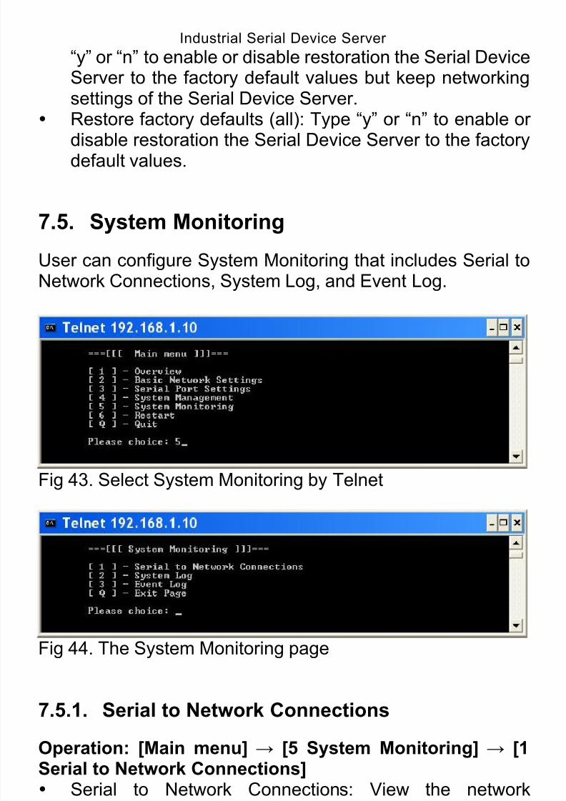
7.5. System Monitoring
User can configure System Monitoring that includes Serial to
Network Connections, System Log, and Event Log.
Fig 43. Select System Monitoring by Telnet
Fig 44. The System Monitoring page
7.5.1. Serial to Network Connections
Operation: [Main menu] → [5 System Monitoring] → [1Serial to Network Connections] Serial to Network Connections: View the network
connections status of serial port on the Serial DeviceServer.

8/15/2019 EtherWAN SE5302-00B User Manual
http://slidepdf.com/reader/full/etherwan-se5302-00b-user-manual 56/105
Industrial Serial Device Server
56
Fig 45. The Serial to Network Connections page
7.5.2. System Log
Operation: [Main menu] → [5 System Monitoring] → [2
System Log] Serial to Network Connections: View the System Log of
serial port on the Serial Device Server.
Fig 46. The System Log page
8/15/2019 EtherWAN SE5302-00B User Manual
http://slidepdf.com/reader/full/etherwan-se5302-00b-user-manual 57/105
Industrial Serial Device Server
57
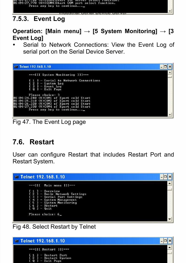
7.5.3. Event Log
Operation: [Main menu] → [5 System Monitoring] → [3Event Log]
Serial to Network Connections: View the Event Log ofserial port on the Serial Device Server.
Fig 47. The Event Log page
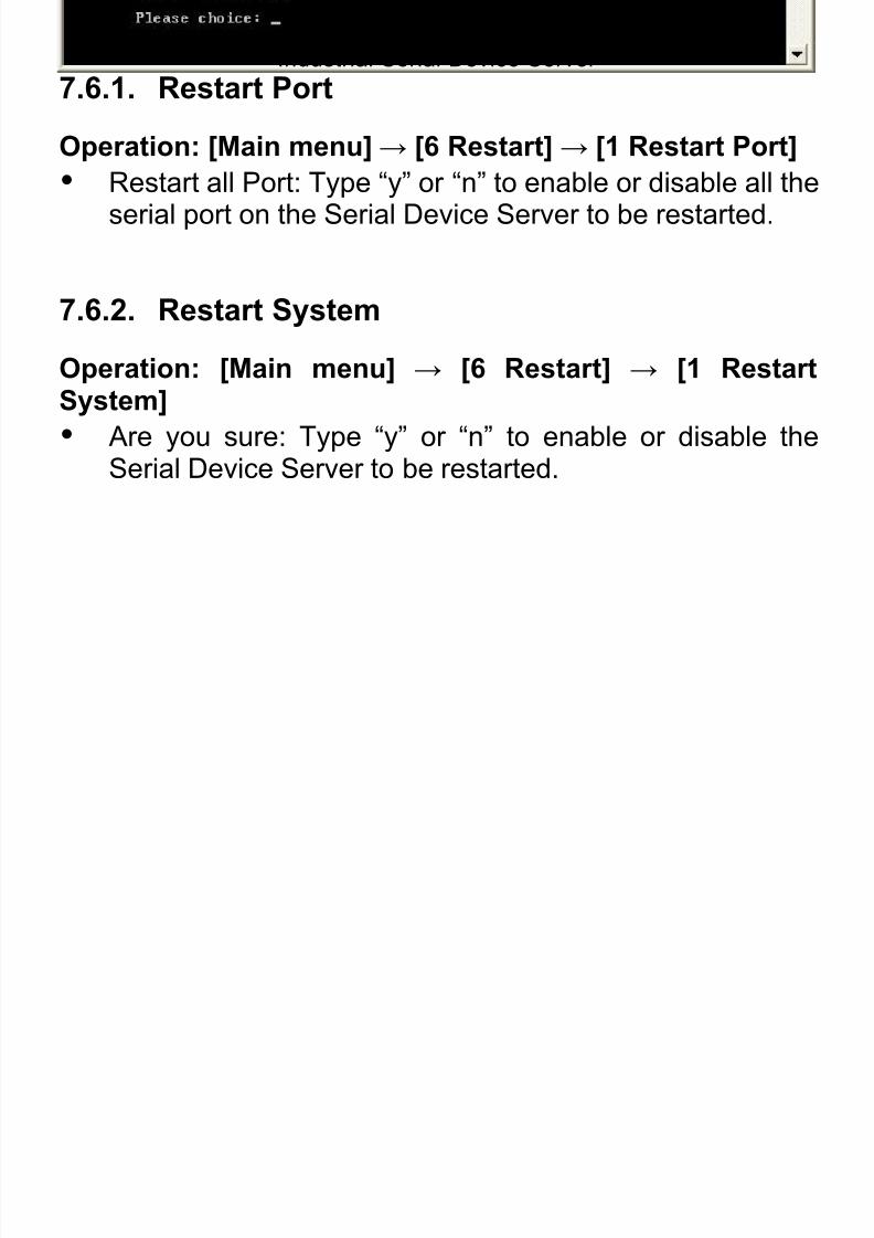
7.6. Restart
User can configure Restart that includes Restart Port andRestart System.
Fig 48. Select Restart by Telnet
Fig 49. The Restart page
8/15/2019 EtherWAN SE5302-00B User Manual
http://slidepdf.com/reader/full/etherwan-se5302-00b-user-manual 58/105
Industrial Serial Device Server
58
7.6.1. Restart Port
Operation: [Main menu]→ [6 Restart]→ [1 Restart Port]
Restart all Port: Type “y” or “n” to enable or disable all the
serial port on the Serial Device Server to be restarted.
7.6.2. Restart System
Operation: [Main menu] → [6 Restart] → [1 RestartSystem]
Are you sure: Type “y” or “n” to enable or disable theSerial Device Server to be restarted.
8/15/2019 EtherWAN SE5302-00B User Manual
http://slidepdf.com/reader/full/etherwan-se5302-00b-user-manual 59/105
Industrial Serial Device Server
59
8. Xport Utility
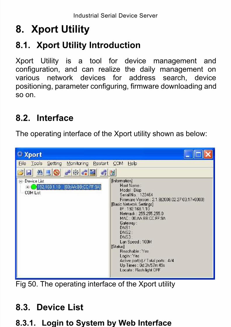
8.1. Xport Utility Introduction
Xport Utility is a tool for device management andconfiguration, and can realize the daily management onvarious network devices for address search, devicepositioning, parameter configuring, firmware downloading andso on.
8.2. Interface
The operating interface of the Xport utility shown as below:
Fig 50. The operating interface of the Xport utility
8.3. Device List
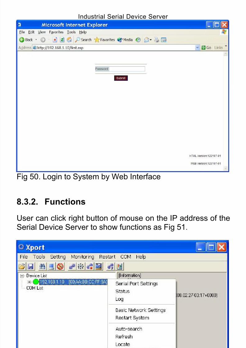
8.3.1. Login to System by Web Interface
User can double click on the IP address of the Serial DeviceServer to login to Serial Device Server by web interface.
8/15/2019 EtherWAN SE5302-00B User Manual
http://slidepdf.com/reader/full/etherwan-se5302-00b-user-manual 60/105
Industrial Serial Device Server
60
Fig 50. Login to System by Web Interface
8.3.2. Functions
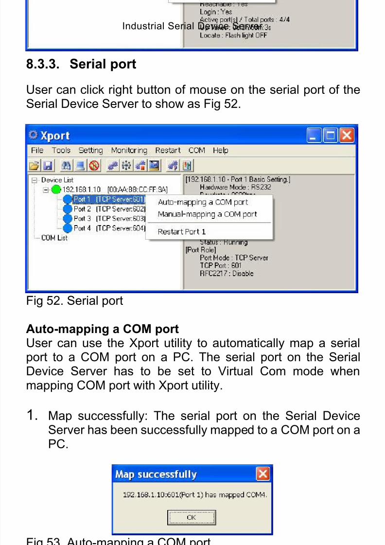
User can click right button of mouse on the IP address of theSerial Device Server to show functions as Fig 51.
Fig 51. Functions
8/15/2019 EtherWAN SE5302-00B User Manual
http://slidepdf.com/reader/full/etherwan-se5302-00b-user-manual 61/105
Industrial Serial Device Server
61
8.3.3. Serial port
User can click right button of mouse on the serial port of theSerial Device Server to show as Fig 52.
Fig 52. Serial port
Auto-mapping a COM portUser can use the Xport utility to automatically map a serialport to a COM port on a PC. The serial port on the SerialDevice Server has to be set to Virtual Com mode when
mapping COM port with Xport utility.
1. Map successfully: The serial port on the Serial DeviceServer has been successfully mapped to a COM port on aPC.
Fig 53. Auto-mapping a COM port
2. COM List: Click right button of mouse on the COM port toshow as Fig 54.
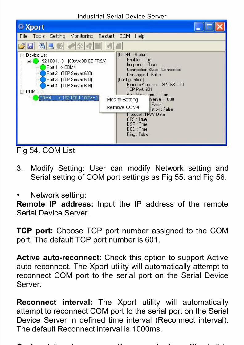
8/15/2019 EtherWAN SE5302-00B User Manual
http://slidepdf.com/reader/full/etherwan-se5302-00b-user-manual 62/105
Industrial Serial Device Server
62
Fig 54. COM List
3. Modify Setting: User can modify Network setting and
Serial setting of COM port settings as Fig 55. and Fig 56.
Network setting:Remote IP address: Input the IP address of the remoteSerial Device Server.
TCP port: Choose TCP port number assigned to the COM
port. The default TCP port number is 601.
Active auto-reconnect: Check this option to support Activeauto-reconnect. The Xport utility will automatically attempt toreconnect COM port to the serial port on the Serial DeviceServer.
Reconnect interval: The Xport utility will automaticallyattempt to reconnect COM port to the serial port on the SerialDevice Server in defined time interval (Reconnect interval).The default Reconnect interval is 1000ms.
Cache data when connection was broken: Check thisoption to ensure that data is buffered if the connection is
broken.
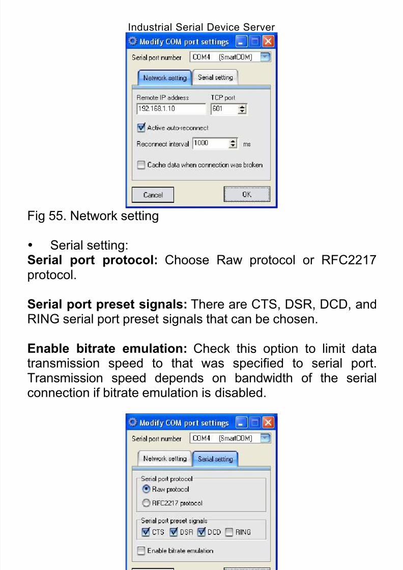
8/15/2019 EtherWAN SE5302-00B User Manual
http://slidepdf.com/reader/full/etherwan-se5302-00b-user-manual 63/105
Industrial Serial Device Server
63
Fig 55. Network setting
Serial setting:Serial port protocol: Choose Raw protocol or RFC2217protocol.
Serial port preset signals: There are CTS, DSR, DCD, andRING serial port preset signals that can be chosen.
Enable bitrate emulation: Check this option to limit datatransmission speed to that was specified to serial port.Transmission speed depends on bandwidth of the serial
connection if bitrate emulation is disabled.
Fig 56. Serial setting
4. Remove COM port: Remove the COM port and remove
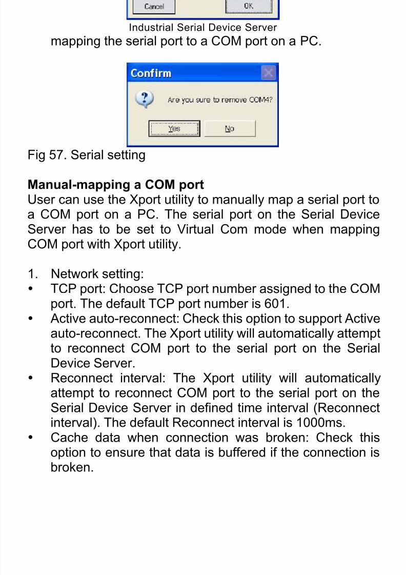
8/15/2019 EtherWAN SE5302-00B User Manual
http://slidepdf.com/reader/full/etherwan-se5302-00b-user-manual 64/105
Industrial Serial Device Server
64
mapping the serial port to a COM port on a PC.
Fig 57. Serial setting
Manual-mapping a COM port
User can use the Xport utility to manually map a serial port toa COM port on a PC. The serial port on the Serial DeviceServer has to be set to Virtual Com mode when mappingCOM port with Xport utility.
1. Network setting: TCP port: Choose TCP port number assigned to the COM
port. The default TCP port number is 601. Active auto-reconnect: Check this option to support Active
auto-reconnect. The Xport utility will automatically attemptto reconnect COM port to the serial port on the SerialDevice Server.
Reconnect interval: The Xport utility will automaticallyattempt to reconnect COM port to the serial port on the
Serial Device Server in defined time interval (Reconnectinterval). The default Reconnect interval is 1000ms.
Cache data when connection was broken: Check thisoption to ensure that data is buffered if the connection isbroken.

8/15/2019 EtherWAN SE5302-00B User Manual
http://slidepdf.com/reader/full/etherwan-se5302-00b-user-manual 65/105
Industrial Serial Device Server
65
Fig 58. Network setting
2. Serial setting: Serial port protocol: Choose Raw protocol or RFC2217
protocol. Serial port preset signals: There are CTS, DSR, DCD,
and RING serial port preset signals that can be chosen. Enable bitrate emulation: Check this option to limit data
transmission speed to that was specified to serial port.Transmission speed depends on bandwidth of the serialconnection if bitrate emulation is disabled.
Fig 59. Serial setting
Restart portClick “Restart port” to restart serial port on the Serial DeviceServer.

8/15/2019 EtherWAN SE5302-00B User Manual
http://slidepdf.com/reader/full/etherwan-se5302-00b-user-manual 66/105
Industrial Serial Device Server
66
8.3.4. COM List
Click right button of mouse on the COM List to show as Fig54.
Fig 60. COM List
Create a new COM portUser can use the Xport utility to map a serial port to a COMport on a PC. The serial port on the Serial Device Server hasto be set to Virtual Com mode when mapping COM port withXport utility.
1. Network setting: TCP port: Choose TCP port number assigned to the COM
port. The default TCP port number is 601. Active auto-reconnect: Check this option to support Active
auto-reconnect. The Xport utility will automatically attempt
to reconnect COM port to the serial port on the SerialDevice Server. Reconnect interval: The Xport utility will automatically
attempt to reconnect COM port to the serial port on theSerial Device Server in defined time interval (Reconnectinterval). The default Reconnect interval is 1000ms.
Cache data when connection was broken: Check this
option to ensure that data is buffered if the connection isbroken.
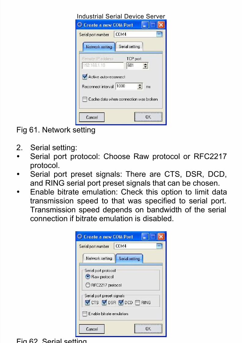
8/15/2019 EtherWAN SE5302-00B User Manual
http://slidepdf.com/reader/full/etherwan-se5302-00b-user-manual 67/105
Industrial Serial Device Server
67
Fig 61. Network setting
2. Serial setting: Serial port protocol: Choose Raw protocol or RFC2217
protocol. Serial port preset signals: There are CTS, DSR, DCD,
and RING serial port preset signals that can be chosen. Enable bitrate emulation: Check this option to limit data
transmission speed to that was specified to serial port.Transmission speed depends on bandwidth of the serialconnection if bitrate emulation is disabled.
Fig 62. Serial setting
Remove all COM portsClick “Remove all COM ports” to remove all the COM portsand remove all the mapping from the serial ports to COM

8/15/2019 EtherWAN SE5302-00B User Manual
http://slidepdf.com/reader/full/etherwan-se5302-00b-user-manual 68/105
Industrial Serial Device Server
68
ports on a PC.
Fig 63. Remove all COM ports
8.4. FileClick “File” from menu bar to show as Fig 64.
Fig 64. File
8.4.1. Logon
Click “Logon” from “File” to show the authentication screen asFig 64. Enter password then click on “OK” button to logon tothe Serial Device Server. The default password is “admin”.
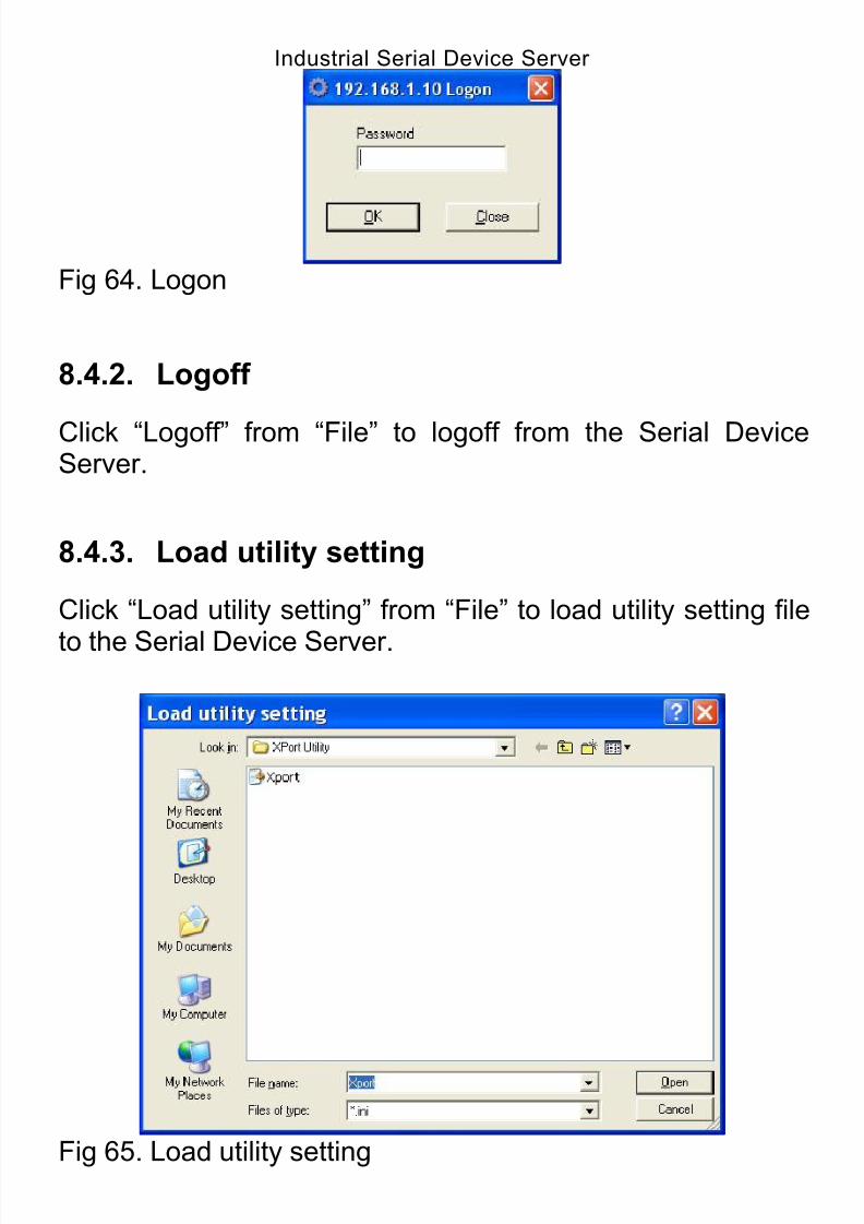
8/15/2019 EtherWAN SE5302-00B User Manual
http://slidepdf.com/reader/full/etherwan-se5302-00b-user-manual 69/105
Industrial Serial Device Server
69
Fig 64. Logon
8.4.2. Logoff
Click “Logoff” from “File” to logoff from the Serial DeviceServer.
8.4.3. Load utility setting
Click “Load utility setting” from “File” to load utility setting file
to the Serial Device Server.
Fig 65. Load utility setting
8.4.4. Save utility setting
Click “Save utility setting” from “File” to save utility setting filefrom the Serial Device Server.
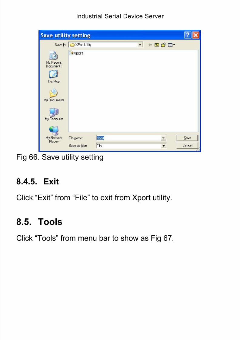
8/15/2019 EtherWAN SE5302-00B User Manual
http://slidepdf.com/reader/full/etherwan-se5302-00b-user-manual 70/105
Industrial Serial Device Server
70
Fig 66. Save utility setting
8.4.5. Exit
Click “Exit” from “File” to exit from Xport utility.
8.5. Tools
Click “Tools” from menu bar to show as Fig 67.
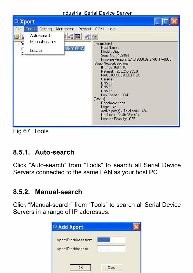
8/15/2019 EtherWAN SE5302-00B User Manual
http://slidepdf.com/reader/full/etherwan-se5302-00b-user-manual 71/105
Industrial Serial Device Server
71
Fig 67. Tools
8.5.1. Auto-search
Click “Auto-search” from “Tools” to search all Serial DeviceServers connected to the same LAN as your host PC.
8.5.2. Manual-search
Click “Manual-search” from “Tools” to search all Serial DeviceServers in a range of IP addresses.
Fig 68. Manual-search
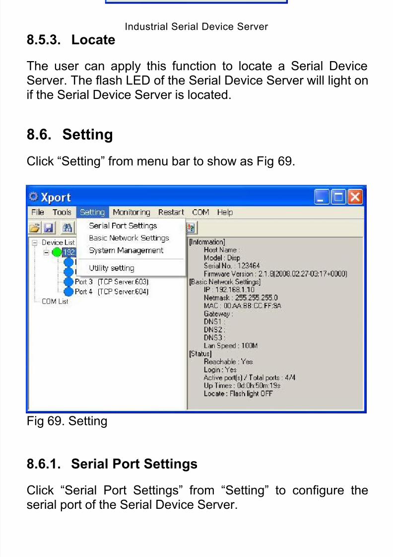
8/15/2019 EtherWAN SE5302-00B User Manual
http://slidepdf.com/reader/full/etherwan-se5302-00b-user-manual 72/105
Industrial Serial Device Server
72
8.5.3. Locate
The user can apply this function to locate a Serial DeviceServer. The flash LED of the Serial Device Server will light on
if the Serial Device Server is located.
8.6. Setting
Click “Setting” from menu bar to show as Fig 69.
Fig 69. Setting
8.6.1. Serial Port Settings
Click “Serial Port Settings” from “Setting” to configure theserial port of the Serial Device Server.

8/15/2019 EtherWAN SE5302-00B User Manual
http://slidepdf.com/reader/full/etherwan-se5302-00b-user-manual 73/105
Industrial Serial Device Server
73
Fig 70. Serial Port Settings
FileClick “File” from menu bar to show as Fig 71.

8/15/2019 EtherWAN SE5302-00B User Manual
http://slidepdf.com/reader/full/etherwan-se5302-00b-user-manual 74/105
Industrial Serial Device Server
74
Fig 71. File
1. Import ConfigurationClick “Import Configuration” from “File” to import configurationfile to the Serial Device Server.

8/15/2019 EtherWAN SE5302-00B User Manual
http://slidepdf.com/reader/full/etherwan-se5302-00b-user-manual 75/105
Industrial Serial Device Server
75
Fig 72. Import Configuration
2. Export ConfigurationClick “Export Configuration” from “File” to export configurationfile from the Serial Device Server.
Fig 73. Export Configuration
3. CloseClick “Close” from “File” to exit from “Serial Port Settings” to
the Serial Device Server.

8/15/2019 EtherWAN SE5302-00B User Manual
http://slidepdf.com/reader/full/etherwan-se5302-00b-user-manual 76/105
Industrial Serial Device Server
76
Fig 74. Close
ActionClick “Action” from menu bar to show as Fig 75.
Fig 75. Action
1. Restart PortClick “Restart Port” from “Action” to restart the serial port onthe Serial Device Server.
2. Update ports setting
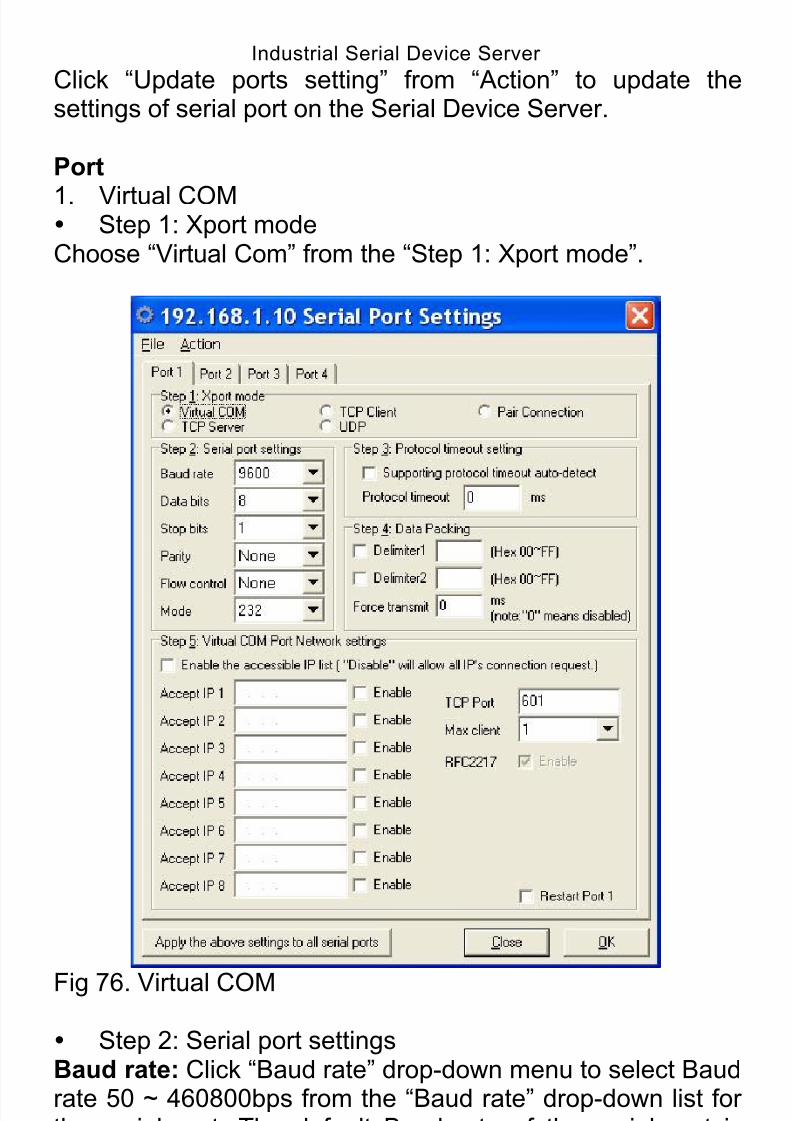
8/15/2019 EtherWAN SE5302-00B User Manual
http://slidepdf.com/reader/full/etherwan-se5302-00b-user-manual 77/105
Industrial Serial Device Server
77
Click “Update ports setting” from “Action” to update thesettings of serial port on the Serial Device Server.
Port
1. Virtual COM Step 1: Xport modeChoose “Virtual Com” from the “Step 1: Xport mode”.
Fig 76. Virtual COM
Step 2: Serial port settingsBaud rate: Click “Baud rate” drop-down menu to select Baudrate 50 ~ 460800bps from the “Baud rate” drop-down list forthe serial port. The default Baud rate of the serial port is9600bps.
Data bits: Click “Data bits” drop-down menu to select Data
8/15/2019 EtherWAN SE5302-00B User Manual
http://slidepdf.com/reader/full/etherwan-se5302-00b-user-manual 78/105
Industrial Serial Device Server
78
bits 5, 6, 7, or 8 from the “Data bits” drop-down list for theserial port. The default Data bits of the serial port is 8 bits.
Stop bits: Click “Stop bits” drop-down menu to select Stop
bits 1 or 2 from the “Stop bits” drop-down list for the serial port.The default Stop bits of the serial port is 1 bit.
Parity: Click “Parity” drop-down menu to select Parity None,Even, Odd, Mark, or Space from the “Parity” drop-down list forthe serial port. The default Parity of the serial port is None.
Flow control: Click “Flow control” drop-down menu to selectFlow control None, Hardware, or Software from the “Flowcontrol” drop-down list for the serial port. The default Flowcontrol of the serial port is None.
Mode: Click “Mode” drop-down menu to select Mode RS232,RS422, or RS485 from the “Mode” drop-down list for theserial port. The default Mode of the serial port is RS232.
Step 3: Protocol timeout settingSupport protocol timeout auto-detect: Check this option tosupport protocol timeout auto-detect. The Serial DeviceServer will automatically test the TCP connection to remote
host. If the TCP connection is idle, the TCP connection will beclosed and the port will be freed for other hosts.
Protocol timeout: Click in “Protocol timeout” text box andtype a period of Protocol timeout assigned to the serial port onthe Serial Device Server. The connection will be closed andthe port will be freed for connection with other hosts when
serial port stops data transmission for a defined period of time(Protocol timeout). The default Protocol timeout is 0ms.
Step 4: Data PackingDelimiter1, 2: Check this option to enable Delimiter1, 2. Clickin “Delimiter1, 2” text box and Delimiter1, 2 assigned to theserial port on the Serial Device Server. The data will be
transmitted if the Delimiter1 is received or Delimiter1 andDelimiter2 are received.
8/15/2019 EtherWAN SE5302-00B User Manual
http://slidepdf.com/reader/full/etherwan-se5302-00b-user-manual 79/105
Industrial Serial Device Server
79
Force transmit: Click in “Force transmit” text box and specifyForce transmit to the serial port on the Serial Device Server.The data will be transmitted when the Force transmit isreached. The default Force transmit of the serial port is 0 to
disable Force transmit.
Step 5: Virtual COM Port Network settingsEnable the accessible IP list: Check this option to enablethe accessible IP list. Disable will allow all IP’s connectionrequest.
Accept IP 1 ~ 8: Click in “Accept IP 1 ~ 8” text box andspecify Accept IP addresses that can access to the serial porton the Serial Device Server. Check this option to enable the Accept IP addresses.
TCP Port: Click in “TCP Port” text box and type a TCP Portnumber assigned to the serial port on the Serial DeviceServer. The default TCP Port number is 601.
Max client: The maximum number of host computers thatcan receive data from the Serial Device Serversimultaneously. Click “Max client” drop-down menu to select 1~ 8 from the “Max client” drop-down list.
RFC2217: RFC2217 is used to establish a transparentconnection between a host computer and a serial device bymapping the serial port on the Serial Device Server to a localCOM port on the host computer. RFC2217 is always enabledfor Virtual Com Mode Setting.
Restart Port: Check this option to restart the serial port onthe Serial Device Server when you click the “OK” button tofinish Virtual Com Mode Setting.
Apply the above settings to all serial ports: Click thisbutton to apply the above settings to all serial ports.
2. TCP Server Step 1: Xport modeChoose “TCP Server” from the “Step 1: Xport mode”.
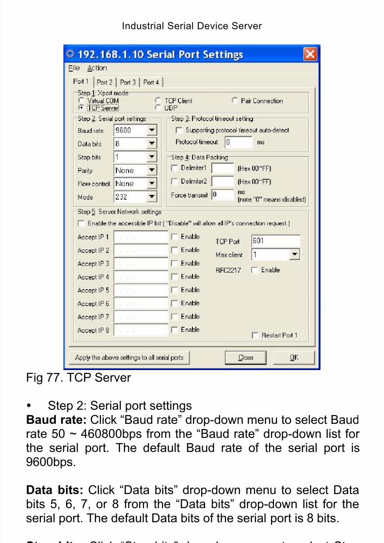
8/15/2019 EtherWAN SE5302-00B User Manual
http://slidepdf.com/reader/full/etherwan-se5302-00b-user-manual 80/105
Industrial Serial Device Server
80
Fig 77. TCP Server
Step 2: Serial port settingsBaud rate: Click “Baud rate” drop-down menu to select Baudrate 50 ~ 460800bps from the “Baud rate” drop-down list forthe serial port. The default Baud rate of the serial port is9600bps.
Data bits: Click “Data bits” drop-down menu to select Databits 5, 6, 7, or 8 from the “Data bits” drop-down list for theserial port. The default Data bits of the serial port is 8 bits.
Stop bits: Click “Stop bits” drop-down menu to select Stopbits 1 or 2 from the “Stop bits” drop-down list for the serial port.
The default Stop bits of the serial port is 1 bit.

8/15/2019 EtherWAN SE5302-00B User Manual
http://slidepdf.com/reader/full/etherwan-se5302-00b-user-manual 81/105
Industrial Serial Device Server
81
Parity: Click “Parity” drop-down menu to select Parity None,Even, Odd, Mark, or Space from the “Parity” drop-down list forthe serial port. The default Parity of the serial port is None.
Flow control: Click “Flow control” drop-down menu to selectFlow control None, Hardware, or Software from the “Flowcontrol” drop-down list for the serial port. The default Flowcontrol of the serial port is None.
Mode: Click “Mode” drop-down menu to select Mode RS232,RS422, or RS485 from the “Mode” drop-down list for the
serial port. The default Mode of the serial port is RS232.
Step 3: Protocol timeout settingSupport protocol timeout auto-detect: Check this option tosupport protocol timeout auto-detect. The Serial DeviceServer will automatically test the TCP connection to remotehost. If the TCP connection is idle, the TCP connection will beclosed and the port will be freed for other hosts.
Protocol timeout: Click in “Protocol timeout” text box andtype a period of Protocol timeout assigned to the serial port onthe Serial Device Server. The connection will be closed andthe port will be freed for connection with other hosts when
serial port stops data transmission for a defined period of time(Protocol timeout). The default Protocol timeout is 0ms.
Step 4: Data PackingDelimiter1, 2: Check this option to enable Delimiter1, 2. Clickin “Delimiter1, 2” text box and Delimiter1, 2 assigned to theserial port on the Serial Device Server. The data will be
transmitted if the Delimiter1 is received or Delimiter1 andDelimiter2 are received.
Force transmit: Click in “Force transmit” text box and specifyForce transmit to the serial port on the Serial Device Server.The data will be transmitted when the Force transmit isreached. The default Force transmit of the serial port is 0 to
disable Force transmit.
Step 5: Server Network settings
8/15/2019 EtherWAN SE5302-00B User Manual
http://slidepdf.com/reader/full/etherwan-se5302-00b-user-manual 82/105
Industrial Serial Device Server
82
Enable the accessible IP list: Check this option to enablethe accessible IP list. Disable will allow all IP’s connectionrequest.
Accept IP 1 ~ 8: Click in “Accept IP 1 ~ 8” text box andspecify Accept IP addresses that can access to the serial porton the Serial Device Server. Check this option to enable the Accept IP addresses.
TCP Port: Click in “TCP Port” text box and type a TCP Portnumber assigned to the serial port on the Serial Device
Server. The default TCP Port number is 601.
Max client: The maximum number of host computers thatcan receive data from the Serial Device Serversimultaneously. Click “Max client” drop-down menu to select 1~ 8 from the “Max client” drop-down list.
RFC2217: RFC2217 is used to establish a transparentconnection between a host computer and a serial device bymapping the serial port on the Serial Device Server to a localCOM port on the host computer. Check this option to enableRFC2217 for TCP Server Setting.
Restart Port: Check this option to restart the serial port onthe Serial Device Server when you click the “OK” button tofinish TCP Server Setting.
Apply the above settings to all serial ports: Click thisbutton to apply the above settings to all serial ports.
3. TCP Client Step 1: Xport modeChoose “TCP Client” from the “Step 1: Xport mode”.
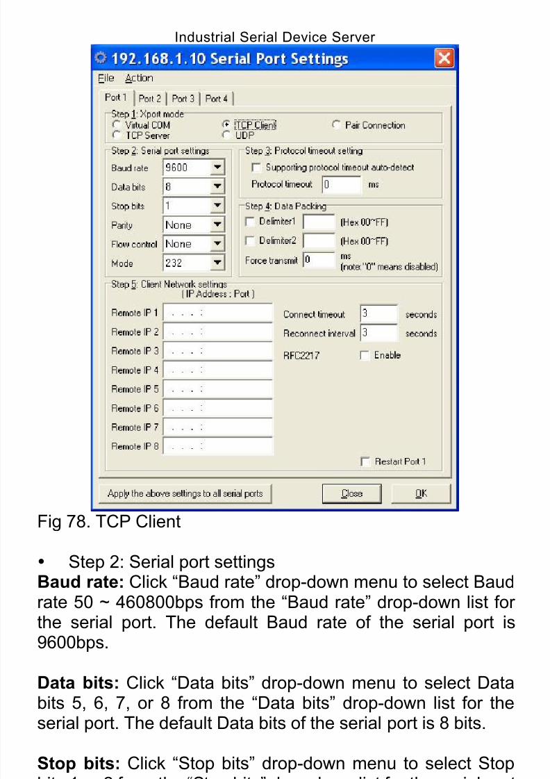
8/15/2019 EtherWAN SE5302-00B User Manual
http://slidepdf.com/reader/full/etherwan-se5302-00b-user-manual 83/105
Industrial Serial Device Server
83
Fig 78. TCP Client
Step 2: Serial port settingsBaud rate: Click “Baud rate” drop-down menu to select Baudrate 50 ~ 460800bps from the “Baud rate” drop-down list forthe serial port. The default Baud rate of the serial port is9600bps.
Data bits: Click “Data bits” drop-down menu to select Databits 5, 6, 7, or 8 from the “Data bits” drop-down list for theserial port. The default Data bits of the serial port is 8 bits.
Stop bits: Click “Stop bits” drop-down menu to select Stopbits 1 or 2 from the “Stop bits” drop-down list for the serial port.The default Stop bits of the serial port is 1 bit.
Parity: Click “Parity” drop-down menu to select Parity None,
8/15/2019 EtherWAN SE5302-00B User Manual
http://slidepdf.com/reader/full/etherwan-se5302-00b-user-manual 84/105
Industrial Serial Device Server
84
Even, Odd, Mark, or Space from the “Parity” drop-down list forthe serial port. The default Parity of the serial port is None.
Flow control: Click “Flow control” drop-down menu to select
Flow control None, Hardware, or Software from the “Flowcontrol” drop-down list for the serial port. The default Flowcontrol of the serial port is None.
Mode: Click “Mode” drop-down menu to select Mode RS232,RS422, or RS485 from the “Mode” drop-down list for theserial port. The default Mode of the serial port is RS232.
Step 3: Protocol timeout settingSupport protocol timeout auto-detect: Check this option tosupport protocol timeout auto-detect. The Serial DeviceServer will automatically test the TCP connection to remotehost. If the TCP connection is idle, the TCP connection will beclosed and the port will be freed for other hosts.
Protocol timeout: Click in “Protocol timeout” text box andtype a period of Protocol timeout assigned to the serial port onthe Serial Device Server. The connection will be closed andthe port will be freed for connection with other hosts whenserial port stops data transmission for a defined period of time
(Protocol timeout). The default Protocol timeout is 0ms.
Step 4: Data PackingDelimiter1, 2: Check this option to enable Delimiter1, 2. Clickin “Delimiter1, 2” text box and Delimiter1, 2 assigned to theserial port on the Serial Device Server. The data will betransmitted if the Delimiter1 is received or Delimiter1 and
Delimiter2 are received.
Force transmit: Click in “Force transmit” text box and specifyForce transmit to the serial port on the Serial Device Server.The data will be transmitted when the Force transmit isreached. The default Force transmit of the serial port is 0 todisable Force transmit.
Step 5: Client Network settingsRemote IP 1 ~ 8: Click in “Remote IP 1 ~ 8” text boxes to

8/15/2019 EtherWAN SE5302-00B User Manual
http://slidepdf.com/reader/full/etherwan-se5302-00b-user-manual 85/105
Industrial Serial Device Server
85
specify IP addresses and Port numbers of remote hostcomputers.
Connect timeout: Click in “Connect timeout” text box and
type a period of Connect timeout assigned to the serial porton the Serial Device Server. The connection will be closedand the port will be freed for connection with other hosts whenserial port stops data transmission for a defined period of time(Connect timeout). The default Connect timeout is 3 seconds.
Reconnect interval: Click in “Reconnect interval” text box
and type a period of Reconnect interval assigned to the serialport on the Serial Device Server. The connection will bereestablished with other hosts for a defined period of time(Reconnect interval). The default Reconnect interval is 3seconds.
RFC2217: RFC2217 is used to establish a transparentconnection between a host computer and a serial device bymapping the serial port on the Serial Device Server to a localCOM port on the host computer. Check this option to enableRFC2217 for TCP Client Setting.
Restart Port: Check this option to restart the serial port on
the Serial Device Server when you click the “OK” button tofinish TCP Client Setting.
Apply the above settings to all serial ports: Click thisbutton to apply the above settings to all serial ports.
4. UDP
Step 1: Xport modeChoose “UDP” from the “Step 1: Xport mode”.
8/15/2019 EtherWAN SE5302-00B User Manual
http://slidepdf.com/reader/full/etherwan-se5302-00b-user-manual 86/105
Industrial Serial Device Server
86
Fig 79. UDP
Step 2: Serial port settingsBaud rate: Click “Baud rate” drop-down menu to select Baudrate 50 ~ 460800bps from the “Baud rate” drop-down list forthe serial port. The default Baud rate of the serial port is9600bps.
Data bits: Click “Data bits” drop-down menu to select Databits 5, 6, 7, or 8 from the “Data bits” drop-down list for theserial port. The default Data bits of the serial port is 8 bits.
Stop bits: Click “Stop bits” drop-down menu to select Stopbits 1 or 2 from the “Stop bits” drop-down list for the serial port.The default Stop bits of the serial port is 1 bit.
Parity: Click “Parity” drop-down menu to select Parity None,

8/15/2019 EtherWAN SE5302-00B User Manual
http://slidepdf.com/reader/full/etherwan-se5302-00b-user-manual 87/105
Industrial Serial Device Server
87
Even, Odd, Mark, or Space from the “Parity” drop-down list forthe serial port. The default Parity of the serial port is None.
Flow control: Click “Flow control” drop-down menu to select
Flow control None, Hardware, or Software from the “Flowcontrol” drop-down list for the serial port. The default Flowcontrol of the serial port is None.
Mode: Click “Mode” drop-down menu to select Mode RS232,RS422, or RS485 from the “Mode” drop-down list for theserial port. The default Mode of the serial port is RS232.
Step 3: Protocol timeout settingSupport protocol timeout auto-detect: Check this option tosupport protocol timeout auto-detect. The Serial DeviceServer will automatically test the TCP connection to remotehost. If the TCP connection is idle, the TCP connection will beclosed and the port will be freed for other hosts.
Protocol timeout: Click in “Protocol timeout” text box andtype a period of Protocol timeout assigned to the serial port onthe Serial Device Server. The connection will be closed andthe port will be freed for connection with other hosts whenserial port stops data transmission for a defined period of time
(Protocol timeout). The default Protocol timeout is 0ms.
Step 4: Data PackingDelimiter1, 2: Check this option to enable Delimiter1, 2. Clickin “Delimiter1, 2” text box and Delimiter1, 2 assigned to theserial port on the Serial Device Server. The data will betransmitted if the Delimiter1 is received or Delimiter1 and
Delimiter2 are received.
Force transmit: Click in “Force transmit” text box and specifyForce transmit to the serial port on the Serial Device Server.The data will be transmitted when the Force transmit isreached. The default Force transmit of the serial port is 0 todisable Force transmit.
Step 5: UDP Network settingsServer 1 ~ 8: Click in “Server 1 ~ 8” text boxes to specify IP
8/15/2019 EtherWAN SE5302-00B User Manual
http://slidepdf.com/reader/full/etherwan-se5302-00b-user-manual 88/105
Industrial Serial Device Server
88
addresses and Port numbers of remote UDP Servers.
UDP Port: Click in “UDP Port” text box and type a UDP Portnumber assigned to the Source UDP Clients. The default
UDP Port number is 601.
Source IP 1 ~ 8: Click in “Source IP 1 ~ 8” text box to specifyIP addresses of Source UDP Clients.
Restart Port: Check this option to restart the serial port onthe Serial Device Server when you click the “OK” button to
finish UDP Setting.
Apply the above settings to all serial ports: Click thisbutton to apply the above settings to all serial ports.
5. Pair Connection Step 1: Xport modeChoose “Pair Connection” from the “Step 1: Xport mode”.

8/15/2019 EtherWAN SE5302-00B User Manual
http://slidepdf.com/reader/full/etherwan-se5302-00b-user-manual 89/105
Industrial Serial Device Server
89
Fig 80. Pair Connection
Step 2: Serial port settingsBaud rate: Click “Baud rate” drop-down menu to select Baudrate 50 ~ 460800bps from the “Baud rate” drop-down list forthe serial port. The default Baud rate of the serial port is9600bps.
Data bits: Click “Data bits” drop-down menu to select Databits 5, 6, 7, or 8 from the “Data bits” drop-down list for theserial port. The default Data bits of the serial port is 8 bits.
Stop bits: Click “Stop bits” drop-down menu to select Stopbits 1 or 2 from the “Stop bits” drop-down list for the serial port.The default Stop bits of the serial port is 1 bit.
Parity: Click “Parity” drop-down menu to select Parity None,

8/15/2019 EtherWAN SE5302-00B User Manual
http://slidepdf.com/reader/full/etherwan-se5302-00b-user-manual 90/105
Industrial Serial Device Server
90
Even, Odd, Mark, or Space from the “Parity” drop-down list forthe serial port. The default Parity of the serial port is None.
Flow control: Click “Flow control” drop-down menu to select
Flow control None, Hardware, or Software from the “Flowcontrol” drop-down list for the serial port. The default Flowcontrol of the serial port is None.
Mode: Click “Mode” drop-down menu to select Mode RS232,RS422, or RS485 from the “Mode” drop-down list for theserial port. The default Mode of the serial port is RS232.
Step 3: Protocol timeout settingSupport protocol timeout auto-detect: Check this option tosupport protocol timeout auto-detect. The Serial DeviceServer will automatically test the TCP connection to remotehost. If the TCP connection is idle, the TCP connection will beclosed and the port will be freed for other hosts.
Protocol timeout: Click in “Protocol timeout” text box andtype a period of Protocol timeout assigned to the serial port onthe Serial Device Server. The connection will be closed andthe port will be freed for connection with other hosts whenserial port stops data transmission for a defined period of time
(Protocol timeout). The default Protocol timeout is 0ms.
Step 4: Data PackingDelimiter1, 2: Check this option to enable Delimiter1, 2. Clickin “Delimiter1, 2” text box and Delimiter1, 2 assigned to theserial port on the Serial Device Server. The data will betransmitted if the Delimiter1 is received or Delimiter1 and
Delimiter2 are received.
Force transmit: Click in “Force transmit” text box and specifyForce transmit to the serial port on the Serial Device Server.The data will be transmitted when the Force transmit isreached. The default Force transmit of the serial port is 0 todisable Force transmit.
Step 5: Pair Connection settingsPair Connection Mode: Choose Master or Slave from the
8/15/2019 EtherWAN SE5302-00B User Manual
http://slidepdf.com/reader/full/etherwan-se5302-00b-user-manual 91/105
Industrial Serial Device Server
91
Pair Connection Mode.
IP: Click in “IP” text box and specify the IP address of theSlave Serial Device Server of Pair Connection.
TCP Port: Click in “TCP Port” text box and type a TCP Portnumber assigned to the serial port on the Serial DeviceServer. The default TCP Port number is 601.
Restart Port: Check this option to restart the serial port onthe Serial Device Server when you click the “OK” button to
finish Pair Connection Setting.
Apply the above settings to all serial ports: Click thisbutton to apply the above settings to all serial ports.
8.6.2. Basic Network Settings
Click “Basic Network Settings” from “Setting” to configure theSerial Device Server.
Fig 81. Basic Network Settings
Network Settings1. DHCP: Click this option to enable “DHCP” so that DHCP
8/15/2019 EtherWAN SE5302-00B User Manual
http://slidepdf.com/reader/full/etherwan-se5302-00b-user-manual 92/105
Industrial Serial Device Server
92
server automatically supplies an IP address, gatewayaddress, and subnet mask to Serial Device Server.
2. IP address: Click in “IP address” text box and type a newaddress to change the IP address.
3. Netmask: Click in “Netmask” text box and type a newaddress to change the Netmask.
4. Gateway: Click in “Gateway” text box and type a newaddress to change the Gateway.
5. DNS server 1, 2, 3: Click in “DNS server 1”, “DNS server2”, or “DNS server 3” text box and fill in DNS information.
Time Settings1. Time zone (24-hour): Click “Time zone” drop-down menu
to select a different time zone from the “Time zone”drop-down list.
2. Local time: Click “Local time” drop-down menu to changedate for the Serial Device Server. And adjust time for theSerial Device Server.
3. Time server: Click in “Time server” text box to enter Timeserver address for the Serial Device Server. And check“Enable” to enable this setting.
8.6.3. System Management
Click “System Management” from “Setting” to configure theSerial Device Server.
8/15/2019 EtherWAN SE5302-00B User Manual
http://slidepdf.com/reader/full/etherwan-se5302-00b-user-manual 93/105
Industrial Serial Device Server
93
Fig 82. System Management
Server Name SettingsServer Name: Click in “Server name” text box and specifyServer name to the Serial Device Server.
Change Password1. Old password: Click in “Old password” text box and enter
the Old password of the Serial Device Server.2. New password: Click in “New password” text box and
enter the New password for the Serial Device Server.3. Confirm password: Click in “Confirm password” text box
and enter the New password again for the Serial DeviceServer.
SNMP TrapIP of remote SNMP trap receiver: Click in “IP of remote SNMPtrap receiver” text box and enter IP address of the remoteSNMP trap receiver.
E-mail Alert1. SMTP Setting:

8/15/2019 EtherWAN SE5302-00B User Manual
http://slidepdf.com/reader/full/etherwan-se5302-00b-user-manual 94/105
Industrial Serial Device Server
94
SMTP Host: SMTP (Simple Mail Transfer Protocol). Clickin “SMTP Host” text box and enter IP address of theSMTP Host.
SMTP Port: Click in “SMTP Port” text box and enter the
SMTP Port number. The default SMTP Port number is 25.
2. From E-Mail address From E-mail address: Click in “From E-mail address” text
box and specify the E-mail address to receive the E-mailfrom.
3. E-mail addresses to report E-mail address1 ~ 4: Click in “E-mail address1 ~ 4” text
box and specify the E-mail addresses to receive theE-mail. Check this option to enable E-mail address1 ~ 4.
Firmware UpdateSelect file: Click the “Search File” button to search thefirmware file to be updated to the Serial Device Server.
8.6.4. Utility Setting
Click “Utility Setting” from “Setting” to configure the SerialDevice Server.
Environment1. Auto-detect Device on start: Check this option to enable
the Serial Device Server to automatically detect whetherthe connected serial device is started up.
2. Auto-polling: Click in “Auto-polling” text box and type aperiod of Auto-polling time assigned to Serial DeviceServer. The default Auto-polling is per 2 seconds.
8/15/2019 EtherWAN SE5302-00B User Manual
http://slidepdf.com/reader/full/etherwan-se5302-00b-user-manual 95/105
Industrial Serial Device Server
95
Fig 83. Environment
Load setting1. Replace network setting: Check this option to replace the
network setting of the Serial Device Server when you loadsetting to the Serial Device Server.
2. Replace account and password: Check this option toreplace the account and password of the Serial DeviceServer when you load setting to the Serial Device Server.
3. Replace host name: Check this option to replace the hostname of the Serial Device Server when you load settingto the Serial Device Server.
4. Show this page when load file: Check this option to showthis Utility Setting page when user loads setting to theSerial Device Server.
Fig 84. Load setting
8.7. Monitoring
Click “Monitoring” from menu bar to show as Fig 85.
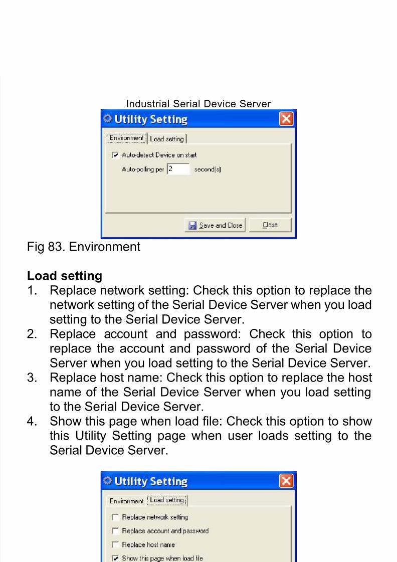
8/15/2019 EtherWAN SE5302-00B User Manual
http://slidepdf.com/reader/full/etherwan-se5302-00b-user-manual 96/105
Industrial Serial Device Server
96
Fig 85. Monitoring
8.7.1. Port Status
Click “Port Status” from “Monitoring” to view the Port Status ofthe Serial Device Server.
Fig 86. Port Status
8.7.2. Logs
SystemUser can view the System Log of the Serial Device Server.

8/15/2019 EtherWAN SE5302-00B User Manual
http://slidepdf.com/reader/full/etherwan-se5302-00b-user-manual 97/105
Industrial Serial Device Server
97
Fig 87. System
EventUser can view the Event Log of the Serial Device Server.
Fig 88. Event
8.8. Restart
Click “Restart” from menu bar to show as Fig 89.
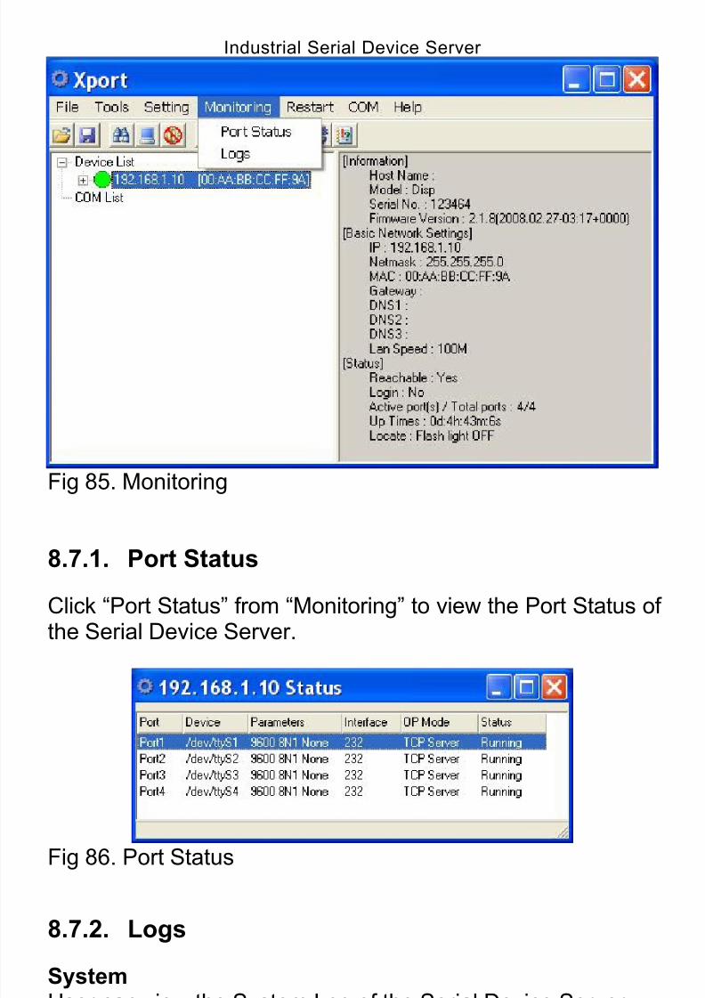
8/15/2019 EtherWAN SE5302-00B User Manual
http://slidepdf.com/reader/full/etherwan-se5302-00b-user-manual 98/105
Industrial Serial Device Server
98
Fig 89. Monitoring
8.8.1. Restart Port
Click “Restart Port” from “Restart” to select the serial port on
the Serial Device Server to be restarted.
8.8.2. Restart System
Click “Restart System” from “Restart” to restart the SerialDevice Server.
Fig 90. Restart System
8.8.3. Restart All Ports
Click “Restart All Ports” from “Restart” to select all serial portson the Serial Device Server to be restarted.
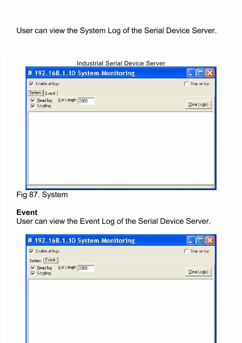
8/15/2019 EtherWAN SE5302-00B User Manual
http://slidepdf.com/reader/full/etherwan-se5302-00b-user-manual 99/105
Industrial Serial Device Server
99
Fig 91. Restart All Ports
8.9. COM
Click “COM” from menu bar to show as Fig 92.
Fig 92. COM
8.9.1. Create a new COM port
Click “Create a new COM port” from “COM” to map a serialport to a COM port on a PC. The serial port on the SerialDevice Server has to be set to Virtual Com mode when
mapping COM port with Xport utility.
Network setting1. Remote IP address: Input the IP address of the remote
Serial Device Server.2. TCP port: Choose TCP port number assigned to the COM
port. The default TCP port number is 601.3. Active auto-reconnect: Check this option to support
Active auto-reconnect. The Xport utility will automatically

8/15/2019 EtherWAN SE5302-00B User Manual
http://slidepdf.com/reader/full/etherwan-se5302-00b-user-manual 100/105
Industrial Serial Device Server
100
attempt to reconnect COM port to the serial port on theSerial Device Server.
4. Reconnect interval: The Xport utility will automaticallyattempt to reconnect COM port to the serial port on the
Serial Device Server in defined time interval (Reconnectinterval). The default Reconnect interval is 1000ms.
5. Cache data when connection was broken: Check thisoption to ensure that data is buffered if the connection isbroken.
Fig 93. Network setting
Serial setting1. Serial port protocol: Choose Raw protocol or RFC2217protocol.
2. Serial port preset signals: There are CTS, DSR, DCD,and RING serial port preset signals that can be chosen.
3. Enable bitrate emulation: Check this option to limit datatransmission speed to that was specified to serial port.
Transmission speed depends on bandwidth of the serialconnection if bitrate emulation is disabled.

8/15/2019 EtherWAN SE5302-00B User Manual
http://slidepdf.com/reader/full/etherwan-se5302-00b-user-manual 101/105
Industrial Serial Device Server
101
Fig 94. Serial setting
8.9.2. Remove all COM ports
Click “Remove all COM ports” to remove all the COM ports
and remove all the mapping from the serial ports to COMports on a PC.
Fig 95. Remove all COM ports
8.10. Help
Click “Help” from menu bar to show as Fig 96. Click “About
utility” from “Help” to show the version of Xport utility as Fig97.
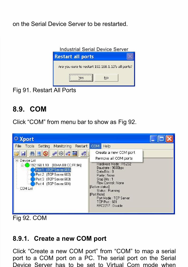
8/15/2019 EtherWAN SE5302-00B User Manual
http://slidepdf.com/reader/full/etherwan-se5302-00b-user-manual 102/105
Industrial Serial Device Server
102
Fig 96. Help
Fig 97. About utility

8/15/2019 EtherWAN SE5302-00B User Manual
http://slidepdf.com/reader/full/etherwan-se5302-00b-user-manual 103/105
Industrial Serial Device Server
103
9. Specifications
9.1. Hardware Specifications
ApplicableStandards
IEEE 802.3 10Base-TIEEE 802.3u 100Base-TX/FX
Switching Method Store-and-Forward
Forwarding Rate
10Base-T100Base-TX100Base-FX
10 / 20Mbps half / full-duplex100 / 200Mbps half / full-duplex200Mbps full-duplex
Performance 14,880pps for 10Mbps148,810pps for 100Mbps
Cable
10Base-T
100Base-TX
100Base-FX
2-pair UTP/STP Cat. 3, 4, 5 Up to 100m (328ft)
2-pair UTP/STP Cat. 5 Up to 100m (328ft)
50 or 62.5/125µm multi-mode fiber (1300nm) up to 2km9 or 10/125µm single-mode fiber (1300nm) up to 75km
Serial PortInterface
Connector
Line ProtectionIsolation
RS-232/422/485
RJ-50 (4-port RS-232/422/485), DB9 (2-port RS-232/422/485),Terminal Block (isolated RS-422/485)15KV ESD2KV
SerialCommunicationParametersParityData Bits
Stop BitFlow ControlSpeed
None, Even, Odd, Mark, Space5, 6, 7, 8
1, 2None, Hardware, Software50bps to 460.8Kbps
LED Indicators Per unit – Power status (Power 1, 2, 3), StatusEthernet port – LAN1, LAN2 (Link/Activity)Serial port –2-port: Port 1 TX, Port 1 RX, Port 2 TX, Port 2 RX (Link/Activity)4-port: Port 1 TX/RX, Port 2 TX/RX, Port 3 TX/RX, Port 4TX/RX (Link/Activity)
Dimensions 100mm (W) x 125mm (D) x 30mm (H)(3.94” (W) x 4.92” (D) x 1.18” (H))
Net Weight 0.3Kg (0.66lb.)
Power Input DC Jack: 12VDCTerminal Block: 12~32VDC
PowerConsumption
4.32W Max. 0.36A @ 12VDC, 0.18A @ 24VDC
OperatingTemperature
-10°C to 60℃ (14℉ to 140℉)
StorageTemperature -20°C to 85℃
(-4℉
to 185℉
)
Humidity 5%-95% non-condensing
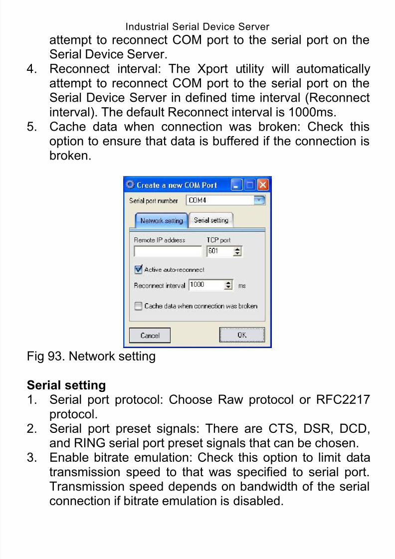
8/15/2019 EtherWAN SE5302-00B User Manual
http://slidepdf.com/reader/full/etherwan-se5302-00b-user-manual 104/105
Industrial Serial Device Server
104
EmissionCompliance
CE Mark Class AFCC Part 15 Class AVCCI Class A

8/15/2019 EtherWAN SE5302-00B User Manual
http://slidepdf.com/reader/full/etherwan-se5302-00b-user-manual 105/105
Industrial Serial Device Server
9.2. Pin Assignments
Pin assignments for serial port
RJ-50:10-Pin 8-Pin 4-Pin RS-232
RS-4224-wire RS-485
2-wire RS-485
1 RI
2 1 DTR
3 2 CTS
4 3 1 Signal GND Signal GND Signal GND
5 4 2 TxD RxD+ D+
6 5 3 RxD RxD- D-
7 6 4 DCD TxD+
8 7 RTS TxD-
9 8 DSR
10 Signal GND
DB-9:
Pin# RS-232RS-422
4-wire RS-4852-wire RS-485
1 DCD TxD+
2 RxD RxD- D-
3 TxD RxD+ D+
4 DTR
5 Signal GND Signal GND Signal GND
6 DSR
7 RTS TxD-
8 CTS9 RI
Terminal Block:RS-422
Related Documents