e-mail: [email protected] For latest product manuals: omegamanual.info Shop online at omega.com ® User’s Guide OME-ET-7000 AND OME-PET-7000 SERIES Ethernet I/O Modules

Welcome message from author
This document is posted to help you gain knowledge. Please leave a comment to let me know what you think about it! Share it to your friends and learn new things together.
Transcript

e-mail: [email protected] latest product manuals:
omegamanual.info
Shop online atomega.com®
User’s Guide
OME-ET-7000 AND OME-PET-7000 SERIES
Ethernet I/O Modules

Servicing North America:U.S.A.: Omega Engineering, Inc., One Omega Drive, P.O. Box 4047ISO 9001 Certified Stamford, CT 06907-0047 USA
Toll Free: 1-800-826-6342 TEL: (203) 359-1660FAX: (203) 359-7700 e-mail: [email protected]
Canada: 976 BergarLaval (Quebec), H7L 5A1 Canada Toll-Free: 1-800-826-6342 TEL: (514) 856-6928FAX: (514) 856-6886 e-mail: [email protected]
For immediate technical or application assistance:U.S.A. and Canada: Sales Service: 1-800-826-6342/1-800-TC-OMEGA®
Customer Service: 1-800-622-2378/1-800-622-BEST®
Engineering Service: 1-800-872-9436/1-800-USA-WHEN®
Mexico/ TEL: 001 (203) 359-1660 FAX: 001 (203) 359-7700Latin America e-mail: [email protected]
Servicing Asia:China: 1698 Ti Shan Road, Unit 102,
Min Hang District, Shanghai, China 201103 P.R.C.Hotline: 800 819 059/400 619 0559 e-mail: [email protected]
Servicing Europe:Benelux: Toll-Free: 0800 099 3344 TEL: +31 20 347 21 21
FAX: +31 20 643 46 43 e-mail: [email protected]
Czech Republic: Frystatska 184733 01 Karviná, Czech RepublicToll-Free: 0800-1-66342 TEL: +420-59-6311899FAX: +420-59-6311114 e-mail: [email protected]
France: Toll-Free: 0850 541038 TEL: 01 57 32 48 17FAX: 01 57 32 48 18 e-mail: [email protected]
Germany/ Austria: Daimlerstrasse 26D-75392 Deckenpfronn, GermanyToll-Free: 0800 8266342 TEL: +49 (0) 7056 9398-0FAX: +49 (0) 7056 9398-29 e-mail: [email protected]
United Kingdom: OMEGA Engineering Ltd.ISO 9001 Certified One Omega Drive, River Bend Technology Centre, Northbank
Irlam, Manchester M44 5BD United KingdomToll-Free: 0800-488-488 TEL: +44 (0) 161 777-6611FAX: +44 (0) 161 777-6622 e-mail: [email protected]
OMEGAnet® Online Service Internet e-mailomega.com [email protected]
It is the policy of OMEGA Engineering, Inc. to comply with all worldwide safety and EMC/EMIregulations that apply. OMEGA is constantly pursuing certification of its products to the European NewApproach Directives. OMEGA will add the CE mark to every appropriate device upon certification.The information contained in this document is believed to be correct, but OMEGA accepts no liability for anyerrors it contains, and reserves the right to alter specifications without notice.WARNING: These products are not designed for use in, and should not be used for, human applications.
Table of Contents
1. Introduction ............................................................................................ 1
1.1. Features ............................................................................................................. 4
1.2. Hardware Overview ........................................................................................... 7
1.2.1. Front Panel .................................................................................................. 7
1.2.2. Back Panel ................................................................................................... 8
1.3. Dimensions ...................................................................................................... 10
1.4. Companion CD ................................................................................................. 12
2. Getting Started ...................................................................................... 13
2.1. Mounting the OME-ET-7000/OME-PET-7000 .................................................. 14
2.2. Configuring the Boot Mode ............................................................................. 16
2.3. OME-ET-7000/OME-PET-7000 Hardware Connections ................................... 17
2.4. Installing the MiniOS7 Utility ........................................................................... 19
2.5. Using the MiniOS7 Utility to Assign an IP Address .......................................... 20
2.6. Enabling the Adobe Flash Player in Your Browser ........................................... 24
2.7. Configuring the I/O Functions ......................................................................... 25
3. Web Applications .................................................................................. 28
3.1. Overview ........................................................................................................ 31
3.2. Configuration ................................................................................................... 33
3.2.1. Network Settings ....................................................................................... 34
3.2.2. Basic Settings ............................................................................................ 37
3.2.3. Module I/O Settings .................................................................................. 48
3.3. Authentication ................................................................................................. 57
3.3.1. Account Management ............................................................................... 58
3.3.2. Accessible IP Settings ................................................................................ 61
3.4. Web HMI .......................................................................................................... 65
3.4.1. Web HMI ................................................................................................... 66
3.4.2. Web Edit .................................................................................................... 67
3.5. I/O Pair Connection ......................................................................................... 76
3.5.1. Example 1: Pair Connection - AO to AI ...................................................... 78
3.5.2. Example 2: Pair Connection - DO to DI ..................................................... 83
3.6. More Information ............................................................................................ 86
4. Modbus and Modbus TCP ..................................................................... 88
4.1. Modbus TCP/IP Interface ................................................................................. 89
4.2. Protocol Description ........................................................................................ 90
4.3. Data Encoding .................................................................................................. 93
4.3.1. Binary ........................................................................................................ 93
4.3.2. 16-bits Word.............................................................................................. 93
4.4. Data Model ...................................................................................................... 94
4.5. Modbus Functions and Registers .................................................................... 95
4.5.1. 01 (0x01) Read Coils .................................................................................. 95
4.5.2. 02 (0x02) Read Discrete Inputs ................................................................. 96
4.5.3. 03 (0x03) Read Holding Registers ............................................................. 97
4.5.4. 04 (0x04) Read Inputs Registers ................................................................ 98
4.5.5. 05 (0x05) Write Single Coil ........................................................................ 99
4.5.6. 06 (0x06) Write Single Register ............................................................... 100
4.5.7. 15 (0x0F) Write Multiple Coils ................................................................ 101
4.5.8. 16 (0x10) Write Multiple Registers ......................................................... 102
4.6. Modbus Master Simulators ........................................................................... 103
4.6.1. Modbus/TCP Client ................................................................................. 103
4.6.2. Modbus Master Tool ............................................................................... 105
4.7. Modbus Demo Programs ............................................................................... 108
5. Calibration .......................................................................................... 109
5.1. Voltage and Current Calibration .................................................................... 109
5.2. Thermocouple Calibration ............................................................................. 114
5.3. RTD Calibration .............................................................................................. 115
5.4. Recover Calibration to Factory Setting .......................................................... 117

6. MiniOS7 Utility .................................................................................... 118
6.1. Establishing a Connection.............................................................................. 118
6.2. Exchanging the Protocol (TCP/IP to UDP) ...................................................... 121
6.3. Updating the OME-ET-7000/OME-PET-7000 OS ............................................ 123
6.4. Updating the OME-ET-7000/OME-PET-7000 Firmware ................................. 126
Appendix A. Node Information Area......................................................... 126
Appendix B. Thermocouple ...................................................................... 132
Appendix C. Application Notes ................................................................. 133
C.1. Dual Watchdog ............................................................................................. 133
C.2. Power-on Value ............................................................................................ 134
C.3. Safe Value ..................................................................................................... 136
C.4. AI High/Low Alarm ....................................................................................... 138
C.5. AI High/Low Latch ........................................................................................ 143
Appendix D. Analog Input Type and Data Format Table ............................ 144
Appendix E. Analog Output Type and Data Format Table ......................... 149
Appendix F. Network Address Translation ................................................ 150
Appendix G. Troubleshooting ................................................................... 152
Page: 1
1. Introduction
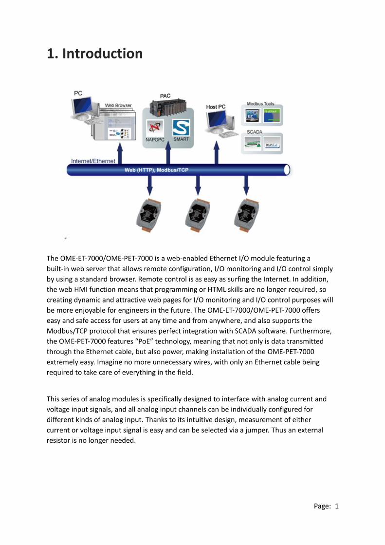
The OME-ET-7000/OME-PET-7000 is a web-enabled Ethernet I/O module featuring a
built-in web server that allows remote configuration, I/O monitoring and I/O control simply
by using a standard browser. Remote control is as easy as surfing the Internet. In addition,
the web HMI function means that programming or HTML skills are no longer required, so
creating dynamic and attractive web pages for I/O monitoring and I/O control purposes will
be more enjoyable for engineers in the future. The OME-ET-7000/OME-PET-7000 offers
easy and safe access for users at any time and from anywhere, and also supports the
Modbus/TCP protocol that ensures perfect integration with SCADA software. Furthermore,
the OME-PET-7000 features “PoE” technology, meaning that not only is data transmitted
through the Ethernet cable, but also power, making installation of the OME-PET-7000
extremely easy. Imagine no more unnecessary wires, with only an Ethernet cable being
required to take care of everything in the field.
This series of analog modules is specifically designed to interface with analog current and
voltage input signals, and all analog input channels can be individually configured for
different kinds of analog input. Thanks to its intuitive design, measurement of either
current or voltage input signal is easy and can be selected via a jumper. Thus an external
resistor is no longer needed.

Page: 2
The "OME-ET-7018Z/OME-PET-7018Z/OME-ET-7019Z/OME-PET-7019Z" is a thermocouple
module that is specifically designed for extremely accurate thermocouple measurement.
The "Z" features automatic cold-junction compensation for each channel to ensure
temperature output consistency and stable temperature output in the field. Open
thermocouple detection and ESD/EFT/Surge protection mechanisms are also included.
Comparison between OME-ET-7000 and OME-PET-7000
The OME-PET-7000 has some unique features that different from the OME-ET-7000
OME-PET-7000 = Power over Ethernet + OME-ET-7000
The OME-PET-7000 includes integrated Power over Ethernet (PoE) technology that allows
both power and data to be carried over a single Ethernet cable, meaning that a device can
operate solely from the power it receives through the data cable. This innovation allows
greater flexibility in office design, higher efficiency in systems design, and faster
turnaround time in installation and implementation. The OME-PET-7000 features true IEEE
802.3af-compliant (classification, Class 1) PoE using both Ethernet pairs (Category 5
Ethernet cable). The OME-PET-7000 can also receive power from auxiliary power sources
such as DC adapters and external battery packs, in addition to the PoE-enabled network.
This is a desirable feature when the total system power requirements exceed the PoE's load
capacity. Furthermore, with the benefit of the auxiliary power option, the OME-PET-7000
can be easily integrated into a standard Ethernet (non-PoE) system.
Industrial PoE Solution
The PoE switch is the ideal power source when using the OME-PET-7000 module. The
NS-205PSE automatically detects whether the connected devices are PoE-enabled or not,
which ensures that the PoE swtch will function in conjunction with both PoE and non-PoE
devices simultaneously.

Page: 3
More information about the OME-PET-7000 series
There are two ways for OME-PET-7000 series devices to obtain power. The first is through
the Ethernet via a PoE switch; the second one is the usual method through wiring from an
external power source. External power source should range from +12 VDC to 48 VDC. The
reason that the second method has been retained is because it might still prove useful for
different applications in a variety of scenarios. The OME-PET-7000 is also equipped with an
LED to indicate whether or not the power is being supplied via a PoE Switch.

Page: 4
1.1. Features
The OME-ET-7000/OME-PET-7000 module offers the most comprehensive configuration
focused on meeting specific application requirements. The following details the features
designed to simplify installation, configuration and application.
Built-in Web Server
Each OME-ET-7000/OME-PET-7000 module has a built-in web server that allows
users to easily configure, monitor and control the module from a remote location
using a standard web browser.
Web HMI
The Web HMI function enables users to create dynamic and attractive web pages
that can be used to monitor and control the I/O points. Users can upload specific I/O
layout diagrams in either bmp, jpg, or gif format, and define a description for each
I/O point. No HTML or Java skills are in order to create the web pages.

Page: 5
Communication Security
An account and password are required when logging into the
OME-ET-7000/OME-PET-7000 web server. An IP Address filter is also included, which
can be used to either allow or deny connections from specific IP addresses.
Modbus/TCP, Modbus/UDP Protocol
The Modbus/TCP, and Modbus/UDP slave functions on the Ethernet Port can be used
to provide data to remote HMI/SCADA software based on the Modbus/TCP driver.
Built-in Multi-function I/O
A variety of I/O components are combined with multiple channels in a single module,
which provides the most cost effective I/O usage and enhances the performance of
the I/O operations.
Automatic MDI/MDI-X Crossover for Plug-and-Play
The RJ-45 Port supports automatic MDI/MDI-x, meaning that it can automatically
detect the type of connection to the Ethernet device without requiring dedicated
straight or crossover cables.
Built-in Dual Watchdog
The Dual Watchdog consists of a Module Watchdog and a Host Watchdog. The
activities of the outputs are also associated with the Dual Watchdog.
The Module Watchdog is a built-in hardware circuit that monitors the operating
status of the module and will reset the module if a failure occurs in either the
hardware or the software.
The Host Watchdog is a software function that monitors the operating status of the
host, and is used to prevent network communication problems or host failures.
When a host watchdog timeout occurs, the module will reset all outputs to a safe
state in order to prevent any erroneous operations of the controlled target.

Page: 6
Highly Reliable Under Harsh Environments
The OME-ET-7000/OME-PET-7000 is housed in a plastic-based case with a vertical
style ventilator that helps to cool the working environment inside the case.
Operating Temperature: -25 ~ +75 °C
Storage Temperature: -30 ~ +80 °C
Humidity: 10 ~ 90% RH (non-condensing)
I/O Pair Connection
The I/O Pair Connection function is used to create a DI to DO (AI to AO) pair via the
Ethernet. Once the configuration is complete, the OME-ET-7000/OME-PET-7000
module can poll the status of the remote input devices using the Modbus TCP
protocol, and then continuously write to the local outputs in the background.

Page: 7
1.2. Hardware Overview
1.2.1. Front Panel
The front panel of the OME-ET-7000/OME-PET-7000 module contains the Ethernet Port,
connectors and LEDs.
L3 LED Indicator
LED Status Function
On Speed = 100 Mbps
Off Speed = 10 Mbps
L2 LED Indicator
LED Status Function
On Ethernet link detected
Off No Ethernet link detected
Flashing Ethernet packet received
L1 LED Indicator
LED Status Function
Flashing The OME-ET-7000/OME-PET-7000 is turned on and is ready for use
PoE LED Indicator
(For PoE series only) Ethernet Port
CON1: The exact design and functionality depends on the module specifications.
CON2: The exact design and functionality depends on the module specifications. .

Page: 8
1.2.2. Back Panel
The back panel of the OME-ET-7000/OME-PET-7000 module contains the frame ground and
the operating mode selector switch.
Operating Mode Selector Switch
Init Mode:
This mode is used for MiniOS7 configuration.
Normal Mode:
This mode is used to execute and run firmware.
On the OME-ET-7000/OME-PET-7000 module, the operating mode selector switch
should usually be in the Normal position. The switch should only be moved from the
Normal position to the Init position when updating the OME-ET-7000/OME-PET-7000
firmware or the OS. Once the update has been completed, ensure that the switch is
returned to the Normal position.
Frame Ground Operating Mode
Selector Switch

Page: 9
Frame Ground
Electronic circuits are constantly vulnerable to Electrostatic Discharge (ESD), which
becomes worse in a continental climate area. The OME-ET-7000/OME-PET-7000
series features a new design for the frame ground that provides a path for bypassing
ESD, allowing enhanced static (ESD) protection capabilities and ensuring that the
module is more reliable.
Choosing either of the following options will provide a better level of protection for
the module:
The OME-ET-7000/OME-PET-7000 has a metallic board attached to the back of the
plastic case, shown as “1” in the figure below.
When mounted to a DIN-Rail, connect the DIN-Rail to the earth ground because the
DIN-Rail is in contact with the upper frame ground, as shown as “2” in the figure
below.
Frame Ground
Frame Ground
2
1

Page: 10
1.3. Dimensions
The following diagrams provide the dimensions of the OME-ET-7000/OME-PET-7000
module and can be used as a reference when defining the specifications for any custom
enclosures. All dimensions are in millimeters.
For the OME-ET-7000Z, OME-PET-7000Z: 72 x 116 x 35
Note that the dimensions of the “Z” version are different from the other models.

Page: 11
For the OME-ET-7000, OME-PET-7000: 72 x 123 x 35
I have a strong mind. I can finish anything.

Page: 12
1.4. Companion CD
This package includes a companion CD that provides the drivers, a software utility, and all
of the required documentation, etc. An outline of the directory structure for the files
contained on the CD is shown below.
CD:\
Application
Data_Sheet
Quick_start
PC_Client
Modbus_TCP
Demo
Document
firmware
OS_image
Tools for MiniOS7
Modbus_ TCP_Client
OME-ET-7000_PET-7000
Modbus_Master_Tool
Software
OME-WISE

Page: 13
2. Getting Started
If you are a new user, begin with this chapter as it includes a guided tour that provides a
basic overview of how to install, configure and use the OME-ET-7000/OME-PET-7000
module.
Before starting any task, please check the package contents. If any of the following items
are either missing or damaged, contact your dealer or distributor.
OME-ET-7000/OME-PET-7000 Software Utility CD Quick Start Guide
Before operating the OME-ET-7000/OME-PET-7000 module, a basic understanding of the
hardware specifications is required, such as the dimensions of the module, the usable
input voltage range of the power supply, and the type of communication interfaces.
Page: 14
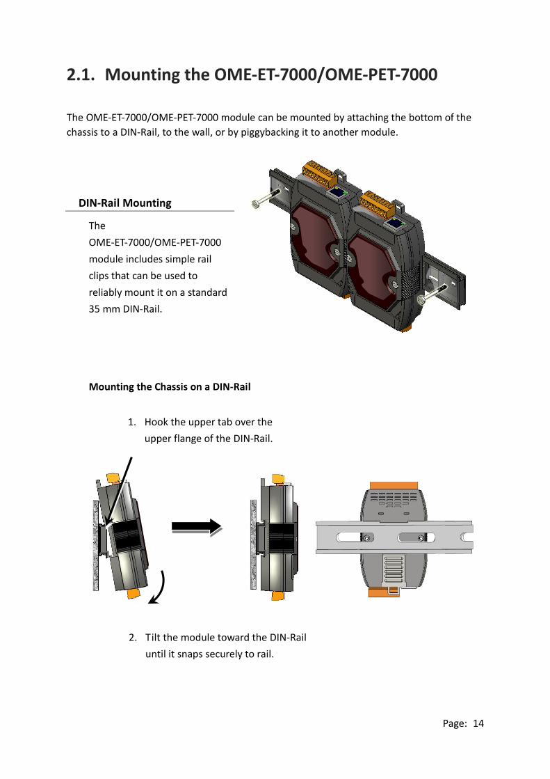
2.1. Mounting the OME-ET-7000/OME-PET-7000
The OME-ET-7000/OME-PET-7000 module can be mounted by attaching the bottom of the
chassis to a DIN-Rail, to the wall, or by piggybacking it to another module.
DIN-Rail Mounting
The
OME-ET-7000/OME-PET-7000
module includes simple rail
clips that can be used to
reliably mount it on a standard
35 mm DIN-Rail.
Mounting the Chassis on a DIN-Rail
1. Hook the upper tab over the
upper flange of the DIN-Rail.
2. Tilt the module toward the DIN-Rail
until it snaps securely to rail.

Page: 15
Piggyback Mounting
The OME-ET-7000/OME-PET-7000
module has a hole on either side of
the casing that can be used for
piggyback mounting.

Page: 16
2.2. Configuring the Boot Mode
The OME-ET-7000/OME-PET-7000 module has two operating modes, which can be
determined by the switch mechanism on the chassis.
Init Mode
Init mode is a way to use
MiniOS7 configuration mode.
Tips & Warnings
Init mode is a method to use MiniOS7 configuration mode and
update the software. After the update is completed, set the switch
to the Normal position.
Normal Mode
Normal mode is the default
mode of operation and the one
you will use most of the time.
Use this mode for more tasks
and configurations. Programs
also are executed in this mode.
Page: 17
2.3. OME-ET-7000/OME-PET-7000 Hardware Connections
OME-ET-7000/OME-PET-7000 series modules provide a variety of communication
interfaces to suit a range of applications. Below is a description of the configuration for
simple applications using the OME-ET-7000/OME-PET-7000 when implementing both PoE
and Non-PoE solutions.
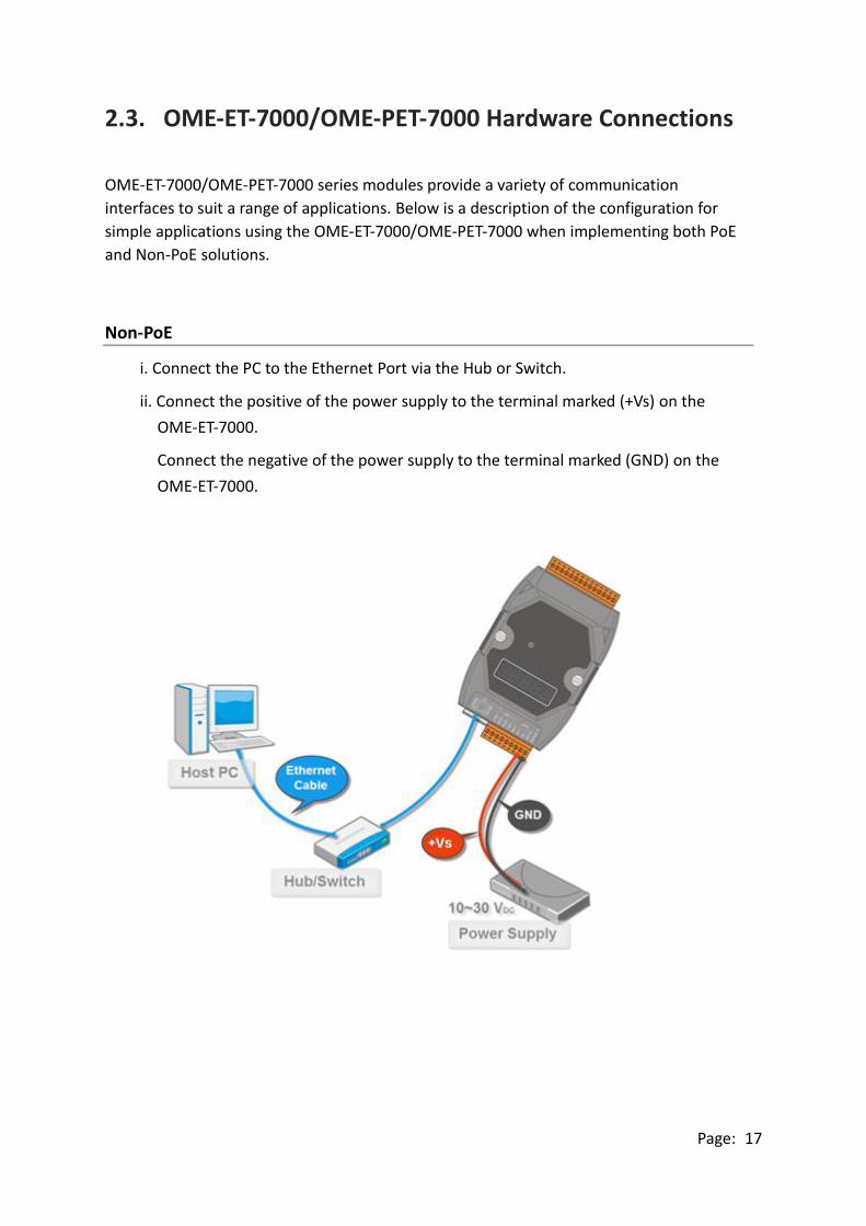
Non-PoE
i. Connect the PC to the Ethernet Port via the Hub or Switch.
ii. Connect the positive of the power supply to the terminal marked (+Vs) on the
OME-ET-7000.
Connect the negative of the power supply to the terminal marked (GND) on the
OME-ET-7000.
Page: 18
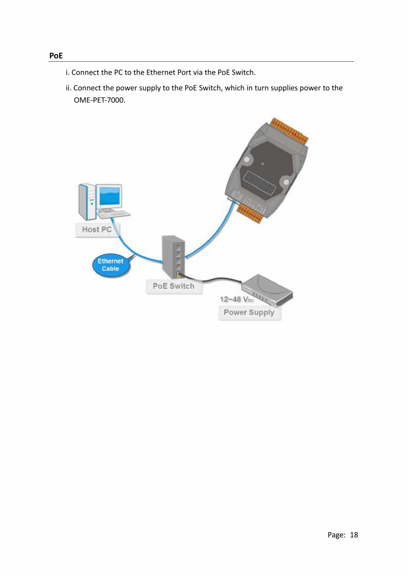
PoE
i. Connect the PC to the Ethernet Port via the PoE Switch.
ii. Connect the power supply to the PoE Switch, which in turn supplies power to the
OME-PET-7000.

Page: 19
2.4. Installing the MiniOS7 Utility
The MiniOS7 Utility is a useful tool that provides a quick and easy way to update the OS
image or the firmware, configure the Ethernet settings, and upload files to the
OME-ET-7000/OME-PET-7000 from a PC.
Step 1: Install the MiniOS7 Utility tool
The latest version of the MiniOS7 Utility can be obtained from the companion CD:
CD:\Software\Tools for MiniOS7\
Step 2:Follow the instructions in the Setup Wizard to complete the installation
After the installation has been
completed, a new short cut for the
MiniOS7 Utility will be displayed on
your desktop.

Page: 20
2.5. Using the MiniOS7 Utility to Assign an IP Address
The OME-ET-7000/OME-PET-7000 is web-based device, and is configured using a default IP
address, meaning that you must first assign a new IP address to the
OME-ET-7000/OME-PET-7000 before operation.
The factory default IP settings are as follows:
Item Default
IP Address 192.168.255.1
Subnet Mask 255.255.0.0
Gateway 192.168.0.1
Step 1:Run the MiniOS7 Utility
Double-click the “MiniOS7 Utility” shortcut on your desktop.

Page: 21
Step 2:Press the “F12” key or choose the “Search” option from the “Connection” menu
After pressing the “F12” key or choosing the “Search” option from
“Connection” menu, the utility will perform a search of all MiniOS7 modules
on your network.
Step 3:Click the “192.168.255.1” item in the IP/Port field list and then click the “IP
Settings” icon in the toolbar
After the search has been completed, click the default value
“192.168.255.1” in the IP/Port field list, and then click the “IP Settings” icon
in the toolbar to display the IP Settings dialog box.
Check the status bar to monitor for the progress of the search
Page: 22
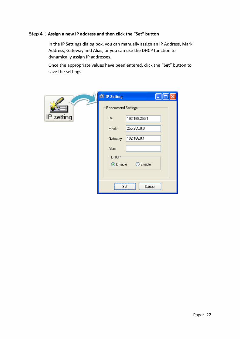
Step 4:Assign a new IP address and then click the “Set” button
In the IP Settings dialog box, you can manually assign an IP Address, Mark
Address, Gateway and Alias, or you can use the DHCP function to
dynamically assign IP addresses.
Once the appropriate values have been entered, click the “Set” button to
save the settings.

Page: 23
Step 5:Reboot the module and then press the “F12” key or click the “Search” option
from the “Connection” menu to check the IP settings
After completing and saving the settings, you should reboot the module and
then use the MiniOS7 Utility to perform another search for the module to
make sure that the IP settings are correct. See Step 2 for details.

Page: 24
2.6. Enabling the Adobe Flash Player in Your Browser
The Web HMI page requires the Adobe Flash Player to be installed. The latest version of the
Adobe Flash Player can be downloaded by accessing the Adobe Systems Incorporated
website. The following instructions will help you to install the Adobe Flash Player in your
web browser.
Step 1:Go to the Adobe Flash Player Download Center
The Adobe Flash Player Download Center:
http://get.adobe.com/flashplayer/
The Adobe Flash Player is subject to change without notice; refer to
http://www.adobe.com/support/flashplayer/downloads.html for the
latest version of this software.
Step 2:Follow the instructions to download the installation file
Click the “Agree and install now” button and follow the instructions to
download the installation file. Note that unless you uncheck the option, the
Google Toolbar will be included in the installation by default, so if you do
not require this feature, be sure to uncheck this option.

Page: 25
2.7. Configuring the I/O Functions
The OME-ET-7000/OME-PET-7000 series contains an advanced web configuration system
that provides users with access to OME-ET-7000/OME-PET-7000 series applications through
a standard web browser.
Step 1:Be sure that the switch is set to the “Normal” position and then reboot the
module
Step 2:Open a browser
Use a standard internet browser to view the OME-ET-7000/OME-PET-7000
web pages, such as Mozilla Firefox or Internet Explorer, etc.
Step 3:Enter the URL address for the OME-ET-7000/OME-PET-7000
If you haven’t changed the default IP address of the
OME-ET-7000/OME-PET-7000 module, please refer to section 2.5. “ Using
the MiniOS7 Utility to Assign an IP Address” to configure it.

Page: 26
Step 4:Enter your User name and Password
After entering the IP address, the login dialog box will appear, prompting you to
enter your user name and password.
The factory default user name and password are as follows:
Step 5:Welcome to the OME-ET-7000/OME-PET-7000 web interface
After logging into the OME-ET-7000/OME-PET-7000 web interface, the welcome
page will be displayed.
Item Default
User name Admin
Password Admin

Page: 27
Step 6:Configure and browse the I/O functions
Click the “Web HMI” option in the “Web HMI”
section of the Main Menu for the
OME-ET-7000/OME-PET-7000, and then click the
I/O function tabs to configure and browse the I/O
functions.
For more detailed information related to the I/O specification, pin assignment, and I/O
functions, etc. for each OME-ET-7000/OME-PET-7000 module, please refer to
“OME-ET-7000/OME-PET-7000 Register Table”, which can be obtained from:
CD:\OME-ET-7000_PET-7000\Document\

Page: 28
3. Web Applications
The OME-ET-7000/OME-PET-7000 contains an advanced web configuration system that
provides users with access to OME-ET-7000/OME-PET-7000 applications through a standard
web browser.
Logging into the OME-ET-7000/OME-PET-7000 web pages
You can log into the OME-ET-7000/OME-PET-7000 web pages from any computer that has
Internet access.
Step 1:Open a browser
Use a standard internet browser to view the OME-ET-7000/OME-PET-7000
web pages, such as Mozilla Firefox or Internet Explorer, etc.
Step 2:Enter the URL address for the OME-ET-7000/OME-PET-7000
If you haven’t changed the default IP address of the
OME-ET-7000/OME-PET-7000 module, please refer to section 2.5. “ Using
the MiniOS7 Utility to Assign an IP Address” to configure it.

Page: 29
Step 3:Enter your User name and Password
After entering the IP address, the login dialog box will appear, prompting you to
enter your user name and password.
The factory default user name and password are as follows:
Item Default
User name Admin
Password Admin
Page: 30
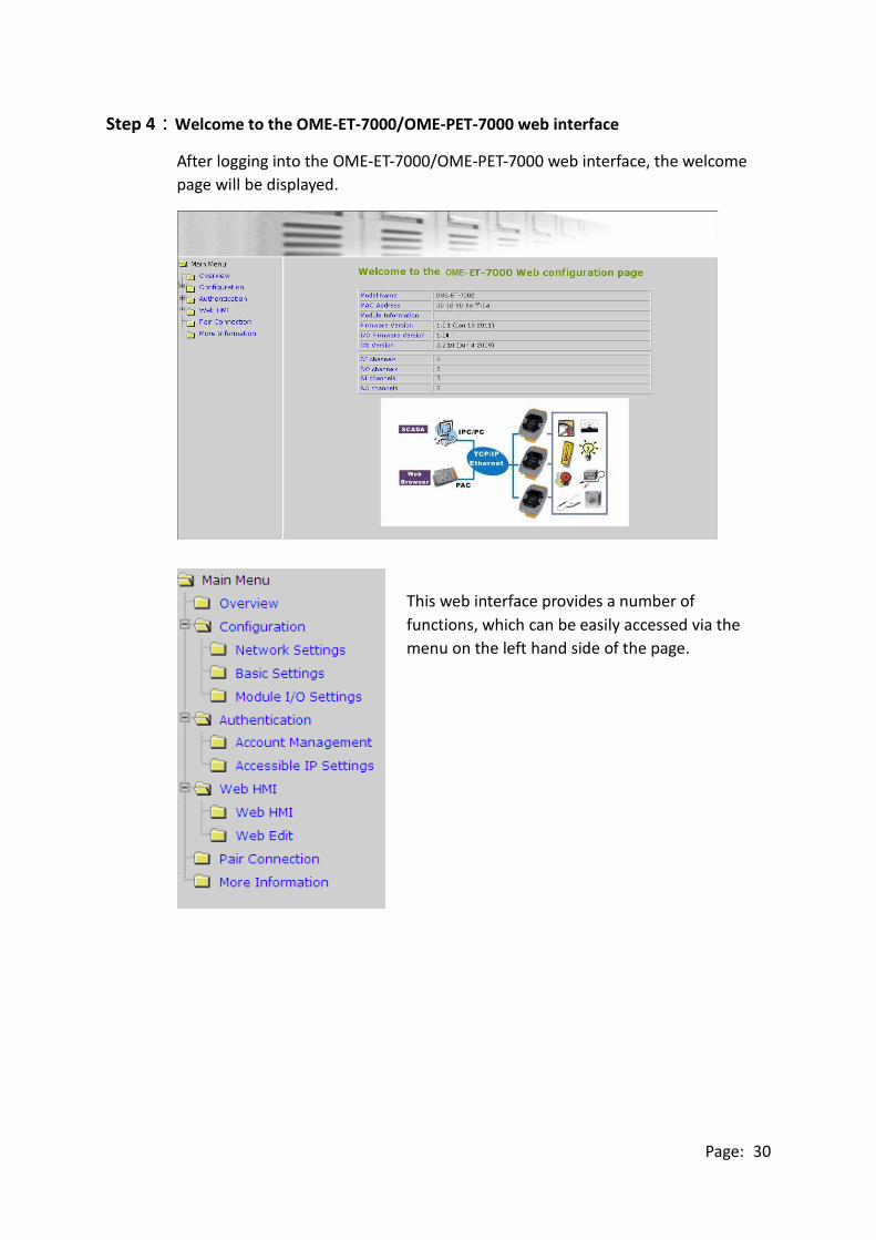
Step 4:Welcome to the OME-ET-7000/OME-PET-7000 web interface
After logging into the OME-ET-7000/OME-PET-7000 web interface, the welcome
page will be displayed.
This web interface provides a number of
functions, which can be easily accessed via the
menu on the left hand side of the page.

Page: 31
3.1. Overview
The “Overview” option in the Main menu provides
a brief introduction to and explanation of the web
interface.
The “Overview” option links to the welcome page
and contains two main parts.
The top section of the page provides some basic
information about both the
OME-ET-7000/OME-PET-7000 hardware and
software.

Page: 32
The lower section of the page provides a brief introduction to the web interface.

Page: 33
3.2. Configuration
The “Configuration” section of the Main menu contains the following options:
Network Settings:
Provides access to the Ethernet Settings page which
allows you to access the IP settings and check the
software version.
Basic Settings:
Provides access to the Basic Settings page which allows
you to configure the basic information for the web
interface.
Module I/O Settings:
Provides access to the Common Functions page which
allows you to configure the settings for the module I/O.

Page: 34
3.2.1. Network Settings
The “Network Settings” page allows you to perform the following functions:
(A) Configure the network settings
(B) Check the software information
(A) Configuring the Network Settings
In general, network settings include the following parameters:
● An IP address: Each OME-ET-7000/OME-PET-7000 on the network must have a unique IP
address.
● A default gateway: A gateway (or router) is a system that is used to connect a network
with one or more other networks.
● A subnet mask: The subnet mask indicates which portion of the IP address that is used to
identify the local network or subnet.
There are two methods of configuring the network settings:
● Dynamic configuration: The Dynamic Host Configuration Protocol (DHCP) is a network
application protocol that automatically assigns an IP address to a device.
● Manual configuration: In the absence of DHCP, OME-ET-7000/OME-PET-7000 modules
can be manually configured with an IP address, mask, and a gateway.
A
B

Page: 35
Dynamic Configuration
If a DHCP server is present on the network, the OME-ET-7000/OME-PET-7000 will
automatically obtain the network settings from the DHCP server when the DHCP function is
enabled.
Step 1:Enable the DHCP by checking the “Enabled” radio button.
Step 2:Click the “Modify Settings” button to finish configuring the network settings.
Manual Configuration
When using manual configuration, all network settings need to be assigned manually. Each
OME-ET-7000/OME-PET-7000 module should have a unique IP address assigned to the
interface in order to identify itself on the network.
Step 1:Disable the DHCP by checking the “Disabled” radio button.
Step 2:Enter the relevant network settings information into the respective fields .
Step 3:Click the “Modify Settings” button to finish configuring the network settings.
1
2
1
3

Page: 36
(B) Checking the Software Information
The software information section includes the following items:
● Web Server Lib. Version: This item provides details of the version number for the web
server library, which is a collection of web development solutions that are providing by
OMEGA for use with custom applications.
● MiniOS7 Version: This item provides defaults of the version number for the MiniOS7 OS
image, which is an embedded operating system specifically designed for use with
OMEGA controllers.
This page can be used to check the version information for the
OME-ET-7000/OME-PET-7000 software after updating the OME-ET-7000/OME-PET-7000
firmware (see section 6.4 . “Uploading the OME-ET-7000/OME-PET-7000 firmware” for
more details).

Page: 37
3.2.2. Basic Settings
The “Basic Settings” page allows you to perform the following functions:
(A) Configure the module information
(B) Configure the web interface information
(C) Reset all parameters to the default settings
C
A
B

Page: 38
(A) Configuring the Module Information
The “Module Information” section includes the following items:
● Module Name: The initial value for this field will depend on the model of the module
and can not be modified.
● Module Information: The module information field indicates the name of the alias that
is used to identify the module.
To configure the module information, follow the procedure below:
Step 1:Enter the Module information in the relevant field.
Step 2:Click the “Submit” button to finish configuring the module information.
1
2

Page: 39
(B) Configuring the Web Interface Information
The “Module Information” section includes the following items:
● Page Header Information (First line) and Page Header Information (Second line): The
title of the website that is displayed the top left-hand corner of the interface, for
example the company name and web address as per the example below.
● More Information URL: This item allows you to specify the URL that will be displayed
when the “More information” option in the Main Menu is clicked in order to provide
additional support for the OME-ET-7000/OME-PET-7000. After completing the settings,
click the “More Information” option to check that the link to the web site is correct (As
per the figure below).

Page: 40
● Web Server TCP Port: By default, TCP/IP uses Port 80.
● Modbus Server TCP Port: By default, TCP/IP uses Port 502.
To configure the web interface information, follow procedure below:
Step 1:Enter the desired information into the respective fields.
Step 2:Click the “Submit” button to finish configuring the module information.
1
2 2
Page: 41
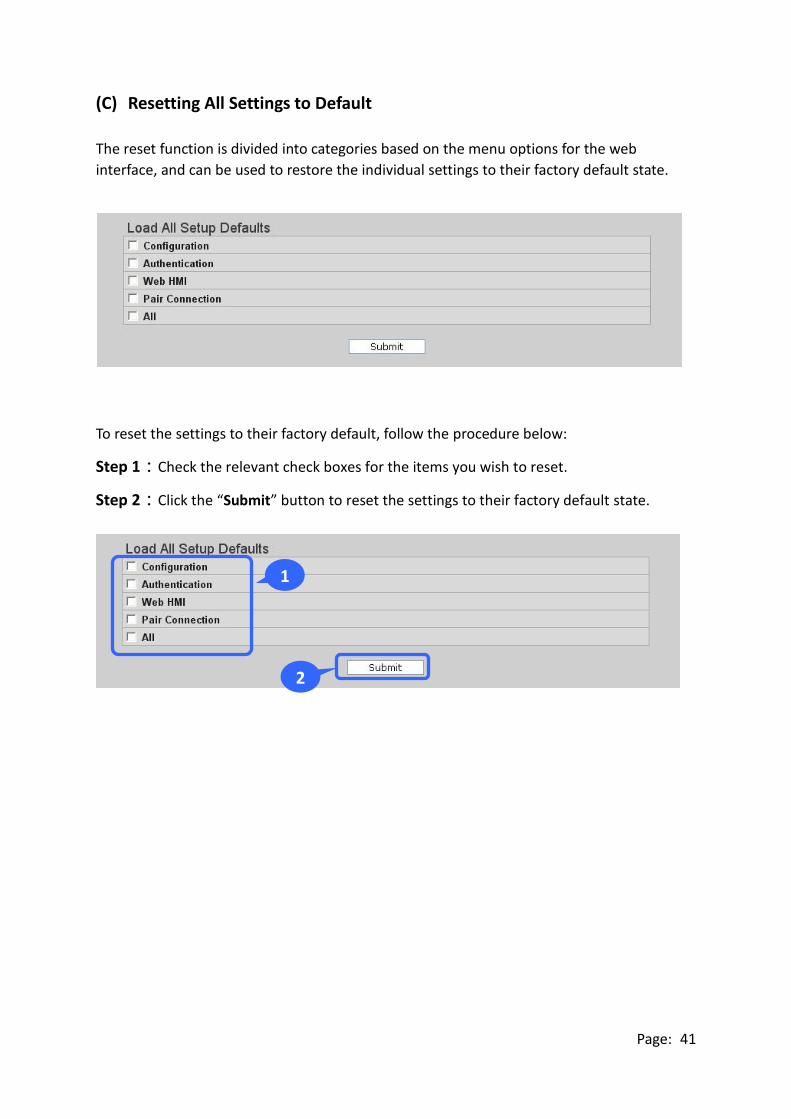
(C) Resetting All Settings to Default
The reset function is divided into categories based on the menu options for the web
interface, and can be used to restore the individual settings to their factory default state.
To reset the settings to their factory default, follow the procedure below:
Step 1:Check the relevant check boxes for the items you wish to reset.
Step 2:Click the “Submit” button to reset the settings to their factory default state.
1
2 2

Page: 42
(a) Factory Default Settings for the “Configuration” Menu Options
The tables below outline the factory default settings for the items listed in the
“Configuration” menu.
Network Settings
Ethernet Settings
Item Factory Default Settings
IP Address 192.168.255.1
Gateway 192.168.0.1
Subnet Mask 255.255.0.0
DHCP Disabled
Basic Settings
Basic Settings
Item Factory Default Settings
Module Name Depends on the name of the module
Module Information Empty
Page Header Information (First line) Empty
Page Header Information (Second line) http://www.omega.com
More Information URL http://www.omega.com
Web Server TCP Port 80
Modbus Server TCP Port 502

Page: 43
Module I/O Settings
The information displayed on the settings page varies depending on the model number.
Common Functions
Item Factory Default Settings
Host WDT Timeout 0 (Disabled)
WDT Event Counter 0
Modbus NetID 1
Digital Output
Item Factory Default Settings
Power-on Value OFF
Safe Value OFF
Digital Input
Item Factory Default Settings
DI Latch Status Disabled
DI Counter Disabled
Analog Output
Item Factory Default Settings
Output Range This value varies depending on the
model of the module
Output Slew Rate 0 (Immediate)
Power-on Value 0
Safe Value 0
Data Format
2’s Comp
Hexadecimal 2’s Comp Hexadecimal
Engineering Unit

Page: 44
Analog Input
Item Factory Default Setting
Input Range This value varies depending on the model
of the module
Enable ON
High Alarm
Alarm Limit Value This value varies depending on the model
of the module
Enable OFF
Alarm Mode Momentary
Low Alarm
Alarm Limit Value This value varies depending on the model
of the module
Enable OFF
Alarm Mode Momentary
Sampling Rate
Normal mode
(16 bits & 10 Hz) Normal mode
Fast mode
(12 bits & 60 Hz)
Filter Setting 60 Hz Rejection
60 Hz Rejection 50 Hz Rejection
Data Format
2’s Comp
Hexadecimal 2’s Comp Hexadecimal
Engineering Unit
Note: The analog input and the analog output share the same data format settings.
Page: 45
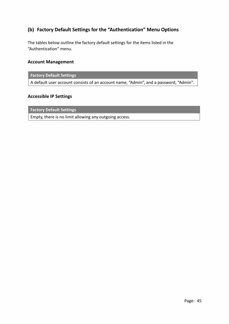
(b) Factory Default Settings for the “Authentication” Menu Options
The tables below outline the factory default settings for the items listed in the
“Authentication” menu.
Account Management
Factory Default Settings
A default user account consists of an account name, “Admin”, and a password, “Admin”.
Accessible IP Settings
Factory Default Settings
Empty, there is no limit allowing any outgoing access.
Page: 46
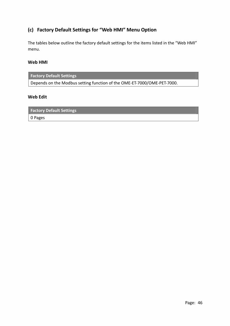
(c) Factory Default Settings for “Web HMI” Menu Option
The tables below outline the factory default settings for the items listed in the “Web HMI”
menu.
Web HMI
Factory Default Settings
Depends on the Modbus setting function of the OME-ET-7000/OME-PET-7000.
Web Edit
Factory Default Settings
0 Pages

Page: 47
(d) Factory Default Settings for the “I/O Pair Connection” Menu Option
The table below outlines the factory default settings for the “Pair Connection” option.
Pair Connection
Factory Default Settings
Empty

Page: 48
3.2.3. Module I/O Settings
After completing the general configuration of the OME-ET-7000/OME-PET-7000 module
described in the previous section, the settings for the input and output channels need to
be configured, such as the channel range and the alarm, etc.
Tips & Warnings
The contents displayed on this page will be depending on the Modbus
functions applicable to the specific the OME-ET-7000/OME-PET-7000
module. Please refer to the user manual for each module for details of how
to configure the relevant I/O settings.
In this example, the OME-ET-7026/OME-PET-7026 will be used in order to explain the I/O
settings. (The OME-ET-7026/OME-PET-7026 is a multi-function module that has 6 AI
channels, 2 AO channels, 2 DI channels and 2 DO channels.)

Page: 49
(A) Common Functions
The Common Functions area provides options that allow the settings for the Modbus
functions to be configured.
Page: 50
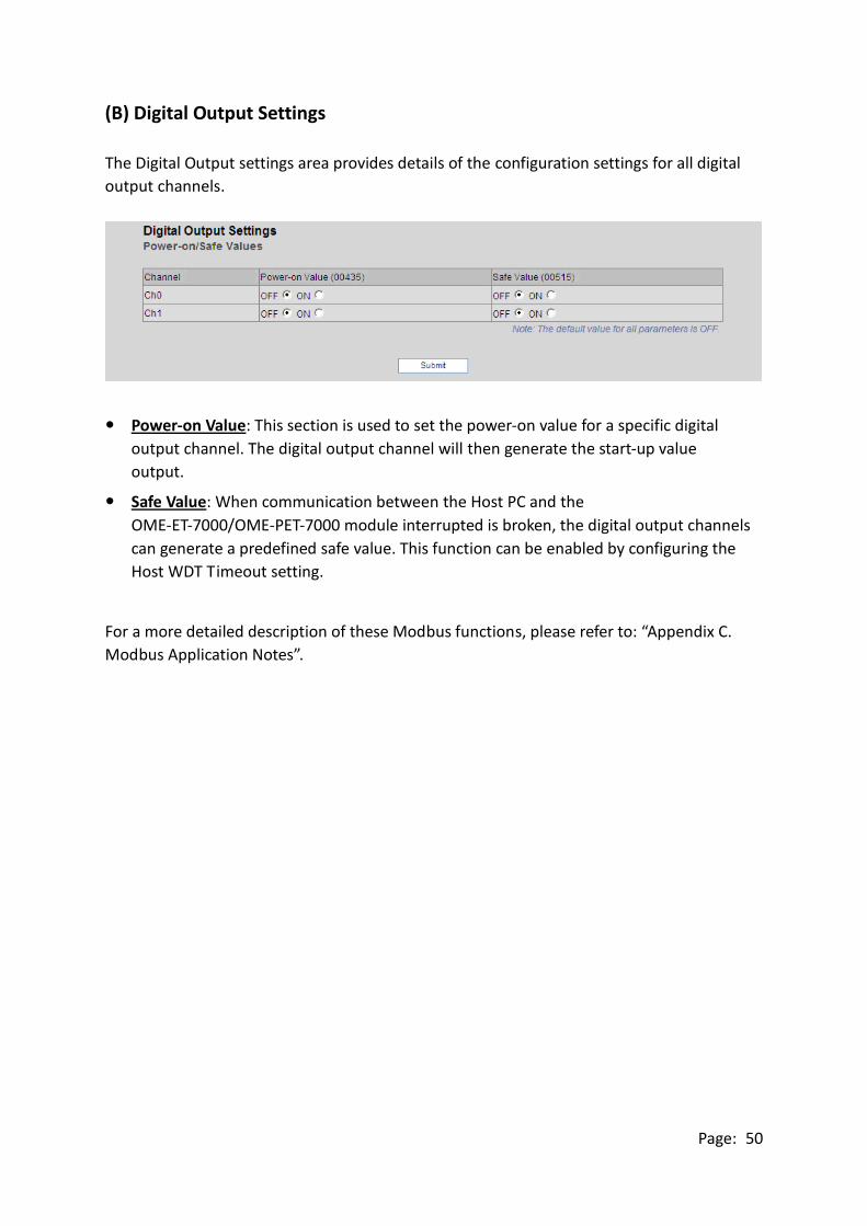
(B) Digital Output Settings
The Digital Output settings area provides details of the configuration settings for all digital
output channels.
Power-on Value: This section is used to set the power-on value for a specific digital
output channel. The digital output channel will then generate the start-up value
output.
Safe Value: When communication between the Host PC and the
OME-ET-7000/OME-PET-7000 module interrupted is broken, the digital output channels
can generate a predefined safe value. This function can be enabled by configuring the
Host WDT Timeout setting.
For a more detailed description of these Modbus functions, please refer to: “Appendix C.
Modbus Application Notes”.

Page: 51
(C) Digital Input Settings
All digital input channels in OME-ET-7000/OME-PET-7000 modules can be used as 32-bit
counters and each counter consists of two address values, the Low word and the High word.
Specific individual DI channels can be counters via the Digital Input settings web page.
DI Latched: When DI Latch function is enabled, once the digital input channel detects
any change in input status, the input status will be latched and will remain in this
condition the latch is manually.
DI Counter: When Counter mode is selected, one counter will record the number of
pulses from the digital signal for the selected channel, and will then record the count
value in the register.
Preset Value: This option allows the default values for the counters to be set.
Page: 52
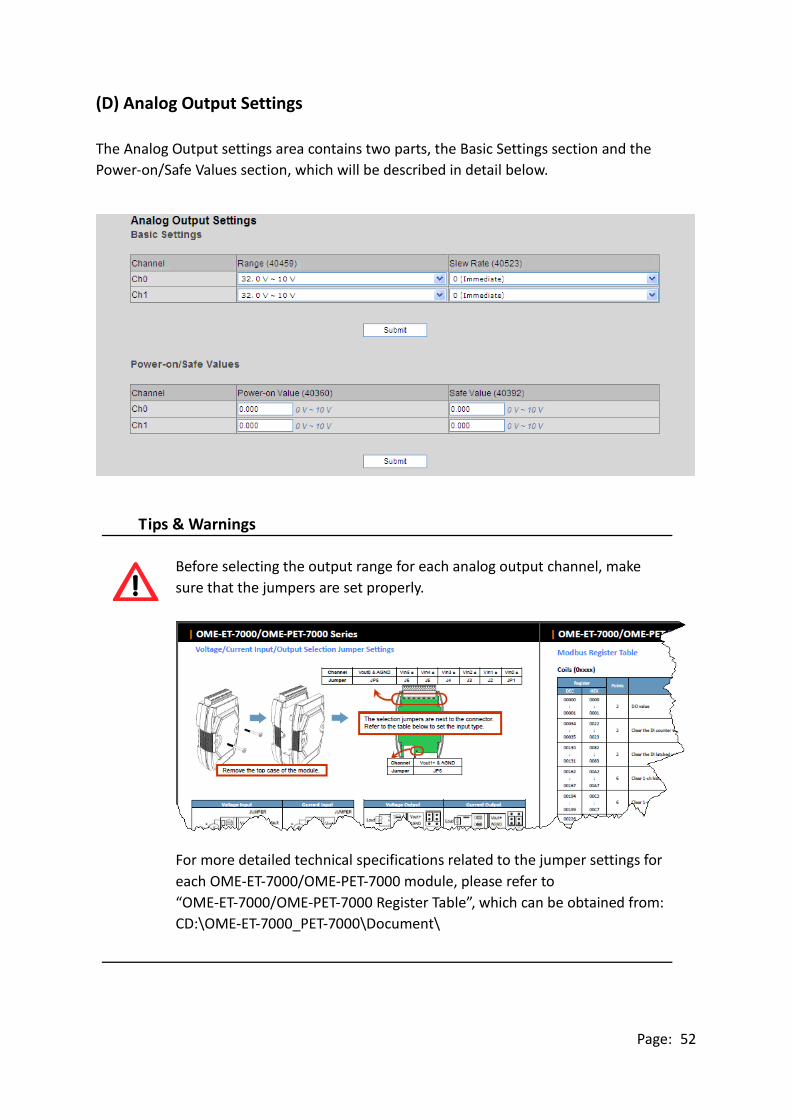
(D) Analog Output Settings
The Analog Output settings area contains two parts, the Basic Settings section and the
Power-on/Safe Values section, which will be described in detail below.
Tips & Warnings
Before selecting the output range for each analog output channel, make
sure that the jumpers are set properly.
For more detailed technical specifications related to the jumper settings for
each OME-ET-7000/OME-PET-7000 module, please refer to
“OME-ET-7000/OME-PET-7000 Register Table”, which can be obtained from:
CD:\OME-ET-7000_PET-7000\Document\

Page: 53
Range: In a manner, a different range can be set for each individual analog output
channel. Select the required voltage/current range from the respective drop-down
menus. For more detailed technical specifications related to the output range for each
analog output channel, please refer to: "Appendix E. Analog Output Type and Data
Format Table".
Slew Rate: This is the programmable output slew rate for the analog output channels,
i.e., the rate of change in the analog output voltage/current as it changes from one
output voltage/current to another. Select the most appropriate value from the
respective drop-down menus.
Power-on Value: A power-on value can be set for a specific analog output channel, and
the analog output channel will then generate the start-up value output.
Safe Value: When communication between the Host PC and the
OME-ET-7000/OME-PET-7000 module is interrupted, the analog output channels can
generate a predefined safe value. This function can be enabled or disabled by
configuring the Host WDT Timeout setting.
For a more detailed description of these Modbus functions, please refer to: “Appendix C.
Modbus Application Notes”.

Page: 54
(E) Analog Input Settings
Analog Input Settings area contains two parts, the Basic Settings section and the Alarm
Settings section, which will be described in detail below.
Tips & Warnings
Before selecting the input range for each analog input channel, make sure
that the jumpers are set properly.
For more detailed technical specifications related to the jumper settings for
each OME-ET-7000/OME-PET-7000 module, please refer to
“OME-ET-7000/OME-PET-7000 Register Table”, which can be obtained from:
CD:\OME-ET-7000_PET-7000\Document\
Page: 55
Range: OME-ET-7000/OME-PET-7000 modules provide a programmable input
voltage/current range on all analog inputs channels, where a different range can be set
for each individual analog input channel. Select the required voltage/current from the
respective drop-down menus. For more detailed technical specifications related to the
input range for each analog input channel, please refer to: “Appendix D. Analog Input
Type and Data Format Table”.
Enable: This section allows each analog input channel to be switched ON or OFF.
Normal/Fast Mode: OME-ET-7000/OME-PET-7000 modules support sample rates in
either “Normal” or “Fast” mode. Fast mode uses 60 Hz with a 12-bit resolution, while
Normal mode uses 10 Hz with a 16-bit resolution.
50/60Hz Rejection for AI: In order to remove the noise from the power supply,
OME-ET-7000/OME-PET-7000 analog input modules feature two built-in rejection filters,
that operate at different frequencies, 50 or 60 Hz, that are designed to remove noise
generated by different power supplies.
AI Data Format: OME-ET-7000/OME-PET-7000 modules allow data to be displayed in
either hexadecimal or engineering unit format. For more detailed technical
specifications related to the data format for each analog input channel, please refer to:
“Appendix D. Analog Input Type and Data Format Table”.

Page: 56
(F) Analog Input Alarm Settings
The OME-ET-7000/OME-PET-7000 modules feature a built-in alarm function. The alarm
includes two parts, the high alarm and the low alarm and each need to be configured for a
specific channel.
Value: You can define both the high alarm value and the low alarm value using the
Alarm Value text box. When the analog input value is higher than the high alarm value,
or lower than the low alarm value, an alarm occurs. The alarm status will then be
activated and switched to on.
Enable: Each analog input alarm can be switched to on or off by clicking the
appropriate radio button.
Mode: The OME-ET-7000/OME-PET-7000 allows the alarm to be selected as either
Momentary or Latch mode, which can be set using the Mode combo box for both the
low alarm and the high alarm.
Latch Mode: Once an alarm occurs, the alarm status will be activated and set to the
logic high level. This value will remain until the alarm is cleared manually.
Momentary Mode: In this mode, the alarm status will dynamically change depending
on whether or not an alarm has occurred. If an alarm occurs, the alarm status will be
set to on. If the alarm is deactivated, the alarm status will be set to off.

Page: 57
3.3. Authentication
The “Authentication” section of the Main Menu contains the following options:
Account Management:
Provides access to the privilege management page,
which allows you to manage user accounts and their
associated privileges.
Accessible IP Settings:
Provides access to the IP Filter Settings page, which
allows you to control access to the web site.

Page: 58
3.3.1. Account Management
The Account Management page provides functions that allow the following tasks to be
performed:
(A) Configuration of user accounts
(B) Restoration of the factory default user account

Page: 59
(A) Configuring the User Accounts
The OME-ET-7000/OME-PET-7000 interface supports a maximum of five user accounts,
including:
● A Built-in Administrator Account
The built-in Administrator account is basically a setup and disaster recovery account
that can be deleted. You can, however, change the password for the administrator
account.
● Four User-defined Accounts
Each user account consists of an account name, a password and an authority level.
The authority level includes the following roles, which determine the type of
operations the user is allowed to perform.
Admin: This level enables access to all OME-ET-7000/OME-PET-7000 web site
features, functions, and commands.
User: This level enables limited access to the OME-ET-7000/OME-PET-7000 web site
features, functions, and commands. In general, operators at this level cannot
change configuration settings.
Once a user account has been created, it can be either enabled or disabled.
To add a new user account, perform the followings:
Step 1:Enter the user account information into the relevant text fields, and then select
the “Enable” checkbox.
Step 2:Click the “Submit” button to complete the user account configuration and save
the details.
1
2 2
Page: 60
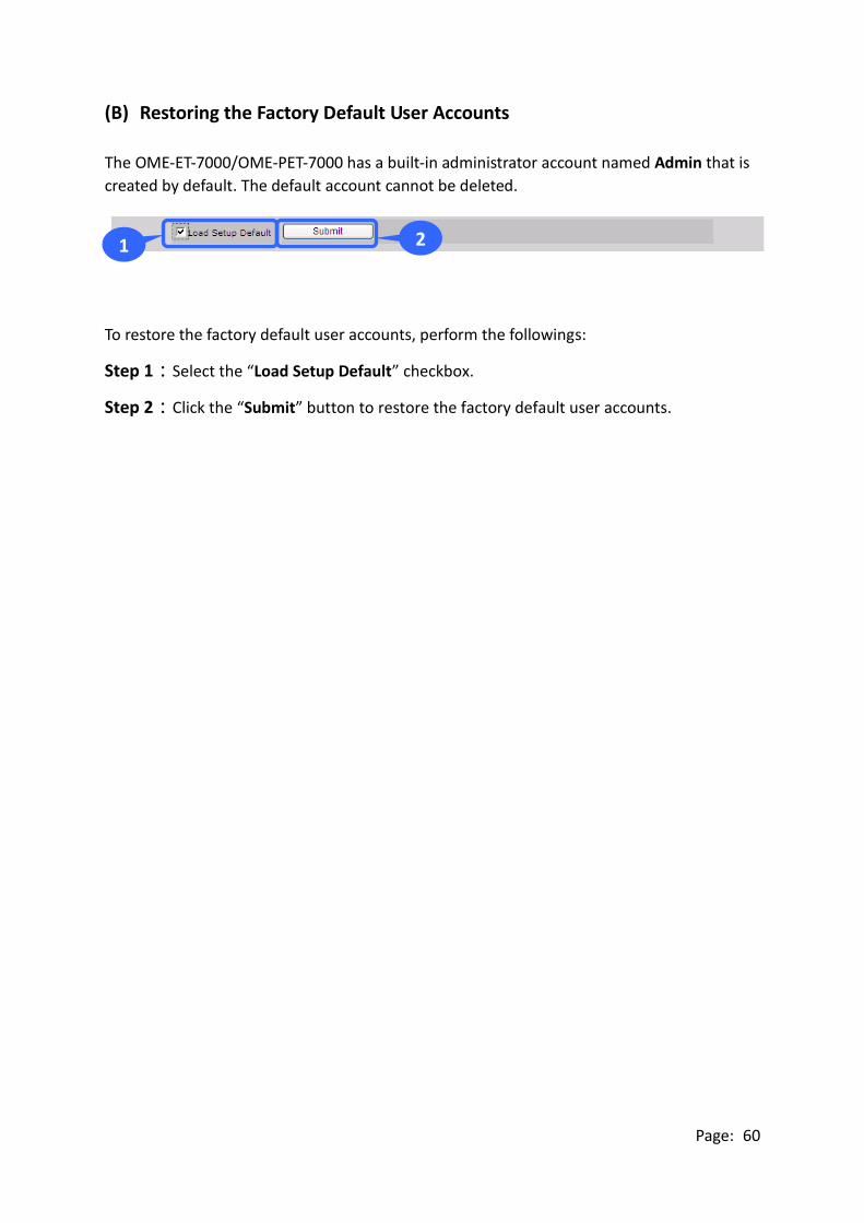
(B) Restoring the Factory Default User Accounts
The OME-ET-7000/OME-PET-7000 has a built-in administrator account named Admin that is
created by default. The default account cannot be deleted.
To restore the factory default user accounts, perform the followings:
Step 1:Select the “Load Setup Default” checkbox.
Step 2:Click the “Submit” button to restore the factory default user accounts.
1 2
2 2

Page: 61
3.3.2. Accessible IP Settings
The IP Filter Settings page provides functions that allow the following tasks to be
performed:
● Configuration of the connection filtering

Page: 62
(A) Configuring IP Filter
The OME-ET-7000/OME-PET-7000 includes an IP filter that enables you to restrict or grant
user access based on a custom IP filter list that you create.
The filter can be enabled by selecting the “Enable the IP filter table” checkbox. After this
option is selected, only requests from the IP addresses included in the list will be allowed
access to the module.
Tips & Warnings
By default, there is no restriction on outgoing access.
Each filter list entry can be either activated or deactivated by selecting the respective
“Activate the Rule” checkbox.

Page: 63
(B) Configuring the IP Filters
Two methods are provided for configuring the IP filter, allowing filtering for either
individual IP addresses, or across a range (group) of IP addresses.
Method 1: Allow access from a single IP address
Step 1:Select the “Enable the IP filter table” checkbox.
Step 2:Enter the same IP address in both the “From (IP Address)” and the “To (IP
Address)” text boxes. (The IP address may be the address of the PC currently
being used or others)
Step 3:Select the “Activate the Rule” checkbox.
Step 4:Click the “Submit” button to complete the configuration of the IP filter list and
save the settings.
4 2
1 2
2 2 3
2

Page: 64
Method 2: Allow access from a group of IP addresses
Step 1:Select the “Enable the IP filter table” checkbox
Step 2:Enter the first IP address in the range in the “From (IP Address)” and enter the
final IP address in the range in the “To (IP Address)” text boxes.
Step 3:Select the “Activate the Rule” checkbox.
Step 4:Click the “Submit” button to complete the configuration of the IP filter list and
save the settings.
4 2
1 2
2 2 3
2

Page: 65
3.4. Web HMI
The “Web HMI” section of the Main Menu contains the following options:
Web HMI:
Provides access to the I/O monitor page, which allows
you to remotely monitor and control the I/O status of
the OME-ET-7000/OME-PET-7000 module.
Web Edit:
Provides access to the Web interface Configuration
page, which allows you to create dynamic web HMI
pages.

Page: 66
3.4.1. Web HMI
The OME-ET-7000/OME-PET-7000 module features a Web HMI web interface that can be
used to display real-time I/O data values and alarms via the LAN or the Internet. Real-time
I/O data values and alarms can be monitored at either the local or remote site using any
web browser. Then, the Web HMI is completed immediately without requiring any
programming skills.

Page: 67
3.4.2. Web Edit
The OME-ET-7000/OME-PET-7000 module provides functions that enable users to create
customized web pages. Users can upload specific I/O layout diagrams in either bmp, jpg, or
gif format and can define a description for each I/O point. No HTML or Java skills are
required in order to create the web pages.

Page: 68
By default, no pages are listed on the initial “Web Page Configuration” page.
The OME-ET-7000/OME-PET-7000 Web Edit function allows the creation of up to 10
user-defined web pages.
A maximum of 10 pages can be created

Page: 69
Below is an example of how to create a customized web page.
Example
Objective:
Create a Web page to monitor the I/O status of a conveyor system, as shown below. The
I/O system contains a sensor that is used to detect the products, and a switch that is used
to turn the conveyor motor on and off.
Step 1:Add a New Page
Click the “Add a new Page” button to begin creating a new page.

Page: 70
Step 2:Upload an Image
Click the “Browse…” button to select an image, and then click the “Upload”
button to upload the image to the OME-ET-7000/OME-PET-7000 module, as
shown in the figure below.
Tips & Warnings
The image can be in either .jpg, .gif, or .bmp format with a maximum file
size of 64 kb. The recommended resolution for the image to be displayed on
the editing Web page is 340 * 250 pixels.
After the upload is completed, the image information will be displayed and the image will
be added to the “Image” dropdown list box, as shown below.
2. Click the “Upload” button to upload the image
1. Click the “Browse…” button to select an image
Image information
File name added to the
Image dropdown list box

Page: 71
Step 3:Set the Page Name and Select the Image
Enter a name for the page in the “Page Name” field and then select an
image from the “Image” dropdown list box. After selecting the image, it will
be displayed in the preview window.
Step 4:Add the Register Item(s) that are to be used to read the selected sensor input
Click the “Edit” button from the first row in the Group table, and the “Edit
Group Register” window will be displayed.
Click the “Edit” button to enter or modify the details of the register item(s)
Enter a name for the page and select an image

Page: 72
Step 5:Add a DI value that is to be used to
read “PHS” input
Set the PHS as an input (use the
Modbus Register 0 (DI0)), and then
select Discrete Input as the Register
Type and enter the name PHS1 as
the Alias, as per the figure shown
below.
Step 6:Save the selected sensor settings
Click the “Save” button to complete the setup and save the register settings.
DI0

Page: 73
Step 7:Add the register item(s) that is to be used to write the selected motor output
After saving the register settings, the new register item will be displayed in
the Group table.
If you wish to edit the details for an item, click the “Edit” button to access
the Edit Group Register page.
If you wish to delete a register item, click the “Clear” button.
Click the “Edit” button to enter or modify the details of the register item(s)

Page: 74
Step 8:Add a DO that is to be used to write
the “Motor” out put to turn the
conveyor motor on and off
Set the Motor as an output (use the
Modbus Register 0 (DO0)), and then
select Coil and Write as the Register
Type and enter Motor as the Alias,
as shown in the figure below.
Step 9:Save the selected sensor settings
Click the “Save” button to complete setup and save the register settings.
DO0
By selecting “write” as the Register type, control button
will be shown on the web page. (Refer to Step 10)

Page: 75
Step 10:Browse the “Carriage” web page
After saving the editing page, a page named Carriage has been added to the
list box on the top left-hand side of the Web Page Configuration window.
Select the Carriage item and click the “Go” button to display to the Carriage
web page.
The conveyer image file and the newly created register items will be displayed on the
Carriage web page, including control buttons that can be used to switch the motor for the
conveyor on or off.
Control buttons

Page: 76
3.5. I/O Pair Connection
The “Pair Connection” option in the Main Menu provides access to the configuration page
for the pair connection function.
The pair connection function is a particular feature of
the OME-ET-7000/OME-PET-7000 module that can be
used to enable a pair of DI-to-DO (AI-to-AO) via
Modbus/TCP. With the pair connection function enabled,
the OME-ET-7000/OME-PET-7000 module can poll the
status of remote input devices using the Modbus/TCP
protocol and then continuously write to its output
channels in the background.

Page: 77
The Pair Connection function consists of the following parameters:
I/O Pair Connection: This item is used to enable/disable the I/O pair connection.
Remote IP Address: The IP address of the remote input device.
Remote TCP Port: The Modbus/TCP Port of the remote input device.
Connection Timeout: The length of time that the OME-ET-7000/OME-PET-7000 module
should wait for a connection to the remote input device.
Reconnect Interval: The reconnect interval is the amount of time between attempts by the
OME-ET-7000/OME-PET-7000 module to reconnect with the remote input device.
Remote Net ID: The Modbus Net ID of the remote device.
Scan Time: The frequency that the remote input device will be polled.
Access Type: Enable/Disable the DI-to-DO (AI-to-AO) pair connection.
Local DO Base Address: The DO base address of the local DO register that will be mapped
to the remote DI device.
Remote DI Base Address: The DI base address of the Remote DI device that will be mapped
to the local DO register.
I/O Count: The I/O count mapped from the base address.
Communication Timeout: The period of time that the OME-ET-7000/OME-PET-7000
module will wait for a response from the remote DI device.

Page: 78
3.5.1. Example 1: Pair Connection - AO to AI
In this example, we will show how to use this feature to achieve AI/AO mapping on two
remote I/O devices.
Hardware devices:
OME-PET-7026 (AIO/DIO module), OME-ET-7017 (AI/DO module), PoE Switch, Power
Supply (24 V), Power Supply (48 V).
Hardware Connections:
Software Configuration:
The following provides step-by-step instructions for how to configure the
OME-ET-7000/OME-PET-7000 via the built-in web interface.
In this example, the AO0/AO1 of the OME-PET-7026 must be mapped to the AI0/AI1 of the
OME-ET-7017. Later, when the AI0/AI1 of the OME-ET-7017 receives the 5 V, the AO0/AO1
of the OME-PET-7026 will automatically output 5 V.
Power Supply
24 V
PoE Switch
OME-PET-7026
OME-ET-7017
Power/GND
(+10 ~ 30 VDC)
Power supply
48 V

Page: 79
Step 1:Log in to the OME-PET-7026 web interface
Enter the IP address of the OME-PET-7026 in the browser, and then enter
your user name and password to log in to the OME-PET-7026 web interface.
Refer to chapter 3, “Web Applications”, for more details.
Step 2:Configure the AO type for the OME-PET-7026
Click the “Module I/O Settings” option in the configuration section of the
Main Menu to open the “analog Output Settings” page and set the
voltage/current range to “-5 V - 5V”, and then click the “Submit” button.
(Follow the same procedure to set the AI range for the OME-ET-7017)
Tips & Warnings
The settings for both the AO type for the OME-PET-7026 and the AI type for
the OME-ET-7017 must be the same. In this example, they are both “-5 V ~ 5
V”.
1
2

Page: 80
Step 3:Configure the Modbus Settings for the OME-PET-7026
Click the “Pair Connection” option in the “Configuration” section of the
Main Menu and enter the details noted in the table below info the
respective fields.
Field Settings
I/O Pair Connection Select this option to enable the I/O pair connection functions.
Remote IP Address This is the IP address of the OME-ET-7017 (e.g. 192.168.1.204)
Remote TCP Port 502
Connection Timeout 3000 ms
Reconnect Interval 5000 ms
Remote Net ID 1 (Default = 1, the Net ID for the OME-ET-7017)
To determine the Net ID, check the “Modbus Definition” section on the “Common
Function” page, which can be found by clicking the “Module I/O Settings” option in
the “Configuration” section of the Main Menu.
Scan Time 300 ms
Access Type Select AO
Local AO Base Address 0, (Starting from AO0 on the OME-PET-7026)
Remote AI Base Address: 0, (Starting from AI0 on the OME-ET-7017)
I/O Count 2, (Using AO0, AO1 and AI0, AI1)
Communication Timeout 400 ms

Page: 81
After completing the configuration, click the “Submit” button to save the settings.
1
2

Page: 82
Testing:
Before beginning testing, check that the Data Format settings are the same for both the
OME-PET-7026 and the OME-ET-7017. To do this, click the “Module I/O Settings” option in
the “Configuration” section of the main menu, and check the “Basic Settings” section on
the “Analog Input” page.
Supply +5 V to AI0 on the OME-ET-7017, and then click the “Web HMI” option in the “Web
HMI” section of the Main Menu for the OME-PET-7026, and then click the “AO” tab, where
you will be able to check the AO0 value for the OME-PET-7026.

Page: 83
3.5.2. Example 2: Pair Connection - DO to DI
In this example, we will show how to use this feature to achieve DI/DO mapping on two
remote I/O devices.
Hardware devices:
OME-PET-7026 (AIO/DIO module), OME-PET-7044 (DIO module), PoE Switch, and Power
Supply (48 V).
Hardware Connections:
Software Configuration:
The following provides step-by-step instructions for how to configure the
OME-ET-7000/OME-PET-7000 via the built-in web interface.
In this example, the DO0/DO1 of the OME-PET-7026 must be mapped to the DI0/DI1 of the
OME-PET-7044. Later, when the status of the DI0/DI1 is switched to ON, the status of the
DO0/DO1 will be switched to logic high automatically.
OME-PET-7044
PoE Switch
OME-PET-7026
Power Supply
48 V

Page: 84
Step 1:Log in to the OME-PET-7026 web interface
Enter the IP address of the OME-PET-7026 in the browser, and then enter
your user name and password to log in to the OME-PET-7026 web interface.
Refer to chapter 3 “Web Applications”, for more details.
Step 2:Configure the Modbus Settings for the OME-PET-7026
Click the “Pair Connection” option in the Main Menu, and enter the details
listed in the table below into the respective fields.
Field Settings
I/O Pair Connection Select this option to enable the I/O pair connection
functions.
Remote IP Address This is the IP address of the OME-PET-7044 (e.g.
192.168.1.99)
Remote TCP Port 502
Connection Timeout 3000 ms
Reconnect Interval 5000 ms
Remote Net ID 1 (Default = 1, the Net ID for the OME-PET-7044)
To determine the Net ID, check the “Modbus Definition” section on the “Common
Function” page, which can be found by clicking the “Module I/O Settings” option in
the “Configuration” section of the Main Menu.
Scan Time 300 ms
Access Type Select DO
Local DO Base Address 0, (Starting from DO0 on the OME-PET-7026)
Remote DI Base Address: 0, (Starting from DI0 on the OME-PET-7044)
I/O Count 2, (Using DO0, DO1 and DI0, DI1)
Communication Timeout 400 ms

Page: 85
After completing the configuration, click the “Submit” button to save the settings.
Testing:
First, set the DI0 status on the OME-PET-7044 to ON, and then click the “Web HMI” option
in the “Web HMI” section of the Main Menu for the OME-PET-7026, and click the “DO” tab,
you will notice the status of the DO0 has changed to “ON”.
1
2

Page: 86
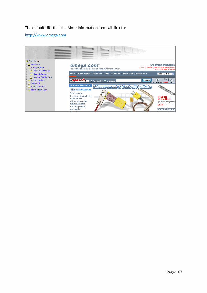
3.6. More Information
The “More Information” option in the main menu will open the OMEGA site in your
browser and display the main introduction page for the OME-ET-7000/OME-PET-7000
series of modules, which provides more detailed information related to the modules.
The URL for this link can be changed by simply
editing the URL. For more details, refer to
section 3.2.2 “Configure the web interface
information”.
Page: 87
The default URL that the More Information item will link to:
http://www.omega.com

Page: 88
4. Modbus and Modbus TCP
Modbus is a serial communication protocol that allows a wide variety of instruments to be
connected to a common data collection network.
Modbus/TCP is a variant of the Modbus communication protocol that allows devices to
communicate over a TCP/IP.
With the support of the Modbus TCP protocol, the OME-ET-7000/OME-PET-7000 series
module can communicate with PC-based applications, such as SCADA (Supervisor Control
And Data Acquisition) and HMI programs. The Modbus/TCP information is only available
via an Ethernet interface.
The Modbus/TCP messaging service provides a Client/Server communication between
devices connected on a TCP/IP network. The OME-ET-7000/OME-PET-7000 module is a
Modbus Server, meaning that it is only capable of responding to requests from the Modbus
client device. Note that the Modbus/RTU protocol requires a serial interface, not Ethernet,
and is therefore not directly compatible with the OME-ET-7000/OME-PET-7000 module.
The Modbus protocol, as well as the TCP extension, is well documented in the
specifications, which are available at http://www.modbus.org, a website established by the
Modbus Organization to provide support and organization for the Modbus protocol. Only
the use of the protocol is documented here.

Page: 89
4.1. Modbus TCP/IP Interface
The Modbus/TCP interface is attached to the TCP/IP stack that is implemented within the
OME-ET-7000/OME-PET-7000 module, and will listen to all communications that come in on
Modbus/TCP registered Port 502.
The Modbus/TCP client uses the standard TCP method for communicating with the
OME-ET-7000/OME-PET-7000 module. UP to 12 connections are possible at one time. If
there are 12 active connections, any attempt at any more connections is ignored.

Page: 90
4.2. Protocol Description
The Modbus protocol defines a simple protocol data unit independent of the underlying
communication layers. The mapping of Modbus protocol on network can introduce some
additional fields on the application data unit.
Modbus/TCP Application Data Unit
MBAP Header Function Code Data
Protocol Data Unit
MBAP
The Modbus/TCP extension includes 7 additional bytes to the original Modbus protocol,
which allows for transport over the TCP/IP layers.
A dedicated header is used on TCP/IP to identify the Modbus Application Data Unit. It is
called the MBAP Header (MODBUS Application Protocol Header). The MBAP Header
consists of 7 bytes of information:
Field Length Description
Transaction
Identifier
2 bytes Identification of Request/Response transaction –
Copied from request to response
Protocol Identifier 2 bytes 0 = Modbus protocol
Length 2 bytes Number of following bytes - Includes the Unit
Identifier
Unit Identifier 1 byte Identification of remote slave

Page: 91
Function Code
The function code field of a Modbus data unit is coded in one byte. Valid codes are in the
range of 1 ... 255 decimal (the range 128 - 255 is reserved and used or exception responses).
When a Modbus request is sent from a Modbus Client to a Server device the function code
field tells the Server what kind of action to perform.
The Modbus/TCP feature of OME-ET-7000/OME-PET-7000 series module supports 8
function codes, which allows the reading and writing of data contents of registers.
Function Code Function
01 (0x01) Read Coil Status
02 (0x02) Read Input Status
03 (0x03) Read Holding Registers
04 (0x04) Read Input Registers
05 (0x05) Force Single Coil
06 (0x06) Preset Single Register
15 (0x0F) Force Multiple Coils
16 (0x10) Preset Multiple Registers
Any other function code request will be returned with an error response indicating the
function code is not supported, as well as a request for too much data or data at a register
address that not present.
Data
The data field of Modbus request sent from a client to server devices contains additional
information that the server uses to take the action defined by the function code. This can
include items like discrete and register addresses, the quantity of items to be handled, and
the count of actual data bytes in the field.
The data field may be nonexistent (of zero length) in certain kinds of requests; in this case
the server does not require any additional information. The function code alone specifies
the action.

Page: 92
Response
If no error occurs related to the Modbus function requested in a properly received Modbus
PDU (Protocol Data Unit) the data field of a Modbus response from a server to a client
contains the data requested. If an error related to the Modbus function requested occurs,
the field contains an exception code that the server application can use to determine the
next action to be taken.
For example a client can read the ON/OFF states of a group of digital input or output or it
can read/write the data contents of a group of registers.
When the server responds to the client, it uses the function code field to indicate either a
normal response or that some kind of error occurred (called an exception response). For a
normal response, the server simply echoes to the request the original function code.
For an exception response, the server returns a code that is equivalent to the original
function code from the request PDU with its most significant bit set to logic 1.

Page: 93
4.3. Data Encoding
Modbus uses a “big-endian” representation for address and data items. This means that
when a numerical quantity larger than single byte is transmitted, the most significant byte
(MSB, also called the high-order byte) is send first. The following sub-topics describe the
different byte of encoding and show how the data is encoded as it is within the
Modbus/TCP packet.
4.3.1. Binary
A binary item is represented as a single bit within a data word. All binary is packed into
16-bits data words, which are accessed using function code 01 and 02. Therefore, a single
register contains 16 bits of binary data, each having a specific meaning.
Value 1st 2nd
0xAA55
(1010101001010101)
0xAA
(10101010)
0x55
(01010101)
4.3.2. 16-bits Word
A 16-bits word item is transmitted with the most significant byte first. Function code 03
and 04 read 16-bits items at a time; therefore, each of these data items will fit within one
register that is read.
Value 1st 2nd
0x1234 0x12 0x34
Page: 94
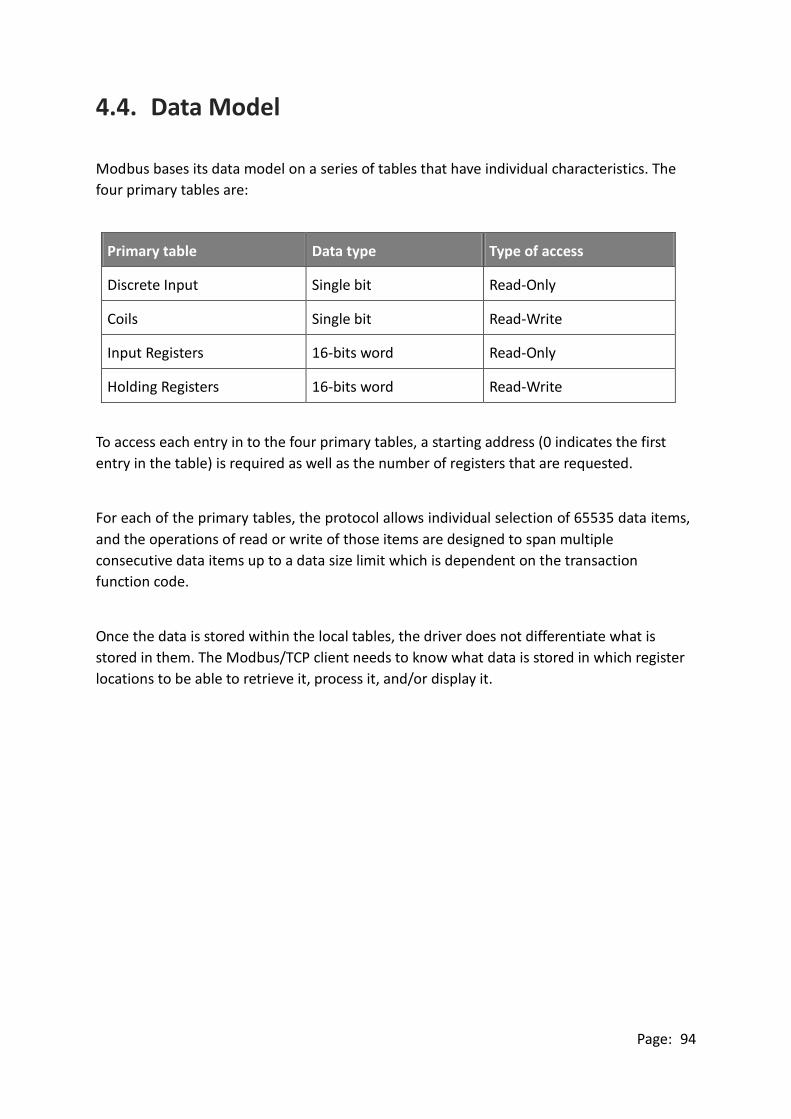
4.4. Data Model
Modbus bases its data model on a series of tables that have individual characteristics. The
four primary tables are:
Primary table Data type Type of access
Discrete Input Single bit Read-Only
Coils Single bit Read-Write
Input Registers 16-bits word Read-Only
Holding Registers 16-bits word Read-Write
To access each entry in to the four primary tables, a starting address (0 indicates the first
entry in the table) is required as well as the number of registers that are requested.
For each of the primary tables, the protocol allows individual selection of 65535 data items,
and the operations of read or write of those items are designed to span multiple
consecutive data items up to a data size limit which is dependent on the transaction
function code.
Once the data is stored within the local tables, the driver does not differentiate what is
stored in them. The Modbus/TCP client needs to know what data is stored in which register
locations to be able to retrieve it, process it, and/or display it.
Page: 95
4.5. Modbus Functions and Registers
4.5.1. 01 (0x01) Read Coils
This function code is used to read the status of coils in an OME-ET-7000/OME-PET-7000
module. The Request PDU specifies the starting address, i.e. the address of the first coil
specified, and the number of coils. In the PDU Coils are addressed starting at zero.
The coils in the response message are packed as one coil per bit of the data field. Status is
indicated as 1=ON and 0=OFF. The LSB of the first data byte contains the output addressed
in the query. The other coils follow toward the high order end of this byte, and from low
order to high order in subsequent bytes.
If the returned output quantity is not a multiple of eight, the remaining bits in the final
data byte will be padded with zeros (toward the high order end of the byte). The Byte
Count field specifies the quantity of complete bytes of data.
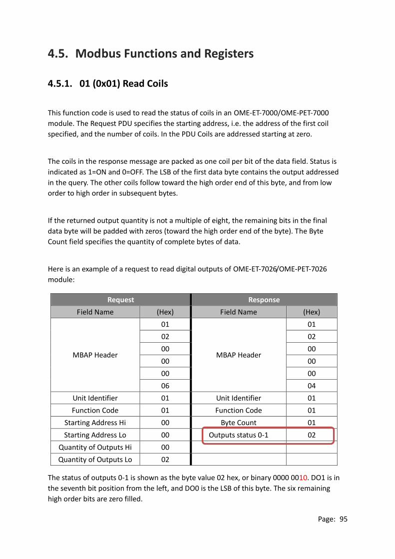
Here is an example of a request to read digital outputs of OME-ET-7026/OME-PET-7026
module:
Request Response
Field Name (Hex) Field Name (Hex)
MBAP Header
01
MBAP Header
01
02 02
00 00
00 00
00 00
06 04
Unit Identifier 01 Unit Identifier 01
Function Code 01 Function Code 01
Starting Address Hi 00 Byte Count 01
Starting Address Lo 00 Outputs status 0-1 02
Quantity of Outputs Hi 00
Quantity of Outputs Lo 02
The status of outputs 0-1 is shown as the byte value 02 hex, or binary 0000 0010. DO1 is in
the seventh bit position from the left, and DO0 is the LSB of this byte. The six remaining
high order bits are zero filled.

Page: 96
4.5.2. 02 (0x02) Read Discrete Inputs
This function code is used to read status of discrete inputs in an
OME-ET-7000/OME-PET-7000 module. The Request PDU specifies the starting address, i.e.
the address of the first input specified, and the number of inputs. In the PDU Discrete
inputs are addressed starting at zero.
The discrete inputs in the response message are packed as one input per bit of the data
field. Status is indicated as 1=ON and 0=OFF. The LSB of the first data byte contains the
input addressed in the query. The other inputs follow toward the high order end of this
byte, and from low order to high order in subsequent bytes.
If the returned input quantity is not a multiple of eight, the remaining bits in the final data
byte will be padded with zeros (toward the high order end of the byte). The Byte Count
field specifies the quantity of complete bytes of data.
Here is an example of a request to read digital inputs of OME-ET-7026/OME-PET-7026
module:
Request Response
Field Name (Hex) Field Name (Hex)
MBAP Header
01
MBAP Header
01
02 02
00 00
00 00
00 00
06 04
Unit Identifier 01 Unit Identifier 01
Function Code 02 Function Code 02
Starting Address Hi 00 Byte Count 01
Starting Address Lo 00 Digital Inputs status 0-1 03
Quantity of Inputs Hi 00
Quantity of Inputs Lo 02
The status of Inputs 0-1 is shown as the byte value 03 hex, or binary 0000 0011. DI1 is in
the seventh bit position from the left, and DI0 is the LSB of this byte. The six remaining
high order bits are zero filled.

Page: 97
4.5.3. 03 (0x03) Read Holding Registers
This function code is used to read the contents of a contiguous block of holding registers in
an OME-ET-7000/OME-PET-7000 module. The Request PDU specifies the starting register
address and the number of registers. In the PDU Registers are addressed starting at zero.
The register data in the response message are packed as two bytes per register, with the
binary contents right justified within each byte. For each register, the first byte contains the
high order bits and the second contains the low order bits.
Here is an example of a request to read analog outputs of OME-ET-7026/OME-PET-7026
module:
Request Response
Field Name (Hex) Field Name (Hex)
MBAP Header
01
MBAP Header
01
02 02
00 00
00 00
00 00
06 07
Unit Identifier 01 Unit Identifier 01
Function Code 03 Function Code 03
Starting Address Hi 00 Byte Count 04
Starting Address Lo 00 Register value Hi (AO0) 02
Quantity of Outputs Hi 00 Register value Lo (AO0) 2B
Quantity of Outputs Lo 02 Register value Hi (AO1) 00
Register value Lo (AO1) 64
The contents of AO0 are shown as the two byte values of 02 2B hex, or 555 decimal. The
content of AO1 are 00 64, or 100 decimal.

Page: 98
4.5.4. 04 (0x04) Read Inputs Registers
This function code is used to read input registers in an OME-ET-7000/OME-PET-7000
module. The Request PDU specifies the starting register address and the number of
registers. In the PDU Registers are addressed starting at zero.
The register data in the response message are packed as two bytes per register, with the
binary contents right justified within each byte. For each register, the first byte contains the
high order bits and the second contains the low order bits.
Here is an example of a request to read analog inputs of OME-ET-7026/OME-PET-7026
module:
Request Response
Field Name (Hex) Field Name (Hex)
MBAP Header
01
MBAP Header
01
02 02
00 00
00 00
00 00
06 07
Unit Identifier 01 Unit Identifier 01
Function Code 04 Function Code 04
Starting Address Hi 00 Byte Count 04
Starting Address Lo 00 Register value Hi (AI0) 00
Quantity of Inputs Hi 00 Register value Lo (AI0) 0A
Quantity of Inputs Lo 02 Register value Hi (AI1) 00
Register value Lo (AI1) 64
The contents of AI0 are shown as the two byte values of 00 0A hex, or 10 decimal. The
content of AI1 are 00 64, or 100 decimal.

Page: 99
4.5.5. 05 (0x05) Write Single Coil
This function code is used to write a single digital output to either ON or OFF in an
OME-ET-7000/OME-PET-7000 module. The requested ON/OFF state is specified by a
constant in the request data field. A value of FF 00 hex requests the output to be ON. A
value of 00 00 requests it to be OFF. All other values are illegal and will not affect the
output.
The normal response is an echo of the request, returned after the coil state has been
written.
Here is an example of a request to write DO1 of OME-ET-7026/OME-PET-7026 ON:
Request Response
Field Name (Hex) Field Name (Hex)
MBAP Header
01
MBAP Header
01
02 02
00 00
00 00
00 00
06 06
Unit Identifier 01 Unit Identifier 01
Function Code 05 Function Code 05
Output Address Hi 00 Output Address Hi 00
Output Address Lo 01 Output Address Lo 01
Output Value Hi FF Output Value Hi FF
Output Value Lo 00 Output Value Lo 00

Page: 100
4.5.6. 06 (0x06) Write Single Register
This function code is used to write a single analog output in an
OME-ET-7000/OME-PET-7000 module. The Request PDU specifies the address of the
register to be written. Registers are addressed starting at zero.
The normal response is an echo of the request, returned after register contents have been
written.
Here is an example of a request to write AO1 of OME-ET-7026/OME-PET-7026 to 55 FF hex:
Request Response
Field Name (Hex) Field Name (Hex)
MBAP Header
01
MBAP Header
01
02 02
00 00
00 00
00 00
06 06
Unit Identifier 01 Unit Identifier 01
Function Code 06 Function Code 06
Register Address Hi 00 Register Address Hi 00
Register Address Lo 01 Register Address Lo 01
Register Value Hi 55 Register Value Hi 55
Register Value Lo FF Register Value Lo FF

Page: 101
4.5.7. 15 (0x0F) Write Multiple Coils
This function code is used to force each coil in a sequence of coils to either ON or OFF in an
OME-ET-7000/OME-PET-7000 module. The Request PDU specifies the coil references to be
forced. Coils are addressed starting at zero.
The requested ON/OFF states are specified by contents of the request data field. A logical
‘1’ in a bit position of the field requests the corresponding output to be ON. A logical ‘0’
requests it to be OFF.
The normal response returns the function code, starting address, and quantity of coils
forced.
Here is an example of a request to write a series of 2 digital outputs starting at DO0:
The request data content is one byte: 02 hex (0000 0010 binary). The binary bits
correspond to the outputs in the following way:
Bit 0 0 0 0 0 0 1 0
Output - - - - - - DO1 DO0
Request Response
Field Name (Hex) Field Name (Hex)
MBAP Header
01
MBAP Header
01
02 02
00 00
00 00
00 00
06 06
Unit Identifier 01 Unit Identifier 01
Function Code 0F Function Code 0F
Starting Address Hi 00 Starting Address Hi 00
Starting Address Lo 00 Starting Address Lo 00
Quantity of Outputs Hi 00 Quantity Value Hi 00
Quantity of Outputs Lo 02 Quantity Value Lo 02
Byte Count 01
Outputs Value Lo 02

Page: 102
4.5.8. 16 (0x10) Write Multiple Registers
This function code is used to write a block of contiguous registers in an
OME-ET-7000/OME-PET-7000 module. The requested written values are specified in the
request data field. Data is packed as two bytes per register.
The normal response returns the function code, starting address, and quantity of registers
written.
Here is an example of a request to write two AO registers starting at AO0:
Request Response
Field Name (Hex) Field Name (Hex)
MBAP Header
01
MBAP Header
01
02 02
00 00
00 00
00 00
06 06
Unit Identifier 01 Unit Identifier 01
Function Code 10 Function Code 10
Starting Address Hi 00 Starting Address Hi 00
Starting Address Lo 00 Starting Address Lo 00
Quantity of Registers Hi 00 Quantity Value Hi 00
Quantity of Registers Lo 02 Quantity Value Lo 02
Byte Count 04
Registers Value Hi 00
Registers Value Lo 0A
Registers Value Hi 01
Registers Value Lo 02

Page: 103
4.6. Modbus Master Simulators
In the previous section, we introduced the Modbus communication protocol. Now, we will
describe how to achieve the Modbus/TCP communication between the
OME-ET-7000/OME-PET-7000 module and PC-connection.
4.6.1. Modbus/TCP Client
Modbus/TCP Client is a Modbus master simulator and test utility designed primarily to help
users who want to test and simulate the Modbus protocol. Using the Modbus/TCP Client
application, you can compose and send individual Modbus requests to a Modbus slave,
and it can also continually poll (send read and write requests to) the slave. Subsequently,
you can re-run the sequence of commands.
For each individual Modubs request you specify the slave ID, function code, starting
address and quantity. You can refer to the previous section for more detailed information
about Modbus communication protocol.
The complete version of the Modbus/TCP Client can be obtained from the companion CD:
CD:\Software\Modbus_TCP_Client\
The following instructions will help you to read the status of digital inputs in an
OME-ET-7026 by using the Modbus/TCP Client application.
Step 1: Double-click the “MBTCP.exe” to open it.

Page: 104
Step 2: Type in the IP address of OME-ET-7026 that you wish to communication with in
the Modbus TCP block shown below. Then click the “Connect” button to connect
the module.
Step 3: Send a Modbus query to the OME-ET-7026 by clicking the “Send” button. An
example of a query to read digital inputs 0 to 1 from the OME-ET-7026 at
Modbus ID 1 is given below.
Step 4: If no error occurs, a data field of a response from the OME-ET-7026 to the
Modbus/TCP Client contains the status of digital inputs of OME-ET-7026.
For a more detailed
description of this
function code, see the
“Protocol Description”
group box.

Page: 105
4.6.2. Modbus Master Tool
Modbus Master Tool is a Modbus master simulator designed by OMEGA. It used to help
developers of Modbus slave devices or others that want to test the Modbus connection.
The complete version of the Modbus Master Tool can be obtained from the companion CD:
CD:\Software\Modbus_Master_Tool\
The following are the step-by-step instruction on how to read the DO status of
OME-PET-7026.
Step 1: Double-click the “ModbusMasterToolPC.exe” to open it.
Step 2: Click the “Setup > Definition” in menu bar to setup the parameters.

Page: 106
We use the same example in the section 4.5.1; you can see the parameters in the table.
Tips & Warnings
Please select “Hex” options in the “Format” drop-up menu when
you read/write the AO/AI.
Step 3: Click the “Connection > Connect” to set TCP Connection.
1.
2.
3. 4.
Request
Field Name (Hex)
1 Unit Identifier 01
2 Function Code 01
3 Starting Address Hi 00
Starting Address Lo 00
4 Quantity of Outputs Hi 00
Quantity of Outputs Lo 02
You can go to “Modules I/O Settings”
(section 3.2.3) to check/set the ID.
Starting from DO0
Read two channels
01 (0x01) Read Coils

Page: 107
1. Select “TCP/IP” in the “Interface” field.
2. Fill out the OME-PET-7026’s IP address in the “Remote Server IP”.
3. You can keep the settings of other fields or change them then click OK.
Now, the DO status of OME-PET-7026 will show on the screen. (1: ON; 0: OFF)
1.
2.

Page: 108
4.7. Modbus Demo Programs
nModbus is a C# 3.0 implementation of the Modbus protocol. It is developed and
maintained on a voluntary basis and provided free of change.
The DLL based on the official releases from http://nmodbus.googlecode.com was verified
and improved. Programmer can use the DLL released to develop a Modbus application for
regular Windows based PCs.
The relevant Modbus demo and SDK can be obtained from the following OMEGA website.
ftp://ftp.omega.com/public/DASgroup/products/OME-ET-7000_OME-PET-7000/
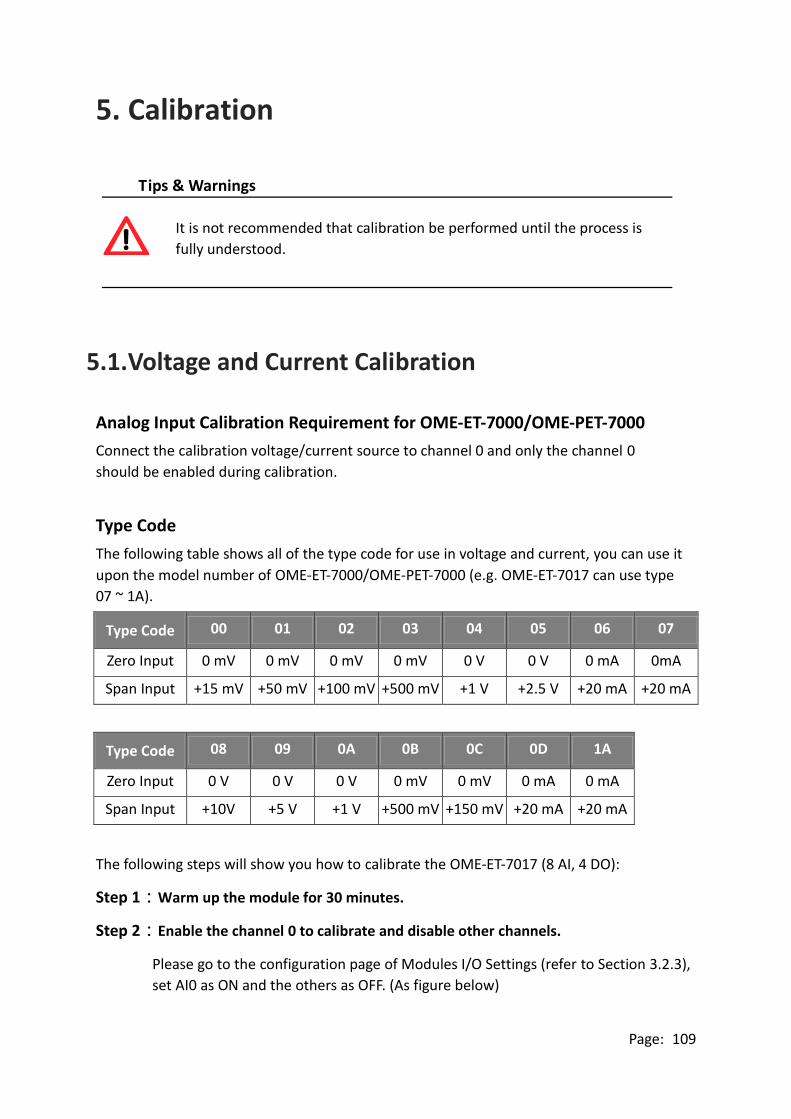
Page: 109
5. Calibration
Tips & Warnings
It is not recommended that calibration be performed until the process is
fully understood.
5.1. Voltage and Current Calibration
Analog Input Calibration Requirement for OME-ET-7000/OME-PET-7000
Connect the calibration voltage/current source to channel 0 and only the channel 0
should be enabled during calibration.
Type Code
The following table shows all of the type code for use in voltage and current, you can use it
upon the model number of OME-ET-7000/OME-PET-7000 (e.g. OME-ET-7017 can use type
07 ~ 1A).
Type Code 00 01 02 03 04 05 06 07
Zero Input 0 mV 0 mV 0 mV 0 mV 0 V 0 V 0 mA 0mA
Span Input +15 mV +50 mV +100 mV +500 mV +1 V +2.5 V +20 mA +20 mA
Type Code 08 09 0A 0B 0C 0D 1A
Zero Input 0 V 0 V 0 V 0 mV 0 mV 0 mA 0 mA
Span Input +10V +5 V +1 V +500 mV +150 mV +20 mA +20 mA
The following steps will show you how to calibrate the OME-ET-7017 (8 AI, 4 DO):
Step 1:Warm up the module for 30 minutes.
Step 2:Enable the channel 0 to calibrate and disable other channels.
Please go to the configuration page of Modules I/O Settings (refer to Section 3.2.3),
set AI0 as ON and the others as OFF. (As figure below)

Page: 110
Step 3:Set the type code to the type you want to calibrate.
Select the AI range (e.g. 09, -5V ~ 5V) then click “Submit” button.
Step 4:Enable calibration.
We will use the software – Modbus Master Tool - to complete the step 4 ~ 8.
The complete version of the Modbus Master Tool can be obtained from the
companion CD:
CD:\Software\Modbus_Master_Tool\
4.1 Please double-click the “ModbusMasterToolPC.exe” to open it and click the
“Setup > Definition” in menu bar to setup the parameters.
3. 2.
It depends on the settings in Modules I/O Settings -
Modbus Definition (refer to Section 3.2.3)
Select “01 Read Coils Status” (no
matter what kind of module you use).
Rrefer to the table below - Modbus
Address for Calibration. (830 ~ 832)
1.
2.
3.
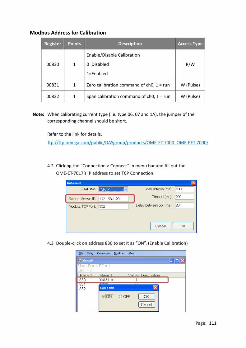
Page: 111
Modbus Address for Calibration
Register Points Description Access Type
00830 1
Enable/Disable Calibration
0=Disabled
1=Enabled
R/W
00831 1 Zero calibration command of ch0, 1 = run W (Pulse)
00832 1 Span calibration command of ch0, 1 = run W (Pulse)
Note: When calibrating current type (i.e. type 06, 07 and 1A), the jumper of the
corresponding channel should be short.
Refer to the link for details.
ftp://ftp.omega.com/public/DASgroup/products/OME-ET-7000_OME-PET-7000/
4.2 Clicking the “Connection > Connect” in menu bar and fill out the
OME-ET-7017’s IP address to set TCP Connection.
4.3 Double-click on address 830 to set it as “ON”. (Enable Calibration)

Page: 112
Step 5:Apply the zero calibration voltage/current to channel 0.
In this example, we use type code - 09 and its “Zero Input” is 0 V.
Type Code 09
Input Range -5V ~ +5 V
Step 6:Send the zero calibration command.
Double-click on address 831 to set it as ON. If the calibration is successful, the
value will return 0.
Step 7:Apply the span calibration voltage/current to channel 0.
In this example, we use type code - 09 and its “Span Input” is +5 V.
Type Code 09
Input Range -5V ~ +5 V

Page: 113
Step 8:Send the span calibration command.
Double-click on address 832 to set it as ON. If the calibration is successful, the
value will return 0.
Step 9:Disable calibration.
As figure above, double-click on address 830 to set it as OFF.

Page: 114
5.2. Thermocouple Calibration
Type Code
The following table shows all of the type code for use in thermocouple.
Type Code 14 18 0E 10 12 13 15 16 19 0F 11 17
Thermocouple
Calibration Range 00 01 02
Zero Input 0 mV 0 mV 0 mV
Span Input +15 mV +50 mV +100 mV
The calibration procedure is similar to the section 5.1. But, the difference between them is
that the OME-ET-7000/OME-PET-7000 doesn’t directly support type code - 0E ~ 19 for AI
calibration, so you need to change the channel 0 as range - 00 ~ 02 to complete the work
(refer to section 5.1 step 3).
Step 1 Warm up the module for latest 30 minutes.
Step 2 Set the type code to the type you wish to calibrate.
Step 3 Enable calibration.
Step 4 Apply the zero calibration voltage to channel 0.
Step 5 Send the zero calibration command.
Step 6 Apply the span calibration voltage to channel 0.
Step 7 Send the span calibration command.
Step 8 Disable calibration.
For example
If you want to calibrate type 0E, you need to set the channel 0 as range - 01.

Page: 115
5.3. RTD Calibration
Type Code
The following table shows all of the type code for use in RTD calibration.
Type Code 20 ~ 29 2E 2F 80 81 83 2B 2C 82 2A 2D
Zero Calibration
Resistor 0 Ω 0 Ω 0 Ω
Span Calibration
Resistor 375 Ω 200 Ω 3200 Ω
Modbus Address for Calibration
Register Points Description Access Type
00830 1
Enable/Disable Calibration
0=Disabled
1=Enabled
R/W
00831 1 Zero calibration command of ch0, 1=run W (Pulse)
00832 1 Span calibration command of ch0, 1=run W (Pulse)
00833 1 Zero calibration command of ch1, 1=run W (Pulse)
00834 1 Span calibration command of ch1, 1=run W (Pulse)
00835 1 Zero calibration command of ch2, 1=run W (Pulse)
00836 1 Span calibration command of ch3, 1=run W (Pulse)
00837 1 Zero calibration command of ch3, 1=run W (Pulse)
00838 1 Span calibration command of ch3, 1=run W (Pulse)
00839 1 Zero calibration command of ch4, 1=run W (Pulse)
00840 1 Span calibration command of ch4, 1=run W (Pulse)
00841 1 Zero calibration command of ch5, 1=run W (Pulse)
00842 1 Span calibration command of ch5, 1=run W (Pulse)
The calibration procedure is similar to the section 5.1. However, the RTD calibration
required an external resistor and must be calibrate for each channel rather than just the
ch0 we mentioned before.

Page: 116
The calibration procedure is as follows:
Step 1 Warm up the module for latest 30 minutes.
Step 2 Set the type code to the type you wish to calibrate.
Step 3 Enable calibration.
Step 4 Connect the zero calibration resistor.
(Refer to the table – Type Code)
Step 5 Send the zero calibration command.
(Refer to the table - Modbus Address for Calibration)
Step 6 Connect the span calibration resistor.
(Refer to the table – Type Code)
Step 7 Send the span calibration command.
(Refer to the table - Modbus Address for Calibration)
Step 8 Disable calibration.

Page: 117
5.4. Recover Calibration to Factory Setting
Please go to the configuration page of Modules I/O Settings – Analog Input (refer to
Section 3.2.3). After you selecting the "Recover AI Calibration to Factory Setting", it will
auto complete the function.

Page: 118
6. MiniOS7 Utility
MiniOS7 Utility is a tool for uploading firmware to flash memory and updating the OS to
OME-ET-7000/OME-PET-7000 module embedded with MiniOS7 with easiness and
quickness.
If you haven’t the MiniOS7 Utility installed on your system, installation of the MiniOS7
Utility should be the first step. Please refer to section “2.4 Installing the MiniOS7 Utility”
to install it.
6.1. Establishing a Connection
To upload firmware or update the OS to OME-ET-7000/OME-PET-7000 module, you must
first establish a connection between PC and the OME-ET-7000/OME-PET-7000 module.
Step 1:Run the MiniOS7 Utility
Double-click the “MiniOS7 Utility” shortcut on your desktop.

Page: 119
Step 2:Press the “F12” key or choose the “Search” option from the “Connection” menu
After pressing the “F12” key or choosing the “Search” option from
“Connection” menu, the utility perform a search of all MiniOS7 modules on
your network.
Step 3:Click the IP address in the IP/Port field list and then click the “Connect” icon in
the toolbar
After the search has been completed, click the IP address for the
OME-ET-7000/OME-PET-7000 module in the IP/Port field list and then click
the “Connect” icon in the toolbar to connect to the
OME-ET-7000/OME-PET-7000.
Check the status bar to monitor
the progress of the search

Page: 120
Step 4:Check the connection symbol to make sure that the connection is established
A connection symbol Check the connection symbol status in the top right
side to make sure the connection has been established
Connection Status
Disconnected
Connected
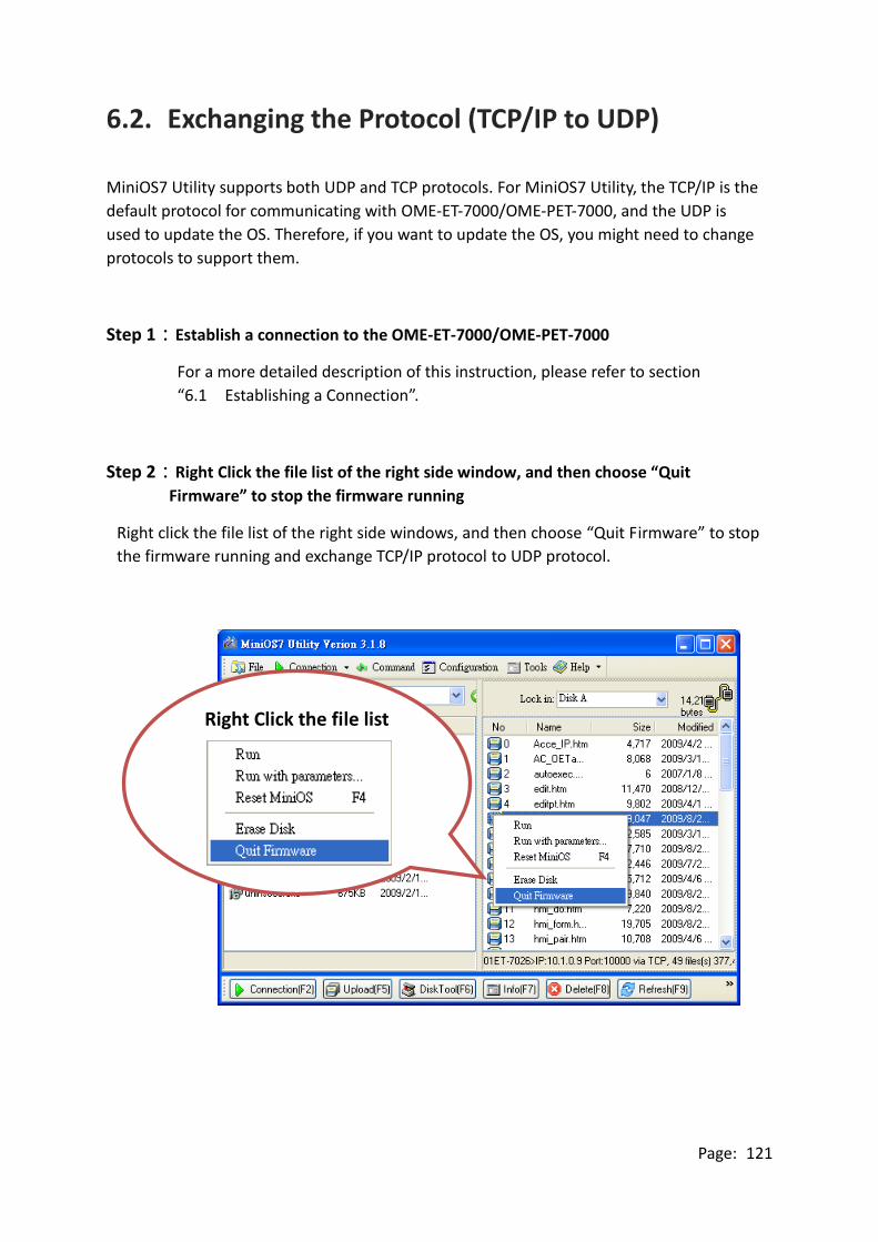
Page: 121
6.2. Exchanging the Protocol (TCP/IP to UDP)
MiniOS7 Utility supports both UDP and TCP protocols. For MiniOS7 Utility, the TCP/IP is the
default protocol for communicating with OME-ET-7000/OME-PET-7000, and the UDP is
used to update the OS. Therefore, if you want to update the OS, you might need to change
protocols to support them.
Step 1:Establish a connection to the OME-ET-7000/OME-PET-7000
For a more detailed description of this instruction, please refer to section
“6.1 Establishing a Connection”.
Step 2:Right Click the file list of the right side window, and then choose “Quit
Firmware” to stop the firmware running
Right click the file list of the right side windows, and then choose “Quit Firmware” to stop
the firmware running and exchange TCP/IP protocol to UDP protocol.
Right Click the file list

Page: 122
Step 3:Click the “Yes” button to continue
After executing the Quick Firmware command, the “Confirm” dialog will appear, and then
click “Yes” button to continue and stop the firmware running.
Step 4:Click “Yes” to continue
After confirming the command, the “Confirm” dialog will appear, and then click “Yes”
button to exchange UDP protocol for TCP protocol.
Step 5:The changes have been affected.

Page: 123
6.3. Updating the OME-ET-7000/OME-PET-7000 OS
Additional features to OME-ET-7000/OME-PET-7000 OS will continue to be added in the
future, so we advise you to periodically check with OMEGA web site for the latest updates.
Step 1:Download the latest version of the MiniOS7 OS image.
The latest version of the MiniOS7 OS image can be obtained from the
companion CD:
CD:\OME-ET-7000_PET-7000\OS_image\
Step 2:Be sure that the switch is set to the “Init” position and then reboot the module

Page: 124
Step 3:Establish a connection to OME-ET-7000/OME-PET-7000.
For a more detailed description of this instruction, please refer to section
“6.1 Establishing a Connection”.
Step 4:Choose “Update MiniOS7 Image” from the “File” menu.
Choose “Update MiniOS7 Image” from File menu to start the update procedure.
Step 5:Select the latest version of the MiniOS7 OS image.
After choosing the update MiniOS7 Image command, the “Select MiniOS7 Image file” dialog
will appear, and then select the latest version of the MiniOS7 OS image.

Page: 125
Step 6:Click “OK” to finish the procedure.
After confirming the command, you just need to wait awhile until the following dialog
appear, and then click “OK” button to finish the procedure.
Step 7:Press “F7” or choose “Info” from the “Command” menu to check the OS
version.
After pressing “F7” or choosing info from “Command” menu to check the OS version.
Check the Build item

Page: 126
6.4. Updating the OME-ET-7000/OME-PET-7000 Firmware
The firmware is stored in flash memory and can be updated to fix functionality issues or
add additional features, so we advise you to periodically check the ICP DAS web site for the
latest updates.
Step 1:Download the latest version of the firmware
ET-7000
The latest version of the MiniOS7 OS image can be obtained from the
companion CD:
CD:\OME-ET-7000_PET-7000\Firmware\
PET-7000
The latest version of the MiniOS7 OS image can be obtained from the
companion CD:
CD:\OME-ET-7000_PET-7000Napdos\Firmware\

Page: 127
Step 2:Be sure that the switch is set to the “Init” position and then reboot the module
Step 3:Establish a connection to connection to the OME-ET-7000/OME-PET-7000
For a more detailed description of this instruction, please refer to section
“6.1 Establishing a Connection”.

Page: 128
Step 4:Choose “Erase Disk” from the “Command” menu.
After establishing a connection, then choose “Erase Disk” from Command
menu (or right-click on the right of window) to erase the contents of the
flash memory.
Tips & Warnings
You have to delete all files existed on the OME-ET-7000/OME-PET-7000
before uploading the firmware.

Page: 129
Step 5:In the Confirm dialog box, click the “Yes” button to continue.
After executing the Erase Disk command, the Confirm dialog will appear, and
then click “Yes” button to continue erasing the memory contents.
Step 6:Select the latest version of the firmware.
Upload the last version of the firmware to the OME-ET-7000/OME-PET-7000
using drag-and-drop operation.
Drag-and-Drop
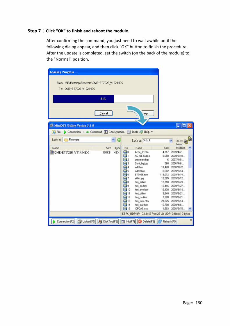
Page: 130
Step 7:Click “OK” to finish and reboot the module.
After confirming the command, you just need to wait awhile until the
following dialog appear, and then click “OK” button to finish the procedure.
After the update is completed, set the switch (on the back of the module) to
the "Normal" position.

Page: 131
Appendix A. Node Information Area
Each OME-ET-7000/OME-PET-7000 module has a built-in EEPROM to store configuration
information such as IP address, type code, etc. One minor drawback is that there are no
visual indications of the configuration of the module. New OME-ET-7000/OME-PET-7000
modules include node information areas that are protected by a cover, as shown below,
and can be used to make a written record of the node information, such as IP address, etc.
To access the node information areas, first slide the covers outward, as shown in the figure
below.

Page: 132
Appendix B. Thermocouple
When two wires composed of dissimilar homogeneous metals are joined at one end, a
thermoelectric electromotive force (emf) appears that depends only on the metals and the
junction temperature. This is called the Seebeck effect. A pair of different metals with a
fixed junction at one end constitutes a thermocouple. For small changes in temperature,
the emf is linearly proportional to the temperature. This implies that the temperature
reading can be obtained by measuring the emf.
We cannot measure the emf, V1, directly because when a voltmeter is connected to the
thermocouple, another emf, V2, is created at the (cold) junction of the thermocouple and
the voltmeter. The cold junction compensation method is used to resolve the problem.
Using another sensor, e.g. a thermistor, to measure the cold junction temperature, T2, we
can calculate the emf, V2, which corresponds to T2. The thermocouple emf, V1, can be
obtained by adding V2 to that measured by the voltmeter and then the temperature.
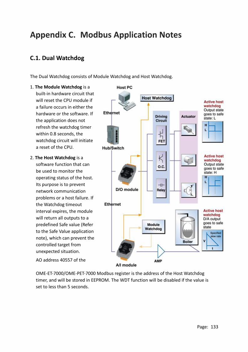
Page: 133
Appendix C. Modbus Application Notes
C.1. Dual Watchdog
The Dual Watchdog consists of Module Watchdog and Host Watchdog.
1. The Module Watchdog is a
built-in hardware circuit that
will reset the CPU module if
a failure occurs in either the
hardware or the software. If
the application does not
refresh the watchdog timer
within 0.8 seconds, the
watchdog circuit will initiate
a reset of the CPU.
2. The Host Watchdog is a
software function that can
be used to monitor the
operating status of the host.
Its purpose is to prevent
network communication
problems or a host failure. If
the Watchdog timeout
interval expires, the module
will return all outputs to a
predefined Safe value (Refer
to the Safe Value application
note), which can prevent the
controlled target from
unexpected situation.
AO address 40557 of the
OME-ET-7000/OME-PET-7000 Modbus register is the address of the Host Watchdog
timer, and will be stored in EEPROM. The WDT function will be disabled if the value is
set to less than 5 seconds.

Page: 134
C.2. Power-on Value
Many industrial applications require a "safe" start-up condition to prevent accidents at
critical points in the process. Each OME-ET-7000/OME-PET-7000 contains an initial power-on
value which is used to configure the analog/digital outputs on power up. In other words,
power-on value can be considered as a start-up value. The power-on value is loaded into the
output modules under 3 conditions: power on, reset by Module Watchdog, reset by the
reset command.
User can set the power-on value of the specific analog/digital output channel and the
power-on value is stored in EEPROM.
Setting the Power-on Value for a Specific Digital Output Channel
Step 1:Log into the OME-ET-7000/OME-PET-7000 web page, and then click the “Module
I/O Settings” option in the “Configuration” section of the Main Menu
Step 2:Enable the Power-on Value by checking the “ON” radio button
Step 3:Click the “Submit” button to complete the configuration of the power-on Value
1 2
3

Page: 135
Setting the Power-on Value for a Specific Analog Output Channel
Step 1:Log into the OME-ET-7000/OME-PET-7000 web page, and then click the “Module
I/O Settings” option in the “Configuration” section of the Main Menu
Step 2:Set the Power-on Value in the “Power-on Value” text box
Step 3:Click the “Submit” button to complete the configuration of the Power-on Value
and save the settings to the EEPROM
2
3
1

Page: 136
C.3. Safe Value
When the Host Watchdog is enabled and the communication between host PC and
OME-ET-7000/OME-PET-7000 modules is broken, the analog/digital output channels can
generate a predefined value to prevent unpredictable damage of the connected devices. By
default, this feature is disabled. User can enable this feature by configuring the Host WDT
Timeout.
Setting the Safe Value for a Specific Digital Output Channel
Step 1:Log into the OME-ET-7000/OME-PET-7000 web page, and then click the “Module
I/O Settings” option in the “Configuration” section of the Main Menu
Step 2:Enable the Safe Value by checking the “ON” radio button
Step 3:Click the “Submit” button to complete the configuration of the power-on Value
1 2
3

Page: 137
Setting the Safe Value for a Specific Analog Output Channel
Step 1:Log into the OME-ET-7000/OME-PET-7000 web page, and then click the “Module
I/O Settings” option in the “Configuration” section of the Main Menu
Step 2:Set the Safe Value in the “Safe Value” text box
Step 3:Click the “Submit” button to complete the configuration of the Safe Value and
save the settings to the EEPROM
2
3
1

Page: 138
C.4. AI High/Low Alarm
OME-ET-7000/OME-PET-7000 module equip with the High/Low Alarm function. When the
alarm function is enabled, the specific registers are the alarm indicator. The alarm function
is to compare the analog input value with given high alarm value and low alarm value.
Address 00636 to 00667 can be used to enable/disable the AI High Alarm function.
Address 00668 to 00699 can be used to enable/disable the AI Low Alarm function.
AI High/Low Alarm Switch Table
Channel
Number
AI High Alarm AI Low Alarm
Register Description Register Description
AI0 00636 0: Disable/1: Enable 00668 0: Disable/1: Enable
AI1 00637 0: Disable/1: Enable 00669 0: Disable/1: Enable
AI2 00638 0: Disable/1: Enable 00670 0: Disable/1: Enable
AI3 00639 0: Disable/1: Enable 00671 0: Disable/1: Enable
AI4 00640 0: Disable/1: Enable 00672 0: Disable/1: Enable
AI5 00641 0: Disable/1: Enable 00673 0: Disable/1: Enable
AI6 00642 0: Disable/1: Enable 00674 0: Disable/1: Enable
AI7 00643 0: Disable/1: Enable 00675 0: Disable/1: Enable
AI8 00644 0: Disable/1: Enable 00676 0: Disable/1: Enable
AI9 00645 0: Disable/1: Enable 00677 0: Disable/1: Enable

Page: 139
Address 40296 to 40327 records the High Alarm value. Address 40328 to 40359 records the
Low Alarm value. By default, the High Alarm value is +32767 (0x7FFF) and the low alarm
value is -32768 (0xFFFF).
AI High/Low Alarm Value Table
Channel
Number
High Alarm Value of AI Low Alarm Value of AI
Register Description Register Description
AI0 40296 -32768 ~ 32767 40328 -32768 ~ 32767
AI1 40297 -32768 ~ 32767 40329 -32768 ~ 32767
AI2 40298 -32768 ~ 32767 40330 -32768 ~ 32767
AI4 40300 -32768 ~ 32767 40332 -32768 ~ 32767
AI5 40301 -32768 ~ 32767 40333 -32768 ~ 32767
AI6 40302 -32768 ~ 32767 40334 -32768 ~ 32767
AI7 40303 -32768 ~ 32767 40335 -32768 ~ 32767
AI8 40304 -32768 ~ 32767 40336 -32768 ~ 32767
AI9 40305 -32768 ~ 32767 40337 -32768 ~ 32767

Page: 140
The analog input High/Low Alarm contains two alarm types, Momentary Alarm and Latch
Alarm. Address 00700 of Modbus register can be used to set the High Alarm type of channel
0 and the total number of channels depends on the type of module. Address 00732 of
Modbus register can be used to set the Low Alarm type of channel 0.
AI High/Low Type Value Table
Channel
Number
AI High Alarm Type AI Low Alarm Type
Register Description Register Description
AI0 00700 0: Momentary Mode
1: Latch Mode 00732
0: Momentary Mode
1: Latch Mode
AI1 00701 0: Momentary Mode
1: Latch Mode 00733
0: Momentary Mode
1: Latch Mode
AI2 00702 0: Momentary Mode
1: Latch Mode 00734
0: Momentary Mode
1: Latch Mode
AI3 00703 0:Momentary
1: Latched 00735
0:Momentary
1: Latched
AI4 00704 0:Momentary
1: Latched 00736
0:Momentary
1: Latched
AI5 00705 0:Momentary
1: Latched 00737
0:Momentary
1: Latched
AI6 00706 0:Momentary
1: Latched 00738
0:Momentary
1: Latched
AI7 00707 0:Momentary
1: Latched 00739
0:Momentary
1: Latched
AI8 00708 0:Momentary
1: Latched 00740
0:Momentary
1: Latched
AI9 00709 0:Momentary
1: Latched 00741
0:Momentary
1: Latched

Page: 141
The following are the descriptions for two alarm types.
Momentary Alarm
The alarm status is cleared while the analog input is not exceeding the alarm value.
For example:
If analog input value of channel 0 (30000) > High Alarm value (40296), the address 10224 is
1, else it is 0.
If analog input Value of channel 0 (30000) < Low Alarm value (40328), the address 10256 is
1, else it is 0.
The address 10224 to 10255 is the high alarm indicator. If a high alarm occurred, the value
of register is 1. In normal condition, it will be 0. The address 10256 to 10287 is the low
alarm indicator. If a low alarm occurred, the value of register is 1. In normal condition, it
will be 0.
Latch Alarm
When the Latch Alarm mode is enabled, the register stays latched until the specified
registers are cleared.
For example:
If analog input value of channel 0 (30000) > High Alarm value (40296), the address 10224 is
1, else if analog input value of channel 0 (30000) < Low Alarm value (40328), the address
10256 is 1.
The address 10224 to 10255 is the high alarm indicator. In normal condition, the value of
register is 0. If a High alarm occurred, the value of register stays 1 until the address 00764
to 00795 is cleared. The address 10256 to 10287 is the low alarm indicator. In normal
condition, the value of register is 0. If a low alarm occurred, the value of register stays 1
until the address 00796 to 00827 is cleared.

Page: 142
Setting the High Alarm and Low Alarm for a Specific Analog Input Channel
Step 1:Log into the OME-ET-7000/OME-PET-7000 web page, and then click the “Module
I/O Settings” option in the “Configuration” section of the Main Menu
Step 2:Set the High Alarm and Low Alarm information in the relevant field
Step 3:Click the “Submit” button to complete the configuration of the High Alarm and
the Low Alarm
1
2
3

Page: 143
C.5. AI High/Low Latch
The address 30236 to 30267 records the maximum value of analog inputs and stays the
value until another maximum input enters. The address 30268 to 30299 records the
minimum value of analog inputs and stays the value until another minimum input enters.
Monitoring the Alarm Status for a Specific Analog Input Channel
Click the “Web HMI” link in the Web HMI Section of the Main Menu tree.
Step 1:Log into the OME-ET-7000/OME-PET-7000 web page, and then click the “Web
HMI” option in the “Web HMI” section of the Main Menu
Step 2:Monitor the alarm status by viewing the “High/Low Latched Value for Analog
Inputs” group table
1 2

Page: 144
Appendix D. Analog Input Type and Data Format Table
Type Code Input Range Data Format +F.S -F.S
00 -15 ~ +15 mA
Engineering Unit +15000 -15000
2’s comp HEX 7FFF 8000
01 -50 ~ +50 mA
Engineering Unit +5000 -5000
2’s comp HEX 7FFF 8000
02 -100 ~ +100 mV
Engineering Unit +10000 -10000
2’s comp HEX 7FFF 8000
03 -500 ~ +500 mV
Engineering Unit +5000 -5000
2’s comp HEX 7FFF 8000
04 -1 ~ +1 V
Engineering Unit +10000 -10000
2’s comp HEX 7FFF 8000
05 -2.5 ~ +2.5 V
Engineering Unit +25000 -25000
2’s comp HEX 7FFF 8000
06 -20 ~ +20 mA
Engineering Unit +20000 -20000
2’s comp HEX 7FFF 8000
07 +4 ~ +20 mA
Engineering Unit +20000 +4000
2’s comp HEX FFFF 0000
08 -10 ~ +10 V
Engineering Unit +10000 -10000
2’s comp HEX 7FFF 8000
09 -5 ~ +5 V
Engineering Unit +5000 -5000
2’s comp HEX 7FFF 8000

Page: 145
Type Code Input Range Data Format +F.S -F.S
0A -1 ~ +1 V
Engineering Unit +10000 -10000
2’s comp HEX 7FFF 8000
0B -500 ~ +500 mV
Engineering Unit +5000 -5000
2’s comp HEX 7FFF 8000
0C -150 ~ +150 mV
Engineering Unit +15000 -15000
2’s comp HEX 7FFF 8000
0D -20 ~ +20 mA
Engineering Unit +20000 -20000
2’s comp HEX 7FFF 8000
1A 0 ~ +20 mA
Engineering Unit +20000 0
2’s comp HEX FFFF 0000
0E
Type J
Thermocouple
-210 ~ 760°C
Engineering Unit +7600 -2100
2’s comp HEX 7FFF DCA2
0F
Type K
Thermocouple
-270 ~ 1372°C
Engineering Unit +13720 -2700
2’s comp HEX 7FFF E6D0
10
Type T
Thermocouple
-270 ~ 400°C
Engineering Unit +4000 -2700
2’s comp HEX 7FFF A99A
11
Type E
Thermocouple
-270 ~ 1000°C
Engineering Unit 10000 -2700
2’s comp HEX 7FFF DD71
12
Type R
Thermocouple
0 ~ 1768°C
Engineering Unit +17680 0
2’s comp HEX 7FFF 0000
13
Type S
Thermocouple
0 ~ 1768°C
Engineering Unit +17680 0
2’s comp HEX 7FFF 0000

Page: 146
Type Code Input Range Data Format +F.S -F.S
14
Type B
Thermocouple
0 ~ 1820°C
Engineering Unit +18200 0
2’s comp HEX 7FFF 0000
15
Type N
Thermocouple
-270 ~ 1300°C
Engineering Unit +13000 -2700
2’s comp HEX 7FFF E56B
16
Type C
Thermocouple
0 ~ 2320°C
Engineering Unit +23200 0
2’s comp HEX 7FFF 0000
17
Type L
Thermocouple
-200 ~ 800°C
Engineering Unit +8000 -2000
2’s comp HEX 7FFF E000
18
Type M
Thermocouple
-200 ~ 100°C
Engineering Unit +10000 -20000
2’s comp HEX 4000 8000
19
Type L
DIN43710
Thermocouple
-200 ~ 900°C
Engineering Unit 9000 -2000
2’s comp HEX FFFF E38E
20
Platinum 100
α=0.00385
-100 ~ 100°C
Engineering Unit +10000 -10000
2’s comp HEX 7FFF 8000
21
Platinum 100
α=0.00385
0 ~ 100°C
Engineering Unit +10000 0
2’s comp HEX 7FFF 0000
22
Platinum 100
α=0.00385
0 ~ 200°C
Engineering Unit +20000 0
2’s comp HEX 7FFF 0000
23
Platinum 100
α=0.00385
0 ~ 600°C
Engineering Unit +6000 0
2’s comp HEX 7FFF 0000

Page: 147
Type Code Input Range Data Format +F.S -F.S
24
Platinum 100
α=0.003916
-100 ~ 100°C
Engineering Unit +10000 -10000
2’s comp HEX 7FFF 8000
25
Platinum 100
α=0.003916
0 ~ 100°C
Engineering Unit +10000 0
2’s comp HEX 7FFF 0000
26
Platinum 100
α=0.003916
0 ~ 200°C
Engineering Unit +20000 0
2’s comp HEX 7FFF 0000
27
Platinum 100
α=0.003916
0 ~ 600°C
Engineering Unit +6000 0
2’s comp HEX 7FFF 0000
28 Nickel 120
-80 ~ 100°C
Engineering Unit +10000 -8000
2’s comp HEX 7FFF 999A
29 Nickel 120
0 ~ 100°C
Engineering Unit +10000 0
2’s comp HEX 7FFF 0000
2A
Platinum 1000
α=0.00385
-200 ~ 600°C
Engineering Unit +6000 -2000
2’s comp HEX 7FFF D556
2B
Cu 100
α=0.00421
-20 ~ 150°C
Engineering Unit +15000 -2000
2’s comp HEX 7FFF EEEF
2C
Cu 100
α=0.00427
0 ~ 200°C
Engineering Unit +20000 0
2’s comp HEX 7FFF 0000
2D
Cu 1000
α=0.00421
-20 ~ 150°C
Engineering Unit +15000 -2000
2’s comp HEX 7FFF EEEF

Page: 148
Type Code Input Range Data Format +F.S -F.S
2E
Platinum 1000
α=0.00385
-200 ~ 200°C
Engineering Unit +20000 -20000
2’s comp HEX 7FFF 8000
2F
Platinum 1000
α=0.003916
-200 ~ 200°C
Engineering Unit +20000 -20000
2’s comp HEX 7FFF 8000
80
Platinum 100
α=0.00385
-200 ~ 600°C
Engineering Unit +6000 -2000
2’s comp HEX 7FFF D556
81
Platinum 100
α=0.003916
-200 ~ 600°C
Engineering Unit +6000 -2000
2’s comp HEX 7FFF D556
82 Cu 50
-50 ~ 150°C
Engineering Unit +15000 -5000
2’s comp HEX 7FFF D556
83 Nickel 100
-60 ~ 180°C
Engineering Unit +18000 -6000
2’s comp HEX 7FFF D556

Page: 149
Appendix E. Analog Output Type and Data Format Table
Type Code Input Range Data Format +F.S -F.S
30 0 ~ +20 mV Engineering Unit +20000 0
2’s comp HEX FFFF 0000
31 4 ~ +20 mV Engineering Unit +20000 4000
2’s comp HEX FFFF 0000
32 0 ~ +10 V Engineering Unit +10000 0
2’s comp HEX 7FFF 0000
33 -10 ~ +10 V Engineering Unit +10000 -10000
2’s comp HEX 7FFF 8000
34 0 ~ +5 V Engineering Unit +5000 0
2’s comp HEX 7FFF 0000
35 -5 ~ +5 V Engineering Unit +5000 -5000
2’s comp HEX 7FFF 8000

Page: 150
Appendix F. Network Address Translation
For a computer to communicate with OME-ET-7000/OME-PET-7000 modules on the
Internet, OME-ET-7000/OME-PET-7000 modules must have a public IP address. Basically, it
works like your street address - as a way to find out exactly where you are and deliver
information to you.
Network Address Translation (NAT) allows a single device, such as a router, to act as an
agent between the Internet (or "public network") and a local (or "private") network. This
means that only a single, unique IP address is required to represent an entire group of
computers.
A type of NAT in which a private IP address is mapped to a public IP address, where the
public address is always the same IP address (i.e., it has a static address). This allows an
internal host, such as an OME-ET-7000/OME-PET-7000 module, to have an unregistered
(private) IP address and still be reachable over the Internet.

Page: 151
Step 1:Configure the Ethernet settings of OME-ET-7000/OME-PET-7000 module.
The Gateway must be set to the IP address of router (i.e., 10.1.0.1)
Step 2:Connect to the web server of OME-ET-7000/OME-PET-7000 module with the
public IP address on the Internet
For accessing the web page, the access URL will need to include the port
number as shown below: http://210.32.166.58:180
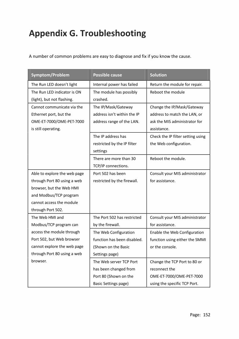
Page: 152
Appendix G. Troubleshooting
A number of common problems are easy to diagnose and fix if you know the cause.
Symptom/Problem Possible cause Solution
The Run LED doesn’t light Internal power has failed Return the module for repair.
The Run LED indicator is ON
(light), but not flashing.
The module has possibly
crashed.
Reboot the module
Cannot communicate via the
Ethernet port, but the
OME-ET-7000/OME-PET-7000
is still operating.
The IP/Mask/Gateway
address isn’t within the IP
address range of the LAN.
Change the IP/Mask/Gateway
address to match the LAN, or
ask the MIS administrator for
assistance.
The IP address has
restricted by the IP filter
settings
Check the IP filter setting using
the Web configuration.
There are more than 30
TCP/IP connections.
Reboot the module.
Able to explore the web page
through Port 80 using a web
browser, but the Web HMI
and Modbus/TCP program
cannot access the module
through Port 502.
Port 502 has been
restricted by the firewall.
Consult your MIS administrator
for assistance.
The Web HMI and
Modbus/TCP program can
access the module through
Port 502, but Web browser
cannot explore the web page
through Port 80 using a web
browser.
The Port 502 has restricted
by the firewall.
Consult your MIS administrator
for assistance.
The Web Configuration
function has been disabled.
(Shown on the Basic
Settings page)
Enable the Web Configuration
function using either the SMMI
or the console.
The Web server TCP Port
has been changed from
Port 80 (Shown on the
Basic Settings page)
Change the TCP Port to 80 or
reconnect the
OME-ET-7000/OME-PET-7000
using the specific TCP Port.

WARRANTY/DISCLAIMEROMEGA ENGINEERING, INC. warrants this unit to be free of defects in materials and workmanship for aperiod of 13 months from date of purchase. OMEGA’s WARRANTY adds an additional one (1) monthgrace period to the normal one (1) year product warranty to cover handling and shipping time. Thisensures that OMEGA’s customers receive maximum coverage on each product. If the unit malfunctions, it must be returned to the factory for evaluation. OMEGA’s Customer ServiceDepartment will issue an Authorized Return (AR) number immediately upon phone or written request.Upon examination by OMEGA, if the unit is found to be defective, it will be repaired or replaced at nocharge. OMEGA’s WARRANTY does not apply to defects resulting from any action of the purchaser,including but not limited to mishandling, improper interfacing, operation outside of design limits, improper repair, or unauthorized modification. This WARRANTY is VOID if the unit shows evidence of having been tampered with or shows evidence of having been damaged as a result of excessive corrosion;or current, heat, moisture or vibration; improper specification; misapplication; misuse or other operatingconditions outside of OMEGA’s control. Components in which wear is not warranted, include but are not limited to contact points, fuses, and triacs.OMEGA is pleased to offer suggestions on the use of its various products. However, OMEGA neither assumes responsibility for any omissions or errors nor assumes liability for anydamages that result from the use of its products in accordance with information provided byOMEGA, either verbal or written. OMEGA warrants only that the parts manufactured by it will beas specified and free of defects. OMEGA MAKES NO OTHER WARRANTIES OR REPRESENTATIONS OF ANY KIND WHATSOEVER, EXPRESS OR IMPLIED, EXCEPT THAT OF TITLE,AND ALL IMPLIED WARRANTIES INCLUDING ANY WARRANTY OF MERCHANTABILITY AND FITNESS FOR A PARTICULAR PURPOSE ARE HEREBY DISCLAIMED. LIMITATION OF LIABILITY: The remedies of purchaser set forth herein are exclusive, and the total liability of OMEGA with respect to this order, whether based on contract, warranty, negligence, indemnification, strict liability or otherwise, shall not exceed the purchase price of the component upon which liability is based. In no event shall OMEGA be liable for consequential, incidental or special damages.CONDITIONS: Equipment sold by OMEGA is not intended to be used, nor shall it be used: (1) as a “BasicComponent” under 10 CFR 21 (NRC), used in or with any nuclear installation or activity; or (2) in medicalapplications or used on humans. Should any Product(s) be used in or with any nuclear installation oractivity, medical application, used on humans, or misused in any way, OMEGA assumes no responsibilityas set forth in our basic WARRANTY/ DISCLAIMER language, and, additionally, purchaser will indemnifyOMEGA and hold OMEGA harmless from any liability or damage whatsoever arising out of the use of theProduct(s) in such a manner.
RETURN REQUESTS/INQUIRIESDirect all warranty and repair requests/inquiries to the OMEGA Customer Service Department. BEFORERETURNING ANY PRODUCT(S) TO OMEGA, PURCHASER MUST OBTAIN AN AUTHORIZED RETURN(AR) NUMBER FROM OMEGA’S CUSTOMER SERVICE DEPARTMENT (IN ORDER TO AVOIDPROCESSING DELAYS). The assigned AR number should then be marked on the outside of the returnpackage and on any correspondence.The purchaser is responsible for shipping charges, freight, insurance and proper packaging to preventbreakage in transit.
FOR WARRANTY RETURNS, please have the following information available BEFORE contacting OMEGA:1. Purchase Order number under which the product
was PURCHASED,2. Model and serial number of the product under
warranty, and3. Repair instructions and/or specific problems
relative to the product.
FOR NON-WARRANTY REPAIRS, consult OMEGAfor current repair charges. Have the followinginformation available BEFORE contacting OMEGA:1. Purchase Order number to cover the COST
of the repair,2. Model and serial number of the product, and3. Repair instructions and/or specific problems
relative to the product.
OMEGA’s policy is to make running changes, not model changes, whenever an improvement is possible. This affordsour customers the latest in technology and engineering.OMEGA is a registered trademark of OMEGA ENGINEERING, INC.© Copyright 2012 OMEGA ENGINEERING, INC. All rights reserved. This document may not be copied, photocopied,reproduced, translated, or reduced to any electronic medium or machine-readable form, in whole or in part, without theprior written consent of OMEGA ENGINEERING, INC.

Where Do I Find Everything I Need for Process Measurement and Control?
OMEGA…Of Course!Shop online at omega.com sm
TEMPERATURE�� �� �� �� ��
PRESSURE, STRAIN AND FORCE�� �� �� ��
FLOW/LEVEL�� �� �� ��
pH/CONDUCTIVITY�� �� �� ��
DATA ACQUISITION�� �� �� �� ��
HEATERS�� �� �� �� ��
ENVIRONMENTALMONITORING AND CONTROL�� �� �� �� �� ��
GaugesGauges
M5185/0113
Related Documents