a simple solution – for difficult tasks Dimensions New ASDO Tie-Rod System M 12 - M 160 ETA-04 /0038

Welcome message from author
This document is posted to help you gain knowledge. Please leave a comment to let me know what you think about it! Share it to your friends and learn new things together.
Transcript
a s i m p l e s o l u t i o n – f o r d i f f i c u l t t a s k s
DimensionsNewASDO Tie-Rod SystemM12 - M160
ETA-04 /0038
ShapeThe new
System advantages
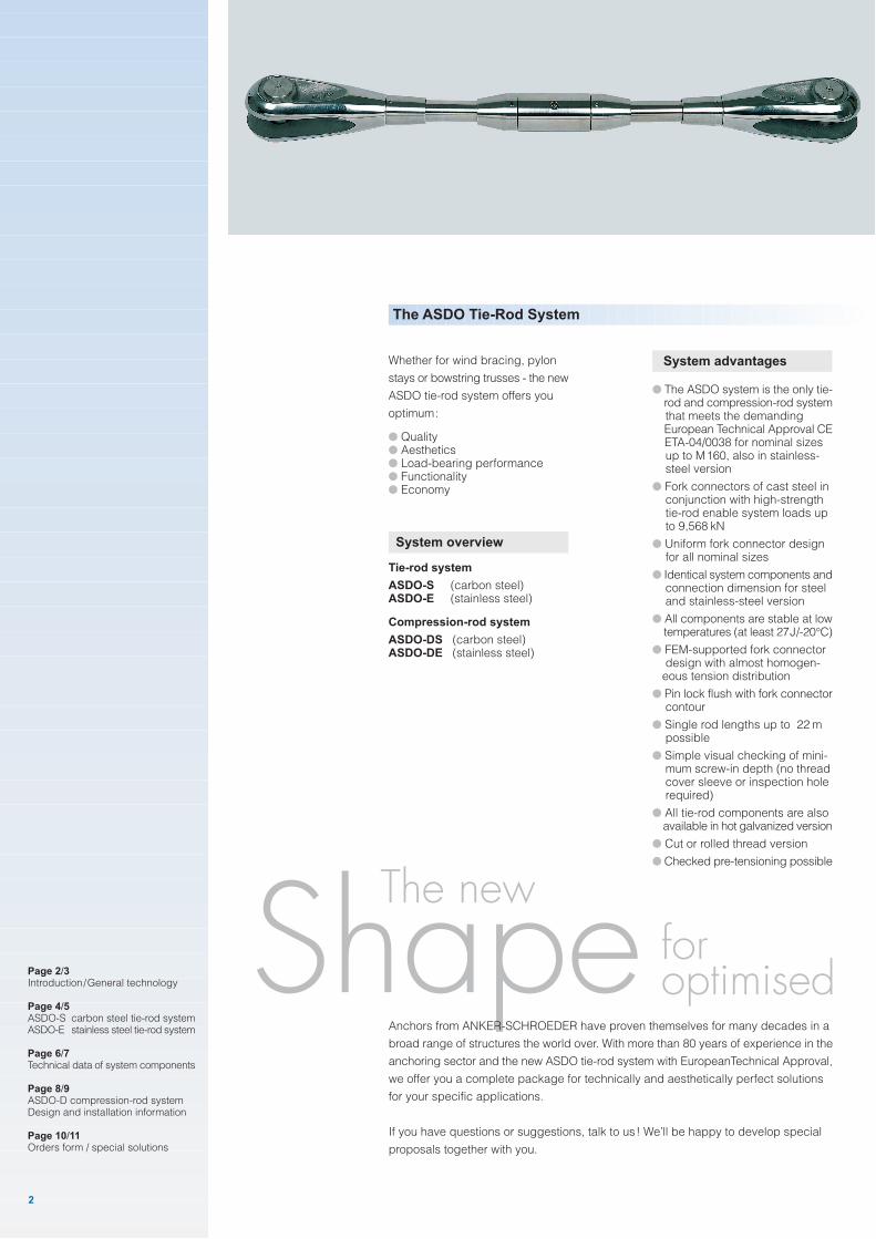
● The ASDO system is the only tie- rod and compression-rod system that meets the demanding European Technical Approval CE ETA-04/0038 for nominal sizes up to M160, also in stainless- steel version
● Fork connectors of cast steel in conjunction with high-strength tie-rod enable system loads up to 9,568 kN
● Uniform fork connector design for all nominal sizes
● Identical system components and connection dimension for steel and stainless-steel version
● All components are stable at low temperatures (at least 27J/-20°C)
● FEM-supported fork connector design with almost homogen- eous tension distribution
● Pin lock flush with fork connector contour
● Single rod lengths up to 22 m possible
● Simple visual checking of mini- mum screw-in depth (no thread cover sleeve or inspection hole required)
● All tie-rod components are also available in hot galvanized version
● Cut or rolled thread version
● Checked pre-tensioning possible
Whether for wind bracing, pylon
stays or bowstring trusses - the new
ASDO tie-rod system offers you
optimum:
● Quality● Aesthetics● Load-bearing performance● Functionality● Economy
System overview
Tie-rod system
ASDO-S (carbon steel)ASDO-E (stainless steel)
Compression-rod system
ASDO-DS (carbon steel)ASDO-DE (stainless steel)
The ASDO Tie-Rod System
Anchors from ANKER-SCHROEDER have proven themselves for many decades in a
broad range of structures the world over. With more than 80 years of experience in the
anchoring sector and the new ASDO tie-rod system with EuropeanTechnical Approval,
we offer you a complete package for technically and aesthetically perfect solutions
for your specific applications.
If you have questions or suggestions, talk to us! We’ll be happy to develop special
proposals together with you.
Page 2/3Introduction/General technology
Page 4/5ASDO-S carbon steel tie-rod systemASDO-E stainless steel tie-rod system
Page 6/7Technical data of system components
Page 8/9ASDO-D compression-rod systemDesign and installation information
Page 10/11Orders form / special solutions
2
foroptimised
performance
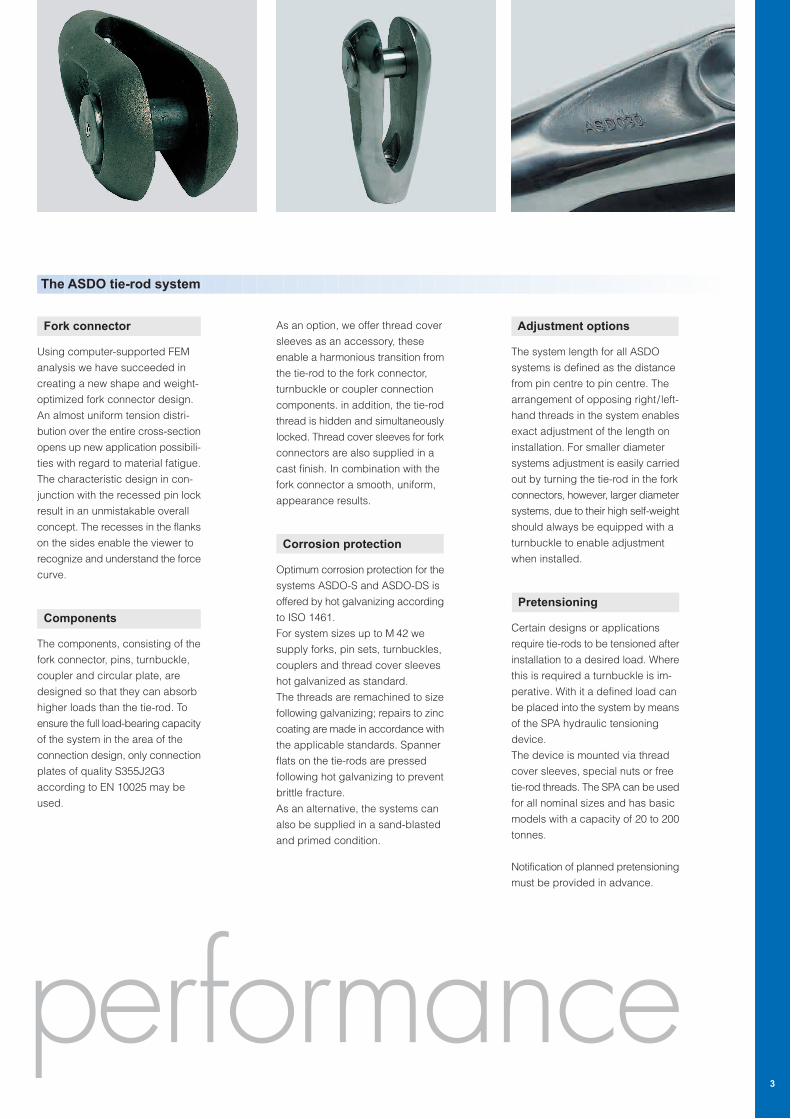
Fork connector
Using computer-supported FEM
analysis we have succeeded in
creating a new shape and weight-
optimized fork connector design.
An almost uniform tension distri-
bution over the entire cross-section
opens up new application possibili-
ties with regard to material fatigue.
The characteristic design in con-
junction with the recessed pin lock
result in an unmistakable overall
concept. The recesses in the flanks
on the sides enable the viewer to
recognize and understand the force
curve.
Components
The components, consisting of the
fork connector, pins, turnbuckle,
coupler and circular plate, are
designed so that they can absorb
higher loads than the tie-rod. To
ensure the full load-bearing capacity
of the system in the area of the
connection design, only connection
plates of quality S355J2G3
according to EN 10025 may be
used.
As an option, we offer thread cover
sleeves as an accessory, these
enable a harmonious transition from
the tie-rod to the fork connector,
turnbuckle or coupler connection
components. in addition, the tie-rod
thread is hidden and simultaneously
locked. Thread cover sleeves for fork
connectors are also supplied in a
cast finish. In combination with the
fork connector a smooth, uniform,
appearance results.
Corrosion protection
Optimum corrosion protection for the
systems ASDO-S and ASDO-DS is
offered by hot galvanizing according
to ISO 1461.
For system sizes up to M 42 we
supply forks, pin sets, turnbuckles,
couplers and thread cover sleeves
hot galvanized as standard.
The threads are remachined to size
following galvanizing; repairs to zinc
coating are made in accordance with
the applicable standards. Spanner
flats on the tie-rods are pressed
following hot galvanizing to prevent
brittle fracture.
As an alternative, the systems can
also be supplied in a sand-blasted
and primed condition.
The ASDO tie-rod system
Adjustment options
The system length for all ASDO
systems is defined as the distance
from pin centre to pin centre. The
arrangement of opposing right/ left-
hand threads in the system enables
exact adjustment of the length on
installation. For smaller diameter
systems adjustment is easily carried
out by turning the tie-rod in the fork
connectors, however, larger diameter
systems, due to their high self-weight
should always be equipped with a
turnbuckle to enable adjustment
when installed.
Pretensioning
Certain designs or applications
require tie-rods to be tensioned after
installation to a desired load. Where
this is required a turnbuckle is im-
perative. With it a defined load can
be placed into the system by means
of the SPA hydraulic tensioning
device.
The device is mounted via thread
cover sleeves, special nuts or free
tie-rod threads. The SPA can be used
for all nominal sizes and has basic
models with a capacity of 20 to 200
tonnes.
Notification of planned pretensioning
must be provided in advance.
3
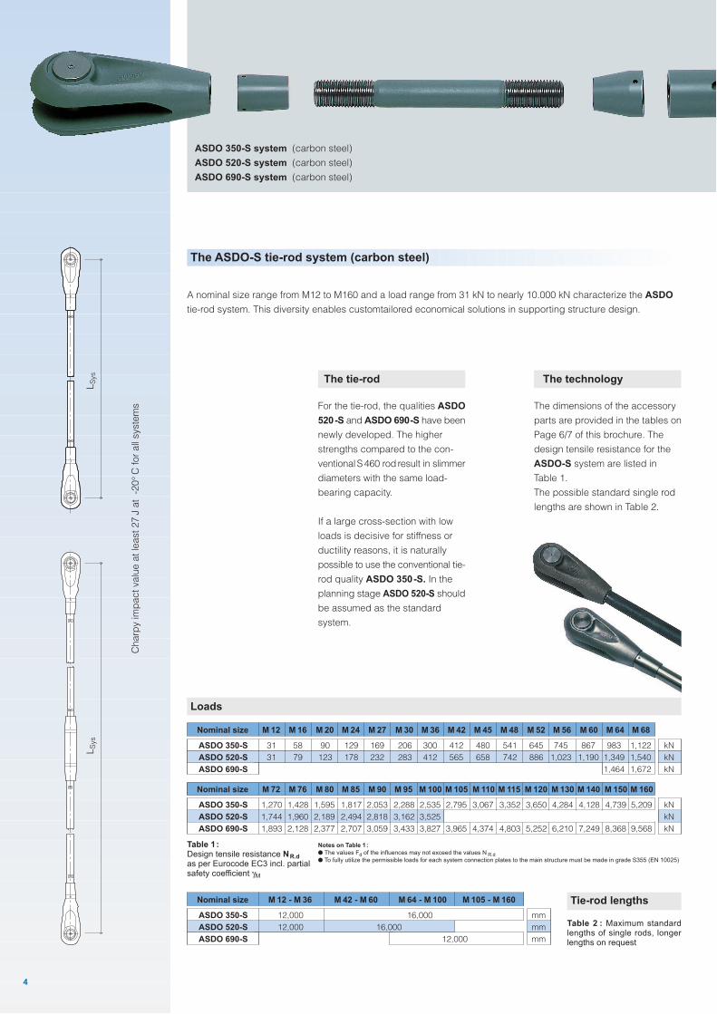
The tie-rod
For the tie-rod, the qualities ASDO
520-S and ASDO 690-S have been
newly developed. The higher
strengths compared to the con-
ventionalS460 rod result in slimmer
diameters with the same load-
bearing capacity.
If a large cross-section with low
loads is decisive for stiffness or
ductility reasons, it is naturally
possible to use the conventional tie-
rod quality ASDO 350-S. In the
planning stage ASDO 520-S should
be assumed as the standard
system.
The ASDO-S tie-rod system (carbon steel)
A nominal size range from M12 to M160 and a load range from 31 kN to nearly 10.000 kN characterize the ASDO
tie-rod system. This diversity enables customtailored economical solutions in supporting structure design.
Loads
Nominal size M 76 M 80 M 85 M 90 M 95 M 100 M 105 M 110 M 115 M 120 M 130 M 140 M 150 M 160
1,270
1,744
1,893
1,428
1,960
2,128
1,595
2,189
2,377
1,817
2,494
2,707
2,053
2,818
3,059
2,288
3,162
3,433
2,535
3,525
3,827
2,795
3,965
3,067
4,374
3,352
4,803
3,650
5,252
4,284
6,210
4,128
7,249
4,739
8,368
5,209
9,568
ASDO 350-S
ASDO 520-S
ASDO 690-S
M 72
kN
kN
kN
Nominal size M 16 M 20 M 24 M 27 M 30 M 36 M 42 M 45 M 48 M 52 M 56 M 60 M 64 M 68
31
31
58
79
90
123
129
178
169
232
206
283
300
412
412
565
480
658
541
742
645
886
745
1,023
867
1,190
983
1,349
1,464
1,122
1,540
1,672
ASDO 350-S
ASDO 520-S
ASDO 690-S
M 12
kN
kN
kN
Notes on Table 1:
● The values Fd of the influences may not exceed the values N R.d● To fully utilize the permissible loads for each system connection plates to the main structure must be made in grade S355 (EN 10025)
The technology
The dimensions of the accessory
parts are provided in the tables on
Page 6/7 of this brochure. The
design tensile resistance for the
ASDO-S system are listed in
Table 1.
The possible standard single rod
lengths are shown in Table 2.
Table 1:Design tensile resistance NR.d
as per Eurocode EC3 incl. partialsafety coefficient γM
Tie-rod lengths
Table 2 : Maximum standardlengths of single rods, longerlengths on request
Nominal size
12,000
12,000
12,000
16,000ASDO 350-S
ASDO 520-S
ASDO 690-S
M 12 - M 36
mm
mm
mm
M 42 - M 60 M 64 - M 100 M 105 - M 160
16,000
4
LS
ys
LS
ys
Ch
arp
y im
pa
ct
va
lue
at
lea
st
27
J a
t -
20
°C
fo
r a
ll syste
ms
ASDO 350-S system (carbon steel)
ASDO 520-S system (carbon steel)
ASDO 690-S system (carbon steel)
The material
The tie-rod and accessories are
manufactured of high-quality duplex
steel (material no. 1.4462) and offer
excellent resistance to corrosion in
structures subjected to heavy
exposure to chlorides and sulphur
oxides. It must be noted that stain-
less steel does not provide long-
term freedom from maintenance
when used in coastal areas or
swimming baths. Therefore, the
overall structure should ensure easy
access to the tie-rod systems.
Depending on the environmental
influences, these must be treated
with suitable cleaners and any minor
surface corrosion removed from time
to time.
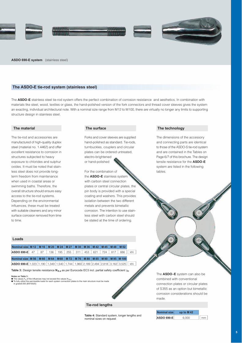
The ASDO-E tie-rod system (stainless steel)
The ASDO-E stainless steel tie-rod system offers the perfect combination of corrosion resistance and aesthetics. In combination with
materials like steel, wood, textiles or glass, the hand-polished version of the fork connectors and thread cover sleeves gives the system
an exacting, individual architectural note. With a nominal size range from M12 to M100, there are virtually no longer any limits to supporting
structure design in stainless steel.
The surface
Forks and cover sleeves are supplied
hand-polished as standard. Tie-rods,
turnbuckles, couplers and circular
plates can be ordered untreated,
electro-brightened
or hand-polished
For the combination of
the ASDO-E stainless system
with carbon steel connection
plates or central circular plates, the
pin body is provided with a special
coating and washers. This provides
isolation between the two different
metals and prevents bimetallic
corrosion. The intention to use stain-
less steel with carbon steel should
be stated at the time of ordering.
The technology
The dimensions of the accessory
and connecting parts are identical
to those of the ASDO-S tie-rod system
and are contained in the Tables on
Page 6/7 of this brochure. The design
tensile resistance for the ASDO-E
system are listed in the following
tables.
The ASDO-E system can also be
combined with conventional
connection plates or circular plates
of S355 as an option but bimetallic
corrosion considerations should be
made.
ASDO 690-E system (stainless steel)
Notes on Table 3:
● The values Fd of the influences may not exceed the values N R.d● To fully utilize the permissible loads for each system connection plates to the main structure must be made
in gradeS355 (EN10025)
Loads
Table 3: Design tensile resistance NR.d as per Eurocode EC3 incl. partial safety coefficient γM
Tie-rod lengths
Table 4: Standard system, longer lengths andnominal sizes on request
Nominal size M 16 M 20 M 24 M 27 M 30 M 36 M 42 M 45 M 48 M 52
47 87 136 195 255 311 453 621 724 817 886ASDO 690-E
M 12
kN
Nominal size M 60 M 64 M68 M 72 M 76 M 80 M 85 M 90 M 95 M 100
1,023 1,190 1,349 1,540 1,744 1,960 2,189 2,494 2,818 3,162 3,525ASDO 690-E
M 56
kN
Nominal size
6,000ASDO 690-E
up to M 42
mm
5
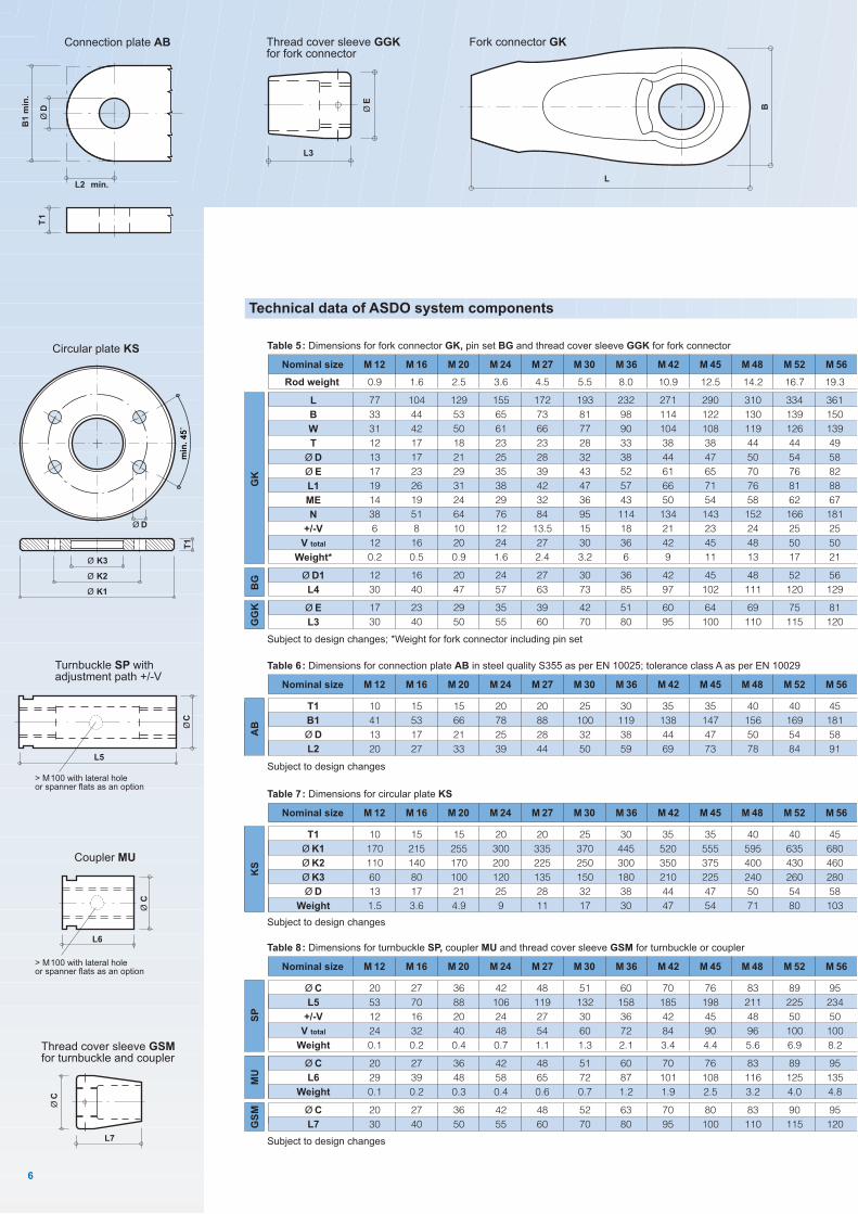
Technical data of ASDO system components
6
Thread cover sleeve GSMfor turnbuckle and coupler
L7
ØC
Subject to design changes; *Weight for fork connector including pin set
Nominal size M 16 M 20 M 24 M 27 M 30 M 36 M 42 M 45 M 48 M 52 M 56
0.9
77
33
31
12
13
17
19
14
38
6
12
0.2
12
30
17
30
Rod weight 1.6
104
44
42
17
17
23
26
19
51
8
16
0.5
16
40
23
40
2.5
129
53
50
18
21
29
31
24
64
10
20
0.9
20
47
29
50
3.6
155
65
61
23
25
35
38
29
76
12
24
1.6
24
57
35
55
4.5
172
73
66
23
28
39
42
32
84
13.5
27
2.4
27
63
39
60
5.5
193
81
77
28
32
43
47
36
95
15
30
3.2
30
73
42
70
8.0
232
98
90
33
38
52
57
43
114
18
36
6
36
85
51
80
10.9
271
114
104
38
44
61
66
50
134
21
42
9
42
97
60
95
12.5
290
122
108
38
47
65
71
54
143
23
45
11
45
102
64
100
14.2
310
130
119
44
50
70
76
58
152
24
48
13
48
111
69
110
16.7
334
139
126
44
54
76
81
62
166
25
50
17
52
120
75
115
19.3
361
150
139
49
58
82
88
67
181
25
50
21
56
129
81
120
Table 5: Dimensions for fork connector GK, pin set BG and thread cover sleeve GGK for fork connector
M 12
GK
BG
GG
K
L
B
W
T
Ø D
Ø E
L1
ME
N
+/-V
V total
Weight*
Ø D1
L4
Ø E
L3
L3
ØE
Thread cover sleeve GGKfor fork connector
L6
Ø C
Coupler MU
> M100 with lateral holeor spanner flats as an option
Turnbuckle SP withadjustment path +/-V
ØC
L5
> M100 with lateral holeor spanner flats as an option
L
B
Fork connector GKConnection plate AB
B1
min
.
ØD
L2 min.
T1
T1
Ø K3
Ø K2
Ø K1
Ø D
min
. 4
5˚
Circular plate KS
Nominal size M 16 M 20 M 24 M 27 M 30 M 36 M 42 M 45 M 48 M 52 M 56
20
53
12
24
0.1
20
29
0.1
20
30
27
70
16
32
0.2
27
39
0.2
27
40
36
88
20
40
0.4
36
48
0.3
36
50
42
106
24
48
0.7
42
58
0.4
42
55
48
119
27
54
1.1
48
65
0.6
48
60
51
132
30
60
1.3
51
72
0.7
52
70
60
158
36
72
2.1
60
87
1.2
63
80
70
185
42
84
3.4
70
101
1.9
70
95
76
198
45
90
4.4
76
108
2.5
80
100
83
211
48
96
5.6
83
116
3.2
83
110
89
225
50
100
6.9
89
125
4.0
90
115
95
234
50
100
8.2
95
135
4.8
95
120
Table 8: Dimensions for turnbuckle SP, coupler MU and thread cover sleeve GSM for turnbuckle or coupler
Ø C
L5
+/-V
V total
Weight
Ø C
L6
Weight
Ø C
L7
M 12
SP
MU
GS
M
Subject to design changes
Subject to design changes
Nominal size M 16 M 20 M 24 M 27 M 30 M 36 M 42 M 45 M 48 M 52 M 56
10
170
110
60
13
1.5
15
215
140
80
17
3.6
15
255
170
100
21
4.9
20
300
200
120
25
9
20
335
225
135
28
11
25
370
250
150
32
17
30
445
300
180
38
30
35
520
350
210
44
47
35
555
375
225
47
54
40
595
400
240
50
71
40
635
430
260
54
80
45
680
460
280
58
103
Table 7: Dimensions for circular plate KS
T1
Ø K1
Ø K2
Ø K3
Ø D
Weight
M 12
KS
Subject to design changes
Nominal size M 16 M 20 M 24 M 27 M 30 M 36 M 42 M 45 M 48 M 52 M 56
10
41
13
20
15
53
17
27
15
66
21
33
20
78
25
39
20
88
28
44
25
100
32
50
30
119
38
59
35
138
44
69
35
147
47
73
40
156
50
78
40
169
54
84
45
181
58
91
Table 6: Dimensions for connection plate AB in steel quality S355 as per EN 10025; tolerance class A as per EN 10029
T1
B1
Ø D
L2
M 12
AB
7
M 60 M 64 M 68 M 72 M 76 M 80 M 85 M 90 M 95 M 100 M 105 M 110 M 115 M 120 M 130 M 140 M 150 M 160
22.2
386
159
149
54
62
88
93
72
196
25
50
26
60
140
87
120
25.3
412
172
159
59
66
93
100
77
210
25
50
32
64
151
92
135
28.5
438
182
167
59
70
100
106
82
225
25
50
40
68
157
99
135
32.0
463
193
179
64
74
105
112
86
240
25
50
47
72
166
104
135
35.6
489
203
191
69
78
111
119
91
254
25
50
58
76
175
110
135
39.5
516
219
196
74
82
115
128
96
267
25
50
63
80
182
113
140
44.5
547
230
211
79
87
124
133
102
287
25
50
74
85
195
122
140
49.9
579
243
226
84
92
131
140
108
306
25
50
92
90
205
129
140
55.6
610
258
237
89
97
136
150
114
321
25
50
105
95
218
134
140
61.7
645
271
248
94
102
146
160
120
340
25
50
127
100
229
143
140
68.0
677
287
259
96
108
155
167
126
359
25
50
162
105
241
152
140
74.6
709
301
271
101
113
161
175
132
377
25
50
195
110
250
158
140
81.5
742
316
284
106
118
169
184
138
395
25
50
230
115
261
166
140
88.8
773
330
303
116
123
176
191
144
413
25
50
265
120
277
173
140
104.2
837
354
327
126
133
190
207
156
449
25
50
332
130
301
187
140
120.8
901
381
351
136
143
206
222
168
486
25
50
400
140
323
202
140
138.7
966
410
375
146
153
220
239
180
522
25
50
470
150
344
216
140
157.8
1,031
436
405
156
163
236
255
192
559
25
50
536
160
365
232
140
kg/m
mm
mm
mm
mm
mm
mm
mm
mm
mm
mm
mm
kg
mm
mm
mm
mm
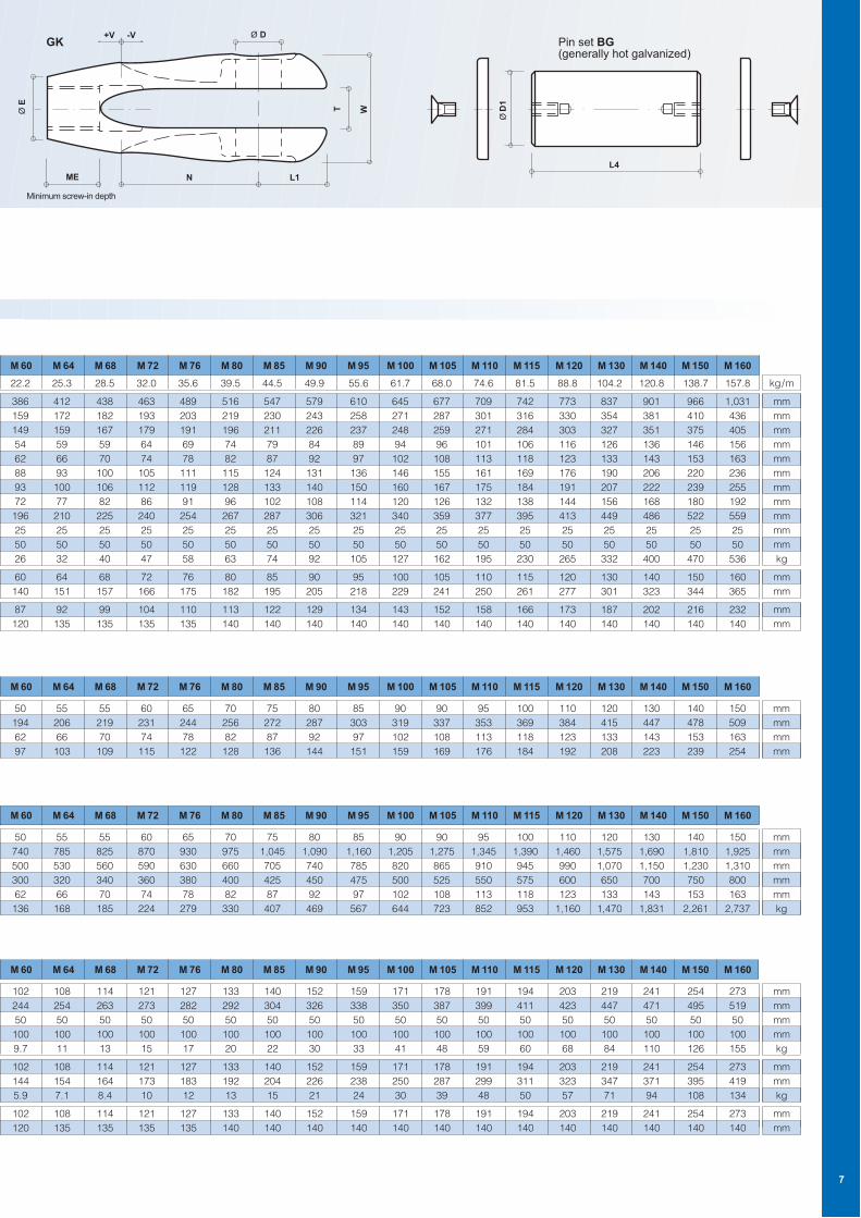
Pin set BG(generally hot galvanized)
ØD
1
L4
M 60 M 64 M 68 M 72 M 76 M 80 M 85 M 90 M 95 M 100 M 105 M 110 M 115 M 120 M 130 M 140 M 150 M 160
102
244
50
100
9.7
102
144
5.9
102
120
108
254
50
100
11
108
154
7.1
108
135
114
263
50
100
13
114
164
8.4
114
135
121
273
50
100
15
121
173
10
121
135
127
282
50
100
17
127
183
12
127
135
133
292
50
100
20
133
192
13
133
140
140
304
50
100
22
140
204
15
140
140
152
326
50
100
30
152
226
21
152
140
159
338
50
100
33
159
238
24
159
140
171
350
50
100
41
171
250
30
171
140
178
387
50
100
48
178
287
39
178
140
191
399
50
100
59
191
299
48
191
140
194
411
50
100
60
194
311
50
194
140
203
423
50
100
68
203
323
57
203
140
219
447
50
100
84
219
347
71
219
140
241
471
50
100
110
241
371
94
241
140
254
495
50
100
126
254
395
108
254
140
273
519
50
100
155
273
419
134
273
140
mm
mm
mm
mm
kg
mm
mm
kg
mm
mm
M 60 M 64 M 68 M 72 M 76 M 80 M 85 M 90 M 95 M 100 M 105 M 110 M 115 M 120 M 130 M 140 M 150 M 160
50
740
500
300
62
136
55
785
530
320
66
168
55
825
560
340
70
185
60
870
590
360
74
224
65
930
630
380
78
279
70
975
660
400
82
330
75
1,045
705
425
87
407
80
1,090
740
450
92
469
85
1,160
785
475
97
567
90
1,205
820
500
102
644
90
1,275
865
525
108
723
95
1,345
910
550
113
852
100
1,390
945
575
118
953
110
1,460
990
600
123
1,160
120
1,575
1,070
650
133
1,470
130
1,690
1,150
700
143
1,831
140
1,810
1,230
750
153
2,261
150
1,925
1,310
800
163
2,737
mm
mm
mm
mm
mm
kg
M 60 M 64 M 68 M 72 M 76 M 80 M 85 M 90 M 95 M 100 M 105 M 110 M 115 M 120 M 130 M 140 M 150 M 160
50
194
62
97
55
206
66
103
55
219
70
109
60
231
74
115
65
244
78
122
70
256
82
128
75
272
87
136
80
287
92
144
85
303
97
151
90
319
102
159
90
337
108
169
95
353
113
176
100
369
118
184
110
384
123
192
120
415
133
208
130
447
143
223
140
478
153
239
150
509
163
254
mm
mm
mm
mm
ME
+V -V
N L1
TØ E
W
Ø DGK
Minimum screw-in depth
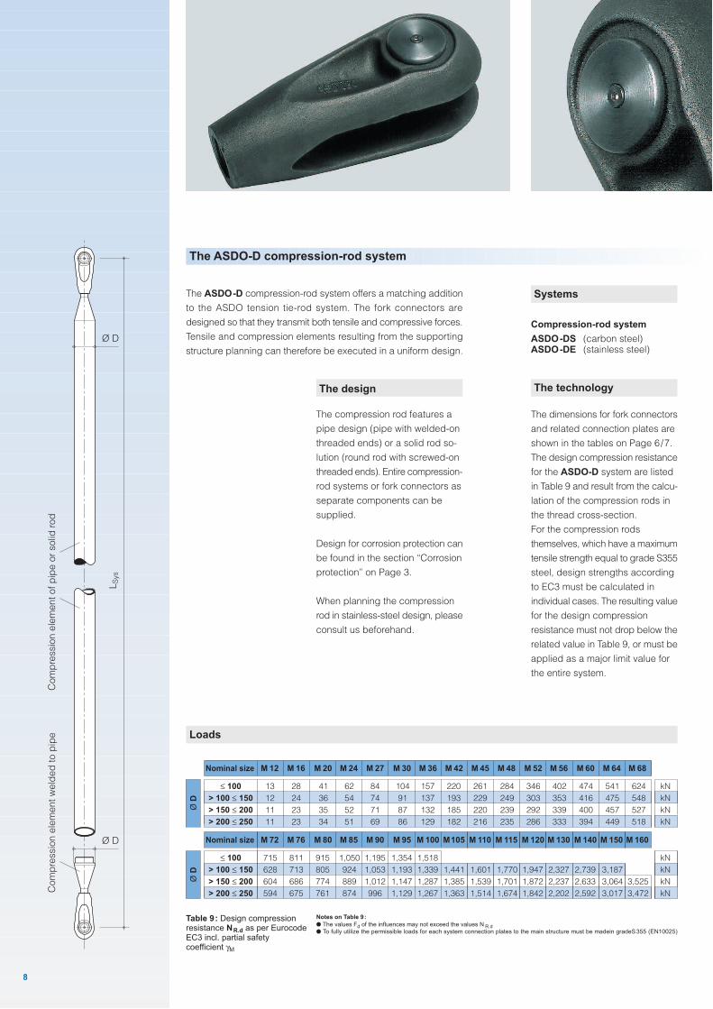
Systems
Compression-rod system
ASDO-DS (carbon steel)ASDO-DE (stainless steel)
The design
The compression rod features a
pipe design (pipe with welded-on
threaded ends) or a solid rod so-
lution (round rod with screwed-on
threaded ends). Entire compression-
rod systems or fork connectors as
separate components can be
supplied.
Design for corrosion protection can
be found in the section “Corrosion
protection” on Page 3.
When planning the compression
rod in stainless-steel design, please
consult us beforehand.
The ASDO-D compression-rod system
The ASDO-D compression-rod system offers a matching addition
to the ASDO tension tie-rod system. The fork connectors are
designed so that they transmit both tensile and compressive forces.
Tensile and compression elements resulting from the supporting
structure planning can therefore be executed in a uniform design.
Loads
Notes on Table 9:
● The values Fd of the influences may not exceed the values N R.d● To fully utilize the permissible loads for each system connection plates to the main structure must be madein gradeS355 (EN10025)
Nominal size M 76 M 80 M 85 M 90 M 95 M 100 M105 M 110 M 115 M 120 M 130 M 140 M 150 M 160
715
628
604
594
811
713
686
675
915
805
774
761
1,050
924
889
874
1,195
1,053
1,012
996
1,354
1,193
1,147
1,129
1,518
1,339
1,287
1,267
1,441
1,385
1,363
1,601
1,539
1,514
1,947
1,872
1,842
2,327
2,237
2,202
2,739
2,633
2,592
3,187
3,064
3,017
≤ 100
> 100 ≤ 150
> 150 ≤ 200
> 200 ≤ 250
M 72
kN
kN
kN
kN
1,770
1,701
1,674
8
The technology
The dimensions for fork connectors
and related connection plates are
shown in the tables on Page 6/7.
The design compression resistance
for the ASDO-D system are listed
in Table 9 and result from the calcu-
lation of the compression rods in
the thread cross-section.
For the compression rods
themselves, which have a maximum
tensile strength equal to grade S355
steel, design strengths according
to EC3 must be calculated in
individual cases. The resulting value
for the design compression
resistance must not drop below the
related value in Table 9, or must be
applied as a major limit value for
the entire system.
Table 9: Design compressionresistance NR.d as per EurocodeEC3 incl. partial safetycoefficient γM
Nominal size M 16 M 20 M 24 M 27 M 30 M 36 M 42 M 45 M 48 M 52 M 56 M 60 M 64 M 68
13
12
11
11
28
24
23
23
41
36
35
34
62
54
52
51
84
74
71
69
104
91
87
86
157
137
132
129
220
193
185
182
261
229
220
216
284
249
239
235
346
303
292
286
402
353
339
333
474
416
400
394
541
475
457
449
624
548
527
518
≤ 100
> 100 ≤ 150
> 150 ≤ 200
> 200 ≤ 250
M 12
kN
kN
kN
kN
Ø D
Ø D
3,525
3,472
LS
ys
Co
mp
ressio
n e
lem
en
t w
eld
ed
to
pip
eC
om
pre
ssio
n e
lem
en
t o
f p
ipe
or
so
lid r
od
Ø D
Ø D
Connection plate
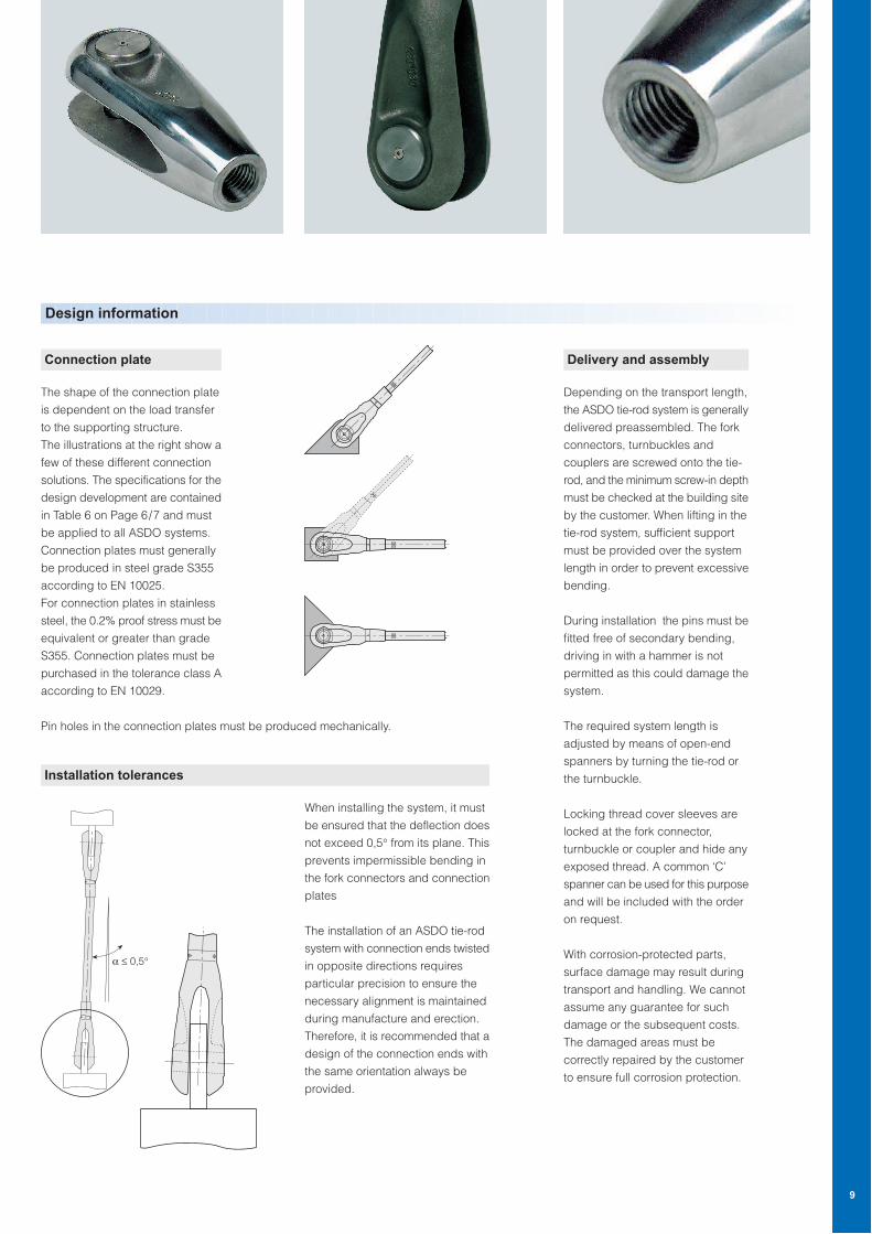
The shape of the connection plate
is dependent on the load transfer
to the supporting structure.
The illustrations at the right show a
few of these different connection
solutions. The specifications for the
design development are contained
in Table 6 on Page 6/7 and must
be applied to all ASDO systems.
Connection plates must generally
be produced in steel grade S355
according to EN 10025.
For connection plates in stainless
steel, the 0.2% proof stress must be
equivalent or greater than grade
S355. Connection plates must be
purchased in the tolerance class A
according to EN 10029.
Design information
Delivery and assembly
Depending on the transport length,
the ASDO tie-rod system is generally
delivered preassembled. The fork
connectors, turnbuckles and
couplers are screwed onto the tie-
rod, and the minimum screw-in depth
must be checked at the building site
by the customer. When lifting in the
tie-rod system, sufficient support
must be provided over the system
length in order to prevent excessive
bending.
During installation the pins must be
fitted free of secondary bending,
driving in with a hammer is not
permitted as this could damage the
system.
The required system length is
adjusted by means of open-end
spanners by turning the tie-rod or
the turnbuckle.
Locking thread cover sleeves are
locked at the fork connector,
turnbuckle or coupler and hide any
exposed thread. A common ‘C’
spanner can be used for this purpose
and will be included with the order
on request.
With corrosion-protected parts,
surface damage may result during
transport and handling. We cannot
assume any guarantee for such
damage or the subsequent costs.
The damaged areas must be
correctly repaired by the customer
to ensure full corrosion protection.
When installing the system, it must
be ensured that the deflection does
not exceed 0,5° from its plane. This
prevents impermissible bending in
the fork connectors and connection
plates
The installation of an ASDO tie-rod
system with connection ends twisted
in opposite directions requires
particular precision to ensure the
necessary alignment is maintained
during manufacture and erection.
Therefore, it is recommended that a
design of the connection ends with
the same orientation always be
provided.
Pin holes in the connection plates must be produced mechanically.
9
Installation tolerances
α ≤ 0,5°
Customer address:
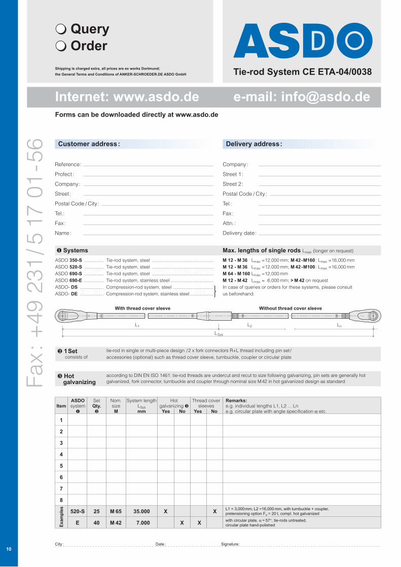
Tie-rod System CE ETA-04/0038
Fax
: +
49
231
/5
17
01
-56
Reference:
Profect:
Company:
Street:
Postal Code / City:
Tel.:
Fax:
Name:
Delivery address:
Company:
Street 1:
Street 2:
Postal Code / City:
Tel.:
Fax:
Attn. :
Delivery date:
❶ Systems
ASDO 350-S
ASDO 520-S
ASDO 690-S
ASDO 690-E
ASDO- DS
ASDO- DE
Max. lengths of single rods Lmax (longer on request)
M 12 - M 36 Lmax =12,000 mm; M 42-M160 : Lmax =16,000 mm
M 12 - M 36 Lmax =12,000 mm; M 42-M100 : Lmax =16,000 mm
M 64 - M 160 Lmax =12,000 mm
M 12 - M 42 Lmax = 6,000 mm; > M 42 on request
In case of queries or orders for these systems, please consult
us beforehand.
Tie-rod system, steel
Tie-rod system, steel
Tie-rod system, steel
Tie-rod system, stainless steel
Compression-rod system, steel
Compression-rod system, stainless steel
...............
...............
...............
...............
..................
..................
...............................................
...............................................
...............................................
.................................
...............................
..................
ItemASDOsystem❶
SetQty.❷
Nom.sizeM
System lengthLSys
mm
Hotgalvanizing ❸ Yes No
Thread coversleeves
Yes No
Remarks:e.g. individual lengths L1, L2 ... Lne.g. circular plate with angle specification α etc.
1
2
3
4
5
6
7
8
Exam
ple
s
520-S
E
25
40
M 65
M 42
35.000
7.000
X
X X
XL1 = 3,000mm; L2 =16,000 mm, with turnbuckle + coupler,pretensioning option Fv = 20 t, compl. hot galvanized
with circular plate, α = 57°, tie-rods untreated,circular plate hand-polished
City: Date: Signature:
❍ Query
❍ Order
10
With thread cover sleeve Without thread cover sleeve
L1 L2 Ln
LSys
tie-rod in single or multi-piece design /2 x fork connectors R+L thread including pin set /
accessories (optional) such as thread cover sleeve, turnbuckle, coupler or circular plate
❷ 1Set consists of
according to DIN EN ISO 1461: tie-rod threads are undercut and recut to size following galvanizing, pin sets are generally hot
galvanized, fork connector, turnbuckle and coupler through nominal size M42 in hot galvanized design as standard❸ Hot
galvanizing
Internet: www.asdo.de e-mail: [email protected]
Shipping is charged extra, all prices are ex works Dortmund;
the General Terms and Conditions of ANKER-SCHROEDER.DE ASDO GmbH
Forms can be downloaded directly at www.asdo.de
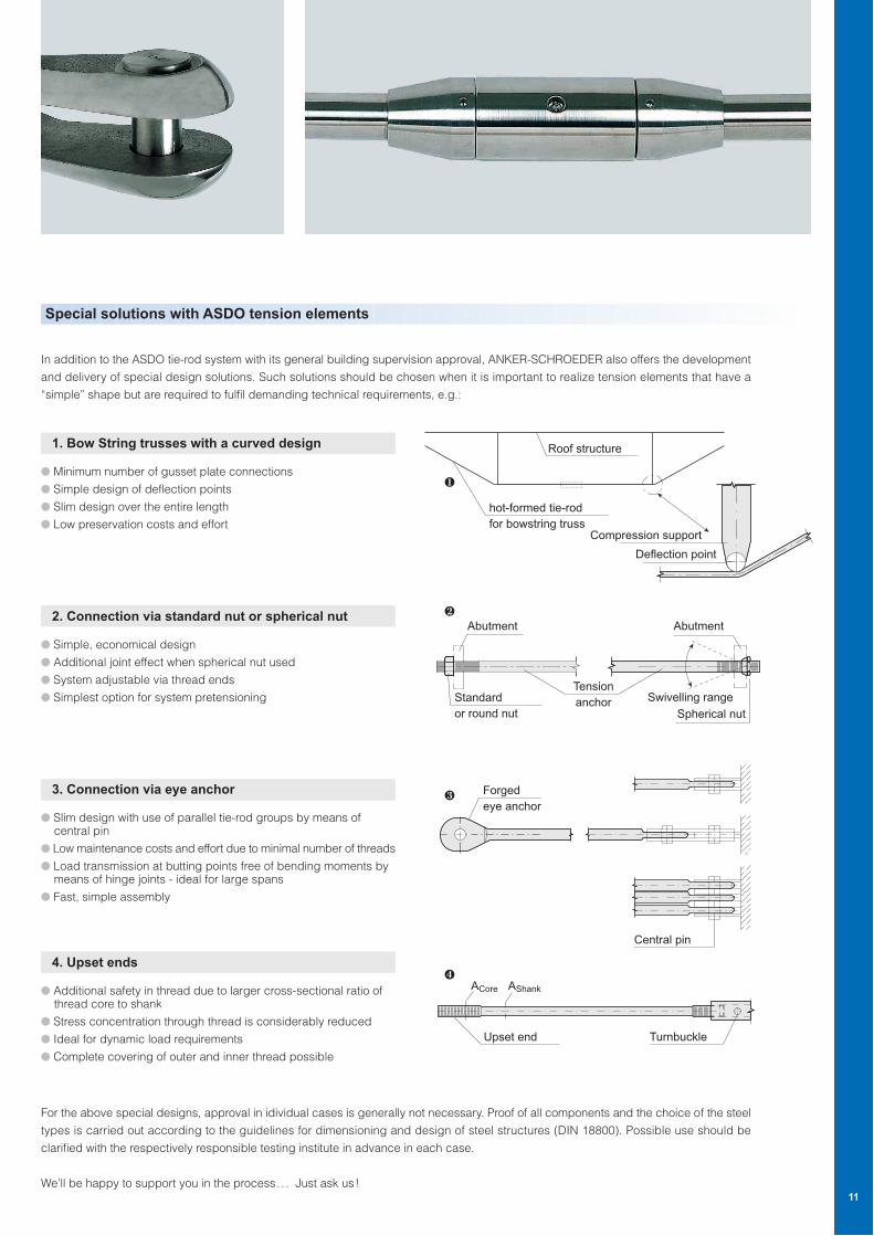
Special solutions with ASDO tension elements
In addition to the ASDO tie-rod system with its general building supervision approval, ANKER-SCHROEDER also offers the development
and delivery of special design solutions. Such solutions should be chosen when it is important to realize tension elements that have a
“simple” shape but are required to fulfil demanding technical requirements, e.g.:
1. Bow String trusses with a curved design
● Minimum number of gusset plate connections
● Simple design of deflection points
● Slim design over the entire length
● Low preservation costs and effort
2. Connection via standard nut or spherical nut
● Simple, economical design
● Additional joint effect when spherical nut used
● System adjustable via thread ends
● Simplest option for system pretensioning
3. Connection via eye anchor
● Slim design with use of parallel tie-rod groups by means of central pin
● Low maintenance costs and effort due to minimal number of threads
● Load transmission at butting points free of bending moments by means of hinge joints - ideal for large spans
● Fast, simple assembly
4. Upset ends
● Additional safety in thread due to larger cross-sectional ratio of thread core to shank
● Stress concentration through thread is considerably reduced
● Ideal for dynamic load requirements
● Complete covering of outer and inner thread possible
For the above special designs, approval in idividual cases is generally not necessary. Proof of all components and the choice of the steel
types is carried out according to the guidelines for dimensioning and design of steel structures (DIN 18800). Possible use should be
clarified with the respectively responsible testing institute in advance in each case.
We’ll be happy to support you in the process.. . Just ask us!11
Roof structure
hot-formed tie-rod
for bowstring trussCompression support
Deflection point
Upset end Turnbuckle
ACore AShank
Forged
eye anchor
Central pin
❶
❸
❹
Standard
or round nut
Abutment Abutment
Tension
anchor Swivelling range
Spherical nut
❷
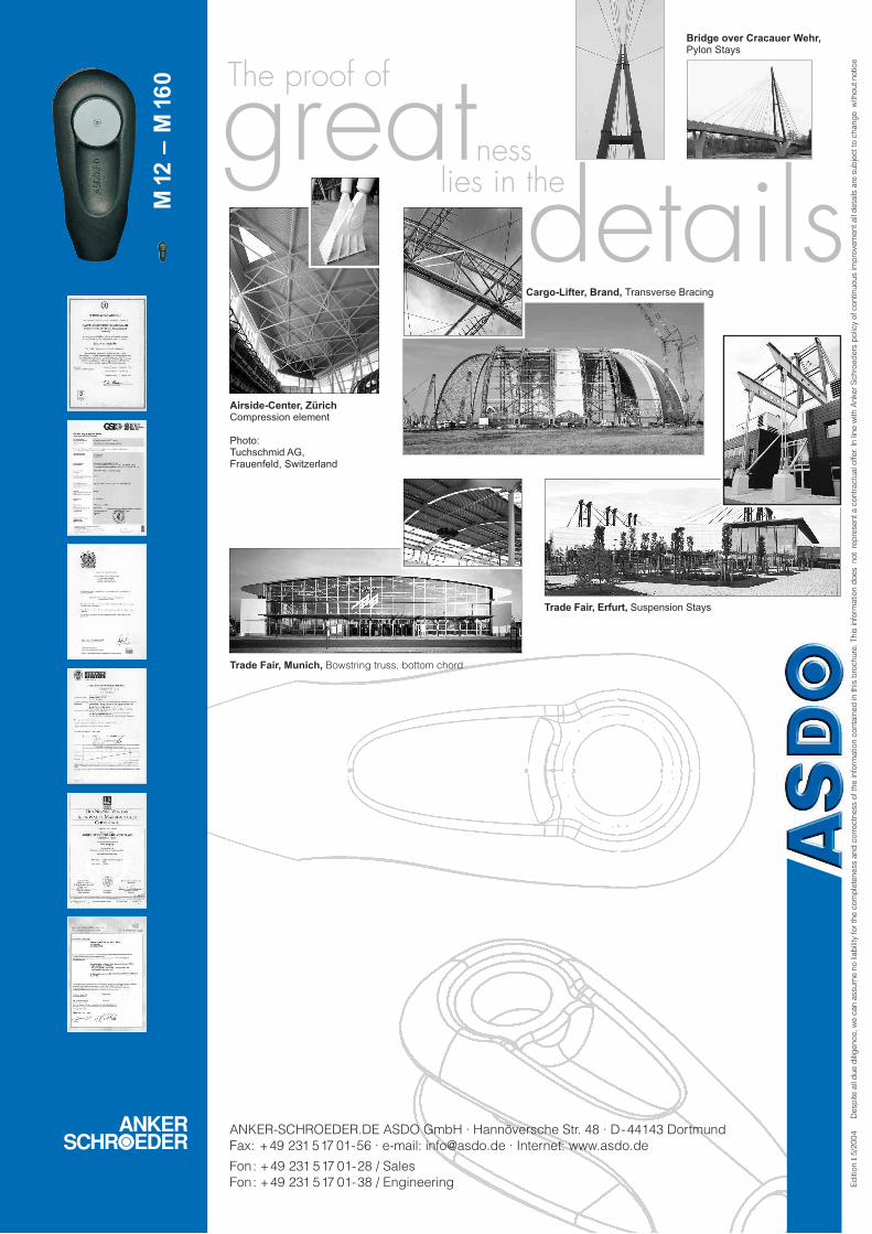
greatdetails
ANKER-SCHROEDER.DE ASDO GmbH · Hannöversche Str. 48 · D-44143 Dortmund
Fax: +49 231 517 01-56 · e-mail: [email protected] · Internet: www.asdo.de
Fon: +49 231 517 01-28 / Sales
Fon: +49 231 517 01-38 / Engineering
lies in the
Ed
itio
n I
5/2
004
Trade Fair, Munich, Bowstring truss, bottom chord
Airside-Center, ZürichCompression element
Photo:Tuchschmid AG,Frauenfeld, Switzerland
Bridge over Cracauer Wehr,Pylon Stays
Trade Fair, Erfurt, Suspension Stays
Cargo-Lifter, Brand, Transverse Bracing
M12
– M
160
Desp
ite a
ll d
ue d
ilig
ence, w
e c
an a
ssum
e n
o li
ab
ility
for
the c
om
ple
teness a
nd
corr
ectn
ess o
f th
e in
form
atio
n c
onta
ined
in this
bro
chure
. This
info
rmatio
n d
oes not r
ep
resent a c
ontr
actu
al o
ffer. In li
ne w
ith A
nker
Schro
ed
ers
polic
y o
f contin
uous im
pro
vem
ent all
deta
ils a
re s
ub
ject to
chang
e w
ithout notic
e
The proof of
ness
Related Documents