SIMATIC ET 200S distributed I/O 2AI TC HF analog electronic module (6ES7134-4NB01-0AB0) _ _____________ _ _____________ _ _____________ _ _____________ _ _____________ Preface Properties 1 Parameters 2 Diagnostics 3 Analog value representation 4 Connecting 5 SIMATIC ET 200S distributed I/O 2AI TC HF analog electronic module (6ES7134-4NB01-0AB0) Manual 04/2007 A5E01076892-01

Welcome message from author
This document is posted to help you gain knowledge. Please leave a comment to let me know what you think about it! Share it to your friends and learn new things together.
Transcript
SIMATIC ET 200S distributed I/O 2AI TC HF analog electronic module (6ES7134-4NB01-0AB0)
______________________________________________________________________
Preface
Properties 1
Parameters 2
Diagnostics 3
Analog value representation 4
Connecting 5
SIMATIC
ET 200S distributed I/O2AI TC HF analog electronic module (6ES7134-4NB01-0AB0)
Manual
04/2007 A5E01076892-01

Safety Guidelines Safety Guidelines This manual contains notices you have to observe in order to ensure your personal safety, as well as to prevent damage to property. The notices referring to your personal safety are highlighted in the manual by a safety alert symbol, notices referring only to property damage have no safety alert symbol. These notices shown below are graded according to the degree of danger.
DANGER indicates that death or severe personal injury will result if proper precautions are not taken.
WARNING indicates that death or severe personal injury may result if proper precautions are not taken.
CAUTION with a safety alert symbol, indicates that minor personal injury can result if proper precautions are not taken.
CAUTION without a safety alert symbol, indicates that property damage can result if proper precautions are not taken.
NOTICE indicates that an unintended result or situation can occur if the corresponding information is not taken into account.
If more than one degree of danger is present, the warning notice representing the highest degree of danger will be used. A notice warning of injury to persons with a safety alert symbol may also include a warning relating to property damage.
Qualified Personnel The device/system may only be set up and used in conjunction with this documentation. Commissioning and operation of a device/system may only be performed by qualified personnel. Within the context of the safety notes in this documentation qualified persons are defined as persons who are authorized to commission, ground and label devices, systems and circuits in accordance with established safety practices and standards.
Prescribed Usage Note the following:
WARNING This device may only be used for the applications described in the catalog or the technical description and only in connection with devices or components from other manufacturers which have been approved or recommended by Siemens. Correct, reliable operation of the product requires proper transport, storage, positioning and assembly as well as careful operation and maintenance.
Trademarks All names identified by ® are registered trademarks of the Siemens AG. The remaining trademarks in this publication may be trademarks whose use by third parties for their own purposes could violate the rights of the owner.
Disclaimer of Liability We have reviewed the contents of this publication to ensure consistency with the hardware and software described. Since variance cannot be precluded entirely, we cannot guarantee full consistency. However, the information in this publication is reviewed regularly and any necessary corrections are included in subsequent editions.
Siemens AG Automation and Drives Postfach 48 48 90327 NÜRNBERG GERMANY
Ordernumber: A5E01076892-01 09/2007
Copyright © Siemens AG 2007. Technical data subject to change
이 기기는 업무용(A급) 전자파 적합기기로서 판매자 또는 사용자는 이 점을 주의하시기 바라며 가정 외의 지역에서 사용하는 것을 목적으로 합니다.

2AI TC HF analog electronic module (6ES7134-4NB01-0AB0) Manual, 04/2007, A5E01076892-01 3
Preface
Purpose of the manual This manual supplements the ET 200S Distributed I/O System Operating Instructions. General functions for the ET 200S are described in the ET 200S Distributed I/O System Operating Instructions. The information in this document along with the operating instructions enables you to commission the ET 200S.
Basic knowledge requirements To understand these operating instructions you should have general knowledge of automation engineering.
Scope of the manual This manual applies to this ET 200S module. It describes the components that are valid at the time of publication.
Recycling and disposal Thanks to the fact that it is low in contaminants, this ET 200S module is recyclable. For environmentally compliant recycling and disposal of your electronic waste, please contact a company certified for the disposal of electronic waste.
Additional support If you have any questions relating to the products described in these operating instructions, and do not find the answers in this document, please contact your local Siemens representative. http://www.siemens.com/automation/partner The portal to our technical documentation for the various SIMATIC products and systems is available at: http://www.siemens.com/automation/simatic/portal The online catalog and ordering system are available at: http://www.siemens.com/automation/mall

Preface
2AI TC HF analog electronic module (6ES7134-4NB01-0AB0) 4 Manual, 04/2007, A5E01076892-01
Training center We offer courses to help you get started with the ET 200S and the SIMATIC S7 automation system. Please contact your regional training center or the central training center in D -90327, Nuremberg, Germany. Phone: +49 (911) 895-3200. http://www.siemens.com/sitrain
Technical Support You can reach technical support for all A&D projects using the support request web form:
http://www.siemens.com/automation/support-request Phone: + 49 180 5050 222 Fax: + 49 180 5050 223 For more information about our technical support, refer to our Web site at http://www.siemens.de/automation/service
Service & Support on the Internet In addition to our documentation services, you can also make use of our comprehensive online knowledge base on the Internet. http://www.siemens.com/automation/service&support There you will find: Our Newsletter, which constantly provides you with the latest information about your
products. The right documentation for you using our Service & Support search engine. The bulletin board, a worldwide knowledge exchange for users and experts. Your local contact for Automation & Drives in our contact database. Information about on-site services, repairs, spare parts. Lots more can be found on our
"Services" pages.

2AI TC HF analog electronic module (6ES7134-4NB01-0AB0) Manual, 04/2007, A5E01076892-01 5
Table of contents Preface ...................................................................................................................................................... 3 1 Properties .................................................................................................................................................. 7
1.1 2AI TC HF analog electronic module (6ES7134-4NB01-0AB0) ....................................................7 2 Parameters .............................................................................................................................................. 13
2.1 Parameters...................................................................................................................................13 2.2 Parameter description..................................................................................................................14
3 Diagnostics .............................................................................................................................................. 15 3.1 Diagnostics using LED display.....................................................................................................15 3.2 Error types....................................................................................................................................16
4 Analog value representation .................................................................................................................... 17 4.1 Introduction ..................................................................................................................................17 4.2 Analog value representation for measuring range with SIMATIC S7 ..........................................17 4.3 Measuring ranges ........................................................................................................................19 4.3.1 Measuring ranges for thermocouples ..........................................................................................19 4.3.2 Voltage measuring ranges ...........................................................................................................24 4.4 Effect on analog value representation .........................................................................................25 4.4.1 Effect of the supply voltage and the operating state on analog input values ..............................25 4.4.2 Effect of the value range on the 2AI TC HF analog input ............................................................25
5 Connecting .............................................................................................................................................. 27 5.1 Connecting measuring sensors ...................................................................................................27 5.2 Connecting thermocouples ..........................................................................................................30 5.3 Wiring unused channels on analog input modules ......................................................................31 5.4 Using the shield connection .....................................................................................................3332
Index........................................................................................................................................................ 33

Table of contents
2AI TC HF analog electronic module (6ES7134-4NB01-0AB0) 6 Manual, 04/2007, A5E01076892-01

2AI TC HF analog electronic module (6ES7134-4NB01-0AB0) Manual, 04/2007, A5E01076892-01 7
Properties 11.1 2AI TC HF analog electronic module (6ES7134-4NB01-0AB0)
Properties 2 inputs for thermocouple or voltage measurement Input ranges:
– Voltage measurement: ± 80 mV, resolution 15 bits + sign – Thermocouples: Types E, N, J, K, L, S, R, B, T, C, resolution 15 bits + sign
Isolated from the load voltage L+ Linearization of the sensor characteristic curves Permitted common-mode voltage 140 VDC/100 VAC Internal reference junction in connection with TM-E15S24-AT or TM-E15C24-AT
General terminal assignment
Terminal assignment for 2AI TC HF (6ES7134-4NB01-0AB0) Terminal Assignment Terminal Assignment Notes 1 M0+ 5 M1+ 2 M0- 6 M1-
• Mn+: Measuring line positive, channel n • Mn-: Measuring line negative, channel n

Properties 1.1 2AI TC HF analog electronic module (6ES7134-4NB01-0AB0)
2AI TC HF analog electronic module (6ES7134-4NB01-0AB0) 8 Manual, 04/2007, A5E01076892-01
Usable terminal modules
Usable terminal modules for 2AI TC HF (6ES7134-4NB01-0AB0) TM-E15C24-AT (6ES7193-4CL30-0AA0)
Spring terminal
TM-E15S24-AT (6ES7193-4CL20-0AA0)
Screw-type terminal
Block diagram
Figure 1-1 Block diagram of the 2AI TC HF

Properties 1.1 2AI TC HF analog electronic module (6ES7134-4NB01-0AB0)
2AI TC HF analog electronic module (6ES7134-4NB01-0AB0) Manual, 04/2007, A5E01076892-01 9
2AI TC HF technical specifications (6ES7134-4NB01-0AB0)
Dimensions and weight Width (mm) 15 Weight Approx. 40 g
Module-specific data Supports isochronous operation no Number of inputs 2 Cable length • Shielded Max. 50 m Parameter length 4 bytes Address space 4 bytes
Voltages, currents, potentials Rated load voltage L+ (from the power module) 24 VDC • Reverse polarity protection Yes Electrical isolation • Between the channels and backplane bus Yes • Between the channels and load voltage L+ Yes • Between the channels No Permissible potential difference • Between MANA and the central grounding point
(Uiso) 75 VDC / 60 VAC
• Between the inputs and MANA (UCM) 140 VDC / 100 VAC Insulation tested 500 VDC Current consumption • From load voltage L+ Max. 30 mA Power dissipation of the module Typically 0.6 W
Status, interrupts, diagnostics Diagnostics function • Group error Red "SF" LED • Diagnostic functions readable Yes
Analog value generation Measuring principle Integrative Integration time/conversion time/resolution per channel:
• Integration time can be assigned parameters Yes • Interference frequency suppression in Hz 60 50 • Integration time in ms 16,7 20 • Basic conversion time incl. integration time in
ms 66 80
• Additional conversion time for wire break check diagnosis in ms
5 5
• Cycle time in ms Number of active channels per module x conversion time
• Resolution (including overrange) 15 bits plus sign

Properties 1.1 2AI TC HF analog electronic module (6ES7134-4NB01-0AB0)
2AI TC HF analog electronic module (6ES7134-4NB01-0AB0) 10 Manual, 04/2007, A5E01076892-01
Suppression of interference, limits of error Noise suppression for f = n x (f1 ± 1 %), (f1 = interference frequency)
• Common-mode interference (USS) • Series-mode interference
(peak interference value < rated value of input range)
min. 90 dB min. 70 dB
Crosstalk between the inputs Min. -50 dB Operational limit for ±80 mV (over the entire temperature range with reference to the input range)
± 0,1 %
Operational limit for thermocouples (over the entire temperature range with reference to the input range)1
± 1.5 K
Operational limit for thermocouple type C (in the entire temperature range with reference to the input range)1
± 7 K
Basic error limit for ±80 mV (operational limit at 25 °C with reference to the input range)
± 0,05 %
Basic error limit for thermocouples (operational limit at 25 °C with reference to input range)1
± 1 K
Basic error limit for thermocouples of type C (operational limit at 25 °C with reference to the input range)1
± 5 K
Temperature error (with reference to the input range)
± 0.005 %/K
Linearity error (with reference to the input range) ± 0,01 % Repeatability (in steady state at 25°C with reference to input range)
± 0,05 %
Overall error limits using internal compensation • Operational limit (in the entire temperature
range with a static, thermal state, ambient temperature change < 0.3 K/min)2
± 2.5 K
• Basic error limit (operational limit at 25°C with a static, thermal state, ambient temperature change < 0.3 K/min)3
± 1.5 K
Data for selecting a sensor Input range (rated value)/input resistance • Voltage ± 80m V/min. 1 MΩ • Thermocouple Type E, N, J, K, L, S, R, B, T, C/min. 1 MΩ Permitted input voltage (destruction limit) ± 20 V, continuous Connection of the sensors • For measuring voltage Supported Characteristic curve linearization Yes, can be assigned parameters for type E, N,
J, K, L, S, R, B, T, C as per IEC 584

Properties 1.1 2AI TC HF analog electronic module (6ES7134-4NB01-0AB0)
2AI TC HF analog electronic module (6ES7134-4NB01-0AB0) Manual, 04/2007, A5E01076892-01 11
Temperature compensation • Internal temperature compensation Possible with TM-E15S24-ATTM-E15C24-AT • External temperature compensation by
looping a compensating box into the measuring circuit
Possible, one external compensating box per channel
Smoothing of the measured values Yes, can be assigned parameters in 4 steps by means of digital filtering
Step None Weak Medium Strong
Time constant 1 x cycle time 4 x cycle time 32 x cycle time 64 x cycle time
1 The specified error limits apply starting with the following temperatures: • Thermocouple Type T: -200°C • Thermocouple Type K: -100°C • Thermocouple Type B: +700°C • Thermocouple Type N: -150°C • Thermocouple Type E: -150°C • Thermocouple Type R: +200°C • Thermocouple Type S: +100°C 2 In the case of thermocouple Type C: ± 8 K 3 In the case of thermocouple Type C: ± 6 K
Compensation of thermocouples with a compensating box As well as the error limits of the 2AI TC HF electronic module (see Table "Technical specifications 2AI TC HF (6ES7134-4NB01-0AB0)" in this chapter) you must also take the accuracy of the compensating box into account.
Internal compensation with TM-E 15S24-AT or TM-E15C24-AT
Factors affecting the accuracy of the temperature measurement The connected channel with internal compensation must be assigned parameters separately.
Rules on using internal temperature compensation
Don't insert the 2AI TC HF directly next to a power module with high incoming current (> 3 A). An incoming current of 10 A can result in a further ± 2 K error. The station must be in a static state1 to ensure that the specified accuracy is achieved. Accuracy is achieved 30 minutes after the static state has been achieved.
Additional technical specifications for the error limits of the 2AI TC HF
The overall malfunction of the channel is caused by the combination of the input error and the internal compensation error.
1 The static state is defined by an almost constant ambient temperature (no draft, for example, in a closed cabinet!)

Properties 1.1 2AI TC HF analog electronic module (6ES7134-4NB01-0AB0)
2AI TC HF analog electronic module (6ES7134-4NB01-0AB0) 12 Manual, 04/2007, A5E01076892-01
2AI TC HF analog electronic module (6ES7134-4NB01-0AB0) Manual, 04/2007, A5E01076892-01 13
Parameters 22.1 Parameters
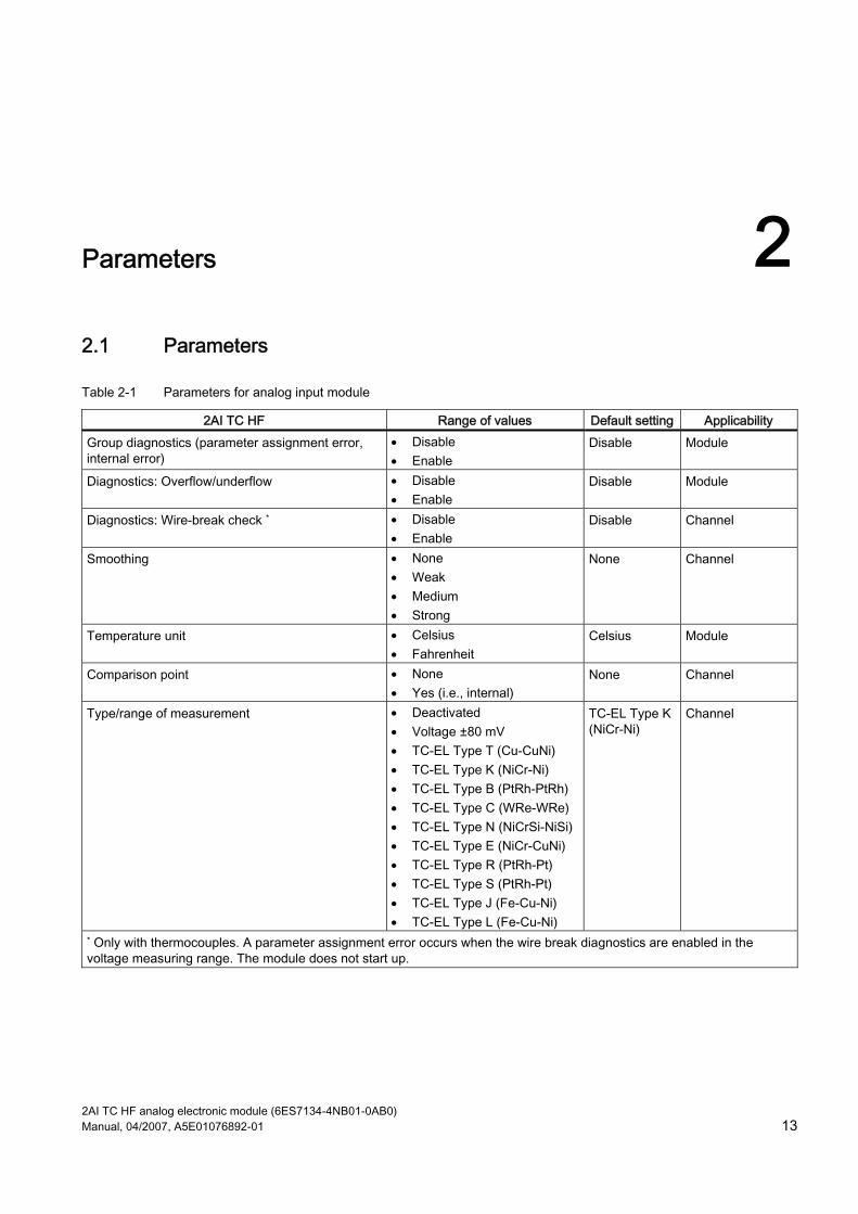
Table 2-1 Parameters for analog input module
2AI TC HF Range of values Default setting Applicability Group diagnostics (parameter assignment error, internal error)
• Disable • Enable
Disable Module
Diagnostics: Overflow/underflow • Disable • Enable
Disable Module
Diagnostics: Wire-break check * • Disable • Enable
Disable Channel
Smoothing • None • Weak • Medium • Strong
None Channel
Temperature unit • Celsius • Fahrenheit
Celsius Module
Comparison point • None • Yes (i.e., internal)
None Channel
Type/range of measurement • Deactivated • Voltage ±80 mV • TC-EL Type T (Cu-CuNi) • TC-EL Type K (NiCr-Ni) • TC-EL Type B (PtRh-PtRh) • TC-EL Type C (WRe-WRe) • TC-EL Type N (NiCrSi-NiSi) • TC-EL Type E (NiCr-CuNi) • TC-EL Type R (PtRh-Pt) • TC-EL Type S (PtRh-Pt) • TC-EL Type J (Fe-Cu-Ni) • TC-EL Type L (Fe-Cu-Ni)
TC-EL Type K (NiCr-Ni)
Channel
* Only with thermocouples. A parameter assignment error occurs when the wire break diagnostics are enabled in the voltage measuring range. The module does not start up.

Parameters 2.2 Parameter description
2AI TC HF analog electronic module (6ES7134-4NB01-0AB0) 14 Manual, 04/2007, A5E01076892-01
2.2 Parameter description
Smoothing The individual measured values are smoothed by digital filtering. The smoothing can be adjusted in four steps, in which the smoothing factor k multiplied with cycle time of the electronic module equals the time constant of the smoothing filter. The greater the smoothing, the greater the time constant of the filter. The following diagrams show the step response with the various smoothing factors in relation to the number of module cycles.
Figure 2-1 Smoothing with the 2AI TC HF

2AI TC HF analog electronic module (6ES7134-4NB01-0AB0) Manual, 04/2007, A5E01076892-01 15
Diagnostics 33.1 Diagnostics using LED display
LED display
1
① Batch error (red)
Status and error displays
Event (LED) SF
Cause Remedy
On No configuration or incorrect module plugged in. No load voltage.present There is a diagnostic message.
Check the parameter assignment. Check the load voltage. Evaluate the diagnostics.

Diagnostics 3.2 Error types
2AI TC HF analog electronic module (6ES7134-4NB01-0AB0) 16 Manual, 04/2007, A5E01076892-01
3.2 Error types
Analog input module error types
Table 3-1 Error types
Error type Meaning Remedy 16D 10000: Parameter
assignment error Module cannot use the parameter for the channel: Inserted module does not match the one configured. Incorrect parameter assignment.
Correct the configuration (align actual and set configuration). Correct the parameter assignment (wire break diagnostics only parameterized for the permitted measuring ranges).
9D 01001: Error Internal module error (diagnostic message at channel 0 applies to the entire module)
Replace the module.
7D 00111: Upper limit exceeded
Value is above the overshoot range.
Correct the module/final controlling element tuning.
8D 01000: Lower limit value undershot
Value is below the underrange. Correct the module/final controlling element tuning.
6D 00110: Open circuit
Line to the encoder interrupted.
Correct the process wiring.
21D 10101: Reference channel error
Error on the reference channel Check the reference module

2AI TC HF analog electronic module (6ES7134-4NB01-0AB0) Manual, 04/2007, A5E01076892-01 17
Analog value representation 44.1 Introduction
Electronic modules with analog outputs With the electronic module with analog inputs, continuously variable signals, such as those occurring in temperature measurement and resistance measurement, can be acquired, evaluated, and converted to digital values for further processing.
4.2 Analog value representation for measuring range with SIMATIC S7
Analog value representation With the same nominal range, the digitized analog value is the same for input and output values. Analog values are represented in two's complement. The following table shows the analog value representation of the analog electronic modules.
Table 4-1 Analog value representation (SIMATIC S7 format)
Resolution Analog value Bit number 15 14 13 12 11 10 9 8 7 6 5 4 3 2 1 0 Significance of the bits S 214 213 212 211 210 29 28 27 26 25 24 23 22 21 20
Sign The sign (S) of the analog value is always in bit number 15: "0" → + "1" → –
Analog value representation 4.2 Analog value representation for measuring range with SIMATIC S7
2AI TC HF analog electronic module (6ES7134-4NB01-0AB0) 18 Manual, 04/2007, A5E01076892-01
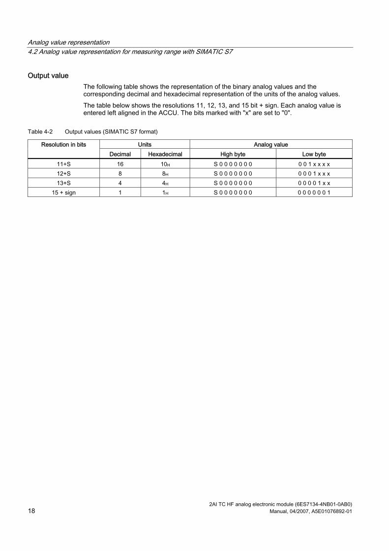
Output value The following table shows the representation of the binary analog values and the corresponding decimal and hexadecimal representation of the units of the analog values. The table below shows the resolutions 11, 12, 13, and 15 bit + sign. Each analog value is entered left aligned in the ACCU. The bits marked with "x" are set to "0".
Table 4-2 Output values (SIMATIC S7 format)
Units Analog value Resolution in bits Decimal Hexadecimal High byte Low byte
11+S 16 10H S 0 0 0 0 0 0 0 0 0 1 x x x x 12+S 8 8H S 0 0 0 0 0 0 0 0 0 0 1 x x x 13+S 4 4H S 0 0 0 0 0 0 0 0 0 0 0 1 x x
15 + sign 1 1H S 0 0 0 0 0 0 0 0 0 0 0 0 0 1
Analog value representation 4.3 Measuring ranges
2AI TC HF analog electronic module (6ES7134-4NB01-0AB0) Manual, 04/2007, A5E01076892-01 19
4.3 Measuring ranges
4.3.1 Measuring ranges for thermocouples
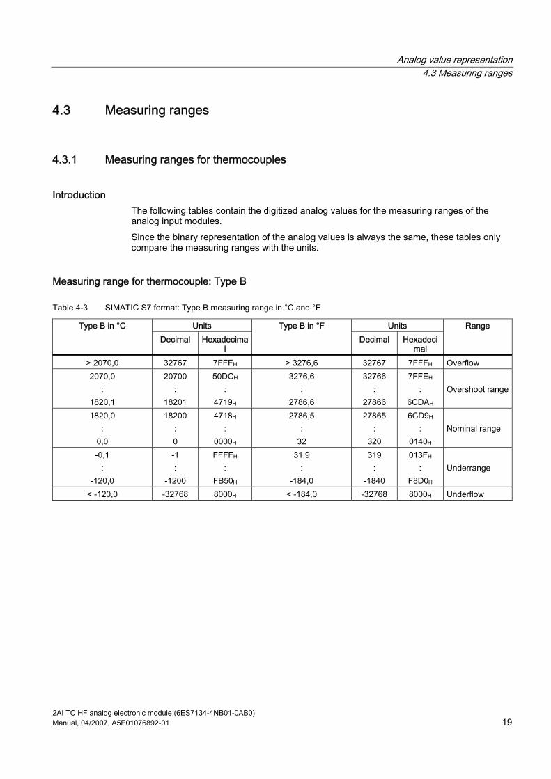
Introduction The following tables contain the digitized analog values for the measuring ranges of the analog input modules. Since the binary representation of the analog values is always the same, these tables only compare the measuring ranges with the units.
Measuring range for thermocouple: Type B
Table 4-3 SIMATIC S7 format: Type B measuring range in °C and °F
Units Units Type B in °C Decimal Hexadecima
l
Type B in °F Decimal Hexadeci
mal
Range
> 2070,0 32767 7FFFH > 3276,6 32767 7FFFH Overflow 2070,0
: 1820,1
20700 :
18201
50DCH :
4719H
3276,6 :
2786,6
32766 :
27866
7FFEH :
6CDAH
Overshoot range
1820,0 :
0,0
18200 : 0
4718H :
0000H
2786,5 :
32
27865 :
320
6CD9H :
0140H
Nominal range
-0,1 :
-120,0
-1 :
-1200
FFFFH :
FB50H
31,9 :
-184,0
319 :
-1840
013FH :
F8D0H
Underrange
< -120,0 -32768 8000H < -184,0 -32768 8000H Underflow

Analog value representation 4.3 Measuring ranges
2AI TC HF analog electronic module (6ES7134-4NB01-0AB0) 20 Manual, 04/2007, A5E01076892-01
Measuring range for thermocouple: Type C
Table 4-4 SIMATIC S7 format: Type C measuring range in °C and °F
Units Units Type C in °C Decimal Hexadecima
l
Type C in °F Decimal Hexadeci
mal
Range
> 2500,0 32767 7FFFH > 3276,6 32767 7FFFH Overflow 2500,0
: 2315,1
25000 :
23151
61A8H :
5A6FH
3276,6 :
2786,6
32766 :
27866
7FFEH :
6CDAH
Overshoot range
2315,0 :
0,0
23150 : 0
5A6EH :
0000H
2786,5 :
32,0
27865 :
320
6CD9H :
0140H
Nominal range
0,1 :
-120,0
-1 :
-1200
FFFFH :
FB50H
31,9 :
-184,0
319 :
-1840
013FH :
F8D0H
Underrange
< -120,0 -32768 8000H < -184,0 -32768 8000H Underflow
Measuring range for thermocouple Type E
Table 4-5 SIMATIC S7 format: Type E measuring range in °C and °F
Units Units Type E in °C Decimal Hexadecima
l
Type E in °F Decimal Hexadeci
mal
Range
> 1200,0 32767 7FFFH > 2192,0 32767 7FFFH Overflow 1200,0
: 1000,1
12000 :
10001
2EE0H :
2711H
2192,0 :
1832,1
21920 :
18321
55A0H :
4791H
Overshoot range
1000,0 :
-270,0
10000 :
-2700
2710H :
F574H
1832,0 :
-454,0
18320 :
-4540
4790H :
EE44H
Nominal range
< -270,0 - 32768 8000H < -454,0 - 32768 8000H Underflow
Analog value representation 4.3 Measuring ranges
2AI TC HF analog electronic module (6ES7134-4NB01-0AB0) Manual, 04/2007, A5E01076892-01 21
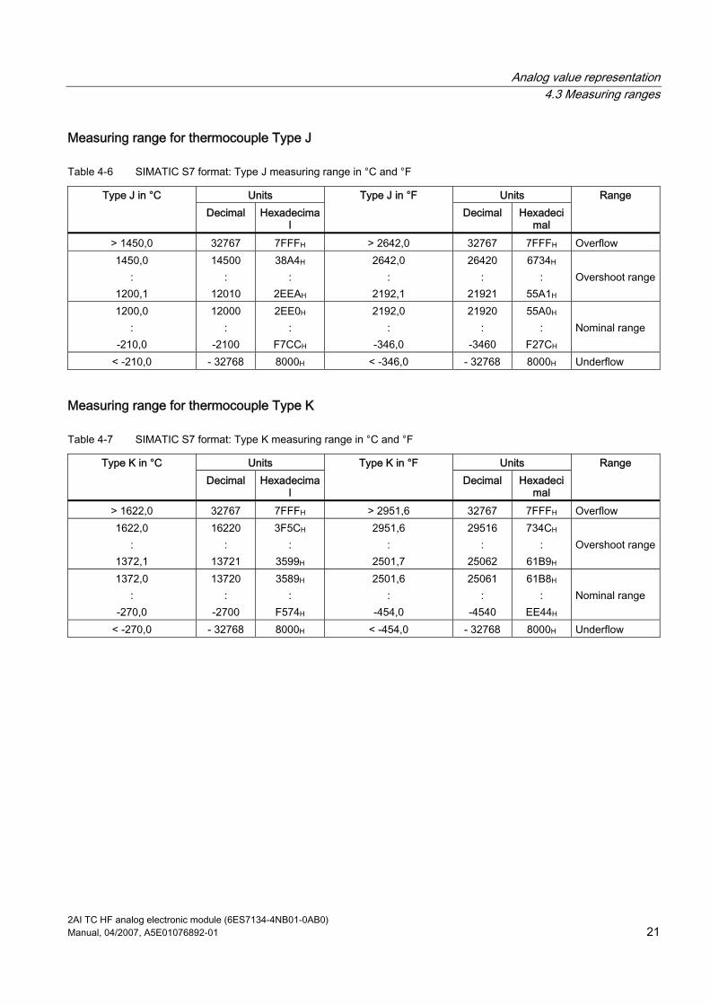
Measuring range for thermocouple Type J
Table 4-6 SIMATIC S7 format: Type J measuring range in °C and °F
Units Units Type J in °C Decimal Hexadecima
l
Type J in °F Decimal Hexadeci
mal
Range
> 1450,0 32767 7FFFH > 2642,0 32767 7FFFH Overflow 1450,0
: 1200,1
14500 :
12010
38A4H :
2EEAH
2642,0 :
2192,1
26420 :
21921
6734H :
55A1H
Overshoot range
1200,0 :
-210,0
12000 :
-2100
2EE0H :
F7CCH
2192,0 :
-346,0
21920 :
-3460
55A0H :
F27CH
Nominal range
< -210,0 - 32768 8000H < -346,0 - 32768 8000H Underflow
Measuring range for thermocouple Type K
Table 4-7 SIMATIC S7 format: Type K measuring range in °C and °F
Units Units Type K in °C Decimal Hexadecima
l
Type K in °F Decimal Hexadeci
mal
Range
> 1622,0 32767 7FFFH > 2951,6 32767 7FFFH Overflow 1622,0
: 1372,1
16220 :
13721
3F5CH :
3599H
2951,6 :
2501,7
29516 :
25062
734CH :
61B9H
Overshoot range
1372,0 :
-270,0
13720 :
-2700
3589H :
F574H
2501,6 :
-454,0
25061 :
-4540
61B8H :
EE44H
Nominal range
< -270,0 - 32768 8000H < -454,0 - 32768 8000H Underflow

Analog value representation 4.3 Measuring ranges
2AI TC HF analog electronic module (6ES7134-4NB01-0AB0) 22 Manual, 04/2007, A5E01076892-01
Measuring range for thermocouple Type L
Table 4-8 SIMATIC S7 format: Type L measuring range in °C and °F
Units Units Type L in °C Decimal Hexadecima
l
Type L in °F Decimal Hexadeci
mal
Range
> 1150,0 32767 7FFFH > 2102,0 32767 7FFFH Overflow 1150,0
: 900,1
11500 :
9001
2CECH :
2329H
2102,0 :
1652,1
21020 :
16521
521CH :
4089H
Overshoot range
900,0 :
-200,0
9000 :
-2000
2328H :
F830H
1652,0 :
-328,0
16520 :
-3280
4088H :
F330H
Nominal range
< -200,0 -32768 8000H < -328,0 -32768 8000H Underflow
Measuring range for thermocouple Type N
Table 4-9 SIMATIC S7 format: Type N measuring range in °C and °F
Units Units Type N in °C Decimal Hexadecima
l
Type N in °F Decimal Hexadeci
mal
Range
> 1550,0 32767 7FFFH > 2822,0 32767 7FFFH Overflow 1550,0
: 1300,1
15500 :
13001
3C8CH :
32C9H
2822,0 :
2372,1
28220 :
23721
6E3CH :
5CA9H
Overshoot range
1300,0 :
-270,0
13000 :
-2700
32C8H :
F574H
2372,0 :
-454,0
23720 :
-4540
5CA8H :
EE44H
Nominal range
< -270,0 -32768 8000H -32768 8000H <EE44H Underflow

Analog value representation 4.3 Measuring ranges
2AI TC HF analog electronic module (6ES7134-4NB01-0AB0) Manual, 04/2007, A5E01076892-01 23
Measuring range for thermocouple Types R, S
Table 4-10 SIMATIC S7 format: Type R, S measuring range in °C and °F
Units Units Type R, S in °C Decimal Hexadecima
l
Type R, S in °F Decimal Hexadeci
mal
Range
> 2019,0 32767 7FFFH > 3276,6 32767 7FFFH Overflow 2019,0
: 1769,1
20190 :
17691
4EDEH :
451BH
3276,6 :
3216,3
32766 :
32163
7FFEH :
7DA3H
Overshoot range
1769,0 :
-50,0
17690 :
-500
451AH :
FE0CH
3216,2 :
-58,0
32162 :
-580
7DA2H :
FDBCH
Nominal range
-50,1 :
-170,0
-510 :
-1700
FE0BH :
F95CH
-58,1 :
-274,0
-581 :
-2740
FDBBH :
F54CH
Underrange
< -170,0 -32768 8000H < -274,0 -32768 8000H Underflow
Measuring range for thermocouple Type T
Table 4-11 SIMATIC S7 format: Type T measuring range in °C and °F
Units Units Type T in °C Decimal Hexadecima
l
Type T in °F Decimal Hexadeci
mal
Range
> 540,0 32767 7FFFH > 1004,0 32767 7FFFH Overflow 540,0
: 400,1
5400 :
4001
1518H :
0FA1H
1004,0
752,1
10040
7521
2738H
1DC1H
Overshoot range
400,0 :
-270,0
4000 :
-2700
0FA0H :
F574H
752,0 :
-454,0
7520 :
-4540
1D60H :
EE44H
Nominal range
< -270,0 -32768 8000H < -454,0 -32768 8000H Underflow

Analog value representation 4.3 Measuring ranges
2AI TC HF analog electronic module (6ES7134-4NB01-0AB0) 24 Manual, 04/2007, A5E01076892-01
4.3.2 Voltage measuring ranges
Voltage measuring ranges: ±80 mV
Table 4-12 SIMATIC S7 format: Measuring range ±80 mV
Units Measuring range ±80 mV Decimal Hexadecimal
Range
> 94,071 32767 7FFFH Overflow 94,071
: 80,003
32511 :
27649
7EFFH :
6C01H
Overshoot range
80,000 60,000
: -60,000 -80,000
27648 20736
: -20736 -27648
6C00H 5100H
: AF00H 9400H
Nominal range
-80,003 :
-94,074
-27649 :
-32512
93FFH :
8100H
Underrange
< -94,074 -32768 8000H Underflow
Measured values in the event of a wire break, depending on the diagnostics enabled for voltage measurement
In the case of the measuring ranges for types B, C, E, J, K, L, N, R, S, and T thermocouples, the following additional information applies:
Table 4-13 Measured values in the event of a wire break, depending on the diagnostics enabled for voltage measurement
Measured values Format Parameter assignment Decimal Hexadecimal
Description
• "Wire-break check" diagnostics enabled
32767 7FFFH • "Open circuit" diagnostic message
• "Overflow/underflow" diagnostics disabled
-32767 8000H • Measured value after leaving the underrange
• "Lower limit value undershot" diagnostic message
S7
• "Wire-break check" diagnostics disabled
--- --- • Open input: Undefined measured value

Analog value representation 4.4 Effect on analog value representation
2AI TC HF analog electronic module (6ES7134-4NB01-0AB0) Manual, 04/2007, A5E01076892-01 25
4.4 Effect on analog value representation
4.4.1 Effect of the supply voltage and the operating state on analog input values The input values of the analog modules are dependent on the supply voltage for electronics/encoders and on the operating state of the PLC (CPU of the DP master). This is illustrated by the table below.
Table 4-14 Relationship between the analog input values for the operating state of the PLC (CPU of the DP master) and the supply voltage L+
Operating state of the PLC (CPU of the DP master)
Supply voltage L+ on ET 200S (power
module)
Input value of the electronic module with analog inputs (evaluation possible on the
CPU of the DP master) Process values L+ present 7FFFH until first conversion after startup, or after assignment of parameters for the module is completed.
POWER ON RUN
L+ missing 7FFFH L+ present Process value POWER ON STOP L+ missing 7FFFH L+ present - POWER OFF - L+ missing -
4.4.2 Effect of the value range on the 2AI TC HF analog input The way electronic modules respond to analog inputs depends on where the input values fall within the value range. This is illustrated by the table below.
Table 4-15 Response of the analog modules, depending on where the analog input value falls within the range of values
Measured value within ... Input value in SIMATIC S7 format Input value in SIMATIC S5 format Nominal range Measured value Measured value Over-/underrange Measured value Measured value Overflow 7FFFH End of the overshoot range +1 plus
overflow bit Underflow 8000H End of the underrange -1 plus overflow
bit Prior to parameter assignment, or incorrect parameter assignment
7FFFH 7FFFH

Analog value representation 4.4 Effect on analog value representation
2AI TC HF analog electronic module (6ES7134-4NB01-0AB0) 26 Manual, 04/2007, A5E01076892-01

2AI TC HF analog electronic module (6ES7134-4NB01-0AB0) Manual, 04/2007, A5E01076892-01 27
Connecting 55.1 Connecting measuring sensors
Introduction You can connect encoders with voltage signals and thermocouples to the 2AI TC HF analog input module. In this chapter you will find out how to connect the measuring encoders and what to watch out for when doing so.
Cables for analog signals You should use shielded and twisted-pair cables for the analog signals. This reduces the effect of interference. You should ground the shield of the analog cables at both ends. If there are differences in potential between the cable ends, an equipotential bonding current that may interfere with the analog signals will flow across the shield. If this is the case, you should only ground the shield at one end of the cable.
Analog input modules The analog input modules are electrically isolated: Between the logic and backplane bus Between the load voltage and the channels.
– Electrical isolation: No link between MANA and the central grounding point (UISO)
Note Ensure that this difference in potential UISO does not exceed the permitted value. If there is a possibility of exceeding the permitted value, establish a connection between terminal MANA and the central grounding point.
Connecting measuring encoders to analog inputs There can be only a limited potential difference UCM (common mode) between the measuring lines M- of the input channels and the reference point of the measuring circuit MANA. To ensure that the permitted value is not exceeded, you must take different steps depending on the whether the encoders are isolated or non-isolated. The steps you have to take are described in this chapter.

Connecting 5.1 Connecting measuring sensors
2AI TC HF analog electronic module (6ES7134-4NB01-0AB0) 28 Manual, 04/2007, A5E01076892-01
Abbreviations used The meanings of the abbreviations in the figures below are as follows:
M+: Measuring line (positive) M- Measuring line (negative) M Ground connection L+ Rated load voltage 24 V DC UCM Potential difference between inputs and reference potential of the measuring
circuit MANA UISO Potential difference between M- and central grounding point
Isolated measuring encoders The isolated measuring encoders are not connected to the local ground potential. These can be potential-free. Depending on local conditions or interference, potential differences UCM (static or dynamic) can occur between the measuring lines M- of the input channels and the reference point of the measuring circuit MANA. The permitted value for UCM must not be exceeded, even in environments with strong EMC interference. The following schematic representation illustrates the connection of isolated measuring encoders to the optically isolated analog input modules.
1
2
3
4
5
① Logic ② Backplane bus ③ Ground bus ④ Central grounding point ⑤ Isolated measuring encoders

Connecting 5.1 Connecting measuring sensors
2AI TC HF analog electronic module (6ES7134-4NB01-0AB0) Manual, 04/2007, A5E01076892-01 29
Non-isolated measuring encoders The non-isolated measuring encoders are connected to the local ground potential. You must connect MANA to the ground potential. Depending on local conditions or interference, potential differences UCM (static or dynamic) can occur between the locally distributed measuring points. If the permitted value for UCM is exceeded, there must be equipotential bonding conductors between the measuring points. The following schematic representation illustrates the connection of non-isolated measuring encoders to an optically isolated analog input module.
5
4
1
2
3
① Logic ② Backplane bus ③ Ground bus ④ Equipotential bonding conductor ⑤ Non-isolated measuring encoders
Non-isolated thermocouples When using non-isolated thermocouples, you must comply with the permitted common mode voltage.

Connecting 5.2 Connecting thermocouples
2AI TC HF analog electronic module (6ES7134-4NB01-0AB0) 30 Manual, 04/2007, A5E01076892-01
5.2 Connecting thermocouples
Introduction This section contains additional information on connecting thermocouples.
Compensation of the comparison point temperature There are various ways of obtaining the comparison point temperature in order to get an absolute temperature value from the temperature difference between the comparison point and the measuring point.
Table 5-1 Compensation of the comparison point temperature
Option Description Comparison point parameters No compensation It is not just the temperature of the measuring
point that you need to record: The temperature of the comparison point (transition from Cu line to thermocouple line) also affects the thermo-electromotive force. The measured value on its own is incorrect.
None
Using a compensating box on the supply lines of a single thermocouple
You compensate using a compensating box. The compensating box is the transition point from the Cu line to the thermocouple line. No further processing is necessary using the 2AI TC ST.
None
Internal compensation in the case of the 2AI TC HF
There is a temperature sensor in the TM-E15S24-AT and TM-E15C24-AT terminal modules. The temperature sensor reports the temperature of the terminals to the 2AI TC HF. This value is then calculated together with the measured value from the channel of the electronic module.
• 2AI TC HF: Reference junction: Yes
Extension to a comparison point The thermocouples can be extended from their connection point by means of compensating lines to the comparison point (transition to Cu line) or the compensating box. The comparison point can also be an ET 200S terminal module. The compensating lines are made of the same material as the wires of the thermocouple. The supply lines are made of copper. Ensure the correct polarity when connecting.
Connecting 5.3 Wiring unused channels on analog input modules
2AI TC HF analog electronic module (6ES7134-4NB01-0AB0) Manual, 04/2007, A5E01076892-01 31
Using a compensating box The effect of the temperature on the comparison point of a thermocouple (such as a terminal box) can be adjusted with a compensating box. The compensating box contains a bridge circuit that is adjusted for a certain comparison point temperature (compensating temperature). You connect the thermocouples or their compensating lines to the compensating box. The compensating box then forms the comparison point. If the actual reference temperature differs from the compensating temperature, the temperature-dependent bridge resistance changes. A positive or negative compensation voltage occurs; this is added to the thermo-electromotive force. Compensating boxes with a comparison point temperature of 0°C must be used for the compensation of the analog input modules. Note: The power supply to the compensating box must be isolated. The power supply unit must have adequate interference filtering (by means of a grounded
shielding winding, for example).
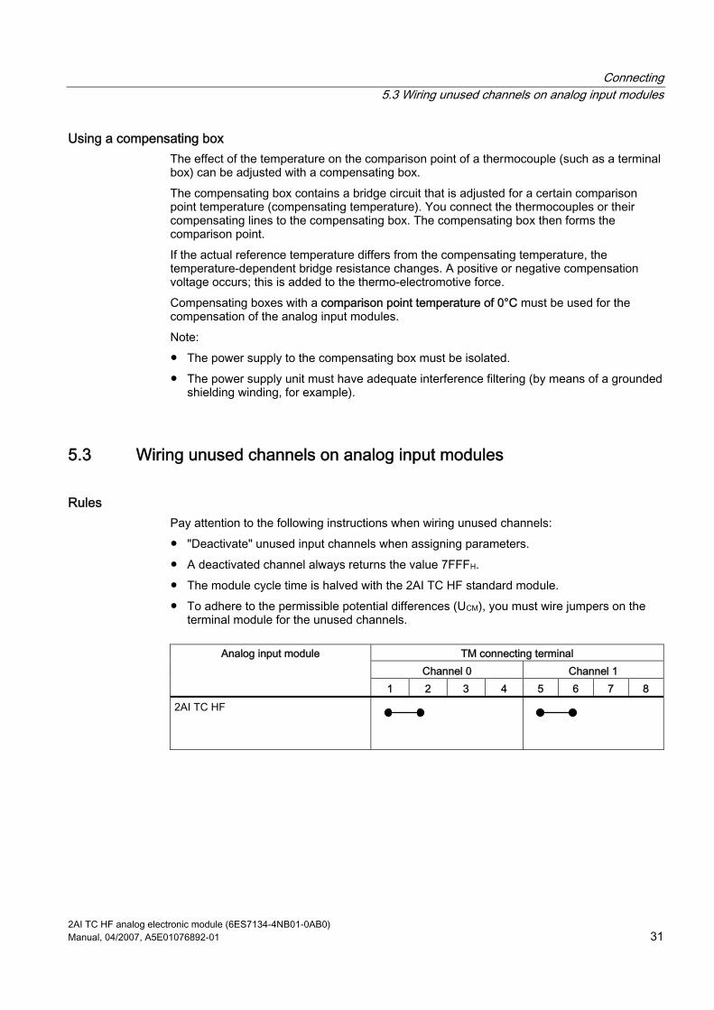
5.3 Wiring unused channels on analog input modules
Rules Pay attention to the following instructions when wiring unused channels: "Deactivate" unused input channels when assigning parameters. A deactivated channel always returns the value 7FFFH. The module cycle time is halved with the 2AI TC HF standard module. To adhere to the permissible potential differences (UCM), you must wire jumpers on the
terminal module for the unused channels.
TM connecting terminal Channel 0 Channel 1
Analog input module
1 2 3 4 5 6 7 8 2AI TC HF

Connecting 5.4 Using the shield connection
2AI TC HF analog electronic module (6ES7134-4NB01-0AB0) 32 Manual, 04/2007, A5E01076892-01
5.4 Using the shield connection
Rules To prevent interference we recommend the following for analog electronic modules: Use shielded wires to the sensors and actuators. Lay out the wire shields on the shield connection. Connect the shield connection to the ground bus with low impedance.

2AI TC HF analog electronic module (6ES7134-4NB01-0AB0) Manual, 04/2007, A5E01076892-01 33
Index
2 2AI TC HF analog electronic module
Block diagram, 8 Properties, 7 Technical data, 9 Terminal assignment, 7
A Analog input modules
Error types, 16 Analog value representation, 27
For thermocouples, 20, 21, 22, 23
B Basic knowledge requirements, 3
C Cables for analog signals, 27 Compensation of the comparison point temperature, 30 Connecting, 27, 30 Connecting measuring encoders to analog inputs, 27
D Disposal, 3
I Internet
Service & Support, 4 Isolated measuring encoders, 28
L LED display, 15
M Measured value resolution, 18 Measuring ranges with SIMATIC S7, 17
N Non-isolated measuring encoders, 29 Non-isolated thermocouples, 29
R Recycling, 3 Response of the analog modules, 25
During operation, 25 When faults occur, 25
S Scope
Manual, 3 Service & Support, 4 Shield connection, 32 Smoothing, 14
T Technical Support, 4 Thermocouples, 30 Training center, 4

Index
2AI TC HF analog electronic module (6ES7134-4NB01-0AB0) 34 Manual, 04/2007, A5E01076892-01
Related Documents


