MIDDLE POMERANIAN SCIENTIFIC SOCIETY OF THE ENVIRONMENT PROTECTION Rocznik Ochrona Środowiska Volume 21. Year 2019 ISSN 1506-218X 294-315 Estimation of Load Bearing Capacity of Bending Fibrocomposite Elements Wiesława Głodkowska, Marek Ziarkiewicz * Koszalin University of Technology, Poland * corresponding author’s e-mail: [email protected] 1. Introduction Ordinary concrete is commonly used as construction material. Despite its major advantages, it has an important drawback – it is fragile and has very little tensile strength. In order to improve its qualities, various fibers are added to con- crete mix. Thus, a new material called fiber-reinforced concrete is created. This material has been researched for over 30 years (Zollo 1997, Shah and Ribakov 2011, Domski 2016)and its main application areas are industrial floors, founda- tion slabs, road/airport pavements, tunnel linings, structures prone to seismic ac- tivity and considerable dynamic loads (de la Fuente et al. 2011, Tiberti et al. 2008, Gossla 2006, Destrée 2008, Pepin 2009, Li 2002). By the end of the 1990s, the application of fiber-reinforced concrete was limited by the lack of standard regulations making reliable design possible. After the year 2000, the first national and international standards and guidelines con- cerning fiber-reinforced concrete design were introduced (DBV 2001,RILEM 2003,fib Model Code 2010, CNR-DT 204 2006, EHE-08 2008). As for flexural design, these regulations provide different models of stress distribution in tension zone. Differences also concern the methods of defining post-cracking concrete tensile strength. This is the reason why so many researchers have focused their efforts on verifying these regulations. Blanco et al.(2013) made an attempt to verify selected standards based on the results of experimental research on rein- forced concrete beams – the variables in this research being the volume content of fibers and their type. The research results demonstrated that DBV standard (2001)defined underestimated capacity in regard to both small and big strains. However, the calculations in accordance with CNR-DT 204 (2006), EHE-08 (2008), RILEM (2003) and Model Code 2010 standards represented slightly

Welcome message from author
This document is posted to help you gain knowledge. Please leave a comment to let me know what you think about it! Share it to your friends and learn new things together.
Transcript
MIDDLE POMERANIAN SCIENTIFIC SOCIETY OF THE ENVIRONMENT PROTECTION
Rocznik Ochrona Środowiska
Volume 21. Year 2019 ISSN 1506-218X 294-315
Estimation of Load Bearing Capacity of Bending Fibrocomposite Elements
Wiesława Głodkowska, Marek Ziarkiewicz*
Koszalin University of Technology, Poland *corresponding author’s e-mail: [email protected]
1. Introduction
Ordinary concrete is commonly used as construction material. Despite its major advantages, it has an important drawback – it is fragile and has very little tensile strength. In order to improve its qualities, various fibers are added to con-crete mix. Thus, a new material called fiber-reinforced concrete is created. This material has been researched for over 30 years (Zollo 1997, Shah and Ribakov 2011, Domski 2016)and its main application areas are industrial floors, founda-tion slabs, road/airport pavements, tunnel linings, structures prone to seismic ac-tivity and considerable dynamic loads (de la Fuente et al. 2011, Tiberti et al. 2008, Gossla 2006, Destrée 2008, Pepin 2009, Li 2002).
By the end of the 1990s, the application of fiber-reinforced concrete was limited by the lack of standard regulations making reliable design possible. After the year 2000, the first national and international standards and guidelines con-cerning fiber-reinforced concrete design were introduced (DBV 2001,RILEM 2003,fib Model Code 2010, CNR-DT 204 2006, EHE-08 2008). As for flexural design, these regulations provide different models of stress distribution in tension zone.
Differences also concern the methods of defining post-cracking concrete tensile strength. This is the reason why so many researchers have focused their efforts on verifying these regulations. Blanco et al.(2013) made an attempt to verify selected standards based on the results of experimental research on rein-forced concrete beams – the variables in this research being the volume content of fibers and their type. The research results demonstrated that DBV standard (2001)defined underestimated capacity in regard to both small and big strains. However, the calculations in accordance with CNR-DT 204 (2006), EHE-08 (2008), RILEM (2003) and Model Code 2010 standards represented slightly
Estimation of Load Bearing Capacity... 295
higher capacities when compared to the research findings especially in regard to small strains. Tiberti et al. (2014)conducted comprehensive research aimed at verifying Model Code 2010 regulations used to calculate crack spacing in fiber-reinforced concrete specimens. The research revealed that concrete compressive strength is a major parameter influencing crack spacing, which is not included in the standard.Kelpsa et al.(2014) verified the methods of calculating crack width in accordance withRILEM (2003). The experimental tests on concrete beams re-inforced with steel bars and with the addition of steel fibers showed considerable disagreement between the calculated values and measured ones. Ning et al. (2015) conducted tests on seven steel fiber reinforced concrete beams. The ulti-mate moment capacities calculated in accordance with fib Model Code 2010proved to be significantly lower than the measured values of ultimate mo-ments. Dupont (2003) proposed to modify the method of designing flexural SFRC elements in accordance with RILEM TC 162-TDFand he conducted research on full-scale reinforced concrete beams in order to verify both the original RILEM method and his own method. The research results showed good agreement of theoretical and experimental values. However, in case of high-strength fiber-re-inforced concrete beams differences were considerable. The author underlined the importance of scale effect. Mertol et al. (2015)conducted vast research on full-scale fiber-reinforced concrete beams, where the main variable was conven-tional reinforcement ratio. The result of these analyses was to indicate stress-strain models from published literature, which best describe the load-midspan deflection relation of bending specimens. The multiplicity of research areas, standards and individual propositions regarding SFRC elements design prove that calculating values like ultimate moment capacity, crack spacing and crack width are of continued relevance in science.
One type of fiber-reinforced concrete is Steel Fiber Reinforced Waste Sand Concrete (SFRWSC), which has been developed in the Department of Con-crete Structures and Concrete Technology at Koszalin University of Technology. This composite has been created primarily to manage waste fine aggregate remain-ing after hydroclassification process in local mines (Głodkowska and Kobaka 2009, 2012, Dvorkin et al. 2016).
To date, comprehensive research on physico-mechanical properties of this composite has been conducted (Głodkowska and Kobaka 2009, 2012, Pie-karski 2011, Głodkowska and Laskowska-Bury 2015).The obtained results show that the addition of steel fibers significantly increases, among others, concrete compressive/tensile/shear strength, frost/abrasion resistance and static modulus of elasticity(Głodkowska and Laskowska-Bury 2015, Laskowska-Bury 2017). High parameters of strength in SFRWSC, particularly tensile strength and resid-ual strengths, show that this composite can be used in the production of

296 Wiesława Głodkowska, Marek Ziarkiewicz
construction elements. Therefore, it can be expected that the addition of steel fi-bers to conventionally reinforced bending elements will not only increase their load bearing capacity, stiffness and ductility but will also contribute to the reduc-tion of crack spacing and crack width (Kelpsa et al. 2014, Ning et al. 2015, Mertol et al. 2015, Meda et al. 2012).
2. Aim and significance of research
Natural aggregates are commonly used in construction industry. According to European Aggregates Association, European countries produce currently about 2.5 billion tons of aggregates per year. Due to specific geological conditions, fine and coarse aggregate deposits in Poland are qualitatively and quantitatively diverse. In the Pomerania region of Poland, aggregate deposits occur mainly as a mix of fine and coarse aggregates. It is estimated that about 90% of coarse aggregate de-posits in Poland occur in the south, 6% in the middle and only 4% in the north of the country. Huge demand for coarse aggregates has contributed to the develop-ment of an extraction technology which involves washing out aggregates from de-posits. This technology is called hydroclassification and its main by-product is piles of sand without coarse fractions.
Excavation sites thus created should become the object of reclamation. However, the use of waste sand as a structural materialcan provide an alternative to costly reclamation. Partially replacing ordinary concrete with SFRWSC which exhibits the same or even better properties would be an excellent solution for the regions where natural deposits of coarse aggregate are scarce e.g. Pomerania (where only 4% of total Polish coarse aggregates occur) (Głodkowska and Las-kowska-Bury 2015), the Middle East and North Africa.
This article presents only a part of a vast research program exploring the possibilities of applying SFRWSC in the production of structural elements. The scope of research in this publication is limited to experimental and theoretical calculation of ultimate moment capacities for full-scale beams made from SFRWSC. In oder to determine the influence of steel fibers on the load bearing capacity of conventionally reinforced beams, the production of reference beams without fibers was foreseen in the program. The obtained results made it possible to evaluate RILEM TC-162-TDF and fib Model Code 2010 design methods.
3. Materials and test specimens
In order to produce SFRWSC, waste sand (fractions ranging from 0.125 to 4 mm) from a local mine of natural aggregates was used in the quantity of 1570 kg/m3 . As a binder, portland cement CEM II/AV 42.5R (420 kg/m3) was applied. Other ingredients were: silica fume (21 kg/m3), superplasticizer BETO-
Estimation of Load Bearing Capacity... 297
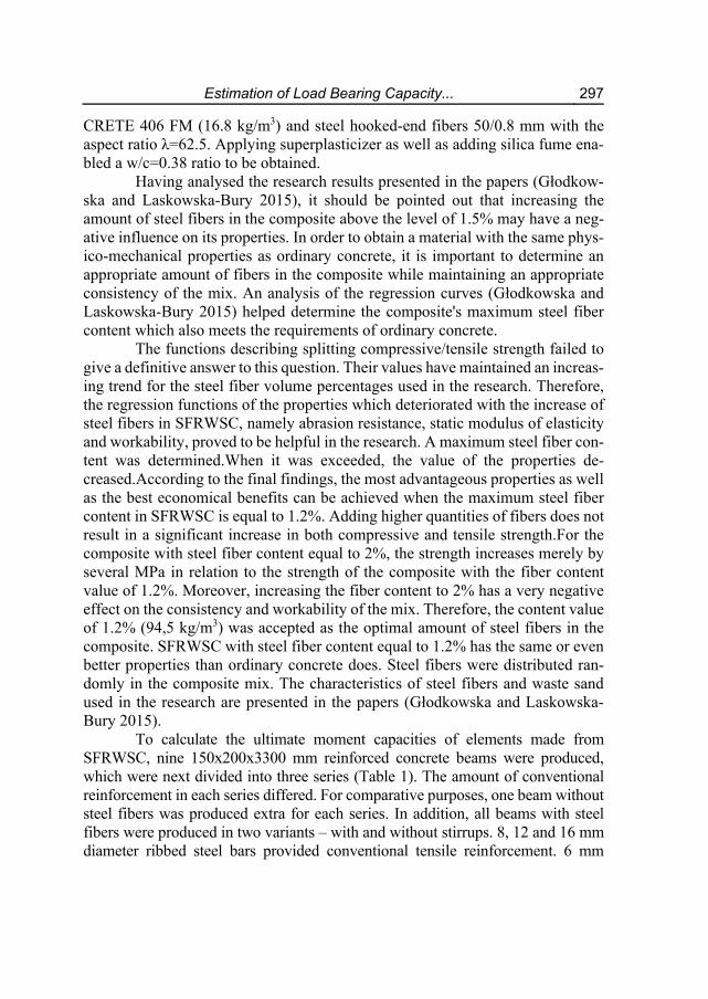
CRETE 406 FM (16.8 kg/m3) and steel hooked-end fibers 50/0.8 mm with the aspect ratio λ=62.5. Applying superplasticizer as well as adding silica fume ena-bled a w/c=0.38 ratio to be obtained.
Having analysed the research results presented in the papers (Głodkow-ska and Laskowska-Bury 2015), it should be pointed out that increasing the amount of steel fibers in the composite above the level of 1.5% may have a neg-ative influence on its properties. In order to obtain a material with the same phys-ico-mechanical properties as ordinary concrete, it is important to determine an appropriate amount of fibers in the composite while maintaining an appropriate consistency of the mix. An analysis of the regression curves (Głodkowska and Laskowska-Bury 2015) helped determine the composite's maximum steel fiber content which also meets the requirements of ordinary concrete.
The functions describing splitting compressive/tensile strength failed to give a definitive answer to this question. Their values have maintained an increas-ing trend for the steel fiber volume percentages used in the research. Therefore, the regression functions of the properties which deteriorated with the increase of steel fibers in SFRWSC, namely abrasion resistance, static modulus of elasticity and workability, proved to be helpful in the research. A maximum steel fiber con-tent was determined.When it was exceeded, the value of the properties de-creased.According to the final findings, the most advantageous properties as well as the best economical benefits can be achieved when the maximum steel fiber content in SFRWSC is equal to 1.2%. Adding higher quantities of fibers does not result in a significant increase in both compressive and tensile strength.For the composite with steel fiber content equal to 2%, the strength increases merely by several MPa in relation to the strength of the composite with the fiber content value of 1.2%. Moreover, increasing the fiber content to 2% has a very negative effect on the consistency and workability of the mix. Therefore, the content value of 1.2% (94,5 kg/m3) was accepted as the optimal amount of steel fibers in the composite. SFRWSC with steel fiber content equal to 1.2% has the same or even better properties than ordinary concrete does. Steel fibers were distributed ran-domly in the composite mix. The characteristics of steel fibers and waste sand used in the research are presented in the papers (Głodkowska and Laskowska-Bury 2015).
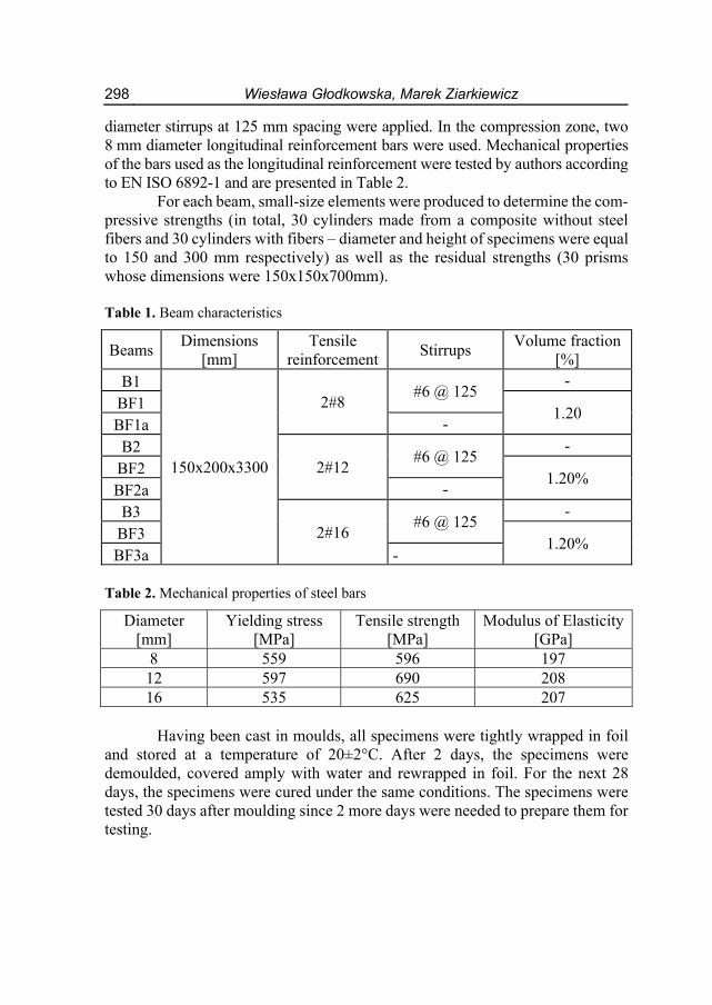
To calculate the ultimate moment capacities of elements made from SFRWSC, nine 150x200x3300 mm reinforced concrete beams were produced, which were next divided into three series (Table 1). The amount of conventional reinforcement in each series differed. For comparative purposes, one beam without steel fibers was produced extra for each series. In addition, all beams with steel fibers were produced in two variants – with and without stirrups. 8, 12 and 16 mm diameter ribbed steel bars provided conventional tensile reinforcement. 6 mm
298 Wiesława Głodkowska, Marek Ziarkiewicz
diameter stirrups at 125 mm spacing were applied. In the compression zone, two 8 mm diameter longitudinal reinforcement bars were used. Mechanical properties of the bars used as the longitudinal reinforcement were tested by authors according to EN ISO 6892-1 and are presented in Table 2.
For each beam, small-size elements were produced to determine the com-pressive strengths (in total, 30 cylinders made from a composite without steel fibers and 30 cylinders with fibers – diameter and height of specimens were equal to 150 and 300 mm respectively) as well as the residual strengths (30 prisms whose dimensions were 150x150x700mm). Table 1. Beam characteristics
Beams Dimensions
[mm] Tensile
reinforcement Stirrups
Volume fraction [%]
B1
150x200x3300
2#8 #6 @ 125
-
BF1 1.20
BF1a -
B2 2#12
#6 @ 125 -
BF2 1.20%
BF2a -
B3 2#16
#6 @ 125 -
BF3 1.20%
BF3a -
Table 2. Mechanical properties of steel bars
Diameter [mm]
Yielding stress [MPa]
Tensile strength [MPa]
Modulus of Elasticity [GPa]
8 559 596 197 12 597 690 208 16 535 625 207
Having been cast in moulds, all specimens were tightly wrapped in foil
and stored at a temperature of 20±2°C. After 2 days, the specimens were demoulded, covered amply with water and rewrapped in foil. For the next 28 days, the specimens were cured under the same conditions. The specimens were tested 30 days after moulding since 2 more days were needed to prepare them for testing.
Estimation of Load Bearing Capacity... 299
4. Research methodology
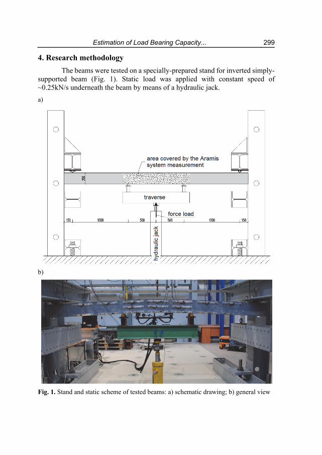
The beams were tested on a specially-prepared stand for inverted simply-supported beam (Fig. 1). Static load was applied with constant speed of ~0.25kN/s underneath the beam by means of a hydraulic jack.
a)
b)
Fig. 1. Stand and static scheme of tested beams: a) schematic drawing; b) general view
300 Wiesława Głodkowska, Marek Ziarkiewicz
When the yield stress was achieved in tensile reinforcement, the load was controlled by the beam's deflection speed, which was 0,1±0.025 mm/s.
The beams were monitored using SAD256 data acquisition system and ARAMIS 4M optical-measurement system. SAD256 was used to measure the load force "P", deflection (5 linear variable displacement transducers LVDT), strain of the beam's one lateral surface (17 LVDTs) as well as tensile reinforcement strain (6 electrical resistance strain gauges).
ARAMIS 4M optical-measurement system made it possible to track pre-cisely the process of crack formation and crack propagation. The system also en-abled the strain of the beam's second surface to be measured. The area of the tested surface was 1 m long and it covered the length of the beam between points where load was applied. All sensors of both SAD256 and ARAMIS 4M systems recorded measured displacements and load at a frequency of 1 per 2 seconds. The measurement accuracy for the two systems was 1x10⁻³ mm.
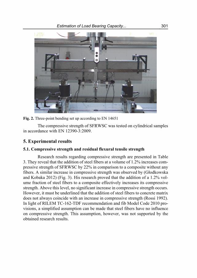
Residual strengths (Fig. 2) were tested on 150x150x700 mm prisms in accordance with EN 14651:2005. Load was applied at the mid-span of the beam while load, deflection and crack width were measured. Load increase values were set depending on crack mouth opening displacement (CMOD). The test was ter-minated when the specimen's deflection was equal to 5 mm. Ultimate deflection of the prisms was set in accordance with EN 14651:2005 in order to achieve all CMOD values and to determine residual strengths (fRi) for the corresponding value CMODj, in which j=1,2,3,4. The quantities fR,1, fR,2, fR,3 i fR,4 correspond to the tensile stresses associated to the force at a given CMOD, which were equal to 0.5, 1.5, 2.5, 3.5 mm respectively. The calculations assumed linear stress distri-bution in both compression and tension zones of the test prism.
An important parameter enabling a SFRC to be classified is the chart shape “load – CMOD” from the point of attaining limit of proportionality until ultimate deflection. One can distinguish two shapes of the chart: the first shape is characterised by a decrease in load and an increase in CMOD value following the appearance of the first crack (post-crack softening – pcs), the second shape is defined by an increase in both load and CMOD value (post-crack hardening – pch). Residual strengths determine the capacity of SFRC to transmit tensile stresses in cracked cross-section.
Estimation of Load Bearing Capacity... 301
Fig. 2. Three-point bending set up according to EN 14651
The compressive strength of SFRWSC was tested on cylindrical samples in accordance with EN 12390-3:2009.
5. Experimental results
5.1. Compressive strength and residual flexural tensile strength
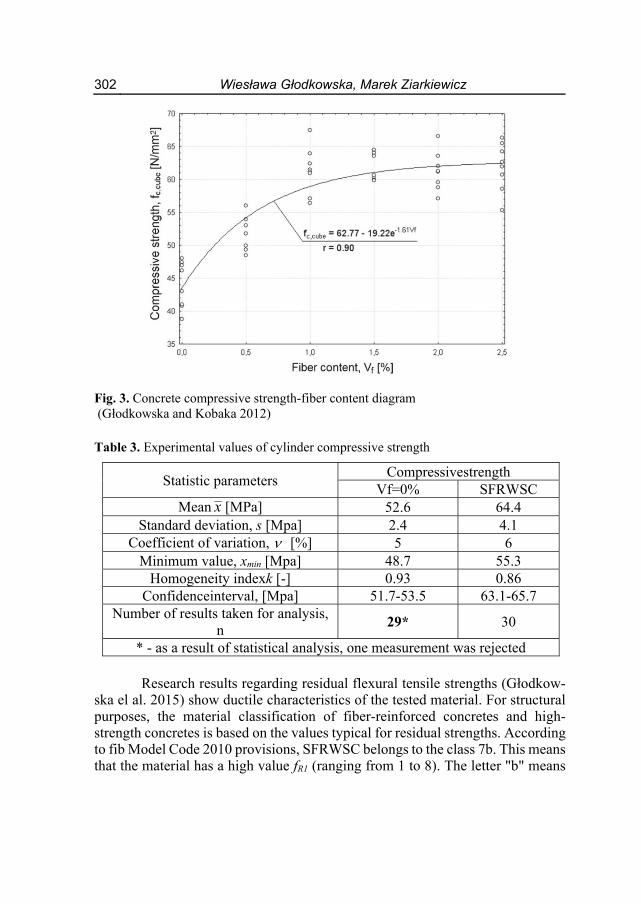
Research results regarding compressive strength are presented in Table 3. They reveal that the addition of steel fibers at a volume of 1.2% increases com-pressive strength of SFRWSC by 22% in comparison to a composite without any fibers. A similar increase in compressive strength was observed by (Głodkowska and Kobaka 2012) (Fig. 3). His research proved that the addition of a 1.2% vol-ume fraction of steel fibers to a composite effectively increases its compressive strength. Above this level, no significant increase in compressive strength occurs. However, it must be underlined that the addition of steel fibers to concrete matrix does not always coincide with an increase in compressive strength (Rossi 1992). In light of RILEM TC-162-TDF recommendation and fib Model Code 2010 pro-visions, a simplified assumption can be made that steel fibers have no influence on compressive strength. This assumption, however, was not supported by the obtained research results.
302 Wiesława Głodkowska, Marek Ziarkiewicz
Fig. 3. Concrete compressive strength-fiber content diagram (Głodkowska and Kobaka 2012)
Table 3. Experimental values of cylinder compressive strength
Statistic parameters Compressivestrength
Vf=0% SFRWSC Mean x [MPa] 52.6 64.4
Standard deviation, s [Mpa] 2.4 4.1 Coefficient of variation, [%] 5 6
Minimum value, xmin [Mpa] 48.7 55.3 Homogeneity indexk [-] 0.93 0.86
Confidenceinterval, [Mpa] 51.7-53.5 63.1-65.7 Number of results taken for analysis,
n 29* 30
* - as a result of statistical analysis, one measurement was rejected Research results regarding residual flexural tensile strengths (Głodkow-
ska el al. 2015) show ductile characteristics of the tested material. For structural purposes, the material classification of fiber-reinforced concretes and high-strength concretes is based on the values typical for residual strengths. According to fib Model Code 2010 provisions, SFRWSC belongs to the class 7b. This means that the material has a high value fR1 (ranging from 1 to 8). The letter "b" means
Estimation of Load Bearing Capacity... 303
that the tested fiber-reinforced composite is characterised by post-crack soften-ing, which is fixed by means of the ratio fR3/fR1.
5.2. Load-midspan deflection behavior
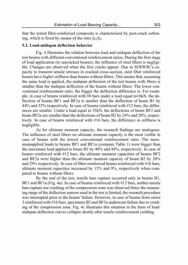
Fig. 4 illustrates the relation between load and midspan deflection of the test beams with different conventional reinforcement ratios. During the first stage of load application (to uncracked beams), the influence of steel fibers is negligi-ble. Changes are observed when the first cracks appear. Due to SFRWSC's ca-pacity to transmit tensile stresses in cracked cross-section, steel fiber reinforced beams have higher stiffness than beams without fibers. This means that, assuming the same load is applied, the midspan deflection of the test beams with fibers is smaller than the midspan deflection of the beams without fibers. The lower con-ventional reinforcement ratio, the bigger the deflection difference is. For exam-ple, in case of beams reinforced with #8 bars under a load equal to16kN, the de-flection of beams BF1 and BF1a is smaller than the deflection of beam B1 by 44% and 55% respectively. In case of beams reinforced with #12 bars, the differ-ences are smaller. Under a load equal to 35kN, the deflections of beam BF2 and beam BF2a are smaller than the deflections of beam B2 by 24% and 28%, respec-tively. In case of beams reinforced with #16 bars, the difference in stiffness is negligible.
As for ultimate moment capacity, the research findings are analogous. The influence of steel fibers on ultimate moment capacity is the most visible in case of beams with the lowest conventional reinforcement ratio. The maxi-mumapplied loads to beams BF1 and BF1a (compare Table 1) were bigger than the maximum load applied to beam B1 by 40% and 44%, respectively. In case of beams reinforced with #12 bars, the ultimate moment capacities of beams BF2 and BF2a were higher than the ultimate moment capacity of beam B2 by 20% and 29% respectively. In case of fiber-reinforced beams reinforced with #16 bars, ultimate moment capacities increased by 15% and 9%, respectively when com-pared to beams without fibers.
By the end of the test, tensile bars rupture occurred only in beams B1, BF1 and BF1a (Fig. 4a). In case of beams reinforced with #12 bars, neither tensile bars rupture nor crushing of the compression zone was observed.Since the measur-ing range of the deflection sensors used in the test is limited, the research procedure was interrupted prior to the beams' failure. However, in case of beams from series 3 reinforced with #16 bars, specimens B3 and BF3a underwent failure due to crush-ing of the compression zone. Fig. 4c illustrates this situation in the form of load-midspan deflection curves collapse shortly after tensile reinforcement yielding.

304 Wiesława Głodkowska, Marek Ziarkiewicz
a) b)
c)
Fig. 4. Load-midspan deflection curves with different longitudinal reinforcement ratios: (a) 2#8; (b) 2#12;(c) 2#16 (Głodkowska and Ziarkiewicz 2018)
Having analysed the research results, it was stated that beams without
stirrups attained larger load bearing capacity than beams with stirrups did (except for beams from series 3, Table 2, due to the crushing of the compression zone in beam BF3a). The presence of stirrups limits the beneficial distribution of fibers in the bar's direct vicinity, which may decrease the load bearing capacity of the cross-section in beams with stirrups.
Estimation of Load Bearing Capacity... 305
5.3. Load bearing capacity
It was indispensable for further analysis to determine the maximum force (Pu) as well as the load force at which tensile reinforcement reached yield stress (Py). Load values Puand Pyas well as strains on lateral surfaces of the beams meas-ured bySAD256 and ARAMIS 4M systems (εt – tensile edge strains; εc – com-pressive edge strains) are presented in Table 4. These values constitute the basis for theoretical analysis of ultimate moment capacity in accordance with RILEM TC-162-TDFand fib Model Code 2010.
Table 4. Load values and strains at time of tensile reinforcement yielding and ultimate bearing capacity
Speci-men
Yielding of tensile reinforcement Ultimate bearing capacity
Py εt εc Pu
εt εc A4M SAD A4M SAD A4M SAD A4M SAD
kN [‰] kN [‰] B1 16.68 3.08 2.81 -0.62 -0.66 18.48 7.53 7.75 -1.03 -1.13
BF1 25.21 3.78 4.12 -0.97 -0.82 25.86 5.49 4.97 -1.10 -0.99 BF1a 25.51 2.89 2.79 -0.78 -0.76 26.61 4.06 3.51 -0.88 -0.85
B2 36.68 3.57 3.13 -1.17 -1.17 39.34 11.64 10.17 -2.29 -2.03 BF2 44.63 3.48 4.29 -1.20 -1.32 47.33 13.01 16.76 -2.30 -2.62 BF2a 49.03 3.88 3.65 -1.37 -1.24 50.93 10.73 11.42 -2.26 -1.96
B3 63.71 3.67 4.13 -1.51 -1.73 66.80 8.11 9.61 -2.10 -2.70 BF3 70.25 3.28 3.41 -1.80 -1.56 76.56 12.01 13.59 -3.58 -2.79 BF3a 71.25 3.38 3.49 -1.71 -1.62 72.68 5.08 5.72 -1.99 -1.93
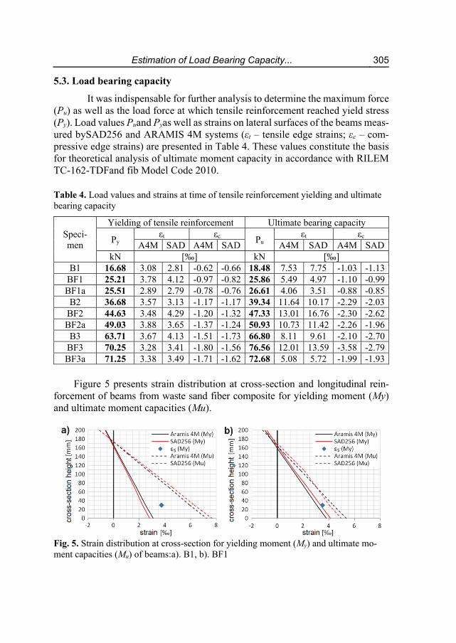
Figure 5 presents strain distribution at cross-section and longitudinal rein-
forcement of beams from waste sand fiber composite for yielding moment (My) and ultimate moment capacities (Mu).
Fig. 5. Strain distribution at cross-section for yielding moment (My) and ultimate mo-ment capacities (Mu) of beams:a). B1, b). BF1

306 Wiesława Głodkowska, Marek Ziarkiewicz
Fig. 5. Strain distribution at cross-section for yielding moment (My) and ultimate moment capacities (Mu) of beams: c). BF1a, d). B2, e). BF2, f). BF2a, g). B3, h). BF3, i). BF3a
Estimation of Load Bearing Capacity... 307
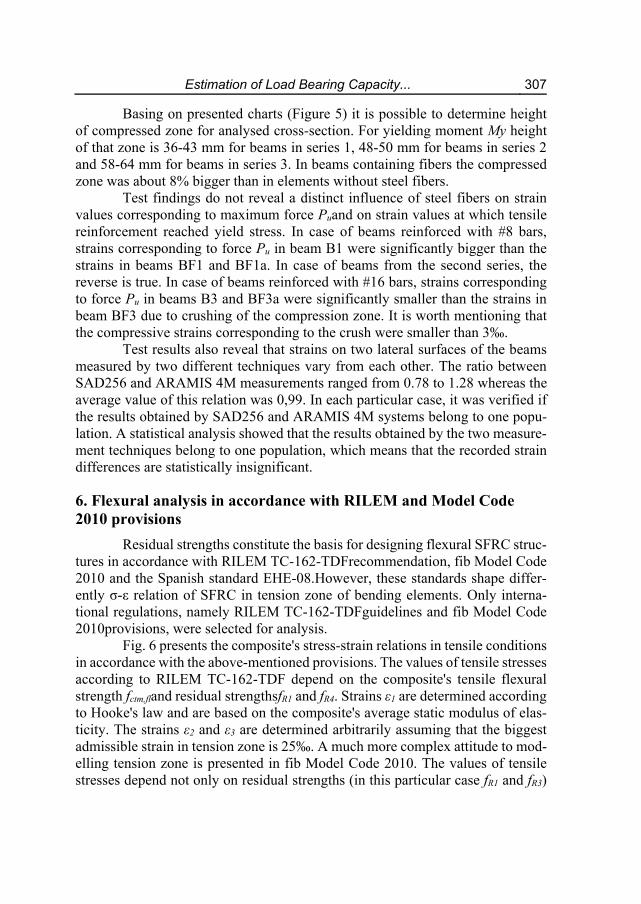
Basing on presented charts (Figure 5) it is possible to determine height of compressed zone for analysed cross-section. For yielding moment My height of that zone is 36-43 mm for beams in series 1, 48-50 mm for beams in series 2 and 58-64 mm for beams in series 3. In beams containing fibers the compressed zone was about 8% bigger than in elements without steel fibers.
Test findings do not reveal a distinct influence of steel fibers on strain values corresponding to maximum force Puand on strain values at which tensile reinforcement reached yield stress. In case of beams reinforced with #8 bars, strains corresponding to force Pu in beam B1 were significantly bigger than the strains in beams BF1 and BF1a. In case of beams from the second series, the reverse is true. In case of beams reinforced with #16 bars, strains corresponding to force Pu in beams B3 and BF3a were significantly smaller than the strains in beam BF3 due to crushing of the compression zone. It is worth mentioning that the compressive strains corresponding to the crush were smaller than 3‰.
Test results also reveal that strains on two lateral surfaces of the beams measured by two different techniques vary from each other. The ratio between SAD256 and ARAMIS 4M measurements ranged from 0.78 to 1.28 whereas the average value of this relation was 0,99. In each particular case, it was verified if the results obtained by SAD256 and ARAMIS 4M systems belong to one popu-lation. A statistical analysis showed that the results obtained by the two measure-ment techniques belong to one population, which means that the recorded strain differences are statistically insignificant.
6. Flexural analysis in accordance with RILEM and Model Code 2010 provisions
Residual strengths constitute the basis for designing flexural SFRC struc-tures in accordance with RILEM TC-162-TDFrecommendation, fib Model Code 2010 and the Spanish standard EHE-08.However, these standards shape differ-ently σ-ε relation of SFRC in tension zone of bending elements. Only interna-tional regulations, namely RILEM TC-162-TDFguidelines and fib Model Code 2010provisions, were selected for analysis.
Fig. 6 presents the composite's stress-strain relations in tensile conditions in accordance with the above-mentioned provisions. The values of tensile stresses according to RILEM TC-162-TDF depend on the composite's tensile flexural strength fctm,fland residual strengthsfR1 and fR4. Strains ε1 are determined according to Hooke's law and are based on the composite's average static modulus of elas-ticity. The strains ε2 and ε3 are determined arbitrarily assuming that the biggest admissible strain in tension zone is 25‰. A much more complex attitude to mod-elling tension zone is presented in fib Model Code 2010. The values of tensile stresses depend not only on residual strengths (in this particular case fR1 and fR3)

308 Wiesława Głodkowska, Marek Ziarkiewicz
but also on the crack width wu. This value can be calculated from the formula (fib Model Code 2010):
w l ∙ ε
The ultimate strain εFu according to fib Model Code 2010 should be as-sumed to be equal to 20‰ in a cross-section with variable distribution of strains. It is also crucial to know the characteristic length lcs, which can be calculated from the formula:
l min s ; y
The value srm stands for the average crack spacing and the parameter y stands for the height of tension zone. It is not easy to determine these two param-eters as they are dependent on both amount and diameter of bars used in conven-tional reinforcement.
The characteristic length lcs is essential for calculating stresses εSLS
andεULS, too. It must be underlined that the maximum strains of cross section's tensile edge cannot exceed 20‰.
Additionally, fib Model Code 2010 standard allows for the simplified model to be possibly applied. This model assumes that constant tensile stresses equal to fR3/3 exist in tension zone.
Stresses in the composite's compression zone in accordance with RILEM and MC2010 are modelled identically as in case of ordinary concrete. A parabolic graph is used for strains below 2‰. For strains ranging from 2 to 3.5‰, a linear graph with a constant value of stress equal to the composite's compressive strength is used. These rules are identical with the requirements of EN1992-1-1.
An analysis of ultimate moment capacity in accordance with RILEM TC-162-TDFand fib Model Code 2010provisions was performed based on the results of tests carried out on 6 beams made from SRWSC and on three beams without fibers. The analysis was conducted in two variants. In the first variant, the bend-ing moment (My) corresponding to tensile reinforcement yielding was calculated. Average strains of cross-section (Table 4) served as an input data for calculations. In the second variant, ultimate bearing capacity (Mu) was calculated assuming the ultimate strains in compression and tension zones as defined by RILEM TC-162-TDFand fib Model Code 2010.

Estimation of Load Bearing Capacity... 309
Fig. 6. Stress-strain relationship in tensile cross-section according to RILEM TC-162-TDF and fib Model Code 2010
6.1. Yielding moment My
The cross-section analysis at time of conventional reinforcement yielding was conducted as follows. The strains of compression and tension zones were measured by SAD256 and ARAMIS 4M and averaged. Next, tensile and com-pressive stresses were assigned to the strains in accordance with RILEM TC-162-TDFand fib Model Code 2010. Mean material characteristics of SFRWSC and reinforcement bars were used in the calculations. Yielding moment My was cal-culated from the equilibrium condition of moments in relation to the centroid of compressive stresses block (Table 5). Compressive reinforcement bars were taken into account in the calculations.
Moments My,pre for beams without steel fibers calculated according to RILEM TC-162-TDF and fib Model Code 2010 correspond precisely to the ex-perimental values My,exp. The values of the ratio My,pre/My,exp range from 0.87 to 0.99. However, the situation is different in case of beams with fibers. Moments My,pre calculated according to RILEM and MC2010 are considerably bigger than the experimental values My,exp. For RILEM method, the moment ratio My,pre/My,exp
ranges from 1.07 to 1.44 and for MC2010 method, it ranges from 1.02 to 1.36. Relative differences between the measured moments and calculated ones de-crease proportionally to the increase in conventional reinforcement.

310 Wiesława Głodkowska, Marek Ziarkiewicz
Table 5. Experimental and predicted values of Yielding Moment
Specimen My,exp
My,pre My,pre/My,exp
RILEM MC2010 RILEM MC2010
[kNm] [kNm]
B1 8.70 7.57 7,61 0,87 0,87
BF1 13.00 18.74 17,67 1,44 1,36
BF1a 13.14 16.85 15,3 1,28 1,16
B2 18.70 18.44 18,48 0,99 0,99
BF2 22.70 29.6 28,29 1,30 1,25
BF2a 24.90 29.33 28 1,18 1,12
B3 32.20 31.04 31,11 0,96 0,97
BF3 35.51 37.83 36,3 1,07 1,02
BF3a 36.02 38.82 37,39 1,08 1,04
Mean [-] 1.13 1.09 Coefficient of variation, [%] 16 14
6.2. Ultimate Moment Mu
The ultimate moment capacity of the beams (Mu) was calculated differ-ently than in the previous variant. An input data for the calculations was an as-sumption concerning maximum admissible strains both in compression and ten-sion zones according to RILEM TC-162-TDF and fib Model Code 2010. Next, equilibrium of internal forces toward the beam's longitudinal axis was verified. In each particular case, the analysis revealed that the internal forces were not in equilibrium. The strains in either compression or tension zone were then reduced to achieve equilibrium of the internal forces. The ultimate moment capacity (Mu) was calculated from the equilibrium condition of moments in relation to the cen-troid of compressive stresses block (Table 6, Głodkowska and Ziarkiewicz 2018). Compressive reinforcement force was taken into account in the calculations. In the analysed variant, ultimate moment capacities were also calculated using the simplified method in accordance with fib Model Code 2010.
Calculating the ultimate moment capacity (Mu) according to RILEM TC-162-TDF and fib Model Code 2010leads to similar conclusions as calculating the yielding moment Myin the previous variant. In case of beams without steel fibers, the calculated values and measured ones are in very good agreement. In case of beams with steel fibers, the calculated values of ultimate moment capacity (Mu) are considerably bigger than the experimental ones. For RILEM TC-162-
Estimation of Load Bearing Capacity... 311
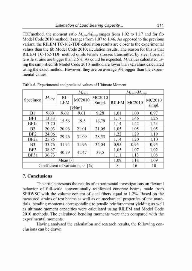
TDFmethod, the moment ratio My,pre/My,exp ranges from 1.02 to 1.17 and for fib Model Code 2010 method, it ranges from 1.07 to 1.46. As opposed to the previous variant, the RILEM TC-162-TDF calculation results are closer to the experimental values than the fib Model Code 2010calculation results. The reason for this is that RILEM TC-162-TDF method omits tensile stresses transmitted by steel fibers if tensile strains are bigger than 2.5%. As could be expected, Muvalues calculated us-ing the simplified fib Model Code 2010 method are lower than Muvalues calculated using the exact method. However, they are on average 9% bigger than the experi-mental values.
Table 6. Experimental and predicted values of Ultimate Moment
Specimen Mu,exp
Mu,pre Mu,pre/Mu,exp RI-
LEM MC2010
MC2010 Simpl. RILEM MC2010
MC2010 simpl.
[kNm] B1 9.60 9.69 9.61 9,28 1,01 1,00 0,97
BF1 13.33 15.56 19.5 16,79
1,17 1,46 1,26 BF1a 13.70 1,14 1,42 1,23 B2 20.03 20.96 21.01 21,05 1,05 1,05 1,05
BF2 24.06 29.46 31.09 28,53
1,22 1,29 1,19 BF2a 25.85 1,14 1,20 1,10 B3 33.76 31.94 31.96 32,04 0,95 0,95 0,95
BF3 38.67 40.79 41.47 39,5
1,05 1,07 1,02 BF3a 36.73 1,11 1,13 1,08
Mean [-] 1.09 1.18 1.09 Coefficient of variation, [%] 8 16 10
7. Conclusions
The article presents the results of experimental investigations on flexural behavior of full-scale conventionally reinforced concrete beams made from SFRWSC with the volume content of steel fibers equal to 1.2%. Based on the measured strains of test beams as well as on mechanical properties of test mate-rials, bending moments corresponding to tensile reinforcement yielding as well as ultimate moment capacities were calculated using RILEM and Model Code 2010 methods. The calculated bending moments were then compared with the experimental moments.
Having analysed the calculation and research results, the following con-clusions can be drawn:
312 Wiesława Głodkowska, Marek Ziarkiewicz
1) Waste sand cement-based composite without the addition of fibers behaves like ordinary concrete in conventionally reinforced bending elements. For these elements, the yielding moment and ultimate moment capacity values calculated using RILEM and Model Code 2010 methods are entirely satisfac-tory.
2) The addition of steel fibers considerably improves the ultimate moment ca-pacity of SFRWSC elements, which makes reduction of conventional rein-forcement possible.
3) Taking into account the physico-mechanical properties of SFRWSC as well as the research results regarding ultimate moment capacities of beams made from this composite, one may safely assume that SFRWSC can be used as a structural material, which in turn creates new possibilities for waste sand management.
4) In case of elements made from SFRWSC, bending moments calculated using RILEM and Model Code 2010 methods are bigger than the experimental val-ues. The obtained results highlight the necessity to correct these methods be-fore using them for designing bending elements made from SFRWSC. Similar conclusions were reached by researchers specialising in SFRC.
References
Blanco, A., Pujadas, P., de la Fuente, A., Cavalaro, S., Aguado, A. (2013). Application of constutive models in European codes to RC-FRC. Construction and Building Ma-terials, 40, 246-259.
CNR-DT 204 (2006).Istruzioni per la Progettazione, l’Esecuzione ed il Controllo di Strutture Fibrorinforzato. Consiglio Nazionale delle Riserche, Italia.
DBV Merkblatt Stahlfaserbeton (2001). Deutsche Beton Vereins. de la Fuente, A., Pujadas, P., Blanco, A., Aguado, A. (2011). Experiences in Barcelona
with the use of steel fibres in segmental linings. Tunn. Undergr. Sp. Tech., 7(1), 60-71.
Destrée, X. (2008). Free suspended elevated flat slabs of steel fibre reinforced concrete: full scale tests and design. In: 7th international RILEM-symposium on fibre rein-forced concrete, Chennai, 941-50.
Domski, J. (2016). A blurred border between ordinary concrete and SFRC. Construction and Building Materials, 112, 247-252.
Dupont, D. (2003). Modelling and experimental validation of the constitutive law (σ-ε) and cracking behaviour of steel fibre reinforced concrete. Dissertation, Catholic University of Leuven.
Dvorkin. L.I., Dvorkin, O.L., Ribakov Y. (2016).Construction Materials Based on Indus-trial Waste Products. Nova Science Publishers Inc. New York, United States.
EHE-08 (2008).Instrucción del Hormigón Estructural. Comisión Permanente del Hormi-gón (Ministerio de Fomento).
EN 12390-3:2009 Testing hardened concrete, Compressive strength of test specimens.
Estimation of Load Bearing Capacity... 313
EN 14651:2005 Test method for metallic fibered concrete - Measuring the flexural tensile strength (limit of proportionality (LOP), residual).
EN 1992-1-1:2004 Design of concrete structures – Part 1-1: General rules and rules for buildings.
EN ISO 6892-1:2010. Tensile Testing Part 1: Method of test at room temerature. European Aggregates Association. Annual Review 2013-2014, A sustainable Industry for
a Sustainable Europe. Model Code 2010, Comité Euro-International du Beton-Federation International de la
Precontrainte. Paris. Głodkowska, W., Kobaka, J. (2009). Application of Waste Sands for Making Industrial
Floors. Rocznik Ochrona Środowiska, 11, 193-206. Głodkowska, W., Kobaka, J. (2012). The model of brittle matrix composites for distribution
of steel fibres. Journal of Civil Engineering and Management, 18(1), 145-150. Głodkowska, W., Laskowska-Bury, J. (2015).Waste Sands as a Valuable Aggregates to
Produce Fibre-composites. Rocznik Ochrona Środowiska,17, 507-525. Głodkowska, W., Lehmann, M., Ziarkiewicz, M. (2015). Wytrzymałości resztkowe fi-
brokompozytu na bazie piasków odpadowych. Materiały Budowlane, 5, 75-77. Głodkowska, W., Ziarkiewicz, M. (2018). Nośność na zginanie belek żelbetowych wy-
konanych z fibrokompozytu drobnokruszywowego. Przegląd Budowlany, 7-8, 124-127.
Gossla, U. (2006). Flachdecken aus Stahlfaserbeton. Beton- und Stahlbetonbau, 101(2), 94-102.
Kelpsa, S., Augonis, M., Dauksys, M., Augonis, A. (2014).Analysis of crack width cal-culation of steel fibre and ordinary reinforced concrete flexural members.Journal of Sustainable Architecture and Civil Engineering, 1(6),50-57.
Laskowska-Bury, J. (2017).Selected physico-mechanical properties fiber reinforced composit produced on waste aggregate. Dissertation, Koszalin University of Tech-nology.
Li, V.C. (2002). Large volume, high-performance applications of fiber in civil engineer-ing. Journal of Applied Polymer Science 83(3), 660-686.
Meda, A., Minelli, F., Plizzari, G.A. (2012).Flexural behaviour of RC beams in fibre re-inforced concrete. Composites: Part B, 43, 2930-2937.
Mertol, H.C., Baran, E., Bello, H.J. (2015). Flexural behavior of lightly and heavily rein-forced steel fiber concrete beams. Construction and Building Materials, 98, 185-193.
Ning, X., Ding, Y., Zhang, F., Zhang, Y. (2015). Experimental study and prediction model for flexural behavior of reinforced SCC beam containing steel fibers. Con-struction and Building Materials, 93, 644-653.
Pepin, R. (2009). Structural applications for SFRC. Central European Congress on Con-crete Engineering.
Piekarski, J. (2011). Application of Numerical Methods to Modelling of Gravitational Filtration Process. Rocznik Ochrona Środowiska, 13.
RILEM TC 162-TDF (2003) Test and design methods for steel fibre reinforced concrete – σ–ε design method: final recommendation.Mater. Struct. 36(262), 560-7.

314 Wiesława Głodkowska, Marek Ziarkiewicz
Rossi, P. (1992). Mechanical behaviour of metal-fibre reinforced concretes. Cement and Concrete Composites 14, 3-16.
Shah, A.A., Ribakov, Y. (2011). Recent trends in steel fibered high-strength concrete. Materials and Design 32, 4122-4151.
Tiberti, G., Minelli, F., Plizzari, G.A., Vecchio, F.J. (2014). Influence of concrete strength on crack development in SFRC members. Cement & Concrete Composites 45, 176-185.
Tiberti, G., Plizzari, G.A., Walraven, J.C., Blom, C.B.M. (2008).Concrete tunnel seg-ments with combined traditional and fiber reinforcement. In: Walraven, J.C., Stoe-lhorst, D. editors. Tailor made concrete structures. London: Taylor & Francis Group, 199-205.
Ziarkiewicz, M. (2018). Experimental evaluation of selected design methods of Steel Fi-ber Reinforced Waste Sand Concrete Beams. PhD thesis. Koszalin University of Technology.
Zollo, R.F. (1997). Fiber-reinforced Concrete: an Overview after 30 Years of Develop-ment. Cement and Concrete Composites, 19, 107-122.
Abstract
Waste sands resulting from coarse aggregate extraction are becoming an increas-ingly pressing ecological issue in northern Poland, the Middle East or North Africa. In order to manage the waste sand, a fine-grained composite with the addition of steel fibers has been developed. As steel fibers constitute 1.2% of the composite, it has been called Steel Fiber Reinforced Waste Sand Concrete (SFRWSC). The physico-mechanical and rheological properties of the composite meet the requirements of construction materials and make it more effective than ordinary concrete. In order to prove SFRWSC's useful-ness in the production of construction elements, experimental investigations on flexural behavior of full-scale conventionally reinforced concrete beams have been carried out. The test specimens were divided into three series differing as to the conventional rein-forcement ratio. It has been demonstrated that SFRWSC can be readily used in the pro-duction of bending structural elements. Steel fibers increase considerably the load bearing capacity and stiffness of the specimens, which makes partial reduction of conventional reinforcement possible. Next, the calculation results in accordance with RILEM and Model Code 2010 provisions and the experimental research results have been compared. It has been proved that bending moments according to the aforementioned international regulations are overestimated in relation to the experimental values. The obtained results highlight the necessity to correct these methods before using them for designing elements made from SFRWSC and Steel Fiber Reinforced Concrete (SFRC).
Keywords: waste sand, structural element, load bearing capacity, flexural failure, fibercomposite
Estimation of Load Bearing Capacity... 315
Obliczanie nośności zginanych elementów fibrokompozytowych
Streszczenie
Hałdy piasku odpadowego powstałego w wyniku wydobycia kruszyw grubych stanowią coraz poważniejszy problem ekologiczny w północnej Polsce, na Bliskim Wschodzie czy tez północnej Afryce. W celu zagospodarowania tego piasku opracowano drobnokruszywowy kompozyt z dodatkiem włókien stalowych (Steel Fibre Reinforced Waste Sand Concrete – SFRWSC), których zawartość wynosi 1,2%. Opracowany kom-pozyt charakteryzuje się właściwościami fizyko-mechanicznymi i reologicznymi, które spełniają wymagania materiałów konstrukcyjnych i są korzystniejsze niż betonu zwy-kłego. Aby wykazać przydatność tego kompozytu do wytwarzania elementów konstruk-cyjnych przeprowadzono badania zginanych belek żelbetowych w skali naturalnej. Ba-dane elementy podzielono na trzy serie różniące się stopniem zbrojenia konwencjonal-nego (zbrojenie z uwagi na zginanie). Wykazano, że opracowany fibrokompozyt może być z powodzeniem stosowany do wykonywania zginanych elementów konstrukcyjnych. Włókna stalowe w istotny sposób zwiększają nośność i sztywność elementów, a przez to możliwa jest częściowa redukcja zbrojenia konwencjonalnego. Wyniki badań ekspery-mentalnych porównano z wynikami obliczeń wg RILEM i Model Code 2010. Dowie-dziono, że momenty zginające obliczone wg wspomnianych międzynarodowych przepi-sów są zawyżone względem wartości doświadczalnych. Uzyskane wyniki wskazują na konieczność dokonania korekty tych metod w celu ich zastosowania do wymiarowania zginanych elementów wykonanych z kompozytu SFRWSC oraz fibrobetonu (Steel Fibre Reinforced Concrete – SFRC).
Słowa kluczowe: piasek odpadowy, element konstrukcyjny, nośność, zniszczenie, fibrokompozyt
Related Documents