ESTATES SERVICES MECHANICAL AND ELECTRICAL DESIGN PHILOSOPHY 9 Written by: Mark Davies Written by: David Baker Written by: John Matthews Written by: Alan Wood Checked by: Steve Pearson Checked by: Richard Jones Approved by: Mike Wigg

Welcome message from author
This document is posted to help you gain knowledge. Please leave a comment to let me know what you think about it! Share it to your friends and learn new things together.
Transcript
ESTATES SERVICES
MECHANICAL AND ELECTRICAL DESIGN
PHILOSOPHY 9
Written by: Mark Davies
Written by: David Baker
Written by: John Matthews
Written by: Alan Wood
Checked by: Steve Pearson
Checked by: Richard Jones
Approved by: Mike Wigg

Mechanical & Electrical
Design Philosophy Issue 9 November 2014
1
INTRODUCTION
The purpose of this document is to provide general guidance to Consulting Engineers
and Contractors on the design requirements of electrical and mechanical installations
within buildings which will be operated and maintained by Estates Services. At its
highest level this document is intended to set out requirements that minimise the total
life cost of building services i.e. the total life cost of purchase, operation, maintenance
and replacement costs.
The principles referred to in this document have been influenced by maintenance,
operational and environmental sustainability requirements, and also by the need to
standardise the mechanical and electrical services throughout the University's 650,000
m2
of building stock.
To accommodate the ever increasing demand for continuity of services it is essential
that systems are designed so that they can be repaired, maintained, inspected and
extended with minimal disruption to the building user.
New systems should be as simple as possible and there must be adequate, safe and
easy access provided to all parts of the installations.
Designers should note that all routine maintenance work is only carried out during
normal working hours. Systems should be designed such that they can be maintained
by a single person if possible. Designers must be aware of who is responsible for the
various services so that separate plant rooms can be provided where necessary for
Estates Services and departmental plant.
It is essential that the proposed building services for all projects are discussed with the
University Head of Building Services as soon as possible after the appointment of the
Building Services Consultant or Contractor to ensure that there are no
misunderstandings over the contents of this document or the reasons for a particular
requirement. All work within listed and historic buildings requires careful
consideration and all proposals must be agreed with the Head of Building and
Conservation before any work is carried out.
Where the project involves working on or extending existing building services,
no work may be carried out on the existing systems without the prior knowledge
and approval of the University Head of Building Services. This is particularly
important in the case of existing electrical systems where all work must be
carried out in accordance with Estates Services Code of Practice 'Electrical
Safety on Low Voltage Systems'. Please note that only the University Electrical
Engineers can authorise work to be carried out on the University's existing fixed
electrical installations.
The Estates Services Direct Labour Organisation (DLO) Manager must also be
consulted before any work is carried out on any mechanical services installations
within existing buildings. They will assist in the location of isolation valves,
provide advice on the draining down/refilling of wet systems, etc. The DLO is
responsible for the operation of the majority of the University's mechanical
services and it is essential that they are told of any impending work on
Mechanical & Electrical
Design Philosophy Issue 9 November 2014
2
installations under their control. No contractor is allowed to isolate existing
mechanical services without consultation with the DLO. Contractors must
obtain a 'transfer of control' permit from the DLO before commencing work on
any system.
Only contractors who are on the Estates Services Approved Contractor's List
will be allowed to carry out work on the University's existing mechanical,
electrical and controls installations unless otherwise approved by the Head of
Building Services
A site visit can be arranged if required to inspect a typical existing installation in
order to see at first hand the principles outlined in this document.
The University Head of Building Services must be consulted before any changes are
made to an agreed building services design because of a need to reduce project costs.
Value engineering should be carried out as part of the project design process and not
after tenders have been received.
The designer should always select and specify the most energy efficient plant and
equipment wherever possible. Any alternative equipment manufacturer
proposed by the contractor may only be used if it is equally as energy efficient as
the originally specified item and is also approved by the Head of Building
Services.
To assist Estate Services in assessing whether or not the Project mechanical and
electrical design complies with this Philosophy Document, the check list on pages
4 to 8 must be completed by the Designer and given to Estates Services Project
Manager before the design can be signed off at stage D. An explanation must be
provided for all items where non-compliance is indicated and agreed by the Head
of Building Services.
REASONS FOR REVISION
Sections generally revised with minor comments
Design Philosophy checklist updated and completion at stage D added.
Introduction
Reference to transfer of control document added.
Section 1.2 updated regarding maintenance reviews.
Section 1.4 updated regarding metering and BMS logging and includes guidance on
seasonal commissioning.
Section 1.5 clarified
Section 2.0. 'Accessible' clarified
Section 2.1 Plant room bunding and leak detection amended
Section 2.5 Trench heating prohibited
Mechanical & Electrical
Design Philosophy Issue 9 November 2014
3
Section 2.9 night time purge requirement added. Air conditioning form cross
referenced.
Section 2.11 Electrical requirements added. Approved lift contractor to be used.
Section 2.12 BMS section deleted
Section 2.14 Fused spur requirement for trace heating.
Section 2.27 Ground source Energy Systems section added (previously issued as an
appendix to M&E 8).
Section 3 updated:
Section 3.11.8 maximum size of plug and socket arrangement reduced.
Section 3.12 Section updated, with inclusion of external lighting.
Section 3.13 Fire Alarm Section added.
Section 3.14 Update to emergency lighting requirements.
Section 3.16.7 Change in control philosophy for generator systems.
Section 3.21 metering deleted and information added to section 6 and updated.
Section 3.26 Photo voltaic section added.
Section 4 On-line Building Information (Operation and Maintenance manual) updated
with Edocuments information and moved to a separate document.
Section 5 BMS section added (was a subsection of Mechanical).
Section 6 Metering Strategy added.
Mechanical & Electrical
Design Philosophy Issue 9 November 2014
4
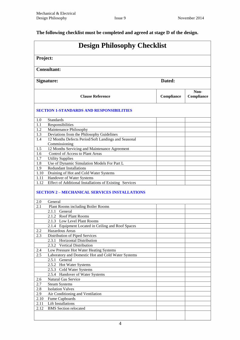
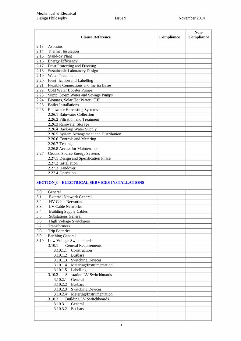
The following checklist must be completed and agreed at stage D of the design.
Design Philosophy Checklist
Project:
Consultant:
Signature: Dated:
Clause Reference
Compliance
Non-
Compliance
SECTION 1-STANDARDS AND RESPONSIBILITIES
1.0 Standards
1.1 Responsibilities
1.2 Maintenance Philosophy
1.3 Deviations from the Philosophy Guidelines
1.4 12 Months Defects Period/Soft Landings and Seasonal
Commissioning
1.5 12 Months Servicing and Maintenance Agreement
1.6 Control of Access to Plant Areas
1.7 Utility Supplies
1.8 Use of Dynamic Simulation Models For Part L
1.9 Redundant Installations
1.10 Draining of Hot and Cold Water Systems
1.11 Handover of Water Systems
1.12 Effect of Additional Installations of Existing Services
SECTION 2 – MECHANICAL SERVICES INSTALLATIONS
2.0 General
2.1 Plant Rooms including Boiler Rooms
2.1.1 General
2.1.2 Roof Plant Rooms
2.1.3 Low Level Plant Rooms
2.1.4 Equipment Located in Ceiling and Roof Spaces
2.2 Hazardous Areas
2.3 Distribution of Piped Services
2.3.1 Horizontal Distribution
2.3.2 Vertical Distribution
2.4 Low Pressure Hot Water Heating Systems
2.5 Laboratory and Domestic Hot and Cold Water Systems
2.5.1 General
2.5.2 Hot Water Systems
2.5.3 Cold Water Systems
2.5.4 Handover of Water Systems
2.6 Natural Gas Service
2.7 Steam Systems
2.8 Isolation Valves
2.9 Air Conditioning and Ventilation
2.10 Fume Cupboards
2.11 Lift Installations
2.12 BMS Section relocated
Mechanical & Electrical
Design Philosophy Issue 9 November 2014
5
Clause Reference
Compliance
Non-
Compliance
2.13 Asbestos
2.14 Thermal Insulation
2.15 Stand-by Plant
2.16 Energy Efficiency
2.17 Frost Protecting and Freezing
2.18 Sustainable Laboratory Design
2.19 Water Treatment
2.20 Identification and Labelling
2.21 Flexible Connections and Inertia Bases
2.22 Cold Water Booster Pumps
2.23 Sump, Storm Water and Sewage Pumps
2.24 Biomass, Solar Hot Water, CHP
2.25 Boiler Installations
2.26 Rainwater Harvesting Systems
2.26.1 Rainwater Collection
2.26.2 Filtration and Treatment
2.26.3 Rainwater Storage
2.26.4 Back-up Water Supply
2.26.5 System Arrangement and Distribution
2.26.6 Controls and Metering
2.26.7 Testing
2.26.8 Access for Maintenance
2.27 Ground Source Energy Systems
2.27.1 Design and Specification Phase
2.27.2 Installation
2.27.3 Handover
2.27.4 Operation
SECTION 3 – ELECTRICAL SERVICES INSTALLATIONS
3.0 General
3.1 External Network General
3.2 HV Cable Networks
3.3 LV Cable Networks
3.4 Building Supply Cables
3.5 Substations General
3.6 High Voltage Switchgear
3.7 Transformers
3.8 Trip Batteries
3.9 Earthing General
3.10 Low Voltage Switchboards
3.10.1 General Requirements
3.10.1.1 Construction
3.10.1.2 Busbars
3.10.1.3 Switching Devices
3.10.1.4 Metering/Instrumentation
3.10.1.5 Labelling
3.10.2 Substation LV Switchboards
3.10.2.1 General
3.10.2.2 Busbars
3.10.2.3 Switching Devices
3.10.2.4 Metering/Instrumentation
3.10.3 Building LV Switchboards
3.10.3.1 General
3.10.3.2 Busbars
Mechanical & Electrical
Design Philosophy Issue 9 November 2014
6
Clause Reference
Compliance
Non-
Compliance
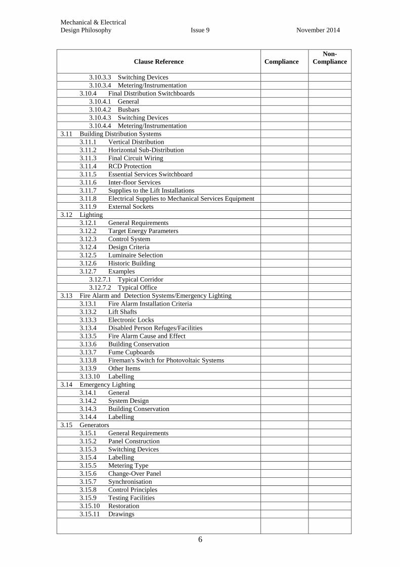
3.10.3.3 Switching Devices
3.10.3.4 Metering/Instrumentation
3.10.4 Final Distribution Switchboards
3.10.4.1 General
3.10.4.2 Busbars
3.10.4.3 Switching Devices
3.10.4.4 Metering/Instrumentation
3.11 Building Distribution Systems
3.11.1 Vertical Distribution
3.11.2 Horizontal Sub-Distribution
3.11.3 Final Circuit Wiring
3.11.4 RCD Protection
3.11.5 Essential Services Switchboard
3.11.6 Inter-floor Services
3.11.7 Supplies to the Lift Installations
3.11.8 Electrical Supplies to Mechanical Services Equipment
3.11.9 External Sockets
3.12 Lighting
3.12.1 General Requirements
3.12.2 Target Energy Parameters
3.12.3 Control System
3.12.4 Design Criteria
3.12.5 Luminaire Selection
3.12.6 Historic Building
3.12.7 Examples
3.12.7.1 Typical Corridor
3.12.7.2 Typical Office
3.13 Fire Alarm and Detection Systems/Emergency Lighting
3.13.1 Fire Alarm Installation Criteria
3.13.2 Lift Shafts
3.13.3 Electronic Locks
3.13.4 Disabled Person Refuges/Facilities
3.13.5 Fire Alarm Cause and Effect
3.13.6 Building Conservation
3.13.7 Fume Cupboards
3.13.8 Fireman's Switch for Photovoltaic Systems
3.13.9 Other Items
3.13.10 Labelling
3.14 Emergency Lighting
3.14.1 General
3.14.2 System Design
3.14.3 Building Conservation
3.14.4 Labelling
3.15 Generators
3.15.1 General Requirements
3.15.2 Panel Construction
3.15.3 Switching Devices
3.15.4 Labelling
3.15.5 Metering Type
3.15.6 Change-Over Panel
3.15.7 Synchronisation
3.15.8 Control Principles
3.15.9 Testing Facilities
3.15.10 Restoration
3.15.11 Drawings
Mechanical & Electrical
Design Philosophy Issue 9 November 2014
7
Clause Reference
Compliance
Non-
Compliance
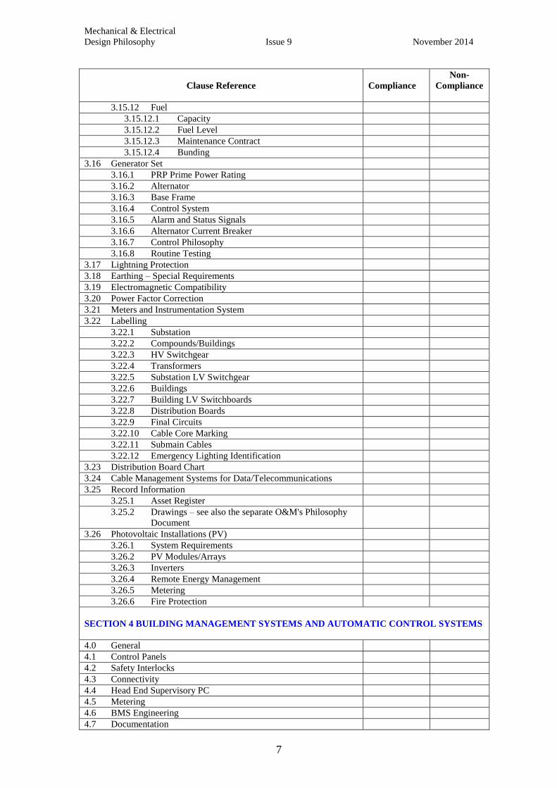
3.15.12 Fuel
3.15.12.1 Capacity
3.15.12.2 Fuel Level
3.15.12.3 Maintenance Contract
3.15.12.4 Bunding
3.16 Generator Set
3.16.1 PRP Prime Power Rating
3.16.2 Alternator
3.16.3 Base Frame
3.16.4 Control System
3.16.5 Alarm and Status Signals
3.16.6 Alternator Current Breaker
3.16.7 Control Philosophy
3.16.8 Routine Testing
3.17 Lightning Protection
3.18 Earthing – Special Requirements
3.19 Electromagnetic Compatibility
3.20 Power Factor Correction
3.21 Meters and Instrumentation System
3.22 Labelling
3.22.1 Substation
3.22.2 Compounds/Buildings
3.22.3 HV Switchgear
3.22.4 Transformers
3.22.5 Substation LV Switchgear
3.22.6 Buildings
3.22.7 Building LV Switchboards
3.22.8 Distribution Boards
3.22.9 Final Circuits
3.22.10 Cable Core Marking
3.22.11 Submain Cables
3.22.12 Emergency Lighting Identification
3.23 Distribution Board Chart
3.24 Cable Management Systems for Data/Telecommunications
3.25 Record Information
3.25.1 Asset Register
3.25.2 Drawings – see also the separate O&M's Philosophy
Document
3.26 Photovoltaic Installations (PV)
3.26.1 System Requirements
3.26.2 PV Modules/Arrays
3.26.3 Inverters
3.26.4 Remote Energy Management
3.26.5 Metering
3.26.6 Fire Protection
SECTION 4 BUILDING MANAGEMENT SYSTEMS AND AUTOMATIC CONTROL SYSTEMS
4.0 General
4.1 Control Panels
4.2 Safety Interlocks
4.3 Connectivity
4.4 Head End Supervisory PC
4.5 Metering
4.6 BMS Engineering
4.7 Documentation

Mechanical & Electrical
Design Philosophy Issue 9 November 2014
8
Clause Reference
Compliance
Non-
compliance
SECTION 5 – BUILDING INFORMATION AND OPERATING AND MAINTENANCE
MANUALS
This is now a separate section in the suite of Philosophy documents
SECTION 6 – METERING STRATEGY
6.0 Strategy Overview
6.1 Electricity Meters and Instrumentation Systems
6.1.1 General
6.1.2 Current Transformer General Arrangements
6.1.3 Voltmeter Monitoring General Arrangements
6.1.4 Meter and Sub Meter Types
6.1.5 Earth Leakage Instrumentation
6.1.6 Meter Networks
6.1.7 Metering - Substations
6.1.7.1 HV Metering
6.1.7.2 LV Metering
6.1.7.3 Substation LV Switchboard Outgoing Circuits
6.1.8 Department/Building Metering
6.1.8.1 Incoming Circuits
6.1.8.2 Outgoing Circuits
6.1.9 Riser/Tap Offs
6.1.10 Sub Distribution Boards
6.1.11 kWh Metering
6.2 Standby Generators
6.3 Photovoltaic Panel Systems
6.4 Combined Heat & Power (CHP) Plants
6.5 Natural Gas Service
6.6 Water
6.6.0 General
6.6.1 Controls and Metering
6.7 Heat Energy Metering
SECTION 7- HAND OVER PROCEDURE
SECTION 8 – CAD LAYER DETAILS, SPACE MANAGEMENT TEAM, DRAWING LAYER
CONVENTIONS
Appendices
Appendix A: Standard Requirements for Online Build Inf. Now separate
document
Appendix B: Oxford Univ. Telecoms. Infrastructure … As above
Appendix C: CAD Layer Details Now Section 8

Mechanical & Electrical
Design Philosophy Issue 9 November 2014
9
SECTION 1 – STANDARDS AND RESPONSIBILITIES
1.0 Standards
All plant, equipment and systems shall be designed and installed in accordance with
the appropriate British Standard or European equivalent, Codes of Practice, relevant
Statutory Instruments and Regulations, Building Regulations, University
Environmental Sustainability Policy, Estates Services Policy & Procedures document
'The Control of Legionella Bacteria in Water Systems' the Sustainability Building
Philosophy and the University Safety Office Policy statements.
The University of Oxford Standing Orders or 'Estates Regulations' (current edition),
University Environmental Sustainability Policy, Estates Services Policy & Procedures
document 'The Control of Legionella Bacteria in Water Systems' and the University
Safety Office Policy Statements are available either on the website or for inspection at
Estates Services.
1.1 Responsibility
The following table which is taken from the Estates Regulations (current edition)
indicates the division of responsibilities for the operation and maintenance of the
listed services. The list is not exhaustive and is intended as a guide only. Designers
should check with Estates Services Project Manager or Head of Building Services if
in doubt.
Responsibility for Mechanical and Electrical Services Estates Services
Department
Heating installations
Medical gases
Domestic hot and cold water systems
Demineralised water systems
Natural gas
Water treatment plant serving only departmental
equipment Air conditioning
Process water cooling systems
Ventilation
Warm and cold rooms
Lift installations
Compressed air systems
Steam plant and associated pipework
distribution
Steam plant and associated pipework distribution
serving only department equipment Fume cupboard extract systems
Fume cupboards
Lightning Protection Installations
Autoclaves, sterilizers and cage washers
Electrical sub-stations and switch rooms
Safety cabinets and associated extract systems
Fixed electrical distribution system
including light fittings and associated
lighting controls.
Electrical equipment (including UPS) connected to
socket outlets and isolators of the fixed electrical
installation. Building management systems
Emergency lighting (guided by the Safety Office
responsibility) External lighting
Fire detection systems (Safety Office responsibility)

Mechanical & Electrical
Design Philosophy Issue 9 November 2014
10
Standby generators required by
legislation, CHP and ground
source heat pumps
Sprinklers and misting systems
maintenance
Sprinklers and misting systems (weekly testing)
Standby generators for departmental requirements
only.
Estates Services equipment should be located in dedicated and separate mechanical
and electrical plant rooms under the control of Estates Services, with Departmental
equipment being located in separate plant rooms which are under the control of the
Department. If shared plantrooms are unavoidable then the project manager must
consult with both the department and Estates Services jointly.
1.2 Maintenance Philosophy
It is a requirement that all systems should be designed such that they can be repaired,
maintained, inspected, extended and removed with the minimum of disruption to the
building user. The Consulting Engineer or Contractor must submit a detailed
maintenance philosophy to Estates Services, as early as possible in the design of the
project, and in all cases before the completion stage E, to demonstrate that the above
objectives are being met.
For larger projects or complex plantrooms a formal maintenance review addressing
all of the above requirements should be carried out with the project team, Estates
Services and the department. The output from the review(s) must be documented and
this document must be reviewed with Estates Services at appropriate stages of the
project. The document must form part of the Operation and Maintenance manuals.
The philosophy should detail for example:
(i) The effects on the building user of planned maintenance on the various plant
items;
(ii) The effect of periodic test and inspection programmes of the electrical
installation;
(iii) The provision of any standby plant;
(iv) The provision of any alternative sources of electrical supply to maintain
essential services, etc.
(v) End of life removal
In the event of a cost minimising exercise (value engineering) it is important to ensure
that the client representative and PSG are made fully aware of the effects of any
changes which will increase disruption or add cost to their activities.
1.3 Deviations from the Philosophy Guidelines
The Consulting Engineer shall provide a written report to the Head of Building
Services highlighting where the principles of the Design Philosophy cannot be
complied with, together with a justification for the alternative solution proposed. The
form on pages 4 to 8 needs to be completed.

Mechanical & Electrical
Design Philosophy Issue 9 November 2014
11
1.4 12 Months Defects Period (Soft Landings and Seasonal
Commissioning)
The project costs shall include for the mechanical services commissioning contractor
(and/or the BMS controls contractor) to visit the new or refurbished building during
the 12 months defects period on a quarterly basis in order to carry out
adjustments/fine tuning of the mechanical services installations throughout the
building. A quarterly review (seasonal commissioning) meeting shall be held with the
client representative building manager or other nominated representative, Estates
Services mechanical services engineer and the commissioning engineer. Minutes of
the meeting shall be recorded.
It is essential that accurate and comprehensive metering and sub-metering data is
available through the ION metering system. The BMS must be fully functional with
all necessary sensors, drivers and other devices logged at appropriate intervals with
plots available.
Seasonal commissioning as a minimum should include:
Confirmation that all meters are reading correctly;
Comparison of meter data with predicted performance;
Review of all BMS graphics to confirm that they are reading correctly;
Review the BMS graphics to confirm they are a reasonable representation of the
system schematics;
Review of set points and dead bands;
Review of real occupancy hours and level (with the building FM manager)
Discussion of perceived performance / comfort levels;
Review sensor and driver plots and compare with actual occupancy;
Detailed performance review of LZC plant including representatives from the
equipment suppliers;
Detail performance review of weather compensation;
Detailed performance review night set back;
Detail performance review of night purging;
Detailed performance review of heat reclaim devices;
Review of rain water collection devices.
1.5 12 Months Servicing and Maintenance Agreement
For complex package plant e.g. CHP, GSES, generators, lifts etc. a fully detailed
maintenance proposal with a full breakdown of costs shall be provided to Estates
Services. It is essential that the maintenance quotation is obtained prior to
ordering the plant. The maintenance proposal shall cover only those mechanical
services which are the responsibility of Estates Services (see clause 1.1) and shall
detail all of the plant, equipment and installations to be maintained and shall provide a
schedule of work to be carried out. The proposal shall be fully comprehensive and
include for all necessary consumables such as filters, drive belts, etc. a 365 day, 24
hour emergency call out cover with a maximum of a four hour response time to deal
with breakdowns for five year contracts. The total life cost should be considered
before purchasing complex plant.
Mechanical & Electrical
Design Philosophy Issue 9 November 2014
12
The maintenance quotation should not be binding on the University. An order may be
placed by Estates Services Building Services Section directly with the contractor for
the maintenance contract after handover.
1.6 Control of Access to Plant Areas
In order for Estates Services to control access to the areas it is responsible for, all lift
motor rooms, mechanical services plant rooms, electrical substations, switch rooms
and riser cupboards shall have Estates Services suited locks fitted. Lock details shall
be as follows: the main suite is electrical, 'P' suite is for mechanical plant and 'L' suite
is for lift motor rooms. There is a grand master key which will unlock all three suites
and sub-master keys for each individual suite. Door locks shall be as supplied by Yale
Security Products Limited, type GMK suite, ref YN8114(Y). The standard locks shall
be key operation externally with thumb turn on room side for emergency exit
purposes and each lock shall be supplied with three keys.
The use of SALTO Door Access Systems for Plant Rooms is subject to approval by
Head of Building Services.
Access into all underground heating ducts is controlled by Estates Services and entry
into the ducts can only be allowed after a risk assessment has been carried out, a
method statement approved and a permit to work in Estates Services. Underground
ducts are treated as confined spaces.
1.7 Utility Supplies
Estates Services Energy Manager is responsible for organising the gas, water and
electricity supply contracts for all of the University's functional estate. All new utility
supplies or alterations to existing utility supplies must be arranged through Estates
Services Energy Manager.
1.8 Use of Dynamic Simulation Models for Part L CO2 Calculations
Designers working on all new buildings and extensions to the current Part L Building
Regulations must use a dynamic simulation package (approved by the Department for
Communities and Local Government [DCLG]) rather than the Simplified Building
Energy Model (SBEM) for calculating CO2 emissions. Estates Services reserve the
right to allow the use of SBEM for simple buildings and extensions. The Designer
must send a copy of the BRUKL (Building Regulations United Kingdom Part L)
Output Document 1 Compliance with ADL2 (Approved Document Part L-
Conservation of Fuel and Power – Part 2 – New Buildings other than Dwellings) to
Estates Services Energy Manager for comment prior to Part L submission. A table of
the input variables must also be provided which includes occupancy hours, plant
running hours, occupancy density, small power load density (W/m2), internal design
temperature and air change rates.
A copy of the 'Asset Rating' BRUKL Output Document 1 Compliance with ADL2
using actual construction data must be handed to Estates Services Energy Manager
before final handover of the building.
The National Calculation Method (NCM) allows calculation by accredited software,
dynamic simulation models or SBEM. See www.ncm.bre.co.uk for the latest updates.

Mechanical & Electrical
Design Philosophy Issue 9 November 2014
13
1.9 Redundant Installations
It is the policy of Estates Services that where buildings or parts of buildings are being
refurbished all redundant equipment, cables, pipework etc shall be removed. It is
particularly important that no 'dead legs' are left in the hot and cold water or natural
gas services. All redundant pipework must be removed back to the tee position on the
remaining live pipework and capped off.
1.10 Draining of Hot and Cold Water Systems with Standing Water
During the Project
If during the course of a project, especially refurbishment projects where existing Hot
Water or Cold Water systems are not used or underused, wherever possible the system
should be drained to manage the Legionella risk.
If there is a need to retain water supplies, for instance to maintain services to toilets
or hand-wash facilities or where Asbestos removal requires a water supply then there
must be an adequate Risk Assessment and measures should be taken such as regular
flushing of the system and as soon as possible the systems drained thereafter.
1.11 Handover of Water Systems
If during the course of a project the responsibility for Hot or Cold Water systems is
handed to Estates Services then adequate notice should be given of this intention in
order for Estates Services to allow their appointed specialist contractor to have access
to complete a full risk assessment in the case of a new building or a re-risk assessment
in the case of a refurbishment, to allow for access for the monitoring team to identify
assets and complete bar-coding and implement a new control regime. If the building is
not due to be fully occupied then Estates Services would instigate additional measures
such as flushing until the building is brought into full use.
1.12 Effect of Additional Installations on Existing Services
Consideration should be given during any new project or refurbishment to the
surrounding area/s that may be affected by the works. This includes the cleaning of
surrounding buildings externally and internally e.g. ductwork and filters that may
need more attention due to the works. Also any internal spaces that may need any
services modified and/or any effects to the environmental conditions of any spaces
that could be compromised because of the works need to be included within the
project or refurbishment.

Mechanical & Electrical
Design Philosophy Issue 9 November 2014
14
SECTION 2 – MECHANICAL SERVICES INSTALLATIONS
2.0 General
It is an absolute requirement that all systems are designed to be easily and safely
accessible and are straightforward to operate, maintain and replace. Where plant is
hidden for aesthetic reasons 'accessible' means that hatches, removal panels and other
access devices can be removed by a single person without using tools (or lifting
devices).
All work within listed and 'historic' buildings requires careful consideration and all
proposals must be agreed with the Head of Building and Conservation during the
design process and before any work is carried out. Building and Conservation should
also be consulted on works on buildings that are not Listed but are historically
significant.
2.1 Plant Rooms including Boiler Rooms
2.1.1 General
All plant rooms must have safe, easy, secure access and, in the case of basement and
ground floor rooms, the access must be direct from the outside of the building in
which the plant rooms are located. All plant rooms must be of adequate size and
height. Access to all plant rooms must be as safe and easy as entering any other room
within the building.
The use of vertical ladders will not be accepted as a means of gaining access to
any plant room or roof top plant area.
All plant rooms shall have adequate ventilation, floor drainage, good uniform lighting,
emergency lighting, a telephone, a data point, rcd protected 13 amp socket(s), a fire
alarm sounder and appropriate fire detection. Telephone and data points are in
addition to those dedicated for equipment monitoring.
All plant rooms which are located above occupied areas and contain 'wet' services
shall be fully tanked and bunded with sufficient drainage points so as to prevent the
possibility of water damage to the areas below. Floors should be laid to fall towards
drains. All penetrations through the tanked floor shall have a minimum of 100mm
upstands all around the openings.
Where there is significant risk of damage from leakage e.g. Plant Room above
laboratories, a leak detection system must be installed and wired back to a locally
monitored area. It must not be connected to the BMS and is not a substitute for
bunding the Plant Room. To reduce the risk of false alarms, leak detection cables
should be run in appropriate locations on wire baskets such that they a very slightly
raised above the floor. Alternative 'prong type' detectors may be used if appropriate.
All discharges to plant room drains e.g. from condense, blowdown shall be adequately
designed and installed to prevent water leaking onto the plant room floor. If there is a
need to 'bund' a drain to cope with the flow then a separate drain must be provided.
Mechanical & Electrical
Design Philosophy Issue 9 November 2014
15
Doors into Estates Services plant rooms must be fitted with Estates Services suited
locks and adequate access must be provided for future plant replacement.
Door Locks shall be as supplied by Yale Security Products Limited, type GMK suite,
ref no. YN8114(Y), 'P' suite for mechanical plant rooms. The standard lock shall be
key operation externally, with thumb turn on room side for emergency exit purposes
and each lock shall be supplied with three keys.
Adequate space shall be provided around all plant for safe maintenance, inspection
and replacement. Headroom under plant, pipes, ducting, etc., along access routes
shall not be less than 2000mm with access space around plant being not less than
900mm or more if recommended by the equipment manufacturer.
All plant shall be installed so as to prevent vibration and noise transmission to
occupied areas. Appropriately positioned lifting beams shall be provided to enable
the safe replacement of large items of plant such as pump motors.
Any plant located on a roof shall be provided with adequate lighting and a non-slip
walkway with guard rails to permit safe access.
Tripping hazards must be avoided, particularly low level pipework discharging over
floor drains located in access routes.
Access to departmental plant areas, server rooms and electrical switch rooms must not
be via an Estates Services controlled mechanical services plant room.
Open flue gas and oil fired heating and hot water heaters must always be located in a
separate plant room from supply and extract ventilation plant.
2.1.2 Roof Plant Rooms
Access must be by a staircase having a clear width of at least 800mm. Floors shall be
tanked and bunded to prevent water damage to floors below and there must be an
adequate number of drainage points provided.
2.1.3 Low Level Plant Rooms
Main plant and boiler rooms should be at ground level and must be separate from any
electrical intake room. If a ground floor location is not possible then consideration
may be given to a lower ground floor or basement location, in which case access must
be via double doors from an adequately sited well, with ramped access if possible.
2.1.4 Equipment Located in Ceiling and Roof Spaces
The designer shall avoid wherever possible positioning equipment such as fan coil
units which require regular servicing and maintenance in ceiling voids and roof
spaces. However, where this is absolutely unavoidable, then a safe, easy means of
access shall be provided, e.g. full sized hinged panels, boarded out walkways in roof
spaces and deep ceiling voids, etc. Any equipment which needs to be serviced must
not be located above laboratory benches, computer equipment, fixed room furniture,
etc., and every effort shall be made to locate equipment away from occupied areas.
Mechanical & Electrical
Design Philosophy Issue 9 November 2014
16
2.2 Hazardous Areas
All plant and equipment serving hazardous and restricted access areas such as animal
rooms, containment rooms, etc., shall be designed and installed such that they can be
totally maintained from outside of the actual area. The requirements of the University
Safety Office briefing document for category 2 and 3 containment areas must be
followed. Visual indication (i.e. magnehelic gauges) of differential pressures shall be
provided where rooms are required to operate at a greater or lesser pressure than
adjacent areas.
2.3 Distribution of Piped Services
2.3.1 Horizontal Distribution
Main horizontal distribution pipework shall be at high level in corridors, in a single
depth and preferably not hidden above ceiling tiles. If ceiling tiles are unavoidable
then they must be easily removable and replaceable.
Pipes must not have fixed equipment or cable and data trays positioned directly
underneath them and all valves must be easily accessible from below.
2.3.2 Vertical Distribution
Main vertical distribution pipework shall rise in a wide shallow duct containing a
single depth of pipes with access from full height doors at each floor level. Such
vertical ducts shall be complete with solid floors at each level, open mesh type
flooring is not acceptable.
2.4 Low Pressure Hot Water Heating Systems
All wet heating systems shall be designed as low pressure hot water systems.
Medium and high pressure systems are not acceptable.
Radiators should be used in preference to fan coil units and to natural convectors
wherever possible. All mild steel pipework shall be heavyweight mild steel to
BS1387 up to 150mm and to BS3600 for larger sizes. Thin walled stainless steel
pipework may be used as an alternative if using crimped fittings. Trench heating
must not be used.
Pipework up to and including 50mm shall have screwed joints and pipework 65mm
and above welded joints. Adequate dismantling points using unions or flanges as
appropriate shall be provided to enable appliances to be disconnected and pipework to
be repaired.
2.5 Laboratory and Domestic Hot and Cold Water Systems
2.5.1 General
All water systems must be designed to comply with L8: Legionnaires' disease. The
control of legionella bacteria in water systems. Approved Code of Practice and
HSG274: Legionnaires' disease - Technical Guidance issued by the Health & Safety

Mechanical & Electrical
Design Philosophy Issue 9 November 2014
17
Commission and the requirements of the current Estates Services Policy & Procedures
document 'The Control of Legionella Bacteria in Water Systems'.
Galvanised mild steel pipework, fittings and calorifiers shall not be installed; only
copper, stainless steel or appropriate plastic materials may be used. Flexible
connections to terminal fittings are not permitted (as these are a potential site for
bacteria growth) final connections must be copper or stainless steel. The only
exception will be mixer taps which have integral flexible connection but these should
be avoided if possible. Location isolation valves (ballofix type) are to be provided to
all water systems
In order to standardise across the University Estate only Yorkshire Fittings Limited
Xpress jointing system is approved as an alternative to traditional methods of jointing
of copper pipework.
Where buildings or areas are being refurbished all redundant pipework shall be
removed back to the tee on the live pipework and the tee removed and a through joint
used wherever practicable.
All drinking water outlets must be supplied directly from the mains supply pipe.
Any work on water services must be given prior approval by the Head of Building
Services and/or the Mechanical Engineer with adequate information provided on
application. A transfer of control must be issued by the DLO.
Suitable pre-treatment water softening plant should be considered particularly for hot
water systems.
Spray and aerated taps shall not be used.
2.5.2 Hot Water Systems
Plate heat exchangers or direct gas fired hot water heaters should be used in
preference to storage calorifiers.
Hot water with central storage and associated pipework distribution systems shall
only be used if it is impractical to use point of use electric hot water heaters. Trace
heated hot water flow pipework shall not be used in place of a pumped hot water
return.
Mixer taps are preferred to individual hot and cold taps. Thermostatic mixing valves
(i.e. TMV2 or TMV3 as appropriate) shall be installed on all baths and wash hand
basins in high risk environments such as child care following an assessment of the
scalding risk to provide safe hot water temperatures. If TMVs are required they
should be incorporated within the terminal fitting and all TMVs must be accessible
for routine maintenance and must not be installed in ceiling voids or other difficult to
access areas. Local isolation valves (ballofix) must be provided for testing for both
hot and cold water feeds.
Electric water heaters must be manufactured by Heatrae Sadia and showers by either
Mira or Triton.

Mechanical & Electrical
Design Philosophy Issue 9 November 2014
18
2.5.3 Cold Water Systems
Two cold water storage tanks shall be provided to enable supplies to be maintained
whilst one tank is taken out of service for inspection/cleaning. If a dual tank is
specified it must be designed so that it can operate for long periods with only one tank
in use. The tank should be capable of being cleaned from outside. If this is not
possible then suitable provision should be made for confined space entry.
A water meter shall be fitted in the mains cold water supply pipework to all cold
water storage tanks and these meters together with the water storage temperature of
each tank shall be monitored by the Building Management System. Refer to Section
6 Metering.
The main meter on the incoming cold water supply to the building and any other sub-
meters shall be monitored by the ION metering system. (See reference section 4.6 in
Project Managers Guidance of Sustainable Building Philosophy document).
2.5.4 Handover of Water Systems
All new and renovated water mains, service pipes and fittings must be disinfected,
flushed and sampled before returning to service irrespective of pipe diameter.
Water services must be cleaned and disinfected within 7 days of handover and a
representative number of potable water samples, including pseudomonas, must be
taken no less than 5 days after disinfection. The water services must be of acceptable
water quality and will not be accepted unless all water samples are satisfactory. The
contractor will be responsible for flushing of all outlets before acceptance and this
should be appropriately recorded.
A Legionella Risk Assessment must be issued before any water system is accepted.
2.6 Natural Gas Service
A gas shut off valve, operated by a heat detector(s) and/or emergency push button
shall be incorporated in the boiler supply pipe. This valve must not be connected to
any building fire detection system other than that located within the boiler room. Gas
pipework shall be heavyweight mild steel to BS 1387(EN 10255).
Basement and semi-basement boiler rooms shall have a gas detection system installed.
The gas supply to other areas such as kitchens and laboratories shall be separately
metered from the heating boilers and hot water heaters.
All gas meters must be monitored by the ION metering system. See Section 6.
For a gas supply that normally is metered at 21 mbar, the pressure drop between the
primary meter and any booster or the plant manual isolation valve, at maximum flow,
shall not exceed 1 mbar.
For a gas supply that normally is metered at greater than 21 mbar, the pressure drop in
the pipework, at maximum flow, shall not exceed 10% of the design pressure.

Mechanical & Electrical
Design Philosophy Issue 9 November 2014
19
Gas boosters should be avoided if at all possible.
All installations must comply with current IGEM and other relevant regulations for
industrial and commercial establishments (unless agreed otherwise for genuine
domestic installations). Designer and installers should particularly note the earthing
requirements of gas pipework.
2.7 Steam Systems
Steam shall not be used as a primary or secondary form of heating or for
humidification. It is the policy that where steam is necessary, it should be generated
adjacent to the point of use. Steam plant which serves only departmental equipment,
e.g. cage washers, autoclaves, etc., will be maintained by department personnel and
the design proposals should be discussed with both Estates Services and the building
user.
2.8 Isolation Valves
All piped services shall have adequate numbers of isolation valves fitted for future
maintenance requirements to minimise drain down. As a minimum each floor must
be zoned.
All items of plant shall be fitted with isolation valves. Commissioning valves and
other throttling valves must not be used for isolation there must be dedicated isolation
valve.
2.9 Air Conditioning and Ventilation
The use of air conditioning systems shall be avoided wherever possible except where
close control of the environment is necessary. Natural ventilation should always be
used in preference to mechanical ventilation. Designs should incorporate free cooling
and/or night time purge cooling wherever possible. Not only are these requirements
of the Carbon Management Strategy, they also reduces the total life cost of the
building.
When existing A/C units are being replaced or a department wishes to install cooling
to discrete areas within a building, the Mechanical section must be consulted prior to
the design stage. The air conditioning approval form, available on the Estates
Services website, must be completed before any design takes place.
All air handling plant shall be located within plant rooms and the use of weatherproof
outdoor air handling units should be avoided.
Evaporative type cooling towers must not be used under any circumstances.
Evaporative cooling systems e.g. adiabatic should be avoided to reduce
maintenance costs and water hygiene risks.
Ventilation ducting shall be provided with an adequate number of suitably sized
access points to enable the ducting to be thoroughly cleaned. Adequately sized access
panels shall be provided adjacent to all in-line plant and dampers. See-through vision
panels shall be provided adjacent to all motorised dampers fitted in ductwork and air
handling units.

Mechanical & Electrical
Design Philosophy Issue 9 November 2014
20
All ductwork manufacture and installation must be in accordance with DW 144.
Filters shall be of the easily replaceable type and shall be fitted with dirty filter
indicators. Bag, HEPA and carbon filters shall have a pre-filter. Energy efficient
filters should be used in all plant.
Fresh air inlets shall be positioned so as to be unaffected by vehicle exhausts and to be
as far away as possible from fume cupboards, other exhaust points and heat rejection
equipment such as chillers.
Electric resistive type or gas steam humidifiers (Neptronic preferred), with
appropriate RO water treatment, shall be used for providing humidification. Electrode
type electric humidifiers must not be used.
Separate dedicated cooling systems should be used for server rooms, departmental
equipment and the like which require cooling continuously throughout the year.
Gauges shall be installed across all filters. Magnehelic gauges are preferred.
2.10 Fume Cupboards
Fume cupboard installations shall be in accordance with the current University Safety
Office Policy Statement University policy S7/01 on fume cupboards.
Wherever practical each fume cupboard (or bank of fume cupboards) shall have a
dedicated extract system which discharges at least three metres above the highest part
of the roof. Extract fans must be easily accessible.
Each fume cupboard shall have a balanced quantity of filtered, heated make-up air
introduced into the room in a manner designed to cause the minimum possible
disruption to the fume cupboard air flow pattern.
All fume cupboards and associated extract fans shall be numbered in accordance with
Estates Services current requirements.
2.11 Lift Installations
The lift manufacturer/supplier must be approved by the Head of Building
Services or Mechanical Services Engineer before contracts are placed.
Lift installations shall comply with BS(EN) 81 and all disabled persons legislation.
Car top controls, a pit stop switch and adequate shaft lighting shall also be provided.
Please consult with the Mechanical section regarding proposed tenderer. An engraved
plate with Estates Services unique lift reference number shall be fixed within the lift
car. Lift numbers will be provided by Estates Services Mechanical Services Engineer.
Where necessary, the facility to send unaccompanied loads such as gas cylinders to
their destination floor shall be incorporated in the lift control system.
A 'Windcrest' voice communication system and emergency lighting shall be
incorporated into the lift car. The voice communication system shall be programmed

Mechanical & Electrical
Design Philosophy Issue 9 November 2014
21
to dial up the University Security Services control room which is manned 24 hours a
day on 01865 272944.
The lift shaft shall not contain any other services within it, and shall have a pit access
ladder and adequate smoke ventilation at the top of the shaft.
Lift motor rooms shall have good uniform lighting, including emergency lighting and
emergency stop switches fitted in appropriate positions.
Lift motor rooms shall be adequately heated/cooled and ventilated to suit the type of
lift equipment.
All moving parts in the lift motor room must be painted yellow and suitably guarded.
There must always be an upward flow of air in lift shafts.
See clause 3.11.7 in the electrical service section for details of how the wiring serving
lift installations shall be configured. All electrical installation within the shaft and the
lift itself shall comply with Section 3 of this document.
Lift motor room doors must be fitted with Yale Security Products Limited, type GMK
suite, ref no YN811(Y), 'L' suite for lift motor rooms. The standard lock shall be key
operation externally and thumb turn on the room side complete with three keys.
Lift installations will not be accepted for use by Estates Services until:
they have been inspected and passed by the University's lift insurance company;
the O&M manual has been received and approved;
the test certificates have been approved;
wiring diagrams have been supplied;
communication system is in place and fully tested.
Servicing and maintenance of the lift(s) shall be included in the project cost for the 12
months following handover. Servicing intervals and maintenance of the lift shall be
carried out in accordance with the manufacturer's recommendations.
A smoke detector should preferably be located in the lift motor room rather than at the
top of the lift shaft, assuming that there will be adequate openings between the lift
shaft and the motor room. Where the lift motor room is not directly above the lift
shaft or the lift is an hydraulic type or there is no lift motor room, then an aspirated
type of smoke detector should be installed at the top of the lift shaft, with that part of
the detector which requires calibration/maintenance being positioned outside of the
actual lift shaft.
2.12 BMS Section Relocated
This section is intentionally blank – see section 4.0 for BMS.

Mechanical & Electrical
Design Philosophy Issue 9 November 2014
22
2.13 Asbestos
The use of asbestos in any form is forbidden. Existing buildings and services
installations may contain asbestos contaminated materials and this possibility must be
brought to the attention of any potential contractor. Estates Services maintain a
register of where asbestos has been found and made safe in existing University
buildings and there is also an Asbestos Register available based on a 'visual only'
survey of the University's buildings. All sightings of suspected asbestos material
must be reported to the University Safety Office so that the relevant action can be
taken in accordance with the current Asbestos Policy Statement.
2.14 Thermal Insulation
Mechanical services pipework and ductwork shall be insulated as necessary to
conserve energy or prevent condensation and freezing.
Fibre glass insulation must not be used in any form. Surface finish to the insulation
shall be appropriate for the location but in plant rooms 'Isogenopak' sheeting shall be
used in preference to aluminium cladding for pipework, and Ventureclad or similar
should be used for ductwork.
Valves and flanges, plate heat exchanger, pump bodies etc. shall be insulated with
purpose made high quality easily removable muff covers, aluminium valve boxes
are not acceptable.
The insulation to pipework either in the open air or in external service ducts shall be
rigid sectional insulation backed with an approved waterproof finish to form an
unbroken surface along the entire length.
Trace heating is to be avoided. Where unavoidable the system needs to be properly
insulated and accessible for routine testing. A list of each separate system must be
included with the Operation and Maintenance manuals. Tracing heating should be
installed on a fused spur not a plug and socket.
2.15 Stand-by Plant
A risk assessment shall be carried out to decide whether or not to provide stand-by
plant where there is a need to maintain constant environmental conditions at all times.
The risk assessment shall consider the vulnerability of the plant in question, the effect
of down time for maintenance, the importance of the service being provided and the
consequences of failure of the plant to the users.
Where automatic changeover of plant is provided, a suitable alarm shall be provided
to alert the appropriate staff that plant has failed and needs attention.
Generally all ventilation plant shall have run and standby motors and heating, chilled
water and hot and cold water systems shall have run and standby pumps. Twin headed
pumps are acceptable in most situations so long as supplied with a blanking flange.

Mechanical & Electrical
Design Philosophy Issue 9 November 2014
23
2.16 Energy Efficiency
This section should be read in conjunction with the Sustainable Buildings Philosophy
Document (section 3.2 and following in the Project Managers' Handbook) which
applies to all building projects.
Plant, equipment and systems must be specified at the time of tender and the most
energy efficient plant and equipment available must be selected for use. It is not
acceptable for the selection to be made by the installation contractor. Any alternative
equipment manufacturer proposed by the contractor may only be used if it is equally
as energy efficient as the specified item and is also approved by the Head of Building
Services.
All systems shall be designed to be as energy efficient as possible. Time and
temperature controlled zones shall be as small as practicable, with each room being
independently temperature controlled.
Appropriate heat recovery measures shall be incorporated wherever practical and cost
effective.
Free cooling shall be incorporated into air conditioning systems wherever possible.
Radiators shall always be used in preference to fan convectors and shall be fitted with
thermostatic radiator valves. Only Herz valves must be fitted.
Natural ventilation systems shall be used in preference to air conditioning systems
wherever possible.
All electric motors shall be of the high efficiency type (4 pole on three phase motors).
All air handling units should be fitted with high efficiency aerofoil bladed fans
wherever possible.
Ductwork shall be fitted with appropriate turning vanes to DW144.
2.17 Frost Protection and Freezing
Appropriate frost protection and prevention of freezing must be provided to all plant,
equipment and systems to all current guidelines and regulations. All critical systems
or exceptions must be discussed and agreed with the Head of Building Services.
2.18 Sustainable Laboratory Design
Laboratories consume large quantities of energy and water; typically 40-50% of a
laboratory's annual electrical consumption is consumed by the ventilation system. The
Sustainable Building Philosophy Document should be followed for any new
laboratory developments.
There are five key principles which should be considered when designing sustainable
laboratories:

Mechanical & Electrical
Design Philosophy Issue 9 November 2014
24
Match air change rates to requirements. Avoid high (>6) air change rates
wherever possible. Consider reducing air change rates out of hours.
The request for over 'tight' temperature and humidity control should be
challenged as this constrains energy efficiency options.
Minimise loads by low air pressure drop design, selecting high-efficiency fans
for all air handling equipment, use of variable speed drives and the specification
of lower face velocity fume cupboards wherever possible.
Match variable loads and supply through a variable air volume system.
'Right size' equipment so that supply capacity matches loads.
2.19 Water Treatment
Appropriate water treatment must be provided for all steam plant, laboratory and
domestic hot water services, heating installations, chilled water installations, heat
recovery systems, humidifiers, low and zero carbon technologies (e.g. solar, GSHP).
2.20 Identification and Labelling
All plant and equipment must be clearly labelled to identify their function and the area
of the building that they serve.
All control equipment must be clearly labelled to indicate their function.
Labels shall be white traffolyte with black lettering, securely fixed to each item of
equipment.
All piped services within plant rooms, service ducts, ceiling voids, etc., shall be
clearly identified to BS(EN) 1710 together with the direction of flow.
2.21 Flexible Connections and Inertia Bases
Flexible connections and inertia bases shall not be installed on heating, chilled water
and domestic hot water pumps sets unless there is a proven need to provide a
completely vibration free environment for research purposes.
2.22 Cold Water Booster Pumps
Cold water booster sets should have the following minimum features:
Duty/assist pumps
Inverter control on each pump
Plastic, Stainless steel or copper manifolds for potable water
applications
Control panel with system monitoring
Auto rotation of pumps
Monitoring by the Building Management System
2.23 Sump, Storm Water and Sewage Pumps
Sewage pumping stations shall have the following minimum features:
Mechanical & Electrical
Design Philosophy Issue 9 November 2014
25
Adequate pit size for operation and maintenance and removal
3 phase duty/assist pumps
Guide rails and auto pedestals or high level couplings where
appropriate
Suitable weight bearing manhole covers
Channel/vortex impeller with additional cutter to prevent ragging for
heavy duty applications (*)
Macerators should be considered where there are long discharge pipe
runs or an excessive static head (*)
Coated ductile iron pipework in the pit
Bronze gate valve and self-cleaning non-return valve for each pump
Stainless steel chains and shackles
In-line grease trap on the inlet pipework if serving a commercial
kitchen (*) Fitted as close as possible to kitchen
Access points for servicing including adequate clearance for tripods
or lifting beams
Twin pump control panel
Ultrasonic level control
Facility to manually start pumps on a time basis if the start level has
not been reached to avoid stagnant effluent
System status readout to include the level in the pit
Automatic duty/standby operation
Auto rotation of duty pump
Run and trip indication of pumps
High level alarm, audible and visual on the panel with volt free
connection
Alarm linked back to the building management system
Panel should be installed with line of sight of the pumps
Sump and storm water pumps shall have similar features as the above but not the
items indicated above by an asterisk.
Pumping stations must be designed and installed to comply with the current Confined
Spaces Regulations and a Safe Systems of Work provided within the O&M manuals.
Lighting, suitable for a flammable atmosphere, should be provided.
2.24 Biomass, Solar Hot Water, Combined Heat and Power
Remote monitoring of plant by external contractor. Connections and access should be
approved by Estates Services and available three weeks prior to PC. Some system
may require a dedicate phone line in copper rather than VOIP.
The metering for renewable energy generation systems must comply with the relevant
regulations in order to be approved for any government repayment scheme. See
Section 6 Metering.
2.25 Boiler Installations
Condensing boilers must be fitted with neutralisers on the condensate discharge to
manufacturers' guidelines and current regulations. These must be easily accessible for
Mechanical & Electrical
Design Philosophy Issue 9 November 2014
26
routine maintenance. Condensate pipework must be designed to prevent freezing in
cold weather e.g. by the provision of tundishes within plant rooms. Externally run
condensate lines must insulated.
2.26 Rainwater Harvesting Systems
All rainwater harvesting systems as a whole shall be designed in accordance with BS
8515:2009 (or any subsequent revisions) by a suitable qualified and experienced
engineer. New buildings often have a planning requirement for stormwater
attenuation (from the Environment Agency). The design of an attenuation system
should be combined with the rainwater harvesting system design.
2.26.1 Rainwater Collection
Rainwater collection shall be from the normal guttering pipework of the building. The
pipework shall be arranged such that rainwater enters the storage tank only by gravity
or symphonic action. Pumping of rainwater supply to the storage tank is not
acceptable.
Supply pipework shall be free-draining to avoid stagnation and arranged to prevent
contamination entering the system at any point.
Where collection from ground level or trafficked surfaces is proposed, a risk
assessment following a recognised procedure (such as BS31100) must be undertaken
and presented to Estates Services for approval before being adopted as the accepted
solution.
Water run-off from green roofs must be segregated from rainwater harvesting systems
to avoid contamination and discolouration of water systems.
2.26.2 Filtration and Treatment
All rainwater harvesting systems will be provided with debris filtration upstream of
the storage tank which shall have a minimum efficiency of 90% and that will pass a
maximum particle size of <1.25mm.
Rainwater systems shall also be provided with a system of biocidal control suitable
for the application, such as UV disinfection as described in the Market
Transformation Programme (MTP) publication, Rainwater and Grey Water: A guide
for specifiers.
Where water is pumped from the storage tank, a floating suction filter (such as the
Wisy SAFF or equal and approved) shall be used in conjunction with a remote pump.
2.26.3 Rainwater Storage
Any tanks which form part of the rainwater harvesting system shall be designed and
manufactured for the purpose.
The preferred location of rainwater storage tanks shall be either in basement
plantrooms or externally below ground. The use of external tanks above ground shall
be avoided to reduce the opportunity for increases in temperature which may

Mechanical & Electrical
Design Philosophy Issue 9 November 2014
27
encourage multiplication of Legionella or algal blooms. All storage facilities whether
consisting of one or more tanks, shall be designed to avoid stagnation, contamination
and microbial growth.
2.26.4 Back-up Water Supply
In all cases, a mains fed back-up water supply shall be provided to ensure that demand
can be met during dry periods. In all cases, suitable air-gaps conforming to
BSEN13076 or BSEN13077 will be used in order to prevent any possibility of
contamination of mains potable water with rainwater in accordance with the Water
Fittings Regulations.
The back-up water supply shall be arranged and controlled to ensure that the amount
of water supplied is minimised to that required for immediate use.
Consideration shall also be given to the appropriate use of the rainwater system
during dry spells when certain uses (such as irrigation) may not be appropriate when
the system is being supplied by mains back-up rather than rainwater.
2.26.5 System Arrangement and Distribution
The system arrangement, including collection, storage and distribution systems, shall
be such that there are no deadlegs and an adequate turnover of water is achieved to
avoid stagnation.
All storage tanks shall be provided with an overflow outlet of equal or greater
capacity than the inlet to allow discharge during extreme rainfall periods. Where an
anti-surcharge device is fitted it shall conform to BSEN13564.
Rainwater shall be distributed from the storage tank using a pump located outside the
tank and suction pipe arrangement, the latter being arranged to minimise the
possibility of sucking in air, sediment or debris through the use of a floating suction
filter. The flow rate and pressure head of the pump shall be determined in accordance
with BSEN12056-4. A non-return valve with isolating valve shall be incorporated into
the suction line to prevent drain down of the water column. Where multiple pumps are
used, the system shall conform to BSEN12056-4 (as amended).
Rainwater pipework shall be distinguishable from potable water pipework through the
use of different colour pipework as set out in WRAS Information & Guidance Note
No 9-02-05. It shall not be blue to avoid any confusion with mains potable water
supply pipework.
2.26.6 Controls and Metering
Controls shall be designed to minimise energy consumption and operational wear, to
activate the back-up water supply automatically and with suitable connections to
allow the system to be connected to a BMS.
Flow meters shall be provided to the back-up water supply and the pumped outlet
from the storage tank to enable the performance of the system to be monitored. The
meters shall be capable of being monitored remotely through connection to the ION
system.
Mechanical & Electrical
Design Philosophy Issue 9 November 2014
28
Consideration should be given to incorporating status monitoring which provides
additional information for example; how full the tank is, any plant faults, which
supply is being used.
2.26.7 Testing
The system shall be flushed and tested as part of the normal commissioning of the
building services systems. Pipework shall be tested in accordance with and meet the
standards of BS6700.
Commissioning certification shall be provided once all system components have been
tested and comply with any relevant legislation, regulations and standards.
On hand-over, a legionella risk assessment and monitoring programme for the system
shall be provided.
2.26.8 Access for Maintenance
The system design and installation shall ensure that suitable access for maintenance,
repair or replacement of consumable parts is provided.
2.27 Ground Source Energy Systems (GSES)
2.27.1 Design and Specification Phase
GSES within the University must be designed, installed, controlled and interfaced
with other systems with the primary purpose of reducing Carbon emissions. The
control strategy for carbon emissions reduction may be different from those for cost
savings. The programming of the GSES controls must make reference to the actual
efficiencies of the installed conventional plant (if installed) so that the plant only runs
when it is more (carbon) efficient than the alternative.
Systems should be designed so that the amount of heat extracted from the ground
annually is reasonably well balanced with the amount of heat rejected to the ground as
far as is practical. The depth of the loops is limited by the Great Oolite Aquifer which
is especially limiting where buildings have deep basements.
The designer will need utility cost and tariff information from Estate Services
sustainability section and will be forced to make assumptions of future costs (it is
important that the assumptions of future costs are agreed by all parties otherwise the
design/payback rationale could be misunderstood). Savings should be calculated
using the seasonal energy efficiency rates of the chillers and boilers selected for the
project and not a typical figure for relevant plant.
The designer must set out clearly in the Stage reports of how much heating and
cooling the system is designed to supply, both in absolute and percentage terms, the
likely availability of the system (and what happens if this is not achieved), and the
annual average COP of the system in heating and cooling. The heating and cooling
data will be based on a model which makes many assumptions. The assumptions
must be well documented and approved by the PSG.
Mechanical & Electrical
Design Philosophy Issue 9 November 2014
29
The interface of the GSES with other control systems needs to be considered
carefully. The extent and speed of data transfer should be minimised. Data traffic
increases as systems mature so what works at handover may not continue working for
long. Detailed consideration must be made of how GSES interfaces with building
Trend BMS.
The designers must ensure that there is separate metering so that the GSES actual
performance can be verified independently. The heat meters should be in the best
possible positions (appropriate lengths of straight pipes up and down stream) to give
accurate readings. Note there will be discrepancies between the meters but the
designer should agree with the Contractor what the acceptable error should be before
measurements start. All meters must be connected to the ION system. The designer
must clarify which meters will be used to assess the system performance. Buffer
vessels must be carefully sized to minimise starting cycles. The designers must
ensure that heating and cooling outputs from the GSES are metered separately and
that the GSES's electrical consumption in heating and cooling respectively can be
separately identified. They should ensure that all parasitic loads e.g. ground loop
pumps are also metered.
The designers must ensure that conventional systems do not take away load from
GSES. Dead bands and control set points must be carefully considered.
The project manager must get a quotation for comprehensive 5 year maintenance as
part of the project costing. Current experience is that critical components -
compressors expansion valves and header valves are inherently unreliable so
comprehensive contracts are essential.
The project manager must engage with the University's IT services to ensure that a
comprehensive remote monitoring system is available to the contractor before the
start of commissioning. The frequency of monitoring and reporting must be agreed.
The project costing must include for regular and seasonal reviews of system
performance post handover. Seasonal commissioning must be built into the contract
price. The number of years of commissioning should be based on the complexity and
criticality of the system. Consider the use of a specialised validation engineer to
review the performance at a detailed level and the interface with the BMS controls.
2.27.2 Installation
The Designer must witness the factory testing of the heat pumps under load at
representative source and load side temperatures. Estates Services Mechanical
Engineer should also be given the option to attend.
Ensure that (client) IT infrastructure for the remote monitoring of the system by the
supplier is available before commissioning. It is important to start discussions early
as there are potential security considerations.
Ensure that meters are only reset to zero after all meter readings have been taken.
Both the BMS and the GSES will have to be tuned and some of this will be
interdependent. Both systems will also require seasonal commissioning post
Mechanical & Electrical
Design Philosophy Issue 9 November 2014
30
handover and this should be coordinated. The avoidance of short cycling is important
but neither do you want to keep bringing on auxiliary heating and cooling.
The description of operations (DESOPs) needs to be written in sufficient detail and
structured so as to be useful for witnessing. The BMS DESOPs must be coordinated
with the GSES DESOPs, and any other relevant third party controls e.g. chiller/ boiler
sequence controllers. The system needs to be witnessed jointly with the BMS after
both systems have been commissioned fully.
All systems must be installed so as not to let the conventional systems take away load
from the GSES. A refrigerant leakage detection system must be installed in
appropriate locations around the GSES and connected to the BMS system.
2.27.3 Handover
The GSES needs to be handed over to the following groups all of whom have a role to
play in the successful operation of the system:
The department building manager;
Estates Services Mechanical Engineer;
Estates Services Energy Manager;
The DLO Mechanical Supervisors.
The handover of the system should be coordinated with the handover of the BMS.
Suitable and sufficient training, instruction and documentation (including the DESOP
for both the GSES and the relevant sections of the BMS) must be provided.
2.27.4 Operation
Ensure that meters are only reset to zero after all meter readings have been taken. If
you are trying to interpret the information that is obtained from the system to assess
either carbon saving or energy savings it is critically important that very good records
are kept of anyone working on the system and what they have done or are doing be it
remedial, repairs replacement etc---without this and knowing for example when
meters have been off it is impossible to have faith in the readings and hence faith in
the energy / carbon saving results. Meters should be read locally and cross checked
against the metering system periodically.
The maintenance of the system must be overseen very closely. Ensure any problems
picked up by the contractors maintenance engineers are reported to the projects team
and rectified under defects liability.
The contractor and designer should produce regular (monthly) reports of performance
post handover which should be reviewed by Estates Services Repairs and
Maintenance and the Project team. Major reviews should be carried out to assess
seasonal performance and used to inform the fine turning during the soft landing
period. The project manager should coordinate these meetings with participation
from designers, GSES contractor and Estates Services Mechanical and Sustainability
teams.
The system must be operated so as not to let the conventional systems take away load
from GSES.
Mechanical & Electrical
Design Philosophy Issue 9 November 2014
31
SECTION 3 – ELECTRICAL SERVICES INSTALLATIONS
3.0 General
It is an absolute requirement that all systems are designed to be easily and safely
accessible, are straightforward to operate, maintain, extend, replace and allow the
carrying out of periodic test and inspections with the minimum of disruption to the
building users. Where plant is hidden for aesthetic reasons 'accessible' means that
hatches, removal panels and other access devices can be removed by a single person
without using tools (or lifting devices).
All work within listed or historic buildings requires careful consideration and all
proposals must be agreed with the Head of Building and Conservation before any
work is carried out.
Whilst surface mounting of electrical services is preferred, it is recognised that
prestigious areas within buildings will require a more sympathetic approach. Within
such areas the method of concealment of electrical services should be agreed with the
Electrical Engineer.
There is an on-going rationalisation and standardisation of the electrical systems and
associated equipment within the University and, therefore, it is essential that the
principles outlined in this document are strictly followed.
The selection of equipment, particularly main switchboards must be discussed and
agreed with the University Electrical Engineer at the earliest opportunity.
All systems must be designed to be simple, symmetrical and easy to understand.
Drawing no. 400005 as attached illustrates the layout of a typical Estates Services
electrical distribution system complete with labelling requirements.
Systems shall be designed, specified and supervised to ensure full compliance with
BS7671 as well as other relevant Regulations, Codes of Practice and HSE Directives
to ensure the provision of a suitable electrical system to the satisfaction of Estates
Services.
Circuit protection shall be by circuit breakers – fuses must not be used.
The neutral conductor must be switched on the incoming supplies and at strategic
points throughout the system to ensure complete isolation of sections of the system to
simplify fault investigations.
Instrumentation and metering shall be provided with sufficient flexibility to enable
load analysis. Current transformer secondary connections shall be brought out to
terminals (with appropriate shorting links) to enable instruments to be connected
without having to switch off the supply – see the Metering Section 6 of this document
for details.
All indoor cables shall be LSOH type whether armoured or not.
Mechanical & Electrical
Design Philosophy Issue 9 November 2014
32
All parts of the electrical installation shall be sized to have a minimum of 25% spare
capacity to cater for future growth.
Where the project involves working on or extending existing electrical services, no
work may be carried out on the existing systems without the prior knowledge and
approval of the University Electrical Engineer. All work must be carried out in
accordance with Estates Services Code of Practice 'Electrical Safety on Low Voltage
Systems'.
Only electrical contractors who are on Estates Services Approved List of Inducted
Contractors will be allowed to work on the University's fixed electrical systems.
3.1 External Network General
The University owns and operates several external networks in and around Oxford.
These networks generally comprise of two types:-
HV Network: One or more high voltage substations on a system where all the HV
and LV equipment is owned and operated by the University.
LV Network: A network where the LV switchboard which supplies more than one
building is directly connected to a local DNO owned transformer.
The point of supply must be discussed and agreed with the Electrical Engineer at the
earliest opportunity.
Any reinforcement of the University electrical supply network required because of
additional electrical loadings for new or refurbished buildings must be funded by the
individual building project(s). The reinforcement work will be designed, organised
and implemented as part of the project to comply with the technical details provided
by Estates Services.
The design and installation of all new incoming supplies from the University network
will be arranged in conjunction with Estates Services based upon the anticipated
building electrical loadings provided by the project electrical consultant/contractor.
Estates Services will advise values of fault level and earth fault loop impedance.
3.2 HV Cable Networks
For all University Networks containing two or more substations it is expected that the
University Network will be connected either directly to the local DNO primary
substation or via a metered Switch located in a local DNO substation.
All University HV cable networks are designed and installed in the form of an open
ring. The routing of each cable shall be such that no other cables forming part of the
same network shall be laid together. The open point on a ring shall be determined by
the load and building types. This is of particular concern for those buildings
containing essential supplies where it may be appropriate that the adjacent substation
is on a separate part of the network. This is to enable a quick resumption of supply
following an HV failure.

Mechanical & Electrical
Design Philosophy Issue 9 November 2014
33
All cables shall be laid directly in the ground in accordance with part IV of the ESQC
2002 regulations. Ducts should be avoided accept during road crossings. Cables shall
not be located under buildings. In the event of new buildings being placed across
cable route, cable shall be diverted.
The cables type shall be PVC Insulated, Armoured, with Copper conductors
complying with BS6622. All the cables in each part of the network shall be a
minimum of 185mm2. Consideration shall be given to network design such as placing
loads over as many circuits as practicable, reducing disruption to as few buildings as
possible during faults etc. For guidance, all University high voltage ring circuits shall
have a minimum capacity of 8MW. All systems shall be designed for a 50 year life.
All networks shall comprise of ring circuits with no spurs or tees. Joints shall be kept
to a minimum.
All cables shall be accurately mapped, including joints onto University Standard
drawings maintained by the Estates Space management team.
3.3 LV Cable Networks
In order to carry out future maintenance or for dealing with local HV faults, all
University Networks containing two or more substations shall have each substation
connected to at least one other substation via a LV System with a capacity not less
than 500kVA.
Each interconnection shall comprise of a 2* 4c 185mm2 PVC/SWA/PVC cables run
in parallel. In addition each interconnector system shall incorporate a supplementary
earth conductor with a minimum size of 95mm2.
All cables shall be laid directly in the ground in accordance with part IV of the ESQC
regulations 2002. Ducts are to be avoided except during road crossings and entrance
to buildings. Consideration shall be given to grouping factors in trench. Cables shall
not be laid under or through buildings; in the event of a new building being
constructed all affected cables shall be diverted.
Each interconnecting cable group shall be directly coupled between substations with
no branch/tee joints.
All cables shall be accurately mapped, including joint locations, onto University
Standard drawings maintained by the Estates Space management team.
3.4 Building Supply Cables
For all buildings with a proposed demand greater than 250 kVA 2 circuits are to be
provided from the local University Substation. Each circuit shall be connected to a
separate transformer and sized such that each circuit can provide a minimum of 70%
of final connected load.
All cables shall be laid directly in the ground in accordance with part IV of the ESQC
regulations 2002. Ducts are to be avoided accept for road crossings and entrances to
buildings. Cables shall not be laid under or through buildings; in the event of a new

Mechanical & Electrical
Design Philosophy Issue 9 November 2014
34
building being constructed all affected cables shall be diverted. Consideration shall
be given to grouping factors in trench.
Building switchboards shall be located on ground floor and positioned such that
supply cables do not pass through significant parts of the building.
Each supply cable shall incorporate a supplementary earth conductor with a minimum
size of 95mm2.
3.5 Substations General
All substations that are owned and operated by the University and located on
University land shall be as follows:
All substation enclosures shall be constructed in accordance with the ESQC
Regulations 2002.
All substations shall incorporate an external/internal HV compound and an adjacent
fully enclosed LV switch-room. All access doors shall be secured as detailed
elsewhere in this document.
.
All internal LV floor cable trenches shall be fully protected by removable marine
plywood varnished covers.
LV switch room shall be suitably sized to allow a minimum of 1000mm of clear space
around rear of switchboard.
All equipment including switchgear shall be suitably placed so as not to impede
emergency evacuation from the site.
Entrance access doors to switchrooms will be sized to allow for unimpeded
installation and replacement of switchgear.
Each switch room shall be provided with a suitably sized 3 phase distribution board
located in a suitable location on the switch room wall. The distribution board shall be
fed from the centre section of the main Switchboard via a suitably sized 4 pole
MCCB.
Thermostatically controlled frost protection electric heating shall be installed in all
LV switch rooms. Heating shall be fed from the local distribution board.
Adequate ventilation shall be provided in all LV switch rooms to prevent
condensation.
Suitable RCD protected 13A sockets are to be provided in both LV switch room and
HV compound.
Adequate energy efficient lighting shall be provided in all HV compounds controlled
by a suitably placed switch.
Adequate precautions shall be taken to prevent water ingress in the cable trenches
from incoming ducts.
Mechanical & Electrical
Design Philosophy Issue 9 November 2014
35
External ground work shall comprise of a covering of loose pebbles/gravel complete
with weed control fabric.
Internal floors shall be constructed so as to provide a non-slip dust proof surface.
In circumstances where the LV switch room is not adjacent to the HV compound,
consideration shall be given to zoned protection systems including HV/LV inter-
tripping.
All substation LV switchboards shall be provided with a generator connection point.
The connection point shall be connected to the centre section of the main LV
switchboard and sized to allow for the connection of a 1MW generator.
The connection point shall comprise of a suitably sized ACB mounted in a weather
proof enclosure in a suitable location external to the LV switch room. The location of
which is to be agreed by Estates Services Electrical Engineer.
Lighting to a minimum of 200LUX shall be provided in all LV Substation switch
rooms using high frequency fluorescent lighting.
Emergency lighting to a minimum of 100LUX shall be provided in all LV Substation
switch rooms.
3.6 High Voltage Switchgear
Each item of HV switchgear shall comprise of a 630A (21ka rated) Ring Main unit
from the Schneider Ringmaster C range mounted directly on the transformer.
Protection of transformer shall be provided by Schneider VIP300 Protection relay.
Restricted Earth fault protection shall be provided on all systems where the
Transformer is not located directly adjacent to LV switch room. System shall be
designed to open both HV and corresponding LV switches.
Pfisterer sockets shall be provided on all HV switchgear.
Each Transformer switch shall be provided with a shunt trip connected to an
emergency power off switch. Each switch is to operate both Transformer HV switch
and corresponding LV Switch on main LV switchboard. Each switch shall comprise
of a break glass unit located inside the LV switch room adjacent to the main door. A
suitably sized wall mounted battery and charger shall be provided to power the
system.
All HV switchgear shall be normally mounted directly on their respective transformer.
For safety reasons operators shall have direct unimpeded access from the substation
entrance to operating handles.
A minimum of 1000mm unimpeded access shall be provided around all the
equipment.
Mechanical & Electrical
Design Philosophy Issue 9 November 2014
36
3.7 Transformers
Standard substation configuration shall comprise two suitably sized transformers with
associated HV switchgear.
All transformers shall be 11000\415V extra low loss, ground mounted free breathing,
KNAN Midel 7131 fluid filled.
HV Tappings shall be +-2.5% to +-7.5%. (6 position switch)
Air cooled transformers shall not be used.
Transformers shall be of the vector group DYN11 with an impedance matching
adjacent transformers but nominally <5%. It should be noted that transformers may be
run in parallel for short periods of time.
Each transformer shall be sized to suit the required load, but shall be not less than
500kVA. The designer should allow for each transformer to be operating at no more
than 75% capacity on completion, for transformers greater then 2MVA agreement
shall be sought from Estates Services Electrical Engineer.
Each transformer shall be directly connected to the LV switchboard using cables or
busbar.
An emergency power off switch shall be provided to enable all local transformers to
be isolated in an emergency. Switch to be suitably located such as to prevent
unintended operation. Switch shall isolate both HV and corresponding LV switch
Each transformer shall be mounted on a suitably constructed concrete plinth with
adequate access for cables. Adequate containment of coolant leakages shall be
provided.
Adequate access will be provided to allow unimpeded transformer replacement.
HV termination box shall be dry type with gasket sealed lid suitably oriented to accept
local cable connection.
LV termination box shall be dry type with gasket sealed lid suitably oriented to accept
local cable or busbar connection.
Buchholze type protection shall be considered for all transformers greater than
1500KVA.
All labelling shall be as detailed in Labelling section of this document.
No load and load loss data shall be provided by the manufacturer.
3.8 Trip Batteries
A 30V trip battery manufactured by PB design shall be provided at each substation.
The trip battery shall be Valve regulated Lead Acid with a 10 year life @20 degrees
C.

Mechanical & Electrical
Design Philosophy Issue 9 November 2014
37
The charger shall be constant voltage, current limited type with solid state controller.
The voltage control shall be within 1% of setting at+- 10% mains supply variations.
Supply voltage shall be 230V single phase from local DB with full recharge within
24hours.
Charge transformer shall be double wound with earth screen to BS7671.
Rectifier shall be full wave controlled thyristor/diode bridge type.
Charger shall be compliant with BS6231.
System shall comprise a composite facia with LCD display and LED indicator.
All output terminals shall be DIN mounted.
The system shall be fitted with an audible alarm with additional volt free contacts to
enable connection to the remote alarm system provided through the metering system.
3.9 Earthing General
The earth system shall comply with BS 7430.
The earth system shall be TN-C-S.
Prior to installation the earth resistivity shall be measured as described in BS7430 and
local conditions checked for suitability of installing earth rods. If conditions and/or
resistivity are not suitable advice shall be sought from Estates Services.
An earth electrode nest system shall be provided within the substation boundary. The
system shall comprise as a minimum 4 no 2400mm*16mm2 diameter copper rods
arranged in a pattern 3m apart. Each rod shall be driven vertically into the ground to
finish just below ground level. An inspection cover over a suitably constructed
housing shall be provided at the top of each rod. All rods shall be connected by a
copper strip not less than 25mm*3mm section buried at least 500mm below the
surface. All connections to rod shall be bolted.
The earthing resistance test measurements for each rod and the total system shall be
provided to Estates Services on completion of installation.
A hard drawn copper earth bar with a minimum section size of 50mm*6mm shall be
provided in the substation. The bar shall be wall mounted on shock resistant insulators
in a suitable location adjacent to the LV switchboard. The earth bar will have
minimum 25% spare ways on completion.
The external earth electrode system shall be connected to the substation earth bar by
means of a removable link with a suitably labelled green/yellow sheathed copper
conductor not less than 70mm2.
The cable shall be buried 500mm below ground and
enter the substation via a suitably sized sealed duct.
The transformer neutral/earth link shall be provided in an accessible location at the
low voltage switchboard.
Mechanical & Electrical
Design Philosophy Issue 9 November 2014
38
Each transformer and associated High Voltage switchgear shall be separately
connected to the substation earth bar with a suitably labelled green/yellow sheathed
copper conductor not less than 150mm2.
All external and internal metal work shall be connected to the substation earth bar
using a suitably labelled green/yellow sheathed copper conductor not less than
25mm2.
The LV switchboard earth bar shall be connected to the substation earth bar using a
suitably sized green/yellow sheathed copper conductor not less than 150mm2.
The metallic armour on all incoming/outgoing SWA cables shall be connected to the
switchboard earth bar.
No cables shall be routed across the floor.
All earth cable connections to the substation earth bar shall be hydraulic crimp lugged
and connected by a suitably sized nut and bolt torque fastening.
3.10 Low Voltage Switchboards
3.10.1 General Requirements
For the purposes of this guidance the following definitions will apply:
A substation LV switchboard:
Is a switchboard that is supplied directly by one or more HV transformers and
supplies one or more University buildings.
A building LV switchboard:
Is a switchboard that is supplied from either the local DNO, or a University substation
LV switchboard.
A final LV switchboard:
Is any one of the following switchboards that are supplied directly from the building
switchboard by cable or busbar riser.
Special Panel, MCCB Final distribution Panel, and Rising Main Panels and any
switch board or control panel containing protective devices
(Note mechanical plant switchboards are covered elsewhere in the Philosophy
document).
3.10.1.1 Construction
Unless otherwise specified the following section applies to all types of switchboards.

Mechanical & Electrical
Design Philosophy Issue 9 November 2014
39
All switchboards shall conform to BS EN 61439-1:2009 , BS EN 61439-2:2009 Type
Tested and partially type-tested assemblies.
Where top entry switchboards are located below ground floor they shall be mounted
on a suitably constructed plinth with a minimum height of 100mm. Where appropriate
the switchboard shall be protected against ingress of water from above. Sufficient
headroom should be allowed for to terminate the largest foreseeable size SWA cable
(Nominally no greater then 185mm2) taking into consideration the containment
routing and bend radii. Additional side entry glanding boxes are to be avoided.
Switchboard busbars shall be designed to withstand the maximum fault current. The
PSC value shall be determined after taking account of all incoming supply
characteristics as well as contributions from connected loads. The fault rating shall be
determined by calculations but it shall not be less than 65kA for one second in
substations, 50kA in buildings.
All switchboards shall be designed and constructed in cubicle form so that they can be
extended and erected by an approved contractor. Prior to despatch, the switchboard
shall be factory tested in accordance with BS EN 61439-1:2009, BS EN 61439-
2:2009. The board shall be fully assembled for testing prior to splitting for transport.
All test record documentation and 'as built' drawings shall be provided at the time of
despatch. As built drawings to include control panel wiring diagrams.
When re-assembled onsite, the switchboard manufacturer shall inspect and test the
switchboard in accordance with BS EN 61439-1:2009, BS EN 61439-2:2009, and
certify that it represents the factory-built assembly. All site test record documentation
shall be provided at the time of completion. All joints shall be fully torque tested and
marked with an indelible pen.
All exposed external metalwork shall be finished by an electro statically applied
epoxy powder primer and paint finish. Colour - Oxford Blue to BS 3381.105.
A white mimic diagram shall be applied to the front of the switchboard. The mimic
shall accurately indicate the internal busbar routing (including height from floor) and
connection to all switches.
The switchboard frame shall be fully welded manufactured from Zintec steel of not
less than 2mm thickness. Panels and doors shall be dished and manufactured from
Zintec steel having minimum thickness of 1.5mm.
All 3phase cable gland plates shall be hex bolted removable with plates made from
Zintec steel of minimum thickness 3mm. Gland plates for single core cables shall be
non-ferrous.
Where top and bottom covers are removable from the cable way, access through the
cable way must be unobstructed. If support angles are required across the opening,
then these shall be designed to enable them to be removed during installation works,
without detriment, to facilitate future cabling.
Cables shall be terminated on horizontally mounted gland plates within the cable way.
The location of the plate shall ensure that future cables can be installed and removed.
A drawing detailing the glanding facility and indicating how a pair of 4c cables up to
Mechanical & Electrical
Design Philosophy Issue 9 November 2014
40
185mm2
XLPE/SWA/LSF can be terminated at each position shall be submitted at
tender stage.
Where bottom entry is to be utilised, the base infill panels of the cableway of the
switchboard shall be constructed of 12mm varnished Marine ply or equivalent
material and fixed from above to ensure that they can be easily removed from within
the switchboard. Means shall be provided to gland off cables within the cableway to
enable easy connection onto each of the switch devices within a particular section.
A minimum of 25% spare ways are required on all new switchboards. As a minimum,
one spare way of each size subject to the minimum 25% rule shall be allowed for.
Where the number of spare ways proposed dictates that a single spare way would
necessitate a further cubicle section this will be brought to the attention of Estates
Services prior to manufacture.
All tenderers shall submit a drawing at the time of tendering. This shall show a
general layout of devices, their rating, the configuration of busbars and
compartmentalisation arrangements to meet required form of separation.
The minimum frame capacity shall be 160A TPN.
3.10.1.2 Busbars
All busbar assemblies shall comply with BS EN60429-2: Particular requirements for
busbar trunking systems.
All conductors shall be of hard drawn high conductivity copper fully rated.
The current rating of all neutral bars shall be the same as the respective phase bars.
The earth bar shall be run the full length of the switchboard. Each cubicle section
shall be positively connected to it. The bar shall be positioned to ensure that
connections can be taken easily from it. The section of the earth bar shall be a
minimum of two-thirds of the section of the primary busbar.
All spare ways shall be equipped with copper work and pluggable base in the same
way as an equipped circuit to enable future circuits to be added without the need to
switch off the incoming supply.
3.10.1.3 Switching Devices
All switchgear and control gear shall comply with BSEN60947 and unless otherwise
specified shall be as follows:
All switching devices shall break all incoming phase conductors including the neutral
simultaneously.
Switchboard devices up to and including 630A shall comprise of a suitably sized Plug
in Moulded Case Circuit Breaker (MCCB) from the Schneider NSX type H range.
The trip unit shall be from the Micrologic 5/6 A or E range and sized to suit
application. There should be adequate discrimination between the MCCB and
upstream devices.

Mechanical & Electrical
Design Philosophy Issue 9 November 2014
41
The fault rating for all switching devices shall not be less then 65kA for Substation
switchboards, 50 kA for Building switchboards and 36kA for all other switchboards.
Switchboard devices above 630A shall comprise of a withdrawable Air Circuit
Breaker (ACB) from the Schneider Masterpact NW range rated to suit application.
The circuit breaker shall comply with BS EN60947-2 and IEC947-2. The trip unit
shall be a Micrologic 6P sized to suit application.
For both operational and maintenance reasons, it is required to have interchangeability
between the fixed and moving assemblies on the A.C.B`s
The contact assembly of the circuit breakers and all associated live metalwork shall be
double insulated from the operator. For Substation switchboards the operating
mechanism shall be spring assisted via an auto-charged spring: manual charging shall
also be provided. The closing time and spring charge times shall be advised at the
time of tendering.
The status of the main contact is to be indicated and shall be such that the Off position
can only be indicated when all contacts have been parted and separated.
When the moving portion is removed, safety shutters shall automatically cover the
incoming and outgoing main circuits and auxiliaries. The shutters shall have the
facility for padlocking the circuit breaker capable of meeting requirements for
isolation as set out in IEC947-2.
The auxiliaries shall isolate all outgoing control circuit wiring when the circuit
breaker is in the isolated position.
A test facility shall be provided to allow the auxiliaries to be closed with the main
contact open.
All out-going circuits shall be equipped with over-current and short circuit protection
from the Schneider Micrologic 5/6 A or E range of trip units. The protection shall
have a wide range of time adjustment to permit flexibility of grading downstream.
All units shall be designed to recognise true RMS current and be able to discriminate
against system disturbances.
The trip module for all switching devices shall be visible without the need to remove
switchboard panelling.
All outgoing circuit breakers shall be able to be plugged into a pre-connected base
assembly equipped with a safety trip to prevent plug-in connection to the base unit in
the on position. A pre-connected base (rating to be advised by designer) shall be
fitted to all spare ways.
All circuit protective devices shall be equipped with a manual "push to trip"
mechanism to test the operation of the device. The status of the contacts shall be
clearly visible when viewed from the front of the switchboard. The "push to trip"
actuator shall be adequately shielded to prevent inadvertent operation.
Mechanical & Electrical
Design Philosophy Issue 9 November 2014
42
All switching devices shall be capable of being padlocked using a University of
Oxford approved system which forms an integral part of the switchboard, in both on
and off positions, by means of a Union Cat. No: 3104 padlock.
All device settings are to be determined beforehand and set during
commissioning. All trip setting details to be recorded and issued to Estates
Services prior to handover.
3.10.1.4 Metering/Instrumentation
A suitably rated CT shall be fitted to each phase and neutral on all incoming and
outgoing circuits. See the Metering Section 6 of this document for further advice.
All incoming circuits and active outgoing circuits to be metered in accordance with
the Metering Section 6 of this document.
3.10.1.5 Labelling
All Switchboards, and all circuits shall be labelled in accordance with the Labelling
section of this document.
3.10.2 Substation LV Switchboards
This part of the guidance sets out requirements for switchboards that are to be
installed in University Substations. It is based on the standard substation arrangement
which comprises 2 No 1500 kVA liquid cooled (KNAN) transformers. A typical
general arrangement for a two transformer sub-station LV switchboard is shown on
drawing E400987.1. A copy of this drawing is attached.
3.10.2.1 General
All switchboard incoming and outgoing arrangements shall conform to BS EN 61439-
1:2009 , BS EN 61439-2:2009 Form 4b type 6.
The IP rating shall be a minimum of IP43.
There must be no pipework of any kind or other unrelated equipment (e.g. emergency
lighting inverters) installed within the switch room.
Access to the switch room must be either direct from outside of the building or from
the adjacent circulation space.
The access door(s) must be secured by a Yale Security Products Limited, type GMK
suite, ref no YN8114(Y) cylinder type 88 night latch barrel lock.
The switchboard shall be arranged to provide operation from the front with rear
access for cabling. It shall be designed to provide for cables to enter from above or
below as determined by site conditions.
Access into rear of panel shall be via lift off, padlockable hinged doors using 1.25"
Pin tumbler padlocks as manufactured by Union Cat 3104 (Estates Services issue type
B locks).
Mechanical & Electrical
Design Philosophy Issue 9 November 2014
43
LV supplies shall be arranged and suitably rated, to permit short term parallel
operation of the transformers. No interlocking mechanisms are to be fitted.
All switchboards will require a minimum 1500mm front clearance. Rear access
switchboards will require 1000mm perimeter clearance
3.10.2.2 Busbars
Primary busbars shall be run vertically and horizontally and shall be fully rated to suit
transformer but not less than 1600 Amps continuous rating throughout. Distribution
busbars shall be used to connect to the outgoing devices. The distribution bars should
be sized to meet load requirements but shall not be less than 800 Amps continuous
rating.
3.10.2.3 Switching Devices
Protection shall be graded across the board. The rating of the HV 11kV fuse or
equivalent shall be taken at 80amps on a 1500KVA transformer.
Incoming switching devices shall comprise of a suitably rated Air Circuit Breaker
(A.C.B) as above.
The inline buscoupler switch device shall be a non-draw out manually operated A.C.B
that meets all requirements for the incoming air circuit breakers, however the device
shall be non-automatic and therefore will not require protection tripping. All devices
must be capable of operating under load conditions and be fully fault rated.
For all sites where the transformer is remote from the LV switchboard i.e. where
cables pass outside the substation boundary, Restricted Earth fault protection with HV
inter-tripping shall be installed.
For outgoing circuits up to and including 630A a suitably rated pluggable 4 pole
MCCB from the Schneider NSX type H range shall be used. The trip unit shall be
from the Micrologic 5/6 A or E range of trip units selected to suit the application.
For outgoing circuits above 630A a suitably rated ACB and trip unit from the
Schneider range shall be used.
3.10.2.4 Metering/Instrumentation
Refer to section 6 table 1.
3.10.3 Building LV Switchboards
This part of the guidance sets out requirements for main switchboards that are to be
installed in University buildings.

Mechanical & Electrical
Design Philosophy Issue 9 November 2014
44
3.10.3.1 General
The switchboard incoming arrangements shall conform to BS EN60439-1: 1999 Form
4b type 6. All outgoing arrangements shall conform as a minimum to BS EN60439-1:
1999 Form 4b type 6.
For buildings where the demand is expected to exceed 250kVA the switchboard shall
be designed to accommodate two LV incoming supplies with a single bus-section
switch.
A typical general arrangement for a building LV switchboard incorporating two
incomers is shown on drawing E400987.2.
A typical general arrangement for a building LV switchboard incorporating single
incomer is shown on drawing E400987.3.
The IP rating shall be a minimum of IP31
For single incomer switchboards the designer shall allow for a future second incomer
with corresponding bus-section. Sufficient space should also be provided within the
switchroom for this extension.
All switchboards will require a minimum 1500mm front clearance. Rear access
switchboards will require 1000mm perimeter clearance.
There must be no pipework of any kind or other unrelated equipment (e.g. emergency
lighting inverters) installed within the switch room.
Access to the switch room must be either direct from outside of the building or from
the adjacent circulation space.
3.10.3.2 Busbars
Primary busbars on switchboards should be sized to meet load requirements but shall
not be less then 400amps continuous rating.
3.10.3.3 Switching Devices
For switchboards up to and including 630amps the incoming device shall be a fixed
unit non auto 4 pole from the Schneider NSX type H.
For switchboards above 630amps the incoming device shall be a withdrawable ACB
as outlined elsewhere in this document.
For all outgoing circuits up to and including 630A the device shall be a 4 pole group
mounted pluggable MCCB. All spare ways to be fully equipped with base portion.
For all outgoing circuits above 250 amps consideration shall be given to segregated
sections with pluggable MCCBs as outlined in the substation switchboard above.
All trip units shall be from the Schneider Micrologic 5/6 Type E range and sized to
suit the application.
Mechanical & Electrical
Design Philosophy Issue 9 November 2014
45
3.10.3.4 Metering/Instrumentation
Refer to Section 6.
3.10.4 Final Distribution Switchboards
This part of the guidance sets out requirements for final, special, and rising main
Panels generally up to 400A that are installed in University buildings. (Mechanical
Plant switchboards are dealt with elsewhere)
3.10.4.1 General
The switchboard incoming arrangements shall conform to BS EN60439-1: 1999 Form
4 type 6. All outgoing arrangements shall conform to BS EN60439-1: 1999 Form 4
type 3.
The IP rating shall be a minimum of IP31.
3.10.4.2 Busbars
Primary busbars on switchboards should be sized to meet load requirements but shall
not be less than 250A continuous rating.
3.10.4.3 Switching Devices
The incoming switch device shall be a suitably rated non auto 4 pole fixed MCCB
from Schneider NSX range as above.
All outgoing devices shall be a suitably rated 4 pole pluggable MCCB from the
Schneider NSX range as above, with the following exception:
When assembled into a multi way MCCB distribution board it is possible that in some
situations 3P/1P devices may be used, this is acceptable providing the main device
controlling the distribution board is 4 pole.
3.10.4.4 Metering/Instrumentation
See Section 6 Metering
3.11 Building Distribution Systems
3.11.1 Vertical Distribution
The layout of the equipment in all riser cupboards is a designer responsibility and
must not be left to the installation contractor to sort out on site. The
consultant/contractor must produce detailed drawings which show the precise layout
of all equipment within the riser cupboard including the position of all busbar joints
and the positions of tap-off units. The drawings must provide for a minimum clear
working area of 750mm x 750mm for each item of equipment that requires access for
operation and maintenance. All riser cupboards shall have solid floors, a level
Mechanical & Electrical
Design Philosophy Issue 9 November 2014
46
threshold and doors secured with Yale cylinder type 88 night latch barrel locks to the
same specification as the switch room locks.
The major distribution system shall be run vertically, to serve all floors, in a central
position using busbars where appropriate. Only one 3 phase 4 pole tap-off at shall be
provided at each level in an accessible position where it can be operated without the
use of a ladder.
Risers shall have a minimum of 25% spare capacity to take account of future
increases in electrical load growth.
Risers shall be located in circulation areas and shall be connected to 'riser' distribution
boards located on each floor adjacent to the risers.
Sub-distribution shall be from the 'riser boards' to final circuit boards in research
rooms and circulation spaces. Separate lighting and power distribution boards are
preferred, but where this is not possible, separate isolation must be provided for the
lighting and power sections of the distribution board. Distribution boards shall be
positioned so that they are fully accessible and can be worked on without the use of a
ladder or other aids. Distribution boards should not be located in mechanical services
plant rooms unless they serve the equipment within those areas. Distribution board
enclosures shall be from the Schneider Acti 9 range. Distribution boards constructed
out of plastic or fibre glass material are not acceptable. Incoming supply cables to
main isolator\switch disconnector shall be fully shrouded.
For metering instrumentation of the 'riser boards', see Metering Section 6 of this
document for details.
3.11.2 Horizontal Sub-Distribution
All sub-distribution systems should be installed in accessible circulation spaces up to
the point where cables terminate into final circuit distribution boards which shall be
sited either in circulation spaces or rooms themselves.
Sub-distribution cables and final circuit wiring on any floor level must be run between
the soffit and floor surfaces of that level and must be available for inspection over the
complete length of run.
Cable containment systems must be visible and fully accessible throughout their
entire length, trunking lids must be easily removable and replaceable wherever they
are installed. Containment capacity shall be maintained throughout its length, reduced
capacity links between walls and partitions are not acceptable. Dedicated cable trays
or basket shall be provided for telecommunication and data cabling. Flexible conduits
shall not exceed 500mm in length.
Each room and circulation space will be given an Estates Services space reference and
these references must be used to label all circuits in accordance with the latest Estates
Services standard.

Mechanical & Electrical
Design Philosophy Issue 9 November 2014
47
3.11.3 Final Circuit Wiring
Listed buildings and other prestigious areas will require a more sympathetic approach
and the method of concealment of the electrical services should be agreed with the
Electrical Engineer and the Head of Buildings and Conservation.
Where practicable, all distribution equipment shall be run on the surface. Supplies to
sockets, data, and telephones within the room should be run in multi-compartment
trunking positioned at high level or dado height or using a combination of both.
Laboratories and research rooms shall be equipped with their own final circuit
distribution boards which shall be complete with recording instrumentation and have
facilities for metering if required – see Metering Section 6 of this document for
details. The location of these distribution boards needs careful consideration and they
should be positioned such that they are fully accessible and can be worked on without
the use of a ladder. They should not be positioned above doors or above laboratory
benches or any other position where access may be obstructed by user activities. Only
power circuits within the room shall be supplied from these distribution boards.
Fridges and freezers should be connected using non-standard plug and sockets.
Freezers should preferably be grouped together in freezer rooms and fed directly from
the essential services panel in the main switch room.
Fume cupboards shall be provided with a dedicated consumer unit fed from the room
distribution board.
No ring main or radial socket circuit shall supply more than one room, multiple
circuits within the room are acceptable.
Flexible conduits should not be used, where circumstances dictate that a flexible
conduit provides the only solution then it shall be limited to no more than 500mm in
length.
3.11.4 RCD Protection
Passive RCDs with a sensitivity of 30 milliamps shall be provided on all 13A socket
outlets, except those sockets serving fridges and freezers which must be protected by
an appropriate breaker. Ideally, the RCDs should be situated within the dado trunking
located within the body of the room to enable users to be able to reset them. RCDs
shall not be located in the distribution board. Cleaner's socket outlets shall contain an
integral RCD. Active RCDs shall only be installed with the prior agreement of the
Estates Services Electrical Engineer.
3.11.5 Essential Services Switchboard
A separate essential services switchboard shall be provided to supply the fire alarms,
intruder alarm, security monitoring equipment, data hub, freezer rooms and any other
systems considered to be indispensable.

Mechanical & Electrical
Design Philosophy Issue 9 November 2014
48
3.11.6 Inter-floor Services
This relates to services which require connection at more than one level, i.e. fume
cupboards. A vertical containment system shall be provided and located adjacent to
the main riser to accommodate all inter-floor electrical supplies.
3.11.7 Supplies to the Lift Installation
A suitably sized cable terminating in the lift motor room with a four pole, lockable
isolator shall be provided to serve the lift installation.
A consumer unit type distribution board fitted with suitably rated mcbs and controlled
by a double pole lockable isolator shall be provided in the lift motor room to supply
all the electrical services which are normally maintained and tested as part of the
University lift maintenance contract. Each outgoing circuit shall have its own rcd –
30milli-amp sensitivity. The circuits shall supply the car lighting, the car emergency
lighting, lift shaft lighting, pit lighting and any small power associated with the pit,
shaft or car.
The lighting for the lift motor room shall be taken off the floor distribution system – it
must not be taken from the lift consumer unit. Likewise, socket outlets in the lift
motor room which are not part of the lift installation shall also be taken off the floor
distribution system.
The principles given above still apply if it is intended to install machine room-less
type lifts.
3.11.8 Electrical Supplies to Mechanical Services Equipment
Electrical supplies shall be via dedicated distribution boards which shall be fed from
the 'riser boards or main mechanical services riser'.
Each individual item of mechanical services plant – pump motors, fume cupboard
extract fans, boilers, pressurisation units, water heaters, etc., must be connected to the
fixed electrical system via an interlocking plug and socket to provide safe isolation for
mechanical maintenance. Plug and sockets should not be used for variable speed
inverter drives.
Approved interlocking plug and socket isolators up to a maximum size of 32 amps
shall be used wherever possible. For all other circumstances an approved lockable
isolator shall be used. Isolators for electrical safety must have fully shrouded
incoming connections which will permit a person to safely work on the outgoing
circuits when the device is in the 'off' position.
All isolators shall be clearly labelled and shall be positioned adjacent to the
equipment that they isolate. Isolators positioned external to a building must be
waterproof.
Where an item of equipment or enclosure contains live parts that cannot be isolated by
a single isolator (e.g. compressor crankcase heater) then a permanent warning notice
must be fixed in such a position that any person intending to work on the
Mechanical & Electrical
Design Philosophy Issue 9 November 2014
49
equipment\enclosure will be warned of the need to use additional isolation devices to
make the equipment\enclosures electrically safe.
3.11.9 External Sockets
Where external sockets are to be used they shall be fully waterproofed with an IP
rating of IP67.
3.12 Lighting
3.12.1 General Requirements
Generally internal lighting shall comprise of luminaires incorporating DALI control
gear. The circuitry for the lighting shall be controlled and protected from local
lighting boards, not the room distribution board. External lighting does not require
DALI configuration
A method of electrically isolating the various lighting fittings and/or lighting circuits,
other than using the MCB's within the lighting distribution boards, shall be provided
to enable the building users to safely replace the fluorescent tubes and lamps. Where
plug-in connection is not appropriate the designer shall contact Estates Services
Electrical section for guidance. The method of isolation adopted must comply with
the 'mechanical maintenance requirements' of BS7671 and the 'secure isolation'
requirements of the Electricity at Work Regulations 1989.
Illuminance levels, Glare, Uniformity and Colour Rendering in all internal areas of
the building shall be specified in accordance with the SLL Code for Lighting and BS
EN: 12464.
All lighting designs shall be submitted to the Estates Services Electrical section for
approval at the earliest opportunity. No work should take place on site until the
scheme has been approved. Lighting calculations to support the design shall also be
provided where requested. All drawings submitted to Estates Services Electrical
section shall have the following information:
Luminaire description
Luminaire efficiency
Average lux level
uniformity
w/m2/100 Lux
3.12.2 Target Energy Parameters
The designer shall in all cases design systems to meet the following energy targets. If
these cannot be achieved then the designer shall approach Estates Services Electrical
section to discuss a suitable solution:
Office Area lighting (recessed) 2w/m2/100 lux
Office Area lighting (suspended) 2.5w/m2/100 lux
Lab Area lighting (recessed) 2w/m2/100 lux
Lab Area lighting (suspended) 2.5w/m2/100 lux

Mechanical & Electrical
Design Philosophy Issue 9 November 2014
50
Open area Circulation spaces (excluding display
lighting)
3w/m2/100 lux
Corridors 3w/ m2/100 lux
Toilets 3w/ m2/100 lux
Extfg
3.12.3 Control System
Centrally administered fully networked lighting control systems are not acceptable
within the University unless agreed in writing with Estates Services Electrical section.
Lighting controls shall be provided to reduce energy consumption. All occupied
spaces shall be provided with absence detection (manual on/automatic off) to ensure
lights are switched off when the room has been left unoccupied for a preset period of
15 minutes unless otherwise agreed. Circulation spaces shall be provided with fully
automated controls, circulation detectors shall be set for a dimming period of 15
minutes prior to completely turning off the luminaire when no presence is detected.
Day light regulation shall be provided in areas where adequate natural light is
available.
All lighting control sensors shall be of DALI type unless otherwise agreed with
Estates Services Section, and located in a suitable position and shall be configured
for Broadcast DALI. All sensors shall be configured by a remote IR device. A handheld
programmer shall be given to the Building services manager (if required) after
consultation with Estates Services Electrical Section.
The university preferred manufacturer for this type of device is Ex-Or.
Lighting control systems in specialised areas such as Lecture Theatres, Museums,
exhibitions etc shall be discussed and approved by Estates Services Electrical
Section.
Preferred Manufacturer: iLight/Exor
Plantrooms, Switchrooms and other areas where there are safety considerations
shall either be traditional switched or manually switched via absence detector (set
with 8 hour off delay).
The contractor shall allow for commissioning of the system. A repeat visit shall
be made post handover to check the operation is correct and optimised. (Nominal
period of three months)
3.12.4 Design Criteria
Illuminance levels shall be as outlined within SLL Code for Lighting and BS
EN:12464. The designer shall ensure that the recommended average maintained
lighting level recommended by the standard be provided by fixed lighting, task
lighting, such as desk lamps shall not be used to meet the required level unless agreed
with Estates Services Electrical Section.
The lighting design shall be provided to ensure that the lighting level is uniform
across the space to enable furniture layouts to be flexible.

Mechanical & Electrical
Design Philosophy Issue 9 November 2014
51
Lighting shall be designed to at meet a minimum of 420 Lux in offices and 500 Lux
in Laboratories.
When selecting any LED products, the designer shall make allowance for the
maintenance factor so that the correct lighting levels are still achieved after 50,000
hours.
In order to assist with good recognition of objects and visual communication, the
volume of the space shall be provided with good illumination. To provide good
illumination, the "mean cylindrical illuminance" shall be provided as follows:
For teaching spaces, meeting rooms and lecture theatres a "mean cylindrical
illuminance" of not less than 150 lux shall be provided with a minimum uniformity of
0.3. This shall be measured on a horizontal plane of 1.6m above floor level.
The calculation grid shall be set out in accordance with the requirements of
CIBSE Lighting Guide 5
In all enclosed places, the maintained illuminances on the major surface shall meet the
following requirements:
Minimum of 100 lux with a uniformity of 0.4 on the walls
Minimum of 75 lux with a uniformity of 0.3 on the ceiling
3.12.5 Luminaire Selection
General lighting (excluding display lighting) within Offices, Labs, Industrial and
Storage spaces shall have a luminaire efficacy of not less than 75 luminaire lumens
per circuit watt before any control factor is applied. This requirement also applies to
all areas provided with a desk — for example classrooms, meeting rooms and
Libraries
Display Lighting (excluding Museums) shall have a minimum luminaire efficacy not
less than 45 luminaire lumens per circuit watt.
DALI Ballasts shall be fitted to all internal luminaires regardless of whether or not
controls are to be applied.
Lamp types shall be selected to suit the application, energy efficiency requirements
and to minimise maintenance.
Lamp colour temperature shall be discussed and agreed with Estates Services
electrical section during the design phase. Lamps will generally be 4000K but
building finishes need to be considered prior to selection. Lamp colour temperature in
Listed Buildings will also be required from Estates Services building conservation
section.
Circulation area lighting (except display lighting) shall have a luminaire efficacy of
no less than 80 luminaire lumens per circuit watt before any control factor is applied.
Mechanical & Electrical
Design Philosophy Issue 9 November 2014
52
If the efficacy requirements outlined above cannot be achieved due to design
constraints of the building then the designer shall discuss and obtain approval from
Estates Services Electrical Section.
Fluorescent Tubes shall be manufactured by one of the following suppliers:
Phillips Lighting
Osram
GE Lighting
Sylvania
The following lamp types shall not be used:
Incandescent
Tungsten Halogen
T8/12 fluorescent lamps
All LED products must meet the following criteria:
5 year warranty (including driver)
All LED luminaires to have a minimum service life of 50,000 hour at 70%
luminous flux at 25 degrees Celsius.
Colour temperature shall be within a 3 step ellipse on all luminaires (unless
agreed with Estates Services Electrical Section)
Minimum CRI of 80 (subject to requirements outlined in SLL Code for
Lighting and BS EN:12464.)
Colour Rending Index for the luminaire shall not decrease by more than 3
points for the rated CRI value after 25% of the luminaires rated life.
Minimum power factor of 0.95
Maximum failure percentage of 10% over the rated life of the LED
External lighting shall be LED type, luminaires will have their colour
temperature selected by the location they are being installed into. Any external
lighting to the circulation spaces of the ROQ and Science Area will be 3000K
with minimum CRI of 80, other areas such as Old Road, Begbroke will require
their colour temperature agreed with Estates Services Electrical Section.
The designer shall ensure light levels are in line with the University Strategic
masterplan for these areas.
When Façade Lighting is required all designs will need to be submitted for
approval to Estates Services Electrical Section and Estates Services Building
conservation teams.
Mechanical & Electrical
Design Philosophy Issue 9 November 2014
53
3.12.6 Historic Buildings
It is recognised that lighting of historic buildings requires further consideration, it is
noted that many of the requirements of this document cannot be achieved without
detrimental impact on the appearance of the building. The designer and installer shall
have detailed discussions with Estates Services Electrical section and the Head of
Building Conservation to provide an energy efficient system that is still in keeping
with the buildings appearance.
3.12.7 Examples
3.12.7.1 Typical Corridor
Luminaires used within circulation spaces shall be selected to achieve the required
efficacy requirements. Lighting controls within corridors shall consist of suitable
movement detectors capable of detecting movement in all areas of the space.
Detectors shall be set for a dimming period (approximately 15 minutes) prior to
completely turning off the luminaire when no presence is detected. Automatic
daylight regulation shall be provided in areas where natural light is available.
3.12.7.2 Typical Office
Where display screen equipment is used the lighting design shall comply with the
requirements of CIBSE Lighting Guide 7.
Each office space shall be provided with a standalone lighting control system
comprising manual on/off switches with absence detection and with daylight
regulation where natural light is available.
Luminaires should be selected to ensure a minimum efficacy as detailed in this
document before any control factors are applied.
No more than 4 desk positions shall be monitored by a single detector.
3.13 Fire Alarm and Detection Systems/Emergency Lighting
3.13.1 Fire Alarm Installation Criteria
This section outlines the design requirement of the Fire Alarm and Detection System
within University buildings. The Fire Alarm System design must be submitted to the
University Fire Officer for approval.
The fire alarm system shall be designed, installed, tested and commissioned to all
requirements as detailed in BS5839 and BS7671.
The Fire Alarm Systems shall be designed for buildings as follows:
Buildings with no sleeping risk – L2 as defined by BS5839-1
Buildings with sleeping risk – L1 ad defined by BS5839-1
Mechanical & Electrical
Design Philosophy Issue 9 November 2014
54
All systems must be analogue/addressable. All systems installed must be Open
Protocol. Closed Protocol systems are not acceptable.
Fire alarm control panels shall be manufactured by Kentec Electronics.
All field devices must be manufactured by Hochiki Corporation UK.
The Fire Alarm system shall be connected to the University Security Services control
room for 24/7 monitoring using Drax outstations to relay a fire alarm signal. All
systems shall incorporate a 'Security Alert' facility. The fire alarm control panel shall
be fitted with a dedicated switch labelled 'Security Alert'. This switch will activate all
sounders on an intermittent basis through a timer fitted within the control panel and
will also activate a separate output to the University Security Services control room
through the Drax outstation. The fire alarm output will not be activated by the
'Security Alert' switch.
Final exit doors may de-lock upon fire alarm activation and by way of green break
glass units for other emergencies. In addition, doors must be held secure from within
either a night latch, panic bar or push pad and the door is also to be provided with a
self-closing device.
All fire alarm systems shall be fitted with a radio paging system with monitoring
facilities in accordance with the recommendations within BS5839-1. Two alpha-
numeric vibrating pager units and chargers shall be supplied for each system.
Fire alarm detection devices located in vertical service risers or above suspended
ceilings shall all be provided with means of identifying their precise location. Ceiling
panels immediately below each device shall be provided with a label, disc or remote
indicator and must show the device address.
Fire detection in any toilet area shall contain both visual and audible devices. Refer to
3.13.4
Fire alarm device location plans showing basic floor plans, zoning and the location
and address of every device shall be provided and located adjacent to the fire alarm
control panel.
The plans are also to show the following:
location of the incoming power supply isolation switch;
shutdown valves for incoming gas main and water supply;
foam inlets;
dry risers.
3.13.2 Lift Shafts
A single zone air sampling detector shall be installed outside the shaft with a short run
of pipe work into the shaft. The aspirating device shall be connected to the fire alarm
system via an interface unit.
3.13.3 Electronic Locks
Magnetic plate locks are preferred.
Mechanical & Electrical
Design Philosophy Issue 9 November 2014
55
Latch plate locks are only acceptable if a lever handle or knob (to mechanically de-
latch the door) is fitted on the escape side of the door.
All electronic locks 'upon total power loss' shall fail to an unlocked condition.
Plate locks must always be provided with a push switch to release together with a
green break glass unit to enable total electrical isolation to the lock in the event of a
push switch failure.
Plate locks incorporating power driven shoot bolts should be avoided.
Doors fitted with electronic locks on common escape routes should de-lock upon fire
alarm activation but a physical punch bar may remain locked to provide security.
Doors are also be provided with green break glass units.
3.13.4 Disabled Person Refuges/Facilities
Where disabled person refuges are required, communication should be through the
fire alarm system. At each refuge point an addressable yellow break glass unit is
provided, together with a reassurance lamp, all installed on the relevant system loop
wiring. The location of the reassurance lamp is to be 300mm above the yellow call
point. The fire alarm control panel shall have additional LED indicators and
acceptance/reassurance switches fitted for each refuge. The break glass unit will
activate the fire alarm control panel but not the fire alarm sounders or any other
system outputs. The refuge location will be indicated on the control panel display
unit and LED indicator. Operation of the relevant acceptance/reassurance switch will
activate the reassurance lamp at the refuge.
All disabled toilets shall be fitted with an appropriate alarm system to comply with
BS8300. The system shall have a remote alarm indicator within the main reception
area of the building.
Fire detection in any toilet area shall contain both visual and audible devices. Fully
enclosed cubicles shall be individually provided with visual devices.
3.13.5 Fire Alarm Cause and Effect
The buildings gas supply shall only shut down upon fire alarm activation by way of a
device within the room in which the supply enters the building.
Air handling plant supplying essential make-up air to fume cupboards, biological
laboratories or any other facility where an interruption to the air supply could be
dangerous or damaging, must not automatically shut down upon fire alarm activation.
A fireman's switch shall be provided in an agreed safe location to permit essential air
handling shutdown at user/fire service discretion. A secure switch to resurrect extract
only regardless of fire alarm condition is to be provided adjacent to the main fire
alarm control panel for post-fire smoke purging at fire service discretion.
Atriums or void spaces provided with openable vents to control building temperature
shall also be provided with a fireman's switch to enable vent opening or closing at fire
service discretion.

Mechanical & Electrical
Design Philosophy Issue 9 November 2014
56
Lifts shall upon fire alarm activation return to ground floor level with doors open. A
key switch override shall be available at the fire alarm panel to rapidly revert lift
operation by key managerial staff if it is considered safe to use for disabled person
evacuation. The use of passenger lifts for this purpose must be approved by Estates
Services and Safety Office.
3.13.6 Building Conservation
When fire alarm services are to be installed in a listed building, the installation details
must be discussed and approved by the Estates Services' Building Conservation team
and the Safety Office.
3.13.7 Fume Cupboards
No fire dampers must be installed in fume cupboard flues or within essential
supply/extract ductwork for biological cabinets or laboratories.
Fume cupboards must be fitted with Firetrace or similar suppression systems
wherever fume cupboard use could produce a fire risk within the enclosed cabinet and
within the associated ductwork.
3.13.8 Fireman's Switch for Photovoltic Systems (PV)
The PV system shall be configured so that there is a fireman's switch located adjacent
to the building fire alarm panel. On operation of the switch, the AC side of the
invertor will be disconnected from the electrical system of the building. The switch
shall be in the form of a white breakglass unit and wired through the fire alarm
system. Only a manual activation of the breakglass shall trip the invertor, it is not to
be activated through the fire detection system. The breakglass shall be clearly marked
with the following description on a trifoliate label:
"Fireman's Switch – Solar Panels Isolation"
3.13.9 Other Items
Planned gas flooding/oxygen depletion fire suppression systems, together with
suppression systems for kitchen ranges and hobs must have Safety Office approval.
3.13.10 Labelling
Every fire alarm device (including call points/interfaces etc…) shall be labelled with
its full address (panel/loop number/address number).
Every fireman's switch shall be labelled to clearly indicate its precise function,
including a plan, section or diagram where considered necessary to avoid confusion.
Mechanical & Electrical
Design Philosophy Issue 9 November 2014
57
3.14 Emergency Lighting
3.14.1 General
This section outlines the design requirement of the Emergency Lighting Systems
within University buildings. The Emergency Lighting design shall be submitted to the
University Fire Officer for approval.
The Emergency Lighting system shall be designed, installed, tested and
commissioned to all requirements as detailed in BS5266 and BS7671.
All emergency luminaires shall be LED type and have standby load of no more than
1.5W, connected load of no more than 5W and an efficacy of no less than 110
Luminaire Lumens per circuit watt.
3.14.2 System Design
Emergency lighting within building shall fall into one of the following installation:
Several Low Power Invertors: Emergency lighting system will consist of
several small powered invertors located around the building. This invertor will
power, test and monitor the emergency lights.
Self contained: 3 hour stand-alone self test LED emergency luminaires shall
be used. Any stand-alone luminarie shall have the functionality for its internal
clock to be programmed so it carries out its test at a specific time dictated by
the University. The luminaire shall also have the capability of being monitored
(if required at a later date or through discussions with Estates Services and
Safety Office) Key switches are not required for testing of system. Batteries
shall be NiMh and must able to be replaced without the use of a special tool.
The selected system design will need to be agreed in writing with the Project
Manager, Estates Services Electrical Section, and Safety Office.
3.14.3 Building Conservation
When emergency lighting services are installed in a listed building, the installation
details must be discussed and approved by the Estates Services Building Conservation
team.
3.14.4 Labelling
Emergency lighting labelling shall be as detailed in the Labelling section of this
document.
3.15 Generators
This section outlines the design requirement of the Automatic Generator System when
connected to University buildings.
A separate generator change-over control panel shall be installed adjacent to the
building main switchboard.
Mechanical & Electrical
Design Philosophy Issue 9 November 2014
58
The system detailed design shall be submitted the University Electrical Engineer
for approval.
3.15.1 General Requirements
3.15.2 Panel Construction
Please see Switchgear section in this document for details.
3.15.3 Switching Devices
Please see Switchgear section in this document for details. All auxiliary devices to be
24V DC.
3.15.4 Labelling
Please see Labelling section of this document for details.
3.15.5 Metering Type
Please see Metering section 6 of this document for details.
3.15.6 Change-Over Panel
The control panel shall have the following instrumentation and control functions:
Instrumentation:
Mains/Generator Voltmeter
Generator running (Red LED )
Mains Healthy ( Green LED)
Generator circuit breaker closed (Red LED)
Mains circuit breaker closed (Green LED)
Control:
Simulated loss of supply (key switch)
Mains restoration. (spring return key switch)
Main incoming circuit breaker(s)
Generator incoming circuit breaker(s)
The generator changeover panel shall be fitted with a Deep Sea Electronics 8000
series Auto Transfer switch to control the operation of the circuit breakers.
All incoming supplies shall be monitored via phase failure relays. All three phases
shall be monitored. The relays shall be mounted on the incoming side of the
changeover panel incomers.
The phase failure relays shall be fitted with a time delay to prevent immediate
activation of the shunt trip coils on the incomers. (Adjustable from 1 second to 5
minutes). The default setting of the timer shall be 30 Seconds. All circuit breakers
Mechanical & Electrical
Design Philosophy Issue 9 November 2014
59
that form part of the control system shall be controlled via 24V DC supplied from the
Generator Batteries. Undervoltage release coils shall not be used; all tripping of
circuit breakers will be via shunt trip coils.
An external bypass switch shall be fitted to all control panels of less the 500KVA.
3.15.7 Synchronisation
Generator sets of generation capacity of 350KVA and above (unless otherwise agreed
in writing by Estates Services Electrical Engineer) shall be designed to synchronise
with the mains supply. The system shall comply with all requirements as defined in
Engineering Recommendation G59.
3.15.8 Control Principles
The following control principles are required on loss of supply.
When loss of supply is detected by any mains failure relay, they will activate the time
delay circuit. After the predetermined time has elapsed and if the loss of supply is still
present, the generator will start. However, if the mains supply has returned during the
time delay period the system shall revert back to normal operating conditions. On
reaching the correct speed and voltage the generator will send a `ready for load' signal
back to the changeover control panel – this shall initiate the opening of the mains
incoming circuit breaker(s) and then close the generator incoming circuit breaker.
The system is now on generator support.
For restorations of supply the following principles shall apply.
Restoration shall be a manual operation. Automatic transfer back to mains supply is
not permitted unless agreed with the University Electrical Engineer.
On turning the mains restoration key switch the following sequence should happen,
Generator circuit breaker opens, after a delay of 30 Seconds the main incoming circuit
breaker shall close. The generator runs for a three minute cool down period before
return to standby.
The system is returned to normal operating conditions.
3.15.9 Testing Facilities
The simulation of loss of supply key switch shall initiate the following sequence of
events:
Supply to phase failure relay is failed (facility will be required to test each relay if
applicable).
Generator starts. On reaching correct speed and voltage it shall initiate the opening of
the Incoming circuit breaker(s) then closing of the generator incoming circuit breaker.
The system is now on generator support.

Mechanical & Electrical
Design Philosophy Issue 9 November 2014
60
3.15.10 Restoration
Return simulation key switch back to normal to reset the phase failure relays.
On turning the Mains Restoration key switch the following sequence should happen,
Generator circuit breaker opens, after a delay of 30 Seconds the main incoming circuit
breaker shall close. The generator runs for a three minute cool down period before
returning to standby.
The system is returned to normal operating conditions.
3.15.11 Drawings
Drawing E001900 details the requirements for complete generator coverage for
University buildings which have a dual incoming supply arrangement. The same
principle shall be applied for a single incoming supply.
Diagram E001901 details the requirements for University buildings which require
partial generator coverage.
3.15.12 Fuel
3.15.12.1 Capacity
All generator systems shall be provided with a fuel capacity of 72 hours at full load of
the system. If circumstances dictate a different arrangement this shall be agreed with
the University Electrical Engineer and the Project Sponsor Group.
3.15.12.2 Fuel Level
Any fuel tank associated with the generators shall be fitted with floats to indicate fuel
levels of 0-100%. A separate analogue full gauge will be required on both day tank
and bulk tank.
If a separate bulk tank is required, the day tank shall transfer fuel from the bulk tank
when the fuel level drops to 75% of its capacity.
Fuel level of 100% of the system capacity shall be provided with the system.
3.15.12.3 Maintenance Contract
A maintenance contract shall be placed with the generator supplier. This shall consist
of two maintenance visits over a 12 Month period. The contract shall be inclusive of
all parts and labour.
The contract start date will commence when the University electrical engineer accepts
responsibility for the generator system (generator system is inclusive of all power
changeover control systems).

Mechanical & Electrical
Design Philosophy Issue 9 November 2014
61
An emergency call out shall be included within the contract. The response time for an
engineer will be determined by the University Engineer and the Project Sponsor
Group. The response time shall be no longer than 24 hours.
A copy of the maintenance contract shall be submitted to the University Electrical
engineer for approval.
3.15.12.4 Bunding
The generator shall be provided with adequate bunding to prevent the loss of fuel
either during filling or by damage or fault to the generator set.
3.16 Generator Set
3.16.1 PRP Prime Power Rating
The generator set may be run continuously for an unlimited operating time under
varying load factors with an average load factor of not more than 70% or the Prime
Power rating. An overload of 10% is required for 1 hour in 12.
Fuel should comply with BS 2869: 1970, Class A1/A2 ASTM D975 N02, SIS 55432,
DIN 51601 or equivalent.
Engine Fault protection for:
Low oil pressure
High water temperature
3.16.2 Alternator
Shall be close coupled, single bearing, PMG excited, self-regulating, brushless, 4
pole, alternator generating 3 phase at 50Hz and 400V (ph-ph) with, class H insulation
and class H rises and IP21 protection.
Radio suppression to BS800.
Alternator anti-condensation heater.
3.16.3 Base Frame
The engine and alternator shall be mounted on a heavy duty fabricated channel steel
base frame with high isolation anti-vibration mounts mounted beneath the base frame
designed to give =>96% isolation.
3.16.4 Control System
Set mounted, automatic start control system control cubicle comprising:
Deep Sea Electronics 8760 ATS/Auto Mains controller and 8721 colour remote
display module (or equivalent and approved by Estates Services Electrical Engineer)
Electronic Generator Control Module complete with:

Mechanical & Electrical
Design Philosophy Issue 9 November 2014
62
Controls for Off/Auto/Manual and Alarm Mute
Generator Shutdowns
Fault (Shutdown) Protections for:
Low Oil Pressure
High Coolant Temperature
Engine Over/Under speed
Generator Over/Under Volts
Generator Over/Under Frequency
Fire Detected
Emergency Stop
Warning Alarms for:
Fail to Start
Low Oil Pressure
High Coolant Temperature
Generator Overcurrent
Low Battery Volts
High Battery Volts
Low Fuel Level (Bulk Tank)
Fuel in Container Bund
Fuel in Fuel Tank Bund
Generator not in Auto
Fuel Transfer Pump 1 and 2 Tripped
Fuel Pipe Leak
Low Coolant Level
Battery Charger Tripped
Electrical Trips for:
Alternator Circuit Breaker Tripped
Status Indication for:
Remote Start
Generator Running
Fuel Pump 1 Running
Fuel Pump 2 Running
Generator Available
All Lamps to be of LED type.

Mechanical & Electrical
Design Philosophy Issue 9 November 2014
63
Instrumentation for:
Generator Volts (phase-to-phase and phase-neutral, all phases)
Generator Amps (each phase)
Generator KVA (each phase and total)
Generator KW (each phase and total)
Generator KVAr (each phase and total)
Generator Power Factor (each phase and total)
Generator Frequency
Engine Speed
Engine Oil Pressure
Engine Coolant Temperature
Engine Oil Temperature
Battery Volts
Engine Hours Run
Engine Starts
Control Functions/Timers for:
Multiple Attempts to Start
Start Delay
Stop Delay
Cool Down
Warm Up
Fail to Stop
Crank Disconnect
Protection Over-ride
Remaining Time until maintenance
Exerciser Function
25 event history log
Note: All Fault, Alarm, Instrumentation and History information shall be provided via
a two line, graphic LCD display with back-lighting. Alarms and Faults shall also give
audible indication.
3.16.5 Alarm and Status Signals
Volt free signals for interfacing to the ION metering system for:
Generating Set Start (VF Input)
Generator Ready for Load (VF Output)
Low Fuel Level (Bulk Tank) Warning
0-100% day tank fuel level indication
25%, 50%,75%,100% bulk tank fuel level indication

Mechanical & Electrical
Design Philosophy Issue 9 November 2014
64
Generator Not in Auto (also to be connected into Estates Services
Metering system)
Generator Running (also to be connected into Estates Services
Metering system)
Common Fault (also to be connected into Estates Services Metering
system)
Common Alarm (also to be connected into Estates Services Metering
system)
Fuel Transfer Pump Fail
Low Battery Volts Warning
3.16.6 Alternator Circuit Breaker
Schneider Electric 3 pole, fixed pattern, lockable, Circuit Breaker complete with:
Auxiliary Indications
Protections for:
o Short Circuit
o Over Current
Fuel Transfer Pump Control Section complete with:
Pump duty selector switch
On/Off/Auto selector switch
The control panel shall be equipped with controls for:
Emergency Stop Button (Twist to Reset)
Engine Heater On/Off
Alternator Heater On/Off
Battery Charger On/Off/Boost
The control panel will also be equipped with Panel Anti-condensation Heater(s).
Auxiliaries Distribution System will be required for feeds to:
Engine Heater
Alternator Heater
Starter Battery Charger
Fuel Transfer Pumps
3.16.7 Control Philosophy
The above control system is designed to work as follows:
The generating set will start upon receipt of a start signal from the LVAC Distribution
board. When the generating set has reached rated speed and voltage it will give a volt
free "Ready for Load" signal. No load shall be applied to the generating set until this
signal has been received. The generating set shall be equipped with a manual

Mechanical & Electrical
Design Philosophy Issue 9 November 2014
65
Alternator Circuit Breaker. This breaker is normally closed and is used for the
protection of the generating set.
Upon removal of the start signal the generating set will run on for a user configurable
cool down period and then stop.
Any of conditions listed above as "Faults" will cause the generating set to stop
immediately.
Any of the conditions listed above as "Warnings" will cause an alarm (visual and
audible) to be displayed but will not stop the generating set.
Any of the conditions listed above as "Electrical Trips" will cause the generating set
circuit breaker to open and the generating set to stop after a cool down period. The
transfer of fuel from the bulk tank to the day tank is stopped by any of the following
conditions:
Base Tank High Fuel Level
Fire Detected
Fuel in Container Bund Warning
Fuel in Pipework Bund Warning
Signage: The generating set shall be marked with all appropriate warning signs to
relevant European and British Standards including:
Voltage warning signs
Noise warning signs
Automatic machinery warning signs
Hot surface warning signs
Testing: All generators are fully works tested in accordance with standard Diesel
Engine Test Procedures these will include:
Full functional test
Load Tests and including:-
1. 25% Load Test to stability
2. 50% Load Test to stability
3. 75% Load Test to stability
4. 100% Load Test for 4 hour
5. 110% Load Test for 1 hour
3.16.8 Routine Testing
Generators below 350 KVA shall be programmed to run off load for duration of 5
minutes once a week. (Programmed for 9am on Wednesdays)
All sets of 350KVA and above shall synchronise with the mains and run on-load for
30 minutes once a week. (Programmed for 9am on Wednesdays).

Mechanical & Electrical
Design Philosophy Issue 9 November 2014
66
3.17 Lightning Protection
All new and refurbished buildings shall have lightning protection systems which
comply with the requirements of BSEN 62305:2006.
3.18 Earthing - Special Requirements
The clean earthing system shall be taken along the same routes as the main
distribution. It shall start at the main earthing busbar and connect into a multi-outlet
busbar at each level. The interconnections between the busbars shall be via insulated,
flexible multi-stranded cable to minimise impedance to high frequency leakage
currents. The requirements for reference/special earths shall be determined with the
user.
3.19 Electro-magnetic Compatibility
All systems shall fully comply with legislation on electro-magnetic interference.
Details of the precautions that have been taken to comply with the legislation shall be
provided to the end user of the building and Estates Services.
3.20 Power Factor Correction
Any power factor correction equipment provided shall be completely separate from
the building's LV switchboard.
3.21 Meters and Instrumentation System
Refer to Section 6 for metering requirements.
3.22 Labelling
3.22.1 Substation
3.22.2 Compounds/Buildings
All entrances to substation compounds and switch rooms shall be identified with a
nameplate in the following form.
Min Size 160mm*50mm
All main entrances to substation compounds and switch rooms shall display an
emergency contact number as shown below.
160mm * 60mm
IN CASE OF EMERGENCY PLEASE CONTACT
ESTATES SERVICES
THE MALTHOUSE
TIDMARSH LANE, OXFORD
TELEPHONE 01865 278750
PATHOLOGY S/S
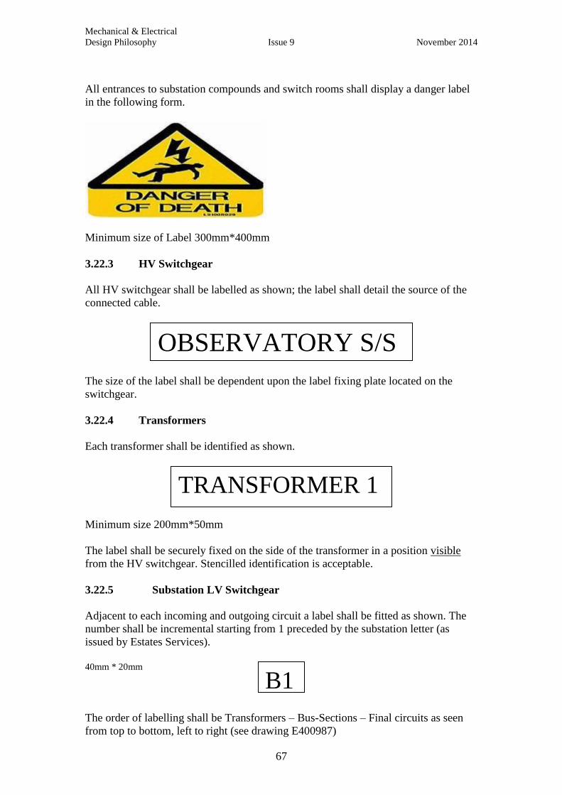
Mechanical & Electrical
Design Philosophy Issue 9 November 2014
67
All entrances to substation compounds and switch rooms shall display a danger label
in the following form.
Minimum size of Label 300mm*400mm
3.22.3 HV Switchgear
All HV switchgear shall be labelled as shown; the label shall detail the source of the
connected cable.
The size of the label shall be dependent upon the label fixing plate located on the
switchgear.
3.22.4 Transformers
Each transformer shall be identified as shown.
Minimum size 200mm*50mm
The label shall be securely fixed on the side of the transformer in a position visible
from the HV switchgear. Stencilled identification is acceptable.
3.22.5 Substation LV Switchgear
Adjacent to each incoming and outgoing circuit a label shall be fitted as shown. The
number shall be incremental starting from 1 preceded by the substation letter (as
issued by Estates Services).
40mm * 20mm
The order of labelling shall be Transformers – Bus-Sections – Final circuits as seen
from top to bottom, left to right (see drawing E400987)
OBSERVATORY S/S
TRANSFORMER 1
B1

Mechanical & Electrical
Design Philosophy Issue 9 November 2014
68
In addition to the label above each outgoing circuit shall also be labelled as follows.
The label shall identify the building supplied, the circuit reference in that building and
the cable size.
100mm * 35mm
3.22.6 Buildings
3.22.7 Building LV Switchboards
All building LV switchboards shall be identified as shown below. The label shall be
fitted in a prominent position at the front.
125mm*30mm
.
The label shall be made up of the following parts:
a) First part (2 digits) Level in the form of 00, 10, 20 and so on.
b) Second part (3 digits) Space number of location /area.
c) Third part (3 digits) Unique number for the switchgear in the form 002, 034, 135
etc. It is expected that the main department/building switchboard number will 001.
The first and second part of the number will be provided by Estates Services space
management team. The third part to be agreed with the University Electrical Engineer
prior to label installation.
A numbered sequential label shall be fitted adjacent to outgoing circuits as shown.
The numbering shall be top to bottom left to right.
45mm*10mm
In addition to the label above a label shall be fitted adjacent to all incoming circuits as
shown; the label shall display the Substation Name, the circuit reference and size and
type of cable.
Circuit 1
New Building
DB10/001/001.1L123N 2*185mm 4c XLPE/SWA/PVC
20/004/00
1

Mechanical & Electrical
Design Philosophy Issue 9 November 2014
69
100mm*40m
In addition to the circuit reference above all outgoing circuit shall be identified as
shown. The distribution board number shall be in the form shown above.
100mm*40mm
3.22.8 Distribution Boards
All switchgear and control panels containing one or more circuit protective devices
shall be treated as distribution boards and shall be identified as shown below. Busbar
systems shall also be treated as a Distribution board and labelled as below.
125mm*30mm
The label shall be fitted in a prominent position on the front panel.
The label shall be made up of the following parts
a) First part (2 digits) Level in the form 00, 10, 20 etc.
b) Second part (3 digits) Space number of area in the form 023, 031 etc.
c) Third part (3 digits) Unique number for the switchgear in the form 002,
034, 135 etc.
The first and second part of the number would normally be provided by Estates
Services space management team. The third part to be agreed with the University
Electrical Engineer prior to label installation.
3.22.9 Final Circuits
All outgoing ways on all distribution boards shall be identified with a sequential tag
number and circuit reference. The tag number shall identify the actual location of the
protective device within the board with each single module being identified. The
circuit reference shall comprise a way number and phase reference L1, L2 or L3.
Where an isolator is fitted within the outgoing part of the board it shall be numbered
within the sequential numbering above. Both the tag number and circuit reference
shall correspond to the Distribution board chart. (See below)
SUBSTATION NAME
Circuit ref
2*185mm 4c XLPE/SWA/PVC
Distribution Board Number
Circuit ref
Cable size and Type
20/004/00
2
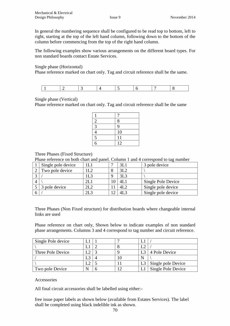
Mechanical & Electrical
Design Philosophy Issue 9 November 2014
70
In general the numbering sequence shall be configured to be read top to bottom, left to
right, starting at the top of the left hand column, following down to the bottom of the
column before commencing from the top of the right hand column.
The following examples show various arrangements on the different board types. For
non standard boards contact Estate Services.
Single phase (Horizontal)
Phase reference marked on chart only. Tag and circuit reference shall be the same.
1 2 3 4 5 6 7 8
Single phase (Vertical)
Phase reference marked on chart only. Tag and circuit reference shall be the same
1 7
2 8
3 9
4 10
5 11
6 12
Three Phases (Fixed Structure)
Phase reference on both chart and panel. Column 1 and 4 correspond to tag number
1 Single pole device 1L1 7 3L1 3 pole device
2 Two pole device 1L2 8 3L2 \
3 / 1L3 9 3L3 \
4 \ 2L1 10 4L1 Single Pole Device
5 3 pole device 2L2 11 4L2 Single pole device
6 / 2L3 12 4L3 Single pole device
Three Phases (Non Fixed structure) for distribution boards where changeable internal
links are used
Phase reference on chart only, Shown below to indicate examples of non standard
phase arrangements. Columns 3 and 4 correspond to tag number and circuit reference.
Single Pole device L1 1 7 L1 /
\ L1 2 8 L2 /
Three Pole Device L2 3 9 L3 4 Pole Device
/ L3 4 10 N \
\ L2 5 11 L3 Single pole Device
Two pole Device N 6 12 L1 Single Pole Device
Accessories
All final circuit accessories shall be labelled using either:-
free issue paper labels as shown below (available from Estates Services). The label
shall be completed using black indelible ink as shown.

Mechanical & Electrical
Design Philosophy Issue 9 November 2014
71
Or following agreement with Estates Services Engineer.
Dymo/Computer label comprising circuit details as shown on top line of label above.
The circuit identifies the distribution board and circuit and shall correspond with the
circuit reference column on the distribution board chart:
For single phase circuits (Single Pole) DB10.5L2
For single phase circuits (2 Pole) DB2.6L1N
For Three phase circuits (3 Pole) DB22.6L123
For Three phase circuits (4 Pole) DB7.10L123N
The space identifies the location of the distribution board i.e.10/20
The room identifies the actual location of the distribution board i.e. Corridor, Room 6
etc.
3.22.10 Cable Core Marking
All cable cores within the distribution board shall be marked as follows.
Each phase conductor including the neutral shall be identified by its associated way
number and circuit reference as shown on the distribution board chart. The label shall
be securely fixed in a manner which will allow easy replacement.
The earth conductors shall be identified with their corresponding number detailed
above.
For single phase boards the numbering shall be as follows:-
Example Single Phase Distribution Board (New colours)
Position
of Device
(Way on
Chart)
Circuit Device Phase
Reference
on chart
Core
Colour
Phase
Conductor
Reference
Neutral
conductor and
Earth
conductor
Reference
1 SPARE 1L1
2 2p Vigi Unit 2L1 Brown 2L1
3 / 3L1 Blue 2L1
4 Spare 4L1
5 Spare 5L1
6 1 Pole Device 6L1 Brown 6L1 6L1
7 Spare 7L1
8 1 Pole Device 8L1 Brown 8L1 8L1
9 Single Pole
Device
9L1 Brown 9L1 9L1
CIRCUIT……DB32.1L123
LOCATION DIST.BOARD:-
SPACE……00/32……………
ROOM……LIBRARY……….
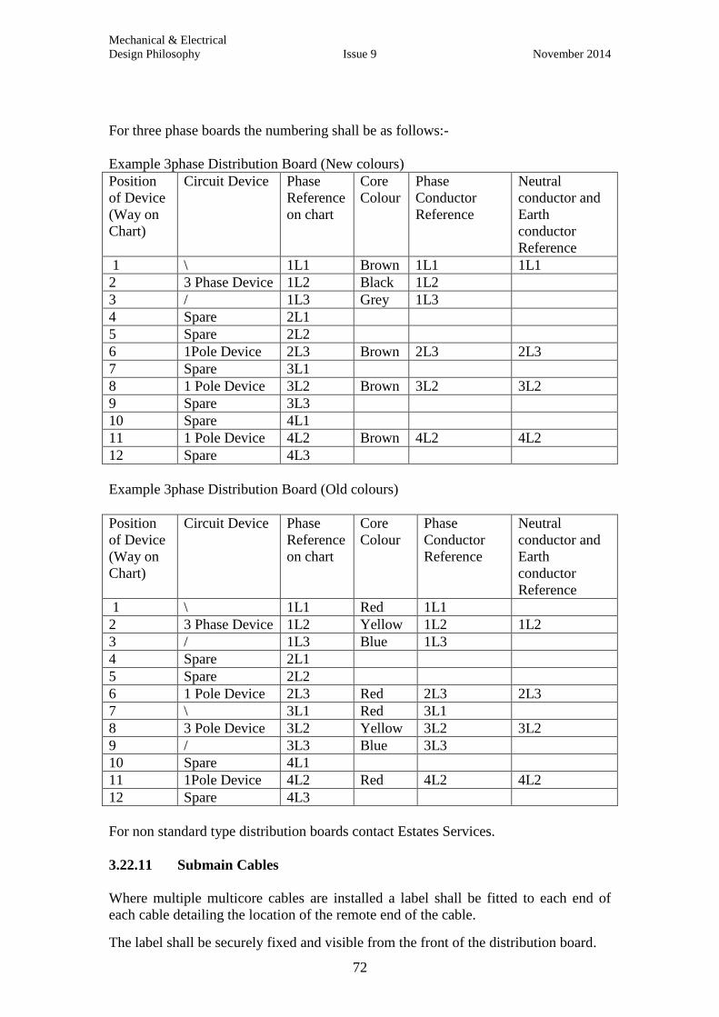
Mechanical & Electrical
Design Philosophy Issue 9 November 2014
72
For three phase boards the numbering shall be as follows:-
Example 3phase Distribution Board (New colours)
Position
of Device
(Way on
Chart)
Circuit Device Phase
Reference
on chart
Core
Colour
Phase
Conductor
Reference
Neutral
conductor and
Earth
conductor
Reference
1 \ 1L1 Brown 1L1 1L1
2 3 Phase Device 1L2 Black 1L2
3 / 1L3 Grey 1L3
4 Spare 2L1
5 Spare 2L2
6 1Pole Device 2L3 Brown 2L3 2L3
7 Spare 3L1
8 1 Pole Device 3L2 Brown 3L2 3L2
9 Spare 3L3
10 Spare 4L1
11 1 Pole Device 4L2 Brown 4L2 4L2
12 Spare 4L3
Example 3phase Distribution Board (Old colours)
Position
of Device
(Way on
Chart)
Circuit Device Phase
Reference
on chart
Core
Colour
Phase
Conductor
Reference
Neutral
conductor and
Earth
conductor
Reference
1 \ 1L1 Red 1L1
2 3 Phase Device 1L2 Yellow 1L2 1L2
3 / 1L3 Blue 1L3
4 Spare 2L1
5 Spare 2L2
6 1 Pole Device 2L3 Red 2L3 2L3
7 \ 3L1 Red 3L1
8 3 Pole Device 3L2 Yellow 3L2 3L2
9 / 3L3 Blue 3L3
10 Spare 4L1
11 1Pole Device 4L2 Red 4L2 4L2
12 Spare 4L3
For non standard type distribution boards contact Estates Services.
3.22.11 Submain Cables
Where multiple multicore cables are installed a label shall be fitted to each end of
each cable detailing the location of the remote end of the cable.
The label shall be securely fixed and visible from the front of the distribution board.
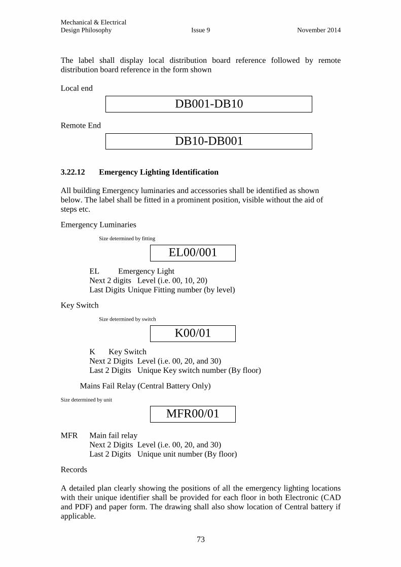
Mechanical & Electrical
Design Philosophy Issue 9 November 2014
73
The label shall display local distribution board reference followed by remote
distribution board reference in the form shown
Local end
Remote End
3.22.12 Emergency Lighting Identification
All building Emergency luminaries and accessories shall be identified as shown
below. The label shall be fitted in a prominent position, visible without the aid of
steps etc.
Emergency Luminaries Size determined by fitting
EL Emergency Light
Next 2 digits Level (i.e. 00, 10, 20)
Last Digits Unique Fitting number (by level)
Key Switch
Size determined by switch
K Key Switch
Next 2 Digits Level (i.e. 00, 20, and 30)
Last 2 Digits Unique Key switch number (By floor)
Mains Fail Relay (Central Battery Only)
Size determined by unit
MFR Main fail relay
Next 2 Digits Level (i.e. 00, 20, and 30)
Last 2 Digits Unique unit number (By floor)
Records
A detailed plan clearly showing the positions of all the emergency lighting locations
with their unique identifier shall be provided for each floor in both Electronic (CAD
and PDF) and paper form. The drawing shall also show location of Central battery if
applicable.
DB10-DB001
DB001-DB10
EL00/001
K00/01
MFR00/01

Mechanical & Electrical
Design Philosophy Issue 9 November 2014
74
A schedule of luminaries shall be provided in electronic form as follows
Bld
Nos
EL
Nos
EL
location
Type of Fitting Lamp Type Key
No
Key Switch
Location
254 00/001 00.46 Main
Intake
5ft Poly Carb
Battery
integral
T5 49W *2 00/01 00.46
254 10/010 10.13 Exit Sign T8 8W * 1 10/01 10.32
3.23 Distribution Board Chart
A protected paper chart shall be fitted adjacent to each distribution board. The chart
shall be visible without the need to open the distribution board door or panel.
The minimum information for each chart is as shown on the standard University Chart
shown below
A brief description of the University chart is as follows
BUILDING NAME
Short description of location of DB
DB Nos
Bld Ref10/13/008 Designation i.e.
Clean, Dirty, Plant
etc
Manufacturer and Type
MERLIN GERIN 6W TPN
Local Isolator
Type and Size of local
Isolator (Or CPD)
Either on the DB or adjacent
Shrouding Details
Submain details
Type and size of
cable between
remote and local
isolator
Remote Isolator/Location
Type and size of remote
isolator/CPD with location
and reference number
Zs and PSC readings at Distribution board
Way
Physical
location of
outgoing
device
Counting top
to bottom left
to right
Size Amps
Protective device
size and Type
Circuit Ref
Reference as
seen on top
line of
Accessory
label
Circuit
Description of
circuit, to
include space
number(if
known) and
local space
identity i.e.
S/O: 10.24
Office 2
(60 Characters
only)
Cable Size
Final circuit
cable type and
size
Contractors shall be aware that the University operates an asset register system which
records details of distribution boards and final circuits. This system will automatically
generate the standard University Chart. See Section 3.

Mechanical & Electrical
Design Philosophy Issue 9 November 2014
75
Submain Details
University Estates Directorate Distribution Board Chart 28-Mar-06
THE MALTHOUSE
00 / 025 / 18Designation Manufacturer/Type
MERLIN GERIN PNTWay12
Local Isolator
125A ISOLATOR3
Remote Isolator/Location
60A TP ISOLATOR
00/025/029
DB Nos
Pole
174
UED/
25.0sqmm PVC SINGLES
MILL WORKSHOP
INTEGRAL
DPB
Way Size
Amps
Circuit Ref Circuit Description Cable size PSC 1.34ZS 0.22 kAohms
Type
C L120 \ 90618 1. mm PVC1 2.5C L220 TP&N ISOLATOR 00.25 WADKIN SAW18 1. mm PVC2 2.5C L320 /18 1. mm PVC3 2.5C L110 \ 90918 2. mm PVC4 4C L210 15A TP&N ISOLATOR SANDER18 2. mm PVC5 4C L310 /18 2. mm PVC6 4C L116 \ 90718 3. mm PVC7 2.5C L216 20A TP&N ISOLATOR 00.25 WADKIN PLANER18 3. mm PVC8 2.5C L316 /18 3. mm PVC9 2.5C L110 \ 92418 4. mm PVC10 2.5C L210 TP&N ISOLATOR 00.25 MOULDING MACHINE18 4. mm PVC11 2.5C L310 /18 4. mm PVC12 2.5C L16 \ 90418 5. mm PVC13 2.5C L26 20A TP&N ISOLATOR 00.25 GRINDER18 5. mm PVC14 2.5C L36 /18 5. mm PVC15 2.5C L132 \ 90518 6. mm PVC16 4C L232 20A TP&N ISOLATOR 00.25 SANDER18 6. mm PVC17 4C L332 /18 6. mm PVC18 4C L110 \ 90818 7. mm PVC19 2.5C L210 20A TP&N ISOLATOR 00.25 BANDSAW18 7. mm PVC20 2.5C L310 /18 7. mm PVC21 2.5C L116 \ 90118 8. mm PVC22 4C L216 16A TP S/O : CROSS CUT SAW 00.2518 8. mm PVC23 4C L316 /18 8. mm PVC24 4C L120 \ 92618 9. mm PVC25 6C L220 32A TP&N SOCKET OUTLET 00.25 DUST EXTRACT18 9. mm PVC26 6C L320 /18 9. mm PVC27 6C L16 \ 90218 10. mm PVC28 2.5C L26 TP&N ISOLATOR 00.25 MORTICE MACHINE18 10. mm PVC29 2.5C L36 /18 10. mm PVC30 2.5C L116 \18 11. mm PVC31 4C L216 16A TP S/O : WOODLATHE 00.2518 11. mm PVC32 4C L316 /18 11. mm PVC33 4C L110 \ 91018 12. mm PVC34 2.5C L210 TP&N ISOLATOR PILLAR DRILL18 12. mm PVC35 2.5C L310 /18 12. mm PVC36 2.5
Departments other then the Estates Directorate must not carry out , or cause to be carried out, any modifications or extensions of
the systems defined as the responsibility of the Director of Estates without the prior knowledge and prior written approval of the
Director . ( University Policy Statement S1/00)
University Estates Directorate - The Malthouse,Tidmarsh Lane, Oxford 0X1 1NQ174
Departments other than the Estates Services must not carry out, or cause to be carried out, any
modifications or extensions of the
systems defined as the responsibility of the Director of Estates without the prior knowledge and prior
written approval of the
Director . ( University Policy Statement S1/00)
174 University Estates Services - The Malthouse,Tidmarsh Lane,
Oxford OX1 1N
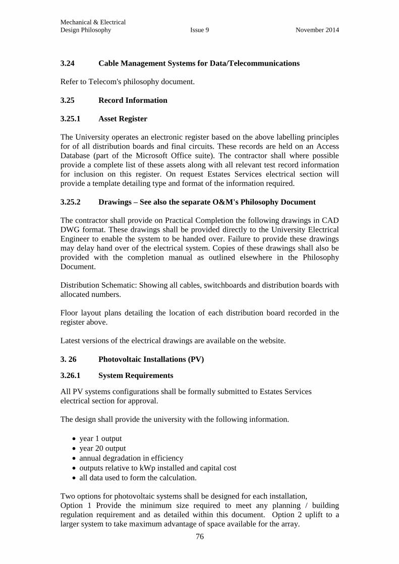
Mechanical & Electrical
Design Philosophy Issue 9 November 2014
76
3.24 Cable Management Systems for Data/Telecommunications
Refer to Telecom's philosophy document.
3.25 Record Information
3.25.1 Asset Register
The University operates an electronic register based on the above labelling principles
for of all distribution boards and final circuits. These records are held on an Access
Database (part of the Microsoft Office suite). The contractor shall where possible
provide a complete list of these assets along with all relevant test record information
for inclusion on this register. On request Estates Services electrical section will
provide a template detailing type and format of the information required.
3.25.2 Drawings – See also the separate O&M's Philosophy Document
The contractor shall provide on Practical Completion the following drawings in CAD
DWG format. These drawings shall be provided directly to the University Electrical
Engineer to enable the system to be handed over. Failure to provide these drawings
may delay hand over of the electrical system. Copies of these drawings shall also be
provided with the completion manual as outlined elsewhere in the Philosophy
Document.
Distribution Schematic: Showing all cables, switchboards and distribution boards with
allocated numbers.
Floor layout plans detailing the location of each distribution board recorded in the
register above.
Latest versions of the electrical drawings are available on the website.
3. 26 Photovoltaic Installations (PV)
3.26.1 System Requirements
All PV systems configurations shall be formally submitted to Estates Services
electrical section for approval.
The design shall provide the university with the following information.
year 1 output
year 20 output
annual degradation in efficiency
outputs relative to kWp installed and capital cost
all data used to form the calculation.
Two options for photovoltaic systems shall be designed for each installation,
Option 1 Provide the minimum size required to meet any planning / building
regulation requirement and as detailed within this document. Option 2 uplift to a
larger system to take maximum advantage of space available for the array.
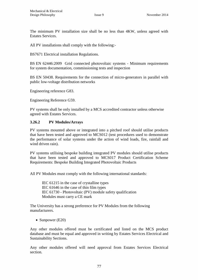
Mechanical & Electrical
Design Philosophy Issue 9 November 2014
77
The minimum PV installation size shall be no less than 4KW, unless agreed with
Estates Services.
All PV installations shall comply with the following:-
BS7671 Electrical installation Regulations.
BS EN 62446:2009 Grid connected photovoltaic systems - Minimum requirements
for system documentation, commissioning tests and inspection
BS EN 50438. Requirements for the connection of micro-generators in parallel with
public low-voltage distribution networks
Engineering reference G83.
Engineering Reference G59.
PV systems shall be only installed by a MCS accredited contractor unless otherwise
agreed with Estates Services.
3.26.2 PV Modules/Arrays
PV systems mounted above or integrated into a pitched roof should utilise products
that have been tested and approved to MCS012 (test procedures used to demonstrate
the performance of solar systems under the action of wind loads, fire, rainfall and
wind driven rain).
PV systems utilising bespoke building integrated PV modules should utilise products
that have been tested and approved to MCS017 Product Certification Scheme
Requirements: Bespoke Building Integrated Photovoltaic Products
All PV Modules must comply with the following international standards:
IEC 61215 in the case of crystalline types
IEC 61646 in the case of thin film types
IEC 61730 - Photovoltaic (PV) module safety qualification
Modules must carry a CE mark
The University has a strong preference for PV Modules from the following
manufacturers.
Sunpower (E20)
Any other modules offered must be certificated and listed on the MCS product
database and must be equal and approved in writing by Estates Services Electrical and
Sustainability Sections.
Any other modules offered will need approval from Estates Services Electrical
section.
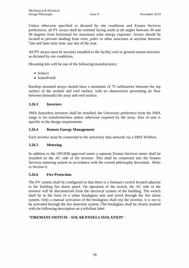
Mechanical & Electrical
Design Philosophy Issue 9 November 2014
78
Unless otherwise specified or dictated by site conditions and Estates Services
preferences, all PV arrays shall be oriented facing south at tilt angles between 30 and
40 degrees from horizontal for maximum solar energy exposure. Arrays should be
located to prevent shading from trees, poles or other structures at anytime between
7am and 5pm solar time, any day of the year.
All PV arrays must be securely installed to the facility roof or ground-mount structure
as dictated by site conditions.
Mounting kits will be one of the following manufacturers:
Schuco
SolarWorld
Rooftop mounted arrays should have a minimum of 75 millimetres between the top
surface of the module and roof surface, with no obstructions preventing air flow
between (beneath) the array and roof surface.
3.26.3 Inverters
SMA Sunnyboy invertors shall be installed; the University preference from the SMA
range is for transformerless unless otherwise required by the array. Size of unit is
specific to the design requirements.
3.26.4 Remote Energy Management
Each invertor must be connected to the university data network via a SMA Webbox.
3.26.5 Metering
In addition to the OFGEM approved meter a separate Estates Services meter shall be
installed on the AC side of the invertor. This shall be connected into the Estates
Services metering system in accordance with the current philosophy document. Refer
to Section 6.
3.26.6 Fire Protection
The PV system shall be configured so that there is a fireman's switch located adjacent
to the building fire alarm panel. On operation of the switch, the AC side of the
invertor will be disconnected from the electrical system of the building. The switch
shall be in the form of a white breakglass unit and wired through the fire alarm
system. Only a manual activation of the breakglass shall trip the invertor, it is not to
be activated through the fire detection system. The breakglass shall be clearly marked
with the following description on a trifoliate label
"FIREMANS SWITCH – SOLAR PANELS ISOLATION"

Mechanical & Electrical
Design Philosophy Issue 9 November 2014
79
SECTION 4 - BUILDING MANAGEMENT SYSTEMS AND AUTOMATIC
CONTROL SYSTEMS
4.0 General
Control systems are fundamental to the operation of plant by Estates Services.
The Project Manager must consult with Estates Services Building Management
System section at an early stage and throughout the project development.
Standardisation of hardware software and installation is critical.
Control systems must be as manufactured and supplied by Trend Controls Limited.
The control system shall be designed to suit the particular building services
requirements and shall always incorporate sufficient features to operate the plant
safely with the minimum of energy use. All parts of the control system, hardware and
space, must allow for a minimum of 25% spare capacity.
Note: Digital input multiplexers must not be used.
Packaged plant controls shall utilise Trend controllers for their final control. Where
Trend controllers cannot be fitted as standard, a full read/write interface shall be
provided. The BMS should be used for sequence control of major plant.
Fire alarm interface should not drop out the plant during routine testing.
4.1 Control Panels
All controlled plant shall have a panel fascia mounted Hand/Off/Auto switch for
maintenance / testing purposes. The position of each switch shall be monitored and a
common VFC input shall connect to the Trend controller to alarm when any switch is
put in the hand position.
Software override knobs shall be configured to allow maintenance personnel to test
analogue controlled equipment, i.e. valve actuators, inverter drives etc. The override
knobs should reset themselves back to auto after 30 minutes. (This is to prevent them
inadvertently being left in manual override.)
Control panels shall generally be Form 2 with separate control and power sections
where switching off the electrical supply to the panel does not unduly disrupt the
building user. Form 4 type 6 should be used where it is necessary to maintain
continuous operation of plant serving animal accommodation, computer suites, etc.
All live conductive parts within the panel shall be shrouded. It should not be
necessary for plant attendants to have to go into any control panels in order to make
minor adjustments to time/s or set points.
All control wiring shall be adequately identified and protected where necessary.
Wiring should be installed to BS7671.
Control panel wiring must be configured so that all types of plant failure are indicated
by appropriate warning lamps on the panel fascia. In addition a fascia common BMS
Fault Indicator Lamp will be provided. It will be connect to a controller output and
will alarm when a software alarm is current. A fascia mounted fault reset button will
connected to a digital input on the controller so that the software alarms can be reset.

Mechanical & Electrical
Design Philosophy Issue 9 November 2014
80
Control panels must be fitted with LED lamps.
Control panels shall be complete with fascia mounted display panels, to enable local
monitoring and operation of the plant. These should be installed at eye level and have
the appropriate passwords and pin numbers active as per discussions with Estates
Services.
4.2 Safety Interlocks
All safety interlocks shall be hard and soft wired. In the case of an AHU freeze
protection circuit a BMS pulse output relay will required to allow the alarm to be reset
remotely.
4.3 Connectivity
Where IP addressable outstations are used an Ethernet switch should be provided
within the control panel. This switch should have a spare port for use by the BMS
Service Engineer. A patch cable will need to be installed from this switch to connect
to an external data point socket. If more than one network cable is wired to the
control panel then a separate network enclosure should be provided which will be
separately powered. Display panels are to be connected to the outstation RS232 port.
All remote connectivity should be via the dedicated BMS building network which
connects back to the Building FRODO.
Where additions are made to the BMS the Estates BMS Engineer will advise the exact
method and point of network connection.
4.4 Head End Supervisory PC
Head end site supervisory PC systems are to be installed on the larger sites only.
Where these are installed a 3 user wet server version should be provided. Elsewhere
building users should be provided with connectivity to web client into the 963
installed in the Malthouse. Temporary facilities for witnessing the operation of the
BMS within the building may be required prior to handover.
The controls package shall include adding the graphics and user pages associated with
the new control system on to Estates Services central Trend 963 supervisor. The
format of the graphics and user pages added must be the same as those already on the
system. The appointed BMS contractor must visit the Malthouse to establish for
himself the exact format of the graphics required by Estates Services. A relevant
extract from the description of operation shall be included on each graphic page
within an info box and a jump button engineered for it.
Passwords and PIN numbers for any new addition to the Trend BMS network must be
discussed and agreed with Estates Services.
Mechanical & Electrical
Design Philosophy Issue 9 November 2014
81
4.5 Metering
Gas, water and heat metering shall be connected to the ION system NOT the BMS.
Where metered information is required for control or monitoring then a duplicate
connection must be made the BMS.
Electricity meters must not be monitored by the Trend BMS and they shall be
monitored as per the requirements of the Metering section of this document. Refer to
Section 6.
4.6 BMS Engineering
When engineering the system consideration should be given to keep communications
traffic to a minimum. In general all common items of plant shall be controlled from a
single outstation and not from two smaller ones.
Should a control sensor be in a remote location it should be hard wired back to the
outstation which has the controlled device connected to it. In this instance it is not
acceptable to use IC Comms.
To allow user operation data plots shall be engineered for the following points.
All real inputs (Analogue and Digital)
All real outputs (Analogue and Digital)
IC Comms. (Data points entering the controller)
IC Comms. (Data points leaving the controller)
Calculated setpoints
Demand bits
Hours Run Sensors
Alarms are to be configured/enabled but with the alarm transmission disabled. A list
of the alarms will be issued to the Estates Services who will decide on the alarm
classification.
Internal software alarms should be programmed for duplex plant to advise when both
items of plant have failed.
Alarm Groups will be set up for Critical and Non Critical Alarms. Alarms that are not
to be sent will be assigned to alarm Group 0.
Alarm routes and destinations will be configured with each route having a software
switch to disable alarm transmission. Once the project is fully complete the controls
installer will verify that alarms are being received OK at the remote 963 supervisor.
All control software shall be fully tested and documented off site using set and
simulation mode. Estates Services must be given the opportunity to witness this
testing.
Retransmission of alarms via SMS is to be considered during the design phase.
Mechanical & Electrical
Design Philosophy Issue 9 November 2014
82
4.7 Documentation
The control system including hardware, software and panels must be fully
documented. At handover of the system the documentation must include but not be
limited to:
1. LAN map,
2. Network schematic line diagrams
3. Panel wiring diagrams
4. SET files hard copy
5. SET file electronic copy
6. Component manuals
Mechanical & Electrical
Design Philosophy Issue 9 November 2014
83
SECTION 5 – BUILDING INFORMATION AND OPERATING AND
MAINTENANCE MANUALS
This is now a separate section in the suite of Philosophy documents.

Mechanical & Electrical
Design Philosophy Issue 9 November 2014
84
SECTION 6 - METERING STRATEGY
6.0 Strategy Overview
The University has a large energy distribution system encompassing electricity (both
HV&LV), natural gas, gasoil, water and heat energy. The management of these
energy flows relies on high quality data supplied from numerous sources. This
strategy is proposed to ensure that, as the University expands a minimum standard of
energy metering is adopted. This standard is based on existing installed equipment
and known future legislative requirements. If at any stage a designer/installer believes
that they may not achieve that standard then they shall contact the head of Mechanical
& Electrical Maintenance at Estates Services for further guidance.
In all cases any new meters or changes to existing metering shall be notified to the
Environmental Sustainability Team at:
Environmental Sustainability Team
Telephone: 01865 (2) 78780
Fax: 01865 (2) 88578
Email: [email protected]
All meters need to be readable from the floor without the use of mirrors or access
equipment. Where this is not possible, a permanent access platform shall be installed.
6.1 Electricity Meters and Instrumentation Systems
6.1.1 General
The University is supplied with electricity from the Scottish and Southern Electricity
(SSE) local grid distribution system. This feeds directly in to Oxford University
buildings or supplies the Oxford University's own High voltage (HV) and Low
voltage (LV) distribution system.
All buildings that are fed from the SSE local grid or the Oxford University HV
network are metered at point of supply. In addition there is a comprehensive sub
metering network on many buildings. This sub metering network (ION) supplies and
processes half hourly data on electrical consumption to Oxford University's Energy
management system (TEAM). Revenue half hourly (HH) supply meters that are not
on Oxford University's HV and LV distribution network also produce half hourly data
for billing purposes. This data is supplied by SSE and is transferred to the TEAM
system.
University sub-metering is also in place on LV distribution boards across the estate,
the half hourly data from these is also available to the ION system and then to the
TEAM system. In addition to normal electricity supplies the University also has a
small quantity of standby generators and Combined Heat and Power (CHP) plants that
have the ability to both synchronise and feed the LV grid system. These systems have
special metering requirements that are explained in Section 6.4.
Mechanical & Electrical
Design Philosophy Issue 9 November 2014
85
The following sections outline the requirements for Energy Metering and Monitoring
of the Electrical systems with the University. They detail the metering/instrument
requirements from the substation through to the final Sub distribution within a
University building. The general principles as shown in the Standard University
Metering and Instrumentation diagram E400978 Sheet 1. Refer to the Estates section
of the website to obtain the latest revision of the drawings.
Metering requirements shall be read in conjunction with CIBSE Guide TM39
Building Energy Metering as required by Part L2 of the Building Regulations.
6.1.2 Current Transformer General Arrangements
Instrument Transformers (C/Ts) shall be to BS EN 61869-2:2012.
C/Ts shall be installed on outgoing circuits such that they can be replaced without
disrupting other circuits.
All C/Ts shall be Class 1 with a minimum capacity of 2.5VA.
C/T Ratio shall be dependent on site. CT secondary shall be 5A.
C/Ts shall be fitted on all phases including the neutral.
All C/T secondary wiring shall be wired to separate terminal blocks (Klippon or
equivalent) with shorting links such that connections and alterations can be carried out
whilst switchboard is in use. See E400978 Sheet 2.
A label detailing the C/T type, size and ratio shall be fitted adjacent to this terminal
block and fully accessible without the need to isolate the switchboard.
C/T configuration for metering shall take place from terminal block.
6.1.3 Voltmeter Monitoring General Arrangements
A fuse protected three phase and neutral reference voltage shall be provided for each
section of the switchboard.
Fuses required for instrumentation and metering shall be not less than 10A rated and
shall be sited such that they can be removed safely without the need to isolate any part
of the switchboard. All fuses shall be labelled with size and circuit details.
All Voltage potential cables shall be 6mm LSF double insulated.
The voltage measuring arrangement along with instrument or meter requirements
shall be as outlined elsewhere in this guide.
6.1.4 Meter and Sub Meter Types
It should be noted that the University currently operates an existing remote
monitoring system using Schneider PowerLogic ION devices via the ION Enterprise
power monitoring system and that all electronic meters and instruments shall be
compatible with this system.
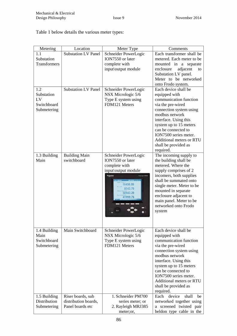
Mechanical & Electrical
Design Philosophy Issue 9 November 2014
86
Table 1 below details the various meter types:
Metering Location Meter Type Comments
1.1
Substation
Transformers
Substation LV Panel Schneider PowerLogic
ION7550 or later
complete with
input\output module
Each transformer shall be
metered. Each meter to be
mounted in a separate
enclosure adjacent to
Substation LV panel.
Meter to be networked
onto Frodo system.
1.2
Substation
LV
Switchboard
Submetering
Substation LV Panel Schneider PowerLogic
NSX Micrologic 5/6
Type E system using
FDM121 Meters
Each device shall be
equipped with
communication function
via the pre-wired
connection system using
modbus network
interface. Using this
system up to 15 meters
can be connected to
ION7500 series meter.
Additional meters or RTU
shall be provided as
required.
1.3 Building
Main
Building Main
switchboard
Schneider PowerLogic
ION7550 or later
complete with
input\output module
The incoming supply to
the building shall be
metered. Where the
supply comprises of 2
incomers, both supplies
shall be summated onto
single meter. Meter to be
mounted in separate
enclosure adjacent to
main panel. Meter to be
networked onto Frodo
system
1.4 Building
Main
Switchboard
Submetering
Main Switchboard Schneider PowerLogic
NSX Micrologic 5/6
Type E system using
FDM121 Meters
Each device shall be
equipped with
communication function
via the pre-wired
connection system using
modbus network
interface. Using this
system up to 15 meters
can be connected to
ION7500 series meter.
Additional meters or RTU
shall be provided as
required.
1.5 Building
Distribution
Submetering
Riser boards, sub
distribution boards,
Panel boards etc
1. Schneider PM700
series meter; or
2. Rayleigh MRJ385
meter;or,
Each device shall be
networked together using
a screened twisted pair
beldon type cable in the
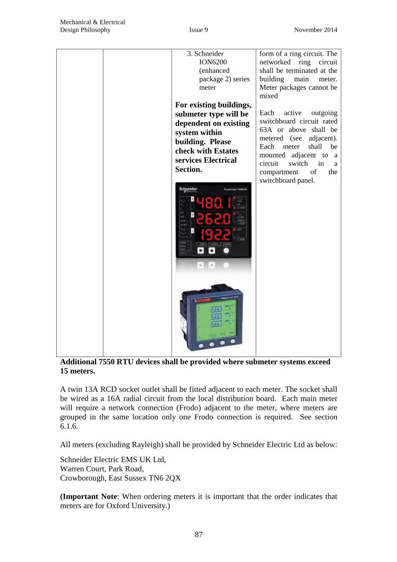
Mechanical & Electrical
Design Philosophy Issue 9 November 2014
87
3. Schneider
ION6200
(enhanced
package 2) series
meter
For existing buildings,
submeter type will be
dependent on existing
system within
building. Please
check with Estates
services Electrical
Section.
form of a ring circuit. The
networked ring circuit
shall be terminated at the
building main meter.
Meter packages cannot be
mixed
Each active outgoing
switchboard circuit rated
63A or above shall be
metered (see adjacent).
Each meter shall be
mounted adjacent to a
circuit switch in a
compartment of the
switchboard panel.
Additional 7550 RTU devices shall be provided where submeter systems exceed
15 meters.
A twin 13A RCD socket outlet shall be fitted adjacent to each meter. The socket shall
be wired as a 16A radial circuit from the local distribution board. Each main meter
will require a network connection (Frodo) adjacent to the meter, where meters are
grouped in the same location only one Frodo connection is required. See section
6.1.6.
All meters (excluding Rayleigh) shall be provided by Schneider Electric Ltd as below:
Schneider Electric EMS UK Ltd,
Warren Court, Park Road,
Crowborough, East Sussex TN6 2QX
(Important Note: When ordering meters it is important that the order indicates that
meters are for Oxford University.)
Mechanical & Electrical
Design Philosophy Issue 9 November 2014
88
6.1.5 Earth Leakage Instrumentation
An earth leakage ammeter shall be fitted on all building switchboard outgoing circuits
and sub-distribution panels. Instrument type shall be agreed with Estates Services.
6.1.6 Meter Networks
All main Meters shall be connected to the local LAN (Frodo) using a CAT 5e type
cable as shown on attached drawing.
Where submetering is to be installed, up to 15 submeters can be connected to the main
meter using the Modbus protocol with Beldon 9841 type cable (RS485 connector)
type cable as shown refer to drawings. Where more than 15 submeters are to be
installed additional ION7550 RTU devices shall be provided.
6.1.7 Metering - Substations
6.1.7.1 HV Metering
No metering/Instrumentation required.
6.1.7.2 LV Metering
For the purposes of this guide the substation LV switchboard is defined as being a
switchboard which is supplied directly by one or more HV transformers, and feeds
one or more University buildings.
An analogue voltmeter and selector switch, mounted adjacent to all the incoming LV
isolating devices shall be fitted, reading ph-ph and ph-n volts. A separate switch will
select incoming volts or busbar volts. Potential fuses shall be placed such that
connections can be made without the need to isolate any part of the switchboard.
A C/T shall be fitted on each incoming phase and neutral connection and wired to a
terminal block as shown on drawing E400978 sheet 2. The location of the terminal
block shall be such that access can be obtained without the need to isolate any part of
the switchboard.
A main meter shall be installed on each transformer circuit.
The meters shall be configured to read all phases and neutral current.
The meters shall be correctly calibrated with all previous energy readings and
maximum demand readings reset to zero. Thermal demand shall be set at 30 minutes.
6.1.7.3 Substation LV Switchboard Outgoing Circuits
For all outgoing circuits that are to supply variable loads greater than 63A(50kW), a
Schneider FDM121 meter with associated NSX Micrologic 5/6 A or E trip units shall
be used.
All meters shall be networked together and connected using the Schneider Modbus
protocol to one or both the Transformer meters above.
Mechanical & Electrical
Design Philosophy Issue 9 November 2014
89
The network cable shall be terminated at:
a) Location which is accessible without the need to switch of power
b) Location that will allow an external cable connection
6.1.8 Department/Building Metering
6.1.8.1 Incoming Circuits
For the purposes of this guide the LV building switchboard is defined as being a
switchboard which is supplied from either the local DNO or a University substation
LV switchboard.
An analogue voltmeter and selector switch, mounted adjacent to each of the incoming
LV isolating devices, reading ph-ph and ph-n volts shall be installed. A separate
switch will select incoming volts or busbar volts. Potential fuses shall be placed such
that connections can be made without the need to isolate any part of the switchboard.
The C/T's shall be wired as shown on drawing E400978 sheet 2. The location of the
terminal block shall be such that access can be obtained without disruption to normal
switchboard operation.
6.1.8.2 Outgoing Circuits
For all outgoing circuits that are to supply variable loads greater then 63A (50kW), a
meter as outlined in table 1 section 1.5 shall be installed.
All meters shall be networked together and connected to the main meter using the
Schneider Modbus protocol.
6.1.9 Riser/Tap Offs
The riser is defined as being the vertical/horizontal distribution system, cable or
busbar, supplied from the building LV switchboard and/or other riser.
For all tap off circuits that are expected to supply variable loads greater than 63A
(50KW) the meter detailed in Table 1 above shall be used.
The C/T's shall be wired as shown on drawing E400978 sheet 3 including earth
leakage. The location of the terminal block shall be such that access can be obtained
without disruption to supplies.
6.1.10 Sub Distribution Boards
For the purpose of this guide the Departmental sub-distribution board is a distribution
board which supplies one or more distribution boards with a combined variable load
in excess of 63A. It may be supplied from either the building LV switchboard or
riser.
For all sub-distribution board circuits that are expected to supply a variable load
greater then 63A (50KW) the meter detailed in Table 1 above shall be used.
Mechanical & Electrical
Design Philosophy Issue 9 November 2014
90
A C/T shall be wired on each phase and neutral as shown on drawing E400978 sheet
3. The location of the terminal block shall be such that access can be obtained without
disruption to normal switchboard operation.
All submeters are to be wired together using a Beldon RS485 type cable in the form
of a ring back to main meter position located adjacent to the main switchboard.
6.1.11 kWh Metering
Each building/department switchboard shall have a single main meter (see Table 1 in
this document) fitted in a separate enclosure adjacent to the switchboard.
Where switchboards comprise of two incoming circuits, C/Ts shall be summated onto
single meter.
The C/T wiring shall be configured to read all phases, neutral and earth leakage
current.
The meter shall be calibrated with all previous energy readings and maximum
demands reset. Thermal demand shall be set at 30 minutes.
6.2 Standby Generators
The University has numerous standby generators installed at key locations to ensure a
reliable electricity supply in the case of the HV distribution system failing. All
standby generator installations shall have the following metering installed:
1. A suitable electrical meter (type to be confirmed by Estates Services electrical
team) to dynamically measure and record the energy KWh output from the unit.
This meter shall be connected to the Frodo system and linked to the ION
automated metering system.
2. A flow-metering device that complies with BS 2869:2010 shall be fitted to the
gasoil supply to record the gasoil usage of the unit. This device shall record
dynamic flow and total consumption in litres and report via the Frodo network
to the ION automated metering system.
6.3 Photovoltaic Panel Systems
The Feed-in-Tariff requires an OFGEM approved generation meter. In addition to
this meter, a separate Estates Services meter shall be installed on the AC side of the
invertor and connected back to Estates Services as described in section 6.1.
6.4 Combined Heat & Power (CHP) Plants
The university has numerous CHP plants installed across the estate to enhance the
energy efficiency of individual buildings. All CHP installations shall have the
following metering installed:
1. A suitable meter from table 1 shall be used to dynamically measure and record
the energy KWh output from the unit. This meter shall be connected to the

Mechanical & Electrical
Design Philosophy Issue 9 November 2014
91
Frodo system and linked to the ION automated metering system. Refer to
Electrical section for advice on selection.
2. A suitable revenue standard gas meter (see section ref natural gas meters) shall
be installed on the gas supply to the unit, this shall be in addition to any existing
gas meter for the building or other installed plant. This meter shall be connected
to the Frodo system and linked to the ION automated metering system.
3. A heat energy flow-meter (see section ref heat energy meters) shall be fitted to
the flow and return pipe-work from the CHP to the final heat load. If the CHP is
fitted with a separate heat energy 'dump' device, this shall be separately metered
both on the flow and return. All heat energy meters shall comply with the
following:
The Renewable Heat Incentive Guidance, Volume 1, Chapter 7
http://www.icax.co.uk/pdf/RHI_GuidanceConsultationV1.pdf
6.5 Natural Gas Service
The University has numerous gas meters, both revenue and sub-metering installed.
Some of these meters are connected to individual building management systems. This
arrangement is not consistent with a total energy metering strategy and gives limited
scope for effective data management. To standardise the methodology of gas meter
data collection the following standards are to be followed:
1. All gas meters installed on the University estate shall comply with the Gas
(Meters) Regulations 1983, SI 684 and the Measuring Instruments (Gas
Meters) Regulations (SI 2006/2647)
2. All gas meters installed shall be stamped in accordance with the gas Act
1986.
3. If the meter in question is a revenue meter owned by meter asset manager
(MAM) or others, then an automated method shall be installed to ensure
that half hour data is supplied to the Universities Sustainability Team
(preferably via the ION system). All gas sub-meters shall be connected to
the Universities automated metering system (ION) utilising the FRODO
network.
4. The gas supply to areas such as kitchens and laboratories shall be
separately metered from the heating boilers and hot water heaters.
6.6 Water
6.6.0 General
The buildings on the University functional estate and colleges are supplied either
directly from a Thames water pipe fee or from a University water network that has
been fed from a Thames Water pipe feed. Some buildings have data collection
systems linked to the Building Management Systems (BMS). All water meter
installations shall comply with the Water Supply (Water Quality) Regulations 2000,
Mechanical & Electrical
Design Philosophy Issue 9 November 2014
92
The Measuring Instruments (Cold Water Meters) Regulations 2006 (S.I 2006
No.1268)
6.6.1 Controls and Metering
Controls shall be designed to minimise energy consumption and operational wear, to
activate the back-up water supply automatically and with suitable connections to
allow the system to be connected to the BMS. Consideration should be given to
incorporating status monitoring which provides additional information such as; how
full the tank is, any malfunctions, which supply is being used and so on.
Flow meters shall be provided to the back-up water supply and the pumped outlet
from the storage tank to enable the performance of the system to be monitored.
The meters shall be capable of being monitored remotely through connection to the
ION system enabling the collection of consumption data dynamically. All water
meters installed shall comply with BS EN 14154-3:2005+A2:2011 and OIML R49.
6.7 Heat Energy Metering
All heat meters shall have the following characteristics and be capable of meeting the
following performance standards.
Heat meters shall meet the Class 2 requirements in Annex MI-004 of the EU
Measuring Instruments Directive (MID) 2004 and comply with The Renewable Heat
Incentive Guidance, Volume 1, Chapter 7
http://www.icax.co.uk/pdf/RHI_GuidanceConsultationV1.pdf
The following is an extract from the guidance note:
1. Shall consist of:
a flow sensor (or meter)
a matched pair of temperature sensors (such as two thermocouples) –
the two temperature sensors shall have been calibrated together as a
pair to make sure the temperature difference between the input and
output of the system is measured to the stated accuracy level, and
a calculator/digital integrator – the integrator shall be provided with
both Modbus and pulse output.
2. All heat meter installations must conform to EU MID Class 2 standard.
3. Digital integrators shall have an integral display which allows recorded parameters
to be viewed locally.
Digital integrators shall also be provided with Modbus output for connection to the
ION system.
Heat meters shall be capable of recording and transmitting the following data at a
minimum regularity of every 30 minutes:
Heat (energy) consumed (kWh)
Mechanical & Electrical
Design Philosophy Issue 9 November 2014
93
Flow temperature
Return temperature
Flow rate (m3/hr)
Extreme care must be taken when installing and commission heat meters. Heat
meters must be calibrated in situ post installation. They must be checked prior to
Practical completion and within a month after PC to ensure they are providing
accurate data. Schematics showing how the meters inter-ralate must be provided.
Good quality Heat meter data must be in place before seasonal commissioning can
take place.
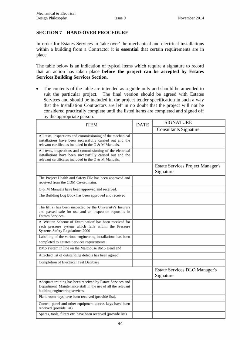
Mechanical & Electrical
Design Philosophy Issue 9 November 2014
94
SECTION 7 – HAND-OVER PROCEDURE
In order for Estates Services to 'take over' the mechanical and electrical installations
within a building from a Contractor it is essential that certain requirements are in
place.
The table below is an indication of typical items which require a signature to record
that an action has taken place before the project can be accepted by Estates
Services Building Services Section.
The contents of the table are intended as a guide only and should be amended to
suit the particular project. The final version should be agreed with Estates
Services and should be included in the project tender specification in such a way
that the Installation Contractors are left in no doubt that the project will not be
considered practically complete until the listed items are completed and signed off
by the appropriate person. ITEM
DATE
SIGNATURE
Consultants Signature
All tests, inspections and commissioning of the mechanical
installations have been successfully carried out and the
relevant certificates included in the O & M Manuals.
All tests, inspections and commissioning of the electrical
installations have been successfully carried out and the
relevant certificates included in the O & M Manuals.
Estate Services Project Manager's
Signature
The Project Health and Safety File has been approved and
received from the CDM Co-ordinator.
O & M Manuals have been approved and received.
The Building Log Book has been approved and received
The lift(s) has been inspected by the University's Insurers
and passed safe for use and an inspection report is in
Estates Services.
A 'Written Scheme of Examination' has been received for
each pressure system which falls within the Pressure
Systems Safety Regulations 2000
Labelling of the various engineering installations has been
completed to Estates Services requirements.
BMS system in line on the Malthouse BMS Head end
Attached list of outstanding defects has been agreed.
Completion of Electrical Test Database
Estate Services DLO Manager's
Signature
Adequate training has been received by Estate Services and
Department Maintenance staff in the use of all the relevant
building engineering services
Plant room keys have been received (provide list).
Control panel and other equipment access keys have been
received (provide list).
Spares, tools, filters etc. have been received (provide list).
Mechanical & Electrical
Design Philosophy Issue 9 November 2014
95
SECTION 8 – CAD LAYER DETAILS, SPACE MANAGEMENT TEAM,
DRAWING LAYERING CONVENTIONS
Estates Services has specific requirements about how drawings are set out and the
layering conventions used. This applies to consultants and contractors. A detailed
'Information Requirement' policy document is currently being prepared. Until this
document is published queries on the University's requirements on drawings should
be discussed with the Information Manager on 278750.
Related Documents