EST3 System Operation Manual P/N 270382 • Rev 4.0 • 30AUG01

Welcome message from author
This document is posted to help you gain knowledge. Please leave a comment to let me know what you think about it! Share it to your friends and learn new things together.
Transcript

EST3System Operation
Manual
P/N 270382 • Rev 4.0 • 30AUG01

DEVELOPED BY Edwards Systems Technology6411 Parkland DriveSarasota, FL 34243(941) 739–4300
COPYRIGHT NOTICE Copyright © 1996–2001. All rights reserved.
This manual and the products it describes are copyrighted byEdwards Systems Technology, Inc. (EST). You may notreproduce, translate, transcribe, or transmit any part of thismanual without express, written permission from EST.
This manual contains proprietary information intended fordistribution to authorized persons or companies for the solepurpose of conducting business with EST. If you distribute anyinformation contained in this manual to unauthorized persons,you have violated all distributor agreements and we may takelegal action.
TRADEMARKS Microsoft, Microsoft Mouse, and Windows are all trademarksof Microsoft Corporation.
CREDITS This manual was designed and written by the EST TechnicalServices - Documentation Department, Sarasota.
DOCUMENT HISTORY
Revision Date Reason for Change
1.0 17JULY96 Initial Release
1.5 02APR97 Revised: System Addressing; Command MenuAdded: Operations Placard
2.0 14DEC98 Revised: Display examples. Corrected minor typographical errorsthroughout.
3.0 21OCT99 Restructured and revised concurrent with 1.5 release.
4.0 31AUG01 Revised to incorporate security and access control integration.
EST3 System Operation Manual i
Content
About this manual • iiiThe EST3 library • ivImportant information • vi
Chapter 1 Introduction • 1.1Introduction • 1.2Display operation • 1.5Message processing • 1.10Optional features • 1.12Entering logical addresses • 1.17
Chapter 2 3-LCD operating instructions • 2.1Controls and indicators • 2.2Creating a status report • 2.8Disabling groups • 2.9Enabling groups • 2.10Disabling hardware components • 2.11Enabling hardware components • 2.12Arming security partitions • 2.13Disarming security partitions • 2.14Resetting security partitions • 2.15Bypassing security devices • 2.16Removing bypasses from security devices • 2.17Guard patrol groups • 2.18Check-in groups • 2.19Changing the smoke detector sensitivity level • 2.21Changing event message routing • 2.22Changing the output state of a relay or LED • 2.23Creating reports • 2.24Setting the system time and date • 2.26Changing user access level passwords • 2.27Restarting a panel • 2.28Scheduling holidays • 2.29Clearing the panel history file • 2.30Testing alarm input devices • 2.31
Chapter 3 3-ASU operating instructions • 3.1Controls and indicators • 3.2Operation the Audio Source Unit • 3.4Optional audio zone controls • 3.7
Chapter 4 3-FTCU operating instructions • 4.1Controls and indicators • 4.2Operation • 4.4
Content
ii EST3 System Operation Manual
Appendix A System addresses • A.1Address format • A.2LRM addresses • A.4Control / display module addresses • A.8Device addresses • A.10
Appendix B Operation sequence charts • B.1
Z Index • Z.1
Content
EST3 System Operation Manual iii
About this manualThis manual provides information on how to operate an EST3integrated system. The information presented here is of a generalnature, since each site and system is unique. The EST3 system atyour site has been designed by professionals to meet the specificrequirements of the fire and security codes in your location.Please refer to the site-specific instructions, provided by yourEST representative, to determine the exact operation of yoursystem.
OrganizationThe manual contains the following chapters:
• Chapter 1: Introduction: gives you a general description ofsystem functions and operations.
• Chapter 2: LCD operating instructions: provides detailedoperating instructions for the primary control module, the3-LCD module.
• Chapter 3: 3-ASU Audio Source Unit operation: providesdetailed operating instructions for the 3-ASU audio sourceunit.
• Chapter 4: 3-FTCU operating instructions: providesdetailed operating instructions for the 3-FTCU firefightertelephone control unit.
• Appendix A: System addresses: contains figures that showyou how to determine various device addresses.
• Appendix B: Operation sequence charts: contains tables orcharts that show the sequence of events, actions, anddisplays for the most common panel operations.
Content
iv EST3 System Operation Manual
The EST3 library
EST3 documentsA library of documents and multi-media presentations supportsthe EST3 life safety system. A brief description of each isprovided below.
EST3 Installation and Service Manual (P/N 270380): Givescomplete information on how to install and service the EST3hardware. The manual also includes installation information onselected Signature Series components.
EST3 Installation Sheets (P/N 3100051): Is a convenientpackage of all EST3 component installation sheets. This manualshows you the jumper settings and terminal connections for eachcomponent.
SDU Online Help (P/N 180653): Provides full online support forconfiguring and programming a system using the EST3 SystemDefinition Utility program.
EST3 System Operation Manual (P/N 270382): Providesdetailed information on how to operate the system and systemcomponents.
EST3 International Installation Supplement Manual (P/N270925): Provides information specific to systems installedoutside the United States and Canada.
EST3 Smoke Management Application Manual (P/N 270913):Provides information for designing, programming, and testing anEST3 smoke control system.
EST3 Users Self-Study Course (P/N 270684): Contains a self-paced manual and accompanying video. The course is designedfor building personal, security guards, firefighters, and otherindividuals that may be required to operate the system.
Other documentsIn addition to documents in the EST3 library, you may find thefollowing documents useful.
Signature Series Intelligent Smoke and Heat DetectorsApplications Bulletin (P/N 270145): Provides additionalapplications information on the Signature series smoke and heatdetector applications.
Signature Series Component Installation Manual (P/N 270497):Contains detailed mounting and wiring information for allSignature series devices.

Content
EST3 System Operation Manual v
Speaker Application Guide (P/N 85000-0033): Providesinformation on the placement and layout of speakers for firealarm signaling and emergency voice communications.
Strobe Applications Guide (P/N 85000-0049): Providesinformation on the placement and layout of strobes for fire alarmsignaling.

Content
vi EST3 System Operation Manual
Important information
Limitation of liabilityThis product has been designed to meet the requirements ofNFPA Standard 72; Underwriters Laboratories, Inc., Standard864; and Underwriters Laboratories of Canada, Inc., StandardULC S527. Installation in accordance with this manual,applicable codes, and the instructions of the Authority HavingJurisdiction is mandatory. EST shall not under anycircumstances be liable for any incidental or consequentialdamages arising from loss of property or other damages or lossesowing to the failure of EST products beyond the cost of repair orreplacement of any defective products. EST reserves the right tomake product improvements and change product specificationsat any time.
While every precaution has been taken during the preparation ofthis manual to ensure the accuracy of its contents, EST assumesno responsibility for errors or omissions.
FCC warningThis equipment can generate and radiate radio frequency energy.If this equipment is not installed in accordance with this manual,it may cause interference to radio communications. Thisequipment has been tested and found to comply within the limitsfor Class A computing devices pursuant to Subpart B of Part 15of the FCC Rules. These rules are designed to providereasonable protection against such interference when thisequipment is operated in a commercial environment. Operationof this equipment is likely to cause interference, in which casethe user at his own expense, will be required to take whatevermeasures may be required to correct the interference.
Industry Canada informationNote: The Industry Canada label identifies certified equipment.This certification means that the equipment meets certaintelecommunications network protective, operational, and safetyrequirements. Industry Canada does not guarantee the equipmentwill operate to the user’s satisfaction.
Before installing this equipment, users should ensure that it ispermissible to be connected to the facilities of the localtelecommunications company. The equipment must also beinstalled using an acceptable method of connection. Thecustomer should be aware that compliance with the aboveconditions may not prevent degradation of service in somesituations.
Content
EST3 System Operation Manual vii
Repairs to certified equipment should be made by an authorizedCanadian maintenance facility designated by the supplier. Anyrepairs or alterations made by the user to this equipment, orequipment malfunctions, may give the telecommunicationscompany cause to request the user disconnect the equipment.
Users should ensure for their own protection that the electricalground connections of the power utility, telephone lines, andinternal metallic water pipe system, if present, are connectedtogether. This precaution may be particularly important in ruralareas.
Caution: Users should not attempt to make such connectionsthemselves, but should contact the appropriate electricinspection authority, or electrician, as appropriate
Note: The Load Number (LN) assigned to each terminal devicedenotes the percentage of the total load to be connected to atelephone loop which is used by the device, to preventoverloading. The termination on a loop may consist of anycombination of devices subject only to the requirements that thesum of the Load Numbers of all the devices does not exceed100.

Content
viii EST3 System Operation Manual
EST3 System Operation Manual 1.1
Chapter 1 Introduction
Summary
This chapter provides a general description of system functionsand their operation.
ContentIntroduction • 1.2
Password protection • 1.2Feature and function domains • 1.4
Display operation • 1.5Normal state • 1.5Off-normal state • 1.5Message details • 1.7Display priorities • 1.9
Message processing • 1.10Common event LEDs and queue buttons • 1.10
Optional features • 1.12Guard patrol • 1.12Check-in groups • 1.13System timers • 1.14Time controls • 1.15Control/display module buttons • 1.15
Entering logical addresses • 1.17Panels • 1.17Local rail modules • 1.17Devices • 1.17
Introduction
1.2 EST3 System Operation Manual
IntroductionSystem operating requirements can be configured based ongeographic location and protected premises ownership.
In North America, systems can be configured as protectedpremises (local) systems or as proprietary systems, both incompliance with NFPA 72.
In the local mode, there is no requirement to acknowledge eachindividual event. Each event message can be reviewed using thePrevious and Next buttons. System events that automaticallyrestore will automatically be removed from the message queue,without requiring the operator to view a restoral message.
In the proprietary mode, each event must be individuallyacknowledged by pressing the respective message acknowledgebutton. The Previous and Next button functions are not availablein the proprietary mode. Operators are required to acknowledgeboth an event and its restoration to remove it from a messagequeue.
Note: Alarm and supervisory events do not automaticallyrestore. They remain in their respective message queues until thesystem is manually reset.
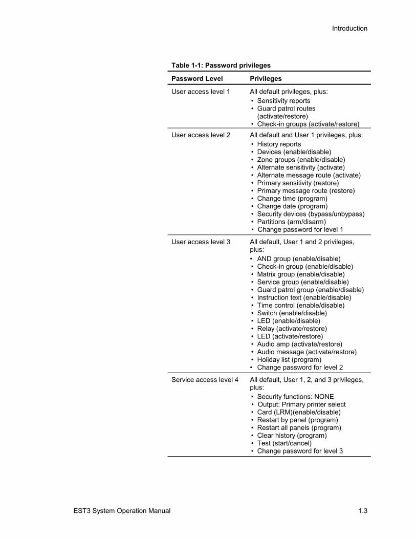
Password protectionCertain front-panel controls and command menu functions arepassword-protected and have a user access level that isdetermined by the marketplace setting. The four user accesslevels are detailed in Table 1-1.
Each access level is given a default password that should bechanged once the panel is put into service. See Chapter 2:Changing user access level passwords for more information.
Table 1-1: Password privileges
Password Level Privileges
DefaultNo password required
• Status• Revision level report• Output selection• Display/printer selection• Printer selection• Reset function• Alarm silence function• Drill function
Introduction
EST3 System Operation Manual 1.3
Table 1-1: Password privileges
Password Level Privileges
User access level 1 All default privileges, plus:• Sensitivity reports• Guard patrol routes
(activate/restore)• Check-in groups (activate/restore)
User access level 2 All default and User 1 privileges, plus:• History reports• Devices (enable/disable)• Zone groups (enable/disable)• Alternate sensitivity (activate)• Alternate message route (activate)• Primary sensitivity (restore)• Primary message route (restore)• Change time (program)• Change date (program)• Security devices (bypass/unbypass)• Partitions (arm/disarm)• Change password for level 1
User access level 3 All default, User 1 and 2 privileges,plus:• AND group (enable/disable)• Check-in group (enable/disable)• Matrix group (enable/disable)• Service group (enable/disable)• Guard patrol group (enable/disable)• Instruction text (enable/disable)• Time control (enable/disable)• Switch (enable/disable)• LED (enable/disable)• Relay (activate/restore)• LED (activate/restore)• Audio amp (activate/restore)• Audio message (activate/restore)• Holiday list (program)• Change password for level 2
Service access level 4 All default, User 1, 2, and 3 privileges,plus:• Security functions: NONE• Output: Primary printer select• Card (LRM)(enable/disable)• Restart by panel (program)• Restart all panels (program)• Clear history (program)• Test (start/cancel)• Change password for level 3
Introduction
1.4 EST3 System Operation Manual
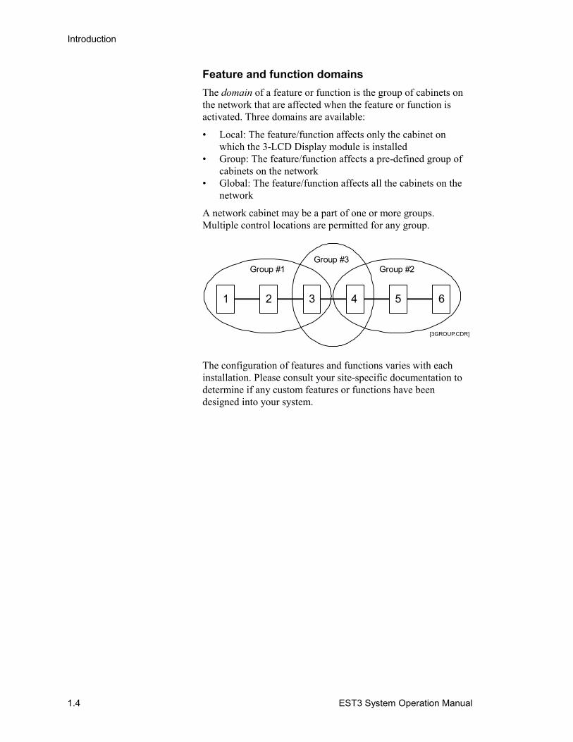
Feature and function domainsThe domain of a feature or function is the group of cabinets onthe network that are affected when the feature or function isactivated. Three domains are available:
• Local: The feature/function affects only the cabinet onwhich the 3-LCD Display module is installed
• Group: The feature/function affects a pre-defined group ofcabinets on the network
• Global: The feature/function affects all the cabinets on thenetwork
A network cabinet may be a part of one or more groups.Multiple control locations are permitted for any group.
1 6
[3GROUP.CDR]
52 3 4
Group #1 Group #2Group #3
The configuration of features and functions varies with eachinstallation. Please consult your site-specific documentation todetermine if any custom features or functions have beendesigned into your system.
Introduction
EST3 System Operation Manual 1.5
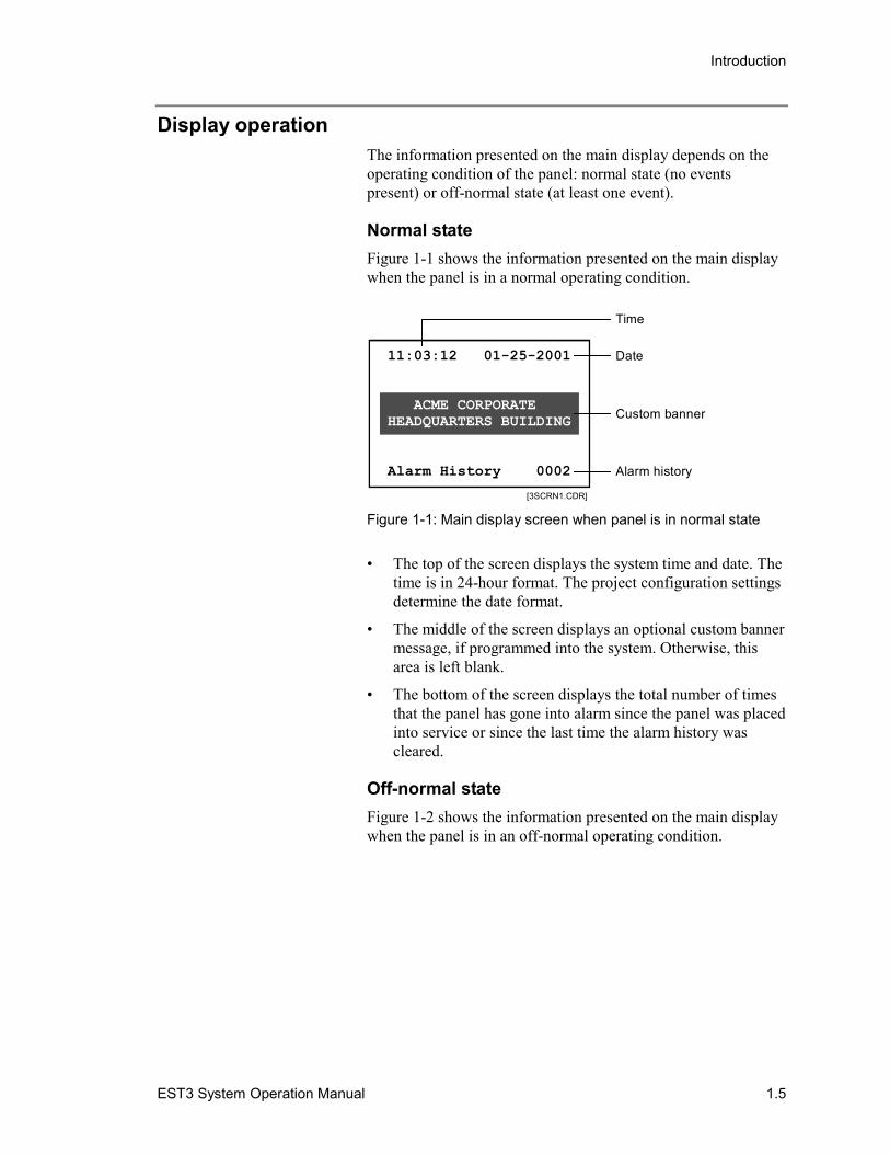
Display operationThe information presented on the main display depends on theoperating condition of the panel: normal state (no eventspresent) or off-normal state (at least one event).
Normal stateFigure 1-1 shows the information presented on the main displaywhen the panel is in a normal operating condition.
11:03:12 01-25-2001
Alarm History 0002
ACME CORPORATEHEADQUARTERS BUILDING
[3SCRN1.CDR]
Date
Custom banner
Alarm history
Time
Figure 1-1: Main display screen when panel is in normal state
• The top of the screen displays the system time and date. Thetime is in 24-hour format. The project configuration settingsdetermine the date format.
• The middle of the screen displays an optional custom bannermessage, if programmed into the system. Otherwise, thisarea is left blank.
• The bottom of the screen displays the total number of timesthat the panel has gone into alarm since the panel was placedinto service or since the last time the alarm history wascleared.
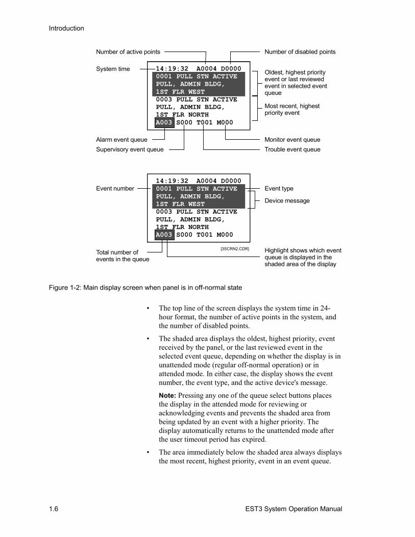
Off-normal stateFigure 1-2 shows the information presented on the main displaywhen the panel is in an off-normal operating condition.
Introduction
1.6 EST3 System Operation Manual
Highlight shows which eventqueue is displayed in the shaded area of the display
Total number of events in the queue
[3SCRN2.CDR]
Event typeEvent number
Device message
System time
Alarm event queue Monitor event queueSupervisory event queue Trouble event queue
Oldest, highest priorityevent or last reviewedevent in selected eventqueue
Most recent, highestpriority event
Number of disabled pointsNumber of active points
14:19:32 A0004 D0000
0003 PULL STN ACTIVEPULL, ADMIN BLDG,1ST FLR NORTH
S000 T001 M000
0001 PULL STN ACTIVEPULL, ADMIN BLDG,1ST FLR WEST
A003 |
14:19:32 A0004 D0000
0003 PULL STN ACTIVEPULL, ADMIN BLDG,1ST FLR NORTH
S000 T001 M000
0001 PULL STN ACTIVEPULL, ADMIN BLDG,1ST FLR WEST
A003 |
Figure 1-2: Main display screen when panel is in off-normal state
• The top line of the screen displays the system time in 24-hour format, the number of active points in the system, andthe number of disabled points.
• The shaded area displays the oldest, highest priority, eventreceived by the panel, or the last reviewed event in theselected event queue, depending on whether the display is inunattended mode (regular off-normal operation) or inattended mode. In either case, the display shows the eventnumber, the event type, and the active device's message.
Note: Pressing any one of the queue select buttons placesthe display in the attended mode for reviewing oracknowledging events and prevents the shaded area frombeing updated by an event with a higher priority. Thedisplay automatically returns to the unattended mode afterthe user timeout period has expired.
• The area immediately below the shaded area always displaysthe most recent, highest priority, event in an event queue.
Introduction
EST3 System Operation Manual 1.7
Note: Cabinet configuration option settings determine whichevents are routed to the main display and placed in an eventqueue.
• The bottom line of the display shows the number of eventsin each event queue. The highlight around the event counterindicates which event queue is displayed in the shaded area.
Note: The event counter stops at 999. It is possible for anevent queue to hold more than 999 events.
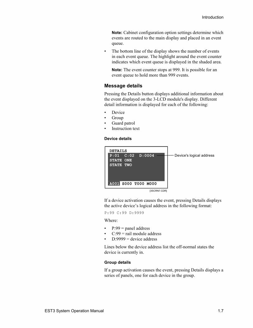
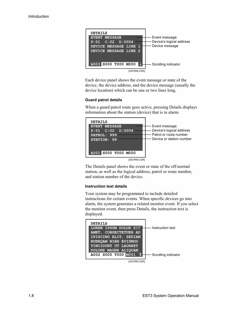
Message detailsPressing the Details button displays additional information aboutthe event displayed on the 3-LCD module's display. Differentdetail information is displayed for each of the following:
• Device• Group• Guard patrol• Instruction text
Device details
DETAILS
S000 T000 M000
P:01 C:02 D:0004STATE ONESTATE TWO
A001
[3SCRN7.CDR]
Device's logical address
If a device activation causes the event, pressing Details displaysthe active device’s logical address in the following format:P:99 C:99 D:9999
Where:
• P:99 = panel address• C:99 = rail module address• D:9999 = device address
Lines below the device address list the off-normal states thedevice is currently in.
Group details
If a group activation causes the event, pressing Details displays aseries of panels, one for each device in the group.
Introduction
1.8 EST3 System Operation Manual
DETAILS
S000 T000 M000
EVENT MESSAGEP:01 C:02 D:0004DEVICE MESSAGE LINE 1DEVICE MESSAGE LINE 2
A003
[3SCRN6.CDR]
Event message
Scrolling indicator
Device's logical addressDevice message
Each device panel shows the event message or state of thedevice, the device address, and the device message (usually thedevice location) which can be one or two lines long.
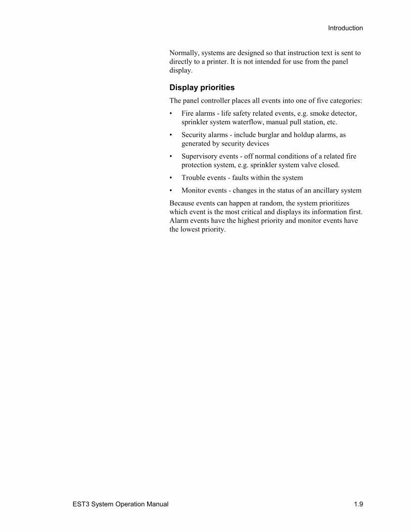
Guard patrol details
When a guard patrol route goes active, pressing Details displaysinformation about the station (device) that is in alarm.
DETAILS
S000 T000 M000
EVENT MESSAGEP:01 C:02 D:0004PATROL: 999STATION: 99
A001
[3SCRN8.CDR]
Event messageDevice's logical addressPatrol or route numberDevice or station number
The Details panel shows the event or state of the off-normalstation, as well as the logical address, patrol or route number,and station number of the device.
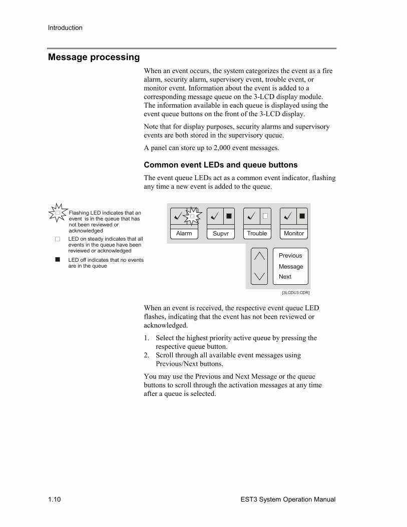
Instruction text details
Your system may be programmed to include detailedinstructions for certain events. When specific devices go intoalarm, the system generates a related monitor event. If you selectthe monitor event, then press Details, the instruction text isdisplayed.
DETAILS
A002 S000 T000
LOREM IPSUM DOLOR SIT AMET, CONSECTETUER ADIPISCING ELIT, SEDIAMNONEQAM NIBH EUISMOD TINCIDUNT UT LAOREET DOLORE MAGNA ALIQUAM
M001
[3SCRN9.CDR]
Instruction text
Scrolling indicator
Introduction
EST3 System Operation Manual 1.9
Normally, systems are designed so that instruction text is sent todirectly to a printer. It is not intended for use from the paneldisplay.
Display prioritiesThe panel controller places all events into one of five categories:
• Fire alarms - life safety related events, e.g. smoke detector,sprinkler system waterflow, manual pull station, etc.
• Security alarms - include burglar and holdup alarms, asgenerated by security devices
• Supervisory events - off normal conditions of a related fireprotection system, e.g. sprinkler system valve closed.
• Trouble events - faults within the system
• Monitor events - changes in the status of an ancillary system
Because events can happen at random, the system prioritizeswhich event is the most critical and displays its information first.Alarm events have the highest priority and monitor events havethe lowest priority.
Introduction
1.10 EST3 System Operation Manual
Message processingWhen an event occurs, the system categorizes the event as a firealarm, security alarm, supervisory event, trouble event, ormonitor event. Information about the event is added to acorresponding message queue on the 3-LCD display module.The information available in each queue is displayed using theevent queue buttons on the front of the 3-LCD display.
Note that for display purposes, security alarms and supervisoryevents are both stored in the supervisory queue.
A panel can store up to 2,000 event messages.
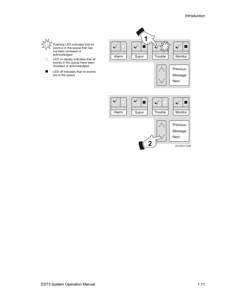
Common event LEDs and queue buttonsThe event queue LEDs act as a common event indicator, flashingany time a new event is added to the queue.
[3LCDU3.CDR]
Previous
MessageNext
Supvr Trouble MonitorAlarm
Flashing LED indicates that an event that has not been reviewed or acknowledged
is in the queue
LED on steady indicates that all events in the queue have been reviewed or acknowledged
LED off indicates that no in the queue
events are
When an event is received, the respective event queue LEDflashes, indicating that the event has not been reviewed oracknowledged.
1. Select the highest priority active queue by pressing therespective queue button.
2. Scroll through all available event messages usingPrevious/Next buttons.
You may use the Previous and Next Message or the queuebuttons to scroll through the activation messages at any timeafter a queue is selected.
Introduction
EST3 System Operation Manual 1.11
[3LCDU4.CDR]
Previous
Previous
Message
Message
Next
Next
Supvr
Supvr
Trouble
Trouble
Monitor
Monitor
Alarm
Alarm
1
2
Flashing LED indicates that an event that has not been reviewed or acknowledged
is in the queue
LED on steady indicates that all events in the queue have been reviewed or acknowledged
LED off indicates that no in the queue
events are
Introduction
1.12 EST3 System Operation Manual
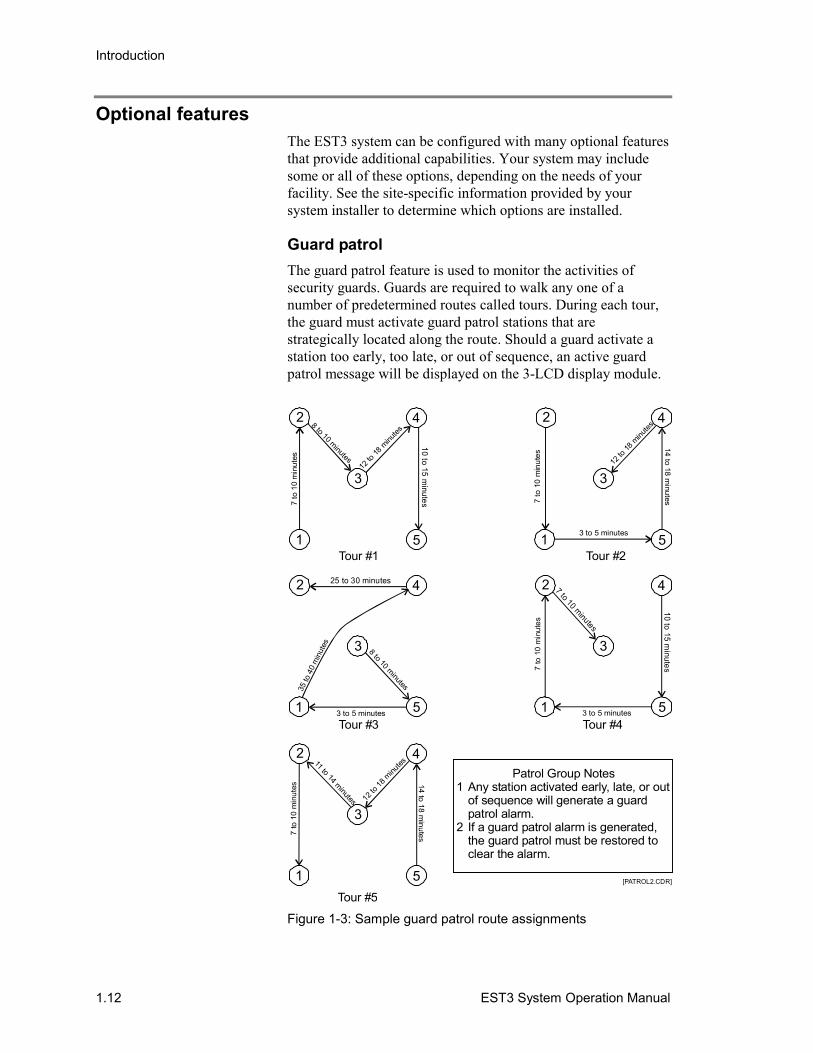
Optional featuresThe EST3 system can be configured with many optional featuresthat provide additional capabilities. Your system may includesome or all of these options, depending on the needs of yourfacility. See the site-specific information provided by yoursystem installer to determine which options are installed.
Guard patrolThe guard patrol feature is used to monitor the activities ofsecurity guards. Guards are required to walk any one of anumber of predetermined routes called tours. During each tour,the guard must activate guard patrol stations that arestrategically located along the route. Should a guard activate astation too early, too late, or out of sequence, an active guardpatrol message will be displayed on the 3-LCD display module.
[PATROL2.CDR]
1
3
5
2 4
10 to 15 minutes
8 to 10 minutes
7 to
10
min
utes
12 to
18 m
inutes
Tour #1
1
3
5
2 4
Tour #3
8 to 10 minutes35 to
40
min
utes
3 to 5 minutes
25 to 30 minutes
Tour #5
1
3
5
2 4
14 to 18 minutes
11 to 14 minutes 12 to
18 m
inutes
7 to
10
min
utes
Tour #21
3
5
2 4
14 to 18 minutes
12 to
18 m
inutes
7 to
10
min
utes
3 to 5 minutes
Tour #41
3
5
2 4
10 to 15 minutes7
to 1
0 m
inut
es
7 to 10 minutes
3 to 5 minutes
Patrol Group Notes1 Any station activated early, late, or out
of sequence will generate a guard patrol alarm.
2 If a guard patrol alarm is generated, the guard patrol must be restored to clear the alarm.
Figure 1-3: Sample guard patrol route assignments
Introduction
EST3 System Operation Manual 1.13
Figure 1-3 shows five guard patrol routes consisting of fivestations. The system designer has assigned a minimum andmaximum time allowance for the guard to go between any twoguard stations. If the guard arrives too early, too late or at thewrong station, an active guard patrol event is generated.
Starting a tour
There are three ways to start a guard patrol tour:
• Activate the first guard patrol station on the route
• Enable the Guard Patrol group from the 3-LCD module
• Press a control/display panel button programmed to turn onthe Guard Patrol group
Note: A guard patrol station designated as the first station in oneguard patrol route can not be the first station in another route.
Ending a tour
A guard patrol tour is automatically ended when all stations onthe route have been successfully operated within the allowabletime period and in the proper sequence.
Should a tour end with an active guard patrol response, thesystem must be reset to clear the guard patrol response.
Press the Details button to reveal the stations reporting in.
Clearing a guard patrol alarm
When a guard patrol alarm is generated, you must restore theguard patrol route to clear the alarm. The steps are detailed laterin this manual.
Check-in groupsCheck-in groups are used to monitor occupants in nursing carefacilities. Occupants must check in during their assigned check-in period to signal that they are well. Failure to check in alerts anattendant that something is wrong.
Check-in groups provide two indications when something iswrong. The check-in group sends a Check-In Active message tothe 3-LCD display for each member of the group that fails tocheck in on time. The check-in group sends an EmergencyActive message when the following happens:
• Any member of the group activates their check-in device anytime other than the check-in period
• Any member of the group activates their check-in device asecond time during the check-in period
Introduction
1.14 EST3 System Operation Manual
Check-in active message
When a check-in active message is displayed, one or morestations in the check-in group have not been activated during therequired time period. The check-in active messages may beviewed in the monitor message queue to determine the locationof the event. Contact the late check-in station and determine theproblem.
Emergency active message
The emergency active message is displayed when a check-instation is activated outside the check-in period. This is used tosignal an emergency condition such as a fall, etc. To determinethe location of the check-in station, view the event in the alarmmessage queue.
Note: Emergency Active messages are placed in the alarmmessage queue but the event does not place the panel into alarm.
System timersThe system has a number of optional timers that are required bycertain jurisdictions to comply with fire codes. Most of thesetimer functions do not require operator action, however,understanding the function of these optional timers (if enabled)will improve your understanding of why the system functions asit does.
Alarm silence/reset inhibit timer
The alarm silence/reset inhibit timer is used to guarantee that thenotification appliances will sound for the minimum specifiedperiod. This timer effectively disables the alarm silence andreset buttons for a predetermined period. While the timers areactive, pressing the alarm silence and reset buttons has no effect.
Notes
• Your system may be equipped with notification appliancesassociated with the fire sprinkler system, which can not besilenced.
• Visual notification appliances can be configured not to turnoff when the audible notification appliances are silenced.
Automatic alarm silence timer
The automatic alarm silence timer is used to automaticallysilence the notification appliances after a preset period, if theyhave not been silenced using the alarm silence button. Typicaltimer settings silence the signals from 5 to 30 minutes afteroperation.
Introduction
EST3 System Operation Manual 1.15
Automatic general alarm (GA) timer
Some systems are designed to permit a short investigation periodbetween the detection of a fire and sending a general alarm tothe entire facility. The automatic general alarm timer is used toinitiate the general alarm after a predetermined time period, if noaction has been taken by the operator to prevent the generalalarm from being sent.
Time controlsTime controls provide for the automatic starting and stopping ofsystem events based on time and date. Time controls run in thebackground and do not require any operator action.
Setting holidays
The system provides for special time controls, referred to asholiday time controls. Holiday time controls supersede thenormal time controls on dates that are designated as holidays.The list of dates that are defined as holidays is entered into thesystem from the 3-LCD Display module.
Control/display module buttonsThe buttons on a control/display module use one of threeavailable operating modes.
• Toggle - The state of the button changes each time thebutton is pushed, i.e. “off” to “on” or “on” to “off.”
• Interlocked - Three adjacent toggle buttons that operate as agroup. Pushing any button in the group turns the output ofthe other two buttons “off” and turns its own output “on.”
• Momentary - The button is “on” only while pressed by theoperator.
You may find multiple button modes on a single control/displaymodule. Consult your site-specific documentation for additionalinformation.
Toggle buttons
Toggle buttons are commonly used to control two stateoperations such as on/off, open/close, speaker select, telephoneselect, etc. The output of an “on” button remains “on” duringpanel reset, and must be manually turned “off” when no longerrequired.
Interlocked buttons
The interlocked mode is commonly used for hands-off autocontrol of HVAC systems. An interlocked button in the “on”
Introduction
1.16 EST3 System Operation Manual
state can be turned “off” without activating a second button bypressing the “on” button a second time. The output of the “on”button remains on, during panel reset, and must be manuallyreturned to “Auto” when no longer required.
Momentary buttons
Momentary buttons are typically to issue brief commands.Example uses for momentary buttons: lamp tests, function reset,and test sequences. The command is issued only while thebutton is pressed.
Introduction
EST3 System Operation Manual 1.17
Entering logical addressesEach addressable device or circuit in the system has a logicaladdress. This includes panels, local rail modules, and devices.Depending on the operation you are performing, you will beprompted to enter a logical address in one of several formats.
Tip: Get an SDU Objects report for your system and keep it withthis documentation. The SDU Objects report lists all of theaddressable devices or circuits in the system and shows theirlogical addresses.
PanelsThe logical address format for a panel is PP, where PP is thecabinet number (01 to 64). For example, enter 01 for the paneldesignated as Cabinet 1.
(System-wide events that are not related to a particular cabinetuse panel number 00.)
To determine a cabinet's panel number, use the CommandMenus to request a Status report. Choose any type of list. Thesystem displays the cabinet's panel number as the default panelnumber. Once you’ve noted the panel number, press theBackspace key to exit from the function.
Local rail modulesLocal rail modules include the rail modules that connect to thelocal rail bus and the control/display modules. The logicaladdress format for a local rail module is PPCC, where:
• PP is the cabinet number of the panel containing the railmodule
• CC is the address of the rail module
• CC+32 is the address of the control/display moduleconnected to the rail module at slot address CC
For example, enter 0102 for the rail module installed in chassisrail 1, slot 4 of Cabinet 1. Enter 0134 for the control/displaymodule connected to the rail module installed in chassis rail 1,slot 4 of Cabinet 1.
Note: The rail-slot number and the slot address are not the same.Slot addresses vary with the cabinet configuration. Refer toAppendix A: System addresses.
DevicesDevices include the circuits, buttons, or LEDs that exist on thelocal rail module and all addressable devices connected by the
Introduction
1.18 EST3 System Operation Manual
field wiring. The address format for a device is PPCCDDDD,where:
• PP is the cabinet number of the panel containing the railmodule
• CC is the address of the rail module responsible for thedevice
• DDDD is the address of the individual component or circuit
For example, Enter 01340129 for the first LED on thecontrol/display module connected to the rail module installed inchassis rail 1, slot 4 of Cabinet 1.
The CRC Card Reader Controller and KPDISP Keypad Displayare devices supported by a 3-SAC module. However, they alsoact as independent processors, and have their own points andpseudo points. For this reason, their device numbers are furthersubdivided.
You can think of a SAC device as having this address format:PPCCSSDD: SS is the CRC or KPDISP device number, asassigned during LRM configuration. DD is a point or pseudopoint within the device.
EST3 System Operation Manual 2.1
Chapter 2 3-LCD operating instructions
Summary
This chapter provides a functional description of the controlsand indicators provided on the 3-LCD display module.
ContentControls and indicators • 2.2Creating a status report • 2.8Disabling groups • 2.9Enabling groups • 2.10Disabling hardware components • 2.11Enabling hardware components • 2.12Arming security partitions • 2.13Disarming security partitions • 2.14Resetting security partitions • 2.15Bypassing security devices • 2.16Removing bypasses from security devices • 2.17Guard patrol groups • 2.18
Starting a guard patrol • 2.18Restoring a guard patrol • 2.18
Check-in groups • 2.19Activating a check-in group • 2.19Restoring a check-in group • 2.19Canceling a check-in sequence • 2.20
Changing the smoke detector sensitivity level • 2.21Changing event message routing • 2.22
Activating event alternate message routing • 2.22Restoring event primary message routing • 2.22
Changing the output state of a relay or LED • 2.23Creating reports • 2.24Setting the system time and date • 2.26Changing user access level passwords • 2.27Restarting a panel • 2.28Scheduling holidays • 2.29Clearing the panel history file • 2.30Testing alarm input devices • 2.31
3-LCD operating instructions
2.2 EST3 System Operation Manual
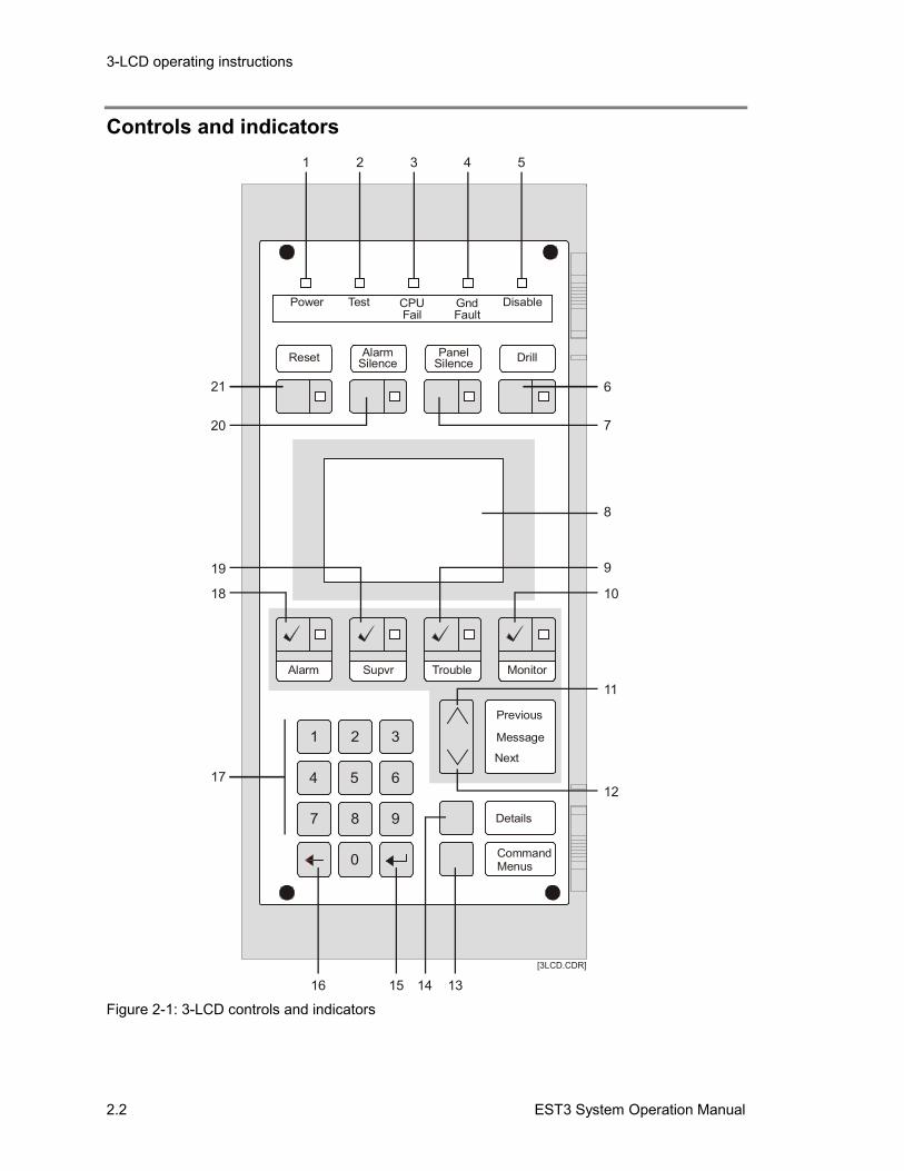
Controls and indicators
4
7
0
1 2 3
Power
Reset DrillAlarm PanelSilence Silence
Test DisableCPUFail
GndFault
Details
CommandMenus
1 2 3 4 5
6
7
8
9
10
11
1217
18
19
20
21
131516 14[3LCD.CDR]
Previous
Message
Next
Supvr Trouble MonitorAlarm
5
8
6
9
Figure 2-1: 3-LCD controls and indicators
3-LCD operating instructions
EST3 System Operation Manual 2.3
Functional description of 3-LCD controls and indicators (see Figure 2-1)
IndexControl orindicator Functional description
1 Power LED The Power LED indicates that mains ac is applied to the panel.
2 Test LED The Test LED indicates that a part of the system is in test mode.A programmable timer automatically exits the test mode after aperiod of system inactivity.
3 CPU Fail LED The CPU Fail LED indicates the 3-CPU1 module has detected aprocessor failure. Processor failures must be reset manually.
4 Gnd Fault LED The Gnd Fault LED indicates that the 3-CPU1 module hasdetected a ground fault.
5 Disable LED The Disable LED indicates that a point or zone has beendisabled using the Disable command.
6 Drill Button / LED Pressing the Drill button activates the Drill command function.The Drill LED, when lit, indicates that the Drill command functionis active.
7 Panel SilenceButton / LED
For U.S. Local and Canadian Local systems, pressing the PanelSilence button turns the 3-CPU1 buzzer off. The Panel SilenceLED, when lit, indicates the panel is in an off-normal conditionand the panel has been placed in Panel Silence mode.
For U.S. Proprietary and Canadian Proprietary systems, thePanel Silence button is not operational. The panel buzzer onlysilences after all events have been acknowledged.
Notes• The 3-CPU1 buzzer can be configured to resound at a regular
interval to remind the operator that the panel has beensilenced
• Pressing the Alarm Silence and Panel Silence buttons at thesame time actives the panel lamp test function
8 Liquid crystaldisplay screen
168 character, backlit alphanumeric display of system status.
9 Trouble Button /LED
Pressing the Trouble button places the contents of the Troublequeue onto the display screen for review. Active trouble eventsare displayed in the order in which they are received. When atrouble event is highlighted on the display, pressing the Troublebutton acknowledges the event and advances the display to thenext event.
The Trouble LED serves as a common trouble event indicator.The LED, when flashing, indicates that there is an event in thequeue that has not been reviewed (local systems) oracknowledged (proprietary systems). When on steady, the LEDindicates that all events in the queue have been reviewed oracknowledged.
3-LCD operating instructions
2.4 EST3 System Operation Manual
Functional description of 3-LCD controls and indicators (see Figure 2-1)
IndexControl orindicator Functional description
10 Monitor Button /LED
Pressing the Monitor button places the contents of the Monitorqueue onto the display screen for review. Active monitor eventsare displayed in the order in which they are received. When amonitor event is highlighted on the display, pressing the Monitorbutton acknowledges the event and advances the display to thenext event.
The Monitor LED serves as a common monitor event indicator.The LED, when flashing, indicates that there is an event in thequeue that has not been reviewed (local systems) oracknowledged (proprietary systems). When on steady, the LEDindicates that all events in the queue have been reviewed oracknowledged.
11 Previous MessageButton
For U.S. Local and Canadian Local systems, pressing thePrevious Message button scrolls the display to show thepreceding event in the selected event queue. Reviewing eventsusing the Previous Message button does not acknowledge theevent.
For U.S. Proprietary and Canadian Proprietary systems, thePrevious event button is not operational. Events must beacknowledged in order of their occurrence.
12 Next MessageButton
For U.S. Local and Canadian Local systems, pressing the NextMessage button scrolls the display to show the following event inthe selected event queue. Reviewing events using the NextMessage button does not acknowledge the event.
For U.S. Proprietary and Canadian Proprietary systems, the NextMessage button is not operational. Events must beacknowledged in order of their occurrence.
13 Command MenusButton
Pressing the Command Menus button displays the systemcommand menu to access the following system functions:
Status, Enable, Disable, Activate, Restore, Control Output,Reports, Program, and Test
Pressing the button a second time returns the user to the currentevent window.
3-LCD operating instructions
EST3 System Operation Manual 2.5
Functional description of 3-LCD controls and indicators (see Figure 2-1)
IndexControl orindicator Functional description
14 Details Button Pressing the Details button displays additional information aboutthe event highlighted on the display screen.
• For Zone Groups, pressing the Details button displays a list ofthe active devices in the zone group.
• For Instruction Text Groups, pressing the Details buttondisplays the entire instruction text.
• For Maintenance Alerts, pressing the Details button displays alist of the dirty devices.
• For Common Troubles, pressing the Details button displays alist of the specific troubles for the selected device.
• For Guard Patrols, pressing the Details button displays theoffending station and indicates whether the activation wascaused because of an early, late, or out of sequence condition.
15 Enter key Pressing the Enter key selects the highlighted menu option orcauses the system to start processing the information shown inthe display.
16 Delete / Backspacekey
Pressing the Delete / Backspace key moves the cursor to the leftof the current position and removes the character from thedisplay. The Delete / Backspace key is also used to cancelfunctions and move the operator back through the menus.
17 Numeric Keypad Pressing any number key selects the menu item or enters therespective number into the system for use in conjunction withother system functions.
18 Alarm Button / LED Pressing the Alarm button places the contents of the Alarmqueue onto the display screen for review. Active alarm events aredisplayed in the order in which they are received. When an alarmevent is highlighted on the display, pressing the Alarm buttonacknowledges the event and advances the display to the nextevent.
The Alarm LED serves as a common alarm event indicator. TheLED, when flashing, indicates that there is an event in the queuethat has not been reviewed (local systems) or acknowledged(proprietary systems). When on steady, the LED indicates that allevents in the queue have been reviewed or acknowledged.
3-LCD operating instructions
2.6 EST3 System Operation Manual
Functional description of 3-LCD controls and indicators (see Figure 2-1)
IndexControl orindicator Functional description
19 Supvr Button / LED Pressing the Supervisory button places the contents of theSupervisory queue onto the display screen for review. Activesupervisory events are displayed in the order in which they arereceived. When a supervisory event is highlighted on the display,pressing the Supervisory button acknowledges the event andadvances the display to the next event.
The Supervisory LED serves as a common supervisory eventindicator. The LED, when flashing, indicates that there is anevent in the queue that has not been reviewed (local systems) oracknowledged (proprietary systems). When on steady, the LEDindicates that all events in the queue have been reviewed oracknowledged.
20 Alarm SilenceButton / LED
Pressing the Alarm Silence button turns off the EVAC andALERT channels, and all active audible and visible notificationappliance circuits. Pushing the button a second time turns thenotification appliance circuits back on. This button may be usedto cancel the drill signal.
The Alarm silence LED, when lit, indicates that the activenotification appliance circuits have been silenced.
Notes• Project configuration settings affect Alarm Silence function
operation
• Pressing the Alarm Silence and Panel Silence buttons at thesame time actives the panel lamp test function
21 Reset Button / LED Pressing the Reset button activates the system’s reset sequenceto restore the system to normal.
The Reset LED flashes quickly during the smoke power-downphase, flashes slowly during the power-up phase, is on steadyduring the restoral phase, and is off when the system has reset.
Notes• The Reset button is disabled as long as the alarm silence
inhibit timer is running
• The Reset button does not affect disabled points or manuallyoverridden functions
• The Reset button has no effect on security or access controldevices
3-LCD operating instructions
EST3 System Operation Manual 2.7
Functional description of 3-LCD controls and indicators (see Figure 2-1)
IndexControl orindicator Functional description
n/a Buzzer The buzzer on the 3-CPU1 sounds to alert the operator to off-normal system conditions, such as:
• Active alarms
• Active test or disabled zones
• Active fault conditions
• Active monitor conditions
The buzzer sounds a pattern associated with each event asdetermined by the market place settings.
Alarm: 3-3-3 pattern
Supervisory: 2-2 pattern
Trouble: 30 pulses per minute
Monitor: 3-3-3 pattern
3-LCD operating instructions
2.8 EST3 System Operation Manual
Creating a status reportUse the Status command to create reports of off-normal points,or to determine the status of points in a security partition. TheStatus command generates a list that you can view on the 3-LCDdisplay module or print on a local printer.
The Status Menu lets you choose the following reports:
• All active points• Alarm points• Supervisory points• Trouble points• Monitor points• Test points• Disabled points• Output points• Security points
On the Security Status Menu, you can choose between Partitionand Holdup status reports.
To create a status report:
1. Press the Command Menus button, then choose Status.
2. Choose the type of list you want to generate.
3. Enter the target panel’s 2-digit address (PP).—or—Choose a partition from the Partition List.
4. Do one of the following:
Choose Display if you want to view the list on the 3-LCDmodule.
Choose Print Locally, then select a printer, if you want tosend the list to a printer connected to the local panel.

3-LCD operating instructions
EST3 System Operation Manual 2.9
Disabling groupsA group is an object created during system programming.Groups are required in order to execute certain system functions,but groups bear no physical relationship to the system.
For example, smoke detectors can be assigned to the same zonegroup even though they are not attached to the same wire run.
Disabling a group isolates the group from the system just as if itwere a hardware component. Disabling a zone group disableseach of the devices in the group individually. Disabling othergroups only disables the group response.
There are several types of group:
• And group• Check-in group• Matrix group• Service group• Guard patrol group• Zone group• Instruction text group
When you disable a group, the 3-CPU1 lights the 3-LCD DisableLED and places a Disabled Active event in the trouble queue.
Note: Before disabling a group, you need to know which devicesare included in the group. You should be able to get a list oflogical groups and their members from the company thatinstalled the system.
To disable a group:
1. Press the Command Menus button , then choose Disable.
2. Choose Group.
3. Choose the group type.
4. Select the group from the list.
5. If prompted, enter a valid user access level password.
3-LCD operating instructions
2.10 EST3 System Operation Manual
Enabling groupsA group is an object created during system programming.Groups are required in order to execute certain system functions,but groups bear no physical relationship to the system.
For example, smoke detectors can be assigned to the same zonegroup even though they are not attached to the same wire run.
Enabling a group establishes the group as part of the system justas if it were a hardware component. When enabled, any changesin state that occurred while the group was disabled areprocessed. Enabling a zone group enables each of the devices inthe group individually. Enabling other groups only enables theirgroup response.
There are several types of group:
• And group• Check-in group• Matrix group• Service group• Guard patrol group• Zone group• Instruction text group
To enable a group:
1. Press the Command Menus button , then choose Enable.
2. Choose Group.
3. Choose the group type.
4. Select the group from the list.
5. If prompted, enter a valid user access level password.
3-LCD operating instructions
EST3 System Operation Manual 2.11
Disabling hardware componentsDisabling a hardware component isolates the component fromthe system. While disabled, a component’s state changes are notprocessed. For example, if a disabled smoke detector changes tothe alarm state, the panel will not go into alarm. The panel willgo into alarm if you enable the disabled smoke detector and thesmoke detector is still in the alarm state.
Hardware components include:
• Devices (input and output circuits, detectors, and modules)• Rail modules• Buttons• LEDs
When you disable a hardware component, the 3-CPU1 lights the3-LCD Disable LED and places a Disabled Active event in thetrouble queue.
Note: To disable a component you need the component’s logicaladdress. You can get component’s logical addresses from anSDU Objects report.
To disable a hardware component:
1. Press the Command Menus button , then choose Disable.
2. Do one of the following:
• Choose Device to disable: input circuits, output circuits,detectors, or modules
• Choose Card to disable: rail modules or control / displaymodules
• Choose Button to disable: control / display module buttons
• Choose LED to disable: control / display module LEDs
3. Enter the target component’s logical address.
4. If prompted, enter a valid user access level password.
3-LCD operating instructions
2.12 EST3 System Operation Manual
Enabling hardware componentsEnabling a hardware component re-establishes a disabledcomponent as part of the system. When enabled, any changes instate that occurred while the component was disabled areprocessed. For example, if you enable a smoke detector thatchanged to the alarm state while it was disabled the panel willgo into alarm.
Hardware components consist of:
• Devices (input and output circuits, detectors, and modules)• Rail modules• Buttons• LEDs
To enable a disabled component you need the component’slogical address. You can get a disabled component’s logicaladdress from the disabled points list.
Note: All components are enabled at startup, unless programmedotherwise. The 3-LCD does not indicate a trouble for any pointsdisabled at startup and points disabled at startup are not listed onthe disabled points list.
To enable a hardware component:
1. Press the Command Menus button , then choose Enable.
2. Do one of the following:
• Choose Device to enable: input circuits, output circuits,detectors, or modules
• Choose Card to enable: rail modules or control / displaymodules
• Choose Button to enable: control / display module buttons
• Choose LED to enable: control / display module LEDs
3. Enter the component’s logical address.
4. If prompted, enter a valid user access level password.
3-LCD operating instructions
EST3 System Operation Manual 2.13
Arming security partitionsA security partition is a group of devices intended to secure aphysical area. When you arm a partition, you instruct the systemto monitor those devices for alarm events.
Partitions can be armed in two ways: stay and away. Arming tostay causes the system to monitor only those devices on theperimeter of the protected area. This leaves you free to moveabout inside the partition. Arming to go away causes the systemto monitor all devices, both perimeter and interior.
When you choose an arming command, the system checks all thedevices in the partition to ensure that they’re in a normal statebefore arming the partition. If a device is off-normal it preventsthe partition from being armed. However, you can elect tobypass the device and arm the remaining devices in the partition.
After you choose one of the partition arming commands, thesystem displays a list of partitions. You scroll through this listand select the partition you wish to arm.
Note: Security commands are optional. Project configurationsettings determine whether security commands appear on thepanel menus.
To arm a security partition:
1. Press the Command Menus button , then choose Security.
2. Choose Partition.
3. Choose the type of arming you want: Partition Away orPartition Stay.
4. Scroll through the Partition List and choose the partition youwant to arm.
5. If prompted, enter a valid user access level password.
3-LCD operating instructions
2.14 EST3 System Operation Manual
Disarming security partitionsA security partition is a group of devices intended to secure aphysical area. When you disarm a partition, you instruct thesystem to stop monitoring those devices for alarm events.
When you choose the disarm command, the system checks allthe devices in the partition to ensure that they’re in a normalstate. If a device is off-normal it prevents the partition frombeing disarmed.
After you choose the disarm command, the system displays a listof partitions. You scroll through this list and select the partitionyou wish to disarm.
Note: Security commands are optional. Project configurationsettings determine whether security commands appear on thepanel menus.
To disarm a security partition:
1. Press the Command Menus button , then choose Security.
2. Choose Partition.
3. Choose Partition Disarm.
4. Scroll through the Partition List and choose the partition youwant to disarm.
5. If prompted, enter a valid user access level password.
3-LCD operating instructions
EST3 System Operation Manual 2.15
Resetting security partitionsA security partition is a group of devices intended to secure aphysical area. When you reset a partition, you instruct thesystem to update the status of the devices, then update the eventmessages in all annunciator message queues.
When you choose the reset command, the system checks all thedevices in the partition to determine their current state. Eventmessages previously stored in message queues are deleted, andnew event messages are added as required by the current state ofthe devices.
After you choose the reset command, the system displays a listof partitions. Only disarmed partitions can be reset. You scrollthrough this list and select the partition you wish to reset.
Note: Security commands are optional. Project configurationsettings determine whether security commands appear on thepanel menus. The Partition Reset command has no effect on firealarm devices.
To restore a security partition:
1. Press the Command Menus button , then choose Security.
2. Choose Partition.
3. Choose Partition Reset.
4. Scroll through the Partition List and choose the partition youwant to reset.
5. If prompted, enter a valid user access level password.
3-LCD operating instructions
2.16 EST3 System Operation Manual
Bypassing security devicesWhen you bypass a security device, the system does not processthe device’s alarm events, but continues to process all otherevents. For example, say a loading bay door is damaged so thatthe door contact cannot be closed. This prevents arming of thepartition. As a temporary measure you can bypass the doorcontact to make it possible to arm the partition.
While bypassed, the device’s alarm events are not processed.The panel will go into alarm if you unbypass the device while itis still in an alarm state.
Note: To bypass a device you need the device’s logical address.You can get device’s logical addresses from an SDU Objectsreport.
To bypass a security device:
1. Press the Command Menus button , then choose Security.
2. Choose Device.
3. Choose Bypass.
4. Enter the logical address of the device.
5. If prompted, enter a valid user access level password.
3-LCD operating instructions
EST3 System Operation Manual 2.17
Removing bypasses from security devicesWhen you remove a bypass from a security device, the systemresumes processing the device’s alarm events. The panel will gointo alarm if you remove a bypass from a device while it is stillin an alarm state.
To unbypass a device, you need the device’s logical address.You can get the logical address from the Disabled Points list.
To remove a bypass from a security device:
1. Press the Command Menus button , then choose Security.
2. Choose Device.
3. Choose Remove Bypass.
4. Enter the logical address of the device.
5. If prompted, enter a valid user access level password.
3-LCD operating instructions
2.18 EST3 System Operation Manual
Guard patrol groupsGuard patrol groups are used to monitor the activities of securityguards. A security guard can be required to walk any one of anumber of predetermined tours. During each tour, the guardmust activate guard patrol stations that are located along thetour.
When a guard activates a station too early, too late, or out ofsequence, the 3-LCD displays a Guard Patrol Active message inthe alarm message queue. The operator can press the Detailsbutton to determine which station reported in.
Starting a guard patrolActivating a guard patrol group starts the system’s early, late,and out of sequence sensing mechanisms. Once a station reportsin the system’s early, late, and out of sequence sensingmechanisms stop and end the tour.
To activate a guard patrol:
1. Press the Command Menus button , then choose Activate.
2. Choose Guard Patrol Route.
3. Select the guard patrol route from the list.
4. If prompted, enter a valid user access level password.
Restoring a guard patrolWhen a guard patrol tour ends because a guard patrol stationwas not activated at the proper time, you must restore the GuardPatrol group to which the station belonged.
To restore a guard patrol:
1. Press the Command Menus button then choose Restore.
2. Choose Guard Patrol Route.
3. Select the guard patrol route from the list.
4. If prompted, enter a valid user access level password.
3-LCD operating instructions
EST3 System Operation Manual 2.19
Check-in groupsCheck-In groups are used to monitor occupants in nursing carefacilities. Occupants must check in during their assigned check-in period by activating a check-in device. The 3-LCD displays aCheck-In Active message for any member of a group that fails tocheck in on time. Activating a check-in device anytime outsidethe check-in period or a second time within the check-in periodsends an Emergency Active message to the 3-LCD display.
Activating a check-in groupActivating a check-in group starts the group’s check-insequence. The 3-LCD displays a Check-In Active event to signalthe operator that the check-in timer has started. If every memberof the group checks in, the group restores and the panel returnsto standby operation. If any member fails to check in the groupmust be restored by the operator.
Note: Normally time controls are used to activate check-ingroups. you can also use the Enable command to activate acheck-in group.
To activate a check-in group:
1. Press the Command Menus button , then choose Activate.
2. Choose Check-In Group.
3. Select the group from the list.
4. If prompted, enter a valid user access level password.
Restoring a check-in groupDevices that are not activated during a check-in period aretemporarily removed from the group’s device register.Unregistered devices are not recognized by the system.Restoring the Check-In group returns the missing check-indevices to the group.
To restore a check-in group:
1. Press the Command Menus button , then choose Restore.
2. Choose Check-In Group.
3. Select the check-in group from the list.
4. Activate the nonactivated check-in devices one time.
5. If prompted, enter a valid user access level password.
3-LCD operating instructions
2.20 EST3 System Operation Manual
Canceling a check-in sequenceYou cancel a check-in sequence by restoring the check-in groupbefore the check-in timer expires.
To cancel a check-in sequence:
1. Press the Command Menus button , then choose Restore.
2. Choose Check-In Group.
3. Select the check-in group from the list.
4. If prompted, enter a valid user access level password.
3-LCD operating instructions
EST3 System Operation Manual 2.21
Changing the smoke detector sensitivity levelSmoke detectors can operate using two levels of sensitivity,called primary sensitivity and alternate sensitivity. The systemconfigures smoke detectors to use their primary sensitivity level(typically, less sensitive) during normal business hours. A timecontrol then reconfigures the smoke detectors to use theiralternate sensitivity level (typically, more sensitive) after hourswhen the premises are unoccupied.
You can use menu commands to manually switch betweensensitivity levels as required. To change to the alternatesensitivity level, you activate alternate sensitivity. To change toprimary sensitivity level, you restore primary sensitivity.
Note: You should be able to get a list of the primary andalternate sensitivity setting for each smoke detector from thecompany that installed the system.
To change to alternate sensitivity level:
1. Press the Command Menus button , then choose Activate.
2. Choose Alt. Sensitivity.
3. If prompted, enter a valid user access level password.
To change to primary sensitivity level:
1. Press the Command Menus button , then choose Restore.
2. Choose Primary Sensitivity.
3. If prompted, enter a valid user access level password.
3-LCD operating instructions
2.22 EST3 System Operation Manual
Changing event message routingEach device in the system is configured with a primary andalternate message routing. When a device in the system changesstate, the panel connected to the device produces an event. Thepanel distributes the event according to the active messagerouting setting that is active at the time.
Activating event alternate message routingActivating the alternate event message routing directs the panelto use the alternate routing destinations for any device thatchanges state.
To activate event alternate message routing:
1. Press the Command Menus button , then choose Activate.
2. Choose Alt Message Route
3. If prompted, enter a valid user access level password.
Restoring event primary message routingRestoring the primary message directs the panel to use theprimary routing destinations for any device that changes state.
To restore event primary message routing:
1. Press the Command Menus button , then choose Restore.
2. Choose Primary Msg Route
3. If prompted, enter a valid user access level password.
3-LCD operating instructions
EST3 System Operation Manual 2.23
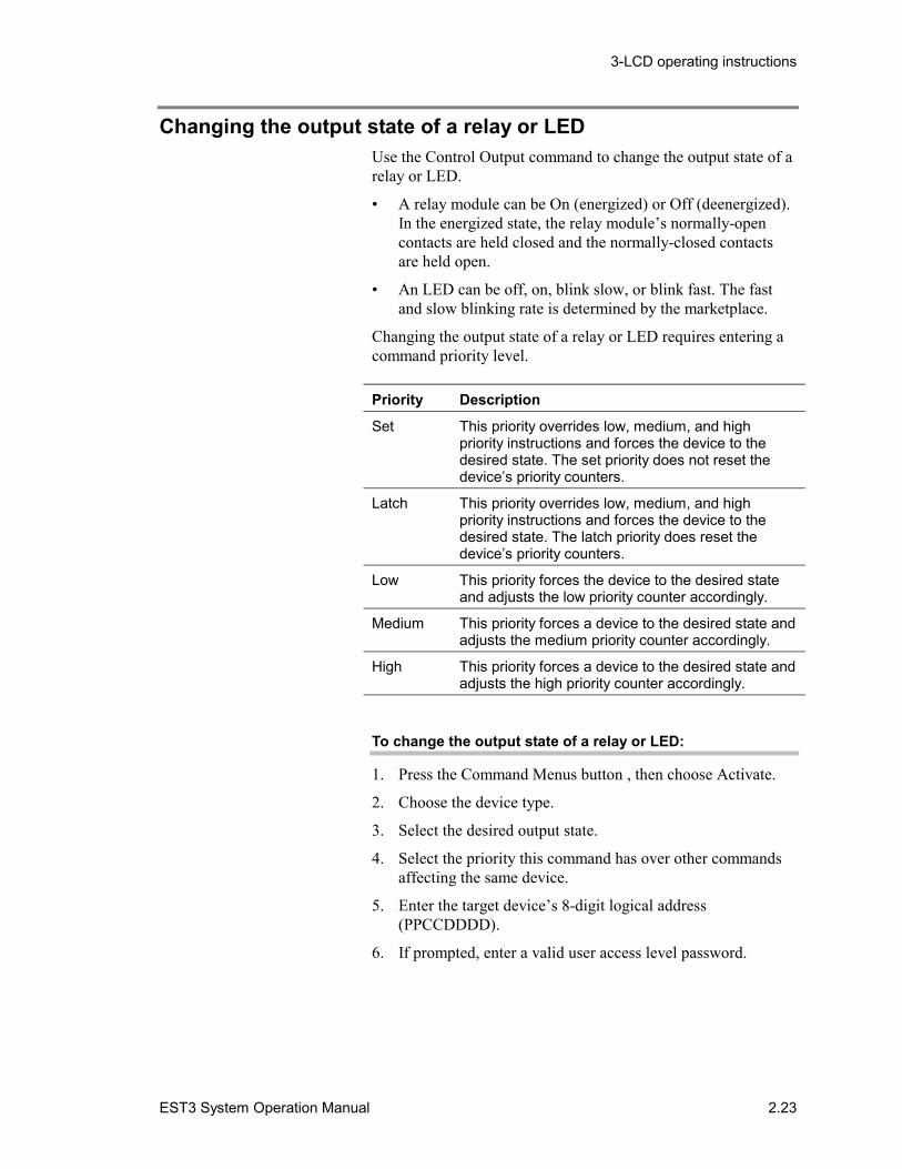
Changing the output state of a relay or LEDUse the Control Output command to change the output state of arelay or LED.
• A relay module can be On (energized) or Off (deenergized).In the energized state, the relay module’s normally-opencontacts are held closed and the normally-closed contactsare held open.
• An LED can be off, on, blink slow, or blink fast. The fastand slow blinking rate is determined by the marketplace.
Changing the output state of a relay or LED requires entering acommand priority level.
Priority Description
Set This priority overrides low, medium, and highpriority instructions and forces the device to thedesired state. The set priority does not reset thedevice’s priority counters.
Latch This priority overrides low, medium, and highpriority instructions and forces the device to thedesired state. The latch priority does reset thedevice’s priority counters.
Low This priority forces the device to the desired stateand adjusts the low priority counter accordingly.
Medium This priority forces a device to the desired state andadjusts the medium priority counter accordingly.
High This priority forces a device to the desired state andadjusts the high priority counter accordingly.
To change the output state of a relay or LED:
1. Press the Command Menus button , then choose Activate.
2. Choose the device type.
3. Select the desired output state.
4. Select the priority this command has over other commandsaffecting the same device.
5. Enter the target device’s 8-digit logical address(PPCCDDDD).
6. If prompted, enter a valid user access level password.
3-LCD operating instructions
2.24 EST3 System Operation Manual
Creating reportsThe Reports command generates a report that you can view onthe 3-LCD display module or print on the local printer. Threetypes of report are available:
• Device Maintenance• History• Revisions• Modcom Compliance
Device Maintenance: a list of detectors and the amount ofenvironmental compensation they have used. You can choose tolist devices in several ways.
History: a chronological list of events that have occurred on apanel since the panel was placed into service or since the lasttime the history was cleared.
Two versions of the History report are available: History WithText, and History Without Text. History With Text is onlyavailable for the panel at which you enter the command. Anypanel can provide History Without Text.
Revisions: a list of all the hardware and software componentsinstalled in a panel and their revision levels.
Modcom Compliance: lists the NFPA 72 compliance level ofall 3-MODCOM modules in a given panel.
To create a Device Maintenance report:
1. Press the Command Menus button , then choose Report.
2. Choose device maintenance.
3. Do one of the following:
• Choose Dirty Devices >80% then enter the target paneladdress (PP).
• Choose Dirty Devices >20% then enter the target paneladdress (PP).
• Choose Single Device then enter the target device address(PPCCDDDD).
• Choose Devices On A Card to get the compensation levelfor all the detectors on a single loop then enter the targetloop’s logical address (PPCCL).
4. Send the list to the display or to the printer. If you choose tosend the list to the printer, choose Printer 1 if the printer isconnected to port 1 or Printer 2 if connected to port 2.
3-LCD operating instructions
EST3 System Operation Manual 2.25
To create a History report:
1. Press the Command Menus button , then choose Report.
2. Choose History.
3. Choose History With Text or History Without Text.
4. Enter the target panel’s 2-digit address (PP).
5. Send the list to the display or to the printer. If you choose tosend the list to the printer, choose Printer 1 if the printer isconnected to port 1 or Printer 2 if connected to port 2.
To create a Revisions report:
1. Press the Command Menus button , then choose Report.
2. Choose Revision Levels.
3. Enter the target panel’s 2-digit address (PP).
4. Send the list to the display or to the printer. If you choose tosend the list to the printer, choose Printer 1 if the printer isconnected to port 1 or Printer 2 if connected to port 2.
To create a Modcom Compliance report:
1. Press the Command Menus button , then choose Report.
2. Choose Modcom Compliance.
3. Enter the target panel’s 2-digit address (PP).
4. Send the list to the display or to the printer. If you choose tosend the list to the printer, choose Printer 1 if the printer isconnected to port 1 or Printer 2 if connected to port 2.
3-LCD operating instructions
2.26 EST3 System Operation Manual
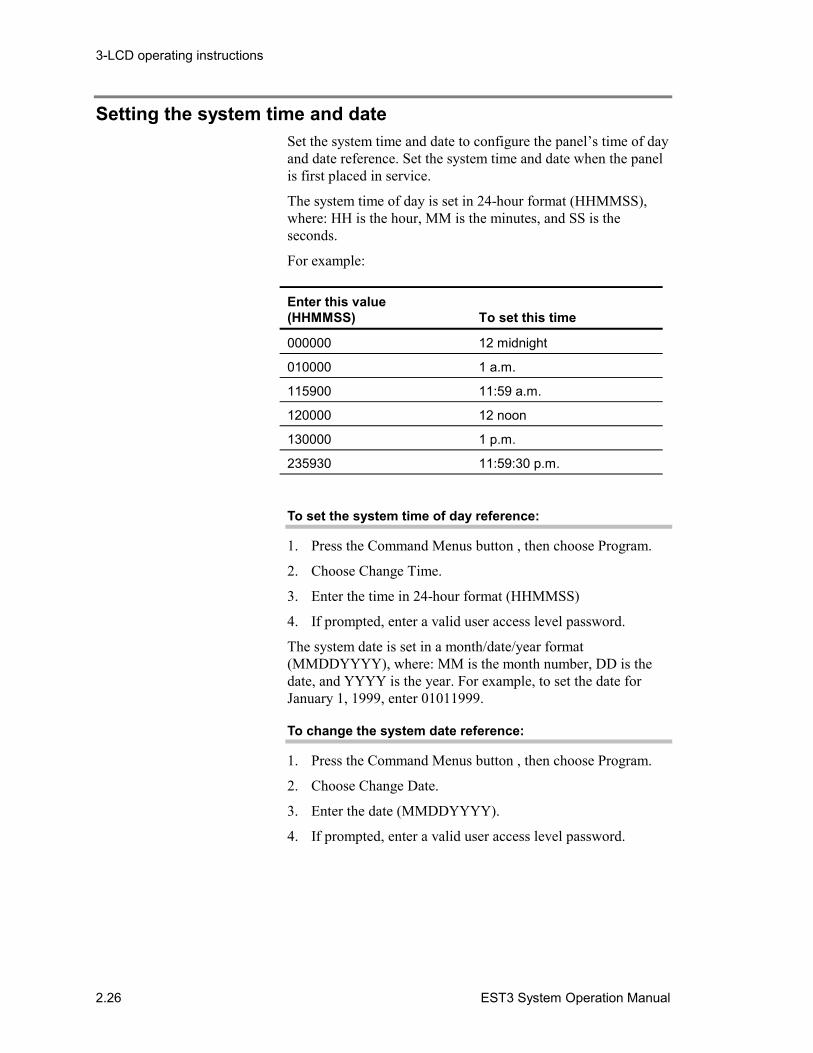
Setting the system time and dateSet the system time and date to configure the panel’s time of dayand date reference. Set the system time and date when the panelis first placed in service.
The system time of day is set in 24-hour format (HHMMSS),where: HH is the hour, MM is the minutes, and SS is theseconds.
For example:
Enter this value(HHMMSS) To set this time
000000 12 midnight
010000 1 a.m.
115900 11:59 a.m.
120000 12 noon
130000 1 p.m.
235930 11:59:30 p.m.
To set the system time of day reference:
1. Press the Command Menus button , then choose Program.
2. Choose Change Time.
3. Enter the time in 24-hour format (HHMMSS)
4. If prompted, enter a valid user access level password.
The system date is set in a month/date/year format(MMDDYYYY), where: MM is the month number, DD is thedate, and YYYY is the year. For example, to set the date forJanuary 1, 1999, enter 01011999.
To change the system date reference:
1. Press the Command Menus button , then choose Program.
2. Choose Change Date.
3. Enter the date (MMDDYYYY).
4. If prompted, enter a valid user access level password.
3-LCD operating instructions
EST3 System Operation Manual 2.27
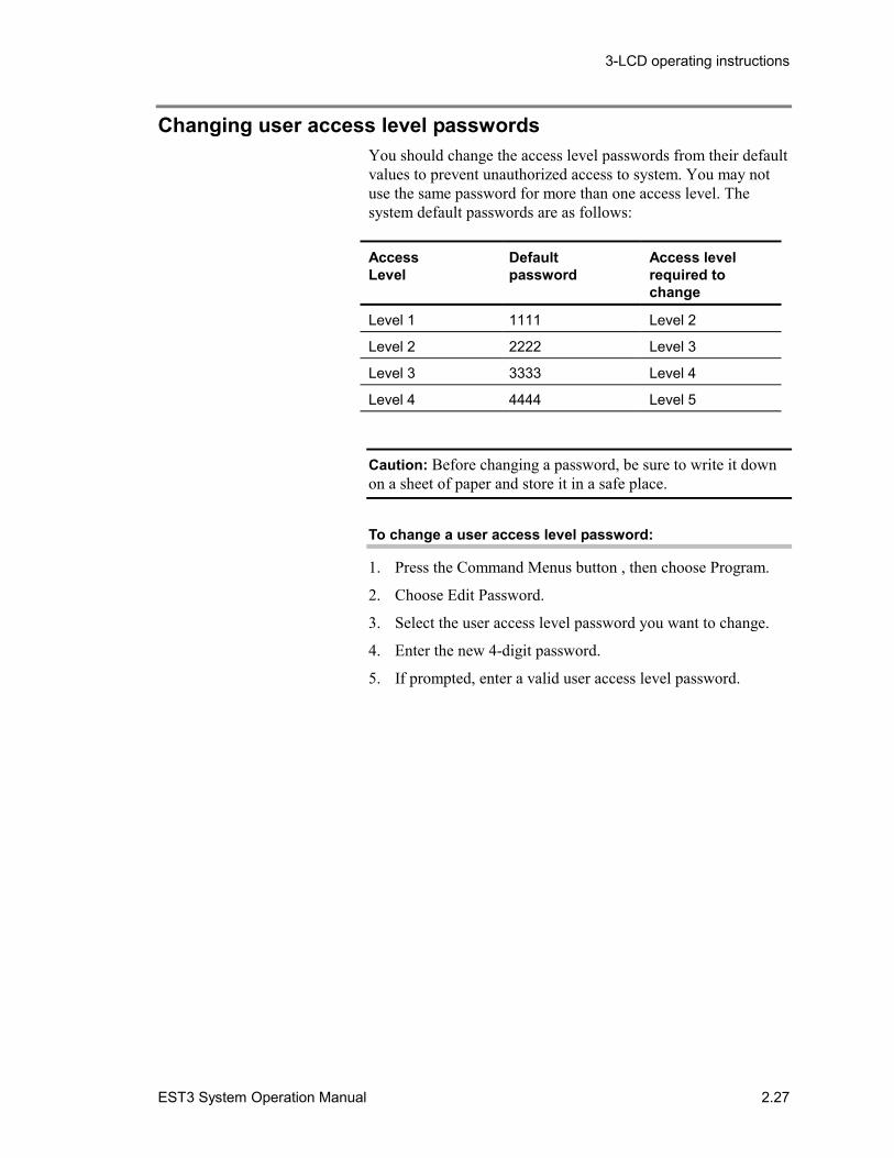
Changing user access level passwordsYou should change the access level passwords from their defaultvalues to prevent unauthorized access to system. You may notuse the same password for more than one access level. Thesystem default passwords are as follows:
AccessLevel
Defaultpassword
Access levelrequired tochange
Level 1 1111 Level 2
Level 2 2222 Level 3
Level 3 3333 Level 4
Level 4 4444 Level 5
Caution: Before changing a password, be sure to write it downon a sheet of paper and store it in a safe place.
To change a user access level password:
1. Press the Command Menus button , then choose Program.
2. Choose Edit Password.
3. Select the user access level password you want to change.
4. Enter the new 4-digit password.
5. If prompted, enter a valid user access level password.
3-LCD operating instructions
2.28 EST3 System Operation Manual
Restarting a panelRestarting a panel initiates the panel’s start up processes withoutfirst turning off the operating power.
To restart a panel:
1. Press the Command Menus button , then choose Program.
2. Choose Restart.
3. Choose whether to restart a single panel or all panels on thenetwork. If you choose to restart a single panel, then enterthe target panel’s 2-digit address (PP).
4. If prompted, enter a valid user access level password.
3-LCD operating instructions
EST3 System Operation Manual 2.29
Scheduling holidaysHolidays vary from installation to installation and may changefrom year to year. By scheduling holidays, a panel can activate atime-controlled event based on whether the day is a scheduledholiday.
Note: Each panel can store up to 255 holidays.
To schedule a holiday:
1. Press the Command Menus button , then choose Program.
2. Choose Edit Holiday List.
3. Choose Add Holiday.
4. Enter the holiday’s month and date (MMDD).
5. If prompted, enter a valid user access level password.
To delete a holiday from the list:
1. Press the Command Menus button , then choose Program.
2. Choose Edit Holiday List.
3. Select Delete Holiday.
4. Select the holiday from the list.
5. If prompted, enter a valid user access level password.
To change a holiday:
1. Press the Command Menus button , then choose Program.
2. Choose Edit Holiday List.
3. Choose Edit Holiday.
4. Select a holiday from the list.
5. Enter the new month and date (MMDD).
6. If prompted, enter a valid user access level password.
3-LCD operating instructions
2.30 EST3 System Operation Manual
Clearing the panel history fileClearing the panel’s history file:
• Resets the alarm history counter on the 3-LCD displaymodule
• Erases the list of events that occurred on the panel since thepanel was placed into service or the last time the history filewas cleared.
Caution: Clearing the panel history file means that all historydata for the panel is permanently deleted. This commandrequires a level 4 password, and is for use by an authorizedservice technician only.
To clear the alarm history:
1. Press the Command Menus button .
2. Choose Program, then choose Clear History.
3. If prompted, enter a valid user access level password.
3-LCD operating instructions
EST3 System Operation Manual 2.31
Testing alarm input devicesIn order to test an alarm input device, the device must be part ofa service group. Service groups allow alarm input devices to beactivated without placing the system into alarm. The protectedpremises may be divided into more than one service group tomake testing possible without leaving the entire premisesunprotected.
Without any additional programming, you can test alarm inputdevices by:
• Putting the service group into test
• Activating each of the devices in the service group
• Verifying each of the devices show up on the active pointslist
• Canceling the test
Note: Putting a service group into test introduces a ServiceGroup Active event in the trouble queue. You can press theDetails button to verify which service group is in test.
To put a service group into test:
1. Press the Command Menus button , then choose Test.
2. Choose Start Test.
3. Select the service group.
4. If prompted, enter a valid user access level password.
To cancel the test:
1. Press the Command Menus button , then choose Test.
2. Choose Cancel Test.
3. Select the service group that is in test.
4. If prompted, enter a valid user access level password.
Note: A service group will automatically time-out and cancelafter approximately 1 hour of inactivity.

3-LCD operating instructions
2.32 EST3 System Operation Manual
EST3 System Operation Manual 3.1
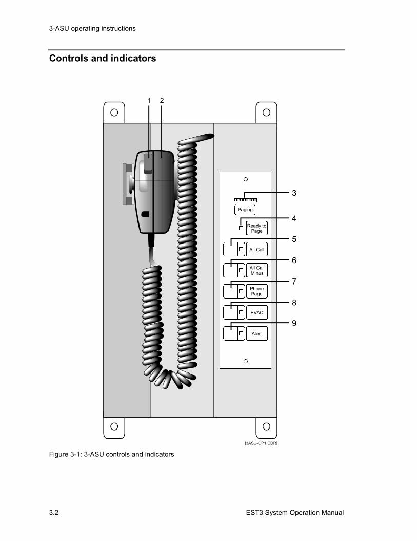
Chapter 3 3-ASU operating instructions
Summary
This chapter provides a functional description of the controls andindicators provided on the 3-ASU Audio Source Unit. The 3-ASU is the control point for all the audio signals distributed bythe system.
ContentControls and indicators • 3.2Operation the Audio Source Unit • 3.4
Event signaling • 3.4Basic response tasks • 3.5Paging sequence • 3.5Phone page • 3.5Paging with the remote microphone • 3.6
Optional audio zone controls • 3.7
3-ASU operating instructions
3.2 EST3 System Operation Manual
Controls and indicators
[3ASU-OP1.CDR]
Ready toPage
Paging
All Call
All CallMinus
PhonePage
EVAC
Alert
1 2
3
4
5
6
7
8
9
Figure 3-1: 3-ASU controls and indicators
3-ASU operating instructions
EST3 System Operation Manual 3.3
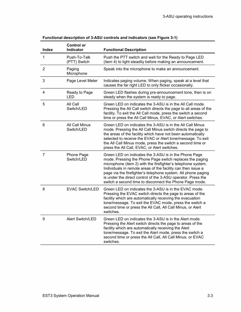
Functional description of 3-ASU controls and indicators (see Figure 3-1)
IndexControl orIndicator Functional Description
1 Push-To-Talk(PTT) Switch
Push the PTT switch and wait for the Ready to Page LED(item 4) to light steadily before making an announcement.
2 PagingMicrophone
Speak into the microphone to make an announcement.
3 Page Level Meter Indicates paging volume. When paging, speak at a level thatcauses the far right LED to only flicker occasionally.
4 Ready to PageLED
Green LED flashes during pre-announcement tone, then is onsteady when the system is ready to page.
5 All CallSwitch/LED
Green LED on indicates the 3-ASU is in the All Call mode.Pressing the All Call switch directs the page to all areas of thefacility. To exit the All Call mode, press the switch a secondtime or press the All Call Minus, EVAC, or Alert switches.
6 All Call MinusSwitch/LED
Green LED on indicates the 3-ASU is in the All Call Minusmode. Pressing the All Call Minus switch directs the page tothe areas of the facility which have not been automaticallyselected to receive the EVAC or Alert tone/message. To exitthe All Call Minus mode, press the switch a second time orpress the All Call, EVAC, or Alert switches.
7 Phone PageSwitch/LED
Green LED on indicates the 3-ASU is in the Phone Pagemode. Pressing the Phone Page switch replaces the pagingmicrophone (item 2) with the firefighter’s telephone system.Individuals in remote areas of the facility can then issue apage via the firefighter’s telephone system. All phone pagingis under the direct control of the 3-ASU operator. Press theswitch a second time to disconnect the Phone Page mode.
8 EVAC Switch/LED Green LED on indicates the 3-ASU is in the EVAC mode.Pressing the EVAC switch directs the page to areas of thefacility which are automatically receiving the evacuationtone/message. To exit the EVAC mode, press the switch asecond time or press the All Call, All Call Minus, or Alertswitches.
9 Alert Switch/LED Green LED on indicates the 3-ASU is in the Alert mode.Pressing the Alert switch directs the page to areas of thefacility which are automatically receiving the Alerttone/message. To exit the Alert mode, press the switch asecond time or press the All Call, All Call Minus, or EVACswitches.
3-ASU operating instructions
3.4 EST3 System Operation Manual
Operation the Audio Source UnitThe function of a life safety system is to alert people occupying afacility of an emergency. The Audio Source Unit is designed topermit rapid selection and paging to the affected areas of thefacility. For example, the page signal automatically overridesany other signals.
Event signalingIn large facilities, the people most effected by an emergencyshould be instructed to evacuate the area immediately, andpeople not in immediate danger should receive an alert signal.Since most large facilities have a significant number of transientoccupants, the most effective signaling is a combination ofattention getting tones, followed by instructional messages.
The information provided here is general in nature. Each facilityis unique. The life safety system in your facility has beendesigned by fire safety professionals to meet the specificrequirements of the fire codes in your location. Please refer tothe site-specific instructions provider by the installer todetermine the exact operation of your system.
Evacuation (EVAC) Signaling
The evacuation signal notifies facility occupants that they are inimmediate danger, and must evacuate the area. Evacuationsignals can take the form of bells, horns, tones, and audiomessages. Accompanying the audio message is a visualnotification appliance, typically a flashing strobe light.
The system automatically activates all the evacuation signals inthe affected areas of the facility.
Alert Signaling (optional)
The alert signal notifies the occupants of a facility that: anemergency event is in progress; they are not in immediatedanger; and they should prepare to evacuate, but not to evacuateat this time. Alert signals are typically tones or audio messages.
The system automatically activates the alert signals (ifprogrammed in your system) in the affected areas of the facility.
Page Messages
The most reliable source of information about an emergencyevent comes from the individual who is in charge of the facilityduring the emergency. This individual is typically the fire chiefor facility manager. The page function permits the individual incharge to make announcements to selected portions of the
3-ASU operating instructions
EST3 System Operation Manual 3.5
building, advising occupants of what actions to take for safeegress, etc.
Basic response tasksThe basic tasks in responding to an emergency event are:
1. Use the All Call function to announce the arrival of the firedepartment, making any necessary announcements.
2. Use the Page to Evac function to reinforce the evacuation ofthe occupants in areas receiving the evacuation signal. As anexample, occupants may be directed to follow the evacuationplan, not to use the elevators, etc.
3. Use the Page to Alert function to notify the areas not inimmediate danger to prepare to evacuate, or that people inthe evacuation area may be entering their area as an area ofrefuge.
4. Use the All Call Minus switch to make announcements toareas of the facility not receiving the Evac or Alert signals,as required. Stairwells are typical areas accessed using theAll Call Minus page function.
5. The zone page controls may be used to manually selectpaging areas.
Paging sequenceSelect the areas to receive the page by pressing the appropriatepage function switch(s). The switch’s integral LED will be onsteady when the system is ready to receive the page.
Press the PTT switch on the microphone. The Ready to PageLED will flash while the pre-announcement tone is sounding.Begin the announcement once the Ready to Page LED is onsteady. Adjust your voice level so that the far right LED on thevolume meter only flickers occasionally. Release the PTT switchwhen the announcement is finished. The system will turn off thepage, and return to its pre-page condition after a short delay.
Note: The local microphone has priority over a telephone page,which has priority over a remote microphone page.
Each installation is customized. Please refer to your site-specificdocumentation to determine which areas of your facilityautomatically receives the page, or how to select the areas toreceive the page.
Phone pageIf your system is equipped with a firefighter’s telephone circuit,you can connect the telephone circuit to the page function bypressing the Phone Page switch. This permits an individual
3-ASU operating instructions
3.6 EST3 System Operation Manual
talking on the firefighter’s telephone system to makeannouncements over the paging system.
Establish the phone connection over the Firefighter’s TelephoneControl Unit. Select the areas to receive the page the same wayas if it were to be originated using the microphone. Instruct theindividual who is remote paging to begin speaking after the pre-announcement tone has finished. Press the Phone Page Switchand begin the phone page. The phone page is under completecontrol of the 3-ASU/FT, and may be interrupted at any time bypressing the Phone Page switch a second time.
Paging with the remote microphoneIf your system is equipped with the remote paging microphone,it may be used to issue pages throughout the facility. The remotemicrophone page is automatically overridden by any pagesissued by the local microphone in the Audio Source Unit or aphone page.
Each remote microphone installation is customized. Please referto your site-specific documentation to determine which areas ofyour facility automatically receives the page, or how to select theareas to receive the page.
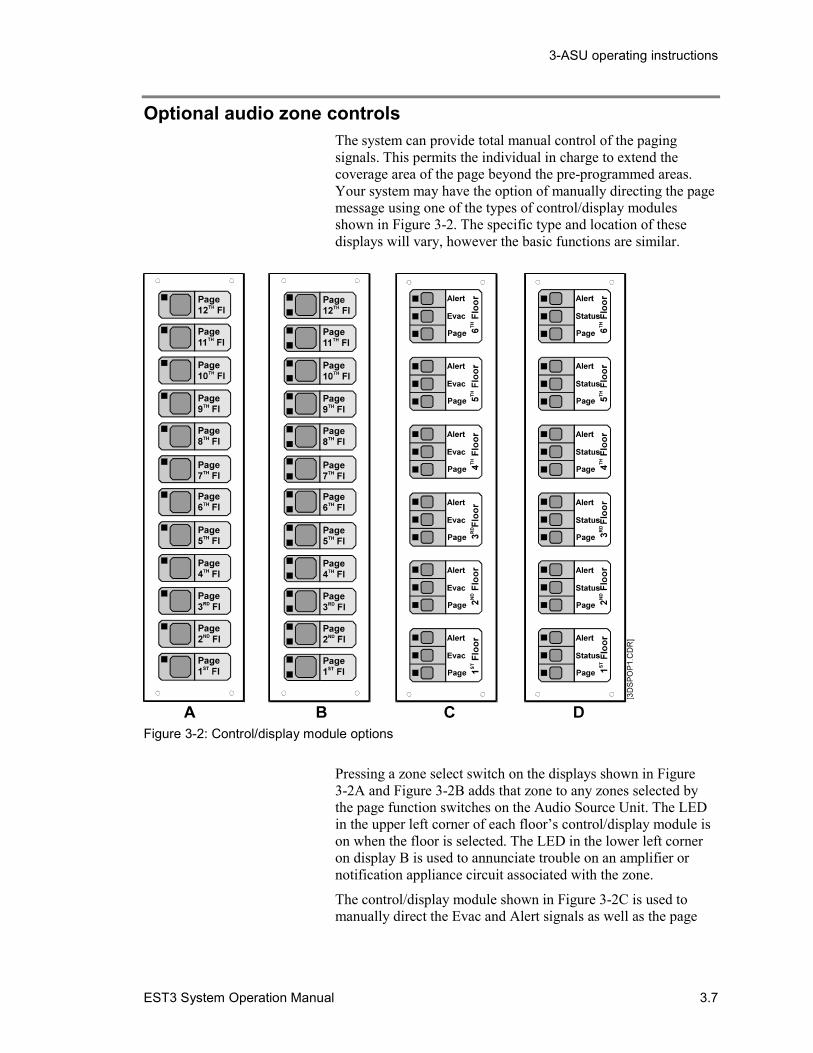
3-ASU operating instructions
EST3 System Operation Manual 3.7
Optional audio zone controlsThe system can provide total manual control of the pagingsignals. This permits the individual in charge to extend thecoverage area of the page beyond the pre-programmed areas.Your system may have the option of manually directing the pagemessage using one of the types of control/display modulesshown in Figure 3-2. The specific type and location of thesedisplays will vary, however the basic functions are similar.
Figure 3-2: Control/display module options
Pressing a zone select switch on the displays shown in Figure3-2A and Figure 3-2B adds that zone to any zones selected bythe page function switches on the Audio Source Unit. The LEDin the upper left corner of each floor’s control/display module ison when the floor is selected. The LED in the lower left corneron display B is used to annunciate trouble on an amplifier ornotification appliance circuit associated with the zone.
The control/display module shown in Figure 3-2C is used tomanually direct the Evac and Alert signals as well as the page
3-ASU operating instructions
3.8 EST3 System Operation Manual
message to individual areas of the facility. The LEDs can beprogrammed to follow any automatic system responses as wellas manual audio zone selections.
The control/display module shown in Figure 3-2D is used tomanually direct the Evac signal and pages to individual areas ofthe facility. The center switch is inoperative. This configurationis typically used in facilities where the alert signal isautomatically sent to all areas not receiving the evacuationsignal. The LEDs follow any automatic system responses as wellas manual audio zone selections. The Status LED can beprogrammed to indicate the trouble state of the zone amplifier.
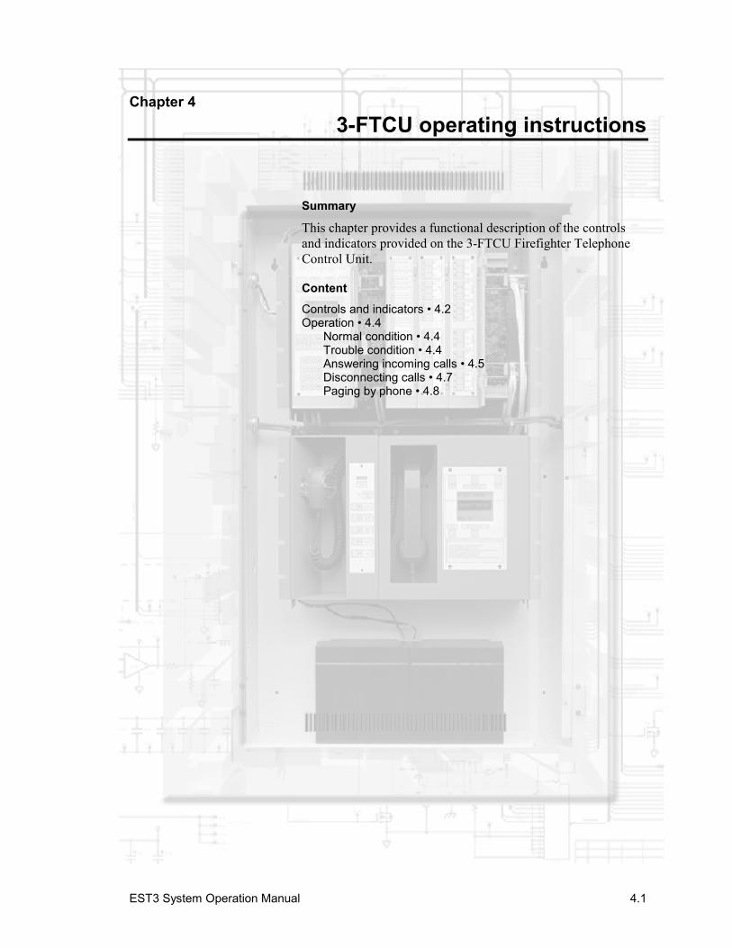
EST3 System Operation Manual 4.1
Chapter 4 3-FTCU operating instructions
Summary
This chapter provides a functional description of the controlsand indicators provided on the 3-FTCU Firefighter TelephoneControl Unit.
ContentControls and indicators • 4.2Operation • 4.4
Normal condition • 4.4Trouble condition • 4.4Answering incoming calls • 4.5Disconnecting calls • 4.7Paging by phone • 4.8
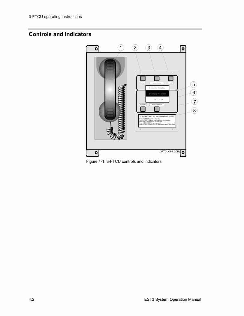
3-FTCU operating instructions
4.2 EST3 System Operation Manual
Controls and indicators
[3FTCUOP1.CDR]
31 2 4
56
7
8
Unit: ok
0 Calls Pending
DISCONNECT R EVIEW CONNECTED
CONNEC T R EVIEW PEND ING ACK
To Answer call, LIFT PHONE HANDSET and,Press CONNECT to select call pendingPress REVIEW PENDING to scroll pending for connectionPress ACK to silence phone call-in buzzerPress DISCONNECT to terminate a callPress REVIEW CONNECTED to select active calls for disconnect
Figure 4-1: 3-FTCU controls and indicators
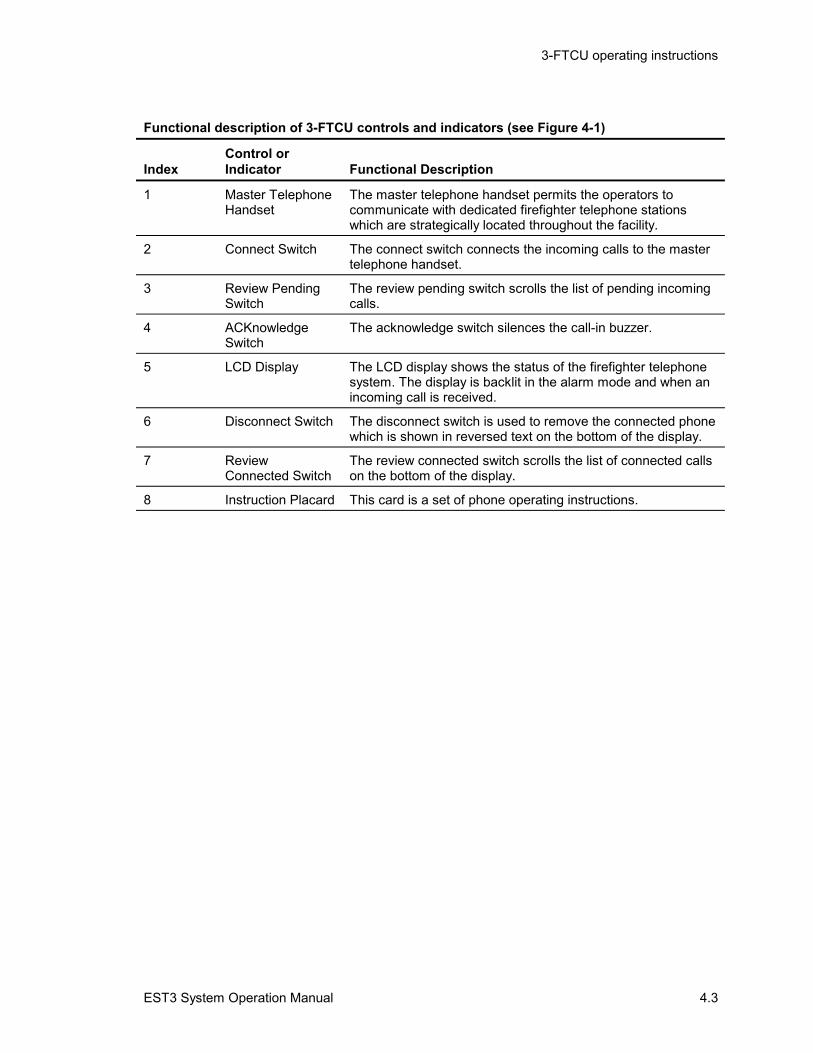
3-FTCU operating instructions
EST3 System Operation Manual 4.3
Functional description of 3-FTCU controls and indicators (see Figure 4-1)
IndexControl orIndicator Functional Description
1 Master TelephoneHandset
The master telephone handset permits the operators tocommunicate with dedicated firefighter telephone stationswhich are strategically located throughout the facility.
2 Connect Switch The connect switch connects the incoming calls to the mastertelephone handset.
3 Review PendingSwitch
The review pending switch scrolls the list of pending incomingcalls.
4 ACKnowledgeSwitch
The acknowledge switch silences the call-in buzzer.
5 LCD Display The LCD display shows the status of the firefighter telephonesystem. The display is backlit in the alarm mode and when anincoming call is received.
6 Disconnect Switch The disconnect switch is used to remove the connected phonewhich is shown in reversed text on the bottom of the display.
7 ReviewConnected Switch
The review connected switch scrolls the list of connected callson the bottom of the display.
8 Instruction Placard This card is a set of phone operating instructions.
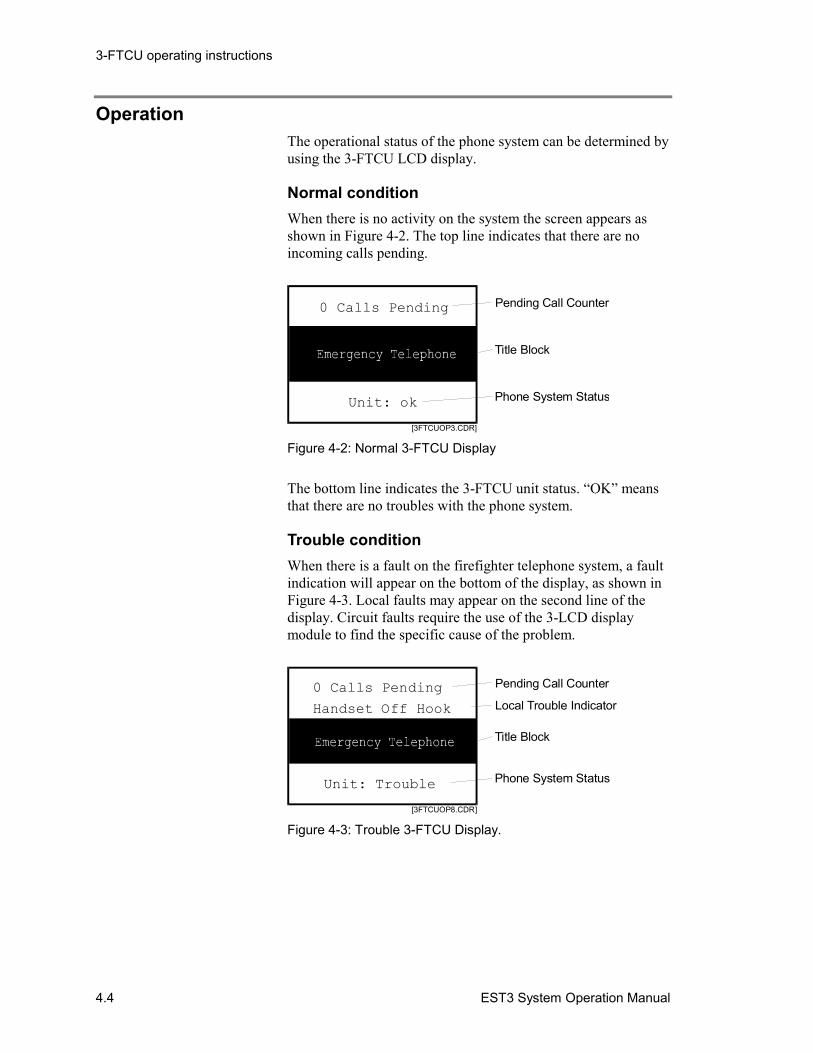
3-FTCU operating instructions
4.4 EST3 System Operation Manual
OperationThe operational status of the phone system can be determined byusing the 3-FTCU LCD display.
Normal conditionWhen there is no activity on the system the screen appears asshown in Figure 4-2. The top line indicates that there are noincoming calls pending.
[3FTCUOP3.CDR]
Pending Call Counter
Phone System Status
Title Block
Unit: ok
0 Calls Pending
Figure 4-2: Normal 3-FTCU Display
The bottom line indicates the 3-FTCU unit status. “OK” meansthat there are no troubles with the phone system.
Trouble conditionWhen there is a fault on the firefighter telephone system, a faultindication will appear on the bottom of the display, as shown inFigure 4-3. Local faults may appear on the second line of thedisplay. Circuit faults require the use of the 3-LCD displaymodule to find the specific cause of the problem.
[3FTCUOP8.CDR]
Pending Call Counter
Local Trouble Indicator
Phone System Status
Title Block
Unit: Trouble
0 Calls Pending
Handset Off Hook
Figure 4-3: Trouble 3-FTCU Display.
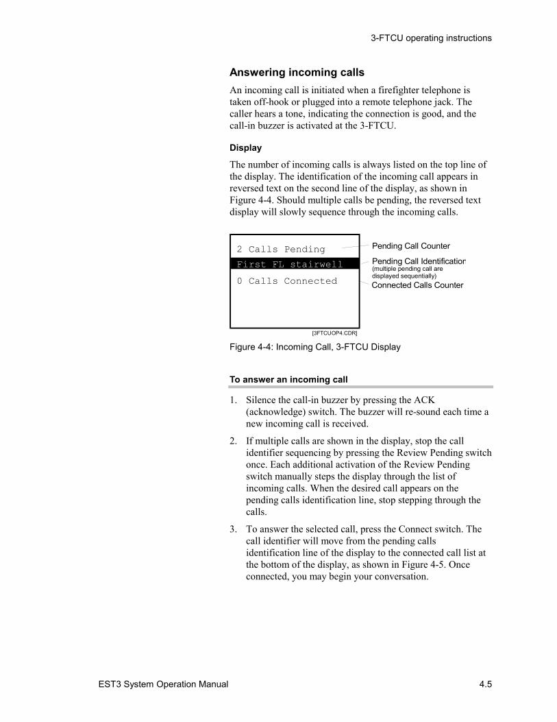
3-FTCU operating instructions
EST3 System Operation Manual 4.5
Answering incoming callsAn incoming call is initiated when a firefighter telephone istaken off-hook or plugged into a remote telephone jack. Thecaller hears a tone, indicating the connection is good, and thecall-in buzzer is activated at the 3-FTCU.
Display
The number of incoming calls is always listed on the top line ofthe display. The identification of the incoming call appears inreversed text on the second line of the display, as shown inFigure 4-4. Should multiple calls be pending, the reversed textdisplay will slowly sequence through the incoming calls.
[3FTCUOP4.CDR]
Pending Call Counter
Pending Call Identification(multiple pending call aredisplayed sequentially)Connected Calls Counter0 Calls Connected
2 Calls Pending
First FL stairwell
Figure 4-4: Incoming Call, 3-FTCU Display
To answer an incoming call
1. Silence the call-in buzzer by pressing the ACK(acknowledge) switch. The buzzer will re-sound each time anew incoming call is received.
2. If multiple calls are shown in the display, stop the callidentifier sequencing by pressing the Review Pending switchonce. Each additional activation of the Review Pendingswitch manually steps the display through the list ofincoming calls. When the desired call appears on thepending calls identification line, stop stepping through thecalls.
3. To answer the selected call, press the Connect switch. Thecall identifier will move from the pending callsidentification line of the display to the connected call list atthe bottom of the display, as shown in Figure 4-5. Onceconnected, you may begin your conversation.
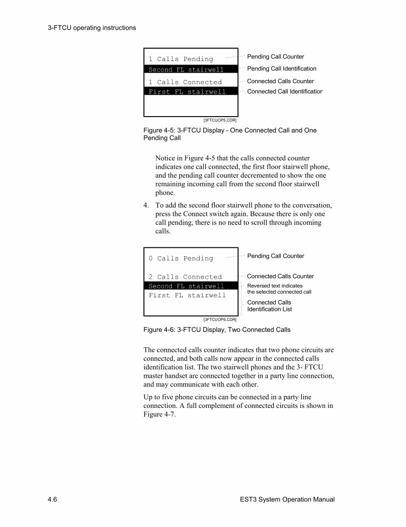
3-FTCU operating instructions
4.6 EST3 System Operation Manual
[3FTCUOP5.CDR]
Pending Call Counter
Connected Call Identification
Pending Call Identification
Connected Calls Counter1 Calls Connected
1 Calls Pending
First FL stairwell
Figure 4-5: 3-FTCU Display - One Connected Call and OnePending Call
Notice in Figure 4-5 that the calls connected counterindicates one call connected, the first floor stairwell phone,and the pending call counter decremented to show the oneremaining incoming call from the second floor stairwellphone.
4. To add the second floor stairwell phone to the conversation,press the Connect switch again. Because there is only onecall pending, there is no need to scroll through incomingcalls.
[3FTCUOP6.CDR]
Pending Call Counter
Connected CallsIdentification List
Connected Calls CounterReversed text indicatesthe selected connected call
2 Calls Connected
0 Calls Pending
First FL stairwell
Figure 4-6: 3-FTCU Display, Two Connected Calls
The connected calls counter indicates that two phone circuits areconnected, and both calls now appear in the connected callsidentification list. The two stairwell phones and the 3- FTCUmaster handset are connected together in a party line connection,and may communicate with each other.
Up to five phone circuits can be connected in a party lineconnection. A full complement of connected circuits is shown inFigure 4-7.
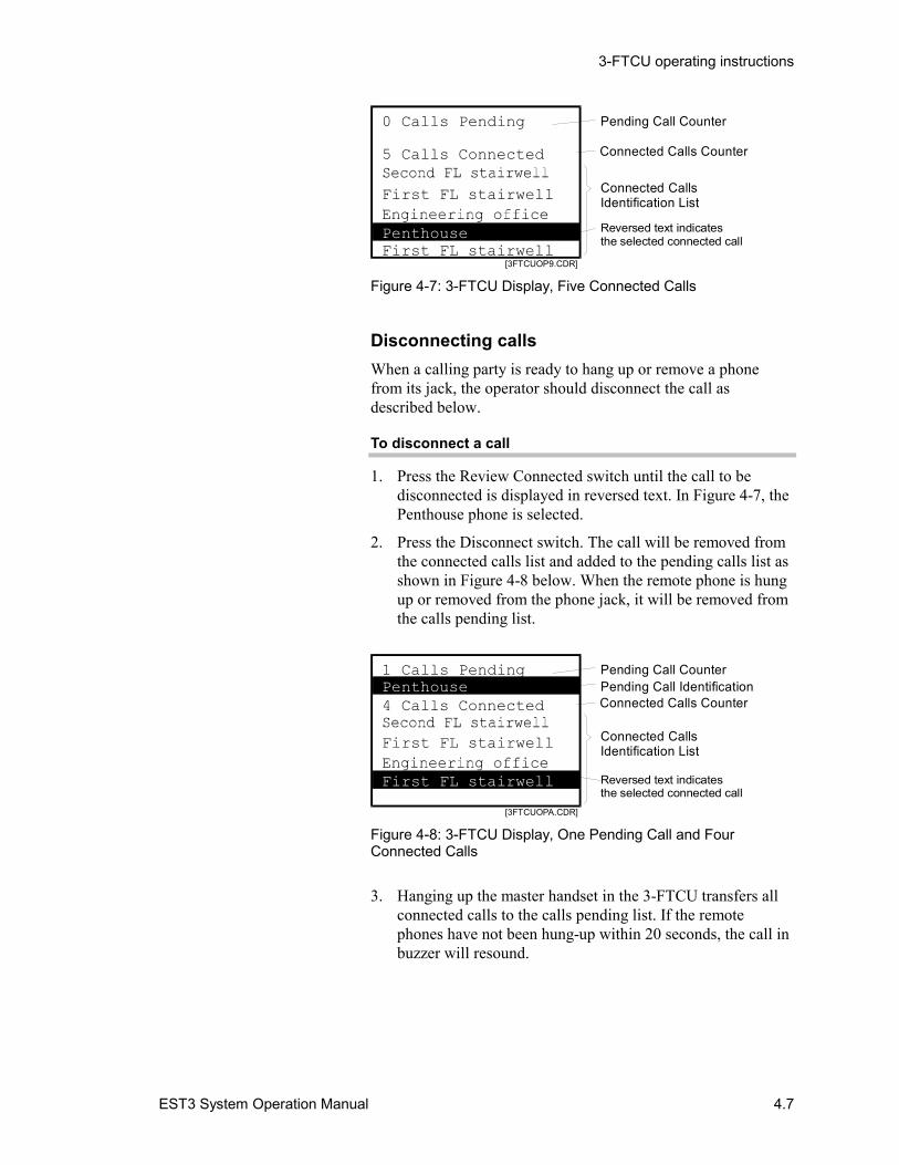
3-FTCU operating instructions
EST3 System Operation Manual 4.7
[3FTCUOP9.CDR]
Pending Call Counter
Connected CallsIdentification List
Connected Calls Counter
Reversed text indicatesthe selected connected call
5 Calls Connected
0 Calls Pending
First FL stairwell
PenthouseFirst FL stairwell
Figure 4-7: 3-FTCU Display, Five Connected Calls
Disconnecting callsWhen a calling party is ready to hang up or remove a phonefrom its jack, the operator should disconnect the call asdescribed below.
To disconnect a call
1. Press the Review Connected switch until the call to bedisconnected is displayed in reversed text. In Figure 4-7, thePenthouse phone is selected.
2. Press the Disconnect switch. The call will be removed fromthe connected calls list and added to the pending calls list asshown in Figure 4-8 below. When the remote phone is hungup or removed from the phone jack, it will be removed fromthe calls pending list.
[3FTCUOPA.CDR]
Pending Call CounterPending Call Identification
Connected CallsIdentification List
Reversed text indicatesthe selected connected call
Connected Calls Counter4 Calls Connected
1 Calls Pending
First FL stairwell
Penthouse
First FL stairwell
Figure 4-8: 3-FTCU Display, One Pending Call and FourConnected Calls
3. Hanging up the master handset in the 3-FTCU transfers allconnected calls to the calls pending list. If the remotephones have not been hung-up within 20 seconds, the call inbuzzer will resound.
3-FTCU operating instructions
4.8 EST3 System Operation Manual
Paging by phoneThe phone page feature of the 3-ASU audio source unit permitsindividuals with access to a remote firefighter telephone to makeannouncements over the emergency voice/alarmcommunications system, under the supervision of the AudioSource Unit operator.
1. Establish a phone connection with the remote phone whichis to issue the page.
2. Set up the areas to receive the page using one of the ASUpage area functions and/or manual switch selection ofadditional audio zones.
3. When ready to begin the paging sequence, the ASU operatorshould press the Phone Page switch.
4. Begin the announcement. The 3-ASU operator can monitorthe page using the master handset.
EST3 System Operation Manual A.1
Appendix A System addresses
Summary
This appendix provides a quick reference for interpreting themapping of system addresses.
ContentAddress format • A.2LRM addresses • A.4Control / display module addresses • A.8Device addresses • A.10
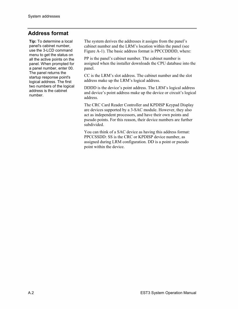
System addresses
A.2 EST3 System Operation Manual
Address formatThe system derives the addresses it assigns from the panel’scabinet number and the LRM’s location within the panel (seeFigure A-1). The basic address format is PPCCDDDD, where:
PP is the panel’s cabinet number. The cabinet number isassigned when the installer downloads the CPU database into thepanel.
CC is the LRM’s slot address. The cabinet number and the slotaddress make up the LRM’s logical address.
DDDD is the device’s point address. The LRM’s logical addressand device’s point address make up the device or circuit’s logicaladdress.
The CRC Card Reader Controller and KPDISP Keypad Displayare devices supported by a 3-SAC module. However, they alsoact as independent processors, and have their own points andpseudo points. For this reason, their device numbers are furthersubdivided.
You can think of a SAC device as having this address format:PPCCSSDD: SS is the CRC or KPDISP device number, asassigned during LRM configuration. DD is a point or pseudopoint within the device.
Tip: To determine a localpanel's cabinet number,use the 3-LCD commandmenu to get the status onall the active points on thepanel. When prompted fora panel number, enter 00.The panel returns thestartup response point'slogical address. The firsttwo numbers of the logicaladdress is the cabinetnumber.
System addresses
EST3 System Operation Manual A.3
OU
TPU
TM
OD
ULE
SIGA2 SIGA2 SIGA2
B-
B+
A-
A+
SH
B-
B+
PWRK
MS
2
A-
PB+
B-
A+
SIGA1
S B+
B-
K RWM
1
SH
SIGA1 SIGA1
0102 01360129 01370001
Signature detectors01020001 - 01020125
Signature modules01020126 - 01020250
01360152 01370012
[SYS_ADDR_EX1.CDR]
Cabinet #1
Slot 1 Slot 2 Slot 3 Slot 4 Slot 5 Slot 6 Slot 7
Figure A-1: Addressing example

System addresses
A.4 EST3 System Operation Manual
LRM addressesFigure A-2, Figure A-3, and Figure A-4 show the logicaladdresses that the system assigns to LRMs based on the panelconfigurations.
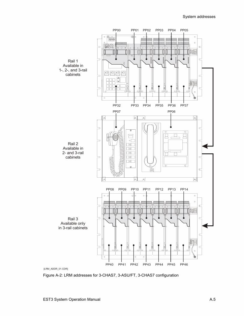
System addresses
EST3 System Operation Manual A.5
TB1
SU P
C
ALARMTROUB LECN
ON C
ON C -
A CN N
ON
CN
NE TW ORK
+B
+A A
-
AU DIOAU DIOB- +
A I N A OU T+- -
RX1 1 1
TX
RTS
21 2 2
C
XOM
RR
TX
TS
2
COMINOUT B OU T
AU DIO
++
AU DIOB I N
- -
J1
AUXILIARY POWER1 2
PP33
PP42
PP01
PP10
PP32
PP40 PP41
PP00
PP08 PP09
PP34
PP43
PP02
PP11
PP35
PP44
PP03
PP12
PP36
PP45
PP04
PP13
PP37
PP46
PP05
PP14
PP06PP07
Rail 1Available in
1-, 2-, and 3-railcabinets
Rail 2Available in2- and 3-rail
cabinets
Rail 3Available only
in 3-rail cabinets
[LRM_ADDR_01.CDR]
Figure A-2: LRM addresses for 3-CHAS7, 3-ASU/FT, 3-CHAS7 configuration
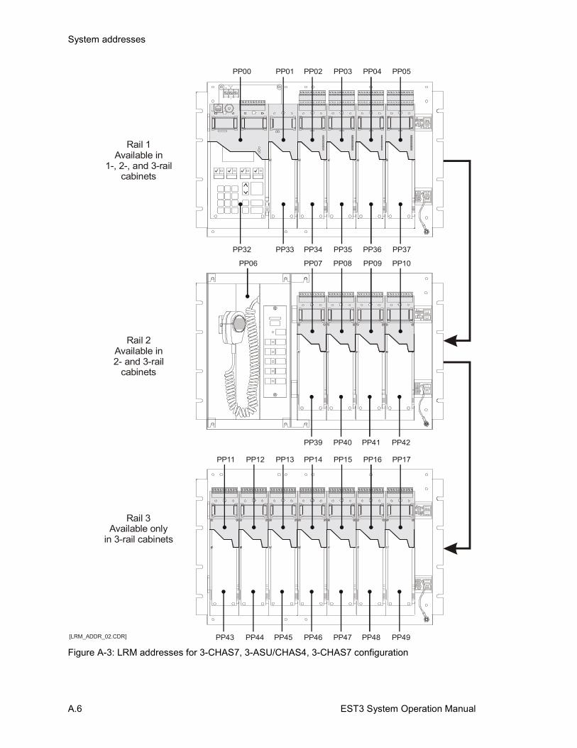
System addresses
A.6 EST3 System Operation Manual
TB1
SU P
C
ALARMTROUB LECN
ON C
ON C -
A CN N
ON
CN
NE TW ORK
+B
+A A
-
AU DIOAU DIOB- +
A I N A OU T+- -
RX1 1 1
TX
RTS
21 2 2
C
XOM
RR
TX
TS
2
COMINOUT B OU T
AU DIO
++
AU DIOB I N
- -
J1
AUXILIARY POWER1 2
PP33
PP45
PP01
PP13
PP32
PP43 PP44
PP00
PP11 PP12
PP34
PP46
PP02
PP14
PP07PP06
PP35
PP47
PP03
PP15
PP08
PP36
PP48
PP04
PP16
PP09
PP37
PP49
PP05
PP17
PP10
PP39 PP40 PP41 PP42
Rail 1Available in
1-, 2-, and 3-railcabinets
Rail 2Available in2- and 3-rail
cabinets
Rail 3Available only
in 3-rail cabinets
[LRM_ADDR_02.CDR]
Figure A-3: LRM addresses for 3-CHAS7, 3-ASU/CHAS4, 3-CHAS7 configuration
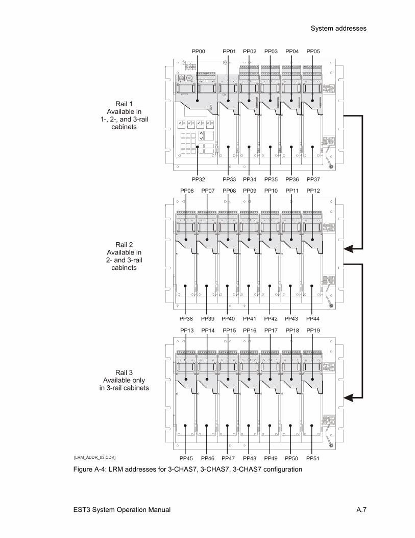
System addresses
EST3 System Operation Manual A.7
TB1
SU P
C
ALARMTROUB LECN
ON C
ON C -
A CN N
ON
CN
NE TW ORK
+B
+A A
-
AU DIOAU DIOB- +
A I N A OU T+- -
RX1 1 1
TX
RTS
21 2 2
C
XOM
RR
TX
TS
2
COMINOUT B OU T
AU DIO
++
AU DIOB I N
- -
J1
AUXILIARY POWER1 2
PP33
PP47
PP40
PP01
PP15
PP08
PP32
PP45
PP38
PP46
PP39
PP00
PP13
PP06
PP14
PP07
PP34
PP48
PP41
PP02
PP16
PP09
PP35
PP49
PP42
PP03
PP17
PP10
PP36
PP50
PP43
PP04
PP18
PP11
PP37
PP51
PP44
PP05
PP19
PP12
Rail 1Available in
1-, 2-, and 3-railcabinets
Rail 2Available in2- and 3-rail
cabinets
Rail 3Available only
in 3-rail cabinets
[LRM_ADDR_03.CDR]
Figure A-4: LRM addresses for 3-CHAS7, 3-CHAS7, 3-CHAS7 configuration

System addresses
A.8 EST3 System Operation Manual
Control / display module addressesFigure A-5 shows the device logical addresses that the systemassigns the control/display modules.
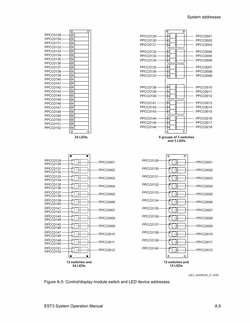
System addresses
EST3 System Operation Manual A.9
PPCC0001 PPCC0001
PPCC0002 PPCC0002
PPCC0003 PPCC0003
PPCC0004 PPCC0004
PPCC0005 PPCC0005
PPCC0006 PPCC0006
PPCC0007 PPCC0007
PPCC0008 PPCC0008
PPCC0009 PPCC0009
PPCC0010 PPCC0010
PPCC0011 PPCC0011
PPCC0012 PPCC0012
PPCC0129 PPCC0129
PPCC0141 PPCC0135
PPCC0130
PPCC0142
PPCC0133 PPCC0131
PPCC0145 PPCC0137
PPCC0136
PPCC0148
PPCC0131 PPCC0130
PPCC0143 PPCC0136
PPCC0134
PPCC0146
PPCC0137 PPCC0133
PPCC0149 PPCC0139
PPCC0132
PPCC0144
PPCC0135 PPCC0132
PPCC0147 PPCC0138
PPCC0138
PPCC0150
PPCC0139 PPCC0134
PPCC0151 PPCC0140
PPCC0140
PPCC0152
PPCC0129
PPCC0141
PPCC0130
PPCC0142
PPCC0133
PPCC0145
PPCC0136
PPCC0148
PPCC0131
PPCC0143
PPCC0134
PPCC0146
PPCC0137
PPCC0149
PPCC0132
PPCC0144
PPCC0135
PPCC0147
PPCC0138
PPCC0150
PPCC0139
PPCC0151
PPCC0140
PPCC0152
24 LEDs
PPCC0129
PPCC0132
PPCC0135
PPCC0138
PPCC0141
PPCC0144
PPCC0001
PPCC0004
PPCC0007
PPCC0010
PPCC0013
PPCC0016
PPCC0130
PPCC0133
PPCC0136
PPCC0139
PPCC0142
PPCC0145
PPCC0002
PPCC0005
PPCC0008
PPCC0011
PPCC0014
PPCC0017
PPCC0131
PPCC0134
PPCC0137
PPCC0140
PPCC0143
PPCC0146
PPCC0003
PPCC0006
PPCC0009
PPCC0012
PPCC0015
PPCC0018
6 groups of 3 switchesand 3 LEDs
12 switches and12 LEDs
12 switches and24 LEDs
[DEV_ADDRESS_01.CDR]
Figure A-5: Control/display module switch and LED device addresses

System addresses
A.10 EST3 System Operation Manual
Device addressesFigure A-6 shows the device logical addresses that the systemassigns to various rail modules.
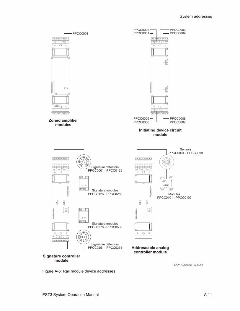
System addresses
EST3 System Operation Manual A.11
TB2
TB1
J1
IDC /NAC1
IDC /NAC2
IDC3
IDC4
NAC IN1/2
JP1
JP3
JP2
JP4
IDC /NAC5
IDC /NAC6
IDC7
IDC8
NAC IN5/6
PPCC0001
PPCC0006
PPCC0004
PPCC0007
PPCC0002
PPCC0005
PPCC0003
PPCC0008
TB2
TB1
J3J4
JP1
JP2
11
NAC /B-+
24VD CUN USEDUN USEDUN USED UN USED
+- -
BACK-UP
+
NAC /BNAC /A
-- SS ++
PPCC0001
Zoned amplifiermodules
Initiating device circuitmodule
Signature controllermodule
Addressable analogcontroller module
OU
TP
UT
MO
DU
LE
SIGA2 SIGA2 SIGA2
A A SH
BB BBPWRK
MS2
A PB B A
SIGA1
S B B
KRWM
1
SH
SIGA1 SIGA1
Signature detectorsPPCC0001 - PPCC0125
SensorsPPCC0001 - PPCC0099
Signature detectorsPPCC0251 - PPCC0375
Signature modulesPPCC0126 - PPCC0250 Modules
PPCC0101 - PPCC0199
Signature modulesPPCC0376 - PPCC0500
[DEV_ADDRESS_02.CDR]
OU
TP
UT M
OD
ULE
AB B A
LOOP1
N/C N/CB BSH
LOOP1 LOOP1
Figure A-6: Rail module device addresses

System addresses
A.12 EST3 System Operation Manual
EST3 System Operation Manual B.1
Appendix B Operation sequence charts
Summary
This appendix summarizes the operation of the system in a seriesof convenient charts.
ContentTable B-1: Fire Alarm Sequence - 3-LCD Display
Response • B.2Table B-2: Fire Alarm Sequence - Common Feature
Response • B.2Table B-3: Fire Alarm Sequence - Zone Annunciation • B.3Table B-4: Fire Alarm Sequence - Notification Appliance Circuits
(Default Operation) • B.3Table B-5: Fire Alarm Sequence - Off Premise Connection • B.3Table B-6: Trouble Sequence - 3-LCD Display Response • B.4Table B-7: Trouble Sequence - Common Feature
Response • B.4Table B-8: Trouble Sequence - Annunciation • B.4Table B-9: Trouble Sequence - Annunciation • B.5
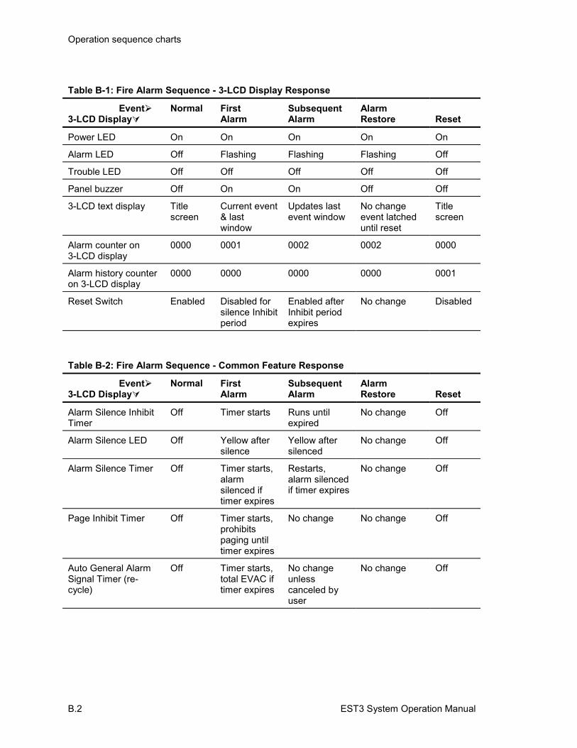
Operation sequence charts
B.2 EST3 System Operation Manual
Table B-1: Fire Alarm Sequence - 3-LCD Display Response
Event�3-LCD Display�
Normal FirstAlarm
SubsequentAlarm
AlarmRestore Reset
Power LED On On On On On
Alarm LED Off Flashing Flashing Flashing Off
Trouble LED Off Off Off Off Off
Panel buzzer Off On On Off Off
3-LCD text display Titlescreen
Current event& lastwindow
Updates lastevent window
No changeevent latcheduntil reset
Titlescreen
Alarm counter on3-LCD display
0000 0001 0002 0002 0000
Alarm history counteron 3-LCD display
0000 0000 0000 0000 0001
Reset Switch Enabled Disabled forsilence Inhibitperiod
Enabled afterInhibit periodexpires
No change Disabled
Table B-2: Fire Alarm Sequence - Common Feature Response
Event�3-LCD Display�
Normal FirstAlarm
SubsequentAlarm
AlarmRestore Reset
Alarm Silence InhibitTimer
Off Timer starts Runs untilexpired
No change Off
Alarm Silence LED Off Yellow aftersilence
Yellow aftersilenced
No change Off
Alarm Silence Timer Off Timer starts,alarmsilenced iftimer expires
Restarts,alarm silencedif timer expires
No change Off
Page Inhibit Timer Off Timer starts,prohibitspaging untiltimer expires
No change No change Off
Auto General AlarmSignal Timer (re-cycle)
Off Timer starts,total EVAC iftimer expires
No changeunlesscanceled byuser
No change Off
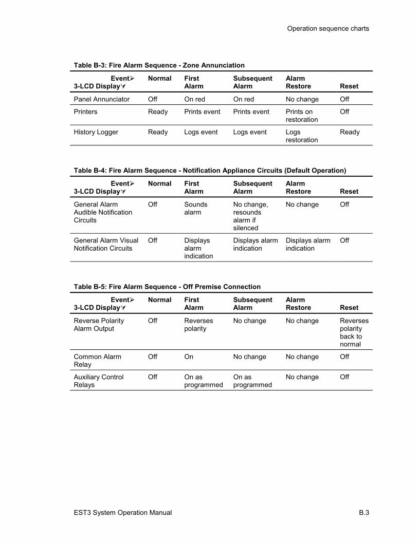
Operation sequence charts
EST3 System Operation Manual B.3
Table B-3: Fire Alarm Sequence - Zone Annunciation
Event�3-LCD Display�
Normal FirstAlarm
SubsequentAlarm
AlarmRestore Reset
Panel Annunciator Off On red On red No change Off
Printers Ready Prints event Prints event Prints onrestoration
Off
History Logger Ready Logs event Logs event Logsrestoration
Ready
Table B-4: Fire Alarm Sequence - Notification Appliance Circuits (Default Operation)
Event�3-LCD Display�
Normal FirstAlarm
SubsequentAlarm
AlarmRestore Reset
General AlarmAudible NotificationCircuits
Off Soundsalarm
No change,resoundsalarm ifsilenced
No change Off
General Alarm VisualNotification Circuits
Off Displaysalarmindication
Displays alarmindication
Displays alarmindication
Off
Table B-5: Fire Alarm Sequence - Off Premise Connection
Event�3-LCD Display�
Normal FirstAlarm
SubsequentAlarm
AlarmRestore Reset
Reverse PolarityAlarm Output
Off Reversespolarity
No change No change Reversespolarityback tonormal
Common AlarmRelay
Off On No change No change Off
Auxiliary ControlRelays
Off On asprogrammed
On asprogrammed
No change Off
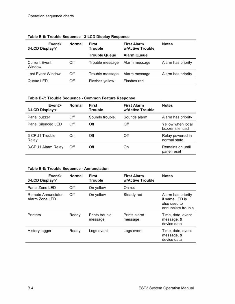
Operation sequence charts
B.4 EST3 System Operation Manual
Table B-6: Trouble Sequence - 3-LCD Display Response
Event�3-LCD Display�
Normal FirstTroubleTrouble Queue
First Alarmw/Active TroubleAlarm Queue
Notes
Current EventWindow
Off Trouble message Alarm message Alarm has priority
Last Event Window Off Trouble message Alarm message Alarm has priority
Queue LED Off Flashes yellow Flashes red
Table B-7: Trouble Sequence - Common Feature Response
Event�3-LCD Display�
Normal FirstTrouble
First Alarmw/Active Trouble
Notes
Panel buzzer Off Sounds trouble Sounds alarm Alarm has priority
Panel Silenced LED Off Off Off Yellow when localbuzzer silenced
3-CPU1 TroubleRelay
On Off Off Relay powered innormal state
3-CPU1 Alarm Relay Off Off On Remains on untilpanel reset
Table B-8: Trouble Sequence - Annunciation
Event�3-LCD Display�
Normal FirstTrouble
First Alarmw/Active Trouble
Notes
Panel Zone LED Off On yellow On red
Remote AnnunciatorAlarm Zone LED
Off On yellow Steady red Alarm has priorityif same LED isalso used toannunciate trouble
Printers Ready Prints troublemessage
Prints alarmmessage
Time, date, eventmessage, &device data
History logger Ready Logs event Logs event Time, date, eventmessage, &device data
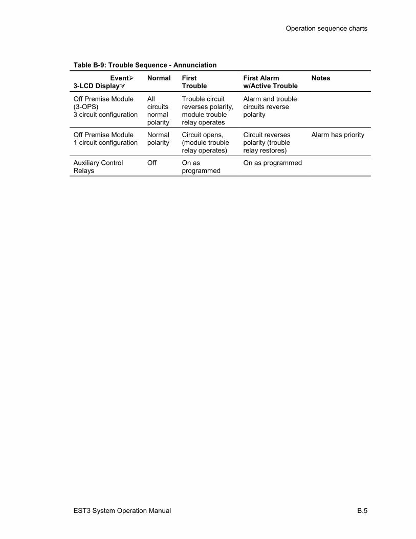
Operation sequence charts
EST3 System Operation Manual B.5
Table B-9: Trouble Sequence - Annunciation
Event�3-LCD Display�
Normal FirstTrouble
First Alarmw/Active Trouble
Notes
Off Premise Module(3-OPS)3 circuit configuration
Allcircuitsnormalpolarity
Trouble circuitreverses polarity,module troublerelay operates
Alarm and troublecircuits reversepolarity
Off Premise Module1 circuit configuration
Normalpolarity
Circuit opens,(module troublerelay operates)
Circuit reversespolarity (troublerelay restores)
Alarm has priority
Auxiliary ControlRelays
Off On asprogrammed
On as programmed

Operation sequence charts
B.6 EST3 System Operation Manual
EST3 System Operation Manual Z.1
Z Index
33-ASU
controls and indicators • 3.2operating • 3.4
3-FTCUcontrols and indicators • 4.2operation • 4.4
3-LCD controls and indicators • 2.2
AActive points
identifying • 2.8Alarm silence/reset inhibit timer • 1.14Alternate message routing
activating • 2.22Alternate sensitivity
changing to primary • 2.21And groups
disabling • 2.9, 2.10Audio Source Unit
paging sequence • 3.5paging with remote microphone • 3.6phone page • 3.5
Automatic alarm silence timer • 1.14Automatic general alarm (GA) timer • 1.15
BButton
operation • 1.15Buttons
disabling • 2.11enabling • 2.12
CCanceling the test • 2.31Changing holidays • 2.29Changing the output state of a relay or LED • 2.23Changing the smoke detector sensitivity level • 2.21Changing user access level passwords • 2.27Check-in groups • 1.13Check-In groups
disabling • 2.9, 2.10Clearing the panel history file • 2.30
DDate
entering • 2.26Default passwords • 2.27Deleting holidays • 2.29Device Maintenance report
creating • 2.24description • 2.24
Devicesdisabling • 2.11enabling • 2.12
Dirty head reportcreating • 2.24
Disabled pointsidentifying • 2.8
Disabling hardware components • 2.11Disabling logical devices • 2.9, 2.10
EEmergency active • 1.14Enabling hardware components • 2.12
GGuard patrol • 1.12Guard Patrol groups
disabling • 2.9, 2.10Guard patrols
activating • 2.18restoring • 2.18
HHardware components
disabling • 2.11enabling • 2.12
High prioritydescription • 2.23
History reportcreating • 2.24
Holidays • 1.15scheduling • 2.29
IIdentifying active or disabled points • 2.8
LLatch priority
description • 2.23LEDs
changing the state of • 2.23disabling • 2.11enabling • 2.12
Logical devicesdisabling • 2.9, 2.10
Low prioritydescription • 2.23
Index
Z.2 EST3 System Operation Manual
MMatrix groups
disabling • 2.9, 2.10Medium priority
description • 2.23Modcom Compliance report
creating • 2.24description • 2.24
PPassword protection • 1.2Passwords
changing • 2.27default • 2.27
Primary message routingrestoring • 2.22
Primary sensitivitychanging to alternate • 2.21
Putting a service group into test • 2.31
RRail modules
disabling • 2.11enabling • 2.12
Relayschanging the state of • 2.23
Reports • 2.24Restarting a panel • 2.28
Revisions reportcreating • 2.24description • 2.24
SScheduling holidays • 2.29Service groups
disabling • 2.9, 2.10Set priority
description • 2.23Setting the system time and date • 2.26Smoke detector sensitivity
description • 2.21Smoke detector sensitivity level
changing • 2.21System timers • 1.14
TTesting alarm input devices • 2.31Time controls • 1.15
holidays • 1.15Time Controls
disabling • 2.9, 2.10Time of day
entering • 2.26
ZZone groups
disabling • 2.9, 2.10
Related Documents


