17” LCD Color Monitor 170V7 1 Service Service Service Horizontal Frequency 30 - 83 KHz TABLE OF CONTENTS Description Page Description Page SAFETY NOTICE ANY PERSON ATTEMPTING TO SERVICE THIS CHASSIS MUST FAMILIARIZE HIMSELF WITH THE CHASSIS AND BE AWARE OF THE NECESSARY SAFETY PRECAUTIONS TO BE USED WHEN SERVICING ELECTRONIC EQUIPMENT CONTAINING HIGH VOLTAGES. CAUTION: USE A SEPARATE ISOLATION TRANSFOMER FOR THIS UNIT WHEN SERVICING Table of Contents..................….…….............………….1 Revision List........................……................…………….2 Important Safety Notice…………….……….................3 1. Monitor Specifications…............................................4 2. LCD Monitor Description…........................................5 3. Operation instructions…............................................6 3.1General Instructions…………………………………...6 3.2 Control buttons….…….……………………………6 3.3 Adjusting the Picture…...........................................8 3.4 Connecting to your PC …......................................11 4. Input/Output Specification.......……..........……….12 4.1 Input Signal Connector……………………………..12 4.2 Factory Preset Display Mode...………..................12 4.3 Pixel Defect Policy………………………………..13 5. Block Diagram…......................................................15 5.1 Monitor Exploded View…......................................15 5.2 Software Flow Chart………………………………16 5.3 Electrical Block Diagram……………………………18 6. Schematic Diagram….................................................20 6.1 Main Board……………………………………………..20 6.2 Power Board…………………………………………...24 7. PCB Layout………………………………………………26 7.1 Main Board…………………………………………..26 7.2 Power Board.............................................................29 7.3 Key Board………..….…………………………………31 8. Wiring Diagram………………………………………….32 9. Mechanical Instructions……………………………...33 10. Trouble shooting………………………………………38 11. Repair Flow Chart…………………..…………………40 12. ISP Instructions………………………………………...45 13. DDC Instructions…...................................................51 14. White Balance, Luminance Adjustment……….........63 15. Recommended & Spare Parts List...….……............64 16. Different Parts List…………………………………...75 17. General Product Specification……………………….78 GB 3138 106 10518 170V7FB/27 170V7FB/93 170V7FB/69 170V7FB/00

Welcome message from author
This document is posted to help you gain knowledge. Please leave a comment to let me know what you think about it! Share it to your friends and learn new things together.
Transcript

17” LCD Color Monitor 170V7
1
Service Service Service
Horizontal Frequency 30 - 83 KHz
TABLE OF CONTENTS
Description Page Description Page
SAFETY NOTICE ANY PERSON ATTEMPTING TO SERVICE THIS CHASSIS MUST FAMILIARIZE HIMSELF WITH THE CHASSIS
AND BE AWARE OF THE NECESSARY SAFETY PRECAUTIONS TO BE USED WHEN SERVICING
ELECTRONIC EQUIPMENT CONTAINING HIGH VOLTAGES.
CAUTION: USE A SEPARATE ISOLATION TRANSFOMER FOR THIS UNIT WHEN SERVICING
Table of Contents..................….…….............………….1Revision List........................……................…………….2Important Safety Notice…………….……….................31. Monitor Specifications…............................................4 2. LCD Monitor Description…........................................53. Operation instructions…............................................63.1General Instructions…………………………………...63.2 Control buttons….…….……………………………63.3 Adjusting the Picture…...........................................83.4 Connecting to your PC …......................................114. Input/Output Specification.......……..........……….124.1 Input Signal Connector……………………………..124.2 Factory Preset Display Mode...………..................124.3 Pixel Defect Policy………………………………..135. Block Diagram…......................................................155.1 Monitor Exploded View…......................................155.2 Software Flow Chart………………………………165.3 Electrical Block Diagram……………………………18
6. Schematic Diagram….................................................206.1 Main Board……………………………………………..206.2 Power Board…………………………………………...247. PCB Layout………………………………………………267.1 Main Board…………………………………………..267.2 Power Board.............................................................297.3 Key Board………..….…………………………………318. Wiring Diagram………………………………………….329. Mechanical Instructions……………………………...3310. Trouble shooting………………………………………3811. Repair Flow Chart…………………..…………………4012. ISP Instructions………………………………………...4513. DDC Instructions…...................................................5114. White Balance, Luminance Adjustment……….........6315. Recommended & Spare Parts List...….……............6416. Different Parts List…………………………………...7517. General Product Specification……………………….78
GB 3138 106 10518
170V7FB/27 170V7FB/93 170V7FB/69 170V7FB/00
17” LCD Color Monitor 170V7
2
Revision List
Version Release Date Revision History
A00 May.16, 2006 Initial release, draft version
A01 Jun.15, 2006 Add CTV Model 170V7FB/69 in Item 16
A02 Aug.22, 2006 Modify CTV Model 170V7FB/69 in Item 16
A03 Sep.16, 2006 Modify CTV Model 170V7FB/00 in Item 16
A04 Sep.19, 2006 Make some engineering changes in Item 15 and Item 16
A05 Oct.24, 2006 Add Service Kit in Page 64
A06 Nov.10, 2006 Revise Service Kit in Page 64
A07 Nov.29, 2006 Add DDC Instruction for OSD SN in Item 13
A08 Dec.05, 2006 Add OSD SN Kit in Page 64
A09 Jan.17, 2007 Add To Lock/Unlock OSD function in Page 8
A10 Sep.06, 2007 Add To “Recommended parts list ” in Page 64
A11 Sep 20,2008 Update BOM for 170V7FB/93 in Page 75
17” LCD Color Monitor 170V7
3
Important Safety Notice Proper service and repair is important to the safe, reliable operation of all Philips Company** Equipment. The
service procedures recommended by Philips and described in this service manual are effective methods of
performing service operations. Some of these service operations require the use of tools specially designed for the
purpose. The special tools should be used when and as recommended. It is important to note that this manual contains various CAUTIONS and NOTICES which should be carefully read in order to minimize the risk of personal injury to service personnel. The possibility exists that improper service methods may damage the equipment. It is also important to understand that these CAUTIONS and NOTICES ARE NOT EXHAUSTIVE. Philips could not possibly know, evaluate and advise the service trade of all conceivable ways in which service might be done or of the possible hazardous consequences of each way. Consequently, Philips has not undertaken any such broad evaluation. Accordingly, a servicer who uses a service procedure or tool which is not recommended by Philips must first satisfy himself thoroughly that neither his safety nor the safe operation of the equipment will be jeopardized by the service method selected. * * Hereafter throughout this manual, Philips Company will be referred to as Philips. WARNING Use of substitute replacement parts, which do not have the same, specified safety characteristics may create shock, fire, or other hazards. Under no circumstances should the original design be modified or altered without written permission from Philips. Philips assumes no liability, express or implied, arising out of any unauthorized modification of design. Servicer assumes all liability. FOR PRODUCTS CONTAINING LASER: DANGER-Invisible laser radiation when open. AVOID DIRECT EXPOSURE TO BEAM. CAUTION-Use of controls or adjustments or performance of procedures other than those specified herein may result in hazardous radiation exposure. CAUTION -The use of optical instruments with this product will increase eye hazard. TO ENSURE THE CONTINUED RELIABILITY OF THIS PRODUCT, USE ONLY ORIGINAL MANUFACTURER'S REPLACEMENT PARTS, WHICH ARE LISTED WITH THEIR PART NUMBERS IN THE PARTS LIST SECTION OF THIS SERVICE MANUAL. Take care during handling the LCD module with backlight unit -Must mount the module using mounting holes arranged in four corners. -Do not press on the panel, edge of the frame strongly or electric shock as this will result in damage to the screen. -Do not scratch or press on the panel with any sharp objects, such as pencil or pen as this may result in damage to the panel. -Protect the module from the ESD as it may damage the electronic circuit (C-MOS). -Make certain that treatment person’s body is grounded through wristband. -Do not leave the module in high temperature and in areas of high humidity for a long time. -Avoid contact with water as it may a short circuit within the module. -If the surface of panel becomes dirty, please wipe it off with a soft material. (Cleaning with a dirty or rough cloth may damage the panel.)

17” LCD Color Monitor 170V7
4
1. Monitor Specifications
Screen type Active matrix - TFT LCD
Size 430mm (17.0") LCD Panel
Pixel pitch 0.264mm(H) x 0.264mm(V)
Video R, G, B Analog Interface
Separate Sync TTL level, input impedance 2.2k OHM terminate
Horizontal Frequency 30kHz – 83kHz Input
Vertical refresh rate 56 - 76Hz
Display Colors 16.2 M
Video dot rate 140 MHz
Maximum Resolution 1280 x 1024 at 76Hz (analog input)
Recommended Resolution 1280 x 1024 at 60Hz (analog input)
Plug & Play VESA DDC2B
Power Consumption Power on: < 30 W Power off: < 1 W
Input Connector D -Sub 15pin
Input Video Signal 0.7 Vp-p, input impedance, 75 ohm @DC
Tilt -5° ~ 25°
Maximum Screen Size Horizontal: 337.9mm;Vertical: 270.3 mm
Power Source 100-240 VAC, 50/60 Hz
Environmental Considerations
Operating Temp: 5°C to 40°C Storage Temp.: -20°C to 60°C Relative Humidity: 20%-80% Max
Weight (Net) 4.7kg
Cabinet color 170V7FG: Light Gray 170V7FB: Black 170V7FS: Silver
17” LCD Color Monitor 170V7
5
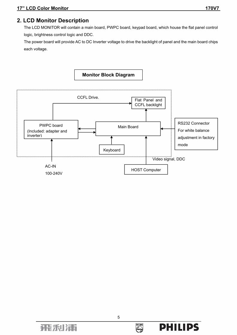
2. LCD Monitor Description The LCD MONITOR will contain a main board, PWPC board, keypad board, which house the flat panel control
logic, brightness control logic and DDC.
The power board will provide AC to DC Inverter voltage to drive the backlight of panel and the main board chips
each voltage.
Video signal, DDC
PWPC board (Included: adapter and inverter)
Main Board
Keyboard
RS232 Connector
For white balance
adjustment in factory
mode
CCFL Drive.
AC-IN
100-240V
Monitor Block Diagram
HOST Computer
Flat Panel and CCFL backlight

17” LCD Color Monitor 170V7
6
3. Operation instructions 3.1 General Instructions
Press the power button to turn the monitor on or off. The other control buttons are located at front panel of the
monitor. By changing these settings, the picture can be adjusted to your personal preferences.
- The power cord should be connected.
- Connect the video cable from the monitor to the video card.
- Press the power button to turn on the monitor, the power indicator will light up. 3.2 Control Buttons
Front View

17” LCD Color Monitor 170V7
7
Back View
17” LCD Color Monitor 170V7
8
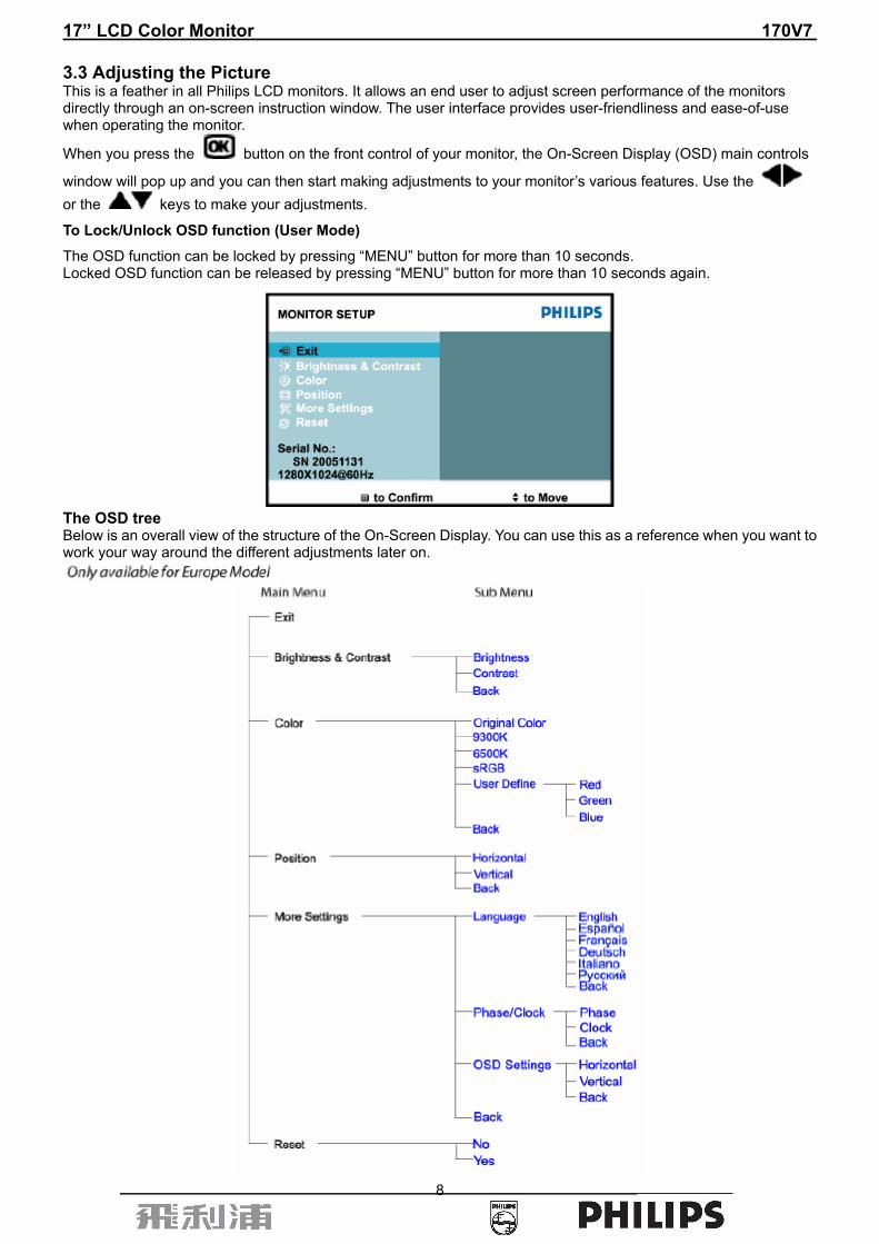
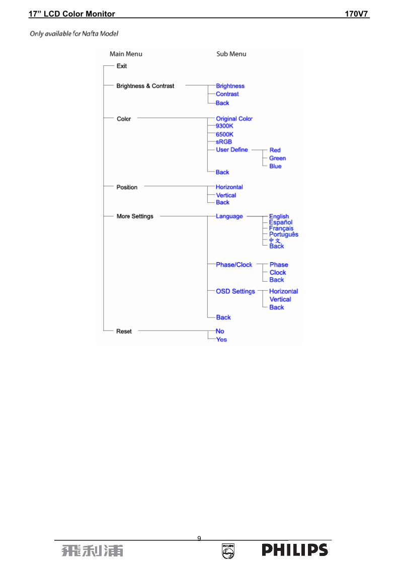
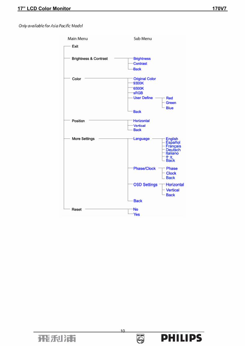
3.3 Adjusting the Picture This is a feather in all Philips LCD monitors. It allows an end user to adjust screen performance of the monitors directly through an on-screen instruction window. The user interface provides user-friendliness and ease-of-use when operating the monitor.
When you press the button on the front control of your monitor, the On-Screen Display (OSD) main controls
window will pop up and you can then start making adjustments to your monitor’s various features. Use the or the keys to make your adjustments.
To Lock/Unlock OSD function (User Mode)
The OSD function can be locked by pressing “MENU” button for more than 10 seconds. Locked OSD function can be released by pressing “MENU” button for more than 10 seconds again.
The OSD tree Below is an overall view of the structure of the On-Screen Display. You can use this as a reference when you want to work your way around the different adjustments later on.
17” LCD Color Monitor 170V7
9
17” LCD Color Monitor 170V7
10

17” LCD Color Monitor 170V7
11
3.4 Connecting to the PC 1) Connect the power cord to the back of the monitor firmly. (Philips has pre-connected) VGA cable for the first
installation.)
2) Connect to PC
(a) Turn off your computer and unplug its power cable.
(b) Connect the monitor signal cable to the video connector on the back of your computer.
(c) Plug the power cord of your computer and your monitor into a nearby outlet.
(d) Turn on your computer and monitor. If the monitor displays an image, installation is complete.
17” LCD Color Monitor 170V7
12
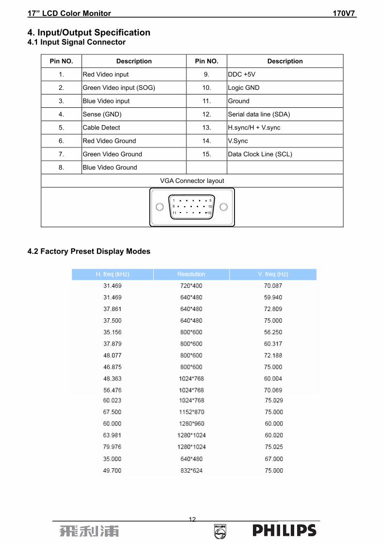
4. Input/Output Specification 4.1 Input Signal Connector
Pin NO. Description Pin NO. Description
1. Red Video input 9. DDC +5V
2. Green Video input (SOG) 10. Logic GND
3. Blue Video input 11. Ground
4. Sense (GND) 12. Serial data line (SDA)
5. Cable Detect 13. H.sync/H + V.sync
6. Red Video Ground 14. V.Sync
7. Green Video Ground 15. Data Clock Line (SCL)
8. Blue Video Ground
VGA Connector layout
1 56 10
11 15
4.2 Factory Preset Display Modes

17” LCD Color Monitor 170V7
13
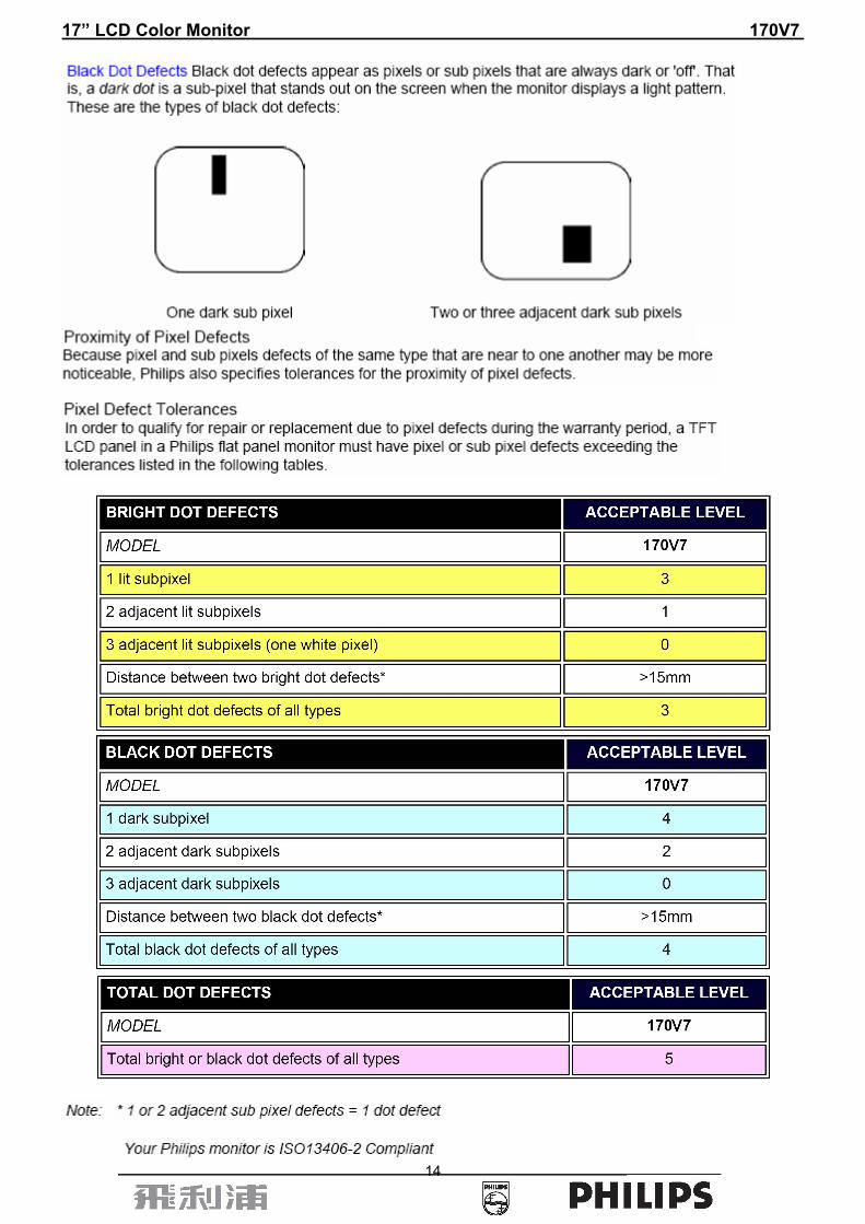
4.3 Pixel Defect Policy
17” LCD Color Monitor 170V7
14

17” LCD Color Monitor 170V7
15
5. Block Diagram 5.1 Monitor Exploded View

17” LCD Color Monitor 170V7
16
5.2 Software Flow Chart
1
2
N
Y
5
Y
N
10
Y
N
12
Y
N
7
Y
N
6
4
3
8
9
14
11
13
Y
N
15
Y
N16
17
19
Y
N 18

17” LCD Color Monitor 170V7
17
1) MCU Initializes. 2) Is the EEPROM blank? 3) Program the EEPROM by default values. 4) Get the PWM value of brightness from EEPROM. 5) Is the power key pressed? 6) Clear all global flags. 7) Are the AUTO and SELECT keys pressed? 8) Enter factory mode.
9) Save the power key status into EEPROM.
Turn on the LED and set it to green color. Scalar initializes. 10) In standby mode? 11) Update the lifetime of back light. 12) Check the analog port, are there any signals coming? 13) Does the scalar send out an interrupt request? 14) Wake up the scalar. 15) Are there any signals coming from analog port?
16) Display "No connection Check Signal Cable" message. And go into standby mode after the message
disappears. 17) Program the scalar to be able to show the coming mode. 18) Process the OSD display. 19) Read the keyboard. Is the power key pressed?
17” LCD Color Monitor 170V7
18
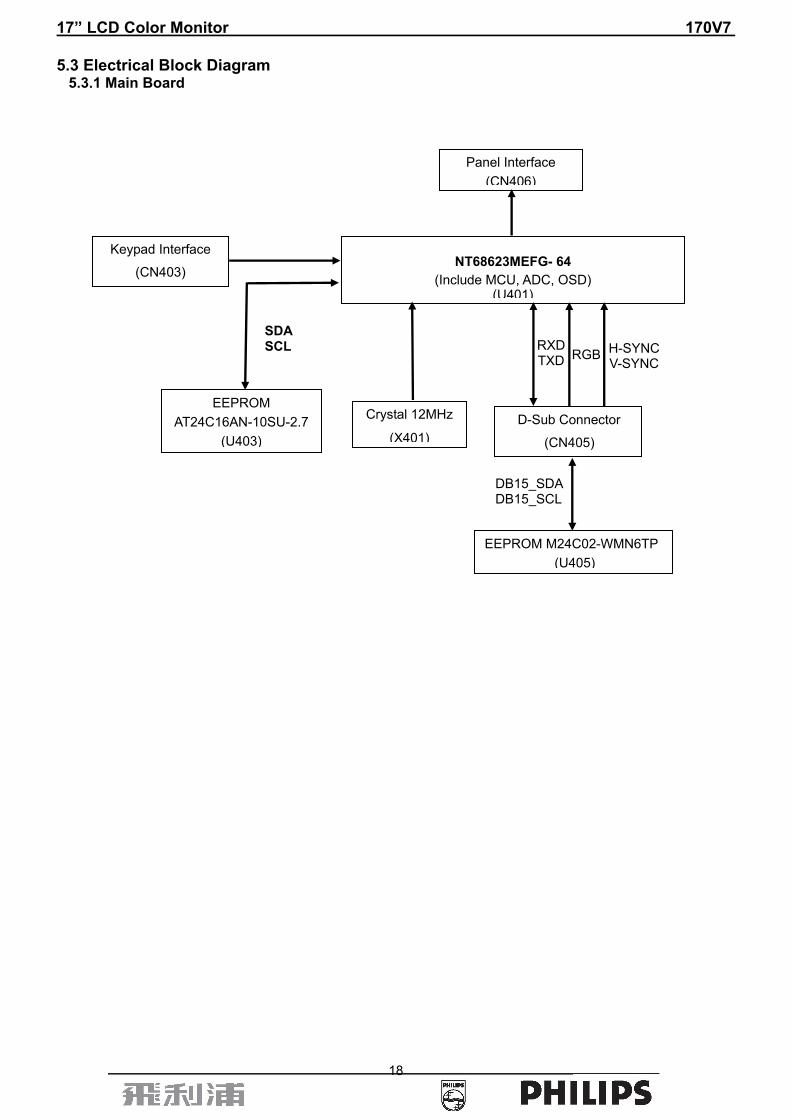
5.3 Electrical Block Diagram 5.3.1 Main Board
EEPROM AT24C16AN-10SU-2.7
(U403)
Panel Interface (CN406)
NT68623MEFG- 64 (Include MCU, ADC, OSD)
(U401)
D-Sub Connector
(CN405)
EEPROM M24C02-WMN6TP (U405)
SDA SCL RXD
TXD RGB H-SYNCV-SYNC
DB15_SDA DB15_SCL
Crystal 12MHz
(X401)
Keypad Interface
(CN403)

17” LCD Color Monitor 170V7
19
5.3.2 Inverter/Power Board

17” LCD Color Monitor 170V7
20
6. Schematic Diagram 6.1 Main Board
715G1712-1
RI1
GND_A
GND_A
B1
C434100pF
GND_A
GND_A
+5V
VGA-SDA
C452
NC
GND_A
GND_A
R440220 1/16W
GI1
C4460.1uF
D405BAV99
3
1 2
D406BAV99
3
1 2
24C02_WP
VS
VS
GND_A
HS
VGA-SDA
GND_A
GND_A
R45675 1/16W
R4261K 1/16W
R45575 1/16W
ZD405
UDZS5.6B
FB4060 1/16W
G1
R405100 1/16W
R4764.7K 1/16W
CH201209T-300
DB15
R47
84.
7K 1
/16W
R4352.2K 1/16W
GND_A
GND_A
CH201209T-300
ZD403UDZS5.6B
VSIN
FB4020 1/16W
100pFC402
ZD407UDZS5.6B
C433100pF
PHILIPS 170V-ADC Input
R4851K 1/16W
GND_A
RI1-
ZD414UDZS5.6B
VGA-SCL
GND_A
R1
M_TXD
GND_A
GND_A
D416
BAV70
3
1
2
U405
M24C02WMN6
4
8123
765
GND
VCCA0A1A2
WPSCLSDA
R4362.2K 1/16W
B1
R441220 1/16W
ZD408UDZS5.6B
HS C453
NC
CN405DB15
162738495
11
12
13
14
1510
1716
VGA-5V
BI1-
VGA-5V
FB4040 1/16W
+5V
GND_A
D404BAV99
3
1 2
ZD402UDZS5.6B
C4110.1uF
GND_A
FB4030 1/16W
R45475 1/16W
GND_A
HSIN
R406100 1/16W
C43022pF
BI1
VGA-DET
ZD406UDZS5.6B
M_RXD
FB4010 1/16W
FB4050 1/16W
ZD404UDZS5.6B
C4090.1uF
G1
R1
VGA-VDD
C4100.1uF
GND_A
GI1-
CH201209T-300
GND_A
C451
NC
B
715G1712-1A4
5 5Thursday, March 02, 2006
Title
Size Document Number Rev
Date: Sheet of
GND_A
ZD401UDZS5.6B
GND_A
VGA-SCL
R47
94.
7K 1
/16W

17” LCD Color Monitor 170V7
21
R411100 1/16W
M_TXD
OUT-R+ BL_EN
C4140.1uF
GND_A
LEDG
R4433.3K 1/16W
CVDD1V8
T1P
STANDBY
R408100 1/16W
DVDD
T7P
R40110K 1/16W
AUTO
C4180.1uF
R452 75 1/16W
R423 150 1/16W
LED-Orange
GND_A
DVDD
LCD-ON
HSO
R427 1K 1/16W
+5V
STANDBY
R451 75 1/16W
HSO
B+
R4464.7K 1/16W
CN403
CON16A
1 23 45 67 89 10
11 1213 1415 16
+1V8
R4423.3K 1/16W
DVDD
IRQn
STANDBYRX
Power-key
GND_A
T5P
TCLK2M
SDA
R407100 1/16W
LIGHT_SEN
FB409
120 OHM
C415/NC0.1uF
89
T6M
TX
C4411000pF
GND_A
T7M
DVDD
112
T1M
R+
Q404
PMBS3906
BL-PWM
B
715G1712-1
C
4 5Thursday, March 02, 2006
Title
Size Document Number Rev
Date: Sheet of
AUTO
R40210K 1/16W
X40112MHz
MCU-VDD
GND_A
+5V
GI1-
VGA-SDA
OUT-L-
LED-Green
C429NC
C450/NC100pF
R419 10K 1/16W
TODEBUG
82
GND_A
R438/NC
1K 1
/16W
R4594.7K 1/16W
+5V
T3P
R445 390 1%
T5M
IRQN
LED-Orange
GND_A
VGA-SCL
C4200.1uF
R447
4.7K 1/16W MCU-VDD
R424 150 1/16W
C4210.1uF
T0P
PWR
VGA_3V3
R4221K 1/16W
T2P
C4401000pF
R428 1K 1/16W R432 1K 1/16W
14
GND_A
C404 0.047uF
MCU-VDD
24C16_WP
CVDD1V8
TCLK1P
BI1-
R418 10K 1/16W
Q401PMBS3904
VGA_3V3
VSO
C4360.1uF
+5V
GND_A
OUT-R-
LIGHT_SEN
R410100 1/16W
15
DVDD
M_RXD
C403 0.047uF
GND_A
GND_A
TCLK1M
RSTn
R484/NC10K 1/16W
R421 150 1/16W
LED-Green
C4190.1uF
OUT-L+
24C16_WP
Q402
PMBS3906
R409/NC100 1/16W
T4P
VOLUME
GND_A
LEDG
MENU
CN401NC/3PIN/2.0mm
123
MCU-VDD
BL-BRIGHT
C427
22pF
C4381000pF
R437 200 1/16W
C4170.1uF
C4130.1uF
R433 1K 1/16W
GND_A
GND_A
+
C426220uF/16V
FB412120 OHM
CVDD1V8
C435NC
R450/NC4.7K 1/16W
R453 75 1/16W
CN402NC/4PIN/2.0mm
1234
R412/NC10K 1/16W
VOLUME
C4551000pF
G+
SDA
7/8 Changed from +5V to DVDD
9
GND_A
GND_A
GI1
LEFT
LEFT
T0M
BL-ON
D401
BAV99
3
12
MCU-VDD
GND_A
ADC_VAA
T2M
SDA
R4604.7K 1/16W
LEDA
R41
5/N
C10
K 1
/16W
R4484.7K 1/16W
SCL
R4341M 1/16W
NT68623
T6P
LEDA
Left-pwm
TO RS232
MCU-VDDVSO
120
VOL-PWM
TCLK2P
VGA-DET
RX
BL_EN
C4120.1uF
C4160.1uF
PANEL_IDX
R438 200 1/16W
GND_A
U403M24C16-MN6T
1234 5
678A0
A1A2VSS SI
SCKWP
VCC
Right-pwm
SCL
ADC_VAA
T4M
Mute/Auto
C714
1000pF
+ C43110uF/16V
BI1
MUTEVOL-PWM
BL-PWM
U401
39
46
47
50
51
52
53
54
40
48
49
17 18 19 20 21 22 23 24 25 26 27 28 29 30 31 32 33 34 35 36 37 386 7 8 9 11 12
55
56
57
58
59
60
697071727376 74777879808182838485869697
111
1 2 3 4 5 10 13 14 1615
41
42
43
44
45
61
62
63
64
65666768758788899091929394959899100
101
103
102
104
110
109
108
107
106
105
117
116
115
114
113
112
118
119
120
121
122
124
123
126
125
128
127
PC3/PWM0
PA1/PWM3
PA2/PWM4
PA5/PWM7*
PA6/PWM8*
PA7/PWM9*
RSTB
P30/RXD
PC2
PA3/PWM5
PA4/PWM6*
PE
0
PE
1
OS
CO
OS
CI
MC
U_G
ND
PB
0/A
DC
0
PB
1/A
DC
1
PB
4/D
DC
_SC
L0*
PB
5/D
DC
_SD
A0*
PB
6/D
DC
_SC
L1*
PB
7/D
DC
_SD
A1*
PD
5
PD
4
PD
3
NC
NC
PD
2
PD
1
PC
7
PC
6
PC
5
PC
4/P
WM
1
VS
YN
CI0
DP
LL_G
ND
TC
LK
DP
LL_V
DD
PW
M11
TS
_CLK
PD6
P31/TXD
PB2/ADC2/INTE0
PB3/ADC3/INTE1
P34/T0
P35/T1
T4P
T4M
DG
ND
T3P
T3MT2P
TC
LK1P
T2MT1P
T1MT0P
T0M
DV
DD
DG
ND
GP
O1
GP
O2/
AD
0
GP
O3/
AD
1
AG
ND
NC
PGND
TE
ST
VR
EF
HS
YN
CI1
TO
UT
P/V
SY
NC
I1
HY
NC
I0
PW
M10
CG
ND
CV
DD
DG
ND
DV
DD
PC1*
PC0*
MCU_VCC
PD0
PA0/PWM2
T7P
T7M
TCLK2P
TCLK2M
T6P
T6MT5P
T5M
TC
LK1M
INT
_VS
O/G
PO
4
INT
_HS
O/G
PO
5
CV
DD
CG
ND
GP
O6
SC
L
SD
A
RS
TN
IRQ
N
NC
NC
NC
NC
NC
AG
ND
NC
PVCC
NC
NC
NC
NC
AGND
GIN1-
GIN1+
SOGI1
BIN1-
BIN1+
ADC_VAA
RIN1+
RIN1-
ADC_VAA
ADC_GNDA
BIN0+
SOGI0
BIN0-
GIN0-
GIN0+
RIN0-
RIN0+
R4291K 1/16W
C4371000pF
C401 1000pF
RIGHTFB407120 OHM
R420 1K 1/16W
VSIN
MENU
C408 0.047uF
+5V
GND_A
RSTn
C407 0.047uF
C42822pF R449
4.7K 1/16W
GND_A
MCU-VDD
SCL
C405 0.047uF
BL-ON
RI1-
24C02_WP
C4391000pF
PHILIPS 170V-SCALER
HSIN
TX
RIGHT
stdby/Enter
RI1
PWR
C406 0.047uF
C4541000pF
R404100K 1/16W
T3M
R431 1K 1/16W
SCL
SDA
GND_A
GND_A
C4220.1uF
R45810K 1/16W
12/7 Delete R457-0 ohm

17” LCD Color Monitor 170V7
22
LCD-VDD
LCD-VDD
T0M
T5M
T2P
Q405
AO3401L
T6P
LCD-ON
T3P
Q406PMBS3904
T5M
T4P
TCLK1P
TCLK2P
R472
10K 1/16W
LCD-VDD
TCLK2M
GND_A
T1M
C4250.1uF
T7P
T3M
TCLK2P
PHILIPS 170V-PANEL OUTPUT
VGA_3V3
+12V
FB409/NC120 OHM
GND_A
+C432
4.7uF/16V
R414100K 1/16W
T0P
T7M
T2P
TCLK1M
T4P
GND_A
TCLK1M
T6M
T7M
TCLK1P
R41710K 1/16W
CN406
30PIN/2.0mm
123456789
101112131415161718192021222324252627282930
B
715G1712-1A4
3 5Thursday, March 02, 2006
Title
Size Document Number Rev
Date: Sheet of
T2M
T5P
+5V
FB410120 OHM
FB408120 OHM
T3PT3M
T6P
R444150 1/8W
T0P
R403100K 1/16W
T5P
T1P
T7P
LVDSOUTPUT
TCLK2M
T6M
T1P
T4M
T1M
C424 0.1uF
T2M
T4M
C4230.1uF
T0M

17” LCD Color Monitor 170V7
23
OUT-L-
C7020.1uF
H2
11
FB704120 OHM
+ C70710uF/16V
PANEL_IDX BL-ON
403mA
+12V
GND_A
+5V
VGA_3V3
OUT-L+
FB706(NC)120 OHM
+
C711100uF/25V
D702(NC)FA20-04
FB703120 OHM
C7050.1uF
+
C712100uF/25V
+12V
U702MM1117DT18
123
AD
J/G
ND
OU
TPU
TIN
PU
T
+
C710100uF/16V
PHILIPS 170V-Scaler Power
H1
11
FB705120 OHM
CN702/NC7x2PIN/2.0mm
2468101214
13579
1113
C7011000pF
GND_A
CN7016x2PIN/2.0mm
24681012
13579
11
GND_A
VGA_3V3
FB702120 OHM
+
C709100uF/16V
+5V
VGA_3V3
+1V8
STANDBY
FB701120 OHM
U701MM1085DT33
123
AD
J(G
ND
)V
OU
T(TA
B)
VIN
FOR 3.3V POWER USE
R70147 1/16W
GND_A
OUT-R-
D701(NC)FA20-04
ADC_VAA
GND_A
GND_A
+
C70810uF/16V
H3
11
+5V
DVDD
C7131000pF
CONNECTOR FORPOWER/INVERTERBOARD 2.0 mm
C7030.1uF
B
715G1712-1A4
2 5Thursday, March 02, 2006
Title
Size Document Number Rev
Date: Sheet of
BL-BRIGHT
VOLUME
FB707(NC)120 OHM
+5V
MUTEFOR 1.8V POWER USE
GND_AGND_A
CVDD1V8
C7060.1uF
OUT-R+
C7040.1uF
138mA

17” LCD Color Monitor 170V7
24
6.2 Power Board 715G1813-1
N
L903
C8B-R6H
1 2
R95522K _NC
L
R9531K 1/4W_NC
12
C9150.012uF/25V
R917 33K
C9130.1uF
12
R915 10
R927 4.7K_120612
- +
BD901U4KB80R
2
1
3
4
5VA
+C927
68u/25V
R946
110K_1%
12
+12VCC
FB905BEAD
C9200.001uF/1KV
12
R9101.5M/R1206
C903
0.001uF/250V
1 2
D918 1N4148
R944
9.1K/0805_1%
12
Lie down
C942
4.7nF/25V_NC
D931MBRF10H100CT-45
NR901
SCK084
D926
RGP10D
12
TEA1532
IC901
TEA1532
4
1
2
8
5
3 6
7
FB901BEAD
C9141uF
12
D901BYT42J
R932
2R2_1206
1 2
+C933
1000uF/25V
+C952
220u/25V
C9010.001uF/250V
12
O
T901
POWER X'FMR
4
6
2
1
5
9
78
1112
10
J91212
R9121M
12
R951
3.3K_N
C
12
FB902BEAD
C935
3.3nF/500V_NC
12
R920
0.2R/1W
R902680K
12
C917 0.33uF/25V
+12VCCVAR901
varistor_NC
R935
2R2_1206_NC
1 2
C9000.001uF/250V
12
CN951
HARNESS 12P-12P 120mm
123456789101112
R9041.5M/R1206
+C907
100uF/450V
R926 0R
R942
27K _NC
12
R901680K
12
+C956
220u/16V
IC902TCET1103
12
43
IC941KIA431A
L951
0.8uH
1 2
C912
0.0022uF/400V
12
+12V
CN901
AC SOCKET
12
3
C9550.1uF/25V
L955
0.8uH1 2
S901
spotgap_NC
R9459.1K_1%
12
R90715K/R1206
R936
2R2_1206_NC
1 2
R905100K/1W
L901
7mH
14
23
+5V
R941220
BRIGHTNESS
+C936
2200uF/16V
C9510.1uF/25V
R9141K24_1%
R900
680K
12
C941 0.0056uF
5VA
R95210
12
ZD949RLZ12B_NC
12
R916 1.5K
12
BL_CTL
D905P4KE_NC
D919
RGP10D
12
+C932
1000uF/25V
R9371.8K_1/8W
12
F902
FUSE_5A/250V_NC
R949
100 1/10W_NC
12
C9080.47uF/275V
12
PANEL_ID
L902
C8B-R6H
1 2
R918 150R12
R931
2R2_12061 2
FB903BEAD
S902
spotgap_NC
ZD975RLZ5.1B
12
ZD951P6KE8.2A
C931
3.3nF/500V
12
Q901STP7NK80ZFP1
23
F901
FUSE 3.15A 250V
1 21 2
D935STPS10L45CFP
R95410 1/10W
R9435.1K 1/10W
12
R923 8K66_1%
12

17” LCD Color Monitor 170V7
25
R887100K 1/10W
12
C8310.33uF
12
R812
620K 1/10W
12
Q841
AM9945N
1234 5
678S1
G1S2G2 D2
D2D1D1
D885
IN4148
C8255PF/NC
12
Q8712N70021
32
C8120.1uF
12
Q8862N7002 1
32
OP2
C8230.001uF
12
C8075pF/3KV
12
R84310R
12
R87210K/NC
12
D831BAV99
3
12
R82210R
12
D853BAV70/SOT23B
3
1
2
R81530K
R8596.2M 1/2W
12
Q8852N7002 1
32
Isen
C8260.01uF/NC
R82310R
12
R884
1K 1/10W
12
R871
10K 1/2W
12
OP3
Q8802N7002 1
32
R8396.2M 1/2W
12
R8732K 1/10W
C8870.01uF
Q873PDTA144EU
31
2
R8247.5K_1%_NC
12
VDD
OP2
C8190.01uF/25V
12
R83010K_1%_NC
12
D881
IN4148
OP4
C8461uF
12
C8445PF/NC
12
CN853CONN
12
C8055pF/3KV_NC
12
C8420.001uF
12
VDD
R8577.5K_NC
C858390pF
C813560pF
C8320.1uF
12
C8105pF/3KV_NC
12
C8211uF
12
Q8012N70021
32
Q8742N3904
32
1
R80410K 1/10W
12
D851BAV99
3
12
PANEL_ID
OP1
C8095pF/3KV_NC
12C845
5PF/NC
12
D883
IN4148
C8085pF/3KV
12
R855
10K_1%
ZD874RLZ5.6B
12
OP4
Isen
C8830.01uF
R861
100K_1%
12
C8411uF
12
R866100K/NC
12+12V
R886
1K 1/10W
12
CN831CONN
12
R883100K 1/10W
12
C86533nF
12
R835
10K_1%
1 2
C80610pF/6KV1
2
R8191M
CN833CONN
12
C860220pF
12
CN851CONN
12
C8111uF
12
PT802
24:24:2400
71
3
856
2
4
R807
10K 1/10W
12
C840470uF/25V
VDD
C820470uF/25V
C8220.001uF
12
PT801
24:24:2400
71
3
856
2
4
OP1
R8331.2K
R80110K
12
R854
6.2M_NC
12
+12V
R85610K_1%
12
R88010K 1/10W
12
R8311K
R8511K
R8257.5K_1%
12
R806100K/NC
12
C8710.1uF_NC
C8245PF/NC
12
C8301000pF/NC
R8346.2M 1/2W_NC
12
BL_CTL
OP3
R83610K_1%
12
R874330 1/10W
12
R803
10K/NC
12
C8430.001uF
12
+12V
PANEL_ID
R80210K/NC
12
C8850.01uF
R85010K_1%_NC
12
R882
1K 1/10W
12
R888
1K 1/10W
12
R8531.2K
R885100K 1/10W
12
Q821
AM9945N
1234 5
678S1
G1S2G2 D2
D2D1D1
R829
0 1/10W
C8035pF/3KV
12
VDD
R865232
C8381000pF
Q8832N7002 1
32
C80110pF/6KV
12
R8377.5K_1%
12
C847
0.022uF/25V
D887
IN4148
C8025pF/3KV
12
U811
OZ9938GN
1
2
3
4
5
6
7
8 9
10
11
12
13
14
15
16DRV1
VDDA
TIMER
DIM
ISEN
VSEN
OVPT
NC1 NC2
ENA
LCT
SSTCMP
CT
GNDA
DRV2
PGND
C8741uF
12
BRIGHTNESS
D833BAV70/SOT23B
3
1
2
R849
0 1/10W
1 2
C8800.1uF/25V
C8611000pF
12
VDD
R881100K 1/10W
12
R84210R
12
R81620K
C8045pF/3KV_NC
12
R863
33K 1/4W
12
R81333K_1%
R8113M3
12
C8810.01uF
Q8812N7002 1
32

17” LCD Color Monitor 170V7
26
7. PCB Layout 7.1 Main Board
715G1712-1

17” LCD Color Monitor 170V7
27
17” LCD Color Monitor 170V7
28

17” LCD Color Monitor 170V7
29
7.2 Power Board 715G1813-1
17” LCD Color Monitor 170V7
30
17” LCD Color Monitor 170V7
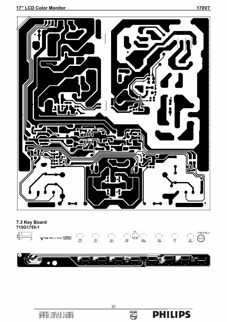
31
7.3 Key Board 715G1755-1
17” LCD Color Monitor 170V7
32
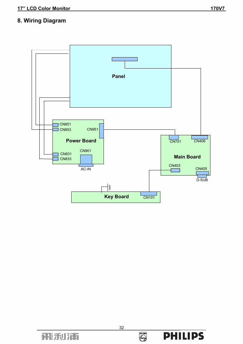
8. Wiring Diagram
Power Board
Panel
Main Board
Key Board
D-SUB
AC-IN
CN851 CN853
CN831 CN833
CN951
CN901
CN101
CN406 CN701
CN403 CN405

17” LCD Color Monitor 170V7
33
9. Mechanical Instructions 1. Back View as Fig.1
Fig.1 2. Remove base as Fig.2- Fig.3 a. Remove 1 screw for hinge cover as Fig.2 b. Remove 5 screws for base as Fig.3
Fig.2
Fig.3
17” LCD Color Monitor 170V7
34
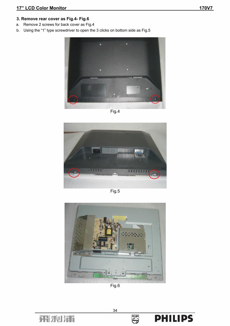
3. Remove rear cover as Fig.4- Fig.6 a. Remove 2 screws for back cover as Fig.4 b. Using the “1” type screwdriver to open the 3 clicks on bottom side as Fig.5
Fig.4
Fig.5
Fig.6
17” LCD Color Monitor 170V7
35
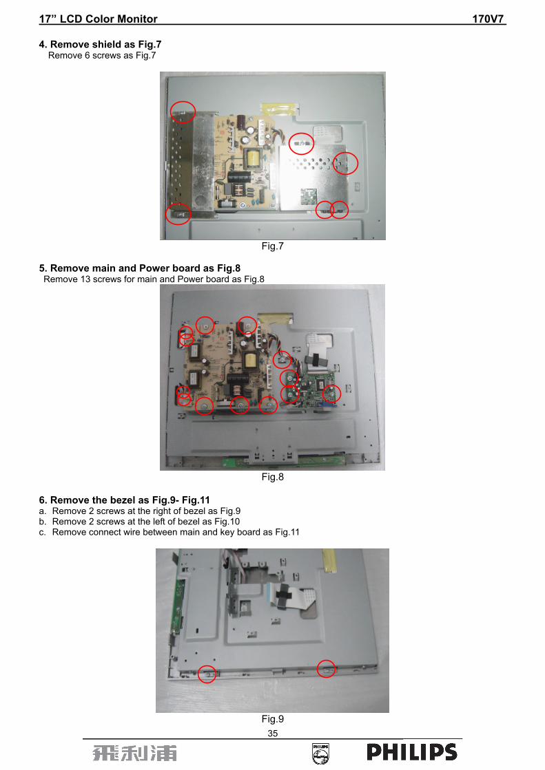
4. Remove shield as Fig.7 Remove 6 screws as Fig.7
Fig.7
5. Remove main and Power board as Fig.8 Remove 13 screws for main and Power board as Fig.8
Fig.8
6. Remove the bezel as Fig.9- Fig.11 a. Remove 2 screws at the right of bezel as Fig.9 b. Remove 2 screws at the left of bezel as Fig.10 c. Remove connect wire between main and key board as Fig.11
Fig.9
17” LCD Color Monitor 170V7
36
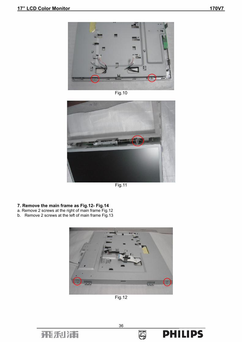
Fig.10
Fig.11
7. Remove the main frame as Fig.12- Fig.14 a. Remove 2 screws at the right of main frame Fig.12 b. Remove 2 screws at the left of main frame Fig.13
Fig.12

17” LCD Color Monitor 170V7
37
Fig.13
Fig.14

17” LCD Color Monitor 170V7
38
10. Trouble Shooting This page deals with problems that can be corrected by a user. If the problem still persists after you have tried these solutions, contact Philips customer service representative.

17” LCD Color Monitor 170V7
39

17” LCD Color Monitor 170V7
40
11. Repair Flow Chart (1). No Power
No power
Press power key and look if the picture is normal
Please reinsert and make sure the AC of 100-240 is normal
Reinsert or check the power section
X401 oscillate waveforms are normal
Measure U701 Pin2=3.3V, U702 Pin2=1.8V?
OK
OK
NG
NG
NG Replace U701, U702
Replace U401
Replace X401 OK NG
17” LCD Color Monitor 170V7
41
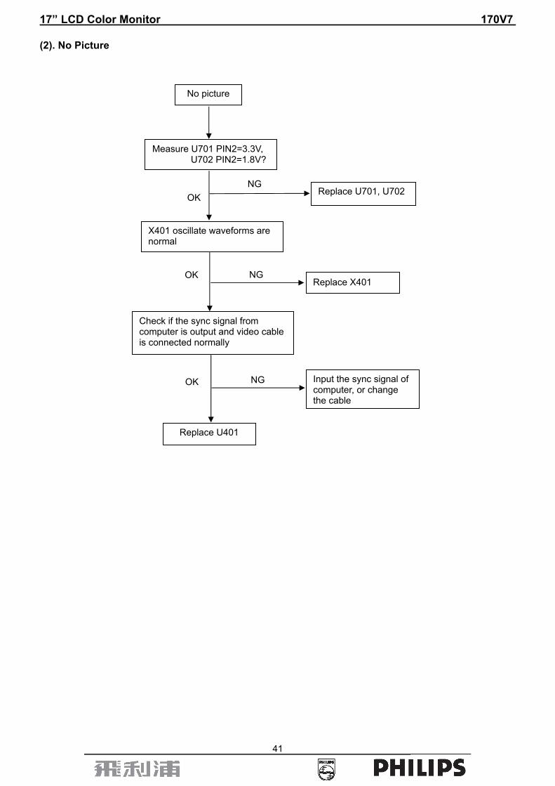
(2). No Picture
No picture
OK
OK
NG
NG
Measure U701 PIN2=3.3V, U702 PIN2=1.8V?
Replace U701, U702
X401 oscillate waveforms are normal
Replace X401
Check if the sync signal from computer is output and video cable is connected normally
Input the sync signal of computer, or change the cable
Replace U401
NG OK
17” LCD Color Monitor 170V7
42
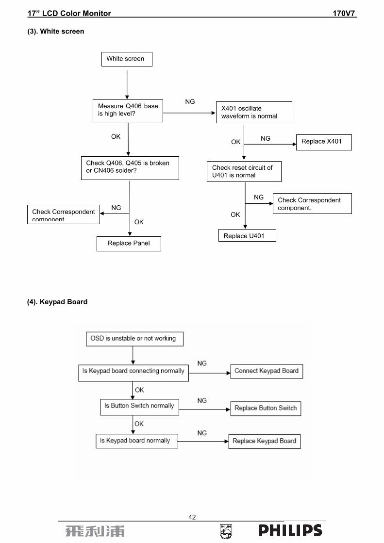
(3). White screen
(4). Keypad Board
White screen
Measure Q406 base is high level?
X401 oscillate waveform is normal
Check Q406, Q405 is broken or CN406 solder?
Check Correspondent component.
Replace Panel
Check Correspondent component.
Replace U401
OK OK Replace X401
OK
NG
NG
NG
NG
Check reset circuit of U401 is normal
OK

17” LCD Color Monitor 170V7
43
Power/Inverter Board No power Adapter Board
Check CN951 pin 6/7 = 12V?
Check AC line volt 100-240V
Check AC input
Check the voltage of C907 (+)
Check bridge rectified circuit and F901 circuit
Check start voltage for the pin 8 of IC901
Check R907 and IC901
NG
Check the auxiliary voltage is bigger than 10V and smaller than 20V
Check IC901, D926, T901
OK
Check D931, D935, IC902, IC941, ZD975
OK
NG
NGOK
OK NG
NG
17” LCD Color Monitor 170V7
44
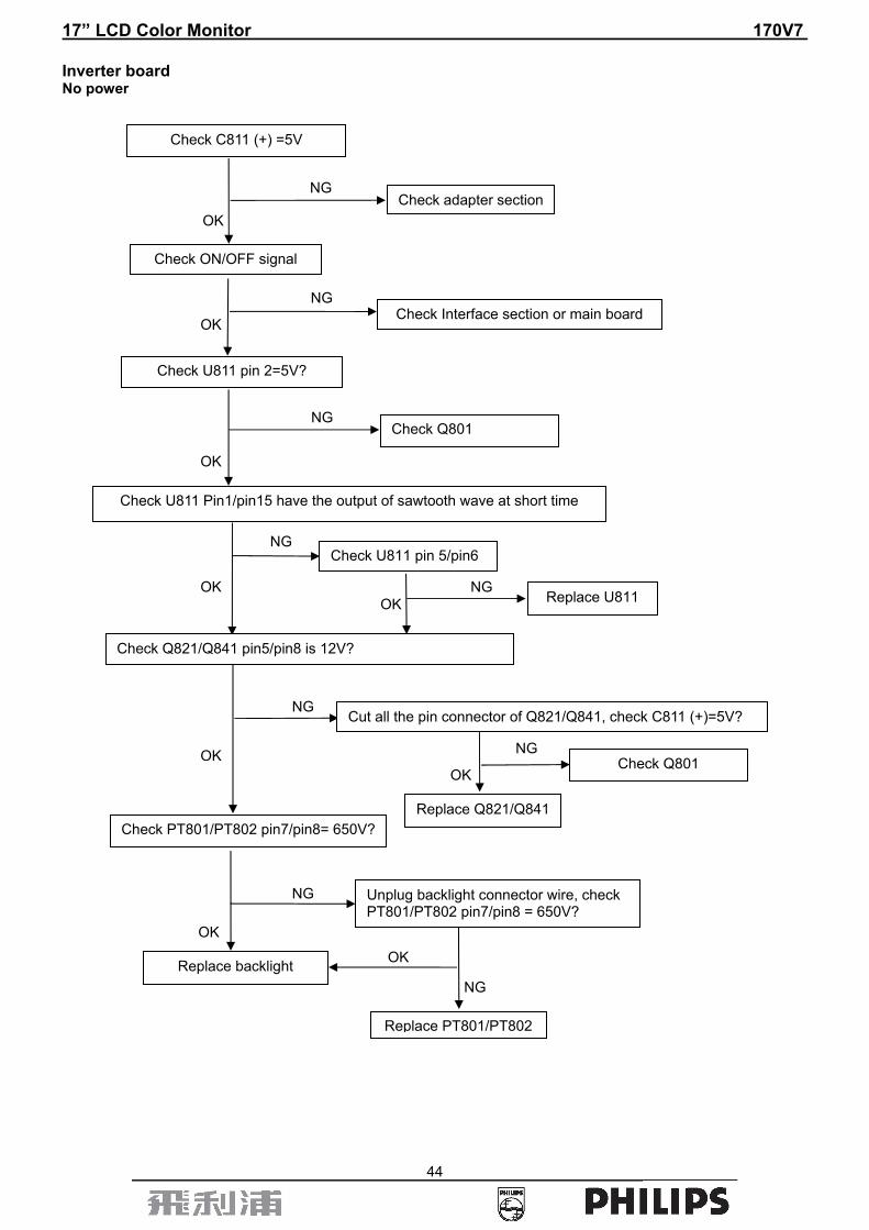
Inverter board No power
Check C811 (+) =5V
NG
OK Check adapter section
Check ON/OFF signal
Check Interface section or main board NG
OK
Check U811 pin 2=5V?
NG
OK
Check Q801
Check U811 Pin1/pin15 have the output of sawtooth wave at short time
NG
OK
Check U811 pin 5/pin6
NGOK Replace U811
Check Q821/Q841 pin5/pin8 is 12V?
Check PT801/PT802 pin7/pin8= 650V?
Cut all the pin connector of Q821/Q841, check C811 (+)=5V?
OK
NG
Unplug backlight connector wire, check PT801/PT802 pin7/pin8 = 650V?
OK
NG
Replace backlight
Replace PT801/PT802
OK
NG
NG
Replace Q821/Q841
Check Q801 OK
17” LCD Color Monitor 170V7
45
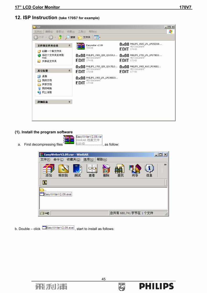
12. ISP Instruction (take 170S7 for example)
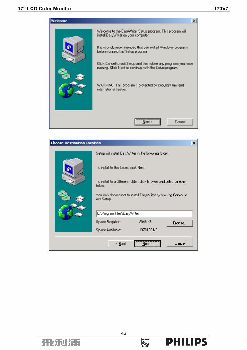
(1). Install the program software
a. First decompressing files , as follow:
b. Double – click , start to install as follows:
17” LCD Color Monitor 170V7
46

17” LCD Color Monitor 170V7
47
c. There will be a shortcut key appears on the desktop. (2). Connect the ISP board as follow:
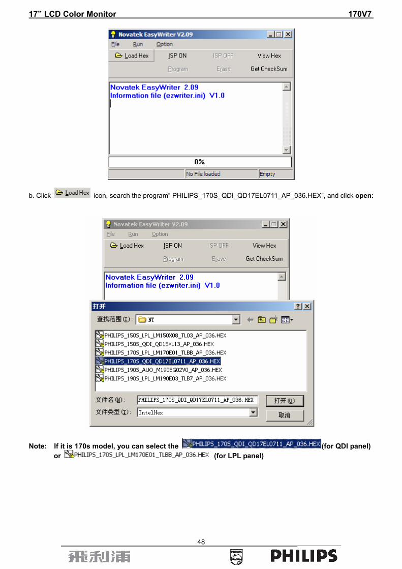
a. Double-click ,running the program as follows:
Connect to the PC LPT
Connect to the Philips 170V/190V
17” LCD Color Monitor 170V7
48
b. Click icon, search the program” PHILIPS_170S_QDI_QD17EL0711_AP_036.HEX”, and click open:
Note: If it is 170s model, you can select the (for QDI panel) or (for LPL panel)

17” LCD Color Monitor 170V7
49
c. After click “OPEN”, there would be a dialog box, select .
17” LCD Color Monitor 170V7
50
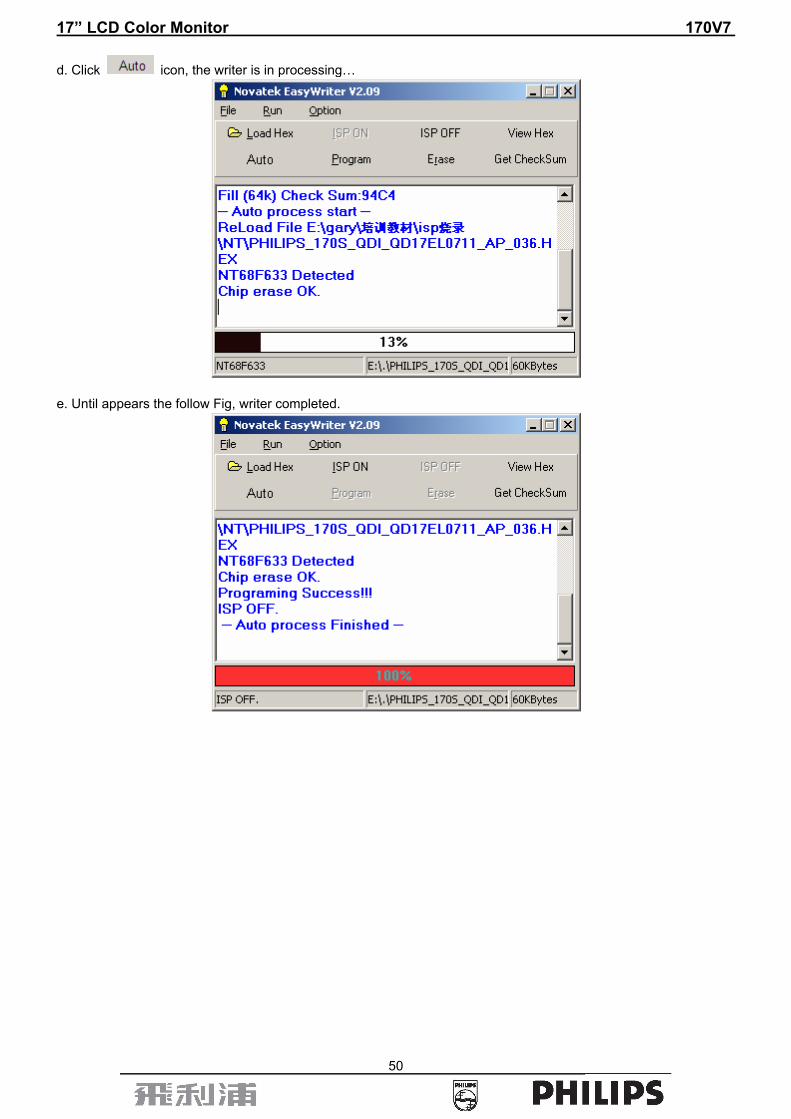
d. Click icon, the writer is in processing…
e. Until appears the follow Fig, writer completed.

17” LCD Color Monitor 170V7
51
13. DDC Instruction (take 170S7 for example) General DDC Data Re-programming In case the main EEPROM with Software DDC which store all factory settings were replaced because a defect, repaired monitor’ the serial numbers have to be re-programmed. It is advised to re- soldered the main EEPROM with Software DDC from the old board onto the new board if circuit board have been replaced, in this case the DDC data does not need to be re-programmed. Additional information about DDC (Display Data Channel) may be obtained from Video Electronics Standards Association (VESA). Extended Display Identification Data (EDID) information may be also obtained from VESA.
13.1 DDC for OSD SN System and equipment requirements 1. An i486 (or above) personal computer or compatible. 2. Microsoft operation system Windows 95/98/2000/XP. 3. “ PORT95NT, SerialNumberGlobal.exe、sn.ini” program. 4. Software OSD SN Alignment kits The kit contents: a. OSD SN BOARD x1 b. Printer cablex1 c. VGA cable x1 d. 12V DC power source 1. Install the “PORT95NT.EXE”, and restart the computer.

17” LCD Color Monitor 170V7
52
2. Connect the board as below
3. Run the “SerialNumberGlobel.exe”

17” LCD Color Monitor 170V7
53
4. It will display as below:
5. Setting as below:

17” LCD Color Monitor 170V7
54
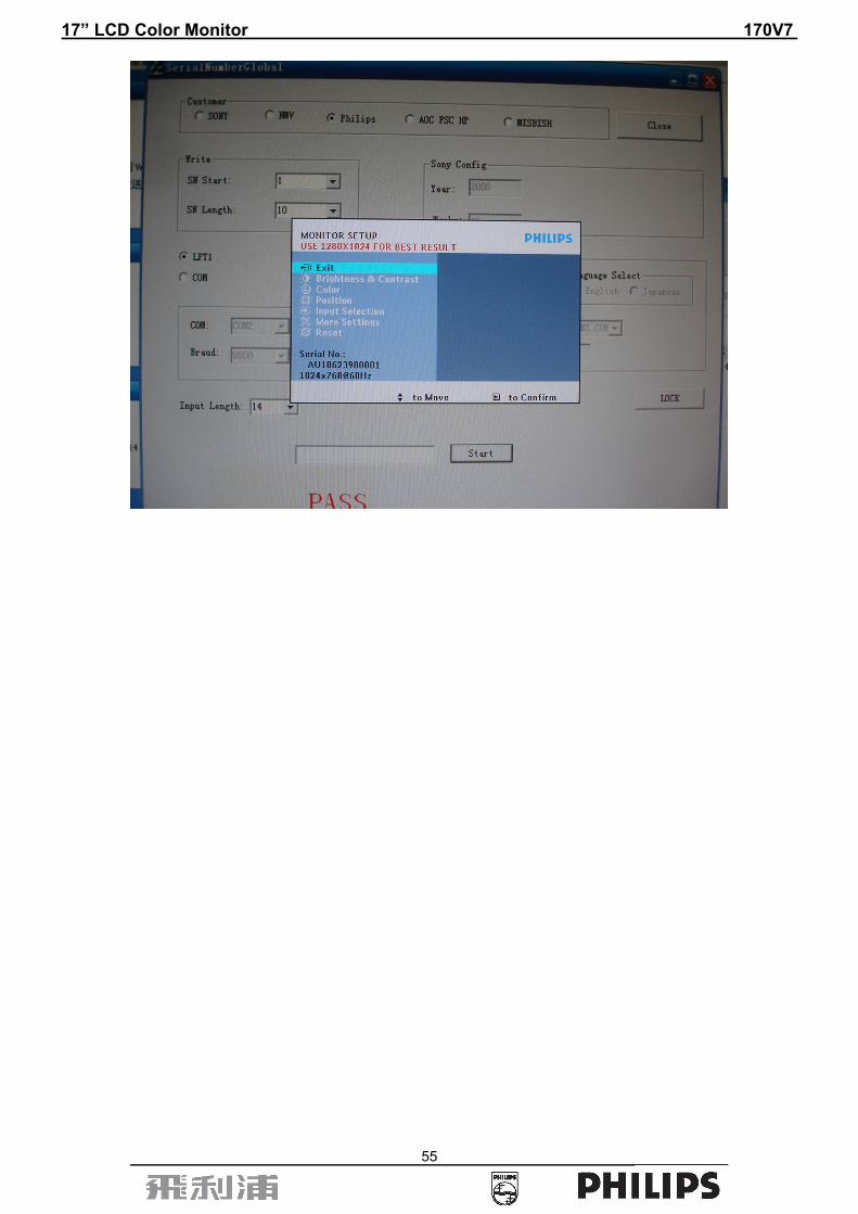
6. Key in the new SN. Then click the “Start” icon.
7. When change SN success, there would be display “PASS” as below.
17” LCD Color Monitor 170V7
55
17” LCD Color Monitor 170V7
56
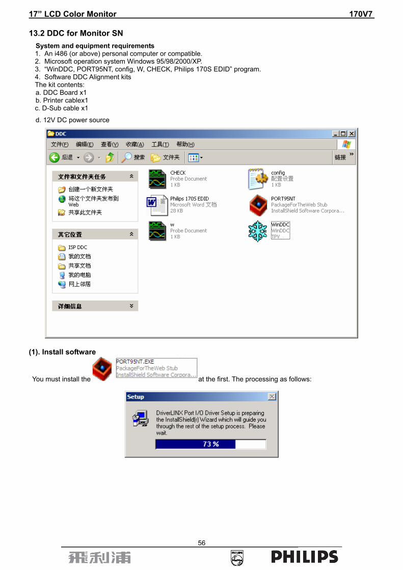
13.2 DDC for Monitor SN System and equipment requirements 1. An i486 (or above) personal computer or compatible. 2. Microsoft operation system Windows 95/98/2000/XP. 3. “WinDDC, PORT95NT, config, W, CHECK, Philips 170S EDID” program. 4. Software DDC Alignment kits The kit contents: a. DDC Board x1 b. Printer cablex1 c. D-Sub cable x1
d. 12V DC power source
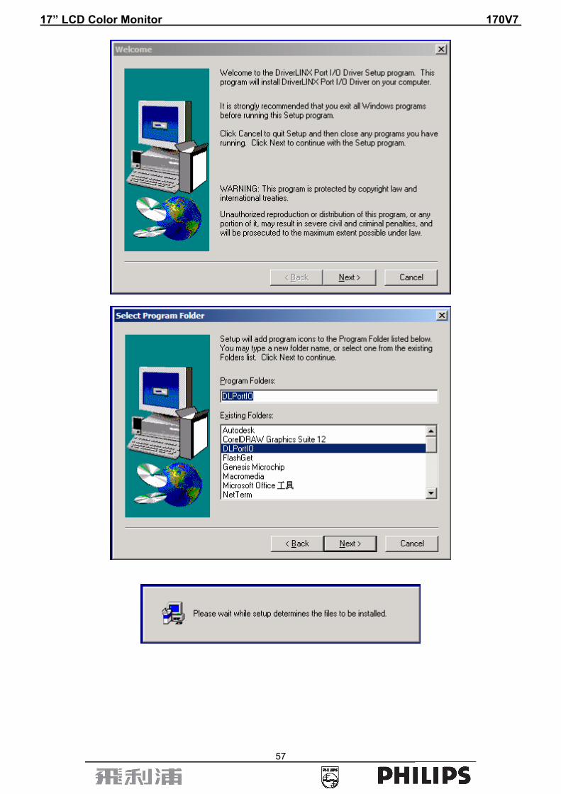
(1). Install software
You must install the at the first. The processing as follows:
17” LCD Color Monitor 170V7
57

17” LCD Color Monitor 170V7
58
Click to complete the installation.
Note: After installation, you must restart the PC to take the setup effect. (2). Connect the DDC board as follow:
Note: Pin5 of the VGA cable should be cut off.
Connect to the PC LPT
Connect to the Philips 150S/170S/190S
12V Input

17” LCD Color Monitor 170V7
59
a. Double-click ,appear as follow Figs:
b. Click .
c. Key in the Serial Number printed on the barcode label, then click “OK”
14 codes, for example.

17” LCD Color Monitor 170V7
60
d. Unit appears the following Fig, writer completed.
17” LCD Color Monitor 170V7
61
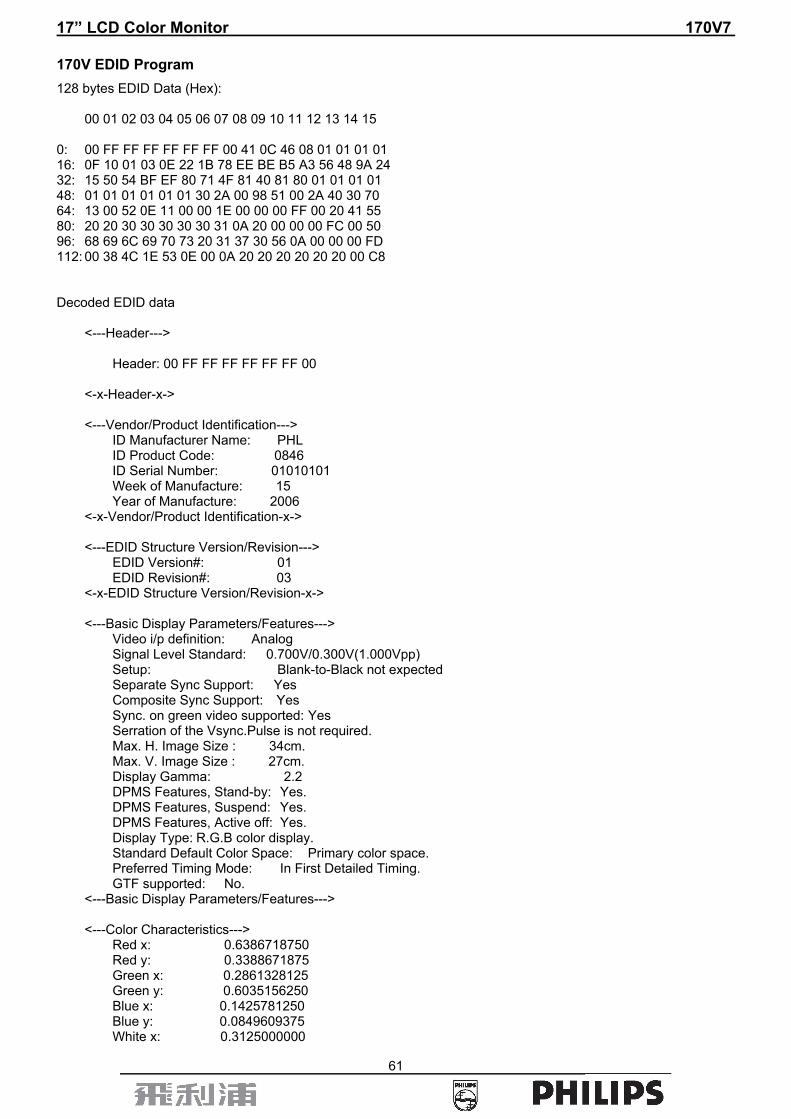
170V EDID Program 128 bytes EDID Data (Hex): 00 01 02 03 04 05 06 07 08 09 10 11 12 13 14 15 0: 00 FF FF FF FF FF FF 00 41 0C 46 08 01 01 01 01 16: 0F 10 01 03 0E 22 1B 78 EE BE B5 A3 56 48 9A 24 32: 15 50 54 BF EF 80 71 4F 81 40 81 80 01 01 01 01 48: 01 01 01 01 01 01 30 2A 00 98 51 00 2A 40 30 70 64: 13 00 52 0E 11 00 00 1E 00 00 00 FF 00 20 41 55 80: 20 20 30 30 30 30 30 31 0A 20 00 00 00 FC 00 50 96: 68 69 6C 69 70 73 20 31 37 30 56 0A 00 00 00 FD 112: 00 38 4C 1E 53 0E 00 0A 20 20 20 20 20 20 00 C8 Decoded EDID data <---Header---> Header: 00 FF FF FF FF FF FF 00 <-x-Header-x-> <---Vendor/Product Identification---> ID Manufacturer Name: PHL ID Product Code: 0846 ID Serial Number: 01010101 Week of Manufacture: 15 Year of Manufacture: 2006 <-x-Vendor/Product Identification-x-> <---EDID Structure Version/Revision---> EDID Version#: 01 EDID Revision#: 03 <-x-EDID Structure Version/Revision-x-> <---Basic Display Parameters/Features---> Video i/p definition: Analog Signal Level Standard: 0.700V/0.300V(1.000Vpp) Setup: Blank-to-Black not expected Separate Sync Support: Yes Composite Sync Support: Yes Sync. on green video supported: Yes Serration of the Vsync.Pulse is not required. Max. H. Image Size : 34cm. Max. V. Image Size : 27cm. Display Gamma: 2.2 DPMS Features, Stand-by: Yes. DPMS Features, Suspend: Yes. DPMS Features, Active off: Yes. Display Type: R.G.B color display. Standard Default Color Space: Primary color space. Preferred Timing Mode: In First Detailed Timing. GTF supported: No. <---Basic Display Parameters/Features---> <---Color Characteristics---> Red x: 0.6386718750 Red y: 0.3388671875 Green x: 0.2861328125 Green y: 0.6035156250 Blue x: 0.1425781250 Blue y: 0.0849609375 White x: 0.3125000000

17” LCD Color Monitor 170V7
62
White y: 0.3300781250 <-x-Color Characteristics-x-> <---Established Timings---> Established Timings 1: BF -720x400 @70Hz VGA,IBM -640x480 @60Hz VGA,IBM -640x480 @67Hz Apple,Mac II -640x480 @72Hz VESA -640x480 @75Hz VESA -800x600 @56Hz VESA -800x600 @60Hz VESA Established Timings 2: EF -800x600 @72Hz VESA -800x600 @75Hz VESA -832x624 @75Hz Apple,Mac II -1024x768 @60Hz VESA -1024x768 @70Hz VESA -1024x768 @75Hz VESA -1280x1024 @75Hz VESA Established Timings 3: 80 -1152x870 @75Hz Apple,Mac II <-x-Established Timings-x-> <---Standard Timing Identification---> -1152x864 @75 -1280x960 @60 -1280x1024 @60 <-x-Standard Timing Identification-x-> <---Detailed Timing Descriptions---> Detailed Timing: 1280x1024 @ 60Hz. <-x-Detailed Timing Descriptions-x-> <---Detailed Timing Descriptions---> Detailed Timing: FF (Monitor SN) ' AU 000001' Detailed Timing: FC (Monitor Name) 'Philips 170V' Detailed Timing: FD (Monitor limits) Min. V. rate: 56Hz Max. V. rate: 76Hz Min. H. rate: 30KHz Max. H. rate: 83KHz Max. Pixel Clock: 140MHz <-x-Detailed Timing Descriptions-x-> Extension Flag: 00 Checksum: C8

17” LCD Color Monitor 170V7
63
14. White Balance, Luminance Adjustment Approximately 30 minutes should be allowed for warm up before proceeding White-Balance adjustment.
1. Required instruments: Chroma 7120、Chroma 2325(BGA265A)。
2. First connect the instruments together and turn on the LCD power.
3. Set Chroma 2325(BGA265A)to be T144(1280*1024/60HZ)and P105 of full white screen. 4. Enter into the factory mode:
Firstly, turn off the power, press the AUTO and OK at one time, and then turn the power on (AUTO and OK are still pressed, about 10s), release, press the menu again will activate the factory mode, the factory OSD will be at the left top of the screen.
Move the cursor to select the Hyson 170V7***********, press OK button to enter into the sub-menu; Move the
cursor again to select ” Cool/warm “.
5. Set Chroma-7120 CH3 as 9300K color temperature by ID key, press SC and Next key set 9300K: x=283±20,
y=297±20,Y>230.
Set Chroma-7120 CH4 as 6500K color temperature by ID key, press SC and Next key set 6500K: x=313±20,
y=329±20,Y>200. 6. Adjust 9300K color temperature:
1). Switch the Chroma-7120 to RGB-Mode (with press “MODE” button)
2). Switch the MEM. Channel to Channel 3 (with up or down arrow on chroma 7120)
3). Adjust the R of Cool item on factory window until chroma 7120 indicator reached the value R=100±5
4). Adjust the G of Cool item on factory window until chroma 7120 indicator reached the value G=100±5
5). Adjust the B of Cool item on factory window until chroma 7120 indicator reached the value B=100±5
6). Switch the Chroma-7120 to x, y, Y Mode (with press “MODE” button), check whether the color-temperature
value is within Spec (the Spec is 9300K: x=283±20, y=297±20,Y>230). If not in the SPEC, repeat step 3,4,5.
7. Adjust 6500K/SRGB color temperature:
1). Switch the Chroma-7120 to RGB-Mode (with press “MODE” button)
2). Switch the MEM. Channel to Channel 4 (with up or down arrow on chroma 7120)
3). Adjust the R of Warm item on factory window until chroma 7120 indicator reached the value R=100±5
4). Adjust the G of Warm item on factory window until chroma 7120 indicator reached the value G=100±5
5). Adjust the B of Warm item on factory window until chroma 7120 indicator reached the value B=100±5
6). Switch the Chroma-7120 to x, y, Y Mode, check whether the color-temperature value is within Spec.
the Spec is 6500K: x=313±20, y=329±20,Y>200. If not in the SPEC, repeat step 3,4,5.
Turn the Power-button off to quit and save the factory mode.

17” LCD Color Monitor 170V7
64
15. Recommended & Spare Parts List
Service Kit Description Part No. Philips 12NC Remark
DDC Kit 715L2005C2 9965 000 43197 FOR ALL PHILIPS MODEL OSD SN Kit 715GT033 C 9965 000 43252 FOR ALL PHILIPS MODEL
FOR ALL PHILIPS HUDSON 7 NOVATEK ISP Kit 715LT035A 9965 000 43198 For 190B8,170B8,170A8,190A8,170P8,
170S8,190S8,170V8,190V8,150S8 MSTAR ISP Kit 715GT039 A 996510010027 200CW8M,190P8 REALTEK ISP Kit 715GT039 A 996510010027 170CW8
Recommended Parts List 170V7FB/27
Location Part No for TPV Description Philips 12NC
750GLG70E1B11M PANEL LCD 17" E01 TLBB PHILIPS L 9965 000 37088
750GLQ70L0761M000F PANEL LCD 17" EL07 R11 PHILIPS QDI 996500041332
750GLC70A7Q12M000F PANEL LCD 17" EA07Q 272 PHILIPS CPT 996500038183
750GLG70E1B31M000F PANEL LCD LM170E01-TLBL PHILIPS LPL 9965 000 41256
CBPC780KGMP3P CONVERSION BOARD ASS'Y 9965 000 37416
CBPC780KQMP2P CONVERSION BOARD (750GLQ70L0761M000F) 996500037564
CBPC780KCMP1P CONVERSION BOARD (750GLC70A7Q12M000F) 996500041328
CBPC780KGMP6P CONVERSION BOARD (750GLG70E1B31M000F) 996500041327
PWPC1742QDR1P POWER BOARD 9965 000 37020
KEPC780KE7P KEY BOARD 9965 000 35900
089G179E30C4 FFC CABLE P-TWO 9965 000 37008
089G 728HAA550 SIGNAL CABLE D-SUB HONGLIN (750GLC70A7Q12M000F) 996500037360
089G402A18N IS POWER CORD (750GLC70A7Q12M000F) 996500037563
705GQ7K0P3402 STAND-BASE 9965 000 37412
P15G82991 BKT-VESA 9965 000 35919
P15G83151 MAIN FRAME 9965 000 37012
P15G83161 POWER BRACKET 9965 000 37013
P33G4972VB1L COVER_HINGE 9965 000 35921
P34G1846VBC1T BEZEL 9965 000 37407
P34G1850VB1T REAR_COVER 9965 000 37016
P44G37901 EPS 9965 000 37018
17” LCD Color Monitor 170V7
65
P44G37902 EPS 9965 000 37019
P44G37908132A CARTON 9965 000 37411
040G4576241B LABEL-CPU 9965 000 35944
Q40G17N8137A RATING LABEL 9965 000 37418
Q70G17008135A CD MANUAL 9965 000 37410
U401 056G562112 NT68623MEFG-64 9965 000 35962
U701 056G5637 AIC1084-33PM 9965 000 37095
U702 056G56331 AI1117D-1.8-EI 9965 000 35963
U403 056G113324 AT24C16AN-10SU-2.7 9965 000 35964
U405 056G113334 M24C02-WMN6TP 9965 000 35965
U811 056G60810 0Z9938 9965 000 36059
IC902 056G1393A PC123Y22FZOF 9965 000 36055
IC901 056G564911 IC TEA1532AT S08 9965 000 36960
IC941 056G15810T AZ431AZ-AE1 9965 000 36101
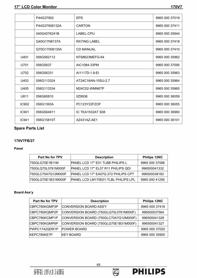
Spare Parts List 170V7FB/27 Panel
Part No for TPV Description Philips 12NC 750GLG70E1B11M PANEL LCD 17" E01 TLBB PHILIPS L 9965 000 37088
750GLQ70L0761M000F PANEL LCD 17" EL07 R11 PHILIPS QDI 996500041332
750GLC70A7Q12M000F PANEL LCD 17" EA07Q 272 PHILIPS CPT 996500038183
750GLG70E1B31M000F PANEL LCD LM170E01-TLBL PHILIPS LPL 9965 000 41256 Board Ass’y
Part No for TPV Description Philips 12NC CBPC780KGMP3P CONVERSION BOARD ASS'Y 9965 000 37416
CBPC780KQMP2P CONVERSION BOARD (750GLQ70L0761M000F) 996500037564
CBPC780KCMP1P CONVERSION BOARD (750GLC70A7Q12M000F) 996500041328
CBPC780KGMP6P CONVERSION BOARD (750GLG70E1B31M000F) 996500041327
PWPC1742QDR1P POWER BOARD 9965 000 37020
KEPC780KE7P KEY BOARD 9965 000 35900

17” LCD Color Monitor 170V7
66
Accessory and Mechanical
Part No for TPV Description Philips 12NC 089G179E30C4 FFC CABLE P-TWO 9965 000 37008
089G 728HAA550 SIGNAL CABLE D-SUB HONGLIN (750GLC70A7Q12M000F) 996500037360
089G402A18N IS POWER CORD (750GLC70A7Q12M000F) 996500037563
705GQ7K0P3402 STAND-BASE 9965 000 37412
P15G82991 BKT-VESA 9965 000 35919
P15G83151 MAIN FRAME 9965 000 37012
P15G83161 POWER BRACKET 9965 000 37013
P33G4972VB1L COVER_HINGE 9965 000 35921
P34G1846VBC1T BEZEL 9965 000 37407
P34G1850VB1T REAR_COVER 9965 000 37016
P44G37901 EPS 9965 000 37018
P44G37902 EPS 9965 000 37019
P44G37908132A CARTON 9965 000 37411
040G4576241B LABEL-CPU 9965 000 35944
Q40G17N8137A RATING LABEL 9965 000 37418
Q70G17008135A CD MANUAL 9965 000 37410
Main Board
Location Part No for TPV Description Philips 12NC CBPC780KGMP3P CONVERSION BOARD ASS'Y 9965 000 37416
C712 067G215L1014N KY25VB100M-L 6.3*11 9965 000 35958
C711 067G215L1014N KY25VB100M-L 6.3*11 9965 000 35958
C710 067G215L1014N KY25VB100M-L 6.3*11 9965 000 35958
C709 067G215L1014N KY25VB100M-L 6.3*11 9965 000 35958
C432 067G215Y4797N LOW ESR EC 4.7 UF 50V NCC 9965 000 35959
C431 067G305V1003 105∑ 10UF -20% 16V 9965 000 37413
C707 067G305V1003 105∑ 10UF -20% 16V 9965 000 37413
C708 067G305V1003 105∑ 10UF -20% 16V 9965 000 37413
C426 067G305V2213P 105∑ 220UF M 16V 9965 000 37414
CN405 088G35315FH D-SUB 15PIN 9965 000 35960
X401 093G2251 CRYSTAL 12MHZ HC-49US ARG6-120 9965 000 35961
705G 56G PH009 CPU ASS'Y (CBPC780KCMP1P) 996500041654
705G 56G PH014 CPU ASS'Y (CBPC780KGMP3P) 996500041658
705G 56G PH020 CPU ASS'Y (CBPC780KQMP2P) 996500041661
U701 056G5637 AIC1084-33PM 9965 000 37095
U702 056G56331 AI1117D-1.8-EI 9965 000 35963
U403 056G113324 AT24C16AN-10SU-2.7 9965 000 35964
U405 056G113334 M24C02-WMN6TP 9965 000 35965
Q401 057G4174 PMBS3904/PHILIPS-SMT(04) 9965 000 35966
Q406 057G4174 PMBS3904/PHILIPS-SMT(04) 9965 000 35966
Q402 057G41713T KEC 2N3906S-RTK/PS 9965 000 35967

17” LCD Color Monitor 170V7
67
Q404 057G41713T KEC 2N3906S-RTK/PS 9965 000 35967
Q405 057G7631 A03401 SOT23 BY AOS(A1) 9965 000 35968
R411 061L0603000 RST SM 0603 JUMP MAX 0R05 R 9965 000 36002
R410 061L0603000 RST SM 0603 JUMP MAX 0R05 R 9965 000 36002
FB702 061L0603000 RST SM 0603 JUMP MAX 0R05 R 9965 000 36002
FB406 061L0603000 RST SM 0603 JUMP MAX 0R05 R 9965 000 36002
FB405 061L0603000 RST SM 0603 JUMP MAX 0R05 R 9965 000 36002
FB404 061L0603000 RST SM 0603 JUMP MAX 0R05 R 9965 000 36002
FB403 061L0603000 RST SM 0603 JUMP MAX 0R05 R 9965 000 36002
FB402 061L0603000 RST SM 0603 JUMP MAX 0R05 R 9965 000 36002
FB401 061L0603000 RST SM 0603 JUMP MAX 0R05 R 9965 000 36002
R441 061L0603101 CHIPR 100 OHM -5% 1/16W 9965 000 35969
R440 061L0603101 CHIPR 100 OHM -5% 1/16W 9965 000 35969
R408 061L0603101 CHIPR 100 OHM -5% 1/16W 9965 000 35969
R407 061L0603101 CHIPR 100 OHM -5% 1/16W 9965 000 35969
R406 061L0603101 CHIPR 100 OHM -5% 1/16W 9965 000 35969
R405 061L0603101 CHIPR 100 OHM -5% 1/16W 9965 000 35969
R422 061L0603102 CHIPR 1K OHM -5% 1/16W 9965 000 35970
R485 061L0603102 CHIPR 1K OHM -5% 1/16W 9965 000 35970
R433 061L0603102 CHIPR 1K OHM -5% 1/16W 9965 000 35970
R432 061L0603102 CHIPR 1K OHM -5% 1/16W 9965 000 35970
R431 061L0603102 CHIPR 1K OHM -5% 1/16W 9965 000 35970
R428 061L0603102 CHIPR 1K OHM -5% 1/16W 9965 000 35970
R427 061L0603102 CHIPR 1K OHM -5% 1/16W 9965 000 35970
R426 061L0603102 CHIPR 1K OHM -5% 1/16W 9965 000 35970
R420 061L0603102 CHIPR 1K OHM -5% 1/16W 9965 000 35970
R472 061L0603103 CHIPR 10K OHM -5% 1/16W 9965 000 35971
R458 061L0603103 CHIPR 10K OHM -5% 1/16W 9965 000 35971
R419 061L0603103 CHIPR 10K OHM -5% 1/16W 9965 000 35971
R418 061L0603103 CHIPR 10K OHM -5% 1/16W 9965 000 35971
R417 061L0603103 CHIPR 10K OHM -5% 1/16W 9965 000 35971
R414 061L0603103 CHIPR 10K OHM -5% 1/16W 9965 000 35971
R402 061L0603103 CHIPR 10K OHM -5% 1/16W 9965 000 35971
R401 061L0603103 CHIPR 10K OHM -5% 1/16W 9965 000 35971
R403 061L0603104 RST SM 0603 RC0603 100K PM5 R 9965 000 35972
R404 061L0603104 RST SM 0603 RC0603 100K PM5 R 9965 000 35972
R434 061L0603105 RST SM 0603 RC0603 1M PM5 R 9965 000 35973
R421 061L0603151 CHIPR 150 OHM -5% 1/16W 9965 000 35974
R423 061L0603151 CHIPR 150 OHM -5% 1/16W 9965 000 35974
R424 061L0603151 CHIPR 150 OHM -5% 1/16W 9965 000 35974
R437 061L0603201 CHIP 200 OHM 1/16W 9965 000 35975
R438 061L0603201 CHIP 200 OHM 1/16W 9965 000 35975
R436 061L0603222 CHIPR 2.2K OHM -5% 1/16W 9965 000 35977
R435 061L0603222 CHIPR 2.2K OHM -5% 1/16W 9965 000 35977

17” LCD Color Monitor 170V7
68
R442 061L0603332 CHIP 3.3K OHM 1/10W 9965 000 35978
R443 061L0603332 CHIP 3.3K OHM 1/10W 9965 000 35978
R445 061L06033900F CHIP 390 OHM 1/10W 1% 9965 000 35979
R701 061L0603470 CHIPR 47 OHM -5% 1/16W 9965 000 35980
R479 061L0603472 CHIPR 4.7K OHM -5% 1/16W 9965 000 35981
R478 061L0603472 CHIPR 4.7K OHM -5% 1/16W 9965 000 35981
R476 061L0603472 CHIPR 4.7K OHM -5% 1/16W 9965 000 35981
R460 061L0603472 CHIPR 4.7K OHM -5% 1/16W 9965 000 35981
R459 061L0603472 CHIPR 4.7K OHM -5% 1/16W 9965 000 35981
R447 061L0603472 CHIPR 4.7K OHM -5% 1/16W 9965 000 35981
R446 061L0603472 CHIPR 4.7K OHM -5% 1/16W 9965 000 35981
R451 061L0603750 CHIPR 75 OHM -5% 1/16W 9965 000 35982
R452 061L0603750 CHIPR 75 OHM -5% 1/16W 9965 000 35982
R453 061L0603750 CHIPR 75 OHM -5% 1/16W 9965 000 35982
R454 061L06037509F 75OHM 1% 1/10W 9965 000 35983
R455 061L06037509F 75OHM 1% 1/10W 9965 000 35983
R456 061L06037509F 75OHM 1% 1/10W 9965 000 35983
FB410 061L0805000 CHIPR 0OHM -5% 1/10W 9965 000 35984
R444 061L1206151 CHIP 150OHM 1/4W 9965 000 36068
C429 065G040210031T MLCC 0402 10UF J 50V NPO TAIYO Y 9965 000 36566
C714 065G040210131T 0402 MLCC 100PF J 50V 9965 000 35986
C713 065G040210131T 0402 MLCC 100PF J 50V 9965 000 35986
C455 065G040210131T 0402 MLCC 100PF J 50V 9965 000 35986
C454 065G040210131T 0402 MLCC 100PF J 50V 9965 000 35986
C441 065G040210131T 0402 MLCC 100PF J 50V 9965 000 35986
C440 065G040210131T 0402 MLCC 100PF J 50V 9965 000 35986
C439 065G040210131T 0402 MLCC 100PF J 50V 9965 000 35986
C438 065G040210131T 0402 MLCC 100PF J 50V 9965 000 35986
C437 065G040210131T 0402 MLCC 100PF J 50V 9965 000 35986
C434 065G040210131T 0402 MLCC 100PF J 50V 9965 000 35986
C433 065G040210131T 0402 MLCC 100PF J 50V 9965 000 35986
C402 065G040210131T 0402 MLCC 100PF J 50V 9965 000 35986
C701 065G040210232T 0402 MLCC 1000PF K 50V 9965 000 35987
C401 065G040210232T 0402 MLCC 1000PF K 50V 9965 000 35987
C422 065G040210415T 0402 MLCC 0.1UF K 16V 9965 000 35988
C423 065G040210415T 0402 MLCC 0.1UF K 16V 9965 000 35988
C424 065G040210415T 0402 MLCC 0.1UF K 16V 9965 000 35988
C425 065G040210415T 0402 MLCC 0.1UF K 16V 9965 000 35988
C436 065G040210415T 0402 MLCC 0.1UF K 16V 9965 000 35988
C446 065G040210415T 0402 MLCC 0.1UF K 16V 9965 000 35988
C702 065G040210415T 0402 MLCC 0.1UF K 16V 9965 000 35988
C703 065G040210415T 0402 MLCC 0.1UF K 16V 9965 000 35988
C704 065G040210415T 0402 MLCC 0.1UF K 16V 9965 000 35988
C705 065G040210415T 0402 MLCC 0.1UF K 16V 9965 000 35988
17” LCD Color Monitor 170V7
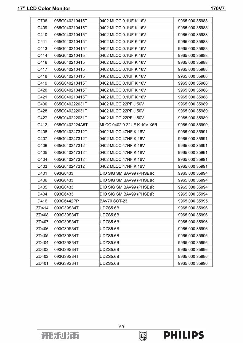
69
C706 065G040210415T 0402 MLCC 0.1UF K 16V 9965 000 35988
C409 065G040210415T 0402 MLCC 0.1UF K 16V 9965 000 35988
C410 065G040210415T 0402 MLCC 0.1UF K 16V 9965 000 35988
C411 065G040210415T 0402 MLCC 0.1UF K 16V 9965 000 35988
C413 065G040210415T 0402 MLCC 0.1UF K 16V 9965 000 35988
C414 065G040210415T 0402 MLCC 0.1UF K 16V 9965 000 35988
C416 065G040210415T 0402 MLCC 0.1UF K 16V 9965 000 35988
C417 065G040210415T 0402 MLCC 0.1UF K 16V 9965 000 35988
C418 065G040210415T 0402 MLCC 0.1UF K 16V 9965 000 35988
C419 065G040210415T 0402 MLCC 0.1UF K 16V 9965 000 35988
C420 065G040210415T 0402 MLCC 0.1UF K 16V 9965 000 35988
C421 065G040210415T 0402 MLCC 0.1UF K 16V 9965 000 35988
C430 065G040222031T 0402 MLCC 22PF J 50V 9965 000 35989
C428 065G040222031T 0402 MLCC 22PF J 50V 9965 000 35989
C427 065G040222031T 0402 MLCC 22PF J 50V 9965 000 35989
C412 065G0402224A5T MLCC 0402 0.22UF K 10V X5R 9965 000 35990
C408 065G040247312T 0402 MLCC 47NF K 16V 9965 000 35991
C407 065G040247312T 0402 MLCC 47NF K 16V 9965 000 35991
C406 065G040247312T 0402 MLCC 47NF K 16V 9965 000 35991
C405 065G040247312T 0402 MLCC 47NF K 16V 9965 000 35991
C404 065G040247312T 0402 MLCC 47NF K 16V 9965 000 35991
C403 065G040247312T 0402 MLCC 47NF K 16V 9965 000 35991
D401 093G6433 DIO SIG SM BAV99 (PHSE)R 9965 000 35994
D406 093G6433 DIO SIG SM BAV99 (PHSE)R 9965 000 35994
D405 093G6433 DIO SIG SM BAV99 (PHSE)R 9965 000 35994
D404 093G6433 DIO SIG SM BAV99 (PHSE)R 9965 000 35994
D416 093G6442PP BAV70 SOT-23 9965 000 35995
ZD414 093G39S34T UDZS5.6B 9965 000 35996
ZD408 093G39S34T UDZS5.6B 9965 000 35996
ZD407 093G39S34T UDZS5.6B 9965 000 35996
ZD406 093G39S34T UDZS5.6B 9965 000 35996
ZD405 093G39S34T UDZS5.6B 9965 000 35996
ZD404 093G39S34T UDZS5.6B 9965 000 35996
ZD403 093G39S34T UDZS5.6B 9965 000 35996
ZD402 093G39S34T UDZS5.6B 9965 000 35996
ZD401 093G39S34T UDZS5.6B 9965 000 35996
17” LCD Color Monitor 170V7
70
Power Board
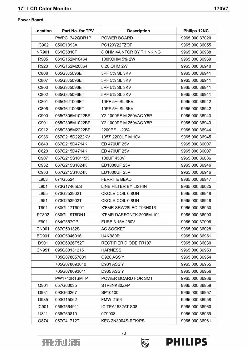
Location Part No. for TPV Description Philips 12NC PWPC1742QDR1P POWER BOARD 9965 000 37020
IC902 056G1393A PC123Y22FZOF 9965 000 36055
NR901 061G5810T 8 OHM 4A NTCR BY THINKING 9965 000 36938
R905 061G152M10464 100KOHM 5% 2W 9965 000 36939
R920 061G152M20864 0.20 OHM 2W 9965 000 36940
C808 065G3J5096ET 5PF 5% SL 3KV 9965 000 36941
C807 065G3J5096ET 5PF 5% SL 3KV 9965 000 36941
C803 065G3J5096ET 5PF 5% SL 3KV 9965 000 36941
C802 065G3J5096ET 5PF 5% SL 3KV 9965 000 36941
C801 065G6J1006ET 10PF 5% SL 6KV 9965 000 36942
C806 065G6J1006ET 10PF 5% SL 6KV 9965 000 36942
C900 065G305M1022BP Y2 1000PF M 250VAC Y5P 9965 000 36943
C901 065G305M1022BP Y2 1000PF M 250VAC Y5P 9965 000 36943
C912 065G305M2222BP 2200PF -20% 9965 000 36944
C936 067G215D2222KV 105∑ 2200UF M 10V 9965 000 36945
C840 067G215D4714K ED 470UF 25V 9965 000 36007
C820 067G215D4714K ED 470UF 25V 9965 000 36007
C907 067G215S10115K 100UF 450V 9965 000 36086
C932 067G215S1024K ED1000UF 25V 9965 000 36946
C933 067G215S1024K ED1000UF 25V 9965 000 36946
L903 071G5524 FERRITE BEAD 9965 000 36947
L901 073G17465LS LINE FILTER BY LISHIN 9965 000 36025
L955 073G253902T CKOLE COIL 0.8UH 9965 000 36948
L951 073G253902T CKOLE COIL 0.8UH 9965 000 36948
T901 080GL17T900T X'FMR SRW28LEC-T93H016 9965 000 36950
PT802 080GL19T8DN1 X'FMR DARFONTK.2006M.101 9965 000 36093
F901 084G557GP FUSE 3.15A 250V 9965 000 37006
CN901 087G50132S AC SOCKET 9965 000 36028
BD901 093G5046016 U4KB80R 9965 000 36951
D901 093G6026T52T RECTIFIER DIODE FR107 9965 000 36030
CN951 095G80131215 HARNESS 9965 000 36953
705G078057001 Q920 ASS'Y 9965 000 36954
705G078093010 D931 ASS'Y 9965 000 36955
705G078093011 D935 ASS'Y 9965 000 36956
PW1742R1SMTP POWER BOARD FOR SMT 9965 000 36936
Q901 057G60035 STP8NK80ZFP 9965 000 36959
D931 093G60267 SP10100 9965 000 36957
D935 093G15062 FMW-2156 9965 000 36958
IC901 056G564911 IC TEA1532AT S08 9965 000 36960
U811 056G60810 0Z9938 9965 000 36059
Q874 057G41712T KEC 2N3904S-RTK/PS 9965 000 36961

17” LCD Color Monitor 170V7
71
Q886 057G7592 RK7002 9965 000 36033
Q885 057G7592 RK7002 9965 000 36033
Q883 057G7592 RK7002 9965 000 36033
Q881 057G7592 RK7002 9965 000 36033
Q871 057G7592 RK7002 9965 000 36033
Q873 057G7604B PDTA144WK SOT346 9965 000 36962
Q841 057G76314 AM9945N 9965 000 36100
Q821 057G76314 AM9945N 9965 000 36100
RJ827 061L0805000 CHIPR 0OHM -5% 1/10W 9965 000 35984
R849 061L0805000 CHIPR 0OHM -5% 1/10W 9965 000 35984
R829 061L0805000 CHIPR 0OHM -5% 1/10W 9965 000 35984
R822 061L0805100 CHIPR 10 OHM -5% 1/10W 9965 000 36012
R823 061L0805100 CHIPR 10 OHM -5% 1/10W 9965 000 36012
R842 061L0805100 CHIPR 10 OHM -5% 1/10W 9965 000 36012
R843 061L0805100 CHIPR 10 OHM -5% 1/10W 9965 000 36012
R954 061L0805100 CHIPR 10 OHM -5% 1/10W 9965 000 36012
R836 061L08051002F CHIP 10K OHM 1/8W 1% 9965 000 36020
R855 061L08051002F CHIP 10K OHM 1/8W 1% 9965 000 36020
R856 061L08051002F CHIP 10K OHM 1/8W 1% 9965 000 36020
R835 061L08051002F CHIP 10K OHM 1/8W 1% 9965 000 36020
R941 061L0805102 CHIPR 1K OHM -5% 1/10W 9965 000 36963
R851 061L0805102 CHIPR 1K OHM -5% 1/10W 9965 000 36963
R888 061L0805102 CHIPR 1K OHM -5% 1/10W 9965 000 36963
R886 061L0805102 CHIPR 1K OHM -5% 1/10W 9965 000 36963
R884 061L0805102 CHIPR 1K OHM -5% 1/10W 9965 000 36963
R882 061L0805102 CHIPR 1K OHM -5% 1/10W 9965 000 36963
R831 061L0805102 CHIPR 1K OHM -5% 1/10W 9965 000 36963
R801 061L0805103 CHIPR 10K OHM -5% 1/10W 9965 000 36964
R804 061L0805103 CHIPR 10K OHM -5% 1/10W 9965 000 36964
R807 061L0805103 CHIPR 10K OHM -5% 1/10W 9965 000 36964
R880 061L0805103 CHIPR 10K OHM -5% 1/10W 9965 000 36964
R887 061L0805104 CHIPR 100K OHM -5% 1/10W 9965 000 36965
R802 061L0805104 CHIPR 100K OHM -5% 1/10W 9965 000 36965
R872 061L0805104 CHIPR 100K OHM -5% 1/10W 9965 000 36965
R885 061L0805104 CHIPR 100K OHM -5% 1/10W 9965 000 36965
R883 061L0805104 CHIPR 100K OHM -5% 1/10W 9965 000 36965
R881 061L0805104 CHIPR 100K OHM -5% 1/10W 9965 000 36965
R819 061L0805105 CHIP 1M OHM 5% 1/8W 9965 000 36013
R912 061L0805105 CHIP 1M OHM 5% 1/8W 9965 000 36013
R946 061L08051103F 110KOHM 1% 1/10W 9965 000 36966
R853 061L0805122 1.2KOHM -5%,1/8W,0805 9965 000 36967
R833 061L0805122 1.2KOHM -5%,1/8W,0805 9965 000 36967
R923 061L0805123 CHIP 12KOHM 1/8W 9965 000 36968
R914 061L08051241F CHIP 1.24K OHM 1/10W 1% 9965 000 36969

17” LCD Color Monitor 170V7
72
R916 061L0805152 CHIPR 1.5K OHM -5% 1/10W 9965 000 36970
R873 061L0805202 CHIP 2KOHM 1/8W 9965 000 36971
R816 061L0805203 CHIPR 20KOHM -5% 1/8W 9965 000 36972
R865 061L08052320F CHIP 232OHM 9965 000 36973
R815 061L0805303 CHIP 30K OHM 1/8W 9965 000 36974
R813 061L08053302F CHIP 33KOHM 1/8W 1% 9965 000 36975
R874 061L0805331 CHIP 330 OHM 5% 1/10W 9965 000 36976
R917 061L0805333 CHIP 33KOHM 1% 1/8W 9965 000 36977
R811 061L0805335 3.3M 0805 9965 000 36978
R943 061L08055101F CHIP 5.1K OHM 1/10W 1% 9965 000 36979
R812 061L0805624 CHIP 620KOHM 5% 0805 1/8W 9965 000 36980
R825 061L0805752 CHIP 7.5K OHM 1/10W 9965 000 36981
R837 061L0805752 CHIP 7.5K OHM 1/10W 9965 000 36981
R944 061L08059101F CHIP 9.1K OHM 1/10W 1% 9965 000 36982
R945 061L08059101F CHIP 9.1K OHM 1/10W 1% 9965 000 36982
R926 061L1206000 CHIPR 0 OHM -5% 1/8W 9965 000 36067
R918 061L1206000 CHIPR 0 OHM -5% 1/8W 9965 000 36067
R907 061L1206103 CHIP 10KOHM 5% 1/4W 9965 000 36016
R904 061L1206155 1.5M/0805 9965 000 36983
R910 061L1206155 1.5M/0805 9965 000 36983
R937 061L1206182 CHIP 1.8KOHM 9965 000 36984
R931 061L1206229 CHIP 2.2OHM 5% 1/8W 9965 000 36985
R932 061L1206229 CHIP 2.2OHM 5% 1/8W 9965 000 36985
R927 061L1206472 CHIP 4.7KOHM 5% 1/4W 9965 000 36986
R902 061L1206684 CHIPR 680K OHM -5% 1/8W 9965 000 36024
R901 061L1206684 CHIPR 680K OHM -5% 1/8W 9965 000 36024
R900 061L1206684 CHIPR 680K OHM -5% 1/8W 9965 000 36024
C838 065G080510231 1000PF 50V NPO 9965 000 36991
C861 065G080510231 1000PF 50V NPO 9965 000 36991
C822 065G080510232 CHIP 1000P 50VX7R 0805 9965 000 36038
C823 065G080510232 CHIP 1000P 50VX7R 0805 9965 000 36038
C842 065G080510232 CHIP 1000P 50VX7R 0805 9965 000 36038
C843 065G080510232 CHIP 1000P 50VX7R 0805 9965 000 36038
C887 065G080510322 CHIP 0.01UF 25V X7R 0805 9965 000 36039
C885 065G080510322 CHIP 0.01UF 25V X7R 0805 9965 000 36039
C883 065G080510322 CHIP 0.01UF 25V X7R 0805 9965 000 36039
C881 065G080510322 CHIP 0.01UF 25V X7R 0805 9965 000 36039
C819 065G080510322 CHIP 0.01UF 25V X7R 0805 9965 000 36039
C913 065G080510422 0.1UF -10% 25V X7R 080 9965 000 36040
C955 065G080510422 0.1UF -10% 25V X7R 080 9965 000 36040
C951 065G080510422 0.1UF -10% 25V X7R 080 9965 000 36040
C812 065G080510422 0.1UF -10% 25V X7R 080 9965 000 36040
C914 065G080510522 CHIP 1UF 25V X7R 0805 9965 000 36073
C841 065G080510522 CHIP 1UF 25V X7R 0805 9965 000 36073
17” LCD Color Monitor 170V7
73
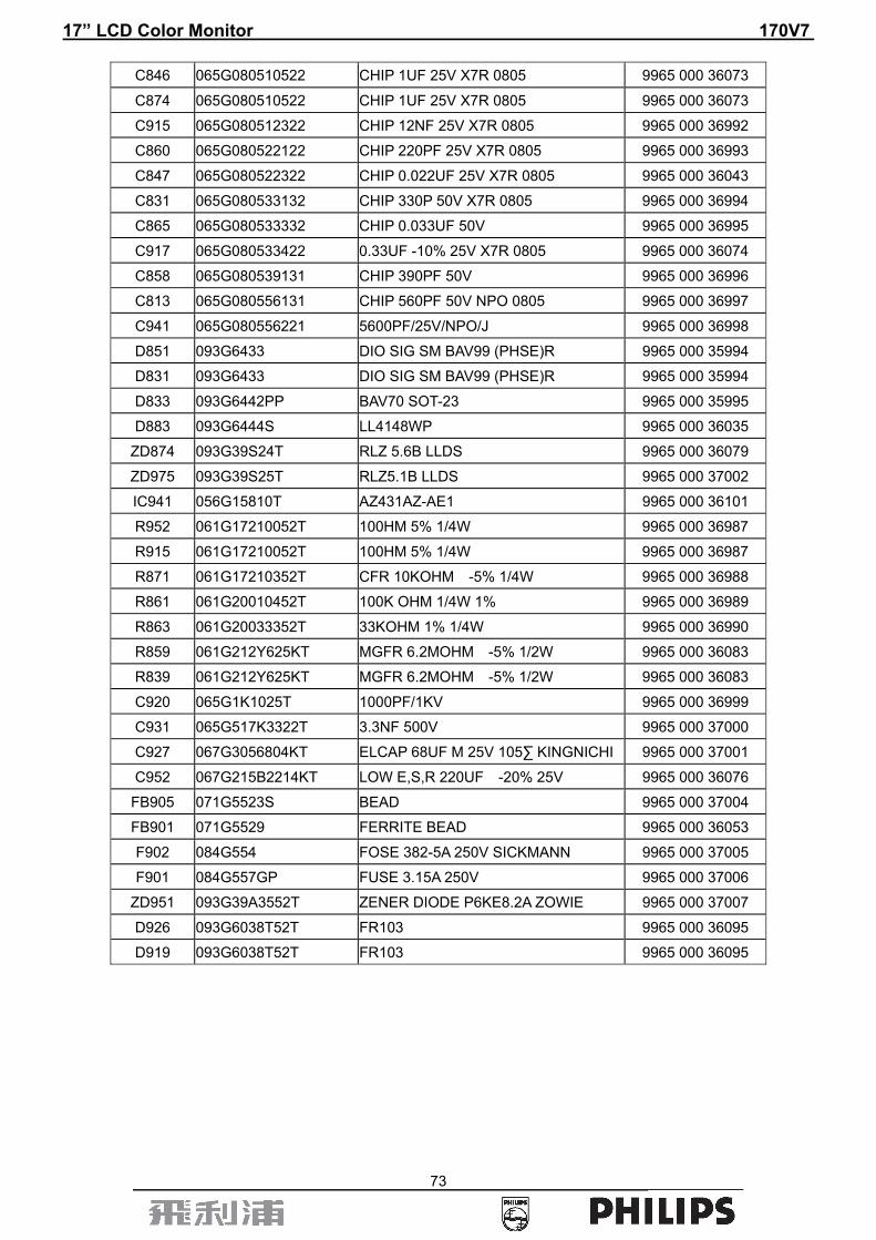
C846 065G080510522 CHIP 1UF 25V X7R 0805 9965 000 36073
C874 065G080510522 CHIP 1UF 25V X7R 0805 9965 000 36073
C915 065G080512322 CHIP 12NF 25V X7R 0805 9965 000 36992
C860 065G080522122 CHIP 220PF 25V X7R 0805 9965 000 36993
C847 065G080522322 CHIP 0.022UF 25V X7R 0805 9965 000 36043
C831 065G080533132 CHIP 330P 50V X7R 0805 9965 000 36994
C865 065G080533332 CHIP 0.033UF 50V 9965 000 36995
C917 065G080533422 0.33UF -10% 25V X7R 0805 9965 000 36074
C858 065G080539131 CHIP 390PF 50V 9965 000 36996
C813 065G080556131 CHIP 560PF 50V NPO 0805 9965 000 36997
C941 065G080556221 5600PF/25V/NPO/J 9965 000 36998
D851 093G6433 DIO SIG SM BAV99 (PHSE)R 9965 000 35994
D831 093G6433 DIO SIG SM BAV99 (PHSE)R 9965 000 35994
D833 093G6442PP BAV70 SOT-23 9965 000 35995
D883 093G6444S LL4148WP 9965 000 36035
ZD874 093G39S24T RLZ 5.6B LLDS 9965 000 36079
ZD975 093G39S25T RLZ5.1B LLDS 9965 000 37002
IC941 056G15810T AZ431AZ-AE1 9965 000 36101
R952 061G17210052T 100HM 5% 1/4W 9965 000 36987
R915 061G17210052T 100HM 5% 1/4W 9965 000 36987
R871 061G17210352T CFR 10KOHM -5% 1/4W 9965 000 36988
R861 061G20010452T 100K OHM 1/4W 1% 9965 000 36989
R863 061G20033352T 33KOHM 1% 1/4W 9965 000 36990
R859 061G212Y625KT MGFR 6.2MOHM -5% 1/2W 9965 000 36083
R839 061G212Y625KT MGFR 6.2MOHM -5% 1/2W 9965 000 36083
C920 065G1K1025T 1000PF/1KV 9965 000 36999
C931 065G517K3322T 3.3NF 500V 9965 000 37000
C927 067G3056804KT ELCAP 68UF M 25V 105∑ KINGNICHI 9965 000 37001
C952 067G215B2214KT LOW E,S,R 220UF -20% 25V 9965 000 36076
FB905 071G5523S BEAD 9965 000 37004
FB901 071G5529 FERRITE BEAD 9965 000 36053
F902 084G554 FOSE 382-5A 250V SICKMANN 9965 000 37005
F901 084G557GP FUSE 3.15A 250V 9965 000 37006
ZD951 093G39A3552T ZENER DIODE P6KE8.2A ZOWIE 9965 000 37007
D926 093G6038T52T FR103 9965 000 36095
D919 093G6038T52T FR103 9965 000 36095

17” LCD Color Monitor 170V7
74
Key Board
Location Part No for TPV Description Philips 12NC
KEPC780KE7P KEY BOARD 9965 000 35900
CN101 033G38026H WAFER 6P RIGHT ANGLE PITCH 2.0 9965 000 35999
SW1 077G6001GCJ TACT SWITCH TSPB-2 -NP 9965 000 36000
SW2 077G6001GCJ TACT SWITCH TSPB-2 -NP 9965 000 36000
SW3 077G6001GCJ TACT SWITCH TSPB-2 -NP 9965 000 36000
SW4 077G6001GCJ TACT SWITCH TSPB-2 -NP 9965 000 36000
SW5 077G6001GCJ TACT SWITCH TSPB-2 -NP 9965 000 36000
SW6 077G6001GCJ TACT SWITCH TSPB-2 -NP 9965 000 36000
SW7 077G6001GCJ TACT SWITCH TSPB-2 -NP 9965 000 36000
SW8 077G6001GCJ TACT SWITCH TSPB-2 -NP 9965 000 36000
LED1 081G121GP GP32032ME 9965 000 36001
R109 061L0603000 RST SM 0603 JUMP MAX 0R05 R 9965 000 36002
R100 061L0603000 RST SM 0603 JUMP MAX 0R05 R 9965 000 36002
R101 061L0603101 CHIPR 100 OHM -5% 1/16W 9965 000 35969
R104 061L0603102 CHIPR 1K OHM -5% 1/16W 9965 000 35970
R108 061L0603102 CHIPR 1K OHM -5% 1/16W 9965 000 35970
R103 061L0603103 CHIPR 10K OHM -5% 1/16W 9965 000 35971
R107 061L0603103 CHIPR 10K OHM -5% 1/16W 9965 000 35971
R106 061L0603473 RST SM 0603 RC0603 47K PM5 R 9965 000 36003
R102 061L0603473 RST SM 0603 RC0603 47K PM5 R 9965 000 36003
C101 065G060310332 0.01UF -10% 50V X7R 9965 000 36004
C102 065G060310332 0.01UF -10% 50V X7R 9965 000 36004
C103 065G060310332 0.01UF -10% 50V X7R 9965 000 36004
C104 065G060310332 0.01UF -10% 50V X7R 9965 000 36004
C105 065G060310332 0.01UF -10% 50V X7R 9965 000 36004

17” LCD Color Monitor 170V7
75
16. Different Parts List Diversity of 170V7FB/93 compared with 170V7FB/27 Location Part No. for TPV Description Philips 12NC Remark
E089A 089G414A18NYH POWER CABLE(32E1818021) 9965 000 37557 E089B 089G 728TAA550 SIGNAL CABLE D-SUB TONGFU 996510006491 2nd source
750GLQ70L0761M PANEL LCD 17" EL07 R11 PHILIPS Q 9965 000 37087 FQ002 CBPC780KGMP2P CONVERSION BOARD 9965 000 37085 2nd sourceFQ101 P34G1846VBD1T BEZEL 9965 000 38205 FQ522 095G8014 10529 WIRE HARNESS 996510019778 2nd sourceFQ103 705GQ7K0P34 02 STAND-BASE ASS'Y 996500037412 2nd sourceFQ001 750GLG70E1B11M000F PANEL LM170E01-TLBB NJ LPL 996500041326 2nd sourceFQ405 P33G4989 VQA1C KEY PAD 996500037014 2nd sourceFQ111 P34G1850 VB 1T REAR COVER 996500037016 2nd sourceFQ205 705GQ8CS058 CUSHION ASSY 996510019896 2nd sourceFQ202 Q44G7003813 2D CARTON 996510019897 2nd sourceFQ203 Q45G 88607 R PE BAG FOR MONITOR 996510019892 2nd sourceFQ204 Q70G1700813 5B CD MANUAL 996510019893 2nd sourceFQ206 Q41G780081322A 170V7 QSG 996510019894 2nd sourceFQ304 089G179E30H 4 FFC CABLE 996500042351 2nd sourceIC902 056G 139 3B IC PC123Y82FZ0F 996500040055 2nd sourceFQ003 PWPC1742QDR1P POWER BOARD ASSY 996500037020 2nd sourceIC902 056G 139 5A TCET1103G 996500040056 2nd sourceT901 080GL17T900 L XFMR FOR POWER LITAI 996500040061 2nd sourceT901 080GL17T900 N XFMR FOR POWER YUVA 996500040062 2nd source
PT801 080GL19T 8DN1 X'FMR DARFONTK.2006M.101 996500036093 2nd sourceIC941 056G 158 4 T H431BA 996500040068 2nd sourceF901 084G 55 7W FUSE 3.15A 250V WICKMANN 996510007401 2nd source
CN403 033G8027 10 WAFER 2*5P 2.0MM R/A 996510019777 2nd sourceU701 056G 563 21 AP1084K33LA 996500037330 2nd sourceU702 056G 563 64 MM1117ST18 SOT-223 996510019895 2nd sourceU401 705G 56G PH012 MCU ASS`Y 996500041657 2nd source
FQ004 KEPC780KE7P KEY BOARD ASSY 9965 000 35900 2nd sourceCN406 033G801930FH FPC CONN. 1.0MM 30P 9965 000 36924 R411 061L0603101 CHIPR 100 OHM -5% 1/16W 9965 000 35969 R410 061L0603101 CHIPR 100 OHM -5% 1/16W 9965 000 35969 R440 061L0603221 CHIPR 220 OHM -5% 1/16W 9965 000 35976 R441 061L0603221 CHIPR 220 OHM -5% 1/16W 9965 000 35976 R449 061L0603472 CHIPR 4.7K OHM -5% 1/16W 9965 000 35981 R448 061L0603472 CHIPR 4.7K OHM -5% 1/16W 9965 000 35981 L902 071G5524 FERRITE BEAD 9965 000 36947
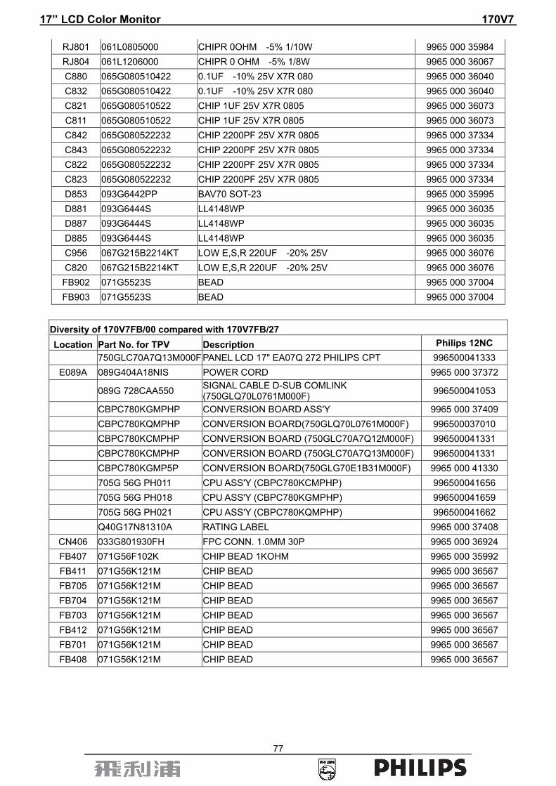
PT801 080GL19T8DN1 X'FMR DARFONTK.2006M.101 9965 000 36093 BD901 093G50460900 BRIDEGE DIODE GBU408 LITEON 9965 000 37336 D935 093G60240 YG802C06R TO-220F15 9965 000 37337 Q880 057G7592 RK7002 9965 000 36033 Q801 057G7592 RK7002 9965 000 36033 RJ801 061L0805000 CHIPR 0OHM -5% 1/10W 9965 000 35984 RJ804 061L1206000 CHIPR 0 OHM -5% 1/8W 9965 000 36067

17” LCD Color Monitor 170V7
76
C880 065G080510422 0.1UF -10% 25V X7R 080 9965 000 36040 C832 065G080510422 0.1UF -10% 25V X7R 080 9965 000 36040 C821 065G080510522 CHIP 1UF 25V X7R 0805 9965 000 36073 C811 065G080510522 CHIP 1UF 25V X7R 0805 9965 000 36073 C842 065G080522232 CHIP 2200PF 25V X7R 0805 9965 000 37334 C843 065G080522232 CHIP 2200PF 25V X7R 0805 9965 000 37334 C822 065G080522232 CHIP 2200PF 25V X7R 0805 9965 000 37334 C823 065G080522232 CHIP 2200PF 25V X7R 0805 9965 000 37334 D853 093G6442PP BAV70 SOT-23 9965 000 35995 D881 093G6444S LL4148WP 9965 000 36035 D887 093G6444S LL4148WP 9965 000 36035 D885 093G6444S LL4148WP 9965 000 36035 C956 067G215B2214KT LOW E,S,R 220UF -20% 25V 9965 000 36076 C820 067G215B2214KT LOW E,S,R 220UF -20% 25V 9965 000 36076 FB902 071G5523S BEAD 9965 000 37004 FB903 071G5523S BEAD 9965 000 37004
Diversity of 170V7FB/69 compared with 170V7FB/27 Location Part No. for TPV Description Philips 12NC
089G410A18NIS POWER CORD WALL-OUT FOR UK 9965 000 37340 089G728CAA550 SIGNAL CABLE D-SUB COMLINK 9965 000 41053 750GLQ70L0761M PANEL LCD 17" EL07 R11 PHILIPS Q 9965 000 37087 750GLC70A7Q12M PANEL LCD 17 EA07Q 272 PHILIPS 9965 000 39683 CBPC780KGMP2P CONVERSION BOARD 9965 000 37085 CBPC780KQMP1P CONVERSION BOARD 9965 000 37086 CBPC780KCMP2P CONVERSION BOARD(CPT) 9965 000 41054 CBPC780KGMP4P CONVERSION BOARD(750GLG70E1B31M000F) 996500041329 P44G37908132B CARTON 9965 000 41055 Q40G17N81310A RATING LABEL 9965 000 37408
CN406 033G801930FH FPC CONN. 1.0MM 30P 9965 000 36924 R411 061L0603101 CHIPR 100 OHM -5% 1/16W 9965 000 35969 R410 061L0603101 CHIPR 100 OHM -5% 1/16W 9965 000 35969 R440 061L0603221 CHIPR 220 OHM -5% 1/16W 9965 000 35976 R441 061L0603221 CHIPR 220 OHM -5% 1/16W 9965 000 35976 R449 061L0603472 CHIPR 4.7K OHM -5% 1/16W 9965 000 35981 R448 061L0603472 CHIPR 4.7K OHM -5% 1/16W 9965 000 35981 L902 071G5524 FERRITE BEAD 9965 000 36947
PT801 080GL19T8DN1 X'FMR DARFONTK.2006M.101 9965 000 36093 089G410A18N LS POWER CORD(750GLG70E1B31M000F) 9965 000 37340 705G 56G PH010 CPU ASS'Y(CBPC780KCMP2P) 996500041655 705G 56G PH012 CPU ASS'Y (CBPC780KGMP2P) 996500041657 705G 56G PH019 CPU ASS'Y (CBPC780KQMP1P) 996500041660
BD901 093G50460900 BRIDEGE DIODE GBU408 LITEON 9965 000 37336 D935 093G60240 YG802C06R TO-220F15 9965 000 37337 Q880 057G7592 RK7002 9965 000 36033 Q801 057G7592 RK7002 9965 000 36033
17” LCD Color Monitor 170V7
77
RJ801 061L0805000 CHIPR 0OHM -5% 1/10W 9965 000 35984 RJ804 061L1206000 CHIPR 0 OHM -5% 1/8W 9965 000 36067 C880 065G080510422 0.1UF -10% 25V X7R 080 9965 000 36040 C832 065G080510422 0.1UF -10% 25V X7R 080 9965 000 36040 C821 065G080510522 CHIP 1UF 25V X7R 0805 9965 000 36073 C811 065G080510522 CHIP 1UF 25V X7R 0805 9965 000 36073 C842 065G080522232 CHIP 2200PF 25V X7R 0805 9965 000 37334 C843 065G080522232 CHIP 2200PF 25V X7R 0805 9965 000 37334 C822 065G080522232 CHIP 2200PF 25V X7R 0805 9965 000 37334 C823 065G080522232 CHIP 2200PF 25V X7R 0805 9965 000 37334 D853 093G6442PP BAV70 SOT-23 9965 000 35995 D881 093G6444S LL4148WP 9965 000 36035 D887 093G6444S LL4148WP 9965 000 36035 D885 093G6444S LL4148WP 9965 000 36035 C956 067G215B2214KT LOW E,S,R 220UF -20% 25V 9965 000 36076 C820 067G215B2214KT LOW E,S,R 220UF -20% 25V 9965 000 36076 FB902 071G5523S BEAD 9965 000 37004 FB903 071G5523S BEAD 9965 000 37004
Diversity of 170V7FB/00 compared with 170V7FB/27 Location Part No. for TPV Description Philips 12NC
750GLC70A7Q13M000F PANEL LCD 17" EA07Q 272 PHILIPS CPT 996500041333 E089A 089G404A18NIS POWER CORD 9965 000 37372
089G 728CAA550 SIGNAL CABLE D-SUB COMLINK (750GLQ70L0761M000F) 996500041053
CBPC780KGMPHP CONVERSION BOARD ASS'Y 9965 000 37409 CBPC780KQMPHP CONVERSION BOARD(750GLQ70L0761M000F) 996500037010 CBPC780KCMPHP CONVERSION BOARD (750GLC70A7Q12M000F) 996500041331 CBPC780KCMPHP CONVERSION BOARD (750GLC70A7Q13M000F) 996500041331 CBPC780KGMP5P CONVERSION BOARD(750GLG70E1B31M000F) 9965 000 41330 705G 56G PH011 CPU ASS'Y (CBPC780KCMPHP) 996500041656 705G 56G PH018 CPU ASS'Y (CBPC780KGMPHP) 996500041659 705G 56G PH021 CPU ASS'Y (CBPC780KQMPHP) 996500041662 Q40G17N81310A RATING LABEL 9965 000 37408
CN406 033G801930FH FPC CONN. 1.0MM 30P 9965 000 36924 FB407 071G56F102K CHIP BEAD 1KOHM 9965 000 35992 FB411 071G56K121M CHIP BEAD 9965 000 36567 FB705 071G56K121M CHIP BEAD 9965 000 36567 FB704 071G56K121M CHIP BEAD 9965 000 36567 FB703 071G56K121M CHIP BEAD 9965 000 36567 FB412 071G56K121M CHIP BEAD 9965 000 36567 FB701 071G56K121M CHIP BEAD 9965 000 36567 FB408 071G56K121M CHIP BEAD 9965 000 36567

17” LCD Color Monitor 170V7
78
17. General Product Specification CONTENT 1 FOREWORD 2 PRODUCT PROFILE 2.1 LCD 2.2 SCANNING FREQUENCIES 2.3 AMBIENT TEMPERATURE 2.4 REGULATORY COMPLIANCE 3 ELECTRICAL CHARACTERISTICS 3.1 INTERFACE SIGNALS 3.2 INTERFACE 3.3 TIMING REQUIREMENT 3.4 HORIZONTAL SCANNING 3.5 VERTICAL SCANNING 3.6 POWER INPUT CONNECTION 3.7 POWER MANAGEMENT 3.8 DISPLAY IDENTIFICATION 3.9 USB HUB 4 VISUAL CHARACTERISTICS 4.1 TEST CONDITIONS 4.2 BRIGHTNESS 4.3 IMAGE SIZE 4.4 BRIGHTNESS UNIFORMITY 4.5 CHECK CROSS TALK (S)3 4.6 WHITE COLOR ADJUSTMENT 5 MECHANICAL CHARACTERISTICS 5.1 CONTROLS 5.2 UNIT DIMENSION / WEIGHT 5.3 TILT AND SWIVEL BASE 5.4 TRANSPORTATION PACKAGES 6 ENVIRONMENTAL CHARACTERISTICS 6.1 SUSCEPTIBILITY OF DISPLAY TO EXTERNAL ENVIRONMENT 6.2 TRANSPORTATION TESTS 6.3 DISPLAY DISTURBANCES FROM EXTERNAL ENVIRONMENT 6.4 DISPLAY DISTURBANCES TO EXTERNAL ENVIRONMENT 7 RELIABILITY 7.1 MEAN TIME BETWEEN FAILURES 8 QUALITY ASSURANCE REQUIREMENTS 8.1 ACCEPTANCE TEST 9 SERVICEABILITY 10 PHILIPS’ FLAT PANEL MONITORS PIXEL DEFECT POLICY

17” LCD Color Monitor 170V7
79
. ANALOG D-SUB INPUT . AUTO PICTURE ADJUSTMENT . 17 FACTORY PRESET MODES AND 33 PRESET MODES WHICH CAN BE RECOVERED TO PRESET MODES . USER FRIENDLY OSD DISPLAY FOR MODE IDENTIFICATION /ADJUSTMENT . MAX. RESOLUTION 1280*1024 NON-INTERLACED AT 75 HZ . 17” COLOR TFT LCD FLAT PANEL . EASY TILT & FOLDABLE BASE . FULL RANGE POWER SUPPLY 90 – 264 VAC . CE ENVIRONMENTAL POLICY . ANTI-GLARE TO REDUCE LIGHT REFLECTION . SMART MANAGEMENT AND SMART CONTROL REQUIREMENT . POWER MANAGEMENT CAPABILITY . SOG SUPPORT . TCO 03 . RoHS required . WEEE required

17” LCD Color Monitor 170V7
80
1. FOREWORD
This specification describes a 17” wide SXGA multi-scan color TFT LCD monitor with max. resolution up to 1280*1024/ 75 Hz non-interlaced. All optical characteristics (including WHITE-D, Brightness, and so on) are determined according to panel specification after warming up approximate 30 minutes that brightness stability is optimal, and follow strictly after panel specification.
2. PRODUCT PROFILE
This display monitor unit is a color display monitor enclosed in PHILIPS global styling cabinet, which has an integrated foldable base.
2.1 LCD
Type NR. : LM170E01-TLBB/TLBD , Outside dimensions : 358.5(w)∗296.5(h)∗17.0(d) (Typ) mm Pitch ( mm ) : 0.264 x 0.264mm Color pixel arrangement: RGB vertical stripes
Display surface : low reflection, antiglare with hard coating Color depth : 16M colors (8 bits) Backlight : 4 CCFL‘s Active area(WxH) : 17” diagonal View angle : Horizontal ±70º, Vertical +75º,-65º (CR>10) Contrast ratio : 700:1(Typ.) 500:1(Min.) White luminance : Original color 250 nits (Min), 300 nits (Typ.) Gate IC : Toshiba ( TLBB , TLBD) Source IC : SS ( TLBB) , NEC ( TLBD) Response time : 8ms Type NR. : QD17EL07-Rev11 Outside dimensions : 358.5(w)*296.5(h)*17.0(d)(Max)mm Pitch ( mm ) : 0.264 x 0.264mm Color pixel arrangement : RGB vertical stripes
Display surface : low reflection, antiglare with hard coating Color depth : 16M colors (8 bits) Backlight : 4 CCFL‘s Active area(WxH) : 17” diagonal View angle : Horizontal ±70º, Vertical +65º,-60º (CR>10) Contrast ratio : 600:1(Typ.) 400:1(Min.) White luminance : Original color 220nits (Min), 270nits (Typ.) Gate IC : Novatek NT39328 , Sunplus SPLC1698A Source IC : Novatek NT39604, Sunplus SPFD6464A Response time : 8ms
2.2 Scanning frequencies
Hor. : 30 – 83 KHz Ver. : 56 - 76Hz
Video dot rate : 140MHz Power input : 90-264 V AC, 50/60 ± 2 Hz Power consumption : 36W (max.), 30W (typ.) Functions : (1) D-SUB: analog R/G/B separate inputs, H/V sync separated, Composite (H+V) TTL level, SOG
sync (2) DVI_A: NA (3) DVI_D: NA
2.3 Ambient temperature : 0 °C - 35 °C

17” LCD Color Monitor 170V7
81
3. Electrical characteristics
3.1 Interface signals
The input signals can be applied in three different modes :
1). D-Sub Analog Input signal : Video, Hsync., Vsync
Video : 0.7 Vp-p, input impedance, 75 ohm @DC Sync. : Separate sync TTL level , input impedance 2.2k ohm terminate
Hsync Positive/Negative Vsync Positive/Negative
Composite sync TTL level, input impedance 5k ohm terminate (Positive/Negative) Sync on green video 0.3 Vp-p Negative (Video 0.7 Vp-p Positive)
2). Intel DVI Digital NA
3.2 Interface
3.2.1 D-Sub Cable
Length : 1.8 M +/- 50mm (fixed) Connector type : D-Sub male with DDC2B pin assignments. Blue connector thumb-operated jack screws
pin assignment :
PIN No. SIGNAL 1 Red 2 Green/ SOG 3 Blue 4 Sense (GND) 5 Cable Detect 6 Red GND 7 Green GND 8 Blue GND 9 DDC +5V 10 GND 11 Sense (GND) 12 Bi-directional data 13 H/H+V sync 14 V-sync 15 Data clock

17” LCD Color Monitor 170V7
82
3.2.2 DVI Cable NA
3.2.3 Software control functions via OSD/control adjustable functions:
(1) PC Analog only Signal Input Mode
Adjustable functions:
1st LEVEL 2nd LEVEL 3rd LEVEL
MONITOR SETUP
Exit Brightness & Contrast Brightness
Contrast Color Original Color, 9300K,6500K,
sRGB, User Define Position Horizontal
Vertical
Language /00 : English, Espanol, Frencais,
Deutsch, Italiano, , Russian /27 : English, Espanol, Frencais,Portuguess, S-Chinese /69,/75,/93,/96 : English, Espanol,Frencais, Deutsch, Italiano, , S-Chinese
Phase/ Clock Phase
Clock
More Settings
OSD Settings Horizontal Vertical
Reset No Yes
Serial No.: (Serial No.) Timing Mode Up/Down to Move, ok to Confirm
Remark : < to Adjust > ---------- < to Move > - < to Confirm > Remark : Color Temperature factory default setting = see 170V7 SKU. Remark: Language default to English, and Language couldn’t be reset.
(2) Digital interface OSD : NA
3.3 Timing requirement
3.3.1 Mode storing capacity Factory preset modes : 17 Preset modes : 33

17” LCD Color Monitor 170V7
83
3.3.2 Factory preset timings
Item H.Freq. (KHz)
Mode Resolution
V.Freq. (Hz)
Item H.Freq. (KHz)
Mode Resolution V.Freq. (Hz)
1 31.469 DOS 720x400 70.087 11 60.023 VESA 1024x768 75.029
2 31.469 VESA 640x480 59.940 12 67.500 VESA 1152x864 75.000
3 37.861 VESA 640x480 72.809 13 60.000 VESA 1280x960 60.000
4 37.500 VESA 640x480 75.000 14 63.981 VESA 1280x1024 60.020
5 35.156 VESA 800x600 56.250 15 79.976 VESA 1280x1024 75.025
6 37.879 VESA 800x600 60.317 16 35.000 MACINTOSH 640x480 67.000
7 48.077 VESA 800x600 72.188 17 49.700 MACINTOSH 832x624 75.000
8 46.875 VESA 800x600 75.000 18
9 48.363 VESA 1024x768 60.004 19
10 56.476 VESA 1024x768 70.069 20
3.3.3 Preset Modes
MODE NO. 1 2 3 4 RESOLUTION 640 x 350 720 x 400 640 x 480 640 x 480
Dot clock(MHz) 25.175 28.321 25.175 30.24
f h 31.469kHz 31.468kHz 31.5kHz 35 kHz
A ( us ) 31.778(800 dots) 31.78(900dots) 31.778(800 dots) 28.571 (864 dots) B ( us ) 3.813(96 dots) 3.813(108dots) 3.813(96 dots) 2.116 (64 dots) C ( us ) 1.907(48 dots) 1.907(54dots) 1.907(48 dots) 3.175(96 dots) D ( us ) 25.422(640 dots) 25.42(720dots) 25.422(640 dots) 21.164(640 dots) E ( us ) 0.636(16 dots) 0.636(18dots) 0.636(16 dots) 2.116(64 dots)
f v 70Hz(70.09) 70Hz(70.085) 60Hz 67Hz
O (ms ) 14.27(449 lines) 14.27(449 lines) 16.683 (525 lines) 15 (525 lines) P ( ms ) 0.064(2 lines) 0.064(2 lines) 0.064 (2 lines) 0.086(3 lines) Q (ms ) 1.907(60 lines) 1.080(34 lines) 1.049 (33 lines) 1.114(39 lines) R ( ms ) 11.12(350 lines) 12.71(400 lines) 15.253 (480 lines) 13.714(480 lines) S ( ms ) 1.175(37 lines) 0.381(13 lines) 0.317 (10 line) 0.086(3 line)
SYNC. H/V +/- -/+ - / - - / - POLARITY
SEP . SYNC Y Y Y Y

17” LCD Color Monitor 170V7
84
MODE NO. 5 6 7 8
RESOLUTION 640 x 480 640 x 480 640x480 800 x 600
Dot clock(MHz) 31.500 31.501 36 36
f h 37.861kHz 37.5kHz 36kHz 35.2kHz A ( us ) 26.413(832 dots) 26.667 (840 dots) 23.111 (832 dots) 28.444(1024 dots)B ( us ) 1.270(40 dots) 2.032 (54 dots) 1.556 (56 dots) 2.000 (72 dots) C ( us ) 3.810(120 dots) 3.81 (120 dots) 2.222 (80 dots) 3.556 (128 dots) D ( us ) 20.317(640 dots) 20.317 (640 dots) 17.778 (640 dots) 22.222(800 dots) E ( us ) 1.016(32 dots) 0.508 (26 dots) 1.555 (56 dots) 0.666 (24 dots)
f v 72.809Hz 75Hz 85Hz 56Hz
O (ms ) 13.735(520 lines) 13.333 (500 lines) 11.763 (509 lines) 17.778 (625 lines) P ( ms ) 0.079(3 lines) 0.08 (3 lines) 0.069 (3 lines) 0.057 (2 lines) Q (ms ) 0.528(20 lines) 0.427 (16 lines) 0.578 (25 lines) 0.626 (22 lines) R ( ms ) 12.678(480 lines) 12.8 (480 lines) 11.093 (480 lines) 17.066 (600 lines) S ( ms ) 0.45(17 lines) 0.026 (1 lines) 0.023 (1 lines) 0.029 (1 line)
SYNC. H/V -/- - / - -/- + / + POLARITY
SEP . SYNC Y Y Y Y
MODE NO. 9 10 11 12 RESOLUTION 800 x 600 800 x 600 800 x 600 800 x 600 Dot clock(MHz) 40 50 49.498 56.251
f h 37.9kHz 48.077kHz 46.9kHz 53.7kHz
A ( us ) 26.4 (1056 dots) 20.80 (1040dots) 21.333(1056 dots) 18.631 1048 dots) B ( us ) 3.2 (128 dots) 2.400 (120 dots) 1.616 ( 80 dots) 1.138 ( 64 dots) C ( us ) 2.2 ( 88 dots) 1.280 (64 dots) 3.232 ( 160 dots) 2.702 ( 152 dots) D ( us ) 20 ( 800 dots) 16.00 ( 800 dots) 16.162 ( 800 dots) 14.222 ( 800 dots)E ( us ) 1 ( 40 dots) 1.120 (56 dots) 0.323 (16 dots) 0.569 ( 32 dots)
f v 60Hz 72Hz (72.188) 75Hz 85Hz
O (ms ) 16.579 (628 lines) 13.85 (666 lines) 13.333 (625 lines) 11.756(631 lines) P ( ms ) 0.106 ( 4 lines) 0.125 (6 lines) 0.064 (3 lines) 0.056 (3 lines) Q (ms ) 0.607 ( 23 lines) 0.478 ( 23 lines) 0.448 ( 21 lines) 0.503 ( 27 lines) R ( ms ) 15.84 (600lines) 12.48 (600 lines) 12.8 (600 lines) 11.179 (600 lines) S ( ms ) 0.026 ( 1 line ) 0.770 ( 37 line ) 0.021 ( 1 line ) 0.018 (1 lines)
SYNC. H/V + / + + / + + / + + / + POLARITY
SEP . SYNC Y Y Y Y
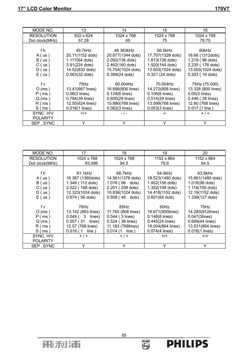
17” LCD Color Monitor 170V7
85
MODE NO. 13 14 15 16 RESOLUTION 832 x 624 1024 x 768 1024 x 768 1024 x 768 Dot clock(MHz) 57.28 65 75 78.75
f h 49.7kHz 48.363kHz 56.5kHz 60kHz
A ( us ) 20.11(1152 dots) 20.677(1344 dots) 17.707(1328 dots) 16.66 (1312dots) B ( us ) 1.117(64 dots) 2.092(136 dots) 1.813(136 dots) 1.219 ( 96 dots) C ( us ) 3.91(224 dots) 2.462(160 dots) 1.920(144 dots) 2.235 ( 176 dots) D ( us ) 14.52(832 dots) 15.754(1024 dots) 13.653(1024 dots) 13.003(1024 dots)E ( us ) 0.563(32 dots) 0.369(24 dots) 0.321 (24 dots) 0.203 ( 16 dots)
f v 75Hz 60.004Hz 70.004Hz 75Hz (75.000)
O (ms ) 13.41(667 lines) 16.666(806 lines) 14.272(806 lines) 13.328 (800 lines) P ( ms ) 0.06(3 lines) 0.124(6 lines) 0.106(6 lines) 0.05(3 lines) Q (ms ) 0.784(39 lines) 0.600(29 lines) 0.514(29 lines) 0.446 ( 28 lines) R ( ms ) 12.55(624 lines) 15.880(768 lines) 13.599(768 lines) 12.80 (768 lines) S ( ms ) 0.016(1 lines) 0.062(3 lines) 0.053(3 lines) 0.017 (1 line )
SYNC. H/V +/+ - / - -/- + / + POLARITY
SEP . SYNC Y Y Y Y
MODE NO. 17 18 19 20
RESOLUTION 1024 x 768 1024 x 768 1152 x 864 1152 x 864 Dot clock(MHz) 83.096 94.5 79.9 94.5
f h 61.1kHz 68.7kHz 54.0kHz 63.9kHz
A ( us ) 16.367 (1360dots) 14.561(1376 dots) 18.523(1480 dots) 15.661(1480 dots)B ( us ) 1.348 ( 112 dots) 1.016 ( 96 dots) 1.952(156 dots) 1.016(96 dots) C ( us ) 2.022 ( 168 dots) 2.201 ( 208 dots) 1.352(108 dots) 1.116(105 dots) D ( us ) 12.323(1024 dots) 10.836(1024 dots) 14.418(1152 dots) 12.19(1152 dots) E ( us ) 0.674 ( 56 dots) 0.508 ( 48 dots) 0.801(64 dots) 1.339(127 dots)
f v 76Hz 85Hz 60Hz 70Hz
O (ms ) 13.142 (803 lines) 11.765 (808 lines) 16.671(900lines) 14.283(912lines) P ( ms ) 0.049 ( 3 lines) 0.044 ( 3 lines) 0.148(8 lines) 0.047(3lines) Q (ms ) 0.507 ( 31 lines) 0.524 ( 36 lines) 0.445(24 lines) 0.689(44 lines) R ( ms ) 12.57 (768 lines) 11.183 (768lines) 16.004(864 lines) 13.531(864 lines) S ( ms ) 0.016 ( 1 line ) 0.014 (1 line ) 0.074(4 lines) 0.016(1 lines)
SYNC. H/V + / + + / + +/+ +/+ POLARITY
SEP . SYNC Y Y Y Y

17” LCD Color Monitor 170V7
86
MODE NO. 21 22 23 24
RESOLUTION 1152 x 864 1152 x 870 1152 x 900 1152 x 900
Dot clock(MHz) 108 100 94.5 108
f h 67.5kHz 68.7kHz 61.8kHz 71.8kHz A ( us ) 14.815(1600 dots) 14.56 (1456 dots) 16.169(1528 dots) 13.926 (1054dots)B ( us ) 1.185 ( 128 dots) 1.28 ( 128 dots) 1.354 ( 128 dots) 1.185 ( 128 dots) C ( us ) 2.37 ( 256 dots) 1.44( 144 dots) 2.201 ( 208 dots) 1.778 ( 192 dots) D ( us ) 10.667 (1152 dots) 11.52 ( 1152 dots) 12.19 ( 1152 dots) 10.667( 1152 dots)E ( us ) 0.593 ( 64 dots) 0.32 ( 32 dots) 0.424 ( 40 dots) 0.296 ( 32 dots)
f v 75Hz 75Hz 66Hz 76Hz
O (ms ) 13.333 (900 lines) 13.333 (916 lines) 15.151 (937lines) 13.132 (943 lines) P ( ms ) 0.044 ( 3 lines) 0.044 ( 3 lines) 0.065 (4 lines) 0.111( 8 lines) Q (ms ) 0.474 (32 lines) 0.568( 39 lines) 0.501 ( 31 lines) 0.46 ( 33 lines) R ( ms ) 12.8 (864 lines) 12.678 (870 lines) 14.552 (900lines) 12.533 (900 lines) S ( ms ) 0.015 (1 lines) 0.043 ( 4 line ) 0.033 ( 2 line ) 0.028 ( 2 lines)
SYNC. H/V - / - - / - Serr- + / + POLARITY
SEP . SYNC Y Y Y Y
MODE NO. 25 26 27 28 RESOLUTION 1280 x 960 1280 x 960 1280 x 1024 1280 x 1024
Dot clock(MHz) 108 129.895 108 117
f h 60kHz 75kHz 64kHz 71.7kHz
A ( us ) 16.667(1800 dots) 13.307(1728 dots) 15.63 (1688 dots) 13.949(1632 dots)B ( us ) 1.037(112 dots) 1.047 ( 136 dots) 1.037 ( 112 dots) 0.957 (112 dots) C ( us ) 2.889(312 dots) 1.725 ( 224 dots) 2.296 ( 248 dots) 1.915 (224 dots) D ( us ) 11.852(1280 dots) 9.857 ( 1280 dots) 11.852 (1280 dots) 10.94 (1280 dots) E ( us ) 0.889(96 dots) 0.678 ( 88 dots) 0.445 ( 48 dots) 0.137 (16 dots)
f v 60Hz 75Hz 60Hz 67Hz
O (ms ) 16.667(1000 lines) 13.333(1002 lines) 16.661(1066 lines) 14.883 (1067lines)P ( ms ) 0.05(3 lines) 0.039 ( 3 lines) 0.047 (3 lines) 0.112 ( 8 lines) Q (ms ) 0.600(36 lines) 0.48 ( 36 lines) 0.594 ( 38 lines) 0.46 ( 33 lines) R ( ms ) 16(960 lines) 12.774 (960 lines) 16.005(1024 lines) 14.283(1024 lines)S ( ms ) 0.017(1 lines) 0.04 ( 3 lines ) 0.015 ( 1 line) 0.028 (2 lines )
SYNC. H/V +/+ + / + + / + + / + POLARITY
SEP . SYNC Y Y Y Y

17” LCD Color Monitor 170V7
87
MODE NO. 29 30 31 32 RESOLUTION 1280 x 1024 1280 x 1024 1280 x 1024 960x720
Dot clock(MHz) 130.223 135 138.008 57.58
F h 76kHz 80kHz 81.1kHz 44.76kHz
A ( us ) 13.158(1712 dots) 12.504(1688 dots) 12.326(1664 dots) 22.34(1286 dots) B ( us ) 1.024 ( 133 dots) 1.067(144 dots) 0.474 (64 dots) 1.72(99 dots) C ( us ) 1.905 ( 248 dots) 1.837(248 dots) 2.133 (288 dots) 2.58(148 dots) D ( us ) 9.83 ( 1280 dots) 9.481(1280 dots) 9.481 (1280 dots) 16.67(960 dots) E ( us ) 0.399( 51 dots) 0.119(16 dots) 0.238 (32 dots) 0.856(49 dots)
F v 72Hz 75Hz 76Hz 60Hz
O (ms ) 14 (1064 lines) 13.329(1066 lines) 13.139(1066 lines) 16.667(746 lines) P ( ms ) 0.02 ( 2 lines) 0.038(3 lines) 0.099 ( 8 lines) 0.067(2.9 lines) Q (ms ) 0.5 ( 38 lines) 0.475(38 lines) 0.394 ( 32 lines) 0.495(22 lines) R ( ms ) 13.468(1024 lines) 12.804(1024 lines) 12.622(1024 lines) 16.081(720 lines) S ( ms ) 0.012 ( 0 line) 0.012 (1 line) 0.024( 2 lines ) 0.0228(1 lines)
SYNC. H/V + / + +/+ - / - -/+ POLARITY
SEP . SYNC Y Y Y Y
MODE NO. 33 RESOLUTION 960X720
Dot clock(MHz)
72.42
F h
56.4kHz
A ( us ) 17.73(1284 dots) B ( us ) 1.44(104 dots) C ( us ) 2.21(160 dots) D ( us ) 13.256(960 dots) E ( us ) 0.780(56 dots)
F v 75Hz
O (ms ) 13.333(752 lines) P ( ms ) 0.053(3 lines) Q (ms ) 0.5(28 lines) R ( ms ) 12.766(720 lines) S ( ms ) 0.0184(1 lines)
SYNC. H/V -/ + POLARITY
SEP . SYNC Y
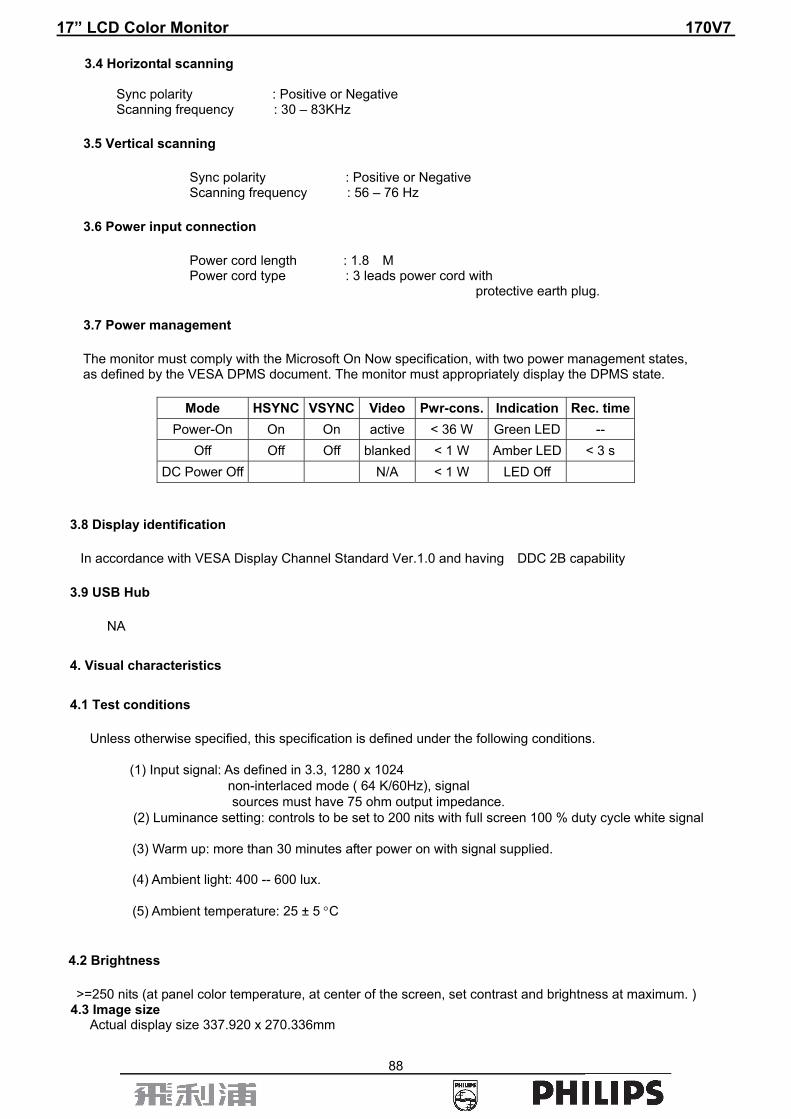
17” LCD Color Monitor 170V7
88
3.4 Horizontal scanning Sync polarity : Positive or Negative Scanning frequency : 30 – 83KHz
3.5 Vertical scanning
Sync polarity : Positive or Negative Scanning frequency : 56 – 76 Hz
3.6 Power input connection
Power cord length : 1.8 M Power cord type : 3 leads power cord with protective earth plug.
3.7 Power management
The monitor must comply with the Microsoft On Now specification, with two power management states, as defined by the VESA DPMS document. The monitor must appropriately display the DPMS state.
Mode HSYNC VSYNC Video Pwr-cons. Indication Rec. time
Power-On On On active < 36 W Green LED -- Off Off Off blanked < 1 W Amber LED < 3 s
DC Power Off N/A < 1 W LED Off
3.8 Display identification
In accordance with VESA Display Channel Standard Ver.1.0 and having DDC 2B capability
3.9 USB Hub
NA
4. Visual characteristics
4.1 Test conditions
Unless otherwise specified, this specification is defined under the following conditions. (1) Input signal: As defined in 3.3, 1280 x 1024
non-interlaced mode ( 64 K/60Hz), signal sources must have 75 ohm output impedance.
(2) Luminance setting: controls to be set to 200 nits with full screen 100 % duty cycle white signal
(3) Warm up: more than 30 minutes after power on with signal supplied. (4) Ambient light: 400 -- 600 lux. (5) Ambient temperature: 25 ± 5 °C
4.2 Brightness
>=250 nits (at panel color temperature, at center of the screen, set contrast and brightness at maximum. ) 4.3 Image size Actual display size 337.920 x 270.336mm
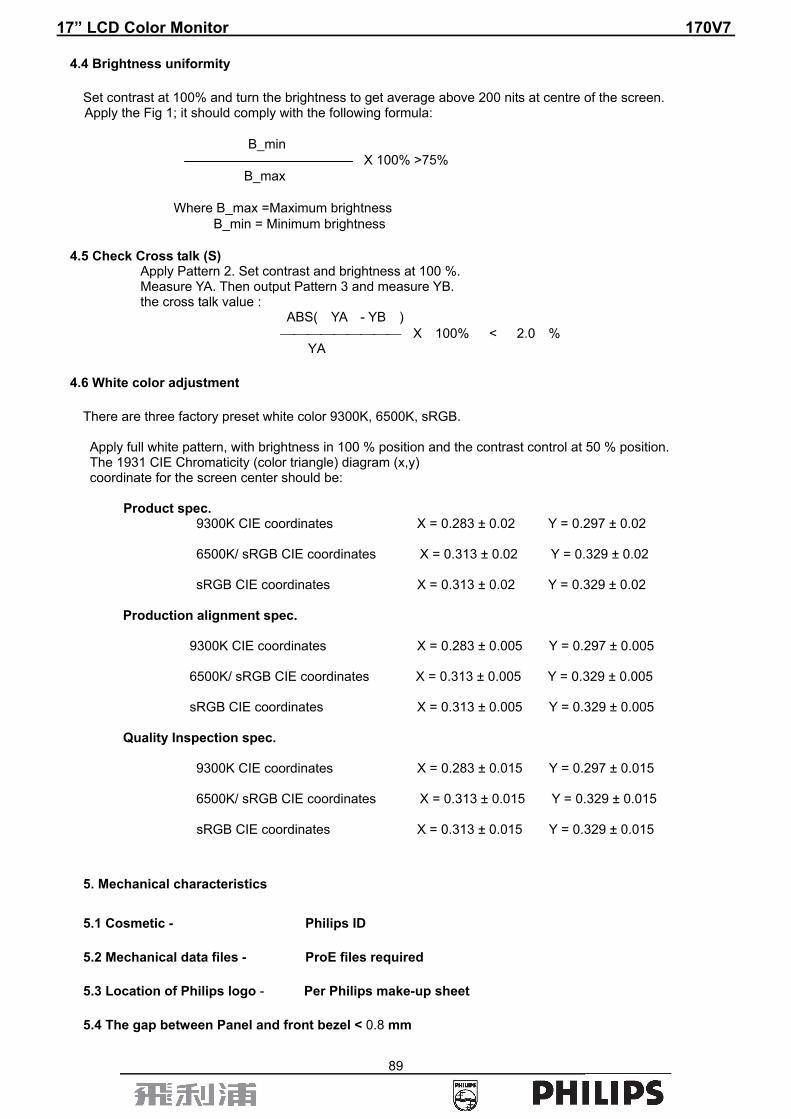
17” LCD Color Monitor 170V7
89
4.4 Brightness uniformity
Set contrast at 100% and turn the brightness to get average above 200 nits at centre of the screen. Apply the Fig 1; it should comply with the following formula: B_min
X 100% >75% B_max Where B_max =Maximum brightness B_min = Minimum brightness
4.5 Check Cross talk (S) Apply Pattern 2. Set contrast and brightness at 100 %. Measure YA. Then output Pattern 3 and measure YB. the cross talk value : ABS( YA - YB ) ⎯⎯⎯⎯⎯⎯⎯⎯⎯ X 100% < 2.0 % YA
4.6 White color adjustment
There are three factory preset white color 9300K, 6500K, sRGB. Apply full white pattern, with brightness in 100 % position and the contrast control at 50 % position. The 1931 CIE Chromaticity (color triangle) diagram (x,y) coordinate for the screen center should be: Product spec. 9300K CIE coordinates X = 0.283 ± 0.02 Y = 0.297 ± 0.02 6500K/ sRGB CIE coordinates X = 0.313 ± 0.02 Y = 0.329 ± 0.02
sRGB CIE coordinates X = 0.313 ± 0.02 Y = 0.329 ± 0.02
Production alignment spec.
9300K CIE coordinates X = 0.283 ± 0.005 Y = 0.297 ± 0.005 6500K/ sRGB CIE coordinates X = 0.313 ± 0.005 Y = 0.329 ± 0.005
sRGB CIE coordinates X = 0.313 ± 0.005 Y = 0.329 ± 0.005 Quality Inspection spec. 9300K CIE coordinates X = 0.283 ± 0.015 Y = 0.297 ± 0.015 6500K/ sRGB CIE coordinates X = 0.313 ± 0.015 Y = 0.329 ± 0.015
sRGB CIE coordinates X = 0.313 ± 0.015 Y = 0.329 ± 0.015
5. Mechanical characteristics
5.1 Cosmetic - Philips ID
5.2 Mechanical data files - ProE files required
5.3 Location of Philips logo - Per Philips make-up sheet
5.4 The gap between Panel and front bezel < 0.8 mm

17” LCD Color Monitor 170V7
90
5.5 Location of Control icons - Per Philips Graphic sheet
5.6 Color for resin/paint - Per Philips make-up sheet
5.7 Resins
• RoHS required • WEEE required.
5.8 If paint is used
• Rohs required • WEEE require
5.9 Plastic mold tooling
• Tooling to be designed to minimize cosmetic defects induced by molding process (sink, blush, weld lines, gate marks, ejector marks, etc.).
• Painting to cover up cosmetic defects due to molding is strongly discouraged.
5.10 Plastics flammability
• All Plastics to be Flame Retardant UL 94-V0 or Better (if monitor weighs less than 18kg; UL94-V0 is OK). • All major plastic parts (bezel, back cover ) need to be molded from same resin.
5.11 Texture/Glossing of housing
• The texture area and texture no should follow Philips make-up sheet. • The exterior surfaces shall have a uniform texture. • Philips must approve the mold texturing. • Detail document for texture refer to UAN-D249. • < = 20 gloss units 5.12 Tilt and swivel base
Tilt angle: -5 ° max (forward) and +20 ° min. (backward).
5.13 Label
• Regulatory label / Carton label should follow Philips requirement. • Detail document refer to Philips Engineering Reference Book.
5.14 Product dimension / Weight
• Unit dimension (incl. pedestal) : W: 380 mm, H: 387 mm, D: 200mm • Packed unit dimension ( WW carton) : W: 449mm, H: 182mm, D: 489mm • Packed unit dimension (carton) - W: 460mm, H: 189mm, D: 499mm for China, India • Net weight : 4.7 Kg (Including I/F cable ) • Gross weight : 6.1 Kg (for WWW) • 6.2 Kg ( for PRC )
5.15 Transportation
Transportation standards refer to TYE-M0002.

17” LCD Color Monitor 170V7
91
5.15.1 Transportation packages Packaging and wrapping shall be sufficient to protect the product against damage or loss during
shipment from the supplier to the destination specified in the purchase order. All packaging materials
are subject to test and evaluation per TYE-M0002. The cushion material shall be constructed using EPS
material.
5.15.2 Transportation Test
The overall test refer to TYE-M0002. Vibration, drop test should be performed at ambient temperature(20°C to 23oC) and relative humidity (40% to 65% ).
A. Transportation test specification for all regions except China/India
• Package test 1. Random Vibration test 2. Drop test 3. Cold Drop test (for design reference)
• Un-package test 1. Sine vibration (operating) 2. Half sine shock test (non operation)
B. Transportation test specification for China/India
• Package test 1. Random Vibration test 2. Drop test 3. Cold Drop test (for design reference)
• Un-package test 1. Sine vibration (operating) 2. Half sine shock test (non operation)
5.16 Pallet / Container loading
Except China China/India
Transportation standards refer to TYE-M0002. Pallet Slip sheet Pallet Slip sheet • Air shipment - 32 sets --- 28sets --- • Sea container 20'(pallet/slip sheet) - 550 590 528 528 • Sea container 40'(pallet/slip sheet) - 1320 1430 1056 1056 • Sea container 40' High Cube (pallet/slip sheet) -1560 1560 1152 1248 • Truck shipment- tbc • tbc
A. Air shipment B. Container loading for other regions C. Truck loading for other regions
6. Environmental characteristics
The following sections define the interference and susceptibility condition limits that might occur between external environment and the display device.
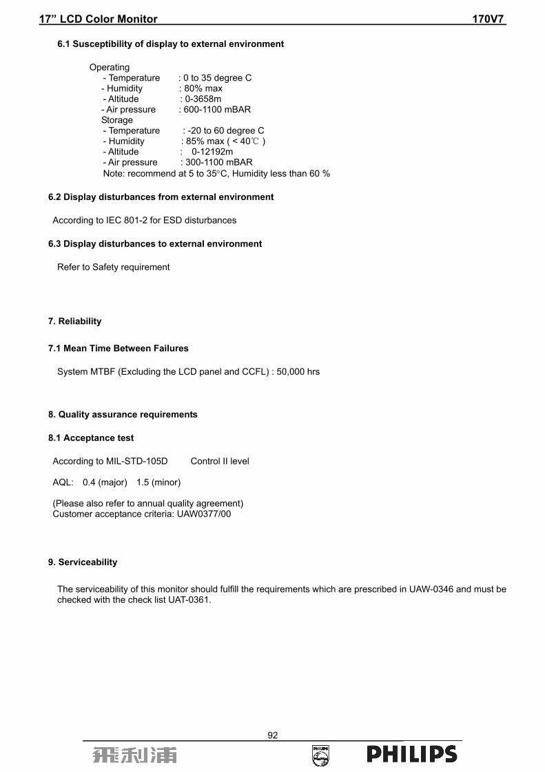
17” LCD Color Monitor 170V7
92
6.1 Susceptibility of display to external environment
Operating - Temperature : 0 to 35 degree C
- Humidity : 80% max - Altitude : 0-3658m
- Air pressure : 600-1100 mBAR Storage - Temperature : -20 to 60 degree C - Humidity : 85% max ( < 40℃ ) - Altitude : 0-12192m - Air pressure : 300-1100 mBAR
Note: recommend at 5 to 35°C, Humidity less than 60 %
6.2 Display disturbances from external environment
According to IEC 801-2 for ESD disturbances
6.3 Display disturbances to external environment
Refer to Safety requirement
7. Reliability
7.1 Mean Time Between Failures
System MTBF (Excluding the LCD panel and CCFL) : 50,000 hrs
8. Quality assurance requirements
8.1 Acceptance test
According to MIL-STD-105D Control II level AQL: 0.4 (major) 1.5 (minor) (Please also refer to annual quality agreement) Customer acceptance criteria: UAW0377/00
9. Serviceability
The serviceability of this monitor should fulfill the requirements which are prescribed in UAW-0346 and must be checked with the check list UAT-0361.

17” LCD Color Monitor 170V7
93
10. Philips’ Flat Panel Monitors Pixel Defect Policy
BRIGHT DOT DEFECTS ACCEPTABLE LEVEL MODEL 170V7 1 lit subpixels 3 2 adjacent lit subpixels 1 3 adjacent lit subpixels 0 Distance between two bright dot defects > 15 mm Total bright dot defects of all types 3
BLACK DOT DEFECTS MODEL 170V7 1 dark subpixels 4 2 adjacent dark subpixels 2 3 adjacent dark subpixels 0 Distance between two dark dot defects > 15 mm Total dark dot defects of all types 4
Total DOT DEFECTS MODEL 170V7 Total bright or dark dot defect of all type 5
Fig 1: Brightness Uniformity
P2 P6 P3
P4
P1
960
768
640
512 P7 P8
P5P9
256
320 PIXEL

17” LCD Color Monitor 170V7
94
Fig 2: Cross talk pattern Gray level 46 (64 Gray level)
YA
1/2
1/2
1/6
Fig 3: Cross talk Pattern Center at Gray level 0 (Black)
YB
1/2
1/2
1/61/3 1/3
1/3
1/3
1/3

17” LCD Color Monitor 170V7
95
D
VIDEO
C E
SEPARATE SYNC.
HORIZONTAL
BA
R
VIDEO
Q S
PO
D
VIDEO
C E
BA
VERTICAL
HORIZONTAL
COMPOSITE SYNC.
FIG-4 TIMING CHART -1
Related Documents