ESI-50L Communications Server Hardware Installation Manual 0450-1159 Rev. C Copyright © 2008 ESI (Estech Systems, Inc.). IVX is a registered trademark of Estech Systems, Inc. Ethernet is a registered trademark of Xerox Corporation. Motorola and ColdFire are registered trademarks of Motorola, Inc. Rayovac is a registered trademark of Rayovac Corporation. Act! is a registered trademark of Symantec Corporation. Goldmine is a trademark of Goldmine Software Corporation. Microsoft, Windows, NT and Outlook are registered trademarks of Microsoft Corporation. Panasonic and DBS are registered trademarks of Matsushita Electric Corporation of America. Smart Jack is a trademark of Westell Technologies, Inc. Information contained herein is subject to change without notice. Certain features described herein may not be available at initial release. ESI products are protected by various U.S. Patents, granted and pending. Visit ESI on the Web at www.esi-estech.com.

Welcome message from author
This document is posted to help you gain knowledge. Please leave a comment to let me know what you think about it! Share it to your friends and learn new things together.
Transcript
ESI-50L Communications Server
Hardware Installation Manual
0450-1159 Rev. C
Copyright © 2008 ESI (Estech Systems, Inc.). IVX is a registered trademark of Estech Systems, Inc. Ethernet is a registered trademark of Xerox Corporation. Motorola and ColdFire are registered trademarks of Motorola, Inc. Rayovac is a registered trademark of Rayovac Corporation. Act! is a registered trademark of Symantec Corporation. Goldmine is a trademark of Goldmine Software Corporation. Microsoft, Windows, NT and Outlook are registered trademarks of Microsoft Corporation. Panasonic and DBS are registered trademarks of Matsushita Electric Corporation of America. Smart Jack is a trademark of Westell Technologies, Inc. Information contained herein is subject to change without notice. Certain features described herein may not be available at initial release. ESI products are protected by various U.S. Patents, granted and pending. Visit ESI on the Web at www.esi-estech.com.
Contents
Overview........................................................................A.1 Cabinet components.............................................................. A.1 Main board............................................................................. A.1 Memory Module..................................................................... A.1 Power supply ......................................................................... A.1 Port card options.................................................................... A.1 NSP....................................................................................... A.2
Phones...........................................................................B.1 Digital phone models ............................................................. B.1 ESI Cordless Handsets.......................................................... B.1 Expansion Consoles .............................................................. B.1 Feature Phone overlays......................................................... B.2
Licensing.......................................................................C.1
System capacities.........................................................D.1
Cautions and regulatory information..........................E.1 Cautions ................................................................................ E.1 Regulatory information........................................................... E.2
Hardware installation ................................................... F.1 Site location ............................................................................F.1 Opening the Base Cabinet......................................................F.2 Mounting the Base Cabinet.....................................................F.2 Expansion Cabinet installation................................................F.2 Port card installation................................................................F.3 Memory Module installation or replacement............................F.4 LED functions .........................................................................F.4 ESI Presence Management installation ..................................F.4
ESI Cellular Management installation..................................... F.4
External connections................................................... G.1 Grounding instructions .......................................................... G.1 Power.................................................................................... G.1 MOH port .............................................................................. G.3 Maintenance/SMDR serial port.............................................. G.3 External paging device connection........................................ G.4 Amphenol cable connections................................................. G.4 CO line connection................................................................ G.5 Station connection................................................................. G.5 60-Key Expansion Console connection................................. G.6 60-Key Second Expansion Console connection.................... G.7 Installing ESI’s Cordless Handsets........................................ G.8 Port card connections.......................................................... G.10 Cabinet worksheet................................................................G.11
Index
Important: For information concerning the programming of an ESI-50L Communications Server, see the ESI-50L
Programming Manual (ESI document # 0450-1137).
ESI-50L Hardware Installation Manual Overview
A.1
Overview
Cabinet components
The ESI-50L’s cabinet components1 consist of the standard Base Cabinet and an optional Expansion Cabinet.
The ESI-50L can accept one Expansion Cabinet.
Base Cabinet
The ESI-50L Base Cabinet is designed for easy installation and component access. The Base Cabinet, which measures 8.5″ W 11″ H 3″ D, houses a main board with a built-in 482 card, as well as the Memory
Module, Network Services Processor (NSP), one multi-purpose serial port, an MOH connector, an additional port card slot (see “Port card,” below), and an external wall-mounted power supply.
Expansion Cabinet
The ESI-50L’s optional Expansion Cabinet contains two port card slots, providing a total system capacity of
three port cards (in addition to the built-in 482 card).
Main board
The ESI-50L main board combines leading-edge hardware components — including a Motorola® ColdFire
®
processor and DSP structure — along with proprietary operating system software. The board provides: system control of the Memory Module and port cards; a standard RS-232C DB9 serial port; a built-in modem for remote access; an external paging-device interface; MOH interface; and an NSP, which provides remote access via TCP/IP and supports certain optional ESI PC software applications.
Memory Module
The Memory Module — a CompactFlash® with proprietary formatting — contains all system programming
and configuration data, and pre-loaded voice prompts. The Memory Module provides voice storage at 64 kilobits per second — the industry's highest-quality sampling rate — and has a voice storage capacity of 15 hours.
Power supply
The ESI-50L’s 3-amp, 24 VAC power supply is included at purchase.
Port card options
Whether built-in or external, each 482 card2 provides circuits to connect up to four loop-start CO lines, eight
Digital Feature Phones, and two analog station ports. The CO line ports support standard CO and Centrex loop-start lines; ground-start CO lines are not supported. Only one analog device can be connected to each analog station port. This card uses 10 station ports and four CO ports when installed.
Notes: The main board comes in a four-line, eight-digital station, two-analog port configuration. You can add three 482 port cards on an ESI-50L. Therefore, the system can have the following configurations. — 4 8 2: Base Cabinet (main board only)
— 8 16 4: Base Cabinet with one additional 482 port card. — 12 24 6: Base Cabinet with one additional 482 port card and an Expansion Cabinet with one 482 port card.
— 16 32 8: Base Cabinet with one additional 482 port card and an Expansion Cabinet with two 482 port cards.
1 Memory Modules and port cards are packed separately and are mounted in each system’s cabinet during installation.
2 The external 482 card also is used by the ESI-50L, the ESI C-Plus, and IVX S-Class Generation II systems.
ESI-50L Hardware Installation Manual Overview
A.2
NSP
Built into the main board, the NSP (Network Services Processor) serves as a bridge between an Ethernet-based network and the ESI-50L. Using TCP/IP, the NSP communicates directly with specific PC applications for maintenance of, and integration with, the ESI-50L. The NSP manages optional features such as VIP and phone control via TAPI PC applications; it also provides
access to not only maintenance and administration (through use of ESI System Programmer software) but also an Installer-selectable SMDR interface.
The NSP hardware interface consists of a dedicated Ethernet port. Its external RJ-45 jack provides a 10/100Base-T connection to the LAN. The NSP consumes no call-processing ports.
Note: The ESI-50L provides one Ethernet port for access to the NSP.
ESI-50L Hardware Installation Manual Phones
B.1
Phones
Digital phone models
The ESI-50L supports several different models of ESI digital phones, each of which connects to the cabinet via standard two-wire twisted pair:
• 48-Key Digital Feature Phone — Three-line, 56-character1 display (backlit display available);
speakerphone; headset jack2; 30 programmable feature keys; the only one of the three Digital Feature
Phones that supports VIP or the 60-Key Expansion Consoles.
Note: Not all modular headsets will work on the 48-Key Feature Phone’s headset jack. ESI has tested and can
recommend the following headset models:
Manufacturer: Plantronics — P51-U10P sound tube microphone — P51N-U10P noise-cancelling microphone — P251-U10P sound tube microphone
— P251N-U10P noise-cancelling microphone Manufacturer: GN Netcom
— GN2120 NCD 01 “over-the-head” — GN2127 NCD 01 “on-the-ear”
Note that GN Netcom models also are available in a “-02” configuration, which wires differently and won’t work with ESI phones. Therefore, when ordering GN Netcom headsets for use with ESI phones, be sure to specify the “-01” configuration.
• 24-Key Digital Feature Phone — Two-line, 32-character display (backlit display available); speakerphone; 12 programmable feature keys.
• 12-Key Digital Feature Phone — One-line, 16-character display; nine programmable feature keys.
Note: When a desktop phone is in the highest upright position, use the wall-mount hook located under the handset to secure the handset when you’re not using the phone.
ESI Cordless Handsets
The ESI-50L also supports ESI’s digital Cordless Handsets. Each comes in two sizes — small and large — and includes four familiar fixed feature keys, four programmable feature keys, and a headset jack. The Base Station for each ESI digital Cordless Handset uses a standard line cord and is line-powered.
Expansion Consoles
The 60-Key Expansion Console gives a designated user 60 additional programmable feature keys. The
Expansion Console is connected to its host 48-Key Feature Phone via a special cable (provided) and doesn’t require a separate station port of its own. Additionally, it may be connected to a 60-Key Second Expansion Console via a special cable (provided with the 60-Key Second Expansion Console) so that one 48-Key Feature Phone can have a total of 150 programmable feature keys.
A maximum of four stations with one or two Expansion Consoles (60-Key and 60-Key Second) can be installed in a fully configured ESI-50L system.
1 The top two lines each have 16 characters, as on the 24-Key Digital Feature Phone; the bottom line has 24 characters.
2 Headset jack only on 48-Key Feature Phones (Digital, Digital TAPI, [local] IP, or Remote IP) manufactured after March, 2004.
ESI-50L Hardware Installation Manual Phones
B.2
Feature Phone overlays
Each Feature Phone comes with one overlay for the programmable feature keys. To order additional overlays, visit the DESI
™ Web site, www.desi.com. While there, you may also want to download the free Windows-based
software, DESI Lite, which allows you to print on the overlays. For assistance with DESI products, contact DESI (the DESI Web site contains contact information).
Tip: Remember that ESI System Programmer, ESI Personal Programmer, and VIP — software titles all available from www.esiresellers.com — also let you print on the overlays as well as perform many other programming tasks.
ESI-50L Hardware Installation Manual Licensing
C.1
Licensing
There are various types of licenses needed to activate certain features and functionality. The following features, products, and capabilities require license activation:
• VIP.
• VIP Professional.
• VIP PC Attendant Console.
License activation
To have licenses activated by ESI Technical Support:
1. Licenses must already have been ordered from ESI.
2. The ESI Communications Server must have either:
• A CO line connected to it; or
• The NSP, which is connected to a LAN with a public IP address, “port-forwarded”1 to it.
3. You’ll need the following to provide to the ESI representative:
• The ESI sales order number.
• The customer (site) name.
• The phone number of the CO line or the public IP address of the NSP.
• The quantity of VIP Professional licenses.
1 For more information about the NSP, refer to NSP Installation Made Simple (ESI #0450-0669).
ESI-50L Hardware Installation Manual System capacities
D.1
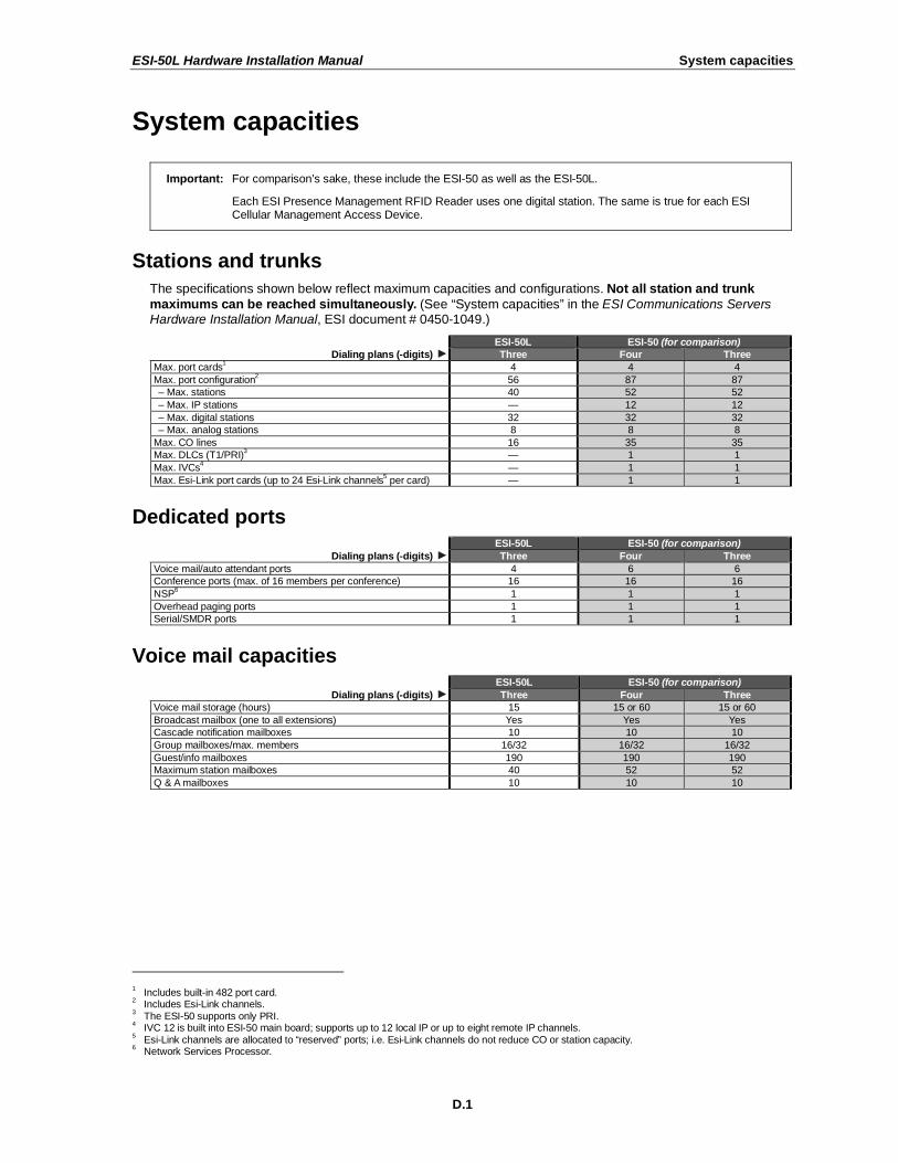
System capacities
Important: For comparison’s sake, these include the ESI-50 as well as the ESI-50L.
Each ESI Presence Management RFID Reader uses one digital station. The same is true for each ESI Cellular Management Access Device.
Stations and trunks
The specifications shown below reflect maximum capacities and configurations. Not all station and trunk
maximums can be reached simultaneously. (See “System capacities” in the ESI Communications Servers Hardware Installation Manual, ESI document # 0450-1049.)
ESI-50L ESI-50 (for comparison)
Dialing plans (-digits) Three Four Three
Max. port cards1 4 4 4
Max. port configuration2 56 87 87
– Max. stations 40 52 52
– Max. IP stations — 12 12
– Max. digital stations 32 32 32
– Max. analog stations 8 8 8
Max. CO lines 16 35 35
Max. DLCs (T1/PRI)3 — 1 1
Max. IVCs4 — 1 1
Max. Esi-Link port cards (up to 24 Esi-Link channels5 per card) — 1 1
Dedicated ports ESI-50L ESI-50 (for comparison)
Dialing plans (-digits) Three Four Three
Voice mail/auto attendant ports 4 6 6
Conference ports (max. of 16 members per conference) 16 16 16
NSP6 1 1 1
Overhead paging ports 1 1 1
Serial/SMDR ports 1 1 1
Voice mail capacities ESI-50L ESI-50 (for comparison)
Dialing plans (-digits) Three Four Three
Voice mail storage (hours) 15 15 or 60 15 or 60
Broadcast mailbox (one to all extensions) Yes Yes Yes
Cascade notification mailboxes 10 10 10
Group mailboxes/max. members 16/32 16/32 16/32
Guest/info mailboxes 190 190 190
Maximum station mailboxes 40 52 52
Q & A mailboxes 10 10 10
1 Includes built-in 482 port card.
2 Includes Esi-Link channels.
3 The ESI-50 supports only PRI.
4 IVC 12 is built into ESI-50 main board; supports up to 12 local IP or up to eight remote IP channels.
5 Esi-Link channels are allocated to “reserved” ports; i.e. Esi-Link channels do not reduce CO or station capacity.
6 Network Services Processor.
ESI-50L Hardware Installation Manual System capacities
D.2
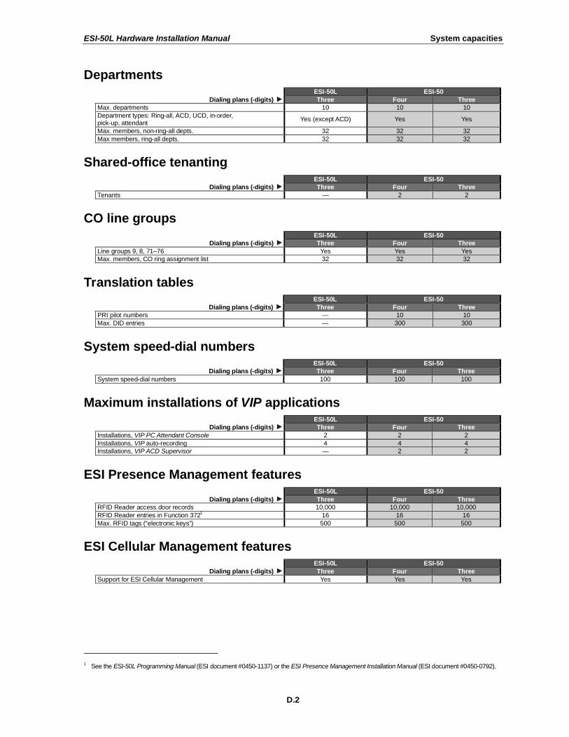
Departments ESI-50L ESI-50
Dialing plans (-digits) Three Four Three
Max. departments 10 10 10
Department types: Ring-all, ACD, UCD, in-order, pick-up, attendant
Yes (except ACD) Yes Yes
Max. members, non-ring-all depts. 32 32 32
Max members, ring-all depts. 32 32 32
Shared-office tenanting ESI-50L ESI-50
Dialing plans (-digits) Three Four Three
Tenants — 2 2
CO line groups ESI-50L ESI-50
Dialing plans (-digits) Three Four Three
Line groups 9, 8, 71–76 Yes Yes Yes
Max. members, CO ring assignment list 32 32 32
Translation tables ESI-50L ESI-50
Dialing plans (-digits) Three Four Three
PRI pilot numbers — 10 10
Max. DID entries — 300 300
System speed-dial numbers ESI-50L ESI-50
Dialing plans (-digits) Three Four Three
System speed-dial numbers 100 100 100
Maximum installations of VIP applications ESI-50L ESI-50
Dialing plans (-digits) Three Four Three
Installations, VIP PC Attendant Console 2 2 2
Installations, VIP auto-recording 4 4 4
Installations, VIP ACD Supervisor — 2 2
ESI Presence Management features ESI-50L ESI-50
Dialing plans (-digits) Three Four Three
RFID Reader access door records 10,000 10,000 10,000
RFID Reader entries in Function 3721 16 16 16
Max. RFID tags (“electronic keys”) 500 500 500
ESI Cellular Management features ESI-50L ESI-50
Dialing plans (-digits) Three Four Three
Support for ESI Cellular Management Yes Yes Yes
1 See the ESI-50L Programming Manual (ESI document #0450-1137) or the ESI Presence Management Installation Manual (ESI document #0450-0792).
ESI-50L Hardware Installation Manual Cautions and regulatory information
E.1
Cautions and regulatory information
Cautions
Important: This information complies with the requirements of Underwriters’ Laboratories (UL) and UL Standards 1950,
60950, and 60950-1, as applicable.
When using this telephone equipment, always exercise basic safety precautions in order to minimize the risk of fire, electric shock or injury to persons. Before proceeding, please read the following:
• Do not use liquids or aerosols to clean any system equipment; rather, use a cloth that is only slightly damp.
• An ESI Communications Server contains no components that are serviceable by either non-Resellers or non-manufacturer technicians. All service must be referred to the Reseller for further handling.
• Do not install the cabinet in areas with extreme heat or improper ventilation.
• Install the cabinet only in “low-traffic” or “non-public” areas.
• To reduce the risk of fire, use only 24 AWG or larger telecom wire.
Power supply
Heed all warnings and instructions in documentation or marked on the cabinet or peripheral equipment.
Fuse
Contact the factory before attempting to replace the fuse. The fuse is located on the main board in the Base Cabinet.
Battery (located on the main board)
“Caution: There is a danger of explosion if the onboard lithium battery is incorrectly replaced. Replace only with Ray-O-Vac BR1225 (or equivalent). Dispose of used batteries according to the battery manufacturer’s instructions.”
“Notice: This product is intended to be supplied by a Listed Direct Plug-In Power Unit marked ‘Class 2’ and provided
with electrical ratings.”
ESI-50L Hardware Installation Manual Cautions and regulatory information
E.2
Regulatory information
United States of America
Registration
The CO line telephone numbers, FCC registration number, and ringer equivalence number (REN) of this equipment must be provided to the telephone company before installation. (See below for FCC registration number and ringer equivalence number.)
FCC Part 15
This equipment has been tested and found to comply with the limits for a Class A digital device, pursuant to Part 15 of the FCC Rules. These limits are designed to provide reasonable protection against harmful interference when the equipment is operated in a commercial environment. This equipment generates, uses and can radiate radio frequency energy and — if not installed and used in accordance with the instruction manual — may cause harmful interference to radio communications (in which case, the user will be required to correct the interference at his/her own expense).
FCC Part 68
This equipment complies with Part 68 of the FCC Rules. On the bottom of this equipment is a label that contains, among other information, the FCC Registration Number and Ringer Equivalence Number (REN) for this equipment. You must, upon request, provide this information to your telephone company.
The REN is helpful to determine the quantity of devices you say connect to your telephone line and still have
all of those devices ring when your telephone number is called. In most, but not all, areas, the sum of the RENs of all devices connected to one line should not exceed five (5.0). To be certain of the number of devices you may connect to your line, as determined by the REN, you should contact your local telephone company to determine the maximum REN for your calling area.
If your telephone equipment causes harm to the telephone network, the telephone company may discontinue your service temporarily. If possible, the telephone company will notify you in advance but, if advance notice is not practical, you will be notified as soon as possible. You will be informed of your right to file a complaint with the FCC.
Your telephone company may make changes to its facilities, equipment, operations or procedures that could
affect the proper functioning of your equipment. If so, you will be notified in advance, to give you an opportunity to maintain uninterrupted telephone service.
If you experience trouble with this telephone equipment, the telephone company may ask that you disconnect this equipment from the network until the problem has been corrected or until you are sure that the equipment is not malfunctioning.
This equipment may not be used on coin service provided by the telephone company. Connection to party lines is subject to state tariffs.
Installation: The device is equipped with a USOC connector.
Registration Number: 1T1MF08B33727. Ringer equivalence number (REN): 0.8
Hearing-aid compatibility
This equipment, utilizing telephone station equipment manufactured by ESI, meets all FCC requirements for hearing-aid compatibility.
ESI-50L Hardware Installation Manual Hardware installation
F.1
Hardware installation
Site location
As with most electronic equipment, the environmental considerations for this site need to observe good common sense. Provide a dry, clean, and accessible area.
Locate space in the telephone equipment room, which will provide easy connection to the 66 blocks and 110 VAC power. The location should be no further than 1,000 feet from the farthest station.
Ambient room temperature must be 400 –80
0 (F.), and relative humidity no higher than 90%.
Notes: Do not place the equipment or run station cabling near high voltage electrical equipment or electrical lines susceptible to high voltage surges from air conditioner compressors, etc.
Do not mount the equipment in a place that receives direct sunlight.
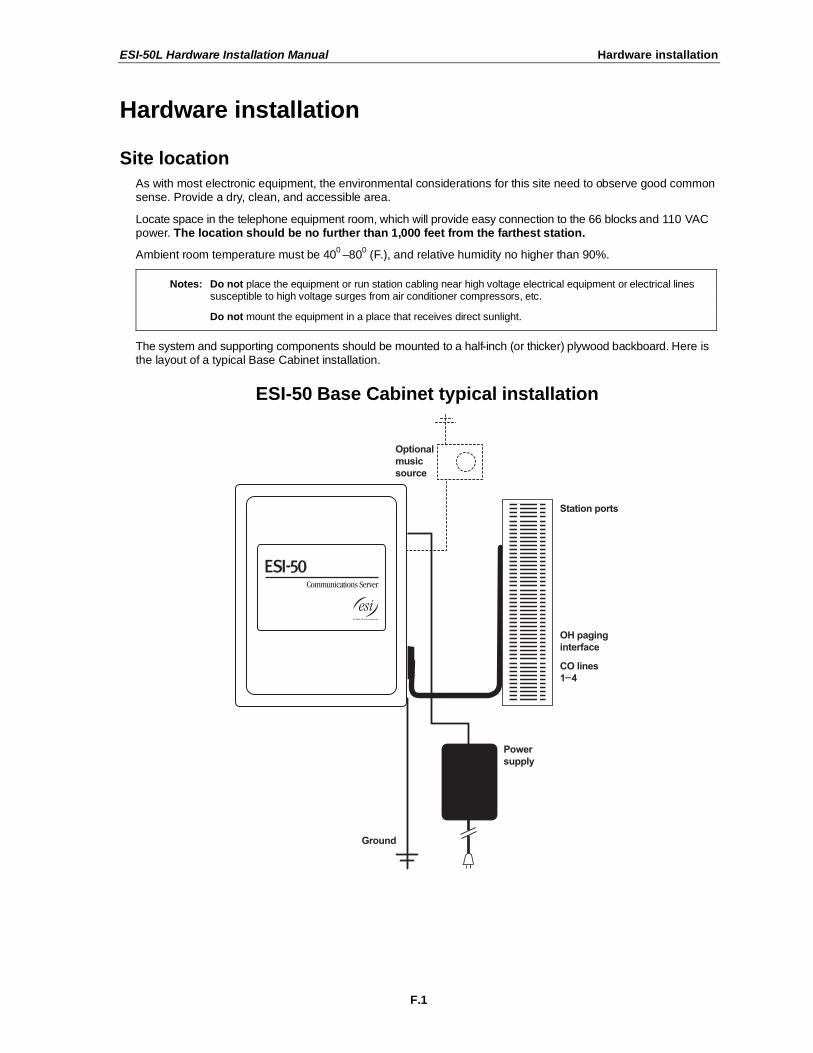
The system and supporting components should be mounted to a half-inch (or thicker) plywood backboard. Here is the layout of a typical Base Cabinet installation.
ESI-50 Base Cabinet typical installation
ESI-50L Hardware Installation Manual Hardware installation
F.2
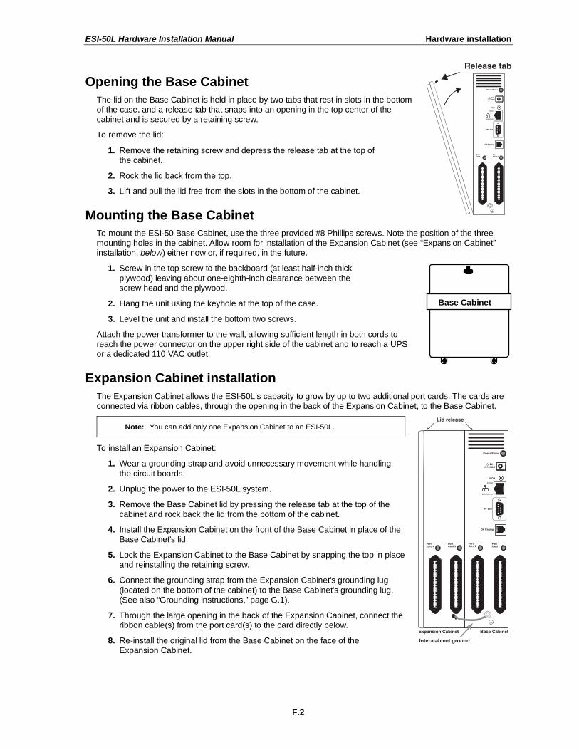
Opening the Base Cabinet
The lid on the Base Cabinet is held in place by two tabs that rest in slots in the bottom of the case, and a release tab that snaps into an opening in the top-center of the cabinet and is secured by a retaining screw.
To remove the lid:
1. Remove the retaining screw and depress the release tab at the top of the cabinet.
2. Rock the lid back from the top.
3. Lift and pull the lid free from the slots in the bottom of the cabinet.
Mounting the Base Cabinet
To mount the ESI-50 Base Cabinet, use the three provided #8 Phillips screws. Note the position of the three mounting holes in the cabinet. Allow room for installation of the Expansion Cabinet (see “Expansion Cabinet” installation, below) either now or, if required, in the future.
1. Screw in the top screw to the backboard (at least half-inch thick
plywood) leaving about one-eighth-inch clearance between the screw head and the plywood.
2. Hang the unit using the keyhole at the top of the case.
3. Level the unit and install the bottom two screws.
Attach the power transformer to the wall, allowing sufficient length in both cords to reach the power connector on the upper right side of the cabinet and to reach a UPS or a dedicated 110 VAC outlet.
Expansion Cabinet installation
The Expansion Cabinet allows the ESI-50L’s capacity to grow by up to two additional port cards. The cards are connected via ribbon cables, through the opening in the back of the Expansion Cabinet, to the Base Cabinet.
Note: You can add only one Expansion Cabinet to an ESI-50L.
To install an Expansion Cabinet:
1. Wear a grounding strap and avoid unnecessary movement while handling
the circuit boards.
2. Unplug the power to the ESI-50L system.
3. Remove the Base Cabinet lid by pressing the release tab at the top of the cabinet and rock back the lid from the bottom of the cabinet.
4. Install the Expansion Cabinet on the front of the Base Cabinet in place of the Base Cabinet's lid.
5. Lock the Expansion Cabinet to the Base Cabinet by snapping the top in place and reinstalling the retaining screw.
6. Connect the grounding strap from the Expansion Cabinet's grounding lug
(located on the bottom of the cabinet) to the Base Cabinet's grounding lug. (See also “Grounding instructions,” page G.1).
7. Through the large opening in the back of the Expansion Cabinet, connect the ribbon cable(s) from the port card(s) to the card directly below.
8. Re-install the original lid from the Base Cabinet on the face of the Expansion Cabinet.
Base Cabinet
ESI-50L Hardware Installation Manual Hardware installation
F.3
Port card installation
Adding or replacing port cards will require the system to be taken out of service (the ESI-50L doesn’t support “hot-swapping” of its port cards).
Important: The ESI-50L can use only the 482 port card (see “Port card options,” page A.1).
ALWAYS power down the system BEFORE adding or replacing any hardware. Also, be sure to observe all proper procedures regarding the prevention of electrostatic discharge (ESD) when performing the following procedures; otherwise, circuit boards may suffer damage.
Whenever you change the port card configuration, you must create a backup file for the new configuration to be able to perform the Restore function later.
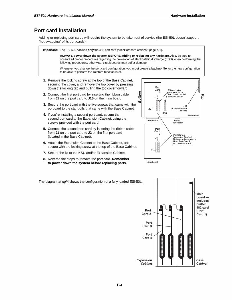
1. Remove the locking screw at the top of the Base Cabinet,
securing the cover, and remove the top cover by pressing down the locking tab and pulling the top cover forward.
2. Connect the first port card by inserting the ribbon cable from J1 on the port card to J16 on the main board.
3. Secure the port card with the five screws that came with the port card to the standoffs that came with the Base Cabinet.
4. If you’re installing a second port card, secure the second port card to the Expansion Cabinet, using the
screws provided with the port card.
5. Connect the second port card by inserting the ribbon cable from J1 on the port card to J2 on the first port card (located in the Base Cabinet).
6. Attach the Expansion Cabinet to the Base Cabinet, and secure with the locking screw at the top of the Base Cabinet.
7. Secure the lid to the KSU and/or Expansion Cabinet.
8. Reverse the steps to remove the port card. Remember
to power down the system before replacing parts.
The diagram at right shows the configuration of a fully loaded ESI-50L.
ESI-50L Hardware Installation Manual Hardware installation
F.4
Memory Module installation or replacement
Note: The Memory Module has a proprietary formatting scheme — do not attempt to install a non-ESI drive. Contact ESI for a replacement Memory Module, if needed.
Adding or replacing the CompactFlash Memory Module will require that the ESI-50L be taken out of service. All of the system’s configuration data and customer recordings are stored in the Memory Module. Replacing it, therefore, requires re-programming and re-recording, unless you have previously performed a backup using ESI System Programmer software. (Prompts stay intact, however.)
Note: Be sure to observe all proper procedures regarding the prevention of electrostatic discharge (ESD) when
performing the following procedures; otherwise, circuit boards may suffer damage.
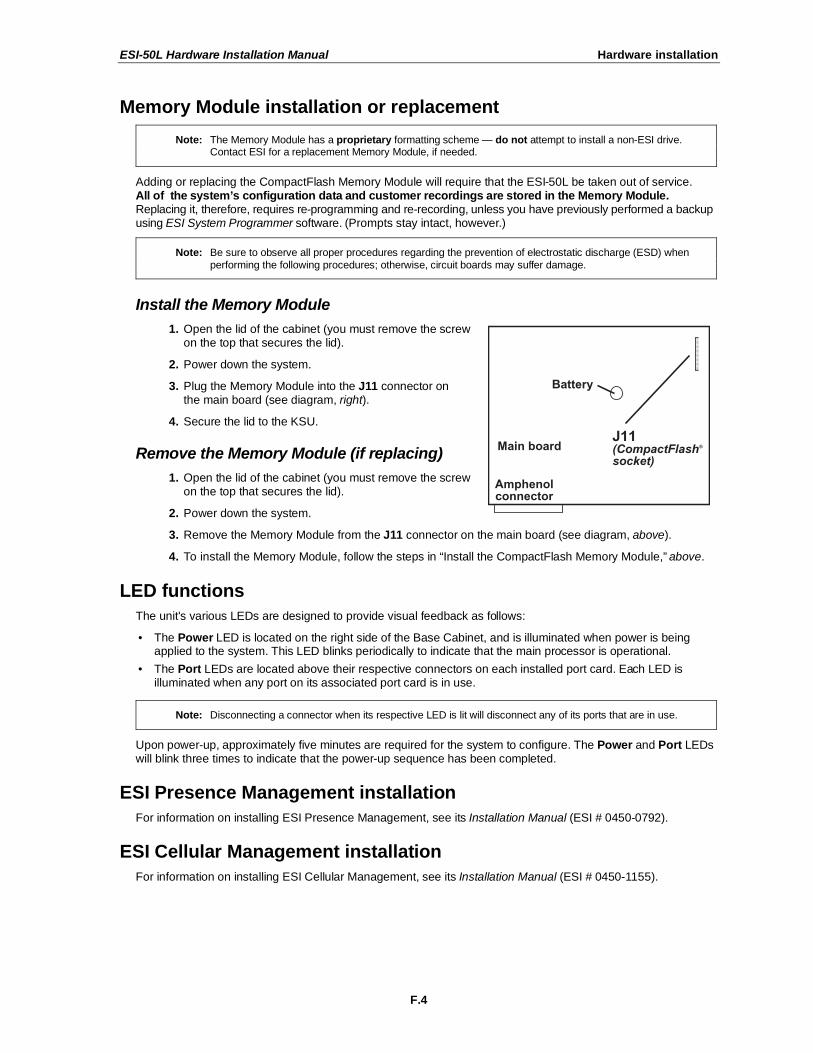
Install the Memory Module
1. Open the lid of the cabinet (you must remove the screw on the top that secures the lid).
2. Power down the system.
3. Plug the Memory Module into the J11 connector on the main board (see diagram, right).
4. Secure the lid to the KSU.
Remove the Memory Module (if replacing)
1. Open the lid of the cabinet (you must remove the screw on the top that secures the lid).
2. Power down the system.
3. Remove the Memory Module from the J11 connector on the main board (see diagram, above).
4. To install the Memory Module, follow the steps in “Install the CompactFlash Memory Module,” above.
LED functions
The unit's various LEDs are designed to provide visual feedback as follows:
• The Power LED is located on the right side of the Base Cabinet, and is illuminated when power is being applied to the system. This LED blinks periodically to indicate that the main processor is operational.
• The Port LEDs are located above their respective connectors on each installed port card. Each LED is illuminated when any port on its associated port card is in use.
Note: Disconnecting a connector when its respective LED is lit will disconnect any of its ports that are in use.
Upon power-up, approximately five minutes are required for the system to configure. The Power and Port LEDs will blink three times to indicate that the power-up sequence has been completed.
ESI Presence Management installation
For information on installing ESI Presence Management, see its Installation Manual (ESI # 0450-0792).
ESI Cellular Management installation
For information on installing ESI Cellular Management, see its Installation Manual (ESI # 0450-1155).
ESI-50L Hardware Installation Manual External connections
G.1
External connections
Grounding instructions
System grounding (supplemental ground) is as follows:
• The conductor wires can be no smaller than the ungrounded branch-circuit supply conductors (usually 16-gauge or higher).
• Acceptable wire: bare or covered with green (or green-and-yellow-striped) jacket.
• Conductors (and power receptacles) shall connect to earth ground at the service equipment (usually a cold-water pipe or copper ground rod).
• The supplemental ground must: be used regardless of power cord ground, be connected to the ground lug on the bottom of the cabinet, and retain ground connection when the power supply module is unplugged.
• Connect the grounding lugs of all units to system ground
Note: ESI Communications Server lines are protected against a 10 KV surge only if the earth ground procedures described above are followed.
Power
Each cabinet requires a 110 VAC outlet (if possible, a dedicated outlet). Use only the Class-2 power supply module provided. A clean, isolated power source in conjunction with a UPS is STRONGLY recommended.
A fully loaded ESI-50L system (one Base Cabinet, one Expansion Cabinet) consumes 72 watts.
If AC power is interrupted, the system will drop all connections. When power is restored, the system will resume normal operation in approximately five minutes, having retained its full programming and clock setting.
UPS
For system protection and to maintain uninterrupted operation, an uninterruptible power supply is STRONGLY recommended.
For the ESI-50L, the recommended UPS minimum rating per installed cabinet is 125 VA.
Refer to the particular UPS unit’s specifications to determine expected backup duration during a power outage.
Note: The remaining information under “UPS” comes from Technical Update #216.
Most people have heard about UPSs, but seem to think that there is just one kind of device that goes by that name. In fact, there are several different major designs in use by today’s major UPS manufacturers. These makers share much of the blame for confusing UPSs’ end users by, far too often, lumping different designs under the “UPS” name.
(Continued)
ESI-50L Hardware Installation Manual External connections
G.2
UPSs can first be broken down into system types:
• Stand-by — A very simple design that affects power only when either a lag/brownout occurs below, or a spike/surge occurs above, a certain threshold. When either occurs, the unit trips — i.e., goes into battery mode. This "cleans" the voltage and helps to keep any load safe. Industry average "trip" times are 2–8 ms. No other filtration of AC power is performed.
• Line interactive — Constantly monitors inbound voltages, and uses special circuitry to boost low voltages and clamp high voltages without having to use the batteries. Indeed, the batteries are used only if the input voltage drops below acceptable levels (typically about 12% below normal), goes out completely or rises to dangerous levels (typically about 14% above normal) at which components will be damaged if line voltage is not removed. Industry average transfer time is 1–3 ms. (If voltage stays within its normal window, this unit continues to pass voltage, unaltered, from the wall.)
• On-line (or full on-line) — Constantly filters the power and performs a function known as double conversion (AC to DC to AC). This assures that the load — in this case, phone equipment — will receive not only uninterrupted, true sine wave output but also the cleanest, steadiest power possible throughout any foreseeable power disruptions or voltage irregularities. According to industry specs, it is not unusual
for these types of units to be able to regulate utility power, even when it drops to 27% below or rises to 33% above normal, all without using their batteries.
From this point, UPSs can be further broken down by inverter types, which determine output. These are:
• Square wave.
• Modified sine wave (or quasi sine wave).
• Sine wave.
Most devices with wall-mounted chargers, such as cordless drills or screwdrivers, can behave erratically —
sometimes not allowing the charge circuit to engage at all — when operating with modified sine or square wave inverters. Small wall-based transformer-style power supplies, similar to those ESI phone systems use, can experience overheating problems with modified sine or square wave outputs, which occur while some UPSs are operating in battery mode. This overheating could eventually cause damage to the power supplies;
and, in time, the damage could cause a spike through the phone system — seriously damaging some of the static-sensitive components inside the casing.
While the true sine wave UPS output power curve smoothly increases to its peak, then smoothly decreases (allowing connected loads and equipment to operate the same as they would from utility supplied wall power), the modified sine wave and square wave UPS output power curve will shoot straight up, level off at peak voltage and then drop straight down. Additionally troublesome is that the modified sine wave sits at zero voltage for a short period during the transition to or from batteries — which is the main difference between it and the square wave output of some UPS. Please note that this short interval during which the
modified sine wave UPS sits at zero voltage can directly affect the transfer time of the UPS and could, theoretically, be enough to cause the phone equipment to reset or even “freeze.”
Though it is hard to predict exactly when different ESI systems will have problems with modified sine wave or square waveform UPSs (meaning during a power failure event or the recovery from one), it’s fair to assume that a problem will eventually arise from the use of such UPSs. Therefore, ESI recommends that only true sine wave output UPSs provide backup power to our phone systems and equipment.
ESI-50L Hardware Installation Manual External connections
G.3
MOH port
The MOH (messages-, or music-, on-hold) connector — located on the Base Cabinet’s right side — is a standard 1/8″ monophonic mini-jack, used for loading custom MOH recordings or for playing live music-on-hold from an
external source such as a CD player.
Maintenance/SMDR serial port
The Maintenance/SMDR port is a standard DB9 female serial connector, located on the Base Cabinet’s right side. Use a standard shielded serial cable, DB9-to-DB9, for printer-to-computer; this is usually male-to-female.
Note: The maximum distance from the cabinet is 100 ft.
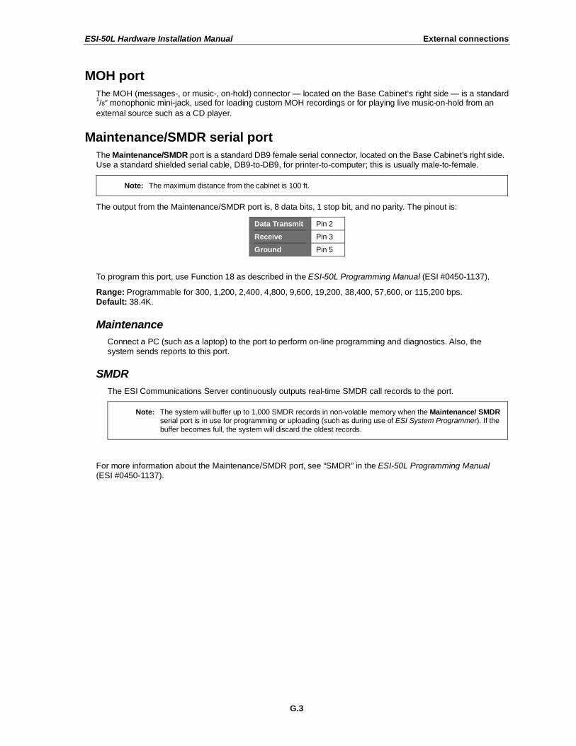
The output from the Maintenance/SMDR port is, 8 data bits, 1 stop bit, and no parity. The pinout is:
Data Transmit Pin 2
Receive Pin 3
Ground Pin 5
To program this port, use Function 18 as described in the ESI-50L Programming Manual (ESI #0450-1137).
Range: Programmable for 300, 1,200, 2,400, 4,800, 9,600, 19,200, 38,400, 57,600, or 115,200 bps. Default: 38.4K.
Maintenance
Connect a PC (such as a laptop) to the port to perform on-line programming and diagnostics. Also, the system sends reports to this port.
SMDR
The ESI Communications Server continuously outputs real-time SMDR call records to the port.
Note: The system will buffer up to 1,000 SMDR records in non-volatile memory when the Maintenance/ SMDR serial port is in use for programming or uploading (such as during use of ESI System Programmer). If the
buffer becomes full, the system will discard the oldest records.
For more information about the Maintenance/SMDR port, see “SMDR” in the ESI-50L Programming Manual (ESI #0450-1137).
ESI-50L Hardware Installation Manual External connections
G.4
External paging device connection
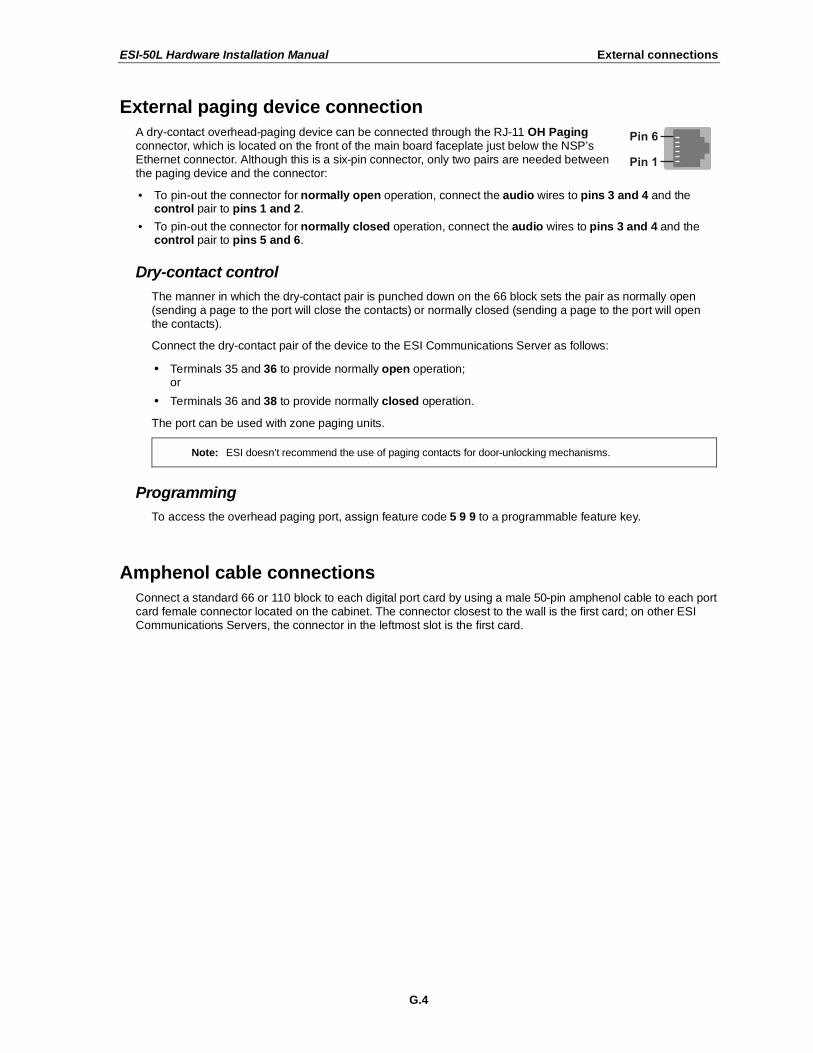
A dry-contact overhead-paging device can be connected through the RJ-11 OH Paging connector, which is located on the front of the main board faceplate just below the NSP’s Ethernet connector. Although this is a six-pin connector, only two pairs are needed between the paging device and the connector:
• To pin-out the connector for normally open operation, connect the audio wires to pins 3 and 4 and the control pair to pins 1 and 2.
• To pin-out the connector for normally closed operation, connect the audio wires to pins 3 and 4 and the control pair to pins 5 and 6.
Dry-contact control
The manner in which the dry-contact pair is punched down on the 66 block sets the pair as normally open (sending a page to the port will close the contacts) or normally closed (sending a page to the port will open the contacts).
Connect the dry-contact pair of the device to the ESI Communications Server as follows:
• Terminals 35 and 36 to provide normally open operation; or
• Terminals 36 and 38 to provide normally closed operation.
The port can be used with zone paging units.
Note: ESI doesn’t recommend the use of paging contacts for door-unlocking mechanisms.
Programming
To access the overhead paging port, assign feature code 5 9 9 to a programmable feature key.
Amphenol cable connections
Connect a standard 66 or 110 block to each digital port card by using a male 50-pin amphenol cable to each port card female connector located on the cabinet. The connector closest to the wall is the first card; on other ESI Communications Servers, the connector in the leftmost slot is the first card.
ESI-50L Hardware Installation Manual External connections
G.5
CO line connection
Local loop
An ESI Communication Server’s advanced CO line circuitry provides for open loop detection and the system’s built-in Caller ID interface. Loop start lines are connected via the last four pairs on each 66 block on the 482 card.
Note: Observe correct order of connection to preserve proper rotary hunting of the CO lines.
Station connection
Each 482 port card (built-in or external) supports up to eight digital stations and up to two analog devices.
All stations are connected using a single pair. Each port position is pre-numbered and fixed as indicated in the 66 block wiring diagram shown for each port card type.
Note: The station runs can be up to 1,000 ft.
Digital stations
Digital stations for the ESI Communications Server include:
• ESI Digital Feature Phones
• ESI Digital Cordless Handsets
• ESI Presence Management RFID Readers1
The digital station wiring is not polarity-sensitive. Only one phone can be connected per digital port. The station line voltage is 33 VDC.
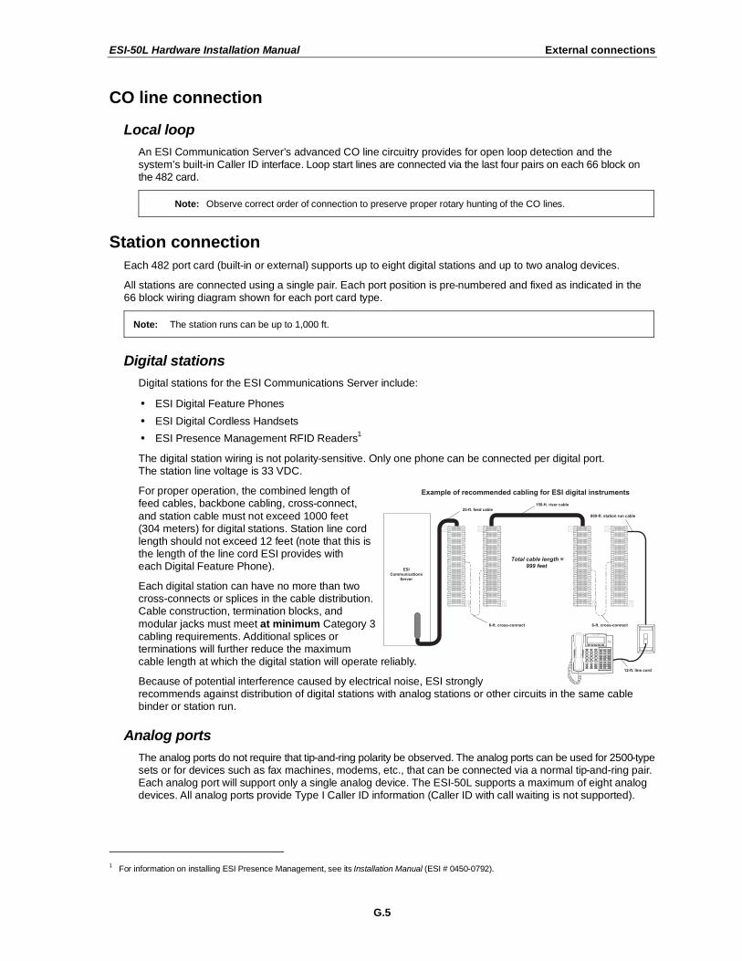
For proper operation, the combined length of feed cables, backbone cabling, cross-connect,
and station cable must not exceed 1000 feet (304 meters) for digital stations. Station line cord length should not exceed 12 feet (note that this is the length of the line cord ESI provides with each Digital Feature Phone).
Each digital station can have no more than two cross-connects or splices in the cable distribution. Cable construction, termination blocks, and
modular jacks must meet at minimum Category 3 cabling requirements. Additional splices or terminations will further reduce the maximum cable length at which the digital station will operate reliably.
Because of potential interference caused by electrical noise, ESI strongly recommends against distribution of digital stations with analog stations or other circuits in the same cable binder or station run.
Analog ports
The analog ports do not require that tip-and-ring polarity be observed. The analog ports can be used for 2500-type sets or for devices such as fax machines, modems, etc., that can be connected via a normal tip-and-ring pair. Each analog port will support only a single analog device. The ESI-50L supports a maximum of eight analog devices. All analog ports provide Type I Caller ID information (Caller ID with call waiting is not supported).
1 For information on installing ESI Presence Management, see its Installation Manual (ESI # 0450-0792).
ESI-50L Hardware Installation Manual External connections
G.6
60-Key Expansion Console connection
Notes: The 60-Key Expansion Console can be connected to only a 48-Key Feature Phone.
If connecting both a 60-Key Expansion Console and a 60-Key Second Expansion Console to a 48-Key Feature Phone, see “60-Key Second Expansion Console connection,” page G.7.
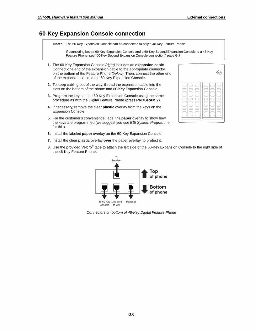
1. The 60-Key Expansion Console (right) includes an expansion cable. Connect one end of the expansion cable to the appropriate connector on the bottom of the Feature Phone (below). Then, connect the other end of the expansion cable to the 60-Key Expansion Console.
2. To keep cabling out of the way, thread the expansion cable into the slots on the bottom of the phone and 60-Key Expansion Console.
3. Program the keys on the 60-Key Expansion Console using the same procedure as with the Digital Feature Phone (press PROGRAM 2).
4. If necessary, remove the clear plastic overlay from the keys on the Expansion Console.
5. For the customer’s convenience, label the paper overlay to show how the keys are programmed (we suggest you use ESI System Programmer for this).
6. Install the labeled paper overlay on the 60-Key Expansion Console.
7. Install the clear plastic overlay over the paper overlay, to protect it.
8. Use the provided Velcro® tape to attach the left side of the 60-Key Expansion Console to the right side of
the 48-Key Feature Phone.
Connectors on bottom of 48-Key DIgital Feature Phone
ESI-50L Hardware Installation Manual External connections
G.7
60-Key Second Expansion Console connection
Notes: If connecting only one Expansion Console to a 48-Key Feature Phone, see “60-Key Expansion Console connection,” page G.6.
The 60-Key Second Expansion Console connects to the 60-Key Expansion Console and cannot connect directly to the 48-Key Feature Phone (the only phone to which you can connect a 60-Key Expansion Console).
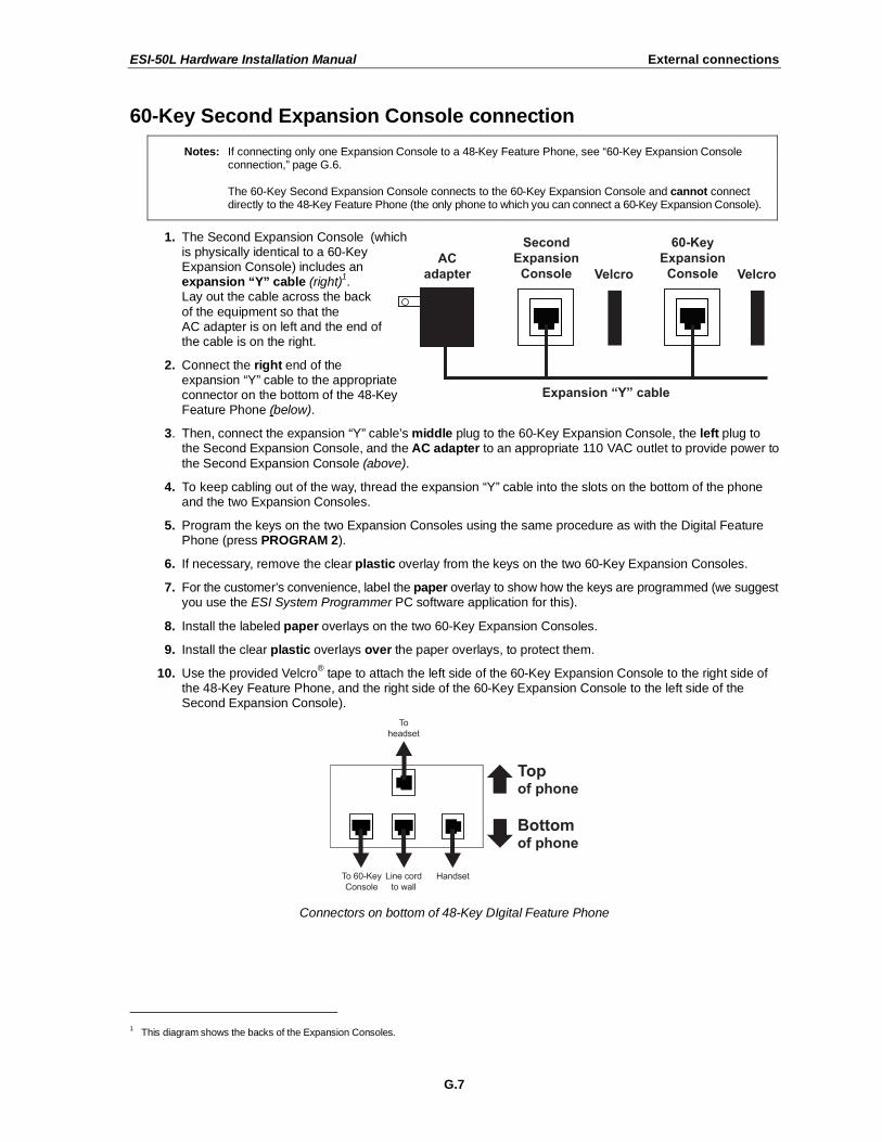
1. The Second Expansion Console (which is physically identical to a 60-Key Expansion Console) includes an expansion “Y” cable (right)
1.
Lay out the cable across the back
of the equipment so that the AC adapter is on left and the end of the cable is on the right.
2. Connect the right end of the expansion “Y” cable to the appropriate connector on the bottom of the 48-Key Feature Phone (below).
3. Then, connect the expansion “Y” cable’s middle plug to the 60-Key Expansion Console, the left plug to the Second Expansion Console, and the AC adapter to an appropriate 110 VAC outlet to provide power to
the Second Expansion Console (above).
4. To keep cabling out of the way, thread the expansion “Y” cable into the slots on the bottom of the phone and the two Expansion Consoles.
5. Program the keys on the two Expansion Consoles using the same procedure as with the Digital Feature Phone (press PROGRAM 2).
6. If necessary, remove the clear plastic overlay from the keys on the two 60-Key Expansion Consoles.
7. For the customer’s convenience, label the paper overlay to show how the keys are programmed (we suggest you use the ESI System Programmer PC software application for this).
8. Install the labeled paper overlays on the two 60-Key Expansion Consoles.
9. Install the clear plastic overlays over the paper overlays, to protect them.
10. Use the provided Velcro® tape to attach the left side of the 60-Key Expansion Console to the right side of
the 48-Key Feature Phone, and the right side of the 60-Key Expansion Console to the left side of the Second Expansion Console).
Connectors on bottom of 48-Key DIgital Feature Phone
1 This diagram shows the backs of the Expansion Consoles.
ESI-50L Hardware Installation Manual External connections
G.8
Installing ESI’s Cordless Handsets
Each ESI Cordless Handset comes with:
• A charger/cradle to charge the Handset.
• An AC adapter for use with only the charger.
• A base station to provide a digital interface between the ESI phone system and ESI Cordless Handset. This base station is line-powered and therefore needs no AC power.
• Wall-mount(s), a belt clip, and a Quick Reference Guide.
Each ESI Cordless Handset is keyed to only one base station and takes up one digital port on a 482 card.
Base station installation
Due to each site’s unique characteristics, the range and distance information we’ll provide herein is only approximate.
Characteristics that positively affect performance:
• The base station should be installed so it has a clear line-of-sight with the Cordless Handset.
• The base station antenna should always be pointed in its uppermost vertical position.
Characteristics that negatively affect performance:
• Large amounts of metal shelving (such as in manufacturing or warehouse areas).
• Close proximity to (within one mile of) a radio tower.
• Concrete walls that divide spaces where Cordless Handsets are used (assuming the base stations are in one location).
Don’t install the base station:
• Close to a wall with metal studs.
• On a metal wall.
• Next to a device that emits RFI or EMI1 — e.g., a television, radio, computer, computer printer,
fluorescent light fixture, or fax machine.
• Next to any other 900 MHz device — e.g., a hand-held inventory control device.
• In a ceiling that has foil-backed insulation.
• Behind doors that typically are closed, tinted windows, one-way glass, or other areas that limit or cut off transmission to the Cordless Handset.
Base stations must be installed at least 10 feet apart, regardless of whether the base station is for the small-model or large-model Cordless Handset. Don’t install more than six base stations in one area (such as a network room). Choose a location at least 30 feet away if more than six base stations are needed
in a building.
A Digital Cordless Handset base station requires only a line cord to the phone system; AC power isn’t needed because the base station receives power from the phone system via the line cord.
Once the base stations are installed and the Cordless Handsets charged, change each Handset’s channel by pressing its CH key. Each Handset should have its own channel. There are 30 available channels on the small Cordless Handset and 10 on the large Cordless Handset.
Note: Feedback may result if the Cordless Handset is within three inches of an ESI desktop Feature Phone.
1 RFI is radio frequency interference. EMI is electromagnetic interference.
ESI-50L Hardware Installation Manual External connections
G.9
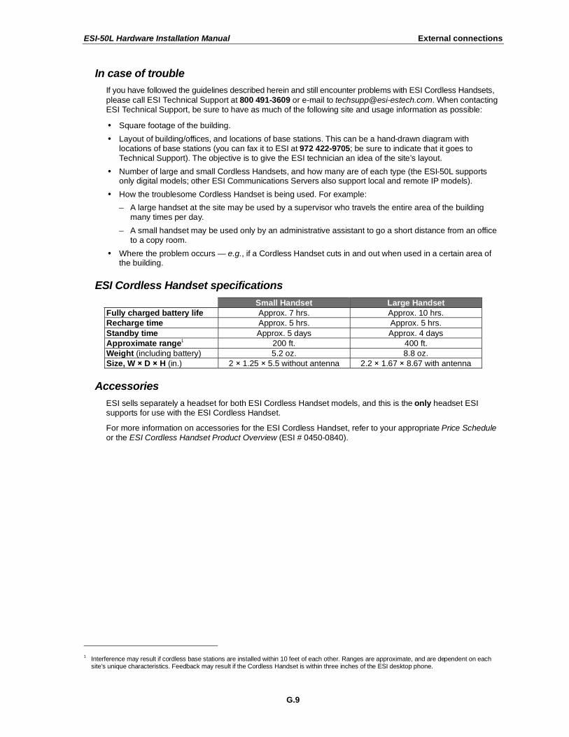
In case of trouble
If you have followed the guidelines described herein and still encounter problems with ESI Cordless Handsets,
please call ESI Technical Support at 800 491-3609 or e-mail to [email protected]. When contacting ESI Technical Support, be sure to have as much of the following site and usage information as possible:
• Square footage of the building.
• Layout of building/offices, and locations of base stations. This can be a hand-drawn diagram with locations of base stations (you can fax it to ESI at 972 422-9705; be sure to indicate that it goes to Technical Support). The objective is to give the ESI technician an idea of the site’s layout.
• Number of large and small Cordless Handsets, and how many are of each type (the ESI-50L supports only digital models; other ESI Communications Servers also support local and remote IP models).
• How the troublesome Cordless Handset is being used. For example:
– A large handset at the site may be used by a supervisor who travels the entire area of the building many times per day.
– A small handset may be used only by an administrative assistant to go a short distance from an office to a copy room.
• Where the problem occurs — e.g., if a Cordless Handset cuts in and out when used in a certain area of the building.
ESI Cordless Handset specifications
Small Handset Large Handset
Fully charged battery life Approx. 7 hrs. Approx. 10 hrs.
Recharge time Approx. 5 hrs. Approx. 5 hrs.
Standby time Approx. 5 days Approx. 4 days
Approximate range1 200 ft. 400 ft.
Weight (including battery) 5.2 oz. 8.8 oz.
Size, W D H (in.) 2 1.25 5.5 without antenna 2.2 1.67 8.67 with antenna
Accessories
ESI sells separately a headset for both ESI Cordless Handset models, and this is the only headset ESI supports for use with the ESI Cordless Handset.
For more information on accessories for the ESI Cordless Handset, refer to your appropriate Price Schedule or the ESI Cordless Handset Product Overview (ESI # 0450-0840).
1 Interference may result if cordless base stations are installed within 10 feet of each other. Ranges are approximate, and are dependent on each
site’s unique characteristics. Feedback may result if the Cordless Handset is within three inches of the ESI desktop phone.
ESI-50L Hardware Installation Manual External connections
G.10
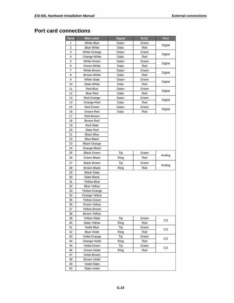
Port card connections
Term Wire color Signal RJ11 Port
1 White-Blue Data+ Green
2 Blue-White Data- Red Digital
3 White-Orange Data+ Green
4 Orange-White Data- Red Digital
5 White-Green Data+ Green
6 Green-White Data- Red Digital
7 White-Brown Data+ Green
8 Brown-White Data- Red Digital
9 White-Slate Data+ Green
10 Slate-White Data- Red Digital
11 Red-Blue Data+ Green
12 Blue-Red Data- Red Digital
13 Red-Orange Data+ Green
14 Orange-Red Data- Red Digital
15 Red-Green Data+ Green
16 Green-Red Data- Red Digital
17 Red-Brown
18 Brown-Red
19 Red-Slate
20 Slate-Red
21 Black-Blue
22 Blue-Black
23 Black-Orange
24 Orange-Black
25 Black-Green Tip Green
26 Green-Black Ring Red Analog
27 Black-Brown Tip Green
28 Brown-Black Ring Red Analog
29 Black-Slate
30 Slate-Black
31 Yellow-Blue
32 Blue-Yellow
33 Yellow-Orange
34 Orange-Yellow
35 Yellow-Green
36 Green-Yellow
37 Yellow-Brown
38 Brown-Yellow
39 Yellow-Slate Tip Green
40 Slate-Yellow Ring Red CO
41 Violet-Blue Tip Green
42 Blue-Violet Ring Red CO
43 Violet-Orange Tip Green
44 Orange-Violet Ring Red CO
45 Violet-Green Tip Green
46 Green-Violet Ring Red CO
47 Violet-Brown
48 Brown-Violet
49 Violet-Slate
50 Slate-Violet
ESI-50L Hardware Installation Manual External connections
G.11
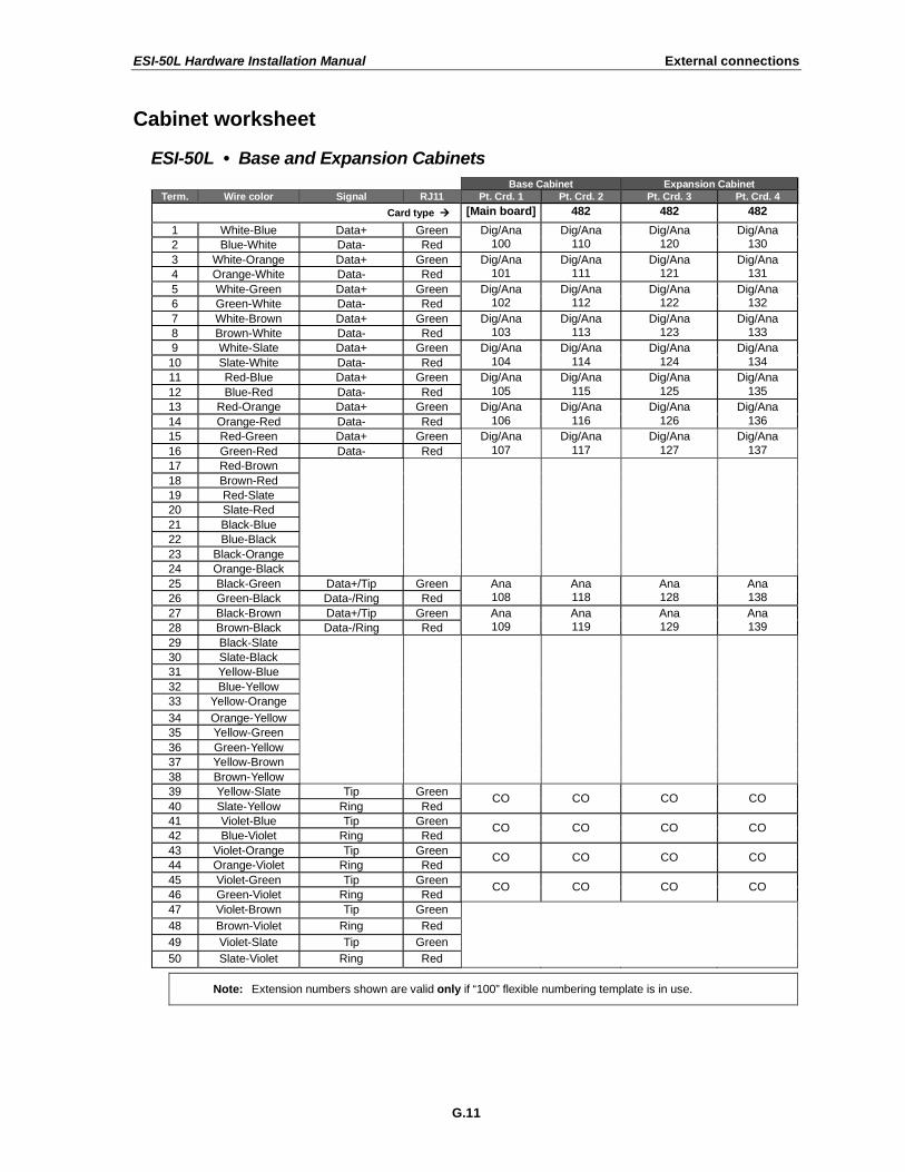
Cabinet worksheet
ESI-50L • Base and Expansion Cabinets
Base Cabinet Expansion Cabinet
Term. Wire color Signal RJ11 Pt. Crd. 1 Pt. Crd. 2 Pt. Crd. 3 Pt. Crd. 4
Card type [Main board] 482 482 482
1 White-Blue Data+ Green
2 Blue-White Data- Red
Dig/Ana 100
Dig/Ana 110
Dig/Ana 120
Dig/Ana 130
3 White-Orange Data+ Green
4 Orange-White Data- Red
Dig/Ana 101
Dig/Ana 111
Dig/Ana 121
Dig/Ana 131
5 White-Green Data+ Green
6 Green-White Data- Red
Dig/Ana 102
Dig/Ana 112
Dig/Ana 122
Dig/Ana 132
7 White-Brown Data+ Green
8 Brown-White Data- Red
Dig/Ana 103
Dig/Ana 113
Dig/Ana 123
Dig/Ana 133
9 White-Slate Data+ Green
10 Slate-White Data- Red
Dig/Ana
104
Dig/Ana
114
Dig/Ana
124
Dig/Ana
134
11 Red-Blue Data+ Green
12 Blue-Red Data- Red
Dig/Ana
105
Dig/Ana
115
Dig/Ana
125
Dig/Ana
135
13 Red-Orange Data+ Green
14 Orange-Red Data- Red
Dig/Ana
106
Dig/Ana
116
Dig/Ana
126
Dig/Ana
136
15 Red-Green Data+ Green
16 Green-Red Data- Red
Dig/Ana
107
Dig/Ana
117
Dig/Ana
127
Dig/Ana
137
17 Red-Brown
18 Brown-Red
19 Red-Slate
20 Slate-Red
21 Black-Blue
22 Blue-Black
23 Black-Orange
24 Orange-Black
25 Black-Green Data+/Tip Green
26 Green-Black Data-/Ring Red
Ana 108
Ana 118
Ana 128
Ana 138
27 Black-Brown Data+/Tip Green
28 Brown-Black Data-/Ring Red
Ana 109
Ana 119
Ana 129
Ana 139
29 Black-Slate
30 Slate-Black
31 Yellow-Blue
32 Blue-Yellow
33 Yellow-Orange
34 Orange-Yellow
35 Yellow-Green
36 Green-Yellow
37 Yellow-Brown
38 Brown-Yellow
39 Yellow-Slate Tip Green
40 Slate-Yellow Ring Red CO CO CO CO
41 Violet-Blue Tip Green
42 Blue-Violet Ring Red CO CO CO CO
43 Violet-Orange Tip Green
44 Orange-Violet Ring Red CO CO CO CO
45 Violet-Green Tip Green
46 Green-Violet Ring Red CO CO CO CO
47 Violet-Brown Tip Green 48 Brown-Violet Ring Red 49 Violet-Slate Tip Green 50 Slate-Violet Ring Red
Note: Extension numbers shown are valid only if “100” flexible numbering template is in use.
Index
482 port card, A.1 60-Key Expansion Console, B.1, G.6, G.7 60-Key Second Expansion Console, B.1, G.6, G.7 Analog ports, G.5 Battery. See Cautions Cautions, E.1
Battery, E.1 Fuse, E.1 Power supply, E.1
CO lines Capacities. See System capacities Connecting, G.5
Console, B.1, G.6, G.7 ESI Cordless Handsets. See Phones ESI Presence Management, D.1 Expansion Console, B.1, G.6, G.7 Fuse. See Cautions Grounding, G.1, G.3 LED functions, F.4 Main board, A.1 Memory Module, A.1
Installation or replacement, F.4
MOH, G.3 NSP (Network Services Processor), A.2 Overlays, B.2 Paging, G.4 Phones
Digital Feature Phones, B.1 ESI Cordless Handsets, B.1
Port cards Charts, G.10 Installation, F.3
Power, G.1 Power supply. See Cautions Transformers, wall-mount, A.1
Regulatory information (U.S. and Canada), E.2 Ringer equivalence number (REN), E.2 Serial ports, G.3 SMDR, G.3 System capacities, D.1 UPS (uninterruptible power supply), G.1
www.esi-estech.com
Related Documents