ES250: Electrical Science HW4: Node Voltage and Mesh Current Methods of Circuit Analysis

Welcome message from author
This document is posted to help you gain knowledge. Please leave a comment to let me know what you think about it! Share it to your friends and learn new things together.
Transcript

ES250:Electrical Science
HW4: Node Voltage and Mesh Current Methods of Circuit Analysis
James Carroll
As of 2/14/10 at 11pm: 30% of students have yet to attempt HW#1 57% of students have yet to attempt HW#2 80% of students have yet to attempt HW#3 99% of students have yet to attempt HW#4
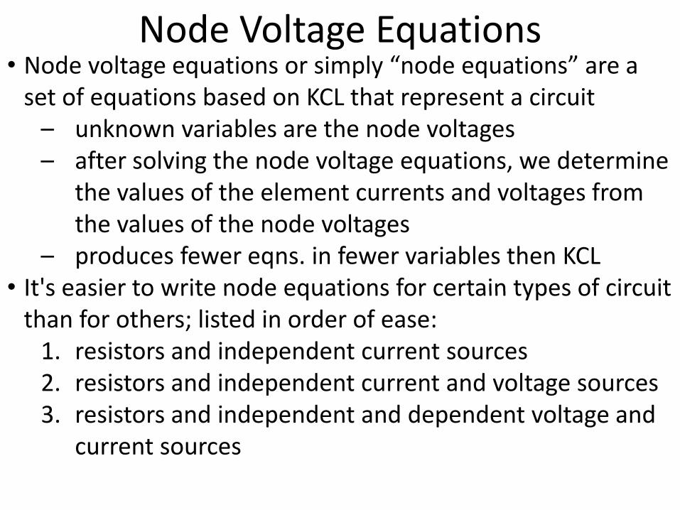
• Node voltage equations or simply “node equations” are aNode Voltage Equations
Node voltage equations or simply node equations are a set of equations based on KCL that represent a circuit
– unknown variables are the node voltages– after solving the node voltage equations, we determine
the values of the element currents and voltages from th l f th d ltthe values of the node voltages
– produces fewer eqns. in fewer variables then KCL • It's easier to write node equations for certain types of circuitIt s easier to write node equations for certain types of circuit
than for others; listed in order of ease:1. resistors and independent current sources2. resistors and independent current and voltage sources3. resistors and independent and dependent voltage and
current sources

• Circuit nodes are the places where elements connectNode Voltage with Current Sources
Circuit nodes are the places where elements connect together, e.g., nodes are labeled as node a, b, and c below:
≡
• The node voltages are represented as v and v but it is
Arbitrary reference node
• The node voltages are represented as vac and vbc but it is conventional to drop the subscript c and refer to these node voltages as simply va and vbg p y a b

• The reference node vcc = vc = 0 V, since a voltmeterNode Voltage with Current Sources
The reference node vcc vc 0 V, since a voltmeter measuring the node voltage at the reference node would have both probes connected to the same point
Arbitrary reference node

• The unknown variables in node equations are the nodeNode Voltage Equations
The unknown variables in node equations are the node voltages, determined by solving the node equations• To write a set of node equations, we do two things:
1. express element currents as functions of the node voltages
2 l Ki hh ff’ t l (KCL) t h f th d2. apply Kirchhoff’s current law (KCL) at each of the nodes of the circuit, except for the reference node
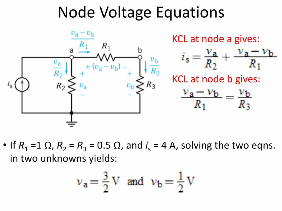
KCL at node a gives:KCL at node a gives:
KCL at node b gives:
Node Voltage Equations
KCL at node a gives:
KCL at node b gives:
• If R1 =1 Ω, R2 = R3 = 0.5 Ω, and is = 4 A, solving the two eqns. 1 2 3 sin two unknowns yields:

Example 4.2‐2: Node Equations
• Obtain the node equations for the circuit letting va denote the node voltage at node a, vb denote the node voltage at
d b d d h d l d h hnode b, and vc denote the node voltage at node c with the reference node as shown

• Apply KCL at node a to obtain:Example 4.2‐2: Node Equations
S t th t f thi ti th t i l f th• Separate the terms of this equation that involve va from the terms that involve vb and the terms that involve vc to obtain:
• Note the pattern in the node eqns. of circuits that contain only resistors and current sources:
– in the node eqn. at node a, the coefficient of va is the sum of the reciprocals of the resistances of all resistors connected to node areciprocals of the resistances of all resistors connected to node a
– the coefficients of vb (and likewise vc) are minus the sum of the reciprocals of the resistances of resistors connected between
d b d d ( d d d f )nodes b and node a (or nodes c and node a for vc)– the right‐hand side of this eqn. is the algebraic sum of current
source currents directed into node a
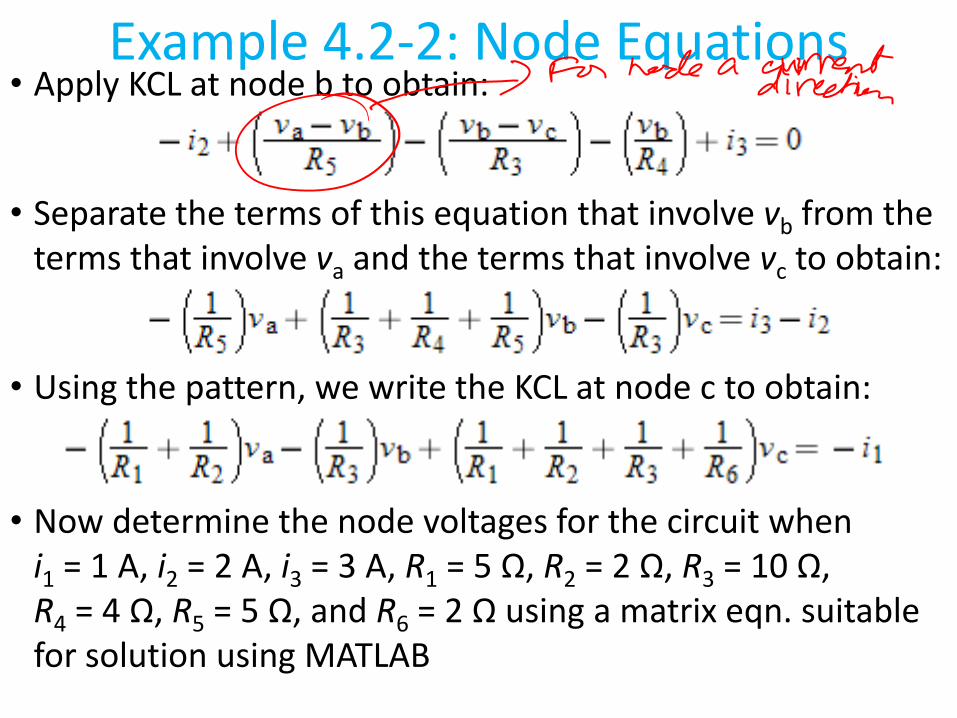
• Apply KCL at node b to obtain:Example 4.2‐2: Node Equations
S t th t f thi ti th t i l f th• Separate the terms of this equation that involve vb from the terms that involve va and the terms that involve vc to obtain:
• Using the pattern, we write the KCL at node c to obtain:
N d t i th d lt f th i it h• Now determine the node voltages for the circuit when i1 = 1 A, i2 = 2 A, i3 = 3 A, R1 = 5 Ω, R2 = 2 Ω, R3 = 10 Ω, R = 4 Ω R = 5 Ω and R = 2 Ω using a matrix eqn suitableR4 = 4 Ω, R5 = 5 Ω, and R6 = 2 Ω using a matrix eqn. suitable for solution using MATLAB
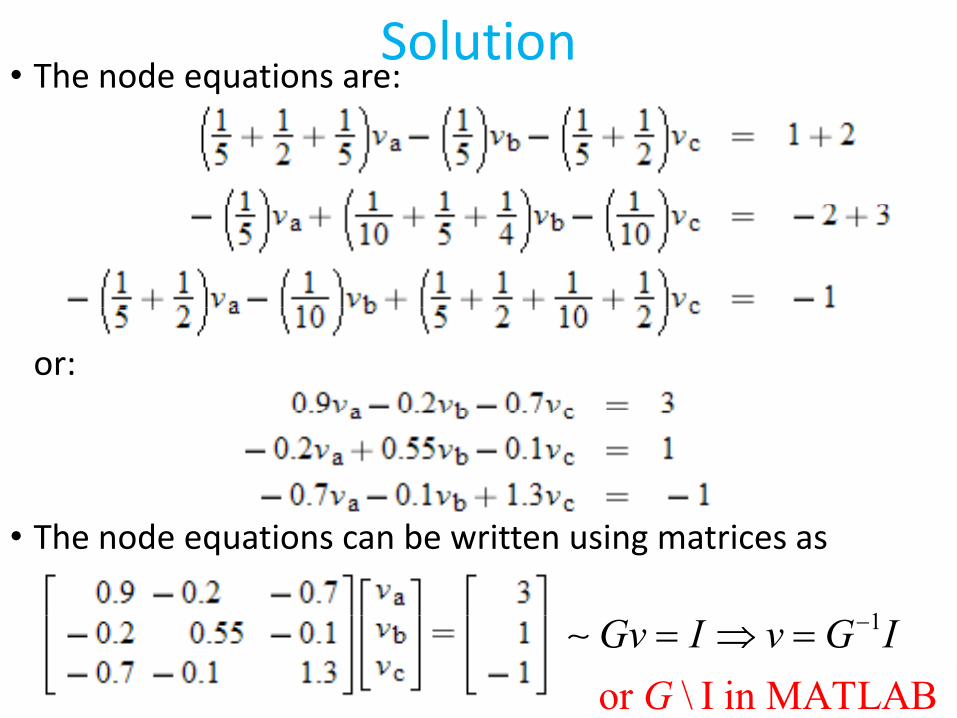
• The node equations are:Solution
or:
• The node equations can be written using matrices as
11
or \ I in MATL A BGv I v G IG
−= ⇒ =∼

MATLAB Solution>> G=[0.9 ‐0.2 ‐0.7;‐0.2 0.55 ‐0.1;‐0.7 ‐0.1 1.3]G =
0.9000 ‐0.2000 ‐0.7000‐0.2000 0.5500 ‐0.10000.2000 0.5500 0.1000‐0.7000 ‐0.1000 1.3000
>> I [3 1 1]>> I=[3; 1; ‐1]I =
31‐1
>> v=G\Iv =
7 15797.15795.05263.4737
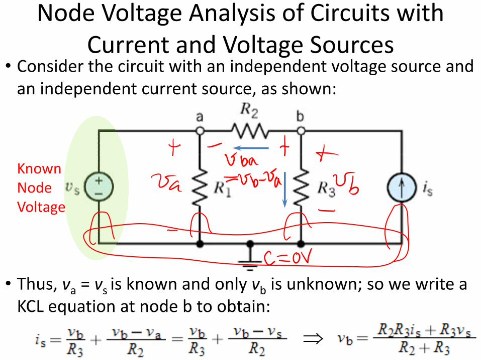
Node Voltage Analysis of Circuits with Current and Voltage Sources
• Consider the circuit with an independent voltage source and an independent current source, as shown:
Current and Voltage Sources
KnownNodeVoltageVoltage
• Thus, va = vs is known and only vb is unknown; so we write a KCL equation at node b to obtain:KCL equation at node b to obtain:
⇒

• Consider the circuit with an independent voltage source and Circuits with a Supernode
an independent current source, as shown:By KVL:
By KCL:
⇒
• Since v and v are dependent we consider nodes a and b as
⇒
• Since va and vb are dependent, we consider nodes a and b as part of one larger supernode represented by the shaded ellipse; by KCL the algebraic sum of the currents entering aellipse; by KCL the algebraic sum of the currents entering a supernode is zero which means that we apply KCL to a supernode in the same way as a regular node
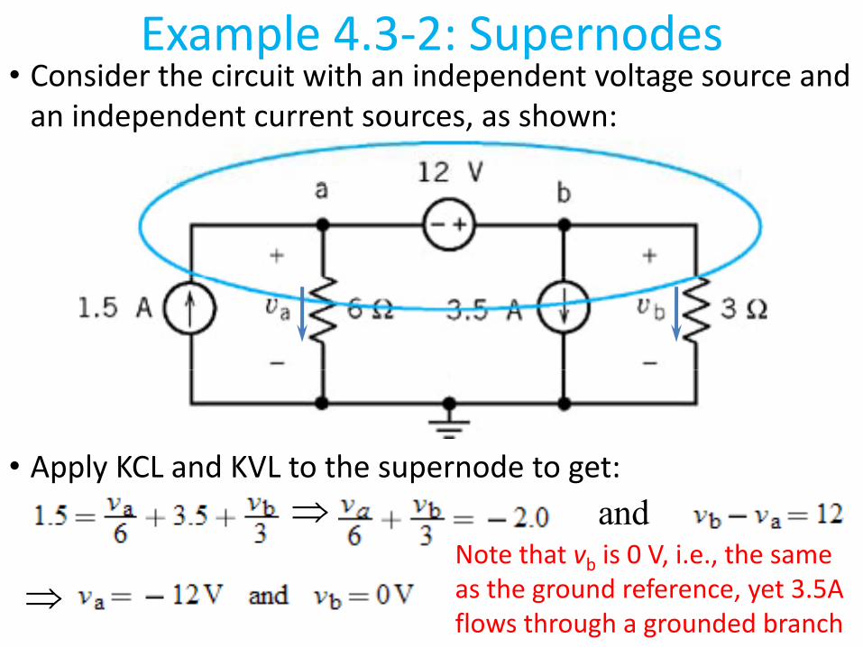
• Consider the circuit with an independent voltage source and Example 4.3‐2: Supernodes
an independent current sources, as shown:
• Apply KCL and KVL to the supernode to get• Apply KCL and KVL to the supernode to get:⇒ and
Note that v is 0 V i e the same
⇒Note that vb is 0 V, i.e., the sameas the ground reference, yet 3.5Aflows through a grounded branch

Example 4.3‐3 Node Equations for a Circuit Containing Voltage Sources
• Determine the node voltages for the circuit shown:Containing Voltage Sources
B KVLBy KVL:
By KCL at supernode:
⇒• Solving these eqns. for vc we get:
⇒
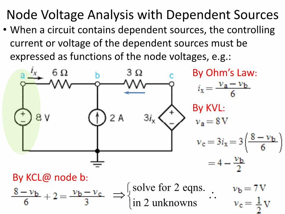
• When a circuit contains dependent sources the controllingNode Voltage Analysis with Dependent Sources• When a circuit contains dependent sources, the controlling
current or voltage of the dependent sources must be expressed as functions of the node voltages, e.g.:p g , g
By Ohm’s Law:
By KVL:
l fBy KCL@ node b:
solve for 2 eqns.in 2 unknowns
⇒ ∴

• Determine the node voltages for the circuit shown:Example 4.4‐2: Circuit with a VCVS
• Determine the node voltages for the circuit shown:First express control voltage vx as a fcn. ofvoltage vx as a fcn. of the node voltages using KVL:
By KVL:By KVL:
l fBy KCL@ the supernode:
⇒
solve for 2 eqns.in 2 unknowns
⇒ ∴

Questions?Questions?

• Mesh current equations or simply “mesh equations” are aMesh Current Equations
Mesh current equations or simply mesh equations are a set of equations based on KVL that represent a circuit
– unknown variables are the mesh currents– after solving the mesh current equations, we determine
the values of the element currents and voltages from th l f th h tthe values of the mesh currents
– produces fewer eqns. in fewer variables then KCL • It's easier to write mesh current equations for some types ofIt s easier to write mesh current equations for some types of
circuit than for others; listed in order of ease:1. resistors and independent voltage sources2. resistors and independent current and voltage sources3. resistors and independent and dependent voltage and
current sources
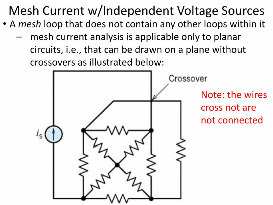
• A mesh loop that does not contain any other loops within itMesh Current w/Independent Voltage Sources
– mesh current analysis is applicable only to planar circuits, i.e., that can be drawn on a plane without
ll d b lcrossovers as illustrated below:
Note: the wires cross not are
dnot connected

• For planar networks the meshes look like “windows”Mesh Current w/Independent Voltage Sources
– there are four meshes in the circuit below identified as Mi– mesh 2 contains the elements R3, R4, and R5, with R3
b h h d hcommon to both mesh 1 and mesh 2

• A circuit with two mesh currents i1 and i2 is shown on the Mesh Current w/Independent Voltage Sources
1 2 left‐hand side below:– we will assume mesh currents flow clockwise
h f h h h h ld b– the figure on the right shows how ammeters could be inserted in the circuit to measure the mesh currents

• To write a set of mesh equations, we do two things:Mesh Current w/Independent Voltage Sources
1. express element voltages as fucns. of the mesh currents2. apply KVL to each of the circuit meshes
bi ′
• The current of element B has been labeled as ib; applying KCL at node b gives:KCL at node b gives:
2 1or b bi i i i′ = − = −

• Write mesh equations to represent the circuit below using Mesh Current w/Independent Voltage Sources
the standard KVL convention, i.e., add voltages when the + reference polarity of an element voltage is encountered b f h dbefore the − sign, and vice versa:
By KVL @ mesh 1:By KVL @ mesh 1:
By KVL @ mesh 2:

• Solve the circuit with three mesh currents and two voltage Mesh Current w/Independent Voltage Sources
sources:

• These three mesh equations can be rewritten by collecting Mesh Current w/Independent Voltage Sources
coefficients for each mesh current as:
• The matrix eqn. for solving the mesh analysis:• Note that R is a symmetric matrix, as shown:y ,
• This eqn. can be solved using MATLAB as shown: i = R \ v
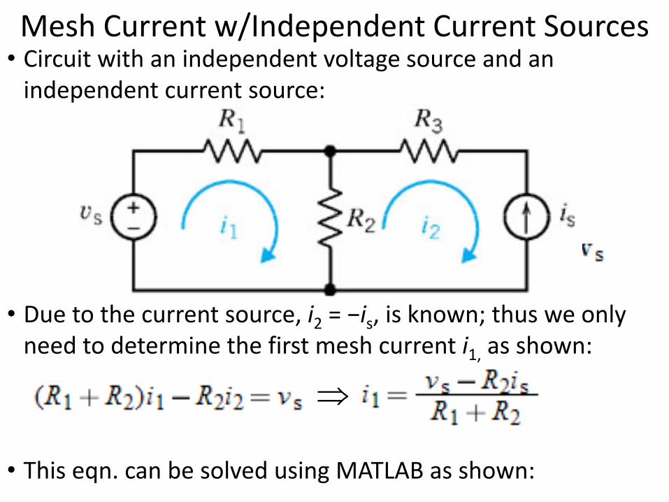
• Circuit with an independent voltage source and an Mesh Current w/Independent Current Sources
independent current source:
• Due to the current source, i2 = −is, is known; thus we only need to determine the first mesh current i1, as shown:1,
⇒
• This eqn. can be solved using MATLAB as shown:
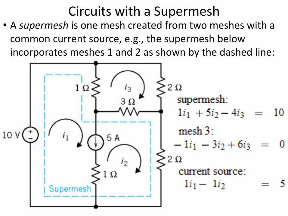
• A supermesh is one mesh created from two meshes with a Circuits with a Supermesh
common current source, e.g., the supermesh below incorporates meshes 1 and 2 as shown by the dashed line:
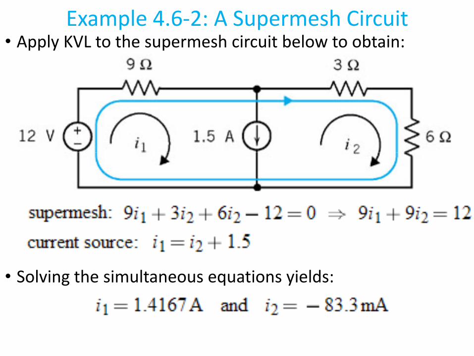
• Apply KVL to the supermesh circuit below to obtain:Example 4.6‐2: A Supermesh Circuit
• Solving the simultaneous equations yields:

• When a circuit contains dependent sources, the controlling Mesh Current Analysis with Dependent Sources
current or voltage of the dependent sources must be expressed as a function of the mesh currents– it is then a simple matter to express the controlled current
or voltage as a function of the mesh currents– the mesh equations are then obtained using KVL
• The controlling current of the dependent source, ia, is the current in a short circuit:
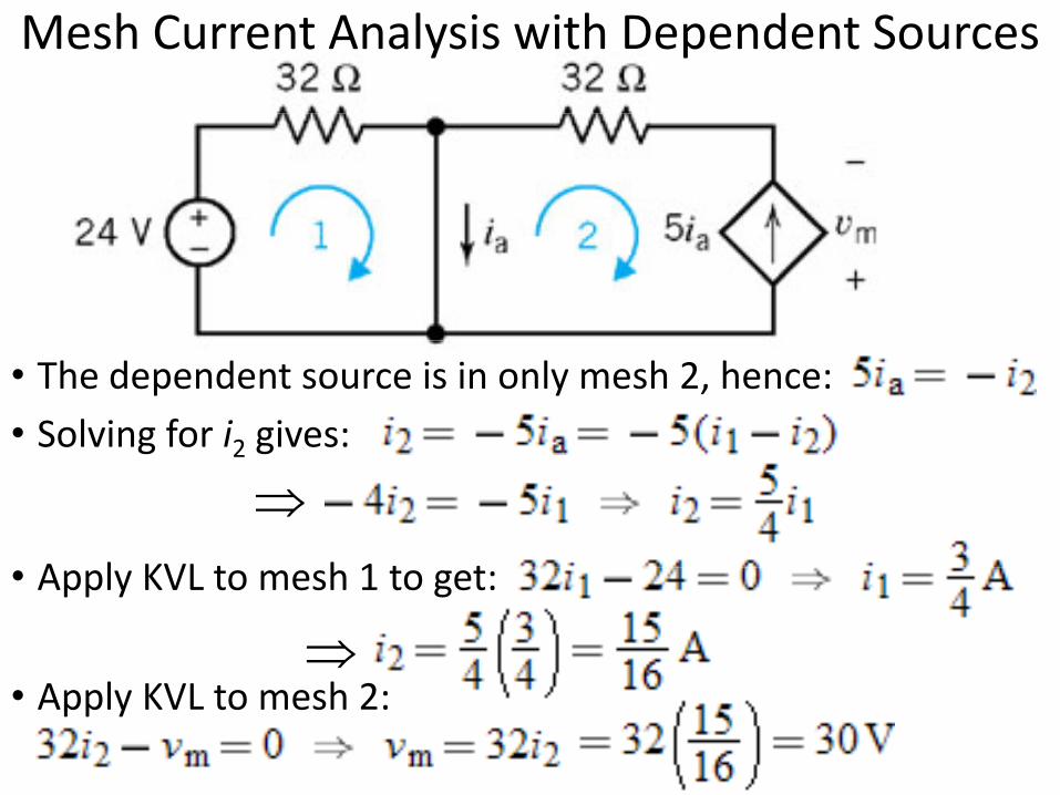
Mesh Current Analysis with Dependent Sources
• The dependent source is in only mesh 2, hence:• Solving for i2 gives:
⇒g 2 g
A l KVL t h 1 t t
⇒• Apply KVL to mesh 1 to get:
• Apply KVL to mesh 2:

Questions?Questions?
Related Documents