NREL is a national laboratory of the U.S. Department of Energy, Office of Energy Efficiency and Renewable Energy, operated by the Alliance for Sustainable Energy, LLC. 2011 DOE Vehicle Technologies Program Review Numerical and Experimental Investigation of Internal Short Circuits in a Li-ion Cell Project ID: ES109 This presentation does not contain any proprietary, confidential, or otherwise restricted information PI: Matthew Keyser, Gi-Heon Kim Presenter: Gi-Heon Kim Energy Storage Task Lead: Ahmad Pesaran Contributors: Matthew Keyser, Dirk Long, John Ireland, YoonSeok Jung, Kyu-Jin Lee, Kandler Smith, Shriram Santhanagopalan National Renewable Energy Laboratory Eric Darcy National Renewable Energy Laboratory (Jan-Sep, 2010) NASA-JSC

Welcome message from author
This document is posted to help you gain knowledge. Please leave a comment to let me know what you think about it! Share it to your friends and learn new things together.
Transcript

NREL is a national laboratory of the U.S. Department of Energy, Office of Energy Efficiency and Renewable Energy, operated by the Alliance for Sustainable Energy, LLC.
2011 DOE Vehicle Technologies Program Review
Numerical and Experimental Investigation of Internal Short Circuits in a Li-ion Cell
Project ID: ES109 This presentation does not contain any proprietary, confidential, or otherwise restricted information
PI: Matthew Keyser, Gi-Heon KimPresenter: Gi-Heon Kim
Energy Storage Task Lead: Ahmad Pesaran
Contributors:Matthew Keyser, Dirk Long, John Ireland, YoonSeok Jung,
Kyu-Jin Lee, Kandler Smith, Shriram Santhanagopalan National Renewable Energy Laboratory
Eric DarcyNational Renewable Energy Laboratory (Jan-Sep, 2010)
NASA-JSC

NATIONAL RENEWABLE ENERGY LABORATORY
Overview
Timeline
2
Budget
Barriers
Partners
• Li-ion abuse tolerance and reliability• Li-ion performance
• NASA-JSC• Dow Kokam• Battery Safety Consulting Inc.• Battery Design LLC• Sandia National Laboratories (SNL)• U.S. Navy
Overview
• Project Start: 2009• Project End : 2014• Ongoing
• FY10: $500K• FY11: Anticipated $500K
Funded by Dave Howell, Energy Storage R&DVehicle Technology Program, U.S. Department of Energy

NATIONAL RENEWABLE ENERGY LABORATORY
Background
3
Relevance
• Because of its high specific energy and power density, the Li-ion battery (LIB) is a promising candidate to date for electric energy storage in electric drive vehicles(EDVs)
• Safety concerns regarding violent failure of the LIB system are a major obstacle to overcome for fast market acceptance of EDV technologies
• Thermal instability and flammability of the LIB components make them prone to catastrophic thermal runaway under some rare ISC conditions
• Many safety incidents that take place in the field are due to an ISC that is not detectable or predictable at the point of manufacture
Internal Short Circuit (ISC), a Major Concern

NATIONAL RENEWABLE ENERGY LABORATORY
Motivation
4
Relevance
• Evolving during Life: Latent defect gradually evolves to create an ISC while the battery is in use; inadequate design and/or off-limit operation causes Li plating, stressing separator
• Difficulty of Early Detection: Electrical and thermal signals of early stage ISCs are not easily detected in large-capacity LIB systems
• Complex Physics with Numerous Sensitive Factors: Behavior of a LIB with an ISC depends on various factors, including nature of the short; cell characteristics such as capacity, chemistry, electrical and configuration; and attributes of the pack where the cell is integrated
• Poor Reproducibility: To date, no reliable and practical method exists to create an on-demand ISC in Li-ion cells that produces a response that is relevant to the ones produced by field failures
Barriers for Addressing Failures Due to ISC

NATIONAL RENEWABLE ENERGY LABORATORY
Objectives
5
Relevance
1. Model Investigation: Enhance knowledge of the complex physics of evolution and development of an ISC and subsequent cell responses using NREL’s multiphysics ISC model
2. Test Method Development: Establish a relevant ISC test method by developing an on-demand short activation device to produce representative and reproducible ISCs in a active cell and relevant cell responses
3. Model+Test: Perform a synergistic study with combination of modeling and experimental approaches

NATIONAL RENEWABLE ENERGY LABORATORY
Milestones
6
Milestones
• Matthew Keyser, Dirk Long, Ahmad Pesaran, “NREL Internal Short Circuit Simulator Development Summary”
FY10 Milestone Report
• “Li-Ion Abuse Response Modeling and Internal Short Circuit Simulation”FY11 Milestone Report – Due in September 2011

NATIONAL RENEWABLE ENERGY LABORATORY
Approach
7
Approach
Model Validation
• Confirm Model Assumptions• Provide Model Input
• Identify Critical Parameters• Provide Complete Data Set for
Non-Measurable Quantities
• Multiphysics ISC modeling• Understanding cell behaviors
• Develop relevant ISC in active cell
• Provide consistent and reproducible results
Lead Investigator: Gi-Heon Kim
Lead Investigator: Matthew Keyser
Focus of Testing Study
Focus of Modeling Study
Experiment Design
Photo Credits: Dow Kokam – Ben McCarthy
Photo Credits: NREL– Dirk Long
NATIONAL RENEWABLE ENERGY LABORATORY 8
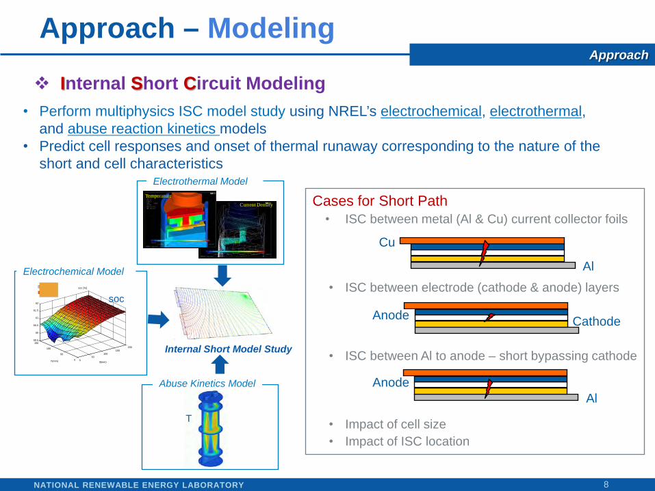
• Perform multiphysics ISC model study using NREL’s electrochemical, electrothermal, and abuse reaction kinetics models
• Predict cell responses and onset of thermal runaway corresponding to the nature of the short and cell characteristics
Internal Short Circuit Modeling
Electrochemical Model
050
100150
200
0
50
100
15059.5
60
60.5
61
61.5
62
X(mm)
soc [%]
Y(mm)
Internal Short Model Study
soc
Current Density
Temperature
Electrothermal Model
Abuse Kinetics Model
T
Cases for Short Path• ISC between metal (Al & Cu) current collector foils
• ISC between electrode (cathode & anode) layers
• ISC between Al to anode – short bypassing cathode
• Impact of cell size• Impact of ISC location
CathodeAnode
Al
Cu
AlAnode
Approach – ModelingApproach

NATIONAL RENEWABLE ENERGY LABORATORY 9
• Small, low-profile and implantable into Li-ion cells, preferably during assembly• Consistent and repeatable activation of internal short• Electrolyte-compatible phase change material (PCM) for key component• Triggered by heating the cell above PCM melting temperature
Approach – TestingApproach
Internal Short Circuit Instigator Device Development
Spiral wound battery shown – can also be applied to prismatic batteries

NATIONAL RENEWABLE ENERGY LABORATORY
Previous Accomplishments
10
Technical Accomplishments
20 40 sec8 28
Total Volumetric Heat Release from Component Reactions
4 2416 3612 32
• Three-dimensional LIB abuse kinetics model was developed in support of DOE’s ATD program, and the development was continued in the DOE’s ABR program
• Previous study Focused on understanding the interaction between heat transfer and
exothermic abuse reaction propagation for a particular cell/module design
Provided insight on how thermal characteristics and conditions can impact safety events of LIBs
Internal T External T(°C)
0 20 40 (sec)Note: Since NREL did not participate in 2010 AMR, this poster presentation include some of the project accomplishments done before May, 2010.

NATIONAL RENEWABLE ENERGY LABORATORY
Accomplishments
11
Technical Accomplishments
ISC Model Investigation

NATIONAL RENEWABLE ENERGY LABORATORY
Impact of Cell Capacity
12
Technical Accomplishments
Initial cell heating pattern under ISC varies with cell capacity• Shorted area: 1 mm x 1 mm
• Rshort ~ 10 mΩ• Ishort ~ 300 A (15 C-rate)
Temperature at 10 sec after short
800°C
25 C
surface temperature
internal temperature
• Short between Al and Cu foils
20 Ah cell 0.4 Ah cell • Rshort ~ 7 mΩ• Ishort ~ 34 A (85 C-rate)
100 110 120 130 1400
0.1
0.2
100 110 120 130 1400
0.1
0.2
temperature [°C]
volu
me
fract
ion
volu
me
fract
ion
100 C
140 CTemperature
at 7 sec after short
Temperatureat 8 sec after short
0 10 20 30 40 50 600
2
4
6
8
10
12
Exo
ther
mic
Rea
ctio
n H
eat [
kW]
Time [sec]
20 sec10 sec
30 sec
50 sec
40 sec
60 sec
Temperature evolving with time
200 mm
140 mm
7.5 mm
Shorted Spot
Positive Tab
Negative Tab40 mm
35 mm
3 mm
Shorted Spot
• A small-capacity cell is heated globally• ISC heating in a large cell is likely local • Thermally triggered “shut-down separator”
may function effectively in a small cell

NATIONAL RENEWABLE ENERGY LABORATORY
Impact of Separator Integrity
13
Technical Accomplishments
Maintaining integrity of separator seems critical to delay evolution of the short
Shorted area: 1 mm x 1 mm• Rshort ~ 20 Ω• Ishort ~ 0.16 A (< 0.01 C-rate)
current density field near short
surface temperature
43.1 C
25.5 C
• Thermal signature of the short is hard to detect from the surface
• The short for simple separator puncture is not likely to lead to an immediate thermal runaway
separator hole propagation
Shorted area: 3 cm x3 cm• Rshort ~ 30 mΩ• Ishort ~ 100 A (5 C)
3cm x 3cm Separator Hole
Exot
herm
ic H
eat [
W]
Time [sec]
Temperature at 1min after short1cm x 1cm Separator Hole
Joule heat @ cathode layer
Joule heat @ foils
• Short between anode to cathode • 20 Ah capacity cell

NATIONAL RENEWABLE ENERGY LABORATORY
Impact of Short Paths
14
Technical Accomplishments
Electrical resistance of ISC varies with short path across electrodes
• 20 Ah capacity cell
Short betweenAl & Cu foils
Short betweenanode and cathode
Short betweenanode and Al foil
• Rshort ~ 10 mΩ• Ishort ~ 300 A (15 C-rate)
Temperatures at 10 sec after short
800°C
25°C
surface temperature
internal temperature
• Rshort ~ 20 Ω• Ishort ~ 0.16 A (<0.01 C-rate)
Temperatures at 20 min after short
43.1°C
25.5°Cinternal temperature
Temperatures at 1 hr after short
surface temperatures
internal temperatures
250°C
37°C
• Rshort ~ 2 Ω• Ishort ~ 1.8 A (<0.1 C-rate)
• ISC bypassing cathode is likely to evolve into a hard short in relatively brief time

NATIONAL RENEWABLE ENERGY LABORATORY
Impact of Short Location
15
Technical Accomplishments
Cell response varies with short location and cell electrical configuration
Surface Temperatures
• 20-Ah capacity stacked cellISC Far from Tab
0 10 20 30 40 50 600
2
4
6
8
10
12
Exo
ther
mic
Rea
ctio
n H
eat [
kW]
Time [sec]
900°C50°C
ISC Near Tab
ISC far from tab
Rshort ~ 10 mΩIshort ~ 300 A (15 C-rate)
Electric Potential at Shorting Layers
Rshort ~ 4.7 mΩIshort ~ 520 A (26 C-rate)
300oC
30oC
Internal Temperatures
• For low-resistance ISC, near-tab ISC results in a smaller resistance because of shorter short-current path through shorting layers
• Pattern of local heating for convergence of short-current varies with location of short and internal electrical configuration of a cell
Surface Temperatures
ISC Near Tab

NATIONAL RENEWABLE ENERGY LABORATORY
Accomplishments
16
Technical Accomplishments
ISC Test Method Development

NATIONAL RENEWABLE ENERGY LABORATORY
NREL ISC Device
17
Technical Accomplishments
NREL developed an on-demand activation device creating representative ISC
Separator
Positive current collector (Al)Cathode electrode
ISC device
Negative current collector (Cu)Anode electrode
Activated short with PCM wickedby battery separator
Photo Credit: Dirk Long, NREL
• Triggered by heating the cell above PCM melting temperature (presently 40°C – 60°C)• Initial device design focus is on anode-to-cathode active material short • Improved device design focus is on anode-to-Al short
NREL’s ISC instigator design
Wax
• Anode to Cathode ISC • Anode to Al ISC
This device is applied for patent

NATIONAL RENEWABLE ENERGY LABORATORY
Characterizing the ISC Device
18
Technical Accomplishments
Model helps to understand characteristics of ISC device and short triggered
Axis symmetry geometry Current Boundary Condition
Ground Boundary Condition
Property Al pad Cu pad Cu piecePositive current
collector
Negativecurrent
collector
Cathode electrode
Anode electrode Separator
Electric conductivity [S/m] 3.541x10⁷ 5.8x10⁷ 5.8x10⁷ 3.541x10⁷ 5.8x10⁷ 5 58 1x10-15
Assuming no interface contact resistance between components
Electric potential contour
Current density norm contour
Graphic not drawn to scale• Cathode layer is the most
resistive part in the short current path
• Short current is mostly carried by metal foils
separator

NATIONAL RENEWABLE ENERGY LABORATORY
ISC Device Function Test
19
Technical Accomplishments
NREL ISC device consistently activated a short in laboratory testing
0
50
100
150
200
250
0
0.1
0.2
0.3
0.4
0.5
0.6
0.7
0.8
0.9
1
0 20 40 60 80 100 120 140Cu
rren
t (A
mps
), T
empe
ratu
re (
oC)
Volt
age
Dro
p A
cros
s Pl
aten
s (V
olts
)
Time (Seconds)
Voltage Current Temperature
Consistent Short Impedance ~ 0.5 mΩ
• Impedance test • Coin cell test
0
5
10
15
20
25
30
35
40
45
50
0
0.5
1
1.5
2
2.5
3
3.5
4
4.5
0 5 10 15 20 25 30 35 40
Copp
er P
late
n Te
mpe
ratu
re (
oC)
Coin
Cel
l Vol
tage
(Vo
lts)
Time (Minutes)
Voltage Temperature
Reliable ISC Trigger in Coin Cells – 100% Success Rate
• In laboratory testing, the activated device can handle currents in excess of 200 A to simulate hard shorts (<5mΩ).
• Phase change from non-conducting to conducting has been 100% successful during trigger tests.• Separator is an excellent wick for melted PCM.• Nine of nine coin cells shorted with new ISC device design, shown here using a 42°C – 44°C melting PCM.
Photo Credit: Dirk Long, NREL

NATIONAL RENEWABLE ENERGY LABORATORY
ISC Device Implantation in a Large Cell
20
2.5
2.7
2.9
3.1
3.3
3.5
3.7
3.9
4.1
4.3
0 20 40 60 80 100 120 140
Volta
ge (V
olts
)
Time (Minutes)
Cell 11 Cell 12 Cell 13
4-amp discharge voltage curves from initial cycle dataDow Kokam 8-Ah pouch cells with anode-Al ISC device
Device has negligible impact on cell performance.Cell 11 capacity = 7.862 AhCell 12 capacity = 7.864 AhCell 13 capacity = 7.789 Ah
Technical Accomplishments
Implantation of NREL ISC device does not impact electrochemical performance of 8-Ah Dow Kokam cells

NATIONAL RENEWABLE ENERGY LABORATORY
Implanting Anode-to-Cathode ISC in 8-Ah cells
21
Technical Accomplishments
ISC was consistently activated in 8-Ah stacked cells using NREL’s ISC device
Implantation of ISC Device for Anode to Cathode short
Anode electrode
Cathode electrode
ISC device Cu side
Voltage Response to ISC
Shown here implanted inside a Dow Kokam 8-Ah pouch cell
ISC device Al side
• Thermal runway was not observed due to high impedance of the ISC between anode-to-cathode electrode surfaces
Photo Credits: Dow Kokam – Ben McCarthy

NATIONAL RENEWABLE ENERGY LABORATORY
Implanting Anode-to-Al ISC in 8-Ah cells
22
Technical Accomplishments
Anode-to-Al ISC implanted yielded lower impedance shorts in a 8-Ah cell
Dow Kokam lightly glued the custom ISC device to the modified cathode, lined up the separator hole with a template to center the separator hole, and then allowed stacking to proceed.
Implantation of ISC Device for Anode-to-Aluminum short
removed cathode coating
ISC device Cu side
stacking0
20
40
60
80
100
120
3.85
3.9
3.95
4
4.05
4.1
4.15
0 5 10 15 20 25 30 35 40 45 50
Tem
pera
ture
(o C)
Volta
ge (V
olts
)
Time, Minutes
Voltage, Temperature Response to ISC
Detected a 55 C temperature rise in 80 seconds
Cell temperature on side of ISC device
OCV
Hot plate temperatureturned off here
On demand ISC – anode-to-Al trigger deviceDK 8-Ah pouch cellIsoc = 100%, 57 C ISC trigger temperature
• NREL’s ISC device was easily implanted during the manufacturing process on DK’s automated production line
Photo Credits: Dow Kokam – Ben McCarthy
OCV: Open Circuit Voltage

NATIONAL RENEWABLE ENERGY LABORATORY 23
Destructive Physical Analysis of Triggered CellTechnical Accomplishments
Severe heat-affected zones were observed near the implanted short, subsequently creating separator holes in the adjacent layers
Photos courtesy of Ben McCarthy, Dow Kokam
Unfolding the cell after the anode-to-Al short
• Severe heat-affected zones in eight electrode layers in vicinity of ISC device and on inside of pouch laminate side near short.
• Tabs stayed intact.• Anode and cathode sandwiching the ISC were not yet
separated to prevent damage.
Inside pouch Anode electrode Damaged separator
Photo Credit: Dow Kokam – Ben McCarthy

NATIONAL RENEWABLE ENERGY LABORATORY
Collaborations
24
Collaborations with Other Institutions
Dow Kokam• Dow Kokam assembled ISC-implanted cells and tested them to evaluate
NREL’s ISC instigator device
NASA Johnson Space Center• Eric Darcy of NASA-JSC, awarded by NASA’s Innovation Ambassador
Program, joined NREL’s energy storage team (Jan ~ Sep 2010) and participated in the invention of NREL’s ISC instigator device
• NASA-JSC also tested the ISC device at its facilities in Houston, Texas
Battery Safety Consulting, Inc.• Dr. Daniel Doughty of Battery Safety Consulting, Inc. was subcontracted
to submit a recommendation of Li-ion “Safety Roadmap” to DOE• This document analyzes battery safety and failure modes of state-of-the-
art cells and batteries and makes recommendations on future investments that would support DOE’s mission

NATIONAL RENEWABLE ENERGY LABORATORY
Collaborations
25
Collaborations with Other Institutions
Battery Design LLC• NREL researchers are collaborating with Robert Spotnitz of Battery
Design LLC to expand NREL’s exothermic kinetics (empirical) model inventory
Sandia National Laboratories• NREL researchers continue to discuss using SNL’s test data for NREL’s
model development and validation with Christopher Orendorff of SNL
U.S. Navy• NREL researchers continue to discuss using Naval Surface Warfare
Center (NSWC) test data for NREL’s model development and validation with Clint Winchester of NSWC’s Carderock division

NATIONAL RENEWABLE ENERGY LABORATORY
Future Work
26
Future Work / Deployment Strategy
NREL ISC Device– Test cathode-to-Cu and Al-Cu collector shorts in stacked cells – Implant and test ISC device in 18650 cylindrical cell designs (with
NASA)– Test the effectiveness of battery management systems in preventing
collateral damage to cells neighboring the cell with an ISC– Partner with cell manufacturers and auto industry to help them design
safer LIB systems, which appears critical to realizing technologies for green mobility
I
Time
ISC Evolution Study– Understand initial evolution of an ISC using a
controllable test fixture– Investigate factors and conditions affecting the time
scale for ISC development– Quantify the sensitivity of the factors

NATIONAL RENEWABLE ENERGY LABORATORY
Future Work
27
Future Work / Deployment Strategy
Pressure Model – Predict pressure evolving inside a battery
container during thermal runway– Understand cell venting mechanism– Based on empirical correlations between
temperature and volume of gas evolved from abuse reactions
ARC chamber pressure evolution C. Orendorff, SNL
Modeling Overcharge Mechanism– Cathode Instability: Changes in the composition and lattice structure of
the cathode host matrix during overcharge will be simulated– Electrolyte Decomposition: The electrolyte decomposes due to the high
voltage. The reactions taking place during this process will be included in the safety model
– Lithium Deposition: Lithium deposition during overcharge is usually assumed to take place when the anode voltage goes below 0V vs. lithium, whereas in this work we will explore the factors leading to the drop in the anode voltage

NATIONAL RENEWABLE ENERGY LABORATORY
Summary – Model Investigation
• The multiphysics ISC model study was performed using NREL’s electrochemical, electrothermal, and abuse reaction kinetics models
• Initial cell heating pattern under ISC varies with cell capacity
• Maintaining integrity of separator seems critical to delay evolution of the short
• The short for simple separator puncture is not likely to lead to an immediate thermal runaway
• Electrical resistance of ISC varies with short path across electrodes
• ISC bypassing cathode is likely to evolve into a hard short in relatively short time
• Cell thermal runaway response varies with short location and cell electrical configuration
• For low-resistance ISC, near-tab ISC results in a smaller resistance in a stacked cell because of shorter short-current path through shorting layers
• Pattern of local heating for convergence of short current varies with the location of the short and the internal electrical configuration of the cell
28
Summary

NATIONAL RENEWABLE ENERGY LABORATORY
Summary – Test Method Development
• NREL has developed a small, low profile device for simulating ISCs in active Li-Ion cells (applied for a patent)
• The ISC device was proven to activate a short consistently and repeatedly in laboratory tests
• To date, anode-cathode and anode-Al short-circuit cases have been tested in Li-ion coin and stacked pouch cells
• Implantation of NREL ISC device does not impact electrochemical performance of 8-Ah Dow Kokam cells
• The ISC device has shown great potential to produce results relevant to field failures caused by internal cell defects
– Evaluation of ISC response of a cell no longer has to rely on less-relevant crush tests
– Results show promise to guide and focus cell production line defect and contamination mitigation measures
– Comparison of the abuse tolerance of various cell designs will be possible
29
Summary

NATIONAL RENEWABLE ENERGY LABORATORY
Publications and Presentations
30
1. G.-H. Kim, L. Chaney, K. Smith, A. Pesaran, E. Darcy, “Thermal Analysis of the Vulnerability of the Spacesuit Battery Design to Short-Circuit Conditions,” 2010 Space Power Workshop, Manhattan Beach, CA, April 22, 2010.
2. G.-H. Kim, K. Smith, K.-J. Lee, A. Pesaran, “Integrated Lithium-Ion Battery Model Encompassing Physics in Varied Length Scales,” The 3rd International Conference on Advanced Lithium Batteries for Automobile Application, Seoul, Korea, September 8–10, 2010.
3. G.-H. Kim, K.-J. Lee, L. Chaney, K. Smith, E. Darcy, A. Pesaran, “Numerical Analysis on Multi-physics Behaviors of Lithium-ion Batteries for Internal and External Short,” 218th ECS Meeting, Las Vegas, NV, October 10–15, 2010.
4. G.-H. Kim, K.-J. Lee, L. Chaney, K. Smith, E. Darcy, A. Pesaran, “Prediction of Multi-physics Behaviors of Large Lithium-ion Batteries at Internal and External Short Circuit,” Battery Safety 2010 in conjunction with 6th Lithium Mobile Power, Boston, MA, November 3, 2010.
5. E. Darcy, M. Keyser, D. Long, Y.S. Jung, G.-H. Kim, A. Pesaran, B. McCarty, “On-Demand Internal Short Circuit Device,” 2010 NASA Aerospace Battery Workshop, Huntsville, AL, November 17, 2010.
6. M. Keyser, D. Long, Y.S. Jung, A. Pesaran, E. Darcy, B. McCarthy, L. Patrick, C. Kruger, “Development of a Novel Test Method for On-Demand Internal Short Circuit in a Li-Ion Cell,” Large Lithium Ion Battery Technology and Application Symposium in conjunction with Advanced Automotive Battery Conference 2011, Pasadena, CA, January, 24–28, 2010.
7. E. Darcy, M. Keyser, D. Long, Y.S. Jung, A. Pesaran, B. McCarthy, “On-Demand Internal Short Circuit Device,” 83rd Li Battery Technical/Safety Group Meeting, Key West, FL, February 16–17, 2011.

NATIONAL RENEWABLE ENERGY LABORATORY
Technical Back-up Slides
31

NATIONAL RENEWABLE ENERGY LABORATORY
Current abuse test methods may not be relevant to field failures
32
Penetration and Crush Tests Methods
• Army/Navy/FBI use nail/bullet penetration tests.1
• NASA uses a crush test with a rounded rod.2
• Underwriters Laboratory (UL) uses a blunt nail crush test.3
• Motorola/Oak Ridge National Laboratory use a pinch (crush) test on pouch cells.4
Reliable, but not representative of field failures
1. Lyman, P., and Klimek, P., 69th Lithium Battery Technical/Safety Meeting, Myrtle Beach 2004.2. Jeevarajan, J., 2008 NASA Aerospace Battery Workshop, Huntsville, AL.3. Chapin, T., and Wu, A., 2009 NASA Aerospace Battery Workshop, Huntsville, AL.4. Maleki, H., and Howard, J.N., J. Power Sources, 2008.

NATIONAL RENEWABLE ENERGY LABORATORY
Current abuse test methods may not be relevant to field failures
33
Contamination Test Methods
• BAJ5 and Celgard6 retrofitted a Ni particle into the jellyroll of a cell and triggered the event using a crush test.
• Sandia National Laboratories has tried several methods7,8,9:• Building cells with Ni particle contamination and combined with sonication,
thermal ramp, or overcharge to trigger the short• Implanting low-melting indium (In) alloy in the separator combined with heat
trigger.• TIAX retrofitted a metallic particle into the jellyroll of a cell and
triggered the event by repeated charge/discharge cycling.10
More relevant, but with reliability and reproducibility challenges5. Battery Association of Japan, Nov 11, 2008, presentation on web.6. S. Santhanagopalan et al., J. Power Sources, 194 (2009) 550-557.7. Orendorff, C., et al., ECS Meeting, May 2009.8. Orendorff, C., and Roth, E.P., USABC TT Meeting, Feb 2009.9. Orendorff, C., et al., ECS Meeting, Oct 2010.10. Barnett, B., et al., 2010 Power Sources Conference.

NATIONAL RENEWABLE ENERGY LABORATORY
Hot Plate
34
Electrical Insulation
+
Mass
Internal short circuit simulator
-
Power cables to a battery cycler
Copper buss bars
Acrylic guide tube
Thermal/Elec. Insulation
Varying mass yields pressuresbetween 1 and 15 psi
Photo Credit: Dirk Long, NREL
Laboratory Test Fixture

NATIONAL RENEWABLE ENERGY LABORATORY
Test Setup for Triggering ISC Implanted in a Cell
• Cell is charged to the appropriate state of charge.
• Hot plate provides the heating source.
• Cell is placed under compression (~1.6 psi).
• Al plate between hot plate and cell has an embedded thermocouple (TC).
• Thermocouple placed cell side opposite hot plate.
• Thin foam pad and Lexan plate placed between cell top and 25-lb weight.
• Thin particulate bag encapsulates cell and its top TC (not shown for clarity).
Hot plateAluminum plate with embedded TC
Cell with ISC deviceThin rubber foam liner
Lexan sheet
25 lbs
TC
Graphic is not to scaleand for illustration only
TC
35

NATIONAL RENEWABLE ENERGY LABORATORY
Al layer of ISC device
Improving Interface Contact Resistance
• Cathode active material contact resistance with the pure Al foil pad of our ISC is on the order of ~1 Ω and is driving the resistance of the anode-to-cathode short.
– A metallic contaminant pressed into the cathode material during manufacturing would have much better contact resistance, as field failures have demonstrated
• Looking at advanced materials for improving contact resistances
– Carbon/polyvinylidenefluoride (PVDF) deposited on Al (pictured)
– High-conductivity micro-carbon fibers (pictured)
• Bonding Al disc onto the cathode active material during electrode coating. Photo courtesy of ESLI
Cathode layer
Cathode layer
Al
Carbon/PVDF
Photo Credit: Bobby To, NREL
36
Related Documents