ETSI ES 201 554 V1.1.1 (2012-04) Environmental Engineering (EE); Measurement method for Energy efficiency of Core network equipment ETSI Standard

Welcome message from author
This document is posted to help you gain knowledge. Please leave a comment to let me know what you think about it! Share it to your friends and learn new things together.
Transcript

ETSI ES 201 554 V1.1.1 (2012-04)
Environmental Engineering (EE); Measurement method for
Energy efficiency of Core network equipment
ETSI Standard
ETSI
ETSI ES 201 554 V1.1.1 (2012-04) 2
Reference DES/EE-EEPS00001
Keywords Core Network, Energy Efficiency
ETSI
650 Route des Lucioles F-06921 Sophia Antipolis Cedex - FRANCE
Tel.: +33 4 92 94 42 00 Fax: +33 4 93 65 47 16
Siret N° 348 623 562 00017 - NAF 742 C
Association à but non lucratif enregistrée à la Sous-Préfecture de Grasse (06) N° 7803/88
Important notice
Individual copies of the present document can be downloaded from: http://www.etsi.org
The present document may be made available in more than one electronic version or in print. In any case of existing or perceived difference in contents between such versions, the reference version is the Portable Document Format (PDF).
In case of dispute, the reference shall be the printing on ETSI printers of the PDF version kept on a specific network drive within ETSI Secretariat.
Users of the present document should be aware that the document may be subject to revision or change of status. Information on the current status of this and other ETSI documents is available at
http://portal.etsi.org/tb/status/status.asp
If you find errors in the present document, please send your comment to one of the following services: http://portal.etsi.org/chaircor/ETSI_support.asp
Copyright Notification
No part may be reproduced except as authorized by written permission. The copyright and the foregoing restriction extend to reproduction in all media.
© European Telecommunications Standards Institute 2012.
All rights reserved.
DECTTM, PLUGTESTSTM, UMTSTM and the ETSI logo are Trade Marks of ETSI registered for the benefit of its Members. 3GPPTM and LTE™ are Trade Marks of ETSI registered for the benefit of its Members and
of the 3GPP Organizational Partners. GSM® and the GSM logo are Trade Marks registered and owned by the GSM Association.
ETSI
ETSI ES 201 554 V1.1.1 (2012-04) 3
Contents
Intellectual Property Rights ................................................................................................................................ 4
Foreword ............................................................................................................................................................. 4
Introduction ........................................................................................................................................................ 4
1 Scope ........................................................................................................................................................ 5
2 References ................................................................................................................................................ 6
2.1 Normative references ......................................................................................................................................... 6
2.2 Informative references ........................................................................................................................................ 6
3 Definitions and abbreviations ................................................................................................................... 6
3.1 Definitions .......................................................................................................................................................... 6
3.2 Abbreviations ..................................................................................................................................................... 7
4 Definition of Power consumption and metrics for Core networks ........................................................... 9
4.1 Black box............................................................................................................................................................ 9
4.2 Site energy consumption .................................................................................................................................... 9
4.3 Power consumption ............................................................................................................................................ 9
4.4 Shaping of weight coefficients ......................................................................................................................... 10
4.5 Energy efficiency ............................................................................................................................................. 11
5 Measurement methods ............................................................................................................................ 11
5.1 Measurement basics ......................................................................................................................................... 11
5.1.1 General ........................................................................................................................................................ 11
5.1.2 Measurement and test equipment requirements .......................................................................................... 11
5.2 Measurement conditions ................................................................................................................................... 12
5.2.1 Configuration .............................................................................................................................................. 12
5.2.2 Environmental conditions ........................................................................................................................... 12
5.2.3 Power supply .............................................................................................................................................. 12
5.3 Measurement procedure ................................................................................................................................... 13
5.3.1 Tests to be performed ................................................................................................................................. 13
5.3.2 Measurement report .................................................................................................................................... 13
Annex A (normative): Reference parameters for MGW .................................................................. 15
Annex B (normative): Reference parameters for HLR, AUC and EIR .......................................... 16
B.1 Reference parameters for HLR and AUC .............................................................................................. 16
B.2 Reference parameters for EIR ................................................................................................................ 17
Annex C (normative): Reference parameters for MSC .................................................................... 19
Annex D (normative): Reference parameters for GGSN ................................................................. 21
Annex E (normative): Reference parameters for SGSN .................................................................. 22
Annex F (normative): Reference parameters for MME................................................................... 23
Annex G (normative): Reference parameters for SGW and PGW ................................................. 24
Annex H (informative): Bibliography ................................................................................................... 25
History .............................................................................................................................................................. 26

ETSI
ETSI ES 201 554 V1.1.1 (2012-04) 4
Intellectual Property Rights IPRs essential or potentially essential to the present document may have been declared to ETSI. The information pertaining to these essential IPRs, if any, is publicly available for ETSI members and non-members, and can be found in ETSI SR 000 314: "Intellectual Property Rights (IPRs); Essential, or potentially Essential, IPRs notified to ETSI in respect of ETSI standards", which is available from the ETSI Secretariat. Latest updates are available on the ETSI Web server (http://ipr.etsi.org).
Pursuant to the ETSI IPR Policy, no investigation, including IPR searches, has been carried out by ETSI. No guarantee can be given as to the existence of other IPRs not referenced in ETSI SR 000 314 (or the updates on the ETSI Web server) which are, or may be, or may become, essential to the present document.
Foreword This ETSI Standard (ES) has been produced by ETSI Technical Committee Environmental Engineering (EE).
Introduction Energy efficiency is an increasingly important requirement for all modern systems. Governments, communication service providers, vendors, etc do all agree that energy efficiency is a critical "piece" in the joint strive for a more sustainable society.
With the present document, the industry gets a jointly agreed definition of metrics and measurement methods that - over time - can serve as a platform to excel, measure, and report energy efficiency of the core networks of telecommunication systems. The present document provides robust and reproducible measurements for products used in core telecom networks.
The present document defines energy efficiency metrics and measurement methods for mobile core equipment. In later revisions radio access control nodes and IMS core will be added.
Energy efficiency is defined as useful output normalized to energy consumption, and the assumption is that an energy efficient system handles more calls, subscribers, etc., with less energy. The present document promotes energy saving features as the traffic profile is a representation of the expected behavior of the equipment in operation, i.e. the power consumption is measured at different load levels when processing traffic mimicing a typical usage of the equipment.
The defined metrics can be used for comparing energy efficiency of different implementations (HW and SW) of the same function only. Energy efficiency of co-located functions can however not be compared using the methodology defined in the present document.

ETSI
ETSI ES 201 554 V1.1.1 (2012-04) 5
1 Scope The present document defines metrics and measurement methods applicable for the following systems and nodes defined in TS 123 002 [3]:
• Mobile core functions (GGSN, HLR, MGW, MME, MSC, SGSN and PGW/SGW).
Later revisions of the present document will include Radio access control nodes (BSC, RNC) and IMS core functions (BGCF, CSCF, HSS, IBCF, MRFC, MRFP, SLF and LRF).
Figure 1: Illustrative view of the scope
ETSI
ETSI ES 201 554 V1.1.1 (2012-04) 6
2 References References are either specific (identified by date of publication and/or edition number or version number) or non-specific. For specific references, only the cited version applies. For non-specific references, the latest version of the reference document (including any amendments) applies.
Referenced documents which are not found to be publicly available in the expected location might be found at http://docbox.etsi.org/Reference.
NOTE: While any hyperlinks included in this clause were valid at the time of publication, ETSI cannot guarantee their long term validity.
2.1 Normative references The following referenced documents are necessary for the application of the present document.
[1] ETSI EN 300 132-2: "Environmental Engineering (EE); Power supply interface at the input to telecommunications and datacom (ICT) equipment; Part 2: Operated by -48 V direct current (dc)".
[2] ISO/IEC 17025:2005: "General requirements for the competence of testing and calibration laboratories".
[3] ETSI TS 123 002 (V9.2.0): "Digital cellular telecommunications system (Phase 2+); Universal Mobile Telecommunications System (UMTS); LTE; Network architecture (3GPP TS 23.002 version 9.2.0 Release 9)".
[4] ETSI TR 121 905: "Digital cellular telecommunications system (Phase 2+); Universal Mobile Telecommunications System (UMTS); LTE; Vocabulary for 3GPP Specifications (3GPP TR 21.905)".
2.2 Informative references The following referenced documents are not necessary for the application of the present document but they assist the user with regard to a particular subject area.
[i.1] IEEE (05 June 2009): "Traffic Analysis for GSM Networks", Boulmalf, M. Abrache, J. Aouam, T. Harroud, H. Al Akhawayn Univ. in Ifrane, Ifrane.
[i.2] Sandvine: "Fall 2010 Global Internet Phenomena Report".
3 Definitions and abbreviations
3.1 Definitions For the purposes of the present document, the following terms and definitions apply:
energy consumption: amount of consumed energy
NOTE: It is measured in Joule or kWh (where 1 kWh = 3,6 × 10⁶ J) and corresponds to energy use.
energy efficiency: relation between the useful output and energy consumption
erlang: average number of concurrent calls carried by the circuits
function: logical representation of a network element defined by 3GPP
node: physical representation of one or more functions
ETSI
ETSI ES 201 554 V1.1.1 (2012-04) 7
power consumption: amount of consumed power
NOTE: It is measured in W and corresponds to the rate which energy is converted.
power saving feature: feature which contributes to decreasing power consumption compared to the case when the feature is not implemented
system under test: node being measured
test suite: complete sequence of measurements including low, medium, and high load levels as individual test steps
useful output: maximum capacity of the system under test which is depending on the different functions
NOTE: It is expressed as the number of Erlang (Erl), Packets/s (PPS), Subscribers (Sub), or Simultaneously Attached Users (SAU).
3.2 Abbreviations For the purposes of the present document, the following abbreviations apply:
NOTE: Additional abbreviations may be found in TR 121 905 [4].
2G Second-Generation wireless telephone technology
EXAMPLE: GSM.
3G Third-Generation mobile telecommunications
EXAMPLE: WDCMA.
A Ampere
NOTE: SI unit of electric current.
AC Alternating Current
NOTE: Bidirectional flow of electric charge.
AS Application Server AUC AUthentication Centre BGCF Breakout Gateway Control Function BICC Bearer Independent Call Control BSC Base Station Controller BTS Base Transceiver Station CS Circuit Switched CSCF Call Session Control Function DC Direct Current
NOTE: Unidirectional flow of electric charge.
EIR Equipment Identity Register GGSN Gateway GPRS Support Node GPRS General Packet Radio Service GSM Global System for Mobile communication GUTI Globally Unique Temporary Identity h Hour
NOTE: SI unit of measurement of time.
HLR Home Location Register HO HandOver HSS Home Subscriber Service HW HardWare IBCF Interconnect Border Control Function IMEI International Mobile Equipment Identity
ETSI
ETSI ES 201 554 V1.1.1 (2012-04) 8
IMS IP Multimedia Subsystem IMSI International Mobile Subscriber Identity IP Internet Protocol ISUP Integrated Services digital network User Part J Joule
NOTE: SI unit of energy or work, J = W × s.
LRF Location Retrieval Function LU Location Update MGW Media GateWay MHT Mean Holding Time MME Mobility Management Entity MO Mobile Originated MRFC Media Resource Function Controller MRFP Media Resource Function Processor MSC Mobile Switching Centre MSS Mobile Switching centre Server MT Mobile Terminated Node B eq Base Transceiver Station PDN Public Data Network PDP Packet Data Protocol PGW PDN Gateway PLMN Public Land Mobile Network POI Point of Interface PPS Packets Per Second PSTN Public Switched Telephone Network RNC Radio Network Controller s Second
NOTE: SI unit of measurement of time.
SAU Simultaneously Attached Users SGSN Serving GPRS Support Node SGW Serving Gateway SI International System of units SIP Session Initiation Protocol SLF Subscriber Location Function SMS Short Message Service SW SoftWare TDM Time Division Multiplexing USSD Unstructured Supplementary Service Data V Volt
NOTE: SI unit for electric potential difference (voltage).
VLR Visitor Location Register W Watt
NOTE: W = V × A.
WCDMA Wideband Code Division Multiple Access

ETSI
ETSI ES 201 554 V1.1.1 (2012-04) 9
4 Definition of Power consumption and metrics for Core networks
4.1 Black box The system under test is seen as a "black box", i.e. only the total power consumed by the device or shelf/shelves is/are measured and not different parts of the device or shelf/shelves. A "black box" can be viewed solely in terms of its input, output and transfer characteristics without any knowledge of its internal workings.
Figure 2: Measurement set-up of system under test
4.2 Site energy consumption Energy consumption at site includes also climate units, losses, auxiliary equipment, etc. These aspects are not observed in the present document.
4.3 Power consumption The defined traffic profile mimics the behavior of a function in operation (i.e. with load level variations) and the resulting performance indicators constitutes of a weighted average of multiple measurements.
The load levels are defined as:
• Specification: TS - the maximum capacity according to the vendor's specification of the specific implementation of the function
• High: TH = 1,0 × TS
• Mid: TM = 0,7 × TS
• Low : TL = 0,1 × TS
As the present document defines metrics and measurements for a wide variety of implementations of functions - operating in control and/or user planes as well as circuit switched and/or packet switched domains - further details on the traffic models are specified per function in annexes A to G.
The power consumption levels associated with the above load levels are defined as:
• High: PH = average power consumption [W] measured at TH
• Mid: PM = average power consumption [W] measured at TM
• Low: PL = average power consumption [W] measured at TL

ETSI
ETSI ES 201 554 V1.1.1 (2012-04) 10
The average power consumption is defined as:
Pavg = α × PL + β × PM + γ × PH [W] (1a)
Where α, β, and γ are weight coefficients selected such as (α + β + γ) = 1.
The inclusion of power consumption at TM, and TL highlights the importance of Power saving features.
See annexes A to G for further details.
4.4 Shaping of weight coefficients Although the functions included in the present document are heterogeneous in the sense that they operates in control and/or user planes as well in circuit switched and/or packet switched domains, it is possible to distinguish three normalized traffic profiles:
• Voice
• Data
• Subscriber
The weight coefficients for the normalized traffic profiles are derived by mapping the defined load levels (low, medium, and high) to the following analysis of live networks; IEEE (05 June 2009): "Traffic Analysis for GSM Networks" [i.1], Sandvine: "Fall 2010 Global Internet Phenomena Report" [i.2], respectively.
Table 1
Profiles KPI (Key Performance Indicator) Pavg weight coefficients α β γ
Subscriber Subscriber 0,1 0,4 0,5 Data PPS or SAU 0,2 0,45 0,35 Voice Erlang or Subscriber 0,4 0,4 0,2
The mapping of load levels to the analysis of live networks are illustrated in figures 3, 4 and 5, respectively.
0%
20%
40%
60%
80%
100%
00:00
02:00
04:00
06:00
08:00
10:00
12:00
14:00
16:00
18:00
20:00
22:00
Real-world analysis
Load level mapping
Figure 3: Working states for voice centric function
ETSI
ETSI ES 201 554 V1.1.1 (2012-04) 11
0,00%
20,00%
40,00%
60,00%
80,00%
100,00%
00:00
02:00
04:00
06:00
08:00
10:00
12:00
14:00
16:00
18:00
20:00
22:00
Real-world analysis
Load level mapping
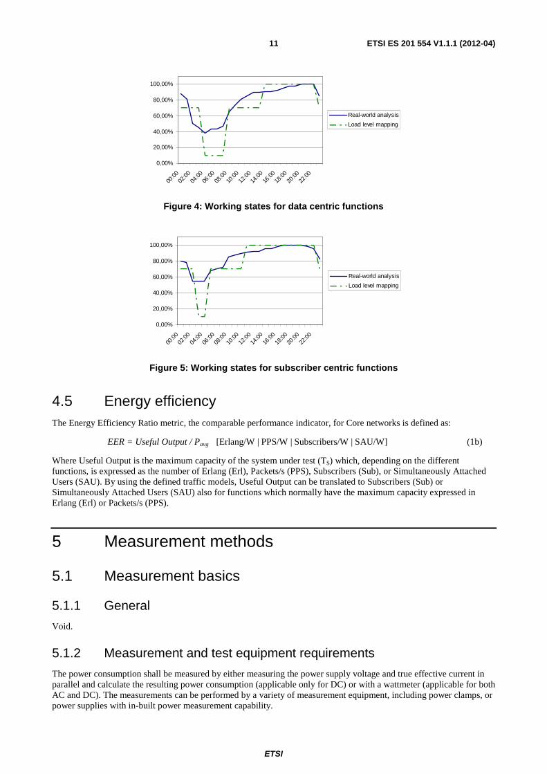
Figure 4: Working states for data centric functions
0,00%
20,00%
40,00%
60,00%
80,00%
100,00%
00:00
02:00
04:00
06:00
08:00
10:00
12:00
14:00
16:00
18:00
20:00
22:00
Real-world analysis
Load level mapping
Figure 5: Working states for subscriber centric functions
4.5 Energy efficiency The Energy Efficiency Ratio metric, the comparable performance indicator, for Core networks is defined as:
EER = Useful Output / Pavg [Erlang/W | PPS/W | Subscribers/W | SAU/W] (1b)
Where Useful Output is the maximum capacity of the system under test (TS) which, depending on the different functions, is expressed as the number of Erlang (Erl), Packets/s (PPS), Subscribers (Sub), or Simultaneously Attached Users (SAU). By using the defined traffic models, Useful Output can be translated to Subscribers (Sub) or Simultaneously Attached Users (SAU) also for functions which normally have the maximum capacity expressed in Erlang (Erl) or Packets/s (PPS).
5 Measurement methods
5.1 Measurement basics
5.1.1 General
Void.
5.1.2 Measurement and test equipment requirements
The power consumption shall be measured by either measuring the power supply voltage and true effective current in parallel and calculate the resulting power consumption (applicable only for DC) or with a wattmeter (applicable for both AC and DC). The measurements can be performed by a variety of measurement equipment, including power clamps, or power supplies with in-built power measurement capability.

ETSI
ETSI ES 201 554 V1.1.1 (2012-04) 12
All measurement equipments shall be calibrated and shall have data output interface in order to allow long term data recording and calculation of the complete power consumption over a dedicated time.
The measurement equipment shall comply with following attributes:
• Resolution: ≤ 10 mA; ≤ 100 mV; ≤ 100 mW
• DC current: ±1,5 %
• DC voltage: ±1 %
• Wattmeter: ±1 %
• Capable of accurate reading of waveforms having a crest factor of up to at least 5
All nodes shall be stimulated via the standard interfaces by the emulation of the test-models in conjunction with the traffic models and reference parameters given in annexes A to G.
5.2 Measurement conditions
5.2.1 Configuration
All equipment part of the system under test shall be generally available and orderable by customers. All configurations shall be done before the test and shall not be changed or updated during the test suite.
Only Power saving features considered as generally available may be used during the measurement. All used Power saving features shall be listed in the measurement report.
The equipment shall be measured and tested under - according to the information accompanying the equipment - normal operational conditions. Used versions of SW, firmware, HW and other test configurations shall represent the normal intended usage and be listed in the measurement report.
All signaling requested for normal operation shall be activated. Traffic profile data needed in addition to the traffic models specified in the present document, shall be listed in the measurement report.
5.2.2 Environmental conditions
For the power consumption measurements the environmental conditions under which the nodes have to be tested are defined as follows.
Table 2
Condition Minimum Maximum Barometric pressure 86 kPa (860 mbar) 106 kPa (1 050 mbar)
Relative Humidity 20 % 85 % Vibration Negligible
Temperature +25 °C Temperature accuracy ±2 °C
5.2.3 Power supply
For measurements of the nodes power consumption the following operating voltage value shall be used (for non standard power supply voltages one should use operating voltage with ±2,5 % tolerances).
Table 3
Type Standard Nominal value Operating value for testing DC EN 300 132-2 [1] -48 V -54,5 V ± 1,5 V
ETSI
ETSI ES 201 554 V1.1.1 (2012-04) 13
5.3 Measurement procedure
5.3.1 Tests to be performed
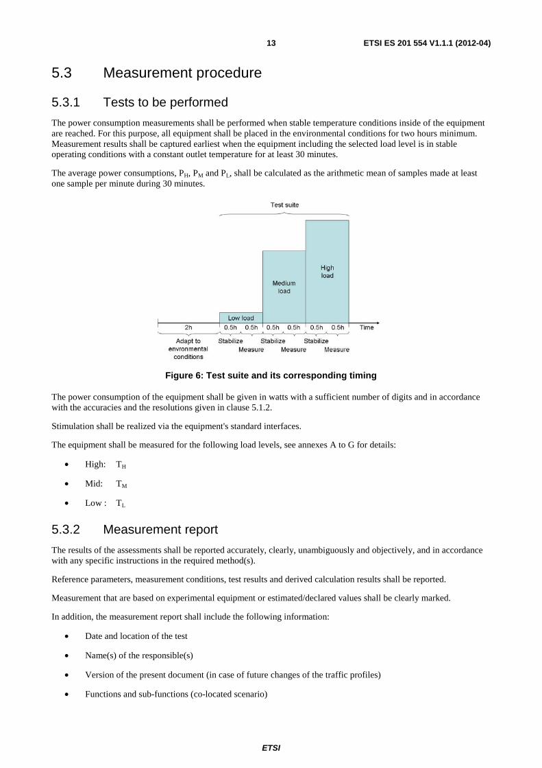
The power consumption measurements shall be performed when stable temperature conditions inside of the equipment are reached. For this purpose, all equipment shall be placed in the environmental conditions for two hours minimum. Measurement results shall be captured earliest when the equipment including the selected load level is in stable operating conditions with a constant outlet temperature for at least 30 minutes.
The average power consumptions, PH, PM and PL, shall be calculated as the arithmetic mean of samples made at least one sample per minute during 30 minutes.
Figure 6: Test suite and its corresponding timing
The power consumption of the equipment shall be given in watts with a sufficient number of digits and in accordance with the accuracies and the resolutions given in clause 5.1.2.
Stimulation shall be realized via the equipment's standard interfaces.
The equipment shall be measured for the following load levels, see annexes A to G for details:
• High: TH
• Mid: TM
• Low : TL
5.3.2 Measurement report
The results of the assessments shall be reported accurately, clearly, unambiguously and objectively, and in accordance with any specific instructions in the required method(s).
Reference parameters, measurement conditions, test results and derived calculation results shall be reported.
Measurement that are based on experimental equipment or estimated/declared values shall be clearly marked.
In addition, the measurement report shall include the following information:
• Date and location of the test
• Name(s) of the responsible(s)
• Version of the present document (in case of future changes of the traffic profiles)
• Functions and sub-functions (co-located scenario)
ETSI
ETSI ES 201 554 V1.1.1 (2012-04) 14
• The maximum capacity TS
• Redundancy level
• Model(s) and serial/version number(s) of the equipment/modules (HW/SW)
• Data of the used measurement equipment (type, serial number, calibration information)
• Samples of measurements of PH, PM and PL, respectively
• Calculations of PH, PM, PL and Pavg, respectively
• The calculated Energy Efficiency Ratio, EER
• Error statistics
Further guidelines on the test report can be found in clause 5.10 of ISO/IEC 17025 [2].
ETSI
ETSI ES 201 554 V1.1.1 (2012-04) 15
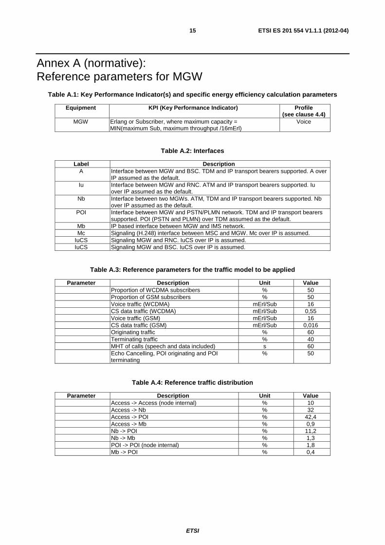
Annex A (normative): Reference parameters for MGW
Table A.1: Key Performance Indicator(s) and specific energy efficiency calculation parameters
Equipment KPI (Key Performance Indicator) Profile (see clause 4.4)
MGW Erlang or Subscriber, where maximum capacity = MIN(maximum Sub, maximum throughput /16mErl)
Voice
Table A.2: Interfaces
Label Description A Interface between MGW and BSC. TDM and IP transport bearers supported. A over
IP assumed as the default. Iu Interface between MGW and RNC. ATM and IP transport bearers supported. Iu
over IP assumed as the default. Nb Interface between two MGWs. ATM, TDM and IP transport bearers supported. Nb
over IP assumed as the default. POI Interface between MGW and PSTN/PLMN network. TDM and IP transport bearers
supported. POI (PSTN and PLMN) over TDM assumed as the default. Mb IP based interface between MGW and IMS network. Mc Signaling (H.248) interface between MSC and MGW. Mc over IP is assumed.
IuCS Signaling MGW and RNC. IuCS over IP is assumed. IuCS Signaling MGW and BSC. IuCS over IP is assumed.
Table A.3: Reference parameters for the traffic model to be applied
Parameter Description Unit Value Proportion of WCDMA subscribers % 50 Proportion of GSM subscribers % 50 Voice traffic (WCDMA) mErl/Sub 16 CS data traffic (WCDMA) mErl/Sub 0,55 Voice traffic (GSM) mErl/Sub 16 CS data traffic (GSM) mErl/Sub 0,016 Originating traffic % 60 Terminating traffic % 40 MHT of calls (speech and data included) s 60 Echo Cancelling, POI originating and POI
terminating % 50
Table A.4: Reference traffic distribution
Parameter Description Unit Value Access -> Access (node internal) % 10 Access -> Nb % 32 Access -> POI % 42,4 Access -> Mb % 0,9 Nb -> POI % 11,2 Nb -> Mb % 1,3 POI -> POI (node internal) % 1,8 Mb -> POI % 0,4
ETSI
ETSI ES 201 554 V1.1.1 (2012-04) 16
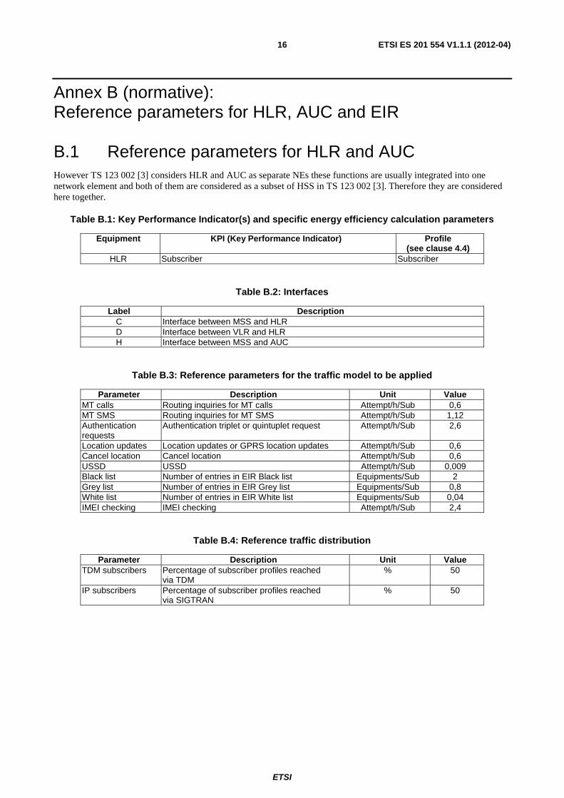
Annex B (normative): Reference parameters for HLR, AUC and EIR
B.1 Reference parameters for HLR and AUC However TS 123 002 [3] considers HLR and AUC as separate NEs these functions are usually integrated into one network element and both of them are considered as a subset of HSS in TS 123 002 [3]. Therefore they are considered here together.
Table B.1: Key Performance Indicator(s) and specific energy efficiency calculation parameters
Equipment KPI (Key Performance Indicator) Profile (see clause 4.4)
HLR Subscriber Subscriber
Table B.2: Interfaces
Label Description C Interface between MSS and HLR D Interface between VLR and HLR H Interface between MSS and AUC
Table B.3: Reference parameters for the traffic model to be applied
Parameter Description Unit Value MT calls Routing inquiries for MT calls Attempt/h/Sub 0,6 MT SMS Routing inquiries for MT SMS Attempt/h/Sub 1,12 Authentication requests
Authentication triplet or quintuplet request Attempt/h/Sub 2,6
Location updates Location updates or GPRS location updates Attempt/h/Sub 0,6 Cancel location Cancel location Attempt/h/Sub 0,6 USSD USSD Attempt/h/Sub 0,009 Black list Number of entries in EIR Black list Equipments/Sub 2 Grey list Number of entries in EIR Grey list Equipments/Sub 0,8 White list Number of entries in EIR White list Equipments/Sub 0,04 IMEI checking IMEI checking Attempt/h/Sub 2,4
Table B.4: Reference traffic distribution
Parameter Description Unit Value TDM subscribers Percentage of subscriber profiles reached
via TDM % 50
IP subscribers Percentage of subscriber profiles reached via SIGTRAN
% 50
ETSI
ETSI ES 201 554 V1.1.1 (2012-04) 17
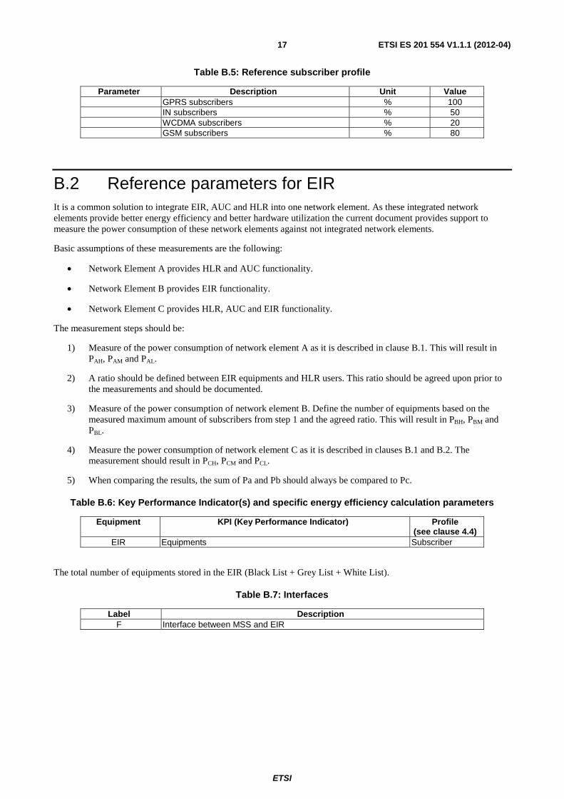
Table B.5: Reference subscriber profile
Parameter Description Unit Value GPRS subscribers % 100 IN subscribers % 50 WCDMA subscribers % 20 GSM subscribers % 80
B.2 Reference parameters for EIR It is a common solution to integrate EIR, AUC and HLR into one network element. As these integrated network elements provide better energy efficiency and better hardware utilization the current document provides support to measure the power consumption of these network elements against not integrated network elements.
Basic assumptions of these measurements are the following:
• Network Element A provides HLR and AUC functionality.
• Network Element B provides EIR functionality.
• Network Element C provides HLR, AUC and EIR functionality.
The measurement steps should be:
1) Measure of the power consumption of network element A as it is described in clause B.1. This will result in PAH, PAM and PAL.
2) A ratio should be defined between EIR equipments and HLR users. This ratio should be agreed upon prior to the measurements and should be documented.
3) Measure of the power consumption of network element B. Define the number of equipments based on the measured maximum amount of subscribers from step 1 and the agreed ratio. This will result in PBH, PBM and PBL.
4) Measure the power consumption of network element C as it is described in clauses B.1 and B.2. The measurement should result in PCH, PCM and PCL.
5) When comparing the results, the sum of Pa and Pb should always be compared to Pc.
Table B.6: Key Performance Indicator(s) and specific energy efficiency calculation parameters
Equipment KPI (Key Performance Indicator) Profile (see clause 4.4)
EIR Equipments Subscriber
The total number of equipments stored in the EIR (Black List + Grey List + White List).
Table B.7: Interfaces
Label Description F Interface between MSS and EIR
ETSI
ETSI ES 201 554 V1.1.1 (2012-04) 18
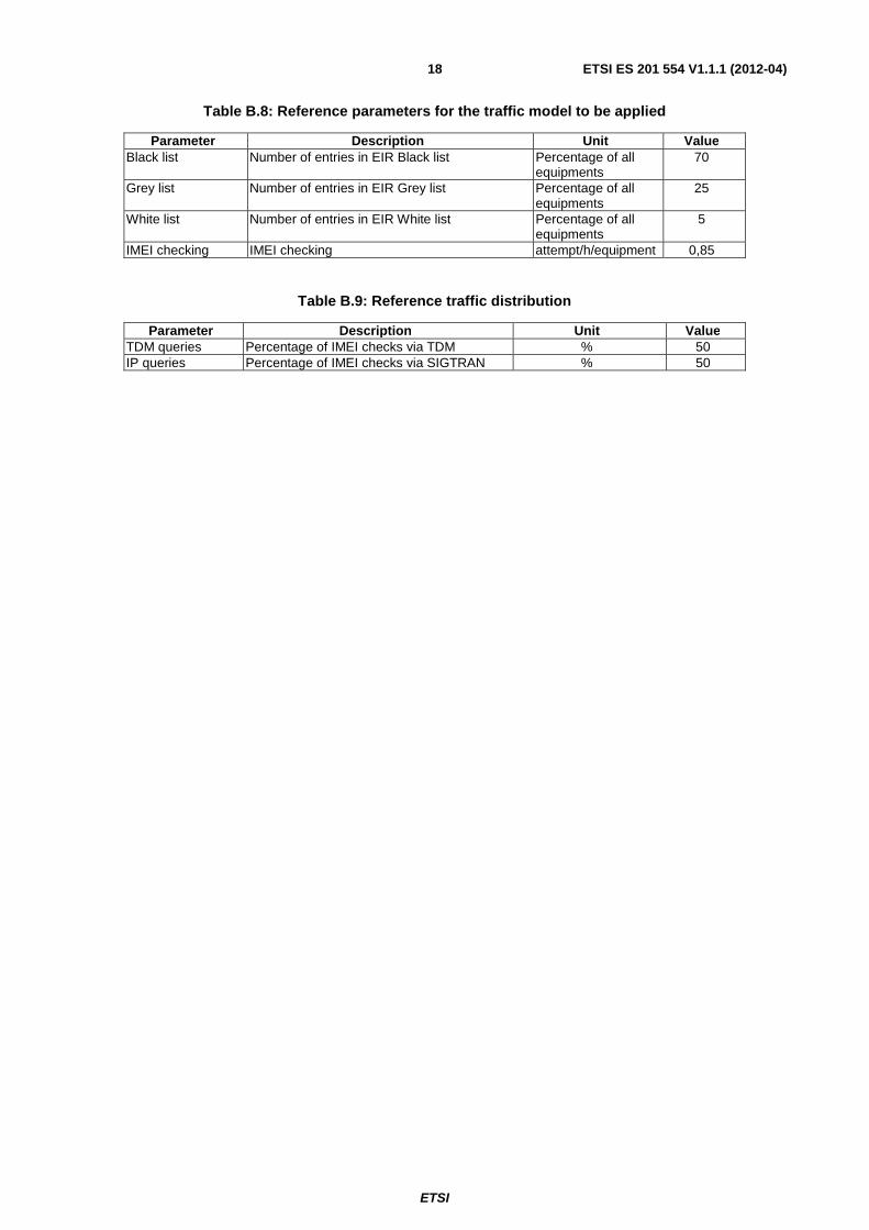
Table B.8: Reference parameters for the traffic model to be applied
Parameter Description Unit Value Black list Number of entries in EIR Black list Percentage of all
equipments 70
Grey list Number of entries in EIR Grey list Percentage of all equipments
25
White list Number of entries in EIR White list Percentage of all equipments
5
IMEI checking IMEI checking attempt/h/equipment 0,85
Table B.9: Reference traffic distribution
Parameter Description Unit Value TDM queries Percentage of IMEI checks via TDM % 50 IP queries Percentage of IMEI checks via SIGTRAN % 50
ETSI
ETSI ES 201 554 V1.1.1 (2012-04) 19
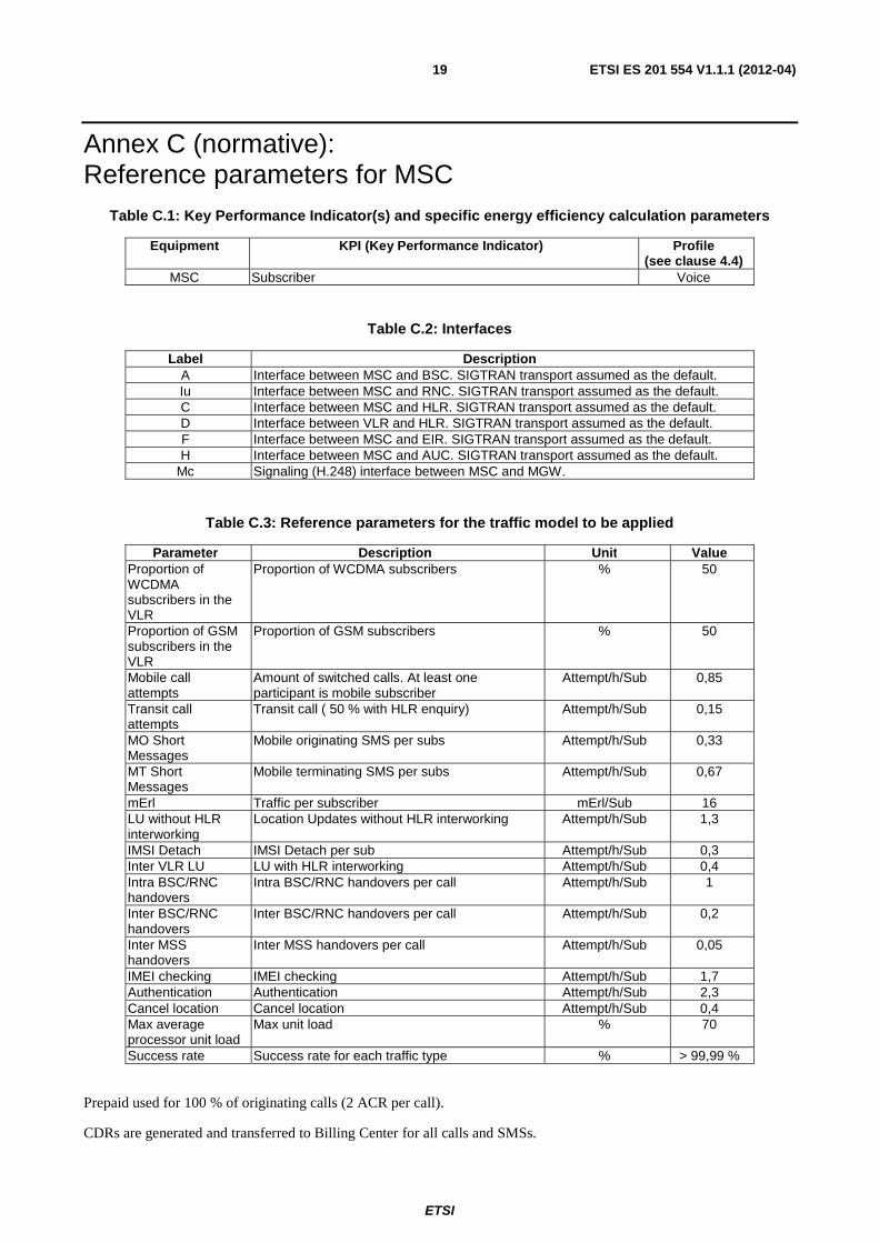
Annex C (normative): Reference parameters for MSC
Table C.1: Key Performance Indicator(s) and specific energy efficiency calculation parameters
Equipment KPI (Key Performance Indicator) Profile (see clause 4.4)
MSC Subscriber Voice
Table C.2: Interfaces
Label Description A Interface between MSC and BSC. SIGTRAN transport assumed as the default. Iu Interface between MSC and RNC. SIGTRAN transport assumed as the default. C Interface between MSC and HLR. SIGTRAN transport assumed as the default. D Interface between VLR and HLR. SIGTRAN transport assumed as the default. F Interface between MSC and EIR. SIGTRAN transport assumed as the default. H Interface between MSC and AUC. SIGTRAN transport assumed as the default.
Mc Signaling (H.248) interface between MSC and MGW.
Table C.3: Reference parameters for the traffic model to be applied
Parameter Description Unit Value Proportion of WCDMA subscribers in the VLR
Proportion of WCDMA subscribers % 50
Proportion of GSM subscribers in the VLR
Proportion of GSM subscribers % 50
Mobile call attempts
Amount of switched calls. At least one participant is mobile subscriber
Attempt/h/Sub 0,85
Transit call attempts
Transit call ( 50 % with HLR enquiry) Attempt/h/Sub 0,15
MO Short Messages
Mobile originating SMS per subs Attempt/h/Sub 0,33
MT Short Messages
Mobile terminating SMS per subs Attempt/h/Sub 0,67
mErl Traffic per subscriber mErl/Sub 16 LU without HLR interworking
Location Updates without HLR interworking Attempt/h/Sub 1,3
IMSI Detach IMSI Detach per sub Attempt/h/Sub 0,3 Inter VLR LU LU with HLR interworking Attempt/h/Sub 0,4 Intra BSC/RNC handovers
Intra BSC/RNC handovers per call Attempt/h/Sub 1
Inter BSC/RNC handovers
Inter BSC/RNC handovers per call Attempt/h/Sub 0,2
Inter MSS handovers
Inter MSS handovers per call Attempt/h/Sub 0,05
IMEI checking IMEI checking Attempt/h/Sub 1,7 Authentication Authentication Attempt/h/Sub 2,3 Cancel location Cancel location Attempt/h/Sub 0,4 Max average processor unit load
Max unit load % 70
Success rate Success rate for each traffic type % > 99,99 %
Prepaid used for 100 % of originating calls (2 ACR per call).
CDRs are generated and transferred to Billing Center for all calls and SMSs.
ETSI
ETSI ES 201 554 V1.1.1 (2012-04) 20
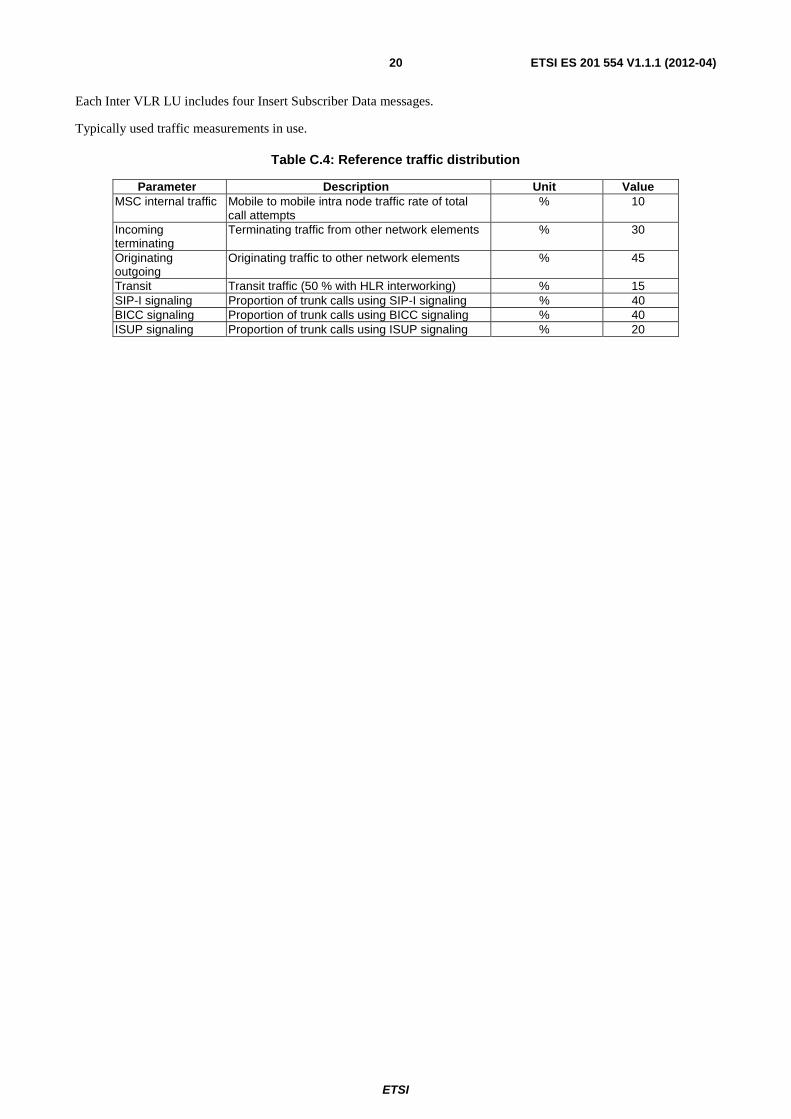
Each Inter VLR LU includes four Insert Subscriber Data messages.
Typically used traffic measurements in use.
Table C.4: Reference traffic distribution
Parameter Description Unit Value MSC internal traffic Mobile to mobile intra node traffic rate of total
call attempts % 10
Incoming terminating
Terminating traffic from other network elements % 30
Originating outgoing
Originating traffic to other network elements % 45
Transit Transit traffic (50 % with HLR interworking) % 15 SIP-I signaling Proportion of trunk calls using SIP-I signaling % 40 BICC signaling Proportion of trunk calls using BICC signaling % 40 ISUP signaling Proportion of trunk calls using ISUP signaling % 20
ETSI
ETSI ES 201 554 V1.1.1 (2012-04) 21
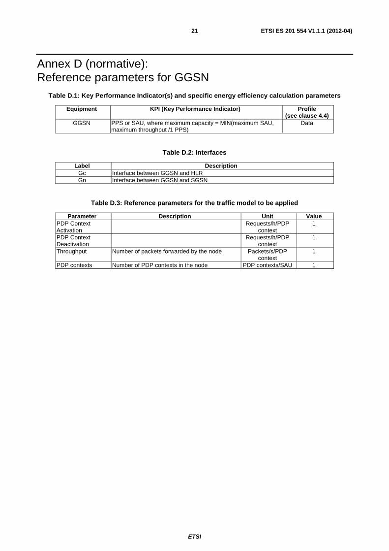
Annex D (normative): Reference parameters for GGSN
Table D.1: Key Performance Indicator(s) and specific energy efficiency calculation parameters
Equipment KPI (Key Performance Indicator) Profile (see clause 4.4)
GGSN PPS or SAU, where maximum capacity = MIN(maximum SAU, maximum throughput /1 PPS)
Data
Table D.2: Interfaces
Label Description Gc Interface between GGSN and HLR Gn Interface between GGSN and SGSN
Table D.3: Reference parameters for the traffic model to be applied
Parameter Description Unit Value PDP Context Activation
Requests/h/PDP context
1
PDP Context Deactivation
Requests/h/PDP context
1
Throughput Number of packets forwarded by the node Packets/s/PDP context
1
PDP contexts Number of PDP contexts in the node PDP contexts/SAU 1
ETSI
ETSI ES 201 554 V1.1.1 (2012-04) 22
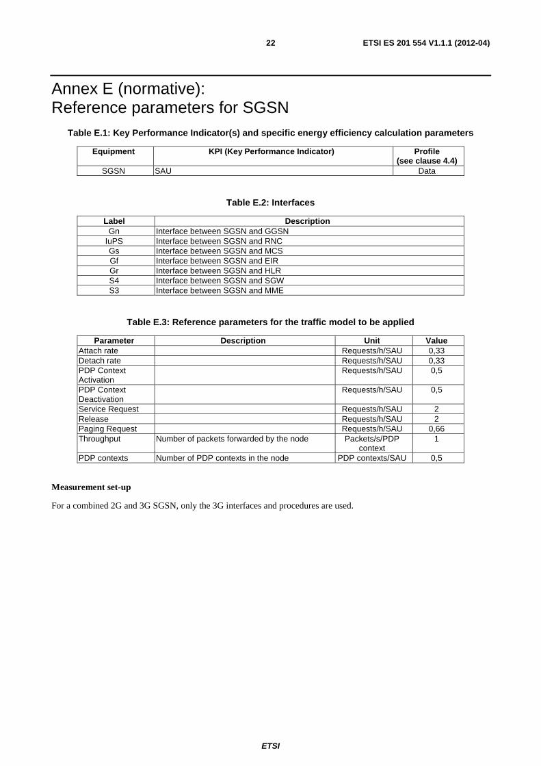
Annex E (normative): Reference parameters for SGSN
Table E.1: Key Performance Indicator(s) and specific energy efficiency calculation parameters
Equipment KPI (Key Performance Indicator) Profile (see clause 4.4)
SGSN SAU Data
Table E.2: Interfaces
Label Description Gn Interface between SGSN and GGSN
IuPS Interface between SGSN and RNC Gs Interface between SGSN and MCS Gf Interface between SGSN and EIR Gr Interface between SGSN and HLR S4 Interface between SGSN and SGW S3 Interface between SGSN and MME
Table E.3: Reference parameters for the traffic model to be applied
Parameter Description Unit Value Attach rate Requests/h/SAU 0,33 Detach rate Requests/h/SAU 0,33 PDP Context Activation
Requests/h/SAU 0,5
PDP Context Deactivation
Requests/h/SAU 0,5
Service Request Requests/h/SAU 2 Release Requests/h/SAU 2 Paging Request Requests/h/SAU 0,66 Throughput Number of packets forwarded by the node Packets/s/PDP
context 1
PDP contexts Number of PDP contexts in the node PDP contexts/SAU 0,5
Measurement set-up
For a combined 2G and 3G SGSN, only the 3G interfaces and procedures are used.
ETSI
ETSI ES 201 554 V1.1.1 (2012-04) 23
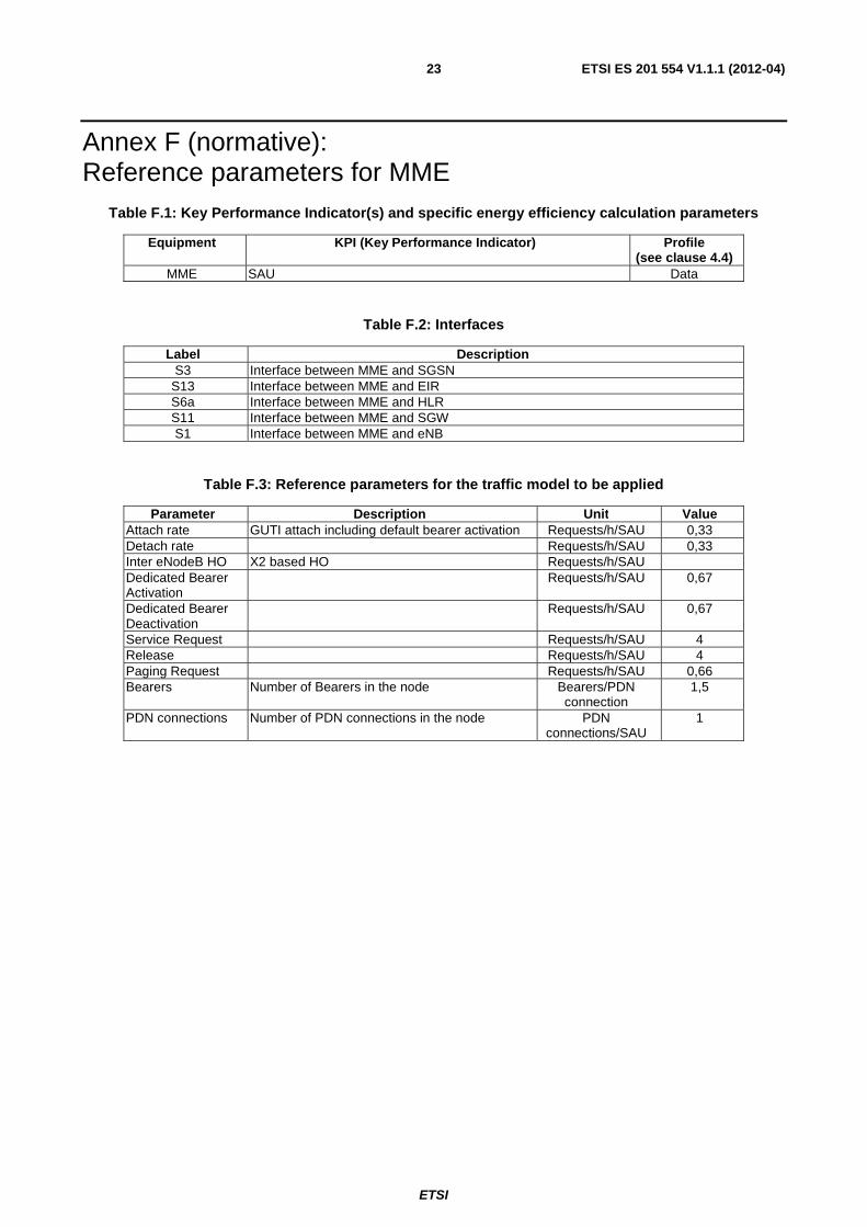
Annex F (normative): Reference parameters for MME
Table F.1: Key Performance Indicator(s) and specific energy efficiency calculation parameters
Equipment KPI (Key Performance Indicator) Profile (see clause 4.4)
MME SAU Data
Table F.2: Interfaces
Label Description S3 Interface between MME and SGSN
S13 Interface between MME and EIR S6a Interface between MME and HLR S11 Interface between MME and SGW S1 Interface between MME and eNB
Table F.3: Reference parameters for the traffic model to be applied
Parameter Description Unit Value Attach rate GUTI attach including default bearer activation Requests/h/SAU 0,33 Detach rate Requests/h/SAU 0,33 Inter eNodeB HO X2 based HO Requests/h/SAU Dedicated Bearer Activation
Requests/h/SAU 0,67
Dedicated Bearer Deactivation
Requests/h/SAU 0,67
Service Request Requests/h/SAU 4 Release Requests/h/SAU 4 Paging Request Requests/h/SAU 0,66 Bearers Number of Bearers in the node Bearers/PDN
connection 1,5
PDN connections Number of PDN connections in the node PDN connections/SAU
1
ETSI
ETSI ES 201 554 V1.1.1 (2012-04) 24
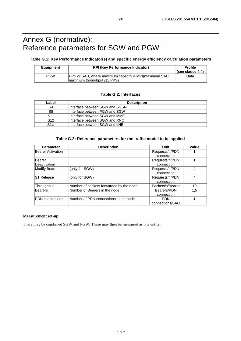
Annex G (normative): Reference parameters for SGW and PGW
Table G.1: Key Performance Indicator(s) and specific energy efficiency calculation parameters
Equipment KPI (Key Performance Indicator) Profile (see clause 4.4)
PGW PPS or SAU, where maximum capacity = MIN(maximum SAU, maximum throughput /15 PPS)
Data
Table G.2: Interfaces
Label Description S4 Interface between SGW and SGSN S5 Interface between PGW and SGW
S11 Interface between SGW and MME S12 Interface between SGW and RNC S1U Interface between SGW and eNB
Table G.3: Reference parameters for the traffic model to be applied
Parameter Description Unit Value Bearer Activation Requests/h/PDN
connection 1
Bearer Deactivation
Requests/h/PDN connection
1
Modify Bearer (only for SGW) Requests/h/PDN connection
4
S1 Release (only for SGW) Requests/h/PDN connection
4
Throughput Number of packets forwarded by the node Packets/s/Bearer 10 Bearers Number of Bearers in the node Bearers/PDN
connection 1,5
PDN connections Number of PDN connections in the node PDN connections/SAU
1
Measurement set-up
There may be combined SGW and PGW. These may then be measured as one entity.

ETSI
ETSI ES 201 554 V1.1.1 (2012-04) 25
Annex H (informative): Bibliography ETSI TR 102 530: "Environmental Engineering (EE); The reduction of energy consumption in telecommunications equipment and related infrastructure".

ETSI
ETSI ES 201 554 V1.1.1 (2012-04) 26
History
Document history
V1.1.1 February 2012 Membership Approval Procedure MV 20120415: 2012-02-15 to 2012-04-16
V1.1.1 April 2012 Publication
Related Documents