2-6 Service Manual 7525-xxx Go Back Previous Next Error codes and messages User status and attendance messages User status and attendance messages User primary message Explanation Busy Wait for the message to clear. Calibrating The printer is performing a color adjustment. Close Door Message clears when upper and lower doors are closed. Check Config ID The printer configuration ID is invalid. Check Model Name Message clears when a valid model name is set. Check Serial Num Message clears when a valid serial number is set. <color> Low Replace the toner cartridge, and then wait for the message to clear. Defragmenting Flash DO NOT POWER OFF The printer is performing the defragmentation operation of flash memory. Wait for the message to clear. Warning: Do not turn the printer off while this message appears on the display. Flushing buffer Wait for the message to clear. Formatting Flash DO NOT POWER OFF Wait for the message to appear. Warning: Do not turn the printer off while this message appears on the display. Hex Trace This message appears between status messages and warnings. Wait for the message to clear. Imaging Kit Replace the imaging kit, and then press Select ( ) to clear the message and continue printing. Insert Tray <x> This message is displayed when the printer requests the user to insert tray x before it can continue printing the job. The printer needs to pick media from the missing tray or the trays below it. Tray x=Tray 1, Tray 2, Tray 3 Note: This message displays when refilling the trays during a job. Before filling tray a tray, take the printer offline by pressing Stop , and wait for pages to stop feeding into the output bin. The following actions can be taken: • Insert the requested tray. • Cancel the current job No Analog Phone Line An analog line is not detected as being plugged into the modem. If the device is in Analog mode, this has a source of Fax. If the device is in Fax Server mode, and the 'Enable analog receive' Fax Server setting is set to 'On', this has a source of Fax Receive. If the device is in Fax Server mode and the 'Enable analog receive' Fax Server setting is set to 'Off', then this IR is not generated. Memory Full, cannot send faxes After a start, there is no memory to do the fax job. Attempted fax is cancelled. Insert Duplex Page in Tray <x> Reload printed page in tray <x>. Cancel Job appears if the job can be cancelled. Install Tray <x> or Cancel job Printer detects that tray <x> is missing, where x is 1 or 2. This message appears if the job was begun, but the paper has not yet been retrieved. The tray is no longer detected. Replace the indicated tray. Load <source> <custom string> Printer does not detect media meeting the description <custom string> in <source>, where <source> is Tray 1, Tray 2, Tray 3, Multi-Page Feeder (MP feeder), or Envelope Feeder. • Load the input source with the correct type and size media. • Cancel the current job.

Welcome message from author
This document is posted to help you gain knowledge. Please leave a comment to let me know what you think about it! Share it to your friends and learn new things together.
Transcript
2-6 Service Manual
7525-xxx
Go Back
Previous
Next
Error codes and messages
User status and attendance messages
User status and attendance messages
User primary message Explanation
Busy Wait for the message to clear.
Calibrating The printer is performing a color adjustment.
Close Door Message clears when upper and lower doors are closed.
Check Config ID The printer configuration ID is invalid.
Check Model Name Message clears when a valid model name is set.
Check Serial Num Message clears when a valid serial number is set.
<color> Low Replace the toner cartridge, and then wait for the message to clear.
Defragmenting FlashDO NOT POWER OFF
The printer is performing the defragmentation operation of flash memory. Wait for the message to clear.
Warning: Do not turn the printer off while this message appears on the display.
Flushing buffer Wait for the message to clear.
Formatting FlashDO NOT POWER OFF
Wait for the message to appear.
Warning: Do not turn the printer off while this message appears on the display.
Hex Trace This message appears between status messages and warnings. Wait for the message to clear.
Imaging Kit Replace the imaging kit, and then press Select ( ) to clear the message and continue printing.
Insert Tray <x> This message is displayed when the printer requests the user to insert tray x before it can continue printing the job. The printer needs to pick media from the missing tray or the trays below it.
Tray x=Tray 1, Tray 2, Tray 3
Note: This message displays when refilling the trays during a job. Before filling tray a tray, take the printer offline by pressing Stop , and wait for pages to stop feeding into the output bin.
The following actions can be taken:
• Insert the requested tray.• Cancel the current job
No Analog Phone Line An analog line is not detected as being plugged into the modem. If the device is in Analog mode, this has a source of Fax. If the device is in Fax Server mode, and the 'Enable analog receive' Fax Server setting is set to 'On', this has a source of Fax Receive. If the device is in Fax Server mode and the 'Enable analog receive' Fax Server setting is set to 'Off', then this IR is not generated.
Memory Full, cannot send faxes
After a start, there is no memory to do the fax job. Attempted fax is cancelled.
Insert Duplex Page in Tray <x>
Reload printed page in tray <x>. Cancel Job appears if the job can be cancelled.
Install Tray <x> or Cancel job
Printer detects that tray <x> is missing, where x is 1 or 2. This message appears if the job was begun, but the paper has not yet been retrieved. The tray is no longer detected. Replace the indicated tray.
Load <source> <custom string>
Printer does not detect media meeting the description <custom string> in <source>, where <source> is Tray 1, Tray 2, Tray 3, Multi-Page Feeder (MP feeder), or Envelope Feeder.
• Load the input source with the correct type and size media.• Cancel the current job.
Diagnostic information 2-7
7525-xxx
Go Back
Previous
Next
Load <source> <custom type>
Printer does not detect media meeting the description <custom type> in <source>, where <source> is Tray 1 or Tray 2, Tray 3.
• Load the input source with the correct type and size media.• Cancel the current job.
Load <source><size>
Printer does not detect media meeting the size requested in the source indicated.
• Load the input source with the correct type and size media.• Cancel the current job.
Load <source> <type> <size>
Printer does not detect media meeting the size or type requested in the source indicated.
• Load the input source with the correct type and size media.• Cancel the current job.
Load single sheet <custom type>
Printer does not detect media meeting the description <custom type> in the single sheet feeder (manual feeder).
The following actions can be taken:
• Load paper, and the job continues.• press Select ( ), and choose an alternate source for media.• Cancel the current job.
Load single sheet <custom string>
Printer does not detect media meeting the description <custom string> in the single sheet feeder (manual feeder).
The following actions can be taken:
• Load paper and the job continues.• press Select ( ), and choose an alternate source for media.• Cancel the current job.
Load single sheet <size>
Printer does not detect media meeting the description <size> in the single sheet feeder (manual feeder).
The following actions can be taken:
• Load paper and the job continues.• press Select ( ), and choose an alternate source for media.• Cancel the current job.
Load single sheet <type> <size>
Printer does not detect media meeting the description <type> and <size> in the single sheet feeder (manual feeder).
The following actions can be taken:
• Load paper and the job continues.• press Select ( ), and choose an alternate source for media.• Cancel the current job.
PJL ST Message Try one or more of the following:
• press Select ( ) to clear the message, and continue printing.• Wait for the message to clear.
Power Saver The printer is saving power while it waits for the next print job.
• Send a job to print.• Press Select ( ) to warm the printer to normal operating temperature.
Afterwards, Ready appears.
Programming Code The printer is receiving a file that is a code update. Wait for the message to clear.
Warning—Potential Damage: Do not turn the printer off while this message appears on the display.
Programming Flash Fonts and macros are being written to flash. Wait for the message to clear.
Ready The printer is ready to print.
User status and attendance messages (continued)
User primary message Explanation
2-8 Service Manual
7525-xxx
Go Back
Previous
Next
Remove Paper ADF This posts when there is paper detected in the ADF upon POR or when the cover is closed (or any other situation that re-inits the scanner). Message clears when paper is removed.
Remove Paper Standard Bin
The standard output bin is full or nearly full. Remove the media from the bin.
Remove PackagingMaterial
Packaging material is detected by the printer. Remove the packaging material and press Continue.
Unplug and Change Mode
Camera is not in a proper mode to use the PictBridge feature. Unplug the camera cable to the printer, and change the camera mode.
Replace Black Imaging Unit
Replace the Black Imaging Unit.
Replace Color Imaging Unit
Replace the Color Imaging Unit.
Replace <color> Cartridge
Replace the toner cartridge of the indicated color. The printer continues after the toner door is closed.
Std Bin Full The following actions can be taken:
• Remove paper from the standard exit bin to clear the message and continue printing.
• Press Select ( ) to clear the message and continue printing.
Tray <x> Empty The following actions can be taken:
• Load the paper tray or other source with the correct paper type and size.• Press Stop ( ) and then press Select ( ) to cancel the current job.
Tray <x> Low Load the paper tray or other source with the correct paper type and size.
Tray <x> Missing Insert the specified tray into the printer.
Unplug and Change Mode
Camera is not in a proper mode to use the PictBridge feature. Unplug the camera cable to the printer, and change the camera mode.
Unsupported Mode Camera is not in a proper mode to use the Pict Bridge feature. Unplug the camera cable to the printer and change the camera mode.
Unsupported USB Device, Please Remove
Remove the unrecognized device from the USB port on the front of the printer.
Unsupported USB Hub, please remove
Remove the unrecognized USB hub/device from the USB port on the front of the printer.
Waiting The printer has received data to print, but is waiting for an End-of-job command, a Form Feed command, or additional data.
The following actions can be taken:
• Press Select ( ) to print the contents of the buffer.• Cancel the current print job.
Waiting, too many events
Wait for the message to clear.
Warning—Potential Damage: Do not turn the printer off while this message appears on the display.
Waste Toner Box The waste toner bottle is nearly full. Press Select ( ) to clear the message and continue printing.
30.xx <color> Toner Cart Missing
The specified toner cartridge is missing. Re-install the missing toner cartridge to clear the message, and then continue printing. If the message recurs remove and re-install the cartridge. Listen for the click to ensure the cartridge is installed properly. Close the front cover.
User status and attendance messages (continued)
User primary message Explanation
Diagnostic information 2-9
7525-xxx
Go Back
Previous
Next
31.xx Defective <color> cartridge
The specified cartridge is defective. Try one of the following:
• Open and close the top cover.• Remove and re-install the cartridge(s). Listen for the click to ensure the cartridge
is installed properly.• Turn the printer power off and turn the printer power on.
If the message persists, replace the cartridge with a new one, and close the front cover.
31.xx Defective Imaging Kit.
Defective imaging kit. Try one or more of the following:
• Open and close the top cover.• Remove and re-install the cartridge(s). Listen for the click to ensure the cartridge
is installed properly.• Turn the printer power off, and then turn the printer power on.
If the message persists, determine if the imaging kit counter is greater than 15,000 cycles. It it is, then replace the entire kit. See “Imaging unit (IU) removal” on page 4-45. If the counter is below 250,000 cycles, replace only the photoconductors.
32.xx Replace unsupported <color> Cartridge
Remove the specified cartridge, replace with a supported cartridge, and close the front cover.
34 Short Paper • press Select ( ) to clear the message and continue printing.The printer does not automatically reprint the page that prompted the message.
• Check tray length and width guides to ensure paper is properly fitted in the tray.• Make sure the print job is requesting the correct size of paper.• Adjust the Paper Size setting for the size paper you are using.
If MP Feeder Size is set to Universal, make sure the paper is large enough for the formatted data.
• Cancel the current job.
35 RES Save Off Deficient Memory
This message displays when the printer lacks sufficient memory to enable Resource Save. This message usually indicates the user has allocated too much memory for one or more of the printer link buffers; however, modification of other printer settings which affect the amount of available memory may also create this condition. If restoration of Resource Save is required after this message is received, the customer should install additional memory or set each link buffer to Auto. Once all link buffers are returned to Auto, you should exit the menu to activate the link buffer changes. Once the printer returns to the Ready state, you can enable Resource Save and go back and modify the link buffers again. Note the reduction of available memory to the link buffers when Resource Save has been enabled, and compare it to the memory available when Resource Save is disabled.
• press Select ( ) to disable Resource Save and continue printing.To enable Resource Save after you get this message:
- Make sure the link buffers are set to Auto, then exit the menus to activate the link buffer changes.
- When Ready is displayed, enable Resource Save.• Install additional memory.
37 Insufficient Collation Area
This message is displayed when the printer memory used to store pages is too full to collate the print job.
The following actions can be taken:
• press Select ( ) to print the portion of the job already stored, and begin collating the rest of the job.
• press Menus ( ) to access the Busy/Waiting Menu. The following functions are available.
- Cancel JobNote: Menu Lockout does NOT prevent access to the Busy/Waiting Menu.
User status and attendance messages (continued)
User primary message Explanation
2-10 Service Manual
7525-xxx
Go Back
Previous
Next
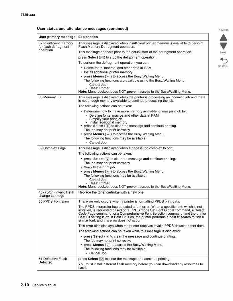
37 Insufficient memory for flash defragment operation
This message is displayed when insufficient printer memory is available to perform Flash Memory Defragment operation.
This message appears prior to the actual start of the defragment operation.
press Select ( ) to stop the defragment operation.
To perform the defragment operation, you can:
• Delete fonts, macros, and other data in RAM.• Install additional printer memory.• press Menus ( ) to access the Busy/Waiting Menu.
The following functions are available using the Busy/Waiting Menu:- Cancel Job- Reset Printer
Note: Menu Lockout does NOT prevent access to the Busy/Waiting Menu.
38 Memory Full This message is displayed when the printer is processing an incoming job and there is not enough memory available to continue processing the job.
The following actions can be taken:
• Determine how to make more memory available to your print job by:- Deleting fonts, macros and other data in RAM.- Simplify your print job.- Install additional memory
• press Select ( ) to clear the message and continue printing.The job may not print correctly.
• press Menus ( ) to access the Busy/Waiting Menu.The following functions may be available:
- Cancel Job
39 Complex Page This message is displayed when a page is too complex to print.
The following actions can be taken:
• press Select ( to clear the message and continue printing.The job may not print correctly.
• Simplify the print job.• press Menus ( ) to access the Busy/Waiting Menu.
The following functions may be available:- Cancel Job- Reset Printer
Note: Menu Lockout does NOT prevent access to the Busy/Waiting Menu.
40 <color> Invalid Refill, change cartridge
Replace the toner cartridge with a new one.
50 PPDS Font Error This error only occurs when a printer is formatting PPDS print data.
The PPDS interpreter has detected a font error. When a specific font, which is not installed, is requested based on a PPDS mode Set Font Global command, a Select Code Page command, or a Comprehensive Font Selection command, and the printer Best Fit setting is off. If Best Fit is on, the printer performs a best fit search to find a similar font, and this error does not occur.
This error also displays when the printer receives invalid PPDS download font data.
The following actions can be taken while this message is displayed:
• press Select ( to clear the message and continue printing.The job may not print correctly.
• press Menus ( to access the Busy/Waiting Menu.The following functions may be available:
- Cancel Job
51 Defective Flash Detected
press Select ( to clear the message and continue printing.
You must install different flash memory before you can download any resources to flash.
User status and attendance messages (continued)
User primary message Explanation
Diagnostic information 2-11
7525-xxx
Go Back
Previous
Next
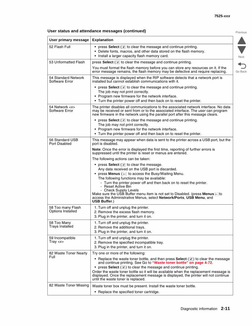
52 Flash Full • press Select ( to clear the message and continue printing.• Delete fonts, macros, and other data stored on the flash memory.• Install a larger capacity flash memory card.
53 Unformatted Flash press Select ( to clear the message and continue printing.
You must format the flash memory before you can store any resources on it. If the error message remains, the flash memory may be defective and require replacing.
54 Standard Network Software Error
This message is displayed when the RIP software detects that a network port is installed but cannot establish communications with it.
• press Select ( to clear the message and continue printing.The job may not print correctly.
• Program new firmware for the network interface.• Turn the printer power off and then back on to reset the printer.
54 Network <x> Software Error
The printer disables all communications to the associated network interface. No data may be received or sent from or to the associated interface. The user can program new firmware in the network using the parallel port after this message clears.
• press Select ( to clear the message and continue printing.The job may not print correctly.
• Program new firmware for the network interface.• Turn the printer power off and then back on to reset the printer.
56 Standard USB Port Disabled
This message may appear when data is sent to the printer across a USB port, but the port is disabled.
Note: Once the error is displayed the first time, reporting of further errors is suppressed until the printer is reset or menus are entered.
The following actions can be taken:
• press Select ( to clear the message.Any data received on the USB port is discarded.
• press Menus ( to access the Busy/Waiting Menu.The following functions may be available:
- Turn the printer power off and then back on to reset the printer.- Reset Active Bin- Check Supply Levels
Make sure the USB Buffer menu item is not set to Disabled. (press Menus to access the Administrative Menus, select Network/Ports, USB Menu, and USB Buffer.)
58 Too many Flash Options Installed
1. Turn off and unplug the printer.2. Remove the excess flash memory.3. Plug in the printer, and turn it on.
58 Too Many Trays Installed
1. Turn off and unplug the printer.2. Remove the additional trays.3. Plug in the printer, and turn it on.
59 Incompatible Tray <x>
1. Turn off and unplug the printer.2. Remove the specified incompatible tray.3. Plug in the printer, and turn it on.
82 Waste Toner Nearly Full
Try one or more of the following:
• Replace the waste toner bottle, and then press Select ( ) to clear the message and continue printing. See Go to “Waste toner bottle” on page 4-72.
• press Select ( ) to clear the message and continue printing.Order the waste toner bottle so it will be available when the replacement message is displayed. Once the replacement message is displayed, the printer will not continue until the waste toner is replaced.
82 Waste Toner Missing Waste toner box must be present. Install the waste toner bottle.
• Replace the specified toner cartridge.
User status and attendance messages (continued)
User primary message Explanation
2-12 Service Manual
7525-xxx
Go Back
Previous
Next
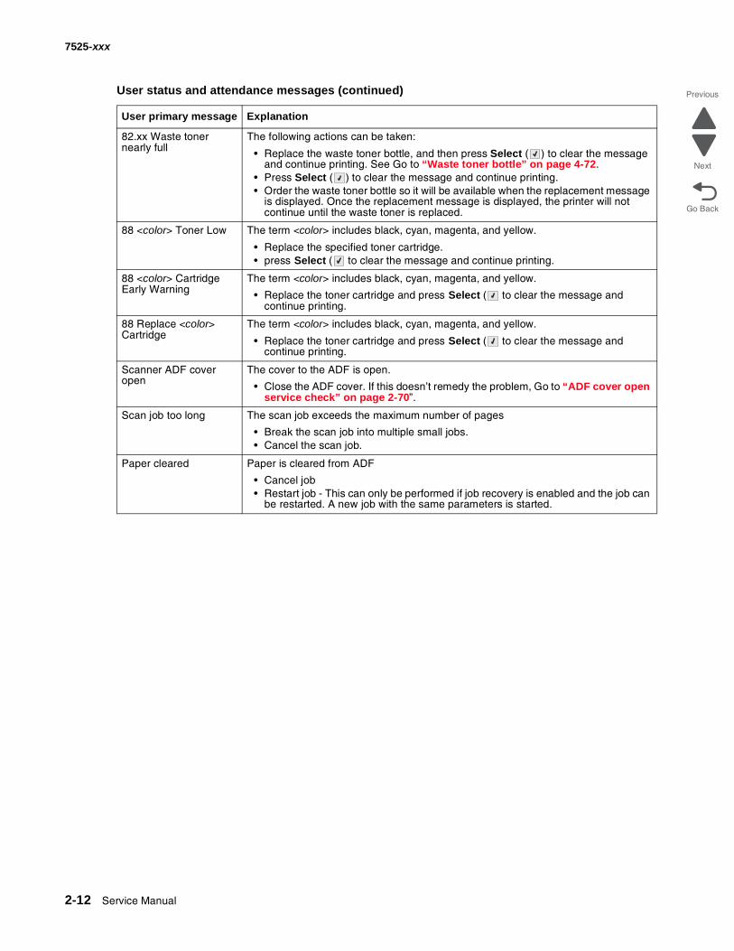
82.xx Waste toner nearly full
The following actions can be taken:
• Replace the waste toner bottle, and then press Select ( ) to clear the message and continue printing. See Go to “Waste toner bottle” on page 4-72.
• Press Select ( ) to clear the message and continue printing.• Order the waste toner bottle so it will be available when the replacement message
is displayed. Once the replacement message is displayed, the printer will not continue until the waste toner is replaced.
88 <color> Toner Low The term <color> includes black, cyan, magenta, and yellow.
• Replace the specified toner cartridge.• press Select ( to clear the message and continue printing.
88 <color> Cartridge Early Warning
The term <color> includes black, cyan, magenta, and yellow.
• Replace the toner cartridge and press Select ( to clear the message and continue printing.
88 Replace <color> Cartridge
The term <color> includes black, cyan, magenta, and yellow.
• Replace the toner cartridge and press Select ( to clear the message and continue printing.
Scanner ADF cover open
The cover to the ADF is open.
• Close the ADF cover. If this doesn’t remedy the problem, Go to “ADF cover open service check” on page 2-70”.
Scan job too long The scan job exceeds the maximum number of pages
• Break the scan job into multiple small jobs.• Cancel the scan job.
Paper cleared Paper is cleared from ADF
• Cancel job• Restart job - This can only be performed if job recovery is enabled and the job can
be restarted. A new job with the same parameters is started.
User status and attendance messages (continued)
User primary message Explanation
Diagnostic information 2-13
7525-xxx
Go Back
Previous
Next
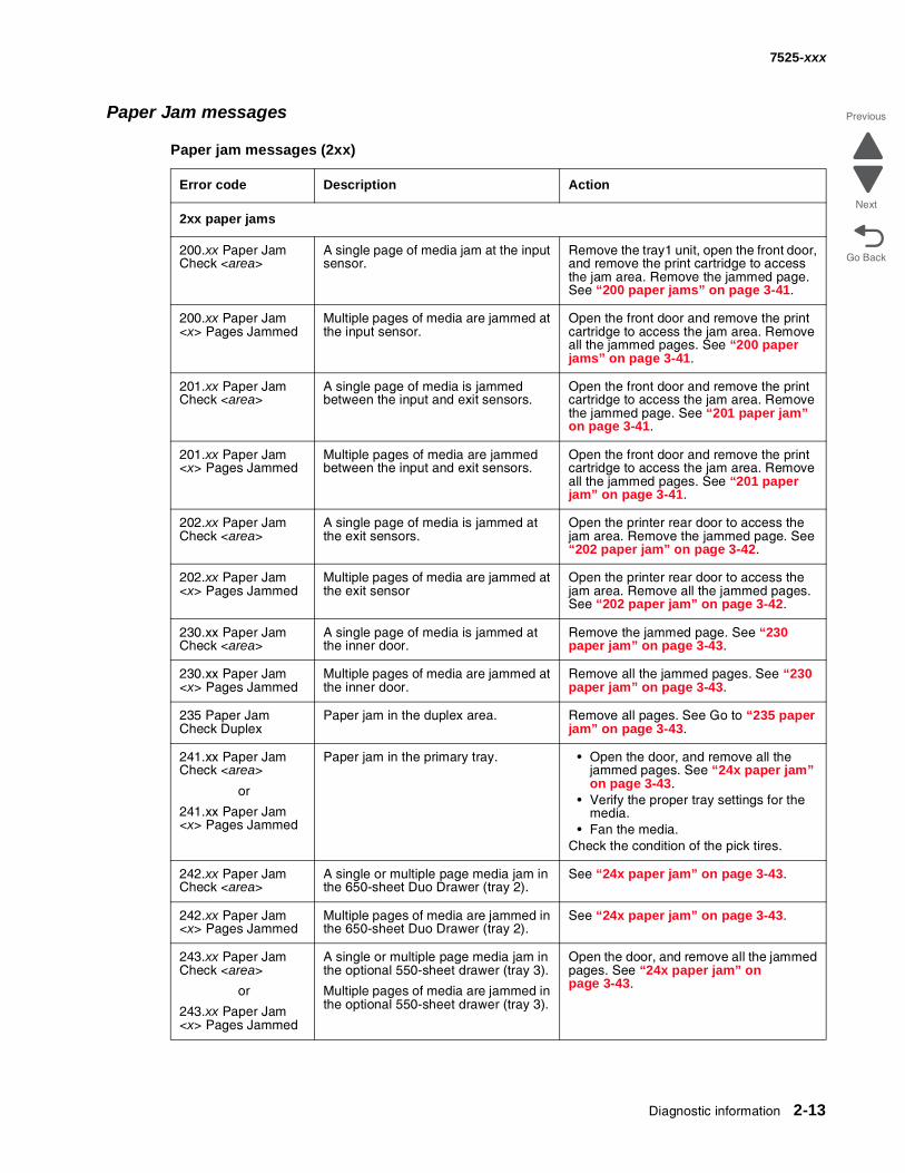
Paper Jam messages
Paper jam messages (2xx)
Error code Description Action
2xx paper jams
200.xx Paper JamCheck <area>
A single page of media jam at the input sensor.
Remove the tray1 unit, open the front door, and remove the print cartridge to access the jam area. Remove the jammed page. See “200 paper jams” on page 3-41.
200.xx Paper Jam<x> Pages Jammed
Multiple pages of media are jammed at the input sensor.
Open the front door and remove the print cartridge to access the jam area. Remove all the jammed pages. See “200 paper jams” on page 3-41.
201.xx Paper JamCheck <area>
A single page of media is jammed between the input and exit sensors.
Open the front door and remove the print cartridge to access the jam area. Remove the jammed page. See “201 paper jam” on page 3-41.
201.xx Paper Jam<x> Pages Jammed
Multiple pages of media are jammed between the input and exit sensors.
Open the front door and remove the print cartridge to access the jam area. Remove all the jammed pages. See “201 paper jam” on page 3-41.
202.xx Paper JamCheck <area>
A single page of media is jammed at the exit sensors.
Open the printer rear door to access the jam area. Remove the jammed page. See “202 paper jam” on page 3-42.
202.xx Paper Jam<x> Pages Jammed
Multiple pages of media are jammed at the exit sensor
Open the printer rear door to access the jam area. Remove all the jammed pages. See “202 paper jam” on page 3-42.
230.xx Paper JamCheck <area>
A single page of media is jammed at the inner door.
Remove the jammed page. See “230 paper jam” on page 3-43.
230.xx Paper Jam<x> Pages Jammed
Multiple pages of media are jammed at the inner door.
Remove all the jammed pages. See “230 paper jam” on page 3-43.
235 Paper Jam Check Duplex
Paper jam in the duplex area. Remove all pages. See Go to “235 paper jam” on page 3-43.
241.xx Paper JamCheck <area>
or
241.xx Paper Jam<x> Pages Jammed
Paper jam in the primary tray. • Open the door, and remove all the jammed pages. See “24x paper jam” on page 3-43.
• Verify the proper tray settings for the media.
• Fan the media.Check the condition of the pick tires.
242.xx Paper JamCheck <area>
A single or multiple page media jam in the 650-sheet Duo Drawer (tray 2).
See “24x paper jam” on page 3-43.
242.xx Paper Jam<x> Pages Jammed
Multiple pages of media are jammed in the 650-sheet Duo Drawer (tray 2).
See “24x paper jam” on page 3-43.
243.xx Paper JamCheck <area>
or
243.xx Paper Jam<x> Pages Jammed
A single or multiple page media jam in the optional 550-sheet drawer (tray 3).
Multiple pages of media are jammed in the optional 550-sheet drawer (tray 3).
Open the door, and remove all the jammed pages. See “24x paper jam” on page 3-43.
2-14 Service Manual
7525-xxx
Go Back
Previous
Next
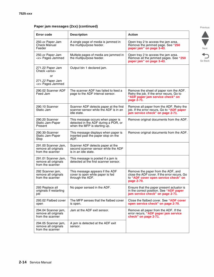
250.xx Paper JamCheck Manual Feeder
A single page of media is jammed in the multipurpose feeder.
Open tray 2 to access the jam area. Remove the jammed page. See “250 paper jam” on page 3-43.
250.xx Paper Jam<x> Pages Jammed
Multiple pages of media are jammed in the multipurpose feeder.
Open tray 2 to access the jam area. Remove all the jammed pages. See “250 paper jam” on page 3-43.
271.22 Paper JamCheck <area>
or
271.22 Paper Jam<x> Pages Jammed
Output bin 1 declared jam.
290.02 Scanner ADF Feed Jam
The scanner ADF has failed to feed a page to the ADF interval sensor.
Remove the sheet of paper rom the ADF. Retry the job. If the error recurs, Go to “ADF paper jam service check” on page 2-71.
290.10 Scanner Static Jam
Scanner ADF detects paper at the first scanner sensor while the ADF is in an idle state.
Remove all paper from the ADF. Retry the job. If the error recurs, Go to “ADF paper jam service check” on page 2-71.
290.20 Scanner Static Jam-Paper Present
This message occurs when paper is detected in the ADF during a POR, or when the MFP is starting up.
Remove original documents from the ADF.
290.30-Scanner Static Jam-Paper Stop
This message displays when paper is inserted past the paper stop on the ADF.
Remove original documents from the ADF.
291.00 Scanner Jam, remove all originals from the scanner
Scanner ADF detects paper at the second scanner sensor while the ADF is in an idle state.
291.01 Scanner Jam, remove all originals from the scanner
This message is posted if a jam is detected at the first scanner sensor.
292 Scanner jam, remove all originals from the scanner
This message appears if the ADF cover is open while paper is fed through the ADF.
Remove the paper from the ADF, and close the ADF cover. If the error recurs, Go to “ADF cover open service check” on page 2-70.
293 Replace all originals if restarting job
No paper sensed in the ADF. Ensure that the paper present actuator is in the correct position. See “ADF paper jam service check” on page 2-71.
293.02 Flatbed cover open
The MFP senses that the flatbed cover is open.
Close the flatbed cover. See “ADF cover open service check” on page 2-70.
294.04 Scanner jam, remove all originals from the scanner
Jam at the ADF exit sensor. Remove all paper from the ADF. If the error recurs, “ADF paper jam service check” on page 2-71.
294.05 Scanner jam, remove all originals from the scanner
A jam is detected at the ADF exit sensor.
Paper jam messages (2xx) (continued)
Error code Description Action
Diagnostic information 2-15
7525-xxx
Go Back
Previous
Next
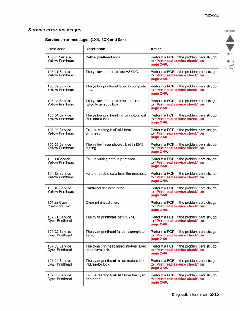
Service error messages
Service error messages (1XX, 8XX and 9xx)
Error code Description Action
106.xx ServiceYellow Printhead
Yellow printhead error. Perform a POR. If the problem persists, go to “Printhead service check” on page 2-60.
106.01 ServiceYellow Printhead
The yellow printhead lost HSYNC. Perform a POR. If the problem persists, go to “Printhead service check” on page 2-60.
106.02 ServiceYellow Printhead
The yellow printhead failed to complete servo.
Perform a POR. If the problem persists, go to “Printhead service check” on page 2-60.
106.03 ServiceYellow Printhead
The yellow printhead mirror motors failed to achieve lock.
Perform a POR. If the problem persists, go to “Printhead service check” on page 2-60.
106.04 ServiceYellow Printhead
The yellow printhead mirror motors lost PLL motor lock.
Perform a POR. If the problem persists, go to “Printhead service check” on page 2-60.
106.05 ServiceYellow Printhead
Failure reading NVRAM from printhead.
Perform a POR. If the problem persists, go to “Printhead service check” on page 2-60.
106.08 ServiceYellow Printhead
The yellow laser showed bad in EMS testing.
Perform a POR. If the problem persists, go to “Printhead service check” on page 2-60.
106.11ServiceYellow Printhead
Failure writing data to printhead Perform a POR. If the problem persists, go to “Printhead service check” on page 2-60.
106.12 ServiceYellow Printhead
Failure reading data from the printhead Perform a POR. If the problem persists, go to “Printhead service check” on page 2-60.
106.13 ServiceYellow Printhead
Printhead declared error Perform a POR. If the problem persists, go to “Printhead service check” on page 2-60.
107.xx CyanPrinthead Error
Cyan printhead error. Perform a POR. If the problem persists, go to “Printhead service check” on page 2-60.
107.01 ServiceCyan Printhead
The cyan printhead lost HSYNC. Perform a POR. If the problem persists, go to “Printhead service check” on page 2-60.
107.02 ServiceCyan Printhead
The cyan printhead failed to complete servo.
Perform a POR. If the problem persists, go to “Printhead service check” on page 2-60.
107.03 ServiceCyan Printhead
The cyan printhead mirror motors failed to achieve lock.
Perform a POR. If the problem persists, go to “Printhead service check” on page 2-60
107.04 ServiceCyan Printhead
The cyan printhead mirror motors lost PLL motor lock.
Perform a POR. If the problem persists, go to “Printhead service check” on page 2-60.
107.05 ServiceCyan Printhead
Failure reading NVRAM from the cyan printhead.
Perform a POR. If the problem persists, go to “Printhead service check” on page 2-60.
2-16 Service Manual
7525-xxx
Go Back
Previous
Next
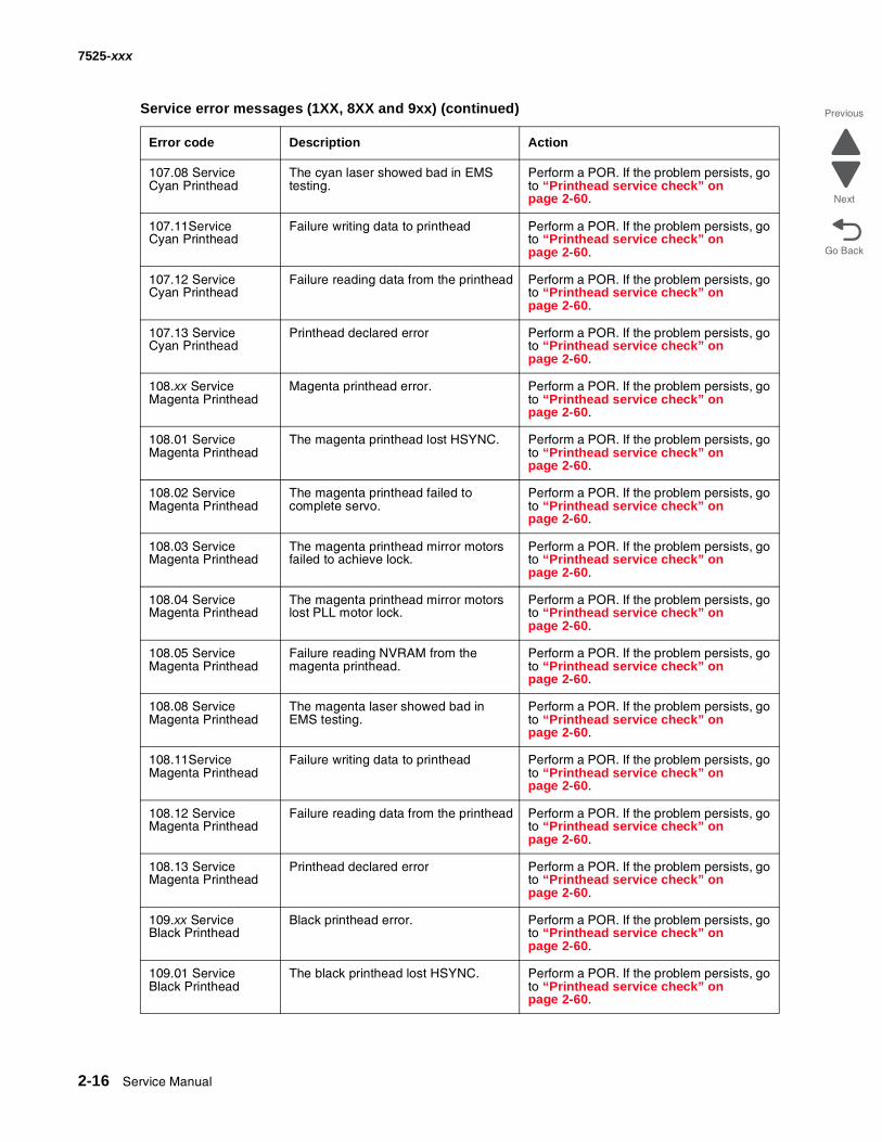
107.08 ServiceCyan Printhead
The cyan laser showed bad in EMS testing.
Perform a POR. If the problem persists, go to “Printhead service check” on page 2-60.
107.11ServiceCyan Printhead
Failure writing data to printhead Perform a POR. If the problem persists, go to “Printhead service check” on page 2-60.
107.12 ServiceCyan Printhead
Failure reading data from the printhead Perform a POR. If the problem persists, go to “Printhead service check” on page 2-60.
107.13 ServiceCyan Printhead
Printhead declared error Perform a POR. If the problem persists, go to “Printhead service check” on page 2-60.
108.xx ServiceMagenta Printhead
Magenta printhead error. Perform a POR. If the problem persists, go to “Printhead service check” on page 2-60.
108.01 ServiceMagenta Printhead
The magenta printhead lost HSYNC. Perform a POR. If the problem persists, go to “Printhead service check” on page 2-60.
108.02 ServiceMagenta Printhead
The magenta printhead failed to complete servo.
Perform a POR. If the problem persists, go to “Printhead service check” on page 2-60.
108.03 ServiceMagenta Printhead
The magenta printhead mirror motors failed to achieve lock.
Perform a POR. If the problem persists, go to “Printhead service check” on page 2-60.
108.04 ServiceMagenta Printhead
The magenta printhead mirror motors lost PLL motor lock.
Perform a POR. If the problem persists, go to “Printhead service check” on page 2-60.
108.05 ServiceMagenta Printhead
Failure reading NVRAM from the magenta printhead.
Perform a POR. If the problem persists, go to “Printhead service check” on page 2-60.
108.08 ServiceMagenta Printhead
The magenta laser showed bad in EMS testing.
Perform a POR. If the problem persists, go to “Printhead service check” on page 2-60.
108.11ServiceMagenta Printhead
Failure writing data to printhead Perform a POR. If the problem persists, go to “Printhead service check” on page 2-60.
108.12 ServiceMagenta Printhead
Failure reading data from the printhead Perform a POR. If the problem persists, go to “Printhead service check” on page 2-60.
108.13 ServiceMagenta Printhead
Printhead declared error Perform a POR. If the problem persists, go to “Printhead service check” on page 2-60.
109.xx ServiceBlack Printhead
Black printhead error. Perform a POR. If the problem persists, go to “Printhead service check” on page 2-60.
109.01 ServiceBlack Printhead
The black printhead lost HSYNC. Perform a POR. If the problem persists, go to “Printhead service check” on page 2-60.
Service error messages (1XX, 8XX and 9xx) (continued)
Error code Description Action
Diagnostic information 2-17
7525-xxx
Go Back
Previous
Next
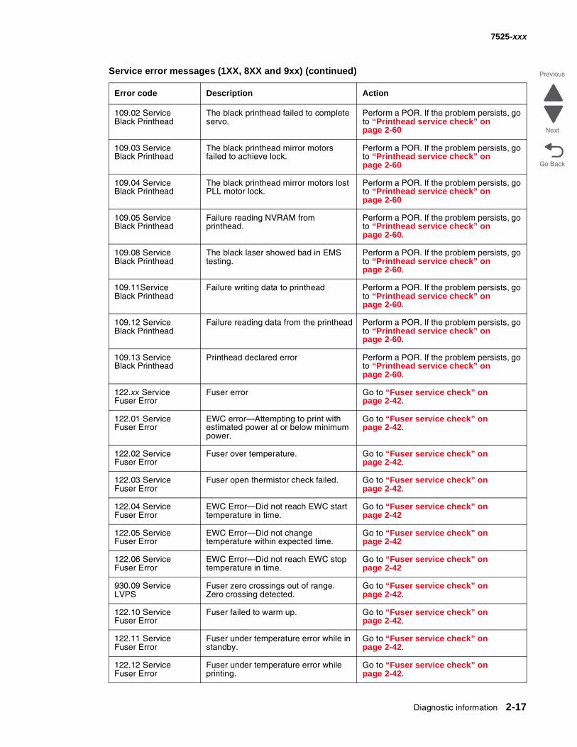
109.02 ServiceBlack Printhead
The black printhead failed to complete servo.
Perform a POR. If the problem persists, go to “Printhead service check” on page 2-60
109.03 ServiceBlack Printhead
The black printhead mirror motors failed to achieve lock.
Perform a POR. If the problem persists, go to “Printhead service check” on page 2-60
109.04 ServiceBlack Printhead
The black printhead mirror motors lost PLL motor lock.
Perform a POR. If the problem persists, go to “Printhead service check” on page 2-60
109.05 ServiceBlack Printhead
Failure reading NVRAM from printhead.
Perform a POR. If the problem persists, go to “Printhead service check” on page 2-60.
109.08 ServiceBlack Printhead
The black laser showed bad in EMS testing.
Perform a POR. If the problem persists, go to “Printhead service check” on page 2-60.
109.11ServiceBlack Printhead
Failure writing data to printhead Perform a POR. If the problem persists, go to “Printhead service check” on page 2-60.
109.12 ServiceBlack Printhead
Failure reading data from the printhead Perform a POR. If the problem persists, go to “Printhead service check” on page 2-60.
109.13 ServiceBlack Printhead
Printhead declared error Perform a POR. If the problem persists, go to “Printhead service check” on page 2-60.
122.xx ServiceFuser Error
Fuser error Go to “Fuser service check” on page 2-42.
122.01 ServiceFuser Error
EWC error—Attempting to print with estimated power at or below minimum power.
Go to “Fuser service check” on page 2-42.
122.02 ServiceFuser Error
Fuser over temperature. Go to “Fuser service check” on page 2-42.
122.03 ServiceFuser Error
Fuser open thermistor check failed. Go to “Fuser service check” on page 2-42.
122.04 ServiceFuser Error
EWC Error—Did not reach EWC start temperature in time.
Go to “Fuser service check” on page 2-42
122.05 ServiceFuser Error
EWC Error—Did not change temperature within expected time.
Go to “Fuser service check” on page 2-42
122.06 ServiceFuser Error
EWC Error—Did not reach EWC stop temperature in time.
Go to “Fuser service check” on page 2-42
930.09 ServiceLVPS
Fuser zero crossings out of range. Zero crossing detected.
Go to “Fuser service check” on page 2-42.
122.10 ServiceFuser Error
Fuser failed to warm up. Go to “Fuser service check” on page 2-42.
122.11 ServiceFuser Error
Fuser under temperature error while in standby.
Go to “Fuser service check” on page 2-42.
122.12 ServiceFuser Error
Fuser under temperature error while printing.
Go to “Fuser service check” on page 2-42.
Service error messages (1XX, 8XX and 9xx) (continued)
Error code Description Action
2-18 Service Manual
7525-xxx
Go Back
Previous
Next
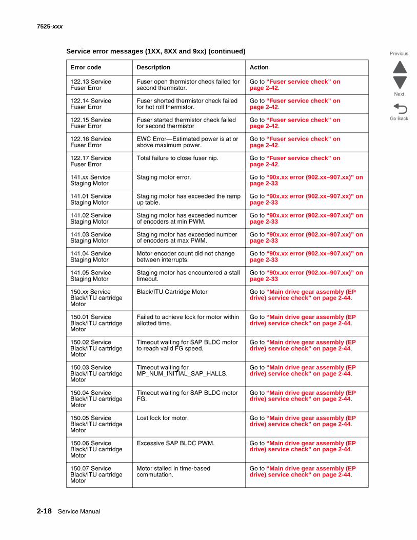
122.13 ServiceFuser Error
Fuser open thermistor check failed for second thermistor.
Go to “Fuser service check” on page 2-42.
122.14 ServiceFuser Error
Fuser shorted thermistor check failed for hot roll thermistor.
Go to “Fuser service check” on page 2-42.
122.15 ServiceFuser Error
Fuser started thermistor check failed for second thermistor
Go to “Fuser service check” on page 2-42.
122.16 ServiceFuser Error
EWC Error—Estimated power is at or above maximum power.
Go to “Fuser service check” on page 2-42.
122.17 ServiceFuser Error
Total failure to close fuser nip. Go to “Fuser service check” on page 2-42.
141.xx ServiceStaging Motor
Staging motor error. Go to “90x.xx error (902.xx–907.xx)” on page 2-33
141.01 ServiceStaging Motor
Staging motor has exceeded the ramp up table.
Go to “90x.xx error (902.xx–907.xx)” on page 2-33
141.02 ServiceStaging Motor
Staging motor has exceeded number of encoders at min PWM.
Go to “90x.xx error (902.xx–907.xx)” on page 2-33
141.03 ServiceStaging Motor
Staging motor has exceeded number of encoders at max PWM.
Go to “90x.xx error (902.xx–907.xx)” on page 2-33
141.04 ServiceStaging Motor
Motor encoder count did not change between interrupts.
Go to “90x.xx error (902.xx–907.xx)” on page 2-33
141.05 ServiceStaging Motor
Staging motor has encountered a stall timeout.
Go to “90x.xx error (902.xx–907.xx)” on page 2-33
150.xx ServiceBlack/ITU cartridge Motor
Black/ITU Cartridge Motor Go to “Main drive gear assembly (EP drive) service check” on page 2-44.
150.01 ServiceBlack/ITU cartridge Motor
Failed to achieve lock for motor within allotted time.
Go to “Main drive gear assembly (EP drive) service check” on page 2-44.
150.02 ServiceBlack/ITU cartridge Motor
Timeout waiting for SAP BLDC motor to reach valid FG speed.
Go to “Main drive gear assembly (EP drive) service check” on page 2-44.
150.03 ServiceBlack/ITU cartridge Motor
Timeout waiting for MP_NUM_INITIAL_SAP_HALLS.
Go to “Main drive gear assembly (EP drive) service check” on page 2-44.
150.04 ServiceBlack/ITU cartridge Motor
Timeout waiting for SAP BLDC motor FG.
Go to “Main drive gear assembly (EP drive) service check” on page 2-44.
150.05 ServiceBlack/ITU cartridge Motor
Lost lock for motor. Go to “Main drive gear assembly (EP drive) service check” on page 2-44.
150.06 ServiceBlack/ITU cartridge Motor
Excessive SAP BLDC PWM. Go to “Main drive gear assembly (EP drive) service check” on page 2-44.
150.07 ServiceBlack/ITU cartridge Motor
Motor stalled in time-based commutation.
Go to “Main drive gear assembly (EP drive) service check” on page 2-44.
Service error messages (1XX, 8XX and 9xx) (continued)
Error code Description Action
Diagnostic information 2-19
7525-xxx
Go Back
Previous
Next
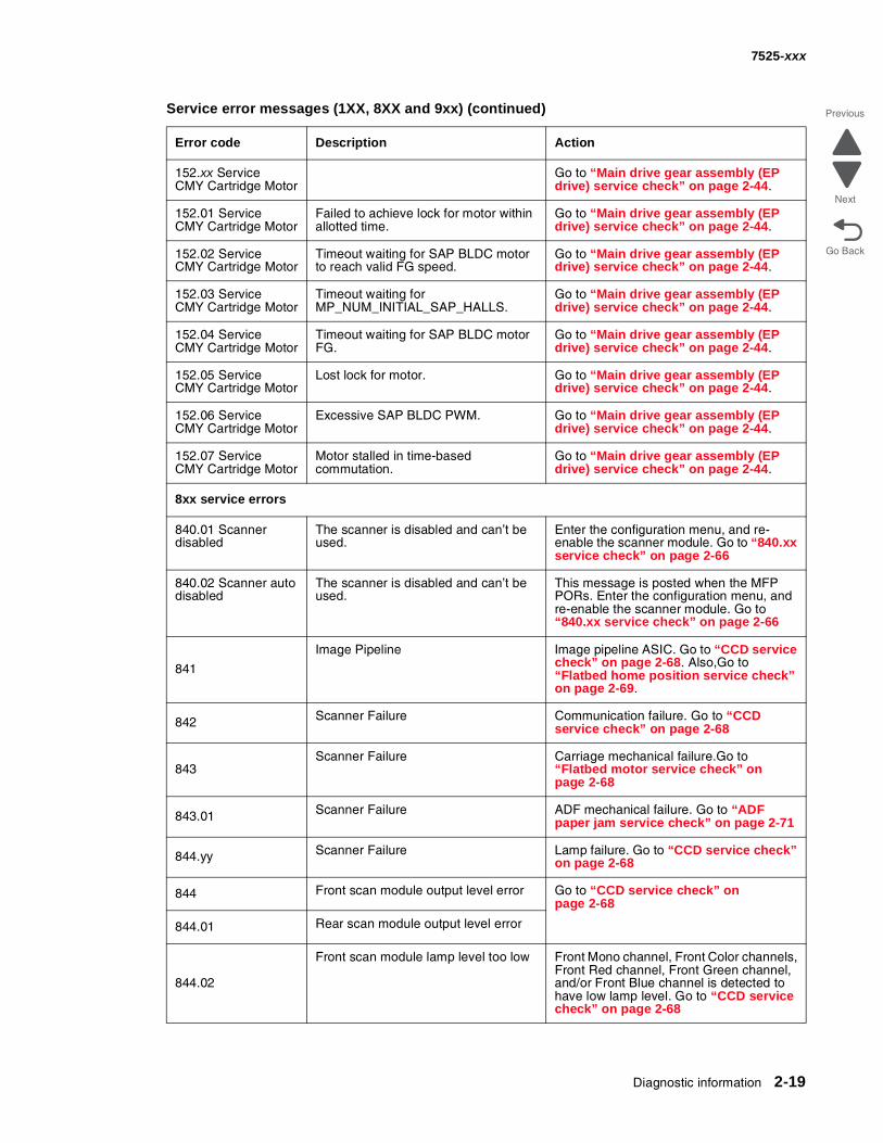
152.xx ServiceCMY Cartridge Motor
Go to “Main drive gear assembly (EP drive) service check” on page 2-44.
152.01 ServiceCMY Cartridge Motor
Failed to achieve lock for motor within allotted time.
Go to “Main drive gear assembly (EP drive) service check” on page 2-44.
152.02 ServiceCMY Cartridge Motor
Timeout waiting for SAP BLDC motor to reach valid FG speed.
Go to “Main drive gear assembly (EP drive) service check” on page 2-44.
152.03 ServiceCMY Cartridge Motor
Timeout waiting for MP_NUM_INITIAL_SAP_HALLS.
Go to “Main drive gear assembly (EP drive) service check” on page 2-44.
152.04 ServiceCMY Cartridge Motor
Timeout waiting for SAP BLDC motor FG.
Go to “Main drive gear assembly (EP drive) service check” on page 2-44.
152.05 ServiceCMY Cartridge Motor
Lost lock for motor. Go to “Main drive gear assembly (EP drive) service check” on page 2-44.
152.06 ServiceCMY Cartridge Motor
Excessive SAP BLDC PWM. Go to “Main drive gear assembly (EP drive) service check” on page 2-44.
152.07 ServiceCMY Cartridge Motor
Motor stalled in time-based commutation.
Go to “Main drive gear assembly (EP drive) service check” on page 2-44.
8xx service errors
840.01 Scanner disabled
The scanner is disabled and can’t be used.
Enter the configuration menu, and re-enable the scanner module. Go to “840.xx service check” on page 2-66
840.02 Scanner auto disabled
The scanner is disabled and can’t be used.
This message is posted when the MFP PORs. Enter the configuration menu, and re-enable the scanner module. Go to “840.xx service check” on page 2-66
841
Image Pipeline Image pipeline ASIC. Go to “CCD service check” on page 2-68. Also,Go to “Flatbed home position service check” on page 2-69.
842 Scanner Failure Communication failure. Go to “CCD service check” on page 2-68
843Scanner Failure Carriage mechanical failure.Go to
“Flatbed motor service check” on page 2-68
843.01 Scanner Failure ADF mechanical failure. Go to “ADF paper jam service check” on page 2-71
844.yy Scanner Failure Lamp failure. Go to “CCD service check” on page 2-68
844 Front scan module output level error Go to “CCD service check” on page 2-68
844.01 Rear scan module output level error
844.02
Front scan module lamp level too low Front Mono channel, Front Color channels, Front Red channel, Front Green channel, and/or Front Blue channel is detected to have low lamp level. Go to “CCD service check” on page 2-68
Service error messages (1XX, 8XX and 9xx) (continued)
Error code Description Action
2-20 Service Manual
7525-xxx
Go Back
Previous
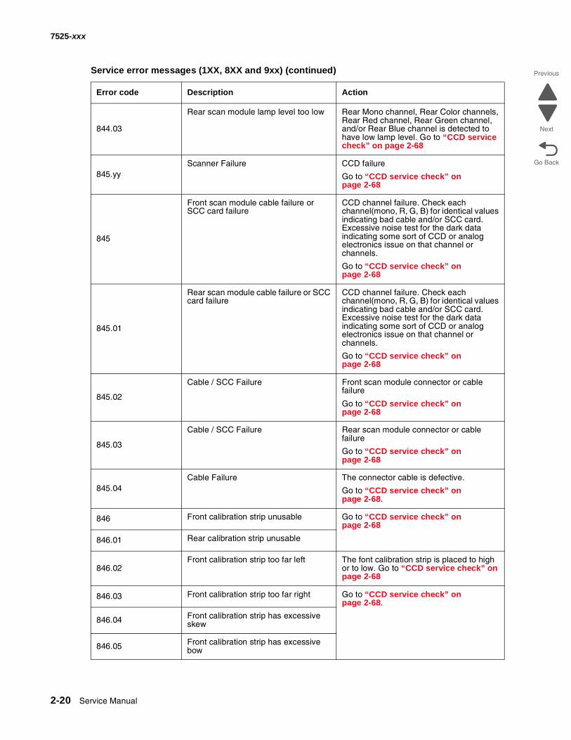
Next844.03
Rear scan module lamp level too low Rear Mono channel, Rear Color channels, Rear Red channel, Rear Green channel, and/or Rear Blue channel is detected to have low lamp level. Go to “CCD service check” on page 2-68
845.yyScanner Failure CCD failure
Go to “CCD service check” on page 2-68
845
Front scan module cable failure or SCC card failure
CCD channel failure. Check each channel(mono, R, G, B) for identical values indicating bad cable and/or SCC card. Excessive noise test for the dark data indicating some sort of CCD or analog electronics issue on that channel or channels.
Go to “CCD service check” on page 2-68
845.01
Rear scan module cable failure or SCC card failure
CCD channel failure. Check each channel(mono, R, G, B) for identical values indicating bad cable and/or SCC card. Excessive noise test for the dark data indicating some sort of CCD or analog electronics issue on that channel or channels.
Go to “CCD service check” on page 2-68
845.02
Cable / SCC Failure Front scan module connector or cable failure
Go to “CCD service check” on page 2-68
845.03
Cable / SCC Failure Rear scan module connector or cable failure
Go to “CCD service check” on page 2-68
845.04Cable Failure The connector cable is defective.
Go to “CCD service check” on page 2-68.
846 Front calibration strip unusable Go to “CCD service check” on page 2-68
846.01 Rear calibration strip unusable
846.02Front calibration strip too far left The font calibration strip is placed to high
or to low. Go to “CCD service check” on page 2-68
846.03 Front calibration strip too far right Go to “CCD service check” on page 2-68.
846.04 Front calibration strip has excessive skew
846.05 Front calibration strip has excessive bow
Service error messages (1XX, 8XX and 9xx) (continued)
Error code Description Action
Diagnostic information 2-21
7525-xxx
Go Back
Previous
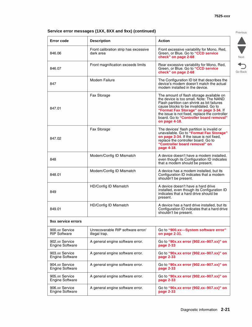
Next846.06
Front calibration strip has excessive dark area
Front excessive variability for Mono, Red, Green, or Blue. Go to “CCD service check” on page 2-68
846.07Front magnification exceeds limits Rear excessive variability for Mono, Red,
Green, or Blue. Go to “CCD service check” on page 2-68
847Modem Failure The Configuration ID bit that describes the
device’s modem doesn’t match the actual modem installed in the device.
847.01
Fax Storage The amount of flash storage available on the device is too small. Note: The NAND Flash partition can shrink as bit failures cause blocks to be invalidated. Go to “Format Fax Storage” on page 3-34. If the issue is not fixed, replace the controller board. Go to “Controller board removal” on page 4-18.
847.02
Fax Storage The devices’ flash partition is invalid or unavailable. Go to “Format Fax Storage” on page 3-34. If the issue is not fixed, replace the controller board. Go to “Controller board removal” on page 4-18.
848Modem/Config ID Mismatch A device doesn’t have a modem installed,
even though its Configuration ID indicates that a modem should be present.
848.01Modem/Config ID Mismatch A device has a modem installed, but its
Configuration ID indicates that a modem shouldn’t be present.
849
HD/Config ID Mismatch A device doesn’t have a hard drive installed, even though its Configuration ID indicates that a hard drive should be present.
849.01HD/Config ID Mismatch A device has a hard drive installed, but its
Configuration ID indicates that a hard drive shouldn’t be present.
9xx service errors
900.xx ServiceRIP Software
Unrecoverable RIP software error/illegal trap.
Go to “900.xx—System software error” on page 2-31.
902.xx ServiceEngine Software
A general engine software error. Go to “90x.xx error (902.xx–907.xx)” on page 2-33
903.xx ServiceEngine Software
A general engine software error. Go to “90x.xx error (902.xx–907.xx)” on page 2-33
904.xx ServiceEngine Software
A general engine software error. Go to “90x.xx error (902.xx–907.xx)” on page 2-33
905.xx ServiceEngine Software
A general engine software error. Go to “90x.xx error (902.xx–907.xx)” on page 2-33
906.xx ServiceEngine Software
A general engine software error. Go to “90x.xx error (902.xx–907.xx)” on page 2-33
Service error messages (1XX, 8XX and 9xx) (continued)
Error code Description Action
2-22 Service Manual
7525-xxx
Go Back
Previous
Next
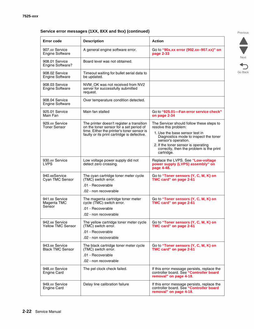
907.xx ServiceEngine Software
A general engine software error. Go to “90x.xx error (902.xx–907.xx)” on page 2-33
908.01 ServiceEngine Software?
Board level was not obtained.
908.02 ServiceEngine Software
Timeout waiting for bullet serial data to be updated.
908.03 ServiceEngine Software
NVM_OK was not received from NV2 server for successfully submitted request.
908.04 ServiceEngine Software
Over temperature condition detected.
925.01 ServiceMain Fan
Main fan stalled Go to “925.01—Fan error service check” on page 2-34
929.xx ServiceToner Sensor
The printer doesn't register a transition on the toner sensor for a set period of time. Either the printer's toner sensor is faulty or its print cartridge is defective.
The Servicer should follow these steps to resolve this problem:
1. Use the base sensor test in Diagnostics mode to inspect the toner sensor's operation.
2. If the toner sensor is operating correctly, then the problem is the print cartridge.
930.xx ServiceLVPS
Low voltage power supply did not detect zero crossing.
Replace the LVPS. See “Low-voltage power supply (LVPS) assembly” on page 4-48.
940.xxServiceCyan TMC Sensor
The cyan cartridge toner meter cycle (TMC) switch error.
.01 - Recoverable
.02 - non recoverable
Go to “Toner sensors (Y, C, M, K) on TMC card” on page 2-61
941.xx ServiceMagenta TMC Sensor
The magenta cartridge toner meter cycle (TMC) switch error.
.01 - Recoverable
.02 - non recoverable
Go to “Toner sensors (Y, C, M, K) on TMC card” on page 2-61
942.xx ServiceYellow TMC Sensor
The yellow cartridge toner meter cycle (TMC) switch error.
.01 - Recoverable
.02 - non recoverable
Go to “Toner sensors (Y, C, M, K) on TMC card” on page 2-61
943.xx ServiceBlack TMC Sensor
The black cartridge toner meter cycle (TMC) switch error.
.01 - Recoverable
.02 - non recoverable
Go to “Toner sensors (Y, C, M, K) on TMC card” on page 2-61
948.xx ServiceEngine Card
The pel clock check failed. If this error message persists, replace the controller board. See “Controller board removal” on page 4-18.
949.xx ServiceEngine Card
Delay line calibration failure If this error message persists, replace the controller board. See “Controller board removal” on page 4-18.
Service error messages (1XX, 8XX and 9xx) (continued)
Error code Description Action
Diagnostic information 2-23
7525-xxx
Go Back
Previous
Next
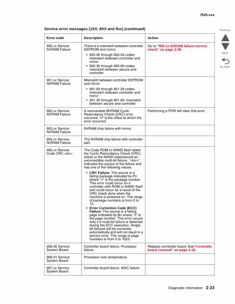
950.xx ServiceNVRAM Failure
There is a mismatch between controller EEPROM and mirror.
• 950.00 through 950.29 codes: mismatch between controller and mirror
• 950.30 through 950.60 codes: mismatch between secure and controller
Go to “950.xx NVRAM failure service check” on page 2-36.
951.xx ServiceNVRAM Failure
Mismatch between controller EEPROM and mirror.
• 951.00 through 951.29 codes: mismatch between controller and mirror
• 951.30 through 951.60: mismatch between secure and controller
952.xx ServiceNVRAM Failure
A recoverable MVRAM Cyclic Redundancy Check (CRC) error occurred. “n” is the offset at which the error occurred.
Performing a POR will clear this error.
953.xx ServiceNVRAM Failure
NVRAM chip failure with mirror.
954.xx ServiceNVRAM Failure
The NVRAM chip failure with controller part.
955.xx ServiceCode CRC <loc>
The Code ROM or NAND flash failed the Cyclic Redundancy Check (CRC) check or the NAND experienced an uncorrectible multi-bit failure. “<loc>” indicates the source of the failure and has one of the following values:
• CRC Failure: The source is a failing package indicated by Pn where “n” is the package number. This error could occur on a controller with ROM or NAND flash and could occur as a result of the CRC check done when the machine is powered on. The range of package numbers is from 0 to 15.
• Error Correction Code (ECC) Failure: The source is a failing page indicated by Bn where “n” is the page number. This error occurs only if a multi-bit failure is detected during the ECC execution. Single bit failures will be corrected automatically and will not result in a service error. The range of page numbers is from 0 to 1023.
956.00 ServiceSystem Board
Controller board failure. Processor failure.
Replace conrtroller board. See“Controller board removal” on page 4-18.
956.01 ServiceSystem Board
Processor over temperature.
957.xx ServiceSystem Board
Controller board failure. ASIC failure.
Service error messages (1XX, 8XX and 9xx) (continued)
Error code Description Action
2-24 Service Manual
7525-xxx
Go Back
Previous
Next
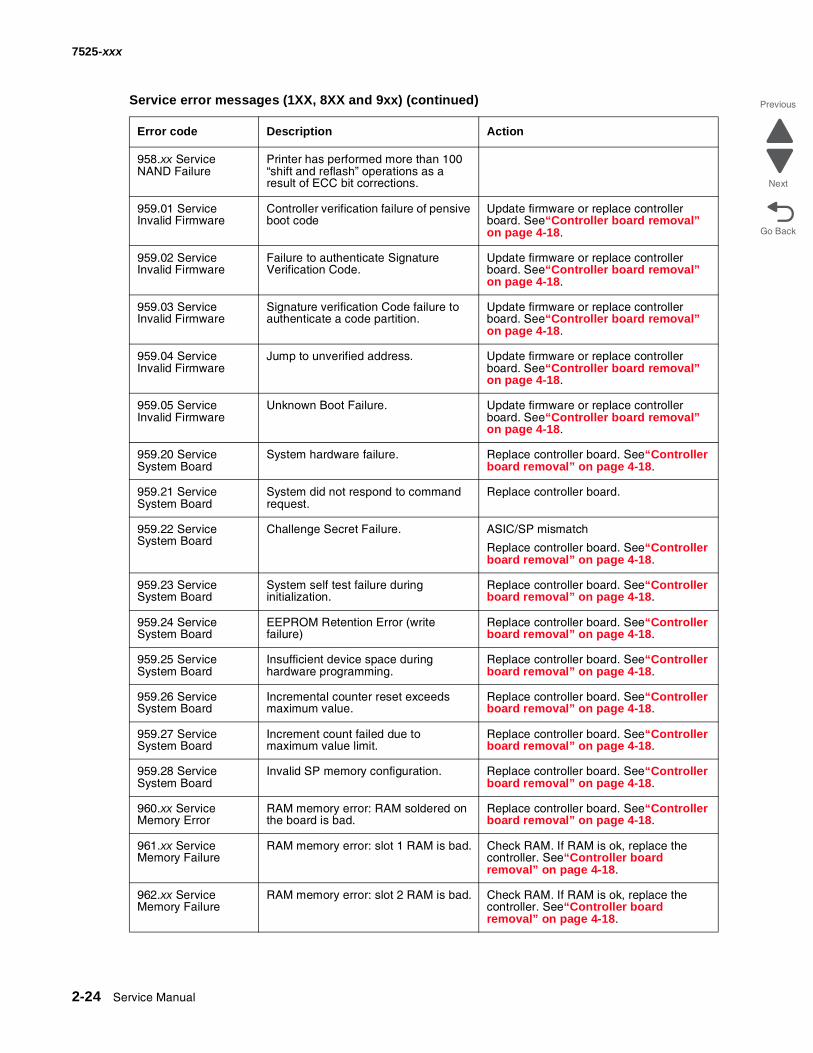
958.xx ServiceNAND Failure
Printer has performed more than 100 “shift and reflash” operations as a result of ECC bit corrections.
959.01 ServiceInvalid Firmware
Controller verification failure of pensive boot code
Update firmware or replace controller board. See“Controller board removal” on page 4-18.
959.02 ServiceInvalid Firmware
Failure to authenticate Signature Verification Code.
Update firmware or replace controller board. See“Controller board removal” on page 4-18.
959.03 ServiceInvalid Firmware
Signature verification Code failure to authenticate a code partition.
Update firmware or replace controller board. See“Controller board removal” on page 4-18.
959.04 ServiceInvalid Firmware
Jump to unverified address. Update firmware or replace controller board. See“Controller board removal” on page 4-18.
959.05 ServiceInvalid Firmware
Unknown Boot Failure. Update firmware or replace controller board. See“Controller board removal” on page 4-18.
959.20 ServiceSystem Board
System hardware failure. Replace controller board. See“Controller board removal” on page 4-18.
959.21 ServiceSystem Board
System did not respond to command request.
Replace controller board.
959.22 ServiceSystem Board
Challenge Secret Failure. ASIC/SP mismatch
Replace controller board. See“Controller board removal” on page 4-18.
959.23 ServiceSystem Board
System self test failure during initialization.
Replace controller board. See“Controller board removal” on page 4-18.
959.24 ServiceSystem Board
EEPROM Retention Error (write failure)
Replace controller board. See“Controller board removal” on page 4-18.
959.25 ServiceSystem Board
Insufficient device space during hardware programming.
Replace controller board. See“Controller board removal” on page 4-18.
959.26 ServiceSystem Board
Incremental counter reset exceeds maximum value.
Replace controller board. See“Controller board removal” on page 4-18.
959.27 ServiceSystem Board
Increment count failed due to maximum value limit.
Replace controller board. See“Controller board removal” on page 4-18.
959.28 ServiceSystem Board
Invalid SP memory configuration. Replace controller board. See“Controller board removal” on page 4-18.
960.xx ServiceMemory Error
RAM memory error: RAM soldered on the board is bad.
Replace controller board. See“Controller board removal” on page 4-18.
961.xx ServiceMemory Failure
RAM memory error: slot 1 RAM is bad. Check RAM. If RAM is ok, replace the controller. See“Controller board removal” on page 4-18.
962.xx ServiceMemory Failure
RAM memory error: slot 2 RAM is bad. Check RAM. If RAM is ok, replace the controller. See“Controller board removal” on page 4-18.
Service error messages (1XX, 8XX and 9xx) (continued)
Error code Description Action
Diagnostic information 2-25
7525-xxx
Go Back
Previous
Next
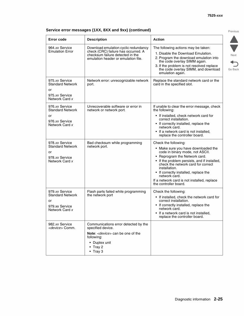
964.xx ServiceEmulation Error
Download emulation cyclic redundancy check (CRC) failure has occurred. A checksum failure detected in the emulation header or emulation file.
The following actions may be taken:
1. Disable the Download Emulation.2. Program the download emulation into
the code overlay SIMM again.3. If the problem is not resolved replace
the code overlay SIMM, and download emulation again.
975.xx ServiceStandard Network
or
975.xx ServiceNetwork Card x
Network error: unrecognizable network port.
Replace the standard network card or the card in the specified slot.
976.xx ServiceStandard Network
or
976.xx ServiceNetwork Card x
Unrecoverable software or error in network or network port.
If unable to clear the error message, check the following:
• If installed, check network card for correct installation.
• If correctly installed, replace the network card.
• If a network card is not installed, replace the controller board.
978.xx ServiceStandard Network
or
978.xx ServiceNetwork Card x
Bad checksum while programming network port.
Check the following:
• Make sure you have downloaded the code in binary mode, not ASCII.
• Reprogram the Network card.• If the problem persists, and if installed,
check the network card for correct installation.
• If correctly installed, replace the network card.
If a network card is not installed, replace the controller board.
979.xx ServiceStandard Network
or
979.xx ServiceNetwork Card x
Flash parts failed while programming the network port
Check the following:
• If installed, check the network card for correct installation.
• If correctly installed, replace the network card.
• If a network card is not installed, replace the controller board.
982.xx Service<device> Comm.
Communications error detected by the specified device.
Note: <device> can be one of the following:
• Duplex unit• Tray 2• Tray 3
Service error messages (1XX, 8XX and 9xx) (continued)
Error code Description Action
2-26 Service Manual
7525-xxx
Go Back
Previous
Next
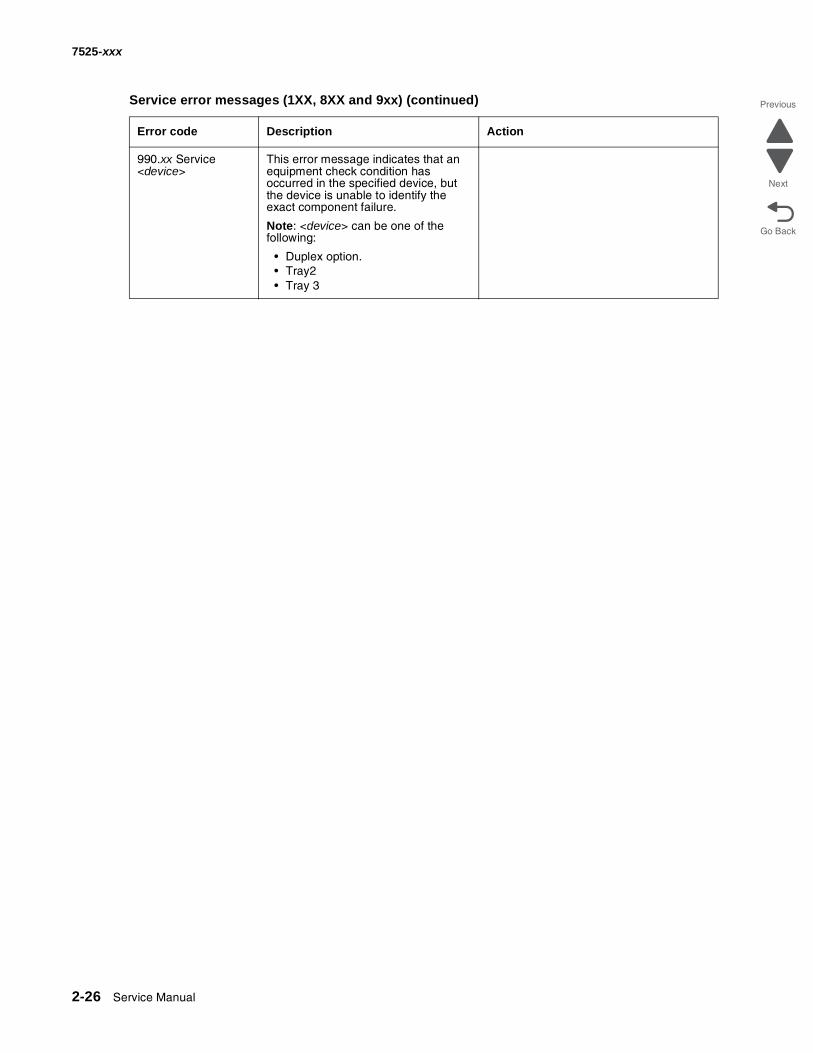
990.xx Service<device>
This error message indicates that an equipment check condition has occurred in the specified device, but the device is unable to identify the exact component failure.
Note: <device> can be one of the following:
• Duplex option.• Tray2• Tray 3
Service error messages (1XX, 8XX and 9xx) (continued)
Error code Description Action
Diagnostic information 2-27
7525-xxx
Go Back
Previous
Next
Fax error log codes
Fax error log codes
Error code Description Action
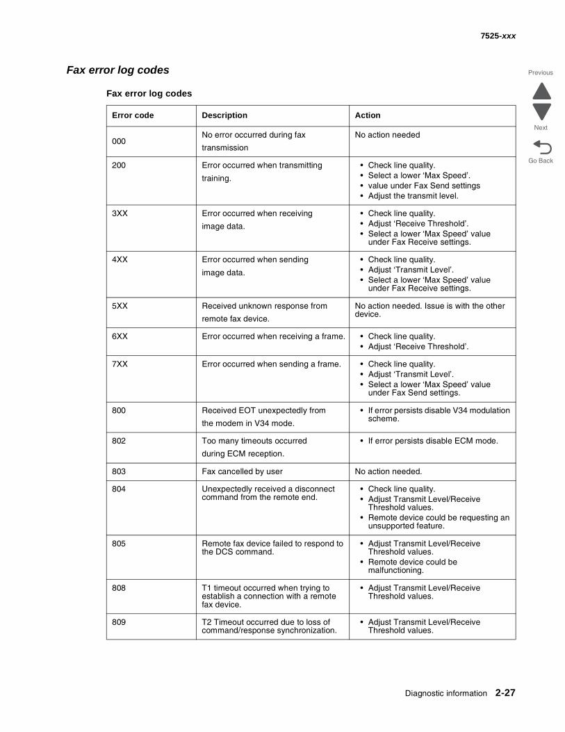
000No error occurred during fax
transmission
No action needed
200 Error occurred when transmitting
training.
• Check line quality.• Select a lower ‘Max Speed’.• value under Fax Send settings• Adjust the transmit level.
3XX Error occurred when receiving
image data.
• Check line quality.• Adjust ‘Receive Threshold’.• Select a lower ‘Max Speed’ value
under Fax Receive settings.
4XX Error occurred when sending
image data.
• Check line quality.• Adjust ‘Transmit Level’.• Select a lower ‘Max Speed’ value
under Fax Receive settings.
5XX Received unknown response from
remote fax device.
No action needed. Issue is with the other device.
6XX Error occurred when receiving a frame. • Check line quality.• Adjust ‘Receive Threshold’.
7XX Error occurred when sending a frame. • Check line quality.• Adjust ‘Transmit Level’.• Select a lower ‘Max Speed’ value
under Fax Send settings.
800 Received EOT unexpectedly from
the modem in V34 mode.
• If error persists disable V34 modulation scheme.
802 Too many timeouts occurred
during ECM reception.
• If error persists disable ECM mode.
803 Fax cancelled by user No action needed.
804 Unexpectedly received a disconnect command from the remote end.
• Check line quality.• Adjust Transmit Level/Receive
Threshold values.• Remote device could be requesting an
unsupported feature.
805 Remote fax device failed to respond to the DCS command.
• Adjust Transmit Level/Receive Threshold values.
• Remote device could be malfunctioning.
808 T1 timeout occurred when trying to establish a connection with a remote fax device.
• Adjust Transmit Level/Receive Threshold values.
809 T2 Timeout occurred due to loss of command/response synchronization.
• Adjust Transmit Level/Receive Threshold values.
2-28 Service Manual
7525-xxx
Go Back
Previous
Next
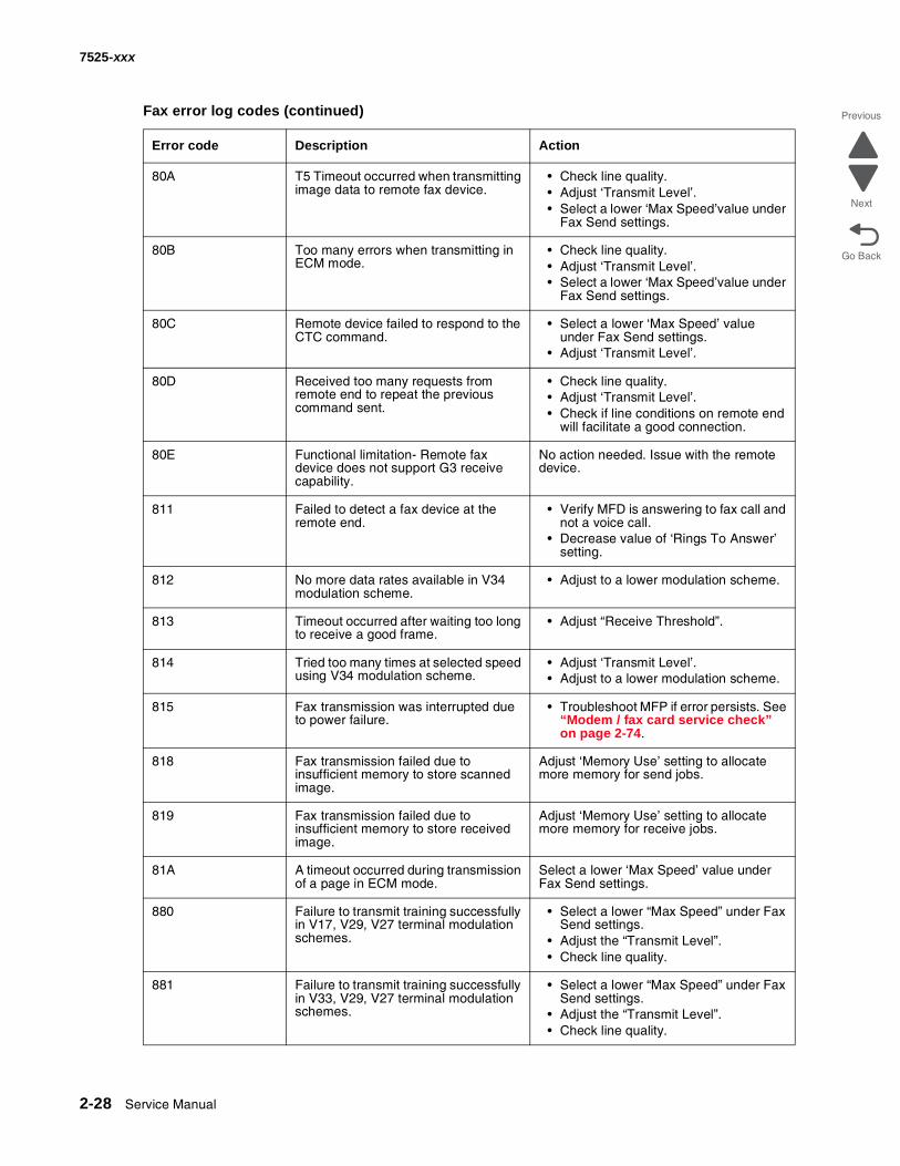
80A T5 Timeout occurred when transmitting image data to remote fax device.
• Check line quality.• Adjust ‘Transmit Level’.• Select a lower ‘Max Speed’value under
Fax Send settings.
80B Too many errors when transmitting in ECM mode.
• Check line quality.• Adjust ‘Transmit Level’.• Select a lower ‘Max Speed’value under
Fax Send settings.
80C Remote device failed to respond to the CTC command.
• Select a lower ‘Max Speed’ value under Fax Send settings.
• Adjust ‘Transmit Level’.
80D Received too many requests from remote end to repeat the previous command sent.
• Check line quality.• Adjust ‘Transmit Level’.• Check if line conditions on remote end
will facilitate a good connection.
80E Functional limitation- Remote fax device does not support G3 receive capability.
No action needed. Issue with the remote device.
811 Failed to detect a fax device at the remote end.
• Verify MFD is answering to fax call and not a voice call.
• Decrease value of ‘Rings To Answer’ setting.
812 No more data rates available in V34 modulation scheme.
• Adjust to a lower modulation scheme.
813 Timeout occurred after waiting too long to receive a good frame.
• Adjust “Receive Threshold”.
814 Tried too many times at selected speed using V34 modulation scheme.
• Adjust ‘Transmit Level’.• Adjust to a lower modulation scheme.
815 Fax transmission was interrupted due to power failure.
• Troubleshoot MFP if error persists. See “Modem / fax card service check” on page 2-74.
818 Fax transmission failed due to insufficient memory to store scanned image.
Adjust ‘Memory Use’ setting to allocate more memory for send jobs.
819 Fax transmission failed due to insufficient memory to store received image.
Adjust ‘Memory Use’ setting to allocate more memory for receive jobs.
81A A timeout occurred during transmission of a page in ECM mode.
Select a lower ‘Max Speed’ value under Fax Send settings.
880 Failure to transmit training successfully in V17, V29, V27 terminal modulation schemes.
• Select a lower “Max Speed” under Fax Send settings.
• Adjust the “Transmit Level”.• Check line quality.
881 Failure to transmit training successfully in V33, V29, V27 terminal modulation schemes.
• Select a lower “Max Speed” under Fax Send settings.
• Adjust the “Transmit Level”.• Check line quality.
Fax error log codes (continued)
Error code Description Action
Diagnostic information 2-29
7525-xxx
Go Back
Previous
Next
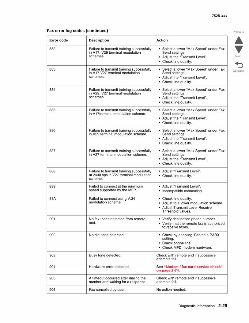
882 Failure to transmit training successfully in V17, V29 terminal modulation schemes.
• Select a lower “Max Speed” under Fax Send settings.
• Adjust the “Transmit Level”.• Check line quality.
883 Failure to transmit training successfully in V17,V27 terminal modulation schemes.
• Select a lower “Max Speed” under Fax Send settings.
• Adjust the “Transmit Level”.• Check line quality.
884 Failure to transmit training successfully in V29, V27 terminal modulation schemes.
• Select a lower “Max Speed” under Fax Send settings.
• Adjust the “Transmit Level”.• Check line quality.
885 Failure to transmit training successfully in V17terminal modulation scheme.
• Select a lower “Max Speed” under Fax Send settings.
• Adjust the “Transmit Level”.• Check line quality.
886 Failure to transmit training successfully in V29 terminal modulation scheme.
• Select a lower “Max Speed” under Fax Send settings.
• Adjust the “Transmit Level”.• Check line quality.
887 Failure to transmit training successfully in V27 terminal modulation scheme.
• Select a lower “Max Speed” under Fax Send settings.
• Adjust the “Transmit Level”.• Check line quality.
888 Failure to transmit training successfully at 2400 bps in V27 terminal modulation scheme.
• Adjust “Transmit Level”.• Check line quality.
889 Failed to connect at the minimum speed supported by the MFP.
• Adjust “Transmit Level”.• Incompatible connection.
88A Failed to connect using V.34 modulation scheme.
• Check line quality.• Adjust to a lower modulation scheme.• Adjust Transmit Level Receive
Threshold values.
901 No fax tones detected from remote end.
• Verify destination phone number.• Verify that the remote fax is authorized
to receive faxes.
902 No dial tone detected. • Check by enabling ‘Behind a PABX’ setting.
• Check phone line.• Check MFD modem hardware.
903 Busy tone detected. Check with remote end if successive attempts fail.
904 Hardware error detected. See “Modem / fax card service check” on page 2-74.
905 A timeout occurred after dialing the number and waiting for a response.
Check with remote end if successive attempts fail.
906 Fax cancelled by user. No action needed.
Fax error log codes (continued)
Error code Description Action
2-30 Service Manual
7525-xxx
Go Back
Previous
Next
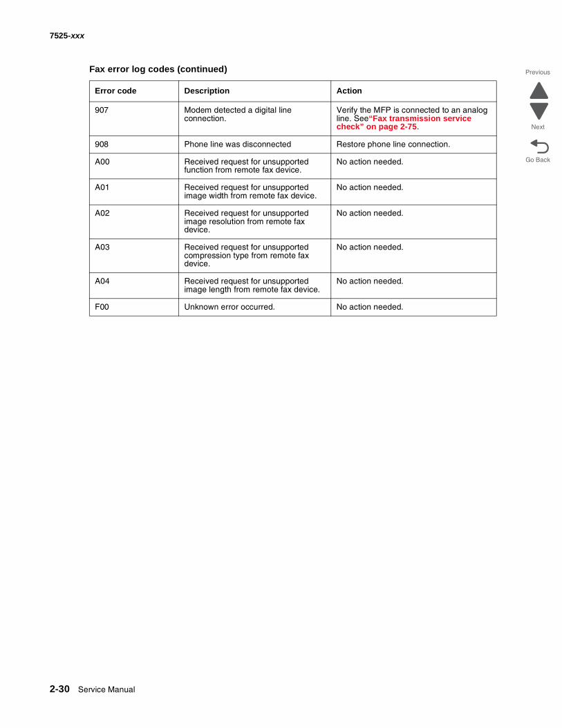
907 Modem detected a digital line connection.
Verify the MFP is connected to an analog line. See“Fax transmission service check” on page 2-75.
908 Phone line was disconnected Restore phone line connection.
A00 Received request for unsupported function from remote fax device.
No action needed.
A01 Received request for unsupported image width from remote fax device.
No action needed.
A02 Received request for unsupported image resolution from remote fax device.
No action needed.
A03 Received request for unsupported compression type from remote fax device.
No action needed.
A04 Received request for unsupported image length from remote fax device.
No action needed.
F00 Unknown error occurred. No action needed.
Fax error log codes (continued)
Error code Description Action
Related Documents