Erosion case study by Computational Fluid Dynamics (CFD) modeling and optimization in situ of clinker sampler probe design Héctor Alfredo López Aguilar 1 , Jorge Alberto Gómez 3 , Marco Antonio Merino 3 , Alberto Duarte Möller 1,2 , E. Orrantia-Borunda 1 and Antonino Pérez Hernández 1 , 1 Centro de Investigación en Materiales Avanzados Miguel de Cervantes 120, Complejo Industrial Chihuahua Chihuahua, Chih. 31109, México 2 Universidad Tecnológica de Querétaro Ave. Pie de la Cuesta 2501, Col. Unidad Nacional Querétaro, Qro. 76148, México 3 Universidad Autónoma de Ciudad Juárez Avenida Plutarco Elías Calles 1210 Ciudad Juárez, Chihuahua, Chih. 32317, México 4 Universidad Autónoma de Chihuahua Ave. Escorza 900, Col. Centro Chihuahua, Chih. 31000, México Abstract. This paper presents the design and modelling of a sampling probe and its erosion particle damage. Applying the simulation tool CFD (Computational Fluid Dynamics)-Fluent ANSYS 15.0, this study verifies and optimizes the dimensional configuration of the probe. The optimized device considers the cooling rate and the internal gases velocity for negative pressure generation (Bernoulli Effect) and its suitable for sampling in cement industry.The synergy with Computational Fluid Dynamics- Design of Experiments- Response Surface modelling (CFD-DOE-RS) tools, allowed the optimization of the operation of the sampler probe and verifies the enoughcooling time to prevent contamination of the specimen in contact with air to maintain its crystallographic structure. The selection of materials for the construction of the device must resist heat transfer rate and abrasive erosion occasioned for friction between the micro particles specimens that moves at high velocity in the internal walls of the device proposed. Keywords: Bernoulli, cement, CFD, sampling probe, oxidative damage, erosion. 1 Introduction Any industry requires the use of devices for process control and quality assurance. In cement industry the extraction of samples at high temperatures and inert atmospheres turns the extraction process into a complex activity by the potential degradation of the specimen in contact with oxygen from air. Xue [1] performed the analysis of a jet Applied Mathematics, Computational Science and Engineering ISBN: 978-1-61804-246-0 13

Welcome message from author
This document is posted to help you gain knowledge. Please leave a comment to let me know what you think about it! Share it to your friends and learn new things together.
Transcript

Erosion case study by Computational Fluid Dynamics (CFD) modeling and optimization in situ of clinker
sampler probe design
Héctor Alfredo López Aguilar1, Jorge Alberto Gómez3, Marco Antonio Merino3, Alberto Duarte Möller1,2, E. Orrantia-Borunda1 and Antonino Pérez Hernández1,
1Centro de Investigación en Materiales Avanzados
Miguel de Cervantes 120, Complejo Industrial Chihuahua Chihuahua, Chih. 31109, México
2 Universidad Tecnológica de Querétaro
Ave. Pie de la Cuesta 2501, Col. Unidad Nacional Querétaro, Qro. 76148, México
3 Universidad Autónoma de Ciudad Juárez
Avenida Plutarco Elías Calles 1210 Ciudad Juárez, Chihuahua, Chih. 32317, México
4 Universidad Autónoma de Chihuahua
Ave. Escorza 900, Col. Centro Chihuahua, Chih. 31000, México
Abstract. This paper presents the design and modelling of a sampling probe and its erosion particle damage. Applying the simulation tool CFD (Computational Fluid Dynamics)-Fluent ANSYS 15.0, this study verifies and optimizes the dimensional configuration of the probe. The optimized device considers the cooling rate and the internal gases velocity for negative pressure generation (Bernoulli Effect) and its suitable for sampling in cement industry.The synergy with Computational Fluid Dynamics- Design of Experiments- Response Surface modelling (CFD-DOE-RS) tools, allowed the optimization of the operation of the sampler probe and verifies the enoughcooling time to prevent contamination of the specimen in contact with air to maintain its crystallographic structure. The selection of materials for the construction of the device must resist heat transfer rate and abrasive erosion occasioned for friction between the micro particles specimens that moves at high velocity in the internal walls of the device proposed. Keywords: Bernoulli, cement, CFD, sampling probe, oxidative damage, erosion.
1 Introduction
Any industry requires the use of devices for process control and quality assurance. In cement industry the extraction of samples at high temperatures and inert atmospheres turns the extraction process into a complex activity by the potential degradation of the specimen in contact with oxygen from air. Xue [1] performed the analysis of a jet
Applied Mathematics, Computational Science and Engineering
ISBN: 978-1-61804-246-0 13

type pump,Yimer [2] through Computational Fluid Dynamics (CFD) software, which principle of operation is based on the Venturi effect [3]. This effect is widely used in the automotive, aviation and flow measurement industries [4-7] and many researchers have modelled this phenomenon by finite volume element [8-13]. In cement industry it has been used for the design and optimization of calciners [14] and to simulate the main transport processes in rotary kilns [15]; there are also patents focused on sampling systems for combustion gases from the rotary kiln. Some patents deal with volatile gases, chlorine and sulfur compounds, and for the removal of lead in the sample [16-20].
In the jet type devices during operation are subjected to friction erosion between the fluid and the surfaces, models have been developed to study this phenomenon [21]. Kumar and Shukla [22] used a finite element simulation to simulate the crater of a particle which impacts a surface and Graham et al. [23] used the CFD analysis to study the erosion caused by high velocity fluid. Therefore during a normal operation of the proposed probe, it is convenient the selection of certain materials. For this study anerosion simulation in finite volume, (CFD) ANSYS FLUENT was employed as a complementary analysis of the design and optimization of the extraction probe to identify risk areas.
2Materials and methods
2.1. Design considerations of specimen extraction probe. Considering it is necessary a procedure to extract specimens during the formation
process of cement clinker and keeping the structure in present phases through a quick cooling in a protective atmosphere, an extraction jet probe type is proposed. This design was based on fluid dynamics, especially on Bernoulli’s principle, considering a basic structure of two tubes connected in "T" shape, by passing a non-reactive high velocity fluid by one of the tubes, a drop pressure is generated and safe extraction of samples subjected to certain atmospheresis allowed.
Fig. 1 Isometric view and CFD simulation inside cyclone process in cement industry.
Applied Mathematics, Computational Science and Engineering
ISBN: 978-1-61804-246-0 14

L
L P
P
P P
DP
D
On the other hand, in order to maintain the microstructural and chemical characteristics of the extracted samples under the mentioned extreme conditions, it is necessary a fast cooling and special-atmosphere device to avoid a reversible reaction in clinker phases or a reaction with oxygen fastened by the high temperature environment. The materials inside the cyclone (Fig. 1) are at temperatures close to 1090 K in a CO2-rich atmosphere. 2.2. Setup and operation of the sampling probe. For quality control in the production of cement, analysis of the samples before and after each process in the manufacture of cement clinker is necessary.
To achieve the extraction and fast cooling in a CO2-rich atmosphere, the device shown in Fig. 2 is proposed.The device consists of an extraction tube that is introduced into the specimens’ extraction gate in the cyclones (Fig. 1).
Fig. 2A) Full frontal view of the configuration of the sampling probe. B) Isometric view of
the mesh of the sampling probe and lateral view with the details of the extraction tube and the gas inlets.
A flow of CO2 (used as carrier fluid) is injected in both, the extraction and cooling
inlet tube. The tangential position (Fig. 2 B) of each pivot promotes a helical flow of CO2. Inside the cyclone, the sample rotates and enters through the hole of the collecting tube. This hole is placed facing the direction of the particles flow within the cyclone, slowing the particles by the impact with the internal wall of the collecting tube. Once the particle sample is stopped, a gas flow is applied to produce a low pressure and it helps to generate a suction effect, in which the particles captured are sending from the collection inlet tube towards the cooling tube.
A second helical effect on the cooling tube is generated by providing a CO2 flow in the cooling inlet tube; the primary objective is to force the particles to follow a helical path toward the same cooling tube to increase the residence time.
In this way, i) by the second cold CO2 flow in the cooling cone, ii) the sudden change in volume of the mixture of the particles with the cold carrier gas and iii) the helical path, the original structure of the samples is maintained inside cyclones. Therefore, the chemical and crystallographic analysis performed to the particles
Applied Mathematics, Computational Science and Engineering
ISBN: 978-1-61804-246-0 15
extracted with this invention is representative of the particles inside the extreme atmospheres in the kiln.
From the process mentioned above, the particles experiment a new volumetric expansion from the second conical section to the sieves-holder tube, where are captured by the sieves and CO2 gases leaving the sieves-holder tube through the venting slots. After the venting slots the conical lid closes the system; the lid is removable in order to place or remove the sieves.
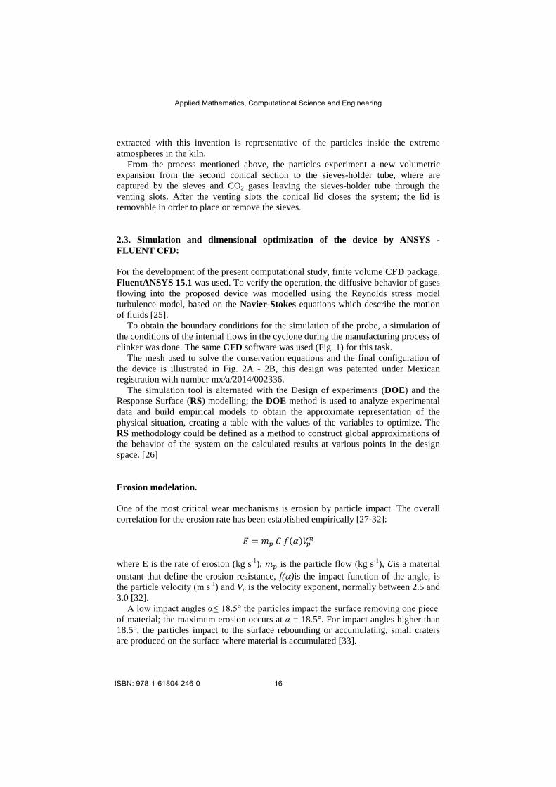
2.3. Simulation and dimensional optimization of the device by ANSYS - FLUENT CFD: For the development of the present computational study, finite volume CFD package, FluentANSYS 15.1 was used. To verify the operation, the diffusive behavior of gases flowing into the proposed device was modelled using the Reynolds stress model turbulence model, based on the Navier-Stokes equations which describe the motion of fluids [25].
To obtain the boundary conditions for the simulation of the probe, a simulation of the conditions of the internal flows in the cyclone during the manufacturing process of clinker was done. The same CFD software was used (Fig. 1) for this task.
The mesh used to solve the conservation equations and the final configuration of the device is illustrated in Fig. 2A - 2B, this design was patented under Mexican registration with number mx/a/2014/002336.
The simulation tool is alternated with the Design of experiments (DOE) and the Response Surface (RS) modelling; the DOE method is used to analyze experimental data and build empirical models to obtain the approximate representation of the physical situation, creating a table with the values of the variables to optimize. The RS methodology could be defined as a method to construct global approximations of the behavior of the system on the calculated results at various points in the design space. [26] Erosion modelation. One of the most critical wear mechanisms is erosion by particle impact. The overall correlation for the erosion rate has been established empirically [27-32]:
where E is the rate of erosion (kg s-1), is the particle flow (kg s-1), is a material onstant that define the erosion resistance, f(α)is the impact function of the angle, is the particle velocity (m s-1) and Vp is the velocity exponent, normally between 2.5 and 3.0 [32].
A low impact angles α ≤ 18.5° the particles impact the surface removing one piece of material; the maximum erosion occurs at α = 18.5°. For impact angles higher than 18.5°, the particles impact to the surface rebounding or accumulating, small craters are produced on the surface where material is accumulated [33].
Applied Mathematics, Computational Science and Engineering
ISBN: 978-1-61804-246-0 16
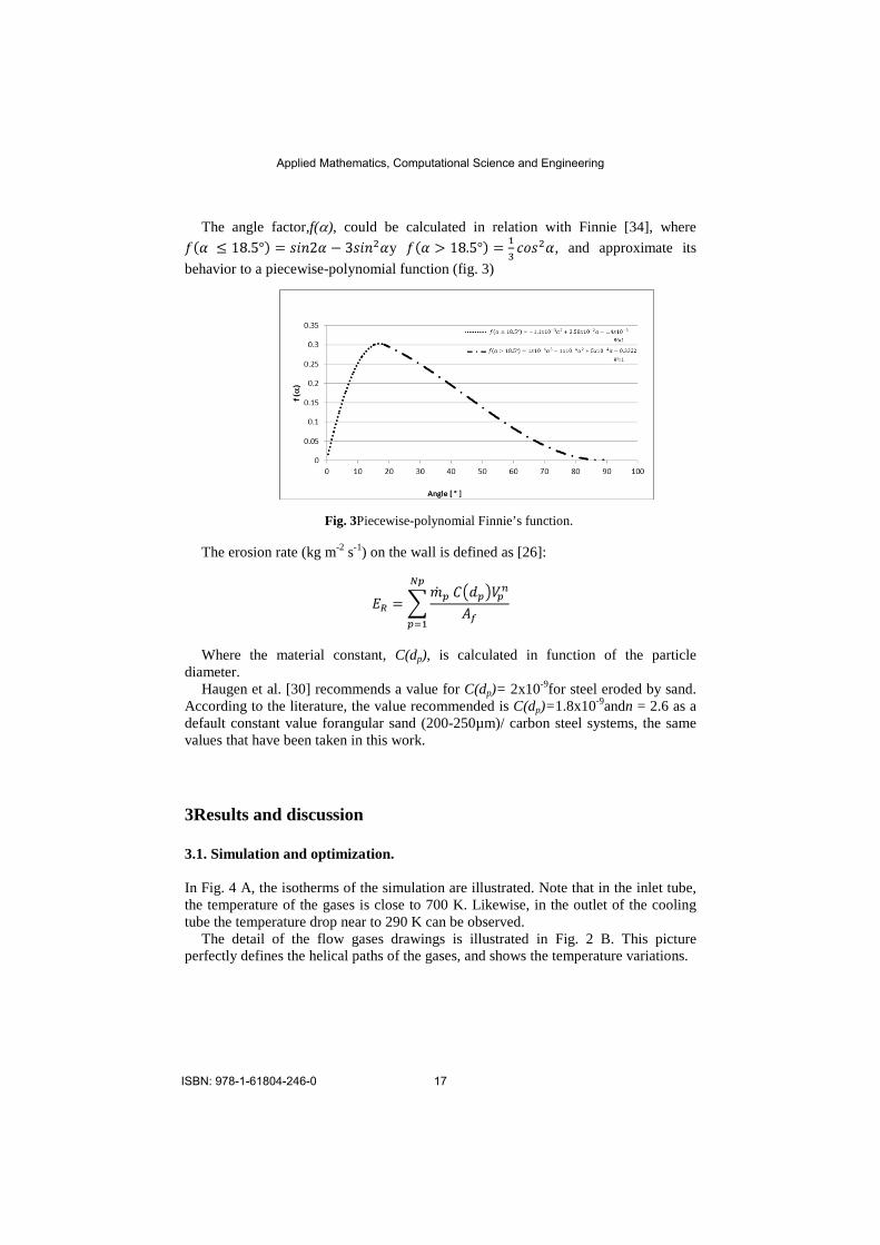
The angle factor,f(α), could be calculated in relation with Finnie [34], where y , and approximate its
behavior to a piecewise-polynomial function (fig. 3)
Fig. 3Piecewise-polynomial Finnie’s function. The erosion rate (kg m-2 s-1) on the wall is defined as [26]:
Where the material constant, C(dp), is calculated in function of the particle
diameter. Haugen et al. [30] recommends a value for C(dp)= 2x10⁻⁹for steel eroded by sand.
According to the literature, the value recommended is C(dp)=1.8x10⁻⁹andn = 2.6 as a default constant value forangular sand (200-250µm)/ carbon steel systems, the same values that have been taken in this work.
3Results and discussion
3.1. Simulation and optimization. In Fig. 4 A, the isotherms of the simulation are illustrated. Note that in the inlet tube, the temperature of the gases is close to 700 K. Likewise, in the outlet of the cooling tube the temperature drop near to 290 K can be observed.
The detail of the flow gases drawings is illustrated in Fig. 2 B. This picture perfectly defines the helical paths of the gases, and shows the temperature variations.
Applied Mathematics, Computational Science and Engineering
ISBN: 978-1-61804-246-0 17

Fig. 4A)Longitudinal section of the device showing temperature contours inlet tubes, and
carries cooling sieves.B) Detail 3D flow lines where gas temperatures shown from the inlet to the outlet of the device.
3.2 Dimensional optimization. This design optimization is based on the construction of a response surface based on fifteen level DOE.
The parameterized variables were: the main angle between the extraction tube and the main tubeθ (fig. 4), the inlet length tube and the cooling length tube L1, L2 (fig 2 B).
The optimal design angle between the two tubes is 90° among themselves, and there is no considerable effect of the length inlet tube in the extraction rate. It was found that the length of the inlet tube has not a dependency to the cooling rate. The SR indicates an optimal distance for a 162.2 mm to improve the heat dissipation rate.
Fig. 5Isometric probe (in red) where the surface taken as a reference for the calculation of
gas velocity and the angle θ.
A)
θ
Applied Mathematics, Computational Science and Engineering
ISBN: 978-1-61804-246-0 18

3. 3. Description of current sampling conditions and case study. For the optimization of the device performance, the Rosin Rammler (RR) distribution model for particles in the range of the sample under study was used (Fig. 6). For the analysis of the actual particle size distribution at the laboratory, a CILAS 1180 L was used conforms to ASTM C430.
Fig. 6 Particle size distribution within the cyclone, obtained with CILAS 1180 L.
The parameters to optimize were: the gases injection angles (extraction and cooling
tubes) injection pressures (Fig 2B). To obtain the maximum velocity at the extraction inlet tube, a negative pressure in
the x-axis direction will be generated by the Bernoulli effect, the optimum value obtained was -850.69 ms-1, calculated on the highlighted surface in red (Fig. 5). A pivot angle of the extraction tube of 21.479° is obtained with a pressure of 0.874 GPa, and a cooling pivot angle of 28.521° with a pressure of 0.2268 GPa.
A 25levels DOE generated the RS simulation which relates the injection angles of CO2with the extraction velocity in the specified area (Fig. 5). Fig. 7 shows theSR relationship between the pressures of both pivots (p1, p2) and the temperature at the output of the device. It can be confirmed that at the magnitudes of the pressures selected as optimal, a minimum level of temperature is obtained at the outlet of the device.
In this simulation, 99% of the path of 2220 particles (DPM) was followed, representing 1x10⁶ steps of 0.01 m. The mean residence time of these particles was 0.5619 s with a standard deviation of 0.8526 s. These results show that the heat transfer (heat rate) was -6.176e10-15 W with a cooling rate of 1423 Ks-1.
Applied Mathematics, Computational Science and Engineering
ISBN: 978-1-61804-246-0 19

Fig. 73D graph of the pressure pivot in cooling tube (p2), the pressure pivot in extraction tube (p1) respect to outlet temperature device (TEMPOUTLET).
In this simulation, 99% of the path of 2220 particles (DPM) was followed,
representing 1x10⁶ steps of 0.01 m. The mean residence time of these particles was 0.5619 s with a standard deviation of 0.8526 s. These results show that the heat transfer (heat rate) was -6.176e10-15 W with a cooling rate of 1423 Ks-1.
Fig. 8 Temperature behavior in each node and position of the particle within the probe.
Applied Mathematics, Computational Science and Engineering
ISBN: 978-1-61804-246-0 20

Fig. 8 shows the temperature behavior representing the values of every node conforming the simulation domain. This figure shows the heat transfer rate of both, the particles and the gas flow. This is true since the energy transfer condition approaches a concentrated system, since it satisfies the Biot number condition; i.e. the temperature changes are the same on the particle surface and inside the particle.In regions 1, 2 and 3 a cooling ramp is identified; region 1 shows how the particles and the carrier gas tend to a thermal equilibrium while region 2 shows a conic geometry in which takes place the expansion of the particle-gas system and a second gas injection at room temperature. At this point, a complementary cooling rate observed in region 1 is generated. Finally, region 3 shows the mixture is thermally homogenized. Regions 4 and 5 contribute to the feedback of the low-pressure gases to keep the necessary turbulence of the system allowing the collection of the samples in the sieves. 3.4. Simulation of erosion rate The images in figure 9 display the damage for erosion rate on the interior surface at the extraction tube. It is seen colored the erosion rate according to the color layer (fig. 9 A, 9B, 9C) are in different perspectives at the maximum erosion zone.
Fig. 9. Erosion rate profiles of the extraction probe and velocity particle track.
Once the particles enter the device through the extraction tube, some collisions occur on the front wall. This effect slow down the particles and these are extracted for the suction pressure generated by the device (fig. 9D). The particles are sent to the cooling section cone (region 2, Fig 6) and continue with the same path toward to the sieves tube. The particle impact angle is modified to achieve the critical angle within the extraction tube (fig. 9), is in this area of the probe where the maximum degree of erosion is achieved. When leaving the extraction tube and enter into the cooling tube, the particles are dispersed in a larger volume so it does not generate a measurable
A B
C
D
Applied Mathematics, Computational Science and Engineering
ISBN: 978-1-61804-246-0 21

damage. The erosion model was found atotal erosionrate of 2.3439x10⁻³ kgm-2seg-1 or 0.234 mgcm2seg-1.
Conclusions. Through the analysis of finite volume CFD, has been possible verify the correct operation of the cement clinker probe sampler at high temperatures and velocity of the particles within a cement industry cyclone, and also included an erosion analysis of this device during normal operation.
Simulation tools and the statistical analysis of the RS values contribute significantly to the design, performance optimization and materials selection for construction devices required to control the current industrial processes.In this particular study, the synergy of the CFD-DOE-RS tools, has allowed the optimization of the operation of the sampling device in the cement industry.
This simulation verifies the enough coolingtime to prevent contamination of the specimen by contact with air maintaining the crystallographic structure of the sample inside the cyclones. The materials for the construction of the device must resist a heat transfer rate and an abrasive wear friction between the particles moving at high velocity and temperature in the internal walls of the device. The erosion model determine the most vulnerable erosion area and the optimal materials for construction could be selected, in which angular sand in carbon steel materials was selected in this analysis for the worst case.
Acknowledgments The authors thank the National Council of Science and Technology of Mexico for its financial support. Also, they thank the National Laboratory of Nanotechnology of CIMAV, S.C., Chihuahua, Mexico.
Conflicts of Interest The author(s) declared there are not any conflict of interests among them or some government institutions. References 1. S. Xue, P. Joon, K. Seung, and P. Young, “Performance comparison and erosion prediction of jet
pumps by using a numerical method”, Mathematical and Computer Modelling, vol. 57, pp. 245–253, June 2011.
2. I. Yimer, H.A. Becker, and E.W. Grandmaison, “The Strong-jet/Weak-jet Problem: New Experiments and CFD. COMBUSTION AND FLAME”, vol. 124, pp. 481–502, 2001.
3. A.M. Abdulaziz, “Performance and image analysis of a cavitating process in a small type venturi,” Experimental Thermal and Fluid Science, vol. 53, pp 40–48, February 2014.
Applied Mathematics, Computational Science and Engineering
ISBN: 978-1-61804-246-0 22

4. P. Kumar, and M.W. Ming, “A CFD study of low pressure wet gas metering using slotted orifice meters”, Flow Measurement and Instrumentation, vol. 22 pp. 33–42, December 2010.
5. J.A. Cruz, F. Sánchez, and P. Quinto, “A new correlation to determine the discharge coefficient of a critical Venturi nozzle with turbulent boundary layer”, Flow Measurement and Instrumentation, vol. 17, pp. 258–266, June 2006.
6. H. Ghassemi, and H. Farshi, “Application of small size cavitating venturi as flow controller and flow meter”, Flow Measurement and Instrumentation, vol. 22, pp. 406–412, May 2011.
7. R.K. Singh, S.N. Singh, and V. Seshadri, “Study on the effect of vertex angle and upstream swirl on the performance characteristics of cone flowmeter using CFD”, Flow Measurement and Instrumentation, vol. 20, pp. 69-74, December 2008.
8. M.T. Kandakure, V.C. Patkar, and A.W. Patwardhan, “Characteristics of turbulent confined jets”, Chemical Engineering and Processing. vol. 47. Pp. 1234–1245, April 2007.
9. A.M. Silva, J.C.F. Teixeira and S.F.C.F. Teixeira, “Experiments in a large-scale venturi scrubber Part I: Pressure drop”, Chemical Engineering and Processing, vol. 48, pp. 59–67, February 2008.
10. P.A.B. de Sampaio J. L.H. Faccini and J. Su, “Modelling of stratified gas–liquid two-phase flow in horizontal circular pipes”, International Journal of Heat and Mass Transfer, vol 51, pp. 2752–2761, December 2007.
11. D. He, and B. Bai, “Numerical investigation of wet gas flow in Venturi meter”, Flow Measurement and Instrumentation, vol 28, pp. 1–6, August 2012.
12. A.N. Johnson, J.D. Wright, S. Nakao, C.L. Merkle, and M.R. Moldover, “The effect of vibrational relaxation on the discharge coefficient of critical flow venturis”, Flow Measurement and Instrumentation, vol. 11, pp. 315–327, December 1999.
13. K.A. Ibrahim, Mofreh H. Hamed, W.A. El-Askary, and S. M. El-Behery, “Swirling gas–solid flow through pneumatic conveying dryer”, Powder Technology, vol. 235, pp. 500–515, October 2012.
14. K.S. Mujumdar, V. V. Ranade, “CFD modeling of rotary cement kilns”, Asia-Pacific Journal of Chemical Engineering, vol 3, pp. 106–118, 2008.
15. H. Mikul, M. Vujanovi, D.K. Fidaros, P. Priesching, I. Mini, R. Tatschl, N. Dui and G. Stefanovi, “The application of CFD modelling to support the reduction of CO2 emissions in cement industry”, Energy, vol 45, pp. 464-473, 2012.
16. U.S. Patent: 7,789,944 B2. 17. U.S. Patent: 4,059,019. 18. U.S. Patent 4,276,092. 19. Request patent 2008/0092739. 20. Request patent 2011/0083745 A1. 21. C. Huang, S. Chiovelli, P. Minev, J. Luo, K. Nandakumar. “A comprehensive
phenomenological model for erosion of materials in jet flow”. Powder Technology, vol. 187, pp. 273–279, 2008.
22. N. Kumara, M. Shukla. “Finite element analysis of multi-particle impact on erosion in abrasive water jet machining of titanium alloy”, Journal of Computational and Applied Mathematics, vol. 236, pp. 4600–4610, 2012.
23. L. Graham, D. Lester, J. Wu. “Quantification of erosion distributions in complex geometries”, Wear, vol. 268, pp.1066–1071, 2010.
24. V. Nguyen, H. Poh, Y. Zhang. “Predicting shot peening coverage using multiphase computational fluid dynamics simulations”, Powder Technology, vol, 256 , pp. 100–112, 2014.
25. D. Montgomery. Diseño y análisis de experimentos. Segunda edición, Limusa Wiley, ISBN 13: 978-968-18-6156-8.
26. User Manual ANSYS-FLUENT 15.1
Applied Mathematics, Computational Science and Engineering
ISBN: 978-1-61804-246-0 23

27. Tilly, GP. "Erosion Caused by Impact of Solid Particles." Academic Press, Inc., Treatise on Materials Science and Technology 13 (1979): 287-319.
28. Adler, WF. "Assessment of the State of Knowledge Pertaining to Solid Particle Erosion, Final Report for Army Research Office Contract No." DAAG29-77-C-0039 1979.
29. Raask, E. "Tube Erosion by Ash Impaction." Wear 13, no. 4 (1969): 301-15. 30. Haugen, K, O Kvernvold, A Ronold, and R_ Sandberg. "Sand Erosion of Wear-Resistant
Materials: Erosion in Choke Valves." Wear 186 (1995): 179-88. 31. Hutchings, I M. "The Erosion of Steels by the Impact of Sand Particles.". (1984). 32. Nøkleberg, Lars, and Terje Søntvedt. "Erosion of Oil&Amp;Gas Industry Choke Valves
Using Computational Fluid Dynamics and Experiment." International Journal of Heat and Fluid Flow 19, no. 6 (12// 1998): 636-43.
33. Keating, Anthony, and Srdjan Nesic. "Particle Tracking and Erosion Prediction in Three-Dimensional Bends." Paper presented at the Proc. of ASME FED Summer Meeting, 2000.
34. Finnie, Iain. "Erosion of Surfaces by Solid Particles." Wear 3, no. 2 (3// 1960): 87-103.
Applied Mathematics, Computational Science and Engineering
ISBN: 978-1-61804-246-0 24
Related Documents