PROJECT NAME: 04-161 – SMART Antennas ERMES: NUMERICAL TOOL FOR SAR COMPUTATIONS SAR TOOL VALIDATION REPORT Project SMART - WP6 Task 6.5 Deliverable 6.5.3 Rubén Otín [email protected] CIMNE - International Center for Numerical Methods in Engineering Edificio C1, Campus Nord UPC, c/ Gran Capità s/n 08034 Barcelona (Spain) Tel.: +34 93 205 70 16. www.cimne.com Barcelona (Spain) - June 2009

Welcome message from author
This document is posted to help you gain knowledge. Please leave a comment to let me know what you think about it! Share it to your friends and learn new things together.
Transcript
PROJECT NAME: 04-161 – SMART Antennas
ERMES: NUMERICAL TOOL FOR SAR COMPUTATIONS
SAR TOOL VALIDATION REPORT
Project SMART - WP6 Task 6.5 Deliverable 6.5.3
Rubén Otín [email protected] CIMNE - International Center for Numerical Methods in Engineering Edificio C1, Campus Nord UPC, c/ Gran Capità s/n 08034 Barcelona (Spain) Tel.: +34 93 205 70 16. www.cimne.com Barcelona (Spain) - June 2009

PIDEA+ 04-161 - SMART antennas
SMART WP6 TASK 6.5 DELIVERABLE 6.5.3 27/10/2008
Page
I/7
DOCUMENT HISTORY
Version Date Comments Author
01.01 27/10/08 CIMNE
Rubén Otín

PIDEA+ 04-161 - SMART antennas
SMART WP6 TASK 6.5 DELIVERABLE 6.5.3 27/10/2008
Page
2/7
CONTENTS
1. SCOPE
2. REFERENCES
3. TERMINOLOGY
3.1 ABBREVIATIONS
3.2 DEFINITIONS
4. SAR TOOL OVERVIEW
5. VALIDATION OF ERMES
5.1 MICROWAVE FILTERS
5.2 SAR BENCHMARKS
6. APPLICATION OF ERMES TO SMART ANTENNAS
6.1 PMR-GPS ANTENNA (RADIALL)
6.2 TRI-BAND MIMO ANTENNA (SRF MOYANO)
7. CONCLUSIONS AND FUTURE DEVELOPMENTS
PIDEA+ 04-161 - SMART antennas
SMART WP6 TASK 6.5 DELIVERABLE 6.5.3 27/10/2008
Page
3/7
1. SCOPE This document contains the description and validation of the SAR tool named ERMES which had been developed by CIMNE in the SMART project.
2. REFERENCES
[1] Rubén Otín, "A High-Order Nodal Finite Element Formulation for Microwave Engineering", 24th International Review of Progress in Applied Computational Electromagnetics (ACES 2008), March 30 - April 4, 2008, Canada (http://aces.ee.olemiss.edu/).
[2] Rubén Otín, “Regularized Maxwell equations with nodal elements as an alternative approach to
the edge-based FEM formulations”, 9th International Workshop on Finite Elements for Microwave Engineering (http://www.lte.uni-saarland.de/fem2008/).
[3] Rubén Otín, "Regularized Maxwell equations and nodal finite elements for electromagnetic field
computations", Electromagnetics, ISSN: 0272-6343 (http://www.tandf.co.uk/journals/titles/02726343.asp) (Provisional publication date in mid 2009).
[4] Rubén Otín, Javier Mora, "El Método de los Elementos Finitos Aplicado a las Ecuaciones de
Maxwell Regularizadas en Presencia de Singularidades", V Encuentro Ibérico de Electromagnetismo Computacional, 25-27 Abril 2007, Aiguablava (Spain) (http://www.tsc.upc.edu/eiec2007/default.php).
[5] EADS SN et al, SMART T0+30 report - deliverable 1.7, February 2008 [6] SRF Moyano, SMART WP5 Task 5.3 report - deliverable 5.3.2, December 2007.
PIDEA+ 04-161 - SMART antennas
SMART WP6 TASK 6.5 DELIVERABLE 6.5.3 27/10/2008
Page
4/7
3. TERMINOLOGY
3.1 ABBREVIATIONS
ERMES Electric Regularized Maxwell Equations with Singularities
FEKO Field Computation for Objects of Arbitrary Shape (In German)
FEM Finite Element Method
GPS Global Position System
GTD Geometrical Theory of Diffraction
HORUS High ORder elements Un-gauged near the Singularity
MoM Method of Moments
Mod(E) Electric field modulus
PMR Personal (or Professional) Mobile Radio
PO Physical Optics
SAR Specific Absorption Rate
UTD Unified Theory of Diffraction
3 .2 DEFINITIONS
ERMES SAR tool developed by CIMNE in the SMART project.
FEKO Commercial software product for the simulation of electromagnetic fields
(www.feko.info).
GiD A universal, adaptive and user-friendly graphical user interface for
geometrical modelling, data input and visualisation of results for all types
of numerical simulation programs (www.gidhome.com).
HORUS Finite element formulation behind ERMES.
PIDEA+ 04-161 - SMART antennas
SMART WP6 TASK 6.5 DELIVERABLE 6.5.3 27/10/2008
Page
5/7
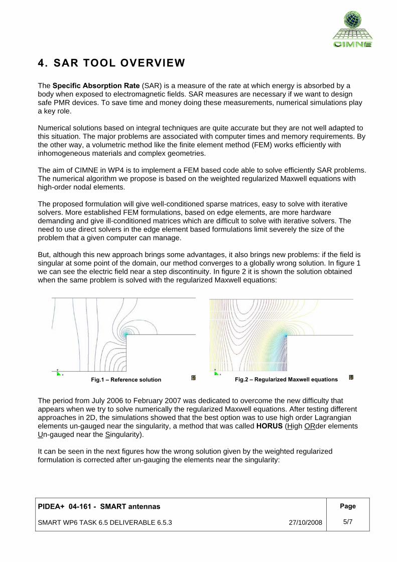
4. SAR TOOL OVERVIEW The Specific Absorption Rate (SAR) is a measure of the rate at which energy is absorbed by a body when exposed to electromagnetic fields. SAR measures are necessary if we want to design safe PMR devices. To save time and money doing these measurements, numerical simulations play a key role. Numerical solutions based on integral techniques are quite accurate but they are not well adapted to this situation. The major problems are associated with computer times and memory requirements. By the other way, a volumetric method like the finite element method (FEM) works efficiently with inhomogeneous materials and complex geometries. The aim of CIMNE in WP4 is to implement a FEM based code able to solve efficiently SAR problems. The numerical algorithm we propose is based on the weighted regularized Maxwell equations with high-order nodal elements. The proposed formulation will give well-conditioned sparse matrices, easy to solve with iterative solvers. More established FEM formulations, based on edge elements, are more hardware demanding and give ill-conditioned matrices which are difficult to solve with iterative solvers. The need to use direct solvers in the edge element based formulations limit severely the size of the problem that a given computer can manage. But, although this new approach brings some advantages, it also brings new problems: if the field is singular at some point of the domain, our method converges to a globally wrong solution. In figure 1 we can see the electric field near a step discontinuity. In figure 2 it is shown the solution obtained when the same problem is solved with the regularized Maxwell equations:
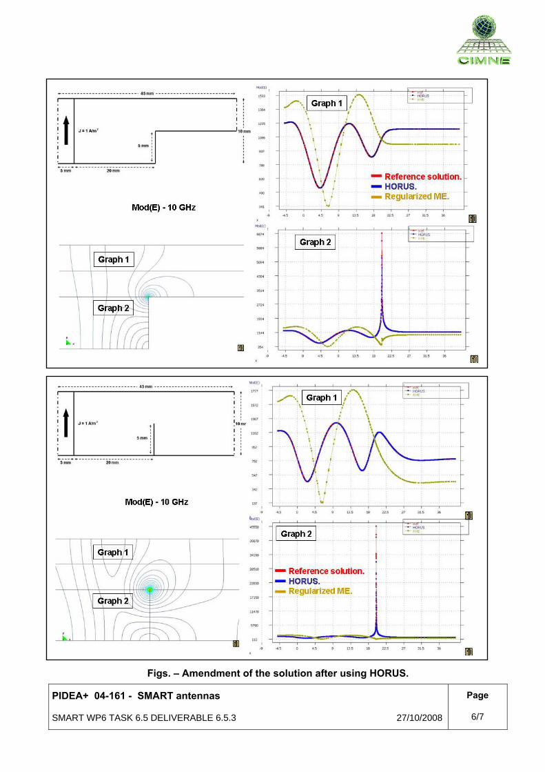
The period from July 2006 to February 2007 was dedicated to overcome the new difficulty that appears when we try to solve numerically the regularized Maxwell equations. After testing different approaches in 2D, the simulations showed that the best option was to use high order Lagrangian elements un-gauged near the singularity, a method that was called HORUS (High ORder elements Un-gauged near the Singularity). It can be seen in the next figures how the wrong solution given by the weighted regularized formulation is corrected after un-gauging the elements near the singularity:
Fig.1 – Reference solution Fig.2 – Regularized Maxwell equations
PIDEA+ 04-161 - SMART antennas
SMART WP6 TASK 6.5 DELIVERABLE 6.5.3 27/10/2008
Page
6/7
Figs. – Amendment of the solution after using HORUS.
PIDEA+ 04-161 - SMART antennas
SMART WP6 TASK 6.5 DELIVERABLE 6.5.3 27/10/2008
Page
7/7
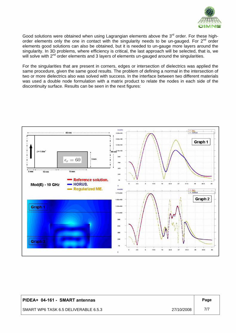
Good solutions were obtained when using Lagrangian elements above the 3rd order. For these high-order elements only the one in contact with the singularity needs to be un-gauged. For 2nd order elements good solutions can also be obtained, but it is needed to un-gauge more layers around the singularity. In 3D problems, where efficiency is critical, the last approach will be selected, that is, we will solve with 2nd order elements and 3 layers of elements un-gauged around the singularities. For the singularities that are present in corners, edges or intersection of dielectrics was applied the same procedure, given the same good results. The problem of defining a normal in the intersection of two or more dielectrics also was solved with success. In the interface between two different materials was used a double node formulation with a matrix product to relate the nodes in each side of the discontinuity surface. Results can be seen in the next figures:
PIDEA+ 04-161 - SMART antennas
SMART WP6 TASK 6.5 DELIVERABLE 6.5.3 27/10/2008
Page
8/7
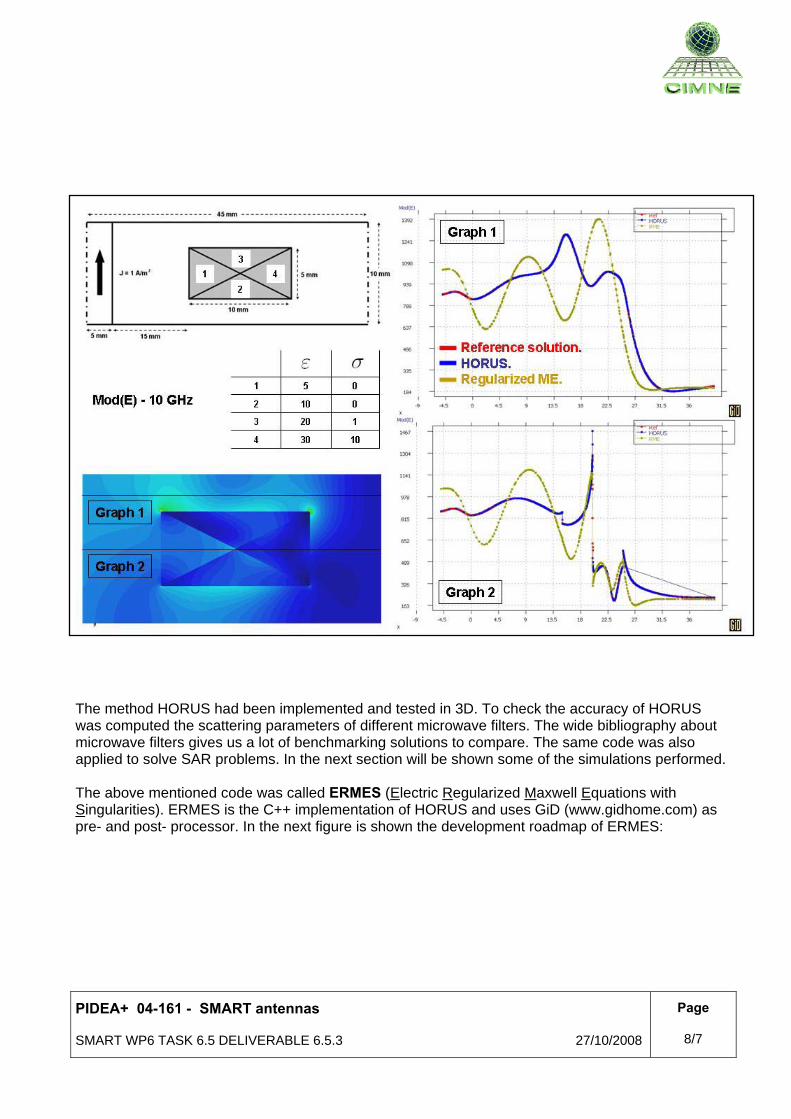
The method HORUS had been implemented and tested in 3D. To check the accuracy of HORUS was computed the scattering parameters of different microwave filters. The wide bibliography about microwave filters gives us a lot of benchmarking solutions to compare. The same code was also applied to solve SAR problems. In the next section will be shown some of the simulations performed. The above mentioned code was called ERMES (Electric Regularized Maxwell Equations with Singularities). ERMES is the C++ implementation of HORUS and uses GiD (www.gidhome.com) as pre- and post- processor. In the next figure is shown the development roadmap of ERMES:

PIDEA+ 04-161 - SMART antennas
SMART WP6 TASK 6.5 DELIVERABLE 6.5.3 27/10/2008
Page
9/7
In the next figure is shown the graphical user-friendly interface of ERMES:
PIDEA+ 04-161 - SMART antennas
SMART WP6 TASK 6.5 DELIVERABLE 6.5.3 27/10/2008
Page
10/7
5. VALIDATION OF ERMES
The validation of ERMES for 3D problems was carried out in two stages:
First, the scattering parameters of some microwave filters were calculated with ERMES and compared with measurements and/or simulations performed with other methods. The measurements and the results of alternative methods were obtained from the broad bibliography available describing microwave devices.
Secondly, two benchmarks, more specifically related with the SAR problems we were interested in, were proposed by EADS SN. These SAR benchmarks were computed with ERMES and compared with measurements or with simulations performed by EADS SN using FEKO.
These two stages will be described in more detail along this section.
5 .1 MICROWAVE FILTERS
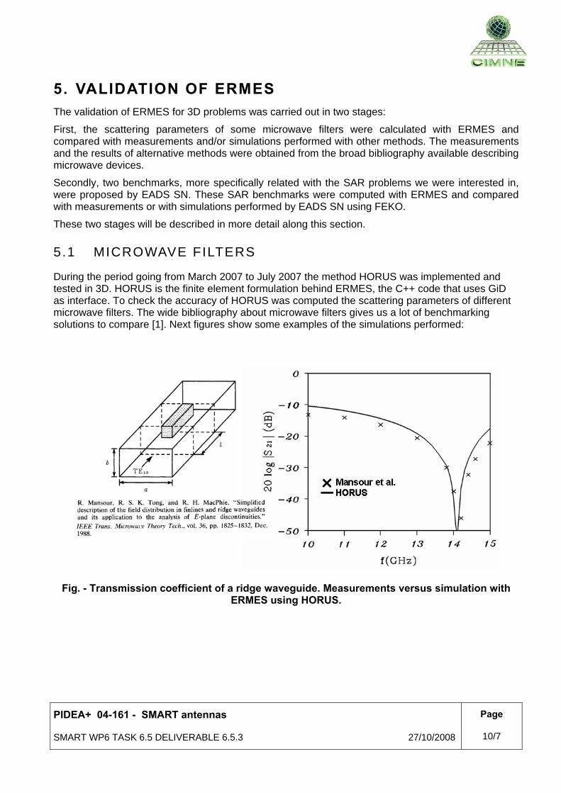
During the period going from March 2007 to July 2007 the method HORUS was implemented and tested in 3D. HORUS is the finite element formulation behind ERMES, the C++ code that uses GiD as interface. To check the accuracy of HORUS was computed the scattering parameters of different microwave filters. The wide bibliography about microwave filters gives us a lot of benchmarking solutions to compare [1]. Next figures show some examples of the simulations performed:
Fig. - Transmission coefficient of a ridge waveguide. Measurements versus simulation with
ERMES using HORUS.

PIDEA+ 04-161 - SMART antennas
SMART WP6 TASK 6.5 DELIVERABLE 6.5.3 27/10/2008
Page
11/7
Fig. – Transmission coefficient of a circular waveguide filter. Measurement versus simulation
with ERMES using HORUS.
Fig. – Reflection coefficient of a waveguide with a dielectric obstacle. Katzier´s method versus
simulation with ERMES using HORUS.
PIDEA+ 04-161 - SMART antennas
SMART WP6 TASK 6.5 DELIVERABLE 6.5.3 27/10/2008
Page
12/7
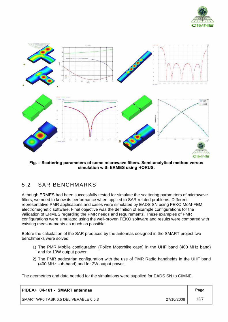
Fig. – Scattering parameters of some microwave filters. Semi-analytical method versus simulation with ERMES using HORUS.
5 .2 SAR BENCHMARKS
Although ERMES had been successfully tested for simulate the scattering parameters of microwave filters, we need to know its performance when applied to SAR related problems. Different representative PMR applications and cases were simulated by EADS SN using FEKO MoM-FEM electromagnetic software. Final objective was the definition of example configurations for the validation of ERMES regarding the PMR needs and requirements. These examples of PMR configurations were simulated using the well-proven FEKO software and results were compared with existing measurements as much as possible. Before the calculation of the SAR produced by the antennas designed in the SMART project two benchmarks were solved:
1) The PMR Mobile configuration (Police Motorbike case) in the UHF band (400 MHz band) and for 10W output power.
2) The PMR pedestrian configuration with the use of PMR Radio handhelds in the UHF band (400 MHz sub-band) and for 2W output power.
The geometries and data needed for the simulations were supplied for EADS SN to CIMNE.
PIDEA+ 04-161 - SMART antennas
SMART WP6 TASK 6.5 DELIVERABLE 6.5.3 27/10/2008
Page
13/7
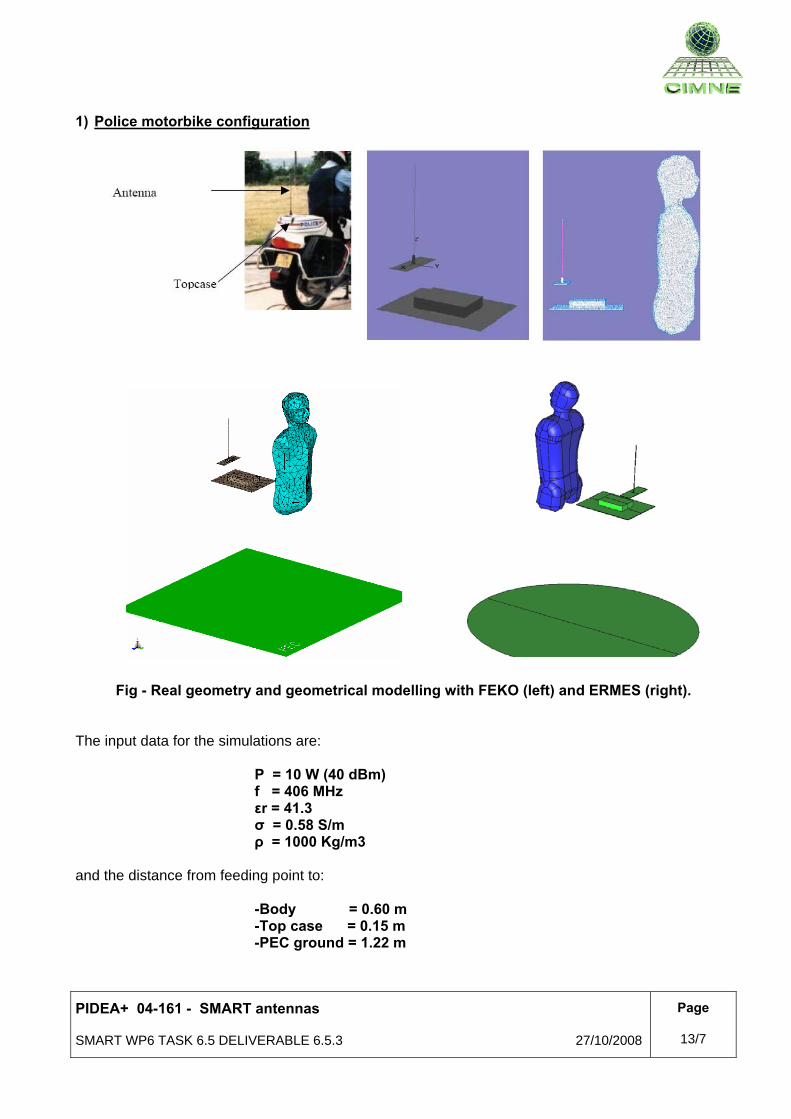
1) Police motorbike configuration
Fig - Real geometry and geometrical modelling with FEKO (left) and ERMES (right).
The input data for the simulations are:
P = 10 W (40 dBm) f = 406 MHz εr = 41.3 σ = 0.58 S/m ρ = 1000 Kg/m3
and the distance from feeding point to:
-Body = 0.60 m -Top case = 0.15 m -PEC ground = 1.22 m

PIDEA+ 04-161 - SMART antennas
SMART WP6 TASK 6.5 DELIVERABLE 6.5.3 27/10/2008
Page
14/7
ERMES results are compared with the simulations performed by EADS SN using FEKO. The results are: • FEKO (EADS SN):
SAR (average over 10g cube) = 0.06 W/Kg (back neck)
• ERMES SAR (average over 10g cube) = 0.04 W/Kg (back neck)
FFEEKKOO SSAARR ddiissttrriibbuuttiioonn.. MMaaxx.. SSAARR == 00..0077 WW//KKgg
EERRMMEESS SSAARR ddiissttrriibbuuttiioonn.. MMaaxx.. SSAARR == 00..0066 WW//KKgg
IIssoo--ssuurrffaacceess ffoorr SSAARR == 00..0033 WW//KKgg
FFEEKKOO EERRMMEESS
PIDEA+ 04-161 - SMART antennas
SMART WP6 TASK 6.5 DELIVERABLE 6.5.3 27/10/2008
Page
15/7
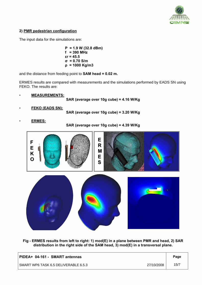
2) PMR pedestrian configuration The input data for the simulations are:
P = 1.9 W (32.8 dBm) f = 390 MHz εr = 45.5 σ = 0.70 S/m ρ = 1000 Kg/m3
and the distance from feeding point to SAM head = 0.02 m. ERMES results are compared with measurements and the simulations performed by EADS SN using FEKO. The results are: • MEASUREMENTS:
SAR (average over 10g cube) = 4.16 W/Kg • FEKO (EADS SN):
SAR (average over 10g cube) = 3.20 W/Kg
• ERMES: SAR (average over 10g cube) = 4.39 W/Kg
Fig - ERMES results from left to right: 1) mod(E) in a plane between PMR and head, 2) SAR distribution in the right side of the SAM head, 3) mod(E) in a transversal plane.
FF EE KK OO
EE RR MM EE SS
PIDEA+ 04-161 - SMART antennas
SMART WP6 TASK 6.5 DELIVERABLE 6.5.3 27/10/2008
Page
16/7
6. APPLICATION OF ERMES TO SMART ANTENNAS
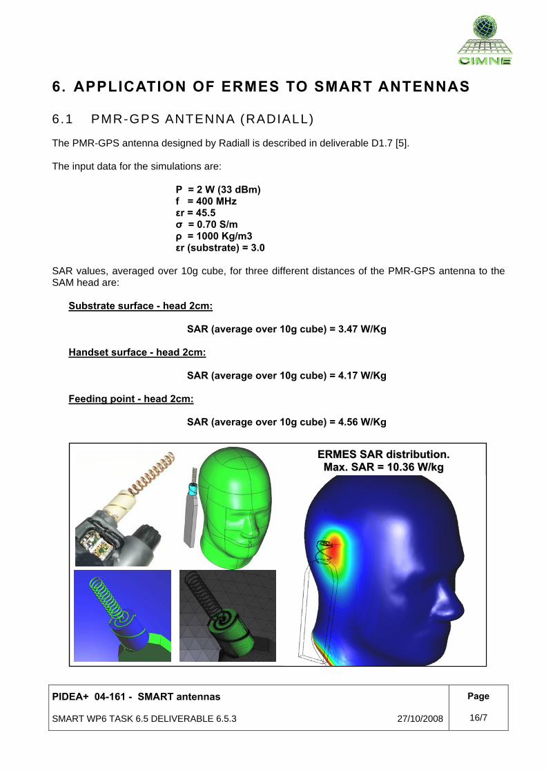
6.1 PMR-GPS ANTENNA (RADIALL)
The PMR-GPS antenna designed by Radiall is described in deliverable D1.7 [5]. The input data for the simulations are:
P = 2 W (33 dBm) f = 400 MHz εr = 45.5 σ = 0.70 S/m ρ = 1000 Kg/m3 εr (substrate) = 3.0
SAR values, averaged over 10g cube, for three different distances of the PMR-GPS antenna to the SAM head are:
Substrate surface - head 2cm:
SAR (average over 10g cube) = 3.47 W/Kg Handset surface - head 2cm:
SAR (average over 10g cube) = 4.17 W/Kg Feeding point - head 2cm:
SAR (average over 10g cube) = 4.56 W/Kg
EERRMMEESS SSAARR ddiissttrriibbuuttiioonn.. MMaaxx.. SSAARR == 1100..3366 WW//kkgg
PIDEA+ 04-161 - SMART antennas
SMART WP6 TASK 6.5 DELIVERABLE 6.5.3 27/10/2008
Page
17/7
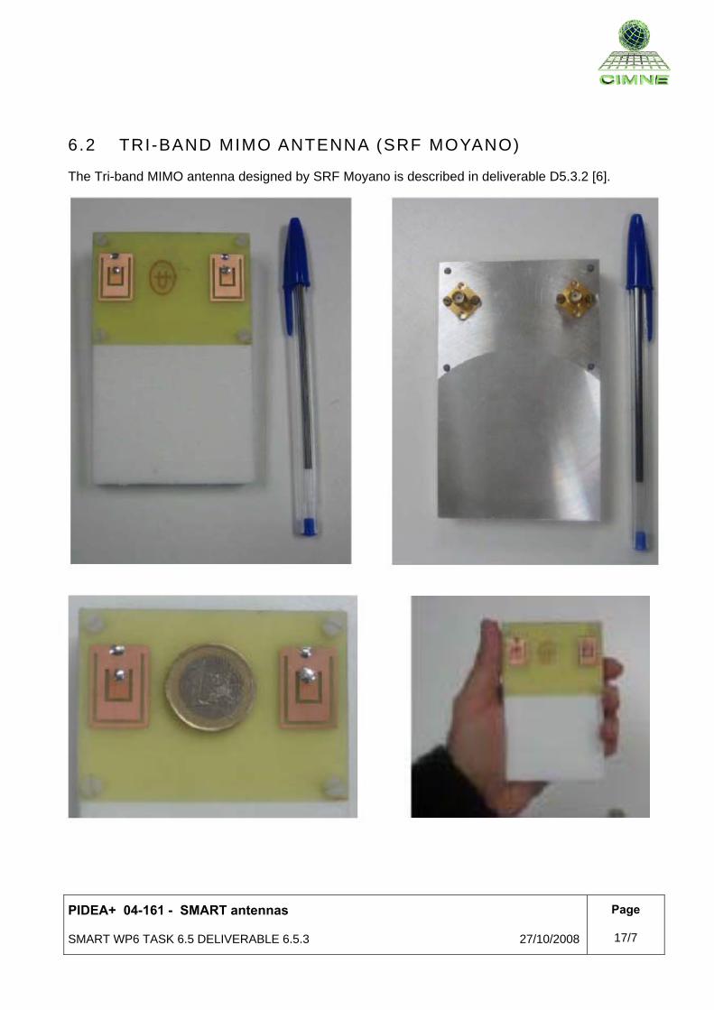
6 .2 TRI-BAND MIMO ANTENNA (SRF MOYANO)
The Tri-band MIMO antenna designed by SRF Moyano is described in deliverable D5.3.2 [6].
PIDEA+ 04-161 - SMART antennas
SMART WP6 TASK 6.5 DELIVERABLE 6.5.3 27/10/2008
Page
18/7
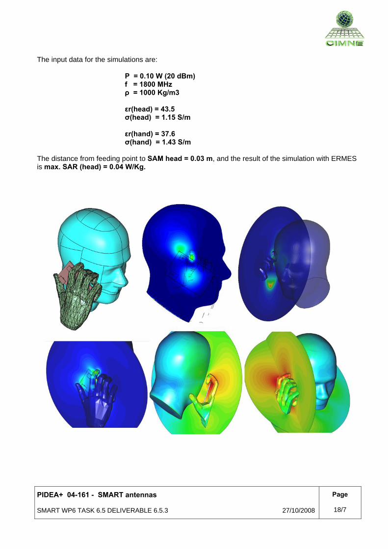
The input data for the simulations are:
P = 0.10 W (20 dBm) f = 1800 MHz ρ = 1000 Kg/m3 εr(head) = 43.5 σ(head) = 1.15 S/m εr(hand) = 37.6 σ(hand) = 1.43 S/m
The distance from feeding point to SAM head = 0.03 m, and the result of the simulation with ERMES is max. SAR (head) = 0.04 W/Kg.
PIDEA+ 04-161 - SMART antennas
SMART WP6 TASK 6.5 DELIVERABLE 6.5.3 27/10/2008
Page
19/7
7. CONCLUSIONS AND FUTURE DEVELOPMENTS After a careful examination of the simulations described in this report, we can conclude that ERMES gives accurate results and that it can solve efficiently SAR problems. However, there are some scenarios in which the efficiency can be put in jeopardy: 1-) Too many singularities in the domain (metallic or dielectric edges and corners): The need of meshing with small elements to catch the behaviour of the fields near the singularities increase dramatically the number of unknowns, therefore, the computational cost is increased. Moreover, the user must be very careful selecting the sizes of the mesh when the singularity interacts strongly with the environment. In conclusion, we must research more in deep how to improve the performance of ERMES when electric field singularities are present in the domain. 2-) Source (antenna) and target (dielectric body) are far away from each other: The finite element method needs to calculate the electric field in the space surrounding source and target. If the distance between source and target is large, the volume needed to run the simulation is large; therefore, the computational cost is high. A possible solution to improve the performance of ERMES in these cases is the implementation of hybrid methods (e.g. FEM-MoM). In conclusion, we must research about hybrid methods. SMART project has allowed CIMNE to develop a new finite element formulation called HORUS (High ORder elements Un-gauged near the Singularity). HORUS is the finite element formulation behind ERMES (Electric Regularized Maxwell Equations with Singularities), a C++ code that uses GiD (www.gidhome.com) as interface. As a consequence, one of the deliverables of SMART is a user-friendly computational tool ready to be used for SAR calculations. SMART project has allowed demonstrating the usefulness of ERMES for professional electromagnetic modelling has increased CIMNE know-how and experience in the electromagnetic field and has set up links between CIMNE and the industry and other university departments. But, although the current ERMES version is suitable for solving SAR problems in near field, further research is required to develop specific formulations and numerical models for electrically large structures e.g. base station antennas with entire body models or complex car configuration with the presence of different passengers. Hybridization of the FEM formulation developed in SMART with MoM and high-frequency methods like PO, GTD or UTD could be investigated and implemented in order to be able to solve such electrically large problems. Also new features could be added and enhancements in the existing ones would improve the computational performance of the SAR tool, for instance: - Incorporation of far field patterns. - Improvements in the radiation boundary conditions. - Improvements in the modelization of the electric field singularities. This let the door open for new projects which allow CIMNE to develop a better and more useful SAR computational tool.
Related Documents


![[Med ITA] Anatomia - Muscoli (Dall'Edi-Ermes)](https://static.cupdf.com/doc/110x72/55cf882655034664618dd96e/med-ita-anatomia-muscoli-dalledi-ermes.jpg)