LZB 1 15 2508 R1A Introduc tion to GSM/DCS/PCS Systems 2-1 Chapter 2 - Introduction to GSM/DCS/PCS Systems Introduction Cellular telecommunication is one of the f astest growing and most demanding telecommunications appli- cations ever. Digital cellular solutions are successfully competing with traditional wire networks and cord- less telephones. Eventually , digital cellular mobile telephones will be the universal way to telecommunicate. CME 20/CMS 40 is a GSM-based system operating in the 900, 1800, or 1900 MHz range (there is a com- mon platform for CME 20 and CMS 40: T elecommunication s Standards Institute (ETSI) and American National Standards Institut e (ANSI). It is a "total system" solution including switching centers, location registers, base station controllers, and base transceiver stations, as well as facilities for centralized opera- tions and maintenance and mobile stations (handsets). The system ensures that operating companies receive the benefits of a full system standard with open interfaces, complete security , and roaming, among others. CME 20 and CMS 40 ar e designed to provide users with advanced telecommunicatio n services according to technical specifications. Also, to meet demands made by operating companies (sometimes referred to as "operators" and "carriers" in some countries) for flexible network solutions, innovat ive charging, service segmentation , service creation, and easy Operation and Maintenance (O&M). Ericsson has been designing cellular radio systems since the 1970s, and offers network products for all major cellular standards - such as the Nordic Mobile Telephone (NMT) system, the Total Access Commu- nication System (T ACS), Advanced Mobile Phone System (AMPS), Digital AMPS; the Personal Digital Cellular (PDC) standard (Japan), and the Global System for Mobile Communicat ion (GSM) standard GSM 900, Digital Communication System (DCS) 1800, and the Personal Communications System (PCS) 1900.

Welcome message from author
This document is posted to help you gain knowledge. Please leave a comment to let me know what you think about it! Share it to your friends and learn new things together.
Transcript
7/27/2019 Ericsson CA638 CF688 Introduction to GSM DCS PCS Systems
http://slidepdf.com/reader/full/ericsson-ca638-cf688-introduction-to-gsm-dcs-pcs-systems 1/27
LZB 115 2508 R1A Introduction to GSM/DCS/PCS Systems
2-1
Chapter 2 -Introduction to GSM/DCS/PCS Systems
Introduction
Cellular telecommunication is one of the fastest growing and most demanding telecommunications appli-
cations ever. Digital cellular solutions are successfully competing with traditional wire networks and cord-
less telephones. Eventually, digital cellular mobile telephones will be the universal way to
telecommunicate.
CME 20/CMS 40 is a GSM-based system operating in the 900, 1800, or 1900 MHz range (there is a com-
mon platform for CME 20 and CMS 40: Telecommunications Standards Institute (ETSI) and American
National Standards Institute (ANSI). It is a "total system" solution including switching centers, location
registers, base station controllers, and base transceiver stations, as well as facilities for centralized opera-
tions and maintenance and mobile stations (handsets). The system ensures that operating companies
receive the benefits of a full system standard with open interfaces, complete security, and roaming, among
others. CME 20 and CMS 40 are designed to provide users with advanced telecommunication services
according to technical specifications. Also, to meet demands made by operating companies (sometimes
referred to as "operators" and "carriers" in some countries) for flexible network solutions, innovative
charging, service segmentation, service creation, and easy Operation and Maintenance (O&M).
Ericsson has been designing cellular radio systems since the 1970s, and offers network products for all
major cellular standards - such as the Nordic Mobile Telephone (NMT) system, the Total Access Commu-
nication System (TACS), Advanced Mobile Phone System (AMPS), Digital AMPS; the Personal Digital
Cellular (PDC) standard (Japan), and the Global System for Mobile Communication (GSM) standard GSM
900, Digital Communication System (DCS) 1800, and the Personal Communications System (PCS) 1900.
7/27/2019 Ericsson CA638 CF688 Introduction to GSM DCS PCS Systems
http://slidepdf.com/reader/full/ericsson-ca638-cf688-introduction-to-gsm-dcs-pcs-systems 2/27
Inroduction to GSM/DCS/PCS Systems LZB 115 2508 R1A
2-2
System Nodes and Related Equipment
Refer to Table 2-1 for system frequency ranges.
GSM 900 is strong in radio coverage. DCS 1800 and PCS 1900 are strong in radio capacity. Additionally,
GSM and DCS is often offered by combined license (PCS 1900 is the GSM standard’s American version).
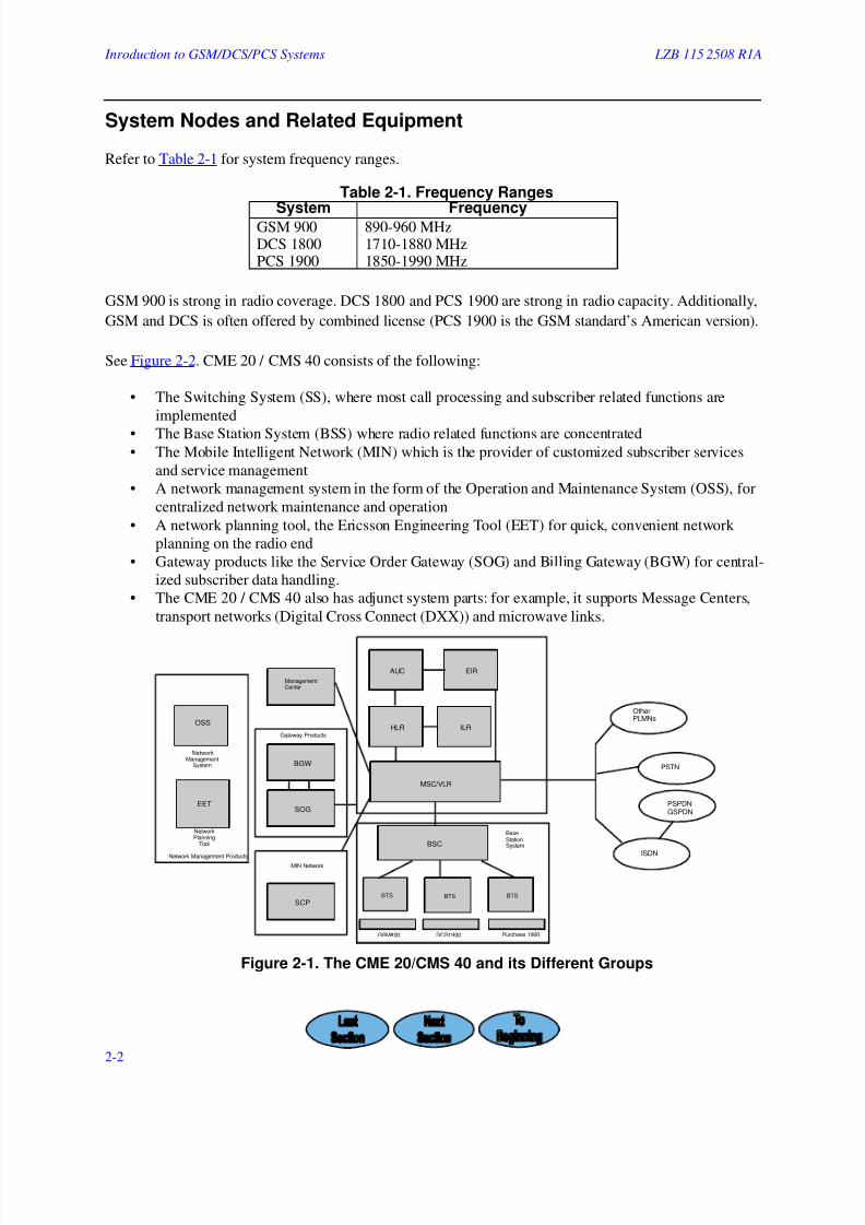
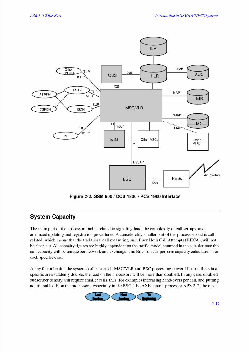
See Figure 2-2. CME 20 / CMS 40 consists of the following:
• The Switching System (SS), where most call processing and subscriber related functions are
implemented
• The Base Station System (BSS) where radio related functions are concentrated• The Mobile Intelligent Network (MIN) which is the provider of customized subscriber services
and service management
• A network management system in the form of the Operation and Maintenance System (OSS), for
centralized network maintenance and operation
• A network planning tool, the Ericsson Engineering Tool (EET) for quick, convenient network
planning on the radio end
• Gateway products like the Service Order Gateway (SOG) and Billing Gateway (BGW) for central-
ized subscriber data handling.
• The CME 20 / CMS 40 also has adjunct system parts: for example, it supports Message Centers,
transport networks (Digital Cross Connect (DXX)) and microwave links.
Figure 2-1. The CME 20/CMS 40 and its Different Groups
Table 2-1. Frequency Ranges
System FrequencyGSM 900 890-960 MHzDCS 1800 1710-1880 MHzPCS 1900 1850-1990 MHz
NetworkManagement
System
NetworkPlanning
Tool
Network Management Products
Gateway Products
MIN Network
GSM800 DCS1900 Purchase 1900
BaseStationSystem
OSS
EET
BGW
SOG
SCP
ManagementCenter
AUC EIR
HLR ILR
MSC/VLR
BSC
BTSBTS BTS
OtherPLMNs
PSTN
PSPDNGSPDN
ISDN
7/27/2019 Ericsson CA638 CF688 Introduction to GSM DCS PCS Systems
http://slidepdf.com/reader/full/ericsson-ca638-cf688-introduction-to-gsm-dcs-pcs-systems 3/27
LZB 115 2508 R1A Introduction to GSM/DCS/PCS Systems
2-3
The Switching System (SS)
The Switching System contains the following nodes:
• The Mobile Services Switching Center (MSC) performs telephony switching functions. A special
Gateway MSC (GMSC) function co-ordinates traffic from other networks. Functions for switch-ing, network interfacing, common channel signaling, toll ticketing, etc., are also included. The
GSM Inter Working Unit (GIWU) for data communication is also implemented in the MSC.
• The Visitor Location Register (VLR) is a database containing information about all Mobile Stations
currently located in the MSC area. The VLR is always integrated with the MSC.
• The Home Location Register (HLR) is a database that stores and manages subscriptions. It contains
permanent subscriber data such as subscription types, subscribed services, and so forth. It also
stores information about a subscriber's location. The HLR can be integrated in the same node as
the MSC, or can be implemented as a separate node.
• The Interworking Location Register (ILR) offers roaming between mobile telephony systems com-
plying with different standards. The possibility to offer intersystem roaming to subscribers gives
operating companies a new, competitive edge. The ILR is a stand-alone node: it will be co-located
only with an AMPS Authentication Center (AUC).
• The Authentication Center (AUC) provides authentication and encryption parameters required to
assure Mobile Station (MS) user identity and to ensure call confidentiality.
• The Equipment Identity Register (EIR) is a database containing information about mobile equip-
ment identities in order to prevent Mobile Station (MS) unauthorized use. (The EIR is often
located in the same node as the AUC, but it can be implemented as a separate node.)

7/27/2019 Ericsson CA638 CF688 Introduction to GSM DCS PCS Systems
http://slidepdf.com/reader/full/ericsson-ca638-cf688-introduction-to-gsm-dcs-pcs-systems 4/27
Inroduction to GSM/DCS/PCS Systems LZB 115 2508 R1A
2-4
The Base Station System (BSS)
The Base Station System contains the following nodes:
• The Base Station Controller (BSC) is a high capacity switch responsible for radio functions such as
hand-over, managing radio network resources, and handling cell configuration data. It also con-trols radio frequency power levels in RBSs (BTSs), and Mobile Stations (or, mobile telephone
handsets).
• The Base Transceiver Station* (BTS) is radio equipment needed to serve one cell (according to
GSM). Radio Base Stations (RBSs), however, are the equipment needed to serve many cells. The
traffic interface between the BSC and the BTS is the Abis interface. Typically, one MSC in the
Switching System supervises one or more BSCs, which in turn can control a number of BTSs.
NOTES
CME 20 and CMS 40 has ETSI (CME 20) 32 channel a-law, and ANSI (CMS 40)
24 channel (-law ("bit-stealing") that serves BTSs at 900, 1800, and 1900 MHz (bit
rates are 2 Mbit/s for CME 20 and 1.5 Mbit/s for CMS 40, respectively).
The MSC/VLR, HLR, ILR, MIN as well as BSC are all AXE applications. The
AXE is a flexibly applied, high capacity switch that is the basic building block in
Ericsson Public Land Mobile Networks (PLMNs), Public Switched Telephone
Exchanges (PSTNs), Public Data Networks (PDNs) and Integrated Services Digital
Networks (ISDNs). Using AXE technology gives network operators a proven tele-
communication base when setting up their network and ensuring continued techni-
cal development in the system. Having system nodes AXE based also makes
operation and maintenance easier, since the same maintenance skills that apply to
AXE also apply to the MSC, HLR, the ILR, BSC, and SCP.
Mobile Intelligent Network (MIN)
The MIN is a concept consisting of all possible Intelligent Network (IN) nodes. MIN provides intelligent
network services to cellular network users. It is also the foundation for service creation and management in
the network. It lets the operating company to differentiate its services in the market.
The MIN executes service logic and consists, among other nodes, of the Service Control Point , which is a
vital MIN network node that can serve as a stand alone node or be integrated with the Service Switching
Point (SSP), or stand separate from the MIN, altogether.

7/27/2019 Ericsson CA638 CF688 Introduction to GSM DCS PCS Systems
http://slidepdf.com/reader/full/ericsson-ca638-cf688-introduction-to-gsm-dcs-pcs-systems 5/27
LZB 115 2508 R1A Introduction to GSM/DCS/PCS Systems
2-5
Operation and Support System (OSS)
The Operation and Support System (OSS): a network management product and tool based on system node
software making it possible to centralize operation, support, and management of a network. The basic
functions can always be accessed from local operation and maintenance terminals. But higher level net-
work administrative tasks can be performed from one or multiple Operation and Maintenance Centers
(OMC), Network Management Centers (NMCs), or both, through the OSS. The OSS is necessary for effi-
cient network management as the network rapidly grows. The OSS also provides functions for radio net-
work configuration management, as well as network and radio traffic measurements, post processing,
display, and report generation.
Ericsson Engineering Tool (EET)
The Ericsson Engineering Tool (EET): a software-based network management product that engineers use
as a cell planning tool, and that can interface with the OSS. EET allows for planning and managing a radionetwork’s resources.
Gateway Products
The Service Order Gateway (SOG): connects an operating company’s Customer Administrative System
(CAS) to the various system nodes.
The Billing Gateway (BGW), which connects an operating company’s Customer Billing System to the var-
ious system nodes.
Adjunct System Parts
GSM-based systems can access or use the following adjunct parts.
• Message Center : Different Message Systems can be connected to the network. The messaging sys-
tem stores and passes on messages such as voice mail, fax mail, short text messages (GSM/pag-
ing), electronic mail, etc.
• Digital Cross Connect (DXX): Ericsson's DXX transport network solution is a highly flexible sys-
tem of modular hardware and management software designed for quickly deploying and broaden-
ing public telecom transport networks. DXX is an ideal transmission solution for all mobilecommunications networks, whether they carry digital or analogue cellular, PCN or paging ser-
vices.
• Microwave Links (Mini Link): Mini link (microwave) products are available for use with GSM-
based systems. Mini links integrate completely with existing telecom (like wire line) networks,
adding new levels of "short-haul" radio flexibility to networks, or point to point transmission of
voice and data. Microwave links are easy to install, are flexible, and are reliable in all climates.
7/27/2019 Ericsson CA638 CF688 Introduction to GSM DCS PCS Systems
http://slidepdf.com/reader/full/ericsson-ca638-cf688-introduction-to-gsm-dcs-pcs-systems 6/27
Inroduction to GSM/DCS/PCS Systems LZB 115 2508 R1A
2-6
Features
The cellular mobile telephone system provides communication to and from Mobile Station subscribers by
providing various basic telecommunication services. Each system release (1.0, 2.0, etc.) witnesses an
increase in new basic and optional functionality. Feature development is driven by customer demands and
feedback. System development also incorporates product enhancements such as new hardware, network
node integration, increased capacity, customer services, continuing staff education and training, and guar-
anteed system reliability.
System Capabilities
For the User
The system provides its users with an extensive set of services and facilities, such as:
• Roaming, or, a Mobile Station's ability to move freely throughout the entire service area, irrespec-
tive of the network operator.
• Integrated voice and data communication. Not only does the system give its users excellent mobile
voice communication, it also enables data communication handling to and from Mobile Station
subscribers.
• Security. Subscriber authentication, transmitted information encryption, and using temporary sub-
scriber identities in the network protects the user against false call charges and ensures total pri-
vacy. (Security aspects of the system are catered to via equipment validity checking in the EIR.)
• An extensive set of Supplementary Services for call forwarding, call barring, multiparty conversa-
tions, and so on.
• The Short Message Service makes it possible to send a short text (alphanumeric) message to, or
from, Mobile Stations. (The short message service can be viewed as an advanced form of alphanu-meric paging.)
• A wide variety of Bearer Services (BSs) up to 9.6 kbit/s.
In addition to normal call handling functions necessary to support the services and facilities just men-
tioned, the system also implements generic features like network wide hand-over. In order to ensure the
connection continuity as a Mobile Station moves, an active call can be handed over between:
• Physical channels within one cell
• Cells controlled by the same BSC
• BSCs connected to MSC
• MSCs belonging to the service area.
7/27/2019 Ericsson CA638 CF688 Introduction to GSM DCS PCS Systems
http://slidepdf.com/reader/full/ericsson-ca638-cf688-introduction-to-gsm-dcs-pcs-systems 7/27
LZB 115 2508 R1A Introduction to GSM/DCS/PCS Systems
2-7
For the Operating Company
The system also ensures optimum performance and economy for the network operating company’s staff:
• Operation and maintenance functions inherent in the MSC/VLR, HLR, and the BSC are virtually
identical to the functions in a general AXE telephone exchange. These functions provide continu-
ous exchange performance supervision and statistics collection, as well as automatic reconfigura-tion during restarts.
• Centralized network management for all system parts is available via the OSS, including dedicated
applications for managing a network.
• Remote control and supervision of RBSs from the BSC (including software updates that decrease
the need for RBS site visits) is also provided by the system.
• Submultiplexing and transcoding in the BSC minimizes the transmissions to Radio Base Stations,
and so reduces costs. (Four voice channels are submultiplexed into one PCM channel.)
• Drop/Insert functionality and Digital Cross Connect (DXC) in RBSs makes it possible to connect
numerous RBSs (BTSs) on the same 1.5 or 2.0 Mbit/s PCM path allowing for a very efficient and
redundant transmission network topology.
• Discontinuous Reception (DRX) and Uplink Discontinuous Transmission (DTX). All paging
requests are transmitted at predefined time intervals, allowing the Mobile Station to switch off the
receiver between paging intervals. Additional battery power is saved with a voice activity detector
that suppresses the handset's transmissions during speech pauses.
• Frequency hopping, Downlink Discontinuous Transmission (DTX), intra cell hand-over, and
dynamic mobile and radio base station power control. These functions maintain cells' call quality
levels as the number of subscribers grows in a network.
• Mobile Station subscriber activity supervision. A Mobile Station subscriber will automatically be
pointed out and not paged if the subscriber has been inactive (or is in an idle state) or is beyond
coverage for a certain time period. Such call supervision decreases the load on paging channels
and instantly tells other networks the Mobile Station user cannot be reached.
• Charging for both voice and data traffic (including Short Message Services) is done on a per call
basis using toll ticketing.• Accounting functions collect and administer data needed for remuneration purposes between oper-
ating companies (that is, network operators).
7/27/2019 Ericsson CA638 CF688 Introduction to GSM DCS PCS Systems
http://slidepdf.com/reader/full/ericsson-ca638-cf688-introduction-to-gsm-dcs-pcs-systems 8/27
Inroduction to GSM/DCS/PCS Systems LZB 115 2508 R1A
2-8
Telecommunication Services
Basic telecommunication services can be divided into two main categories: Teleservices and Bearer Ser-
vices. These "basic services" are augmented by various Supplementary Services, such as call forwarding,
call transfer, and so on.
A Teleservice lets the MS subscriber communicate with another subscriber (usually voice, fax, and Short
Message Services). A Bearer Service lets the MS subscriber send data (transmitting signals between two
access points that provide an interface to the network).
The system is also designed to enable operating companies to distinguish their services from the competi-
tion’s using Ericsson innovative, or customer-defined, services based on Ericsson’s mobile Intelligent Net-
work (IN) techniques. Mobile Intelligent Networks (MINs) let an operating company define personalized
new services for delivery to Mobile Station subscribers in different customer segments (business, residen-
tial, etc.).
Teleservices
The system provides the following Teleservices:
• Telephony
• Emergency calls
• Dual Tone Multi Frequency
• Short Message Service, mobile originated/point to point
• Short Message Service, mobile terminated/point to point
• Automatic facsimile service Gr.3 in transparent mode
Telephony
All subscribers are able to receive and originate calls independently of where in the entire service area they
are located. Telephony is normally two-way voice communication between Mobile Station (MS) subscrib-
ers, and is the most fundamental service.
Emergency Calls
Emergency calls are initiated by dialing a simple emergency call procedure. An emergency call can be
made without using a Subscriber Identity Module (SIM) card in the MS. If the subscriber uses the emer-
gency function in the MS to set up the call, there is no called number to charge.
DTMF
Dual Tone Multi Frequency (DTMF) tone generation provides means to send digits from a Mobile Station
to a remote end. By sending these digits an MS can request the services provided by the remote end. The
digits are sent through the network in the form of tones. DTMF tones are not generated by the MS, but by
the MSC/VLR due to distortion otherwise introduced by a speech coder.
7/27/2019 Ericsson CA638 CF688 Introduction to GSM DCS PCS Systems
http://slidepdf.com/reader/full/ericsson-ca638-cf688-introduction-to-gsm-dcs-pcs-systems 9/27
LZB 115 2508 R1A Introduction to GSM/DCS/PCS Systems
2-9
Short Message Service
The Short Message Service (SMS) provides a means of sending text messages of limited size (containing
up to 160 alphanumerical (that is, both text and number (characters) to and from Mobile Stations. The SMS
makes use of a Service Center (SC), which acts as a store and forwarding center for short messages.
The SMS comprises two basic services:
• Mobile terminated (from an SMSC to a Mobile Station).
• Mobile originated (from a Mobile Station to an SMSC).
Mobile Terminated SMS
The mobile terminated SMS can transfer a short message from the SMSC to a Mobile Station. It also pro-
vides information about the delivery of the message. Information is either a delivery report, which con-
firms the delivery of the short message to the recipient, or a failure report, which informs the originator that
the short message was not delivered, and the reason why.
Mobile Originated SMS
Mobile originated SMS will transfer a short message submitted by the MS to an SC. It will also provideinformation about the delivery of the short message either by a delivery report or a failure report.
Interworking MSC for SMS (SMS-IWMSC) is an MSC capable of receiving a short message from within
the PLMN and submitting it to the recipient SC. SMS-GMSC and SMS-IWMSC are located in all MSC/
VLR nodes.
Cell Broadcast Short Message
Another short message service type is the cell broadcast facility, where a short message is forwarded to all
Mobile Station subscribers in a geographical area. Typical types of messages (93 characters or less) may
include, for example, traffic delay warnings, bad weather ahead, etc., for boaters, surfers, or drivers, and so
on.
Automatic Facsimile Gr.3
The automatic (autocalling/autoanswering) fax Gr.3 in the transparent mode is supported by CME 20 /
CMS 40. This means that fax connections may be established to or from group 3 apparatus.
Bearer Services
With a Bearer Service, the network provides a transmission path between two access points and also a
user-to-network interface. The network will be responsible for delivering in one interface what was
received in the other. Interworking attributes may be defined for the support of Bearer Services over transit
networks.
The system supports both transparent and non-transparent data services. A transparent data service is char-
acterized by a fixed delay (no flow control seen or handled by the network and known user traffic through-
put) and an error rate that may vary. A non-transparent data service includes the flow control and the
Radio Link Protocol (RLP), which gives a variable delay, but a lower and more constant error rate over the
radio interface.
7/27/2019 Ericsson CA638 CF688 Introduction to GSM DCS PCS Systems
http://slidepdf.com/reader/full/ericsson-ca638-cf688-introduction-to-gsm-dcs-pcs-systems 10/27
Inroduction to GSM/DCS/PCS Systems LZB 115 2508 R1A
2-10
Within the network, all connections are circuit switched. This does not, however, prohibit circuit switched
connections to be set up through the Packet Switched Public Data Network (PSPDN) access node in the
network in order to utilize a packet switched connection to an end subscriber. This requires, though, a
Packet Handler or similar resources within the fixed network.
Data on Internet and Video Conferencing
Connecting to private data networks or to the Internet directly from cellular networks is now frequent. The
next step in data services will be to enable users to access two time slots within the Time Division Multiple
Access (TDMA) frame to double the data rate. Ericsson is already developing solutions for the data market
that will offer multimedia and Internet connectivity. General Packet Radio Services (GPRS) will soon be
available. Operators will also later be able to offer bandwidth on demand, dynamically allocating up to 8
time slots to meet 64 kbps user requirements. Using full bandwidth will permit services such as multimedia
access, video conferencing, and CD quality sound.
Traffic to PSTN or 3.1 kHz Services in ISDN
Applicable data traffic to the PSTN will be modem and fax calls.
For connections via PSTN, a modem is selected in the Interworking Unit (IWU) and so the informationtransfer capability will be 3.1 kHz. In case of incoming calls from a PSTN, multi-numbering is used for
this selection. On the other hand, if the call is mobile originated, the selected service and modem used will
be indicated in the bearer capability.
The ISUP trunk will offer 3.1 kHz transmission media for modems and fax applications in the ISDN net-
work.
Traffic to PSPDN
The PSTN can be used as a transit network for basic Packet Assembly/Disassembly (PAD) access (asyn-
chronous services) or basic packet access utilizing an Access Unit (AU) (synchronous services) to the
Packet Switched Public Data Network (PSPDN).
Packet services utilize the bit-oriented synchronous non-transparent or transparent service. User data rates
to be supported are 2400, 4800 and 9600 Kilobits per Second (kbit/s).
Traffic to CSPDN
The Circuit Switched Public Data Network (CSPDN) is reachable through PSTN or ISDN, but depends on
the provision of interworking in these transit networks.
Traffic Between MSs
Data traffic inside the PLMN also must pass through the IWU to handle the V.110’ protocol used for rate
adaptation in the radio path.
Basic PAD Service
Access from an MS to a PSPDN is possible via a PAD in the switched telephone network. Rates between
300 and 9600 bit/s are supported.
The basic PAD access refers to the use of existing PADs in the PSPDN via PSTN. The circuit switched
asynchronous service is used for accessing a PAD outside the PLMN.

7/27/2019 Ericsson CA638 CF688 Introduction to GSM DCS PCS Systems
http://slidepdf.com/reader/full/ericsson-ca638-cf688-introduction-to-gsm-dcs-pcs-systems 11/27
LZB 115 2508 R1A Introduction to GSM/DCS/PCS Systems
2-11
Alternate Speech/Fax Service
This service enables alternation between speech and fax within one call set up.
Supplementary Services
The Switching System supports a comprehensive set of Supplementary Services that can complement and
modify Teleservices and Bearer Services.
Supplementary Services can be activated by commands (operator) or by subscriber procedures (subscribers
themselves).
Supplementary Services lets the operator define certain services, as well as call restrictions under certain
conditions throughout the mobile network. (Some examples are operator determined barring, regional sub-
scription services, etc.)
In order to be able to provide the MS subscriber with the ability to modify or interrogate Supplementary
Services, the system needs some basic functions. These functions enable the subscriber to control whichservices they want to activate, deactivate, or interrogate among those they subscribe to.
Subscribers can control Supplementary Services in order to register, erase, activate, deactivate, or make
inquiries. Here’s a short list:
Call Forwarding
Call forwarding lets the subscriber forward incoming calls to another number in any number of Mobile
Station subscriber situations. (The calling party may be notified by a recorded announcement before the
call is forwarded.)
Call Restriction
Call restriction enables the MS subscriber to prevent certain calls being made using their MS subscription.There are 2 different kinds of call restrictions: barring of outgoing calls and barring of incoming calls. Both
of these prevent or allow local or international calls. (The calling MS subscriber is notified when a call is
not permitted.)
Advice of Charge
The Advice of Charge (AOC) service lets an MS subscriber estimate a call’s charge.
AOC I (Information), is given to the user as information only, and AOCC (Charging) is for charging pur-
poses. (AOC Supplementary Services constitute part of the MS subscriber data received from the HLR.)
Call HoldCall hold lets a subscriber interrupt an existing call and subsequently resume the call, if desired. (Call hold
applies to both Telephony and Bearer Services.)
Call Waiting
Call waiting lets an MS subscriber be notified about an incoming call even if busy. (The subscriber can
subsequently either answer, reject, or ignore the incoming call.) The call waiting service applies to all ser-
vices using a CSPDN connection (except for emergency calls and Short Message Services).
7/27/2019 Ericsson CA638 CF688 Introduction to GSM DCS PCS Systems
http://slidepdf.com/reader/full/ericsson-ca638-cf688-introduction-to-gsm-dcs-pcs-systems 12/27
Inroduction to GSM/DCS/PCS Systems LZB 115 2508 R1A
2-12
Multiparty Service
The multiparty service enables an MS subscriber to establish simultaneous communication between three,
and up to six, other subscribers. An MS subscriber who is active on a call can, for example, hold that call,
make an additional call to a third party, switch from one call to the other, or join the two calls together in a
three way conversation.
Calling Number Identification Presentation/Restriction
These Supplementary Services supply the called party with the calling party’s ISDN number. The restric-
tion service lets the calling party restrict this presentation. The restriction takes precedence over the pre-
sentation. If the calling line identity cannot be delivered, reasons why are sent. Calling line identification
restriction can be subscribed to permanently or temporarily. As a temporary service, it is possible to sup-
press the identity on a per call basis.
Connected Line Identification Presentation/Restriction
These Supplementary Services supply the calling party with the ISDN number of the actively connected
party. The restriction service enables the connected party to restrict this presentation.
Closed User Group
The closed user group service enables MS subscribers connected to the PLMN/ISDN to form Closed User
Groups (CUGs) - to and from which access is restricted. This lets a subscriber group telecommunicate
between themselves.
User to User Signaling
User to user signaling lets an MS subscriber send or receive a limited amount of information to or from
another subscriber over the channel.
Other Features
Operator Determined Barring
Operator determined barring refers to means used by the service provider (for example, an operating com-
pany’s client, such as a trucking company) to bar its MS subscribers (that is, their employees) from outgo-
ing calls, for example, that are either local, international, premium rate, or are roaming outside a home
PLMN. (Operator-specific barring and barring Supplementary Services are also enabled.)
Regional Subscription
Regional subscription restricts MS subscribers from roaming into certain location areas. This is a special
kind of subscription that splits the home PLMN as seen by the subscriber into the subscription area and the
rest of the home PLMN.
Handling Unstructured Data
Unstructured data handling allows end to end Supplementary Services operations between the MS and the
HLR following specific operating company rules. These operations are sent transparently through the
MSC/VLR, which supports the feature.
7/27/2019 Ericsson CA638 CF688 Introduction to GSM DCS PCS Systems
http://slidepdf.com/reader/full/ericsson-ca638-cf688-introduction-to-gsm-dcs-pcs-systems 13/27
LZB 115 2508 R1A Introduction to GSM/DCS/PCS Systems
2-13
Ericsson Innovative Features
Ericsson-developed, or innovative, features offer customers a service level beyond those allowed by basic
network standards. A few are listed below.
Single Personal Number
The single personal number feature arranges efficient call forwarding to other networks when the Mobile
Station subscriber cannot be reached in a network. A subscriber can be reached by one directory number
even though the Mobile Station subscriber may have subscriptions many different networks.
Immediate Call Itemization
Immediate call itemization (also called "hot billing") is used when toll ticketing records copies for certain
subscribers need to be sent immediately to the subscriber’s premises. This is done in order to bill a third
party for using a handset rented from them, or for other reasons where it is necessary to have call data out-
put quickly.
Other innovative services include:
• Local Subscription
• Dual Numbering
Ericsson IN Services
IN services in Ericsson are often divided between mobile IN services and fixed IN services: but both are
executed on the same platform. With Ericsson IN, services are no longer lines of software code, created,extended or modified to provide added functionality. Services are now built from easily understood func-
tional modules (Service Independent Building Blocks, or "SIBs"). Design cycles no longer takes years.
Only weeks and days are discussed from service concept to service realization.
This is the Ericsson mobile "Intelligent Network" concept, and it is driven by user (operating company or
their clients’, or both) demands. Services can be customized using service scripts and end user control of
service scripts is allowed. Created services can be given trial periods to test feasibility or popularity - or
both.
Due to the dynamic nature of Ericsson mobile IN, no complete list of subscriber services can be given. But
a few services are listed below:
Private Numbering Plans
Private numbering plans allow user groups to define a common short code numbering plan, which they can
use to simplify communication amongst themselves. Virtual private numbering plans can be created which
encompass both fixed and Mobile Station subscribers. Other cellular virtual private numbering plans
include originating call barring, terminating call screening, and Closed User Groups.
7/27/2019 Ericsson CA638 CF688 Introduction to GSM DCS PCS Systems
http://slidepdf.com/reader/full/ericsson-ca638-cf688-introduction-to-gsm-dcs-pcs-systems 14/27
Inroduction to GSM/DCS/PCS Systems LZB 115 2508 R1A
2-14
Universal Access Number
This service lets subscribers have only one access number for numerous locations. The number is indepen-
dent of area codes. Additionally, this service can be used with freephone services.
Account Calling
This service (also known as Account Card Calling Service) lets a user call from any terminal in the net-work and have the call charged to their own account instead of the account of the terminal used.
Universal Personal Telecommunications
This service takes away the fixed relationship between the user and the line, telephone, or other MS to
make a connection. Users of this service will have a universal personal telecommunications number. When
the universal personal telecommunications number is dialed, the network will find out where the number is
registered at the particular moment, whether the universal personal telecommunications number owner
wishes to receive or make calls, forward them, and so on. Charging, subscription, and service profiles are
all related to the universal personal telecommunications number.
Premium RatePremium rate makes it possible for an operating company’s client to offer service users access to informa-
tion via their MS handsets. In return, the service user pays a fee for the call that is higher than the fee for a
normal call. (The fee is split between the client and the operating company).
Freephone Services
These involve businesses connecting to the mobile network and being prepared to pay the cost for all
incoming calls to certain (such as advertised) numbers. There is also a personal freephone service, where
the subscriber is allocated a special Personal Identification Number (PIN) which they then distribute to
people they would like to have call them (for example, on business cards). Credit card calling access num-
bers with a PIN number make credit card calls possible, too.
Personal Number Service
The personal number service makes it easier for a person to be reached in a cellular network. The sub-
scriber only needs one number (PIN). The personal number service then translates the PIN number dialed
into the one most likely to find the subscriber, given their daily and weekly activities (known as their "pro-
file"). A destination in another network (or a voice mailbox) can be selected if the call still fails to connect.
Location Dependent Services
These can be made from the Mobile Station subscriber’s location so that they can receive the correct infor-
mation based on where they happen to be. (For example, traffic and tourist information could be always
accessed via a single national number and the caller’s location used to provide very accurate local informa-
tion on such matters.) National retail outlets, restaurant chains, car repair companies, and so on, could have
a single number (universal access number) which uses the caller’s location to divert their calls to their near-
est branch. Additionally, talking directories could provide the nearest service of interest to the caller.
Economy Calls
Using a pre-defined "cheap call area" and information about the caller’s location, a calculation can be
applied to find out if the subscriber is calling from inside or outside this designated area. If the subscribers

7/27/2019 Ericsson CA638 CF688 Introduction to GSM DCS PCS Systems
http://slidepdf.com/reader/full/ericsson-ca638-cf688-introduction-to-gsm-dcs-pcs-systems 15/27
LZB 115 2508 R1A Introduction to GSM/DCS/PCS Systems
2-15
are outside the cheap call area, they can be warned that the call will be expensive, and they must affirm
their intention to continue. (This service allows cellular operating companies to compete with fixed operat-
ing companies by charging fees similar to, or even below, fees charged by the fixed operating companies.)
Service and Number Integration Between Networks (Flexible Routing)
This can be offered in order to make the move from an analogue mobile network to a digital one easier, asthe subscriber can retain their old number. (Intelligent routing between the two networks can be used to
locate the subscriber and number translation can ensure that the correct subscription is reached.)
Network Functions
One of the most fundamental tasks in a mobile telephone system is to continuously keep track of where the
MSs are located. This is a consequence of the need to route an incoming call to the MSC, BSC, and finally
to the BTS that has the best possibility of establishing the radio path to the MS.
Each subscriber is assigned a unique International Mobile Subscriber Identity (IMSI) when they enter a
subscription. The IMSI is the piece of information that uniquely identifies the subscriber within the net-work. Consequently, the IMSI is used by the HLR and the VLR to keep track of the subscriber.
Location Updating
Location updating takes place in order to inform the location registers where in the network the MS sub-
scriber is situated.
Hand-over
When a subscriber moves between adjacent cells during conversation, the call is automatically switched to
the new cell. This changing to a new channel (in another cell) is referred to as hand-over. Hand-over can
also take place during call set-up. Hand-over will take place irrespective of whether or not the new and old
cells are served by the same BSC or MSC.
Roaming
The subscriber will be able to be reached and make calls wherever they are within the entire service area.
This feature is called roaming. (The roaming feature depends on agreements made between neighboring
operators.)
7/27/2019 Ericsson CA638 CF688 Introduction to GSM DCS PCS Systems
http://slidepdf.com/reader/full/ericsson-ca638-cf688-introduction-to-gsm-dcs-pcs-systems 16/27
Inroduction to GSM/DCS/PCS Systems LZB 115 2508 R1A
2-16
Interfaces and Signaling
PSTN and ISDN Interfaces
ISDN User Part (ISUP)
The signaling systems used between an MSC/VLR and the PSTN or ISDN are individually designed to
meet the requirements of the exchange to which the MSCs are connected.
The MSC is integrated in the fixed network as an ordinary fixed ISDN exchange. It has, for call set-up, the
same interface as the fixed network exchanges. The signaling is done according to CCITT Telephone User
part (TUP) or ISDN User Part (ISUP)
Channel Associated Signaling (CAS)
The CAS signaling system used between an MSC/VLR and the PSTN is standard register signaling MFC -
R2 digital, and the line signaling system based on CCITT R2 PCM.
Signaling Within the Switching System
The Mobile Application Part (MAP) provides the necessary signaling procedures required for information
exchange between the MSC and the location registers, and between the MSCs. MAP uses Signaling Sys-
tem 7 (SS7) for transferring information; that is, Transaction Capability Application Part (TCAP), Signal-
ing Connection Control Part (SCCP) and Message Transfer Part (MTP).
The Ericsson MAP is the enhanced version of MAP, as it enables information about Ericsson innovative
services to be transferred through the network.
The A and Abis Interfaces
Base Station System Application Part (BSSAP)
Signaling over the A-interface, or, between the Switching System and the Base Station System, is done by
using the Base Station System Application Part (BSSAP). The Ericsson BSSAP is made according to GSM
specifications. The amount of options in the specifications may require verification between different ven-
dors’ equipment (some have been verified). There is also signaling over the Abis interface (that is, between
the BSC and the RBS). Traffic management on a radio signaling link has also been implemented according
to the GSM standard. RBS operation and maintenance is implemented using a proprietary Ericsson proto-
col giving additional functionality for (as an example) RBS configuration and error handling.
The Air Interface
See Figure 2-3. Signaling between the RBS and the Mobile Station takes place over the air interface (radio
interface). The signaling uses a protocol hierarchy for Open Systems Interconnection (OSI) levels 1, 2, and
3, which is referred to as the Link Access Protocol on Dm (LAPDm) channel.
7/27/2019 Ericsson CA638 CF688 Introduction to GSM DCS PCS Systems
http://slidepdf.com/reader/full/ericsson-ca638-cf688-introduction-to-gsm-dcs-pcs-systems 17/27
LZB 115 2508 R1A Introduction to GSM/DCS/PCS Systems
2-17
Figure 2-2. GSM 900 / DCS 1800 / PCS 1900 Interface
System Capacity
The main part of the processor load is related to signaling load, the complexity of call set-ups, and
advanced updating and registration procedures. A considerably smaller part of the processor load is call
related, which means that the traditional call measuring unit, Busy Hour Call Attempts (BHCA), will not
be clear-cut. All capacity figures are highly dependent on the traffic model assumed in the calculations: thecall capacity will be unique per network and exchange, and Ericsson can perform capacity calculations for
each specific case.
A key factor behind the systems call success is MSC/VLR and BSC processing power. If subscribers in a
specific area suddenly double, the load on the processors will be more than doubled. In any case, doubled
subscriber density will require smaller cells, thus (for example) increasing hand-overs per call, and putting
additional loads on the processors -especially in the BSC. The AXE central processor APZ 212, the most
OtherPLMNs
PSTN
ISDN
PSPDN
CSPDN
IN
TUP
ISUP
TUP
MFC
ISUP
TUPISUPTUP
ISUP
BSSAP
A
Abis
Air Interfac
MAP
“MAP”
MAP
“MAP”
X25
X25
Other
VLRs
Other MSCsMIN
BSC RBSs
MC
EIR
AUC
ILR
HLROSS
MSC/VLR
7/27/2019 Ericsson CA638 CF688 Introduction to GSM DCS PCS Systems
http://slidepdf.com/reader/full/ericsson-ca638-cf688-introduction-to-gsm-dcs-pcs-systems 18/27
Inroduction to GSM/DCS/PCS Systems LZB 115 2508 R1A
2-18
powerful processor in telephone switching today, enables operating companies to implement high capacity,
multiple MSC networks in subscriber dense metropolitan areas. The smaller APZ 211 is cost efficient in
small-to-medium sized systems, and can be used for portable combined MSC/BSC nodes located in rural
areas or in temporary locations.
MSC/VLR Capacity
Ericsson MSCs are themselves high capacity switches. This is mainly due to the well-proven AXE system
architecture in combination with high capacity AXE processors. MSC/VLR call capacity depends a great
deal on a specific network’s functionality and traffic mix. The traffic mix is based on operating company-
specific data regarding the network architecture, the function level, and Mobile Station subscriber behavior
within the network. Each operating company has considerable influence on call capacity for their MSC.
This influence depends on what APZ processor is used, an operator’s charging strategies, network func-
tionality chosen, what kinds of Supplementary Services their users prefer, and parameters (authentication,
IMEI check, triplet reuse, etc.).
HLR Capacity
HLR call capacity depends on these factors:
• Memory dependent factors are triplet amounts for storing in the HLR (depending on the AUC
capacity to produce triplets in real time), whether or not backup memory for direct reload is used,
and data amount per subscriber for storage (which increases when new services are introduced).
• Processing dependent factors are what APZ processor is used, the traffic model, the traffic inten-
sity (for example, in many location update requests, the data amount per subscriber to be sent),
how many times different kinds of services are used, and the mobile originating and mobile termi-
nating call ratio.
ILR Capacity
The ILR is a high capacity node capable of supporting a large number of subscribers. This is achieved by
using the well-proven AXE architecture with the high capacity processor APZ 212 20 (traffic handling is
predicted to increase compared to APZ 212 10 and APZ 212 11). Like the HLR, the capacity of the ILR is
dependent on a number of factors such as subscriber behavior and network configuration.
Memory guidelines are based on an Ericsson GSM and AMPS traffic model, where the traffical behavior is
taken from the GSM HLR and authentication and mobility are taken from an AMPS traffic model for Eric-
sson’s AMPS HLR.
BSC Capacity
Ericsson BSCs are based on the same high capacity APZ processors as the MSC, VLR and HLR. BSC
hardware can be dimensioned according to actual traffic requirements. The maximum configuration serves
up to 512 Transceiver Units (TRUs) in 512 cells.
However, BSC capacity will be unique per customer and exchange. Traffic profiles (models) made for the
various APZs used by CME 20/CMS 40 BSCs and MSC/VLRs and HLRs can be obtained from Ericsson.
7/27/2019 Ericsson CA638 CF688 Introduction to GSM DCS PCS Systems
http://slidepdf.com/reader/full/ericsson-ca638-cf688-introduction-to-gsm-dcs-pcs-systems 19/27
LZB 115 2508 R1A Introduction to GSM/DCS/PCS Systems
2-19
System Components
AXE
The AXE plays an important role in the system where nodes like MSC, BSC, and MIN, etc., are shown as
being AXE "based.". See . AXE is used in PLMNs and PSTNs that support the system. Functions in these
PLMNs and PSTNs are built from the same basic hardware units and use the same common software mod-
ules as AXE. The differences between the various applications are handled by additional software modules
and sometimes by modified hardware units.
The AXE system comprises a set of specified functions that are implemented as function blocks. A func-
tion block consists of hardware or software units performing a specific function. A related set of function
blocks is described as an AXE subsystem, such as the Charging Subsystem (CHS) or the Mobile Telephone
Subsystem (MTS).
On the next higher structural level the subsystems form the AXE switching part (APT) and the control, or
computer, part (APZ) in AXE. The APT switching system contains all subsystems dealing with traffic han-
dling operation and maintenance, charging, and other switching oriented tasks. The APZ control system
contains all control computers’ hardware and software units employed by the AXE system.
The Switching System
MSC/VLR, GMSC, and the Interworking Unit (IWU)
The MSC is the system "heart". It handles call set up, call routing control, and call termination; manages
inter MSC hand-over, Supplementary Services, and collects charging and accounting data. The VLR is a
"visiting Mobile Station" database containing temporary information about all Mobile Stations served byan MSC. The MSC and VLR are always integrated in the same node. This is due to the extensive signaling
between the two nodes for each call set up, which would otherwise place a very high load on the signaling
link. The interface between the MSC and VLR is therefore completely internal within the AXE system.
The MSC also has gateway functionality towards external Public Switched Telephone Networks (PSTNs).
In this role, the MSC acts as a GMSC incorporating many AXE applications. The Interworking Unit
(IWU) is integrated in the MSC and supports all data services offered by the system. (IWU consists of
hardware and software.)
The MSC can be combined with a BSC, and MSC, VLR, and HLR functionality can be completely inte-
grated in the combined MSC/BSC node.
HLR
The HLR is a "home subscriber" data base responsible for all subscriber related data, whether "dynamic"
data (temporary) like subscriber location or Supplementary Services; or permanent (subscriber numbers).
The HLR also has a large call handling responsibility for terminating calls. HLRs guarantee flexible num-
bering plans and easier subscriber data administration handling.

7/27/2019 Ericsson CA638 CF688 Introduction to GSM DCS PCS Systems
http://slidepdf.com/reader/full/ericsson-ca638-cf688-introduction-to-gsm-dcs-pcs-systems 20/27
Inroduction to GSM/DCS/PCS Systems LZB 115 2508 R1A
2-20
The HLR can be implemented as a "stand alone" node or can be integrated with the MSC/VLR. The HLR
is itself a high capacity node equipped for high customer availability. As an integrated MSC/VLR/HLR
node, it will be a suitable solution to small or beginning operators and easily fit into a possible combined
MSC/BSC node.
ILRThe ILR consists of the AMPS Home Location Register (HLR), parts of the PCS 1900 Visitor Location
Register (VLR) and interworking functions. When a PCS 1900 subscriber roams into an area where there
is only AMPS coverage, the AMPS VMSC will, based on the analysis of the subscriber’s number, notify
the ILR. The ILR is seen as an AMPS HLR from the AMPS network’s point of view. The ILR will, in turn,
notify the subscriber’s PCS 1900 HLR.
This will cause the HLR to download the subscriber’s profile to the ILR and the ILR will map the sub-
scriber’s PCS services into the corresponding AMPS services. The ILR then passes the subscriber’s profile
on to the AMPS VMSC. The PCS 1900 HLR now considers the subscriber roaming in the ILR since the
ILR is seen as a VLR from the PCS 1900 HLR’s point of view. The ILR, however, knows the exact AMPS
VMSC where the subscriber is located. Initial ILR versions will pertain only to AMPS users: PCS 1900users will be accommodated later.
AUC/EIR
The AUC and the EIR can be regarded as databases within a PLMN. The AUC provides the HLR with
authentication and ciphering (or, encryption) parameters (triplets). The basic EIR function is to prevent
unauthorized Mobile Station (handset) use by checking their statuses against black, gray, and white equip-
ment lists. The white list contains information about the allowed International Mobile Equipment Identities
(IMEIs). The gray list contains information about suspected identities. The black list contains information
about prohibited identities.
The AUC and EIR are software products which run on a VAX computer platform. The AUC and EIR canbe combined on the same computer platform.

7/27/2019 Ericsson CA638 CF688 Introduction to GSM DCS PCS Systems
http://slidepdf.com/reader/full/ericsson-ca638-cf688-introduction-to-gsm-dcs-pcs-systems 21/27
LZB 115 2508 R1A Introduction to GSM/DCS/PCS Systems
2-21
The Base Station System
Ericsson’s powerful Base Station System (BSS) concept makes optimum use of limited frequency spectra.
To provide the best BSS solution, Ericsson uses a high capacity Base Station Controller (BSC) which
serves a larger area, and allows more powerful intra BSC algorithms to be employed. The Ericsson locat-
ing and Hierarchical Cell Structure (HCS) algorithms ensure that traffic is distributed to the cell best capa-
ble of handling the call and can, in the case of single cell congestion, distribute the traffic to other cells
with spare capacity with minimum impact on the end user. The Ericsson BSS also contains functions for
fast, accurate, and reliable call hand-over to the correct cell or channel.
BSC
The BSC handles all radio-related functions in the system, and is the BSS’s centerpoint. The BSC can man-
age the entire radio network, handling connections to Mobile Stations (and hand-overs); it administrates
BTSs (RBSs), and handles the radio transmission network, as well as RBS remote control. An important
reason for having a powerful BSC that can handle many RBSs is the need to use available radio resources
efficiently (frequencies, time slots drop/insert, sound quality in the RBSs, etc.). When a large BSC controls
a radio network, it can efficiently level out temporary imbalances in the traffic load. The BSC also helps
supervise circuits towards the MSC and orders faulty circuits blocked.
BSC transmission efficiency is one of the most important operating company concerns for reducing opera-
tion costs, and measures to reduce the amount of physical transmission links per site have been taken. Fur-
thermore, half rate bolsters overall capacity.
The BSC uses macrocells as overlaid and underlaid cells, and a microcell and umbrella cell combination.
This allows handling fast moving vehicles with Mobile Stations in them in macrocells, serves "hotspots"
where cells are overloaded with calls in microcells, and fills in hotspots with umbrella cell coverage. Thebest location for a BSC on the transmission path between MSC and the RBS varies from network to net-
work. In many cases, using a combined MSC/BSC node will be an attractive solution for smaller operating
companies.
The large BSCs handle up to 512 cells (TRUs) and use a larger capacity APZ. The smaller combined MSC/
BSC is intended for lesser call capacity, will be portable, and is ideal for beginning mobile operating com-
panies. (If a small operating company later purchases a large BSC, the combined MSC/BSC can be used as
an adjunct to it - or as a transportable standby.) Transmission costs are lower in the combined MSC/BSC
than in the large BSC due to shared premises for all the nodes (MSC/VLR/HLR, AUC/EIR, etc.), but mea-
sures to reduce the amounts of transmission links and bolstered overall transmission efficiency on the Abis
interface have been made, in any case. Operation and maintenance costs are also low, as personnel require-ments are fewer for the combined MSC/BSC.

7/27/2019 Ericsson CA638 CF688 Introduction to GSM DCS PCS Systems
http://slidepdf.com/reader/full/ericsson-ca638-cf688-introduction-to-gsm-dcs-pcs-systems 22/27
Inroduction to GSM/DCS/PCS Systems LZB 115 2508 R1A
2-22
Radio Network Management
A radio network must be frequently reconfigured to accommodate subscriber growth (10,000 new custom-
ers entering a network per week can occur). With the introduction of a half rate speech coder, traffic capac-
ity in the radio network is increased. The Ericsson BSC includes advanced functions for administrating the
radio network (that is, cells and their logical channels). To provide a basis for reconfiguration decisions,
statistics on the number of lost calls, successful/unsuccessful hand-overs, traffic per cell, etc., are continu-
ously collected by the BSC. (These data can be more centrally accessed and processed in the advanced net-
work configuration functions (for example, in the parameter consistency check function in the cellular
network administration feature (using the Ericsson Operation and Support System.)
Handling Connections to Mobile Stations
During call set up, a logical channel is allocated to the connection, based on information about an available
channel’s characteristics. When the connection has been established, signal strength and speech quality are
monitored by the Mobile Station and the Transceiver Unit (TRU) and are reported to the BSC. The deci-
sion to initiate a hand-over of the connection can then be taken autonomously by the BSC. The BSC
ensures good resource use by making the right decisions for the RBS regarding hand-over, etc.
Radio Base Station Management
Strict Ericsson RBS (BTS) transceiver orientation leads to a master/slave relationship between the BSC
and the transceivers (that is, all major activities in the RBS are orchestrated by the BSC). The BSC sets
TRU configurations and frequencies for each cell. The BSC thus receives a set of logical channels that can
be allocated to connections with Mobile Stations. The TRUs are then supervised by internal software tests
and loop tests on the speech path. A detected failure results in an automatic TRU reconfiguration, thereby
keeping the logical channel set intact.
7/27/2019 Ericsson CA638 CF688 Introduction to GSM DCS PCS Systems
http://slidepdf.com/reader/full/ericsson-ca638-cf688-introduction-to-gsm-dcs-pcs-systems 23/27
LZB 115 2508 R1A Introduction to GSM/DCS/PCS Systems
2-23
Base Transceiver Stations (BTSs)
RBS
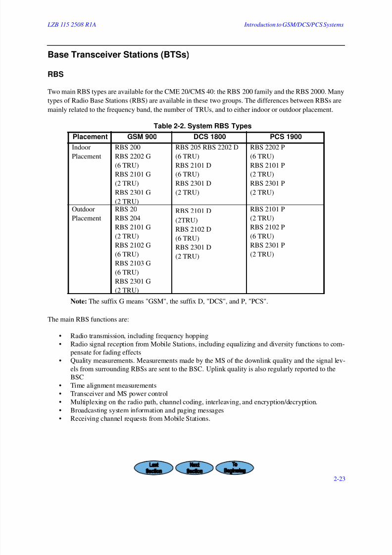
Two main RBS types are available for the CME 20/CMS 40: the RBS 200 family and the RBS 2000. Many
types of Radio Base Stations (RBS) are available in these two groups. The differences between RBSs are
mainly related to the frequency band, the number of TRUs, and to either indoor or outdoor placement.
Table 2-2. System RBS Types
Note: The suffix G means "GSM", the suffix D, "DCS", and P, "PCS".
The main RBS functions are:
• Radio transmission, including frequency hopping
• Radio signal reception from Mobile Stations, including equalizing and diversity functions to com-
pensate for fading effects
• Quality measurements. Measurements made by the MS of the downlink quality and the signal lev-
els from surrounding RBSs are sent to the BSC. Uplink quality is also regularly reported to the
BSC
• Time alignment measurements• Transceiver and MS power control
• Multiplexing on the radio path, channel coding, interleaving, and encryption/decryption.
• Broadcasting system information and paging messages
• Receiving channel requests from Mobile Stations.
Placement GSM 900 DCS 1800 PCS 1900
Indoor
Placement
RBS 200
RBS 2202 G
(6 TRU)
RBS 2101 G
(2 TRU)
RBS 2301 G(2 TRU)
RBS 205 RBS 2202 D
(6 TRU)
RBS 2101 D
(6 TRU)
RBS 2301 D
(2 TRU)
RBS 2202 P
(6 TRU)
RBS 2101 P
(2 TRU)
RBS 2301 P
(2 TRU)
Outdoor
Placement
RBS 20
RBS 204
RBS 2101 G
(2 TRU)
RBS 2102 G
(6 TRU)
RBS 2103 G
(6 TRU)
RBS 2301 G
(2 TRU)
RBS 2101 D
(2TRU)
RBS 2102 D
(6 TRU)
RBS 2301 D
(2 TRU)
RBS 2101 P
(2 TRU)
RBS 2102 P
(6 TRU)
RBS 2301 P
(2 TRU)
7/27/2019 Ericsson CA638 CF688 Introduction to GSM DCS PCS Systems
http://slidepdf.com/reader/full/ericsson-ca638-cf688-introduction-to-gsm-dcs-pcs-systems 24/27
Inroduction to GSM/DCS/PCS Systems LZB 115 2508 R1A
2-24
Ericsson’s RBSs are TRU oriented (that is, they have minimal equipment common to a number of TRUs),
thus achieving redundancy. A hardware fault at the radio site will just affect one TRU at a time.
The RBS consists of a cluster of autonomous TRUs. The software stored in TRU RAMs is controlled,
loaded, and upgraded from the BSC, thus eliminating the need for on-site RBS visits. This remote control
capability also includes automatic tuning in the combiner in case frequency planning is changed. Strict
transceiver orientation means that faults will be isolated per TRU and will not affect adjacent TRUs in the
same RBS.
RBS 200
The RBS 200 functional units are:
• The Transmission Radio Interface (TRI), a switch that enables a very flexible cross connection
between the BSC and several Transceiver Groups (TGs). The TRI extracts the time slots in the 2
Mbit/s circuit that are allocated to the units in the RBS (BTS) and forwards the remaining time
slots to other equipment (for example, to the next RBS).
• The Transceiver Subsystem (TRS), which includes all radio equipment at the BTS (RBS) site.• One or many TGs, which include all the radio equipment connected to one transmission antenna.
Each group can have up to 16 transceivers connected to the same transmitter antenna and each
transceiver can serve 8 full rate duplex channels. The RBS (BTS) has a motor driven transmitter
combiner that combines signals from transmitters to one antenna. The combiner is self-tuning.
• The Local Maintenance Terminal (LMT) is used for on site operation and maintenance purposes.
The LMT can be directly connected to each transceiver group in the field.
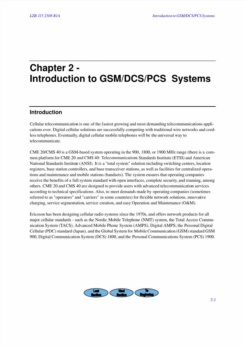
RBS 2000
See . The RBS 2000 supports numerous configurations for radio network planners (who are provided witha choice of RBS configurations allowing flexible system "roll out" options). RBS development in this
regard for supporting micro and pico cell structures will continue with fast locating and hand-over to keep
call connections intact for slow-moving Mobile Station users, such as pedestrians, as well as for MSs mov-
ing rapidly by in vehicles. shows two configurations that are possible with Ericsson RBSs.
7/27/2019 Ericsson CA638 CF688 Introduction to GSM DCS PCS Systems
http://slidepdf.com/reader/full/ericsson-ca638-cf688-introduction-to-gsm-dcs-pcs-systems 25/27
LZB 115 2508 R1A Introduction to GSM/DCS/PCS Systems
2-25
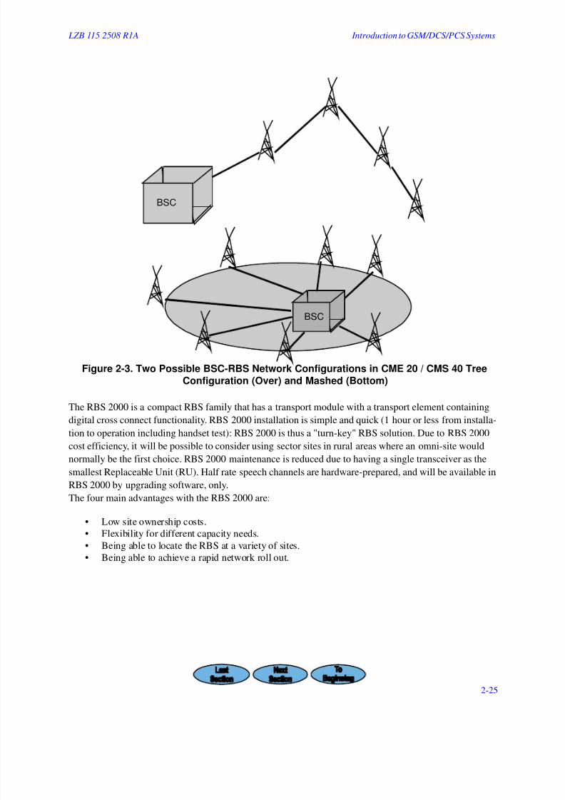
Figure 2-3. Two Possible BSC-RBS Network Configurations in CME 20 / CMS 40 TreeConfiguration (Over) and Mashed (Bottom)
The RBS 2000 is a compact RBS family that has a transport module with a transport element containing
digital cross connect functionality. RBS 2000 installation is simple and quick (1 hour or less from installa-tion to operation including handset test): RBS 2000 is thus a "turn-key" RBS solution. Due to RBS 2000
cost efficiency, it will be possible to consider using sector sites in rural areas where an omni-site would
normally be the first choice. RBS 2000 maintenance is reduced due to having a single transceiver as the
smallest Replaceable Unit (RU). Half rate speech channels are hardware-prepared, and will be available in
RBS 2000 by upgrading software, only.
The four main advantages with the RBS 2000 are:
• Low site ownership costs.
• Flexibility for different capacity needs.
• Being able to locate the RBS at a variety of sites.
• Being able to achieve a rapid network roll out.
BSC
BSC

7/27/2019 Ericsson CA638 CF688 Introduction to GSM DCS PCS Systems
http://slidepdf.com/reader/full/ericsson-ca638-cf688-introduction-to-gsm-dcs-pcs-systems 26/27
Inroduction to GSM/DCS/PCS Systems LZB 115 2508 R1A
2-26
Functional units in the RBS 2000 are:
• Distribution Switch Unit (DXU), which provides a system interface to the 1.5 Mbit/s PCM link
and cross connects individual time slots to selected transceivers. It also extracts synchronization
information from PCM links and generates a timing reference for the RBS.
• The Transceiver Unit (TRU) is a single replacement unit for easy handling. The TRU includes all
functionality needed for handling 8 time slots in one Time Division Multiple Access (TDMA)frame, such as timing reference generation, signal processing, radio receiving and transmitting,
and power amplification.
• Combining and Distribution Unit (CDU): is available in many types, and combines transmitted
signals from various transceivers and distributes received signals to all transceivers.
• A Low Noise Amplifier (LNA) can be used optionally on receiving antennas in order to compen-
sate for loss in the antenna feeder and to lessen receiver noise.
• Power Supply Units (PSU) are replacement units with defined interfaces. Battery back up (internal
or external) may be connected to the PSU.
• The Energy Control Unit (ECU) controls and supervises all power equipment and regulates the
environmental conditions inside the cabinet within prescribed RBS operating conditions.
Micro RBS
Ericsson is introducing a new RBS 2000 family member: the RBS 2301: a weatherproof GSM 900, DCS
1800, and PCS 1900 RBS. Through this Micro RBS, operating companies now have a cost-efficient solu-
tion for increasing channel capacity or coverage in limited areas (a Hierarchical Cell Structure with micro
and macro base stations provides extra coverage, quality, and capacity as the hot spot micro cell networks
evolve towards a very high capacity micro cell).
This approximately 25-30 kilogram in weight RBS can support up to two transceivers, giving a total of 15
traffic channels. The cabinet’s low volume yields an impressive 15 liters per transceiver, or 3.3 liters perErlang (subscriber). It provides a system interface to the 2/1.5 Mbit/s link and cross connects individual
time slots to transceivers.
The RBS 2301 is small, lightweight, and attractively encased, making it an ideal indoor RBS (pico) solu-
tion. It supports most CME 20 / CMS 40 software (observe that the first version does not support half rate).
Fixed Cellular Solutions
Radio access technology is a quick way for getting an operator digitally accessed. Fixed cellular consists of
a complete overlay cellular network for accessing the PSTN. System functionality to support differentia-
tion of services, access, priority, and charging is enabled.
Fixed cellular allows new operators to compete with existing operators. Operators can modernize in a dig-
ital way, cheaply and quickly.
7/27/2019 Ericsson CA638 CF688 Introduction to GSM DCS PCS Systems
http://slidepdf.com/reader/full/ericsson-ca638-cf688-introduction-to-gsm-dcs-pcs-systems 27/27
LZB 115 2508 R1A Introduction to GSM/DCS/PCS Systems
Adjunct System Parts
Message Centers
The CME 20 / CMS 40 allows the use of different messaging systems. In order to guarantee system func-
tionality, Ericsson is verifying the function of different vendor’s products. A message system should pro-
vide a multimedia messaging infrastructure that reaches mobile handsets, pagers, fax machines, etc. The
system shall link with PSTNs, as well as PLMNs. A user should be able to store messages in the infrastruc-
ture, and then distribute these messages to other media.
The message "kernel" is the platform’s core: all message traffic flows through it. Messages can be stored in
any media that is capable of such storage (from mobile handsets, computers, etc.). These messages can be
communicated between different media (for example, mobile phone to computer, and vice versa). Switch-
ing between media (for example, from mobile phone to computer) while in, for example, a phone confer-
ence is also possible.
Related Documents