Environmental Record Editing and Printing Program (EREP) Reference Version 3 Release 5 GC35-0152-07

Welcome message from author
This document is posted to help you gain knowledge. Please leave a comment to let me know what you think about it! Share it to your friends and learn new things together.
Transcript

Environmental Record Editing and Printing Program(EREP)
ReferenceVersion 3 Release 5
GC35-0152-07
���

NoteBefore using this information and the product it supports, read the information in “Notices” on page 379.
Eighth Edition (September 2015)
This book applies to EREP Version 3 Release 5 until otherwise indicated in new editions.
IBM welcomes your comments. A form for readers' comments may be provided at the back of this document, oryou may address your comments to the following address:
International Business Machines Corporation
MHVRCFS, Mail Station P181
2455 South Road
Poughkeepsie, NY 12601-5400
United States of America
FAX (United States and Canada): 1+845+432-9405
FAX (Other Countries):
Your International Access Code +1+845+432-9405
IBMLink ™ (United States customers only): IBMUSM10(MHVRCFS)
Internet e-mail: [email protected]
World Wide Web: http://www.ibm.com/Systems/z/os/zos/webqs.html
If you would like a reply, be sure to include your name, address, telephone number, or FAX number.
Make sure to include the following in your comment or note:v Title and order number of this document
v Page number or topic related to your comment
When you send information to IBM, you grant IBM a nonexclusive right to use or distribute the information in anyway it believes appropriate without incurring any obligation to you.
© Copyright IBM Corporation 1983, 2015.US Government Users Restricted Rights – Use, duplication or disclosure restricted by GSA ADP Schedule Contractwith IBM Corp.

Contents
Figures . . . . . . . . . . . . . . . . . . . . . . . . . . . . . . . . . . . . ix
Tables . . . . . . . . . . . . . . . . . . . . . . . . . . . . . . . . . . . . xiii
Preface . . . . . . . . . . . . . . . . . . . . . . . . . . . . . . . . . . . xvWho Should Read This Publication . . . . . . . . . . . . . . . . . . . . . . . . . . . xvOrganization and Contents . . . . . . . . . . . . . . . . . . . . . . . . . . . . . . xvz/OS information . . . . . . . . . . . . . . . . . . . . . . . . . . . . . . . . . xvii
Summary of changes . . . . . . . . . . . . . . . . . . . . . . . . . . . . . xixEighth Edition . . . . . . . . . . . . . . . . . . . . . . . . . . . . . . . . . . xixSeventh Edition . . . . . . . . . . . . . . . . . . . . . . . . . . . . . . . . . . xixSixth Edition. . . . . . . . . . . . . . . . . . . . . . . . . . . . . . . . . . . xixFifth Edition . . . . . . . . . . . . . . . . . . . . . . . . . . . . . . . . . . . xix
Part 1. General Reference Information . . . . . . . . . . . . . . . . . . . . . 1
Chapter 1. Introduction to EREP Controls . . . . . . . . . . . . . . . . . . . . . 3Syntax Rules and Conventions . . . . . . . . . . . . . . . . . . . . . . . . . . . . . 3
Conventions for Syntax Rules. . . . . . . . . . . . . . . . . . . . . . . . . . . . . 4
Chapter 2. EREP Parameters . . . . . . . . . . . . . . . . . . . . . . . . . . . 5Report Parameter Summary . . . . . . . . . . . . . . . . . . . . . . . . . . . . . . 7Selection Parameter Summary . . . . . . . . . . . . . . . . . . . . . . . . . . . . . 8Processing Parameter Summary . . . . . . . . . . . . . . . . . . . . . . . . . . . . 10EREP Parameter Combinations . . . . . . . . . . . . . . . . . . . . . . . . . . . . . 11Default Actions for EREP Parameters . . . . . . . . . . . . . . . . . . . . . . . . . . . 13Parameter Descriptions . . . . . . . . . . . . . . . . . . . . . . . . . . . . . . . 14
ACC — Accumulate Records (Processing Parameter) . . . . . . . . . . . . . . . . . . . . 16CPU — Central Processing Unit (Selection Parameter) . . . . . . . . . . . . . . . . . . . . 17CPUCUA — CPU/Channel/Unit Address (Selection Parameter) . . . . . . . . . . . . . . . . . 19CUA — Channel/Unit Address (Selection Parameter) . . . . . . . . . . . . . . . . . . . . 20DATE — Date Range (Selection Parameter) . . . . . . . . . . . . . . . . . . . . . . . . 22DEBUG — Debug (Diagnostic Parameter) . . . . . . . . . . . . . . . . . . . . . . . . 23DEV — Device Type (Selection Parameter) . . . . . . . . . . . . . . . . . . . . . . . . 24DEVSER — Device Serial Number (Selection Parameter) . . . . . . . . . . . . . . . . . . . 26ERRORID — Error Identifier (Selection Parameter) . . . . . . . . . . . . . . . . . . . . . 27EVENT — Event History (Report Parameter) . . . . . . . . . . . . . . . . . . . . . . . 28HIST — History Input (Processing Parameter) . . . . . . . . . . . . . . . . . . . . . . . 29LIA/LIBADR — Line Interface Base Address (Selection Parameter) . . . . . . . . . . . . . . . . 30LINECT — Line Count (Processing Parameter) . . . . . . . . . . . . . . . . . . . . . . 31LINELEN — Line Length (Processing Parameter) . . . . . . . . . . . . . . . . . . . . . . 32MERGE — Merge Input Data Sets (Processing Parameter) . . . . . . . . . . . . . . . . . . . 33MOD — Processor Model (Selection Parameter) . . . . . . . . . . . . . . . . . . . . . . 34MODE — Operating Mode (Selection Parameter) . . . . . . . . . . . . . . . . . . . . . . 35PRINT — Print reports (report parameter) . . . . . . . . . . . . . . . . . . . . . . . . 36SHORT — Print Short OBR Records (Processing Parameter) . . . . . . . . . . . . . . . . . . 37SYMCDE — Fault Symptom Code (Selection Parameter) . . . . . . . . . . . . . . . . . . . 38SYSEXN — System Exception Reports (Report Parameter) . . . . . . . . . . . . . . . . . . . 40SYSUM — System Summary (Report Parameter) . . . . . . . . . . . . . . . . . . . . . . 41TABSIZE — Sort Table Size (Processing Parameter) . . . . . . . . . . . . . . . . . . . . . 42TERMN — Terminal Name (Selection Parameter) . . . . . . . . . . . . . . . . . . . . . . 43THRESHOLD — Threshold Summary (Report Parameter) . . . . . . . . . . . . . . . . . . . 44TIME — Time Range (Selection Parameter) . . . . . . . . . . . . . . . . . . . . . . . . 45
© Copyright IBM Corp. 1983, 2015 iii

TRENDS — Trends Report (Report Parameter) . . . . . . . . . . . . . . . . . . . . . . 46TYPE — Record Type (Selection Parameter) . . . . . . . . . . . . . . . . . . . . . . . 47VOLID — Volume Identifier (Selection Parameter) . . . . . . . . . . . . . . . . . . . . . 49ZERO — Clear the ERDS (Processing Parameter) . . . . . . . . . . . . . . . . . . . . . . 50
Chapter 3. EREP Control Statements . . . . . . . . . . . . . . . . . . . . . . . 51Coding Control Statements . . . . . . . . . . . . . . . . . . . . . . . . . . . . . . 51Summarizing Control Statements . . . . . . . . . . . . . . . . . . . . . . . . . . . . 52Using Control Statements with Reports . . . . . . . . . . . . . . . . . . . . . . . . . . 53Control Statement Syntax . . . . . . . . . . . . . . . . . . . . . . . . . . . . . . . 54Program Syntax Diagrams . . . . . . . . . . . . . . . . . . . . . . . . . . . . . . 54
CONTROLLER Control Statement . . . . . . . . . . . . . . . . . . . . . . . . . . . 56DASDID Control Statement . . . . . . . . . . . . . . . . . . . . . . . . . . . . . 58Setting up DASDID Controls . . . . . . . . . . . . . . . . . . . . . . . . . . . . 60Checking Your DASDID Statements . . . . . . . . . . . . . . . . . . . . . . . . . . 62DASDID Configuration Chart Notes . . . . . . . . . . . . . . . . . . . . . . . . . . 62LIMIT Control Statement . . . . . . . . . . . . . . . . . . . . . . . . . . . . . . 64SHARE Control Statements . . . . . . . . . . . . . . . . . . . . . . . . . . . . . 66Using SHARE Statements to Combine Data in EREP Reports . . . . . . . . . . . . . . . . . . 67How EREP Assigns Numbers to CPUs . . . . . . . . . . . . . . . . . . . . . . . . . 69SYSIMG Control Statement . . . . . . . . . . . . . . . . . . . . . . . . . . . . . 71
Chapter 4. Error Records for EREP . . . . . . . . . . . . . . . . . . . . . . . 75Error-Recording Process . . . . . . . . . . . . . . . . . . . . . . . . . . . . . . . 75ERDS Formats . . . . . . . . . . . . . . . . . . . . . . . . . . . . . . . . . . 75ERDS Header Record . . . . . . . . . . . . . . . . . . . . . . . . . . . . . . . . 76
MVS Header Record for the ERDS. . . . . . . . . . . . . . . . . . . . . . . . . . . 77VM Header Record for the Error Recording Area (Cylinder) . . . . . . . . . . . . . . . . . . 78VSE Header Record for SYSREC with CKD. . . . . . . . . . . . . . . . . . . . . . . . 78VSE Header Record for SYSREC with FBA . . . . . . . . . . . . . . . . . . . . . . . . 79
Time-Stamp Record for IPL Records . . . . . . . . . . . . . . . . . . . . . . . . . . . 80Information in Error and Operational Records . . . . . . . . . . . . . . . . . . . . . . . . 80
Standard Record Header: Data Common to All Record Types. . . . . . . . . . . . . . . . . . 81Record Type/Class Codes . . . . . . . . . . . . . . . . . . . . . . . . . . . . . 82
Chapter 5. Correcting EREP Job Set-Up Problems . . . . . . . . . . . . . . . . . 85Using the EREP Messages File (TOURIST Output) . . . . . . . . . . . . . . . . . . . . . . 85Problem Determination Aids. . . . . . . . . . . . . . . . . . . . . . . . . . . . . . 86
EREP Return Codes . . . . . . . . . . . . . . . . . . . . . . . . . . . . . . . 87Problem Determination Procedures . . . . . . . . . . . . . . . . . . . . . . . . . . 87Trouble-Shooting Flowchart . . . . . . . . . . . . . . . . . . . . . . . . . . . . . 87Using the DEBUG Parameter . . . . . . . . . . . . . . . . . . . . . . . . . . . . 88
Missing Records . . . . . . . . . . . . . . . . . . . . . . . . . . . . . . . . . . 89
Chapter 6. EREP Messages . . . . . . . . . . . . . . . . . . . . . . . . . . . 91
Chapter 7. Codes for Control Units, OBRs, and MDRs . . . . . . . . . . . . . . . 109Control Unit Type Codes . . . . . . . . . . . . . . . . . . . . . . . . . . . . . . 109OBR Codes . . . . . . . . . . . . . . . . . . . . . . . . . . . . . . . . . . . 111MDR Codes . . . . . . . . . . . . . . . . . . . . . . . . . . . . . . . . . . . 114
Part 2. Examples of Output from Reports . . . . . . . . . . . . . . . . . . 117
Chapter 8. System Summary Report . . . . . . . . . . . . . . . . . . . . . . 119Description of the System Summary Report . . . . . . . . . . . . . . . . . . . . . . . . 119
System Summary Part 1 . . . . . . . . . . . . . . . . . . . . . . . . . . . . . . 119System Summary Part 2 . . . . . . . . . . . . . . . . . . . . . . . . . . . . . . 120
Examples of the System Summary Reports . . . . . . . . . . . . . . . . . . . . . . . . 121
iv EREP V3R5 Reference
Chapter 9. Trends Report . . . . . . . . . . . . . . . . . . . . . . . . . . . 127Description of the Trends Report . . . . . . . . . . . . . . . . . . . . . . . . . . . . 127Examples of the Trends Report . . . . . . . . . . . . . . . . . . . . . . . . . . . . 127
Chapter 10. Event History Report . . . . . . . . . . . . . . . . . . . . . . . . 135Description of the Event History Report . . . . . . . . . . . . . . . . . . . . . . . . . 135Examples of the Event History Report . . . . . . . . . . . . . . . . . . . . . . . . . . 135
Chapter 11. System Exception Report Series . . . . . . . . . . . . . . . . . . . 141Description of the System Exception Series . . . . . . . . . . . . . . . . . . . . . . . . 142Examples of the System Error Summary . . . . . . . . . . . . . . . . . . . . . . . . . 143
System Error Summary, Part 1. . . . . . . . . . . . . . . . . . . . . . . . . . . . 144System Error Summary, Part 2. . . . . . . . . . . . . . . . . . . . . . . . . . . . 147
Examples of the Subsystem Exception Report Series . . . . . . . . . . . . . . . . . . . . . 149Processor (CPU) Subsystem Exception . . . . . . . . . . . . . . . . . . . . . . . . . . 150Channel Subsystem Exception . . . . . . . . . . . . . . . . . . . . . . . . . . . . . 152DASD Subsystem Exception . . . . . . . . . . . . . . . . . . . . . . . . . . . . . 154
DASD Subsystem Exception, Part 1 . . . . . . . . . . . . . . . . . . . . . . . . . . 156DASD Subsystem Exception, Part 2 . . . . . . . . . . . . . . . . . . . . . . . . . . 161DASD String Summary, Part 1. . . . . . . . . . . . . . . . . . . . . . . . . . . . 162DASD String Summary, Part 2. . . . . . . . . . . . . . . . . . . . . . . . . . . . 165DASD Service Informational Messages (SIMs) . . . . . . . . . . . . . . . . . . . . . . 166DASD Informational Messages . . . . . . . . . . . . . . . . . . . . . . . . . . . 167DASD Data Transfer Summary . . . . . . . . . . . . . . . . . . . . . . . . . . . 168DASD Symptom Code Summary . . . . . . . . . . . . . . . . . . . . . . . . . . . 171DASD Storage Control Unit Summary . . . . . . . . . . . . . . . . . . . . . . . . . 176
Optical Subsystem Exception . . . . . . . . . . . . . . . . . . . . . . . . . . . . . 1773995 Optical Subsystem Exception Report Series. . . . . . . . . . . . . . . . . . . . . . 1779246/9247 Optical Subsystem Exception Report Series . . . . . . . . . . . . . . . . . . . . 185
Tape Subsystem Exception . . . . . . . . . . . . . . . . . . . . . . . . . . . . . . 193Tape Subsystem Exception Report . . . . . . . . . . . . . . . . . . . . . . . . . . 195Tape Forced Error Log/Permanent Error Summary Reports . . . . . . . . . . . . . . . . . . 198Tape Temporary Error Summary . . . . . . . . . . . . . . . . . . . . . . . . . . . 201Tape Volume Statistics Summary . . . . . . . . . . . . . . . . . . . . . . . . . . . 208Tape Permanent/Recovered Error Summary . . . . . . . . . . . . . . . . . . . . . . . 2113490 FRU Summary Report. . . . . . . . . . . . . . . . . . . . . . . . . . . . . 2163490 Error Code Summary . . . . . . . . . . . . . . . . . . . . . . . . . . . . . 218Tape DEVNO/CUA Statistics Summary . . . . . . . . . . . . . . . . . . . . . . . . 220EREP Reports for the Tape Library . . . . . . . . . . . . . . . . . . . . . . . . . . 224
TAPE Subsystem Exception. . . . . . . . . . . . . . . . . . . . . . . . . . . . . . 232TAPE Subsystem Exception Report . . . . . . . . . . . . . . . . . . . . . . . . . . 233TAPE Service Informational Messages (SIMs) . . . . . . . . . . . . . . . . . . . . . . . 236TAPE Media Informational Messages (MIMs). . . . . . . . . . . . . . . . . . . . . . . 237
Chapter 12. Threshold Summary Report . . . . . . . . . . . . . . . . . . . . . 239Description of the Threshold Summary Report . . . . . . . . . . . . . . . . . . . . . . . 239Examples of the Threshold Summary Reports . . . . . . . . . . . . . . . . . . . . . . . 239
Chapter 13. Detail Edit and Summary Reports . . . . . . . . . . . . . . . . . . 245Description of the Detail Edit and Summary Reports . . . . . . . . . . . . . . . . . . . . . 245Examples of the Detail Edit and Summary Report . . . . . . . . . . . . . . . . . . . . . . 245
External Timer Reference Maintenance Information Detail Edit (A1) Report . . . . . . . . . . . . 246Link Maintenance Information Detail Edit (A2) Report . . . . . . . . . . . . . . . . . . . 247Asynchronous Notification Record Detail (A3) Report . . . . . . . . . . . . . . . . . . . . 249A3 Report for Incorrect Record . . . . . . . . . . . . . . . . . . . . . . . . . . . 249Channel Check Handler (CCH) Detail Reports . . . . . . . . . . . . . . . . . . . . . . 251Channel Report Word (CRW) Detail Report . . . . . . . . . . . . . . . . . . . . . . . 257Dynamic Device Reconfiguration (DDR) Detail Report. . . . . . . . . . . . . . . . . . . . 259Data Reduction Report . . . . . . . . . . . . . . . . . . . . . . . . . . . . . . 260Recovery/Termination (EOD) Detail Reports . . . . . . . . . . . . . . . . . . . . . . . 261
Contents v

System Initialization (IPL) Detail Reports . . . . . . . . . . . . . . . . . . . . . . . . 263Machine Check Handler (MCH) Detail Reports . . . . . . . . . . . . . . . . . . . . . . 264Miscellaneous Data Record (MDR) Detail Reports . . . . . . . . . . . . . . . . . . . . . 272Missing Interrupt Handler (MIH) Detail Reports . . . . . . . . . . . . . . . . . . . . . 278Outboard Record (OBR) Detail Edit Reports . . . . . . . . . . . . . . . . . . . . . . . 281Software (SFT) Detail Edit Reports . . . . . . . . . . . . . . . . . . . . . . . . . . 307Subchannel Logout Handler (SLH) Detail Edit Reports . . . . . . . . . . . . . . . . . . . 318Unknown Detail Edit Reports . . . . . . . . . . . . . . . . . . . . . . . . . . . . 324
Part 3. Product-Dependent Information. . . . . . . . . . . . . . . . . . . . 327
Chapter 14. Supported Devices. . . . . . . . . . . . . . . . . . . . . . . . . 329
Chapter 15. Card Readers and Punches . . . . . . . . . . . . . . . . . . . . . 333EREP Reports . . . . . . . . . . . . . . . . . . . . . . . . . . . . . . . . . . 333Supported Devices . . . . . . . . . . . . . . . . . . . . . . . . . . . . . . . . 333
Chapter 16. Consoles and Displays . . . . . . . . . . . . . . . . . . . . . . . 335EREP Reports . . . . . . . . . . . . . . . . . . . . . . . . . . . . . . . . . . 335EREP Controls . . . . . . . . . . . . . . . . . . . . . . . . . . . . . . . . . . 335Supported Devices . . . . . . . . . . . . . . . . . . . . . . . . . . . . . . . . 335
Chapter 17. Direct-Access Storage Devices (DASD) . . . . . . . . . . . . . . . . 337Supported Devices . . . . . . . . . . . . . . . . . . . . . . . . . . . . . . . . 3373390 DASD . . . . . . . . . . . . . . . . . . . . . . . . . . . . . . . . . . . 338
3390 Model Identifiers . . . . . . . . . . . . . . . . . . . . . . . . . . . . . . 338Subsystem Exception Report . . . . . . . . . . . . . . . . . . . . . . . . . . . . 338OBR and MDR Codes . . . . . . . . . . . . . . . . . . . . . . . . . . . . . . 338
9392 DASD . . . . . . . . . . . . . . . . . . . . . . . . . . . . . . . . . . . 3399392 Model Identifiers . . . . . . . . . . . . . . . . . . . . . . . . . . . . . . 339Subsystem Exception Report . . . . . . . . . . . . . . . . . . . . . . . . . . . . 339OBR and MDR Codes . . . . . . . . . . . . . . . . . . . . . . . . . . . . . . 339
9395 DASD . . . . . . . . . . . . . . . . . . . . . . . . . . . . . . . . . . . 3399395 Model Identifiers . . . . . . . . . . . . . . . . . . . . . . . . . . . . . . 339Subsystem Exception Report . . . . . . . . . . . . . . . . . . . . . . . . . . . . 340OBR and MDR Codes . . . . . . . . . . . . . . . . . . . . . . . . . . . . . . 340
9345 DASD . . . . . . . . . . . . . . . . . . . . . . . . . . . . . . . . . . . 3409345 Model Identifiers . . . . . . . . . . . . . . . . . . . . . . . . . . . . . . 340Subsystem Exception Report . . . . . . . . . . . . . . . . . . . . . . . . . . . . 340EREP Controls . . . . . . . . . . . . . . . . . . . . . . . . . . . . . . . . . 340
3380 DASD . . . . . . . . . . . . . . . . . . . . . . . . . . . . . . . . . . . 3413380 Model Identifiers . . . . . . . . . . . . . . . . . . . . . . . . . . . . . . 341Subsystem Exception Report . . . . . . . . . . . . . . . . . . . . . . . . . . . . 341MDR and OBR Codes . . . . . . . . . . . . . . . . . . . . . . . . . . . . . . 341
3370 DASD . . . . . . . . . . . . . . . . . . . . . . . . . . . . . . . . . . . 34233XX DASD . . . . . . . . . . . . . . . . . . . . . . . . . . . . . . . . . . . 342
33XX Identifiers . . . . . . . . . . . . . . . . . . . . . . . . . . . . . . . . 342Subsystem Exception Report . . . . . . . . . . . . . . . . . . . . . . . . . . . . 343Detail Edit Report . . . . . . . . . . . . . . . . . . . . . . . . . . . . . . . . 343DASDID Control Statement . . . . . . . . . . . . . . . . . . . . . . . . . . . . 343LIMIT Control Statement . . . . . . . . . . . . . . . . . . . . . . . . . . . . . 344
Chapter 18. Diskette Unit . . . . . . . . . . . . . . . . . . . . . . . . . . . 347EREP Reports . . . . . . . . . . . . . . . . . . . . . . . . . . . . . . . . . . 347EREP Controls . . . . . . . . . . . . . . . . . . . . . . . . . . . . . . . . . . 347Supported Devices . . . . . . . . . . . . . . . . . . . . . . . . . . . . . . . . 347
Chapter 19. Magnetic Tape Devices . . . . . . . . . . . . . . . . . . . . . . . 349Reports for Tape Devices . . . . . . . . . . . . . . . . . . . . . . . . . . . . . . 349
vi EREP V3R5 Reference
34XX Tape Devices . . . . . . . . . . . . . . . . . . . . . . . . . . . . . . . . 349Subsystem Exception Report . . . . . . . . . . . . . . . . . . . . . . . . . . . . 350Threshold Summary Report Information . . . . . . . . . . . . . . . . . . . . . . . . 350LIMIT Control Statement . . . . . . . . . . . . . . . . . . . . . . . . . . . . . 350
3480, 3490, and 3490E Tape Subsystems . . . . . . . . . . . . . . . . . . . . . . . . . 353Subsystem Exception Report . . . . . . . . . . . . . . . . . . . . . . . . . . . . 353LIMIT Control Statement . . . . . . . . . . . . . . . . . . . . . . . . . . . . . 354
9347 and 9348 Subsystem Exception Report . . . . . . . . . . . . . . . . . . . . . . . . 35435XX Tape Devices . . . . . . . . . . . . . . . . . . . . . . . . . . . . . . . . 355
Subsystem Exception Report . . . . . . . . . . . . . . . . . . . . . . . . . . . . 355
Chapter 20. OCR/MICR Devices. . . . . . . . . . . . . . . . . . . . . . . . . 357EREP Reports . . . . . . . . . . . . . . . . . . . . . . . . . . . . . . . . . . 357EREP Controls . . . . . . . . . . . . . . . . . . . . . . . . . . . . . . . . . . 357Supported Devices . . . . . . . . . . . . . . . . . . . . . . . . . . . . . . . . 357
Chapter 21. Optical Devices . . . . . . . . . . . . . . . . . . . . . . . . . . 3593995 Optical Disk Storage Dataserver . . . . . . . . . . . . . . . . . . . . . . . . . . 3599246 Optical Library . . . . . . . . . . . . . . . . . . . . . . . . . . . . . . . . 3599247 Optical Disk Drive . . . . . . . . . . . . . . . . . . . . . . . . . . . . . . . 359
Chapter 22. Printers . . . . . . . . . . . . . . . . . . . . . . . . . . . . . 361Reports for Printers . . . . . . . . . . . . . . . . . . . . . . . . . . . . . . . . 361Devices Supported by EREP . . . . . . . . . . . . . . . . . . . . . . . . . . . . . 361AFP1 Printers . . . . . . . . . . . . . . . . . . . . . . . . . . . . . . . . . . 362
Detail Edit Report . . . . . . . . . . . . . . . . . . . . . . . . . . . . . . . . 362Detail Summary Report . . . . . . . . . . . . . . . . . . . . . . . . . . . . . . 362EREP Controls . . . . . . . . . . . . . . . . . . . . . . . . . . . . . . . . . 363
3820 Printer . . . . . . . . . . . . . . . . . . . . . . . . . . . . . . . . . . . 3634248 Printer . . . . . . . . . . . . . . . . . . . . . . . . . . . . . . . . . . . 3636262 Printer . . . . . . . . . . . . . . . . . . . . . . . . . . . . . . . . . . . 363
Chapter 23. Processors (CPUs). . . . . . . . . . . . . . . . . . . . . . . . . 365Processor Information . . . . . . . . . . . . . . . . . . . . . . . . . . . . . . . 365LIMIT Control Statement . . . . . . . . . . . . . . . . . . . . . . . . . . . . . . 365PR/SM Feature. . . . . . . . . . . . . . . . . . . . . . . . . . . . . . . . . . 367
Chapter 24. Punched Tape Devices . . . . . . . . . . . . . . . . . . . . . . . 369EREP Reports . . . . . . . . . . . . . . . . . . . . . . . . . . . . . . . . . . 369EREP Controls . . . . . . . . . . . . . . . . . . . . . . . . . . . . . . . . . . 369Supported Devices . . . . . . . . . . . . . . . . . . . . . . . . . . . . . . . . 369
Chapter 25. Teleprocessing (TP) Devices . . . . . . . . . . . . . . . . . . . . 371EREP Reports . . . . . . . . . . . . . . . . . . . . . . . . . . . . . . . . . . 371EREP Controls . . . . . . . . . . . . . . . . . . . . . . . . . . . . . . . . . . 371Notes . . . . . . . . . . . . . . . . . . . . . . . . . . . . . . . . . . . . . 371
Chapter 26. Other Devices . . . . . . . . . . . . . . . . . . . . . . . . . . . 373EREP Reports . . . . . . . . . . . . . . . . . . . . . . . . . . . . . . . . . . 373EREP Controls . . . . . . . . . . . . . . . . . . . . . . . . . . . . . . . . . . 373Supported Devices . . . . . . . . . . . . . . . . . . . . . . . . . . . . . . . . 373BA00 Serial OEM Interface Adapter . . . . . . . . . . . . . . . . . . . . . . . . . . . 374CTCA Channel to Channel Adapters . . . . . . . . . . . . . . . . . . . . . . . . . . 374ESIO I/O Connected to an ESCON Link . . . . . . . . . . . . . . . . . . . . . . . . . 375IDSK Internal Disk . . . . . . . . . . . . . . . . . . . . . . . . . . . . . . . . 375Serial Link Connection . . . . . . . . . . . . . . . . . . . . . . . . . . . . . . . 375SWCH Channel Switch . . . . . . . . . . . . . . . . . . . . . . . . . . . . . . . 376
Part 4. Appendixes . . . . . . . . . . . . . . . . . . . . . . . . . . . . . 377
Contents vii

Notices . . . . . . . . . . . . . . . . . . . . . . . . . . . . . . . . . . . 379Policy for unsupported hardware. . . . . . . . . . . . . . . . . . . . . . . . . . . . 380Minimum supported hardware . . . . . . . . . . . . . . . . . . . . . . . . . . . . 381Trademarks . . . . . . . . . . . . . . . . . . . . . . . . . . . . . . . . . . . 381
Glossary . . . . . . . . . . . . . . . . . . . . . . . . . . . . . . . . . . 383
Index . . . . . . . . . . . . . . . . . . . . . . . . . . . . . . . . . . . . 391
viii EREP V3R5 Reference

Figures
1. DASD Configuration Diagram for DASDID Statements . . . . . . . . . . . . . . . . . . . 612. Examples of DASDID Control Statements . . . . . . . . . . . . . . . . . . . . . . . 623. Configuration for SHARE Statements . . . . . . . . . . . . . . . . . . . . . . . . . 684. EREP Messages File (TOURIST Output) from a CPEREP Run . . . . . . . . . . . . . . . . . 855. EREP Messages File (TOURIST Output): DASDID Configuration Chart . . . . . . . . . . . . . 866. TOURIST Output that Describes EREP Messages . . . . . . . . . . . . . . . . . . . . . 917. Event History Template . . . . . . . . . . . . . . . . . . . . . . . . . . . . . 1368. Event History Report . . . . . . . . . . . . . . . . . . . . . . . . . . . . . . 1379. Event History Summary . . . . . . . . . . . . . . . . . . . . . . . . . . . . . 138
10. System Error Summary, Part 1 . . . . . . . . . . . . . . . . . . . . . . . . . . . 14411. Processor (CPU) Subsystem Exception Report . . . . . . . . . . . . . . . . . . . . . . 15012. Channel Subsystem Exception Report . . . . . . . . . . . . . . . . . . . . . . . . 15213. Subsystem Exception DASD Report, Part 1. . . . . . . . . . . . . . . . . . . . . . . 15614. DASD Subsystem Exception, Part 2 . . . . . . . . . . . . . . . . . . . . . . . . . 16115. DASD String Summary, Part 1 . . . . . . . . . . . . . . . . . . . . . . . . . . . 16316. DASD String Summary, Part 2 (1) . . . . . . . . . . . . . . . . . . . . . . . . . . 16517. DASD String Summary, Part 2 (2) . . . . . . . . . . . . . . . . . . . . . . . . . . 16518. DASD Service Information Messages (SIMS) . . . . . . . . . . . . . . . . . . . . . . 16619. DASD Informational Messages . . . . . . . . . . . . . . . . . . . . . . . . . . . 16720. DASD Storage Control Unit Summary . . . . . . . . . . . . . . . . . . . . . . . . 17621. 3995 Permanent Error Summary . . . . . . . . . . . . . . . . . . . . . . . . . . 17822. 3995 Optical Drives Error Summary . . . . . . . . . . . . . . . . . . . . . . . . . 17923. 3995 Volume Statistics Summary . . . . . . . . . . . . . . . . . . . . . . . . . . 18124. 3995 DEVNO/CUA Statistics Summary . . . . . . . . . . . . . . . . . . . . . . . . 18325. 9246 Optical Library Permanent/Temporary Error Summary . . . . . . . . . . . . . . . . . 18626. 9246 Optical Library Permanent/Temporary Error Summary by CUA. . . . . . . . . . . . . . 18727. 9247 Optical Disk Drive Permanent/Temporary Error Summary . . . . . . . . . . . . . . . 18828. 9247 Optical Disk Drive Error Code Summary . . . . . . . . . . . . . . . . . . . . . 19029. 9247 Optical Disk Drive Volume Error Summary. . . . . . . . . . . . . . . . . . . . . 19130. 3490 Subsystem Exception Report Example . . . . . . . . . . . . . . . . . . . . . . 19531. 3490 Forced Log Report Example . . . . . . . . . . . . . . . . . . . . . . . . . . 19932. 3490 Temporary Error Summary Channel Example . . . . . . . . . . . . . . . . . . . . 20233. 3490 Temporary Error Summary Device Example . . . . . . . . . . . . . . . . . . . . 20434. 3420/3410 Temporary Error Summary . . . . . . . . . . . . . . . . . . . . . . . . 20635. 9347 Temporary Error Summary . . . . . . . . . . . . . . . . . . . . . . . . . . 20736. 3490 Volume Statistics Summary . . . . . . . . . . . . . . . . . . . . . . . . . . 20937. 3490 Permanent/Recovered Error Summary Example . . . . . . . . . . . . . . . . . . . 21338. 3420/3410 Permanent Error Summary . . . . . . . . . . . . . . . . . . . . . . . . 21539. 3424 Permanent / Recovered Error Summary . . . . . . . . . . . . . . . . . . . . . . 21540. 3490 FRU Summary Report Example. . . . . . . . . . . . . . . . . . . . . . . . . 21641. 3490 Error Code Summary Example . . . . . . . . . . . . . . . . . . . . . . . . . 21842. 3490 DEVNO/CUA Statistics Summary Report Example . . . . . . . . . . . . . . . . . . 22143. 3422 DEVNO/CUA Statistics Summary . . . . . . . . . . . . . . . . . . . . . . . . 22344. 9347 DEVNO/CUA Statistics Summary . . . . . . . . . . . . . . . . . . . . . . . . 22345. Tape Library Permanent Error Summary Example . . . . . . . . . . . . . . . . . . . . 22546. Tape Library Service Alert Summary Example . . . . . . . . . . . . . . . . . . . . . 22847. Tape Library Error Code Summary Example . . . . . . . . . . . . . . . . . . . . . . 23048. 3590 Subsystem Exception Report Example . . . . . . . . . . . . . . . . . . . . . . 23349. 3592 Subsystem Exception Report Example . . . . . . . . . . . . . . . . . . . . . . 23450. 3592 Emulated Device Summary Report . . . . . . . . . . . . . . . . . . . . . . . 23551. TAPE Service Information Messages (SIMS) . . . . . . . . . . . . . . . . . . . . . . 23652. TAPE Media Information Messages (MIMS) . . . . . . . . . . . . . . . . . . . . . . 23753. External Timer Reference Maintenance Information Detail . . . . . . . . . . . . . . . . . 24754. Link Maintenance Information Detail Edit (A2) Report . . . . . . . . . . . . . . . . . . . 24855. Asynchronous Notification Record Detail (A3) Report . . . . . . . . . . . . . . . . . . . 249
© Copyright IBM Corp. 1983, 2015 ix

56. A3 Report for Incorrect Record. . . . . . . . . . . . . . . . . . . . . . . . . . . 25057. CCH Summary Report for 3090, Record Type 20 . . . . . . . . . . . . . . . . . . . . . 25258. CCH Detail Report for 3090, Record Type 21 . . . . . . . . . . . . . . . . . . . . . . 25359. CCH Summary Report for 3090, Record Type 21 . . . . . . . . . . . . . . . . . . . . . 25460. CCH Summary Report for 4341 . . . . . . . . . . . . . . . . . . . . . . . . . . 25561. CCH (Inboard) Summary Report for 9373 . . . . . . . . . . . . . . . . . . . . . . . 25762. CRW Detail Report with Recording Code of X'01' . . . . . . . . . . . . . . . . . . . . 25863. CRW Detail Report with Recording Code of X'02' . . . . . . . . . . . . . . . . . . . . 25964. Dynamic Device Reconfiguration (DDR) Detail Report . . . . . . . . . . . . . . . . . . . 26065. Dynamic Device Reconfiguration (DDR) Summary Report . . . . . . . . . . . . . . . . . 26066. Data Reduction Report . . . . . . . . . . . . . . . . . . . . . . . . . . . . . 26167. End of Day (EOD) Detail Report . . . . . . . . . . . . . . . . . . . . . . . . . . 26268. End of Day (EOD) Summary Report . . . . . . . . . . . . . . . . . . . . . . . . . 26269. System Termination Detail Report. . . . . . . . . . . . . . . . . . . . . . . . . . 26370. System Termination Summary Report . . . . . . . . . . . . . . . . . . . . . . . . 26371. Initial Program Load (System Initialization) Detail Report (IPL) for 2084 . . . . . . . . . . . . . 26472. Initial Program Load (System Initialization) Summary Report (IPL) for 2084 . . . . . . . . . . . 26473. MDR Detail Edit Report for 3800-3-8 . . . . . . . . . . . . . . . . . . . . . . . . . 27374. MDR Detail Summary Report for 3800-3-8 . . . . . . . . . . . . . . . . . . . . . . . 27475. MDR Detail Edit Report (Outboard) . . . . . . . . . . . . . . . . . . . . . . . . . 27576. MDR Detail Summary Report (Outboard) . . . . . . . . . . . . . . . . . . . . . . . 27677. MDR Detail Edit Report, BSC/SS Permanent Line Error . . . . . . . . . . . . . . . . . . 27778. MDR Detail Summary Report, BSC/SS Permanent Line Error . . . . . . . . . . . . . . . . 27779. MDR Detail Report, SDLC Link Errors . . . . . . . . . . . . . . . . . . . . . . . . 27880. MDR Summary Report, SDLC Link Errors . . . . . . . . . . . . . . . . . . . . . . . 27881. MIH (370) Detail Edit Report . . . . . . . . . . . . . . . . . . . . . . . . . . . 27982. MIH (370) Detail Summary Report . . . . . . . . . . . . . . . . . . . . . . . . . 27983. MIH (370XA) Detail Edit Report . . . . . . . . . . . . . . . . . . . . . . . . . . 28084. MIH (370XA) Detail Summary Report . . . . . . . . . . . . . . . . . . . . . . . . 28085. MIH (370XA) Detail Edit Report for zHPF . . . . . . . . . . . . . . . . . . . . . . . 28186. OBR (Short) Detail Edit Report, Device Type 3277 . . . . . . . . . . . . . . . . . . . . 28387. OBR (Short) Detail Edit Report, Device Type 3800 . . . . . . . . . . . . . . . . . . . . 28388. OBR (Short) Detail Edit Report, Device Type 3791, VTAM. . . . . . . . . . . . . . . . . . 28489. OBR (Short) Unit Check . . . . . . . . . . . . . . . . . . . . . . . . . . . . . 28590. OBR (Long) Detail Edit Report, Device Type AFP1 . . . . . . . . . . . . . . . . . . . . 28691. OBR (Long) Summary Report, Device Type AFP1 . . . . . . . . . . . . . . . . . . . . 28792. OBR (Long) Detail Edit Report, Device Type CTCA . . . . . . . . . . . . . . . . . . . . 28893. OBR (Long) Detail Edit Report, Device Type 3277 Part 1 . . . . . . . . . . . . . . . . . . 28994. OBR (Long) Detail Edit Report, Device Type 3277 Part 2 . . . . . . . . . . . . . . . . . . 29095. OBR (Long) Detail Edit Report, Device Type 3380 Part 1 . . . . . . . . . . . . . . . . . . 29196. OBR (Long) Detail Edit Report, Device Type 3380 Part 12 . . . . . . . . . . . . . . . . . . 29297. OBR (Long) Detail Edit Report, Device Type 3390 . . . . . . . . . . . . . . . . . . . . 29398. OBR (Long) Detail Edit Report, Device Type 3480 . . . . . . . . . . . . . . . . . . . . 29499. OBR (Long) Detail Edit Report, Device Type 3490 . . . . . . . . . . . . . . . . . . . . 295
100. OBR (Long) Detail Edit Report, Device Type 3590 . . . . . . . . . . . . . . . . . . . . 296101. OBR (Long) Detail Edit Report, Device Type 3800 Part 1 . . . . . . . . . . . . . . . . . . 297102. OBR (Long) Detail Edit Report, Device Type 3800 Part 12 . . . . . . . . . . . . . . . . . . 298103. OBR (Long) Detail Edit Report, Autochanger Device Type 3995 . . . . . . . . . . . . . . . . 299104. OBR Record (Long) Detail Edit Report, Device Type 9347 Part 1 . . . . . . . . . . . . . . . 300105. OBR Record (Long) Detail Edit Report, Device Type 9347 Part 2 . . . . . . . . . . . . . . . 301106. OBR (Long) Detail Edit Report, Device Type 3380, DPA . . . . . . . . . . . . . . . . . . 302107. OBR (Long) Detail Edit Report, Device Type 3590, DPA . . . . . . . . . . . . . . . . . . 303108. OBR (Long) Dynamic Pathing Validation Analysis Detail Edit Report . . . . . . . . . . . . . . 304109. OBR (Long) Dynamic Pathing Validation Analysis Summary Report . . . . . . . . . . . . . . 304110. OBR (Long) DPS Validation Detail Edit Report, Device Type 3390 Part 1 . . . . . . . . . . . . . 305111. OBR (Long) DPS Validation Detail Edit Report, Device Type 3390 Part 2 . . . . . . . . . . . . . 305112. OBR (Long) Detail Edit Report for zHPF . . . . . . . . . . . . . . . . . . . . . . . 306113. OBR (Long) Detail Edit Report for Extended Address Volume (EAV) . . . . . . . . . . . . . . 307114. Unknown or Unsupported Record Detail Edit Report, Record Type E1 . . . . . . . . . . . . . 324115. Unknown or Unsupported Record Detail Summary Report, Record Type E1 . . . . . . . . . . . 325116. Unknown or Unsupported Record Detail Edit Report, Record Type 40 . . . . . . . . . . . . . 325
x EREP V3R5 Reference

117. Unknown or Unsupported Record Detail Summary Report, Record Type 40 . . . . . . . . . . . 325
Figures xi

xii EREP V3R5 Reference

Tables
1. EREP Selection, Processing, and Report Parameter Combinations. . . . . . . . . . . . . . . . 112. When You Omit EREP Parameters . . . . . . . . . . . . . . . . . . . . . . . . . . 133. Valid Combinations of Control Statements and Report Parameters . . . . . . . . . . . . . . . 534. MVS ERDS Header Record . . . . . . . . . . . . . . . . . . . . . . . . . . . . 775. VM Error Recording Cylinder Header Record . . . . . . . . . . . . . . . . . . . . . . 786. VSE CKD SYSREC Header Record . . . . . . . . . . . . . . . . . . . . . . . . . . 787. VSE FBA SYSREC Header Record . . . . . . . . . . . . . . . . . . . . . . . . . . 798. Header Data Fields Common To All Records . . . . . . . . . . . . . . . . . . . . . . 819. Record Types and Systems Recording Them. . . . . . . . . . . . . . . . . . . . . . . 83
10. Standard Problem Determination Procedures . . . . . . . . . . . . . . . . . . . . . . 8711. The Order of Product Groups in the Reports . . . . . . . . . . . . . . . . . . . . . . 12012. Possible Failure Affects . . . . . . . . . . . . . . . . . . . . . . . . . . . . . 15813. PFU Identifier Formats . . . . . . . . . . . . . . . . . . . . . . . . . . . . . 15914. OBR Record Form . . . . . . . . . . . . . . . . . . . . . . . . . . . . . . . 282
© Copyright IBM Corp. 1983, 2015 xiii

xiv EREP V3R5 Reference

Preface
The EREP Reference applies to EREP Version 3, Release 5.
The following operating systems can run EREP:v DOS/VS, DOS/VSE, VSE/ESA ™, and VSE/Advanced Functions—known
collectively in this book as VSE systems.v VS2, MVS/370, MVS/XA ™, MVS/ESA ™, OS/390 ®, and z/OS ® —known
collectively in this book as MVS ™ systems.v VM/370, VM/SP ™, VM/SP/HPO, VM/XA, VM/ESA ®, and z/VM ® —known
collectively in this book as VM systems.
If EREP 3.5 is not installed on your system, some of the information in this bookmay not apply. You can find out which level of EREP your system supports bychecking the release number of the EREP tape last installed; the release number isin the System Control Programming Specifications, which accompany the EREPtape.
Note: New releases of EREP are always downward compatible. That is, the latestversion of EREP always runs on your system. New releases also include newfunctions that you can only use if you have the latest version of your operatingsystem; but generally, old functions are not eliminated. The same is true of thisbook, although some very old versions of EREP (for example, IFCEREP0) are nolonger supported.
Who Should Read This PublicationThis publication is for people who manage and maintain data processingequipment in a system installation.
USER DESCRIPTION
System programmers Who set up and run EREP
IBM service representatives Who use the EREP reports to diagnose problems in theinstallation’s hardware devices
IBM systems engineers (SE) Who are called when there is a problem with therunning of EREP
Note: It is also for anyone who wants to find out what EREP is and how it works.
When reading this publication, you will find a working knowledge of theoperating system EREP runs under very helpful; familiarity with the system jobcontrol and entry language is also helpful, but not necessary.
Organization and ContentsThe information on EREP is divided into two manuals:
MANUAL DESCRIPTION
EREP User’s Guide Introductory and explanatory information about EREP anddetailed process information for the person who may not knowhow to set up a job to run EREP.
© Copyright IBM Corp. 1983, 2015 xv

MANUAL DESCRIPTION
EREP Reference Reference information in quick-look-up format—for the personwho is familiar with EREP and the process of setting it up, butwho wants to check out syntax, message wording, or coding rules.
The information in this manual is divided into the following topics:v Part 1, “General Reference Information,” on page 1 provides detailed information
on how to create, use, and correct problems with EREP reports. It contains:– Chapter 1, “Introduction to EREP Controls,” on page 3, provides a preview of
the information in the topics of part 1.– Chapter 2, “EREP Parameters,” on page 5, presents the syntax and coding
rules for all EREP keyword parameters.– Chapter 3, “EREP Control Statements,” on page 51, presents the format and
coding rules for EREP control statements.– Chapter 4, “Error Records for EREP,” on page 75, presents general
information about the records that EREP uses, showing format and contents.– Chapter 5, “Correcting EREP Job Set-Up Problems,” on page 85, provides
information about methods to identify and correct EREP job set up problems.– Chapter 6, “EREP Messages,” on page 91, lists the IFC-prefixed messages as
they appear in EREP output with explanations and recommended responses.Also included are such problem determination aids as the EREP return codes,standard problem determination tables, and the DEBUG parameter.
– Chapter 7, “Codes for Control Units, OBRs, and MDRs,” on page 109, lists thecontrol unit codes, outboard record (OBR) codes, and miscellaneous datarecord (MDR) codes.
v Part 2, “Examples of Output from Reports,” on page 117 provides descriptionsand examples of each report to help you select the reports you need toadequately monitor your installation.– Chapter 8, “System Summary Report,” on page 119, provides an overview of
errors for each of your installation’s principal parts or subsystems: processors(CPU), channels, subchannels, storage, operating system control programs(SCPs), and I/O subsystems.
– Chapter 9, “Trends Report,” on page 127, presents the pattern and frequencyof errors on a daily basis. You can use this performance trend to see when theerrors began, their pattern, and when they end.
– Chapter 10, “Event History Report,” on page 135, consists of one-line abstractsof selected information from each record. The event history report showserrors in a time sequence that allows you to see how often and in what ordererrors occur.
– Chapter 11, “System Exception Report Series,” on page 141, is a series ofreports that list software and hardware error data in a variety of ways to helpyou identify problems within your subsystems.
– Chapter 12, “Threshold Summary Report,” on page 239, shows all thepermanent read/write errors, temporary read/write errors, and mediastatistics for each volume mounted, using the OBR and MDR records, for3410, 3420, and 8809 tape devices. The system exception series is areplacement for the threshold summary. Consider switching to the systemexception series.
– Chapter 13, “Detail Edit and Summary Reports,” on page 245, provideenvironmental information, hexadecimal dumps and summaries of errors todetermine their nature and causes.
Organization and Contents
xvi EREP V3R5 Reference
v Part 3, “Product-Dependent Information,” on page 327 contains informationspecific to particular IBM ® machines and device types supported by EREP. Theproduct-dependent information is presented by product group, as follows:– Chapter 14, “Supported Devices,” on page 329– Chapter 15, “Card Readers and Punches,” on page 333– Chapter 16, “Consoles and Displays,” on page 335– Chapter 17, “Direct-Access Storage Devices (DASD),” on page 337– Chapter 18, “Diskette Unit,” on page 347– Chapter 19, “Magnetic Tape Devices,” on page 349– Chapter 20, “OCR/MICR Devices,” on page 357– Chapter 21, “Optical Devices,” on page 359– Chapter 22, “Printers,” on page 361– Chapter 23, “Processors (CPUs),” on page 365– Chapter 24, “Punched Tape Devices,” on page 369– Chapter 25, “Teleprocessing (TP) Devices,” on page 371– Chapter 26, “Other Devices,” on page 373
Note: This publication also includes a Glossary of terms and a list of the IBMpublications mentioned or associated with the use of EREP.
z/OS informationThis information explains how z/OS references information in other documentsand on the web.
When possible, this information uses cross document links that go directly to thetopic in reference using shortened versions of the document title. For completetitles and order numbers of the documents for all products that are part of z/OS,see z/OS Information Roadmap.
To find the complete z/OS® library, go to IBM Knowledge Center(http://www.ibm.com/support/knowledgecenter/SSLTBW/welcome).
Organization and Contents
Preface xvii

Organization and Contents
xviii EREP V3R5 Reference

Summary of changes
This document contains terminology, maintenance, and editorial changes. Technicalchanges or additions to the text and illustrations are indicated by a vertical line tothe left of the change.
Eighth EditionThis version has received editorial and terminology updates.
Seventh EditionThis book has the following changes:v A new record type, 4E, see Table 9 on page 83v A new DASD SIM example, see Figure 56 on page 250v Support for processor model 2818.
Sixth EditionThis book includes new EREP reports for High Performance FICON for System z,also referred to as High Performance FICON or zHPF.v MIH Reportv OBR Reportv SLH Reports
System Initialization (IPL) reports for 2084 have been added, see Figure 71 on page264 and Figure 72 on page 264.
EREP now supports processor models 2086, 2094, 2096, 2097, and 2098.
CPU reports involving the obsolete processor models 3081, 3083, 3084, and 3090have been replaced by CPU reports of supported processor models. Also, otherreferences to these obsolete processor models have been removed or updated ifnecessary.
Fifth EditionThis book includes new and updated EREP reports for Alternative SubchannelSupport.v MIH (370XA) Detail Edit Report, see Figure 83 on page 280v MIH (370XA) Detail Summary Report, see Figure 84 on page 280v OBR (Long) Detail Edit Report, Device Type 3590, see Figure 100 on page 296v OBR (Long) Detail Edit Report, Device Type 3380, DPA, see Figure 106 on page
302v OBR (Long) Detail Edit Report, Device Type 3590, DPA, see Figure 107 on page
303v OBR (Long) Dynamic Pathing Validation Analysis Detail Edit Report, Device
Type 3390, see Figure 110 on page 305
© Copyright IBM Corp. 1983, 2015 xix
v SLH Detail Edit Report, Device Type FCTC, see “Subchannel Logout Handler(SLH) Detail Edit Report, FCTC” on page 320
This book includes new EREP reports for Extended Address Volume (EAV),provided by APAR IO03548.v DASD String Summary, Part 2 (2), see Figure 17 on page 165v OBR (Long) Detail Edit Report for Extended Address Volume (EAV), see
Figure 113 on page 307
This book includes new and updated EREP reports in support of the 3592-E06 tapedrives.v 3592 Tape Subsystem Exception Report, see Figure 49 on page 234v 3592 Emulated Device Summary Report, see Figure 50 on page 235v TAPE Media Informational Messages (MIMs), see Figure 52 on page 237
This book includes updates to the following messages:v IFC253Iv IFC258I
xx EREP V3R5 Reference

Part 1. General Reference Information
This part of the EREP Reference provides detailed information on how to:v Create EREP reportsv Use EREP reportsv Correct problems with EREP reports
Read the topics as you need them for information about the reports you arecreating.
The EREP Reference, Part 1 covers the following subjects:
Topic
Chapter 1, “Introduction to EREP Controls,” on page 3
Chapter 2, “EREP Parameters,” on page 5
Chapter 3, “EREP Control Statements,” on page 51
Chapter 4, “Error Records for EREP,” on page 75
Chapter 5, “Correcting EREP Job Set-Up Problems,” on page 85
Chapter 6, “EREP Messages,” on page 91
Chapter 7, “Codes for Control Units, OBRs, and MDRs,” on page 109
© Copyright IBM Corp. 1983, 2015 1

2 EREP V3R5 Reference

Chapter 1. Introduction to EREP Controls
You communicate with EREP using keyword parameters and control statements.
Parameters tell EREP which report to run, which records to use for the report, andwhat to do with the records when the report is complete.
Control statements tell EREP what your hardware configuration is like, how manyprocessors you have, whether or not your I/O devices are shared by more thanone processor, and exactly where the devices are. Control statements also giveEREP other information, such as limits on the number of errors included in anyreport.
All operating systems use the same parameters and controls to tell EREP whatspecific information to print in the reports.
If you run EREP using no controls at all, EREP produces detail summary reports(and data reduction reports, if your installation includes 3370 DASD) of all therecords on the ERDS. The reports do not combine the records from shared I/Odevices, nor do they identify the records as being from shared devices. EREPwrites the records to a history file if one is available to receive them; if none isavailable, EREP issues an error message and the job or step abends.
Syntax Rules and ConventionsCommon notations (rules) are used to define the syntax and format of EREPcontrol statements and parameters. The following syntax rules define what isrequired for the specific report you are requesting.
Use the following alphanumeric characters and symbols when you writeprocedures that create EREP reports:v Code uppercase letters, numbers, and this set of symbols exactly as they are shown.
SYMBOL DESCRIPTION
’ apostrophe
* asterisk
, comma
= equal sign
- hyphen
( ) parentheses
. .
period
A– Z alphabetic
0–9 numeric
$ # @ national
v Substitute specific information for variables appearing as lowercase letters and othersymbols.
© Copyright IBM Corp. 1983, 2015 3

For example: If the variable serial appears in the parameter or control statementsyntax, substitute a specific serial number value (such as 012345 or 503B) in theparameter or control statement.
v Code a hyphen or a dash between two entries to indicate a range.
For example:
hhmm-hhmmindicates a range of time.
addr-addrindicates a range of continuous addresses.
Conventions for Syntax RulesThe following set of symbols describe the syntax of the parameter and controlstatements in this book. Never put these symbols in the parameter or controlstatements.
SYMBOL DESCRIPTION How to read these symbols
{ } braces Group related items, such as alternatives.
For example: ALPHA=({A|B|C},D) indicates that youmust choose one of the items enclosed within the braces.If you choose A, code ALPHA=(A,D).
[ ] brackets Group related items; however, everything within thebrackets is optional and may be omitted.
For example: ALPHA=([A|B|C],D) indicates that youmay choose one of the items within the brackets or omitall of them. If you select only D, code ALPHA=(,D).
... ellipses Indicate that the preceding item or group of items canbe repeated more than once in succession.
For example: ALPHA [,BETA] ... indicates that ALPHAcan appear alone or can be followed by ,BETA anynumber of times in succession.
— underscore Indicates a default option. You only need to specify theparameter if you do not want the underscored defaultoption.
│ vertical bar Represents logical OR, and means that you can codeone or the other of two alternatives.
For example: KEYWORD=[ALPHA|BETA] indicatesthat you can code either ALPHA or BETA as the valuefor KEYWORD.
Syntax Rules
4 EREP V3R5 Reference
Chapter 2. EREP Parameters
You can direct EREP processing and tailor EREP reports with the followingkeyword parameters: report, selection, and processing parameters.
Because none of the parameters are required, you can allow EREP to operateentirely by default. However, you must check the default options in Table 2 onpage 13 to be sure they are the ones you want.
See Part 3, “Product-Dependent Information,” on page 327 for more information onusing the EREP parameters with specific devices.
Refer to the following topics in the EREP User's Guide for more information onusing EREP parameters with each operating system.
Topic
Running EREP under MVS
Running EREP under VM
Running EREP under VSE
© Copyright IBM Corp. 1983, 2015 5

The following general coding rules apply to all the EREP parameters. Theparameter string must be limited to 100 characters. EREP will reject any parameterstrings over 100 characters.
Rules Examples
Parameters consist of a keywordfollowed by an equal sign and one ormore values. Some parameters requireparentheses around the value field.
...DATE=(82136,82143)...
When the allowed value of aparameter is Y or N, you may omit=Y and code only the keyword. EREPalways interprets this as specifyingYES regardless of the default value.
...HIST=Y,ACC=N...
or
...HIST,ACC=N...
Use commas to separate theparameters if they are on the sameline. There can be no spaces in aparameter expression or parameterfield. However, when enteringparameters as CPEREPXA operands,you can separate them by commas orby one or more blanks.
...PRINT=PS,TYPE=MC,HIST,ACC=NENDPARM...
If parameters and control statementsare in the same file, you must codeENDPARM to indicate the end ofparameters before coding any controlstatements.
...TRENDS,HIST,ACC=N,DATE=(89032,89056)ENDPARM...control statements...
If you code the parameters asin-stream data, they can be entered asindividual records.
...TRENDSHISTACC=NDATE=(89032,89056)ENDPARMcontrol statements...
6 EREP V3R5 Reference
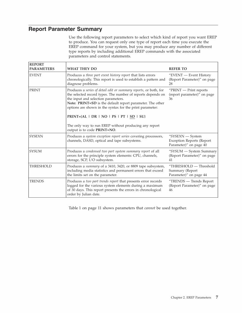
Report Parameter SummaryUse the following report parameters to select which kind of report you want EREPto produce. You can request only one type of report each time you execute theEREP command for your system, but you may produce any number of differenttype reports by including additional EREP commands with the associatedparameters and control statements.
REPORTPARAMETERS WHAT THEY DO REFER TO
EVENT Produces a three part event history report that lists errorschronologically. This report is used to establish a pattern anddiagnose problems.
“EVENT — Event History(Report Parameter)” on page28
PRINT Produces a series of detail edit or summary reports, or both, forthe selected record types. The number of reports depends onthe input and selection parameters.Note: PRINT=SD is the default report parameter. The otheroptions are shown in the syntax for the print parameter:
PRINT={AL | DR | NO | PS | PT | SD | SU}
The only way to run EREP without producing any reportoutput is to code PRINT=NO.
“PRINT — Print reports(report parameter)” on page36
SYSEXN Produces a system exception report series covering processors,channels, DASD, optical and tape subsystems.
“SYSEXN — SystemException Reports (ReportParameter)” on page 40
SYSUM Produces a condensed two part system summary report of allerrors for the principle system elements: CPU, channels,storage, SCP, I/O subsystem.
“SYSUM — System Summary(Report Parameter)” on page41
THRESHOLD Produces a summary of a 3410, 3420, or 8809 tape subsystem,including media statistics and permanent errors that exceedthe limits set on the parameter.
“THRESHOLD — ThresholdSummary (ReportParameter)” on page 44
TRENDS Produces a two part trends report that presents error recordslogged for the various system elements during a maximumof 30 days. This report presents the errors in chronologicalorder by Julian date.
“TRENDS — Trends Report(Report Parameter)” on page46
Table 1 on page 11 shows parameters that cannot be used together.
Chapter 2. EREP Parameters 7

Selection Parameter SummaryUse the following selection parameters to select records for EREP to use in thereport.
SELECTION PARAMETERS TELLS EREP TO: REFER TO
CPU (Processor serial and machinetype numbers)
Use only the records associated with thisparticular processor.
“CPU — Central ProcessingUnit (Selection Parameter)” onpage 17
CPUCUA (Processor serial numberand device address)
Use only the records associated with thisdevice attached to this processor.
“CPUCUA —CPU/Channel/Unit Address(Selection Parameter)” on page19
CUA (Device address or number) Use only the records associated with thisparticular device address or device number.
“CUA — Channel/UnitAddress (Selection Parameter)”on page 20
DATE Use only the records created during this daterange.
“DATE — Date Range(Selection Parameter)” on page22
DEV (Device type) Use only the records associated with thisparticular device type; or, conversely, do notuse the records associated with this devicetype.
“DEV — Device Type(Selection Parameter)” on page24
DEVSER (Device serial number) Use only the OBR records associated with thistape device serial number. (Use only for theTHRESHOLD report and only with the 3410,3420, and 8809 tape OBR records.)
“DEVSER — Device SerialNumber (Selection Parameter)”on page 26
ERRORID (Error identifier) Use only the MCH and MVS software recordscontaining this particular error identifier.
“ERRORID — Error Identifier(Selection Parameter)” on page27
LIA/LIBADR (Line interface[base] address)
Use only the 3705, 3720, 3725, 3735 or 3745communication controller records containingthis line interface address.
“LIA/LIBADR — LineInterface Base Address(Selection Parameter)” on page30
MOD (Processor model) Use only the records containing this processormachine type (number).
“MOD — Processor Model(Selection Parameter)” on page34
MODE (370 or 370XA) Use only the records created in this operatingmode.
“MODE — Operating Mode(Selection Parameter)” on page35
SYMCDE (Fault symptom code) Use only the 33XX DASD records containingthis particular fault symptom code.
“SYMCDE — Fault SymptomCode (Selection Parameter)” onpage 38
TERMN (Terminal name) Use only the VTAM OBR records containingthis terminal name.
“TERMN — Terminal Name(Selection Parameter)” on page43
TIME Use only the records created during this timerange.
“TIME — Time Range(Selection Parameter)” on page45
TYPE (Record type) Use only the records of the specified types. “TYPE — Record Type(Selection Parameter)” on page47
8 EREP V3R5 Reference

SELECTION PARAMETERS TELLS EREP TO: REFER TO
VOLID (Volume serial number) Use only the 33XX DASD or 34XX tape recordscontaining this volume serial number.
“VOLID — Volume Identifier(Selection Parameter)” on page49
Table 1 on page 11 shows the parameters that cannot be used together.
Chapter 2. EREP Parameters 9

Processing Parameter SummaryUse the following processing parameters to control the way EREP processes therecords you have selected:
PROCESSING PARAMETERS WHAT THEY DO REFER TO
ACC (Accumulate) Tells EREP to copy the records used for the report into anoutput history file.
“ACC —AccumulateRecords(ProcessingParameter)” onpage 16
HIST (History) Tells EREP that its input consists of records on a historyfile.
“HIST — HistoryInput (ProcessingParameter)” onpage 29
LINECT (Line count) Tells EREP that each page of the report output mustcontain this number of lines.
“LINECT — LineCount (ProcessingParameter)” onpage 31
LINELEN (Line length) Tells EREP that each line of the system summary reportoutput may contain up to this number of characters.
“LINELEN —Line Length(ProcessingParameter)” onpage 32
MERGE (Merge) Tells EREP that its input consists of records from both theERDS and a history file.
“MERGE —Merge Input DataSets (ProcessingParameter)” onpage 33
SHORT (Short OBR) Tells EREP to print out short form OBR records in detailedit report output.
“SHORT — PrintShort OBRRecords(ProcessingParameter)” onpage 37
TABSIZE (Table size) Tells EREP that the sort table it uses for internal processingmust be this size.
“TABSIZE — SortTable Size(ProcessingParameter)” onpage 42
ZERO (Zero ERDS) Tells EREP that when this report is complete, to change theheader pointer to allow the ERDS to be overwritten withnewly collected errors.
“ZERO — Clearthe ERDS(ProcessingParameter)” onpage 50
Table 1 on page 11 shows the parameters that cannot be used together.
10 EREP V3R5 Reference

EREP Parameter CombinationsTo help you to avoid using invalid parameter combinations, Table 1 shows theparameters that cannot be used together. An X in a column indicates which twoparameters cannot be used together; for example the ACC and the thresholdparameters cannot be used together. Numbers in the column are identified in thenotes following the table.
Table 1. EREP Selection, Processing, and Report Parameter CombinationsProcessing Parameters Selection Parameters
ACC
H IST
L INECNT
L INE LEN
MERGE
SHORT
TABS IZE
ZERO
CPU
CPUCUA
14C
UA
DATE
DEV
DEVS ER
ERROR ID
L IA /L IBADR
MOD
MODE
SYMCDE
TERMN
T IME
TYP E
15
VOL ID
REPORT
EVENT X X
PRINT 1 2 X
SYSEXN X X
SYSUM X X
THRESHOLD X X X X X 3 X X X X X X
TRENDS X X
PROCESSING
ACC X 4 X
HIST X X X
LINECT X
LINELEN X
MERGE X X X
SHORT X
TABSIZE X X
ZERO 4 X X X X X X X X X X 5 X X X X X
SELECTION
CPU X X X X
CPUCUA X X X X X X 6
CUA 14 X X X 6
DATE X X
DEV X X 7 8 9 10
DEVSER X X X X 7 X X X X X X 11 12
ERRORID X X X 12
LIA/LIBADR X 8 X X X X X
MOD X X X X X
MODE 5 X
SYMCDE X X X X X 11 X
TERMN X X X X X 11 X
TIME X X
TYPE X 6 6 9 11 12 11 11 X 13
VOLID 15 X 10 12 X X X 13 X
Note:
1. Invalid when PRINT=NO.2. Invalid when PRINT=DR, NO, SD, or SU.
Chapter 2. EREP Parameters 11
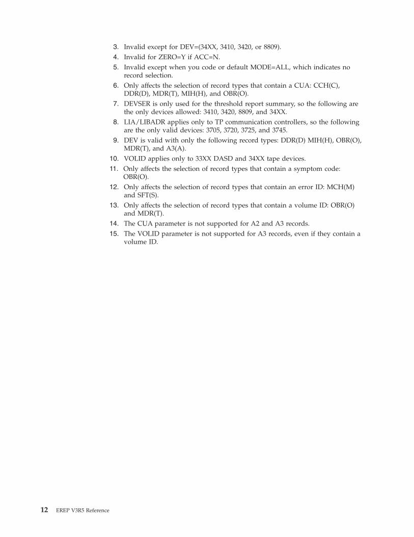
3. Invalid except for DEV=(34XX, 3410, 3420, or 8809).4. Invalid for ZERO=Y if ACC=N.5. Invalid except when you code or default MODE=ALL, which indicates no
record selection.6. Only affects the selection of record types that contain a CUA: CCH(C),
DDR(D), MDR(T), MIH(H), and OBR(O).7. DEVSER is only used for the threshold report summary, so the following are
the only devices allowed: 3410, 3420, 8809, and 34XX.8. LIA/LIBADR applies only to TP communication controllers, so the following
are the only valid devices: 3705, 3720, 3725, and 3745.9. DEV is valid with only the following record types: DDR(D) MIH(H), OBR(O),
MDR(T), and A3(A).10. VOLID applies only to 33XX DASD and 34XX tape devices.11. Only affects the selection of record types that contain a symptom code:
OBR(O).12. Only affects the selection of record types that contain an error ID: MCH(M)
and SFT(S).13. Only affects the selection of record types that contain a volume ID: OBR(O)
and MDR(T).14. The CUA parameter is not supported for A2 and A3 records.15. The VOLID parameter is not supported for A3 records, even if they contain a
volume ID.
12 EREP V3R5 Reference

Default Actions for EREP ParametersTable 2 shows the default values that EREP uses when you do not include aparameter in the controls for an EREP run.
Table 2. When You Omit EREP Parameters
PARAMETER IF YOU OMIT THIS PARAMETER
ACC EREP assumes ACC=Y, except when you request a threshold report. Then, thedefault is ACC=N.
CPU EREP processes records from all processors.
CPUCUA EREP processes all available records.
CUA EREP uses the records from all device addresses.
DATE EREP uses all the records in the input data set, regardless of when they werecreated except for the trends report. For the trends report, if you do not codethe DATE parameter, the default is to process 30 days of error data.
DEV EREP processes records associated with all device types.
DEVSER EREP uses records for the threshold summary regardless of the device serialnumbers they contain.
ERRORID EREP processes all MCH and SFT records, regardless of their error identifiers.
EVENT Unless you specifically code EVENT or EVENT=Y, EREP does not produce anevent history report.
HIST EREP assumes HIST=N and uses the ERDS as input.
LIA/LIBADR EREP uses 3705, 3720, 3725, 3735, and 3745 TP communication controller recordsregardless of the line interface base address they contain.
LINECT For MVS, and VM, 50 lines per page; for VSE systems, the default is thenumber of lines per page set for SYSLST at SYSGEN.
LINELEN 132.
MERGE EREP assumes MERGE=N and uses records from only one input file.
MOD EREP processes records regardless of which kind of processor they were createdon.
MODE EREP uses all available records, regardless of whether they were recorded in 370or 370XA mode.
PRINT If you do not code any report parameter at all, EREP assumes PRINT=SD,which produces a detail summary and, if applicable, a data reduction report foreach record and device type you select. If you code PRINT without anykeyword value, it is a syntax error.
SHORT EREP does not print out short OBR records for detail edit reports. It does printthem out for detail summaries, however.
SYMCDE EREP uses all OBR records, regardless of the fault symptom codes they contain.
SYSEXN Unless you specifically code SYSEXN or SYSEXN=Y, EREP does not produce asystem exception report series.
SYSUM Unless you specifically code SYSUM or SYSUM=Y, EREP does not produce asystem summary.
TABSIZE For MVS, and VM, EREP’s internal sort table is 24KB; for VSE systems, it is4KB.
TERMN EREP processes VTAM OBR records regardless of the terminal name theycontain.
THRESHOLD Unless you specifically code THRESHOLD and some threshold values, EREPproduces no threshold summary.
TIME EREP uses all available records, regardless of the time they were created.
TRENDS Unless you specifically code TRENDS or TRENDS=Y, EREP produces no trendsreport.
TYPE EREP uses all types of records.
Chapter 2. EREP Parameters 13

Table 2. When You Omit EREP Parameters (continued)
PARAMETER IF YOU OMIT THIS PARAMETER
VOLID EREP uses certain DASD and tape records regardless of the associated volumeserial numbers.
ZERO EREP does not clear the ERDS after completing the report. The default isZERO=N.
Parameter DescriptionsUse the following syntax summaries of the EREP parameters to find completeparameter descriptions.
SYNTAX REFER TO
ACC[=Y] | =N “ACC — Accumulate Records(Processing Parameter)” on page 16
CPU=({nnnnnn|Xnnnnn|XXnnnn}.model[, ...]) “CPU — Central Processing Unit(Selection Parameter)” on page 17
CPUCUA=(serial.{cua|cuX}[,serial.{cua|cuX}]...) “CPUCUA — CPU/Channel/UnitAddress (Selection Parameter)” onpage 19
CUA=({[N]addr|[N]addr-[N]addr}[, ...]) “CUA — Channel/Unit Address(Selection Parameter)” on page 20
DATE=({yyddd[,yyddd] | yyddd[-yyddd]}) “DATE — Date Range (SelectionParameter)” on page 22
DEBUG=(nn[,nn] ...) “DEBUG — Debug (DiagnosticParameter)” on page 23
DEV=(type | Ntype[,type | Ntype]...) “DEV — Device Type (SelectionParameter)” on page 24
DEVSER=(serial[,serial]...) “DEVSER — Device Serial Number(Selection Parameter)” on page 26
ERRORID=(seqno[,cpuid,asid,hh,mm,ss,t]) “ERRORID — Error Identifier(Selection Parameter)” on page 27
EVENT[=Y] | =N “EVENT — Event History (ReportParameter)” on page 28
HIST[=Y] | =N “HIST — History Input (ProcessingParameter)” on page 29
LIA | LIBADR=address “LIA/LIBADR — Line InterfaceBase Address (SelectionParameter)” on page 30
LINECT=nnn “LINECT — Line Count(Processing Parameter)” on page 31
LINELEN={132 | 165 | 204} “LINELEN — Line Length(Processing Parameter)” on page 32
MERGE[=Y] | =N “MERGE — Merge Input Data Sets(Processing Parameter)” on page 33
MOD=(model[,model]...) “MOD — Processor Model(Selection Parameter)” on page 34
MODE={370 | 370XA | ALL} “MODE — Operating Mode(Selection Parameter)” on page 35
14 EREP V3R5 Reference

SYNTAX REFER TO
PRINT={AL | DR | NO | PS | PT | SD | SU} “PRINT — Print reports (reportparameter)” on page 36
SHORT[=Y] | =N “SHORT — Print Short OBRRecords (Processing Parameter)”on page 37
SYMCDE={nnnn | nnnX | nnXX | nXXX} “SYMCDE — Fault Symptom Code(Selection Parameter)” on page 38
SYSEXN[=Y] | =N “SYSEXN — System ExceptionReports (Report Parameter)” onpage 40
SYSUM[=Y] | =N “SYSUM — System Summary(Report Parameter)” on page 41
TABSIZE=nnnnK “TABSIZE — Sort Table Size(Processing Parameter)” on page 42
TERMN=name “TERMN — Terminal Name(Selection Parameter)” on page 43
THRESHOLD=(xxx,yyy) “THRESHOLD — ThresholdSummary (Report Parameter)” onpage 44
TIME=({hhmm,hhmm | hhmm-hhmm}) “TIME — Time Range (SelectionParameter)” on page 45
TRENDS[=Y] | =N “TRENDS — Trends Report(Report Parameter)” on page 46
TYPE=code[code]... “TYPE — Record Type (SelectionParameter)” on page 47
VOLID=(volser[,volser]...) “VOLID — Volume Identifier(Selection Parameter)” on page 49
ZERO[=Y] | =N “ZERO — Clear the ERDS(Processing Parameter)” on page 50
Chapter 2. EREP Parameters 15

ACC — Accumulate Records (Processing Parameter)Tells EREP to
Copy the records that passed filtering for the report onto an output data set.
Syntax
ACC[=Y] | =N
Defaults
EREP assumes ACC=Y, except when you request a threshold report. Then, thedefault is ACC=N.
Coding
Specifying ACC is the same as ACC=Y.
Important: If you request a system summary report using the ERDS as input andcode ACC=Y or allow it by default, EREP clears the ERDS even if you codeZERO=N. If your EREP run defines the ACCDEV file as DUMMY, the records arelost.
If you code or imply ACC=Y for an EREP run, you must also code the systemcontrol statements needed to define the output data set to hold the records. Referto the following topics in the EREP User's Guide for more details and examples:MVS System Controls, Defining Files for CPEREPXA, and VSE System Controls.
If you code ZERO=Y when requesting PRINT=SU or PRINT=NO, EREP assumesACC=Y and expects you to define the output file.
Parameter Conflicts
DEVSER THRESHOLD ZERO=Y if ACC=N
Notes
EREP does not zero the ERDS unless all the records have been accumulated on anoutput file.
ACC Parameter
16 EREP V3R5 Reference

CPU — Central Processing Unit (Selection Parameter)Tells EREP to
Use only the records containing the specified model and CPU ID numbers:v The model number is the machine type.v The CPU ID number may also be called the serial number in some reports.
The following are valid processor model numbers for the CPU parameter:
Processor2003 2097 93752064 2098 93772066 2817 96722084 2818 96732086 2827 96742094 29642096 9373
Syntax
CPU=({nnnnnn|Xnnnnn|XXnnnn}.model[,nnnnnn|Xnnnnn|XXnnnn}.model]...)
nnnnnnThe six-digit hexadecimal CPU ID number. It defines a single processor in ann-way central processor complex.
XnnnnnThe processor identifier. You may wish to use this form if you want to select allthe records for an n-way central processor complex, single image or physicallypartitioned, without having to specify all the processor addresses individually.For example: 012345, 112345, 212345.
XXnnnnThe processor identifier. You may wish to use this form if you want to select allthe records for a logical partitioned (PR/SM ™ LPAR) central processorcomplex, whether single image or physically partitioned. See “PR/SM Feature”on page 367.
modelThe four-digit decimal processor model number.
Defaults
EREP processes records from all processors.
Coding
Maximum of six entries.
When using PR/SM to create logical partitions, use the logical partition identifierin conjunction with the last four digits of the serial number. See “PR/SM Feature”on page 367 for more information.
Parameter Conflicts
CPUCUA MOD THRESHOLD ZERO
CPU Parameter
Chapter 2. EREP Parameters 17
|

Notes
If you use the CPU parameter, you cannot use ZERO=Y because you haveexcluded some records from processing.
ExamplesCPU=(123456.0168,234567.2084)
CPU=(0A1572.2098,1B1572.2098,2C1572.2098)
CPU=(XX1572.2096,X37297.2097)
CPU Parameter
18 EREP V3R5 Reference
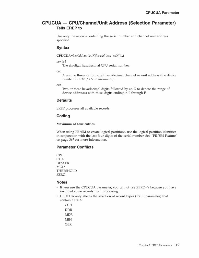
CPUCUA — CPU/Channel/Unit Address (Selection Parameter)Tells EREP to
Use only the records containing the serial number and channel unit addressspecified.
Syntax
CPUCUA=(serial.{cua|cuX}[,serial.{cua|cuX}]...)
serialThe six-digit hexadecimal CPU serial number.
cuaA unique three- or four-digit hexadecimal channel or unit address (the devicenumber in a 370/XA environment).
cuXTwo or three hexadecimal digits followed by an X to denote the range ofdevice addresses with those digits ending in 0 through F.
Defaults
EREP processes all available records.
Coding
Maximum of four entries.
When using PR/SM to create logical partitions, use the logical partition identifierin conjunction with the last four digits of the serial number. See “PR/SM Feature”on page 367 for more information.
Parameter Conflicts
CPUCUADEVSERMODTHRESHOLDZERO
Notesv If you use the CPUCUA parameter, you cannot use ZERO=Y because you have
excluded some records from processing.v CPUCUA only affects the selection of record types (TYPE parameter) that
contain a CUA:CCHDDRMDRMIHOBR
CPUCUA Parameter
Chapter 2. EREP Parameters 19

CUA — Channel/Unit Address (Selection Parameter)Tells EREP to
Use only the records containing (or not containing) the channel or unit addressspecified.
Syntax
CUA=({[N]addr|[N]addr-[N]addr}[,...])
addrA three- or four-digit hexadecimal address or group of addresses. The formatof the address may be nnXX, nnnX, or nnnn (for example: 01XX, 038X, or049C). nnXX means that EREP processes all controller or unit addresses onchannel nn; nnnX means that EREP processes all unit addresses on channel orcontrol unit nnn.
Important: The channel identifier can be one or two digits.
addr-addrA range of contiguous hexadecimal addresses, which may include more thanone channel and control unit. The lower address must appear first in theexpression. An X in the lower address represents a 0; in the upper address itrepresents an F.
N Indicates not; it excludes CUAs from the report. NnnXX means that EREPprocesses all controller or unit addresses not on channel nn; NnnnX means thatEREP processes all unit addresses not on channel or control unit nnn.
Defaults
EREP processes records from all devices (CUAs).
Coding
Maximum of eight entries.
You cannot select and exclude CUAs on the same CUA parameter;CUA=(123-320,N12C) is invalid.
Parameter Conflicts
CPUCUA ZERO
Notesv If you use the CUA parameter, you cannot use ZERO=Y because you have
excluded some records from processing.v CUA only affects the selection of record types (TYPE parameter) that contains a
CUA:CCHDDRMDRMIHOBR
CUA Parameter
20 EREP V3R5 Reference
Exception: A2 and A3 records cannot be selected by CUA.v If there are alternate paths to a device, and you want EREP to process all the
records for the device, you must specify the CUAs for all the alternate paths.
Examples
To select records from a specific CUA or range of CUAs:CUA=(012C)
CUA=(0123,032X,04XX)
CUA=(123-320,04XX)
CUA=(123-320,4B0-C00)
To exclude records from a specific CUA or range of CUAs:CUA=(N012C)
CUA=(N0123,N032X,N04XX)
CUA=(N123-N320,N04XX)
CUA=(N123-N320,N4B0-NC00)
CUA Parameter
Chapter 2. EREP Parameters 21

DATE — Date Range (Selection Parameter)Tells EREP to
Select records created during the specified date range.
Syntax
DATE=({yyddd[,yyddd] | yyddd[-yyddd]})
yydddThe year yy and the Julian day ddd.
The first yyddd is the year and day when the date range begins; the secondyyddd is the ending year and day. The second date is optional; you can selectrecords from a single date as well as from a range of dates. To select a singledate, code only one yyddd.
When you code a date range, the second yyddd must be greater than or equalto the first. If it is not, EREP issues a syntax-error message.
Defaults
If you do not code the DATE parameter, all the records in the ERDS or history filewill be selected for all the reports except for the trends report. For the trendsreport the default is to process 30 days of error data ending with the current date.
Codingv DATE is valid with all the report parameters.v To express a range of 30 days, add 29 to the beginning Julian day.v DATE is required when you use the TIME selection parameter.
Parameter Conflicts
ZERO
Notesv If you use the DATE parameter, you cannot use ZERO=Y because you have
excluded some records from processing.v The dates in the PERIOD FROM and TO in the report headings are the dates of
the first and the last record found within the date range specified in the DATEparameter.
ExamplesDATE=(82137)
DATE=(82136,82143)
DATE=(89152-89181)
DATE Parameter
22 EREP V3R5 Reference
DEBUG — Debug (Diagnostic Parameter)Tells EREP to
Print the record input information indicated by the specified options as part of theEREP report.
Syntax
DEBUG=(nn[,nn] ...)
nn The one- or two-digit decimal number assigned to an EREP DEBUG option.
The following DEBUG options are available for customer use:
NumberMeaning
4 Print the name and compile date of all control modules. Print the start andstop times of each routine called by IFCEREP1. The information appears inthe EREP messages file (TOURIST output).
17 Print a hexadecimal dump of every record that passed filtering on theevent report. The records appear in the event history report, one followingeach normal data line.
If you select a print report with DEBUG=(17) a hexadecimal dump of everyrecord that passed filtering appears in the EREP messages file (TOURISToutput).
Defaults
None. Debugging information is not normally printed.
Coding
No special considerations
Parameter Conflicts
None.
Notesv See your IBM service representative before attempting any debugging of the
EREP program.v Because this book is primarily for IBM customers, it includes only those DEBUG
options available and recommended for customer use; your IBM servicerepresentative can advise you further, if necessary.
DEV Parameter
Chapter 2. EREP Parameters 23

DEV — Device Type (Selection Parameter)Tells EREP to
Select or exclude records associated with the specified generic device types.
The following are valid device types for DEV:
Device TypesAFP1 1060 2303 2780 327T 3490 3886 9313BA00 1130 2305 2790 3277 3504 3890 ™ 9332BCTA 115A 2311 2930 3278 3505 3895 9335CTCA 1255 2314 2947 3284 3525 3945 9336ESIO 1270 2321 2955 3286 3540 3968 9345
NMVT 1275 2400 2956 3289 3590 3995 9347OSA 1285 2495 2970 3310 3670 4245 9348
OSAD 1287 2501 2972 3330 3700 4248SCTC 1288 2520 3036 3340 3704 5080
SWCH 1403 2540 3066 3350 3705 52030671 1419 2560 3138 3370 3720 54241012 1442 2596 3148 3375 3725 54251015 1443 2671 3158 3380 3735 62621017 2020 2701 3168 3390 3745 73401018 2150 2702 3203 3400 3791 74431030 2250 2703 3210 3410 3800 7770105D 2260 2715 3211 3420 3820 7772105T 2265 2740 3213 3422 3838 83B31050 2280 2741 3215 3424 3848 88091052 2282 2760 3262 3430 3850 92461053 2301 2770 327D 3480 3851 9247
The following are valid general device classes for DEV:23XX 27XX 32XX 33XX 34XX 35XX 37XX 38XX ESIO
Syntax
DEV=(type | Ntype[,type| Ntype]...)
typeA four character field: either a specific device type (3340, 3420) or therepresentation of a class of devices (33XX, 34XX).
N Indicates not; excludes a device type from the report.
Defaults
EREP processes records associated with all device types.
Codingv Maximum of eight entries.
v The device type numbers must be enclosed in parentheses.v You cannot select and exclude devices on the same DEV parameter;
DEV=(3330,N2400) is invalid.v DEV=(NMVT) selects NMVT records from all devices.
DEV Parameter
24 EREP V3R5 Reference
v DEV=(ESIO) selects the I/O units that are supported in EREP on the ESCON ®
links. See “ESIO I/O Connected to an ESCON Link” on page 375 for moreinformation.
Parameter Conflicts
ZERO
Notesv If you use the DEV parameter, you cannot use ZERO=Y because you have
excluded some records from processing.v The only record types affected by the DEV parameter are the following:
Record typesA3 (A) MDR (T)CCH (C) MIH (H)DDR (D) OBR (O)
v Special restrictions apply if you use the DEV parameter with any of thefollowing parameters:
DEVSERLIA/LIBADRTYPETHRESHOLDVOLID
See the other parameter descriptions and Part 3, “Product-DependentInformation,” on page 327 for the special restrictions.
v If a device is emulating another device, use the device type number of theemulated device on the DEV parameter.
v EREP interprets some DEV entries to mean more than just the device you havecoded; see Part 3, “Product-Dependent Information,” on page 327for additionaldevice-specific considerations.
Examples
To select records from specific devices or a class of devices:DEV=(3420)
DEV=(33XX,3705)
To exclude the records from specific devices or a class of devices:DEV=(N3420)
DEV=(N33XX,N3705)
DEV Parameter
Chapter 2. EREP Parameters 25

DEVSER — Device Serial Number (Selection Parameter)Tells EREP to
Select for the threshold summary only those OBR records that contain the specifieddevice serial numbers.
Syntax
DEVSER=(serial[,serial]...)
serialA six-digit decimal device serial number from the service data.
Defaults
EREP selects OBR records without regard for the device serial numbers theycontain.
Coding
Maximum of eight entries.
DEVSER is used only for the threshold summary report.
Parameter Conflicts
ParametersACC EVENT PRINT SYSEXN TRENDSCPUCUA LIA/LIBADR SHORT SYSUM ZEROERRORID MOD SYMCDE TERMN
Notesv EREP forces the DEV and TYPE parameters when you use the DEVSER
parameter. See “Threshold Summary Report Information” on page 350 in Part 3,“Product-Dependent Information,” on page 327.
v The device serial number is a value in a 2-byte field of a tape OBR record thatcorresponds to the external serial number of the device. If the external serialnumber is greater than 65535, only the four low-order digits (decimal) arecorrect for the device serial. To use DEVSER to specify numbers larger than65535, do the following:1. Convert the external serial number to binary2. Reconvert the low-order (rightmost) 16 bits to decimal3. Pad the resulting number with leading zeros to make a six-digit decimal
number.
Examples
DEVSER=(013455,113455,213455)
DEVSER Parameter
26 EREP V3R5 Reference

ERRORID — Error Identifier (Selection Parameter)Tells EREP to
Select for the requested report only the records containing the specified erroridentifier.
Syntax
ERRORID=(seqno[,cpuid,asid,hh,mm,ss,t])
seqnoA 5-digit decimal error identifier from an MCH record or an MVS software(SFT) record.
cpuidA 2-digit hexadecimal processor (CPU) identifier.
asidA 4-digit hexadecimal address space identifier.
hh A 2-digit decimal value representing the hour.
mm A 2-digit decimal value representing the minute.
ss A 2-digit decimal value representing the second.
t A single decimal digit indicating tenths of the second.
Defaults
EREP processes all MCH and SFT records, regardless of their error identifiers.
Codingv Coding only the sequence number seqno causes EREP to process all records with
the same error ID, regardless of when or where they were recorded.v If you code the time-stamp values on the ERRORID parameter, you must also
code the DATE parameter.v If you use the ERRORID parameter, you cannot use ZERO=Y because you have
excluded some records from processing.v The only records that contain an error ID are machine check (MCH) records and
software (SFT) records produced by MVS. Therefore, the only record TYPEvalues you can code with the ERRORID parameter are M and S.
Parameter Conflicts
DEVSER THRESHOLD ZERO
ExamplesERRORID=(01234)
ERRORID=(23456,01,0012,06,21,31,6)
ERRORID Parameter
Chapter 2. EREP Parameters 27

EVENT — Event History (Report Parameter)Tells EREP to
Produce an event history report (one-line abstracts of selected records inchronological order).
Syntax
EVENT[=Y] | =N
Defaults
EREP does not produce an event history report.
Coding
EREP produces an event history report only when you specifically code EVENT.
Specifying EVENT is the same as EVENT=Y.
Parameter Conflicts
DEVSER SHORT
Notes
If you do not code any selection parameters with EVENT, EREP processes allavailable records for the report. The default value of ZERO=N means that EREPdoes not clear the ERDS unless you specifically request it.
EVENT Parameter
28 EREP V3R5 Reference

HIST — History Input (Processing Parameter)Tells EREP to
Use the records in a history file for the requested report, instead of those in theERDS.
Syntax
HIST[=Y] | =N
Defaults
EREP assumes HIST=N and uses the ERDS as input, if you omit this processingparameter.
Codingv Specifying HIST is the same as HIST=Y.v HIST is valid for all the report parameters.v You must code the system control statements to define the input file and a
temporary work file. Refer to the following topics in the EREP User's Guide formore details and examples: MVS System Controls, Defining Files forCPEREPXA, and VSE System Controls.
v To use more than one data set as the history input under MVS concatenate DDstatements for the other data sets to the ACCIN DD statement. For VM and VSE,the history input must be in a single data set.
Parameter Conflicts
MERGE ZERO
Notes
When creating history dataset, HIST means write records to ACCDEV ddname (see1st step in SYS1.SAMPLIB(IFBEREPS) ).
HIST Parameter
Chapter 2. EREP Parameters 29

LIA/LIBADR — Line Interface Base Address (SelectionParameter)
Tells EREP to
Select MDR records according to the specified line interface base address. SeeChapter 25, “Teleprocessing (TP) Devices,” on page 371 in Part 3,“Product-Dependent Information,” on page 327.
Syntax
LIA | LIBADR=address
addressA four-digit hexadecimal line interface base address.
Defaults
EREP processes all available records.
Coding
You can use LIA or LIBADR; EREP accepts both forms.
Parameter Conflicts
DEVSER SYMCDE TERMN THRESHOLD VOLID ZERO
Notesv If you use the LIA/LIBADR parameter, you cannot use ZERO=Y because you
have excluded some records from processing.v If you code the DEV parameter with any device other than a 3705, 3720, 3725,
3735, or 3745 communications controller, a parameter conflict occurs. SeeChapter 25, “Teleprocessing (TP) Devices,” on page 371 in Part 3,“Product-Dependent Information,” on page 327.
LIA/LIBADR Parameter
30 EREP V3R5 Reference

LINECT — Line Count (Processing Parameter)Tells EREP to
Print this many lines on each page of output.
Syntax
LINECT=nnn
nnnOne-to-three decimal digits.
Defaults
For VSE systems, the number of lines set for SYSLST at SYSGEN.
For MVS, and VM systems, 50 lines per page.
Coding
Minimum value is 25.
For large installations, with more than 42 processors, LINECT=60 is recommended.
Parameter Conflicts
PRINT=NO
Notes
If the value you specify for LINECT is less than 25, EREP ignores it and uses thedefault value instead.
LINECT Parameter
Chapter 2. EREP Parameters 31
LINELEN — Line Length (Processing Parameter)Tells EREP to
Print up to this many characters in each line of output.
Syntax
LINELEN=nnn
nnnindicates the maximum number of characters to be printed on each line ofoutput.
132 Standard print
165 High-density print, 3800 printer only, paper width≥12 inches.
204 High-density print, 3800 printer only, paper width≥14 7/8 inches.
Defaults
132
Codingv Only LINELEN=132, LINELEN=165, or LINELEN=204 are valid.v When you code LINELEN=204, the EREPPT DD statement must be coded to
indicate high-density print is requested via the CHARS option://EREPPT DD SYSOUT=A,CHARS=(GSC,GFC,GUC)
OR//EREPPT DD SYSOUT=A,CHARS=DUMP
Parameter Conflicts
None.
Notesv This parameter is valid only for the system summary report. It is not useful for
the following reports:
EVENTPRINT={AL DR NO PS PT SD SU}SYSEXNTHRESHOLDTRENDS
v This parameter applies only if your installation has a 3800 printer and you arerunning under an MVS operating system.
LINELEN Parameter
32 EREP V3R5 Reference

MERGE — Merge Input Data Sets (Processing Parameter)Tells EREP to
Use the records from both the ERDS and a history file as input for the requestedreport.
Syntax
MERGE[=Y] | =N
Defaults
EREP assumes MERGE=N and uses records from only one input file if you omitthis processing parameter.
Codingv Specifying MERGE is the same as MERGE=Y.v You must make sure the system control statements needed to define both of the
input files are present. Refer to the following topics in the EREP User's Guide formore details and examples: MVS System Controls, Defining Files forCPEREPXA, and VSE System Controls
Parameter Conflicts
HIST
Notesv If you do not use the MERGE (or HIST) parameter, you are telling EREP that the
ERDS is its only input.v Under MVS, the history input can be in more than one data set. See “HIST —
History Input (Processing Parameter)” on page 29.v Under VSE, the input and output files should be assigned to different EXTENTs.
MERGE Parameter
Chapter 2. EREP Parameters 33
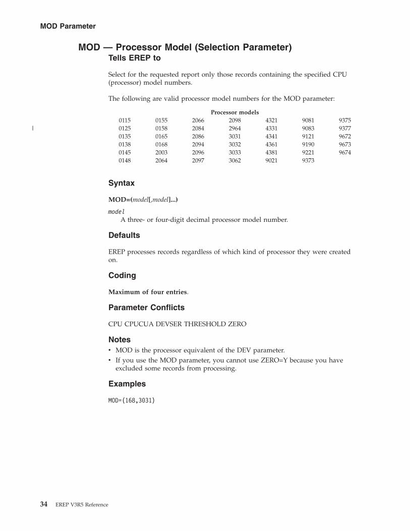
MOD — Processor Model (Selection Parameter)Tells EREP to
Select for the requested report only those records containing the specified CPU(processor) model numbers.
The following are valid processor model numbers for the MOD parameter:
Processor models0115 0155 2066 2098 4321 9081 93750125 0158 2084 2964 4331 9083 93770135 0165 2086 3031 4341 9121 96720138 0168 2094 3032 4361 9190 96730145 2003 2096 3033 4381 9221 96740148 2064 2097 3062 9021 9373
Syntax
MOD=(model[,model]...)
modelA three- or four-digit decimal processor model number.
Defaults
EREP processes records regardless of which kind of processor they were createdon.
Coding
Maximum of four entries.
Parameter Conflicts
CPU CPUCUA DEVSER THRESHOLD ZERO
Notesv MOD is the processor equivalent of the DEV parameter.v If you use the MOD parameter, you cannot use ZERO=Y because you have
excluded some records from processing.
Examples
MOD=(168,3031)
MOD Parameter
34 EREP V3R5 Reference
|
MODE — Operating Mode (Selection Parameter)Tells EREP to
Select for the requested report only those records created while the system wasoperating in the specified mode.
Syntax
MODE={370 | 370XA | ALL}
370means 370 mode only.
370/XAmeans 370XA and 370/ESA modes only.
ALLmeans 370, 370XA and 370/ESA modes.
Defaults
If you omit this selection parameter, EREP assumes MODE=ALL and processes allavailable records, regardless of the mode they were recorded in.
Codingv ZERO=Y is valid only with MODE=ALL.v If you code:
– MODE=370 and TYPE=C, EREP processes CCH records– MODE=370XA and TYPE=C, EREP processes SLH and CRW records– MODE=ALL and TYPE=C, EREP processes all available CCH, SLH, and CRW
records
Parameter Conflicts
None.
Notesv If EREP is running under any MVS system except MVS/XA, it treats software
(SFT) records produced by MVS/XA as unknown records. Therefore, thecombination of MODE=370XA or MODE=ALL and TYPE=S is meaningful onlyif the records were produced by MVS/XA.
v If a device is supported in 370XA mode, any detail summary reports yourequest for the device reflect that mode, regardless of what you specify on theMODE parameter.
MODE Parameter
Chapter 2. EREP Parameters 35

PRINT — Print reports (report parameter)Tells EREP to
Produce the PRINT reports specified (or PRINT=NO to produce no report output).
Syntax
PRINT={AL | DR | NO | PS | PT | SD | SU}
AL requests all the detail (PRINT) reports: detail edits of the records, detailsummaries, and, if applicable, data reduction reports.
DR requests only data reduction reports.
NO requests that no reports be generated at all.
PS requests both detail edit and detail summary reports.
PT requests only detail edit reports.
SD requests detail summaries and data reduction reports.
SU requests only detail summary reports.
Defaults
If you do not code any report parameter at all, EREP assumes PRINT=SD, whichproduces a detail summary and, if applicable, a data reduction report for eachrecord and device type you select.
Codingv If you code PRINT without a keyword value, it is a syntax error. You cannot
code PRINT alone.v If you code ZERO=Y and either PRINT=NO or PRINT=SU, EREP assumes
ACC=Y; make sure the ACCDEV output file is present to receive theaccumulated records.
v If you do not want any report output, code PRINT=NO.v If you want EREP to clear the ERDS you must change the value of the ZERO
parameter YES. The default value for the ZERO parameter is NO with PRINT.v If you use selection parameters with PRINT, you cannot clear the ERDS because
not all the records have been processed for the report.
Parameter Conflicts
DEVSER
PRINT Parameter
36 EREP V3R5 Reference
SHORT — Print Short OBR Records (Processing Parameter)Tells EREP to
Include short OBR records in a requested detail edit (PRINT) report.
Syntax
SHORT[=Y] | =N
Defaults
If you omit this processing parameter, EREP assumes SHORT=N and suppressesthe detail printing of short OBR records.
Coding
Specifying SHORT is the same as SHORT=Y.
Parameter Conflicts
DEVSER EVENT PRINT=DR PRINT=NO PRINT=SD PRINT=SU SYSEXN SYSUMTRENDS THRESHOLD
Notes
The OBR detail summary always includes the information in short OBR records(unless they are VTAM OBR records.)
SHORT Parameter
Chapter 2. EREP Parameters 37

SYMCDE — Fault Symptom Code (Selection Parameter)Tells EREP to
Select for the requested report only those 33XX DASD records having the specifiedfault symptom code. The symptom code consists of the bit settings in a two-bytefield of the sense data in an OBR record for a 33XX DASD.
Syntax
SYMCDE={nnnn | nnnX | nnXX | nXXX}
n is a hexadecimal digit.
Defaults
EREP processes 33XX records regardless of their symptom code bit settings.
Coding
No special considerations.
Parameter Conflicts
ParametersDEVSER THRESHOLDLIA/LIBADR VOLIDTERMN ZERO
Notesv If you use the SYMCDE parameter, you cannot use ZERO=Y because you have
excluded some records from processing.v The SYMCDE parameter only affects TYPE=O records that contain a symptom
code.v The combination of digits and Xs on the parameter indicate how specific you are
being: if you code 4032, you want EREP to select only the records containingthat exact symptom code; if you code 40XX, you want EREP to select the recordscontaining symptom codes that begin with 40.
Examples
Following are some ways to code SYMCDE, and the resulting bit setting EREPlooks for in the OBR sense data.
Parameter ValueBit Setting
SYMCDE=40320100 0000 0011 0010
SYMCDE=193X0001 1001 0011 xxxx
SYMCDE=92XX1001 0010 xxxx xxxx
SYMCDE=9XXX1001 xxxx xxxx xxxx
SYMCDE Parameter
38 EREP V3R5 Reference

x indicates either a 0 or 1 is valid.
SYMCDE Parameter
Chapter 2. EREP Parameters 39

SYSEXN — System Exception Reports (Report Parameter)Tells EREP to
Produce the system exception report series (several reports covering variousaspects of your processing and I/O subsystems).
Syntax
SYSEXN[=Y] | =N
Defaults
EREP does not produce a system exception report series.
Codingv EREP only produces a system exception report series when you specifically code
SYSEXN.v Specifying SYSEXN is the same as SYSEXN=Y.v Take care when specifying TYPE with SYSEXN because the report results can be
misleading.v You may need the DASDID, SYSIMG, and LIMIT control statements to
customize the system exception reports. See Chapter 3, “EREP ControlStatements,” on page 51
Parameter Conflicts
DEVSER SHORT
Notesv See Part 3, “Product-Dependent Information,” on page 327, for device-specific
information about the system exception report series.v Unless you use DATE or TIME or both with SYSEXN, EREP processes all the
available records.v EREP requires a large internal sort table to create the system exception reports
(512KB is a reasonable TABSIZE value). The increase in TABSIZE probablyrequires a corresponding increase in the virtual storage (partition or region size)available to EREP. Refer to the following topics in the EREP User's Guide formore details and examples: MVS Storage Requirementsand VSE StorageRequirements.
SYSEXN Parameter
40 EREP V3R5 Reference

SYSUM — System Summary (Report Parameter)Tells EREP to
Produce a system summary (a comprehensive report of errors for each of yoursystem’s principle elements: CPU, channel, subchannel, storage, SCP, and I/Osubsystem).
Syntax
SYSUM[=Y] | =N
Defaults
EREP does not produce a system summary.
Codingv EREP produces a system summary only when you specifically code SYSUM.v Specifying SYSUM is the same as SYSUM=Y.v Take care when specifying TYPE with SYSUM as report results can be
misleading.
Parameter Conflicts
DEVSER SHORT
Notesv When you request a system summary EREP accumulates the records to an
output (ACCDEV) file and zeroes the ERDS if the following are true:– The input records are on the ERDS– The record selection is not restricted by date and time– The default value for ACC of YES is not changed to NO– The default value for ZERO of YES is not changed to NO
Important: When you code ACC=Y with SYSUM, EREP always clears the ERDS,even if you code ZERO=N.
v If you do not define an output (ACCDEV) file, EREP ABENDs.
SYSUM Parameter
Chapter 2. EREP Parameters 41

TABSIZE — Sort Table Size (Processing Parameter)Tells EREP to
Use a sort table of the specified size to process the records selected for the report.
The sort table is EREP’s internal work space, where it arranges the records into theorder required for a given report.
Syntax
TABSIZE=nnnnK
nnnnis a 1–4 digit decimal number.
K The value is in thousands of bytes.
Defaults
Op.Sys. Virtual Storage Sort Table Records Processed
MVS 100KB 24KB 2400VM 100KB 24KB 2400VSE 100KB 4KB 400
Coding
No special considerations.
Parameter Conflicts
None.
Notesv EREP requires at least 100KB of virtual storage for its internal sort table.
Depending on the kind of report you are running, and on the number of recordsinvolved, you might have to increase the sort table size for a single EREP run orfor all your EREP reports. Refer to the following topics in the EREP User's Guidefor information on increasing the table size: MVS Storage Requirementsand VSEStorage Requirements.
v The approximate maximum practical table size beyond which EREP mayterminate due to insufficient storage is shown in the following table:
Op.Sys. Sort Table Size Region Size
MVS 1500KB 8 MBVM 2500KB 16 MB
v Requests for a table size greater than 3328KB may exceed EREP’s addressingcapability.
TABSIZE Parameter
42 EREP V3R5 Reference

TERMN — Terminal Name (Selection Parameter)Tells EREP to
Select for the requested report only those VTAM OBR records that contain thespecified terminal name.
VTAM OBR records are created only for local teleprocessing devices. The terminalname in these records is the NCP, or major node name. Remote attached TPdevices produce only MDR records, which contain the minor node name. SeeChapter 25, “Teleprocessing (TP) Devices,” on page 371 in Part 3,“Product-Dependent Information,” on page 327, for the devices to which thisparameter applies.
Syntax
TERMN=name
nameThe valid one-to-eight character alphanumeric name assigned to a particularterminal.
Defaults
EREP processes VTAM OBR records regardless of the terminal name they contain.
Coding
No special considerations.
Parameter Conflicts
ParametersDEVSER THRESHOLDLIA/LIBADR VOLIDSYMCDE ZERO
Notesv If you use the TERMN parameter, you cannot use ZERO=Y because you have
excluded some records from processing.v Although TERMN applies only to VTAM OBR records, EREP processes other
types of records for the report unless you also code the appropriate DEV valueand TYPE=O. See Chapter 25, “Teleprocessing (TP) Devices,” on page 371.
ExamplesTERMN=T001
TERMN=TERM0025
TERMN Parameter
Chapter 2. EREP Parameters 43
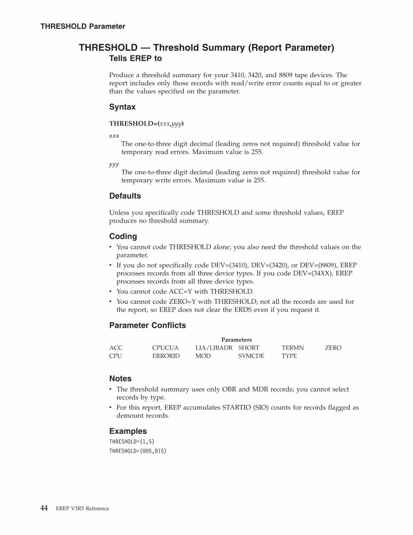
THRESHOLD — Threshold Summary (Report Parameter)Tells EREP to
Produce a threshold summary for your 3410, 3420, and 8809 tape devices. Thereport includes only those records with read/write error counts equal to or greaterthan the values specified on the parameter.
Syntax
THRESHOLD=(xxx,yyy)
xxxThe one-to-three digit decimal (leading zeros not required) threshold value fortemporary read errors. Maximum value is 255.
yyyThe one-to-three digit decimal (leading zeros not required) threshold value fortemporary write errors. Maximum value is 255.
Defaults
Unless you specifically code THRESHOLD and some threshold values, EREPproduces no threshold summary.
Codingv You cannot code THRESHOLD alone; you also need the threshold values on the
parameter.v If you do not specifically code DEV=(3410), DEV=(3420), or DEV=(8809), EREP
processes records from all three device types. If you code DEV=(34XX), EREPprocesses records from all three device types.
v You cannot code ACC=Y with THRESHOLD.v You cannot code ZERO=Y with THRESHOLD; not all the records are used for
the report, so EREP does not clear the ERDS even if you request it.
Parameter Conflicts
ParametersACC CPUCUA LIA/LIBADR SHORT TERMN ZEROCPU ERRORID MOD SYMCDE TYPE
Notesv The threshold summary uses only OBR and MDR records; you cannot select
records by type.v For this report, EREP accumulates STARTIO (SIO) counts for records flagged as
demount records.
ExamplesTHRESHOLD=(1,5)
THRESHOLD=(005,015)
THRESHOLD Parameter
44 EREP V3R5 Reference
TIME — Time Range (Selection Parameter)Tells EREP to
Select only those records created during the specified time period.
Syntax
TIME=({hhmm,hhmm | hhmm-hhmm})
hhmmIs a valid time period, hours and minutes.
Defaults
EREP selects records regardless of when they were created.
Codingv You must always code DATE when you code TIME.v You code hhmm using a 24-hour clock (for example: 1400 for 2 p.m.).
Parameter Conflicts
ZERO
Notesv If you use the TIME parameter, you cannot use ZERO=Y because that excludes
some records from processing.v If the second hhmm value is greater than or equal to the first, the time interval
pertains to each day of the date range specified on the DATE parameter. Forexample:DATE=(89031,89033),TIME=(1000,1100)
tells EREP to select records from 10:00 to 11:00 on each of three successive days.v If the second hhmm value is less than the first, EREP assumes that the time
interval crosses a day boundary. The interval is then regarded as twosub-intervals, one ending at 2400 and the other beginning at 0000. For example:DATE=(89031–89033),TIME=(1100–1000)
tells EREP to select records from 1100 to 2400 on day 89031; from 000 to 1000and 1100 to 2400 on day 89032; and from 000 to 1000 on day 89033.
TIME Parameter
Chapter 2. EREP Parameters 45

TRENDS — Trends Report (Report Parameter)Tells EREP to
Produce a trends report that shows the pattern and frequency of errors on a dailybasis.
Syntax
TRENDS[=Y] | =N
Defaults
EREP produces no trends report.
Coding
EREP produces a trends report only when you specifically code TRENDS.
Specifying TRENDS is the same as TRENDS=Y.
Parameter Conflicts
DEVSER SHORT
Notesv SIM generating devices will not be included in trends reports. (These devices
include all of the devices in the 3390, 9345, and subsequent families.)v If you request a trends report without specifying a date range on the DATE
parameter, EREP processes the last 30 days of data, ending with the current date.v If you do specify a date range, it cannot exceed 30 days.v The default value for the ZERO parameter is NO with TRENDS; you must
change the value of the ZERO parameter if you want EREP to clear the ERDS.
TRENDS Parameter
46 EREP V3R5 Reference

TYPE — Record Type (Selection Parameter)Tells EREP to
Select only the specified types of records.
Syntax
TYPE=code[code]...
Each code is one of the following:
Code Record Type
A A1 through AF records
B B1 through BF records
C CCH/CRW/SLH: Channel check/channel report word/subchannel logoutrecords
D DDR: Dynamic device reconfiguration records
E System termination (EOD): End of day and other terminating events
F F0 through FF records
H MIH: Missing interrupt records
I System initialization (IPL): Initial program load
M MCH: Machine check records
O OBR: Outboard records; unit checks
S Software (SFT): System abends and other software events
T MDR (formerly TPR): Miscellaneous data records
X C0 through CF records
Y D0 through DF records
Z E0 through EF records
Defaults
EREP uses all types of records for the report.
Coding
Do not include parenthesis, commas, or blanks when coding TYPE.
Parameter Conflicts
THRESHOLD ZERO
Notesv Take care when specifying TYPE with SYSUM or SYSEXN as report results can
be misleading.v If you use the TYPE parameter, you cannot use ZERO=Y because you have
excluded some records from processing.
TYPE Parameter
Chapter 2. EREP Parameters 47

v Some other EREP selection parameters are meaningful with only some of therecord types. The following table shows these parameters and the record-typecodes they work with:
ParameterRecord Types
CPUCUAC, D, H, O, T
CUA C, D, H, O, T
DEV A, C, D, H, O, T
DEVSERO
ERRORIDM, S
LIA/LIBADRT
SYMCDEO
TERMNO
VOLIDO, T
Coding these selection parameters by themselves does not fully limit the typesof records EREP processes; you also need the TYPE parameter to improveEREP’s processing efficiency.For example:If you want a report using CCH records selected by CPUCUA, you must codeTYPE=C as well as the CPUCUA parameter. Otherwise, EREP will use all therecord types that contain a CPUCUA, which are DDR, MCH, MDR, MIH, andOBR, as well as CCH.
v If you use the TYPE selection parameter, EREP does not process records that areinvalid or unknown.
Examples
To select machine-check and channel-check records:TYPE=MC
To select all software-generated records:TYPE=EIS
TYPE Parameter
48 EREP V3R5 Reference

VOLID — Volume Identifier (Selection Parameter)Tells EREP to
Select only those DASD and tape records associated with the specified volumeidentifiers.
Syntax
VOLID=(volser[,volser]...)
volserA valid volume identifier (or serial number) that can be from one-to-sixalphanumeric characters long.
Defaults
EREP selects DASD and tape records regardless of their volume identifiers.
Coding
Maximum of four entries.
No special considerations.
Parameter Conflicts
LIA/LIBADR SYMCDE TERMN ZERO
Notesv The VOLID parameter is meaningful only for devices providing volume serial
numbers.v The VOLID parameter is not supported for A3 records, even if they contain a
volume ID.v If you use the VOLID parameter, you cannot use ZERO=Y, because you have
excluded some records from processing.v When you are using VOLID for a threshold summary, EREP assumes you want
to see records from all your 34XX tape devices unless you specifically codeDEV=(3410), DEV=(3420), or DEV=(8809).
ExamplesVOLID=(TPONE,TPE2),DEV=(3420),THRESHOLD=(01,15)
VOLID=(TAPE5,CLPACK),PRINT=PS
VOLID Parameter
Chapter 2. EREP Parameters 49

ZERO — Clear the ERDS (Processing Parameter)Tells EREP to
Reset the pointers in the ERDS header record so the operating system writing therecords can start writing at the beginning of the ERDS (overwriting old, previouslyprocessed records). EREP uses the ERDS header record to know where to start andstop reading to get only the records written since the last time the ERDS pointerswere reset.
Syntax
ZERO[=Y] | =N
Defaults
EREP does not clear the ERDS.
Coding
EREP clears the ERDS when you code ZERO (specifying ZERO is the same asZERO=Y).
A few circumstances exist where EREP does not clear the ERDS even when youcode ZERO=Y:v If an overflow occurs in the sort table or work data setv If you coded ACC=Y, but the output file cannot be openedv If you coded ACC=Y, but EREP cannot process all the records because of table
overflow
Important: Allow read-only users to read ERDS without a RACF ABENDs913 ifZERO=N is specified or defaulted. If a user requests a system summary reportusing the ERDS as input and codes ACC=Y or allows it by default, EREP clears theERDS, even if ZERO=N is specified. This means that when users generate a systemsummary report, they must have update-access instead of read-only access. IfACCDEV is defined as DUMMY, the records are lost.
If you code ZERO=Y when requesting PRINT=SU or PRINT=NO, EREP assumesACC=Y and expects you to define the output file.
Parameter Conflicts
ParametersACC=N if ZERO=Y DEV MOD TYPECPU DEVSER SYMCDE VOLIDCPUCUA ERRORID TERMNCUA HIST THRESHOLDDATE LIA/LIBADR TIME
Notes
MODE is a conflict except when ZERO=Y and MODE=ALL, which indicates norecord selection.
ZERO Parameter
50 EREP V3R5 Reference
||||||

Chapter 3. EREP Control Statements
Use EREP control statements in addition to EREP parameters to direct EREPprocessing. Control statements give EREP more information about your hardwareconfiguration and about how you want it to organize the report you arerequesting.
This topic covers the following subjects:
TOPIC
“Coding Control Statements”
“Summarizing Control Statements” on page 52
“Using Control Statements with Reports” on page 53
“Control Statement Syntax” on page 54
“CONTROLLER Control Statement” on page 56
“DASDID Control Statement” on page 58
“LIMIT Control Statement” on page 64
“SHARE Control Statements” on page 66
“SYSIMG Control Statement” on page 71
Coding Control StatementsHere are some considerations and recommendations to keep in mind when codingcontrol statements:v Several control statements are required for each EREP run.v The same control statements may apply to several EREP runs.v EREP ignores statements that do not apply.v The control statements usually change only when your configuration changes.v Some EREP control statements require considerable preparation.v Putting control statements in a file is preferable to entering the statements in the
input data stream.
Each EREP control statement has its own coding rules. Here are a few generalcoding rules that you must follow:v Using ENDPARM
Control statements cannot be mixed with EREP parameters. If parameters andcontrol statements are in the same file, you must code ENDPARM to indicatethe end of parameters before coding any control statements. ENDPARM mustbegin on column 1.
v Entering Control StatementsThe following table shows the operating system specific guidelines you mustfollow.
© Copyright IBM Corp. 1983, 2015 51

OP. SYSTEM EREP CONTROL STATEMENT GUIDELINES
MVS The EREP control statements must always be entered as SYSIN data.
v You can enter the control statements as in-stream data.
v You can put the control statements into a separate file specified by theSYSIN JCL statement.
Refer to the SYSIN DD statement description in MVS System Controlsand Coding the JCL in the EREP User's Guide for more information andexamples.
VM There are several ways to enter control statements:
v You can enter CPEREPXA on the command line and supply theparameters and then the control statements in response to itsprompting messages.
v You can put the parameters and control statements in a file that iscalled as an operand to CPEREPXA.
v You can use the CMS EXEC &STACK control statement to enter theparameters and then the control statements as in-stream data beforecoding the CPEREPXA EXEC.
Refer to Entering CPEREPXA Operandsin the EREP User's Guide for moreinformation and examples.
VSE You must always code control statements as in-stream data in the SYSIPTdata statement. Refer to Assignments at Initialization in the EREP User'sGuide for more information.
v Continuing Control StatementsYou cannot continue a control statement from one line to the next. However, youcan code several control statements by repeating complete statements on newlines in order to convey your information to the EREP program. See the controlstatement descriptions for more details.
v CPU Serial Number RestrictionThe combined number of CPUs or system images specified on all of the controlstatements for an EREP run cannot exceed 16.Use the SYSIMG statement to expand EREP’s capabilities.The SYSIMG statement allows EREP to process records from an n-way processorso that those processors operating in the same system image are reported underthe CPU serial number. See “SYSIMG Control Statement” on page 71 foradditional information.
Summarizing Control StatementsEREP control statements provide information about your configuration and setoverall criteria for the way you want EREP to create a report. The following tablelists the types of control statements and describes how each affects the EREP run.
CONTROLSTATEMENTS WHAT THEY DO REFER TO
CONTROLLER Tells EREP to combine the error records associated withthis particular control unit and its attached devices. Thiscontrol statement only applies to the system summary andthreshold reports.
“CONTROLLER ControlStatement” on page 56
General Coding Rules
52 EREP V3R5 Reference

CONTROLSTATEMENTS WHAT THEY DO REFER TO
DASDID Tells EREP that this is the configuration of the 33XXDASDs within each subsystem; identifies those that do notprovide physical IDs for the system exception reportseries. This control statement applies only to the systemexception report series.
“DASDID Control Statement” onpage 58
ENDPARM Tells EREP that this is the end of the in-stream EREPparameters; the in-stream data that follows consists ofEREP control statements.
LIMIT Tells EREP to produce output for the system exceptionreports only when the number of megabytes processed pererror is less than the megabytes specified by the errorfrequency value and the number of times the error occursis greater than or equal to the number specified by thecount value. This control statement applies only to thesystem exception report series.
“LIMIT Control Statement” onpage 64
SHARE Tells EREP to combine the records for these devices thatare shared between systems. This control statement appliesto all the reports that generate I/O device summaries.
“SHARE Control Statements” onpage 66
SYSIMG Tells EREP to modify the CPU serial numbers for n-wayprocessors so that those processors operating in the samesystem image are reported under the same CPU serialnumber.
“SYSIMG Control Statement” onpage 71
Using Control Statements with ReportsSome EREP control statements are general-purpose, applying to most of the reportsand most kinds of devices. Others are quite report-specific and product-specific.
Table 3 shows which control statements you can use with the various EREP reportparameters.
Table 3. Valid Combinations of Control Statements and Report Parameters
PARAMETERS CONTROLLER DASDID LIMIT SHARE(1)
SYSIMG
EVENT YES YES
PRINT = AL (2) (3)
PRINT = DR YES (3)
PRINT = NO (3)
PRINT = PS (2) (3)
PRINT = PT (4)
PRINT = SD (2) (3)
PRINT = SU YES (3)
SYSEXN YES YES (5) YES
SYSUM YES YES YES
THRESHOLD YES YES YES
TRENDS YES YES
EREP Control Statements
Chapter 3. EREP Control Statements 53

Table 3. Valid Combinations of Control Statements and Report Parameters (continued)
PARAMETERS CONTROLLER DASDID LIMIT SHARE(1)
SYSIMG
Notes:
1. SHARE statements are not used for DASD devices that provide product identifierswithin their sense.
2. These PRINT options include detail summaries, which can include shared I/O devices.
3. Do not use if data is from the ERDS.
4. Use of the SYSIMG parameter does not affect the PRINT=PT parameter. The PRINT=PTparameter allows the processing of an unlimited number of CPUs; there is no need toalter serial numbers.
5. Use only for tape devices and DASD devices that do NOT provide product identifierswithin their sense data.
Control Statement SyntaxThe following table summarizes the syntax of individual EREP control statementsand shows where to find the complete control statement descriptions.
SYNTAX REFER TO
CONTROLLER=(cpuser.{ccua | ccuX | ccua-ccua}[,cpuser.{ccua|ccuX | ccua-ccua}]...) “CONTROLLER ControlStatement” on page 56
370: DASDID CPU=nnnnnn,CH=xx,SCU=ss,STR=ccuu,STR=ccuu,STR=ccuu,STR=ccuu,... “DASDID Control Statement” onpage 58
370XA: DASDIDCPU=Xnnnnn,CHP=xx,SCU=ss,STR=ccdddd,STR=ccdddd,STR=ccdddd,STR=ccdddd,...
“DASDID Control Statement” onpage 58
LIMIT {dasd,dkeyword[,dkeyword]... | tape,tkeyword[,tkeyword]... | cpu,ckeyword[,ckeyword ]...} “LIMIT Control Statement” onpage 64
SHARE=([XA.]cpuser.{ccua|ccuX | ccua-ccua}[,[XA.]cpuser.{ccua | ccu X | ccua-ccua}]...) “SHARE Control Statements” onpage 66
SYSIMG BASESN={ALL | sssss[,CPCTYPE=tttt][,CP=n.n...]} “SYSIMG Control Statement” onpage 71
Program Syntax DiagramsProgram syntax diagrams describe the syntax of the control statements. Thefollowing table contains samples and explanations of some of the syntax diagramelements:
PROGRAM SYNTAX DIAGRAM DESCRIPTION
�� ccua ccuX ��Required sequence of variables
�� CPU= ccuX ��Required keyword followed by a required variable
��ccua ccuX
��Optional sequence of variables
Using Control Statements with Reports
54 EREP V3R5 Reference

PROGRAM SYNTAX DIAGRAM DESCRIPTION
�� ccuaccuXccua-ccua
��Required choice between these variables
�� �
,
ccua ��
Required variable that can be repeated after aseparator character
Using Control Statements with Reports
Chapter 3. EREP Control Statements 55

CONTROLLER Control Statement
The CONTROLLER control statement provides EREP with channel control unitaddresses (CUAs) or device numbers for the I/O devices attached to a control unit,allowing EREP to total the error counts for the control unit.
CONTROLLER control statements are:v Used with the system summary report and the threshold report.v Necessary when there are more than 16 devices on a control unit.v Not used for DASD devices that provide product identifiers within their sense.
Indicates
The CUAs attached to a control unit.
Syntax
�� CONTROLLER= �
,
( cpuser. ccua )ccuXccua-ccua
��
cpuserIs a six-digit hexadecimal CPU serial number (digits 0–F).
ccuaIs a three- or four-digit hexadecimal channel CUA or device number (digits0–F). The first digit is the channel designated to the operating system as theprimary CUA for the device.
ccuXIs a two- or three-digit hexadecimal channel-control unit number with Xindicating all the device addresses attached to that control unit.
ccua-ccuaIs a range of continuous addresses. The low end of the range must be first. Therange must be at least one, and cannot exceed 32.
Defaults
None.
Codingv CONTROLLER must be the first word in the statement, followed by an equal
sign and the desired values in parentheses. No embedded blanks are allowed.v Each entry on the CONTROLLER statement defines a controller grouping (the
range of devices on a particular control unit). Additional entries on this andother CONTROLLER statements define other controller groupings.
v The combined number of CPUs (cpuser), specified on all of your controlstatements cannot exceed 16.
v Each control unit summary is limited to 16 device addresses unlessCONTROLLER statements indicate otherwise.
v You can specify up to 32 CUAs for a single control unit.
CONTROLLER Control Statements
56 EREP V3R5 Reference

v Every entry on a CONTROLLER statement must define the complete set ofdevices attached to that control unit.
v When a CONTROLLER statement specifies part of a 0–F range of deviceaddresses and physical devices are attached to addresses in the remainingportion of the range, use another CONTROLLER entry to define the remainingdevices, to prevent misleading output.
v You cannot overlap device address ranges on two CONTROLLER statements.v Specify a range of addresses (cpuser.ccua-ccua) the same way each time you use
it.v If you specify a processor-device address combination on a CONTROLLER
statement, you cannot specify a range that includes that combination on anyother CONTROLLER statement.
v When you code a range of device addresses (ccua-ccua):
If the control unit digit, u, in the low CUA For Example
Is odd, the high CUA must have the same ccu digits. 0350–0357 is valid 0358–0367 is notvalid
Is even, the high CUA must have the same even ccu digits, or the next greaterodd u digit.
0368–036F is valid 0368–0377 isvalid 0368–0388 is not valid
Note: The channel identifier can be one or two digits.
Notesv You can combine CONTROLLER statements with SHARE statements to make
EREP combine the errors for shared devices by control unit. See “SHAREControl Statements” on page 66.
v The CPU entries that appear on CONTROLLER statements override the defaultnumber identifier assignments EREP makes for processors that appear in reports.See “How EREP Assigns Numbers to CPUs” on page 69 for details.
Examples
The following example illustrates the use of the CONTROLLER statement to definea controller grouping containing the full range of 32 devices:
CONTROLLER=(011111.0480–049F)
The result of this statement is that EREP combines the errors reported from thedevices at addresses 0480 through 049F on CPU 011111 in one report entry.
CONTROLLER Control Statements
Chapter 3. EREP Control Statements 57

DASDID Control StatementThe DASDID control statements identify the devices in your installation and thepaths to the processors they work with.
You need DASDID control statements to provide EREP with physical identifiers forthe DASD in your installation that do not provide their own physical IDs. SeeChapter 17, “Direct-Access Storage Devices (DASD),” on page 337 for thesedevices.
EREP uses these physical identifiers to determine the probable failing unit (PFU) forthe system exception report series.
The DASDID statements define the different paths from processors to devices inmuch the same way as do SHARE statements:v You can use the DASDID statements to take the place of SHARE statements for
the DASD subsystem exception reports.v You can include the SHARE statements for DASD when you run the system
exception report series, but EREP ignores them and uses the DASDIDinformation instead.
Set up the DASDID statements, before you request the system exception reportseries. See “Setting up DASDID Controls” on page 60 for detailed directions onpreparing DASDID controls.
Indicates
The paths from a processor through channels, storage control units and controllersto each drive.
Syntax
DASDID statement formats differ depending on whether the processor is runningin 370 or 370XA mode.
The syntax of the 370 DASDID control statement is:
�� DASDID CPU= nnnnnn , CH= xx , SCU= ss , �
,
STR= ccuu ��
nnnnnnIs a six-digit decimal CPU serial number.
xx Is a two-digit hexadecimal number identifying the channel (CH) between thisCPU and the storage control unit.
ss Is the physical identifier of the storage control unit (SCU). Each SCU musthave a unique ID number.
ccuuIs a four-digit hexadecimal value representing the controller and unit addressfor each DASD string (STR). The DASD string is the set of eight unit addressesassigned to one controller (or pair of controllers):
cc Is the number you assign, in the range of 01–FE, to each controller. Each
DASDID Control Statements
58 EREP V3R5 Reference
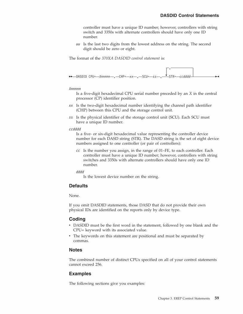
controller must have a unique ID number; however, controllers with stringswitch and 3350s with alternate controllers should have only one IDnumber.
uu Is the last two digits from the lowest address on the string. The seconddigit should be zero or eight.
The format of the 370XA DASDID control statement is:
�� DASDID CPU= Xnnnnn , CHP= xx , SCU= ss , �
,
STR= ccdddd ��
XnnnnnIs a five-digit hexadecimal CPU serial number preceded by an X in the centralprocessor (CP) identifier position.
xx Is the two-digit hexadecimal number identifying the channel path identifier(CHP) between this CPU and the storage control unit.
ss Is the physical identifier of the storage control unit (SCU). Each SCU musthave a unique ID number.
ccddddIs a five- or six-digit hexadecimal value representing the controller devicenumber for each DASD string (STR). The DASD string is the set of eight devicenumbers assigned to one controller (or pair of controllers):
cc Is the number you assign, in the range of 01–FE, to each controller. Eachcontroller must have a unique ID number; however, controllers with stringswitches and 3350s with alternate controllers should have only one IDnumber.
ddddIs the lowest device number on the string.
Defaults
None.
If you omit DASDID statements, those DASD that do not provide their ownphysical IDs are identified on the reports only by device type.
Codingv DASDID must be the first word in the statement, followed by one blank and the
CPU= keyword with its associated value.v The keywords on this statement are positional and must be separated by
commas.
Notes
The combined number of distinct CPUs specified on all of your control statementscannot exceed 256.
Examples
The following sections give you examples:
DASDID Control Statements
Chapter 3. EREP Control Statements 59

1. “Setting up DASDID Controls” describes how to set up DASDID controlstatements for your DASD subsystem.
2. “Checking Your DASDID Statements” on page 62 describes how to use theEREP messages file (TOURIST output) to make sure that your DASDIDstatements match your DASD subsystem configuration.
3. “DASDID Configuration Chart Notes” on page 62 describes how to use thenotes that may accompany the DASDID configuration chart and theirmeanings.
Setting up DASDID ControlsYou do not need DASDID statements for DASD that provide their own physicalIDs (for example, 3375s and 3380s). If you choose to code control statements forthese devices, make sure the physical IDs you create match those switched into thestorage directors.
Use the following steps to set up DASDID controls for your DASD subsystem.
STEP ACTION
1 Set up a diagram of your DASD configuration ( see Figure 1 on page 61).
a Show all connections between DASD controllers, storage control units, andchannels.
b Include all processors that can record data on the ERDS. See CPU 033333in Figure 1 on page 61.
c Label each channel or channel path.
d Label the devices that have physical IDs.
e Create physical IDs for the devices that do not provide their own:
1) Assign a unique ID to each 3880. Do not duplicate IDs used onother storage control units.
2) Assign a unique ID to each controller that does not have one. Donot duplicate IDs used on other controllers.
3) Determine the lowest unit address (or device number; the last twodigits of the device address) for each string, by processor (CPU).
f Assign a unique label to each processor in the diagram.
2 Create a comment line (as shown in Figure 2 on page 62) for each storage controlunit, indicating the connected controllers and the DASD strings connected tothem. For example:
*SCU15 CTRL14,33,22 CPU A (980-995) B (800-815)
describes one of the storage control units shown in Figure 1 on page 61. This isstorage control unit 15, that is connected to strings 980–987, 988–98D, and990–995 from CPU A (X11111); and to strings 800–807, 808–80D, and 810–815 fromCPU B (022222). The paths to the devices are through controllers 14, 33, and 22,in that order.
a The comment lines serve two purposes:
1) They outline the DASDID statements.
2) They document the DASDID statements in case of futureconfiguration changes.
b The STR value in the DASDID statement consists of the controller ID andthe lowest address or device number from the string attached through thatcontroller to the CPU.
DASDID Control Statements
60 EREP V3R5 Reference

STEP ACTION
3 Create DASDID statements according to the comment lines.
Figure 2 on page 62 shows the completed comments and DASDID statements forthe configuration shown in Figure 1.
Figure 1shows one way to define the DASD configuration in an installation.
Important: This is an example; not a model configuration.
Figure 2 on page 62 contains examples of the comment lines you create for eachstorage control unit, showing the controllers and the DASD strings connected to
CP U X 1 1 1 1 1 A
CHP I D S
CP U 0 2 2 2 2 2 B
CHANN E L S
CP U 0 3 3 3 3 3 B
( AP o r MP )
0 7 0 9 0 A 0 8 0 A
3 8 8 0
S D - 1
P H Y S I CA L I D = 1 4
3 8 8 0
S D - 2
P H Y S I CA L I D = 1 5
3 8 8 0
I D = E E
3 3 5 0
I D = 0 2
3 3 5 0 B 1
3 3 5 0 B 1
A 1
ADDRESSES (DNO ) :CPU X 1 111 19 88 - 98DA88 - A8DCPU 022 222 / 0 3 333 38 08 - 80DA08 - A0D
ADDRESSES (DNO ) :CPU X 1 111 19 90 - 99 5A90 - A9 5CPU 022 222 / 0 3 333 38 10 - 8 15A10 - A15
3 3 5 0
I D = 1 4
3 3 5 0
I D = 3 3
3 3 5 0
I D = 2 2
3 3 5 0 3 3 5 0 3 3 5 0
3 3 5 0 3 3 5 0 3 3 5 0
ADDRESSES (DNO ) :CPU X 1 111 177 8 - 77F
ADDRESSES (DNO ) :CPU X 1 111 19 80 - 987A80 - A87CPU 022 222 / 0 3 333 38 00 - 807A00 - A07
Notes:
IFC
UG
00
5
1. The PHYSICAL IDs for the 3880s (14 and 15) are those switched into the storage director.
2. The IDs for the 3350s are arbitrary unique numbers that you assign.
Figure 1. DASD Configuration Diagram for DASDID Statements. DASD Configuration Diagram for DASDID Statements
DASDID Control Statements
Chapter 3. EREP Control Statements 61

them.
Checking Your DASDID StatementsThe EREP messages file (TOURIST output) for the system exception report seriesincludes:v The DASDID statements usedv A table showing the generated configuration
Important: This report must agree with your configuration if you expect theprobable failing unit assignments in the system exception reports to be accurate.
To check the accuracy of your DASDID statements, you can do the following:
STEP ACTION
1 Run EREP, requesting the system exception reports. Refer to Generating SystemException Reportsin the EREP User's Guide for the location of examples on how torequest these reports under each operating system.
2 Check the configuration chart in the EREP messages file (TOURIST) against yourcomment lines to be sure that your DASDID statements accurately show yourconfiguration. Figure 5 on page 86 shows the configuration chart produced for theDASDID statements in Figure 2.
DASDID Configuration Chart NotesSeveral notes may accompany the DASDID configuration chart.
...*******************************************************************SYSEXN,TABSIZE=512K,HIST,DATE=84348,ACC=NENDPARM******************************************************************** CPU DEFINITIONS A=X11111 B=022222 and 033333* SCU 14 CTRL 02 A(778-77F)DASDID CPU=X11111,CHP=07,SCU=14,STR=02778* SCU 15 CTRL 14,33,22 A(980-995) B(800-815)DASDID CPU=X11111,CHP=09,SCU=15,STR=14980,STR=33988,STR=22990DASDID CPU=022222,CH=08,SCU=15,STR=1400,STR=3308,STR=2210DASDID CPU=033333,CH=08,SCU=15,STR=1400,STR=3308,STR=2210* SCU EE CTRL 14,33,22 A(A80-A95) B(A00-A15)DASDID CPU=X11111,CHP=0A,SCU=EE,STR=14A80,STR=33A88,STR=22A90DASDID CPU=022222,CH=0A,SCU=EE,STR=1400,STR=3308,STR=2210DASDID CPU=033333,CH=0A,SCU=EE,STR=1400,STR=3308,STR=2210*******************************************************************
Figure 2. Examples of DASDID Control Statements
DASDID Control Statements
62 EREP V3R5 Reference

Explanation of Notes:
1. The program generating the configuration table has found no controller ID forany set of addresses or device numbers. Because the controller ID defines astring of devices, there must be a unique controller ID for each string definedby its lowest unit address/device number. The controller ID is the first twodigits of the STR parameter.
2. There should be only one SCU or controller assigned to a specific ID for theinstallation. The controller ID must be the same for a string no matter whichCPU it is accessed from. Check the STR parameters to determine which stringshave different controller IDs defined for the same string.
3. In order to format the unit addresses (UAs) or device numbers (DNOs) as arange (for example: 120–12F), the numbers must be consecutive. The numbersin the group have not been increasing consecutively by eight.
4. A maximum of four strings can connect to one SCU (unless a switch is used).At least one CPU is found to have more than four strings defined by controllerID or unit address/device number.
5. The configuration generator provides space in the format for only threechannels from one CPU to an SCU, in 370 mode.
6. The configuration generator provides space in the format for only four channelpaths from one CPU complex to an SCU, in 370XA mode.
7. Four is the maximum number of strings allowed per SCU.
NOTETHE SCUs CANNOT BE FORMATTED. CC, CHANNEL, AND UA/DNO ARE GIVEN BY CPU.THE SCUs INDICATED ABOVE COULD NOT BE FORMATTED FOR THE FOLLOWING REASONS.
1. THE NUMBER OF CONTROLLER IDS DOES NOT EQUAL THE NUMBER OF UA/DNOS FOR A CPU.
2. THE CONTROLLER IDS ARE NOT THE SAME FOR ALL THE CPUS ATTACHED TO THE SCU.
3. THE UA/DNOS FOR A CPU ARE EXPECTED TO CONSECUTIVELY INCREASE BY EIGHT.THIS MAY NOT NECESSARILY BE AN ERROR.
4. THERE ARE MORE THAN FOUR UA/DNOS FOR A CPU.
5. THERE ARE MORE THAN THREE CHANNELS FOR A CPU IN 370 MODE.
6. THERE ARE MORE THAN FOUR CHANNELS FOR A CPU IN 370XA MODE.
7. THERE ARE MORE THAN FOUR CONTROLLER IDS FOR AN SCU.
DASDID Control Statements
Chapter 3. EREP Control Statements 63
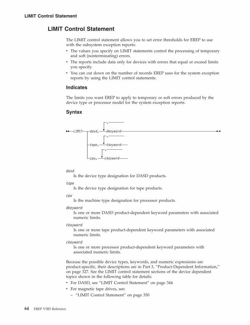
LIMIT Control Statement
The LIMIT control statement allows you to set error thresholds for EREP to usewith the subsystem exception reports:v The values you specify on LIMIT statements control the processing of temporary
and soft (nonterminating) errors.v The reports include data only for devices with errors that equal or exceed limits
you specify.v You can cut down on the number of records EREP uses for the system exception
reports by using the LIMIT control statements.
Indicates
The limits you want EREP to apply to temporary or soft errors produced by thedevice type or processor model for the system exception reports.
Syntax
�� LIMIT �
�
�
,
dasd, dkeyword,
tape, tkeyword,
cpu, ckeyword
��
dasdIs the device type designation for DASD products.
tapeIs the device type designation for tape products.
cpuIs the machine type designation for processor products.
dkeywordIs one or more DASD product-dependent keyword parameters with associatednumeric limits.
tkeywordIs one or more tape product-dependent keyword parameters with associatednumeric limits.
ckeywordIs one or more processor product-dependent keyword parameters withassociated numeric limits.
Because the possible device types, keywords, and numeric expressions areproduct-specific, their descriptions are in Part 3, “Product-Dependent Information,”on page 327. See the LIMIT control statement sections of the device dependenttopics shown in the following table for details:v For DASD, see “LIMIT Control Statement” on page 344v For magnetic tape drives, see:
– “LIMIT Control Statement” on page 350
LIMIT Control Statement
64 EREP V3R5 Reference

– “LIMIT Control Statement” on page 354v For processors, see “LIMIT Control Statement” on page 365
Defaults
The default action for the LIMIT statement varies according to the productinvolved. See the discussions of the LIMIT statement in Part 3,“Product-Dependent Information,” on page 327.
Coding
The LIMIT statement is different for each product group. The details are in Part 3,“Product-Dependent Information,” on page 327.
Here are a few general rules that apply:v LIMIT must be the first word in the statement, followed by one blank, the
device or machine type, and the keyword parameters, separated by commas.v If you code more than one LIMIT statement for a device type, EREP uses the
temporary error limits set in the latest LIMIT statement; the values on a secondstatement override those on a previous one.
Examples
See the DASD, tape, and processor sections of Part 3, “Product-DependentInformation,” on page 327, for the details and examples of using LIMIT statements.
LIMIT Control Statement
Chapter 3. EREP Control Statements 65

SHARE Control Statements
The SHARE control statement directs EREP to combine errors for any device that isshared between processors or systems. The report associates all the errors for thatdevice with the device address rather than with the different processors.
You can use SHARE statements to influence the way EREP assigns hexadecimalidentifiers to the processors shown in the reports. See “How EREP AssignsNumbers to CPUs” on page 69 for details.
Indicates
The paths to devices shared by processors.
Syntax
�� SHARE= �
,
( cpuser. ccua )XA. ccuX
ccua-ccua
��
[XA.]cpuserIs a six-digit hexadecimal CPU serial number (digits 0–F). Use cpuser toindicate that the processor is running in 370 mode. Use XA.cpuser to indicatethat the processor is running in 370XA mode.
ccuaIs a three- or four-digit hexadecimal channel-control unit-device address ordevice number (digits 0–F). The first digit is the channel designated to theoperating system as the primary CUA for the device.
ccuXIs a two- or three-digit hexadecimal channel-control unit number with Xindicating all the device addresses (0–F) attached to that control unit.
ccua-ccuaIs a range of continuous addresses. The low end of the range must be first. Therange must be at least one, and cannot exceed 32.
Defaults
None.
If you omit this control statement, EREP presents each device’s error records bydevice type.
If a device is shared between processors or systems and you omit this controlstatement:v The EREP reports present the error records by processor and device type.v The message, IFC221I NO SHARE CARD is generated and the job completes
with a return code of 4 (RC=4).
Codingv SHARE must be the first word in the statement, followed by the equal sign and
the desired values in parentheses.
SHARE Control Statements
66 EREP V3R5 Reference

v You must put at least two entries (cpuser.ccua|ccuX|ccua-ccua) in each statement.v You may need more than one SHARE statement to show all the possible paths
to one device. If so, repeat the first entry in the statements for the remainingpaths, because EREP equates all the paths in the SHARE statement to the oneyou specify first.For example:SHARE=(011111.01F0,022222.0330,022222.06F0,022222.0FF0)SHARE=(011111.01F0,033333.03F0,033333.0630,033333.0F30)
v The cpuser values in SHARE statements override the hexadecimal identifiersassigned by EREP for the CPUs in the report. See “How EREP Assigns Numbersto CPUs” on page 69 for details.
v Once you have specified a range (cpuser.ccua-ccua) in a SHARE statement, youmust specify that range the same way each time you use it in any other SHAREstatement.
v The combined number of CPUs, cpuser, specified in all of your controlstatements cannot exceed 255.
v When you code a range of device addresses (ccua-ccua):
If the control unit digit, u, in the low CUA For Example
Is odd, the high CUA must have the same ccu digits. 0350–0357 is valid 0358–0367 is notvalid
Is even, the high CUA must have the same even ccu digits, or the nextgreater odd u digit.
0368–036F is valid 0368–0377 is valid0368–0388 is not valid
Note: The channel identifier can be one or two digits.
v If more than one address range is specified on one SHARE statement, the totalnumber of addresses specified in each range must match.
Notesv The SHARE control statements are not used for DASD devices that provide
product identifiers within their sense (For example: 3990/3390).v When you include SHARE statements in your EREP controls, each report
indicates whether a particular set of error data represents a device that you havespecified in SHARE statements.
Examples
The following sections give you more detailed instructions and examples:v “Using SHARE Statements to Combine Data in EREP Reports” describes how to
set up share statements for the devices in your system.v “How EREP Assigns Numbers to CPUs” on page 69 describes how to control the
numbers EREP assigns to the CPUs.
Using SHARE Statements to Combine Data in EREP ReportsFigure 3 on page 68 is an example of the kind of I/O configuration that requiresSHARE statements. The text that follows explains how to set up SHARE controlsfor the illustrated configuration.
SHARE Control Statements
Chapter 3. EREP Control Statements 67

SHARE Statements for DASD DrivesEREP combines all records for the DASD drives in the strings when you use:SHARE=(011111.01BX,022222.02BX)
ORSHARE=(011111.01B0–01BF,022222.02B0–02BF)
Either of these SHARE statements causes the records from DASD drive 0 (deviceaddresses/numbers 01B0 and 02B0) to be combined and presented as data for 01B0on CPU 011111.
Without the SHARE statements the records are presented by the primary channeladdress for each processor as follows:v Records for drive 0 on CPU 011111 are presented as 01B0, regardless of whether
they have been recorded on channel 01 or 03.v Records for drive 0 on CPU 022222 are presented as 02B0, regardless of whether
they have been recorded on channel 02 or 03.
SHARE Statements for Tape DrivesEREP combines all records for the tape drives in the strings when you use:SHARE=(011111.0460–0467,022222.0560–0567)
This SHARE statement causes all records from drive 7 (device address/numbers0467 and 0567) to be combined and presented as data for 0467 on CPU 011111.
0 1 0 4
0 3 0 6
0 2 0 5
0 3 07
8 T ap eDrives:Numbers0 - 7
3 8 0 3Address:6X....
3 8 0 3Address:6X....
CHANNELS
CHANNELS
CHANNELS
CHANNELS
CPU0 2 2 2 2 2
CPU0 1 1 1 1 1
Addresses fromCPU 011111:Primary: 01B0-01BFAl ternate : 03B0-03BF
Addresses fromCPU 011111:Pr imary : 0460-0467A l te rna te : 0660-0667
Addresses fromC PU 0 22222 :Pr imary : 02B0-02BFAl ternate : 03B0-03BF
Addresses fromC PU 0 22222 :Pr imary : 0560-0567Al ternate : 0760-0767
IFC
UG
00
6
2 St r ings o f3390s:B 0 - B 7 a n dB 8 - B F
3 8 3 0 - 2
3 8 8 0S D - 1
Figure 3. Configuration for SHARE Statements. An example of the kind of I/O configuration that requires SHAREstatements
SHARE Control Statements
68 EREP V3R5 Reference

Without the SHARE statements the records are presented by the primary channeladdress for each processor as follows:v Records for drive 5 on CPU 011111 are presented as 0465, regardless of whether
they have been recorded on channel 04 or 06.v Records for drive 5 on CPU 022222 are presented as 0565, regardless of whether
they have been recorded on channel 05 or 07.
How EREP Assigns Numbers to CPUsEREP identifies each processor by a two-digit hexadecimal number (00–FF). Itassigns the number identifiers separately for each report, based on the model andserial number of each processor and when it is encountered.
Important: You can use SHARE or CONTROLLER control statements to forceEREP to assign specific numbers to specific processors, and to use the samenumber for each processor in all the EREP reports.
EREP always assigns numbers to the processors you have specified on SHARE orCONTROLLER control statements, before reverting to the default method. Thedefault method assigns numbers to processors in the order in which they occur inthe input data. These number assignments can change from one report to the next,if the reports use different error records.
EREP assigns numbers to the processors in the following manner:
STAGE DESCRIPTION
1 EREP examines the first entry on every statement, assigning the next hexadecimalnumber to each new CPU model or serial number it encounters.
2 After assigning numbers to the CPUs in all the first entries, EREP examines therest of the entries on each statement in turn, assigning the next hexadecimalnumber to each new CPU serial number it finds.
3 After completing these assignments, EREP assigns numbers to any processors itencounters in the input data that are not specified on SHARE or CONTROLLERstatements, using its default method.
The following example illustrates EREP’s hexadecimal number assignments forCPUs that appear on SHARE or CONTROLLER statements:SHARE=(000001.120,000002.120,000006.120)SHARE=(000003.130,000004.130)SHARE=(000005.140,000003.140)
If EREP also encounters CPU serial number 000007 in the input data. EREP assignsnumber identifiers to all of these processors as follows:
Number IdentifierCPU Serial Number
00 000001
01 000003
02 000005
03 000002
04 000006
05 000004
SHARE Control Statements
Chapter 3. EREP Control Statements 69
06 000007
SHARE Control Statements
70 EREP V3R5 Reference
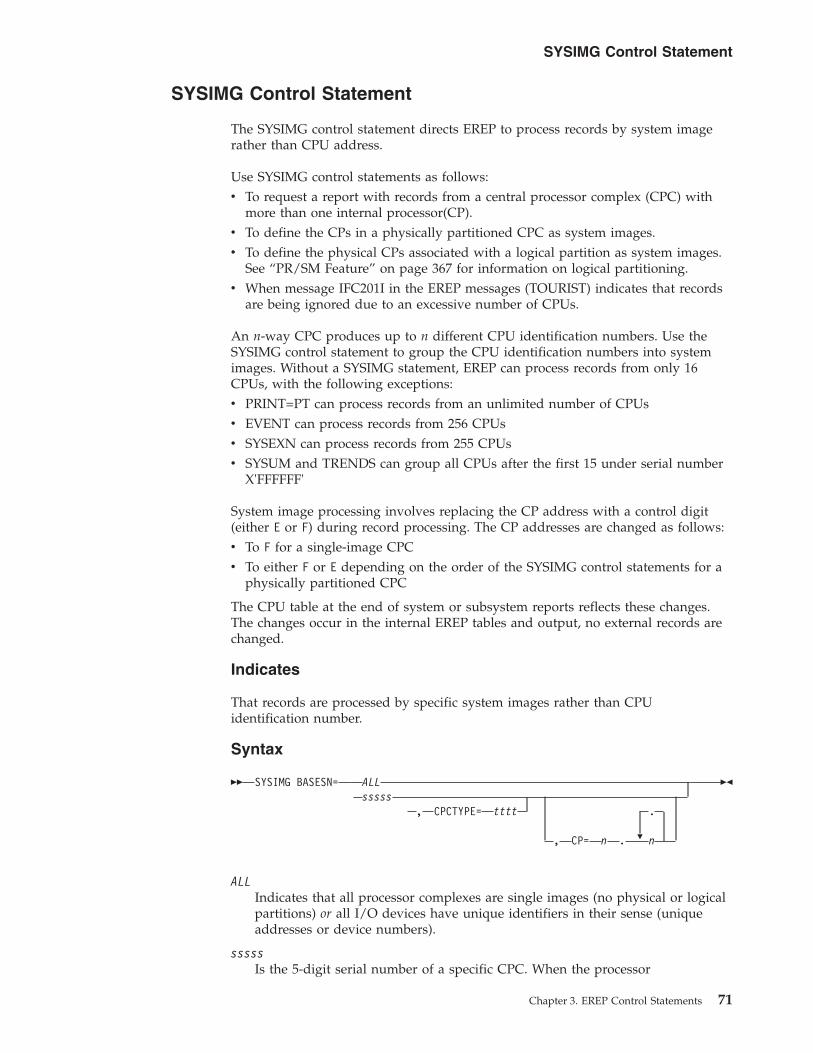
SYSIMG Control Statement
The SYSIMG control statement directs EREP to process records by system imagerather than CPU address.
Use SYSIMG control statements as follows:v To request a report with records from a central processor complex (CPC) with
more than one internal processor(CP).v To define the CPs in a physically partitioned CPC as system images.v To define the physical CPs associated with a logical partition as system images.
See “PR/SM Feature” on page 367 for information on logical partitioning.v When message IFC201I in the EREP messages (TOURIST) indicates that records
are being ignored due to an excessive number of CPUs.
An n-way CPC produces up to n different CPU identification numbers. Use theSYSIMG control statement to group the CPU identification numbers into systemimages. Without a SYSIMG statement, EREP can process records from only 16CPUs, with the following exceptions:v PRINT=PT can process records from an unlimited number of CPUsv EVENT can process records from 256 CPUsv SYSEXN can process records from 255 CPUsv SYSUM and TRENDS can group all CPUs after the first 15 under serial number
X'FFFFFF'
System image processing involves replacing the CP address with a control digit(either E or F) during record processing. The CP addresses are changed as follows:v To F for a single-image CPCv To either F or E depending on the order of the SYSIMG control statements for a
physically partitioned CPC
The CPU table at the end of system or subsystem reports reflects these changes.The changes occur in the internal EREP tables and output, no external records arechanged.
Indicates
That records are processed by specific system images rather than CPUidentification number.
Syntax
�� SYSIMG BASESN=
�
ALLsssss
, CPCTYPE= tttt .
, CP= n . n
��
ALLIndicates that all processor complexes are single images (no physical or logicalpartitions) or all I/O devices have unique identifiers in their sense (uniqueaddresses or device numbers).
sssssIs the 5-digit serial number of a specific CPC. When the processor
SYSIMG Control Statement
Chapter 3. EREP Control Statements 71

resource/system manager (PR/SM) feature is used to create logical partitionsthe high-order digit must be the same as the PR/SM partition identifier. See“PR/SM Feature” on page 367 for information on logical partitioning.
ttttIs the 4-digit processor type.
n A single hexadecimal digit identifying the CPs in this system image.
Defaults
None.
If you omit this control statement EREP processes all records by the CPUidentification number and machine type (CPUID).
Codingv One control statement is sufficient for all system images, when BASESN=ALL is
specified.
Important: By coding BASESN=ALL when devices do not have unique physicalidentifiers or unique addresses, you may cause incorrect or invalid results.
v There are no more than two system images per CPC unless logical partitioningis available.
v Code CPCTYPE= if there are records from processors with different machinetypes, but the same CPU identification numbers.
v SYSIMG controls apply to all report parameters except PRINT= as follows:– SYSIMG controls does not affect the PRINT=PT parameter.– SYSIMG controls apply for all other PRINT= selections when records are read
from a history file.– SYSIMG controls do not apply when PRINT= is specified and records are
read from the error recording data set.
Important: No message is issued in this case.
Notesv BASESN=ALL is particularly useful when producing reports on I/O devices
with unique addresses or device numbers.
Important: Do not use BASESN=ALL when reports include software or MIHrecords from partitioned CPCs.
v If the normal mode of operation is to physically partition the CPC during areporting interval and the I/O devices do not have unique identifiers, thendefine each partition as a separate image system.
v The DASDID and SHARE control statements do not require changes when youuse SYSIMG. EREP changes the high-order digit of the CPU serial number in theinternal tables created by the DASDID and SHARE control statements.
v EREP issues message IFC262I to the EREP messages (TOURIST) informing theuser that the CPU serial numbers in the CPU table have been modified as aresult of the SYSIMG control statement.
Examples
The following example shows you how to code SYSIMG control statements:
SYSIMG Control Statement
72 EREP V3R5 Reference

Code as follows if all I/O units in the complex can be identified by uniqueidentifiers within their sense data:SYSIMG BASESN=ALL
This defines all CPCs as single images and changes the first two digits of the serialnumbers in the CPU table to FF.
SYSIMG Control Statement
Chapter 3. EREP Control Statements 73

74 EREP V3R5 Reference
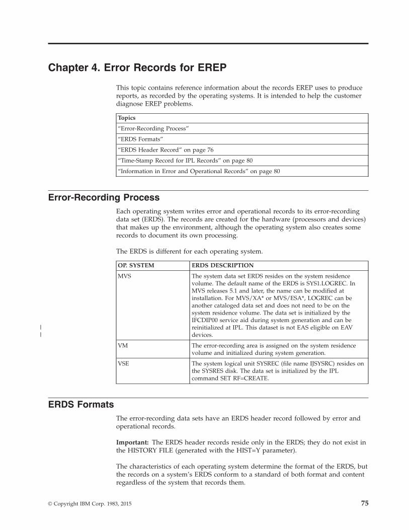
Chapter 4. Error Records for EREP
This topic contains reference information about the records EREP uses to producereports, as recorded by the operating systems. It is intended to help the customerdiagnose EREP problems.
Topics
“Error-Recording Process”
“ERDS Formats”
“ERDS Header Record” on page 76
“Time-Stamp Record for IPL Records” on page 80
“Information in Error and Operational Records” on page 80
Error-Recording ProcessEach operating system writes error and operational records to its error-recordingdata set (ERDS). The records are created for the hardware (processors and devices)that makes up the environment, although the operating system also creates somerecords to document its own processing.
The ERDS is different for each operating system.
OP. SYSTEM ERDS DESCRIPTION
MVS The system data set ERDS resides on the system residencevolume. The default name of the ERDS is SYS1.LOGREC. InMVS releases 5.1 and later, the name can be modified atinstallation. For MVS/XA* or MVS/ESA*, LOGREC can beanother cataloged data set and does not need to be on thesystem residence volume. The data set is initialized by theIFCDIP00 service aid during system generation and can bereinitialized at IPL. This dataset is not EAS eligible on EAVdevices.
VM The error-recording area is assigned on the system residencevolume and initialized during system generation.
VSE The system logical unit SYSREC (file name IJSYSRC) resides onthe SYSRES disk. The data set is initialized by the IPLcommand SET RF=CREATE.
ERDS FormatsThe error-recording data sets have an ERDS header record followed by error andoperational records.
Important: The ERDS header records reside only in the ERDS; they do not exist inthe HISTORY FILE (generated with the HIST=Y parameter).
The characteristics of each operating system determine the format of the ERDS, butthe records on a system’s ERDS conform to a standard of both format and contentregardless of the system that records them.
© Copyright IBM Corp. 1983, 2015 75
||
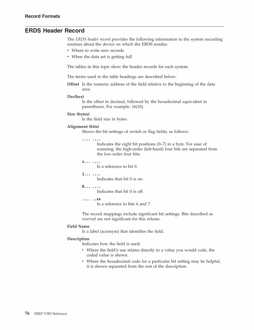
ERDS Header RecordThe ERDS header record provides the following information to the system recordingroutines about the device on which the ERDS resides:v Where to write new recordsv When the data set is getting full
The tables in this topic show the header records for each system.
The terms used in the table headings are described below:
Offset Is the numeric address of the field relative to the beginning of the dataarea.
Dec(hex)Is the offset in decimal, followed by the hexadecimal equivalent inparentheses. For example: 16(10).
Size (bytes)Is the field size in bytes.
Alignment (bits)Shows the bit settings of switch or flag fields, as follows:
.... ....Indicates the eight bit positions (0–7) in a byte. For ease ofscanning, the high-order (left-hand) four bits are separated fromthe low-order four bits.
x... ....Is a reference to bit 0.
1... ....Indicates that bit 0 is on.
0... ....Indicates that bit 0 is off.
.... ..xxIs a reference to bits 6 and 7.
The record mappings include significant bit settings. Bits described asreserved are not significant for this release.
Field NameIs a label (acronym) that identifies the field.
DescriptionIndicates how the field is used:v Where the field’s use relates directly to a value you would code, the
coded value is shown.v Where the hexadecimal code for a particular bit setting may be helpful,
it is shown separated from the rest of the description.
Record Formats
76 EREP V3R5 Reference

MVS Header Record for the ERDSTable 4 shows an example of the MVS header record for the ERDS.
Table 4. MVS ERDS Header Record
OffsetDec(Hex)
Size(bytes)Alignment(bits) Field Name Description
0(0) 2 CLASRC Header-record identifier. Each bit in this field is set to 1 unless criticaldata has been destroyed.
2(2) 4 LOWLIMIT Address of low extent. Track address (in CCHH format) of first extent ofSYS1.LOGREC.
6(6) 4 UPLIMIT Address of high extent. Track address (in CCHH format) of last extent ofSYS1.LOGREC.
10(A) 1 MSGCNT Count of the number of times LOGREC-full message has been issued(maximum is 15).
11(B) 7 RESTART Address of record entry area, and address of time-stamp record. Startingtrack address (in BBCCHHR format) of the recording area onSYS1.LOGREC. If a time-stamp record is present, it begins at the addresspointed to by this field.
18(12) 2 BYTSREM Remaining bytes on track. Number of bytes remaining on the track uponwhich the last record entry was written.
20(14) 2 TRKCAP Total bytes on track. Number of bytes that can be written on a track ofthe volume containing SYS1.LOGREC.
22(16) 7 LASTTR Address of last record written. Track address (in BBCCHHR format) oflast record written on SYS1.LOGREC.
29(1D) 2 TRKSPER Highest addressable track for each cylinder on volume containingSYS1.LOGREC.
31(1F) 2 EWMCNT Warning count. Number of bytes remaining on early-warning-messagetrack of SYS1.LOGREC when 90%-full point of data set is reached. Whenthis is detected by a recording routine, it issues a message and turns onthe early-warning-message switch at displacement 38.
33(21) 1 DEVCODE Device code, indicating the device type of the volume on whichSYS1.LOGREC resides:
Code Device
04 2302
07 2305 MOD II
09 3330 and 3333 MOD I or 3350 operating in 3330-1 compatibilitymode
0A 3340 and 3344
0B 3350 native mode
0C 3375
0D 3330 and 3333 MOD II or 3350 operating in 3330-IIcompatibility mode
0E 3380
0F 3390
34(22) 4 EWMTRK Early-warning-message track. Track address (in CCHH format) on which90% full point for data set exists.
38(26) 1 EWMSW Switch byte:1... .... 90%-full-point message has been issued. This switch is turned on by the
recording routine detecting 90% full point and is turned off by IFCEREP1when clearing SYS1.LOGREC.
.xxx xxxx Reserved.39(27) 1 SFTYBYTS Check byte. Each bit in this field is set to 1; the field is used to check the
validity of the header-record identifier.
Record Formats
Chapter 4. Records for EREP 77

VM Header Record for the Error Recording Area (Cylinder)Table 5 shows an example of the VM header record for the error-recording area.
Table 5. VM Error Recording Cylinder Header Record
OffsetDec(Hex)
Size(bytes)Alignment(bits) Field Name Description
0(0) 4 RECCCPD Address of this cylinder.4(4) 2 RECNXT Displacement to the next available space for records.6(6) 1 RECFLAG1 Record usage flags:
1... .... RECPAGIU The page contains valid data..1.. .... RECPAGFR The page is cleared. This bit is set by EREP when it clears the
error-recording area...1. .... RECPAGFL The page is full. When this bit is set, a message is issued to the operator
to clear the error-recording area....1 .... RECPAGER The next page is unreadable..... 1... RECPAGFA Frame records exist for this page..... .xxx Reserved.
7(7) 1 RECFLAG2 Record format flags:1... .... RECPAGFM The cylinder is being formatted. This bit is turned on in the first page of
a recording cylinder while the cylinder is being formatted. The field isreset only when all pages are cleared.
0000 0000 RECPAGDN The cylinder has been formatted. If this field is nonzero, the cylinder is inthe process of being formatted.
VSE Header Record for SYSREC with CKDTable 6 shows the format of the header record when IJSYSRC is on acount-key-data device.
Table 6. VSE CKD SYSREC Header Record
OffsetDec(Hex)
Size(bytes)Alignment(bits) Field Name Description
0(0) 2 CLASRC Header record identifier. This field is set to X‘FF00’ unless critical datahas been destroyed.
2(2) 4 LOWLIMIT Address of low extent. Track address (in CCHH format) of first extent ofSYSREC.
6(6) 4 UPLIMIT Address of high extent. Track address (in CCHH format) of last extent ofSYSREC.
10(A) 1 TRKSPER Highest addressable track for each cylinder on the volume containingSYSREC.
11(B) 7 RESTART Address of record entry area. Starting track address (in BBCCHHRformat) for recording area on SYSREC.
18(12) 2 BYTSREM Remaining bytes on track: number of bytes remaining on the track uponwhich the last record entry was written.
20(14) 2 TRKCAP Total bytes on track. Number of bytes that can be written on a track ofthe volume containing SYSREC.
22(16) 7 LASTTR Address of last record written. Track address (in BBCCHHR format) oflast record written on SYSREC.
29(1D) 2 PUBNUM Number of PUBS in the system.31(1F) 2 EWMCNT Warning count. Number of bytes remaining on early warning message
track of SYSREC when 90% full point of data set is reached. When this isdetected by a recording routine, it issues a message and turns on theearly-warning-message switch at displacement 38.
Record Formats
78 EREP V3R5 Reference

Table 6. VSE CKD SYSREC Header Record (continued)
OffsetDec(Hex)
Size(bytes)Alignment(bits) Field Name Description
33(21) 1 DEVCODE Device code. Code indicating device type of system volume on whichSYSREC resides:
Code Device
01 2311
02 2301
03 2303
04 2302
06 2305 MOD 1
07 2305 MOD 2
08 2314
09 3330 and 3333 MOD 1 or 3350 operating in 3330-1 compatibilitymode
0A 3340 and 3344
0B 3350 native mode
0C 3375
0D 3330 and 3333 MOD 11 or 3350 operating in 3330-11compatibility mode
0E 3380
0F 3390
34(22) 4 EWMTRK Early warning message track. Track address (in CCHH format) on whichthe 90% full point will be found.
38(26) 1 EWMSW Switch byte:1... .... 90% full point message has been issued. This switch is turned on by
recording routine detecting 90% full point and is turned off by IFCEREP1when clearing SYSREC.
.1.. .... An emergency recording has occurred. This switch is turned on when thesystem terminates because SYSREC is full.
..1. .... FRAMES Machine-check and channel-check frames exist on SYSREC.
...x xxxx Reserved.39(27) 1 SFTYBYT Check byte. Each bit in this field is set to 1 (X'FF'); used to check the
validity of the header-record identifier.
VSE Header Record for SYSREC with FBATable 7 shows the format of the VSE header record when IJSYSRC is on afixed-block-architecture device.
Table 7. VSE FBA SYSREC Header Record
OffsetDec(Hex)
Size(bytes)Alignment(bits) Field Name Description
0(0) 2 CLASRC Header record identifier. This field is set to X‘FF00’ unless critical datahas been destroyed.
2(2) 4 LOWLIMIT Address of low extent. Block number of the first extent of SYSREC.6(6) 4 UPLIMIT Address of high extent. Block number of the last extent of SYSREC.10(A) 1 Reserved.
Record Formats
Chapter 4. Records for EREP 79

Table 7. VSE FBA SYSREC Header Record (continued)
OffsetDec(Hex)
Size(bytes)Alignment(bits) Field Name Description
11(B) 4 RESTART Address of record entry area. Block number of the start of the recordingarea of SYSREC.
15(F) 7 Reserved.22(16) 4 LSTREC Address of last record. Block number of the last record written on the
recording area.26(1A) 7 Reserved.33(21) 1 DEVCODE X'0F' Device code for FBA device.34(22) 4 EWMTRK Early-warning-message block. Block number on which the 90%-full point
will be found.38(26) 1 EWMSW Switch byte:
1... .... 90%-full-point message has been issued. This switch is turned on byrecording routine detecting 90% full point and is turned off by IFCEREP1when clearing SYSREC.
.1.. .... An emergency recording has occurred. This switch is turned on when thesystem terminates because SYSREC is full.
..1. .... FRAMES Machine-check and channel-check frames exist on SYSREC.
...x xxxx Reserved.39(27) 1 SFTYBYT Check byte. Each bit in this field is set to 1 (X'FF'); used to check the
validity of the header-record identifier.
Time-Stamp Record for IPL RecordsThe time-stamp record consists of a standard 24-byte header plus 16 bytes that arereserved for system use. The system date and time fields are at offsets 8 and 12.These fields are updated at preset intervals, to keep the date and time current.
The recording routines take the current date and time from the time-stamp recordand put them in the system date and time fields of the IPL record header.
The current date and time information in an IPL record allows you to measure theinterval between system termination and reinitialization.
Information in Error and Operational RecordsThere are two types of records on the system’s ERDS:
RECORD TYPE DESCRIPTION
Hardware andsoftware errors
Reflect the failure and recovery of processors, channels, I/O devices,and operating system software.
Softwareoperational data
Indicate the time and circumstances of the failures and otherconditions.
Although the records reflect different events and are of different lengths, they allcontain the following kinds of information:v Relevant system information at the time the record is generatedv Device hardware status at the time the record is generatedv Results of any device or control unit recovery attemptv Results of any software system recovery attemptv Statistical data about device usage and recoverable errors
Record Formats
80 EREP V3R5 Reference
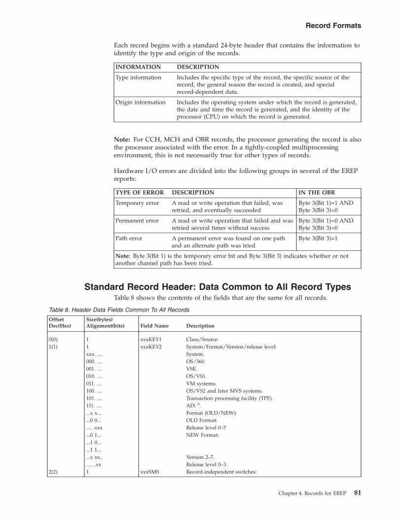
Each record begins with a standard 24-byte header that contains the information toidentify the type and origin of the records.
INFORMATION DESCRIPTION
Type information Includes the specific type of the record, the specific source of therecord, the general reason the record is created, and specialrecord-dependent data.
Origin information Includes the operating system under which the record is generated,the date and time the record is generated, and the identity of theprocessor (CPU) on which the record is generated.
Note: For CCH, MCH and OBR records, the processor generating the record is alsothe processor associated with the error. In a tightly-coupled multiprocessingenvironment, this is not necessarily true for other types of records.
Hardware I/O errors are divided into the following groups in several of the EREPreports:
TYPE OF ERROR DESCRIPTION IN THE OBR
Temporary error A read or write operation that failed, wasretried, and eventually succeeded
Byte 3(Bit 1)=1 ANDByte 3(Bit 3)=0
Permanent error A read or write operation that failed and wasretried several times without success
Byte 3(Bit 1)=0 ANDByte 3(Bit 3)=0
Path error A permanent error was found on one pathand an alternate path was tried
Byte 3(Bit 3)=1
Note: Byte 3(Bit 1) is the temporary error bit and Byte 3(Bit 3) indicates whether or notanother channel path has been tried.
Standard Record Header: Data Common to All Record TypesTable 8 shows the contents of the fields that are the same for all records.
Table 8. Header Data Fields Common To All Records
OffsetDec(Hex)
Size(bytes)Alignment(bits) Field Name Description
0(0) 1 xxxKEY1 Class/Source:1(1) 1 xxxKEY2 System/Format/Version/release level:
xxx. .... System.000. .... OS/360.001. .... VSE.010. .... OS/VS1.011. .... VM systems.100. .... OS/VS2 and later MVS systems.101. .... Transaction processing facility (TPF).111. .... AIX ®....x x... Format (OLD/NEW):...0 0... OLD Format:.... .xxx Release level 0–7...0 1... NEW Format:...1 0......1 1......x xx.. Version 2–7..... ..xx Release level 0–3.
2(2) 1 xxxSMS Record-independent switches:
Record Formats
Chapter 4. Records for EREP 81
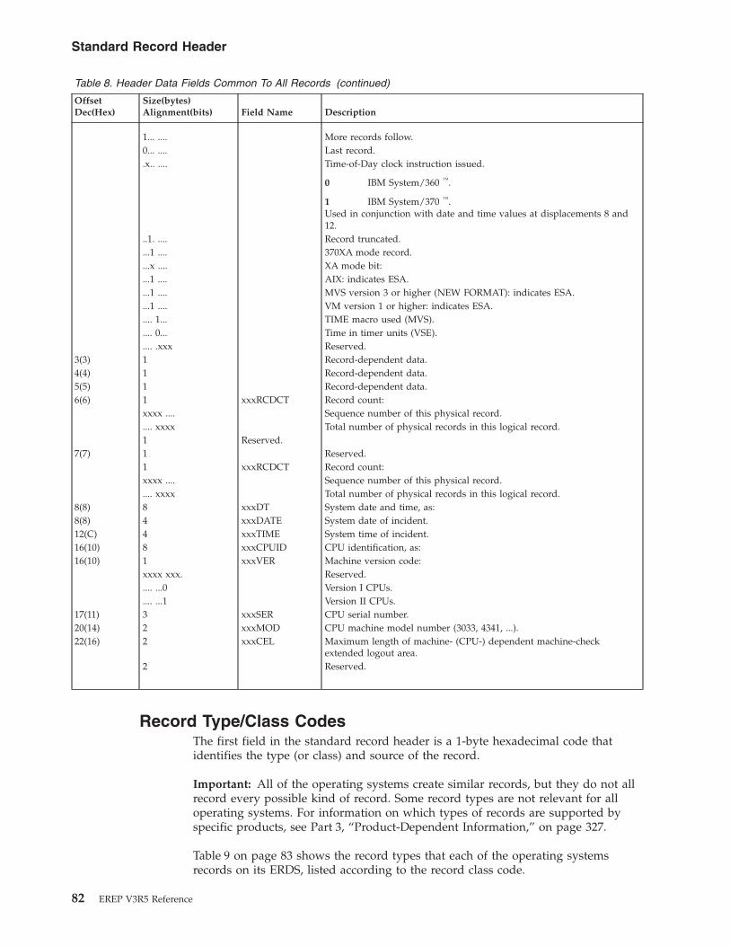
Table 8. Header Data Fields Common To All Records (continued)
OffsetDec(Hex)
Size(bytes)Alignment(bits) Field Name Description
1... .... More records follow.0... .... Last record..x.. .... Time-of-Day clock instruction issued.
0 IBM System/360 ™.
1 IBM System/370 ™.Used in conjunction with date and time values at displacements 8 and12.
..1. .... Record truncated.
...1 .... 370XA mode record.
...x .... XA mode bit:
...1 .... AIX: indicates ESA.
...1 .... MVS version 3 or higher (NEW FORMAT): indicates ESA.
...1 .... VM version 1 or higher: indicates ESA.
.... 1... TIME macro used (MVS).
.... 0... Time in timer units (VSE).
.... .xxx Reserved.3(3) 1 Record-dependent data.4(4) 1 Record-dependent data.5(5) 1 Record-dependent data.6(6) 1 xxxRCDCT Record count:
xxxx .... Sequence number of this physical record..... xxxx Total number of physical records in this logical record.1 Reserved.
7(7) 1 Reserved.1 xxxRCDCT Record count:xxxx .... Sequence number of this physical record..... xxxx Total number of physical records in this logical record.
8(8) 8 xxxDT System date and time, as:8(8) 4 xxxDATE System date of incident.12(C) 4 xxxTIME System time of incident.16(10) 8 xxxCPUID CPU identification, as:16(10) 1 xxxVER Machine version code:
xxxx xxx. Reserved..... ...0 Version I CPUs..... ...1 Version II CPUs.
17(11) 3 xxxSER CPU serial number.20(14) 2 xxxMOD CPU machine model number (3033, 4341, ...).22(16) 2 xxxCEL Maximum length of machine- (CPU-) dependent machine-check
extended logout area.2 Reserved.
Record Type/Class CodesThe first field in the standard record header is a 1-byte hexadecimal code thatidentifies the type (or class) and source of the record.
Important: All of the operating systems create similar records, but they do not allrecord every possible kind of record. Some record types are not relevant for alloperating systems. For information on which types of records are supported byspecific products, see Part 3, “Product-Dependent Information,” on page 327.
Table 9 on page 83 shows the record types that each of the operating systemsrecords on its ERDS, listed according to the record class code.
Standard Record Header
82 EREP V3R5 Reference

Important: VM writes records on its own behalf or on behalf of another operatingsystem running in a virtual machine, while MVS creates different versions of somerecords.
Table 9. Record Types and Systems Recording Them
Description MVS VM VSE
1X Machine check errors10 MCH Y Y Y13 MCH in multiple storage environment Y Y1 Y
2X Channel check errors20 CCH Y Y² Y21 CCH in multiple storage environment Y3
23 SLH subchannel logout Y⁴25 CRW channel report word Y⁴
3X Outboard errors30 OBR Y Y1 Y34 BTAM OBR (VSE) Y36 VTAM OBR Y Y3A DPA OBR Y3C DPS OBR Y
4X Software errors40 Software-detected Y42 Hardware-detected Y44 Operator-detected Y48 Hardware-detected hardware Y4C Programming symptom code Y4E Programming symptom code Y4F Lost record Y
50 IPL Y Y
60 DDR Y3 Y⁵
7X Missing interrupt handler70 MIH Y3 Y² Y⁶71 MIX Y⁴ Y⁴ Y
8X System termination80 EOD Normal End of Day Y Y81 Nonrestartable wait state (MCH) Forced Y3
84 EOD Restartable Y3
84 Restartable wait state (IOS) Forced Y3
9X Miscellaneous data record (MDR)90 MDR formatted by SVC91 Y Y91 MDR Y Y1 Y
A0 MCH frame Y Y YA1 External Time Reference Y Y YA2 Link Maintenance Information Y Y YA3 Asynchronous Notification Y Y YA4 through AF records Y Y
Record Type Codes
Chapter 4. Records for EREP 83

Table 9. Record Types and Systems Recording Them (continued)
Description MVS VM VSE
B0 CCH frame Y Y YB1 through BF records Y Y YC0 through CF records Y Y YD0 through DF records Y Y YE0 through EF records Y Y YF0 through FF records Y Y Y
Note:
1. For both VM and the virtual machine
2. For VM only; SVC 76 is reflected back to the virtual machine
3. MVS/370 only
4. XA and above only
5. For the virtual machine only
6. VSE/advanced functions only
Record Type Codes
84 EREP V3R5 Reference

Chapter 5. Correcting EREP Job Set-Up Problems
This topic provides information about methods to use to identify and correct EREPjob set up problems.
The following subjects are covered:
HEADING
“Using the EREP Messages File (TOURIST Output)”
“Problem Determination Aids” on page 86
“Missing Records” on page 89
Using the EREP Messages File (TOURIST Output)If your EREP job does not run, you can use the EREP messages file (TOURISToutput) to see how EREP interprets your control statements and parameters. SeeChapter 6, “EREP Messages,” on page 91 for descriptions of the EREP messages.Figure 4 is an example of the typical TOURIST output generated for an EREPreport.
Figure 5 on page 86 shows an example of the EREP messages file using theDASDID configuration chart in “DASDID Control Statement” on page 58.
LEVEL = VERSION 3 RELEASE 5 EREP INFORMATIONAL MESSAGES
INPUT PARAMETER STRING PRINT=PS,DEV=(3380)
PARAMETER OPTIONS VALID FOR THIS EXECUTIONRECORD TYPES(MCH,CCH,OBR,SOFT,IPL,DDR,MIH,EOD,MDR,AX,BX,CX,DX,EX,FX),MODE ALLDATE/TIME RANGE - ALLTABLE SIZE - 0024K,LINE COUNT - 050LINE LENGTH - 132
DEVICE ENTRIESDEVICE TYPES(CCH,SLH)-3380(ALL)DEVICE TYPES(OBR,MIH,DDR)-3380(200E),3380(202E),3380(201E),3380(2021),3380(20DEVICE TYPES(MDR)-3380(14),3380(1B),3380(1C),3380(21),3380(22),3380(23)
IFC120I 109 RECORDS THAT PASSED FILTERING
Figure 4. EREP Messages File (TOURIST Output) from a CPEREP Run
© Copyright IBM Corp. 1983, 2015 85

Problem Determination AidsSometimes you must go through the process of problem determination in order toidentify a failing hardware unit or program and determine who is responsible forfixing it. The following problem determination aids can help you determine thecauses of problems encountered while running EREP jobs:v EREP return codesv Problem determination proceduresv Trouble-shooting flowchartv DEBUG parameter
LEVEL = VERSION 3 RELEASE 5
INPUT PARAMETER STRING HIST,ACC=N,SYSEXN
* CPU DEFINITIONS A=X11111 B=022222 C=033333* SCU 14 CTRL 02 A(778-77F)DASDID CPU=X11111,CHP=07,SCU=14,STR=02778* SCU 15 CTRL 14,33,22 A(980-995) B(800-815)DASDID CPU=X11111,CHP=09,SCU=15,STR=14980,STR=33988,STR=22990DASDID CPU=022222,CH=08,SCU=15,STR=1400,STR=3308,STR=2210DASDID CPU=033333,CH=08,SCU=15,STR=1400,STR=3308,STR=2210* SCU EE CTRL 14,33,22 A(A80-A95) B(A00-A15)DASDID CPU=X11111,CHP=0A,SCU=EE,STR=14A80,STR=33A88,STR=22A90DASDID CPU=022222,CH=0A,SCU=15,STR=1400,STR=3308,STR=2210DASDID CPU=033333,CH=0A,SCU=15,STR=1400,STR=3308,STR=2210
DASDID CONFIGURATION CHARTCPUs - CPUS WITH IDENTICAL CONFIGURATIONS ARE IN THE SAME COLUMNSCU - STORAGE CONTROL UNIT IDCC,CC,CC,CC - CONTROLLER IDS ORDERED BY PHYSICAL UNIT ADDRESSCHAN - CHANNELS WHICH CONNECT TO THE STORAGE CONTROL UNITUA-UA - LOWEST PHYSICAL UNIT ADDRESS OF FIRST AND LAST STRING (370 MODE)DNO-DNO - LOWEST DEVICE NUMBER OF FIRST AND LAST STRING (370XA MODE)
CPUs CPUs
X11111 022222033333
SCU CC,CC,CC,CC CHAN DNO-DNO CHAN UA-UA------------------------------------------------------------------------14 02 07 778------------------------------------------------------------------------15 14,33,22 09 980-990 08 00-10EE 14,33,22 0A A80-A90 0A 00-10
PARAMETER OPTIONS VALID FOR THIS EXECUTION
RECORD TYPES(MCH,CCH,OBR,SOFT,IPL,DDR,MIH,EOD,MDR,MODE ALL),SYSTEM EXCEPTION,HISTORY
DATE/TIME RANGE - ALLTABLE SIZE - 512K,LINE COUNT - 050NONE
IFC221I NO SHARE CARDIFC120I 3 RECORDS SAVED FOR SYSEXNIFC120I 3 RECORDS THAT PASSED FILTERING
Figure 5. EREP Messages File (TOURIST Output): DASDID Configuration Chart
Problem Determination
86 EREP V3R5 Reference

EREP Return CodesEREP issues the following return codes whenever it stops processing:
RETURNCODE
(Decimal)
MEANING DESCRIPTION
00 No errors None.
04 Warning Processing and the report are complete but the reportmay not contain all possible records.
08 Severe error(nonterminating)
Processing may or may not continue to the end of therecords depending on the kind of error EREP hasencountered. If processing continues, the report may beincomplete.
10
12 Severe error(terminating)
EREP has terminated abnormally and cannot completethe report.
16 Catastrophic error
EREP (IFCEREP1) issues at least one IFCxxxI message for every return code greaterthan 04, and issues messages for some situations that produce return codes of 04.The messages appear in the EREP messages file or in the body of the report. SeeChapter 6, “EREP Messages,” on page 91 for descriptions of the EREP messages.
Problem Determination ProceduresUse the standard problem determination procedures specified by IBM to help youdetermine the probable causes of errors that result in EREP messages. Themessages are described in Chapter 6, “EREP Messages,” on page 91. The standardproblem determination procedures are described in Table 10.
Table 10. Standard Problem Determination Procedures
STEP ACTION
1 Save the console sheet from the operator console. In systems with a displayoperator console (DOC), save a copy of the hard copy log.
2 Save the system output associated with the job.
3 Save all the associated output.
4 Contact IBM for programming support.
5 Contact IBM for hardware support.
The standard problem determination procedures are recommended to diagnoseproblems with a system control program (SCP).
Trouble-Shooting FlowchartUse the following flowchart to help you determine the probable causes ofproblems encountered while running EREP jobs.
Problem Determination
Chapter 5. Correcting EREP Job Set-Up Problems 87

Using the DEBUG ParameterIf a problem with your EREP run is associated with an input record, you must beable to look at the record. Use an event history report and include the DEBUGparameter with its option 17 in the EREP controls to see the records used, asshown in the following example:
EVENTHISTACC=NLINECT=60DATE=(89040-93365)DEBUG=(17)
Problem Determination Tables
88 EREP V3R5 Reference
The records in the report will appear one line item at a time with an unformattedhexadecimal dump immediately following each line item. See “DEBUG — Debug(Diagnostic Parameter)” on page 23 for coding details.
If you select a print report with DEBUG=(17) a hexadecimal dump of every recordthat passed filtering appears in the EREP messages file (TOURIST output).
The IBM service representative can help you interpret the records, by referring tothe maintenance documentation for the device that generated the record.
Missing RecordsTo check for records you suspect are missing, run an event history reportspecifying the DEV and TYPE parameters to match the suspected missing records.This report includes data from every record that meets your selection criteria.Another way to look for a particular record is to run a detail edit report specifyingDEV, TYPE, DATE, TIME, and any other parameter that narrows the choice.
DEBUG Parameter
Chapter 5. Correcting EREP Job Set-Up Problems 89
Problems Running EREP
90 EREP V3R5 Reference

Chapter 6. EREP Messages
This topic contains the messages issued by the IFCEREP1 program modules. Theseare the messages that appear in the EREP messages file (TOURIST output).
EREP messages begin with the prefix “IFC”. EREP message numbers after the IFCprefix are followed by “I”, meaning that the messages are informational. However,informational messages can also indicate:v The status of EREP processingv The occurrence of a problem with EREP processingv The occurrence of a problem with your EREP or system controls
The EREP messages are listed in Chapter 6, “EREP Messages” in ascending orderby the numbers.
Important: Not all messages apply to all operating systems.
Figure 6 is an example of the typical EREP messages file generated for an EREPreport.
LEVEL = VERSION 3 RELEASE 5 EREP INFORMATIONAL MESSAGES DATE - 032 94
INPUT PARAMETER STRING SYSEXN,HIST,ACC=N,DATE=(89040-93365)
PARAMETER OPTIONS VALID FOR THIS EXECUTIONRECORD TYPES(MCH,CCH,OBR,SOFT,IPL,DDR,MIH,EOD,MDR,AX,BX,CX,DX,EX,FX), MODE ALL,SYSTEM EXCEPTION,HISTORY INPUTDATE/TIME RANGE - 89040,93365/00000000:24000000TABLE SIZE - 0024K,LINE COUNT - 050LINE LENGTH - 132
IFC221I NO SHARE CARDIFC120I 359 RECORDS SAVED FOR SYSEXNIFC120I 403 RECORDS THAT PASSED FILTERING
Figure 6. TOURIST Output that Describes EREP Messages
© Copyright IBM Corp. 1983, 2015 91

IFC101I REQUEST FOR NON-EXISTENT IOSERVICE
Explanation: (MVS, VM, and VSE) An internalrequest for I/O service specifies an invalid requestcode.
System action: The request is ignored. No furtherinput is processed.
Programmer response: Make sure the system controlsare correct, and rerun the job. If the problem persists,perform problem determination.
Problem determination: Table 10 on page 87, items 1,2, 4.
IFC102I ddname OPEN REQUESTED, ALREADYOPEN
Explanation: (MVS and VM) A second open has beenrequested for a data set that is already open.
System action: The request is ignored. No furtherinput is processed.
Programmer response: Make sure the DD statementsor FILEDEFs are correct, and rerun the job. If theproblem persists, perform problem determination.
Problem determination: Table 10 on page 87, items 1,2, 4.
IFC103I ddname DD STATEMENT MISSING ORINCORRECTLY CODED
Explanation: (MVS and VM) The named data setcannot be opened because the required DD statementor FILEDEF is missing or invalid. For an existing dataset, the DD statement or FILEDEF may be correct butthe attributes (RECFM, BLKSIZE) invalid. The data setmay also be the result of a previous step FILEDEFpointing to the XAEREPIO RECORD file, rather thanthe SERLOG. SERLOG should always be used. UsingXAEREPIO RECORD as input causes unpredictableresults. The message will also be issued if the Data SetName coded on this DD statement resides on Tape.
System action: EREP terminates.
Programmer response: Add or correct the indicatedsystem control and rerun the job.
Problem determination: Table 10 on page 87, items 1,2, 4.
IFC104I ddname NOT OPEN WHEN{READ|WRITE} REQUESTED
Explanation: (MVS and VM) The named data set isnot open when a read or write is requested.
System action: The request is ignored. No furtherinput is processed.
Programmer response: Make sure the DD statements
and FILEDEFS are correct, and rerun EREP. If theproblem persists, perform problem determination.
Problem determination: Table 10 on page 87, items 1,2, 4.
IFC105I RECORD IGNORED, ddname READ[DIRECT] ERROR
Explanation: (MVS and VM) A permanent I/O errorhas occurred on the named data set.
System action: Processing continues. The physicalrecord that has caused the error is ignored.
Programmer response: Move the volume containingthe data set to another device, or move the data set toanother volume, to determine if the problem wascaused by a hardware malfunction.
Attention: Move the suspect volume only once toascertain a fault. Indiscriminate mounting anddemounting of the disk pack could cause thedestruction of packs and drives.
For MVS systems: If the message does not recur, thereprobably is a hardware error on the device (or volume)originally used. If the error persists, execute the SPZAP(VS2), or HMASPZAP (VS1) service aid program toobtain a dump of the data set on which the input errorhas occurred. If the error has occurred onSYS1.LOGREC, execute IFCDIP00 to reinitialize thedata set.
For VM systems: If the error has occurred in theerror-recording area, issue the CPEREP EXEC, with theCLEAR/CLEARF operand, to reinitialize the cylinders.
Problem determination: Table 10 on page 87, items 1,2, 4, 5.
IFC106I ddname CLOSE REQUESTED, ddnameNOT OPEN
Explanation: (MVS and VM) The ddname data set isnot open when a close is requested.
System action: The request is ignored.
Programmer response: Make sure the system controlsare correct, and rerun the job. If the problem persists,perform problem determination.
Problem determination: Table 10 on page 87, items 1,2, 4.
IFC107I ACCIN RECORD FORMAT NOT V ORVB
Explanation: (MVS and VM) The ACCIN DDstatement or FILEDEF that defines the history inputdata set either:
v Does not specify RECFM, or
IFC101I • IFC107I
92 EREP V3R5 Reference
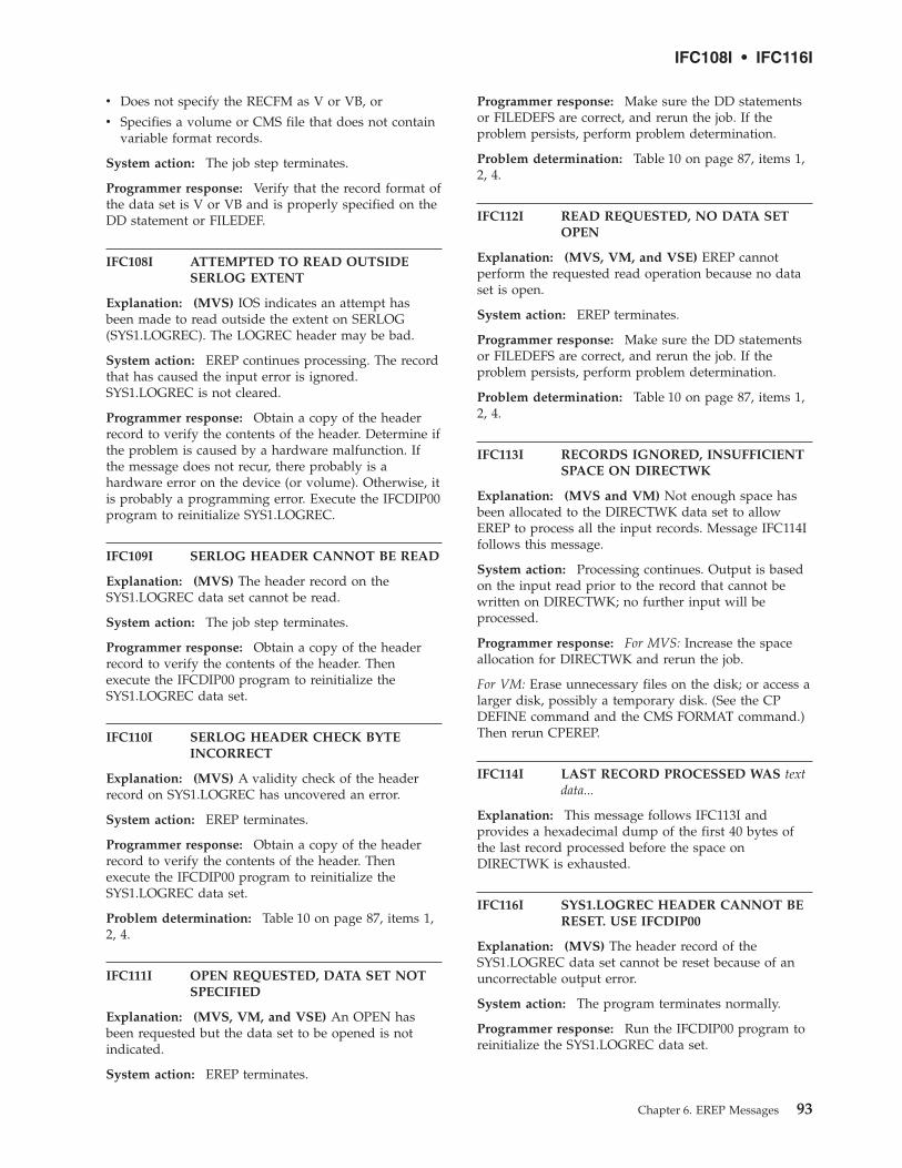
v Does not specify the RECFM as V or VB, or
v Specifies a volume or CMS file that does not containvariable format records.
System action: The job step terminates.
Programmer response: Verify that the record format ofthe data set is V or VB and is properly specified on theDD statement or FILEDEF.
IFC108I ATTEMPTED TO READ OUTSIDESERLOG EXTENT
Explanation: (MVS) IOS indicates an attempt hasbeen made to read outside the extent on SERLOG(SYS1.LOGREC). The LOGREC header may be bad.
System action: EREP continues processing. The recordthat has caused the input error is ignored.SYS1.LOGREC is not cleared.
Programmer response: Obtain a copy of the headerrecord to verify the contents of the header. Determine ifthe problem is caused by a hardware malfunction. Ifthe message does not recur, there probably is ahardware error on the device (or volume). Otherwise, itis probably a programming error. Execute the IFCDIP00program to reinitialize SYS1.LOGREC.
IFC109I SERLOG HEADER CANNOT BE READ
Explanation: (MVS) The header record on theSYS1.LOGREC data set cannot be read.
System action: The job step terminates.
Programmer response: Obtain a copy of the headerrecord to verify the contents of the header. Thenexecute the IFCDIP00 program to reinitialize theSYS1.LOGREC data set.
IFC110I SERLOG HEADER CHECK BYTEINCORRECT
Explanation: (MVS) A validity check of the headerrecord on SYS1.LOGREC has uncovered an error.
System action: EREP terminates.
Programmer response: Obtain a copy of the headerrecord to verify the contents of the header. Thenexecute the IFCDIP00 program to reinitialize theSYS1.LOGREC data set.
Problem determination: Table 10 on page 87, items 1,2, 4.
IFC111I OPEN REQUESTED, DATA SET NOTSPECIFIED
Explanation: (MVS, VM, and VSE) An OPEN hasbeen requested but the data set to be opened is notindicated.
System action: EREP terminates.
Programmer response: Make sure the DD statementsor FILEDEFS are correct, and rerun the job. If theproblem persists, perform problem determination.
Problem determination: Table 10 on page 87, items 1,2, 4.
IFC112I READ REQUESTED, NO DATA SETOPEN
Explanation: (MVS, VM, and VSE) EREP cannotperform the requested read operation because no dataset is open.
System action: EREP terminates.
Programmer response: Make sure the DD statementsor FILEDEFS are correct, and rerun the job. If theproblem persists, perform problem determination.
Problem determination: Table 10 on page 87, items 1,2, 4.
IFC113I RECORDS IGNORED, INSUFFICIENTSPACE ON DIRECTWK
Explanation: (MVS and VM) Not enough space hasbeen allocated to the DIRECTWK data set to allowEREP to process all the input records. Message IFC114Ifollows this message.
System action: Processing continues. Output is basedon the input read prior to the record that cannot bewritten on DIRECTWK; no further input will beprocessed.
Programmer response: For MVS: Increase the spaceallocation for DIRECTWK and rerun the job.
For VM: Erase unnecessary files on the disk; or access alarger disk, possibly a temporary disk. (See the CPDEFINE command and the CMS FORMAT command.)Then rerun CPEREP.
IFC114I LAST RECORD PROCESSED WAS textdata...
Explanation: This message follows IFC113I andprovides a hexadecimal dump of the first 40 bytes ofthe last record processed before the space onDIRECTWK is exhausted.
IFC116I SYS1.LOGREC HEADER CANNOT BERESET. USE IFCDIP00
Explanation: (MVS) The header record of theSYS1.LOGREC data set cannot be reset because of anuncorrectable output error.
System action: The program terminates normally.
Programmer response: Run the IFCDIP00 program toreinitialize the SYS1.LOGREC data set.
IFC108I • IFC116I
Chapter 6. EREP Messages 93

Problem determination: Table 10 on page 87, items 1,2, 5.
IFC117I SERLOG CLOSED PREMATURELY.USE IFCDIP00
Explanation: (MVS and VM) When EREP tries tocheck the ERDS header for records written whileprocessing, it finds that the data set is already closed.
System action: The request is ignored; the ERDS is notcleared.
Programmer response: If you get all the report outputyou have expected, run IFCDIP00 or CPEREP withCLEAR/CLEARF to reinitialize LOGREC. Recordswritten on SYS1.LOGREC during processing will belost.
Problem determination: Table 10 on page 87, items 1,2, 4.
IFC118I GETMAIN FAILURE WHILECLEARING SYS1.LOGREC
Explanation: (MVS) While EREP is clearing LOGREC,it tries to obtain storage for the records written toLOGREC during EREP’s previous processing, but theGETMAIN has failed.
System action: Processing continues. However, thoserecords for which EREP cannot obtain storage are lost.
Programmer response: The next time EREP isexecuted, increase the region size. Investigate thepossibility that a large number of error records havebeen written on SYS1.LOGREC during EREPprocessing.
IFC119I RECORDS IGNORED, TABSIZEALLOCATION TOO SMALL
Explanation: (MVS, VM, and VSE) EREP’s internalsort table, controlled by the TABSIZE parameter, is toosmall for this report.
System action: Processing continues.
Programmer response: Increase the value of theTABSIZE parameter, increase the region, virtualmachine storage or partition size if necessary, and rerunthe job step. If running IFCOFFLD, you need onlyincrease the region, virtual machine storage or partitionsize.
IFC120I nnnnnn {RECORDS SAVED FOR rrrrrrrr|RECORDS THAT PASSEDFILTERING}
Explanation: (MVS, VM, and VSE)
1. Indicates the number of records that EREP used togenerate the requested report; rrrrrrrr is one of thefollowing:
SYSEXN
SYSUM PART1
SYSUM PART2
TREND PART1
TREND PART2
2. Indicates the number of records that met theselection criteria (that is, DEV=, TYPE=, ...).
All records that meet the selection criteria pass filtering.It is possible, however, that not all of those records areused to generate the report. Only the records applicableto the report you have requested will be saved.
IFC121I GETMAIN FAILED FOR tttttttt TABLE
Explanation: (MVS and VM) EREP issues aGETMAIN for the amount of storage indicated by theTABSIZE parameter, but not enough storage isavailable; tttttttt is one of the following:
DASDID
LIMIT
SHARE
SYSTEM IMAGE
SORT
SUMM
System action: EREP terminates.
Programmer response: For MVS: Increase the regionsize on the job or EXEC statement and rerun the job; orif the TABSIZE value is larger than necessary, rerunwith a smaller value for the TABSIZE parameter.
For VM: Rerun CPEREP in a virtual machine having alarger virtual storage capacity; or if the TABSIZE valueis larger than necessary, rerun with a smaller value forthe TABSIZE parameter.
IFC122I nnnnnn RECORDS IGNOREDBECAUSE TRUNCATED BIT ON
Explanation: (MVS, VM, and VSE) Indicates thenumber of records EREP found that have the truncatedbit set on.
System action: The records are ignored; when youcode the TYPE parameter, EREP does not processtruncated or unknown records.
IFC123I nnnnnn RECORDS IGNOREDBECAUSE OF UNKNOWN TYPE
Explanation: (MVS and VM) Indicates the number ofrecords EREP found that are from an unsupportedsource.
System action: The records are ignored; when youcode the TYPE parameter, EREP does not processtruncated or unknown records.
IFC117I • IFC123I
94 EREP V3R5 Reference

Programmer response: For MVS: Execute the SPZAP(VS2), or HMASPZAP (VS1) service aid program toobtain a dump of the output data set to verify theexistence of the records of unknown type.
For VM: Try to determine which device triggered theerror records.
IFC129I nnnnnnnnn RCDS IGNORED BECAUSEDIRECTWK READ ERRORS
Explanation: (MVS and VM) Indicates the number ofrecords EREP cannot process because of I/O errors inreading the DIRECTWK data set.
System action: Processing continues.
Programmer response: Rerun the job. If the problempersists, check the DASD device or CMS disk on whichthe DIRECTWK data set resides.
Problem determination: Table 10 on page 87, items 1,2, 5.
IFC130I UNABLE TO FIND MODULESPECIFIED BY USERPGM
Explanation: (MVS) EREP is unable to find therequested program via the USERPRG parameter.
System action: EREP terminates.
Programmer response: Verify that the requested userprogram is correct, and that the program is inSYS1.LINKLIB.
IFC131I SYNTAX ERROR AT *
Explanation: (MVS and VM) The EREP controls thatappear above this message contain a syntax error. Theerror is in the keyword or operand above the asterisk.This message also appears when EREP encounters adevice type on the DEV parameter that it does notrecognize.
System action: EREP terminates.
Programmer response: Correct the parameter andrerun the job.
IFC132I DUPLICATION AT *
Explanation: (MVS and VM) The EREP controls thatappear above this message contain a duplicate keywordor operand. The duplicate is above the asterisk.
System action: EREP terminates.
Programmer response: Eliminate the duplicatekeyword or operand and rerun the job.
IFC133I PARAMETER CONFLICTS - parametertext
Explanation: (MVS and VM) The EREP controlsappearing above this message contain parameters,either specified or implied, that are mutually exclusive.
System action: EREP terminates.
Programmer response: Eliminate the conflictingparameters and rerun the job.
IFC134I {EXCESSIVE CPUS ENCOUNTERED -sssssss MORE THAN {10 13 16} CPUSENCOUNTERED - sssssss MORETHAN 16 CPUS SPECIFIED WITHSHARE CARDS SHARE CARDSSPECIFY EXCESSIVE CPUS FOR THISREPORT}
Explanation: (MVS, VM, and VSE) The number ofCPUs is excessive; sssssss is the serial number of thefirst excess CPU. The following are possible reasons forthe message:
v The data sets being processed contain records froman excessive number of CPUs, and the EREP controlsdo not include a valid combination of CPU or MODselection parameters or SYSIMG control statements.
OR
v EREP has found CONTROLLER, DASDID or SHAREstatements specifying too many processors (CPUs)for the requested report.
The system summary report defaults to a maximum of10 processors; all other reports can show up to 16, withthe following exceptions:
v System exception reports on a maximum of 255processors
v Event history reports on a maximum of 256processors
v PRINT=PT reports on an unlimited number ofprocessors
v Threshold reports on an unlimited number ofprocessors
To increase the maximum number of processors forsystem summary to 16, see “LINELEN — Line Length(Processing Parameter)” on page 32.
System action: If it is a case of the data sets beingprocessed containing records from an excessive numberof CPUs, processing continues but the output does notshow all possible processors, only the maximumallowed for the requested report.
If it is a case of CONTROLLER, DASDID or SHAREstatements specifying too many processors, processingis terminated.
Programmer response: If excessive CPUs have beenencountered, code the SYSIMG control statement andrerun the job. This reduces the number of CPUs to the
IFC129I • IFC134I
Chapter 6. EREP Messages 95
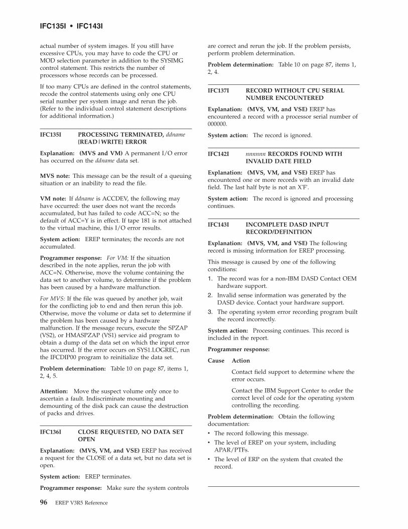
actual number of system images. If you still haveexcessive CPUs, you may have to code the CPU orMOD selection parameter in addition to the SYSIMGcontrol statement. This restricts the number ofprocessors whose records can be processed.
If too many CPUs are defined in the control statements,recode the control statements using only one CPUserial number per system image and rerun the job.(Refer to the individual control statement descriptionsfor additional information.)
IFC135I PROCESSING TERMINATED, ddname{READ|WRITE} ERROR
Explanation: (MVS and VM) A permanent I/O errorhas occurred on the ddname data set.
MVS note: This message can be the result of a queuingsituation or an inability to read the file.
VM note: If ddname is ACCDEV, the following mayhave occurred: the user does not want the recordsaccumulated, but has failed to code ACC=N; so thedefault of ACC=Y is in effect. If tape 181 is not attachedto the virtual machine, this I/O error results.
System action: EREP terminates; the records are notaccumulated.
Programmer response: For VM: If the situationdescribed in the note applies, rerun the job withACC=N. Otherwise, move the volume containing thedata set to another volume, to determine if the problemhas been caused by a hardware malfunction.
For MVS: If the file was queued by another job, waitfor the conflicting job to end and then rerun this job.Otherwise, move the volume or data set to determine ifthe problem has been caused by a hardwaremalfunction. If the message recurs, execute the SPZAP(VS2), or HMASPZAP (VS1) service aid program toobtain a dump of the data set on which the input errorhas occurred. If the error occurs on SYS1.LOGREC, runthe IFCDIP00 program to reinitialize the data set.
Problem determination: Table 10 on page 87, items 1,2, 4, 5.
Attention: Move the suspect volume only once toascertain a fault. Indiscriminate mounting anddemounting of the disk pack can cause the destructionof packs and drives.
IFC136I CLOSE REQUESTED, NO DATA SETOPEN
Explanation: (MVS, VM, and VSE) EREP has receiveda request for the CLOSE of a data set, but no data set isopen.
System action: EREP terminates.
Programmer response: Make sure the system controls
are correct and rerun the job. If the problem persists,perform problem determination.
Problem determination: Table 10 on page 87, items 1,2, 4.
IFC137I RECORD WITHOUT CPU SERIALNUMBER ENCOUNTERED
Explanation: (MVS, VM, and VSE) EREP hasencountered a record with a processor serial number of000000.
System action: The record is ignored.
IFC142I nnnnnn RECORDS FOUND WITHINVALID DATE FIELD
Explanation: (MVS, VM, and VSE) EREP hasencountered one or more records with an invalid datefield. The last half byte is not an X'F'.
System action: The record is ignored and processingcontinues.
IFC143I INCOMPLETE DASD INPUTRECORD/DEFINITION
Explanation: (MVS, VM, and VSE) The followingrecord is missing information for EREP processing.
This message is caused by one of the followingconditions:
1. The record was for a non-IBM DASD Contact OEMhardware support.
2. Invalid sense information was generated by theDASD device. Contact your hardware support.
3. The operating system error recording program builtthe record incorrectly.
System action: Processing continues. This record isincluded in the report.
Programmer response:
Cause Action
Contact field support to determine where theerror occurs.
Contact the IBM Support Center to order thecorrect level of code for the operating systemcontrolling the recording.
Problem determination: Obtain the followingdocumentation:
v The record following this message.
v The level of EREP on your system, includingAPAR/PTFs.
v The level of ERP on the system that created therecord.
IFC135I • IFC143I
96 EREP V3R5 Reference

IFC149I nnnnnn DIRECTWK READ FAILURES
Explanation: (MVS and VM) Indicates the number ofrecords that are lost while reading from theDIRECTWK data set.
System action: Processing continues.
Programmer response: Rerun the job. If the problempersists, check the direct access device on which thedata set resides.
Problem determination: Save the console spool file.Contact IBM for hardware support.
IFC150I nnnnnn RECORDS READ FROMINPUT SOURCE
Explanation: (MVS, VM, and VSE) Indicates thenumber of records EREP read for the report.
IFC152I nnnnnn RECORD(S) FOUND WITH AZERO VOLID
Explanation: (MVS, VM, and VSE) Indicates thenumber of records EREP has found that contain volumeserial number 000000.
IFC153I {GETMAIN GETVIS} FAILED FORMODULE mmmmmmmm
Explanation: (MVS, VM, and VSE) The region orstorage size is too small to contain the tables for thismodule.
System action: EREP terminates.
Programmer response: Increase the region size or thevirtual machine storage size and rerun the job.
IFC154I SORTBREAK FORCED DUE TOEXCESSIVE FAULT CODES
Explanation: (MVS, VM, and VSE) EREP hasencountered more different fault symptom codes thanthe symptom code table can hold.
System action: The DASD device summary for thischannel/control unit contains two (or more) reportsrather than one.
Programmer response: Increase the region/partitionor virtual machine storage size. If the problemcontinues, limit the amount of data by use of selectionparameters.
IFC165I SORTBREAK FORCED DUE TOEXCESSIVE VOLIDS
Explanation: (MVS, VM, and VSE) EREP hasencountered more unique volume identifiers than theVOLID table can hold.
System action: The DASD detail summary for this
channel/control unit contains two (or more) reportsrather than one.
Programmer response: Increase the region/partitionor virtual machine storage size. If the problem persists,restrict the amount of data by use of selectionparameters.
IFC166I tttttttt TABLE IS FULL, INCREASETABSIZE
Explanation: (MVS, VM, and VSE) The area allocatedto the specified table has been filled; tttttttt is one ofthe following:
DASDID
LIMIT
SHARE/CONTROLLER
SUMM
System action: EREP terminates.
Programmer response: Increase the TABSIZE valueand, if necessary, the region/partition or virtualmachine storage size as well. Then rerun the job.
IFC167I CUA RANGE IS INVALID ON ASHARE/CONTROLLER CARD
Explanation: (MVS, VM, and VSE) The rangespecified on the SHARE or CONTROLLER statementeither exceeds the 32-address limit, or crosses aninvalid control unit boundary. For example, the rangeon SHARE=(...130–14F) crosses from an odd to an evenCUA and is invalid.
System action: EREP terminates.
Programmer response: Correct theSHARE/CONTROLLER statement and rerun the job.
IFC168I CUA OVERLAPS WITH ANOTHERSHARE/CONTROLLER ENTRY
Explanation: (MVS, VM, and VSE) The address rangeon one SHARE or CONTROLLER statement overlapsthe range on another SHARE or CONTROLLERstatement.
System action: EREP terminates.
Programmer response: Correct the SHARE orCONTROLLER statements and rerun the job.
IFC169I nnnn RECORDS NOT USED BY modulename FOR THIS CUX xxx
Explanation: (MVS, VM, and VSE) Indicates why thenumber of records used to build the maintenancedevice code does not equal the number of recordspresent for this channel or control unit: all MDR andOBR records are passed to EREP, but only OBR recordswith particular fault symptom codes are used for thedata reduction report.
IFC149I • IFC169I
Chapter 6. EREP Messages 97

System action: Processing continues.
IFC170I GETVCE FAILURE. LOGICAL UNITSYSxxx
Explanation: (VSE) The get-device-characteristics SVChas failed. The device type needed to open SYSxxxcannot be obtained.
System action: The job step terminates.
Programmer response: Correct or add the // ASSGNstatement for the appropriate logical unit.
IFC171I INVALID DEVICE TYPE SYSxxx
Explanation: (VSE) The device assigned to logical unitSYSxxx is invalid for the type of processing that mustbe performed.
System action: The job step terminates.
Programmer response: Correct the // ASSGNstatement for SYSxxx.
IFC172I SEGMENTED RECORD INCOMPLETE(24-byte header)
Explanation: (VSE) A segment of a logical record onSYSREC is missing or incorrect. The first 24 bytes of therecord are included in the message.
System action: Not all of the record segments areprocessed. If the segment involved belongs to a frameor to SYSREC, the entire frame set is deleted, so someMCH and CCH records might not be processed.
Programmer response: Check for a succeeding readerror message. You may have to reallocate andreinitialize IJSYSRC. An error-recording transient maybe executing incorrectly. Call IBM programmingsupport.
IFC173I ERROR READING SYSREC, RECORDSKIPPED
Explanation: (VSE) A read error occurred on SYSREC.
System action: Processing continues.
Programmer response: Reallocate IJSYSRC andreinitialize SYSREC using the SET RF=CREATE IPLcommand.
IFC174I nnnn RECORDS WITH SB 3 and 4EQUAL TO SB 8 & 9
Explanation: (MVS, VM, and VSE) OBR records withfault symptom code 191A should not have sense bytes3 and 4 equal to sense bytes 8 and 9. This messageindicates the number that do, nevertheless.
System action: Processing continues. However, theserecords are not used to determine the maintenancedevice code.
Programmer response: A hardware problem; notifyyour CE or other maintenance person.
Problem determination: Table 10 on page 87, item 5.
IFC175I logical unit OPEN REQUESTED,ALREADY OPEN
Explanation: (VSE) A second open has been requestedfor a data set that is already open.
System action: The request is ignored. No furtherinput is processed.
Programmer response: Make sure the system controlsare correct and rerun the job. If the problem persists,perform problem determination.
Problem determination: Table 10 on page 87, items 1,2, 4.
IFC176I logical unit FAILED TO OPEN
Explanation: (VSE) The specified data set cannot beopened.
System action: The job step terminates.
Programmer response: Add or correct the // ASSGNstatement for the specified data set and rerun the job.
IFC177I logical unit NOT OPEN WHEN{READ|WRITE} REQUESTED
Explanation: (VSE) The specified data set is not openwhen a read or write is requested.
System action: The request is ignored. No furtherinput is processed.
Programmer response: Make sure the system controlsare correct and rerun the job. If the problem persists,perform problem determination.
Problem determination: Table 10 on page 87, 1, 2, 4.
IFC178I RECORD IGNORED; logical unit READDIRECT ERROR
Explanation: (VSE) A permanent I/O error hasoccurred on the specified data set. EREP has ignoredone or more records.
System action: Processing continues. The physicalrecord that caused the error is ignored.
Programmer response: Move the volume containingthe data set to another device or move the data set toanother volume, to determine if the problem is causedby a hardware malfunction. If the message does notrecur, there probably is a hardware error on the device(or volume) originally used. If the error persists,execute a utility to obtain a dump of the data set onwhich the error occurred. If the error occurs onSYSREC, re-IPL and issue SET RF=CREATE toreinitialize the data set.
IFC170I • IFC178I
98 EREP V3R5 Reference

Attention: Move the suspect volume only once toascertain a fault. Indiscriminate mounting anddemounting of the disk pack can cause the destructionof packs and drives.
Problem determination: Table 10 on page 87, items 1,2, 4, 5.
IFC179I {ddname logical unit} CLOSEREQUESTED, logical unit NOT OPEN
Explanation: (VSE) The specified data set is not openwhen a close is requested.
System action: The request is ignored.
Programmer response: Make sure the system controlsare correct and rerun the job. If the problem persists,perform problem determination.
Problem determination: Table 10 on page 87, items 1,2, 4.
IFC180I SYSREC HEADER CANNOT BE READ
Explanation: (VSE) EREP cannot read the headerrecord on SYSREC.
System action: The job step terminates.
Programmer response: Execute a utility to obtain adump of SYSREC. Then re-IPL and issue SETRF=CREATE to reinitialize the recorder file (SYSREC).
IFC181I SYSREC HEADER CHECK BYTEINCORRECT
Explanation: (VSE) A validity check of the headerrecord on SYSREC has uncovered an error.
System action: The EREP program terminates.
Programmer response: Execute a utility to obtain adump of SYSREC. Then re-IPL and issue SETRF=CREATE to reinitialize the recorder file (SYSREC).
Problem determination: Table 10 on page 87, items 1,2, 4.
IFC182I RECORDS IGNORED; INSUFFICIENTSPACE ON SYS001
Explanation: (VSE) Not enough space was allocatedon SYS001 to process all input records. MessageIFC183I should follow this message.
System action: Processing continues. The reportoutput includes only the records read prior to therecord that cannot be written on SYS001. EREP readsno more records for the report.
Programmer response: Increase the space allocationfor SYS001 and rerun the job.
IFC183I LAST RECORD PROCESSED WAS textdata ...
Explanation: (VSE) This message follows IFC1821 andprovides a hexadecimal dump of the first 40 bytes ofthe last record processed before the space on SYS001 isexhausted.
IFC184I RECORDER FILE HEADER CANNOTBE RESET
Explanation: (VSE) The header record of SYSRECcannot be reset because of an uncorrectable outputerror.
System action: The program terminates normally.
Programmer response: Re-IPL and issue SETRF=CREATE to reinitialize SYSREC.
Problem determination: Table 10 on page 87, items 1,2, 5.
IFC185I {GETVIS|GETVCE} FAILED FOR tttttttt
Explanation: (VSE) A GETVIS has been issued for thevalue indicated by parameter TABSIZE and thepartition GETVIS area is too small; tttttttt is one of thefollowing:
tttttttt valueDASDID TABLE SYSTEM IMAGE TABLELIMIT TABLE ALIAS LISTSHARE TABLE CI BUFFERSORT TABLE HEADER BUFFERSUMM TABLE
System action: The job step terminates.
Programmer response: Alter the SIZE parameter onthe // EXEC statement to increase the partition sizeand rerun the job.
IFC186I nnnnnn RECORDS IGNOREDBECAUSE OF UNKNOWN TYPE
Explanation: (VSE) EREP has encountered recordsfrom an unsupported device.
System action: The records are ignored; not used forthe report.
Programmer response: Execute a utility to obtain adump of the output data set to verify the existence ofthe unknown records.
IFC187I nnnnnn RCDS IGNORED BECAUSESYS001 READ ERRORS
Explanation: (VSE) The message indicates the numberof records EREP cannot process because of I/O errorsin reading the SYS001 data set.
System action: Processing continues.
IFC179I • IFC187I
Chapter 6. EREP Messages 99
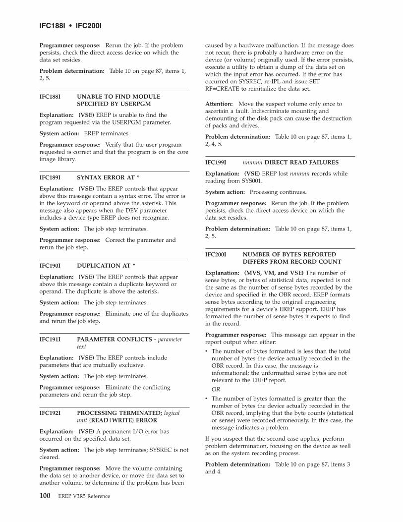
Programmer response: Rerun the job. If the problempersists, check the direct access device on which thedata set resides.
Problem determination: Table 10 on page 87, items 1,2, 5.
IFC188I UNABLE TO FIND MODULESPECIFIED BY USERPGM
Explanation: (VSE) EREP is unable to find theprogram requested via the USERPGM parameter.
System action: EREP terminates.
Programmer response: Verify that the user programrequested is correct and that the program is on the coreimage library.
IFC189I SYNTAX ERROR AT *
Explanation: (VSE) The EREP controls that appearabove this message contain a syntax error. The error isin the keyword or operand above the asterisk. Thismessage also appears when the DEV parameterincludes a device type EREP does not recognize.
System action: The job step terminates.
Programmer response: Correct the parameter andrerun the job step.
IFC190I DUPLICATION AT *
Explanation: (VSE) The EREP controls that appearabove this message contain a duplicate keyword oroperand. The duplicate is above the asterisk.
System action: The job step terminates.
Programmer response: Eliminate one of the duplicatesand rerun the job step.
IFC191I PARAMETER CONFLICTS - parametertext
Explanation: (VSE) The EREP controls includeparameters that are mutually exclusive.
System action: The job step terminates.
Programmer response: Eliminate the conflictingparameters and rerun the job step.
IFC192I PROCESSING TERMINATED; logicalunit {READ|WRITE} ERROR
Explanation: (VSE) A permanent I/O error hasoccurred on the specified data set.
System action: The job step terminates; SYSREC is notcleared.
Programmer response: Move the volume containingthe data set to another device, or move the data set toanother volume, to determine if the problem has been
caused by a hardware malfunction. If the message doesnot recur, there is probably a hardware error on thedevice (or volume) originally used. If the error persists,execute a utility to obtain a dump of the data set onwhich the input error has occurred. If the error hasoccurred on SYSREC, re-IPL and issue SETRF=CREATE to reinitialize the data set.
Attention: Move the suspect volume only once toascertain a fault. Indiscriminate mounting anddemounting of the disk pack can cause the destructionof packs and drives.
Problem determination: Table 10 on page 87, items 1,2, 4, 5.
IFC199I nnnnnn DIRECT READ FAILURES
Explanation: (VSE) EREP lost nnnnnn records whilereading from SYS001.
System action: Processing continues.
Programmer response: Rerun the job. If the problempersists, check the direct access device on which thedata set resides.
Problem determination: Table 10 on page 87, items 1,2, 5.
IFC200I NUMBER OF BYTES REPORTEDDIFFERS FROM RECORD COUNT
Explanation: (MVS, VM, and VSE) The number ofsense bytes, or bytes of statistical data, expected is notthe same as the number of sense bytes recorded by thedevice and specified in the OBR record. EREP formatssense bytes according to the original engineeringrequirements for a device’s EREP support. EREP hasformatted the number of sense bytes it expects to findin the record.
Programmer response: This message can appear in thereport output when either:
v The number of bytes formatted is less than the totalnumber of bytes the device actually recorded in theOBR record. In this case, the message isinformational; the unformatted sense bytes are notrelevant to the EREP report.
OR
v The number of bytes formatted is greater than thenumber of bytes the device actually recorded in theOBR record, implying that the byte counts (statisticalor sense) were recorded erroneously. In this case, themessage indicates a problem.
If you suspect that the second case applies, performproblem determination, focusing on the device as wellas on the system recording process.
Problem determination: Table 10 on page 87, items 3and 4.
IFC188I • IFC200I
100 EREP V3R5 Reference

IFC201I nnnn RECORDS IGNORED DUE TO{EXCESSIVE CPUS|MORE THAN 15CPUS}
Explanation: (MVS, VM, and VSE) EREP encounteredmore than 16 unique CPUs in the input data.
System action: Processing continues.
Programmer response: Code the SYSIMG controlstatement to reduce the number of CPUs to the actualnumber of system images. Rerun the job.
If you still have excessive CPUs, you may need to codethe CPU or MOD selection parameter in addition to theSYSIMG control statement. This restricts the number ofprocessors whose records are processed.
IFC202I nnnn RECORDS IGNORED DUE TOEXCESSIVE DIRECTOR IDS
Explanation: (MVS and VM) Indicates the number ofrecords EREP has to ignore because they representmore different storage directors than it can handle.
System action: Processing continues.
Programmer response: Increase the region or virtualmachine storage size. If the problem persists, limit theamount of data by use of selection parameters.
IFC203I nnnn RECORDS IGNORED DUE TOSTORAGE DIRECTOR ID = ZERO
Explanation: (MVS, VM, and VSE) Indicates thenumber of records EREP cannot use because theycontain invalid storage director IDs.
System action: Processing continues.
IFC204I // ASSGN FOR LOGICAL UNIT SYSxxxMISSING OR INVALID
Explanation: (VSE) The device type needed to openSYSxxx cannot be obtained.
System action: The job step terminates.
Programmer response: Correct or add the // ASSGNstatement for the appropriate logical unit.
IFC210I INVALID REQUEST CODE xx: MODyyyy SER zzzzzz
Explanation: (MVS, VM, and VSE) EREP receives aninvalid request relating to a 303X MCH or CCH detailSummary.
System action: The request is not processed.
Programmer response: Can be a software or hardwareerror. Rerun the job. If the error persists, performproblem determination.
Problem determination: Table 10 on page 87, items 3and 4.
IFC214I CANNOT PROCESS RECORD: TYPEOR LENGTH INVALID
Explanation: (MVS, VM, and VSE) EREP encountersan MCH or CCH record with a logout-length field ofzero, or a CCH record produced by a non-IBM systemor a system other than MVS, VM or VSE.
System action: This record is not included in thesummary.
Programmer response: Check the input record andrerun the job. If the error persists, perform problemdetermination.
Problem determination: Table 10 on page 87, items 3and 4.
IFC217I 303X LOAD LIST IS FULL
Explanation: (MVS, VM, and VSE) EREP has foundthe 303X load list in the summary-table module alreadyfull.
System action: EREP terminates summary processing.
Programmer response: Rerun the job. If the errorpersists, perform problem determination. This can be ahardware or IBM software problem.
Problem determination: Table 10 on page 87, items 3and 4
IFC218I 303X DEFAULT SUMMARY TABLEMODULE mmmmmmmm USED
Explanation: (MVS, VM, and VSE) EREP uses defaultmodule mmmmmmmm in place of the missing summarymodule identified in the previously issued IFC219Imessage.
System action: EREP continues summary processingusing the default summary table module named in themessage.
Programmer response: Make sure the latest release ofEREP is installed on your system and rerun the job. Ifthe error persists, perform problem determination.
Problem determination: Table 10 on page 87, items 3and 4.
IFC219I 303X SUMMARY MODULEmmmmmmmm NOT FOUND
Explanation: (MVS, VM, and VSE) EREP cannot findthe selected mmmmmmmm summary module.
System action: EREP omits this record from thesummary and continues summary processing using thedefault summary module named in message IFC218I. Ifthe default summary-table module is missing, EREPterminates summary processing and issues messageIFC220I.
Programmer response: If message IFC218I
IFC201I • IFC219I
Chapter 6. EREP Messages 101
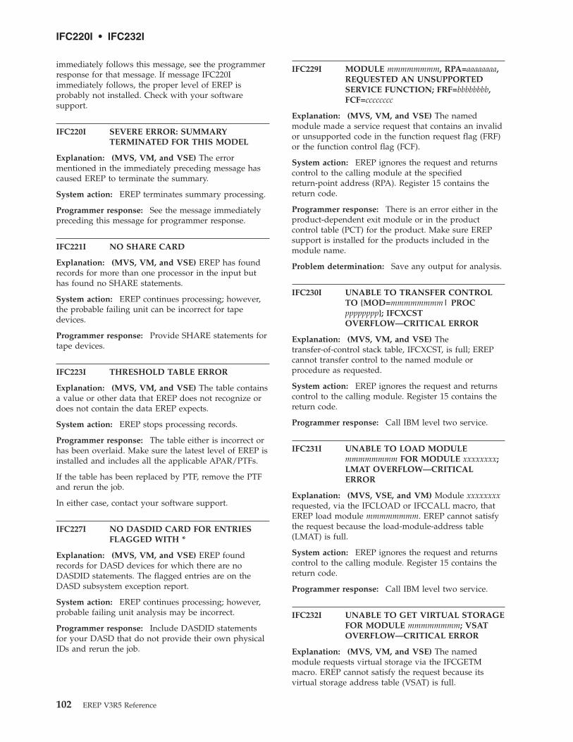
immediately follows this message, see the programmerresponse for that message. If message IFC220Iimmediately follows, the proper level of EREP isprobably not installed. Check with your softwaresupport.
IFC220I SEVERE ERROR: SUMMARYTERMINATED FOR THIS MODEL
Explanation: (MVS, VM, and VSE) The errormentioned in the immediately preceding message hascaused EREP to terminate the summary.
System action: EREP terminates summary processing.
Programmer response: See the message immediatelypreceding this message for programmer response.
IFC221I NO SHARE CARD
Explanation: (MVS, VM, and VSE) EREP has foundrecords for more than one processor in the input buthas found no SHARE statements.
System action: EREP continues processing; however,the probable failing unit can be incorrect for tapedevices.
Programmer response: Provide SHARE statements fortape devices.
IFC223I THRESHOLD TABLE ERROR
Explanation: (MVS, VM, and VSE) The table containsa value or other data that EREP does not recognize ordoes not contain the data EREP expects.
System action: EREP stops processing records.
Programmer response: The table either is incorrect orhas been overlaid. Make sure the latest level of EREP isinstalled and includes all the applicable APAR/PTFs.
If the table has been replaced by PTF, remove the PTFand rerun the job.
In either case, contact your software support.
IFC227I NO DASDID CARD FOR ENTRIESFLAGGED WITH *
Explanation: (MVS, VM, and VSE) EREP foundrecords for DASD devices for which there are noDASDID statements. The flagged entries are on theDASD subsystem exception report.
System action: EREP continues processing; however,probable failing unit analysis may be incorrect.
Programmer response: Include DASDID statementsfor your DASD that do not provide their own physicalIDs and rerun the job.
IFC229I MODULE mmmmmmmm, RPA=aaaaaaaa,REQUESTED AN UNSUPPORTEDSERVICE FUNCTION; FRF=bbbbbbbb,FCF=cccccccc
Explanation: (MVS, VM, and VSE) The namedmodule made a service request that contains an invalidor unsupported code in the function request flag (FRF)or the function control flag (FCF).
System action: EREP ignores the request and returnscontrol to the calling module at the specifiedreturn-point address (RPA). Register 15 contains thereturn code.
Programmer response: There is an error either in theproduct-dependent exit module or in the productcontrol table (PCT) for the product. Make sure EREPsupport is installed for the products included in themodule name.
Problem determination: Save any output for analysis.
IFC230I UNABLE TO TRANSFER CONTROLTO {MOD=mmmmmmmm| PROCpppppppp}; IFCXCSTOVERFLOW—CRITICAL ERROR
Explanation: (MVS, VM, and VSE) Thetransfer-of-control stack table, IFCXCST, is full; EREPcannot transfer control to the named module orprocedure as requested.
System action: EREP ignores the request and returnscontrol to the calling module. Register 15 contains thereturn code.
Programmer response: Call IBM level two service.
IFC231I UNABLE TO LOAD MODULEmmmmmmmm FOR MODULE xxxxxxxx;LMAT OVERFLOW—CRITICALERROR
Explanation: (MVS, VSE, and VM) Module xxxxxxxxrequested, via the IFCLOAD or IFCCALL macro, thatEREP load module mmmmmmmm. EREP cannot satisfythe request because the load-module-address table(LMAT) is full.
System action: EREP ignores the request and returnscontrol to the calling module. Register 15 contains thereturn code.
Programmer response: Call IBM level two service.
IFC232I UNABLE TO GET VIRTUAL STORAGEFOR MODULE mmmmmmmm; VSATOVERFLOW—CRITICAL ERROR
Explanation: (MVS, VM, and VSE) The namedmodule requests virtual storage via the IFCGETMmacro. EREP cannot satisfy the request because itsvirtual storage address table (VSAT) is full.
IFC220I • IFC232I
102 EREP V3R5 Reference
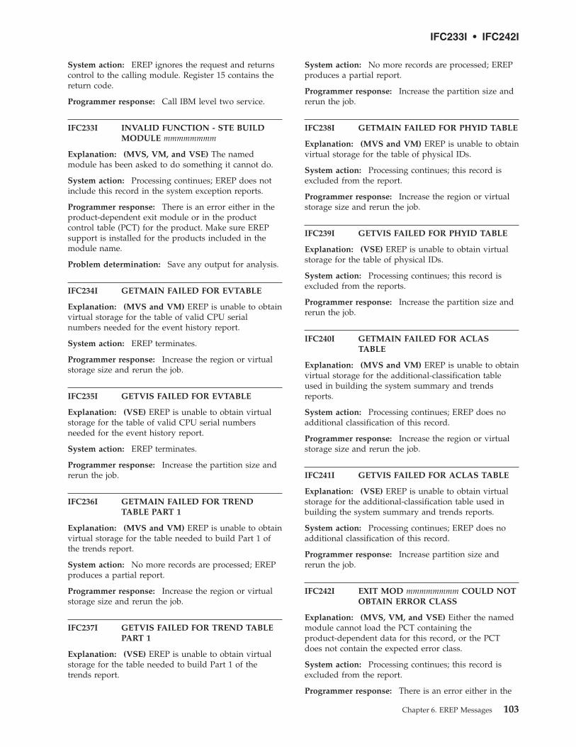
System action: EREP ignores the request and returnscontrol to the calling module. Register 15 contains thereturn code.
Programmer response: Call IBM level two service.
IFC233I INVALID FUNCTION - STE BUILDMODULE mmmmmmmm
Explanation: (MVS, VM, and VSE) The namedmodule has been asked to do something it cannot do.
System action: Processing continues; EREP does notinclude this record in the system exception reports.
Programmer response: There is an error either in theproduct-dependent exit module or in the productcontrol table (PCT) for the product. Make sure EREPsupport is installed for the products included in themodule name.
Problem determination: Save any output for analysis.
IFC234I GETMAIN FAILED FOR EVTABLE
Explanation: (MVS and VM) EREP is unable to obtainvirtual storage for the table of valid CPU serialnumbers needed for the event history report.
System action: EREP terminates.
Programmer response: Increase the region or virtualstorage size and rerun the job.
IFC235I GETVIS FAILED FOR EVTABLE
Explanation: (VSE) EREP is unable to obtain virtualstorage for the table of valid CPU serial numbersneeded for the event history report.
System action: EREP terminates.
Programmer response: Increase the partition size andrerun the job.
IFC236I GETMAIN FAILED FOR TRENDTABLE PART 1
Explanation: (MVS and VM) EREP is unable to obtainvirtual storage for the table needed to build Part 1 ofthe trends report.
System action: No more records are processed; EREPproduces a partial report.
Programmer response: Increase the region or virtualstorage size and rerun the job.
IFC237I GETVIS FAILED FOR TREND TABLEPART 1
Explanation: (VSE) EREP is unable to obtain virtualstorage for the table needed to build Part 1 of thetrends report.
System action: No more records are processed; EREPproduces a partial report.
Programmer response: Increase the partition size andrerun the job.
IFC238I GETMAIN FAILED FOR PHYID TABLE
Explanation: (MVS and VM) EREP is unable to obtainvirtual storage for the table of physical IDs.
System action: Processing continues; this record isexcluded from the report.
Programmer response: Increase the region or virtualstorage size and rerun the job.
IFC239I GETVIS FAILED FOR PHYID TABLE
Explanation: (VSE) EREP is unable to obtain virtualstorage for the table of physical IDs.
System action: Processing continues; this record isexcluded from the reports.
Programmer response: Increase the partition size andrerun the job.
IFC240I GETMAIN FAILED FOR ACLASTABLE
Explanation: (MVS and VM) EREP is unable to obtainvirtual storage for the additional-classification tableused in building the system summary and trendsreports.
System action: Processing continues; EREP does noadditional classification of this record.
Programmer response: Increase the region or virtualstorage size and rerun the job.
IFC241I GETVIS FAILED FOR ACLAS TABLE
Explanation: (VSE) EREP is unable to obtain virtualstorage for the additional-classification table used inbuilding the system summary and trends reports.
System action: Processing continues; EREP does noadditional classification of this record.
Programmer response: Increase partition size andrerun the job.
IFC242I EXIT MOD mmmmmmmm COULD NOTOBTAIN ERROR CLASS
Explanation: (MVS, VM, and VSE) Either the namedmodule cannot load the PCT containing theproduct-dependent data for this record, or the PCTdoes not contain the expected error class.
System action: Processing continues; this record isexcluded from the report.
Programmer response: There is an error either in the
IFC233I • IFC242I
Chapter 6. EREP Messages 103

product-dependent exit module or in the productcontrol table (PCT) for the product. Make sure EREPsupport is installed for the products included in themodule name.
IFC243I EXIT MOD mmmmmmmm COULD NOTOBTAIN PHYSICAL ID
Explanation: (MVS, VM, and VSE) Either the namedmodule cannot load the PCT containing theproduct-dependent data for this record, or the PCTdoes not contain the expected physical ID.
System action: Processing continues; this record isexcluded from the report.
Programmer response: There is an error either in theproduct-dependent exit module or in the productcontrol table (PCT) for the product. Make sure EREPsupport is installed for the products included in themodule name.
IFC244I EXIT MOD mmmmmmmm COULD NOTOBTAIN VOLID
Explanation: (MVS, VM, and VSE) Either the namedmodule cannot load the PCT containing theproduct-dependent data for this record, or the PCTdoes not contain the expected volume serial number.
System action: Processing continues; this record isexcluded from the report.
Programmer response: There is an error either in theproduct-dependent exit module or in the productcontrol table (PCT) for the product. Make sure EREPsupport is installed for the products included in themodule name.
IFC245I EXIT MOD mmmmmmmm COULD NOTOBTAIN SYMCDE
Explanation: (MVS, VM, and VSE) Either the namedmodule cannot load the PCT containing theproduct-dependent data for this record, or the PCTdoes not contain the expected fault symptom code
System action: Processing continues; this record isexcluded from the report.
Programmer response: There is an error either in theproduct-dependent exit module or in the productcontrol table (PCT) for the product. Make sure EREPsupport is installed for the products included in themodule name.
IFC246I EXIT MOD mmmmmmmm COULD NOTOBTAIN TERMINAL NAME
Explanation: (MVS, VM, and VSE) Either the namedmodule cannot load the PCT containing theproduct-dependent data for this record, or the PCTdoes not contain the expected terminal name.
System action: Processing continues; this record isexcluded from the report.
Programmer response: There is an error either in theproduct-dependent exit module or in the productcontrol table (PCT) for the product. Make sure EREPsupport is installed for the products included in themodule name.
IFC247I EXIT MOD mmmmmmmm COULD NOTOBTAIN LIA/LIBADR
Explanation: (MVS, VM, and VSE) Either the namedmodule cannot load the PCT containing theproduct-dependent data for this record, or the PCTdoes not contain the expected line interface baseaddress.
System action: Processing continues; this record isexcluded from the report.
Programmer response: There is an error either in theproduct-dependent exit module or in the productcontrol table (PCT) for the product. Make sure EREPsupport is installed for the products included in themodule name.
IFC248I {GETMAIN GETVIS} FAILED FORSYSUM TABLE PART 1
Explanation: (MVS, VM, and VSE) EREP is unable toobtain virtual storage for the table needed to build Part1 of the system summary.
System action: No more records are processed; EREPproduces a partial report.
Programmer response: Increase region or virtualstorage size and rerun the job.
IFC250I EXIT MOD mmmmmmmm COULD NOTOBTAIN SFT DATA
Explanation: (MVS, VM, and VSE) The namedmodule supplies product-dependent data for the eventhistory report. It is unable to find the data for thissoftware (SFT) record.
System action: Processing continues; however, theentry for this record does not include theproduct-dependent data.
Programmer response: There is an error either in theexit module or in the product control table (PCT) forthe product. Make sure EREP support is installed forthe products included in the module name.
IFC251I EXIT MOD mmmmmmmm COULD NOTOBTAIN OBR DATA
Explanation: (MVS, VM, and VSE)
The named module supplies product-dependent data
IFC243I • IFC251I
104 EREP V3R5 Reference

for the event history report. It is unable to find the datafor this OBR record.
The named exit module has detected an error, or thereis an error in the product control table (PCT) for thisproduct.
System action: Processing continues; however, theentry for this record does not include theproduct-dependent data.
Programmer response: Make sure EREP support isinstalled for the products included in the module name.
IFC252I EXIT MOD mmmmmmmm COULD NOTOBTAIN CCH DATA
Explanation: (MVS, VM, and VSE) The namedmodule supplies product-dependent data for the eventhistory report. It is unable to find the data for this CCHrecord.
System action: Processing continues; however, theentry for this record does not include theproduct-dependent data.
Programmer response: There is an error either in theexit module or in the product control table (PCT) forthe product. Make sure EREP support is installed forthe products included in the module name.
IFC253I EXIT MOD mmmmmmmm COULD NOTOBTAIN MDRDASD DATA
Explanation: (MVS, VM, and VSE) The namedmodule supplies product-dependent data for the eventhistory report. It is unable to find the DASD-specificdata for this MDR record. A hexdump of the record isalso printed after the message.
System action: Processing continues; however, theentry for this record does not include theproduct-dependent data.
Programmer response: There is an error either in theexit module or in the product control table (PCT) forthe product. Make sure EREP support is installed forthe products included in the module name.
IFC256I UNABLE TO LOAD MODULEmmmmmmmm FOR MODULEIFCZIMGR
Explanation: (MVS, VM, and VSE) Duringinitialization of the EREP run, the named servicemodule can not be found or loaded.
System action: EREP terminates.
Programmer response: Make sure the named moduleis included in the library being searched duringinitialization and try again to run EREP.
IFC257I UNABLE TO INITIALIZE IFCZIMGRFOR mmmmmmmm
Explanation: (MVS, VM, and VSE) EREP cannotinitialize its system interface manager (IFCZIMGR) forthe named module. Either it cannot load a neededservice module or it cannot open the TOURIST/SYSLSTdata set. The reason is indicated in the precedingmessage.
System action: EREP terminates.
Programmer response: Take the action recommendedfor the preceding message and try again.
IFC258I EXIT MOD mmmmmmmm COULD NOTFORMAT REPORT FOR ssrr
Explanation: (MVS, VM, and VSE)
The named module produces the product-dependentdetail summary report. It is unable to produce thereport for this SCP (ss) and record type (rr). Ahexdump of the record is also printed after themessage.
The record type is byte 0 of the record. For adescription of the various record types see Table 9 onpage 83.
The SCP is byte 1 of the record and is one of thefollowing:
v VM
v VE (VSE)
v V2 (MVS)
The named exit module has detected an error, or thereis an error in the product control table (PCT) for thisproduct.
System action: Processing continues; however, thedetail summary report for this SCP and record typewill not be produced.
Programmer response: Make sure EREP support isinstalled for the products included in the module name.
IFC259I EXIT MOD mmmmmmmm COULD NOTOBTAIN DATA FOR ssrr
Explanation: (MVS, VM, and VSE)
The named module supplies product-dependent datafor the event history report. It is unable to find the datafor this SCP (ss) and record type (rr).
The record type is byte 0 of the record. For adescription of the various record types, see Table 9 onpage 83.
The SCP is byte 1 of the record and is one of thefollowing:
v VM
v VE (VSE)
IFC252I • IFC259I
Chapter 6. EREP Messages 105

v V2 (MVS)
The named exit module has detected an error, or thereis an error in the product control table (PCT) for thisproduct.
System action: Processing continues; however, theentry for this record does not include theproduct-dependent data.
Programmer response: Make sure EREP support isinstalled for the products included in the module name.
IFC260I USER EXIT MOD mmmmmmmmCOULD NOT BE LOADED BY EREP
Explanation: (MVS, VM, and VSE) The namedmodule supplies product-dependent data for the eventhistory report. EREP is unable to load it.
System action: Processing continues; however, theentry for this record does not include theproduct-dependent data.
Programmer response: There is an error in theproduct control table (PCT) for the product. Make sureEREP support is installed for the products included inthe module name.
IFC261I SYSIMG STATEMENTS IGNOREDWHEN PRINT=PT REQUESTED
Explanation: (MVS, VM, and VSE) When PRINT=PTis requested, SYSIMG control statements should not becoded.
System action: Processing continues. The SYSIMGcontrol statements are ignored.
IFC262I SYSTEM IMAGE STATEMENTS ALTERCPU SERIAL NUMBERS
Explanation: (MVS, VM, and VSE) The first or thefirst and second digits of the CPU identificationnumbers in the CPU tables at the end of the reporthave been altered as a result of information given inthe SYSIMG control statement.
IFC263I TABSIZE REQUEST EXCEEDSMAXIMUM ALLOWED VALUE
Explanation: (MVS, VM, and VSE) The TABSIZErequest exceeds EREP’s addressing capability.
System action: EREP terminates.
Programmer response: Run the job again specifying asmaller value for TABSIZE. See “TABSIZE — Sort TableSize (Processing Parameter)” on page 42 forinformation on allowable values.
IFC264I INVALID INFORMATION FOUNDFOR DASD {OBR|MDR} CODE{xxxx|xx} IN RECORD
Explanation: (MVS, VM, and VSE) The followingrecord contains information that is inconsistent with theOBR or MDR device type code found in the record.Device type codes are documented in “OBR Codes” onpage 111 and “MDR Codes” on page 114.
This message is caused by one of the followingconditions:
1. The record was for a non-IBM DASD. Contact OEMhardware support.
2. Invalid sense information was generated by theDASD device. Contact your hardware support.
3. The record should not have been recorded by theoperating system.
4. The operating system error recording program builtthe record incorrectly because:
a. The DASD device had never been on-line beforethe error recovery procedures (ERP) generatedthe record.
b. The DASD device is not supported by the levelof ERP that generated the record.
5. The DASD device is not supported by the level ofEREP that generated the report.
System action: Processing continues butdevice-dependent information will not be printed forthis record.
Programmer response:
Cause Action
Contact field support to determine where theerror occurs.
Vary the offline device online and then backoffline to resolve the problem.
Contact the IBM Support Center to order thecorrect level of code for the operating systemcontrolling the recording.
Contact the IBM Support Center to order thecorrect level of code for the device.
Problem determination: Obtain the followingdocumentation:
v The record following this message.
v The level of EREP on your system, includingAPAR/PTFs.
v The level of ERP on the system that created therecord.
IFC260I • IFC264I
106 EREP V3R5 Reference

IFC265I INVALID INFORMATION FOUNDFOR DASD DEVICE xxxx
Explanation: (MVS, VM, and VSE) The followingrecord contains sense information that is inconsistentwith the indicated the device type code.
This message is caused by one of the followingconditions:
1. The record was for a non-IBM DASD. Contact yourOEM hardware support.
2. Invalid sense information was generated by theDASD device. Contact your hardware support.
3. The record should not have been recorded by theoperating system.
4. The operating system error recording program builtthe record incorrectly because:
a. The DASD device had never been on-line beforethe error recovery procedures (ERP) generatedthe record.
b. The DASD device is not supported by the levelof ERP that generated the record.
5. The DASD device is not supported by the level ofEREP that generated the report.
System action: Processing continues butdevice-dependent information will not be printed forthis record.
Programmer response:
Cause Action
Contact field support to determine where theerror occurs.
Vary the offline device online and then backoffline to resolve the problem.
Contact the IBM Support Center to order thecorrect level of code for the operating systemcontrolling the recording.
Contact the IBM Support Center to order thecorrect level of code for the device.
Problem determination: Obtain the followingdocumentation:
v The record following this message.
v The level of EREP on your system, includingAPAR/PTFs.
v The level of ERP on the system that created therecord.
IFC266I UNABLE TO OBTAIN VIRTUALSTORAGE FOR MODULE“mmmmmmmm”, GETVIS FAILURE,SIZE=‘ ’X.
Explanation: (VSE) This error message indicates thatthe virtual storage request made for modulemmmmmmmm cannot be honored as insufficient
GETVIS storage remained to fulfill the request.
System action: EREP ignores the request and returnscontrol to the calling module.
Programmer response: Increase the partition size andrerun the job.
IFC265I • IFC266I
Chapter 6. EREP Messages 107

Message Format
108 EREP V3R5 Reference

Chapter 7. Codes for Control Units, OBRs, and MDRs
The control unit codes, outboard record (OBR) codes, and miscellaneous datarecord (MDR) codes are gathered in tables to help you cross-reference devices tothe codes that represent them in EREP records.
This topic covers the following subjects:
TOPIC
“Control Unit Type Codes”
“OBR Codes” on page 111
“MDR Codes” on page 114
The following table contains an example of the four-byte field in the long OBR thatcontains the device type associated with an error.
OffsetDec(Hex)
Size(bytes)Alignment(bits) Field Name Description
......
......
52(34) 4 Device type for the device associated with the error.Byte 01... .... Byte 1 contains a control unit ID..xxx xxxx Reserved.Byte 1 Control unit ID if byte 0(bit 0)=1. Otherwise system dependent data
unused by EREP.Byte 2 Device class code.Byte 3 Device type code.
......
......
The four-byte field contains data gathered from different sources for differentoperating systems.
Some of the other types of error records contain a four byte-field at the same or adifferent offset.
MDRs have a one-byte field at an offset of four to hold the device code. Refer tothe system product error recording manual for your operating system to find theerror record layouts that show the size and offset of the device codes.
Control Unit Type CodesThis section contains tables sorted by both the control unit and the control unittype code to help you cross-reference control units and type codes.
The following table shows the control unit type codes and control units sorted bytype code:
© Copyright IBM Corp. 1983, 2015 109

TYPECODE
CONTROL UNIT
01 3880-3
02 3880-3 with Speed Matching Buffer
03 3880-13
04 3880-23
05 3990-2
06 3990-3
09 3880-3 (3380-JK attachment feature)
0A 3880-23
0B 3880-11
0C 3880-21
0D 3880-1
0E 3880-1 with Speed Matching Buffer (3375)
0F 3380-CJ (Direct Attach)
10 3990-1
11 9343-C02
12 9343-C04
13 9343-D04
14 9341
15 3990-6
17 3995-151
18 9343-CC4
19 9343-DC4
1A 9343-CC2
1B 2105
1C 9696 (IDSK)
1F 2107
20 3995-153
24 1750
30 9394
The following table shows the control unit type codes and control units sorted bycontrol unit:
CONTROL UNIT TYPECODE
1750 24
2105 1B
2107 1F
3380-CJ (Direct Attach) 0F
3880-1 0D
3880-1 with Speed Matching Buffer (3375) 0E
110 EREP V3R5 Reference

CONTROL UNIT TYPECODE
3880-3 01
3880-3 with Speed Matching Buffer 02
3880-3 (3380-JK attachment feature) 09
3880-23 0A
3880-11 0B
3880-13 03
3880-21 0C
3880-23 04
3990-1 10
3990-2 05
3990-3 06
3990-6 15
3995-151 17
3995-153 20
9341 14
9343-C02 11
9343-C04 12
9343-CC2 1A
9343-CC4 18
9343-D04 13
9343-DC4 19
9394 30
9696 (IDSK) 1C
OBR CodesThis section contains tables sorted by both the OBR device class or type code (alsocalled the OBR codes) and the device or family type to help you cross-referenceOBR codes and devices.
The following table shows the OBR device class or type codes and the device typeor family sorted by OBR code:
Chapter 7. Codes for Control Units, OBRs, and MDRs 111

OBR code = DeviceClass
OBR code = DeviceClass
OBR code = DeviceClass
OBR code = DeviceClass OBR code = Device Class
0801 = 2540DD0802 = 2540DD0803 = 14420804 = 25010805 = 25200806 = 35050807 = 35250808 = 14030809 = 3211080A = 1443080B = 3203080C = 3525080D = 3262080E = 3800-01080F = AFP10810 = 26710811 = 42450812 = 10120813 = 42480813 = 62620814 = 29470816 = 38900817 = 38860818 = 24950819 = 3895081A = 1285081B = 1287081C = 1288081D = 1419081E = 1419081F = 12750820 = 10520821 = 21500822 = 32100823 = 32150824 = 29560825 = 29560826 = 29560827 = 29560828 = 29560829 = 1419082A = 1275082B = 1275082C = 1275
082D = 1419082E = 1419082F = 24950830 = 32130831 = 10170832 = 10180833 = 32100834 = 32150835 = 12550836 = 12550837 = 12700838 = 12700839 = 2596083A = SWCH083D = 74430840 = 38900841 = 38860842 = 38500844 = 35400846 = 25600847 = 35040848 = 54250849 = 3203084C = 3838084D = 5203084E = 52030880 = 54240882 = 384808A0 = 3800-031001 = 10151002 = 22501003 = 226D1004 = 105D1005 = 22801006 = 22821007 = 32781008 = 30661009 = 327D100A = 3284100B = 3286100C = 3158100D = 3036100E = 3138100F = 3148
1013 = 50801014 = BA002001 = 23112002 = 23012003 = 23032005 = 23212006 = 23052007 = 23052008 = 23142009 = 3330200A = 3340200B = 3350200C = 3375200D = 3330200E = 3380-A,B201E = 3380-D2021 = 3380-J2023 = 3380-K2024 = 3390-032026 = 3390-012027 = 3390-022028 = 9345-012029 = 9345-02202E = 3380-E2031 = 3395-1512032 = 3390-092033 = 9392-022034 = 9392-012035 = 21052036 = 3995-1532037 = 9395-012038 = 9395-02203A = 9392-03203B = IDSK203C = 2107203D = 17502101 = 33102102 = 33702105 = 33702106 = 93352107 = 93322108 = 93132111 = 93362112 = 06712180 = 92462181 = 92472182 = 3995
2183 = 39954000 = 77704001 = 27024002 = 27014003 = 27034004 = 29554005 = 37054006 = 37054009 = 3704400A = 39684011 = 27024013 = 27034014 = 77724015 = 37054021 = 27024022 = 27014023 = 27034025 = 37054031 = 27024032 = 27014033 = 27034035 = 37054041 = 27024042 = 27014043 = 27034045 = 10604051 = 27024052 = 27014053 = 27034061 = 27024062 = 27014063 = 27034071 = 27024072 = 27014073 = 27034081 = 27024082 = 27014083 = 27034091 = 27024092 = 27014093 = 270340F1 = 37914100 = CTCA4101 = SCTC
4102 = BCTC4105 = 0SA4106 = OSAD4107 = IQD4120 = FCTC4122 = 39954201 = 10304202 = 10504203 = 10604204 = 27404205 = 27404206 = 27414207 = 226T4208 = 105T4209 = 2760420A = 83B3420B = 115A420F = 11304210 = 20204211 = 27804212 = 27704213 = 22654214 = 29304215 = 29724216 = 327T4217 = 29704218 = 37354219 = 3945421A = 2790421B = 36704420 = 37008001 = 24008003 = 34008004 = 34208005 = 34108006 = 88098007 = 34308008 = 73408009 = 9347800A = 3422800C = 3424800E = 93488080 = 34808081 = 34908083 = 35908084 = 3591/3490 EMU8085 = 3590/3490 EMU
Note:
v OBR codes are left of the equal signs; device types are right of the equal signs.
v Some OBR codes may be used with multiple device types or models; for example: AFP1, CTCA, SWCH.
The following table shows the OBR device class or type codes (also called the OBRcodes) and the device type or family sorted by device or family type:
OBR Codes
112 EREP V3R5 Reference

Device/family type = OBR code
AFP1 = 080FBA00 = 1014BCTC = 4102CTCA = 4100FCTC = 4120IDSK = 203BIQD = 4107OSA = 4105OSAD = 4106SCTC = 4101SWCH = 083A0671 = 21121012 = 08121015 = 10011017 = 08311018 = 08321030 = 4201105D = 1004105T = 42081050 = 42021052 = 08201060 = 40451060 = 42031130 = 420F115A = 420B1255 = 08351255 = 08361270 = 08371270 = 08381275 = 081F1275 = 082A1275 = 082B1275 = 082C1285 = 081A1287 = 081B1288 = 081C1403 = 08081419 = 081D1419 = 081E1419 = 082D1419 = 082E1419 = 08291442 = 08031443 = 080A1750 = 203D2020 = 42102105 = 20352107 = 203C2150 = 08212250 = 1002226D = 1003
226T = 42072265 = 42132280 = 10052282 = 10062301 = 20022303 = 20032305 = 20062305 = 20072311 = 20012314 = 20082321 = 20052400 = 80012495 = 08182495 = 082F2501 = 08042520 = 08052540DD = 08012540DD = 08022560 = 08462596 = 08392671 = 08102701 = 40022701 = 40222701 = 40322701 = 40422701 = 40522701 = 40622701 = 40722701 = 40822701 = 40922702 = 40012702 = 40112702 = 40212702 = 40312702 = 40412702 = 40512702 = 40612702 = 40712702 = 40812702 = 40912703 = 40032703 = 40132703 = 40232703 = 4033
2703 = 40432703 = 40532703 = 40632703 = 40732703 = 40832703 = 40932740 = 42042740 = 42052741 = 42062760 = 42092770 = 42122780 = 42112790 = 421A2930 = 42142947 = 08142955 = 40042956 = 08242956 = 08252956 = 08262956 = 08272956 = 08282970 = 42172972 = 42153036 = 100D3066 = 10083138 = 100E3148 = 100F3158 = 100C3203 = 08493203 = 080B3210 = 08223210 = 08333211 = 08093213 = 08303215 = 08233215 = 08343262 = 080D327D = 1009327T = 42163278 = 10073284 = 100A3286 = 100B3310 = 2101
3330 = 20093330 = 200D3340 = 200A3350 = 200B3370 = 21023370 = 21053375 = 200C3380-A,B= 200E3380-D = 201E3380-J = 20213380-K = 20233380-E = 202E3390-01 = 20263390-02 = 20273390-03 = 20243390-09 = 20323400 = 80033410 = 80053420 = 80043422 = 800A3424 = 800C3430 = 80073480 = 80803490 = 80813504 = 08473505 = 08063525 = 08073525 = 080C3540 = 08443590 = 80833590 = 80853591 = 80843670 = 421B3700 = 44203704 = 40093705 = 40053705 = 40063705 = 40153705 = 40253705 = 40353735 = 42183791 = 40F13800-01 = 080E3800-03 = 08A03838 = 084C
3848 = 08823850 = 08423886 = 08173886 = 08413890 = 08163890 = 08403895 = 08193945 = 42193968 = 400A3995 = 20313995 = 20363995 = 21823995 = 21833995 = 41224245 = 08114248 = 08135080 = 10135203 = 084D5203 = 084E5424 = 08805425 = 08486262 = 08137340 = 80087443 = 083D7770 = 40007772 = 401483B3 = 420A8809 = 80069246 = 21809247 = 21819313 = 21089332 = 21079335 = 21069336 = 21119345-01 = 20289345-02 = 20299347 = 80099348 = 800E9392-01 = 20349392-02 = 20339392-03 = 203A9395 = 20379395 = 2038
Note:
v Device types are left of the equal signs; OBR codes are right of the equal signs.
v Some OBR codes may be used with multiple device types or models; for example: AFP1, CTCA, SWCH.
OBR Codes
Chapter 7. Codes for Control Units, OBRs, and MDRs 113

MDR CodesThis section contains tables sorted by both the MDR device code (also called theMDR code) and the device or family type to help you cross-reference MDR codesand devices.
The following table shows MDR codes and device types sorted by MDR code:
MDR code = device type MDR code = device type
01 = 333002 = 2305 MOD 203 = 327703 = 328603 = 3284 (non-NCP mode)04 = 321105 = 3705 (non-NCP mode)06 = 367007 = 316808 = 271509 = 334009 = 33440A = 3330 MOD 110B = 32770C = 3800 MOD 10D = 38950E = 38500F = IGAR Diskette10 = 320310 = 328911 = 335012 = 2305 MOD 113 = 3277 (NCP mode)14 = 3380 Mod A,B15 = 3705 (NCP mode)16 = 331017 = 3370 MOD 118 = 337519 = 93131A = 3370 MOD 21B = 3380 MOD E1C = 3380 MOD D1D = 93351E = 93321F = 934720 = 3800 MOD 3,821 = 3380 MOD J
23 = 3380 MOD K24 = 3390-0325 = 372526 = 3390-0127 = 3390-0228 = 9345-0129 = 9345-022A = 06712B = 93362E = 37202F = 374530 = NMVT31 = 3995-15132 = 3390-0933 = 9392-0234 = 9392-0135 = 210536 = 3995-15337 = 939538 = 93953A = 9392-033B = IDSK3C = 21073D = 17503E = 2107 EVA mod A40 = 880941 = 348042 = 349044 = 342445 = 934846 = 359047 = 3591/3490 EMU48 = 3590/3490 EMU50 = 3995F0 = 2946F1 = 2948F3 = 2703
Note: MDR codes are left of the equal signs; device types are right of the equal signs.
The following table shows MDR codes and device types sorted by Device Type.
MDR Codes
114 EREP V3R5 Reference

Device type = MDR code Device type = MDR code
0671 = 2A1750 = 3D2105 = 352107 = 3C2107 EVA mod A = 3E2305 MOD 1 = 122305 MOD 2 = 022703 = F32715 = 082946 = F02948 = F13168 = 073203 = 103211 = 043277 = 033277 = 0B3277 (NCP mode) = 133284 (non-NCP mode) = 033286 = 033289 = 103310 = 163330 = 013330 MOD 11 = 0A3340 = 093344 = 093350 = 113370 MOD 1 = 173370 MOD 2 = 1A3375 = 183380 MOD A,B = 143380 MOD J = 213380 MOD K = 233380 MOD E = 1B3380 MOD D = 1C3390-01 = 263390-02 = 273390-03 = 243390-09 = 323424 = 443480 = 41
3490 = 423590 = 463591/3490 EMU = 473590/3490 EMU = 483670 = 063705 (non-NCP mode) = 053705 (NCP mode) = 153720 = 2E3725 = 253745 = 2F3800 MOD 1 = 0C3800 MOD 3,8 = 203850 = 0E3895 = 0D3995 = 503995-151 = 313995-153 = 369336 = 2B8809 = 409313 = 199332 = 1E9335 = 1D9345-01 = 289345-02 = 299347 = 1F9348 = 459392-01 = 349392-02 = 339392-03 = 3A9395-01 = 379395-02 = 38IDSK = 3BIGAR Diskette = 0FNMVT = 30
Note: Device types are left of the equal signs; MDR codes are right of the equal signs.
MDR Codes
Chapter 7. Codes for Control Units, OBRs, and MDRs 115

MDR Codes
116 EREP V3R5 Reference
Part 2. Examples of Output from Reports
To help you select which reports you need to adequately monitor your installation,this part of the EREP Reference provides descriptions and examples of each reportgenerated by EREP.
EREP reports are designed to give you a variety of views of the data beingprocessed. EREP produces:v Overview reports, from which you can determine if there are problemsv Analysis reports, from which you can determine where there are problemsv Detail reports, from which you can determine what the problems are.
In order to decide which report to run at which time, you need to understandwhat each one is telling you. The following reports are described in this topic:
Topic
Chapter 8, “System Summary Report,” on page 119
Chapter 9, “Trends Report,” on page 127
Chapter 10, “Event History Report,” on page 135
Chapter 11, “System Exception Report Series,” on page 141
Chapter 12, “Threshold Summary Report,” on page 239
Chapter 13, “Detail Edit and Summary Reports,” on page 245
Note: The reports are listed from most general to most specific, because the mosteffective way to use EREP reports is to start with the most general and worktoward the most specific.
© Copyright IBM Corp. 1983, 2015 117

118 EREP V3R5 Reference
Chapter 8. System Summary Report
The system summary report provides an overview of errors for each of yourinstallation’s principal parts or subsystems:v Processors (CPU)v Channelsv Subchannelsv Storagev Operating system control programs (SCPs)v I/O subsystems.
Important: The system summary report does not go into detail; it shows howmany errors and exceptions were recorded overall. It is a good place to start whenevaluating the performance of your system.
Description of the System Summary ReportThe system summary report has the following two parts:
PART DESCRIPTION
1 Summarizes errors by CPUs from all but the I/O subsystem.
2 Summarizes errors recorded in the I/O subsystem.
Note:
1. Record counts are listed by CPU. See “How EREP Assigns Numbers to CPUs”on page 69 for an explanation of the way the number identifiers are assigned.EREP can report information from a variable number of CPUs depending uponyour operating system, type of printer and what parameters you specify.Information from the remaining CPUs are grouped together under serialnumber X'FFFFFF'.It is also possible to have multiple internal CPUs reported under one serialnumber. See “SYSIMG Control Statement” on page 71 for more information.
2. DASD and tape are listed by strings in the system summary.3. A field with all 9’s means that the number was larger than the print position
allowed.4. A dash (–) in part 2 of the system summary means there are no records for this
DEVNO/CUA on this processor (CPU).5. It is most useful to address the permanent errors first.
System Summary Part 1The first part of the system summary report varies according to the mode of therecords it summarizes.
RECORD MODE CONTAINS
370 v Counts of machine checks (MCH records)
v Channel checks (CCH records) by channel
© Copyright IBM Corp. 1983, 2015 119

RECORD MODE CONTAINS
370XA v Machine-check totals
v Counts of subchannel logouts (SLH records) by channel path ID
v Channel report words (CRW records) created by both hardware andsoftware
Note:
1. For MVS only, actual software error records are included in the report.2. Counts of software events that may or may not be associated with errors (IPLs
and system termination) are shown in the first part of the system summary.
“System Summary Report, Part 1” on page 121 shows an example of the systemsummary part 1.
System Summary Part 2The second part of the system summary is a condensed report of every permanentand temporary error recorded for the I/O devices in your installation, listed underthe CPU associated with the error.
When your CPUs share I/O devices, you must use SHARE control statements forthe system summary if you want to see I/O errors combined for all the possiblepaths to a device that is common to different systems. See “SHARE ControlStatements” on page 66 for details.
The temporary errors appearing in part 2 of this report are totals of temporaryread/write errors and statistical data.
The temporary and permanent I/O errors are listed by product or device groups.Table 11 shows the product groups in the order they appear in part 2 of the systemsummary and the trends reports.
Table 11. The Order of Product Groups in the Reports
ORDER PRODUCT GROUP
1 Console and unit record devices:
1. Operator’s console
2. Card reader
3. Card punch
4. Printer
5. OCR/MICR
2 Direct-access storage devices:
1. Disk
2. Drum/fixed-head file
3. Mass storage system
4. Optical
3 Tape devices
4 Displays (channel-attached)
5 Teleprocessing (TP) communications controllers
6 Terminals
System Summary Report Part 1
120 EREP V3R5 Reference
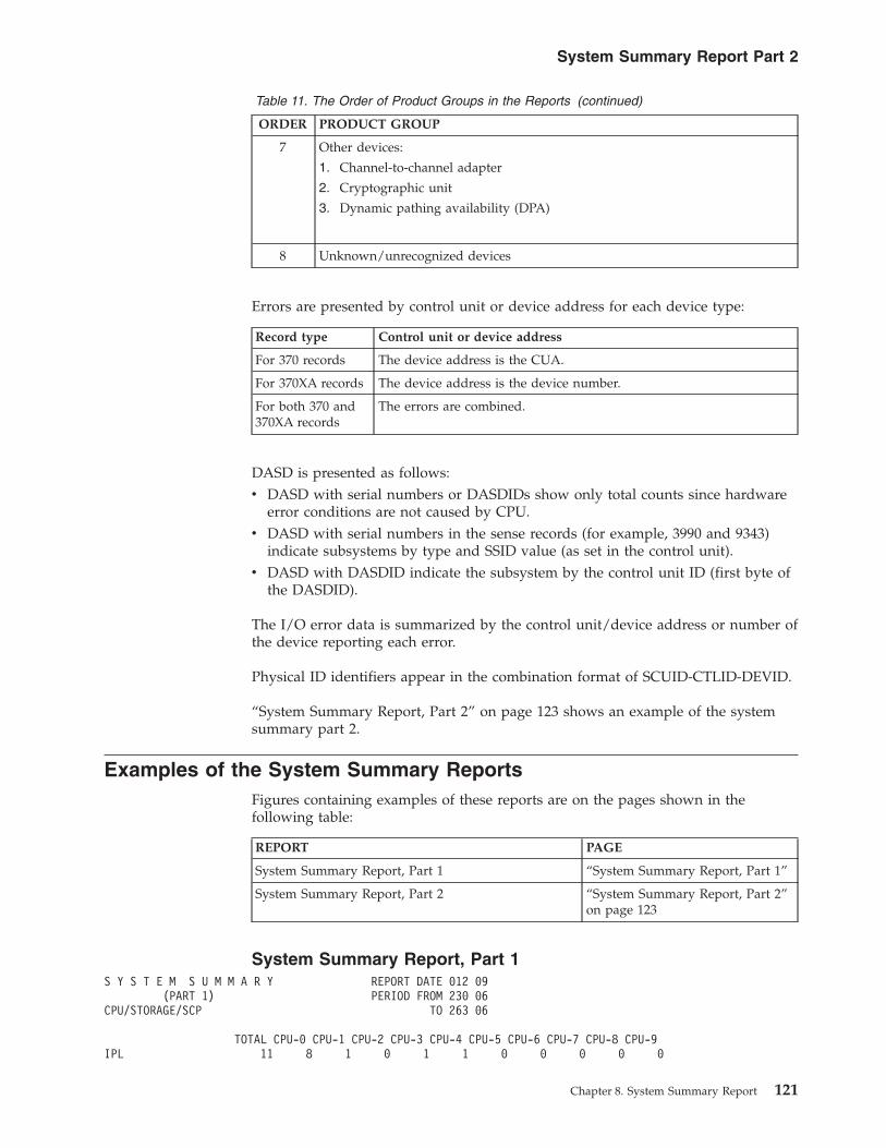
Table 11. The Order of Product Groups in the Reports (continued)
ORDER PRODUCT GROUP
7 Other devices:
1. Channel-to-channel adapter
2. Cryptographic unit
3. Dynamic pathing availability (DPA)
8 Unknown/unrecognized devices
Errors are presented by control unit or device address for each device type:
Record type Control unit or device address
For 370 records The device address is the CUA.
For 370XA records The device address is the device number.
For both 370 and370XA records
The errors are combined.
DASD is presented as follows:v DASD with serial numbers or DASDIDs show only total counts since hardware
error conditions are not caused by CPU.v DASD with serial numbers in the sense records (for example, 3990 and 9343)
indicate subsystems by type and SSID value (as set in the control unit).v DASD with DASDID indicate the subsystem by the control unit ID (first byte of
the DASDID).
The I/O error data is summarized by the control unit/device address or number ofthe device reporting each error.
Physical ID identifiers appear in the combination format of SCUID-CTLID-DEVID.
“System Summary Report, Part 2” on page 123 shows an example of the systemsummary part 2.
Examples of the System Summary ReportsFigures containing examples of these reports are on the pages shown in thefollowing table:
REPORT PAGE
System Summary Report, Part 1 “System Summary Report, Part 1”
System Summary Report, Part 2 “System Summary Report, Part 2”on page 123
System Summary Report, Part 1S Y S T E M S U M M A R Y REPORT DATE 012 09
(PART 1) PERIOD FROM 230 06CPU/STORAGE/SCP TO 263 06
TOTAL CPU-0 CPU-1 CPU-2 CPU-3 CPU-4 CPU-5 CPU-6 CPU-7 CPU-8 CPU-9IPL 11 8 1 0 1 1 0 0 0 0 0
System Summary Report Part 2
Chapter 8. System Summary Report 121

MACHINE CHECK
RECOVERABLE 163 75 0 0 0 0 0 0 0 0 88NON-RECOVERABLE 0 0 0 0 0 0 0 0 0 0 0
CHANNEL CHECK 1
CHANNEL 0 0 0 0 0 0 0 0 0 0 0 0CHANNEL 1 9 9 0 0 0 0 0 0 0 0 0CHANNEL 2 0 0 0 0 0 0 0 0 0 0 0CHANNEL 3 3 3 0 0 0 0 0 0 0 0 0CHANNEL 4 0 0 0 0 0 0 0 0 0 0 0CHANNEL 5 0 0 0 0 0 0 0 0 0 0 0CHANNEL 6 0 0 0 0 0 0 0 0 0 0 0CHANNEL 7 2 2 0 0 0 0 0 0 0 0 0CHANNEL 8 0 0 0 0 0 0 0 0 0 0 0CHANNEL 9 7 7 0 0 0 0 0 0 0 0 0CHANNEL A 4 4 0 0 0 0 0 0 0 0 0CHANNEL B 0 0 0 0 0 0 0 0 0 0 0CHANNEL C 25 25 0 0 0 0 0 0 0 0 0CHANNEL D 1 1 0 0 0 0 0 0 0 0 0CHANNEL E 0 0 0 0 0 0 0 0 0 0 0CHANNEL F 0 0 0 0 0 0 0 0 0 0 0CHANNEL 10 0 0 0 0 0 0 0 0 0 0 0CHANNEL 11 0 0 0 0 0 0 0 0 0 0 0CHANNEL 12 0 0 0 0 0 0 0 0 0 0 0CHANNEL 13 0 0 0 0 0 0 0 0 0 0 0CHANNEL 14 2 2 0 0 0 0 0 0 0 0 0CHANNEL 15 0 0 0 0 0 0 0 0 0 0 0CHANNEL 16 0 0 0 0 0 0 0 0 0 0 0CHANNEL 17 0 0 0 0 0 0 0 0 0 0 0CHANNEL 18 0 0 0 0 0 0 0 0 0 0 0CHANNEL 19 0 0 0 0 0 0 0 0 0 0 0CHANNEL 1A 0 0 0 0 0 0 0 0 0 0 0CHANNEL 1B 0 0 0 0 0 0 0 0 0 0 0
PROGRAM ERROR
ABEND 42488 11787 76 510 14 35 10825 100 321 518 18302PROGRAM CHECK 5295 7 1 3451 0 2 622 28 362 819 3SYMPTOM RECORD 1077 361 18 44 7 57 55 36 423 74 2
END OF DAY 1 0 1 0 0 0 0 0 0 0 0
CPU MODEL SERIAL NO.0 FFFFXA FFFFFF1 2084XA 05A8BA2 2084XA 05A5BA3 2084XA 04A8BA4 2084XA 03A8BA5 2084XA 0356BF6 2084XA 02A8BA7 2084XA 02A5BA8 2084XA 0256BF9 2084XA 019F1A
S Y S T E M S U M M A R Y REPORT DATE 012 09(PART 1 CONTINUED) PERIOD FROM 230 06
SUBCHANNEL/CHANNEL TO 263 06
TOTAL CPU-0 CPU-1 CPU-2 CPU-3 CPU-4 CPU-5 CPU-6 CPU-7 CPU-8 CPU-9
SUBCHANNEL LOGOUT
CHPID 00 44 17 0 0 0 0 0 0 0 0 27CHPID 01 280 163 0 27 0 0 29 0 34 27 0CHPID 05 304 187 0 27 0 0 29 0 34 27 0
System Summary Report Part 2
122 EREP V3R5 Reference

CHPID 72 11 5 0 1 1 0 1 1 1 1 0CHPID 81 421 232 0 33 0 0 34 47 40 35 0CHPID 85 404 219 0 32 0 0 34 43 41 35 0CHPID 86 3 0 0 0 3 0 0 0 0 0 0CHPID 87 3 0 1 0 2 0 0 0 0 0 0CHPID F0 4 0 0 1 0 0 0 1 1 1 0CHPID F1 11 6 0 1 0 0 1 1 1 1 0CHPID F2 12 5 1 1 1 0 1 1 1 1 0CHANNEL REPORT WORD
HARDWARE 4 3 0 0 0 0 0 0 1 0 0SOFTWARE 0 0 0 0 0 0 0 0 0 0 0
TOTAL RECORDS 50536 13075 99 4128 29 95 11631 258 1260 1539 18422
CPU MODEL SERIAL NO.0 FFFFXA FFFFFF1 2084XA 05A8BA2 2084XA 05A5BA3 2084XA 04A8BA4 2084XA 03A8BA5 2084XA 0356BF6 2084XA 02A8BA7 2084XA 02A5BA8 2084XA 0256BF9 2084XA 019F1A
�1� If there are 32 channels, then the channel check summary displayschannels X'10' through X'1F' only if there is activity on one or more of thechannels in the string.
System Summary Report, Part 2S Y S T E M S U M M A R Y REPORT DATE 012 09
(PART 2) PERIOD FROM 230 06I/O SUBSYSTEM TO 263 06
----- TOTAL ---- CPU-0 CPU-1 CPU-2 CPU-3 CPU-4 CPU-5 CPU-6 CPU-7 CPU-8 CPU-9PERM TEMP PATH PERM TEMP PERM TEMP PERM TEMP PERM TEMP PERM TEMP PERM TEMP PERM TEMP PERM TEMP PERM TEMP PERM TEMP
CONS +UR ***********************************************************************************************************************
3525 000B 1 0 0 1 0 - - - - - - - - - - - - - - - - - -3800 000F 2 1 0 2 1 - - - - - - - - - - - - - - - - - -3505 0012 1 2 0 1 2 - - - - - - - - - - - - - - - - - -3213 0016 3 0 0 3 0 - - - - - - - - - - - - - - - - - -02C7 0200 2 0 0 2 0 - - - - - - - - - - - - - - - - - -AFP1 0390 1 0 0 1 0 - - - - - - - - - - - - - - - - - -1403 041E 1 0 0 1 0 - - - - - - - - - - - - - - - - - -3800 0803 4 3 0 4 3 - - - - - - - - - - - - - - - - - -
0803 1 0 0 - - - - - - - - 1 0 - - - - - - - - - -3800 0B09 0 1 0 - - - - - - 0 1 - - - - - - - - - - - -3800 0B17 1 0 0 - - - - - - 1 0 - - - - - - - - - - - -
0B17 1 0 0 - - - - - - - - 1 0 - - - - - - - - - -
DASD ***********************************************************************************************************************
3350 0100 1 0 0 - - - - - - 1 0 - - - - - - - - - - - -3350 010C 1 0 0 - - - - - - - - 1 0 - - - - - - - - - -2305 01CX 4 0 0 4 0 - - - - - - - - - - - - - - - - - -3340 03E8 0 1 0 0 1 - - - - - - - - - - - - - - - - - -2314 0530 4 0 0 4 0 - - - - - - - - - - - - - - - - - -3310 0597 0 4096 0 0 4096 - - - - - - - - - - - - - - - - - -9246 0ACX 0 2 0 0 2 - - - - - - - - - - - - - - - - - -13990-SSID 00C2 0 0 1 - - - - - - - - - - - - - - - - - - - -9343-SSID 0243 0 1 0 - - - - - - - - - - - - - - - - - - - -UKNO-SSID A0-X 0 1 0 - - - - - - - - - - - - - - - - - - - -UKNO-SSID 0002 0 2 0 - - - - - - - - - - - - - - - - - - - -UKNO-SSID 02. 0 23 16 - - - - - - - - - - - - - - - - - - - -3990-SSID 0243 0 0 1 - - - - - - - - - - - - - - - - - - - -E2-XX-XX 7 28 0 - - - - - - - - - - - - - - - - - - - -17-XX-XX 11 0 0 - - - - - - - - - - - - - - - - - - - -
DASD STRINGS ***********************************************************************************************************************
3422 015X 1 0 0 1 0 - - - - - - - - - - - - - - - - - -3400 0180 1 4 0 1 4 - - - - - - - - - - - - - - - - - -
System Summary Report Part 2
Chapter 8. System Summary Report 123

3480 02B2 1 0 0 1 0 - - - - - - - - - - - - - - - - - -9348 049X 10 0 0 10 0 - - - - - - - - - - - - - - - - - -3424 94AX 2 0 0 2 0 - - - - - - - - - - - - - - - - - -3490 04B0 0 1 0 0 1 - - - - - - - - - - - - - - - - - -2400 06A1 0 2 0 0 2 - - - - - - - - - - - - - - - - - -9347 0C7X 12 229 0 12 229 - - - - - - - - - - - - - - - - - -E2-XX-XX 7 28 0 - - - - - - - - - - - - - - - - - - - -17-XX-XX 11 0 0 - - - - - - - - - - - - - - - - - - - -
TAPE ***********************************************************************************************************************
3422 015X 1 0 0 1 0 - - - - - - - - - - - - - - - - - -3400 0180 1 4 0 1 4 - - - - - - - - - - - - - - - - - -3430 0190 1 0 0 1 0 - - - - - - - - - - - - - - - - - -3480 02B2 1 0 0 1 0 - - - - - - - - - - - - - - - - - -9348 049X 10 0 0 10 0 - - - - - - - - - - - - - - - - - -3424 04AX 2 0 0 2 0 - - - - - - - - - - - - - - - - - -3490 04B0 0 1 0 0 1 - - - - - - - - - - - - - - - - - -3490 04B1 2 0 0 2 0 - - - - - - - - - - - - - - - - - -3490 04B2 2 1 0 2 1 - - - - - - - - - - - - - - - - - -
S Y S T E M S U M M A R Y REPORT DATE 012 09(PART 2) PERIOD FROM 230 06
I/O SUBSYSTEM TO 263 06
----- TOTAL ---- CPU-0 CPU-1 CPU-2 CPU-3 CPU-4 CPU-5 CPU-6 CPU-7 CPU-8 CPU-9PERM TEMP PATH PERM TEMP PERM TEMP PERM TEMP PERM TEMP PERM TEMP PERM TEMP PERM TEMP PERM TEMP PERM TEMP PERM TEMP
TAPE ***********************************************************************************************************************
3400 0574 0 4 0 0 4 - - - - - - - - - - - - - - - - - -0574 0 2 0 - - - - - - - - 0 2 - - - - - - - - - -
3400 0575 0 13 0 0 13 - - - - - - - - - - - - - - - - - -0575 1 2 0 - - - - - - - - - - - - - - - - - - - -
2400 06A1 0 2 0 0 2 - - - - - - - - - - - - - - - - - -2400 06A4 1 0 0 1 0 - - - - - - - - - - - - - - - - - -3400 0584 0 9 0 0 9 - - - - - - - - - - - - - - - - - -
0584 0 9 0 - - - - 0 9 - - - - - - - - - - - - - -9347 0C7X 12 229 0 12 229 - - - - - - - - - - - - - - - - - -8809 0BA2 0 376 0 - - - - - - - - - - - - - - - - 0 376 - -8809 0BA5 1 0 0 - - - - - - - - - - - - - - - - 1 0 - -8809 0BA8 0 247 0 - - - - - - - - - - - - - - - - 0 247 - -8809 0BAE 0 222 0 0 222 - - - - - - - - - - - - - - - - - -
DISPLAY ***********************************************************************************************************************
3286 0026 5 0 0 5 0 - - - - - - - - - - - - - - - - - -3277 0361 2 0 0 2 0 - - - - - - - - - - - - - - - - - -
0361 3 0 0 - - - - - - 3 0 - - - - - - - - - - - -0361 1 0 0 - - - - - - - - 1 0 - - - - - - - - - -
3284 03E2 0 2 0 0 2 - - - - - - - - - - - - - - - - - -3277 0B86 1 0 0 1 0 - - - - - - - - - - - - - - - - - -
TP CNTRL ***********************************************************************************************************************
2701 0011CNTRLR 1 0 0 1 0 - - - - - - - - - - - - - - - - - -
3705 0036CNTRLR 3 0 0 3 0 - - - - - - - - - - - - - - - - - -
3791 0319CNTRLR 0 3 0 0 3 - - - - - - - - - - - - - - - - - -
3705 0581LINES 1 0 0 1 0 - - - - - - - - - - - - - - - - - -
3705 06FFCNTRLR 0 3 0 0 3 - - - - - - - - - - - - - - - - - -LINES 0 1 0 0 1 - - - - - - - - - - - - - - - - - -
2703 0740CNTRLR 1 0 0 1 0 - - - - - - - - - - - - - - - - - -
7770 0740CNTRLR 6 0 0 6 0 - - - - - - - - - - - - - - - - - -
OTHER *************************************************************************************************************************
BA00 0040 1 0 0 1 0 - - - - - - - - - - - - - - - - - -3848 0330 0 3 0 0 3 - - - - - - - - - - - - - - - - - -DPA 0A82 0 0 1 - - - - 0 1 - - - - - - - - - - - - - -DPA 0AA0 0 0 1 - - - - - - - - 0 1 - - - - - - - - - -CTCA 0B03 12 0 1 0 12 0 - - - - - - - - - - - - - - - - -
TOTALS 163 5558 20 116 4838 0 0 0 10 5 1 4 3 0 0 0 0 0 0 1 623 0 0
CPU MODEL SERIAL NO.0 FFFFXA FFFFFF1 2084XA 05A8BA2 2084XA 05A5BA3 2084XA 04A8BA4 2084XA 03A8BA5 2084XA 0356BF
System Summary Report Part 2
124 EREP V3R5 Reference

6 2084XA 02A8BA7 2084XA 02A5BA8 2084XA 0256BF9 2084XA 019F1A
�1� The first 4 characters of identifiers containing “SSID” are used only forrecords with 32 byte ECKD architecture sense (for example, 3990/3390,9341/9345, or a 9343/9345). The characters “UNKO” are used for recordscontaining other than 32 byte ECKD architecture sense.
System Summary Report Part 2
Chapter 8. System Summary Report 125

System Summary Report Part 2
126 EREP V3R5 Reference

Chapter 9. Trends Report
Trends reports present the pattern and frequency of errors on a daily basis. Youcan use this performance trend to see when the errors began, their pattern, andwhen they end.
Description of the Trends ReportThe trends report presents error data in chronological order, by the Julian day (1through 365) and consists of the following two parts:
PART DESCRIPTION
1 Presents errors by type of failure: CPU, channel, storage, and SCP. It contains IPL,MCH, CCH/SLH/CRW, and program error (software) records for each processor(CPU).
2 Presents permanent and temporary I/O errors for the product groups in the ordershown in Table 11 on page 120.
Note:
1. Trends reports do not report on SIM-producing devices such as 3990/3390DASD.
2. 9340 direct access storage subsystems are not shown in the trends report.3. Within product groups, errors are presented by device address or number or
physical ID within generic device or product types.4. CPUs associated with records appear on the line with the device
address/number. Devices that provide physical IDs are associated with thecontrol unit and not with a CPU.
5. DASD and tape devices are listed by DEVNO/CUA.
Examples of the Trends ReportFigures containing examples of these reports are on the pages shown in thefollowing table:
REPORT REFER TO
Trends Report, Part 1 “Trends Report, Part 1”
Trends Report, Part 2 “Trends Report, Part 2” onpage 131
Trends Report, Part 1T R E N D S R E P O R T REPORT DATE 071 97
(PART 1) PERIOD FROM 041 97CPU/CHANNEL/STORAGE/SCP TO 058 97
JULIAN 97DAY 41 42 43 44 45 46 47 48 49 50 51 52 53 54 55 56 57 58
�1� �2�IPL
CPU 0 0 0 0 0 0 0 0 0 0 0 0 0 0 0 0 0 0 0CPU 1 0 0 0 0 0 0 0 0 0 0 0 0 0 0 0 0 0 1
© Copyright IBM Corp. 1983, 2015 127
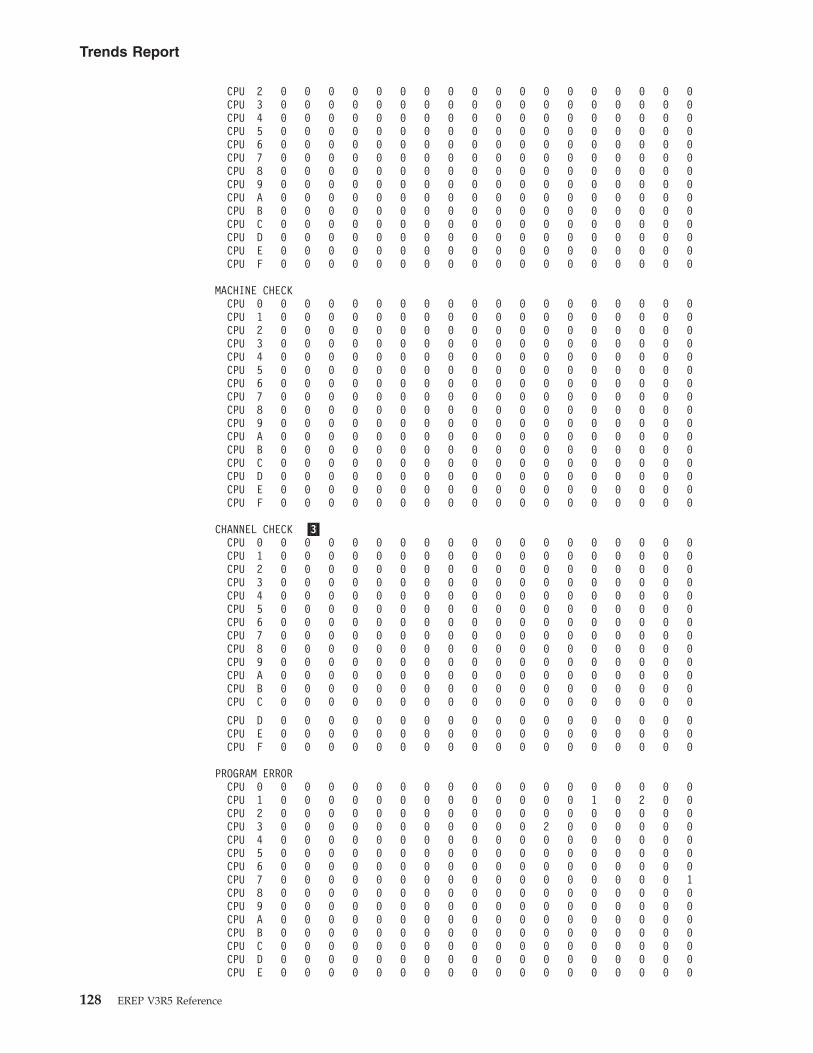
CPU 2 0 0 0 0 0 0 0 0 0 0 0 0 0 0 0 0 0 0CPU 3 0 0 0 0 0 0 0 0 0 0 0 0 0 0 0 0 0 0CPU 4 0 0 0 0 0 0 0 0 0 0 0 0 0 0 0 0 0 0CPU 5 0 0 0 0 0 0 0 0 0 0 0 0 0 0 0 0 0 0CPU 6 0 0 0 0 0 0 0 0 0 0 0 0 0 0 0 0 0 0CPU 7 0 0 0 0 0 0 0 0 0 0 0 0 0 0 0 0 0 0CPU 8 0 0 0 0 0 0 0 0 0 0 0 0 0 0 0 0 0 0CPU 9 0 0 0 0 0 0 0 0 0 0 0 0 0 0 0 0 0 0CPU A 0 0 0 0 0 0 0 0 0 0 0 0 0 0 0 0 0 0CPU B 0 0 0 0 0 0 0 0 0 0 0 0 0 0 0 0 0 0CPU C 0 0 0 0 0 0 0 0 0 0 0 0 0 0 0 0 0 0CPU D 0 0 0 0 0 0 0 0 0 0 0 0 0 0 0 0 0 0CPU E 0 0 0 0 0 0 0 0 0 0 0 0 0 0 0 0 0 0CPU F 0 0 0 0 0 0 0 0 0 0 0 0 0 0 0 0 0 0
MACHINE CHECKCPU 0 0 0 0 0 0 0 0 0 0 0 0 0 0 0 0 0 0 0CPU 1 0 0 0 0 0 0 0 0 0 0 0 0 0 0 0 0 0 0CPU 2 0 0 0 0 0 0 0 0 0 0 0 0 0 0 0 0 0 0CPU 3 0 0 0 0 0 0 0 0 0 0 0 0 0 0 0 0 0 0CPU 4 0 0 0 0 0 0 0 0 0 0 0 0 0 0 0 0 0 0CPU 5 0 0 0 0 0 0 0 0 0 0 0 0 0 0 0 0 0 0CPU 6 0 0 0 0 0 0 0 0 0 0 0 0 0 0 0 0 0 0CPU 7 0 0 0 0 0 0 0 0 0 0 0 0 0 0 0 0 0 0CPU 8 0 0 0 0 0 0 0 0 0 0 0 0 0 0 0 0 0 0CPU 9 0 0 0 0 0 0 0 0 0 0 0 0 0 0 0 0 0 0CPU A 0 0 0 0 0 0 0 0 0 0 0 0 0 0 0 0 0 0CPU B 0 0 0 0 0 0 0 0 0 0 0 0 0 0 0 0 0 0CPU C 0 0 0 0 0 0 0 0 0 0 0 0 0 0 0 0 0 0CPU D 0 0 0 0 0 0 0 0 0 0 0 0 0 0 0 0 0 0CPU E 0 0 0 0 0 0 0 0 0 0 0 0 0 0 0 0 0 0CPU F 0 0 0 0 0 0 0 0 0 0 0 0 0 0 0 0 0 0
CHANNEL CHECK �3�CPU 0 0 0 0 0 0 0 0 0 0 0 0 0 0 0 0 0 0 0CPU 1 0 0 0 0 0 0 0 0 0 0 0 0 0 0 0 0 0 0CPU 2 0 0 0 0 0 0 0 0 0 0 0 0 0 0 0 0 0 0CPU 3 0 0 0 0 0 0 0 0 0 0 0 0 0 0 0 0 0 0CPU 4 0 0 0 0 0 0 0 0 0 0 0 0 0 0 0 0 0 0CPU 5 0 0 0 0 0 0 0 0 0 0 0 0 0 0 0 0 0 0CPU 6 0 0 0 0 0 0 0 0 0 0 0 0 0 0 0 0 0 0CPU 7 0 0 0 0 0 0 0 0 0 0 0 0 0 0 0 0 0 0CPU 8 0 0 0 0 0 0 0 0 0 0 0 0 0 0 0 0 0 0CPU 9 0 0 0 0 0 0 0 0 0 0 0 0 0 0 0 0 0 0CPU A 0 0 0 0 0 0 0 0 0 0 0 0 0 0 0 0 0 0CPU B 0 0 0 0 0 0 0 0 0 0 0 0 0 0 0 0 0 0CPU C 0 0 0 0 0 0 0 0 0 0 0 0 0 0 0 0 0 0
CPU D 0 0 0 0 0 0 0 0 0 0 0 0 0 0 0 0 0 0CPU E 0 0 0 0 0 0 0 0 0 0 0 0 0 0 0 0 0 0CPU F 0 0 0 0 0 0 0 0 0 0 0 0 0 0 0 0 0 0
PROGRAM ERRORCPU 0 0 0 0 0 0 0 0 0 0 0 0 0 0 0 0 0 0 0CPU 1 0 0 0 0 0 0 0 0 0 0 0 0 0 1 0 2 0 0CPU 2 0 0 0 0 0 0 0 0 0 0 0 0 0 0 0 0 0 0CPU 3 0 0 0 0 0 0 0 0 0 0 0 2 0 0 0 0 0 0CPU 4 0 0 0 0 0 0 0 0 0 0 0 0 0 0 0 0 0 0CPU 5 0 0 0 0 0 0 0 0 0 0 0 0 0 0 0 0 0 0CPU 6 0 0 0 0 0 0 0 0 0 0 0 0 0 0 0 0 0 0CPU 7 0 0 0 0 0 0 0 0 0 0 0 0 0 0 0 0 0 1CPU 8 0 0 0 0 0 0 0 0 0 0 0 0 0 0 0 0 0 0CPU 9 0 0 0 0 0 0 0 0 0 0 0 0 0 0 0 0 0 0CPU A 0 0 0 0 0 0 0 0 0 0 0 0 0 0 0 0 0 0CPU B 0 0 0 0 0 0 0 0 0 0 0 0 0 0 0 0 0 0CPU C 0 0 0 0 0 0 0 0 0 0 0 0 0 0 0 0 0 0CPU D 0 0 0 0 0 0 0 0 0 0 0 0 0 0 0 0 0 0CPU E 0 0 0 0 0 0 0 0 0 0 0 0 0 0 0 0 0 0
Trends Report
128 EREP V3R5 Reference

CPU F 0 0 0 0 0 0 0 0 0 0 0 0 0 0 0 0 0 0
CPU MODEL SERIAL NO. �4�
0 3090XA 6543211 3090XA 1700282 3084XA 3211283 3084XA 2211284 3084XA 1211285 3081XA 2211706 3084XA 1211287 3084XA 0211038 3081 2203449 3081XA 020447A 3081XA 020344B 3081 020063C 3033 021929D 3033 021928E 3033 020808F 0168 099111
�5�T R E N D S R E P O R T REPORT DATE 071 97
(PART 1) PERIOD FROM 041 97SUBCHANNEL/CHANNEL TO 058 97
JULIAN 97DAY 41 42 43 44 45 46 47 48 49 50 51 52 53 54 55 56 57 58
SUBCHANNEL
CPU 0
NO ERRORS FOR THIS CPU
CPU 1
NO ERRORS FOR THIS CPU
CPU 2
NO ERRORS FOR THIS CPU
CPU 3
NO ERRORS FOR THIS CPU
CPU 4
NO ERRORS FOR THIS CPU
CPU 5
NO ERRORS FOR THIS CPU
CPU 6
CHPID 15 0 0 0 0 0 0 0 0 0 0 0 0 0 0 0 0 0 0
CPU 7
NO ERRORS FOR THIS CPU
CPU 8
NO ERRORS FOR THIS CPU
CPU 9
Trends Report
Chapter 9. Trends Report 129

NO ERRORS FOR THIS CPU
CPU A
NO ERRORS FOR THIS CPU
CPU B
NO ERRORS FOR THIS CPU
CHANNEL REPORT WORDCPU 0
HARDWARE 0 0 0 0 0 0 0 0 0 0 0 0 0 0 0 0 0 0SOFTWARE 0 0 0 0 0 0 0 0 0 0 0 0 0 0 0 0 0 0
CPU 1
HARDWARE 0 0 0 0 0 0 0 0 0 0 0 0 0 0 0 0 0 0SOFTWARE 0 0 0 0 0 0 0 0 0 0 0 0 0 0 0 0 0 0
CPU 2
HARDWARE 0 0 0 0 0 0 0 0 0 0 0 0 0 0 0 0 0 0SOFTWARE 0 0 0 0 0 0 0 0 0 0 0 0 0 0 0 0 0 0
CPU 3
HARDWARE 0 0 0 0 0 0 0 0 0 0 0 0 0 0 0 0 0 0SOFTWARE 0 0 0 0 0 0 0 0 0 0 0 0 0 0 0 0 0 0
CPU 4
HARDWARE 0 0 0 0 0 0 0 0 0 0 0 0 0 0 0 0 0 0SOFTWARE 0 0 0 0 0 0 0 0 0 0 0 0 0 0 0 0 0 0
CPU 5
HARDWARE 0 0 0 0 0 0 0 0 0 0 0 0 0 0 0 0 0 0SOFTWARE 0 0 0 0 0 0 0 0 0 0 0 0 0 0 0 0 0 0
CPU 6
HARDWARE 0 0 0 0 0 0 0 0 0 0 0 0 0 0 0 0 0 0SOFTWARE 0 0 0 0 0 0 0 0 0 0 0 0 0 0 0 0 0 0
CPU 7
HARDWARE 0 0 0 0 0 0 0 0 0 0 0 0 0 0 0 0 0 0SOFTWARE 0 0 0 0 0 0 0 0 0 0 0 0 0 0 0 0 0 0
CPU 8
HARDWARE 0 0 0 0 0 0 0 0 0 0 0 0 0 0 0 0 0 0SOFTWARE 0 0 0 0 0 0 0 0 0 0 0 0 0 0 0 0 0 0
CPU 9
HARDWARE 0 0 0 0 0 0 0 0 0 0 0 0 0 0 0 0 0 0SOFTWARE 0 0 0 0 0 0 0 0 0 0 0 0 0 0 0 0 0 0
CPU A
HARDWARE 0 0 0 0 0 0 0 0 0 0 0 0 0 0 0 0 0 0SOFTWARE 0 0 0 0 0 0 0 0 0 0 0 0 0 0 0 0 0 0
CPU B
HARDWARE 0 0 0 0 0 0 0 0 0 0 0 0 0 0 0 0 0 0SOFTWARE 0 0 0 0 0 0 0 0 0 0 0 0 0 0 0 0 0 0
CPU C
HARDWARE 0 0 0 0 0 0 0 0 0 0 0 0 0 0 0 0 0 0SOFTWARE 0 0 0 0 0 0 0 0 0 0 0 0 0 0 0 0 0 0
CPU D
HARDWARE 0 0 0 0 0 0 0 0 0 0 0 0 0 0 0 0 0 0SOFTWARE 0 0 0 0 0 0 0 0 0 0 0 0 0 0 0 0 0 0
Trends Report
130 EREP V3R5 Reference
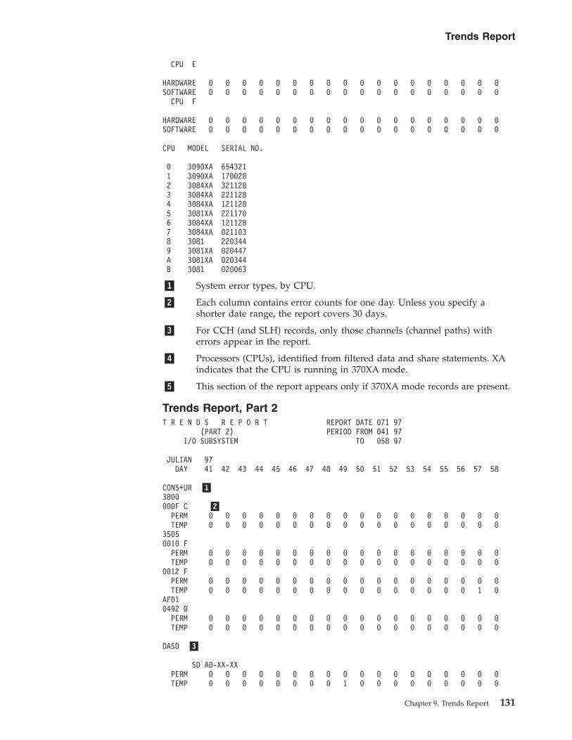
CPU E
HARDWARE 0 0 0 0 0 0 0 0 0 0 0 0 0 0 0 0 0 0SOFTWARE 0 0 0 0 0 0 0 0 0 0 0 0 0 0 0 0 0 0
CPU F
HARDWARE 0 0 0 0 0 0 0 0 0 0 0 0 0 0 0 0 0 0SOFTWARE 0 0 0 0 0 0 0 0 0 0 0 0 0 0 0 0 0 0
CPU MODEL SERIAL NO.
0 3090XA 6543211 3090XA 1700282 3084XA 3211283 3084XA 2211284 3084XA 1211285 3081XA 2211706 3084XA 1211287 3084XA 0211038 3081 2203449 3081XA 020447A 3081XA 020344B 3081 020063
�1� System error types, by CPU.
�2� Each column contains error counts for one day. Unless you specify ashorter date range, the report covers 30 days.
�3� For CCH (and SLH) records, only those channels (channel paths) witherrors appear in the report.
�4� Processors (CPUs), identified from filtered data and share statements. XAindicates that the CPU is running in 370XA mode.
�5� This section of the report appears only if 370XA mode records are present.
Trends Report, Part 2T R E N D S R E P O R T REPORT DATE 071 97
(PART 2) PERIOD FROM 041 97I/O SUBSYSTEM TO 058 97
JULIAN 97DAY 41 42 43 44 45 46 47 48 49 50 51 52 53 54 55 56 57 58
CONS+UR �1�3800000F C �2�
PERM 0 0 0 0 0 0 0 0 0 0 0 0 0 0 0 0 0 0TEMP 0 0 0 0 0 0 0 0 0 0 0 0 0 0 0 0 0 0
35050010 F
PERM 0 0 0 0 0 0 0 0 0 0 0 0 0 0 0 0 0 0TEMP 0 0 0 0 0 0 0 0 0 0 0 0 0 0 0 0 0 0
0012 FPERM 0 0 0 0 0 0 0 0 0 0 0 0 0 0 0 0 0 0TEMP 0 0 0 0 0 0 0 0 0 0 0 0 0 0 0 0 1 0
AF010492 0
PERM 0 0 0 0 0 0 0 0 0 0 0 0 0 0 0 0 0 0TEMP 0 0 0 0 0 0 0 0 0 0 0 0 0 0 0 0 0 0
DASD �3�
SD A0-XX-XXPERM 0 0 0 0 0 0 0 0 0 0 0 0 0 0 0 0 0 0TEMP 0 0 0 0 0 0 0 0 1 0 0 0 0 0 0 0 0 0
Trends Report
Chapter 9. Trends Report 131

DEVICE FF.X-16PERM 0 0 0 0 0 0 4 0 0 0 0 0 0 0 0 0 0 0TEMP 0 0 0 0 0 0 0 0 0 0 0 0 0 0 0 0 0 0DEVICE FF.X-17PERM 2 0 0 0 0 0 0 0 0 0 0 0 0 0 0 0 0 0TEMP 0 0 0 0 0 0 0 0 0 0 0 0 0 0 0 0 0 0CNTRL XX-0D-XXPERM 0 0 0 0 0 0 0 0 0 0 0 0 0 0 0 0 0 0TEMP 0 0 0 0 0 0 0 0 1 0 0 0 0 0 0 0 0 0DEVICE 01.X-11PERM 0 0 0 0 0 0 0 0 0 0 0 0 0 0 0 0 0 0TEMP 1 0 0 0 0 0 0 0 0 0 0 0 0 0 0 0 0 0DEVICE SD.02PERM 0 0 0 0 0 0 0 0 0 0 0 0 0 0 0 0 0 0TEMP 0 0 0 0 0 4 0 0 0 0 0 0 0 0 0 0 0 0
SD 10114PERM 0 0 0 0 0 0 0 0 0 0 0 0 0 0 0 0 0 0TEMP 0 0 0 2 0 0 0 0 0 0 0 0 0 0 0 0 0 0
TAPE3400 �4�0180 2
PERM 0 0 0 0 0 0 0 0 0 0 0 0 0 1 0 0 0 0TEMP 0 0 0 0 0 0 0 0 0 0 0 0 0 0 0 0 0 4
0181 2 �5�PERM 0 0 0 0 0 0 0 0 0 0 0 0 0 0 1 0 0 0TEMP 0 0 0 0 0 0 0 0 0 0 0 0 0 0 0 0 0 0
3480018B 1
PERM 0 0 0 0 0 0 0 0 0 0 0 0 0 0 0 0 0 0TEMP 0 0 0 0 0 0 0 0 0 0 0 0 0 0 0 0 0 0
340001A0 2
PERM 0 0 0 0 0 0 0 0 0 0 0 0 0 0 0 0 0 0TEMP 0 0 0 0 0 0 0 0 0 0 0 0 0 0 0 0 0 5
348001B2 1
PERM 0 0 0 0 0 0 0 0 0 0 0 0 0 0 0 0 0 2TEMP 0 0 0 0 0 0 0 0 0 0 0 0 0 0 0 0 0 0
02B2 1PERM 0 0 0 0 0 0 0 0 0 0 0 0 0 0 0 0 0 1TEMP 0 0 0 0 0 0 0 0 0 0 0 0 0 0 0 0 0 0
0453 9PERM 0 0 0 0 0 0 0 0 0 0 0 0 2 0 0 0 0 3TEMP 0 0 0 0 0 0 0 0 0 0 0 0 0 0 0 0 0 0
88090BA1 D
PERM 0 0 0 0 0 0 0 0 0 0 0 0 0 0 0 0 0 0TEMP 0 0 0 0 0 0 0 0 0 0 0 0 0 0 0 280 0 0
T R E N D S R E P O R T REPORT DATE 071 97(PART 2) PERIOD FROM 041 97
I/O SUBSYSTEM TO 058 97
JULIAN 97DAY 41 42 43 44 45 46 47 48 49 50 51 52 53 54 55 56 57 58
TP CNTRL370500FE C
CNTRLRPERM 0 0 0 0 0 0 0 0 0 0 0 0 0 0 0 0 0 0TEMP 0 0 0 0 0 0 0 0 0 0 0 1 0 0 0 0 0 0
0120 FLINESPERM 0 0 0 0 0 0 0 0 0 0 0 1 1 0 0 0 0 0TEMP 0 0 0 0 0 0 0 0 0 0 0 0 0 0 0 0 0 0
0581 F
Trends Report
132 EREP V3R5 Reference

LINESPERM 0 0 0 0 0 0 0 0 0 0 0 0 1 0 0 0 0 0TEMP 0 0 0 0 0 0 0 0 0 0 0 0 999 0 0 0 0 0
06FF CCNTRLRPERM 0 0 0 0 0 0 0 0 0 0 0 0 0 0 0 0 0 0TEMP 0 0 0 0 0 0 0 0 0 0 0 0 0 0 0 0 0 0
OTHERDPA0453 9
PERM 0 0 0 0 0 0 0 0 0 0 0 0 2 0 0 0 0 3TEMP 0 0 0 0 0 0 0 0 0 0 0 0 0 0 0 0 0 0
0A82 1PERM 0 0 0 0 0 2 0 0 0 0 0 0 0 0 0 0 0 0TEMP 0 0 0 0 0 0 0 0 0 0 0 0 0 0 0 0 0 0
CPU MODEL SERIAL NO. �6�
0 3090XA 6543211 3090XA 1700282 3084XA 3211283 3084XA 2211284 3084XA 1211285 3081XA 2211706 3084XA 1211287 3084XA 0211038 3081 2203449 3081XA 020447
�1� Device group.
�2� Each column represents one day. A field of all 9s indicates that this numberis larger than the print positions allowed.
�3� DASD with physical IDs (or serial numbers) list the DASD by the physicalidentifier. See “DASDID Control Statement” on page 58 for an explanationof DASD physical identifiers.
�4� Device type.
�5� CPU-CUA (or device number) path.
�6� Processors (CPUs), identified from filtered data and share statements. XAindicates that the CPU is running in 370XA mode.
Trends Report
Chapter 9. Trends Report 133

Trends Report
134 EREP V3R5 Reference
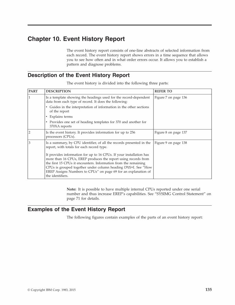
Chapter 10. Event History Report
The event history report consists of one-line abstracts of selected information fromeach record. The event history report shows errors in a time sequence that allowsyou to see how often and in what order errors occur. It allows you to establish apattern and diagnose problems.
Description of the Event History ReportThe event history is divided into the following three parts:
PART DESCRIPTION REFER TO
1 Is a template showing the headings used for the record-dependentdata from each type of record. It does the following:
v Guides in the interpretation of information in the other sectionsof the report
v Explains terms
v Provides one set of heading templates for 370 and another for370XA reports
Figure 7 on page 136
2 Is the event history. It provides information for up to 256processors (CPUs).
Figure 8 on page 137
3 Is a summary, by CPU identifier, of all the records presented in thereport, with totals for each record type.
It provides information for up to 16 CPUs. If your installation hasmore than 16 CPUs, EREP produces the report using records fromthe first 15 CPUs it encounters. Information from the remainingCPUs is grouped together under column heading CPUS>E. See “HowEREP Assigns Numbers to CPUs” on page 69 for an explanation ofthe identifiers.
Figure 9 on page 138
Note: It is possible to have multiple internal CPUs reported under one serialnumber and thus increase EREP’s capabilities. See “SYSIMG Control Statement” onpage 71 for details.
Examples of the Event History ReportThe following figures contain examples of the parts of an event history report:
© Copyright IBM Corp. 1983, 2015 135

EVENT HISTORY TEMPLATE (S/370)
FOR RECORD TYPES: RECORD DEPENDENT DATA
MCH: PSW-MCH /PROG-EC ERROR-ID
CCH: CUA DEVT CSW
OBR: CUA DEVT CMD CSW
MDR: CUA DEVT VOLUME/TERM NAME
MIH: CUA DEVT SCUA CSID VOLUME/TERM NAME
DDR: CUA DEVT VOLUME/TERM NAME
OBRDMT, OBREOD: CUA DEVT VOLUME/TERM NAME
OBRPRM, OBRTMP, OBRPTH: CUA DEVT CMD CSW SENSE 04 06 08 10 12 14 16 18 20 22 VOLUME SEEK SD CT
OBRDPA: CUA DEVT CMD CSW SPID SNID
SFTLST: REASON PSW-MCH /PROG-EC RCYRYXIT COMP/MOD CSECTID ERROR-ID
IPL: SSYS ID REASON
MDRDAS: CUA DEVT SENSE 04 06 08 10 12 14 16 18 20 22 VOLUME SD CT
OTHER: ONLY COMMON PREFIX DATA APPLIES FOR ALL OTHER RECORD TYPESCOMMON PREFIX: (FOR ALL RECORD TYPES)
TIME JOBNAME RECTYP CP
EVENT HISTORY TEMPLATE (S/370XA)
FOR RECORD TYPES: RECORD DEPENDENT DATA
MCH: PSW-MCH /PROG-EC ERROR-ID
SLH: DNO DEVT CHP SCSW ESW
CRW: DNO CRW
OBR: DNO DEVT CMD SCSW
MDR: DNO DEVT CHP VOLUME/TERM NAME
MIH: DNO DEVT CHP REASON CSID VOLUME/TERM NAME
DDR: DNO DEVT VOLUME/TERM NAME
OBRDMT, OBREOD: DNO DEVT CHP VOLUME/TERM NAME
OBRPRM, OBRTMP, OBRPTH: DNO DEVT CHP CMD SCSW SENSE 04 06 08 10 12 14 16 18 20 22 VOLUME SEEK SD CT
OBRDPA: DNO DEVT CHP CMD SCSW SPID SNID
SFTLST: REASON PSW-MCH /PROG-EC RCYRYXIT COMP/MOD CSECTID ERROR-ID
IPL: SSYS ID REASON
MDRDAS: DNO DEVT CHP SENSE 04 06 08 10 12 14 16 18 20 22 VOLUME SD CT
OTHER: ONLY COMMON PREFIX DATA APPLIES FOR ALL OTHER RECORD TYPESCOMMON PREFIX: (FOR ALL RECORD TYPES)
TIME JOBNAME RECTYP CP
Figure 7. Event History Template
Event History Report
136 EREP V3R5 Reference

�1� The header is written for 24 bytes of sense data, but is also used for 32byte sense data. When you have 32 bytes of sense data, VOLUME and SEEKinformation do not appear on the report. Sense data for bytes 25 through32 is shown instead.
�2� The DASD cylinder head or block number is listed under SEEK. The storagedirector/controller physical ID for DASD is listed under SD CT.
�3� The hexadecimal identifiers are internal to the event history report andshould not be confused with external CPU machine identifiers. The firstoccurring serial number is assigned X'00'. The external CPU models andserial numbers associated with the hexadecimal identifiers are shown atthe end of the report summary. (See in Figure 9 on page 138.)
NOTE: 3590/3490EMU and 3591/3490EMU device records will print onthe EVENT report under their native device type only. They will notappear under the device being emulated. Also, OBR records that arehandled as SIM or MIM records in the SYSEXN reports will be shown asOBR records on the EVENT report.
EVENT HISTORY (S/370 & S/370XA) REPORT DATE 046 97PERIOD FROM 041 97
�1� PERIOD TO 043 97
SPID SNIDSSYS ID REASON PSW-MCH /PROG-EC RCYRYXIT COMP/MOD CSECTID ERROR-ID �2�
TIME JOBNAME RECTYP CP CUA DEVT CMD CSW SENSE 04 06 08 10 12 14 16 18 20 22 VOLUME SEEK SD CT* DNO CRW CHP SCSW ESW�3�
DATE 041 97
04 11 37 21 N/A OBREOD 12 03E2 3284 NA06 54 49 45 N/A ASYNCH 02 0883 3590B11 JANZ01 024098C0 1102F071 33010057 00211229 D1C1D5E9 F0F10089 48042300 0001101009 26 32 65 N/A ASYNCH 02 0887 3590A00 024098C0 1101F171 11910000 00730000 D1C1D5E9 F0F40081 28042300 5BA0101011 33 17 21 N/A MDR 0B 0905 3995 0012 41 13 30 N/A IPL 0E 00 DF12 41 17 92 SFTLST 0E LOST RECORD SUMMARY - COUNT= 10 N/A14 30 22 51 *MASTER* SFTMCH 0C 900F3000 040C00008105E932 IEAVEDSR IEAVEDS0 IEAVEDS0 0019004100010007F7EE
DATE 042 97
00 20 32 34 N/A MCH 09 070E000000000000 3D8F000000000000000002 31 48 38 PACAH210 OBRTMP 11 0239 3390 07 0200 10000600 3932C143 00030000 01050404 22101842 11440C01 00000F01 0C000000 AH21004 12 59 12 VARY OBRDPA 0F 0A82 3380 40 AF 2210 000002112830849718 CEF0 000000000000000000000008 59 03 32 *MASTER* CCH 0D 0063 3277 0100000000020080 CSID=00,0009 29 08 68 *MASTER* OBRTMP 02 0880 3590 1C 04 0200 004A8C5A 80100050 0004FF00 00000000 00000000 00000088 20042300 0001101012 07 30 59 MCH 05 070E000000000000 N/A14 27 10 15 N/A MDR 0B 0884 3590 2920 10 52 49 T2SRTMRG OBR 03 04BC 3490 16 02 0400 T2SRT120 32 10 71 DDR 0A 0580 3400 TO 0581 3400 F2201122 02 80 01 N/A MDRDAS 10 030F 3390 03 00000600 0F32C000 FFFF0422 795AF780 00050410 02436F01 04100000 035BDA45 HHGK6
DATE 043 97
00 12 34 01 N/A LINK 08 TYP-MOD S/N INTERF: INC=3090-60J IBM 00 70039 0073 ATT=9032-002 IBM 02 10148 00DF IC=03 DCI=N/A01 08 12 32 SYSTEM MIHCE 00 0C40 9332 C40 CHANNEL END VMRESA06 54 28 40 CHNDRV SLH 0C 01D0 3380 12 840240170032F0F800040000 0080748210 03 14 36 N/A CLOCK 02 NETWORK ID = 1, RC = 0, NO PROBLEMS REPORTED BY 903710 26 24 90 EREPHIST MIH 06 03B2 3380 NA START PENDING CATLOG12 36 03 09 N/A EOD 0715 39 44 04 N/A ASYNCH 04 0350 3390-09 PACSM3 00900600 10328FC2 11010124 00000304 22204411 004143C0 05108202 FF003B0C B742517 08 15 64 ILVRAS04 CRW 01 0000 0903001E HARDWARE GENERATED21 06 44 42 *MASTER* OBR 0B 08AB 3590 29 03 060022 12 09 01 *MASTER* MIH 09 08A9 3590 NA START PENDING
Figure 8. Event History Report
Event History Report
Chapter 10. Event History Report 137

�1�RECORD TYPES TOTAL CPU-0 CPU-1 CPU-2 CPU-3 CPU-4 CPU-5 CP U-6 CPU-7 CPU-8 CPU-9 CPU-A CPU-B CPU-C CPU-D CPU-E CPUS>E
MCH 2 0 0 0 0 0 1 0 0 0 1 0 0 0 0 0 0MACHINE CHECK 2 0 0 0 0 0 1 0 0 0 1 0 0 0 0 0 0
OBREOD 1 0 0 0 0 0 0 0 0 0 0 0 0 0 0 0 1OBRTMP 2 0 1 0 0 0 0 0 0 0 0 0 0 0 0 0 1OBRDPA 1 0 0 0 0 0 0 0 0 0 0 0 0 0 0 0 1OBR 2 0 1 0 1 0 0 0 0 0 0 0 0 0 0 0 0
OUTBOARD 4 0 0 0 1 0 0 0 0 0 0 0 0 0 0 0 3
SFTLST 1 0 0 0 0 0 0 0 0 0 0 0 0 0 0 1 0SFTMCH 1 0 0 0 0 0 0 0 0 0 0 0 0 1 0 0 0
SOFTWARE 2 0 0 0 0 0 0 0 0 0 0 0 0 1 0 1 0
IPL 1 0 0 0 0 0 0 0 0 0 0 0 0 0 0 1 0SYSTEM INITIALIZATION 1 0 0 0 0 0 0 0 0 0 0 0 0 0 0 1 0
DDR 1 0 0 0 0 0 0 0 0 0 0 1 0 0 0 0 0SYSTEM RECONFIGURATION 1 0 0 0 0 0 0 0 0 0 0 1 0 0 0 0 0
EOD 1 0 0 0 0 0 0 0 1 0 0 0 0 0 0 0 0SYSTEM TERMINATION 1 0 0 0 0 0 0 0 1 0 0 0 0 0 0 0 0
MDRDAS 1 0 0 0 0 0 0 0 0 0 0 0 0 0 0 0 1MDR 2 0 1 0 0 0 0 0 0 0 0 0 1 0 0 0 0
BUFFER OFFLOAD 2 0 0 0 0 0 0 0 0 0 0 0 1 0 0 0 1
CCH 1 0 0 0 0 0 0 0 0 0 0 0 0 0 1 0 0CHANNEL CHECK 1 0 0 0 0 0 0 0 0 0 0 0 0 0 1 0 0
CHANNEL END 1 1 0 0 0 0 0 0 0 0 0 0 0 0 0 0 0MISSING INTERRUPT 370 1 1 0 0 0 0 0 0 0 0 0 0 0 0 0 0 0
RECORD TYPES TOTAL CPU-0 CPU-1 CPU-2 CPU-3 CPU-4 CPU-5 CP U-6 CPU-7 CPU-8 CPU-9 CPU-A CPU-B CPU-C CPU-D CPU-E CPUS>E
START PENDING 2 0 1 0 0 0 0 1 0 0 0 0 0 0 0 0 0MISSING INTERRUPT XA�2� 2 0 1 0 0 0 0 1 0 0 0 0 0 0 0 0
0
HARDWARE 1 0 1 0 0 0 0 0 0 0 0 0 0 0 0 0 0SOFTWARE 0 0 0 0 0 0 0 0 0 0 0 0 0 0 0 0 0
CHANNEL REPORTS 1 0 1 0 0 0 0 0 0 0 0 0 0 0 0 0 0
LINK 1 0 0 0 0 0 0 0 0 1 0 0 0 0 0 0 0CLOCK 1 0 0 1 0 0 0 0 0 0 0 0 0 0 0 0 0ASYNCH 2 0 1 0 0 1 0 0 0 0 0 0 0 0 0 0 0
AX RECORD TYPES 3 0 0 1 0 1 0 0 0 1 0 0 0 0 0 0 0
BX RECORD TYPES 0 0 0 0 0 0 0 0 0 0 0 0 0 0 0 0 0
CX RECORD TYPES 0 0 0 0 0 0 0 0 0 0 0 0 0 0 0 0 0
DX RECORD TYPES 0 0 0 0 0 0 0 0 0 0 0 0 0 0 0 0 0
EX RECORD TYPES 0 0 0 0 0 0 0 0 0 0 0 0 0 0 0 0 0
FX RECORD TYPES 0 0 0 0 0 0 0 0 0 0 0 0 0 0 0 0 0
RECORD TYPES TOTAL CPU-0 CPU-1 CPU-2 CPU-3 CPU-4 CPU-5 CP U-6 CPU-7 CPU-8 CPU-9 CPU-A CPU-B CPU-C CPU-D CPU-E CPUS>E
CHPID-12 1 0 0 0 0 0 0 0 0 0 0 0 0 1 0 0 0SUBCHANNEL LOGOUTS 1 0 0 0 0 0 0 0 0 0 0 0 0 1 0 0 0�3�OVER ALL TOTALS 21 1 1 1 1 1 1 1 1 1 1 1 1 2 1 2 4
�4� �5�CPU MODEL SERIAL00 2097XA 0E06C001 2097XA 0C06C002 2097XA 0A06C003 2097XA 0906C004 2097XA 0806C005 2097XA 0106C006 2094XA 096DD207 2094XA 076DD208 2094XA 066DD209 2094XA 046DD20A 2094XA 036DD20B 2094XA 026DD20C 2094XA 016DC20D 2086XA 06AD2C0E 2086XA 05AD2C0F 2086XA 04AD2C10 2086XA 03AD2C11 2086XA 01AD2C12 2084XA 0356BF
Figure 9. Event History Summary
Event History Report
138 EREP V3R5 Reference
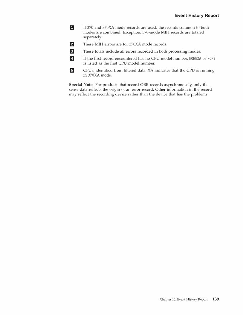
�1� If 370 and 370XA mode records are used, the records common to bothmodes are combined. Exception: 370-mode MIH records are totaledseparately.
�2� These MIH errors are for 370XA mode records.
�3� These totals include all errors recorded in both processing modes.
�4� If the first record encountered has no CPU model number, NONEXA or NONEis listed as the first CPU model number.
�5� CPUs, identified from filtered data. XA indicates that the CPU is runningin 370XA mode.
Special Note: For products that record OBR records asynchronously, only thesense data reflects the origin of an error record. Other information in the recordmay reflect the recording device rather than the device that has the problems.
Event History Report
Chapter 10. Event History Report 139

Event History Report
140 EREP V3R5 Reference

Chapter 11. System Exception Report Series
The system exception series is a series of reports that list software and hardwareerror data in a variety of ways to help you identify problems within yoursubsystems.
© Copyright IBM Corp. 1983, 2015 141

Description of the System Exception SeriesThe system exception report series can contain several separate reports:
REPORT REFER TO
A two-part system error summary “Examples of the System ErrorSummary” on page 143
A subsystem exception report series “Examples of the SubsystemException Report Series” onpage 149
Note:
1. EREP accumulates error data and usage statistics on subsystem componentsthen summarizes the information by component for the subsystem exceptionreports.
2. These reports are produced for some hardware subsystems, but not all of them.To find which subsystems generate system exception reports see Part 3,“Product-Dependent Information,” on page 327.
142 EREP V3R5 Reference
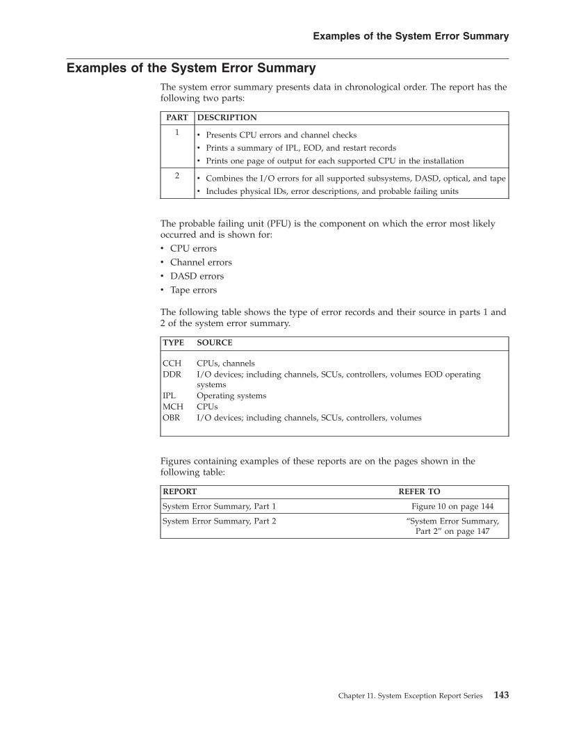
Examples of the System Error SummaryThe system error summary presents data in chronological order. The report has thefollowing two parts:
PART DESCRIPTION
1 v Presents CPU errors and channel checks
v Prints a summary of IPL, EOD, and restart records
v Prints one page of output for each supported CPU in the installation
2 v Combines the I/O errors for all supported subsystems, DASD, optical, and tape
v Includes physical IDs, error descriptions, and probable failing units
The probable failing unit (PFU) is the component on which the error most likelyoccurred and is shown for:v CPU errorsv Channel errorsv DASD errorsv Tape errors
The following table shows the type of error records and their source in parts 1 and2 of the system error summary.
TYPE SOURCE
CCH CPUs, channelsDDR I/O devices; including channels, SCUs, controllers, volumes EOD operating
systemsIPL Operating systemsMCH CPUsOBR I/O devices; including channels, SCUs, controllers, volumes
Figures containing examples of these reports are on the pages shown in thefollowing table:
REPORT REFER TO
System Error Summary, Part 1 Figure 10 on page 144
System Error Summary, Part 2 “System Error Summary,Part 2” on page 147
Examples of the System Error Summary
Chapter 11. System Exception Report Series 143

System Error Summary, Part 1Part 1 of the system error summary is a chronological listing of all machine checksand channel checks. IPL, restart (software), and termination records are includedfor MVS and VSE/Advanced Function operating systems.
Figure 10 shows an example of part 1 of the system error summary report.
�1� The report is generated by CPU. This line contains the CPU model number,serial number, and a CPU indicator that corresponds to the CPU indicatorsused throughout the system exception reports.
�2� This section presents records of system events. It appears only when theoperating system is MVS or VSE/Advanced Function. The column headed
SYSTEM ERROR SUMMARY REPORT DATE 065 97(PART 1) PERIOD FROM 041 97
TO 059 97
MODEL 3033 SERIAL 020557 CPU 01 �1�
IPL/RESTART/TERMINATION �2�
RECORD TIME SINCETIME TYPE LAST ACTIVE REASON PROBABLE CAUSE
DATE 042/9708:01:30:95 IPL 09:01:29:56 NM NORMAL SYSTEM INITIALIZATION15:23:09:29 TERM MCH FORCED TERMINATION15:26:30:76 IPL 00:02:29:56 NM NORMAL SYSTEM INITIALIZATION19:15:56:22 RESTART NM RESTART ABEND CODE 071
PROCESSOR CHECKS �3�PROBABLE
TIME JOBNAME CUA/TYPE ERROR DESCRIPTION FAILING UNIT
DATE 042/9708:40:55:52 N/A N/A BUFFER ERROR PROCESSOR12:07:30:41 N/A N/A SYSTEM DAMAGE PROCESSOR15:23:03:72 N/A N/A REGISTER/PSW INVALID PROCESSOR
CHANNEL CHECKS �4�PROBABLE
TIME JOBNAME CUA/TYPE ERROR DESCRIPTION FAILING UNIT
DATE 042/9710:39:11:04 PAYROLL1 0384/3330 CHANNEL CONTROL CHECK CHANNEL13:11:18:64 JOBLOADA 0233/3380 INTERFACE CONTROL CHECK CONTROL UNIT***** 2 DUPLICATE LINES WITHIN THIS TIME INTERVAL HAVE NOT BEEN PRINTED �5�13:14:33:09 JOBLOADA 0233/3380 INTERFACE CONTROL CHECK CONTROL UNIT
SYSTEM ERROR SUMMARY REPORT DATE 065 97(PART 1) PERIOD FROM 041 97
TO 059 97
MODEL 2097XA SERIAL 0706C0 CPU 04
IPL/RESTART/TERMINATION
RECORD TIME SINCETIME TYPE LAST ACTIVE REASON PROBABLE CAUSE
DATE 042/9708:30:06:49 TERM-XA EOD NORMAL END OF DAY PROCESSING
DATE 043/9705:03:54:33 TERM-XA EOD NORMAL END OF DAY PROCESSING
DATE 049/9711:10:00:07 TERM-XA EOD NORMAL END OF DAY PROCESSING22:43:27:00 TERM-XA EOP IOS ERROR
Figure 10. System Error Summary, Part 1
Examples of the System Error Summary
144 EREP V3R5 Reference

by REASON contains the IPL or the restart ABEND reason code. The columnheaded by PROBABLE CAUSE contains an explanation of the code.
Possible termination reason codes are:
REASON PROBABLE CAUSE
EOD END-OF-DAY RECORD
EOP END OF PROCESSING FROM IOS
RESTARTABLE WAIT STATE
DF DEFAULT
MCH MACHINE CHECK FORCED TERMINATION
NONRESTARTABLE
NM NORMAL SYSTEM INITIALIZATION
RESTART ABEND CODE 071
�3� This section appears when EREP encounters MCH records. MCH recordsare error records created when the machine check handler causes aninterrupt as a result of an unsuccessful attempt to retry a failed instruction.
If the JOBNAME field is blank, the failure is within an operating system task.
Possible ERROR DESCRIPTIONS are:BUFFER ERROREXTERNAL DAMAGEHARD STORAGE ERRORHIR SUCCESSFULINSTRUCTION PROCESSORINVALID LOGOUTPOWER WARNINGREGISTER OR PSW INVALIDSTORAGE PROTECT KEY ERRORSYSTEM DAMAGEUNDEFINED ERROR
Possible PROBABLE FAILING UNITS are:CHANNELCHANNEL/DIRECTORCONTROL UNITPROCESSORSTORAGEUNDEFINEDUNPROCESSED ENTRY
�4� This section appears if EREP encounters CCH records. CCH records areerror records created by the channel check handler when a channel erroroccurs.
If the JOBNAME field is blank, the failure is within an operating system task.
Possible ERROR DESCRIPTIONS are:CHANNEL CONTROL CHECKSCHANNEL CONTROL/INTERFACE CONTROL CHECKS
Examples of the System Error Summary
Chapter 11. System Exception Report Series 145
CHANNEL DATA/CHANNEL CONTROL CHECKSCHANNEL DATA/CHANNEL CONTROL/INTERFACE CONTROLCHECKSCHANNEL DATA CHECKSCHANNEL DATA/INTERFACE CONTROL CHECKSINTERFACE CONTROL CHECKS
Possible PROBABLE FAILING UNITS are the same as those shown in �3�.
�5� EREP does not print out duplicates of records occurring together.
Examples of the System Error Summary
146 EREP V3R5 Reference
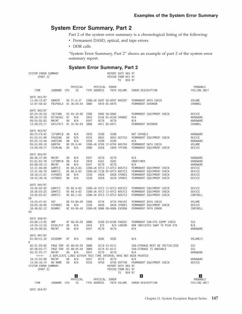
System Error Summary, Part 2Part 2 of the system error summary is a chronological listing of the following:v Permanent DASD, optical, and tape errorsv DDR calls
“System Error Summary, Part 2” shows an example of part 2 of the system errorsummary report.
System Error Summary, Part 2SYSTEM ERROR SUMMARY REPORT DATE 065 97
(PART 2) PERIOD FROM 041 97TO 059 97
PHYSICAL PHYSICAL ERROR PROBABLETIME JOBNAME CPU ID TYPE ADDRESS PATH VOLUME ERROR DESCRIPTION FAILING UNIT
DATE 041/9711:59:12:87 GAM297 05 FF.X-17 3380-JK 0297 02-0297 RAS297 PERMANENT DATA CHECK VOLUME12:07:58:52 P$SPOOL2 01 36-XX-XX 3880 0470 0C-0470 PERMANENT OVERRUN CHANNEL
DATE 042/9702:24:35:55 I$ITA80 03 XX-10-02 3380 0A82 56-0A82 PERMANENT EQUIPMENT CHECK DEVICE09:10:37:29 OCT9USG1 07 N/A 3422 0156 01-0156 340002 N/A HARDWARE09:55:02:83 MAINT 00 N/A 9347 0C70 0C70 N/A HARDWARE13:28:25:71 D#CLP471 01 32-XX-XX 3880 0471 02-0471 PERMANENT OVERRUN CHANNEL
DATE 043/9700:F3:F9:4E ICFSMPLB 08 N/A 3420 0180 0180 NOT CAPABLE HARDWARE01:53:41:99 PAUSEBG 00 N/A 9335 0D53 0D53 KEST53 PERMANENT EQUIPMENT CHECK DEVICE04:22:15:46 SORTCHK 08 N/A 3430 0190 0190 N/A HARDWARE09:53:09:10 GAM704 00 20.X-04 3380-JK 0704 17-0704 RAS704 PERMANENT DATA CHECK VOLUME14:28:49:77 TSIMLRW 04 N/A 3480 03EB EB40 TPF490 PERMANENT EQUIPMENT CHECK DEVICE
DATE 044/9700:46:37:09 MAINT 00 N/A 9347 0C70 0C70 N/A HARDWARE01:01:EE:7B ICFSMPLB 08 N/A 3420 0181 0181 UNDEFINED HARDWARE04:08:28:13 MAINT 00 N/A 9347 0C70 0C70 N/A HARDWARE12:31:46:69 GAM7C3 05 60.X-03 3380-JK 07C3 17-07C3 RAS7C3 PERMANENT EQUIPMENT CHECK DEVICE12:31:46:70 GAM7C3 05 60.X-03 3380-JK 7C3B 07-07C3 RAS7C3 PERMANENT EQUIPMENT CHECK DEVICE18:18:31:01 #IPORES 06 N/A 3330 0428 0428 IPORES PERMANENT EQUIPMENT CHECK DEVICE18:43:38:16 #IPORES 06 N/A 3330 0428 0E28 IPORES PERMANENT EQUIPMENT CHECK DEVICE
DATE 045/9710:26:02:92 GAM7C3 05 60.X-03 3380-JK 07C3 17-07C3 RAS7C3 PERMANENT EQUIPMENT CHECK DEVICE10:26:03:25 GAM7C3 05 60.X-03 3380-JK 07C3 17-07C3 RAS7C3 PERMANENT EQUIPMENT CHECK DEVICE10:26:03:67 GAM7C3 05 60.1-XX 3380-JK 07C3 17-07C3 RAS7C3 PERMANENT EQUIPMENT CHECK CONTROLLER14:25:47:01 DSF 0D XX-84-04 3380 0734 0734 PAK167 PERMANENT DATA CHECK VOLUME18:03:30:85 #IPORES 06 N/A 3330 0428 0428 IPORES PERMANENT EQUIPMENT CHECK DEVICE18:48:02:12 BSAM01 0E XX-95-XX 3380-DE 0DB6 00-0DB6 EVERD6 PERMANENT PATH ERROR CONTROLLER
DATE 046/9703:00:13:92 RMF 0F A8-XX-XX 3880 0100 01=0100 PAGE01 PERMANENT SUB-STG EQPMT CHECK SCU14:24:12:55 D15ELP1F 06 N/A 34XX 575 N/A L00200 DDR INDICATES SWAP TO PCUA 570 N/A18:10:48:55 MAINT 00 N/A 9347 0C70 0C70 N/A HARDWARE
DATE 047/9701:50:41:32 DSSDUMP 0F N/A 3480 02B2 02B2 N/A VOLUME/CD02:41:29:62 PAGE ERR 03 A8-XX-XX 3880 0119 51-0111 SUB-STORAGE MUST BE INITIALIZED SCU02:58:03:77 PAGE ERR 03 A8-XX-XX 3880 0119 01-0111 SUB-STORAGE IS UNUSABLE SCU05:32:25:77 MAINT 00 N/A 9347 0C70 0C70 N/A HARDWARE
***** 2 DUPLICATE LINES WITHIN THIS TIME INTERVAL HAVE NOT BEEN PRINTED10:14:52:90 MAINT 00 N/A 9347 0C70 0C70 N/A HARDWARE13:50:16:74 NO NAME 00 N/A 9335 0F50 0F50 DSFF50 PERMANENT EQUIPMENT CHECK DEVICESYSTEM ERROR SUMMARY REPORT DATE 065 97
(PART 2) PERIOD FROM 041 97TO 059 97
�1� �2� �3�PHYSICAL PHYSICAL ERROR PROBABLE
TIME JOBNAME CPU ID TYPE ADDRESS PATH VOLUME ERROR DESCRIPTION FAILING UNIT
DATE 054/97
Examples of the System Error Summary
Chapter 11. System Exception Report Series 147
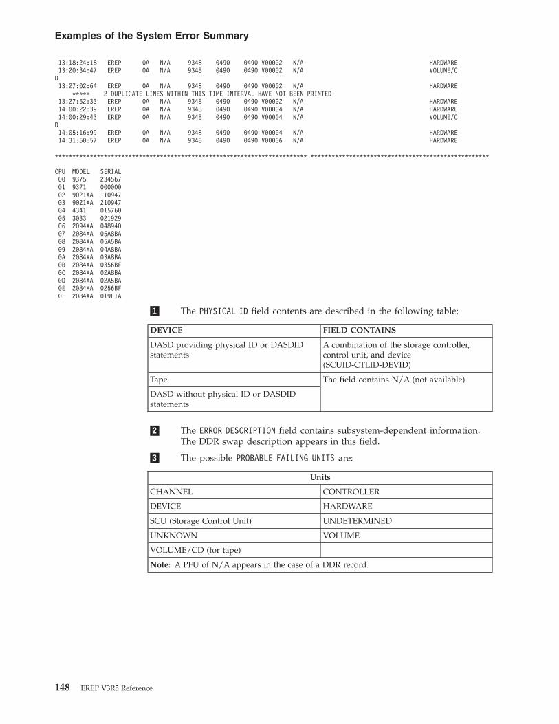
13:18:24:18 EREP 0A N/A 9348 0490 0490 V00002 N/A HARDWARE13:20:34:47 EREP 0A N/A 9348 0490 0490 V00002 N/A VOLUME/CD13:27:02:64 EREP 0A N/A 9348 0490 0490 V00002 N/A HARDWARE
***** 2 DUPLICATE LINES WITHIN THIS TIME INTERVAL HAVE NOT BEEN PRINTED13:27:52:33 EREP 0A N/A 9348 0490 0490 V00002 N/A HARDWARE14:00:22:39 EREP 0A N/A 9348 0490 0490 V00004 N/A HARDWARE14:00:29:43 EREP 0A N/A 9348 0490 0490 V00004 N/A VOLUME/CD14:05:16:99 EREP 0A N/A 9348 0490 0490 V00004 N/A HARDWARE14:31:50:57 EREP 0A N/A 9348 0490 0490 V00006 N/A HARDWARE
************************************************************************ ***************************************************
CPU MODEL SERIAL00 9375 23456701 9371 00000002 9021XA 11094703 9021XA 21094704 4341 01576005 3033 02192906 2094XA 04894007 2084XA 05A8BA08 2084XA 05A5BA09 2084XA 04A8BA0A 2084XA 03A8BA0B 2084XA 0356BF0C 2084XA 02A8BA0D 2084XA 02A5BA0E 2084XA 0256BF0F 2084XA 019F1A
�1� The PHYSICAL ID field contents are described in the following table:
DEVICE FIELD CONTAINS
DASD providing physical ID or DASDIDstatements
A combination of the storage controller,control unit, and device(SCUID-CTLID-DEVID)
Tape The field contains N/A (not available)
DASD without physical ID or DASDIDstatements
�2� The ERROR DESCRIPTION field contains subsystem-dependent information.The DDR swap description appears in this field.
�3� The possible PROBABLE FAILING UNITS are:
Units
CHANNEL CONTROLLER
DEVICE HARDWARE
SCU (Storage Control Unit) UNDETERMINED
UNKNOWN VOLUME
VOLUME/CD (for tape)
Note: A PFU of N/A appears in the case of a DDR record.
Examples of the System Error Summary
148 EREP V3R5 Reference

Examples of the Subsystem Exception Report SeriesEREP formats each of the reports in the subsystem exception report seriesaccording to the requirements of the hardware involved.
EREP produces a different series of subsystem exception reports for each type ofhardware.
The following table shows the location of subsystem exception report seriesexamples:
REPORT
“Processor (CPU) Subsystem Exception” on page 150
“Channel Subsystem Exception” on page 152
“DASD Subsystem Exception” on page 154
“Optical Subsystem Exception” on page 177
“Tape Subsystem Exception” on page 193
The following table shows the type of error records and their source in thesubsystem exception report series.
TYPE SOURCE
A3 33XX DASD, 34XX TapeCCH CPUs, channelsMCH CPUsMDR 33XX DASD, 34XX Tape, 3995 OpticalOBR 33XX DASD, 34XX Tape, 3995 Optical, 9246 Optical, 9247 Optical
Examples of the Subsystem Exception Report Series
Chapter 11. System Exception Report Series 149

Processor (CPU) Subsystem ExceptionThe processor (CPU) subsystem exception report is organized by service level for:
TYPE DESCRIPTION
Termination errors The total number of incidents and the dateand time of the last incident are shown fortermination errors and hard errors.
Hard errors
Soft machine checks The total number of 60-minute intervals inwhich the number of events that occurequals or exceeds the LIMIT values is shownfor soft machine checks. The LIMIT value isset by the LIMIT control statement, whichsets the minimum number of errors (1–99).When the minimum has been reached, errorsare recorded in the EXCEPTION COUNT column.
Figure 11 shows an example of the processor subsystem exception report.
�1� This space is used for self-explanatory SCP and device-dependentmessages specific to this subsystem exception report. For example:** WARNING ** REPORT SPANS MORE THAN 3 DAYS
�2� This report is provided for the following CPUs only:0158
�1�
SUBSYSTEM EXCEPTION REPORT DATE 065 97PROCESSOR PERIOD FROM 041 97
TO 059 97�2�
MODEL 3033 SERIAL 021595 CPU B
TERMINATION ERROR �3� �4� �5�SERVICE LEVEL INDICATOR TOTAL COUNT DATE/TIME OF LAST ERROR
POWER WARNING . . . . . . . . . . . . . . . . 2 042/97 11:23:45:37INVALID LOGOUT . . . . . . . . . . . . . . . . 2 042/97 23:24:35:87
HARD ERRORSERVICE LEVEL INDICATOR TOTAL COUNT DATE/TIME OF LAST ERROR
REGISTER/PSW INVALID . . . . . . . . . 8 042/97 13:25:46:57HARD STORAGE ERROR . . . . . . . . . 4 045/97 13:35:58:77SYSTEM DAMAGE . . . . . . . . . 2 049/97 14:34:34:87INSTRUCTION PROCESSOR DAMAGE . . . . . . . . . 2 053/97 11:43:45:47STORAGE PROTECT KEY ERROR . . . . . . . . . 2 057/97 11:23:45:37
�6�SOFT MACHINE CHECK EXCEPTION COUNT
SERVICE LEVEL INDICATOR 60 MINUTE REFERENCE TOTAL COUNT DATE/TIME OF LAST ERROR
EXTERNAL DAMAGE . . . . . . . 2 . . . 4 044/97 13:35:58:77BUFFER ERROR . . . . . . . 2 . . . 2 051/97 17:54:45:87HIR SUCCESSFUL . . . . . . . 1 . . . 1 056/97 12:22:33:46
LIMITS APPLIED EXTD=01,BUFE=01,HIRS=01 �7�0 UNITS EXCLUDED DUE TO LIMITS
20 MCH RECORDS PROCESSED1 MCH RECORDS UNDEFINED TO MCH ALGORITHMS �8�
Figure 11. Processor (CPU) Subsystem Exception Report
Processor (CPU) Subsystem Exception
150 EREP V3R5 Reference

0168303130323033
�3� The types of errors are:TERMINATION ERRORHARD ERRORSOFT MACHINE CHECK
�4� The count of input records containing this particular error.
�5� Date and time of the last MCH record that includes this error. If the dateand time are the same for several service level indicators, it means that asingle record includes all the indicators.
�6� The number of 60-minute intervals in which the number of events thatoccur equals or exceeds the LIMIT values for each type of soft machinecheck.
�7� The LIMIT values applied to this report. If the LIMIT value is zero, theEXCEPTION COUNT field is also zero.
�8� Execution-time notes. These may be:
NOTE DESCRIPTION
nn UNITS EXCLUDED DUE TO LIMITS If LIMIT values are present
nn MCH RECORDS PROCESSED Number of valid MCH records processed
nn MCH RECORDS UNDEFINED Not identifiable to EREP as valid MCH records
nn MCH RECORDS IGNORED DUE TO CCH DUPLICATION 0158 models only, from which MCH records might bedouble-reporting an assumed channel failure
Processor (CPU) Subsystem Exception
Chapter 11. System Exception Report Series 151

Channel Subsystem ExceptionThis report is organized according to the possible source of channel checks:v The channelv The storage control unitv The controller
It shows the number of times each of these error types exceeded the LIMIT valuesfor specific channels or controllers.
Figure 12 shows an example of the channel subsystem exception report.
�1� This space is used for self-explanatory system control program anddevice-dependent messages specific to this subsystem exception report. Forexample:** WARNING ** REPORT SPANS MORE THAN 3 DAYS
�2� This report is provided for the following CPUs only:
�1�
SUBSYSTEM EXCEPTION REPORT DATE 065 97CHANNEL PERIOD FROM 041 97
TO 059 97�2�
MODEL 3033 SERIAL 021595 CPU 01
�3� �4� �5� �6� .SERVICE LEVEL INDICATOR EXCEPTION COUNT TOTAL COUNT DATE/TIME OF LAST ERROR
60 MINUTE REFERENCE
CHANNEL ERROR
CHANNEL 6XX 3 4 043/97 18:47:38:67CHANNEL 1XX 1 1 048/97 21:22:23:43CHANNEL 2XX 1 1 052/97 11:34:43:65CHANNEL 8XX 1 1 059/97 11:43:32:87
DIRECTOR ERROR
DIRECTOR #1 1 1 041/97 19:32:54:89DIRECTOR #2 1 1 045/97 13:25:46:57DIRECTOR #3 1 1 057/97 11:24:36:57
CONTROL UNIT ERROR
CONTROL UNIT 34X 1 1 042/97 13:25:44:57CONTROL UNIT 456 1 1 056/97 13:32:22:37
LIMITS APPLIED CHAN=01,DRCT=01,CTRL=01 �7�0 UNITS EXCLUDED DUE TO LIMITS
2 CCH RECORDS UNDEFINED TO CCH ALGORITHMS2 CCH RECORDS IGNORED BECAUSE OF MCH DUPLICATION �8�
Figure 12. Channel Subsystem Exception Report
Channel Subsystem Exception
152 EREP V3R5 Reference

01580168303130323033
�3� The sources of the channel checks are shown in the following table:CHANNEL ERROR (31XX/303X)CHANNEL STORAGE ERROR (31XX) or DIRECTOR ERROR (303X)CONTROL UNIT ERROR
�4� The number of unique 60-minute intervals that had at least the LIMITvalue number of this kind of channel check.
�5� The count of input records containing this particular error.
�6� Date and time of the last CCH record that includes this error. If the dateand time are the same for several service level indicators, it means that asingle record includes all the indicators.
�7� The LIMIT values applied to this report. If the LIMIT value is zero, theEXCEPTION COUNT field is also zero.
�8� Execution-time notes. These may be:
NOTE DESCRIPTION
nn UNITS EXCLUDED DUE TO LIMITS If LIMIT values are present
nn INPUT RECORDS UNDEFINED Not identifiable to EREP as valid CCHrecords
nn CCH RECORDS IGNORED DUE TO MCHDUPLICATION
The number of 0158 or 0168 channel storageerrors, or 303X channel errors, ignoredbecause they might be double-reporting aprocessor storage error
nn CCH RECORDS FOUND GENERATED FORSOFTWARE RECOVERY
The number of sympathetic channel errorsfound; for 303X only
Channel Subsystem Exception
Chapter 11. System Exception Report Series 153

DASD Subsystem ExceptionThis report shows conditions that may need maintenance action. Records that areincluded in other reports may not be listed in the system exception reports.
This exception report can be used to determine if the DASD subsystem hasexcessive errors or is operating within acceptable limits.
This report is organized by probable failing unit (PFU) starting with the units closestto the processor (CPU) and working toward the volume. Within each section, thePFUs are ordered from most critical to least severe (or from the unit with thelargest number of permanent errors to the unit with the smallest number oftemporary errors).
The series contains the following types of reports:
TYPE REPORT
1 “DASD Subsystem Exception, Part 1” on page 156
1 “DASD Subsystem Exception, Part 2” on page 161
2 “DASD String Summary, Part 1” on page 162
DASD String Summary helps you determine if a problem is unique to a particulardevice or is also occurring on other devices in the controller string.
2 “DASD String Summary, Part 2” on page 165
3 “DASD Service Informational Messages (SIMs)” on page 166
Informational Messages help you define a problem to IBM customer servicepersonnel.
3 “DASD Informational Messages” on page 167
4 “DASD Data Transfer Summary” on page 168
Data Transfer is further broken down according to whether the PFU is the volumeor something other than the volume.
5 “DASD Symptom Code Summary” on page 171
Symptom Code lists the errors by fault symptom code within each probable failingunit (PFU) group.
6 “DASD Storage Control Unit Summary” on page 176
Storage Control Unit (SCU) groups overruns under each interface between channelor subchannel and SCU.
These reports work together to provide a picture of the errors occurring in thesystem. The DASD subsystem exception report determines if your DASDsubsystem is experiencing an excessive amount of errors.
The following table shows the type of error records and their source in the DASDsubsystem exception reports:
TYPE SOURCE
A3 DASD devices; including SCUs, controllersMDR DASD devices; including SCUs, controllersOBR DASD devices; including SCUs, controllers
DASD Subsystem Exception
154 EREP V3R5 Reference
TYPE SOURCE
A probable failing unit is identified through the physical ID of the device. Thephysical ID is the combined identifiers of storage controller, control unit, anddevice.
Note: You must code DASDID control statements to establish physical IDs forthose DASD in your installation that do not provide their own physical IDs. Thatway, EREP recognizes units common to different systems and arrives at the correctPFUs.
Messages IFC264I and IFC265I are logged in the EREP messages (TOURIST) file foreach invalid record. These records are not included in the system exception reportand do not print device dependent information in other reports.
Valid records that do not indicate a need for maintenance action may be shown inreports other than the subsystem exception.
If errors are found, the necessary corrective action is shown on the next deeperlevel of DASD reports. See Figure 19 on page 167 through Figure 20 on page 176and Chapter 17, “Direct-Access Storage Devices (DASD),” on page 337.
Figure 13 on page 156 through Figure 20 on page 176 show examples of the reportsin the DASD subsystem exception series.
DASD Subsystem Exception
Chapter 11. System Exception Report Series 155

DASD Subsystem Exception, Part 1This part of the exception report provides the primary listing of events todetermine if the DASD subsystem has excessive errors or is operating withinacceptable limits.
This report provides the information to connect these events to the other reports inthe series that have more details.
This report is organized by PFU starting with the units closest to the CPU andworking toward the volume.
The PFUs are ordered from most critical to least severe.
Figure 13 shows an example of the DASD subsystem exception, part 1.
Explanations for �1� through �12� shown in the following report begin on thefollowing pages.
�1�** WARNING ** REPORT WAS RUN FOR A PERIOD EXCEEDING 3 DAYS. PROBABLE UNIT ANALYSIS MAY BE IN ERROR.
SUBSYSTEM EXCEPTION REPORT DATE 080 97DASD (1) �2� PERIOD FROM 037 97
TO 079 97
B-BUS OUT PARITY CHK C-CHECK DATA CHK D-DISKETTE CHK I-INVOKED OFF SETS�3�
PROBABLE �4� �6� �7� ---IMPACT OF TEMPORARY ERRORS----FAILING FAILURE �5� PHYSICAL -----TOTALS----- EQU �8� �9�UNIT AFFECT CPU ADDRESS SIMS PERM TEMP CHK SKS RD OVRN OTHER************************************************************************ *****************************************CHAN 0C CHAN/SCU TOTAL 1
03 36-XX-XX 1�10�02 CHAN/SCU TOTAL 1
03 32-XX-XX 1
05XX CHAN/SCU TOTAL 1 107 A0-XX-XX 1 1
07XX CHAN/SCU TOTAL 1 107 61-XX-XX 1 1
SCU 10111.3 SCU TOTAL 63990-02�11� 00+ 10111.3 6
10114.2 SCU TOTAL 33990-02 01 10114.2 3
A8-XX-XX SCU TOTAL 5 1 13880 2B+ *A8-XX-XX 5 1 1
03. SCU TOTAL 2 23880 00 03. 2 2
*052X SCU TOTAL 1 13830 35 *0520 1 1
** WARNING ** REPORT WAS RUN FOR A PERIOD EXCEEDING 3 DAYS. PROBABLE UNIT ANALYSIS MAY BE IN ERROR.
SUBSYSTEM EXCEPTION REPORT DATE 080 97DASD (1) PERIOD FROM 037 97
TO 079 97
B-BUS OUT PARITY CHK C-CHECK DATA CHK D-DISKETTE CHK I-INVOKED OFF SETS
PROBABLE ---IMPACT OF TEMPORARY ERRORS----FAILING FAILURE PHYSICAL -----TOTALS----- EQUUNIT AFFECT CPU ADDRESS SIMS PERM TEMP CHK SKS RD OVRN OTHER************************************************************************ *****************************************
CTLR 20.1-XX SCU/CTLR TOTAL 8 3 33380-JK 01+ 20.1-XX 2 2 2
00+ 20.0-XX 6 1 1
20.0-XX CTLR/DEV TOTAL 4 2 2
Figure 13. Subsystem Exception DASD Report, Part 1
DASD Subsystem Exception
156 EREP V3R5 Reference

3380-JK 00 20.0-03 101 20.0-00 101 20.0-0E 1 100 20.0-0F 1 100 20.0-05 101 20.0-07 1
20.1-XX MULTIPLE TOTAL 4 1 13380-JK 00 20.1-09 1
00 20.1-05 101 20.1-08 1 100 20.0-06 101 20.0-07 1
AH210.0-XX CTLR TOTAL 13390-09 00 AH210.0-XX 1
------------------+----------+--------+------------+------+-----+-----+- -----+------+------+------+-------------+MULT 20.X-XX MULTIPLE TOTAL 7 7
3380-JK 00 20.0-0C 1 101 20.0-0E 1 100 20.0-0F 1 101+ 20.0-04 2 200 20.0-05 1 101 20.0-07 1 1
------------------+----------+--------+------------+------+-----+-----+- -----+------+------+------+-------------+DEV XX-10-02 CTLR/DEV TOTAL 1
3380 02 76-10-02 1
*04AE SEEK TOTAL 7 73330 2A *04AE 7 7
HANDY.X-08 DEV TOTAL 13390-09 01 HANDY.0.08 1
GRAM9.X-17 DATAXFR TOTAL 23390-01 0A GRAM9.0-17 2
VOL RAS70F DATAXFR TOTAL 1 2 23380-JK 01 20.0-OF 1 1
01+ 20.1-OF 1 1 1
RAS296 DATAXFR TOTAL 4
** WARNING ** INVALID PHYSICAL ID ON NEXT LINE3380-JK 00+ FF.0-16 2
** WARNING ** INVALID PHYSICAL ID ON NEXT LINE3380-JK 01 FF.2-16 1
** WARNING ** REPORT WAS RUN FOR A PERIOD EXCEEDING 3 DAYS. PROBABLE UNIT ANALYSIS MAY BE IN ERROR.
SUBSYSTEM EXCEPTION REPORT DATE 080 97DASD (1) PERIOD FROM 037 97
TO 079 97
B-BUS OUT PARITY CHK C-CHECK DATA CHK D-DISKETTE CHK I-INVOKED OFF SETS
PROBABLE ---IMPACT OF TEMPORARY ERRORS----FAILING FAILURE PHYSICAL -----TOTALS----- EQUUNIT AFFECT CPU ADDRESS SIMS PERM TEMP CHK SKS RD OVRN OTHER************************************************************************ *****************************************
PACV07 DATAXFR TOTAL 1 40963390-09 01 HANDY.0-01 1 4096
ERPVOL DATAXFR TOTAL 4096 40963310 26 *0597 4096 4096
PAGE03 DATAXFR TOTAL 128 1283310 26 *059D 128 128-C
------------------+----------+--------+------------+------+-----+-----+- -----+------+------+------+-------------+** WARNING ** NO DASDID CARD FOUND OR INVALID PHYSICAL ID - PROBABLE UNIT NOT ASSIGNED FOR THE FOLLOWING:
CTLR/DEV TOTAL 3 33330 19+ *0428 3 3
******************************************************************************************************************0 UNIT(S) EXCLUDED DUE TO LIMITS�12�
** ENTRIES WITH AN ASTERISK INDICATE THAT DASDID CARDS WERE NOT FOUND FOR THE UNIT.
NOTE: "IMPACT OF TEMPORARY ERRORS" IS THE NUMBER OF TIMES ERROR THRESHOLD HAS BEEN EXCEEDED.NOTE: BLANK ENTRIES INDICATE ZERO VALUES OR NOT APPLICABLE. N/A = NOT AVAILABLE.NOTE: ZERO ENTRIES INDICATE RECORDS EXIST IN EREP REPORTS BUT THRESHOLDS WERE NOT EXCEEDED.
�1� This space is used for self-explanatory system control program anddevice-dependent messages specific to this subsystem exception report. Forexample:
DASD Subsystem Exception
Chapter 11. System Exception Report Series 157

** WARNING ** REPORT WAS RUN FOR A PERIOD EXCEEDING 3 DAYS. PROBABLE UNIT ANALYSIS MAYBE IN ERROR.
�2� This field includes conditions that require analysis of OBR records toevaluate if repair is required. Units that report service informationmessages (SIMs) only put information in the system exception report whenthe unit has a condition that prevents it from reporting a SIM.
�3� This field shows the unit most likely to be the source of the failure, even ifthe failure is recorded against another unit. EREP identifies the PFU basedon the failure affect and the units reporting errors. The accuracy of thisanalysis for devices without physical ID depends on DASDID controlstatements. See “DASDID Control Statement” on page 58 for details onDASDID statements. Possible PFUs are shown in the following table:
PFU DESCRIPTION
CHAN Channel (channel, program, or CPU)
SCU Storage control unit (for example, 3830, FTA, ISC)
CTLR Controller (drive string controller, or something common to more than one device onthe string)
MULTIPLE Failure common to more than one device
DEV Device (addressable unit)
VOL Volume (data on volume)
UNK Unknown (cannot be determined by report algorithms)
If no DASDID entry exists or the physical ID is invalid, a warning messagereplaces the PFU line.
In the line for PFU are its identifier, the failure affect, and the total errorsattributed to this combination of PFU and failure affect. Usage counts arenot available (N/A) because the total usage of the device is not determinedin generating the report (non-failing devices are not considered).
�4� This field defines the function or machine area affected by the failure.Possible failure affects are shown in Table 12.
Table 12. Possible Failure Affects
FAILURE AFFECT DESCRIPTION
CHAN/SCU The channel, CPU, or program, or the channel/storage control unit interface.
SCU The storage control unit.
SCU/CTLR The storage control unit/controller interface.
CTLR The controller.
CTLR/DEV The controller/device interface.
MULTIPLE Failure common to more than one device.
DEV The device, including problems with a volume that must be handled by aservice representative.
SEEK The function of accessing the track; the failure may be in the controller, thedrive, or the volume.
DATAXFR Data transfer: the function of reading or writing data; the failure may be in thecontroller, the drive, or the volume.
DATAXFR(HDA) Data transfer, where the failure is in the head disk assembly.
UNK Unknown; it is possible that two failures exist, providing conflictinginformation.
�5� The EREP-assigned CPU identifier. If there is more than one CPU, one isshown and a plus sign is printed to indicate that there is more than one.
DASD Subsystem Exception
158 EREP V3R5 Reference
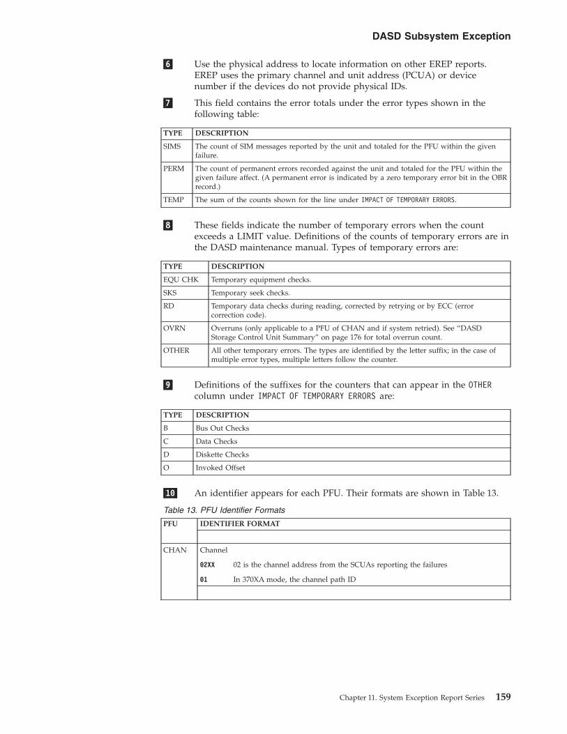
�6� Use the physical address to locate information on other EREP reports.EREP uses the primary channel and unit address (PCUA) or devicenumber if the devices do not provide physical IDs.
�7� This field contains the error totals under the error types shown in thefollowing table:
TYPE DESCRIPTION
SIMS The count of SIM messages reported by the unit and totaled for the PFU within the givenfailure.
PERM The count of permanent errors recorded against the unit and totaled for the PFU within thegiven failure affect. (A permanent error is indicated by a zero temporary error bit in the OBRrecord.)
TEMP The sum of the counts shown for the line under IMPACT OF TEMPORARY ERRORS.
�8� These fields indicate the number of temporary errors when the countexceeds a LIMIT value. Definitions of the counts of temporary errors are inthe DASD maintenance manual. Types of temporary errors are:
TYPE DESCRIPTION
EQU CHK Temporary equipment checks.
SKS Temporary seek checks.
RD Temporary data checks during reading, corrected by retrying or by ECC (errorcorrection code).
OVRN Overruns (only applicable to a PFU of CHAN and if system retried). See “DASDStorage Control Unit Summary” on page 176 for total overrun count.
OTHER All other temporary errors. The types are identified by the letter suffix; in the case ofmultiple error types, multiple letters follow the counter.
�9� Definitions of the suffixes for the counters that can appear in the OTHERcolumn under IMPACT OF TEMPORARY ERRORS are:
TYPE DESCRIPTION
B Bus Out Checks
C Data Checks
D Diskette Checks
O Invoked Offset
�10� An identifier appears for each PFU. Their formats are shown in Table 13.
Table 13. PFU Identifier Formats
PFU IDENTIFIER FORMAT
CHAN Channel
02XX 02 is the channel address from the SCUAs reporting the failures
01 In 370XA mode, the channel path ID
DASD Subsystem Exception
Chapter 11. System Exception Report Series 159
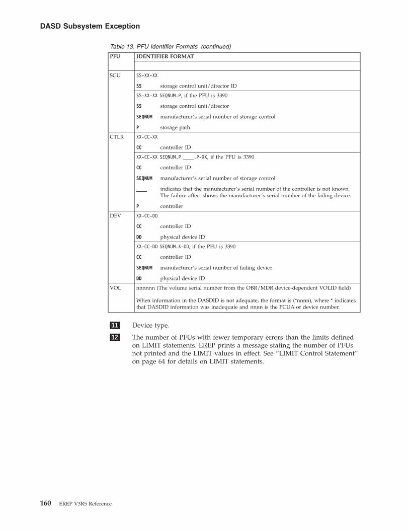
Table 13. PFU Identifier Formats (continued)
PFU IDENTIFIER FORMAT
SCU SS-XX-XX
SS storage control unit/director ID
SS-XX-XX SEQNUM.P, if the PFU is 3390
SS storage control unit/director
SEQNUM manufacturer’s serial number of storage control
P storage path
CTLR XX-CC-XX
CC controller ID
XX-CC-XX SEQNUM.P ____.P-XX, if the PFU is 3390
CC controller ID
SEQNUM manufacturer’s serial number of storage control
____ indicates that the manufacturer’s serial number of the controller is not known.The failure affect shows the manufacturer’s serial number of the failing device.
P controller
DEV XX-CC-DD
CC controller ID
DD physical device ID
XX-CC-DD SEQNUM.X-DD, if the PFU is 3390
CC controller ID
SEQNUM manufacturer’s serial number of failing device
DD physical device ID
VOL nnnnnn (The volume serial number from the OBR/MDR device-dependent VOLID field)
When information in the DASDID is not adequate, the format is (*nnnn), where * indicatesthat DASDID information was inadequate and nnnn is the PCUA or device number.
�11� Device type.
�12� The number of PFUs with fewer temporary errors than the limits definedon LIMIT statements. EREP prints a message stating the number of PFUsnot printed and the LIMIT values in effect. See “LIMIT Control Statement”on page 64 for details on LIMIT statements.
DASD Subsystem Exception
160 EREP V3R5 Reference

DASD Subsystem Exception, Part 2Subsystem exception DASD (2) reports list only the SIM (A3) records. Units whichrely on SIMs for statement of service requirement are shown in this report.
Figure 14 shows an example of the DASD subsystem exception, part 2.
SUBSYSTEM EXCEPTION REPORT DATE 105 97DASD (2) PERIOD FROM 100 97
TO 104 97PROBABLEFAILING FAILURE PHYSICALUNIT AFFECT CPU ADDRESS SIMS*********************************************************************CHAN 07 CHAN/SCU TOTAL 1
01 10221.2 1------------------+----------+--------+--------------+------+-------+SCU 34988.3 SCU/CTRL TOTAL 3
9341 03+ 22887.3-XX 3------------------+----------+--------+--------------+------+-------+CTLR FFFFF.0-XX SCU/CTLR TOTAL 1
9343 01 FFFFF.0-XX 1------------------+----------+--------+--------------+------+-------+MULT 12245.X-XX MULTIPLE TOTAL 2
9345 01 12245.1-1A 102 12245.2-1B 1
------------------+----------+--------+--------------+------+-------+DEV 23345.X-02 CTLR/DEV TOTAL 2
9345 01+ 23345.0-02 2*********************************************************************
0 UNIT(S) EXCLUDED DUE TO LIMITS
Figure 14. DASD Subsystem Exception, Part 2
DASD Subsystem Exception
Chapter 11. System Exception Report Series 161

DASD String Summary, Part 1Provides information about the following:v Failure affect and usage datav Usage statisticsv CPUs
The usage information in the DASD string summary can help you determinewhether a failure affect reported in the DASD subsystem exception report isassociated with just one device or is common to more than one device in the samecontroller string.
The report is useful in helping analyze error causes. It is used in conjunction withthe DASD subsystem exception report.
The DASD STRING SUMMARY (1) includes units that report usage statistics. Itshows the following:v Physical IDv Volume IDv Error types that are shown as equipment checks, seek errors, or data transfer
errorsv Thousands of accessesv Megabytes processedv Total number of seeks and megabytes processed for the report regardless of
failure affect
Note: The MEGABYTES WRITTEN WITH VERIFY column is used for 3310s and 3370sthat have write with verify commands.
Figure 15 on page 163 shows an example of the DASD subsystem exception, part 2.
DASD String Summary
162 EREP V3R5 Reference

�1� The failure affect for each unique combination of volume and physical IDbelonging to every controller string that appeared on the subsystemexception report. A Y is placed in one or more of the columns under theERROR TYPES heading to indicate which types of error have occurred. Thefollowing table shows failure affects and the error types:
FAILURE AFFECT ERROR TYPE COLUMN WITH A Y
CTLR EQU.CHKS
CTLR/DEV EQU.CHKS
DEV EQU.CHKS
SEEK SEEK
DASD STRING SUMMARY (1) REPORT DATE 105 97PERIOD FROM 100 97
TO 104 97REPORT INCLUDES ALL DASD WITH PHYSICAL IDS OR A VALID DASDID
ERROR TYPES SEEK MEGABYTESEQU. ³SEEK ³DATA ACCESSES MEGABYTES WRITTEN
SSID SCU CTLR DEV VOLUME CHKS ³ ³XFER X 1000 READ W/VERIFY***********************************************************************************************
26 34 �1� �2�27 35
08 MX1RS1 8 13709 MX1DL1 66
22 66.023 60.1
0202 RAS7C2 Y Y Y03 RAS7C3 Y Y Y
07 8023 80.1
02 RAS7C2 Y03 RAS7D3 Y05 IBM355 Y
03 A502 RAS712 35 7303 RAS713 34 800C RAS71C 31 680E RAS71E 31 770F RAS71F 31 69
0004 10114.0 0F.010114.2 0F.2
01 RAS841 65 305 RAS845 65 306 RAS846 65 3
0041 .1 01.111 RAS291 Y
0243 .0 00HHGK6.0 00
ZZZ23-0F SOQV04 131 112ZZZ23-0F SOQV06 Y
1144 .0 00DBDMC.0 00
AH210-02 SLT221 2AH210-02 SOQV01 65 295122-14 SOQV19 YRM102-16 SOQV09 YGRAM9-17 SOQV31 Y95122-1E SOQV21 Y*****-1F SOQV13 Y
1144 .0 01DBDMC.0 01
GRAM9-10 SOQV03 65 287GRAM9-10 SOQV05 Y
ALL DASD PROCESSED FOR EXCEPTION REPORT 1530 9325�3�***********************************************************************************************
NOTE: THE COUNTS FOR SEEK ACCESSES X 1000, MEGABYTES READ, ANDMEGABYTES WRITTEN W/VERIFY ARE SIX DIGIT POSITIONS. IF THESPACE IS EXCEEDED, THE COUNT IS DIVIDED BY 1000 AND A K ISPLACED AT THE END OF THE NUMBER. IF THE COUNT IS EXCEEDEDWITH A K AT THE END, 99999K WILL BE PRINTED.
Figure 15. DASD String Summary, Part 1
DASD String Summary
Chapter 11. System Exception Report Series 163

FAILURE AFFECT ERROR TYPE COLUMN WITH A Y
DATAXFR DATAXFER
DATAXFR(HDA) DATAXFER
MULTIPLE Any combination
�2� The usage data for each volume/physical ID appears under three possibleheadings:v SEEK ACCESSES X 1000v MEGABYTES READv MEGABYTES WRITTEN W/VERIFY
�3� The usage statistics for all DASD processed for the subsystem exceptionreport.
Note: To generate a DASD string summary, EREP needs valid physical IDs for thedevices, relevant failure affect data from the exception report, or usage data for theselected devices. If these items are not present, the first part of the report isreplaced by a message explaining the absence of report data.
DASD String Summary
164 EREP V3R5 Reference
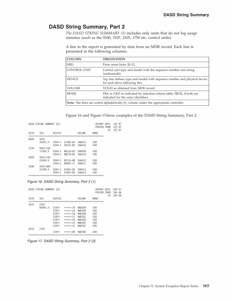
DASD String Summary, Part 2The DASD STRING SUMMARY (2) includes only units that do not log usagestatistics (such as the 9340, 2107, 2105, 1750 etc. control units).
A line in the report is generated by data from an MDR record. Each line ispresented in the following columns:
COLUMN ORIGINATION
SSID From sense bytes 20–21.
CONTROL UNIT Control unit type and model with the sequence number and string(underneath).
DEVICE Top line defines type and model with sequence number and physical devicefor each drive following this.
VOLUME VOLID as obtained from MDR record.
MODE FBA or CKD as indicated by selection criteria table; FBCK, if both areindicated for the same identifiers.
Note: The lines are sorted alphabetically by volume under the appropriate controller.
Figure 16 and Figure 17show examples of the DASD String Summary, Part 2.
DASD STRING SUMMARY (2) REPORT DATE 132 97PERIOD FROM 123 97
TO 123 97SSID SCU DEVICE VOLUME MODE*******************************************************0505 9341
43541.X 9345-1 37426-0A SAWV15 CKD9345-1 38722-0D SAWV16 CKD
1144 9343-C0217204.X 9345-1 N6210-02 SAWV09 CKD
9345-1 N6210-03 SAWV10 CKD2020 9343-C04
21044.X 9345-1 N2114-08 SAWV12 CKD9345-1 N9282-17 SAWV11 CKD
3030 9343-D0421299.X 9345-1 A1091-04 SAWV13 CKD
9345-1 A1091-05 SAWV14 CKD*******************************************************
Figure 16. DASD String Summary, Part 2 (1)
DASD STRING SUMMARY (2) REPORT DATE 220 07PERIOD FROM 104 06
TO 104 06SSID SCU DEVICE VOLUME MODE*******************************************************4E43 2107
BXXN1.X 2107+ *****-19 NWD359 CKD2107+ *****-1A NWD35A CKD2107+ *****-1B NWD35B CKD2107+ *****-1C NWD35C CKD2107+ *****-1D NWD35D CKD2107+ *****-1E NWD35E CKD2107+ *****-1F NWD35F CKD
4E43 21072107+ *****-00 NWD360 CKD
*******************************************************
Figure 17. DASD String Summary, Part 2 (2)
DASD String Summary
Chapter 11. System Exception Report Series 165

DASD Service Informational Messages (SIMs)This report relates to hardware or media failures that may require the customer tocall for service or run ICKDSF.
SIMs always appear ahead of other informational messages.
The DASD informational messages report appears after all SIMs.
Refer to the device maintenance library for information about the SIMs and actionsrequired.
Figure 18 shows an example of the DASD service informational messages.
�1� The number of occurrences of this particular SIM based on the SEQNUMand SIM ID.
�2� The date and time of the first occurrence of this particular SIM.
�3� The date and time of the last occurrence of this particular SIM.
DASD SERVICE INFORMATION MESSAGES (SIMS) REPORT DATE 028 97PERIOD FROM 023 97
TO 028 97
�1� �2� �3�COUNT FIRST OCCURRENCE LAST OCCURRENCE*******************************************************************************1 023/97 00:10:05:00 023/90 00:10:05:00
* SERVICE ALERT 9345-1 S/N 0113-N6968 REFCODE D100-11C1-9000 ID=05* DASD EXCEPTION ON SSIS 1123, PHYSICAL DEVICE 02, VOLSER SUTUXX
DEVICE ADDRESS= 0B02, 11* REPAIR WILL DISABLE STORAGE CLUSTER 1 AND INTERFACE A-B
1 023/97 00:10:06:00 023/90 00:10:06:00* MODERATE ALERT 9345-1 S/N 0113-P1337 REFCODE D800-22D2-0000 ID=06* DASD SERVICE OPERATION COMPLETED ON SSID 2123* REPAIR WILL DISABLE STORAGE CLUSTER 0 AND SERIAL INTERFACES 00-01
1 023/97 00:10:07:00 023/90 00:10:07:00* SERIOUS ALERT 9345-1 S/N 0113-P5706 REFCODE E300-33E3-1000 ID=07* DASD EXCEPTION ON SSID 3123 DEVICE PATH 3** INVALID SERVICE CODE 3 FOR SENSE BYTE 28 = AE** S/N 0113-P5706 NO FORMATTED MESSAGE - SENSE DATA:
00001200 2428CF07 93808333 E3100004 23603D5A 3123E300 05100200 AE020700
1 028/97 00:00:32:03 223/90 00:00:32:03* SERIOUS ALERT 9343-C02 S/N 0113-T0003 REFCODE 2300-251D-9000 ID=17* SCU EXCEPTION ON SSID 3123, STORAGE CLUSTER 1 DEVICE PATH 2* NO SERVICE ACTION REQUIRED
1 028/97 00:00:01:00 123/90 00:00:01:00* SERVICE ALERT 9345-1 S/N 0113-Y1989 REFCODE 4121-1634-5678 ID=21* MEDIA EXCEPTION ON SSID 0127, VOLSER SUTEFG DEVICE ADDRESS= 0B00, CH 1F
PHYSICAL DEVICE 00, CYLINDER 01B1 HEAD 01* REFERENCE MEDIA MAINTENANCE PROCEDURE 1
Figure 18. DASD Service Information Messages (SIMS)
DASD Service Informational Messages
166 EREP V3R5 Reference

DASD Informational MessagesThis report provides information for the hardware service representative. Therecords involved may relate to hardware failures that can degrade performance;but the records are not standard sense records resulting from an error condition.
This report automatically follows the DASD subsystem exception report. Theinformation within the two reports is connected by the physical ID address.
The symptom code in the report tells you if any action is required.
Information about the actions required for the various messages is in themaintenance library for the device identified in the PHYSICAL ID field.
Figure 19 shows an example of the DASD informational messages.
DASD INFORMATIONAL MESSAGES REPORT DATE 175 97PERIOD FROM 041 97
TO 174 97PHYSICAL SYMPTOMID CODE COUNT MESSAGE************************************************************************ ****************************03-01-06 0001 1 THRESHOLD LOGGING COMPLETE FOR SEEK CHECKS04.0-XX 0002 1 THRESHOLD LOGGING COMPLETE FOR DATA CHECKS WITHOUT OFFSET20.1-XX 0002 1 THRESHOLD LOGGING COMPLETE FOR DATA CHECKS WITHOUT OFFSETAH210 N/A 1 CUU 0402 DEVICE FENCED FROM STORAGE PATH04.1-00 0001 1 THRESHOLD LOGGING COMPLETE FOR SEEK CHECKS04.1-XX 0002 1 THRESHOLD LOGGING COMPLETE FOR DATA CHECKS WITHOUT OFFSET21. 000F 1 THRESHOLD LOGGING COMPLETE FOR SUBSYSTEM STORE CHECKS22. 000F 1 THRESHOLD LOGGING COMPLETE FOR SUBSYSTEM STORE CHECKS60.0-02 0001 1 THRESHOLD LOGGING COMPLETE FOR SEEK CHECKS23. 000F 1 THRESHOLD LOGGING COMPLETE FOR SUBSYSTEM STORE CHECKSAA-CC-01 1010 1 SECTOR RETRY THRESHOLD EXCEEDED RBN 33694AA-CC-01 1313 1 THRESHOLD LOGGING COMPLETE FOR EQUIPMENT CHECKSAA-CC-01 1616 1 THRESHOLD LOGGING COMPLETE FOR SEEK CHECKSAA-CC-01 1919 1 THRESHOLD LOGGING COMPLETE FOR DATA CHECKSAA-CC-01 2121 1 ALTERNATE BLOCKS NEARLY EXHAUSTEDBB-DD-01 101F 1 SECTOR RETRY THRESHOLD EXCEEDED RBN 260753BB-DD-01 2072 1 CALL FOR SERVICE
Figure 19. DASD Informational Messages
DASD Informational Messages
Chapter 11. System Exception Report Series 167
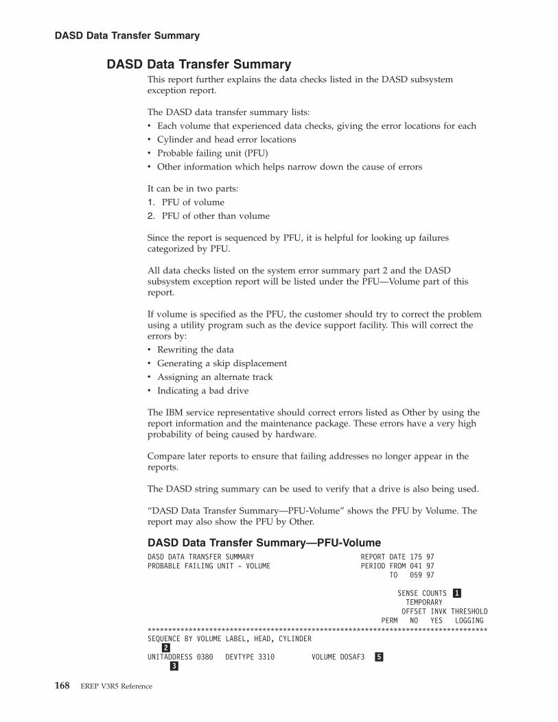
DASD Data Transfer SummaryThis report further explains the data checks listed in the DASD subsystemexception report.
The DASD data transfer summary lists:v Each volume that experienced data checks, giving the error locations for eachv Cylinder and head error locationsv Probable failing unit (PFU)v Other information which helps narrow down the cause of errors
It can be in two parts:1. PFU of volume2. PFU of other than volume
Since the report is sequenced by PFU, it is helpful for looking up failurescategorized by PFU.
All data checks listed on the system error summary part 2 and the DASDsubsystem exception report will be listed under the PFU—Volume part of thisreport.
If volume is specified as the PFU, the customer should try to correct the problemusing a utility program such as the device support facility. This will correct theerrors by:v Rewriting the datav Generating a skip displacementv Assigning an alternate trackv Indicating a bad drive
The IBM service representative should correct errors listed as Other by using thereport information and the maintenance package. These errors have a very highprobability of being caused by hardware.
Compare later reports to ensure that failing addresses no longer appear in thereports.
The DASD string summary can be used to verify that a drive is also being used.
“DASD Data Transfer Summary—PFU-Volume” shows the PFU by Volume. Thereport may also show the PFU by Other.
DASD Data Transfer Summary—PFU-VolumeDASD DATA TRANSFER SUMMARY REPORT DATE 175 97PROBABLE FAILING UNIT - VOLUME PERIOD FROM 041 97
TO 059 97
SENSE COUNTS �1�TEMPORARY
OFFSET INVK THRESHOLDPERM NO YES LOGGING
***********************************************************************************SEQUENCE BY VOLUME LABEL, HEAD, CYLINDER
�2�UNITADDRESS 0380 DEVTYPE 3310 VOLUME DOSAF3 �5�
�3�
DASD Data Transfer Summary
168 EREP V3R5 Reference

CPU 26 PHYSICAL ADDRESS 0590 �4�FAILURE AT BLOCK: 3834 CCHS 0010-09-26 0 1 0 0
08015000 0A091A50 06000012 0000004D 004D01C4 28000000 �6�LAST SENSE AT: 045/97 07:52:15:81
UNITADDRESS 06C7 DEVTYPE 3330 VOLUME TSO190CPU 27 PHYSICAL ADDRESS 06C5
FAILURE AT ADDRESS: CYLINDER 0158 HEAD 01 1 0 0 008800000 159E0143 009E0001 0A1F301B 60000000 00004943
LAST SENSE AT: 044/97 10:43:02:62
UNITADDRESS 0921 DEVTYPE 3350 VOLUME DSAPAKCPU 35 PHYSICAL ADDRESS 0921
�7�FAILURE AT ADDRESS: CYLINDER 0385 HEAD 26 0 1 0 0
00001000 40813A40 0181801A 00000000 00000000 00004940LAST SENSE AT: 050/97 16:18:38:16
UNITADDRESS 0381 DEVTYPE 3370 VOLUME DOSAF3CPU 30 PHYSICAL ADDRESS 0380
FAILURE AT BLOCK: 3413 CCHS 0004-05-49 0 0 0 108015000 04053150 06000006 00000059 00590093 06000000
LAST SENSE AT: 045/97 07:52:05:07
UNITADDRESS 0734 DEVTYPE 3380 VOLUME PAK167CPU 07 PHYSICAL ADDRESS XX-84-04
FAILURE AT BLOCK: CYLINDER 0148 HEAD 07 1 0 0 008800000 84940743 00020007 066C8400 00000000 00314943
LAST SENSE AT: 043/97 14:25:47:01
UNITADDRESS 0D17 DEVTYPE 3390-01 VOLUME SOQV31CPU 0A PHYSICAL ADDRESS GRAM9.X-17
FAILURE AT BLOCK: CYLINDER 0025 HEAD 14 0 0 2 018000504 1726CE98 00001E00 08400004 2224CB83 1144432000800E01 0000109E LAST SENSE AT: 058/97 13:56:55:11
UNITADDRESS 0F50 DEVTYPE 9335 VOLUME DSFF50CPU 13 PHYSICAL ADDRESS 0F50
FAILURE AT BLOCK: 4097 CCHS 0083-01-50 1 0 0 008800000 53013241 00000000 00000000 00000000 10014401
LAST SENSE AT: 048/97 16:25:17:43
-----------------------------------------------------------------------------------THE FOLLOWING ENTRIES HAVE ONLY MDR RECORD TYPES. THEREFORE, NO CYLINDER/HEAD �8�ADDRESSES ARE REPORTED. SEE THE EXCEPTION REPORT FOR THE ERROR COUNTS.
UNITADDRESS 0597 DEVTYPE 3310 VOLUME ERPVOLCPU 26 PHYSICAL ADDRESS 0597
NOTE: CYLINDER/HEAD/BLOCK NUMBERS ARE DECIMAL VALUESNOTE: UNITADDRESS IS THE LOGICAL ADDRESS OF THE DEVICENOTE: ? FOLLOWING THE PHYSICAL ADDRESS DENOTES MULTIPLE
PHYSICAL UNITS HAD ERRORS WITH THIS VOLUME LABEL
�1� These columns contain counts of the data checks for the particularcylinder/head or block. The permanent data checks appear in the firstcolumn. The temporary data checks are broken down as follows:
DASD Data Transfer Summary
Chapter 11. System Exception Report Series 169

COLUMN DESCRIPTION
OFFSET INVK (offsetinvoked)
Indicates the number of recovered temporary data checks, andwhether it was necessary to offset the access mechanism with theNO and the YES sub-columns
THRESHOLD LOGGING Indicates the number of temporary data checks recorded when thedevice was in logging mode because the threshold for data checkswas exceeded.
�2� The keyword used by the device support facility to identify the device. It isthe logical address (SCUA) or device number of the volume reporting theerror.
�3� The CPU identified for the last sense record.
�4� For devices providing physical IDs, this is the physical ID; for otherdevices, it is the PCUA or physical device number.
�5� The volume serial number of the volume reporting the error.
�6� There may be either 24 or 32 sense bytes in the last sense record receivedfor this cylinder and head or block. The format of the sense record is inbyte 7 and is shown in the following table:
FORMAT DESCRIPTION
4 The symptom code is in the last two sense bytes
5 The value in byte 7 is repeated in the last two sense bytes
The date and time follow the sense bytes.
�7� The location of the data check as shown in the following table:
FOR ADDRESS
Count key data (CKD) devices The address is expressed as cylinder and head
Fixed block (FBA) devices The address is expressed as block number
Note:
v The values are in decimal.
v When a volume records data checks at more than one location, the report includes anentry for each location and puts them in ascending order.
�8� In cases where the only error data is from error counters, meaning thatfailure addresses are not available, only the lines that define the device andvolume appear.
DASD Data Transfer Summary
170 EREP V3R5 Reference

DASD Symptom Code SummaryThis report provides information required for hardware maintenance. The servicerepresentative uses it to locate the failures noted in the DASD subsystem exceptionreport and to note the symptom code and first sense record for each failure.
The data in this report is taken from each sense record in the corresponding DASDsubsystem exception report.
Each sense (OBR) record reported in the exception report is listed by probablefailing unit (PFU), fault symptom code, and physical ID.
Data is organized by PFU. The PFUs are listed in order of severity beginning withchannel and ending with volume. The sequence of the report is different for eachPFU.
The symptom code, which is listed under the PFU, is to be used with themaintenance procedures and documentation for the device. Symptom codes withan asterisk (*) are counted as errors in the exception report. The following is shownfor each symptom code:v Physical IDv Device typev Permanent and temporary errorsv Function or machine area affectedv Physical addressv Error pathv Date and time (first and last occurrence)v CPUsv Sense record from the first occurrence
The physical address is the same as the physical ID if the physical ID is provided.Otherwise, the physical address is the device number or physical control unitaddress (PCUA).
Data checks (symptom codes 4XXX and 5XXX) that appear in the DASD datatransfer summary, also appear here for use when hardware repair is required.
“DASD Symptom Code Summary” shows an example of the DASD symptom codesummary.
Note: Explanations for �1� through �11� follow the example.
DASD Symptom Code SummaryDASD SYMPTOM CODE SUMMARY REPORT DATE 065 97
PERIOD FROM 041 97TO 059 97
SEQUENCE BY PROBABLE FAILING UNIT �1�
SYMPTOM PHYSICAL OCCURRENCES FAILURE DATE AND TIME OFCODE ID PERM/TEMP AFFECT FIRST OCCURRENCE LAST OCCURRENCE
SENSE FROM FIRST OCCURRENCEDEVICE 0 0 0 0 0 0 0 0 0 0 1 1 1 1 1 1 1 1 1 1 2 2 2 2 2 2 2 2 2 2 3 3TYPE 0 1 2 3 4 5 6 7 8 9 0 1 2 3 4 5 6 7 8 9 0 1 2 3 4 5 6 7 8 9 0 1
PHYSICAL ERRORADDRESS SSID-STRING PATH CPUS
***************************************************************************************************
DASD Symptom Code Summary
Chapter 11. System Exception Report Series 171

PROBABLE FAILING UNIT: CHANNEL---------------------------------------------------------------------SEQUENCE BY SCUID, SYMPTOM CODE -------------------------------------------------------------------0F00 * 70-XX-XX 0 1 CHAN/SCU 049/97 05:11:43:08 049/97 05:11:43:08
3880 04000100 83080100 00000000 00000000 00000000 00700F0070-XX-XX 02-0283 03
�2� �3� �4� �5� �6� �6�0F00 * E1-XX-XX 1 0 CHAN/SCU 048/97 04:21:11:80 048/97 04:21:11:80
3880 04000100 84000100 00000000 00000000 00000000 00E10F00 �7��8� E1-XX-XX 22-0284 03
�9� �10�
PROBABLE FAILING UNIT: STORAGE CONTROL UNIT--------------------------------------------------------SEQUENCE BY PCUA, SYMPTOM CODE --------------------------------------------------------------------
3930 * N/A 0 1 SCU 042/97 18:44:51:51 042/97 18:44:51:513830 10000000 00050030 56340000 00040000 00000000 00003930
0520 20-0520 04�11�
FA08 * N/A 3 0 SCU 049/97 03:51:39:59 049/97 03:52:00:953880 10100100 000000F4 08000000 FFFFFFFF FFFFFFFF 040EFA08
013C 41-0130 03013D 01-0131 030138 01-0130 03
FA04 * N/A 2 0 SCU 049/97 03:29:44:54 049/97 03:31:11:233880 10100100 000000F4 04000000 FFFFFFFF FFFFFFFF 040FFA04
0124 11-0120 03013C 51-0130 03
DASD SYMPTOM CODE SUMMARY REPORT DATE 065 97PERIOD FROM 041 97
TO 059 97
SEQUENCE BY PROBABLE FAILING UNIT
SYMPTOM PHYSICAL OCCURRENCES FAILURE DATE AND TIME OFCODE ID PERM/TEMP AFFECT FIRST OCCURRENCE LAST OCCURRENCE
SENSE FROM FIRST OCCURRENCEDEVICE 0 0 0 0 0 0 0 0 0 0 1 1 1 1 1 1 1 1 1 1 2 2 2 2 2 2 2 2 2 2 3 3TYPE 0 1 2 3 4 5 6 7 8 9 0 1 2 3 4 5 6 7 8 9 0 1 2 3 4 5 6 7 8 9 0 1
PHYSICAL ERRORADDRESS SSID-STRING PATH CPUS
***************************************************************************************************
SEQUENCE BY SCUID, SYMPTOM CODE -------------------------------------------------------------------
2800 * 14-XX-XX 0 1 SCU 050/97 08:52:47:37 050/97 08:52:47:373880 10000096 81360B2F 04000020 09A00760 00210000 00142800
14-XX-XX 00-0AB1 03
2810 * 22. 0 1 SCU/CTLR 049/97 21:47:18:81 050/97 21:47:18:813880 10008260 03A6622F 82000002 09F30060 05880005 10222810
60.0-XX 22-0 07-07C3 00
SEQUENCE BY PCUA, SYMPTOM CODE --------------------------------------------------------------------
3F29 * N/A 0 1 CHAN/SCU 041/97 15:59:16:46 041/97 15:59:16:463880 10000000 00106839 00000000 00D60900 07000040 02603F29
0840 22-0840 04
27F9 * N/A 1 0 CHAN/SCU 050/97 02:55:57:79 050/97 02:55:57:793880 10000000 10050028 80000002 0903838F 86800400 006527F9
0443 54-0443 03
F223 N/A 0 2 SCU 042/97 02:37:38:85 049/97 05:24:46:263880 00001100 000000F2 17100000 00020000 00000883 CCA8F223
0105 41-0101 03011D 01-0111 03
F426 * N/A 1 0 SCU 046/97 02:30:14:17 046/97 02:30:14:173880 10900100 000000F2 21800000 00020040 C0004881 CCA8F426
0100 01-0100 03
FB04 * N/A 4 0 SCU 049/97 02:41:29:60 049/97 02:45:21:413880 00900100 000000F5 04000000 00000000 00000000 CCA8FB04
0104 01-0100 030109 51-0101 030118 41-0110 030119 51-0111 03
DASD Symptom Code Summary
172 EREP V3R5 Reference

PROBABLE FAILING UNIT: CONTROLLER------------------------------------------------------------------SEQUENCE BY CTLID, SYMPTOM CODE -------------------------------------------------------------------
834D * XX-11-XX 1 0 CTLR/DEV 042/97 01:53:15:92 042/97 01:53:15:923380 10000011 83000083 50100200 01004D00 825A00FF FF59834D
59-11-03 56-0A83 03DASD SYMPTOM CODE SUMMARY REPORT DATE 065 97
PERIOD FROM 041 97TO 059 97
SEQUENCE BY PROBABLE FAILING UNIT
SYMPTOM PHYSICAL OCCURRENCES FAILURE DATE AND TIME OFCODE ID PERM/TEMP AFFECT FIRST OCCURRENCE LAST OCCURRENCE
SENSE FROM FIRST OCCURRENCEDEVICE 0 0 0 0 0 0 0 0 0 0 1 1 1 1 1 1 1 1 1 1 2 2 2 2 2 2 2 2 2 2 3 3TYPE 0 1 2 3 4 5 6 7 8 9 0 1 2 3 4 5 6 7 8 9 0 1 2 3 4 5 6 7 8 9 0 1
PHYSICAL ERRORADDRESS SSID-STRING PATH CPUS
***************************************************************************************************
838D * XX-11-XX 3 0 CTLR/DEV 042/97 03:57:48:93 042/97 03:57:48:933380 10000011 82000083 50100200 01008D00 03FA00FF FF59838D
59-11-02 56-0A82 03
E780 * 20.1-XX 1 0 MULTIPLE 047/97 18:18:36:92 047/97 18:18:36:923880-JK 10000020 49796180 81100100 08000200 0F80D4FF FF03E780
20.1-09 03-0 17-070C 00
D310 * 20.0-XX 2 0 SCU/CTRL 047/97 20:24:09:43 047/97 20:24:09:733880-JK 10000020 061A0C70 81008286 00100000 0A9A0A7A 0002D310
20.0-XX 02-0 07-0705 0020.0-XX 02-0 07-0706 01
B02A * AH210.0-XX 0 1 CTLR 044/97 09:31:36:47 044/97 09:31:36:473880-JK 10000600 0132C143 00030000 01050404 22101842 0023B021 00000E01 00000000
AH210.0-XX 0023-0 0101 00PROBABLE FAILING UNIT: MULTIPLE -------------------------------------------------------------------SEQUENCE BY CTLID, SYMPTOM CODE -------------------------------------------------------------------
E7C0 * 20.X-XX 0 2 MULTIPLE 044/97 11:18:07:01 044/97 11:19:01:073380-JK 10000020 0E886580 81100100 08000200 0FC094FF FF02E7C0
20.0-0E 02-0 07-070E 0120.0-07 02-0 07-0707 01
EBF9 * 20.X-XX 0 3 MULTIPLE 044/97 09:04:32:95 047/97 18:18:39:263380-JK 10000020 04040180 81100100 08008100 0FC0D4FF FF02EBF9
20.0-04 02-0 07-0704 01+20.0-05 02-0 07-0705 01
PROBABLE FAILING UNIT: DEVICE----------------------------------------------------------------------SEQUENCE BY PCUA, SYMPTOM CODE --------------------------------------------------------------------
150A * N/A 1 1 SEEK 043/97 08:03:12:71 043/97 10:52:05:003340 01008200 00B74B1B 290A61ED 00000000 5A010000 0000150A
03EB EB40 0A
1911 * N/A 0 3 DEV 049/97 15:43:01:34 049/97 15:43:22:713330 10000000 383E0F11 08000000 01303185 00000000 00001911
0428 0E2F 010428 042F 01
DASD SYMPTOM CODE SUMMARY REPORT DATE 065 97PERIOD FROM 041 97
TO 059 97
SEQUENCE BY PROBABLE FAILING UNIT
SYMPTOM PHYSICAL OCCURRENCES FAILURE DATE AND TIME OFCODE ID PERM/TEMP AFFECT FIRST OCCURRENCE LAST OCCURRENCE
SENSE FROM FIRST OCCURRENCEDEVICE 0 0 0 0 0 0 0 0 0 0 1 1 1 1 1 1 1 1 1 1 2 2 2 2 2 2 2 2 2 2 3 3TYPE 0 1 2 3 4 5 6 7 8 9 0 1 2 3 4 5 6 7 8 9 0 1 2 3 4 5 6 7 8 9 0 1
PHYSICAL ERRORADDRESS SSID-STRING PATH CPUS
***************************************************************************************************
DASD Symptom Code Summary
Chapter 11. System Exception Report Series 173

SEQUENCE BY CTLID, DEVID, SYMPTOM CODE ------------------------------------------------------------
191A XX-01-06 0 3 SEEK 050/97 08:01:16:14 050/97 08:01:31:723375 00001001 0636401A 38400008 000000FF 0A0D8000 9005191A
05-01-06 0286 018343 * XX-A0-07 0 1 CTLR/DEV 042/97 03:53:19:04 042/97 03:53:19:04
3380 100000A0 87000483 50100200 01084300 02EA0008 027D83437D-A0-07 13-0877 03
1316 * XX-01-06 0 1 DEV 042/97 16:32:45:55 042/97 16:32:45:553375 10000001 0600011E 84882929 000000FF 168C0001 99031316
03-01-06 0186 31
45C1 * GRAM9.X-17 2 0 DATAXFER 048/97 13:56:55:11 058/97 13:56:55:113390-01 18800504 1726CE98 00001E00 08400004 2224CB83 1114445C1 00800E02 0002D805
GRAM9.0-17 1144-0 2A-0D17 0APROBABLE FAILING UNIT: VOLUME----------------------------------------------------------------------SEQUENCE BY PCUA, SYMPTOM CODE --------------------------------------------------------------------
5050 N/A 0 3 DATAXFER 043/97 07:28:45:43 043/97 07:52:25:253370 08015001 3E013A50 0600000A 000001F6 000E01B2 10000000
0381 0381 02
4945 * N/A 0 1 DATAXFER 045/97 07:52:33:22 045/97 07:52:33:223310 08011000 14051B45 06000003 0000005C 005C0000 3B5D4945
0590 0380 01
45C0 * N/A 2 0 DATAXFER 041/97 11:59:10:97 041/97 11:59:12:873380-JK 08800001 57030445 00070001 022BFF00 00010000 004145C0 04084CE1 00000304
0297 0013-0 02-0297 010297 0041-0 12-0297 01
4943 * N/A 1 0 DATAXFER 044/97 10:43:02:62 044/97 10:43:02:623330 08800000 159E0143 009E0001 0A1F301B 60000000 00004943
06C5 23-06C7 27
4401 * N/A 1 0 DATAXFER 048/97 16:25:17:43 048/97 16:25:17:439335 08800000 53013241 00000000 00000000 00000000 10014401 00000000 00000000
0F50 0F50 13DASD SYMPTOM CODE SUMMARY REPORT DATE 065 97
PERIOD FROM 041 97TO 059 97
SEQUENCE BY PROBABLE FAILING UNIT
SYMPTOM PHYSICAL OCCURRENCES FAILURE DATE AND TIME OFCODE ID PERM/TEMP AFFECT FIRST OCCURRENCE LAST OCCURRENCE
SENSE FROM FIRST OCCURRENCEDEVICE 0 0 0 0 0 0 0 0 0 0 1 1 1 1 1 1 1 1 1 1 2 2 2 2 2 2 2 2 2 2 3 3TYPE 0 1 2 3 4 5 6 7 8 9 0 1 2 3 4 5 6 7 8 9 0 1 2 3 4 5 6 7 8 9 0 1
PHYSICAL ERRORADDRESS SSID-STRING PATH CPUS
***************************************************************************************************
SEQUENCE BY CTLID, DEVID, SYMPTOM CODE ------------------------------------------------------------
40C0 * 20.X-04 1 3 DATAXFER 043/97 09:53:09:10 043/97 09:53:09:103380-JK 08800000 445D3440 035D0004 00022000 02000000 000340C0
20.1-04 03-0 17-0704 00
43CO * HANDY.X-01 1 0 DATAXFER 048/97 13:05:18:65 050/97 00:58:49:333390-09 10800600 2132E243 00030000 01050404 2215EA85 00CA43C0 00000E00 00001B08
HANDY.0-01 00CA-1 0EA1 01
4180 * 60.X-02 0 2 DATAXFER 044/97 18:10:50:65 044/97 18:15:33:473380-JK 00003000 42010E41 0001000E 0C8B6000 01000000 00234180
60.0-02 22-0 07-07C2 0160.1-02 23-0 17-07C2 01
4320 * GRAM9.X-17 0 2 DATAXFER 048/97 13:56:55:11 058/97 13:56:55:113390-01 18000504 1726CE98 00001E00 08400004 2224CB83 11444320 00800E01 0000190E
GRAM9.0-17 1144-0 2A-0D17 0A
PROBABLE FAILING UNIT: NO DASDID CARD OR UNKNOWN---------------------------------------------------SEQUENCE BY PCUA, SYMPTOM CODE --------------------------------------------------------------------
900F * N/A 0 1 CTLR/DEV 044/97 15:16:49:03 044/97 15:16:49:033350 10000000 00001412 090960B5 00000000 0E010F03 0000900F
DASD Symptom Code Summary
174 EREP V3R5 Reference

0523 15-0523 03
9101 * N/A 0 3 CTLR/DEV 041/97 08:57:00:37 044/97 17:16:58:533330 10000000 388D4010 08000000 00017D85 00008001 00009101
0428 0E28 190428 0E28 19+
***************************************************************************************************
NOTE: SYMPTOM CODES WITH AN ASTERISK ARE COUNTED AS ERRORS IN EXCEPTION REPORTNOTE: PHYSICAL ID OF N/A MEANS THERE WERE NO DASDID CARDS
�1� The overall sequence of this report is by probable failing unit.
�2� A fault symptom code recorded for this PFU. All symptom codes exceptthose for records collected in logging mode are followed by an asterisk (*).(Records collected in logging mode do not appear on the subsystemexception report.) The symptom code that appears for the format 5 (ECCcorrectable) OBR record is a dummy created by duplicating the contents ofsense byte 7. (If sense byte 7=53, the symptom code is 5353.)
�3� For DASD providing physical IDs or DASDID statements, this fieldcontains some combination of SCUID-CTLID-DEVID, which is used toidentify the probable failing unit related to a TOTAL line in the report, (See“Subsystem Exception Report” on page 343 for exceptions). See Table 13 onpage 159 for the format of the physical ID. For other devices the fieldcontains N/A.
�4� The number of permanent and temporary errors encountered for thissymptom code, this physical ID, and this failure affect.
�5� This field defines the function or machine area affected by the failure. Thepossible failure affects are shown in Table 12 on page 158.
�6� The date and time of the first and last occurrences of the sense records forthis symptom code.
�7� The first sense record received for this symptom code. There may be either24 or 32 bytes of sense data.
�8� Device type.
�9� If the DASD device provides physical ID, this field is the same as thephysical ID and is used to identify the device related to a SUBTOTAL linein the report. Otherwise, it is the PCUA or device number.
�10� The address from which the record was received. In 370XA mode, theformat is CHPID device number (01–0120).
�11� The EREP assigned CPU identifier. If more than one CPU, one is shownand a plus sign is printed to show there is more than one.
DASD Symptom Code Summary
Chapter 11. System Exception Report Series 175

DASD Storage Control Unit SummaryThis report looks for balanced loads on the interfaces. It is designed for use bycustomers.
It defines the physical channel interface over which overruns occurred for the 3830,3880, and 3990 storage control units (SCU).
A few overruns on most or all interfaces indicates that the DASD subsystems arebalanced in terms of interface utilization. If overruns show on some interfaces, butnot others, the load is unbalanced.
To correct an unbalanced situation, the customer can reconfigure the system tobalance the load.
Figure 20 shows an example of the DASD storage control unit summary.
�1� The storage control unit channel interface.
DASD STORAGE CONTROL UNIT SUMMARY REPORT DATE 065 97PERIOD FROM 041 97
TO 059 97
******************************************************************************PHYSICAL ID 101114.0 DEVTYPE 3990-02
CPU/CHANNEL 04OVERRUNS INTF-A INTF-B INTF-C INTF-D INTF-E INTF-F INTF-G INTF-H �1�CMND 0 2 0 0 0 0 0 0DATA 0 0 0 0 0 0 0 0
PHYSICAL ID N/A DEVTYPE 3830 PHYSICAL ADDR 032X CPU(S) 19 27
OVERRUNS INTF-A INTF-B INTF-C INTF-DCMND 0 2 4 0DATA 0 0 0 0
PHYSICAL ID A0-XX-XX DEVTYPE 3880
CPU/CHANNEL 03OVERRUNS INTF-A INTF-B INTF-C INTF-D INTF-E INTF-F INTF-G INTF-HCMND 4 0 0 0 0 0 0 0DATA 0 0 0 0 0 0 0 0
DISKETTE READER SEEK DATATEMPORARY CHECKS 0 0
******************************************************************************
CPU MODEL SERIAL00 9375 23456701 3090XA 17002802 3084XA 32112803 3084XA 12112804 3081XA 02117005 3084XA 22110306 3081XA 22044707 3081XA 02044708 3062 51135209 3083XA 221573
Figure 20. DASD Storage Control Unit Summary
DASD Storage Control Unit Summary
176 EREP V3R5 Reference
Optical Subsystem ExceptionThis section covers the following reports:
REPORT
“3995 Optical Subsystem Exception Report Series”
“9246/9247 Optical Subsystem Exception Report Series” on page 185
3995 Optical Subsystem Exception Report SeriesThis optical subsystem exception report series shows permanent error data (OBRs)and cartridge statistical data (MDRs), which are used for analytical and predictivemaintenance for 3995 optical library data servers serving in non-emulating roles.
It consists of the following summaries:
DEVICE REPORT
3995 v Permanent error summary
v Optical drives error summary
v Volume statistics summary
v DEVNO/CUA statistics summary
Figures containing examples of these reports are on the pages shown in thefollowing table:
REPORT REFER TO
3995 Permanent Error Summary Figure 21 on page 178
3995 Optical Drives Error Summary Figure 22 on page 179
3995 Volume Statistics Summary Figure 23 on page 181
3995 DEVNO/CUA Statistics Summary Figure 24 on page 183
Optical Subsystem Exception
Chapter 11. System Exception Report Series 177

3995 Permanent Error SummaryThis permanent error summary presents all 3995 permanent errors sorted by CUA,date, and time.
Figure 21 shows an example of the 3995 permanent error summary.
�1� REPORT DATE is the Julian date the report ran.
PERIOD FROM is the Julian date of the earliest record.
PERIOD TO is the Julian date of the latest record.
�2� CHPID is the channel path ID.
�3� DEVNO/CUA is the device number consisting of channel address and unitaddress.
�4� CPU is the CPU version/serial number.
�5� DTE is the date of incident.
�6� TIME HHMMSS is the time of incident.
�7� LIB/DRIVE NAME is the library or drive name.
�8� VOLUME SERIAL NUMBER is the volume ID used with the FAIL CMD.
�9� FAIL CMD is the command to be processed for the addressed device.
�10� TASK RQBLK RETCD is the task request block return code.
�11� FAULT SYMPTM CODE is the device fault symptom code, FSC.
�12� SCSI SENSE KEY is the textual description of the SCSI sense key.
�13� SENSE BYTES 4 THROUGH 31 is the device sense data.
�14� CPU, MODEL, SERIAL NUMBER further identifies the CPU listed in thereport (370-XA mode if MODEL ends in X'XA').
3995 PERMANENT ERROR SUMMARY �1�REPORT DATE 167 97PERIOD FROM 102 97
TO 118 97**** SORTED BY CUA, DATE AND TIME ****�2 3 4 5 6 7 8 9 10 11 12 13�
C LIB/ VOLUME TASK FAULT SCSICHP DEVNO P TIME DRIVE SERIAL FAIL RQBLK SYMPTM SENSE SENSE BYTES 4 THROUGH 31ID /CUA U DTE HHMMSS NAME NUMBER CMD RETCD CODE KEY-- ----- -- --- ------ -------- ------ ---- ----- ------ --------------- --------------------------------------------------------00 0280 00 117 104727 LIB2 O00677 02 00111 02FF HARDWARE ERROR 0415010020910300803D00000000000000000000000000000000000000 0282 01 117 104727 L2D1 O00673 02 00166 02A0 HARDWARE ERROR 041501B890880100803B00000000000000000000000000000000000000 0285 01 117 104727 L2D4 O00671 02 00172 02A0 HARDWARE ERROR 041501BB90880400803A00000000000000000000000000000000000000 0285 00 117 110545 L2D4 O00578 0A 00171 02A0 HARDWARE ERROR 041501BB94900C00850400000000000000000000000000000000000000 0285 01 117 111014 L2D4 O00602 0A 00171 02A0 HARDWARE ERROR 041501BB94901800850400000000000000000000000000000000000000 0285 01 117 111726 L2D4 O00642 0A 00171 02A0 HARDWARE ERROR 041501BB94902C008504000000000000000000000000000000000000�14�CPU MODEL SERIAL NUMBER00 9021XA 11094701 9021XA 21094702 9021XA 010947
Figure 21. 3995 Permanent Error Summary
3995 Optical Subsystem Exception Report Series
178 EREP V3R5 Reference

3995 Optical Drives Error SummaryThis optical drives error summary presents all 3995 cartridge statistical data,counted and sorted by CUA and CPU, followed by totals and averages.
Figure 22 shows an example of the 3995 optical drives error summary.
�1� REPORT DATE is the Julian date the report ran.
PERIOD FROM is the Julian date of the earliest record.
PERIOD TO is the Julian date of the latest record.
�2� DEVNO/CUA is the device number.
�3� CPU is the CPU serial number.
�4� DRIVE NAME is the name of the drive.
�5� CARTRIDGE MOUNTS is the count of cartridge mounts on a specificCUA/CPU.
�6� Total number of megabytes read (READ) divided by the number ofpermanent read errors (CT) on a specific CUA/CPU.
3995 OPTICAL DRIVES ERROR SUMMARY �1�REPORT DATE 167 97PERIOD FROM 102 97
**** SORTED BY CUA AND CPU **** TO 118 97�2 3 4 5 6 7 8 9 10 11 12�DEVNO DRIVE CARTRIDGE MB/ERR PERM----------- MB/ERR TEMP----------- TOTAL MB------ SEEK ERRS---- LOAD ERRS----/CUA CPU NAME MOUNTS READ(CT) WRITE(CT) READ(CT) WRITE(CT) READ WRITE PERM TEMP PERM TEMP----- --- -------- --------- ---------------------- ---------------------- -------------- ------------- -------------0242 00 L0D1 19 -- ( 0) -- ( 0) -- ( 0) -- ( 0) 0 0 0 0 0 00242 01 L0D1 33 -- ( 0) -- ( 0) -- ( 0) -- ( 0) 0 0 0 0 0 00242 02 L0D1 19 -- ( 0) -- ( 0) -- ( 0) -- ( 0) 0 0 0 0 0 00243 00 L0D2 14 -- ( 0) -- ( 0) -- ( 0) -- ( 0) 0 0 0 0 0 00243 01 L0D2 26 -- ( 0) -- ( 0) -- ( 0) -- ( 0) 0 0 0 0 0 00243 02 L0D2 32 -- ( 0) -- ( 0) -- ( 0) -- ( 0) 0 0 0 0 0 00244 00 L0D3 23 -- ( 0) -- ( 0) -- ( 0) -- ( 0) 0 0 0 0 0 00244 01 L0D3 30 -- ( 0) -- ( 0) 619(111) 22( 7) 68761 155 0 0 0 00244 02 L0D3 19 -- ( 0) -- ( 0) -- ( 0) -- ( 0) 0 0 0 0 0 10245 00 L0D4 15 -- ( 0) -- ( 0) -- ( 0) -- ( 0) 0 0 0 0 0 00245 01 L0D4 35 -- ( 0) -- ( 0) 715( 48) 67( 1) 34360 67 0 0 0 00245 02 L0D4 22 -- ( 0) -- ( 0) -- ( 0) -- ( 0) 0 0 0 0 0 00282 00 L2D1 8 -- ( 0) -- ( 0) -- ( 0) -- ( 0) 0 0 0 0 0 00282 01 L2D1 18 -- ( 0) -- ( 0) -- ( 0) -- ( 0) 0 0 0 0 0 10282 02 L2D1 15 -- ( 0) -- ( 0) -- ( 0) -- ( 0) 0 0 0 0 0 00283 00 L2D2 9 -- ( 0) -- ( 0) -- ( 0) -- ( 0) 0 0 0 0 0 10283 01 L2D2 17 -- ( 0) -- ( 0) -- ( 0) -- ( 0) 0 0 0 0 0 00283 02 L2D2 14 -- ( 0) -- ( 0) -- ( 0) -- ( 0) 0 0 0 0 0 10284 00 L2D3 10 -- ( 0) -- ( 0) -- ( 0) -- ( 0) 0 0 0 0 0 00284 01 L2D3 16 -- ( 0) -- ( 0) -- ( 0) -- ( 0) 0 0 0 0 0 00284 02 L2D3 14 -- ( 0) -- ( 0) -- ( 0) -- ( 0) 0 0 0 0 0 00285 00 L2D4 1 -- ( 0) -- ( 0) -- ( 0) -- ( 0) 0 0 0 0 0 00285 01 L2D4 1 -- ( 0) -- ( 0) -- ( 0) -- ( 0) 0 0 0 0 0 00285 02 L2D4 2 -- ( 0) -- ( 0) -- ( 0) -- ( 0) 0 0 0 0 0 0
TOTALS: �13� 412 0 0 159 8 103121 222 0 0 04
�14�AVERAGE MEGABYTES/TEMPORARY READ ERROR = 648 (*) = THERE WERE NO ERRORS LOGGED FOR CALCULATIONAVERAGE MEGABYTES/TEMPORARY WRITE ERROR = 27AVERAGE MEGABYTES/TEMPERARY READ/WRITE ERROR = 618AVERAGE MEGABYTES/PERMANENT READ ERROR = *AVERAGE MEGABYTES/PERMANENT WRITE ERROR = *AVERAGE MEGABYTES/PERMANENT READ/WRITE ERROR = *TOTAL MEGABYTES PROCESSED = 103343
�15�CPU MODEL SERIAL NUMBER00 9021XA 11094701 9021XA 21094702 9021XA 010947
Figure 22. 3995 Optical Drives Error Summary
3995 Optical Subsystem Exception Report Series
Chapter 11. System Exception Report Series 179

�7� Total number of megabytes written (WRITE) divided by the number ofpermanent write errors (CT) on a specific CUA/CPU.
�8� Total number of megabytes read (READ) divided by the number oftemporary read errors (CT) on a specific CUA/CPU.
�9� Total number of megabytes written (WRITE) divided by the number oftemporary write errors (CT) on a specific CUA/CPU.
�10� Total number of megabytes read (READ) and total number of megabyteswritten (WRITE) on a specific CUA/CPU.
�11� Total number of permanent (PERM) and temporary (TEMP) seek errors ona specific CUA/CPU.
�12� Total number of permanent (PERM) and temporary (TEMP) load/unloaderrors on a specific CUA/CPU.
�13� TOTALS by column of all the CUA/CPUs.
�14� AVERAGE MEGABYTES/TEMPORARY READ ERROR is the total numberof megabytes read divided by the total number of temporary read errorsfor all CUAs/CPUs. AVERAGE MEGABYTES/TEMPORARY WRITEERROR is the total number of megabytes written divided by the totalnumber of temporary write errors for all CUAs/CPUs. AVERAGEMEGABYTES/TEMPORARY READ/WRITE ERROR is the total number ofmegabytes processed (both read and write) divided by the total oftemporary errors for all CUAs/CPUs. AVERAGE MEGABYTES/PERMANENT READ ERROR is the total number of megabytes readdivided by the total number of permanent read errors for all CUAs/CPUs.AVERAGE MEGABYTES/PERMANENT WRITE ERROR is the totalnumber of megabytes written (on all CUAs/CPUs) divided by the totalnumber of permanent write errors for all CUAs/CPUs. AVERAGEMEGABYTES/PERMANENT READ/WRITE ERROR is the total number ofmegabytes read/written divided by the total number of permanent errorsfor all CUAs/CPUs. . TOTAL MEGABYTES PROCESSED is the totalnumber of megabytes read/written for all CUAs/CPUs.
�15� CPU, MODEL, SERIAL NUMBER further identifies the CPU listed in thereport (370-XA mode if MODEL ends in X'XA').
3995 Optical Subsystem Exception Report Series
180 EREP V3R5 Reference

3995 Volume Statistics SummaryThis volume statistics summary presents all 3995 cartridge statistical data and all3995 permanent errors counted and sorted by volume, date, and time.
Figure 23 shows an example of the 3995 volume statistics summary.
�1� REPORT DATE is the Julian date the report ran.
PERIOD FROM is the Julian date of the earliest record.
PERIOD TO is the Julian date of the latest record.
�2� VOLUME ID is the volume ID used with the command to be processed forthe addressed device.
�3� USER INFO. 10 BYTES are the first 10 bytes of owner information.
�4� DTE DAY is the date of incident.
�5� TIME HHMMSS is the time of incident.
�6� CUA is the device number consisting of channel address and unit address.
�7� CPU is the CPU version/serial number.
�8� DRV NO. is the drive number.
�9� MED. TYPE is the media type.
�10� PCT SPR SEC USD is the percent used of spare sectors.
�11� TOTAL NO. SPARE SECTRS is the total number of spare sectors.
�12� Total number of megabytes read (READ) divided by the number ofpermanent read errors (CT) on a specific CUA/CPU.
3995 VOLUME STATISTICS SUMMARY �1�REPORT DATE 167 97PERIOD FROM 102 97
**** SORTED BY VOLUME DATE AND TIME **** TO 118 97�2 3 4 5 6 7 8 9 10 11 12 13 14 15 16 17�
PCT TOTALC SPR NO.
VOLUME USER INFO. DTE TIME P DRV MED. SEC SPARE MB/ERR PERM----------- MB/ERR TEMP----------- SEEK ERRS---- LOAD ERRS----ID 10 BYTES DAY HHMMSS CUA U NO. TYPE USD SECTRS READ(CT) WRITE(CT) READ(CT) WRITE(CT) PERM TEMP PERM TEMP------ ---------- --- ------ ---- -- --- ---- --- ------ ---------------------- ---------------------- ------------- -------------O00578 117 110545 0285 00 0 0000 0 0 -- ( 0) -- ( 0) -- ( 0) -- ( 0) 0 0 0 0O00578 NAME OF CO 117 110653 0284 01 3 8000 0 0 -- ( 0) -- ( 0) -- ( 0) -- ( 0) 0 0 0 0O00578 NAME OF CO 117 110702 0284 01 3 8000 0 0 -- ( 0) -- ( 0) -- ( 0) -- ( 0) 0 0 0 0
O00582 117 104727 0280 01 0 0000 0 0 -- ( 0) -- ( 0) -- ( 0) -- ( 0) 0 0 0 0O00582 NAME OF CO 117 110629 0283 00 2 8000 0 0 -- ( 0) -- ( 0) -- ( 0) -- ( 0) 0 0 0 0O00582 NAME OF CO 117 110638 0283 01 2 8000 0 0 -- ( 0) -- ( 0) -- ( 0) -- ( 0) 0 0 0 0
O00602 117 111014 0285 01 0 0000 0 0 -- ( 0) -- ( 0) -- ( 0) -- ( 0) 0 0 0 0O00602 NAME OF CO 117 111119 0284 01 3 8000 0 0 -- ( 0) -- ( 0) -- ( 0) -- ( 0) 0 0 0 0O00602 NAME OF CO 117 111129 0284 02 3 8000 0 0 -- ( 0) -- ( 0) -- ( 0) -- ( 0) 0 0 0 0
O00642 117 111726 0285 01 0 0000 0 0 -- ( 0) -- ( 0) -- ( 0) -- ( 0) 0 0 0 0O00642 NAME OF CO 117 111833 0283 01 2 8000 0 0 -- ( 0) -- ( 0) -- ( 0) -- ( 0) 0 0 0 0O00642 NAME OF CO 117 111844 0283 01 2 8000 0 0 -- ( 0) -- ( 0) -- ( 0) -- ( 0) 0 0 0 0
O00671 117 104727 0285 01 0 0000 0 0 -- ( 0) -- ( 0) -- ( 0) -- ( 0) 0 0 0 0
O00673 117 104727 0282 01 0 0000 0 0 -- ( 0) -- ( 0) -- ( 0) -- ( 0) 0 0 0 0
O00677 117 103340 0280 00 0 0000 0 0 -- ( 0) -- ( 0) -- ( 0) -- ( 0) 0 0 0 0O00677 117 104727 0280 00 0 0000 0 0 -- ( 0) -- ( 0) -- ( 0) -- ( 0) 0 0 0 0
�18�CPU MODEL SERIAL NUMBER00 9021XA 11094701 9021XA 21094702 9021XA 010947
Figure 23. 3995 Volume Statistics Summary
3995 Optical Subsystem Exception Report Series
Chapter 11. System Exception Report Series 181

�13� Total number of megabytes written (WRITE) divided by the number ofpermanent write errors (CT) on a specific CUA/CPU.
�14� Total number of megabytes read (READ) divided by the number oftemporary read errors (CT) on a specific CUA/CPU.
�15� Total number of megabytes written (WRITE) divided by the number oftemporary write errors (CT) on a specific CUA/CPU.
�16� Total number of permanent (PERM) and temporary (TEMP) seek errors ona specific CUA/CPU.
�17� Total number of permanent (PERM) and temporary (TEMP) load/unloaderrors on a specific CUA/CPU.
�18� CPU, MODEL, SERIAL NUMBER further identifies the CPU listed in thereport (370-XA mode if MODEL ends in X'XA').
3995 Optical Subsystem Exception Report Series
182 EREP V3R5 Reference

3995 DEVNO/CUA Statistics SummaryThis DEVNO/CUA statistics summary presents all 3995 cartridge statistical dataand all 3995 permanent errors sorted by CPU, date, and time. A separate summaryis generated for each device (CUA).
Figure 24 shows an example of the 3995 DEVNO/CUA statistics summary.
�1� REPORT DATE is the Julian date the report ran.
PERIOD FROM is the Julian date of the earliest record.
PERIOD TO is the Julian date of the latest record.
�2� FOR- is the device number consisting of channel address and unit address.
�3� DTE DAY is the date of incident.
�4� TIME HHMMSS is the time of incident.
�5� VOLUME ID is the volume ID used with the command to be processed forthe addressed device.
�6� CPU is the CPU version/serial number.
�7� MED. TYPE is the media type.
�8� Total number of megabytes read (READ) divided by the number ofpermanent read errors (CT) on a specific CUA/CPU.
�9� Total number of megabytes written (WRITE) divided by the number ofpermanent write errors (CT) on a specific CUA/CPU.
�10� Total number of megabytes read (READ) divided by the number oftemporary read errors (CT) on a specific CUA/CPU.
�11� Total number of megabytes written (WRITE) divided by the number oftemporary write errors (CT) on a specific CUA/CPU.
�12� Total number of megabytes read (READ) and total number of megabyteswritten (WRITE) on a specific CUA/CPU.
�13� Total number of permanent (PERM) and temporary (TEMP) seek errors ona specific CUA/CPU.
�14� Total number of permanent (PERM) and temporary (TEMP) load/unloaderrors on a specific CUA/CPU.
3995 DEVNO/CUA STATISTICS SUMMARY FOR-0285 �1�REPORT DATE 167 97�2� PERIOD FROM 102 97
**** SORTED BY DATE AND TIME **** TO 118 97�3 4 5 6 7 8 9 10 11 12 13 14�DTE TIME VOLUME MED. MB/ERR PERM----------- MB/ERR TEMP----------- TOTAL MB------ SEEK ERRS---- LOAD ERRS----DAY HHMMSS ID CPU TYPE READ(CT) WRITE(CT) READ(CT) WRITE(CT) READ WRITE PERM TEMP PERM TEMP--- ------ ------ --- ---- ---------------------- ---------------------- -------------- ------------- -------------105 081325 O00662 00 8000 -- ( 0) -- ( 0) -- ( 0) -- ( 0) 0 0 0 0 0 0117 110545 O00578 00 0000 -- ( 0) -- ( 0) -- ( 0) -- ( 0) 0 0 0 0 0 0102 132005 O00662 01 8000 -- ( 0) -- ( 0) -- ( 0) -- ( 0) 0 0 0 0 0 0117 104727 O00671 01 0000 -- ( 0) -- ( 0) -- ( 0) -- ( 0) 0 0 0 0 0 0117 111014 O00602 01 0000 -- ( 0) -- ( 0) -- ( 0) -- ( 0) 0 0 0 0 0 0117 111726 O00642 01 0000 -- ( 0) -- ( 0) -- ( 0) -- ( 0) 0 0 0 0 0 0102 125718 O00654 02 8000 -- ( 0) -- ( 0) -- ( 0) -- ( 0) 0 0 0 0 0 0105 083534 O00670 02 8000 -- ( 0) -- ( 0) -- ( 0) -- ( 0) 0 0 0 0 0 0�15�CPU MODEL SERIAL NUMBER00 9021XA 11094701 9021XA 21094702 9021XA 010947
Figure 24. 3995 DEVNO/CUA Statistics Summary
3995 Optical Subsystem Exception Report Series
Chapter 11. System Exception Report Series 183

�15� CPU, MODEL, SERIAL NUMBER further identifies the CPU listed in thereport (370-XA mode if MODEL ends in X'XA').
3995 Optical Subsystem Exception Report Series
184 EREP V3R5 Reference
9246/9247 Optical Subsystem Exception Report SeriesThis optical subsystem exception report series shows permanent error data (OBRs)that is used for analytical and predictive maintenance for 9246 optical libraries and9247 optical disk drives.
It consists of the following summaries:
DEVICE REPORT
9246 v Permanent/temporary error summary
v Permanent/temporary error summary by CUA
9247 v Permanent/temporary error summary
v Error code summary
v Volume error summary
Figures containing examples of these reports are on the pages shown in thefollowing table:
REPORT REFER TO
9246 Optical Library Permanent/Temporary Error Summary Figure 25 on page 186
9246 Optical Library Permanent/Temporary Error Summaryby CUA
Figure 26 on page 187
9247 Optical Disk Drive Permanent/Temporary ErrorSummary
Figure 27 on page 188
9247 Optical Disk Drive Error Code Summary Figure 28 on page 190
9247 Optical Disk Drive Volume Error Summary Figure 29 on page 191
9246/9247 Optical Subsystem Exception Report
Chapter 11. System Exception Report Series 185

9246 Permanent/Temporary Error SummaryThis permanent/temporary error summary presents 9246 permanent andtemporary errors sorted by overall library status, CUA, date, and time.
Figure 25 shows an example of the 9246 permanent/temporary error summary.
�1� REPORT DATE is the Julian date the report ran.
PERIOD FROM is the Julian date of the earliest record.
PERIOD TO is the Julian date of the latest record.
�2� CHP-ID is the channel path ID.
�3� DEVNO/CUA is the device number consisting of channel address and unitaddress.
�4� CPU is the CPU version/serial number.
�5� DTE is the date of incident.
�6� TIME HHMMSS is the time of incident.
�7� LIBRARY NAME is the name of the library.
�8� LIBRARY SERIAL NUMBER is the library serial number.
�9� LIBRARY FAILING COMMAND is the failing command issued to library.
�10� NO. OF RETRIES is the number of I/O retries.
�11� PROTO STATUS is the protocol status.
�12� ADAPTER RETURN CODE is the library adapter return code.
�13� OVERALL LIBRARY STATUS is the library status characters.
�14� FAULT CODE is the library fault code.
�15� BACKUP MODE CODE is the code for the backup mode.
�16� PERM/TEMP is the identifier of permanent versus temporary errors.
�17� CPU, MODEL, SERIAL NUMBER provides further information on the CPUlisted �4�in the lines of the report (370-XA mode if MODEL ends in X'XA').
9246 PERMANENT/TEMPORARY ERROR SUMMARY �1�REPORT DATE 064 97PERIOD FROM 052 97
TO 054 97****SORTED BY:OVERALL LIBRARY STATUS, CUA, DATE AND TIME****�2 3 4 5 6 7 8 9 10 11 12 13 14 15 16�
LIBRARY LIBRARY ADAPTER OVERALL BACKUPCHP DEVNO TIME LIBRARY SERIAL FAILING NO. OF PROTO RETURN LIBRARY FAULT MODE-ID /CUA CPU DTE HHMMSS NAME NUMBER COMMAND RETRIES STATUS CODE STATUS CODE CODE PERM/TEMP
00 0AC0 00 052 143355 LIB1 0000001 FL001 1111 1005 TEMPORARY00 0AC0 00 054 143355 LIB1 0000001 FL002 2222 2005 TEMPORARY
�17�CPU MODEL SERIAL NUMBER00 3090XA 073676
Figure 25. 9246 Optical Library Permanent/Temporary Error Summary
9246/9247 Optical Subsystem Exception Report
186 EREP V3R5 Reference

9246 Permanent/Temporary Error Summary by CUAThis permanent/temporary error summary by CUA presents a frequency table oflibrary failing commands versus overall library statuses.
Figure 26 shows an example of the 9246 permanent/temporary error summary byCUA.
�1� REPORT DATE is the Julian date the report ran.
PERIOD FROM is the Julian date of the earliest record.
PERIOD TO is the Julian date of the latest record.
�2� CUA: is the device number consisting of channel address and unit address.
�3� LIBRARY NAME is the name of the library.
�4� LIBRARY FAILING COMMAND is the failing command issued to library.
�5� FREQUENCY is the accumulated number of each LIBRARY FAILINGCOMMAND �4�.
�6� OVERALL LIBRARY STATUS is the library status characters.
�7� FREQUENCY is the accumulated number of each OVERALL LIBRARYSTATUS �6�.
�8� TOTAL is the accumulated number of FREQUENCYs �7�.
9246 PERMANENT/TEMPORARY ERROR SUMMARY BY CUA �1�REPORT DATE 064 97PERIOD FROM 052 97
TO 054 97�2 3�CUA:0AC0 LIBRARY NAME:LIB1�4 5�LIBRARY FAILING COMMAND FREQUENCY
FL001 1FL002 1
�6 7�OVERALL LIBRARY STATUS FREQUENCY
O*** UNDETERMINED 2�8�TOTAL 2
Figure 26. 9246 Optical Library Permanent/Temporary Error Summary by CUA
9246/9247 Optical Subsystem Exception Report
Chapter 11. System Exception Report Series 187
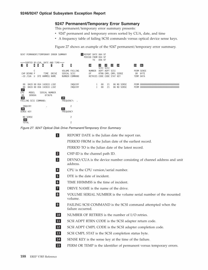
9247 Permanent/Temporary Error SummaryThis permanent/temporary error summary presents:v 9247 permanent and temporary errors sorted by CUA, date, and timev A frequency table of failing SCSI commands versus optical device sense keys.
Figure 27 shows an example of the 9247 permanent/temporary error summary.
�1� REPORT DATE is the Julian date the report ran.
PERIOD FROM is the Julian date of the earliest record.
PERIOD TO is the Julian date of the latest record.
�2� CHP-ID is the channel path ID.
�3� DEVNO/CUA is the device number consisting of channel address and unitaddress.
�4� CPU is the CPU version/serial number.
�5� DTE is the date of incident.
�6� TIME HHMMSS is the time of incident.
�7� DRIVE NAME is the name of the drive.
�8� VOLUME SERIAL NUMBER is the volume serial number of the mountedvolume.
�9� FAILING SCSI COMMAND is the SCSI command attempted when thefailure occurred.
�10� NUMBER OF RETRIES is the number of I/O retries.
�11� SCSI ADPT RTRN CODE is the SCSI adapter return code.
�12� SCSI ADPT CMPL CODE is the SCSI adapter completion code.
�13� SCSI CMPL STAT is the SCSI completion status byte.
�14� SENSE KEY is the sense key at the time of the failure.
�15� PERM OR TEMP is the identifier of permanent versus temporary errors.
9247 PERMANENT/TEMPORARY ERROR SUMMARY �1�REPORT DATE 064 97PERIOD FROM 054 97
TO 056 97****SORTED BY:CUA, DATE AND TIME****�2 3 4 5 6 7 8 9 10 11 12 13 14 15 16�
SCSI SCSIC VOLUME FAILING NUMBER ADPT ADPT SCSI PERM SENSE
CHP DEVNO P TIME DRIVE SERIAL SCSI OF RTRN CMPL CMPL SENSE OR BYTE-ID /CUA U DTE HHMMSS NAME NUMBER COMMAND RETRIES CODE CODE STAT KEY TEMP DATA
00 0AC0 00 054 142833 L1D2 INQUIRY 1 00 21 06 NO SENSE PERM 0000000000000000000000000000000000 0AC0 00 056 142833 L1D2 INQUIRY 1 00 21 06 NO SENSE PERM 00000000000000000000000000000000
�17�CPU MODEL SERIAL NUMBER00 3090XA 073676�18� �19�FAILING SCSI COMMAND: FREQUENCY: .
INQUIRY . 2�20� �21�SENSE KEY FREQUENCY
NO SENSE 2�22�TOTAL 2
Figure 27. 9247 Optical Disk Drive Permanent/Temporary Error Summary
9246/9247 Optical Subsystem Exception Report
188 EREP V3R5 Reference
�16� SENSE BYTE DATA is the 9247 device dependent sense data.
�17� CPU, MODEL, SERIAL NUMBER provides further information on the CPUlisted �4�in the lines of the report (370-XA mode if MODEL ends in X'XA').
�18� FAILING SCSI COMMAND is the heading for the failing SCSI commandsummary.
�19� FREQUENCY is the accumulated number of each FAILING SCSICOMMAND �18�.
�20� SENSE KEY is the heading for the sense key summary.
�21� FREQUENCY is the accumulated number of each SENSE KEY �20�.
�22� TOTAL is the accumulated total of column �21�.
9246/9247 Optical Subsystem Exception Report
Chapter 11. System Exception Report Series 189

9247 Error Code SummaryThis error code summary presents 9247 permanent and temporary errors sorted bysense key (PFU), CUA, date, and time.
Figure 28 shows an example of the 9247 error code summary.
�1� REPORT DATE is the Julian date the report ran.
PERIOD FROM is the Julian date of the earliest record.
PERIOD TO is the Julian date of the latest record.
�2� SENSE KEY is the sense key at the time of the failure.
�3� CHP-ID is the channel path ID.
�4� DEVNO/CUA is the device number consisting of channel address and unitaddress.
�5� CPU is the CPU version/serial number.
�6� DTE is the date of incident.
�7� TIME HHMMSS is the time of incident.
�8� DRIVE NAME is the name of the drive.
�9� VOLUME SERIAL NUMBER is the volume serial number of the mountedvolume.
�10� FAILING SCSI COMMAND is the SCSI command attempted when thefailure occurred.
�11� NUMBER OF RETRIES is the number of I/O retries.
�12� SCSI ADPT RTRN CODE is the SCSI adapter return code.
�13� SCSI ADPT CMPL CODE is the SCSI adapter completion code.
�14� SCSI CMPL STAT is the SCSI completion status byte.
�15� PERM OR TEMP is the identifier of permanent vs. temporary errors.
�16� SENSE BYTE DATA is the 9247 device dependent sense data.
�17� CPU, MODEL, SERIAL NUMBER provides further information on the CPUlisted �5�in the lines of the report (370-XA mode if MODEL ends in X'XA').
9247 ERROR CODE SUMMARY �1�REPORT DATE 065 97PERIOD FROM 054 97
TO 056 97****SORTED BY SENSE KEY(PFU), CUA, DATE AND TIME****�2 3 4 5 6 7 8 9 10 11 12 13 14 15 16�
SCSI SCSIC VOLUME FAILING NUMBER ADPT ADPT SCSI PERM SENSE
SENSE CHP DEVNO P TIME DRIVE SERIAL SCSI OF RTRN CMPL CMPL OR BYTEKEY -ID /CUA U DTE HHMMSS NAME NUMBER COMMAND RETRIES CODE CODE STAT TEMP DATA
NO SENSE 00 0AC0 00 054 142833 L1D2 INQUIRY 1 00 21 06 PERM 00000000000000000000000000000000NO SENSE 00 0AC0 00 056 142833 L1D2 INQUIRY 1 00 21 06 PERM 00000000000000000000000000000000�17�CPU MODEL SERIAL NUMBER00 3090XA 073676
Figure 28. 9247 Optical Disk Drive Error Code Summary
9246/9247 Optical Subsystem Exception Report
190 EREP V3R5 Reference

9247 Volume Error SummaryThis volume error summary presents:v 9247 permanent and temporary errors sorted by volume, CUA, date, and timev A frequency table of failing SCSI commands versus optical device sense keysv A frequency table of volume serial number versus drive
Figure 29 shows an example of the 9247 volume error summary.
�1� REPORT DATE is the Julian date the report ran.
PERIOD FROM is the Julian date of the earliest record.
PERIOD TO is the Julian date of the latest record.
�2� VOLUME SERIAL NUMBER is the volume serial number of the mountedvolume.
�3� CHP-ID is the channel path ID.
�4� DEVNO/CUA is the device number consisting of channel address and unitaddress.
�5� CPU is the CPU version/serial number.
�6� DTE is the is the date of incident.
�7� TIME HHMMSS is the time of incident.
�8� DRIVE NAME is the name of the drive.
�9� FAILING SCSI COMMAND is the SCSI command attempted when thefailure occurred.
�10� NUMBER OF RETRIES is the number of I/O retries.
�11� SCSI ADPT RTRN CODE is the SCSI adapter return code.
�12� SCSI ADPT CMPL CODE is the SCSI adapter completion code.
�13� SCSI CMPL STAT is the SCSI completion status byte.
�14� SENSE KEY is the sense key at the time of the failure.
9247 VOLUME ERROR SUMMARY �1�REPORT DATE 065 97PERIOD FROM 054 97
TO 056 97****SORTED BY:VOLUME, CUA, DATE AND TIME****�2 3 4 5 6 7 8 9 10 11 12 13 14 15 16�
SCSI SCSIVOLUME C FAILING NUMBER ADPT ADPT SCSI PERM SENSESERIAL CHP DEVNO P TIME DRIVE SCSI OF RTRN CMPL CMPL SENSE OR BYTENUMBER -ID /CUA U DTE HHMMSS NAME COMMAND RETRIES CODE CODE STAT KEY TEMP DATA
00 0AC0 00 054 142833 L1D2 INQUIRY 1 00 21 06 NO SENSE PERM 0000000000000000000000000000000000 0AC0 00 056 142833 L1D2 INQUIRY 1 00 21 06 NO SENSE PERM 00000000000000000000000000000000
�17�CPU MODEL SERIAL NUMBER00 3090XA 073676�18� �19�FAILING SCSI COMMAND FREQUENCY
INQUIRY 2�20� �21�SENSE KEY FREQUENCY
NO SENSE 2�22�TOTAL 2
Figure 29. 9247 Optical Disk Drive Volume Error Summary
9246/9247 Optical Subsystem Exception Report
Chapter 11. System Exception Report Series 191

�15� PERM OR TEMP is the identifier of permanent versus temporary errors.
�16� SENSE BYTE DATA is the 9247 device dependent sense data.
�17� CPU, MODEL, SERIAL NUMBER provides further information on the CPUlisted �5�in the lines of the report (370-XA mode if MODEL ends in X'XA').
�18� FAILING SCSI COMMAND is the heading for the failing SCSI commandsummary.
�19� FREQUENCY is the accumulated number of each FAILING SCSICOMMAND �18�.
�20� SENSE KEY is the heading for the sense key summary.
�21� FREQUENCY is the accumulated number of each SENSE KEY �20�.
�22� TOTAL is the accumulated total of column �21�.
9246/9247 Optical Subsystem Exception Report
192 EREP V3R5 Reference

Tape Subsystem ExceptionThe tape subsystem exception report series shows error data and usage statisticsfor tape subsystems. Data is summarized by component.
The series comprises any combination of the following tape reports:
Tape reports
Subsystem exception Permanent/recovered error summary
Permanent error summary Error code summary report
Temporary error summary Temporary error summary device
Forced error log Temporary error summary channel
DEVNO/CUA statistics summary Library permanent/recover report
Volume statistics summary Library error code summary report
FRU summary CUA statistics summary
Refer to your device maintenance information (MI) manual for the list of EREPreports that appear under the subsystem exception report for your specific device.
The reports are organized as shown in the following table:
ORGANIZED BY DESCRIPTION
Exception type Permanent errors and temporary errors that exceed the values in theLIMIT control statement
Suspected source ofthe error
Either hardware or the volume and the drive it has been created on.
The following table shows the type of error records and their source in the tapesubsystem exception reports.
TYPE SOURCE
A3 Tape devices (not 3590s) ; including controllersMDR Tape devices (not 3590s) ; including controllersOBR Tape devices (not 3590s) ; including controllers
If the tape subsystem exception report indicates that corrective action is necessary,the summary reports provide the details required for correction.
The errors may relate to the megabytes processed and depend on product type andusage.
Set the values for temporary errors in the LIMIT control statement so the reportscan be used as a maintenance tool. Refer to your MI manual for additionalinformation.
Look for temporary errors that cause system degradation.
Figures containing examples of these reports are on the pages shown in thefollowing table:
Tape Subsystem Exception
Chapter 11. System Exception Report Series 193
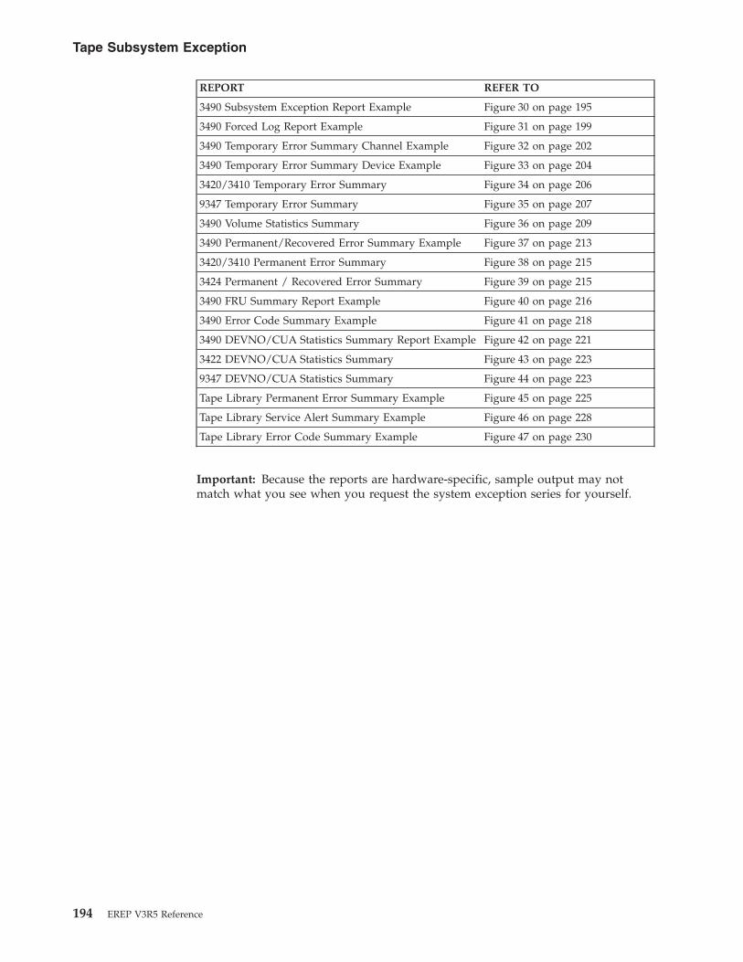
REPORT REFER TO
3490 Subsystem Exception Report Example Figure 30 on page 195
3490 Forced Log Report Example Figure 31 on page 199
3490 Temporary Error Summary Channel Example Figure 32 on page 202
3490 Temporary Error Summary Device Example Figure 33 on page 204
3420/3410 Temporary Error Summary Figure 34 on page 206
9347 Temporary Error Summary Figure 35 on page 207
3490 Volume Statistics Summary Figure 36 on page 209
3490 Permanent/Recovered Error Summary Example Figure 37 on page 213
3420/3410 Permanent Error Summary Figure 38 on page 215
3424 Permanent / Recovered Error Summary Figure 39 on page 215
3490 FRU Summary Report Example Figure 40 on page 216
3490 Error Code Summary Example Figure 41 on page 218
3490 DEVNO/CUA Statistics Summary Report Example Figure 42 on page 221
3422 DEVNO/CUA Statistics Summary Figure 43 on page 223
9347 DEVNO/CUA Statistics Summary Figure 44 on page 223
Tape Library Permanent Error Summary Example Figure 45 on page 225
Tape Library Service Alert Summary Example Figure 46 on page 228
Tape Library Error Code Summary Example Figure 47 on page 230
Important: Because the reports are hardware-specific, sample output may notmatch what you see when you request the system exception series for yourself.
Tape Subsystem Exception
194 EREP V3R5 Reference

Tape Subsystem Exception ReportThis report indicates if the tape subsystem has permanent errors or is operatingwithin acceptable limits. It is a good tool to use for system maintenance.
The following are recommendations for using this report:v Set LIMITS on temporary errors to prevent printing excessive errors. See “LIMIT
Control Statement” on page 64 for LIMIT control statement details.v Use temporary errors to track system degradation.v The errors shown may relate to megabytes processed.v The tape subsystem exception report format and content vary somewhat
according to the device type involved. See for more information about specificproducts.
Figure 30 shows an example of the tape subsystem exception report.
Note: The following example is for a 3490E tape subsystem. Column headingsmay differ depending upon the specific device.
�1� REPORT DATE is the Julian date the report ran.
PERIOD FROM is the Julian date of the earliest record.
PERIOD TO is the Julian date of the latest record.
SUBSYSTEM EXCEPTION �1� REPORT DATE 063 973490 PERIOD FROM 049 97
TO 052 97
�2� TEMP WRT(CT) TEMP RD(CT)CURRENT LIMITS HARDWARE 999 5 999 1MBYTES/ERR VOLUME 40 3 200 1
�12� �13��3� �4� �5� �6� �7� �8� �9� �10� �11�
VOLUME DEVNO EQU ----MB/ERR PERM---- ----MB/ERR TEMP---- BUS OVR TOTAL - MBYTES HDREXCEPTION SERIAL /CUA CPU CHK READ(CT) WRITE(CT) WRITE(CT) READ(CT) OUT RUN READ WRITE SER
HARDWAREPERMANENT ERROR
5A3 E 1 0 0 0 0 1339 1 0 0 0 0 3249 13395A7 E 0 0 0 0 0 0 0 0 0 0 0 3985 1160
HARDWAREFAILED TEMPORARY READ OR WRITE LIMITS
5BC E 0 0 0 0 0 0 0 428 1 0 0 428 1
VOLUME OR CREATING DRIVEPERMANENT READ OR WRITE ERRORS ON MORE THAN ONE DRIVE
L30570 1 5A5 F 1 0 0 3 1 0 0 0 0 0 0 0 3 00000L27530 5A2 E 0 0 0 5 1 0 0 0 0 0 0 0 5 00000
VOLUME OR CREATING DRIVEFAILED TEMPORARY READ OR WRITE LIMITS ON MORE THAN ONE DRIVE
L70630 5A4 F 0 0 0 0 0 0 12 0 0 0 0 0 0 00000L72930 5B2 F 0 0 0 0 0 0 0 39 1 0 0 39 0 00000
VOLUMEFAILED TEMPORARY READ OR WRITE LIMITS
B42750 5BC E 0 0 0 0 0 0 0 0 1 0 0 0 0B07146 5A2 E 0 0 0 0 0 0 0 73 1 0 0 73 73
�15� �16�TOTAL NUMBER OF DRIVES FAILING LIMITS 004 (20%) TOTAL NUMBER OF VOLUMES USED = 823
PASSING LIMITS 016 (80%) TOTAL NUMBER OF VOLUMES LISTED = 6
�14�CPU MODEL SERIAL NUMBERE 3081 210819F 3081 010819
Figure 30. 3490 Subsystem Exception Report Example
Tape Subsystem Exception
Chapter 11. System Exception Report Series 195

�2� CURRENT LIMITS and megabytes/error for both the hardware and thevolume are the limit values from the limit control statement. For details onusing the LIMIT statement, see “LIMIT Control Statement” on page 64 andChapter 19, “Magnetic Tape Devices,” on page 349.
�3� There are five exception categories:v Hardware Permanent Error
All CUAs with a tape permanent error are listed, or there are read/writeerrors on more than one drive not identified by a common volumeidentifier. Details of the permanent errors are found on the TapePermanent Error Summary report. When the CUA has an X as the lastdigit, sense bytes 16-17 have indicated a control unit failure.
v Hardware Failed Temporary Read or Write Limits
All CUAs that have an error rate equal to or exceeding the specifiedlimits are shown (but are not identified by a common volume identifier).Use the Temporary Error Summary report and the Volume StatisticsSummary report for more details.
v Volume or Creating Drive Permanent Read or Write Errors on MoreThan One Drive
The indicated volume has permanent errors on more than one drive. Thevolume may have been written (created) on one drive but has readerrors detected on another drive. Use the Permanent Error Summaryreport and the Volume Statistics Summary report for more details.
v Volume or Creating Drive Failed Temporary Read or Write Limits onMore Than One Drive
The indicated volume has an error rate equal to or exceeding thespecified limit on more than one drive. The volume may have beenwritten (created) on one drive but has read errors detected on anotherdrive. Use the Temporary Error Summary report and the VolumeStatistics Summary report for more details.
v Volume Failed Temporary Read or Write Limits
The indicated volumes has an error rate equal to or exceeding thespecified volume limits as shown. Use the Temporary Error Summaryreport and the Volume Statistics report for more details.
�4� The volume serial number.
�5� The device number in XA mode or the primary control unit address(PCUA).
�6� Identifies the host processor reporting the exception, and is shown as avalue of A through H. The actual CPU model and serial number are shownat the bottom of the report �14�.
�7� The number of equipment checks that have occurred.
�8� MB/ERR PERM is the reliability and error counts for permanent errors asshown in the following table:
TYPE DESCRIPTION
READ Is the average number of megabytes read per permanent read error.
CT Is the number of permanent read errors that have occurred.
WRITE Is the average number of megabytes written per permanent write error.
CT Is the number of permanent write errors that have occurred.
Tape Subsystem Exception
196 EREP V3R5 Reference

�9� MB/ERR TEMP is the reliability and error counts for temporary errors asshown in the following table:
TYPE DESCRIPTION
WRITE Is the average number of megabytes written per temporary write error.
CT Is the number of temporary write errors that have occurred.
READ Is the average number megabytes read per temporary read error.
CT Is the number of temporary read errors that have occurred.
�10� The number of bus out checks that have occurred.
�11� The number of overruns that have occurred.
�12� Total-MBYTES
READ is the total number of megabytes read.WRITE is the total number of megabytes written.
�13� The header serial number on the tape volume. The header number isderived from the last 4 digits of the control unit serial number that wrotethe volume, with the drive address added to the last position.
For example:Header serial is 3892F.The last 4 digits of the control unit serial number are 3892.Drive address is F.
�14� Identifies the CPU �6� listed in the error summary lines of the report.
�15� Lists the total number of drives:
Pass or Fail Description
FAILING LIMITS The number and the percentage of drives that exceeded the limit controls fortemporary errors and lists all drives that had permanent errors.
These drives are included in this report.
PASSING LIMITS The number and the percentage of drives that were within the limit controlsfor temporary errors and had no permanent errors.
These drives are not included in this report.
�16� Lists the total number of volumes:
Used orListed Description
USED Is the number of volumes used during the report period that did not exceed the limitcontrols for temporary errors and had no permanent errors.
LISTED Is the number of volumes used during the report period that exceeded the limit controlvalues for temporary errors and all volumes that had permanent errors.
Tape Subsystem Exception
Chapter 11. System Exception Report Series 197
Tape Forced Error Log/Permanent Error Summary ReportsThe tape forced log report and the permanent error summary report summarizethe temporary error OBR records. Look for clusters of errors that occur within astring of drives or at specific times. This could indicate a control unit problem.
The Forced Error Log report is generated only when the forced error logging bithas been set.
Both types of reports have the same format. The only difference is the heading, onetitled Permanent Error Summary and the other Forced Error Log. Sense byte 7 willbe 19 to indicate format 19 sense (temporary errors) on the Forced Error Log reportor 20 to indicate format 20 sense (permanent errors) on the Permanent ErrorSummary report.
Only the 3422, 3430, 3480, and 3490 devices produce this report.
The errors are listed by channel unit address (CUA) for hardware errors and byvolume identifier (VOLID) for suspected volume errors. The errors are listed by theCUA unless they occur on the same VOLID on at least two different driveaddresses, then they are listed by VOLID.
Figure 31 on page 199 shows an example of the tape forced error log/permanenterror summary reports.
Tape Subsystem Exception
198 EREP V3R5 Reference
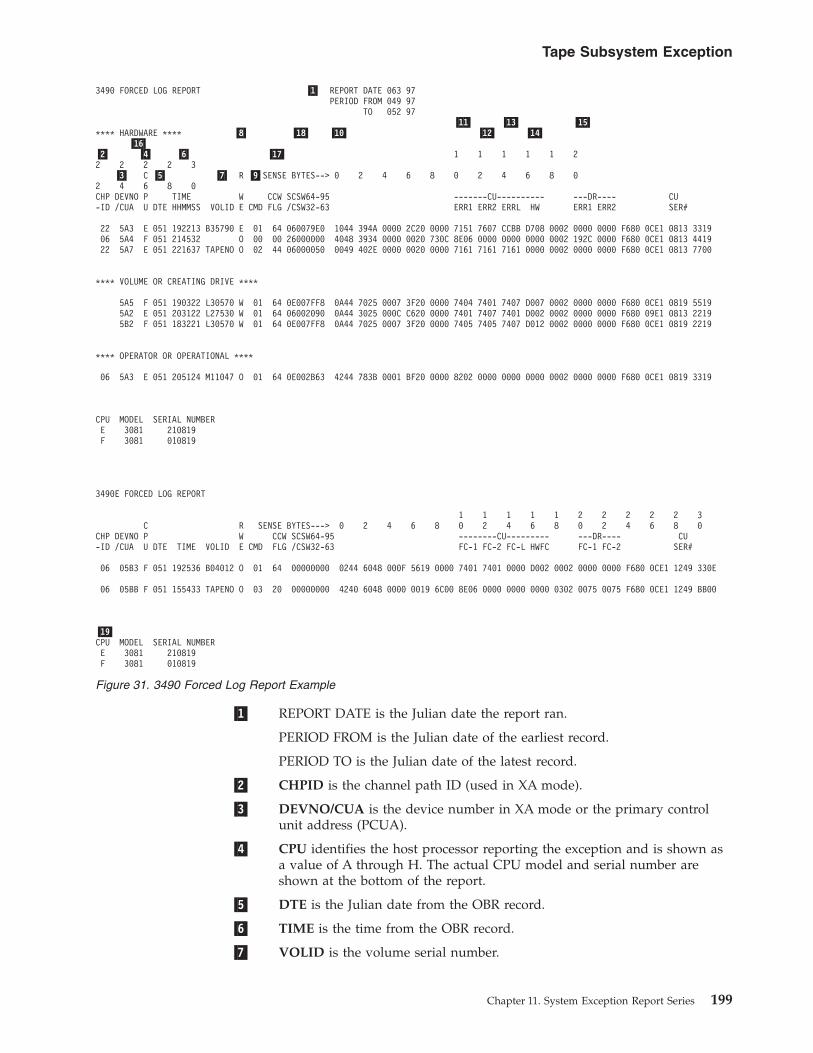
�1� REPORT DATE is the Julian date the report ran.
PERIOD FROM is the Julian date of the earliest record.
PERIOD TO is the Julian date of the latest record.
�2� CHPID is the channel path ID (used in XA mode).
�3� DEVNO/CUA is the device number in XA mode or the primary controlunit address (PCUA).
�4� CPU identifies the host processor reporting the exception and is shown asa value of A through H. The actual CPU model and serial number areshown at the bottom of the report.
�5� DTE is the Julian date from the OBR record.
�6� TIME is the time from the OBR record.
�7� VOLID is the volume serial number.
3490 FORCED LOG REPORT �1� REPORT DATE 063 97PERIOD FROM 049 97
TO 052 97�11� �13� �15�
**** HARDWARE **** �8� �18� �10� �12� �14��16�
�2� �4� �6� �17� 1 1 1 1 1 22 2 2 2 3
�3� C �5� �7� R �9�SENSE BYTES--> 0 2 4 6 8 0 2 4 6 8 02 4 6 8 0CHP DEVNO P TIME W CCW SCSW64-95 -------CU---------- ---DR---- CU-ID /CUA U DTE HHMMSS VOLID E CMD FLG /CSW32-63 ERR1 ERR2 ERRL HW ERR1 ERR2 SER#
22 5A3 E 051 192213 B35790 E 01 64 060079E0 1044 394A 0000 2C20 0000 7151 7607 CCBB D708 0002 0000 0000 F680 0CE1 0813 331906 5A4 F 051 214532 O 00 00 26000000 4048 3934 0000 0020 730C 8E06 0000 0000 0000 0002 192C 0000 F680 0CE1 0813 441922 5A7 E 051 221637 TAPENO O 02 44 06000050 0049 402E 0000 0020 0000 7161 7161 7161 0000 0002 0000 0000 F680 0CE1 0813 7700
**** VOLUME OR CREATING DRIVE ****
5A5 F 051 190322 L30570 W 01 64 0E007FF8 0A44 7025 0007 3F20 0000 7404 7401 7407 D007 0002 0000 0000 F680 0CE1 0819 55195A2 E 051 203122 L27530 W 01 64 06002090 0A44 3025 000C C620 0000 7401 7407 7401 D002 0002 0000 0000 F680 09E1 0813 22195B2 F 051 183221 L30570 W 01 64 0E007FF8 0A44 7025 0007 3F20 0000 7405 7405 7407 D012 0002 0000 0000 F680 0CE1 0819 2219
**** OPERATOR OR OPERATIONAL ****
06 5A3 E 051 205124 M11047 O 01 64 0E002B63 4244 783B 0001 BF20 0000 8202 0000 0000 0000 0002 0000 0000 F680 0CE1 0819 3319
CPU MODEL SERIAL NUMBERE 3081 210819F 3081 010819
3490E FORCED LOG REPORT
1 1 1 1 1 2 2 2 2 2 3C R SENSE BYTES---> 0 2 4 6 8 0 2 4 6 8 0 2 4 6 8 0
CHP DEVNO P W CCW SCSW64-95 --------CU--------- ---DR---- CU-ID /CUA U DTE TIME VOLID E CMD FLG /CSW32-63 FC-1 FC-2 FC-L HWFC FC-1 FC-2 SER#
06 05B3 F 051 192536 B04012 O 01 64 00000000 0244 6048 000F 5619 0000 7401 7401 0000 D002 0002 0000 0000 F680 0CE1 1249 330E
06 05BB F 051 155433 TAPENO O 03 20 00000000 4240 6048 0000 0019 6C00 8E06 0000 0000 0000 0302 0075 0075 F680 0CE1 1249 BB00
�19�CPU MODEL SERIAL NUMBERE 3081 210819F 3081 010819
Figure 31. 3490 Forced Log Report Example
Tape Subsystem Exception
Chapter 11. System Exception Report Series 199

�8� R/W/E/O defines the type of check as Read, Write, Equipment or Othercheck.
�9� CMD is the command code from the channel command word (CCW) inthe OBR record.
�10� SENSE BYTES is the sense data from the OBR record.
�11� CU-ERR1 is the microcode-detected error code for the first error (controlunit or drive), from the OBR record (sense bytes 10 and 11). This errorcode should not be used as an entry to the maintenance package unlessefforts using CU-HW �14� or DR-ERR1 �15� or both have not corrected thesubsystem problem.
�12� CU-ERR2 is the microcode-detected error code for the second error (controlunit or drive), from the OBR record (sense bytes 12 and 13). This errorcode can be a result of the first error indicated in CU-HW �14�, DR-ERR1�15�, or CU-ERR1 �11�.
�13� CU-ERRL is the microcode-detected error code for the last error (controlunit or drive), from the OBR record (sense bytes 14 and 15). This errorcode can be a result of the first error indicated in CU-HW �14�, DR-ERR1�15�, CU-ERR1 �11�, DR-ERR2 �16�, or CU-ERR2 �12�.
�14� CU-HW is the control unit hardware-detected error code from the OBRrecord (sense bytes 16 and 17). This error code defines a control unit failureand should be used to enter the maintenance package if you have multipledrive failures.
�15� DR-ERR1 is the drive hardware-detected error code, from the OBR record(sense bytes 20 and 21). This error code defines the first failure for anydrive and should be used to enter the maintenance package if you havesingle drive failures.
�16� DR-ERR2 is the drive hardware-detected error code, from the OBR record(sense bytes 22 and 23). This error code defines the second or last failurefor any drive and should not be used to enter the maintenance package ifyou have single drive failures. This error information providessupplemental information and may be a result of the first failure(DR-ERR1) in the drive.
�17� CCW FLG is CCW bits 32 to 39 from the OBR.
�18� SCSW/CSW is:SCSW64—95 (in XA Mode)CSW32—63
These are the SCSW or CSW bits from the OBR record.
�19� CPU, MODEL, SERIAL NUMBER provides further information on theCPU listed �4� in the error summary lines of the report.
Tape Subsystem Exception
200 EREP V3R5 Reference

Tape Temporary Error SummaryThis report presents all the temporary read/write errors recorded for tapehardware during the report period for all MDR records. Errors are listed by CUAor device number and density regardless of whether or not they exceeded theLIMIT values and appeared in the subsystem exception report.
The LIMIT control values specified when invoking EREP are ignored for thisreport.
The column headings may differ depending upon the specific device.
Only the 3480 and 3490 devices can produce a two-part temporary error summaryreport: one displaying device activity and the other displaying channel activity. Therest of the 34XX devices combine them in one report.
Figures containing examples of these reports are on the pages shown in thefollowing table:
REPORT REFER TO
3490 Temporary Error Summary Channel Example Figure 32 on page 202
3490 Temporary Error Summary Device Example Figure 33 on page 204
3420/3410 Temporary Error Summary Figure 34 on page 206
9347 Temporary Error Summary Figure 35 on page 207
Tape Subsystem Exception
Chapter 11. System Exception Report Series 201

�1� REPORT DATE is the Julian date the report ran.
PERIOD FROM is the Julian date of the earliest record.
PERIOD TO is the Julian date of the latest record.
�2� DEVNO/CUA is the device number in XA mode or the primary controlunit address (PCUA).
�3� DRIVE ID is the last 4 digits of the control unit serial number that wrotethe volume, with the drive address added as the last digit.
�4� CPU identifies the host processor reporting the exception. The actual CPUmodel and serial number are shown at the bottom of the report.
�5� MOUNTS is the total number of all mounts on this device.
�6� WRITE
MB/ERR is the average number of megabytes written per temporarywrite error from the channel.
3490 TEMPORARY ERROR SUMMARY CHANNEL �1� REPORT DATE 067 97PERIOD FROM 049 97
TO 052 97
�2� �3� �4� �5� �6� �7� �8� �9��10�
TOTAL BLOCKS �11�DEVNO DRIVE --WRITE----- --READ------ TOTAL MBYTES -PROCESSED- --READ------ --WRITE----/CUA ID CPU MOUNTS MB/ERR ERRCT MB/ERR ERRCT READ WRITE READ WRITE MB/COR ECC MB/COR ECC
5A0 08160 0F 101 -- 0 -- 0 2495 2328 530176 300288 68 71 62 1005A1 08151 0F 94 -- 0 -- 0 4070 1691 458240 237824 74 146 49 1015A2 08152 0F 118 866 1 7030 1 7030 866 653056 94720 35 391 33 565A3 08153 0F 151 2108 1 -- 0 5563 2108 793088 330752 34 318 20 2075A4 08154 0F 94 179 12 -- 0 6114 2148 802408 243968 49 243 41 1025A5 08155 0F 109 1516 1 -- 0 6492 1516 797440 200448 60 215 59 515A6 08156 0F 106 -- 0 -- 0 1676 1590 190464 283392 45 79 20 1665A7 08157 0F 127 -- 0 -- 0 5697 1970 705792 227072 85 248 56 1215B0 12450 0F 23 -- 0 -- 0 42 142 5376 13568 27 1 10 135B1 12451 0F 35 -- 0 -- 0 2584 195 173070 25600 27 182 4 425B2 12452 F0 29 -- 0 528 1 528 55 95744 4096 132 15 44 15B3 12453 F0 25 383 1 -- 0 22 383 4864 46848 -- 0 82 225B4 12454 F0 18 -- 0 -- 0 541 481 48384 26112 19 87 80 175B5 12455 F0 17 -- 0 -- 0 19 8 2048 1024 14 3 8 15B8 12458 F0 21 -- 0 -- 0 5 553 3840 18432 -- 0 66 215B9 12459 F0 25 -- 0 -- 0 856 185 77568 6144 35 53 185 15BA 1245A F0 19 -- 0 -- 0 6 4 768 0 -- 0 0 05BB 1245B F0 15 -- 0 -- 0 12 256 1024 23040 -- 0 42 155BC 1245C F0 12 -- 0 609 1 609 13 53760 3328 64 26 3 45BD 1245D F0 16 -- 0 -- 0 728 83 65792 6912 52 43 41 4
TOTAL 1155 16 3 45076 17076 5534K 1899K 1843 950
�17�AVERAGE MEGABYTES/TEMPORARY READ ERROR = 15025AVERAGE MEGABYTES/TEMPORARY WRITE ERROR = 1067AVERAGE MEGABYTES/RECOVERED ERROR = 15538AVERAGE MEGABYTES/PERMANENT READ ERROR = *AVERAGE MEGABYTES/PERMANENT WRITE ERROR = 8538AVERAGE MEGABYTES/PERMANENT ERROR # = 12430 (#) = THERE WERE NO ERRORS LOGGED FOR CALCULATIONAVERAGE MEGABYTES/PERMANENT HARDWARE ERROR = 20717AVERAGE MEGABYTES/PERMANENT VOLUME ERROR = 31076AVERAGE MEGABYTES/PERMANENT OTHER ERROR = *TOTAL MEGABYTES PROCESSED = 62152
�18�CPU MODEL SERIAL NUMBER0E 3081 210819F0 3081 010819
Figure 32. 3490 Temporary Error Summary Channel Example
Tape Subsystem Exception
202 EREP V3R5 Reference
ERRCT is the total count of all temporary write errors from thechannel.
�7� READ
MB/ERR is the average number of megabytes read per temporary readerror from the channel.ERRCT is the total count of all temporary read errors from the channel.
�8� TOTAL MBYTES READ WRITE
READ is the total number of megabytes read on the channel.WRITE is the total number of megabytes written on the channel.
�9� TOTAL BLOCKS PROCESSED READ WRITE
READ is the total number of blocks read from the channel.WRITE is the total number of blocks written from the channel.
�10� READ MB/COR ECC
MB/COR is the average number of megabytes read on the device, perread ECC error.ECC is the number of read ECC corrected blocks read from the device.
�11� WRITE MB/COR ECC
MB/COR is the average number of megabytes written on the device,per correctable error.ECC is the number of blocks that have been written with read ECCcorrectable errors, as determined by read-back ECC checking.
�17� TOTAL and AVERAGE
v AVERAGE is the total number of megabytes divided by the totalnumber of errors of a particular type, for all 3490 drives used by theoperating system.For example:Average Megabytes/Temporary Read Errors is the total number of themegabytes read divided by the total number of the temporary readerrors.The PERMANENT ERROR values are meant to provide a source ofperformance information for all 3490 drives in the operating system. TheTOTAL MEGABYTES read, written and processed are for all 3490 drivesused by the operating system.An asterisk (*) in the calculation field (to the right of the equal sign)indicates that no errors were logged.
�18� CPU, MODEL, SERIAL NUMBER further identifies the CPU listed in theerror summary lines of the report.
Tape Subsystem Exception
Chapter 11. System Exception Report Series 203

�1� REPORT DATE is the Julian date the report ran.
PERIOD FROM is the Julian date of the earliest record.
PERIOD TO is the Julian date of the latest record.
�2� DEVNO/CUA is the device number in XA mode or the primary controlunit address (PCUA).
�3� DRIVE ID is the last 4 digits of the control unit serial number that wrotethe volume, with the drive address added as the last digit.
�4� CPU identifies the host processor reporting the exception. The actual CPUmodel and serial number are shown at the bottom of the report.
�5� MOUNTS is the total number of all mounts on this device.
�6� WRITE
MB/ERR is the average number of megabytes written per temporarywrite error on the device.ERRCT is the total count of all temporary write errors on the device.
3490 TEMPORARY ERROR SUMMARY DEVICE �1� REPORT DATE 067 97PERIOD FROM 049 97
TO 052 97 �13� �15��11� �12�
�2� �3� �4� �5� �6� �7� �8� �9��10�
TOTAL BLOCKS READ WRITE DRV CU �16�:erk.DEVNO DRIVE --WRITE----- --READ------ TOTAL MBYTES -PROCESSED- --READ------ --WRITE---- RECVY ERASE DET EQC TRA/CUA ID CPU MOUNTS MB/ERR ERRCT MB/ERR ERRCT READ WRITE READ WRITE MB/COR ECC MB/COR ECC ACTS GAPS ERR CHK ERR
5A0 08160 0F 101 -- 0 -- 0 2495 2328 530176 300288 68 71 62 100 0 0 0 0 05A1 08151 0F 94 -- 0 -- 0 4070 1691 458240 237824 74 146 49 101 0 0 0 0 05A2 08152 0F 118 866 1 7030 1 7030 866 653056 94720 35 391 33 56 3 0 0 0 05A3 08153 0F 151 2108 1 -- 0 5563 2108 793088 330752 34 318 20 207 0 0 0 0 05A4 08154 0F 94 179 12 -- 0 6114 2148 802408 243968 49 243 41 102 0 0 1 0 05A5 08155 0F 109 1516 1 -- 0 6492 1516 797440 200448 60 215 59 51 0 0 0 0 05A6 08156 0F 106 -- 0 -- 0 1676 1590 190464 283392 45 79 20 166 0 0 0 0 05A7 08157 0F 127 -- 0 -- 0 5697 1970 705792 227072 85 248 56 121 0 0 0 0 05B0 12450 0F 23 -- 0 -- 0 42 142 5376 13568 27 1 10 13 0 0 0 0 05B1 12451 0F 35 -- 0 -- 0 2584 195 173070 25600 27 182 4 42 0 0 0 0 05B2 12452 F0 29 -- 0 528 1 528 55 95744 4096 132 15 44 1 0 0 0 0 05B3 12453 F0 25 383 1 -- 0 22 383 4864 46848 -- 0 82 22 0 1 0 0 05B4 12454 F0 18 -- 0 -- 0 541 481 48384 26112 19 87 80 17 0 0 0 0 05B5 12455 F0 17 -- 0 -- 0 19 8 2048 1024 14 3 8 1 0 0 0 0 05B8 12458 F0 21 -- 0 -- 0 5 553 3840 18432 -- 0 66 21 0 0 0 0 05B9 12459 F0 25 -- 0 -- 0 856 185 77568 6144 35 53 185 1 0 0 0 0 05BA 1245A F0 19 -- 0 -- 0 6 4 768 0 -- 0 0 0 0 0 0 0 05BB 1245B F0 15 -- 0 -- 0 12 256 1024 23040 -- 0 42 15 0 0 0 0 05BC 1245C F0 12 -- 0 609 1 609 13 53760 3328 64 26 3 4 0 0 0 0 05BD 1245D F0 16 -- 0 -- 0 728 83 65792 6912 52 43 41 4 0 0 0 0 0
TOTAL 1155 16 3 45076 17076 5534K 1899K 1843 950 3 1 1 0 0
�17�AVERAGE MEGABYTES/TEMPORARY READ ERROR = 15025AVERAGE MEGABYTES/TEMPORARY WRITE ERROR = 1067AVERAGE MEGABYTES/RECOVERED ERROR = 15538AVERAGE MEGABYTES/PERMANENT READ ERROR = *AVERAGE MEGABYTES/PERMANENT WRITE ERROR = 8538AVERAGE MEGABYTES/PERMANENT ERROR # = 12430 (#) = THERE WERE NO ERRORS LOGGED FOR CALCULATIONAVERAGE MEGABYTES/PERMANENT HARDWARE ERROR = 20717AVERAGE MEGABYTES/PERMANENT VOLUME ERROR = 31076AVERAGE MEGABYTES/PERMANENT OTHER ERROR = *TOTAL MEGABYTES PROCESSED = 62152
�18�CPU MODEL SERIAL NUMBER0E 3081 210819F0 3081 010819
Figure 33. 3490 Temporary Error Summary Device Example
Tape Subsystem Exception
204 EREP V3R5 Reference

�7� READ
MB/ERR is the average number of megabytes read per temporary readerror on the device.ERRCT is the total count of all temporary read errors on the device.
�8� TOTAL MBYTES READ WRITE
READ is the total number of megabytes read from the device.WRITE is the total number of megabytes written on the device.
�9� TOTAL BLOCKS PROCESSED READ WRITE
READ is the total number of blocks read on the device.WRITE is the total number of blocks written on the device.
�10� READ MB/COR ECC
MB/COR is the average number of megabytes read on the device, perread ECC error.ECC is the number of read ECC corrected blocks read from the device.
�11� WRITE MB/COR ECC
MB/COR is the average number of megabytes written on the device,per correctable error.ECC is the number of blocks that have been written with read ECCcorrectable errors, as determined by read-back ECC checking.
�12� READ RECVY ACTS is the total number of correctable read errorsdetected during 3490 read error recovery.
�13� WRITE ERASE GAPS is the total number of blocks rewritten during errorrecovery.
�14� DRV DET ERR is the number of unit checks set by the drive.
�15� CU EQU CHK is the number of errors found in the use of external regs inthe CU for a given device.
�16� TRA ERR Flag indicating that transient errors have been detected byhardware checkers.
�17� TOTAL and AVERAGE
v AVERAGE is the total number of megabytes divided by the totalnumber of errors of a particular type, for all 3490 drives that were usedby the operating system.For example:Average Megabytes/Temporary Read Errors is the total number of themegabytes read divided by the total number of the temporary readerrors.The PERMANENT ERROR values are meant to provide a source ofperformance information for all 3490 drives in the operating system.The TOTAL MEGABYTES read, written and processed are for all 3490drives used by the operating system.An asterisk (*) in the calculation field (to the right of the equal sign)indicates that no errors were logged.
�18� CPU, MODEL, SERIAL NUMBER further identifies the CPU listed in theerror summary lines of the report.
Tape Subsystem Exception
Chapter 11. System Exception Report Series 205

3420/3410 TEMPORARY ERROR SUMMARY REPORT DATE 065 97PERIOD FROM 041 97
TO 059 97
TAPE C WRITE READDEVNO UNIT P DEN- TOTAL TOTAL STATISTICS STATISTICS ENV MTE SRC EDC VEL SKEW R/W WTM PAR/ OVER IBG/CUA SER U SITY I/O CNT MOUNT MB/ERR(CT) ERSGAP MB/ERR(CT) CLNACT VRC LRC /PC CRC CHG ERR VRC CHK TACH RUN DET
0180 59437 07 6250 10 0 -- ( 0) 0 -- ( 0) 0 0 0 0 0 0 0 0 0 0 0 00180 59437 07 1600 7526 1 0 ( 4) 4 -- ( 0) 0 2 0 0 0 2 0 0 0 0 0 0
0181 N/A 07 6250 6 0 -- ( 0) 0 -- ( 0) 0 0 0 0 0 0 0 0 0 0 0 0
0570 N/A 03 6250 3961 2 -- ( 0) 0 -- ( 0) 0 0 0 0 0 0 0 0 0 0 0 0
0570 N/A 08 OTHR 7 1 -- ( 0) 0 -- ( 0) 0 0 0 0 0 0 0 0 0 0 0 0
0572 N/A 09 6250 539 1 -- ( 0) 0 -- ( 0) 0 0 0 0 0 0 0 0 0 0 0 0
0573 N/A 03 6250 2314 1 -- ( 0) 0 -- ( 0) 0 0 0 0 0 0 0 0 0 0 0 0
0573 N/A 06 1600 1073 1 -- ( 0) 0 -- ( 0) 0 0 0 0 0 0 0 0 0 0 0 0
0575 N/A 03 1600 3 1 -- ( 0) 0 -- ( 0) 0 0 0 0 0 0 0 0 0 0 0 0
6250BPI TOTALS: 6830 4 ( 0) 0 ( 0) 0
1600BPI TOTALS: 8602 3 ( 4) 4 ( 0) 0
OTHRBPI TOTALS: 7 1 ( 0) 0 ( 0) 0
TOTALS: 15439 8 ( 4) 4 ( 0) 0
AVERAGE MEGABYTES/TEMPORARY READ ERROR = ------AVERAGE MEGABYTES/TEMPORARY WRITE ERROR = 0AVERAGE MEGABYTES/PERMANENT READ ERROR = ------AVERAGE MEGABYTES/PERMANENT WRITE ERROR = ------AVERAGE MEGABYTES/PERMANENT ERROR = ------TOTAL MEGABYTES PROCESSED = 0TOTAL MEGABYTES READ = 0TOTAL MEGABYTES WRITTEN = 0
CPU MODEL SERIAL NUMBER00 9375 23456701 3090XA 17002802 3084XA 32112803 3084XA 12112804 3081XA 22117005 4341 01508506 3081XA 22044707 4331 01307808 3081XA 22157309 3033 021928
Figure 34. 3420/3410 Temporary Error Summary
Tape Subsystem Exception
206 EREP V3R5 Reference

9347 TEMPORARY ERROR SUMMARY REPORT DATE 065 97PERIOD FROM 041 97
TO 059 97
CDEVNO P TIME VOLUME I/O--COUNTS PERM ERROR TEMP ERROR RETRIES REPSN ---------------- COUNT ----------------/CUA U DTE HHMMSS SERIAL READ WRITE READ WRITE READ WRITE READ WRITE COUNT OVR MLT RUP IBG WPC SKW TR4 TR5 TRP ECC
0C70 00 047 181315 0 1249 0 0 0 0 0 0 105 0 0 0 0 0 0 0 0 0 00C70 00 049 060759 227 0 6 15 1 0 58 92 192 0 7 3 1 0 0 7 7 4 2240C70 00 049 061239 229 0 0 0 1 0 1 0 226 0 0 1 0 0 0 0 1 0 224
CPU MODEL SERIAL NUMBER00 9375 23456701 3090XA 17002802 3084XA 32112803 3084XA 12112804 3081XA 22117005 4341 01508506 3081XA 22044707 4331 01307808 3081XA 22157309 3033 021928
Figure 35. 9347 Temporary Error Summary
Tape Subsystem Exception
Chapter 11. System Exception Report Series 207

Tape Volume Statistics SummaryThis report provides an easy-to-use list of volumes with exceptions. It is useful infinding the media that is causing problems.
It is generated whenever a volume is listed on the tape subsystem exceptionreport; therefore, only volumes that have permanent errors or have failed thetemporary error limits are listed.
All the activity for every volume listed as an exception on the tape subsystemexception report as well as errors against the unit addresses (shown in theDEVNO/CUA statistics summary reports) is shown in chronological order. Entriesare grouped by volume serial and listed in order of occurrence.
The report shows:v Channel path IDv Device or control unit addressv Number of permanent and temporary errorsv Serial number of the tape drive that created the volume
Note: This can be used to find a device that generates volumes which causeproblems when used on other devices.
Erase gaps indicate the following sequence has occurred:1. A write error has occurred.2. The tape has been repositioned for the retry.3. The second attempt also detected an error.4. The tape has been repositioned again.5. A section of tape is erased and the write operation is retried again.
Note: Excessive write erase gaps indicate a problem with a cartridge or a drive.
Figure 36 on page 209 shows an example of the tape volume statistics summary.
Tape Subsystem Exception
208 EREP V3R5 Reference

�1� REPORT DATE is the Julian date the report ran.
PERIOD FROM is the Julian date of the earliest record.
PERIOD TO is the Julian date of the latest record.
�2� CURRENT LIMITS (MB/ERR) is the megabyte per temporary error limitthreshold from the limit control cards. For details on using the LIMITstatement, see .
�3� VOLUME SERIAL is the volume serial number.
�4� DATE DAY YR is the Julian date and year from the OBR or MDR record.
�5� TIME is the time from the OBR or MDR record.
�6� CHP-ID is the channel path ID (used in XA mode) and only appears if allerrors have occurred on 1 CHP-ID.
�7� DEVNO/CUA is the device number in XA mode or the primary controlunit address (PCUA).
�8� R/W/E defines the type of permanent error as a read, write, or equipmentcheck.
�9� BLOCK ID is the logical block position for permanent errors.
3490 VOLUME STATISTICS SUMMARY �1�REPORT DATE 067 97PERIOD FROM 051 97
TO 051 97
VOLUMES FAILING LIMITS OR PERMANENT ERRORS�2�CURRENT LIMITS TEMP WRT(CT) TEMP RD(CT)
MBYTES/ERR VOLUME 40 ( 3) 200 ( 1)�14� �15� �16�
�8� �12��17�
�3� �4� �5� �6� �7� R �9� �10� �11�READ �13�
VOLUME DATE TIME CHP DEVNO W BLOCK ----MB/ERR PERM--- ----MB/ERR TEMP---- RECVY ERASE -BLKS PROC- BLK --JOB--- PSERIAL DAY YR HH:MM:SS -ID /CUA E ID READ(CT) WRITE(CT) WRITE(CT) READ(CT) ACTNS GAPS READ WRITE LEN --NAME-- U
B07146 051 97 18:48:31 00 5A2 -- ( 0) -- ( 0) -- ( 0) -- ( 0) 3 0 6144 6144 0000 E
B42750 051 97 15:34:33 00 5BC -- ( 0) -- ( 0) -- ( 0) 0 ( 1) 0 0 0 0 0000 E
M11407 051 97 20:51:24 06 5A3 O 001BF -- ( 0) -- ( 0) -- ( 0) -- ( 0) 0 0 0 0 2EE4 C4KCC33E EM11407 051 97 20:57:53 00 5A3 001BF -- ( 0) -- ( 0) -- ( 0) -- ( 0) 0 0 0 256 0000 EM11407 051 97 21:07:11 00 5A1 001C5 -- ( 0) -- ( 0) -- ( 0) -- ( 0) 0 0 0 0 0000
TAPENO 051 97 22:16:18 22 5A7 -- ( 0) -- ( 0) -- ( 0) -- ( 0) 0 0 0 0 0000 EOX EXIT ETAPENO 051 97 22:16:37 22 5A7 O -- ( 0) -- ( 0) -- ( 0) -- ( 0) 0 0 0 0 0050 OPERX ETAPENO 051 97 22:18:40 22 5A7 -- ( 0) -- ( 0) -- ( 0) -- ( 0) 0 0 0 0 0000 EOS EXIT E
L30570 051 97 19:03:22 22 5A5 W -- ( 0) -- ( 0) 3 ( 1) -- ( 0) 0 0 0 5934 0234 EOS EXIT E
L27530 051 97 20:31:22 06 5A2 W -- ( 0) -- ( 0) 5 ( 1) -- ( 0) 0 0 0 10120 0256 EOS EXIT E
L70630 051 97 16:24:33 06 5A4 -- ( 0) -- ( 0) -- ( 12) -- ( 0) 0 0 0 9050 1250 EOS EXIT E
L72930 051 97 11:22:19 22 5B2 -- ( 0) -- ( 0) -- ( 0) 39 ( 1) 0 0 20302 0 2350 EOS EXIT E
B35790 051 97 19:22:13 22 5A3 E -- ( 0) -- ( 0) -- ( 0) -- ( 0) 0 0 0 0 0000 E
COLUMN TOTALS: ( 0) ( 0) ( 14) ( 2) ( 3) ( 0)
TOTALS: MOUNTS = 9TOTALS: MEGABYTES PROCESSED = 201
�18�CPU MODEL SERIAL NUMBERA 3081 210819B 3081 010819
Figure 36. 3490 Volume Statistics Summary
Tape Subsystem Exception
Chapter 11. System Exception Report Series 209

�10� MB/ERR PERM
READ is the average number of megabytes read per permanent readerror.CT is the total count of all permanent read errors.WRITE is the average number of megabytes written per permanentwrite error.CT is the total count of all permanent write errors.
�11� MB/ERR TEMP
READ is the average number of megabytes read per temporary readerror.CT is the total count of all temporary read errors.WRITE is the average number of megabytes written per temporarywrite error.CT is the total count of all temporary write errors.
�12� READ RECVY ACTNS is the total count of recoverable read errorsdetected during 3490 read error recovery.
�13� ERASE GAPS is the number of times a block is rewritten during errorrecovery for the listed volumes.
�14� BLKS PROCESSED
READ is the total number of blocks read for a volume that has had atleast one temporary, but no permanent, errors.WRITE is the total number of blocks written for a volume that has hadat least one temporary error, but no permanent errors.
�15� BLK LEN is the block length as taken from the OBR record for any listedvolume that had permanent errors.
�16� JOB NAME is the job name from the OBR record for any listed volumethat had permanent errors.
�17� CPU identifies the host processor reporting the exception.
�18� CPU, MODEL, SERIAL, NUMBER further identifies the CPU listed in theerror summary lines of this report.
Tape Subsystem Exception
210 EREP V3R5 Reference

Tape Permanent/Recovered Error SummaryThe tape permanent error summary report helps you analyze the causes ofpermanent errors. These errors require immediate attention because they indicatethat something in the system needs to be fixed.
This report describes in more detail the permanent errors that appear on the tapesubsystem exception report.
The following table shows how sense bytes 7 and 3 indicate the error type:
ERROR TYPE SENSE BYTE VALUES
Permanent Sense byte 7 will be 20 to indicate format 20 sense.
Sense byte 3 will be a value other than 48.
Recovered Sense byte 7 will be 20.
Sense byte 3 will always indicate 48. See note.
Service alert Sense byte 7 will be 20.
Sense byte 3 will always indicate 48. See note.
Note: This indicates that an error occurred and it took host interaction to recover from the error (CU error recoverywas not adequate).
The errors are grouped under separate headings indicating classification ofprobable failures and are listed by CUA or VOLID (volume serial number) in theorder they occurred.
Two groups of permanent errors are shown:v Hardwarev Volume or creating drive
The following details are provided in the report:v Channel path IDv Device numberv CPU connection, which tells were the error was detectedv Date and time the error was loggedv Volume ID (VOLID), which indicates which volume experienced the failurev Read, write, or equipment (RWE) column, which shows what type of error was
experiencedv Channel command word (CCW) that failed, which supplies data such command
code, flag byte, and byte countv Bits and bytes of pertinent inform from command status word (CSW)v Sense information from outboard records (OBR)v Header serial (HDRSER) number (serial number of the creating drive)
The information is organized so that permanent errors are shown in the order inwhich they occur.
The long OBR format is used with tape drives.
The column headings may differ depending upon the specific device.
Tape Subsystem Exception
Chapter 11. System Exception Report Series 211

Figures containing examples of these reports are on the pages shown in thefollowing table:
REPORT REFER TO
3490 Permanent/Recovered Error Summary Example Figure 37 on page 213
3420/3410 Permanent Error Summary Figure 38 on page 215
3424 Permanent/Recovered Error Summary Figure 39 on page 215
Tape Subsystem Exception
212 EREP V3R5 Reference
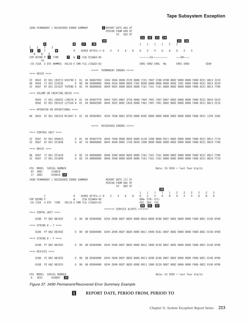
�1� REPORT DATE, PERIOD FROM, PERIOD TO
3490 PERMANENT / RECOVERED ERROR SUMMARY �1�REPORT DATE 063 97PERIOD FROM 049 97
TO 052 97�11� �12� �13� �14�
�10� �15� �16��4� �8� �17� �18� 1 1 1 1 2 2
2 2 2 3�2� �3� C �6� R SENSE BYTES--> 0 2 4 6 8 0 2 4 6 8 0 2 4
6 8 0CHP DEVNO P �5� TIME �7� W �9� CCW SCSW64-95 -------CU---------- ---DR----
CU-ID /CUA U DTE HHMMSS VOLID E CMD FLG /CSW32-63 ERR1 ERR2 ERRL HW ERR1 ERR2 SER#
***** PERMANENT ERRORS ********* DRIVE ****
22 05A3 07 051 192213 B35790 E 01 64 060079E0 1044 394A 0000 2C20 0000 7151 7607 CCBB D708 0002 0000 0000 F680 0CE1 0813 331906 05A4 17 051 214532 O 00 00 26000000 4048 3934 0000 0020 730C 8E06 0000 0000 0000 0002 192C 0000 F680 0CE1 0813 441922 05A7 07 051 221637 TAPENO O 02 44 06000050 0049 402E 0000 0020 0000 7161 7161 7161 0000 0002 0000 0000 F680 0CE1 0813 7700
**** VOLUME OR CREATING DRIVE ****
05A5 17 051 190322 L30570 W 01 64 0E007FF8 0A44 7025 0007 3F20 0000 7404 7401 7407 D007 0002 0000 0000 F680 0CE1 0819 551905A2 07 051 203122 L27530 W 01 64 06002090 0A44 3025 000C C620 0000 7401 7407 7401 D002 0002 0000 0000 F680 0CE1 0813 2219
**** OPERATOR OR OPERATIONAL ****
06 05A3 07 051 205124 M11047 O 01 64 0E002B63 4244 783B 0001 BF20 0000 8202 0000 0000 0000 0002 0000 0000 F680 0CE1 1249 330E
***** RECOVERED ERRORS *****
**** CONTROL UNIT ****
22 05A7 07 051 040633 O 01 64 0E007FF8 0A44 7048 0000 0020 0000 A130 3300 0000 D5C1 0002 0000 0000 F680 0CE1 0813 771922 05A7 07 051 221838 O 02 43 00000000 0044 4048 0002 1720 0040 3300 0000 0000 0000 0002 0000 0000 F680 0CE1 0819 7700
**** DRIVE ****
06 05A7 17 051 221618 O 02 24 00000000 0048 3948 0000 0020 0000 7161 7161 7161 0000 0002 0000 0000 F680 0CE1 0813 770022 05A7 17 051 221840 O 02 24 00000000 0048 3948 0000 0020 0000 7161 7161 7161 0000 0002 0000 0000 F680 0CE1 0819 7719
CPU MODEL SERIAL NUMBER Note: CU SER# = last four digits07 3081 21081917 3081 010819 �19�
3490 PERMANENT / RECOVERED ERROR SUMMARY REPORT DATE 117 97PERIOD FROM 062 97
TO 062 97�10�
1 1 1 1 1 2 2 2 2 2 3C R SENSE BYTES--> 0 2 4 6 8 0 2 4 6 8 0 2 4 6 8 0
CHP DEVNO P W CCW SCSW64-95 HDW- STR- V/C--ID /CUA U DTE TIME VOLID E CMD FLG /CSW32-63 PSC DEV FSC
�20� �21� �22�******* SERVICE ALERTS *******
**** CONTRL UNIT ****
0188 FF 062 081932 O 00 00 0E004000 0244 2048 002F 8820 0000 B010 8000 B180 D007 0002 0000 0000 F680 08E1 0140 6F00
**** STRING 0 - 7 ****
0185 FF 062 081932 O 00 00 0E004000 0244 2048 002F 8820 0000 B011 0400 B181 D007 0002 0000 0000 F680 08E1 0140 6F00
**** STRING 8 - F ****
0189 FF 062 081932 O 00 00 0E004000 0244 2048 002F 8820 0000 B012 2000 B140 D007 0002 0000 0000 F680 08E1 0140 6F00
**** DEVICES ****
0186 FE 062 081932 O 00 00 0E004000 0244 2048 002F 8820 0000 B013 0200 B108 D007 0002 0000 0000 F680 08E1 0140 6F00
0189 FE 062 081933 O 00 00 0E004000 0244 2048 002F 8820 0000 B013 1000 B120 D007 0002 0000 0000 F680 08E1 0140 6F00
CPU MODEL SERIAL NUMBER Note: CU SER# = last four digitsA 3031 010847 �19�
Figure 37. 3490 Permanent/Recovered Error Summary Example
Tape Subsystem Exception
Chapter 11. System Exception Report Series 213

REPORT DATE is the Julian date the report ran.
PERIOD FROM is the Julian date of the earliest record.
PERIOD TO is the Julian date of the latest record.
�2� CHPID is the channel path ID (used in XA mode).
�3� DEVNO/CUA is the device number in XA mode or the primary controlunit address (PCUA).
�4� CPU identifies the host processor reporting the exception. The actual CPUmodel and serial number are shown at the bottom of the report.
�5� DTE is the Julian date from the OBR record.
�6� TIME is the time from the OBR record.
�7� VOLID is the volume serial number.
�8� R/W/E/O defines the type of check as read, write, equipment, or othercheck.
�9� CMD is the command code from the channel command word (CCW) inthe OBR record.
�10� SENSE BYTES is the sense data from the OBR record.
For sense byte definitions see the SENSE section of the maintenanceinformation (MI) manual.
�11� CU-ERR1 is the microcode-detected error code for the first error (controlunit or drive), from the OBR record (sense bytes 10 and 11). This errorcode should not be used as an entry to the maintenance package unlessefforts using CU-HW �14� and/or DR-ERR1 �15� have not corrected thesubsystem problem.
�12� CU-ERR2 is the microcode-detected error code for the second error (controlunit or drive), from the OBR record (sense bytes 12 and 13). This errorcode can be a result of the first error indicated in CU-HW �14�, DR-ERR1�15�, or CU-ERR1 �11�.
�13� CU-ERRL is the microcode-detected error code for the last error (controlunit or drive), from the OBR record (sense bytes 14 and 15). This errorcode can be a result of the first error indicated in CU-HW �14�, DR-ERR1�15�, CU-ERR1 �11�, DR-ERR2 �16�, or CU-ERR2 �12�.
�14� CU-HW is the control unit hardware-detected error code from the OBRrecord (sense bytes 16 and 17). This error code defines a control unit failureand should be used to enter the maintenance package if you have multipledrive failures.
�15� DR-ERR1 is the drive hardware-detected error code, from the OBR record(sense bytes 20 and 21). This error code defines the first failure for anydrive and should be used to enter the maintenance package if you havesingle drive failures.
�16� DR-ERR2 is the drive hardware-detected error code, from the OBR record(sense bytes 22 and 23). This error code defines the second or last failurefor any drive and should not be used to enter the maintenance package ifyou have single drive failures. This error information providessupplemental information and may be a result of the first failure(DR-ERR1) in the drive.
�17� CCW FLG is CCW bits 32 to 39 from the OBR.
Tape Subsystem Exception
214 EREP V3R5 Reference

�18� SCSW/CSW is:SCSW64—95 (in XA Mode)CSW32—63
These are the SCSW or CSW bits from the OBR record.
�19� CPU, MODEL, SERIAL NUMBER provides further information on theCPU listed �4� in the error summary lines of the report.
�20� HDW-FSC is sense bytes 10 and 11. This is the error code for statisticalanalysis of temporary errors and will always be a B0nn type error code.This error code can be used for entry into the maintenance package.
�21� STR-DEV is sense bytes 12 and 13. These sense bytes identify the driveswithin the string that are failing. See the FSI section table of contents forFSC B011 or B012 for a detailed explanation.
�22� V/C-FSC is sense bytes 14 and 15. These sense bytes identify the types ofunacceptable temporary errors. If sense byte 14 = B1, then sense byte 15 =the type of temporary errors that are unacceptable. See the FSI section tableof contents a detailed explanation of B011 or B012.
3420/3410 PERMANENT ERROR SUMMARY REPORT DATE 065 97PERIOD FROM 041 97
TO 059 97
C R ...SENSE...CHP DEVNO P W SCSW64-95/ 1 1 2 EXPLANATION HDR-ID /CUA U DTE TIME VOLID E CMD FLG CNT CSW32-63 0 4 8 2 6 0 SER
**** HARDWARE ****
0180 1B 043 00F3F9 02 20000050 0E000050 00430004 00400400 00080000 002F1F24 DD910100 001A0002 NOT CAPABLE 00000
0181 1B 044 0101EE 02 20000050 0C080000 00000000 00000000 00000000 00000000 00000000 00000002 UNDEFINED 00000
NOTE: TO CONVERT ’HDR SER’ TO ’CUA’ USE ’TAPE UNIT SER’ IN ’TAPE TEMPORARY ERROR SUMMARY’ (NEXT REPORT).
Figure 38. 3420/3410 Permanent Error Summary
3424 PERMANENT / RECOVERED ERROR SUMMARY REPORT DATE 065 97PERIOD FROM 041 97
TO 059 97
1 1 1 1 1 2 2 2 2 2 0C R SENSE BYTES---> 0 2 4 6 8 0 2 4 6 8 0 2 4 6 8 0
CHP DEVNO P W CCW SCSW64-95 ER BLOCK SN -- CU -- DR.-ID /CUA U DTE TIME VOLID E CMD FLG /CSW32-63 PA ID FM FSC LVL FSC SERIAL#
****** PERMANENT ERRORS ******
**** DEVICE ****
4A1 21 045 090359 UA2940 W 00 00 00000000 0082 3825 0017 1D20 0080 3300 0000 0000 0000 0002 0000 0000 F680 0CF1 1783 6620
**** OTHER ****
4A3 21 045 090438 UC2942 O 00 00 00000000 0042 3821 0017 1D20 0080 3300 0000 0000 0000 0002 0000 0000 F680 0CF1 1783 6620
Figure 39. 3424 Permanent / Recovered Error Summary
Tape Subsystem Exception
Chapter 11. System Exception Report Series 215
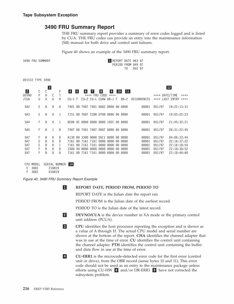
3490 FRU Summary ReportTHE FRU summary report provides a summary of error codes logged and is listedby CUA. THE FRU codes can provide an entry into the maintenance information(MI) manual for both drive and control unit failures.
Figure 40 shows an example of the 3490 FRU summary report.
�1� REPORT DATE, PERIOD FROM, PERIOD TO
REPORT DATE is the Julian date the report ran.
PERIOD FROM is the Julian date of the earliest record.
PERIOD TO is the Julian date of the latest record.
�2� DEVNO/CUA is the device number in XA mode or the primary controlunit address (PCUA).
�3� CPU identifies the host processor reporting the exception and is shown asa value of A through H. The actual CPU model and serial number areshown at the bottom of the report. CHA identifies the channel adapter thatwas in use at the time of error. CU identifies the control unit containingthe channel adapter. PTH identifies the control unit containing the bufferand data flow in use at the time of error.
�4� CU-ERR1 is the microcode-detected error code for the first error (controlunit or drive), from the OBR record (sense bytes 10 and 11). This errorcode should not be used as an entry to the maintenance package unlessefforts using CU-HW �8� and/or DR-ERR1 �9� have not corrected thesubsystem problem.
3490 FRU SUMMARY �1�REPORT DATE 063 97PERIOD FROM 049 97
TO 052 97
DEVICE TYPE 3490
�3� �13��2� C C P �4� �5� �6� �7� �8� �9� �10� �11�
DEVNO P H C T **** FRU CODE **** **** DATE/TIME ****/CUA U A U H CU-1 F CU-2 CU-L CUHW DR-1 F DR-2 OCCURRENCES **** LAST ENTRY ****
5A2 E B 0 0 7401 00 7407 7401 D002 0000 00 0000 00001 051/97 19:22:13:31
5A3 E B 0 1 7151 00 7607 CCBB D708 0000 00 0000 00001 051/97 19:03:22:23
5A4 F B 0 1 8E06 0C 0000 0000 0000 192C 00 0000 00001 051/97 21:45:32:21
5A5 F B 1 0 7407 00 7401 7407 D007 0000 00 0000 00001 051/97 20:31:22:45
5A7 F B 0 0 A130 00 3300 0000 D5C1 0000 00 0000 00001 051/97 04:06:33:445A7 E B 0 0 7161 00 7161 7161 0000 0000 00 0000 00001 051/97 22:16:37:225A7 E B 0 1 7161 00 7161 7161 0000 0000 00 0000 00001 051/97 22:16:18:545A7 F B 0 0 3300 40 0000 0000 0000 0000 00 0000 00001 051/97 22:18:38:525A7 F B 0 0 7161 00 7161 7161 0000 0000 00 0000 00001 051/97 22:18:40:60
CPU MODEL SERIAL NUMBER �14�E 3081 210819F 3081 010819
Figure 40. 3490 FRU Summary Report Example
Tape Subsystem Exception
216 EREP V3R5 Reference

�5� CU-F is a microcode-developed flag byte, from the OBR record (sense byte9). This byte provides additional information, if available, for CU-ERR1�4�.
�6� CU-ERR2 is the microcode-detected error code for the second error (controlunit or drive), from the OBR record (sense bytes 12 and 13). This errorcode can be a result of the first error indicated in CU-HW �8�, DR-ERR1�9� or CU-ERR1 �4�.
�7� CU-ERRL is the microcode-detected error FRU code for the last error(control unit or drive), from the OBR record (sense bytes 14 and 15). Thiserror code can be a result of the first error indicated in CU-HW �8�,DR-ERR1 �9�, CU-ERR1 �4�, DR-ERR2 �11�, or CU-ERR2 �6�.
�8� CU-HW is the control unit hardware-detected error code from the OBRrecord (sense bytes 16 and 17). This error code defines a control unit failureand should be used to enter the maintenance package if you have multipledrive failures.
�9� DR-ERR1 is the drive hardware-detected error code, from the OBR record(sense bytes 20 and 21). This error code defines the first failure for anydrive and should be used to enter the maintenance package if you havesingle drive failures.
�11� DR-ERR2 is the drive hardware-detected error code, from the OBR record(sense bytes 22 and 23). This error code defines the second or last failurefor any drive and should not be used to enter the maintenance package ifyou have single drive failures. This error information providessupplemental information and can be a result of the first failure (DR-ERR1)in the drive.
�12� OCCURRENCES is the total number of times this error code occurs.
�13� DATE/TIME is the Julian date and time of the last occurrence.
�14� CPU, MODEL, SERIAL NUMBER further identifies the CPU listed in theFRU SUMMARY REPORT.
Tape Subsystem Exception
Chapter 11. System Exception Report Series 217

3490 Error Code SummaryThis report shows error codes for the control unit (CU) and the drive (DRV). Onlythe 3480/3490 devices produce this report.
The Error Code Summary report provides a summary of error codes logged and islisted by CUA. The error codes can provide an entry into the maintenanceinformation (MI) manual for both drive and control unit failures.
Figure 41 shows an example of the 3490 error code summary.
�1� REPORT DATE, PERIOD FROM, PERIOD TO
REPORT DATE is the Julian date the report ran.
PERIOD FROM is the Julian date of the earliest record.
PERIOD TO is the Julian date of the latest record.
�2� DEVNO/CUA is the device number in XA mode or the primary controlunit address (PCUA).
�3� CPU identifies the host processor reporting the exception. The actual CPUmodel and serial number are shown at the bottom of the report. CHRidentifies the channel adapter that was in use at the time of error. CURidentifies the control unit containing the channel adapter. CUD identifiesthe control unit containing the buffer and data flow in use at the time oferror.
�4� CU-ERR1 is the microcode-detected error code for the first error (controlunit or drive), from the OBR record (sense bytes 10 and 11). This errorcode should not be used as an entry to the maintenance package unlessefforts using CU-HW �8� and/or DR-ERR1 �9� have not corrected thesubsystem problem.
3490 ERROR CODE SUMMARY REPORT �1�REPORT DATE 063 97PERIOD FROM 049 97
TO 052 97�13�
�2� �3� �4� �5� �6� �7� �8� �9� �10� �11��12�C C C C
DEVNO P H U U ----------CU---------- -----DR------- **** DATE/TIME ****/CUA U R R D ERR1 F ERR2 ERRL HW ERR1 F ERR2 OCCURRENCES **** LAST ENTRY ****
5A2 E0 B 0 0 7401 00 7407 7401 D002 0000 00 0000 00001 051/97 19:22:13:31
5A3 E0 B 0 1 7151 00 7607 CCBB D708 0000 00 0000 00001 051/97 19:03:22:23
5A4 F0 B 0 1 8E06 0C 0000 0000 0000 192C 00 0000 00001 051/97 21:45:32:21
5A5 F0 B 1 0 7407 00 7401 7407 D007 0000 00 0000 00001 051/97 20:31:22:45
5A7 F0 B 0 0 A130 00 3300 0000 D5C1 0000 00 0000 00001 051/97 04:06:33:445A7 E0 B 0 0 7161 00 7161 7161 0000 0000 00 0000 00001 051/97 22:16:37:225A7 E0 B 0 1 7161 00 7161 7161 0000 0000 00 0000 00001 051/97 22:16:18:845A7 E0 B 0 0 3300 40 0000 0000 0000 0000 00 0000 00001 051/97 22:18:38:525A7 F0 B 0 0 7161 00 7161 7161 0000 0000 00 0000 00001 051/97 22:18:40:60
CPU MODEL SERIAL NUMBER �14�E0 3081 210819F0 3081 010819
Figure 41. 3490 Error Code Summary Example
Tape Subsystem Exception
218 EREP V3R5 Reference

�5� CU-F is a microcode-developed flag byte, from the OBR record (sense byte9). This byte provides additional information, if available, for CU-ERR1�4�.
�6� CU-ERR2 is the microcode-detected error code for the second error (controlunit or drive), from the OBR record (sense bytes 12 and 13). This errorcode can be a result of the first error indicated in CU-HW �8�, DR-ERR1�9� or CU-ERR1 �4�.
�7� CU-ERRL is the microcode-detected error FRU code for the last error(control unit or drive), from the OBR record (sense bytes 14 and 15). Thiserror code can be a result of the first error indicated in CU-HW �8�,DR-ERR1 �9�, CU-ERR1 �4�, DR-ERR2 �11�, or CU-ERR2 �6�.
�8� CU-HW is the control unit hardware-detected error code from the OBRrecord (sense bytes 16 and 17). This error code defines a control unit failureand should be used to enter the maintenance package if you have multipledrive failures.
�9� DR-ERR1 is the drive hardware-detected error code, from the OBR record(sense bytes 20 and 21). This error code defines the first failure for anydrive and should be used to enter the maintenance package if you havesingle drive failures.
�10� DR-F is a microcode-developed flag byte, from the OBR record (sense byte18). This byte provides additional information, if available, for DR-ERR1�9�.
�11� DR-ERR2 is the drive hardware-detected error code, from the OBR record(sense bytes 22 and 23). This error code defines the second or last failurefor any drive and should not be used to enter the maintenance package ifyou have single drive failures. This error information providessupplemental information and can be a result of the first failure (DR-ERR1)in the drive.
�12� OCCURRENCES is the total number of times this error code occurred.
�13� DATE/TIME is the Julian date and time of the last occurrence.
�14� CPU, MODEL, SERIAL NUMBER further identifies the CPU listed in theError Code Summary report.
Tape Subsystem Exception
Chapter 11. System Exception Report Series 219

Tape DEVNO/CUA Statistics SummaryThis report allows you to quickly see what has been happening to a device. Sinceall normal data is included, you can see how much activity has been experiencedby a device and the pertinent exception data for the device.
The data in this report is listed by CUA for all device addresses that exceedhardware limits or had permanent errors. The data is a summary of all activity onthe device for the given period in which the report was run. This includespermanent, temporary and statistical data.
Temporary errors for devices and control unit addresses are shown when the errorcount exceeds the LIMIT control statement.
Errors are listed by volume serial number in the order (date and time) in whichthey occur. The following are shown on the report:v Datev Timev VOLIDv Permanent errorsv Megabytes processed per error shown
This report is different from other tape reports because the statistical data comesfrom the 3480 miscellaneous data record (MDR), which gets its information fromthe buffered tape control units. 3420 tape drives get statistical data from OBRdemounts received and counts are kept in main storage by the operating system.
One of these reports is generated for each device (device number or CUA) thatappears as a hardware exception on the tape subsystem exception report.
The report presents the DEVNO/CUA’s temporary errors that have failed thelimits set in LIMIT control statements.
Figures containing examples of these reports are on the pages shown in thefollowing table:
REPORT REFER TO
3490 DEVNO/CUA Statistics Summary Report Example Figure 42 on page 221
3422 DEVNO/CUA Statistics Summary Figure 43 on page 223
9347 DEVNO/CUA Statistics Summary Figure 44 on page 223
Tape Subsystem Exception
220 EREP V3R5 Reference
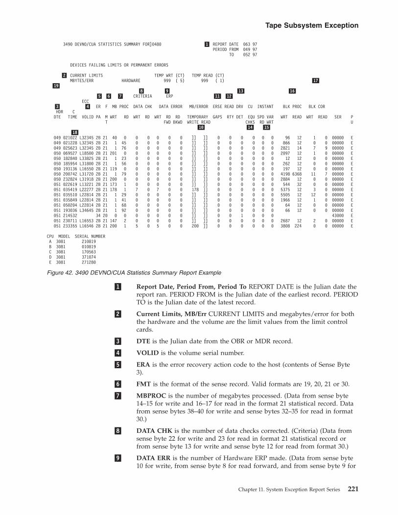
�1� Report Date, Period From, Period To REPORT DATE is the Julian date thereport ran. PERIOD FROM is the Julian date of the earliest record. PERIODTO is the Julian date of the latest record.
�2� Current Limits, MB/Err CURRENT LIMITS and megabytes/error for boththe hardware and the volume are the limit values from the limit controlcards.
�3� DTE is the Julian date from the OBR or MDR record.
�4� VOLID is the volume serial number.
�5� ERA is the error recovery action code to the host (contents of Sense Byte3).
�6� FMT is the format of the sense record. Valid formats are 19, 20, 21 or 30.
�7� MBPROC is the number of megabytes processed. (Data from sense byte14–15 for write and 16–17 for read in the format 21 statistical record. Datafrom sense bytes 38–40 for write and sense bytes 32–35 for read in format30.)
�8� DATA CHK is the number of data checks corrected. (Criteria) (Data fromsense byte 22 for write and 23 for read in format 21 statistical record orfrom sense byte 13 for write and sense byte 12 for read from format 30.)
�9� DATA ERR is the number of Hardware ERP made. (Data from sense byte10 for write, from sense byte 8 for read forward, and from sense byte 9 for
3490 DEVNO/CUA STATISTICS SUMMARY FOR]0480 �1� REPORT DATE 063 97PERIOD FROM 049 97
TO 052 97
DEVICES FAILING LIMITS OR PERMANENT ERRORS
�2� CURRENT LIMITS TEMP WRT (CT) TEMP READ (CT)MBYTES/ERR HARDWARE 999 ( 5) 999 ( 1) �17�
�19��8� �9� �13� �16�
�5� �6� �7� CRITERIA ERP �11� �12�ECC
�3� �4� ER F MB PROC DATA CHK DATA ERROR MB/ERROR ERSE READ DRV CU INSTANT BLK PROC BLK CORHDR CDTE TIME VOLID PA M WRT RD WRT RD WRT RD RD TEMPORARY GAPS RTY DET EQU SPD VAR WRT READ WRT READ SER P
T FWD BKWD WRITE READ CHKS RD WRT U�10� �14� �15�
�18�049 021022 L32345 2B 21 40 0 0 0 0 0 0 ]] ]] 0 0 0 0 0 0 96 12 1 0 00000 E049 021228 L32345 2B 21 1 45 0 0 0 0 0 ]] ]] 0 0 0 0 0 0 866 12 0 0 00000 E049 025623 L32345 2B 21 1 76 0 0 0 0 0 ]] ]] 0 0 0 0 0 0 2821 14 7 9 00000 E050 069527 L18500 2B 21 201 0 0 0 0 0 0 ]] ]] 0 0 0 0 0 0 2097 12 1 0 00000 E050 182840 L33825 2B 21 1 23 0 0 0 0 0 ]] ]] 0 0 0 0 0 0 12 12 0 0 00000 E050 185954 L31800 2B 21 1 56 0 0 0 0 0 ]] ]] 0 0 0 0 0 0 262 12 0 0 00000 E050 193136 L16550 2B 21 119 0 0 0 0 0 0 ]] ]] 0 0 0 0 0 0 197 12 0 0 00000 E050 200742 L31720 2B 21 1 79 0 0 0 0 0 ]] ]] 0 0 0 0 0 0 4198 6368 11 7 00000 E050 232824 L31918 2B 21 200 0 0 0 0 0 0 ]] ]] 0 0 0 0 0 0 2884 12 0 0 00000 E051 022619 L13221 2B 21 173 1 0 0 0 0 0 ]] ]] 0 0 0 0 0 0 544 32 0 0 00000 E051 035419 L22277 2B 21 178 1 7 0 7 0 0 178 ]] 0 0 0 0 0 0 5375 12 3 0 00000 E051 035510 L22814 2B 21 1 29 0 0 0 0 0 ]] ]] 0 0 0 0 0 0 5505 12 12 0 00000 E051 035849 L22814 2B 21 1 41 0 0 0 0 0 ]] ]] 0 0 0 0 0 0 1966 12 1 0 00000 E051 050204 L22814 2B 21 1 68 0 0 0 0 0 ]] ]] 0 0 0 0 0 0 64 12 0 0 00000 E051 193036 L34645 2B 21 1 92 0 0 0 0 0 ]] ]] 0 0 0 0 0 0 66 12 0 0 00000 E051 214532 34 20 0 0 0 0 0 0 0 ]] ]] 0 0 1 0 0 0 43000 E051 230711 L16553 2B 21 147 2 0 0 0 0 0 ]] ]] 0 0 0 0 0 0 2687 12 2 0 00000 E051 233355 L16546 2B 21 200 1 5 0 5 0 0 200 ]] 0 0 0 0 0 0 3808 224 0 0 00000 E
CPU MODEL SERIAL NUMBERA 3081 210819B 3081 010819C 3081 170563D 3081 371074E 3081 271280
Figure 42. 3490 DEVNO/CUA Statistics Summary Report Example
Tape Subsystem Exception
Chapter 11. System Exception Report Series 221

read backward in format 21 statistical record or data from sense byte 9 forwrite, from sense byte 8 for read forward and from sense byte 10 for readbackward from format 30.)
�10� MB/ERR
WRITE is the average number of megabytes written per temporarywrite error.READ is the average number of megabytes read per temporary readerror.
�11� ERSE GAPS is the total number of blocks re-written during error recovery.(Data from sense byte 24 of the format 21 statistical record or from sensebyte 15 from format 30.)
�12� READ RTY is the total number of correctable read errors detected during3490 read error recovery. (Data from sense byte 30 of the format 21 or fromsense byte 14 of format 30 statistical record.)
�13� DRV DET is the number of unit checks set by the drive. (Data from sensebyte 25 of the format 21 or 30 statistical record.)
�14� CU EQU CHKS is the number of errors found in the use of external regsin the CU for a given device. (Data from sense byte 13 of the format 21statistical record.)
�15� INSTANT SPD VAR flag indication that tape speed variations have beendetected by hardware checkers. (A function of control unit microcode orsense bytes 22, 23 and 24 of format 30.)
�16� BLK PROC is the total number of blocks processed. (Data from sense byte19 on a write and 18 on a read of the format 21 Statistical Record or sensebytes 47–49 on a write and sense bytes 50–52 on read from format 30.)
�17� BLK COR is the total number of blocks corrected. (ECC corrected) (Datafrom sense byte 12 on a write and 11 on a read of the format 21 statisticalrecord or sense byte 19 on a write and sense byte 18 on a read from format30.)
�18� HDR SER is the header serial number on the tape volume. The headernumber is derived from the last 4 digits of the control unit serial numberthat wrote the volume, with the drive address added to the last position.For example:
Header Serial is 3892FThe last 4 digits of control unit serial number is 3892Drive address is F
�19� CPU is the host processor reporting the data.
All error and statistical data (MDR records) are shown for devices which werelisted in the Subsystem Exception Report. They are listed by CUA for the periodindicated.
Note: Due to space limitations, this report does not show activity on all deviceslisted in the Subsystem Exception Report.
Tape Subsystem Exception
222 EREP V3R5 Reference

3422 DEVNO/CUA STATISTICS SUMMARY FOR-0156 REPORT DATE 065 97PERIOD FROM 041 97
TO 059 97
----------------------- 3422 -----------------------1600 BPI 6250 BPI
CURRENT LIMITS TEMP WRT(CT) TEMP RD(CT) TEMP WRT(CT) TEMP RD(CT)MBYTES/ERR HARDWARE NONE ( ) NONE ( ) NONE ( ) NONE ( )
DTE TIME VOLID- R/W ------MB/ERR TEMP------ LD BST FLS EDC VEL OVR RST TIE CPU DEN-E/U WRITE(CT) READ(CT) SIOCOUNT FAL CHK VRC END CRC MTE CHK RUN INK CU1 CU2 CU3 P 07 ID SITY
042 091037 340002 R -- ( 0) -- ( 0) 101 0 0 0 1 1 0 0 0 0 0 0 0 0 00 1D 6250050 084059 TAP156 -- ( 0) -- ( 0) 84 0 0 0 0 0 0 0 0 0 0 0 0 0 00 1D 6250
COLUMN TOTALS: ( 0) -- ( 0) 185 0 0 0 1 1 0 0 0 0 0 0
TOTALS: MOUNTS 1
AVERAGE MEGABYTES/TEMPORARY READ ERROR = --AVERAGE MEGABYTES/TEMPORARY WRITE ERROR = --
CPU MODEL SERIAL NUMBER00 9375 23456701 3090XA 17002802 3084XA 32112803 3084XA 12112804 3081XA 22117005 3084XA 22110306 3081XA 220447
Figure 43. 3422 DEVNO/CUA Statistics Summary
9347 DEVNO/CUA STATISTICS SUMMARY FOR-0C70 REPORT DATE 065 97PERIOD FROM 041 97
TO 059 97
---------------- SENSE DATA ----------------
TIME R/W SCSW64-95 FAULT 1 1 2 2 2-ID CPU DTE HH:MM:SS VOLID E/O CMD FLG /CSW32-63 SYMCD 0 4 8 2 6 0 48
00 042 09 55 02 R 02 04 0E000000 2007 08C00409 10000010 38280000 00004000 80000400 00000000 00000000 0000200700 044 00 46 37 E 02 04 0E000000 3006 10240003 10000010 28380000 40000000 80000400 48C00000 00000000 0000300600 044 04 08 28 W 02 04 0E000000 2003 0844000F 10100010 38380000 00200000 80000400 00000000 00000000 0000200300 045 18 55 37 W 02 04 0E000000 2001 08441D07 10000010 38380000 00800000 80000400 00000000 00000000 0000200100 045 20 02 06 E 02 04 0E000000 3006 10240003 10000010 28380000 40000000 80000400 48C00000 00000000 0000300600 049 05 32 25 W 02 04 0E000000 2003 0844000F 10100010 38380000 00200000 80000400 00000000 00000000 0000200300 049 05 38 59 W 02 04 0E000000 2003 0844000F 10100010 38380000 00200000 80000400 00000000 00000000 0000200300 049 06 34 24 W 02 04 0E000000 2001 08440407 10000010 38380000 00800000 80000400 00000000 00000000 0100200100 049 10 14 52 W 02 04 0E000000 2003 0844000F 10100010 38300000 00200000 80000400 00000000 00000000 00002003
TIME VOLUME I/O--COUNTS PERM ERROR TEMP ERROR RETRIES REPSN ------------------ COUNT ----------DTE HH:MM:SS SERIAL READ WRITE READ WRITE READ WRITE READ WRITE COUNT OVR MLT RUP IBG WPC SKW TR4 TR5 TRP ECC
047 18 13 15 0 1249 0 0 0 0 0 0 105 0 0 0 0 0 0 0 0 0 0049 06 07 59 227 0 6 15 1 0 58 92 192 0 7 3 1 0 0 7 7 4 224049 06 12 39 227 0 0 0 1 0 1 0 226 0 0 1 0 0 0 0 1 0 224
CPU MODEL SERIAL NUMBER00 9375 23456701 3090XA 17002802 3084XA 32112803 3084XA 12112804 3081XA 22117005 3084XA 221103
Figure 44. 9347 DEVNO/CUA Statistics Summary
Tape Subsystem Exception
Chapter 11. System Exception Report Series 223

EREP Reports for the Tape LibraryThe EREP reports for the tape library are included in the Subsystem ExceptionReport for the 3490E. The reports unique to the tape library are identified by “TapeLibrary” in the report title.
Important: The Tape Library report cannot be sorted by device type.
The following detail reports are available for the tape library:v Permanent and Recovered Error Summary
– Permanent Error– Recovered Error– Service Alert
v Error Code Summary Report
Figures containing examples of these reports are on the pages shown in thefollowing table:
REPORT REFER TO
Tape Library Permanent Error Summary Example Figure 45 on page 225
Tape Library Service Alert Summary Example Figure 46 on page 228
Tape Library Error Code Summary Example Figure 47 on page 230
Tape Subsystem Exception
224 EREP V3R5 Reference

Tape Library Permanent and Recovered Error Summary ReportFigure 45 shows a tape library permanent error summary report.
Note: Permanent errors are outboard recorder (OBR) format 23 records with thetemporary bit off. Recovered errors are OBR format 23 records with the temporarybit on.
�1� Report Date, Period From, Period To
REPORT DATE is the Julian date the report ran.PERIOD FROM is the Julian date of the earliest record.PERIOD TO is the Julian date of the latest record.
�2� The sense data from the OBR 23 log record.
�3� The channel path ID obtained from byte 49 (or offset 49 decimal) of theOBR 23 log record.
�4� The device number or the control unit address obtained from the offset(decimal) OBR format 23 log record.
A0
5M
00
17A
05
M0
02
0
Figure 45. Tape Library Permanent Error Summary Example
Tape Subsystem Exception
Chapter 11. System Exception Report Series 225

Because of the way unsolicited unit checks are handled, this field cancontain the address of devices that are not physically present.
�5� The date obtained from bytes 8–11 of the OBR 23 log record.
�6� The time obtained from bytes 12–15 of the OBR 23 log record.
�7� The central processing unit obtained from bytes 20–21 of the OBR 23 logrecord.
�8� The status obtained from sense bytes 0–2.
�9� The ERA code obtained from sense byte 3 of the OBR 23 log record.
�10� The channel logical block number obtained from sense bytes 4–6 of theOBR 23 log record.
�11� The sense format obtained from sense byte 7 of the OBR 23 log record.Sense byte 7 is 23 to indicate format 23.
�12� The library error modifier obtained from sense byte 8 of the OBR 23 logrecord.
�13� The library manager error code obtained from sense bytes 9–10 of the OBR23 log record.
�14� Contains zeros or contains additional information obtained from sensebytes 11–12 of the OBR 23 log record.
�15� The volume serial number of sense bytes 13–18 of the OBR 23 log record.
�16� The software EC level obtained from sense byte 19 of the OBR 23 logrecord.
�17� The subsystem ID obtained from sense byte 20 of the OBR 23 log record.
�18� The encoded serial number of the 3494 library.
�19� The control unit channel interface information obtained from sense byte 24of the OBR 23 log record.
�20� The subsystem features obtained from sense byte 25 of the OBR 23 logrecord.
�21� The control unit microcode EC level obtained from sense byte 26 of theOBR 23 log record.
�22� The control unit hardware information and serial number obtained fromsense bytes 27–29 of the OBR 23 log record.
�23� The drive address obtained from sense byte 30 of the OBR 23 log record.
�24� Reserved—obtained from sense byte 31 of the OBR 23 log record.
�25� The volume serial number in printable form obtained and converted fromsense bytes 13–18 of the OBR 23 log record.
Tape Subsystem Exception
226 EREP V3R5 Reference

Tape Library Permanent and Recovered Error Summary Report(Service Alerts)Figure 46 on page 228 shows an example of the service alerts contained in thePermanent and Recovered Error Summary Report.
All service alerts are noted by ERA 74 (library information data) in sense byte 3.The ERA modifier field (sense byte 8) specifies which group or category theparticular ERA 74 belongs to, while the OTH (Other) field (sense bytes 11 and 12)contains additional information about ERA 74.
The modifier and OTH fields combined with the library manager error code (sensebytes 9 and 10) describe the specific reason for each ERA 74 service alert entry.
The following table lists the definitions of the OTH field for ERA 74 and addressescomponent unavailability (modifier byte 01) and component availability (modifierbyte 02) for the OTH field.
OTH Field Definition
0011 The convenience input station is made unavailable or available. (See note.)
0021 The convenience output station is made unavailable or available. (Seenote.)
004X The hard disk is made unavailable or available. (See note.) The X is 1 forthe primary disk or 2 for the backup disk.
0051 The dual write is made unavailable or available. (See note.)
0111 The cartridge accessor is made unavailable or available. (See note.)
021X The vision system is made unavailable or available. (See note.) The X is 1for the bar code reader.
111X The grip is made unavailable or available. (See note.)
Note: Check the modifier where 01 is unavailable and 02 is available.
Tape Subsystem Exception
Chapter 11. System Exception Report Series 227
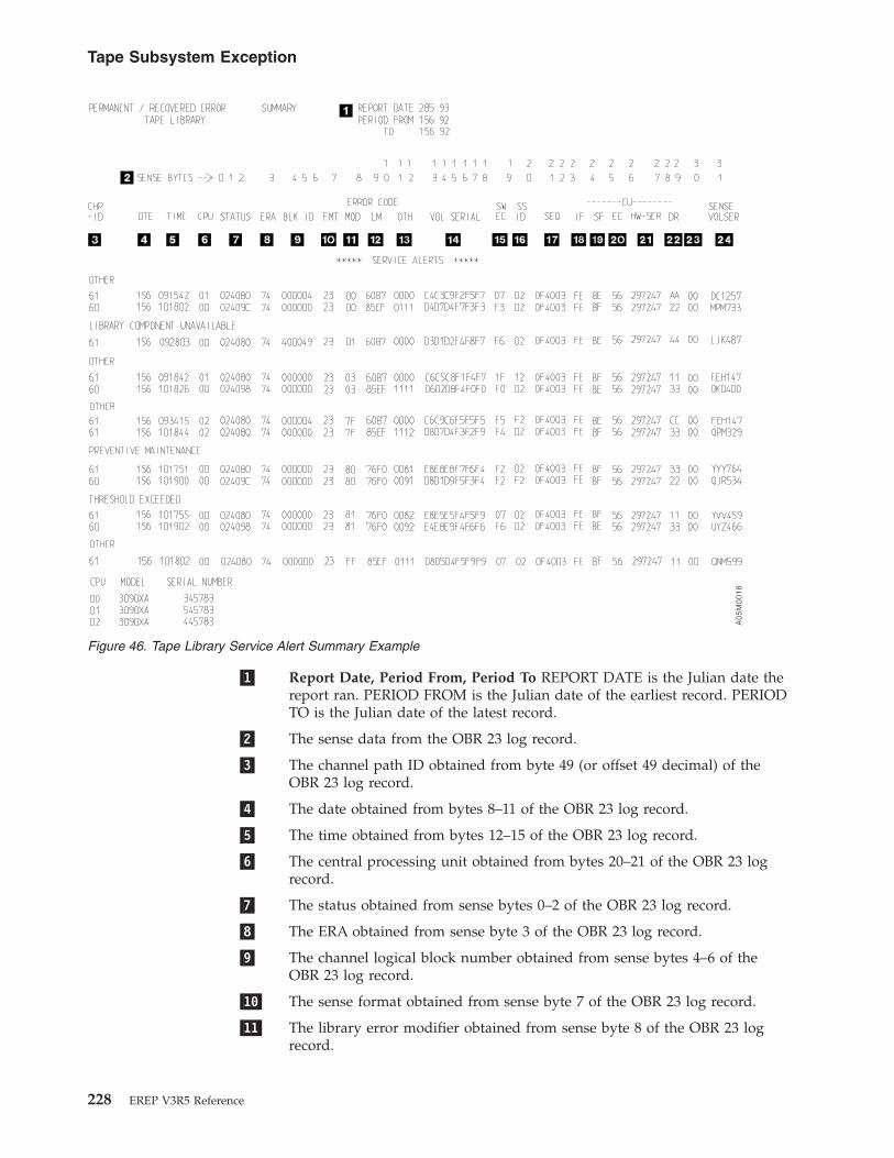
�1� Report Date, Period From, Period To REPORT DATE is the Julian date thereport ran. PERIOD FROM is the Julian date of the earliest record. PERIODTO is the Julian date of the latest record.
�2� The sense data from the OBR 23 log record.
�3� The channel path ID obtained from byte 49 (or offset 49 decimal) of theOBR 23 log record.
�4� The date obtained from bytes 8–11 of the OBR 23 log record.
�5� The time obtained from bytes 12–15 of the OBR 23 log record.
�6� The central processing unit obtained from bytes 20–21 of the OBR 23 logrecord.
�7� The status obtained from sense bytes 0–2 of the OBR 23 log record.
�8� The ERA obtained from sense byte 3 of the OBR 23 log record.
�9� The channel logical block number obtained from sense bytes 4–6 of theOBR 23 log record.
�10� The sense format obtained from sense byte 7 of the OBR 23 log record.
�11� The library error modifier obtained from sense byte 8 of the OBR 23 logrecord.
A0
5M
00
18
Figure 46. Tape Library Service Alert Summary Example
Tape Subsystem Exception
228 EREP V3R5 Reference

�12� The library manager error code obtained from sense bytes 9–10 of the OBR23 log record.
�13� Contains zeros or contains additional information obtained from sensebytes 11–12 of the OBR 23 log record.
�14� The volume serial number of the OBR 23 log record.
�15� The software EC level obtained from sense byte 19 of the OBR 23 logrecord.
�16� The subsystem ID obtained from sense byte 20 of the OBR 23 log record.
�17� The encoded serial number of the 3494 library.
�18� The control unit channel interface information obtained from sense byte 24of the OBR 23 log record.
�19� The subsystem features obtained from sense byte 25 of the OBR 23 logrecord.
�20� The control unit microcode EC level obtained from sense byte 26 of theOBR 23 log record.
�21� The control unit hardware information and serial number obtained fromsense bytes 27–29 of the OBR 23 log record.
�22� The drive address obtained from sense byte 30 of the OBR 23 log record.
�23� Reserved—obtained from sense byte 31 of the OBR 23 log record.
�24� The volume serial number in printable form obtained and converted fromsense bytes 13–18 of the OBR 23 log record.
Tape Subsystem Exception
Chapter 11. System Exception Report Series 229
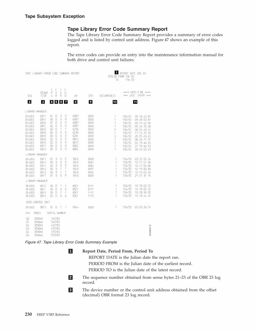
Tape Library Error Code Summary ReportThe Tape Library Error Code Summary Report provides a summary of error codeslogged and is listed by control unit address. Figure 47 shows an example of thisreport.
The error codes can provide an entry into the maintenance information manual forboth drive and control unit failures.
�1� Report Date, Period From, Period To
REPORT DATE is the Julian date the report ran.PERIOD FROM is the Julian date of the earliest record.PERIOD TO is the Julian date of the latest record.
�2� The sequence number obtained from sense bytes 21–23 of the OBR 23 logrecord.
�3� The device number or the control unit address obtained from the offset(decimal) OBR format 23 log record.
A0
5M
00
19
Figure 47. Tape Library Error Code Summary Example
Tape Subsystem Exception
230 EREP V3R5 Reference

Because of the way unsolicited unit checks are handled, this field maycontain the address of devices that are not physically present.
�4� The central processing unit obtained from bytes 20–21 of the OBR 23 logrecord.
�5� Identifies the associated channel adapter to which command the error wasreported.
�6� Identifies the control unit reporting the error and refers to sense byte 2, bit3 of the OBR 23 log record.
�7� Identifies the control-unit-detected error and refers to sense byte 2, bit 4 ofthe OBR 23 log record.
�8� The library manager error code obtained from sense bytes 9–10 of the OBR23 log record.
�9� Contains zeros or contains additional information obtained from sensebytes 11–12 of the OBR 23 log record.
�10� Obtained by adding each of the same values from the error codes.
�11� Obtained from bytes 8–11 and 12–15 of the OBR log record.
Tape Subsystem Exception
Chapter 11. System Exception Report Series 231

TAPE Subsystem ExceptionThis report shows conditions that may need maintenance action. Records that areincluded in other reports may not be listed in the system exception reports.
This exception report can be used to determine if the TAPE subsystem hasexcessive errors or is operating within acceptable limits.
The series contains the following types of reports:
TYPE REPORT
1 “TAPE Subsystem Exception Report” on page 233
2 “TAPE Service Informational Messages (SIMs)” on page 236
Informational Messages help you define a problem to IBM customer service personnel.
3 “TAPE Media Informational Messages (MIMs)” on page 237
Informational Messages help you define a problem to IBM customer service personnel.
These reports work together to provide a picture of the errors occurring in the system. The TAPEsubsystem exception report determines if your TAPE subsystem is experiencing an excessiveamount of errors.
The following table shows the type of error records and their source in the TAPEsubsystem exception reports.
TYPE SOURCE
A3 Tape devices (only 3590s) ; including controllersOBR Tape devices (only 3590s) ; including controllers
Valid records that do not indicate a need for maintenance action may be shown inreports other than the subsystem exception.
TAPE Subsystem Exception
232 EREP V3R5 Reference

TAPE Subsystem Exception ReportThis part of the exception report series provides the primary listing of events todetermine if the TAPE subsystem has excessive errors or is operating withinacceptable limits.
This report provides the information to connect these events to the other reports inthe series that have more details.
Examples of these reports are listed as follows.
REPORT REFER TO
3592 Subsystem Exception Report Example Figure 49 on page 234
�1� If the record is a MIM, the information appearing in this column will bethe volid. If the record is any other type, the device type will appear inthis column.
�2� This field shows the unit most likely to be the source of the failure, even ifthe failure is recorded against another unit. EREP identifies the PFU basedon the failure affect and the units reporting errors.
TAPE SUBSYSTEM EXCEPTION REPORT REPORT DATE 080 97PERIOD FROM 037 97TO 079 97
*** SEQUENCE BY PROBABLE FAILING UNIT ***�6�
PROBABLE DEVICE �4� �5� --------TOTALS--------FAILING TYPE/ FAILURE DEVNO OBR OBRUNIT VOLID AFFECT CPU /CUA SIMS MIMS PERM TEMP
******************************************************************************************************�2� �1� �3�MEDIA TOTAL 0 2 0 0
JANZ01 DATA DEGRADED IN PARTITION 08 0883 0 1 0 0
JANZ99 DATA DEGRADED IN PARTITION 00 08A9 0 1 0 0
DEVICE TOTAL 1 0 0 1
3590-B11 PREVENTIVE MAINTENANCE COMPLETED 08 0883 1 0 0 0
3590-B11 LOADER INTERVENTION REQUIRED 0A 0883 0 0 0 1
CONTROLLER TOTAL 1 0 0 3
3590-A00 RESETTING EVENT 08 0880 0 0 0 1
3591/3490EMU RECOVERED CHECK-ONE FAILURE 08 0880 0 0 0 1
3590/3490EMU TAPE LENGTH INCOMPATIBLE 08 0880 0 0 0 1
3590-A00 EFFECT OF FAILURE IS UNKNOWN 08 0887 1 0 0 0
CPU MODEL SERIAL NUMBER00 3090XA 04578301 9021XA 11034102 9221XA 0D048103 3090XA 24578304 3090XA 14578305 3090XA 15578306 3090XA 05578307 3090XA 25578308 9672XA 06103509 9672XA 4610350A 9672XA 161035
Figure 48. 3590 Subsystem Exception Report Example
TAPE Subsystem Exception
Chapter 11. System Exception Report Series 233

PFU DESCRIPTION
MEDIA Media (tape volume)
DEVICE Device involved (3590)
CONTROLLER Controller (drive string controller, or something common to more than onedevice on the string)
LIBRARY Tape library
�3� This field defines the function or machine area affected by the failure.
�4� The EREP-assigned CPU identifier. If there is more than one CPU, one isshown and a plus sign is printed to indicate that there is more than one.
�5� Use the physical address to locate information on other EREP reports.EREP uses the primary channel and unit address (PCUA) or devicenumber if the devices do not provide physical IDs.
�6� This field contains the error totals under the error types shown in thefollowing table:
TYPE DESCRIPTION
SIMS The count of SIM messages reported by the unit and totaled for the PFU within the givenfailure.
MIMS The count of MIM messages reported by the unit and totaled for the PFU within the givenfailure.
PERM The count of permanent errors recorded against the unit and totaled for the PFU within thegiven failure affect. (A permanent error is indicated by a zero temporary error bit in the OBRrecord.)
TEMP The count of temporary errors recorded against the unit and totaled for the PFU within thegiven failure affect.
TAPE SUBSYSTEM EXCEPTION REPORT REPORT DATE 220 05PERIOD FROM 076 02
TO 077 02
*** SEQUENCE BY PROBABLE FAILING UNIT ***
PROBABLE DEVICE --------TOTALS----------FAILING TYPE/ FAILURE DEVNO OBR OBRUNIT VOLID AFFECT CPU /CUA SIMS MIMS PERM TEMP
******************************************************************************************************
LIBRARY TOTAL 0 0 0 1
3570-CXX LIBRARY INFORMATIONAL DATA 00 07C2 0 0 0 1
DEVICE TOTAL 0 0 2 1
3590-H1X LIBRARY DRIVE NOT UNLOADED 02 0C24 0 0 1 0
3592-J1X WORM OVERWRITE REJECTED 03 0C27 0 0 0 1
3592-E05 LIBRARY DRIVE NOT UNLOADED 00 1B90 0 0 0 1
3592-E06 LIBRARY DRIVE NOT UNLOADED 00 1B90 0 0 0 1
Figure 49. 3592 Subsystem Exception Report Example
TAPE Subsystem Exception
234 EREP V3R5 Reference

3590 DEVICE SUMMARY REPORT DATE 295 07PERIOD FROM 195 06
TO 195 06
DEVICE ADDRESS REAL / EMULATED DEVICE TYPE
0FA2 3592-J1X / 3490-CXX
0FA3 3592-E05 / 3590-B1X0FA4 3592-E06 / 3590-B1X
CPU MODEL SERIAL NUMBER00 2084XA 13290601 2084XA 142906
Figure 50. 3592 Emulated Device Summary Report
TAPE Subsystem Exception
Chapter 11. System Exception Report Series 235

TAPE Service Informational Messages (SIMs)This report relates to hardware failures that may require the customer to call forservice.
Refer to the device maintenance library for information about the SIMs and actionsrequired.
Figure 51 shows an example of the TAPE service informational messages.
TAPE SERVICE INFORMATION MESSAGES (SIMS) REPORT DATE 028 97PERIOD FROM 023 97
TO 028 97
***********************************************************************************DEVICE-0883 S/N 0113-00001 DATE-023/90 TIME-06:54:49:45 ID=21
* SERVICE ALERT D/T-3590-B11 REF1-D1C1 REF2-D5E9 REF3-F0F2 UM-1229* DV PREVENTIVE MAINTENANCE COMPLETED* DV CLEANING COMPLETE
DEVICE-0887 S/N 0113-23456 DATE-023/90 TIME-09:26:32:65 ID=73* SERIOUS ALERT D/T-3590-A00 REF1-D1C1 REF2-D5E9 REF3-F0F4 UM-0000* EFFECT OF FAILURE IS UNKNOWN* REPAIR IMPACT IS UNKNOWN
DEVICE-08A9 S/N 0113-23456 DATE-023/90 TIME-15:35:30:19 ID=73* SERIOUS ALERT D/T-3590/3490EMU REF1-D1C1 REF2-D5E9 REF3-F0F4 UM-0000* EFFECT OF FAILURE IS UNKNOWN* REPAIR IMPACT IS UNKNOWN
Figure 51. TAPE Service Information Messages (SIMS)
TAPE Subsystem Exception
236 EREP V3R5 Reference

TAPE Media Informational Messages (MIMs)This report relates to media failures that may require the customer to call forservice.
Refer to the device maintenance library for information about the MIMs andactions required.
Figure 52 shows an example of the TAPE media informational messages.
TAPE MEDIA INFORMATION MESSAGES (MIMS) REPORT DATE 028 97PERIOD FROM 023 97
TO 028 97
*******************************************************************************VOLUME-JANZ01 DEVICE-0883 DATE-023/90 TIME-06:54:49:45
* D/T-3590-B11 S/N 0113-00001* SERVICE ALERT REFCODE-0057 MEDIA IDENTIFIER-0021 FORMAT IDENTIFIER-00* DATA DEGRADED IN PARTITION 1229* REFERENCE MEDIA MAINTENANCE PROCEDURE 57
VOLUME-JANZ98 DEVICE-08A9 DATE-023/90 TIME-15:35:30:19* D/T-3590-A00 S/N 0113-23456* SERIOUS ALERT REFCODE-0000 MEDIA IDENTIFIER-0073 FORMAT IDENTIFIER-00* EXCEPTION 00* REFERENCE MEDIA MAINTENANCE PROCEDURE 00
VOLUME-JANZ99 DEVICE-08A9 DATE-023/90 TIME-15:35:30:19* D/T-3590/3490EMU S/N 0113-23456* SERIOUS ALERT REFCODE-0000 MEDIA IDENTIFIER-0073 FORMAT IDENTIFIER-00* EXCEPTION 00* REFERENCE MEDIA MAINTENANCE PROCEDURE 00
VOLUME-SL0001 DEVICE-0DC1 DATE-297/07 TIME-08:39:56:05* D/T-3592-E06 S/N 0000-00000* SERIOUS ALERT REFCODE-1011 MEDIA IDENTIFIER-0120 FORMAT IDENTIFIER-01* EXCEPTION 10* REFERENCE MESSAGE CODE 10
Figure 52. TAPE Media Information Messages (MIMS)
TAPE Subsystem Exception
Chapter 11. System Exception Report Series 237

TAPE Subsystem Exception
238 EREP V3R5 Reference

Chapter 12. Threshold Summary Report
The threshold summary report shows all the permanent read/write errors,temporary read/write errors, and media statistics for each volume mounted, usingthe OBR and MDR records, for 3410, 3420, and 8809 tape devices.
Note: The system exception series is a replacement for the threshold summary.Consider switching to the system exception series.
Description of the Threshold Summary ReportThe data in the threshold summary report is grouped by tape subsystem. Thereport has four sections as shown in the following table:
SECTION DESCRIPTION
DEV(ice) STATISTICS Shows one line of statistical and error data for every demount record whose errorcount exceeds the read or write threshold you coded on the report parameter.
PERMANENT ERRORSUMMARY
Shows a one-line entry for every permanent error. A permanent error can be a readerror, a write error, or an equipment check. This section ignores threshold settings sothere are no limits.
TEMPORARY ERRORSUMMARY
Shows a summary of all temporary errors recorded for each device number or CUA,whether they exceeded your threshold or not.
VOLUME STATISTICS Shows the errors and usage statistics by volume serial number using each MDR andOBR record from the first three sections of the report. This section also ignoresthreshold settings so there are no limits.
Note:
v The first three sections appear once for each processor in your installation.
v The columns in the fourth section of the report are titled differently depending on the device type involved.
v See “Threshold Summary Report Information” on page 350 for how the columns differ and for the device typessupported by the threshold summary reports.
v Information for up to 256 CPUs can be provided in the threshold summary.
v It is possible to have multiple internal processors reported under one serial number and thus increase EREP’scapabilities. See “SYSIMG Control Statement” on page 71 for details.
Examples of the Threshold Summary ReportsFigures containing examples of these reports are on the pages shown in thefollowing table:
REPORT REFER TO
34XX/3803/8809 Subsystem Summary “34XX/3803/8809 SubsystemSummary”
34XX/3803/8809 Subsystem Summary–VolumeStatistics
“34XX/3803/8809 SubsystemSummary–Volume Statistics” onpage 242
34XX/3803/8809 Subsystem Summary�1� XXXXX 34XX/3803/8809 SUBSYSTEM SUMMARY XXXXX
XXXXX PRIMARY DEV 0180-018F XXXXX�2� DEV STATISTICS - DEVS EQUAL TO OR EXCEEDING 001 TEMP RDS OR 001 TEMP WRTS
© Copyright IBM Corp. 1983, 2015 239
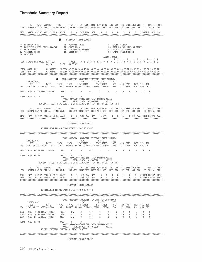
TU DATE VOLUME TIME --TEMP-- IO DEN- NRZI R/W WR TG LRC CRC ECC SKEW ERLY VEL ----CPU---- HDRDEV SERIAL DAY YR SERIAL HH MM SS.TH RDS WRTS COUNT SITY NOISE VRC VRC MTE EDC ENV ERR BOR CHG ID SERIAL SER
0180 59437 047 97 XXXXXX 01 07 52.89 0 4 7526 1600 N/A 0 0 0 0 2 0 0 2 4331 013078 N/AXXXXXXXXXXXXXXXXXXXXXXXXXXXXXXXXXXXXXXXXXXXXXXXXXXXXXXXXXXXXXXXXXXXXXXXXXXXXXXXXXXXXXXXXXXXXXXXXXXXXXXXXXXXXXXXXXXXXXXXXXXXXXXXXXX
�1� PERMANENT ERROR SUMMARY
PW PERMANENT WRITE PR PERMANENT READ PF CAUSE UNKNOWNEC EQUIPMENT CHECK, CAUSE UNKNOWN EE ERASE HEAD EB TAPE BOTTOM, LEFT OR RIGHTEL LOAD FAILURE EP AIR BEARING PRESSURE ET TACH START FAILUREEV VELOCITY CHECK ER RESET KEY WC WRITE CURRENT CHECKEM MODE SET
...SENSE BYTES....1 1 1 1 1 1 1 1 1 1 2 2 2 2
DEV SERIAL ERR VOLID LAST CCW STATUS 0 1 2 3 4 5 6 7 8 9 0 1 2 3 4 5 6 7 8 9 0 1 2 3CC CA FL CT US CS CT
0180 59437 PR 02 003751 20 0050 0E 00 0050 00 43 00 04 00 40 04 00 00 08 00 00 00 2F 1F 24 DD 91 01 00 00 1A 00 FE0181 N/A PR 02 003751 20 0050 0C 08 0000 00 00 00 00 00 00 00 00 00 00 00 00 00 00 00 00 00 00 00 00 00 00 00 00XXXXXXXXXXXXXXXXXXXXXXXXXXXXXXXXXXXXXXXXXXXXXXXXXXXXXXXXXXXXXXXXXXXXXXXXXXXXXXXXXXXXXXXXXXXXXXXXXXXXXXXXXXXXXXXXXXXXXXXXXXXXXXXXXX
�1� 34XX/3803/8809 SUBSYSTEM TEMPORARY ERROR SUMMARYERRORS/100K READ WRITE ECC
IOS DATE TOTAL TOTAL STATISTICS STATISTICS VRC STRD PART OVER VEL IBGDEV READ WRITE -FROM---TO-- IOS MOUNTS. ERRORS CLNRAC . ERRORS ERSGAP . ENV CHK RECK RUN CHG DET
0180 0.00 53.10 04797 04797 7532 2 . 0 0 . 4 4 . 2 0 0 0 2 0
TOTAL 0.00 53.10 7532 2 0 4XXXXX 34XX/3803/8809 SUBSYSTEM SUMMARY XXXXXXXXXX PRIMARY DEV 01A0-01AF XXXXX
DEV STATISTICS - DEVS EQUAL TO OR EXCEEDING 001 TEMP RDS OR 001 TEMP WRTS
TU DATE VOLUME TIME --TEMP-- IO DEN- NRZI R/W WR TG LRC CRC ECC SKEW ERLY VEL ----CPU---- HDRDEV SERIAL DAY YR SERIAL HH MM SS.TH RDS WRTS COUNT SITY NOISE VRC VRC MTE EDC ENV ERR BOR CHG ID SERIAL SER
01A0 N/A 047 97 XXXXXX 01 03 55.35 0 5 7508 N/A N/A 5 N/A 0 0 5 0 N/A N/A 4331 013078 N/AXXXXXXXXXXXXXXXXXXXXXXXXXXXXXXXXXXXXXXXXXXXXXXXXXXXXXXXXXXXXXXXXXXXXXXXXXXXXXXXXXXXXXXXXXXXXXXXXXXXXXXXXXXXXXXXXXXXXXXXXXXXXXXXXXX
PERMANENT ERROR SUMMARY
NO PERMANENT ERRORS ENCOUNTERED: 97047 TO 97047
XXXXXXXXXXXXXXXXXXXXXXXXXXXXXXXXXXXXXXXXXXXXXXXXXXXXXXXXXXXXXXXXXXXXXXXXXXXXXXXXXXXXXXXXXXXXXXXXXXXXXXXXXXXXXXXXXXXXXXXXXXXXXXXXXX
34XX/3803/8809 SUBSYSTEM TEMPORARY ERROR SUMMARYERRORS/100K READ WRITE ECC
IOS DATE TOTAL TOTAL STATISTICS STATISTICS VRC STRD PART OVER VEL IBGDEV READ WRITE -FROM---TO-- IOS MOUNTS. ERRORS CLNRAC . ERRORS ERSGAP . ENV CHK RECK RUN CHG DET
01A0 0.00 66.54 04797 04797 7514 2 . 0 0 . 5 5 . 5 0 0 0 0 0
TOTAL 0.00 66.54 7514 2 0 5XXXXX 34XX/3803/8809 SUBSYSTEM SUMMARY XXXXXXXXXX PRIMARY DEV 0570-057F XXXXX
DEV STATISTICS - DEVS EQUAL TO OR EXCEEDING 001 TEMP RDS OR 001 TEMP WRTS
TU DATE VOLUME TIME --TEMP-- IO DEN- NRZI R/W WR TG LRC CRC ECC SKEW ERLY VEL ----CPU---- HDRDEV SERIAL DAY YR SERIAL HH MM SS.TH RDS WRTS COUNT SITY NOISE VRC VRC MTE EDC ENV ERR BOR CHG ID SERIAL SER
0574 N/A 042 97 D12213 01 17 46.99 0 1 1018 N/A N/A 0 0 0 0 1 0 0 0 3081 020447 40920574 N/A 042 97 RMFD01 02 11 43.07 0 1 563 N/A N/A 0 0 0 0 1 0 0 0 3081 020447 4092XXXXXXXXXXXXXXXXXXXXXXXXXXXXXXXXXXXXXXXXXXXXXXXXXXXXXXXXXXXXXXXXXXXXXXXXXXXXXXXXXXXXXXXXXXXXXXXXXXXXXXXXXXXXXXXXXXXXXXXXXXXXXXXXXX
PERMANENT ERROR SUMMARY
NO PERMANENT ERRORS ENCOUNTERED: 97042 TO 97044
XXXXXXXXXXXXXXXXXXXXXXXXXXXXXXXXXXXXXXXXXXXXXXXXXXXXXXXXXXXXXXXXXXXXXXXXXXXXXXXXXXXXXXXXXXXXXXXXXXXXXXXXXXXXXXXXXXXXXXXXXXXXXXXXXX
34XX/3803/8809 SUBSYSTEM TEMPORARY ERROR SUMMARYERRORS/100K READ WRITE ECC
IOS DATE TOTAL TOTAL STATISTICS STATISTICS VRC STRD PART OVER VEL IBGDEV READ WRITE -FROM---TO-- IOS MOUNTS. ERRORS CLNRAC . ERRORS ERSGAP . ENV CHK RECK RUN CHG DET
0570 0.00 0.00 04497 04497 805 3 . 0 0 . 0 0 . 0 0 0 0 0 00573 0.00 0.00 04297 04297 609 1 . 0 0 . 0 0 . 0 0 0 0 0 00574 0.00 86.65 04297 04297 2308 5 . 0 0 . 2 2 . 2 0 0 0 0 0
TOTAL 0.00 53.73 3722 9 0 2XXXXX 34XX/3803/8809 SUBSYSTEM SUMMARY XXXXXXXXXX PRIMARY DEV 0570-057F XXXXX
NO DEVS EXCEEDED THRESHOLD: 97047 TO 97058
XXXXXXXXXXXXXXXXXXXXXXXXXXXXXXXXXXXXXXXXXXXXXXXXXXXXXXXXXXXXXXXXXXXXXXXXXXXXXXXXXXXXXXXXXXXXXXXXXXXXXXXXXXXXXXXXXXXXXXXXXXXXXXXXXX
PERMANENT ERROR SUMMARY
Threshold Summary Report
240 EREP V3R5 Reference

NO PERMANENT ERRORS ENCOUNTERED: 97047 TO 97058
XXXXXXXXXXXXXXXXXXXXXXXXXXXXXXXXXXXXXXXXXXXXXXXXXXXXXXXXXXXXXXXXXXXXXXXXXXXXXXXXXXXXXXXXXXXXXXXXXXXXXXXXXXXXXXXXXXXXXXXXXXXXXXXXXX
34XX/3803/8809 SUBSYSTEM TEMPORARY ERROR SUMMARYERRORS/100K READ WRITE ECC
IOS DATE TOTAL TOTAL STATISTICS STATISTICS VRC STRD PART OVER VEL IBGDEV READ WRITE -FROM---TO-- IOS MOUNTS. ERRORS CLNRAC . ERRORS ERSGAP . ENV CHK RECK RUN CHG DET
0571 0.00 0.00 05797 05797 1224 1 . 0 0 . 0 0 . 0 0 0 0 0 00572 0.00 0.00 04797 04797 4525 2 . 0 0 . 0 0 . 0 0 0 0 0 0
TOTAL 0.00 0.00 5749 3 0 0XXXXX 34XX/3803/8809 SUBSYSTEM SUMMARY XXXXXXXXXX PRIMARY DEV 0570-057F XXXXX
NO DEVS EXCEEDED THRESHOLD: 97041 TO 97056
XXXXXXXXXXXXXXXXXXXXXXXXXXXXXXXXXXXXXXXXXXXXXXXXXXXXXXXXXXXXXXXXXXXXXXXXXXXXXXXXXXXXXXXXXXXXXXXXXXXXXXXXXXXXXXXXXXXXXXXXXXXXXXXXXX
PERMANENT ERROR SUMMARY
NO PERMANENT ERRORS ENCOUNTERED: 97041 TO 97056
XXXXXXXXXXXXXXXXXXXXXXXXXXXXXXXXXXXXXXXXXXXXXXXXXXXXXXXXXXXXXXXXXXXXXXXXXXXXXXXXXXXXXXXXXXXXXXXXXXXXXXXXXXXXXXXXXXXXXXXXXXXXXXXXXX
34XX/3803/8809 SUBSYSTEM TEMPORARY ERROR SUMMARYERRORS/100K READ WRITE ECC
IOS DATE TOTAL TOTAL STATISTICS STATISTICS VRC STRD PART OVER VEL IBGDEV READ WRITE -FROM---TO-- IOS MOUNTS. ERRORS CLNRAC . ERRORS ERSGAP . ENV CHK RECK RUN CHG DET
0570 0.00 0.00 05297 05297 30 1 . 0 0 . 0 0 . 0 0 0 0 0 00571 0.00 0.00 05597 05697 4174 2 . 0 0 . 0 0 . 0 0 0 0 0 00572 0.00 0.00 04797 04797 4525 2 . 0 0 . 0 0 . 0 0 0 0 0 00574 0.00 0.00 05397 05397 1707 1 . 0 0 . 0 0 . 0 0 0 0 0 00575 0.00 0.00 04597 04597 20 1 . 0 0 . 0 0 . 0 0 0 0 0 00577 0.00 0.00 05497 05497 5 1 . 0 0 . 0 0 . 0 0 0 0 0 0
TOTAL 0.00 0.00 10461 8 0 0XXXXX 34XX/3803/8809 SUBSYSTEM SUMMARY XXXXXXXXXX PRIMARY DEV 0570-057F XXXXX
DEV STATISTICS - DEVS EQUAL TO OR EXCEEDING 001 TEMP RDS OR 001 TEMP WRTS
TU DATE VOLUME TIME --TEMP-- IO DEN- NRZI R/W WR TG LRC CRC ECC SKEW ERLY VEL ----CPU---- HDRDEV SERIAL DAY YR SERIAL HH MM SS.TH RDS WRTS COUNT SITY NOISE VRC VRC MTE EDC ENV ERR BOR CHG ID SERIAL SER
0575 N/A 041 97 SMP010 18 12 27.52 2 0 10 N/A N/A 2 0 2 2 0 0 0 0 3033 021928 55600571 N/A 041 97 T28375 18 13 28.09 0 1 1647 N/A N/A 1 0 1 0 1 0 0 0 3033 021928 37580578 N/A 046 97 69945 13 32 08.20 2 0 9 N/A N/A 0 0 0 0 1 0 0 0 3033 021928 3964XXXXXXXXXXXXXXXXXXXXXXXXXXXXXXXXXXXXXXXXXXXXXXXXXXXXXXXXXXXXXXXXXXXXXXXXXXXXXXXXXXXXXXXXXXXXXXXXXXXXXXXXXXXXXXXXXXXXXXXXXXXXXXXXXX
PERMANENT ERROR SUMMARY
PW PERMANENT WRITE PR PERMANENT READ PF CAUSE UNKNOWNEC EQUIPMENT CHECK, CAUSE UNKNOWN EE ERASE HEAD EB TAPE BOTTOM, LEFT OR RIGHTEL LOAD FAILURE EP AIR BEARING PRESSURE ET TACH START FAILUREEV VELOCITY CHECK ER RESET KEY WC WRITE CURRENT CHECKEM MODE SET
...SENSE BYTES....1 1 1 1 1 1 1 1 1 1 2 2 2 2
DEV SERIAL ERR VOLID LAST CCW STATUS 0 1 2 3 4 5 6 7 8 9 0 1 2 3 4 5 6 7 8 9 0 1 2 3CC CA FL CT US CS CT
0575 55560 EC 1F 000000 40 0050 26 00 0050 18 44 00 28 00 40 34 00 10 08 10 00 00 BA 2F 15 B8 91 02 D8 00 1A 00 00XXXXXXXXXXXXXXXXXXXXXXXXXXXXXXXXXXXXXXXXXXXXXXXXXXXXXXXXXXXXXXXXXXXXXXXXXXXXXXXXXXXXXXXXXXXXXXXXXXXXXXXXXXXXXXXXXXXXXXXXXXXXXXXXXX
34XX/3803/8809 SUBSYSTEM TEMPORARY ERROR SUMMARYERRORS/100K READ WRITE ECC
IOS DATE TOTAL TOTAL STATISTICS STATISTICS VRC STRD PART OVER VEL IBGDEV READ WRITE -FROM---TO-- IOS MOUNTS. ERRORS CLNRAC . ERRORS ERSGAP . ENV CHK RECK RUN CHG DET
0570 0.00 0.00 04197 04197 103 1 . 0 0 . 0 0 . 0 0 0 0 0 00571 0.00 60.71 04197 04197 1647 1 . 0 0 . 1 1 . 1 0 0 0 0 00572 0.00 0.00 04197 04197 539 1 . 0 0 . 0 0 . 0 0 0 0 0 00574 0.00 0.00 04197 04197 2945 1 . 0 0 . 0 0 . 0 0 0 0 0 00575 100+ 0.00 04197 04197 38 2 . 2 0 . 0 45 . 0 0 0 0 0 00577 0.00 0.00 04197 04197 636 2 . 0 0 . 0 0 . 0 0 0 0 0 00578 100+ 0.00 04697 04697 9 1 . 2 0 . 0 0 . 1 0 0 0 0 0
TOTAL 67.60 16.90 5917 9 4 1XXXXX 34XX/3803/8809 SUBSYSTEM SUMMARY XXXXXXXXXX PRIMARY DEV 0BA0-0BAF XXXXX
DEV STATISTICS - DEVS EQUAL TO OR EXCEEDING 001 TEMP RDS OR 001 TEMP WRTS
DATE VOLUME TIME TEMP IO COUNTDEV DAY YR SERIAL HH MM SS TH RDS WRTS RDS WRTS MTE EDC SRC RBF ENV NOP CRE SKEW VEL MODEL SERIAL
0BAE 045 97 16 08 04.23 77 145 18 0 0 0 0 33 0 0 1 0 0 3033 020808XXXXXXXXXXXXXXXXXXXXXXXXXXXXXXXXXXXXXXXXXXXXXXXXXXXXXXXXXXXXXXXXXXXXXXXXXXXXXXXXXXXXXXXXXXXXXXXXXXXXXXXXXXXXXXXXXXXXXXXXXXXXXXXXXX
PERMANENT ERROR SUMMARY
Threshold Summary Report
Chapter 12. Threshold Summary Report 241

NO PERMANENT ERRORS ENCOUNTERED: 97045 TO 97045
34XX/3803/8809 SUBSYSTEM TEMPORARY ERROR SUMMARY
ERRORS/100K READ WRITEIOS DATE TOTAL IOS TOTAL STATISTICS STATISTICS OVER VEL
DEV READ WRITE -FROM---TO-- READ WRITE MOUNTS ERRORS RETRIES ERRORS ERS GAP RUN CHK
0BAE 100+ 0.00 04597 04597 18 0 0 77 1 145 256 0 0
TOTAL 100+ 0.00 18 0 0 77 145XXXXX 34XX/3803/8809 SUBSYSTEM SUMMARY XXXXXXXXXX PRIMARY DEV 0BA0-0BAF XXXXX
DEV STATISTICS - DEVS EQUAL TO OR EXCEEDING 001 TEMP RDS OR 001 TEMP WRTSDATE VOLUME TIME TEMP IO COUNTDEV DAY YR SERIAL HH MM SS TH RDS WRTS RDS WRTS MTE EDC SRC RBF ENV NOP CRE SKEW VEL MODEL SERIAL0BA2 045 97 SSAG03 16 07 45.45 78 46 18 0 0 0 0 33 0 0 1 0 4 3033 0208680BA2 045 97 SSAG25 16 08 58.51 26 97 6 0 0 6 55 33 0 0 0 0 0 3033 0208680BA1 045 97 SSAG02 16 09 07.02 26 254 6 0 0 6 92 33 0 0 0 0 0 3033 0208680BA2 045 97 SSAG03 16 11 49.05 78 51 18 0 0 0 0 33 0 0 0 0 0 3033 0208680BA8 045 97 SSAG20 16 13 22.22 104 143 24 0 0 24 139 33 0 0 0 0 0 3033 020868XXXXXXXXXXXXXXXXXXXXXXXXXXXXXXXXXXXXXXXXXXXXXXXXXXXXXXXXXXXXXXXXXXXXXXXXXXXXXXXXXXXXXXXXXXXXXXXXXXXXXXXXXXXXXXXXXXXXXXXXXXXXXXXXXX
PERMANENT ERROR SUMMARY
PW PERMANENT WRITE PR PERMANENT READ PF CAUSE UNKNOWNEC EQUIPMENT CHECK, CAUSE UNKNOWN EE ERASE HEAD EB TAPE BOTTOM, LEFT OR RIGHTEL LOAD FAILURE EP AIR BEARING PRESSURE ET TACH START FAILUREEV VELOCITY CHECK ER RESET KEY WC WRITE CURRENT CHECKEM MODE SET
DATE TIME 100 SYMPDEV ERR VOL ID LAST CCW STATUS DAY YR HH MM SS TH IPS LGM CODE
CC CA FL CT US CS CT0BA0 WC T2DLIB 00 000000 00 0000 00 00 0000 041 97 01 05 07.33 0 0 1E1F0BA2 WC T2DLIB 00 000000 00 0000 00 00 0000 041 97 01 30 02.09 0 0 3E3F0BA3 WC T2DLIB 00 000000 00 0000 00 00 0000 041 97 01 47 17.48 0 0 5E5F0BA7 WC T77371 00 000000 00 0000 00 00 0000 041 97 08 45 21.71 0 0 7E7F0BA8 WC T75537 00 000000 00 0000 00 00 0000 041 97 08 58 44.67 0 0 9E9F0BAA WC DUMPTP 00 000000 00 0000 00 00 0000 041 97 11 40 33.00 0 0 BEBF0BA5 WC 12121 01 CAEF30 20 0050 0E 00 0000 041 97 11 41 09.86 0 0 DEDF0BA0 WC B61204 00 000000 00 0000 00 00 0000 041 97 11 41 46.48 0 0 FEFF0BA5 WC 12121 00 000000 00 0000 00 00 0000 041 97 11 41 53.25 0 1 11000BA1 PF ZDA12A 00 000000 00 0000 00 00 0000 041 97 11 42 45.57 1 0 EEFFXXXXXXXXXXXXXXXXXXXXXXXXXXXXXXXXXXXXXXXXXXXXXXXXXXXXXXXXXXXXXXXXXXXXXXXXXXXXXXXXXXXXXXXXXXXXXXXXXXXXXXXXXXXXXXXXXXXXXXXXXXXXXXXXXX
34XX/3803/8809 SUBSYSTEM TEMPORARY ERROR SUMMARY
ERRORS/100K READ WRITEIOS DATE TOTAL IOS TOTAL STATISTICS STATISTICS OVER VEL
DEV READ WRITE -FROM---TO-- READ WRITE MOUNTS ERRORS RETRIES ERRORS ERS GAP RUN CHK
0BA1 100+ 0.00 04597 04597 6 0 0 26 0 254 0 0 00BA2 100+ 0.00 04597 04597 42 0 0 182 1 194 256 0 40BA8 100+ 0.00 04597 04597 24 0 0 104 1 143 1 0 0
TOTAL 100+ 0.00 72 0 0 312 591
�1� The first three parts of this report are produced for each processor (CPU)involved.
�2� DEV is the device number; same as the CUA.
34XX/3803/8809 Subsystem Summary–Volume Statistics�1�VOLUME STATISTICS - VOLUMES EQUAL TO OR EXCEEDING 001 TEMPORARY READS OR 001 TEMPORARY WRITES OR PERMANENT ERRORS
VOLUME DATE TIME TU RD/ --PERM-- --TEMP-- RD RTRY/ ERASE IO COUNT BLOCK PROGRAM ----CPU---- MOD DEN- HDRSERIAL DAY YR HH MM SS TH DEV SERIAL WRT RDS WRTS RDS WRTS CLNR ACT GAPS RDS WRTS LENGTH ID ID SERIAL # SITY SER
041 97 16 23 48.93 0575 55560 E 0 0 0 0 0 0 9 80 E17JWS1C 3033 021928 5 800 5347043 97 00 13 49.44 0180 59437 R 0 0 0 0 0 0 10 0 ICFSMPLB 4331 013078 5 1600 0044 97 01 01 33.70 0181 N/A R 0 0 0 0 0 0 6 0 ICFSMPLB 4331 013078 N/A N/A N/A045 97 16 08 04.23 0BAE 77 145 1 256 18 0 0 3033 020808
B61204 041 97 11 41 46.48 0BA0 N/A W 32768 H92RCS1B 3033 020868 N/A N/A 57569DUMPTP 041 97 11 40 33.00 0BAA N/A W 24576 REL3DUMP 3033 020868 N/A N/A 41121D12213 042 97 01 17 46.99 0574 N/A 0 0 0 1 0 1 1018 0 BATCH 3081 020447 N/A N/A 4092LM2.0C 058 97 09 38 39.23 0574 N/A 0 0 0 4 0 4 8069 0 D58RAM1O 3084 121128 N/A N/A 4309L00000 046 97 12 14 06.32 0575 N/A 0 0 0 13 0 14 4112 0 D15ELP1F 3033 021929 N/A N/A 5560RMFD01 042 97 02 11 43.07 0574 N/A 0 0 0 1 0 1 563 0 BATCH 3081 020447 N/A N/A 4092SMP010 041 97 18 12 27.52 0575 N/A 1 0 2 0 0 0 10 3200 E17JWS1E 3033 021928 N/A N/A 5560SSAG02 045 97 16 09 07.02 0BA1 26 254 0 0 6 0 0 3033 020868SSAG03 045 97 16 07 45.45 0BA2 78 46 0 256 18 0 0 3033 020868SSAG03 045 97 16 11 49.05 0BA2 78 51 1 0 18 0 0 3033 020868SSAG20 045 97 16 13 22.22 0BA8 104 143 1 1 24 0 0 3033 020868SSAG25 045 97 16 08 58.51 0BA2 26 97 0 0 6 0 0 3033 020868
Threshold Summary Report
242 EREP V3R5 Reference

T2DLIB 041 97 01 05 07.33 0BA0 N/A R 4096 D86RAS11 3033 020868 N/A N/A 1T2DLIB 041 97 01 30 02.09 0BA2 N/A R 8192 D86RAS13 3033 020868 N/A N/A 8225T2DLIB 041 97 01 47 17.48 0BA3 N/A R 12288 D86RAS14 3033 020868 N/A N/A 16449T28375 041 97 18 13 28.09 0571 N/A 0 0 0 1 0 1 1647 0 #IPORS2 3033 021928 N/A N/A 3758T69217 047 97 19 50 58.03 0583 N/A 0 0 0 1 0 1 2671 0 #TSO013 3084 221128 N/A N/A 24793T69299 047 97 19 52 36.88 0584 N/A 0 0 0 9 0 12 2609 0 #TSO105 3084 321128 N/A N/A 53793T69299 057 97 19 52 36.88 0584 N/A 0 0 0 9 0 12 2609 0 #TSO105 3084 021103 N/A N/A 53793T75537 041 97 08 58 44.67 0BA8 N/A W 20480 D24WLF1M 3033 020868 N/A N/A 32897T77371 041 97 08 45 21.71 0BA7 N/A R 16384 D24WLF1L 3033 020868 N/A N/A 24673T81582 046 97 04 26 26.14 0572 N/A 0 0 0 1 0 1 1781 0 D10LLC1C 3084 121128 N/A N/A 4201XXXXXX 047 97 01 07 6D.B9 0180 59437 0 0 0 4 0 4 7526 0 4331 013078 5 1600 0XXXXXX 047 97 01 03 65.35 01A0 N/A 0 0 0 5 0 5 7508 0 4331 013078 N/A N/A N/AZDA12A 041 97 11 42 45.57 0BA1 N/A W 40960 D24LAC1A 3033 020868 N/A N/A 6551812121 041 97 11 41 09.86 0BA5 55560 W 28672 E17JWS1A 3033 020868 5 800 4934512121 041 97 11 41 53.25 0BA5 N/A R 36864 E17JWS1A 3033 020868 N/A N/A 1769945 046 97 13 32 08.20 0578 N/A 0 0 2 0 0 0 9 0 D10LEM1B 3033 021928 N/A N/A 3964
�1� The volume statistics summarize all the permanent errors presented in thepreceding parts of the report.
Threshold Summary Report
Chapter 12. Threshold Summary Report 243

Threshold Summary Report
244 EREP V3R5 Reference

Chapter 13. Detail Edit and Summary Reports
The detail edit and summary reports provide environmental information,hexadecimal dumps and summaries of errors to determine their nature and causes.
Description of the Detail Edit and Summary ReportsThe detail edit and summary reports allow you to look at the error records on thetwo levels shown in the following table:
REPORT TYPE DESCRIPTION
Detail edits Format every record you have selected on a separate page, includinga hexadecimal dump of the record
Detail summaries Summarize selected data from the record and total the number ofrecords that meet your selection criteria; some detail summaries showonly the total number of selected records. EREP produces one detailsummary per processor (CPU) for each record type selected.
Note:
1. The format and content of the detail edits and summaries vary according to thetype of record and the device or product involved.
2. These reports cover all products and devices and all record types except DASDCCH.
3. DASD does not use the combined outboard record/miscellaneous data record(OBR/MDR) detail summary (PRINT=PS|SD|SU,TYPE=OT) or the MDR detailedit and summary reports, because the DASD subsystem exception reportsummarizes the DASD devices.
4. VTAM OBRs do not appear on the print summary reports.
Examples of the Detail Edit and Summary ReportThis section covers the following reports:
REPORT
“External Timer Reference Maintenance Information Detail Edit (A1) Report” on page 246
“Link Maintenance Information Detail Edit (A2) Report” on page 247
“Asynchronous Notification Record Detail (A3) Report” on page 249
“A3 Report for Incorrect Record” on page 249
“Channel Check Handler (CCH) Detail Reports” on page 251
“Channel Report Word (CRW) Detail Report” on page 257
“Dynamic Device Reconfiguration (DDR) Detail Report” on page 259
“Data Reduction Report” on page 260
“Recovery/Termination (EOD) Detail Reports” on page 261
“Machine Check Handler (MCH) Detail Reports” on page 264
“Miscellaneous Data Record (MDR) Detail Reports” on page 272
“Missing Interrupt Handler (MIH) Detail Reports” on page 278
© Copyright IBM Corp. 1983, 2015 245

REPORT
“Outboard Record (OBR) Detail Edit Reports” on page 281
“Software (SFT) Detail Edit Reports” on page 307
“Subchannel Logout Handler (SLH) Detail Edit Reports” on page 318
“Unknown Detail Edit Reports” on page 324
It is unlikely that you would request all of these reports at once, but it is possibleto do so. The output would include many detail edit reports for each record type.
Important: All possible PRINT report combinations for each record type are notshown in the following examples. Maintenance documentation for most devicesincludes sample detail edit reports for the relevant records.
External Timer Reference Maintenance Information Detail Edit(A1) Report
This detail edit report provides a printout of the information contained in theexternal timer reference maintenance information (A1) records (ETR). The report isused when detailed information must be gathered for a particular ETR-relatedevent.
Figure 53 on page 247 contains an example of the external timer referencemaintenance information detail edit (A1) report.
Detail Edit and Summary Reports
246 EREP V3R5 Reference

�1� The NETWORK ID (ETR-network ID) identifies the time source for allCPCs directly connected to the ETR.
�2� The REASON CODE specifies the probable area of errors or containsinformation about exception conditions.
�3� The BOX ID (ETR ID) of the ETR to which the alternate CPC port isconnected.
�4� The PORT ID (port number) of the ETR (output) port to which thealternate CPC port is immediately connected.
�5� The text of a message issued to the console or to the system log (SYSLOG).
�6� The contents of the record are displayed in hex format.
Link Maintenance Information Detail Edit (A2) ReportThe link maintenance information detail edit report provides a printout of theinformation contained in a link maintenance information (A2) record. The report isused when detailed or model-dependent information must be gathered for aparticular unit or link incident.
Figure 54 on page 248contains an example of the link maintenance informationdetail edit (A2) report.
REPORT: ETR MAINTENANCE INFORMATION - DETAIL EDIT DAY YEARSCP: VS 2 REL. 3 DATE: 043 97MODE IS: 370XA HH MM SS.TH
�1�NETWORK ID = 1
�2�REASON CODE = 0 NO PROBLEMS REPORTED BY 9037
ALTERNATE PORT INFORMATION--------------------------
�1�NETWORK ID = 1
�3�BOX ID = 2
�4�PORT ID = 7
CONSOLE ERROR MESSAGE---------------------IEA263I BOTH CPC PORTS ARE CONNECTED TO THE SAME SIDE OF ETR 2. �5�
HEX DUMP OF RECORD �6�HEADER A1831800 00000000 0097043F 10031436 A6110074 90210000
0018 C8000000 000000F0 A3071F6B 00000180 00010207 A3071F6B 0011708F C4C4C4C40038 00000000 00000000 00000000 00000000 00010207 00000000 00000000 000000000058 00000000 00000000 00000000 00000000 00000000 00000000 00000000 000000000078 00000000 00000000 00000000 00000000 00000000 00000000 00000000 000000000098 00000000 00000000 C9C5C1F2 F6F3C940 C2D6E3C8 40C3D7C3 40D7D6D9 E3E240C100B8 D9C540C3 D6D5D5C5 C3E3C5C4 40E3D640 E3C8C540 E2C1D4C5 40E2C9C4 C540D6C600D8 40C5E3D9 4040F24B 40404040 40404040 40404040 40404040 40404040 4040404000F8 40404040 40404040 00000000 00000000 00000000 00000000 00000000 00000000
Edit (A1) Report
Figure 53. External Timer Reference Maintenance Information Detail
Detail Edit and Summary Reports
Chapter 13. Detail Edit and Summary Reports 247
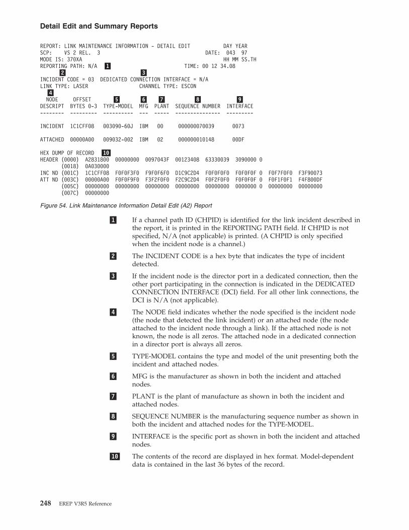
�1� If a channel path ID (CHPID) is identified for the link incident described inthe report, it is printed in the REPORTING PATH field. If CHPID is notspecified, N/A (not applicable) is printed. (A CHPID is only specifiedwhen the incident node is a channel.)
�2� The INCIDENT CODE is a hex byte that indicates the type of incidentdetected.
�3� If the incident node is the director port in a dedicated connection, then theother port participating in the connection is indicated in the DEDICATEDCONNECTION INTERFACE (DCI) field. For all other link connections, theDCI is N/A (not applicable).
�4� The NODE field indicates whether the node specified is the incident node(the node that detected the link incident) or an attached node (the nodeattached to the incident node through a link). If the attached node is notknown, the node is all zeros. The attached node in a dedicated connectionin a director port is always all zeros.
�5� TYPE-MODEL contains the type and model of the unit presenting both theincident and attached nodes.
�6� MFG is the manufacturer as shown in both the incident and attachednodes.
�7� PLANT is the plant of manufacture as shown in both the incident andattached nodes.
�8� SEQUENCE NUMBER is the manufacturing sequence number as shown inboth the incident and attached nodes for the TYPE-MODEL.
�9� INTERFACE is the specific port as shown in both the incident and attachednodes.
�10� The contents of the record are displayed in hex format. Model-dependentdata is contained in the last 36 bytes of the record.
REPORT: LINK MAINTENANCE INFORMATION - DETAIL EDIT DAY YEARSCP: VS 2 REL. 3 DATE: 043 97MODE IS: 370XA HH MM SS.THREPORTING PATH: N/A �1� TIME: 00 12 34.08
�2� �3�INCIDENT CODE = 03 DEDICATED CONNECTION INTERFACE = N/ALINK TYPE: LASER CHANNEL TYPE: ESCON
�4�NODE OFFSET �5� �6� �7� �8� �9�
DESCRIPT BYTES 0-3 TYPE-MODEL MFG PLANT SEQUENCE NUMBER INTERFACE-------- --------- ---------- --- ----- --------------- ---------
INCIDENT 1C1CFF08 003090-60J IBM 00 000000070039 0073
ATTACHED 00000A00 009032-002 IBM 02 000000010148 00DF
HEX DUMP OF RECORD �10�HEADER (0000) A2831800 00000000 0097043F 00123408 63330039 3090000 0
(0018) 0A030000INC ND (001C) 1C1CFF08 F0F0F3F0 F9F0F6F0 D1C9C2D4 F0F0F0F0 F0F0F0F 0 F0F7F0F0 F3F90073ATT ND (003C) 00000A00 F0F0F9F0 F3F2F0F0 F2C9C2D4 F0F2F0F0 F0F0F0F 0 F0F1F0F1 F4F800DF
(005C) 00000000 00000000 00000000 00000000 00000000 0000000 0 00000000 00000000(007C) 00000000
Figure 54. Link Maintenance Information Detail Edit (A2) Report
Detail Edit and Summary Reports
248 EREP V3R5 Reference

Asynchronous Notification Record Detail (A3) ReportThe A3 report shows the details of the service information messages (SIMs).
Figure 55 contains an example of the asynchronous notification record detail (A3)report.
A3 Report for Incorrect RecordThis report is received when there is an incorrect A3 record.
REPORTING DEVICE: 000350 REPORT: ASYNCHRONOUS DAY YEARREPORTING DEVICE TYPE: 3390 REPORTING SYSTEM: VS 2 REL. 3 370XA DATE: 043 97REPORTING PATH: 08-0350 SUBCHANNEL ID: 00010029 HH MM SS.TH
TIME: 15 39 44.04RECORD TYPE: DASD SIM
DEVICE DEPENDENT DATA
DASD SERVICE INFORMATION MESSAGE* SERVICE ALERT 2107 S/N 0112-B7425 REFCODE 43C0-2400-0003 ID=C2* MEDIA EXCEPTION ON SSID 0041, VOLSER PACSM3 DEV 0350, 08
PHYSICAL DEVICE 10, CYLINDER 003B HEAD 0C* REFERENCE MEDIA MAINTENANCE PROCEDURE 1
HEX DUMP OF RECORDHEADER A3831810 00000000 0097043F 15394404 61572320 30900000
0018 00000000 00000000 00000000 00000000 00000000 00000000 20 080350 800620320038 08000350 D7C1C3E2 D4F30000 00900600 10328FC2 11010124 00 000304 222044110058 004143C0 05108202 FF003B0C
Figure 55. Asynchronous Notification Record Detail (A3) Report
Detail Edit and Summary Reports
Chapter 13. Detail Edit and Summary Reports 249

�1� The exception code is used to identify the TYPE and LOCATION of theerror and the effect that the repair will have on the subsystem.
�2� The TYPE, LOCATION, and REPAIR information normally provided by theEXCEPTION CODE will not be printed.
�3� Device dependent data from the control program. May include the VOLID.
.****************REPORTING DEVICE: 00023F REPORT: ASYNCHRONOUS DAY YEARREPORTING DEVICE TYPE: 3390 REPORTING SYSTEM: VS 2 REL. 3 370XA DATE: 068 97REPORTING PATH: 19-023F HH MM SS.TH
TIME: 07 04 49.80RECORD TYPE: DASD SIMDEVICE DEPENDENT DATA
SERVICE INFORMATION MESSAGE -----øøøøøøøøøøøøø* SERVICE ALERT 3390-02 S/N 0113-12931 REFCODE 62AC-0000-000F ID=02** INVALID EXCEPTION CODE F FOR SENSE BYTE 28 = FE �1�DEVICE DEPENDENT DATA NOT FORMATTED �2�SYSTEM INFORMATION DATA �3�BYTE 00 01 02 03 04 05 06 07
D1 C5 E2 D7 D3 F2 00 00
SUBSYSTEM INFORMATION DATA �4�BYTE 00 01 02 03 04 05 06 07 08 09 10 11 12 13 14 15
00 00 06 20 20 27 8F 02 FC 00 00 00 00 00 0F 04BYTE 16 17 18 19 20 21 22 23 24 25 26 27 28 29 30 31
23 00 32 83 00 02 62 AC 05 10 46 00 FE 00 00 00
HEX DUMP OF RECORDHEADER A3831810 00000000 0097068F 07044980 A2221023 90210000
0018 00000000 00000000 00000000 00000000 00000000 00000000 2019023F 800620270038 0800023F D1C5E2D7 D3F20000 00000620 20278F02 FC000000 00000F04 230032830058 000262AC 05104600 FE000000
REPORTING DEVICE: 004400 REPORT: ASYNCHRONOUSREPORTING DEVICE TYPE: 3390 REPORTING SYSTEM: VS 2 REL. 3REPORTING PATH: 66-4400
RECORD TYPE: DASD SIMDEVICE DEPENDENT DATA
DASD SERVICE INFORMATION MESSAGE* REMOTE SESSION 2107 S/N 0175-ANLX1 REFCODE BE81-00** INVALID EXCEPTION CODE 8 FOR SENSE BYTE 28 = FE �1�** REQUIRE MANUAL INTERVENTION FROM CE.DEVICE DEPENDENT DATA NOT FORMATTED �2�SYSTEM INFORMATION DATA �3�BYTE 00 01 02 03 04 05 06 07
D4 E5 E2 C5 E2 C1 00 00
SUBSYSTEM INFORMATION DATA �4�BYTE 00 01 02 03 04 05 06 07 08 09 10 11 12 13 14 15
00 80 10 00 00 3C CF 01 8F 40 40 00 81 FF 09 04BYTE 16 17 18 19 20 21 22 23 24 25 26 27 28 29 30 31
E5 2C 03 5D 00 00 BE 81 04 10 02 00 F3 00 00 00
HEX DUMP OF RECORDHEADER A3831810 00000000 0005304F 10393729 00116D3A 20640000
0018 00000000 00000000 00000000 00000000 00000000 00000038 08004400 D4E5E2C5 E2C10000 00801000 003CCF01 8F400058 0000BE81 04100200 F3000000 00000000 00000000 0000
Figure 56. A3 Report for Incorrect Record
Detail Edit and Summary Reports
250 EREP V3R5 Reference

�4� Device dependent information from the reporting subsystem.
Channel Check Handler (CCH) Detail ReportsThe operating system writes a CCH record when a channel failure occurs but doesnot terminate the system control program. The errors recorded include channelcontrol checks, channel data checks, and interface control checks.
Figures containing examples of these reports are on the pages shown in thefollowing table:
REPORT REFER TO
CCH Detail Report for 3090, Record Type 20 “CCH Detail Report for 3090, RecordType 20”
CCH Summary Report for 3090, Record Type 20 Figure 57 on page 252
CCH Detail Report for 3090, Record Type 21 Figure 58 on page 253
CCH Summary Report for 3090, Record Type 21 Figure 59 on page 254
CCH Detail Report for 4341 “CCH Detail Report for 4341” onpage 254
CCH Summary Report for 4341 Figure 60 on page 255
CCH (Inboard) Detail Report for 9373 “CCH (Inboard) Detail Report for9373” on page 255
CCH (Inboard) Summary Report for 9373 Figure 61 on page 257
CCH Detail Report for 3090, Record Type 20CPU MODEL: 3090 REPORT: CCH EDIT DAY YEAR JOB IDENTITY: C078938B
DATE: 042 97 C3F0F78F9F3F8C2CPU ID: 370150 SCP: V370 REL. 6 HH MM SS.
TIME: 02 18 50.57CHANNEL UNIT ADDR: 1481
CHANNEL TYPE: INTEGRATED BLOCK MPX
CC DA FL CTFAILING CCW 02 9D6ED0 04 90 7D00
K CA US CS CTCSW 00 9D6ED0 00 02 7D80
UNIT STATUS CHANNEL STATUSATTENTION 0 PROGRAM CONTROLLED INTERRUPT 0STATUS MODIFIER 0 INCORRECT LENGTH 0CONTROL UNIT END 0 PROGRAM CHECK 0BUSY 0 PROTECTION CHECK 0CHANNEL END 0 CHANNNEL DATA CHECK 0DEVICE END 0 CHANNNEL CONTROL CHECK 0UNIT CHECK 0 INTERFACE CONTROL CHECK 1UNIT EXCEPTION 0 CHAINING CHECK 0
SOFTWARE RECOVERY STATUS
HARD FAIL 1DEGRADE FAIL 0SOFT FAIL 0PASSED 0
I/O UNIT FOUND BUSY
CHANNEL/UNIT ADDR: 1481
CHANNEL ERROR ANALYSIS
Detail Edit and Summary Reports
Chapter 13. Detail Edit and Summary Reports 251
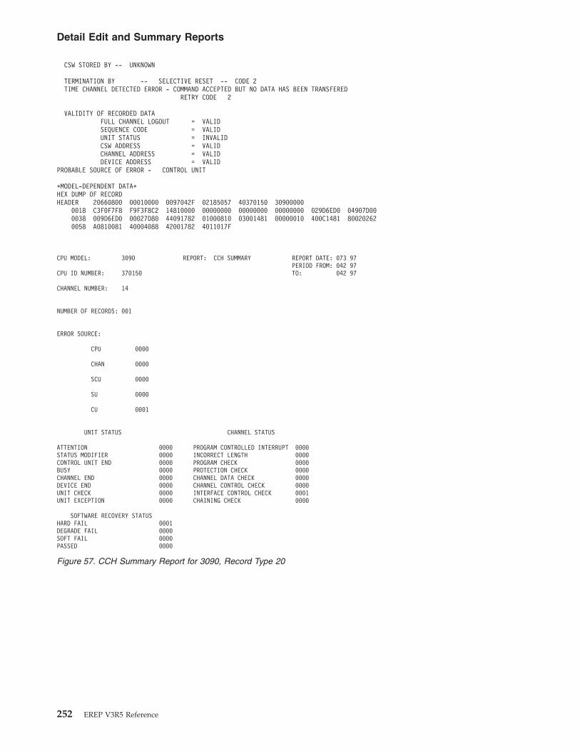
CSW STORED BY -- UNKNOWN
TERMINATION BY -- SELECTIVE RESET -- CODE 2TIME CHANNEL DETECTED ERROR - COMMAND ACCEPTED BUT NO DATA HAS BEEN TRANSFERED
RETRY CODE 2
VALIDITY OF RECORDED DATAFULL CHANNEL LOGOUT = VALIDSEQUENCE CODE = VALIDUNIT STATUS = INVALIDCSW ADDRESS = VALIDCHANNEL ADDRESS = VALIDDEVICE ADDRESS = VALID
PROBABLE SOURCE OF ERROR - CONTROL UNIT
*MODEL-DEPENDENT DATA*HEX DUMP OF RECORDHEADER 20660800 00010000 0097042F 02185057 40370150 30900000
0018 C3F0F7F8 F9F3F8C2 14810000 00000000 00000000 00000000 029D6ED0 04907D000038 009D6ED0 00027D80 44091782 01000810 03001481 00000010 400C1481 800202620058 A0810081 40004088 42001782 4011017F
CPU MODEL: 3090 REPORT: CCH SUMMARY REPORT DATE: 073 97PERIOD FROM: 042 97
CPU ID NUMBER: 370150 TO: 042 97
CHANNEL NUMBER: 14
NUMBER OF RECORDS: 001
ERROR SOURCE:
CPU 0000
CHAN 0000
SCU 0000
SU 0000
CU 0001
UNIT STATUS CHANNEL STATUS
ATTENTION 0000 PROGRAM CONTROLLED INTERRUPT 0000STATUS MODIFIER 0000 INCORRECT LENGTH 0000CONTROL UNIT END 0000 PROGRAM CHECK 0000BUSY 0000 PROTECTION CHECK 0000CHANNEL END 0000 CHANNEL DATA CHECK 0000DEVICE END 0000 CHANNEL CONTROL CHECK 0000UNIT CHECK 0000 INTERFACE CONTROL CHECK 0001UNIT EXCEPTION 0000 CHAINING CHECK 0000
SOFTWARE RECOVERY STATUSHARD FAIL 0001DEGRADE FAIL 0000SOFT FAIL 0000PASSED 0000
Figure 57. CCH Summary Report for 3090, Record Type 20
Detail Edit and Summary Reports
252 EREP V3R5 Reference

CPU MODEL: 3090 REPORT: CCH EDIT DAY YEAR JOB IDENTITY: *MASTER*DATE: 042 97 5CD4C1E2E3C5D95C
CPU ID: 170044 SCP: VS 2 REL. 3 HH MM SS.THTIME: 08 59 03.32
CHANNEL UNIT ADDR: 0063
CHANNEL TYPE: INTEGRATED MULTIPLEXOR(MPX)
CC DA FL CTFAILING CCW 03 DE3B89 30 00 0001
K CA US CS CTCSW 01 000000 00 02 0080
UNIT STATUS CHANNEL STATUSATTENTION 0 PROGRAM CONTROLLED INTERRUPT 0STATUS MODIFIER 0 INCORRECT LENGTH 0CONTROL UNIT END 0 PROGRAM CHECK 0BUSY 0 PROTECTION CHECK 0CHANNEL END 0 CHANNNEL DATA CHECK 0DEVICE END 0 CHANNNEL CONTROL CHECK 0UNIT CHECK 0 INTERFACE CONTROL CHECK 1UNIT EXCEPTION 0 CHAINING CHECK 0
SOFTWARE RECOVERY STATUSHARD FAIL 0DEGRADE FAIL 0SOFT FAIL 0PASSED 0I/O UNIT FOUND BUSYCHANNEL/UNIT ADDR: 0063
CHANNEL ERROR ANALYSIS
CSW STORED BY -- SIOTERMINATION BY -- SELECTIVE RESET -- CODE 2
TIME CHANNEL DETECTED ERROR - COMMAND SENT OR SENT BUT NOT ACCEPTED
RETRY CODE 4VALIDITY OF RECORDED DATA
FULL CHANNEL LOGOUT = VALIDSEQUENCE CODE = VALIDUNIT STATUS = INVALIDCSW ADDRESS = INVALIDCHANNEL ADDRESS = VALIDDEVICE ADDRESS = VALID
PROBABLE SOURCE OF ERROR - CONTROL UNIT
CCH FOOTPRINTS: 8468
IOS GPRS SAVED 1UCB ADDRESS ZERO 0ERPIB EXISTS 0IGFCCHSI ENTERED 0IGFCCHII ENTERED 0IGFCCHFE ENTERED 1IGFC60 ENTERED 0IGFC70 ENTERED 0IGDC80 ENTERED 0IGFCIC ENTERED 1IGFCCHRD ENTERED 1IGFCCHMP EDTERED 0IGFCCHUC ENTERED 1IGFCCHAS ENTERED 0IGFCCHIO ENTERED 0IGFCCHEX ENTERED 0
MULTIPROCESSING INFORMATION0 1 2 3 4 5 6 7 8 9 10 11 12 13 14 15
CPU/CHANNEL SET ID 0000 CHANNELS ON LINE X X X X X X X X X X X X X X X XCPU/CHANNEL SET ID 0001 CHANNELS ON LINE X X X X X X X X X X X X X X X X
*MODEL-DEPENDENT DATA*HEX DUMP OF RECORDHEADER 21830800 20000000 0097042F 08590332 00170044 30900000
0018 5CD4C1E2 E3C5D95C 00630000 00000000 00000000 00000000 03 DE3B89 300000010038 01000000 00020080 80091384 12501009 01000063 00630060 FF FFFFFF FFFFFFFF0058 FFFFFFFF FFFFFFFF 80001011 F0040063 06000C08 00001384 FF FFFFFF FFFFFFFF0078 FFFFFFFF FFFFFFFF FFFFFFFF FFFFFFFF FFFFFFFF FFFFFFFF FF FFFFFF FFFFFFFF0098 FFFFFFFF FFFFFFFF FFFFFFFF FFFFFFFF FFFFFFFF FFFFFFFF 84 680000 0000000200B8 00000000 00010000 00000000 00000000 00000000 00000000 00 000000 0000000000D8 00000000 00000000 00000000 00000000 00000000 00000000 00 000000 00000000
Figure 58. CCH Detail Report for 3090, Record Type 21
Detail Edit and Summary Reports
Chapter 13. Detail Edit and Summary Reports 253

CCH Detail Report for 4341MODEL 4341 SERIAL NO.015085 VS 2 REL. 03--- RECORD SOURCE - CCH TYPE - INBOARDJOB NAME IEEVMPCR
DAY YEAR HH MM SS.THDATE _ 045 97 TIME _ 11 48 44 81CHANNEL/UNIT ADDRESS 0001C1
ADDR.STORED IN HARDWARE LOC 186 - 187: 01C1CC DA FL CT
FAILING CCW 31 63A847 40 80 0005
K CA US CS CTCSW 10 619EC8 00 42 0000
---UNIT STATUS--- ---CHANNEL STATUS---ATTENTION 0 PRGM-CTLD IRPT 0STATUS MODIFIER 0 INCORRECT LENGTH 0CONTROL UNIT END 0 PROGRAM CHECK 0BUSY 0 PROTECTION CHECK 0CHANNEL END 0 CHAN DATA CHECK 0DEVICE END 0 CHAN CTRL CHECK 1UNIT CHECK 0 I/F CTRL CHECK 0UNIT EXCEPTION 0 CHAINING CHECK 0
I/O UNIT FOUND BUSYCHANNEL/UNIT ADDR 0131 01C1
--- CHANNEL TYPE ---INTGTD BLK MPX
******************************************************************************CHANNEL ERROR ANALYSIS
CSW STORED BY INTERRUPTTERMINATION BY -- SELECTIVE RESET- CODE 2
CPU MODEL: 3090 REPORT: CCH SUMMARY REP ORT DATE: 073 97PER IOD FROM: 042 97
CPU ID NUMBER : 170044 TO: 042 97
CHANNEL NUMBER: 00
NUMBER OF RECORDS: 001
ERROR SOURCE:
CPU 0000
CHAN 0000
SCU 0000
SU 0000
CU 0001
UNIT STATUS CHANNEL STATUS
ATTENTION 0000 PROGRAM CONTROLLED INTERRUPT 00 00STATUS MODIFIER 0000 INCORRECT LENGTH 00 00CONTROL UNIT END 0000 PROGRAM CHECK 00 00BUSY 0000 PROTECTION CHECK 00 00CHANNEL END 0000 CHANNEL DATA CHECK 00 00DEVICE END 0000 CHANNEL CONTROL CHECK 00 00UNIT CHECK 0000 INTERFACE CONTROL CHECK 00 01UNIT EXCEPTION 0000 CHAINING CHECK 00 00
SOFTWARE RECOVERY STATUS
HARD FAIL 0000DEGRADE FAIL 0000SOFT FAIL 0000PASSED 0000
Figure 59. CCH Summary Report for 3090, Record Type 21
Detail Edit and Summary Reports
254 EREP V3R5 Reference

TIME CHANNEL DETECTED ERROR - COMMAND ACCEPTED-DATA TRANSFER UNDETERMINEDRETRY CODE 5
VALIDITY OF RECORDED DATACOUNT = NOT VALIDSENSE DATA = NOT STOREDUNIT STATUS = NOT VALIDCOMMAND ADDRESS = VALIDCHANNEL ADDRESS = VALIDDEVICE ADDRESS = VALID
PROBABLE SOURCE OF ERROR- COULD NOT BE ASSESSED*******************************************************************************NO CHANNEL LOGOUT RECORDED
CCH FOOTPRINTS: 8468IOS GPRS SAVED 1UCB ADDRESS ZERO 0ERPIB EXISTS 0IGFCCHSI ENTERED 0IGFCCHII ENTERED 0IGFCCHFE ENTERED 1IGFC60 ENTERED 0IGFC70 ENTERED 0IGDC80 ENTERED 0IGFCIC ENTERED 1IGFCCHRD ENTERED 1IGFCCHMP EDTERED 0IGFCCHUC ENTERED 1IGFCCHAS ENTERED 0IGFCCHIO ENTERED 0IGFCCHEX ENTERED 0
MULTIPROCESSING INFORMATION0 1 2 3 4 5 6 7 8 9 10 11 12 13 14 15
CPU/CHAN SET ID 0000 CHANNELS ON LINE X X X X X XHEX DUMP OF RECORDHEADER 21830800 20000000 0097045F 11484481 02015085 43410000
0000 C9C5C5E5 D4D7C3D9 013101C1 00000000 00000000 00000000 3163A847 408000050020 10619EC8 00420000 40481785 3030200E 030001C1 84680000 00000001 000000000040 000003FF 00000000 00000000 00000000 00000000 00000000 000000000060 00000000 00000000 00000000
CCH (Inboard) Detail Report for 9373MODEL 9373 SERIAL NO. 237967
V370 REL. 06
--- RECORD SOURCE - CCH TYPE - INBOARD
MODEL 4341 CHANNEL CHECK RECORDS DAY YEAR DAY YEAR
DATE RANGE - FROM 045 97 TO 045 97
SERIAL NO. 015085
NO.OF RECORDS 00009
--- SUMMARY OF MODEL 4341 CHANNEL CHECK RECORDS ---
ERROR SOURCE
CPU 0000CHAN 0009SCU 0000SU 0000CU 0009
--- UNIT STATUS --- --- CHANNEL STATUS ---
ATTENTION 0000 CHANNEL END 0000 PRGM-CTLD IRPT 0000 CHAN DATA CHECK 0000STATUS MODIFIER 0000 DEVICE END 0000 INCORRECT LENGTH 0000 CHAN CTL CHECK 0000CONTROL UNIT END 0000 UNIT CHECK 0000 PROGRAM CHECK 0000 I/F CTL CHECK 0009BUSY 0000 UNIT EXCEPTION 0000 PROTECTION CHECK 0000 CHAINING CHECK 0000
Figure 60. CCH Summary Report for 4341
Detail Edit and Summary Reports
Chapter 13. Detail Edit and Summary Reports 255

JOB NAME CP/370
DAY YEAR HH MM SS.THDATE _ 048 97 TIME _ 04 36 54 15
CHANNEL/UNIT ADDRESS 000700
CC DA FL CTFAILING CCW 00 000000 00 00 0000
K CA US CS CTCSW 00 000000 00 04 0000
---UNIT STATUS--- ---CHANNEL STATUS---ATTENTION 0 PRGM-CTLD IRPT 0STATUS MODIFIER 0 INCORRECT LENGTH 0CONTROL UNIT END 0 PROGRAM CHECK 0BUSY 0 PROTECTION CHECK 0CHANNEL END 0 CHAN DATA CHECK 0DEVICE END 0 CHAN CTRL CHECK 1UNIT CHECK 0 I/F CTRL CHECK 0UNIT EXCEPTION 0 CHAINING CHECK 0
******************************************************************************************************
---LIMITED CHANNEL LOGOUT DATA EDITING---
---FIELD VALIDITY FLAGS--- ---TERMINATION CODE---SEQUENCE CODE STORED IS VALID 0 INTERFACE DISCONNECT 0UNIT STATUS STORED IS VALID 0 STOP, STACK OR NORMAL 0CCW ADDR AND KEY IN CSW ARE VALID 0 SELECTIVE RESET 0CHANNEL ADDRESS STORED IS VALID 1 INTERFACE INOPERATIVE 0DEVICE ADDRESS STORED IS VALID 0 ERROR ALERT 0
---SEQUENCE CODE---ERROR DETECTED DURING TEST I/O OR CLEAR I/O 1COMMAND WENT OUT, DEVICE STATUS NOT IN 0COMMAND ACCEPTED, NO DATA TRANSFERRED 0AT LEAST ONE DATA BYTE TRANSFERRED 0COMMAND EITHER NOT SENT OR NOT ACCEPTED 0COMMAND ACCEPTED BUT DATA XFER UNPREDICTABLE 0
---MEASUREMENT BYTE---
BYTE: 00000000 NUMBER OF PENDING OPERATIONS (NPO): 000(CCH - Inboard - Detail Report)
(Part 1 Continued)
---DELAY CODE---CHANNEL BUSY 0CONTROL UNIT BUSY 0DEVICE BUSY 0
I/O UNIT FOUND BUSYCHANNEL/UNIT ADDR 0740
--- CHANNEL TYPE ---INTGTD MPX
*******************************************************************************CHANNEL ERROR ANALYSIS
CSW STORED BY INTERRUPTTERMINATION BY -- SYSTEM RESET- CODE 3TIME CHANNEL DETECTED ERROR - COULD NOT BE ASSESSEDVALIDITY OF RECORDED DATA
COUNT = NOT VALIDSENSE DATA = STOREDUNIT STATUS = NOT VALIDCOMMAND ADDRESS = NOT VALIDCHANNEL ADDRESS = VALIDDEVICE ADDRESS = NOT VALID
PROBABLE SOURCE OF ERROR- CHANNEL*******************************************************************************
HEX DUMP OF RECORD
Detail Edit and Summary Reports
256 EREP V3R5 Reference

HEADER 20660800 00000000 0097048F 5204552 00234567 93730000
0000 4040C3D7 61F3F7F0 07400000 00000000 00000000 00000000 00000000 000000000020 00000000 00040000 444002C0 00000000 01000700 00000000 00000700 00000000
Channel Report Word (CRW) Detail ReportIn a 370/XA environment, the CRW describes channel incidents reported throughmachine checks. The CRW specifies the error environment and the severity of theerror.
Figure 62 on page 258 and Figure 63 on page 259 contain examples of the channelreport word (CRW) detail report.
MODEL 9373 CHANNEL CHECK RECORDS DAY YEAR DAY YEAR
DATE RANGE - FROM 044 97 TO 048 97
SERIAL NO. 234567
NO.OF RECORDS 00002
--- SUMMARY OF MODEL 9373 CHANNEL CHECK RECORDS ---
ERROR SOURCE
CPU 0000CHAN 0002SCU 0000SU 0000CU 0000
--- UNIT STATUS --- --- CHANNEL STATUS ---
ATTENTION 0000 CHANNEL END 0000 PRGM-CTLD IRPT 0000 CHAN DATA CHECK 0000STATUS MODIFIER 0000 DEVICE END 0000 INCORRECT LENGTH 0000 CHAN CTL CHECK 0002CONTROL UNIT END 0000 UNIT CHECK 0000 PROGRAM CHECK 0000 I/F CTL CHECK 0000BUSY 0000 UNIT EXCEPTION 0000 PROTECTION CHECK 0000 CHAINING CHECK 0000
Figure 61. CCH (Inboard) Summary Report for 9373
Detail Edit and Summary Reports
Chapter 13. Detail Edit and Summary Reports 257
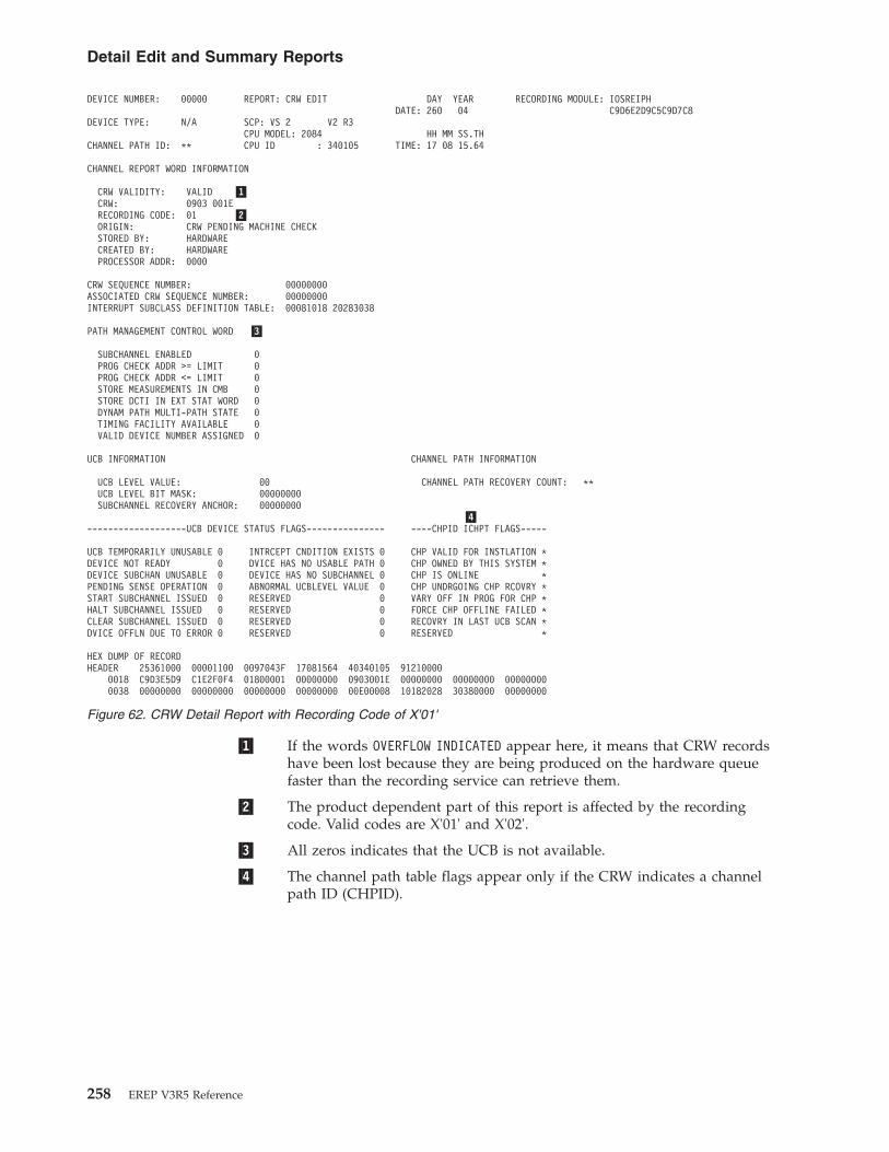
�1� If the words OVERFLOW INDICATED appear here, it means that CRW recordshave been lost because they are being produced on the hardware queuefaster than the recording service can retrieve them.
�2� The product dependent part of this report is affected by the recordingcode. Valid codes are X'01' and X'02'.
�3� All zeros indicates that the UCB is not available.
�4� The channel path table flags appear only if the CRW indicates a channelpath ID (CHPID).
DEVICE NUMBER: 00000 REPORT: CRW EDIT DAY YEAR RECORDING MODULE: IOSREIPHDATE: 260 04 C9D6E2D9C5C9D7C8
DEVICE TYPE: N/A SCP: VS 2 V2 R3CPU MODEL: 2084 HH MM SS.TH
CHANNEL PATH ID: ** CPU ID : 340105 TIME: 17 08 15.64
CHANNEL REPORT WORD INFORMATION
CRW VALIDITY: VALID �1�CRW: 0903 001ERECORDING CODE: 01 �2�ORIGIN: CRW PENDING MACHINE CHECKSTORED BY: HARDWARECREATED BY: HARDWAREPROCESSOR ADDR: 0000
CRW SEQUENCE NUMBER: 00000000ASSOCIATED CRW SEQUENCE NUMBER: 00000000INTERRUPT SUBCLASS DEFINITION TABLE: 00081018 20283038
PATH MANAGEMENT CONTROL WORD �3�
SUBCHANNEL ENABLED 0PROG CHECK ADDR >= LIMIT 0PROG CHECK ADDR <= LIMIT 0STORE MEASUREMENTS IN CMB 0STORE DCTI IN EXT STAT WORD 0DYNAM PATH MULTI-PATH STATE 0TIMING FACILITY AVAILABLE 0VALID DEVICE NUMBER ASSIGNED 0
UCB INFORMATION CHANNEL PATH INFORMATION
UCB LEVEL VALUE: 00 CHANNEL PATH RECOVERY COUNT: **UCB LEVEL BIT MASK: 00000000SUBCHANNEL RECOVERY ANCHOR: 00000000
�4�-------------------UCB DEVICE STATUS FLAGS--------------- ----CHPID ICHPT FLAGS-----
UCB TEMPORARILY UNUSABLE 0 INTRCEPT CNDITION EXISTS 0 CHP VALID FOR INSTLATION *DEVICE NOT READY 0 DVICE HAS NO USABLE PATH 0 CHP OWNED BY THIS SYSTEM *DEVICE SUBCHAN UNUSABLE 0 DEVICE HAS NO SUBCHANNEL 0 CHP IS ONLINE *PENDING SENSE OPERATION 0 ABNORMAL UCBLEVEL VALUE 0 CHP UNDRGOING CHP RCOVRY *START SUBCHANNEL ISSUED 0 RESERVED 0 VARY OFF IN PROG FOR CHP *HALT SUBCHANNEL ISSUED 0 RESERVED 0 FORCE CHP OFFLINE FAILED *CLEAR SUBCHANNEL ISSUED 0 RESERVED 0 RECOVRY IN LAST UCB SCAN *DVICE OFFLN DUE TO ERROR 0 RESERVED 0 RESERVED *
HEX DUMP OF RECORDHEADER 25361000 00001100 0097043F 17081564 40340105 91210000
0018 C9D3E5D9 C1E2F0F4 01800001 00000000 0903001E 00000000 00000000 000000000038 00000000 00000000 00000000 00000000 00E00008 10182028 30380000 00000000
Figure 62. CRW Detail Report with Recording Code of X'01'
Detail Edit and Summary Reports
258 EREP V3R5 Reference

Dynamic Device Reconfiguration (DDR) Detail ReportA dynamic device reconfiguration (DDR) record is created for eachoperator-initiated or system-initiated swap between direct-access devices havingbuffered logs and demountable disk packs (such as the IBM 3330, 3330 MOD 11,and 3340 devices) and between magnetic tape devices.
The DDR record identifies the physical devices involved in the swap.
Figure 64 on page 260 and Figure 65 on page 260 contain examples of the dynamicdevice reconfiguration (DDR) detail report.
DEVICE NUMBER: 0000 REPORT: CRW EDIT DAY YEAR RECORDING MODULE: ILVRAS04DATE: 043 97 C9D3E5D9C1E2F0F4
DEVICE TYPE: N/A SCP: VSE/ESA V5 R2CPU MODEL: 9121 HH MM SS.TH
CHANNEL PATH ID: ** CPU ID : 340105 TIME: 17 08 15.64
CHANNEL REPORT WORD INFORMATION
CRW VALIDITY: VALIDCRW: 0903 001ERECORDING CODE: 02ORIGIN: CRW PENDING MACHINE CHECKSTORED BY: HARDWARECREATED BY: HARDWAREPROCESSOR ADDR: 0000
MACHINE CHECK INTERRUPT CODE: 00000000 00000000
RDEV STATUS INFORMATION
REAL DEVICE IS BUSY 0IORBK QUEUED FOR LATER START 0DEVICE IS OCCUPIED 0ERROR RECOVERY PROC ACTIVE 0DEVICE TEMPORARILY DOWN 0RDEV IS INITIALIZED AT IPL 0
DEVICE ALLOC CONTROL FLAGS ERROR RECOVERY CONTROL FLAGS
DEVICE IS OFFLINE 0 MSG HNDLR WAIT FOR DEV END 0DEVICE ATTACHED TO SYSTEM 0 INTENSIV RECRDING MODE ACT 0DEVICE IS NOT IN USE 0 INTRVNTION REQUIRED ON DEV 0CP VOLUME IS ATTACHED 0 DEVICE IS BEING RESET 0DEVICE IS ATTACHED TO USER 0 SENSE CONTINGENT CONNECTN 0DEVICE IS FOR SPOOLING 0 DEVICE HAS BEEN RESERVED 0DEV MOUNTED, NOT ATTACHED 0 UNSOLICITED DEV END IN ERP 0XVOLID SPECD FOR DASD/TAPE 0 MISSING INTERRUPT MSG SENT 0
SCHIB INFORMATION
CONTROL FLAGS CHANNEL PATH IDS 00 E0 00 08 10 18 20 28SUBCHANNEL ENABLED 0 INTERRUPT REQUEST CODE 0 0 0 0 0 0 0 0PROG CHECK ADDR >= LIMIT 0 LOGICAL PATH MASK 0 0 0 0 0 0 0 0PROG CHECK ADDR <= LIMIT 0 PATH NOT OPERATIONAL MASK 0 0 0 0 0 0 0 0MEASUREMENTS ARE PERMITTED 0 LAST PATH USED MASK 0 0 0 0 0 0 0 0TIMING IS PERMITTED 0 PATH INSTALLED MASK 0 0 0 0 0 0 0 0DYNAMIC PATHING AVAILABLE 0 PATH OPERATIONAL MASK 0 0 0 0 0 0 0 0TIMING FACILITY AVAILABLE 0 PATH AVAILABLE MASK 0 0 0 0 0 0 0 0VALID DEVICE NUM ASSIGNED 0
HEX DUMP OF RECORDHEADER 25361000 00001100 0097043F 17081564 40340105 91210000
0018 C9D3E5D9 C1E2F0F4 02800001 00000000 0903001E 00000000 00000000 000000000038 00000000 00000000 00000000 00000000 00E00008 10182028 30380000 00000000
Figure 63. CRW Detail Report with Recording Code of X'02'
Detail Edit and Summary Reports
Chapter 13. Detail Edit and Summary Reports 259
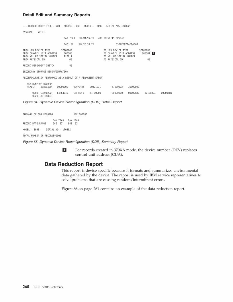
�1� For records created in 370XA mode, the device number (DEV) replacescontrol unit address (CUA).
Data Reduction ReportThis report is device specific because it formats and summarizes environmentaldata gathered by the device. The report is used by IBM service representatives tosolve problems that are causing random/intermittent errors.
Figure 66 on page 261 contains an example of the data reduction report.
--- RECORD ENTRY TYPE - DDR SOURCE - DDR MODEL - 3090 SERIAL NO. 170802
MVS/370 V2 R1
DAY YEAR HH.MM.SS.TH JOB IDENTITY CPSB46
042 97 20 32 10 71 C3D7E2C2F4F64040
FROM UCB DEVICE TYPE 32108003 TO UCB DEVICE TYPE 32108003FROM CHANNEL UNIT ADDRESS 000580 TO CHANNEL UNIT ADDRESS 000581 �1�FROM VOLUME SERIAL NUMBER F22011 TO VOLUME SERIAL NUMBERFROM PHYSICAL ID 00 TO PHYSICAL ID 00
RECORD DEPENDENT SWITCH 50
SECONDARY STORAGE RECONFIGURATION
RECONFIGURATION PERFORMED AS A RESULT OF A PERMANENT ERROR
HEX DUMP OF RECORDHEADER 60890A50 00000000 0097042F 20321071 61170802 30900000
0000 C3D7E2C2 F4F64040 C6F2F2F0 F1F10000 00000000 00000580 32108003 000005810020 32108003
Figure 64. Dynamic Device Reconfiguration (DDR) Detail Report
SUMMARY OF DDR RECORDS DEV 000580
DAY YEAR DAY YEARRECORD DATE RANGE 042 97 042 97
MODEL - 3090 SERIAL NO - 170802
TOTAL NUMBER OF RECORDS=0001
Figure 65. Dynamic Device Reconfiguration (DDR) Summary Report
Detail Edit and Summary Reports
260 EREP V3R5 Reference

�1� There are six different types of maintenance device codes (MDC), eachusing a particular subset of fault symptom codes.
�2� The number of records used to build this MDC.
�3� Two of the MDCs have additional information printed.
�4� An additional MDC is printed for records with only the environmentaldata bit on.
�5� To build the MDC, only selected OBR (by fault code) records from a 3370are used.
Recovery/Termination (EOD) Detail ReportsThe recovery/termination record contains information relating to the cause oftermination and system environmental information. If the record is documentingnormal termination, it consists only of the 24-byte header. In a record written forabnormal termination, the header is followed by fields of variable lengthcontaining data relevant to the system termination or wait state codes.
Record type X'80' indicates that the system terminated normally under programcontrol, at the request of the operator. With MVS Only:v Record type X'81' is written when the system is put in a nonrestartable wait by
the operating system following a machine check.v Record type X'84' indicates a restartable wait state requiring operator
intervention.
Figures containing examples of these reports are on the pages shown in thefollowing table:
*******************************************************************************
MAINTENANCE DEVICE CODE FOR DEVICE TYPE = 3370DEVICE ADDRESS = 0701 SHARED SERIAL = 700006�1�
MD CODE TYPE = DC1 MDC=0008 SAMPLES= 1MD CODE TYPE = FC1 MDC=0200 SAMPLES= 1 �2�MD CODE TYPE = SV MDC=0130 SAMPLES= 2
MODIFERS: �3�EXPECTED ACTUAL ACCESS EVEN OVER/ DIFFERENCE CTDESTINATION DESTINATION DIRECTION TRACK UNDER REMAINDERCCC-HH-M/F-SM CCC-HH-M/F-SM F/R E/O OS/US DIFF
7 0 M 0 0 15 F 3 R 0 OS- 7 07 0 M 0 0 15 F 3 R 0 OS- 7 0
�4�MD CODE TYPE = SVE MDC=8130 SAMPLES= 1
MODIFERS:EXPECTED ACTUAL ACCESS EVEN OVER/ DIFFERENCE CTDESTINATION DESTINATION DIRECTION TRACK UNDER REMAINDERCCC-HH-M/F-SM CCC-HH-M/F-SM F/R E/O OS/US DIFF
7 0 M 0 0 15 F 3 R 0 OS- 7 0MD CODE TYPE = SC MDC=0001 SAMPLES= 2MD CODE TYPE = SCE MDC=8001 SAMPLES= 1MD CODE TYPE = RW MDC=0132 SAMPLES= 6MD CODE TYPE = DC MDC=0300 SAMPLES= 1
ECC CORRECTABLE UNCORRECTABLE NO SYNC BYTE FOUNDALTERNATE DATA BLOCK N/A N/ACCC = 999 HH = 2 BB = 2
IFC1691 6 RECORDS NOT USED BY IFCNFPDR FOR THIS CUX 070X �5�
Figure 66. Data Reduction Report
Detail Edit and Summary Reports
Chapter 13. Detail Edit and Summary Reports 261

REPORT REFER TO
End of Day (EOD) Detail Report Figure 67
End of Day (EOD) Summary Report Figure 68
System Termination Detail Report Figure 69 on page 263
System Termination Summary Report Figure 70 on page 263
EOD RECORD EDIT AND PRINTING SECTIONDAY YEAR HH MM SS TH
DATE -193 08 TIME -16 27 45 97MODEL - 2097 CPU SERIAL NO. - 0706C0
MVS/ESA V7 R0
HEX DUMP OF RECORDHEADER 809C1800 00000000 0108193F 16274597 000706C0 20978000
0000
Figure 67. End of Day (EOD) Detail Report
SUMMARY OF EOD RECORDS MODEL 2097DAY YEAR DAY YEAR CPU SERIAL 0706C0
DATE RANGE FROM 193 08 TO 193 08
NO. OF RECORDS 001
XXXXXXX END OF EOD SUMMARY XXXXXX
Figure 68. End of Day (EOD) Summary Report
Detail Edit and Summary Reports
262 EREP V3R5 Reference

System Initialization (IPL) Detail ReportsIPL records are written to document operating system initialization.
Figures containing examples of these reports are on the pages shown in thefollowing table:
REPORT REFER TO
Initial Program Load (System Initialization) DetailReport (IPL) for 2084
Figure 71 on page 264
Initial Program Load (System Initialization)Summary Report (IPL) for 2084
Figure 72 on page 264
EOD RECORD EDIT AND PRINTING SECTION
SYSTEM TERMINATION RECORD EDIT AND PRINT SECTION
DAY YEAR HH MM SS THDATE -046 08 TIME -04 00 00 25
MODEL - 2097 CPU SERIAL NO. - 0706C0
VS 2 REL. 3
HEX DUMP OF RECORDHEADER 81000800 00000000 0008046F 04000025 230706C0 20970000
0000 00000088 00000014 00FD3E04 80FD3DD8 00000042 00FD3E04 00000C00 000000000020 0004C1D1 00FFBB40 00FDF890 7004B1D2 00031358 00029DE0 00FFBB40 000000000040 0004B1D0 000487A2 DD84EE40 0FC98C00 00040011 00000000 070C0000 000487A20060 00000000 00000000 00FDF890 00FDF890
EOD RECORD EDIT AND PRINTING SECTION
SYSTEM TERMINATION RECORD EDIT AND PRINT SECTION
DAY YEAR HH MM SS THDATE -056 08 TIME -04 00 00 25
MODEL - 2097 CPU SERIAL NO. - 0706C0
VS 2 REL. 3
HEX DUMP OF RECORDHEADER 81000800 00000000 0008056F 04000025 230706C0 20970000
0000 00000088 00000014 00FD3E04 80FD3DD8 00000042 00FD3E04 00000C00 000000000020 0004C1D1 00FFBB40 00FDF890 7004B1D2 00031358 00029DE0 00FFBB40 000000000040 0004B1D0 000487A2 DD84EE40 0FC98C00 00040011 00000000 070C0000 000487A20060 00000000 00000000 00FDF890 00FDF890
Figure 69. System Termination Detail Report
SUMMARY OF SYSTEM TERMINATION RECORDS MODELDAY YEAR DAY YEAR CPU SERIAL 220344
DATE RANGE FROM 046 97 TO 056 97
NO. OF RECORDS 002
XXXXXXX END OF SYSTEM TERMINATION SUMMARY XXXXXXX
Figure 70. System Termination Summary Report
Detail Edit and Summary Reports
Chapter 13. Detail Edit and Summary Reports 263

Machine Check Handler (MCH) Detail ReportsMCH records document the occurrence of processor, storage, storage key or timingfacility (external damage) failures under the following conditions:v The problem is recovered by the hardware or the software.v The problem is not corrected by hardware. A hard machine check is one that
cannot be corrected or circumvented, so the software recovery routines are givencontrol for the task.
v The problem resulted in the loss of a processor.
Figures containing examples of these reports are on the pages shown in thefollowing table:
REPORT REFER TO
Machine Check handler (MCH) Detail Report for 2084-XA (MVS) “Machine Check Handler (MCH) DetailReport for 2084-XA (MVS)” on page 265
Machine Check Handler (MCH) Summary Report for 2084-XA (MVS) “Machine Check Handler (MCH) SummaryReport for 2084-XA (MVS)” on page 267
Machine Check handler (MCH) Detail Report for 2084-XA (VM) “Machine Check Handler (MCH) DetailReport for 2084-XA (VM)” on page 268
IPL RECORD EDIT AND PRINTING SECTIONDAY YEAR HH MM SS TH
DATE -159 07 TIME -11 12 48 89MODEL - 2084 CPU SERIAL NO. - 159BBE
MVS/ESA V7 R0
IPL REASON CODE - DF DEFAULT -U-SUBSYSTEM ID - 00 SUBSYSTEM NAME - NULLHIGHEST STORAGE ADDRESS 7FFFFFFF
LAST ACTIVITY INFORMATION :DAY YEAR HH MM SS TH
DATE -159 07 TIME -11 09 45 48END OF IPL RECORD
HEX DUMP OF RECORDHEADER 509C1880 00000000 0107159F 11124889 FF159BBE 20840000
0000 00000000 C4C60000 00000000 00000000 7FFFFFFF 00000000 0107159F 11094548
Figure 71. Initial Program Load (System Initialization) Detail Report (IPL) for 2084
SUMMARY OF IPL RECORDS MODEL 2084DAY YEAR DAY YEAR CPU SERIAL 159BBE
DATE RANGE FROM 158 07 TO 159 07NO. OF RECORDS 002
XXXX SUBSYSTEM NAME AND NUMBER OF OCCURRENCES XXXXNULL 002 PROCESSOR 000TAPE 000 TELEPROCESSING 000MICR/OCR 000 GRAPHIX/DISPLAY/AUDIO 000CARD/PRINT 000 IBM SYSTEM CONTROL PROGRAM 000DIRECT ACCESS 000 IBM PROGRAMMING PRODUCT 000OTHER 000XXXX IPL REASON CODE AND NUMBER OF OCCURRENCES XXXNORMAL 000 MEDIA 000UNKNOWN 000 OPERATIONAL 000USER PROGRAM 000 ENVIRONMENTAL 000IBM HARDWARE PROGRAMMING PROBLEM-CE/SE NOT REQUIRED 000IBM HARDWARE PROGRAMMING PROBLEM-CE/SE REQUIRED 000CE/SE HAS THE SYSTEM 000DEFAULT -U- 002INVALID IPL REASON CODE 000
Figure 72. Initial Program Load (System Initialization) Summary Report (IPL) for 2084
Detail Edit and Summary Reports
264 EREP V3R5 Reference

REPORT REFER TO
Machine Check Handler (MCH) Summary Report for 2084-XA (VM) “Machine Check Handler (MCH) SummaryReport for 2084-XA (VM)” on page 270
Machine Check Handler (MCH) Detail Report for 9373 “Machine Check Handler (MCH) DetailReport for 9373” on page 270
Machine Check Handler (MCH) Summary Report for 9373 “Machine Check Handler (MCH) SummaryReport for 9373” on page 272
�1� In a processor resource/system manager (PR/SM) environment, the logicalCPU ID and physical CPU address are shown. In non-PR/SMenvironments, only physical CPU ID is shown.
Machine Check Handler (MCH) Detail Report for 2084-XA (MVS)MODEL: 2084-XA REPORT: MACHINE CHECK EDIT DAY YEAR DAY YEAR
DATE: 215 04 REPORT DATE: 289 04CPU ID: 270044 SCP: VS2 REL. 3ADDRESS: 00
�1� HH MM SS.THMACHINE VERSION CODE: 20 TIME: 00 20 32.34
SM KS CM UA IAMACHINE CHECK OLD PSW: 07 0E 00 00 00000000
SEQ CPU ASID TIMEERROR ID: 15759 0000 0000 0 0 00.0
FAILING STORAGE ADDRESS: NOT APPLICABLE
REGION CODE: NOT APPLICABLE
EXTERNAL DAMAGE CODE: NOT APPLICABLE
SOFTWARE RECOVERY STATUS
HARD FAIL 0DEGRADE FAIL 0SOFT FAIL 0PASSED 0
**** NOTE: THE PRODUCT FUNCTIONAL CHARACTERISTICS PUBLICATION DESCRIBES THE MACHINE CHECK INTERRUPT CODE SUPPORT. ****
MACHINE CHECK INTERRUPT CODE (MCIC)SUBCLASS
SYSTEM DAMAGE (SD) 0 RESERVEDINSTR-PROCESSING DAMAGE (PD) 0 DEGRADATION (DG) 0SYSTEM RECOVERY (SR) 0 WARNING (W ) 0RESERVED CHANNEL REPORT PENDING (CP) 0TIMING-FACILITY (CD) 1 SERVICE-PROCESSOR DAMAGE (SP) 0EXTERNAL DAMAGE (ED) 0 CHANNEL-SUBSYSTEM DAMAGE (CK) 0
INTERRUPT TENSE CODES
BACKED UP (B ) 0
STORAGE AND PROTECTION ERROR CODES
STORAGE ERROR UNCORRECTED (SE) 0 STOR-KEY ERROR UNCORRECTED (KE) 0STORAGE ERROR CORRECTED (SC) 0 STORAGE DEGRADATION (DS) 0
M.C. OLD PSW VALIDITY CODES
EMWP BITS ARE VALID (WP) 1 PROGRAM MASK IS VALID (PM) 1SYSTEM MASK IS VALID (MS) 1 INSTR ADDRESS IS VALID (IA) 1
MISCELLANEOUS VALIDITY CODESFAILING STOR ADDR IS VALID (FA) 0 CNTRL REGS STORED VALID (CR) 1RESERVED EXTENDED LOGOUT AREA VALID (LG) 0EXTERNAL DAMAGE CODE VALID (EC) 0 INSTR MODIFIED STOR VALID (ST) 1FP REGS STORED ARE VALID (FP) 1 CPU-TIMER IS VALID (CT) 1GEN REGS STORED ARE VALID (GR) 1 CLOCK-COMPARATOR IS VALID (CC) 1IPD MODIFIER 0
EXTENDED LOGOUT LENGTH 0000
Detail Edit and Summary Reports
Chapter 13. Detail Edit and Summary Reports 265
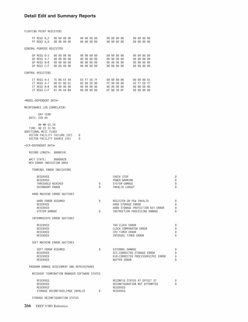
FLOATING POINT REGISTERS
FP REGS 0,2 00 00 00 00 00 00 00 00 00 00 00 00 00 00 00 00FP REGS 4,6 00 00 00 00 00 00 00 00 00 00 00 00 00 00 00 00
GENERAL PURPOSE REGISTERS
GP REGS 0-3 00 00 00 00 00 00 00 00 00 00 00 00 00 00 00 00GP REGS 4-7 00 00 00 00 00 00 00 00 00 00 00 00 00 00 00 00GP REGS 8-B 00 00 00 00 00 00 00 00 00 00 00 00 00 00 00 00GP REGS C-F 00 00 00 00 00 00 00 00 00 00 00 00 00 00 00 00
CONTROL REGISTERS
CT REGS 0-3 7E B0 EE 40 03 F7 E0 7F 00 00 00 00 00 00 00 01CT REGS 4-7 00 01 00 01 82 60 20 00 FE 00 00 00 03 F7 E0 7FCT REGS 8-B 00 00 00 00 00 00 00 00 00 00 00 00 00 00 00 00CT REGS C-F 01 40 A4 B0 00 00 00 00 DF 88 3D 8F 00 00 00 00
*MODEL-DEPENDENT DATA*
MAINTENANCE LOG CORRELATOR:
DAY YEARDATE: 220 04
HH MM SS.THTIME: 00 22 31.95
ADDITIONAL MCIC FLAGSVECTOR FACILITY FAILURE (VF) 0VECTOR FACILITY SOURCE (VS) 0
*SCP-DEPENDENT DATA*
RECORD LENGTH: 0000014C
WAIT STATE: 00000A28MCH ERROR INDICATION AREA
TERMINAL ERROR INDICATORS
RESERVED CHECK STOP 0RESERVED POWER WARNING 0THRESHOLD REACHED 0 SYSTEM DAMAGE 0SECONDARY ERROR 0 INVALID LOGOUT 0
HARD MACHINE ERROR SWITCHES
HARD ERROR ASSUMED 0 REGISTER OR PSW INVALID 0RESERVED HARD STORAGE ERROR 0RESERVED HARD STORAGE PROTECTION KEY ERROR 0SYSTEM DAMAGE 0 INSTRUCTION PROCESSING DAMAGE 0
INTERMEDIATE ERROR SWITCHES
RESERVED TOD CLOCK ERROR 0RESERVED CLOCK COMPARATOR ERROR 0RESERVED CPU TIMER ERROR 0RESERVED INTERVAL TIMER ERROR 0
SOFT MACHINE ERROR SWITCHES
SOFT ERROR ASSUMED 0 EXTERNAL DAMAGE 0RESERVED ECC-CORRECTED STORAGE ERROR 0RESERVED HIR-CORRECTED PROCESSOR(CPU) ERROR 0RESERVED BUFFER ERROR 0
PROGRAM DAMAGE ASSESSMENT AND REPAIR(PDAR)
RECOVERY TERMINATION MANAGER SOFTWARE STATES
RESERVED RECONFIG STATUS AT OFFSET 37 0RESERVED RECONFIGURATION NOT ATTEMPTED 0RESERVED RESERVEDSTORAGE RECONFIGED,PAGE INVALID 0 RESERVED
STORAGE RECONFIGURATION STATUS
Detail Edit and Summary Reports
266 EREP V3R5 Reference

RESERVED FRAME OFFLINE OR SCHEDULE OFFLINE 0RESERVED INTERCEPT 0RESERVED PERMANENT ERROR OCCURED IN FRAME 0RESERVED FRAME HAS RESIDENT SYSTEM STORAGE 0RESERVED FRAME IS IN USE FOR SQA 0RESERVED FRAME IS IN USE FOR LSQA 0STORAGE ERROR SET IN FRAME 0 FRAME CONTAINS PAGE-FIXED DATA 0FRAME HAD CHANGE INDICATOR ON 0 FRAME IS V=R OR SCHEDULED V=R 0
CHECKING BLOCK LENGTH: 80
*NO MACHINE CHECK EXTENDED LOGOUT HAS BEEN STORED*
HEX DUMP OF RECORDHEADER 13831818 FF000000 0097042F 00203234 20270044 30900000
0018 0000014C 00000A28 00000000 00000080 070E0000 00000000 08000F1D 000300000038 00000000 00000000 00000000 00000000 98F62D02 39AC0000 00000000 000000000058 00000000 00000000 00000000 00000000 00000000 00000000 00000000 000000000078 00000000 00000000 00000000 00000000 00000000 00000000 00000000 000000000098 00000000 00000000 00000000 00000000 00000000 00000000 00000000 0000000000B8 00000000 00000000 00000000 00000000 00000000 00000000 00000000 0000000000D8 00000000 00000000 00000000 00000000 00000000 00000000 00000000 0000000000F8 00000000 00000000 00000000 00000000 7EB0EE40 03F7E07F 00000000 000000010118 00010001 82602000 FE000000 03F7E07F 00000000 00000000 00000000 000000000138 0140A4B0 00000000 DF883D8F 00000000 00000000
Machine Check Handler (MCH) Summary Report for 2084-XA(MVS)
MODEL: 2084 REPORT: MACHINE CHECK SUMMARY DAY YEAR DAY YEARDATE RANGE: 215 04 REPORT DATE: 289 04
CPU ID: 270044
MACHINE VERSION CODE: 20
NO. OF RECORDS: 1
NO. OF 370 RECORDS: 0
NO. OF XA RECORDS: 1
SOFTWARE RECOVERY STATUS
HARD FAIL 0DEGRADE FAIL 0SOFT FAIL 0PASSED 0
**** NOTE: THE PRODUCT FUNCTIONAL CHARACTERISTICS PUBLICATION DESCRIBES THE MACHINE CHECK INTERRUPT CODE SUPPORT. ****
MACHINE CHECK INTERRUPT CODE (MCIC)
SUBCLASS
SYSTEM DAMAGE (SD) 0 RESERVEDINSTR-PROCESSING DAMAGE (PD) 0 DEGRADATION (DG) 0INSTR-PROCESSING BACKUP (PD) 0 WARNING (W ) 0SYSTEM RECOVERY (SR) 0 PENDING CRW REPORT (CP) 0INTERVAL-TIMER DAMAGE (TD) 0 SERVICE PROCESSOR DAMAGE (SP) 0TIMING-FACILITY DAMAGE (CD) 1 CHANNEL SUBSYSTEM DAMAGE (CK) 0EXTERNAL DAMAGE (ED) 0
INTERRUPT TENSE CODES
BACKED-UP (B ) 0 DELAYED (D ) 0
STORAGE AND PROTECTION ERROR CODES
UNCORRECTED STOR ERRORS (SE) 0 STOR-KEY ERROR UNCORRECTED (KE) 0CORRECTED STORAGE ERRORS (SC) 0 STORAGE DEGRADATION (DS) 0
M.C. OLD PSW VALIDITY CODES
EMWP BITS ARE VALID (WP) 1 PROGRAM MASK IS VALID (PM) 1SYSTEM MASK IS VALID (MS) 1 INSTR ADDRESS IS VALID (IA) 1
Detail Edit and Summary Reports
Chapter 13. Detail Edit and Summary Reports 267

MISCELLANEOUS VALIDITY CODESFAILING STOR ADDR IS VALID (FA) 0 CNTRL REGS STORED VALID (CR) 1REGION CODE IS VALID (RC) 0 EXTENDED LOGOUT AREA VALID (LG) 0EXTERNAL DAMAGE CODE VALID (EC) 0 INSTR MODIFIED STOR VALID (ST) 1FP REGS STORED ARE VALID (FP) 1 CPU TIMER IS VALID (CT) 1GEN REGS STORED ARE VALID (GR) 1 CLOCK COMPARATOR IS VALID (CC) 1
Machine Check Handler (MCH) Detail Report for 2084-XA (VM)MODEL: 2084-XA REPORT: MACHINE CHECK EDIT DAY YEAR DAY YEAR
DATE: 215 04 REPORT DATE: 289 04CPU ID: 511353 SCP: VM/ESA V1 R2ADDRESS: 00 HH MM SS.TH
MACHINE VERSION CODE: 00 TIME: 12 07 30.59SM KS CM UA IA
MACHINE CHECK OLD PSW: 07 0E 00 00 00000000
SEQ CPU ASID TIMEERROR ID: 00000 8000 4100 0 0 00.0
FAILING STORAGE ADDRESS: NOT APPLICABLE
REGION CODE: NOT APPLICABLE
EXTERNAL DAMAGE CODE: NOT APPLICABLE
SOFTWARE RECOVERY STATUS
HARD FAIL 0DEGRADE FAIL 0SOFT FAIL 0PASSED 0
**** NOTE: THE PRODUCT FUNCTIONAL CHARACTERISTICS PUBLICATION DESCRIBES THE MACHINE CHECK INTERRUPT CODE SUPPORT. ****
MACHINE CHECK INTERRUPT CODE (MCIC)SUBCLASS
SYSTEM DAMAGE (SD) 1 RESERVEDINSTR-PROCESSING DAMAGE (PD) 0 DEGRADATION (DG) 0SYSTEM RECOVERY (SR) 0 WARNING (W ) 0RESERVED CHANNEL REPORT PENDING (CP) 0TIMING-FACILITY (CD) 0 SERVICE-PROCESSOR DAMAGE (SP) 0EXTERNAL DAMAGE (ED) 0 CHANNEL-SUBSYSTEM DAMAGE (CK) 0
INTERRUPT TENSE CODES
BACKED UP (B ) 0
STORAGE AND PROTECTION ERROR CODES
STORAGE ERROR UNCORRECTED (SE) 0 STOR-KEY ERROR UNCORRECTED (KE) 0STORAGE ERROR CORRECTED (SC) 0 STORAGE DEGRADATION (DS) 0
M.C. OLD PSW VALIDITY CODESEMWP BITS ARE VALID (WP) 1 PROGRAM MASK IS VALID (PM) 0SYSTEM MASK IS VALID (MS) 1 INSTR ADDRESS IS VALID (IA) 0
MISCELLANEOUS VALIDITY CODES
FAILING STOR ADDR IS VALID (FA) 0 CNTRL REGS STORED VALID (CR) 1RESERVED EXTENDED LOGOUT AREA VALID (LG) 1EXTERNAL DAMAGE CODE VALID (EC) 0 INSTR MODIFIED STOR VALID (ST) 0FP REGS STORED ARE VALID (FP) 1 CPU-TIMER IS VALID (CT) 1GEN REGS STORED ARE VALID (GR) 1 CLOCK-COMPARATOR IS VALID (CC) 1IPD MODIFIER 0
EXTENDED LOGOUT LENGTH 0588
FLOATING POINT REGISTERS
FP REGS 0,2 00 00 00 00 00 00 00 00 00 00 00 00 00 00 00 00FP REGS 4,6 00 00 00 00 00 00 00 00 00 00 00 00 00 00 00 00
GENERAL PURPOSE REGISTERS
GP REGS 0-3 00 00 00 00 00 00 00 00 00 00 00 00 00 00 00 00GP REGS 4-7 00 00 00 00 00 00 00 00 00 00 00 00 00 00 00 00
Detail Edit and Summary Reports
268 EREP V3R5 Reference

GP REGS 8-B 00 00 00 00 00 00 00 00 00 00 00 00 20 64 00 00GP REGS C-F 00 00 00 00 00 00 00 00 98 EB 99 BB 04 CF 71 01
CONTROL REGISTERS
CT REGS 0-3 80 02 00 01 00 00 00 41 01 0A C3 32 00 F8 0A A4CT REGS 4-7 00 00 00 00 04 88 00 00 00 00 00 00 00 00 00 00CT REGS 8-B 00 00 00 00 00 00 00 00 00 00 00 00 00 00 00 00CT REGS C-F 00 00 00 00 00 00 00 00 00 01 00 19 C9 C5 C1 E5
*MODEL-DEPENDENT DATA*
MAINTENANCE LOG CORRELATOR:
DAY YEARDATE: 220 04
HH MM SS.THTIME: 16 47 41.98
ADDITIONAL MCIC FLAGSVECTOR FACILITY FAILURE (VF) 0VECTOR FACILITY SOURCE (VS) 0
MACHINE CHECK EXTENDED LOGOUT BYTES
0000 C5C4E2F0 C9C5C1E5 C5C4E2F0 C9C5C1E5 C5C4E2D9 00F80A50 00000000 000000000020 00000000 00000000 00000000 00000000 00000000 00000000 00000000 000000000040 00000000 FFFF0003 00F80C70 00000000 00000000 00000000 00000000 000000000060 00000000 0007F7EE 00FFA0D2 1106C9C8 C1D7E2C1 15020224 120400FB 308015020080 021C1204 00000000 150202EC 12040000 00001502 049C1204 00000008 1107C9C800A0 C1C1E2C3 C2150200 80120400 00000015 0200E812 04000000 00150200 EC12040000C0 00000015 0200B412 04000000 00150201 3C120400 00000015 02014812 0400000000E0 001107C9 C8C1D3C3 C3C11502 036C1204 00000000 1502021C 12020000 1502053C0100 120C0000 00000000 00000000 00001106 C9C8C1E2 E5E31502 001C1204 000000000120 00000000 1018E2C3 D9C100FF B1E800F8 04E08000 000000F8 08480400 0000E2C30140 F1C3F5C9 C5C1E5C5 C4E2F000 00000000 00000000 00000000 0000F0F1 61F2F9610160 F8F540D1 C2C2F2F1 F3F30000 0000C9C5 C1E5C5C4 E2D90000 00000000 000000000180 00000400 00000000 0000810B 09D00000 00000000 00000000 00000000 0000000001A0 00000000 00000000 00000000 00000000 00000000 00000000 0000D203 824095FE01C0 D20303A4 038000FB 308003F7 E07F900F 30000000 00000000 00000000 0000400001E0 00000000 00000000 00000000 00000000 00000000 00000000 00000000 000000000200 00000000 00000019 00410001 0007F7EE 00000000 00000000 00000000 000000000220 00000000 00000000 00000000 00000000 00000000 00000000 00000000 000000000240 00000000 00000000 00000000 00000000 00000000 00000000 00000000 000000000260 00000000 00000000 00000000 00000000 00000000 00000000 00000000 000000000280 00000000 00000000 00000000 00000000 00000000 00000000 00000000 0000000002A0 00000000 00000000 00000000 00000000 00000000 00000000 00000000 0000000002C0 00000000 00000000 00000000 00000000 00000000 00000000 00000000 0000000002E0 00000000 00000000 00000000 00000000 00000000 00000000 00000000 000000000300 00000000 00000000 00000000 00000000 00000000 00000000 00000000 000000000320 00000000 00000000 00000000 00000000 00000000 00000000 00000000 000000000340 00000000 00000000 00000000 00000000 00000000 00000000 00000000 000000000360 00000000 00000000 00000000 00000000 00000000 00000000 00000000 000000000380 00000000 00000000 00000000 00000000 00000000 00000000 00000000 0000000003A0 00000000 00000000 00000000 00000000 00000000 00000000 00000000 0000000003C0 00000000 00000000 00000000 00000000 00000000 00000000 00000000 0000000003E0 00000000 00000000 00000000 00000000 00000000 00000000 00000000 000000000400 00000000 00000000 00000000 00000000 00000000 00000000 00000000 000000000420 00000000 00000000 00000000 00000000 00000000 00000000 00000000 000000000440 00000000 00000000 00000000 00000000 00000000 00000000 00000000 000000000460 00000000 00000000 00000000 00000000 00000000 00000000 00000000 000000000480 00000000 00000000 00000000 00000000 00000000 00000000 00000000 0000000004A0 00000000 00000000 00000000 00000000 00000000 00000000 00000000 0000000004C0 00000000 00000000 00000000 00000000 00000000 00000000 00000000 0000000004E0 00000000 00000000 00000000 00000000 00000000 00000000 00000000 000000000500 00000000 00000000 00000000 00000000 00000000 00000000 00000000 000000000520 00000000 00000000 00000000 00000000 00000000 00000000 00000000 000000000540 00000000 00000000 00000000 00000000 00000000 00000000 00000000 000000000560 00000000 00000000 00000000 00000000 00000000 00000000 00000000 000000000580 00000000 00000000
HEX DUMP OF RECORDHEADER 10661010 FF000000 0097042F 12073059 00511353 30900000
0018 000006D0 00000000 00180000 00000008 070E0000 00000000 80000C1E 000305880038 00000000 00000000 00000000 00000000 80004100 00000000
Detail Edit and Summary Reports
Chapter 13. Detail Edit and Summary Reports 269

Machine Check Handler (MCH) Summary Report for 2084-XA(VM)
MODEL: 2084 REPORT: MACHINE CHECK SUMMARY DAY YEAR DAY YEARDATE RANGE: 214 04 REPORT DATE: 289 04
CPU ID: 511353
MACHINE VERSION CODE: 00
NO. OF RECORDS: 1
NO. OF 370 RECORDS: 0
NO. OF XA RECORDS: 1
SOFTWARE RECOVERY STATUS
HARD FAIL 0DEGRADE FAIL 0SOFT FAIL 0PASSED 0
**** NOTE: THE PRODUCT FUNCTIONAL CHARACTERISTICS PUBLICATION DESCRIBES THE MACHINE CHECK INTERRUPT CODE SUPPORT. ****
MACHINE CHECK INTERRUPT CODE (MCIC)
SUBCLASS
SYSTEM DAMAGE (SD) 1 RESERVEDINSTR-PROCESSING DAMAGE (PD) 0 DEGRADATION (DG) 0INSTR-PROCESSING BACKUP (PD) 0 WARNING (W ) 0SYSTEM RECOVERY (SR) 0 PENDING CRW REPORT (CP) 0INTERVAL-TIMER DAMAGE (TD) 0 SERVICE PROCESSOR DAMAGE (SP) 0TIMING-FACILITY DAMAGE (CD) 0 CHANNEL SUBSYSTEM DAMAGE (CK) 0EXTERNAL DAMAGE (ED) 0
INTERRUPT TENSE CODES
BACKED-UP (B ) 0 DELAYED (D ) 0
STORAGE AND PROTECTION ERROR CODES
UNCORRECTED STOR ERRORS (SE) 0 STOR-KEY ERROR UNCORRECTED (KE) 0CORRECTED STORAGE ERRORS (SC) 0 STORAGE DEGRADATION (DS) 0
M.C. OLD PSW VALIDITY CODES
EMWP BITS ARE VALID (WP) 1 PROGRAM MASK IS VALID (PM) 0SYSTEM MASK IS VALID (MS) 1 INSTR ADDRESS IS VALID (IA) 0
MISCELLANEOUS VALIDITY CODES
FAILING STOR ADDR IS VALID (FA) 0 CNTRL REGS STORED VALID (CR) 1REGION CODE IS VALID (RC) 0 EXTENDED LOGOUT AREA VALID (LG) 1EXTERNAL DAMAGE CODE VALID (EC) 0 INSTR MODIFIED STOR VALID (ST) 0FP REGS STORED ARE VALID (FP) 1 CPU TIMER IS VALID (CT) 1GEN REGS STORED ARE VALID (GR) 1 CLOCK COMPARATOR IS VALID (CC) 1
Machine Check Handler (MCH) Detail Report for 9373--- MACHINE CHECK DATA EDITING ---
************************************************************************************************************************
MODEL=9373 SERIAL NO= 234567
V370 REL. 06DAY YEAR HH MM SS
DATE - 044 97 TIME - 07 19 52SM KS CM UA IA
OLD MACHINE CHECK PSW 00 0C 30 0000 01AADC
JOB NAME=
PROGRAM NAME= CP/370
************************************************************************
Detail Edit and Summary Reports
270 EREP V3R5 Reference

NOTE: THE PRODUCT FUNCTIONAL CHARACTERISTICS PUBLICATION DESCRIBES THE MACHINE CHECK INTERRUPT CODE SUPPORT.
--- MACHINE CHECK INTERRUPT CODE ---
--- SUB CLASS ---
SYSTEM DAMAGE (SD) 0 CLOCK DAMAGE (CD) 0PROC. DAMAGE (PD) 0 WARNING (W) 0SYSTEM RECOVERY (SR) 0 DEGRADATION (DG) 0
--- INTERRUPT TENSE CODES ---
--- STORAGE AND PROTECTION ERROR CODES ---
UNCORRECTED STORAGE ERRORS (SE) 0 KEY IN STOR ERR(KE) 0CORRECTED STORAGE ERRORS (SC) 0 STOR DEGRADATION (DS) 0
--- PSW VALIDITY CODES ---
EMWP BITS OF M.C. OLD ARE VALID (WP) 1 SYSTEM MASK OF M.C. OLD IS VALID (MS) 1PROGRAM MASK OF M.C. OLD IS VALID (PM) 1 INSTR ADDR OF M.C. OLD IS VALID (IA) 1
--- MISC VALIDITY CODES ---
FAILING STORAGE ADDR IS VALID (FA) 0 INSTR MODIFIED STORAGE IS VALID (ST) 1FP REGS STORED ARE VALID (FP) 1 GP REGS STORED ARE VALID (GP) 1CONTROL REGS STORED ARE VALID (CR) 1 CLOCK COMPARATOR STORED IS VALID(CC) 1REGION CODE IS VALID (RC) 0EXTERNAL LOGOUT AREA IS VALID(CC) 0 EXTERNAL DAMAGE CODE IS VALID (EC) 1
EXTENDED LOGOUT LENGTH 0000 FAILING STORAGE ADDRESS 00000000
--- EXTERNAL DAMAGE CODE ---
EXTERNAL SECONDARY REPORT 1 CHANNEL NOT OPERATIONAL 0I/O INTERRUPT TIMEOUT 0 I/O INSTRUCTION TIMEOUT 1
--- REGION CODE ---
DAMAGE DURING I/O INSTRUCTION DEVICE 0000
************************************************************************
--- FLOATING POINT REGISTERS ---
FP REGS 0,2 00 00 00 00 00 00 00 00 00 00 00 00 00 00 00 00FP REGS 4,6 00 00 00 00 00 00 00 00 00 00 00 00 00 00 00 00
--- GENERAL PURPOSE REGISTERS ---
GP REGS 0-3 00 00 00 00 00 00 00 00 00 00 00 00 00 00 00 00GP REGS 4-7 00 00 00 00 00 00 00 00 00 00 00 00 00 00 00 00GP REGS 8-B 00 00 00 00 00 00 00 00 00 00 00 00 20 09 00 02GP REGS C-F 00 00 00 00 00 00 00 00 98 F6 2F 1D 00 01 DF 01
--- CONTROL REGISTERS ---
CT REGS 0-3 80 02 00 01 00 00 00 42 01 0A C3 32 00 F9 EA A4CT REGS 4-7 00 00 00 00 04 88 00 00 00 00 00 00 00 00 00 00CT REGS 8-B 00 00 00 00 00 00 00 00 00 00 00 00 00 00 00 00CT REGS C-F 00 00 00 00 00 00 00 00 00 01 00 11 C9 C5 C1 E5
--- MACHINE CHECK LOGOUT BYTES ---
0000 0400043D 00030000 00000000 24000000 00000000 00000000 00000000 00000000 00000000 00000000 00000000 000000000030 00000000 00000000 00000000 00000000 00000000 00000000 00000000 00000000 00000000 00000000 070E0000 000000000060 00000000 00042000 040C0000 810B09D0 00000000 00042000 00000000 00000000 00000000 00000000 00000000 000000000090 00000000 00000000 00000000 00000000 00000000 00000000 00000000 00000000 00000000 00000000 00000000 0000000000C0 00000000 00000000 00000000 00000000 98F62F1D 0001DF01 80020001 00000042 010AC332 00F9EAA4 00000000 0488000000F0 00000000 00000000 00000000 00000000 00000000 00000000 00000000 00000000 00010011 C9C5C1E5
HEX DUMP OF RECORDHEADER 10660800 00000000 0097044F 07195268 00234567 93730000
0018 4040C3D7 61F3F7F0 00000000 00000000 000C3000 0001AADC 04000F3D 000300000038 00000000 24000000 00000000 00000000 00000000 00000000 00000000 000000000058 00000000 00000000 00000000 00000000 00000000 00000000 00000000 000000000078 00000000 00000000 00000000
Detail Edit and Summary Reports
Chapter 13. Detail Edit and Summary Reports 271

Machine Check Handler (MCH) Summary Report for 9373MODEL 9373 MACHINE CHECK RECORDS DAY YEAR DAY YEAR
DATE RANGE - FROM 044 97 TO 044 97
SERIAL NO. 234567
NO.OF RECORDS 00001
--- SUMMARY OF MODEL 9373 MACHINE CHECK RECORDS ---
--- MACHINE CHECK INTERRUPT CODE ---
--- SUB CLASS ---
SYSTEM DAMAGE (SD) 0000 CLOCK DAMAGE (CD) 0000PROC. DAMAGE (PD) 0000 EXTERNAL DAMAGE (ED) 0001SYSTEM RECOVERY (SR) 0000 AUTO-CONFIG (AC) 0000TIMER DAMAGE (TD) 0000 WARNING (W) 0000
--- INTERRUPT TENSE CODES ---
BACK-UP (B) 0000 DELAYED (D) 0000
--- STORAGE AND PROTECTION ERROR CODES ---
UNCORRECTED STORAGE ERRORS (SE) 0000 UNCORRECTED PROTECTION ERRORS (PE) 0000CORRECTED STORAGE ERRORS (SC) 0000 STORAGE DEGRADATION (DS) 0000
Miscellaneous Data Record (MDR) Detail ReportsMDR records contain error and usage data from buffered control units orcommunications controllers, or they document device failures on teleprocessing(TP) devices connected to a communications controller.
The following are some of the events that can cause MDR recording:v Overflow of the statistical counters in a buffered control unitv Overflow of the network control program (NCP) counter in a communications
controllerv TP device failurev DASD volume demountsv Operator-initiated end of day (EOD), record on demand (ROD), or VARY
OFFLINE commandsv Invocations of EREP that force the writing of statistical data
Figures containing examples of these reports are on the pages shown in thefollowing table:
REPORT REFER TO
MDR Detail Edit Report for 3800-3-8 Figure 73 on page 273
MDR Detail Summary Report for 3800-3-8 Figure 74 on page 274
MDR Detail Edit Report (Outboard) Figure 75 on page 275
MDR Detail Summary Report Figure 76 on page 276
MDR Detail Edit Report, BSC/SS Permanent LineError
Figure 77 on page 277
MDR Summary Report, BSC/SS Permanent LineError
Figure 78 on page 277
MDR Detail Edit Report, SDLC Link Errors Figure 79 on page 278
MDR Detail Summary Report, SDLC Link Errors Figure 80 on page 278
Detail Edit and Summary Reports
272 EREP V3R5 Reference

---RECORD ENTRY TYPE - MDR SOURCE - MISC CPU MODEL 3084XA SERIAL NO. 121128VS 2 REL. 03
DAY YEAR HH.MM.SS.TH BTS COUNT (DECIMAL) 00116000DATE - 048 97 TIME - 07 31 10 71 CFS COUNT (DECIMAL) 00000000
PAPER COUNT (DECIMAL) 00000000
DEVICE TYPE 3800-3,8DEVICE SERIAL NO. 0000DEVICE NUMBER 0B03
NUMBER OF ENTRIES IN THIS RECORD (DECIMAL) - 00INTERNAL LOG ENTRY BYTES 0-15 ARE SAME AS SENSE BYTES 4-19
ENTRY STATUS STATUS ------------------------------ SENSE BYTES -----------------------------NO. CODE NAME 5 6 7 8 9 10 11 12 13 14 15 16 17 18 19
HEX DUMP OF RECORDHEADER 90831800 20000000 0097048F 07311071 66121128 30840000
0018 0B030000 00000000 00000000 00000000 00000000 00000000 00000000 000000000038 00000000 00000000 00000000 00000000 00000000 00000000 00000000 000000000058 00000000 00000000 00000000 00000000 00000000 00000000 00000000 000000000078 00000000 00000000 00000000 00000000 00000000 00000000 00000000 00000000
Figure 73. MDR Detail Edit Report for 3800-3-8
Detail Edit and Summary Reports
Chapter 13. Detail Edit and Summary Reports 273

�1� The statistical data counters keep track of the number of temporary dataand equipment checks experienced by the device.
�2� OBR records reflect permanent (uncorrectable) data and equipment checks.In this report, the data is from long OBR records only.
�3� Error information kept on the device’s internal log becomes MDR records.This column shows the number of entries in the log; the data issummarized below as recovered errors.
�4� These counts do not represent total paper usage. They are used as adiagnostic tool by IBM service representatives.
SUMMARY OF I/O RECORDS TYPE-OBR/SDR/MDR SOURCE-OUTBOARD/MISC DEVICE 3800 MOD 3,8 CPU MODEL- 3084XA SERIAL NO. 121128
DAY YEAR DAY YEARDATE RANGE 048 97 TO 048 97
NO. OBR SHORT RECORDS 0000NO. OBR LONG RECORDS 0000NO. MDR RECORDS 0001
------CHANNEL UNIT ADDRESS/DEVICE NUMBER 0B03 TOTAL NUMBER OF RECORDS 0001
--SUMMARY BY ERROR TYPE (COUNTS IN DECIMAL) --�1� �2� �3�
SDR COUNTERS LONG OBR DATA MDR RECORDS
TEMP CHL DATA CK 0000 CFS MISFOLD (32) 0000 PERM CHL DATA CK 0000 INTVN RQD CK 0000 NO. INT LOG ENTRY 0000TEMP CHL CTL CK 0000 BUR/TRIM JAM(40) 0000 PERM CHL CTL CK 0000 EQUIP CK 0000TEMP INTF CTL CK 0000 NO BURST CK (41) 0000 PERM INTF CTL CK 0000 TEMP BOPAR 0000
BUR/STKR JAM(42) 0000 PERM BOPAR 0000
--SUMMARY OF PERMANENT ERRORS FROM OBR RECORDS BY STATUS CODE (SENSE BYTE 4) - COUNTS IN DECIMAL
11 XFR UNDETENTED 0000 33 DATA WIDTH CK 0000 73 RPG SHIFTER CK 0000 95 POST XFR CRNA 0000 B3 PLTN OVTEMP 000014 XFR ST/SP CK 0000 34 FSR OUTPUT CK 0000 74 STRIP BUFFR CK 0000 96 LSR PWR SUPPLY 0000 B4 PLN THRM OPEN 000015 XFR MISREG/JAM 0000 3B X/F PG CT CK 0000 75 CG XEQ CS CK 0000 97 MIRROR DR CK 0000 B5 HR THRMSTR OPN 000016 XFR ENCODER CK 0000 43 EARLY BURST CK 0000 76 LASER POWER CK 0000 98 DVM CHECK 0000 B6 FSR CURRENT CK 000017 XFR MTR OVRLD 0000 4B BTS LOOP CK 0000 77 MIRROR SPD CK 0000 B7 THERMAL- NO CK 000018 XFR PRT POS CK 0000 78 SERIALIZER CK 0000 A0 PRNT PWR NRDY 0000 B8 NVS CHECK 00001C XFR TRACTOR CK 0000 51 MISSING FO FLH 0000 79 SRLZR INTRF CK 0000 B9 PROC PAPER CK 00001E X/F LOOP CK 0000 52 EXTRA FO FLASH 0000 7A MIRR ROTATE CK 0000 A2 PROC VOLT CP 0000 BA SYS CHNL CK 0000
62 PRINT CONTRAST 0000 7C SER SYNCH CK 0000 A3 LOGIC VOLT CP 0000 BB DISK FILE CK 000021 FSR TEMP CK 0000 63 VACUUM SYS CK 0000 7D S/B OVER-RUN 0000 A4 MIRROR MTR TH 0000 BC FILE READ CK 000022 PLATN TEMP CK 0000 64 OPT STP LMT CK 0000 7E CG CS START CK 0000 A5 DR COOLR CHECK 0000 BD FILE WRITE CK 000023 FSR BUR NCLOSD 0000 65 CLNR BRUSH CK 0000 7F CG CS CMPLT CK 0000 A6 CYC BLWR MT TH 0000 BF DISK DAMAGED 000024 FSR BUR NOPEN 0000 66 ERASE LAMP CK 0000 80 RETRY G LOG FL 0000 A7 DEV MOTOR THRM 0000 D0 EXGRF-CGEN CK 000025 FSR PRT ALGNMT 0000 67 MARK SENSOR CK 0000 89 PERM IEU PE 0000 A8 CLNR BR MTR TH 0000 D1 X/G CPS CHECK 000026 FSR WIDTH CK 0000 68 DRUM SLOW 0000 8B SUBSYS CLK CK 0000 A9 CTL ASM GT TH 0000 D2 X/G RD WR CK 000027 FSR MTR OVRLD 0000 69 DRUM FAST 0000 8D SUC PRT RSTART 0000 D3 EXGRF-DECOMP CK000028 FSR PAPER SKEW 0000 6A DRUM MTR OVLD 0000 8E SUBSYS RUN RST 0000 AB FSR SCFF MT TH 0000 D4 CPS ER-DECOMP 00002A X/F SHORT LOOP 0000 6C TONER OVRFEED 0000 8F CHAN SEL RESET 0000 AC CFS ELEV MT TH 0000 D8 ACCUMULATOR CK 00002B X/F LONG LOOP 0000 6D TONER LOOP OPN 0000 90 PROC CLOCK CK 0000 AD CFS MOTOR THRM 0000 D9 ACCUM STRG CK 00002E FSR ROLL WRAP 0000 91 CHARGE CRNA CK 0000 AE MUL THRM SW CK 0000 DA ACCUM/SB CK 0000
70 CGEN INTRF CK 0000 92 XFR CORONA CK 0000 AF FSR THERM CHK 0000 DB NO RSP TIMEOUT 000030 OUTPT LNGTH CK 0000 71 CGEN CNTRL CK 0000 93 PRCLN CRNA CK 0000 B1 BTS CAM MT TH 0000 DD CPS RD/WR CK 000031 DRDY LNGTH CK 0000 72 RPG CHECK 0000 94 MAG BR BIAS CK 0000 B2 FSR ROLL OVR T 0000 DF EXGRF DEC CK 0000
--SUMMARY OF RECOVERED ERRORS FROM MDR RECORDS BY STATUS CODE (INTERNAL LOG ENTRY BYTE 0) - COUNTS IN DECIMAL--
51 MISSING FO FLH 0000 72 RPG CHECK 0000 79 SRLZR INTRF CK 0000 93 PRCLN CRNA CK 0000 D1 X/G CPS CHECK 000052 EXTRA FO FLASH 0000 73 RPG SHIFTER CK 0000 7C SER SYNCH CK 0000 94 MAG BR BIAS CK 0000 D2 X/G RD WR CK 000063 VACUUM SYS CK 0000 74 STRIP BUFFR CK 0000 7D S/B OVER-RUN 0000 95 POST XFR CORONA0000 D8 ACCUMULATOR CK 000065 CLNR BRUSH CK 0000 75 CG XEQ CS CK 0000 7E CG CS START CK 0000 96 LSR PWR SUPPLY 0000 D9 ACCUM STRG CK 000066 ERASE LAMP CK 0000 76 LASER POWER CK 0000 7F CG CS CMPLT CK 0000 97 MORROR DR CK 0000 DA ACCUM/SB CK 00006A DRUM MTR OVLD 0000 77 MIRROR SPD CK 0000 BA SYS CHNL CK 000070 CGEN INTRF CK 0000 78 SERIALIZER CK 0000 91 CHSRGE CRNA CK 0000 BC FILE READ CK 0000
71 CGEN CNTRL CK 0000 BD FILE WRITE CK 0000
--SUMMARY OF STATISTICAL USAGE DATA FROM INTERNAL LOG FOR DATE RANGE INDICATED ABOVE - COUNTS IN DECIMAL--BTS COUNT 000000116000 �4�CFS FEET COUNT 000000000000PAPER COUNT 000000000000
Figure 74. MDR Detail Summary Report for 3800-3-8
Detail Edit and Summary Reports
274 EREP V3R5 Reference

---RECORD ENTRY SOURCE -MDR- TYPE- OUTBOARD DEVICE TYPE 2305-2VS 2 REL. 03
DAY YEAR HH MM SS.TH MODEL- 3033 SERIAL NO. 021929DATE- 048 97 TIME- 01 44 34 44
CHANNEL/UNIT ADDR--01CX(INCLUDES ALT PATH RECORDS)
---------BUFFERED LOG DATA------------
NAME --BYTE 0-- --BYTE 1-- --BYTE 2-- --BYTE 3-- --BYTE 4-- --BYTE 5-- --BYTE 6-- -BYTE 7--CU SEL RESET ERROR PATT TC REG X TG REG X HIGH ADD LOW ADD CK 1 0-7 CK 1 8-15
00000000 11010001 00000000 00010000 00000000 10000111 00000000
X REGISTERS WILL BE ZERO IF SELECTIVE RESET CAUSED BY TYPE 1 ERROR.HEX DUMP OF RECORDHEADER 90830800 020000E3 0097048F 01443444 00021929 303304C8 01C8
0000 00000000 00000000 00000000 00000000 00000000 00000000 00000000 000000000020 00000000 00000000 00000000
Figure 75. MDR Detail Edit Report (Outboard)
Detail Edit and Summary Reports
Chapter 13. Detail Edit and Summary Reports 275
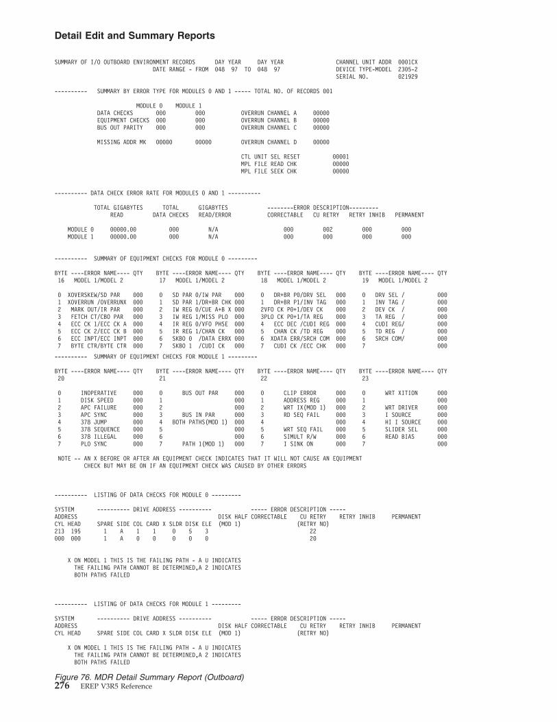
SUMMARY OF I/O OUTBOARD ENVIRONMENT RECORDS DAY YEAR DAY YEAR CHANNEL UNIT ADDR 0001CXDATE RANGE - FROM 048 97 TO 048 97 DEVICE TYPE-MODEL 2305-2
SERIAL NO. 021929
---------- SUMMARY BY ERROR TYPE FOR MODULES 0 AND 1 ----- TOTAL NO. OF RECORDS 001
MODULE 0 MODULE 1DATA CHECKS 000 000 OVERRUN CHANNEL A 00000EQUIPMENT CHECKS 000 000 OVERRUN CHANNEL B 00000BUS OUT PARITY 000 000 OVERRUN CHANNEL C 00000
MISSING ADDR MK 00000 00000 OVERRUN CHANNEL D 00000
CTL UNIT SEL RESET 00001MPL FILE READ CHK 00000MPL FILE SEEK CHK 00000
---------- DATA CHECK ERROR RATE FOR MODULES 0 AND 1 ----------
TOTAL GIGABYTES TOTAL GIGABYTES --------ERROR DESCRIPTION---------READ DATA CHECKS READ/ERROR CORRECTABLE CU RETRY RETRY INHIB PERMANENT
MODULE 0 00000.00 000 N/A 000 002 000 000MODULE 1 00000.00 000 N/A 000 000 000 000
---------- SUMMARY OF EQUIPMENT CHECKS FOR MODULE 0 ---------
BYTE ----ERROR NAME---- QTY BYTE ----ERROR NAME---- QTY BYTE ----ERROR NAME---- QTY BYTE ----ERROR NAME---- QTY16 MODEL 1/MODEL 2 17 MODEL 1/MODEL 2 18 MODEL 1/MODEL 2 19 MODEL 1/MODEL 2
0 XOVERSKEW/SD PAR 000 0 SD PAR 0/IW PAR 000 0 DR+BR P0/DRV SEL 000 0 DRV SEL / 0001 XOVERRUN /OVERRUNX 000 1 SD PAR 1/DR+BR CHK 000 1 DR+BR P1/INV TAG 000 1 INV TAG / 0002 MARK OUT/IR PAR 000 2 IW REG 0/CUE A+B X 000 2VFO CK P0+1/DEV CK 000 2 DEV CK / 0003 FETCH CT/CBO PAR 000 3 IW REG 1/MISS PLO 000 3PLO CK P0+1/TA REG 000 3 TA REG / 0004 ECC CK 1/ECC CK A 000 4 IR REG 0/VFO PHSE 000 4 ECC DEC /CUDI REG 000 4 CUDI REG/ 0005 ECC CK 2/ECC CK B 000 5 IR REG 1/CHAN CK 000 5 CHAN CK /TD REG 000 5 TD REG / 0006 ECC INPT/ECC INPT 000 6 SKBO 0 /DATA ERRX 000 6 XDATA ERR/SRCH COM 000 6 SRCH COM/ 0007 BYTE CTR/BYTE CTR 000 7 SKBO 1 /CUDI CK 000 7 CUDI CK /ECC CHK 000 7 000
---------- SUMMARY OF EQUIPMENT CHECKS FOR MODULE 1 ---------
BYTE ----ERROR NAME---- QTY BYTE ----ERROR NAME---- QTY BYTE ----ERROR NAME---- QTY BYTE ----ERROR NAME---- QTY20 21 22 23
0 INOPERATIVE 000 0 BUS OUT PAR 000 0 CLIP ERROR 000 0 WRT XITION 0001 DISK SPEED 000 1 000 1 ADDRESS REG 000 1 0002 APC FAILURE 000 2 000 2 WRT IX(MOD 1) 000 2 WRT DRIVER 0003 APC SYNC 000 3 BUS IN PAR 000 3 RD SEQ FAIL 000 3 I SOURCE 0004 378 JUMP 000 4 BOTH PATHS(MOD 1) 000 4 000 4 HI I SOURCE 0005 378 SEQUENCE 000 5 000 5 WRT SEQ FAIL 000 5 SLIDER SEL 0006 378 ILLEGAL 000 6 000 6 SIMULT R/W 000 6 READ BIAS 0007 PLO SYNC 000 7 PATH 1(MOD 1) 000 7 I SINK ON 000 7 000
NOTE -- AN X BEFORE OR AFTER AN EQUIPMENT CHECK INDICATES THAT IT WILL NOT CAUSE AN EQUIPMENTCHECK BUT MAY BE ON IF AN EQUIPMENT CHECK WAS CAUSED BY OTHER ERRORS
---------- LISTING OF DATA CHECKS FOR MODULE 0 ---------
SYSTEM ---------- DRIVE ADDRESS ---------- ----- ERROR DESCRIPTION -----ADDRESS DISK HALF CORRECTABLE CU RETRY RETRY INHIB PERMANENTCYL HEAD SPARE SIDE COL CARD X SLDR DISK ELE (MOD 1) (RETRY NO)213 195 1 A 1 1 0 5 3 22000 000 1 A 0 0 0 0 0 20
X ON MODEL 1 THIS IS THE FAILING PATH - A U INDICATESTHE FAILING PATH CANNOT BE DETERMINED,A 2 INDICATESBOTH PATHS FAILED
---------- LISTING OF DATA CHECKS FOR MODULE 1 ---------
SYSTEM ---------- DRIVE ADDRESS ---------- ----- ERROR DESCRIPTION -----ADDRESS DISK HALF CORRECTABLE CU RETRY RETRY INHIB PERMANENTCYL HEAD SPARE SIDE COL CARD X SLDR DISK ELE (MOD 1) (RETRY NO)
X ON MODEL 1 THIS IS THE FAILING PATH - A U INDICATESTHE FAILING PATH CANNOT BE DETERMINED,A 2 INDICATESBOTH PATHS FAILED
Figure 76. MDR Detail Summary Report (Outboard)
Detail Edit and Summary Reports
276 EREP V3R5 Reference
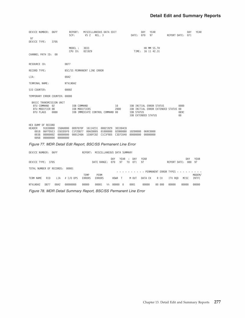
DEVICE NUMBER: 06FF REPORT: MISCELLANEOUS DATA EDIT DAY YEAR DAY YEARSCP: VS 2 REL. 3 DATE: 070 97 REPORT DATE: 071
97DEVICE TYPE: 3705
MODEL : 3033 HH MM SS.THCPU ID: 021929 TIME: 16 11 42.31
CHANNEL PATH ID: 00
RESOURCE ID: D877
RECORD TYPE: BSC/SS PERMANENT LINE ERROR
LIA: 00A2
TERMINAL NAME: NTVLN0A2
SIO COUNTER: 00002
TEMPORARY ERROR COUNTER: 00000
BASIC TRANSMISSION UNITBTU COMMAND 02 IOB COMMAND 10 IOB INITIAL ERROR STATUS 0000BTU MODIFIER 0B IOB MODIFIERS 2000 IOB INITIAL ERROR EXTENDED STATUS 00BTU FLAGS 0080 IOB IMMEDIATE CONTROL COMMAND 00 IOB STATUS 069C
IOB EXTENDED STATUS 00
HEX DUMP OF RECORDHEADER 91830800 158A0000 0097070F 16114231 00021929 303304C8
0018 06FFD5E3 E5D3D5F0 C1F2D877 00A28005 01000000 020B0080 10200000 069C00000038 00000002 00000000 0001248A 1E00FC02 C1C3F9D5 C3D7C640 00000000 000000000058 00000000 00000000
Figure 77. MDR Detail Edit Report, BSC/SS Permanent Line Error
DEVICE NUMBER: 06FF REPORT: MISCELLANEOUS DATA SUMMARY
DAY YEAR - DAY YEAR DAY YEARDEVICE TYPE: 3705 DATE RANGE: 070 97 TO 071 97 REPORT DATE: 080 97
TOTAL NUMBER OF RECORDS: 00001- - - - - - - - - - PERMANENT ERROR TYPES - - - - - - - - -
TEMP PERM MODEM/TERM NAME RID LIA # I/O OPS ERRORS ERRORS HDWR T M OUT DATA CK R CV ITV RQD MISC INTFC
NTVLN0A2 D877 00A2 00000000 00000 00001 %% 00000 0 0001 00000 00 000 00000 00000 00000
Figure 78. MDR Detail Summary Report, BSC/SS Permanent Line Error
Detail Edit and Summary Reports
Chapter 13. Detail Edit and Summary Reports 277

Missing Interrupt Handler (MIH) Detail ReportsMIH records are created whenever an expected interrupt fails to occur in a presettime interval. They are produced for missing channel-end (primary status) anddevice-end (secondary status) interrupts on non-TP devices. The records use fieldsfrom the unit control block (UCB) to define the origin and status of the missinginterrupt.
In VSE, only the Advanced Function system produces MIH reports.
Figures containing examples of these reports are on the pages shown in thefollowing table:
REPORT Refer To
MIH (370) Detail Edit Report Figure 81 on page 279
MIH (370) Detail Summary Report Figure 82 on page 279
MIH (370XA) Detail Edit Report Figure 83 on page 280
MIH (370XA) Detail Summary Report Figure 84 on page 280
MIH (370XA) Detail Edit Report for zHPF Figure 85 on page 281
DEVICE NUMBER: 06FF REPORT: MISCELLANEOUS DATA EDIT DAY YEAR DAY YEARSCP: VS 2 REL. 3 DATE: 070 97 REPORT DATE: 071
97DEVICE TYPE: 3705
MODEL : 3033 HH MM SS.THCPU ID: 021929 TIME: 15 58 21.66
RESOURCE ID: D8A2
RECORD TYPE: STATISTICAL DATA ON SDLC LINK ERRORS
LIA: 00A2
TERMINAL NAME: PUAC9L27
STATION TYPE: 02
TOTAL TRANSMISSION COUNT 032770I FORMAT RECEIVE COUNT 001718S FORMAT RECEIVE COUNT 028214I FORMAT RECEIVE ERRORS 000000I FORMAT FRAMES ACKNOWLEDGED 002963I FORMAT TOTAL RETRANSMISSIONS 000000TOTAL RETRY COUNT 000000
HEX DUMP OF RECORDHEADER 91830800 158A00C8 0097070F 15582166 00021929 303304C8
0018 06FFD7E4 C1C3F9D3 F2F7D8A2 00278605 02000000 00000000 00000000 000000000038 00000B93 00000000 02000000 00000000 00000000 00008002 06B66E36 0B9300000058 00001E00 FC03D3C1 C3F9D3F2 F740C1C3 F9D5C3D7 C6400000 00000000 0000
Figure 79. MDR Detail Report, SDLC Link Errors
DEVICE NUMBER: 06FF REPORT: MISCELLANEOUS DATA SUMMARY
DAY YEAR - DAY YEAR DAY YEARDEVICE TYPE: 3705 DATE RANGE: 048 97 TO 049 97 REPORT DATE: 071 97
TOTAL NUMBER OF RECORDS: 00001- - - - - - - - - - PERMANENT ERROR TYPES - - - - - - - - -
TEMP PERM MODEM/TERM NAME RID LIA # I/O OPS ERRORS ERRORS HDWR TM OUT DATA CK RCV ITV RQD MISC INTFC
NTVLN0A2 D877 00A2 00000002 00000 00001 %% 00000 00000 00000 00000 00000 00001 00000PUAC9L26 D890 0026 00000000 00000 00000 %% 00000 00000 00000 00000 00000 00000 00000PUAC9L27 D8A2 0027 00002963 00000 00000 %% 00000 00000 00000 00000 00000 00000 00000
Figure 80. MDR Summary Report, SDLC Link Errors
Detail Edit and Summary Reports
278 EREP V3R5 Reference

--- RECORD ENTRY TYPE - MIH SOURCE - MIH MODEL - 9375 SERIAL NO. 234567
V370 REL. 06
DAY YEAR HH.MM.SS.TH JOB IDENTITY SYSTEM
043 97 18 57 22 12 E2E8E2E3C5D44040
UCB DEVICE TYPE 00002107PRIMARY CHANNEL UNIT ADDRESS 000C41ALTERNATE CHANNEL UNIT ADDRESS 000C41CHANNEL SET ID 00MISSING INTERRUPT C0
HH MM SS.THTIME INTERVAL 00 00 15.00
VOLUME SERIAL NUMBER VMRESA
HEX DUMP OF RECORDHEADER 70660800 C0000000 0097043F 01081232 10234567 93750000
0000 E2E8E2E3 C5D44040 000C4000 0C40E5D4 D9C5E2C1 00002107 F0F0F0F0 F1F5F0F00020 00000000
Figure 81. MIH (370) Detail Edit Report
SUMMARY OF MIH RECORDS CUA 000C40
DAY YEAR DAY YEARRECORD DATE RANGE 043 97 043 97
MODEL - 9375 SERIAL NO - 234567
TOTAL NUMBER OF RECORDS=0001
Figure 82. MIH (370) Detail Summary Report
Detail Edit and Summary Reports
Chapter 13. Detail Edit and Summary Reports 279

�1� The hexadecimal value in the byte is shown in Figure 83; the bit settingsare shown in Figure 84.
DEVICE NUMBER: 02300 REPORT: MIH EDIT DAY YEAR JOB IDENTITY: *MASTER*SCP: VS 2 REL. 3 DATE: 260 04 5CD4C1E2E3C5D95C
DEVICE NED: 002105.000.IBM.075.000000012252.0615DEVICE TYPE: 3390
CPU MODEL: 2084 HH MM SS.THCHANNEL PATH ID: N/A CPU ID: 0190CC TIME: 05 34 30.13
MISSING INTERRUPT: 10 - START PENDING IN SUBCHANNEL SUBCHANNEL ID NUMBER: 000100EFVOLUME SERIAL: D83RL7
HH MM SS.TH UCB LEVEL BYTE: 01TIME INTERVAL: 00 00 15.00
RECOVERY ACTIONS PERFORMED BYTE: AC �1�
HALT OR CLEAR SUBCHANNEL 1SIMULATED INTERRUPT 0REDRIVE DEVICE 1REQUEUE I/O REQUEST 0ISSUE MESSAGE 1LOG THE CONDITION 1BIT 6 0BIT 7 0
HEX DUMP OF SUBCHANNEL INFORMATION BLOCKOFFSET 02106BC8 289F237A C00040C0 10C3FFC0
0010 40440000 00000000 00000001 008044000020 5BD52000 10000004 00000000 000000000030 00000000
HEX DUMP OF RECORDHEADER 71831800 00000000 0004260F 05343013 000190CC 20848000
0018 5CD4C1E2 E3C5D95C 02106BC8 289F237A C00040C0 10C3FFC0 40440000 000000000038 00000001 00804400 5BD52000 10000004 00000000 00000000 00000000 F0F0F0F00058 F1F5F0F0 10BCBCAC 000110EF 289CC040 C0404400 00000000 00010800 000001000078 00002300 0800801B 2024C4F8 F3D9D3F7 0010C000 01230000 00000100 000010010098 00806600 00120100 00000146 00020001 00A2F0F0 F2F1F0F5 F1F2F3C9 C2D4F1F300B8 F7F6F5F4 F3F2F1F1 F9F8F3F1 C1C2C3C4 40E2E8E2 E3C5D440 40404040 4040404000D8 40404040 4040D0D0 D0D0E0E0 E0E0F0F0 F0F0A0A0 A0A0F0F0 FFFF
Figure 83. MIH (370XA) Detail Edit Report
DEVICE NUMBER: 02300 REPORT: MIH SUMMARY REPORT DATE: 289 04PERIOD FROM: 260 04
DEVICE TYPE: 3390 CPU MODEL: 2084 TO: 260 04CPU ID: 0190CC
MISSING INTERRUPT
MISSING CSCH 00000000MISSING HSCH 00000000IDLE DEVICE WITH WORK QUEUED 00000000START PENDING IN SUBCHANNEL 00000001I/O TIMEOUT CONDITION FOR
ACTIVE I/O REQUEST 00000000I/O TIMEOUT CONDITION FOR
QUEUED I/O REQUEST 00000000MOUNT PENDING 00000000MISSING PRIMARY STATUS 00000000MISSING SECONDARY STATUS 00000000
Figure 84. MIH (370XA) Detail Summary Report
Detail Edit and Summary Reports
280 EREP V3R5 Reference

Outboard Record (OBR) Detail Edit ReportsOBR records document a variety of I/O errors and statistical data. They can takeone of two forms (short or long), depending on why they are written. See Table 14on page 282 for a description of each form.
DEVICE NUMBER: 02300 REPORT: MIH EDIT DAY YEAR JOB IDENTITY: *MASTER*SCP: VS 2 REL. 3 DATE: 260 04 5CD4C1E2E3C5D95C
DEVICE TYPE: 3390CPU MODEL: 2084 HH MM SS.TH
CHANNEL PATH ID: N/A CPU ID: 0190CC TIME: 05 34 30.13
MISSING INTERRUPT: 10 - START PENDING IN SUBCHANNEL SUBCHANNEL ID NUMBER: 000110EFVOLUME SERIAL: D83RL7
HH MM SS.TH UCB LEVEL BYTE: 01TIME INTERVAL: 00 00 15.00
RECOVERY ACTIONS PERFORMED BYTE: AC
HALT OR CLEAR SUBCHANNEL 1SIMULATED INTERRUPT 0REDRIVE DEVICE 1REQUEUE I/O REQUEST 0ISSUE MESSAGE 1LOG THE CONDITION 1BIT 6 0BIT 7 0
HEX DUMP OF SUBCHANNEL INFORMATION BLOCKOFFSET 02106BC8 289F237A C00040C0 10C3FFC0
0010 40440000 00000000 00000001 008044000020 5BD52000 10000004 00000000 000000000030 00000000
COMMAND CODE: 00 I/O DRIVER ID: 12
STATUS: DEVICE RESERVED BY ANOTHER SYSTEM
INTERROGATE INFORMATION:
FORMAT: F0 FLAGS: F0 CU STATE: A0 DEVICE STATE: A0 I/O STATE: A0
STATE DEPENDENT DATA: FFFF2794 2D4D2794 2D4D2794DEVICE LEVEL ID: 2D4D2861DEVICE DEPENDENT DATA: 2D4D2895 00000000 01000000 2D4D25C6
00000000 00000000 F1FDF0F0INTERROGATE INFORMATION:OFFSET C0000004 F1F1F1F1 F2F2F2F2 F3F3F3F3
0010 F4F4F4F4 F5F5F5F5 F6F6F6F6 F7F7F7F70020 F8F8F8F8 10203040 A0A0A0A0 B0B0B0B00030 C0C0C0C0 D0D0D0D0 E0E0E0E0 F0F0F0F00040 A0A0A0A0 F0F0FFFF 27942D4D 27942D4D0050 27942D4D 28612D4D 28950000 000001000060 00002D4D 25C60000 00000000 0000F1FD0070 F0F0F0F9 00000000 00000096 000001010080 000F0000 00000000 00000000 000000000090 00000000 00000000 00000000
HEX DUMP OF RECORDHEADER 71831800 00000000 0004260F 05343013 000190CC 20848000
0018 5CD4C1E2 E3C5D95C 02106BC8 289F237A C00040C0 10C3FFC0 40440000 000000000038 00000001 00804400 5BD52000 10000004 00000000 00000000 00000000 F0F0F0F00058 F1F5F0F0 10BCBCAC 000110EF 289CC040 C0404400 00000000 00010800 000001000078 00002300 0800801B 2024C4F8 F3D9D3F7 0010C000 01230000 00000100 000010010098 00806600 00120100 00000146 00010001 00A2C000 0004F1F1 F1F1F2F2 F2F2F3F300B8 F3F3F4F4 F4F4F5F5 F5F5F6F6 F6F6F7F7 F7F7F8F8 F8F81020 3040A0A0 A0A0B0B000D8 B0B0C0C0 C0C0D0D0 D0D0E0E0 E0E0F0F0 F0F0A0A0 A0A0F0F0 FFFF
Figure 85. MIH (370XA) Detail Edit Report for zHPF
Detail Edit and Summary Reports
Chapter 13. Detail Edit and Summary Reports 281

Table 14. OBR Record Form
FORM DESCRIPTION
Short The short form is:
v Used to record statistical data for the devices (except tape drives) whosestatistical data counters are in “memory” rather than in control-unitbuffers. (Short OBRs are not created by the 33XX DASD family.)
v Written in response to the same operator-initiated and program-initiatedactions that can trigger an MDR record.
Before EREP begins to retrieve records for a report, the statistical data iswritten to the ERDS in short OBR records or MDR records, depending onthe devices involved. (For optical and tape devices, statistical data is in longOBR records.)
Long The long form is:
v Used to record the permanent unit checks, (I/O) errors that the system’serror recovery program could not correct.
v Used to record some temporary unit checks and statistical data fordevices with in-core counters.
v Used to record the errors encountered by the dynamic pathing availabilityfacility while changing the state of a path group.
Figures containing examples of these reports are on the pages shown in thefollowing table:
REPORT REFER TO
OBR (Short) Detail Edit Report, Device Type 3277 Figure 86 on page 283
OBR (Short) Detail Edit Report, Device Type 3800 Figure 87 on page 283
OBR (Short) Detail Edit Report, Device Type 3791,VTAM
Figure 88 on page 284
OBR (Short) Unit Check Figure 89 on page 285
OBR (Long) Detail Edit Report, Device Type AFP1 Figure 90 on page 286
OBR (Long) Summary Report, Device Type AFP1 Figure 91 on page 287
OBR (Long) Detail Edit Report, Device Type CTCA Figure 92 on page 288
OBR (Long) Detail Edit Report, Device Type 3277 Figure 93 on page 289
OBR (Long) Detail Edit Report, Device Type 3380 Figure 95 on page 291
OBR (Long) Detail Edit Report, Device Type 3390 Figure 97 on page 293
OBR (Long) Detail Edit Report, Device Type 3480 Figure 98 on page 294
OBR (Long) Detail Edit Report, Device Type 3490 Figure 99 on page 295
OBR (Long) Detail Edit Report, Device Type 3590 Figure 100 on page 296
OBR (Long) Detail Edit Report, Device Type 3800 Figure 101 on page 297
OBR (Long) Detail Edit Report, Autochanger DeviceType 3995
Figure 103 on page 299
OBR Record (Long) Detail Edit Report, Device Type9347
Figure 103 on page 299
OBR (Long) Detail Edit Report, Device Type 3380,DPA
Figure 106 on page 302
OBR (Long) Detail Edit Report, Device Type 3590,DPA
Figure 107 on page 303
Detail Edit and Summary Reports
282 EREP V3R5 Reference
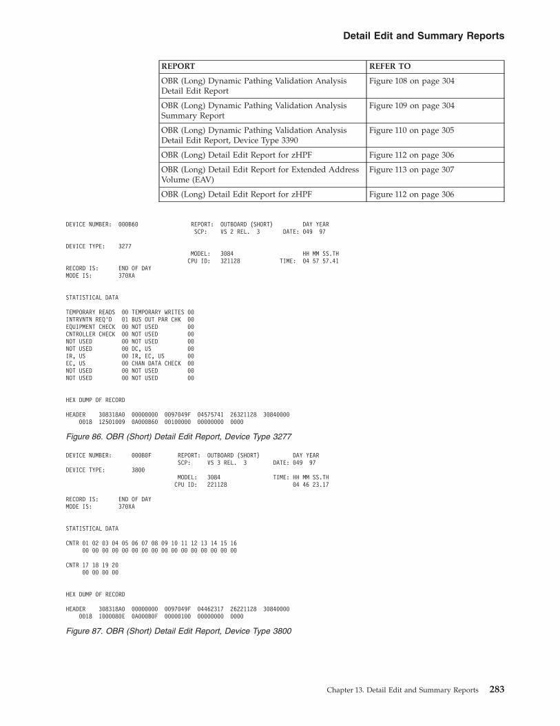
REPORT REFER TO
OBR (Long) Dynamic Pathing Validation AnalysisDetail Edit Report
Figure 108 on page 304
OBR (Long) Dynamic Pathing Validation AnalysisSummary Report
Figure 109 on page 304
OBR (Long) Dynamic Pathing Validation AnalysisDetail Edit Report, Device Type 3390
Figure 110 on page 305
OBR (Long) Detail Edit Report for zHPF Figure 112 on page 306
OBR (Long) Detail Edit Report for Extended AddressVolume (EAV)
Figure 113 on page 307
OBR (Long) Detail Edit Report for zHPF Figure 112 on page 306
DEVICE NUMBER: 000B60 REPORT: OUTBOARD (SHORT) DAY YEARSCP: VS 2 REL. 3 DATE: 049 97
DEVICE TYPE: 3277MODEL: 3084 HH MM SS.TH
CPU ID: 321128 TIME: 04 57 57.41RECORD IS: END OF DAYMODE IS: 370XA
STATISTICAL DATA
TEMPORARY READS 00 TEMPORARY WRITES 00INTRVNTN REQ'D 01 BUS OUT PAR CHK 00EQUIPMENT CHECK 00 NOT USED 00CNTROLLER CHECK 00 NOT USED 00NOT USED 00 NOT USED 00NOT USED 00 DC, US 00IR, US 00 IR, EC, US 00EC, US 00 CHAN DATA CHECK 00NOT USED 00 NOT USED 00NOT USED 00 NOT USED 00
HEX DUMP OF RECORD
HEADER 308318A0 00000000 0097049F 04575741 26321128 308400000018 12501009 0A000B60 00100000 00000000 0000
Figure 86. OBR (Short) Detail Edit Report, Device Type 3277
DEVICE NUMBER: 000B0F REPORT: OUTBOARD (SHORT) DAY YEARSCP: VS 3 REL. 3 DATE: 049 97
DEVICE TYPE: 3800MODEL: 3084 TIME: HH MM SS.TH
CPU ID: 221128 04 46 23.17
RECORD IS: END OF DAYMODE IS: 370XA
STATISTICAL DATA
CNTR 01 02 03 04 05 06 07 08 09 10 11 12 13 14 15 1600 00 00 00 00 00 00 00 00 00 00 00 00 00 00 00
CNTR 17 18 19 2000 00 00 00
HEX DUMP OF RECORD
HEADER 308318A0 00000000 0097049F 04462317 26221128 308400000018 1000080E 0A000B0F 00000100 00000000 0000
Figure 87. OBR (Short) Detail Edit Report, Device Type 3800
Detail Edit and Summary Reports
Chapter 13. Detail Edit and Summary Reports 283

---RECORD ENTRY TYPE - UNIT CHECK SOURCE VTAM OUTBOARD MODEL- 3084 SERIAL NO. 021220VS 2 REL. 3
DAY YEAR HH MM SS.TH JOB IDENTITYDATE- 044 97 TIME 16 14 53 08 0000000000000000
DEVICE TYPE 3791 LOCALDEVICE NUMBER 0902CHANNEL PATH ID 00
SDR COUNTER1 NOT USED 000 9 DATA CHK, LENGTH CHK 0002 NOT USED 000 10 DATA CHK, DATA REJECT 0003 BUS OUT, P-CHK #2 000 11 EQUIP CHK, MACH CHK 0004 BUS OUT, P-CHK #1,2 000 12 NOT USED 0005 EQUIP CHK, P-CHK #1 000 13 NOT USED 0006 EQUIP CHK, P-CHK #2 000 14 NOT USED 0007 EQUIP CHK, P-ERR, P-CHK #1 000 15 NOT USED 0008 DATA CHK 000 16 CHANNEL DATA CHK 000
TERMINAL NAME JOB IDENTITY ZL902 TYPE OF RECORD *OVERFLOW*
SIO CNTR 65535 TEMPORARY ERR CNTR 00000
HEX DUMP OF RECORDHEADER 36891840 10000000 0097044F 16145308 66021220 30840000
0018 00000000 00000000 00000000 00000000 00000000 00000000 02000902 500040F10038 0A000902 00000000 FFFF0000 00004000 E9D3F9F0 F2404040 00000000 000000000058 00000000 00006000 40170095 C8D08D00 01730000 0000
Figure 88. OBR (Short) Detail Edit Report, Device Type 3791, VTAM
Detail Edit and Summary Reports
284 EREP V3R5 Reference

---RECORD ENTRY TYPE - UNIT CHECK SOURCE - OUTBOARD MODEL- 4381 SERIAL NO. 010024V370 REL. 06
DAY YEAR HH MM SS.TH JOB IDENTITY SYSTEMDATE- 048 97 TIME- 15 59 31 29 E2E8E2E3 C5D44040
CORRELATION NO 03
DEVICE TYPE 3262-5PRIMARY CHANNEL UNIT ADDRESS 0004E3ALTERNATE CHANNEL UNIT ADDRESS 0004E3
CC CA US CT K CA US CS CTFAILING CCW 01 09D017 60 00 0001 CSW 00 09D008 06 00 0000
UNIT STATUS CHANNEL STATUS STATISTICAL DATA STATISTICAL DATA
ATTENTION 0 PGM-CTLD IRPT 0 TEMPY READS 000 TEMPY READS 001STATUS MODIFIER 0 INCORRECT LENGTH 0 NOT USED 000 BUS OUT CHK 000CONTROL UNIT END 0 PROGRAM CHECK 0 EQUIP CHK 000 BUFF PTY CHK 000BUSY 0 PROTECTION CHECK 0 LOAD CHECK 000 NOT USED 000CHANNEL END 0 CHAN DATA CHECK 0 CMND RETRY 000 PRINT CHECK 001DEVICE END 1 CHAN CTL CHECK 0 NOT USED 000 LINE POS 000UNIT CHECK 1 I/F CTL CHECK 0 NOT USED 000 CMND SUPPRESS 000UNIT EXCEPTION 0 CHAINING CHECK 0 NOT USED 000 CHAN DATA CHK 000
SENSE BYTA DATA
BYTE 0 08 BYTE 1 40 BYTE 2 00 BYTE 3 00 BYTE 4 00 BYTE 5 00
CMND REJ 0 UNASSIGN 0 CAR F MOV 0 UNASSIGN 0 --------- 1 UNASSIGN 0INTV REQ 0 PRINT CHK 1 CAR MO CK 0 UNASSIGN 0 HEX CODE 0 UNASSIGN 0BUSOUT CK 0 UNASSIGN 0 UNASSIGN 0 UNASSIGN 0 84 EQUALS 0 UNASSIGN 0EQUIP CHK 0 LINE POS 0 UNASSIGN 0 H COIL CK 0 A 3262 0 UNASSIGN 0DATA CHK 1 FORMS CHK 0 UNASSIGN 0 H FIRE CK 0 PRINTER 0 UNASSIGN 0BUFPAR CK 0 CMD SUPP 0 FORMS JAM 0 UNASSIGN 0 1 UNASSIGN 0LOAD CHK 0 CTRLR CK 0 UNASSIGN 0 SYNC CHK 0 0 UNASSIGN 0CHAN 9 0 UNASSIGN 0 BLT VELOC 0 RIBBON CK 0 --------- 0 UNASSIGN 0
THE VALUES OF BYTES 6 TO 17 INCLUSIVEARE NOT REPORTED ON IN THE EDIT REPORT
BYTE 18 0D BYTE 19 00 BYTE 20 FF BYTE 21 00 BYTE 22 00 BYTE 23 22
-------- 0 UNASSIGN 0 --------- 1 UNASSIGN 0 UNASSIGN 0 --------- 0STATUS 0 UNASSIGN 0 1 UNASSIGN 0 UNASSIGN 0 MODEL 0OR 0 UNASSIGN 0 00 = 3262 1 UNASSIGN 0 UNASSIGN 0 ID. 1
COMMUNI- 0 UNASSIGN 0 MODEL 1 1 UNASSIGN 0 UNASSIGN 0 HEX 22 0CATION 1 UNASSIGN 0 1 UNASSIGN 0 UNASSIGN 0 FOR 0CODES 1 UNASSIGN 0 55 = 3262 1 UNASSIGN 0 UNASSIGN 0 3262 0
0 UNASSIGN 0 MODEL 5 1 UNASSIGN 0 UNASSIGN 0 1--------- 1 UNASSIGN 0 --------- 1 UNASSIGN 0 UNASSIGN 0 --------- 0
HEX DUMP OF RECORD
HEADER 30668800 00000000 0097048F 15593129 04010024 438100000018 E2E8E2E3 C5D44040 0109D017 60000001 0009D008 06000000 01000E43 0000080D0038 0A0004E3 00000018 03000000 00000000 01000000 01000000 00000840 000084000058 00000000 00000000 00000000 0D00FF00 00220000 00000000 00000000 000000000078 00000000 00000000 00000000
Figure 89. OBR (Short) Unit Check
Detail Edit and Summary Reports
Chapter 13. Detail Edit and Summary Reports 285

DEVICE NUMBER: 000493 REPORT: OUTBOARD (LONG) DAY YEAR JOB IDENTITY: H3XA21SCP: VS 2 REL. 3 DATE: 042 97 C8F3F8E7C1E6F140
DEVICE TYPE: AFP1MODEL: 4381 HH MM SS.TH
ERROR PATH: 04-0493 CPU ID: 010142 TIME: 18 59 17.97
RECORD IS: PERMANENT
MODE IS: 370XA
CC CA FL CTFAILING CCW: 01 D3D000 64 00 0007
K FLAGS CA US SS CTCSW: 11 004417 10203008 02 00 0007
---UNIT STATUS---- SUB-CHANNEL STATUS --------------------------SCSW FLAGS------------------------FLAG 0 FLAG 1
ATTENTION 0 PGM-CTLD IRPT 0 CCW FORMAT 0 RESERVED 0 SUBCHANNEL ACTIV 0STATUS MODIFIER 0 INCORRECT LENGTH 0 PRE-FETCH CCW 0 SSCH FUNCTION 1 DEVICE ACTIVE 0CONTROL UNIT END 0 PROGRAM CHECK 0 INIT STATUS 0 HSCH FUNCTION 0 SUSPENDED 0BUSY 0 PROTECTION CHECK 0 ADDR LIMIT 0 CSCH FUNCTION 0 ALERT STATUS 1CHANNEL END 0 CHAN DATA CHECK 0 SUPP SUSPEND INT 0 RESUME PENDING 0 INTERMED STATUS 0DEVICE END 0 CHAN CTL CHECK 0 ZERO COND CODE 0 START PENDING 1 PRIMARY STATUS 1UNIT CHECK 1 I/F CTL CHECK 0 EXTENDED CONTROL 0 HALT PENDING 0 SECONDARY STATUS 1UNIT EXCEPTION 0 CHAINING CHECK 0 PATH NOT OPER 0 CLEAR PENDING 0 STATUS PENDING 1
DEVICE DEPENDENT DATATYPE/MODEL 3835-01
STATISTICAL DATA
TMP CHAN DATA CK 00 PAPER JAMS 00TMP CHAN CTL CHK 00 TEMPORARY ERROR 00TMP INTF CTL CHK 00
SENSE BYTE DATA
BYTE 00 01 02 03 04 05 06 07 08 09 10 11 12 13 14 15 16 17 18 19 20 21 22 2340 E2 02 01 00 00 00 00 00 00 00 00 00 00 00 00 00 00 00 00 00 00 00 00
HEX DUMP OF RECORD
HEADER 30831800 00001100 0097042F 18591797 00010142 428100000018 C8F3F8E7 C1E6F140 01D3D000 64000007 00000000 00000000 01040493 0000080F0038 0A000493 00000018 00383501 00000000 00000000 00000000 000040E2 020100000058 00000000 00000000 00000000 00000000 00001100 44171020 30080200 000700000078 00008500
Figure 90. OBR (Long) Detail Edit Report, Device Type AFP1
Detail Edit and Summary Reports
286 EREP V3R5 Reference

OBR (Long) Detail Edit Report for CTCA (Channel to Channel Adapter)
PRIMARY CUA: 000493 REPORT: OUTBOARD SUMMARY REPORT DATE: 071 97MODEL: 4381 PERIOD FROM: 042 97
DEVICE TYPE: AFP1 CPU ID: 010142 TO: 042 97
TOTAL NUMBER OF RECORDS 001 TOTAL OF OVERFLOW RECORDS 000
CCW COMMAND CODES ENCOUNTERED(MAXIMUM OF 24)
CMND TOTAL01 001
USAGETYPE/MODEL 3835-01 START 0
LAST 0
STATISTICAL DATA SUMMARY
TMP CHAN DATA CK 000 PAPER JAMS 000TMP CHAN CTL CHK 000 TEMPORARY ERROR 000TMP INTF CTL CHK 000
SENSE DATA SUMMARY
SRC PERM TEMP
0000 0001 0000
Figure 91. OBR (Long) Summary Report, Device Type AFP1
Detail Edit and Summary Reports
Chapter 13. Detail Edit and Summary Reports 287

Note: The device type field in the report’s header prints out as “CACA” instead ofCTCA.
DEVICE NUMBER: 000CEB REPORT: OUTBOARD (LONG) DAY YEAR JOB IDENTITY:SCP: VS 2 REL. 3 DATE: 068 97 0000000000000000
DEVICE TYPE: CACAMODEL: 3084 HH MM SS.TH
ERROR PATH: 55-0CEB CPU ID: 121128 TIME: 04 41 57.73
RECORD IS: PERMANENT
MODE IS: 370XA
CC CA FL CTFAILING CCW: 04 000000 20 00 0007
K FLAGS CA US SS CTSCSW: 61 004417 10A99108 02 00 0001
---UNIT STATUS---- SUB-CHANNEL STATUS --------------------------SCSW FLAGS------------------------FLAG 0 FLAG 1
ATTENTION 0 PGM-CTLD IRPT 0 CCW FORMAT 0 RESERVED 0 SUBCHANNEL ACTIV 0STATUS MODIFIER 0 INCORRECT LENGTH 0 PRE-FETCH CCW 0 SSCH FUNCTION 1 DEVICE ACTIVE 0CONTROL UNIT END 0 PROGRAM CHECK 0 INIT STATUS 0 HSCH FUNCTION 0 SUSPENDED 0BUSY 0 PROTECTION CHECK 0 ADDR LIMIT 0 CSCH FUNCTION 0 ALERT STATUS 1CHANNEL END 0 CHAN DATA CHECK 0 SUPP SUSPEND INT 0 RESUME PENDING 0 INTERMED STATUS 0DEVICE END 0 CHAN CTL CHECK 0 ZERO COND CODE 0 START PENDING 1 PRIMARY STATUS 1UNIT CHECK 1 I/F CTL CHECK 0 EXTENDED CONTROL 0 HALT PENDING 0 SECONDARY STATUS 1UNIT EXCEPTION 0 CHAINING CHECK 0 PATH NOT OPER 0 CLEAR PENDING 0 STATUS PENDING 1
STATISTICAL DATA
CNTR 01 02 03 04 05 06 07 08 09 10 11 12 13 14 15 1600 00 00 00 00 00 00 00 00 00 00 00 00 00 00 00
CNTR 17 18 19 2000 00 00 00
SENSE BYTE DATA
BYTE 0040
HEX DUMP OF RECORD
HEADER 30831800 00000000 0097068F 04415773 66121128 308400000018 00000000 00000000 43000000 20000001 00000000 00000000 00550CEB 100141000038 0A000CEB 00000001 00000000 00000000 00004061 00441710 A9910802 000001000058 00000000
Figure 92. OBR (Long) Detail Edit Report, Device Type CTCA
Detail Edit and Summary Reports
288 EREP V3R5 Reference

DEVICE NUMBER: 000B4A REPORT: OUTBOARD (LONG) DAY YEAR JOB IDENTITY:SCP: VS 2 REL. 3 DATE: 064 97 0000000000000000
DEVICE TYPE: 3277MODEL: 3084 HH MM SS.TH
ERROR PATH: 05-0B4A CPU ID: 121128 TIME: 07 36 14.73
RECORD IS: PERMANENT
MODE IS: 370XA
CC CA FL CTFAILING CCW: 05 258F5D 20 00 0009
K FLAGS CA US SS CTSCSW: 60 000013 00000000 06 00 0000
---UNIT STATUS---- SUB-CHANNEL STATUS --------------------------SCSW FLAGS------------------------FLAG 0 FLAG 1
ATTENTION 0 PGM-CTLD IRPT 0 CCW FORMAT 0 RESERVED 0 SUBCHANNEL ACTIV 0STATUS MODIFIER 0 INCORRECT LENGTH 0 PRE-FETCH CCW 0 SSCH FUNCTION 1 DEVICE ACTIVE 0CONTROL UNIT END 0 PROGRAM CHECK 0 INIT STATUS 0 HSCH FUNCTION 0 SUSPENDED 0BUSY 0 PROTECTION CHECK 0 ADDR LIMIT 0 CSCH FUNCTION 0 ALERT STATUS 1CHANNEL END 0 CHAN DATA CHECK 0 SUPP SUSPEND INT 0 RESUME PENDING 0 INTERMED STATUS 0DEVICE END 1 CHAN CTL CHECK 0 ZERO COND CODE 0 START PENDING 0 PRIMARY STATUS 0UNIT CHECK 1 I/F CTL CHECK 0 EXTENDED CONTROL 0 HALT PENDING 0 SECONDARY STATUS 1UNIT EXCEPTION 0 CHAINING CHECK 0 PATH NOT OPER 0 CLEAR PENDING 0 STATUS PENDING 1
DEVICE DEPENDENT DATA
TYPE OF RECORD: PERMANENT (X’00’)
TERMINAL NAME: M01LB4A
INITIAL FAILURE FINAL RETRY---------------------- ----------------------COMMAND CODE: X’05’ COMMAND CODE: X’05’SENSE BYTE 0: 01000000 SENSE BYTE 0:00001100
FIRST FAILURE CMND REJ 0 INTV RQD 1 BUS O CK 0 EQUIP CK 0 DATA CHK 0 UNIT SPC 0 CNTRL CK 0 OPER CHK 0FINAL RETRY CMND REJ 0 INTV RQD 0 BUS O CK 0 EQUIP CK 0 DATA CHK 1 UNIT SPC 1 CNTRL CK 0 OPER CHK 0
STATS: READ DC 00 WRITE DC 00 INTV RQD 00 BUS O CK 00 EQUIP CK 00 NOT USED 00 CNTRL CK 00 NOT USED 00NOT USED 00 NOT USED 00 NOT USED 00 DC US 01 NOT USED 00 IR,EC,US 00 EC,US 00 CHANL DC 00
STATISTICAL DATA
CNTR 01 02 03 04 05 06 07 08 09 10 11 12 13 14 15 1600 00 00 00 00 00 00 00 00 00 00 01 00 00 00 00
CNTR 17 18 19 2000 00 00 00
SENSE BYTE DATA
BYTE 00 01 02 0340 0C 0C 40
HEX DUMP OF RECORD
HEADER 36831800 00000000 0097064F 07361473 66121128 308400000018 00000000 00000000 05258F5D 20000009 00000000 00000000 02050B4A 125010090038 0A000B4A 00000004 00050000 05050000 D4F0F1D3 C2F4C140 00000000 000100000058 0000400C 0C406000 00130000 00000600 00000000 0000
Figure 93. OBR (Long) Detail Edit Report, Device Type 3277 Part 1
Detail Edit and Summary Reports
Chapter 13. Detail Edit and Summary Reports 289

DEVICE NUMBER: 000361 REPORT: OUTBOARD (LONG) DAY YEAR JOB IDENTITY:SCP: VS 2 REL. 3 DATE: 068 97 0000000000000000
DEVICE TYPE: 3277MODEL: 3084 HH MM SS.TH
ERROR PATH: 03-0361 CPU ID: 121128 TIME: 23 52 49.53
RECORD IS: PERMANENT
MODE IS: 370XA
CC CA FL CTFAILING CCW: 4B 000000 40 00 0001
K FLAGS CA US SS CTSCSW: 00 000013 00000000 06 00 0000
---UNIT STATUS---- SUB-CHANNEL STATUS --------------------------SCSW FLAGS------------------------FLAG 0 FLAG 1
ATTENTION 0 PGM-CTLD IRPT 0 CCW FORMAT 0 RESERVED 0 SUBCHANNEL ACTIV 0STATUS MODIFIER 0 INCORRECT LENGTH 0 PRE-FETCH CCW 0 SSCH FUNCTION 0 DEVICE ACTIVE 0CONTROL UNIT END 0 PROGRAM CHECK 0 INIT STATUS 0 HSCH FUNCTION 0 SUSPENDED 0BUSY 0 PROTECTION CHECK 0 ADDR LIMIT 0 CSCH FUNCTION 0 ALERT STATUS 1CHANNEL END 0 CHAN DATA CHECK 0 SUPP SUSPEND INT 0 RESUME PENDING 0 INTERMED STATUS 0DEVICE END 1 CHAN CTL CHECK 0 ZERO COND CODE 0 START PENDING 0 PRIMARY STATUS 0UNIT CHECK 1 I/F CTL CHECK 0 EXTENDED CONTROL 0 HALT PENDING 0 SECONDARY STATUS 1UNIT EXCEPTION 0 CHAINING CHECK 0 PATH NOT OPER 0 CLEAR PENDING 0 STATUS PENDING 1
STATISTICAL DATA
TEMPORARY READS 00 TEMPORARY WRITES 00INTRVNTN REQ’D 00 BUS OUT PAR CHK 00EQUIPMENT CHECK 00 NOT USED 00CNTROLLER CHECK 00 NOT USED 00NOT USED 00 NOT USED 00IR, US 00 DC, US 00EC, US 00 IR, EC, US 00NOT USED 00 NOT USED 00NOT USED 00 NOT USED 00
SENSE BYTE DATA
------BYTE00----01 ------BYTE01----00 ------BYTE02----00 ------BYTE03----00 ------BYTE04----00 ------BYTE05----00COMMAND REJECT 0 BIT 0 0 BIT 0 0 BIT 0 0 BIT 0 0 BIT 0 0INTRVNTN REQ’D 0 BIT 1 0 BIT 1 0 BIT 1 0 BIT 1 0 BIT 1 0BUS OUT PAR CHK 0 BIT 2 0 BIT 2 0 BIT 2 0 BIT 2 0 BIT 2 0EQUIPMENT CHECK 0 BIT 3 0 BIT 3 0 BIT 3 0 BIT 3 0 BIT 3 0DATA CHECK 0 BIT 4 0 BIT 4 0 BIT 4 0 BIT 4 0 BIT 4 0UNIT SPECIFY 0 BIT 5 0 BIT 5 0 BIT 5 0 BIT 5 0 BIT 5 0CNTROLLER CHECK 0 BIT 6 0 BIT 6 0 BIT 6 0 BIT 6 0 BIT 6 0OPERATION CHECK 1 BIT 7 0 BIT 7 0 BIT 7 0 BIT 7 0 BIT 7 0
HEX DUMP OF RECORD
HEADER 30831800 00000000 0097068F 23524953 26121128 308400000018 00000000 00000000 04B00000 40000001 00000000 00000000 00030361 125010090038 0A000361 00000006 00000000 00000000 00000100 00000000 00000013 000000000058 06000000 00000000
Figure 94. OBR (Long) Detail Edit Report, Device Type 3277 Part 2
Detail Edit and Summary Reports
290 EREP V3R5 Reference
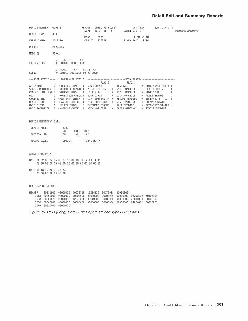
DEVICE NUMBER: 000E70 REPORT: OUTBOARD (LONG) DAY YEAR JOB IDENTITY:SCP: VS 2 REL. 3 DATE: 071 97 0000000000000000
DEVICE TYPE: 3380MODEL: 3090 HH MM SS.TH
ERROR PATH: 2D-0E70 CPU ID: 170028 TIME: 16 21 43.36
RECORD IS: PERMANENT
MODE IS: 370XA
CC CA FL CTFAILING CCW: 00 000000 00 00 0000
K FLAGS CA US SS CTSCSW: 04 824017 000122C8 00 02 0000
---UNIT STATUS---- SUB-CHANNEL STATUS --------------------------SCSW FLAGS------------------------FLAG 0 FLAG 1
ATTENTION 0 PGM-CTLD IRPT 0 CCW FORMAT 1 RESERVED 0 SUBCHANNEL ACTIV 0STATUS MODIFIER 0 INCORRECT LENGTH 0 PRE-FETCH CCW 0 SSCH FUNCTION 1 DEVICE ACTIVE 0CONTROL UNIT END 0 PROGRAM CHECK 0 INIT STATUS 0 HSCH FUNCTION 0 SUSPENDED 0BUSY 0 PROTECTION CHECK 0 ADDR LIMIT 0 CSCH FUNCTION 0 ALERT STATUS 1CHANNEL END 0 CHAN DATA CHECK 0 SUPP SUSPEND INT 0 RESUME PENDING 0 INTERMED STATUS 0DEVICE END 0 CHAN CTL CHECK 0 ZERO COND CODE 0 START PENDING 0 PRIMARY STATUS 1UNIT CHECK 0 I/F CTL CHECK 1 EXTENDED CONTROL 1 HALT PENDING 0 SECONDARY STATUS 1UNIT EXCEPTION 0 CHAINING CHECK 0 PATH NOT OPER 0 CLEAR PENDING 0 STATUS PENDING 1
DEVICE DEPENDENT DATA
DEVICE MODEL 3380SD CTLR DVC
PHYSICAL ID 00 XX XX
VOLUME LABEL SPOOLA FINAL RETRY
SENSE BYTE DATA
BYTE 01 02 03 04 05 06 07 08 09 10 11 12 13 14 1500 00 00 00 00 00 00 00 00 00 00 01 00 00 00
BYTE 17 18 19 20 21 22 2300 00 00 00 00 00 00
HEX DUMP OF RECORD
HEADER 30831800 00000000 0097071F 16214336 00170028 309000000018 00000000 00000000 00000000 00000000 00000000 00000000 032D0E70 3030200E0038 00000E70 00000018 E2D7D6D6 D3C10000 00000000 00000000 2D000000 000000000058 00000000 00000000 00000000 00000000 00000000 00000000 04824017 000122C80078 00020000 00000000
Figure 95. OBR (Long) Detail Edit Report, Device Type 3380 Part 1
Detail Edit and Summary Reports
Chapter 13. Detail Edit and Summary Reports 291
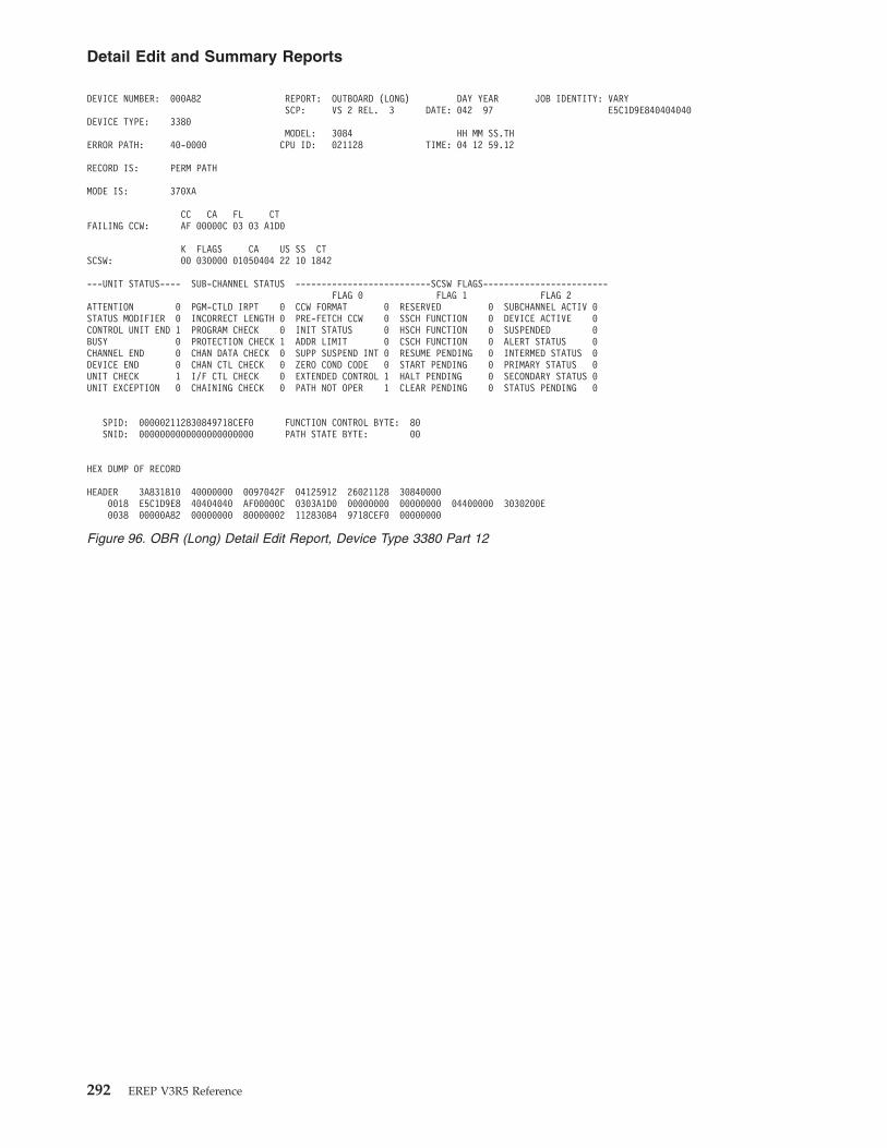
DEVICE NUMBER: 000A82 REPORT: OUTBOARD (LONG) DAY YEAR JOB IDENTITY: VARYSCP: VS 2 REL. 3 DATE: 042 97 E5C1D9E840404040
DEVICE TYPE: 3380MODEL: 3084 HH MM SS.TH
ERROR PATH: 40-0000 CPU ID: 021128 TIME: 04 12 59.12
RECORD IS: PERM PATH
MODE IS: 370XA
CC CA FL CTFAILING CCW: AF 00000C 03 03 A1D0
K FLAGS CA US SS CTSCSW: 00 030000 01050404 22 10 1842
---UNIT STATUS---- SUB-CHANNEL STATUS --------------------------SCSW FLAGS------------------------FLAG 0 FLAG 1 FLAG 2
ATTENTION 0 PGM-CTLD IRPT 0 CCW FORMAT 0 RESERVED 0 SUBCHANNEL ACTIV 0STATUS MODIFIER 0 INCORRECT LENGTH 0 PRE-FETCH CCW 0 SSCH FUNCTION 0 DEVICE ACTIVE 0CONTROL UNIT END 1 PROGRAM CHECK 0 INIT STATUS 0 HSCH FUNCTION 0 SUSPENDED 0BUSY 0 PROTECTION CHECK 1 ADDR LIMIT 0 CSCH FUNCTION 0 ALERT STATUS 0CHANNEL END 0 CHAN DATA CHECK 0 SUPP SUSPEND INT 0 RESUME PENDING 0 INTERMED STATUS 0DEVICE END 0 CHAN CTL CHECK 0 ZERO COND CODE 0 START PENDING 0 PRIMARY STATUS 0UNIT CHECK 1 I/F CTL CHECK 0 EXTENDED CONTROL 1 HALT PENDING 0 SECONDARY STATUS 0UNIT EXCEPTION 0 CHAINING CHECK 0 PATH NOT OPER 1 CLEAR PENDING 0 STATUS PENDING 0
SPID: 000002112830849718CEF0 FUNCTION CONTROL BYTE: 80SNID: 0000000000000000000000 PATH STATE BYTE: 00
HEX DUMP OF RECORD
HEADER 3A831810 40000000 0097042F 04125912 26021128 308400000018 E5C1D9E8 40404040 AF00000C 0303A1D0 00000000 00000000 04400000 3030200E0038 00000A82 00000000 80000002 11283084 9718CEF0 00000000
Figure 96. OBR (Long) Detail Edit Report, Device Type 3380 Part 12
Detail Edit and Summary Reports
292 EREP V3R5 Reference

PRIMARY CUA: 0239 REPORT: OUTBOARD (LONG) DAY YEAR JOB IDENTITY: PACAH210SCP: V370 REL. 6 DATE: 042 97 D7C1C3C1C8F2F1F0
DEVICE TYPE: 3390MODEL: 3084 HH MM SS.TH
ERROR PATH: 0239 CPU ID: 020060 TIME: 02 31 48.38
RECORD IS: TEMPORARY
MODE IS: 370
CC CA FL CTFAILING CCW: 07 DFA1E8 40 00 0006
K CA US CS CTCSW: 01 DFA1C8 02 00 0006
---UNIT STATUS---- CHANNEL STATUSATTENTION 0 PGM-CTLD IRPT 0STATUS MODIFIER 0 INCORRECT LENGTH 0CONTROL UNIT END 0 PROGRAM CHECK 0BUSY 0 PROTECTION CHECK 0CHANNEL END 0 CHAN DATA CHECK 0DEVICE END 0 CHAN CTL CHECK 0UNIT CHECK 1 I/F CTL CHECK 0UNIT EXCEPTION 0 CHAINING CHECK 0
DEVICE DEPENDENT DATA
STORAGE CONTROL UNIT: TYPE: 2107 SEQUENCE NUMBER: N/A PATH: 0
DEVICE: TYPE: 2107 SEQUENCE NUMBER: AH210 DEVICE ID: 19 STRING: 1 SUBCHANNEL ID: 00123456
SSID: 1144 VOLUME: PACV01
SENSE BYTE DATA
BYTE 00 01 02 03 04 05 06 07 08 09 10 11 12 13 14 1510 00 06 00 39 32 C1 43 00 03 00 00 01 05 04 04
BYTE 16 17 18 19 20 21 22 23 24 25 26 27 28 29 30 3122 10 18 42 11 44 0C 01 00 00 0F 01 0C 00 00 00
HEX DUMP OF RECORD
HEADER 30660840 00000000 0097042F 02314838 00020060 308400000018 D7C1C3C1 C8F2F1F0 07DFA1E8 40000006 01DFA1C8 02000006 03000239 800620320038 00000239 00010020 D7C1C3E5 F0F10000 00000001 D8000000 00000000 000000000058 10000600 3932C143 00030000 01050404 22101842 11440C01 00000F01 0C000000
Figure 97. OBR (Long) Detail Edit Report, Device Type 3390
Detail Edit and Summary Reports
Chapter 13. Detail Edit and Summary Reports 293

PRIMARY CUA: 018B REPORT: OUTBOARD (LONG) DAY YEAR JOB IDENTITY: RELIAB2SCP: VS 2 REL. 3 DATE: 048 97 D9C5D3C9C1C2F240
DEVICE TYPE: 3480MODEL: 4341 HH MM SS.TH
ERROR PATH: 018B CPU ID: 015760 TIME: 11 03 20.32RECORD IS: PERMANENTMODE IS: 370
CC CA FL CTFAILING CCW: 02 3EDD50 04 00 775B
K CA US CS CTCSW: 50 01A4D8 02 00 0001---UNIT STATUS---- CHANNEL STATUSATTENTION 0 PGM-CTLD IRPT 0STATUS MODIFIER 0 INCORRECT LENGTH 0CONTROL UNIT END 0 PROGRAM CHECK 0BUSY 0 PROTECTION CHECK 0CHANNEL END 0 CHAN DATA CHECK 0DEVICE END 0 CHAN CTL CHECK 0UNIT CHECK 1 I/F CTL CHECK 0UNIT EXCEPTION 0 CHAINING CHECK 0Ê│DEVICE DEPENDENT DATAÊCU ERR #1 8202 08 DEV ERR #1 0000 00CU ERR #2 0000 DEV ERR #2 0000CU ERR LAST 0000 VOLUME LABEL SSAG03CU ERR HDW 0000 BLOCK LENGTH 00000BLOCK ID 000004Ê│SENSE BYTE DATABYTE 00 01 02 03 04 05 06 07 08 09 10 11 12 13 14 15
42 40 78 3B 00 00 04 20 00 08 82 02 00 00 00 00BYTE 16 17 18 19 20 21 22 23 24 25 26 27 28 29 30 31
00 00 00 00 00 00 00 00 F6 04 E7 80 00 00 00 00│HEX DUMP OF RECORD»HEADER 30830800 00001100 0097048F 11032032 03015760 43410000
0018 D9C5D3C9 C1C2F240 023EDD50 0400775B 5001A4D8 02000001 02 00018B 780080800038 0000018B 00000020 E2E2C1C7 F0F30000 00001171 00000000 42 40783B 000004200058 00088202 00000000 00000000 00000000 F604E780
Figure 98. OBR (Long) Detail Edit Report, Device Type 3480
Detail Edit and Summary Reports
294 EREP V3R5 Reference

DEVICE NUMBER: 0004B2 REPORT: OUTBOARD (LONG) DAY YEAR JOB IDENTITY:SCP: VS 2 REL. 3 DATE: 053 97 E3F2E2E4D7C5D9F1
DEVICE TYPE: 3490MODEL: 4381 HH MM SS.TH
ERROR PATH: 04-04B2 CPU ID: 017260 TIME: 17 00 49.72
RECORD IS: PERMANENT
MODE IS: 370XA
CC CA FL CTFAILING CCW: 4B 000000 40 00 0001
K FLAGS CA US SS CTSCSW: 00 000013 00000000 06 00 0000
---UNIT STATUS---- SUB-CHANNEL STATUS --------------------------SCSW FLAGS------------------------FLAG 0 FLAG 1
ATTENTION 0 PGM-CTLD IRPT 0 CCW FORMAT 0 RESERVED 0 SUBCHANNEL ACTIV 0STATUS MODIFIER 0 INCORRECT LENGTH 0 PRE-FETCH CCW 0 SSCH FUNCTION 1 DEVICE ACTIVE 0CONTROL UNIT END 0 PROGRAM CHECK 0 INIT STATUS 0 HSCH FUNCTION 0 SUSPENDED 0BUSY 0 PROTECTION CHECK 0 ADDR LIMIT 0 CSCH FUNCTION 0 ALERT STATUS 1CHANNEL END 0 CHAN DATA CHECK 0 SUPP SUSPEND INT 0 RESUME PENDING 0 INTERMED STATUS 0DEVICE END 1 CHAN CTL CHECK 0 ZERO COND CODE 0 START PENDING 0 PRIMARY STATUS 1UNIT CHECK 1 I/F CTL CHECK 0 EXTENDED CONTROL 0 HALT PENDING 0 SECONDARY STATUS 1UNIT EXCEPTION 0 CHAINING CHECK 0 PATH NOT OPER 0 CLEAR PENDING 0 STATUS PENDING 1
DEVICE DEPENDENT DATA
CU ERR #2 70CE 00 DEV ERR #1 0000 00CU ERR #2 0000 DEV ERR #2 0000CU ERR LAST 0000 VOLUME LABELCU ERR HDW 0000 BLOCK LENGTH 08704
SENSE BYTE DATA
BYTE 00 01 02 03 04 05 06 07 08 09 10 11 12 13 14 1500 49 20 2E 00 00 00 20 00 00 70 CE 00 00 00 00
BYTE 16 17 18 19 20 21 22 23 24 25 26 27 28 29 30 3100 00 00 F8 00 00 00 00 F6 8F 6D A0 02 39 22 00
HEX DUMP OF RECORD
HEADER 30831800 00001100 0097053F 17004972 0C017260 438100000018 E3F2E2E4 D7C5D9F1 37000000 20000050 00000000 00000000 020404B2 780480810038 000004B2 00000020 00000000 00000000 00000100 00000000 00000013 000000000058 000070CE 00000000 000000F8 00000000 F68F6DA0 02392200 50004017 00F391400078 06000050 00000000 A520
Figure 99. OBR (Long) Detail Edit Report, Device Type 3490
Detail Edit and Summary Reports
Chapter 13. Detail Edit and Summary Reports 295
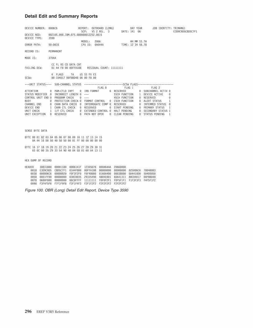
DEVICE NUMBER: 0006C6 REPORT: OUTBOARD (LONG) DAY YEAR JOB IDENTITY: TRINHNG1SCP: VS 2 REL. 3 DATE: 141 06 E3D9C9D5C8D5C7F1
DEVICE NED: 002105.000.IBM.075.000000012252.0615DEVICE TYPE: 3590
MODEL: 2066 HH MM SS.THERROR PATH: 50-06C6 CPU ID: 0A644A TIME: 12 34 56.78
RECORD IS: PERMANENT
MODE IS: 370XA
CC FL RS CD DATA CNTFAILING DCW: 01 A4 F8 00 00FFA108 RESIDUAL COUNT: 11111111
K FLAGS TA US SS FX ESSCSW: 80 C04017 00FBBD48 06 00 F8 00
---UNIT STATUS---- SUB-CHANNEL STATUS --------------------------SCSW FLAGS------------------------FLAG 0 FLAG 1 FLAG 2
ATTENTION 0 PGM-CTLD IRPT 0 IRB FORMAT 6 RESERVED 0 SUBCHANNEL ACTIV 0STATUS MODIFIER 0 INCORRECT LENGTH 0 --- SSCH FUNCTION 1 DEVICE ACTIVE 0CONTROL UNIT END 0 PROGRAM CHECK 0 --- HSCH FUNCTION 0 RESERVED 0BUSY 0 PROTECTION CHECK 0 FORMAT CONTROL 0 CSCH FUNCTION 0 ALERT STATUS 1CHANNEL END 0 CHAN DATA CHECK 0 INTERROGATE COMP 0 RESERVED 0 INTERMED STATUS 0DEVICE END 1 CHAN CTL CHECK 0 RESERVED 0 START PENDING 0 PRIMARY STATUS 1UNIT CHECK 1 I/F CTL CHECK 0 EXTENDED CONTROL 0 HALT PENDING 0 SECONDARY STATUS 1UNIT EXCEPTION 0 RESERVED 0 PATH NOT OPER 0 CLEAR PENDING 0 STATUS PENDING 1
SENSE BYTE DATA
BYTE 00 01 02 03 04 05 06 07 08 09 10 11 12 13 14 150A 44 10 D0 50 40 50 50 00 01 FF 00 00 00 00 00
BYTE 16 17 18 19 20 21 22 23 24 25 26 27 28 29 30 3103 0C 00 35 29 33 54 90 4B 04 E8 01 60 A4 13 11
HEX DUMP OF RECORD
HEADER 30831800 00001100 0006141F 12345678 000A644A 206600000018 E3D9C9D5 C8D5C7F1 01A4F800 00FFA108 80000000 00000000 025006C6 780480830038 000006C6 00000020 F0F3F2F0 F6F40000 0160A400 00038000 0A4410D0 504050500058 0001FF00 00000000 030C0035 29335490 4B04E801 60A41311 80C04017 00FBBD480078 0600F800 00000000 06C0FFFF 11111111 F0F0F2F1 F0F5F1F1 F1F3F3F3 F4F5F1F20098 F3F4F5F6 F7F1F9F8 F3F1F4F3 F2F1F2F2 F2F2F2F2 F2F2F2F2
Figure 100. OBR (Long) Detail Edit Report, Device Type 3590
Detail Edit and Summary Reports
296 EREP V3R5 Reference

DEVICE NUMBER: 000B0F REPORT: OUTBOARD (LONG) DAY YEAR JOB IDENTITY:SCP: VS 2 REL. 3 DATE: 065 97 0000000000000000
DEVICE TYPE: 3800MODEL: 3084 HH MM SS.TH
ERROR PATH: 20-0B0F CPU ID: 121128 TIME: 03 11 19.35
RECORD IS: PERMANENT
MODE IS: 370XA
CC CA FL CTFAILING CCW: 4B 000000 40 00 0001
K FLAGS CA US SS CTSCSW: 00 000013 00000000 06 00 0000
---UNIT STATUS---- SUB-CHANNEL STATUS --------------------------SCSW FLAGS------------------------FLAG 0 FLAG 1
ATTENTION 0 PGM-CTLD IRPT 0 CCW FORMAT 0 RESERVED 0 SUBCHANNEL ACTIV 0STATUS MODIFIER 0 INCORRECT LENGTH 0 PRE-FETCH CCW 0 SSCH FUNCTION 1 DEVICE ACTIVE 0CONTROL UNIT END 0 PROGRAM CHECK 0 INIT STATUS 0 HSCH FUNCTION 0 SUSPENDED 0BUSY 0 PROTECTION CHECK 0 ADDR LIMIT 0 CSCH FUNCTION 0 ALERT STATUS 0CHANNEL END 0 CHAN DATA CHECK 0 SUPP SUSPEND INT 0 RESUME PENDING 0 INTERMED STATUS 0DEVICE END 0 CHAN CTL CHECK 0 ZERO COND CODE 0 START PENDING 0 PRIMARY STATUS 1UNIT CHECK 1 I/F CTL CHECK 0 EXTENDED CONTROL 0 HALT PENDING 0 SECONDARY STATUS 1UNIT EXCEPTION 0 CHAINING CHECK 0 PATH NOT OPER 0 CLEAR PENDING 0 STATUS PENDING 1
DEVICE DEPENDENT DATA
STATISTICAL DATA
NOT USED 00 NOT USED 00TMP CHAN DATA CK 00 TMP CHAN CTL CHK 00TMP INTF CTL CHK 00 CFS MISFOLD(32) 00BUR/TRIM JAM(40) 00 NO BURST CHK(41) 00BUR/STKR JAM(42) 00 NOT USED 00NOT USED 00 NOT USED 00NOT USED 00 NOT USED 00NOT USED 00 NOT USED 00NOT USED 00 NOT USED 00
SENSE BYTE DATA
------BYTE00----40 ------BYTE01----40 ------BYTE02----00 ------BYTE03----6C ------BYTE04----8E ------BYTE05----00COMMAND REJECT 0 NOT READY 0 FORM HOLD INTRLK 0 PRINTER READY 0 ---------------- 1 ---------------- 0INTRVNTN REQ’D 0 OPERATION CHECK 1 TRANSFER CHECK 0 PAGE BUFFR EMPTY 1 0 0BUS OUT PAR CHK 0 TONER COLL FULL 0 FUSER CHECK 0 BACK DATA CHECK 1 DIAGNOSTIC 0 DIAGNOSTIC 0EQUIPMENT CHECK 0 TONER READY 0 CPS CHECK 0 PAPR THREAD STCK 0 STATUS 0 ERROR DEPEN- 0DATA CHECK 0 DEV REPLACE REQ 0 PROCESS CHECK 0 SYS RESTRT REQD 1 CODES 1 DENT DATA 0BIT 6 NOT USED 0 END OF FORMS 0 BURST/TRIM CHECK 0 PHOTO CON ADV EN 1 1 0LOAD CHECK 0 OUTPUT FULL 0 BIT 6 NOT USED 0 BIT 6 NOT USED 0 1 BYTE 1 OF 7 0
BIT 7 NOT USED 0 LINE OVERRUN 0 BIT 7 NOT USED 0 ---------------- 0 ---------------- 0
Figure 101. OBR (Long) Detail Edit Report, Device Type 3800 Part 1
Detail Edit and Summary Reports
Chapter 13. Detail Edit and Summary Reports 297

------BYTE06----00 ------BYTE07----F9 ------BYTE08----00 ------BYTE09----02 ------BYTE10----00 ------BYTE11----0C---------------- 1 ---------------- 0 ---------------- 0 ---------------- 0 ---------------- 0 ---------------- 0
0 0 0 0 0 0DIAGNOSTIC 0 DIAGNOSTIC 0 DIAGNOSTIC 0 DIAGNOSTIC 0 DIAGNOSTIC 0 DIAGNOSTIC 0ERROR DEPEN- 0 ERROR DEPEN- 0 ERROR DEPEN- 0 ERROR DEPEN- 0 ERROR DEPEN- 0 ERRPR DEPEN- 0DENT DATA 1 DENT DATA 0 DENT DATA 0 DENT DATA 0 DENT DATA 0 DENT DATA 1
1 0 0 0 0 1BYTE 2 OF 7 1 BYTE 3 OF 7 0 BYTE 4 OF 7 0 BYTE 5 OF 7 1 BYTE 6 OF 7 0 BYTE 7 OF 7 0
---------------- 0 ---------------- 0 ---------------- 0 ---------------- 0 ---------------- 0 ---------------- 0
------BYTE12----0B ------BYTE13----0B ------BYTE14----0F ------BYTE15----4C ------BYTE16----01 ------BYTE17----58---------------- 1 ---------------- 0 ---------------- 0 ---------------- 0 ---------------- 0 ---------------- 0
0 0 0 0 0 0MODULO 256 0 MODULO 256 0 0 0 0 0XFER 2 PPI 0 FUSER 8-16 0 FUSER PAGE 0 FUSER PAGE 0 PAPER COUNT 0 PAPER COUNT 0COUNT 1 PPI COUNT 0 COUNT 0 COUNT 0 0 1
1 0 0 0 0 11 0 BYTE 1 OF 2 0 BYTE 2 OF 2 1 BYTE 1 OF 2 0 BYTE 2 OF 2 0
---------------- 0 ---------------- 0 ---------------- 0 ---------------- 0 ---------------- 0 ---------------- 0
------BYTE18----06 ------BYTE19----CF ------BYTE20----00 ------BYTE21----1F ------BYTE22----FE ------BYTE23----DF---------------- 0 ---------------- 1 ---------------- 0 ---------------- 0 ---------------- 1 ---------------- 1
0 1 0 0 PHOTO CONDUC 1 PHOTO CONDUC 10 0 0 0 GAP LOC OR 1 GAP LOC OR 0
SERIAL 0 SERIAL 0 PAGE BACKUP 0 PAGE BACKUP 0 LOAD CHECK 1 LOAD CHECK 1NUMBER 0 NUMBER 1 COUNT 0 COUNT 0 OFFSET 1 OFFSET 1
1 1 0 0 1 1BYTE 1 OF 2 1 BYTE 2 OF 2 1 BYTE 1 OF 2 0 BYTE 2 OF 2 1 BYTE 1 OF 2 1 BYTE 2 OF 2 1
---------------- 0 ---------------- 1 ---------------- 0 ---------------- 0 ---------------- 0 ---------------- 1
HEX DUMP OF RECORD
HEADER 30831800 00000000 0097065F 03111935 26121128 308400000018 00000000 00000000 0981341D 60000070 00000000 00000000 00200B0F 1000080E0038 0A000B0F 00000018 00000000 00000000 00004040 006C8300 00000013 000C0B0B0058 0F4C0158 06CF001F FEDF1100 4007102C 40A80200 00700000 0000
Figure 102. OBR (Long) Detail Edit Report, Device Type 3800 Part 12
Detail Edit and Summary Reports
298 EREP V3R5 Reference
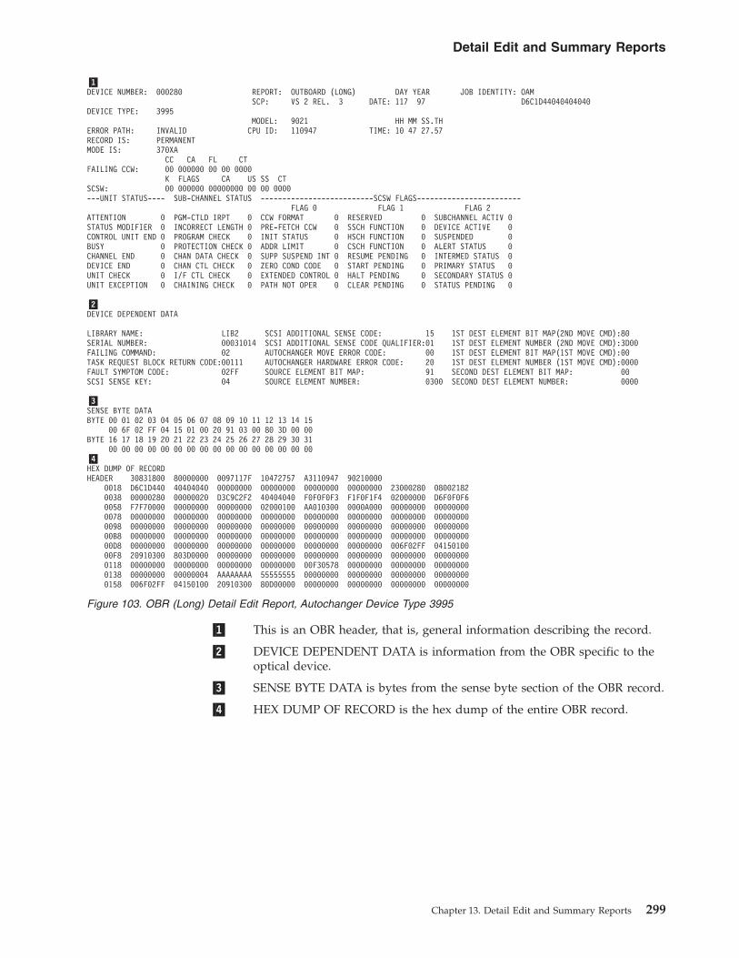
�1� This is an OBR header, that is, general information describing the record.
�2� DEVICE DEPENDENT DATA is information from the OBR specific to theoptical device.
�3� SENSE BYTE DATA is bytes from the sense byte section of the OBR record.
�4� HEX DUMP OF RECORD is the hex dump of the entire OBR record.
�1�DEVICE NUMBER: 000280 REPORT: OUTBOARD (LONG) DAY YEAR JOB IDENTITY: OAM
SCP: VS 2 REL. 3 DATE: 117 97 D6C1D44040404040DEVICE TYPE: 3995
MODEL: 9021 HH MM SS.THERROR PATH: INVALID CPU ID: 110947 TIME: 10 47 27.57RECORD IS: PERMANENTMODE IS: 370XA
CC CA FL CTFAILING CCW: 00 000000 00 00 0000
K FLAGS CA US SS CTSCSW: 00 000000 00000000 00 00 0000---UNIT STATUS---- SUB-CHANNEL STATUS --------------------------SCSW FLAGS------------------------
FLAG 0 FLAG 1 FLAG 2ATTENTION 0 PGM-CTLD IRPT 0 CCW FORMAT 0 RESERVED 0 SUBCHANNEL ACTIV 0STATUS MODIFIER 0 INCORRECT LENGTH 0 PRE-FETCH CCW 0 SSCH FUNCTION 0 DEVICE ACTIVE 0CONTROL UNIT END 0 PROGRAM CHECK 0 INIT STATUS 0 HSCH FUNCTION 0 SUSPENDED 0BUSY 0 PROTECTION CHECK 0 ADDR LIMIT 0 CSCH FUNCTION 0 ALERT STATUS 0CHANNEL END 0 CHAN DATA CHECK 0 SUPP SUSPEND INT 0 RESUME PENDING 0 INTERMED STATUS 0DEVICE END 0 CHAN CTL CHECK 0 ZERO COND CODE 0 START PENDING 0 PRIMARY STATUS 0UNIT CHECK 0 I/F CTL CHECK 0 EXTENDED CONTROL 0 HALT PENDING 0 SECONDARY STATUS 0UNIT EXCEPTION 0 CHAINING CHECK 0 PATH NOT OPER 0 CLEAR PENDING 0 STATUS PENDING 0
�2�DEVICE DEPENDENT DATA
LIBRARY NAME: LIB2 SCSI ADDITIONAL SENSE CODE: 15 1ST DEST ELEMENT BIT MAP(2ND MOVE CMD):80SERIAL NUMBER: 00031014 SCSI ADDITIONAL SENSE CODE QUALIFIER:01 1ST DEST ELEMENT NUMBER (2ND MOVE CMD):3D00FAILING COMMAND: 02 AUTOCHANGER MOVE ERROR CODE: 00 1ST DEST ELEMENT BIT MAP(1ST MOVE CMD):00TASK REQUEST BLOCK RETURN CODE:00111 AUTOCHANGER HARDWARE ERROR CODE: 20 1ST DEST ELEMENT NUMBER (1ST MOVE CMD):0000FAULT SYMPTOM CODE: 02FF SOURCE ELEMENT BIT MAP: 91 SECOND DEST ELEMENT BIT MAP: 00SCSI SENSE KEY: 04 SOURCE ELEMENT NUMBER: 0300 SECOND DEST ELEMENT NUMBER: 0000
�3�SENSE BYTE DATABYTE 00 01 02 03 04 05 06 07 08 09 10 11 12 13 14 15
00 6F 02 FF 04 15 01 00 20 91 03 00 80 3D 00 00BYTE 16 17 18 19 20 21 22 23 24 25 26 27 28 29 30 31
00 00 00 00 00 00 00 00 00 00 00 00 00 00 00 00�4�HEX DUMP OF RECORDHEADER 30831800 80000000 0097117F 10472757 A3110947 90210000
0018 D6C1D440 40404040 00000000 00000000 00000000 00000000 23000280 080021820038 00000280 00000020 D3C9C2F2 40404040 F0F0F0F3 F1F0F1F4 02000000 D6F0F0F60058 F7F70000 00000000 00000000 02000100 AA010300 0000A000 00000000 000000000078 00000000 00000000 00000000 00000000 00000000 00000000 00000000 000000000098 00000000 00000000 00000000 00000000 00000000 00000000 00000000 0000000000B8 00000000 00000000 00000000 00000000 00000000 00000000 00000000 0000000000D8 00000000 00000000 00000000 00000000 00000000 00000000 006F02FF 0415010000F8 20910300 803D0000 00000000 00000000 00000000 00000000 00000000 000000000118 00000000 00000000 00000000 00000000 00F30578 00000000 00000000 000000000138 00000000 00000004 AAAAAAAA 55555555 00000000 00000000 00000000 000000000158 006F02FF 04150100 20910300 80D00000 00000000 00000000 00000000 00000000
Figure 103. OBR (Long) Detail Edit Report, Autochanger Device Type 3995
Detail Edit and Summary Reports
Chapter 13. Detail Edit and Summary Reports 299

DEVICE NUMBER: 0C70 REPORT: OUTBOARD (LONG) DAY YEAR JOB IDENTITY:SCP: VS 2 REL. 3 DATE: 054 97 D4C1C9D5E3404040
DEVICE TYPE: 9347MODEL: 9375 HH MM SS.TH
ERROR PATH: 0C70 CPU ID: 234567 TIME: 10 14 52.90
RECORD IS: PERMANENT
MODE IS: 370XA
CC CA FL CTFAILING CCW: 01 3838E3 20 80 0055
K CA US SS CTCSW: 00 6A7348 0E 00 0055
---UNIT STATUS---- CHANNEL STATUS
ATTENTION 0 PGM-CTLD IRPT 0STATUS MODIFIER 0 INCORRECT LENGTH 0CONTROL UNIT END 0 PROGRAM CHECK 0BUSY 0 PROTECTION CHECK 0CHANNEL END 1 CHAN DATA CHECK 0DEVICE END 1 CHAN CTL CHECK 0UNIT CHECK 1 I/F CTL CHECK 0UNIT EXCEPTION 0 CHAINING CHECK 0
DEVICE DEPENDENT DATA
SYMPTOM CODE 2003VOLUME SERIAL
SENSE BYTE DATA
------BYTE00----08 ------BYTE01----44 ------BYTE02----00 ------BYTE03----0F ------BYTE04----10 ------BYTE05----10COMMAND REJECT 0 NOISE 0 ---------------- 0 ---------------- 0 NOT USED 0 NOT USED 0INTRVNTN REQ’D 0 DEVICE STATUS A 1 0 0 NOT USED 0 NOT USED 0NOT USED 0 DEVICE STATUS B 0 0 ERROR 0 TAPE INDICATE 0 NOT USED 0EQUIPMENT CHECK 0 NOT USED 0 TRACK IN 0 RECOVERY 0 PERMANENT ERROR 1 PE-ID CHECK 1DATA CHECK 0 AT LOAD POINT 0 ERR (0-7) 0 PROCUDURE 1 HOST DETECT ERR 0 NOT USED 0OVERRUN 0 WRITE STATUS 1 0 (0-7) 1 LOOP WRITE-READ 0 NOT USED 0NOT USED 0 FILE PROTECT 0 0 1 NOT USED 0 NOT USED 0NOT USED NOT CAPABLE 0 ---------------- 0 ---------------- 1 NOT USED 0 NOT USED 0
------BYTE06----00 ------BYTE07----10 ------BYTE08----38 ------BYTE09----30 ------BYTE10----00 ------BYTE11----00NOT USED 0 FORMAT CODE 8 0 BUFFER FULL LOW 0 BOT 0 DFCI SEQ CHECK 0 DOOR OPENED 0NOT USED 0 FORMAT CODE 4 0 BUFFER FULL HIGH 0 EOT 0 DFCI PARITY CHK 0 REEL MISSING 0NOT USED 0 FORMAT CODE 2 0 DRIVE ONLINE 1 TAPE-IN PATH SNR 1 SYNCH INS/OUTS 0 REEL INVERTED 0NOT USED 0 FORMAT CODE 1 1 DRIVE READY 1 WRITE ENABLED 1 XFER FAILURE 0 NO BOT 0NOT USED 0 DATA SECUR ERASE 0 POS. TO MOVE FWD 1 PE 1600 ID BURST 0 NOT USED 0 LOAD FAILURE 0NOT USED 0 NOT USED 0 NOT USED 0 PE 3200 ID BURST 0 NOT USED 0 REEL NOT CNTERED 0NOT USED 0 NOT USED 0 NOT USED 0 NOT USED 0 NOT USED 0 NOT USED 0NOT USED 0 NOT USED 0 NOT USED 0 NOT USED 0 NOT USED 0 P.O.S.T. 0
Figure 104. OBR Record (Long) Detail Edit Report, Device Type 9347 Part 1
Detail Edit and Summary Reports
300 EREP V3R5 Reference

------BYTE12----00 ------BYTE13----20 ------BYTE14----00 ------BYTE15----00 ------BYTE16----80 ------BYTE17----00TENSION ARM 0 WRITE CHECK 0 READ SKEW 0 TIE PARITY 0 1600 CPI/25IPS 1 NOT USED 0TAPE SPEED 0 WRITE IBG NOISE 0 READ UNCORRECT P 0 NOT USED 0 1600 CPI/100IPS 0 NOT USED 03700 FT OF TAPE 0 WRITE ID CHECK 1 READ MCHNL DROP 0 NOT USED 0 3200 CPI/50IPS 0 IBG 32 0TENSION ARM VOL 0 WRT POSTAMBLE CK 0 READ ID PAGE 0 NOT USED 0 NOT USED 0 IBG 16 0TACHOMETER 0 ERASE GAP SIZE 0 NOT USED 0 NOT USED 0 NOT USED 0 IBG 8 0SUPPLY HUB LOCK 0 PIC ERROR 0 NOT USED 0 NOT USED 0 NOT USED 0 IBG 4 0TAKE-UP HUB SLIP 0 NOT USED 0 NOT USED 0 NOT USED 0 NOT USED 0 IBG 2 0SUPPLY HUB SLIP 0 NOT USED 0 NOT USED 0 NOT USED 0 NOT USED 0 IBG 1 0
------BYTE18----04 ------BYTE19----00 ------BYTE20----00 ------BYTE21----00 ------BYTE22----00 ------BYTE23----00BLK LENGTH 32768 0 BLK LENGTH 128 0 1ST LVL IND BIT1 0 2ND LVL IND BIT1 0 3RD LVL IND BIT1 0 4TH LVL IND BIT1 0BLK LENGTH 16384 0 BLK LENGTH 65 0 1ST LVL IND BIT2 0 2ND LVL IND BIT2 0 3RD LVL IND BIT2 0 4TH LVL IND BIT2 0BLK LENGTH 8192 0 BLK LENGTH 32 0 1ST LVL IND BIT3 0 2ND LVL IND BIT3 0 3RD LVL IND BIT3 0 4TH LVL IND BIT3 0BLK LENGTH 4096 0 BLK LENGTH 16 0 1ST LVL IND BIT4 0 2ND LVL IND BIT4 0 3RD LVL IND BIT4 0 4TH LVL IND BIT4 0BLK LENGTH 2048 0 BLK LENGTH 8 0 1ST LVL IND BIT5 0 2ND LVL IND BIT5 0 3RD LVL IND BIT5 0 4TH LVL IND BIT5 0BLK LENGTH 1024 1 BLK LENGTH 4 0 NOT USED 0 NOT USED 0 NOT USED 0 NOT USED 0BLK LENGTH 512 0 BLK LENGTH 2 0 NOT USED 0 NOT USED 0 NOT USED 0 NOT USED 0BLK LENGTH 256 0 BLK LENGTH 1 0 NOT USED 0 NOT USED 0 NOT USED 0 NOT USED 0
------BYTE24----00 ------BYTE25----00 ------BYTE26----00 ------BYTE27----00 ------BYTE28----00 ------BYTE29----005TH LVL IND BIT1 0 6TH LVL IND BIT1 0 NOT USED 0 ---------------- 0 ---------------- 0 NOT USED 05TH LVL IND BIT2 0 6TH LVL IND BIT2 0 NOT USED 0 0 0 NOT USED 05TH LVL IND BIT3 0 6TH LVL IND BIT3 0 NOT USED 0 0 0 NOT USED 05TH LVL IND BIT4 0 6TH LVL IND BIT4 0 NOT USED 0 CONDITION 0 DIAGNOSTIC 0 NOT USED 05TH LVL IND BIT5 0 6TH LVL IND BIT5 0 NOT USED 0 FLAG 0 LED 0 NOT USED 0NOT USED 0 NOT USED 0 NOT USED 0 0 0 NOT USED 0NOT USED 0 NOT USED 0 NOT USED 0 0 0 NOT USED 0NOT USED 0 NOT USED 0 NOT USED 0 ---------------- 0 ---------------- 0 NOT USED 0
------BYTE30----20 ------BYTE31----03---------------- 0 ---------------- 0
0 0FAULT 1 FAULT 0SYMPTOM 0 SYMPTOM 0CODE 0 CODE 0(MSB) 0 (LSB) 0
0 1---------------- 0 ---------------- 1
HEX DUMP OF RECORD
HEADER 30550800 00000000 0097054F 10145290 10234567 937500000018 D4C1C9D5 E3404040 013838E3 20800055 006A7348 0E000055 01000C70 000080090038 00000C70 00000020 40404040 40400000 0844000F 10100010 38300000 002000000058 80000400 00000000 00000000 00002003 00000000 00000000 00000000 000000000078 00000000 00000000 00000000
Figure 105. OBR Record (Long) Detail Edit Report, Device Type 9347 Part 2
Detail Edit and Summary Reports
Chapter 13. Detail Edit and Summary Reports 301

DEVICE NUMBER: 000A82 REPORT: OUTBOARD (LONG) DAY YEAR JOB IDENTITY: VARYSCP: VS 2 REL. 3 DATE: 046 97 E5C1D9E840404040
DEVICE TYPE: 3380MODEL: 3084 HH MM SS.TH
ERROR PATH: 56-0000 CPU ID: 321128 TIME: 04 11 55.73
RECORD IS: PERM PATH
MODE IS: 370XA
CC CA FL CTFAILING CCW: AF 0303A058 00 000C
K FLAGS CA US SS CTSCSW: 03 814407 01a16058 00 00 000C
---UNIT STATUS---- SUB-CHANNEL STATUS --------------------------SCSW FLAGS------------------------FLAG 0 FLAG 1 FLAG 2
ATTENTION 0 PGM-CTLD IRPT 0 CCW FORMAT 1 RESERVED 0 SUBCHANNEL ACTIV 0STATUS MODIFIER 0 INCORRECT LENGTH 0 PRE-FETCH CCW 0 SSCH FUNCTION 1 DEVICE ACTIVE 0CONTROL UNIT END 0 PROGRAM CHECK 0 INIT STATUS 0 HSCH FUNCTION 0 SUSPENDED 0BUSY 0 PROTECTION CHECK 0 ADDR LIMIT 0 CSCH FUNCTION 0 ALERT STATUS 0CHANNEL END 0 CHAN DATA CHECK 0 SUPP SUSPEND INT 0 RESUME PENDING 0 INTERMED STATUS 0DEVICE END 0 CHAN CTL CHECK 0 ZERO COND CODE 0 START PENDING 1 PRIMARY STATUS 1UNIT CHECK 0 I/F CTL CHECK 0 EXTENDED CONTROL 0 HALT PENDING 0 SECONDARY STATUS 1UNIT EXCEPTION 0 CHAINING CHECK 0 PATH NOT OPER 1 CLEAR PENDING 0 STATUS PENDING 1
SPID: 000002112830849718CEF0 FUNCTION CONTROL BYTE: 80SNID: 0000000000000000000000 PATH STATE BYTE: 00
HEX DUMP OF RECORD
HEADER 3A891810 40000000 0097046F 04115573 26321128 308400000018 E5C1D9E8 40404040 AF00000C 0303A058 00000000 00000000 04560000 3030200E0038 00000A82 00000000 80000002 11283084 9718CEF0 00000000 00000000 000000000058 00000000 00000000 03814407 01A16058 0000000C 00000000 00000000 000000000078 00000000 00000000 00000000
Figure 106. OBR (Long) Detail Edit Report, Device Type 3380, DPA
Detail Edit and Summary Reports
302 EREP V3R5 Reference

DEVICE NUMBER: 0006C6 REPORT: OUTBOARD (LONG) DAY YEAR JOB IDENTITY: TRINHNG3SCP: VS 2 REL. 3 DATE: 141 06 E3D9C9D5C8D5C7F3
DEVICE NED: 002105.000.IBM.075.000000012252.0615DEVICE TYPE: 3590
MODEL: 2066 HH MM SS.THERROR PATH: 50-06C6 CPU ID: 0A644A TIME: 12 34 56.78
RECORD IS: PERMANENT
MODE IS: 370XA
CC FL RS CD DATA CNTFAILING DCW: 01 A4 F8 00 00FFA108 RESIDUAL COUNT: 11111111
K FLAGS TA US SS FX ESSCSW: 80 C04017 00FBBD48 06 00 F8 00
---UNIT STATUS---- SUB-CHANNEL STATUS --------------------------SCSW FLAGS------------------------FLAG 0 FLAG 1 FLAG 2
ATTENTION 0 PGM-CTLD IRPT 0 IRB FORMAT 6 RESERVED 0 SUBCHANNEL ACTIV 0STATUS MODIFIER 0 INCORRECT LENGTH 0 --- SSCH FUNCTION 1 DEVICE ACTIVE 0CONTROL UNIT END 0 PROGRAM CHECK 0 --- HSCH FUNCTION 0 RESERVED 0BUSY 0 PROTECTION CHECK 0 FORMAT CONTROL 0 CSCH FUNCTION 0 ALERT STATUS 1CHANNEL END 0 CHAN DATA CHECK 0 INTERROGATE COMP 0 RESERVED 0 INTERMED STATUS 0DEVICE END 1 CHAN CTL CHECK 0 RESERVED 0 START PENDING 0 PRIMARY STATUS 1UNIT CHECK 1 I/F CTL CHECK 0 EXTENDED CONTROL 0 HALT PENDING 0 SECONDARY STATUS 1UNIT EXCEPTION 0 RESERVED 0 PATH NOT OPER 0 CLEAR PENDING 0 STATUS PENDING 1
SPID: F3F2F0F6F400000160A400 FUNCTION CONTROL BYTE: F0SNID: 0380000A4410D050405050 PATH STATE BYTE: 00
SENSE BYTE DATA
BYTE 00 01 02 03 04 05 06 07 08 09 10 11 12 13 14 150A 44 10 D0 50 40 50 50 00 01 FF 00 00 00 00 00
BYTE 16 17 18 19 20 21 22 23 24 25 26 27 28 29 30 3103 0C 00 35 29 33 54 90 4B 04 E8 01 60 A4 13 11
HEX DUMP OF RECORD
HEADER 3A831800 00001100 0006141F 12345678 000A644A 206600000018 E3D9C9D5 C8D5C7F3 01A4F800 00FFA108 80000000 00000000 025006C6 780480830038 000006C6 00000020 F0F3F2F0 F6F40000 0160A400 00038000 0A4410D0 504050500058 0001FF00 00000000 030C0035 29335490 4B04E801 60A41311 80C04017 00FBBD480078 0600F800 00000000 06C0FFFF 11111111 F0F0F2F1 F0F5F3F3 F3F3F3F3 F4F5F1F20098 F3F4F5F6 F7F1F9F8 F3F1F4F3 F2F1F2F2 F2F2F2F2 F2F2F2F2
Figure 107. OBR (Long) Detail Edit Report, Device Type 3590, DPA
Detail Edit and Summary Reports
Chapter 13. Detail Edit and Summary Reports 303

RECORD TYPE - 3C
MODEL-3084 SERIAL NO- 021103
--- RECORD ENTRY SOURCE - OBR
VS 2 REL. 03
DAY YEAR HH MM SS.THDATE- 044 97 TIME- 17 40 12 99
JOB IDENTITY- DYN PATH
FAILING CCW - 00 00 00 00 00 00 00 00
CSW 00 00 00 00 00 00 00 00
DEVICE TYPE CODE- 3030200E
PRIMARY CUA 0002C2 SECONDARY CUA 000000
HEX DUMP OF RECORDHEADER 3C831840 00000000 0097044F 17401299 26021103 30840000
0018 C4E8D540 D7C1E3C8 00000000 00000000 00000000 00000000 1D000000 3030200E0038 000002C2 00000000 01000000 E2D5C9C4 00FBC168 01A1C110 10000004 580000020058 80800080 00000000 00000000 22800640 00000000 00000000 00000000 000000000078 00000000 00000000 00000000 00000000 00000000 00000000 00000000 000000000098 00000000 00000000 00000000 00000000 00000000 00000000 00000000 0000000000B8 00000000 00000000 00000000 00000000 00000000 00000000 00000000 0000000000D8 00000000 50040000 00000000 00000000 00000000 00000000 00000000 0000000000F8 00000000 00000000 00000000 00000000 00000000 00000000 00000000 000000000118 00000000 00000000 00000000 01000015 00000000
Figure 108. OBR (Long) Dynamic Pathing Validation Analysis Detail Edit Report
SUMMARY OF 3C RECORDS
DAY YEAR DAY YEARRECORD DATE RANGE 044 97 044 97
MODEL - 3084 SERIAL NO - 021103
TOTAL NUMBER OF RECORDS=0001
CLASSES ENCOUNTERED(MAXIMUM OF 10)
RECORD CLASS -3C 0001
Figure 109. OBR (Long) Dynamic Pathing Validation Analysis Summary Report
Detail Edit and Summary Reports
304 EREP V3R5 Reference

DPS VALIDATION REPORTDAY YEAR RECORD DESCRIPTION: IOSVVARY
DEVICE NUMBER: 0018C SCP: VS 2 REL. 3 DATE: 213 07 C9D6E2E5E5C1D9E8CPU MODEL: 2094 HH MM SS.TH
DEVICE TYPE: 3390 CPU SERIAL: 0F9950 TIME: 14 30 32.75DEVICE NED: 002105.000.IBM.75.000000012252.0615
------------------------------------ RETURN CODES ------------------------------------DPTH CALLS FOR: SNID 00 DEVICE 00 PATH 00 DPSV: 00
------------------------------------LOGICAL STATUS OF DEVICE------------------------------------RESVD/ASSGND 0 RESERVE PEND 0 MULTI PTH ACT 1 RESVD/ASSGND VAL 0 UCB IN PERM ERR 0RESVD/REL PEND 0 DP ACTIVE 1 ASSIGNABLE DEV 0 UCB NOT CONNECT 0 DEVICE BOXED 0
------------------------------------ CHANNEL PATH MASKS ------------------------------------LPU MASK 80 PHYS AVAIL PG F0 NO SPID SINCE SR 00 PG RESERVED MASK 00 RESV OTHER PG 00NO. VALID ICP 04 SNID SUCCESS MK F0 VAL ID NOT GROUP 00 PG NOT RESERVED F0 MODE PATH MASK F0LPM F0 SNID FAILURE MK 00 VAL ID IN GROUP F0
ACT FOR DEV 00 ACT FOR PATH 00 DEV MSG CODE 00
------------------------------------ DATA FOR CHANNEL PATH 22 ------------------------------------PIM 80 SNID SUCCESS 1 REMOVE FROM LPM 0 ALTER PS ACT 2 0 RC ON ACTION 1 00LOG AVAIL MASK 1 SNID FAILED 0 ALTER PS ACT 1 0 EST/RES REQ ACT1 0 RC ON ACTION 2 00PHY AVAIL MASK 1 DCC3 CONDITION 0 EST/RES REQ ACT2 0
UNIT CHECK 0 LONG RECOVERY 0SNID DATA PATH STATE C8 PGID 880003069A2084C0F8A451
------------------------------------ DATA FOR CHANNEL PATH 21 ------------------------------------PIM 40 SNID SUCCESS 1 REMOVE FROM LPM 0 ALTER PS ACT 2 0 RC ON ACTION 1 00LOG AVAIL MASK 1 SNID FAILED 0 ALTER PS ACT 1 0 EST/RES REQ ACT1 0 RC ON ACTION 2 00PHY AVAIL MASK 1 DCC3 CONDITION 0 EST/RES REQ ACT2 0
UNIT CHECK 0 LONG RECOVERY 0SNID DATA PATH STATE C8 PGID 880003069A2084C0F8A451
------------------------------------ DATA FOR CHANNEL PATH 2B ------------------------------------PIM 20 SNID SUCCESS 1 REMOVE FROM LPM 0 ALTER PS ACT 2 0 RC ON ACTION 1 00LOG AVAIL MASK 1 SNID FAILED 0 ALTER PS ACT 1 0 EST/RES REQ ACT1 0 RC ON ACTION 2 00PHY AVAIL MASK 1 DCC3 CONDITION 0 EST/RES REQ ACT2 0
UNIT CHECK 0 LONG RECOVERY 0SNID DATA PATH STATE C8 PGID 880003069A2084C0F8A451
------------------------------------ DATA FOR CHANNEL PATH 2A ------------------------------------PIM 10 SNID SUCCESS 1 REMOVE FROM LPM 0 ALTER PS ACT 2 0 RC ON ACTION 1 00LOG AVAIL MASK 1 SNID FAILED 0 ALTER PS ACT 1 0 EST/RES REQ ACT1 0 RC ON ACTION 2 00PHY AVAIL MASK 1 DCC3 CONDITION 0 EST/RES REQ ACT2 0
UNIT CHECK 0 LONG RECOVERY 0SNID DATA PATH STATE C8 PGID 880003069A2084C0F8A451
Figure 110. OBR (Long) DPS Validation Detail Edit Report, Device Type 3390 Part 1
HEX DUMP OF RECORDHEADER C2831840 00000000 0007213F 14303275 FF0F9950 20940000
0018 C9D6E2E5 E5C1D9E8 0000018C 801B2024 00000000 00000000 01000100 E2D5C9C40038 021D48F8 02387660 00000000 1A208004 F0F0F000 0000F000 F000F000 228006800058 00000000 C8880003 069A2084 C0F8A451 00000000 21400680 00000000 C88800030078 069A2084 C0F8A451 00000000 2B200680 00000000 C8880003 069A2084 C0F8A4510098 00000000 2A100680 00000000 C8880003 069A2084 C0F8A451 00000000 0000000000B8 00000000 00000000 00000000 00000000 00000000 00000000 00000000 0000000000D8 00000000 00000000 00000000 00000000 00000000 00000000 00000000 0000000000F8 00000000 00000000 00000000 00000000 00000000 00000000 00000000 000000000118 00000000 00000000 00000000 00000000 00000000 00000000 00000000 000000000138 00000000 00000000 00000000 00000000 00000000 00000000 00000000 000000000158 00000000 00000000 00000000 00000000 00000000 00000000 00000000 000000000178 00000000 00000000 00000000 00000000 00000000 00000000 00000000 000000000198 00000000 00000000 00000000 00000000 00000000 00000000 00000000 0000000001B8 00000000 00000000 00000000 00000000 00000000 00000000 00000000 0000000001D8 00000000 00000000 00000000 00000000 00000000 00000000 00000000 0000000001F8 00000000 00000000 00000000 00000000 00000000 00000000 00000000 000000000218 00000000 00000000 00000000 00000000 00000000 00000000 00000000 000000000238 00000000 00000000 DC010100 F0F0F2F1 F0F5F0F0 F0C9C2D4 F7F5F0F0 F0F0F0F00258 F0F1F2F2 F5F20615
Figure 111. OBR (Long) DPS Validation Detail Edit Report, Device Type 3390 Part 2
Detail Edit and Summary Reports
Chapter 13. Detail Edit and Summary Reports 305

DEVICE NUMBER: 0006C9 REPORT: OUTBOARD (LONG) DAY YEAR JOB IDENTITY:BOX DEVSCP: VS 2 REL. 3 DATE: 142 06 C2D6E740C4C5E540
DEVICE TYPE: 3390MODEL: 2066 HH MM SS.TH
ERROR PATH: 50-06C9 CPU ID: 0D644A TIME: 02 21 17.75
RECORD IS: TEMPORARY
MODE IS: 370XA
CC FL RS CD DATA CNTFAILING CCW: AF 00 00 0C 03BE46D8 RESIDUAL COUNT: 0000
K FLAGS TA US SS FX ESSCSW: 00 800000 00000000 00 00 00 00
---UNIT STATUS---- SUB-CHANNEL STATUS --------------------------SCSW FLAGS------------------------FLAG 0 FLAG 1
ATTENTION 0 PGM-CTLD IRPT 0 IRB FORMAT 4 RESERVED 0 SUBCHANNEL ACTIV 0STATUS MODIFIER 0 INCORRECT LENGTH 0 --- SSCH FUNCTION 0 DEVICE ACTIVE 0CONTROL UNIT END 0 PROGRAM CHECK 0 --- HSCH FUNCTION 0 RESERVED 0BUSY 0 PROTECTION CHECK 0 FORMAT ESCAPE 0 CSCH FUNCTION 0 ALERT STATUS 0CHANNEL END 0 CHAN DATA CHECK 0 RESERVED 0 RESERVED 0 INTERMED STATUS 0DEVICE END 0 CHAN CTL CHECK 0 RESERVED 0 START PENDING 0 PRIMARY STATUS 0UNIT CHECK 0 I/F CTL CHECK 0 EXTENDED CONTROL 0 HALT PENDING 0 SECONDARY STATUS 0UNIT EXCEPTION 0 RESERVED 0 PATH NOT OPER 0 CLEAR PENDING 0 STATUS PENDING 0
SPID: 00000D644A2066BED5C7F8 FUNCTION CONTROL BYTE: 20SNID: 0000000000000000000000 PATH STATE BYTE: 00
SENSE BYTE DATABYTE 00 01 02 03 04 05 06 07 08 09 10 11 12 13 14 15
00 00 00 00 00 00 00 00 00 00 00 00 00 00 00 00BYTE 16 17 18 19 20 21 22 23 24 25 26 27 28 29 30 31
00 00 00 00 00 00 00 00 00 00 00 00 00 00 00 00
HEX DUMP OF RECORDHEADER 3A831840 00000000 0006142F 02211775 000D644A 20660000
0018 C2D6E740 C4C5E540 AF00000C 03BE46D8 00000000 00000000 045006C9 780420320038 000006C9 00000020 2000000D 644A2066 BED5C7F8 00000000 00000000 000000000058 00000000 00000000 00000000 00000000 00000000 00000000 00000000 000000000078 00000000 00000000 00800000 00000000 00000000 00000000
Figure 112. OBR (Long) Detail Edit Report for zHPF
Detail Edit and Summary Reports
306 EREP V3R5 Reference

Software (SFT) Detail Edit ReportsThis report contains software records that are produced as part of the system errorrecovery process. It may include the following:v Software-specific information such as:
– The error ID– The system diagnostic work area (SDWA) control block and its extensions for
the failing task or request block.v Software records written at the request of the machine check handler (MCH) to
provide program-damage assessment data in case of a machine check.v A short form of the software record is produced to indicate the number of
records lost because the error-recording (ERDS) buffer is full.v Under VS1, VTAM prepares software records to document program failures.
Figures containing examples of these reports are on the pages shown in thefollowing table:
REPORT REFER TO
Software (SVC 13) Detail Edit Report “Software (SVC 13) Detail EditReport” on page 308
DEVICE NUMBER: 005708 REPORT: OUTBOARD (LONG) DAY YEAR JOB IDENTITY: EOS EXITSCP: VS 2 REL. 3 DATE: 273 05 C5D6E240C5E7C9E3
DEVICE TYPE: 3390MODEL: 2084 HH MM SS.TH
ERROR PATH: 14-5708 CPU ID: 132906 TIME: 13 38 42.32
RECORD IS: TEMPORARY
MODE IS: 370XA
CC CA FL CTFAILING CCW: 1E E76072 60 00 0000
K FLAGS CA US SS CTSCSW: 00 404017 00E68400 0E 00 0000
---UNIT STATUS---- SUB-CHANNEL STATUS --------------------------SCSW FLAGS------------------------FLAG 0 FLAG 1
ATTENTION 0 PGM-CTLD IRPT 0 CCW FORMAT 0 RESERVED 0 SUBCHANNEL ACTIV 0STATUS MODIFIER 0 INCORRECT LENGTH 0 PRE-FETCH CCW 1 SSCH FUNCTION 1 DEVICE ACTIVE 0CONTROL UNIT END 0 PROGRAM CHECK 0 INIT STATUS 0 HSCH FUNCTION 0 SUSPENDED 0BUSY 0 PROTECTION CHECK 0 ADDR LIMIT 0 CSCH FUNCTION 0 ALERT STATUS 1CHANNEL END 1 CHAN DATA CHECK 0 SUPP SUSPEND INT 0 RESUME PENDING 0 INTERMED STATUS 0DEVICE END 1 CHAN CTL CHECK 0 ZERO COND CODE 0 START PENDING 0 PRIMARY STATUS 1UNIT CHECK 1 I/F CTL CHECK 0 EXTENDED CONTROL 0 HALT PENDING 0 SECONDARY STATUS 1UNIT EXCEPTION 0 CHAINING CHECK 0 PATH NOT OPER 0 CLEAR PENDING 0 STATUS PENDING 1
DEVICE DEPENDENT DATA
STORAGE CONTROL UNIT: TYPE: 2107 SEQUENCE NUMBER: 00000 PATH: 0
DEVICE: TYPE: 2107+ SEQUENCE NUMBER: N/A DEVICE ID: 00 STRING: 0
SSID: N/A VOLUME: 339S02 CYLINDER: 00101A0 HEAD: E
SENSE BYTE DATABYTE 00 01 02 03 04 05 06 07 08 09 10 11 12 13 14 15
10 00 00 00 00 3C 20 00 00 00 00 00 00 00 00 00BYTE 16 17 18 19 20 21 22 23 24 25 26 27 28 29 30 31
00 00 00 00 00 00 00 00 04 81 00 10 DE F1 AB C2
HEX DUMP OF RECORDHEADER 30831840 00000000 0005273F 13384232 FF132906 20840000
0018 C5D6E240 C5E7C9E3 1EE76072 60000000 00000000 00000000 03145708 801F20320038 00005708 00000020 F3F3F9E2 F0F30000 00000000 00000000 00000000 000000000058 10000000 003C2000 00000000 00000000 00000000 00000000 04810010 00101A0E0078 00404017 00E68400 0E000000 0080000D F0F261F2 F461F0F5
Figure 113. OBR (Long) Detail Edit Report for Extended Address Volume (EAV)
Detail Edit and Summary Reports
Chapter 13. Detail Edit and Summary Reports 307
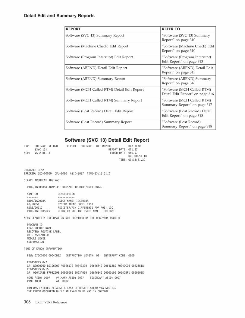
REPORT REFER TO
Software (SVC 13) Summary Report “Software (SVC 13) SummaryReport” on page 310
Software (Machine Check) Edit Report “Software (Machine Check) EditReport” on page 310
Software (Program Interrupt) Edit Report “Software (Program Interrupt)Edit Report” on page 313
Software (ABEND) Detail Edit Report “Software (ABEND) Detail EditReport” on page 315
Software (ABEND) Summary Report “Software (ABEND) SummaryReport” on page 316
Software (MCH Called RTM) Detail Edit Report “Software (MCH Called RTM)Detail Edit Report” on page 316
Software (MCH Called RTM) Summary Report “Software (MCH Called RTM)Summary Report” on page 317
Software (Lost Record) Detail Edit Report “Software (Lost Record) DetailEdit Report” on page 318
Software (Lost Record) Summary Report “Software (Lost Record)Summary Report” on page 318
Software (SVC 13) Detail Edit ReportTYPE: SOFTWARE RECORD REPORT: SOFTWARE EDIT REPORT DAY YEAR
(SVC 13) REPORT DATE: 071.97SCP: VS 2 REL 3 ERROR DATE: 060.97
HH: MM:SS.THTIME: 03:13:51.39
JOBNAME: JES2ERRORID: SEQ=00020 CPU=0000 ASID=0007 TIME=03:13:51.2
SEARCH ARGUMENT ABSTRACT
RIDS/IGC0008A AB/20351 REGS/0611C RIDS/IGCT1081#R
SYMPTOM DESCRIPTION------- -----------RIDS/IGC008A CSECT NAME: IGC0008AAB/S0351 SYSTEM ABEND CODE: 0351REGS/0611C REGISTER/PSW DIFFERENCE FOR R06: 11CRIDS/IGCT1081#R RECOVERY ROUTINE CSECT NAME: IGCT1081
SERVICEABILITY INFORMATION NOT PROVIDED BY THE RECOVERY ROUTINE
PROGRAM IDLOAD MODULE NAMERECOVERY ROUTINE LABELDATE ASSEMBLEDMODULE LEVELSUBFUNCTION
TIME OF ERROR INFORMATION
PSW: 070C1000 0004DDE2 INSTRUCTION LENGTH: 02 INTERRUPT CODE: 000D
REGISTERS 0-7GR: 80000000 80106000 A00E6170 00042320 00646840 0064C880 7004DCC6 00623518REGISTERS 8-15GR: 00642A88 FF9B2698 0000000E 0063A000 00646840 00000106 0064C8F1 0000000E
HOME ASID: 0007 PRIMARY ASID: 0007 SECONDARY ASID: 0007PKM: 4000 AX: 0002
RTM WAS ENTERED BECAUSE A TASK REQUESTED ABEND VIA SVC 13.THE ERROR OCCURRED WHILE AN ENABLED RB WAS IN CONTROL.
Detail Edit and Summary Reports
308 EREP V3R5 Reference
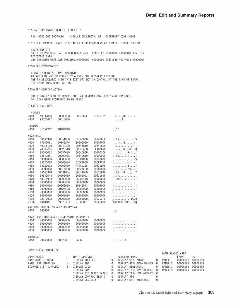
STATUS FROM ESTAE RB OR AT FRR ENTRY
PSW: 075C1000 00CF4C10 INSTRUCTION LENGTH: 02 INTERRUPT CODE: 0008
REGISTERS FROM RB LEVEL OF ESTAE EXIT OR REGISTERS AT TIME OF ERROR FOR FRR
REGISTERS 0-7GR: FF9C321C 00631DA8 00000008 60CF4938 00627EF0 00000000 0064C9F8 00631DE4REGISTERS 8-15GR: 00631DE0 00631DA8 00631DA8 00000000 00000001 00631F58 A0CF40D4 00000000
RECOVERY ENVIRONMENT
RECOVERY ROUTINE TYPE: UNKNOWNAN SVC DUMP WAS SCHEDULED BY A PREVIOUS RECOVERY ROUTINE.THE RB ASSOCIATED WITH THIS EXIT WAS NOT IN CONTROL AT THE TIME OF ERROR.I/O OPERATIONS WERE HALTED.
RECOVERY ROUTINE ACTION
THE RECOVERY ROUTINE REQUESTED THAT TERMINATION PROCESSING CONTINUE.NO LOCKS WERE REQUESTED TO BE FREED.
HEXADECIMAL DUMP
HEADER+000 40830820 000000B8 0097060F 03135139 C.....8.I. ....+010 23020447 30810000 .....A..
JOBNAME+000 D1C5E2F2 40404040 JES2
SDWA BASE+000 0064C998 80351000 FF04000D 5004DDE2 ..IQ........ ..S+010 FF140051 60146AA6 80000000 80106000 ....-. W......-.+020 A00E6170 00042320 00646840 0064C880 ./........ ..H.+030 7004DCC6 00623518 00642A88 FF9B2698 ...F-. W...H.}.Q+040 0000000E 0063A000 0064D968 00000106 ...... ...R.....+050 0064C8F1 0000000E 0064C880 00000000 ..H1......H.....+060 00000000 00000000 070C1000 0004DD32 ...............S+070 0002000D 00000000 075C1000 00CF4C10 .........*....<.+080 00020008 00000000 FF9CE21C 00631DA8 ......... S....Y+090 00000008 60CF4938 00627EF0 00000000 ....-.....=0....+0A0 0064C9F8 00631DE4 00631DE0 00631DA8 ..I8...U...\...Y+0B0 00631DA8 00000000 00000001 00631F58 ...Y............+0C0 A0CF49D4 00000000 E6000418 00000000 ..M....W.......+0D0 00000000 00000000 00000000 00000000 ................+0E0 00000000 00000000 10040841 00004000 .............. .+0F0 00000000 00625C28 00000000 00800000 ......*.........+100 00000000 00000000 00000000 00000000 ................+110 00000000 00000000 00000000 00000000 ................+120 0007C998 00000000 00000000 C9C7C3F0 ............IGC0+130 F0F0F8C1 C9C7C3E3 F1F0F8F1 00625BD8 008AIGCT1081..$Q
VARIABLE RECORDING AREA (SDWAVRA)+000 106000 .-.
SDWA FIRST RECORDABLE EXTENSION (SDWARC1)+000 00000000 00000000 00000000 00000000 ................+010 00000000 00000000 00000000 00000000 ................+020 00000000 00000000 00000000 00000000 ................+030 00000000 00000000 00000000 00000000 ................
ERRORID+000 00140000 00070001 C658 ........F.
DUMP CHARACTERISTICSDUMP RANGES AREA
DUMP FLAGS SDATA OPTIONS PDATA OPTIONS FROM TOSNAP DUMP REQUEST 0 DISPLAY NUCLEUS 0 DISPLAY SAVE AREAS 0 RANGE 1 00000000 00000000PARM LIST SUPPLIED 0 DISPLAY SQA 0 DISPLAY SAVE AREA HEADER 0 RANGE 2 00000000 00000000STORAGE LIST SUPPLIED 0 DISPLAY LSQA 0 DISPLAY REGISTERS 0 RANGE 3 00000000 00000000
DISPLAY SWA 0 DISPLAY TASK LPA MODULES 0 RANGE 4 00000000 00000000DISPLAY GTF TRACE TABLE 0 DISPLAY TASK JPA MODULES 0DISPLAY CONTROL BLOCKS 0 DISPLAY PSW 0DISPLAY QCB/QELS 0 DISPLAY USER SUBPOOLS 0
Detail Edit and Summary Reports
Chapter 13. Detail Edit and Summary Reports 309
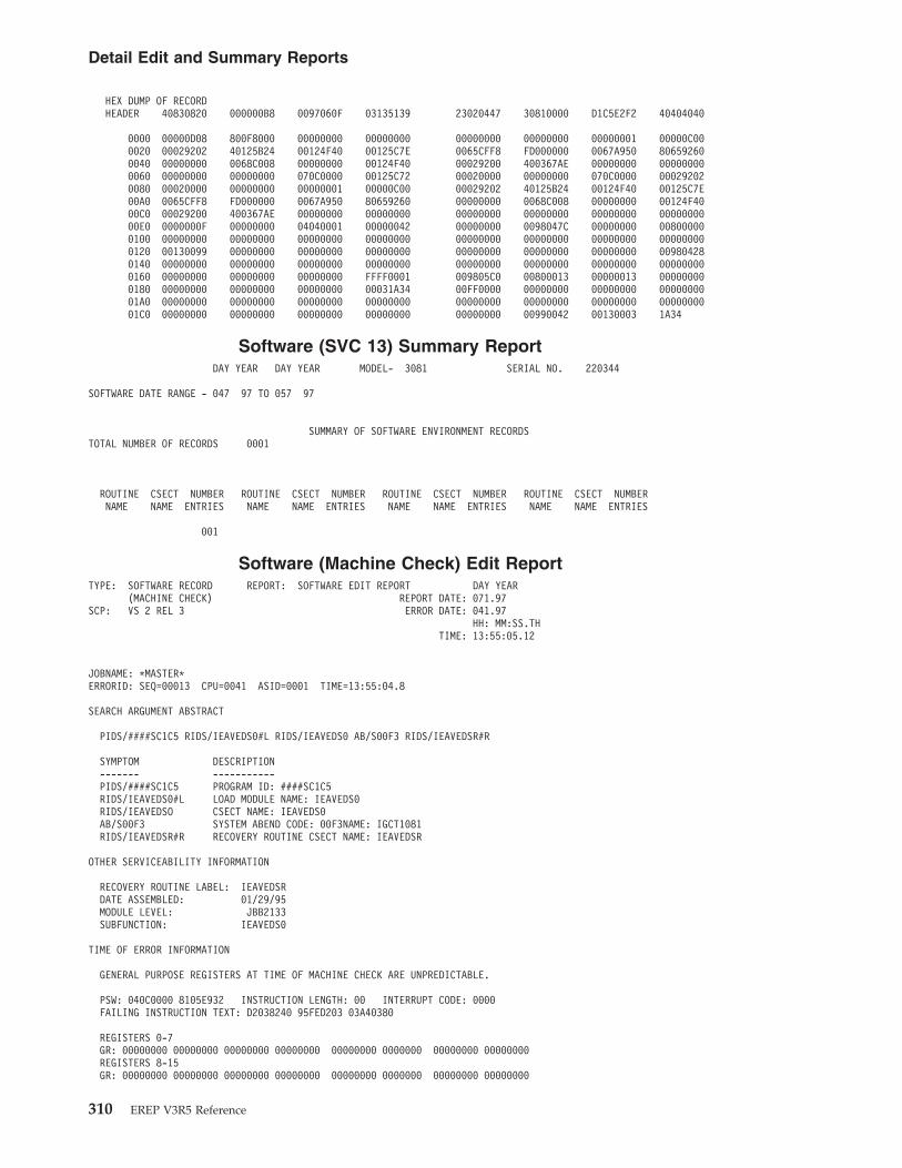
HEX DUMP OF RECORDHEADER 40830820 000000B8 0097060F 03135139 23020447 30810000 D1C5E2F2 40404040
0000 00000D08 800F8000 00000000 00000000 00000000 00000000 00000001 00000C000020 00029202 40125B24 00124F40 00125C7E 0065CFF8 FD000000 0067A950 806592600040 00000000 0068C008 00000000 00124F40 00029200 400367AE 00000000 000000000060 00000000 00000000 070C0000 00125C72 00020000 00000000 070C0000 000292020080 00020000 00000000 00000001 00000C00 00029202 40125B24 00124F40 00125C7E00A0 0065CFF8 FD000000 0067A950 80659260 00000000 0068C008 00000000 00124F4000C0 00029200 400367AE 00000000 00000000 00000000 00000000 00000000 0000000000E0 0000000F 00000000 04040001 00000042 00000000 0098047C 00000000 008000000100 00000000 00000000 00000000 00000000 00000000 00000000 00000000 000000000120 00130099 00000000 00000000 00000000 00000000 00000000 00000000 009804280140 00000000 00000000 00000000 00000000 00000000 00000000 00000000 000000000160 00000000 00000000 00000000 FFFF0001 009805C0 00800013 00000013 000000000180 00000000 00000000 00000000 00031A34 00FF0000 00000000 00000000 0000000001A0 00000000 00000000 00000000 00000000 00000000 00000000 00000000 0000000001C0 00000000 00000000 00000000 00000000 00000000 00990042 00130003 1A34
Software (SVC 13) Summary ReportDAY YEAR DAY YEAR MODEL- 3081 SERIAL NO. 220344
SOFTWARE DATE RANGE - 047 97 TO 057 97
SUMMARY OF SOFTWARE ENVIRONMENT RECORDSTOTAL NUMBER OF RECORDS 0001
ROUTINE CSECT NUMBER ROUTINE CSECT NUMBER ROUTINE CSECT NUMBER ROUTINE CSECT NUMBERNAME NAME ENTRIES NAME NAME ENTRIES NAME NAME ENTRIES NAME NAME ENTRIES
001
Software (Machine Check) Edit ReportTYPE: SOFTWARE RECORD REPORT: SOFTWARE EDIT REPORT DAY YEAR
(MACHINE CHECK) REPORT DATE: 071.97SCP: VS 2 REL 3 ERROR DATE: 041.97
HH: MM:SS.THTIME: 13:55:05.12
JOBNAME: *MASTER*ERRORID: SEQ=00013 CPU=0041 ASID=0001 TIME=13:55:04.8
SEARCH ARGUMENT ABSTRACT
PIDS/####SC1C5 RIDS/IEAVEDS0#L RIDS/IEAVEDS0 AB/S00F3 RIDS/IEAVEDSR#R
SYMPTOM DESCRIPTION------- -----------PIDS/####SC1C5 PROGRAM ID: ####SC1C5RIDS/IEAVEDS0#L LOAD MODULE NAME: IEAVEDS0RIDS/IEAVEDSO CSECT NAME: IEAVEDS0AB/S00F3 SYSTEM ABEND CODE: 00F3NAME: IGCT1081RIDS/IEAVEDSR#R RECOVERY ROUTINE CSECT NAME: IEAVEDSR
OTHER SERVICEABILITY INFORMATION
RECOVERY ROUTINE LABEL: IEAVEDSRDATE ASSEMBLED: 01/29/95MODULE LEVEL: JBB2133SUBFUNCTION: IEAVEDS0
TIME OF ERROR INFORMATION
GENERAL PURPOSE REGISTERS AT TIME OF MACHINE CHECK ARE UNPREDICTABLE.
PSW: 040C0000 8105E932 INSTRUCTION LENGTH: 00 INTERRUPT CODE: 0000FAILING INSTRUCTION TEXT: D2038240 95FED203 03A40380
REGISTERS 0-7GR: 00000000 00000000 00000000 00000000 00000000 0000000 00000000 00000000REGISTERS 8-15GR: 00000000 00000000 00000000 00000000 00000000 0000000 00000000 00000000
Detail Edit and Summary Reports
310 EREP V3R5 Reference

HOME ASID: 0001 PRIMARY ASID: 0000 SECONDARY ASID: 0000PKM: 0000 AX: 0000
RTM WAS ENTERED BECAUSE OF A MACHINE CHECK INTERRUPT.THE ERROR OCCURRED WHILE A LOCKED OR DISABLED ROUTINE WAS IN CONTROL.NO LOCKS WERE HELD.SUPER BITS SET: PSADISP - DISPATCHER
RECOVERY ENVIRONMENT
RECOVERY ROUTINE TYPE: FUNCTIONAL RECOVERY ROUTINE (FRR)PSE AT ENTRY TO FRR: 040C0000 810B09D0SFRR PARAMETER AREA ON ENTRY TO FRR:+00 00000000 00000000 00000000 00000000 00000000 00000000
RECOVERY ROUTINE ACTION
THE RECOVERY ROUTINE RETRIED TO ADDRESS 010AC332.AN SVC DUMP WAS NOT REQUESTED.NO LOCKS WERE REQUESTED TO BE FREED.
THE REGISTER VALUES TO BE USED FOR RETRY:REGISTERS 0-7GR: 00000000 00000000 00000000 00000000 00000000 0000000 00000000 00000000REGISTERS 8-15GR: 00000000 00000000 00000000 00000000 00000000 0000000 00000000 00000000
HEXADECIMAL DUMP
HEADER+000 48831820 00000000 0097041F 13550512 C.......I......+010 00170044 30900000 ........
JOBNAME+000 5CD4C1E2 30900000 *MASTER*
SDWA BASE+000 00F80608 900F3000 00000000 00000000 .8..............+010 00000000 00000000 00000000 00000000 ................+020 00000000 00000000 00000000 00000000 ................+030 00000000 00000000 00000000 00000000 ................+040 00000000 00000000 00000000 00000000 ................+050 00000000 00000000 00000000 00000000 ................+060 00000000 00000000 040C0000 8105E932 ............A.Z.+070 00000000 01BB111E 040C0000 810B09D0 ..... .......A..+080 00000000 01BB111E 00000000 00000000 ..... ..........+090 00000000 00000000 00000000 00000000 ................+0A0 00000000 00000000 00000000 00000000 ................+0B0 00000000 00000000 00000000 00000000 ................+0C0 00000000 00000000 00000000 00000000 ................+0D0 00000000 20440000 00000000 00000000 ................+0E0 98EB91D7 B8A6FE01 80020001 00000041 Q.JP8W..........+0F0 010AC332 00F80AA4 00000000 04880000 ..C..8.U.....H..+100 00000000 00000000 00000000 00000000 ................+110 00000000 00000000 00000000 00000000 ................+120 0001000D C9C5C1E5 C5C4E2F0 C9C5C1E5 ....8EAVEDS0IEAV+130 C5C4E2F0 C9C5C1E5 C5C4E2D9 00F80A50 EDS0IEAVEDSR.8.+140 00000000 00000000 00000000 00000000 ................+150 00000000 00000000 00000000 00000000 ................+160 00000000 00000000 00000000 FFFF0003 ................+170 00F80C70 00000000 00000000 00000000 .8..............+180 00000000 00000000 00000000 0007A538 ..............V.+190 00FF0003 ....
VARIABLE RECORDING AREA (SDWAVRA)+000 KEY: 11 LENGTH: 06+002 C9C8C1D7 E2C1 IHAPSA
+008 KEY: 15 LENGTH: 02+00A 0224 ..
+00C KEY: 12 LENGTH: 04+00E 00FB3080 ....
+012 KEY: 15 LENGTH: 02+014 021C ..
+016 KEY: 12 LENGTH: 04+018 00000000 ....
Detail Edit and Summary Reports
Chapter 13. Detail Edit and Summary Reports 311
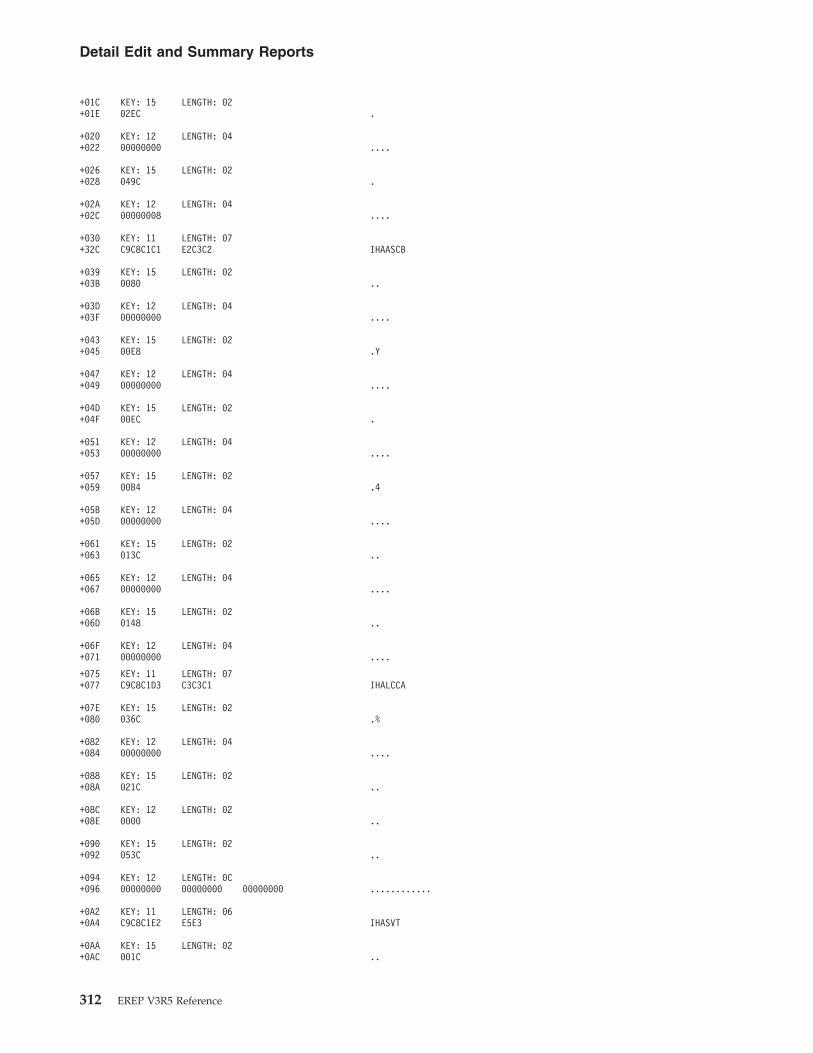
+01C KEY: 15 LENGTH: 02+01E 02EC .
+020 KEY: 12 LENGTH: 04+022 00000000 ....
+026 KEY: 15 LENGTH: 02+028 049C .
+02A KEY: 12 LENGTH: 04+02C 00000008 ....
+030 KEY: 11 LENGTH: 07+32C C9C8C1C1 E2C3C2 IHAASCB
+039 KEY: 15 LENGTH: 02+03B 0080 ..
+03D KEY: 12 LENGTH: 04+03F 00000000 ....
+043 KEY: 15 LENGTH: 02+045 00E8 .Y
+047 KEY: 12 LENGTH: 04+049 00000000 ....
+04D KEY: 15 LENGTH: 02+04F 00EC .
+051 KEY: 12 LENGTH: 04+053 00000000 ....
+057 KEY: 15 LENGTH: 02+059 00B4 .4
+05B KEY: 12 LENGTH: 04+05D 00000000 ....
+061 KEY: 15 LENGTH: 02+063 013C ..
+065 KEY: 12 LENGTH: 04+067 00000000 ....
+06B KEY: 15 LENGTH: 02+06D 0148 ..
+06F KEY: 12 LENGTH: 04+071 00000000 ....
+075 KEY: 11 LENGTH: 07+077 C9C8C1D3 C3C3C1 IHALCCA
+07E KEY: 15 LENGTH: 02+080 036C .%
+082 KEY: 12 LENGTH: 04+084 00000000 ....
+088 KEY: 15 LENGTH: 02+08A 021C ..
+08C KEY: 12 LENGTH: 02+08E 0000 ..
+090 KEY: 15 LENGTH: 02+092 053C ..
+094 KEY: 12 LENGTH: 0C+096 00000000 00000000 00000000 ............
+0A2 KEY: 11 LENGTH: 06+0A4 C9C8C1E2 E5E3 IHASVT
+0AA KEY: 15 LENGTH: 02+0AC 001C ..
Detail Edit and Summary Reports
312 EREP V3R5 Reference
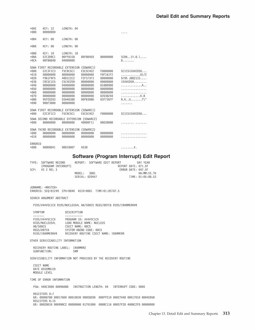
+0AE KEY: 12 LENGTH: 04+0B0 00000000 ....
+0B4 KEY: 00 LENGTH: 00
+0B6 KEY: 00 LENGTH: 00
+0B8 KEY: 10 LENGTH: 18+0BA E2C3D9C1 00FFB1E8 00F804E0 80000000 SCRA..1Y.8.\....+0CA 00F80848 04000000 8.......
SDWA FIRST RECORDABLE EXTENSION (SDWARC1)+000 E2C3F1C3 F5C9C5C1 E5C5C4E2 F0000000 SC1C5IEAVEDS0...+010 00000000 00000000 00000000 F0F161F2 ............01/2+020 F961F9F5 40D1C2C2 F2F1F3F3 00000000 9/95 JBB2133....+030 C9C5C1E5 C5C4E2D9 00000000 00000000 IEAVEDSR........+040 00000000 04000000 00000000 810B09D0 .............A..+050 00000000 00000000 00000000 00000000 ................+060 00000000 00000000 00000000 00000000 ................+070 00000000 00000000 00000000 D2038240 ............K.B+080 95FED203 03A40380 00FB3080 03F7307F N.K..U.......7\"+090 900F3000 00000000 .......
SDWA FIRST RECORDABLE EXTENSION (SDWARC1)+000 E2C3F1C3 F5C9C5C1 E5C5C4E2 F0000000 SC1C5IEAVEDS0...
SDWA SECOND RECORDABLE EXTENSION (SDWARC2)+000 00000000 00000000 40000F11 00030000 ........ .......
SDWA THIRD RECORDABLE EXTENSION (SDWARC2)+000 00000000 00000000 00000000 00000000 ................+010 00000000 00000000 00000000 00000000 ................
ERRORID+000 000D0041 00010007 A538 ........V.
Software (Program Interrupt) Edit ReportTYPE: SOFTWARE RECORD REPORT: SOFTWARE EDIT REPORT DAY YEAR
(PROGRAM INTERRUPT) REPORT DATE: 071.97SCP: VS 2 REL 3 ERROR DATE: 047.97
MODEL: 3081 HH:MM:SS.THSERIAL: 020447 TIME: 01:05:08.53
JOBNAME: *MASTER*ERRORID: SEQ=01249 CPU=0040 ASID=0001 TIME=01:05l07.5
SEARCH ARGUMENT ABSTRACT
PIDS/####SC1CX RIDS/NUCLEUS#L AB/S00C5 REGS/097C6 RIDS/IRARMERR#R
SYMPTOM DESCRIPTION------- -----------PIDS/####SC1CX PROGRAM ID: ####SC1CXRIDS/NUCLEUS#L LOAD MODULE NAME: NUCLEUSAB/S00C5 CSECT NAME: 00C5REGS/097C6 SYSTEM ABEND CODE: 00C5RIDS/IRARMERR#R RECOVERY ROUTINE CSECT NAME: IRARMERR
OTHER SERVICEABILITY INFORMATION
RECOVERY ROUTINE LABEL: IRARMRR2SUBFUNCTION: SRM
SERVICEABILITY INFORMATION NOT PROVIDED BY THE RECOVERY ROUTINE
CSECT NAMEDATE ASSEMBLEDMODULE LEVEL
TIME OF ERROR INFORMATION
PSW: 440C3000 0009A088 INSTRUCTION LENGTH: 04 INTERRUPT CODE: 0005
REGISTERS 0-7GR: 00000780 000176D0 0001D030 000E8E00 000FFE10 00027A48 00017010 8004E858REGISTERS 8-15GR: 00028010 000998C2 00000000 01701000 000BC116 00057F28 400BC2F0 00000000
Detail Edit and Summary Reports
Chapter 13. Detail Edit and Summary Reports 313
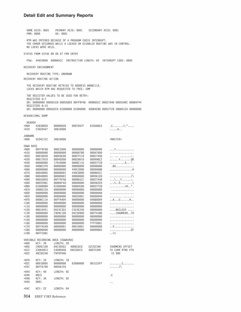
HOME ASID: 0001 PRIMARY ASID: 0001 SECONDARY ASID: 0001PKM: 0000 AX: 0001
RTM WAS ENTERED BECAUSE OF A PROGRAM CHECK INTERRUPT.THE ERROR OCCURRED WHILE A LOCKED OR DISABLED ROUTINE WAS IN CONTROL.NO LOCKS WERE HELD.
STATUS FROM ESTAE RB OR AT FRR ENTRY
PSW: 440C0000 000B65CC INSTRUCTION LENGTH: 04 INTERRUPT CODE: 0005
RECOVERY ENVIRONMENT
RECOVERY ROUTINE TYPE: UNKNOWN
RECOVERY ROUTINE ACTION
THE RECOVERY ROUTINE RETRIED TO ADDRESS 000BC11A.LOCKS WHICH RTM HAS REQUESTED TO FREE: SRM
THE REGISTER VALUES TO BE USED FOR RETRY:REGISTERS 0-7GR: 00000000 000561E0 000558E0 00FF9FA8 000B65CC 00027A48 0005596C 800B4F44REGISTERS 8-15GR: 00000000 000562E0 01000000 01000000 500B4EB0 00057F28 500B51EA 00000000
HEXADECIMAL DUMP
HEADER+000 42830820 00000028 0097047F 01050853 .C.......I."....+010 23020447 30810000 .....A..
JOBNAME+000 5CD4C1E2 30810000 *MASTER*
SDWA BASE+000 00FF9FA8 900C5000 00000000 00000000 ...Y............+010 00000000 00000000 00000780 000A76D0 ................+020 0001D030 000E8E00 000FFE10 00027A48 .. ... .......:.+030 00017010 8004E858 00028010 000998C2 ......Y.......QB+040 00000000 17010000 000BC116 00057F28 ..........A...".+050 400BC2F0 00000000 00000000 00000000 .BO............+060 00000000 00000000 440C3000 0009A088 ...............H+070 00040005 80000003 440C0000 000B65CC ................+080 00040005 80000003 00000000 000561E0 ............../\+090 000558E0 00FF9FA8 000B65CC 00027A48 ...\...Y......:.+0A0 0005596C 800B4F44 00000000 000562E0 ...%..Û........\+0B0 01000000 01000000 500B4EB0 00057F28 ..........+0..".+0C0 500B51EA 00000000 00000000 00000000 ...............+0D0 00000000 00000000 00000000 00000000 ................+0E0 00000000 00000000 40020001 00000040 ........ .......+0F0 000BC11A 00FFA404 00000000 04880004 ..A...U......H..+100 00000000 00000000 00000000 00000000 ................+110 00000000 00000000 00000000 00000000 ................+120 000104E1 D5E4C3D3 C5E4E240 00000000 ....NUCLEUS ....+130 00000000 C9D9C1D9 D4C5D9D9 00FFA380 ....IRARMERR..T0+140 00000000 00000000 00000000 00000000 ................+150 00000000 00000000 00000000 00000000 ................+160 00000000 00000000 00000000 FFFF0001 ................+170 00FFA548 00000001 00010001 00000000 ..V.............+180 00000000 00000000 00000000 000098A3 ..............QT+190 00FFE06C ..\%
VARIABLE RECORDING AREA (SDWAVRA)+000 KEY: 39 LENGTH: 28+002 C9D9C1D9 D4C3D5E2 40D6C6C6 E2C5E340 IRARMCNS OFFSET+012 E3D640C3 E4D9D940 D9E3D5C5 40D7E3D9 TO CURR RTNE PTR+022 40C9E240 F9F0F040 IS 900
+02A KEY: 10 LENGTH: 18+02C 00010005 00000000 83080000 003125FF ........C.......+03C 00FF6790 000561E0 ....../\
+044 KEY: 40 LENGTH: 02+046 00C5 .E+048 KEY: 3A LENGTH: 02+04A 0001 ..
+04C KEY: 22 LENGTH: 04
Detail Edit and Summary Reports
314 EREP V3R5 Reference
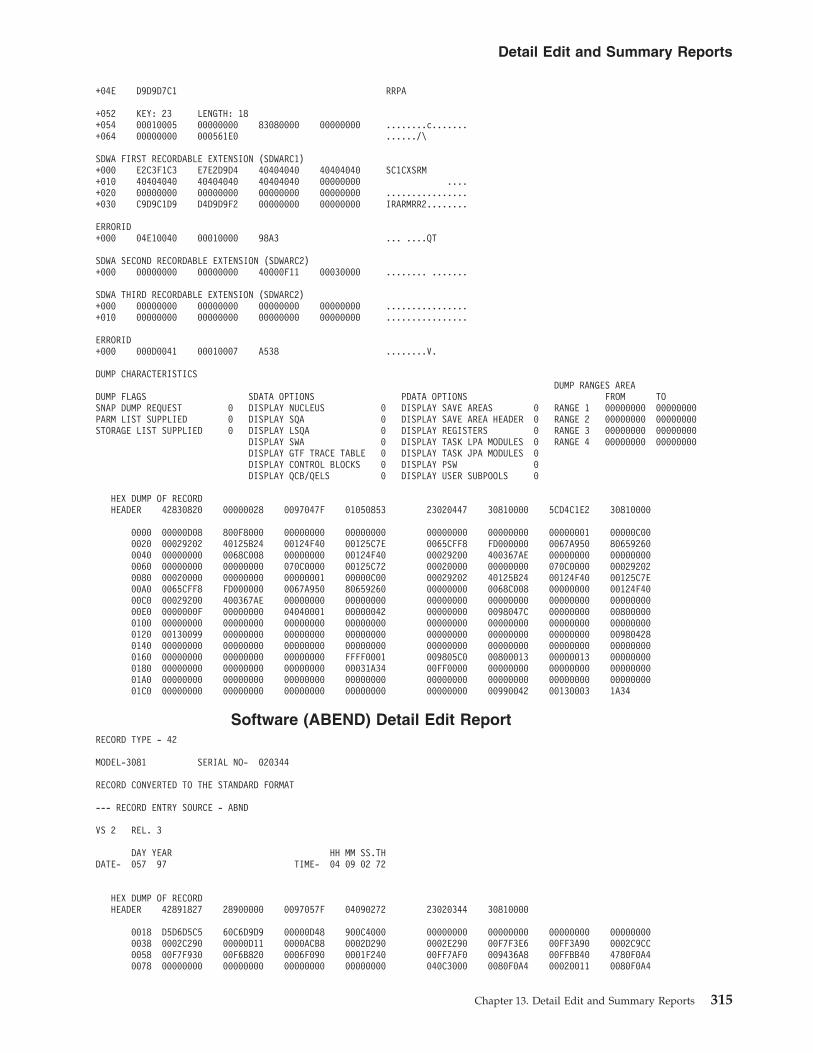
+04E D9D9D7C1 RRPA
+052 KEY: 23 LENGTH: 18+054 00010005 00000000 83080000 00000000 ........c.......+064 00000000 000561E0 ....../\
SDWA FIRST RECORDABLE EXTENSION (SDWARC1)+000 E2C3F1C3 E7E2D9D4 40404040 40404040 SC1CXSRM+010 40404040 40404040 40404040 00000000 ....+020 00000000 00000000 00000000 00000000 ................+030 C9D9C1D9 D4D9D9F2 00000000 00000000 IRARMRR2........
ERRORID+000 04E10040 00010000 98A3 ... ....QT
SDWA SECOND RECORDABLE EXTENSION (SDWARC2)+000 00000000 00000000 40000F11 00030000 ........ .......
SDWA THIRD RECORDABLE EXTENSION (SDWARC2)+000 00000000 00000000 00000000 00000000 ................+010 00000000 00000000 00000000 00000000 ................
ERRORID+000 000D0041 00010007 A538 ........V.
DUMP CHARACTERISTICSDUMP RANGES AREA
DUMP FLAGS SDATA OPTIONS PDATA OPTIONS FROM TOSNAP DUMP REQUEST 0 DISPLAY NUCLEUS 0 DISPLAY SAVE AREAS 0 RANGE 1 00000000 00000000PARM LIST SUPPLIED 0 DISPLAY SQA 0 DISPLAY SAVE AREA HEADER 0 RANGE 2 00000000 00000000STORAGE LIST SUPPLIED 0 DISPLAY LSQA 0 DISPLAY REGISTERS 0 RANGE 3 00000000 00000000
DISPLAY SWA 0 DISPLAY TASK LPA MODULES 0 RANGE 4 00000000 00000000DISPLAY GTF TRACE TABLE 0 DISPLAY TASK JPA MODULES 0DISPLAY CONTROL BLOCKS 0 DISPLAY PSW 0DISPLAY QCB/QELS 0 DISPLAY USER SUBPOOLS 0
HEX DUMP OF RECORDHEADER 42830820 00000028 0097047F 01050853 23020447 30810000 5CD4C1E2 30810000
0000 00000D08 800F8000 00000000 00000000 00000000 00000000 00000001 00000C000020 00029202 40125B24 00124F40 00125C7E 0065CFF8 FD000000 0067A950 806592600040 00000000 0068C008 00000000 00124F40 00029200 400367AE 00000000 000000000060 00000000 00000000 070C0000 00125C72 00020000 00000000 070C0000 000292020080 00020000 00000000 00000001 00000C00 00029202 40125B24 00124F40 00125C7E00A0 0065CFF8 FD000000 0067A950 80659260 00000000 0068C008 00000000 00124F4000C0 00029200 400367AE 00000000 00000000 00000000 00000000 00000000 0000000000E0 0000000F 00000000 04040001 00000042 00000000 0098047C 00000000 008000000100 00000000 00000000 00000000 00000000 00000000 00000000 00000000 000000000120 00130099 00000000 00000000 00000000 00000000 00000000 00000000 009804280140 00000000 00000000 00000000 00000000 00000000 00000000 00000000 000000000160 00000000 00000000 00000000 FFFF0001 009805C0 00800013 00000013 000000000180 00000000 00000000 00000000 00031A34 00FF0000 00000000 00000000 0000000001A0 00000000 00000000 00000000 00000000 00000000 00000000 00000000 0000000001C0 00000000 00000000 00000000 00000000 00000000 00990042 00130003 1A34
Software (ABEND) Detail Edit ReportRECORD TYPE - 42
MODEL-3081 SERIAL NO- 020344
RECORD CONVERTED TO THE STANDARD FORMAT
--- RECORD ENTRY SOURCE - ABND
VS 2 REL. 3
DAY YEAR HH MM SS.THDATE- 057 97 TIME- 04 09 02 72
HEX DUMP OF RECORDHEADER 42891827 28900000 0097057F 04090272 23020344 30810000
0018 D5D6D5C5 60C6D9D9 00000D48 900C4000 00000000 00000000 00000000 000000000038 0002C290 00000D11 0000ACB8 0002D290 0002E290 00F7F3E6 00FF3A90 0002C9CC0058 00F7F930 00F6B820 0006F090 0001F240 00FF7AF0 009436A8 00FFBB40 4780F0A40078 00000000 00000000 00000000 00000000 040C3000 0080F0A4 00020011 0080F0A4
Detail Edit and Summary Reports
Chapter 13. Detail Edit and Summary Reports 315

0098 040C0000 0002FC54 00020011 0080F0A4 2EA80047 00FFB770 00FF0F6C 00FFBB4000B8 400301F0 0002C290 00000D48 000037D8 0002D290 0002E290 2EA70046 00000C0000D8 00000D40 00FF7AF0 9002EF4A 00071B28 00000000 00000000 00000000 0000000000F8 00000000 00000000 00000000 00000000 40030801 00000040 0002C5C4 00FFB9040118 00000000 048800C0 00000000 000039D0 0001F0C8 00000000 00000000 000000000138 00000000 00000000 000101D1 C9C5C3C9 D6E2C1D4 C9C5C3C9 D6E2C3D5 C9C5C3C60158 D9D94040 00FFB8B0 00000000 00000000 00000000 00000000 00000000 000000000178 00000000 00000000 00000000 00000000 00000000 FFFF0001 00FFBA48 800000010198 00010001 00000000 00000000 00000000 00000000 000247A8 00FF0038 C000000001B8 FFFFFFFF 403CFF80 00FF0F6C 00000040 00FF3AA4 0000FF82 03D10000 7001050001D8 00F3C4F1 12501009 00011C2C 40E4E9F6 F1F1F8F0 E2C3F1C3 F3000000 0000000001F8 00000000 00000000 00000000 00000000 00000000 00000000 00000000 000000000218 00000000 00000000 00000000 00000000 00000000 01D10040 00010002 47A8
Software (ABEND) Summary ReportSUMMARY OF 40 RECORDS
DAY YEAR DAY YEARRECORD DATE RANGE 057 97 057 97
MODEL - 3081 SERIAL NO - 020344
TOTAL NUMBER OF RECORDS=0002
CLASSES ENCOUNTERED(MAXIMUM OF 10)
RECORD CLASS -42 0002
Software (MCH Called RTM) Detail Edit ReportDATE TIME CPU CPUDAY YR HH MM SS.TH SERIAL ID
--- RECORD ENTRY SOURCE - SOFTWARE --- TYPE MCH CALLED RTM 047 97 10 39 39 87 270044 3090
VS 2 REL. 3
ERRORID=SEQ00030 CPU0041 ASID0001 TIME10.39.38.9
JOBNAME *MASTER*ABENDING PROGRAM NAME N/A BC MODE PSW AT TIME OF ERROR BC MODE PSW OF LAST RBNAME OF MODULE INVOLVED IEAVEDS0NAME OF CSECT INVOLVED IEAVEDS0 00000000 00000000 00000000 00000000FUNCTIONAL RECOVERY ROUTINE IEAVEDSR
REGS AT TIME OF ERROR
REGS 0-7 00000000 00000000 00000000 00000000 00000000 00000000 00000000 00000000REGS 8-15 00000000 00000000 00000000 00000000 00000000 00000000 00000000 00000000
EC PSW AT TIME OF ABEND 00000000 00000000 EC PSW FROM ESTAE RB(0 FOR ESTAI) 040C0000 0005B5E0ADDITIONAL INFO: ADDITIONAL INFO:INST LENGTH CODE 00 INST LENGTH CODE 00INTERRUPT CODE 0000 INTERRUPT CODE 0000VIRT ADDR OF TRANS EXCEP 00154FE0 VIRT ADDR OF TRANS EXCEP 00154FE0
REGS OF RB LEVEL OF ESTAE EXIT OR ZERO FOR ESTAI
REGS 0-7 00000000 00000000 00000000 00000000 00000000 00000000 00000000 00000000REGS 8-15 00000000 00000000 00000000 00000000 00000000 00000000 00000000 00000000
MCH FLAG BYTE MCK INPUT INFO FRAME ERROR INDICATORS STORAGE ERROR INDICATORSSTORAGE ADDRS ARE VALID 0 STORAGE KEY FAILURE 0 STORAGE ERROR ALREADY SET 0 FRAME OFFLINE(OR SCHED) 0MCK RECORD NOT RECORDED 0 REGISTERS UNPREDICTABLE 1 CHANGE INDICATOR ON 0 INTERCEPT 0TIME STAMP IS VALID 1 PSW UNPREDICTABLE 1 STORAGE ERROR PERMANENT 0STORAGE IS RECONFIGURED 0 STORAGE DATA CHECK 0 PERMANENT RES. STORAGE 0RECONFIGURE STATUS AVAIL 0 ACR REQUEST 1 FRAME IN SQA 0RECONFIGURE NOT ATTEMPTED 0 INSTRUCTION FAILURE 0 FRAME IN LSQA 0
SOFT ERROR 0 FRAME IS PAGE FIXED 0TIMER ERROR 0 FRAME IS V=R 0
TIME STAMP OF ASSOCIATED MACHINE CHECK RECORDBEGINNING VIRT ADDR OF STORAGE CHECK 00000000 DATE TIMEENDING VIRT ADDR OF STORAGE CHECK 00000000 DAY YR HH MM SS.THREAL STORAGE FAILING ADDRESS 00000000 057 97 10 39 39 00
MACHINE CHECK 1 TYPE 1 SVC IN CONTROL 0 PREV ESTA OR FRR FAILED 0 EXIT TO CLEANUP ONLY 0PROGRAM CHECK 0 ENABLED RB IN CONTROL 0 (E)STAI PREV IN CONTROL 0 RB OF ESTA NOT IN CONTROL 0RESTART KEY DEPRESSED 0 DISABLED RTN IN CONTROL 1 IRB PRECEDED RB 0 ESTA EXIT FOR PREV ABEND 0
Detail Edit and Summary Reports
316 EREP V3R5 Reference

TASK ISSUED SVC 13 0 SYSTEM IN SRB MODE 0 THIS RTN PERCOLATED TO 0 STEP ABEND REQUESTED 0SYSTEM FORCED SVC 13 0 LOWER LEVEL EXIT INFO 0 TASK ANCESTOR ABENDED 0SVC BY LOCKED OR SRB RTN 0 REGS AND PSW UNAVAILABLE 0TRANSLATION FAILURE 0 MCK INFO UNAVAILABLE 0PAGE I/O ERROR 0
CURRENT I/O STATUSMEMORY ASID 0000 I/O IS RESTORABLE 0RECOVERY RETURN CODE 04 I/O IS NOT RESTORABLE 0
NO I/O OUTSTANDING 0NO I/O PROCESSING 0
ADDITIONAL PROCESSING GLOBAL LOCKS TO BE FREED LOCKWORDSRECORDING REQUESTED 1 DISPATCHER LOCK 0VALID SPIN 0 SRM LOCK 0UPDATED REGS FOR RETRY 1 IOSCAT LOCK 0 IOSCAT LOCKWORD 00000000FREE RTCA BEFORE RETRY 0 IOSUCB LOCK 0 IOSUCB LOCKWORD 00000000
IOSLCH LOCK 0 IOSLCH LOCKWORD 00000000IOSYNCH LOCK 0 IOSYNCH LOCKWORD 00000000NCB LOCK 0 NCB LOCKWORD 00000000DNCB LOCK 0 DNCB LOCKWORD 00000000ACBDEBS LOCK 0 ACBDEBS LOCKWORD 00000000ASMPAT LOCK 0 ASMPAT LOCKWORD 00000000SALLOC LOCK 0 ASID CURRENT 0001CMS LOCK 0LOCAL LOCK 0
DUMP CHARACTERISTICSDUMP RANGES AREA
DUMP FLAGS SDATA OPTIONS PDATA OPTIONS FROM TOSNAP DUMP REQUEST 0 DISPLAY NUCLEUS 0 DISPLAY SAVE AREAS 0 RANGE 1 00000000 00000000PARM LIST SUPPLIED 0 DISPLAY SQA 0 DISPLAY SAVE AREA HEADER 0 RANGE 2 00000000 00000000STORAGE LIST SUPPLIED 0 DISPLAY LSQA 0 DISPLAY REGISTERS 0 RANGE 3 00000000 00000000
DISPLAY SWA 0 DISPLAY TASK LPA MODULES 0 RANGE 4 00000000 00000000DISPLAY GTF TRACE TABLE 0 DISPLAY TASK JPA MODULES 0DISPLAY CONTROL BLOCKS 0 DISPLAY PSW 0DISPLAY QCB/QELS 0 DISPLAY USER SUBPOOLS 0
HEX DUMP OF RECORDHEADER 48891820 00000000 0097047F 10393987 00270044 30900000 5CD4C1E2 E3C5D95C
0000 00FF6648 900F3000 00000000 00000000 00000000 00000000 00000000 000000000020 00000000 00000000 00000000 00000000 00000000 00000000 00000000 000000000040 00000000 00000000 00000000 00000000 00000000 00000000 00000000 000000000060 00000000 00000000 00000000 00000000 00000000 00154FE0 040C0000 0005B5E00080 00000000 00154FE0 00000000 00000000 00000000 00000000 00000000 0000000000A0 00000000 00000000 00000000 00000000 00000000 00000000 00000000 0000000000C0 00000000 00000000 00000000 00000000 00000000 20680001 00000000 0000000000E0 9885057F 10393900 80020001 00000041 00096212 00FF6AE4 00000000 048800000100 00000000 00000000 00000000 00000000 00000000 00000000 00000000 000000000120 0001001E C9C5C1E5 C5C4E2F0 C9C5C1E5 C5C4E2F0 C9C5C1E5 C5C4E2D9 00FF6A900140 00000000 00000000 00000000 00000000 00000000 00000000 00000000 000000000160 00000000 00000000 00000000 FFFF0001 00FF6C28 00000000 00000000 000000000180 00000000 00000000 00000000 0005DB2D 00FFA0D2 1106C9C8 C1D7E2C1 1502022401A0 12040002 40B81502 021C1204 00000000 150202EC 12040000 00001502 049C120401C0 00000008 1107C9C8 C1C1E2C3 C2150200 80120400 00000015 0200E812 0400000001E0 00150200 EC120400 00000015 0200B412 04000000 00150201 3C120400 000000150200 02014812 04000000 001107C9 C8C1D3C3 C3C11502 036C1204 00000000 1502021C0220 12028000 1502053C 120C0000 00000000 00000000 00001106 C9C8C1E2 E5E315020240 001C1204 00000000 00000000 1018E2C3 D9C1000E 9BB000FF 65408000 000000FF0260 68880400 0000E2C3 F1C3F5C9 C5C1E5C5 C4E2F000 00000000 00000000 000000000280 0000F1F1 61F2F761 F8F440D1 C2C2F1F3 F5F60000 0000C9C5 C1E5C5C4 E2D9000002A0 00000000 0000001E 00410001 0005DB2D
Software (MCH Called RTM) Summary ReportDAY YEAR DAY YEAR MODEL- 3090 SERIAL NO. 270044
SOFTWARE DATE RANGE - 047 97 TO 047 97
SUMMARY OF SOFTWARE ENVIRONMENT RECORDSTOTAL NUMBER OF RECORDS 0001
ROUTINE CSECT NUMBER ROUTINE CSECT NUMBER ROUTINE CSECT NUMBER ROUTINE CSECT NUMBERNAME NAME ENTRIES NAME NAME ENTRIES NAME NAME ENTRIES NAME NAME ENTRIES
IEAVEDS0 IEAVEDS0 001
Detail Edit and Summary Reports
Chapter 13. Detail Edit and Summary Reports 317
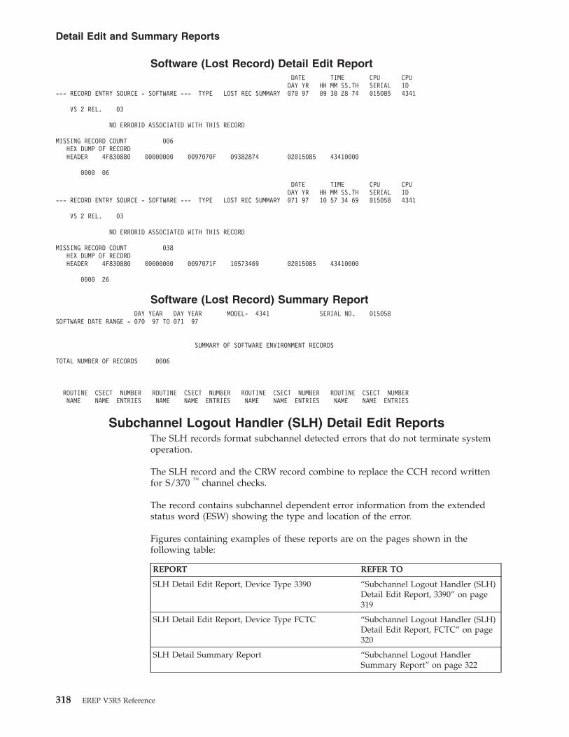
Software (Lost Record) Detail Edit ReportDATE TIME CPU CPUDAY YR HH MM SS.TH SERIAL ID
--- RECORD ENTRY SOURCE - SOFTWARE --- TYPE LOST REC SUMMARY 070 97 09 38 28 74 015085 4341
VS 2 REL. 03
NO ERRORID ASSOCIATED WITH THIS RECORD
MISSING RECORD COUNT 006HEX DUMP OF RECORDHEADER 4F830880 00000000 0097070F 09382874 02015085 43410000
0000 06
DATE TIME CPU CPUDAY YR HH MM SS.TH SERIAL ID
--- RECORD ENTRY SOURCE - SOFTWARE --- TYPE LOST REC SUMMARY 071 97 10 57 34 69 015058 4341
VS 2 REL. 03
NO ERRORID ASSOCIATED WITH THIS RECORD
MISSING RECORD COUNT 038HEX DUMP OF RECORDHEADER 4F830880 00000000 0097071F 10573469 02015085 43410000
0000 26
Software (Lost Record) Summary ReportDAY YEAR DAY YEAR MODEL- 4341 SERIAL NO. 015058
SOFTWARE DATE RANGE - 070 97 TO 071 97
SUMMARY OF SOFTWARE ENVIRONMENT RECORDS
TOTAL NUMBER OF RECORDS 0006
ROUTINE CSECT NUMBER ROUTINE CSECT NUMBER ROUTINE CSECT NUMBER ROUTINE CSECT NUMBERNAME NAME ENTRIES NAME NAME ENTRIES NAME NAME ENTRIES NAME NAME ENTRIES
Subchannel Logout Handler (SLH) Detail Edit ReportsThe SLH records format subchannel detected errors that do not terminate systemoperation.
The SLH record and the CRW record combine to replace the CCH record writtenfor S/370 ™ channel checks.
The record contains subchannel dependent error information from the extendedstatus word (ESW) showing the type and location of the error.
Figures containing examples of these reports are on the pages shown in thefollowing table:
REPORT REFER TO
SLH Detail Edit Report, Device Type 3390 “Subchannel Logout Handler (SLH)Detail Edit Report, 3390” on page319
SLH Detail Edit Report, Device Type FCTC “Subchannel Logout Handler (SLH)Detail Edit Report, FCTC” on page320
SLH Detail Summary Report “Subchannel Logout HandlerSummary Report” on page 322
Detail Edit and Summary Reports
318 EREP V3R5 Reference

REPORT REFER TO
SLH Detail Edit Report for zHPF “Subchannel Logout Handler (SLH)Detail Edit Report for zHPF” onpage 322
SLH Detail Summary Report for zHPF “Subchannel Logout HandlerSummary Report for zHPF” on page324
Subchannel Logout Handler (SLH) Detail Edit Report, 3390DEVICE NUMBER: 01000 REPORT: SLH EDIT DAY YEAR JOB IDENTITY: CHNDRV
SCP: MVS/XA V2 R1 DATE: 260 04 C3C8D5C4D9E54040DEVICE TYPE: 3390
CPU MODEL: 2084XA HH MM SS.THCHANNEL PATH ID: 12 LOGICAL CPU ID: 170044 TIME: 06 54 28.40
PHYSICAL CHAN ID: 0290 PHYSICAL CPU ADDRESS: 07 �1�
CC CA FL CTFAILING CCW 31 C3605A 40 00 0005 VOLUME SERIAL 1D01D0
SUBCHANNEL ID NUMBER 00010018K FLAGS CA US SS CT ERROR TYPE OTHER �2�
SCSW 84 024017 0032F0F8 00 04 0000
---UNIT STATUS---- SUB-CHANNEL STATUS --------------------------SCSW FLAGS------------------------FLAG 0 �3� FLAG 1 FLAG 2
ATTENTION 0 PGM-CTLD IRPT 0 CCW FORMAT 0 RESERVED 0 SUBCHANNEL ACTIV 0STATUS MODIFIER 0 INCORRECT LENGTH 0 PRE-FETCH CCW 0 SSCH FUNCTION 1 DEVICE ACTIVE 0CONTROL UNIT END 0 PROGRAM CHECK 0 INIT STATUS 0 HSCH FUNCTION 0 SUSPENDED 0BUSY 0 PROTECTION CHECK 0 ADDR LIMIT 0 CSCH FUNCTION 0 ALERT STATUS 1CHANNEL END 0 CHAN DATA CHECK 0 SUPP SUSPEND INT 0 RESUME PENDING 0 INTERMED STATUS 0DEVICE END 0 CHAN CTL CHECK 1 ZERO COND CODE 0 START PENDING 0 PRIMARY STATUS 1UNIT CHECK 0 I/F CTL CHECK 0 EXTENDED CONTROL 1 HALT PENDING 0 SECONDARY STATUS 1UNIT EXCEPTION 0 CHAINING CHECK 0 PATH NOT OPER 0 CLEAR PENDING 0 STATUS PENDING 1
----SOFTWARE RECOVERY STATUS-----
HARD FAIL 0DEGRADE FAIL 0SOFT FAIL 0PASSED 0
CHANNEL ERROR ANALYSIS
IRB STORED BY INTERRUPT
TERMINATION BY -- SELECTIVE RESET -- CODE 2
SEQ CODE 2 - COMMAND ACCEPTED BY DEVICE BUT NO DATA TRANSFERREDVALIDITY OF RECORDED DATA
COUNT INVALIDTERMINATION CODE VALIDSEQUENCE CODE VALIDDEVICE STATUS INVALIDCCW ADDRESS VALIDDEVICE NUMBER VALIDSENSE DATA NOT STORED
*MODEL-DEPENDENT DATA*
HARDWARE CHECKS-------(BYTE 0) MICROPROGRAM ERROR ID-(BYTE 1) LOG ID----------------(BYTE 2) PRESENT STATUS BYTE---(BYTE 3)00 ** 01 25
REFER TO INCIDENT LOG 1IO INTERFACE TIME OUT 0MICROPROGRAM DETECT ERR 0INVAL IO INTERF TAG SEQ 0IO ALERT (DISCONN IN) 0MULT IO INTERF IN TAGS 0IO INTERF BUS IN PAR ERR 0INJECTED ERROR 0SERV OR DAT TAG DUR SHORT 0SERVICE/DATA ACTIVE 0OPERATIONAL IN FELL EARLY 0
CHANNEL TAG CONTROL 1-(BYTE 4) CHANNEL TAG CONTROL 2-(BYTE 5) I/O BUS IN------------(BYTE 6) UNIT ADDRESS----------(BYTE 7)A0 C1 00 D0
OPERATIONAL OUT 1 OPERATIONAL IN 1ADDRESS OUT 0 STATUS IN 1SELECT OUT 1 SELECT IN 0* BUS OUT TAG 0 ADDRESS IN 0
Detail Edit and Summary Reports
Chapter 13. Detail Edit and Summary Reports 319

* SERVICE OUT 0 REQUEST IN 0* DATA OUT 0 SERVICE OR DATA IN 0SUPPRESS OUT 0 FIRST DATA 0COMMAND OUT 0 COMMAND SENT 1
USTATS/CONFIG---------(BYTE 8) CUCW STATUS-----------(BYTE 9) CONFIGURATION BYTE 0-(BYTE 10) CONFIGURATION BYTE 1-(BYTE 11)06 00 70 88
ENABLE SIM IO 0 RESERVED 0ENABLE TIMEOUT CHECK 1 TYPE 1 CONTROL UNIT 0ENABLE DEV TRACE 1 TYPE 2 CONTROL UNIT 1INTERLOCK PROTOCOL 00 0 RESERVED 0INTERLOCK PROTOCOL 01 0 DYNAMIC PATHING 0STREAMING PROTOCOL 1 RESERVED 0RESERVED 0 IOCP CONFIGURED 1BYTE MULTIPLEX 0 RESERVED 0RESERVED 0 RESERVED 0RESERVED 0 RESERVED 0
PHYSICAL PATH--------(BYTE 12) ZERO-----------------(BYTE 13) ZERO-----------------(BYTE 14) ZERO-----------------(BYTE 15)12 00 34 82
CHANNEL LOGOUT DATA
0000 00000000 00000002 00000000 00000000 00000002 00000000 00000000 000000000020 00000000 00000000 00000000 00000000 00000000 9000AB00 80000000 000000000040 00000000 00693713 00006942 10000800 88A0745E 10000800 88A0745E 500507640060 01006573 50050764 00C890CC 001A0047 00000000 00000000 0800009B 000000000080 22000022 00000000 02000000 18100020 50050769 00C414E7 00000000 0000000000A0 00800100 30303231 30373030 3049424D 30303030 30303030 30303030 3030021100C0 00000000 00000000 00000000 00000000 00000000 00000000 00000000 0000000000E0 00000000 00000000 00000000 00000000 00000000 00000000 00000000 00000000
CONTROL UNIT LOGOUT DATA
0000 00000000 00000000 00000000 00000000 00000000 00000000 00000000 000000000020 00000000 00000000 00000000 00000000 00000000 00000000 00000000 000000000040 00000000 00000000 00000000 00000000 00000000 00000000 00000000 000000000060 00000000 00000000 00000000 00000000 00000000 00000000 00000000 000000000080 00000000 00000000 00000000 00000000 00000000 00000000 00000000 0000000000A0 00000000 00000000 00000000 00000000 00000000 00000000 00000000 0000000000C0 00000000 00000000 00000000 00000000 00000000 00000000 00000000 0000000000E0 00000000 00000000 00000000 00000000 00000000 00000000 00000000 00000000
HEX DUMP OF RECORD
HEADER 23831800 00030000 0004260F 10483163 000190CC 208480000018 C3C8C4C4 F3F14040 04200020 00FFF420 801F2024 00000000 00000000 04C240170038 00861A38 00020000 00406480 20000000 40000000 00000000 00000000 000000000058 00000000 00000000 00000000 00000000 00000000 00000001 00A000A8 020968080078 1003D4D4 F1F0F0F2 01000000 01010091 00018EAE 00000000 00000000 000000000098 800002A0 00000001 000000B8 02000100 00000000 00000000 00000000 0000000000B8 00000000 00000002 00000000 00000000 00000002 00000000 00000000 0000000000D8 00000000 00000000 00000000 00000000 0C000000 9000AB00 80000000 0000000000F8 00000000 00693713 00006942 10000800 88A0745E 10000800 88A0745E 500507640118 01006573 50050764 00C890CC 001A0047 00000000 00000000 0800009B 000000000138 22000022 00000000 02000000 18100020 50050769 00C414E7 00000000 000000000158 00800100 30303231 30373030 3049424D 30303030 30303030 30303030 303002110178 00000000 00000000 00000000 00000000 00000000 00000000 00000000 000000000198 00000000 00000000 00000000 00000000 00000000 00000000 00000000 0000000001B8 00000000 00000000 00000000 00000000 00000000 00000000 00000000 0000000001D8 00000000 00000000 00000000 00000000 00000000 00000000 00000000 0000000001F8 00000000 00000000 00000000 00000000 00000000 00000000 00000000 000000000218 00000000 00000000 00000000 00000000 00000000 00000000 00000000 000000000238 00000000 00000000 00000000 00000000 00000000 00000000 00000000 000000000258 00000000 00000000 00000000 00000000 00000000 00000000 00000000 000000000278 00000000 00000000 00000000 00000000 00000000 00000000 00000000 000000000298 00000000 00000000 00000000 00000000 00000000 00000000 00000000 00000000
�1� The SLH record is logged in 370XA mode only. It is identified by CPUcomplex, not individual CPU ID number. Only the last 5 digits aresignificant. In PR/SM environments, the logical and physical CPU IDs areidentified.
�2� The error type may be storage, key, or other. If the error type is storage orkey, a line containing the absolute address of the error is printed.
�3� CCW format is 0 in 24-bit addressing mode, 1 in 31-bit addressing mode.
Subchannel Logout Handler (SLH) Detail Edit Report, FCTCDEVICE NUMBER: 00E26 REPORT: SLH EDIT DAY YEAR JOB IDENTITY: XCFAR
SCP: VS 2 REL. 3 DATE: 260 04 E7C3C6C1D9404040DEVICE NED: 002105.000.IBM.075.000000012252.0615DEVICE TYPE: FCTC
CPU MODEL: 2084XA HH MM SS.THCHANNEL PATH ID: A4 LOGICAL CPU ID: 1084XA TIME: 22 38 05.43
PHYSICAL CHAN ID: 0210 PHYSICAL CPU ADDRESS: 3A
Detail Edit and Summary Reports
320 EREP V3R5 Reference
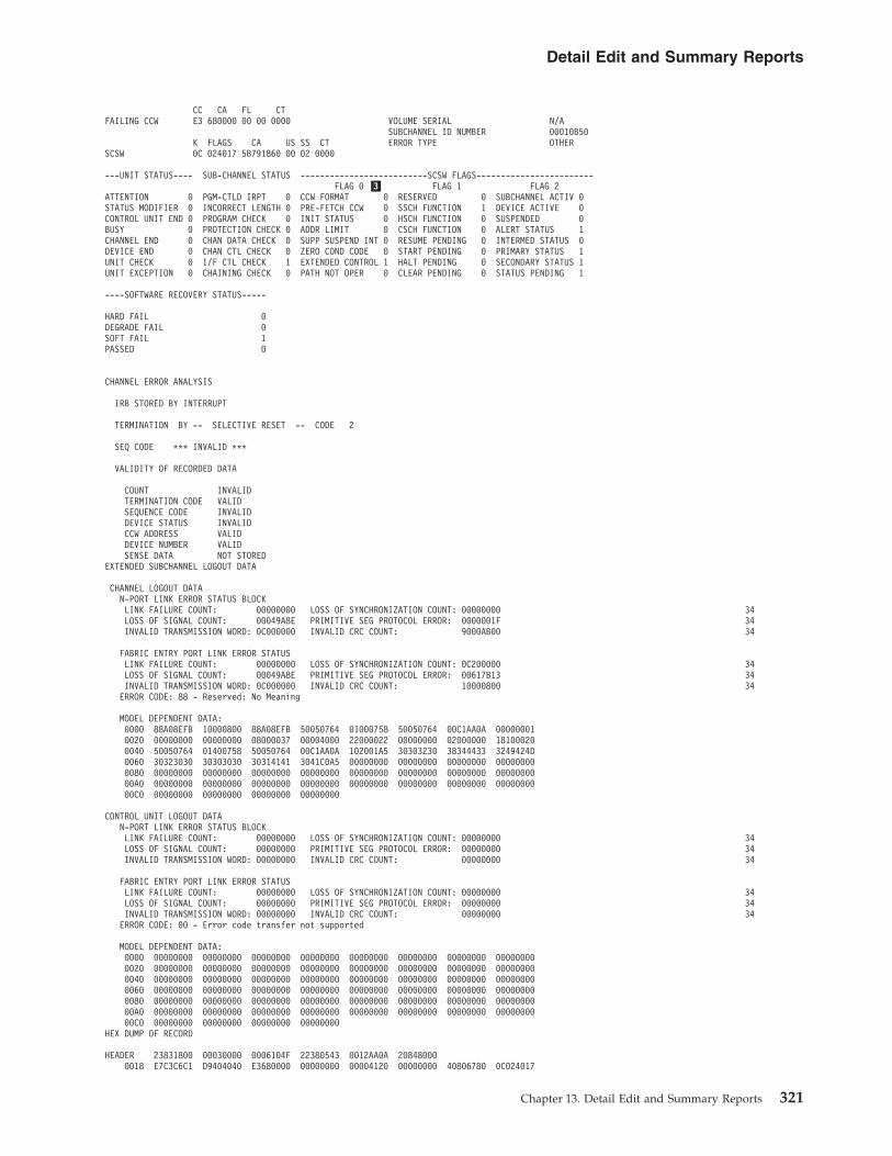
CC CA FL CTFAILING CCW E3 680000 00 00 0000 VOLUME SERIAL N/A
SUBCHANNEL ID NUMBER 00010B50K FLAGS CA US SS CT ERROR TYPE OTHER
SCSW 0C 024017 5B791860 00 02 0000
---UNIT STATUS---- SUB-CHANNEL STATUS --------------------------SCSW FLAGS------------------------FLAG 0 �3� FLAG 1 FLAG 2
ATTENTION 0 PGM-CTLD IRPT 0 CCW FORMAT 0 RESERVED 0 SUBCHANNEL ACTIV 0STATUS MODIFIER 0 INCORRECT LENGTH 0 PRE-FETCH CCW 0 SSCH FUNCTION 1 DEVICE ACTIVE 0CONTROL UNIT END 0 PROGRAM CHECK 0 INIT STATUS 0 HSCH FUNCTION 0 SUSPENDED 0BUSY 0 PROTECTION CHECK 0 ADDR LIMIT 0 CSCH FUNCTION 0 ALERT STATUS 1CHANNEL END 0 CHAN DATA CHECK 0 SUPP SUSPEND INT 0 RESUME PENDING 0 INTERMED STATUS 0DEVICE END 0 CHAN CTL CHECK 0 ZERO COND CODE 0 START PENDING 0 PRIMARY STATUS 1UNIT CHECK 0 I/F CTL CHECK 1 EXTENDED CONTROL 1 HALT PENDING 0 SECONDARY STATUS 1UNIT EXCEPTION 0 CHAINING CHECK 0 PATH NOT OPER 0 CLEAR PENDING 0 STATUS PENDING 1
----SOFTWARE RECOVERY STATUS-----
HARD FAIL 0DEGRADE FAIL 0SOFT FAIL 1PASSED 0
CHANNEL ERROR ANALYSIS
IRB STORED BY INTERRUPT
TERMINATION BY -- SELECTIVE RESET -- CODE 2
SEQ CODE *** INVALID ***
VALIDITY OF RECORDED DATA
COUNT INVALIDTERMINATION CODE VALIDSEQUENCE CODE INVALIDDEVICE STATUS INVALIDCCW ADDRESS VALIDDEVICE NUMBER VALIDSENSE DATA NOT STORED
EXTENDED SUBCHANNEL LOGOUT DATA
CHANNEL LOGOUT DATAN-PORT LINK ERROR STATUS BLOCKLINK FAILURE COUNT: 00000000 LOSS OF SYNCHRONIZATION COUNT: 00000000 34LOSS OF SIGNAL COUNT: 00049A8E PRIMITIVE SEG PROTOCOL ERROR: 0000001F 34INVALID TRANSMISSION WORD: 0C000000 INVALID CRC COUNT: 9000AB00 34
FABRIC ENTRY PORT LINK ERROR STATUSLINK FAILURE COUNT: 00000000 LOSS OF SYNCHRONIZATION COUNT: 0C200000 34LOSS OF SIGNAL COUNT: 00049A8E PRIMITIVE SEG PROTOCOL ERROR: 00617B13 34INVALID TRANSMISSION WORD: 0C000000 INVALID CRC COUNT: 10000800 34ERROR CODE: 88 - Reserved: No Meaning
MODEL DEPENDENT DATA:0000 88A08EFB 10000800 88A08EFB 50050764 01000758 50050764 00C1AA0A 000000010020 00000000 00000000 08000037 00004000 22000022 00000000 02000000 181000200040 50050764 01400758 50050764 00C1AA0A 102001A5 30303230 38344433 3249424D0060 30323030 30303030 30314141 3041C0A5 00000000 00000000 00000000 000000000080 00000000 00000000 00000000 00000000 00000000 00000000 00000000 0000000000A0 00000000 00000000 00000000 00000000 00000000 00000000 00000000 0000000000C0 00000000 00000000 00000000 00000000
CONTROL UNIT LOGOUT DATAN-PORT LINK ERROR STATUS BLOCKLINK FAILURE COUNT: 00000000 LOSS OF SYNCHRONIZATION COUNT: 00000000 34LOSS OF SIGNAL COUNT: 00000000 PRIMITIVE SEG PROTOCOL ERROR: 00000000 34INVALID TRANSMISSION WORD: 00000000 INVALID CRC COUNT: 00000000 34
FABRIC ENTRY PORT LINK ERROR STATUSLINK FAILURE COUNT: 00000000 LOSS OF SYNCHRONIZATION COUNT: 00000000 34LOSS OF SIGNAL COUNT: 00000000 PRIMITIVE SEG PROTOCOL ERROR: 00000000 34INVALID TRANSMISSION WORD: 00000000 INVALID CRC COUNT: 00000000 34ERROR CODE: 00 - Error code transfer not supported
MODEL DEPENDENT DATA:0000 00000000 00000000 00000000 00000000 00000000 00000000 00000000 000000000020 00000000 00000000 00000000 00000000 00000000 00000000 00000000 000000000040 00000000 00000000 00000000 00000000 00000000 00000000 00000000 000000000060 00000000 00000000 00000000 00000000 00000000 00000000 00000000 000000000080 00000000 00000000 00000000 00000000 00000000 00000000 00000000 0000000000A0 00000000 00000000 00000000 00000000 00000000 00000000 00000000 0000000000C0 00000000 00000000 00000000 00000000
HEX DUMP OF RECORD
HEADER 23831800 00030000 0006104F 22380543 0012AA0A 208480000018 E7C3C6C1 D9404040 E3680000 00000000 00004120 00000000 40806780 0C024017
Detail Edit and Summary Reports
Chapter 13. Detail Edit and Summary Reports 321

0038 5B791860 00020000 00806480 20000000 80000000 00000000 00000000 000000000058 00000000 00000000 00000000 00000000 00000000 00000012 003A00A1 021907A80078 0E260000 00000000 01000000 010200A4 00010B50 00000000 00000000 000000000098 80000210 00000001 000000D8 02000100 00000201 00050101 01020202 0405010200B8 F0F0F2F1 F0F5F1F1 F1F2F2F2 F4F5F1F2 F3F4F5F6 F7F1F9F8 F3F1F4F3 F2F1000000D8 00000000 00000000 00049A8E 0000001F 0C000000 9000AB00 08000000 0C20000000F8 00400000 00617B13 0000617A 10000800 88A08EFB 10000800 88A08EFB 500507640118 01000758 50050764 00C1AA0A 00000001 00000000 00000000 08000037 000040000138 22000022 00000000 02000000 18100020 50050764 01400758 50050764 00C1AA0A0158 102001A5 30303230 38344433 3249424D 30323030 30303030 30314141 3041C0A50178 00000000 00000000 00000000 00000000 00000000 00000000 00000000 000000000198 00000000 00000000 00000000 00000000 00000000 00000000 00000000 0000000001B8 00000000 00000000 00000000 00000000 00000000 00000000 00000000 0000000001D8 00000000 00000000 00000000 00000000 00000000 00000000 00000000 0000000001F8 00000000 00000000 00000000 00000000 00000000 00000000 00000000 000000000218 00000000 00000000 00000000 00000000 00000000 00000000 00000000 000000000238 00000000 00000000 00000000 00000000 00000000 00000000 00000000 000000000258 00000000 00000000 00000000 00000000 00000000 00000000 00000000 000000000278 00000000 00000000 00000000 00000000 00000000 00000000 00000000 000000000298 00000000 00000000 00000000 00000000 00000000 00000000 00000000 00000000
Subchannel Logout Handler Summary ReportCHANNEL PATH ID: 12 REPORT: SLH SUMMARY REPORT DATE: 073 97
PERIOD FROM: 043 97NUMBER OF RECORDS: 0001 CPU MODEL: 3090XA TO: 043 97
CPU ID : 170044
ERROR TYPE: STORAGE 0000KEY 0000OTHER 0001
----UNIT STATUS---- --SUB-CHANNEL STATUS--
ATTENTION 0000 PGM-CTLD IRPT 0000STATUS MODIFIER 0000 INCORRECT LENGTH 0000CONTROL UNIT END 0000 PROGRAM CHECK 0000BUSY 0000 PROTECTION CHECK 0000CHANNEL END 0000 CHAN DATA CHECK 0000DEVICE END 0000 CHAN CTN CHECK 0001UNIT CHECK 0000 I/F CTL CHECK 0000UNIT EXCEPTION 0000 CHAINING CHECK 0000
-----SOFTWARE RECOVERY STATUS-----
HARD FAIL 0000DEGRADE FAIL 0000SOFT FAIL 0000PASSED 0000
Subchannel Logout Handler (SLH) Detail Edit Report for zHPFDEVICE NUMBER: 00E26 REPORT: SLH EDIT DAY YEAR JOB IDENTITY: XCFAS
SCP: MVS/XA V2 R3 DATE: 104 06 E7C3C6C1E2404040DEVICE TYPE: FCTC
CPU MODEL: 2084XA HH MM SS.THCHANNEL PATH ID: A4 LOGICAL CPU ID: 12AA0A TIME: 22 38 05.43
PHYSICAL CHAN ID: 0210 PHYSICAL CPU ADDRESS: 3A
FAILING CCW N/A VOLUME SERIAL N/ASUBCHANNEL ID NUMBER 00010B50
K FLAGS TA US SS FX ES ERROR TYPE OTHERSCSW 0C 424017 5B791860 00 02 00 00
---UNIT STATUS---- SUB-CHANNEL STATUS --------------------------SCSW FLAGS------------------------FLAG 0 FLAG 1 FLAG 2
ATTENTION 0 PGM-CTLD IRPT 0 IRB FORMAT 2 RESERVED 0 SUBCHANNEL ACTIV 0STATUS MODIFIER 0 INCORRECT LENGTH 0 --- SSCH FUNCTION 1 DEVICE ACTIVE 0CONTROL UNIT END 0 PROGRAM CHECK 0 --- HSCH FUNCTION 0 SUSPENDED 0BUSY 0 PROTECTION CHECK 0 FORMAT CONTROL 0 CSCH FUNCTION 0 ALERT STATUS 1CHANNEL END 0 CHAN DATA CHECK 0 INTERROGATE COMP 0 RESUME PENDING 0 INTERMED STATUS 0DEVICE END 0 CHAN CTL CHECK 0 RESERVED 0 START PENDING 0 PRIMARY STATUS 1UNIT CHECK 0 I/F CTL CHECK 1 EXTENDED CONTROL 1 HALT PENDING 0 SECONDARY STATUS 1UNIT EXCEPTION 0 CHAINING CHECK 0 PATH NOT OPER 0 CLEAR PENDING 0 STATUS PENDING 1
----SOFTWARE RECOVERY STATUS-----
HARD FAIL 0DEGRADE FAIL 0
Detail Edit and Summary Reports
322 EREP V3R5 Reference

SOFT FAIL 1PASSED 0
CHANNEL ERROR ANALYSIS
IRB STORED BY INTERRUPT
TERMINATION BY -- SELECTIVE RESET -- CODE 2
SEQ CODE 2 *** INVALID ***VALIDITY OF RECORDED DATA
COUNT INVALIDTERMINATION CODE VALIDSEQUENCE CODE INVALIDDEVICE STATUS INVALIDTCW ADDRESS VALIDDEVICE NUMBER VALIDSENSE DATA NOT STORED
EXTENDED SUBCHANNEL LOGOUT DATA
CHANNEL LOGOUT DATAN-PORT LINK ERROR STATUS BLOCKLINK FAILURE COUNT: 00000001 LOSS OF SYNCHRONIZATION COUNT: 00000002LOSS OF SIGNAL COUNT: 00000000 PRIMITIVE SEG PROTOCOL ERROR: 00000000INVALID TRANSMISSION WORD: 00000000 INVALID CRC COUNT: 00000000
FABRIC ENTRY PORT LINK ERROR STATUSLINK FAILURE COUNT: 00000002 LOSS OF SYNCHRONIZATION COUNT: 00000000LOSS OF SIGNAL COUNT: 00000000 PRIMITIVE SEG PROTOCOL ERROR: 00000000INVALID TRANSMISSION WORD: 00049A8E INVALID CRC COUNT: 0000001FERROR CODE: 0C - Receive ABTS
MODEL DEPENDENT DATA:0000 0C000000 9000AB00 08000000 0C200000 00400000 00617B13 000 0617A 100008000020 88A08EFB 10000800 88A08EFB 50050764 01000758 50050764 00C 1AA0A 000000010040 00000000 00000000 08000037 00004000 22000022 00000000 020 00000 181000200060 50050764 01400758 50050764 00C1AA0A 102001A5 30303230 383 44433 3249424D0080 30323030 30303030 30314141 3041C0A5 00000000 00000000 000 00000 0000000000A0 00000000 00000000 00000000 00000000 00000000 00000000 000 00000 0000000000C0 00000000 00000000 00000000 00000000
CONTROL UNIT LOGOUT DATAN-PORT LINK ERROR STATUS BLOCKLINK FAILURE COUNT: 00000000 LOSS OF SYNCHRONIZATION COUNT: 00000000LOSS OF SIGNAL COUNT: 00000000 PRIMITIVE SEG PROTOCOL ERROR: 00000000INVALID TRANSMISSION WORD: 00000000 INVALID CRC COUNT: 00000000
FABRIC ENTRY PORT LINK ERROR STATUSLINK FAILURE COUNT: 00000000 LOSS OF SYNCHRONIZATION COUNT: 00000000LOSS OF SIGNAL COUNT: 00000000 PRIMITIVE SEG PROTOCOL ERROR: 00000000INVALID TRANSMISSION WORD: 00000000 INVALID CRC COUNT: 00000000ERROR CODE: 00 - Error code transfer not supported
MODEL DEPENDENT DATA:0000 00000000 00000000 00000000 00000000 00000000 00000000 000 00000 000000000020 00000000 00000000 00000000 00000000 00000000 00000000 000 00000 000000000040 00000000 00000000 00000000 00000000 00000000 00000000 000 00000 000000000060 00000000 00000000 00000000 00000000 00000000 00000000 000 00000 000000000080 00000000 00000000 00000000 00000000 00000000 00000000 000 00000 0000000000A0 00000000 00000000 00000000 00000000 00000000 00000000 000 00000 0000000000C0 00000000 00000000 00000000 00000000
HEX DUMP OF RECORD
HEADER 23831800 00030000 0006104F 22380543 0012AA0A 208480000018 E7C3C6C1 E2404040 E3680000 00000000 00004120 00000000 40806780 0CC240170038 5B791860 00020000 00806480 20000000 80000000 00000000 00000000 000000000058 00000000 00000000 00000000 00000000 00000000 00000012 003A00A1 021907A80078 0E260000 00000000 01000000 010100A4 00010B50 00000000 000000000 000000000098 80000210 00000001 000000B8 02000100 00000000 00000000 00000000 0000000000B8 00000001 00000002 00000000 00000000 00000000 00000000 00000002 0000000000D8 00000000 00000000 00049A8E 0000001F 0C000000 9000AB00 08000000 0C20000000F8 00400000 00617B13 0000617A 10000800 88A08EFB 10000800 88A08EFB 500507640118 01000758 50050764 00C1AA0A 00000001 00000000 00000000 08000037 00004000
0138 22000022 00000000 02000000 18100020 50050764 01400758 50050764 00C1AA0A
Detail Edit and Summary Reports
Chapter 13. Detail Edit and Summary Reports 323

0158 102001A5 30303230 38344433 3249424D 30323030 30303030 30314141 3041C0A50178 00000000 00000000 00000000 00000000 00000000 00000000 00000000 000000000198 00000000 00000000 00000000 00000000 00000000 00000000 00000000 0000000001B8 00000001 00000002 00000000 00000000 00000000 00000000 00000012 0000000001D8 00000000 00000000 00000000 00000000 00000000 00000000 00000000 0000000001F8 00000000 00000000 00000000 00000000 00000000 00000000 00000000 000000000218 00000000 00000000 00000000 00000000 00000000 00000000 00000000 000000000238 00000000 00000000 00000000 00000000 00000000 00000000 00000000 000000000258 00000000 00000000 00000000 00000000 00000000 00000000 00000000 000000000278 00000000 00000000 00000000 00000000 00000000 00000000 00000000 000000000298 00000000 00000000 00000000 00000000 00000000 00000000 00000000 00000000
Subchannel Logout Handler Summary Report for zHPFCHANNEL PATH ID: A4 REPORT: SLH SUMMARY REPORT DATE: 111 06
PERIOD FROM: 104 06NUMBER OF RECORDS: 0001 CPU MODEL: 2084XA TO: 104 06
CPU ID : 12AA0A
ERROR TYPE: STORAGE 0000KEY 0000OTHER 0001
----UNIT STATUS---- --SUB-CHANNEL STATUS--
ATTENTION 0000 PGM-CTLD IRPT 0000STATUS MODIFIER 0000 INCORRECT LENGTH 0000CONTROL UNIT END 0000 PROGRAM CHECK 0000BUSY 0000 PROTECTION CHECK 0000CHANNEL END 0000 CHAN DATA CHECK 0000DEVICE END 0000 CHAN CTN CHECK 0000UNIT CHECK 0000 I/F CTL CHECK 0001UNIT EXCEPTION 0000 CHAINING CHECK 0000
-----SOFTWARE RECOVERY STATUS-----
HARD FAIL 0000DEGRADE FAIL 0000SOFT FAIL 0001PASSED 0000
Unknown Detail Edit ReportsThese reports are used to provide a detail print of records whose formatting isunsupported or that come from devices whose type is unknown.
Figure 114 through Figure 117 on page 325 contain examples of the unknown detailedit reports.
RECORD TYPE - E1
MODEL-3084 SERIAL NO- 221128
--- RECORD ENTRY SOURCE - NONE
VS 2 REL. 3DAY YEAR HH MM SS.TH
DATE- 048 97 TIME- 04 54 51 81
HEX DUMP OF RECORDHEADER E18A1800 00000000 0097048F 04545181 66221128 30840000
0018 C9D7D340 E2E8E2E3 C5D440C6 D6D940E2 C5D9E5C9 C3C5E24B 4B4BC4D9 C9E5C5D90038 40F8C6F1
Figure 114. Unknown or Unsupported Record Detail Edit Report, Record Type E1
Detail Edit and Summary Reports
324 EREP V3R5 Reference

�1� A three character description of the record type or the hex representationof the first byte in the record.
SUMMARY OF E0 RECORDS�1�
DAY YEAR DAY YEARRECORD DATE RANGE 048 97 048 97
MODEL - 3084 SERIAL NO - 221128
TOTAL NUMBER OF RECORDS=0001
CLASSES ENCOUNTERED(MAXIMUM OF 10)
RECORD CLASS -E1 0001
Figure 115. Unknown or Unsupported Record Detail Summary Report, Record Type E1
RECORD TYPE - 40
MODEL-3090 SERIAL NO- 142815
--- RECORD ENTRY SOURCE - ABND
VS 2 REL. 03
DAY YEAR HH MM SS.THDATE- 041 97 TIME- 09 36 26 80
HEX DUMP OF RECORDHEADER 40831820 00000000 0097041F 09362680 16142815 30900000
0018 D5D6D5C5 60C6D9D9 00000C60 84202000 00000000 00000000 00000000 000000000038 84000000 84202000 00000000 00000C00 00004780 00E4C500 0003AC6C 00FB77000058 00FF0229 80000000 00FEE870 009FED38 00000C58 00000000 00FEACB8 000000000078 00000000 00000000 00000000 00000000 070C1000 80FF06DE 0002000D 7D9E00000098 070C0000 80FF111E 0002000D 7D9E0000 84000000 84202000 00000000 00000C0000B8 00004780 00E4C500 0003AC6C 00FB7700 00FF0229 80000000 00FEE870 009FED3800D8 00000C58 00000000 00FEACB8 00000000 00000000 00000000 00000000 0000000000F8 00000000 00000000 00000000 00000000 04030001 00000041 00FF117A 00FB273C0118 00000000 04880000 00000000 00000000 00000000 00000000 00000000 000000000138 00000000 00000000 003E00C7 C9C5C1D5 E4C3F0F1 C9C5C1E5 C5D7E2E3 C9C5C1E50158 C5D7E2E3 00FB26E8 00000000 00000000 00000000 00000000 00000000 000000000178 00000000 00000000 00000000 00000000 00000000 FFFF0005 00FB2A20 8000003E
Figure 116. Unknown or Unsupported Record Detail Edit Report, Record Type 40
SUMMARY OF 40 RECORDS
DAY YEAR DAY YEARRECORD DATE RANGE 041 97 041 97
MODEL - 3090 SERIAL NO - 142815
TOTAL NUMBER OF RECORDS=0001
CLASSES ENCOUNTERED(MAXIMUM OF 10)
RECORD CLASS -40 0001
Figure 117. Unknown or Unsupported Record Detail Summary Report, Record Type 40
Detail Edit and Summary Reports
Chapter 13. Detail Edit and Summary Reports 325

Detail Edit and Summary Reports
326 EREP V3R5 Reference

Part 3. Product-Dependent Information
This part of the EREP Reference contains information about how EREP works withspecific hardware and software products.
The following subjects are covered in this part of the EREP Reference:
Topic
Chapter 14, “Supported Devices,” on page 329
Chapter 15, “Card Readers and Punches,” on page 333
Chapter 16, “Consoles and Displays,” on page 335
Chapter 17, “Direct-Access Storage Devices (DASD),” on page 337
Chapter 18, “Diskette Unit,” on page 347
Chapter 19, “Magnetic Tape Devices,” on page 349
Chapter 20, “OCR/MICR Devices,” on page 357
Chapter 21, “Optical Devices,” on page 359
Chapter 22, “Printers,” on page 361
Chapter 23, “Processors (CPUs),” on page 365
Chapter 24, “Punched Tape Devices,” on page 369
Chapter 25, “Teleprocessing (TP) Devices,” on page 371
Chapter 26, “Other Devices,” on page 373
© Copyright IBM Corp. 1983, 2015 327

328 EREP V3R5 Reference

Chapter 14. Supported Devices
This topic contains a list of the devices EREPsupports.
Device TypeSubsection
AFP1 Printers
BA00 Other Devices
BCTC Other Devices
CACA Other Devices
CTCA Other Devices
IDSK Other Devices
NMVTTP Devices
OSA Other Devices
OSADOther Devices
SCTC Other Devices
SWCHOther Devices
0115 Processors
0125 Processors
0135 Processors
0138 Processors
0145 Processors
0148 Processors
0155 Processors
0158 Processors
0165 Processors
0168 Processors
0671 DASD
1012 Punched Tape Devices
1015 Consoles and Displays
1017 Punched Tape Devices
1018 Punched Tape Devices
1030 TP Devices
1050 TP Devices
1052 Consoles and Displays
1053 Printers
1060 TP Devices
1130 TP Devices
115A TP Devices
1255 OCR/MICR
1270 OCR/MICR
1275 OCR/MICR
1285 OCR/MICR
1287 OCR/MICR
1288 OCR/MICR
1403 Printers
1419 OCR/MICR
1442 Card Readers and Punches
1443 Printers
2003 Processors
2020 Consoles and Displays
2150 Consoles and Displays
2245 Printers
2250 Consoles and Displays
2260 Consoles and Displays
2265 Consoles and Displays
2280 Other Devices
2282 Other Devices
2301 DASD
2303 DASD
2305 DASD
2311 DASD
2314 DASD
2321 DASD
2400 Magnetic Tape Devices
2495 Other Devices
2501 Card Readers and Punches
2520 Card Readers and Punches
2540 Card Readers and Punches
© Copyright IBM Corp. 1983, 2015 329

2560 Card Readers and Punches
2596 Card Readers and Punches
2671 Punched Tape Devices
2701 TP Devices
2702 TP Devices
2703 TP Devices
2715 TP Devices
2740 TP Devices
2741 TP Devices
2760 TP Devices
2770 TP Devices
2780 TP Devices
2790 TP Devices
2930 Other Devices
2947 TP Devices
2955 Other Devices
2956 Other Devices
2970 TP Devices
2972 TP Devices
3031 Processors
3032 Processors
3033 Processors
3036 Consoles and Displays
3052 Processors
3062 Processors
3066 Consoles and Displays
3138 Consoles and Displays
3148 Consoles and Displays
3158 Consoles and Displays
3168 Consoles and Displays
3203 Printers
3210 Consoles and Displays
3211 Printers
3213 Consoles and Displays
3215 Consoles and Displays
3262 Printers
3277 Consoles and Displays
3278 Consoles and Displays
3279 3279 terminals are processed as 3277records
3284 Printers
3286 Printers
3287 Printers
3288 Printers
3289 Printers
3310 DASD
3330 DASD
3340 DASD
3344 DASD
3350 DASD
3370 DASD
3375 DASD
3380 DASD
3390 DASD
3400 Magnetic Tape Devices
3410 Magnetic Tape Devices
3420 Magnetic Tape Devices
3422 Magnetic Tape Devices
3430 Magnetic Tape Devices
3480 Magnetic Tape Devices
3490 Magnetic Tape Devices
3490E Magnetic Tape Devices
3494 Magnetic Tape Devices
3495 Magnetic Tape Devices
3504 Card Readers and Punches
3505 Card Readers and Punches
3525 Card Readers and Punches
3540 Diskette Units
3590 Magnetic Tape Devices
3591 Magnetic Tape Devices
3670 TP Devices
3700 TP Devices
3704 TP Devices
3705 TP Devices
3720 TP Devices
330 EREP V3R5 Reference

3725 TP Devices
3735 TP Devices
3745 TP Devices
3791 TP Devices
3800 Printers
3820 Printers
3825 Printers
3827 Printers
3835 Printers
3838 Other Devices
3848 Other Devices
3850 DASD
3851 DASD
3886 OCR/MICR
3890 OCR/MICR
3895 OCR/MICR
3900 Printers
3945 TP Devices
3968 TP Devices
3995 Optical Devices
4245 Printers
4248 Printers
4321 Processors
4331 Processors
4341 Processors
4361 Processors
4381 Processors
5080 Consoles and Displays, Printers
5203 Printers
5424 Card Readers and Punches
5425 Card Readers and Punches
6262 Printers
7340 Magnetic Tape Devices
7443 Other Devices
7770 Other Devices
7772 Other Devices
83B3 TP Devices
8809 Magnetic Tape Devices
9021 Processors
9034 Other Devices
9037 Other Devices
9081 Processors
9083 Processors
9121 Processors
9190 Processors
9221 Processors
9246 Optical Devices
9247 Optical Devices
9313 DASD
9332 DASD
9335 DASD
9336 DASD
9345 DASD
9347 Magnetic Tape Devices
9348 Magnetic Tape Devices
9371 TP Devices
9373 Processors
9375 Processors
9377 Processors
9392 DASD
9395 DASD
9696 (IDSK)Other Devices
Chapter 14. Supported Devices 331

332 EREP V3R5 Reference

Chapter 15. Card Readers and Punches
This topic provides device specific information about how to use EREP controls toproduce EREP reports for the devices listed below.
EREP ReportsUseful reports for these devices:
SYSUMEVENTTRENDSPRINT=PT or PS with DEV=nnnn and TYPE=OH
Take care when requesting reports other than these as the results from otherreports can be misleading.
Some devices may produce different record types. In that case, request that recordtype when requesting detail edit and summary (PRINT) reports.
Supported DevicesThese devices are valid for DEV=
1442 card reader/punch
2501 card reader
2520 card reader/punch
2540 card reader/punch
2560 multifunction card machine
2596 card reader/punch
3504 card reader
3505 card reader
3525 card punch
5424 multifunction card machine
5425 multifunction card machine
© Copyright IBM Corp. 1983, 2015 333

Card Readers and Punches
334 EREP V3R5 Reference

Chapter 16. Consoles and Displays
This topic provides device specific information about how to use EREP controls toproduce EREP reports for the devices listed below.
EREP ReportsUseful reports for these devices:
SYSUMEVENTTRENDSPRINT=PT or PS with DEV=nnnn and TYPE=OTH
Take care when requesting reports other than these as the results from otherreports can be misleading.
Some devices may produce different record types. In that case, request that recordtype when requesting detail edit and summary (PRINT) reports.
EREP ControlsNo special considerations.
Supported DevicesThese devices are valid for DEV=
1015 display unit
1052 console
2020 console
2150 console
2250 display unit
2260 display station
2265 display station
3036 console
3066 console
3138 console
3148 console
3158 console
3168 console
3210 console printer/keyboard
3213 console printer
3215 console printer/keyboard
3277 display station (terminal)
© Copyright IBM Corp. 1983, 2015 335

3278 display station (terminal)
5080 graphics systems workstation
Note: Although the 3279 display terminal is not valid for the DEV parameter,EREP does process its records as 3277 records.
Consoles and Displays
336 EREP V3R5 Reference

Chapter 17. Direct-Access Storage Devices (DASD)
This topic provides device specific information about how to use EREP controls toproduce EREP reports for the DASD listed under following headings:
HEADING
“3390 DASD” on page 338
“9392 DASD” on page 339
“9395 DASD” on page 339
“9345 DASD” on page 340
“3380 DASD” on page 341
“3370 DASD” on page 342
“33XX DASD” on page 342
Supported DevicesThese devices are valid for DEV=
0671 direct access storage
2301 drum storage
2303 drum storage
2305 fixed head storage
2311 disk storage
2314 disk storage
2321 data cell drive
23XX families of direct-access storage devices
3310 disk storage
3330 disk storage
3340 disk storage facility
3344 disk storage
3350 disk storage
3370 direct access storage
3375 direct access storage
3380 direct access storage
3390 direct access storage
33XX families of direct-access storage devices
3850 mass storage system
3851 mass storage facility
9313 direct access storage
9332 direct access storage
© Copyright IBM Corp. 1983, 2015 337

9335 direct access storage
9336 direct access storage
9345 direct access storage
3390 DASDThis section covers special considerations for EREP reports that containinformation about 3390 DASD.
3390 Model IdentifiersThe subsystem exception report series and the device-dependent section of thedetail edit (PRINT) report identify 3390 models as follows:
IDENTIFIER 3390 MODELS
3390-01 Models A14, A18, B14, B18, and B1C
3390-02 Models A24, A28, B24, B28, and B2C
3390-03 Models A34, A38, B34, B38, and B3C
Subsystem Exception ReportWhen service actions are required information is placed in the DASD subsystemexception series.
Important: The 3990 storage control and the 3390 family of devices use the serviceinformation messages (SIM) part of the DASD subsystem exception series as theprimary indication that service is required. OBR records are logged but not placedin the system exception report part of the DASD subsystem exception series unlessthe 3990 cannot generate a SIM for the error condition.
OBR and MDR CodesThe MDR codes for the 3390 are shown in the following table:
MDR CODE DESCRIPTION
X'24' 3390 Models A34, A38, B34, B38, and B3C
X'26' 3390 Models A14, A18, B14, B18, and B1C
X'27' 3390 Models A24, A28, B24, B28, and B2C
Note: See “MDR Codes” on page 114.
The OBR codes for the 3390 are shown in the following table:
OBR CODE DESCRIPTION
X'2024' 3390 Model 03
X'2026' 3390 Models A14, A18, B14, B18, and B1C
X'2027' 3390 Models A24, A28, B24, B28, and B2C
Note: See “OBR Codes” on page 111.
Direct-Access Storage Devices (DASD)
338 EREP V3R5 Reference

9392 DASDThis section covers special considerations for EREP reports that containinformation about 9392 DASD.
These devices are defined to the operating system as the type of DASD that isbeing emulated (for example, 3390-3). Addresses with these devices are selectedwith the same parameter as the emulated device (for example, DEV=(3390) orDEV=(33xx)).
9392 Model IdentifiersThe subsystem exception report series and the device-dependent section of thedetail edit (PRINT) report identify 9392 models as follows:
IDENTIFIER 9392 MODELS
9392 Model B13
Subsystem Exception ReportWhen service actions are required, information is placed in the DASD subsystemexception series.
Important: The 3990 storage control and the 9392 family of devices use the serviceinformation messages (SIM) part of the DASD subsystem exception series as theprimary indication that service is required. OBR records are logged but not placedin the system exception report part of the DASD subsystem exception series unlessthe 3990 cannot generate a SIM for the error condition.
OBR and MDR CodesByte 4 of the MDR contains the MDR code of the device the 9392 is emulating (forexample, X'24' for a 3390-03). The MDR code of the 9392 is in the ECKD ™ sensedata later in the record. See “MDR Codes” on page 114.
Byte 54 and 55 of the OBR contain the OBR code of the device the 9392 isemulating (for example, X'2024' for a 3390-03). The OBR code of the 9392 is in theECKD sense data later in the record. See “OBR Codes” on page 111.
9395 DASDThis section covers special considerations for EREP reports that containinformation about 9395 DASD.
These subsystems are defined to the operating system as the type of controlunit/DASD that is being emulated (for example, 3990/3390). Addresses with thesedevices are selected with the same parameter as the emulated device (for example,DEV=(3390) or DEV=(33xx)).
9395 Model IdentifiersThe subsystem exception report series and the device-dependent section of thedetail edit (PRINT) report identify 9395 models as follows:
IDENTIFIER 9395 MODELS
9395 Model B13
9392 DASD
Chapter 17. Direct-Access Storage Devices (DASD) 339
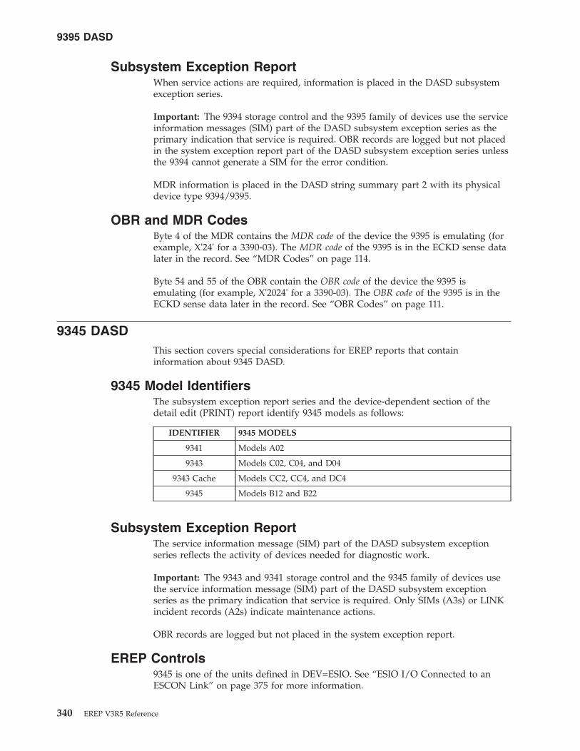
Subsystem Exception ReportWhen service actions are required, information is placed in the DASD subsystemexception series.
Important: The 9394 storage control and the 9395 family of devices use the serviceinformation messages (SIM) part of the DASD subsystem exception series as theprimary indication that service is required. OBR records are logged but not placedin the system exception report part of the DASD subsystem exception series unlessthe 9394 cannot generate a SIM for the error condition.
MDR information is placed in the DASD string summary part 2 with its physicaldevice type 9394/9395.
OBR and MDR CodesByte 4 of the MDR contains the MDR code of the device the 9395 is emulating (forexample, X'24' for a 3390-03). The MDR code of the 9395 is in the ECKD sense datalater in the record. See “MDR Codes” on page 114.
Byte 54 and 55 of the OBR contain the OBR code of the device the 9395 isemulating (for example, X'2024' for a 3390-03). The OBR code of the 9395 is in theECKD sense data later in the record. See “OBR Codes” on page 111.
9345 DASDThis section covers special considerations for EREP reports that containinformation about 9345 DASD.
9345 Model IdentifiersThe subsystem exception report series and the device-dependent section of thedetail edit (PRINT) report identify 9345 models as follows:
IDENTIFIER 9345 MODELS
9341 Models A02
9343 Models C02, C04, and D04
9343 Cache Models CC2, CC4, and DC4
9345 Models B12 and B22
Subsystem Exception ReportThe service information message (SIM) part of the DASD subsystem exceptionseries reflects the activity of devices needed for diagnostic work.
Important: The 9343 and 9341 storage control and the 9345 family of devices usethe service information message (SIM) part of the DASD subsystem exceptionseries as the primary indication that service is required. Only SIMs (A3s) or LINKincident records (A2s) indicate maintenance actions.
OBR records are logged but not placed in the system exception report.
EREP Controls9345 is one of the units defined in DEV=ESIO. See “ESIO I/O Connected to anESCON Link” on page 375 for more information.
9395 DASD
340 EREP V3R5 Reference

3380 DASDThis section covers special considerations for EREP reports that containinformation about 3380 DASD.
3380 Model IdentifiersThe subsystem exception report series and the device-dependent section of thedetail edit (PRINT) report identify 3380 models as follows:
IDENTIFIER 3380 MODELS
3380-CJ CJ2 (device addresses 02 and 03)
3380-DE AD4, AE4, BD4, BE4
3380-JK AJ4, AK4, BJ4, BK4, CJ2 (device addresses except 02 and 03)
Subsystem Exception ReportIn the DASD subsystem exception reports that show FAILURE AFFECT orPROBABLE FAILING UNIT fields, the 3380 family of devices has an additionalcategory called MULTIPLE. This category describes errors that may affect morethan one device but are not controller failures.
The following reports use the MULTIPLE category:v System error summary part 2v Subsystem exception reportv Symptom code summaryv String summary
MDR and OBR CodesThe MDR codes for the 3380 are shown in the following table:
MDR CODE DESCRIPTION
X'14' 3380 Models AA4, A04, B04, AD4, and BD4.
X'1B' 3380 Models AE4 and BE4.
X'1C' 3380 Models AD4 and BD4 with full command support provided bythe system.
X'21' 3380 Models AJ4, BJ4 and CJ2 in single density mode.
X'23' 3380 Models AK4, BK4 and CJ2 with TCO (triple capacity option).
Note: See “MDR Codes” on page 114.
The OBR codes for the 3380 are shown in the following table:
OBR CODE DESCRIPTION
X'200E' 3380 Models AA4, A04, B04, AD4, and BD4.
X'201E' 3380 Models AD4 and BD4 with full command support provided bythe system.
X'202E' 3380 Models AE4 and BE4.
X'2021' 3380 Models AJ4, BJ4 and CJ2 in single density mode.
X'2023' 3380 Models AK4, BK4 and CJ2 with TCO (triple capacity option).
3380 DASD
Chapter 17. Direct-Access Storage Devices (DASD) 341

OBR CODE DESCRIPTION
Note: See “OBR Codes” on page 111.
3370 DASDA data reduction report is produced for the 3370 only. To separate the report forthe 3370 and for dedicated DASD from the rest of the detail (PRINT) output forI/O devices, run the following step before running any detail (PRINT) reports forother I/O devices:
PRINT=SDDEV=(3370)TYPE=OT
33XX DASDThis section covers special considerations for EREP reports that containinformation about 33XX DASD.
33XX IdentifiersSome 33XX DASD identify themselves to EREP via physical IDs, identifiers assignedto the storage control unit (SCU), the controller, and the device.
Other 33XX DASD are identified by the physical and logical controller-unit addresses(CUAs).
The sources of these different identifiers are as follows:
IDENTIFIER DESCRIPTION
physical ID Is located in the sense records created for 3375, 3380, and 9345devices and 3880, 3990, 9341, and 9343 storage controls.
manufacture serial number Is located in the sense records for the 3390 and 9345 devicesand the 3990, 9341, and 9343 storage controls.
secondary control unitaddress (SCUA)
Is located in the OBR or MDR record. It is the logical addressfrom which the sense data is received.
primary control unit address(PCUA)
Is the address of the physical device via the base (primary)channel. This is the position of the drive in the string. ThePCUA is also the physical address for all demountable DASD.
Some EREP reports show 33XX DASD by physical ID. In those that do not, theaddress shown is the PCUA. See “DASDID Control Statement” on page 58 formore information about the physical ID.
The only records used for 33XX DASD are OBR (long), MDR, and X'Ax' typerecords:v OBR records indicate errors or single incidents.v MDR records contain statistical data collected at the storage control unit for
usage, errors, and overruns.
In the system summary and trends reports, 33XX devices providing physical IDs areonly listed by those IDs; the CPU identifiers are omitted.
Devices having physical IDs do not require DASDID or SHARE statements.
3380 DASD
342 EREP V3R5 Reference

The reports that require SHARE statements for nonphysical ID devices are:v System summaryv Trendsv Data reduction (PRINT=DR or SD)
Subsystem Exception ReportThe following DASD subsystems are included in the subsystem exception reportseries:v 0671 devicesv 3310-3350, 3375, 3380 and 3390 DASD drivesv 9313, 9332, 9335, 9336, and 9345 DASD drivesv 3830 and 3880 DASD storage controlsv 3990 and 3380-CJ DASD storage controls
Important: The system exception series replaces detail summaries for thesedevices.
3375 and 3380 errors are reported differently from those of other DASD in thevarious summary reports of the system exception series, because:v The 3375 and 3380 can have two or more controllers at the head of the stringv The PHYSICAL ID field contains failures associated with the lowest control ID
for the string with the device or volume failure.
Detail Edit ReportThe following parameters allow you to selectively print X'Ax' type records (SIMs)in a detail edit report.
PRINT=PTDEV=(33XX)TYPE=A
Important: The DASD summaries included in the system exception series replacethe following reports:v The combined OBR/MDR detail summary (PRINT=PS|SD|SU,TYPE=OT)v The MDR detail edit and summary reports
DASDID Control Statement
Important:
v The DASDID control statement only applies to the system exception reportseries.
v The DASDID control statement is not valid for the 3375, 3380 and 3390 DASDdevices.
v The description and explanation of the DASDID statement are in “DASDIDControl Statement” on page 58.
The 3880 control unit supplies its own physical ID. Note those physical IDs beforeassigning any IDs to control units.
The control unit ID assigned by the DASDID control statement must coincide withthe storage director physical ID. The physical ID for each control unit should havebeen set with hardware switches at installation.
33XX DASD
Chapter 17. Direct-Access Storage Devices (DASD) 343

LIMIT Control StatementThe LIMIT control statement works differently for each of the product groups.
Important: The LIMIT control statement only applies to the system exceptionreport series.
The LIMIT control statement has the following format for 33XX DASD:LIMIT dasd,keyword[,keyword...]
dasdRepresents the device type designation for DASD products. dasd can be one ofthe following generic product types:
Product type33XX 33703310 33753330 33803340 38303350 3880
Note: 3340 includes 3344.
33XX is the general device type designation for all the listed direct accessdevices and control units. When you code 33XX on a LIMIT control statement,you are requesting that the limits apply to all devices of the general type.
Important: The LIMIT control statement is not valid for the following devicesand storage controllers:
Device/Storage Controller0671 9332 93413390 9335 93439313 9336 9345
keywordRepresents one or more DASD product-dependent keyword parameters withthe associated numeric limits.
You can set minimum thresholds for different kinds of temporary errors orevents using the keyword values listed here:
TO SET LIMITS FOR USE KEYWORD
Seek errors SKS=nnnn
Read errors RD=nnnn
Bus out parity errors B=nnnn
Equipment checks EQUCHK=nnnn
Check data C=nnnn
Invoked offsets I=nnnn
Diskette checks D=nnnn
Overruns OVRN=nnnn
All not otherwise specified ALL=nnnn
Note: nnnn can range from 1 to 9999; it requires no leading zeros.
33XX DASD
344 EREP V3R5 Reference

Not all the keywords are valid for every device type. The following table showsthe valid error type keywords for each of the 33XX DASD device types:
DEVICE TYPE SKS RD B EQUCHK C I D OVRN ALL
3310 X X X X X
3330 X X X X
3340 X X X X
3350 X X X X
3370 X X X X
3375 X X X
3380 X X X
3830 X X X X X
3880 X X X X X
33XX X X X X X X X X X
Notes:v If you do not specify a number for nnnn, EREP uses a default value of 01
applying no limits to temporary errors. So all errors of that type are included inthe subsystem exception report.
v When you set limits on temporary errors EREP excludes those errors that do notequal or exceed the LIMIT control statement values. For example, if you code:LIMIT 3830,EQUCHK=5,OVRN=10
the DASD subsystem exception report shows temporary equipment checks andoverrun errors for a 3830 control unit only if there are 5 or more equipmentchecks or 10 or more overruns recorded against the device.
v When you specify 33XX or ALL on a LIMIT control statement, EREP only usesthe valid keywords for each device type included.
v EREP ignores the ALL values on any LIMIT control statements that follow a33XX statement on which ALL is specified. For example:LIMIT 3330,SKS=5,ALL=10LIMIT 33XX,ALL=15LIMIT 3340,RD=5,ALL=20
EREP limits the 3330 using the values in the 3330 statement, and limits all otherDASD using the value in the 33XX statement. It ignores the ALL value in the3340 statement, because the 33XX statement takes precedence. If you need theALL value for 3340s, put that LIMIT control statement before the one for 33XX.For example:LIMIT 3330,SKS=5,ALL=10LIMIT 3340,RD=5,ALL=20LIMIT 33XX,ALL=15
Now EREP limits the 3330 using the values in the 3330 statement, the 3340 usingthe values in the 3340 statement, and all other DASD using the value in the33XX statement.
v Only one LIMIT control statement is allowed for the general device class of33XX.
33XX DASD
Chapter 17. Direct-Access Storage Devices (DASD) 345

33XX DASD
346 EREP V3R5 Reference

Chapter 18. Diskette Unit
This topic provides device specific information about how to use EREP controls toproduce EREP reports for the devices listed below.
EREP ReportsUseful reports for these devices:
SYSUMEVENTTRENDSPRINT=PT or PS with DEV=nnnn and TYPE=OH
Take care when requesting reports other than these as the results from otherreports can be misleading.
EREP ControlsNo special considerations.
Supported DevicesThis device is valid for DEV=
3540 diskette I/O unit
© Copyright IBM Corp. 1983, 2015 347

Diskette Unit
348 EREP V3R5 Reference

Chapter 19. Magnetic Tape Devices
This topic provides device specific information about how to use EREP controls toproduce EREP reports for the magnetic tape devices listed under the followingheadings:
HEADING
“Reports for Tape Devices”
“34XX Tape Devices”
“3480, 3490, and 3490E Tape Subsystems” on page 353
“9347 and 9348 Subsystem Exception Report” on page 354
“35XX Tape Devices” on page 355
Reports for Tape DevicesThe following table identifies reports that can help analyze the performance of thetape devices:
DEVICE 34XXFAMILY
35XXFAMILY
SYSEXN THRESH FORCEDLOG SUM
LIMIT CTLSTMT
3400 YES NO YES YES NO YES
3410 YES NO YES YES NO YES
3420 YES NO YES YES NO YES
3422 YES NO YES NO YES YES
3424 NO NO YES NO NO NO
3430 YES NO YES NO YES YES
3480 YES NO YES NO YES YES
3490 YES NO YES NO YES YES
3590 NO YES YES NO NO NO
8809 YES NO NO YES NO NO
9347 NO NO YES NO NO NO
9348 NO NO YES NO NO NO
Note:
The 3494 and 3495 tape libraries are processed as 3490 devices, but are put on separatereports.
34XX Tape DevicesThis section provides information about EREP reports and EREP controls specificto the 34XX tape devices.
© Copyright IBM Corp. 1983, 2015 349
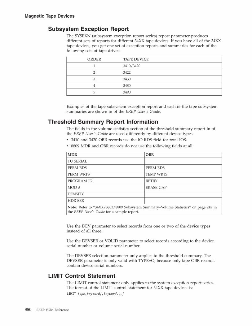
Subsystem Exception ReportThe SYSEXN (subsystem exception report series) report parameter producesdifferent sets of reports for different 34XX tape devices. If you have all of the 34XXtape devices, you get one set of exception reports and summaries for each of thefollowing sets of tape drives:
ORDER TAPE DEVICE
1 3410/3420
2 3422
3 3430
4 3480
5 3490
Examples of the tape subsystem exception report and each of the tape subsystemsummaries are shown in of the EREP User's Guide.
Threshold Summary Report InformationThe fields in the volume statistics section of the threshold summary report in ofthe EREP User's Guide are used differently by different device types:v 3410 and 3420 OBR records use the IO RDS field for total IOS.v 8809 MDR and OBR records do not use the following fields at all:
MDR OBR
TU SERIAL
PERM RDS PERM RDS
PERM WRTS TEMP WRTS
PROGRAM ID RETRY
MOD # ERASE GAP
DENSITY
HDR SER
Note: Refer to “34XX/3803/8809 Subsystem Summary–Volume Statistics” on page 242 inthe EREP User's Guide for a sample report.
Use the DEV parameter to select records from one or two of the device typesinstead of all three.
Use the DEVSER or VOLID parameter to select records according to the deviceserial number or volume serial number.
The DEVSER selection parameter only applies to the threshold summary. TheDEVSER parameter is only valid with TYPE=O, because only tape OBR recordscontain device serial numbers.
LIMIT Control StatementThe LIMIT control statement only applies to the system exception report series.The format of the LIMIT control statement for 34XX tape devices is:LIMIT tape,keyword[,keyword...]
Magnetic Tape Devices
350 EREP V3R5 Reference

Important: 3480 and 3490 tape subsystem LIMIT control statements differ from theother 34XX devices shown here. See “LIMIT Control Statement” on page 354 fordetails.
tapeOne of these device types: 34XX?410?420?422?430
keywordxxbpi=nnn(ct)
xx Pairs of initials indicating the types of temporary errors to be limited.
bpiDensity (bits per inch) at which the device is operating. The possiblevalues for bpi are 1600 and 6250.
nnnThree-digit decimal value representing the number of megabytes of dataprocessed between errors (MB/ERROR).
ct Decimal value from 1 to 999 representing the number of errorsencountered before the device or volume appears on the subsystemexception report.
Keywords and Values for LIMIT Control StatementsLIMIT keywords for 34XX tape drives are:
BPI TO SET LIMITS FOR USE KEYWORD
1600 Hardware read HR1600=nnn(ct)
Hardware write HW1600=nnn(ct)
Volume read VR1600=nnn(ct)
Volume write VW1600=nnn(ct)
6250 Hardware read HR6250=nnn(ct)
Hardware write HW6250=nnn(ct)
Volume read VR6250=nnn(ct)
Volume write VW6250=nnn(ct)
Temporary Error LimitsEREP uses both the nnn (MBYTES/ERROR) and ct (total errors) values to establishthresholds for temporary errors. The errors are reported on the subsystemexception report if both of the following criteria are met:v The number of megabytes processed per error is less than the number of
megabytes specified by the error frequency (nnn) valuev The number of times the error occurs is greater than or equal to the number
specified by the count (ct) value
If you want the subsystem exception report for a 3420 tape subsystem to report1600 bpi volume temporary read errors when:v Less than 599MB are read per errorv The errors occur at least 5 times
Set the volume read limit control card as follows:LIMIT 3420,VR1600=599(5)
With this setting:
Magnetic Tape Devices
Chapter 19. Magnetic Tape Devices 351

WHEN AND THEN
Temporary read errors occur at a rate of500MB per error
6 errors occur The errors are reported on the subsystemexception report.
Temporary read errors occur at a rate of600MB per error
6 errors occur The errors are not reported on thesubsystem exception report.
Temporary read errors occur at a rate of500MB per error
4 errors occur The errors are not reported on thesubsystem exception report.
Note:
1. To cover all the possible sources of errors for a 34XX device, code LIMITcontrol statements for both hardware and volume read and write errors.Results are unpredictable if any values are omitted, or if a value is coded aszero.
2. If you do not code LIMIT control statements for a tape device or volume, thesubsystem exception report includes only the permanent errors recordedagainst that device or volume.
Important: All temporary errors appear in the temporary error summary.3. To force EREP to show all the temporary errors on the subsystem exception
report, use 999(1) for the nnn(ct) variables on the LIMIT statement, providedthat the number of megabytes processed per error is less than 999.
4. The density of 6250 BPI applies only to 3420 and 3430 drives. A LIMIT controlstatement for 34XX is ignored for 3410 devices.
5. If a tape drive is operating at a density other than 1600 or 6250 BPI, EREPuses the LIMIT values you specify for 1600 BPI.
6. Only one LIMIT control statement is allowed for the general 34XX type.7. You may not continue a LIMIT control statement from one line to the next.8. You should use separate LIMIT control statements to establish hardware and
volume limits for a device.9. If the device operates at both 1600 and 6250 BPI, you must use separate
statements.10. If only one tape density is involved, you can combine all four keywords on
the same LIMIT control statement. For example, you may want to see thetemporary errors for your 3410 and 3420 drives, operating at 1600 BPI density,as follows:
Hardware /Volume R/W Errors
Hardware Read 1 or more errors, at 25MB per error
Write 15 or more errors, at 10MB per error
Volume Read 1 or more errors, at 25MB per error
Write 15 or more errors, at 10MB per error
Magnetic Tape Devices
352 EREP V3R5 Reference

Hardware /Volume R/W Errors
Note:
To set these limits, you can code the following LIMIT control statements:
LIMIT 3410,HR1600=025(1),HW1600=010(15),VR1600=025(1),VW1600=010(15)LIMIT 3420,HR1600=025(1),HW1600=010(15),VR1600=025(1),VW1600=010(15)
Because the limiting values and density are the same, these two statements can becombined into a single 34XX LIMIT control statement:
LIMIT 34XX,HR1600=025(1),HW1600=010(15),VR1600=025(1),VW1600=010(15)
11. When your 34XX devices are operating at different densities, you cannot fit allfour sets of keywords on the single 34XX LIMIT control statement.If you specify only the volume or hardware values for both densities on asingle 34XX LIMIT control statement, EREP applies those values to whicheverkinds of errors you have not specified. For example:LIMIT 34XX,VR1600=010(1),VW1600=010(1),VR6250=020(1),VW6250=020(1)
EREP applies the values specified here for volume reads and writes to hardwarereads and writes for all your 34XX devices.
Important: When EREP checks the LIMIT control statement syntax, it fills inany blanks it finds with the corresponding values supplied elsewhere on thesame statement. This is why results can be unpredictable when you do notcode all the values on a LIMIT control statement or code a value as zero.
3480, 3490, and 3490E Tape SubsystemsThis section provides information specific to EREP reports and controls specific tothe 3480, 3490, and 3490E tape subsystems.
Subsystem Exception ReportEREP produces a separate set of subsystem exception reports for the 3480, 3490,and 3490E subsystem. Records for the following devices are included in the reportseries:v 34XX tape drives (3410, 3420, and 3430)v 3480 flexible media tape subsystemv 3490 and 3490E magnetic tape subsystemsv 3494 tape library (included in the 3490/3490E series)v 3495 tape library (included in the 3490/3490E series)
You must request both OBR (type O) and MDR (type T) records; EREP uses both forthe 3480, 3490, and 3490E subsystem exception report.
Important: You cannot get detail edit reports of 3480, 3490, and 3490E MDRrecords.
When you code DEV=34XX, EREP selects records from 3410, 3420, 3422, 3430, 3480,3490, 3490E, and 8809 tape drives, depending on the report requested. See “34XXTape Devices” on page 349 for details.
Magnetic Tape Devices
Chapter 19. Magnetic Tape Devices 353

LIMIT Control StatementThe format of the 3480, 3490, and 3490E LIMIT control statement is:LIMIT tape,keyword[,keyword...]
tapeOne of these device types: 3480 or 3490
keywordxxtape=nnn(ct)
xx Pairs of initials indicating the types of temporary errors to limit. Thepossible values for xx are listed under the valid LIMIT keywords for 3490.
nnnThree-digit decimal value representing the number of megabytes of dataprocessed between errors (MB/ERROR).
ct Decimal value from 1 to 999 representing the number of errorsencountered before the device or volume appears on the subsystemexception report.
Keywords and Values for the LIMIT Control StatementThe LIMIT control statement uses the following keywords for the 3480, 3490, and3490E:
TO SET LIMITS FOR USE KEYWORD
Hardware read HR3480=nnn(ct)
HR3490=nnn(ct)
Hardware write HW3480=nnn(ct)
HW3490=nnn(ct)
Volume read VR3480=nnn(ct)
VR3490=nnn(ct)
Volume write VW3480=nnn(ct)
VW3490=nnn(ct)
Temporary Error LimitsSee “Temporary Error Limits” on page 351 to gain an understanding of how thetemporary error limit works. To meet the conditions in “Temporary Error Limits”on page 351, set the 3480 volume read limit control card shown as follows:LIMIT 3480,VR3480=599(5)
The LIMIT control statement does not control the printing of nonerror records inthe DEVNO/CUA statistics summary or volume statistics summary sections of thesubsystem exception report. All nonerror activity is reported for each 3480 deviceor volume appearing in the subsystem exception report.
See the notes following “Temporary Error Limits” on page 351 for more detailedinformation about LIMIT control statements.
9347 and 9348 Subsystem Exception ReportThe LIMIT control statement is invalid for the 9347 and 9348. The current limitsare not reported.
Magnetic Tape Devices
354 EREP V3R5 Reference

The count and frequency of permanent and temporary errors are not recorded, sothe MB/ERR counts are not reported.
35XX Tape DevicesThis section provides information about EREP reports and EREP controls specificto the 35XX tape devices.
Subsystem Exception ReportThe SYSEXN (subsystem exception report series) report parameter producesdifferent sets of reports for 35XX tape devices. If you have all of the 35XX tapedevices, you get one set of exception reports and summaries that includes all thedrives.
Examples of the TAPE subsystem exception report and the TAPE messages areshown in “TAPE Subsystem Exception” on page 232.
Magnetic Tape Devices
Chapter 19. Magnetic Tape Devices 355

356 EREP V3R5 Reference

Chapter 20. OCR/MICR Devices
This topic provides device specific information about how to use EREP controls toproduce EREP reports for the devices listed below.
EREP ReportsUseful reports for these devices:
SYSUMEVENTTRENDSPRINT=PT or PS with DEV=nnnn and TYPE=OTH
Take care when requesting reports other than these as the results from otherreports can be misleading.
Some devices may produce different record types. In that case, request those recordtypes when requesting detail edit and summary (PRINT) reports.
EREP ControlsNo special considerations.
Supported DevicesThese devices are valid for DEV=
1255 MICR reader
1270 optical character reader
1275 optical reader/sorter
1285 optical reader
1287 optical reader/sorter
1288 optical page reader
1419 MICR reader/sorter
3886 optical character reader
3890 document processor
3895 document reader/sorter
© Copyright IBM Corp. 1983, 2015 357

OCR/MICR Devices
358 EREP V3R5 Reference

Chapter 21. Optical Devices
This topic provides device specific information about how to use EREP controls toproduce EREP reports for the optical devices listed below.
3995 Optical Disk Storage DataserverEREP supports the following reports for the 3995 optical disk library:
SYSEXNEVENTPRINT=PT or PS with DEV=nnnn and TYPE=OTH
3995 is valid for the DEV parameter.
This device generates A3, OBR and MDR records.A3/OBR codes — X'2182', X'2183', and X'4122'MDR code — X'17', X'20' and X'50'
9246 Optical LibraryEREP supports the following reports for the 9246 optical disk library:
SYSEXNEVENTPRINT=PT or PS with DEV=nnnn and TYPE=OTH (does not include A3records)
9246 is valid for the DEV parameter.
This device only generates OBR records. The OBR code is X'2180'.
9247 Optical Disk DriveEREP supports the following reports for the 9247 optical storage device:
SYSEXNEVENTPRINT=PT or PS with DEV=nnnn and TYPE=OTH (does not include A3records)
9247 is valid for the DEV parameter.
This device only generates OBR records. The OBR code is X'2181'.
© Copyright IBM Corp. 1983, 2015 359

360 EREP V3R5 Reference
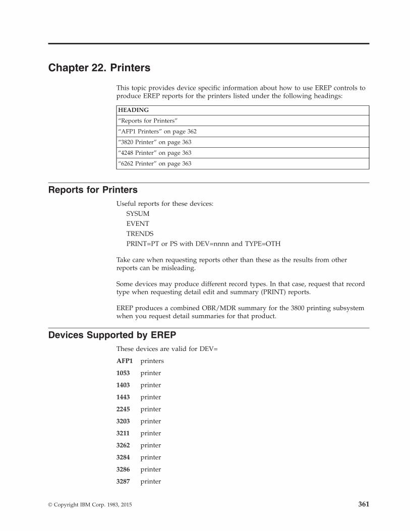
Chapter 22. Printers
This topic provides device specific information about how to use EREP controls toproduce EREP reports for the printers listed under the following headings:
HEADING
“Reports for Printers”
“AFP1 Printers” on page 362
“3820 Printer” on page 363
“4248 Printer” on page 363
“6262 Printer” on page 363
Reports for PrintersUseful reports for these devices:
SYSUMEVENTTRENDSPRINT=PT or PS with DEV=nnnn and TYPE=OTH
Take care when requesting reports other than these as the results from otherreports can be misleading.
Some devices may produce different record types. In that case, request that recordtype when requesting detail edit and summary (PRINT) reports.
EREP produces a combined OBR/MDR summary for the 3800 printing subsystemwhen you request detail summaries for that product.
Devices Supported by EREPThese devices are valid for DEV=
AFP1 printers
1053 printer
1403 printer
1443 printer
2245 printer
3203 printer
3211 printer
3262 printer
3284 printer
3286 printer
3287 printer
© Copyright IBM Corp. 1983, 2015 361

3288 printer
3289 line printer
32XX includes families of IBM printers
3800 printing subsystem
3820 page printer
38XX includes families of IBM printers
4245 printer
4248 printer
5080 graphics systems workstation
5203 printer
6262 printer
AFP1 PrintersAFP1 is a family of system printers designed to operate under the Print ServicesFacility ™ (PSF) of the Advanced Function Printing (AFP) software application. Theentire family of non-impact system printers use the common control unit (CCU) todrive various printer engines. AFP1 is the general device type designation thatincludes all of this family of printers.
The following printers are members of the AFP1 family:
TYPE/MODEL DESCRIPTION
3825/01 Cut sheet printer
3827/01 Cut sheet printer
3835/01 Fan fold printer
3900/01 Fan fold printer
Detail Edit ReportThe detail report provides detailed information for each OBR error recordincluding the sense information in hexadecimal.
The unique TYPE/MODEL information is obtained from the long OBR error recordand printed in the device dependent data area.
Detail Summary ReportThis report provides summary information for the OBR error records, sorted bySystem Reference Code (SRC). It shows the total permanent and temporaryoccurrences of each SRC during the period of the report.
The unique TYPE/MODEL information is printed in the device dependent dataarea.
For a description of what the SRC number means for each unique printer, refer tothe maintenance library for that specific machine type.
Printers
362 EREP V3R5 Reference
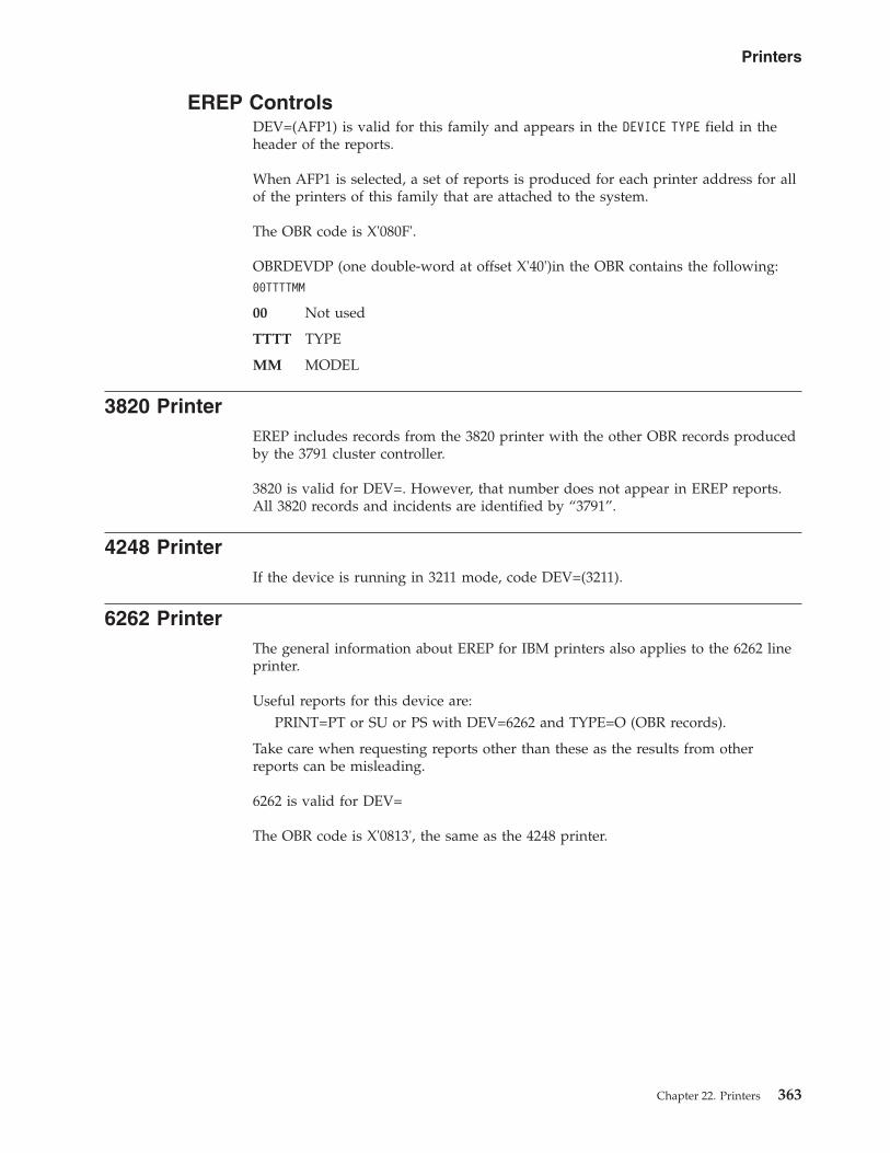
EREP ControlsDEV=(AFP1) is valid for this family and appears in the DEVICE TYPE field in theheader of the reports.
When AFP1 is selected, a set of reports is produced for each printer address for allof the printers of this family that are attached to the system.
The OBR code is X'080F'.
OBRDEVDP (one double-word at offset X'40')in the OBR contains the following:00TTTTMM
00 Not used
TTTT TYPE
MM MODEL
3820 PrinterEREP includes records from the 3820 printer with the other OBR records producedby the 3791 cluster controller.
3820 is valid for DEV=. However, that number does not appear in EREP reports.All 3820 records and incidents are identified by “3791”.
4248 PrinterIf the device is running in 3211 mode, code DEV=(3211).
6262 PrinterThe general information about EREP for IBM printers also applies to the 6262 lineprinter.
Useful reports for this device are:PRINT=PT or SU or PS with DEV=6262 and TYPE=O (OBR records).
Take care when requesting reports other than these as the results from otherreports can be misleading.
6262 is valid for DEV=
The OBR code is X'0813', the same as the 4248 printer.
Printers
Chapter 22. Printers 363

364 EREP V3R5 Reference

Chapter 23. Processors (CPUs)
This topic provides device specific information about how to use EREP controls toproduce EREP reports for the processors listed under the following headings:
HEADING
“Processor Information”
“LIMIT Control Statement”
“PR/SM Feature” on page 367
Processor InformationThe following table identifies what types of records the processors generate,whether or not CPU= and MOD= are valid parameters, and whether or not theprocessor is included in the subsystem exception report series.
CPU SYSEXN CPU=MOD=
CCH MCH SLH CRW¹ LIMIT CTLSTMT
0158 YES VALID X X VALID
0168 YES VALID X X VALID
303X YES VALID X X VALID
9021 NO VALID X X X NO
9121 NO VALID X X X NO
9221 NO VALID X X X NO
9373 NO VALID X X NO
9375 NO VALID X X NO
9377 NO VALID X X NO
LIMIT Control StatementThe LIMIT control statement applies only to the system exception report series.The following is a description of how to use LIMIT control statements for theprocessor and channel subsystem exception reports.
The LIMIT control statement has the following format for processors:LIMIT cpu,keyword=nn[,keyword=nn...]
cpuIs one of the following S/370 processors and its associated channels:
01580168303130323033
© Copyright IBM Corp. 1983, 2015 365
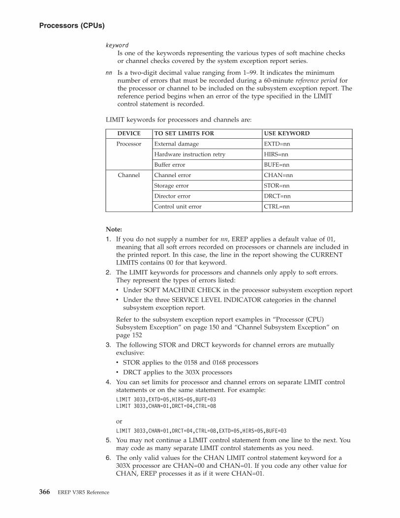
keywordIs one of the keywords representing the various types of soft machine checksor channel checks covered by the system exception report series.
nn Is a two-digit decimal value ranging from 1–99. It indicates the minimumnumber of errors that must be recorded during a 60-minute reference period forthe processor or channel to be included on the subsystem exception report. Thereference period begins when an error of the type specified in the LIMITcontrol statement is recorded.
LIMIT keywords for processors and channels are:
DEVICE TO SET LIMITS FOR USE KEYWORD
Processor External damage EXTD=nn
Hardware instruction retry HIRS=nn
Buffer error BUFE=nn
Channel Channel error CHAN=nn
Storage error STOR=nn
Director error DRCT=nn
Control unit error CTRL=nn
Note:
1. If you do not supply a number for nn, EREP applies a default value of 01,meaning that all soft errors recorded on processors or channels are included inthe printed report. In this case, the line in the report showing the CURRENTLIMITS contains 00 for that keyword.
2. The LIMIT keywords for processors and channels only apply to soft errors.They represent the types of errors listed:v Under SOFT MACHINE CHECK in the processor subsystem exception reportv Under the three SERVICE LEVEL INDICATOR categories in the channel
subsystem exception report.
Refer to the subsystem exception report examples in “Processor (CPU)Subsystem Exception” on page 150 and “Channel Subsystem Exception” onpage 152
3. The following STOR and DRCT keywords for channel errors are mutuallyexclusive:v STOR applies to the 0158 and 0168 processorsv DRCT applies to the 303X processors
4. You can set limits for processor and channel errors on separate LIMIT controlstatements or on the same statement. For example:LIMIT 3033,EXTD=05,HIRS=05,BUFE=03LIMIT 3033,CHAN=01,DRCT=04,CTRL=08
orLIMIT 3033,CHAN=01,DRCT=04,CTRL=08,EXTD=05,HIRS=05,BUFE=03
5. You may not continue a LIMIT control statement from one line to the next. Youmay code as many separate LIMIT control statements as you need.
6. The only valid values for the CHAN LIMIT control statement keyword for a303X processor are CHAN=00 and CHAN=01. If you code any other value forCHAN, EREP processes it as if it were CHAN=01.
Processors (CPUs)
366 EREP V3R5 Reference

PR/SM FeatureWhen the processor resource/system manager (PR/SM) feature is used to createlogical partitions on a central processor complex (CPC) a unique logical CPUID iscreated for each logical partition by creating a new and unique CPU identificationnumber (all other fields are unchanged).
The CPU identification number is a six-digit number as follows:asnnnn
a Logical processor address
s PR/SM logical partition identifier or second digit of the machine serial number
nnnnRepresents the last four digits of the machine serial number
The logical processor address is a function of the CPC model, whether the CPC isa single image or physically partitioned and how many logical processors areassigned to the partition.
The PR/SM logical partition identifier is the same hexadecimal digit used toidentify the partition when it was initially defined (in the IOCDS).
The PR/SM logical partition identifier must be used in conjunction with the lastfour digits of the machine serial number, whenever using the CPU serial numberin a parameter or control statement.
Processors (CPUs)
Chapter 23. Processors (CPUs) 367

368 EREP V3R5 Reference

Chapter 24. Punched Tape Devices
This topic provides device specific information about how to use EREP controls toproduce EREP reports for the devices listed below.
EREP ReportsUseful reports for these devices:
SYSUMTRENDSEVENTPRINT=PT or PS with DEV=nnnn and TYPE=OH
Take care when requesting reports other than these as the results from otherreports can be misleading.
EREP ControlsNo special considerations.
Supported DevicesThese devices are valid for DEV=
1012 paper tape punch
1017 paper tape reader
1018 paper tape punch
2671 paper tape reader
© Copyright IBM Corp. 1983, 2015 369

Punched Tape Devices
370 EREP V3R5 Reference

Chapter 25. Teleprocessing (TP) Devices
This topic provides device specific information about how to use EREP controls toproduce EREP reports for the devices listed below.
EREP ReportsVTAM record type 36 will no longer be supported by the detail summary report.
In OBR records, EREP sees the 3720, 3725 and 3745 communications controllers as3705s. Therefore, if you want to isolate an OBR record from a 3720, 3725 or 3745controller, you must request the detail report using DEV=3705 and TYPE=O.
In MDR records, the 3720, 3725 and 3745 have their own device codes, so you canselect records by coding DEV=(3720,3725, or 3745) and TYPE=T.
NMVT alert records have their own device code, so you can select records bycoding DEV=(NMVT) and TYPE=T. NMVT alert records can only be printed asdetail edit reports.
In the MDR detail summary report, the LIB ADDR field contains the line interfacebase address for 3705s. If the field is all zeros, it means the error is in the devicerather than in the line.
Some devices may produce different record types. In that case, request that recordtype when requesting detail edit and summary (PRINT) reports.
EREP ControlsThe LIA/LIBADR and TERMN parameters are for use with TP devices.LIA/LIBADR is for 3705, 3720, 3725 and 3745 communications controllers, andTERMN is for 2700 terminals and 3705 controllers.
EREP does not limit the device or record type in response to the TERMNparameter alone. You must also code TYPE=O and DEV=(27XX,3705) to limit areport to VTAM records from terminals with the specified names.
Notesv The network control program (NCP) does not recognize XA-specific MDR record
information for 3705 and 3725 communications controllers. It records 370-modeMDR records even when the device is generating XA-mode records.
v Selected NMVT records are logged by VTAM. These records originate withinSNA network devices (for example, 3745).
v Selected NMVT records are logged in a 9370/VM environment. These recordsoriginate within the attached token-ring network.
© Copyright IBM Corp. 1983, 2015 371

Teleprocessing (TP) Devices
372 EREP V3R5 Reference
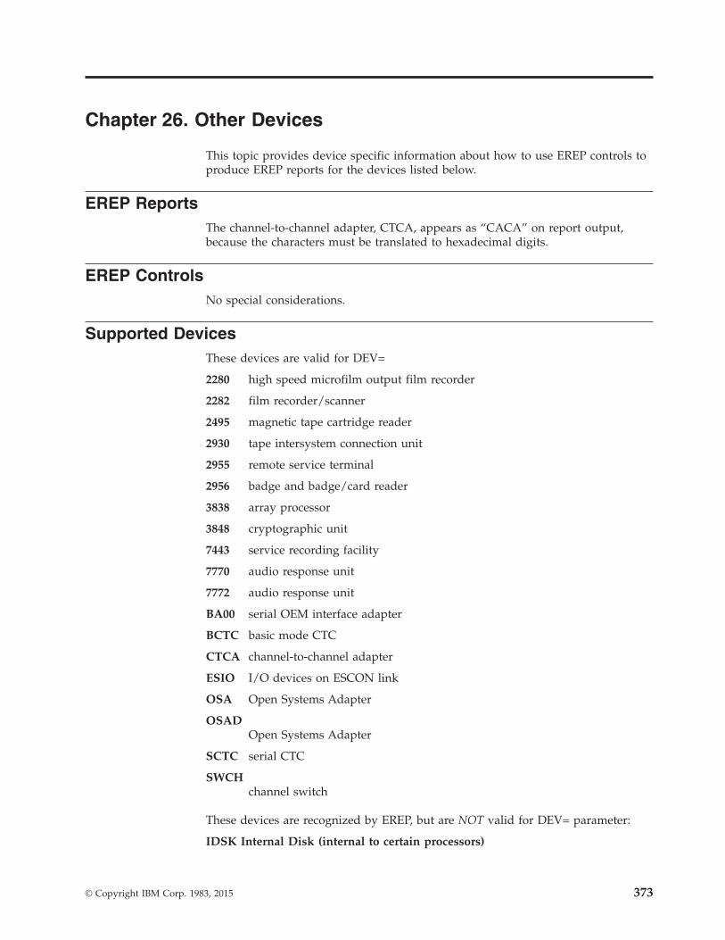
Chapter 26. Other Devices
This topic provides device specific information about how to use EREP controls toproduce EREP reports for the devices listed below.
EREP ReportsThe channel-to-channel adapter, CTCA, appears as “CACA” on report output,because the characters must be translated to hexadecimal digits.
EREP ControlsNo special considerations.
Supported DevicesThese devices are valid for DEV=
2280 high speed microfilm output film recorder
2282 film recorder/scanner
2495 magnetic tape cartridge reader
2930 tape intersystem connection unit
2955 remote service terminal
2956 badge and badge/card reader
3838 array processor
3848 cryptographic unit
7443 service recording facility
7770 audio response unit
7772 audio response unit
BA00 serial OEM interface adapter
BCTC basic mode CTC
CTCA channel-to-channel adapter
ESIO I/O devices on ESCON link
OSA Open Systems Adapter
OSADOpen Systems Adapter
SCTC serial CTC
SWCHchannel switch
These devices are recognized by EREP, but are NOT valid for DEV= parameter:
IDSK Internal Disk (internal to certain processors)
© Copyright IBM Corp. 1983, 2015 373
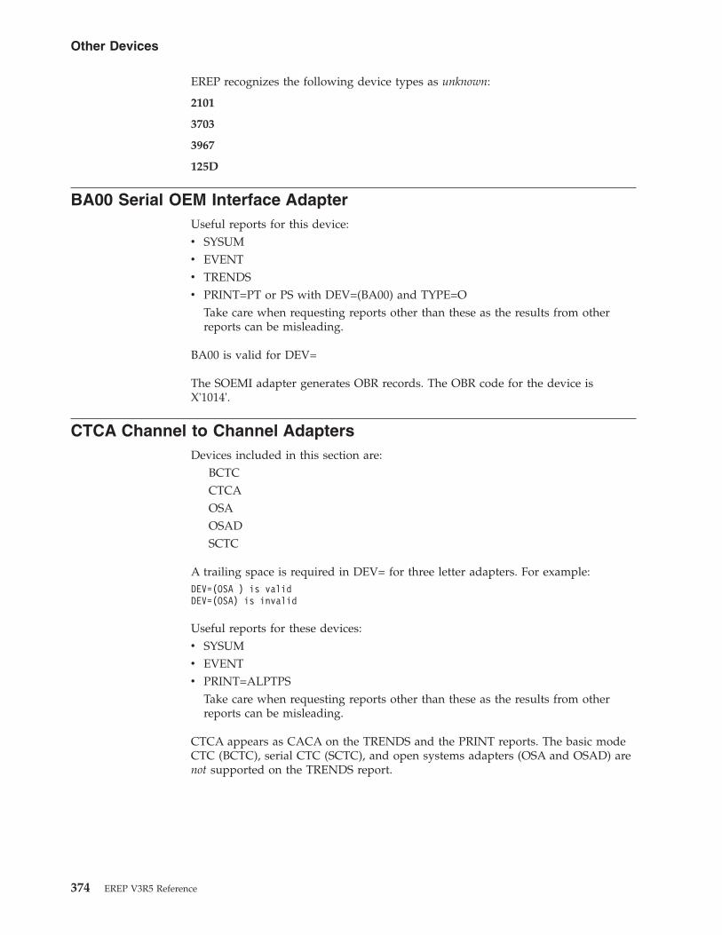
EREP recognizes the following device types as unknown:
2101
3703
3967
125D
BA00 Serial OEM Interface AdapterUseful reports for this device:v SYSUMv EVENTv TRENDSv PRINT=PT or PS with DEV=(BA00) and TYPE=O
Take care when requesting reports other than these as the results from otherreports can be misleading.
BA00 is valid for DEV=
The SOEMI adapter generates OBR records. The OBR code for the device isX'1014'.
CTCA Channel to Channel AdaptersDevices included in this section are:
BCTCCTCAOSAOSADSCTC
A trailing space is required in DEV= for three letter adapters. For example:DEV=(OSA ) is validDEV=(OSA) is invalid
Useful reports for these devices:v SYSUMv EVENTv PRINT=ALPTPS
Take care when requesting reports other than these as the results from otherreports can be misleading.
CTCA appears as CACA on the TRENDS and the PRINT reports. The basic modeCTC (BCTC), serial CTC (SCTC), and open systems adapters (OSA and OSAD) arenot supported on the TRENDS report.
Other Devices
374 EREP V3R5 Reference

ESIO I/O Connected to an ESCON LinkESIO in the DEV= parameter selects the following set of devices:
Device3380 38013390 38033420 93453480 AFP13490 SWCH
Useful reports for this device:SYSUMEVENTPRINT=PT
Take care when requesting reports other than these as the results from otherreports can be misleading.
The ESIO parameter is helpful for creating a file for the I/O devices defined whenrunning PRINT=NO.
IDSK Internal DiskThis section contains special considerations for EREP reports that containinformation about the IDSK.
This subsystem is internal to a processor and is defined to the operating system asthe type of control unit/DASD that is being emulated (for example:3990-06/3390-03). Addresses with these devices are selected with the sameparameter as the emulated device (for example: DEV=(3390) or DEV=(33XX) -NOTE: DEV=(IDSK) is NOT valid).
The following report is useful for this mode of connection:EVENT
Only the emulated device type will appear on this report.
Bytes 54 and 55 of the OBR contain the OBR code of the device the IDSK isemulating (for example: x'2024' for a 3390-03). The OBR code of the IDSK is in theECKD sense data later in the record. See "OBR Codes" in Chapter 7.
Byte 4 of the MDR contains the MDR code of the device the IDSK is emulating (forexample: x'24' for a 3390-03). The MDR code of the IDSK is in the ECKD sensedata later in the record. See "MDR Codes" in Chapter 7.
Serial Link ConnectionThe following reports are useful for this mode of connection:
EVENTPRINT=PT or PS with DEV=(N33XX) and TYPE=A
For each A2 record, the event report provides a time of occurrence indication thatdisplays the following:
Other Devices
Chapter 26. Other Devices 375

v Incident node type, model, interfacev Attached node type, model, interfacev Incident codev Dedicated connection interface identifier (when applicable)
The PRINT report provides an interpretation of the node information from the A2record.
The control parameters are the following:v Timev Typev DEV
SWCH Channel SwitchDevices included in this section are:
SWCH9032903390349037
DEV= applies only to the SWCH and not the individual models.
Other Devices
376 EREP V3R5 Reference

Part 4. Appendixes
© Copyright IBM Corp. 1983, 2015 377

378 EREP V3R5 Reference

Notices
This information was developed for products and services offered in the U.S.A. orelsewhere.
IBM may not offer the products, services, or features discussed in this document inother countries. Consult your local IBM representative for information on theproducts and services currently available in your area. Any reference to an IBMproduct, program, or service is not intended to state or imply that only that IBMproduct, program, or service may be used. Any functionally equivalent product,program, or service that does not infringe any IBM intellectual property right maybe used instead. However, it is the user's responsibility to evaluate and verify theoperation of any non-IBM product, program, or service.
IBM may have patents or pending patent applications covering subject matterdescribed in this document. The furnishing of this document does not give youany license to these patents. You can send license inquiries, in writing, to:
IBM Director of LicensingIBM CorporationNorth Castle DriveArmonk, NY 10504-1785U.S.A
For license inquiries regarding double-byte character set (DBCS) information,contact the IBM Intellectual Property Department in your country or sendinquiries, in writing, to:
Intellectual Property LicensingLegal and Intellectual Property LawIBM Japan, Ltd.19-21, Nihonbashi-Hakozakicho, Chuo-kuTokyo 103-8510, Japan
The following paragraph does not apply to the United Kingdom or any othercountry where such provisions are inconsistent with local law: INTERNATIONALBUSINESS MACHINES CORPORATION PROVIDES THIS PUBLICATION “AS IS”WITHOUT WARRANTY OF ANY KIND, EITHER EXPRESS OR IMPLIED,INCLUDING, BUT NOT LIMITED TO, THE IMPLIED WARRANTIES OFNON-INFRINGEMENT, MERCHANTABILITY OR FITNESS FOR A PARTICULARPURPOSE. Some states do not allow disclaimer of express or implied warranties incertain transactions, therefore, this statement may not apply to you.
This information could include technical inaccuracies or typographical errors.Changes are periodically made to the information herein; these changes will beincorporated in new editions of the publication. IBM may make improvementsand/or changes in the product(s) and/or the program(s) described in thispublication at any time without notice.
Any references in this information to non-IBM Web sites are provided forconvenience only and do not in any manner serve as an endorsement of those Websites. The materials at those Web sites are not part of the materials for this IBMproduct and use of those Web sites is at your own risk.
© Copyright IBM Corp. 1983, 2015 379
IBM may use or distribute any of the information you supply in any way itbelieves appropriate without incurring any obligation to you.
Licensees of this program who wish to have information about it for the purposeof enabling: (i) the exchange of information between independently createdprograms and other programs (including this one) and (ii) the mutual use of theinformation which has been exchanged, should contact:
Site CounselIBM Corporation2455 South RoadPoughkeepsie, NY 12601-5400USA
Such information may be available, subject to appropriate terms and conditions,including in some cases, payment of a fee.
The licensed program described in this information and all licensed materialavailable for it are provided by IBM under terms of the IBM Customer Agreement,IBM International Program License Agreement, or any equivalent agreementbetween us.
Information concerning non-IBM products was obtained from the suppliers ofthose products, their published announcements or other publicly available sources.IBM has not tested those products and cannot confirm the accuracy ofperformance, compatibility or any other claims related to non-IBM products.Questions on the capabilities of non-IBM products should be addressed to thesuppliers of those products.
All statements regarding IBM's future direction or intent are subject to change orwithdrawal without notice, and represent goals and objectives only.
If you are viewing this information softcopy, the photographs and colorillustrations may not appear.
COPYRIGHT LICENSE:
This information might contain sample application programs in source language,which illustrate programming techniques on various operating platforms. You maycopy, modify, and distribute these sample programs in any form without paymentto IBM, for the purposes of developing, using, marketing or distributingapplication programs conforming to the application programming interface for theoperating platform for which the sample programs are written. These exampleshave not been thoroughly tested under all conditions. IBM, therefore, cannotguarantee or imply reliability, serviceability, or function of these programs. Thesample programs are provided "AS IS", without warranty of any kind. IBM shallnot be liable for any damages arising out of your use of the sample programs.
Policy for unsupported hardwareVarious z/OS elements, such as DFSMS, HCD, JES2, JES3, and MVS™, contain codethat supports specific hardware servers or devices. In some cases, thisdevice-related element support remains in the product even after the hardwaredevices pass their announced End of Service date. z/OS may continue to serviceelement code; however, it will not provide service related to unsupportedhardware devices. Software problems related to these devices will not be accepted
380 EREP V3R5 Reference

for service, and current service activity will cease if a problem is determined to beassociated with out-of-support devices. In such cases, fixes will not be issued.
Minimum supported hardwareThe minimum supported hardware for z/OS releases identified in z/OSannouncements can subsequently change when service for particular servers ordevices is withdrawn. Likewise, the levels of other software products supported ona particular release of z/OS are subject to the service support lifecycle of thoseproducts. Therefore, z/OS and its product publications (for example, panels,samples, messages, and product documentation) can include references tohardware and software that is no longer supported.v For information about software support lifecycle, see: IBM Lifecycle Support for
z/OS (http://www.ibm.com/software/support/systemsz/lifecycle/)v For information about currently-supported IBM hardware, contact your IBM
representative.
TrademarksIBM, the IBM logo, and ibm.com are trademarks or registered trademarks ofInternational Business Machines Corp., registered in many jurisdictions worldwide.Other product and service names might be trademarks of IBM or other companies.A current list of IBM trademarks is available at Copyright and Trademarkinformation (http://www.ibm.com/legal/copytrade.shtml).
Notices 381

382 EREP V3R5 Reference

Glossary
This glossary contains a list of terms used withinthe Environmental Record Editing and PrintingProgram library.
A
AFP Advanced Function Printing.
B
BPI Bits per inch.
BTAM Basic telecommunications access method.
BUFE Buffer error.
BYTES RD/SRCHDMegabytes read/searched.
C
CAT Channel availability table.
CCF Channel-check frame.
CCH Channel-check handler.
CCHCRHCCH channel reconfiguration hardware.
CCHINCCCH incomplete record.
CCU Channel control unit.
CCW Channel control word.
CDDACommand data.
CE IBM customer engineer (changed to IBMservice representative).
central processor (CP)One of the internal processors that is partof a central processing complex.
channelThe physical connector between aprocessor and an input/output device,usually via a control unit of some kind. Inthe case of the extended architecture(System 370/XA), the hardware channelsare replaced by subchannels, which arecapable of dynamic variation controlledby microcode in the processor complex.
While this book refers to “subchannels”when discussing fields in 370XA reportoutput, it uses “channel” in the general
sense to mean the connection betweencontroller and device.
channel-check frame (CCF)The record on the ERDS that EREP usesto format channel-check records from the303X group of processors.
channel-check handler (CCH)A S/370 hardware feature that, when achannel error occurs, records informationabout the error and issues a message tothe operator. In VSE, machine checkanalysis and recording performs a similarfunction. The records created in bothcases are called CCH records.
channel-report word (CRW)In S/370XA, a part of thechannel-subchannel recovery mechanism.It contains information about channelincidents reported through machinechecks, specifying the error environmentand the severity of the error. MVS/XAbuilds a CRW record that, in combinationwith the subchannel logout handlerrecord, replaces the CCH record.
CHK Check.
CHNL Channel.
CHP Channel path ID.
CHPIDChannel path ID.
CHR Channel reporting (error).
CK Check.
CKD Count key data.
CLNACTCleaner action.
CMD Command.
CMNDCommand.
CMS Conversational monitor system.
CNT Count.
CNTRLControl.
CNTRLRController.
© Copyright IBM Corp. 1983, 2015 383
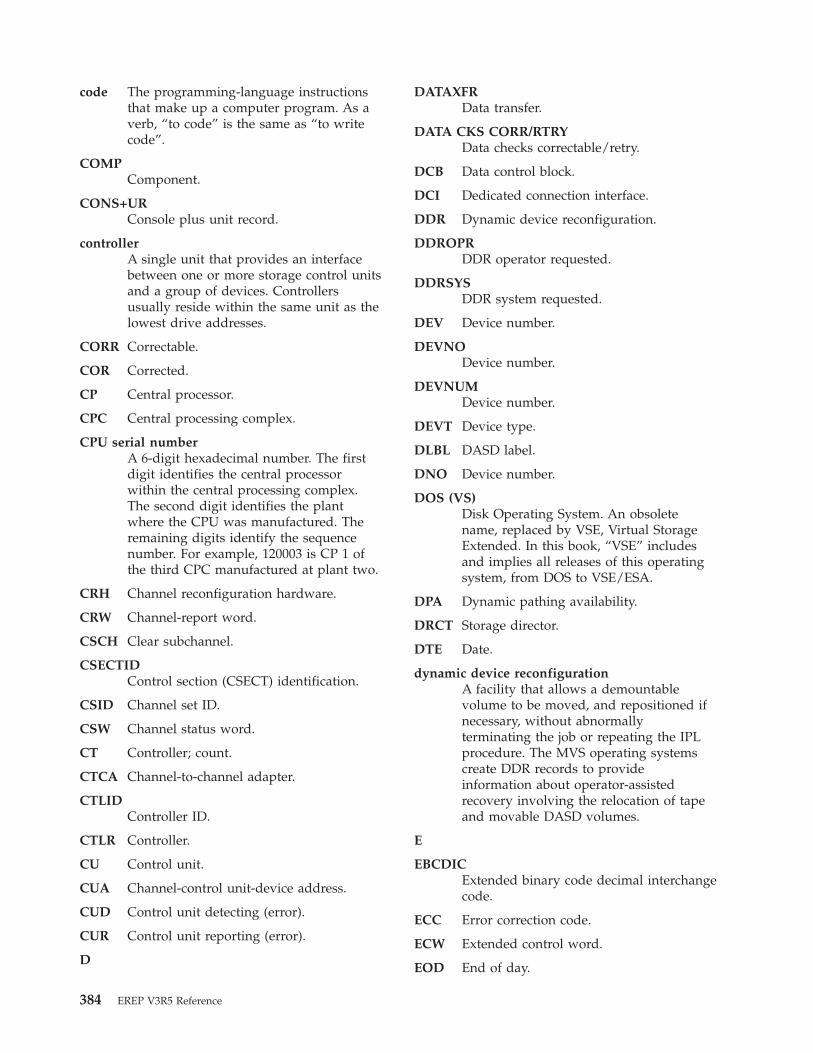
code The programming-language instructionsthat make up a computer program. As averb, “to code” is the same as “to writecode”.
COMPComponent.
CONS+URConsole plus unit record.
controllerA single unit that provides an interfacebetween one or more storage control unitsand a group of devices. Controllersusually reside within the same unit as thelowest drive addresses.
CORR Correctable.
COR Corrected.
CP Central processor.
CPC Central processing complex.
CPU serial numberA 6-digit hexadecimal number. The firstdigit identifies the central processorwithin the central processing complex.The second digit identifies the plantwhere the CPU was manufactured. Theremaining digits identify the sequencenumber. For example, 120003 is CP 1 ofthe third CPC manufactured at plant two.
CRH Channel reconfiguration hardware.
CRW Channel-report word.
CSCH Clear subchannel.
CSECTIDControl section (CSECT) identification.
CSID Channel set ID.
CSW Channel status word.
CT Controller; count.
CTCA Channel-to-channel adapter.
CTLIDController ID.
CTLR Controller.
CU Control unit.
CUA Channel-control unit-device address.
CUD Control unit detecting (error).
CUR Control unit reporting (error).
D
DATAXFRData transfer.
DATA CKS CORR/RTRYData checks correctable/retry.
DCB Data control block.
DCI Dedicated connection interface.
DDR Dynamic device reconfiguration.
DDROPRDDR operator requested.
DDRSYSDDR system requested.
DEV Device number.
DEVNODevice number.
DEVNUMDevice number.
DEVT Device type.
DLBL DASD label.
DNO Device number.
DOS (VS)Disk Operating System. An obsoletename, replaced by VSE, Virtual StorageExtended. In this book, “VSE” includesand implies all releases of this operatingsystem, from DOS to VSE/ESA.
DPA Dynamic pathing availability.
DRCT Storage director.
DTE Date.
dynamic device reconfigurationA facility that allows a demountablevolume to be moved, and repositioned ifnecessary, without abnormallyterminating the job or repeating the IPLprocedure. The MVS operating systemscreate DDR records to provideinformation about operator-assistedrecovery involving the relocation of tapeand movable DASD volumes.
E
EBCDICExtended binary code decimal interchangecode.
ECC Error correction code.
ECW Extended control word.
EOD End of day.
384 EREP V3R5 Reference

EQUCHKEquipment check.
EQUIPEquipment.
ERDS Error-recording dataset.
EREP Environmental record editing andprinting program.
ERP Error-recovery program/processing.
ERROPSError operations.
error-recovery datasetInput to the IFCEREP1 program. In MVSsystems, the ERDS is SYS1.LOGREC; inVSE systems, it is SYSREC; in VM, it isthe error-recording area or cylinders.
error-recovery program/processingSystem routines that detect and processerrors, writing records to the ERDS.
ERSGAPErase gap.
ESIO I/O devices on ESCON link.
ESW Extended status word.
EXCP Execute channel program.
EXTD External damage.
F
FBA Fixed block access.
FCF Function control flag.
FCG Floating channel group.
FLG Flag.
FMT Format.
FRF Function request flag.
FRR Function recovery routines.
FTA File tape adapter.
H
hard machine check or errorA hardware error that disables theprocessor or other unit.
HDR SERHeader (tape)/serial number of drive thatcreated tape.
HIRS Hardware instruction retry (successful).
HSCH Halt subchannel.
I
IC Incident code.
ICHPTInstallation channel path table.
ID Identification.
initial program load (IPL)The process by which an operatingsystem is initialized at the beginning ofthe day or session. At IPL, the systemoperator enters the installation-specificinformation the operating system musthave in order to manage the installation’scomputing system and handle theinstallation’s application programs. Thisinformation includes system parameters,system dataset definitions, and otherinformation needed so the operatingsystem can begin operating.
installationA data processing system location; forexample, a computer center housingprocessors, I/O devices, other hardwaredevices, the software that controls themachines, and the people who control thecomputer center.
INV Invalid.
INVK Invoked.
IOB Input output block.
IPL Initial program load.
IRB Interrupt response block.
J
JCL Job control language.
JCS Job control statement.
K
KB Kilobyte.
L
LEN Length.
LMAT Load-module-address table.
LSQA Local system queue area.
M
machine-check frame (MCF)The record, on the ERDS, that EREP usesto format machine-check records from the303X group of processors.
Glossary 385
machine-check handler (MCH)A S/370 hardware feature that analyzeserrors and attempts recovery by retryingthe failing instruction. If unsuccessful, itcauses an interrupt that triggers thecreation of an error record. In VSEsystems, machine check analysis andrecording performs similar functions. Therecords created in either case are calledMCH records.
MB Megabyte.
MCF Machine-check frame.
MCH Machine-check handler.
MCHTRMMCH System terminated.
MCIC Machine check interrupt code.
MCK Machine check.
MDC Maintenance device code.
MDR Miscellaneous data record.
MDRDASDASD MDR record.
MI Maintenance information.
MICR Magnetic ink character recognition.
MIH Missing-interrupt handler.
miscellaneous data record (MDR)A record type that records error andusage information from buffered controlunits or communications controllers, anddevice failures on TP devices connected to3705/3725 communications controllers.The record is created when there is anoverflow of statistical counters; itspurpose is to provide more informationabout the accompanying failure.
missing-interrupt handler (MIH)An MVS and MVS/XA facility that keepstrack of I/O interrupts, informing theoperator and creating a record wheneveran expected interrupt fails to occur in apreset time interval.
MIX The XA version of the missing-interrupthandler.
MOD Module.
MSHPMaintain system history program.
MVS, MVS/ESA, MVS/XAMultiple Virtual Storage, Multiple Virtual
Storage/Enterprise Systems Architecture,and Multiple Virtual Storage/ExtendedArchitecture, two versions of theSystem/370 operating system that areextensions of OS/VS2.
This manual uses “MVS” to refer to afamily of operating systems that controlsSystem/370 computing systems. “MVS”includes MVS/370, MVS/XA andMVS/ESA.
N
NCP Network control program.
network management vector transport (NMVT)An SNA management services requestunit that flows over an active sessionbetween a device implementing an SNAphysical unit and a device implementingan SNA control point.
NMVTNetwork management vector transport.
O
OBR Outboard recorder.
OBRDMTOBR demount record.
OBRDPAOBR dynamic pathing availability.
OBRDPSOBR dynamic pathing validation analysis.
OBREODOBR End-of-day.
OBRPRMOBR Permanent error record.
OBRPTHOBR Permanent path error record.
OBRSHTOBR Short record.
OBRTMPOBR Temporary error.
OCR Optical character recognition.
Operating System/Virtual Storage (OS/VS)A family of operating systems that controlIBM System/370 computing systems.OS/VS includes VS2, MVS/370, MVS/XAand MVS/ESA. This book refers to theseoperating systems by the general term“MVS”.
386 EREP V3R5 Reference

OS/VSOperating System/Virtual Storage.
OS/VS2Virtual Storage 2 (MVS, Version 1).MVS/370; one of the MVS operatingsystems.
outboard recorder (OBR)In VSE systems, the outboard recorder isa feature that records pertinent data aboutan unrecoverable I/O error. MVS systemscreate a similar record from informationrecorded when an I/O device is inunit-check status. The resulting record inboth cases is called an OBR record.
OVERRNOverrun.
OVERRUN CDDAOverrun command data.
OVRNOverrun.
P
PCCA Physical configuration communicationsarea.
PCT Product control table.
PCUA Primary channel-control unit-deviceaddress.
PDAR Program damage assessment and repair.
PERM Permanent.
PFU Probable failing unit.
PR/SMProgram resource/system manager.
PRGM INTProgram-initiated.
PRI Primary.
PRM Permanent.
product control table (PCT)The internal table that contains data EREPneeds in order to identify and processrecords from a particular IBM device orproduct.
PROG-ECProgram-extended control mode.
PSF Print Services Facility.
PSW Program status word.
PUB Physical unit block.
Q
QSAMQueued sequential access method.
R
RCT Record control table.
RCVRYXITRecovery exit module.
RD Read error.
RDE Reliability data extractor.
REC-TYPRecord type.
ROD Record on demand.
RPA Return point address.
RSM Real storage manager.
RTM Recovery termination manager.
RTN Routine.
RTRY Retry.
R/W Read/write.
S
S/370 and S/370XAComputing systems built around largeIBM processors. XA stands for ExtendedArchitecture, the architecture basis for the3081 and later processors, characterizedby 31-bit addresses. S/370 implies notonly the processor but also the manyother data processing devices that can beconnected to it to make a 370 (or 370XA)data processing system.
SCD System control data.
SCP System control program.
SCSW Subchannel status word.
SCU Storage control unit.
SCUA Secondary channel-control unit-deviceaddress.
SCUIDStorage control unit ID.
SD Storage director.
SDR Statistical data recorder.
SDWASystem diagnostic work area.
SE Systems Engineer.
Glossary 387

SEC Secondary.
SEEKS CNTR/HHSeek errors cylinder track/head
SFT Software record. A record that isproduced as part of the system errorrecovery process. It includes suchsoftware-specific information as theERRORID and the system diagnosticwork area control block and its extensionsfor the failing task or request block. MVSand AIX/ESA ® build software records.
SFTABNSFT ABEND record.
SFTLSTSFT lost record.
SFTMCHSFT machine error, recoverable.
SFTPI SFT program interrupt.
SFTRSTSFT restart.
SIM Service information messages.
SIO Start I/O.
SKS Seeks; data access errors.
SLH Subchannel-logout handler.
SNA Systems network architecture.
SNID Sense path group ID (DPA).
Soft machine check or errorA hardware error that is not disabling.
SPID Set path group ID (DPA).
SQA System queue area.
SRC System reference code.
SRCHDSearched.
SRF Service record file.
SSYS IDSubsystem identifier.
STOR Storage error.
storage control unitA functional unit which resides betweenchannels and controllers.
STSCHStore subchannel.
SSCH Start subchannel.
subchannelThe extended architecture version of“channel”. See also channel.
subchannel-logout handlerA S/370XA feature that provides detailedmodel-independent information relatingto a subchannel; the subchannel logoutdescribes equipment errors detected bythe channel subsystem. MVS/XA andMVS/ESA build an SLH record that, incombination with the CRW record,replaces the CCH record.
subsystemIn hardware terms, a group of devicesthat function together to perform I/Ooperations. An I/O subsystem can consistof a control unit (controller) and itsassociated drives—either disk or tape; orit can consist of all the DASD or tapestorage—including drives andcontrollers—in an installation. In the caseof newer DASD, the I/O subsystem alsoincludes storage control units and storagedirectors, within the controller.
SVC Supervisor call.
syntax The relationships among the elements andcharacters in a parameter or languagestatement. For our purposes, the way youhave to code something in order for theprogram to understand and accept it.
SYSGENSystem generation.
system control programThe minimum software package that willmake your operating system work.
system generationThe process of selecting optional parts ofan operating system and of creating aparticular operating system tailored to therequirements of a data processinginstallation. Can also include I/OGEN,which is the time when the systemprogrammer defines the installation’scomputing system configuration to theoperating system.
Systems EngineerThe person responsible for helping youmaintain the IBM software in yourinstallation.
T
TCO Triple capacity option.
388 EREP V3R5 Reference

TEMP Temporary.
TERM Terminal.
TLBL Tape label.
TMP Temporary.
TP Teleprocessing.
TPF Transaction processing facility.
transaction processing facility (TPF)A high performance, real-time operatingsystem designed for message-drivenapplications that require high availabilityand rapid response time at high messagevolumes.
TSCH Test subchannel.
U
UCB Unit control block.
V
virtual machine (VM)A time-sharing system control programthat manages the resources of an IBMSystem/370 computing system so thatmultiple remote terminal users have afunctional simulation of the computingsystem (a virtual machine) at theirdisposal. This book uses “VM” to meanall versions of the Virtual Machine systemcontrol program, including VM/370,VM/System Pro duct, VM/SP/HighPerformance Option, VM/ESA, andVM/XA.
Virtual Storage Extended (VSE)A family of disk operating systems thatcontrols IBM System/360 and System/370computing systems and includes VSE andVSE/Advanced Functions.
VM Virtual machine.
VOLIDVolume serial number.
VS2 Virtual Storage 2 (MVS, Version 1).MVS/370; one of the OS/VS operatingsystems.
VSAT Virtual storage address table.
VSE Virtual Storage Extended.
VSE/AFVirtual Storage Extended/AdvancedFunctions.
W
WRT Write error.
Glossary 389

390 EREP V3R5 Reference

Index
Numerics0671 DASD
MDR codes 114OBR codes 113subsystem exception report 343
2084 processorIPL detail edit report example 263IPL summary report example 264
3090 processorCCH detail report 251CCH summary report 252
3370 DASD 3423380 DASD
OBR and MDR codes 341subsystem exception report 341
3380 OBR (long) detail report 2903390 DASD
OBR and MDR codes 338subsystem exception report 338
33xx DASDDASDID control statement 343detail edit report 343identifying to EREP 342LIMIT control statement
keywords for control statement 344valid error type keywords 345
subsystem exception report 3433420/3410 temporary error summary 2053422 DEVNO/CUA statistics summary 2223480 OBR (Long) Detail Report 2933480 Tape Subsystem
analyzing tape device performance 349LIMIT control statement
keywords and values 354temporary error limits 354
subsystem exception report 350, 3533490 Tape Subsystem
analyzing tape device performance 349LIMIT control statement
keywords and values 354subsystem exception report 350, 353
3490E Tape Subsystemanalyzing tape device performance 349LIMIT control statement
keywords and values 354temporary error limits 354
subsystem exception report 35335XX Tape Subsystems
analyzing tape device performance 349LIMIT control statement
keywords and values 351temporary error limits 351
OBR and MDR codes 350selection parameters
DEV 350DEVSERV 350VOLID 350
subsystem exception report 350, 355threshold summary report information 350
370 or 370XA operating systemCRW detail edit report (370XA) 257
370 or 370XA operating system (continued)MIH detail edit report (370) 279MIH detail edit report (370XA) 279, 280MIH summary report (370) 279record mode in event history summary 139SLH detail edit report (370XA) 319, 320, 322SLH detail summary report (370XA) 322, 324template for event history 135
3791 OBR detail report for VTAM 2833800 printer
MDR detail report for 3800-3-8 272OBR (Long) Detail Report 296OBR (short) detail report 283
3995 Optical Disk Storage Datasevercontrols 359OBR and MDR codes 359optical subsystem exception series 177
DEVNO/CUA statistics summary 183optical drives error summary 179permanent error summary 178volume statistics summary 181
reports 3594341 processor 2559246 optical library
controls 359OBR codes 359permanent temporary error summary 186permanent temporary error summary by CUA 187reports 359
9247 optical librarycontrols 359error code summary 190OBR codes 359permanent temporary error summary 188reports 359volume error summary 191
9313 DASDsubsystem exception report 343
9332 DASDsubsystem exception report 343
9335 DASDsubsystem exception report 343
9336 DASDsubsystem exception report 343
9345 DASDcontrols 340subsystem exception report 340
9347 Tape Subsystemanalyzing tape device performance 349invalid LIMIT control statement 354subsystem exception report 354
9348 Tape Subsystemanalyzing tape device performance 349invalid LIMIT control statement 354subsystem exception report 354
9373 processorCCH detail report 255CCH summary report 257MCH detail report 264MCH summary report 264
© Copyright IBM Corp. 1983, 2015 391

9392 DASDOBR and MDR codes 339subsystem exception report 339
9395 DASDOBR and MDR codes 340subsystem exception report 340
AA2 record 375Accumulate Records (ACC)
coding 16conflicts, parameter 16defaults 16notes, coding 16syntax 16
analysis, device performance 349
BBA00 SOEMI adapter 374
Ccard readers and punches
reports 333supported devices 333
CCH detail reportdetail edit examples
for 3090 251for 4341 255for 9373 255
summary examplesfor 3090 252for 4341 255for 9373 257
Central Processing Unit (CPU)coding 17conflicts, parameter 17defaults 17example 18instructions to EREP 8notes, coding 18syntax 17
channel subsystem exception report 152channel-to-channel adapters 374Channel/Unit Address (CUA)
coding 20conflicts, parameter 20defaults 20example 21notes, coding 20syntax 20
Clear the ERDS (ZERO)coding 50conflicts, parameter 50defaults 50notes, coding 50syntax 50
codingproblems, correcting 85rules for control statements 51the LIMIT control statement
for 34xx tape devices 350, 354for DASD 344
consoles and displayscontrols 335reports 335supported devices 335
control statementcoding
continuing on new lines 52ENDPARM 51
CONTROLLER usage information 56CPU restrictions (SYSIMG) 52DASDID
control statement without physical IDs 53description 58for 33xx DASD 343
LIMITcoding notations 366for 33xx DASD 344for 34xx tape devices 350, 354for processors, CPUs 365format 344invalid devices and controllers 354keywords and values 344, 351, 366syntax restrictions 4temporary error limits 351usage information 64valid error type keywords 345
SHARE usage information 66summary 52SYSIMG usage information 71
CONTROLLER control statementcoding 56defaults 56description 56example 57notes, coding 57syntax 56
CPU subsystem exception report 150CPU/Channel/Unit Address (CPUCUA)
coding 19conflicts, parameter 19defaults 19notes, coding 19syntax 19
CPUs (processors)generated information 365LIMIT control statement
format 365keywords and values 366notes for coding 366
PR/SM feature 367CRW detail edit report example (370XA) 257CUA statistics for tape drives 220customizing reports 3, 5
DDASD
3370data reduction report 342
3380OBR and MDR codes 341subsystem exception report 341
3390subsystem exception report 338
33XXDASDID control statement 343LIMIT control statement 344
392 EREP V3R5 Reference

DASD (continued)33XX (continued)
subsystem exception report 3439345
controls, EREP 340subsystem exception report 340
9392OBR and MDR codes 339subsystem exception report 339
9395OBR and MDR codes 340subsystem exception report 340
coding the LIMIT control statement 344, 350data transfer summary 168informational messages 167keywords and values for 33xx 344, 345OBR and MDR codes 338service informational messages 166, 236setting limits for report output 344SIMs 166, 236storage control unit summary 176string summary 162subsystem exception report 154, 177symptom code summary 171transfer summary 168
DASDID control statement33xx DASD 343checking for accuracy 62, 85coding 59configuration chart notes 62control statement without physical IDs 53defaults 59description 52, 58example 59notes, coding 59setting up and using 60, 62syntax 58
data reduction report example 260data transfer summary 168Date Range (DATE)
coding 22conflicts, parameter 22defaults 22example 22notes, coding 22specifying for missing records 89syntax 22
DDR detail report and summary example 259Debug (DEBUG)
coding 23conflicts, parameter 23defaults 23for problem determination 88notes, coding 23syntax 23
default actions for parameters 13Detail Edit and Summary Reports (PRINT) 245
coding 36conflicts, parameter 36defaults 36examples
A1 time reference maintenance information 246A2 link maintenance 247A3 asynchronous notification 249A3 report for incorrect record 250CCH detail report 251CRW detail edit (370XA) 257
Detail Edit and Summary Reports (PRINT) (continued)examples (continued)
data reduction report 260DDR detail report and summary 259EOD detail edit 262EOD summary 262IPL detail report 263MCH detail report 264MDR detail report 272MIH detail report 278OBR detail report 282SFT detail report 307SLH Detail Edit Report (370XA) 319, 322unknown detail report 324
syntax 36device
card readers and punches 333example OBR code for device type 109OBR, MDR, and control unit codes 109, 117optical 359other 373performance reports for tape 349punched tape 369reports for analyzing device performance 349teleprocessing 371valid LIMIT keywords for DASD 345
Device Serial Number (DEVSER)coding 26conflicts, parameter 26defaults 26example 26for 34xx tape devices 350notes, coding 26syntax 26
Device Type (DEV)coding 24conflicts, parameter 25defaults 24ESIO 375example 25for 34xx tape devices 350for card readers and punches 333for other devices 376notes, coding 25specifying for missing records 89SWCH channel switch 376syntax 24
diagnostic parameterDebug (DEBUG) 23
diskettecontrol 347report 347supported devices 347
displays and consolescontrols 335reports 335supported devices 335
dynamic pathing availability facility 121
EENDPARM
description 53indicating the end of parameters 51
EOD detail edit report example 262erase gaps 208
Index 393

EREPcodes
device type 109, 111MDR 114, 117OBR 111, 114
control statementsdefault actions 4descriptions 14for MVS 52for VM 52for VSE 52syntax rules 3, 54
DASD 337, 347diskette unit 347hardware supported 329, 333magnetic tape drives 349, 355messages 91OCR/MICR devices 357optical devices 359other devices 373parameters
default actions 4, 13descriptions 14syntax rules 3using to customize reports 3
printers 361, 363procedures for problem determination 87processors (CPUs) 365, 367punched tape devices 369reports
card readers and punches 333consoles and displays 335customizing 3, 5detail edit and summary 245, 327event history 135, 139for analyzing device performance 349processing parameter summary 10report parameter summary 7selection parameter summary 8system exception series 142, 231system summary 119, 125threshold summary 239, 243trends 127, 133
return codes 87teleprocessing devices 371
EREP reports for the tape library 224Error Identifier (ERRORID)
coding 27conflicts, parameter 27defaults 27example 27syntax 27
error-recording data set (ERDS)header record
error and operational records 80field descriptions 76MVS 77overview 76standard record header 81VM 78VSE for SYSREC with CKD 78VSE for SYSREC with FBA 79
IJSYSRC file name 75, 79record type/class codes 82, 83time-stamp record for IPL records 80writing errors/operational records
for MVS 75
error-recording data set (ERDS) (continued)writing errors/operational records (continued)
for VM/SP 75for VSE 75
ESIO ESCON I/O 375Event History (EVENT)
coding 28conflicts, parameter 28defaults 28description 135, 139notes, coding 28notes, creating history dataset 29purpose 135report 136summary 137syntax 28template 135
examplecontrol statement
CONTROLLER 57DASDID 59LIMIT 65SHARE 67SYSIMG 72
OBR codes for device type 109parameter
CPU 18CUA 21DATE 22DEV 25DEVSERV 26ERRORID 27MOD 34SYMCDE 38TERM 43THRESHOLD 44TYPE 48VOLID 49
TOURIST output 85
FFault Symptom Code (SYMCDE)
coding 38conflicts, parameter 38defaults 38example 38notes, coding 38syntax 38
fault symptom code summary for DASD 171
HHistory Input (HIST)
coding 29conflicts, parameter 29defaults 29syntax 29
IIDSK internal disk 375IFC101I 92IFC102I 92IFC103I 92IFC104I 92
394 EREP V3R5 Reference
IFC105I 92IFC106I 92IFC107I 92IFC108I 93IFC109I 93IFC110I 93IFC111I 93IFC112I 93IFC113I 93IFC114I 93IFC116I 93IFC117I 94IFC118I 94IFC119I 94IFC120I 94IFC121I 94IFC122I 94IFC123I 94IFC129I 95IFC130I 95IFC131I 95IFC132I 95IFC133I 95IFC134I 95IFC135I 96IFC136I 96IFC137I 96IFC142I 96IFC143I 96IFC149I 97IFC150I 97IFC152I 97IFC153I 97IFC154I 97IFC165I 97IFC166I 97IFC167I 97IFC168I 97IFC169I 97IFC170I 98IFC171I 98IFC172I 98IFC173I 98IFC174I 98IFC175I 98IFC176I 98IFC177I 98IFC178I 98IFC179I 99IFC180I 99IFC181I 99IFC182I 99IFC183I 99IFC184I 99IFC185I 99IFC186I 99IFC187I 99IFC188I 100IFC189I 100IFC190I 100IFC191I 100IFC192I 100IFC199I 100IFC200I 100IFC201I 101IFC202I 101IFC203I 101
IFC204I 101IFC210I 101IFC214I 101IFC217I 101IFC218I 101IFC219I 101IFC220I 102IFC221I 102IFC223I 102IFC227I 102IFC229I 102IFC230I 102IFC231I 102IFC232I 102IFC233I 103IFC234I 103IFC235I 103IFC236I 103IFC237I 103IFC238I 103IFC239I 103IFC240I 103IFC241I 103IFC242I 103IFC243I 104IFC244I 104IFC245I 104IFC246I 104IFC247I 104IFC248I 104IFC250I 104IFC251I 104IFC252I 105IFC253I 105IFC256I 105IFC257I 105IFC258I 105IFC259I 105IFC260I 106IFC261I 106IFC262I 106IFC263I 106IFC264I 106IFC265I 107IFC266I 107invalid parameter combinations 11IPL detail report
detail edit examplefor 2084 263
summary examplefor 2084 264
LLIMIT control statement
33XX DASDcontrol statement keywords 344invalid devices and controllers 344valid error type keywords 345
34XX tape devicesformatting 350, 354keywords and values 354temporary error limits 351
coding 65defaults 65description 53, 64example 65
Index 395
LIMIT control statement (continued)processors (CPUs)
formatting 365keywords and values 366notes for coding 366
setting for DASD report output 344syntax 64
Line Count (LINECT)coding 31conflicts, parameter 31defaults 31notes, coding 31syntax 31
Line Interface Base Address (LIA/LIBADR)coding 30conflicts, parameter 30defaults 30notes, coding 30syntax 30
Line Length (LINELEN)coding 32conflicts, parameter 32defaults 32notes, coding 32syntax 32
lost record detail edit example (MVS) 318
Mmagnetic tape drives
device performance reports 349media informational messages 237MIMs 237OBR and MDR codes 350subsystem exception report 232, 239, 350, 355threshold summary report information 350
magnetic-ink character readercontrols 357reports 357supported devices 357
MCH detail reportdetail edit examples
for 2084-XA 264for 9373 264
summary examplesfor 2084-XA 264for 9373 264
MDR and OBR codes 3753390 DASD 33834xx tape devices 341, 3503995 optical device 3599392 DASD 3399395 DASD 340device type codes 111, 117example for device type 109print short OBR records 37
MDR detail reportdetail edit examples
3800-3,8 272BSC/SS permanent line error 272outboard 272SDLC link errors 272
summary examplesBSC/SS permanent line error summary 272outboard environment summary 272SDLC link errors 272
media informational messages 237
Merge Input Data Sets (MERGE)coding 33conflicts, parameter 33defaults 33notes, coding 33syntax 33
messagesEREP 91file, TOURIST output 85for MVS users
IFC101I 92IFC102I 92IFC103I 92IFC104I 92IFC105I 92IFC106I 92IFC107I 92IFC108I 93IFC109I 93IFC110I 93IFC111I 93IFC112I 93IFC113I 93IFC114I 93IFC116I 93IFC117I 94IFC118I 94IFC119I 94IFC120I 94IFC121I 94IFC122I 94IFC123I 94IFC129I 95IFC130I 95IFC131I 95IFC132I 95IFC133I 95IFC134I 95IFC135I 96IFC136I 96IFC137I 96IFC142I 96IFC149I 97IFC150I 97IFC152I 97IFC153I 97IFC154I 97IFC165I 97IFC166I 97IFC167I 97IFC169I 97IFC174I 98IFC200I 100IFC201I 101IFC202I 101IFC203I 101IFC210I 101IFC214I 101IFC217I 101IFC218I 101IFC219I 101IFC220I 102IFC221I 102IFC223I 102IFC227I 102IFC229I 102IFC230I 102
396 EREP V3R5 Reference

messages (continued)for MVS users (continued)
IFC231I 102IFC232I 102IFC233I 103IFC234I 103IFC236I 103IFC238I 103IFC240I 103IFC242I 103IFC243I 104IFC244I 104IFC245I 104IFC246I 104IFC247I 104IFC248I 104IFC250I 104IFC251I 104IFC252I 105IFC253I 105IFC256I 105IFC257I 105IFC258I 105IFC259I 105IFC260I 106IFC261I 106IFC262I 106IFC263I 106IFC264I 106IFC265I 107
for VM usersIFC101I 92IFC102I 92IFC103I 92IFC104I 92IFC105I 92IFC106I 92IFC107I 92IFC111I 93IFC112I 93IFC113I 93IFC114I 93IFC117I 94IFC119I 94IFC120I 94IFC121I 94IFC122I 94IFC123I 94IFC129I 95IFC131I 95IFC132I 95IFC133I 95IFC134I 95IFC135I 96IFC136I 96IFC137I 96IFC142I 96IFC149I 97IFC150I 97IFC152I 97IFC153I 97IFC154I 97IFC165I 97IFC166I 97IFC167I 97IFC168I 97IFC169I 97
messages (continued)for VM users (continued)
IFC174I 98IFC200I 100IFC201I 101IFC202I 101IFC203I 101IFC210I 101IFC214I 101IFC217I 101IFC218I 101IFC219I 101IFC220I 102IFC221I 102IFC223I 102IFC227I 102IFC229I 102IFC230I 102IFC231I 102IFC232I 102IFC233I 103IFC234I 103IFC236I 103IFC238I 103IFC240I 103IFC242I 103IFC243I 104IFC244I 104IFC245I 104IFC246I 104IFC247I 104IFC248I 104IFC250I 104IFC251I 104IFC252I 105IFC253I 105IFC256I 105IFC257I 105IFC258I 105IFC259I 105IFC260I 106IFC261I 106IFC262I 106IFC263I 106IFC264I 106IFC265I 107
for VSE usersIFC101I 92IFC111I 93IFC112I 93IFC119I 94IFC120I 94IFC122I 94IFC134I 95IFC136I 96IFC137I 96IFC142I 96IFC150I 97IFC152I 97IFC153I 97IFC154I 97IFC165I 97IFC166I 97IFC167I 97IFC168I 97IFC169I 97IFC170I 98
Index 397

messages (continued)for VSE users (continued)
IFC171I 98IFC172I 98IFC173I 98IFC174I 98IFC175I 98IFC176I 98IFC177I 98IFC178I 98IFC179I 99IFC180I 99IFC181I 99IFC182I 99IFC183I 99IFC184I 99IFC185I 99IFC186I 99IFC187I 99IFC188I 100IFC189I 100IFC190I 100IFC191I 100IFC192I 100IFC199I 100IFC200I 100IFC201I 101IFC203I 101IFC204I 101IFC210I 101IFC214I 101IFC217I 101IFC218I 101IFC219I 101IFC220I 102IFC221I 102IFC223I 102IFC227I 102IFC229I 102IFC230I 102IFC231I 102IFC232I 102IFC233I 103IFC235I 103IFC237I 103IFC239I 103IFC241I 103IFC242I 103IFC243I 104IFC244I 104IFC245I 104IFC246I 104IFC247I 104IFC248I 104IFC250I 104IFC251I 104IFC252I 105IFC253I 105IFC256I 105IFC257I 105IFC258I 105IFC259I 105IFC260I 106IFC261I 106IFC262I 106IFC263I 106IFC264I 106
messages (continued)for VSE users (continued)
IFC265I 107IFC266I 107
MICR/OCR devicescontrols 357reports 357supported devices 357
MIH detail reportdetail edit examples
for 370 279for 370XA 279, 280
summary examplesfor 370 279
Nnotes, coding
34xx LIMIT control statement 352, 353for control statements
CONTROLLER 57DASDID 59LIMIT 366SHARE 67SYSIMG 72
for parameterAccumulate Records (ACC) 16Central Processing Unit (CPU) 18Channel/Unit Address (CUA) 20Clear the ERDS (ZERO) 50CPU/Channel/Unit Address (CPUCUA) 19Date Range (DATE) 22Debug (DEBUG) 23Device Serial Number (DEVSER) 26Device Type (DEV) 25Event History (EVENT) 28Fault Symptom Code (SYMCDE) 38History Input (HIST) 29Line Count (LINECT) 31Line Interface Base Address (LIA/LIBADR) 30Line Length (LINELEN) 32Merge Input Data Sets (MERGE) 33Operating Mode (MODE) 35Print Short OBR Records (SHORT) 37Processor Model (MOD) 34Record Type (TYPE) 47Sort Table Size (TABSIZE) 42System Exception Report (SYSEXN) 40Terminal Name (TERM) 43Threshold Summary (THRESHOLD) 44Time Range (TIME) 45Trends Report (TRENDS) 46Volume Identifier (VOLID) 49
Notices 379
OOBR (long) detail report for Extended Address Volume
(EAV) 306OBR (long) detail report for zHPF 305OBR and MDR codes 375
3390 DASD 33834xx tape devices 341, 3503995 optical device 3599392 DASD 3399395 DASD 340
398 EREP V3R5 Reference
OBR and MDR codes (continued)device type codes 111, 117example for device type 109print short OBR records 37
OCR/MICR devicescontrols 357reports 357supported devices 357
Operating Mode (MODE)coding 35conflicts, parameter 35defaults 35header record for ERDS 77notes, coding 35syntax 35writing operational/error information 75
optical character readercontrols 357reports 357supported devices 357
optical devices3995 Optical Disk Storage Datasever
controls 359OBR and MDR codes 359reports 359
9246 optical librarycontrols 359OBR codes 359reports 359
9247 optical librarycontrols 359OBR codes 359reports 359
Optical subsystem exception series 177, 192other devices
controls 373ESIO ESCON I/O 375reports 373serial link connection
control parameters 376reports 375
serial OEM interface adapter 374supported devices 373
outboard environment summary example 272
Pparameter
avoiding invalid combinations 11coding rules 5, 7customizing reports 3default actions 13descriptions 14ENDPARM 51summary
combinations 11control statement 52processing 10report 7selection 8
syntax rules and restrictions 4parameter, processing
Accumulate Records (ACC) 16Clear the ERDS (ZERO) 50History Input (HIST) 29Line Count (LINECT) 31Line Length (LINELEN) 32
parameter, processing (continued)Merge Input Data Sets (MERGE) 33Print Short OBR Reports (SHORT) 37Sort Table Size (TABSIZE) 42
parameter, reportEvent History (EVENT) 28Print Reports (PRINT) 36System Exception Reports (SYSEXN) 40System Summary (SYSUM) 41Threshold Summary (THRESHOLD) 44Trends Report (TRENDS) 46
parameter, selectionCentral Processing Unit (CPU) 17Channel/Unit Address (CUA) 20CPU/Channel/Unit Address (CPUCUA) 19Date Range (DATE) 22Device Serial Number (DEVSER) 26Device Type (DEV) 24Error Identifier (ERRORID) 27Fault Symptom Code (SYMCDE) 38Line Interface Base Address (LIA/LIBADR) 30Operating Mode (MODE) 35Processor Model (MOD) 34Record Type (TYPE) 47summary 8Terminal Name (TERM) 43Time Range (TIME) 45Volume Identifier (VOLID) 49
performance analysis reports 349permanent error summary for tape 211PR/SM feature 367Print Short OBR Reports (SHORT)
coding 37conflicts, parameter 37defaults 37notes, coding 37syntax 37
printersAFP1 362controls 363edit report 362reports 8, 361summary report 362supported devices
3820 3634248 3636262 363
problem determinationDEBUG parameter 88missing records 89procedures 87trouble-shooting 87
processparameter summary 10writing errors and records to ERDS 75
processing parameterAccumulate Records (ACC) 16Clear the ERDS (ZERO) 50History Input (HIST) 29Line Count (LINECT) 31Line Length (LINELEN) 32Merge Input Data Sets (MERGE) 33Print Short OBR Reports (SHORT) 37Sort Table Size (TABSIZE) 42
Processor Model (MOD)coding 34conflicts, parameter 34
Index 399

Processor Model (MOD) (continued)defaults 34example 34notes, coding 34syntax 34
processor subsystem exception report 150processors, (CPUs)
generated information 365LIMIT control statement
format 365keywords and values 366notes for coding 366
PR/SM feature 367punched tape devices
control 369report 369supported devices 369
punches and card readersreports 333supported devices 333
Rrecord header
information type 81record type 80standard 81time-stamp for IPL records 80type/class code 82, 83
Record Type (TYPE)coding 47conflicts, parameter 47defaults 47example 48notes, coding 47specifying for missing records 89syntax 47
reportparameter summary
combination 11processing 10report 7selection 8
report parameterEvent History (EVENT) 28Print Reports (PRINT) 36System Exception Reports (SYSEXN) 40System Summary (SYSUM) 41Threshold Summary (THRESHOLD) 44Trends Report (TRENDS) 46
return codes from EREP processing 87rules
codingcontrol statement 51parameter 6
syntax 4, 54
SSCU summary 176selection parameter
Central Processing Unit (CPU) 17Channel/Unit Address (CUA) 20CPU/Channel/Unit Address (CPUCUA) 19Date Range (DATE) 22Device Serial Number (DEVSER) 26
selection parameter (continued)Device Type (DEV) 24Error Identifier (ERRORID) 27Fault Symptom Code (SYMCDE) 38Line Interface Base Address (LIA/LIBADR) 30Operating Mode (MODE) 35Processor Model (MOD) 34Record Type (TYPE) 47summary 8Terminal Name (TERM) 43Time Range (TIME) 45Volume Identifier (VOLID) 49
serial link connection 375serial OEM interface adapter 374service informational messages 166, 236setting limits
for DASD report output 344SFT detail report
detail edit examplesfor ABEND 315for lost record (MVS) 318for machine check 310for MCH called RTM 316for program interrupt 313for SVC 13 308
summary examplesfor ABEND 316for lost record (MVS) 318for MCH called RTM 317for SVC 13 310
SHARE control statementassigning CPU numbers 69coding 66combining data in reports 67default 66description 53, 66examples 67for DASD drives 68for tape drives 68notes, coding 67syntax 66
Sort Table Size (TABSIZE)coding 42conflicts, parameter 42defaults 42notes, coding 42syntax 42
standard record headerinformation type 81record type 80standard 81time-stamp for IPL records 80type/class code 82, 83
statement, controlcoding
continuing on new lines 52ENDPARM 51
CONTROLLER usage information 56CPU restrictions (SYSIMG) 52DASDID
control statement without physical IDs 53description 58for 33xx DASD 343
LIMITcoding notations 366for 33xx DASD 344for 34xx tape devices 350, 354
400 EREP V3R5 Reference
statement, control (continued)LIMIT (continued)
for processors, CPUs 365format 344invalid devices and controllers 354keywords and values 344, 351, 366syntax restrictions 4temporary error limits 351usage information 64valid error type keywords 345
SHARE usage information 66summary 52SYSIMG usage information 71
subsystem exception report3380 DASD 3413390 DASD 33833xx DASD 34334xx Tape Devices
3410/3420 3503430 3503480 350, 3533490 350, 353
9345 DASD 3409347 and 9348 tape drives 3549392 DASD 339tape subsystems (3480/3490/3490E) 353
summarydefault actions 13parameter descriptions 14processing 10report 7selection 8
SWCH Channel Switch 376syntax
characters and symbols 3coding parameters 6control statement descriptions 54parameter descriptions 14rules and conventions 4
SYSIMG control statementcoding 72CPU restriction 52defaults 72description 53, 71examples 72notes, coding 72syntax 71
system error summary, part 1 144system error summary, part 2 147System Exception Reports (SYSEXN)
coding 40conflicts, parameter 40defaults 40notes, coding 40subsystem exception series 149
3490 error code summary 2183490 FRU summary report 2163995 DEVNO/CUA statistics summary 1833995 optical drives error summary 1793995 optical subsystem exception report series 1773995 permanent error summary 1783995 volume statistics summary 1819246 permanent/temporary error summary 1869246 permanent/temporary error summary by
CUA 1879246/9247 optical subsystem exception report
series 185
System Exception Reports (SYSEXN) (continued)subsystem exception series (continued)
9247 error code summary 1909247 permanent/temporary error summary 1889247 volume error summary 191channel subsystem exception 152DASD data transfer summary 168DASD informational messages 167DASD service informational messages 166DASD storage control unit summary 176DASD string summary, part 2 165DASD subsystem exception series 154, 177DASD subsystem exception, part 1 156DASD subsystem exception, part 2 161, 162DASD Symptom Code Summary 171Optical subsystem exception series 177, 192processor subsystem exception 150tape DEVNO/CUA statistics summary 220tape forced error log/permanent error summary
reports 198tape library error code summary report 230tape library permanent and recovered error summary
report 225, 227tape library reports 224TAPE media informational messages 237tape permanent error summary 211TAPE service informational messages 236tape subsystem exception report 195TAPE subsystem exception report 233tape subsystem exception report series 193, 231TAPE subsystem exception series 232, 239tape temporary error summary 201tape volume statistics summary 208
syntax 40system error summary, part 1 144system error summary, part 2 147
system initialization reportdetail edit example
for 2084 263summary example
for 2084 264System Summary (SYSUM)
coding 41compatible control statements 53conflicts, parameter 41defaults 41notes, coding 41syntax 41
System Summary Reportdescription 119device address for system summary part 2 121examples 121order of product groups in the reports 120purpose 119system summary part 1 119system summary part 2 120system summary record in 370 or 370XA mode 119
system termination (EOD) detail edit example 262system termination (EOD) detail summary example 263
TTAPE
media informational messages 237service informational messages 236subsystem exception report 233
Index 401

tape devices, punchedcontrol 369report 369supported devices 369
tape drivesdevice performance reports 349media informational messages 237MIMs 237OBR and MDR codes 350subsystem exception report 232, 239, 350, 355threshold summary report information 350
tape library error code summary report 230tape library permanent and recovered error summary
report 225tape library permanent and recovered error summary report
(Service Alerts) 227tape library reports 224tape subsystem exception report series 193
3490 error code summary 2183490 FRU summary report 216subsystem exception series 208tape DEVNO/CUA statistics summary 220tape forced error log/permanent error summary
reports 198tape permanent error summary 211tape subsystem exception report 195tape temporary error summary 201tape volume statistics summary 208
tape subsystems (3480, 3490 and 3490E)analyzing tape device performance 349LIMIT control statement
keywords and values 354temporary error limits 354
subsystem exception report 353teleprocessing (TP) devices
controls 371OBR and MDR codes 371report 371
temporary error summary for tape 201Terminal Name (TERMN)
coding 43conflicts, parameter 43defaults 43example 43notes, coding 43syntax 43
Threshold Summary (THRESHOLD)34xx tape devices 350coding 44compatible control statements 53conflicts, parameter 44defaults 44example 44examples 239, 243notes, coding 44report information 350syntax 44
Time Range (TIME)coding 45conflicts, parameter 45defaults 45notes, coding 45specifying for missing records 89syntax 45
TOURIST outputexample 85for DASDID configuration chart 85
TOURIST output (continued)return codes 87
trademarks 381Trends Report (TRENDS)
coding 46compatible control statements 53conflicts, parameter 46defaults 46example 127, 133notes, coding 46syntax 46
Vvalid parameter combinations 11VM
header record for ERDS 78writing operational/error information 75
Volume Identifier (VOLID)coding 49conflicts, parameter 49defaults 49example 49for 34xx tape devices 350notes, coding 49syntax 49
volume statistics for tape 208VSE
header recordfor SYSREC with CKD 78for SYSREC with FBA 79
writing operational/error information 75
ZZERO processing parameter
coding 50conflicts, parameter 50defaults 50notes, coding 50syntax 50
402 EREP V3R5 Reference


����
Printed in USA
GC35-0152-07
Related Documents