ER-Force Team Description Paper for RoboCup 2011 Florian Bauer, Peter Blank, Michael Bleier, Hannes Dohrn, Michael Eischer, Stefan Friedrich, Adrian Hauck, Jan Kallwies, Patrick Kugler, Dominik Lahmann, Philipp Nordhus, Benjamin Reck, Christian Riess Robotic Activities Erlangen e.V. Pattern Recognition Lab, Department of Computer Science University of Erlangen-Nuremberg Martensstr. 3, 91058 Erlangen, Germany [email protected] http://www.er-force.de/ Abstract. This paper presents an overview description of ER-Force, the RoboCup Small Size League team from Erlangen, Germany. The current hard- and software design of the robots and the motion control system are described. An insight in the software framework and strategy archi- tecture is provided. Furthermore, upcoming changes and improvements are outlined. Fig. 1. ER-Force robot design from 2010.

Welcome message from author
This document is posted to help you gain knowledge. Please leave a comment to let me know what you think about it! Share it to your friends and learn new things together.
Transcript

ER-ForceTeam Description Paper for RoboCup 2011
Florian Bauer, Peter Blank, Michael Bleier, Hannes Dohrn, Michael Eischer,Stefan Friedrich, Adrian Hauck, Jan Kallwies, Patrick Kugler, Dominik
Lahmann, Philipp Nordhus, Benjamin Reck, Christian Riess
Robotic Activities Erlangen e.V.Pattern Recognition Lab, Department of Computer Science
University of Erlangen-NurembergMartensstr. 3, 91058 Erlangen, Germany
http://www.er-force.de/
Abstract. This paper presents an overview description of ER-Force, theRoboCup Small Size League team from Erlangen, Germany. The currenthard- and software design of the robots and the motion control systemare described. An insight in the software framework and strategy archi-tecture is provided. Furthermore, upcoming changes and improvementsare outlined.
Fig. 1. ER-Force robot design from 2010.

1 Introduction
This paper describes the RoboCup Small Size team ER-Force from the Univer-sity of Erlangen-Nuremberg. The team was founded in fall 2006 by students fromvarious engineering disciplines, such as computer science, mechatronics and elec-trical engineering. In 2007 we founded a non-profit association called “RoboticActivities Erlangen e.V.”. This association is engaged in many robot-related ac-tivities including the support of two Robotics groups at local high schools. Theteam participates at the international competitions of RoboCup since 2009.
The following sections provide an overview of our current Small Size Leagueteam. In Section 2 the hardware and firmware architecture of the robots is de-scribed. We discuss the hardware of our 2010 system and outline the new devel-opments and improvements. In Section 3 we examine the software architectureand revisit the techniques used for the filtering of the position data provided bySSL-Vision. Moreover, we give some details on the motion control of our robots.The strategy module and decision algorithms implemented in our system aredescribed in Section 4.
2 Hardware
The design of our 2010 robots is shown in Fig. 1. The team consists of six robotsthat are identical in construction. The chassis consists of laser-milled aluminiumplates connected with custom-built milled components. The lower part of thechassis contains the motors with wheels, the kicker unit with capacitor and thedribbler, while the upper part is completely reserved for the electronics andbattery. In order to be able to reach the inner part of the robots, e.g. to changethe battery, the cover plate is mounted with permanent magnets. The robotdesign is fully rule compliant and has a maximum diameter of 175 mm and amaximum height of roughly 120 mm. The robot covers less than 20 % of the ballalong its z-axis projection at all times.
2.1 Drive
To allow an optimal mobility the ER-Force robots use an omni-directional drive-system. It is similar to other RoboCup Small Size teams, but currently usesonly three wheels. The three wheels were custom built to provide optimal gripin the rotation direction and minimal resistance in any other direction. Theactual speed of the wheels is monitored using quadrature encoders attached tothe motor shafts. This information is used to adjust the motor PWM-signal toachieve the desired wheel speed using a cascaded controller which is running ona microcontroller at a control loop speed of 400 Hz.
This year we are upgrading our driving system to four brushless DC motors(Maxon EC 45 flat) with four omni-directional wheels. By switching to brushlessDC motors we hope to benefit from two things. The new motors have more powerand a higher efficiency than the old brushed motors, which will result in a highermaximum speed.

Fig. 2. Drive system.
2.2 Kicker and Dribbler
We currently employ a solenoid kicker, which consists of a high voltage capac-itor with a capacity of 4900µF and a solenoid with a resistance of 1.5Ω. Thecapacitor is charged by a step-up charging circuit to a voltage of up to 200 V.To activate the kicker a Power MOS-FET is used to drive the high current andvoltage load. The current system is capable of shooting the ball at a speed of upto 8 m/s. A chip-kicking device using the same capacitor but a second solenoidwas developed in 2009 and is still in use. We are currently redesigning the thekicker mechanics with a larger solenoid to make the mechanism even more robustand to increase the maximum ball speed.
The dribbler system in our current robots is placed above the kicking device.It consists of a rubber coated bar driven by a small DC motor (Maxon A-max 19). This bar was designed to exert backspin on the ball and keeping it inposition. The current dribbler design proved to be insufficient, as it is almostimpossible to receive passes with a stationary mounted dribbler. Therefore, weare constructing a passively damped dribbler bar which slows the ball downwhen it hits the robot. This should facilitate passing the ball at high speed.
2.3 Microcontrollers and communication
The 2010 robot generation is using three microcontrollers. An ARM7 receivescommands from the radio module, runs the controller loop, and generates thePWM signal. The encoder signals are evaluated by an ATmega48, which is con-nected to the ARM7 via an SPI bus. Our solenoid kicker is actuated by a ARM
Cortex-M3 microcontroller located on a different board. In order to provide aclean and consistent interface to the different controllers in use, we wrote alibrary that encapsulates hardware specific features such as PWM-signal gener-ation or bus communication. In our new electronic design we are using solelyARM Cortex-M3 microcontrollers.
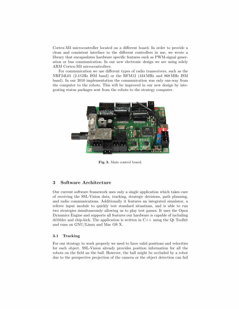
For communication we use different types of radio transceivers, such as theNRF24L01 (2.4 GHz ISM band) or the RFM12 (434 MHz and 868 MHz ISMband). In our 2010 implementation the communication was only one-way fromthe computer to the robots. This will be improved in our new design by inte-grating status packages sent from the robots to the strategy computer.
Fig. 3. Main control board.
3 Software Architecture
Our current software framework uses only a single application which takes careof receiving the SSL-Vision data, tracking, strategic decisions, path planning,and radio communications. Additionally it features an integrated simulator, areferee input module to quickly test standard situations, and is able to runtwo strategies simultaneously allowing us to play test games. It uses the OpenDynamics Engine and supports all features our hardware is capable of includingdribbler and chip-kick. The application is written in C++ using the Qt Toolkitand runs on GNU/Linux and Mac OS X.
3.1 Tracking
For our strategy to work properly we need to have valid positions and velocitiesfor each object. SSL-Vision already provides position information for all therobots on the field an the ball. However, the ball might be occluded by a robotdue to the perspective projection of the camera or the object detection can fail
because of noise or other processing problems. These problems can be solved bya tracking algorithm, which is able to filter out noise, such as invalid objects,and can track an occluded ball.
The robots are tracked by a multiple target tracker which is using robotstacks, which can contain multiple possible position estimates. At first a stackcreated from the previous iteration is searched for each new robot candidate. Ifa robot with the same identification as the new candidate is found and is closerthan 20 cm, the candidate is added to this stack, otherwise it is added to a newlycreated stack. Afterwards each stack with more than one robot is reduced to asingle robot by averaging the position over all robots on this stack. The speed isapproximated from the difference to the last position. If a stack does not containany robots, e.g. if the robot is currently not visible, the position of the robot isestimated as pi = pi−1 + vi−1 × ∆t. Here pi−1 is the position in the previoustime-step and vi−1 is the last known speed, which is assumed to be constant.If no robot was assigned to a stack for more than one second, it is no longertracked as the robot has most likely been removed from the field.
Tracking the ball is a more difficult task, as it moves up to 20 cm between twoframes and can be occluded by a robot due to the perspective projection of thecamera. Since a simple Kalman Filter can not model the non-linear dynamicsintroduced by ball occlusions, we decided to use a Particle Filter [1] to track theball. Particle Filters or Sequential Monte Carlo Methods (SMC) are a differentapproach on tracking. The idea is to get a number of randomly distributed sam-ples and to calculate a weight for each of them. Then the samples are updated,i.e. they are moved according to the system dynamics. The common Particle Fil-ter, also known as Sampling Importance Resampling (SIR), Sequential MonteCarlo Filter, Bootstrap Filter, or Condensation Filter, is a direct implementationof Bayesian Filtering.
In detail, we implemented a Sampling Importance Resampling filter whichuses a model with different state transition functions depending on the situation.If the ball is visible and not in the neighborhood of a robot, a simple linear statetransition model is used. If the ball is close to a robot, modelling the motionis more complex, as the ball may occluded and dribbled or shot by the robot.If it is occluded and the robot is not moving, no measurements are availableand the model is entirely probabilistic and influenced only by the noise model.However, if the robot is moving, the ball is assumed to be still near the samerobot and the ball position estimate is updated using the motion of the robot.As the robot may shoot the ball, an instant acceleration must also be includedinto the model. The only assumption that can be made in this case is that theball can only be shot away from the robot in a single direction. However, thecurrent implementation does not perform any reasoning on which side of a robotthe ball is positioned and does not use this information to improve the estimate.But we are still planning to integrate this and other extension into our statetransitioning model until the competition.
3.2 Strategy
The strategy itself is implemented in the scripting language Lua [2]. The scriptgets all available information such as positions and current referee commandand generates appropriate commands for each robot. To allow for easier testingthe script is automatically reloaded when the files have changed resulting in aninstant behavior change upon saving of the script.
3.3 Motion control
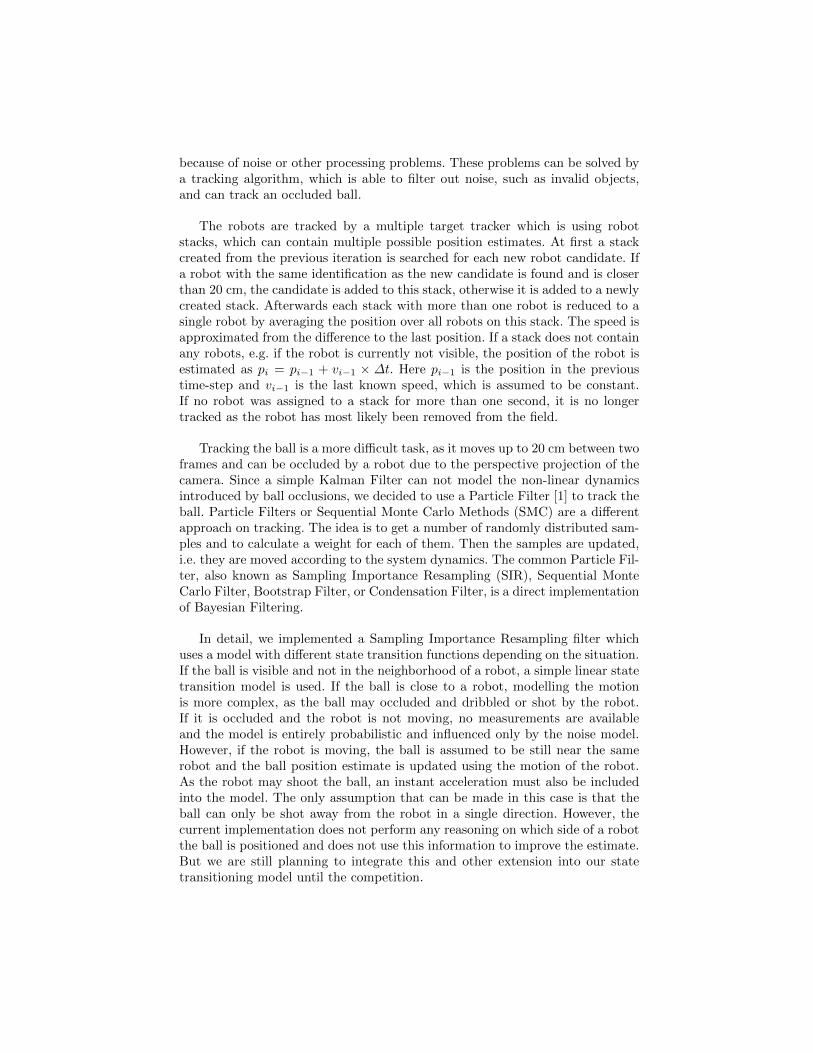
To allow smooth motion of the robots the positions generated by the strategyneed to be processed by a motion controller. The position controller (see Fig. 4)gets the current position of the robot pmeasured from the vision system, comparesit to the desired position psetpoint and calculates the postion error eposition:
eposition = psetpoint − pmeasured . (1)
This is used to calculates a setpoint for the velocity of each robot:
vsetpoint =
vx,setpointvy,setpointωsetpoint
= Kpeposition(t)+Ki
∫ t
0
eposition(τ) dτ+Kdd
dteposition(t) .
(2)
-Strategy
Vision
Positioncontroller
Robots withstate controller
vsoll
eposition
psetpoint
pmeasured
xyφ
p =
Fig. 4. Complete controller structure.
Each velocity setpoint is then transmitted to the according robot. The veloc-ity needs to be controlled by the control software running on the microcontrollersof robots.
The simplest way to control an omni-directional drive-system is to controleach wheel individually with a simple PID controller. Since 2010 our new ap-proach for the motion control is to use a state controller, which takes the ro-tational speed of all wheels into account. It then controls the velocity of therobot as outlined in Fig. 6. The three state variables are the velocities of the

vx
vy
ω
v =
-Strategy /
Radio module
Transformation
Statecontroller
Motors Wheelsu ne
vv
setpoint
vestimated
n1
n2
n3
n =
Fig. 5. The state controller implemented on the robots.
robot in x and y direction and the angular speed. The used coordinate system isshown in Fig. 6. The actual controller implemented in our system is a PI statecontroller. Currently we cannot measure the velocity of the robot directly butwe measure the rotational speed of each wheel and transform it into velocities.The problem with this approach is that the wheels can slip and the velocity ismeasured wrongly. A new idea to improve the velocity estimate is to use lasermotion sensors which are capable to measure the velocity of the robot directly.
n1
n2
n3
ω
vx
vy
Fig. 6. Velocities used for motion control.
3.4 Radio communication
We are using a two way communication to our robots. During each iteration ourstrategy module (described in chapter 4) updates the destination positions forthe robots. The relative movement speed (in robot-local coordinates) is calcu-lated, and sent via USB to a radio sender module. To simplify the communication
we have implemented a small C library which can be used in the C++ strategyapplication as well as on the radio transceiver itself. It focuses on three aspects:
• Same source code on strategy computer and robots• Small packet sizes to keep latency low• Forward compatibility to be able to use robots without reprogramming them
after a protocol extension
The feedback channel is used to report battery level, light barrier state, andother system information from the robots to the control computer for visualiza-tion.
4 Strategy Module
The strategy module uses the output from the tracking algorithm to create anabstract representation of the world. Based on the current position of the robotsand the ball and the actions taken in the previous frames, the strategy thenproduces motion and action vectors (dribbling, kicking or chipping) for eachrobot.
4.1 Overview
The artificial intelligence in the RoboCup Small Size team ER-Force runs af-ter the tracking and before the motion control system. Our approach in the2011 system consists of three main components. First, an observer collects gamestatistics that are used by other components.
Second, roles influence the behavior of a robot. Roles are dynamically as-signed, depending on the game situation. The transition between roles dependson the game situation, and is modelled using finite state machines (FSMs).These FSMs feature a cascade of smaller state machines with partially random-ized transitions. A special case are referee decisions. Referee decisions change thestate immediately to so-called referee states. Such states handle the particularreferee situation, for instance to keep the minimum distance to the center spot.Finally, skills model a single, separate action. Skills of different complexity areused to perform particular roles.
We describe these components bottom-up, starting with the skills of therobots.
4.2 Skills
Skills are implemented as elementary functions of varying complexity. Particularskills can be used within other skills. A skill can be a very straightforward task,such as move to point or grab ball. Skills can also be used to model more complexmedium level and high level functions like pass-and-shoot.
The implementation of higher level skills can become rather complex. It mayuse sub-skills, and require additional reasoning. For instance, it may require

objective evaluation functions and geometric considerations, similar to the onesdescribed in [3]. To perform these tasks, skills use information from the observer(described below).
4.3 Roles
Each role encapsulates a single robot behavior. The execution of a role is typicallyimplemented as a FSM consisting of single skills. Available roles are
• Goal defenders: robots that directly protect the goal.• Field defenders: robots that try to intercept passes.• Ball grabber: robot that runs for the ball.• Attacker: robot that shoots at the goal (when in ball possession).• Assistant: robot that breaks clear, i.e. it aims to get in a position that is not
covered by defending opponents.• Pass player: robot that plays a pass (when in ball possession).• Runner: robot that assists offensive moves, e.g. to receive a passed ball.
4.4 Role Assignment
A role distribution constitutes a mapping of roles to robots. For instance, oneof the robots obtains the goal keeper role, while three others obtain defendingroles. One such distribution is referred to as tactic. A team is assumed to followeither an offensive or defensive tactic. Depending on game statistics from theobserver, an offensive or defensive tactic is chosen.
A tactic contains a set of roles for the team, e.g. how many robots should stayon defense. Furthermore, it states whether the robot that controls the ball shoulddribble, play a pass or shoot at the goal. Thus, the current tactic completelydescribes the immediate next actions of the team.
Within a tactic, the roles are greedily distributed among the robots, accordingto their current positions. The offensive player aims to obtain the ball, and topass and shoot at the opponents goal. The goal defender aims to cover the owngoal.
The selection of a tactic is based on the game state. For instance, withinan offensive situation a robot might be able to safely play a pass next to theopponent’s goal. This tactic is typically preferred over a direct shot on the goal.A tactic can at any time abort itself if it assumes that it can not successfullyfinish the objective.
Subject to recent development was the refinement of roles that involve multi-ple players. This is most relevant during pass play. The current implementationconsiders pass play as an outcome of “reasonable moves”. A more advanced ap-proach is to consider pass play as a part of the solution itself. Thus, we arecurrently modelling joint roles that involve multiple robots. One example for ajoint role is “get next to the goal”, which implies for instance one ball grabber,two assistants and a planning component in order to raise the success probabilityto pass to one of the assistants.

Fig. 7. Visualization of the reasoning for determining a tactic. One option is to shootdirectly. Meanwhile, the second robot changes to the assistant role. If it succeeds inobtaining a better shooting position, the robot at the ball will not shoot himself, butpass.
4.5 Observer
Parallel to the role assignment and execution, an observer analyzes the matchby gathering game play statistics. These include general referee information, ballspecific information and player specific information:
• Referee information Number of goals per team Number of direct/indirect free kicks per team Number of penalty kicks per team
• Ball specific information Ball’s average position and variance Ball’s average speed
• Player specific information Each player’s average position and its variance Average position of all robots of a team Number of shots Number of shots towards a goal Number of successful ball interceptions and ball passes
For this purpose, it is necessary to interpret the opponent players’ behavior.Therefore, the observer recognizes events such as kicking the ball, grabbing theball, passing the ball or intercepting the ball. For all of these events some condi-tions are specified to recognize them. For example the following conditions haveto be fulfilled for the event kicking the ball (player P) in a time interval [t−1, t]:

• The ball has been in a specified orbital region around P (the radius is de-pending on the ball’s velocity).
• The ball’s moving direction has been changed significantly.• The ball’s speed has been increased.
4.6 Enhancements
The observer provides statistical information on the game flow. Using this in-formation in medium level functions and high level functions (for defining therobots’ behavior) leads to remarkable improvements. The analysis of the gamerefers to both the opponents activity and the overall situation. The role assign-ment and skills can take these aspects into account for planning tactical movesof the own robots. Besides this, the system is able to react to damages of our ownrobots, e.g. by swapping the roles of a robot having a broken chip-kick devicewith another robot.
After improving the skills we are currently working on an agent-orientedsystem in order to make planning more flexible and decentralized.
5 Conclusion
The current hardware design we presented in this paper is very similar to theone we used last year at RoboCup 2010, as most components proved to be veryreliable. However, we are also planning to improve some parts as the kicker andthe drive and we want to test a lot of new concepts like a two-way communicationlink. Major improvements, however, are present in the software of our system.
The strategy software was greatly improved, as we are integrating roles thatinvolve multiple players. This was done to allow better robot interaction. More-over, we did a lot of work on the role assignment algorithms. By analyzing therobots behavior and collecting statistical game data it is possible to react ina much more precise way to the opponent. We also implemented an improvedtracking algorithm for robots and ball positions based on Particle filtering.
As we presented a lot of improvements we are eager to test them at RoboCup2011 in Istanbul.
References
1. Arulampalam, M.S., Maskell, S., Gordon, N.: A tutorial on particle filters for onlinenonlinear/non-gaussian bayesian tracking. IEEE Transactions on Signal Processing50 (2002) 174–188
2. Ierusalimschy, R.: Programming in Lua. Lua.org (2006)3. James Bruce, Stefan Zickler, M.L., Veloso, M.: CMDragons: Dynamic Passing and
Strategy on a Champion Robot Soccer Team. In: 2008 IEEE International Confer-ence on Robotics and Automation. (2008) 4074–4079
4. Brooks, R.A.: How to Build Complete Creatures Rather than Isolated CognitiveSimulators. In VanLehn, K., ed.: Architectures for Intelligence. Lawrence ErlbaumAssociates Inc. (1992) 225–239
5. Mitchell, T.: Machine Learning. McGraw-Hill (1997)
Related Documents