. .., .... LATHES - 6"and 10 ll SWING Pages 2-36 DRILL PRESSES Pages 49.61 7 INCH SHAPER . Pages 43 .. 48 EQUIPMENT NEW BENCH MILLING MACHINE Pages 37 .. 42

Welcome message from author
This document is posted to help you gain knowledge. Please leave a comment to let me know what you think about it! Share it to your friends and learn new things together.
Transcript

. ..,.... LATHES - 6"and 10llSWING
Pages 2-36
DRILL PRESSES
Pages 49.61
7 INCH SHAPER. Pages 43 .. 48
EQUIPMENT
NEW BENCH MILLING MACHINE Pages 37 .. 42

II
z
LATHE EQUIPPED ... I I
The Atlas F-Series lO-Inch Lathe
Tool and Die Shop
A BETTER EQUIPPED MODERN SHOP
I N factories, tool and die shops, garages, schools, laboratories, experimental and model-building shops, the backgeared screw-cutting lathe is the basic multi-purpose machine toO'l. More operations are handled on the lathe than on any other single unit of equipment. In recent years, tlrapid advances in Atlas Lathes-their accural:>.,-/ power, rugged strength, and efficiency-coupled with distinctive advanced design features, have made them the preferred lathes in shops throughout the world.
THE NEW ~ F-SERIES lO-INCH LATHES
Atlas F-Series. IO-Inch Lathes are the only low-cost precision lathes with all these modern construction features- precision ground bed ways. custom-built spindle bearings. instantly reversible automatic power cross feed and longitudinal feed. complete V-belt drive. quick-change countershafts. exceptionally wide speed range and screw-cutting range. backgeared power for heavy jobs, compact controls, a nd rugged Zamak alloy parts.
INDEX-tltttu... LATHES
New F-Series lO-Inch Backgeared Screw-
Page
Cutting Lathes. . . . . 3 to 14
lO-Inch La the Tools and Attachments .. . 15 to 28
New 6-Inch Backgeared Screw-Cutting Lathes 29 to 32 ~
6-Inch Lathe Tools and Attachments .. . .... 34 to 36
Complete Arm a t u r e Servicing Outfits ... 33

LATHE
AN ATLAS LATHE meets all the requirements of the modem shop
- accuracy for the finest work. strength and power for heavy jobs.
ruqged materials and large bearing surfaces for long service life
and in addition incorporates many modern features essential for
simple. efficient operation. From its massive precision-ground hed
10 the convenient quick-change countershafts, each part of an Atlas
lathe has been designed on these fundamental principles.
THE rigidity and strength of the Atlas lathe are the results of careful selection of materials and their scientific design. The lathe
bed is a heavy, massive, close-grained, semisteel iron casting- wide thick flat-type ways and heavy box-type cross braces resist all
rning forces . This modern bed design prodes a rigid foundation for the entire lathe.
The lathe headstock, carriage, and tail stock are heavy, well braced, semi-steel iron castings-strong supports for work and cutting tool.
The rugged strength of the Atlas lathe bed, headstock, carriage a nd tail stock, plus heavy duty spindle and spindle bearings, permits a powerful backgeared V-belt drive.
Large bearings with full provision for their complete adjustment and thorough lubrication mean extra years of service with an Atlas lathe. These fine bearings reduce friction, minimize wear, maintain initial accuracy and rigidity.
The heavy duty headstock spindle bearings are high-speed babbitt of the two-piece splitcap type now used in larger machine tools and automobile engines. Laminated shims are provided for take-up. Precision grinding gives the close-grained bed ways a tough, wear-resisting surface. The carriage has six fulllength bearing surfaces on the bed ways, each 9 1/ 2 inches long-two on the top bed wa ys, two on the side ways, and two on the bottom surfaces. The bottom bearing plates have laminated shims for takeup. The lathe tail-
ck has four bearing surfaces on the bed.ne inside bearing on the rear bed way has an adjustable gib. Unusually large carriage and tail stock bearings keep bed wear at a minimum.
Precision lathe work requires accurate a lignment of head- and tailstock spindles, carriage,
and bed ways in both horizontal and vertical planes. In the Atlas lathe, this alignment is guaranteed to be within .001 inch. To obtain this alignment accurate bed ways are the first essential.
The flat-type ways of the Atlas lathe bed are precision-ground. The ways and leg pads are first rough-milled, and the bed is allowed to season naturally to prevent warping and twisting of the finished bed. After seasoning, the bed ways are accurately finish-milled on machines designed especially for the operation. The tops, bottoms, and sides of the ways are then ground and trued on special-built precision grinding machines until all eight surfaces are aligned to within .001 inch.
These precision-ground bed ways are the basis for the accuracy of the Atlas lathe. The headstock spindle bearings are accurately bored by an especially designed machine mounted in position on the bed ways after the
headstock has been carefully fitted to the bed.
This custom-boring method means that the spindle of each lathe is positively aligned with the ways. The carriage is hand-fitted to the bed-the tops and sides of the ways guide the carriage along the bed in alignment with the headstock spindle. The tail stock is fitted to the bed so that the tail stock a nd headstock spindles are aligned to within .001 inch w ith the bed ways and with each other.
Each part for an Atlas lathe is machined on precision equipment of the latest design. Machining processes are checked with preciSion instruments and gauges to insure accuracy and uniformity. Further tests a re made in each stage of assembly, and the completed lathe passes actual working tests for accuracy in all lathe operations. Alignment of spindles, carriage, and bed ways is carefully rechecked before shipment.
RUGGED STRENGTH
LONG SERVICE LIFE
GUARANTEED ACCURACY
FOR SIMPLE EFFICIENT OPERATION INSTANTLY REVERSIBLE
POWER CROSS FEED • INSTANTLY REVERSIBLE
POWER LONGITUDINAL f EED • BACKGEARED POWER FOR
HE.AVY JOBS •
SIXTEEN SPEEDS BETWEEN 28 AND 2072 RPM
• SIMPLIFIED CHANGE GEAR SET-UPS COMPLET E IN D£)(INSIDE BACK COVIER
LARGE EASY.t O-READ THREADING CHART
• 60-HOLE INDEXING MECHANISM ., QUICK·CHANGE COUNTERSHAF
(Horizontal 01 Vertical)
• WIDE THRE.A.D..cUTTING RANGE
(4 10 96 per Inch. Siandcuci. Metric .S to 7DU1l" Standard)
COMPLETE V-BELT ORNE (Motor 1o Countersholt 10 Spindle) ..
PRECISION LEAD SCREW~4" DV\METER
(8 Acme- Threa d per Inch) •
KICROMETER-GRADUA'IED STEEL FE&D SCREW COLLARS
" FOUR BED WIPERS ON CARRIAGE
" GEADU.A.TEO TAILSTOCK RAM

4
Complete Description Pages 6·12
EVERYTHING YOU WANT IN A METAL LATHE

F·SERIES IO·INCB BACKGEARED SCREW·CUTTING
LATHES THE ONLY LOW COST PRECISION LATHE WITH ALL THESE MODERN FEAT ·URES
• Reversible Automatic Power • Quick-Change Countershafts Cross and Longitudinal Feeds • Extra Power for Heavy Jobs
• Precision Ground Bed Ways • Wide Thread Cutting Range • Custom-Built Spindle Bearings • 60 Hole Indexing Mechanism
• Complete V-Belt Drive-IS Speeds l!lC~:a
IS IN THE MODERN ATLAS COMPLETE INDIEXINSIDE BACK COVER 5

THE NEW
F-SERIES ATLAS LATHES WITH VERTICAL COUNTERSHAFT
Boxed Order Length Between Overall Weight Code PRICE No. of Bed Centers Length less motor Word less motor
V36 36/1 18/1 40/1 249 lb. YEKIJ $107.00 V42 42/1 24/1 46/1 261 lb. YEKKO 114.00 V48 48/1 30/1 52/1 269 lb. YEKMY 123.00 V54 54/1 36/1 58/1 274 1b. YEKOK 132.00
All Models: Overall Depth-21", Overall Height-24". Available with Timken Tapered Roller Bearinqs- See Paqes 8 and 9.
No. 2480 113 H.P. 1740 R.P.M. SINGLE PHASE MOTOR-IIO volt, 60 cycle. Has ball bearing double-end shaft Ph" diam
eter), 10 ft. Sj approved extension cord and plug. Code word WYI)L, wt. 28 lb . . .. .... . .... . .. . . ....... ...... .. ...... $14.25 No. 2490 1/2 H.P. 1740 R.P.M. SINGLE PHASE MOTOR-IIO volt,
60 cycle. Has ball bearing double-end shaft (1/2" diameler), 10 ft. Sj approved extension cord and plug. Code word WYILN, wt. 35 lb . .... . . . ...... . ............... ... .... . . $17.50
OTHER MOTORS-PAGE 67 No. 10.420 REVERSING SWITCH with mounting bracket, cable
connections, and installation diagram (see page 26). Code word YELlE, wI. 31/2 lb . .. . , .. ,', .. , . . ,", .. , . . ,",.,", ... . , . $4.50
6
• VERTICAL COUNTERSHAFT
Attached directly to headstock and bed, making lathe a self-contained unit. Hyatt roller bearings, belt-stretch adjustment, quick-change belt tension lever, motor mounting bracket. Each back gear enclosed by iron saiety guard.
Complete Description, Page 13
• Instantly Reversible Automatic Power CI'055 Feed and Longitudinal Feed
F-SERIES
WITH VERTICAL COUNTERSHAFT
Power Cross Feed Standard Equipment
as
COMPLETE SPECIFICATIONS ATLAS F-SERIES IO-INCH
CAPACITY
SPEEDS AND FEEDS
HEADSTOCK
CARRIAGE
{
SWin9 Over .lIed", ....... " ...... , ......... . 10V4" Swinq Over Carriage ..... , . ....... . . .... ..• . as;." Threadinq Range. 4 to 96 Standcud. Riqht or Left Hand
-":Melric •. 5 10 7 mm. Standard Collet Capacity ...••.• ...•. .. •. . 1/2" (see page 16)
~NUmber of Spindle Speeds- 16 (8 Direct. 8 Backgeared) Speeds ............ 28.45.70. ' 83. 112, 134. 164.211.
266. 345. 418. 500. 685. 805. 1270 and 2072 R.P.M. Feeds (Left or Riqht) pet R&volution of Spindle . ...
.. .. ........•.... ... ..... . 0104", .0087" •. 0070 .0060", .0050" •. 0035". or .001877" (Equivalent i threads per inch: 96. 115. 143. 167, 200, 289 or 533)
Lead Screw .. 3/4" Diameter. 8 Acme Threads per inch Change Gears Furnished . . .... . .. . ...... . ..... . 16 Spindle Nose ...... _ .......... .... I 1/2" Diameter
8 pitch Notional form Threads Spindle Nose Taper .... Bored for No.3 Morse Taper
with reducinq sleeve to take No. 2 Morse Taper Hole Through Spindle ... .... ,. "" ......... 25/32" Back Gears ............. ...... 12 Pilch, 7/8" Wide Backqear Shaft Bearinqs. , .•.. .. _ ..... OUite Bronze Bac)tqear Ratio (approximate) .......... , ... .. 6 to 1 Spindle Gear ...... . . IS Pilch. 32 Teeth, 7/8" Wide
)
cr055 Feed Travel. ..... . .. ... , . ... .. ........ 6. 1/2/0 Cross Feed Screw ..... 1/2" Diameter, Acme Threads Feed Screw Collar Graduations .... O to 0.1" by .001" Tool Post Slide Travel. . .. .. . .. ............... 21/4 Tool Post .... 3/8" x 7/B" slot to take 3/B" Tool Bit.., ...........
or Tool Holder for 1/4" Tool Bltll 1-Tool Post Swivel .. , Graduated 0 to 90 0 riqht and 1.ft ""
• Custom-Bu.Ut Spindle Beal'ings • Complete V-Belt Drive,
Sixteen Speeels PLEAse ORDER BY eATALOQ NUMBER

IO-INCB BACKGEARED SCREW CUTTING
AND EQUIPMENT FURNISHED BACKGEARED SCREW CUTTING LATHES
{
TaiiSIOCk Ram ..........•....... . 1-1/4/1 Diameter Bored for No. 2 Morse 'Taper'
TAILSTOCK TaiJstock Ram TraveL ........ . ............... 2%" Tailstock Ram Graduations ...•.. . 0 10 3" by 1/1Sths Tailstock Set·Over. Forward or Back ........... 3/4"
~Motor Recommended .... 1/3 or 1/2 H.P •• 1740 R.P.M. Motor Mounling ... .... .. . .... ... .. Adjuslable Base Hole Through Molor Pulley .......... 1/2" Diameler Buill·In Motor Conlrol Switch ............ 10 Ampere
jl'~ UNIT Switch is lor single phase current only - .. ~ Y M ( -3.pha.e switch is No. 57·300 (page 26)
Countershafl Spindle .. : ...... . Hyall Roller B?ari~gs V·Belts for Complete Dnve ............... 1/2 WIde Motor Pulleys .•.•...•..•........ • .......... 2·slep Drive Pulleys . . .. ........ .. ............... ,4·step
Reversible Automatic Power Cross Feed and Longitudinal Feed. Quick. Change Counlershafl. Complete V·Belt Drive. SO·Hole IndeXing Mechan· ism. Chrome Plated Control Handles. Finish. Speci<il Atlas Gray.
Atlas F·SeriesLalhes are available with Timken Tapered ~ Roller Bearinqs for the headstock spindle. See pages 8 and 3. ~
EQUIPMENT FURNISHED-F·SERIES 10" LATHES Reversible Aulomatic Power Cross Feed: Reversible Automatic Power Longi.
tudinal Feed: Graduated Compound Rest: Tool Post. Ring. and Rocker: Com· plete Set 01 Change Gears to Cut Standard Threads from 4 to 96 per inch and standard metric threads Irom .5 to 7 mm.; Threading Chart. Threading Dial; Quick·Change Countershalt with Motor Mounting Bracket; Belts and
\Jeys lor Complete V·Belt Drive; Motor pulley furnished is for V2" diameter lor shalt-prices 01 pulleys lor other motor shalts on request: 10.Ampere
_"tor Control Switch and Cord-switch is lor single phase current only, :I·phase switch i. No. S7·300 (page 26); GO·Hole Indexing Mechanism: 6" Face Plate; Two 600 Lathe Centers; Reducing Sleeve for Headstock Center: Combi. nation Tool·Post and Compound Wrench. Wrenches for Socket·head Screws: Instruction Book- Atlas "Manual 01 Lalhe Operation" (PerIJ!! 14).
ill Precision .. Ground. Bed Ways ill Extra Power for Heavy Jobs
ALL PRIC ES SUiUIECT TO CN.ANGIE WITHOUT NOTICE;
LATBES
WITH HORIZONTAL COtJNTERSHAFT
Power Cross Feed Standard Equipment
F·SERIES ATLAS LATHES WITH HORIZONTAL COUNTERSHAFT
Boxed Order Length Between Overall Weight Code PRICE No. of Bed Centers Length less motor Word less motor
H3S 36/1 18/1 40/1 2591b. YEKUL $112.00 H42 42/1 24/1 46/1 271 Ib. YELAH 119.00 H48 48/1 30/1 52/1 2791b. YELHA 128.00 H54 54/1 36/1 58/1 2841b. YELIK 137.00
All Models: Overall Depth-2S", Overall Height-19" Available with Timken Tapered Roller Bearings-See Pages 8 and 9.
No. 2480 V3 H.P. 1740 R.P.M. SINGLE PHASE MOTOR- liD volt, SO cycle. Has ball bearing double·end shaft (V2" diam·
eter), 10 ft. SJ approved extension cord and plug. Code word WYIJL. wI. 28 lb........ . .. ... . ............. . . ......... $14.25 No. 2490 112 H.P. 1740 R.P.M. SINGLE PHASE MOTOR-110 volt.
SO cycle. Has ball bearing double·end shaft (V2" diam· eter), 10 ft. SJ approved extension cord and plug. Code word WYILN, wI. 35 lb ........ ... . ....... . ..... . ............. $17.50
OTHER MOTORS- PAGE 67 No. 10·420 REVERSING SWITCH with mounting bracket. cable
connections, and installation diagram (see page 26}. Code word YELJE. wI. 3V2 lb ......... . . .. ........ ................... $4.50
• HORIZONTAL COUNTERSHAFT
Support·bracket is mounted on bench. a heavy rugged support for entire countershaft assembly. Hyatt roller bearings, belt·stretch adjustment, q'Jick·change belt tension lever. motor mounting bracket. Lathe spindle pulley and back gears covered by hinged iron safety guard.
Complete Description. Page 13
• Wide Thread Cutting Range • 60 Hole Indexing Mechanism
7
F-SERIES lO-INCB
WITH
VERTICAL COUNTERSHAFT Power Cross Feed Standard Equipment
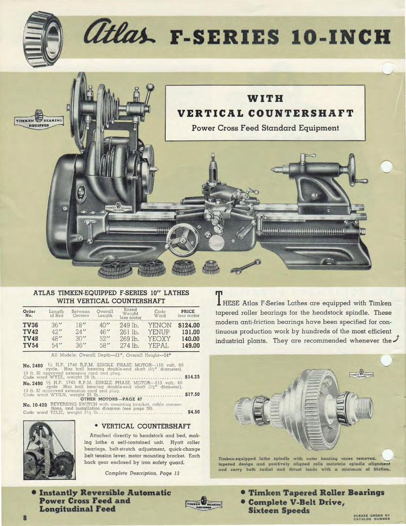
ATLAS TIMKEN-EQUIPPED F-SERIES 10" LATHES WITH VERTICAL COUNTERSHAFT
Order Length Between Overall Boxed Code PRICE Weight No. of Bed Centers Length less motor Word less motor
TV36 36/1 lS /I 40 /1 249 lb. YENON $124.00 TV42 42/1 24/1 46/1 261 lb. YENUP 131.00 TV48 4S/I 30 /1 52/1 269 lb. YEOXY 140.00 TV54 54/1 36 /1 5S /I 274 lb. YEPAL 149.00
All Models : O verall Depth- 21", Overall Heigh t- 24"
No. 2480 lj3 H. P . 1740 R.P .M. SINGLE PHASE MOTOR- 11 0 volt, 60 cycle. Has ball bearing double-end shaft (112" diameter),
10 ft. SI approved extension cord and plug. $ 14.25 Code word WYI)L, weight 28 Ib .. . .. ... . . No 2490 lj2 H. P. 1740 R.P.M. SINGLE PH ASE MOTO R- 11 0 volt, 60
. cycle Has ball bearing double-end shaft (lj2 " diameter), 10 It. SI approved extension cord and plug. Code word W YI LN, weight 35 Ib .. .... .. .. .......... .. .......... .. .. . $1 7 .50
OTHER MOTORS- PAGE 67 No. 10-420 REVERSING SWITCH with mounting bracket, cable connec-
tions , and installation diagram (see page 26). $4.50 Code word YELjE, weight 3 1/ 2 Ib.. . . .......... .
8
• VERTICAL COUNTERSHAFT Attached directly to headstock and bed, mak·
ing la the a se ll-contained unit. Hyatt roller bearings, b e lt-stretch adjustment, quick·change belt tension lever, motor mounting bracket. Each back gear enclosed by iron safety gua rd.
Complete Description, Page 13
• Instantly Reversible Automatic Power Cross Feed and Longitudinal reecl
THESE Atlas F-Series La thes are equipped with Timken
tapered roller bearings for the headstock spindle. These
modern anti-friction bearings have been speCified for con
tinuous production work by hundreds of the most efficient
industrial plants. They are recommended whenever the.J
~ ~
'rimken·eqllippeel lalhe spindle with ouler bearin9 racet removeQ. "--" lapered desicpt and positively a iicpted roll.. mainlain spindle ali9nment a nd carry ' bOlh raelial and thrust load~ w ith a minimum of friction.
• Timken Tapered Roller Bearings • Complete V~Belt Drive,
Sixteen Speeds PL.EASE ORDER IiiV CATAl,QQ NUMBER

LATHES WITH TIMKEN~:f~::BEAR IGS
spindle speed must be exceptionally high for long inter
vals-ideal for metal spinning, plastiCS machining, and
woodturning as well as the usual work at normal speeds.
Construction features of the Timken-Equipped F-Series
Lathes are identical with the Atlas F-Series models de·
scribed on pages 6 and 7 and between pages 10 and 14.
(lUqht) CrOll seetion view of Y·Serles lesthe heesdstock equipped with Timken tapered roller bearings for the headstock spindle. Beesrinq bosses are custom.bored after thl> headstock hess been ~ fitted to the lathe bed. insurinq positive alignment with the
.--...:ecision -ground bed )YII.
WITH
HORIZONTAL COUNTERSHAFT Power Cross Feed Standard Equipment
ATLAS TIMKEN·EQUIPPED F-SERIES 10" LATHES WITH HORIZONTAL COUNTERSHAFT
Order Length Between Overall Boxed Code PRICE No. of Bed Centers Length Weight Word less motor less motor
TH36 36" 18" 40" 259 lb. YEPEM $129.00 TH42 42" 24" 46" 271 lb. YEPLA 136.00 TH48 48" 3~'' 52" 279 lb. YEP ME 145.00 TH54 54" 36" 58" 284 lb. YEPOP 154.00
All Models: Overall Depth-26", Overall Height-19"
No.2480 V3 H.P. 1740 R.P.M. SINGLE PHASE MOTOR-110 volt, 60 • cycle . Has ball bearing double-end shaft (V2" diameter), 10 It. ST approved extension cord and plug. Code word WYIJL, weight 28 lb. .. . . . . . . . . . . ............. . $14.25 No.2490 '/2 H.P. 1740 R.P.M. SINGLE PHASE MOTOR- 110 volt, 60
cycle. Has ball bearing double-end shaft (liz" diameter), 10 ft. ST approved extension cord and plug. Code word WYILN, weight 35 lb . ........................... _. _ . ... _ . . $17.50
OTHER MOTORS-PAGE 67 No. 10-420 REVERSING SWITCH with mounting bracket, cable connec
tions, and installation diagram (see page 26). Code word YELTE, weight 3V2 lb .. .. .... .................. _ .. _ .•. .... $4.50
• HORIZONTAL COUNTERSHAFT Support-bracket is mounted on bench, a heavy
rugged support for entire counters haft assembly. Hyatt roller bearings, belt-stretch adjustment. quick·change belt tension lever, motor mounting bracket. Lathe spindle pulley and back gears covered by hinged iron safety guard.
Complete Description, Page 13
• Precision Gl'oudd Bed Ways • Extra Power fol' Heavy lobs ~ .-- • Wide Thread Cutting Range
• 60 Hole Indexing Mechanism ALL !tRICES SUBJECT TO C t-lAHc:,1: WJTHOUT NOTICI: 9

NEW t1iIm.. F·SERIES 10" BACKGEARED SCREW-CUTTING LATHES (1)
PRECISION-GROUND BED
The rigid, accurate foundation of the Atlas lathe. The entire bed, including cross ribs, ways, and base is
a single heavy, massive, close-grained, semi-steel iron casting. Heavy box ribs, spaced every four inches, rigidly brace the bed ways against heavy turning forces. The wide thick ways at the top and the inner ribs at the bottom maintain rigid alignment of headstock, carriage, and tailstock under heavy loads.
Atlas bed design furnishes the rugged strength essential for heavy duty lathe work. .J
HEADSTOCK The heavy headstock casting is ribbed and reinforced for permanent
rigidity and strength. The front extends up to the bearing height. forming a rugged truss between the bearings and maintaining spindle align· ment under the heaviest loads. The accurately machined base is fitted to the bed ways and solidly anchored to the bed by a steel clamp and large clamp screws. A 10 ampere motor control switch is built into the headstock casting in a convenient position.
10
The following pages present complete information regarding the new Atlas F-Series 10-Inch Backgeared Screw· Cutting Lathe-detailed descriptions of the modern design and construc· tion that mean accurate lathe work, strength and power. long service life. simple eHicient
operation.
The flat-type bed ways are machined by the most modern precision equipment. They are first rough-milled on giant machines designed especially for the operation. The bed is then naturally seasoned for months so that warping and twisting will not occur in the finished bed. After seasoning, the bed ways are accurately finishmilled. The bed ways are given their final precision finish by special-built precision grinding machines like the one illustrated below. The tops, bottoms, and sides are ground and trued until all eight surfaces are aligned to within .001 inch in all planes. Precision grinding gives the close-grained bed ways a tough wear-resisting surface.
Special·built modern grinding equipment of the type shown above gives the final precision finish to the bed ways of the Atlas lathe. These grinders incorporate the latest methods of scientific control. so that each square inch of surface is subjected to exactly the same amount of grind· ing pressure. By precision grinding the tops. bottoms. and sides of the ways until all surfaces are aligned to within .001 inch. these massive machines insure accuracy-the first essential of a precision lathe.
COMPLETE INDEXINSIDE BACK COVER
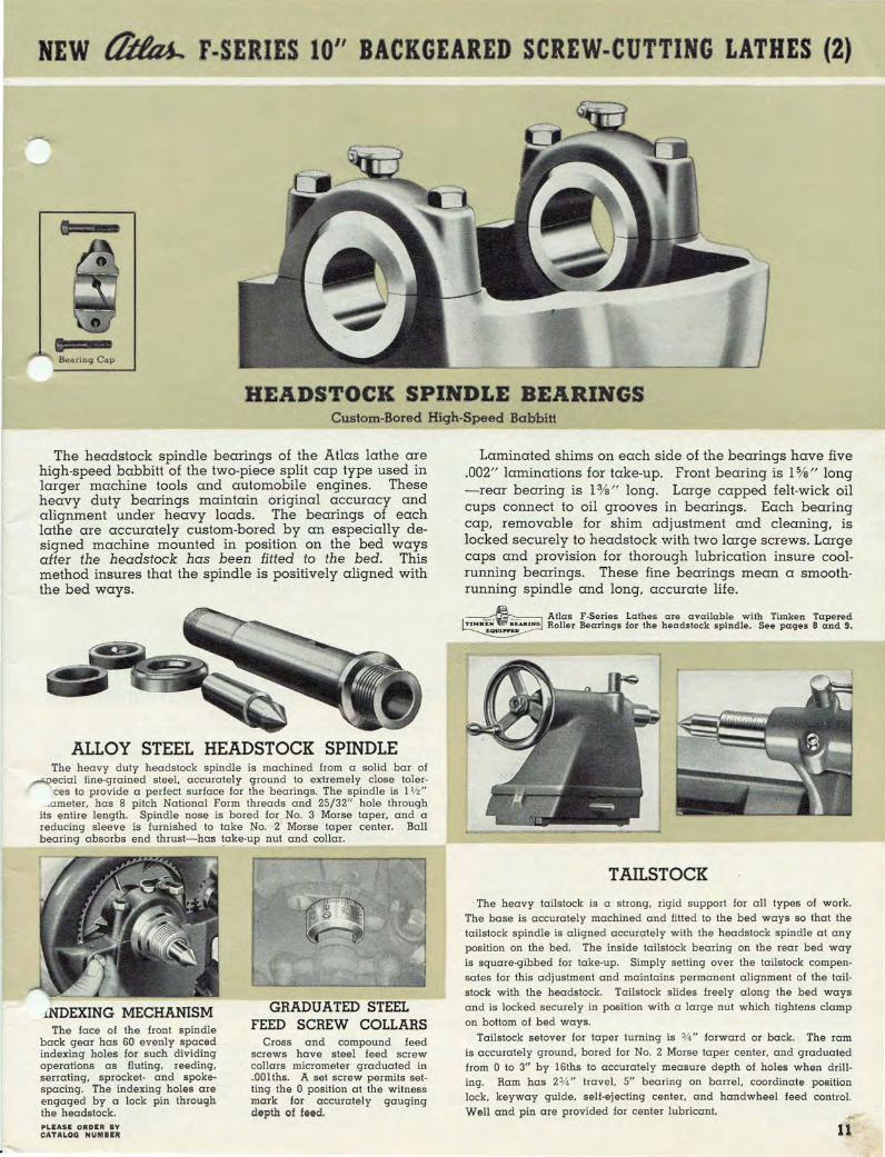
NEW t'ltItu.. F SERIES 10" BACKGEARED SCREW .. CUTTING LATHES (2)
Bearing Cap
HEADSTOCK SPINDLE BEARINGS Custom-Bored High-Speed Babbitt
The headstock spindle bearings of the Atlas lathe are high-speed babbitt of the two-piece split cap type used in larger machine tools and automobile engines. These heavy duty bearings maintain original accuracy and alignment under heavy loads. The bearings of each lathe are accurately custom-bored by an especially deSigned machine mounted in position on the bed ways after the headstock has been fitted to the bed. This method insures that the spindle is positively aligned with the bed ways.
ALLOY STEEL HEADSTOCK SPINDLE The heavy duty headstock spindle is machined from a solid bar of ~ecial fine-grained steel. accurately ground to extremely close toler-
ces to provide a perfect surface for the bearings_ The spindle is 1 1/ 2" __ .a meter. has 8 pitch National Form threads and 25/32" hole through
its entire length_ Spindle nose is bored for _ No_ 3 Morse taper. and a reducing sleeve is furnished to take No_ -2' Morse taper center. Ball bearing absorbs end thrust-has !ake-up nut and collar.
·""""-<:<.t..f " -~.,., (f
rr~~ !··-~I'.-~ '--... -.-.......... -.~ • ' .. ~ . f.,~
, \ i..
lNDEXING MECHANISM The face of the front spindle
back gear has 60 evenly spaced indexing holes for such dividing operations as fluting. reeding. serrating. sprocket- and spokespacing. The indexing holes are engaged by a lock pin through the headstock. PLEASE ORDER BY C:j\Tj\~OG N~MIIII
GRADUATED STEEL FEED SCREW COLLARS
Cross and compound feed screws have steel feed screw collars micrometer graduated in .00lths. A set screw permits setting the 0 position at the witness mark for accurately gauging depth of feed.
Laminated shims on each side of the bearings have five .002" laminations for take-up. Front bearing is 1 %" long -rear bearing is 1 %" long. Large capped felt-wick oil cups connect to oil grooves in bearings. Each bearing cap, removable for shim adjustment and cleaning, is locked securely to headstock with two large screws. Large caps and provision for thorough lubrication insure coolrunning bearings. These fine bearings mean a smoothrunning spindle and long, accurate life.
-~"""--- Atlas F-Series Lathes are available with Timken Tapered Roller Bearings for the headstock spindle. See pages 8 and 9.
TAILSTOCK
The heavy tail stock is a strong. rigid support for all types of work. The base is accurately machined and fitted to the bed ways so that the tail stock spindle is aligned accurately with the headstock spindle at any position on the bed. The inside tail stock bearing on the rear bed way is square-gibbed for take-up. Simply setting over the tail stock compensates for this adjustment and maintains permanent alignment of the tailstock with the headstock. Tailstock slides freely along the bed ways and is locked securely in position with a large nut which tightens clamp on bottom of bed ways.
Tailstock setover for taper turning is 314" forward or back. The ram is accurately ground, bored for No.2 Morse taper center. and graduated from 0 to 3" by 16ths to accurately measure depth of holes when drilling. Ram has 2% " travel. 5" bearing on barrel, coordinate position lock, keyway guide, self-ejecting center, and handwheel feed control. Well and pin are provided for center lubricant.

NEW (/tta,j.. F .. SERIES 10" BACKGEARED SCREW .. CUTTING LATHES (3)
CARRIAGE AND COMPOUND REST
• POWER CROSS FEED
• POWER LONGITUDINAL fEED
• FLAT-TYPE BEARINGS AND WAYS PREVENT LIFT AND TWIST OF CARRIAGE
• :!At" PRECISION LEAD SCREW
• UNUSUALLY LARGE BEARING SURF ACES
• FOUR BED WIPERS
• MICROMETER GRADUATED STEEL FEED SCREW COLLARS
• CROSS SLIDE GRADUATED THROUGH 1800
B---+
THE carriage of the Atlas lathe consists of two heavy castings-the saddle, a broad base and rigid mounting for the compound rest
and the apron, a rugged housing for the power feed mechanisms. The saddle has six accurately machined full· length bearing surfaces on the bed ways, each 9 1/2 " long- two on the top bed ways, two on the side ways, and two on the bottom surfaces. These unusually large bearin"gs assure smooth carriage action and minimize wear. The bottom bearing plates have laminated shims with four .002" and two .001" laminations, and the side bearing on the rear way has an adjustable gib. These adjustments maintain accurate alignment of the carriage with headstock and tailstock. The two plates, one at each side of the saddle, bearing on the ground bottom surfaces of the flat-type bed ways, prevent lift and twist and provide the carriage and tool rigidity essential for maximum accuracy and operating efficiency.
Large hand wheel on apron controls reduction gears meshing with rack for hand-feeding carriage. Carriage travels full length of bed. Carriage lock tightens clamping plate on bott0m of front bed way, locking carriage to the bed in any desired position. Four bed wipers, one at each corner of the carriage, have oil-resisting Neoprene pads to clean the bed ways and felt pads to hold oil.
Dovetails of the cross slide and carriage saddle are accurately machined and hand-fitted to insure accuracy on such operations as facing, milling, and face-plate grinding. The heavy compound rest has 5 V2 " bearing surface on the cross slide-a rigid tool post suppori. It can be turned in a complete circle and locked quickly and securely at any angle. Two clamp screws on compound base control the plunger pins of dovetail swivel lock. Top of cross slide is machine graduated through laO o-compound base has witness mark for setting angle.
Cross feed travel is 6 V2 "-tool post slide travel is 21,4", Dovetail ways of carriage cross slide and tool post slide have adjustable gibs for take-up--gib screws have lock nuts. Feed screws have Acme threads, ball crank controls with take-up adjustment and micrometergraduated steel feed screw collars. Iron cover keeps cross feed screw free from dirt and chips. Milled T-slot holds drop forged tool post assembly-tooi post slot takes %" tool bits or holder for 1/4 " bits.
12
CARRIAGE APRON DETAIL
:A- Precision I e a d screw with keyway to drive poWet cross feed
~-Hall-nul engaging lever C-Hall nuts for power
lonqiludinaJ leeds
D- Knob controlling- bevelqeat drive for power cross leed
E- Handwheel and 9 ear lot hand-feedinq carziag ..
INSTANTLY REVERSIBLE AUTOMATIC POWER CROSS FEED AND LONGITUDINAL FEED
The new Atlas F-series lathes are the only low-cost preCision lathes with both of these efficient. time-saving features . Pulling knob control
on carriage apron engages cross feed mechanism- lever at right engages longitudinal feed mechanism. Both may be reversed instantly by shifting lever on gear box at headstock end of lead screw.
~Lead screw reversing mechanism. Feed reverse lever engages shift collar with either of the two reverse gears, reversing instantly the lead screw rotation which changes tra vel of both cross and longitudinal power feeds.
The power cross feed speeds up all facing operations. Sliding spur gear controlled by knob engages bevel-gear drive from keyway in lead screw with gear on cross slide feed screw.
Power longitudinal feeds make quick, easy work of all turning operations and simplify culling right or left hand threads. Dropping lever closes half nuts on lead screw.
Precision lead screw is % " diameter, a Acme threads per inch-has keyway to drive power cross feed. Lead screw is driven by the gear train from spindle gear through reverse gear box. Rotation of lead screw can be changed instantly while lathe is running. Gear trains can be set up for dozens of different feeds-the six most frequentl~ used are listed on the threading chart mounted on the inside of the gear>-"""'-train guard.
METRIC SCREWS AND COLLARS The F-Series 10" lathes can be furnished with
metric-pitch threads for cross and compound feed screws and with feed screw collars graduated in .02 mm. These metric screws and collars are supplied at no extra cost in place of standard screws and collars when ordered with lathe (specify "Metric Screws and Collars").
COMPLETE INDEXINSIDE BACK COVER

NEW ~ F·SERIES 10" BACKGEARED SCREW-CUTTING LATHES (4)
16 SPINDLE SPEEDS-COMPLETE V-BELT DRIVE (Right) Two-step pulleys from motor to countershaft and four-steppul
.-Aeys from countershaft to spindle give 16 speeds between 28 and 2072 PM. This unusually wide range provides correct speeds for all types
of modern lathe work from heavy metal turning on large diameters to light finishing cuts, polishing, woodworking, and plastics machining. 8 speeds are direct and 8 are backgeared. These speeds are obtained with a standard 1740 RPM motor.
Complete V-belt drive is furnished-from motor to countershaft, and countershaft to spindle- the standard drive furnished on all Atlas lathes. The combination of V-belts, V-pulleys, and adjustable countershaft delivers maximum power to the spindle. This type of power transmission, practically standard in all modern machine tools, results in smooth operation and low operating cost.
BACK GEARED POWER (Right) Heavy oversized back gears reduce spindle speed and deliver e power required for heavy cuts and large diameter work. Here is an
.,{ample which proves the plentiful power of the Atlas backgeared drive: The F-series lathe, in tests, reduces the diameter of a 3V2" steel bar as much as 3/ 4" in a single cut. This cut is taken with the power longitudinal feed engaged. While this is more than any machine of this size should be expected to handle regularly, it is a convincing demonstration of the powerful backgeared drive and indicates the extremely rigid construction of the Atlas lathe.
Back gears are engaged quickly by eccentric lever and removal of lock pin from spindle pulley. Back gear ratio is approximately 6 to l. Gears are %" wide and have 12-pitch teeth. Spindle assembly (backgears, spindle and pulley) is accurately balanced for smooth operation. Backgear shaft runs on oilite bronze bearings. Back gears are enclosed by iron safety guard.
Verrical Counrershaft
_,---i--",--~_~
RUGGED ZAMAK ALLOY PARTS QUICK-CHANGE COUNTERSHAFTS "Zamak," a modern alloy composed of aluminum, mag
nesium, copper and zinc, has twice the tensile strength and four times the impact strength of cast iron. Its amazingly tough properties were developed after years of exhaustive research.
The superior wearing qualities of Zamak-used for pulleys, gears, handwheels, handles and other small parts of the Atlas lathe- have been proved by laboratory experiments and the service tests of thousands of Atlas lathe owners. After eight years of operation, for example, the
ack gears of an Atlas lathe showed very little wear,hey were still good for years of further service. Each Zamak part is cast in a precision master die, insuring uniform accuracy.
Atlas pioneered the use of Zamak alloy in the manufacture of screw-cutting lathes. Zamak parts permit a modern compact deSign, eliminate idle weight, provide greater strength and longer lathe life. PLEASE ORDER BY CATALOG NUMBER
Horizontal or Vertical Two types of countershaft are available with the Atlas
F-series lathes- (l) the new horizontal bench-mounted model and (2) the vertical or built-in countershaft attached to the headstock and bed. Both are "quick-change," with the belt tension lever in easy reach for speed changes. The lever has two positions- forward to release belts for changing speeds, and back to engage belts. The countershaft spindle turns on smooth-running Hyatt roller bearings. Adjustments are provided to compensate for belt stretch. An adjustable motor bracket is attached to the countershaft support bracket.
Two-step pulleys from motor to countershaft and 4-step pulleys from countershaft to spindle provide 16 speeds between 28 and 2072 RPM, 8 direct and 8 backgeared. V-pulleys are balanced, keeping vibration at a minimum. The combination of V-belts, V-pulleys, and the adjustable quick-change countershaft results in smooth efficient operation, maximum power and low operating cost.
13

NEW I1iIm.. F·SERIES 10" BACK GEARED SCREW·CUTTING LATHES (5)
left end of lathe with gear traia guard open, showing change gears, gear train, edge of threading chart.
(Right) Threading chart for culling all standard threads between 4 and 96 per inch and standard metric threads between .5 and 7 mm.
(Actual chart is 7\12" high).
WIDE SCREW CUTTING RANGE 4 to 96 Per Inch. Riqht or Lelt Hand (Standard)
Metric • • 5 to 7mm. Standard
GUARANTEED
The Atlas F-series lathe is equipped with change gears and threading dial for cutting all threads. either right or left hand. from 4 to 96 per inch. in the following standards: National Coarse (USS), National Fine (SAE). Acme, Square, and Whitworth. All standard metric threads from .5 to 7 mm. can be cut with ' the standard change gears furnished. (Metric screws and collars, page 12.) Gear set-ups for these threads are shown on the easy-to-read threading chart on the inside of the gear train guarr '
Hundreds of additional feeds are available for screw ct:>--' ting, coil winding, and spedal work. Complete instructions for gear train set-ups are described and illustrated in the Atlas "Manual of Lathe Operation" (below).
ACCURACY
THREADING DIAL
The threading dial indicates the proper
time to engage halfnut lever so that the tool
enters the same groove of the thread for each
cut. This eliminates splitting threads and
simplifies screw cutting operations. Thread
ing dial is furnished with all Atlas lathes.
Highest standards of accuracy extend to every phase of Atlas lathe manufacture. Each part is machined on precision equipment of the latest design-all machining meets minimum tolerance limits checked by precision instruments and master gauges to insure uniformity and accuracy. Fur-
ther tests are made in each stage of assembly. and alignment of headstock. tailstock, carriage, and bed ways in both horizontal and vertical planes must be within .001". The finished lathe passes actual operating tests for accuracy in all lathe operations. A few of these tests are shown below.
Using Micrometer to Check Test Cut Taken with Work Held in Chuc:k.
14
Opens Easily lI~s Flat
Dial Indic:ator Test-Alignment of Dial Indic:ator Test-Alignment of Tail-Headstock Spindle with Bed Ways. stock Spindle with Headstock Spindle.
Taking Test Cut with Croll reed to Check Alignment of Crols Slid • •
IIMANUAL OF LATHE OPERATION" "LATHE OPERATION" has earned a place as an authentic reference
source for all shop men, both experienced and beginners. Its pages illustrate and describe in easy·to·understand language the care and operation of modern screw·cutting lathes. It includes the latest technical data for machining the new metal alloys and plastics- tool grinding, cutting speeds, lubricants, tables and charts.
The Atlas Manual is logically arranged and accurately indexed for quick "--' reference. Divisional tabs make each chapter instantly available-the special metal binding allows the book to lie open flat at any page.
"MANUAL OF LATHE OPERATION," $1 00 SV2"x8 lj2 " . Pos tpaid pel' copy ... ..... . . • (Furn ished free w ith Atlas 10" me tal la thes)
COMPLETE INDEXINSIDE BACK COVER

ACCESSORIES FOR IO·INCH LATHES
FLOOR STANDS These floor stands furnish the rigid foundation required for accurate lathe
work. The rugged floor legs are heavy iron castings, thickly ribbed and cross
braced for maximum rigidity. Legs alone weigh 95 pounds. The lathe is mounted with each leg directly over a floor leg, anchoring the lathe firmly in position. Table boards are I Sfa " thick, thoroughly seasoned, shellacked, varnished, and ready-drilled for quick assembly. Large bottom board is handy place for chucks, wrenches, gears, tools and accessories. The floor stand makes a convenient "lathe table," improving accuracy of all operations and saving valuable floor space. Height 33 %".
Floor Stands for 10" Lathes WITH VERTICAL COUNTERSHAFT No,
100·442A 100·442B 100·442C 100·4420
For Lathe Nos. Weight Code Price V36 and TV36 150 lb. YADYO $19.00 V 42 and TV 42 155 lb. Y AEBS 20.00 V 48 and TV 48 160 lb. Y AECT 21.00 V54 and TV54 165 lb. YAEGY 22.00
No. 100-441 FLOOR LEGS ONLY. Code YADVE, weight 110 lb . ..... .. $14.00 When ordering, please g ive lathe serial number or year purchased -serial number is stamped on right end of front bed way.
Floor Stands for F·Series 10" Lathes WITH HORIZONTAL COUNTERSHAFT No. For Lathe Nos. Weight Code Price
10F·442A H36 and TH36 161 lb. YEPPO $21.00 ~ 10F·442B H42 and TH42 1661b. YEPRY 22.00
10F.442C H48 and TH48 171 lb . YEPYR 23.00 10F-4420 H54 and TH54 176 lb. YERAN 24.00 No. 10F·441 FLOOR LEGS ONLY. Code YEVAR, weight 110 lb . .... .. . $16.00
• INSTRUCTORS-NOTICE: The above floor stands are available with overall height of 29% " instead of the standard 33%" height listed above. The 4" shorter floor le gs, ofte n desirable for junior class instruction, are supplied at no extra cost. Whe n ordering, specify "Short Floor Legs."
SAFETY BELT GUARDS
FLOOR CABINETS MODERN-RO OMY -RIGID
Here is a new cabinet that provides a rigid lathe support and has plenty of covered shelf space for tools and attachments. Its attractive modern design makes a pleasing appearance in the shop.
The heavy steel panels of the cabinet body are lapped together and strongly welded. Two inside shelves, extending the length of the cabinet and welded securely, give added bracing and provide clean, convenient storage space. Doors have fulllength hinges, spring clip latches, and plastic handles. Each corner of the base has a reinforced hole for bolting the cabinet to the floor. Table board is 15/s" thick, seasoned, shellacked, and varnished.
These new floor cabinets are available in two sizes as listed below (shipped completely assembled). They are finished in special Atlas gray.
FLOOR CABINETS FOR 10" LATHES
For Bed Table Overall No. Length Dimensions HI. Weight Code Price
W71 36" and 42" 45"xI4" 32" 120 lb. YEYHK $24.00 W72 48" and 54" 57"xI4" 32" 1451b. YEYJL 28.00
Atlas belt guards eliminate the hazards of exposed belting by providing a safety cover for all lathe belts as required by industrial and vocational safety codes in many states. These sturdy attractive shields may be installed on any Atlas lO-inch lathe.
the motor-to·countershaft belt and has a special inner guard for the pulley on the countershaft. The right guard covers belt from countershaft to lathe spindle. The entire assembly is readytapped for easy installation.
Both guards are light, durable aluminum castings with pin hinges for quick raising and speed changes. It is not necessary to remove guards to change belts. The left guard covers
No. 10-720 SAFETY BELT GUARDS for Atlas 10" lathes
with v e r tic a 1 countershaft. Code Y ADUZ, weight 8 lb. Per set. .. _ . ••• $15.50
ALL PRICES SUBJECT TO CHANGE WITHOUT NOTICK
The complete transmission - pulleys, feed gears. countershaft and belting-of the Atlas lathe is fully enclosed after these safety belt guards are installed.
No. 10F-720 SAFETY BELT GUARDS for Atlas 10" lathes
with horb;ontal countershaft. Cod e YEVSE, weight 13 lb. Per set. . .•• _ .. $15.50
" 15

•
COLLET ClUCK
ATTACHMENTS FOR
10 INCH LATHES
No . 750 Draw-in Collet Chuck Attachment in operation-collet is controlled by handwheel at left.
DRAW-IN COLLET CHUCK ATTACHMENT The draw-in collet chuck attachment is the most accurate method
for chucking work between 1/32" and 1/2" in diameter. It is used in making precision tools, instruments, gauges, and in the production of small parts requiring extreme accuracy. The attachment consists of a hollow draw-in spindle with hand wheel control, tapered closing sleeve. and split holding collet.
The hollow draw-in spindle extends through the lathe headstock spindle and is threaded at the spindle nose end to hold the collets in the tapered sleeve. The hollow construction permits rods to be passed through the lathe spindle- the handwheel releases and tightens the collet on work. Tapered sleeve is ground inside and outside to insure extreme accuracy. Lathe must be stopped to open and close collet.
No.750 DRAW-IN COLLET CHUCK ATTACHMENT complete. Includes draw-in spindle, ta-
pered closing sleeve, and one split holding collet listed $21 50 below- specify diameter_ Code Y AIRL, wI. 3 lb .. , _ , . •
No. 548 SPINDLE NOSE CAP to pcotect lathe spindle threads. Code $1.90
word YETRE, weight 12 ounces .. . .. . .... .
No. 751 SPLIT HOLDING COLLET for round work-spec-ify diameter. Available in 32nd s between 1/ 32"
and V2" as follows: 1/ 32", 106", 3/ 32", Ve", 5/ 32", 3/ 16", 7/32", V4" , 9/32," 5/ 16". 11 /32", :Y~" , 13/32", 7/ 16", 15 / 32" , $4.75 and V2 " . Code word YAJAZ, weight 4 ounces .. . .. . ... each
No. 900 Lever-Type Collet Chuck Atta chment ha nd ling production work w ith turret attachments.
LEVER-TYPE COLLET CHUCK ATTACHMENT
Chucks and Releases Work with Lathe Running
This new lever-release collet attachment is the ideal chucking method for fast accurate duplicate work on stock between 1/32" and 1/2" diameter. Teamed with turret attachments (page 19). it converts the Atlas IO-inch lathe into a high·speed hand-type production screw machine.
Work may be fed through the hollow torque tube of the lever-type attach· ment, chucked, machined and released without stopping the lathe. Moving hand lever to the left tightens collet on work-collet is released by moving lever to right. Preliminary adjust. ment of collet is made with knurled collar at left end of torque tubeclutch tension sleeve has fifteen evenly spaced slots for fine adjustment. Tapered collet sleeve is ground inside and outside to insure concentric closing of collet. Spindle nose cap protects lathe spindle threads.
The No. 900 attachment is easy to install- there are no holes to drill or tap.
FURNISHED COMPLETE includ· ing hollow torque tube, hand lever controL tapered closing sleeve, spindle nose cap, support bracket, mounting instructions, and one split holding collet listed belowspecify diameter desired.
I
No.900 LEVER-TYPE COLLET CHUCK ATTACHMENT for Atlas 10" Lathes with babbitt spindle bearings_ Furnished
comI?lete _ as shown with one split holding collet listed below- $49 50 specify dlameter_ Code word YEYCF, weigh t 6 lb . ....... . .... ... •
No. 900T LEVER-TYPE COLLET CHUCK ATTACHMENT for Atlas 10" Lathes with Timken tapered roller bearings. Fur-
nished _ com!,lete as shown with one split ho.ld ing collet listed below $49 50 - specify dlQmeter. Code word YEZUB, weight 6 lb. . .... . . . .... . •
SPLIT HOLDING COLLETS For Nos. 750 and 900 Collet Chuck Attachments
Collet tool steeL heat treated and ground inside and outside for precision work. One end of the collet is threaded to fit the draw-in spindle or torque tube and the other end is ground to fit the tapered closing sleeve. Keyway prevents collet turning while in operation. These collets handle round work with diameters between 1/32" and 1/ 2" by 32nds (left). One collet, any fractionct1 size as listed at the lett, is furnished with the No. 750 or No. 900 collet chuck attachment. Collets are available for hexagonaL square, and other sj:lecial work-details on request.
"1.1. ".Icas SUBJECT TO CHAHGIl: tviTHen,IT "'Mu;;e

• FOR AL.L MILLING
OPERATIONS
SHAFT WORK ANGULAR (Vertical) ANGULAR (Horizontal)
MILLING ATTACHMENT FOR IO·INCH LATHES T HIS attachment converts the Atlas lO-inch lathe into a small milling
machine for face milling. cutting keyways and slots. milling dovetails. squaring shafts. making dies and moulds and a wide variety of other important operations. It is quickly and easily installed by removing the compound rest and clamping the base of the milling attachment in its place.
The milling attachment can be swivelled completely to hold work at any angle. Extra heavy castings reduce vibration--gib take-up assures permanent accuracy. The position of the vise is controlled by a feed screw with micrometer graduated collar. Two positive clamping screws lock vise to hold work firmly in position. Vise is graduated and can be
This set holds the milling cutter in headstock spindle . Consists of draw bar, sleeve# and one arbor for
1/ 2 " straight shank cutters .
HOLDING COLLET SET
No. 945 HOLDI NG COLLET SET. Complete: draw bar. sleeve and a rbor. Code YEYAT. weigh t 3 lb .. .. ... . . .. . ..... $4.50
ANGULAR CUTTERS WITH THREADED HOLE
For face-milling. dovetailing. and cutting angles less than 90°. Included angle is 600. Adapted to collet set with arbors listed below.
~~o~ . .-____ ~T~h~ic~k~ __ ~D~ia~m~e;te~r ____ ~H~ol~e~ ___ T~h~r~e~a~d~ __ ~C70~d~e~ ____ ~P~r~ic~e 74A 7/1S" 1% " 3/8" 24 YALIF $4.10
S74B 9/ IS" 15/8" V2" 20 YALJY 4.70 Weight S oz . each
ARBORS FOR ANGULAR CUTTERS
Required to adapt 574 angular cutlers to No . 945 holding collet set. Weight 8 oz. each.
No. 572 567
For No. 574A No. 574B
Code YEWTE YEWUX
Price - --SI.00
1.00
CLAMPING PLATE
For Extra Larqe Work
ClamI'll In place 01 vls&-eapacity 23,4" diameter. Grey !rOJl caBtiJlq with machined working surface. and T-.lot for boll. Oro". forqed clamp. bolt fumlahed.
swivelled to any desired angle. For handling extra large work. clamping plate may be fastened in place of the v ise (see below. left).
No. SOOA MILLING ATTACHMENT. For lO-inch lathes with serial numbers following 3970. Code
word YAKBA. weight 17 pounds ..................... .. ... $16.00 FURNISHED: Complete as shown including graduated swivel vise. vertical feed screw with graduated collar. flat block. V-block for round work. Vertical Feed ....... .. .... ..... 3%" Jaw Depth ..... .. ....... ..... . .. 7fs" Cross Feed ........ ..... ..... .... 5" Jaw Width ............ .. .. .. . . 2V2"
Vise Capacity ..... . .. . .. ....... 2% " For lathes with serial numbers lower than 397o-prices on request
R. H. SPIRAL STRAIGHT SHANK END MILLS
For general milling operations-slots. facing and routing. squaring , and splining shafts. cutting straight keyways. Adapted to collet set with collet bushings below. 4 oz; each. No. Length of Flute Diameter Code Word Price
576A 5/ 8" 1/ 4" YAKCE S1.75 576B II / IS" 5/ IS" YAKEC 1.85 576C 3/ 4" 3/ 8" YAKFO 1.95 5760 7/ 8" 7 / IS" YAKlD 2.15 576E IS/ IS" 1/ 2" YAKOF 2.35
COLLET BUSHINGS
~ Required to adapt 576 straight shank end mills to No. 945
\1 ing collet set. Not required for 576E end mill. No. For End Mill Dia meter Code
5630 No. 57SA li4" YAKYH
" 563C No. 57SB 5/ IS" YALAC 563B No. 57SC 3/ 8" YALCA 563A No. 57SD 7/ IS" YALDE
No. 563E Set of four above bushings- Code w ord YALED . ..... . .. . . ...
STRAIGHT SHANK WOODRUFF KEYWAY CUTTERS Designed especially for cutting Woodruff keyways-<!1so used
for milling slots. grooves. T-slots. etc. Held directly in arbor of No. 945 collet set. Weight 6 oz. each.
No. 575A 575B 575C 5750 575E
Diameter Thickness 1/ 8"
3/ IS" 1/ 4"
5/ 16" 3/ 8"
Diam. Shank
V2" V2" liz" V2" 1J2"
GEAR CUTTING
Code YALUH YALYJ YAMAD YAMDA YAMEF
Price 52.65 2.85 3.50 3.95 4.35
hold-
Price SO.30
.30
.30
.30 1.15
No. 5021 CLAMPING PLATE. Code word YEZOZ. wI. S lb . ••• - :14.75
lMPOllTAlffI Please Give Latlae Se-rfal Number and Dcrte ~.
(Above) HandliJlq ionq horlnq operation with work held in ciampinq ph:ile and hortnq bar DlOWlted between centers. Blueprint qutde for matmq honnq ba1'-Jfo. ISP. I01 YEREP 10.35.
A blueprint i. amiable for bullcUnq the qear cuItlng at. tachment shown at the rfght. Thi. attachment. mounted in the mllUn" Yi... bold. the blank ,ear at one end and an iJldex.
. lnq "ear at the other end. Outer ucmJr of the index shaft can be adapted to bold any indexing 'lear. No. ISP· I01 BLUEPRINT. Gear Cuttlnq .. _Allachmenl. Code word YERNA ••••• • • • •• • • • 1D.50
K __ lI:lIila"
CATALOG NWI_
18
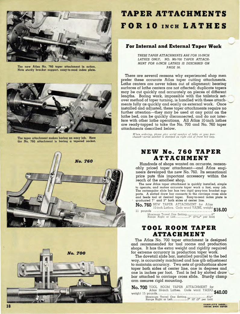
The new Atlas No. 760 taper attachment in action. Note alurdy bracket support. easy·to·reed index plate.
The taper attachment makes borinq an easy iob. Here tho No. 760 attachment Is borinq Cl tapered socket.
No. 760
No. 700
TAPER ATTACHMENTS
FOR 10 INCH LATHES
For Internal and External Taper Work
THESE TAPER ATTACHMENTS ARE FOR lO-INCH LATHES ONLY. NO. M6-700 TAPER ATT ACHMENT FOR 6-INCH LATHES IS DESCRIBED ON
PAGE 36.
There are several reasons why experienced shop men prefer these accurate Atlas taper cutting attachments. Lathe centers are never taken Qut of alignment; bearing surfaces of lathe centers are not affected; duplicate tapers may be cut quickly and accurately on pieces of different lengths. Boring work, impossible with the tailstock setover method of taper turning. is handled with these attachments fully as quickly and easily as external work. Once installed and adjusted. these taper attachments require no further attention-they may be used at any point on the lathe bed. can be qUickly disconnected, and do not interfere with other lathe operations. All Atlas lO-inch lathes are ready-tapped to take the No. 700 and No. 760 taper attachments described below. '
When orden'ny, please give sC1·ial llU111 bC1' of lathe 01' )'CQ1' pur'cha.sed-sc1'ial number £s stamped on right clId of front bed 'Way.
NEW No. 760 TAPER ATTACHMENT
Hundreds of shops wanted an accurate, reasonably priced taper attachment-and Atlas engineers developed the new No. 760. Its sensational price puts this important accessory within the reach of the smallest shop.
The new Atlas taper attachment is quickly installed, simple to operate, and makes accurate taper w ork a fast, easy job, The rectangular slide bar has two rigid grey-iron bracket supports, A slotted draw bar connects to the carriage cross slide and feeds tool at desired taper. Easy-to-read index plate is graduated 7° and 3" both sides of center line.
No. 760 NEW TAPER ATTACHMENT for Atlas
11 pounds IO-~~~~ ,~~t,h,e,s.' , ~,o~e. ~~~~ :. ~:~~: ~~i,~~t $16.00 Maximum Travel One Setting ..... . .. . ..... .... 6" Range Right or LefL, _ . ..... . 7' (21~;O" per foot)
TOOL ROOM TAPER ATTACHMENT
The Atlas No. 700 taper attachment is designed and recommended for tool rooms and production shops. It has the extra weight and rigidity required for extreme accuracy in production taper work.
The dovetail slide bar, installed parallel to the bed way, is accurately machined and has gib adjustment to maintain accuracy. Two sets of graduations show taper both sides of center line, one in degrees and one in inches per foot. Tool is fed by slotted draw bar attached to carriage cross slide. Sturdy clamp arm assures rigid mounting.
No 700 TOOL ROOM TAPER ATTACHMENT for
Weig~ t 15 p!~~~ . ~ ~-.i~~~ .. L.~t~~.s: .. ?~~.~ . v:.0.r~ .. : ~?~?, $40.00 Maximum Travel One Setting . .. . . __ . __ . .... 6112" Range Right or Left .. . .. . .•• .. 7° 10' (3" per foot)
C: OMPLET~ INOEXINSIII .. 1I'1C:K c;OVl1I
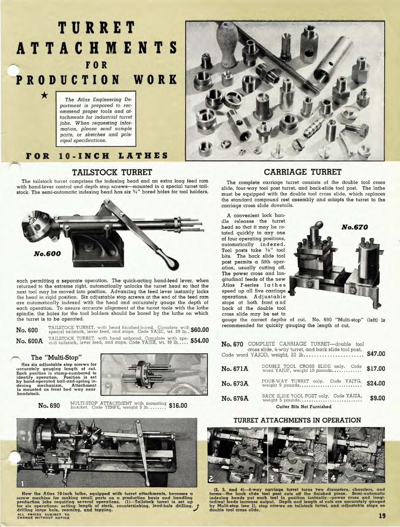
TURRET ATTACHMENTS
FOR PRODUCTION
* The Atlas Engineering Depa rtment is prepared to recommend proper tools and attachments for industrial turret jobs_ When requesting information, please send sample parts, or sketches and principal specifications_
WORK
FOR lO·INCH LATHES
TAILSTOCK TURRET The ta ils tock turret comprises the indexing head and an extra long feed ram
with hand-lever cont rol and depth stop screws- mounted in a special turret tailstock. The semi-automatic indexing head has six %" bored holes for tool holders,
No. 600
each permitting a separate operation. The quick-acting hand-feed lever, when returned to the extreme right, automatically unlocks the turret head so that the next tool may be moved into position. Advancing the feed lever instantly locks the head in rigid position. Six adjustable stop screws at the end of the feed ram are automatically indexed with the head and accurately gauge the depth of each operation. To assure accurate alignment of the turret tools with the lathe spindle, the holes for the tool holders should be bored by the lathe on which the turret is to be operated.
No. 600 TA ILSTOCK TURRET, with head finished-bored. Complete with $60 00 special tailstock, lever feed, and stops . Code Y AJIC, wt. 39 lb.. •
N 600A TAILSTOCK TURRET. with head unbored. Complete with spe- $54 00 O. cial tailstock, lever feed, and stops. Code Y AJEB, wt. 39 lb .. _ . . •
...-... The "Multi-Stop" Has six adjustable stop screws for
accurately gauging length of cut. Each position is stamp-numbered to identify operation. Position is set by hand-operated ball-and-spring indexing mechanism. Attachment is mounted on front bed way near headstock.
No. 690 MULTI-STOP ATTACHMENT with mounting $16.00 b racke t. Code YEHF E, weight 3 lb ....... .
How the Alias lO-inch lathe, equipped with turret attachments. becomes a screw machine for makinq small parts on a production basis and handling production jobs requilinq several operations. (l)- Tailstock turret is set up for six operations: sellinq lenqth of s tock. countersinkinq. lead·hole cirillin'1'.J drilling large hole. reaming. and tapping. AU.. PR'CIltS SUBJECT TO CHANGE WITHOUT NOTICE
CARRIAGE TURRET The complete carriage turret consists of the double tool cross
slide, four-way tool post turret, and back-slide tool post. The lathe must be equipped with the double tool cross slide, which replaces the standard compound rest assembly and adapts the turret to the carriage cross slide dovetails.
A convenient lock han-dle releases the turret head so that it may be rotated quickly to anyone of four operating positions, automatically indexed. Tool posts take 3/8 " tool bits_ The back slide tool post permits a fifth operation, usually cutting off_ The power cross and longitudinal feeds of the new Atlas F-series I at h e s speed up all five carriage operations. Adj ustable stops at both front a nd back of the double tool cross slide may be set to
No. 670
gauge the correct depths of cut. No. 690 "Multi-stop" (left) is recommended for quickly gauging the length of cut.
No.670 COMPLETE CARRIAGE TURRET-double tool cross slide, 4-way turret, and back slide tool post.
Code word YAJOD, weight, 22 lb ... .. . ........ . .. ... _ . . $47.00
No. 671A DOUBl.E TOOL CROSS SLIDE only. Code word Y AJUF, weight 10 pounds_ .. _ . . ... . .. . $17.00
No. 673A FOUR-WAY TURRET only . Code YAJYG, weight 9 pounds .... . ... .... ... . . .. . .. .. .. . $24.00
No. 676A BACK SLIDE TOOL POST only. Code YAJZA, weight 5 pounds .. .. . __ ... ... . ... .. __ .. ... . $9.00
Cutter Bits Not Furnished
TURRET ATTACHMENTS IN OPERATION
(2. 3, and 4}--4-way carriage tunel turns two diameters, chamfers. and forms-the back slide tool post cuts of{ the finished piece. Semi-automatic indexinq heads put each tool in position instantly- power eross and lonqiludinal feeds increase output. Depth and length of cut .. are accurately gauged by Multi-stop (see 1). stop !i!crew& on tailsloc!c tunel. and adjustable stops on double tool cross slide.
19
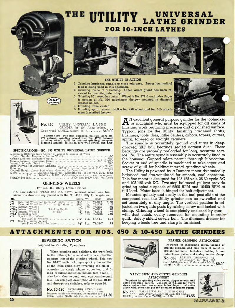
UTILIT·Y UNIVERSAL LATHE O'RINDER
FOR 10-INC& LATHES
1. Grinding hardened sp indle to close tolerance. feed is being used in this operation.
2. Grinding inside o f a bushing. Outer wheel guard has been t e o m oved for mounting inte rnal quill.
3. G rind ing 90 · reseating cutter. Wheel is No. 477 1/2 and index finger is portion of No. 550 attachment (below) mounted i n diamond dresser holder.
4. Grinding lathe center. 5. Grinding spiral rea mer. Notice No. 478 wheel and No. 535 attach·
ment (described below).
No. 450 UTILITY UNIVERSAL L A THE GRINDER for 10" Atlas lathes.
Code word Y ANEG, weight 35 lb ... ..... . $49.00 FURNISHED: Two·step balanced pulleys, belt; No,
475 external grinding wheel and No. 4771/2 internal grinding wheel; quill for internal grinding; complete diamond dresser; extension cord with switch and plug.
SPECIFICATIONS-NO. 450 UTILITY UNIVERSAL LATHE GRINDER Maximum Distance from Center of vVheel to Center of Work
(with Grinder Perpendicular to Work) ... . .. . .... . . . . . .. 5" Grinds External Diameters up to .... . . . . . . . . . . . . . . . . ... . ....... . 7V2" Grinds In ternal Diameters from ... . .. . . . ... . ..... . ........ 1/4 " to 93/ 4" Internal Wheels Grind to Depth of. . . . . .. . 2%" Base Swivels for Angular Grinding . . . . . . . . . . . . . . .0 to 90° Spindle .... . .. . .. . ......... . . .. .. .. SKF Ball Bearing Equipped, 3/8 " Diameter Overa ll Height a bove Bed when Mounted for Operation . . ........... . .. .. 13" Motor . . . .. .... . .. .... Dumore Universal- Operates on 105·125 volt, 25·60 cycle
AC, and 105-125 volt DC. Odd·voltage motors, prices on request. Spindle Speeds ... . ... . .. .. ......... ... ..... .. 6800 and 10400 RPM, Full Load
GRINDING WHEELS For No. 450 Utility Lathe Grinder
No. 475 external whee l and No. 477 1/2 internal wheel are fur· nished as stand ard equipment with the No. 450 Utility lathe grinder.
No. Diam. WI. Code Price 475 External Wheel for Steel, 3/ 8 " thick . . . .. . . . 21/ 2" l ib . YANFA $1.20 476 External Wheel for Cast Iron, Va" thick . . .. 21/2" l ib . YANGE 1.20 4771,4 In ternal Wheel I 1f4" 2 oz. YA NJO .80 477 lj2 Internal Wheel Grind to Depth lJ2" 3 oz . YANLY .80 477% Internal Wheel ( of 2%" 3/4" 3 oz. YANOJ .85 477-1 Internal Wheel J I" 3 oz. YANUK l.00 478 Special Cup Wheel
for O.D. of Reamers . . . ..... 2%" l Ib. YANYL 1.75 479 Special Saucer Wheel
for Face of Solid Reamers . .. . . .... . .... 3/4" 3 oz. YAODY .85
A N excellent general purpose grinder for the toolmaker or machinist who must be equipped for all kinds of
finishing work requiring precision and a polished surface. Typical jobs for the Utility: finishing hardened shafts, bushings, tools. dies. lathe centers. arbors. tapers, cutters. spiral. tapered or straight reamers.
The spindle is accurately ground and turns in deepgrooved SKF ball bearings sealed against dust. These bearings are properly preloaded for long, accurate service life. The entire spindle assembly is accurately fitted to the housing. Capped oilers permit thorough lubrication. Socket at end of spindle is machined to take taper and screw of quill for holding internal grinding wheels.
The Utility is powered by a Dumore motor dynamically balanced and fan-ventilated for smooth. cool operation. This fine motor is designed for 105-125 volt, 25-60 cycle AC and 105-125 volt DC. Two-step balanced pulleys provide grinding spindle speeds of 6800 RPM and 10400 RPM at full load. Motor base is hinged for belt adjustment.
Mounted qUickly and easily in the tool post slide of the compound rest. the Utility grinder can be swivelled and set accurately at any angle. The vertical position is ad· justed on two guide posts by raising screw and locked with clamp. Grinding wheel is completely enclosed by gua: with dust catch. eaSily removed for mounting internCcr-" quill. Safety shield covers belt. The diamond dresser for keeping wheels true and sharp is furnished.
ATTACHMENTS FOR NOS. 450 " 10-450 LATHE GRINDERS
zo
REVERSING SWITCH REAMER GRINDING ATTACHMENT
Required for Grinding Operations
When g rinding and polishing, the work held in the lathe spindle must rotate in a direction oppos ite that of the grinding wheel. This new No. 10-420 switch changes quickly the rotation of the lathe spindle by reversing the motoroperates on single phase, capacitor, and 3-lead repulsion.induction motors (not 4-lead)also bo th shunt·w ound and compound·wound D.C. For complete d escrip tion of the No . 10-420 and thre e ·phase switch es. re fer to p a g e 26.
No. 10·420 REVERSING SWITCH com· plete with mounti ng
bracket, cable connections, installation dia -$4 50 gram. Code YELjE, wt. 3V2 lb. ... . . . .. . . •
Required for sharpening spiral, tapered or straight reamers and side teeth of spiral or straight end mills. Includes a holding fixture, index finger guide, and spring tension clamp. No 535 REAMER GRINDING AT·
• TACHMENT for Nos. 450 and 10-450 g rinders. Code word YAOLG, $9 or weIght 4 lb. . . . . .• ............. ..••• •
VALVE STEM AND CUTTER GRINDING ATTACHMENT
Required for grinding valve stems, tappet screws. and valve resealing cutters. Consists of V·block for valve stems, cutter clearance gauge, index finger, and cutter arbor with centering pin for grinding reseating cutters.
No 550 VALVE·STEM AND CUTTER GRIND-• ING ATTACHMENT for Nos . 450 a nd $800
10·450 grinders. Code Y AONJ, wt 3 lb. .. .... .. • ALL PR ICES SUBJECT TO CHANGI> WITHOUT "OTIC!;
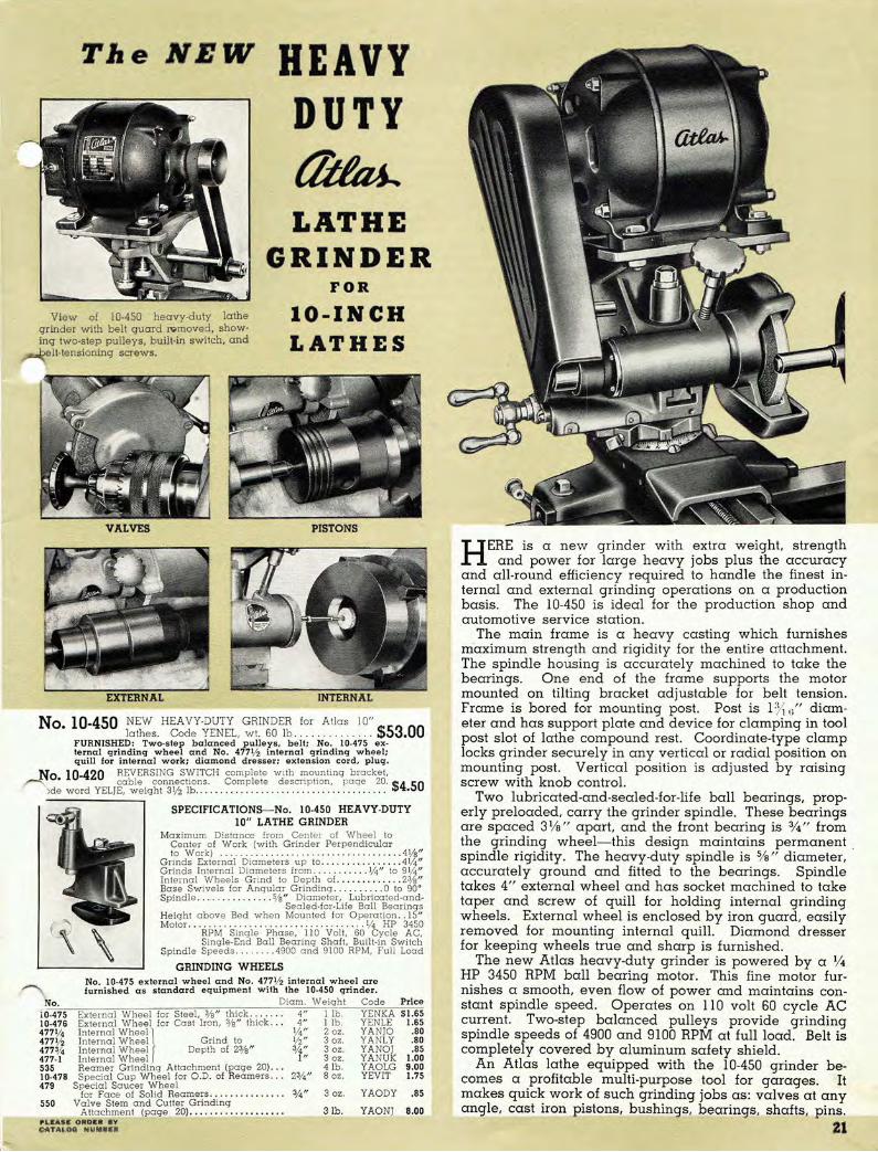
The NBW HEAVY DUTY ~ LATHE
GRINDER FOR
View of 10-450 heavy-duty lathe grinder with belt guard Nmoved, showing two-step pulleys, built-in switch, and
elt-tensioning screws.
lO-INCH LATHES
VALVES PISTONS
No. 10-450 NEW HEAVY-DUTY GRINDER for Atlas 10" lathes. Code YENEL, wt. 60 lb. . . . . . . $53.00
FURNISHED: Two-step balanced pulleys, belt ; No. 10-475 ex-ternal grinding wheel and No . 4771/2 internal grinding wheel; quill for internal work; diamond dresser; extension cord, plug .
No 10-420 REVERSING SWITCH complete with mounting bracket, .-'"'""'\ • cable connections . Complete description, page 20. $4 50
)de word YELJE, weight 3 1/2 lb . . ................ . . . .. . ... . .. .. __ . . . . •
No.
\
SPECIFICATIONS-No. 10-450 HEAVY-DUTY 10" LATHE GRINDER
Maximum Distance from Center of Wheel 10 Cen ter of Work (with Grinder Perpendicular to W ork) . ........ . . . ............ . .... . .. . ... 4 1/s"
Grinds External Diameters up to . . ... .... . . .... . 4 1/4/1 Grinds Internal Diameters irom . ......... . 1/ 4 " to 91/4 " Internal Wheels Grind to Depth of. .. . . ........ 23/S" Base Swivels for A ngular G rinding . . ..... _ . . 0 to 90" Spindle ... . . .. .. . . . . . . Sfs" Diamete r, Lubricated -and-
Sealed-for-Life Ball Bearings Height above Bed when Mou nted for Operation . . 15" Motor . . . . . .. . . ... ..... .. .. . 1/4 HP 3450
RPM Sing le Phase, 11 0 Volt, 60 Cycle A C, Single-End Ball Bearing Shaft, Built-in Switch
Spindle Speeds ........ 4900 and 9100 RPM, Full Load
GRINDING WHEELS No , 10-475 external wheel and No . 4771/2 internal wheel are furni sh e d a s s tandard equipme nt w ith the 10-450 grinder.
Diam. Weight Code Price 10-475 External Wheel for Steel, 3/s " thick .. 10-476 External Wheel for Cast Iron, 3/S" thick ... 477% Internal Wheell 4771/2 Internal Wheel I Grind to
4" I lb. YENKA $1.65 4" I lb. YENLE 1.65
1/4" 2 oz. Y A NJO .80 1/2 " 3 oz. Y ANL Y .80
477~'4 Internal WheelJ Depth of 23/s" 477-1 Internal Wheel 535 Reamer Grinding Attachment (page 20) . . . 10-478 Special Cup Wheel for 0.0. of Reamers .. . 479 Special Saucer Wheel
for Face of Solid Reamers ..... . , ....... . 550 Valve Stem and Cutter Grinding
Attachment (page 20) ................. .. PLEASE ORDIER BY CATALOG HUM.IUI
%" 3 oZ. YANOJ .85 I" 3 oz. Y ANUK 1.00
4 lb. Y AOLG 9.00 23;"" 8 oz. YEVIT 1.75
3 oz. YAODY .85
31b. YAONJ 8.00
H ERE is a new grinder with extra weight, strength and power for large heavy jobs plus the accuracy
and all-round efficiency required to handle the finest internal and external grinding operations on a production basis. The 10-450 is ideal for the production shop and automotive service station.
The main frame is a heavy casting which furnishes m'aximum strength and rigidity for the entire attachment. The spindle hOUSing is accurately machined to take the bearings. One end of the frame supports the motor mounted on tilting bracket adjustable for belt tension. Frame is bored for mounting post. Post is 1:Y, (;" diameter and has support plate and device for clamping in tool post slot of lathe compound rest. Coordinate-type clamp locks grinder securely in any vertical or radial position on mounting post. Vertical position is adjusted by raising screw with knob control.
Two lubricated-and-sealed-for-life ball bearings, properly preloaded, carry the grinder spindle. These bearings are spaced 31/8" apart, and the front bearing is %" from the grinding wheel- this design maintains permanent spindle rigidity. The heavy-duty spindle is % " diameter, accurately ground and fitted to the bearings. Spindle takes 4" external wheel and has socket machined to take taper and screw of quill for holding internal grinding wheels. External wheel is enclosed by iron guard, easily removed for mounting internal quill. Diamond dresser for keeping wheels true and sharp is furnished.
The new Atlas heavy-duty grinder is powered by a 1/ 4
HP 3450 RPM ball bearing motor. This fine motor furnishes a smooth, even flow of power and maintains constant spindle speed. Operates on 110 volt 60 cycle AC current. Two-step balanced pulleys provide grinding spindle speeds of 4900 and 9100 RPM at full load. Belt is completely covered by aluminum safety shield.
An Atlas lathe equipped with the 10-450 grinder becomes a profitable multi-purpose tool for garages. It makes quick work of such grinding jobs as: valves at any angle, cast iron pistons, bushings, bearings, shafts, pins.
21

AUTO-SERVICING ATTACHMENTS FOR t1iIa4. lO-INCH LATHES
MOTOR DRIVEN MICA UNDERCUTTER Armature servicing is one of the most profitable lathe jobs for
the garage and electric shop. Only on a rigid, accurate lathe
is it possible to turn out the accurate work required for today's
automotive and appliance armatures.
The Atlas 10" lathe equipped with the motor driven mica undercutter takes the guess-work out of armature reconditioning and finishes the complete job in less than 10 minutes. The undercutting attachment is mounted on the back of the carriage cross slide where it can be put into action in a second or moved quickly out of the way when not in use. Height of cutter arbor is adjusted by elevation screw with handwheel control-position is set with thumb screw. Saw is fed through mica by turning lathe carriage handwheel-the new grooves are always clean, square, paralleL and uniform in depth. The saw arbor is driven by a Dumore motor.
N 510 MICA UNDERCUTIING ATTACHMENT for Atlas O. 10" lathes. complete as shown. Dumore motor is
IOS- 12S volt 2S-60 cycle AC and IOS-12S volt DC. Furnished: Set of S high speed undercuttmg saws (.O IS", .020" , .02S" .
N 523A SET OF 10 HIGH O. SPEED SAWS (2 of
each of following thicknesses: .015", .020", .025", .030" and
~';;'~~t ;?16 .. YET~V .. vrL. 20z $3.60 . 030", and .03S").. extension cord, switch and plug. Code $20 00 word YAMFE. weIght ]] lb .... .. ..... . ......... . .. . .. .. .. .. •
No. 386G 1/4" HIGH SPEED CUTTER BIT \.J ready-ground for t rue I n g $0 40
Maximum Work Capacity Under Arbor .... .... S" armatures. Code YEVVO. wL 2 oz..... . . •
NEW ARMATURE CHUCK KITS For Any Lathe with No.1 or No.2 Morse Taper Spindles
There's a spot for this new low.priced kit on every lathe
bench. It contains a pair of Jacobs chucks designed es
pecially to hold armature shafts rigidly and accurately
during reconditioning.
No. 9.441 CHUCK KIT for Atlas 10" lathes -arbors for No. 2 Morse taper $18 00
spindles. Code YEjOj, wL 8 lb . . ...... .. . . . . •
No 441 CHUCK KIT with arbors for No. I • . Morse taper spindles. Code word $18 00
YEKHE, weIght 8 lb . . . . . . . . . . . . . . . . . . . . . . . . . . •
Headstock (driving) chuck has heat·treated steel jaws
and body- key-type wrench is furnished. Center rest chuck
supports armature shaft in tailstock-adjustable durable
bronze jaws form accurate bearing in which shaft rotates
in exact position.
No. M6·441 ~Ifr~~~st~~k f~~u~~a~~~ I~~he~ MT arbor, center rest chuck with No. I MT ar- $18 00 bar. Code YEjLY, wt. 8 lb.. . . ...... . .. .... .. . •
FURNISHED with above kits: Jacobs headstock and center rest chucks with recessed type Morse taper arbors. Chuck capacities-1/4" to 3/4" . Metal case has attractive finish.
PISTON MACHINING EQUIPMENT Piston work is another job handled on the Atlas lathe which would
otherwise require an expensive single·purpose machine. These accessories equip the Atlas 10" lathe for accurately machining and finishing cast iron, aluminum, and alloy pistons. The complete assortment, con· sisting of piston driving unit. skirt reamers, and self-centering cones, handles pistons between 21/4 " and 5 ljB " in diameter. The set-ups for centering, reaming, and finishing are simply made-it is not necessary to chuck the piston. These fixtures are recommended for finish-grinding cast iron pistons with the new Atlas heavy·duty lathe grinder (page 21).
DRIVING UNIT
(I) (2)
No. 400 PISTON DRIVING UNIT complete. Includes driv-
(3)
Consists of: (I) Driving adapter which threads directly on lathe spindle nose-has key for hold· ing reamers and cones; {2} Driving dog which threads on adapter-has hole for wrist pin to drive piston; (3) Driving dog extension for extra large pistons.
ing adapter. driving dog, driving dog $675 extenSIOn. Code YAMHO, 4 lb . . .. .. . •
• SERVICE MEN! SEND FOR THESE FREE LATHE BOOKLETS ••
"IT PAYS to have an Atlas lathe"and these four shop booklets tell why:
I. "On the Turns." 2. "Make 'Em on Your Lathe." 3. "A Bench Lathe in the Electrical Department."
These three are magazine articles by no· tionally known service men, each with over twenty years of shop experience.
4. "Lathe Guide for the Service Man."
22
Condenses lathe lore to 12 pages-contains bits 01 information that would otherwise have to be dug out from dozens of handbooks and guides, or from operaling experience. Sent free on request.
SKIRT REAMERS
For accurately reaming piston skirt before mounting on
centering cone. Cutter blades are VB" high speed steel. Heavy body has keyway for adapter connection.
No. 408 409 410
Capacity Wt. 21b. 31b. SIb.
SELF·CENTERING CONES
Code YAMIG YAMKY YAMOH
For squaring skirt end of piston while drilling center hole and holding work while taking cut. Sizes correspond to skirt reamers. Entire surface is accurately ground. Has keyway for adapter connection.
No. Capacity 405 21/4 " to 31/4" 406 3:~i1f;" to 4: ~/1t;"
407 4 ljB" to SljB"
Pree I.atlle Booklet.
Wt. 21b. 3 lb . SIb.
Code YAMUj YAMYK YANAF
$6.50 8.35 9.75
$2 .00 2.50 3.00
COM l'bItT£ iND£)(I,.5ID£ BACK COVER

~ lOll LATHE CHUCKS
No. U-370 rN ~E~IJ1~-~UJ: ENT CHUCK co r.1 pie t e with wrench. Body threaded for 10" $12 50 lathe spindle. YIAGH, wI. 10 lb. •
FOR lO.INCH LATHES ONLY 6·Inch Lathe Chucks Are Described on Page 34.
MEDIUM DUTY INDEPENDENT
CHUCKS
MEDIUM DUTY UNIVERSAL
CHUCK
Atlas medium duty lathe chucks are designed to handle the chucking requirements of the average shop. High strength semi-steel bodies are scientifically proportioned and exceptionally strong . Alloy steel jaws a re heat treated- have raised and g round steps. Accuracy is guaranteed within s tandard chuck tolerances.
Rugged and accurately built for holding work of all shapes. One-piece body is high strength semi-steel casting-entire face and outer edge are ground. Ha nd fitted jaw s are heatt rea t ed alloy steel- deep shoulders have r a i sed and
No. U-435 5~ N~E,J>I~~-~l~T CHUCK complete with 2 sets of jaws (inside and ou tside) a nd wrench. Body threadeGl for 10" No. U-370-8 r~ ~Ei'1U~-EUJ:
,r--"n CHUCK com pie t e with ground steps for full. firm inside or outside grip. Jaws are reversible for large diameters. Screws are heat-treated alloy
Has self-centering jaws con
trolled by turning one screw
ide a I for quickly centering
round and hexagonal stock.
Body is h igh-strength semi-steel.
Scroll is special alloy metal
pinion is special alloy steel.
Jaws are alloy steel h eat -
lathe spi7dle. Code word YEZZO $1895 weight 7 Vz lb . . .. ...... . .... .. •
·ench. Body threaded for 10" $18 50 "the spindle. YIAHL 22 lb . . . . . •
steel-have socket head for wrench. lathe spindle- no adapter required.
Chuck bodies are threaded for 10"
treated- have raised and ground steps. Furnished with two sets of jaws
(inside and outside) and wrench. This chuck handles rods through head
stock. Body is threaded for Atlas 10" la the spindle- no adapter required.
HEAVY DUTY INDEPENDENT CHUCK HEAVY DUTY UNIVERSAL CHUCK Th ese chucks have the same general design and construction as the medium duty chucks -with the extra weight and strength required lor heavy-duty jobs and production work.
Heavy, rug g e done-piece hi g h - Accurate self-centering jaws s trength semi-steel body is reinforced are controlled by bevel gear
driven scroll. Scroll is special alloy metal. A spiral thread, with which the jaw teeth mesh, is cut on the upper side of the scroll. On the under sid e is the bevel gearing which meshes with the operating pinions. Pinions are special alloy steel. Han d -fitted jaws are special alloy machinery steel, heat treated to withstand shock, strain and
and braced. Jaws are special a lloy ma-chinery steel. heat treated to withstand
shock, strain, and wear. Jaws are
hand-fitted to body and are reversible
for large diameter work. Screws are
h eat treated alloy steel. carefully fitted
to bearings and operate the jaw s
smoothly. Screws have mortised heads
to take square-end wrench. T h r u s t
bearings are heat treated steel tightly fitted to body.
wear. Two sets of jaws are furnished (inside and outside). Heavy rugged body is high-strength semi-steel. reinforced and braced.
N U 765B 6" HEAVY-DUTY IN DEPENDENT CHUCK complete w~~ Y~ZV A, wei':;~; 2g~bPt~r . fiued . fo~· . 10" .. l~th.e . sPindl~ .... COd.e. $28.50
No U-770B 6" HEAVY-DUTY UNIVERSAL CHUCK complete with . • 2 sets of jaws and adapter fitted for 10" lathe $33 00
spmdle. Code word YEZWE, weight 23 lb ....... ........ . . .. . ... .. . • No. U-765 6" HEAVY-DUTY INDEPENDENT CHUCK only less $2550
adapter. Code YIAMN, weight 17 lb.. .... .. ..... . • No. U-770 6" HEAVY-DUTY UNIVERSAL CHUCK only less $3000 adapter. Code YIARS, weight 19 lb ... .. . . .. .. . . •
No U 765A ADAPTER PLATE for 6" heevy-duty independent • - chuck, threaded for lQ" lathe spmdle, face semi- $375 No. U-770A ADAPTER PLATE ON LY. Diameter 3i"",,", threaded
for 10" lathe spindle, face semi-finished. Code $3 75 finished. Code word YIANP, weight 3Vz lb .. ....... . ....... . .. ... . _ . _ • word YIAST, weight 4 lb .. . .......... .. . ....... . ........ .. ......... . •
JACOBS CHUCKS For 10-Inch Lathes Only. 6" Lathe Chucks Are Described on Page 34-Armature Chuck Kits, Page ZZ.
HEADSTOCK CHUCKS These J acobs
ch ucks are accurate and convenient for holding small-diame t e r work. Hollow construction permits handling long shafts through 10" lathe headstock spindle. Heattreated steel jaws and body. Ideal for valve refacing with lathe grinders (pages 20 and 21). Both sizes thread directly on 10" lathe spindle-
, . 375 can be used in tailstock with 377 a rbor .,elow, right}.
N 375 JACOBS HEADSTOCK CHUCK o. capacity l/e" to 5/S" complete
with key-type wrench. Can be used in $1200 tailstock with 377 arbor. YAGYE, 4 lb . . .. • No 377 ARBOR lor 375 chuck only. Code $1 00
• word YAHUD, 8 ounces. .. .. . .. . •
No. 375B ~~;~~t; ~7f6SS;~c;~4,9Hc~~~ plete with key-type wrench. Code YAHCO, $14.40 5 lb. _ ......... . .... . ..... . ... ......... . ALL PRICES SUBJECT TO CHANGE WITHOUT NOTICE
CENTER REST CHUCK The jacobs center rest
chuck supports arma
tures and shafts in the
lathe tailstock. Adjust
able durable b ron z e
jaws form accurate bear
ing in which shaft rotates
in exact position. Essential for accurate arma
ture work. No. 377 arbor is required to adapt chuck to 10" lathe tailstock.
No 445 JACOBS CENTER REST CHUCK • capacity V4" to 3/4 ". Code word $8 00
YAHOC, 3 pounds .. .. ... ............ .... . •
No. 377 ARBOR required. Code. w .. o.r.d. $1.00 YAHUD, weight 8 oz .. .
DRILL CHUCKS Rugged Jacobs chucks
for accurate drilling and countersinking. Heat-treated steel jaws and body. Adapted to 10" lathe headstock and tailstock spind les with No. 378 arbor (below)_
No BDl-60 JACOBS DRILL CHUCK ca-• pacity 5/ 64" to 1/ 2" com- $57
plete with key-type wrench. Y AHEZ, 2 lb. • 5 No 40-60 JACOBS DRILL CHUCK ca-
• pacity 0 to 1/2" complete with $ key-type wrench. Code YAHIB, 2 lb ..... 6.75 No. 378 ~r~I~O~h~~~~ ir~: ~e~~~Fo~~ac~~J tailstock spindles of 10" lathes. Code $1.00 word YAHYA, weigh t 8 oz .. .. ... . .
q] .i 13 CHUCK ARBORS =;; . No. 378 ~hR!~~~olg'?~~:h~D~~~Od~t~~~-~~ tailstock. Code Y AHY A, 8 oz .. "" .. " _ .. . $1.00
23

lO-INCH LATHE ATTACHMENTS THESE ATTACHMENTS ARE FOR ATLAS 10-INCH LATHES ONLY
6" La the Attachments a re Described on Pages 34-36
You'll do better work with Atlas lathe attachments.
Each one is designed to save time and effort. do ac
curate work, and give long, troublefree service. Care-
1ully selected materials. modem precision machining.
and thorough working tests result in the most efficient
and durable tool for any given lathe operation. You'll
No. 139L 139R 139
TOOL HOLDERS
De scrip tion LH Tool Holder RH Tool Holder Straigh t Tool Holde r
W eight l ib . lib. l Ib .
Drop.forged 5 pe c i al 5 tee 1, accurately rna· chined. heat treated and hardened. Set screws are alloy steel heat treated. Slot is accurately machined for 1/4" cutter bits - 3fa" shank fits tool post slot. Set of 3 holders han· dIes all turning and facing operations .
Code YAUDZ YAUHD YAUCY
Price $1.30
1.30 1.30
CUT-OFF TOOL
For quick. clean cutting-off. Drop-forged RH holder with 3V2" highspeed replaceable blade. ready-ground with correct top rake. front and side clearance-front face cuts freely without binding. Blade is resharpened by grinding front edge only. Hardened clamp locks blade rigidly. No. 590 CUT-OFF TOOL with blade and w rench. Code
w ord YAUJF. weigh t I pound . ... .. . .. .. ..... .. . .. $1.65 No.592 Extra Blade. Code word YAURN. weight 4 oz . . . ... .. .. Each $0.55
THREADING TOOL
The sides of the threading tool are ready-ground to cut 60 0 threads. The tool is resharpened easily and accurately by grinding the top edge only. The RH holder is a drop-forging-c1amp screw holds tool rigidly.
No. 430 THREADING TOOL with w rench. Code word Y AUXT. weight I pound . . . . ..... ....... ..... . . . .. . ... ... $2.75
save money, too! Atlas modem economical manufac
turing methods supply these superior attachments at remarkably low prices_
A complete assortment insures maximum accuracy,
speed. and convenience in perionning important machining operations.
LARGE FACE PLATE 8 V2 " diameter for holding large work. Threaded
to fit spindle nose of Atlas 10" lathes. Accurately machined grey iron casting with 8 slots for cla mping work firmly in position.
No. 365 8 '12" FACE PLATE as shown . Code Y AVSY. weigh t 7 lb . .. . . .... .. . . $4.2E
6-Inch Face Plate '-....,../
6" diameter as furnished with 10" lathes-threaded for lathe spindle nose. Has 3 clamping slots and slot for lathe dog .
No. 15 ~~ei~~f~ fbLA.TE . CO.de .word. YE~~P .. . $2.75
KNURLING TOOL
Forms gripping surface for tool handles. nuts. markers. and instruments. "Floating" construction makes rollers self-centering- thrust is transmitted to heavy steel shank. Rollers are hardened tool steel (medium diamond shape).
No. 340 KNURLING TOOL with medium diamond-sha pe k n uri s .
word YAUSP. w eight I lb .. .. .. . ..... . .. .
BORING TOOL HOLDER
Rigid support for boring tools. Drop-forged holder has reversible"------,, yoke for right or left hand work.
Includes 1/4" boring tool, Ij. " cutter bit. and wrench. Capacity 1/2" diameter shank-accommodates tool-post boring tool set. page 25. No. A2030 BORING TOOL HOLDER with IN' high-speed bor-
ing tool. V." cu tte r b it . and ' wrench . Code w ord Y ATME, w eight I V2 pounds .... ........ .. ... ...... .. . $3.50
THBSEATTACHMENTS ARE FOR ATLAS to-INCH LATHES ONLY 24 6" Lathe Attachments are DGscribed on Pages 34·36 ALL PlUCKS SuBJ ECT TO
CH.ANO~ WITHOuT HoTIC5

FOR lO-INCH LATI:JES ONLY 6" Lathe Attachments are Described on Pages 34.36 lO·INCH LATHE ATTACHMENTS (2)
TOOL-POST TOOL SET
High speed ready·ground boring and turning toolsideal for accurate jobs reo 2 qui ring rigid tool mount·
ing. Solid one·piece con· 3 eE~;;;;;il·-5ili struction eliminates extra jOint of holder- held di· 4 ........ ,.. rectly in tool post. Weight 2 oz. each.
5 ___ VII 6 7 8 9 10
No. 380 TOOL·POST TOOL SET complete : 5 internal tools, 2 heavy·duty external tools, V·block, 2 h eight sp ac·
e rs. Code word YARYP, weight 2 lb . .. .. ..... ..... . ... . ... $5.25 No. Order
Above No. (]) 383 (2) 382 (3) 381 (4) 385e (5) 385A (6) 393L (7) 388B (8) 392L (9) 391L
(10) 390L
Description Code Price -----
Sma ll Spacer YATAL SO.35 Spacer YATEM .35 V·Block YATLA .45
3/ 8" External Threading (60 0 V·type) YASUP .75 3/ 8" External Turning YASON .65
3 / 16" Boring YASAK .65 1/4" Inte rnal Threading (60 0 V.type) YASEL 1.00 1/ 4" Boring YASKA .70
5/ 16" Boring YASLE 1.05 3/ 8" Boring YASNO 1.35
CLAMP-TYPE DOGS For holding square, rectangular, hexagonal,
or round work. Mounted without removing work from lathe centers. Clamp bars are steel forgings carefully machined and hardenedscrews are heat treated. No 741 CLAMP· TYPE DOG. 0 pe n s
wei~ht I lb . . 2V4':-. ... COd~ ... ,:,~~d .. . ~ A.~~~, $3.30 No 742 CLAMp·TYPE DOG. 0 pen S
wei~ht 2\12 I;V:': ..... C~~.e ... ,:,:~r.d .. Y.~~~.~, $6.40
STEADY REST For Supporting Long Work
porting axle for turning and shafltor fac ing end.
The Atlas steady rest, clamped to the bed ways, serves as a rigid 'Nork support to insure accuracy in turning, boring, and threading fong pieces. Frame and base are strong iron castings. Bronze jaws prevent scoring work. Each jaw can be adjusted easily and locked in exact position to provide proper work bearing. Top is hinged so that work may be inserted or removed without unclamping rest.
No.10-325A STEADY REST FOR 10" lathes-capacity 2% " diameter. Code YIA WY, wt. 5 lb .... . . .. . .. . $5.25
CUTTER BITS
High speed II," x II." cutter bits ready·ground for use in Atlas tool holders on page 24 . Complete set of six permits wide range of oper· ations. Weight, 2 oz. each. 3/s" unground bits for use in tool post are also listed below.
No.386 SET OF 6 FORMED CUTTER BITS W ' x W '. In· cludes bits shown . Code YARjA, wt. I pound .. . . $1.75
386A 386B 386C 386D 386E 386F
No. Description Code Price -- --_. 386A I;" " RH Turn ing YAPMY 386B V." LH Turning YAPOK 386C V4" RH Facing YAPUL 386D I;" " LH Facing YARAJ 386E V. " Round Nose Turning YAREK 386F II." Threading (60 0 V·type) YARIL
386S Se t of 6 Un ground II." cutter bits YARKE 386T Set of 12 Unground II. " cutte r bits YARMO 3855 Set of 6 Unground 3/s" cutter bits YARPY
LATHE DOGS Drop·forged steel, new lightweight deSign-hold the
work firmly and transmit maximum power from the lathe spindle. Set screws are heat·treated. Four sizes.
No.142A SET OF 4 LATHE DOGS to handle d iameters up to 1 V2" . Code word
YAPAG, weigh t 2 lb ... .. .... .. . .... .... ... . . $2.75 No. Openin g Weight Code Price 142 V2" 4 oz. YAOPK SO.55 143 3/4" 5 oz. YAORM .65 144 I" 7 oz. YAOWR .75 145 Jl/2" 10 oz. YAOZT .85
FOLLOWER REST Braces Slender Rods
SO.30 .30 .30 .30 .30 .40
.95 1.80 2.30
The Atlas follower rest insures accurate work on long slender rods.
It is mounted quickly and easily on the back of the carriage dovetail
slide, follows the cutting tool, and holds the work in rigid position.
Ruggedly built- hardened s teel jaws quickly adjusted and locked.
No. 425 FOLLOWER REST for 10" lathes. Code word Y A VNE, weight 3 pounds . . .. . ..... .... . . ... . .. . $3.50
TRESE ATTACHMENTS ARE FOR ATLAS to-INCH LATHES ONLY ""~4SIf ORDt'_ RY (:.IH,a Ofl NVMIIUI
.''''----6" Lathe Attachments are Described on Pnges 34·36 25

IO·INCB LATHE ATTACHMENTS (3) FOR lO-INCH LATHES ONLY 6" Lathe Attachments are Described on Pages 34-36
DRILL PAD
The drill pad, mounted in the tailstock ram, serves as a rigid support for drilling flat or square work with drill held in h eadstock. Ground steel shank is No. 2 Morse taper.
No. 360 DRILL PAD, No . 2 MT
shank. 31/ a" diameter face. Code word Y ATOP, weight !I/2 lb ... . .. . . . . . $1.65
CROTCH CENTER r----.....,.,...---." The crotch center au
tomatically c en t e r s round work in the tailstock ram for accurate cross-drilling. V-slot is carefully machinedground steel shank is No. 2 Morse taper. 2" diameter. 1" slot.
No. 356 ~ ~ if I ECRH
Code YATR Y' $1 65 weIght · I lb.. . ... •
600 COUNTERSINK DRILLS
For accurately centering work to be mounted between lathe centers- provides proper bearing for center.
Drill Body No. Size Diameter Length WI. Code Price 395 1/16" 13/ 64" I Va" 2 oZ. ZAURJ $0.65 395A 1/ 8" .300" 2V4 " 2 oZ. ZAUSK .70
60 0 LATHE CENTERS Hardened and ground high-car
bon tool s teel with No. 2 Morse taper shank for headstock or tails tock.
No 9-88 60' LATHE CEN-• TER. Code word $1 35
YAVAM, wI. 8 oz. .......... • No. 138 REDUCING SLEEVE, No. 3 to No.2 Morse taper (as furn ished with 10" lathes) . Code YEYLN, wt. 6 oz ........ . $1.20
BALL BEARING T AILSTOCK CENTER
Center point rotates on enclosed ball bearing - recommended for high-speed operations.
No.348 BALL BEARING CENTER, No. 2
Morse taper shank. Cod. $1 0 50 YEMMO, weIght I lb. . . . . . . •
CENTER EJECTOR BAR This new ejector removes center from spindle without burring center
and sleeve. which may happen when using makeshift bar. Steel shaft has knurled ball grip- guide collar keeps shaft aligned as it passes through spindle. Brass head cannot damage center, sleeve, or spindle. No. 790 CENTER ElECTOR BAR. Length 13W'. Code word $1 25
YEMPY, weight 2 pounds . .. . ... ... ... . . . .... . .... .. . . . •
MICROMETER CARRIAGE STOP
The Atlas carriage stop has micromete" adjustment to indicate the proper stop pin ...../ point of carriage when turning. boring. or facing - simplifies accurate duplicate work. Clamps securely on front bed way. Will not automatically stop carriage.
No. 10-315 CARRIAGE STOP. Code word YIAZ B,
weight 2 pounds . . . . . ........... $3.50
CROSS SLIDE STOP
The cross slide stop indicates the proper depth at which to stop the cross feed for accurate duplicate work. It clamps to the cross slide dovetail-has adjustable screw and lock nut. Will not automatically stop cross feed.
No. 725 CROSS SLIDE STOP. eo dewar d Y AlBT,
weight 8 oz . . .. . ........ ...... . . $2.45
NEW REVERSING SWITCH A dependable reversing switch is essential to reverse the rotation of motor and lathe spindle for grinding. tapping, nut-setting. and fine metal and wood finishing.
THE N E W NO . 10-420 R EVE R S I NG SWITCH is mounted on the reverse gear box -a handy, easy·to-reach position. It is a drum-type switch w ith knobbed lever control easily shifted to forward. off. or reverse position. Durable contacts are hard rolled copper. The No. 10·420 operates on single phase, capacitor, and 3-lead repulsion-induction motors (not 4-leadl-also both shunt-wound and compound-wound DC.
No. 10-420 REVERSING SWITCH complete wlth mounting
bracket, cable connections, installation $4 50 diagram. Code YELlE, wt. 3V2 lb. . . . . . . •
THREE PHASE REVERSING SWITCH The No. 420D reversing switch is designed for three phase current.
Construction features are the same as those of No. 10-420 above.
No. 420D THREE PHASE REVERSING SWITCH with 4mlobu.n. t.i.n.g. $13.50 bracket and connecltons. Code YEMYP. wt.
THREE PHASE MOTOR CONTROL SWITCH
No. 57-300 is required with a three ph ase motor. It is a thermal overload 3-pole manual starter for three phase circuits. Mounting bracket and flexibl" cable-covered motor connection cord ar furnished.
No. S7-300 THREE PHASE CON-TROL SWITCH with
mounting bracket and connections Code word ZEBAR, wt. 6 Ib .. ... .... $13.50 I
THESE ATTACHMENTS ARE FOR ATLAS lO-INCH LATHES ONLY 26 6" Lathe Attachments are Described on Pages 34-36 CO MftLt:TIi! '"DEX_
INSIDE BACK CO",,,,,!

IO·INCB LATHE ATTACHMENTS (4) FOR IO·INCH LATHES ONLY 6" La~he Attachments are Described on Pages 34-36
No. W68-2A BORING TABLE for 10" lathes, complete with v ise
and w rench. Code ZEFZO, wt. 12 lb . .... $10.50 ~'ze of Table . . .. . .. 7" X 7" Jaw Opening .... . ... 45/8"
w Width .. ....... . . . . 3" Jaw Height .. . .. . .... 1% "
BORING TABLE AND VISE This new fixture permits boring and
threading long holes with maximum accuracy- holds work rigidly while cut is taken with boring bar. It is easily installed, replacing lathe compound rest.
The table working surface is machine ground. Two socket head cap screws lock table to lathe cross slide. Four T -slots for positioning and locking vise jaws extend from center of table to edges. Each vise jaw is locked by a socket-head cap screw. One jaw can be swiveled to grip irregula r work- the other has a moveable face which is tightened upon the work after both jaws have been clamped to the table.
No . wav V-Block Jaw for holding round work in Vl se jaws. Code word ZADSO, weight 10 oz .. . ........ . ..... .... ... . ... $0.75
No. BP-IOI Blueprint Guide for Making Boring Bar shown at r ight. Code YEREP .. $0.35
TURRET-TYPE BORING SET
A production boring tool set which provides maximum rigidity for every job. Steel turret head has heavy clamp screw for locking bars in rigid position- replaces standard lathe tool post. Three boring bars furnished are special bar steel-'Vs" bar is solid high-speed steel-1/2" and % " bars have 3 end-caps for holding cutters at 30°, 45° , and 90 °. Six high-speed cutters and three wrenches are furnished.
No. 668 TURRET-TYPE BORING SET complete a s shown . Code word YELNY, weight 8 lb .... . ... . .. . . . .... . .. . .... $16.00
FURNISHED: Turret head , 3 wrenches,3/4" x 11" boring b ar and 3 end caps with 1/ 4" high-speed cutters ; V2" x 8" boring bar and 3 end caps with %6" high-speed cutters; 3/8 " x 7" solid high-speed boring tool.
COIL WINDING ATTACHMENT PIPE CENTERS
COIL WINDING ATTACHMENT. Code word YAWEP, weight 2 lb . . $3.25
Feeds are available on the Atlas lathe to ma tch th e diameter of B&S magnet wire in s izes between 12 and 40, using bare or insu lated wire. Feeds are also available for spring making, wire wrapping, and coil winding with
For supporting pipe in tailstock for machining or cutting pipe-type threads with taper attachment (page 18). Accurately ground centering cones turn with work and are supported in tail-stock by arbor with No. 2 Morse Taper shank. Thrust is absorbed by ball bearing.
steel and iron w ire in various gauges . Gear train se tups are given in detail in th e Atlas "Manual of Lathe O p·
.; eration" (page 1 4).
ANGLE PLATE The angle plate is bolted to any point on the face plate for machin
ing irregular shapes and for off-center drilling and boring. The heavy grey iron casting is machined to a right angle. The shorter side has two 1/2-inch slots for bolting to face plate. The 5-inch horizontal face may be drilled to serve as a clamping base for the piece to be machined.
No. 740 ANGLE PLATE. Code $ YAVYS, wI. 10 lb . .. 4.00
No. 755 SET OF PIPE CENTERS as s how n . Code
YAWAN, wI. 12 lb . . . . . .. .. . . . $19.00
No. 757 ~~fT~~~~~~~~~ 1~?NE: . Ca.p~~i.tY : .:': .t~. ~~ :. ~.o.~~ .':'~~~ $10.00
No. 756 ~~r~ ~~~0~~I~~g~prTb.~~.pa~ itY : .. lj4 ~' .. to . . :': .... ~~.d.e $8.00
No. 758A :~~~S~~~~E,A;:i~~t 4\~~ . TH.RUS.T . ~E~R:~~ .. .. ~~d.e . . $3.00
LATHE LAMP Correct lighting means accurate lathe
work. The Atlas lathe lamp improves the operator 's vision by throwing plenty of light directly on the work- eye glare is eliminated by proper deflection.
The 15" flexible cable allows bulb and shade to be moved easily and kept in any desired position. II" rigid post has mounting bracket which clamps at base of bed. Adjustable ball jOint in shade-convenient push-thru switch -6-foot rubber cord and plug. Attractively finished in satin-chrome plate with polished shade.
No. 745 LATHE LAMP. Code YAIKD, wI. 3 lb . .. .. . $3.00
".I'JIZIII: ATTACllMENTI ARE FOR ATLAS lO-DlCR I.AftIBI OIILY-e' LAlhe AII""'''1I101l1u 111. OftIRibed _ '''.S 3+3e ~ 27

WOODWORKING ATTACHMENTS FOR 10" LATHES Rigid conairucliorl 01 headstock lind lall.lock urld Cl wide runge of spindle speeds make the Atlas lalh .. ideal tor w<>odw" rkln9 operation/; ao well aa m<lcbbUnq all types of metab and "Iaillles.
WOODTURNING CHISELS
Professional·type chi s e I s
with tool·steel blades. scien
tifically heat treated. Extra
long handles are polished
maple with strong brass fer
rules. Approximate len g t h
14". Weight 1 lb. each.
No. W13A SET OF 8 WOODTURNING CHISELS as shown a bove a nd listed below. YAZWY. 6 lb .. ...
1/4" Gouge 1/ 2 " Gouge
l " Gouge Y2" Ske w
No. Code PRICE I W13-1 YAYPA S1.25 I" Skew W13-2 Y A YSO 1.30 liz " Rd. Nose W13-3 YAYUT 1.75 Vz"SpearPI. W13-4 Y A YVY 1.10 Vz " Parting
HAND REST SWIVEL The hand rest swivel clamps to carriage in
place of compound rest-can be turned and locked at any angle. Furnished complete wilh 4", 8" , and 12" T-rests. When ordering, please give lathe serial number or year purchased.
No W27 HAND REST SWIVEL com-• plete with 4". 8" . and 12" 4 50
T-rests. Code YAWRO. wI. 4 lb ..... . ... $ .
EXTENSION BED
No. W13-5 W13-6 W13-7 WI3-B
Code YAZER YAZRE YAZTO YAZUV
$9.25
PRICE S1.60
1.10 1.10 1.20
For handling extra long woodwork. Machined and finished 10 same specification. as lalhe bed. Bolts 10 bench-overall length 18".
No. 1·18 ~~1fPS~~g~E~O fib .. ~~~~.~~~~~ng .. ~~IY ... . ~~~.e .. ~~~~ $10.00
c «1; . SPUR CENTER CUP CENTER
For driving work mounted be~ tween centers. Ground and hard~ ened steel with replaceable center point-No. 2 Morse taper shank.
Supports work in tail stock. Ground and hardened steel with replaceable center point- No. 2 Morse taper shank.
No 350SPUR CENTER. Code No 351CUP CENTER. Code • YAWTY, weight 8
oz . ...... . . ... . ... .. . ... .... $1.10 • YAWUS, weight 8
oz . . ........ ... . .. ......... $1.10
No. L3-147 EXTRA CENTER No. L3-147 EXTRA CENTER POINT. Cod e POINT. Cod e
word YEWIV. weight 2 oz . . . $0.35 word YEWIV, weight 2 oz ... $0.35
SCREW CENTER For facing and hollow
ing operations. Special steel with replaceable center. No. 2 Morse taper.
Diameter 2".
No. 352 ~C~E:
~~\rYT ~o';';f. I wlb"d $1.65
HAND REST Clamps to bed and furnishes
rigid sup pori for chisel. Has sliding clamp plate to protect bed. T-rest can be swivelled to any position and locked securely with hand clamp screw. 4" and 12" T~ rests are furnished.
No. 330 WOOD-WORKING HAN D REST complete with 4" and 12" T-rests. Code
r~;;{Q.R •. .. ,:,,~i:.ht $3.00
No. 355 EXTRA CENTER POINT for No. 352. Code YEYEV, wI. 2 oz ... $0.35
FACE PLATES FOR WOODWORKING (Left) No. L5-365 is an 8V2" diameler combination face
plate for bolh wood and metal operations. Threads directly on 10" lathe spindle nose-has holes for wood screws and four 1/2" slots for metal work.
No L5-365 COMBINATION FACE • PLA TE. Code word
Y A VUH, weight 8 lb ... .. ... . ... .. .... $4.25 (Righi) No. L4T-15 is a 31;''' face plale for
woodworking. Threads directly on spindle nose and has three holes for wood screws.
No L4T-15 woo D WORKING • FACE PLATE. Code $1 60
word YELOL. welght 2 lb.. . .. . . . . . . . . •
MACHINISTS TOO
No. No_ Leaves
28
SCREW PITCH GAUGE By comparing the pitches on the
leaves of this gauge, by contact. the pitch of a V-thread screw or nut is quickly and positively determined. There are thirty leaves with the following pitches: 4. 4 liz. 5. 5 1/z . 6. 7. 8. 9. 10. 11. 1 Jl/z . 12. 13. 14. IS. 16, 18. 20. 22, 24. 26. 27. 28. 30. 32, 34. 36. 38. 40 and 42 teeth per inch. Weight 6 oz.
Length Leaves
IVa"
OUTSIDE +- CALIPERS
5" Capacity No. MF503 Code word WYBID .......... .. S1.20
W\.-6 oz.
INSIDE CALIPERS ~
5" Capacity No. MF509 Code word WYBUG ... . .. . .... S1.20
Wt.-6 oz.
Code Word
WYCGO Price S1.45
MICROMETERS
The accuracy of these micrometers is guaranteed. They measure by
1/ 1000ths of an inch. Anvil. spindle. barrel. and thimble are beautifully
polished. Frame black enameled. Quick. positive adjustment for wear is
provided.
No. MF821 No_ MF822 No. MF21R No. MF22R
Capacity WI. Code Price o to 1" I lb. WUYVY S 6.' ·
I" to 2" I lb . WUZER 7 2" to 3" 2 lb. WUZRE 11\ 3" to 4" 2 lb. WUZTO 12:&r--'
CENTER GAUGE
For setting 60 ° threading tool at e xact right
angle to work-edges graduated threads per
inch.
No. MF438 CENTER GAUGE. Code WYCIF. weight 2 oz ....... . ...... $0.55 ALL PRICES SuBJECT TO CHANG E WITHOUT NOTICE

SIX-INCH BACKGEARED SCREW-CUTTING LATHES
Complete Description
Page 32
• TIMKEN BEARING EQUIPPED • 16 SPEEDS • REVERSIBLE AUTOMATIC LONGITUDINAL POWER FEEDS • TWO BED ~ENGTHS
THIS rugged Atlas machine tool is the first precisionbuilt small lathe at a popular price. These are some
of the features of its modern compact design: Timkenequipped backgeared headstock, V-belt drive, precisionground bed, 16 spindle speeds, reversible automatic power feed, wide thread cutting range. The following description explains all the construction details furnishing the ac-
curacy, versatility, strength, and power that result in efficient performance and long service life. Behind this exceptional lathe value is the story of modern Atlas manufacturing methods-special-built machinery; rigid inspections at each stage of part-machining; efficient line production assembly; and thorough performance tests of the completed machine.
CONSTRUCTION FEATURES COMPLETE SPECIFICATIONS ..... ... . .. . _ . . .• .. PAGES 30 AND 31 COMPLETE DESCRIPTION ....... . . . . ___ . . ..... . .. . .... . PAGE 32 ATTACHMENTS AND ACCESSORIES. _. __ ... .. ... . PAGES 34 TO 36
Precision lathe work requires accurate alignment of the spindle. tail stock, carriage, and bed ways in both horizontal and vertical planes. In the Atlas 6-inch lathe, this alignment is guaranteed to be within .001 inch. To obtain such alignment a rigid, accurate lathe bed is the first essential.
The entire bed of the Atlas 6-inch lathe, com· f'<ising cross ribs, ways, and base, is one heavy
l ssive casting of close-grained semi-steel iron. The box-type cross ribs and wide thick ways resist all turning and twisting forces _ This mod· ern scientific bed design provides a strong, rigid foundation for the entire lathe.
The Atlas lathe bed is machined by the most modern precision equipment. The ways and leg pads are first rough-milled and the casting is allowed to season naturally to prevent warping and twisting of the finished bed_ After seasoning, the bed ways are accurately finish· milled on machines designed especially for the operation. The tops, bottoms, and sides are then ground and trued on special-built grinding machines until all eight surfaces are aligned to within .001 inch in all planes. Precision grind-~g gives the bed way s a tough, wear-resisting
.rface. At the assembly line the headstock, , a ilstock, and carriage are hand·fitted to the bed ways so that headstock and tailstock spin· dIes are aligned to within .001 inch with the bed ways and with each other.
Large bearing surfaces and provision for their complete adjustment and lubrication minimize wear and mainlain the accuracy of the Atlas lathe. The carriage has six full-length bearings on the bed, each 5, inches long-two on the top ways, tw@ on the side ways, and two on the- bottom surfaces. The bottom bearing plates have shims with four .002 inch lami· nations and two .001 inch laminations for takeup- the side bearing on the rear be d way has an adjustable gib. Cross-slide and compoundslide dovetails are gibbed for adjustment.
The tailstock has four full-length bearing surfaces each 3% inches long- two on the top bed ways and two on the inside bed ways. A gib at the inside tailstock bearing on the rear bed way provides adjustment for take· upsimply setting over the tailstock compensates for this adjustment and maintains alignment of tail stock with headstock.
Each part of an Atlas lathe is machined on production equipment of the latest design. Machining operations are checked with pre· cision instruments and gauges to insure uniformity and accuracy. Further tests are made in each stage of assembly. The completed lathe passes actual working tests for accuracy in all lathe operations. Alignment of spindles, carriage, and bed ways in all planes is carefully rechecked before shipment.
The modern construction features of the Atlas
6·inch lathe maintain accuracy and rigidity, increase versatility, and simplify operation. Timken headstock bearings carryall spindle loads with minimum of friction and permit an un· usually wide range of spindle speeds. Six· teen speeds are available between 54 and 3225 R.P.M. with a standard 1740 R.P .M. mo· tor, providing correct speeds for all types of metal turning, polishing, and finishing ; woodworking and plastics machining. The back-geared drive, powered completely by Vbelts, delivers a smooth, even flow of power. The adjustable countershaft is mounted on bench, within easy reach for speed changes_ Half nuts are engaged with lead screw for longitUdinal power feed by a convenient lever on the carriage apron. Direction of feed is changed by shifting tumbler lever at headstock - five feeds are available. 60 holes in the front spindle gear provide a convenient indexing mechanism for dividing operations. Threading diaL gears, and chart are furnished for cutting all standard threads between 8 and 96 per inch.
AN IDEAL COMBINATION LATHE
Timken bearings, rigid construction of headstock and tailstock. and a wide range of spindle speeds make the Atlas 6·inch lathes ideal for woodworking operations as well as machining all types of metals a"ftd plastics. Attachments for woodworking are shown on page 36.
The Atlas a·lnch lathe is available with 12 or 18 inch capacity between centers. For complete speclfica. tions. equipment luml.h.d. and motors recommended .ee pages 30 and 31. Lathe tool. and attachment .. are shown 0 .. PGCJ(lt1l 34. 35. one! ~6. Co".truction d(ltlalls are completllly described "nd pictuRd on 1><ICJe 32.
COMPt:ETE INDIlXI NSI DE BACK COVER

NEW • TIMKEN TAPERED
ROLLER BEARINGS • REVERSIBLE AUTOMATIC
LONGITUDINAL POWER FEED
~
I" 1111 j I 11111111 ) III! I i
SIX INCH "'--"
• CUTS 8 TO 96 THREADS PER INCH (Standard)
• 16 SPEEDS-54 TO 3225 RPM
Complete Description •• Pages 29 and 32
c o M p L E T E s p Swinq Over Carriaqe .•..•.. • ••••• • •.•••••.•. .4Va"
{
SWinc:r Over Bed ..... ................. . .. ...... 6"
CAPACITY Threading Range .. 8 to 96 Standard. Riqht Of Left Hand - Metric. .5 to 3 min. Standard
Collet Capacity .............. , ,9/32" (see page 34) OVERALL { OVerall Lenqth ... . . No. 612. 28 I1z"-No. 618. 33 Vz::
DIMENSIONS Overall De~th .•• ........ .. ...... .... •• . . .... 27" Overall Helqht .•.•... . . .. , .. ..• . .......•.... 12
~Number of Spindle Speeds . 16 (8 Direct. 8 Backqearedl Speed!i~·I; .. __ SA. 82, 122, 140. 187,287. 311. 36S. 481 .
550. 82i,. 940. 1250. 1925. 2125. 3225 R.P.M. SPEEDS AND Feeds (Left or Right) per ReYolution of Spindle ..... •
FEEDS l ···· .0104" .. 0078" •• 0048"' . . 0039" or .0024" (Equiv. a1entln threads per inch: 96. 128, 208. 256 or 4171
Lead Screw . , . . liz" Diam., 16 Acme Threads per inch Chanc:r8 Gears Furnished ....... ....... ......... U.
Motor Mountinq .... . .. . .....•.. . .......... Bench Hole Throuqh Motor Pulley ...•..••. . . Vz" Diameter
E c I F I c A T I o N Bearinqs with, Thrust TaJce·Up Collar and Nul
Spindle Nose ...•.•. .. •. .•.. 1" Diameter, 10 Pitch Natioaal Form Threads ~
SPindle Beatinc:rs ....... . .. . TimJten Tapered RoUet
HEADSTOCK Spindle Nose Taper .......... .. No. 2 Morse Taper
(
HOle Through Spindle,,, ... .. . ,, ............. 1. 7/32"
CARRIAGE
Back Gears .. ...... ......• . . •.. 20 Pilch. 3!a" Wide Backgear Shaft Bearinq8 ... ..•.. ...... Oilite Brome Spindle Gear ........ 2t Pitch, 32 Teeth, 7/16" Wide Back Gear Ralio (approximate) . .. ••• • •••••• 6 Yz to 1
fcross Feed Travel. .••.•. .. .•.• . ..••.••••• , .. ",.v.." Cross Feed Screw .... .. %" Diameter. Acme Thread Feed Screw Collar GracillatlOJ1S •.......•..••• • 001 '
lTOOI Post Slide Travel. ......... '.' . .. .. ... •.. . 1"/,,'''--' Tool Post ...• . • .. o/a" x 3/4" slot 10 take 'Ia" bits or
tool holder for 3/16" bits Tool Post Swivel-Graduated 0 10 90 0 riqhl and left f
Motor Recommended ... ... . .... ~ H.P., 1740 R.P.M.
Countershaft Spindle Bearinqs ...•••.. OHite Bronze 1 Tailstock Ram . ~" Diam. Bored for No. 1 Morse Taper V·Belts for Complete Drive ........ . ...... 1/z" Wide TAlLSTOCK Tailstock Ram Travel. ......•................. l V." ~tor Pulleys ......... .. . ............ . .. ' .. 2,Step .t - Tailslock Ram Graduaticma .... O 10 1I/z" by I/16thlll Drive Pulleys ..... . .. .. ... ...... . .. .. ' ... "·Step l'ailslock Set·Over. Forward or hex . . . .. ..... 9/16"
DRIVE UNIT
30 Reyersible Automatic Power Feed, Complete V·Belt Drive. 60·Hole IndelCin9 Me~hgnism. CI!,ome Plated Control Handles. Finish-Spec;al All",,. GlIlY.

BACK GEARED SCREW-CUTTING LATHES
THB FIBS T P B BClSlON-BUl£ T SMALL LATHB A T A P OPULJl B PBlCB
• QUICK-CHANGE COUNTERSHAFT
• COMPLETE V-BELT DRIVE
No. 612 6" BACK-GEARED SCREW-CUTTING LATHE. Com~
plete a s shown, less motor, with equipment listed a bove . Code word YEDOD, shipping weight, 92 lb. . . .. . . . . . .. . . $66.50
Capacity between centers .......... . .... . 12"
Bed length . . . . . . . ... . . . ..... . . . .... . . .. . 24"
Overall length ... .. .. ... . . . . . . .... . . . .. . 28th"
'No 618 6" BACK-GEARED SCREW-• CUTTING LATHE. Com-
plete a s shown, less motor, with equipment listed above. Code word YEDUF, shipping weight 100 lb. . .... .. .. .. .. $68.50
Capacity between centers . .. ... • . ... .. •.. 18"
Bed length .. . , . . ....................... 30" Overall length .............. . ...... , •••• 33 112"
!PLEASE O!!fO£R 8Y CIITIILOO MUI!IIIER
• PRECISION-GROUND BED WAYS
• SO-HOLE INDEXING MECHANISM
EQUIPMENT FURNISHED
Reversible Automatic Power Longitudinal Feed; Graduated Compound Rest ; Tool Post. Ring and Rocker; %" Tool Bit; Complete Set of Change Gears to cut standard threads between 8 and 96 per inch; Threading Chart, Threading Dial; Quick-Change Countershaft; Complete V-Belt Drive; Motor Pulley furnished is for Y2" diameter motor shaft- prices for other size motor shafts on request; 51/4" Combination Metal and Woodworking Face Plate; Two 60 ° Lathe Centers- No. 2 Morse Taper for headstock No. 1 Morse Taper for tailstock; 3 Wrenches; Instruction Booklet.
MOTORS
These 1/ 4 H.P. motors are recommended for use with th e Atlas 6" la thes. Both motors are 110 volt. 60 cycle- have p hosphor b ronze bearings. single-end 1/ 2 " shaft. Other motors. page 67.
No. 2470 2460B
RPM 1740 1740
Weight 21 lb. 26 lb.
METRIC SCREWS AND COLLARS
Atlas 6-inch lathes can be furnished w ith metric-pitch threads for cross and compound feed screw s and w ith feed screw collars graduated in .04 mm. These metric screw s a nd collars are supplied at no extra cost
Code W YORV ZEDAT
Price $8.25
9.75
i n place of standard screws and collars w hen ordered with lathe (specify "With Metric Screw s and Collars").
FLOOR STANDS Permanently rigid lathe sup·
p o rl - s a v e s valuable flo o r space_ Legs are h ea vy grey iron castings. thickly ribbed and cross braced. Table boa rds are l o/s" thick. thoroughly seasoned. shellacked. v a rni s h e d . and ready-drilled for quick assembly. Large bottom board is convenient for holding chucks. wrenches. gears. and other tools and accessories. Motor mounting b racket and countersha ft support a re furnished.
No M6-800 FLOOR STAND for • No. 612 la the .
Code YELUM, wI. 135 lb .... S18.00
No M'S-800A FLOOR STAND for • , No. 618 l athe .
Code YELYN, wI. 140 lb .... $18.50
Lathes with serial number lower than Ml975 require special ""untersha ft bracket and spindle bell. JiJo. JIII ·BIO YEVOV, 10 Ib ... $2.45
31

SIX·INCH BACKGEARED SCREW·CUTTING LATHES
TIMKEN Cross section view of Atlas 6" lathe head
stock showing Timken tapered roller bearings for the headstock spindle_ The tapered design and positively aligned rolls maintain accurate spindle alignment and carry both radial and thrust loads with a minimum of friction . Each bearing is lubricated through a large capped felt-wick oil cup. Simple take-up adjustment is provided. These fine bearings permit the wide range of spindle speeds · essential for handling all types of lathe work.
• HEADSTOCK-Rigid support for spindle and work-grey iron casting ribbed and reinforced. Base is accurate ly machined. fitted to bed ways, and bolted securely to bed. Iron safety guard. hinged for easy raising. covers entire spindle assembly. 60 evenly spaced holes on face of front spindle gear. engaged by pin through headstock, provide a convenient indexing mechanism.
• HEADSTOCK SPINDLE-Spindle is machined from a solid bar of special fine-grained steel. accurately qround- l inch diameter, IO-pitch National Form threads, and I 'll :!" hole through entire length. Spindle nose is bored for No. 2 Morse taper center furnished. Reducing sleeve to hold No. 1 Morse taper center is available- No. M6-138. Code YEHHO-SJ.20. No. I Morse taper center-No. L2-80-Code YAVEN- SI.OO.
• TAILSTOCK-The tails tack provides a strong. rigid work support-base is accurately machined and fitted to bed ways, maintaining accurate alignment of tailstock center with headstock center. Ram is special stee l , fini sh·ground, accurately reamed for No. I Morse taper center and graduated in l 'l_ri ths . Ram has co-ordinate position lock. keyway guide . self-ejecting center. and handwheel control. Tails tock can be set over 9ha" for taper turning. Inside tailstock bearing surface on the rear bed way has adjustable gib to maintain permanent aliqnment with headstock.
32
CONSTRUCTION FEATURES
PRECISION-GROUND BED Seasoned. milled. ground. and
ready for the assembly line- the foundation of the accuracy and rigidity of the Atlas 6-inch lathe. Tops. sides. and bottoms of bed ways have been ground and trued until all eight surfaces are aligned in all planes to within _001 inch. Precision grinding gives the bed ways a tough wear-resisting surface. Entire lathe bed is a massive semi-steel iron casting-notice wide thick ways and box-type cross ribs.
V-BELT COUNTERS HAFT The modern V-belt drive from motor to co un
tershaft to spindle. standard equipment on all Atlas lathes. transmits maximum power to the spindle with a smooth. even action at all speeds_ 2-step pulleys from motor to countershaft and 4-step pulleys from countershaft to spindle provide 16 speeds-8 direct and 8 backgeared_ The belt tension lever is in a convenient position for changing speeds. Counters haft spindle turns on oilite bronze bearings. Countershaft support bracket and motor are mounted on bench.
• WIDE SCREW CUTTING RANGE-All standard threads. either right or left hand. from 8 to 96 per inch in the following standards can be cut with change gears and feed gears furnished : National Form including National Coarse (USS) and National Fine (SAE). Acme. Square. and Whitworth. Selflocking iron safety guard completely encloses the gear train- threading chart is mounted on inside of guard. An attachment to cut standard metric threads from .5 to 3 mm. is available-No. M6-735. Code YE)GE-SI.65 . (Metric screws and collars. page 31.)
• ZAMAK ALLOY PARTS-Pulleys. gears. handwheels. handles. and other small parts are made of Zamak. a rugged metal alloy with twice the te nsile strength and four times the impact strength of cas t iron . Each Zamak part is made in an extremely accurate master die. insuring uniform accuracy. Zamak parts permit a compact modern design. eliminate idle weight, provide greater strength and longer lathe life.
BACK GEARS The Atlas backgeared drive reduces the
spindle speed for heavy cuts and large V diameter work. providing 8 speeds between
54 and 481 R.P.M. The back gears are en-
gaged by advancing the eccentric lever
and removing loc)<-pin from spindle puliey.
Gears are 3/ S " wide. 20 pitch-headstock guard
provides safety covering. Backgear ra,io is ap
proximately 6 V2 to 1. Backgear shaft runs on
oilite bronze bearings.
• COMPOUND REST-Compound rest base is a qrey-iron casting machine-graduated through 1800 -
compound feed can be swivelled in a complete circle so that cuts may be taken at any angle . Two socket-head lock screws control dovetail swivel lock. Dovetail ways of cross slide and tool post slide have adjustable gibs- gib screws have lock nuts. Milled T-slot holds tool post assembly. Tool post slide has 13/4" travel- slot is 3/8" x 3/4" to take 3/8" cutter bits or holder for =}'IH" bits. Compound feed screw has micrometer-graduated steel collar.
• CARRIAGE-Six large full-length bearings on bed reduce wear to a minimum and assure smooth carriage action. Side bearing on the rear bed way has adjustable gib. Cross-feed screw has Acme threads. ball crank control with take-up adjustment. and micrometer-graduated steel collar. Handy clamp locks carriage in position. Hand-wheel controls reduction gears meshing with rack for handfeeding carriage. Carriage travels full length of the bed. Threading dial simplifies thread cuttinq '----"" operations.
• AUTOMATIC POWER FEED-Reversible power feed speeds up all longitudinal operations and permits cutting right or left hand threads. Feed direotion lever on headstock has three positions: right. neutral. and left. Lever on carriage apron engages two half nuts with lead screw. Lead screw is accurately machined and has 16 Acme thteads per inch. Standard feeds per spindle revolution: .0024" , .0039" • . 0048" , .0078" , or .0104" .
COMPLETE INDIIXIN IDE lOACK C:OYKII

~ARMATURE SERVICING OUTFITS
1'0' Quick, Basy, Accurate Armatu,e Work
A N ATLAS outfit puts the full armature profit in your own pocket. In less than 10 minutes it finishes the
complete job-trueing, undercutting, and polishing. It's always ready to run, and just one set-up handles any armature, centered or centerless ... quickly, easily, accurately.
Only on a rigid accurate lathe is it possible to turn out accurate armature work. The Atlas outfits are built around
LATHE-The Atlas 618 is sturdy. powerfuL and accurate-alignment of headstock. carriage. and tail stock is guaranteed to wiihin .001 inch. Timken-equipped backgeared headstock. complete V-belt drive. rugged precision.ground bed, 16 spindle sp~eds. 18" centers. wide thread cutting range-these are some of the features of its modern compact de· sign fully described between pages 29 and 32. Automatic power feed
for the carriage permits a smooth. fast trueing cut.
UNDERCUTTER-The motor-driven undercutting at· tachment is mounted on the back of the carriage cross slide where it can be put into action in a second or moved quickly out of the way when not in use. Furnished: Dumore motor. five high-speed saws for slots between .015 and .035 inch. extension cord with push-thru switch and plug.
ALL ... IMS SUUKCT TO CHANOIl WITHOUT NOTICK
TOOLS AND MOTOR-The Atlas armature outfits include a I-inch drop-forged lathe dog. LH offset tool holder. 3/ 16" high speed cutter bit ready·ground for trueing armatures. The Atlas No. 2470 V4 H.P. motor (furnished) is 1740 R.P.M., 110 volt. 60 cycle; has phos
phor·bronze bearings, 1/2-inch diameter single· end shaft.
CHUCK KIT-Jacobs headstock and bearing chucks provide a quick accurate method for holding centered or center less armature shafts. Both chucks are 1/4 " to 3,4 " capacity and are furnished with recess-type arbors. The head· stock (driving) chuck has heat trepted jaws and body. The bearing or center rest chuck supports the armature in the tail stock-its adjustable. durable bronze jaws form an accurate bearing in which the shaft rotates in exact position.
the 6181athe-a rugged, precision-built machine tool. The armature, held in Jacobs chucks, is trued on its bearingsthe motor-driven undercutter cuts clean, square, parallel grooves of uniform depth. Result--a perfect contact for the brushes.
Equipment furnished includes everything you need to start work at once: lathe, undercutter, chucks, tools, motors.
No. 15A ATLAS ARMATURE OUTFIT COM-PLETE. Code YEJUK. wt. 138 lb. $115.00
FURNISHED: Atlas 618 lathe with V4 H.P. 1740 R.P.M. motor ... com· plete ready to run; motor driven undercutting attachment with quill. 5 saws (. 015 . . 020 •. 025 . . 030, and .035 inch). cord. switch, and plug; complete armature chuck kit with instructions (page 22); LH tool holder. 3/ 16" high speed armature bit. 1" lathe dog.
No. ISA (Same as No. 15A. less motor.) Code YEJYL. weight 117 lb . .. $10S.75
No. llA ATLAS ARMATURE OUTFIT COM-PLETE. Code YEIZY. wt. 140 lb. $121.00
FURNISHED: Atlas 618 lathe with lj4 H.P. 1740 R.P.M. motor ... complete ready to run; motor driven undercutting attachment with quilL 5 saws (. 015 .. 020 . . 025 . . 030. and .035 inch); cord. switch. and plug; complete armature chuck kit with 4" universal chuck in place of Jacobs head· stock chuck and arbor: LH tool holder. 3/ 16" high speed armature bit. I" lathe dog.
No. 12A (Same as No. IIA. less motor. ) Code YEJEG. weight 119 lb .... $112.75
Above four outfits are standard- prices for other outfits on request.
UNIVERSAL CHUCK I 4" Diameter
Furnished with llA and 12A Outfits in place of Jacobs headstock chuck and arbor. Complete description page 34. Refer to No. U6-437.
\~ ARMATURE CHUCK KIT-Purchased Separately
For Atlas 6" Lathes No. MS-441 ARMATURE CHUCK KIT for Atlas 6" lathes-
Jacobs headstock chuck with No.2 Morse taper arbor .. Jacobs center rest chuck with No. I Morse taper arbor for tOilstock. Code word YEJLY, weight 8 lb .. ...... . .. . .. $18.00 FURNISHED: Jacobs headstock chuck and center rest chuck with recessed type Morse taper arbors-chuck capacities 1/4" to 3,4 " . Metal case has attractive ~finish. Description, page 22.
33

6 INCH LATHE ATTACHMENTS (1) FOR 6-INCH LATHES ONLY 10· Lathe Attachments are Described on Pages 15-28
4-JA W INDEPENDENT CHUCK HEADSTOCK CHUCK For holding work of all shapes. One·piece
body is high.strength semi·steel casting-<!ntire face and outer edge are ground. Hand·filled jaws are special alloy machinery steel, heat treated-have raised and ground steps and are reversible for large work. Screws are heat treated alloy steel-have socket head for wrench . Body is threaded for spindle nose of A \las 6·inch lathes.
This Jacobs chuck is accurate and convenient for holding small work. Note construction permits handling long shafts through headstock. Heat treated steel jaws and body. Threads directly on 6-inch lathe spindle .
N M6 375 JACOBS HEADSTOCK CHUCK ---..-'
O. - capacity 0 to 17/32", complete
:~t~hretl\;p~ . . wren~h: .. C.o.~~ . . ":'~:~ . . :~.~BY: $9.60
Rugged JaCob.s ~h~!;sLfO?~?uS.~Sdrilling and coun- • No. U6-439 4·JA W INDEPENDENT CHUCK, 4" diameter. . Body
threaded for Atlas 6" lathe spmdle. Wrench furmshed '$8 75 Code word YIALM, weight 6 lb . . ....... . . .. . .. . .... .. . .. ... .. . ..... .. •
tersinking. Heat-treated steel jaws and body. Arbors listed below are required. Furnished with key-type . ~ ~ adjusting wrench. '
No. Capaci ty Weight Code PRICE ~ ;t
3-JA W UNIVERSAL CHUCK
The Atlas universal chuck has self-centering jaws controlled by turning one screw. Ideal for quickly centering round and hexagonal work. Body is highstrength semi-steel. Jaws are alloy steel heat treated -have raised and ground steps. Scroll is special alloy metal-pinion is special alloy steel. Handles %" rods through headstock. No U6-437 4" 3 - JAW UN IVERSAL
• CHUCK complete with 2 sets of jaws (inside and outside) and wrench. Body threaded for 6" lathe spin· $14 95 die. Code YIAJK, wI. 9 lb. . . . . . . . . . . . . . . . •
STEADY REST
BDI-60 5/ 64 to Y2 " 2 lb . YAHEZ 55.75 • 40-60 0 to Y2" 2 lb. YAHIB 6.75 -L2-378 Arbor (tailstock) 8 oz. YECOC 1.00 378 Arbor (headstock) 8 oz. Y AHY A 1.00
CENTER REST CHUCK The Jacobs center rest chuck supports armatures
and shafts in lathe tailstock. Adjustable durable b ronze jaws form accurate bearing in which shaft rotales in exact position.
445 JACOBS CENTER REST CHUCK,
No. capacity y." to 3/4 " , Code word $800 YAHOC, weIght 3 lb.. ... . ........ . ........ .. • N M6-377 ARBOR (Required). Code word $1 00 '---"
O. YEELj, weIght 8 oz . .. . .... .. . •
Armature Outfits. Page 33- Chuck Kits. Page 22
DRAW-IN COLLET CHUCK ATTACHMENT
The Atlas steady rest. clamped to the bed ways. serves as a rigid work support to insure accuracy in turning, boring, and threading long pieces. Frame and base are strong grey iron castings. Bronze jaws prevent scoring work. Each jaw can be adjusted easily and locked in
(I) (2) (3)
For chucking d;ameters between 1/ 32" and 9, 32" when maximum accuracy is required. Consists of (I) hollow draw·in spindle which extends through the lathe spindle. (2) tapered closing sleeve and (3) split holding collets.
exact position for proper work bearing.
N o M6 325 STEADY REST for Atlas 6" • - lathes, capacity 23fa" d ia m-$3 75
The draw-in spindle is threaded to hold the collet in tapered sleeve. Hollow construction permits rods to be passed through lathe spindle-handwheel control releases and tightens collet on work . Closing sleeve is ground inside and outside to insure maximum accuracy. Lathe must be stopped to open and close collet. eter. Code word YEFHY, weight 3 lb . . ... •
FOLLOWER REST The Atlas follower rest insures accurate work on long
slender rods. It is mounted quickly and easily on the back of the carriage dovetail slide, follows the culling tool. and holds the work in rigid position. Ruggedly built -hardened steel jaws quickly adjusted and locked.
No. M6-395 FOLLOWER REST for Atlas 6" lathes . Code word YEFID, $2 75
weight 2 lb. ... .... .. . ...... . . . .... . .. ... .. .. . . •
,MILLING ATTACHMENT With this milling attachment
clamped in place of the compound rest, the new Atlas 6" lathe be· comes a small milling machine for face-milling and routing, cutting keyways and slots, milling dovetails. squaring and splining shafts, making dies and molds, and many other important operations. Quickly and easily installed.
No. 576A 576B 576C 576D 576E
Atlas split collets are collet tool steeL heat-treated and ground inside and outside. One end threads on draw-in spindle, and other end is ground to fit tapered sleeve. Keyway prevents collet from turning. Collets are available in 1/ 32nds between 1/ 32" and 9/ 32"-one collet is furnished with collet attachment (any size in 1/ 32nds between 1/ 32" and 9/ 32" ).
No M6-750 DRAW-IN COLLET CHUCK ATTACHMENT Complete : • draw-in spindle, tapered closing sleeve, and one split
~o~fd~( 2con)e ~ . ~i~~~d . . ~~I.o.,,:,~~~ecifY . ~ia~eter .... Code .. ,,:,~~d .. YE~YK: $19.50
No. M6-751 ~bt~TinH~i~J~~et~~~;ET/3~~e~~~ ~~~~~t~~ foft~~i;: 1/32", 1/16", 3/32", Ifa", 5/ 32", 3/ 16", 7/ 32", If," and 9; 32". Code $4.50 word YEIBZ, weight 4 oz., each .. . . ..... .. . . ..... ... ... ... . . No M6-548 SPINDLE NOSE CAP to protect lathe spindle threads $1.65
• (6" lathes). Code YELLO, weight 8 oz . .. . ...... .. .. .
R. H. SPIRAL END MILLS
For general milling operations-slots. facing and routing. squaring and splining shafts, cutting straight keyways. Straight shank-adapted to collet set with collet bushings below at right. Wt. 4 oz. each.
Lgth. Flute 5/ 8"
11/ 16" 3/4" 7/8"
15/ 16"
Diam.
1/4" 5/ 16" 3/8"
7/ 16" 1/2"
Code YAKCE YAKEC YAKFO YAKID YAKOF
WOODRUFF KEYWAY CUTTERS
PRICE SI.75
1.85 1.95 2.15 2.35
HOLDING COLLET SET
This set holds milling cutter in headstock spindle . Consists of draw bar. sleeve, and one arbor for 1,12" straight shank cutters.
No. M6.945 HOLDING COLLET SET. Complete: draw bar, sleeve ,
and one arbor. Code YEYBD, 2 lb ... . .... S4.00
COLLET BUSHINGS The milling attachment can be swivelled to hold work at any
angle. The vise slide is gibbed for
adjustment. A micrometer-gradu
ated feed screw controls the posi·
tion of the vise-clamping screws hold vise and work firmly in posi
For cutting Woodruff keyways- also used for milling slots, grooves. T-slots. Y2" slraighl shan.k-held in collet ar
Required to adapt 576 straight shank end mills to M6-945 holding collet sel. Not required for No . 576E 1/ 2 " diameter end mill.
"'~~--::::A tion. Vise slide is graduated in -_ ... ",...- degrees, and vise can be swivelled
to any angle.
N M6 500 MILLING ATTACHMENT. ComO. - plete with graduated swivel
vise, vertical feed screw with gradu~ted collar, $13 00 flat block, V-block. Code YEILK, wI. 8/2 lb .. . ... • Vise Capacity .. . . ... .. 2" Jaw Width . . . .. .. .. . .. 2" Jaw Depth .. ........ . ¥4" Vertical Feed .. . ... .. 1%"
Cross Feed .. • .. . . . . . 30/e"
bor. No.
575A 575B 575C 575D 575E
No. 574A 574B
Diam. Thick Code PRICE ~" 1/ 8" YALUH $2.65
2.85 3.50 3.95 4.35
%" 3/ 16" YALYJ I" 1/ 4" YAMAD l Ye" 5/ 16" YAMDA I If4" 3/8" Y AMEF
Thick '1/16" 9/ 16"
W I. 6 oz. each . ANGULAR CUTTERS
For face-milling. dovetailing, and culling angles less than 90°. Threaded hole-adapted to collet draw·bar with arb7rs listed at right. WI. 6 oz. each. Diam. Hole Thread Code PRICE Jl~ " 3/8" 24 Y AUF $4.10 I Sfa " J/2" 20 YALJY 4.70
No. For End Mill Cod., PRICE 563D No. 57fJA YAKYH S .30 563C No. 576B Y ALAC .30 563B No. 576C YALCA .30 563A No. 576D YA LDE .30 563E Set of 4
Above Bush ings Y ALED 1.15
II \~
ARBORS FOR ANGULAR CUTTERS Required to adapt No. 574 angular cutters to
M6.945 holding collet set. Wt. 8 oz. each. No. For No. Code PRICE 572 574A YEWTE $1.00 567 574B YEWUX 1.00
THESE ATTACBMIINTI ARII FOR ATLAS 6 .. INCH LATHES ONLY-34 ~ 10' Lathe Attachments are o..cribed on Pa'1e. 15·28 ALL " II ICES I UIIJ ac" '1'''
eM 'IN!!. WIT""IIT NOTIOI
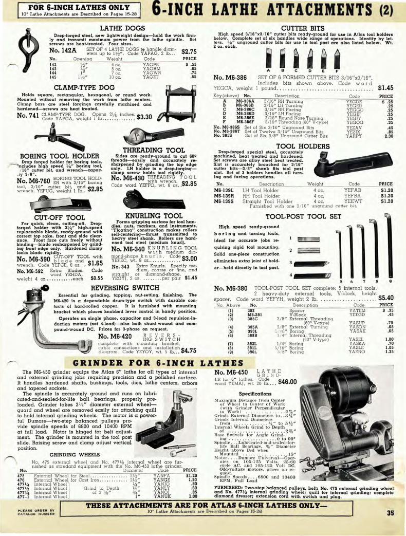
FOR 6-INCH LATHES ONLY 10" Lathe Attachments are Described on Pages 15-28 6·INCH LATHE ATTACHMENTS (2)
LATHE DOGS CUTTER BITS Drop-forged steel, new lightweight de sign-hold the work fi rm
ly and transmit maximum power from the lathe spindle_ Se t screws a re heat-treated. Four sizes.
High speed 3/ 16"x3/ 16" culler bits ready-ground for u se in Atlas tool holders below. Complete set of six handle s wide range of operations. Identify by letters . 3/8 " unground culler bits for use in tool post are also listed below. Wt. 2 oz_ each.
No. 142A SET OF 4 LATHE DOGS tD handle diam- $2 eters up to 11/2" . Code YAPAG, 2 lb . .. .75
No_ Opening Weight Code PRICE ~14~2~----~~Y:~2 '~'~------~4~0·~z~.~----~y7A~O~P~K~--------$ .55 143 %" 5 oz. Y AORM .65 144 1" 7 oz . YAOWR .75 145 1\12" 10 oz. YAOZT .85 No. MS-38S SET OF 6 FORMED CUTTER BITS 3/ 16 I x3/ 16".
CLAMP-TYPE DOG Includes bits shown above . Code war d
YEGCA, weight I pound. . ....... . .............. . .. . . .. .. ... $1.45 Holds square , rectangular, hexagonal, or round work.
Mounted without removinq the work from lathe centers. Clamp bars are s teel forqinqs care fully machined and hardened-screws are heat treated.
No. 741 CLAMP-TYPE DOG. Opens 21/4 inches. $3 30 Code YAPGA, weight I lb........... ... •
BORING TOOL HOLDER Drop forged holde r for boring tools.
------Includes high speed V4" boring tool, / 16" cutte r bit, and w rench-capac
. Iy 3/ 8" .
N M BORING TOOL HOLDo. S-7S0 ER wi th 3/ 16" boring
tool, 3/ 16" cutter bit, and $285 wrench. YEFUG, weight l Ib.. •
CUT-OFF TOOL For quick, clean, cutting-oH. Drop
forged holder with 31/4" high-speed replaceable blade, ready-ground with correct top rake, front and side clearance. Front face cuts freely w ithout binding- blade resharpe ned by grinding front edge only. Hardened clamp locks blade rigidly.
No. MS-590 ~y;;-~~ a~~OL with wrench. Code YEFCE, 8 oz . . ' $1.S5 No. MS-592 Extra Blades. Code
word YEHDA, w eight 4 oz . •. • •••• , .. • each $0.55
THREADING TOOL Sides are ready-ground to cut 600
threads-easily and accurately resharpe ned by grinding the top edge only. LH holder is a drop-forgingclamp screw holds tool rigidly • No. MS-430 THREA DING TOO L
with wrench. $2 85 Code word YEFFO, wI. 8 oz.. •
KNURLING TOOL Forms gripping surface for tool han
dles, nuts , markers, and instruments. "Floatinq" construction makes rollers self-centering- thrust transmilled to heavy steel shank. Rollers are hardened tool stee l (medium knurl).
No. MS-340 ~ ~.vh R ~~~:m T~~~ mond-shape k n uri s. Code $3 00 YEFEC, wI. 8 oz.. . .. .. .. .. .. . • No. 343 Extra Knurls. Specify me-
d ium , coarse or fine, and straight or diamond-shape. YEGYj, 2 oz . ...... . . per pair $1.45
REVERSING SWITCH
Key (above) No. Description A M6-386A 3/ 16" RH Turning B M6-386B 3/ 16" LH Turning C M6-386C 3/16" RH Facing D M6-386D 3/ 16" LH Facing E M6-386E 3/ 16" Rou nd Nose Turning F M6-386F 3/ 16" Threading (60· V-ty pe)
No. M6-386S Set of Six 3/ 16" Ung round Bits No. M6-386T Se t of Twelve 3/ 16" Unground Bits No. 3855 S" t of Six 3/ 8" Unground Cutter Bits
TOOL HOLDERS Drop-forqed special steel, accurately
machined, heat trea ted and hardened. Se t screws a re alloy steel heat treate d. Slot is accurately broached for 3/ 16" culle r bits- 3/ 8" shank fits tool post slol. Set of 3 holders handles all turning and facing operations .
No. Description Weight
Code YEGDE YEGED YEGGO YEGIF YEGJY YEGOG YEZAV YEZIX YARPY
Code
MS-139L MS-139R MS-139S
LH Tool Holder 4 oz. YEFAB RH Tool Ho lder S traight Tool Holder
Furnished with one
4 oz. YEFBA 4 oz. YEEWT
3/ 16" unground cutte r bi!.
TOOL-POST TOOL SET High speed ready-ground
b 0 r i n g and turning tools,
ideal for accurate jobs re
quiring rigid tool mounting.
Solid one-p iece construction
eliminate s e xtra joint of hold
er- he ld directly in tool post. 3 V 4 ___ 1!Zl1J
5 6 7 8 No. MS-380 TOOL-POST TOOL SET complete: 5 internal tools,
PRICE $ .25
.25 .25 .25 .25 .35 .45 .85
2.30
PRICE
$1.20 $1.20 $1.20
9
Essential for grinding, tapping, nut-selling, finishing. The M6-420 is a dependable drum-type switch with durable contacts of hard-rolled copper. It is furnished with mounting bracket which places knobbed lever control in handy position.
spacer. 2 heavy-duty external tools, V-b lock, height 0
Code word YEFYH, w eight 2 lb ... . .. . .. . ... . ..... ... $5.4 No. Above (I) '--~~ ____ --;;--,:...:.::c=:":,:,,::,,,-___ ~~~,;---_-,--;;:-= No. Description Code PRICE
382 Spacer YATEM $ .35
Operates on single phase, capacitor and 3-lead repulsion-induction motors (not 4-lead}--also both shunt-wound and com· pound-wound DC. Prices for 3-phase on request.
No. MS-420 fNJ ¥.J; I~ ~ If complete with mounting bracke t, cable connections and ins tallation $4 75 dia gram . Code YEYOY, wI. 5 lb... •
(2) (3)
(4) (5) (6)
(7) (8) (9)
M6-381 385C
385A 393L 388B
392L 391L 390L
V-Block 3/ 8" External Threading
(60· V -type) 3/ 8" External Turning
::; / 16" Boring 1/ 4" Internal Threading
(60· V-type) 1/ 4" Boring
5/ 16" Boring 318" Boring
GR I NDER FOR 6·I NC H LA T HES The M6-4S0 grin der equ ip s the Atlas 6" lathe for all types of interna l
and e xternal grinding jobs requiring precision and a polished surface. It hand les hardened shafts, bushings, tools , dies. lathe ce nters, arbors and tapered sock e ts.
The spindle is accurately g round and runs on lubri· cated-and-sealed-for-life ball b e arings, properly preloa d ed. Grinde r take s 2 1/2" d iame te r external wheelg uard and wheel are removed e asily for attaching quill to hold internal grinding w hee ls. The motor is a power
No. MS-450 ~ ~! NHl ~~r~orY~~lJ~h~. 2~°1r,e ... $4S.00
Specifications j\faximum Distance from Cen ter
u[ Whee t to Cent"- I' of WOl'k (w ith G rinder P el1)end ic ula r to Work) ...... ....... .. 2%"
Grinds Exte rna l Diarll ete rs to . . 3 ¥.&: " Gl'i nds Inte l'n a l Diameters
from .. . . . .... .. .. II , II t o 5 %" Intel'lla l Wheels Gl' ind to Dep th
or .. . .. . . ... . . . . . . ...... 2 ~s " Base Swi vels for An gle Grind-
in g .. .... . ... .. ...... 0 to 90·
fu l Dum ore--tw o-step balance d pulle ys p rovide spind le spee ds of 6800 and 10400 RPM a t full load. Moto r is hinged for b e lt a dj ust. m e nt. The grind er is mounted in the tool post slide. RaiSing screw a n d clamp a dj ust v e rtical posit ion .
Sp indte . .. Lubrica ted-and-sealed-for-vGtt ;~ li fe Ball Bearings. %" Diameter
~ j He~~~nt~8ve .~e.d .\~h~l~ .. . ... . 15" GRINDING WHEELS
No.
..... , .. ;..---...... Motol' .. . . DllmOI'e U niversa l- Oper-No. 475 external wheel a nd No. 477 1f2 internal wheel are fur- ales on 105-125 Volt s. 25·60 nished a s standard equipment with the No . M6-4S0 lathe grinder. cycle AC. and 105-1 25 Volt DC.
Diamete r Code PRICE Odd-volt age motol's. pl'ices on re o
External Wheel for Steel. . . 211z" Y ANFA $1.20 spih':J"i~t. Speeds .... 6800 a nd 10400 External Wheel for Cast Iron ............ 21/2" YANGE 1.20 RPM. Full Load
YEEGD .45
YASUP .75 YASON .65 YASAK .65
YASEL 1.00 YASKA .70 YASLE 1.05 YASNO 1.35
475 476 4771/ 4 477V2 477% 477- 1
Internal Wheel] 1/4" Y ANJO .80 Internal Wheel Grind to Depth liz" Y ANL Y .80 FURNISHED : T":,,o-step bal",nc~d pulleys, beit; No. 475 external grinding wheel In ternal Wheel ( of 2 3/8" %" YANOJ .85 a~d No. 4771/2 mternal grmdmg wheel; quill for internal grinding; complete Internal Wheel J 1" YANUK 1.00 dlamond dresser; extension cord with switch and plug.
,--.;.--T ..... H=E~SE~A~T ..... T~A-::C ..... H ..... M ..... E ..... N ..... T:::-:S:-A-:-R=-=E-::F:-::O-::R:-A:::-:T=L:-A:::-:S::-::-t-"=:IN:":'C=H::::-::-L-:A"::T ..... H ..... E ..... S=-O ..... N ..... L---y ..... -.....;.......;...--, PL~A5E ORD ER BY C~TA,"QG NUMBJ:R
10' Lathe AHac hmeDt. are Described aD Paqe8 15-28 35

6-INCH LATHE ATTACHMENTS (3) FOR 6-INCH LATHES ONLY 10· Lathe Attachments a re Described on Pages 15-28
MICA UNDERCUTTER TAPER ATTACHMENT Garages and service stations! The new Atlas S18 lathe can be
equipped for armature reconditioning at reasonable cost. For complete information on special outfits see page 33-armature chuck kits, page 22.
Another new Atlas developme nt - the first accurate. sensibly priced taper attachment. It is quickly installed, simple to operate, and makes accurate taper work a fast. easy job. The rectangular slide bar has rigid g rey-iron bracket supports . A slotted draw bar connects to carriage c ross slide and feeds tool at
The No. MS-SIO motor-driven undercutting attachment makes s hort work of mica undercutting and puts real profit in armature jobs. It is mounted quickly on the carriage cross slide and moved easily out of the way when not in use.
No. MS-510 MICA UNDERCUTTER for 6" lathes.
Code YEEVS, weight 9 lb . .. .. ... $18.00 M a xim um working d iameter . . ..... 4"
FURNISHED: Dumore motor 105- 130 volt A.C. or D.C. 25-60 cycle. Set of 5 high speed saws (.015", .020", .025", .030", .035" ), extension cord, switch and plug. No. 523A SET OF 10 HIGH SPEED SAWS (2 each of following thicknesses: .015", .020" , .025", .030", and .035") . Code YETUV .. . 53.S0 No. MS-38SG 3/16" HIGH SPEED CUTTER BIT ready-ground for trueing armatures. Code word YEWAS, weight 2 oz .... , . . ,' , .. . $0.35
LATHE LAMP For 6-;1I ch Lath es
Throws plenty of light on work. Has 14" flexible cable and ball joint at shade. Mounting bracket clamps at base of bed. Attractively finished in satin-chrome plate with polished shade. S ft. rubber cord and plug furnished.
No. MS-745 6" LATHE LAMP. Code w 0 r d $2 85
YEERP, weight 2 Ib .. . . . . .. . .. .. •
COIL WINDER
CARRIAGE STOP
C I amp s to bed way and indicates accurately stopping point of carriage.
No. 10-315 Code YIAZB, wt. I lb .... ... S3.50
d e sired taper. Eas y-to-read index plate is g radua ted 7 ° and 3" both sides of center line.
No. MS·700 TAPER ATTACHMENT for Atlas G" lathes. Code YEITS, weight 4 V2 lb . Max;mum tl avel
one setting 73/4". Range r ight o r le ft 7 ° (215/ 16" per foot) .... $15.00
DRILL PAD The drill pad. m cunted in the tails tock ram, serves
as a rigid support for drilling flat or square work with drill held in headstock. Ground s teel shank is No. 1 Morse taper . No L2·3S0 DRI LL PAD, No. I Morse ta-
• per shank. 3Ve" diam. face . $1 S5 Code word YATPO, weIght 12 oz ........ . ... •
CROTCH CENTER The crotch center automatically centers round warl!
in the tail stock ram for accurate cross~drilling. V -slot is accurately machined-ground steel shank is No. 1 Morse taper.
No. L2-35S e te r j I " slot.
CROTCH CENTER, No . Morse taper shank. 2" diam
Code YATYR, wt. 12 oz . .. $1.S5
SOO LATHE CENTERS Hardened and ground high-carbon
tool steel. Weight 8 oz.
No. Morse Taper Code PRICE
L2-80 No . I YA VEN S1.00 9-88 No.2 Y A V AM 1.35 MS-138 No. 2 to I Sleeve YEHHO 1.20
BALL BEARING
T AILSTOCK CENTER Center point rotates on enclosed
ban bearing-recommended for high speed operations.
No. MS·348 BALL BEARING CENTER No. I Morse taper. $10.50 Code YElJO, wt. 8 oz
Simplifies accurate coil winding. Replaces tool post-has fibre wire guide and spring adjustment on spool for correct tension. Quickly mounted and removed.
CROSS SLIDE STOP CENTER EJECTOR BAR Clamps to c r 0 S S
s lid e dovetail and sets depth of duplicate cuts ,
e ;:;;;§! Removes center from spindle without burring center or sleeve. Steel shaft has
knurled ball grip- brass head cannot damage center sleeve. or spindle. No. MS-780 COIL WINDER. YEMIL, wt. I V2 lb. , ... $3.25
No. M6-725 Cod e YEMKE, wt. 8 oz. $2.45 No. MS-790 ~~~.J:,~ ~e~~~~~V2Bfb~' .. ~~~gth,l.O~': .. ::.o~~ . :':'~~~ $I.l0
WOODWORKING ATTACHMENTS Sturdy. rigid construction and a n exceptionally w ide range of spindle speeds make the new Atlas S·inch lath e an id e al mach ine for woodworking as well as
m a chining a ll types 01 m e ta ls and p lastics. FOR 6-INCH LATHES
WOODTURNING CHISELS Professional-type chisels with tool steel blades
scientifically heat treated. Extra long handles are polished maple with strong brass ferrules. Approximate length. 14" .
No. WI3A ~ro 8~ B ~~~;L~o~d Y AZWY, weight 6 pounds. . . ... .. .. . . .. .. $9.25
Chisel No. Code 1/1" Gouge ... , .... .. . .. W13·1 YAYPA 1f2" Gouge ..... . ... .. . . W13-2 Y A YSO I" Gouge ... .... ..... . W13-3 YAYUT
1f2" Skew .... . .... . .. .. W13-4 Y A YVY I" Skew ... . . .. . ...... W13-5 YAZER
1/2" Round Nose . ....... WI3-S YAZRE 1/ 2" Spear Point .... . ... W13-7 YAZTO V2" Parting ......... W13-8 YAZUV
Weight I lb. each
PRICE Sl.25
1.30 1.75 1.10 I.S0 1.10 1.10 1.20
SPUR CENTERS
For driving work mounted between centers. Ground and hardened steel with replaceable center point. Morse taper shanks. No. Shank Wt.
350 No.2 Morse Taper I lb. L2-16 No. I Morse Taper 8 oz. MS-138 No. 2 to No.1 Sleeve 6 oz. L3-147 Extra Poin t for No. 350. 147 Extra Point for No. L2-16.
CUP CENTER
Code YAWTY YEADZ YEHHO
YEWIV YEWSA
PRICE 51.10
.85 1.20
.35
.25
Supports work in tailstock. Ground and hardened steel with replaceable center point- No. 1 Morse tapo: shank. No L2·17 CUP CENTER. Code word
• YEACY, weight 8 oz .... . .. .. . $0.85 $0.25 No 147 EXTRA CENTER POINT.
• Code YEWSA, wt. 2 oz .
No. 352 L2-352 MS· 138 355
SCREW CENTER For facing and hollowing
operations. Alloy steel with replaceable center. Morse taper shank. Diameter 2" .
No. 2 Morse Taper No. I Morse Taper No.2 to No. I Sleeve Extra Center Point
Wt. Code PRICE lIb . YAWYT S1.65 8 oz. YEAHD I.S5 6 oz. YEHHO 1.20 2 oz. YEYEV .35
EXTENSION BED For handling e xtra long wood work . Machined
and finished to same specifications as lathe bed. Overall length 161/ 2 inches .
No. MS-IE EXTENSION BED for wood-workmg only. Code $7 00
YEMEK, weight 24 lb. .. .. ... ...... . ....... •
HAND REST Clamps to bed and furnishes
rigid support for chisel. Has sliding clamp plate to protect bed. T-rest can be sw ivelled to any position and locked securely with hand clamp. 4" and 8" T-rests are furnished . No. MS·330 WOODWORKING HAN D REST complete with 4" and
~~FbF~s~t. ~0li,e $2.75
1?IESE ATTACHMENTS ARE FOR ATLAS 6-INCH LATHES ONLY-10' Lathe AUachmenla are Described all Pagel 15-28 ALL Plilelll §U8JIlI:T TO
ellANQI< WITilOU'i' NOTICI'

The Near
MILLING MACHINE
T HERE are spots for this handy milling machine in
every shop and tool room with any volume of small-part
milling. It has been designed after years of research with
this one idea in mind-to eliminate the wasted time and
effort involved in setting up and operating a large, ex
pensive miller for small pieces of work.
The new Atlas Milling Machine will cut your costs on
the full range of milling-from slabbing and facing cuts to end milling, keyways, finishing and layout work. The
compact Atlas is rugged, accurate, and efficient-eco
nomical in investment cost and economical in operation.
Investigate the possibilities for the Atlas Milling Ma
chine in your shop. Arrange today for a working demon
stration. The modern Atlas construction features and
complete specifications are presented on the following
pages.
GEAR CUTTING BODING DBlLLlNG-LAYOUT
FACING SLABBING
STBADDLE SLOTTING
DOVETAIUNG PROFILING
CO.PI.ETt; jHDEXIH' IDii ilACK COVf"R THE FIRST LOW COST PRECISION BENCH MILLING MACHINE

View 01 column and spindle h"ad .how ing eleva tion screw for knee a nd lable.
THE NEW THE FIRST LOW- C OS T P RECI SION
I"f'iHESE descriptions explain how every construction detail of th' .L new Atlas Milling Machine has been designed to meet thes,--J
modern machine tool requirements: rigidity and rugged strength essential for the firm support of cutter and work: accuracy of construction for accuracy in operation, plus provisions to maintain that accuracy; power for heavy cuts-a wide range of spindle speeds for all types of cutters and work; opera ting efficiency to reduce set-up and machining time . • RIGIDITY-Heavy semi-steel iron castings are used for the columns. base. spindle head. knee. saddle. table. and arbor supports. These castings a re scientifically proportioned. rib-bra ced a nd reinforced. and have large bearing surfaces. Overa rm is a solid bar of stress-proof steel. 1 '/2" in diameter. The extra weight of a ll of these pa rts is the foundation for smooth. a ccurate cutting action a nd long service life. e ACCURACY- The new Atlas miller is entirely precision-machined. Jigs and fixtures hold each pa rt in exa ct position during machining. and each operation is inspected fo r uniformity and a ccuracy with preCision tools and master gauges.
COLUMN-A massive th ick-walled g rey iron casting. ribbed a nd reinforced to provide a rigid support for the spindle head. knee. and counlershaft . Ways for the knee bearings. each I V2" wide a nd 1/ 2"
thick a nd cast integrally with the column. a re precision ground for smooth. accurate knee a nd table a ction. Four large cap screws and two dowel p ins hold the column securely to the base casting. a broad a nd hea vy foundation for the entire machine_ Front 0.1 bose is shaped to retain oil. and portion below column forms a reservoir for automatic coolant system (page 42). Column bearing surfaces for base. spindle hea d. and countersha ft a re a ll accura tel y ma chined. A single phase on-ofl switch (10 a mperes a t 110 voll) is built in to the column cast· ing. Three phase switch is listed on page 40.
The wide. thick column ways for the knee bearings a re p recision-ground . smooth. accurate movement 01 knee and table. Dovetail slides of knee. saddle. a~ table are accurately rI).a chined and hand fi tted. Table top and sides are precision g round. Bearing bosses for the spindle bearings. backgear shaft. and overarm are a ccurately line bored for positive alignment. Precision ground spindle turns on Timken tapered roller bea rings. Full provision is made fo r thorough lubrication and complete adjustment of all bearings.
Careful inspection at every stage of assembly a nd thorough working tests of the completed machine insure accuracy in handling the lull range of milling operations. • POWER- The Atla s backgea red drive. powered completely by V-belts. plus the Timken bearing equipped spindle. transmits maximum power to the cutter with a smooth. even action. This modern design permits the use of a n economically operated '/3 HP motor.
• OPERATING EFFICIENCY-All controls are w ithin easy reach. Sixteen spindle speeds between 54 and 3225 RPM provide correct surface speeds lor a ll types of work and cutters. Correct spindle speed is obtained quickly by referring to easy-to-read chart for belt positions. Turning a socket-hea d screw releases arbor support for changing cutters. and the overarm can be easily removed when mounting cutter on spindle. A convenient 10 ampere 110 volt on-off switch is built into the column.
SPINDLE HEAD-A heavy well-bra ced iron cast. ing anchored rigidly to the column by four large cap screws. Accurate line boring of bearing bosses for spindle bearings. backgear shaft. and overarm insures positive alignment. Spindle head houses the spindle, bearings. pulley and backgears and provides a rugged support for overarm and cutter gua rd. An iron guard a t the rear of the spindle head covers Ihe spindle gear and has all opening for operat. ing the draw-in bar.
Three types of table controls are a vailable: hand-operated screw feed. rapidproduction lever feed. and the new Atlas "Change-O-Matic" for instant selection of reversible a utomatic longitudinal table leeds between 0.162" and 9.125" per minute.
Side view of new Atlas milling machine showing V-belt countershaft at·~ached to column. Two-step pulleys Irom motor to countershaft and fourstep pulleys from countershaft to spindle. Notice handy position of counter.
shaft lE>ver.
38
l,I. ttachments a re described on pa ge 42.
OVERARM AND ARBOR SUPPORT ~ The overarm is a solid bar of stress-proof steel. I If2" in
diameter-a rugged brace for the arbor support at its ouler end. It insures accurate work by maintaining the rigid horizontal position of the arbor and cutters. Bearing bosses for the overarm. on each end of the spindle head casting. are accurately line bored for positive alignment with the spindle. Two coordinatetype clamps lock the overarm rigidly in the spindle head. Arbor is described on page 42.
The grey iron arbor support has a split compressiontype bearing which clamps tightly to the overarmsocket head screw releases bearing lor changing cutters. Arbor bearing is oHite b ronze. lubricated through a ball oiler. Overarm. arbor support. and arbor are covered by a n iron safety · gua rd. Overarm and guard can be easily removed.
~INTEGRAL V-BELT CO'UNTERSHAFT - S u p· port brackets for the countershaft and motor base are attached directly to the column. making the Atlas milling machine a compact, self-conta ined unit. Coun· tersha ft is "quick-change" type with belt tension lever in ea sy reach for speed changes. Lever has two positions-forward to release belts. and ba ck to engage them_ Counlershaft spindle turns on oilite bea rings.
The modern V -belt drive from motor to countersha ft to spindle transmits maximum power to the spindle with a smooth. even action at all speeds. Sixteen spindle speeds are available between 54 and 3225 RPM -an easy-to-read chart is furnished listing spindle speeds for the vQrioul! belt positions_
Overarm and Arbor Support
MOTOR DATA-The new Atlas mill ing machine is designed to be operated from a 1/3 HP 1740 RPM motor (see page 40). Motor bracket support is a ttached directly to column. On-off switch built into left side 01 column is 10 ampere a t 110 volts . single phase only (3 phase motor and switch. page 40). A flexible conduit is furnished to cover portion of switch-to-motor cord between machine and motor.

MILLING MACHINE BENCH MILLING MACHINE
TABLE - The table is a solid grey iron casting 18" long. 4 1/2 " wide and 13fa" thicka massive work support with the extra weight essential for maximum rigidity.
All table surfaces are accurately machined. and the top and sides are precision ground. The table top has a T·slot in the center for bolting work and attachments
.~V·groove on each side of this T·slot simplifies the firm gripping of bar stock. An ustable dog·type stop in the front table T·slot can be set to stop longitudinal table
"..;vel at any point. . Table dovetail bearing on the saddle is accurately machined and carefully fitted.
This bearing is equipped with an adjustable gib-gib screws have lock nuts. A gib lock sets the table rigidly at any point on the saddle. A sloping recess around the table working surface removes oil and cutting compound.
TABLE CONTROLS-The table feed screw for longitudinal travel has a ball crank at each end for hand·feeding the table- screw is supported at each end by an ollite
Graduated Feed Screw Collar
bearing. Vertical travel of the knee and table is controlled by the large front handwheel which operates a telescoping screw with acme threads-ball bearing absorbs end thrust. [Note: Model MH (page 40) has hand lever controls for rapid movement of table vertically and longitudinally.] Table cross feed screw is controlled by the small hand wheel in front --cover keeps screw free from dirt and chips. All table feed screws have acme threads. Steel feed screw collars are micrometer graduated in .00Uhs and have a knurled screw' which permits setting the o position at the witness mark for accurately gauging feed.
Three types of table controls are available: hand-operated screw feed, rapid.production lever feed. and the new Atlas "Change-O-Matlc" for instant selection of reversible automatic longitudinal table feeds between 0.162" (lnd 9.125" per minute. These con· trois are described on pages 40 and 41.
PUAS. ORDJ. 8Y CATAI~IIII NUMBER
~ ~
SPINDLE AND BEARINGS - The spindle is machined from a solid bar of special fine-grained steel, accurately ground-is 1" diameter, has 10-pilch NF threads and 17/ 32" hole through entire length. Spindle nose is bored for No. 2 Morse taper.
Timken tapered roller bearings maintain accurate spindle alignment and carry both radial and thrust loads with a minimum of friction. Each bearing is lubricated through a large capped felt-wick oil cup. Simple take-up adjustment is provided. These fine bearings permit the wide range of spindle and surface speeds essential for all types of work and cutters_
BACKGEARED POWER-The Atlas backgeared drive. powered completely by V-belts, reduces the spindle speed for slabbing and lacing, and work requiring large diameter cutters. The back gears. completely housed by the spindle head, are engaged by advancing eccentric lever and shifting pulley lock pin. Pulley and gears are accessible through a door in the left side of the spindle head. Backgears are 3/8 "
wide. 20 pitch, and have ratio of about 6 1/2 to 1. Backgear shaft turns on ollite bronze bearings.
KNEE AND SADDLE-The heavy knee casting travels vertically on the ground column ways and is supported rigidly by full 5 'h" -long bearings on the ways and by the telescoping elevation screw. Top of knee has an accurately machined dovetail for the saddle. Column bearing plates with laminated shims and an adjustable gib maintain a firm fit between knee and column ways-gib screws have lock nuts Gib lock permits setting knee rigidly at any height.
The thick heavy saddle casting has dovetail bearings 5" long on the knee and 6" long on the tableforms a rigid table support. Dovetail ways are accuratery- machined and carefully fitted for smooth table travel. Bearings are equipped with adjustable gibsgib screws have loek nuts. Gib lock permits setting IItlddle securely at any point Oil the knee.
31

THE NEW ~ MILLING MACHINE --~ ~
NUMBER Ml NEW ATLAS MILLING MACHINE WITH
HAND-OPERATED TABLE CONTROLS
N Ml G NEW ATLAS MILLING MACHINE, O. - complete with safety belt guards and
hand-operated table controls, less motor. Code w ord ZEVNE, net weight 179 pounds, shipping $21650 weight 229 pounds .. . . . . . .. .. . . ... . ...... ... .. .. • N Ml NEW ATLAS MILLING MACHINE, with
O. hand-operated table controls, less safety belt guards and motor. Code ZESAK, net weight $205 00 174 lb., shipping weight 224 lb........ . . . . . ... .. •
NUMBER MH NEW ATLAS MILLING MACHINE WITH
RAPID-PRODUCTION LEVER CONTROLS
No MH G NEW ATLAS MILLING MACHINE, • - complete with safety belt guards and
rapid-production lever controls. less motor. Code word ZEVUR, net weight 183 pounds, shipping $221 50 weight 243 pounds . ... . . .... . . ..... .. ... .... .. . . • No MH NEW ATLAS MILLI NG MACHINE, with
• rapid-production lever controls, less safety belt guards and motor. Code ZESKA, net $"1000 w e ight 178 pounds, shipping weight 228 pounds .. ,~ •
40
COMPLETE SPECIFICATIONS-THE NEW
FEED
RANGE
TABLE
Longitudinal Table Travel with "Change·O·Matic" ... . . .... . .... . 10"
)
LongitUdinal Power Feeds with "Change·O·Matic": Per Revolution 01 Spindle ... . .. .. 0.003" .. OOS " , .0125" . or .025" Range . .. ... , .. . . . .. . .. .. . . .... ... 0.162" to 9.125" per minute
Longitudinal Table Travel with Hand-Operated Controls ... .. .. . (Nos. MI and MI ·G) ... .. ......... . ..... . . ... .. .. . . .... ... 12"
Maximum Longitudinal Travel at One Setting . . . .. .. .. .. . ... . .. .
l (Lever· Control Models. Nos. MH and MH·G) . . . . .. .. • .. . .. 5'12"
Cros.s Table Travel, Hand·Operated (all models) ... .. .... . ... ... 3'12" Verhcal Table Travel wlth Hand-Operated Controls .. . . . ...... .
(Nos. MI. MI-G. MF. and MF·G) ...... .... ...... .. .. .... ... S" Maximum Vertical Travel at One Setting .... .. ..... . . . ....... . .
(Lever. Control Models. Nos. MH and MH·G) . .... . ... ........ 2" Center of Spindle to Table in Lowest Position. . . . ... . ..... . ... .. 6"
1 Working Surface. Precision Ground ... ... .. .. .......... . . 4 lj2" X 18" Overall Table Dimensions . " .... .. ...... . .. . 41/2" x 18" x P i s " thick T ·Slots. Side and Top 01 Table .. . . .... . . ... .. . .... %" x 5/a" x 18 " Longitudinal Table Feed Screw ..... . . . lj2" diameter, acme threads Telescoping Elevation Screw .. . lj2/1 and sis" diameter, acme threads Sixteen Spindle Speeds between .... .. .. . ... . . .. . 54 and 3225 R.P .M.
SPINDLE' Spindle Bearings . . . . . .. .. ... . ... .. . Timken Tapered Roller Bearings ) with thrust take-up nut and collar
AND tSPindle .. . . 1" diameter. 10-pitch National Form threads. 17 / 32" hole through entire length. nose bored for No. 2 Morse Taper
ARBOR Arbor (see No. MI -5S0 below) ... . ........ . .. . .. . . ... . . ?fe" diameter ..../ Center of Arbor to Underside of Overarm . . . . ..... . . . ..... . ... . 21/s" '-..
V-BELT
DRIVE
UNIT
)
Back Gears ..... . .... .. ...... .. .. .. .. .. ......... 20 pitch. % " wide Backgear Ratio (approximate) ... . ... .. . .. ... . .. . ... . .... . . . Slj2 to I Backgear Shalt Bearings .. .. ..... . . . . . . .. . . . ... . . .. .... oilite bronze
t Countershalt and Spindle Pulleys .. . . . .... . . . ........ .4.step, V-type Countershalt Spindle Bearings . . . ...... . . . .. .. .. . ... .. . oilite bronze
. Motor Recommended . ..... .. . ..... . . ... .. .. . . ... 1/ 3 H.P. 1740 R.P.M. Overall Dir#.ensions ... :" . . .. .. . . .... .. . .. . . ... . . . . . ... 251/2/1 x 32lj2" x 22" high Base Dimensions (Bench Space Required), including motor bracket. . 20 lj2" x 18lj2"
FURNISHED: Integral V·Belt Countershaft; Belts and Pulleys for Complete V·belt Drive; Motor pulley furnished is for '12" diameter motor shaft-prices of pulleys for other motor shafts on request; Motor Mounting Bracket; IO-Ampere Motor Control Switch and Cord with 18" Flexible Conduit Covering- switch is for sing le p hase current only, 3·phase switch is No. S7-300 below, O perating Instruc tions.
No. MH NEW ATLAS MILUNG MACHINE WITH
RAPID-PRODUCTION LEVER CONTROLS
The MH models have quick·acting lever controls to speed up longitudinal and vertical table movement for production milling operations. One setting of the lever at the left permits 5 1/2 " longitudinal travel of the table-second lever moves table 2" vertically at one setting.
Each lever operates a rack·and-pinion feed- lever shafts hav e squared ends for quick table pOSitioning with crank handle (furnished). Adjustable stops are furnished to set limits of table travel as desired . Dog·type stop in front table T-slot has a set screw for close adjustment of longitudinal travel. A screw anchored securely to the base casting has two sets of lock nuts to set upper and lower limits 01 vertical table travel. A heavy boss on the miller knee travels between these stops.
MOTORS AND ACCESSORIES FOR THE
CUTTER ARBOR-Slressprool slee1. ground all over -has lull·length keyway and No. 2 Morse laper shank lor spindle. Driver furnished is threaded for spindle nose. Collars are precision ground. No. MI·576 draw-in bar is r"quired.
No. MI·560 CU'ITER ARBOR for Atlas milling machine. complete with nut, 5 collars and driver. Code ZETYR. Weight 5 lb ....... .. ... . .... $18.00
Diam. Arbor ... 'Vs" Shank. No. 2 Morse taper Diam. Collars .. 13/s" Length Shoulder to Nut 6\14" Collars Furnished: two 2", one I", one 3/4H
, one V2"
DRAW-IN BAR- Required to hold MI-560 cutter arbor and MI-577 shank cutter adapter (page 42) in spindle taper. No. MI·576 DRAW-IN BAR. Code word ZEVAM, weight 1'12 lb ............. . . . . . . . . . ..... . .. $2.00 No. 87.100 CRANK HANDLE for No. MI-576. Code word ZEVYS, weight 1\12 lb ................ $2.25
SINGLE PHASE MOTORS No. 2480 '13 H.P. 1740 R.P.M. SINGLE PHASE BALL BEARING MOTOR. 110 volt, 60 cycle, 112" double-end shaft, built-in switch, 10 It. S) approved cord and plug. Code WYI)L, 28 lb . . . $14.25 No. 2520 '13 H.P. 1740 R.P.M. SINGLE PHASE CAPACITOR·START BALL BEAR· ING MOTOR. 110/ 220 volt, 60 cycle. '12" double ·end shaft, built·in switch, 10 ft . S) approved cord and plug. Code WY)lL, weight 33 lb .. .... . . ... . $20.50 No. 2485B '13 H.P. 1740 R.P.M. SINGLE PHASE BRONZE BEAII. ING MOTOR. 11 0 volt, 60 cycle. '12" single-end shaft. 10 ft. SI approved cord and plug. Code ZEBIT, weight 28 lb .. ...... .. . . . $1l.0r
THREE PHASE MOTOR , No. 2S30 '13 H.P. 1740 R.P.M. THREE:--"" PHASE BALL BEARING MOTOR. 220 volt. 60 cycle, \12" double end shaft, BX connector in terminal box. Does not have switch, cord or plug. Code WY· KAK. weight 28 lb . . . . ... ..... .. $21.00 No. S7-300 THREE PHASE SWITCH lor Atlas milling machine. Code word ZEBAR, weight 6 lb . . . . . ... ... . . . $13.50
(A thermal overload 3-pole manual starter. Mounting bracket and flexible cable-covered motor cord are furnished.)
ALL PIlICES S UaJ ECT TO CH"HOIt WITHOIrT NOTICE

SPECIFICATI ONS AND ORDERING INFOR MATI ON t:ltItu.. MILLI NG MACHI NES
• Precision-Ground Table 4%"xl8", Three Types of
Controls Available
• Backgeared Power
• Complete V-Belt Drive
• Sixteen Spindle Speeds 54 to 3225 RPM
EQUIPPED WITH
TIMIEN ~:{:!:BEARINGS
NUMBER MF
NEW ATLAS MILLING MACHINE
WITH eit~-rJ-Matic POWER FEEDS FOR LONGITUDINAL TABLE TRAVEL (Patent Applied For)
The MF models are equipped with the Atlas "Cha nge-o-Matic" mechanism fo r instant selection of reversible automatic table feeds between 0_162" and 9.1 25" per minute. This convenient feature speeds up all operations requiring long itudina l movement of the table_ Maximum table tra vel with the Change-o-Matic is 10". No MF-G NEW ATLAS MILLING MACHINE, complete with safe ty
• belt guards and " Change-O-Matic" power feeds, less. $236 50 motor. Code ZEVSY, net weight 190 lb., shipping weight 240 lb.. . • No MF NEW ATLAS MILLING MACHINE w ith " Change-O-Ma tic"
• power feeds , less safety belt guard s and motor. Code $225 00 ,EL, net weight 185 lb., shipping weight 235 Ib.. . . . . . . . . . . . . . . . •
NE W t:ltItu.. MILLING M A C HINES
SAFETY BELT GUARDS Eliminate hazards of exposed
belting by providing salety
cover as required by industrial
and vocational safety codes.
Light. durable calltings with
pin hinges, ready-tapped lor
~sy installation. Vertical guard
J v e r s motor·to-countershalt
belt-horizontal guard covers belt from countershaft to
spindle.
No. Ml-400 SAFE'fV BELT
GUARDS for Atlas mIll-ing machine. Code ZE- $11 50 SUP, wi. 7 lb .. _ . .... . , . • ttL.AS. ORDa. av CATALOG HU ....
THE eluuu;e-rJ-Matic (Patent Applied for)
The Change-o-Matic controls are pictured above. Simply turning the large knob engage. the spindle gear with a gear train which drives the telescoping universal bar. this bar controls bevel-gear drive to keyway in table feed screw. Four feeds are available for each of eight spindle speeds-32 table feeds in all. As a gear train Is engaged. a chart appears through the small window and shows the table feed selected (.003" •• 006" •. 0125" or .025" per revolution of spindle). Below this figure is listed the equivalent in inches per minute for each of eight spindle speeds_
Direction of the lable feed is reversed instantly by shifting the tumbler lever at Ihe right of the Change.o-Matic chari window. Lever has, neulral position to disengage power feed. so that table may be fed by hand. A doq in the side T-slot of the table can be set to automatically 810}, the power feed' at any pOint by tripping a lever on the table feed.gear case. This lever can also be disengaged by hand.
41

ATTACHMENTS FOR THE NEW
INDEX CENTERS For dividing operations required in such work
as splininq, fluting, gear cutting. and squaring shafts. Headstock and tailstock are heavy well. braced castings. locked with bolts to table T·slot -both have keys at each end to maintain alignment with table T·slot. Centers may be positioned lor work lengths up to 9 inches and locked with coordinate clamps. Headstock spindle nose is threaded lor double·end dog driver or chucks listed below- outer end of spindle accommodates index gear and lock nut. Lock pin support bracket is adjustable for various gear diameters. Tailstock center has handwheel control. No. MI ·200 INDEX CENTERS for Atlas m ill· ing machine. Code ZESLE, weight 15 lb . ... $28.50
Max~mum dis~ance between centers .. . . 9:; Maxlmum sWlng .. . . .. . ... . . . . .. 6
ROTARY INDEX TABLE
Holds work lor accurate angular indexing and spacing. Table is precision ground on all surfaces and has three T-slots for positioning and locking work- can be swiveled to any angle and locked to base with two bolts. Holes spaced around table side permit indexing table rigidly every 300 with plunger and knob . Base is graduated 0 to 900 both ways. No. MI·350 ROTARY INDEX TABLE for At· las Miller, with two base·clamping bolts and w r ench. Code ZESNO, wI. 15 lb . .. ... .... . $27.50
Table Diameter .. ... .. .. . . . . . . . 5lj2" He ight to Top of Table ........ . . I Ye"
MILLING MACHINE
SWIVEL VISE
Grips work rh~ idly at any angle. Vise and base are heavy, accurately machined cas t -ings- b a s e has machine d bolt slot at each end and 3lj2" long key in
bottom to maintain alignment w ith table T-slo1. Vise can b e turned in a comple te circle and locke d in any position-base i s graduated from o to 90 0 le ft and r ight. Jaw s are 3" wide. '/e" high, ope n 3lje". and have s tee l insert plates. Acme -thread screw has tobin bronze nut, take-up adjus tment. and crank control.
No. MI·300 SWIVEL VISE with crank, 2 clamping bolts. Code ZESON, weight IS lb . .. . ........... ... . . .. . . . . . ......... .. .. $16.75
Overall .height with base 31/8" . Vise may be re o moved from base and used alone as plain v ise.
Furnished: Nine indexing gears (36, 40, 44, 46 . 48, 52. 54, 56, and 64 teeth); I V2" dog, drive r. bolts . The following chucks are threaded to fit the h eadstock spindle nose of the MI·200 attachment - Nos. U6·437. U6-439. M6·375 (Details, pa ge 34).
HIGJI SPEED MILLING CUTTERS
ANGLE PLATE
The angle plate holds irregular shapes which cannot be gripped in the No. MI·300 vise or bolted to the table. It is a solid well-braced i ron casting, accurately machined to a right
angle and preCiSIon ground on the outer faces. Working lace has lour holes lor bolting work. Base has two holes lor bolting to T·slot in the milling machine table . Base and face each measure 2lj2" x4 " x7 / 16" . No. 57·430 ANGLE PLATE with bolts. Code word ZEHUD, weight 3 lb .. .. .... . ... . ..... $5 .00
COOLANT FLUIDS protect the milling cutter and im prove work finish by carrying off heat generated at the tool edge. Coolants are required when milling steel, and for maximum accuracy on high speed operations with such materials as brass and plastics.
Automatic COOLANT SYSTEM Recommended
for production milling. Pump and motor unit is installed in 3-pint reservoir compartment in base casting . Delivery and return hoses are oil-resisting Neoprene . Delivery hose has sliding 5 U P P 0 r t arm, and nozzle i s adjustable so
that flow 01 coolant can be directed to any point on the cutter arbor. Valve regulates flow-nozzle is tipped with oil-resisting Neoprene . Coolant is filtered twice: once in a cup at table outlet. and again by 40-mesh screen enclosing the pump unit. Pump is automotive gear type with a capacity of 1/2 pint per minute- pump motor has on-off sw itch built into cove r plate . No. MI·600 AUTOMATIC COOLANT SYS· TEM for Atlas milling machine, as shown. Code ZETEM, weight 8 lb. . ....... .SI9 .50
COOLANT TANK A gravity·flow tank 01 approximately one quart
capacity. Sliding support arm and adjustable noz· zle permit directing flow 01 coolant to any point on the cutter arbor. Valve regulates flow. Nozzle is tipped with oil· resisting Neoprene-will not be injured if it comes in contact with revolving cutter. No. MI·550 COOLANT TANK, capacity ap· prox. I quart. Code ZETAL, w eight 8 lb . . . S5.00
42 2
CUTTER ARBOR
.~; it P;;;;F~ Holds culler for slabbing. straddle culling. slil.
tiDCJ, forminq, etc. Arbor is atresaproof steel, ground all over- haa full-length keyway and No. 2 Morse taper shank lor spindle. Driver furnished is threaded for s pindle noae. Collars are preci. s ion qround. No. Ml·576 draw·in bar is required. No. MI-560 CUTTER ARBOR for Atlas mill-ing machine, complete with nut, five collars and driver. Code ZETYR, wI. 5 lb ... . . .. .. . $18.00 Diam. Arbor . .. . Ye" Length Shoulder to Nut 61/4" Diam. Collars .. 13/8" Shank ... No.2 Morse taper Collars Furnished: two 2" , one 1", one 3/4" , one 1/2",
SLAB MILLING CUTTER For plain surfacing- has · RH
s piral teeth. Held on MI·560 ar· b or. Wt. 2 ib .. hole 'lis".
No. Diam. Face Code PRICE: Ml·SeO 2%" I" ZETLA $6.00
574A S74B
7/ 16" 9/16"
&
ANGULAR CUTTERS For face·milling and dovetail
ing. Threaded hole-adapted to No. MI·571 shank.culter adapter with arbors listed below. Wt. 6 oz. each. Diam. Hole Thread Code 11/4" 3/8" 24 YAUF 10/8" V2" 20 Y ALl Y
PRICE: $4.10
4.70
ARBORS FOR ANGULAR CUTTERS Required for holding No. 574 angular culters in
No. MI·577 Shank·Cutter adapter. Wt. 8 oz. each. No. For No. Code PRICE 572 574A YEWTE $ 1.00 567 574B YEWUX LOQ
R. H. SPIRAL END MILLS For qen.ral milling operations-slots.
facing and routing. squaring and s plininq ahafts, cuttinq straight keyways . Straight shank- held in No. Ml·577 Shank· Cutter a dapter w ith bl'lhinga b e low. Wt. 4 oz. e ach.
No. Lgth. Flute Diarn. Code PRICE 576A 5/ 8" 1/4" YAKCE S1.75 576B 1l / 16" 5/16" YAKEC 1.85 576C 3/4" 3/8" YAKFO 1.95 576l> 7/8" 7/16" Y AKlD 2 .15 576E IS/16" 1/2" Y AKOF 2.35
END MILL BUSHINGS Required 10 adapt 576 stralqht shank end mills
to No. Ml·577 Shank-Cu tter adapter. Not required
\II for No. 576E VZ" diameter end mill.
No. For End Mill Code PRICE 563D No. 576A YAKYH 5 .30
, & 563C No. 576B YALA C .30 .. 563B No. 576C Y ALCA .30
563A No. 576D Y ALDE .30 563E Set of 4
Above Bushings Y ALED 1.15
SIDE MILLING CUTTER
For slotting. g rooving. keyways. e tc.-used in pairs for straddle mill. ing. Teeth have cutting edges on three sides. He ld on Ml·560 arbor.
Face Hole Code Wt. PRICE V4" %" ZETME I lb. $5.40
METAL SLITTING SAWS For s li tting and slotting. cutting small
keyways, and cut·off operations. Sides taper-ground for proper clearance. Held on MI·560 arbor . 1'8" hole. wt. 8 oz. each.
No. DlQm. Thickness Code PRICE "M~lo-.5"'8:-;:2:-=2;'V:~2~":""":'::':'1"'/"'372'~' =-~Z';:ET=O~P"":"=:S2.80 MI·583 2V2" 1/ 16" ZETPO 2.80 Ml·584 2V2" !, 8" ZETRY 2.90
DRAW·IN liAR
• i s - ' -;J hWiIij@@j
Required to hold MI·560 cutte r arbor and MI.577 shank-cutter adapter in spindle laper. No. Ml ·576 DRAW-IN BAR. Code word ZEV AN, weight IV2 lb ..... ... .. .. . ......... ........ $2 .00 No. 57-100 CRANK HANDLE required for No. M I-576. Code ZEVYS. weight I V2 lb ... ..... $2.25
di } . ) SHANK· CUTTER 'IJ_~--iooiOiij~~';iiiiiiiiiil"~® ADAPTER Holds 1/2" straight shank cullers (angular cut.
ters, end mills. Woodruff keyway cutters). Has No. 2 Morse tape r s hank and is held in milling machine s p indle w ith M I·576 dra w·in b ar (re. quire d ). No. MI ·577 SHANK CUTTER ADAPTER. Code word ZEVEN. weight 1 lb ..... .. ... ..••.... $3.'
RH SpmAL SHELL END MILt;...---For w ide facinq cuts, Burlac
ingl an d _ end m illinq-tecom mended for heavy·duty w ork. Has RH spiral teeth. Back 0 1 c utler is s lotle d 10 lit drivinq p ins ot Ml·S70 driver (requ ire d).
Wt.2Ib. No. Diam. Thickness Hole Code
Ml-ses 2" I'lla" %" ZEVIP
SHELL END MILL DRIVER - Require d lor No. MI.58S e nd mill. Is thre ade d lor s p indle nose and has two driving pins for slot in b ack 01 cutler. ground pilot .for cutler hole. and large r etainer screw.
PRICE $7.70
No. MI ·570 SHELL END MILL DRIVER reo quired for No. Ml·S85 shell end mill. Code wor&! ZEVMA. weight 2 lb ...... .... . •.•••• . $1.5
WOODRUFF KEYWAY CUTTERS -...."....-For cutting Woodruff keyways-also
u sed for millinq ,slots, grooves. T-slotst
e tc. Straight shank- held directly in No. MI·577 shank-cutter adapte r. 6 oz. each.
No. Diam. Thick Code PRICE S75A 1/2" 1/8" Y ALUH. 52.65 575B %" 3/16" YALYl 2.85 575C 1 " 1/4" YAMAD 3.50 5750 I\la" 5/16" YAMDA 3.95 575£ 11/4" 3/8" Y AMEF 4.35
PLl!AlIIl ORDER IV CIITALOQ NU •• 1l1t

ANGULAR CUTS
V-CUTS
VERTICAL CUTS (Work In Vise)
HORIZONT AL CUTS (Work in Vise)
DOVETAILING
ON DOZENS OF SMALL JOBS YOU'LL save
WITH AN
A RE you operating a large shaper for small jobs
tying up a big investment and paying high costs for set
up and operation-when the greater portion of your work
requires a stroke of 7 inches or less?
This new Atlas handles such jobs quickly, easily, and
economically. It's compact-it's easy to set up and get in
motion-it's fast. powerful. and accurate. The initial invest
ment is extremely low and the V2 HP motor keeps operating
costs at a minimum.
Here is a machine tool with all of the .a<::curacy. power.
strength. and versatility of larger shapers built down to
scale for machining small work. Over two years were spent
in designing the Atlas shapero selecting the materials for
its construction and testing it in operation. Today hundreds
of shop men report its remarkable efficiency on small work.
We believe you will find many ways to put this new
economical shaper profitably at work in your plant, either
in the tool room or on production work where shaping is
indicated. The following pages present complete construc
tion details and specifications.
HORIZONTAL CUTS (Work Bolted to
Table Top)
KEYSEATING VERTICAL CUTS (Work Bolted to
Table Side)
HORIZONTAL CUTS (Work Bolted to
Table Side)
SQUARING SHAFTS
INTERNAL
WEDGES AND TAPERS
CUTTING RACK TEETH
DOVETAILING
43

J.hL NEW SHAPER
CONSTRUCTION FEATURES
THE new Atlas Shaper incorporates the fundamental requirements of modern shaper design and con
struction- rigidity, accuracy, and power-and includes many features which insure working efficiency and ease of operation. The following description explains construction features . Notice that bearing surfaces are
RIG I D I T Y To provide rigidity, the first shaper fundamental, heavy semi-steel iron castings are used for column, base, ram, tool head, cross rail, table and vise. Each of these parts is designed with adequate braCing, proper weight distribution, and extremely large bearing surfaces. This construction gives the Atlas shaper the rigidity and strength essential for durability and smooth performance.
Ace U RAe Y The accuracy of the Atlas shaper is the result of modern Atlas methods of machining, assembling, and testing. Each part is machined on precision equipment of the latest design. Jigs and fixtures hold the part in exact position during machining, and each operation is inspected for uniformity and accuracy with precision tools and master gauges.
The ram bearing surfaces on the column guides and the cross rail ways bearing on the table are precision-ground and hand-fitted. The unusually large dimensions of these bearings plus provision for thorough lubrication serves to minimize wear. To maintain accuracy and rigidity these bearings have adjustable gibs, and bearing plates have shims with four .002" and two .001 " laminations.
Careful inspection at every stage of assembly and thorough working tests of the completed shaper assure accuracy in handling the full range of shaper work. 44
unusually large with full provision for thorough lubri
cation and complete adjustment, and that carefully
selected bearings are provided for all shafts. These
fine bearings mean efficient, accurate performance,
and long service life.
POW E R The crank-type ram-driving mechanism, powered completely by V belts from motor to bull-gear pinion shaft and provided with heavy-duty bearings for all shafts, transmits maximum power to the ram with a smootry even action at all speeds. This modern design permits us/.. / of a Y2 HP motor with resultant savings in operating costs:'-'
EASE OF OPERATION 4-step pulleys for countershaft and pinionshaft provide four speeds between 45 and 200 strokes per minute. The adjustable countershaft saves time in selecting and changing speeds. It is attached directly to the column within easy reach. The combination belt tension lever and brake permits stopping the ram without stopping the motor. A 15 ampere 110 volt on-off switch is built into the column casting in a handy position.
The stroke-length adjusting mechanism is operated easily with the hand crank and set with a grip-lock. The _ stroke-positioning control is conveniently located at the top of the ram. The length of stroke in inches is shown by a n '-' indicator on a graduated index plate. Direction of the automatic cross feed is shifted with a toggle pawl- five feeds between .005" and .025" per stroke are available in either direction. The crank handle furnished operates all controls; vise jaws, table elevation (with extension furnished), hand cross feed, feed adjustment, stroke-length adjustment, and stroke positioning.
COMP L ETE INDEXI NSIDE BACK CO VER

CLOSE • UP V lEW S
COLUMN The massive box-type column of the Atlas shaper is heavily
ribbed and braced_ The cross rail ways and guides for the ram ways are cast integral with the column. The heavy base casting is ribbed and reinforced, and has a ground bearing for the table brace pin. Cross rail ways are precision ground. Bearing bosses for the bull-gear pinion and crank-lever link shafts are bored and line-reamed. The fully enclosed ram-driving mechanism is easily accessible for lubrication through a panel on the left side of the column. A convenient on-off switch (15 ampere. 110 volt) is built into the column casting. Wipers at the front of the column keep ram ways clean at all times. Flexible metal conduit and motor connector cord are furnished. Special switch is required for 3-phase current-see page 48.
RAM The massive streamlined ram is unusually heavy. The ram
ways are wide and thick. bearing on the tops. sides. and bot · toms of the guides. They are precision ground and hand-fitted. Oil grooves in the column guides form a reservoir assuring thorough lubrication of the ram ways through their entire length. An oil pan is provided to catch drippings from ram ways. The length of stroke in inches is shown by an indicator on a graduated index plate. Stroke-positioning control at the top of the ram operates screw through two mitre gears-a thrust collar provides full take-up. Lock handle and clamp secures ram to crank-lever yoke.
RAM DRIVING MECHANISM-+ Leverage design assures maximum power. The bull gear is semi-steel iron with 10 pitch teeth and 1 inch face.
Crank arm is special nickel-chrome-vanadium alloy steel. milled and parallel-ground on outer surfaces and milled and lapped on the inner "slide." Upper crank pin runs on oilite bronze bearings. The stroke-positioning screw. crank pin. and slide are lubricated through a wick oiler in the ram clamp screw handle. Block is wear-resisting super-oilite.
The bull gear is supported by two heavy-duty Timken tapered roller bearings, one housed in the cast iron flange adjacent to the bull gear and the other at the outer end of the bull gear sleeve. These fine bearings take extremely heavy radial loads and absorb all end thrust. An oiler at the top of the flange permits thorough lubrication.
The large housing for the bull gear spindle is bored. counterbored. line-reamed, and faced-six large cap screws hold it securely to the column. Each end of the bullgear pinion shaft runs on a Timken tapered roller bearing lubricated through capped grease cups. Crank-lever link shaft bearing and crank-lever link pin bearings are oilite bronze.
DETAILS OF CONSTRUCTION
~ ~
COUNTERSHAFT. The adjustable V-belt countershaft and the motor base are attached directly to the column. making the Atlas shaper a single compact unit. The countershaft bracket is slotted for belt stretch adjustment. Hardened and ground countershaft spindle turns on roller bearings.
/'- An extra V-drum on the countershaft pulley and a brake shoe at the end of the adjusting lever converts this lever into a combination belt tension lever and brake to stop the ram without stopping the motor. All belts and pulleys are fully enclosed with modern aluminum safety guards. Pulleys are balanced.
V-BELT DRIVE. Complete V·belt drive from motor to pinion shaft. 4· step countershaft and pinion·shaft pulleys provide four speeds between 45 and 200 strokes per minute (3 '12 and 116 surface feet per minute).
TABLE AND VISE. The box·type table is supported rigidly by the large square ways of the cross rail and a 3/4 " brace pin at the outer end. This pin can be adjusted and locked securely to brace the table at any height-a ground "runner pad" on the base casting provides a smooth bearing surface when table is fed horizontally. It has three T-slots in its top for the vise or work and two slots in each side for bolt· ing work- interiors of the side slots are ribbed to prevent bolt·turning. The top of the table is given its final finish cut by the shaper itse)ftable sides are preCision ground. Table elevating screw. operated by the crank control. has Acme thread. tobin bronze spiral or helical gears. and tobin bronze nut. Two wipers. one at each side of the table. have Neoprene pads to clean the ways and felt pads to hold oil.
STROKE·LENGTH ADJUSTMENT. Hand crank controls the tobin bronze 45 ° spiral or helical gears operating the stroke·adjusting screw (Acme thread). A tobin bronze nut on this screw adjusts the position of the crank throw·block. Mechanism is set with griplock.
TOOL HEAD. The tool head is locked rigidly to the accurately mao chined ram head. The special locking mechanism consists of a steel anchor and anchor disc, pivoted on an over·sized steel stud clamped to the tool post swivel with two cap screws. The base of the tool post is graduated 0 to 50° both ways. The tool post slide has dovetail ways with full gib adjustment-gib screws have lock nuts. The vertical feed screw has Acme threads. ball crank control, and micrometer·graduated collar with take·up adjustment. The clapper head can be swivelled both ways to provide proper tool clearance-tapered mounting pin simplifies take·up for wear.
CROSS RAIL. The large cross·rail way guides bearing on the column are accurately machined and hand·fitted. The ways bearing on the table are precision ground and hand·fitted. Both bearing surfaces have full take·up adjustment by means of gibs and laminated shims-gib screws have lock nuts. PLEASE ORDER BY CATALOG NUMBER
The base of the vise is machined for accurate alignment with the ram ways. It can be swivelled and locked at any angle and is graduated o to 90 ° both ways. The vise jaws have steel insert plates. The vise screw has Acme threads, tobin bronze nut. and take·up adjustment. Vise is furnished as standard equipment.
AUTOMATIC CROSS FEED. The automatic cross feed is engaged by a toggle pawl controlling a fully enclosed steel ratchet gear. Five feeds are available in either direction: .005 .. 010, .015 • . 020. and .025 inches per stroke. The complete cross feed mechanism consists of a feed gear on the bull·gear spindle. a slotted gear for adjusting feed per stroke. and the ratchet gear connected through two pitman rods to the cross slide feed gear. The feed screw has Acme threads, micrometel graduated collar, and runs on oilite bearings.
The crank handle furnished operates all controls: vise jaws, table elevation. hand cross feed. feed adjustment, stroke length adjustment. and stroke positioning. All controls are within easy reach. Motor mounting base has adjustment for belt tension.
The Atlas shaper is designed to be run from a '12 HP 1740 RPM motor. (Page 48)
2 45

Tlae
7 " STROKE
4 SPEEDS
5 AUTOMATIC CROSS FEEDS
COMPLETE V - BEL T DRIVE
CRANK - TYPE RAM - DRIVING MECHANISM
OPERATES FROM % HP 1740 RPM MOTOR
46
NBW
COMPACT,
EASY TO GET
ACCURATE,

7 -INCH
RUGGED , IN MOTION,
POWERFUL
.. t.£AS~ ORO£. &"1 CAT/U .. OG flU ... ~~
SHAPER COMPLETE
SPECIFICATIONS Length of Ram Stroke .................... Y2" to 7" Strokes per Minute ........... . . ... .45- 78- 122-200 Cutting Speeds. Feet per Minute . .. ...... . 3Y2 to llS Horizontal Table Travel. .. .... . ...... .. ..... . 9%" Vertical Table Travel. . .. .... . . . ......... . ... .4'%" Maximum Distance Table to Ram ..........••• . SY2" Minimum Distance Table to Ram ........ •. .•.. ¥a" Length Overall .... ... . ...... . ...... ...... . .. 36" Width Overall . .. . ........................... 17" Height Overall from Bench Base ... .. ......... 2S" Floor Space with Stand (page 48) . . ... .. . IS" x 34" Height Overall with Stand . . .. . . ... ... , .. .... .. SO"
RAM
TOOL HEAD
DRIVE UNIT
CROSS FEED
CROSS RAIL
TABLE
VISE
{
Length. less Tool Head . ....................... 17" Bearing in Column. total length .. .. .... ... ...... 24" Bearing in Column. total width ..... . .......... 33","
Position Range .......................... .4-3/ 16"
)
Diameter ...... ... .. . ... . ......... . _ .. _ . _ . _ • • ,4" Length Feed ...... . ... . .. ... . . . _ .. • .... __ ._ •.. 3" Too! Post .. .. 7/ 1S" X P ia" slot 10 take 3/s" tool bits
or holder for 1/," tool bits (page 48) Graduated 0 10 50 0 right and lefl-Collar graduated in .00lths - Swivel Clapper.
{
V Belt ..... . ..... . .. . ..... . ..... .. .. . . . . 1/2" wide Gear Ratio .... .................. 5 1/3 to 1- 1" Face Pinion Shaft and Countershaft V-Pulleys .... .4·step Switch Built in Column ...... 15 ampere at 110 volts
Switch is for single'phase current only-3-phase current requires No. S7·300 switch (see page 48)
( Reversible-Power and Hand. J Feeds Available. Both Directions .... 005 •. 010 •. 015. ) .020 •. 025 inches per stroke t Crank Slot Adjustment for Setting Feeds.
{
Table Bearing, total length .... . .... ... ... ... . . . 12" Table Bearing. total width ..... .... .. . ....... . 41/2" Bearing on Column. total length ......... . .... . 12" Bearing on Column. total width ................. 6"
)
TraVel. . . .... .•. • . .... 9'Vs" horizontal. 4 'Va" vertical Overall Length ........ .. . . . ......... . . ...... 8% " Finished Surface. length . . . .... . .. . .. . ....... . . . 7"
(
Width . . .. ..... . ........ ... ..... : . ........... . 6" Depth . ...... . .. ..... .. ...... . .. . .... . .. ..... . S" 3 T·Slots on Top .. . . . ... . . ... ' " . . . ... 3/s" x 5/a" x 7" 2 Clamping Slots on each side . . ..... . 13/ 32" x 5 '12"
}
JOW Length . . .. . . . . .. ............... ...... .... 4" Jaw Depth ... .. ... .... ... ... ....... . . .. . .. .. . 'Va " Vise Opens . . . .... .. .. ............ . . . ..... ... . 4"
) Sc~~v~:a~~~rG~~d~-;t~d· O· i; 90'0' Ri~h't'~~d' i.~i t:2 " ~ 4 Bolts {or Table T-slots; Key for Center T-slol.
No. 7B NEW ATLAS SHAPER Complete As Shown Including Safe ty Guards. less Motor. Shipping Weig ht. 360 Pounds . Net Weight. 260 Pounds. Code w ord ZEIBT .... ... .. . ...... . . . ...... . . . ... . . . .... . ...... . . $265.00
No. 7 AB NEW ATLAS SHAPER as Shown but Without Safety Guards a nd less Motor. Shipping Weigh t, 355 Pounds. Net Weigh t, 255 Pounds. Code w ord ZE1FY .. . ..... . ... .... . .. ....... ............ ...... $250.00
FURNISHED W ITH ATLAS SHAPER: Vise, Counte rsha lt, Comple te V·belt Drive. Cra nk Handle and Extension, Wrenches, Instruction Booklet.
No. S7 ·442C ~~~~:.. Sltd~D w!~d ik1f'h ~t~~~ .. Sh~p:r. (p.~g~ . :.8~ ... . ::~i:~~ . ~~~ $20.00 No. S7-139 ~~~:Wy~~gL . . H?~DE~ .':"lth . :'~: . (~~:~. :8) .. vveigh.t 1 .. ~~~n~ : . ~~d.~ $4.15 No 2530A 1/2 HP CAPACITOR·START BALL BEA RI NG MOTOR, 110/ 220 Volt, $23.75
• 60 Cycle , 1740 R.P.M. (Other Motors Page 48.) WYZIC, 38 lb . .. ... . .
47

ATTACHMENTS FOR THE SHAPER
FLOOR STAND
The Atlas shaper stand provides the rigid
machine foundation required for accurate
shaper work. The legs are massive iron cast·
ings with heavy cross braces- legs alone weigh 95 pounds. Table boards are 1 5!a " thick, thor
oughly seasoned, shellacked and varnished
the bottom board has plenty of space for tools
and wrenches. Stand is shipped completely as
sembled. Height 33 1/2".
No. S7-442C FLOOR STAND FOR
SHAPER. Complete,
assembled-floor legs and table boards.
Code ZEHEZ, weight 135 lb .. , ... .. ... $20.00
ROTARY INDEX TABLE . For quick, accurate spacing and dividing opera.
hans. Table is precision ground and has three T -slots for positioning and locking work-can be swivelled to any angle and locked with two bolts to circular T-510t5 in base. Holes spaced around side permit indexing the table rigidly every 300 with plunger and knob, Swivel base is graduated 0 to 900 both ways,
ROTARY INDEX TABLE for No. S7-420 Atlas shaper, with four base-clamping bolts and wrench. Code $27 50 word ZEHOC, weIght 12 lb . . , . . . . . . . . . . . . . . • Table Diameter ........ .. ... . ... .... .......... 51/z" Height to Top of Table ....... ... .... ... ........ 1%"
MOTORS The 1/2 HP 1740 RPM motors listed below
are recommended for the Atlas shaper. Both are single phase, 60 cycle- have SKF ball bearings, 10 ft. cord and plug. No. 2530A is 110/ 220 volt capacitor start, developing full power instantly under load without drawing excess current.
No. Type __ Weight Co~ _ _ Pric,:
2490 Single Phase 35 lb . WYILN $17.50 2530A Capacitor S tart 38 lb . WYZ IC 23.75
THREE PHASE MOTOR
The Atlas 2620 motor is liz HP 1740 RPM designed for three phase current. It is 220 volt, 60 cycle- has SKF ball bearings, dou- ) ble-end shaft, BX connector in terminal box. -...../ Does not have switch, cord, or plug. No. 2620 THREE PHASE MOTOR. Code word WYKEL, weight 3S lb .... . ......... $24.75
THREE PHASE SWITCH No , S7-300 thermal overload 3-pole manual
starter switch is required for 3-phase circuits . Mounting bracket and flexible cable-covered motor cord furnished.
Shaft d iameter- liz" No. S7-300 THREE PHASE SWITCH. Code No. 2490 has double-end shaft - No. 2530A, smgle. word ZEBAR, weight 6 lb . . ... .. ... , .$13.50
FOR COMPLETE DESCRIPTION OF ALL ATLAS MOTORS, SEE PAGE 67. PRICES OF DC MOTORS ON REQUEST.
TOOL HOLDER A rigid holder lor working at all
angles. The head can be swivelled to anyone of 8 positions and locked with the extra large clamp screwcorrect clearance is provided with head in any position. Furnished with
N S7-139 SHAPER TOOL O. with 1/4" tool bit,
WYVZO, wt. 2 lb.
one high speed 1/4" cutter bit, wrench. HOLDER For All Angles
wrench. $4.15
EXTENSION TOOL Designed especially lor the Atlas
shaper-furnishes extra clearance required for internal keyways, splines, grooves, shoulders, straight work. Furnished: drop-Iorged holder, 1,12" diameter polished steel bar with broached hole lor cutter bit, 3/ 16" high-speed cutter bit, wrench. Internal key-seating capacity: 5 lj2" (Atlas shaper). No. S7-315 EXTENSION TOOL w ith cutter bit and wrench. Code WYZZA, wI . 2 lb .... $5.00 No. M6-386S SIX EXT R A 3/16" CU T T E R BITS unground. Code word YEZAV, wI. 1 lb ... ...... $0.45
A Few Shapes Cut with the Extension Tool
INDEX CENTERS
CUTTER BITS
98BB8g~ ABC D E F G
High speed steel lj4"x~4" cutter bits ready-ground for use in tool holder above. Complete set of seven handles wide range of operations. Identify by let· ters. 0/8" unground bits for shaper tool post are also listed below. Weight 2 oz. each.
No. S7-386 SET OF 7 FORMED CUTTER BITS 114" X 1/4" . In-
cludes shapes shown above . Code word $2.50 ZEDEV, weight 1 lb . ........ . . .......... . Key Order Letter No. Description A S7-386A B S7-386B C S7-386C D S7-386D E S7-386E F S7-386F G S7-386G
No. 386S 386T 385S
Roughing, Rd. Nose OHset Roughing, RH OHset Roughing, LH Broad Finishing Bottom Roughing, RH Bottom Roughing, LH Narrow Dovetailing
Un ground Cutter Bits No. WI.
Size in Set (se t) 1/4" 1/4" 3/8 "
6 8 oz. 12 l ib. 6 12 oz .
Code ZEDOY ZEDTA ZEDUZ ZEDVE ZEDYO ZEEBS ZEECT
Code YARKE YARMO YARPY
Price S.40
.40
.40
.40
.40
.40
.40
Price $0.95
1.80 2.30
(Below) For dividing operations required in such work as splining, lluting, gear cutting, and squaring shafts. Heavy base casting is held to table T -slots by socket-head cap screws -support for inner center is cast with base. Outer center support may be positioned for work up to 8 inches long and is locked securely by bolts which travel in two T-slots of base. Adjustable center is operated by screw with ball crank. Two index plates are furnished. each with two circles of indexinq holes engaged by a lock pin through the center support. Center and index plate are locked in position by coordinate clamp.
No. S7-400 INDEX CENTERS for Atlas shaper. $32.50 Code word ZEHIB. weight 21 lb.
Maximum distance between centers . . . . 8" Maximum swing .. . .. ... ... . .. ... .. .. 5 liz" Base dimensions ............ ...... 11l/4"x6"x'l's " thick FURNISHED: Two index plates (30 and 36 holes, 28 and 48 h oles), J'3/4" clamp dog, dog driver, bolts .
ANGLE PLATE The an~le plal.e holds irregular shapes which can- '~)
not be grlpped .n the shaper vise or bolted to the table. It is a solid well-braced iron casting, accurately machined to a right angle and precision ground on the outer laces. Working lace has lour holes lor bolting work. Base has two holes lor bolt-ing to one 01 the T-slots in the shaper table-holes are spaced to permit bolting also in two table slots at right angle to ram stroke. Base and lace each measure 2lj2"x4"x7 / 16".
No. S7-430 ANGLE PLATE with bolts. Code $500 word ZEHUD, wI. 3 lb . . . . . . . . . •
ALL PRICES SUBJECT TO CH.ANGE WITHOUT NOTI CE

DR ILL PRESSES
Bench and Floor-Type
INDEX-ATLAS DRILL PRESSES
No. 73-15·inch Heavy Duty Floor-Type Drill Press. Pages 50-52
No. 63-l5-inch Heavy Duty Bench-Type Drill Press . . . .. • . . . . . . . . . . . . . . . . . . . Pages 50. 51. 53
New Multiple Spindle Drilling Machines . _ • . ....... Page 55
No. 52- 12%-inch Bench-Type Drill Press .. .. . .. .... Page 57
No. 42- 12-inch Bench-Type Drill Press .......... . Page 58
This ballery of seven Atlas No. 73 drill presses eost less 10 install and operate than ONE larger machin~ulpul 01 ;'Dlall .parls has been tripled!
Reducing drilling and tapping eosls 011 east Atlas No. 13 drill presses are standard equipiron parI for blower unit. Special table plate menl in the industrial arts department of this has been installed over drill press bases. prominent vocational school.
t:ltfoJ... DRILL PRESSES occupy an important place in
modern industry. Their records in hundreds of the largest,
most efficient production plants tell the big story-"More
drilled and tapped holes per hour and-lower cost-per hole!" .r---
These "Atlas" economies are the results of design based
on sound engineering principles and years of experience in
building machine tools. Rugged Atlas drill presses give
long, accurate service under the most severe operating con
ditions. They are compact, self-contained units handling
the full range of drill press work quicker and easier-at
lower initial cost and lower operating expense.
~ Cabinet and pattern shops, vocational schools, labora
tories and experimental shops-all types of industry and
enterprise-find Atlas drill presses ideal multi-purpose ma
chines for general shop use. The following pages give com
plete specifications and details of construction.
COMPLETE INDRXINSIDE BACK COV ER
Thi. ope,ator drills and laps two extra holes and has plenty of time to keep the radial drill press in a ction.
ThIs new Allal W-83 thr .. 8Plndle drilling machIne has reduced cosls by 40%. Each c:olllrol plate requires over 100 holes (3 sizes).
49

DEPTH INDICATOR
Graduated in 1/ 16ths. Has two knurled feed-stop nuts. Design eliminates rotational p I a y in drill press quill.
PRECISION JACOBS CHUCK Accurate spindle alignment
plus precision Jacobs chucks. the finest available. means maximum accuracy at the drill point. Capacity a to l/i" . No.1 Morse taper spindle is available-see pages 52 and 53.
SO
NOS. 63 A.ND 73
IS-INCH HEAVY-DUTY
* HEAVY. MASSIVE BASE, TABLE AND HEAD
The drill press base. table. and head are massive iron castings. extra heavy and scientifically rib-braced for maximum rigidity. inside and outside. The base casting forms a solid foundation for the entire drill press. The thickly ribbed table is a rigid, accurate working surfac~ The heavy well-braced head casting is a strong, rigid~ fully enclosed housing for the spindle-bearing assembly.
* FOR EFFICIENCY AND CONVENIENCE ...
FULL-TILTING TABLE Heavy. well-braced. machine
ground casting- a rigid. accurate working surface. May be tilted to any desired angle. right or left. and locked securely. 90 ° and horizontal positions are indexed. Table support casting is linebored to fit column. accurately machined and fitted to table.
COLUMN COLLAR Furnished with Nos. 63 and 73
drill presses. Simplifies raising and lowering head and permits swinging head fo r drilling at different points on large. heavy work. Lock is coordinate type (description at right) .
ADJUSTABLE FEED TENSION Provides any desired feed ten
s ion. Heavy-duty spring housed in cap shown above controls tension on feed pinion shaft. Tension is set by turning ratchet device. released with button.
Pinion gear. controlled by 3-spoke feed wheel. meshes with quill rack. advancing spindle to work. Accurately machined teeth and adjustable spring mechanism give feather-touch feeding.
COORDINATE CLAMP LOCKS For head. column collar. table
support and quill . Ball handle tightens and releases two clamping wedges simultaneously. Permits quick. rigid positioning without scoring or distorting quill or column.
6-SPLINED SPINDLE AND PULLEY
Maintain spindle alignment and transmit maximum power to the drill without whip or backlash. Spindle is special alloy steel ground to extremely close tolerances.
Matched and balanced pulleys .• combined wit h splined drive practically eliminate vibration. Removable cap and iron safety guard cover spindle and pulley. --::s
o MOTOR CONTROL SWITCH
Built into head at convenient position near feed wlwel within easy reach_ Switch is 10 ampere at 110 volt. toggle type.
COMPLETE INDDt' ''''5Ig~ !I~U;1t COV!!"
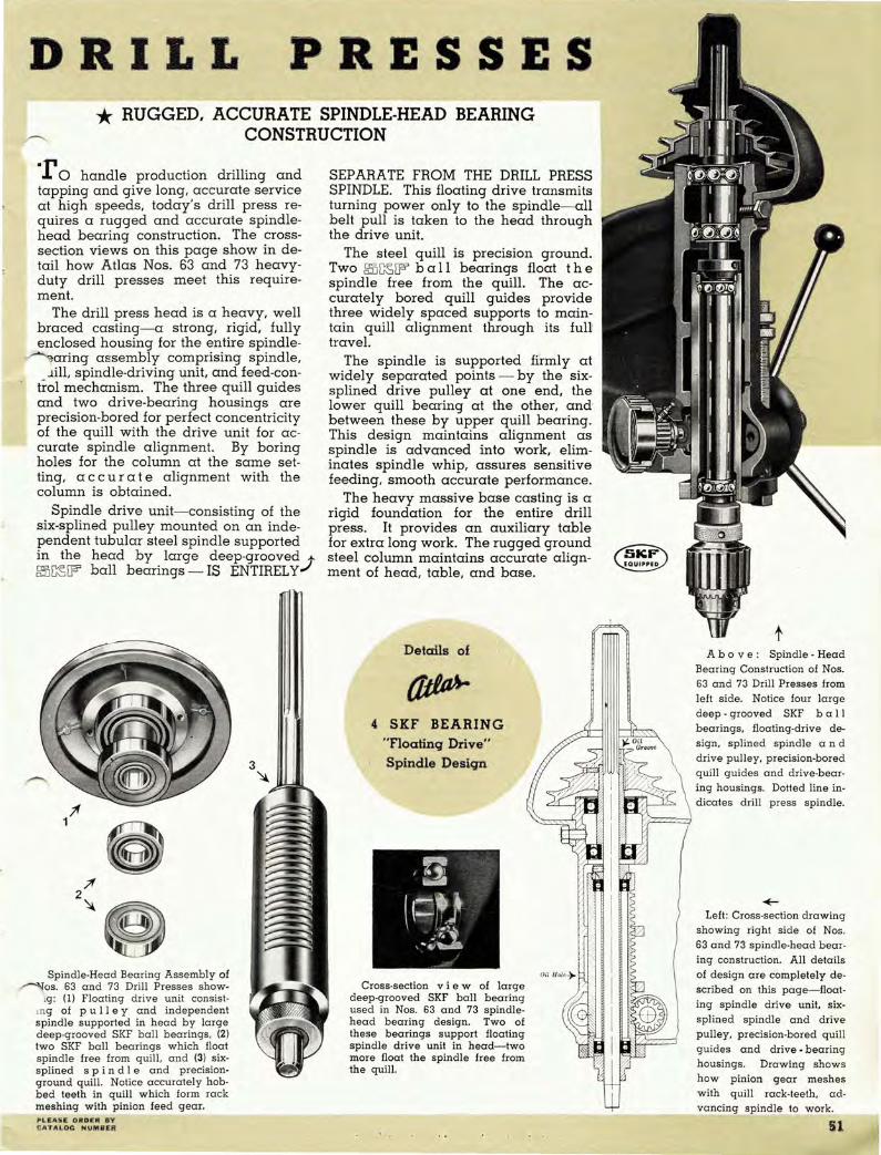
DRILL PRESSES * RUGGED, ACCURATE SPINDLE-HEAD BEARING
CONSTRUCTION
-r 0 handle production drilling and tapping and give long. accurate service at high speeds. today's drill press requires a rugged and accurate spindlehead bearing construction. The crosssection views on this page show in detail how Atlas Nos. 63 and 73 heavyduty drill presses meet this requirement.
The drill press head is a heavy. well braced casting- a strong. rigid. fully enclosed housing for the entire spindle-~aring assembly comprising spindle.
_ .lill. spindle-driving unit. and feed-control mechanism. The three quill guides and two drive-bearing hOUSings are precision-bored for perfect concentricity of the quill with the drive unit for accurate spindle alignment. By boring holes for the column at the same setting. a c cur ate alignment with the column is obtained.
Spindle drive unit- consisting of the six-splined pulley mounted on an independent tubular steel spindle supported in the head by large deep-grooved;@~W ball bearings - IS ENTIRELY
Spindle·Head Bearing Assembly of ~os. 63 and 73 Drill Presses show-
'g : (1) Floating drive unit consist· ing of pull e y and independent spindle supported in head by large deep·grooved SKF ball bearings. (2) two SKF ball bearings which float spindle free from quill . and (3 ) sixsplined s pin die and precisiong round quill. Notice accurately hobbed teeth in quill which form rack meshing with pinion feed gear. PLiEASE OltD':" ev <:;ATALO!: HVMB EI!
3 ~
SEPARATE FROM THE DRILL PRESS SPINDLE. This floating drive transmits turning power only to the spindle- all belt pull is taken to the head through the drive unit.
The steel quill is precision ground. Two 5SJ~W ball bearings float the spindle free from the quill. The accurately bored quill guides provide three widely spaced supports to maintain quill alignment through its full travel.
The spindle is supported firmly at widely separated points - by the sixsplined drive pulley at one end. the lower quill bearing at the other. and between these by upper quill bearing. This design maintains alignment as spindle is advanced into work. eliminates spindle whip. assures sensitive feeding. smooth accurate performance.
The heavy massive base casting is a rigid foundation for the entire drill press. It provides an auxiliary table for extra long work. The rugged ground steel column maintains accurate alignment of head. table. and base.
Details of
4 SKF BEARING "Floatinq Drive" Spindle Desiqn
Cross-section vie w of large deep-grooved SKF ball bearing used in Nos. 63 and 73 spindlehead bearing design. Two of these bearings support floating spindle drive unit in head-two more float the spindle free from the quill.
Abo v e: Spindle - Head Bearing Construction of Nos. 63 and 73 Drill Presses from left side. Notice four large deep - grooved SKF b a I I bearings. floating-drive design. splined spindle and drive pulley. precision-bored quill guides and drive-bearing housings. Dotted line indicates drill press spindle.
~
Left: Cross-section d rawing showing right side of Nos . 63 and 73 spindle-head bearing construction. All details of design are completely described on this page- floating spindle drive unit. sixsplined spindle and drive pulley. precision-bored quill guides and drive - bearing housings. Drawing shows how p inion gear meshes with quill rack-teeth. advanCing spindle to work.
51
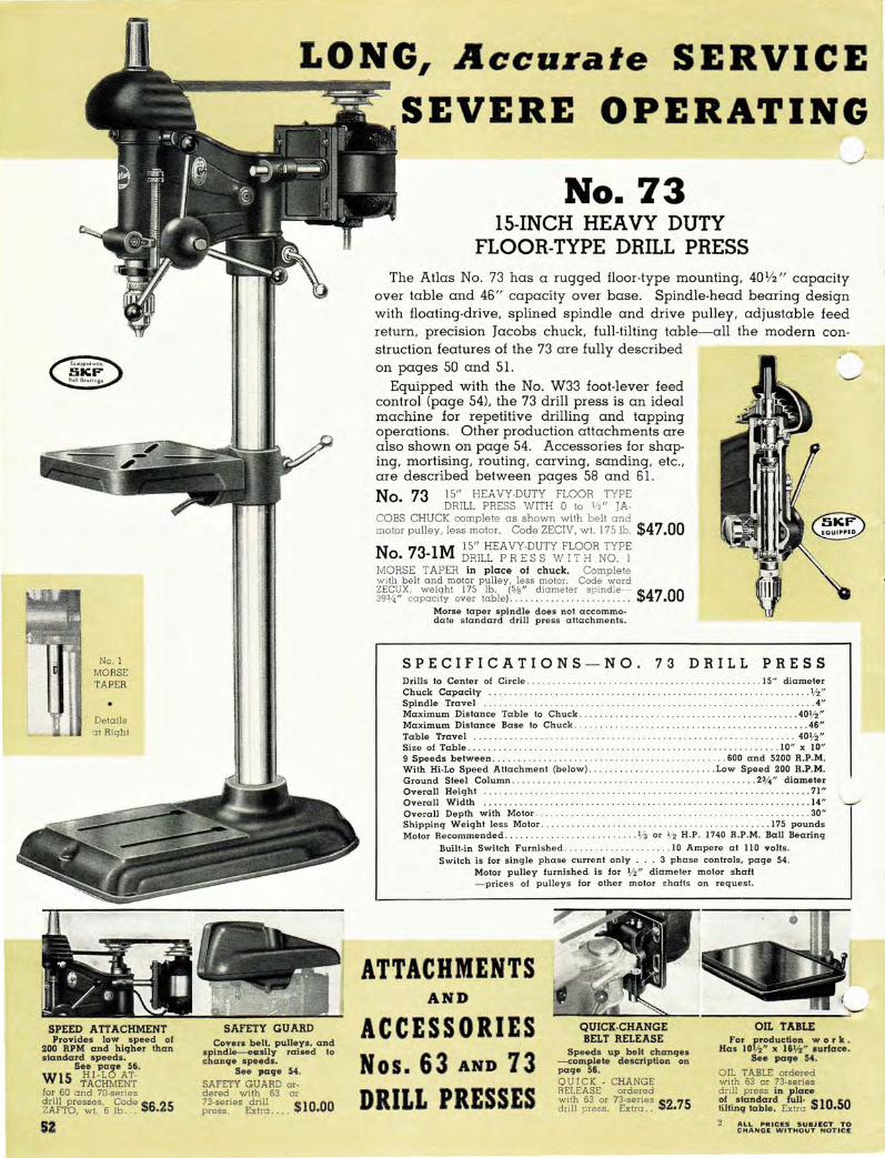
SPEED ATTACHMENT Provides low speed 01
200 RPM and higher than standard speeds.
See paOe 56.
W15 rlc~MEi~ for 60 and 70-series drill presses. Code $6 25 ZArTO, wI. 6 lb . . •. •
51
LONG, Accurate SERVICE
SAFETY GUARD Cover. belt. pulleys. a n d
IIpind l1l-il4lsily raised to change speeds.
See page 54. SAFETY GU ARD or· dered with 63 or 73-series drill $10 00 press. Extra . . • • •
SEVERE OPERATING
No. 73 IS-INCH HEAVY DUTY
FLOOR-TYPE DRILL PRESS The Atlas No. 73 has a rugged floor-type mounting, 40Y2 " capacity
over table and 4S" capacity over base. Spindle-head bearing design with floating-drive, splined spindle and drive pulley, adjustable feed return, precision Iacobs chuck. full-tilting table-all the modern construction features of the 73 are fully described on pages 50 and 51.
Equipped with the No. W33 foot-lever feed control (page 54), the 73 drill press is an ideal machine for repetitive drilling and tapping operations. Other production attachments are also shown on page 54. Accessories for shaping, mortising, routing, carving, sanding, etc., are described between pages 58 and Sl . No. 73 15" HEAVY·DUTY FLOOR TYPE
DRILL PRESS WITH 0 toW' JA· COBS CHUCK complete as shown with belt and motor pulley. less motor. Code ZECIV, wI. 175 1b. $47.00
N 73 1M 15" HEAVY·DUTY FLOOR TYPE O. - DRILL PRE SS W IT H NO. I
MORSE TAPER in place 01 chuck. Complete wi th belt and motor pulley, less motor. Code word ZECUX. weight 175 lb. (5!a" diam e te r s pi ndle-· $47.00 393/4" capacity over table).
Morse taper spindle does not accommodate standard drill press attachments.
SPECIFICATIONS-NO. 73 DRILL PRESS Drills to Center of Circle. .1 5" diameter Chuck Capacity ... ......... . V2" Spindle Travel .......... 4" Maximum Distance Table to Chuck . ... . . .. .. .. . . ... . ... 401/2" Maximum Distance Base to Chuck .. . . . . . .... . . . . .. . . . .. . . .......... . 46" Table Travel .. . 40V2" Size of Table. . . . . . . . . . . . . . . . . . . . . 10" x 10" 9 Speeds betwee n . . . . . . . . . . . . . . . . ..... 600 and 5200 R.P.M. With Hi-Lo Speed Attachment (below) . .. .. . . . ... . .... Low Speed 200 R.P.M. Ground Stee l Column .. . . . .... . ........ . . .. 23/.1" diameter Overall He ight .. . . . . . . . . . . . . ... .... ... . 71" Overall Width .. . .. . . .. ... . . . . .. . ... . .•.. . .. . .. ..... . ........ . 14" Overall Depth with Motor ...... . . .. .. .. . . . .. 30" Shippinq W eiqht less Motor . . ........... 175 pounds Motor Recommended . . . . V3 or V2 H.P. 1740 R.P.M. Ball Bearinq
Built·in Switch Furnished. . 10 Ampere at 110 volts. Switch is for single phase curre nt only ... 3 phase controls, page 54 .
Motor pulley furni shed is for 1f2" diamete r motor shaft - prices of pulle y s for othe r motor !O hafts on request.
ATTACHMENTS AND
ACCESSORIES Nos. 63 AND 73 DRILL PRESSES
QUICK.CHANGE BELT RELEASE
Speeds up be" chanqes -compleie description on page 56. QUICK - CHANGE RELEASE ordered with 63 or 73-series $2 75 drill press. Extra.. •
OIL TABLE For production w 0 r II •
Has l oth" x 16\12" sur/ace. See page 54.
OIL TABLE ordered with 63 or 73·series
~fil~t~~"J~r~n fu\f_ce liltinq table. Extra $10.50
A LL PRICES SUBJ ECT "TO CHANGE WITHOUT NOTiCe
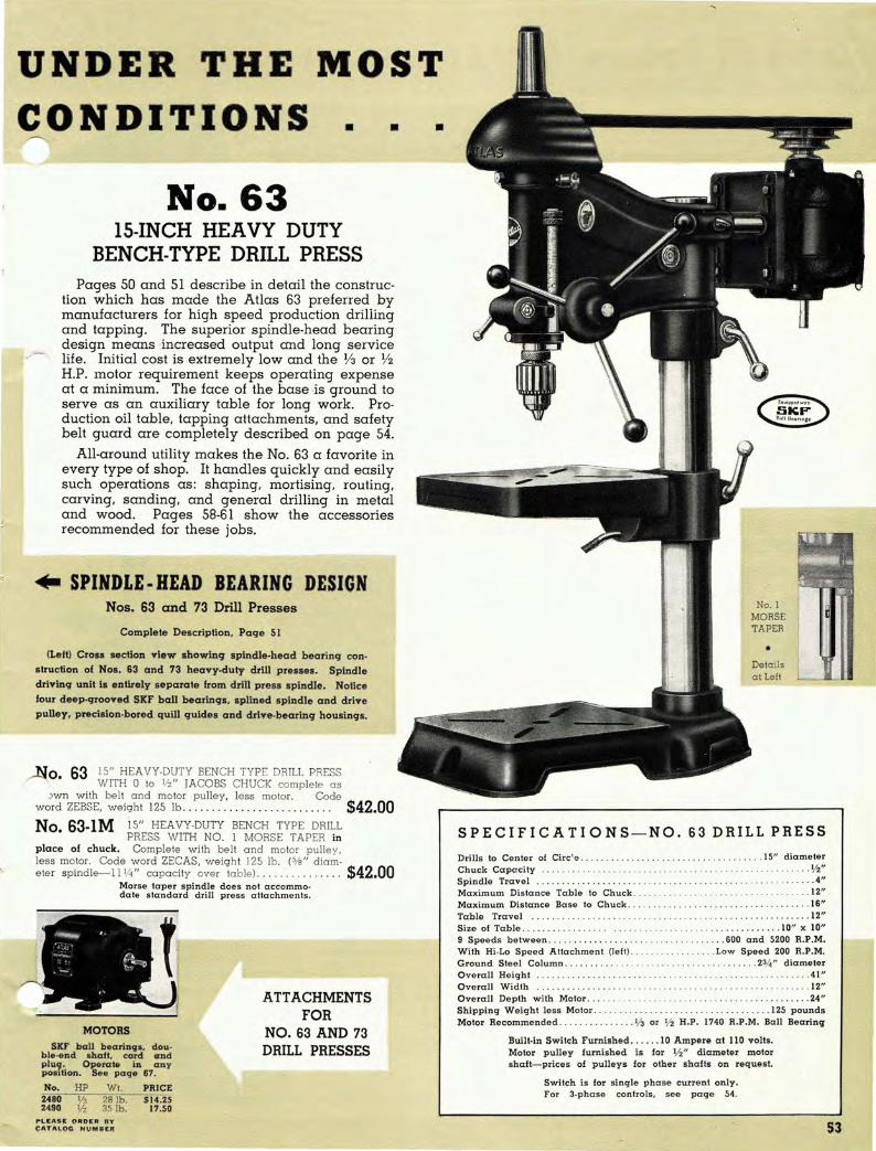
UNDER THE MOST CONDITIONS •
No. 63 IS-INCH HEAVY DUTY
BENCH-TYPE DRILL PRESS
•
Pages 50 and 5 I describe in detail the construction which has made the Atlas 63 preferred by manufacturers for high speed production drilling and tapping. The superior spindle-head bearing design means 'increased output and long service life. Initial cost is extremely low and the Y3 or Y2 H.P. motor requirement keeps operating expense at a minimum. The face of the base ·is ground to serve as an auxiliary table for long work. Production oil table, tapping attachments, and safety belt guard are completely described on page 54.
All-around utility makes the No. 63 a favorite in every type of shop. It handles quickly and easily such operations as: shaping, mortising, routing, carving, sanding, and general drilling in metal and wood. Pages 58-61 show the accessories recommended for these jobs .
.. SPINDLE · HEAD BEARING DESIGN Nos. 63 and 73 Drill Presses
Complete DeSCription, Page 51
(Left) Crosa section view showinq spindle.head bea rinq con. struction of Nos. 63 and 73 hea vy-duty drill presses. Spindle driving unit Is e ntirely separa te from drill press spindle. Notice four dee p-grooved SKF ball bearings, splined spindle and drive pulley, precision-bored quill quldes and drive·bea rinq housings.
~O 63 15" HEAVY-DUTY BENCH TYPE DRILL PRESS • WITH 0 to V2" JACOBS CHUCK complete as
.)wn with belt and motor pulley. less motor. Code word ZEBSE. weigh t 125 lb . ...... . . . . .. . . . . .. .... . .. $42.00 No.63-1M 15" HEAVY-DUTY BENCH TYPE DRILL
PRESS WITH NO. I MORSE TAPER in place of chuck. Complete with belt and motor pulley. less motor. Code word ZECAS. weight 125 lb. (5Is " diam-e te r spindle-I I 114' capacity over table) ........ .. ..... $42.00
Morse taper spindle does not accommo~ date s tandard d rill press attachments.
MOTORS
SKF ball bearin CJ8. dou· ble·end .haft. cord and pJu9' Operate in CI;J1y pOI'UOII. See perCJe 67.
No. HP Wt. PRICE 2480 113 28 lb. S14.25 2490 1/2 35 lb. 17.50
.-t.E ASI£ O RO E R flV f; ATI\ \.OG HUM 8£R
A TT ACHMENTS FOR
NO. 63 AND 73 DRILL PRESSES
•
No. I MORSE TAPER
• Details at Left
SPECIFICATIONS-NO. 63 DRILL PRESS
Drills to Ce nte r of Circ'e. Ch uck Capa city Spindle Travel Maximum Dis ta n ce Table to Chuck .
. . . 15" d iamete r ... .. 1/2" ... .. 4"
. 12" Maximum Distance Base to Chuck . .. . ... . . . . .. ... .. . . . ... . . .16" Table Trave l Size 01 Table. 9 Speed s b e tween . ... . With Hi·Lo Spe ed Altachment (le ft ) .. Ground Steel Column . Overall He iCJht Overall Width Overall Depth with Motor . . Shipping WeiCJht less Motor .... ... . . .. . . .
. .. 12" .. . . ...... ... . . . 10" x 10" . .... SOO a nd 5200 R.P.M.
. ....... Low Speed 200 R.P.M. . . 23/4" dia m e te r
. 41 "
. 12" ........ ... .. . .. .. .. .. .. . U "
Motor Recommended . . ............. 1/ 3 or V2 H.P. .. 125 pounds
1740 R.P.M. Ball Bearing
Buill·in Switch Fu rnishe d . .... . 10 Ampere a t 110 volts. Motor pulley fu rnish ed is for V2" diameter motor sherit-pr ices of pulleys fo r oth e r shafts on reque st.
Switch is for s ingle phase current only . For 3-phase controls. see p a ge 54.
S3

PRODUCTION ATTACHMENTS I'OR NOS . 63 AND 73 DRILL PRESSES
Pictured a t the right is the Atlas 73 drill press equipped to handle high-speed production operations. The complete machine includes No. 73 drill p ress with: No. 61 -2S .. . . . ... . . . .... .. . . Production Oil Table No. W33 . . . . . . .. . .. . . .. . Foot Lever Feed Control No. W39A ... . . . . .. . . . . . . .. . . Tapping Attach ment No. 62-7A .. . . .. . . ..... . .. . . ... Safety Belt Guard
These accessories are fully described on this page.
DRILL PRESS HEADS Atlas drill press heads may be purchased
separately for special industrial applications. Refer to page 55.
THREE PHASE MOTORS The motors listed below are designed for
use with three-phase current. Both motors are 220 volt. 60 cycle-have SKF ba ll bearings. double-end shaft. Furnished with BX connector in terminal box- do not have switch. cord. or plug. Shaft diameter lI2". For complete information on all Atlas motors. see pages 66 and 67. No. 2630 2620
HP RPM 1740 1740
Wt. 281b. 35 lb.
Code WYKAK WYKEL
Price S2J.OD
24.75
THREE PHASE SWITCH
No. W67 switch is required w ith a 3-phase motor. It is a thermal overloa d 3-pol e manual starter for 3 - phase circuits. Mounting bracket and flexible cable-covered motor connection cord are furnished.
No W67 THREE PHASE SWITCH with : mOUl:,ting bracket and con- $13.50
nechons. Code ZECET. wt. 6 lb .. .. . . . .
SAFETY GUARD for Belt, Pulleys and Spindle
Thi s light, durable aluminum shield provides a safety cover for the complete drill press drive mecha nism, as required by industrial and vocational safety codes in many states. Pin h inges permit quick raising for speed changes- it is not necessary to remove guard to change belts. Spring clip holds guard closed.
~~~E~;e~~ A~~r~:d:::~. :,:,~t~ .. 6.3 . . ~r .. 7.3 . . s.e.r~:~ $10.00
No 62-7A DRILL PRESS SAFETY GUARD • for 60 and 70 series drill presses.
ordered separately. Rea dy tapped for easy $11 00 installation. Code ZABSY. w I. 7 Ib.. . . . . . . . . • . •
TAPPING ATTACHMENTS See Complete D escript io" Below
Available in two sizes: No. W39A to tap up to 5/ 16" in steel. 3/ 8" in cast iron. and 1/ 2" in b rass; and No. W39 to tap up to 3/ 16" in steel. a nd 1/4" in brass a nd cast iron. .
PRODUCTION OIL TABLE For production work with jigs and fixtures. Can
be furnished with Nos. 63 and 73 drill presses in place of standard full-tilting table.
Has 10 112" x 16 liz" ground working surface and drain channel to remove oil or cutting compound. Held firmly in position by coordinate clamp lock. Extra w eight a nd proper b racing a ssure maximum rigidity a nd a ccurate work. PRODUCTION OIL TABLE ordered with No. 63
~~l~~bi~. seE~~a~~i:: .~~~~~ .i~. ~I~.C~ . . ~I . ~~~~~: $lO.50
No 61-2S PRODUCTION O IL TABLE for 60 • and 70 serie s drill presses. Or- $13 00
dere. separately- Code ZABUR. 65 lb..... . . . •
FOOT-LEVER FEED CONTROL Speeds up any repetitive operation. Accuracy is
improved because the operator has both ha nds free to hold and guide the work.
Includes draw rod mounted between two a rms, one for foot pedal and one for drill press spindle_ Heavy-duty return spring has 3 positions on spindle arm and tension nut for quick adjustment. Draw rod can be bolted at anyone of 4 positions on foot lever a rm.
No. W33~~gl 7;'yE~0_!";rr~sC2rlii presses complete as shown. Code $16 00 word ZA ETH. weight 31 lb. ........ • Note: No. W33 is not recommended lor production mortising. Please specify if foot lever feed control will be used on drill press equipped with Hi-Lo speed attachment (page 56).
tltIru.. TAPPING ATTACHMENTS For High-Speed Production Tapping
Atlas tapping attachments convert any 60 or 70 series drill press into a sensitive high.speed production tapping machine . They meet the modern demand for a light. compact, accurate tapper.
The lightweight durable aluminum housing encloses a 3-point balanced, heat-treated gear reversing mechanism which distribute s pull to three gears, minimizing wear and eliminating torsion . New improved head design- chuck rotates in tapping direction when idling . This cons truction means a more sensitive head and increases tap life . Reverse speed is twice forward speed. Double-cone friction clutch has cork facinq-spindle turns on ball bearinqs.
These tappinq attachments have tapered socket for drill press spindle and cover which clamps directly to quill. No adapters necessary. Atlas tappinq attachments are available for drill presses with Morse taper spindles-details on request.
No W39ATAPPING ATTACHMENT comple te w ith "Tru-Grip" • tap holder and 7 collets for following taps : Nos. 8. 9.
10, 1/4", ~1t1", 3/8" (shank d iameter .381"), ','i l;", and 1/2". CAPAC-ITY: No , 8 ' tap to ',',,;" in steel. 3/8" in CeIst iron, liz" in brass. Code $60 00 word ZAERF. weIght 10 lb .. . . . . .... . .... . . .... .. . . .. . . . . ... . . . . •
No W39 TAPPING ATTACHMENT complete w ith "Tru-Grip" tap • holder and 4 collet s for following taps : Nos. 2. 3. 4.
5. 6. 7. 8. 9. 10. and 1/4"· CA PACITY: up to ~i 6" in steel. 1/4" in $45 00 brass and cast iron. Code ZAEMZ. w t. 5 Ib.. • • • • •• • • • • • • • • • • . . . •
"TRU-GRIP" TAP HOLDER
The "Tru-Grip" tap holder furnished w ith Atla s tapping a ttachments is Iight.in weigh t. accurate a nd has no delica te parts to cause trouble. Spring collets are furnished - both holder and collets a re hardened and ground.
C.J
54 CO""f"L£T£; I N I)EX_ I N5 ID £ BACK COVER

THE NEW t1iIta.. MULTIPLE SPINDLE DRILLING MACHINES
,A ny part requiring a series 01 drilled and tapped holes can be manufactured more
.)nomically with these new Atlas drilling machines. Complete descriptions and
specifications are given in Bulletin MSI. available on request.
• Rugged Table and Floor Legs - Massive precision ground oil table provides plenty
of "elbow room" for the smooth movement of large h eavy jigs and fixtures. Floor
legs (furnished) are heavy solid well·braced iron castings. Wood shelf p rovides a
convenient place for tools and jigs.
• Floating Drive Spindle Design-These machines incorporate the famous Atlas heavy
duty SKF-equipped spindle bearing construction (pages SO-51). This fine head de
sign accounts for new operating records set by Atlas drill presses in many of the
largest, most efficient production plants.
• New Head Positioning Mechanism - Saves time in making work set·ups. Drilling
~d is raised or lowered by simply turning crank handle. See description below at
.. ht.
Specifications~ Multiple Spindle Drilling Machines Number of Spindles ....... . , .... . , ........ .
Center to Center of Spindles .......... ..... . Spindle Travel . .. ......... . ... . ... . ... ... . Table Working Surface . ...... . ....... ... .. . Overall Height .......... .. . . .. . . .. . . ..... . Overall Depth with Motors ..... . .. . . . ... ... . Overall Width ................... . .• ...... Floor to Top of Table ........ ...... . . . .... . Shipping Weight (Approximate) . . .... ..... . Order Number with Jacobs 0· '12 " Chucks ... . . PRICE Including Floor Legs, less Motor,
with Jacobs 0_ '12" Chucks . ...... ... ...... . Order No. with No. 1 Morse Taper Spindles . . PRICE Including Floor Legs, less Motor, with
No. 1 Morse Taper Spindles in Place of Chucks .. .. ... . ........... . .... ........ .
4
13" 4"
2l"x54" 79'12 " 3 Jl/4"
58" 32"
1405 lb. W84
$350.00 W84·IM
$350.00
3
18" 4"
2l"x54" 79 1/2" 31'14"
58" 32"
1300 lb. W83
$310.00 W83·IM
$310.00 For Complete Specifications, Ask for Bulletin MSl.
2
15" 4"
21"x30" 79'12 " 31%" 34" 32"
850 lb. W82
$195.00 W82-IM
$195.00
fliIII4.. DRILL PRESS HEADS
NEW HEAD POSITIONING MECHANISM
(Patent Applied For) Simply turning crank handle raises or
lowers drill head, a unique design which reduces set-up time to a minimum. Elevating screw controls column collar below drill head-screw has ball thrust bearing at lower end. Head clamping lock is coordinate type for quick, rigid positioning without scoring column.
SIMPLIFY PERPLEXING DRILLING PROBLEMS The installation pictured below is just one of hun·
dreds where Atlas drill press heads have solved difficult production set·ups- what was an expensive awkward operation now is making real money. The possibilities for multiplying drilling efficiency with these heads are practically unlimited.
Atlas drill press heads often eliminate the need for a costly special drilling machine or intricate fixture. They are compacl, porlable, easily adapted to
Ihe job, and may be operated in any position. Atlas SKF ball bearing spindle-head design insures long, accurate service at high speeds. Their cost is a small fraction of special drilling units, and the '12 or 1/3 HP motor requirement keeps operating expense at a minimum.
Atlas drilling heads are available in two sizes: the IS" 63-Series and 12%" 52.Series----complele specifications below al lefl. Nole: We do not manufacture special drilling machines.
SPECIFICATIONS
Two 63-series drilling heads teamed up with multiple spindle drill. Bracket being drilled requires fiv e holes, two of them at an angle to both vertical and horizontal planes. Universal angle bracket holds each head- rams attached to multiple spindle head automatically actuate angular feeds. Drilling time has been reduced by more than 60 per cent- cost of a special drilling machine is eliminated .
63 52 Series Series
Drills to Center of Circle .. 15" 123/4"
Spindle Travel . . . . 4" 3" Column Bore ............ 23/4" 21/4" Chuck Capacity liz" '12" Speed l'I.ange ......... 600 to 5200 RPM ~'mbef SKF Ball Bearings 4 3
No. Series With
63·IV 63 0-'12" Jacobs Chuck 63·IZ 63 No. I Morse Taper 52-lX 52 0. 1/2" Jacobs Chuck
ALL ftl...... $U8J EeT Teo eltllNn WITHOI/T '''".'100:
FURNISHED: Complete as shown with motor mounting bracket, belt and pulley; less motor and column. Motor control switch furnished is 10 ampere a t 110 volt single phase only-three phase switch, page 54. Motor pulley furnished is for 1/2" diameter motor shaft - prices of pulleys for other motor shafts on request.
Bearing Design Code Weight Price
Page 51 ZAHET 60 lb . $33.00 Page 51 ZAHUX 60 lb. 33,00 Page 57 ZAHWO 45 lb. 27.00

ATTACHMENTS FOR DRILL PRESSES
:NEW Head and Table
POSITIONING MECHANISM
For SO- and 70-Series
Drill Presses
• New No_ W76 positioning mechanism mounted on column of No. 73 drill press. N atice convenient location of crank ha ndle.
This new time saver with its handy crank control makes fast, easy work of raising or lowering the drill press head or table_ It can be quickly installed on any Atlas 60- or 70-series drill press.
The W76 mechanism consists of support collars for the drill head and table, positioned by an acme-thread lift screw with bevel-gear drive controlled by the crank handle. Both support collars are equipped with coordinate clamp locks which permit rigid positioning without scoring the drill press column. When the head support collar is tightened, the lower collar may be loosened for raising or lowering the table. In a similar manner, the table collar when tightened serves as a support for positioning drill press head.
One revolution of the crank gives Va " travel-maximum travel at one setting is 12". Two bevel gears, thrust bearing and crank shaft are housed in the gear case cast integrally with the upper support collar. Ball thrust bearing takes load on screw, so that crank handle turns freely.
No. W76 HEAD AND TABLE POSITIONING MECHANISM for 60- and 70-series drill p resses.
Code word ZAIRG, weight 18 lb ... .. .....•...... __ $9.95
NEW 24" RADIAL ARM For SO· and 70·Series Drill Presses
Radial Arm Inverted Radial Arm Upright
This rugged arm converts any Atlas 60- or 70'series drill press into a small radial drilling machine with a work range which permits drilling of extra large pieces. It increases chuck-to-column capacity to a full 24", and the auxiliary column furnished adds 15" to chuck-to-base capacity. Pictures above show how the radial arm can be mounted in an upright or inverted position, whichever is most convenient for the operations being handled.
The massive arm casting is ribbed and reinforced to maintain rigidity at the drill point. Holes for drill press column and auxiliary column are precision bored at the same setting to insure positive alignment. Arm has 8" bearing on the drill press column and 7" bearing on the auxiliary column. Coordinate clamp locks permit quick, rigid positioning of head and arm.
The 19" auxiliary column is 2% " diameter ground steel tubing and allows travel of the drill head up to 6 1/2"-olso permits drill head to be mounted above or below arm. No. 61-75A column collar (Code ZEHY A , $0.95) is recommended as support for drill head on auxiliary column.
No. W79 24" RADIAL ARM for 60- and 70-Series drill presses. Code word ZAJAT, weight 46 Ib .......... ....... . . . ..... .. .. ... . .. ........ .. .. ... $11.75 No. Sl-75A COLUMN COLLAR for supporting drill head on auxiliary column with radia l arm inverted. Code ZEHYA, weigh t 3 1/2 lb . . . ... . . . ... . ....... .. $0.95
"HI-LO" SPEED ATTACHMENT
QUICK-CHANGE BELT RELEASE
The Quick-Change attachm ,,,--,,
speeds up belt changes. Han die
brings motor toward drill press head,
releasing belt tension in an instant.
U. S_ Patent 2073704
• Increases Speed Range
• Easily Installed
• SKF Ball Bearing Equipped
The "Hi-La" provides a low speed of 200 RPM for heavy metal work and higher than standard speeds for woodworking. This wide range is obtained with a standard 1740 RPM motor.
The "Hi-La" can be mounted or removed in less than three minutes. The base is accurately machined to fit inside the top of the drill press column. Pulley is balanced and runs on a large double-row SKF ball bearing-pulley is mounted eccentric with the base, permitting quick release of belt tension for speed changes.
Order No.
W·32 W-14 W-14A W-15
Column Size Atlas Inside Code
Drill Press Diameter Word 40-Series 10/16 " ZAEWK 50-Series 10/\6" ZAFER 52·Series* 2" ZAFRE 60 and 70-Series 21/2" ZAFTO
PRICE $6.25
6.25 6.25 6.25
Low Speed No. W-32- 260 R.P.M.; others 200 R.P.M. Weight 6 lb.- V-belts furnished.
* When ordering for 52-Series drill press, please give date purchased.
56
It is easily installed, replacing
standard drill press motor bracket.
The position of the hinged motor base
is shilted by a hardened rocker-shaft
with ball handle control. assuring cor
rect belt tension at all times.
QUICK CHANGE RELEASE or-dered with No. 52, 63, or 73 drill press. Extra .. . .. _ ... . .... . ... . $2.~
"---'" No. 52·50A QUICK CHANGE RE-LEASE for 60 and 70-
series drill presses, ordered sepa-rately. V-belt furnished. C od e$4 50 ZECWO, weight 12V2 Ib........ .. •
No. 52-50B QUICK CHANGE RE-LEASE f or 50-series
drill presses, ordered separately. $4 50 V-belt furnished. ZECZY, 12V2 Ib.. •
ALL PRICES SUBJECT TO CHANGE WITHOUT NOTICE

r-.... OIL TABLE production work. Has 91/."
__ ,,51,4" ground working surface .
PRODUCTION OIL TABLE ordered with 52 dr ill pre ss in place of standard full-tilting table. Extra ...... . . $8.00 Ordered separately . No . 52-25. Code word ZAASF. w eight 5S lb. . .. SIO.OO
COLUMN COLLAR ~mplifies raising, lowering,
, moving drill press head.
hv. 52-75A COLUMN COLLAR. Code word ZEHZE, weight 3V2 lb ... .......... $0.95
SPEED ATTACHMENT Provides low speed of 200
RPM and higher than standard speeds. V·belts furnished-see page 56.
No. W14A H!-LO SPEED ATTACHMENT for 52 drill press. Code word ZAFRE, weight 6 lb ......... . .... $6 .25
BEL T RELEASE Speeds up belt changes-com
plete description page 56. vbelt furnished.
QUICK-CHANGE BELT RELEASE ordered w ith S2 or 52A drill press . Extra .... $2.75
MOTORS SKF ball-bearings, double-end
shaft, cord and plug. Operate in any position-see page 67.
No. 2480 2490
HP W eight Price 28 lb . 514.25 3S lb. 17.50
No. 52
T HE No. 52 drill press is an excellent general purpose machine for the av
erage shop. It drills to the center of a 12%// circle, has 3// spindle travel, takes 9% // over table, and comes equipped with precision Jacobs chuck. It handles the full range of drill press operationsmortising, shaping, sanding, carving, and routing.
The spindle-head bearing construction of the 52 is the same as Nos. 63 and 73 heavy duty models except that the floating-drive bearing is a single large deepgrooved ball bearing mounted in the pulley. Two more bearings float the spindle free from the quill. This design means smooth, accurate performance at all speeds and long service life.
The No. 52 drill press head is a heavy, accurately machined casting-a strong, fully enclosed housing for the spindle and bearings. Matched and balanced pulleys, combined with splined drive, practically eliminate vibration. Precision Jacobs chucks, graduated d e p t h indicator, three-spoke feed wheeL built-in 10 ampere motor control switch, and adjustable motor mounting bracket are furnished. Drive pulley and splined spindle are completely enclosed by iron guard and cap. Clamp locks for head, quill, and table support are coordinate type. Full tilting table is accurately ground. Heavy base is a rugged support- face is ground to serve as table for long work. Column is 21/4// ground steel.
12!" BENCH TYPE DRILL PRESS
ORDERING INFORMATION
BELOW
SPECIFICATIONS NO. 52 DRILL PRESS
Drills to Center of Circle . .. . .. . .. . .... . 12 3/4 " diameter With Hi-La Speed Attachment (left) . . Low Speed 200 RPM
Chuck Capacity .. .......... .. .... .. . . . _ ...... . .. V2 " Ground Steel Column ........ . . ... . . .... 2 V. " diameter
Spindle Travel ... .. ..... . .. . ... .. . . . . .... .. .. . . . . 3" Overall Height ... .. ..... . .. .. . .... ... .. .. .. . - ... 36"
Maximum Distance Table to Chuck . . .. .. . . .. ..... 9 3,4 " Overall Width .. .. . . ..... . . . . .. ....... . . . .. . .... II"
Maximum Distance Base to Chuck .. . . . . ... . ..... 13 V2" Overall Depth with Motor ... ... . _ .. . ... .. .. .. ..... 24"
Table Travel . ... .... ..... ... .. . ... .... ....... . 9 3,4 " Shipping Weight Less Motor. .. .. . . . .. . .. . ... . . . 95 lb.
Size of Table . ... . . ...... . . . . . .............. .. 8" x 9" Motor Recommended . . . . ... .............. . ... .. . .. . .
9 Speeds between . . .. ..... _ . . ...... 600 and 5200 RPM . ... ... ... . .. . 1/3 or 1/2 HP 1740 RPM BaH Bearing
ORDERING INFORMATION
No. 52 123,4" BENCH TYPE DRILL PRESS WITH 0 to w' No. 52A 123,4" BENCH TYPE DRILL PRESS WITH 5/64" to V2" JACOBS CHUCK complete as shown with belt
and motor pulley. less metor. Code word ZAAJT. shipping JACOBS CHUCK complete as shown with belt and
motor pulley, less motor. Code word ZAAHS, shipping weight 95 pounds . . • . .. • •• ..• .•• •• •••• •... .. • . •• . • .••• • .•• • •• ••• ••• $36.00 weight 95 pounds . .................. . ..... . ...... . ... .-. ~ •• .$35.00
Built-in Switch Furnished • • • 10 Amp. at 110 volt. Switch is for illnqle phase cunent only. 3-phClIIe c;ontroJII, paq. 54.
I'LlEAslE OMDiI"l II.., CAYAbOO NUM.~1f
Motor puney Iumlshed ill for ~ .. diameter motor Bhaft-pricell of puneys for other motor shafts 011 nquelli.
17

~ No. 42 DRILL PRESS • yz" Chuck Capacity • Drills to Center of 12" Circle • 7 Speeds, 700 to 4000 RPM
• llYzll Capacity Over Base • 81.4" Capacity Over Table
speed of 260 RPM and higher than standard speeds. V-bells furnished-see page 56. No. W32 HI-LO SPEED A TT ACRMENT for 40-series drill presses. Code ZAEWK, wI. 6 lb ••• •• •• • $6.25
MOTORS
JACOB CHUCKS The 42 Drill Press is available
with precision Jacobs Chucks in two sizes: -h" to 1/2" and 0 to 1/2" (No. 70 Drill to 1/2"). Furnished with keytype adjusting wrench. See Order Nos. 42A and 42B at right.
L
SKF ball bearings, 10ft. approved SJ extension cord and plug. Se.. COLUMN COLLAR page 67. Simplifies raising, lowerinq and No.2480 1f3 HP Single-Phase.$14.2S moving drill press head. No. 2520 Y3 HP Capacitor No. 42-75 COLUMN COLLAR. Code
Start . ..... •• . .. . .. . . . . . . $20.50 word ZADYV, wI. 4 lb .. ... ... $0.95 Other Attachments tor No. 42 Drill Press-Pages 59-61.
A SENSATIONAL VALUEI _ I'
A TLAS volume production makes possible this c, ) standing drill press value. Construction, perfor!n::"
ance, and all-round utility make the 42 an ideal multipurpose machine for the small shop. In addition to general drilling of metal and wood, it handles such operations as: mortising, shaping, carving, sanding, routing.
The spindle of the Atlas No. 42 runs on two heavy-duty oilite bronze bearings-a ball bearing absorbs end thrust. Belt pull is taken on the spindle sleeve and transmitted to the head through a special oilite bronze bearing. Alloy steel spindle is accurately , ground and furnished with taper for Jacobs chucks or threaded to take standard chuck. Quill is accurately ground and graduated in 16ths for gauging depth of feed-rack and pinion mechanism controls feed. Stop collar on spindle can be set to stop feed at any depth. Spir and drive-pulley have six splines, minimizing vibration-are compll enclosed by cap and iron guard. Motor base is adjustable for belt '1m(.' sian- motor control switch is built into head in easy-to-reach position. Clamp locks are coordinate type.
Base casting can be used as support for long work. Column is ground steel. Solid table has accurately machined face, diagonal slots for clamping. Full-tilting table is available at $4. 00 when ordered with drill press in place of solid table. When ordered separately: No. 40-2A, wI. 12 lb., $5.00.
All Atlas drill press attachments and accessories may be used with the 42 drill press.
No. 42 12" BENCH TYPE DRILL PRESS WITH W'THREADED CHUCK complete as shown with belt and motor pul-
ley, less motor. Code word ZACTY, weight 67 lb .............. $18.00 No.42A 12" BENCH TYPE DRILL PRESS w ith 1/16" TO 1/2"
JACOBS CHUCK complete with belt and motor pul-ley, less motor. Code word ZACYT, weight 67 lb .. . ... . .. . .... $22.00 No.42B 12" BENCH TYPE DRILL PRESS WITH 0 TO 1/2"
JACOBS CHUCK complete with belt a nd motor pul-ley, less motor. Code word ZACUS, weight 67 lb ... . . ....... . .. $23.00
SPECIFICATIONS-42-SERIES DRILL PRESSES Drills to Center of Circle .... .............. ... .... ... ...... .... .. 12" diameter Chuck Capacity .. . ... . ... . .. .. .. . ................. .. ............... ... . . lf2" Spindle Travel. .. . ......... .. ..... ... .. . .. ... . ............ . . . .. .... ...... 3" Maximum Distance Table to Chuck . . .... . .•.. . . ...•.. .. . .. . .•...... ..... 81/4" Maximum Distance Base to Chuck .... . . . .•......... .. ........ .. . . .. . .. lllf2" Table Travel... . ... .... . ... . .......... .. . .. . . . . . . ... . ...... 81/4" Size of Table. . . . . . . . . . . . . . . . . . . . . ... . .. . ....... 7lf2" X 71/2" 9 Speeds between ..... . ..... ...... ..... . . . . . .. .... . . . .... . 700 and 4000 RPM With Hi-Lo Speed Attachment (left) . .. . . .. . . .. .. . . . .. . .... Low Speed 260 RPM Ground Steel Column .......... .. ..... ...... . .. .. . ... .. ........ ISfa" diameter Overall Height ... .. .... ... ... . .. . .... . .. . .. ...... .... ..... 31 " Overall Width ... ... .. ... . ... ... . . . . . . ... . .. . . ... .. . .. . ..... 10" Overall Depth with Motor ... .. ...... . .. . .... .. . ...... ... ..... ... . ........ 24" Shipping Weight. Less Motor. ... . ......... . ... .... .... . ...... . .. . ... 67Ib. Motor Recommende d .... . ... ... ............ . .. . . 1/ 3 HP 1740 RPM Ball Bearing
Built-in Switch furnished-IO Amp. at llO volt. Switch is for singl, phase current only- 3-phase controls, page 54. Motor pulley fUl
nished is for liz" diameter motor shaft-prices of pulleys for other ~ motor shafts on request.
DRUM SANDER FOR ALL ATLAS DRILL PRESSES
The Atlas drum sanding attachment saves time and effort on fine wood and metal finishing work. Abrasive sleeves are available in fine. medium. and coarse garnet for wood finishing and aloxite for metal work.
The drum sander is adapted to the Atlas drill press spindle by the Jacobs spindle adapter W6-6A listed below. No adapter is necessary for the No. 42 drill press with threaded spindle. Drum sander is 2-3/ 16" diameter, 3" long.
ABRASIVE SLEEVES Six Sleeves per Set
No. Code
W6-2F Set of six FINE GARNET abrasive sleeves. ZAKZO W6-2M Six MEDIUM GARNET abrasive sleeves. ZALBO W6-2C Six COARSE GARNET abrasive sleeves. ZALIZ W6-2A Six ALOXITE abrasive slee ves for metal . ZALOB
WI.
4 oz. 4 oz. 6 oz. 8 oz.
No. WS-SA ~~C..P:T~RSfo;Nd~';I; sander, complete with nut, washer
Price
$1.00 1.00 1.00 1.00
and !apered wedge. Code word $1 80 ZALUC, weIght 7 oz. ............. •
1m T: ;; = No. 42 drill press with threaded , pilldle do", not require adapter.
58
No. WSA DRUM SANDER complete with one medium garnet ab-
rasive sleeve. Code ZAKWE, 2 lb .. ... .. $1.75 Using shaping extension table (page 60) to
support large work for sanding.
A TIME SAVER

~ DRILL PRESS ATTACHMENTS NEW OSCILLATING SANDER ATTACHMENT
No. W75 NEW OSCILLATING SANDER ATT ACHMENT as shown with belt
and motor pulley, less drum sander and table. Code ZAJEV, weight 10 lb. .... .. . . .... .. $13.85
Specify bore of motor pulley-1/2" . Prices of pulleys for other motor shafts on request.
No. W6A SANDING DRUM only w ith one medium garnet abrasive sleeve
(see page 58). Code ZAKWE, weight 2 lb. ... . $1.75
No. W7T EXTENSION TABLE only (see page 60). Code ZAGIT, w I. 7 lb ... $3.75
For Production Sanding This new oscillator con verts any drill press
into a production sander for fast, smooth finishing of woods, metals, and plastics. It gives the rotating spindle an up-and-down motion which makes easier work of sanding and insures a smooth finish . The mechanism can be installed in a few minutes and disengaged easily without removing from the drill press.
The W75 attachment is driven from the lower end of the drill press motor shaft. Its gear reduction unit is supported from the motor bracket by an adjustable arm. An adjustable connecting rod from a crank on the gear reducer drives the spindle rocker arm, which is tightened by a thumb screw on the drill press spindle feed shaft. Loosening this thumb screw and disengaging the drive belt leaves the drill press free for other operations. Mechanism can be used in inverted position.
SPECIFICATIONS
Stroke Adjustable between ... .... 1/4" and "Va"
Strokes per Minute (with 1740 R.P.M. motor) ........ 100
Working Strokes per Minute (with 1740 R.P.M. motor) ....... . 200
Motor Pulley Furnished .. . ..... .... ... 2-step (Ordering Information at Left)
Drum Sander, Abrasive Sleeves, Spindle Adapter-Page 58.
MORTISING ATTACHMENT For Accurate Mortising
Equipped with various accessories. the Atlas Drill Press becomes a versatile combination machine for such operations as shaping. mortising. routing. carving and sanding. Atlas spindle-head bearing construction provides the essential rigidity and accuracy. and the spindle design simplifies mounting of the accessories. All attachments are held securely on standard spindle by threaded collar and spindle taper. In this way. original spindle accuracy and rigidity are retained permanently.
INDEX
Production Attachments Page
54 Tapping Attachments ...... ... . 54 New Radial Arm . . _ ... __ ...... 56 "Hi-Lo" Attachment .. ........ . 56 Quick-Change Belt Release.... . 56 Positioning Mechanism ... ..... 56 Drulll Sander .. . . . ... . ...... .. 58 Oscillating Sander _ .. _ ... _ . _ . _ 59
Mortising Attachment ..... _' " 59 Shaping Attachment ..... · .. _ ••• 60 Routing Attachments . ........• 61 Drilling Vises ...••••••.•.•••• 61
The WIB mortising attachment converts any Atlas drill press into a mortising machine for cutting clean, accurate mortiseand-tenon jOints. It saves time and gives a much closer fitting joint than is possible by hand methods-essential for joint work on such projects as tables, chairs, bookcases, cabinets and window screens.
The fence of the WIB may be adjusted after the table bracket has been bolted to the drill press table-an exclusive feature. This permits adjusting work so that mortises larger than the regular range of a chisel may be cut accurately. For example: a 7/ 16" mortise may be cut with a 1/ 4" chisel by moving the fence 3/ 16" after the first cut. This mortise will be uniform in width through its entire length-the fence always
No. WIB MORTISING ATTACHMENT complete as shown including
moves absolutely parallel to the sides of the chisel. The hold-down loot is quickly adjustable for work between 1/2" and 6" high. Capacity between
fence and Side-clamp arm is 5'/z". Clamp arm may be turned out of the way for wider work.
PROFESSIONAL MORTISING CHISELS
Atlas professional chisels are ideal for production mortising. Select high·carbon steel, carefully heat·treated, means long life and superior cutting qualities. Weight 4 oz. each.
Depth of :-:N~o",. = __ --:-,,:S~i.::.ze:::-::----'.M"'o=::r.:'t i"'_s.::.e __:,::.C~o:-=d'"::e=:_--Price WI-'ISP 1/4 "x 114" I VB" ZAMEZ $4.75 WI-17P 3/s"x 3/s " 3l/4" ZAMIB 5.75 WI-ISP Ih "x l/2 " 31/4" ZAMOC S.50
COMPLIETII INDOI"SIDIE .ACK COVIEIt
STANDARD MORTISING CHISELS
Atlas standard mortising chisels are designed for the shop with an occasional mortising job. They produce a smooth, sharp-cornered, square mortise. Weight 4 oz. each.
Deplh of No. Size Mortise Code Price
WI-IS l/4 /1 x l/ 4 /1 I Vs/l ZAMUD $1.S5 WI-17 3/S "X 3/S'1 31/4" ZAMYA I.S5
WI-IS J/Z/lX 1/2/1 3l/4/1 ZAMZE 1.S5
chisel socke t. Code ZAL W A, wt. 10 lb. $5.25
No WI_4 MORTISING CHISEL SOCKET • ONLY- for a ll Atla s drill presses.
Code ZAMAY. weight 3 lb ....... .... .. . . .. $2.20
MORTISING CHISEL BITS
I. ~ •••••• I •• I~I Atlas mortising chisel bits remove stock
quickly and cleanly when used with either the Professional or Standard chisel. These bits are made of special alloy steel carefully heat treated. They are held in the drill press chuck - no special bushings or adapters required.
No. WI-19 WI-20 WI-21
W eight 3 oz. each.
Size Diameter Shank
3/ 16" 19/ 64" 19/64"
Code ZANAZ ZAN BE ZANDO
Price
$1.65 1.65 I.S5
59

SHAPING ATTACHMENT
SHAPES CUT WITH SHAPING ATTACHMENT These drawings show some ot the more popular shapes cut with the A tlas shaping attachment. Order number of cutter is shown opposite each iorm
complete specifications below.
IWSI IWJ-III
SPECIFICA TIONS-SHAPING CUTTERS
N~ A B C NQ A B C NQ A B c
~T WJI .177 .125 .950 Wlil .125 950
~ W3·19 .221 .125 .994
WJ2 264 .187 .950 ill W312 .156 950 JJ ~mo .442 .250 L030 WB .354 .250 .950 W313 .IB7 950 W34 .442 .312 .950 W314 .250 .950
1* W311 .30 .093 1.090
W3-5 .177 .125 1.020 W315 1000 1.150 W3t2 .388 .125 1.160
Hl WJ6 .164 .157 1060
~ WH6 .442 Va"·',,; 1250
W3-7 .35.4 .250 1090 Wl l7 .282 .125 1.180 wm .177 1.120 W3·8 .442 .31 2 1130 Wll8 .)44 .156 1.140 -0i I .i, W3~4 .282 1.210
W19 .194 .093 1.130 W3~0 .260 .1 25 1.200
60
FOR CUTTING HUNDREDS OF SHAPES
Rugged, accurate spindle-head bearing construction makes Atlas Drill Presses ideal for all types of shaping operations. The new W7B shaping attachment convert" I
any Atlas drill press into an accurate, efficient shapin9----/ machine. With the cutters described on this page, al· most any shape or contour may be formed. Its rigid, guarded construction insures quick. clean, accurate cuts with maximum safety. Stock may be fed from either side of the spindle with drill press head in normal or inverted position. Extension table, fence, and holddowns may be purchased separately. SHAPING FENCE. Consists of two accurately machined grey iron castings which provide a rigid mounting for the two wood faces. Each face can be moved close to revolving cutter. Fence on right has screw control with graduated scale for accurately setting depth of jointing cuts. (' EXTENSION TABLE. Has 15" x18 /1 working surface o~ accurately finished 5-ply maple. Ready drilled to take fence and hold-downs- bolts to drill press table. Guide pin is furnished for irregular work. The extension table is recommended for supporting large work for drumsanding (page 58). HOLD-DOWNS. Two spring steel clamps with mounting posts. One holds work firmly against the table and the other presses it against the fence. Easily installed on either side of table. No. W7B SHAPING A TT ACHMENT COMPLETE, including
Table, Fence. Hold-Downs, screws, bolts, washer and clamps. Code word ZAFWY, weigh t 18 lb . .. . .... . .... $10.75 No W55 SHAPING FENCE only-including wood facings, bolts, wei;ht 9 lbc.l~~:~: .. ,,:~.s.~er.s: .. and .. . ~~ts: .. . C~de ... ,,:o~~ .. ~~G~R: $6.25
No. W7T EXTENSION TABLE only-with screws and guide pin $3 75 for ureguiar work. Code ZAGIT, 7 lb... . . . ... . . . .. .. •
No. W7H~~r~P-~fdbttS w~~;;h~ij\bcla~p~ .. ~nd .. Pi~~ ..... Cod~ $2.35
CHROME-VANADIUM SHAPING CUTTERS SPECIFICATIONS AT LEFT. BELOW
Highest g rade chrome vanadium steel carefull y tempered. Involute tooth re lie f assures m a x i m u r streng th at cutting edge a nd prop v clearance. Easily sharp ened on fl a t wheel. Adapted to drill p ress spin-dle w ith No. W 3-32A or W 3-31A below . Complete cutter s pecifications are given in ta ble below at the left - 5/ 16" hole.
No. W3A SET OF 24 SHAPING CUTTERS. In box as shown Code ZAKVA. Weight 2 lb ., pe r se t. . .. . . . . . . $22.00
Nos. W3-1 to W3-14 and W3-16 to W3-24 SHAPING CUTTERS. $ ' ZAGYX. Weight 2 oz. , each . . . ... .. . . . .... . . . . .. . . . ...... . ..... . 0.90 No. W3-15 BLANK SHAPING CUTTER. I" wide. Code word $1 50
ZAKUB. Welght 2 ounces. .. .. . . . ... . .. .. . . .. ... . .. •
10 I,,"ils;! 01 SHAPING CUTTER ADAPTERS
No. W3-32A~HuV.f~~ ADAPTER for all Jacobs chuck spindles. Code word $1 50 ZAGSE, 8 "Z.. .. . . .. . ... . ... • No. W3-3IA ~HuV.f~~ A D APT E R for 40-series threaded spindle. Code word $1 50 ZAGVO. wI. 8 oz......... . . •
SHAPING DEPTH COLLARS Necessary for g auging depth of cut. Have 5/ 16" hole.
No. W3-25A~~lTHO~ot LARS. Diameters: !~'1 0" , 5/a", %". U ", 7/s", +8 ". Code$1 25 ZAGRA. wI. 8 oz., per set. . . •
A LL PRICES SUBJECT TO CHANG I! WITHOUT NOTICE

NEW UNIVERSAL COMPOUND VISE
This new versatile fixture handles all types of accurate indexing. layut. and spacing work-straight lines. radiaL circular- and is buill gidly to permit adapting the Atlas drill press to light milling operations.
it can also be used with shapero milling machine. lathe. and grinder for any jobs which require accurate feeds in two directions.
The rugged base casting is a rigid accurate foundation for the entire attachment- bottom is machine-ground. Four flanged slots permit boiling or clamping to the drill press table or base. Upper slide is graduated through 180· (90· right and left) so that the vise table may be rotated to any angle and set accurately. The transverse (upper) and cross (lower) slides travel on dovetail ways carefully machined and hand-fitted - full length gib plates with screws and lock nuts provide means for take-up. Feed screws have Acme threads. ball crank controls with take-up. and steel collars graduated in thousandths.
The machine-ground table casting is locked to the upper slide by two socket-head cap screws. Four T-slots for positioning and locking vise 'aws extend from center of table to edges. Each vise jaw is locked by a
cket-head cap screw. One jaw can be swiveled to grip irregular ,ark- the other has a movable face which is tightened upon the work
after both jaws have been clamped to the table. Table can be used alone to hold long work for boring on Atlas 10" lathes. replacing the lathe compound rest (refer to page 27).
No. W68 NEW UNIVERSAL VISE complete as shown with $19.95 wrench and bolts , Code word ZEFWE. weight 23% lb,
SPECIFICATIONS Cross Feed (lower slide) , " , ...... . 6V2" Jaw Width .. , ' , . .. , .. , .3" Transverse Feed (upper slide) .. . ... .. 5lj2" Jaw Opening ...... . . . ... 45/8" Size of Base .. . . ... . 6"x7" Jaw Height . .. . .. 15/8 " Size of Table ...... . . . ... .. . .... . ... 7"x7" Height: Base to Table .. .. . . 4 1/4 " No. W68.2A TABLE ONLY for boring on Atlas 10" metal lathes
(see page 27). complete with vise and wrench , $1050 Code word ZEFZO. welght 12 Ib .. " "" """ . " " .. " """.,,"" , • No. W8V V-BLOCK JAW for holding round work in vise jaws. $ 75
Code word ZADSO. welght 10 oz .. . , . " . , , , , " . , , , " .. .. •
A typical spacinq iob for the Vl6a visl>-<irilling holes al SOo inwl'Vub around c .. nt". at drlll Ilg.
The Willi vi~e !Iimplili"ll> many jobs in the pnt\em "hop. Abo", .. , .o"lilt'i _~. lat ,,101 ...
MucNnlng ltiangulcr:t punch i'!l'ii!!SI die en milling ma· elil.m@ willi vi,.., ~lj!.l>l" @i ISO".
MC9Jielic ehueir et ~rliid!}i' holds W6$ ~"e whi!!; !lId.,!! of IrlU"-'JWl:f eli;; em> ii;,I~'ltound.
Viie table uloti@ (No. wlle-21.) h<>ld\n9 IOtig pioco fOf
borlnIJ 1'4 Atlou Ul'" l!l!tli@.
ROUTER BITS Alloy steel ready-ground to shape. Complete set equips drill press for a c
curate carving. inlaying, round-end mortising, dovetailing, reeding, round edging, boring and general routing. Shank 1" long, f}']6" diam. Wt. 2 oz . each. Used with No. W31 Adapter below. No. W4B SET OF II ROUTER BITS shown, ZANGY. 21b.. $11.00
~-----------------------------------------------,
'I No. WS-2. 3/4" Carving
ZANIC S1.30
No.WS-I. 1f2" Carving
ZANOD $ 1.30
No. W2-12. 3/8 " Dov etailing
ZANUF SI.OO
No. W2-l3. 1/2 " Dovetailing
ZANYG $ 1.00
No. W2-1J. 1/4" Dovetailing
ZANZA $ 1.00
No. W4-8. ZAODS
1" Mortising $ 1.30
No. W4-S. ZAOFT
5/a" Mortising SUS
No. W4-4. ZAOWM 1f2" Mor-
tising $1.25
ROUTER BIT ADAPTER
Fits drill press spindle in place of Jacobs chuck. Has 0/16 " hole for router bits above. Wedge furnished. No. W31 ROUTER BIT ADAPT-ER. Code ZANEB. wt. 8 oz . .. . .. $1.50 PLEASE OR DER BY CATALOG NUMBER
No. W4-3. ZAPAB
3/a" Mortising SI.OO
No. W4-2. ZAPBA
V4" Mortising $ 1.00
No. W4-1. ZAPCE
Va" Mortising $1.00
60· COUNTERSINK DRILLS For accurately centering w ork in lathe or drill press.
No. Size W I. Code Price 395 ',."x''!.,'' 2 oz, ZAURJ $.65 395A Va"x,300" 2 oz. ZAUSK .70
DRILL PRESS VISE Assures accuracy by
taking firm grip on work and holding il in rigid position during operation. Grey iron jaws are 25/a" wide and open to 31/ 8"; jaw height over guide rods, Ilia". Steel guide rods keep jaws in accurate alignment and form level work support-hase casting is accurately machined. Ample clearance is provided so that drill point will not gouge table when breaking through. Recesses permit clamping vise to table.
No. W8 DRILL PRESS VISE as shown above , Code word ZADPA.
weight 5 pounds .... ... . .. .. , ' " , .... , "... .. $3.75 No. W8V V-Block JAW for holding round work in drill press vise , Code ZADSO. weight 10 oz ..... .. $.75 No. was SWIVEL JAW for holding tapered and irregular work. Code ZADUT. wI. 8 oz ... . . .... . . S.75
SLEEVE SOCKET Used in lathe or drill press, No,
2 Morse taper outside, No. 1 Morse taper hole. No. CD-I04 SLEEVE SOCKET, Code word ZAVJE. 6 oz ... ", .$1.1 0
MORSE TAPER SOCKETS For holding taper shank drills .
Fit taper end of drill press spindle , No. M,T, Socket Code Price
W9-1 No. I ZA VLO 52.50 W9-2 No, 2 ZA VNY 2.50
CENTER KEY For removing drills from Morse Taper sockets .
No. W9·3 CENTER KEY, Code word ZA VOL. wI. 4 oz .. . .. . ... $0.55
DRILL PRESS
LAMP Assures accurate
work. IS-inch flexi· ble cable, universal mounting bracket with clamp screws, fits almost any make drill press. satin-chrome finish, "push-thru" switch.
No. W38 D R I LL PRESS LAMP w ith mounting bracket, 6 ft. rubber cord, switch. plug , Code ZAFUV. 2 Ib .. . $2.75
61

DR L OR NDING ATTACHMENT
Overall Length f rom Face of Wheel . .... 11"
N W3D DRILL GRIND· o. ING ATTACH· MENT complete a s shown.
~~~eu~~r~ .':':~~.~~: :':'~~:~~ $21.75 1
FOR ANY GRINDER AND WHEEL THICKNESS
Fast, clean. accurate drilling is an easy job when the drill point has been sharpened. on the Atlas drill grinder. This attachment soon pays for itself by resharpening drills quickly and accurately, with none of the uncertainty and waste of hand work.
It takes just two minutes to sharpen any drill between 3/ 32" and 1/ 2" in diameter. and both lips are always ground identically, insuring maximum accuracy and prolonging drill life. Novel chuck and V-block center the drill- shank stop, micrometer graduated feed. and special lip stop assure accurate rechucking for grinding sec 0 n d lip. Radial movement of chuck provides scientific lip clearance. Swivel base allows wide range: 40 0
to 80 0 (80 0 to 1600 included angle)-59° and 41 0
positions are indicated. Easily adaptable to any grinder and any wheel thickness. II
THE PRO PER L Y G R 0 U N D D R I L L,~ As Sharpened with the No. W30 Attachment
Lips Identical A drill paint with both lips ground identically.
Lips are of equal length. clearance and anglethe resulting hole will be exactly the proper size. In addition. the properly ground drill will outlast the one with a poorly ground point.
~' •• ,o'''.-__ '''\ __
... , . " , .", ,'V ........ t,'-
.1 '
" ~ " / / '~ ~
Proper Angle Between Point and Lip A view directly into the drill point showing
the proper angle br.tween point and lip. This angle must be between 120° and 135° in order to provide correct lip clearance at the center,.-
of the drill .
ll~;NCE
em Dr ~
Proper Lip Clearance Another view of the point showing the
proper lip clearance at the circumference of the drill. For correct drilling. this angle must be between 12° and 15°. Too much clearance makes a weak point resulting in rapid wear and chipping- too little clearance makes the drill cut slowly. requiring greater power.
DIAMOND POINT FOR DRESSING WHEEL
Trues face of grinding wheel for maxi· mum accuracy. Held in chuck of drill grind· ing attachment. N W30 35A DIAMOND POINT $5.50 O. - ZEERK. wI. 4 oz ..
t'ltIra- GRINDERS
Diam.
An A tlas heavy-duty grinder, equipped with the W30 drill grinding attachment, is an ideal machine for accurate, efficient drill grinding. 1/4, 1/3, and 1/2 HP -3450 RPM SKF ball bearing motor-rugged, powerful, fast, and smooth-running. See pag .... 65.
No. Wheels PRICE
2505 1/4 HP Smg le Phase. . . . . . . 6" S19.50 2500 1/3 HP Smgle Phase .... .. . 6" 28.75 2570 1/2 HP Full Capaci tor. .... . 7" 41.50 2575B 1/2 HP 3·Pha se ...... . .. . . 7" 41.50
SKF ball bearing equipped Complete descriptions. page 65.
RECESS WHEELS For Drill Grinding Recessed One Side
No. W30-40 ....... S3.55 Diameter . ..... . . . .. 6" Diam. Hole ..... . .. 1/2" Cod e ......... W UVSY Weight. .... . .. . . . 2 lb.
No. W30·41 . . . .. .. $4.60 Diame te r ... . ....... 7" Diam. Hole ..... . .. 5!e" Code . . ....... W UVUR Weigh t. ... . ... . 21/2 lb.
COMPLETE tNDEX_ tNSIDE lACK COVEll

~ MACHINISTS VISE
These rugged vises have a 3D-year reputation for "standing the gaff." Extra weight and scientific design furnish maximum strength- weight has been distributed to the points where it counts most.
Body, base, sliding jaw and beam are tough closegrained Rimcoloy. Replaceable jaws are high-carbon Maxel tool steel, expertly heat-treated, machined to a perfect fit, and mechanically ·serrated. Oversized screw and screw-head are steel-main nut is malleable iron.
Accurate machining of each part assures maximum rigidity and accurate alignment. Beam is rough-milled and finish-mill ed- hole for beam is accurately broached.
ody and jaw castings are accurately machined after as,embly. Screw is protected from dirt and chips by apron on jaw casting. Jaw faces , beam and handle are ground smooth. All corners and edges are round and smoothbody and base have durable, attractive finish.
570-SERIES MACHINISTS VISES (Swivel Base)
Order jaw jaw Code No. Width Opens Weight Word Price
RI·571 3 " 4 " 28 lb. WYOWB $13.00 RI·572 3 1/2" 5 " 38 lb. WYOZD 15.00 RI·573 4 " 6 " 51 lb. WYPAP 17.00 RI·574 4 1/2" 6 V2" 74 lb. WYPIR 20.00 RI·575 5 " 7V2" 95 lb. WYPOS 30.00 RI·576 5 1/2" 8 V2 " 122 lb . WYPPA 38.00 RI·577 6 " 10 " 1471b. WYPSO 52.00
S90-SERIES MACHINISTS VISES (Stationary Base)
Order jaw jaw Code No. Width Opens Weight Word Price
RI·591 3 " 4 " 22 lb. W YPUT $10.00 RI-592 3 1/2 " 5 " 31 lb. WYRAR 11.25 RI·593 4 " 6 " 421b. WYRIT 12.75 RI594 4V2" 6 V2" 62 lb. WYROV 15.50 RI-595 5 " 7V2" 77 lb. WYRRA 20.00 RI·596 5V2" 8 1/ 2" 102 lb . WYRSE 30.00 RI-597 6 " 10 " 130 lb . WYRVO 39.00
HEAVY CHIPPING VISES These heavy-duty vises are similar in every deta il to th e Machinists
Vises but have high-carbon s teel jaws molded rigidly into pla ce. Added weight a nd reinforcements g ive 1he additional strength required for the h eaviest types of mill and ba ck-shop service.
Order jaw jaw Code No. Base Width Opens Weight Word Price
RI-598 Stationary 7 " 12 " 2181b . WYSAS $55.00 RI-567 Stationary 8 " 12 V2" 285 lb. WYSET 75.00 RI-578 Swivel 7 " 12 " 248 lb. WYSIV 70.00 RI-568 Swivel 8 3/s" 14 " 345 lb. WYSSA 105.00
COMBINATION PIPE VISES Excellent utility tools for pipe work, all·around shop and g arage use
as well as general vise op erations. Construction is identical to machinists vises-pipe jaws are Maxel tool s teel.
Order No.
RI.54 1B RI -542B RI-543B RI-544B
Jaw Width
Jaw Opens 4%" 5Vs" 6%" 8'3/4 "
Ali.. "'UCI. SU8Jt:eT TO C~AH(;E W ITHOVT H QT te l
Capacity Pipe
l/e" to 2" Ve" to 3" 1f2" to 4" V2" to 6"
Weight 56 lb. 731b.
117 lb. 189 lb.
Code Word
WYSTE WYSUX WYSWO WYTAT
Price $1 7.50
24.00 38.00 60.00
Exira Pipe Jaw Front Back $1.20 $1.50
1.50 1.90 1.70 2.35 2.35 3.00
RIMCOLOY CASTINGS The tough, close-grained castings used in Atlas vises are
made by a formula develop ed and perfected during 30 years of research and p ractical experience. These superior Rimcoloy castings mean greater strength and longer life on the job. For ma ny years railroad shops, government departments, and heavy industries have specified these rugged
vises for all types of general shop work.

GENERAL-PU POSE VISES
"DELUXE" SERIES
A TLAS General-Purpose Vises handle pipe and anvil work, cut-off operations and general vise work. Unusually low
prices are the result of modern volume production. A new-type swivel base with 3-point contact permits these
vises to be completely rotated and locked rigidly in any desired position. Base is reinforced and ribbed for maximum strength.
Rimcoloy body and jaw are heavily reinforced-replaceable jaws are hardened steel with serrated faces. Removable pipe jaws are Rimcoloy-take pipe up to 1 Y2" diameter. The steel beam has rounded edges and square-cut end, providing rigid support when opened to full capacity. Beam and body are fitted by an exclusive process which assures accurate jaw alignment and quick action. Screw is machine-forged steel. very tough and wear-resisting-apron on jaw casting keeps screw clean.
The General-Purpose Vises have anvil backs for forming operations. On the "Deluxe" vises, the machined anvil top has a removable cut-off swivel. The screw head, handles and pad are highly polished and protected with clear lacquer. Pipe jaws are finished in black.
Order Jaw Jaw Code No. Width Opening Weight Word Price
RI-S03A 3 " 3V2" IS lb. WYTYO $3.00
WOODWORKERS VISES
NOS. 461 and 465 QUICK-ACTING VISES
Nos. 461 and 465 heavy-duty quick-acting
woodworkers vises handle every vise reo
quirement of the commercial woodworking
shop, manual training or trade school shop.
Sturdy, simple construction with minimum
of working parts assures long, efficient serv
ice. Furnished with adjustable lug to hold
wide, flat work on top of bench. Rimcoloy
castings-steel screw and slide rod- malleable nut and wood handle.
No. RI.461 WOODWORKERS' VISE as shown above. Size of jaw 7"x4", opens 9". Code word
WYUVB, weight 28 lb..... ...................... .. ... $8.80
No. RI·465 WOODWORKERS' VISE as shown above . Size of jaw 10"xI4", opens 12". Code word
WYUXD, weight 33 lb . ......... .. . ....... .... .. . .... . $10.40
RI·S04A 3V2" 4 " 20 lb . WYUCH RI·SOSA 4 " 4V2" 28 lb. WYUFK
4.S0 NO. 265 VISE-QUICK-ACTING-LUG-EQUIPPED 7.S0
NEW UTILITY VISES
Nos. 703 and 704 are ideal vises for the small shop-they handle pipe and anvil work as well as general vise jobs.
Base, body, and moving jaw are Rimcoloy- jaw faces are chilled and accurately finished. Pipe jaws are cast with moving jaw and body. Beam is steel; oversize screw-head and Y2" diameter screw are forged steel. Base can be swivelled and locked securely through 180 0
• Anvil top is accurately machined. Steel handle has ball ends.
Order Jaw Jaw Code No. Width Opening Weight Word Price
RI-703 3 " 3V2" I I lb. ZACPE $2.50 RI-704 3 1/2" 4 " IS lb. ZACRO 3.50
64
No. 265 vise has steel s lid i n g jaw-jaws are smooth - ground on faces, top, a nd sides. Nut is heattreated tool steel; handle is hickory. An ideal vis for the small shop.
No. RI-265 WOODWORKERS VISE as shown. " Jaw length 10", jaw width 4", open 700
10 . Code WYVOZ, weIght 21 lb. • ••••• . ••.. ... . . .. . .. $ .
PLAIN SCREW VISES-UNUSUAL VALUES
No. RI-260 PLAIN SCREW VISE . Jaw 1 eng t h 7" , ope n s 9". Code WYVAV, wei g h t 16 $3 65 pounds ". , . . •
No. RI·261 PLAIN SCREW VISE. Jaw length 10", $S 00 opens 9" . Code WYVIX, wI. 18 lb...... •
A LL PRICES S UBJECT T O C HANG E WITHOUT N OTI CE

HEAVY DUTY GRINDERS Yt, '/3, AND Y2 HP- 3450 RPM BALL BEARING MOTOR
UGGED, powerfuL fast. and smooth-running-these Atlas grinders meet every need of the modern shop_
They are built around a 3450 RPM cool-running ball bearing motor with precision balanced rotor. Shatt turns on oversized SKF ball bearings, sealed against wheel dust. The motors of the 1/ 3 and Y2 HP grinders are completely enclosed- I;" HP grinder is partially enclosed. One wheel
SAFETY EYE
SHIELDS Special s hat -terproof glass ,,";o;;;;::;;:::'!!II' protects operator's vision as required by indust ria I and vocational safety codes. Mounted on wheel guards.
No. W37-5A S A F E T Y EYE-SHIELDS
for V4 HP grinders. Code word
;';rM~~: . ~t~ • : . I.~ ... ~~~ $6.50
No. W37-5B ~Y~.[HrElD~ for V3 and V2 HP grinders. (Give year purchased. ) Code word WYMIP, wt. 5 lb . $6 50 Per pair . . .. . . .. . ... . . •
FLOOR PEDESTALS A rugged floor mounting for grinder. Heavy grey iron casting is scientifically designed and braced for maximum rigidity. Pedestal is 12" wide, 16" deep, 34Y2" highl overall.
No. W37-1A FLOOR PEDESTAL for 1/4 HP g rinders, complete with grinder table and water pot. $1525 WYLPO, wI. 110 lb. •
No. W37-1C FLOOR PEDESTAL for V3 HP grinders. (Give y ear purchased.) Complete with grinder table and water pot. $16.25 ZEEPH, wI. 115 lb ..
No. W37-1B FLOOR PEDESTAL for 1/2 HP grinders, complete with grind· er table and water pot. Code
U5r~~YM.A~'.,:,~Ig~.t $16.25
1;4 H.P. GRINDER AN OUTSTANDING VALUE!
tere's a bargain-a sturdy smooth-running 3450 R.P.M. grinder with SKF ball bearings, 6-inch wheels, and built-in switch. Work
~rests and safety wheel guards are adjustable. Finished attractively in black lacquer. Its sensationally low price puts the No. 2505 within reach of the smallest shops.
1,4 HP SINGLE PHASE 110 VOLT GRINDER No 2505 1/4 HP BENCH GRINDER-6" wheels, (9/ 16" thick), 1/2"
• shafl. Overall: 14" x 8" x 9V2" high . MOTOR: S'ingle phase. 110 volt, 60 cycle, 3450 RPM. SKF ball bearings, $19 50 built-in switch, cord and plug. Code ZEBOV, wt. 50 lb.. . . . •
is for roughing, the other for finishing. All grinders are equipped with adjustable work rests and adjustable safety wheel guards.
Atlas grinders can be equipped with floor pedestal and eyeshields-details below at left. The No. W30 drill grinding attachment (page 62) converts the Atlas grinder iDto an accurate, efficient drill grinding machine.
Y'a AND 'll HP GRINDERS These rugged grinders are handling roughing and finishing in thousands
of industrial plants. They are designed for continuous heavy-duty work. SKF ball bearings. completely enclosed 3450 R.P.M. motor, adjustable work rests and wheel guards. Base of wheel guards form chute openings for removal of dust. Crackle finish with black enamel motor band.
1/3 HP SINGLE pHASE 110 VOLT GRINDER No.2500 1/3 HP BENCH GRINDER- 6" wheels (3/;''' thick), 1/2 " shafl. Over
all: 18" x 10" x 11" high. MOTOR: Single phase, 110 volt, 60 cycle, 3450 RPM. SKF ball bearings. built-in switch, cord and plug. $28 75 Code word WYLEM, wmght 72 lb. . . . . . . . . . . . . . . . . . . . . . . . . . . . . . . . . . •
V2 HP SINGLE PHASE 110 VOLT GRINDER No. 2570 V2 HP BENCH GRINDER- 7" wheels (I" thick), 5/S" shaft. Over-
all : 20V2" x ll V2" x 12" high. MOTOR: Single phase full capacitor. 110 volt. 60 cycle. 3450 RPM. SKF ball bearings, built-in $41 50 switch, cord and plug. Code word WYLLA, weight 100 lb . •
V2 HP THREE PHASE 220 VOLT GRINDER
No. 2575B ti}~~a1rRc3~e~~tS2~J;~~c~lx,~~P2~~hi~~. w~6~O~1'; ~~~~~, 220 ,:olt, 60 cycle, 3450 RPM. SKF ball bearings, BX connector in $41 50 term mal box. Code word WYMMA, weIght 100 lb ... ,' ... . . . ... . ... •
E£ PAC'S 66 FOR WHEELS AND ATTACHMENTS PLEASE ORDER BY CATALOG NUMBER 65

HEAVY-DUTY MOTORS IT PAYS to buy a dependable Atlas motor-you will be
sure to get exceptional power, smooth, cool. qwet operation, low power cost, and long service life.
Atlas motors are designed and built to meet the rigid specifications demanded by Atlas engineers. Windings are well-insulated and protected for durability-careful provision is made for thorough ventilation- rotor is slatic-
ally and dynamically balanced. Ball bearing motors hay SKF bearings-heavy phosphor-bronze bearings are sup plied on sleeve-bearing motors.
Before shipment Atlas motors must pass thorough factory tests for full-rated horsepower. electrical characteristics. and satisfactory mechanical condition_ No expense is spared to supply a truly superior. modern motor.
MOTOR RECOMMENDATIONS-~ MACHINE TOOLS
NEW F-SERIES lO-INCH LATHES . ... . . .. .. . ... . . ...... . .. . Nos . V36, V42, V48, V54 (page 6) Nos. H36, H42, H48, H54 (page 7) Nos. TV36, TV42, TV48, TV54 (page 8) Nos . TH36, TH42, TH48, TH54 (page 9)
NOS. 612 AND 618 SIX-INCH LATHES (page 3]) .. . . . ... ... .
Average Duty Use No. 2480, 2485B or 2520 V3 HP motor- No. 2630 3-phase motor.
Use No. 2470 or No. 2460B 1f4 HP motor.
Heavy Duty Use No. 2490, 2530 or 2530A * 1/2 HP motor- No. 2620 3-phase motor.
• Horizontal Countershaft Models Only.
Use No. 2480, 2485B or 2520 V3 HP motor - No. 2630 3-phase motor.
NOS. MI, MF, AND MH MILLING MACHINES (pages 40, 4]) .. Use Nos. 2480, 2485B, or 2520 lh' HP motor, or No. 2630 threephase mo tor.
NOS. 63 AND 73 DRILL PRESSES (pages 52, 53) .. ... ...... . Use No. 2480 or No. 2520 V3 HP motor-No. 2630 3·phase motor.
Use No. 2490, 2530 or 2530A V2 HP motor - No. 2620 3-phase motor.
(And Multiple Spindle Drilling Machines, page 55)
NOS. 52 and 42 DRILL PRESSES (pages 57, 58) ... ... ... .. .• Use No. 2480 or 2520 V3 HP motor- No. 2630 three-phase motor.
NOS. 7B and 7AB SHAPERS (page 47) ... . •... ........ .... . Use No. 2530A V2 HP motor, or No. 2620 three-phase motor.
~ MOTORS-COMPLETE SPECIFICATIONS \ Cord
Order Horse Voltage Cycle RPM Bearings Phase Shaft and Switch Weight Code PRICE No. Power Type Plug
---2460B y,j' 110 60 1740 Bronze Single %" Single -e nd Yes No 26 lb. ZEDAT $ 9.75
247-0 - y,j' 110 60 1740 Bronze Sin gle %" Single-e nd No No 21 lb. WYORV 8_25 2480 >i 110 60 1740 SKF Ball Single %" Double-end Yes Yes 28 lb. WYIJL 14.25 2485B >i 110 60 1740 Bronze Single %" Single-end Yes NO 28 lb. ZEBIT 11.00 2490 % 110 60 1740 SKF Ball Single %" Double-end Yes
--WYILN 17.50 Yes 35 lb. ----Single Phase 2510 y,j' 11 0- 220· 60 1740 SKF Ball Capacitor Start %" Single-end Yes Yes 31 lb. WYJEK 16.00
2520 >i 110-220· 60 1740 SKF Ball Single Phase %" Double-end Yes Yes 33 lb. WYJIL 20_50 Capacitor Start --2530 % 110-220· 60 1740 SKF Ball Single Phase %" Double-end Yes Yes 38 lb. WYJJA 24.75 Capacitor Start --2530A % 110-220· 60 1740 SKF Ball Single Phase %" Single-end Yes No 38 lb. WYZIe 23.75 Capacitor Start ----2540B % 110-220 60 3450 SKF Ball Single Phase
Capa citor Start %" Double-end Yes No 35 lb. ZEELD 24.75 - -
2550B % 110-220 60 3450 SKF Ball Single Phase Capacitor Start %" Single-end Yes No 40 lb. ZEEMF 31.50
2620 % 220 60 1740 SKF Ball Three %" Double -end NO No 35 lb. WYKEL 24.75 2630 >i 220 60 1740 SKF Ball Three %" Double -end NO No 28 lb. WYKAK 21.00
· Se .. J}flflt 67 if orderi"fI motor to operate 0,. !!~O volt cu rre" t u' ilh No. JO-410 or M6-4tO recer~illll ,wi/rh.
WHEELS AND ATT ACHMENTS FOR t2ifaj. HEA VY DUTY GRINDERS (PAGE 65) WIRE BRUSHES AND SECTIONS
For rough buffing and cleaning. 61t diam· eter. 3 sections may be mounted at once.
%" WIRE BRUSH No. W58A for 1/4 and l!3 HP grinders-complete wheel. Code word $2 50 WYKUP, wt. 2 lb ... .. .. ......... ····· •
N W58B %" WIRE BRUSH O. for 112 HP grinders- $2 50
complete wheel. WYLAL, 2 lb .. . .. ... •
No. W57A 3/8" COARSE BRUSH SECTION for 1/4 and 113 HP grinders. WYKKA, I lb. Each .. ... . ... ...... .. . . . . $0.65 No. W57B ¥e" COARSE BRUSH SEC-TION for 1/2 HP grinder. Code WYKLE, I lb. Each ........ . .... . . . ... . ..... . .... $0.65 No. W57C 3/8 " FINE BRUSH SECTION for 1/. and V3 HP grinders. WYKNO, wt. I lb . Each . ....... ... ...... .. ... . . .. $0_80 No. W57D 3/8" FINE BRUSH SECTION for V2 HP grinders. WYKON, wt. I lb. Each _ .... . ............ . ............... $0.80
66
~ B~~ik~~
-:...... For l ig ht
. ..:;:... . cleaning and
...:::: 2;;; -- high fin -'-..~ • _. lsh work.
Mounted with collars furnished
with Atlas grinders. Four sections to a wheel.
6" B U F F-No. W60A ING WHEEL comple te, 4 sections . Thickness $1 30 ~/4 ". Code WYZAZ, wt. 6 oz. . •
7" B U FF-No. W61A ING WHEEL complete, 4 sections. Thickness $1 60 'Va". Code WYZDO, wt. l Ib.... •
No. W60 6" BUFFING SECTION f. " thick. Code WYWYE, 6 oz. Each ......... .. . . .. .. ..... $0.35 No. W61 7" BUFFING SEC-TION, ,,, " thick. Code WYZBE, wt. I lb. Each . .. .. .. ........... $0.40
RECESS WHEELS
For Drill Grinding Recessed One Side No. W30-40 . . . S3.55 Diameter ... ... . 6" Diam. Hole ... .. 1/2" WUVSY .. .. .. 2 lb. No. W30-41 .... $4.60 Diameter ....... 7" Diam. Hole ... .. 5/8" WUVUR .. . . 2Y2 lb.
DRILL GRINDING ATTACHMENT
See Page 62
Takes two minute s to sharpen any drill between 3/ 32" and 1/ 2 " in diameter. Always grinds both lip s identically. insur
ing maximum accuracy and prolonging drill life.
No W30 DRILL GRINDING AT-• TACHMENT for any
grinder and wheel thickness . Code $21.75 word WUVNE, wt. 7 lb .... .. .
C OMPL.ETJ: INDI!Xi"~II)II' ~"Cl< I:OVi!:I!
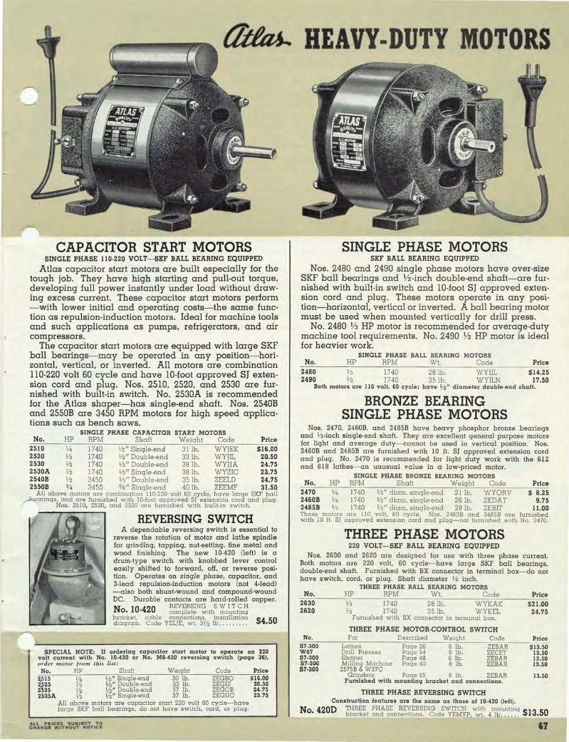
~ HEAVY-DUTY MOTORS
CAPACITOR START MOTORS SINGLE PHASE 110-220 VOLT-SKF BALL BEARING EQUIPPED
Atlas capacitor start motors are built especially for the tough job. They have high starting and pull-out torque. developing full power instantly under load without drawing excess current. These capacitor start motors perform -with lower initial and operating costs-the same function as repulsion-induction motors. Ideal for machine tools and such applications as pumps. refrigerators. and air com pressors.
The capacitor start motors are equipped with large SKF ball bearings-may be operated in any position-horizontal, vertical, or inverted. All motors are combination 110-220 volt 60 cycle and have 10-foot approved SJ extension cord and plug. Nos. 2510. 2520. and 2530 are furnished with built-in switch. No. 2530A is recommended for the Atlas shaper-has single-end shaft. Nos. 2540B and 2550B are 3450 RPM motors for high speed applications such as bench saws.
SINGLE PHASE CAPACITOR START MOTORS No. HP RPM Shaft Weight Code Price
2510 1f4 1740 1/2" Single·end 31 lb. WYJEK $16.00 2520 1/3 1740 1/2" Double·end 33 lb. WYJIL 20.50 2530 1f2 1740 1/2" Double·end 38 lb . WYJjA 24.75 2530A 1f2 1740 1/2" Single·end 38 lb. WYZIC 23.75 2540B 1f2 3450 1/2" Double·end 35 lb. ZEELD 24.75 25SOB % 3450 5/a " Single·end 40 lb. ZEEMF 31.50
All above motors are combination 110-220 volt 60 cycle, have large SKF ball Aarings, and are furnished with 10·foot approved S) extension cord and plug.
Nos. 25 10, 2520, and 2530 are furnished with built·in switch.
REVERSING SWITCH A dependable reversing switch is essential to
reverse the rotation of motor and lathe spindle for grinding, tapping, nut·setting, fine metal and wood finishing. The new 10-420 (left) is a drum·type switch with knobbed lever control easil y shifted to forward, off, or reverse position. Operates on single phase, capacitor, and 3-lead repulsion·induction motors (not 4-lead) -also both shunt·wound and compound·wound DC. Durable contacts are hard·rolled copper.
N 10 420 REVERSING S WI T C H 0.... complete with mounting
bracket, cable connect ions, installation $4.50 diagram. Code YEL)E, wt. 31f2 lb . . .... .. .
SPECIAL NOTE: If ordering capacitor start motor to operate on 220 volt current with No. 10-420 or No. MS-420 reversing switch (page 3S), order t'tlolor fro m this list : No. HP Shaft Weight Code
2.515 1/4 liz" Single·end 30 lb. ZEGBO 2.525 113 1f2" Double·end ~2 lb. ZEGIZ 2535 1f2 1/2" Double-end 37 lb. ZEGOB 2535A 1/2 liz" Single-end 37 lb. ZEGUC
All above motors are capacitor start 220 volt 60 cycle- have large SKF ball bearings, do not have SWitch, cord, or plug.
..... 1.. PttlCES S UIIJ J:CT TO CHAH~E: WITHOUT ~()Tle~
Price $16.00
20.50 24.75 23.75
SINGLE PHASE MOTORS SKF BALL BEARING EQUIPPED
Nos. 2480 and 2490 single phase motors have over-size SKF ball bearings and V2-inch double-end shaft-are furnished with bUilt-in switch and lO-foot SJ approved extension cord and plug. These motors operate in any position-horizontal, vertical or inverted. A ball bearing motor must be used when mounted vertically for drill press.
No. 2480 V3 HP motor is recommended for average-duty machine tool requirements. No. 2490 V2 HP motor is ideal for heavier work.
SINGLE PHASE BALL BEARING MOTORS No. HP RPM Wt. Code Price
2480 1f3 1740 28 lb. WYI)L $14.25 2490 liz 1740 35 lb . WYILN 17.50
Both motors are II 0 volt, SO cycle; have Vi" diameter double-end shaft.
BRONZE BEARING SINGLE PHASE MOTORS
Nos. 2470, 2460B, and 2485B have heavy phosphor bronze bearings and 1f2-inch single·end shaft. They are excellent general purpose motors for light and average duty-cannot be used in vertical position. Nos. 2460B and 2485B are furnished with 10 ft. SJ approved extension cord and plug. No. 2470 is recommended for light duty work with the 612 and 618 lathes- an unusual value in a low·priced motor.
SINGLE PHASE BRONZE BEARING MOTORS No. HP RPM Shaft Weight Code Price
2470 1/4 1740 1f2" diam. single·end 21 lb. WYORV $ 8.25 2460B 1/4 1740 1/2" diam. single-end 26 lb. ZEDAT 9.75 2485B IIJ 1740 1f2" diam. single-end 28 lb. ZEBIT 11.00 These motors are 110 volt, 60 cycle. Nos. 2460B and 2485B are furnished with 10 il. S) approved extension cord and plug-not furnished with No. 2470.
THREE PHASE MOTORS 220 VOLT- SKF BALL BEARING EQUIPPED
Nos. 2630 and 2620 are designed for use with three phase current. Both motors are 220 volt, 60 cycle-have large SKF ball bearings, double·end shaft. Furnished with BX connector in terminal box- do not have switch, cord, or plug. Shaft diameter 1/2 inch.
No. 2630 2620
THREE PHASE BALL BEARING MOTORS HP RPM WI. Code
1740 28 lb. WYKAK 1740 35 lb. WYKEL
Furnished with BX connector in terminal box.
THREE PHASE MOTOR·CONTROL SWITCH
Price $21.00
24.75
;;cN::'-o::.:.=-__ -:-.:.F::..:or=__ ___ --=D:..:e:=s-=cr:..:ib=:ec:d=-_-=W:..:e:.:iq~h:::t=---__=C~o:::d:::e:"...._--,-Price S7-300 Lathes Page 26 6 lb . ZEBAR $13.50 WS7 Drill Presses Page ~4 6 lb. ZECEr 13.50 S7-300 Shaper Page 48 6 lb. ZEBAR 13.50 S7-300 Milling Machine Page 40 6 lb. ZEBAR 13.50 57·300 2575B & W37C
Grinders Page 65 6 lb. ZEBAR 13.50 Furnished with mounting bracket and connections.
THREE PHASE REVERSING SWITCH Construction features are the same as those of 10-420 (left).
No 420D THREE PHASE REVERSING SWITCH with mounting $13 50 • bracket and connections. Code YEMYE, wI. 4 lb...... •
&7

ARBOR PRESSES SIMPLE LEVERAGE PRESSES 8 Models for Pressures from V2 to 5 Tons
Nos. 00, 0, 1, X, and Yare simple leverage qUick-acting presses with capacities between V2 and 2 tons. Manufacturers of watches, clocks, radios, speedometers, office machines, and other delicate instruments use these presses for light, high speed production and assembly work. Nos. X and Y have solid square-planed table in place of standard table with plate.
Atlas Nos. 1 V2, 3A, and 4M presses are operated with a ratchet device which permits using lever in most convenient pOSition- has counterweight for qUick return of lever after down stroke. Lever and ratchet pawl are mouli'.ted in counterweight. Handwheel advances ram to work in an instant. No. 1 V2 is a favorite with garages, service stations and appliance shops for general servicing. Nos. 3A and 4M are larger machines for heavier classes of work up to 5 tons. No. 4M is a floor type press equipped with an adjustable table--rack and pinion with crank control changes table elevation. Heavy duty clamp locks table in position.
Rugged floor pedestals are available for all bench type presses except Nos. 00 and X.
COMPOUND LEVERAGE PRESSES 5 Models for Pressures from 5 to 12 Tons
The original Atlas compound leverage device permits the operator to apply great pressures with minimum of effort. Compound or simple leverage is qUickly obtained by simply inserting or extracting a sliding pin. Handwheel advances ram to work in an instant --spindle brake sets ram in any desired position. All compound leverage presses listed below a re equipped with this mechanism.
Nos. 2, 2B, 2 1f2 , and 3 are bench-type presses available with floor pedestals. No. 2V2 press is same as No. 2 press but with 21 " capacity over table, 19%" over table plate. No. 2B is same as No.2 press with 5 Y2" opening for arbors. No. 4 is a heavy-duty floor type machine and has an adjustable table with rack and pinion to control
PedOe~tal elevation.
tlittu. SIMPLE LEVERAGE ARBOR PRESSES I 'r ~ Length ~.rge.t Il,argest ,c'3'!city. '3'!CI~' acd Floor ArFg:~· Sbipping PRICE Weigbt, Press Diameter ho ver T vbr Height, Leverage Code
No. Work. Ar ~, Table, I • Ie ize of pace. Incbes Ratio Weight, Word LESS Pedestal. Ram. Inches Pressure Pounda PEDESTAL Pounds Inches
00 7 1 41:; 334 lxl x7 Bench 4x l0 9 24-1 Yz -W-PACK $ 14.00 -
I
(Above) Atlas No. 3A Simple Leverage Ar· bor Pre ss . 5 tons capacity-floor ped esta l
a va ilable.
(Left) Atlas No. l V2 Simple Leve ra ge Ar· bar Press on F loor Ped e stal. Capacity 2
tons .
1 Code Price' Word PEDESTAL
ONLY
---_fu_~b~I'~ I Pedestal
_O_~f lH ~ 7~ lx lx12 Ped. 10~x18 14Yz 36-1 1 70 PACE 24.00 5 DELL $24.00 X 7 -I,g.~-- lxlx7 Rench 4xl0 9 24-1 Yz -W- PO T 14.00 ~DELL ---Y 10 - - lxlx12 Ped. 10~x18 14Yz 36-1 ~ 70 POND 24.00 24.00
--1- --u--I 1 % --IT---110 J1 l~x1~x16Yz Ped. 14x22 20 48-1 2 -----r4l)PAGE 35.00 120 I DENT 27.00
lYz 1~11% I~ 10~ 1~xl~x16Yz Ped. 14x22 20 48-1 2 150 [PA LM 39.00 120 DESK 27.00 3A 20 4 16 14% 2x2x22 Ped. 18x28 30 55-1 -5-~PEACH 94.00 275 DEAN 44.00 4M 21 1}-2 25 23!16 2x2x22 I 21x29 62 55-1 5 1030 PATRON 184.00 - 1---- ----
tltttu.. COMPOUND LEVERAGE ARBOR PRESSES
"---IDiame~~~r Largest capacveritYC~l9!b~l~ty LelZ.a~e~othf Floor Approx. Sblpplng Code PRICE W,lgbt, Code P I ,...... '" Arho love a e Space, Hlo'cigbest, Leve,!,g, Tons, Weigbt, LESS Pedestal, Word PEDEST~ No. Work, Incb;'; 'fabio" l'late, Ram, Inches ,b RatIO Pressure Pounds Word PEDESTAL Pounda Pedestal ON LV
______ Incbes ______ ! Incbes l_l_nc_'h_es~ _____ ln_~_es ____ ~ ___________ I _____ ! ______ I ____ ~ _____ I' __ ----f------; --------I-------I-------2 115Yz 3% I 1 .1- 12% l YzxlYzx19 Ped. 18x23Yz 25 100-1 5 270 PADEN 2B 15 Yz I 5 Yz' 15 1 13 %' 1 Yzx 1 Yzx19 Ped. 15x24 25 100- 1 5 290 PICKLE 2Yz 15Yz 3% 21 19 3i n/2x1 Yzx26Yz I Ped. 18x23Yz 35Yz 100-1 5 315 POMP 3 20Yz 5 I 18 16% I 2x2x24 Ped. 21x30 36 160--1 12 640 PARCO 4 I 21 5 25 I 23Ys 2x2x24 24x29 64 160-1 12 1390 PACKER
$ n.oo 80.00 82.00
150.00 245.00
ASK FOR COMPLETE ARBOR PRESS CATALOG NO . 33
225 225 225 375
DESTAL DECK DESTAL DECOX
$38.00 38.00 38.00 53.00
'"
68 ALL IJiIRICiES SUBJECT TO CHANGE WITHOUT NOTice

DRAULIC p SES
No. SOH, SO-TON HYDRAULIC PRESS with EXTRA equipment. Equip m e nt not furnished as standard includes : side press, testing attachment, dial test indicator.
HYDRAULIC WORKHEAD
(Right) Close-up view showing self·contained con· struction and roller mounting of the workhead unit furnished on Atlas Hydraulic Presses. Workhead cylinder is nickel chrome alloy steel. Pump is a drop forging. This unit may be purchased separately for use with any press frame-see table below. The Atlas Engineering Department is prepared to make recommendations for handling extra large or odd· shaped press work.
SPECIFICATIONS AND ORDER NUMBER Height Overall ......... .. . . .. . . ..... .... ............ .. . Floor Space ......... . ..... . . ... . ....... . . . ........ . .. .
/"""'«:lvel of Table... . . .. . .. . ...... . ....... . .. . .. .. ....... . (vel of Piston. . . . . . .. . .... . ... .. .......•. . .... .
_avel of Screw .......... . . ... . ..... . .... .. .. . . .... .. . .. . . . . Width between uprights (largest diameter work) .. Width between table channels (largest arbor) .... Maximum distance ram to table in lowest position .... . ..... . Table Channel .. . Head Channel ... .. ... . . . ... . .... .... ...... . Upright Channels ... . . .. .. ...... .. ....... . . .. ..... . ....... . Capacity .. . .. ... . ... ..... . .. .. . . . . . . ... . . . ....... .. . Weight . . .. . . ........ .. . .... . . . .. ... . .. . ... .. . ... . . . . . . Code Word . ..... ...... .... ... . . . ... ....... . .. . .. .. .
PRICE with Standard Equipment listed below ........... .
Great power and large work capacities make the Atlas Hydraulic Presses ideal for factories, garages, service stations, and machine shops. The hydraulic workhead furnished as standard equipment is a compact. self·contained unit and can be moved quickly to any position along the top channel-an exclusive Atlas feature. Simple design and superior construction result in many years of trouble-free service. The frame is welded reinforced structural steel; p u m p is a drop forging. Workhead cylinder is nickel chrome alloy steel. Auxiliary screw type ram, handy release valve, and adjustable table are described at the right. See table below for complete specifications.
• FRAME- Wei d e d structural steel with heavily reinforced table.
• SELF· CONTAINED WORKHEAD-
Reservoir and controls are one
compact unit. Roller mounting
provides transverse adjustment.
• AUXILIARY SCREW TYPE RAM
Ram is brought down to work
quickly with handwheel control.
• RELEASE VALVE-Automatically reo turns ram to starting point when
opened by small hand wheel.
• ADJUSTABLE TAB L E HEIGHTHandy crank mechanism for rais·
ing or lowering table.
• CONSERVATIVELY RATED-Before
shipment. Alias presses are tested
at pressures S to 10 tons higher
than actual rating.
ATLAS HYDRAULIC WORKHEAD
PRICES No. SOH No.70H
6' 8" 7' I" 36"x43" 36"x56 /1
40" 36" S" 51/4" 7" 7"
33" 44" 7" 8"
43" 381/2" 8"-16.25 lb. 12"·30 lb. 8"·16.2S1b. 12"·30 lb . 7"- 9.8 lb. 8" ·13. 75 lb.
50 tons 70 tons 820 lb. 1390 lb . HAMP HaRT
$210.00 $295.00
STANDARD EQUIPMENT FURNISHED- Pressure Gauge, Hydraulic Workhead, 2 Table Plates, Table Lifting Device, 2 V·Blocks, 1 V Ram Nose for Straightening, 1 Round Nose for Pressing.
No. 70H. 70·TON HYDRAULIC PRESS with standard equipment. Hydrau· Iic work head and pressure gauge are EXTRA EQUIPMENT AVAILABLE
, 0. 1% 2-Ton Rack and Pinion Side Press ............. WYNAN No. 35 Testing and Strmghtening Attachment. . . ....... WYNOR No. 35·20 Dial Test Indicator and Bracket. .. . .......... .. WYNPE
155 lb. 35 lb .
21b.
HYDRAULIC WORKHEAD (When Purchased Separately) Code Word
No. SOHW 50·Ton, Complete with Pressure Gauge WYNRO No. 70HW 70·Ton, Complete with Pressure Gauge WYNUS PLEASE ORDER BY CATALOG NUMBER
Weight 29Slb. 385 lb.
S 39.00 20.00 16.50
Price $130.00 195.00
furnished.
It

PORTABLE
GENERAL PURPOSE PRESS FOR PRESSURES UP TO 10 TONS
* WELDED STRUCTUR·
AL STEEL FRAME.
* IO·TON CAPACITY.
* HANDLES DIAM·
E T E R S UP TO 18
INCHES.
* 16'/2 INCH CAPAC·
ITY OVER BASE.
* ADJUSTABLE TABLE.
* E A S IL Y MOVED
TO JOB.
The Atlas P·lO meets the need for a rugged, sensibly priced multi·purpose press to handle a wide range of work. It can be moved easily to different shop locations or set up on a maintenance or service truck.
Frame is built of heavy structural steel channels electrically welded for maximum strength. Table of structural steel is rigid work support. easily moved to anyone of four positions on frame. Screw is special alloy steel, free fitting for speedy ram travel-is I" diameter, 8 threads per inch. Ram nose has ball thrust bearing. Two table
blocks 1 %"x7"x%" are furnished with the polO press.
No. polO ~;:"~RAfn~~:!~~Et:~!S~IO~~~~~~~ ~~I4~,h~~~ x W '. Code word WYOHL. wI. 80 lb . . . .. ......... . . ... .. $20.00
Largest Diameter 01 Work .. . .... IS" Largest Arbor . .. . .. ............ 3" Capacity over Base • ......•. .. 161/2" Screw Travel . ...•• .. . ..... . . .. 5" Overall Height 01 Frame . . ... 201/4" Bench Space . . •.. ..... •.... S" x17"
TABLE BLOCK AND V-BLOCKS
No. PIO·13 TABLE BLOCK lor g e neral p ress w ork, gluing, e tc.
size 4" x 6" x %". Code word WYOLP, $1.45 weight 6 pounds . . .... . . . .
No. PI0-14 Tw o V·BLOCKS lor s traight. ening and arbor w ork- s ize
1% " x 7" x %" . Code WYOjM, w eight 6 lb. $2.00
Straigh tening s h a I t with No. PI O·14 V·block p la tes supporting work on table. Notice how extra long pieces can be extended beyond
sides o f press.
1 +..:c
~ J ~
v ~
I. f
Using the P·1O a s a gluing press. No. PI O· 13 table block dis· tributes pressure evenly and does not mar wood . Veneering is another job lor the P·IO
press.
Work range of the P· IO includes all types 01 automotive press work - bearings , bushings, shafts and pins . Above, pressing bearin g on a r -
mature sh aft.
WHEEL-OPERATED
PRODUCTION PRESSES
Press No.
- -OOS XS OS YS 2S
Press No.
OOS XS OS YS 2S
No. 005 press handling rapid assembly operation.
Handwheel control speeds up the ram action of these
".
presses and makes them ide' for light production and a~ sembly work. No. 2S has a 3~'' hand wheel- Nos. DOS and XS are equipped with a 14" diameter 3-handled wheel - Nos. OS and YS have 20" wheel. Nos. XS and YS have solid square-planed table in place of standard table with plate. Rugged floor pedestals are available for Nos. 2S, OS and YS.
SPECIFICATIONS-WHEEL· OPERATED PRESSES
Largest Diameter
Work, Inches
- 7 -7
10 10 15 Y2
Levcr-age,
Rlttio
12- 1 12- 1 20- 1 20- 1 16- 1
Capacity Length
CO!~:ty Over and Largest Table Size of Floor Arbor, Table, Plate. Ram. Space. Inches Inches Inches Inches Inches
1 4~- 3 % 1 xl x 7 Bench 4 x10 - 4Y2 - 1 xl x 7 Bench 4 xlO l Ys 7%; 7% 1 x l x 12 Ped. 1Oy,j:x 18 - 8 - 1 xl x 12 Ped . 1 0~x18 3Ys 14 12% 1 Y2xl Y2x19 Ped. 18 x24
PRICE Approx. Shpg. LESS \Y eight, Code
Tons, WOIght Code PE[)ES- Pedestal. Word Pressure Lbs. Word TAL Lbs. Pedestal
),i ---w- $15.00 - - - ---
ZAPEC - -J4 26 ZAPFO 15.00 - -Y2 77 ZAPJD 27.00 85 DELL Y2 77 ZAPOF 27.00 85 DELL Y2 200 PONY 75.00 225 DESTAL
GENERAL CATALOG NO. 41 January, 1941
• Cancels All Previous Catalogs and Price Lists •
• Copyright 1941- AtJas Pre s s Com pan y -
• We Reserve Right to Alter Designs without Notice.
• Complete Index on Inside Ba ck Cover -
Height, Inches
14Y2 14Y2 22~ 22 y,j: 38
Price PEDE
TAL ONL -----
$24.00 24.00 38.00
70 • JIll Prices Subject to Change Wi thout Nolice _ "L~A'SI! ftRO£R BY C""I\LOG HUIMIIEII

\
e,o M PLETE INDEX A BRASIVES. for drill press sander ..... . . ..... , 58
Angle plate. IO·inch metal lathes ..... . .... . 27 Angle plate. new milling machine . ....... . ..... 42 Angle plate. 7·inch shaper ...... . , ... .. ... , . . ,. 48 Angular milling cutters .. .... , , , ..... . .... 17. 34. 42 ~rbor. new milling machine ." .. .. . . .... . , ... 42
,\RBOR PRESSES ............. . ...... . .... , . . 68-70 Arbors. chuck. IO-inch metal lathes. , . . • . . . . . 23 Arbors. chuck. 6·inch metal lathes. . . . . . . . . . . .. ~~ Armature chuck kits .... " ....... .. " ... .. . ... · ARMATURE SERVICING OUTFITS .. , .. . .... .. ... 33 Armature-trueing cutter bits . ... . , , ........... 22. 36 Attachments. drill press ..... .. , .. .... ... .. . .. 52-61 Attachments. metal lathes . .. ....... . , , . 15-28. 34-36
BALL bearing lathe centers ...... . .. . ....... 26. 36 Belt guard. drill press , . ....... , . . . . . . . . . . . . 54
Belt guards. metal lathes ....... . .... ..... ... ... 15 Belt guards. new milling machine .... . . ..... , .. 41
I Belt release, drill press.. . . . . . . . . . . . . . • . . . . . . . .. 56 Bench grinders .. .. , ..... ..... . .. ... ........... 65 Boring bars. IO-inch metal lathes . . . . . . . . . . . . . .. 27 Boring table. IO-inch metal lathes ..... , . ... , . . .. 27 Boring tool holder. la-inch metal lathe . .. , . , ... . 24 Boring tools. 6-inch metal lathes . . .. . . .. , . • . . . . 35 Boring tools. la-inch metal lathes. , . . . . . 25 Bulling wheels. grinder ... ... , ..... ,.... . ...... 66
~ ., ABINETS. for 10·inch metal lathes .... , ..... . 15
,oJ Calipers . ... ... . .. .. . .. . . . . .. . ... . . .... ,... 28 Carriage stop. IO-inch metal lathes .. . , .. .. . , .. , 26 Carriage stop. 6·inch lathes .. . . .. . . . . , . ... , ... 36 Center gauge .,., .. . ...... .. . ...... . . , .. . ..... 28 Center key. drill press . .... . .. .. .. ..... . ....... 61 Cente. rest chuck. la-inch metal lathes ......... 23 Center rest chuck. 6-inch metal lathes ....... , . , 34 Centers. lathe ... .. ... ..... . .. . , . , ...... , ... 26. 36 Centers. woodworking. IO-inch lathes . . . . . . . . .. 28 Centers. woodworking. 6-inch metal lathes . . .... 36 Chipping vises. heavy ... ... . ...... . .. ........ , 63 Chisel bits. mortising ..•• ..• • .... . . . . .. , ... , . . . 59 Chisels. mortising . .... . .•.• . ..• •. . .. . ,... . .... 59 Chisels. woodturning .. .. • •......... , .... . ,. 28. 36 Chuck kits ..... ..... .. . .. . ..... .... .. . , . ... ,.. 22 Chucks. IO·inch metal lathes ... . .... . . .... , .. 22. 23 Chucks. 6·inch metal lathes . . , ... . .... . .. , .. 33. 34 Clamping plate. for milling attachment . .... , . .. 17 Clamp type dogs .. .. . . . ......... . , ...... , . .. 25. 35 Coil winding attachment. IO-inch lathes . . .. ... , . 27 Coil winding attachment. 6-inch metal lathes... 36 Collet bushings. for milling operations ....... 17. 34 Collet chuck attachments. IO-inch lathes ... ... . . 16 Collet chuck attachment. 6-inch metal lathes .. , 34 Collet sets. holding .......... .. .. ... ... . .... 17. 34 Column collars. drill press . ... .. . . . . ..... ... . 57. 58 Combination pipe vises . . . . . . . . . . . . . . . . . . . . . . .. 63 Compound vise. new. for drill presses .......... 61 Coolant tank and pump. milling machine ... "'" 42 Countersink drills ..... .. . .................. 26. 61 Cross slide stop. la-inch metal lathes . . . . . . • . . . . 26 Cross slide stop. 6·inch lathes . . . . . . . . . . . . . . . .. 36 Crotch centers . .. ... , . . ...... , . . ....... ..... 26. 36 Cup centers. woodworking . . , .. . ...... .. ..... 28. 36 Cut-oil tool. IO-inch metal lathes ... ... ..... .. '. 24 Cut-oil tooL 6-inch metal lathes ..... , . . . . . . . .. 35 Cutter bits. 1f4-inch for IO·inch lathes . . . . . . . . . .. 25 Cutter bits. :y, . -inch for 6-inch lathes . . . . . . . . . . . 35 Cutter bits. for 7·inch shaper . ... ,..... . . . .. 48 Cutter grinding attachment. la-inch metal lathes. 20 Cutters. milling. for metal lathes . .... . ... .... 17. 34 Cutters, millinq machine ..... . . ... ... .. . ....... 42
~ JIAL indicator. hydraulic presses . . . . . . . . . . . .. 69
Diamond point wheel dresser .. . . . . . . . . . . . .. 62 Dogs. lathe ... .. . ...... .. .. . ...... . ... . .... 25. 35 Draw·in collet set. IO-inch metal lathes ....... .. 16 Draw·in collet set. 6-inch metal lathes ......... 34 Drill chucks. IO-inch metal lathes .. . . • . . . . . . . . .. 23 Drill chucks. 6-inch metal lathes . . . . . . . . . . . . . .. 34 DRILL GRINDING ATTACHMENT . .. .. . ... .... . . 62 Drill pads ... ... .... . .... . .. .... ... . ... . ... 26. 36 Drill press attachments .. .. . ... . .. . . . . . . . .. . . 52-61 DRILL PRESSES ..... . . .... ... .. . ............ 49·61 Drill press heads, for special set-ups .. .... ... .. 55 Drill press lamp ........... .. .. . .............. 61 Drill press vises .. .......... ... ....... . ....... 61 Drills. countersink .. .. .. . . . . . ..... 26. 61 DRILLING MACHINES. NEW MULTIPLE SPINDLE. 55 Drum sander. drill press . . . . ..... , . . . . . . . . . . . . • 58
END mills ... .... . ... . .. .. •. ...• ..•• •.. 17. 34. 42 Extension beds. lathe . .. ... ........ ...... 28. 36
Extension tool. shaper ....... . ..•.............. 48 Eyeshield. grinder ..... . .. . .. . ... .. .... .. ... .. 65
FACE plates. 10·inch metal lathes ...... . .... 24. 28 Floor grinders . ....... . .......... .... .. .. .. 65
Floor pedestals. grinders ... .. ................. 65 Floor stands and cabinets, IO-inch metal lathes . 15 Floor stands. 6-inch metal lathes .. . .. ...... .... 31 Follower rest. IO-inch metal lathes . . . . . . . . . . . . . . 25 Follower rest. 6-inch metal lathes. . . . . . . . . . . . . . 34 Foot lever feed control. drill press . . . . . . . . . . . . .. 54
GAUGE. center ..... .. ........ . .....•. . .... . . 28 Gauge. screw pitch .. . ... .... . ..•. •. . •. •.. . 28
Gear cutting attachment .... . ...... •. . . .... .. . 17 General purpose press ... ..... . .. . ... .. . . ... . . 70 General purpose vises . .. .. . .......•.... ... .. 64 Grinders. tool post. lO·inch lathes .. ... . .. ... .. 20·21 Grinder. tool post. 6·inch lathes .. . . . . . . . . . . . . .. 35 GRINDERS. BENCH AND FLOOR . ... .... . . .. . ... 65 Grinding wheels. drill .. ...... ..... . . .. .. . . .. 62 Grinding wheels. tool post grinders ...... 20. 21. 35 Grinding wheels. wire ... . . ....... ... .. . ... .. . 66
HANDREST. woodworking . . .... . ........ . . 28. 35 Handwheel feed. arbor presses . . . . . . . . . . . .. 70
Headstock chucks. IO-inch metal lathes. 23 Headstock chucks. 6-inch metal lathes . 34 Hi·Lo speed attachments. drill press ......... . 56 HYDRAULIC PRESSES ....... .. . .. .. ....... . .. 69
I NDEPENDENT chucks. lO·inch lathes .......... 23 Independent chucks . 6·inch metal lathes ..... 34
Index centers, new milling machine .. ... .. .. ... 42 Index centers. 7-inch shaper ...... ..... . .. . ... 48
JACOBS chucks. lO·inch metal lathes ........ .. 23 Jacobs chucks. 6·inch metal lathes . . . . . . . . . .. 34
KNURLI!iG tool. I~.inch metal lathes . . . ..• . ... 24 Knurhng tool. 6·mch metal lathes .... . . . . . .. 35
LAMP. drill . press. . . . . . . . . . . . . . . . . . . . . . . . . . . . . 627
1 Lamp. lO·mch metal lathes .. .. . . . . . .... .... .
Lamp. 6·inch metal lathes. . . . . . . . . . . . . . . . . . . .. 36 Lathe attachments. lO·inch ... .. ...... .. . . ... 16·28 Lathe attachments. 6·inch .... . . . ..... . . .... 34·36 Lathe booklets. automotive . . . . . . . . . . . . .. .... .. 22 Lathe centers ....... . . . .. .. ... 26. 28. 36 Lathe manual ..... ...... . . . 14 LATHES. NEW IO·INCH BACKGEARED WITH
POWER CROSS FEED . . . ...... 2·28 LATHES. 6·INCH BACKGEARED ... . ..... 29·36
MA~~~rufJf;T~?~i~ES ' : : : : : : : : :: ~~ Manual of Lathe Operation . .... 14 Metric screws and collars. lO·inch lathes . 12 Metric screws and collars. 6·inch lathes . . 31 Mica undercutter. lO·inch metal lathes ..... 22 Mica undercutter. 6·inch metal lathes . . . . . . 36 Mica undercutting saws ... . . . . . . .. . .. 22. 36 Micrometers ...... . .. .... .. . ........ 28 Milling attachment. 10·inch metal lathes . ... . . .. 17 Milling attachment. 6·inch metal lathes ... ... .. 34 MILLING MACHINE. NEW BENCH .. . ..... ... . . 37.41 Milling machine. attachments for. .. . ..... . . 42 Morse taper socket. drill press ... .. .. . ........ . 61 Mortising attachments. drill press . . . . . . . . . . . . .. 59 Mortising chisel bits. drill press . . . . . . . . . . . . . . .. 59 Mortising chisels. drill press . . . . . . . . . . . . . . . . . . . 59 MOTORS . .......••.. . . ..... .. . .. . . .. . ...... 66·67
OIL tables. drill press .. . . .. ..... . . ... 52. 54. 57 Oscillating sander. drill press . . .. .. .... .... 59
PEDESTALS. grinder ....... . .. .... .. .. .. . . ... 65 Pipe centers. 10·inch metal lathes .. . . . . . . . . .. 27
Piston equipment. IO-inch metal lathes . 22 Positioning mechanism, drill press ... ... ........ 56 PRESS, GENERAL PURPOSE .... .. .. ... .. . .. . .. . 70 PRESSES. COMPOUND LEVERAGE . .. •. . .. .. . . 68 PRESSES. HYDRAULIC ...... . . .... . ..... . ... .. 69 PRESSES. SIMPLE LEVERAGE •. • ••...... •. .. .. . 68
Arbor Presses ....... Pages 68-70
Drill Presses . .. .. ... Pages 49-61
Lathes, Metalworking. Pages 2-36
Milling Machine .... Pages 37-42
Shaper, Metal .... .. Pages 43-48
RADIAL arm. drill press. . . . . ....... . ..... . .. 52
60 Reamer grinding attachment. ....... .. .. .. .
Recess wheels. for drill grinding . . . . . . . . . . . . . .. 62 Reversing switches .................. . . 20. 35. 67 Rotary index table, new milling machine. 42 Rotary index table. 7·inch shaper . . . . . . . . . . . 48 Route. bits. drill press . 61
SANDING attachments. drill press ....... . .. 58. 59 Saws. undercutting . . .... ... . ......... . . . 22. 36
Screw centers, woodworking ... .. ... ... .. . . . 28, 36 Screw pitch gauge ........ . ...... . .... .. .. . .. 28 SHAPER. NEW 7·INCH ............... ..... .. .. 43·48 Shapero 7.inch. attachments for . . . . ... .. .. . .... . 48 Shaping attachment. drill press . . . . . . . . • . . . . . . . 60 Shaping cutters. drill press ... .. . .. .. .. . .... . " 60 SIX·INCH LATHES. BACKGEARED ..... . . .. .... 29·36 Sleeve socket drill press ..... . .... .. .. ... 61 Sockets, Morse taper, drill press ...... . . .. .... .. 61 Speed attachments. for drill presses . . . . . . . . . . . . 56 Split collets ....... ...... .. ......... . ....... 16. 34 Spur centers. woodworking ... . ... . . . .. .. ... 28. 36 Steady rest. 10·inch metal lathes . . .. ... 25 Steady rest. 6·inch metal lathes. .. . ... . . . . . .. 34 Switches. reversing ...... . ........ .. .... 20. 35. 67 Switches. three phase .... . . . .... .... . . .. 26. 48. 67
TAPER attachments. 1.0.inch lathes . . .. . ... , . .. 18 Taper attachment. 6·mch lathe. . . . . . . . . . . . . .. 36
Tapping attachments. drill press . . . . . . . . . . . . . . . . 54 Testing and straightening attachment. hydraulic
presses .......... .. .... . ...... .... .. .. . .... . 69 Threading tool. 10·inch metal lathes ....... . .. . 24 Threading tool. 6·inch metal lathes.. 35 TIMKEN BEARINGS. 1O·INCH METAL ,LATHES . .. 8. 9 Tool bits. 1/4·inch .... . . ... .. . ..... . ..... ... ... 25 Tool bits. ' /16·inch . .. . .. . . . .... .. . . ... ... . .... . 35 Tool holder. shaper .. ... .... . ...... . .. .. .. . ... 48 Tool holders. lO·inch metal lathes. ... . .... . .... 24 Tool holders. 6·inch metal lathes . ! . . . .... . .... 35 Tool·post grinders. IO·inch lathes .. . .......... 20. 21 Tool.posl grinder. 6·inch metal lathes ... . .... .. . 35 Tool·post tools. la-inch metal lathes .... . ..... . .. 25 Tool-post tools. 6-inch metal lathes . . . . . . . . . . . .. 35 TOOLS. MACHINISTS' ..... . . ... . . . . . . . . . . . 28 Turret attachments. 10·inch metal lathes . . . .. ... 19 Turret type boring set. lO·inch lathes ..... . . . .. 27
UNDER CUTTER. 1.0.inch metal lathes ........ ... 22 Undercutter. 6·mch metal lathes . . . . . . . . . . .. 36
Undercutting ·saws ........ . ...... . . . . .... .. 22. 36 Universal chucks. 10·inch metal lathes . 23 Universal chucks. 6·inch melal lathes ...... . ... 34
VALVE slem grinding attacl:merot, lO·inch metal lathes .. .. . . . ... . .. .... ..... . ... ... .. . .. 20
Vises, combination pipe . . . ............ 63 Vises. drill press .. ..... .. . . .... . ... .... . . . .. 61 Vises, general purpose .. . .. . .... . . ... . .. . ..... 64 ViEes, heavy chipping 63 VISES. MACHINISTS ' . . . . . . . . .. . 63 Vise, swivel, new milling machine ... . •. ... .. . . Vises, woodworkers ' .. . ... . . . .. . .. . . . .•.... .
42 64
WHEEL.OPERA TED Presses ....... • . . ....... . 70 Wheels. bulfing .... . ..... . ... . .•.. . ... .. . . 66
Wheels. drill grinding. . . . . . . . . . . . . . . . . . . . . . . . . . 62 Wire brushes and sections .. ... . .. .. .. . 66 Woodrull keyway cutters . . . .. . . 17. 34. 42 Woodworkers' vises ........... 64 Woodworking attachments. lO·inch metal lathes . 28 Woodworking attachments. 6·inch metal lathes . 36 Workhead. hydraulic presses ...... : ..... . ... .. . 69
r"'lTLAS PRESS COMPANY, MANUFACTURERS 1819-2019 North Pitcher Street, Kalamazoo, Michigan, U. S .. A.
• NEW YORK 130 West 42nd Street
• EXPORT DEPARTMENT, 130
COMPLETE DISPLAYS • PHILADELPHIA • CHICAGO
113 North Third Street 35 E. Wacker, at Wabash West 42nd StreeL New York City, Cable Address: "APCOY" New Yo,..k

MODERN MANUFACTURING
Through every step of production- from engineering department through tool room, machine shops, assembly lines, testing and inspection-the Atlas factory reflects efficient, up-to-the-minute manufacturing methods.
The reputation of Atlas machIne toolstheir precision, power, durability, low costis a tribute to the modern efficiency of Atlas men, methods, and production equipment. Whatever machine tool you buy, the name "Atlas" is your guarantee of long, dependable service.
__ IIIIWl;.~ __
C®w.!MAR~DEL. ESTABL..ISH~D ae7Z
TOOLS • METALS SHOP SUPPLIES 1235 Mission St. 11th & Alice Sts. SAN FRANCISCO OAKLAND
PRINTIUI IN U. $. A.
I •
1
Related Documents