Schlumberger Public Equipment, Systems and Processes Mark E. Teel Client-Relations Manager SRC Schlumberger Rosharon Center

Welcome message from author
This document is posted to help you gain knowledge. Please leave a comment to let me know what you think about it! Share it to your friends and learn new things together.
Transcript

Schlumberger Public
Equipment, Systems and Processes
Mark E. TeelClient-Relations ManagerSRC Schlumberger Rosharon Center

2 Initials

3 Initials5/15/2012
The Life of Oil and Gas Wells and ReservoirsSeismic
ExplorationExploration
DrillingDevelopment
DrillingFormation Evaluation
Well Testing
Casing and Cementing
Complete StimulateWorkover Interventions
Monitor and Manage
Plug and Abandon

4 Initials5/15/2012
Oil and Gas Drilling Rigs
5 CAP
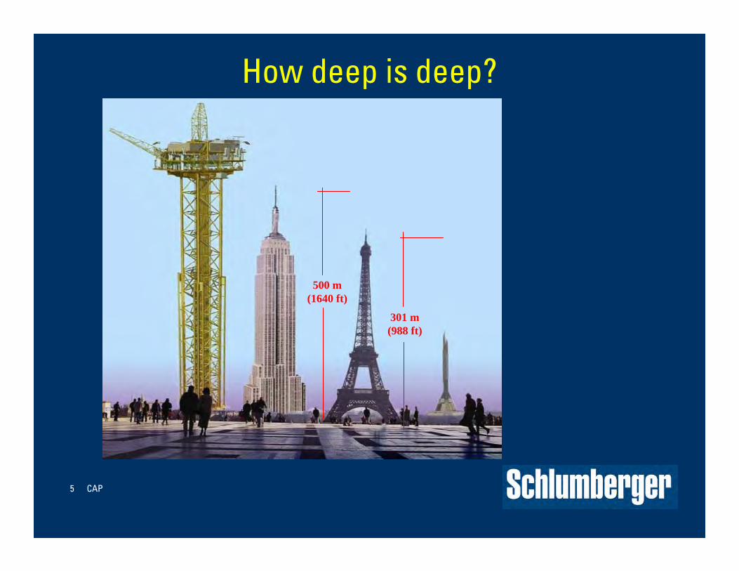
How deep is deep?
500 m (1640 ft)
301 m (988 ft)

6 Initials5/15/2012
7 Initials5/15/2012

8 Initials5/15/2012

9 Initials5/15/2012

10 CAP
Identifying Needs and Challenges
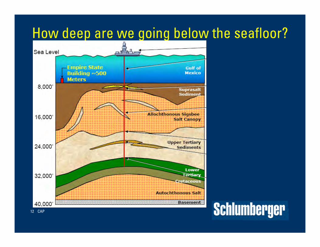
•So, How deep are we going?
Deeper than ever!
Empire State
Building

11 Initials5/15/2012
12 CAP
How deep are we going below the seafloor?

13 Initials5/15/2012

14 CAP
How deep are we going below the seafloor?
15 Initials5/15/2012

Subsea – Intervention and Safety Systems– Offshore fields are increasingly
developed “subsea” with wellheads on the seafloor.
– Anchored rigs or dynamically positioned drillships are used for drilling, testing and well completion activities.
– Safe well access, emergency shut-in and disconnects are a huge challenge.
– SRC develops technology to safely shut-in, disconnect from and reconnect to a subsea wellhead.

17 Initials5/15/2012
Wellbore Architecture
Well Completions
18, Completion Basics15-May-12
Packers• ANCHOR production tubing inside cemented casing
• SEAL to isolate the tubing-casing annulus and act as a pressure barrier between formation, or reservoir pressure, and upper wellbore annulus or between multiple zones
• PROTECT upper steel casing from erosion, corrosion:
H2O, H2S, CO2
Multilateral Wells and Wellbore Junctions
Strength Solids ExclusionHydraulic Pressure IsolationLateral access
Define technique, coiled tubing, wireline, rigSize and type of tools for intervention

20, Completion Basics15-May-12
What is a well completion?
• Equipment installed and procedures performed in oil or gas wellbores to facilitate flowing from—production—or pumping into—injection—subsurface formations after drilling, running steel casing and cementing the primary casing or liner in place.
• Production tubing and other equipment components of a well completion help transport hydrocarbons to surface in an efficient cost-effective, controlled, measured, and safe manner.

Well Completions• Conveyance, or transport, into and out of …• Data acquisition …• Flow control and flow management …• Communication and data transmission …• SAFETY !
Completion installations can be:
temporary for well testing or
permanent for long-term production
— “life of a well, field, or reservoir”

22 Initials5/15/2012
Oilwell Perforating Perforate
• Wireline conveyed• TCP—Tubing Conveyed perforating

Explosive Shaped-Charges
TCP Tubing-Conveyed Perforating
24 Initials5/15/2012
25 Initials5/15/2012

Shaped Charge Animation (to 30 microseconds)

Shaped Charge Animation (to 140 microseconds)

28 Initials5/15/2012

29, Completion Basics15-May-12
Cased, Cemented and Perforated
• The most common type of well completion
• Selective production, stimulation and zonal isolation
• Pressure control and safety
• Multiple individual zones completed in a single wellbore

30 Initials5/15/2012

PERF Lab Testing CapabilitiesPV-93 Test (2008) PV-94 Test#001 (2009)

32, Completion Basics15-May-12
Well Classifications• Wellbore and reservoir interaction
– Steel cased, cemented and perforated
– Openhole, or barefoot
– Standalone screens, gravel and frac packs
– Vertical, high-angle, and horizontal
• Flowing method– Natural flow
– Artificial lift
• Number of completed zones– Single
– Multiple

Completions tubulars and equipment-plumbing
33, Completion Basics15-May-12

34 Initials5/15/2012

35 Initials5/15/2012
Wellbore Architecture
Well Completions

36, Completion Basics15-May-12
Packers• ANCHOR production tubing inside cemented casing
• SEAL to isolate the tubing-casing annulus and act as a pressure barrier between formation, or reservoir pressure, and the upper wellbore annulus or between multiple zones
• PROTECT upper steel casing from erosion, corrosion:
H2O, H2S, CO2
• Available in different types:
– Permanent
– Retrievable
Single, dual or triple string, multi-ported, sealbore

X-Series Retrievable Production Packers
XHP
XMP

38, Completion Basics15-May-12
Openhole Sandface Completions
• Advantages
– Maximizes area open to flow
– Decreases pressure drop, or pressure drawdown
– Minimizes formation damage from cementing, perforating and completion fluids and operations
• Disadvantages
– Lack of pressure containment and selective control
– Possible borehole instability and risk of hole collapse

Mechanical Screens and ICD Inflow Control Devices
39, Completion Basics15-May-12

Swellable Openhole Packers

41 Initials5/15/2012
42 Initials5/15/2012
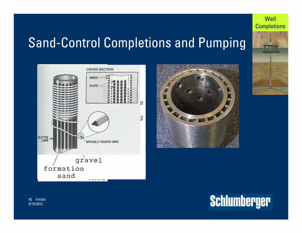
Sand-Control Completions and Pumping
Well Completions
43, Completion Basics15-May-12
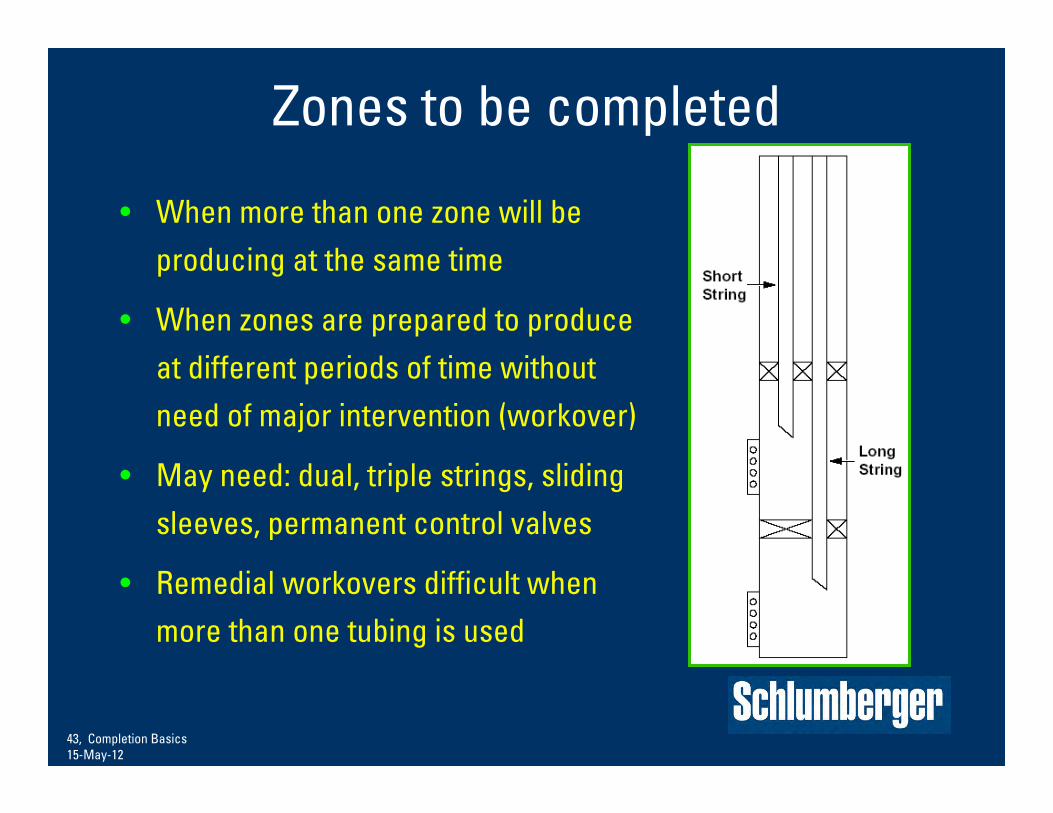
Zones to be completed
• When more than one zone will be producing at the same time
• When zones are prepared to produce at different periods of time without need of major intervention (workover)
• May need: dual, triple strings, sliding sleeves, permanent control valves
• Remedial workovers difficult when more than one tubing is used

44, Completion Basics15-May-12
Sequential Production with a Packer and Single Tubing String
Zone 2: 1000 psi
Zone 1: 1500 psi

45, Completion Basics15-May-12
Sequential Production with a Packer and Single Tubing String
Zone 2: 1000 psi
Zone 1: 1500 psi

46, Completion Basics15-May-12
Commingled Production with a Packer and Single Tubing String
Zone 2: 1000 psi
Zone 1: 1500 psi

47, Completion Basics15-May-12
Packers and Sliding Sleeves or Valves and Single Tubing String
Zone 2: 1000 psi
Zone 1: 1500 psi
48, Completion Basics15-May-12
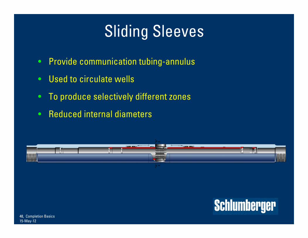
Sliding Sleeves
• Provide communication tubing-annulus
• Used to circulate wells
• To produce selectively different zones
• Reduced internal diameters

49, Completion Basics15-May-12
Flow Management: Two Production Zones
– Dual producing zones, formations or reservoirs
– Drilling, well-construction and well-completions savings

Flow Management: Accelerated Production and Optimal Reserve Recovery

0.7
0.6
0.5
0.4
0.3
0.2
0.1
100 200 300 400 500 600 700
Days
Intelligent Completions – benefits and history
• Cumulative Oil Production and Flow Strategy Comparison
Sequential
Uncontrolled Commingled
Controlled Commingled
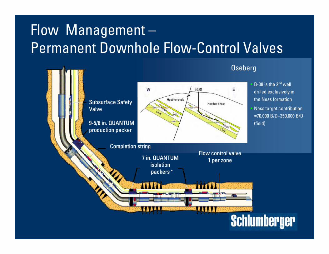
Oseberg
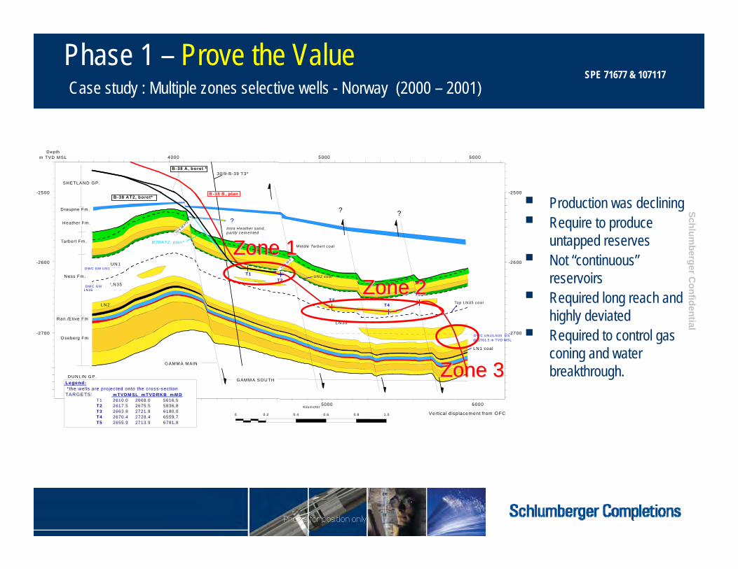
B-38 is the 2nd well drilled exclusively in the Ness formation
Ness target contribution ≈70,000 B/D–350,000 B/D (field)
7 in. QUANTUM isolation packers
Completion string
Subsurface Safety Valve
Flow control valve1 per zone
9-5/8 in. QUANTUM production packer
Flow Management –Permanent Downhole Flow-Control Valves
Schlumberger C
onfidential
-2700
-2600
-2500
Depthm TVD MSL
M iddle Tarbert coal
U N1
30/9-B-39 T3*
T3T4
-2700
-2600
4000 5000 6000
4000 5000 6000
@ 2701.5 m TVD M SL O W C UN1/LN35 G S
0 0.2 0.4 0.6 0.8 1.0
Kilom eter
LN35
T1T2
U N 2 coal
Top LN 35 coa l
LN1 coal
DUNLIN GP.
LN2
LN35
G AMM A M AIN
G AMM A SOU TH
In tra H eather sand, partly cem ented
T5
?
B -38 B , plan
B38AT2, p lan*
B -38 AT2, boret*
Ran./E tive Fm
B -38 A, boret *
O seberg Fm
O W C G M U N1
O W C G M LN35
N ess Fm .
SHETLAND GP.
Draupne Fm .
Heather Fm .
Tarbert Fm .
-2500
TD B 38 A
T2
TD B 38
A
??
Legend: *the wells are projected onto the cross-section TARGETS: m TVDM SL m TVDR KB m M D
T1 2610.0 2668.0 5616,5 T2 2617.5 2675.5 5836,8 T3 2663.8 2721.8 6180,0 T4 2670.4 2728.4 6559,7 T5 2655.9 2713.9 6781,8
Vertical d isp lacem ent from OFC
Zone 1Zone 1
Zone 3Zone 3
Zone 2Zone 2
Production was declining Require to produce
untapped reserves Not “continuous”
reservoirs Required long reach and
highly deviated Required to control gas
coning and water breakthrough.
Phase 1 – Prove the ValueCase study : Multiple zones selective wells - Norway (2000 – 2001)
SPE 71677 & 107117

Schlumberger C
onfidential
► Long reach & highly deviated Monobore wells■ 9-5/8” Casing with 7” liner though reservoir
► 9-5/8” Production and 7” Isolation packers► TRFC-HN remotely operated flow control valves
■ Hydraulic control lines to surface■ Intervention capability
► Pressure & temperature monitoring
9 5/8” Casing
3 ½” Flow Control Valve
3 ½” Flow Control Valves7” Liner
Production packer
Phase 1 – Prove the ValueCase study : Multiple zones selective wells - Norway (2000 – 2001)
SPE 71677 & 107117

55 Initials5/15/2012

56, Completion Basics15-May-12
Expansion joints
• Allow thermal expansion and contraction of tubing string between fixed points
• Allows tubing disconnection and reconnection of upper completion with sealing
• Composed of a assembly with elastomer seal and wiper rings, depending on downhole conditions

57 Initials5/15/2012

58, Completion Basics15-May-12
Pump-Out Plugs• Base component of production tubing
string, many times for hydraulically set packers
• Guide re-entry of intervention tools into tubing once seat and ball are expended
• Allow for easy liner top entry in high-angle wells

59 Initials5/15/2012
60, Completion Basics15-May-12
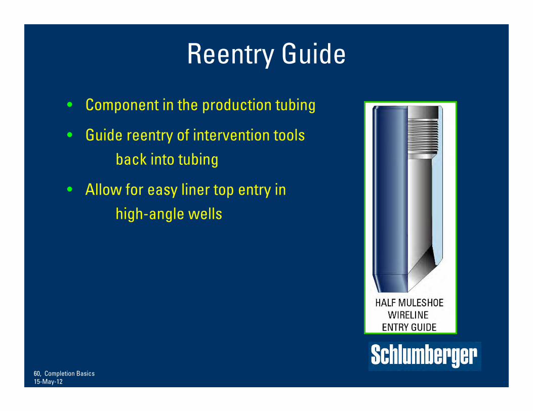
Reentry Guide
• Component in the production tubing
• Guide reentry of intervention tools back into tubing
• Allow for easy liner top entry in high-angle wells

61 Initials5/15/2012

62, Completion Basics15-May-12
Landing Profile Nipples and Locks
• Allow landing and locking of multiple
accessories in the tubing string for:
– Flow control
– Plugging devices
– Many different profiles
– Basic types: No-go and selective

63 Initials5/15/2012

Completion Accessories-Chemical Injection
64 CAP
Schlumberger PrivateDCIN - Features
• New generation of chemical injection mandrels• One piece body (no welds)• Limited leak paths• Internal check system• Proven supplier of check valves• Checks can be tested to full working pressure installed in to the
mandrel• Optional profile

65 Initials5/15/2012

66, Completion Basics15-May-12
Control-Line Clamps and Protectors
•Purpose
– Protect control line
– Support control line
•Features
– Location on tubing couplings
– Lightly grip control line
– Multiple line capability
– Upset for Large O.D. assemblies.
– Various types and sizes of lines.

Flow Control: FIV Formation Isolation Valve
● Bi-directional ball valve to provide a Safety Barrier during the well completion program
● Rig time savings via remote actuation● Improve and enhance reliability and
operability
Next Generation FIV
n-Trigger
New Mechanical Section
New Ball Section
Contingency Opening Tool
API Debris Testing
Actuation Module
Mechanical / Ball Module
n-Trigger
S-Trigger
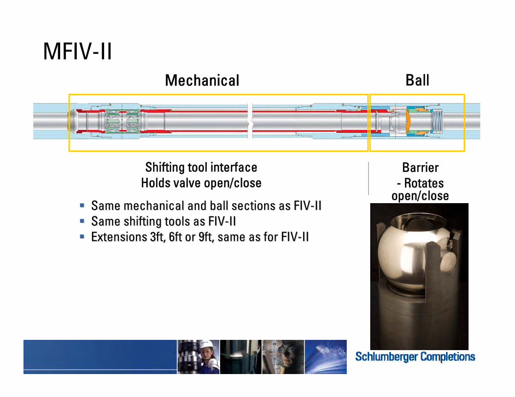
MFIV-IIMechanical Ball
Shifting tool interfaceHolds valve open/close
Barrier- Rotates
open/close Same mechanical and ball sections as FIVSame mechanical and ball sections as FIV--IIII Same shifting tools as FIVSame shifting tools as FIV--IIII Extensions 3ft, 6ft or 9ft, same as for FIVExtensions 3ft, 6ft or 9ft, same as for FIV--IIII
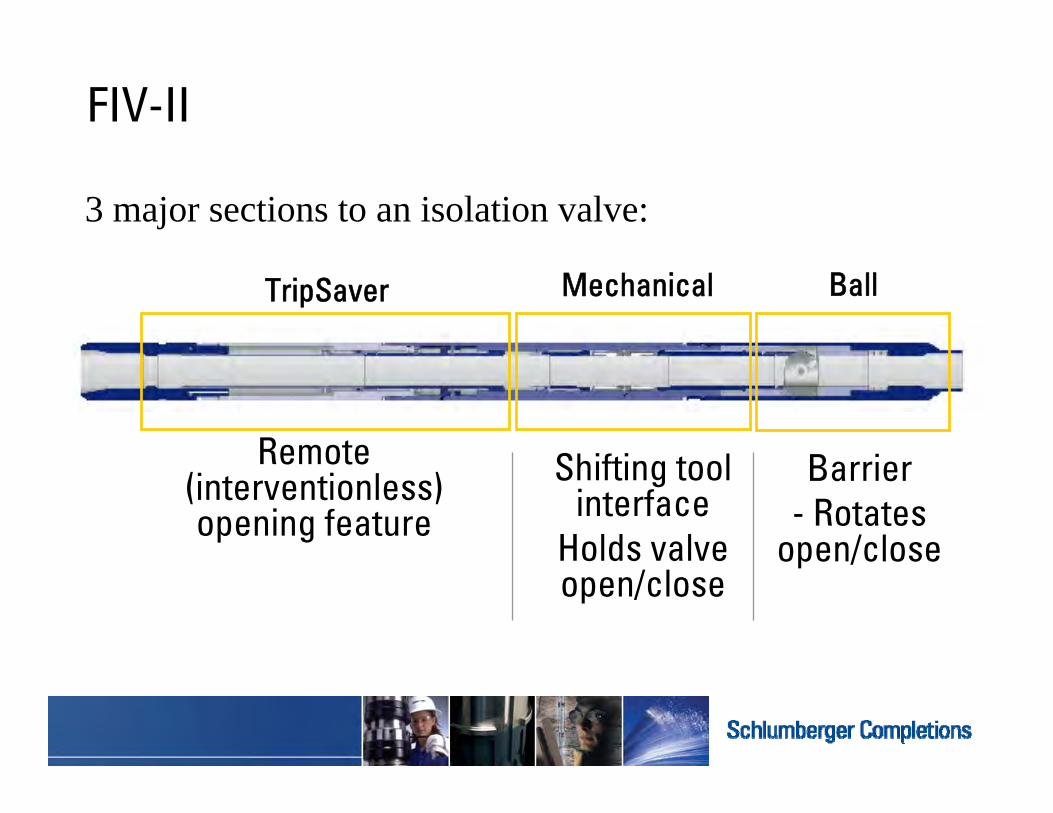
FIV-II
Remote (interventionless) opening feature
3 major sections to an isolation valve:
Mechanical BallTripSaver
Shifting tool interface
Holds valve open/close
Barrier- Rotates
open/close

Flow Control –Surface-Controlled Subsurface Safety Valves
Primary purpose
– Emergency well-control device
– Prevent: (Piper Alpha)
personnel, environmental,
equipment, and reserve losses
Secondary purpose
– Downhole flow control
allow for wellhead maintenance
serve as a secondary barrier
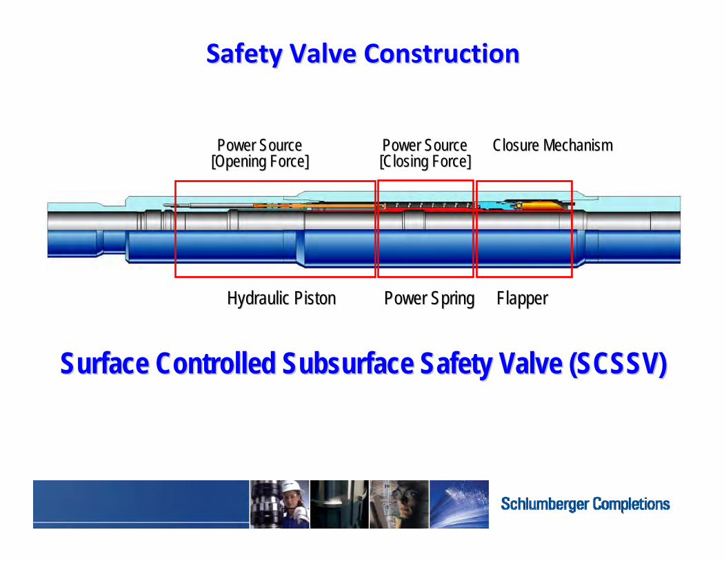
Safety Valve ConstructionSafety Valve Construction
Hydraulic PistonHydraulic Piston Power SpringPower Spring FlapperFlapper
Power SourcePower Source[Opening Force][Opening Force]
Closure MechanismClosure MechanismPower SourcePower Source[Closing Force][Closing Force]
Surface Controlled Subsurface Safety Valve (SCSSV)Surface Controlled Subsurface Safety Valve (SCSSV)

Standard SpringStandard Spring‐‐Type DesignType Design
FlowtubeFlowtubeFlapper ClosureFlapper Closure
Power SpringPower Spring
Hydraulic PistonHydraulic PistonPiston BorePiston Bore
Production Production Tubing PressureTubing Pressure
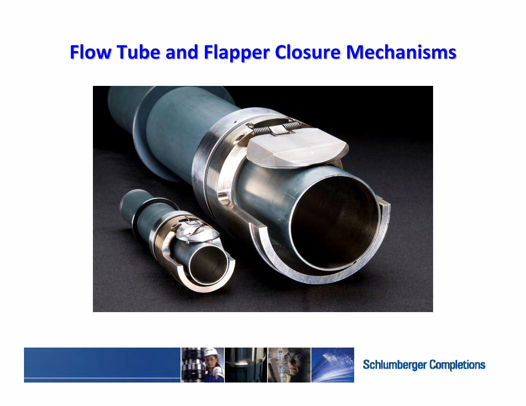
Flow Tube and Flapper Closure MechanismsFlow Tube and Flapper Closure Mechanisms

74, Completion Basics15-May-12
Surface-Controlled Subsurface Safety Valves
• SCSSV Applications:
– Government/country regulations
– Offshore and onshore wells
– Environmentally sensitive wells
– H2S /C02 containing wells

75 Initials5/15/2012
Intelligent Completions
Reservoir Monitoring & Control….Real time production optimization
Monitor and Manage

76 Initials5/15/2012
Reservoir Energy—Pressure
Water drive Gas drive Solution-gas drive

77 Initials5/15/2012
Artificial Lift Technologies
Electrical submersible pumpsGas lift valves
78, Completion Basics15-May-12
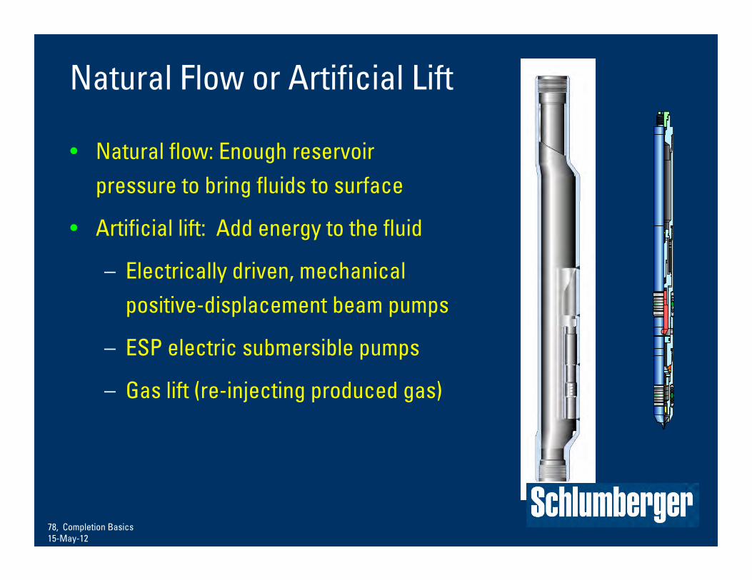
Natural Flow or Artificial Lift
• Natural flow: Enough reservoir pressure to bring fluids to surface
• Artificial lift: Add energy to the fluid
– Electrically driven, mechanical positive-displacement beam pumps
– ESP electric submersible pumps
– Gas lift (re-injecting produced gas)

Schlumberger Public
79, Completion Basics15-May-12
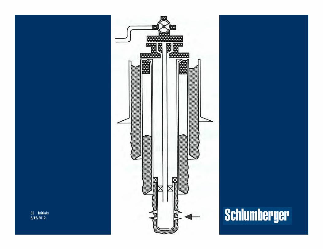
Side-Pocket Mandrels• Annulus-tubing communication
device in an artificial-lift completion
• A valve is located to allow gas to enter the tubing to lift the oil
• More than one are installed in a well

INJECTION GAS
PRODUCED FLUID
PRESSURE (PSI)
DEP
TH (F
T TV
D)
1000
2000
3000
4000
5000
6000
7000
01000 20000
OPERATING GAS LIFTVALVE
CASING PRESSURE WHENWELL IS BEING GAS LIFTED
FBHP
SIB
HP
FLOW
ING TUBING
PRESSUREG
RADIENT
CONSTANT FLOW GAS LIFT WELL
Gas lift valves

High Efficiency Pump
ImpellerDiffuser
Downhole ESP Electrical Submersible Pump
Motor
Intake
82 Initials5/15/2012

83, Completion Basics15-May-12
Completion Components
• Subsurface safety valves• Packers• Sliding sleeves • Expansion joints• Chemical-injection valves• Flow-control valves• Permanent monitoring gauges• Side-pocket mandrels or ESP• Landing profile nipples• Wireline reentry guide• Formation Isolation Valve
5
2
3
4
6
8
13
12
11
10
9
1
7
G04-0032a
70m 10-3/4" 13Cr Csg. to
Shoe
Crit
ical D
imen
sion
Targ
et C
ut Z
one
42
46
45
44
43
45
41
40a
39
38
37
36
35
40b
5
2
3
4
6
8
31
34
33
32
30
29
27
26
25
24
23
16
15
14
13
12
11
10
9
20
18
21
19
1
7
28
22
47
47
17

84 Initials5/15/2012
Stimulation, Pumping Services
Stimulate
Acidizing
Fracturing

85 Initials5/15/2012
Assisting Production From Pressure-Depleted Reservoirs
Water floodingFire Flood –In situ combustion
Workover Interventions
86 Initials5/15/2012
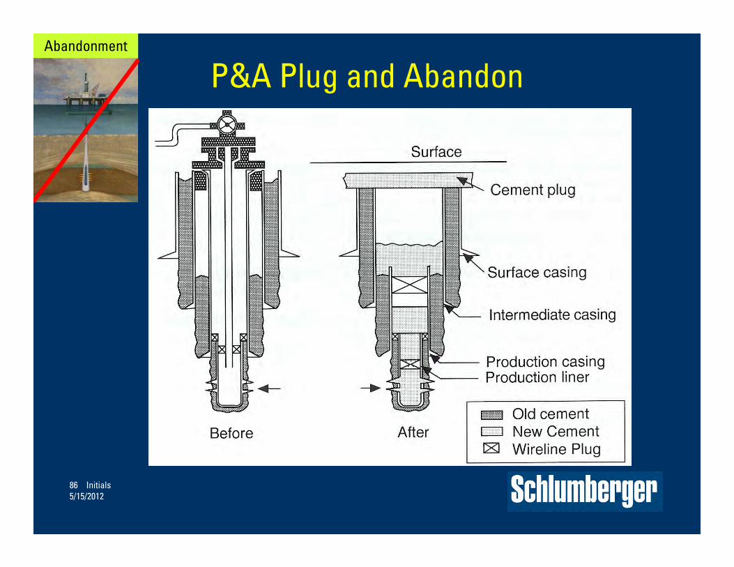
P&A Plug and AbandonAbandonment

87 Initials5/15/2012
Four Life Stages of Reservoir Development
Stage 2Delineation
Determine the reservoir extent
Determine reservoir properties
Determine reservoir model
Further reduce risk
Stage 1Exploration
Starting to reduce the risk
Choose the right point
Locate potential reservoir
Stage 3Development
Achieving full production
Refine reservoir model
Reservoir monitoring
Continue reducing the risk
Stage 4Late Life
Water production
Depleted pressure
Intervention
Stimulation
Flow assistance
88 Initials5/15/2012

Focus on Technology and the Reservoir Life Cycle
Exploration Appraisal Development Production
Reservoir Optimization
Traditional Development
Cash
Flo
w
+
0_ Time
Related Documents