2006-2016 Microchip Technology Inc. DS60001310B-page 1 EQCO400T8 Features • Multi-Rate Adaptive Equalization for UTP Cables up to 500 Mbps • Supports General 8B/10B Coded Signaling over UTP • Supports FireWire IEEE 1394b at S400, S200 and S100 Data Rates • Seamless Connection with any IEEE1394b Compliant PHY • Internal Termination Resistors for Low External Discrete Count • Fully Compatible with Power over Ethernet (1) • Carrier Detect and Mute Functionality with Direct Light Emitting Diode Driving Capability • Single 3.3V Supply • Low-Power Operation - 42 mA (140 mW) Active - 4.25 mA (14 mW) Mute • 16-pin, 0.65 mm Pin Pitch, 4 mm QFN Package • Pb-free and RoHS Compliant General Description The EQCO400T8 is a multi-rate adaptive cable equal- izer designed to restore signals received over Cat 5 or Cat 6 Unshielded Twisted Pair (UTP) cable. For correct operation, the signals must be NRZ (Non-Return-to- Zero) encoded, DC-balanced with a maximum run length of 10 bits and have a speed (edge rate) of between 100 Mbps and 500 Mbps. Typical Equalization Performance Device Bit Rate (8B/10B Coding) 1394 Data Rate Range (2) using Cat 5e Cat 6 EQCO400T8 125 Mbps S100 0m-85m 0m-85m 250 Mbps S200 0m-75m 0m-85m 500 Mbps S400 0m-50m 0m-75m Note 1: IEEE 802.3-2008, clause 33 - "Power over Ethernet" (formerly known as IEEE 802.3af) 2: Measured on UTP pairs 1, 2, 3 and 6 as per IEEE 1394-2008 using recommended Coilcraft magnetics as per Table 2-1. EQCO400T8 UTP Cable Equalizer

Welcome message from author
This document is posted to help you gain knowledge. Please leave a comment to let me know what you think about it! Share it to your friends and learn new things together.
Transcript

EQCO400T8
EQCO400T8 UTP Cable Equalizer
Features
• Multi-Rate Adaptive Equalization for UTP Cables up to 500 Mbps
• Supports General 8B/10B Coded Signaling over UTP
• Supports FireWire IEEE 1394b at S400, S200 and S100 Data Rates
• Seamless Connection with any IEEE1394b Compliant PHY
• Internal Termination Resistors for Low External Discrete Count
• Fully Compatible with Power over Ethernet(1)
• Carrier Detect and Mute Functionality with Direct Light Emitting Diode Driving Capability
• Single 3.3V Supply
• Low-Power Operation
- 42 mA (140 mW) Active
- 4.25 mA (14 mW) Mute
• 16-pin, 0.65 mm Pin Pitch, 4 mm QFN Package
• Pb-free and RoHS Compliant
General Description
The EQCO400T8 is a multi-rate adaptive cable equal-izer designed to restore signals received over Cat 5 orCat 6 Unshielded Twisted Pair (UTP) cable. For correctoperation, the signals must be NRZ (Non-Return-to-Zero) encoded, DC-balanced with a maximum runlength of 10 bits and have a speed (edge rate) ofbetween 100 Mbps and 500 Mbps.
Typical Equalization Performance
DeviceBit Rate
(8B/10B Coding)1394 Data Rate
Range(2) using
Cat 5e Cat 6
EQCO400T8 125 Mbps S100 0m-85m 0m-85m
250 Mbps S200 0m-75m 0m-85m
500 Mbps S400 0m-50m 0m-75m
Note 1: IEEE 802.3-2008, clause 33 - "Power over Ethernet" (formerly known as IEEE 802.3af)
2: Measured on UTP pairs 1, 2, 3 and 6 as per IEEE 1394-2008 using recommended Coilcraft magnetics as per Table 2-1.
2006-2016 Microchip Technology Inc. DS60001310B-page 1

EQCO400T8
Table of Contents
1.0 Device Overview .......................................................................................................................................................................... 32.0 Application Information................................................................................................................................................................. 93.0 Electrical Characteristics ............................................................................................................................................................ 114.0 Packaging................................................................................................................................................................................... 13
TO OUR VALUED CUSTOMERS
It is our intention to provide our valued customers with the best documentation possible to ensure successful use of your Microchipproducts. To this end, we will continue to improve our publications to better suit your needs. Our publications will be refined andenhanced as new volumes and updates are introduced.
If you have any questions or comments regarding this publication, please contact the Marketing Communications Department viaE-mail at [email protected] or fax the Reader Response Form in the back of this data sheet to (480) 792-4150. Wewelcome your feedback.
Most Current Data Sheet
To obtain the most up-to-date version of this data sheet, please register at our Worldwide Web site at:
http://www.microchip.com
You can determine the version of a data sheet by examining its literature number found on the bottom outside corner of any page.The last character of the literature number is the version number, (e.g., DS30000A is version A of document DS30000).
Errata
An errata sheet, describing minor operational differences from the data sheet and recommended workarounds, may exist for currentdevices. As device/documentation issues become known to us, we will publish an errata sheet. The errata will specify the revisionof silicon and revision of document to which it applies.
To determine if an errata sheet exists for a particular device, please check with one of the following:
• Microchip’s Worldwide Web site; http://www.microchip.com• Your local Microchip sales office (see last page)When contacting a sales office, please specify which device, revision of silicon and data sheet (include literature number) you are using.
Customer Notification System
Register on our web site at www.microchip.com to receive the most current information on all of our products.
DS60001310B-page 2 2006-2016 Microchip Technology Inc.

EQCO400T8
1.0 DEVICE OVERVIEW
The EQCO400T8 is ideally suited for long-haul IEEE1394b-2002 connections over Category 5 or Category6 Ethernet cable at the S400 data rate. It can also beused at S200 and S100 data rates over even longercables, as illustrated in the typical long-haul connectionin Figure 1-1. The EQCO400T8 connects seamlesslyto any IEEE 1394b-2002 compliant physical layercontroller (PHY).
The achievable connection reach with theEQCO400T8 depends on the input jitter tolerance ofthe IEEE 1394 PHY and the quality of the connectorsand cables used. Figure 1-1 shows the typicalperformance with CAT5e and CAT6 cables undernominal conditions.
FIGURE 1-1: LONG-HAUL IEEE 1394B-2002, IEEE 1394-2008 CONNECTION
Up to 100 meters
CAT5/CAT6 UTP
EQCO400T
EQCO400TIEEE 1394b
CompliantPHY
IEEE 1394b
CompliantPHY
2006-2016 Microchip Technology Inc. DS60001310B-page 3

EQCO400T8
FIGURE 1-2: EQCO400T8 PIN DIAGRAM (VIEWED FROM TOP)
TABLE 1-1: EQCO400T8 PIN DESCRIPTIONS
Pin Number Pin Name Signal Type Description
2, 11 VCC Power Connect to +3.3V power supply.
5, 13 GND Power Connect to power supply ground.
1, 3 SDIp/SDIn LVDS Input Differential serial data input pair.
12, 10 SDOp/SDOn LVDS Output Differential serial data output pair.
6 CLI Analog Output Cable length indicator:Analog voltage can be used to indicate the length of the cable being equalized; this gives an indication of the amount of equalization being applied. A higher output voltage results from more compensation being used to recover the signal. Leave unconnected when not used.
7 LED Output Carrier detect with light emitting diode driver.High means a valid input signal, and SDOp/SDOn are turned on.Low means no RX signal or the signal is too low, and SDOp/SDOn are muted.This pin can source up to 3 mA to directly drive an LED.Leave unconnected when not in use.
4, 8, 9, 14, 15, 16 NC Leave unconnected.
GND TAB
16 15 14 13
5 6 7 8
1
2
3
4
12
11
10
9
GND
GND
VCC
SDIn
SDIp
VCC
SDOn
SDOp
CLI LED
EQCO400T.8
NCNCNC
NC NC
NC
DS60001310B-page 4 2006-2016 Microchip Technology Inc.

EQCO400T8
FIGURE 1-3: EQCO400T8 BLOCK DIAGRAM SHOWING ELECTRICAL CONNECTIONS
1.1 SDIp/SDIn
SDIp/SDIn together form a differential input pair that isconnected to the receive signal pair of the cable. It isthe differential voltage between these pins that theEQCO400T8 analyzes and adaptively equalizes forsignal level and frequency response. The equalizerautomatically detects and adapts to signals withdifferent edge rates, e.g. S100, S200 and S400.
Both SDI+ and SDI- inputs are terminated by 50Ω toVCC on-chip. It is advised to isolate the inputs fromthe UTP via a transformer, as shown in Figure 2-1.
1.2 SDOp/SDOn
SDOp/SDOn together form a differential pair outputtingthe reconstructed far-end transmit signal. The signalscan be connected via capacitive coupling directly to theRX signal pair of a standard IEEE1394b PHY.
The EQCO400T8 uses Current Mode Logic (CML)drivers with source matching for the 110Ωtransmission line.
1.3 CLI
The EQCO400T, being a fully analog equalizer, has acontinuous transfer function with respect to the equal-ization applied. CLI (Cable Length Indicator) is an ana-log output. The voltage on the pin is proportional to theamount of equalization being applied.
CLI can be used qualitatively to indicate the length ofthe cable being equalized; the higher the voltage, thelonger the cable. However the CLI pin voltage dependson a number of factors, including connector quality,device temperature and to a certain degree on chip-to-chip variations, and as such cannot be used foraccurate cable length measurement.
Figure 1-4 illustrates the voltage at CLI for a typicalCAT6 cable.
EQCO400T
EqualizerCore
Carrier Detect/Mute
Output Driver
LED
SDOp
SDOn
SDIp
SDIn
CLI
2006-2016 Microchip Technology Inc. DS60001310B-page 5

EQCO400T8
FIGURE 1-4: CLI VOLTAGE AS A FUNCTION OF CABLE LENGTH (SYSTIMAX CAT6 CABLE)
1.4 LED
LED is an output that detects and indicates sufficientdifferential signal power at SDIp/SDIn for a link to beestablished.
If the received signal at the serial inputs is either notpresent or too small for proper reconstruction of theoutput (i.e. a signal with amplitude < 40 mV) the voltageon LED is driven low; if sufficient signal power isdetected, the voltage at LED will be driven high. Whenhigh, the pin can source up to 3 mA, enabling it to beused to directly drive an LED. The LED will thus be onwhen a signal is detected, and off otherwise. It is advisedto use a high-efficiency LED. The output from this pin iscurrent limited, and no series resistor is required.
1.2
1.4
1.6
1.8
2
2.2
2.4
2.6
10 20 30 40 50 60 70 80 90 100
Volta
ge (V
)
Cable Length (m)
DS60001310B-page 6 2006-2016 Microchip Technology Inc.

EQCO400T8
1.5 Equalizer Operation
FIGURE 1-5: PRINCIPLE OF EQUALIZER OPERATION
The EQCO400T8 is an equalizer with uniquecharacteristics:
• Auto-adaptive
The equalizer controls a multiple-pole analog filterwhich compensates for attenuation of the cable, asillustrated in Figure 1-5. The filter frequency responseneeded to restore the signal is automatically determinedby the device using a time-continuous feedback loopthat measures the frequency components in the signal.Upon the detection of a valid signal, the control loopconverges within a few microseconds.
• Variable gain
The EQCO400T8 has variable gain to workindependently of the transmit amplitude of the line driver.
The equalizer can be used with any IEEE1394b complianttransmitter. The standard(1) requires a differential transmitamplitude in the range of 475 mV to 800 mV.
• Multi-speed
The EQCO400T8 works at data rates from 100 Mbpsto 500 Mbps. In particular, it supports the S400, S200and S100 data rates specified in the IEEE Standard1394b-2002.
• Carrier detect/auto-mute to save power
The EQCO400T8 will automatically mute its outputdriver when no incoming signal is present. TheEQCO400T8 estimates the remote transmit amplitudeby measuring the low-frequency components of thesignal. When the low-frequency amplitude isapproximately 190 mV or higher, the output stage isturned on. Auto-mute reduces the power consumptionfrom 140 mW to less than 14 mW.
Example equalizer performance measurements can befound in Appendix B: Typical Operating Character-istics.
Note 1: IEEE 1394-2008, Standard for High-Performance Serial Bus
2006-2016 Microchip Technology Inc. DS60001310B-page 7

EQCO400T8
NOTES:
DS60001310B-page 8 2006-2016 Microchip Technology Inc.

EQCO400T8
2.0 APPLICATION INFORMATION
Figure 2-1 illustrates a typical schematic implementation.In this diagram, data is transmitted on pins 1 and 2, andreceived on pins 3 and 6 of the RJ45.
FIGURE 2-1: EQCO400T-8 TYPICAL APPLICATION CIRCUIT
To improve isolation from noise on the board powerplane, it is recommended to power the equalizerthrough a ferrite bead. A 0.1 μF decoupling capacitorshould be placed as close as possible to each VCC pin.Ground vias should be placed as close as possible tothe device GND pins to minimize inductance. Toreduce electromagnetic emissions, it may be advisedto place a 6.8 pF capacitor in between TPB and TPB*(transmit LVDS) of the PHY to reduce the rise/fall timeof the transmitted signals. If fitted, the capacitor shouldbe placed as close as possible to the pins of the PHY.
12345678
0.1uF
0.1uF
0.1uF
3V3
VCC VCCSDOp
SDOn
SDIp
SDIn
GN
D
GN
D
CLI
LE
D
Light Emitting Diode
GND
GND
GND
GND
PHY Termination
NetworkCheck PHY datasheet
PHY Termination
NetworkCheck PHY datasheet
1394b PHY(part)
TPA
TPA*
TPB
TPB*6p8
0.1uF0.1uF
RJ45
Remove Power planes below these components
Keep Close to PHY!
Keep Close to PHY!
GND
0.1uF
0.1uF
0.1uF
CoilcraftWBC1-TLB
CoilcraftWBC1-TLB
Coilcraft0603USB-222ML
Coilcraft0603USB-222ML
Coilcraft0603USB-222ML
Coilcraft0603USB-222ML
2006-2016 Microchip Technology Inc. DS60001310B-page 9

EQCO400T8
DS
2.1 Guidelines for PCB Layout
Because signals are strongly attenuated by a longcable, special attention must be paid on the PCB layoutbetween the RJ45 connector and the EQCO400T. TheEQCO400T8 should be as close as is practical to theRJ45 connector. Traces between the RJ45, thetransformer and the EQCO400T8 should be eithersingle-ended 50Ω traces or, preferably, differentialtraces with a differential impedance of 100Ω. To avoidnoise pickup, these traces should be placed as far awayas possible from other traces carrying digital signals orfast switching signals. All differential traces should bematched in length to minimize time of arrival skew.
For best EMC performance, identical common-modechokes should be used on the unused pairs to thoseused on the signal pairs as shown in Figure 2-1. Thisensures the impedance seen by all conductors in theUTP cable is the same.
A reference design is available on request.
2.2 Recommended Magnetics
The following magnetics are recommended for usewith EQCO400T:
TABLE 2-1: RECOMMENDED MAGNETICS
Note: Operation with magnetics other than the recommended components cannot be guaranteed.
2.3 Connector Pins and Cable Connection
The EQCO400T8 does not support auto-crossover. Ifrequired, this must be implemented externally to thedevice.
To be the same as 100BaseT Ethernet, IEEE Standard1394-2008 recommends that data is transmitted onRJ45 pins 1 and 2, and received on pins 3 and 6. If bothsides of the long-haul UTP connection are configured inthis way, a crossover cable or patch cord must be used.
If one side of the UTP connection transmits data onRJ45 pins 1 and 2 and receives data on pins 3 and 6,and the other side transmits data on RJ45 pins 3 and 6and receives data on pins 1 and 2, a straight-throughcable must be used.
If maximum reach is the highest priority and if a closedsystem is created, it is recommended to use pins 1 and2 for transmit (receive) and pins 7 and 8 for receive(transmit). This reduces near-end crosstalk (NEXT)significantly, which will give a bonus on the maximumcable span; especially for CAT5e.
2.4 Supplying Power over the UTP Cable
The EQCO400T8 is fully compatible with the PowerOver Ethernet standard, allowing standard POE chipsets to be used at the ends of the cable to transmitpower to a remote device. The unused pairs (RJ45 pins4,5 and 7,8) are most easily used for the transmissionof power. The signal pairs can also be used as speci-fied in the standard, but in this case, careful choice ofmagnetic components is required to conform to boththe DC requirements of POE and the AC requirementsof IEEE-1394.
A POE reference design is available on request.
Component Part Number
Transformers (1:1 with center tap) Two per channel
Coilcraft WBC1-1TLB
Common-mode chokes Four per channel
Coilcraft 1206USB-113MLB
60001310B-page 10 2006-2016 Microchip Technology Inc.

EQCO400T8
3.0 ELECTRICAL CHARACTERISTICS
3.1 Absolute Maximum Ratings
Stresses beyond those listed under this section maycause permanent damage to the device. These are stressratings only and are not tested. Functional operation ofthe device at these or any other conditions beyond thoseindicated in the operational sections are not implied.Exposure to absolute maximum rating conditions forextended periods may affect device reliability.
TABLE 3-2: MAXIMUM CURRENT CONSUMPTION AT 3.3V
TABLE 3-1: ABSOLUTE MAXIMUM RATINGS
Parameter Min. Typ. Max. Units Conditions
Storage Temperature -65 — +150 °C
Ambient Temperature -55 — +125 °C Power Applied
Operating Temperature -40 — +85 °C Normal Operation (VCC = 3.3V ±5%)
Supply Voltage to Ground -0.5 — +4.0 V
DC Input Voltage -0.5 — +4.0 V
DC Voltage to Outputs -0.5 — +4.0 V
Current into Outputs — — 90 mA Outputs Low
Description Max Unit
No input signal, LED is low, output driver is disabled 4.25 mA
Valid input, LED is high, output driver is enabled 42.5 mA
TABLE 3-3: ELECTRICAL CHARACTERISTICS (OVER THE OPERATING VCC AND -40°C TO +85°C RANGE)
Parameter Min. Typ. Max. Unit Description
Power Supply
VCC3.135 3.3 3.465 V
100 500 600 Mbps Signaling rate (NRZ, 8b/10b encoded)
SDIp/SDIn Input
Differential Input Voltage Swing
475 — 800 mV VSDIp-VSDIn measured at cable input
LVDSImin
— 40 — mV Minimum differential input for fully reconstructed output
— 3.3 — V Common-mode input voltage
Rinput — 50 — Ω Single-ended; to VCC
2006-2016 Microchip Technology Inc. DS60001310B-page 11

EQCO400T8
SDOp Connection to Coax
LVDSo
— 440 — mV Differential output voltage swingVSDOp-VSDOn(50Ω load to VCC on each output)LED is high.
— VCC–LVDSo/2
— V Common-mode output voltage
SDOoff — VCC — V Output voltage with disabled driver.Single-ended; LED is low.
Routput — 55 — Ω Single-ended; to VCC
Rise/Fall Time 100 190 260 ps 20% to 80%
LED
Voh1.5 VCC — V Differential input voltage at cable input > 250 mV
Vol— GND 0.8 V Differential input voltage at cable input < 40 mV
CLI
Voh— 1.2 — V Output voltage at maximum cable length
Vol— 2.6 — V Output voltage at maximum cable length
TABLE 3-3: ELECTRICAL CHARACTERISTICS (OVER THE OPERATING VCC AND -40°C TO +85°C RANGE)
DS60001310B-page 12 2006-2016 Microchip Technology Inc.

EQCO400T8
4.0 PACKAGING INFORMATION
4.1 Package Marking Information
16-Lead Plastic Quad Flat, No Lead Package – 4x4x0.9 mm Body [QFN]
16-Lead QFN (4x4x0.9 mm) Example
PIN 1 PIN 1
EQCO
30R5.D
YYWWNNNYYWWNNN
Legend: XX...X Customer-specific informationY Year code (last digit of calendar year)YY Year code (last 2 digits of calendar year)WW Week code (week of January 1 is week ‘01’)NNN Alphanumeric traceability code Pb-free JEDEC® designator for Matte Tin (Sn)* This package is Pb-free. The Pb-free JEDEC designator ( )
can be found on the outer packaging for this package.
Note: In the event the full Microchip part number cannot be marked on one line, it willbe carried over to the next line, thus limiting the number of available charactersfor customer-specific information.
3e
3e
2006-2016 Microchip Technology Inc. DS60001310B-page 13

EQCO400T8
BA
0.20 C
0.20 C
(DATUM B)(DATUM A)
CSEATING
PLANE
1
2
N
2XTOP VIEW
SIDE VIEW
BOTTOM VIEW
For the most current package drawings, please see the Microchip Packaging Specification located athttp://www.microchip.com/packaging
Note:
NOTE 1
1
2
N
0.10 C A B
0.10 C A B
0.10 C
0.08 C
Microchip Technology Drawing C04-259B Sheet 1 of 2
16-Lead Plastic Quad Flat, No Lead Package (8E) - 4x4x0.9 mm Body [QFN]
D
E
2X
16X(A3)
A
D2
E2
16X L
16X b
e
e2
(16X K)
A1
0.10 C A B0.05 C
DS60001310B-page 14 2006-2016 Microchip Technology Inc.

EQCO400T8
Microchip Technology Drawing C04-259B Sheet 2 of 2
For the most current package drawings, please see the Microchip Packaging Specification located athttp://www.microchip.com/packaging
Note:
Number of Pins
Overall Height
Terminal Width
Overall Width
Overall Length
Terminal Length
Exposed Pad Width
Exposed Pad Length
Terminal Thickness
Pitch
Standoff
UnitsDimension Limits
A1A
b
DE2
D2
A3
e
L
E
N0.65 BSC
0.20 REF
1.95
1.95
0.450.25
0.800.00
0.30
4.00 BSC
0.55
2.05
2.05
0.870.02
4.00 BSC
MILLIMETERSMIN NOM
16
2.15
2.15
0.650.35
0.950.05
MAX
K 0.425 REF
REF: Reference Dimension, usually without tolerance, for information purposes only.BSC: Basic Dimension. Theoretically exact value shown without tolerances.
1.2.3.
Notes:
Pin 1 visual index feature may vary, but must be located within the hatched area.Package is saw singulatedDimensioning and tolerancing per ASME Y14.5M
Terminal-to-Exposed-Pad
16-Lead Plastic Quad Flat, No Lead Package (8E) - 4x4x0.9 mm Body [QFN]
2006-2016 Microchip Technology Inc. DS60001310B-page 15

EQCO400T8
RECOMMENDED LAND PATTERN
For the most current package drawings, please see the Microchip Packaging Specification located athttp://www.microchip.com/packaging
Note:
Dimension LimitsUnits
C2
Optional Center Pad Width
Contact Pad Spacing
Optional Center Pad Length
Contact Pitch
Y2X2
2.152.15
MILLIMETERS
0.65 BSCMIN
EMAX
3.625
Contact Pad Length (X16)Contact Pad Width (X16)
Y1X1
0.7250.30
BSC: Basic Dimension. Theoretically exact value shown without tolerances.
Notes:1. Dimensioning and tolerancing per ASME Y14.5M
Microchip Technology Drawing C04-2259A
NOM
16-Lead Plastic Quad Flat, No Lead Package (8E) - 4x4x0.9 mm Body [QFN]
SILK SCREEN
1
2
16
C1Contact Pad Spacing 3.625
Contact Pad to Center Pad (X16) G1 0.20
C1
C2 Y2
X2
Y1
G1
X1
E
DS60001310B-page 16 2006-2016 Microchip Technology Inc.

EQCO400T8
APPENDIX A: REVISION HISTORY
Revision B (February 2016)
• Updated Section 4.1 “Package Marking Infor-mation”.
• Removed electrostatic discharge ratings from Table 3-1.
• Minor typographical changes.
Revision A (July 2015)
• This is the initial release of the document in the Microchip format. This replaces EqcoLogic document version 2.4.
TABLE A-1: REVISION HISTORY
Version Date Author Comments
2.4 2/27/14 M. KuijkRemoved data about previous version, added patent information.
2.3 5/3/09 S.E. Ellwood Added information on EQCO400T-8.
2.2 12/8/08 S.E. Ellwood Correction to Table 2-1.
2.1 11/2/08 S.E. EllwoodAdded Table 2-1 Recommended Magnetics, changed postal address.
2.0 7/22/08 S.E. Ellwood Released.
1.1 2/2/06 K. Van Den Brande New document.
2006-2016 Microchip Technology Inc. DS60001310B-page 17

EQCO400T8
APPENDIX B: TYPICAL OPERATING CHARACTERISTICS
Figures B-1 to B-14 have been made under the following conditions:
Receive signal on pair 3, 6; S400; 630 mV Transmit amplitude.
Crosstalk source on pair 1, 2; S400; 630 mV Transmit amplitude.
B.1 Auto-Adaptive
FIGURE B-1: 2M CAT6 CABLE BEFORE EQUALIZER
FIGURE B-2: 30M CAT6 CABLE BEFORE EQUALIZER
FIGURE B-3: 60M CAT6 CABLE BEFORE EQUALIZER
FIGURE B-4: 2M CAT6 CABLE AFTER EQUALIZER
FIGURE B-5: 30M CAT6 CABLE AFTER EQUALIZER
FIGURE B-6: 60M CAT6 CABLE AFTER EQUALIZER
DS60001310B-page 18 2006-2016 Microchip Technology Inc.

EQCO400T8
FIGURE B-7: 90M CAT6 CABLE BEFORE EQUALIZER
B.2 CAT5e
The crosstalk generated in a CAT5e system is muchhigher than in a CAT6 system. This reduces themaximum cable length over which a link can bemaintained.
FIGURE B-8: 70M CAT5E
B.3 Variable Gain
FIGURE B-9: 300 MV TRANSMIT AMPLITUDE (80M CAT6 CABLE)
FIGURE B-10: 90M CAT6 CABLE AFTER EQUALIZER
FIGURE B-11: 70M CAT5E - RX ONLY
FIGURE B-12: 800 MV TRANSMIT AMPLITUDE (80M CAT6 CABLE)
2006-2016 Microchip Technology Inc. DS60001310B-page 19
EQCO400T8
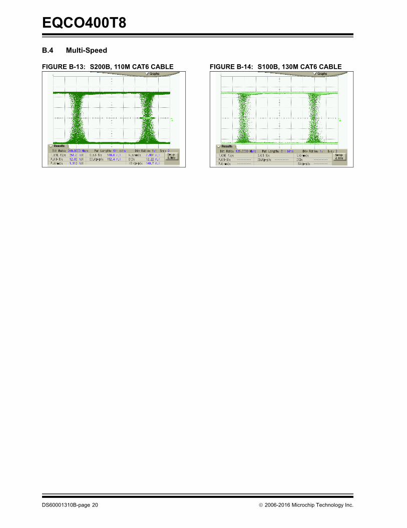
B.4 Multi-Speed
FIGURE B-13: S200Β, 110M CAT6 CABLE FIGURE B-14: S100Β, 130M CAT6 CABLE
DS60001310B-page 20 2006-2016 Microchip Technology Inc.

2006-2016 Microchip Technology Inc. DS60001310B-page 21
EQCO400T8
THE MICROCHIP WEB SITE
Microchip provides online support via our web site atwww.microchip.com. This web site is used as a meansto make files and information easily available tocustomers. Accessible by using your favorite Internetbrowser, the web site contains the following information:
• Product Support – Data sheets and errata, application notes and sample programs, design resources, user’s guides and hardware support documents, latest software releases and archived software
• General Technical Support – Frequently Asked Questions (FAQs), technical support requests, online discussion groups, Microchip consultant program member listing
• Business of Microchip – Product selector and ordering guides, latest Microchip press releases, listing of seminars and events, listings of Microchip sales offices, distributors and factory representatives
CUSTOMER CHANGE NOTIFICATION SERVICE
Microchip’s customer notification service helps keepcustomers current on Microchip products. Subscriberswill receive e-mail notification whenever there arechanges, updates, revisions or errata related to aspecified product family or development tool of interest.
To register, access the Microchip web site atwww.microchip.com. Under “Support”, click on“Customer Change Notification” and follow theregistration instructions.
CUSTOMER SUPPORT
Users of Microchip products can receive assistancethrough several channels:
• Distributor or Representative
• Local Sales Office
• Field Application Engineer (FAE)
• Technical Support
Customers should contact their distributor,representative or field application engineer (FAE) forsupport. Local sales offices are also available to helpcustomers. A listing of sales offices and locations isincluded in the back of this document.
Technical support is available through the web siteat: http://microchip.com/support

EQCO400T8
DS60001310B-page 22 2006-2016 Microchip Technology Inc.
PRODUCT IDENTIFICATION SYSTEM
To order parts, including industrial, or obtain information, for e.g., on pricing or delivery, refer to the factory or the listed sales office.
PART NO.
Device
Device EQCO400T8
Temperature Range I = -40C to +85C (Industrial temperature)
Examples:
a) EQCO400T8/I = Industrial temperature16-Lead QFN package
I
Temp. Range
Note the following details of the code protection feature on Microchip devices:
• Microchip products meet the specification contained in their particular Microchip Data Sheet.
• Microchip believes that its family of products is one of the most secure families of its kind on the market today, when used in the intended manner and under normal conditions.
• There are dishonest and possibly illegal methods used to breach the code protection feature. All of these methods, to our knowledge, require using the Microchip products in a manner outside the operating specifications contained in Microchip’s Data Sheets. Most likely, the person doing so is engaged in theft of intellectual property.
• Microchip is willing to work with the customer who is concerned about the integrity of their code.
• Neither Microchip nor any other semiconductor manufacturer can guarantee the security of their code. Code protection does not mean that we are guaranteeing the product as “unbreakable.”
Code protection is constantly evolving. We at Microchip are committed to continuously improving the code protection features of ourproducts. Attempts to break Microchip’s code protection feature may be a violation of the Digital Millennium Copyright Act. If such actsallow unauthorized access to your software or other copyrighted work, you may have a right to sue for relief under that Act.
Information contained in this publication regarding deviceapplications and the like is provided only for your convenienceand may be superseded by updates. It is your responsibility toensure that your application meets with your specifications.MICROCHIP MAKES NO REPRESENTATIONS ORWARRANTIES OF ANY KIND WHETHER EXPRESS ORIMPLIED, WRITTEN OR ORAL, STATUTORY OROTHERWISE, RELATED TO THE INFORMATION,INCLUDING BUT NOT LIMITED TO ITS CONDITION,QUALITY, PERFORMANCE, MERCHANTABILITY ORFITNESS FOR PURPOSE. Microchip disclaims all liabilityarising from this information and its use. Use of Microchipdevices in life support and/or safety applications is entirely atthe buyer’s risk, and the buyer agrees to defend, indemnify andhold harmless Microchip from any and all damages, claims,suits, or expenses resulting from such use. No licenses areconveyed, implicitly or otherwise, under any Microchipintellectual property rights unless otherwise stated.
2006-2016 Microchip Technology Inc.
Microchip received ISO/TS-16949:2009 certification for its worldwide headquarters, design and wafer fabrication facilities in Chandler and Tempe, Arizona; Gresham, Oregon and design centers in California and India. The Company’s quality system processes and procedures are for its PIC® MCUs and dsPIC® DSCs, KEELOQ® code hopping devices, Serial EEPROMs, microperipherals, nonvolatile memory and analog products. In addition, Microchip’s quality system for the design and manufacture of development systems is ISO 9001:2000 certified.
QUALITY MANAGEMENT SYSTEM CERTIFIED BY DNV
== ISO/TS 16949 ==
Trademarks
The Microchip name and logo, the Microchip logo, AnyRate, dsPIC, FlashFlex, flexPWR, Heldo, JukeBlox, KeeLoq, KeeLoq logo, Kleer, LANCheck, LINK MD, MediaLB, MOST, MOST logo, MPLAB, OptoLyzer, PIC, PICSTART, PIC32 logo, RightTouch, SpyNIC, SST, SST Logo, SuperFlash and UNI/O are registered trademarks of Microchip Technology Incorporated in the U.S.A. and other countries.
ClockWorks, The Embedded Control Solutions Company, ETHERSYNCH, Hyper Speed Control, HyperLight Load, IntelliMOS, mTouch, Precision Edge, and QUIET-WIRE are registered trademarks of Microchip Technology Incorporated in the U.S.A.
Analog-for-the-Digital Age, Any Capacitor, AnyIn, AnyOut, BodyCom, chipKIT, chipKIT logo, CodeGuard, dsPICDEM, dsPICDEM.net, Dynamic Average Matching, DAM, ECAN, EtherGREEN, In-Circuit Serial Programming, ICSP, Inter-Chip Connectivity, JitterBlocker, KleerNet, KleerNet logo, MiWi, motorBench, MPASM, MPF, MPLAB Certified logo, MPLIB, MPLINK, MultiTRAK, NetDetach, Omniscient Code Generation, PICDEM, PICDEM.net, PICkit, PICtail, PureSilicon, RightTouch logo, REAL ICE, Ripple Blocker, Serial Quad I/O, SQI, SuperSwitcher, SuperSwitcher II, Total Endurance, TSHARC, USBCheck, VariSense, ViewSpan, WiperLock, Wireless DNA, and ZENA are trademarks of Microchip Technology Incorporated in the U.S.A. and other countries.
SQTP is a service mark of Microchip Technology Incorporated in the U.S.A.
Silicon Storage Technology is a registered trademark of Microchip Technology Inc. in other countries.
GestIC is a registered trademarks of Microchip Technology Germany II GmbH & Co. KG, a subsidiary of Microchip Technology Inc., in other countries.
All other trademarks mentioned herein are property of their respective companies.
© 2006-2016, Microchip Technology Incorporated, Printed in the U.S.A., All Rights Reserved.
ISBN: 978-1-5224-0255-8
DS60001310B-page 23

DS60001310B-page 24 2006-2016 Microchip Technology Inc.
AMERICASCorporate Office2355 West Chandler Blvd.Chandler, AZ 85224-6199Tel: 480-792-7200 Fax: 480-792-7277Technical Support: http://www.microchip.com/supportWeb Address: www.microchip.com
AtlantaDuluth, GA Tel: 678-957-9614 Fax: 678-957-1455
Austin, TXTel: 512-257-3370
BostonWestborough, MA Tel: 774-760-0087 Fax: 774-760-0088
ChicagoItasca, IL Tel: 630-285-0071 Fax: 630-285-0075
ClevelandIndependence, OH Tel: 216-447-0464 Fax: 216-447-0643
DallasAddison, TX Tel: 972-818-7423 Fax: 972-818-2924
DetroitNovi, MI Tel: 248-848-4000
Houston, TX Tel: 281-894-5983
IndianapolisNoblesville, IN Tel: 317-773-8323Fax: 317-773-5453
Los AngelesMission Viejo, CA Tel: 949-462-9523 Fax: 949-462-9608
New York, NY Tel: 631-435-6000
San Jose, CA Tel: 408-735-9110
Canada - TorontoTel: 905-673-0699 Fax: 905-673-6509
ASIA/PACIFICAsia Pacific OfficeSuites 3707-14, 37th FloorTower 6, The GatewayHarbour City, Kowloon
Hong KongTel: 852-2943-5100Fax: 852-2401-3431
Australia - SydneyTel: 61-2-9868-6733Fax: 61-2-9868-6755
China - BeijingTel: 86-10-8569-7000 Fax: 86-10-8528-2104
China - ChengduTel: 86-28-8665-5511Fax: 86-28-8665-7889
China - ChongqingTel: 86-23-8980-9588Fax: 86-23-8980-9500
China - DongguanTel: 86-769-8702-9880
China - HangzhouTel: 86-571-8792-8115 Fax: 86-571-8792-8116
China - Hong Kong SARTel: 852-2943-5100 Fax: 852-2401-3431
China - NanjingTel: 86-25-8473-2460Fax: 86-25-8473-2470
China - QingdaoTel: 86-532-8502-7355Fax: 86-532-8502-7205
China - ShanghaiTel: 86-21-5407-5533 Fax: 86-21-5407-5066
China - ShenyangTel: 86-24-2334-2829Fax: 86-24-2334-2393
China - ShenzhenTel: 86-755-8864-2200 Fax: 86-755-8203-1760
China - WuhanTel: 86-27-5980-5300Fax: 86-27-5980-5118
China - XianTel: 86-29-8833-7252Fax: 86-29-8833-7256
ASIA/PACIFICChina - XiamenTel: 86-592-2388138 Fax: 86-592-2388130
China - ZhuhaiTel: 86-756-3210040 Fax: 86-756-3210049
India - BangaloreTel: 91-80-3090-4444 Fax: 91-80-3090-4123
India - New DelhiTel: 91-11-4160-8631Fax: 91-11-4160-8632
India - PuneTel: 91-20-3019-1500
Japan - OsakaTel: 81-6-6152-7160 Fax: 81-6-6152-9310
Japan - TokyoTel: 81-3-6880- 3770 Fax: 81-3-6880-3771
Korea - DaeguTel: 82-53-744-4301Fax: 82-53-744-4302
Korea - SeoulTel: 82-2-554-7200Fax: 82-2-558-5932 or 82-2-558-5934
Malaysia - Kuala LumpurTel: 60-3-6201-9857Fax: 60-3-6201-9859
Malaysia - PenangTel: 60-4-227-8870Fax: 60-4-227-4068
Philippines - ManilaTel: 63-2-634-9065Fax: 63-2-634-9069
SingaporeTel: 65-6334-8870Fax: 65-6334-8850
Taiwan - Hsin ChuTel: 886-3-5778-366Fax: 886-3-5770-955
Taiwan - KaohsiungTel: 886-7-213-7828
Taiwan - TaipeiTel: 886-2-2508-8600 Fax: 886-2-2508-0102
Thailand - BangkokTel: 66-2-694-1351Fax: 66-2-694-1350
EUROPEAustria - WelsTel: 43-7242-2244-39Fax: 43-7242-2244-393
Denmark - CopenhagenTel: 45-4450-2828 Fax: 45-4485-2829
France - ParisTel: 33-1-69-53-63-20 Fax: 33-1-69-30-90-79
Germany - DusseldorfTel: 49-2129-3766400
Germany - KarlsruheTel: 49-721-625370
Germany - MunichTel: 49-89-627-144-0 Fax: 49-89-627-144-44
Italy - Milan Tel: 39-0331-742611 Fax: 39-0331-466781
Italy - VeniceTel: 39-049-7625286
Netherlands - DrunenTel: 31-416-690399 Fax: 31-416-690340
Poland - WarsawTel: 48-22-3325737
Spain - MadridTel: 34-91-708-08-90Fax: 34-91-708-08-91
Sweden - StockholmTel: 46-8-5090-4654
UK - WokinghamTel: 44-118-921-5800Fax: 44-118-921-5820
Worldwide Sales and Service
07/14/15
Related Documents