Installation Guide

Welcome message from author
This document is posted to help you gain knowledge. Please leave a comment to let me know what you think about it! Share it to your friends and learn new things together.
Transcript
Installation Guide
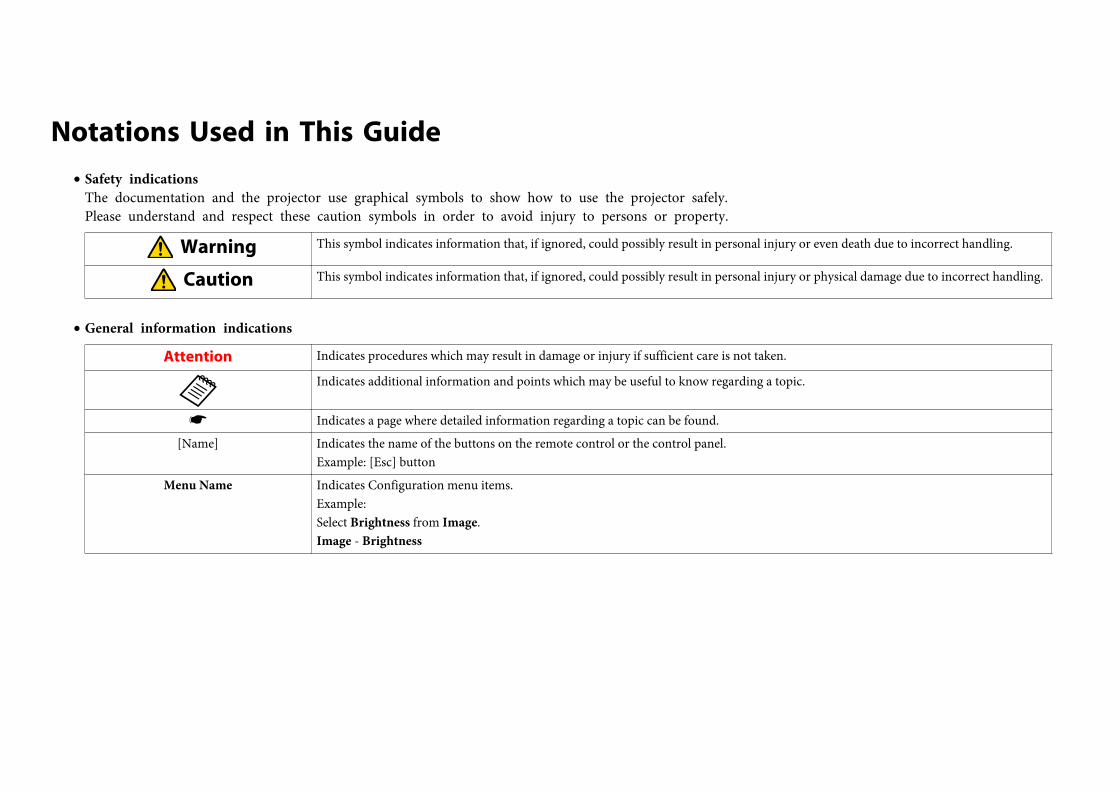
Notations Used in This Guide• Safety indications
The documentation and the projector use graphical symbols to show how to use the projector safely.Please understand and respect these caution symbols in order to avoid injury to persons or property.
Warning This symbol indicates information that, if ignored, could possibly result in personal injury or even death due to incorrect handling.
Caution This symbol indicates information that, if ignored, could possibly result in personal injury or physical damage due to incorrect handling.
• General information indications
Attention Indicates procedures which may result in damage or injury if sufficient care is not taken.
aIndicates additional information and points which may be useful to know regarding a topic.
s Indicates a page where detailed information regarding a topic can be found.
[Name] Indicates the name of the buttons on the remote control or the control panel.Example: [Esc] button
Menu Name Indicates Configuration menu items.Example:Select Brightness from Image.Image - Brightness
Notations Used in This Guide . . . . . . . . . . . . . . . . . . . . . . . . 2
Main Guide
Part Names and Functions . . . . . . . . . . . . . . . . . . . . . . . . . . . . . . . . . . . 6Front/Top . . . . . . . . . . . . . . . . . . . . . . . . . . . . . . . . . . . . . . . . . . . . . . . . . . . 6Rear . . . . . . . . . . . . . . . . . . . . . . . . . . . . . . . . . . . . . . . . . . . . . . . . . . . . . . . 7Interface . . . . . . . . . . . . . . . . . . . . . . . . . . . . . . . . . . . . . . . . . . . . . . . . . . . . 7Base . . . . . . . . . . . . . . . . . . . . . . . . . . . . . . . . . . . . . . . . . . . . . . . . . . . . . . . 8Control Panel . . . . . . . . . . . . . . . . . . . . . . . . . . . . . . . . . . . . . . . . . . . . . . . . . 9Remote Control . . . . . . . . . . . . . . . . . . . . . . . . . . . . . . . . . . . . . . . . . . . . . . . 10
Remote control operating range . . . . . . . . . . . . . . . . . . . . . . . . . . . . . . . . . 10
Removing and Attaching the Projector Lens Unit . . . . . . . . . . . . . 12Attaching . . . . . . . . . . . . . . . . . . . . . . . . . . . . . . . . . . . . . . . . . . . . . . . . . . . 12Removing . . . . . . . . . . . . . . . . . . . . . . . . . . . . . . . . . . . . . . . . . . . . . . . . . . . 14
Turning On and Off . . . . . . . . . . . . . . . . . . . . . . . . . . . . . . . . . . . . . . . . 15Turning On . . . . . . . . . . . . . . . . . . . . . . . . . . . . . . . . . . . . . . . . . . . . . . . . . . 15Turning Off . . . . . . . . . . . . . . . . . . . . . . . . . . . . . . . . . . . . . . . . . . . . . . . . . . 15
Reading the Indicators . . . . . . . . . . . . . . . . . . . . . . . . . . . . . . . . . . . . . 16
Installing the Projector . . . . . . . . . . . . . . . . . . . . . . . . . . . . . . . . . . . . . 20Installation Requirements . . . . . . . . . . . . . . . . . . . . . . . . . . . . . . . . . . . . . . . . 20
Changing the direction of the image (projection mode) . . . . . . . . . . . . . . . . . 21Adjusting the Position of the Projected Image (Lens Shift) . . . . . . . . . . . . . . . . . . 22Adjusting the Zoom . . . . . . . . . . . . . . . . . . . . . . . . . . . . . . . . . . . . . . . . . . . . 23Adjusting the Focus . . . . . . . . . . . . . . . . . . . . . . . . . . . . . . . . . . . . . . . . . . . . 23
When using the short throw zoom lens ELPLU01 . . . . . . . . . . . . . . . . . . . . . . 23Adjusting the Image Position (When Setup on a Desk) . . . . . . . . . . . . . . . . . . . . 24Adjusting the Horizontal Tilt (When Setup on a Desk) . . . . . . . . . . . . . . . . . . . . . 25Screen Settings . . . . . . . . . . . . . . . . . . . . . . . . . . . . . . . . . . . . . . . . . . . . . . . 25
Adjusting the position of the image on the projected screen . . . . . . . . . . . . . . 25Displaying a Test Pattern . . . . . . . . . . . . . . . . . . . . . . . . . . . . . . . . . . . . . . . . 26
Setting Up . . . . . . . . . . . . . . . . . . . . . . . . . . . . . . . . . . . . . . . . . . . . . . . . 28ID Settings . . . . . . . . . . . . . . . . . . . . . . . . . . . . . . . . . . . . . . . . . . . . . . . . . . 28
Set the projector ID . . . . . . . . . . . . . . . . . . . . . . . . . . . . . . . . . . . . . . . . . . 28Checking the Projector ID . . . . . . . . . . . . . . . . . . . . . . . . . . . . . . . . . . . . . . 28Setting the remote control ID . . . . . . . . . . . . . . . . . . . . . . . . . . . . . . . . . . . 28
Setting the Time . . . . . . . . . . . . . . . . . . . . . . . . . . . . . . . . . . . . . . . . . . . . . . 29Other Settings . . . . . . . . . . . . . . . . . . . . . . . . . . . . . . . . . . . . . . . . . . . . . . . . 31
Setting basic operations . . . . . . . . . . . . . . . . . . . . . . . . . . . . . . . . . . . . . . . 31Setting the display . . . . . . . . . . . . . . . . . . . . . . . . . . . . . . . . . . . . . . . . . . . 32
Saving a User's Logo . . . . . . . . . . . . . . . . . . . . . . . . . . . . . . . . . . . . . . . . . . . 33
Connecting Equipment . . . . . . . . . . . . . . . . . . . . . . . . . . . . . . . . . . . . . 34Connecting a Computer . . . . . . . . . . . . . . . . . . . . . . . . . . . . . . . . . . . . . . . . . 34Connecting Image Sources . . . . . . . . . . . . . . . . . . . . . . . . . . . . . . . . . . . . . . . 36Connecting External Equipment . . . . . . . . . . . . . . . . . . . . . . . . . . . . . . . . . . . 39Connecting a LAN Cable . . . . . . . . . . . . . . . . . . . . . . . . . . . . . . . . . . . . . . . . . 40Connecting an HDBaseT Transmitter . . . . . . . . . . . . . . . . . . . . . . . . . . . . . . . . 41Attaching the Cable Cover . . . . . . . . . . . . . . . . . . . . . . . . . . . . . . . . . . . . . . . 42
Attaching . . . . . . . . . . . . . . . . . . . . . . . . . . . . . . . . . . . . . . . . . . . . . . . . . 42
Projecting Images . . . . . . . . . . . . . . . . . . . . . . . . . . . . . . . . . . . . . . . . . 43Correcting Distortion in the Projected Image . . . . . . . . . . . . . . . . . . . . . . . . . . . 43
Control panel . . . . . . . . . . . . . . . . . . . . . . . . . . . . . . . . . . . . . . . . . . . . . . 43Remote control . . . . . . . . . . . . . . . . . . . . . . . . . . . . . . . . . . . . . . . . . . . . . 43H/V-Keystone . . . . . . . . . . . . . . . . . . . . . . . . . . . . . . . . . . . . . . . . . . . . . . 43Quick Corner . . . . . . . . . . . . . . . . . . . . . . . . . . . . . . . . . . . . . . . . . . . . . . . 44Curved Surface . . . . . . . . . . . . . . . . . . . . . . . . . . . . . . . . . . . . . . . . . . . . . 45Corner Wall . . . . . . . . . . . . . . . . . . . . . . . . . . . . . . . . . . . . . . . . . . . . . . . . 52Point Correction . . . . . . . . . . . . . . . . . . . . . . . . . . . . . . . . . . . . . . . . . . . . 59
Changing the Aspect Ratio of the Projected Image . . . . . . . . . . . . . . . . . . . . . . 60Changing methods . . . . . . . . . . . . . . . . . . . . . . . . . . . . . . . . . . . . . . . . . . 60
Multi-Projection . . . . . . . . . . . . . . . . . . . . . . . . . . . . . . . . . . . . . . . . . . . . . . 63Preparing the Projector . . . . . . . . . . . . . . . . . . . . . . . . . . . . . . . . . . . . . . . 63Work flow . . . . . . . . . . . . . . . . . . . . . . . . . . . . . . . . . . . . . . . . . . . . . . . . . 63Scale . . . . . . . . . . . . . . . . . . . . . . . . . . . . . . . . . . . . . . . . . . . . . . . . . . . . 68
Projecting 3D images . . . . . . . . . . . . . . . . . . . . . . . . . . . . . . . . . . . . . . . . . . . 69Image Maintenance . . . . . . . . . . . . . . . . . . . . . . . . . . . . . . . . . . . . . . . . . . . . 70
Panel Alignment . . . . . . . . . . . . . . . . . . . . . . . . . . . . . . . . . . . . . . . . . . . . 70
Contents 3
Color Uniformity . . . . . . . . . . . . . . . . . . . . . . . . . . . . . . . . . . . . . . . . . . . . 71
Security Functions . . . . . . . . . . . . . . . . . . . . . . . . . . . . . . . . . . . . . . . . . 73Managing Users (Password Protection) . . . . . . . . . . . . . . . . . . . . . . . . . . . . . . . 73
Kinds of Password Protection . . . . . . . . . . . . . . . . . . . . . . . . . . . . . . . . . . . 73Setting Password Protection . . . . . . . . . . . . . . . . . . . . . . . . . . . . . . . . . . . . 73Entering the Password . . . . . . . . . . . . . . . . . . . . . . . . . . . . . . . . . . . . . . . . 74
Restricting Operation . . . . . . . . . . . . . . . . . . . . . . . . . . . . . . . . . . . . . . . . . . . 75Control Panel Lock . . . . . . . . . . . . . . . . . . . . . . . . . . . . . . . . . . . . . . . . . . . 75Remote control button lock . . . . . . . . . . . . . . . . . . . . . . . . . . . . . . . . . . . . 76
Anti-Theft Lock . . . . . . . . . . . . . . . . . . . . . . . . . . . . . . . . . . . . . . . . . . . . . . . 76Installing the wire lock . . . . . . . . . . . . . . . . . . . . . . . . . . . . . . . . . . . . . . . . 77
Network Setup . . . . . . . . . . . . . . . . . . . . . . . . . . . . . . . . . . . . . . . . . . . . 78Checking Network Settings . . . . . . . . . . . . . . . . . . . . . . . . . . . . . . . . . . . . . . . 78Making Network Settings . . . . . . . . . . . . . . . . . . . . . . . . . . . . . . . . . . . . . . . . 78List of Menus for Other Network Settings . . . . . . . . . . . . . . . . . . . . . . . . . . . . . 79
Mail menu . . . . . . . . . . . . . . . . . . . . . . . . . . . . . . . . . . . . . . . . . . . . . . . . 79Others menu . . . . . . . . . . . . . . . . . . . . . . . . . . . . . . . . . . . . . . . . . . . . . . 80Reset menu . . . . . . . . . . . . . . . . . . . . . . . . . . . . . . . . . . . . . . . . . . . . . . . 81
Notes on Transportation . . . . . . . . . . . . . . . . . . . . . . . . . . . . . . . . . . . 82Moving Nearby . . . . . . . . . . . . . . . . . . . . . . . . . . . . . . . . . . . . . . . . . . . . . . . 82When Transporting . . . . . . . . . . . . . . . . . . . . . . . . . . . . . . . . . . . . . . . . . . . . 82
Preparing packaging . . . . . . . . . . . . . . . . . . . . . . . . . . . . . . . . . . . . . . . . . 82Notes when packing and transporting . . . . . . . . . . . . . . . . . . . . . . . . . . . . . 82
General Notes . . . . . . . . . . . . . . . . . . . . . . . . . . . . . . . . . . . . . . . . . . . . . 83Trademarks and Copyrights . . . . . . . . . . . . . . . . . . . . . . . . . . . . . . . . . . . . . . 83
Epson Projector Contact List . . . . . . . . . . . . . . . . . . . . . . . . . . . . . . . . 84Europe . . . . . . . . . . . . . . . . . . . . . . . . . . . . . . . . . . . . . . . . . . . . . . . . . . . . . 84Africa . . . . . . . . . . . . . . . . . . . . . . . . . . . . . . . . . . . . . . . . . . . . . . . . . . . . . . 89Middle East . . . . . . . . . . . . . . . . . . . . . . . . . . . . . . . . . . . . . . . . . . . . . . . . . . 90North, Central America and Caribbean Islands . . . . . . . . . . . . . . . . . . . . . . . . . . 90South America . . . . . . . . . . . . . . . . . . . . . . . . . . . . . . . . . . . . . . . . . . . . . . . 91Asia and Oceania . . . . . . . . . . . . . . . . . . . . . . . . . . . . . . . . . . . . . . . . . . . . . . 92
Contents 4

Main Guide
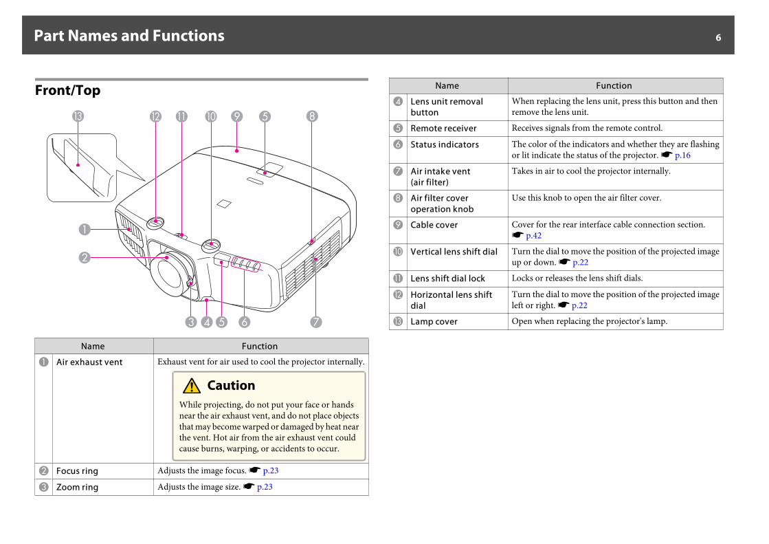
Front/Top
Name Function
A Air exhaust vent Exhaust vent for air used to cool the projector internally.
CautionWhile projecting, do not put your face or handsnear the air exhaust vent, and do not place objectsthat may become warped or damaged by heat nearthe vent. Hot air from the air exhaust vent couldcause burns, warping, or accidents to occur.
B Focus ring Adjusts the image focus. s p.23
C Zoom ring Adjusts the image size. s p.23
Name Function
D Lens unit removalbutton
When replacing the lens unit, press this button and thenremove the lens unit.
E Remote receiver Receives signals from the remote control.
F Status indicators The color of the indicators and whether they are flashingor lit indicate the status of the projector. s p.16
G Air intake vent(air filter)
Takes in air to cool the projector internally.
H Air filter coveroperation knob
Use this knob to open the air filter cover.
I Cable cover Cover for the rear interface cable connection section.s p.42
J Vertical lens shift dial Turn the dial to move the position of the projected imageup or down. s p.22
K Lens shift dial lock Locks or releases the lens shift dials.
L Horizontal lens shiftdial
Turn the dial to move the position of the projected imageleft or right. s p.22
M Lamp cover Open when replacing the projector's lamp.
Part Names and Functions 6
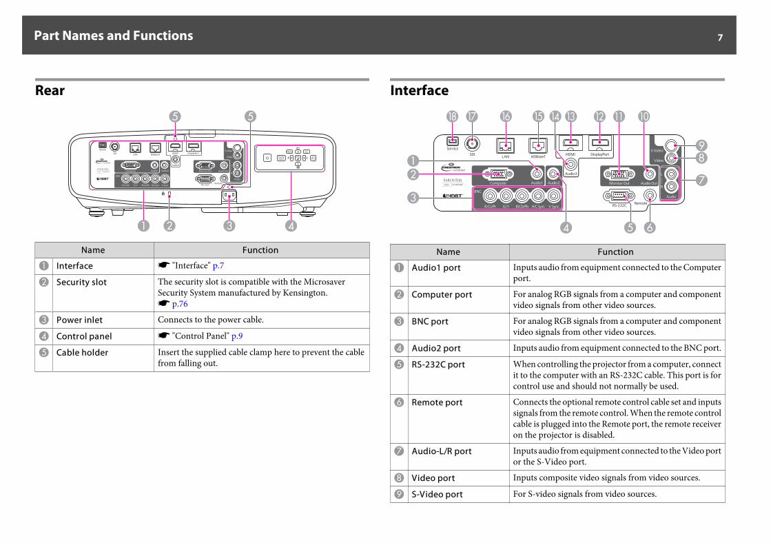
Rear
Name Function
A Interface s "Interface" p.7
B Security slot The security slot is compatible with the MicrosaverSecurity System manufactured by Kensington.s p.76
C Power inlet Connects to the power cable.
D Control panel s "Control Panel" p.9
E Cable holder Insert the supplied cable clamp here to prevent the cablefrom falling out.
Interface
Name Function
A Audio1 port Inputs audio from equipment connected to the Computerport.
B Computer port For analog RGB signals from a computer and componentvideo signals from other video sources.
C BNC port For analog RGB signals from a computer and componentvideo signals from other video sources.
D Audio2 port Inputs audio from equipment connected to the BNC port.
E RS-232C port When controlling the projector from a computer, connectit to the computer with an RS-232C cable. This port is forcontrol use and should not normally be used.
F Remote port Connects the optional remote control cable set and inputssignals from the remote control. When the remote controlcable is plugged into the Remote port, the remote receiveron the projector is disabled.
G Audio-L/R port Inputs audio from equipment connected to the Video portor the S-Video port.
H Video port Inputs composite video signals from video sources.
I S-Video port For S-video signals from video sources.
Part Names and Functions 7
Name Function
J Audio Out port Outputs audio from the currently projected image to anexternal speaker.
K Monitor Out port Outputs to an external monitor the analog signal from thecomputer connected to the Computer port or the BNCport. You cannot output signals input from other ports orcomponent video signals.
L DisplayPort Inputs video signals from DisplayPort compatiblecomputers. This projector is compatible with HDCP.
M HDMI port Inputs video signals from HDMI compatible videoequipment and computers. This projector is compatiblewith HDCP.
N Audio3 port Inputs audio from equipment connected to theDisplayPort or the HDMI port.
O HDBaseT port Connects a LAN cable to the optional HDBaseTTransmitter. s p.41
P LAN port Connects a LAN cable to connect to a network.
Q SDI port(EB-G6900WU only)
Inputs SDI signals from a video equipment. This projectorsupports SD-SDI (Standard Definition) and HD-SDI(High Definition).
R Service port Control port used when updating the projector's software.This should not normally be used.
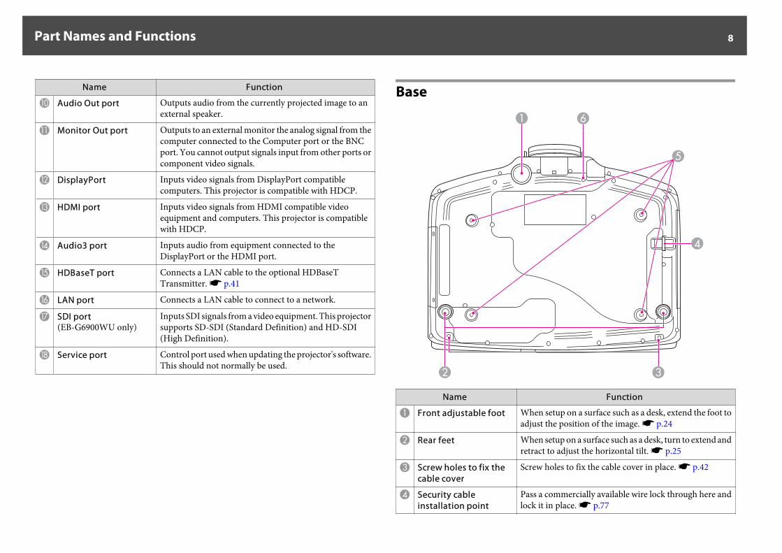
Base
Name Function
A Front adjustable foot When setup on a surface such as a desk, extend the foot toadjust the position of the image. s p.24
B Rear feet When setup on a surface such as a desk, turn to extend andretract to adjust the horizontal tilt. s p.25
C Screw holes to fix thecable cover
Screw holes to fix the cable cover in place. s p.42
D Security cableinstallation point
Pass a commercially available wire lock through here andlock it in place. s p.77
Part Names and Functions 8
Name Function
E Ceiling mount fixingpoints (four points)
Attach the optional Ceiling Mount here when suspendingthe projector from a ceiling. s p.20
F Screw hole for thescrew to fix the lensunit removal button
When installing a lens unit, use this screw hole to fix thelens unit removal button using the screw supplied.s p.12
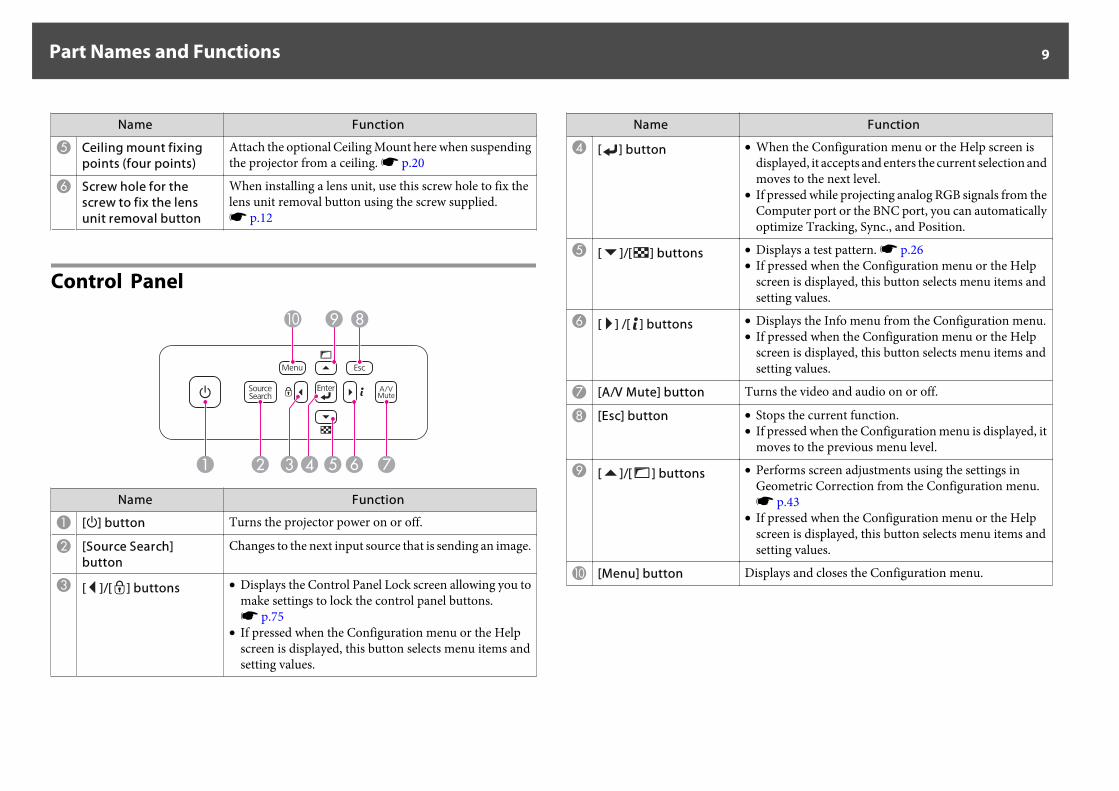
Control Panel
Name Function
A [t] button Turns the projector power on or off.
B [Source Search]button
Changes to the next input source that is sending an image.
C [ ]/[ ] buttons • Displays the Control Panel Lock screen allowing you tomake settings to lock the control panel buttons.s p.75
• If pressed when the Configuration menu or the Helpscreen is displayed, this button selects menu items andsetting values.
Name Function
D [ ] button • When the Configuration menu or the Help screen isdisplayed, it accepts and enters the current selection andmoves to the next level.
• If pressed while projecting analog RGB signals from theComputer port or the BNC port, you can automaticallyoptimize Tracking, Sync., and Position.
E [ ]/[ ] buttons • Displays a test pattern. s p.26• If pressed when the Configuration menu or the Help
screen is displayed, this button selects menu items andsetting values.
F [ ] /[ ] buttons • Displays the Info menu from the Configuration menu.• If pressed when the Configuration menu or the Help
screen is displayed, this button selects menu items andsetting values.
G [A/V Mute] button Turns the video and audio on or off.
H [Esc] button • Stops the current function.• If pressed when the Configuration menu is displayed, it
moves to the previous menu level.
I [ ]/[ ] buttons • Performs screen adjustments using the settings inGeometric Correction from the Configuration menu.s p.43
• If pressed when the Configuration menu or the Helpscreen is displayed, this button selects menu items andsetting values.
J [Menu] button Displays and closes the Configuration menu.
Part Names and Functions 9
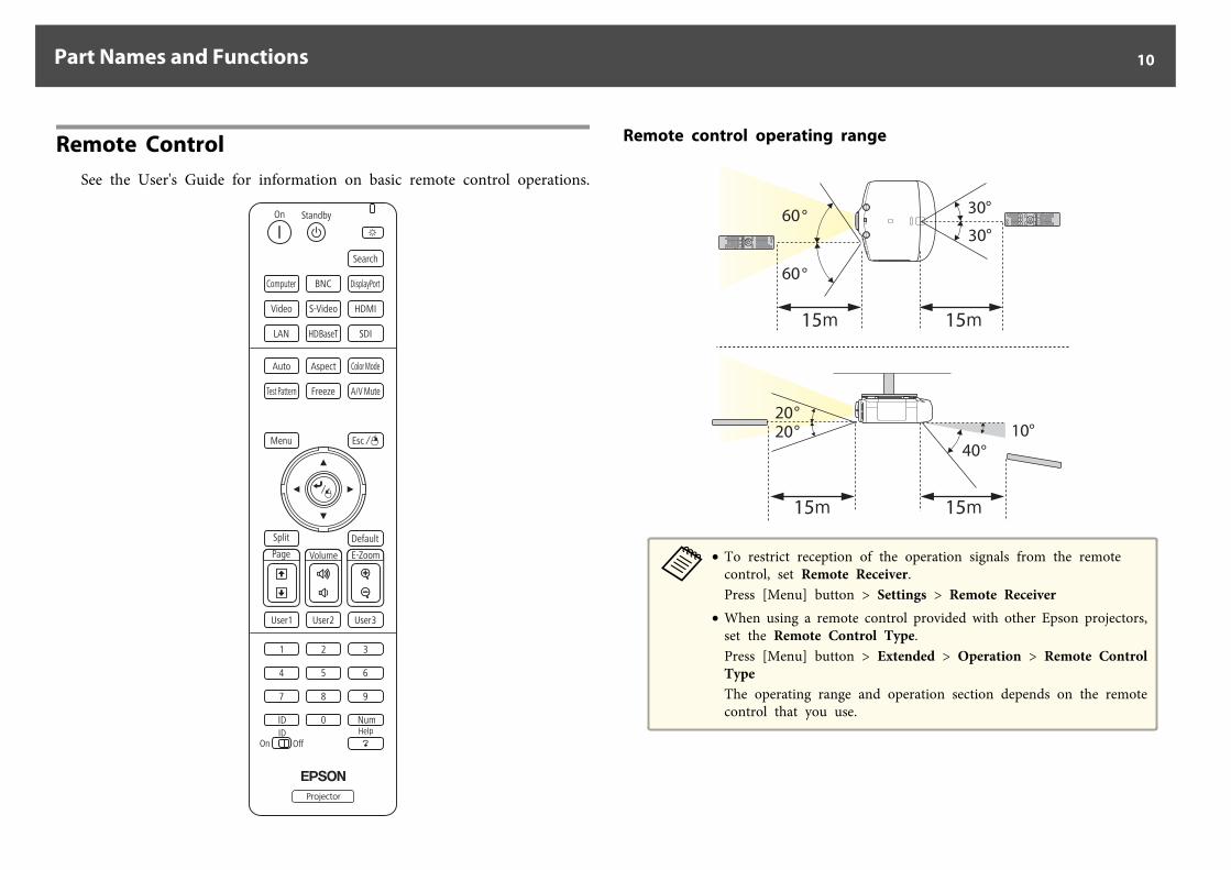
Remote ControlSee the User's Guide for information on basic remote control operations.
Remote control operating range
a• To restrict reception of the operation signals from the remote
control, set Remote Receiver.Press [Menu] button > Settings > Remote Receiver
• When using a remote control provided with other Epson projectors,set the Remote Control Type.Press [Menu] button > Extended > Operation > Remote ControlTypeThe operating range and operation section depends on the remotecontrol that you use.
Part Names and Functions 10
You can perform the following operations by simply pressing one button onthe remote control.
Operation Settings
Reverses the top and bottom of a projectedimage. (Changes Front and Front/Ceilingin Projection) s p.21
Hold down the [A/V Mute] button for atleast five seconds.
Sets password protection s p.73 Hold down the [Freeze] button for at leastfive seconds. Make the settings on thePassword Protection screen.
Applies or releases a partial lock for theremote control buttons. s p.76
Hold down the [Help] button for at leastfive seconds.
Resets the Remote Receiver settings onthe Configuration menu. (Enables all ofthe projector's remote receivers.)
Hold down the [Menu] button for at least15 seconds.
Displays frequently used Configurationmenu items instantly.
Press the [User1], [User2], or [User3]button. You can set the menu itemassigned to each button from UserButton.Press [Menu] button > Settings > UserButtonThe following items can be assigned.Power Consumption, Info, Progressive,Geometric Correction, Multi-Projection, Resolution, Memory, orImage Processing
Part Names and Functions 11
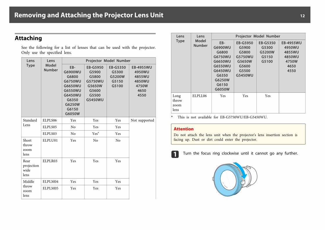
AttachingSee the following for a list of lenses that can be used with the projector.Only use the specified lens.
LensType
LensModel
Number
Projector Model Number
EB-G6900WU
G6800G6750WUG6650WUG6550WUG6450WU
G6350G6250W
G6150G6050W
EB-G5950G5900G5800
G5750WUG5650W
G5600G5500
G5450WU
EB-G5350G5300
G5200WG5150G5100
EB-4955WU4950WU4855WU4850WU4750W
46504550
StandardLens
ELPLS06 Yes Yes Yes Not supported
ELPLS05 No Yes Yes
ELPLS03 No Yes* Yes
Shortthrowzoomlens
ELPLU01 Yes No No
Rearprojectionwidelens
ELPLR03 Yes Yes Yes
Middlethrowzoomlens
ELPLM04 Yes Yes Yes
ELPLM05 Yes Yes Yes
LensType
LensModel
Number
Projector Model Number
EB-G6900WU
G6800G6750WUG6650WUG6550WUG6450WU
G6350G6250W
G6150G6050W
EB-G5950G5900G5800
G5750WUG5650W
G5600G5500
G5450WU
EB-G5350G5300
G5200WG5150G5100
EB-4955WU4950WU4855WU4850WU4750W
46504550
Longthrowzoomlens
ELPLL06 Yes Yes Yes
* This is not available for EB-G5750WU/EB-G5450WU.
AttentionDo not attach the lens unit when the projector's lens insertion section isfacing up. Dust or dirt could enter the projector.
a Turn the focus ring clockwise until it cannot go any further.
Removing and Attaching the Projector Lens Unit 12
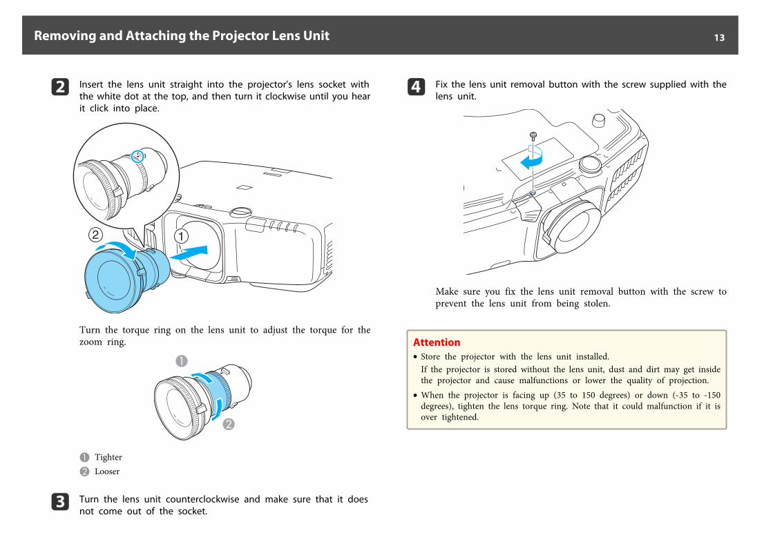
b Insert the lens unit straight into the projector's lens socket withthe white dot at the top, and then turn it clockwise until you hearit click into place.
Turn the torque ring on the lens unit to adjust the torque for thezoom ring.
A TighterB Looser
c Turn the lens unit counterclockwise and make sure that it doesnot come out of the socket.
d Fix the lens unit removal button with the screw supplied with thelens unit.
Make sure you fix the lens unit removal button with the screw toprevent the lens unit from being stolen.
Attention• Store the projector with the lens unit installed.
If the projector is stored without the lens unit, dust and dirt may get insidethe projector and cause malfunctions or lower the quality of projection.
• When the projector is facing up (35 to 150 degrees) or down (-35 to -150degrees), tighten the lens torque ring. Note that it could malfunction if it isover tightened.
Removing and Attaching the Projector Lens Unit 13
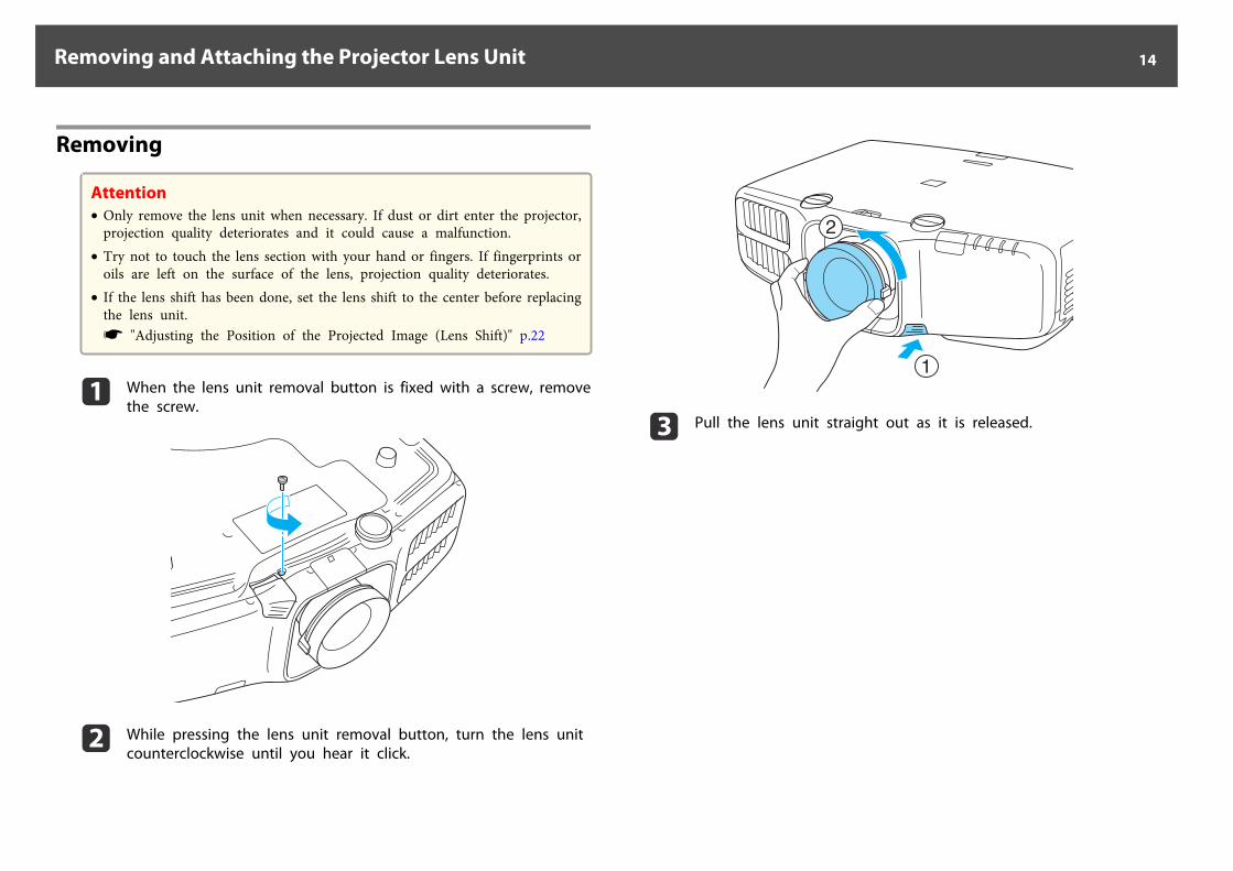
Removing
Attention• Only remove the lens unit when necessary. If dust or dirt enter the projector,
projection quality deteriorates and it could cause a malfunction.• Try not to touch the lens section with your hand or fingers. If fingerprints or
oils are left on the surface of the lens, projection quality deteriorates.• If the lens shift has been done, set the lens shift to the center before replacing
the lens unit.s "Adjusting the Position of the Projected Image (Lens Shift)" p.22
a When the lens unit removal button is fixed with a screw, removethe screw.
b While pressing the lens unit removal button, turn the lens unitcounterclockwise until you hear it click.
c Pull the lens unit straight out as it is released.
Removing and Attaching the Projector Lens Unit 14
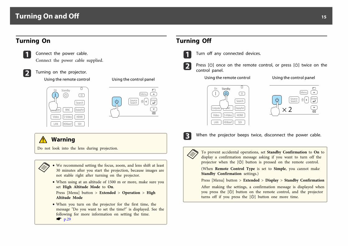
Turning On
a Connect the power cable.
Connect the power cable supplied.
b Turning on the projector.
Using the remote control Using the control panel
WarningDo not look into the lens during projection.
a• We recommend setting the focus, zoom, and lens shift at least
30 minutes after you start the projection, because images arenot stable right after turning on the projector.
• When using at an altitude of 1500 m or more, make sure youset High Altitude Mode to On.Press [Menu] button > Extended > Operation > HighAltitude Mode
• When you turn on the projector for the first time, themessage "Do you want to set the time?" is displayed. See thefollowing for more information on setting the time.s p.29
Turning Off
a Turn off any connected devices.
b Press [t] once on the remote control, or press [t] twice on thecontrol panel.
Using the remote control Using the control panel
× 2
c When the projector beeps twice, disconnect the power cable.
aTo prevent accidental operations, set Standby Confirmation to On todisplay a confirmation message asking if you want to turn off theprojector when the [t] button is pressed on the remote control.(When Remote Control Type is set to Simple, you cannot makeStandby Confirmation settings.)Press [Menu] button > Extended > Display > Standby ConfirmationAfter making the settings, a confirmation message is displayed whenyou press the [t] button on the remote control, and the projectorturns off if you press the [t] button one more time.
Turning On and Off 15
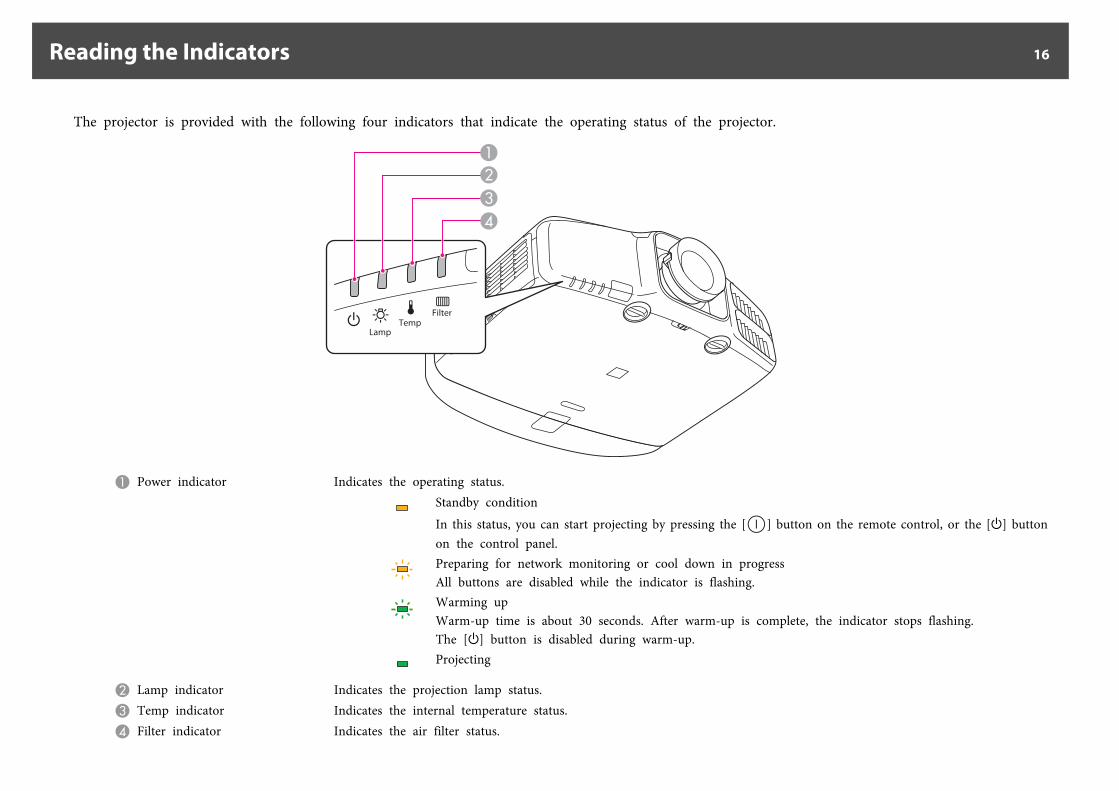
The projector is provided with the following four indicators that indicate the operating status of the projector.
A Power indicator Indicates the operating status.Standby conditionIn this status, you can start projecting by pressing the [ ] button on the remote control, or the [t] buttonon the control panel.Preparing for network monitoring or cool down in progressAll buttons are disabled while the indicator is flashing.Warming upWarm-up time is about 30 seconds. After warm-up is complete, the indicator stops flashing.The [t] button is disabled during warm-up.Projecting
B Lamp indicator Indicates the projection lamp status.C Temp indicator Indicates the internal temperature status.D Filter indicator Indicates the air filter status.
Reading the Indicators 16
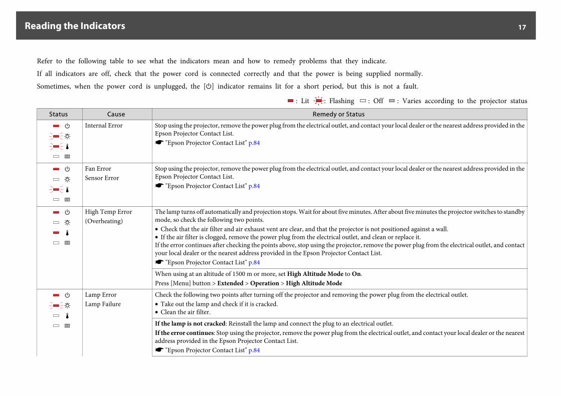
Refer to the following table to see what the indicators mean and how to remedy problems that they indicate.
If all indicators are off, check that the power cord is connected correctly and that the power is being supplied normally.
Sometimes, when the power cord is unplugged, the [t] indicator remains lit for a short period, but this is not a fault.
: Lit : Flashing : Off : Varies according to the projector status
Status Cause Remedy or Status
Internal Error Stop using the projector, remove the power plug from the electrical outlet, and contact your local dealer or the nearest address provided in theEpson Projector Contact List.s "Epson Projector Contact List" p.84
Fan ErrorSensor Error
Stop using the projector, remove the power plug from the electrical outlet, and contact your local dealer or the nearest address provided in theEpson Projector Contact List.s "Epson Projector Contact List" p.84
High Temp Error(Overheating)
The lamp turns off automatically and projection stops. Wait for about five minutes. After about five minutes the projector switches to standbymode, so check the following two points.• Check that the air filter and air exhaust vent are clear, and that the projector is not positioned against a wall.• If the air filter is clogged, remove the power plug from the electrical outlet, and clean or replace it.If the error continues after checking the points above, stop using the projector, remove the power plug from the electrical outlet, and contactyour local dealer or the nearest address provided in the Epson Projector Contact List.s "Epson Projector Contact List" p.84
When using at an altitude of 1500 m or more, set High Altitude Mode to On.Press [Menu] button > Extended > Operation > High Altitude Mode
Lamp ErrorLamp Failure
Check the following two points after turning off the projector and removing the power plug from the electrical outlet.• Take out the lamp and check if it is cracked.• Clean the air filter.
If the lamp is not cracked: Reinstall the lamp and connect the plug to an electrical outlet.If the error continues: Stop using the projector, remove the power plug from the electrical outlet, and contact your local dealer or the nearestaddress provided in the Epson Projector Contact List.s "Epson Projector Contact List" p.84
Reading the Indicators 17
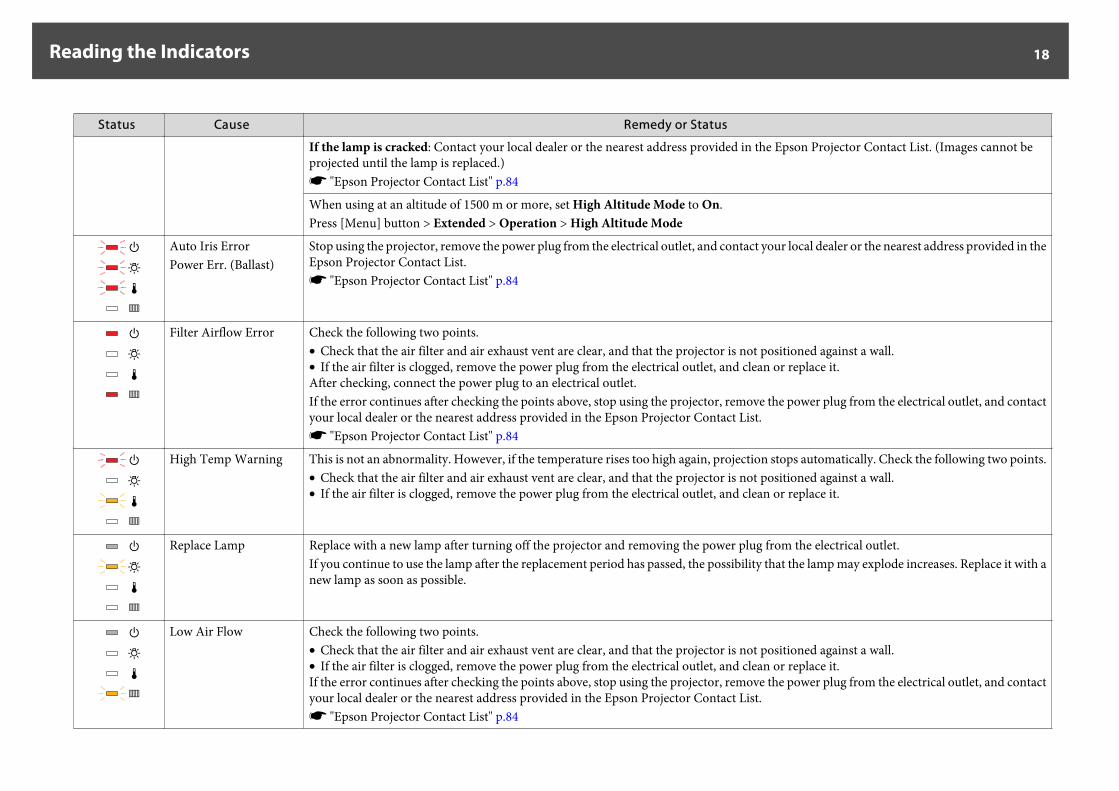
Status Cause Remedy or Status
If the lamp is cracked: Contact your local dealer or the nearest address provided in the Epson Projector Contact List. (Images cannot beprojected until the lamp is replaced.)s "Epson Projector Contact List" p.84
When using at an altitude of 1500 m or more, set High Altitude Mode to On.Press [Menu] button > Extended > Operation > High Altitude Mode
Auto Iris ErrorPower Err. (Ballast)
Stop using the projector, remove the power plug from the electrical outlet, and contact your local dealer or the nearest address provided in theEpson Projector Contact List.s "Epson Projector Contact List" p.84
Filter Airflow Error Check the following two points.• Check that the air filter and air exhaust vent are clear, and that the projector is not positioned against a wall.• If the air filter is clogged, remove the power plug from the electrical outlet, and clean or replace it.After checking, connect the power plug to an electrical outlet.If the error continues after checking the points above, stop using the projector, remove the power plug from the electrical outlet, and contactyour local dealer or the nearest address provided in the Epson Projector Contact List.s "Epson Projector Contact List" p.84
High Temp Warning This is not an abnormality. However, if the temperature rises too high again, projection stops automatically. Check the following two points.• Check that the air filter and air exhaust vent are clear, and that the projector is not positioned against a wall.• If the air filter is clogged, remove the power plug from the electrical outlet, and clean or replace it.
Replace Lamp Replace with a new lamp after turning off the projector and removing the power plug from the electrical outlet.If you continue to use the lamp after the replacement period has passed, the possibility that the lamp may explode increases. Replace it with anew lamp as soon as possible.
Low Air Flow Check the following two points.• Check that the air filter and air exhaust vent are clear, and that the projector is not positioned against a wall.• If the air filter is clogged, remove the power plug from the electrical outlet, and clean or replace it.If the error continues after checking the points above, stop using the projector, remove the power plug from the electrical outlet, and contactyour local dealer or the nearest address provided in the Epson Projector Contact List.s "Epson Projector Contact List" p.84
Reading the Indicators 18
Status Cause Remedy or Status
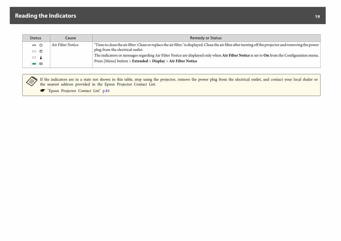
Air Filter Notice "Time to clean the air filter. Clean or replace the air filter."is displayed. Clean the air filter after turning off the projector and removing the powerplug from the electrical outlet.The indicators or messages regarding Air Filter Notice are displayed only when Air Filter Notice is set to On from the Configuration menu.Press [Menu] button > Extended > Display > Air Filter Notice
aIf the indicators are in a state not shown in this table, stop using the projector, remove the power plug from the electrical outlet, and contact your local dealer orthe nearest address provided in the Epson Projector Contact List.s "Epson Projector Contact List" p.84
Reading the Indicators 19
Installation Requirements
Warning• A special method of installation is required when suspending the projector
from a ceiling (ceiling mount). If installation work is not carried outcorrectly, the projector could fall down. This may result in injury oraccidents.Contact your dealer or the nearest address provided in the Epson ProjectorContact List if you want to use this installation method.s "Epson Projector Contact List" p.84
• If you use adhesives on the Ceiling mount fixing points to prevent the screwsfrom loosening, or if you use things such as lubricants or oils on theprojector, the projector case may crack causing it to fall from its ceilingmount. This could cause serious injury to anyone under the ceiling mountand could damage the projector.When installing or adjusting the ceiling mount, do not use adhesives toprevent the screws from loosening and do not use oils or lubricants and soon.
• Do not cover the projector's air intake vent or air exhaust vent. If either ofthe vents are covered, the internal temperature could rise and cause a fire.
a• An optional ceiling mount is required when suspending the projector
from a ceiling.• When mounted on a ceiling, set Inv Direction Button to On so that
the operations and movement of the [ ], [ ], [ ], and [ ]buttons on the control panel match.Press [Menu] button > Extended > Operation > Inv DirectionButton
The projector can be installed at the following angles.
Vertical: Can be installed at any angle in a complete 360 degrees.
Horizontal: Can be tilted within the range of expansion and contraction forthe rear feet.
s "Adjusting the Horizontal Tilt (When Setup on a Desk)" p.25
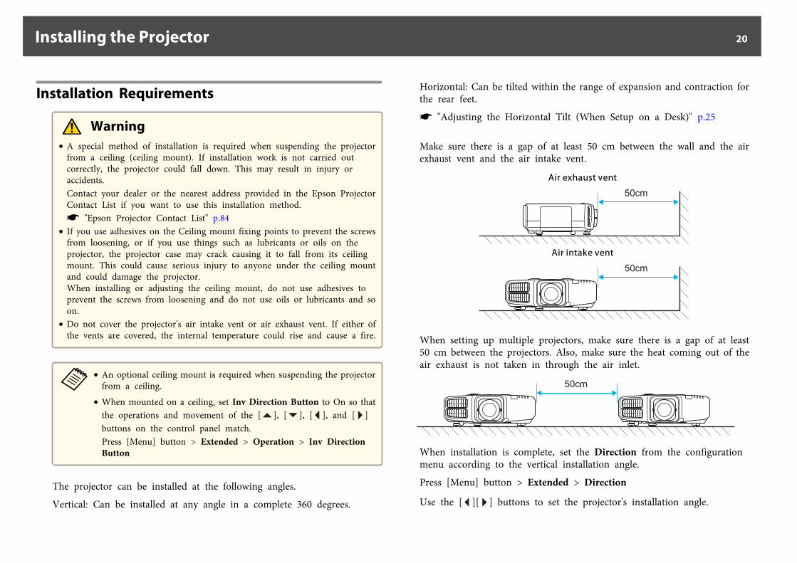
Make sure there is a gap of at least 50 cm between the wall and the airexhaust vent and the air intake vent.
Air exhaust vent
Air intake vent
When setting up multiple projectors, make sure there is a gap of at least50 cm between the projectors. Also, make sure the heat coming out of theair exhaust is not taken in through the air inlet.
When installation is complete, set the Direction from the configurationmenu according to the vertical installation angle.
Press [Menu] button > Extended > Direction
Use the [ ][ ] buttons to set the projector's installation angle.
Installing the Projector 20
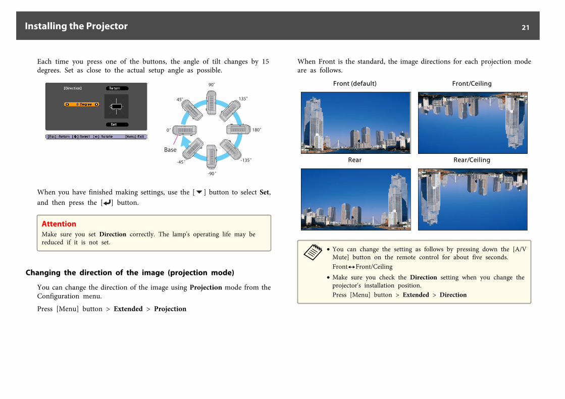
Each time you press one of the buttons, the angle of tilt changes by 15degrees. Set as close to the actual setup angle as possible.
90
45
0
135
180
-135
-90
-45
Base
When you have finished making settings, use the [ ] button to select Set,and then press the [ ] button.
AttentionMake sure you set Direction correctly. The lamp's operating life may bereduced if it is not set.
Changing the direction of the image (projection mode)
You can change the direction of the image using Projection mode from theConfiguration menu.
Press [Menu] button > Extended > Projection
When Front is the standard, the image directions for each projection modeare as follows.
Front (default) Front/Ceiling
Rear Rear/Ceiling
a• You can change the setting as follows by pressing down the [A/V
Mute] button on the remote control for about five seconds.FrontWFront/Ceiling
• Make sure you check the Direction setting when you change theprojector's installation position.Press [Menu] button > Extended > Direction
Installing the Projector 21
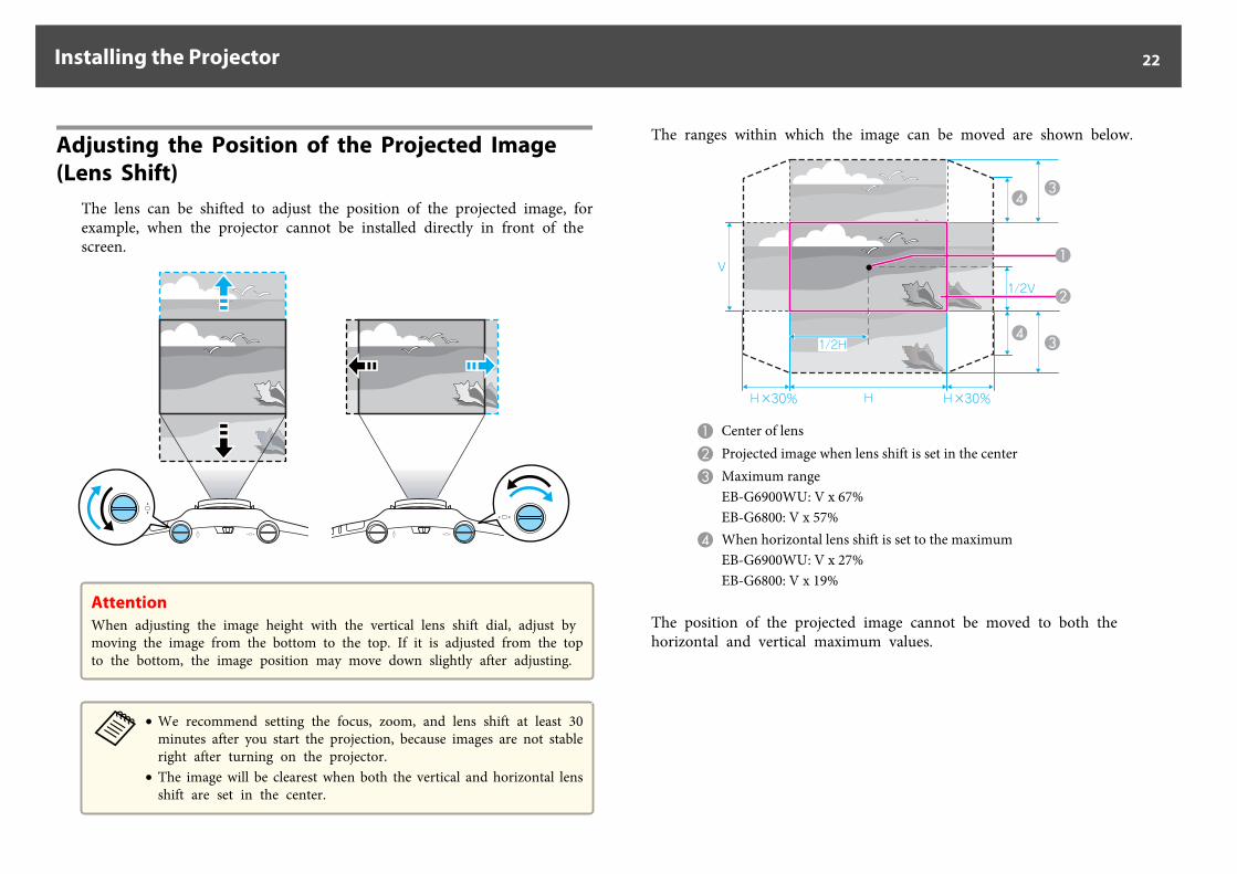
Adjusting the Position of the Projected Image (Lens Shift)
The lens can be shifted to adjust the position of the projected image, forexample, when the projector cannot be installed directly in front of thescreen.
AttentionWhen adjusting the image height with the vertical lens shift dial, adjust bymoving the image from the bottom to the top. If it is adjusted from the topto the bottom, the image position may move down slightly after adjusting.
a• We recommend setting the focus, zoom, and lens shift at least 30
minutes after you start the projection, because images are not stableright after turning on the projector.
• The image will be clearest when both the vertical and horizontal lensshift are set in the center.
The ranges within which the image can be moved are shown below.
A Center of lensB Projected image when lens shift is set in the centerC Maximum range
EB-G6900WU: V x 67%EB-G6800: V x 57%
D When horizontal lens shift is set to the maximumEB-G6900WU: V x 27%EB-G6800: V x 19%
The position of the projected image cannot be moved to both thehorizontal and vertical maximum values.
Installing the Projector 22
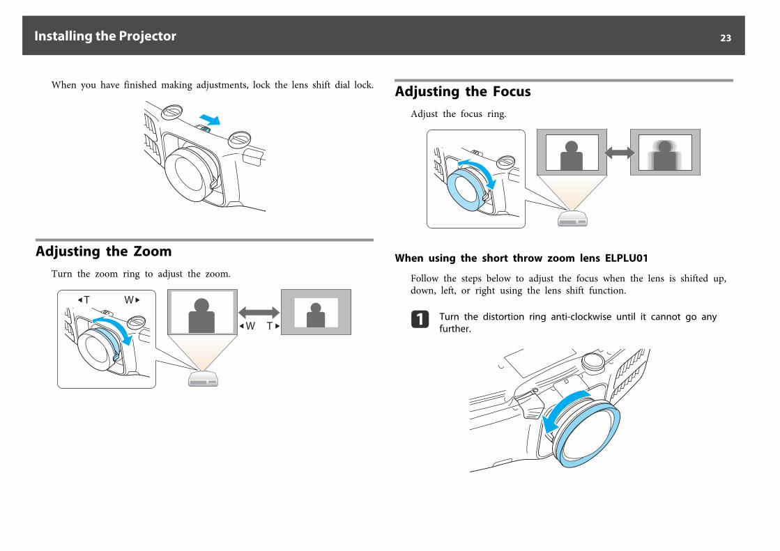
When you have finished making adjustments, lock the lens shift dial lock.
Adjusting the ZoomTurn the zoom ring to adjust the zoom.
W T
Adjusting the FocusAdjust the focus ring.
When using the short throw zoom lens ELPLU01
Follow the steps below to adjust the focus when the lens is shifted up,down, left, or right using the lens shift function.
a Turn the distortion ring anti-clockwise until it cannot go anyfurther.
Installing the Projector 23
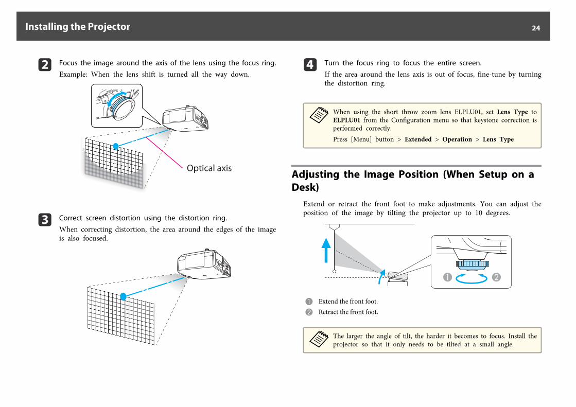
b Focus the image around the axis of the lens using the focus ring.
Example: When the lens shift is turned all the way down.
Optical axis
c Correct screen distortion using the distortion ring.
When correcting distortion, the area around the edges of the imageis also focused.
d Turn the focus ring to focus the entire screen.
If the area around the lens axis is out of focus, fine-tune by turningthe distortion ring.
aWhen using the short throw zoom lens ELPLU01, set Lens Type toELPLU01 from the Configuration menu so that keystone correction isperformed correctly.Press [Menu] button > Extended > Operation > Lens Type
Adjusting the Image Position (When Setup on a Desk)
Extend or retract the front foot to make adjustments. You can adjust theposition of the image by tilting the projector up to 10 degrees.
A Extend the front foot.B Retract the front foot.
aThe larger the angle of tilt, the harder it becomes to focus. Install theprojector so that it only needs to be tilted at a small angle.
Installing the Projector 24

Adjusting the Horizontal Tilt (When Setup on a Desk)
Extend and retract the rear feet to adjust the projector's horizontal tilt.
A Extend the rear foot.B Retract the rear foot.
AttentionThe rear feet can be attached and removed. Note that the feet will detach ifthey are extended more than 10 mm.
Screen SettingsSet the Screen Type to 4:3, 16:9, or 16:10 according to the aspect ratio ofthe screen being used
Press [Menu] button > Extended > Display > Screen > Screen Type
The area where the image is displayed matches the shape of the screen.
aThe default values are shown below.EB-G6900WU: 16:10EB-G6800: 4:3You do not need to set the Screen Type when the default value is thesame as the aspect ratio for the screen being used.
Adjusting the position of the image on the projected screen
You can adjust the position of the image if there are margins between theedge of the image and the projected screen frame due to the Screen Typesetting.
Press [Menu] button > Extended > Display > Screen > Screen Position
Example: When the Screen Type is set to 4:3 for EB-G6900WU
You can move the image to the left and right.
aThe Screen Position cannot be adjusted in the following situations.• If the Screen Type is set to 16:10 when using EB-G6900WU• If the Screen Type is set to 4:3 when using EB-G6800
Installing the Projector 25
Displaying a Test PatternA test pattern can be displayed to adjust the projection status withoutconnecting video equipment.
The shape of a test pattern is according to the setting of Screen Type. SetScreen Type first.
Press [Menu] button > Extended > Display > Screen > Screen Type
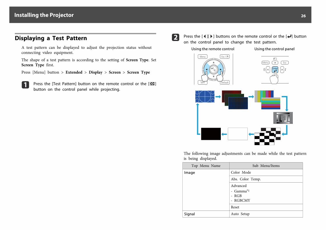
a Press the [Test Pattern] button on the remote control or the [ ]button on the control panel while projecting.
b Press the [ ][ ] buttons on the remote control or the [ ] buttonon the control panel to change the test pattern.
Using the remote control Using the control panel
The following image adjustments can be made while the test patternis being displayed.
Top Menu Name Sub Menu/Items
Image Color Mode
Abs. Color Temp.
Advanced- Gamma*1
- RGB- RGBCMY
Reset
Signal Auto Setup
Installing the Projector 26
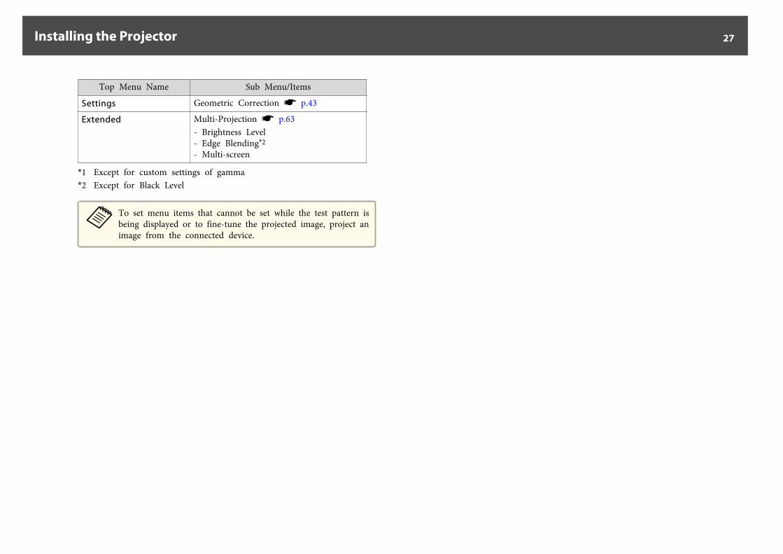
Top Menu Name Sub Menu/Items
Settings Geometric Correction s p.43
Extended Multi-Projection s p.63- Brightness Level- Edge Blending*2
- Multi-screen
*1 Except for custom settings of gamma*2 Except for Black Level
aTo set menu items that cannot be set while the test pattern isbeing displayed or to fine-tune the projected image, project animage from the connected device.
Installing the Projector 27
ID SettingsWhen an ID is set for the projector and the remote control, you can usethe remote control to operate only the projector with a matching ID. Thisis very useful when managing multiple projectors.
a• Operation using the remote control is possible only for projectors
that are within the operating range of the remote control.s p.10
• When Remote Control Type is set to Simple from Operation in theconfiguration menu, you cannot set the remote control ID.
• IDs are ignored when the projector ID is set to Off or the remotecontrol ID is set to 0.
Set the projector ID
Press [Menu] button > Extended > Multi-Projection > Projector ID
Select the ID you want to set, and then press the [ ] button.
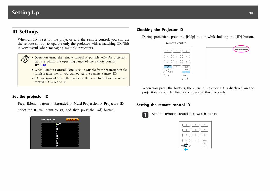
Checking the Projector ID
During projection, press the [Help] button while holding the [ID] button.
Remote control
When you press the buttons, the current Projector ID is displayed on theprojection screen. It disappears in about three seconds.
Setting the remote control ID
a Set the remote control [ID] switch to On.
Setting Up 28
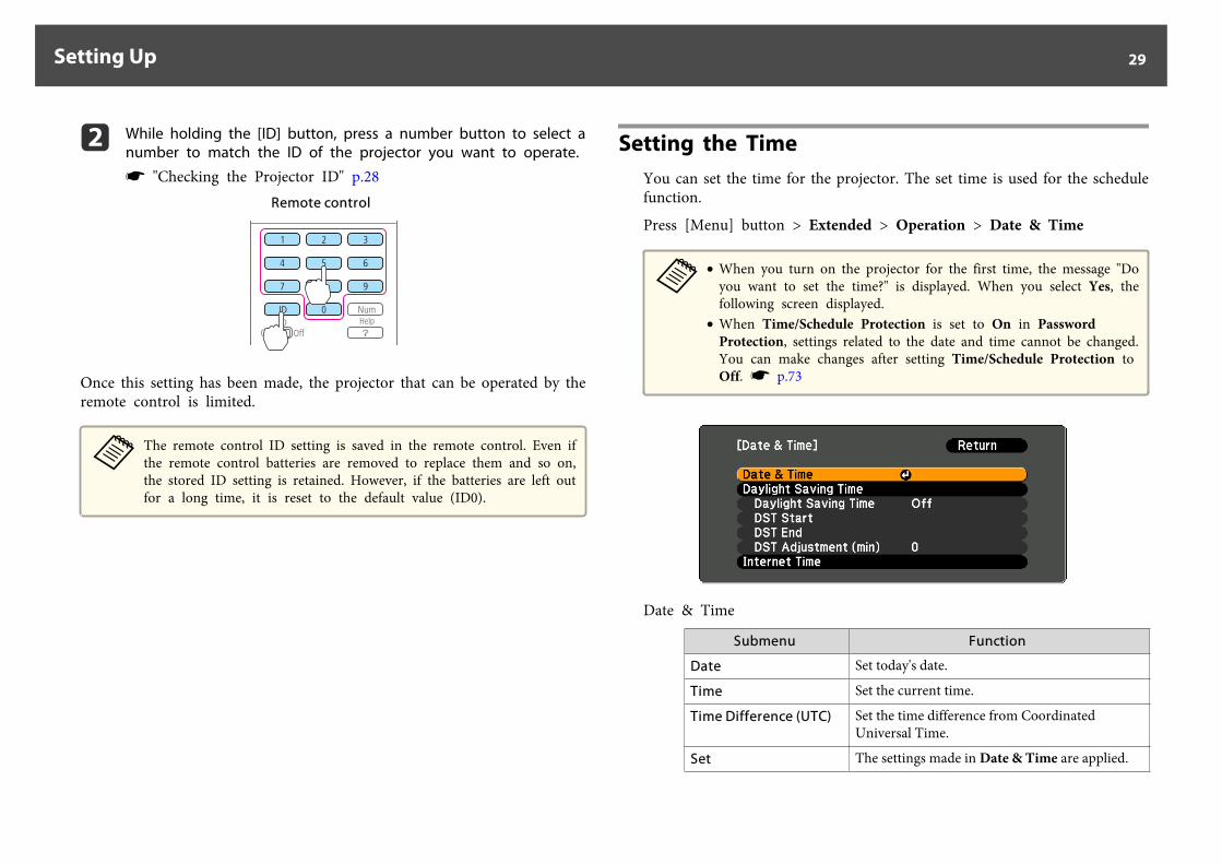
b While holding the [ID] button, press a number button to select anumber to match the ID of the projector you want to operate.
s "Checking the Projector ID" p.28Remote control
Once this setting has been made, the projector that can be operated by theremote control is limited.
aThe remote control ID setting is saved in the remote control. Even ifthe remote control batteries are removed to replace them and so on,the stored ID setting is retained. However, if the batteries are left outfor a long time, it is reset to the default value (ID0).
Setting the TimeYou can set the time for the projector. The set time is used for the schedulefunction.
Press [Menu] button > Extended > Operation > Date & Time
a• When you turn on the projector for the first time, the message "Do
you want to set the time?" is displayed. When you select Yes, thefollowing screen displayed.
• When Time/Schedule Protection is set to On in PasswordProtection, settings related to the date and time cannot be changed.You can make changes after setting Time/Schedule Protection toOff. s p.73
Date & Time
Submenu Function
Date Set today's date.
Time Set the current time.
Time Difference (UTC) Set the time difference from CoordinatedUniversal Time.
Set The settings made in Date & Time are applied.
Setting Up 29
Daylight Saving Time
Submenu Function
Daylight Saving Time Set whether or not (On/Off) to activate thedaylight saving time.DST Adjustment (min)adjusts the time difference between the standardtime and the daylight saving time.
DST Start Set the date and time to start the daylight savingtime.
DST End Set the date and time to end the daylight savingtime.
Set The settings made in Daylight Saving Time areapplied.
Internet Time
Submenu Function
Internet Time Set to On to update the time automatically throughan Internet time server.
Internet Time Server Input the IP address for an Internet time server.
Set The settings made in Internet Time are applied.
aWhen changing settings, make sure you select Set, and then press the[ ] button.
Setting Up 30
Other Settings
Setting basic operations
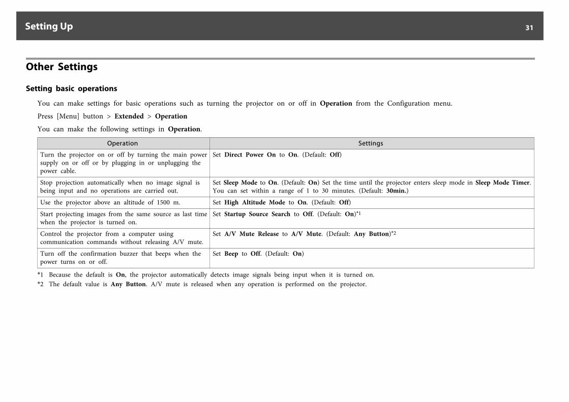
You can make settings for basic operations such as turning the projector on or off in Operation from the Configuration menu.
Press [Menu] button > Extended > Operation
You can make the following settings in Operation.
Operation Settings
Turn the projector on or off by turning the main powersupply on or off or by plugging in or unplugging thepower cable.
Set Direct Power On to On. (Default: Off)
Stop projection automatically when no image signal isbeing input and no operations are carried out.
Set Sleep Mode to On. (Default: On) Set the time until the projector enters sleep mode in Sleep Mode Timer.You can set within a range of 1 to 30 minutes. (Default: 30min.)
Use the projector above an altitude of 1500 m. Set High Altitude Mode to On. (Default: Off)
Start projecting images from the same source as last timewhen the projector is turned on.
Set Startup Source Search to Off. (Default: On)*1
Control the projector from a computer usingcommunication commands without releasing A/V mute.
Set A/V Mute Release to A/V Mute. (Default: Any Button)*2
Turn off the confirmation buzzer that beeps when thepower turns on or off.
Set Beep to Off. (Default: On)
*1 Because the default is On, the projector automatically detects image signals being input when it is turned on.*2 The default value is Any Button. A/V mute is released when any operation is performed on the projector.
Setting Up 31
Setting the display
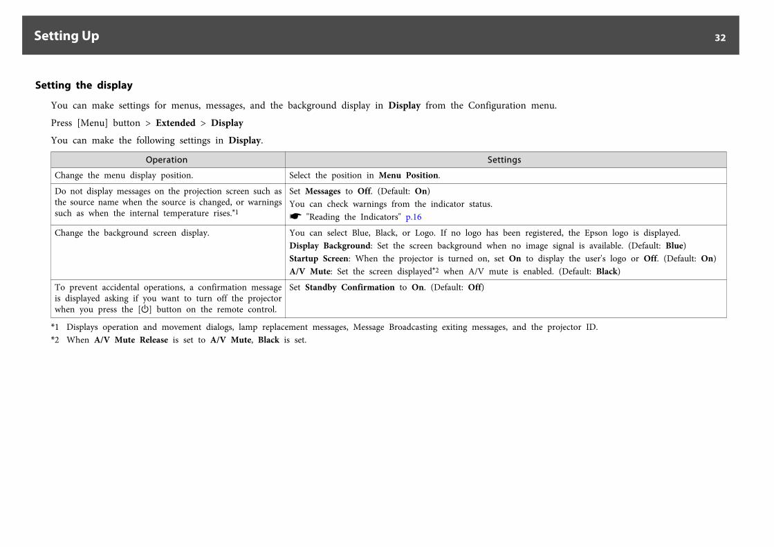
You can make settings for menus, messages, and the background display in Display from the Configuration menu.
Press [Menu] button > Extended > Display
You can make the following settings in Display.
Operation Settings
Change the menu display position. Select the position in Menu Position.
Do not display messages on the projection screen such asthe source name when the source is changed, or warningssuch as when the internal temperature rises.*1
Set Messages to Off. (Default: On)You can check warnings from the indicator status.s "Reading the Indicators" p.16
Change the background screen display. You can select Blue, Black, or Logo. If no logo has been registered, the Epson logo is displayed.Display Background: Set the screen background when no image signal is available. (Default: Blue)Startup Screen: When the projector is turned on, set On to display the user's logo or Off. (Default: On)A/V Mute: Set the screen displayed*2 when A/V mute is enabled. (Default: Black)
To prevent accidental operations, a confirmation messageis displayed asking if you want to turn off the projectorwhen you press the [t] button on the remote control.
Set Standby Confirmation to On. (Default: Off)
*1 Displays operation and movement dialogs, lamp replacement messages, Message Broadcasting exiting messages, and the projector ID.*2 When A/V Mute Release is set to A/V Mute, Black is set.
Setting Up 32
Saving a User's Logo
aOnce a user's logo has been saved, the logo cannot be returned to thefactory default (the Epson logo).
a Project the image you want to save as the user's logo.
b Select User's Logo from the Configuration menu.
Press [Menu] button > Extended > User's LogoWhen the message "Choose this image as the User's Logo?" isdisplayed, select Yes.
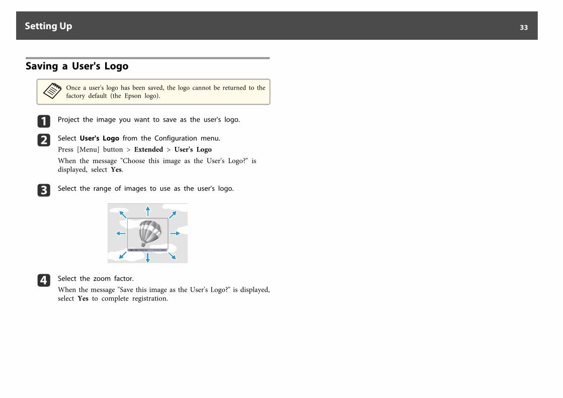
c Select the range of images to use as the user's logo.
d Select the zoom factor.
When the message "Save this image as the User's Logo?" is displayed,select Yes to complete registration.
Setting Up 33
The port name, location, and connector orientation differ depending on the source being connected.
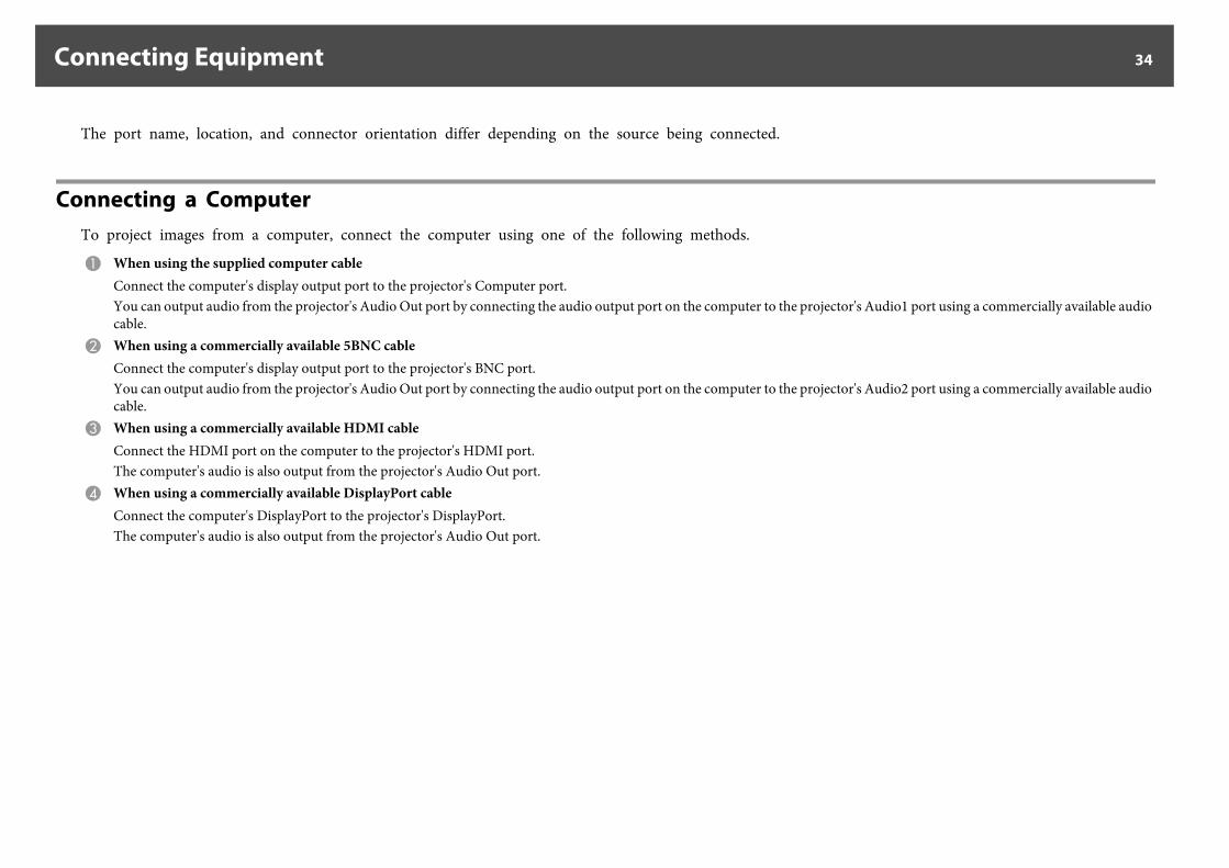
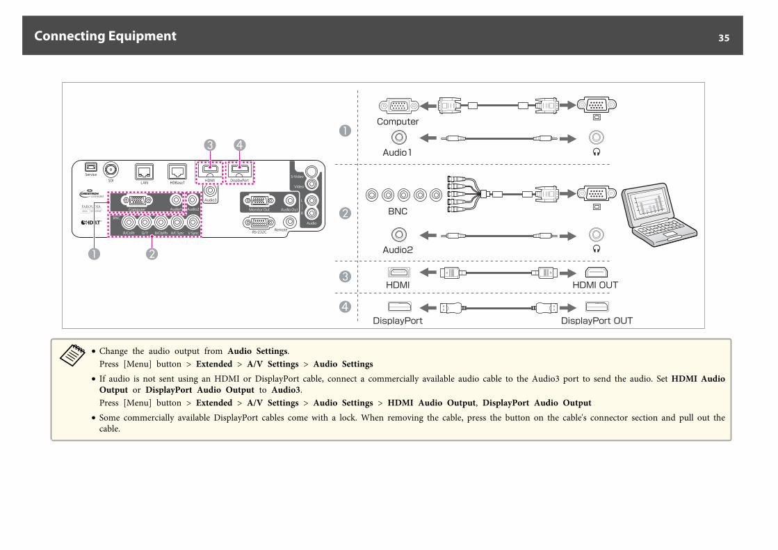
Connecting a ComputerTo project images from a computer, connect the computer using one of the following methods.
A When using the supplied computer cableConnect the computer's display output port to the projector's Computer port.You can output audio from the projector's Audio Out port by connecting the audio output port on the computer to the projector's Audio1 port using a commercially available audiocable.
B When using a commercially available 5BNC cableConnect the computer's display output port to the projector's BNC port.You can output audio from the projector's Audio Out port by connecting the audio output port on the computer to the projector's Audio2 port using a commercially available audiocable.
C When using a commercially available HDMI cableConnect the HDMI port on the computer to the projector's HDMI port.The computer's audio is also output from the projector's Audio Out port.
D When using a commercially available DisplayPort cableConnect the computer's DisplayPort to the projector's DisplayPort.The computer's audio is also output from the projector's Audio Out port.
Connecting Equipment 34
4DisplayPort DisplayPort OUT
Computer
Audio1
Audio2
HDMI OUTHDMI
BNC
4
a• Change the audio output from Audio Settings.
Press [Menu] button > Extended > A/V Settings > Audio Settings• If audio is not sent using an HDMI or DisplayPort cable, connect a commercially available audio cable to the Audio3 port to send the audio. Set HDMI Audio
Output or DisplayPort Audio Output to Audio3.Press [Menu] button > Extended > A/V Settings > Audio Settings > HDMI Audio Output, DisplayPort Audio Output
• Some commercially available DisplayPort cables come with a lock. When removing the cable, press the button on the cable's connector section and pull out thecable.
Connecting Equipment 35
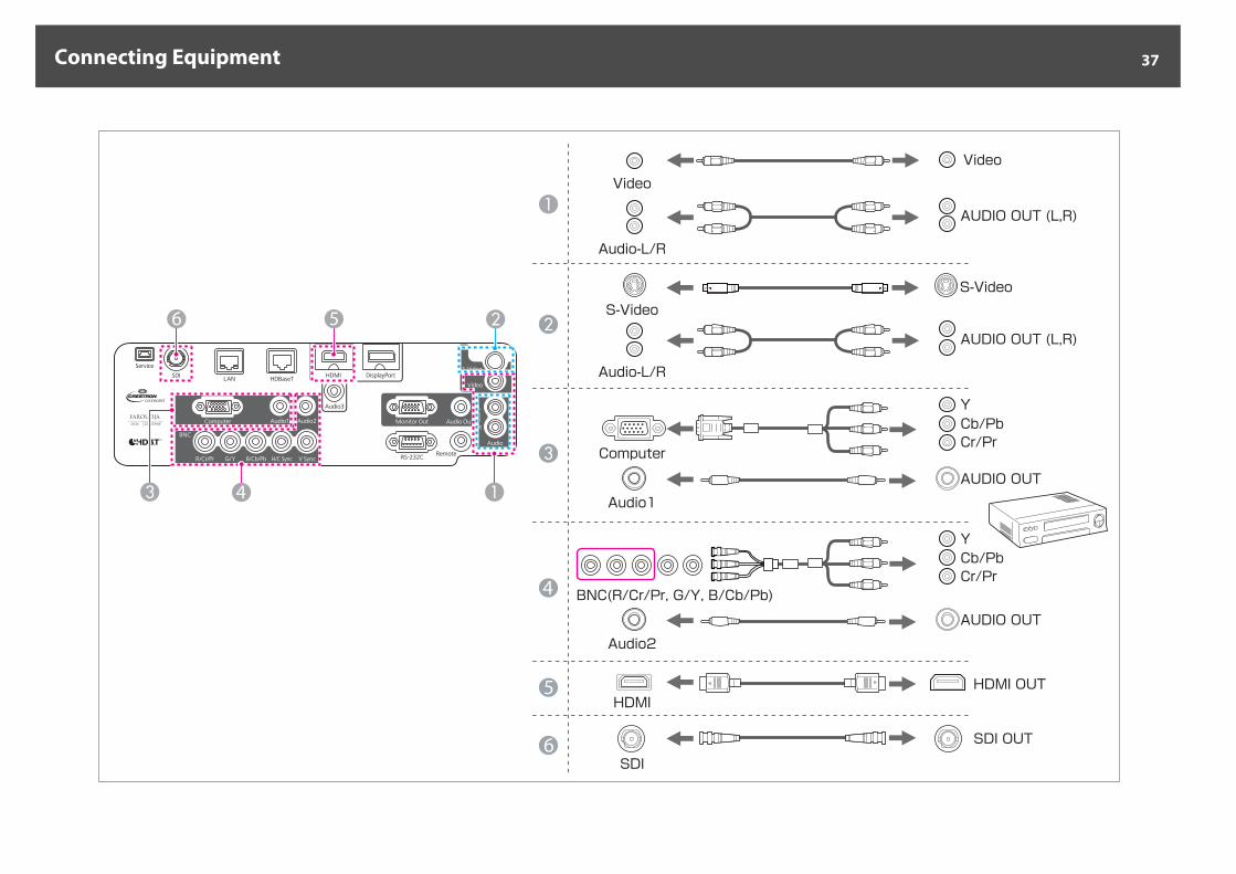
Connecting Image SourcesTo project video images, connect using one of the following methods.
A When using a commercially available video cableConnect the video output port on the image source to the projector's Video port.You can output audio from the projector's Audio Out port by connecting the audio output port on the image source to the projector's Audio-L/R port using a commercially availableaudio cable.
B When using a commercially available S-video cableConnect the S-video output port on the image source to the projector's S-Video port.You can output audio from the projector's Audio Out port by connecting the audio output port on the image source to the projector's Audio-L/R port using a commercially availableaudio cable.
C When using an optional component video cable (ELPKC19: D-sub/component converter)Connect the component output port on the image source to the projector's Computer port.You can output audio from the projector's Audio Out port by connecting the audio output port on the video equipment to the projector's Audio1 port using a commercially availableaudio cable.
D When using a commercially available component video cable (RCA) and a BNC/RCA adapterConnect the component output port on the video equipment to the projector's BNC port (R/Cr/Pr, G/Y, B/Cb/Pb).You can output audio from the projector's Audio Out port by connecting the audio output port on the video equipment to the projector's Audio2 port using a commercially availableaudio cable.
E When using a commercially available HDMI cableConnect the HDMI port on the image source to the projector's HDMI port.The image source's audio is also output from the projector's Audio Out port.
F When using a commercially available BNC video cable (EB-G6900WU only)Connect the SDI port on the image source to the projector's SDI port.Audio output is not supported.
Connecting Equipment 36
5
6
4
Computer
Audio1
Video
Video
S-VideoS-Video
Audio-L/R
AUDIO OUT (L,R)
AUDIO OUT (L,R)
AUDIO OUT
AUDIO OUT
YCb/PbCr/Pr
YCb/PbCr/Pr
Audio2
HDMIHDMI OUT
SDI
SDI OUT
BNC(R/Cr/Pr, G/Y, B/Cb/Pb)
56
Audio-L/R
4
Connecting Equipment 37
Attention• If the input source is on when you connect it to the projector, it could cause a malfunction.• If the orientation or shape of the plug differs, do not try to force it in. The device could be damaged or could malfunction.
a• Change the audio output from Audio Settings.
Press [Menu] button > Extended > A/V Settings > Audio Settings• If audio is not sent using an HDMI cable, connect a commercially available audio cable to the Audio3 port to send the audio. Set HDMI Audio Output to
Audio3.Press [Menu] button > Extended > A/V Settings > Audio Settings > HDMI Audio Output
• If the source you want to connect to has an unusually shaped port, use the cable supplied with the device or an optional cable to connect to the projector.• When using a commercially available 2RCA(L/R)/stereo mini-pin audio cable, make sure it is labeled "No resistance".
Connecting Equipment 38
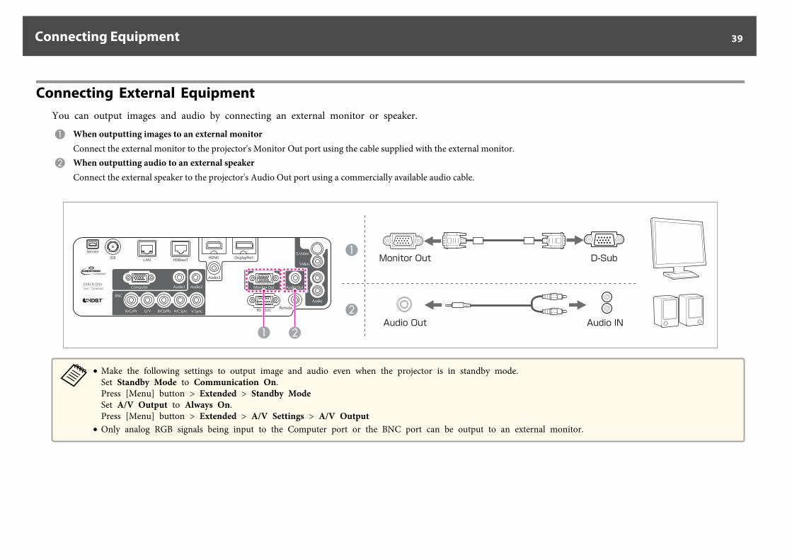
Connecting External EquipmentYou can output images and audio by connecting an external monitor or speaker.
A When outputting images to an external monitorConnect the external monitor to the projector's Monitor Out port using the cable supplied with the external monitor.
B When outputting audio to an external speakerConnect the external speaker to the projector's Audio Out port using a commercially available audio cable.
Monitor Out D-Sub
Audio Out Audio IN
a• Make the following settings to output image and audio even when the projector is in standby mode.
Set Standby Mode to Communication On.Press [Menu] button > Extended > Standby ModeSet A/V Output to Always On.Press [Menu] button > Extended > A/V Settings > A/V Output
• Only analog RGB signals being input to the Computer port or the BNC port can be output to an external monitor.
Connecting Equipment 39
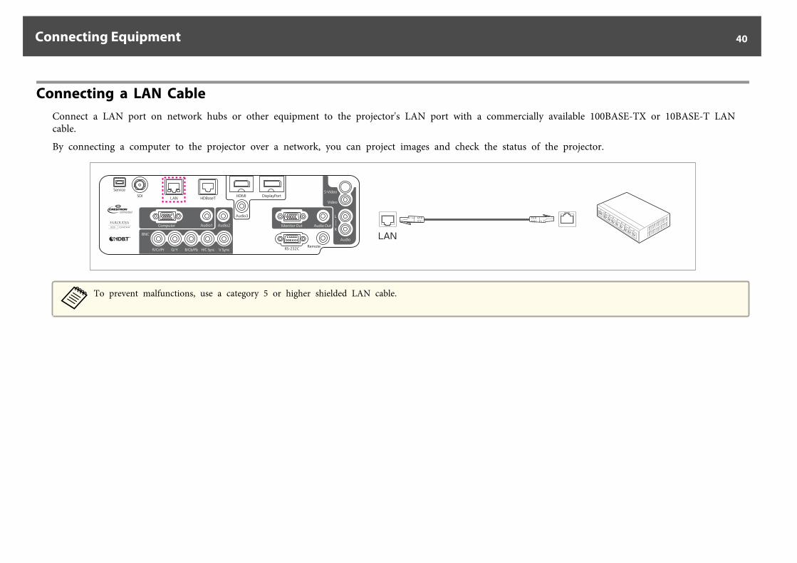
Connecting a LAN CableConnect a LAN port on network hubs or other equipment to the projector's LAN port with a commercially available 100BASE-TX or 10BASE-T LANcable.
By connecting a computer to the projector over a network, you can project images and check the status of the projector.
LAN
aTo prevent malfunctions, use a category 5 or higher shielded LAN cable.
Connecting Equipment 40
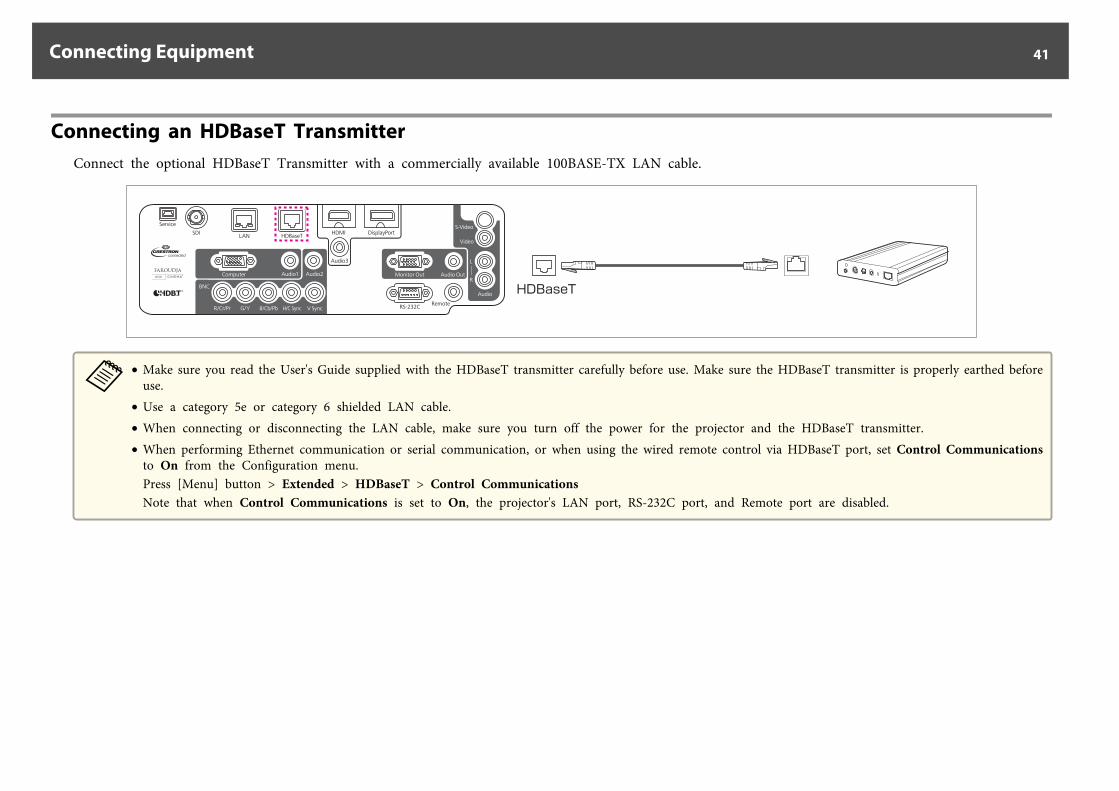
Connecting an HDBaseT TransmitterConnect the optional HDBaseT Transmitter with a commercially available 100BASE-TX LAN cable.
HDBaseT
a• Make sure you read the User's Guide supplied with the HDBaseT transmitter carefully before use. Make sure the HDBaseT transmitter is properly earthed before
use.• Use a category 5e or category 6 shielded LAN cable.• When connecting or disconnecting the LAN cable, make sure you turn off the power for the projector and the HDBaseT transmitter.• When performing Ethernet communication or serial communication, or when using the wired remote control via HDBaseT port, set Control Communications
to On from the Configuration menu.Press [Menu] button > Extended > HDBaseT > Control CommunicationsNote that when Control Communications is set to On, the projector's LAN port, RS-232C port, and Remote port are disabled.
Connecting Equipment 41
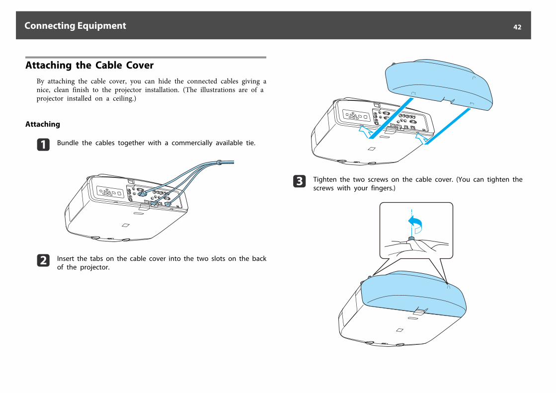
Attaching the Cable CoverBy attaching the cable cover, you can hide the connected cables giving anice, clean finish to the projector installation. (The illustrations are of aprojector installed on a ceiling.)
Attaching
a Bundle the cables together with a commercially available tie.
b Insert the tabs on the cable cover into the two slots on the backof the projector.
c Tighten the two screws on the cable cover. (You can tighten thescrews with your fingers.)
Connecting Equipment 42
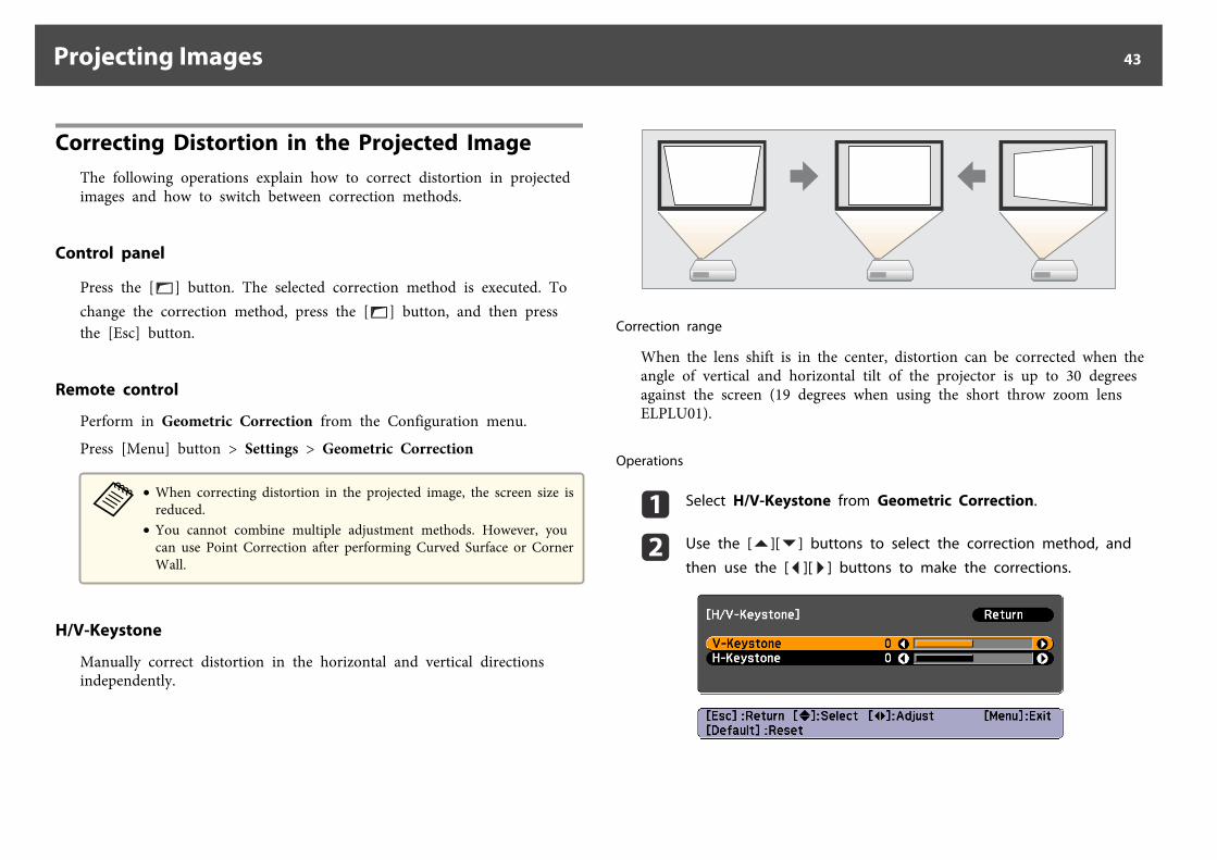
Correcting Distortion in the Projected ImageThe following operations explain how to correct distortion in projectedimages and how to switch between correction methods.
Control panel
Press the [ ] button. The selected correction method is executed. Tochange the correction method, press the [ ] button, and then pressthe [Esc] button.
Remote control
Perform in Geometric Correction from the Configuration menu.
Press [Menu] button > Settings > Geometric Correction
a• When correcting distortion in the projected image, the screen size is
reduced.• You cannot combine multiple adjustment methods. However, you
can use Point Correction after performing Curved Surface or CornerWall.
H/V-Keystone
Manually correct distortion in the horizontal and vertical directionsindependently.
Correction range
When the lens shift is in the center, distortion can be corrected when theangle of vertical and horizontal tilt of the projector is up to 30 degreesagainst the screen (19 degrees when using the short throw zoom lensELPLU01).
Operations
a Select H/V-Keystone from Geometric Correction.
b Use the [ ][ ] buttons to select the correction method, and
then use the [ ][ ] buttons to make the corrections.
Projecting Images 43
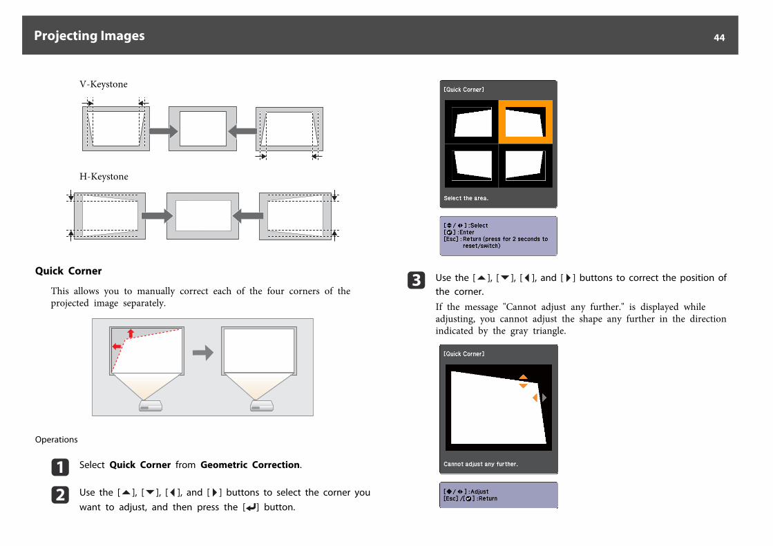
V-Keystone
H-Keystone
Quick Corner
This allows you to manually correct each of the four corners of theprojected image separately.
Operations
a Select Quick Corner from Geometric Correction.
b Use the [ ], [ ], [ ], and [ ] buttons to select the corner youwant to adjust, and then press the [ ] button.
c Use the [ ], [ ], [ ], and [ ] buttons to correct the position ofthe corner.
If the message "Cannot adjust any further." is displayed whileadjusting, you cannot adjust the shape any further in the directionindicated by the gray triangle.
Projecting Images 44
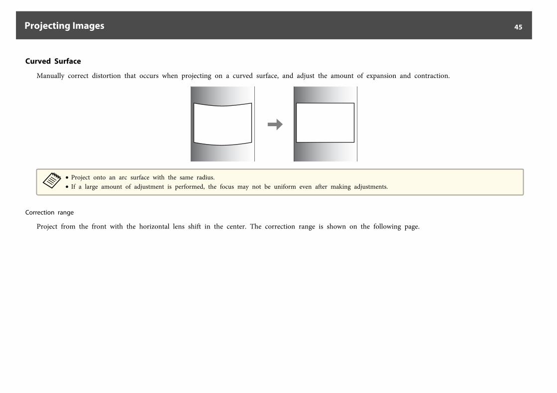
Curved Surface
Manually correct distortion that occurs when projecting on a curved surface, and adjust the amount of expansion and contraction.
a• Project onto an arc surface with the same radius.• If a large amount of adjustment is performed, the focus may not be uniform even after making adjustments.
Correction range
Project from the front with the horizontal lens shift in the center. The correction range is shown on the following page.
Projecting Images 45
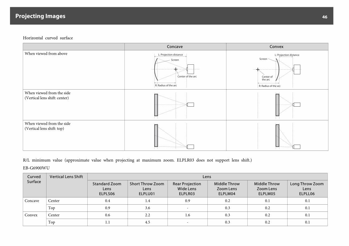
Horizontal curved surface
Concave Convex
When viewed from above L: Projection distance
Screen
Center of the arc
R: Radius of the arc
Screen
Center of the arc
R: Radius of the arc
L: Projection distance
When viewed from the side(Vertical lens shift: center)
When viewed from the side(Vertical lens shift: top)
R/L minimum value (approximate value when projecting at maximum zoom. ELPLR03 does not support lens shift.)
EB-G6900WU
CurvedSurface
Vertical Lens Shift Lens
Standard ZoomLens
ELPLS06
Short Throw ZoomLens
ELPLU01
Rear ProjectionWide LensELPLR03
Middle ThrowZoom LensELPLM04
Middle ThrowZoom LensELPLM05
Long Throw ZoomLens
ELPLL06
Concave Center 0.4 1.4 0.9 0.2 0.1 0.1
Top 0.9 3.6 - 0.3 0.2 0.1
Convex Center 0.6 2.2 1.6 0.3 0.2 0.1
Top 1.1 4.5 - 0.3 0.2 0.1
Projecting Images 46

EB-G6800
CurvedSurface
Vertical Lens Shift Lens
Standard ZoomLens
ELPLS06
Short Throw ZoomLens
ELPLU01
Rear ProjectionWide LensELPLR03
Middle ThrowZoom LensELPLM04
Middle ThrowZoom LensELPLM05
Long Throw ZoomLens
ELPLL06
Concave Center 0.4 1.3 1.0 0.2 0.1 0.1
Top 0.9 3.5 - 0.3 0.2 0.1
Convex Center 0.6 2.2 1.6 0.3 0.2 0.1
Top 1.1 4.1 - 0.4 0.2 0.1
Projecting Images 47
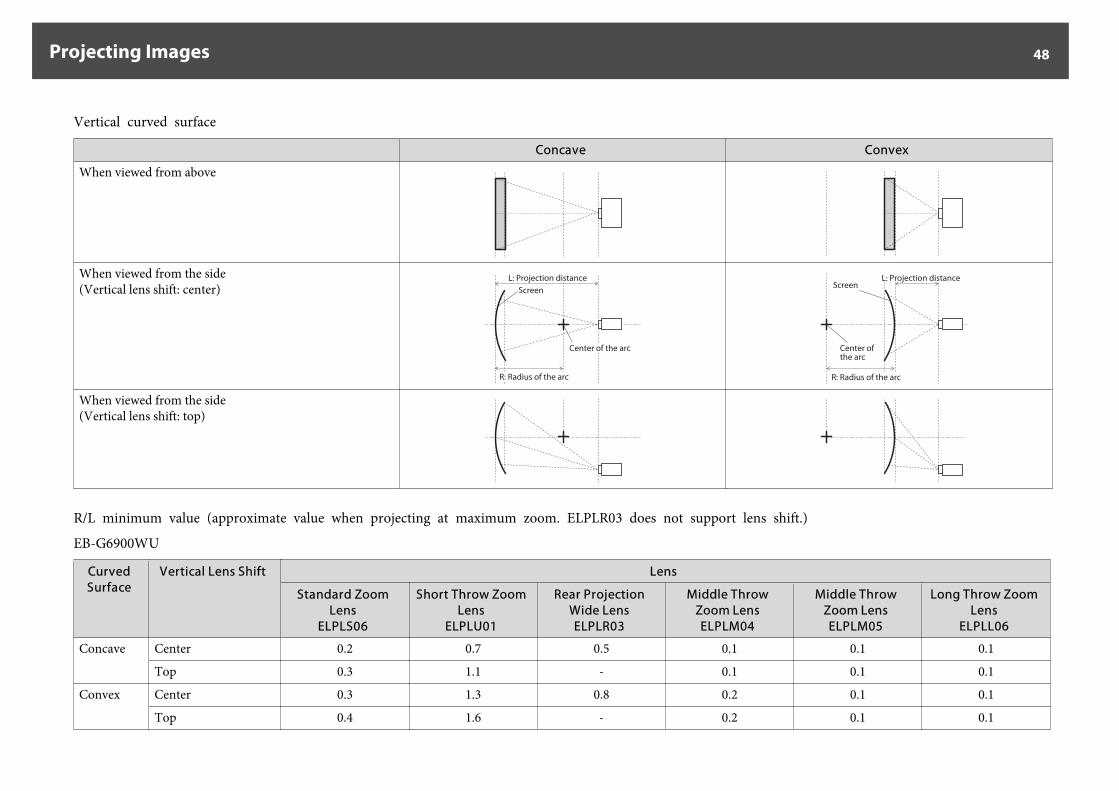
Vertical curved surface
Concave Convex
When viewed from above
When viewed from the side(Vertical lens shift: center) Screen
Center of the arc
R: Radius of the arc
L: Projection distanceScreen
Center of the arc
R: Radius of the arc
L: Projection distance
When viewed from the side(Vertical lens shift: top)
R/L minimum value (approximate value when projecting at maximum zoom. ELPLR03 does not support lens shift.)
EB-G6900WU
CurvedSurface
Vertical Lens Shift Lens
Standard ZoomLens
ELPLS06
Short Throw ZoomLens
ELPLU01
Rear ProjectionWide LensELPLR03
Middle ThrowZoom LensELPLM04
Middle ThrowZoom LensELPLM05
Long Throw ZoomLens
ELPLL06
Concave Center 0.2 0.7 0.5 0.1 0.1 0.1
Top 0.3 1.1 - 0.1 0.1 0.1
Convex Center 0.3 1.3 0.8 0.2 0.1 0.1
Top 0.4 1.6 - 0.2 0.1 0.1
Projecting Images 48
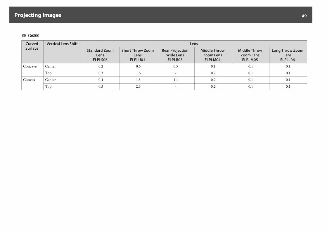
EB-G6800
CurvedSurface
Vertical Lens Shift Lens
Standard ZoomLens
ELPLS06
Short Throw ZoomLens
ELPLU01
Rear ProjectionWide LensELPLR03
Middle ThrowZoom LensELPLM04
Middle ThrowZoom LensELPLM05
Long Throw ZoomLens
ELPLL06
Concave Center 0.2 0.6 0.5 0.1 0.1 0.1
Top 0.3 1.6 - 0.2 0.1 0.1
Convex Center 0.4 1.5 1.1 0.2 0.1 0.1
Top 0.5 2.3 - 0.2 0.1 0.1
Projecting Images 49
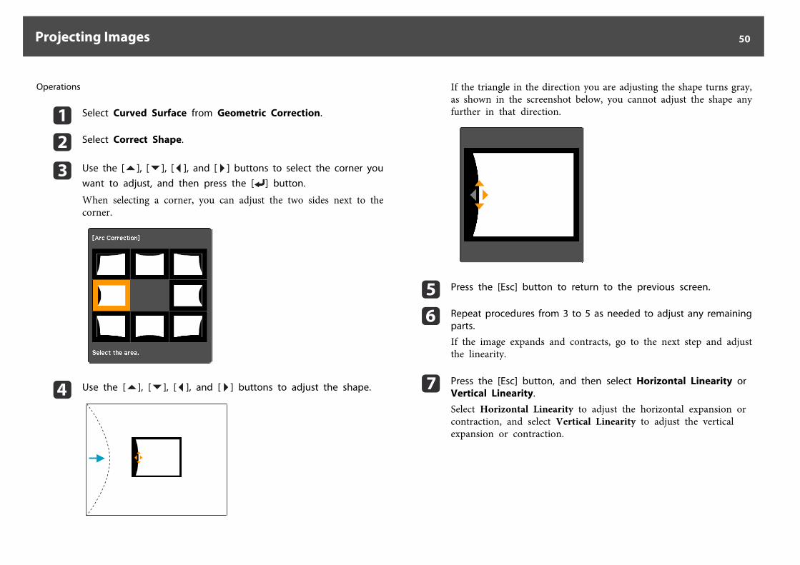
Operations
a Select Curved Surface from Geometric Correction.
b Select Correct Shape.
c Use the [ ], [ ], [ ], and [ ] buttons to select the corner youwant to adjust, and then press the [ ] button.
When selecting a corner, you can adjust the two sides next to thecorner.
d Use the [ ], [ ], [ ], and [ ] buttons to adjust the shape.
If the triangle in the direction you are adjusting the shape turns gray,as shown in the screenshot below, you cannot adjust the shape anyfurther in that direction.
e Press the [Esc] button to return to the previous screen.
f Repeat procedures from 3 to 5 as needed to adjust any remainingparts.
If the image expands and contracts, go to the next step and adjustthe linearity.
g Press the [Esc] button, and then select Horizontal Linearity orVertical Linearity.
Select Horizontal Linearity to adjust the horizontal expansion orcontraction, and select Vertical Linearity to adjust the verticalexpansion or contraction.
Projecting Images 50
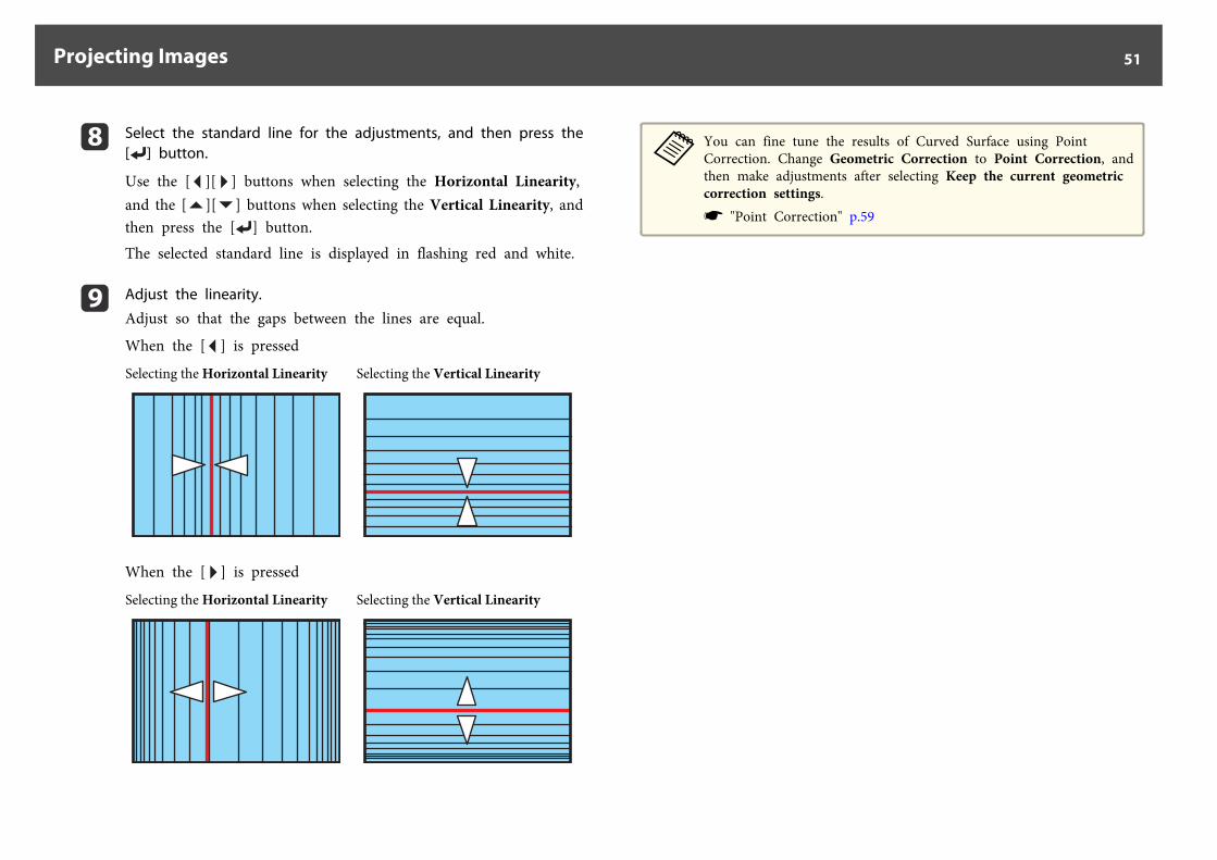
h Select the standard line for the adjustments, and then press the[ ] button.
Use the [ ][ ] buttons when selecting the Horizontal Linearity,and the [ ][ ] buttons when selecting the Vertical Linearity, andthen press the [ ] button.The selected standard line is displayed in flashing red and white.
i Adjust the linearity.
Adjust so that the gaps between the lines are equal.
When the [ ] is pressed
Selecting the Horizontal Linearity Selecting the Vertical Linearity
When the [ ] is pressed
Selecting the Horizontal Linearity Selecting the Vertical Linearity
aYou can fine tune the results of Curved Surface using PointCorrection. Change Geometric Correction to Point Correction, andthen make adjustments after selecting Keep the current geometriccorrection settings.s "Point Correction" p.59
Projecting Images 51
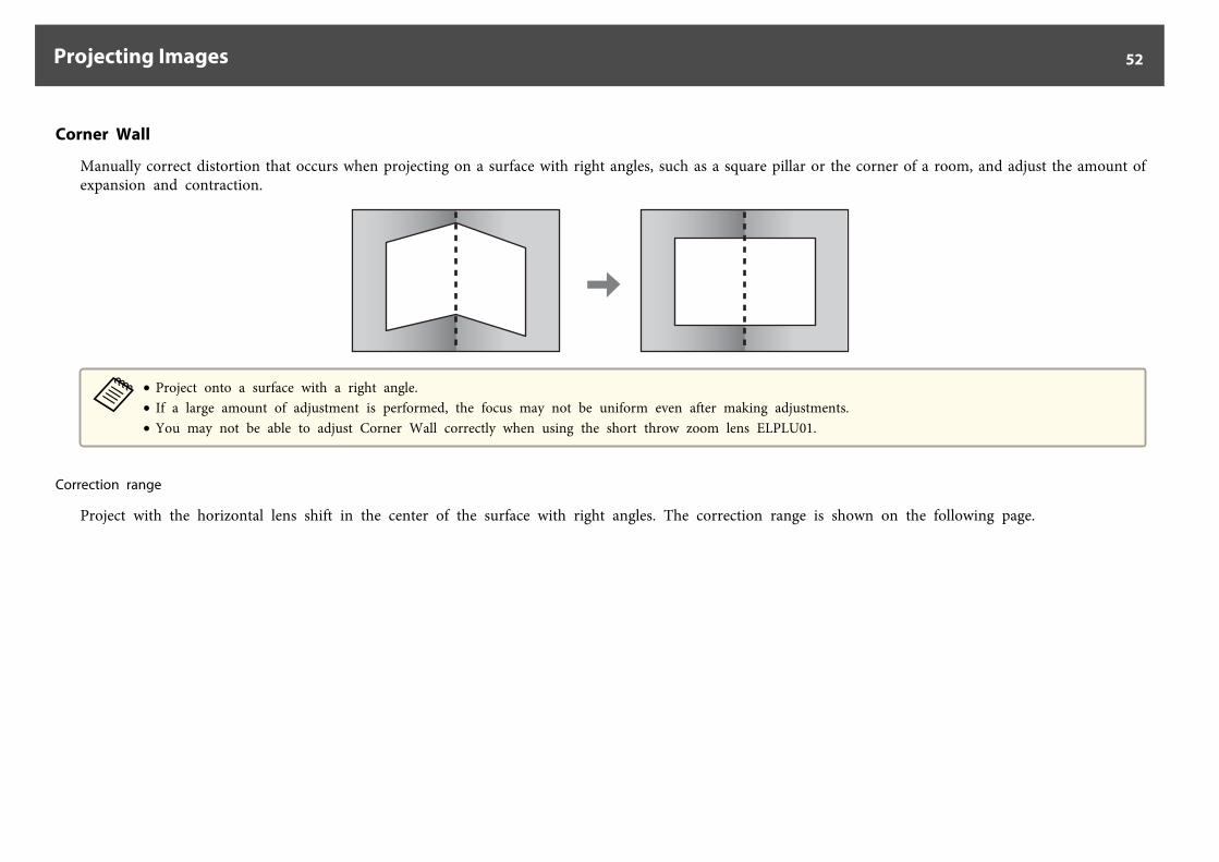
Corner Wall
Manually correct distortion that occurs when projecting on a surface with right angles, such as a square pillar or the corner of a room, and adjust the amount ofexpansion and contraction.
a• Project onto a surface with a right angle.• If a large amount of adjustment is performed, the focus may not be uniform even after making adjustments.• You may not be able to adjust Corner Wall correctly when using the short throw zoom lens ELPLU01.
Correction range
Project with the horizontal lens shift in the center of the surface with right angles. The correction range is shown on the following page.
Projecting Images 52
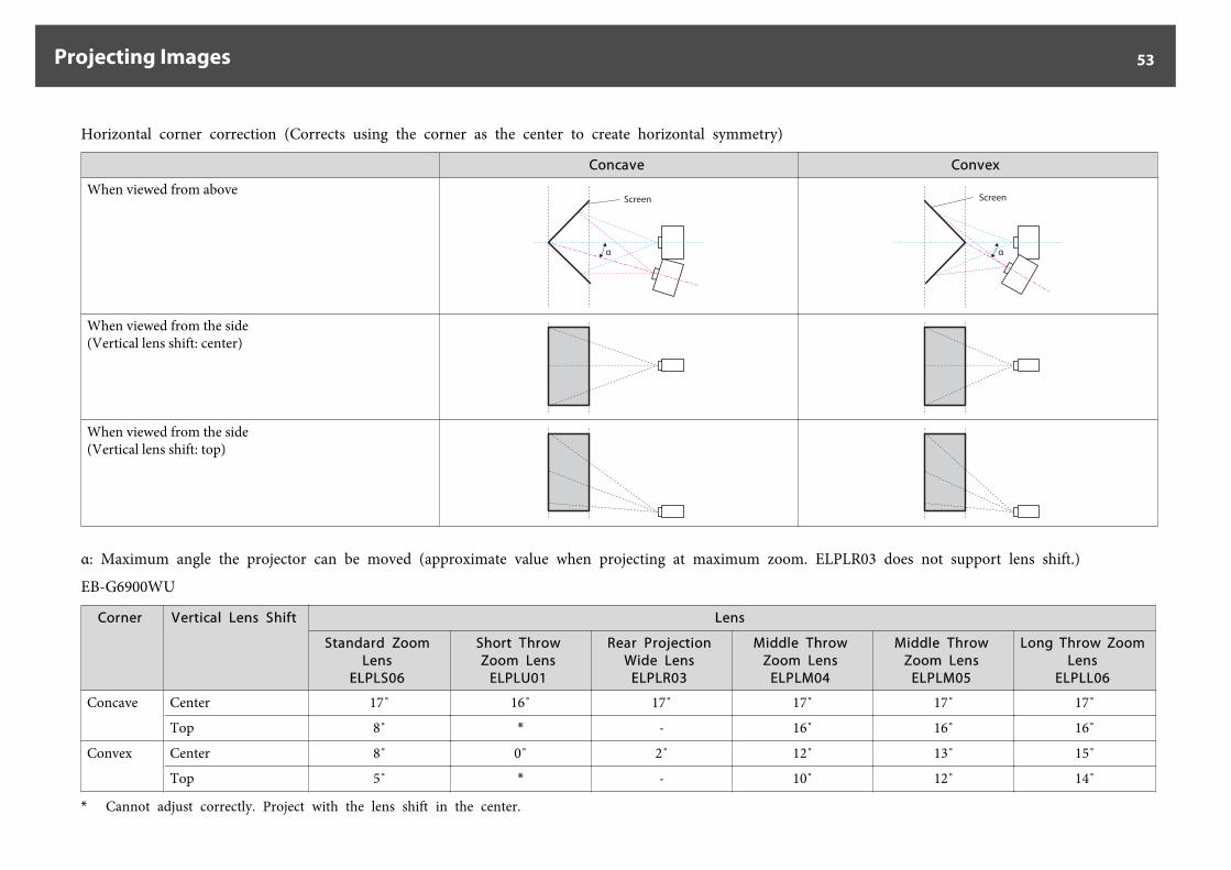
Horizontal corner correction (Corrects using the corner as the center to create horizontal symmetry)
Concave Convex
When viewed from aboveScreen
α
Screen
α
When viewed from the side(Vertical lens shift: center)
When viewed from the side(Vertical lens shift: top)
α: Maximum angle the projector can be moved (approximate value when projecting at maximum zoom. ELPLR03 does not support lens shift.)
EB-G6900WU
Corner Vertical Lens Shift Lens
Standard ZoomLens
ELPLS06
Short ThrowZoom Lens
ELPLU01
Rear ProjectionWide Lens
ELPLR03
Middle ThrowZoom Lens
ELPLM04
Middle ThrowZoom Lens
ELPLM05
Long Throw ZoomLens
ELPLL06
Concave Center 17˚ 16˚ 17˚ 17˚ 17˚ 17˚
Top 8˚ * - 16˚ 16˚ 16˚
Convex Center 8˚ 0˚ 2˚ 12˚ 13˚ 15˚
Top 5˚ * - 10˚ 12˚ 14˚
* Cannot adjust correctly. Project with the lens shift in the center.
Projecting Images 53

EB-G6800
Corner Vertical Lens Shift Lens
Standard ZoomLens
ELPLS06
Short ThrowZoom Lens
ELPLU01
Rear ProjectionWide Lens
ELPLR03
Middle ThrowZoom Lens
ELPLM04
Middle ThrowZoom Lens
ELPLM05
Long Throw ZoomLens
ELPLL06
Concave Center 17˚ 7˚ 16˚ 17˚ 17˚ 17˚
Top 9˚ * - 17˚ 17˚ 17˚
Convex Center 8˚ 0˚ 3˚ 12˚ 14˚ 15˚
Top 7˚ * - 11˚ 13˚ 15˚
* Cannot adjust correctly. Project with the lens shift in the center.
Projecting Images 54
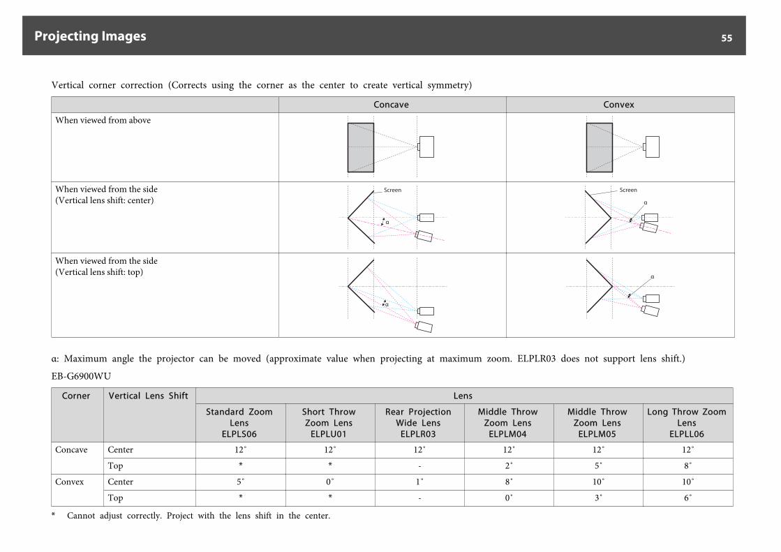
Vertical corner correction (Corrects using the corner as the center to create vertical symmetry)
Concave Convex
When viewed from above
When viewed from the side(Vertical lens shift: center)
Screen
α
Screen
α
When viewed from the side(Vertical lens shift: top)
α
α
α: Maximum angle the projector can be moved (approximate value when projecting at maximum zoom. ELPLR03 does not support lens shift.)
EB-G6900WU
Corner Vertical Lens Shift Lens
Standard ZoomLens
ELPLS06
Short ThrowZoom Lens
ELPLU01
Rear ProjectionWide Lens
ELPLR03
Middle ThrowZoom Lens
ELPLM04
Middle ThrowZoom Lens
ELPLM05
Long Throw ZoomLens
ELPLL06
Concave Center 12˚ 12˚ 12˚ 12˚ 12˚ 12˚
Top * * - 2˚ 5˚ 8˚
Convex Center 5˚ 0˚ 1˚ 8˚ 10˚ 10˚
Top * * - 0˚ 3˚ 6˚
* Cannot adjust correctly. Project with the lens shift in the center.
Projecting Images 55
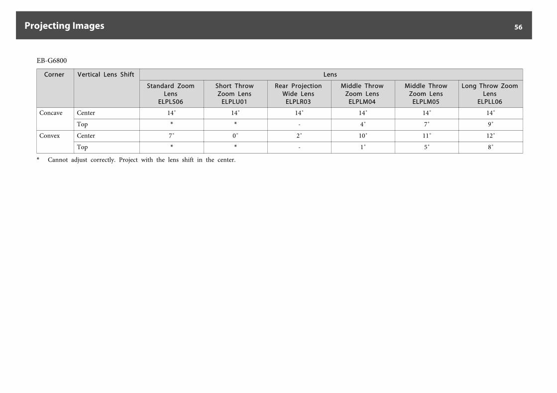
EB-G6800
Corner Vertical Lens Shift Lens
Standard ZoomLens
ELPLS06
Short ThrowZoom Lens
ELPLU01
Rear ProjectionWide Lens
ELPLR03
Middle ThrowZoom Lens
ELPLM04
Middle ThrowZoom Lens
ELPLM05
Long Throw ZoomLens
ELPLL06
Concave Center 14˚ 14˚ 14˚ 14˚ 14˚ 14˚
Top * * - 4˚ 7˚ 9˚
Convex Center 7˚ 0˚ 2˚ 10˚ 11˚ 12˚
Top * * - 1˚ 5˚ 8˚
* Cannot adjust correctly. Project with the lens shift in the center.
Projecting Images 56
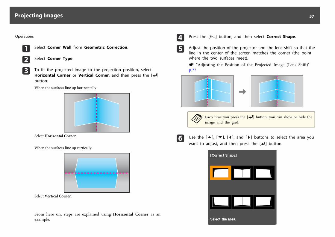
Operations
a Select Corner Wall from Geometric Correction.
b Select Corner Type.
c To fit the projected image to the projection position, selectHorizontal Corner or Vertical Corner, and then press the [ ]button.
When the surfaces line up horizontally
Select Horizontal Corner.
When the surfaces line up vertically
Select Vertical Corner.
From here on, steps are explained using Horizontal Corner as anexample.
d Press the [Esc] button, and then select Correct Shape.
e Adjust the position of the projector and the lens shift so that theline in the center of the screen matches the corner (the pointwhere the two surfaces meet).
s "Adjusting the Position of the Projected Image (Lens Shift)"p.22
aEach time you press the [ ] button, you can show or hide theimage and the grid.
f Use the [ ], [ ], [ ], and [ ] buttons to select the area youwant to adjust, and then press the [ ] button.
Projecting Images 57
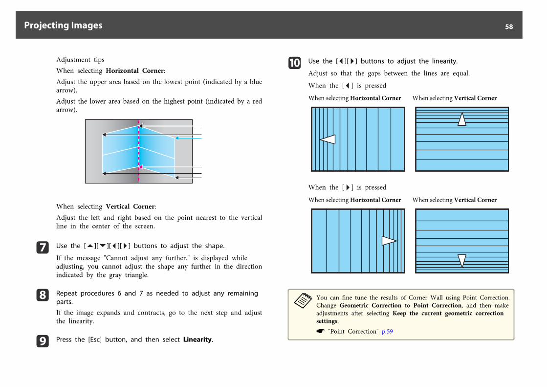
Adjustment tipsWhen selecting Horizontal Corner:Adjust the upper area based on the lowest point (indicated by a bluearrow).Adjust the lower area based on the highest point (indicated by a redarrow).
When selecting Vertical Corner:Adjust the left and right based on the point nearest to the verticalline in the center of the screen.
g Use the [ ][ ][ ][ ] buttons to adjust the shape.
If the message "Cannot adjust any further." is displayed whileadjusting, you cannot adjust the shape any further in the directionindicated by the gray triangle.
h Repeat procedures 6 and 7 as needed to adjust any remainingparts.
If the image expands and contracts, go to the next step and adjustthe linearity.
i Press the [Esc] button, and then select Linearity.
j Use the [ ][ ] buttons to adjust the linearity.
Adjust so that the gaps between the lines are equal.
When the [ ] is pressed
When selecting Horizontal Corner When selecting Vertical Corner
When the [ ] is pressed
When selecting Horizontal Corner When selecting Vertical Corner
aYou can fine tune the results of Corner Wall using Point Correction.Change Geometric Correction to Point Correction, and then makeadjustments after selecting Keep the current geometric correctionsettings.s "Point Correction" p.59
Projecting Images 58
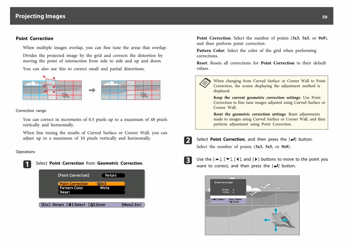
Point Correction
When multiple images overlap, you can fine tune the areas that overlap.
Divides the projected image by the grid and corrects the distortion bymoving the point of intersection from side to side and up and down.
You can also use this to correct small and partial distortions.
Correction range
You can correct in increments of 0.5 pixels up to a maximum of 48 pixelsvertically and horizontally.
When fine tuning the results of Curved Surface or Corner Wall, you canadjust up to a maximum of 10 pixels vertically and horizontally.
Operations
a Select Point Correction from Geometric Correction.
Point Correction: Select the number of points (3x3, 5x5, or 9x9),and then perform point correction.Pattern Color: Select the color of the grid when performingcorrections.Reset: Resets all corrections for Point Correction to their defaultvalues.
aWhen changing from Curved Surface or Corner Wall to PointCorrection, the screen displaying the adjustment method isdisplayed.Keep the current geometric correction settings: Use PointCorrection to fine tune images adjusted using Curved Surface orCorner Wall.Reset the geometric correction settings: Reset adjustmentsmade to images using Curved Surface or Corner Wall, and thenperform adjustment using Point Correction.
b Select Point Correction, and then press the [ ] button.
Select the number of points (3x3, 5x5, or 9x9).
c Use the [ ], [ ], [ ], and [ ] buttons to move to the point youwant to correct, and then press the [ ] button.
Projecting Images 59
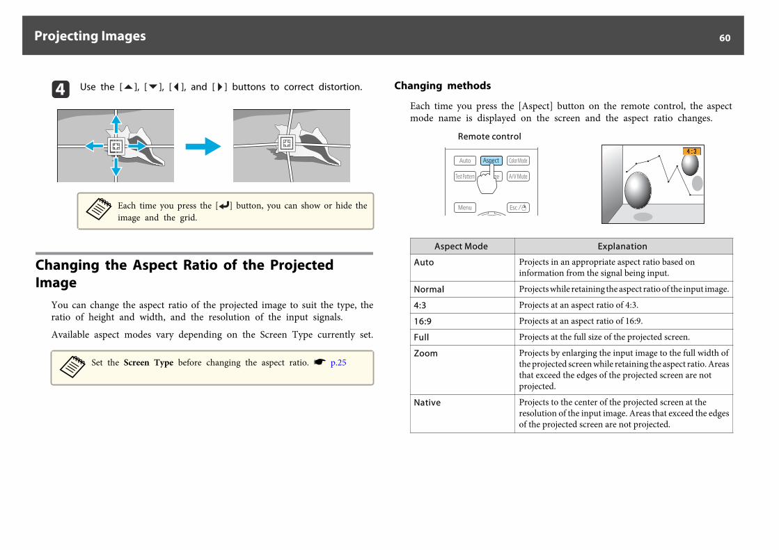
d Use the [ ], [ ], [ ], and [ ] buttons to correct distortion.
aEach time you press the [ ] button, you can show or hide theimage and the grid.
Changing the Aspect Ratio of the Projected Image
You can change the aspect ratio of the projected image to suit the type, theratio of height and width, and the resolution of the input signals.
Available aspect modes vary depending on the Screen Type currently set.
aSet the Screen Type before changing the aspect ratio. s p.25
Changing methods
Each time you press the [Aspect] button on the remote control, the aspectmode name is displayed on the screen and the aspect ratio changes.
Remote control
Aspect Mode Explanation
Auto Projects in an appropriate aspect ratio based oninformation from the signal being input.
Normal Projects while retaining the aspect ratio of the input image.
4:3 Projects at an aspect ratio of 4:3.
16:9 Projects at an aspect ratio of 16:9.
Full Projects at the full size of the projected screen.
Zoom Projects by enlarging the input image to the full width ofthe projected screen while retaining the aspect ratio. Areasthat exceed the edges of the projected screen are notprojected.
Native Projects to the center of the projected screen at theresolution of the input image. Areas that exceed the edgesof the projected screen are not projected.
Projecting Images 60
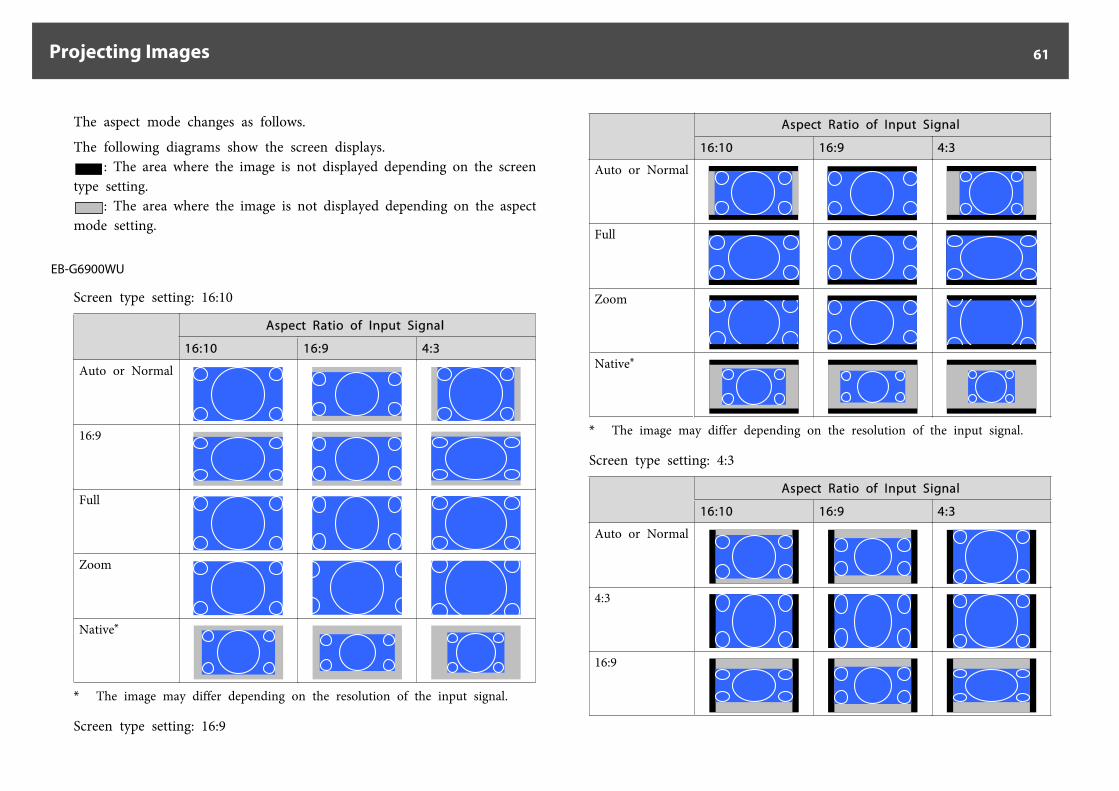
The aspect mode changes as follows.
The following diagrams show the screen displays.: The area where the image is not displayed depending on the screen
type setting.: The area where the image is not displayed depending on the aspect
mode setting.
EB-G6900WU
Screen type setting: 16:10
Aspect Ratio of Input Signal
16:10 16:9 4:3
Auto or Normal
16:9
Full
Zoom
Native*
* The image may differ depending on the resolution of the input signal.
Screen type setting: 16:9
Aspect Ratio of Input Signal
16:10 16:9 4:3
Auto or Normal
Full
Zoom
Native*
* The image may differ depending on the resolution of the input signal.
Screen type setting: 4:3
Aspect Ratio of Input Signal
16:10 16:9 4:3
Auto or Normal
4:3
16:9
Projecting Images 61
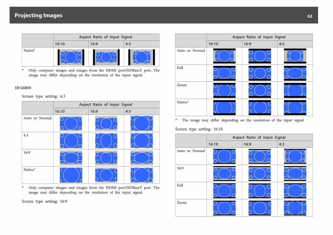
Aspect Ratio of Input Signal
16:10 16:9 4:3
Native*
* Only computer images and images from the HDMI port/HDBaseT port. Theimage may differ depending on the resolution of the input signal.
EB-G6800
Screen type setting: 4:3
Aspect Ratio of Input Signal
16:10 16:9 4:3
Auto or Normal
4:3
16:9
Native*
* Only computer images and images from the HDMI port/HDBaseT port. Theimage may differ depending on the resolution of the input signal.
Screen type setting: 16:9
Aspect Ratio of Input Signal
16:10 16:9 4:3
Auto or Normal
Full
Zoom
Native*
* The image may differ depending on the resolution of the input signal.
Screen type setting: 16:10
Aspect Ratio of Input Signal
16:10 16:9 4:3
Auto or Normal
16:9
Full
Zoom
Projecting Images 62
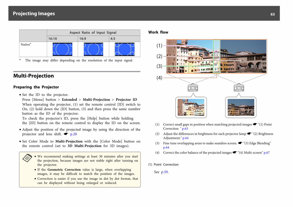
Aspect Ratio of Input Signal
16:10 16:9 4:3
Native*
* The image may differ depending on the resolution of the input signal.
Multi-Projection
Preparing the Projector
• Set the ID to the projector.Press [Menu] button > Extended > Multi-Projection > Projector IDWhen operating the projector, (1) set the remote control [ID] switch toOn, (2) hold down the [ID] button, (3) and then press the same numberbutton as the ID of the projector.To check the projector's ID, press the [Help] button while holdingthe [ID] button on the remote control to display the ID on the screen.
• Adjust the position of the projected image by using the direction of theprojector and lens shift. s p.20
• Set Color Mode to Multi-Projection with the [Color Mode] button onthe remote control (set to 3D Multi-Projection for 3D images).
a• We recommend making settings at least 30 minutes after you start
the projection, because images are not stable right after turning onthe projector.
• If the Geometric Correction value is large, when overlappingimages, it may be difficult to match the position of the images.
• Correction is easier if you use the image in dot by dot format, thatcan be displayed without being enlarged or reduced.
Work flow
(1)
(2)
(3)
(4)
(1) Correct small gaps in position when matching projected images s "(1) PointCorrection " p.63
(2) Adjust the differences in brightness for each projector lamp s "(2) BrightnessAdjustment." p.64
(3) Fine tune overlapping areas to make seamless screen. s "(3) Edge Blending"p.64
(4) Correct the color balance of the projected images s "(4) Multi-screen" p.67
(1) Point Correction
See p.59.
Projecting Images 63
(2) Brightness Adjustment.
Adjust the Brightness Level so that the brightness of the lamp for eachprojector matches.
Press [Menu] button > Extended > Multi-Projection > Brightness Level
Adjust so that all projectors are the same brightness as the darkest lamp.You can adjust the brightness in five levels.
a• Set Power Consumption to Normal.
Press [Menu] button > Settings > Power Consumption• Even if you adjust the Brightness Level, the brightness of each lamp
may not match exactly.
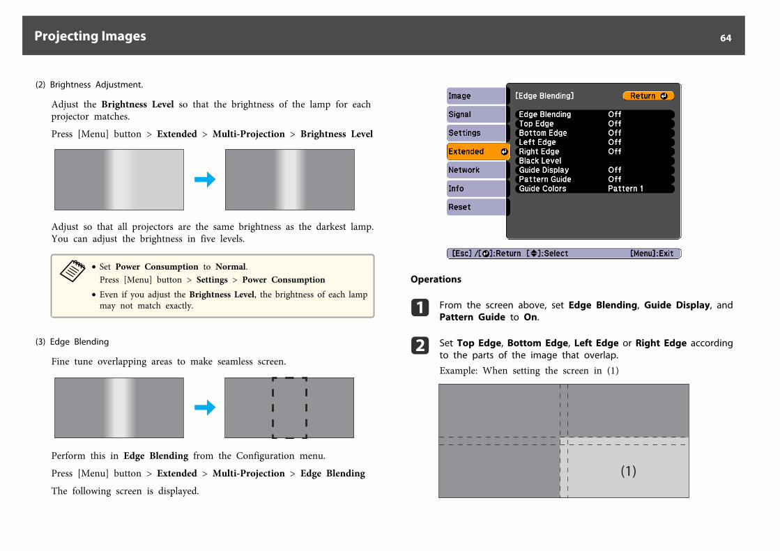
(3) Edge Blending
Fine tune overlapping areas to make seamless screen.
Perform this in Edge Blending from the Configuration menu.
Press [Menu] button > Extended > Multi-Projection > Edge Blending
The following screen is displayed.
Operations
a From the screen above, set Edge Blending, Guide Display, andPattern Guide to On.
b Set Top Edge, Bottom Edge, Left Edge or Right Edge accordingto the parts of the image that overlap.
Example: When setting the screen in (1)
(1)
Projecting Images 64
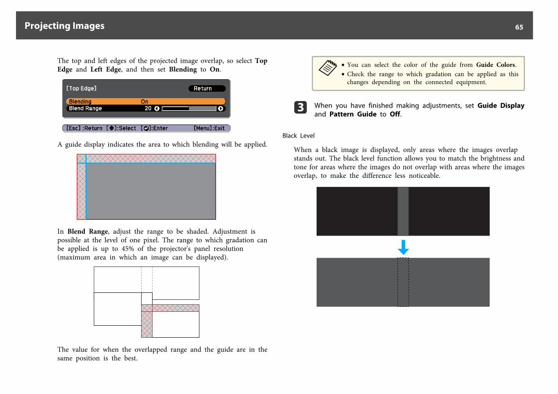
The top and left edges of the projected image overlap, so select TopEdge and Left Edge, and then set Blending to On.
A guide display indicates the area to which blending will be applied.
In Blend Range, adjust the range to be shaded. Adjustment ispossible at the level of one pixel. The range to which gradation canbe applied is up to 45% of the projector's panel resolution(maximum area in which an image can be displayed).
The value for when the overlapped range and the guide are in thesame position is the best.
a• You can select the color of the guide from Guide Colors.• Check the range to which gradation can be applied as this
changes depending on the connected equipment.
c When you have finished making adjustments, set Guide Displayand Pattern Guide to Off.
Black Level
When a black image is displayed, only areas where the images overlapstands out. The black level function allows you to match the brightness andtone for areas where the images do not overlap with areas where the imagesoverlap, to make the difference less noticeable.
Projecting Images 65
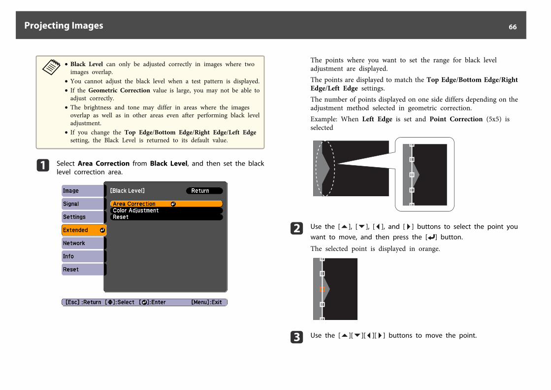
a• Black Level can only be adjusted correctly in images where two
images overlap.• You cannot adjust the black level when a test pattern is displayed.• If the Geometric Correction value is large, you may not be able to
adjust correctly.• The brightness and tone may differ in areas where the images
overlap as well as in other areas even after performing black leveladjustment.
• If you change the Top Edge/Bottom Edge/Right Edge/Left Edgesetting, the Black Level is returned to its default value.
a Select Area Correction from Black Level, and then set the blacklevel correction area.
The points where you want to set the range for black leveladjustment are displayed.The points are displayed to match the Top Edge/Bottom Edge/RightEdge/Left Edge settings.The number of points displayed on one side differs depending on theadjustment method selected in geometric correction.Example: When Left Edge is set and Point Correction (5x5) isselected
b Use the [ ], [ ], [ ], and [ ] buttons to select the point youwant to move, and then press the [ ] button.
The selected point is displayed in orange.
c Use the [ ][ ][ ][ ] buttons to move the point.
Projecting Images 66
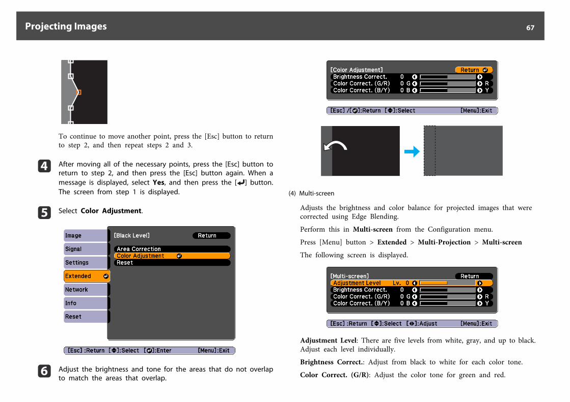
To continue to move another point, press the [Esc] button to returnto step 2, and then repeat steps 2 and 3.
d After moving all of the necessary points, press the [Esc] button toreturn to step 2, and then press the [Esc] button again. When amessage is displayed, select Yes, and then press the [ ] button.The screen from step 1 is displayed.
e Select Color Adjustment.
f Adjust the brightness and tone for the areas that do not overlapto match the areas that overlap.
(4) Multi-screen
Adjusts the brightness and color balance for projected images that werecorrected using Edge Blending.
Perform this in Multi-screen from the Configuration menu.
Press [Menu] button > Extended > Multi-Projection > Multi-screen
The following screen is displayed.
Adjustment Level: There are five levels from white, gray, and up to black.Adjust each level individually.
Brightness Correct.: Adjust from black to white for each color tone.
Color Correct. (G/R): Adjust the color tone for green and red.
Projecting Images 67
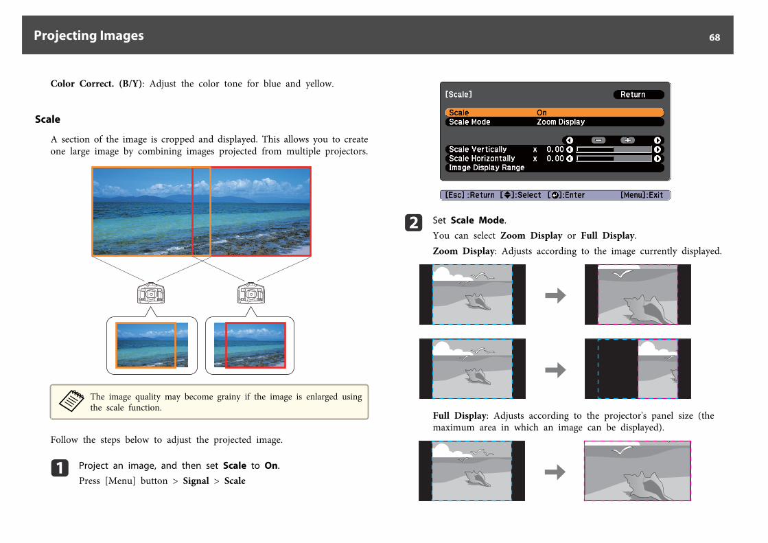
Color Correct. (B/Y): Adjust the color tone for blue and yellow.
Scale
A section of the image is cropped and displayed. This allows you to createone large image by combining images projected from multiple projectors.
aThe image quality may become grainy if the image is enlarged usingthe scale function.
Follow the steps below to adjust the projected image.
a Project an image, and then set Scale to On.
Press [Menu] button > Signal > Scale
b Set Scale Mode.
You can select Zoom Display or Full Display.Zoom Display: Adjusts according to the image currently displayed.
Full Display: Adjusts according to the projector's panel size (themaximum area in which an image can be displayed).
Projecting Images 68
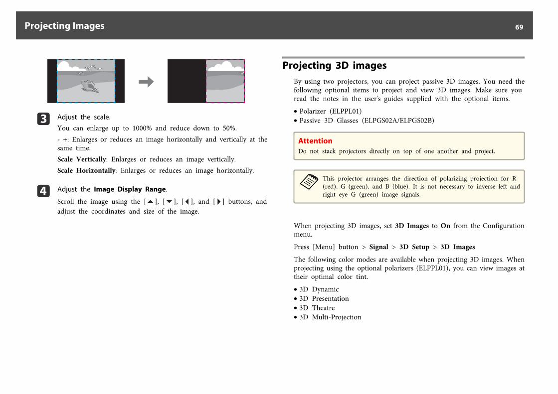
c Adjust the scale.
You can enlarge up to 1000% and reduce down to 50%.- +: Enlarges or reduces an image horizontally and vertically at thesame time.Scale Vertically: Enlarges or reduces an image vertically.Scale Horizontally: Enlarges or reduces an image horizontally.
d Adjust the Image Display Range.
Scroll the image using the [ ], [ ], [ ], and [ ] buttons, andadjust the coordinates and size of the image.
Projecting 3D imagesBy using two projectors, you can project passive 3D images. You need thefollowing optional items to project and view 3D images. Make sure youread the notes in the user's guides supplied with the optional items.
• Polarizer (ELPPL01)• Passive 3D Glasses (ELPGS02A/ELPGS02B)
AttentionDo not stack projectors directly on top of one another and project.
aThis projector arranges the direction of polarizing projection for R(red), G (green), and B (blue). It is not necessary to inverse left andright eye G (green) image signals.
When projecting 3D images, set 3D Images to On from the Configurationmenu.
Press [Menu] button > Signal > 3D Setup > 3D Images
The following color modes are available when projecting 3D images. Whenprojecting using the optional polarizers (ELPPL01), you can view images attheir optimal color tint.
• 3D Dynamic• 3D Presentation• 3D Theatre• 3D Multi-Projection
Projecting Images 69
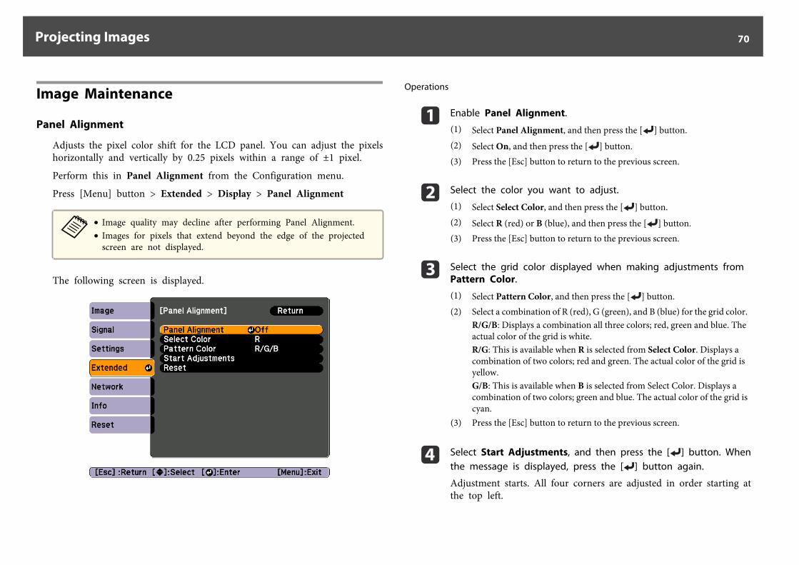
Image Maintenance
Panel Alignment
Adjusts the pixel color shift for the LCD panel. You can adjust the pixelshorizontally and vertically by 0.25 pixels within a range of ±1 pixel.
Perform this in Panel Alignment from the Configuration menu.
Press [Menu] button > Extended > Display > Panel Alignment
a• Image quality may decline after performing Panel Alignment.• Images for pixels that extend beyond the edge of the projected
screen are not displayed.
The following screen is displayed.
Operations
a Enable Panel Alignment.
(1) Select Panel Alignment, and then press the [ ] button.(2) Select On, and then press the [ ] button.(3) Press the [Esc] button to return to the previous screen.
b Select the color you want to adjust.
(1) Select Select Color, and then press the [ ] button.(2) Select R (red) or B (blue), and then press the [ ] button.(3) Press the [Esc] button to return to the previous screen.
c Select the grid color displayed when making adjustments fromPattern Color.
(1) Select Pattern Color, and then press the [ ] button.(2) Select a combination of R (red), G (green), and B (blue) for the grid color.
R/G/B: Displays a combination all three colors; red, green and blue. Theactual color of the grid is white.R/G: This is available when R is selected from Select Color. Displays acombination of two colors; red and green. The actual color of the grid isyellow.G/B: This is available when B is selected from Select Color. Displays acombination of two colors; green and blue. The actual color of the grid iscyan.
(3) Press the [Esc] button to return to the previous screen.
d Select Start Adjustments, and then press the [ ] button. Whenthe message is displayed, press the [ ] button again.
Adjustment starts. All four corners are adjusted in order starting atthe top left.
Projecting Images 70
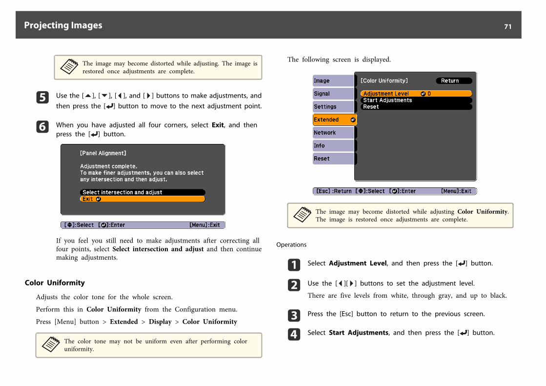
aThe image may become distorted while adjusting. The image isrestored once adjustments are complete.
e Use the [ ], [ ], [ ], and [ ] buttons to make adjustments, andthen press the [ ] button to move to the next adjustment point.
f When you have adjusted all four corners, select Exit, and thenpress the [ ] button.
If you feel you still need to make adjustments after correcting allfour points, select Select intersection and adjust and then continuemaking adjustments.
Color Uniformity
Adjusts the color tone for the whole screen.
Perform this in Color Uniformity from the Configuration menu.
Press [Menu] button > Extended > Display > Color Uniformity
aThe color tone may not be uniform even after performing coloruniformity.
The following screen is displayed.
aThe image may become distorted while adjusting Color Uniformity.The image is restored once adjustments are complete.
Operations
a Select Adjustment Level, and then press the [ ] button.
b Use the [ ][ ] buttons to set the adjustment level.
There are five levels from white, through gray, and up to black.
c Press the [Esc] button to return to the previous screen.
d Select Start Adjustments, and then press the [ ] button.
Projecting Images 71
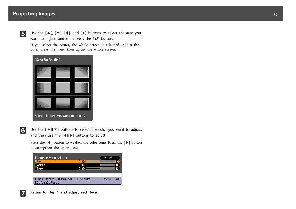
e Use the [ ], [ ], [ ], and [ ] buttons to select the area youwant to adjust, and then press the [ ] button.
If you select the center, the whole screen is adjusted. Adjust theouter areas first, and then adjust the whole screen.
f Use the [ ][ ] buttons to select the color you want to adjust,
and then use the [ ][ ] buttons to adjust.
Press the [ ] button to weaken the color tone. Press the [ ] buttonto strengthen the color tone.
g Return to step 1 and adjust each level.
Projecting Images 72
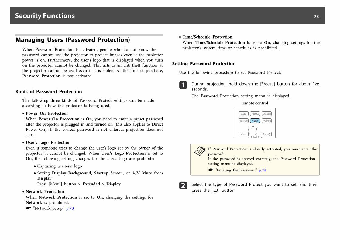
Managing Users (Password Protection)When Password Protection is activated, people who do not know thepassword cannot use the projector to project images even if the projectorpower is on. Furthermore, the user's logo that is displayed when you turnon the projector cannot be changed. This acts as an anti-theft function asthe projector cannot be used even if it is stolen. At the time of purchase,Password Protection is not activated.
Kinds of Password Protection
The following three kinds of Password Protect settings can be madeaccording to how the projector is being used.
• Power On ProtectionWhen Power On Protection is On, you need to enter a preset passwordafter the projector is plugged in and turned on (this also applies to DirectPower On). If the correct password is not entered, projection does notstart.
• User's Logo ProtectionEven if someone tries to change the user's logo set by the owner of theprojector, it cannot be changed. When User's Logo Protection is set toOn, the following setting changes for the user's logo are prohibited.
• Capturing a user's logo• Setting Display Background, Startup Screen, or A/V Mute from
DisplayPress [Menu] button > Extended > Display
• Network ProtectionWhen Network Protection is set to On, changing the settings forNetwork is prohibited.s "Network Setup" p.78
• Time/Schedule ProtectionWhen Time/Schedule Protection is set to On, changing settings for theprojector's system time or schedules is prohibited.
Setting Password Protection
Use the following procedure to set Password Protect.
a During projection, hold down the [Freeze] button for about fiveseconds.
The Password Protection setting menu is displayed.Remote control
aIf Password Protection is already activated, you must enter thepassword.If the password is entered correctly, the Password Protectionsetting menu is displayed.s "Entering the Password" p.74
b Select the type of Password Protect you want to set, and thenpress the [ ] button.
Security Functions 73
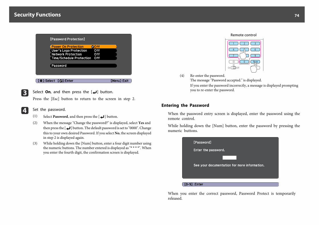
c Select On, and then press the [ ] button.
Press the [Esc] button to return to the screen in step 2.
d Set the password.
(1) Select Password, and then press the [ ] button.(2) When the message "Change the password?" is displayed, select Yes and
then press the [ ] button. The default password is set to "0000". Changethis to your own desired Password. If you select No, the screen displayedin step 2 is displayed again.
(3) While holding down the [Num] button, enter a four digit number usingthe numeric buttons. The number entered is displayed as "* * * *". Whenyou enter the fourth digit, the confirmation screen is displayed.
Remote control
(4) Re-enter the password.The message "Password accepted." is displayed.If you enter the password incorrectly, a message is displayed promptingyou to re-enter the password.
Entering the Password
When the password entry screen is displayed, enter the password using theremote control.
While holding down the [Num] button, enter the password by pressing thenumeric buttons.
When you enter the correct password, Password Protect is temporarilyreleased.
Security Functions 74
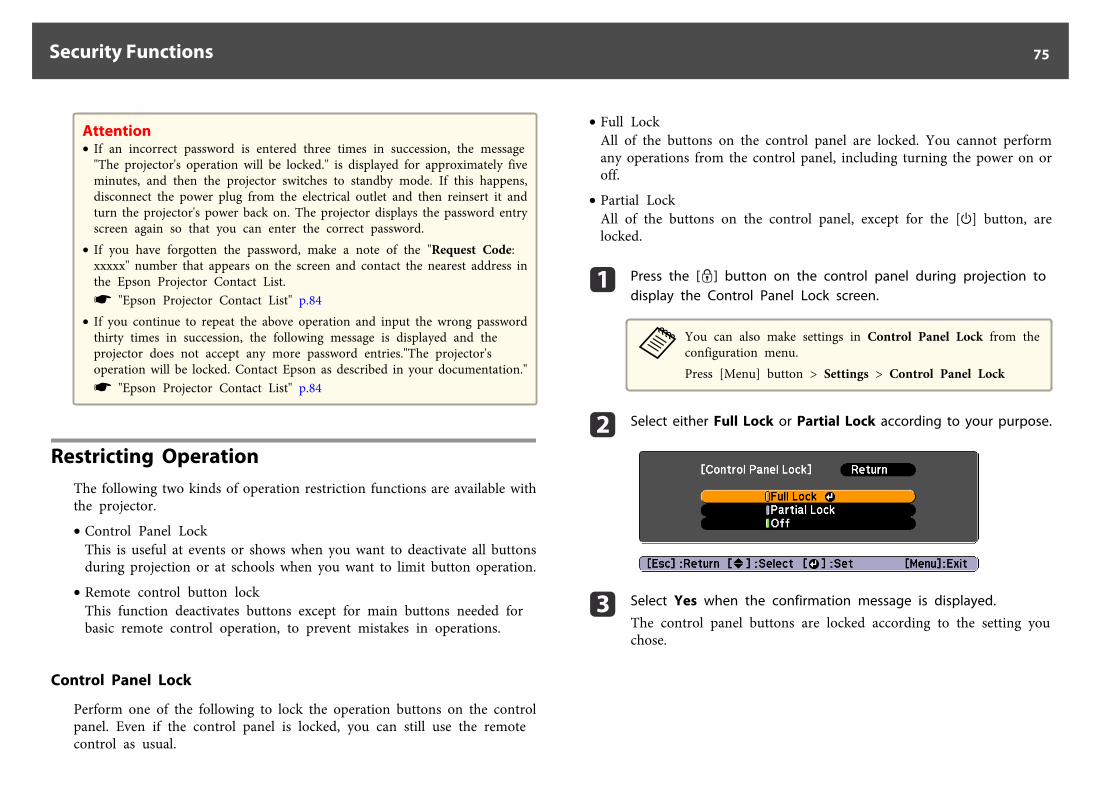
Attention• If an incorrect password is entered three times in succession, the message
"The projector's operation will be locked." is displayed for approximately fiveminutes, and then the projector switches to standby mode. If this happens,disconnect the power plug from the electrical outlet and then reinsert it andturn the projector's power back on. The projector displays the password entryscreen again so that you can enter the correct password.
• If you have forgotten the password, make a note of the "Request Code:xxxxx" number that appears on the screen and contact the nearest address inthe Epson Projector Contact List.s "Epson Projector Contact List" p.84
• If you continue to repeat the above operation and input the wrong passwordthirty times in succession, the following message is displayed and theprojector does not accept any more password entries."The projector'soperation will be locked. Contact Epson as described in your documentation."s "Epson Projector Contact List" p.84
Restricting OperationThe following two kinds of operation restriction functions are available withthe projector.
• Control Panel LockThis is useful at events or shows when you want to deactivate all buttonsduring projection or at schools when you want to limit button operation.
• Remote control button lockThis function deactivates buttons except for main buttons needed forbasic remote control operation, to prevent mistakes in operations.
Control Panel Lock
Perform one of the following to lock the operation buttons on the controlpanel. Even if the control panel is locked, you can still use the remotecontrol as usual.
• Full LockAll of the buttons on the control panel are locked. You cannot performany operations from the control panel, including turning the power on oroff.
• Partial LockAll of the buttons on the control panel, except for the [t] button, arelocked.
a Press the [ ] button on the control panel during projection todisplay the Control Panel Lock screen.
aYou can also make settings in Control Panel Lock from theconfiguration menu.Press [Menu] button > Settings > Control Panel Lock
b Select either Full Lock or Partial Lock according to your purpose.
c Select Yes when the confirmation message is displayed.
The control panel buttons are locked according to the setting youchose.
Security Functions 75
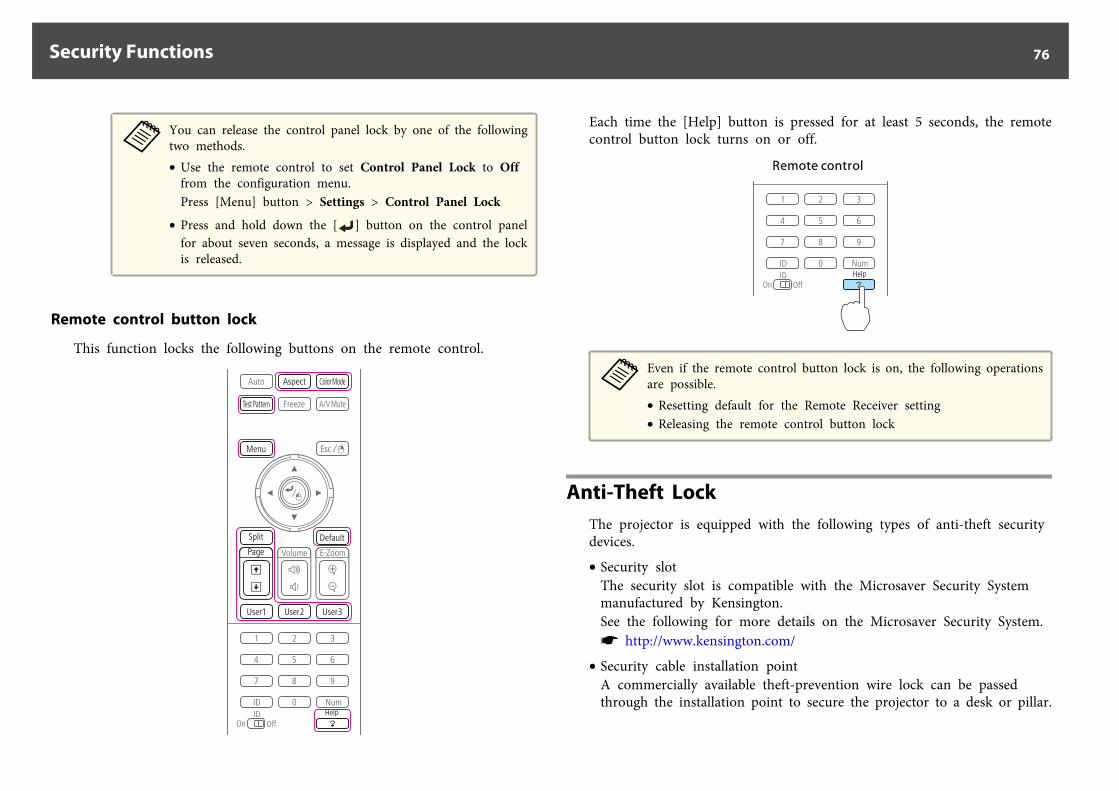
aYou can release the control panel lock by one of the followingtwo methods.• Use the remote control to set Control Panel Lock to Off
from the configuration menu.Press [Menu] button > Settings > Control Panel Lock
• Press and hold down the [ ] button on the control panelfor about seven seconds, a message is displayed and the lockis released.
Remote control button lock
This function locks the following buttons on the remote control.
Each time the [Help] button is pressed for at least 5 seconds, the remotecontrol button lock turns on or off.
Remote control
aEven if the remote control button lock is on, the following operationsare possible.• Resetting default for the Remote Receiver setting• Releasing the remote control button lock
Anti-Theft LockThe projector is equipped with the following types of anti-theft securitydevices.
• Security slotThe security slot is compatible with the Microsaver Security Systemmanufactured by Kensington.See the following for more details on the Microsaver Security System.s http://www.kensington.com/
• Security cable installation pointA commercially available theft-prevention wire lock can be passedthrough the installation point to secure the projector to a desk or pillar.
Security Functions 76
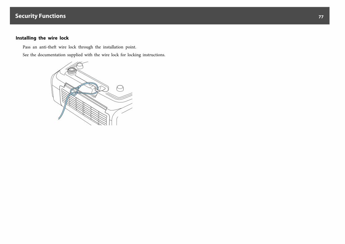
Installing the wire lock
Pass an anti-theft wire lock through the installation point.
See the documentation supplied with the wire lock for locking instructions.
Security Functions 77
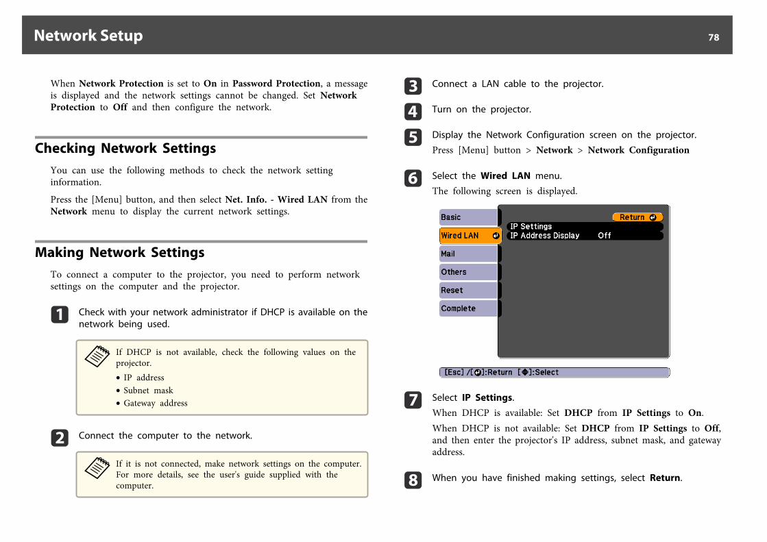
When Network Protection is set to On in Password Protection, a messageis displayed and the network settings cannot be changed. Set NetworkProtection to Off and then configure the network.
Checking Network SettingsYou can use the following methods to check the network settinginformation.
Press the [Menu] button, and then select Net. Info. - Wired LAN from theNetwork menu to display the current network settings.
Making Network SettingsTo connect a computer to the projector, you need to perform networksettings on the computer and the projector.
a Check with your network administrator if DHCP is available on thenetwork being used.
aIf DHCP is not available, check the following values on theprojector.• IP address• Subnet mask• Gateway address
b Connect the computer to the network.
aIf it is not connected, make network settings on the computer.For more details, see the user's guide supplied with thecomputer.
c Connect a LAN cable to the projector.
d Turn on the projector.
e Display the Network Configuration screen on the projector.
Press [Menu] button > Network > Network Configuration
f Select the Wired LAN menu.
The following screen is displayed.
g Select IP Settings.
When DHCP is available: Set DHCP from IP Settings to On.When DHCP is not available: Set DHCP from IP Settings to Off,and then enter the projector's IP address, subnet mask, and gatewayaddress.
h When you have finished making settings, select Return.
Network Setup 78
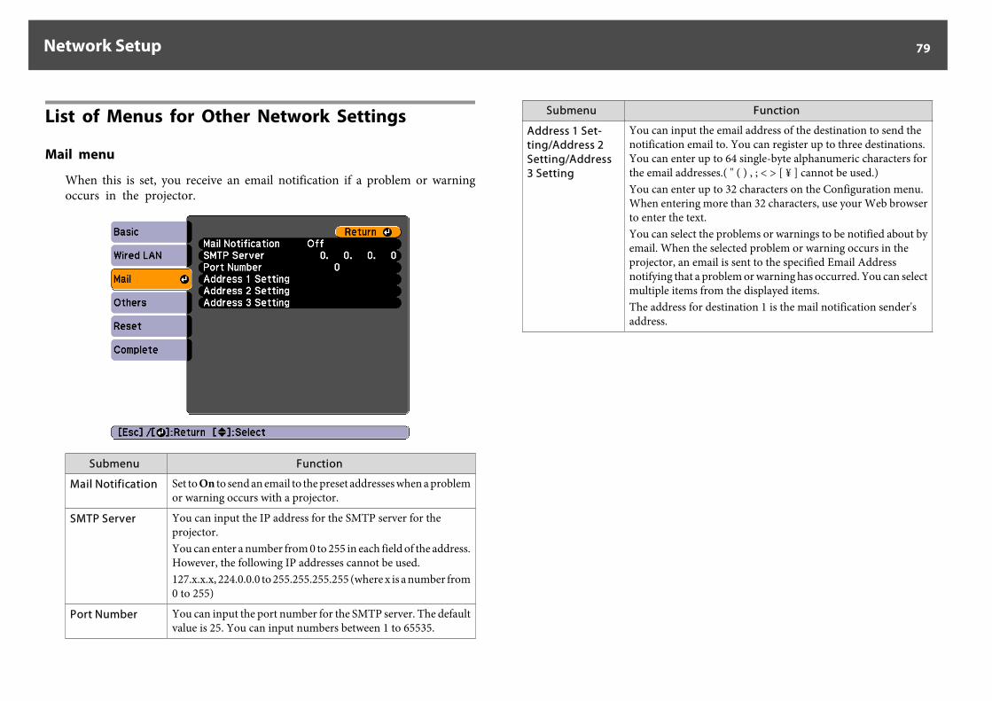
List of Menus for Other Network Settings
Mail menu
When this is set, you receive an email notification if a problem or warningoccurs in the projector.
Submenu Function
Mail Notification Set to On to send an email to the preset addresses when a problemor warning occurs with a projector.
SMTP Server You can input the IP address for the SMTP server for theprojector.You can enter a number from 0 to 255 in each field of the address.However, the following IP addresses cannot be used.127.x.x.x, 224.0.0.0 to 255.255.255.255 (where x is a number from0 to 255)
Port Number You can input the port number for the SMTP server. The defaultvalue is 25. You can input numbers between 1 to 65535.
Submenu Function
Address 1 Set-ting/Address 2Setting/Address3 Setting
You can input the email address of the destination to send thenotification email to. You can register up to three destinations.You can enter up to 64 single-byte alphanumeric characters forthe email addresses.( " ( ) , ; < > [ ¥ ] cannot be used.)You can enter up to 32 characters on the Configuration menu.When entering more than 32 characters, use your Web browserto enter the text.You can select the problems or warnings to be notified about byemail. When the selected problem or warning occurs in theprojector, an email is sent to the specified Email Addressnotifying that a problem or warning has occurred. You can selectmultiple items from the displayed items.The address for destination 1 is the mail notification sender'saddress.
Network Setup 79
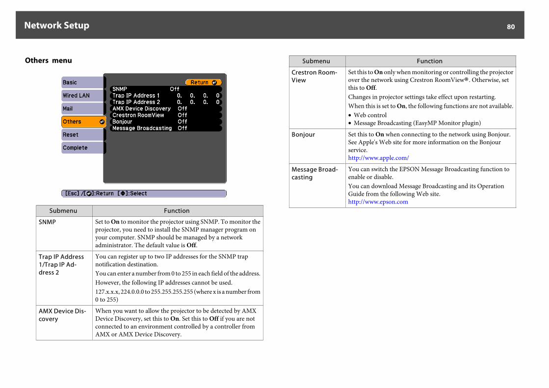
Others menu
Submenu Function
SNMP Set to On to monitor the projector using SNMP. To monitor theprojector, you need to install the SNMP manager program onyour computer. SNMP should be managed by a networkadministrator. The default value is Off.
Trap IP Address1/Trap IP Ad-dress 2
You can register up to two IP addresses for the SNMP trapnotification destination.You can enter a number from 0 to 255 in each field of the address.However, the following IP addresses cannot be used.127.x.x.x, 224.0.0.0 to 255.255.255.255 (where x is a number from0 to 255)
AMX Device Dis-covery
When you want to allow the projector to be detected by AMXDevice Discovery, set this to On. Set this to Off if you are notconnected to an environment controlled by a controller fromAMX or AMX Device Discovery.
Submenu Function
Crestron Room-View
Set this to On only when monitoring or controlling the projectorover the network using Crestron RoomView®. Otherwise, setthis to Off.Changes in projector settings take effect upon restarting.When this is set to On, the following functions are not available.• Web control• Message Broadcasting (EasyMP Monitor plugin)
Bonjour Set this to On when connecting to the network using Bonjour.See Apple's Web site for more information on the Bonjourservice.http://www.apple.com/
Message Broad-casting
You can switch the EPSON Message Broadcasting function toenable or disable.You can download Message Broadcasting and its OperationGuide from the following Web site.http://www.epson.com
Network Setup 80
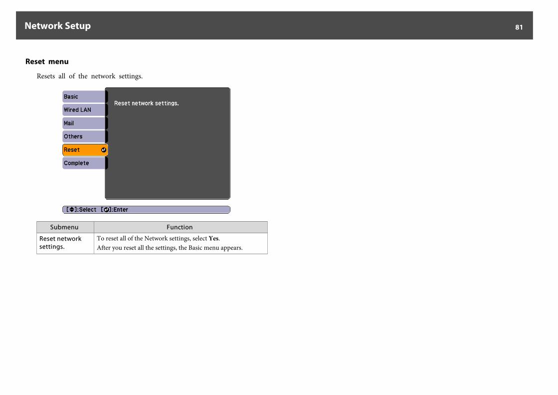
Reset menu
Resets all of the network settings.
Submenu Function
Reset networksettings.
To reset all of the Network settings, select Yes.After you reset all the settings, the Basic menu appears.
Network Setup 81
There are many glass parts and precision components inside the projector.To prevent damage due to impacts when transporting, handle the projectoras follows.
Moving NearbyCheck the following points, and move the projector carefully.
• Turn off the power to the projector and disconnect all cables.• Attach the cover to the lens.
CautionDo not carry the projector by one person.Two people are needed to unpack or carry the projector.
When Transporting
Preparing packaging
After checking the points in "Moving Nearby", prepare the following andthen pack up the projector.
• Remove the lens unit if an option lens, other than the standard zoomlens, is installed. Attach the standard zoom lens if the projector has abuilt-in lens. If the projector does not have a lens, attach the cover thatwas on the lens mount when you purchased the projector.
• Set the horizontal and vertical lens shift to the center.s "Adjusting the Position of the Projected Image (Lens Shift)" p.22
Notes when packing and transporting
Enclose the projector securely in buffer material to protect it from shock,and place it into a strong cardboard container. Be sure to notify the carriercompany that the contents are fragile.
Notes on Transportation 82
All rights reserved. No part of this publication may be reproduced, stored in a retrievalsystem, or transmitted in any form or by any means, electronic, mechanical,photocopying, recording, or otherwise, without the prior written permission of SeikoEpson Corporation. No patent liability is assumed with respect to the use of theinformation contained herein. Neither is any liability assumed for damages resultingfrom the use of the information contained herein.
Neither Seiko Epson Corporation nor its affiliates shall be liable to the purchaser of thisproduct or third parties for damages, losses, costs, or expenses incurred by thepurchaser or third parties as a result of: accident, misuse, or abuse of this product orunauthorized modifications, repairs, or alterations to this product, or (excluding theU.S.) failure to strictly comply with Seiko Epson Corporation's operating andmaintenance instructions.
Seiko Epson Corporation shall not be liable against any damages or problems arisingfrom the use of any options or any consumable products other than those designated asOriginal Epson Products or Epson Approved Products by Seiko Epson Corporation.
The contents of this guide may be changed or updated without further notice.
Illustrations in this guide and the actual projector may differ.
Restriction of UseWhen this product is used for applications requiring high reliability/safety such astransportation devices related to aviation, rail, marine, automotive etc.; disasterprevention devices; various safety devices etc; or functional/precision devices etc, youshould use this product only after giving consideration to including fail-safes andredundancies into your design to maintain safety and total system reliability. Becausethis product was not intended for use in applications requiring extremely highreliability/safety such as aerospace equipment, main communication equipment,nuclear power control equipment, or medical equipment related to direct medical careetc, please make your own judgment on this product’s suitability after a full evaluation.
Trademarks and CopyrightsMac and Mac OS are trademarks of Apple Inc.Microsoft, Windows, Windows Vista, PowerPoint, and Windows logo are trademarksor registered trademarks of Microsoft Corporation in the United States and/or othercountries.HDMI and High-Definition Multimedia Interface are the trademarks or registeredtrademarks of HDMI Licensing LLC.
PJLink trademark is a trademark applied for registration or is already registered inJapan, the United States of America and other countries and areas.The DisplayPort Certified Logo and DisplayPort Icons are Registered Trademarks of theVideo Electronics Standards Association (VESA).The word DisplayPort is a Registered Trademark of VESA in various countries aroundthe world.HDBaseT™ and the HDBaseT Alliance logo are trademarks of the HDBaseT Alliance.Other product names used herein are also for identification purposes only and may betrademarks of their respective owners. Epson disclaims any and all rights in those marks.
©SEIKO EPSON CORPORATION 2013. All rights reserved.
2013.6 412517000
General Notes 83
Addresses and phone numbers are subject to change. For the most currentinformation, check the website of your regional sales office listed below. Ifyou don't find one in your area, visit Epson's main website atwww.epson.com.
EuropeALBANIAITD Sh.p.k.Gjergji Center, Rr MuratToptani04000 Tirana - AlbaniaTel: 00355 4 2256031Fax: 00355 4 2256013Web Address:http://www.itd-al.com
AUSTRIAEpson Deutschland GmbHBuropark Donau Inkustrasse 1-7 / Stg. 6 / 2. OGA-3400 KlosterneuburgAustriaTel: +43 (0) 2243 - 40 181 - 0Fax: +43 (0) 2243 - 40 181 - 30Web Address:http://www.epson.at
BELGIUMEpson Europe B.V.Branch office Belgium
Belgicastraat 4 - Keiberg,B-1930 ZaventemBelgiumTel: +32 2/ 7 12 30 10Fax: +32 2/ 7 12 30 20Hotline: 070 350120Web Address:http://www.epson.be
BOSNIA AND HERZEGOVINANET d.o.o. Computer EngineeringVukovarska 2488000 MostarBosnia and HerzegovinaTel: 00387 36449660Fax: 00387 36449669E-mail: [email protected] Address:http://www.net.com.ba
BULGARIAEpson Service Center Bulgariac/o ProSoft Central ServiceAkad. G. Bonchev SRT. bl.61113 Sofia, BulgariaTel: 00359 2 979 30 75Fax: 00359 2 971 31 79Email: [email protected] Address:http://www.prosoft.bg
CROATIAMR servis d.o.o.
Epson Projector Contact List 84
Dugoselska cesta 510370 Rugvica, CroatiaTel: 00385 16401111Fax: 03485 13654982E-mail: [email protected] Address:http://www.mrservis.hr
CYPRUSMechatronic Ltd.88 Digenis Akritas Avenue"Loizides Centre 2" 2nd FloorCY-1061 Nicosia, CyprusTel: 00357 22582258Fax: 00357 22582222Web Address:http://www.mechatronic.com.cy
CZECH REPUBLICEpson Europe B.V.Branch Office Czech RepublicSlavickova 1a 63800 BrnoCzech RepublicHotline: 800 142 052E-mail: [email protected]@commandWeb Address:http://www.epson.cz
DENMARKEpson Denmark
Transformervej 62730 Herlev, DenmarkTel: 44508585Fax: 44508586Hotline: 80808047Email: [email protected] Address:http://www.epson.dk
ESTONIAEpson Service Center, Estoniac/o Kulbert Ltd. Sirge 4, 10618Tallinn, EstoniaTel: 00372 671 8160Fax: 00372 671 8161Web Address:http://www.epson.ee
FINLANDEpson FinlandRajatorpantie 41 C FI-01640Vantaa, FinlandHotline: 0201 552090Web Address:http://www.epson.fi
FRANCE & DOM-TOM TERRITORYEpson France S.A.150 rue Victor Hugo BP 32092305 Levallois PerretCedex, FranceHotline: 0821017017Web Address:http://www.epson.fr
Epson Projector Contact List 85
GERMANYEpson Deutschland GmbHOtto-Hahn-Strasse 4 D-40670Meerbusch, F.R. GermanyTel: +49-(0)2159-538 0Fax: +49-(0)2159-538 3000Hotline: 01805 2341 10Web Address:http://www.epson.de
GREECEOktabit S.A.Gounari 26,15343 Agia ParaskeviGreeceTel: 0030 210 6067181Fax: 0030 210 6067180Web Address:http://www.oktabitgr.com
HUNGARYEpson EUROPE B.V.Branch Office HungaryInfopark setany 1.HU-1117 Budapest, HungaryHotline: 06 800 14 783E-mail: [email protected] Address:http://www.epson.hu
IRELANDEpson (UK) Ltd.
Westside, London Road Hemel HempsteadHerts HP3 9TD, U.K.Hotline: 01 679 9015Web Address:http://www.epson.ie
ISRAELEpson Israel2 Habonim st.Ramat Gan, IsraelTel: +972-3-5751833Fax: +972-3-575161Web Address:http://www.epson.co.il
ITALYEpson Italia s.p.a.Via M. Vigano de Vizzi, 93/9520092 Cinisello BalsamoMirano, ItalyTel: +39 02. 660321Fax: +39 02. 6123622Hotline: +39 06.60521503Web Address: http://www.epson.it
KAZAKHSTANEpson KazakhstanRep. Office97, Samal-2, bldg A1, 5th floorBusiness Center“Samal Towers”Almaty 050051, KazakhstanTel: +7 727 3560260Fax: +7 727 3560260Web Address:http://www.epson.kz
Epson Projector Contact List 86

LATVIAEpson Service Center, Latviac/o ServiceNet LVJelgavas 361004 Riga, LatviaTel: 00 371 746 0399Fax: 00 371 746 0299Web Address:http://www.epson.lv
LITHUANIAEpson Service Center, Lithuaniac/o ServiceNetGaiziunu 350128 Kaunas, LithuaniaTel: 00 370 37 400 160Fax: 00 370 37 400 161Web Address:http://www.epson.lt
LUXEMBURGEpson Europe B.V.Branch office BelgiumBelgicastraat 4-KeibergB-1930 ZaventemBelgiumTel: +32 2/ 7 12 30 10Fax: +32 2/ 7 12 30 20Hotline: 0900 43010Web Address: http://www.epson.be
MACEDONIADigit Computer Engineering
Bul. Partizanski Odredi 62 VlezII mezanin1000 Skopie, MacedoniaTel: 00389 2 3093393Fax: 00389 2 3093393E-mail: [email protected] Address:http://www.digit.com.mk
NETHERLANDSEpson Europe B.V.Benelux sales officeEntrada 701NL-1096 EJ AmsterdamNetherlandsTel: +31 20 592 65 55Fax: +31 20 592 65 66Hotline: 0900 5050808Web Address: http://www.epson.nl
NORWAYEpson NORWAYFjordveien 31363 Høvik, NorwayTel: 4780030030E-mail: [email protected] Address: http://www.epson.no
POLANDEpson Europe B.V.Branch Office PolandUl. Bokserska 66PL-02-690 WarszawaPolandHotline: (0) 801-646453Web Address: http://www.epson.pl
Epson Projector Contact List 87
PORTUGALEpson Ibérica S.A.U.Branch Office PortugalRua Gregorio Lopes, Lote 1514,Restelo 1400 Lisboa, PortugalTel: 213035400Fax: 213035490Hotline: 707 222 000Web Address: http://www.epson.pt
ROMANIAEpson EUROPE B.V.Branch Office RomaniaStrada Ion Urdareanu nr. 34Sector 5, 050688 BucurestiRomaniaTel: 00 40 21 4025024Fax: 00 40 21 4025020Web Address: http://www.epson.ro
RUSSIAEpson CISSchepkina street, 42, Bldg 2A,3rd floor129110, Moscow, RussiaTel: +7 (495) 777-03-55Fax: +7 (495) 777-03-57Web Address: http://www.epson.ru
UKRAINEEpson Kiev Rep. Office
Pimonenko street, 13,Bldg 7B, Office 1504050, Kiev, UkraineTel: +38 (044) 492 9705Fax: +38 (044) 492 9706Web Address: http://www.epson.ua
SERBIAAVG d.o.o. BeogradPrve pruge 31c11080 Zemun, BeogradRepublic of SerbiaTel: 00381 11 3191868E-mail: [email protected] Address:http://www.a-v-g.rs
SLOVAKIAEpson Europe B.V.Branch Office Czech RepublicSlavickova 1a 63800 BrnoCzech RepublicHotline: 0850 111 429 (national costs)Email: [email protected] Address: http://www.epson.sk
SLOVENIABirotehna d.o.oLitijska Cesta 2591261 Ljubljana - DobrunjeSloveniaTel: 00 386 1 5853 410Fax: 00386 1 5400130E-mail: [email protected] Address:http://www.birotehna.si
Epson Projector Contact List 88
SPAINEpson Ibérica, S.A.U.Av. de Roma, 18-2608290 Cerdanyola del VallésBarcelona, SpainTel: 93 582 15 00Fax: 93 582 15 55Hotline: 902 28 27 26Web Address: http://www.epson.es
SWEDENEpson SwedenBox 329 192 30 SollentunaSwedenTel: 0771-400134Web Address:http://www.epson.se
SWITZERLANDEpson Deutschland GmbHBranch office SwitzerlandZweigniederlassung KlotenSteinackerstrasse 34CH-8302 KlotenSwitzerlandTel: +41 (0) 43 255 70 20Fax: +41 (0) 43 255 70 21Hotline: 0848448820Web Address: http://www.epson.ch
TURKEYTecpro Bilgi TeknolojileriTic. ve San. Ltd. Sti.
Telsizler Mah. ZincirlidereCad.No: 10 Kat 1-2Kagithane 34410 IstanbulTurkeyTel: 0090 212 2684000Fax: 0090 212 2684001E-mail: [email protected] Address: http://www.tecpro.com.tr
UNITED KINGDOMEpson (UK) Ltd.Westside, London RoadHemel Hempstead Herts HP3 9TD, UKTel: (01442) 261144Fax: (01442) 227227Hotline: 08704437766Web Address:http://www.epson.co.uk
AfricaContact your dealerEmail: [email protected] Address:http://www.epson.co.zaorhttp://www.epson.fr
SOUTH AFRICAEpson South Africa
Epson Projector Contact List 89
Grnd. Floor, Durham Hse, Block 6Fourways Office ParkCnr. Fourways Blvd. & Roos Str.Fourways, Gauteng, South AfricaTel: +27 11 465 9621Fax: +27 11 465 1542Helpdesk: 0860 337766or +27 11 201 7741Email: [email protected] Address:http://www.epson.co.za
Middle EastEpson (Middle East)P.O. Box: 17383 Jebel Ali FreeZone DubaiUAE (United Arab Emirates)Tel: +971 4 88 72 1 72Fax: +971 4 88 18 9 45Email: [email protected] Address:http://www.epson.co.ae
North, Central America and Caribbean IslandsCANADAEpson Canada, Ltd.
185 Renfrew DriveMarkham, OntarioL3R 6G3CanadaTel: 905-709-9475or 905-709-3839Web Address:http://www.epson.ca
COSTA RICAEpson Costa Rica, S.A.De la Embajada Americana,200 Sur y 300 OestePavas, San JoseCosta RicaTel: 800-EPSONCR(800-3776627)Web Address:http://www.epson.co.cr
MEXICOEpson Mexico, S.A. de C.V.Boulevard Manuel AvilaCamacho 389Edificio 1, Conjunto LegariaCol Irrigación, C.P. 11500México, DFTel: (52 55) 1323-2052/(52 55) 1323-2096/(52 55) 1323-2127Web Address:http://www.epson.com.mx
ECUADOREpson Ecuador
Epson Projector Contact List 90
Tel: 604-4220 (Guayaquil)(otras ciudades)Web Address:http://www.epson.com.ec
UNITED STATESEpson America, Inc.3840 Kilroy Airport WayLong Beach, CA 90806, USATel: 562-276-4394Web Address:http://www.epson.com
South AmericaARGENTINAEpson Argentina S.R.L.Ave. Belgrano 970(1092) Buenos Aires, ArgentinaTel: (5411) 5167-0300Web Address:http://www.epson.com.ar
BRAZILEpson do Brasil
Av. Tucunaré, 720Tamboré Barueri,Sao Paulo, SP 06460-020BrazilTel: (55 11) 3956-6868Web Address:http://www.epson.com.br
CHILEEpson Chile S.A.La Concepción 322, Piso 3Providencia, Santiago, ChileTel: (562) 484-3400Web Address:http://www.epson.cl
COLOMBIAEpson Colombia Ltd.Calle 100 No 19-54 Piso 7Bogota, ColombiaTel: (571) 523-5000Web Address:http://www.epson.com.co
PERUEpson Peru S.A.Av. Canaval y Moreyra 590San Isidro, Lima, PerúTel: (511) 418 0210Web Address:http://www.epson.com.pe
VENEZUELAEpson Venezuela S.A.
Epson Projector Contact List 91
Calle 4 con Calle 11-1La Urbina Sur.Caracas, VenezuelaTel: (58 212) 240-1111Web Address:http://www.epson.com.ve
Asia and OceaniaAUSTRALIAEpson Australia Pty. Ltd.3 Talavera Road, North Ryde, NSW2113, AUSTRALIATel: 1300 361 054Web Address:http://www.epson.com.au
CHINAEpson (China) Co., Ltd.7F, Jinbao Building,No.89 Jinbao Street,Dongcheng District,Beijing, ChinaZip code: 100005Tel: (86-10) 85221199FAX: (86-10) 85221123Hotline: 400-810-9977Web Address:http://www.epson.com.cn
HONG KONGEpson Hong Kong Ltd.
Unit 715-723, Trade Square,681 Cheung Sha Wan Road,Cheung Sha Wan, Kowloon,Hong KongSupport Hotline: (852) 2827 8911Fax: (852) 2827 4383Web Address:http://www.epson.com.hk
INDIAEpson India Pvt., Ltd.12th Floor, The Millenia, Tower A, No. 1Murphy Road, Ulsoor, Bangalore 560008IndiaTel: 1800 425 0011/1860 3000 1600Web Address:http://www.epson.co.in
INDONESIAPT. Epson IndonesiaWisma Keiai, 16th Floor,Jalan Jenderal Sudirman Kav. 3,Jakarta 10220, IndonesiaTel: 021-5723161Fax: 021-5724357Web Address:http://www.epson.co.id
JAPANSeiko Epson Co.Toyoshina Plant
Epson Projector Contact List 92
VP Customer Support Group:6925 Toyoshinatazawa, Azumino-shi,Nagano-ken, 399-8285 JapanTel: 0263-87-5814Fax: 0263-87-5813Web Address:http://www.epson.jp
KOREAEpson Korea Co., Ltd.11F Milim Tower, 825-22Yeoksam-dong, Gangnam-gu,Seoul, 135-934 KoreaTel: 82-2-558-4270Fax: 82-2-558-4272Web Address:http://www.epson.co.kr
MALAYSIAEpson Malaysia Sdn. Bhd.3rd Floor, East Tower, WismaConsplant 1No.2, Jalan SS 16/4,47500 Subang Jaya,Malaysia.Tel: 03 56 288 288Fax: 03 56 212 088Web Address:http://www.epson.com.my
NEW ZEALANDEpson New Zealand
Level 2,7-9 Fanshawe Street,Auckland Central, 1010New ZealandTel: 09 366 6855Fax 09 366 6865Web Address:http://www.epson.co.nz
PHILIPPINESEpson Philippines Co.8th Floor, Anson's Centre,#23 ADB Avenue, Pasig City 1605,PhilippinesTel: 632-7062609Fax: 632-7062663Web Address:http://www.epson.com.ph
SINGAPOREEpson Singapore Pte. Ltd.1 HarbourFront Place,#03-02 HarbourFront Tower 1,Singapore 098633Tel: 6586 3111Web Address:http://www.epson.com.sg
TAIWANEpson TaiwanTechnology & Trading Ltd.
Epson Projector Contact List 93
14F, No. 7, Song Ren Road,Taipei, TaiwanTel: (02) 8786-6688Fax: (02) 8786-6633Web Address:http://www.epson.com.tw
THAILANDEpson (Thailand) Co., Ltd.195 Empire Tower, 42nd Floor,South Sathorn Road,Yannawa, Sathorn, Bangkok 10120,ThailandTel: 02 685 9888Fax: 02 685 9889Web Address:http://www.epson.co.th
Epson Projector Contact List 94
Related Documents


![EPSON EXCEED YOUR VISION Epson WorkForce AL-M220DN … · EPSON EXCEED YOUR VISION Epson WorkForce AL-M220DN AL-M220DN EP EPSON EPSON WorkForce (1 OBase-T/1 OOBase-TX/1 EP ' 51] EP](https://static.cupdf.com/doc/110x72/5c273ef509d3f2787c8b51ce/epson-exceed-your-vision-epson-workforce-al-m220dn-epson-exceed-your-vision.jpg)