AP1000 European 8. Electric Power Design Control Document EPS-GW-GL-700 8.3-1 Revision 1 8.3 Onsite Power Systems 8.3.1 AC Power Systems 8.3.1.1 Description The onsite ac power system is a non-Class 1E system comprised of a normal, preferred, maintenance and st andby power supplies. The normal, preferred, and maintenance power supplies are included in the main ac power system. The standby power is included in the onsite standby power system. The Class 1E and non-Class 1E 230 Vac instrumentation power supplies are described in subsection 8.3.2 as a part of uninterruptible power supply in the dc power syste ms. 8.3.1.1.1 Onsite AC Power System The main ac power system is a non-Class 1E system and does not perform any safety-related functions. It has nominal bus voltage ratings of 11 kV, 400V, and 230V. Figure 8.3.1-1 shows the main generator, transformers, feeders, buses, and their conne ctions . The ratings of major ac equipment are listed in Table 8.3.1-3. During power generation mode, the turbine generator normally supplies electric power to the plant auxiliary loads through the unit auxiliary transformers. The plant is designed to sustain a load rejection from 100 percent power with the turbine generator continuing stable operation while supplying the plant house loads. The load rejection feature does not perform any safety function. During plant startup, shutdown, and maintenance the generator breaker remains open. The main ac power is provided by the preferred power supply from the high-voltage switchyard ( switchyard voltage is site-specific) through the plant main stepup transformers and two unit auxiliary transformers. Each unit auxiliary transformer supplies power to about 50 percent of the plant loads. A maintenance source is provided to supply power through two reserve auxiliary transforme rs. The maint enance source and the associated reserve auxiliary transformers primary voltage are site specific. The reserve auxiliary transformers are sized so that it can be used in place of the unit auxiliary transformers. The two unit auxiliary transformers have two identically rated 11 kV secondary windings. The third unit auxiliary transformer is a two winding transformer sized to accommodate the electric boiler and site-specific loads. Secondaries of the auxiliary transformers a re connected to the 11 kV switchgear buses by nonsegregated phase buses. The primary of the unit auxiliary transforme r is connected to the main generator isolated phase bus duct tap. The 11 kV switchgear designation, location, connection, and connected loads are shown in Figure 8.3.1- 1. The buses tagged with odd numbers (ES1, ES3, etc.) are connected to one unit auxiliary transformer and the buses tagged with even numbers (ES2, ES4, etc.) are connected to the other unit auxiliary transformer. ES7 is connected to the third unit auxiliary transformer. The 11 kV buses ES1-ES6 are provided with an access to the maintenance source through normally open circuit breaker s connecting the bus to the reserve auxiliary transformer. ES7 is not connected to the maintenance source. Bus trans fer to the maintenance source is manual or automatic through a fast bus transfer scheme.

Welcome message from author
This document is posted to help you gain knowledge. Please leave a comment to let me know what you think about it! Share it to your friends and learn new things together.
Transcript

8/13/2019 EPS GW GL 700 Rev 1 Chapter 8 Section 8 3
http://slidepdf.com/reader/full/eps-gw-gl-700-rev-1-chapter-8-section-8-3 1/65
AP1000 European
8. Electric Power Design Control Document
8.3 Onsite Power Systems
8.3.1 AC Power Systems
8.3.1.1 Description
The onsite ac power system is a non-Class 1E system comprised of a normal, preferred,maintenance and standby power supplies. The normal, preferred, and maintenance power supplies
are included in the main ac power system. The standby power is included in the onsite standby
power system. The Class 1E and non-Class 1E 230 Vac instrumentation power supplies are
described in subsection 8.3.2 as a part of uninterruptible power supply in the dc power systems.
8.3.1.1.1 Onsite AC Power System
The main ac power system is a non-Class 1E system and does not perform any safety-related
functions. It has nominal bus voltage ratings of 11 kV, 400V, and 230V.
Figure 8.3.1-1 shows the main generator, transformers, feeders, buses, and their connections. The
ratings of major ac equipment are listed in Table 8.3.1-3.
During power generation mode, the turbine generator normally supplies electric power to the plant
auxiliary loads through the unit auxiliary transformers. The plant is designed to sustain a load
rejection from 100 percent power with the turbine generator continuing stable operation while
supplying the plant house loads. The load rejection feature does not perform any safety function.
During plant startup, shutdown, and maintenance the generator breaker remains open. The main
ac power is provided by the preferred power supply from the high-voltage switchyard (switchyard
voltage is site-specific) through the plant main stepup transformers and two unit auxiliary
transformers. Each unit auxiliary transformer supplies power to about 50 percent of the plant
loads.
A maintenance source is provided to supply power through two reserve auxiliary transformers.The maintenance source and the associated reserve auxiliary transformers primary voltage are site
specific. The reserve auxiliary transformers are sized so that it can be used in place of the unit
auxiliary transformers.
The two unit auxiliary transformers have two identically rated 11 kV secondary windings. The
thi d it ili t f i t i di t f i d t d t th l t i
8/13/2019 EPS GW GL 700 Rev 1 Chapter 8 Section 8 3
http://slidepdf.com/reader/full/eps-gw-gl-700-rev-1-chapter-8-section-8-3 2/65
AP1000 European
8. Electric Power Design Control Document
The arrangement of the 11 kV buses permits feeding functionally redundant pumps or groups of
loads from separate buses and enhances the plant operational flexibility. The 11 kV switchgear
powers large motors, and the load center transformers. There are two switchgear (ES1 and ES2)
located in the annex building, and five (ES3, ES4, ES5, ES6, and ES7) in the turbine building.
The main stepup transformers have protective devices for sudden pressure, neutral overcurrent,
and differential current. The unit auxiliary transformers have protective devices for suddenpressure, overcurrent, differential current, and neutral overcurrent. The isophase bus duct has
ground fault protection. If these devices sense a fault condition the following actions will be
automatically taken:
• Trip high-side (grid) breaker
• Trip generator breaker
• Trip exciter field breaker
• Trip the 11 kV buses connected to the faulted transformer• Initiate a fast bus transfer of ES1-ES6 11 kV buses ES1-ES6.
The reserve auxiliary transformers have protective devices for sudden pressure, overcurrent, and
differential current and neutral overcurrent. The reserve auxiliary transformers protective devices
trip the reserve supply breaker and any 11 kV buses connected to the reserve auxiliary
transformers.
The onsite standby power system powered by the two onsite standby diesel generators suppliespower to selected loads in the event of loss of normal, and preferred ac power supplies followed
by a fast bus transfer to the reserve auxiliary transformers. Those loads that are priority loads for
defense-in-depth functions based on their specific functions (permanent nonsafety loads) are
assigned to buses ES1 and ES2. These plant permanent nonsafety loads are divided into two
functionally redundant load groups (degree of redundancy for each load is described in the
sections for the respective systems). Each load group is connected to either bus ES1 or ES2. Each
bus is backed by a non-Class 1E onsite standby diesel generator. In the event of a loss of voltage
on these buses, the diesel generators are automatically started and connected to the respectivebuses. In the event where a fast bus transfer initiates but fails to complete, the diesel generator will
start on an undervoltage signal; however, if a successful residual voltage transfer occurs, the diesel
generator will not be connected to the bus because the successful residual voltage transfer will
provide power to the bus before the diesel connection time of 2 minutes. The source incoming
breakers on switchgear ES1 and ES2 are interlocked to prevent inadvertent connection of the
onsite standby diesel generator and preferred/maintenance ac power sources to the 11 kV buses at

8/13/2019 EPS GW GL 700 Rev 1 Chapter 8 Section 8 3
http://slidepdf.com/reader/full/eps-gw-gl-700-rev-1-chapter-8-section-8-3 3/65
AP1000 European
8. Electric Power Design Control Document
modes of pump operation. For pump startup and operation at low reactor coolant temperatures, the
variable speed drive is used to operate the pump at reduced speed. With a 50 Hz electrical
system, the variable speed drive supplies 60 Hz electrical power to the pump motor when reactor
coolant temperatures are elevated, both with and without the reactor trip breakers closed.
Each RCP is powered through two Class 1E circuit breakers connected in series. These are the
only Class 1E circuit breakers used in the main ac power system for the specific purpose ofsatisfying the safety-related tripping requirement of these pumps. The reactor coolant pumps
connected to a common steam generator are powered from two different unit auxiliary
transformers. The bus assignments for the reactor coolant pumps are shown in Figure 8.3.1-1.
The 400V load centers supply power to selected 380V motor loads and to motor control centers.
Bus tie breakers are provided between two 400V load centers each serving predominantly
redundant loads. This intertie allows restoration of power to selected loads in the event of a failure
or maintenance of a single load center transformer. The bus tie breakers are interlocked with the
corresponding bus source incoming breakers so that one of the two bus source incoming breakers
must be opened before the associated tie breaker is closed. Load center 71, associated with ES-7,
does not have an equivalent match.
The 400V motor control centers supply power to 380V motors not powered directly from load
centers, while the 400/230V distribution panels provide power for miscellaneous loads such as
unit heaters, space heaters, and lighting system. The motor control centers also provide ac power
to the Class 1E battery chargers for the Class 1E dc power system as described in
subsection 8.3.2.
Two ancillary ac diesel generators, located in the annex building, provide ac power for Class 1E
post-accident monitoring, MCR lighting, MCR and I&C room ventilation, and pump power to
refill the PCS water storage tank and the spent fuel pool, when all other sources of power are not
available.
Each ancillary ac generator output is connected to a distribution panel. The distribution panel is
located in the room housing the diesel generators. The distribution panel has incoming andoutgoing feeder circuit breakers as shown on Figure 8.3.1-3. The outgoing feeder circuit breakers
are connected to cables which are routed to the divisions B and C voltage regulating transformers
and to the PCS pumps. Each distribution panel has the following outgoing connections:
• Connection for Class 1E voltage regulating transformer to power the post-accident

8/13/2019 EPS GW GL 700 Rev 1 Chapter 8 Section 8 3
http://slidepdf.com/reader/full/eps-gw-gl-700-rev-1-chapter-8-section-8-3 4/65
AP1000 European
8. Electric Power Design Control Document
See Figure 8.3.1-3 for connections to post-72-hour loads.
8.3.1.1.1.1 Electric Circuit Protection
Protective relay schemes and direct acting trip devices on circuit breakers:
• Provide safety of personnel
• Minimize damage to equipment
• Minimize system disturbances
• Isolate faulted equipment and circuits from unfaulted equipment and circuits
• Maintain (selected) continuity of the power supply
Major types of protection systems employed for AP1000 include the following:
Medium Voltage Switchgear
Differential Relaying
Each medium voltage switchgear bus is provided with a bus differential relay (device 87B) to
protect against a bus fault. The actuation of this relay initiates tripping of the source incoming
circuit breaker and all branch circuit load breakers. The differential protection scheme employs
high-speed relays.
Motors rated 1500 hp (1200 kW) and above are generally provided with a high dropoutovercurrent relay (device 50D) for differential protection.
Overcurrent Relaying
To provide backup protection for the buses, the source incoming circuit breakers are equipped
with an inverse time overcurrent protection on each phase and a residually connected inverse time
ground overcurrent protection.
Each medium voltage motor feeder breaker is equipped with a motor protection relay which
provides protection against various types of faults (phase and ground) and abnormal conditions
such as locked rotor and phase unbalance. Motor overload condition is annunciated in the main
control room.
E h di lt f d t 400V l d t h ltif ti l Th l
8/13/2019 EPS GW GL 700 Rev 1 Chapter 8 Section 8 3
http://slidepdf.com/reader/full/eps-gw-gl-700-rev-1-chapter-8-section-8-3 5/65
AP1000 European
8. Electric Power Design Control Document
room if a sustained low or high voltage condition occurs on the utility supply system. The alarm is
provided so that the operator can take appropriate corrective measures.
400V Load Centers
Each motor-feeder breaker in load centers is equipped with a trip unit which has long time,
instantaneous, and ground fault tripping features. Overload condition of motors is annunciated inthe main control room.
The circuit breakers feeding the 400V motor control centers and other non-motor loads have long
time, short time, and ground fault tripping features.
Each load center bus has an undervoltage relay which initiates an alarm in the main control room
upon loss of bus voltage.
Load center transformers have transformer winding temperature relays (device 49T) which givean alarm on transformer overload.
400V Motor Control Center
Motor control center feeders for low-voltage (380V) motors have molded case circuit breakers
(magnetic or motor circuit protectors) and motor starters. Motor starters are provided with thermal
units (overload heaters) or current sensors. Other feeders have molded case circuit breakers with
thermal and magnetic trip elements for overload and short circuit protection.
Non-Class 1E ac motor operated valves are protected by thermal overload devices. Thermal
overload devices are selected and sized so as to provide the necessary protection while minimizing
the probability of spurious interruptions of valve actuation.
8.3.1.1.2 Standby AC Power Supply
8.3.1.1.2.1 Onsite Standby Diesel Generators
Two onsite standby diesel generator units, each furnished with its own support subsystems,
provide power to the selected plant nonsafety-related ac loads. Power supplies to each diesel
generator subsystem components are provided from separate sources to maintain reliability and
operability of the onsite standby power system. These onsite standby diesel generator units and
their associated support systems are classified as AP1000 Class D defense in depth systems
8/13/2019 EPS GW GL 700 Rev 1 Chapter 8 Section 8 3
http://slidepdf.com/reader/full/eps-gw-gl-700-rev-1-chapter-8-section-8-3 6/65
AP1000 European
8. Electric Power Design Control Document
Each of the generators is directly coupled to the diesel engine. Each diesel generator unit is an
independent self-contained system complete with necessary support subsystems that include:
• Diesel engine starting subsystem
• Combustion air intake and engine exhaust subsystem
• Engine cooling subsystem
• Engine lubricating oil subsystem
• Engine speed control subsystem
• Generator, exciter, generator protection, monitoring instruments, and controls subsystems
The diesel-generator starting air subsystem consists of an ac motor-driven, air-cooled compressor,
a compressor inlet air filter, an air-cooled aftercooler, an in-line air filter, refrigerant dryer (with
dew point at least 10°F (-12.22°C) less than the lowest normal diesel generator room
temperature), and an air receiver with sufficient storage capacity for three diesel engine starts. The
starting air subsystem will be consistent with manufacturer's recommendations regarding the
devices to crank the engine, duration of the cranking cycle, the number of engine revolutions per
start attempt, volume and design pressure of the air receivers, and compressor size. The
interconnecting stainless steel piping from the compressor to the diesel engine dual air starter
system includes air filters, moisture drainers, and pressure regulators to provide clean dry
compressed air at normal diesel generator room temperature for engine starting.
The diesel-generator combustion air intake and engine exhaust subsystem provides combustion air
directly from the outside to the diesel engine while protecting it from dust, rain, snow and other
environmental particulates. It then discharges exhaust gases from the engine to the outside of the
diesel generator building more than 20 feet (6.10 m) higher than the air intake. The combustion
air circuit is separate from the ventilation subsystems and includes weather protected dry type inlet
air filters piped directly to the inlet connections of the diesel engine-mounted turbochargers. Thecombustion air filters are capable of reducing airborne particulate material, assuming the
maximum expected airborne particulate concentration at the combustion air intake. Each engine is
provided with two filters as shown in Figure 8.3.1-4. A differential pressure gauge is installed
across each filter to determine the need for filter replacement. The engine exhaust gas circuit
consists of the engine exhaust gas discharge pipes from the turbocharger outlets to a single

8/13/2019 EPS GW GL 700 Rev 1 Chapter 8 Section 8 3
http://slidepdf.com/reader/full/eps-gw-gl-700-rev-1-chapter-8-section-8-3 7/65
AP1000 European
8. Electric Power Design Control Document
contained temperature control valve which modulates the flow of water through or around the
radiator, as necessary, to maintain required water temperature. The temperature control valve has
an expanding wax-type temperature-sensitive element or equivalent. The cooling circuit, which
cools the engine cylinder blocks, jacket, and head areas, includes a keep-warm circuit consisting
of a temperature controlled electric heater and an ac motor-driven water circulating pump.
The diesel-generator engine lubrication system is contained on the engine skid and includes anengine oil sump, a main engine driven oil pump and a continuous engine prelube system
consisting of an ac and dc motor driven prelube pump and electric heater. The prelube system
maintains the engine lubrication system in service when the diesel engine is in standby mode. The
lube oil is circulated through the engine and various filters and coolers to maintain the lube oil
properties suitable for engine lubrication.
The diesel generator engine fuel oil system consists of an engine-mounted, engine-driven fuel oil
pump that takes fuel from the fuel oil day tank, and pumps through inline oil filters to the engine
fuel injectors and a separate recirculation circuit with a fuel oil cooler. The recirculation circuit
discharges back to the fuel oil day tank that is maintained at the proper fuel level by the diesel fuel
oil storage and transfer system.
The onsite standby diesel generators are provided with necessary controls and indicators for local
or remote monitoring of the operation of the units. Essential parameters are monitored and
alarmed in the main control room via the plant data display and processing system as described in
Chapter 7. Indications and alarms that are available locally and in the main control room are listed
in Table 8.3.1-5.
The design of the onsite standby diesel generators does not ensure functional operability or
maintenance access or support plant recovery following design basis events. Maintenance
accessibility is provided consistent with the system nonsafety-related functions and plant
availability goals.
The piping and instrumentation diagrams for the onsite standby diesel generator units and the
associated subsystems are shown on Figures 8.3.1-4 and 8.3.1-5.
The onsite standby power supply system is shown schematically on one line diagram,
Figure 8.3.1-1.
The onsite diesel generators will be procured in accordance with an equipment specification
hi h ill i l d i b d h f ' d d d li bl
8/13/2019 EPS GW GL 700 Rev 1 Chapter 8 Section 8 3
http://slidepdf.com/reader/full/eps-gw-gl-700-rev-1-chapter-8-section-8-3 8/65
AP1000 European
8. Electric Power Design Control Document
in subsection 9.4.10 and the combustion air systems are described above. The fuel oil storage and
handling system is described in subsection 9.5.4. High temperature insulation will be based upon
manufacturer's recommendations. Response to the effects of engine vibration will be based upon
manufacturer's recommendations. Diesel building floor coatings are described in
subsections 6.1.2.1.4 and 6.1.3.2. The diesel generators will be procured to be consistent with the
diesel generator building HVAC system described in subsection 9.4.10.
8.3.1.1.2.2 Generator
Each generator is a direct-shaft driven, air-cooled self ventilated machine. The generator enclosure
is open drip-proof type that facilitates free movement of ventilation air. The generator component
design is in compliance with the NEMA MG-1 (Reference 1) requirements.
Each generator produces its rated power at 11 kV, 50 Hz. Each generator continuous rating is
based on supplying the electrical ac loads listed in Tables 8.3.1-1 or 8.3.1-2. The loads shown on
Tables 8.3.1-1 and 8.3.1-2 represent a set of nonsafety-related loads which provide shutdown
capability using nonsafety-related systems. The generators can also provide power for additional
investment protection ac loads. The plant operator would normally provide power to these loads
by de-energizing one of those system components that are redundantly supplied by both the diesel
generators. The diesel generator design is compatible with the step loading requirements identified
in Tables 8.3.1-1 and 8.3.1-2. The generator exciter and voltage regulator systems are capable of
providing full voltage control during operating conditions including postulated fault conditions.
Each generator has a set of potential and current transformers for protective relaying and meteringpurposes.
The following generator protection functions are provided via relays that are mounted on the local
generator control panel:
Differential (87), overcurrent (50/51), reverse power (32), underfrequency (81), under/over
voltage (27/59), loss of excitation (40), ground fault (51g), negative sequence (46),
synchronization check (25), voltage balance (60).
Note: The number in the parentheses identifies the ANSI device designation.
8.3.1.1.2.3 Onsite Standby Power System Performance
Th it t db t id li bl t th i l t t l t i l

8/13/2019 EPS GW GL 700 Rev 1 Chapter 8 Section 8 3
http://slidepdf.com/reader/full/eps-gw-gl-700-rev-1-chapter-8-section-8-3 9/65
AP1000 European
8. Electric Power Design Control Document
The diesel generator unit is able to reach the rated speed and voltage and be ready to accept
electrical loads within 120 seconds after a start signal.
Each generator has an automatic load sequencer to enable controlled loading on the generator.
The automatic load sequencer connects selected loads at predetermined intervals. This feature
allows recuperation of generator voltage and frequency to rated values prior to the connection of
the next load.
For sequential and manual loading of the onsite standby diesel generator, see Tables 8.3.1-1 and
8.3.1-2.
To enable periodic testing, each generator has synchronizing equipment at a local panel as well as
in the main control room.
The logic diagram for diesel generator initiating circuit is shown in Figure 8.3.1-2.
8.3.1.1.3 Ancillary ac Diesel Generators
Power for Class 1E post-accident monitoring, MCR lighting, MCR and divisions B and C I&C
room ventilation and for refilling the PCS water storage tank and the spent fuel pool when no
other sources of power are available is provided by two ancillary ac diesel generators located in
the annex building. The ancillary generators are not needed for refilling the PCS water storage
tank, spent fuel pool makeup, post-accident monitoring or lighting for the first 72 hours following
a loss of all other ac sources.
The generators are classified as AP1000 Class D. The generators are commercial, skid-mounted,
packaged units and can be easily replaced in the event of a failure. Generator control is manual
from a control integral with the diesel skid package. These generators are located in the portion of
the Annex Building that is a Seismic Category II structure. Features of this structure which protect
the function of the ancillary generators are analyzed and designed for Category 5 hurricanes,
including the effects of sustained winds, maximum gusts, and associated wind-borne missiles.
The fuel for the ancillary generators is stored in a tank located in the same room as the generators.
The fuel tank, piping, and valves are analyzed to show that they withstand an SSE. The tank
includes provisions for venting to the outside atmosphere and for refilling from a truck or other
mobile source of fuel. The tank is Seismic Category II and holds sufficient fuel for 4 days of
operation.

8/13/2019 EPS GW GL 700 Rev 1 Chapter 8 Section 8 3
http://slidepdf.com/reader/full/eps-gw-gl-700-rev-1-chapter-8-section-8-3 10/65
AP1000 European
8. Electric Power Design Control Document
The medium voltage switchgear ES1 and ES2 are located in the electrical switchgear rooms 1 and
2 of the annex building. The incoming power is supplied from the unit auxiliary transformers
ET2A and ET2B (X windings) via nonsegregated buses. The nonsegregated buses are routed from
the transformer yard to the annex building in the most direct path practical.
The switchgear ES3, ES4, ES5, and ES6 are located in the turbine building electrical switchgear
rooms. The incoming power is supplied from the unit auxiliary transformers ET2A and ET2B(Y windings) via nonsegregated buses to ES3 and ES4 and from ET2A and ET2B (X windings)
to ES5 and ES6. Switchgear ES7 is located in the auxiliary boiler room in the turbine building.
The Class 1E medium voltage circuit breakers, ES31, ES32, ES41, ES42, ES51, ES52, ES61, and
ES62, for four reactor coolant pumps are located in the auxiliary building.
The 400V load centers are located in the turbine building electrical switchgear rooms 1 and 2 and
in the annex building electrical switchgear rooms 1 and 2 based on the proximity of loads and the
associated 11 kV switchgear. Load center 71 is located in the auxiliary boiler room in the turbine
building.
The 400V motor control centers are located throughout the plant to effectively distribute power to
electrical loads. The load centers and motor control centers are free standing with top or bottom
cable entry and front access. The number of stacks/cubicles vary for each location.
8.3.1.1.5 Heat Tracing System
The electric heat tracing system is nonsafety-related and provides electrical heating where
temperature above ambient is required for system operation and freeze protection.
The electric heat tracing system is part of the AP1000 permanent nonsafety-related loads and is
powered from the diesel backed 400 Vac motor control centers through 400/230V transformers
and distribution panels.
8.3.1.1.6 Containment Building Electrical Penetrations
The electrical penetrations are in accordance with IEEE 317 (Reference 2).
The penetrations conform to the same functional service level as the cables, (for example, low-
level instrumentation is in a separate nozzle from power and control). The same service class
ti i t l ithi i b d/ tb d t i l b

8/13/2019 EPS GW GL 700 Rev 1 Chapter 8 Section 8 3
http://slidepdf.com/reader/full/eps-gw-gl-700-rev-1-chapter-8-section-8-3 11/65
AP1000 European
8. Electric Power Design Control Document
It is possible to combine low voltage power with control power in the same electrical penetration
assembly.
Penetrations carrying medium voltage power cables have thermocouples to monitor the
temperature within the assembly at the spot expected to have the hottest temperature.
Electrical circuits passing through electrical penetrations have primary and backup protective
devices. These devices coordinate with the thermal capability curves (I2t) of the penetration
assemblies. The penetrations are rated to withstand the maximum short-circuit currents available
either continuously without exceeding their thermal limit, or at least longer than the field cables of
the circuits so that the fault or overload currents are interrupted by the protective devices prior to a
potential failure of a penetration. Penetrations are protected for the full range of currents up to the
maximum short circuit current available.
Primary and backup protective devices protecting Class 1E circuits are Class 1E in accordance
with IEEE 741 (Reference 10). Primary and backup protective devices protecting non-Class 1E
circuits are non-Class 1E.
Penetration overcurrent protection coordination curves are generated based on the protection
requirements specified by the penetration equipment manufacturer. When necessary, penetrations
are protected for instantaneous overcurrent by current limiting devices such as current-limiting
fuses, current-limiting breakers, or reactors.
8.3.1.1.7 Grounding System
The AP1000 grounding system will comply with the guidelines provided in IEEE 665
(Reference 18) and IEEE 1050 (Reference 20). The grounding system consists of the following
four subsystems:
• Station grounding grid
• System grounding
• Equipment grounding• Instrument/computer grounding
The station grounding grid subsystem consists of buried, interconnected bare copper conductors
and ground rods (Copperweld) forming a plant ground grid matrix. The subsystem will maintain a
uniform ground potential and limit the step-and-touch potentials to safe values under all fault

8/13/2019 EPS GW GL 700 Rev 1 Chapter 8 Section 8 3
http://slidepdf.com/reader/full/eps-gw-gl-700-rev-1-chapter-8-section-8-3 12/65
AP1000 European
8. Electric Power Design Control Document
The equipment grounding subsystem provides grounding of the equipment enclosures, metal
structures, metallic tanks, ground bus of switchgear assemblies, load centers, MCCs, and control
cabinets with two ground connections to the station ground grid.
The instrument/computer grounding subsystem provides plant instrument/computer grounding
through separate radial grounding systems consisting of isolated instrumentation ground buses and
insulated cables. The radial grounding systems are connected to the station grounding grid at one
point only and are insulated from all other grounding circuits.
The design of the grounding grid system and the lightning protection system depends on the soil
resistivity and lightning activity in the area. Therefore, the design of both systems is site-specific.
See subsection 8.3.3 for the responsibility for the grounding and lightning protection systems.
8.3.1.1.8 Lightning Protection
The lightning protection system, consisting of air terminals and ground conductors, will beprovided for the protection of exposed structures and buildings housing safety-related and fire
protection equipment in accordance with NFPA 780 (Reference 19). Also, lightning arresters are
provided in each phase of the transmission lines and at the high-voltage terminals of the outdoor
transformers. The isophase bus connecting the main generator and the main transformer and the
medium-voltage switchgear is provided with lightning arresters. In addition, surge suppressors are
provided to protect the plant instrumentation and monitoring system from lightning-induced
surges in the signal and power cables connected to devices located outside.
Direct-stroke lightning protection for facilities is accomplished by providing a low-impedance
path by which the lightning stroke discharge can enter the earth directly. The direct-stroke
lightning protection system, consisting of air terminals, interconnecting cables, and down
conductors to ground, are provided external to the facility in accordance with the guidelines
included in NFPA 780. The system is connected directly to the station ground to facilitate
dissipation of the large current of a direct lightning stroke. The lightning arresters and the surge
suppressors connected directly to ground provide a low-impedance path to ground for the surges
caused or induced by lightning. Thus, fire or damage to facilities and equipment resulting from alightning stroke is avoided.
The design of direct-stroke lightning protection and the associated grounding depends on the
lightning activity at the plant site and the soil resistivity of the ground. It is site specific, and the
design responsibility is as described in subsection 8.3.3.
8/13/2019 EPS GW GL 700 Rev 1 Chapter 8 Section 8 3
http://slidepdf.com/reader/full/eps-gw-gl-700-rev-1-chapter-8-section-8-3 13/65
AP1000 European
8. Electric Power Design Control Document
8.3.1.3 Raceway/Cable
8.3.1.3.1 General
The raceway system for non-Class 1E ac circuits complies with IEEE 422 (Reference 3) in respect
to installation and support of cable runs between electrical equipment including physical
protection. Raceway systems consist primarily of cable tray and wireway.
8.3.1.3.2 Load Groups Segregation
There are two nonsafety-related load groups associated with different transformers, buses, and
onsite standby diesel generators. No physical separation is required as these two ac load groups
are non-Class 1E and nonsafety-related.
8.3.1.3.3 Cable Derating and Cable Tray Fill
Cable Derating
The power and control cable insulation is designed for a conductor temperature of 90°C. The
allowable current carrying capacity of the cable is based on the insulation design temperature
while the surrounding air is at an ambient temperature of 65°C for the containment and 40 to
50°C for other areas. Power cables, feeding loads from switchgear, load centers, motor control
centers, and distribution panels are sized at 125 percent of the full-load current at a 100-percent
load factor.
The power cable ampacities are in accordance with the Insulated Cable Engineers Association
publications (References 4 and 11), and National Electric Code (Reference 5). The derating is
based on the type of installation, the conductor and ambient temperature, the number of cables in
a raceway, and the grouping of the raceways. A further derating of the cables is applied for those
cables which pass through a fire barrier. The method of calculating these derating factors is
determined from the Insulated Cable Engineers Association publications and other applicable
standards.
Instrumentation cable insulation is also designed for a conductor temperature of 90°C. The
operating power of these cables is low (usually mV or mA) and does not cause cable overheating
at the maximum design ambient temperature.
For circuits that are routed partly through conduit and partly through trays or underground ducts

8/13/2019 EPS GW GL 700 Rev 1 Chapter 8 Section 8 3
http://slidepdf.com/reader/full/eps-gw-gl-700-rev-1-chapter-8-section-8-3 14/65
AP1000 European
8. Electric Power Design Control Document
Conduit fill design is in compliance with Tables 1, 2, 3, and 4 of Chapter 9, National Electrical
Code (Reference 5).
8.3.1.3.4 Raceway and Cable Routing
When cable trays are arranged in a vertical array they are arranged physically from top to bottom,
in accordance with the function and voltage class of the cables as follows:
• Medium voltage power (11/6.9 kV)
• Low voltage power (400 Vac, 230 Vac, 125 Vdc/250 Vdc)
• 230 Vac/125 Vdc/250 Vdc signal and control (if used)
• Instrumentation (analog and digital)
400 Vac, 230 Vac, 125 Vdc/250 Vdc power cables may be mixed with 230 Vac/125 Vdc/
250 Vdc signal and control cables.
Separate raceways are provided for medium voltage power, low voltage power and control, as
well as instrumentation cables.
Non-Class 1E raceways and supports installed in seismic Category I structures are designed and/or
physically arranged so that the safe shutdown earthquake could not cause unacceptable structural
interaction or failure of seismic Category I components.
Raceways are kept at a reasonable distance from heat sources such as steam piping, steamgenerators, boilers, high and low pressure heaters, and any other actual or potential heat source.
Cases of heat source crossings are evaluated and supplemental heat shielding is used if necessary.
For Class 1E raceway and cable routing see subsection 8.3.2.
8.3.1.4 Inspection and Testing
Preoperational tests are conducted to verify proper operation of the ac power system. Thepreoperational tests include operational testing of the diesel load sequencer and diesel generator
capacity testing.
8.3.1.4.1 Diesel Load Sequencer Operational Testing
Th l d f h t db di l t i t t d t if th t it d th

8/13/2019 EPS GW GL 700 Rev 1 Chapter 8 Section 8 3
http://slidepdf.com/reader/full/eps-gw-gl-700-rev-1-chapter-8-section-8-3 15/65
AP1000 European
8. Electric Power Design Control Document
8.3.1.4.3 Ancillary Diesel Generator Capacity Testing
Each ancillary diesel generator is tested to verify the capability to provide 35 kW while
maintaining the output voltage and frequency within the design tolerances of 400±10% Vac and
50±5% Hz. The 35 kW capacity is sufficient to meet the loads listed in Table 8.3.1-4. The test
duration will be the time required to reach engine temperature equilibrium plus 2.5 hours. This
duration is sufficient to demonstrate long-term capability.
8.3.2 DC Power Systems
8.3.2.1 Description
The plant dc power system is comprised of independent Class 1E and non-Class 1E dc power
systems. Each system consists of ungrounded stationary batteries, dc distribution equipment, and
uninterruptible power supply (UPS).
The Class 1E dc and UPS system provides reliable power for the safety-related equipment
required for the plant instrumentation, control, monitoring, and other vital functions needed for
shutdown of the plant. In addition, the Class 1E dc and UPS system provides power to the normal
and emergency lighting in the main control room and at the remote shutdown workstation.
The Class 1E dc and UPS system is capable of providing reliable power for the safe shutdown of
the plant without the support of battery chargers during a loss of all ac power sources coincident
with a design basis accident (DBA). The system is designed so that no single failure will result ina condition that will prevent the safe shutdown of the plant.
The non-Class 1E dc and UPS system provides continuous, reliable electric power to the plant
non-Class 1E control and instrumentation loads and equipment that are required for plant
operation and investment protection and to the hydrogen igniters located inside containment.
Operation of the non-Class 1E dc and UPS system is not required for nuclear safety. See
subsection 8.3.2.1.2.
The batteries for the Class 1E and non-Class 1E dc and UPS systems are sized in accordance with
IEEE 485 (Reference 6). The operating voltage range of the Class 1E batteries and of the EDS5
turbine generator motor load support batteries is 210 to 280 Vdc. The maximum equalizing
charge voltage for the Class 1E and EDS5 batteries is 280 Vdc. The nominal system voltage is
250 Vdc. The operating voltage range of non-Class 1E EDS1 through EDS4 batteries is 105 to
140 Vd Th i li i h lt f Cl 1E EDS1 th h EDS4

8/13/2019 EPS GW GL 700 Rev 1 Chapter 8 Section 8 3
http://slidepdf.com/reader/full/eps-gw-gl-700-rev-1-chapter-8-section-8-3 16/65
AP1000 European
8. Electric Power Design Control Document
active component failure, capacity of battery and battery charger, instrumentation and protective
devices, and surveillance test requirements. The Class 1E dc components are housed in seismic
Category I structures. For system configuration and equipment rating, see Class 1E dc one-line
diagram, Figure 8.3.2-1. Nominal ratings of major Class 1E dc equipment are listed in
Table 8.3.2-5.
There are four independent, Class 1E 250 Vdc divisions, A, B, C, and D. Divisions A and D are
each comprising one battery bank, one switchboard, and one battery charger. The battery bank is
connected to Class 1E dc switchboard through a set of fuses and a disconnect switch. Divisions B
and C are each composed of two battery banks, two switchboards, and two battery chargers. The
first battery bank in the four divisions, designated as 24-hour battery bank, provides power to the
loads required for the first 24 hours following an event of loss of all ac power sources concurrent
with a design basis accident (DBA). The second battery bank in divisions B and C, designated as
72-hour battery bank, is used for those loads requiring power for 72 hours following the same
event. Each switchboard connected with a 24-hour battery bank supplies power to an inverter, a
250 Vdc distribution panel, and a 250 Vdc motor control center. Each switchboard connected
with a 72 hour battery bank supplies power to an inverter. No load shedding or load management
program is needed to maintain power during the required 24-hour safety actuation period.
A single spare battery bank with a spare battery charger is provided for the Class 1E dc and UPS
system. In the case of a failure or unavailability of the normal battery bank and the battery charger,
permanently installed cable connections allow the spare to be connected to the affected bus by
plug-in locking type disconnect along with kirk-key interlock switches. The plug-in locking type
disconnect and kirk-key interlock switches permit connection of only one battery bank and batterycharger at a time so that the independence of each battery division is preserved. The spare battery
and the battery charger can also be utilized as a substitute when offline testing, maintenance and
equalization of an operational battery bank is desired.
Each 250 Vdc Class 1E battery division and the spare battery bank are separately housed as
described in subsection 8.3.2.1.3.
Each battery bank, including the spare, has a battery monitor system that detects battery open-circuit conditions and monitors battery voltage. The battery monitor provides a trouble alarm in
the main control room. The battery monitors are not required to support any safety-related
function. Monitoring and alarming of dc current and voltages is through the plant control system
which includes a battery discharge rate alarm. AP1000 generally uses fusible disconnect switches
in the Class 1E dc system. If molded-case circuit breakers are used for dc applications, they will

8/13/2019 EPS GW GL 700 Rev 1 Chapter 8 Section 8 3
http://slidepdf.com/reader/full/eps-gw-gl-700-rev-1-chapter-8-section-8-3 17/65
AP1000 European
8. Electric Power Design Control Document
accordance with IEEE 384 (Reference 7) and Regulatory Guide 1.75. Each battery charger has an
input ac and output dc circuit breaker for the purpose of power source isolation and required
protection. Each battery charger prevents the ac supply from becoming a load on the battery due
to a power feedback as a result of the loss of ac power to the chargers. Each battery charger has a
built-in current limiting circuit, adjustable between 110 to 125 percent of its rating to hold down
the output current in the event of a short circuit or overload on the dc side. The output of the
charger is ungrounded and filtered. The output float and equalizing voltages are adjustable. The
battery chargers have an equalizing timer and a manual bypass switch to permit periodic
equalizing charges. Each charger is capable of providing the continuous demand on its associated
dc system while providing sufficient power to charge a fully discharged battery (as indicated by
the nominal load requirements in Tables 8.3.2-1 through 8.3.2-4) within a 24-hour period. The
battery chargers are provided with a common failure/trouble alarm.
The Class 1E dc motor control centers operate at 250 Vdc nominal two wire, ungrounded system.
The dc motor control centers provide branch circuit protection for the dc motor-operated valves.
Motor-operated valves are protected by thermal overload devices in accordance with RegulatoryGuide 1.106. Motor overload condition is annunciated in the main control room. The loads fed
from the motor control centers are protected against a short-circuit fault by fusible disconnect
switches. Reduced-voltage motor controllers limit the starting current to approximately
500 percent of rated current for motors equal to or larger than 5 HP (3.73 kW).
The Class 1E dc distribution panels provide power distribution and tripping capability between
the 250 Vdc power sources and the assigned safeguard loads indicated on Figure 8.3.2-1.
8.3.2.1.1.2 Class 1E Uninterruptible Power Supplies
The Class 1E UPS provides power at 230 Vac to four independent divisions of Class 1E
instrument and control power buses. Divisions A and D each consist of one Class 1E inverter
associated with an instrument and control distribution panel and a backup voltage regulating
transformer with a distribution panel. The inverter is powered from the respective 24-hour battery
bank switchboard. Divisions B and C each consist of two inverters, two instrument and control
distribution panels, and a voltage regulating transformer with a distribution panel. One inverter ispowered by the 24-hour battery bank switchboard and the other by the 72-hour battery bank
switchboard. For system configuration and equipment rating, see Figures 8.3.2-1 and 8.3.2-2. The
nominal ratings of the Class 1E inverters and the voltage regulating transformers are listed in
Table 8.3.2-5. Under normal operation, the Class 1E inverters receive power from the associated
battery bank. If an inverter is inoperable or the Class 1E 250 Vdc input to the inverter is

8/13/2019 EPS GW GL 700 Rev 1 Chapter 8 Section 8 3
http://slidepdf.com/reader/full/eps-gw-gl-700-rev-1-chapter-8-section-8-3 18/65
AP1000 European
8. Electric Power Design Control Document
rooms. See subsection 8.3.1.1.1 for post-72-hour power distribution details, subsection 9.4.1 for
post-72-hour ventilation, and subsection 9.5.3 for post-72-hour lighting details respectively.
8.3.2.1.2 Non-Class 1E DC and UPS System
The non-Class 1E dc and UPS system consists of the electric power supply and distribution
equipment that provide dc and uninterruptible ac power to the plant non-Class 1E dc and ac loads
that are critical for plant operation and investment protection and to the hydrogen igniters located
inside containment. The non-class 1E dc and UPS system is comprised of two subsystems
representing two separate power supply trains. The subsystems are located in separate rooms in
the annex building. Figure 8.3.2-3, non-Class 1E dc and UPS system one line diagram represents
the distribution configuration.
Each of the EDS1 and 3, and 2 and 4 subsystems consists of separate dc distribution buses. These
two buses can be connected by a normally open circuit breaker to enhance the power supply
source availability.
Each dc subsystem includes battery chargers, stationary batteries, dc distribution equipment, and
associated monitoring and protection devices.
DC buses 1, 2, 3, and 4 (See Figure 8.3.2-3) provide 125 Vdc power to the associated inverter
units that supply the ac power to the non-Class 1E uninterruptible power supply ac system. An
alternate regulated ac power source for the UPS buses is supplied from the associated regulating
transformers. DC bus 5 supplies large dc motors. This configuration isolates the large motors.
The onsite standby diesel generator backed 400 Vac distribution system provides the normal ac
power to the battery chargers. Industry standard stationary batteries that are similar to the Class 1E
design are provided to supply the dc power source in case the battery chargers fail to supply the dc
distribution bus system loads. The batteries are sized to supply the system loads for a period of at
least two hours after loss of all ac power sources.
The dc distribution switchboard houses the dc feeder protection device, dc bus ground faultdetection, and appropriate metering. The component design and the current interrupting device
selection follows the circuit coordination principles.
The non-Class 1E dc and UPS system is designed to meet the quality guidelines established by
Generic Letter 85-06, "Quality Assurance Guidance for ATWS Equipment that is not
S f t R l t d "
8/13/2019 EPS GW GL 700 Rev 1 Chapter 8 Section 8 3
http://slidepdf.com/reader/full/eps-gw-gl-700-rev-1-chapter-8-section-8-3 19/65
AP1000 European
8. Electric Power Design Control Document
through EDS4, this is accomplished by opening the disconnect switch between the two 125 Vdc
battery cell strings, which together, comprise the 250 Vdc spare battery. Additionally, the design
includes two current interrupting devices placed in series with the main feed from the spare
battery that are fault-current activated. This will preserve the spare Class 1E battery integrity
should the non-Class 1E bus experience an electrical fault. This arrangement will not degrade the
electrical independence of the Class 1E safety circuits.
8.3.2.1.3 Separation and Ventilation
For the Class 1E dc system, the 24-hour and the 72-hour battery banks are housed in the auxiliary
building in ventilated rooms apart from chargers and distribution equipment. The battery rooms
are ventilated to limit hydrogen accumulation. Subsection 9.4.1 describes the ventilation system in
the battery rooms. Each of the four divisions of dc systems are electrically isolated and physically
separated to prevent an event from causing the loss of more than one division.
8.3.2.1.4 Maintenance and Testing
Components of the 125 Vdc and 250 Vdc systems undergo periodic maintenance tests to
determine the condition of the system. Batteries are checked for electrolyte level, specific gravity,
and cell voltage, and are visually inspected.
The surveillance testing of the Class 1E 250 Vdc system is performed as required by the
Technical Specifications.
8.3.2.2 Analysis
Compliance with General Design Criteria (GDC) and Regulatory Guides is discussed in
Sections 3.1 and 1.9, respectively. Refer to Table 8.1-1 of Section 8.1 for guidelines and
applicability of GDC, Regulatory Guides and IEEE Standards. A failure modes and effects
analysis for the Class 1E dc and UPS system is provided in Table 8.3.2-7.
In the event of a loss of offsite power coincident with a main generator trip, ac power to the
battery charger is provided from two separate non-Class 1E onsite standby diesel generators.
Divisions A and C chargers receive their ac power from one diesel generator, ZOS MG 02A, and
division B and D chargers from the second diesel generator, ZOS MG 02B. Provisions are also
made to power the post accident monitoring systems and the main control room lighting loads in
divisions B and C from ancillary ac generators during the post 72-hour period as described in
b ti 8 3 2 1 1 2

8/13/2019 EPS GW GL 700 Rev 1 Chapter 8 Section 8 3
http://slidepdf.com/reader/full/eps-gw-gl-700-rev-1-chapter-8-section-8-3 20/65
AP1000 European
8. Electric Power Design Control Document
physical separation prevents the failure or unavailability of a single battery, battery charger, or
inverter from affecting adversely a redundant division.
The Class 1E dc and UPS system is designed in accordance with IEEE 308 (Reference 8) and
IEEE 946 (Reference 9). Important system component failures are annunciated. The battery
monitoring system detects battery open circuit condition and monitors battery voltage. The
Class 1E 230 Vac distribution panels are equipped with undervoltage protection. The set of fuses
located in the 250 Vdc switchboards provide selective tripping of circuits for a fault to limit the
effects of the abnormal condition, minimize system disturbance and protect the battery from
complete accidental discharge through a short circuit fault. The Class 1E dc system is
ungrounded, thus, a single ground fault does not cause immediate loss of the faulted system.
Ground detections with alarms are provided for each division of power so that ground faults can
be located and removed before a second ground fault could disable the affected circuit. A spare
battery bank and charger enables testing, maintenance, and equalization of battery banks offline.
This configuration provides the capability for each battery bank or battery charger to be separately
tested and maintained (including battery discharge tests, battery cell replacement, battery chargerreplacement) without limiting continuous plant operation at 100-percent power.
Short circuit analyses will be performed in accordance with IEEE 946 (reference 9) and/or other
acceptable industry standards or practices to determine fault currents. Circuit interrupting device
coordination analyses will be performed in accordance with IEEE 141, 242 (References 16
and 17), and/or other acceptable industry standards or practices.
8.3.2.3 Physical Identification of Safety-Related Equipment
Each safety-related circuit and raceway is given a unique identification number to distinguish
between circuits and raceways of different voltage level or separation groups. Each raceway is
color coded with indelible ink, paint, or adhesive markers (adhesive markers are not used in the
containment) at intervals of 15 feet (4.57 m) or less along the length of the raceway and on both
sides of floor or wall penetrations. Each cable is color coded at a maximum of 5 feet (1.52 m)
intervals along the length of the cable and cable markers showing the cable identification number
are applied at each end of the cable.
The following color coding is used for identification purposes:
Division Color Code

8/13/2019 EPS GW GL 700 Rev 1 Chapter 8 Section 8 3
http://slidepdf.com/reader/full/eps-gw-gl-700-rev-1-chapter-8-section-8-3 21/65
AP1000 European
8. Electric Power Design Control Document
8.3.2.4.2 Raceway and Cable Routing
There are five separation groups for the cable and raceway system: group A, B, C, D, and N.
Separation group A contains safety-related circuits from division A. Similarly, separation group B
contains safety-related circuits from division B; group C from division C; group D from
division D; and group N from nonsafety-related circuits.
Cables of one separation group are run in separate raceway and physically separated from cablesof other separation groups. Group N raceways are separated from safety-related groups A, B, C
and D. Raceways from group N are routed in the same areas as the safety-related groups according
to spatial separation stipulated in Regulatory Guide 1.75 and IEEE 384 with the following
exceptions:
• Within the main control room and remote shutdown room (nonhazard areas), the minimum
vertical separation for open top cable tray is 3 inches (7.62 cm) and the minimum horizontal
separation is 1 inch (2.54 cm).
• Within general plant areas (limited hazard areas), the minimum vertical separation is
12 inches (30.48 cm), and the minimum horizontal separation is 6 inches (15.24 cm) for
open top cable trays with low-voltage power circuits for cable sizes <2/0 AWG (70 mm2).
For configurations that involve exclusively limited energy content cables (instrumentation
and control), these minimum distances are reduced to 3 inches (7.62 cm) and 1 inch
(2.54 cm) respectively.
• Within panels and control switchboards, the minimum horizontal separation between
components or cables of different separation groups (both field-routed and vendor-supplied
internal wiring) is 1 inch (2.54 cm), and the minimum vertical separation distance is 6 inches
(15.24 cm).
• For configurations involving an enclosed raceway and an open raceway, the minimum
vertical separation is 1 inch (2.54 cm) if the enclosed raceway is below the open raceway.
The exceptions to the guidance in Regulatory Guide 1.75 are based on test results used to support
exceptions to the separation guidance for operating nuclear power plants. A summary of test
results from ten electrical separation test programs is documented in Reference 13. These test
programs support the AP1000 exceptions.

8/13/2019 EPS GW GL 700 Rev 1 Chapter 8 Section 8 3
http://slidepdf.com/reader/full/eps-gw-gl-700-rev-1-chapter-8-section-8-3 22/65
AP1000 European
8. Electric Power Design Control Document
Power and control cables are installed in conduits, solid bottom trays, or ventilated bottom trays
(ladder-type). Solid tray covers are used in outdoor locations and indoors where trays run in areas
where falling debris is a problem. Instrumentation cables are routed in conduit or solid bottom
cable tray with solid tray covers as required. The cables are derated for specific application in the
location where they are installed as stated in subsection 8.3.1.3.3. The environmental design of
electrical equipment including Class 1E cables under normal and abnormal operating conditions is
discussed in Section 3.11.
Separate trays are provided for each voltage service level: 11 kV, 6.9 kV, low voltage power
(400 Vac, 230 Vac, 125 Vdc, 250 Vdc), high-level signal and control (230 Vac, 125 Vdc,
250 Vdc), and low level signal (instrumentation). A tray designed for a single class of cables shall
contain only cables of the same class except that low voltage power cables may be routed in
raceways with high level signal and control cables if their respective sizes do not differ greatly and
if they have compatible operating temperatures. When this is done in trays, the power cable
ampacity is calculated as if all cables in the tray are power cable. Low voltage power cable and
high level signal and control cable will not be routed in common raceways if the fault current,within the breaker or fuse clearing time, is sufficient to heat the insulation to the ignition point.
Vertically stacked trays are arranged from top to bottom as stated in subsection 8.3.1.3.4. In
general, a minimum of 12 inches (30.48 cm) vertical spacing is maintained between trays of
different service levels within the stack.
The electrical penetrations are in accordance with IEEE 317 (Reference 2). Class 1E and non-
Class 1E electrical penetration assemblies are maintained in a separate nozzle. The physical
separation of the Class 1E electrical penetration assemblies are in accordance with RegulatoryGuide 1.75. The containment building penetrations are described in subsection 8.3.1.1.6.
Raceways installed in seismic Category I structures have seismically designed supports or are
shown not to affect safety-related equipment should they fail. Trays are not attached rigidly to
seismic Category I equipment. Conduits may be attached to seismic Category I equipment with
flexible type connections.
8.3.2.4.3 Hazard Protection
Where redundant safety-related and nonsafety-related raceway systems traverse each other,
separation in accordance with Regulatory Guide 1.75 and IEEE 384 is maintained.
Where hazards to safety-related raceways are identified, a predetermined minimum separation is

8/13/2019 EPS GW GL 700 Rev 1 Chapter 8 Section 8 3
http://slidepdf.com/reader/full/eps-gw-gl-700-rev-1-chapter-8-section-8-3 23/65
AP1000 European
8. Electric Power Design Control Document
8.3.2.4.4 Control of Compliance with Separation Criteria during Design and Installation
The separation group identification described in subsection 8.3.2.3 provides for the maintenance
of separation in the routing of cables and the connection of control boards and panels. The
separation group designation on the cable or raceway is assigned to maintain compatibility with a
single line diagram channel designation and other cables or raceways routed. The routing is
verified during installation. Color identification of equipment and cabling (discussed in
subsection 8.3.2.3) assists field personnel in this effort.
8.3.2.5 Inspection and Testing
Preoperational tests are conducted to verify proper operation of the dc power systems. The
preoperational tests include MOV terminal voltage testing and capacity testing of the batteries,
chargers, inverters and regulating transformers.
8.3.2.5.1 Class 1E 24-Hour Battery Capacity Testing
Each Class 1E 24-hour battery is tested to verify the capability to provide its load for 24 hours
while maintaining the battery terminal voltage above the minimum voltage specified in
Table 8.3.2-5. Analysis will be performed based on the design duty cycle and testing will be
performed with loads which envelope the analyzed battery bank design duty cycle. Each battery is
connected to a charger maintained at 270±2V for a period of at least 24 hours prior to the test to
assure the battery is fully charged.
8.3.2.5.2 Class 1E 72-Hour Battery Capacity Testing
Each Class 1E 72-hour battery is tested to verify the capability to provide its load for 72 hours
while maintaining the battery terminal voltage above the minimum voltage specified in
Table 8.3.2-5. Analysis will be performed based on the design duty cycle and testing will be
performed with loads which envelope the analyzed battery bank design duty cycle. Each battery is
connected to a charger maintained at 270±2V for a period of at least 24 hours prior to the test to
assure the battery is fully charged.
8.3.2.5.3 Class 1E Spare Battery Capacity Testing
The Class 1E spare battery is tested to the same requirements as the most severe of the six division
batteries.

8/13/2019 EPS GW GL 700 Rev 1 Chapter 8 Section 8 3
http://slidepdf.com/reader/full/eps-gw-gl-700-rev-1-chapter-8-section-8-3 24/65
AP1000 European
8. Electric Power Design Control Document
8.3.2.5.5 Class 1E 72-Hour Inverter Capacity Testing
Each Class 1E 72-hour inverter is tested to verify the capability to provide 7 kW while
maintaining the output voltage and frequency within the tolerances specified in Table 8.3.2-5. The
7 kW capacity is sufficient to meet the 72-hour inverter loads listed in Tables 8.3.2-2 and 8.3.2-3.
The inverter input voltage will be no more than 210 Vdc during the test to represent the
conditions at the battery end of life.
8.3.2.5.6 Class 1E 24-Hour Charger Capacity Testing
Each Class 1E 24-hour charger is tested to verify the capability to provide 150 A while
maintaining the output voltage within the range specified in Table 8.3.2-5. The 150 A is sufficient
to meet the 24-hour loads listed in Tables 8.3.2-1, 8.3.2-2, 8.3.2-3, and 8.3.2-4 while maintaining
the corresponding battery charged.
8.3.2.5.7 Class 1E 72-Hour Charger Capacity Testing
Each Class 1E 72-hour charger is tested to verify the capability to provide 125 A while
maintaining the output voltage within the range specified in Table 8.3.2-5. The 125 A is sufficient
to meet the 72-hour loads listed in Tables 8.3.2-2 and 8.3.2-3 while maintaining the
corresponding battery charged.
8.3.2.5.8 Class 1E Regulating Transformer Capacity Testing
Each Class 1E regulating transformer is tested to verify the capability to provide 30 kW while
maintaining the output voltage within the tolerance specified in Table 8.3.2-5. The 30 kW
capacity is sufficient to meet the inverter loads listed in Tables 8.3.2-1, 8.3.2-2, 8.3.2-3
and 8.3.2-4.
8.3.2.5.9 Motor-Operated Valves Terminal Voltage Testing
The operating voltage supplied to Class 1E motor-operated valves is measured to verify the motor
starter input terminal voltage is above the minimum design value of 200 Vdc. The battery terminal
voltage will be no more than 210 Vdc during the test to represent the conditions at the battery end
of life.
8.3.2.5.10 Non-Class 1E Battery Capacity Testing

8/13/2019 EPS GW GL 700 Rev 1 Chapter 8 Section 8 3
http://slidepdf.com/reader/full/eps-gw-gl-700-rev-1-chapter-8-section-8-3 25/65
AP1000 European
8. Electric Power Design Control Document
Table 8.3.2-6. The 35 kW capacity is sufficient to meet the loads described in
subsection 8.3.2.1.2.
8.3.2.5.12 Non-Class 1E Charger Capacity Testing
Each load group 1, 2, 3, and 4 non-Class 1E charger is tested to verify the capability to provide
550 A while maintaining the output voltage within the range specified in Table 8.3.2-6. The
550 A is sufficient to meet the loads described in subsection 8.3.2.1.2 while maintaining thecorresponding battery charged.
8.3.3 Combined License Information for Onsite Electrical Power
Combined License applicants referencing the AP1000 certified design will address the design of
grounding and lightning protection.
The Combined License applicant will establish plant procedures as required for:
• Clearing ground fault on the Class 1E dc system
• Checking sulfated battery plates or other anomalous conditions through periodic inspections
• Battery maintenance and surveillance (for battery surveillance requirements, refer to DCD
Chapter 16, Section 3.8)
• Periodic testing of penetration protective devices
• Diesel generator operation, inspection, and maintenance in accordance with manufacturers'
recommendations.
8.3.4 References
1. NEMA MG-1, "Motors and Generators," 1998.
2. IEEE Standard 317, "Electric Penetration Assemblies in Containment Structures for Nuclear
Power Generating Stations," 1983.
3. IEEE Standard 422, "Guide for the Design and Installation of Cable Systems in Power
Generating Stations " 1986

8/13/2019 EPS GW GL 700 Rev 1 Chapter 8 Section 8 3
http://slidepdf.com/reader/full/eps-gw-gl-700-rev-1-chapter-8-section-8-3 26/65
AP1000 European
8. Electric Power Design Control Document
7. IEEE Standard 384, "IEEE Standard Criteria for Independence of Class 1E Equipment and
Circuits," 1981.
8. IEEE Standard 308, "IEEE Standard Criteria for Class 1E Power Systems for Nuclear Power
Generating Stations," 1991.
9. IEEE Standard 946, "IEEE Recommended Practice for the Design of dc Auxiliary Power
Systems for Generating Stations," 1992.
10. IEEE Standard 741, "IEEE Standard Criteria for the Protection of Class 1E Power Systems
and Equipment in Nuclear Power Generating Stations," 1997.
11. IPCEA Standard Publication P-46-426-1962, "Power Cable Ampacities, Volume I - Copper
Conductors."
12. IEEE Standard 450, "IEEE Recommended Practice for Maintenance, Testing andReplacement of Vented Lead-Acid Batteries for Stationary Applications," 1995.
13. Young, G. L. et al., "Cable Separation - What Do Industry Programs Show?," IEEE
Transactions of Energy Conversion, September 1990, Volume 5, Number 3, pp 585-602.
14. Not used.
15. NUREG/CR-0660, "Enhancement of On-Site Emergency Diesel Generator Reliability,"
February 1979.
16. IEEE Standard 141, "IEEE Recommended Practice for Electric Power Distribution for
Industrial Plants" (IEEE Red Book), 1993.
17. IEEE Standard 242, "IEEE Recommended Practice for Protection and Coordination of
Industrial and Commercial Power Systems" (IEEE Buff Book), 1986.
18. IEEE Standard 665, "IEEE Guide for Generating Station Grounding," 1995.
19. NFPA 780, “Standard for the Installation of Lightning Protection Systems,” 2000.
20. IEEE Standard 1050, “IEEE Guide for Instrumentation and Control Equipment Grounding
in Generating Stations ” 1996

8/13/2019 EPS GW GL 700 Rev 1 Chapter 8 Section 8 3
http://slidepdf.com/reader/full/eps-gw-gl-700-rev-1-chapter-8-section-8-3 27/65
AP1000 European
8. Electric Power Design Control Document
Table 8.3.1-1 (Sheet 1 of 5)
ONSITE STANDBY DIESEL GENERATOR ZOS MG 02A NOMINAL LOADS
Automatic Loads (Note 2)
Operating Load (kW)
(Note 4)
Item
No.
Time
Seq.
(sec)
Event or
Load Description
Rating
(kW)
At Power
(Note 10)
Shutdown
(Note 10)
1. 0 D/G Start Signal is Initiated - - -
2. TBD D/G Reaches IDLE Speed
(Note 6)
- - -
3. TBD D/G Reaches Full Speed (Note 6) - - -
4. 120 D/G Breaker Closes, Load
Sequencer Starts
- - -
5. 120 Load Center Transformer EK11
(Note 7)
2500 kVA 7.5 7.5
6. 120 Load Center Transformer EK12
(Note 7)
2500 kVA 7.5 7.5
7. 120 Annex Bldg Lighting Panel
(Note 8)
30 kVA 10 10
8. 120 Annex Bldg Lighting Panel
(Note 8)
30 kVA 10 10
9. 120 Aux Bldg Lighting Panel (Note 8) 60 kVA 15 15
10. 120 Aux Bldg Lighting Panel (Note 8) 60 kVA 15 15
11. 120 Turbine Bldg Lighting Panel
(Note 8)
40 kVA 7 7
12. 120 Turbine Bldg Lighting Panel
(Note 8)
40 kVA 7 7

8/13/2019 EPS GW GL 700 Rev 1 Chapter 8 Section 8 3
http://slidepdf.com/reader/full/eps-gw-gl-700-rev-1-chapter-8-section-8-3 28/65
AP1000 European
8. Electric Power Design Control Document
Table 8.3.1-1 (Sheet 2 of 5)
ONSITE STANDBY DIESEL GENERATOR ZOS MG 02A NOMINAL LOADS
Automatic Loads (Note 2)
Operating Load (kW)
(Note 4)
Item
No.
Time
Seq.
(sec)
Event or
Load Description
Rating
(kW)
At Power
(Note 10)
Shutdown
(Note 10)
17. 120 Diesel Oil Transfer Module
Exhaust Fan A
0.5 kW 0.5 0.5
18. 120 D/G A Jacket Water Radiator Fan 20 kW 21 21
19. 120 Class 1E Div. A RegulatingXFMR 1
45 kVA 15 15
20. 120 Class 1E Div. C Regulating
XFMR 1
45 kVA 15 15
21. 120 Motor Operated Valves (Note 5) - - -
22. 120 D/G A Fuel Oil Transfer Pump 3 kW 3 3
23. 120 D/G A Bldg Stdby Exhaust Fan 1A 3 kW 3 3
24. 120 D/G A Bldg Stdby Exhaust Fan 2A 3 kW 3 3
25. 120 D/G A Bldg Primary AHU MS
01A Fan
3 kW 3 3
26. 120 D/G A Fuel Oil Cooler Fan 2 kW 2 2
27. 140 Start-up Feed Water Pump A 600 kW 665 0
28. 160 Load Center Transformer EK13
(Note 9)
2500 kVA 7.5 7.5
29. 160 Aux Bldg Lighting Panel (Note 8) 60 kVA 15 15
30. 160 Fuel Oil Day Tank Vault Exhaust
Fan A
0.5 kW 0.5 0.5

8/13/2019 EPS GW GL 700 Rev 1 Chapter 8 Section 8 3
http://slidepdf.com/reader/full/eps-gw-gl-700-rev-1-chapter-8-section-8-3 29/65
AP1000 European
8. Electric Power Design Control Document
Table 8.3.1-1 (Sheet 3 of 5)
ONSITE STANDBY DIESEL GENERATOR ZOS MG 02A NOMINAL LOADS
Automatic Loads (Note 2)
Operating Load (kW)
(Note 4)
Item
No.
Time
Seq.
(sec)
Event or
Load Description
Rating
(kW)
At Power
(Note 10)
Shutdown
(Note 10)
35. 240 Normal Residual Heat Removal
Pump A
200 kW 0 207
36. 240 RNS Pump Room Fan A 1.5 kW 0 1.5
37. 240 Annex Bldg Equipment Room
Return/Exhaust Fan A (Note 12)
15 kW 17 17
38. 240 Annex Bldg Equipment Room
AHU MS02A Fan (Note 12)
40 kW 42 42
39. 240 Annex Bldg Swgr Rm AHU MS
05A Fan (Note 12)
40 kW 42 42
40. 240 Annex Bldg Swgr Rm Ret/Exhaust
Fan 06A (Note 12)
20 kW 21 21
41. 240 Instrument Air Compressor A 149 kW 166 166
42. 300 Non-1E Battery Charger
EDS1-DC-1
117 kVA 88 88
43. 300 Non 1E Battery Room A Exhaust
Fan
0.5 kW 0.5 0.5
44. 300 Containment Recirculation Fan A 150 kW 149 149
45. 360 Containment Recirculation Fan D 150 kW 149 149
46. 360 Non-1E Battery Charger
EDS3-DC-1
117 kVA 88 88
47. 420 Div. A/C Class 1E Battery Room 5 kW 5 5

8/13/2019 EPS GW GL 700 Rev 1 Chapter 8 Section 8 3
http://slidepdf.com/reader/full/eps-gw-gl-700-rev-1-chapter-8-section-8-3 30/65
AP1000 European
8. Electric Power Design Control Document
Table 8.3.1-1 (Sheet 4 of 5)
ONSITE STANDBY DIESEL GENERATOR ZOS MG 02A NOMINAL LOADS
Manual Loads (Note 2)
ItemNo.
Time
Seq.(sec)
Event orLoad Description
Rating(kW)
Operating
Load(kW)
50. Class 1E Div. A Battery Charger 1
(Note 13)
78 kVA 26
51. -- Class 1E Div. C Battery Charger 1
(Note 13)
78 kVA 26
52. -- Class 1E Div. C Battery Charger 2 78 kVA 15
53. -- Supplemental Air Filtration
System Fan A
12 kW 15
54. -- Supplemental Air Filtration
System Electric Heater A
20 kW 20
55. -- Backup Group 4A Pressurizer
Heaters
246 kW 246
56. -- CRDM Fan 01A 60 62
57. -- CRDM Fan 01B 60 62
58. -- Spent Fuel Cooling Pump A 200 kW 200
59. -- Make-Up Pump A 450 kW 498
60. -- Non-1E Regulating XFMR
EDS1-DT-1
75 kVA 25
61. -- Non-1E Regulating XFMR
EDS3-DT-1
75 kVA 25
62. -- Main Control Room
AHU Supply Fan A (Note 11)
30 kW 34

8/13/2019 EPS GW GL 700 Rev 1 Chapter 8 Section 8 3
http://slidepdf.com/reader/full/eps-gw-gl-700-rev-1-chapter-8-section-8-3 31/65
AP1000 European
8. Electric Power Design Control Document
Table 8.3.1-1 (Sheet 5 of 5)
ONSITE STANDBY DIESEL GENERATOR ZOS MG 02A NOMINAL LOADS
Manual Loads (Note 2)
ItemNo.
Time
Seq.(sec)
Event orLoad Description
Rating(kW)
Operating
Load(kW)
66. -- Div B/D Class 1E Electrical Room
AHU Supply Fan D (Note 11)
20 kW 21
67. -- Div B/D Class 1E Electrical Room
Return Fan D (Note 11)
20 kW 21
68. -- Air Cooled Chiller Pump 2
(Note 11)
15 kW 17
69. -- Air Cooled Chiller 2 (Note 11) 375 kW 375
70. -- CVS Pump Room Fan A (Note 11) 1.5 kW 1.5
Total Manually Sequenced
Loads (kW)
1765.5
Notes:
1. Loads listed are for diesel generator ZOS MG 02A.2. Loads identified in the first portion of the table (AUTOMATIC LOADS) will be loaded without operator action.
Loads identified in the second portion of the table (MANUAL LOADS) will be energized at operator discretion
based on system needs. Automatic loads may not be started until there is a system need. Not all manually sequenced
loads will be operated simultaneously.
3. Time Sequence is counted from the time a diesel generator receives the start signal.
4. The "Operating Load" column shows the load input power requirement from the diesel generator.
5. Motor operated valves (MOVs) pertaining to various systems will be energized on closure of the diesel generator
breaker. Normally the MOV power requirement is for a very short duration (a few seconds); hence, the MOV load
will not affect the diesel generator capacity rating.
6. On receipt of the diesel generator start signal, the engine accelerates to a set idle speed. The engine operates at the
idle speed for a time to allow bearing oil pressure buildup, proper lubrication of the moving parts, and engine
warmup. After a set time delay (to be determined based on vendor selection), the engine will ramp up to the rated
operating speed.
7 On restoring the power supply to the diesel backed bus ES1 by closing the diesel generator incoming breaker the

8/13/2019 EPS GW GL 700 Rev 1 Chapter 8 Section 8 3
http://slidepdf.com/reader/full/eps-gw-gl-700-rev-1-chapter-8-section-8-3 32/65
AP1000 European
8. Electric Power Design Control Document
Notes:
10. The ‘At Power’ loads are those loads that would be automatically sequenced on the diesel generator following a loss
of offsite power and reactor trip from power; i.e., reactor coolant pressure above the residual heat removal system
operating pressure. The ‘Shutdown’ loads are those loads that would be automatically sequenced on the diesel
generator following a loss of offsite power during a plant shutdown; i.e., reactor coolant pressure below the residual
heat removal system operating pressure and the RNS isolation valves open.
11. Air cooled chiller VWS MS 03 is automatically loaded on diesel generator ZOS MG 02B along with the VAS and
VBS fans associated with the cooling coils served by this chiller. The redundant air cooled chiller VWS MS 02 andits associated VAS and VBS fans can be manually loaded on diesel generator ZOS MG 02A in case of failures of
VWS MS 03 or ZOS MG 02B.
12. Annex building ventilation fans are automatically loaded on diesel generator ZOS MG 02A. The redundant fans can
be manually loaded on diesel generator ZOS MG 02B in case of diesel generator or fan failures.
13. To prevent spurious ADS actuation, the 24-hour Class 1E battery chargers should be manually loaded on the diesel
generator within 22 hours; before the Automatic Depressurization Actuation (ADS) timer in the Protection and
Safety Monitoring System actuates ADS on low battery charger input voltage.
14. Rating based on standard AP1000; if once-through cooling and cooling towers are used in the design, the rating of
pump and addition of cooling tower fans affect the operating load and one-line diagram.

8/13/2019 EPS GW GL 700 Rev 1 Chapter 8 Section 8 3
http://slidepdf.com/reader/full/eps-gw-gl-700-rev-1-chapter-8-section-8-3 33/65
AP1000 European
8. Electric Power Design Control Document
Table 8.3.1-2 (Sheet 1 of 4)
ONSITE STANDBY DIESEL GENERATOR ZOS MG 02B NOMINAL LOADS
Automatic Loads (Note 2)
Operating Load (kW)
Item
No.
TimeSeq.
(sec)
Event or
Load Description
Rating
(kW)
At Power
(Note 10)
Shutdown
(Note 10)
1. 0 D/G Start Signal is Initiated - - -
2. TBD D/G Reaches IDLE Speed
(Note 6)
- - -
3. TBD D/G Reaches Full Speed (Note 6) - - -
4. 120 D/G Breaker Closes, Load
Sequencer Starts
- - -
5. 120 Load Center Transformer EK21
(Note 7)
2500 kVA 7.5 7.5
6. 120 Load Center Transformer EK22
(Note 7)
2500 kVA 7.5 7.5
7. 120 Annex Bldg Lighting Panel
(Note 8)
30 kVA 10 10
8. 120 Annex Bldg Lighting Panel
(Note 8)
30 kVA 10 10
9. 120 Aux Bldg Lighting Panel (Note 8) 60 kVA 15 15
10. 120 Aux Bldg Lighting Panel (Note 8) 60 kVA 15 15
11. 120 Turbine Bldg Lighting Panel
(Note 8)
40 kVA 7 7
12. 120 Turbine Bldg Lighting Panel
(Note 8)
40 kVA 7 7
13. 120 Turbine Bldg Lighting Panel
(Note 8)
40 kVA 7 7

8/13/2019 EPS GW GL 700 Rev 1 Chapter 8 Section 8 3
http://slidepdf.com/reader/full/eps-gw-gl-700-rev-1-chapter-8-section-8-3 34/65
AP1000 European
8. Electric Power Design Control Document
Table 8.3.1-2 (Sheet 2 of 4)
ONSITE STANDBY DIESEL GENERATOR ZOS MG 02B NOMINAL LOADS
Automatic Loads (Note 2)
Operating Load (kW)
Item
No.
TimeSeq.
(sec)
Event or
Load Description
Rating
(kW)
At Power
(Note 10)
Shutdown
(Note 10)
19. 120 Class 1E Div. B Regulating
XFMR 1
45 kVA 15 15
20. 120 Class 1E Div. D Regulating
XFMR 1
45 kVA 15 15
21. 120 Motor Operated Valves (Note 5) - - -
22. 120 D/G B Fuel Oil Transfer Pump 3 kW 3 3
23. 120 D/G B Bldg Stdby Exhaust Fan 1B 3 kW 3 3
24. 120 D/G B Bldg Stdby Exhaust Fan 2B 3 kW 3 3
25. 120 D/G B Bldg. Primary AHU MS
01B Fan
3 kW 3 3
26. 120 D/G B Fuel Oil Cooler Fan 2 kW 2 2
27. 140 Start-up Feed Water Pump B 665 kW 665 0
28. 160 Load Center Transformer EK23
(Note 9)
2500 kVA 7.5 7.5
29. 160 Aux Bldg Lighting Panel (Note 8) 60 kVA 15 15
30. 160 Fuel Oil Day Tank Vault ExhaustFan B 0.5 kW 0.5 0.5
31. 160 Diesel Fuel Oil Transfer Heater B 90 kW 90 90
32. 160 Service Water Pump B (Note 14) 375 kW 350 350
33 N t d

8/13/2019 EPS GW GL 700 Rev 1 Chapter 8 Section 8 3
http://slidepdf.com/reader/full/eps-gw-gl-700-rev-1-chapter-8-section-8-3 35/65
AP1000 European
8. Electric Power Design Control Document
Table 8.3.1-2 (Sheet 3 of 4)
ONSITE STANDBY DIESEL GENERATOR ZOS MG 02B NOMINAL LOADS
Automatic Loads (Note 2)
Operating Load (kW)
Item
No.
TimeSeq.
(sec)
Event or
Load Description
Rating
(kW)
At Power
(Note 10)
Shutdown
(Note 10)
37. 180 Div B/D Class 1E Electrical Room
Return Fan B
20 kW 21 21
38. 180 Div A/C Class 1E Electrical Room
AHU Supply Fan C
30 kW 34 34
39. 180 Div A/C Class 1E Electrical RoomReturn Fan C 20 kW 21 21
40. 180 Air Cooled Chiller Pump 3 15 kW 17 17
41. 200 Component Cooling Water
Pump B
575 kW 500 500
42. 220 Air Cooled Chiller 3 375 kW 375 375
43. 240 CVS Pump Room Fan B 1.5 kW 1.5 1.5
44. 240 Instrument Air Compressor B 150 kW 166 166
45. 300 Normal Residual Heat Removal
Pump B
200 kW 0 207
46. 300 RNS Pump Room Fan B 1.5 kW 0 1.5
47. 300 Non-1E Battery Charger
EDS2-DC-1
117 kVA 88 88
48. 300 Non-1E Battery Room B Exhaust
Fan 09B
0.5 kW 0.5 0.5
49. 360 Containment Recirculation Fan B 150 kW 149 149
50. 360 Containment Recirculation Fan C 150 kW 149 149
51. 360 Non-1E Battery Charger 117 kVA 88 88

8/13/2019 EPS GW GL 700 Rev 1 Chapter 8 Section 8 3
http://slidepdf.com/reader/full/eps-gw-gl-700-rev-1-chapter-8-section-8-3 36/65
AP1000 European
8. Electric Power Design Control Document
Table 8.3.1-2 (Sheet 4 of 4)
ONSITE STANDBY DIESEL GENERATOR ZOS MG 02B NOMINAL LOADS
Manual Loads (Note 2)
ItemNo.
Time
Seq.(sec)
Event orLoad Description
Rating(kW)
Operating
Load(kW)
55. -- Class 1E Div. B Battery Charger 1 78 kVA 26
56. -- Class 1E Div. B Battery Charger 2 78 kVA 15
57. -- Class 1E Div. D Battery Charger 1 78 kVA 26
58. -- Supplemental Air Filtration
System Fan B
12 kW 15
59. -- Supplemental Air Filtration
System Electric Heater B
20 kW 20
60. -- Backup Group 4B Pressurizer
Heaters
246 kW 246
61. -- CRDM Fan 01C 60 kW 62
62. -- CRDM Fan 01D 60 kW 62
63. -- Spent Fuel Cooling Pump B 150 kW 125
64. -- Make-Up Pump B 498 kW 498
65. -- Non-1E Regulating XFMR
EDS2-DT-1
75 kVA 25
66. -- Annex Bldg Equipment Room
Return/Exhaust Fan B
15 kW 17
67. -- Annex Bldg Equipment Room
AHU MS02B Fan
40 kW 42
68. -- Annex Bldg Swgr Rm AHU
MS 05B Fan
40 kW 42
AP1000 E

8/13/2019 EPS GW GL 700 Rev 1 Chapter 8 Section 8 3
http://slidepdf.com/reader/full/eps-gw-gl-700-rev-1-chapter-8-section-8-3 37/65
AP1000 European
8. Electric Power Design Control Document
Notes:
1. Loads listed are for diesel generator ZOS MG02B.
2. Loads identified in the first portion of the table (AUTOMATIC LOADS) will be loaded without operator action.
Loads identified in the second portion of the table (MANUAL LOADS) will be energized at operator discretion
based on system needs. Automatic loads may not be started until there is a system need. Not all manually sequenced
loads will be operated simultaneously.
3. Time Sequence is counted from the time a diesel generator receives the start signal.
4. The "Operating Load" column shows the load input power requirement from diesel generator.5. Motor operated valves (MOVs) pertaining to various systems will be energized on closure of the diesel generator
breaker. Normally the MOV power requirement is for a very short duration (few seconds); hence the MOV load will
not affect the diesel generator capacity rating.
6. On receipt of the diesel generator start signal, the engine accelerates to a set idle speed. Engine operates at the idle
speed for a time period to allow bearing oil pressure build up, proper lubrication of the moving parts, and engine
warmup. After a set time delay (to be determined based on vendor selection), the engine will ramp up to the rated
operating speed.
7. On restoring the power supply to the diesel backed bus ES2 by closing diesel generator incoming breaker, the
associated unit substation ECS EK 21 and 22 load center transformers are energized. The transformers drawmagnetizing current and the no load losses (approx. 0.3 percent of the rating) from the bus.
8. Only a part of the building lighting load is automatically connected to the diesel generator bus. The remaining
lighting load is connected via manual action at the operator's discretion.
9. Load Center ECS EK 23 transformer no load losses and magnetizing current is approximately 0.3 percent of the
transformer rating.
10. The ‘At Power’ loads are those loads that would be automatically sequenced on the diesel generator following a loss
of offsite power and reactor trip from power; i.e., reactor coolant pressure above the residual heat removal system
operating pressure. The ‘Shutdown’ loads are those loads that would be automatically sequenced on the diesel
generator following a loss of offsite power during a plant shutdown; i.e., reactor coolant pressure below the residual
heat removal system operating pressure and the RNS isolation valves open.
11. Air cooled chiller VWS MS 03 is automatically loaded on diesel generator ZOS MG 02B along with the VAS and
VBS fans associated with the cooling coils served by this chiller. The redundant air cooled chiller VWS MS 02 and
its associated VAS and VBS fans can be manually loaded on diesel generator ZOS MG 02A in case of failures of
VWS MS 03 or ZOS MG 02B.
12. Annex building ventilation fans are automatically loaded on diesel generator ZOS MG 02A. The redundant fans can
be manually loaded on diesel generator ZOS MG 02B in case of diesel generator or fan failures.
13. To prevent spurious ADS actuation, the 24-hour Class 1E battery chargers should be manually loaded on the dieselgenerator within 22 hours; before the Automatic Depressurization Actuation (ADS) timer in the Protection and
Safety Monitoring System actuates ADS on low battery charger input voltage.
14. Rating based on standard AP1000; if once-through cooling and cooling towers are used in the design, the rating of
the pump and the addition of cooling tower fans affect the operating load and one-line diagram.
AP1000 E

8/13/2019 EPS GW GL 700 Rev 1 Chapter 8 Section 8 3
http://slidepdf.com/reader/full/eps-gw-gl-700-rev-1-chapter-8-section-8-3 38/65
AP1000 European
8. Electric Power Design Control Document
Table 8.3.1-3
COMPONENT DATA - MAIN AC POWER SYSTEM
(NOMINAL VALUES)
1. Main Stepup Transformer
3 single phase, FOA, 65°C rise, liquid filled2. Unit Auxiliary Transformers (UAT 2A/2B)
3 phase, 3 winding
H = 88 MVA, OA, 65°C
X = 44 MVA, OA, 65°C
Y = 44 MVA, OA, 65°C
Unit Auxiliary Transformer (UAT 2C)
3 phase, 2 winding33 MVA, OA, 65°C
Reserve Auxiliary Transformers (RAT)
3 phase, 3 winding
H = 88 MVA, OA, 65°C
X = 44 MVA, OA, 65°C
Y = 44 MVA, OA, 65°C
3. 11 kV Switchgear
medium voltage metal-clad switchgear
Interrupting current rating – 50 kA
vacuum-type circuit breaker
4. 400V Load Centers
Transformers - Indoor, Air-Cooled
Ventilated Dry-Type, Fire Retardant:
2500 kVA, AA
3 phase, 50 Hz
11000 - 400V
1000 kVA, AA (Load Center 71)3 phase, 50 Hz
11000 - 400V
Main Bus Ampacity 4000 amperes continuous
2000 amperes continuous (Load Center 71)
480V B k t l l d d t i it b k t t t
AP1000 European

8/13/2019 EPS GW GL 700 Rev 1 Chapter 8 Section 8 3
http://slidepdf.com/reader/full/eps-gw-gl-700-rev-1-chapter-8-section-8-3 39/65
AP1000 European
8. Electric Power Design Control Document
Table 8.3.1-4
POST-72 HOURS NOMINAL LOAD REQUIREMENTS
Ancillary
AC Generator 1
Ancillary
AC Generator 2Item
No. Description of Loads Load (kW) Load (kW)
1. Post-Accident Monitoring (PAM) Emergency and Panel
Lighting (Division B) in Main Control Room and ancillary
fans
6.5
2. Post-Accident Monitoring (PAM) Emergency and Panel
Lighting (Division C) in Main Control Room and ancillary
fans
6.5
3(a) PCS Recirculation Pumps 19.3 19.3
4. Ancillary Generator Room Lights 0.5 0.5
5. Ancillary Generator Fuel Tank Heater 1.25 kW 1.25 kW
Total 27.55 kW 27.55 kW
Note:
a. There are two PCS pumps; however, only one pump will be operating at any point in time on each generator. In case
of fire fighting, two pumps (one on each generator) may be used.
AP1000 European

8/13/2019 EPS GW GL 700 Rev 1 Chapter 8 Section 8 3
http://slidepdf.com/reader/full/eps-gw-gl-700-rev-1-chapter-8-section-8-3 40/65
AP1000 European
8. Electric Power Design Control Document
Table 8.3.1-5
INDICATION AND ALARM POINTS
STANDBY DIESEL GENERATORS
Indication Alarm
Parameter Control Room Local Control Room Local
Lube Oil Pressure Low No Yes Yes Yes
Lube Oil Temperature High No Yes Yes Yes
Lube Oil Sump Level Low No Yes No Yes
Cooling Water Temperature High Yes Yes Yes Yes
Cooling Water Pressure Low No Yes Yes Yes
DG Starting Air Pressure Low Yes Yes Yes Yes
AP1000 European
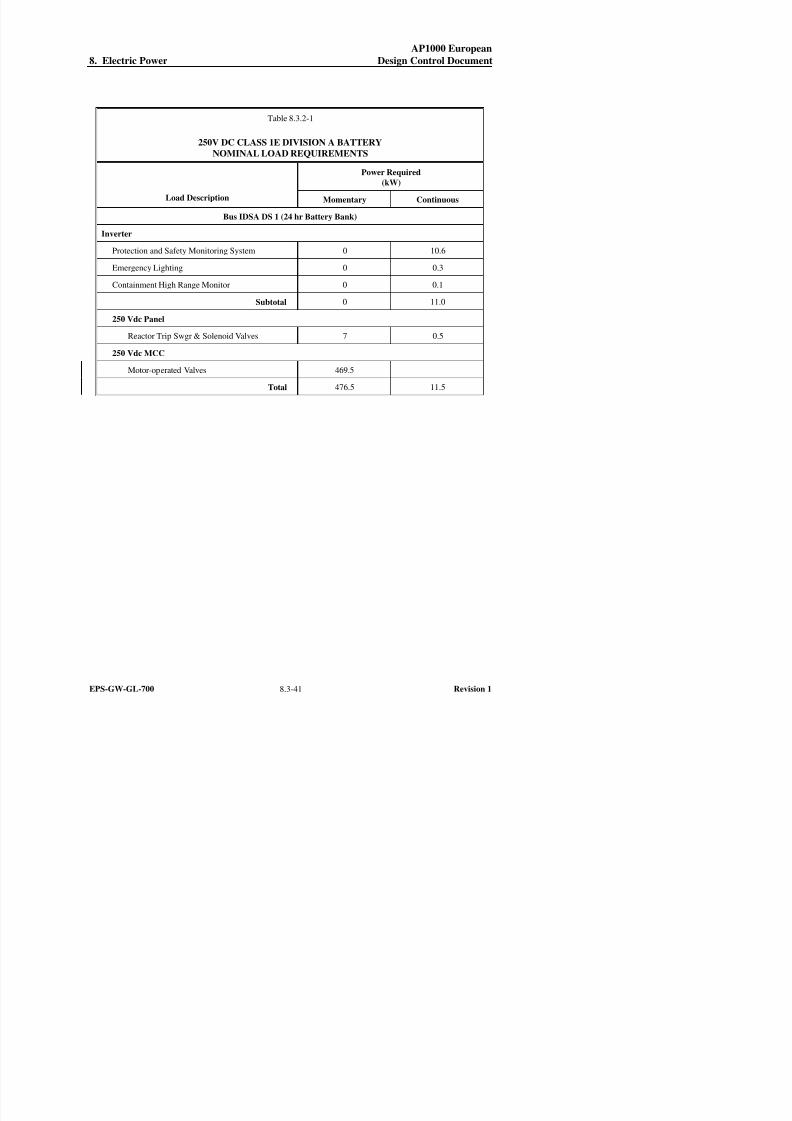
8/13/2019 EPS GW GL 700 Rev 1 Chapter 8 Section 8 3
http://slidepdf.com/reader/full/eps-gw-gl-700-rev-1-chapter-8-section-8-3 41/65
AP1000 European
8. Electric Power Design Control Document
Table 8.3.2-1
250V DC CLASS 1E DIVISION A BATTERY
NOMINAL LOAD REQUIREMENTS
Power Required
(kW)
Load Description Momentary Continuous
Bus IDSA DS 1 (24 hr Battery Bank)
Inverter
Protection and Safety Monitoring System 0 10.6
Emergency Lighting 0 0.3
Containment High Range Monitor 0 0.1
Subtotal 0 11.0
250 Vdc Panel
Reactor Trip Swgr & Solenoid Valves 7 0.5
250 Vdc MCC
Motor-operated Valves 469.5
Total 476.5 11.5
AP1000 European
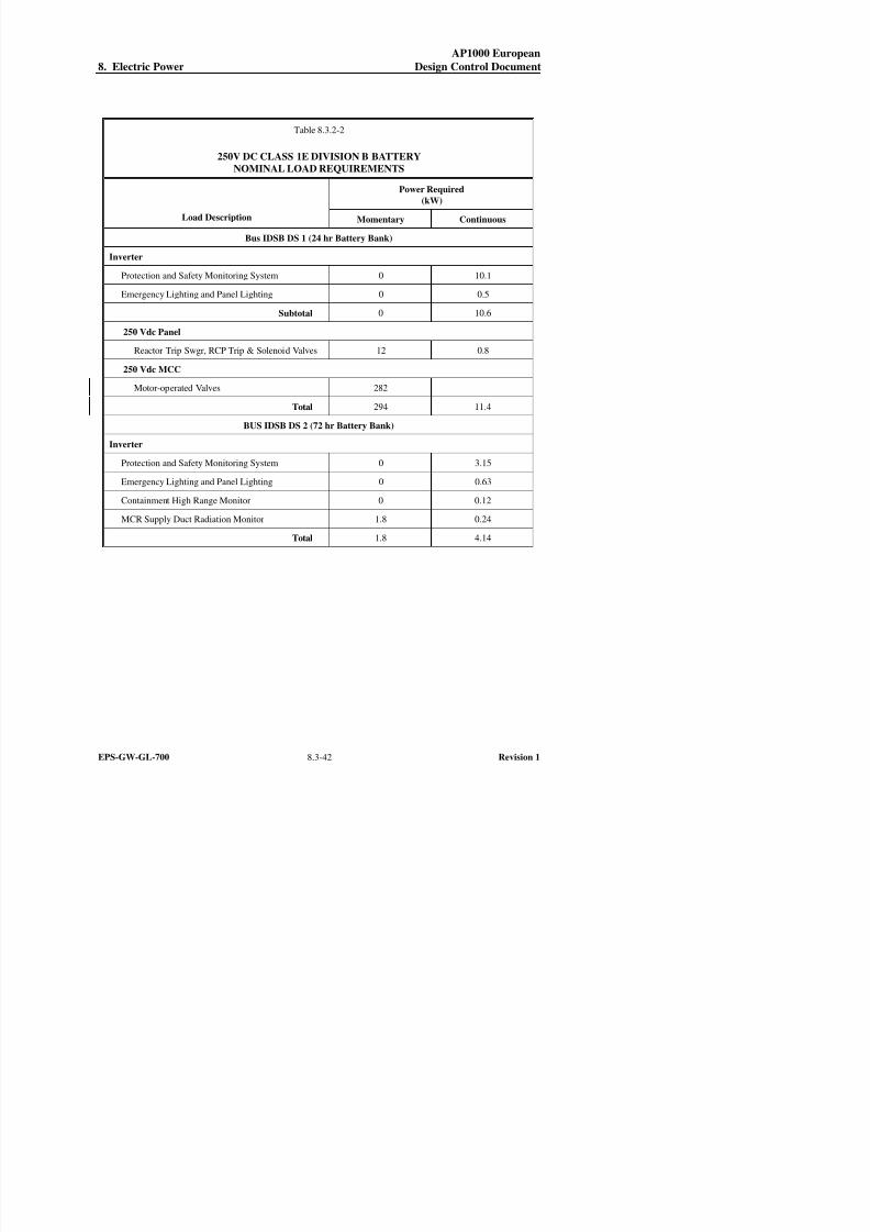
8/13/2019 EPS GW GL 700 Rev 1 Chapter 8 Section 8 3
http://slidepdf.com/reader/full/eps-gw-gl-700-rev-1-chapter-8-section-8-3 42/65
AP1000 European
8. Electric Power Design Control Document
Table 8.3.2-2
250V DC CLASS 1E DIVISION B BATTERY
NOMINAL LOAD REQUIREMENTS
Power Required
(kW)
Load Description Momentary Continuous
Bus IDSB DS 1 (24 hr Battery Bank)
Inverter
Protection and Safety Monitoring System 0 10.1
Emergency Lighting and Panel Lighting 0 0.5
Subtotal 0 10.6
250 Vdc Panel
Reactor Trip Swgr, RCP Trip & Solenoid Valves 12 0.8
250 Vdc MCC
Motor-operated Valves 282
Total 294 11.4
BUS IDSB DS 2 (72 hr Battery Bank)
Inverter
Protection and Safety Monitoring System 0 3.15
Emergency Lighting and Panel Lighting 0 0.63
Containment High Range Monitor 0 0.12
MCR Supply Duct Radiation Monitor 1.8 0.24
Total 1.8 4.14
AP1000 European

8/13/2019 EPS GW GL 700 Rev 1 Chapter 8 Section 8 3
http://slidepdf.com/reader/full/eps-gw-gl-700-rev-1-chapter-8-section-8-3 43/65
p
8. Electric Power Design Control Document
Table 8.3.2-3
250V DC CLASS 1E DIVISION C BATTERY
NOMINAL LOAD REQUIREMENTS
Power Required
(kW)
Load Description Momentary Continuous
Bus IDSC DS 1 (24 hr Battery Bank)
Inverter
Protection and Safety Monitoring System 0 10.1
Emergency Lighting and Panel Lighting 0 0.5
Subtotal 0 10.6
250 Vdc Panel
Reactor Trip Swgr, RCP Trip & Solenoid Valves 12 0.5
250 Vdc MCC
Motor-operated Valves 181
Total 193 11.1
BUS IDSC DS 2 (72 hr Battery Bank)
Inverter
Protection and Safety Monitoring System 0 3.15
Emergency Lighting and Panel Lighting 0 0.63
Containment High Range Monitor 0 0.12
MCR Supply Duct Radiation Monitor 1.8 0.24
Total 1.8 4.14
AP1000 European

8/13/2019 EPS GW GL 700 Rev 1 Chapter 8 Section 8 3
http://slidepdf.com/reader/full/eps-gw-gl-700-rev-1-chapter-8-section-8-3 44/65
8. Electric Power Design Control Document
Table 8.3.2-4
250V DC CLASS 1E DIVISION D BATTERY
NOMINAL LOAD REQUIREMENTS
Power Required
(kW)
Load Description Momentary Continuous
Bus IDSD DS 1 (24 hr Battery Bank)
Inverter
Protection and Safety Monitoring System 0 10.6
Emergency Lighting 0 0.3
Containment High Range Monitor 0 0.1
Subtotal 0 11.0
250 Vdc Panel
Reactor Trip Swgr & Solenoid Valves 6 0.8
250 Vdc MCC
Motor-Operated Valves 380
Total 386 11.8
AP1000 European
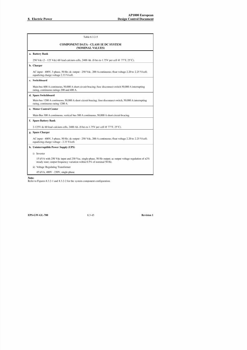
8/13/2019 EPS GW GL 700 Rev 1 Chapter 8 Section 8 3
http://slidepdf.com/reader/full/eps-gw-gl-700-rev-1-chapter-8-section-8-3 45/65
8. Electric Power Design Control Document
Table 8.3.2-5
COMPONENT DATA - CLASS 1E DC SYSTEM
(NOMINAL VALUES)
a. Battery Bank
250 Vdc (2 - 125 Vdc) 60 lead calcium cells, 2400 Ah. (8 hrs to 1.75V per cell @ 77°F, 25°C).
b. Charger
AC input - 400V, 3-phase, 50 Hz; dc output - 250 Vdc, 200 A continuous; float voltage 2.20 to 2.25 V/cell;
equalizing charge voltage 2.33 V/cell.
c. Switchboard
Main bus 600 A continuous, 50,000 A short circuit bracing; fuse disconnect switch 50,000 A interruptingrating, continuous ratings 200 and 400 A.
d. Spare Switchboard
Main bus 1200 A continuous, 50,000 A short circuit bracing; fuse disconnect switch, 50,000 A interrupting
rating, continuous rating 1200 A.
e. Motor Control Center
Main Bus 300 A continuous, vertical bus 300 A continuous, 50,000 A short circuit bracing.
f. Spare Battery Bank
2-125V dc 60 lead calcium cells, 2400 Ah. (8 hrs to 1.75V per cell @ 77°F, 25°C).
g. Spare Charger
AC input - 400V, 3-phase, 50 Hz; dc output - 250 Vdc, 200 A continuous; float voltage 2.20 to 2.25 V/cell;
equalizing charge voltage - 2.33 V/cell.
h. Uninterruptible Power Supply (UPS)
i) Inverter
15 kVA with 250 Vdc input and 230 Vac, single-phase, 50 Hz output; ac output voltage regulation of ±2%
AP1000 European
8 i i C

8/13/2019 EPS GW GL 700 Rev 1 Chapter 8 Section 8 3
http://slidepdf.com/reader/full/eps-gw-gl-700-rev-1-chapter-8-section-8-3 46/65
8. Electric Power Design Control Document
Table 8.3.2-6 (Sheet 1 of 2)
COMPONENT DATA - NON-CLASS 1E DC SYSTEM EDS1 – EDS4
(NOMINAL VALUES)
a. Battery Bank
125 Vdc 60 lead calcium cells, 2400 Ah. (8 hrs to 1.75V per cell @ 77°F, 25°C).
b. Charger
AC input - 400V, 3-phase, 50 Hz; dc output - 125 Vdc, 600 A continuous; float voltage - 2.20 to 2.25 V/cell;
equalizing charge voltage - 2.33 V/cell.
c. Switchgear
Main bus 1200 A continuous, 50,000 A short circuit bracing; breaker 1000A frame size.
d. Spare Charger
AC input - 400V, 3-phase, 50 Hz; dc output - 125 Vdc, 600 A continuous; float voltage - 2.20 to 2.25 V/cell;
equalizing charge voltage – 2.33 V/cell.
e. Uninterruptible Power Supply (UPS)
i) Inverter
50 kVA with 125 Vdc input and 230 Vac, single-phase, 50 Hz output; ac output voltage regulation of ±2%
steady state; output frequency variation within 0.5% of nominal 50 Hz.
ii) Voltage Regulating Transformer
75 kVA, 400V – 230V, single-phase.
Note:
Refer to Figure 8.3.2-3 for the system component configuration.
AP1000 European
8 El t i P D i C t l D t

8/13/2019 EPS GW GL 700 Rev 1 Chapter 8 Section 8 3
http://slidepdf.com/reader/full/eps-gw-gl-700-rev-1-chapter-8-section-8-3 47/65
8. Electric Power Design Control Document
Table 8.3.2-6 (Sheet 2 of 2)
COMPONENT DATA - NON-CLASS 1E DC SYSTEM EDS5
(NOMINAL VALUES)
a. Battery Bank
250 Vdc (2 - 125 Vdc) 60 lead calcium cells, 2400 Ah. (8 hrs to 1.75 V per cell @ 77°F).
b. Charger
AC input - 400 V, 3-phase, 50 Hz; dc output - 250 Vdc, 200 A continuous; float voltage - 2.20 to 2.25 V/cell;
equalizing charge voltage - 2.33 V/cell.
c. Switchgear
Main bus 600 A continuous, 50,000 A short circuit bracing; breaker 1200 A frame size.
Note:
Refer to Figure 8.3.2-3 for the system component configuration.
AP1000 European
8. Electric Power Design Control Document

8/13/2019 EPS GW GL 700 Rev 1 Chapter 8 Section 8 3
http://slidepdf.com/reader/full/eps-gw-gl-700-rev-1-chapter-8-section-8-3 48/65
EPS-GW-GL-700 8.3-48 Revision 1
Table 8.3.2-7 (Sheet 1 of 4)
CLASS 1E 250V DC AND CLASS 1E UNINTERRUPTIBLE POWER SUPPLIES
FAILURE MODES AND EFFECTS ANALYSIS
Item
No. Description of Components Safety Function
Plant
Operating
Mode
Failure
Mode(s) Method of Failure Detection
Failure Effect on
System Safety
Function Capability General Remarks
1. Battery Charger
Division A, IDSA DC 1
Division B, IDSB DC 1, 2
Division C, IDSC DC 1, 2Division D, IDSD DC 1
Provide dc power when
ac power available and
maintain battery in a
charged condition.
A,B No output Annunciator in main control
room; battery charger failure
alarm for ac power failure,
dc output under/ over voltage,dc no charge, and input/output
breaker open.
None;
Battery can provide power
for 24 and 72 hours
without charger; otherdivisions available. Spare
battery charger available
for connection.
Failure of only one div.
chgr. falls into single
failure criteria and the
other three div. are stillavailable.
C No input Same as above. None;
Battery can provide power
for 24 and 72 hours
without charger.
This component
inoperable during
blackout.
2. Battery
Division A, IDSA DB 1A,1BDivision B, IDSB
DB 1A,1B,2A,2B
Division C, IDSC
DB 1A,1B,2A,2B
Division D, IDSD DB 1A,1B
Backup to battery charger
during load cycling (in-rush current) and provide
dc power for 24 and
72 hours without battery
charger.
A,B No output or
low voltage
Battery monitor provides
annunciation in main controlroom; switchboard failure
alarm in main control room for
ground detection and bus
undervoltage.
None;
Battery chargers (item 1)available; other divisions
available. Spare battery
available for connection.
Power still available with
a single ground. Loss ofentire battery function is
single failure and the
other divisions are
available.
C No output or
low voltage
Same as above. None;
Other divisions available;
spare battery available.
3. Fused transfer switch box
Division A, IDSA DF 1Division B, IDSB DF 1,2
Division C, IDSC DF 1,2
Division D, IDSD DF 1
Provide circuit continuity
and protection betweenItem 2 battery and Item 4
switchboard.
A,B,C Inadvertent
opening(blown fuse)
Switchboard failure alarm in
main control room for grounddetection and bus
undervoltage.
None;
Other divisions available.
AP1000 European
8. Electric Power Design Control Document

8/13/2019 EPS GW GL 700 Rev 1 Chapter 8 Section 8 3
http://slidepdf.com/reader/full/eps-gw-gl-700-rev-1-chapter-8-section-8-3 49/65
EPS-GW-GL-700 8.3-49 Revision 1
Table 8.3.2-7 (Sheet 2 of 4)
CLASS 1E 250V DC AND CLASS 1E UNINTERRUPTIBLE POWER SUPPLIES
FAILURE MODES AND EFFECTS ANALYSIS
Item
No. Description of Components Safety Function
Plant
Operating
Mode
Failure
Mode(s) Method of Failure Detection
Failure Effect on
System Safety
Function Capability General Remarks
4. 250V DC Switchboard
Division A, IDSA DS 1
Division B, IDSB DS 1,2
Division C, IDSC DS 1,2Division D, IDSD DS 1
Distribute power via
fusible disconnects to
loads from chargers and
battery.
A,B,C Bus ground
fault
Switchboard failure alarm in
main control room for ground
detection and bus
undervoltage.
None;
Other divisions available.
5. Fusible disconnect
Division A, for Charger 1
Division B, for Charger 1,2
Division C, for Charger 1,2
Division D, for Charger 1
Provide circuit continuity
and protection between
Item 1 and 4.
A,B Inadvertent
opening
(blown fuse)
Alarm in main control room
for charger failure (dc no
charge).
None;
Battery can provide power
for 24 and 72 hours
without chargers. Other
divisions available.
C Inadvertent
opening
(blown fuse)
Same as above. None;
Battery can provide power
for 24 and 72 hourswithout chargers.
6. Fusible disconnect
Division A, for Inverter 1
Division B, for Inverter 1,2
Division C, for Inverter 1,2
Division D, for Inverter 1
Provide circuit continuity
and protection between
Item 4 switchboard and
Item 9 inverters.
A,B,C Inadvertent
opening
(blown fuse)
Inverter trouble alarm in main
control room for loss of dc
input, loss of ac output, input,
output and backup power
supply breaker open.
None;
System safety function can
be met with loss of one
division.
7. Fusible disconnect for DC MCC
Division A
Division B
Division CDivision D
Provide circuit continuity
and protection between
Item 4 switchboard and
Item 13 DC MCC.
A,B,C Inadvertent
opening
(blown fuse)
DC MCC trouble alarm in
main control room for bus
undervoltage.
None;
Other divisions available.
AP1000 European
8. Electric Power Design Control Document

8/13/2019 EPS GW GL 700 Rev 1 Chapter 8 Section 8 3
http://slidepdf.com/reader/full/eps-gw-gl-700-rev-1-chapter-8-section-8-3 50/65
EPS-GW-GL-700 8.3-50 Revision 1
Table 8.3.2-7 (Sheet 3 of 4)
CLASS 1E 250V DC AND CLASS 1E UNINTERRUPTIBLE POWER SUPPLIES
FAILURE MODES AND EFFECTS ANALYSIS
Item
No. Description of Components Safety Function
Plant
Operating
Mode
Failure
Mode(s) Method of Failure Detection
Failure Effect on
System Safety
Function Capability General Remarks
8. Fusible disconnect for DC dist
panel
Division A
Division BDivision C
Division D
Provide circuit continuity
and protection between
Item 4 switchboard and
Item 14 dc panel.
A,B,C Inadvertent
opening
(blown fuse)
DC dist. panel trouble alarm in
main control room for bus
undervoltage.
None;
Other divisions available.
9. Inverter
Division A, IDSA DU 1
Division B, IDSB DU 1,2
Division C, IDSC DU 1,2
Division D, IDSD DU 1
Convert 250V DC to
230V AC and provide
230V AC power.
A,B,C No output Alarm in main control room
for common UPS trouble, for
loss of dc input, loss of ac
output; input, output and
backup power supply breakers
open.
None;
System safety function can
be met with loss of one
division.
10. Voltage regulating transformerDivision A, IDSA DT 1
Division B, IDSB DT 1
Division C, IDSC DT 1
Division D, IDSD DT 1
Backup to inverter(Item 9) when it is
bypassed for maintenance
or malfunction (local
manual switching at
inverter).
A,B No output Alarm in main control roomfor input and output power
supply breakers open. And
bus undervoltage.
None;Other divisions available. For single failureanalysis: These
components are
redundant to Item 1.
These components are
redundant to Item 9.
C No input Bus undervoltage. None This component cannot
function during blackout.
11. 230V AC distr. panel
Division A, IDSA EA 1
Division B, IDSB EA 1,3Division C, IDSC EA 1,3
Division D, IDSD EA 1
Distribute power via
breakers to loads
A,B,C Ground and
bus fault
Alarm in main control room
for undervoltage.
None;
System safety function can
be met with loss of onedivision.
AP1000 European
8. Electric Power Design Control Document
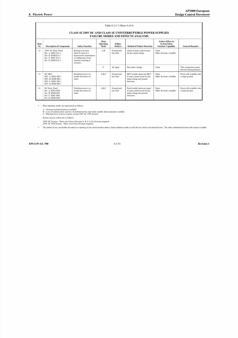
8/13/2019 EPS GW GL 700 Rev 1 Chapter 8 Section 8 3
http://slidepdf.com/reader/full/eps-gw-gl-700-rev-1-chapter-8-section-8-3 51/65
EPS-GW-GL-700 8.3-51 Revision 1
Table 8.3.2-7 (Sheet 4 of 4)
CLASS 1E 250V DC AND CLASS 1E UNINTERRUPTIBLE POWER SUPPLIES
FAILURE MODES AND EFFECTS ANALYSIS
Item
No. Description of Components Safety Function
Plant
Operating
Mode
Failure
Mode(s) Method of Failure Detection
Failure Effect on
System Safety
Function Capability General Remarks
12. 230V AC Distr. Panel
Div. A, IDSA EA 2
Div. B, IDSB EA 2
Div. C, IDSC EA 2Div. D, IDSD EA 2
Backup to invertor
(Item 9) when it is
bypassed for maintenance
or malfunction (localmanual switching at
inverter).
A,B Ground and
bus fault
Alarm in main control room
for bus undervoltage.
None;
Other divisions available.
C No input Bus under voltage. None This component cannot
function during blackout.
13. DC MCC
DIV. A, IDSA DK 1
DIV. B, IDSB DK 1
DIV. C, IDSC DK 1
DIV. D, IDSD DK 1
Distribute power via
fusible disconnect to
loads.
A,B,C Ground and
bus fault
MCC trouble alarm per MCC
in main control room for bus
undervoltage and ground
detection.
None;
Other divisions available.
Power still available with
a single ground.
14. DC Distr. Panel
Div. A, IDSA DD1
Div. B, IDSB DD1
Div. C, IDSC DD1
Div. D, IDSD DD1
Distribute power via
fusible disconnect to
loads.
A,B,C Ground and
bus fault
Panel trouble alarm per panel
in main control room for bus
undervoltage and ground
detection.
None;
Other divisions available.
Power still available with
a single ground.
• Plant operating modes are represented as follows:
A – Normal or preferred power available.
B – Loss of normal power and loss of preferred power and onsite standby diesel generator available.C – Blackout (loss of all ac systems, except 230V AC UPS system).
System success criteria are as follows:
250V DC System – Three out of four (Division A, B, C or D) divisions required.230V AC UPS System – Three out of four divisions required.
• The failure of any one fusible disconnect or opening of one circuit breaker under a fault condition results in only the loss of the associated division. The other redundant divisions still remain available.
AP1000 European
8. Electric Power Design Control Document

8/13/2019 EPS GW GL 700 Rev 1 Chapter 8 Section 8 3
http://slidepdf.com/reader/full/eps-gw-gl-700-rev-1-chapter-8-section-8-3 52/65
g
[This page intentionally blank]
AP1000 European
8. Electric Power Design Control Document

8/13/2019 EPS GW GL 700 Rev 1 Chapter 8 Section 8 3
http://slidepdf.com/reader/full/eps-gw-gl-700-rev-1-chapter-8-section-8-3 53/65
EPS-GW-GL-700 8.3-53 Revision 1
Figure 8.3.1-1
AC Power Station One Line Diagram
AP1000 European
8. Electric Power Design Control Document

8/13/2019 EPS GW GL 700 Rev 1 Chapter 8 Section 8 3
http://slidepdf.com/reader/full/eps-gw-gl-700-rev-1-chapter-8-section-8-3 54/65
EPS-GW-GL-700 8.3-55 Revision 1
Figure 8.3.1-2
On-Site Standby Diesel Generator Initiating Circuit Logic Diagram
AP1000 European
8. Electric Power Design Control Document

8/13/2019 EPS GW GL 700 Rev 1 Chapter 8 Section 8 3
http://slidepdf.com/reader/full/eps-gw-gl-700-rev-1-chapter-8-section-8-3 55/65
EPS-GW-GL-700 8.3-57 Revision 1
Figure 8.3.1-3
Post 72 Hour Temporary Electric Power
One Line Diagram
AP1000 European
8. Electric Power Design Control Document

8/13/2019 EPS GW GL 700 Rev 1 Chapter 8 Section 8 3
http://slidepdf.com/reader/full/eps-gw-gl-700-rev-1-chapter-8-section-8-3 56/65
EPS-GW-GL-700 8.3-59 Revision 1
Inside Diesel Generator Building
Figure 8.3.1-4 (Sheet 1 of 2)
Diesel Generator System
Piping and Instrumentation Diagram
(REF) ZOS 001
AP1000 European
8. Electric Power Design Control Document

8/13/2019 EPS GW GL 700 Rev 1 Chapter 8 Section 8 3
http://slidepdf.com/reader/full/eps-gw-gl-700-rev-1-chapter-8-section-8-3 57/65
EPS-GW-GL-700 8.3-61 Revision 1
Inside Diesel Generator Building
Figure 8.3.1-4 (Sheet 2 of 2)
Diesel Generator System
Piping and Instrumentation Diagram
(REF) ZOS 002
AP1000 European
8. Electric Power Design Control Document

8/13/2019 EPS GW GL 700 Rev 1 Chapter 8 Section 8 3
http://slidepdf.com/reader/full/eps-gw-gl-700-rev-1-chapter-8-section-8-3 58/65
EPS-GW-GL-700 8.3-63 Revision 1
Inside Diesel Generator Building
Figure 8.3.1-5 (Sheet 1 of 2)
Diesel Engine Skid Mounted System
(REF) ZOS K001
AP1000 European
8. Electric Power Design Control Document

8/13/2019 EPS GW GL 700 Rev 1 Chapter 8 Section 8 3
http://slidepdf.com/reader/full/eps-gw-gl-700-rev-1-chapter-8-section-8-3 59/65
EPS-GW-GL-700 8.3-65 Revision 1
Inside Diesel Generator Building
Figure 8.3.1-5 (Sheet 2 of 2)
Diesel Engine Skid Mounted System
(REF) ZOS K002
AP1000 European
8. Electric Power Design Control Document

8/13/2019 EPS GW GL 700 Rev 1 Chapter 8 Section 8 3
http://slidepdf.com/reader/full/eps-gw-gl-700-rev-1-chapter-8-section-8-3 60/65
EPS-GW-GL-700 8.3-67 Revision 1
Figure 8.3.2-1 (Sheet 1 of 2)
Class 1E DC System One Line Diagram
AP1000 European
8. Electric Power Design Control Document

8/13/2019 EPS GW GL 700 Rev 1 Chapter 8 Section 8 3
http://slidepdf.com/reader/full/eps-gw-gl-700-rev-1-chapter-8-section-8-3 61/65
EPS-GW-GL-700 8.3-69 Revision 1
Figure 8.3.2-1 (Sheet 2 of 2)
Class 1E DC System One Line Diagram
AP1000 European
8. Electric Power Design Control Document

8/13/2019 EPS GW GL 700 Rev 1 Chapter 8 Section 8 3
http://slidepdf.com/reader/full/eps-gw-gl-700-rev-1-chapter-8-section-8-3 62/65
EPS-GW-GL-700 8.3-71 Revision 1
Figure 8.3.2-2
Class 1E 250V UPS One Line Diagram
AP1000 European
8. Electric Power Design Control Document

8/13/2019 EPS GW GL 700 Rev 1 Chapter 8 Section 8 3
http://slidepdf.com/reader/full/eps-gw-gl-700-rev-1-chapter-8-section-8-3 63/65
EPS-GW-GL-700 8.3-73 Revision 1
Figure 8.3.2-3 (Sheet 1 of 3)
Non-Class 1E DC & UPS System One Line Diagram
AP1000 European
8. Electric Power Design Control Document

8/13/2019 EPS GW GL 700 Rev 1 Chapter 8 Section 8 3
http://slidepdf.com/reader/full/eps-gw-gl-700-rev-1-chapter-8-section-8-3 64/65
EPS-GW-GL-700 8.3-75 Revision 1
Figure 8.3.2-3 (Sheet 2 of 3)
Non-Class 1E DC & UPS System One Line Diagram
AP1000 European
8. Electric Power Design Control Document

8/13/2019 EPS GW GL 700 Rev 1 Chapter 8 Section 8 3
http://slidepdf.com/reader/full/eps-gw-gl-700-rev-1-chapter-8-section-8-3 65/65
EPS-GW-GL-700 8.3-77 Revision 1
Figure 8.3.2-3 (Sheet 3 of 3)
Non-Class 1E DC & UPS System One Line Diagram
Related Documents