SANDIA REPORT SAND99–8213 Unlimited Release Printed January 1999 . . Epoxy Foam Encapsulant: Processing and Dielectric Characterization Linda Domeier and Marion Hunter Prepared by Sandia Nationa! Laboratories Albuquerque, New Mexico 87185 and Livermore, California 94550 Sandia is a multiprog:arn Iaboratoy operated by Sandia Corporation, a Lockheed Martin Company, for the United States Department of Energy under Contract X-AC04-94AL85000. Approved for public release” further dissemination unlimited Sandia National laboratories ●

Welcome message from author
This document is posted to help you gain knowledge. Please leave a comment to let me know what you think about it! Share it to your friends and learn new things together.
Transcript

SANDIA REPORTSAND99–8213Unlimited ReleasePrinted January 1999
..
Epoxy Foam Encapsulant: Processingand Dielectric Characterization
Linda Domeier and Marion Hunter
Prepared by
Sandia Nationa! Laboratories
Albuquerque, New Mexico 87185 and Livermore, California 94550
Sandia is a multiprog:arn Iaboratoy operated by Sandia Corporation,
a Lockheed Martin Company, for the United States Department ofEnergy under Contract X-AC04-94AL85000.
Approved for public release” further dissemination unlimited
Sandia National laboratories
●
Issued by Sandia National Laboratones, operated for the United States Depart-ment of Energy by Sandia Corporation.
NOTICE: This report was prepared as an account of work sponsored by anagency of the United States Government. Neither the United States Govern-ment, nor any agency thereof, nor any of their employees, nor any of theircontractors, subcontractors, or their employees, make any warranty, express orimplied, or assume any legal liability or responsibility for the accuracy,completeness, or usefulness of any information, apparatus, product, or processdisclosed, or represent that its use would not infringe privately owned rights.Reference herein to any specific commercial product, process, or service bytrade name, trademark, manufacturer, or otherwise, does not necessarilyconstitute or imply its endorsement, recommendation, or favoring by the UnitedStates Government, any agency thereof, or any of their contractors orsubcontractors. The views and opinions expressed herein do not necessarilystate or reflect those of the United States Government, any agency thereof, orany of their contractors.
Printed m the Llnited States of America. This report has been reproduceddirectly born the best available copy.
Available to DOE and DOE contractors fromOffice of Scientific and Technical InformationP.O. BOX 62Oak Ridge, TN 37831
Prices available horn (615) 576-8401, FTS 626-8401
Available to the public fromNational Technical Information ServiceU.S. Department of Commerce5285 Port Royal RdSpringfield, VA 22161
NTIS price codesPrinted copy: A04Microfiche copy: AO1
SAND99-8213Unlimited Release
Printed January 1999
Epoxy Foam Encapsulant: Processing andDielectric Characterization
Linda DomeierMaterials Processing Department
Marion HunterMaterials Chemistry Department
Sandia National LaboratoriesP. O. BOX 969
Livermore, CA 94551-0969
Abstract
The dielectric performance of epoxy foams was investigated to determine if suchmaterials might provide advantages over more standard polyurethane foams in theencapsulation of electronic assemblies. Comparisons of the dielectric characteristicsof epoxy and urethane encapsulant foams found no significant differences betweenthe two resin types and no significant difference between as-molded and machinedfoams.
Blown epoxy foams are an alternative to the more prevalent and versatilepolyurethane foams used as DP firing set encapsulant and in a range of othercommercial applications. Epoxy resins are not as readily foamed and processed asurethanes and have generally seen only limited use as encapsulant. Potentialadvantages for epoxy foams, however, might result from their dielectric properties andalso elimination the of toxic and sometimes sensitizing isocyanates used in urethaneformulations. This study specifically evaluated the formulation and processing of epoxyfoams using simple methylhydrosiloxanes as the blowing agent and compared thedielectric performance of those foams to urethane foams of similar density.
Epoxy foams with densities ranging from 0.25 to 0.90 grams/cc were prepared and theinfluence of various formulation parameters on those foams was established. Thealkylhydrosiloxane blowing agents used generate hydrogen gas during the epoxycuring process, much as urethane foams generate carbon dioxide from water duringthe curing reaction.
3
Dielectric properties were measured on these epoxy foams and also urethane foamsover a range of densities and with both machined and as-molded, skinned surfaces.No significant differences were found. Both as-molded foams with skinned surfacesand machined foams showed little dependence of volume resistivity on foam densityexcept at very low densities. Urethane foams generally had higher volume resistivitiesthan epoxy foams although all the samples, with and without skins, had resistivitiesabove 10’s ohm-cm measured at one minute. Urethane foams were typically about anorder of magnitude higher at 10’7 ohm-cm.
4
Acknowledgements
The contributions of Paul Beeson, now retired from Org. 1812, were invaluable incarrying out the initial foam dielectric tests and in guiding the establishment of that testcapability at Sandia, California. The bulk of the work in setting up the California testcapability was carried out by Marion Hunter with additional assistance from Bill Evenand Bob Crocker.

—
Background on Epoxy Foam Technology
This section is meant to briefly review the various options available in creating epoxyfoams and their relative advantages and disadvantages. The alkylhydro siloxanesselected as the blowing agent for this study is one of several could be used. A majorconsideration in this selection was the ease of formulation and processing and thesimilarity in behavior to current polyurethane foams.
Polyurethane are readily foamed by the simple addition of various amounts of waterthat reacts with isocyanate groups to form the carbon dioxide blowing agent andamines. The resulting amines quickly react with remaining isocyanate groups to formurea linkages within the urethane matrix. Epoxies do not foam on the addition of waterand have instead been foamed by the addition of various reactive and inert blowingagents, each of which provides advantages and disadvantages. Both resin types alsoutilize surfactants and catalysts as needed to modify the resin reactivity and foammorphology. (Note: Only blown foams are considered in this discussion. Syntacticepoxy foams, created by the addition of hollow spheres of glass, GMB, or othermaterials are a separate class of materials which generally cannot provide foamdensities lower than about 0.7 g/cc)
-iHeat activated blowing agents have included azo and hydrazide compounds (nitrogengeneration) and carbonate salts, all of which usually require milling equipment toinsure a uniform distribution of the solid blowing agent and also refrigerated storage toprevent premature decomposition. High curing temperatures are often required toactivate the blowing agents although this can be modified by added catalysts (Ref. 2).AbleFoam 5, a now discontinued commercial product used in the W76 firing set, usedammonium carbonate as the blowing agent (Ref. 3). This proprietary product was soldin Semco cartridges which required storage below about –50° F. The thawedcartridges could be injected into molds and had a potlife of about one hour. Curing attemperatures above 120”F, preferably at about 150° F, was required and heated moldsappeared to be beneficial. Upon decomposition the salt would generate a mixture ofammonia and carbon dioxide. This product was discontinued by the manufacturer,Ablestick, due to the unavailability of the triglycidyl ether of glycerin used in theformulation. This component is a cancer suspect agent. A backup product developedat Bendix, KCP, was called Capoxyfoam and used the same blowing agent in a DEN431 /Epon 828/phenyl glycidyl ether/Shell Z formulation (Ref. 4). Proper dispersion ofthe blowing agent was critical in this formulation and it has not apparently been usedin any weapon applications.
Many of the reactive blowing agents reported in the literature are integral componentsof the epoxy formulation and have included carbamate salts (Ref. 5), carbonateoligomers (Ref. 6), combinations of anhydride curing agents and tertiary aminecatalysts (ref. 7), and trial koxyboroxines (Ref. 8). Carbamate salts are an intermediatereaction product of carbon dioxide and aliphatic amine curing agents and require adifficult synthetic/purification process. Upon heating, the original amine curing agentplus carbon dioxide are generated. Formulation stability and processability are
8

challenges with this class of materials. Carbonate oligomers also generate carbondioxide upon heating (about 140-1 80”C) and are specific epoxy resins containingmultiple carbonate linkages that can be used in standard epoxy formulations. Theseoligomers, basically glycidyl-capped low molecular weight Lexan, do not appear to becommercially available. Tertiary amines and aliphatic anhydrides are standardingredients in epoxy formulations and have been shown to react at elevated curingtempera~tures (at least 115“C) to generate carbon dioxide and foam the resultingepoxy matrix. A patent in this area suggests the use of added auxiliary blowing agents(Ref. 7). Note: This reaction of anhydrides and tertiary amine catalysts was notedpreviously at Sandia and AS/FM&T when a preblend containing such ingredients andused to cure a solid epoxy encapsulant system was found to slowly generate carbondioxide and build up pressure during storage at room temperature. The chemistry ofthis reaction is not well defined but may involve loss of an allylic hydrogen and self-condem;ation (Ref. 9). Finally, trialkoxyboroxines have also been described ascombination curing/blowing (generated methane gas) agents. They must be used athigh levels or supplemented with other blowing agents. Pot life after mixing wasextremely short and the exotherms appeared to be substantial.
Other reactive blowing agent additives, as opposed to simple heat activated agents,have included combinations of sodium borohydride and water (Ref. 10), andalkylhyclro siloxanes (Ref. 11-13). Sodium borohydride reacts with advantageous andadded vvater to generate hydrogen gas and sodium metaborate (NaBOz). Thisblowing agent combination has also been used in thermoplastic foams. It was notconsidered in this study on encapsulant applications due to the expected detrimentaleffect of the sodium salt formed during the foaming process on dielectric properties.
Alkylhydro siloxanes are used as the blowing agent in a commercial foaming epoxy,RP-1 774, from Ciba-Geigy. This specific formulation includes Bentonite clay andcalcium carbonate fillers along with dibutyl phthalate as a diluent or flow modifier. Asreceived, it would be too viscous for most encapsulant applications. Data sheetsindicate both Bisphenol A and diluent epoxies, perhaps Epon 815, and a Versamidtype culring agent. The third component, the blowing agent, is a methylhydrosiloxanehomopciymer which reacts with the amine curing agent to generate hydrogen gas.Similar siloxane-blown systems were the subject of a German study on the fatiguebehaviclr of fiber-reinforced epoxy foam laminates (Ref. 14). Russian work with thisclass of blowing agents has also been reported (Ref 15) including a patentedformulation (Ref 16) using ethylhydrosiloxane as the blowing agent in a carbon blackfilled conductive foam.
Because of the formulation flexibility, the absence of any ozone-depleting agents, theabsence of added or generated salts, and the processing similarity to urethane foams,the alkylhydro siloxanes were chosen as the blowing agents for this study.
lnerl blowing agents include low-boiling solvents and Freons or injected gases andthese have been used in numerous foaming applications with both thermosetting andthermoplastic resins. Freons were used in the late 70’s by Thorn EMI Electronics Ltd.
9
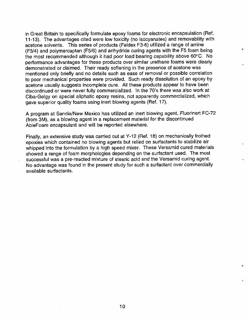
in Great Britain to specifically formulate epoxy foams for electronic encapsulation (Ref.11-1 3). The advantages cited were low toxicity (no isocyanates) and removability withacetone solvents. This series of products (Feldex F3-6) utilized a range of amine(F3/4) and polymercaptan (F5/6) and anhydride curing agents with the F5 foam beingthe most recommended although it had poor load bearing capability above 60°C. Noperformance advantages for these products over similar urethane foams were clearlydemonstrated or claimed. Their ready softening in the presence of acetone wasmentioned only briefly and no details such as ease of removal or possible correlationto poor mechanical properties were provided. Such ready dissolution of an epoxy byacetone usually suggests incomplete cure. All these products appear to have beendiscontinued or were never fully commercialized. In the 70’s there was also work atCiba-Geigy on special aliphatic epoxy resins, not apparently commercialized, whichgave superior quality foams using inert blowing agents (Ref. 17).
A program at SandidNew Mexico has utilized an inert blowing agent, Fluorinert FC-72(from 3M), as a blowing agent in a replacement material for the discontinuedAbleFoam encapsulant and will be reported elsewhere.
Finally, an extensive study was carried out at Y-1 2 (Ref. 18) on mechanically frothedepoxies which contained no blowing agents but relied on surfactants to stabilize airwhipped into the formulation by a high speed mixer. These Versamid cured materialsshowed a range of foam morphologies depending on the surfactant used. The mostsuccessful was a pre-reacted mixture of stearic acid and the Versamid curing agent.No advantage was found in the present study for such a surfactant over commerciallyavailable surfactants.
*
10

Foam Formulations: Siloxane Blowing Agent
The avi~ilable literature did not define what range of alkylhydrosiloxane homopolymersand (alkylhydro)(dialky l)siloxane copolymers might be useful in epoxy foamformulations. Both the level of siloxane additive and the type of homopolymer orcopolymer might be used to adjust the foaming action and final density and the effectsof these parameters were evaluated. The Ciba-Geigy data sheets for RP-1 774indicated the use of methylhydro homopolymers (confirmed by NMR) while theRussian work indicated the use of ethylhydro homopolymers. The use of copolymerswas not discussed in any of the references.
(Methylhydro)(dimethyl) siloxane copolymer
R = methyl
Alkylhydrosiloxane homopolymer
~~~~
i -O-~i-O-~i-O-~i-O- ~i-O— tHHHH
R = methyl or ethyl
Initial foaming trials with hand-mixed samples used a standard 60/40 Epon828/Versamid 125 formulation and various types and levels of siloxane additives. Thevarious siloxanes shown in Table 1 were all screened in both room temperature andoven cured (150° F) formulations at the 1 percent level and none showed significantfoaming action other than the pure alkylhydrosiloxanes. Addition of a stannousoctoate catalyst or water had no effect on the foam density and flame ionizationanalysis of the Ciba-Geigy RP-I 774 siloxane blowing agent showed no addedmetallic compounds. The methylhydrosiloxanes gave better foaming and lowerdensities than ethylhydro-siloxane and both PS-I 20 and HMS 991 gave identicalfoaming behavior to the Ciba-Geigy additive. Based on these results, PS-120 wasselected as the foaming agent for the remaining work.
11
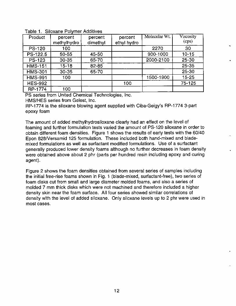
Table 1. Siloxane Polymer Additives
Product percent percent percent Molecular Wt. Viscosity
methylhydro dimethyl ethyl hydro (Cps)
PS-120 100 2270 30I
— 1 , 1 ,—---- - 1 ---- 1 ---- 1 I ----- -- I .->- 1
I IJS-122.5 I 5U-55 I 45-W I I Yuu-1 Uuu I lU-15 II PS-123 I 30-35 65-70 I 2000-2100 I 25-30 I
HMS-151 15-18 82-85 25-35HMS-301 30-35 65-70 25-30HMS-991 100 1500-1900 15-25HES-992 100 75-125RP-1774 100 I I I
PS series from United Chemical Technologies, Inc.HMS/HES series from Gelest, Inc.RP-I 774 is the siloxane blowing agent supplied with Ciba-Geigy’s RP-1 774 3-partepoxy foam
The amount of added methylhydrosiloxane clearly had an effect on the level offoaming and further formulation tests varied the amount of PS-120 siloxane in order toobtain different foam densities. Figure 1 shows the results of early tests with the 60/40Epon 828/Versamid 125 formulation. These included both hand-mixed and blade-mixed formulations as well as sutfactant modified formulations. Use of a surfactantgenerally produced lower density foams although no further decreases in foam densitywere obtained above about 2 phr (parts per hundred resin including epoxy and curingagent).
Figure 2 shows the foam densities obtained from several series of samples includingthe initial free-rise foams shown in Fig. 1 (blade-mixed, surfactant-free), two series offoam disks cut from small and large diameter molded foams, and also a series ofmolded 7 mm thick disks which were not machined and therefore included a higherdensity skin near the foam surface. All four series showed similar correlations ofdensity with the level of added siloxane. Only siloxane levels up to 2 phr were used inmost cases.
‘4
.
.
12
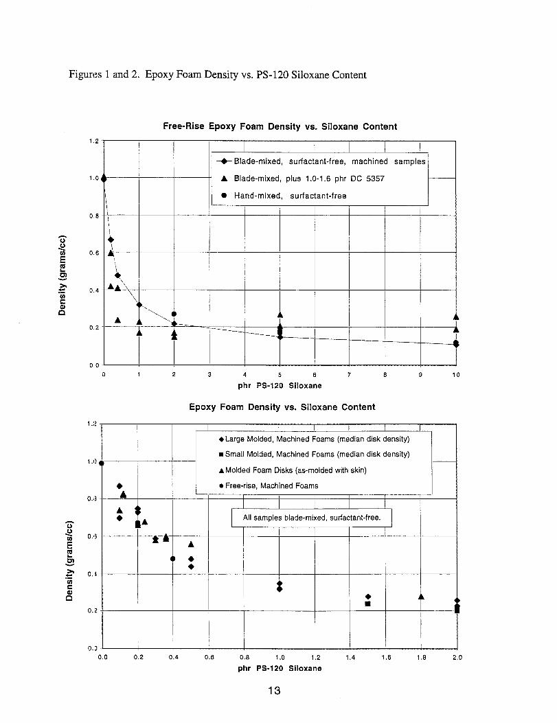
Figures 1 and 2. Epoxy Foam Density vs. PS-120 Siloxane Content
Free-Rise Epoxy Foam Density vs. Siloxane Content
1.2-1
-+- Blade-mixed,surfactant-free,machinedsamples
1.0{) A Blade-mixed,plus 1.0-1,6phr DC 5357\
. Hand-mixed, surfactant-free\1,
0.8- \1
\
0.6- ~‘~
\*
0,4 A A“\‘\
‘\.,.
\... 4A
....A
A ,0.2-
‘i
‘6–––.----—__
-——----,
.[
0,0~
1.:?
1.0
0.8
0.6
0.4
0.2
0.’2
o 1 2 3 4 5 6 7 8 9 10
phr PS-120 Siloxane
Epoxy Foam Density vs. Siloxane Content
I I I I I I I
● Large Molded, Machined Foams (median disk density)
■ Small Molded, Machined Foams (median disk density)
A MoldedFoam Disks (as-moldedwith skin)
● Free-rise, Machined Foams
1 I 1 I ,
All samples blade-mixed, sutiactant-free.
4
:
1-L
i
0.0 0.2 0.4 0.6 0.8 1.0 1.2 1.4 1.6 1.8 2.0
phr PS-120Siloxane
13
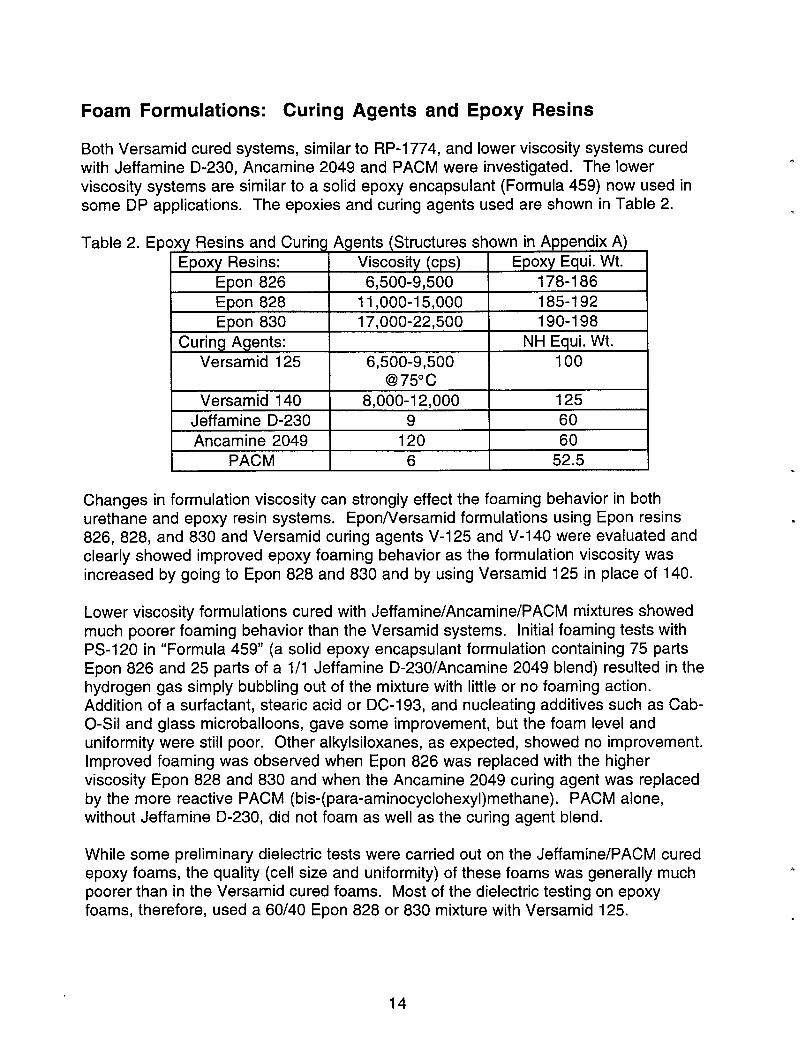
Foam Formulations: Curing Agents and Epoxy Resins
Both Versamid cured systems, similar to RP-1 774, and lower viscosity systems curedwith Jeff amine D-230, Ancamine 2049 and PACM were investigated. The lowerviscositv svstems are similar to a solid epoxy encapsulant (Formula 459) now used insome D-P applications. The epoxies and cu;ing agents used are shown “in Table 2.
Table 2. Epoxy Resins and Curing Agents (Structures shown in Appendix A)Epoxy Resins: Viscosity (cps) Epoxy Equi. Wt.
Epon 826 6,500-9,500 178-186
Epon 828 11,000-15,000 185-192
Epon 830 17,000-22,500 190-198
Curing Agents: NH Equi. Wt.
Versamid 125 6,500-9,500 100@75°c
Versamid 140 8,000-12,000 125
Jeffamine D-230 9 60
Ancamine 2049 120 60
I PACM 6 52.5 I
Changes in formulation viscosity can strongly effect the foaming behavior in bothurethane and epoxy resin systems. Epon/Versamid formulations using Epon resins826, 828, and 830 and Versamid curing agents V-125 and V-140 were evaluated andclearly showed improved epoxy foaming behavior as the formulation viscosity wasincreased by going to Epon 828 and 830 and by using Versamid 125 in place of 140.
Lower viscosity formulations cured with Jeffamine/Ancamine/PACM mixtures showedmuch poorer foaming behavior than the Versamid systems. Initial foaming tests withPS-I 20 in “Formula 459” (a solid epoxy encapsulant formulation containing 75 partsEpon 826 and 25 parts of a 1/1 Jeffamine D-230/Ancamine 2049 blend) resulted in thehydrogen gas simply bubbling out of the mixture with little or no foaming action.Addition of a surfactant, stearic acid or DC-193, and nucleating additives such as Cab-O-Sil and glass microballoons, gave some improvement, but the foam level anduniformity were still poor. Other alkyisiloxanes, as expected, showed no improvement.improved foaming was observed when Epon 826 was replaced with the higherviscosity Epon 828 and 830 and when the Ancamine 2049 curing agent was replacedby the more reactive PACM (his-( para-aminocyclohexyl) methane). PACM alone,without Jeffamine D-230, did not foam as well as the curing agent blend.
While some preliminary dielectric tests were carried out on the Jeffamine/PACM curedepoxy foams, the quality (cell size and uniformity) of these foams was generally muchpoorer than in the Versamid cured foams. Most of the dielectric testing on epoxyfoams, therefore, used a 60/40 Epon 828 or 830 mixture with Versamid 125.
14
Foam Formulations: Surfactants
Surfactants are commonly used in urethane and other foams to control the foamingbehavicw. The effect of various commercial surfactants on the epoxy foam formulationswas investigated with a standard 30/20/0 .2/0.8 Epon 828/Versamid 125/PS-120/surfacant formulation. Over thirty mixes were evaluated for foam quality using a150°F c)ven cure. The various surfactants used are shown in Appendix B. Of these,the most promising was DC-5357, a siloxane/glycol ether copolymer.
In addition to the above trials, a pre-reacted blend of stearic acid with a mixture ofVersamid 125 and 140 was evaluated. This sudactant, presumably a stearic acid salt,was found to have superior foam stabilizing properties in a prior study of frothed epoxyfoams (Ref. 18). A 140/47/2.2 gram mixture of Versamid 140, Versamid 125 andstearic acid was stirred and heated to dissolve the stearic acid. When this curingagent/surfactant blend was used in place of standard Versamid in a PS-I 20 foamedmixture, the level and uniformity of the foaming was actually decreased and no furtherevaluations were carried out. Use of stearic acid alone, with no pre-reaction, providedbetter foam behavior, and both were surpassed by the siloxane/giycol ether typesu rfactants.
While Versarnid cured foams with surfactants showed slightly better uniformity in hand-mixed trials, blade-mixed samples showed only marginal differences with and withoutadded sutfactant. As noted earlier, the use of a surfactant generally gave slightlylower densities at the same PS-I 20 concentration, an effect that made adjustments ofthe foam density more difficult due to the smaller range of PS-I 20 used. The moldedfoams prepared for dielectric testing were formulated without added surfactant.
The lower viscosity Jeffamine/Ancamine 2049 cured formulations also showed lowerdensities and better uniformity when 1 phr of DC-1 93 surfactant was added. Highersurfactant levels gave no further improvement and other sutiactants were notinvestigated with this formulation. This improvement was less noticeable whenAncamine 2049 was replaced with the faster curing PACM and those materials werealso molded without surfactant for dielectric testing.
Processing Studies
Many c~fthe initial screening evaluations was carried out on simple hand-mixedformulations. An overhead mixer with 2-3 inch Corm blades was used during laterformulation trials to determine the density vs. siloxane blowing agent relationship andto prepare samples for dielectric testing. Blade mixing generally gave slightly lowerdensities due to air entrapment and also better uniformity.Most of the epoxy foams, when cured at room temperature and then post-cured in anoven, showed some shrinkage of the foam. More stable and uniform foams wereobtained with oven cures at 125-150° F with pre-heated molds. Larger samples
15
showed darkening in the foam interior, evidence of a significant exotherm, when curedat 1500F.
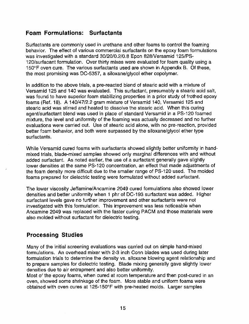
The molds used consisted of a bottom steel plate, a top steel plate perforated withsmall holes to allow gas and foam escape, and steel cylinders of various heightsbetween the plates. Two series of molds were fabricated, an initial series withcylinders having a 5 inch diameter and a second series having a larger 6 inchdiameter. The large diameter molds were required to provide samples for the largerelectrodes fabricated for the dielectric testing. Cylinders of 1-3 inches in height wereused to prepare foams that were later machined into 7 mm thick disks. Densities weremeasured on the individual test disks and did show some variance from the top tobottom of the molded sample in some of the larger molds. Very thin, 7 mm, steelcylinders were used to mold the individual dielectric samp’n- ‘--+-A ‘a’;+k‘k- ‘nmolded skin
w
Perforated Top Plate
Bottom Plate
Steel Molds: Side View
Foam Density and Structure
Foam density in the epoxy foams was controlled by the level of added PS-I 20methylhydro-siloxane up to levels of about 2 phr. Comparison polyurethane foamswere made from a standard CRETE formulation (Ref. 19) based on varying levels of:
Isonate 143L (modified methylene diisocyanate from Dow Chemical, isocyanate equivalentweight, 144.5; functionality 2.1; viscosity 33 cps)
Voranol 490 (propylene oxide polyol from Dow Chemical formed by extensionof a sucrose /glycerin base; functionality 4.3; avg. molecular wt. 460;viscosity 5572 cps)
Polvcat 17 (tertiary amine catalyst from Air Products)DC-1 93 (siloxane/glycol ether surfactant from Air Products)water (generates carbon dioxide blowing agent)
This polyurethane foam is one of several which have been evaluated as replacementencapsulation foams for DP applications. The urethane foams were typically moreexothermic and were cured several hours at room temperature before an overnightpost-cure at 150°F. Foams were prepared over the same general range of densitiesas the epoxy foams.
16
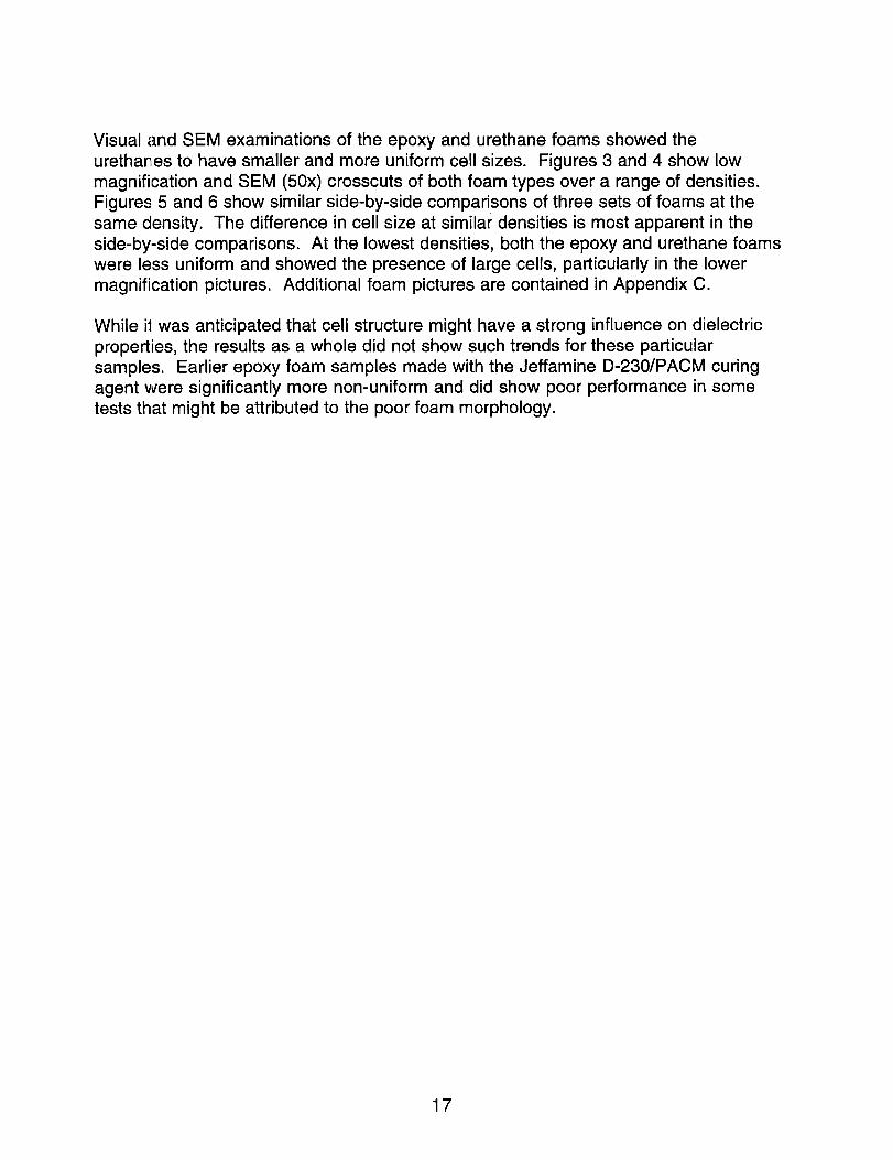
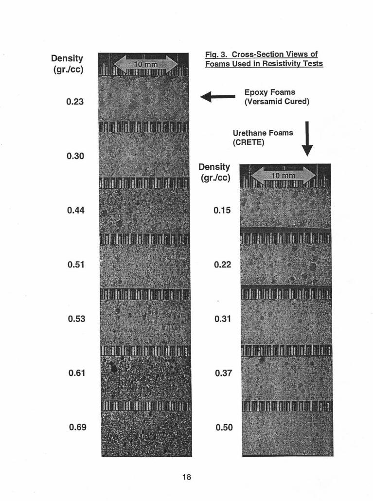
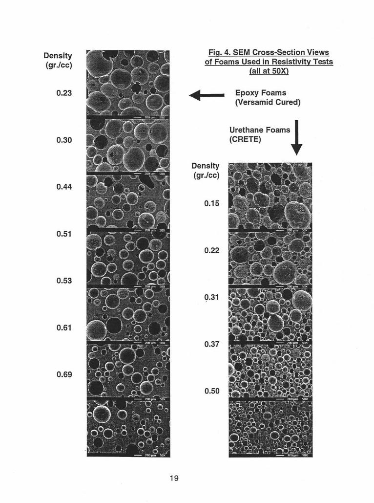
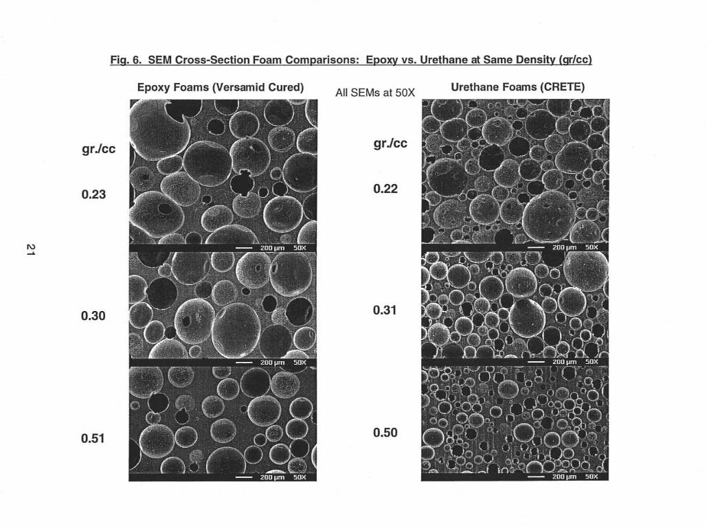
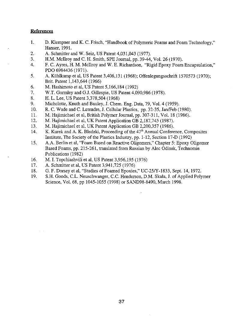
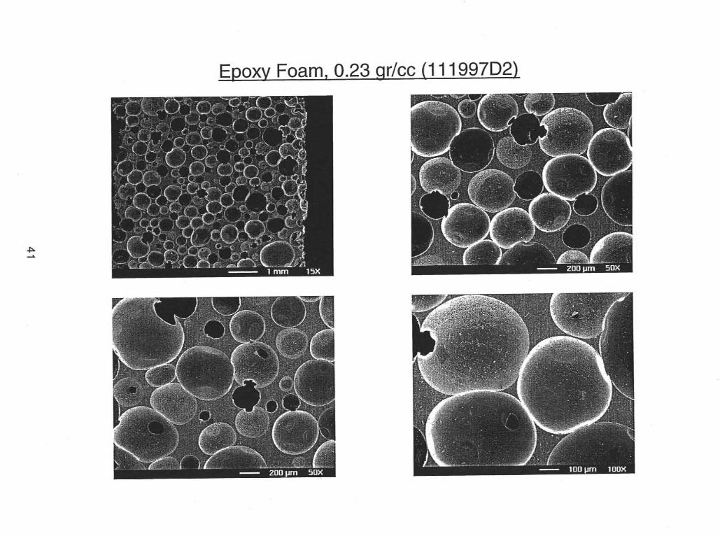
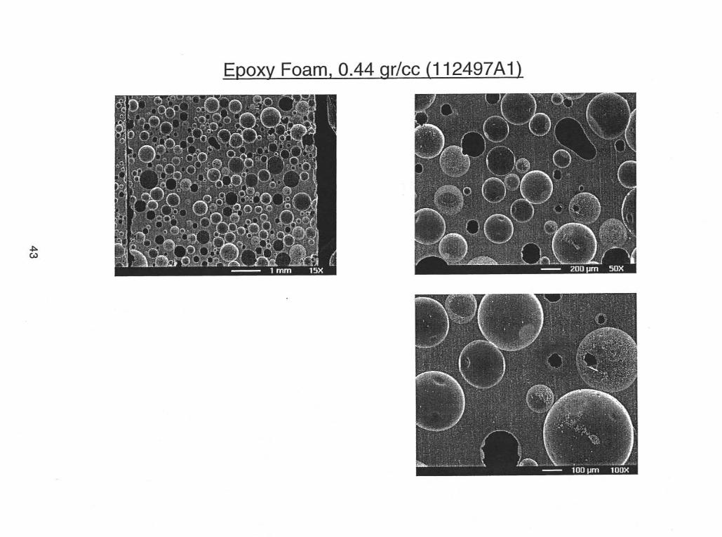
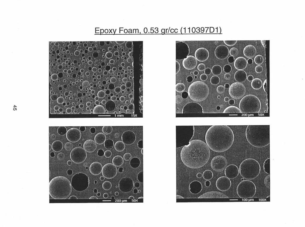
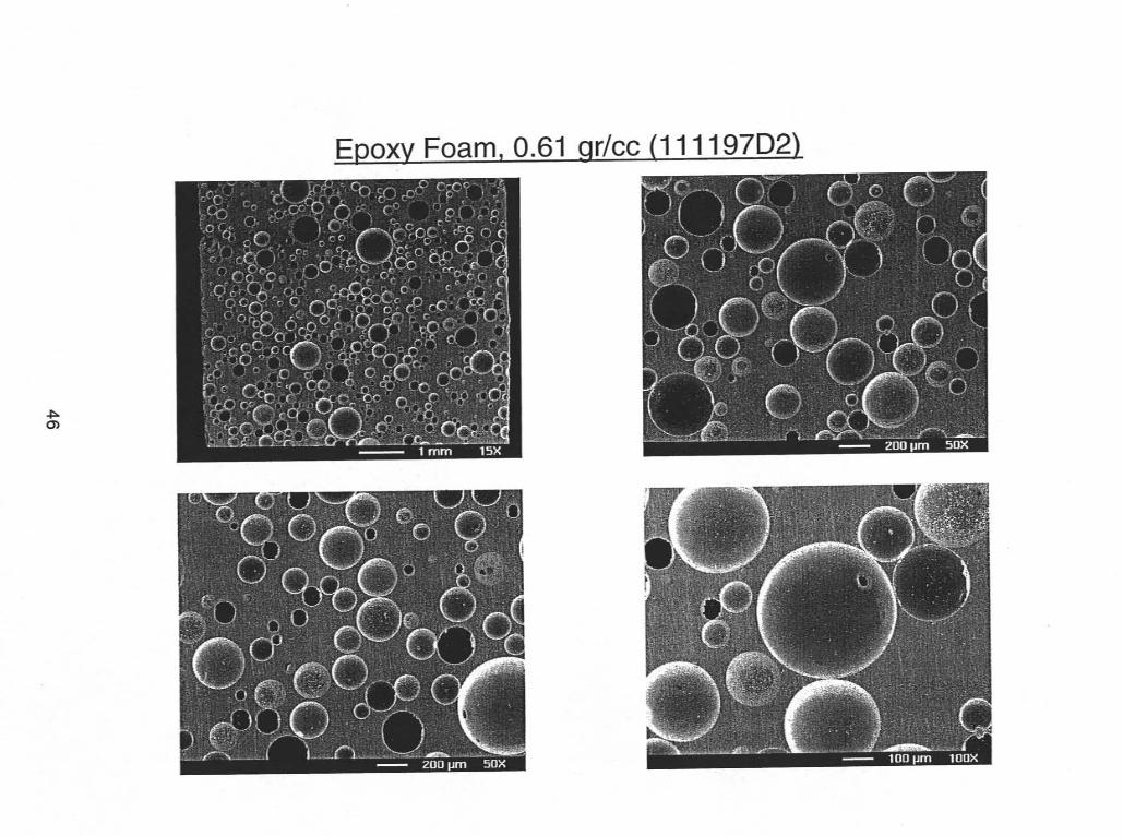
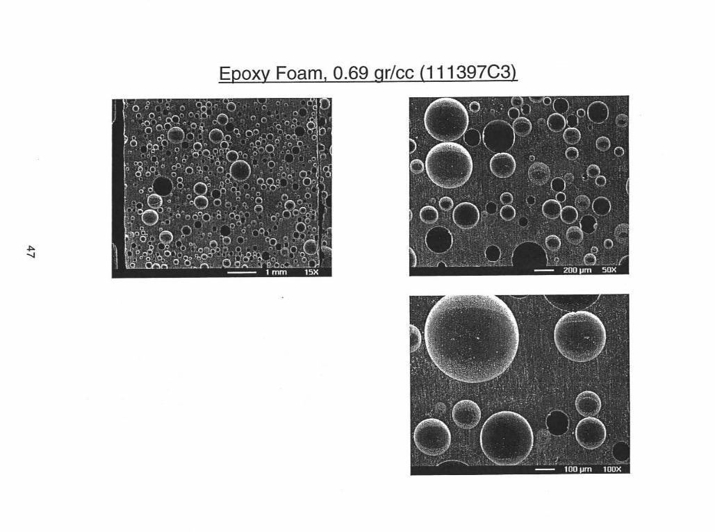
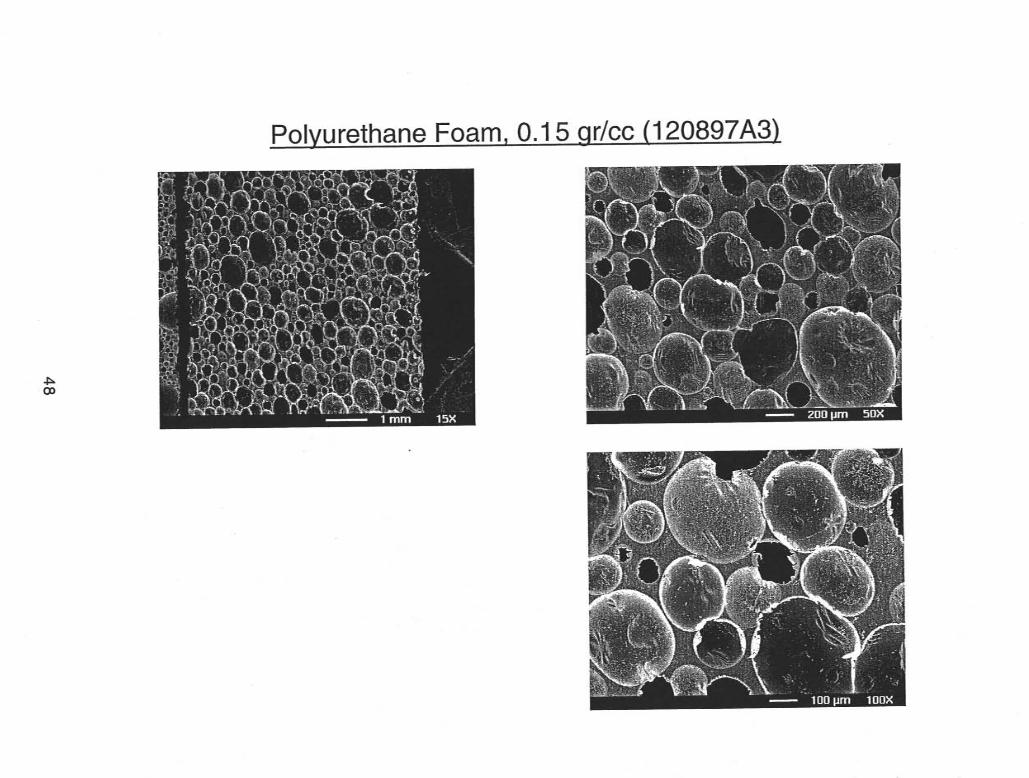
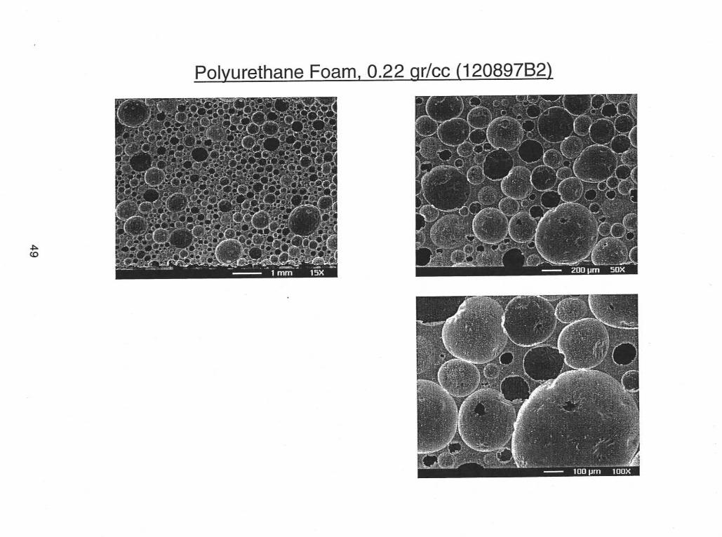
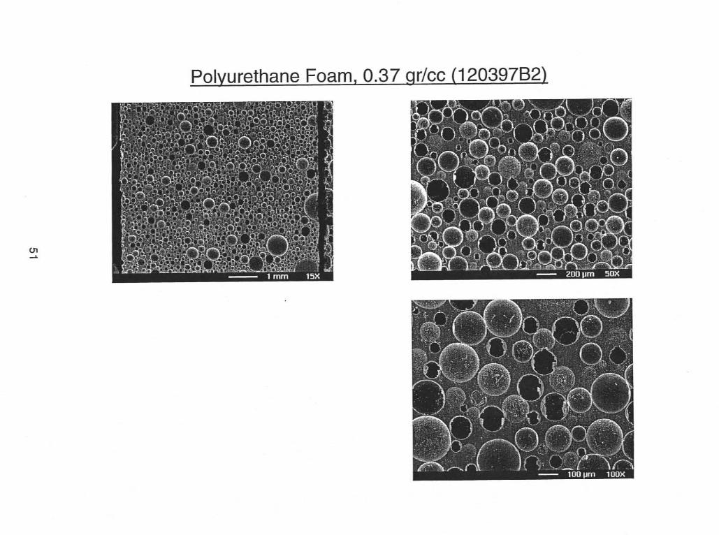
Visual and SEM examinations of the epoxy and urethane foams showed theurethanes to have smaller and more uniform cell sizes. Figures 3 and 4 show lowmagnification and SEM (50x) crosscuts of both foam types over a range of densities.Figures 5 and 6 show similar side-by-side comparisons of three sets of foams at thesame density. The difference in cell size at similar densities is most apparent in theside-by-side comparisons. At the lowest densities, both the epoxy and urethane foamswere less uniform and showed the presence of large cells, particularly in the lowermagnification pictures. Additional foam pictures are contained in Appendix C.
While il was anticipated that cell structure might have a strong influence on dielectricproperties, the results as a whole did not show such trends for these particularsamples. Earlier epoxy foam samples made with the Jeffamine D-230/PACM curingagent were significantly more non-uniform and did show poor performance in sometests that might be attributed to the poor foam morphology.
17
Density (g r ./cc)
0.23
0.30
0.44
0.51
0.53
0.61
0.69
Fiq. 3. Cross-Section Views of Foams Used in Resistivity Tests
Epoxy Foams (Versamid Cured)
Urethane Foams (CRETE)
Density (g r Jcc)
0.1 5
0.22
0.31
0.37
0.50
18
Density (g r ./cc)
0.23
0.30
0.44
0.51
0.53
0.61
0.69
Fiq. 4. SEM Cross-section Views of Foams Used in Resistivitv Tests
lall at 50x1
4 , Epoxy Foams (Versamid Cured)
1 Urethane Foams (CRETE)
Density (g r ./cc)
0.1 5
0.22
0.31
0.37
0.50
19
n .. (DI
rrjl
n
W
I- W
U
0, E m 0
L
J cv 0
c\!
v)
m 0
LL
E * x 0
Q
W
0
u) 0
.+ L
m 0
20
UI 4 .. v) C 0
v)
.- 2 E 0 0
E m 0 u. S
0 0
a,
v)
v)
.- .cI 9 E 0
iii I- W
U
0
Y
E m 0 u. 2 W cn
n
'c1
3 0
2 E m 0 u. )r
x 0 a. W
0
0
EI)
2 cv 0
c\! 0
0
0 0
m
EI) 0
2 c\!
0
0
c?
21
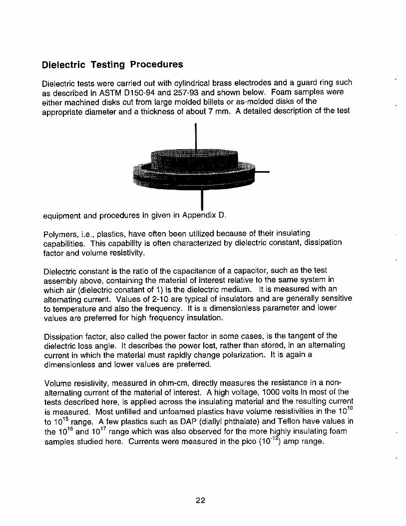
Dielectric Testing Procedures
Dielectric tests were carried out with cylindrical brass electrodes and a guard ring suchas described in ASTM DI 50-94 and 257-93 and shown below. Foam samples wereeither machined disks cut from large molded billets or as-molded disks of theappropriate diameter and a thickness of about 7 mm. A detailed description of the test
equipment and procedures in given in Appe~dix D.
Polymers, i.e., plastics, have often been utilized because of their insulatingcapabilities. This capability is often characterized by dielectric constant, dissipationfactor and volume resistivity.
Dielectric constant is the ratio of the capacitance of a capacitor, such as the testassembly above, containing the material of interest relative to the same system inwhich air (dielectric constant of 1) is the dielectric medium. It is measured with analternating current. Values of 2-10 are typical of insulators and are generally sensitiveto temperature and also the frequency. It is a dimensionless parameter and lowervalues are preferred for high frequency insulation.
Dissipation factor, also called the power factor in some cases, is the tangent of thedielectric loss angle. It describes the power lost, rather than stored, in an alternatingcurrent in which the material must rapidly change polarization. It is again adimensionless and lower values are preferred.
Volume resistivity, measured in ohm-cm, directly measures the resistance in a non-alternating current of the material of interest. A high voltage, 1000 volts in most of thetests described here, is applied across the insulating material and the resulting currentis measured. Most unfilled and unfoamed plastics have volume resistivities in the 1010
to 1015 range. A few plastics such as DAP (diailyl phthalate) and Teflon have values inthe 1016 and 1017 range which was also observed for the more highly insulating foamsamples studied here. Currents were measured in the pico (10-12) amp range.
22

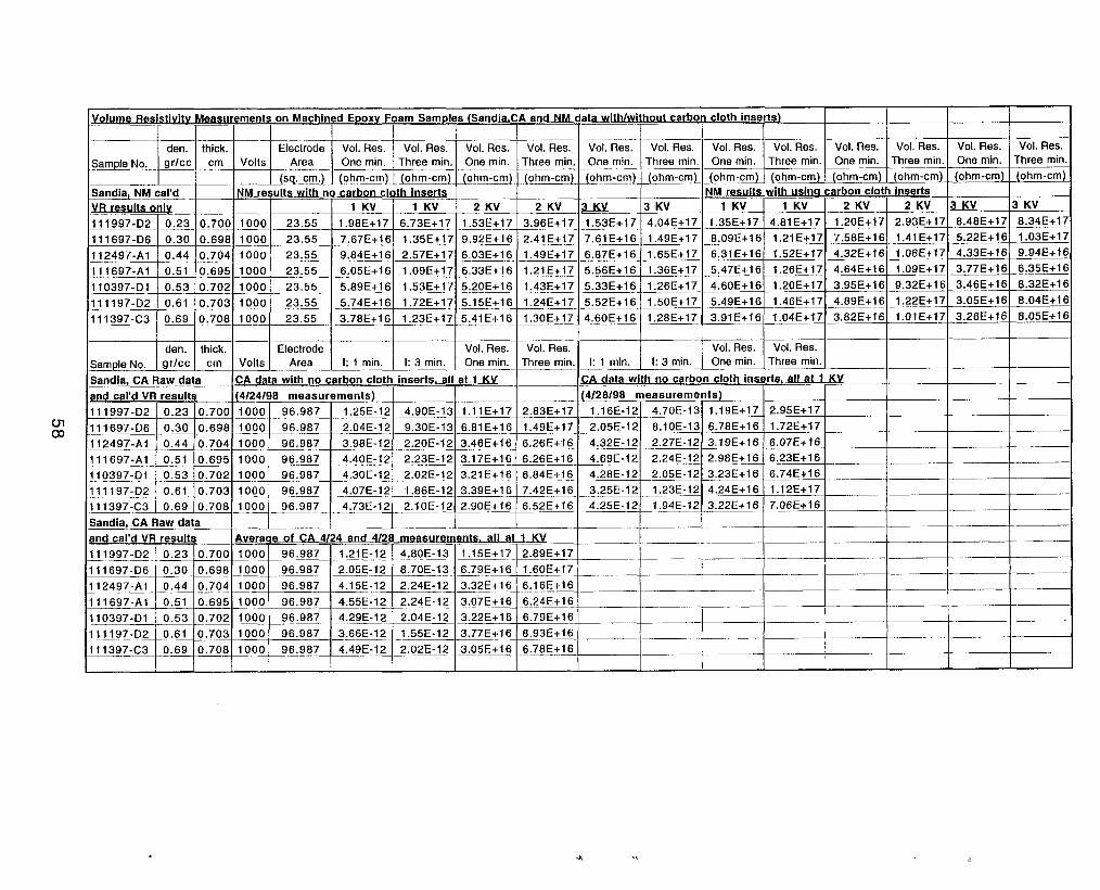
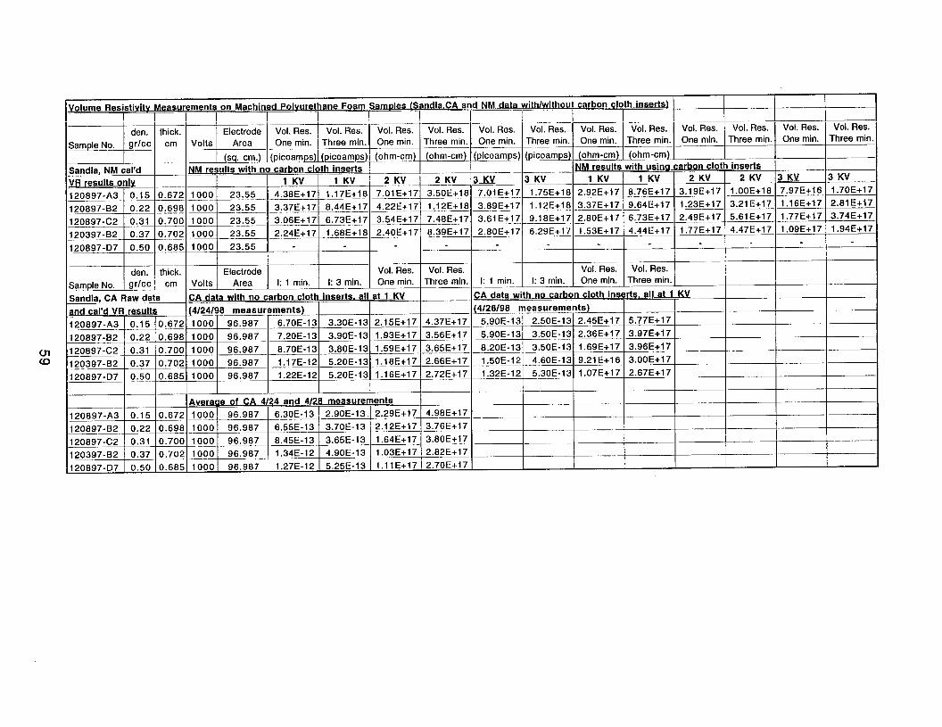
Dielectric Testing Results (Data in Appendix E)
Initial tests with 4 inch x 7 mm machined disks of two epoxy and two urethane foamformulations were carried out with the smaller electrodes in Sandia, NM. The epoxieswere the Versamid cured formulations and the Jeffamine/PACM cured formulationswhile the urethanes were either the TD1-based foam now prevalent in the stockpile orthe newer CRETE family of urethanes. The density range of these samples waslimited and the quality of the foams was also variable. As shown in Fig. 7, however,there was a strong correlation of dielectric constant with foam density, independent ofthe resin type or the test frequency (1-1000 KHz). Dissipation factors, shown in Fig. 8,showed much greater scatter in the results with no clear correlation to resin type ordensity. The test frequency was clearly more dominant in this case although valuesmeasured a 1 KHz were considered too erratic to be reliable.
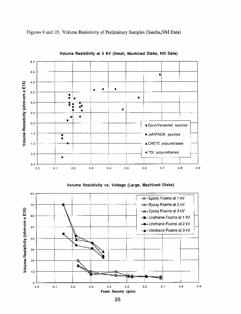
The initial volume resistivity tests were made at 3 kilovolts (KV) due to the sensitivityrequired and, as shown in Fig. 9, were largely in the 1016 ohm-cm range. Values werealso measured at 1 KV on this series of samples but the data was erratic and in thesame range as the noise. These initial results showed varying dependence of theresistivity on foam density. The poorer quality of the epoxy foams cured withJeffamilne/PACM appeared to result in lower resistivity for that group of samples.Overall, no clear conclusions could be drawn about the effects of resin type and foamdensity on volume resistivity from these tests.
It was because of the high sensitivity required that the electrodes fabricated for furthertesting in California were made with a larger surface area, roughly four times the areaof the smaller electrodes. A second series of foams with the larger 5 inch diameterwere fabricated and tested both in California using these larger electrodes and also inNew Mexico. While the electrodes used in New Mexico were still the smaller size, thehigher quality of the foam samples in this series did provide less erratic data and theagreement between the two test locations was, ultimately, very good. These largerfoams were prepared from only the Versamid cured epoxies and the CRETE family ofurethanes.
One series of tests in New Mexico measured the dependence of volume resistivity onthe applied voltage. As shown in Fig. 10, neither the epoxy or urethane samplesshowecl a strong dependence on the applied voltage. The resistivity values shown theresistivity vs. voltage comparisons in Fig. 10 are clearly higher than seen in Figure 9,particularly at lower densities. This is attributed primarily to improvements in thequality (of the samples. All the volume resistivity tests at California were conducted at 1kilovolt,
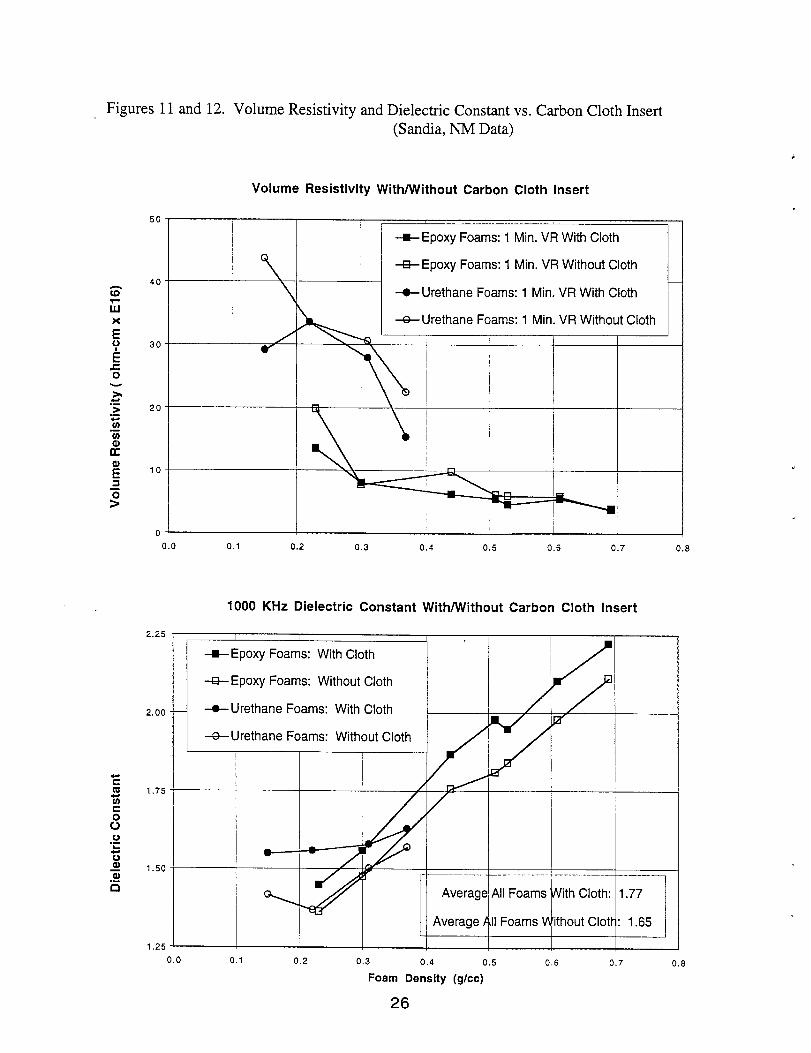
Numerous Round Robin comparisons were made between the two Sandia Labs untilthe test equipment and procedures gave good agreement. One procedure consideredwas th~?insertion of a carbon cloth insert between the foam and electrode surfaces toprovide better electrical contact. As shown in Figs. 11 and 12, such inserts resulted inlittle difference in the volume resistivity measurements and an average increase in the
23

Figures 7 and 8. Dielectric Constants and Dissipation Factors of Preliminary Samples
3.00
2.75
2.50
2.25
2.00
1.75
1.50
1.25
1.00
(Sandia, NM Data)
Foam Dielectric Constant vs. Density (Small, Machined Disks, NM Data)
I
● Versami epoxy, 1 Kl-2
eJerflPAc :M epoxy, 1 <Hz
*
o -ml P041,urethane,1 K+Z
OTDI POI) urethane, 10 KHz
100 KH7 ?
A JefflPA(:M epoxy, 100 KHz
A CRETEpolyurethane,{00 KHzdATDI ool~urethane,10 KHz 8
● Veraamid epoxy, 1 Ml!z
,1
0 Jeff/PAC:M epoxy, 1 Hz~$$
● CRETEpolyurethane MHz @O TDI PO]> urethane, 1 MHz
31
b *.
gw
0.0 0.1 0.2 0.3 0.4 0.5 0.6 0.7 0.8 0.9
Foam Dissipation Factor vs. Density (Small, Machined Disks, NM Data)0.016
0.014-●
●
0,012-●
A*
A
&g 0,010-0 AA o
If*
15:~ 0.006- c1.- A
% R“: #-Q.
; 0.0060 *, In ❑ o ‘. , ■
.-n
ElP
0
0.004 -w
0.002-
0.000- I 1
I Veraamid epoxy, 10 KHz
❑ Jeff/PACM epoxy, 10 KHz
N CRETE polyurethane,10 KHz
12TDI polyurethane, 10 KHz
AVeraamid apoxy, 100 KHz
AJeff/PACM epoxy, 100 KHz
A CRETEpolyurethane,100 KHz
A TDI polyurethane, 100 KHz● Versamid epoxy, 1 MHz
OJeff/PACM epoxy, 1 MHz
. CRETEpolyurethane,1 MHz
OTDI polyurethane, 1 MHzI
0.0 0.1 0.2 0.3 0,4 0.5 0.6 0.7 0.6 0.9
Foam Density (grams/cc)
24
Figures 9 and 10. Volume Resistivity of Preliminary Samples (Sandia,NM Data)
5.0
4.5
x 3.5EyE 3.0cg
b 2.5.->.=Lo.-Cn
2.0
t?1.5
2!=
s1.0
0.5
0.0
80
70
60
50
40
30
20
10
0
Volume Resistivity at 3 KV (Small, Machined Disks, NM Data)
A
● ● ●
●● ● A
w a● ●4
4) ●A
● ●
■
+ EponNersamid epoxies
9 wJeff/PACM epoxiesa
A CRETE polyurethane —
● TDI polyurethanes■
0.0 0.1 0.2 0.3 0.4 0.5 0.6 0.7 0.8 0.9
Volume Resistivity vs. Voltage (Large, Machined Disks)
——
——
—
—
—
—
—
—
+ Epoxy Foams at 1 kV
%-Epoxy Foams at 2 kV –
+ EpoxyFoamsat 3 kV
+ Urethane Foams at 1 kV –
+ Urethane Foams at 2 kV —
-&-- Urethane Foams at 3 kV
0.0 0.1 0.2 0.3 0.4 0.5 0.6 0.7 0.8 0.9
Foam Density (g/cc)
25
Figures 11 and 12. Volume Resistivity and Dielectric Constant vs. Carbon Cloth Insert
50
40
30
20
10
0
(Sandia, NM Data)
Volume Resistivity With/Without Carbon Cloth Insert
+ Epoxy Foams: 1 Min. VR With Cloth
-E Epoxy Foams: 1 Min. VR Without Cloth
-t Urethane Foams: 1 Min. VR With Cloth
+ Urethane Foams: 1 Min. VR Without Cloth
8’
I
0.0 0.1 0.2 0.3 0.4 0.5 0.6 0.7 0.8
1000 KHz Dielectric Constant With/Without Carbon Cloth Insert
2.25
2.00
1.75
1.50
1.25
I I
+ Epoxy Foams: With Cloth
-E- Epoxy Foams: Without Cloth
+ Urethane Foams: With Cloth
%-Urethane Foams: Without Cloth
●* ~
r —_... ,—. ——.......____________
Average All Foams With Cloth: 1.77
Average k,1!Foams VIWhout Clott : 1.65
0.0 0.1 0.2 0.3 0.4 0.5 0.6 0.7 0.8
Foam Dertsity(g/cc)
26

dielectric constant of only 0.12. Further measurements were all made without thecarbon cloth insed.
Measurements on 7 mm thick machined foam disks showed a strong correlation ofdielectric constant with foam density for both the epoxy and urethane materials. This isshown in Figs. 13 and 14. A slight dependence of dielectric constant on frequency isapparent. As noted above, the agreement in test values between NM and CA wasgenerally good. Dissipation factors for these same samples, shown in Figs. 15 and 16,were less well behaved although a general correlation with density was againobserved.
Volume resistivity measurements at both one minute after the voltage was applied(ASTM procedure) and three minutes are shown in Figs. 17 and 18 and indicated littledependence on foam density. All the samples had very high resistivity. The valuesmeasured in CA tended to be slightly more conservative that those made in NM, butthe agreement was generally good. All these resistivities required sensitivity in thepicoamp range and all showed the expected increase in resistivity between one andthree minutes. The resistivity was approaching equilibrium at three minutes with muchless variability.
When used as an encapsulant, the foams would not be machined and would possessa skin c)f higher density and varying thickness near the mold or substrate surface. Aseries c)f molded foam samples, again 7 mm thick, were prepared and tested in thesame manner as the machined foams to determine the effects of such skins on thedielectric performance.
As shown in Figs. 19 and 20, the dielectric constant of the as-molded foams againshoweci a strong correlation with density. Two series of epoxy samples wereprepared, one with Epon 828 and a second with Epon 830 and slightly higher levels ofsiloxane blowing agent to insure more uniform mold filling. Both series gave similarresults which are combined in Fig. 19.
The dissipation factors of these same as-molded foams were better behaved than inthe machined samples and are shown in Figs. 21 and 22. There was a slightcorrelation with foam density and a strong correlation with test frequency, particularlybetween 100 and 1000 KHz.
The volume resistivity results on these as-molded samples, as in the machinedsamples, showed little dependence on foam density except at the very lowesturethane density of about 0.2 g/cc. These results are shown in Figs. 23 and 24.
Pulling all the above results together, Figs. 25 and 26 compare, at 100 KHz, thedielectric constant and dissipation factor of both the epoxy and urethane foams withboth machined and as-molded samples. The dielectric constant of all these materialswas, again, clearly dependent on foam density only with no significant differences dueto the material or the presence or absence of a sutiace skin. The dissipation factors
27
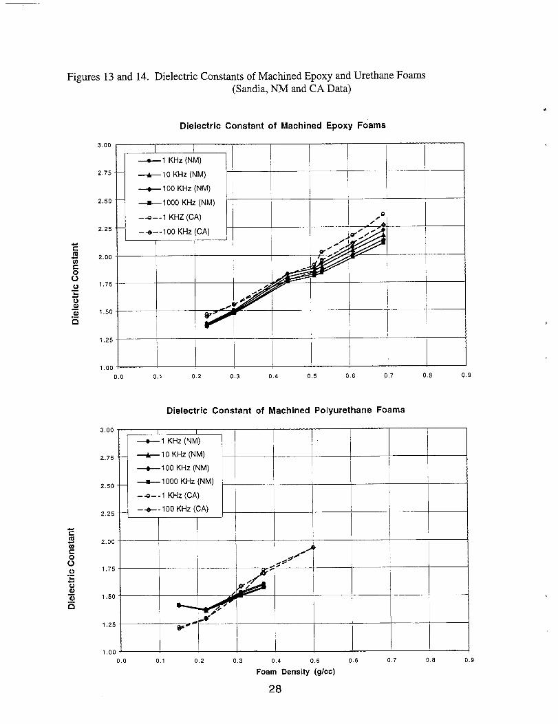
Figures 13 and 14. Dielectric Constants of Machined Epoxy and Urethane Foams
3.00
2.75
2.50
2.25
Eco 2.00Gs
60 1.75.-20aa~ 1.50
n
1.25
1.00
(Sandia, NM and CA Data)
Dielectric Constant of Machined Epoxy Foams
~ 1 KHz (NM)
~10 KHz (NM)
~ 100 KHz (NM)
~1 000 KHz (NM)
-+--1 KHZ(CA) D’/# b- +-- 100 KHz (CA)
0.0 0.1 0.2 0.3 0.4 0,5 0.6 0.7 0.8 0.9
3.00
2.75
2.50
2.25
2.00
1.75
1.50
1.25
1.00
Dielectric Constant of Machined Polyurethane Foams
f ( I
~1 KHz (NM)
~ 100 KHz (NM)
--G--1 KHz (CA)
0.0 0.1 0.2 0.3 0.4 0.5 0.6 0.7 0.8 0.9
Foam Density (g/cc)
28
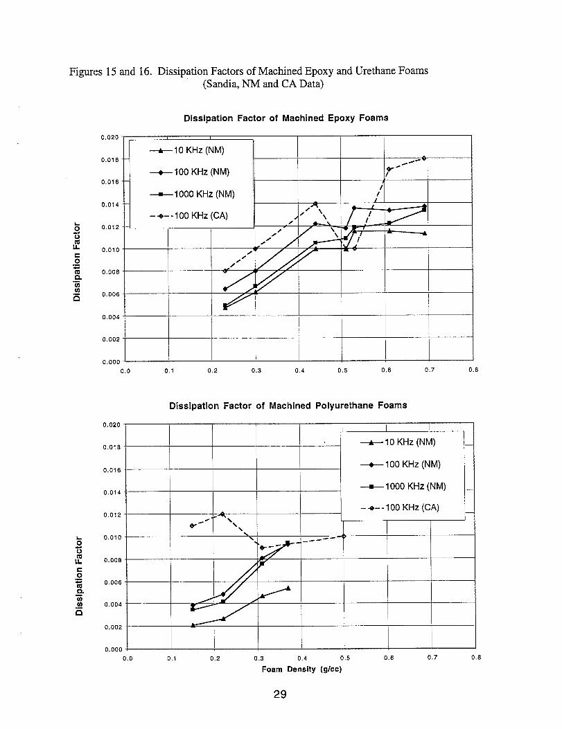
Figures 15 and 16. Dissipation Factors of Machined Epoxy and Urethane Foams(Sandia, NM and CA Data)
Dissipation Factor of Machined Epoxy Foams
0.020 I 1
~ 10 KHz (NM)0.018-– /#~ w
~100 KHz (NM) w“/
0.016-– t
~1000 KHz (NM) /10.014- – i?
~\--e-- 100 KHz (CA) /
/0.012- – — — /
//
/0.010 -— — — ~/ v
/
/’0.008 - v
0.006
0.004
0.002 -
0.000.
0.0 0.1 0.2 0.3 0.4 0.5 0.6 0.7 0.8
Dissipation Factor of Machined Polyurethane Foams
0.020 I
0.018--A-IO KHz (NM)
0.016-~ 100 KHz (NM)
0.014 -~ 1000 KHz (NM) ___
–+-- 100KHz (CA) _0.012 - 4— — —
0-&“ L, I
\
0.010-5
\
b’=-
------ “
G e--
z 0.008-s0.=m 0.006 -
n..-(0
0.004 -.-:
0.002 -
0.000
0.0 0.1 0.2 0.3 0.4 0.5 0.6 0.7 0.8
Foam Density (g/cc)
29

Figures 17 and 18. Volume Resistivity of Machined Epoxy and Urethane Foams
1.E+19
1.E+18
1.E+17
1.E+16
(Sandia, NM and CA Data)
Volume Resistivity of Machined Epoxy Foams
—e-One Minute - NM
-+--One Minute - CA
~Three Minutes - NM
–*–-Three Minutes- cA
m,
\ \~.
‘ ..\ \‘o-. _+*--- LW -%*
1.E+19
1.E+16
1.E+17
1.E+16
0.0 0.1 0.2 0.3 0,4 0.5 0.6 0.7 0.8 0,9
Volume Resistivity of Machined Polyurethane Foams
—-.--One Minute - NM
–4--One Minute - CA
—=-Three Minutes - NM
\ -*–-Three Minutes - CA
\
0.0 0.1 0.2 0.3 0.4 0.5 0.6 0.7 0.8 0.9
Foam Density (g/cc)
30

Figures 19 and 20. Dielectric Constants of As-Molded Epoxy and Urethane Foams (with skins)(Sandia, CA Data)
Dielectric Constant of Epoxy Foams with Skin (Epon 828 & 830 Series)
3.00
● 1 KHz
2.75. — A 10KHz
● 100 KHz
■ 1000 KHz2.!iO -—
.
— Linear (1 KHz)
-—- Linear (10 KHz) 82.25 -~ ------ Linear (100 KHz) ■
---- Linear (1000 KHz)
2.00 -,
1.75
1.50 9
1.25 -
1.00 +
0.0 0.1 0.2 0.3 0,4 0.5 0.6 0.7 0.8 0.9
300
2,75
2.50
2.25
2.00
1.75
1.50
1.25
1.00
Dielectric Constsnt of Polyurethane Foams with Skin (CRETE Series)
● 1KHz
A 10 KHz
● 100 KHz
■ 1000 KHz
— Linear (1 KHz)
––- Linear (10 KHz)
------ Linear (100 KHz)
---- Linear (1000 KHz)
o 0.1 0.2 0.3 0.4 0.5 0.6 0.7 0.8 0.9
Foam Danalty, g/cc
31
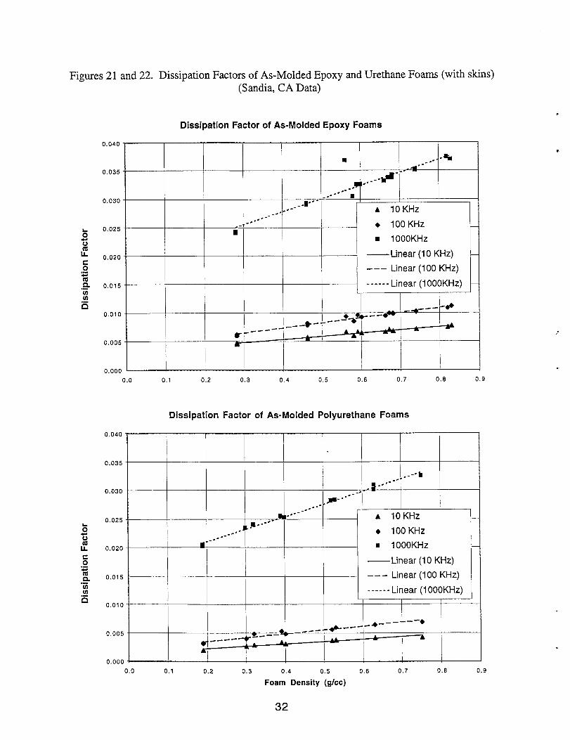
Figures 21 and 22. Dissipation Factors of As-Molded Epoxy and Urethane Foams (with skins)(Sandia, CA Data)-
Dissipation Factor of As-Molded Epoxy Foams
0.040-
9 ---- -%0.035-
~,..--# - ‘-4
. .----0.030- .-.. ■ 1---r -,--- A 10KHz---,---0.025-- .- ?-. ● 100KHz
z ■
z ■ 10OOKHZ
L!! 0.020 —Linear (1O KHz)so.- -–- Linear (100 KHz)%,9 0.015 “ ------ Linear (1OOOKHZ)m Iii.-n
0.010-
0.005-
I I I0.000 1!
0.0 0.1 0.2 0.3 0.4 0.5 0.6 0.7 0.6 0.9
0.040
0.035
0.030
0.025
0.020
0,015
0.010
0.005
0.000
Dissipation Factor of As-Molded Polyurethane Foams
.- b
}r’”--.~ “-----g ‘-----..~,------- A 10 KHz.- s,=---.- . 100 KHz----.
a - m 1000 KHz —
II—Linear (1O KHz)
--- Linear (100 KHz)
------ Linear (1OOOKHZ)I I I
1+ ---’--”--- -~---A a
0.0 0.1 0.2 0.3 0.4 0.5 0.6 0.7 0.8 0.9
Foam Density (g/cc)
32
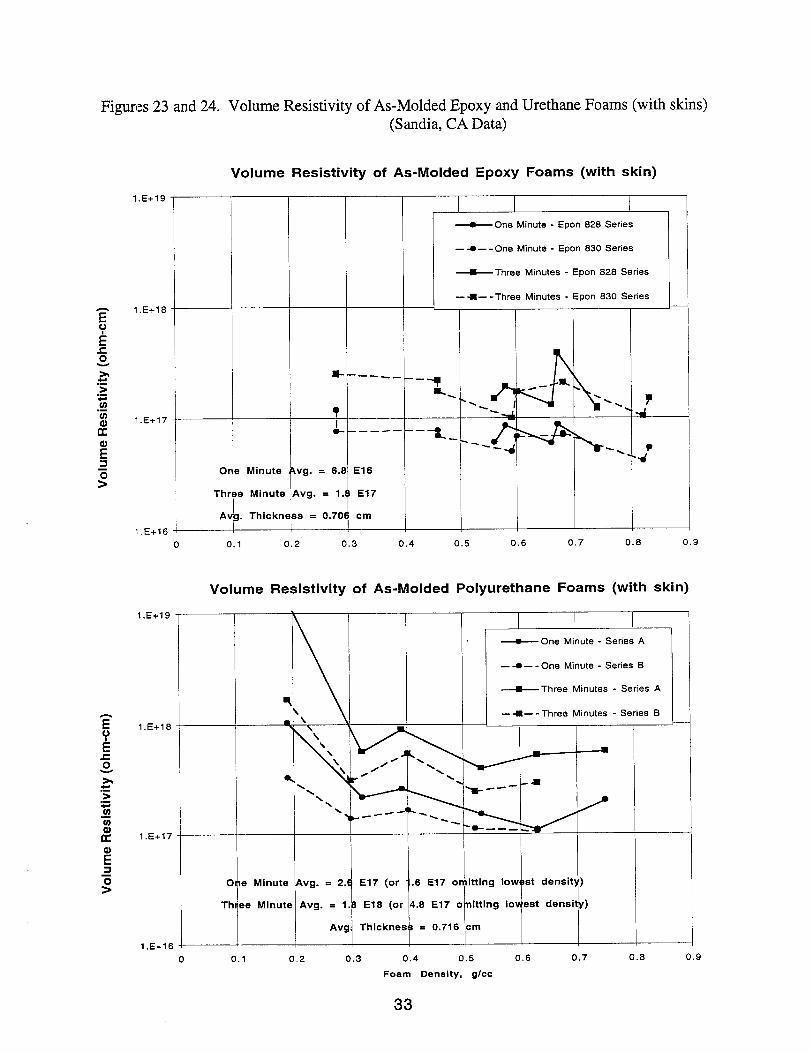
Figures 23 and 24.
1.E+19
1.E+18
1.E+17
“1.E+16
1.E+19
1.E+18
1.E+17
1.E+16
o
Th
A
Volume Resistivity of As-Molded Epoxy and Urethane Foams (with skins)(Sandia, CA Data)
Volume Resistivity of As-Molded Epoxy Foams (with skin)
! Minute
e Minute
I. Thickn
1*—---?J- ——- -
V9. = 16.8 E16
ivg. = 1. E17
,s = 0.70 cm
I~ One Minute - Epon 828 Series
— 4—- One Minute - Epon 830 Series
~ Three Minutes - Epon 828 Series
— -9--Three Minutes - Epon 830 Series—
0 0.1 0.2 0.3 0.4 0.5 0.6 0.7 0.8 0.9
Volume Resistivity of As-Molded Polyurethane Foams (with skin)
I
I~One Minute - Series A
\—-.--One Minute - Series B
I \l I II ~ Three Minutes - Series A
o ne Minuts Avg. = 2.~ E17 (or1
. .6 E17 om itting low st densitb ‘)
Thr“ee Minute Avg. = 1. B E18 (or 4.6 E17 o nitting 10
Avg Thicknes s = 0.716 cm
~
a \Three Minutes - Series B
:<\
\N
\
—
o 0.1 0.2 0.3 0.4 0.5 0.6 0.7 0.8 0.9
Foam Deneity, glee
33

Figures 25 and 26. 100 KHz Comparisons of Epoxy and Urethane Foams (Sandia,CA Data)
3.00
r2.75
2.50
1
2.25
2.00[
1.75
1.50
1.25
1.00
100 KHZ Dielectric Constant of As-Molded/MachinedEpoxy and Polyurethane Foams
I 1 I 1
m MachinedEpoxyFoam
❑ MachinedPolyurethaneFoam !
● As-Molded Epoxy Foam (with akin)
o As-Molded Polyurethane Foam (with sldn)
— Linear (Machined Epoxy Foam)
--- Linear (Machined Polyurethane Foam) + ,+ ,.Tj
------ Linear (As-Molded Epoxy Foam (with skin))~-, -
--–- Linear (As-Molded Polyurethane Foam (with akin)) I
1
2-48‘y
/-, / I I I
1 ,
0.0 0.1 0.2 0.3 0.4 0.5 0.6 0.7 0.8 0.9
Foam Density, g/cc
100 KHZ Dissipation Factor of As-Molded/MachinedEpoxy and Polyurethane Foams
D.025 -
0.020-
0.015-
0.010
0.005
0.000
1 1
m Machined Epoxy Foam
❑ Machined Polyurethane Foam
● As-Molded Epoxy Foam (with skin)
0 As-Molded Polyurethane Foam (with skin)■
— Linear (Machined Epoxy Foam) ■
——- Linear (Machined Polyurethane Foam)
------ Linear (As-Molded Epoxy Foam (with skin))
---- Linear (As-Moided Polyurethane Foam (with skin)) /
U--J --&-------
. . . . . ●--- 0---
8- “----
Q -- ,- -e ---- ~.-e --0 _. ----
0------------ ~
6 “
0.0 0.1 0.2 0.3 0.4 0.5 0.6 0.7 0.6 0.9
Foam Denelty, glee
34

Figures 27 and 28. Volume Resistivity of Machined and As-Molded Epoxy and Urethane Foams
1,E+20
1.E+19
1.E+18
1.E+17
1.E+16
(Sandia,CA Data)
One Minute Volume Resistivity of Epoxy and Polyurethane Foams
● Machined Epoxy
o Machined Polyurethane
■ As-Molded Epoxy (with skin)
❑ As-Molded Polyurethane (with skin)
— Expon. (Machined Epoxy)
--- Expon. (Machined Polyurethane)
------ Expon. (As-Molded Epoxy (with skin))n
--–- Expon. (As-Molded Polyurethane (with skin))
u-------(3-. -< ❑
●------
●■
●
1.E+20
1.E+19
1.E+18
1.E+17
1.E+16
0.0 0.1 0.2 0,3 0.4 0.5 0.6 0.7 0.8 0.9
Three Minute Volume Resistivity of Epoxy and Polyurethane Foams
● Machined Epoxy
o Machin’ed Polyurethane
■ As-Molded Epoxy (with skin)
❑❑ As-Molded Polyurethane (with skin)
— Expon. (Machined Epoxy)
--- Expon. (Machined Polyurethane)
------ Expon. (As-Molded Epoxy (with skin))
—!3- --- ---- Expon. (As-Molded Polyurethane (with skin))
-.* ---
Q
------ ---- _J
● ,0
0.0 0.1 0.2 0.3 0.4 0.5 0.6 0.7 0.8 0.9
Foam Density (g/cc)
35

were more erratic throughout these tests, but did indicate a slightly higher dissipationfactor for the epoxy foams and also higher dissipation factors in the machined samplesthan in the as-molded samples. There was again a clear dependence on foamdensity.
Again pulling all the above results together, Figs. 27 and 28 show that both the oneminute and three minute volume resistivities showed only a slight dependence onfoam density and slightly higher values for the urethane foams. All the foams had veryhigh volume resistivity values with the as-molded foams showing slightly higherresistance than the machined foams.
Conclusions
No dielectric advantages were found for the epoxy foams over polyurethane foams.These comparisons are evident in Figures 25-28.
Both as-molded foams with skinned surfaces and machined foams showed littledependence of volume resistivity on foam density except at very low densities.Urethane foams generally had slightly higher volume resistivities than epoxy foamsalthough all the samples, with and without skins, had resistivities above 1016ohm-cm(measured at one minute). Urethane foams were typically about an order ofmagnitude higher at 1017ohm-cm.
Dielectric constants were clearly dependent on foam density in both the machined andas-molded samples with all samples falling along the same trendline. Neither theresin type or the presence or absence of the foam skin had additional significanteffects on dielectric constant.
The cell sizes and foam morphologies were also examined and did not appear to havesignificant effects on the dielectric constant and volume resistivity.
Processing of the siloxane-blown epoxies was similar to water-blown urethanesalthough the cell size of the epoxies was generally larger and less uniform.
36
1.
2.3.4.
5.
6.7.8.9,10.11.12.13.14.
15.
16.17.18.19.
D. Klempner and K. C. Frisch, “Handbook of Polymeric Foams and Foam Technology,”Hanser, 1991.A. Schmitter and W. Seiz, US Patent 4,031,043 (1977).H.M. McIlroy and C. H. Smith, SPE Journal, pp. 39-44, Vol. 26 (1970).F. C. Ayres, H. M. McIlroy and W. E. Richardson, “Rigid Epoxy Foam Encapsulation,”PDO 6984436 (1971).A. Kuhlkamp et al, US Patent 3,406,131 (1968); Offenlegungsschrift 1570573 (1970);Brit. Patent 1,143,644 (1966)M. Hashimoto et al, US Patent 5,166,184 ( 1992)W.T. Gormley and G.J. Gillespie, US Patent 4,090,986 (1978).H. L. Lee, US Patent 3,378,504 (1968)Michelotte, Knuth and Bauley, J. Chem. Eng. Data, 79, Vol. 4 (1959).R. C. Wade and C. Letendre, J. Cellular Plastics, pp. 32-35, Jan/Feb (1980).M. Hajimichael et al, British Polymer Journal, pp. 307-311, Vol. 18 (1986).M. Hajimichael et al, UK Patent Application GB 2,187,745 (1987).M. Hajimichael et al, UK Patent Application GB 2,200,357 (1986).K. Kurek and A. K. Bledzki, Proceeding of the 47* Annual Conference, CompositesInstitute, The Society of the Plastics Industry, pp. 1-12, Section 17-D (1992)A.A. Berlin et al, “Foam Based on Reactive Oligomers,” Chapter 5: Epoxy OligomerBased Foams, pp. 215-261, translated from Russian by Alec Odinsk, TechnorniePublications (1982)M. I. Topchiashvili et al, US Patent 3,956,195 (1976)A. Schmitter et al, US Patent 3,941,725 (1976)G. F. Dorsey et al, “Studies of Foamed Epoxies,” UC-25/Y-1833, Sept. 14, 1972.S.H. Goods, C.L. Neuschwanger, C.C. Henderson, D.M. Skala, J. of Applied PolymerScience, Vol. 68, pp 1045-1055 (1998) or SAND98-8490, March 1998.
37

Appendix A. Structures of Epoxy Formulation Ingredients
:&.cH20Q+qo.cHJ:cH2.0~+q:.cH,4~
Epon 826/828/830 (increasing value of n and molecular weight in series)
, ,“GZEFICH2CH2N“z- CH2CH#l CH2CH3d
c’<=~pNH,- ‘“2’”4 cH2c H@
H H
c “,’”,- NH2
Versamid 125/140 (complex reaction product of acid dimer and diethylenetriamine)
NH+OANH,CH~
Jeffamine D-230
H2NQ--cH2~NH2
Ancamine 2049
38
PACM

Appendix B. Surfactants Evaluated in EDOXV Foams
Manufacturer——Air Produlcts
Dow-Corning
Union Carbide
Icl
Shin-Etsu
Aldrich
Trade Name
Dabco DC-56Dabco DC-57
Dabco DC-193Dabco DC-197Dabco DC-5098Dabco DC-5103Dabco DC-5164Dabco DC-5320Dabco DC-5357Dabco DC-5367Dabco DC-5384Dabco DC-5385Dabco DC-5454
LK-221LK-443
Q2-5200Q2-8075
L-5420Tergitol 7
Tergitol NP-1 OTergitol 15-S-7
Niax L-6906
Niax Y-10762Triton 100
Tween 20Tween 40Tween 60Tween 80
KF-865
Sorbital MonoloeateGlycerin
HandiManwater
Type
non-ionicnon-ionicnon-ionicnon-ionicnon-ionicnon-ionicnon-ionicnon-ionicnon-ionicnon-ionicnon-ionicnon-ionicnon-ionicnon-ionicnon-ionic
anionic
non-ionicnon-ionic
non-ionicnon-ionic .non-ionicnon-ionic
non-ionic
non-ionicnon-ionic
Identification
;ilicone polymer/copolymer?silicone polymer/copolymer?silicone glycol copolymersilicone glycol copolymersilicone glycol copolymersilicone glycol copolymersilicone polymersilicone glycol copolymer?silicone glycol copolymer?silicone glycol copolymer?silicone glycol copolymer?silicone glycol copolymer?silicone glycol copolymer?non-silicone polymernon-silicone polymer
silicone polymersilicone polymer
0.26% monoheptadecylsulfate, sodium salt inwaternonylphenol ethoxylate (1O EO)secondary alcohol ethoxylate (7 EO)polyalkylene oxide/dimethylsiloxanecopolymersilicone
polyoxyethyene (20) sorbitan monolauratepolyoxyethylene (20) sorbitan monopalmitatepolyoxyethylene (20) sorbitan monostearatepolyoxyethylene (20) monooleate
amine functionalized polysiloxane
sorbital monoloeateglycerol (1 ,2,3 -propanetriol)hand soap formulation
39

Armendix C: Foam Pictures
40
41

P
42
a 0
LL > X
0 c w
Y
43
44
45
.
46
47
48
49
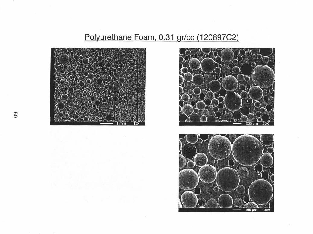
Polyurethane Foam, 0.31 ar/cc (1 20897C2)
51
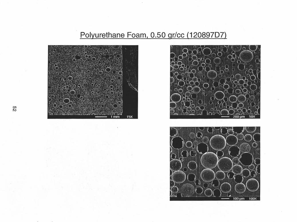
Polyurethane Foam, 0.50 qr/cc (1 20897D7)

~~dix D: Dielectric Testing
Initial dielectric tests were carried out by Paul Beeson at Sandia, NM. This testing capabilitywas later set up in Sandia, CA where most of the tests were run. Round-Robin comparisonsbetween the two labs showed good agreement after some early trouble-shooting.
The early tests carried out by Paul Beeson in Sandia, NM used smaller brass electrodes with a 2inch diameter top electrode, 4 inch bottom electrode and guard ring with an inner diameter of 2.3inches,. A larger set of electrodes with a 4.25 inch top electrode and 5 inch bottom electrode wasdesigned by Paul Beeson and fabricated in the Sandia,NM machine shop for use in Sandia, CA.The guard ring had an inner diameter of 4.5 inches and the effective electrode area uses adiameter midway betsveen the upper electrode and guard ring or 4.375 inches. The CAelectrodes therefore had an effective surface area of 96.99 sq. cm. and the area of the NMelectrodes was 23.55 sq. cm. The electrodes were enclosed in a oven for both faraday shieldingand heating. Low noise test leads were used and all cable connections as well as the electrodeswere carefilly insulated.
The specific equipment used in California, all from Hewlett-Packard, consisted of a Model4339B High Resistance Meter and a Model 4284A Precision LCR Meter along with low-noiseleads (161 17C).
/m
&J)Top electrode ~ I I
Guard Ring ~
BottomElectrode
Tests using carbon cloth inserts between the foam sample and electrodes to improve contactshowed slightly higher conductivity. The differences were minor, however, and the reportedtests were carried out without these inserts, unless otherwise noted, for simplicity.
All volume resistivity measurements except for some early tests and comparisons of resistivityvs. voltage in Sandia,NM were carried out at 1 kilovolt. Volume resistivities were measuredboth one minute, as called for in the ASTM procedures, and three minutes after the voltage wasapplied. The conductivity, as expected, dropped rapidly during the first minute and more slowlyduring the next two minutes.
Calculations:Volunne Resistivity = (Voltage x Electrode Area) / (Measured Current x Sample Thickness)
Dielectric Constant = (Measured Capacitance x Sample Thickness)/ (Electrode Area x @
where &O= electric field constant (8.854x 10-]2 Fro-l)
53

ADDendix E: Dielectric Measurements
54

Dielectric Measurements on Machined Foam Sam Ies Sal?r!–
density thick. Diel.(grlcc) (cm) Cap (pf) IX Con.
Machined Epoxy lJQ!Z
no carbon cloth insefls
111997-D2 0.23 0.700 4.12 0.0020 1.38. —11 1697-D6 0.30 0.698 4.51 0.0020 1.51
112497-AI 0.44 0.704 5.42 0.0045 1.83
11 1697-AI 0.51 0.695 5.65 0.0040 1.88
110397-D1 0.53 0.702 5.72 ‘--0.0050 1.93
111197-D2 0.61 0.703 6.14 0.0060 2.07
111397-C3 0.69 0.708‘-” _6.51 0.0057 2.22
NM data with usina carbon CIOth inserts
1~ 0.23 o.7oo_ 4.37 0.0010 1.47
111697-D6 0.30 0.698 4.76 0.0020 1.59
11 2497-Al 0.44 0.704 5.>6 0.0050 1.95-
111697-AI 0.51 0.695 6.17 0.0050 2.06
110397-D1 0.53 0:702 6.05 0.0050 2.04
111197-D2 0.61 0.703 6.53 0,0060 2.20
111397-C3 0.69 6.86 0.0060 2.33
CA data with no carbon cloth inserts
tl1997-D2 0.23 0.700 18.0 0.0030 1.47
111697-D6 0.30 0.698 19.2 0.0040 1.56
112497-A1 o.i4 0.704 22.3 0.0060 1.83
111697-A1 0.51 0.695 23.6 0.010”0 1.91
110397-D1 0.53 0.702 24.8 0.0050 2.03
111197-D2 0.61 0.703 26.6 0.0070 2.18
111397-C3 0.69 0:708 28.6 0.0080 2.36
—
---
ia.CA and NM data.with/wi
~~
e ——...4.10 0.0047 1.38
4.47 0.0061 1.50
5.35 0.0100 1.81
5.58 0.0099_ 1.86
5.65 0:0115 1.90
6.06 0.0115 2.04
6.41 0.0113 2.18
4.35 0.0046 1.46–
4.73 0.0060 1.58
5.69 0.0101 1.92
6.09 0.0102 2.03
5.97 0.0114 2.01
6.44 0.0116 2.17–
6.76 0.0114 2.30
hout carbon cloth insert)
DieL Diel~Cap (pf) IX Con. Cap (pf) Df Con.
IOOKHZ IJLB!Z
4.06 0.0064 1.37 4.06 0.0049 1.36—.4.43 0.0080 ‘1 .48 4.41 0.0066 1.48
5.26 0.0722 1.78 5.21 0.0105 1.76—.5.49 0:0118- 1.83 5.44 0.0109 1.81
5.54 0.0136 _ 1.86 5.47 0.0119 1.84—.5.94 0.0134 2.00 5.87 0.0122 1.98
6.29 0.0137 2.14 6.21 0.0134 2.11
4.31 0.0064 _1.45 4.31 0.0054 1.45
4.68 0.0080 1.57 4.66 0.0069 1.56
_ 5.59 0.0122 1.89 5.53 _ 0.0109 1.87
__ 5.99 0.0122”- 2.00 5.93 0.0114 1.98
5.86 0.0137 1.97 5,78 0.0124 1.95
6.31 0.0137 2.13 6.24 0.0128 2.10
6.63 0.0140 2.25 6.54 0.0139 2.22
17.8 0.0080 1.45
19.2 0.0100 1.56
21.7 0.0140 1.78
23.8 0.0100 1.93
23.9 0.0100 1.95—25.7 0.0170 2.10
27.6 0.0180 2.28
—-
-.Dielectric Measurements on Machined Foam Samples continued Sandia CA and NM data with/without carbon c1 th insert
~ I

density thick. DieL Diel. DieL DieL
(grlcc) (cm) Cap (pf) lx Con. Cap (pf) IX Con. Cap (pf) lx Con. Cap (pf) lx Con.
Machined Polyurethane m 10 KHz— 100 KHz 1MHz
NM data with no carbon cloth inserts
120897-A3 0.15 ..._QUZZZ 4.41 0.0000 _l .42 4.41 0.0021 1.42 4.39 _ 0.0039 1.41 4.39 0.0035 1.42
T20897-B2 _o.22 0.698 4.11 0.00”00 __1.38 4.10 o.o-027_ 1.37 4.08 _o. oo49 1.37 4.08 0.0042 1.37
120897-C2_.. _
0.31 0.700 4.57 0.0020 --1.54 4.54 0.0047 1.53— 4.50 0.0081 1.51 4.48 0.0076 1.50— —120397-B2 0.37 0.702 4.77 0.0020 1.61 _ 4.74 0.0054 1.60 4.69 -~93 1.58 4.65 0.0094 1.58
120897-D7 0.5-0 0.685 - 1.66
NM data with usina carbon cloth inserts –
120897-A3 0.15 0.672 4.83 0.0000 1.56 4.82 0.0021 1.56 4.80 0.0040 ‘1.55 4.81 0.0036 1.55
120897-B2 0.22 0.698 4:71 0.0000 1.58-- 4.69 0.0030 1.57 4.67 0.0052 1.56 4.66 0.0053 1.56-— .—120897-C2 0.31 0.700 4.79 0.0020 1.61 ‘- 4.77 0.0045 1.60 4.72 0.0081 1.59 4.70 0.0078 1.58
120397-B2 0.37 0.702 4.97 0.oo30- 1.67 - 4.94 0.0054 1.66 4;9 0.0091 1:65 4.85 0.0091”” 1.63—120897-D7 _ 0.50
—.0.685 1.77
CA data with no carbon_cfoth inserts ‘“
g 120897-A3 0.15 o~2_ 15.6 0.0020 1.22 15.4 0.0110 1.21
120897-B2.-
0.22 0.698 16.0 0.0030 1.30 – 15.9 0.0120 1.29
120897:C2 0.31 0.700—.
18.6 0.0280 1.52 19:5 _...-—— 00090 1.59
120397-B2 o.702---
_o.37 21.2 0.0040 1.73 20.8 1.70
120897-D7 0.50 0.685 24.2 0.0050 ‘-.1.93” 1.9324.2 .0.0100 _ -.
..
— .—
—-.
— .— — -.
— —
-.
— —
— .
— —
. +

Dielectric Measurements on As-Molded Foam Samples (all Sandia.CA data with no carb(
density thick. Diel. Diet.(grlcc) (cm) Cap (pf) w Con. Cap (pf) IX Con.
As-Molded Epoxv’ _ly&Lz 10 KHz—82598EP3A
.—0.56 0.575 34.87 0.0036 2.34 34.63 0.0067 2.32
82598EP4B 0.58 0.724 24.35 0.0032 2.05 24.21 0.0060” 2.04—.82598EP5B 0.66 0.720 27.38 0.0038 2.30 27.19 0.0067 2.28
82598EP5A 0.67 0.720 27.71 0.0038 2.32 27.52 0.0070 2.31—.82598EP6A 0.74 0.720 29.43 0.0039 2.47 29.21 0.0072 2.45
82598EP6B 0.74 0.720 29.86 0.0041 2.50 29.64– 0.0072 2.49
82798EPIA 0.28 0.711 18.51 0.0023 1.53 18.43 0.0047 1.53
82798EPI B 0.28 0.71 6“” 18.84——. —
0.0026 1.57 18.76 0.0045 1.56--
02798Ep3A—.—.
0.46 0.716 23.17 0.0031 1.93 23.04 0.0058 1.92
82798EP3B 0.46 0.700 22.71 0.0032 1.85 22.59 0.0056 ‘“ 1.84
82798EP4A- 0.59 0.703 26.34 0:0035 2.16 26.16 0.0067 2.14——82798EP4B 0.60 0.710 26.23 0:0037 2.17 26.06 0.0065 2.16
82798EP5A 0.68 0.708 27.68 0.0036 2.28 27.49 0.0068 2.27
82798EP5B 0.68 0.714 28.13 0.0038 2.34 27.94 0.0068 2.32—.82798EP6A- 0.83 0.715 30.89 0.0042 2.57 30.65 0.0077 2.55
82798EP6B 0.82 0.731 31.55 0.0042 2.69” 31.31 0.0075 2.67
As-Molded Polyurethane I&!Z 10KH;
90298PU1A 0.19 0.720 16.67 0.0011 1.40 16.65 0.0020.— 1.40
90298PU2A 0.32 0.714 19.47 0.0016 1.62 19:42 0.0029 1.62
90298PU3A 0.39 0.716 20.65 0.0020 1.72 20.59 0.0033 1.72—. —90298PU4A 0.53 0.719 23.56 _O.0024 1.97 23.47 0.0038 1.97
90298PU5A 0.63 0.714 25.45 0.0028 2.12 25.35 0.0041 2.11—.——90298PU6A 0.75 .0.713 28.49 0.0029 2.37 28.37 0.0043 2:36
90298PU1B 0.19 0.721 16.30 “0.0013 1.37 16.28 0.0019”” 1.37
90298PU2B 0.30 0.711 19.13 0.0018 1.50 19.09 0.0026 1.58
90298PU3B _o.40 0.716 20.51 0.0019 1.71 20.46 0.0031 1.71
90298PU4B 0.52 0.712 23.80 0.0025 1.97 23.71 0.0037 1.97
30298PU5B 0.63 0.719 26.05 0.0028 2.18-- 25.94 0.0041 2.17
n cloth inserts)
Diel. Diet.Cap (pf) DF Con. Cap (pf) IX= Con.
100 KHz w
34.24 o.oo94_ 2.29 32.68 0.0369 2.19
23.96 0.0085 2.02 23.09 0.0305 1.95
26.88 0.0095 2.25 25.80 0.0332 2.16
27.19 0.0099 2.28 26.08 0.0337 2.19
28.85 0.0103 2.42 27.61 0.0351 2.32
29.27 0.0102 2.46 28.02 0.0353 2.35
18.28 0.0063 1.51 17.77 0.0241 1.47
18.62 0.0060 1.55 18.10 0.0243 1.51
22.81 0.0082 1.90 22.01 0.0293 1.84— .22.37 1.820.0079 _ 21.61 0.0290 1.76
25.86 0.0096 2.12 24.84 0.0326 2.03
25.78 0.0093 2.13 24.77 0.0326 2.05
27.1-7 0.0099 2.24 26.05 0.0338 2.15
27.61 0.0098 2.30 26:48 0.0342 2.20
30.24 0.0112 2.52 _ 28.86 0.0370 2.40
30.90 0.0109 2.63 29.48 0.0374 2.51
10OKHZ lMHz
16.59 0.0032 1.39 16.21 0.0205 1.36
19.32 0.0048 1.61 18.80 0.0240 1.56
20.47 0.0053 1.71 19.88 0.0255 1.66
23.32 0.0060 1.95 22.56 0.0284 1.89
25.18- 0.0064 2.09 24,30 0.0301 2.02
28.17 0.0069 2.34 27.10 0.0325 2.25———.16.23 0.oo31- 1.36 15.87 0.0202 1.33-
19.01 0.0040 1.57 18.53 0.0234 1.53
_20.35 0.0048 1.70 19.77 0.0253 1.65
23.57 0.0056 1.96 22.82 0.0283 1.89—‘25.77 0.0064 2.16 24.86 0.0309 2.08
—.‘ First 6 epoxy samples formulated with Epon 828. Last 10 epoxy samples formulated with Epon 83o. J
mw
Volume Resistivitv Messure ts on Machined Epoxy Foa~men m Samrrles C3andia.C
den. thick. Electrode Vol. Res. Vol. Res. Vol. Res.
Sample No. g rlcc cm volts Area One min. Three min. One min.
(sq. cm.) @hm-cm] (ohm-cm) <ohm-cm~5andia, NM cal’d ~fi. ;ults with no carbon CIOth inserts ._VR results only 1 KV 1 KV 2 KV
111997-D2 0.23 i.7oo j 000 23.55 1.98E+17 6.73E+l~ _l.53E+17——111697-D6 0.30 0.698 1000 23.55 7.67E+16 1.35E+17 9.92E+16— —.112497-A1 0.44 0.704 1000 23.55 9.84E+16 2.57E+17 6.03E+16
fi697-AI 0.51 O* .! 000 23.55 ‘6.05E+16 1.09E+17 6. 33E+16_.110397-D1 0.53 0.702 1000 23.55 5.89E+16 1.*1,7 5.20E+16
111197-D2 0.61 0.703 1000 23.55 5.74E+16 1.72E+17 5.15E+lg
~11397-c3 0.69 0.708 1000 23.55 3.78E+l@ 1.23E+17 5.41 E+16
den. thick. Electrode Vol. Res.sampleNo, grlcc cm volts Area 1:1 min. 1:3 min. One min..Ssndia, CA Raw data__ CA data with no carbo n cloth inserts. all al lKV
zn~ _ (4124198 measurements)
111997-D2 0.23 0.700 1000 96.987 1.25E-12 4.90E-13 1.11 E+17
111697-D6 0.30 0~8 ~o 96.987 2.04E-12 9.30E-13 6.*1 6__ ——.112497-AI 0.44 0.704 1000 96.987 3.98 E-I 2 ._2.20E-12 3.46E+16
111697-A1 0.51 0.695 Qoo 96.987 4.4oE-12 2.23= 3.17E+IQ
ilo397-Dl- 0.53 0.702 1000——..— 96.987 4.30E-12 2.02E~ 3.21 E+16
111 197-D2 “0.61 0.703 1000 96.987 4.07E-12 1.86E-12 3.39E+16
I 11397-C3 0.69 0.708 1000 96.987 4.73E-12 2.;oE-12 2.90E+I 6.—.3andia, CA Raw data _. -..md cal’d VR results A~ ur
~1997-D2 0.23 0.700 1000 96.987 1.21 E-12 4.80E-13
111697-D6 0.30 0.698 1000 96.987 2.05E-12 8.70E-13 ~
I 12497-AI 0.44 0.705 1000 96.987 4.15E-12 2.24E-1~
111697-A1 0.51 0.69!j i 0.00 96.987 4.55E-12 2.24E-12
110397-DI 0.53 o~ 1000 96.987 4:29E-12 2.04E-12
1111 97:D2 0.61 0.703 1000 96.987 3.66E-12 1.55E-12
I 11397-C3 0.69 0.708 1000 96.987 4.49 E-I 2 “-2.02E-12
4 and NM I.
Vol. Res.Three min.
.~ohm-cm)-
_2 KV
3.96E+17
2.41 E+l~_
1.49E+17
‘1.21 E+17
1.43E+17_.—.1.24E+17
1.30E+17
Vol. Res.Three min.
2.83E+17
1.49E+17
6.26E+16
6.26E+16
6.84E+16
7.42E+16
6.52E+l~
rots. all at 1 KV
+
‘1.15E+17 2.89E+17
6.79E+16 1.60E+l~
3.32E+16 6.16E+16——.3.07E+16 6.24E+16
3.22E+16 6.79E+16
3.77E+16 8.93E+16
3.05E+16 6.78E+16
ata withlwithou t carbo lC Ioth inse -&)
Vol. Res. Vol. Res. Vol. Res. Vol. Res. Vol. Res. Vol. Res. Vol. Res. Vol. Res.
–k=One min. Three min.
johm~cm) ohm-cm
~ 3 KV_l.53E+17 4.04E+17
7,61E~ 1.49E+17
6:87E+16 1.65E+17
5.56E+16 1.36E+17
5.33E+16 1.26E+17
5.52E+16 1.50E+17
4.60E+16 1.28E+17
in. One min. Three min.
) (ohm-cm) (ohm-cm)
Y! resuits with uaina : arbon cloth inserts
JKV 1 KV 2 KV 2 Ki _ ~ 3 KV
1.35E+17 4.81 E+17 1.20E+17 2.93E+17 8.48E+17 8.34E+17
8.09E+16 1.21 E+lJ 7.58E+16 1.41 E+17 5.22E+16 1.03E+17.—— —6.31 E+16 1.52E+17 4.32E+16 1.08~7 4.33E+16 9.94E+lt
_5.47E+16 1.26E+17 4.64E+16 1.09E+17 3.77E+16 6.35E+lt
4.60E+16 1.20E+17 3,95E+16 9.32E+I 6 3.46E+16 8.32E+1 [
~E+l 6 1.46E+17 _4.89E+16 1.22E+17 3.05E+16 8.04E+lf
3.91 E~16 1.04E+17 3:82E+16 1.01 E+17 3.26E+16 8.05E+it
+—hZiXid Volhes. I I I i
CA da ta with no carbon cloth inserts. all at 1 KV--[4/28/98 rneaaurements)
z ‘“-
fl.16E-12 4.70E-13 1.1 9E+17 2.95E+17
2.05E-12 8. IOE-13 ~.78E+16 1.72E+17
4.32E:12 2~-12 3, 19~6_ 6.07 E+16.
4.69E-12 2.24E-12 2.98E+16 6,23E+I 6_.. . ___4.28E-12 2.05~ 3.23E+16 6.74E+16 __
_3.25E-12 1.23E-12 4.24E+16 1.12E+17
4.25E-12 1.94 E-f12 3.22E+16 .7.06E+16
——+— “+----+-~+-—~
.4, .*
o-lco
Volume Resistivit easu mton chined P I th F. .
‘ = ‘:: ‘;e -* ‘g; a;$ g: S? ‘:; ‘;~g. :e:t :. :: .%:%.den. thick.
Sample No. grlcc cm
Sandia, NM cal’d JO& re:;ults with no carbo n cloth inae;ts NM re UI sat with usina &L___WXLarbo _utse *
VR reSuits o‘lI)! 1 KV 1 KV 2 KV 2 KV w 3 Kv 1 KV 1 KV 2 KV 3 KV
120897-A3 0.15 0.672 1000 23.55_ 4.38E+17 1.17E+18 7.01 E+17 3.50E* ~lE+17 1.75E+16 ~E+17 8.76E+17 _3.19E+17 1.00E+18 7.97E+16 1.7oE+17
120697-B2 0.22 .0.898 1000 23.55 3.37E+17 8.44E+17 ~2E+17 1.12E+18 3.89E+17 1.12E+18 3.37E+17 .9.64E+17 1.23E+17 3.21 E+17 CE+17 2.81 E+17_ —.—. —..—-
120897-C2 0.31 o= 1000 23.55 3.06E~l 7 6.73E+17 ~E+17 7.48E+17 3.61 E+17 9.18E+17 2.80E+I 7 6.73E+17 ~E+17 5.61 E+17 1.77E+17 3.74E+17
~20397-B2 0.37 0.702 1000 23.55 2.24E+17 1.68E+18 2.40E+17 8.39E+17 2.80E+17 6.29E+17 1.53E+17 4.44E+17 1.77E+17 4.47E+17 1.09E+17 1.94E+17— —.
120897-D7 0.50 0.685 1000 23.55 -
den. thick. Electrode Vol. Ras. Vol. Res. Vol. Res. Vol. Res.
Sample No. grlcc cm volts Area 1:1 min. 1:3 min. One min. Three min. 1:1 min. 1:3 min. One min. Three min.
Sandia, CA Raw data CA data with no carbon CIOtk inserts. all at 1 KV CA data with no carbon cloth inaerts. all at 1 Kv
and cal’d VR resulta (4/24/9; measurements) {4/28/98 measurements)
120897-A3 0.15 0.672 yxJo 96.987 6.70E-13 3.30E-13 2.15E+17 _4.37E+17 5.90E-13 2.50E-13 2.45E+17 5.77E+17
120897-B2 0.22 0.698 1000 96.987 7.20E-13 3.90E-13 1.93E+17 3.56E+17 5.90E-13 3.50E-13 ~E+17 3.97E+17
120897-C2 0.31 0.700 1000 96.987 8.70E-13 3.80 E-I 3 1.59E+17 3.65E+17 _6.20E-l 3 3.50 E-I 3 1.69E+17 3.98E+17
120397-B2 0.37 0.702 1000 96.987 1.17E-12 5.20 E-I 3 1.18E+17 2.66E+17 1.50E-12 4:60 E-I 3 9.21 E+16 3.00E+17—.120897-D7 0.50 0.685 1000 “96.987 1.22E-12 5.20E-13 1.16E+17 2,72E+17 1.32E-12 5.30E-13 1.07E+17 2.67E+17
Avera~ te of CA 4124 an d 4128 measure ments
120897-A3 0.15 0.672 1000 96.987 6.30E-13 2.90 E-13. 2.29E+17 4.98E+17 —
120897-B2 0.22 0.698 _looo 96.987 6,55E-13 3.70 E-I 3 2.12E+17 3.76E+17
120897-C2 0.31 0.700 1000 96.987 8.45E-13 3.65E-13 .I.64E+17 ..WZ?W?
120397-B2 0.37 o.70~ 1000 96.987 1.34E-12 4.90E-13 1.03E+17 2.82E+17
120897-D7 0.50 0.685 1000 96.987 1.27E-12 5.25E-13 1.11 E+17 2.70E+17

~c
‘density thick. Electrode Vol. Res. One
Samp[e No. (grlcc) (cm) volts Area 1:1 min. 1:3 min. min.
As-Molded Epoxv’ (Wa (picoamps) (picoamps) (ohm-cm~
82598EP3A 0.56 0.575 1000 96.987 2.77E-12 1.12E-12 6.09E+16—.82598EP4B 0.58 0.724 1000 96.987 1.56E-12 7~OOE-13 8.59E+16
82598EP5B 0.66 0.720 1000- 96.987 2.26E-12 1.02E-12 5~96E+l 6
82598EP5A “- 0.67_ 0,720 1000 96.987 1.54E-12 3.50E-13 8.75E+16 “.— — ..—82598EP6A 0.74 ‘1 0000.720_ _ 96.987 2.57E-12 1.12E-12 5.24E+16
82598EP6B 0.74 10000.720 _ 96.987 2.63E-12 ‘- 1.06E-12 5.12E+16
82798EPIA 0.28 0.711 100-0 96.987 1.14E-12 5.50E-13— .— 1.20E+17
82798EPI B—. -
0.28 0.716 1000 96.987 1.77E-12 5.30E-13 7.65E+16——82798EP3A 0.46 0.716 1000 96.987 - 1.75E-12 7.74E+166.loE-11—.—82798EP3B 0.46 0.700 1000 96.987 2. OIE-12 7.90E-13 6.89E+16
182798EP4A 0.59 0.703
82798EP4B 0.60- 0:710
82798EP5A 0.68 0.708
82798EP5B 0.68 0.711
82798EP6A 0.83 0.715
82798EP6B 0~82 0.731
As-Molded Polyurethane
90298PUIA 0.19 0.72
90298PU2A 0.32 0.714
90298PU3A 0.3’9 0.716
90298PU4A 0.53 0.719
90298PU5A 0.63 0.714-
90298PU6A 0.75 0.713
90298PU1 B 0.19 0.721
90298PU2B 0.30 0.711
90298PU3B 0.40 0.716——90298PU4B 0.52 0.712.— —— .—90298PU5B 0.63 _0.719
● First 6 epoxy samples formul
=
1000 96.987
1000 96.987
100-0 96.987——1000 96.987
looo– 96.987
1000 96.987I
1000 96.987
1000 96.987
1000-” 96.987
1000 96.987
1000 96.987
1000 96.987
1000 96.987
1000 96.987
“1000 96.987
1000 96.987
1000 96.987
~d with Epon 828. 1
2.77E-12 1.38E-12 4.98E+16
8 OOE-13 ““ 6.83E+162.00E-12 . _.-1.99E-12 6.60E-13 - 6.88E+16
1.89E-12 6.50E-13 - 7. I”9E+16—.—2.54E-12 9.00E-13 5.34E+16
3.21 E-12 1.28E-12 4.13E;6
1.30E-13 1.00E-14 I:04E+18
6.20E-13 2.40E-13 2.19E+17—. _ ..—5.20E-13 1.50E-13 2.60E+17—.8.70E-13 3.40E-13 1.55E+17
1.22E-12 2.60E-13 l.ll E+17--
6.70 E-13- 2.40E-13 2.03E+17
4. IOE-13 8.00E-14 – 3.28E+17..— — —9.70E-13 4.40E-13 1.41 E+17
8.20E-13 2.50E-13 l~65E+17
1.20E-12 5.50E-13 1:14E+17_— -1.26E-12 4.60E-13 1.07E+17
ast 10 epoxy samples formulated with Epon 830.
oth inserts)
Vol. Res. Threemin.
(ohm-cm)
1.51 E+17
1.91 E+17
1.32E+17
———3.85E+17
1.20E+17
1.27E+17—2.48E+17
2.56E+17 _
2.22 E+-17
1.75E+-1 7——.1.00E+17
1.71 E+17
2.08E+17
2.09E+17
1.51 E+17—l.04E+17—
1.35E+19
5.66E+17
‘9.03E+17 -
3.97E+17
5.22 E+-17
5.67E+17
1.68E+18
3.1 OE+17
5.42E+17 __ ——2.48E+17
2.93E+17
.
UNLIMITED RELEASE
INITIAL DISTRIBUTION:
AlliedSignal, Inc.Federal Manufacturing & Technologies Division (FM&T)to: hfiark Wilson, D/834-2C43
David SpiekerMaxine Pennington, D/834-SC4
PO Box 419159Kansas City, MO 64141-6159
MS 0367MS 0367MS 0479MS 0481MS 0533MS 0834MS 0958MS 0958MS 0958MS 0958MS 0961MS 1407MS 1407MS 1407MS 1405
MS 9001MS 9002MS 9003MS 9004MS 9005MS 9007MS 9031MS 90[31MS 90!54MS 9405MS 9420
MS 9042MS 9403MS 9403MS 9403MS 9403MS 9405
Ed Russick, 1815Randall Saunders, 1815Roy HoIt, 2151Randy Harrison, 2167Doug Weiss, 2343Andy Kraynik, 9112Carol Adkins, 1472Matt Donnelly, 1472John Emerson, 1472Ramona Myers, 1472John Sayre, 1403Jim Aubert, 1815Bob Lagasse, 1815Tamara Ulibarri, 1811Cliff Renschler, 1812
T. O. Hunter, 8000Attn: P. N. Smith, 8500
D. L. Crawford, 5200M. E. John, 8100J. B. Wright, 2200R. C. Wayne, 8400/8900P. E. Brewer, 8600L. A. Hiles, 8800W. J. McLean, 8300T. M. Dyer, 8700L. A. West, 8200
Wei-Yang Lu, 8746Bill Even, 8713Steve Goods, 8712Marion Hunter, 8713Jim Wang, 8713Linda Domeier, 8230 (5)
61
MS 9405MS 9405MS 9405MS 9405MS 9405MS 9405
MS 9420MS 9107MS 9133MS 9409MS 9409MS 9409MS 9430MS 9430
MS 9018MS 0899MS 9021
MS 9021
Craig Henderson, 8230Jill Hruby, 8230David Irvin, 8230Pat Keifer, 8230Dawn Skala, 8230LeRoy Whinnery, 8230
L. A. West, 8200Attn: V. Barr, 8210-2
B. E. Affeldt, 8210G. Kubiak, 8250C. Oien, 8260R. Stulen, 8270L. Tallerico, 8204A. J. West, 8240
Central Technical Files, 8940-2 (3 copies)Technical Library, 4916Technical Communications Department, 881 5/MS 0899,Technical Library, 4916Technical Communications Department, 8815, for DOE/OSTl
62
Related Documents