E N V I R O N M E N T P R O T E C T I O N A U T H O R I T Y EPA Guidelines for Stormwater Management in Mount Gambier

Welcome message from author
This document is posted to help you gain knowledge. Please leave a comment to let me know what you think about it! Share it to your friends and learn new things together.
Transcript

E N V I R O N M E N T P R O T E C T I O N A U T H O R I T Y
EPA Guidelines forStormwater Management in Mount Gambier


EPA GUIDELINES FOR STORMWATER MANAGEMENTIN MOUNT GAMBIER

EPA Guidelines for Stormwater Management in Mount Gambier
Text prepared by the Urban Water Resources Centre, Division of IT, Engineering and theEnvironment at the University of South Australia.The development of this guideline was funded through contributions from the EnvironmentProtection Authority, the City of Mount Gambier and the South East NRM Board.
This guideline was developed with valued contributions from the following partnerorganisations:• City of Mount Gambier • South East NRM Board • DWLBC—Department of Water, Land and Biodiversity Conservation• CSIRO—Land and Water • District Council of Grant• Department for Transport, Energy and Infrastructure• SA Water.
For further information please contact:
Information OfficerEnvironment Protection AuthorityGPO Box 2607Adelaide SA 5001
Telephone: (08) 8204 2004Facsimile: (08) 8124 4670Free call (country): 1800 623 445E-mail: [email protected]: www.epa.sa.gov.au
ISBN 1 876562 75 7February 2007
© Environment Protection Authority
This document may be reproduced in whole or part for the purpose of study or training, subject to the inclusion of anacknowledgment of the source and to its not being used for commercial purposes or sale. Reproduction for purposes other thanthose given above requires the prior written permission of the Environment Protection Authority.
Printed on recycled paper
TABLE OF CONTENTS
1 INTRODUCTION 12 HOW TO USE THIS GUIDELINE 23 BACKGROUND 4
General 4Stormwater drainage and disposal 4
4 PRINCIPLES OF STORMWATER MANAGEMENT 75 PERFORMANCE CRITERIA FOR STORMWATER DISCHARGES 8
Water quality 8Flooding and retention capacity 9
6 CHARACTERISTICS OF THE AREA 10Climate 10Soils 11
7 PLANNING METHODS FOR STORMWATER MANAGEMENT 13Residential areas – allotment and cluster scale 13Neighbourhood scale 14
8 STRUCTURAL METHODS FOR STORMWATER MANAGEMENT 18Primary level treatment 18Secondary level treatment 18Tertiary level treatment 19On-site retention 19Structural methods suitability assessment 19
9 DETAILED DESIGN OF STRUCTURAL METHODS 24Gross pollutant traps 24Infiltration trenches 25Permeable pavement 29Kerbline strips 31Swales 32Retention basins 37Storage tanks 45Hydrocarbon interceptor and containment tanks 50Manufactured units with hydrocarbon separators 51Innovative solutions 52
10 SUMMARY OF APPLICABILITY OF STORMWATER METHODS 5311 CONSTRUCTION OF STORMWATER DISPOSAL BORES 5412 PLANNING FOR MAINTENANCE AND MONITORING 55
Monitoring 55Maintenance 55Responsibility 56
13 DOCUMENTATION FOR PLANNING APPLICATIONS 5714 FURTHER READING 5915 APPENDIX A – DOUBLE RING INFILTROMETER TEST 60


LIST OF FIGURESFigure 1 Flow chart for the use of this guideline 3Figure 2 South East Catchment and water protection area 5Figure 3 Stormwater passage to the Blue Lake 6Figure 4 Dominant soils of the Mount Gambier area 12Figure 5 Typical WSUD techniques that can be applied at an allotment scale 13Figure 6 Networked public open space incorporated in development 14Figure 7 Integration of housing with waterway corridor 15Figure 8 Conventional versus water-sensitive road layout 15Figure 9 Conventional versus water-sensitive road cross-section 16Figure 10 Verge design and management 16Figure 11 Lot/street interface 17Figure 12 Cul-de-sac streetscapes 17Figure 13 Litter basket 24Figure 14 Typical filter trench details for collecting roof runoff 26Figure 15 Carpark with grass filter and filter trench system 27Figure 16 Area ratio vs infiltration rate for infiltration trenches 28Figure 17 Typical permeable pavement details 30Figure 18 Kerbline strip 31Figure 19 Examples of swales in Mount Gambier 32Figure 20 Minimum length of swales 33Figure 21 Storage volume required for swales discharging directly to a bore 34Figure 22 Typical swale details 35Figure 23 End of swale detail discharging to a bore 35-36Figure 24 An option for bore protection using a removable shroud 36Figure 25 Retention basin with gravel trench floor and gravel surround at bore 37Figure 26 Large shallow basin incorporating swales 37Figure 27 Retention basin details 39Figure 28 Retention basin preliminary sizing charts 41-44Figure 29 Rainwater storage tank 45Figure 30 Rainwater tank yield curves for Mount Gambier 47-49Figure 31 Manufactured unit ready for in-ground installation 51Figure A1 Double ring infiltrometer 60Figure A2 Setup of the double ring infiltrometer test 63
LIST OF TABLESTable 1 Stormwater treatment objectives 9Table 2 Average monthly rainfall (mm) for Mount Gambier 10Table 3 Mean daily evaporation (mm) for Mount Gambier 10Table 4 Rainfall intensity for Mount Gambier (Lat. 37.83°S Long. 140.78°E) 11Table 5 Contributory area screening tool 20Table 6 Soil and subsoil infiltration rate screening tool 21Table 7 Site constraints screening tool 22Table 8 Pollutant management and cost constraints 23Table 9 Summary of structural treatment measures for Mount Gambier 53


1 INTRODUCTION
The management and protection of stormwater has received greater attention in recent yearsas water management authorities and the community recognise the importance of waterconservation and the role of stormwater in urban environments. There have been many guidingdocuments produced by governments, local councils, research organisations and privatecompanies that provide the community with details of how they can protect stormwaterquality, and thereby protect the surrounding natural water resources. Some of these havefocused upon the treatment and design systems that can be applied in urban settings.
This guideline has been developed in response to the specific environmental setting and thehistorical stormwater management practices that have been applied in the South East region ofSouth Australia. Although the focus is on Mount Gambier, the principles and techniquesdescribed are equally applicable across the region. The guideline is, however, developed mainlyfor urbanised areas.
Incorporating details of best management practices for stormwater management and treatmentfor both new developments and significant redevelopments, this guideline has been producedto help landowners and developers meet their environmental duty of care under section 25 ofthe Environment Protection Act 1993 and their obligations under the Environment Protection (WaterQuality) Policy 2003. This can be achieved by managing stormwater generated on their sites in amanner that minimises impacts on surrounding water resources, particularly the region’sgroundwater.
This guideline has been produced in conjunction with a comprehensive report. Readers who wish toread the comprehensive report on Stormwater management in Mount Gambier - Structural Treatment Measures should contact the Environment Protection Authority.
EPA Guidelines for Stormwater Management in Mount Gambier
1

2 HOW TO USE THIS GUIDELINE
Stormwater management and disposal is complex, and it is not possible to provide a specific direction tolandowners on what needs to be undertaken at all sites. Landowners can apply different stormwatermanagement solutions depending on the size of the property, the depth to groundwater, the soil type,the topography and the use for that site. Although this allows flexibility to landowners to apply solutionsthat complement the purpose of the site, it also means that guidelines can only provide guidance onspecific issues that need to be considered, rather than a single solution. Unfortunately, a ‘one size fitsall’ approach is not possible.
In most cases at least a few options will be available, and this guideline provides information on how tochoose the most appropriate option for each site.
Historically, stormwater management has focused on stormwater treatment at the point of discharge,whether this is at the street, river or sea. However, there is now recognition that better water qualityoutcomes can be achieved at reduced costs if effort is directed throughout the catchment to minimisethe generation of stormwater needing treatment. The water-sensitive urban design (WSUD) concept hasevolved to encompass many of these principles. This guideline has been structured to specificallyrecognise two important aspects of WSUD in stormwater management, namely planning methods (landuse planning) and structural methods (or treatment devices). Planning methods are those that canbe incorporated into the planning of a site—normally a new site such as a residential land division. Thebenefit of using planning methods is that they can greatly reduce the amount of stormwater that needsto be treated for disposal. Structural methods include those systems that are installed to treat anddispose of the stormwater. All landowners should ensure that both aspects are appropriately consideredin on-site stormwater management.
Although this guideline is reasonably comprehensive, it contains only a little of the extensive informationthat is available regarding stormwater management in urban areas. For issues of protection ofstormwater from contamination, particularly during on-site construction activities, the reader is advisedto consider the other documents and guidelines regarding the protection of stormwater (such as forbunding, vehicle washwater, domestic wastewater) that can be found on the EPA web site at<www.epa.sa.gov.au>.
In order to effectively use the information in this guideline, the reader should adopt the followingapproach when considering stormwater management on their site (Figure 1).
EPA Guidelines for Stormwater Management in Mount Gambier
2

Figure 1 Flow chart for the use of this guideline
EPA Guidelines for Stormwater Management in Mount Gambier
3
Read and understand the stormwater management principles–these need to beconsidered throughout the planning process when choosing stormwatermanagement options for the site
SEE SECTION 4
Read and understand the performance criteria that need to be achieved–this willguide the choice and design of stormwater management systems later in theprocess
SEE SECTION 5
Undertake a site assessment to understand and document the environmentsetting (soils, slopes, land uses, catchment areas)–this will be needed to assessthe sustainability of different stormwater management methods
SEE SECTION 6
Select theplanning methodssuitable for the
siteSEE SECTION 7
Select structuralmethods suitablefor the catchment
sizeSEE SECTION 8
(Table 5)
Select structuralmethods suitablefor the soil typeSEE SECTION 8
(Table 6)
Select structuralmethods suitable
for the siteconditions
SEE SECTION 8(Table 7)
Consolidate the planning and structural methods to be applied at the site basedupon the selection method above (use section 10 as a checklist of suggestedoptions)
SEE SECTION 9
Develop the design specifications for each component of the stormwatermanagement system for the site
SEE SECTION 10
Submit a development application to the planning authority for approvalSEE SECTION 13
Carry out construction and implementation of stormwater systems at the site
Review the suitability of the proposed methods for cost effective treatment ofthe identified stormwater contaminants
SEE SECTION 8 (Table 8)
START HERE

3 BACKGROUND
GeneralMount Gambier is located in the South East region of South Australia, and is the only city (population23,600) in the South East catchment, an area of 28,120 km2 (Figure 2).
Stormwater drainage and disposalStormwater drainage in Mount Gambier is unusual, although not unique, in that stormwater is dischargeddirectly through discharge bores to the underlying unconfined aquifer. This practice is widespread and islikely to have proliferated as a result of the topography of the region, which offers little surfacedrainage for stormwater.
There are approximately 400 council operated, and numerous other privately operated, discharge boreswithin the City of Mount Gambier. In the region it is estimated that there could be as many as 4000discharge bores.
Developers must be aware that stormwater discharge results in direct recharge of the aquifer withstormwater, and in the Mount Gambier area this means that stormwater will ultimately find its way tothe Blue Lake, the main water supply source for the city of Mount Gambier. The typical passage ofstormwater from discharge bores to the Blue Lake is illustrated in Figure 3.
EPA Guidelines for Stormwater Management in Mount Gambier
4
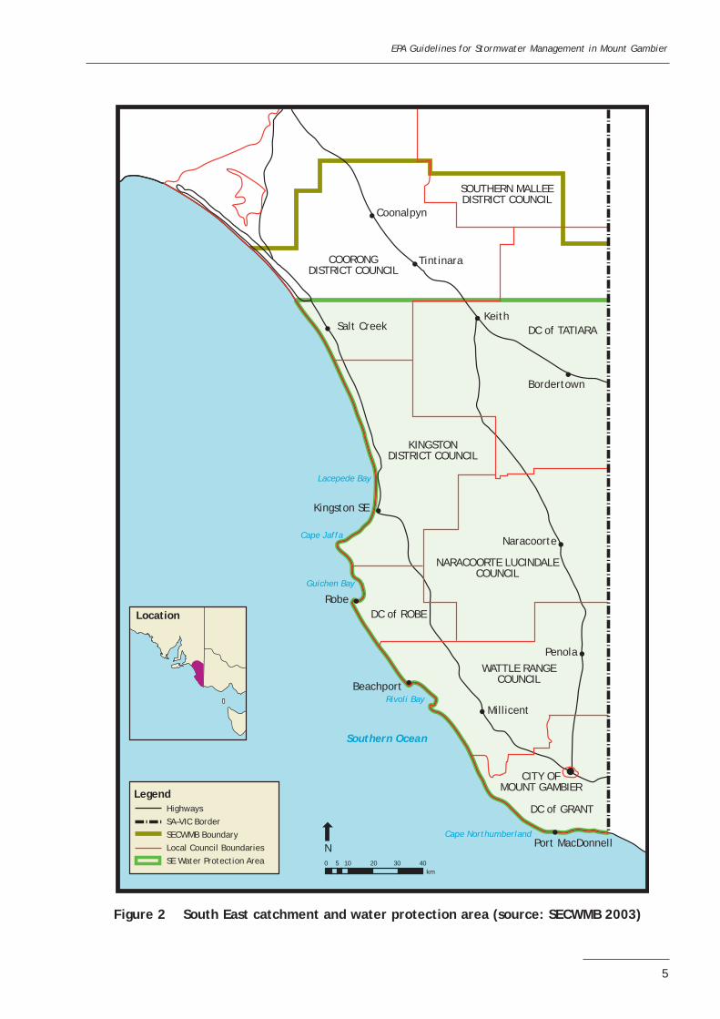
Figure 2 South East catchment and water protection area (source: SECWMB 2003)
EPA Guidelines for Stormwater Management in Mount Gambier
5
Coonalpyn
Tintinara
NARACOORTE LUCINDALECOUNCIL
WATTLE RANGECOUNCIL
CITY OFMOUNT GAMBIER
DC of TATIARA
DC of ROBE
DC of GRANT
KINGSTONDISTRICT COUNCIL
COORONGDISTRICT COUNCIL
SOUTHERN MALLEEDISTRICT COUNCIL
Keith
Bordertown
Robe
Penola
Port MacDonnell
Beachport
N
Millicent
Naracoorte
Kingston SE
Southern Ocean
Cape Northumberland
Guichen Bay
Cape Jaffa
Rivoli Bay
Lacepede Bay
Legend
Location
HighwaysSA–VIC BorderSECWMB BoundaryLocal Council BoundariesSE Water Protection Area 0 5 10 20 30 40
km
Salt Creek

Figure 3 Stormwater passage to the Blue Lake (source: Hill et. al (2002))
EPA Guidelines for Stormwater Management in Mount Gambier
6
VV
VV
V
VV
VV
V
V
VV
V
VV
V
V
V
V
V
VV
V
100
Elevation mAHD80 60 40 20 0
-20
-40
-60
-80
-100
-120
-140
-160
-180
100
80 60 40 20 0 -20
-40
-60
-80
-100
-120
-140
-160
-180
Dra
inag
e bo
reSi
nk h
ole
Sink
hol
e
Gre
enw
ays
mem
ber
Cam
elba
ck m
embe
r
Regi
onal
grou
ndw
ater
flo
w
Mou
nt G
ambi
er
Unc
onfi
ned
aqui
fer
Unconfined tertiary aquiferGambier limestone
Green Point Member
BLA
121
BLA
145
unit
1
unit
2
unit
3
unit
4
unit
5
Nor
thSo
uth
Nar
raw
atur
k m
ari
Conf
ined
ter
tiar
y aq
uife
rD
ilwyn
For
mat
ion
RSW
L(1
2 m
AHD
)
Blue
Lak
e79
m
Infe
rred
faul
t
TD 2
34 m
TD 2
46 m
VV
V
V
V
Volc
anic
ash
and
basa
lt f
low
Land
slid
e ta
lus
Volc
anic
deb
ris
Mar
l wit
h fl
int
Gro
undw
ater
flo
w
Bryo
zoal
lim
esto
neCl
ay/s
and
Dol
omit
e

4 PRINCIPLES OF STORMWATER MANAGEMENT
The detail and direction provided in this guideline have been based on a range of fundamental principlesfor stormwater management that need to be clearly understood. It is expected that the application ofthe suggested methods outlined in this document will be sufficient to achieve these principles; however,the reader and particularly any developers must ensure that these principles are fully considered in thedesign of any stormwater management system.
The principles for stormwater management in urban areas of the South East region are as follows:
• Stormwater discharges should not adversely affect receiving water resources (i.e. groundwater orsurface water).
• Stormwater management should protect built assets from flooding or other damage.• Stormwater should be treated to an acceptable standard on site before discharge.• Non-interventional methods for stormwater management (such as good land-use planning) should be
pursued in preference to interventional and high maintenance systems (such as treatment devices).• Stormwater should be retained for maximum beneficial use.• Every effort should be made to minimise the opportunities for stormwater to become contaminated
and therefore require advanced treatment.• Clean stormwater should be kept separate from contaminated stormwater to minimise the volumes
needing to be treated.• Where possible recharge should involve infiltration rather than direct discharge via wells to the
aquifer.• Stormwater systems should contain sufficient capacity and facilities to prevent spills entering
groundwater.• If possible, stormwater flow rates and volumes should mimic natural regimes.• Storage should be built into the system to provide capacity and to reduce peak stormwater flow
rates.
All landowners should consider the opportunities for implementing these principles when they aredeveloping stormwater management plans for their sites.
EPA Guidelines for Stormwater Management in Mount Gambier
7

5 PERFORMANCE CRITERIA FOR STORMWATER DISCHARGES
It is recognised that in many instances in the South East region there will be a requirement to dischargestormwater off site or to the underground aquifer. The principles for stormwater management in theregion (see section 4) basically outline that there is a need to protect both receiving water quality aswell as built assets. In respect to these issues, this guideline provides the following detail on achievingthese principles.
Water qualityAs outlined in the principles in section 4, this discharge should not adversely affect the groundwater.Considering that the aquifers in the South East region provide much of the drinking water for theregional community, it is important that this resource is protected.
The Environment Protection (Water Quality) Policy 2003 (Water Quality Policy) provides regulatoryguidance on the measures that need to be taken to protect stormwater and groundwater in the state.There are a range of explanatory publications available on the protection of stormwater andgroundwater (www.epa.sa.gov.au). Two key aspects of the policy require that:
• people must not discharge pollutants into stormwater• private landowners must ensure that any stormwater discharged to the aquifer must not degrade the
quality of the groundwater.
Avoiding pollutant discharge to stormwater can be addressed through appropriate planning, landmanagement, behavioural change and the provision of separate wastewater collection and treatmentsystems. Compliance with drinking water criteria is more complex as there are more than 50 compoundsfor which maximum concentrations in drinking water are defined within the policy. This guideline wasdeveloped to provide assistance to landowners on the best available technologies that are economicallyachievable for protection of the underlying groundwater aquifer. When landowners apply the solutionsprovided in this document, it is anticipated that the performance of the technology used will beadequate to achieve compliance.
In addition to the Water Quality Policy, any stormwater treatment system should achieve a minimumstandard for treating stormwater as set out in Table 1. This demonstration of performance willinclude the use of acceptable modelling methods, such as MUSIC (CRC for Catchment Hydrology2002), by suitably qualified professionals. A preferable manner in which to satisfy the water qualitycriteria is to not discharge stormwater directly to the aquifer but to rely on the soakage ofstormwater through the soil profile.
EPA Guidelines for Stormwater Management in Mount Gambier
8

Table 1 Stormwater treatment objectives
Pollutant Stormwater treatment objective
Suspended solids (SS) 80% retention of the average annual loadTotal phosphorous (TP) 45% retention of the average annual loadTotal nitrogen (TN) 45% retention of the average annual loadLitter Retention of litter greater than 50 mm for flow up to the 3-month average
recurrence interval (ARI) peak flowCoarse sediment Retention of sediment coarser than 0.125 mm1 for flows up to the 3-month
ARI peak flowOil and grease No visible oils for flow up to the 3-month ARI peak flow
Source: Australian Institution of Engineers 2003, chapter 1Notes: (1) Based on ideal settling characteristics
Flooding and retention capacityThe management of stormwater is made more difficult with the variability of flow events, and there is aneed to provide a balance between the protection of water quality and the protection of property. In allinstances, stormwater management must incorporate and consider the operation of the systems inresponse to high flow events. Additionally, each stormwater treatment system will need to have beendesigned to manage spills and emergency situations.
In general, both of these issues can be addressed through the provision of sufficient capacity to retainaverage flow events and reasonably foreseeable spills. In new developments retention capacity should beprovided for at least the critical 1-in-1-year storm event before discharge (to bores or off site).Depending on local council requirements, it may also be necessary that all stormwater is retained andtreated on site for any storms below the critical 1-in-100-year event.
EPA Guidelines for Stormwater Management in Mount Gambier
9

6 CHARACTERISTICS OF THE AREA
ClimateThe annual average rainfall for Mount Gambier is 710 mm/year. The daily mean evaporation rate is 3.7mm. The average monthly rainfall and the mean daily evaporation rate for Mount Gambier (Station:Mount Gambier Aero) are presented in Tables 2 and 3.
Table 2 Average monthly rainfall (mm) for Mount Gambier
Jan Feb Mar Apr May Jun Jul Aug Sep Oct Nov Dec
26.2 25.4 35.4 55.0 71.7 83.5 99.3 93.5 72.9 62.7 46.6 37.4
Table 3 Mean daily evaporation (mm) for Mount Gambier
Jan Feb Mar Apr May Jun Jul Aug Sep Oct Nov Dec
6.9 6.7 4.8 2.9 1.7 1.2 1.3 1.9 2.7 3.7 4.8 5.9
Details of the rainfall intensities for Mount Gambier, based on ‘Australian Rainfall and Runoff’ (AR&R)data (Pilgrim 1987), are provided in Table 4. These values are to be used when designing facilities forflood control.
Although these rainfall intensity values are for Mount Gambier, landowners may wish to also use thesevalues for other areas of the region as a default. Because the Mount Gambier area will generally have ahigher rainfall and lower evaporation rate when compared to other parts of the region, any system thathas been designed based on these figures should provide adequate stormwater management capacity.Alternatively, site-specific rainfall and evaporation figures may be sourced.
EPA Guidelines for Stormwater Management in Mount Gambier
10

Table 4 Rainfall intensity for Mount Gambier (Lat. 37.83°S Long. 140.78°E)
Duration Average recurrence interval (ARI)1 year 2 year 5 year 10 year 20 year 50 year 100 year
(mm/hr) (mm/hr) (mm/hr) (mm/hr) (mm/hr) (mm/hr) (mm/hr)
15 min 24.3 32.5 44.2 53.0 64.0 82.0 97.030 min 16.9 22.4 29.9 35.4 42.8 54.0 63.045 min 13.4 17.7 23.4 27.4 33.0 41.3 48.31 hr 11.2 14.8 19.4 22.7 27.2 33.9 39.51.5 hr 8.79 11.6 15.0 17.5 20.8 25.8 30.02 hr 7.37 9.65 12.5 14.4 17.2 21.2 24.52.5 hr 6.41 8.39 10.8 12.4 14.8 18.1 21.03 hr 5.72 7.47 9.56 11.0 13.0 16.0 18.43.5 hr 5.20 6.77 8.64 9.93 11.7 14.3 16.54 hr 4.78 6.22 7.92 9.08 10.7 13.1 15.05 hr 4.16 5.40 6.84 7.82 9.19 11.2 12.86 hr 3.71 4.81 6.06 6.92 8.12 9.85 11.37 hr 3.37 4.37 5.48 6.24 7.31 8.85 10.18 hr 3.10 4.01 5.02 5.71 6.68 8.07 9.229 hr 2.88 3.72 4.65 5.28 6.16 7.43 8.4910 hr 2.70 3.48 4.34 4.92 5.74 6.91 7.8811 hr 2.55 3.28 4.08 4.61 5.38 6.47 7.3712 hr 2.41 3.11 3.85 4.35 5.07 6.09 6.9314 hr 2.18 2.80 3.47 3.92 4.56 5.47 6.2216 hr 1.99 2.57 3.17 3.58 4.16 4.99 5.6718 hr 1.85 2.37 2.93 3.30 3.83 4.59 5.2220 hr 1.72 2.21 2.73 3.07 3.56 4.27 4.8422 hr 1.61 2.07 2.55 2.87 3.33 3.99 4.5324 hr 1.52 1.95 2.40 2.71 3.14 3.75 4.2530 hr 1.31 1.68 2.06 2.31 2.68 3.19 3.6236 hr 1.15 1.47 1.81 2.03 2.34 2.79 3.1642 hr 1.03 1.32 1.61 1.81 2.09 2.49 2.8248 hr 0.94 1.20 1.46 1.64 1.89 2.25 2.5454 hr 0.86 1.1 1.34 1.49 1.72 2.05 2.3160 hr 0.79 1.01 1.23 1.37 1.58 1.88 2.1266 hr 0.73 0.94 1.14 1.27 1.47 1.74 1.9672 hr 0.68 0.87 1.06 1.18 1.36 1.62 1.82
SoilsSoils in the Mount Gambier region are generally volcanic sands with good infiltration capacity. Moststormwater management practices described in this guideline make use of this capacity for thetreatment of stormwater. The map below (Figure 4) shows the dominant surface soil types within thegreater Mount Gambier area; however, given the heterogeneity of soils, a specific site assessment shouldalways be undertaken on each site before planning stormwater treatment methods. In addition, soilprofile information may be available from DWLBC.
EPA Guidelines for Stormwater Management in Mount Gambier
11

Figure 4 Dominant soils of the Mount Gambier area (Source: Soil Landscapes, DWLBC)
EPA Guidelines for Stormwater Management in Mount Gambier
12
H2B6
B6
01
01
01
I102H3
I102H3
I102H3
01
01
01
B6
B6
B3B3
B3
B3
B3
O1B6
O1B6
O1B6
B3O1
B3O1
B3O1
B3O1
B3O1
I101
G3O1B6G3O1B6
Dominant soil type
B3 - Shallow sandy loam on calcreteB3O1 - Shallow sandy loam on calcrete and volcanic ash soilB6 - Shallow loam over red-brown clay on calcreteG3O1B6 - Thick sand over clay and volcanic ash soil and sandy loam over red-brown clay on calcreteH2B6 - Siliceous sand and shallow loam over red-brown clay on calcreteI101 - Highly leached sand and volcanic ash soilI101H3 - Highly leached sand and volcanic ash soil and bleached siliceous sandO1 - Volcanic ash soilO1B3 - Volcanic ash soil and shallow sandy loam on calcreteO1B6 - Volcanic ash soil and shallow loam over red-brown clay on calcreteO1G3 - Volcanic ash soil and thick sand over clayO1H2 - Volcanic ash soil and siliceous sand
O1B3
O1B3
O1H2
O1G3
G3O1B6
I101
G2O1
B6
G3O1B6

7 PLANNING METHODS FOR STORMWATER MANAGEMENT
Developers are encouraged to incorporate water-sensitive urban design (WSUD) concepts intodevelopments during the planning stage. These methods not only provide enhanced water quality and areduction in stormwater quantity, but also offer the developer opportunities for enhanced social andenvironmental amenity, which may improve selling potential. Generally speaking, WSUD aims to minimisethe impact of urbanisation on the urban water cycle. WSUD concepts can be applied at the allotmentscale as well as at the neighbourhood scale. Each concept is discussed in the following sections.
Some important features to recognise within the planning methods are:
• use of more water-sensitive flowing lines instead of the conventional rigid line approach todevelopment
• reduced impervious areas• landscaped links between public and private areas• improvement of visual amenity, public access and passive recreational activities• preservation, minimum disturbance and where possible the incorporation of existing native vegetation
in stormwater design systems• treatment of pollution and encouragement of detention and infiltration of stormwater• reduced cost of stormwater pipe network due to a lower required capacity.
Although the planning methods focus upon residential areas, the concepts can also be applied to non-residential areas. Developers and designers should consider the opportunities for the application of theseconcepts in other developments during the design phase.
Residential areas—allotment and cluster scaleAt an allotment or cluster level the use of rainwater tanks, underground storage tanks, filter trenches,permeable pavement and vegetated swales are all appropriate. Typical measures that can be included intypical urban developments are indicated in Figure 5.
Figure 5 Typical WSUD techniques that can be applied at an allotment scale
EPA Guidelines for Stormwater Management in Mount Gambier
13
Overflow (to garden or trench)
Overflow to swale
Rainwater tank
Overflow to swale
Enlarged gutters (optional)
Footpath
Swale
Infiltration trench
Permeablepavement
Street
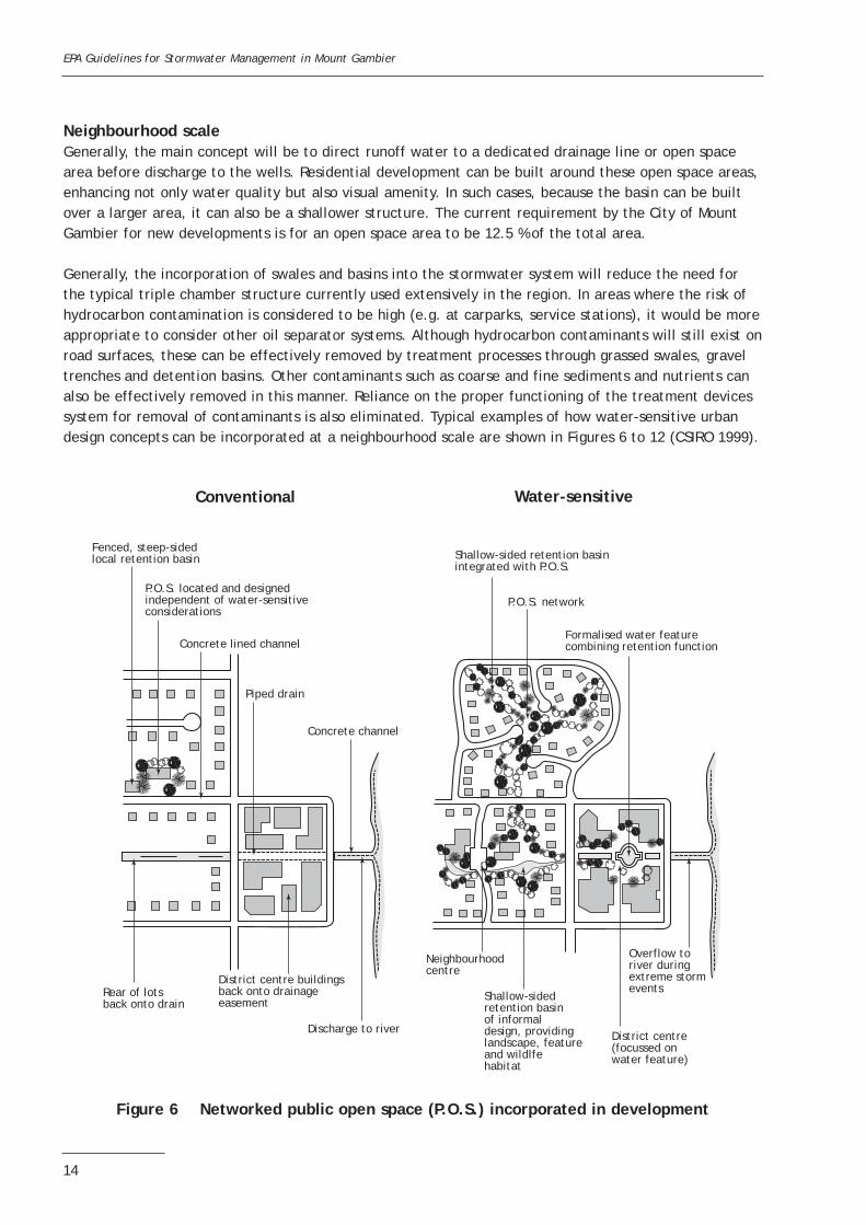
Neighbourhood scaleGenerally, the main concept will be to direct runoff water to a dedicated drainage line or open spacearea before discharge to the wells. Residential development can be built around these open space areas,enhancing not only water quality but also visual amenity. In such cases, because the basin can be builtover a larger area, it can also be a shallower structure. The current requirement by the City of MountGambier for new developments is for an open space area to be 12.5 % of the total area.
Generally, the incorporation of swales and basins into the stormwater system will reduce the need forthe typical triple chamber structure currently used extensively in the region. In areas where the risk ofhydrocarbon contamination is considered to be high (e.g. at carparks, service stations), it would be moreappropriate to consider other oil separator systems. Although hydrocarbon contaminants will still exist onroad surfaces, these can be effectively removed by treatment processes through grassed swales, graveltrenches and detention basins. Other contaminants such as coarse and fine sediments and nutrients canalso be effectively removed in this manner. Reliance on the proper functioning of the treatment devicessystem for removal of contaminants is also eliminated. Typical examples of how water-sensitive urbandesign concepts can be incorporated at a neighbourhood scale are shown in Figures 6 to 12 (CSIRO 1999).
Figure 6 Networked public open space (P.O.S.) incorporated in development
EPA Guidelines for Stormwater Management in Mount Gambier
14
Conventional Water-sensitive
Fenced, steep-sidedlocal retention basin
P.O.S. located and designedindependent of water-sensitiveconsiderations
P.O.S. network
Formalised water featurecombining retention function
District centre(focussed onwater feature)
Shallow-sidedretention basinof informaldesign, providinglandscape, featureand wildlfehabitat
Neighbourhoodcentre
Overflow toriver duringextreme stormevents
Shallow-sided retention basinintegrated with P.O.S.
Rear of lotsback onto drain
Discharge to river
District centre buildingsback onto drainageeasement
Concrete lined channel
Concrete channel
Piped drain

Figure 8 Conventional versus water-sensitive road layout
EPA Guidelines for Stormwater Management in Mount Gambier
15
Access to public open space
House front onto creek
Footpath
Existing vegetationmaintained and restored
Treatment measures on tributary
Traditional setback creates unusablespace which reduces the functionand aesthetics of the street
New footpathalignment allowsfor integratedstormwatermanagement andresponds to natural measures
Variation in widthof the reservefacilitatesintegrated designof stormwatermanagement
Conventional Water-sensitive
Figure 7 Integration of housing with waterway corridor
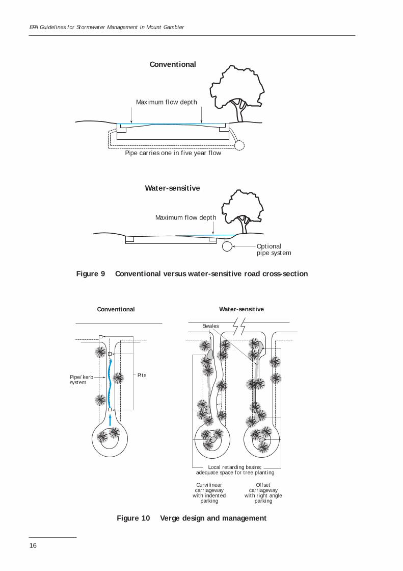
Figure 9 Conventional versus water-sensitive road cross-section
EPA Guidelines for Stormwater Management in Mount Gambier
16
Maximum flow depth
Maximum flow depth
Optionalpipe system
Pipe carries one in five year flow
Conventional
Water-sensitive
Pipe/kerbsystem
Local retarding basins;adequate space for tree planting
Curvilinearcarriageway
with indentedparking
Offsetcarriageway
with right angleparking
Swales
Pits
Conventional Water-sensitive
Figure 10 Verge design and management

Figure 12 Cul-de-sac streetscapes
EPA Guidelines for Stormwater Management in Mount Gambier
17
Unpredictable crossover locationslimit scope for retention of existingvegetation and new planting
Standard footpathalignment createsuseless spaces
Standard verge allocationslimit scope for planting
Uniform setbacks createmonotonous street spaces
Integrated design of crossoversmaximises scope for retentionof existing vegetation and fornew planting
Variation in reservewidth facilities integratedstormwater management
Narrow road reserve reduces arearequiring irrigation
Conventional Water-sensitive
Footpath alignment response tonatural feature and stormwatermanagement to create spacesthat are easy to maintain and efficientto irrigate
Figure 11 Lot/street interface
Drainage basement throughopen space to outfall
Integrated network of open spaceand stormwater disposal systemuse cul-de-sac heads for localretention basins
Local retardingbasin in roadreserve toaccommodatepeak flow
Porouspaving ondrivewaysand carparks
Flushkerbing
Whole road reserve designed,constructed and planted to actas floodway for runoff
Minimiseddirect runoffvia shareddrivewayentry location
Zero local discharge:all surface watercollected and divertedoff-site
Large volumes ofhouse/drivewayrunoff, partiallygenerated bylarge setback
Conventional Water-sensitive
Pipe/kerb drainagesystem for totalroad runoffs
Standard road reserve,building setbacksand service alignment

8 STRUCTURAL METHODS FOR STORMWATER MANAGEMENT
Structural methods include treatment and storage techniques designed to remove pollutants from urbanstormwater. Generally, pollutant removal can be considered as a three-stage process (primary, secondaryand tertiary) based on dominant treatment processes. In most cases the use of a combination oftreatment techniques that remove pollutants through different processes should provide the best overalltreatment of stormwater runoff. This approach has the advantage of being more robust—that is, a failureof one treatment technique or measure will not necessarily result in the complete failure of the system.
Primary level treatmentThe dominant treatment processes at the primary level include physical screening of gross pollutants andrapid sedimentation of coarse particles. This allows for the removal of a portion of the inflow litter andcoarse sediment.
Typical types of primary treatment measures include (NSW EPA 1997):
• well intakes that inhibit entry of floating films• litter baskets and pits—wire or plastic baskets installed in a stormwater pit to collect litter from a
paved surface (litter basket) or within a piped stormwater system (litter pit)• trash racks—series of metal bars located across a channel or pipe to trap litter and debris• sediment traps—structures placed within the stormwater system or upstream of other treatment
mechanisms to trap coarse sediment; they can take the form of a formal tank or less formal pond• in-line gross pollution traps—sediment traps with a litter (or trash) rack, usually located at the
downstream end of the trap• litter booms—floating devices installed in channels and waterways to collect floating litter and oil• catch basins—drainage pits with depressed bases to collect sediment• oil/grease and sediment separators—generally consist of three underground retention chambers
designed to remove coarse sediment and hydrocarbons.
Secondary level treatmentAt the secondary level the dominant treatment processes include the sedimentation of finer particulatesand filtration. This aids in the removal of suspended solids and allows removal of some nutrients andmetals. Typical types of secondary treatment measures include (NSW EPA 1997):
• upflow activated carbon filters for organics removal• filter strips—grassed or vegetated areas that treat overland flow, often adjacent to watercourses• vegetated swales—grass-lined channels for conveying runoff from roads and other impervious surfaces• dry extended detention basins—basins that store runoff for 1–2 days and drain to an essentially dry
condition between storm events• wet detention basins—shallow basins that have a permanent pool of water and are designed to store
runoff for a relatively short period of time• sand filters—beds of sand (or other media) through which runoff is passed; the filtered runoff is then
collected by an underdrain system• infiltration trenches—shallow, excavated trenches filled with gravel through which runoff drains to
groundwater• infiltration basins—open excavated basins that are designed to infiltrate runoff through the floor of
the basin• permeable pavements—pavements that allow runoff to drain through a coarse graded
concrete/asphalt pavement or open concrete blocks, subsequently to infiltrate to the underlying soil.
EPA Guidelines for Stormwater Management in Mount Gambier
18

Tertiary level treatmentAt the tertiary level the dominant treatment processes include enhanced sedimentation and filtration,biological uptake and adsorption of sediments. This allows improved retention of nutrients and heavymetals. Until recently, the main tertiary treatment technique has been the constructed wetland system(NSW EPA 1997), comprising:• ponds (or deep water zones)—open water that might have submerged plants, but with emergent
macrophytes around the fringe (littoral macrophytes)• wetlands—areas vegetated with emergent plants and including various vegetation zones distinguished
by depth, frequency and duration of inundation.
On-site retentionOn-site retention will reduce the volume of stormwater runoff and therefore also reduce the transport ofcontaminants entering the stormwater system. By reducing the quantity of runoff, downstream waterquality treatment systems are able to operate more effectively. On-site retention techniques such asabove-ground (rainwater tanks, enlarged gutters, etc.) and below-ground tanks are typically used tostore roof runoff and can provide a clean source of water for use on site.
Structural methods suitability assessmentThe following tables are presented as an aid to developers to gauge the appropriateness of a treatmentmeasure (adapted from Transport SA 2002). As treatment measures are site specific, these tables canbe used to initially screen out measures that are not appropriate for the site to be developed.Further information on each of these measures is available in the comprehensive version of thisreport from the EPA.
Assessment should include the consideration that:• the structural system is appropriate for the catchment size (Table 5)• the structural system is appropriate for the soil type (Table 6)• the structural system is appropriate given the site’s environmental characteristics (Table 7)• the capital and maintenance costs for the structural system are appropriate (Table 8).
EPA Guidelines for Stormwater Management in Mount Gambier
19
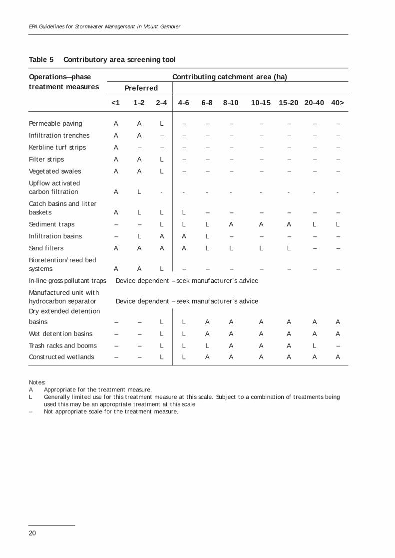
Table 5 Contributory area screening tool
Operations—phase Contributing catchment area (ha)treatment measures Preferred
<1 1–2 2–4 4–6 6–8 8–10 10–15 15–20 20–40 40>
Permeable paving A A L – – – – – – –
Infiltration trenches A A – – – – – – – –
Kerbline turf strips A – – – – – – – – –
Filter strips A A L – – – – – – –
Vegetated swales A A L – – – – – – –
Upflow activated carbon filtration A L - - - - - - - -
Catch basins and litterbaskets A L L L – – – – – –
Sediment traps – – L L L A A A L L
Infiltration basins – L A A L – – – – –
Sand filters A A A A L L L L – –
Bioretention/reed bedsystems A A L – – – – – – –
In-line gross pollutant traps Device dependent – seek manufacturer’s advice
Manufactured unit with hydrocarbon separator Device dependent – seek manufacturer’s adviceDry extended detention
basins – – L L A A A A A A
Wet detention basins – – L L A A A A A A
Trash racks and booms – – L L L A A A L –
Constructed wetlands – – L L A A A A A A
Notes:A Appropriate for the treatment measure.L Generally limited use for this treatment measure at this scale. Subject to a combination of treatments being
used this may be an appropriate treatment at this scale– Not appropriate scale for the treatment measure.
EPA Guidelines for Stormwater Management in Mount Gambier
20

Table 6 Soil and subsoil infiltration rate screening tool
Operations—phase Soil type for infiltration rate constrainttreatment measures
Sand Loamy Sandy Loam Silty Sandy-clay Clay Sandy Silty claysand loam loam loam loam clay or clay
Permeable paving A A A A L P P P P
Infiltration trenches A A A A L P P P P
Kerbline turf strips A A A A A A A A A
Filter strips A A A A A A A L L
Vegetated swales A A A A A A A L L
Upflow activated carbon filtration A A A A A A A A A
Catch basins and litter baskets A A A A A A A A A
Sediment trap A A A A A A A A A
Infiltration basins (dry ponds) A A A A L P P P P
Sand filters A A A A A A A A A
Bioretention/reed bed systems L L L L L L L L L
In-line gross pollutant traps Device dependent—seek manufacturer’s advice
Manufactured unit with hydrocarbon separator Device dependent – seek manufacturer’s advice
Dry extended detention basins A A A A A A A A A
Wet detention basins L L L A A A A A A
Trash racks and booms A A A A A A A A A
Constructed wetlands L L L A A A A A A
Notes:A Generally not a limitation for the treatment measure.P Usually a problem (constraint) for installing the treatment measure.L May be a limitation for installing the treatment measure, but can usually be overcome through appropriate
design.
EPA Guidelines for Stormwater Management in Mount Gambier
21
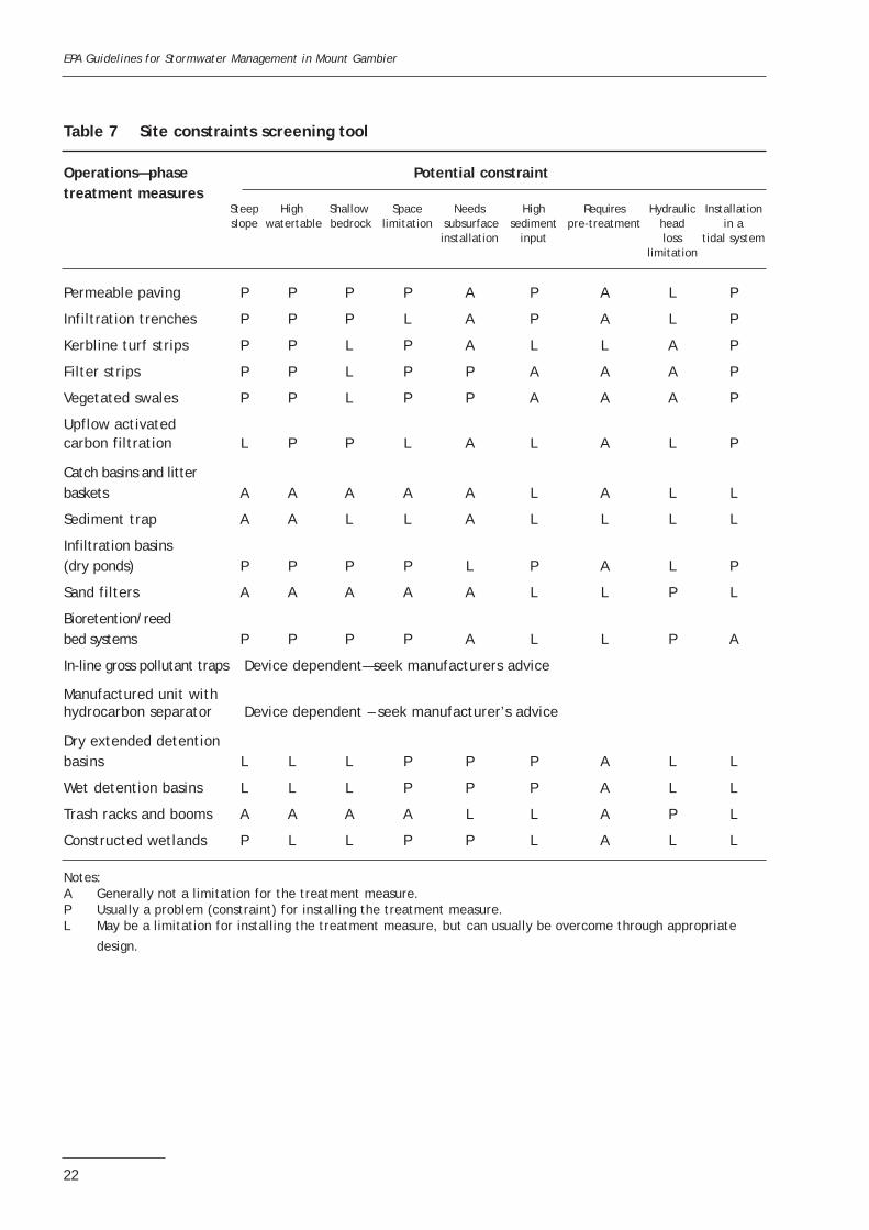
Table 7 Site constraints screening tool
Operations—phase Potential constraint treatment measures
Steep High Shallow Space Needs High Requires Hydraulic Installation slope watertable bedrock limitation subsurface sediment pre-treatment head in a
installation input loss tidal system limitation
Permeable paving P P P P A P A L P
Infiltration trenches P P P L A P A L P
Kerbline turf strips P P L P A L L A P
Filter strips P P L P P A A A P
Vegetated swales P P L P P A A A P
Upflow activated carbon filtration L P P L A L A L P
Catch basins and litterbaskets A A A A A L A L L
Sediment trap A A L L A L L L L
Infiltration basins (dry ponds) P P P P L P A L P
Sand filters A A A A A L L P L
Bioretention/reed bed systems P P P P A L L P A
In-line gross pollutant traps Device dependent—seek manufacturers advice
Manufactured unit with hydrocarbon separator Device dependent – seek manufacturer’s advice
Dry extended detention basins L L L P P P A L L
Wet detention basins L L L P P P A L L
Trash racks and booms A A A A L L A P L
Constructed wetlands P L L P P L A L L
Notes:A Generally not a limitation for the treatment measure.P Usually a problem (constraint) for installing the treatment measure.L May be a limitation for installing the treatment measure, but can usually be overcome through appropriate
design.
EPA Guidelines for Stormwater Management in Mount Gambier
22
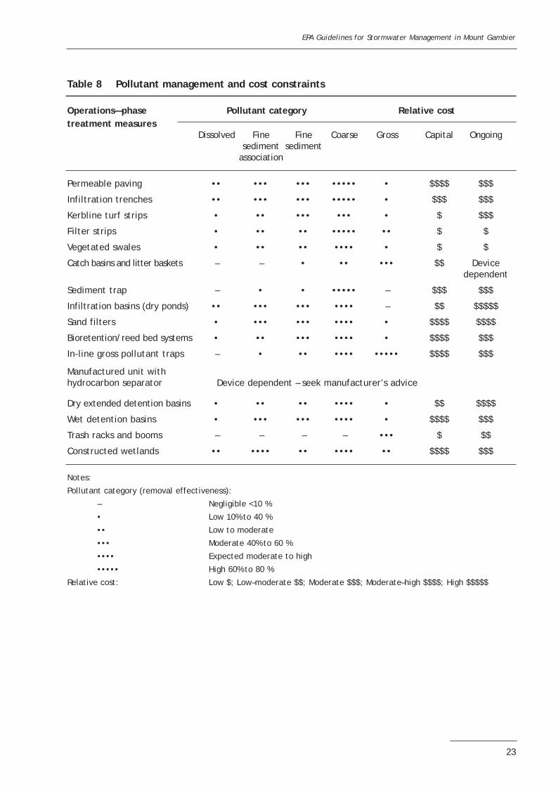
Table 8 Pollutant management and cost constraints
Operations—phase Pollutant category Relative cost treatment measures
Dissolved Fine Fine Coarse Gross Capital Ongoingsediment sediment
association
Permeable paving •• ••• ••• ••••• • $$$$ $$$
Infiltration trenches •• ••• ••• ••••• • $$$ $$$
Kerbline turf strips • •• ••• ••• • $ $$$
Filter strips • •• •• ••••• •• $ $
Vegetated swales • •• •• •••• • $ $
Catch basins and litter baskets – – • •• ••• $$ Devicedependent
Sediment trap – • • ••••• – $$$ $$$
Infiltration basins (dry ponds) •• ••• ••• •••• – $$ $$$$$
Sand filters • ••• ••• •••• • $$$$ $$$$
Bioretention/reed bed systems • •• ••• •••• • $$$$ $$$
In-line gross pollutant traps – • •• •••• ••••• $$$$ $$$
Manufactured unit with hydrocarbon separator Device dependent – seek manufacturer’s advice
Dry extended detention basins • •• •• •••• • $$ $$$$
Wet detention basins • ••• ••• •••• • $$$$ $$$
Trash racks and booms – – – – ••• $ $$
Constructed wetlands •• •••• •• •••• •• $$$$ $$$
Notes:
Pollutant category (removal effectiveness):
– Negligible <10 %
• Low 10% to 40 %
•• Low to moderate
••• Moderate 40% to 60 %
•••• Expected moderate to high
••••• High 60% to 80 %
Relative cost: Low $; Low–moderate $$; Moderate $$$; Moderate–high $$$$; High $$$$$
EPA Guidelines for Stormwater Management in Mount Gambier
23
9 DETAILED DESIGN OF STRUCTURAL METHODS
This section of the guideline provides the design detail for the structural stormwater treatment methodsthat are considered appropriate for application in and around Mount Gambier. Structural methods notdescribed in detail in this section are generally not applicable or require demonstration of performancethrough appropriate modelling (see ‘Innovative solutions’ at the end of section 9).
Detailed designs are provided for:• gross pollutant traps• infiltration trenches• permeable pavement• kerbside strips• swales• retention basins• storage tanks• hydrocarbon interceptor and containment tanks• manufactured units with hydrocarbon separators• innovative solutions.
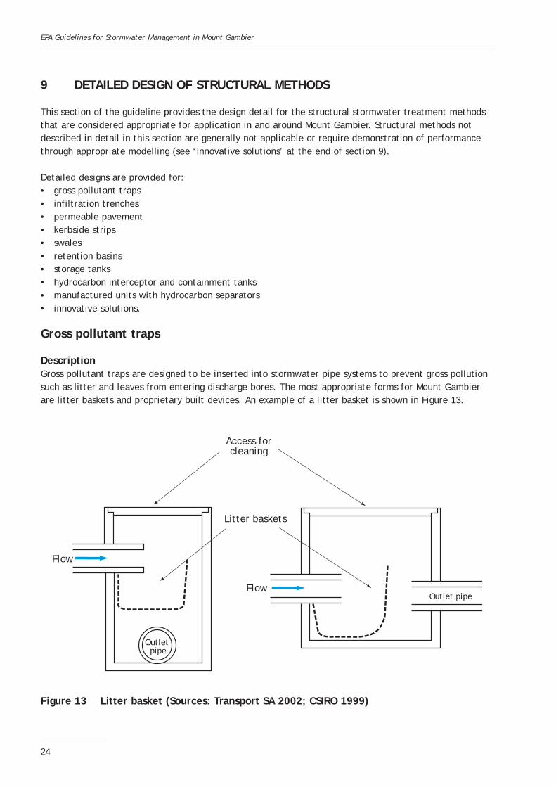
Gross pollutant traps
DescriptionGross pollutant traps are designed to be inserted into stormwater pipe systems to prevent gross pollutionsuch as litter and leaves from entering discharge bores. The most appropriate forms for Mount Gambierare litter baskets and proprietary built devices. An example of a litter basket is shown in Figure 13.
Figure 13 Litter basket (Sources: Transport SA 2002; CSIRO 1999)
EPA Guidelines for Stormwater Management in Mount Gambier
24
Litter baskets
Outlet pipe
Outlet pipeFlow
Flow
Access forcleaning
Typical applicationsThese devices would be most applicable at discharge points to sinkholes, retention basins and swales.They are also appropriate in areas that generate high litter loads, such as shopping centres and schools.However, they are not necessary for devices when the installation of a shroud at the entrance to thedischarge bore would provide a similar function (see Figure 24).
Limitations• They require regular cleaning to perform adequately.
Design• They must not have a significant impact on the hydraulics of the pit or pipe system when fully
blocked.• Allowances should be made for inspection, maintenance and cleaning.
Construction• Appropriate concrete chambers are required at each location.
Maintenance• Regular cleaning out and removal of gross pollutants to an approved disposal site should be carried
out at a typical maintenance frequency of 3 to 6 months.• Occupational health and safety standards should be adhered to during periods of maintenance,
inspection and repair as trapped pollutants may be hazardous.
Infiltration trenches
DescriptionInfiltration trenches are excavated trenches or pits, lined with geotextile fabric and backfilled withclean coarse gravel, into which stormwater is directed. The stormwater is temporarily stored in thetrench or pit prior to infiltrating to the surrounding soil. These devices are generally used as a sourcecontrol measure for sediments which will reduce the quantity of stormwater entering the stormwaterdischarge system.
Typical applicationsDue to the favourable infiltration capacity of soils in Mount Gambier, these are highly applicable in thisregion. They are generally used to capture runoff with low sediment loads and would thus be mostsuitable at the outlets of roof downpipes or paved areas that have low sediment loads. Typical details offilter trenches for collecting roof runoff are shown in Figure 14. Trenches may also be connected todrainage wells, particularly for larger systems.
Limitations• They should not be used without pre-treatment devices in areas that have high sediment loads.• Infiltration capacity may be reduced by fine sediment deposits.• The soil infiltration capacity will determine the effectiveness of infiltration measures; Appendix A
provides a procedure for estimating in-situ infiltration capacity using the double ring infiltrometer.• Generally, they can not be used in steeply sloped areas (i.e. slopes greater than 5%).• Generally, they should not be used in areas that have received waste fill.• They are not suitable for areas with high water tables.• They are not to be used in clay or sodic soils that are prone to collapse on contact with water.
EPA Guidelines for Stormwater Management in Mount Gambier
25

Design• The design is influenced by contributory area, quality and quantity of runoff, soil infiltration capacity
and soil characteristics.• Low infiltration rates may result in unacceptably long draindown times.• Where space permits, a grass filter strip or swale is recommended upstream of filter trenches, and is
considered essential for carpark areas; a typical example of an application for a carpark area is shownin Figure 15.
• Wrapping trenches in geotextile will prevent the ingress of fines.• A perforated pipe within the trench will allow a more even distribution of stormwater runoff to the
trench.• An overflow must be provided to direct excess flows to the stormwater system.• Consideration of soil moisture and swell is important when locating gravel trenches near buildings and
other structures.
EPA Guidelines for Stormwater Management in Mount Gambier
26
Perforated concrete pipewith fitted cover 100 mm above natural surface
Overflow pipe
Inflow fromroof orrainwater tank
Geotextilefabric over allholes and atbottom of pipe
50 mm diameter holes(many) at 400 mm centres
300 mm cover
Top of pipe atnatural surfacelevel
Inflow fromroof or rainwatertank. Single size gravel (average diameter 20 mm)
Oversized socketfor 80 mm diameterstormwater pipe
Perforated PVCtrap 250 mm diameter
Geotextilefabric envelope
Perforateddistributionpipe 75 mm diameter
Gravel fill
1 in 75 minimum grade of overflow pipe
Overflow pipe(to street)
300 mm cover
Natural surface
Inspection coverat ground level
'Leaky' well with overflow
Gravel-filled trench with overflow
2.30
m
Backfill
Diameter fixedby design
Lid
Figure 14 Typical filter trench details for collecting roof runoff (Source: CSIRO 1999)

Figure 15 Carpark with grass filter and filter trench system (Source: CSIRO 1999)
EPA Guidelines for Stormwater Management in Mount Gambier
27
Pipe/gravel trench with overflowSingle size gravel (average diameter 20 mm)
1 in 75 minimum grade of overflow pipe
Overflow pipe(to street)
Inflow pipe from roofor rainwatertank
Geotextile fabricenvelope
Perforateddistributionlarge diameterpipe
Top of pipe atnatural surfacelevel
Perforated pipefitted with coversat both ends
Natural surface
300 mm cover
Figure 14 (cont) Typical filter trench details for collecting roof runoff
Infiltrationsystem
Recessed landscapearea for water storageand infiltration
Kerb cuts to allow flow

• According to the minister’s specification SA78AA, September 2003 ‘On-site retention of stormwater’:- Retention devices shall be located a minimum of three (3) metres from all property boundaries
(excluding front boundaries and/or reserves) and 3 metres from footings of all structures located onthe allotment.
- A minimum clear spacing of 1 metre between the sides of the retention device and any service trench is required.
- Where two or more retention devices are installed, the clear distance between the edges of the devices shall be 1.5 times the depth of the deepest device.
• The following chart (Figure 16) can be used to determine the size of the trench necessary to receiverunoff from an impermeable surface for varying soil infiltration rates. The assumptions are listed inthe figure. The size of the trench determined should be capable of storing events up to a 1-in-1 year(24 hour) storm event before any discharge (to bores or offsite). Soil infiltration rates should bedetermined using the procedure in Appendix A.
Figure 16 Area ratio vs infiltration rate for infiltration trenches (1-in-1 year)
ExampleFor a site where the soil infiltration rate is 36 mm/hr (typical for sandy clay or sandy loam):• The area ratio for a trench 500 mm deep is 0.054• For a contributory equivalent impervious area of 1000 m2, the area of the trench is 54 m2 (1000 x
0.054); a suitable trench size can be 27 x 2.0 x 0.5 m.• This will allow full containment for storms up to a 1-in-1 year event.
EPA Guidelines for Stormwater Management in Mount Gambier
28
1
0.1
0.011 10 100 1000
Area Ratio vs Infiltration Ratefor Infiltration trenches (1-in-1 year)
Area
Rat
io(a
rea
of t
renc
h/eq
uiva
lent
impe
rvio
us a
rea)
Infiltration Rate (mm/hr)
Depth of Trench = 300 mm Depth of Trench = 500 mm Depth of Trench = 750 mm
Assumptions:1. Trench designed to store the maximum volume generated up to the 1-year event (AR&R)2. Time of concentration 10 min.3. Runoff coefficient = 0.94. Porosity of gravel infill = 0.35

Construction• It is essential that sediment from construction activities does not enter the trench.• Preferably, these trenches should be constructed once other construction activities have concluded in
the area.• Gravel must be clean, well washed and free of fines.• Compaction of the base of the trench should not occur.• Inspection of the trench should be undertaken by a suitably qualified engineer before placement of
geotexile to ensure that the infiltration capacity of the excavated trench has not been compromised.• Non-woven geotextile should be used to line the trench to prevent the ingress of fines into the
trench; the geotextile should extend over the top of the trench if topsoil is used.• Before placing gravel, the bottom of the trench may be scarified to improve infiltration.
Maintenance• Performance of the trenches should be monitored to ensure proper functioning, including signs of
surface ponding in the vicinity of the trench, and water levels in the trench wherever piezometersare installed.
• Pre-treatment devices must be inspected and maintained.• The top filter fabric should be replaced if clogged.• The entire trench should be replaced if the base becomes clogged.• Pesticides and herbicides should not be used in the infiltration trench.
Permeable pavement
DescriptionPermeable pavements allow stormwater to infiltrate through to the paving substrate and ultimately intothe underlying soil. Permeable pavements can:• provide on-site retention of stormwater runoff• reduce the overall volume of stormwater runoff from the site• reduce the export of sediments and pollutants off site.
Typical applicationsDue to the favourable infiltration capacity of soils in Mount Gambier, these are highly applicable in thisregion. They are mostly suited to areas not exceeding 0.25 ha with low sediment loadings, andparticularly suitable for carpark areas or low traffic areas surrounding houses and buildings. A typicaldetail of a permeable pavement is shown in Figure 17, with further examples in Figures 5 to 12.
Limitations• They are only suitable for areas with light traffic loads.• They should not be used in areas with anticipated high sediment loads, unless some form of pre-
treatment is provided.• They are not suitable for steep grade areas (>5 %).• They are only suitable for small catchment areas (up to 0.25 ha).• They should only be used in fully established areas.
EPA Guidelines for Stormwater Management in Mount Gambier
29

Design• Pavement slopes should be graded at 1% or less, but not exceed 5%.• The underlying soil must have a moderate infiltration rate as low infiltration rates may result in an
unacceptably long infiltration time; Appendix A provides a field test for determining infiltration ratesusing the double ring infiltrometer.
• The ratio of contributory impervious area to permeable area should not be greater than 2:1 (Argue etal. 2003).
• A deep gravel bed may underlay the permeable pavement to provide a temporary storage prior toinfiltration to the surrounding soil; the chart in Figure 16 can be used to size the gravel bed.
• A perforated pipe may be included in the gravel bed to collect and direct the percolated stormwaterto another site; an impermeable liner should be used to enclose the bed in this case.
• Designers should be familiar with the manufacturer’s recommendations.
Construction• It is essential that sediment arising from construction activities does not enter the porous pavement
area.• Where the design allows for infiltration to the surrounding soil, the area receiving the permeable
pavement should not be compacted.• Installers should be familiar with the permeable pavement manufacturer’s recommendations.
Maintenance• Because permeable pavements are prone to clogging, routine inspection is essential for the proper
performance of the pavement.• Accumulated sediments can be removed using high-suction vacuum cleaners or high-pressure hoses.
EPA Guidelines for Stormwater Management in Mount Gambier
30
Permeable paving
SandGeotextile fabric
Geotextile fabric
Uniform gravel
Sand
Underlying soil
Figure 17 Typical permeable pavement details
Kerbline strips
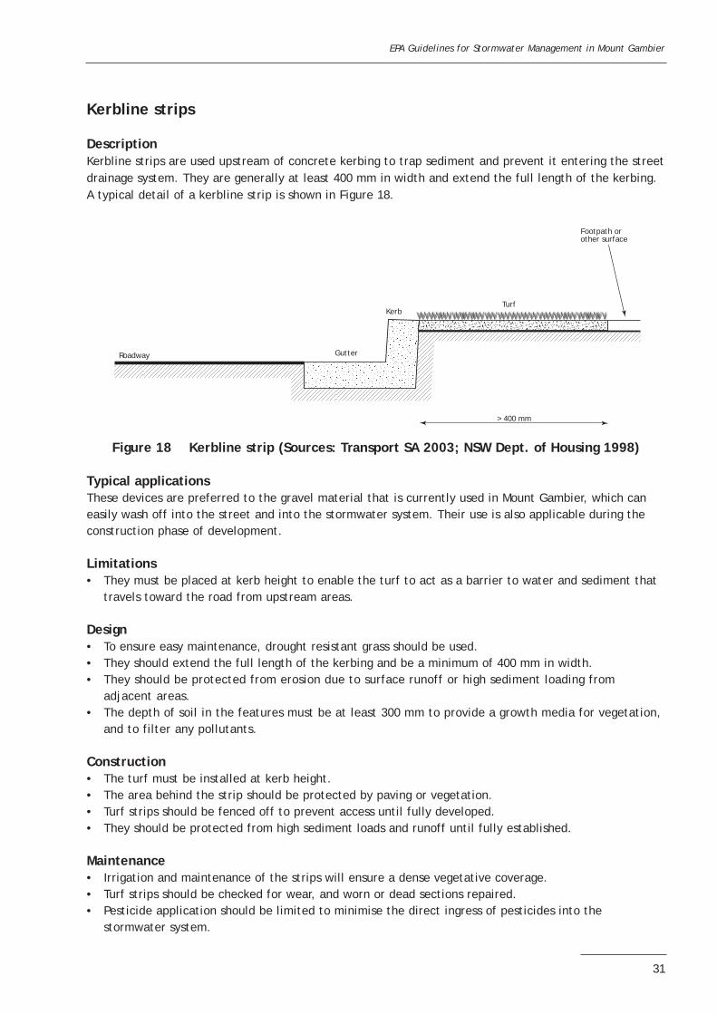
DescriptionKerbline strips are used upstream of concrete kerbing to trap sediment and prevent it entering the streetdrainage system. They are generally at least 400 mm in width and extend the full length of the kerbing.A typical detail of a kerbline strip is shown in Figure 18.
Figure 18 Kerbline strip (Sources: Transport SA 2003; NSW Dept. of Housing 1998)
Typical applicationsThese devices are preferred to the gravel material that is currently used in Mount Gambier, which caneasily wash off into the street and into the stormwater system. Their use is also applicable during theconstruction phase of development.
Limitations• They must be placed at kerb height to enable the turf to act as a barrier to water and sediment that
travels toward the road from upstream areas.
Design• To ensure easy maintenance, drought resistant grass should be used.• They should extend the full length of the kerbing and be a minimum of 400 mm in width.• They should be protected from erosion due to surface runoff or high sediment loading from
adjacent areas.• The depth of soil in the features must be at least 300 mm to provide a growth media for vegetation,
and to filter any pollutants.
Construction• The turf must be installed at kerb height.• The area behind the strip should be protected by paving or vegetation.• Turf strips should be fenced off to prevent access until fully developed.• They should be protected from high sediment loads and runoff until fully established.
Maintenance• Irrigation and maintenance of the strips will ensure a dense vegetative coverage.• Turf strips should be checked for wear, and worn or dead sections repaired.• Pesticide application should be limited to minimise the direct ingress of pesticides into the
stormwater system.
EPA Guidelines for Stormwater Management in Mount Gambier
31
Footpath orother surface
TurfKerb
Gutter
> 400 mm
Roadway
Swales
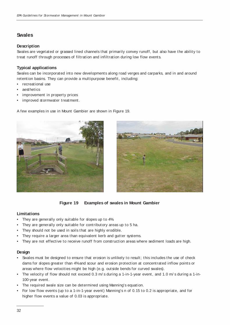
DescriptionSwales are vegetated or grassed lined channels that primarily convey runoff, but also have the ability totreat runoff through processes of filtration and infiltration during low flow events.
Typical applicationsSwales can be incorporated into new developments along road verges and carparks, and in and aroundretention basins. They can provide a multipurpose benefit, including:• recreational use• aesthetics• improvement in property prices• improved stormwater treatment.
A few examples in use in Mount Gambier are shown in Figure 19.
Figure 19 Examples of swales in Mount Gambier
Limitations• They are generally only suitable for slopes up to 4%.• They are generally only suitable for contributory areas up to 5 ha.• They should not be used in soils that are highly erodible.• They require a larger area than equivalent kerb and gutter systems.• They are not effective to receive runoff from construction areas where sediment loads are high.
Design• Swales must be designed to ensure that erosion is unlikely to result; this includes the use of check
dams for slopes greater than 4% and scour and erosion protection at concentrated inflow points orareas where flow velocities might be high (e.g. outside bends for curved swales).
• The velocity of flow should not exceed 0.3 m/s during a 1-in-1-year event, and 1.0 m/s during a 1-in-100-year event.
• The required swale size can be determined using Manning’s equation.• For low flow events (up to a 1-in-1-year event) Manning’s n of 0.15 to 0.2 is appropriate, and for
higher flow events a value of 0.03 is appropriate.
EPA Guidelines for Stormwater Management in Mount Gambier
32
• The flow depth for a 1-in-1-year event should not exceed one-third of the grass height in infrequentlymowed grass, or one-half the height of regularly mowed grass, to a maximum of 75 mm.
• Swales are generally trapezoidal in shape with bottom widths ranging from 0.6 to 2.5 m.• Side slopes are generally determined with regards to maintainability; typically, side slopes are 5H:1V
maximum, although swales that cross driveways or other pavement areas must match the crossovergrade (generally 13H:1V maximum).
• Swales do not necessarily need to be straight and should be blended with existing land forms toimprove aesthetics.
• The length of the swale should provide a minimum 9-minute retention time for a 1-in-1-year event;the minimum length of the swale should not be less than 30 m.
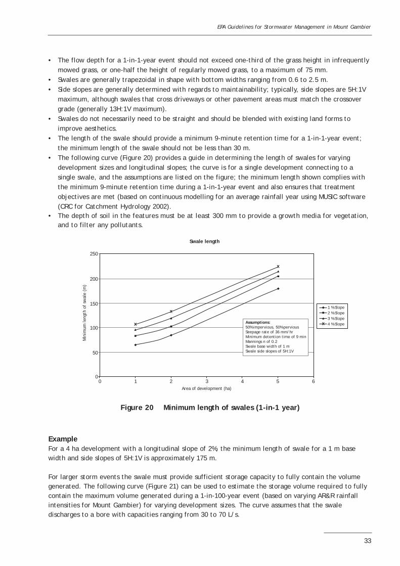
• The following curve (Figure 20) provides a guide in determining the length of swales for varyingdevelopment sizes and longitudinal slopes; the curve is for a single development connecting to asingle swale, and the assumptions are listed on the figure; the minimum length shown complies withthe minimum 9-minute retention time during a 1-in-1-year event and also ensures that treatmentobjectives are met (based on continuous modelling for an average rainfall year using MUSIC software(CRC for Catchment Hydrology 2002).
• The depth of soil in the features must be at least 300 mm to provide a growth media for vegetation,and to filter any pollutants.
ExampleFor a 4 ha development with a longitudinal slope of 2%, the minimum length of swale for a 1 m basewidth and side slopes of 5H:1V is approximately 175 m.
For larger storm events the swale must provide sufficient storage capacity to fully contain the volumegenerated. The following curve (Figure 21) can be used to estimate the storage volume required to fullycontain the maximum volume generated during a 1-in-100-year event (based on varying AR&R rainfallintensities for Mount Gambier) for varying development sizes. The curve assumes that the swaledischarges to a bore with capacities ranging from 30 to 70 L/s.
EPA Guidelines for Stormwater Management in Mount Gambier
33
250
200
150
100
50
03 4 5 6210
Swale length
Min
imum
leng
th o
f sw
ale
(m)
Area of development (ha)
1 % Slope2 % Slope3 % Slope4 % Slopex
x
x
xAssumptions:50% impervious, 50% perviousSeepage rate of 36 mm/hrMinimum detention time of 9 minMannings n of 0.2Swale base width of 1 mSwale side slopes of 5H:1V
Figure 20 Minimum length of swales (1-in-1 year)

ExampleFor a 4 ha residential development with a longitudinal slope of 2%:• The minimum storage volume required to fully contain a 1-in-100-year event for a swale discharging
to a bore with a capacity of 50 L/s is approximately 550 m3.• The design curves presented are intended for planning purposes, and the planning authority will
approve final engineered swale designs.
Construction• Care should be taken during construction to ensure that the channel bed is not compacted, which
would reduce the vegetation growth and infiltration capacity.• Swales should not receive runoff until they are fully vegetated and all scour protection measures have
been implemented.• Typical details for the construction of swales are shown in Figures 22 and 24.
Maintenance• Primarily, maintenance should be aimed at preserving a dense grass or vegetative cover over the
swale, and should include routine inspection, watering, weeding and reseeding as necessary.• Swale effectiveness is enhanced by maintaining grass height at 75 mm or greater.• Erosion of swales should be repaired when required.• Built-up sediment, debris and litter should be removed from the swale surface.• Pesticides and herbicides should not be used in the swale area.
EPA Guidelines for Stormwater Management in Mount Gambier
34
3000Bore discharge30 L/s
Bore discharge50 L/s
Bore discharge70 L/s
2500
2000
1500
1000
500
06 10 12420
Storage Volume Required for Swales
Stor
age
volu
me
requ
ired
(m
3 )
Area of development (ha)
8
Assumptions:50% impervious, 50% perviousARI 100 years (AR&R)Time of concentration 30 min.
Figure 21 Storage volume required for swales discharging directly to a bore (1-in-100 year)

EPA Guidelines for Stormwater Management in Mount Gambier
35
Figure 22 Typical swale details
1 - 4%Longitudinal slope
Length determinedfrom Figure 20
Check dam(optional)
Side slopes 5H:1V max.
Base width 0.6 to 2.5 m
Longitudinalslope 1 to 4%
Check dam (optional)
Removable trash rack
For higher flow imputs, astructured inlet will berequired: see Figure 27A-A
Length determinedfrom Figure 20
A
A
900 mm
600 mm
Figure 23 End of swale detail discharging to a bore

EPA Guidelines for Stormwater Management in Mount Gambier
36
Removable trash rack
Bore heightat least 500 mm
Removable shroud on bore inlet(see Figure 24 for detail)
Volume of storage in swale based upon volumecalculated by Figure 21
Weep holes (50 mm diameter)at intervals of 250 mmin chamber walls andfloor
Bore casing orpipework to bore
Gravel surround
Reinforced concrete walls and base
1 in 100 year
1 in 1 year
CROSS SECTION A-A
Handle forremoval of shroud
Sleeve pipe(approx. 300 mm long) insertedinto (or outside) drainage bore
Bore casing
50-100 mm50-100 mm
100 mm
100 mm
Pin connecting innersleeve to shroud
resting on bore casing
Pipe section shroudcapped at top
Figure 24 An option for bore protection from floating substances using a removable shroud
Figure 23 (cont) End of swale detail discharging to a bore

Retention basins
DescriptionRetention basins are designed to temporarily store runoff for periods no greater than approximately 1day before draining either by infiltration and/or drainage wells. They are used primarily for floodprotection but also allow for pollutant removal through sedimentation and infiltration.
Typical applicationsRetention basins are most applicable for larger developments (>5 ha). Basins can be sized to suit localconditions and can be incorporated within developments to achieve a multipurpose benefit, including:• recreational use• aesthetics• incorporation of small permanent ponds• improvement of property values• incorporation of swales and gravel trenches into the floor of the basin for more efficient contaminant
removal.
Some examples in use in Mount Gambier are shown in Figures 25 and 26.
Limitations• They require large land areas.• They cannot be placed on steep slopes, fill or unstable areas.• Clogging of the basin floor may occur over time, reducing infiltration capacity.
Design• The soil infiltration capacity is a key design factor that should be established at each potential site;
in-situ infiltration tests, as described in Appendix A, should be performed to determine the soilinfiltration capacity at the surface.
• If the basin is capturing stormwater from a catchment area greater than 5 hectares, a site-specificsoil investigation is needed to identify any sub-layers that have a low permeability. This assessmentwill need to document these sub-layers, and determine if they could affect stormwater infiltration.
EPA Guidelines for Stormwater Management in Mount Gambier
37
Figure 25 Retention basin with gravel trench floor and gravel surroundat bore
Figure 26 Large shallow basin incorporating swales

• The inflow into the basin should be spread over a large area.• If sediment loads are expected to be high, pre-treatment measures for sediment and gross pollution
should be incorporated.• The basin floor should be relatively flat.• Inflow velocity should be minimised and outlet protection used on basin slopes where required.• Vegetation should be provided throughout the basin to help filter stormwater, particularly at the
inlets to the basin.• Basin floors and sides should be grassed to reduce erosion and the risk of fine sediment clogging the
basin floor; grass species used should be suitable for frequent inundation.• To permit mowing, side slopes should be 5H:1V maximum.• A shallow basin depth (1–2 m) is usually sufficient.• Vehicle access should be provided where necessary.• A gravel surround to the discharge bore should be provided.• A shroud and trash rack should be provided at the discharge bore chamber inlet.• Typical details of retention basins for new developments are shown in Figure 27.• Basins are designed to operate as two-stage devices—flows up to a 1-in-1-year event will drain via
infiltration only (for water quality purposes based on continuous modelling for an average rainfallyear using MUSIC software (CRC for Catchment Hydrology 2002), and larger flows will drain via thedischarge bore; in high-risk flood areas a second bore may be required.
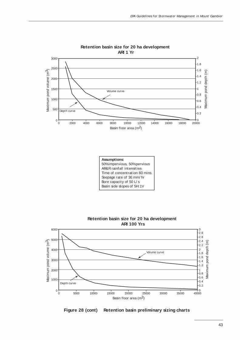
• The basins are to be sized to fully contain a 1-in-100-year event; the following charts in Figure 28 canbe used to determine the level of the bore and the volume of the basin required to fully contain a1-in-100-year event for varying residential development sizes; the follow assumptions have been made:- AR&R rainfall intensities for Mount Gambier (Pilgrim 1987)- an infiltration rate of 36 mm/hr (typical for sandy clay/sandy loam soils)- assumed development of 50% impervious and 50% pervious for new residential developments- basin side slopes of 5H:1V- a bore capacity of 50 L/s1.
• As several assumptions (based on typical conditions that could be expected in Mount Gambier for anew residential development) must be made to develop the curves in Figure 28, the curves presentedfor sizing retention basins are intended for planning purposes only; the planning authority mustapprove final engineered retention basin designs incorporating site-specific data.
• The development of the curves in Figure 28 is based on AR&R rainfall intensities for Mount Gambier,together with the storm duration that results in the maximum pond volume. The user should be awarethat this method is based on standard practice using AR&R criteria and does not take into accountretained volume before the onset of the storm, although a maximum draindown of 24 hours is chosenfor design; continuous modelling using actual or simulated rainfall based on the statistical propertiesof the historic rainfall record will allow prior storages to be modelled.
• The depth of soil in the features must be at least 300 mm to provide a growth media for vegetation,and to filter any pollutants.
EPA Guidelines for Stormwater Management in Mount Gambier
38
1 The assumed bore capacity in these examples must be used with extreme caution. Although capacities of 50 L/s are common in the Mount Gambier area, there are locations where capacities as low as 4 L/s are reported. Individual sites should endeavour to research bore capacities in the surrounding areas.

EPA Guidelines for Stormwater Management in Mount Gambier
39
Figure 27 Retention basin details
1-in-100 year maximum stormwater level
1-in-1 year maximum stormwater level
Area vegetated to reduce flow rate and improve nutrient reduction
Basin edge
B B
A
A
Inflow from development
Catchbasket
Vegetatedbuffer zone(as required)
Check dam(optional)
Basin side slope5H:1V (max.)
Accesschamber
Basin floor
Flexible outletprotection
CROSS SECTION A-A
Pre-determined (ie 1-in-100 year) maximum stormwater level
1-in-1 year maximum stormwater levelPerforatedconcrete chamber
Second borefor higher flooding risk access
Removable trash rack
Refer to Figure 23 A-A and Figure 24 for greater detail on construction of bore chamber
Gravel surround
Basin edge
CROSS SECTION B-B

Construction• Basins should not receive construction sediment loads; where sediment does accumulate, this
material should be removed before basin operation.• Light construction plant should be used to minimise soil compaction of the basin floor.• At the end of construction of the basin, the floor should be tilled and levelled.• The basin should not become operational until it is fully established.
Maintenance• Maintenance should be regular and include periodic removal of built-up sediment, grass mowing and
repair of areas affected by erosion.• Inspection of the basin following storm events should be undertaken to observe draindown times;
increasing draindown times and the presence of ponded water will indicate a reduction in infiltrationrates.
• Periodic tilling may be required to improve the infiltration capacity of the basin.• Pesticides and herbicides should not be used in the detention basin.
EPA Guidelines for Stormwater Management in Mount Gambier
40

EPA Guidelines for Stormwater Management in Mount Gambier
41
800
700
Basin floor area (m2)
Volume curve
Depth curve
Max
imum
pon
d de
pth
(m)
Max
imum
pon
d vo
lum
e (m
3 )
600
500
400
300
100
200
00 500 1000 1500 2000 2500 3000 3500 4000 4500
1.4
1.2
1
0.8
0.6
0.4
0.2
05000
Retention basin size for 5 ha development ARI 1 Yr
Figure 28 Retention basin preliminary sizing charts
Assumptions:50% impervious, 50% perviousAR&R rainfall intensitiesTime of concentration 60 minsSeepage rate of 36 mm/hrBore capacity of 50 L/sBasin side slopes of 5H:1V
800
700
Basin floor area (m2)
Volume curve
Depth curve
Max
imum
pon
d de
pth
(m)
Max
imum
pon
d vo
lum
e (m
3 )
600
500
400
300
0
200
100
0 20001000 3000 4000 5000 70006000 8000 9000
1.6
1.4
1.2
1
0.8
0.6
0.4
0.2
010000
Retention basin size for 5 ha development ARI 100 Yrs

EPA Guidelines for Stormwater Management in Mount Gambier
42
Figure 28 (cont) Retention basin preliminary sizing charts
1600
1400
Basin floor area (m2)
Volume curve
Depth curve
Max
imum
pon
d de
pth
(m)
Max
imum
pon
d vo
lum
e (m
3 )
1200
1000
600
800
200
400
00 1000 2000 3000 4000 5000 6000 7000 8000 9000
1.6
1.4
1.2
1
0.8
0.6
0.4
0.2
010000
Retention basin size for 10 ha development ARI 1 Yr
Assumptions:50% impervious, 50% perviousAR&R rainfall intensitiesTime of concentration 60 minsSeepage rate of 36 mm/hrBore capacity of 50 L/sBasin side slopes of 5H:1V
2500
Basin floor area (m2)
Volume curve
Depth curve
Max
imum
pon
d de
pth
(m)
Max
imum
pon
d vo
lum
e (m
3 )
2000
1500
1000
500
00 2000 60004000 8000 1200010000 14000 1800016000
2
1.8
1.6
1.4
1.2
1
0.8
0.6
0.4
0.2
020000
Retention basin size for 10 ha development ARI 100 Yrs
EPA Guidelines for Stormwater Management in Mount Gambier
43
Figure 28 (cont) Retention basin preliminary sizing charts
3000
2500
Basin floor area (m2)
Volume curve
Depth curve
Max
imum
pon
d de
pth
(m)
Max
imum
pon
d vo
lum
e (m
3 )
2000
1500
1000
500
00 2000 4000 6000 8000 10000 12000 14000 16000 18000
2
1.8
1.6
1.4
1.2
1
0.8
0.6
0.4
0.2
020000
Retention basin size for 20 ha development ARI 1 Yr
Assumptions:50% impervious, 50% perviousAR&R rainfall intensitiesTime of concentration 60 minsSeepage rate of 36 mm/hrBore capacity of 50 L/sBasin side slopes of 5H:1V
6000
5000
Basin floor area (m2)
Volume curve
Depth curve
Max
imum
pon
d de
pth
(m)
Max
imum
pon
d vo
lum
e (m
3 )
4000
3000
2000
1000
00 5000 10000 15000 20000 25000 30000 35000
32.82.82.4
2
2.2
1.81.61.41.2
10.80.60.40.2
040000
Retention basin size for 20 ha development ARI 100 Yrs

EPA Guidelines for Stormwater Management in Mount Gambier
44
Figure 28 (cont) Retention basin preliminary sizing charts
6000
5000
Basin floor area (m2)
Volume curve
Depth curve
Max
imum
pon
d de
pth
(m)
Max
imum
pon
d vo
lum
e (m
3 )
4000
3000
2000
1000
00 5000 10000 15000 20000 25000 30000 35000 40000 45000
1.6
1.4
1.2
1
0.8
0.6
0.4
0.2
050000
Retention basin size for 40 ha development ARI 1 Yr
Assumptions:50% impervious, 50% perviousAR&R rainfall intensitiesTime of concentration 60 minsSeepage rate of 36 mm/hrBore capacity of 50 L/sBasin side slopes of 5H:1V
16000
14000
Basin floor area (m2)
Volume curve
Depth curve
Max
imum
pon
d de
pth
(m)
Max
imum
pon
d vo
lum
e (m
3 )
12000
10000
8000
4000
6000
2000
00 10000 20000 30000 40000 50000 60000
3.232.82.62.42.221.8
1.61.41.210.80.60.40.2
070000
Retention basin size for 40 ha development ARI 100 Yrs

EPA Guidelines for Stormwater Management in Mount Gambier
45
ExampleFor a retention basin required to serve a 40 ha development, an initial basin size of 5000 m2 is proposedby the developer. The following can be determined from Figure 28:• The maximum pond volume and pond depth for a 1-year ARI are approximately 3600 m3 and 0.65 m
respectively.• The maximum pond volume and pond depth for a 100-year ARI are approximately 12,500 m3 and
1.9 m respectively.In the case where a 1.9 m depth is considered too deep, the curves can be used to select a basin areabased on a maximum pond depth. For example, should the depth be limited to 1.5 m, then an area canbe selected based on the maximum pond depth during a 1-in-100-year event. In this case, assuming a300 mm freeboard, the maximum pond depth for a 1-in-100-year event is 1.2 m. The following can thenbe determined from Figure 28: • The basin floor area for a 1.2 m maximum pond depth for a 100-year ARI is 8400 m2.• The maximum pond volume and pond depth for a 1-year ARI are approximately 2500 m3 and 0.32 m
respectively.
The discharge bore level would thus be set at just above the 1-year ARI maximum pond height, i.e. 0.32 m,and the depth of the basin must be at least 1.2 m plus an appropriate freeboard to contain a 1-in-100-year event.
If there is an overflow path then no freeboard is required in the retention basin.
Storage tanks
DescriptionStorage tanks are used for collecting rainwater. They can be above- or below-ground installations andtypically receive roof runoff. These systems can reduce the quantity of stormwater entering thestormwater system and may provide a clean source of water for recycling on site.
Typical applicationsThese are typically used at a residential allotment level in the form of above-ground rainwater tanks tocollect roof runoff . Other systems available at residential allotments include enlarged box gutters toprovide storage at the eaves level and modular fencing with storage incorporated into the fence system.At a commercial and industrial level, underground tanks are commonly used. These can be constructedfrom reinforced concrete, fibreglass or heavy duty plastic. A typical example of a rainwater tank for aresidential allotment is shown in Figure 29.
Overflow(to garden or trench)
Pump (as required)
Rainwater space
Float
Mains top up volume (as required)
Trickle top upfrom mains supply(as required)
Inflow(from roof)
First flushdiversion device
First flush discharge to garden
Outflow to garden,toilet, etc.
Figure 29 Rainwater storage tank
EPA Guidelines for Stormwater Management in Mount Gambier
46
Limitations• They will only provide storage capacity if the stored water is used for purposes such as irrigation and
in-house use (e.g. toilet flushing, etc.).• It is usually difficult to direct all roof runoff from a residential lot to a single downpipe connecting to
an above-ground rainwater tank.• They may not be suitable as a potable source of water in areas where collected runoff is
contaminated from sources such as lead and tar based paints on roofs, asbestos or atmosphericpollution.
• Underground tanks can be subject to contamination from surface runoff or accidental cross-contamination from septic tanks.
Design• Above-ground tanks should be fitted with a first flush device to divert the initial runoff from the roof
away from the tank.• Screens should cover all inlets and outlets to reduce the chance of entry of leaves, debris, animals
and mosquitoes.• An overflow must be provided; overflow water can be directed to gravel filled trenches before
discharging to the stormwater system.• Rainwater tanks can be provided with a slow release mechanism which can direct stored water to
garden areas.• Rainwater tanks may be interconnected with the mains water supply to the house, provided an
approved residential dual check-valve is installed above ground on the mains water service before theconnection with the tank. This is needed to avoid any possible backflow from the rainwater tank intothe mains supply. Further advice on these valves is available from SA Water.
• Typically, above-ground rainwater tanks are 2 to 20 k/L in size and can yield 20 to 150 kL/yr.• Enlarged gutters typically store 1–2 kL, the storage capacity depending on the cross-sectional area
and length of gutter.• Underground storage pits should be located away from heavily trafficked areas to enable easy
maintenance; circular lids are preferred as they are less likely to accidentally fall into the pits.• For pits capturing runoff from paved surfaces, gross pollutants must be prevented from entering the
pits; it is also preferable to remove sediments from the runoff prior to its entering the pits.• Small pumps may be required to deliver water for reuse from above- and below-ground installations.• Water stored in enlarged gutters can be directed to the house without the need for pumping.• Many systems are proprietary built; all manufacturers’ recommendations should be followed.• The following curves (Figure 30) can be used to determine the average annual supply using rainwater
tanks for varying combinations of roof area, daily demand and tank size. The assumptions are listed inthe figure.
Construction• A licensed plumber should be employed for installation.• Manufacturers’ recommendations should be adhered to.
Maintenance• Tanks should be flushed out annually.• Gutters and first flush devices should be cleaned regularly.• Leaks should be repaired as required.

EPA Guidelines for Stormwater Management in Mount Gambier
47
30
25
20
15
10
5
050 100 150 200 250 300 350 400 450 500 550
50 100 150 200 250 300 350 400 450 500 550
Effective Roof Area = 50 m2
Effective Roof Area = 100 m2
Daily demand (litres)
Aver
age
annu
al s
uppl
y (k
L)
70
60
50
40
30
20
0
10
Aver
age
annu
al s
uppl
y (k
L)
1 KL 2 KL 5 KL 20 KL
Daily demand (litres)
1 KL 2 KL 5 KL 10 KL 20 KL
Assumptions:Based on continuous modelling using daily rainfall for Mt Gambier (1942 to 2004). Trickle top up with mains water does not occur. Impervious run off co-efficient = 0.9. First flush volume = 25 litres (bypasses the tank at the onset of rainfall).
Assumptions:Based on continuous modelling using daily rainfall for Mt Gambier (1942 to 2004). Trickle top up with mains water does not occur. Impervious run off co-efficient = 0.9. First flush volume = 25 litres (bypasses the tank at the onset of rainfall).
Figure 30 Rainwater tank yield curves for Mount Gambier

EPA Guidelines for Stormwater Management in Mount Gambier
48
Effective Roof Area = 150 m2
70
80
90
100
60
50
40
30
20
0
10
Aver
age
annu
al s
uppl
y (k
L)
50 100 150 200 250 300 350 400 450 500 550
Daily demand (litres)
1 KL 2 KL 5 KL 10 KL 20 KL
140
120
100
80
60
40
20
050 100 150 200 250 300 350 400 450 500 550
Effective Roof Area = 200 m2
Daily demand (litres)
Aver
age
annu
al s
uppl
y (k
L)
1 KL 2 KL 5 KL 10 KL 20 KL
Assumptions:Based on continuous modelling using daily rainfall for Mt Gambier (1942 to 2004). Trickle top up with mains water does not occur. Impervious run off co-efficient = 0.9. First flush volume = 25 litres (bypasses the tank at the onset of rainfall).
Assumptions:Based on continuous modelling using daily rainfall for Mt Gambier (1942 to 2004). Trickle top up with mains water does not occur. Impervious run off co-efficient = 0.9. First flush volume = 25 litres (bypasses the tank at the onset of rainfall).
Figure 30 (cont.) Rainwater tank yield curves for Mount Gambier

EPA Guidelines for Stormwater Management in Mount Gambier
49
50 100 150 200 250 300 350 400 450 500 550
Effective Roof Area = 250 m2
Effective Roof Area = 300 m2
160
140
120
100
80
60
0
20
40
Aver
age
annu
al s
uppl
y (k
L)
120
140
160
100
80
60
40
20
0
Aver
age
annu
al s
uppl
y (k
L)
Daily demand (litres)
1 KL 2 KL 5 KL 10 KL 20 KL
50 100 150 200 250 300 350 400 450 500 550
Daily demand (litres)
1 KL 2 KL 5 KL 10 KL 20 KL
Assumptions:Based on continuous modelling using daily rainfall for Mt Gambier (1942 to 2004). Trickle top up with mains water does not occur. Impervious run off co-efficient = 0.9. First flush volume = 25 litres (bypasses the tank at the onset of rainfall).
Assumptions:Based on continuous modelling using daily rainfall for Mt Gambier (1942 to 2004). Trickle top up with mains water does not occur. Impervious run off co-efficient = 0.9. First flush volume = 25 litres (bypasses the tank at the onset of rainfall).
Figure 30 (cont.) Rainwater tank yield curves for Mount Gambier

EPA Guidelines for Stormwater Management in Mount Gambier
50
Example• Total roof area = 350 m2
• Total roof area connected to tank (effective roof area) = 200 m2
• Rainwater tank size = 10 kL• Daily demand = 250 litres• Estimated average annual supply (from Figure 30) = 80 kL
Hydrocarbon interceptor and containment tanks
DescriptionInterceptor and containment tanks are used where hydrocarbon contamination could occur. Containmentof potential leaks or spills will prevent the contaminants entering the groundwater system. Thesesystems do not discharge to the stormwater system, but are either retained for off-site transport ordischarged to the sewer.
Typical applicationsTypically, these systems are used at service stations or refuelling areas.
Limitations• They have a limited capacity to contain leaks and spills.
Design• At service stations separate paths must be provided for fuel spills and stormwater.• An interceptor tank must be provided under the roofed refuelling area.• The floor under the roof must be sloped toward the interceptor tank.• For accidental spills from road tankers, a further retention tank must be provided with capacity to
contain one compartment-load of a road tanker in a separate area of the service station beforedischarge to the stormwater system.
• For in-ground storage tanks the double containment management approach should be used (seebelow).
Construction• In-ground storage tanks are placed in large concrete tanks, which are then backfilled with sand
(double containment approach); piezometers can be placed in the backfilled sand to monitor forleaks.
• Above-ground tanks can be surrounded by bunkers to provide full containment of fuel in the event offailure.
Maintenance• Piezometers should be monitored for leaks, and repaired as required.• Periodic removal of collected spills and sediments should be carried out as required.

Manufactured units with hydrocarbon separators
DescriptionIn recent years there has been improvement in the technology used to manufacture units withhydrocarbon separation systems to remove residual hydrocarbons from stormwater before discharge.There are various product brands available, each system generally including a storage reservoir, a pre-filter and a hydrocarbon separator. These systems require a high degree of maintenance but can be veryeffective in areas where the presence of a higher than usual amount of hydrocarbons is expected.
They are produced in a range of sizes to meet catchment and flow demands. The photograph below(Figure 31) illustrates an example of a manufactured unit with hydrocarbon separator installed inMount Gambier.
Typical applicationsTypically, these systems are used for large vehicle parking areas where there is an increased risk ofhydrocarbons in stormwater.
Limitations• They have higher capital and maintenance costs.
Design• The separation device is normally installed below ground level and in a location that is accessible and
allows gravity flow into the device.• The installation of flow delay systems may be required to reduce the magnitude of stormwater flow
entering the device.• Access must be readily available to the device to allow for inspections, pump-outs in the case of
spills, and replacement of filters as necessary.
Construction• The devices are placed into the ground and then backfilled with sand.• The devices are usually very robust and do not generally require double insulation.• Installation is very much directed by the manufacturer’s specifications and directions, and is often
device specific.
Maintenance• Periodic inspection and replacement of filters is necessary to maintain a good level of performance.• Removal of sediment and litter should also occur regularly.
EPA Guidelines for Stormwater Management in Mount Gambier
51
Figure 31 Manufactured unit ready for in-ground installation

Innovative solutions
The developer is not restricted to the measures listed previously and may propose the use of innovativesolutions. Such proposals must be submitted to the planning authority for approval. It must bedemonstrated that the measure or measures proposed achieve the target removal rates as listed inTable 1. Typically, this can be demonstrated using industry software such as MUSIC (CRC for CatchmentHydrology 2002). Continuous modelling using Mount Gambier rainfall data for 1988, which is consideredto represent a typical rainfall year, is to be used; this rainfall data can be purchased from the Bureau ofMeteorology. Rainfall at 6-minute intervals is preferred to accurately model most treatment measures.
EPA Guidelines for Stormwater Management in Mount Gambier
52

10 SUMMARY OF APPLICABILITY OF STORMWATER METHODS
Based on the previous chapters, it is clear that there are a variety of options that can be considered fordifferent sites. In summary, Table 9 provides guidance on the types of stormwater treatment methodsthat should be considered for the main types of developments. As discussed earlier, it is likely that morethan one stormwater management method will be used at each site.
Table 9 Summary of structural treatment measures for Mount Gambier
Type of development Possible actions
New residential Incorporate water-sensitive urban design principals described in Figures 5 to 12
Rainwater tanks with first flush
Infiltration trenches/soak-aways at overflows to rainwater tanks or use as stand-alone systems directly connected to roof runoff
Permeable paving in appropriate locations
Kerbline filter strips
Swales in developments less than 5 ha
Retention basins with or without swales in developments greater than 5 ha
New industrial/commercial On-site retention (above or below ground)
Infiltration trenches/soak-aways at overflows to storage tanks or use as stand-alone systems directly connected to roof runoff
Manufactured units with hydrocarbon separators for areas of higher than usual hydrocarbon presence
Permeable paving in appropriate locations
Grassed depression storage in carpark areas as per Figure 15
Kerbline filter strips
Swales in developments less than 5 ha, where appropriate
Retention basins with or without swales in developments greater than 5 ha, where appropriate
Hydrocarbon interceptor and containment tanks (at fuel storage locations)
Roadway networks Incorporate water-sensitive urban design principals described in Figures 5 to 12
Swales in developments less than 5 ha
Retention basins with or without swales in developments greater than 5 ha
Permeable paving in appropriate locations
Kerbline filter strips
Manufactured units with hydrocarbon separators for areas of higher than usual hydrocarbon presence
EPA Guidelines for Stormwater Management in Mount Gambier
53

11 CONSTRUCTION OF STORMWATER DISPOSAL BORES
As discussed, in some sites there will be a need to install a stormwater bore for disposal. The design andconstruction of stormwater disposal bores needs to be undertaken in a certain manner to minimise therisk of groundwater contamination. As a guide, all stormwater disposal bores will need to include thefollowing.
• Stormwater disposal bores will need to be clearly marked and identified by permanent signs.• Stormwater disposal bores and headwork(s) will need to be accessible at all times.• Stormwater disposal bores will need to be constructed to include physical barriers to protect the bore
and headwork(s) from damage by vehicles (bores should preferably be located away from vehicletraffic-ways and roads).
• Any bore construction or alteration will need to be undertaken in a manner consistent with therelevant provisions outlined in the Water Resources Act 1997 and the ‘Minimum ConstructionRequirements for Water Bores in Australia’ (Agriculture and Resource Management Council of Australiaand New Zealand 1997 ISBN 0 7242 7401 4).
• Stormwater disposal bores will require testing once constructed to ensure that the discharge rates(amount of water able to be disposed of down the bore per unit time) are within the design criteriaof the treatment and retention systems.
All stormwater disposal bores need to be constructed to incorporate contingency and protectionmeasures in response to emergency situations. The types of measures taken will depend on the borelocation and circumstances. Stormwater bores that will come under the control of the local council willneed to match the council established procedures. On private properties other methods such as isolationvalves should be considered.
The Water Resources Act requires that a bore construction permit be obtained before any drilling,rehabilitation or backfilling of bores. The Department for Water, Land and Biodiversity Conservationshould be contacted to discuss the approvals that are needed under the Water Resources Act.
A licence or permit may also be required to discharge stormwater into any discharge bore, dependingupon the location. The Environment Protection Authority and the Department for Water, Land andBiodiversity Conservation should be contacted to identify the specific requirements for ongoing dischargeauthorisations.
EPA Guidelines for Stormwater Management in Mount Gambier
54

12 PLANNING FOR MAINTENANCE AND MONITORING
As recognised throughout this document, the ongoing performance of stormwater treatment andmanagement systems is heavily dependent on the regular maintenance and monitoring of the systems;these stormwater systems are not self-cleaning nor ‘set and forget’.
The resourcing, responsibility and manner of monitoring and maintenance must all be considered duringthe early stages of planning stormwater options for a site. Although in some developments theinfrastructure ownership and responsibility for maintenance may rest with the site owner, there are otherdevelopments such as new residential areas, precinct developments or infill developments where the landmanagement agreements may be established with the council. To ensure that that the system maintenancerequirements are acceptable, the developer should have early discussions with the local council about theoptions for longer-term management of stormwater treatment systems or discharge bores.
In order to document the requirements for monitoring and maintenance, as well as to clearly define theresponsibilities for coordinating this work, a maintenance and monitoring plan needs to be developedduring the planning stages and provided along with the documentation for planning approval. Theconsiderations that should be made in developing this plan are discussed below.
MonitoringThe type of monitoring required to keep the performance of the stormwater system under review willdepend greatly upon the type of system constructed. Although monitoring may, in some cases, includethe collection of stormwater samples being discharged to bores or off site, many other forms ofmonitoring can be effective. Types of monitoring that should be considered are:• visual inspections of traps and areas of potential gross pollutant build-up every two to four months• inspection of soil and vegetation within and around the stormwater treatment system for the early
identification of erosion, scouring or potential erosion that may result in transport of significantsediment loads through the stormwater treatment system
• visual inspections of manufactured units or proprietary devices at the frequency suggested by themanufacturer (there is a need to specify the frequency period in the plan).
Obviously, the frequency and combination of monitoring methods will depend on the circumstances inthe catchment. For instance, a gross pollutant trap near a shopping centre may collect a substantialamount of litter and may need more regular checking than a trap in a small residential area. Thefrequency and scope of monitoring should be based on the identified level of risk.
MaintenanceThis guideline highlights the issues that require specific maintenance focus for each of the structuralstormwater methods (see individual Maintenance headings in Chapter 9), and this work obviously needsto receive appropriate attention. Although the frequency of some of the maintenance will depend on theoutcomes of the monitoring, regular maintenance will be needed on some systems (such as weed controlin basins and swales). For both the regular and irregular maintenance, it is important that ongoingresourcing provisions are made to ensure that when required, maintenance can be undertaken in atimely fashion.
The maintenance section of the plan therefore needs to outline the methods of expected maintenancefor the system, as well as establishing the processes for ensuring that maintenance is undertakeneffectively.
EPA Guidelines for Stormwater Management in Mount Gambier
55

EPA Guidelines for Stormwater Management in Mount Gambier
56
All maintenance and monitoring should be recorded in a log book as a permanent record of theperformance of the system.
ResponsibilityThe monitoring and maintenance plan must also identify the organisation or individual (if privatelyowned) who will be responsible for the monitoring, maintenance and management of the stormwatertreatment system. If management of the stormwater systems is likely to come under the control of thelocal council, the plan must outline when this will occur (e.g. 12 months after all stormwater systemsare constructed and commissioned). In these circumstances, it is strongly suggested that developersdiscuss their plans with the local council before finalising and submitting development applications.Although the monitoring and maintenance plan should detail whether the local council supportsresponsibility arrangements, it is not necessary to include a signed statement from the local council.

EPA Guidelines for Stormwater Management in Mount Gambier
57
13 DOCUMENTATION FOR PLANNING APPLICATIONS
Through the development of the stormwater management proposal for the site, the landowner will needto have undertaken an assessment to ensure that the system being implemented achieves the principlesand objectives as discussed in section 4.
Once the proposal has been submitted to the planning authority, usually the council, the council and/orthe EPA will need to verify that the stormwater system is appropriate. To allow this to occur, theproponent needs to provide specific detail on the proposed stormwater management. Failure to providethis information may initially result in delays in the assessment process, as the information will need tobe requested of the proponent.
In any development involving stormwater management, the proponent should ensure that the followinginformation is included in the development application.
1. Details of the planning and structural methods that are proposed for the site to collect, direct, treatand dispose of stormwater at the site in a manner that achieves the performance criteria defined insection 5 of this guideline. This information should also include justification that the methods areappropriate for the site. Additionally, this information should include:• the design specifications and details of planning and structural methods for stormwater management• the data and information that was used to develop the dimensions and design specifications of the
planning and structural methods (i.e. engineering calculation)• justification for any variation if the performance criteria defined in section 5 of this guideline are
not achieved• if the technology is new or the existing data is not considered reliable, a detailed monitoring plan
to assess the performance of the removal of hydrocarbons, SS, TP and TN (see Table 1).
2. A scaled plan(s) of the proposal site that includes the:• location of all bores on the site which are either existing or are proposed as part of the development• location of all structural stormwater treatment methods (devices)• location of all buildings on the site• location of all storage areas of chemicals or materials likely to degrade stormwater• location of any vehicle washing facilities, refuelling areas or bunded areas• location of any stormwater pipework• the delineation of the entire surface water catchment area for each catchment that exists within
the site• extent to which runoff from the entire catchment will be included in each/all stormwater
discharge bore(s), and whether or not the catchment area exists wholly within the proposed development site.
3. Details and scaled plans of the collection, treatment and disposal methods proposed for any domesticwastewater (from toilets, showers, kitchens or other similar activities) within the site. Usually, thistype of wastewater stream should be directed to the sewer.
4. The details of construction, upgrade or rehabilitation of any bores at the site. This information shouldinclude details such as casing depths, bore hole depths and headworks, etc.

5. The details of all existing bores on the site, including:• registered permit numbers (issued by the Department of Water, Land and Biodiversity Conservation)• geological logs• standing water levels• construction details including headworks.
Note: If not readily available, this information may be sourced from the Resource Assessment Division of the Department of Water, Land and Biodiversity Conservation.
6. A soil landscape description that includes:• a description of the soil characteristics at the location of the stormwater treatment system
(i.e. basin/swale) including the type and depth of soil, and estimated infiltration rates• the results of any assessment undertaken to identify subsurface layers with a low permability• a Soil Erosion and Drainage Management Plan (as described in the Stormwater Pollution/Prevention
Code of Practice for Local, State and Federal Government) that describes the manner in which stormwater will be protected during construction activities within the catchment area.
7. A monitoring and maintenance plan (as described in Chapter 12) that details:• the organisation responsible for ongoing maintenance and management of the stormwater system• any performance monitoring that will be undertaken to demonstrate the effectiveness of the
treatment systems• the maintenance plan that will be implemented to ensure ongoing effective operation of the
stormwater system• the contingency plan that will be implemented at the site to prevent stormwater and groundwater
contamination as a result of a spill or catastrophic event.
EPA Guidelines for Stormwater Management in Mount Gambier
58

14 FURTHER READING
Argue JR, Allen MD, Greiger WF, Johnston LD, Pezzaniti D and Scott P, 2004, Water-sensitive urbandesign: 10 basic procedures for source control of stormwater—A handbook for Australian practice, FirstEdition.
City of Mount Gambier 1999, Stormwater Drainage Emergency Management Plan, Unpublished localgovernment plan, 25 November 1999.
CRC for Catchment Hydrology 2002, MUSIC model for urban stormwater improvement conceptualisation,Version 1.0, Urban stormwater quality software.
CSIRO 1999, Urban stormwater—Best practical environmental management guidelines, Prepared for theStormwater Committee.
Environment Protection Authority 1998, Stormwater Prevention Code of Practice for the Building andConstruction Industry, EPA, Adelaide.
Hill, AJ, Lawson, JS, Mustafa, S 2002, The Hydrostratigraphy of the Tertiary Gambier LimestoneUnconfined Aquifer, Lower South East South Australia. Report Book 2002/30 (unpublished).
Institution of Engineers, Australia 2003, Australian runoff quality (ARQ), Symposium proceedings, 16–17June 2003.
Knox City Council 2002, ‘Water-sensitive urban design guidelines for the City of Knox’, Prepared byMurphy Design Group and KLM Development Consultants.
NSW Department of Housing (NSWDH) 1998, Managing urban stormwater: Soils and construction, NSWDH,Sydney.
NSW Environment Protection Authority (NSW EPA) 1997, ‘Managing urban stormwater: Treatmenttechniques draft’, NSW EPA, Sydney.
Pilgrim, DH (ed) 1987, Australian rainfall and runoff (AR&R)—A guide to flood estimation, Barton, ACT:Institution of Engineers, Australia.
Planning South Australia (Planning SA) 2003, ‘On-site retention of stormwater’, Minister’s SpecificationSA 78AA.
South East Catchment Water Management Board (SECWMB) 2003, South East Catchment WaterManagement Plan 2003–2008, SECWMB.
Texas Natural Resource Conservation Commission (TNRCC) 1999, Complying with the Edwards aquiferrules: Technical guidance on best management practices, Austin, Texas.
Transport SA 2002, Protecting waterways, Prepared by the Environment Operations Unit, SOGC and theStormwater Services Section with the assistance of the Urban Water Resources Centre of the Universityof South Australia.
EPA Guidelines for Stormwater Management in Mount Gambier
59

15 APPENDIX A—DOUBLE RING INFILTROMETER TEST
The double ring infiltrometer test (American Society for Testing and Materials (ASTM) D3385—94) is asimple and inexpensive method for determining the in-situ infiltration capacity of soils. This method isparticularly suitable for relatively uniform fine-grained soils with an absence of very plastic clays andgravel sized particles. The double ring infiltrometer test consists of driving two open cylinders, oneinside the other, into the ground, partially filling the rings with water, and then maintaining the liquid ata constant level. The test may be conducted at the ground surface, at given depths in pits, on bareground or on ground with vegetation in place.
This test method is difficult to use, or the resultant data may be unreliable, or both, in very pervious orimpervious soils or in dry or stiff soils that most likely will fracture when the rings are installed. It mustbe noted that the test cannot be used to directly determine the hydraulic conductivity of the soil.Although the units of infiltration and hydraulic conductivity of soils are the same (m/s), there is adistinct difference between these two quantities. They cannot be directly related unless the hydraulicboundary conditions are known—for example, by knowing the hydraulic gradient and being able toreliably estimate the extent of the lateral flow of water.
Many factors affect the infiltration rate, such as the: • soil structure • soil layering • condition of the soil surface • degree of saturation of the soil • chemical and physical nature of the soil and of the applied liquid • head of the applied liquid • temperature of the liquid• diameter and depth of the embedment rings.
Thus, tests made at the same site are unlikely to give identical results, and the rate measured by thetest method described in this standard is primarily for comparative use. The following summarises thetest method, as detailed in ASTM D3385-94.
EPA Guidelines for Stormwater Management in Mount Gambier
60
Figure A1 Double ring infiltrometer

Apparatus• Infiltrometer rings: open cylinders approximately 500 mm high with diameters of approximately
300 and 600 mm. Larger cylinders may be used providing the ratio of the outer to inner cylinders isapproximately 2:1. Cylinders can be made of 3 mm hard alloy, aluminium sheet or other materialsufficiently strong to withstand hard driving, with the bottom edge bevelled.
• Driving caps: disks of 13 mm thick hard alloy aluminium with centring pins around the edge or,preferably, a recessed groove approximately 5 mm deep and approximately 1 mm wider than thethickness of the ring. The diameters of the disks should be slightly larger than those of theinfiltrometer rings.
• Driving equipment: a 5.5 kg rubber mallet or sledge and a 600 or 900 mm length of woodapproximately 50 by 100 mm or 100 by 100 mm.
• Depth gauge: a hook gauge, steel tape or rule, or length of steel or plastic rod pointed on one end,for use in measuring and controlling the depth of the liquid (head) in the infiltrometer ring, wheneither a graduated Mariotte tube or automatic flow control system is not used.
• Liquid containers:
1. one 200 L barrel for the main liquid supply, along with a length of rubber hose to siphon liquid from the barrel to fill the calibrated head tanks
2. one 13 L bucket for initial filling of the infiltrometers
3. two calibrated head tanks for measurement of liquid flow during the test. These may be either graduated cylinders or Mariotte tubes having a minimum capacity of approximately 3000 mL. It is useful to have one head tank with a capacity three times that of the other because the area of theannular space between the rings is approximately three times that of the inner ring. It must also be noted that the volume of the calibrated head tanks may need to be significantly larger than 3000 mL, particularly if the test is to be conducted overnight. A capacity of approximately 50 L would not be uncommon.
• Liquid supply: clean water (tap water is preferred)
• Watch or stopwatch: a stopwatch would only be required for high infiltration rates.
• Level: a carpenter’s level.
Calibration• Rings:
1. Determine the area of each ring and of the annular space between the rings (equal to the internal area of the 600 mm ring minus the external area of the 300 mm ring) before initial use.
2. Determine these areas using a measuring technique that will provide an overall accuracy to within 1%.
3. Redetermine these measurements before reuse after anything has occurred, including repairs, which may affect the test results significantly.
• Liquid containers: For each graduated cylinder or graduated Mariotte tube, establish the relationshipbetween the change in elevation of liquid level and the change in the volume of the liquid. Thisrelationship should have an overall accuracy to within 1%.
Procedure• Test site:
1. The test requires an area of approximately 3 x 3 m.
EPA Guidelines for Stormwater Management in Mount Gambier
61

2. The test site should be nearly level, or a level surface should be prepared.
3. The test may be set up in a pit if infiltration rates are desired at depth rather than at the surface.
• Driving infiltration rings:
1. Place the driving cap on the outer ring and centre it. Place the wood block on the driving cap.2. Drive the outer ring into the soil with blows of a heavy sledge onto the wood block to a depth that
will: - prevent the test liquid from leaking to the ground surface surrounding the ring, and - be deeper than the depth to which the inner ring will be driven—a depth of 150 mm is usually
adequate.
3. Use blows of medium force to prevent fracturing of the soil surface.
4. Move the wood block around the edge of the driving cap every one or two blows so that the ring will penetrate the soil uniformly.
5. Centre the smaller ring inside the larger ring and drive to a depth that will prevent leakage of the test liquid to the ground surface surrounding the ring—a depth of approximately 50–100 mm is usually adequate.
• Tamping disturbed soil:
1. If the surface of the soil surrounding the wall(s) of the ring(s) is excessively disturbed (signs of cracking, excessive heave, etc.), reset the ring(s) using a technique that will minimise such disturbance.
2. If the surface of the soil surrounding the wall(s) of the ring(s) is only slightly disturbed, tamp the disturbed soil adjacent to the inside and outside wall(s) of the ring(s) until the soil is as firm as it was prior to disturbance.
• Maintaining liquid level:
1. There are basically three ways to maintain a constant head (liquid level) within the inner ring and annular space between the two rings:- manual control of the flow of the liquid—a depth gauge is required to assist the investigator
visually in maintaining a constant head, e.g. a steel tape or rule for soils having relatively high permeability, and a hook gauge or simple point gauge for soils having a relatively low permeability
- the use of constant level float valves- the use of a Mariotte tube.
2. Install the depth gauges, constant level valves or Mariotte tubes as shown in Figure A1, and in sucha manner that the reference head will be at least 25 mm and not greater than 150 mm. Select the head on the basis of the permeability of the soil. Locate the depth gauges near the centre of the inner ring and midway between the two rings.
3. Cover the soil surface within the inner ring and between the two rings with splash guards (square pieces of plastic sheeting) to prevent erosion of the soil when the initial liquid is poured into the rings.
4. Use a pail to fill both rings with liquid to the same desired depth in each ring. Do not record this initial volume of liquid. Remove the splash guards.
5. Start the flow of liquid from the graduated cylinders or Mariotte tubes. As soon as the level becomes basically constant, determine the liquid depth in both the inner ring and the annular
EPA Guidelines for Stormwater Management in Mount Gambier
62
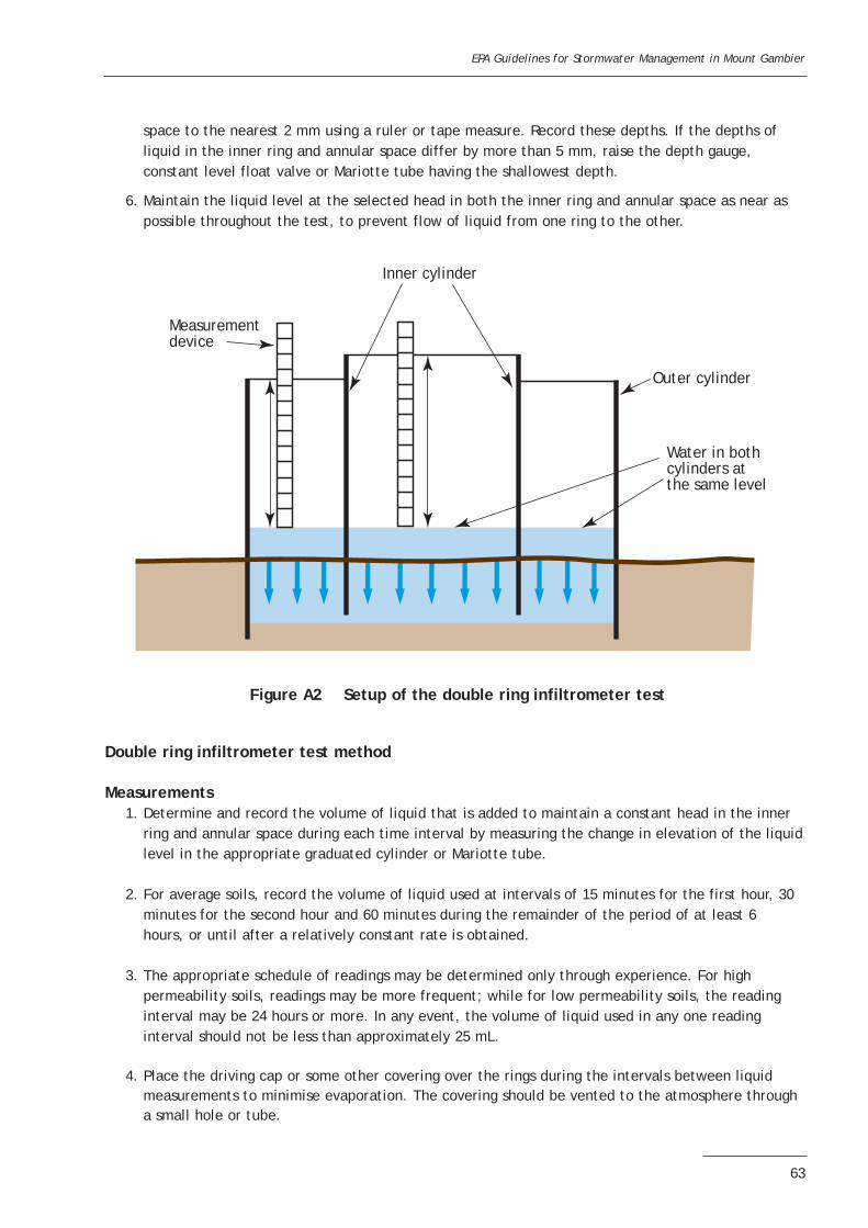
space to the nearest 2 mm using a ruler or tape measure. Record these depths. If the depths of liquid in the inner ring and annular space differ by more than 5 mm, raise the depth gauge, constant level float valve or Mariotte tube having the shallowest depth.
6. Maintain the liquid level at the selected head in both the inner ring and annular space as near as possible throughout the test, to prevent flow of liquid from one ring to the other.
Double ring infiltrometer test method
Measurements1. Determine and record the volume of liquid that is added to maintain a constant head in the inner
ring and annular space during each time interval by measuring the change in elevation of the liquidlevel in the appropriate graduated cylinder or Mariotte tube.
2. For average soils, record the volume of liquid used at intervals of 15 minutes for the first hour, 30 minutes for the second hour and 60 minutes during the remainder of the period of at least 6 hours, or until after a relatively constant rate is obtained.
3. The appropriate schedule of readings may be determined only through experience. For high permeability soils, readings may be more frequent; while for low permeability soils, the reading interval may be 24 hours or more. In any event, the volume of liquid used in any one reading interval should not be less than approximately 25 mL.
4. Place the driving cap or some other covering over the rings during the intervals between liquid measurements to minimise evaporation. The covering should be vented to the atmosphere through a small hole or tube.
EPA Guidelines for Stormwater Management in Mount Gambier
63
Inner cylinder
Measurement device
Outer cylinder
Water in bothcylinders at the same level
Figure A2 Setup of the double ring infiltrometer test

5. Upon completion of the test, remove the rings from the soil, assisted by light hammering on both sides with a rubber hammer.
Calculations1. Convert the volume of liquid used during each measured time interval into an incremental
infiltration velocity for both the inner ring and annular space using the following equations:• For the inner ring:
Vir = _Vir/(Air x _t)whereVir = inner ring incremental infiltration velocity (m/s)_Vir = volume of liquid used during time interval to maintain constant head in the inner ring (m3).(Note 1 m3 = 1000 L)Air = internal area of the inner ring (m)_t = time interval (s)
• For the annular space between the rings:Va = _Va/(Aa x _t)whereVa = annular space incremental infiltration velocity (m/s)_Va = volume of liquid used during time interval to maintain constant head in the annular
space between the rings (m3). (Note 1 m3 = 1000 L)Aa = area of annular space between the rings (m2)_t = time interval (s)
2. The incremental infiltration velocities (Vir and Va) are then plotted versus elapsed time on a graph.
3. The maximum steady state or average incremental infiltration velocity, depending on the purpose/application of the test, is the equivalent infiltration rate. If the rates for the inner ring and annular space differ, the value for the inner ring should be the value used.
Reporting
Report the following information in the report or field records, or both:• location of the test site• dates of test, start and finish times• weather conditions, start to finish• name(s) of technician(s)• description of test site, including soil type• type of liquid used• areas of the rings and annular space between the rings• volume constants for the graduated cylinders or Mariotte tubes• depths of liquid in inner ring and annular space• record of incremental volume measurements and incremental infiltration velocities (inner ring and
annular space) versus elapsed time• if available, depth to the watertable and a description of the soils found between the rings and the
watertable, or to a depth of approximately 1 m• a plot of the incremental infiltration rate versus total elapsed time.
EPA Guidelines for Stormwater Management in Mount Gambier
64

ReferenceThe American Society for Testing and Materials (ASTM) 1994, ‘D 3385—94 Standard test method forinfiltration rate of soils in field using double ring infiltrometer’, Under the jurisdiction of ASTMCommittee D-18 on Soil and Rock.
EPA Guidelines for Stormwater Management in Mount Gambier
65
Related Documents