Note: Within nine months of the publication of the mention of the grant of the European patent in the European Patent Bulletin, any person may give notice to the European Patent Office of opposition to that patent, in accordance with the Implementing Regulations. Notice of opposition shall not be deemed to have been filed until the opposition fee has been paid. (Art. 99(1) European Patent Convention). Printed by Jouve, 75001 PARIS (FR) (19) EP 3 211 048 B1 *EP003211048B1* (11) EP 3 211 048 B1 (12) EUROPEAN PATENT SPECIFICATION (45) Date of publication and mention of the grant of the patent: 08.07.2020 Bulletin 2020/28 (21) Application number: 17155908.1 (22) Date of filing: 13.02.2017 (51) Int Cl.: C09D 11/54 (2014.01) (54) SURFACE TREATMENT LIQUID COMPOSITION, INK SET, RECORDING METHOD, AND RECORDING DEVICE OBERFLÄCHENBEHANDLUNGSFLÜSSIGKEITSZUSAMMENSETZUNG, TINTENSATZ, AUFZEICHNUNGSVERFAHREN UND AUFZEICHNUNGSVORRICHTUNG COMPOSITION LIQUIDE DE TRAITEMENT DE SURFACE, ENSEMBLE D’ENCRE, PROCÉDÉ D’ENREGISTREMENT ET DISPOSITIF D’ENREGISTREMENT (84) Designated Contracting States: AL AT BE BG CH CY CZ DE DK EE ES FI FR GB GR HR HU IE IS IT LI LT LU LV MC MK MT NL NO PL PT RO RS SE SI SK SM TR (30) Priority: 25.02.2016 JP 2016034407 15.12.2016 JP 2016243438 (43) Date of publication of application: 30.08.2017 Bulletin 2017/35 (73) Proprietor: Ricoh Company, Ltd. Tokyo 143-8555 (JP) (72) Inventors: • NAKAGAWA, Tomohiro Ohta-ku, Tokyo 143-8555 (JP) • OKADA, Noriaki Ohta-ku, Tokyo 143-8555 (JP) • HANAZAWA, Atsufumi Ohta-ku, Tokyo 143-8555 (JP) • FURUKAWA, Juichi Ohta-ku, Tokyo 143-8555 (JP) • SEKIGUCHI, Satoyuki Ohta-ku, Tokyo 143-8555 (JP) • IMANAGA, Yukihiro Ohta-ku, Tokyo 143-8555 (JP) • TANAKA, Ayaka Ohta-ku, Tokyo 143-8555 (JP) (74) Representative: White, Duncan Rohan Marks & Clerk LLP Fletcher House (2nd Floor) Heatley Road The Oxford Science Park Oxford OX4 4GE (GB) (56) References cited: EP-A1- 2 233 634 US-A1- 2010 196 603 US-A1- 2012 320 137 US-A1- 2013 070 036

Welcome message from author
This document is posted to help you gain knowledge. Please leave a comment to let me know what you think about it! Share it to your friends and learn new things together.
Transcript
Note: Within nine months of the publication of the mention of the grant of the European patent in the European PatentBulletin, any person may give notice to the European Patent Office of opposition to that patent, in accordance with theImplementing Regulations. Notice of opposition shall not be deemed to have been filed until the opposition fee has beenpaid. (Art. 99(1) European Patent Convention).
Printed by Jouve, 75001 PARIS (FR)
(19)EP
3 21
1 04
8B
1*EP003211048B1*
(11) EP 3 211 048 B1(12) EUROPEAN PATENT SPECIFICATION
(45) Date of publication and mention of the grant of the patent: 08.07.2020 Bulletin 2020/28
(21) Application number: 17155908.1
(22) Date of filing: 13.02.2017
(51) Int Cl.:C09D 11/54 (2014.01)
(54) SURFACE TREATMENT LIQUID COMPOSITION, INK SET, RECORDING METHOD, AND RECORDING DEVICE
OBERFLÄCHENBEHANDLUNGSFLÜSSIGKEITSZUSAMMENSETZUNG, TINTENSATZ, AUFZEICHNUNGSVERFAHREN UND AUFZEICHNUNGSVORRICHTUNG
COMPOSITION LIQUIDE DE TRAITEMENT DE SURFACE, ENSEMBLE D’ENCRE, PROCÉDÉ D’ENREGISTREMENT ET DISPOSITIF D’ENREGISTREMENT
(84) Designated Contracting States: AL AT BE BG CH CY CZ DE DK EE ES FI FR GB GR HR HU IE IS IT LI LT LU LV MC MK MT NL NO PL PT RO RS SE SI SK SM TR
(30) Priority: 25.02.2016 JP 201603440715.12.2016 JP 2016243438
(43) Date of publication of application: 30.08.2017 Bulletin 2017/35
(73) Proprietor: Ricoh Company, Ltd.Tokyo 143-8555 (JP)
(72) Inventors: • NAKAGAWA, Tomohiro
Ohta-ku, Tokyo 143-8555 (JP)• OKADA, Noriaki
Ohta-ku, Tokyo 143-8555 (JP)• HANAZAWA, Atsufumi
Ohta-ku, Tokyo 143-8555 (JP)
• FURUKAWA, JuichiOhta-ku, Tokyo 143-8555 (JP)
• SEKIGUCHI, SatoyukiOhta-ku, Tokyo 143-8555 (JP)
• IMANAGA, YukihiroOhta-ku, Tokyo 143-8555 (JP)
• TANAKA, AyakaOhta-ku, Tokyo 143-8555 (JP)
(74) Representative: White, Duncan RohanMarks & Clerk LLP Fletcher House (2nd Floor) Heatley Road The Oxford Science ParkOxford OX4 4GE (GB)
(56) References cited: EP-A1- 2 233 634 US-A1- 2010 196 603US-A1- 2012 320 137 US-A1- 2013 070 036
EP 3 211 048 B1
2
5
10
15
20
25
30
35
40
45
50
55
Description
BACKGROUND
Technical Field
[0001] The present invention relates to a surface treatment liquid composition, an ink set, a recording method, and arecording device.
Description of the Related Art
[0002] Since inkjet printers are relatively quiet, enjoy low running costs, and are capable of easily printing color images,they are now widely used at home as an output device of digital signals.[0003] Technologies of printing images on packaging materials for food, beverages, commodities, etc. utilizing inkjethave also been developed.[0004] As the substrate to which inkjet recording is applied, non-absorbable substrate such as plastic film have beenused and inks have been developed for such substrates.[0005] Demands to directly print images, etc. on plastic film utilizing inkjet include, for example, package printing forfood and commodities. In such applications, printed substrates are often visually observed at close range, so thatextremely high image quality is demanded.[0006] However, when images etc. are printed on a non-absorbable substrate utilizing inkjet, permeation drying doesnot occur. Therefore, ink droplets excessively widespread to areas of outline characters (also referred to as negativecharacters), thereby rendering the characters illegible. This phenomenon of rendering characters illegible is referred toas "crushed negative characters".[0007] To solve this problem, technologies have been proposed which include applying a reaction liquid including aflocculant and an ink including a coloring material to a non-absorbable recording medium in this sequence.[0008] Charge repulsion type resin emulsions, which are typically used as a surface treatment liquid composition, arenot securely dispersed under the coexistence with multivalent metal salts. That is, there is no surface treatment liquidcomposition for a substrate, which has excellent storage stability over a long period of time yet.[0009] In addition, in most of the package applications, an additive is applied onto a print layer after printing on thereverse side of plastic film and thereafter a heat sealable film is attached for lamination processing to manufacture apackage material. Also, there is no primer capable of demonstrating lamination strength at a non-print portion where theprimer is exposed or a print portion where the primer is covered with ink.[0010] Moreover, customers on the market and food manufacturers tend to demand higher and higher image density.To meet this demand, it is possible to increase the attachment amount of ink but liquid on a film does not dry, which hasa large adverse impact on the productivity as a printer. That is, a trade-off between the high image density and theproductivity occurs.[0011] Furthermore, film may be damaged during conveyance or due to vibration during conveyance before lamination.Also, in the case of surface printing without lamination, the print layer is scraped off due to friction caused by directcontacts with the print layer of an adjacent package, box, etc. As a result, the print content may be unclear and illegible.Therefore, friction resistance is required as well.[0012] As the liquid discharging head (liquid droplet discharging head) to discharge liquid, a circulation type head isknown in which liquid is circulated in a plurality of individual liquid chambers.[0013] For example, a circulation type head has been proposed which includes a common liquid chamber to supplyliquid to each of individual liquid chambers serving as pressure generating chambers and a circulation common liquidchamber communicating with a circulation flow path communicating with each of the individual liquid chambers. Thecommon liquid chamber and the circulation common liquid chamber are formed of a flow path member formed of aplurality of plate-like members forming the individual liquid chambers and the circulation flow path.
SUMMARY
[0014] According to the present invention, provided is an improved surface treatment liquid composition for a substrateincluding a nonionic resin particle, a multivalent metal salt and an organic solvent comprising at least one of 1,2-propanediol, 1,2-butane diol, and 2,3-butane diol.
BRIEF DESCRIPTION OF THE SEVERAL VIEWS OF THE DRAWINGS
[0015] Various other objects, features and attendant advantages of the present invention will be more fully appreciated
EP 3 211 048 B1
3
5
10
15
20
25
30
35
40
45
50
55
as the same becomes better understood from the detailed description when considered in connection with the accom-panying drawings in which like reference characters designate like corresponding parts throughout and wherein:
FIG. 1 is a diagram illustrating the recording device according to an embodiment of the present disclosure;FIG. 2 is a diagram illustrating a perspective view of the main tank accommodating the ink according to an embodimentof the present disclosure;FIG. 3 is a diagram illustrating a perspective view of the appearance of the liquid discharging head according to anembodiment of the present disclosure;FIG. 4 is diagram illustrating a cross section of the liquid discharging head illustrated in FIG. 3 along the directionvertical to the nozzle arrangement direction;FIG. 5 is a diagram illustrating a cross section of a part of the liquid discharging head illustrated in FIG. 3 along thedirection parallel to the nozzle arrangement direction;FIG. 6 is a diagram illustrating a planar view of the nozzle plate of the liquid discharging head illustrated in FIG. 3;FIGS. 7A to 7F are diagrams illustrating planar views of each member constituting the flow path member of theliquid discharging head illustrated in FIG. 3;FIGS. 8A and 8B are diagrams illustrating the planar view of each member constituting the common liquid chambersof the liquid discharging head illustrated in FIG. 3;FIG. 9 is a block diagram illustrating an example of the liquid circulation system relating to an embodiment of thepresent disclosure;FIG. 10 is diagram illustrating a cross section of the recording device according to an embodiment of the presentdisclosure; andFIG. 11 is a schematic diagram illustrating an example of the device to apply the surface treatment liquid compositionof the present disclosure.
DESCRIPTION OF THE EMBODIMENTS
[0016] In describing embodiments illustrated in the drawings, specific terminology is employed for the sake of clarity.However, the disclosure of this specification is not intended to be limited to the specific terminology so selected and itis to be understood that each specific element includes all technical equivalents that have a similar function, operate ina similar manner, and achieve a similar result.[0017] As used herein, the singular forms "a", "an", and "the" are intended to include the plural forms as well, unlessthe context clearly indicates otherwise.[0018] Moreover, image forming, recording, printing, modeling, etc. in the present disclosure represent the samemeaning, unless otherwise specified.[0019] The present disclosure relates to the surface treatment liquid composition described in embodiment 1 below.
1. A surface treatment liquid composition for a substrate includes a nonionic resin particle and a multivalent metal salt.The present disclosure will be described below in detail with reference to several embodiments and accompanyingdrawings. The embodiment 1 of the present disclosure includes the following 2 to 16. Therefore, these are alsodescribed.2. The surface treatment liquid composition according to 1 mentioned above, wherein the nonionic resin particleincludes at least one of a polyolefin resin, a polyvinyl acetate resin, a polyvinyl chloride resin, a urethane resin, astyrene butadiene resin, and a copolymers thereof.3. The surface treatment liquid composition according to 1 or 2 mentioned above, wherein the multivalent metal saltincludes at least one of a calcium salt, a magnesium salt, a nickel salt, and an aluminum salt.4. The surface treatment liquid composition according to 3 mentioned above, wherein the aluminum salt includesaluminum sulfate, aluminum phosphate, polyaluminum chloride, and aluminum potassium sulfate.5. The surface treatment liquid composition according to any one of 1 to 4 mentioned above, wherein the nonionicresin particle accounts for 0.5 - 20 percent by mass of the surface treatment liquid composition.6. An ink set including the surface treatment liquid composition of claim 1; and one or more inks, each ink includinga coloring material.7. The ink set according to 6 mentioned above, wherein the ink includes a non-white coloring material having avolume average particle diameter of from 30 to 110 nm and a thermoplastic resin particle.8. The ink set according to 6 mentioned above, wherein the ink includes a white coloring material and a thermoplasticresin particle.9. The ink set according to 6 mentioned above, wherein the ink includes a non-white ink including a non-whitecoloring material having a volume average particle diameter of from 30 to 110 nm and a thermoplastic resin particleand a white ink including a white coloring material and a thermoplastic resin particle.
EP 3 211 048 B1
4
5
10
15
20
25
30
35
40
45
50
55
10. The ink set according to any one of 7 to 9 mentioned above, wherein at least one ink of the non-white ink andthe white ink has a ratio (R/P) of a mass ratio (R) of the thermoplastic resin particle to the at least one ink of thenon-white ink and the white ink to a mass ratio (P) of the coloring material to the at least one ink of the non-whiteink and the white ink is 0.5 - 3.0.11. The ink set according to any one of 7 to 10 mentioned above, the glass transition temperature Tg1 of the nonionicresin particle of the surface treatment liquid composition is lower than the glass transition temperature Tg2 of theresin particle of the ink.12. A recording method including applying the surface treatment liquid composition of the ink set of any one of 6 to11 to a substrate and printing by discharging the ink of the ink set of any one of 6 to 11 to the substrate.13. The recording method according to 12 mentioned above, further including reforming the surface of the substrate.14. The recording method according to 12 or 13 mentioned above, wherein the ink is discharged by an ink discharginghead including a nozzle configured to discharge the ink, a plurality of individual liquid chambers communicating withthe nozzle, a flow-in path configured to flow the ink into the individual liquid chambers, a flow-out path configuredto flow the ink out of the individual liquid chambers and the step of printing further includes circulating the ink fromthe flow-out path to the flow-in path.15. A recording device including an ink accommodating unit configured to include the ink set of any one of 6 to 11mentioned above and an ink discharging head configured to discharge the ink of the ink set.16. The recording device according to 15 mentioned above, wherein the ink discharging head includes a nozzle todischarge the ink, a plurality of individual liquid chambers communicating with the nozzle, a flow-in path to flow theink into the individual liquid chambers, a flow-out path to flow the ink out of the individual liquid chambers and acirculating device to circulate the ink from the flow-out path to the flow-in path.
[0020] The surface treatment liquid composition to treat the surface of a substrate includes a nonionic resin particleand a multivalent metal salt. The surface treatment liquid composition, however, significantly includes no coloring material."Significantly includes no coloring material" means no coloring material is added as a component of the surface treatmentliquid composition (hereinafter also referred to as liquid composition).[0021] The present inventors have found that non-charge repulsion type emulsion but nonionic resin particles disperseddue to steric barrier are suitable for long-term storage stability of the resin particle under the coexistence of the multivalentmetal salt.[0022] The present inventors have also found that, of the charge repulsion types, anionic resin particles agglomeratewhen it is mixed with a multivalent metal salt. In particular, in the case of multivalent metal salts producing tri-valentcationic ions when dissociated, the particles agglomerate instantly. As the number of valence of a cation increases,agglomeration is promoted in a large amount, thereby salting out the dispersion more.[0023] On the other hand, cationic resin particles are sufficiently stable when left at, for example, ambient temperature.However, if the cationic resin particles are left still under heating as an acceleration test for long-term stability, it alsothickens.[0024] If the nonionic resin particle includes at least one of a polyolefin resin, a polyvinyl acetate resin, a polyvinylchloride, a urethane resin, a styrene butadiene resin, and copolymers thereof, lamination property is particularly excellentdue to strong substrate attachability.[0025] If the multivalent metal salt includes at least one of a calcium salt, a magnesium salt, a nickel salt, and analuminum salt, this is suitable in terms of particularly excellent storage stability and "crushed negative characters" canbe suppressed due to particularly excellent ink droplet agglomeration, "crushed negative characters"is a phenomenonin which characters are rendered illegible due to wide spreading of ink droplets to areas of outline characters (alsoreferred to as negative characters).[0026] If the multivalent metal salt includes an aluminum salt, crushed negative characters can be suppressed due toparticularly excellent ink droplet agglomeration. In addition, aluminum ions are stable as ion. Also, unlike iron (III) ion,the number of valence does not change due to acidity.[0027] When the content ratio of the nonionic resin particle to the entire liquid composition is 0.5 - 20 percent by mass,the amount of resin can be sufficient. In addition, since internal stress caused by increasing the film thickness is sup-pressed, lamination strength of non-printed portions is excellent.[0028] When the concentration of the multivalent metal salt to the entire liquid composition is 0.05 - 0.5 mol/kg, inaddition to storage stability, occurrence of crushed negative characters can be suppressed.[0029] When the glass transition temperature of the nonionic resin particle is -25 to 25 degrees C, since the nonionicresin particle is suitably soft, which is good in terms of striking a balance between the lamination strength and abrasionresistance.[0030] In the case of an ink set including the surface treatment liquid composition and an ink including a coloringmaterial, it is suitable to obtain printed matter having excellent abrasion resistance and image density.[0031] The ink in the ink set preferably includes a resin particle and a non-white ink. The coloring material of the non-
EP 3 211 048 B1
5
5
10
15
20
25
30
35
40
45
50
55
white ink has a volume average particle diameter of 30 to 110 nm. The resin particle is thermoplastic. Such an ink setdemonstrates particularly excellent coloring and is suitable to obtain high density.[0032] The ink in the ink set preferably includes a resin particle and a white ink. The coloring material of the white inkis white. The resin particle is thermoplastic. Such an ink set demonstrates particularly excellent coloring and is suitableto obtain high density.[0033] The ink in the ink set preferably includes a resin particle, a white ink, and a non-white ink. The coloring materialof the white ink is white and the resin particle of the white ink is thermoplastic. The coloring material of the non-whiteink has a volume average particle diameter of 30 to 110 nm and the resin particle of the no-white ink is thermoplastic.Such an ink set demonstrates particularly excellent coloring and is suitable to obtain high density. In addition, the colorrange is wide.[0034] Also, when the resin particle in the ink set includes at least one of an acrylic resin, a urethane resin, and apolyester resin, excellent abrasion resistance is obtained.[0035] The ink in the ink set preferably includes a resin particle. The ratio (R/P) of the mass ratio (R) of the resinparticle to the mass ratio (P) of the coloring material is 0.5 - 3.0. In such an ink set, furthermore excellent abrasion isobtained.[0036] In the ink set, the glass transition temperature Tg1 of the nonionic resin particle in the surface treatment liquidcomposition is preferably lower than the glass transition temperature Tg2 of the resin particle in the ink. In such an inkset, the lamination strength of printed sites is excellent.[0037] It is possible for the white ink to have a ratio (R/P) of the mass ratio (R) of the thermoplastic resin particle tothe white ink to the mass ratio (P) of the coloring material to the white ink is 0.5 - 3.0.[0038] It is possible for the non-white ink to have a ratio (R/P) of the mass ratio (R) of the thermoplastic resin particleto the non-white ink to the mass ratio (P) of the coloring material to the non-white ink is 0.5 - 3.0.[0039] It is also possible for both of the white ink and the non-white ink to have a ratio (R/P) of a mass ratio (R) of thethermoplastic resin particle to the white ink and the non-white ink to the mass ratio (P) of the coloring material to thewhite ink and the non-white in is 0.5 - 3.0.[0040] It is preferable that the recording method include reforming the surface of the substrate (also referred to asrecording medium, print medium), applying the surface treatment liquid composition to the substrate and dischargingthe ink to the substrate to improve the strength of lamination on the non-printed site and the printed site. Moreover, it ispreferable to conduct the reforming step with corona discharging treatment or streamer discharging treatment.[0041] It is preferable that the recording method include reforming the surface of the substrate (also referred to asrecording medium, print medium), applying the surface treatment liquid composition to the substrate and dischargingthe ink to the substrate to improve the strength of lamination on the non-printed site and the printed site. Moreover, it ispreferable to conduct the reforming step with corona discharging treatment or streamer discharging treatment.[0042] The recording method further includes heating after printing. This is preferable because film-forming of thethermoplastic resin in the ink is promoted, leading to amelioration of abrasion resistance of the film.[0043] In the step of applying a surface treatment liquid composition, if the attached amount of the surface treatmentliquid composition is in the range of from 0.4 - 2 g/m2, suppressing crushed negative characters and improving strengthof lamination strike a balance.[0044] In the step of applying the ink, when the attached amount of the ink is 4 - 14 g/m2, the image density and speeddrying can strike a balance.[0045] When the ink discharging step of the recording method includes discharging the non-white ink to a substrateand discharging the white ink to the substrate, images of a wide color gamut and high density can be obtained.[0046] The nonionic resin particle and the multivalent metal salt serving as the constitution components of the surfacetreatment liquid composition of the present disclosure are described below.
Nonionic Resin Particle
[0047] The nonionic resin particle in the present disclosure can be dispersed without utilizing electric charges.[0048] In the nonionic resin particle in the present disclosure, no monomers including acidic functional groups suchas carboxyl group and sulfo group or basic functional groups such as amino group are detected by thermal compositiongas chromatography (GC-MS) (e.g., GC-17A, manufactured by Shimadzu Corporation) after isolating the solid portionfrom the liquid composition by centrifugal.[0049] There is no limit to the chemical structure of the resin particle. Any nonionic dispersible resin particles can beused. It is preferable that the resin particle include at least one of a polyolefin resin, a polyvinyl acetate resin, a polyvinylchloride resin, a urethane resin, a styrene butadiene resin, and copolymers of these resins because attachment propertyto various substrates can be excellent. In addition, it is more preferable to include a copolymer resin of ethylene-vinylacetate, a copolymer resin of ethylene-vinylactate-vinyl chloride, and an olefin-modified urethane resin.[0050] The glass transition temperature Tg of the nonionic resin particle is preferably - 30 to 30 degrees C and more
EP 3 211 048 B1
6
5
10
15
20
25
30
35
40
45
50
55
preferably -25 to 25 degrees C.[0051] When Tg is -30 degrees C or higher, the resin film is sufficiently strong. Therefore, previously formed layersare stronger. When Tg is 30 degrees C or lower, film-forming property of the resin is improved and flexibility (softness)is secured. As a result, substrate attachabitiliy is stronger.[0052] The proportion of the addition amount of the solid portion is preferably 0.5 to 20 percent by mass to the totalamount of the liquid composition.[0053] When the proportion is 0.5 percent by mass or more, the substrate can be fully covered so that attachability isimproved. When the addition ratio is 20 percent by mass or less, the layer thickness is not excessively thick, so that theattachment property does not deteriorate.
Multivalent Metal Salt
[0054] The multivalent metal salt quickly aggregates the coloring material after a droplet of the ink lands on a substrateso that occurrence of crushed negative characters is suppressed and coloring property is improved.[0055] Specific examples of the multivalent metal salts include, but are not limited to, salts (multivalent metal salts) oftitanium, chrome, copper, cobalt, strontium, barium, iron, aluminum, calcium, magnesium, and nickel.[0056] Of these multivalent metal salts, in order to efficiently aggregate pigments, one or more of calcium salts,magnesium salts, nickel salts, and aluminum salts are preferable. Salts of alkali earth metal such as calcium andmagnesium which produces divalent cationic ions by dissociation are more preferable.[0057] In addition, salts of metal such as aluminum and iron which produces trivalent cationic ions by dissociation arepreferable and aluminum salts are more preferable.[0058] In particular, when the multivalent metal salts are calcium salts or aluminum salts, stability of the reaction liquidis better.[0059] Specific examples of the multivalent metal salts include, but are not limited to, calcium carbonate, calciumnitride, calcium chloride, calcium acetate, calcium sulfate, magnesium chloride, magnesium acetate, magnesium sulfate,nickel chloride, barium sulfate, zinc sulfide, zinc carbonate, aluminum silicate, calcium silicate, magnesium silicate,aluminum hydroxide, aluminum sulfate, aluminum phosphate, aluminum lactate, polyaluminum chloride, iron (III) sulfate,potassium aluminum sulfate, potassium iron alum, and ammonium iron alum.[0060] Of these, calcium acetate and aluminum sulfate are preferable to prevent degradation of strength of previouslayers caused by deliquescence.[0061] When the concentration of the multivalent metal salt to the entire liquid composition is 0.05 - 0.5 mol/kg, notonly excellent storage stability is obtained but also occurrence of crushed negative characters can be suppressed.[0062] The medium of the surface treatment liquid composition of the present disclosure is an aqueous medium. It ispossible to add other articles other than water. Examples are water-soluble organic solvents, surfactants, and otherminute quantity of additives.
Organic Solvent
[0063] There is no specific limitation on the type of the organic solvent used in the present disclosure. For example,water-soluble organic solvents are suitable. Specific examples include, but are not limited to, polyols, ethers such aspolyol alkylethers and polyol arylethers, nitrogen-containing heterocyclic compounds, amides, amines, and sulfur-con-taining compounds.[0064] Specific examples of the water-soluble organic solvents include, but are not limited to, polyols such as ethyleneglycol, diethylene glycol, 1,2-propanediol, 1,3-propanediol, 1,2-butanediol, 1,3-butanediol, 1,4-butanediol, 2,3-butane-diol, 3-methyl-1,3-butane diol, triethylene glycol, polyethylene glycol, polypropylene glycol, 1,2-pentanediol, 1,3-pen-tanediol, 1,4-pentanediol, 2,4-pentanediol, 1,5-pentanediol, 1,2-hexanediol, 1,6-hexanediol, 1,3-hexanediol, 2,5-hexan-ediol, 1,5-hexanediol, glycerin, 1,2,6-hexanetriol, 2-ethyl-1,3-hexanediol, ethyl-1,2,4-butane triol, 1,2,3-butanetriol, 2,2,4-trimethyl-1,3-pentanediol, and petriol; polyol alkylethers such as ethylene glycol monoethylether, ethylene glycolmonobutylether, diethylene glycol monomethylether, diethylene glycol monoethylether, diethylene glycolmonobutylether, tetraethylene glycol monomethylether, and propylene glycol monoethylether; polyol arylethers such asethylene glycol monophenylether and ethylene glycol monobenzylether; nitrogen-containing heterocyclic compoundssuch as 2-pyrolidone, N-methyl-2-pyrolidone, N-hydroxyethyl-2-pyrolidone, 1,3-dimethyl-2-imidazolidinone, ε-caprol-actam, and γ-butyrolactone; amides such as formamide, N-methylformamide, N,N-dimethylformamide, 3-methoxy-N,N-dimethyl propioneamide, and 3-buthoxy-N,N-dimethyl propioneamide; amines such as monoethanolamine, dieth-anolamine, and triethylamine; sulfur-containing compounds such as dimethyl sulfoxide, sulfolane, and thiodiethanol;propylene carbonate, and ethylene carbonate.[0065] In terms that the water-soluble organic solvent serves as a humectant and also imparts a good drying property,organic solvents having a boiling point of 250 degrees C or lower are preferable.
EP 3 211 048 B1
7
5
10
15
20
25
30
35
40
45
50
55
[0066] The proportion of the organic solvent in the surface treatment liquid composition has no particular limit and canbe suitably selected to suit to a particular application.[0067] In terms of the drying property and discharging reliability of the liquid composition, the proportion is preferablyfrom 5 to 60 percent by mass, more preferably from 10 to 30 percent by mass, and furthermore preferably from 10 to25 percent by mass.[0068] The surface treatment liquid component includes at least one of 1,2-propane diol, 1,2-butane diol, and 2,3-butane diol, because the film-forming property of the resin is improved and abrasion resistance is also improved.
Surfactant
[0069] Examples of the surfactant are silicone-based surfactants, fluorosurfactants, amphoteric surfactants, nonionicsurfactants, anionic surfactants, etc.[0070] The silicone-based surfactant has no specific limit and can be suitably selected to suit to a particular application.[0071] Of these, preferred are silicone-based surfactants which are not decomposed even in a high pH environment.Specific examples thereof include, but are not limited to, side-chain-modified polydimethylsiloxane, both end-modifiedpolydimethylsiloxane, one-end-modified polydimethylsiloxane, and side-chain-both-end-modified polydimethylsiloxane.A silicone-based surfactant having a polyoxyethylene group or a polyoxyethylene polyoxypropylene group is particularlypreferable because such an agent demonstrates good characteristics as an aqueous surfactant. It is possible to use apolyether-modified silicone-based surfactant as the silicone-based surfactant. A specific example thereof is a compoundin which a polyalkylene oxide structure is introduced into the side chain of the Si site of dimethyl silooxane.[0072] Specific examples of the fluoro surfactants include, but are not limited to, perfluoroalkyl sulfonic acid compounds,perfluoroalkyl carboxylic acid compounds, perfluoroalkyl phosphoric acid ester compounds, adducts of perfluoroalkylethylene oxide, and polyoxyalkylene ether polymer compounds having a perfluoroalkyl ether group in its side chain.These are particularly preferable because they do not foam easily. Specific examples of the perfluoroalkyl sulfonic acidcompounds include, but are not limited to, perfluoroalkyl sulfonic acid and salts of perfluoroalkyl sulfonic acid.[0073] Specific examples of the perfluoroalkyl carboxylic acid compounds include, but are not limited to, perfluoroalkylcarboxylic acid and salts of perfluoroalkyl carboxylic acid. Specific examples of the polyoxyalkylene ether polymercompounds having a perfluoroalkyl ether group in its side chain include, but are not limited to, sulfuric acid ester saltsof polyoxyalkylene ether polymer having a perfluoroalkyl ether group in its side chain and salts of polyoxyalkylene etherpolymers having a perfluoroalkyl ether group in its side chain. Counter ions of salts in these fluorine-based surfactantsare, for example, Li, Na, K, NH4, NH3CH2CH2OH, NH2(CH2CH2OH)2, and NH(CH2CH2OH)3.[0074] Specific examples of the amphoteric surfactants include, but are not limited to, lauryl aminopropionic acid salts,lauryl dimethyl betaine, stearyl dimethyl betaine, and lauryl dihydroxyethyl betaine.[0075] Specific examples of the nonionic surfactants include, but are not limited to, polyoxyethylene alkyl phenyl ethers,polyoxyethylene alkyl esters, polyoxyethylene alkyl amines, polyoxyethylene alkyl amides, polyoxyethylene propyleneblock polymers, sorbitan aliphatic acid esters, polyoxyethylene sorbitan aliphatic acid esters, and adducts of acetylenealcohol with ethylene oxides, etc.[0076] Specific examples of the anionic surfactants include, but are not limited to, polyoxyethylene alkyl ether acetates,dodecyl benzene sulfonates, laurates, and polyoxyethylene alkyl ether sulfates.[0077] These can be used alone or in combination.[0078] Examples of the minute quantity of additives are defoaming agents, preservatives and fungicides, and corrosioninhibitors.
Defoaming Agent
[0079] The defoaming agent has no particular limit. For example, silicon-based defoaming agents, polyether-baseddefoaming agents, and aliphatic acid ester-based defoaming agents are suitable. These can be used alone or in com-bination. Of these, silicone-based defoaming agents are preferable to easily break foams.
Preservatives and Fungicides
[0080] The preservatives and fungicides are not particularly limited. A specific example is 1,2-benzisothiazoline-3-on.
Corrosion inhibitor
[0081] The corrosion inhibitor has not particular limit. Examples thereof are acid sulfite and sodium thiosulfate.
EP 3 211 048 B1
8
5
10
15
20
25
30
35
40
45
50
55
Ink
[0082] The ink of the present disclosure will be described below.[0083] The ink includes a coloring material. In the present disclosure, the ink preferably includes resin particles.
Resin Particle
[0084] The volume average particle diameter of the resin particle is not particularly limited and can be suitably selectedto suit to a particular application. The volume average particle diameter is preferably from 10 to 1,000 nm, more preferablyfrom 10 to 200 nm, and furthermore preferably from 10 to 100 nm to obtain good fixability and image hardness.[0085] The volume average particle diameter can be measured by using a particle size analyzer (Nanotrac Wave-UT151, manufactured by MicrotracBEL Corp.).[0086] The proportion of the resin is not particularly limited and can be suitably selected to suit to a particular application.In terms of fixability and storage stability of ink, it is preferably from 1 to 30 percent by mass and more preferably from5 to 20 percent by mass to the total content of the ink.[0087] In addition, these resin particles are preferably thermoplastic.[0088] Specific examples include, but are not limited to, urethane resins, polyester resins, acrylic-based resins, vinylacetate-based resins, styrene-based resins, butadiene-based resins, styrene-butadiene-based resins, vinyl chloride-based resins, acrylic styrene-based resins, and acrylic silicone-based resins.[0089] The resin particle can be synthesized or is available on the market.[0090] Specific examples of the resin particles available on the market include, but are not limited to, Microgel E-1002and E-5002 (styrene-acrylic-based resin particles, manufactured by Nippon Paint co., Ltd.), Voncoat 4001 (acrylic-basedresin particles, manufactured by Dainippon Ink and Chemicals, Inc.), Voncoat 5454 (styrene/acrylic-based resin particles,manufactured by Dainippon Ink and Chemicals, Inc.), SAE-1014 (styrene-acrylic-based resin particles, manufacturedby Nippon Zeon Co., Ltd.), and Saivinol SK-200 (acrylic-based resin particles, manufactured by Saiden Chemical IndustryCo., Ltd.), Primal AC-22 and AC-61 (acrylic-based resin particles, manufactured by Rohm and Haas Electronic MaterialsK.K.), NANOCRYL SBCX-2821 and 3689 (acrylic-silicone-based resin particles, manufactured by Toyo Ink Co., Ltd.),and #3070 (methyl methacrylate polymer resin particles, manufactured by MIKUNI COLOR LTD.).[0091] Of these, acrylic resins, urethane resins, and polyester resins are preferable in terms of attachability with aprimer and excellent abrasion resistance.[0092] The glass transition temperature Tg2 of the resin particle is preferably higher than room temperature and morepreferably from about 30 to about 90 degrees.[0093] To make the strength of lamination of printed site, the glass transition temperature Tg2 of the resin particle ispreferably higher than the glass transition temperature Tg1 of the nonionic resin particle contained in the surface treatmentliquid composition. In addition, the glass transition temperature Tg2 of the resin particle is more preferably 20 degreesC or more higher than the glass transition temperature Tg1 of the nonionic resin particle contained in the surface treatmentliquid composition.
Coloring Material
[0094] The color of the ink contained in the surface treatment liquid composition of the present disclosure is notparticularly limited. Examples are white and non-white ink.[0095] ISO-2469 (JIS-8148) is used as the reference of the degree of white of the white ink. In general, an articlehaving a degree of white of equal to or greater than 70 is used as white coloring material.[0096] As the coloring material for white ink, metal oxides are preferable. Examples are titanium oxide, iron oxide, tinoxide, zirconium oxide, and iron-titanium double oxide.[0097] In addition, a white particle having a hollow structure is also preferable.[0098] Examples are hollow resin particle and hollow inorganic particles. Examples of the resin composition of thehollow resin particle are acrylic resins, styrene-acrylic resins, cross-linking type styrene-acrylic resins, urethane resins,and maleic-acid based resins. As the material of the hollow inorganic resin, for example, oxides, nitrides, and oxynitridesof metal such as silicon, aluminum, titanium, strontium, and zirconium showing color of white and inorganic compoundssuch as glass and silica.[0099] Metal oxides are used as the coloring material for use in white ink to improve the degree of white. White particleshaving hollow structures are used to prevent sedimentation.[0100] Examples of the non-white ink are color ink, black ink, gray ink, clear ink, metallic ink.[0101] Specific examples of the color ink include, but are not limited to, cyan ink, magenta ink, yellow ink, light cyanink, light magenta ink, red ink, green ink, blue ink, orange ink, and violet ink.[0102] The coloring material for use in the non-white ink has no particular limit as long as it shows non-white color
EP 3 211 048 B1
9
5
10
15
20
25
30
35
40
45
50
55
and can be suitably selected to suit to a particular application. For example, dyes and pigments are suitable. These canbe used alone or in combination. Of these, pigments are preferable.[0103] Examples of the pigment are organic pigments and inorganic pigments.[0104] As the inorganic pigments, for example, in addition to calcium carbonate, barium sulfate, aluminum hydroxide,barium yellow, cadmium red, and chrome yellow, carbon black manufactured by known methods such as contact methods,furnace methods, and thermal methods can be used. These can be used alone or in combination.[0105] Specific examples of the organic pigments include, but are not limited to, azo pigments (azo lakes, insolubleazo pigments, condensed azo pigments, chelate azo pigments, etc.), polycyclic pigments (phthalocyanine pigments,perylene pigments, perinone pigments, anthraquinone pigments, quinacridone pigments, dioxazine pigments, indigopigments, thioindigo pigments, isoindolinone pigments, and quinofuranone pigments, etc.), dye chelate (basic dye typechelate, acid dye type chelate), nitro pigments, nitroso pigments, and aniline black can be used. These can be usedalone or in combination.[0106] Also, hollow resin particles and inorganic hollow particles can be used.[0107] Of these pigments, pigments having good affinity with solvents are preferable.[0108] Specific examples of the black pigments for black include, but are not limited to, carbon black (C.I. PigmentBlack 7) such as furnace black, lamp black, acetylene black, and channel black, metals such as copper, iron (C.I. PigmentBlack 11), and organic pigments such as aniline black (C.I. Pigment Black 1). These can be used alone or in combination.[0109] Specific examples of the pigments for color include, but are not limited to, C.I. Pigment Yellow 1, 3, 12, 13, 14,17, 24, 34, 35, 37, 42 (yellow iron oxide), 53, 55, 74, 81, 83, 95, 97, 98, 100, 101, 104, 108, 109, 110, 117, 120, 138,150, 153, and 155; C.I. Pigment Orange 5, 13, 16, 17, 36, 43, and 51; C.I. Pigment Red 1, 2, 3, 5, 17, 22, 23, 31, 38,48:2, 48:2 {Permanent Red 2B(Ca)}, 48:3, 48:4, 49:1, 52:2, 53:1, 57:1 (Brilliant Carmine 6B), 60:1, 63:1, 63:2, 64:1, 81,83, 88, 101 (rouge), 104, 105, 106, 108 (Cadmium Red), 112, 114, 122 (Quinacridone Magenta), 123, 146, 149, 166,168, 170, 172, 177, 178, 179, 185, 190, 193, 209, and 219; C.I. Pigment Violet 1 (Rohdamine Lake), 3, 5:1, 16, 19, 23,and 38; C.I. Pigment Blue 1, 2, 15 (Phthalocyanine Blue), 15:1, 15:2, 15:3 (Phthalocyanine Blue), 16, 17:1, 56, 60, and63; and C.I. Pigment Green 1, 4, 7, 8, 10, 17, 18, and 36. These can be used alone or in combination.[0110] Specific examples of the dye include, but are not limited to, C.I. Acid Yellow 17, 23, 42, 44, 79, and 142, C.I.Acid Red 52, 80, 82, 249, 254, and 289, C.I. Acid Blue 9, 45, and 249, C.I. Acid Black 1, 2, 24, and 94, C. I. Food Black1 and 2, C.I. Direct Yellow 1, 12, 24, 33, 50, 55, 58, 86, 132, 142, 144, and 173, C.I. Direct Red 1, 4, 9, 80, 81, 225, and227, C.I. Direct Blue 1, 2, 15, 71, 86, 87, 98, 165, 199, and 202, C.I. Direct Black 19, 38, 51, 71, 154, 168, 171, and 195,C.I. Reactive Red 14, 32, 55, 79, and 249, and C.I. Reactive Black 3, 4, and 35. These can be used alone or in combination.[0111] Examples of the coloring material for use in metallic ink are fine powder obtained by finely-pulverizing metal,alloyed metal, or metal compounds. Specific examples include, but are not limited to, articles made of one or more kindsof metals selected from the group consisting of aluminum, silver, gold, nickel, chrome, tin, zinc, indium, titanium, silicon,copper, or platinum, alloys obtained by combining the metals in the group, or articles obtained by finely pulverizing oneor more of oxides, nitrides, sulfides, and carbides of the group of the metals or alloys.[0112] The proportion of the coloring material in ink is preferably from 0.1 to 15 percent by mass and more preferablyfrom 1 to 10 percent by mass in terms of enhancement of image density, fixability, and discharging stability.[0113] In one embodiment, pigments can be dispersed in ink by, for example, a method of introducing a hydrophilicfunctional group into the pigment to obtain a self-dispersible pigment, a method of coating the surface of a pigment witha resin, or a method of using a dispersant to disperse a pigment.[0114] The method of introducing a hydrophilic functional group into the pigment to obtain a self-dispersible pigmentincludes, for example, adding a functional group such as a sulfone group or a carboxyl group into a pigment (e.g., carbon)to render the pigment dispersible in water.[0115] The method of coating the surface of a pigment with a resin includes encapsulating a pigment in a microcapsuleto render the pigment dispersible in water. This can be referred to as a resin-coated pigment. In this case, the pigmentis not necessarily coated with the resin. Pigments partially or wholly uncovered with a resin may be dispersed in the inkunless the pigments have an adverse impact.[0116] In the method of using a dispersant to disperse a pigment, known dispersants, typically surfactants, of a smallmolecular weight type or a high molecular weight type is used to disperse the pigments in ink.[0117] As the surfactant, it is possible to use, for example, anionic surfactants, cationic surfactants, nonionic surfactants,amphoteric surfactants, etc. depending on the pigments. Also, a nonionic surfactant (RT-100, manufactured by TAKE-MOTO OIL & FAT CO., LTD.) and a formalin condensate of naphthalene sodium sulfonate are suitable as dispersants.[0118] These dispersants can be used alone or in combination.
Pigment Dispersion
[0119] The ink can be obtained by mixing a coloring material with water, organic solvents, etc. It is also possible tomix a pigment with water, a dispersant, etc., first to prepare a pigment dispersion and thereafter mix the pigment dispersion
EP 3 211 048 B1
10
5
10
15
20
25
30
35
40
45
50
55
with materials such as water and organic solvents to manufacture ink.[0120] The pigment dispersion is obtained by dispersing water, a pigment, a pigment dispersant, and other optionalcomponents and adjusting the particle size. It is good to use a dispersing device for dispersion.[0121] The particle diameter of the pigment in a pigment dispersion has no particular limit. For example, it is preferablethat non-white pigment have a volume average particle diameter of from 30 to 110 nm to improve dispersion stability ofa pigment, discharging stability, and image quality such as image density. In addition, regarding the white pigment, thevolume average particle diameter of the pigment oxide is preferably from 150 to 400 nm and more preferably from 200to 300 nm to obtain high degree of white. With regard to the hollow resin particle, the volume average particle diameteris preferably from 200 to 1000 nm. With regard to the hollow inorganic particle, the volume average particle diameter ispreferably from 10 to 200 nm to obtain excellent dispersion stability and high degree of white. The particle diameter ofthe pigment can be measured using a particle size analyzer (Nanotrac Wave-UT151, manufactured by MicrotracBELCorp).[0122] In addition, the proportion of the pigment in the pigment dispersion is not particularly limited and can be suitablyselected to suit to a particular application. In terms of improving discharging stability and image density, the proportionis preferably from 0.1 to 50 percent by mass and more preferably from 0.1 to 30 percent by mass.[0123] During the production, coarse particles are optionally subject to filtration with a filter, a centrifuge, etc. anddegassing.[0124] Optionally, a water-soluble organic solvent, a surfactant, minute amount of additives, etc. can be added to theink in the present disclosure as in the case of the surface treatment liquid composition. Specific examples are the sameas mentioned above.[0125] The ink in the present disclosure is manufactured by dispersing or dissolving the ink composition mentionedabove in an aqueous medium followed by optional mixing and stirring.[0126] A stirrer using a typical stirring blade, a magnetic stirrer, a high performance disperser etc., can be used forthe mixing and stirring.[0127] The property of the ink is not particularly limited and can be suitably selected to suit to a particular application.For example, viscosity, surface tension, pH, etc, are preferably in the following ranges.[0128] The viscosity of the ink at 25 degrees C is preferably from 5 to 30 mPa• s and more preferably from 5 to 25mPa• s to improve print density and text quality and obtain good dischargeability. The viscosity can be measured by,for example, a rotatory viscometer (RE-80L, manufactured by TOKI SANGYO CO., LTD.). The measuring conditionsare as follows:
• Standard cone rotor (1°34’ 3 R24)• Sample liquid amount: 1.2 mL• Number of rotations: 50 rotations per minute (rpm)• 25 degrees C• Measuring time: three minutes
[0129] The surface tension of the ink is preferably 35 mN/m or less and more preferably 32 mN/m or less at 25 degreesC in terms that the ink is suitably levelized on a print medium and the drying time of the ink is shortened.[0130] The pH of the ink is preferably from 7 to 12 and more preferably from 8 to 11 in terms of prevention of corrosionof metal materials contacting the ink.
Ink set
[0131] The ink set of the present disclosure includes the surface treatment liquid composition and the ink.[0132] As the ink of the ink set, it is possible to use non-white ink and/or white ink.
Substrate (Recording Medium)
[0133] The substrate for use in printing is not particularly limited. Plain paper, gloss paper, special paper, cloth, etc.are usable. Also, in particular, good images can be formed on a non-permeating substrate.[0134] The non-porous substrate in the present disclosure has a surface with a low level of moisture permeability,absorbency, and/or adsorptive property and includes a material having a number of hollow spaces inside but not opento the exterior.[0135] To be more quantitative, the substrate has a water-absorption amount of 10 mL/m2 or less between the contactand 30 msec1/2 after the contact according to Bristow method.[0136] Of the non-permeating substrate, resin film is preferable. In particular, polypropylene film, polyethylene tereph-thalate film, and nylon film are preferable to obtain good attachability.
EP 3 211 048 B1
11
5
10
15
20
25
30
35
40
45
50
55
[0137] Specific examples of polypropylene film include, but are not limited to, P-2002, P-2102, P-2161, and P-4166(all manufactured by TOYOBO CO., LTD.), PA-20, PA-30, and PA-20W (all manufactured by SUN• TOX Co., Ltd.), andFOA, FOS, and FOR (all manufactured by FUTAMURA CHEMICAL CO., LTD.).[0138] Specific examples of polyethylene terephthalate film include, but are not limited to, E-5100 and E5102 (bothmanufactured by TOYOBO CO., LTD.), P60 and P375 (both manufactured by TORAY INDUSTRIES, INC.), and G2,G2P2, K, and SL (all manufactured by TEIJIN FILM SOLUTIONS LIMITED).[0139] Specific examples of nylon film include, but are not limited to, HARDEN® film N-1100, N-1102, and N-1200(all manufactured by TOYOBO CO., LTD.) and ON, NX, MS, and NK (UNITIKA LTD.).[0140] If a heating process is added after printing, residual solvent in an ink film decreases, which is preferable interms of improvement of substrate attachability.
Recording Method and Recording Device
[0141] The recording method of the present disclosure includes applying a surface treatment liquid composition to asubstrate and printing to discharge (apply) an ink to the substrate, using the ink set including the surface treatment liquidcomposition and the ink.[0142] The recording method of the present disclosure preferably further includes reforming the surface of the substrate.
Surface Reforming
[0143] The surface reforming step can be executed by any method being free of uneven application of the liquidcomponent and capable of improving attachability. Examples of such methods are corona treatment, atmospheric pres-sure plasma processing, frame processing, and ultraviolet irradiation processing.[0144] These known processing can be executed by a known device.[0145] Of these processing methods, regarding the surface reforming of the recording surface, corona processing toconduct corona discharging on a recording surface or streamer processing (plasma processing) to conduct streamerdischarging are preferable. In comparison with atmospheric pressure plasma processing, frame processing, and ultra-violet irradiation processing, corona processing is preferably used because the output performance stability of coronadischarging is stable and surface treatment can be uniformly conducted on a recording surface.
Ink Discharging
[0146] It is preferable to execute the printing step by inkjet method.[0147] The ink is discharged by an ink discharging head including a nozzle to discharge the ink, a plurality of individualliquid chambers communicating with the nozzle, a flow-in path to flow the ink into the individual liquid chambers, a flow-out path to flow the ink out of the individual liquid chambers. Also, the step of printing preferably further includes circulatingthe ink from the flow-out path to the flow-in path.[0148] Ink including a resin component tends to cause defective discharging due to changing over time. However, bythis circulating process, quality images can be obtained with good productivity without causing image defects such asdischarging disturbance, etc.[0149] It is possible and preferable to provide a heating process after the ink discharging.[0150] As for the ink, when using both non-white ink and white ink, the ink is applied in the sequence of the non-whiteink and the white ink or the other way around. In addition, it is preferable to provide the heating process after both oreither of the non-white ink discharging process and the white ink discharging process.[0151] Heating is conducted at a temperature range of preferably from 30 to 100 degrees C and more preferably from60 to 80 degrees C to sufficiently dry a substrate and prevent damaging to the substrate. The heating time is preferablyfrom 10 seconds to 10 minutes and more preferably from 1 minute to 2 minutes to sufficiently dry a substrate and preventdamaging to the substrate.[0152] In addition, in the ink discharging of discharging the non-white ink to a substrate and the ink discharging ofdischarging the white ink to a(the) substrate, the respective attachment amounts of the non-white ink and the white inkare from 4 to 14 g/m2.[0153] It is possible to discharge the white ink to the entire surface of a substrate to form the background and under-coating thereof or to a part of the substrate to form the undercoating thereof. In addition, when discharging white ink toa part of a substrate, for example, it is suitable to discharge the white ink to the same site or partially overlapping siteof the print site of the non-white ink. When non-white ink is laminated on the layer of white ink on a transparent substrate,visibility of the thus-obtained image is better than when the non-white ink is directly applied onto the transparent substrate.When white ink is applied to a site where no image is formed, images having a background can be formed.[0154] Undercoating means an undercoating viewed from the image surface onto which the non-white ink is discharged.
EP 3 211 048 B1
12
5
10
15
20
25
30
35
40
45
50
55
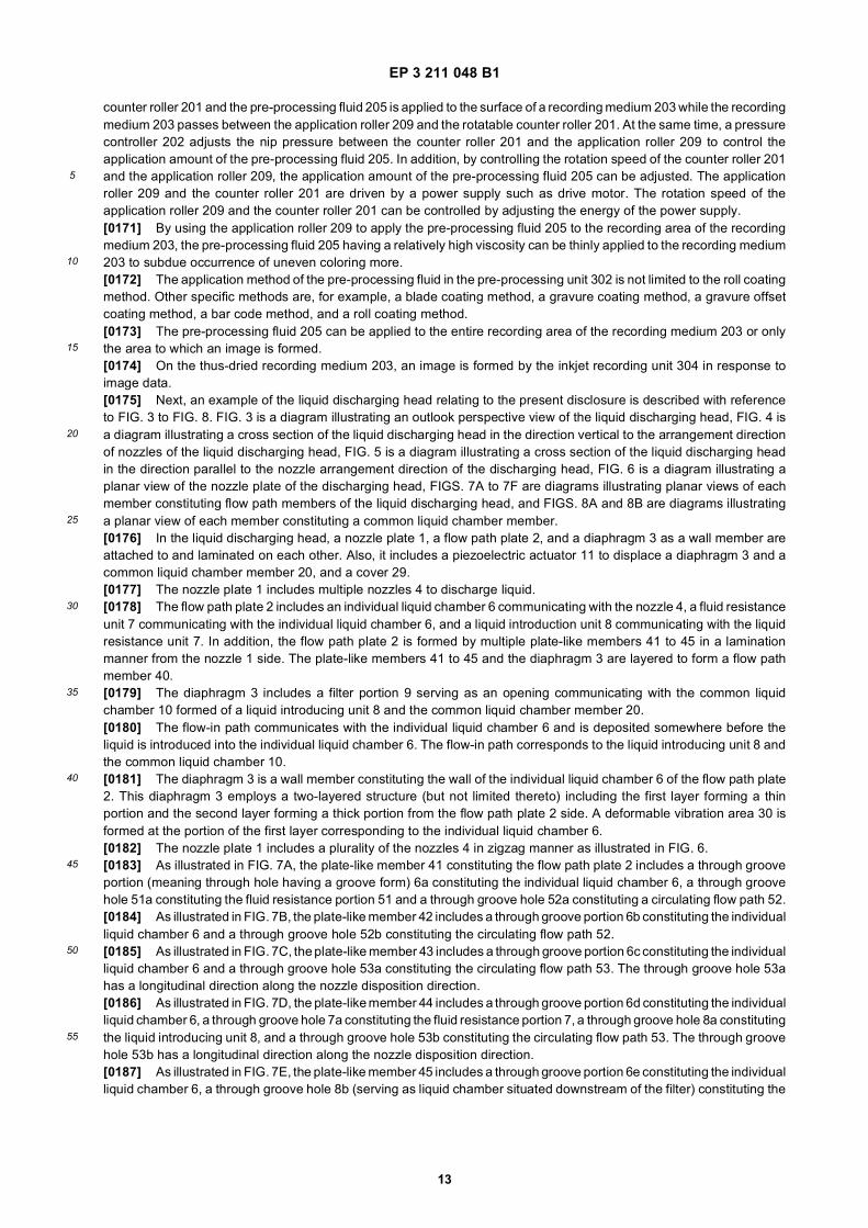
When non-white ink and white ink are discharged to a substrate in this sequence, the white ink forms undercoating ifviewed from the image surface onto which the non-white ink is discharged.[0155] The recording device includes the ink set of the present disclosure and a discharging head to discharge theink of the ink set.[0156] The ink discharging head preferably includes a nozzle to discharge the ink, a plurality of individual liquid cham-bers communicating with the nozzle, a flow-in path to flow the ink into the individual liquid chambers, a flow-out path toflow the ink out of the individual liquid chambers and a circulating device to circulate the ink from the flow-out path tothe flow-in path.[0157] The ink for use in the present disclosure can be suitably used for various printing devices employing an inkjetprinting method such as printers, facsimile machines, photocopiers, multifunction peripherals (serving as a printer, afacsimile machine, and a photocopier), and 3D object manufacturing devices (3D printers, additive manufacturing device).[0158] In the present disclosure, the recording device and the recording method respectively represent a devicecapable of attaching (applying) an ink and the surface treatment liquid composition of the present disclosure to a recording(print) medium and a method of printing an image on the print medium using the device. The print (recording) mediummeans an article to which the ink or the various processing fluids can be attached at least temporarily.[0159] The recording device may further optionally include a device relating to sheet (print medium) feeding, conveying,and ejecting the print medium and other devices referred to as a pre-processing device, a post-processing device, etc.in addition to the device to attach the surface treatment liquid composition and the head portion to discharge the ink.[0160] The recording device and the recording method may further optionally include a heater for use in the heatingprocess and a drier for use in the drying process. The heating device and the drying device include, for example, devicesto heat and dry the print surface and the reverse surface of a print medium. The heating device and the drying deviceare not particularly limited. For example, a fan heater and an infra-red heater can be used. The print medium can beheated and dried before, during, and after printing.[0161] In addition, the recording device and the recording method are not limited to those producing merely meaningfulvisible images such as texts and figures with the ink. For example, the recording device and the recording method canproduce patterns like geometric design and 3D images.[0162] In addition, the recording device includes both a serial type device in which the liquid discharging head is causedto move and a line type device in which the liquid discharging head is not moved, unless otherwise specified.[0163] Furthermore, in addition to the desktop type, this recording device includes a device capable of printing imageson a large print medium such as A0, a continuous printer capable of using continuous paper reeled up in a roll form asrecording media.[0164] The recording device of the present disclosure is described using an example with reference to FIG. 1 and FIG. 2.[0165] FIG. 1 is a diagram illustrating a perspective view of the recording device. FIG. 2 is a diagram illustrating aperspective view of the main tank. An image forming apparatus 400 as an example of the recording (printing) device isa serial type image forming apparatus. A mechanical unit 420 is disposed in a housing 401 of the image forming apparatus400. Also, the image forming apparatus 400 includes a pre-processing device to apply the surface treatment liquidcomposition of the present disclosure. Each ink accommodating unit (ink container) 411 of each main tank 410 (410k,410c, 410m, and 410y) for each color of black (K), cyan (C), magenta (M), and yellow (Y) is made of a packaging membersuch as aluminum laminate film. The ink container 411 is, for example, accommodated in a plastic housing unit 414. Asa result, the main tank 410 is used as an ink cartridge of each color.[0166] Although black (K), cyan (C), magenta (M), and yellow (Y) are used in this description, it is possible to usewhite instead of at least one of black (K), cyan (C), magenta (M), and yellow (Y) or add white ink to black (K), cyan (C),magenta (M), and yellow (Y).[0167] A cartridge holder 404 is disposed on the rear side of the opening when a cover 401c is opened. The cartridgeholder 404 is detachably attachable to the main tank 410. As a result, each ink discharging outlet 413 of the main tank410 communicates with a discharging head 434 for each color via a supplying tube 436 for each color so that the inkcan be discharged from the discharging head 434 to a print (recording) medium.[0168] A device to form images with ink after applying the surface treatment liquid composition of the present disclosureas a pre-processing fluid to a substrate is described with reference to FIG. 10. FIG. 10 is a diagram illustrating an exampleof the inkjet recording device scanning an inkjet recording head to form images.[0169] In the device of FIG. 10, a substrate 6 is sent out by a sheet feeding roller 7 and an application roller 4 and acounter roller 5 thinly and evenly apply a pre-processing fluid 1 to the substrate 6. The pre-processing fluid 1 is drawnup by a draw-up roller 3 and evenly applied to the application roller 4 by a layer thickness regulating roller 2. The substrate6 to which the pre-processing fluid is applied is sent to a recording scanning unit including an inkjet recording head 20.[0170] FIG. 11 is another example of the pre-processing unit. The pre-processing unit illustrated in FIG. 11 accom-modates a pre-processing fluid 205 in a pre-processing fluid container 204. In this unit, a thin film of the pre-processingfluid 205 is formed on the surface of an application roller 209 by a stirring and supplying roller 206, a conveying roller207, and a thin film forming roller 208. Thereafter, the application roller 209 rotates while being pressed against a rotatable
EP 3 211 048 B1
13
5
10
15
20
25
30
35
40
45
50
55
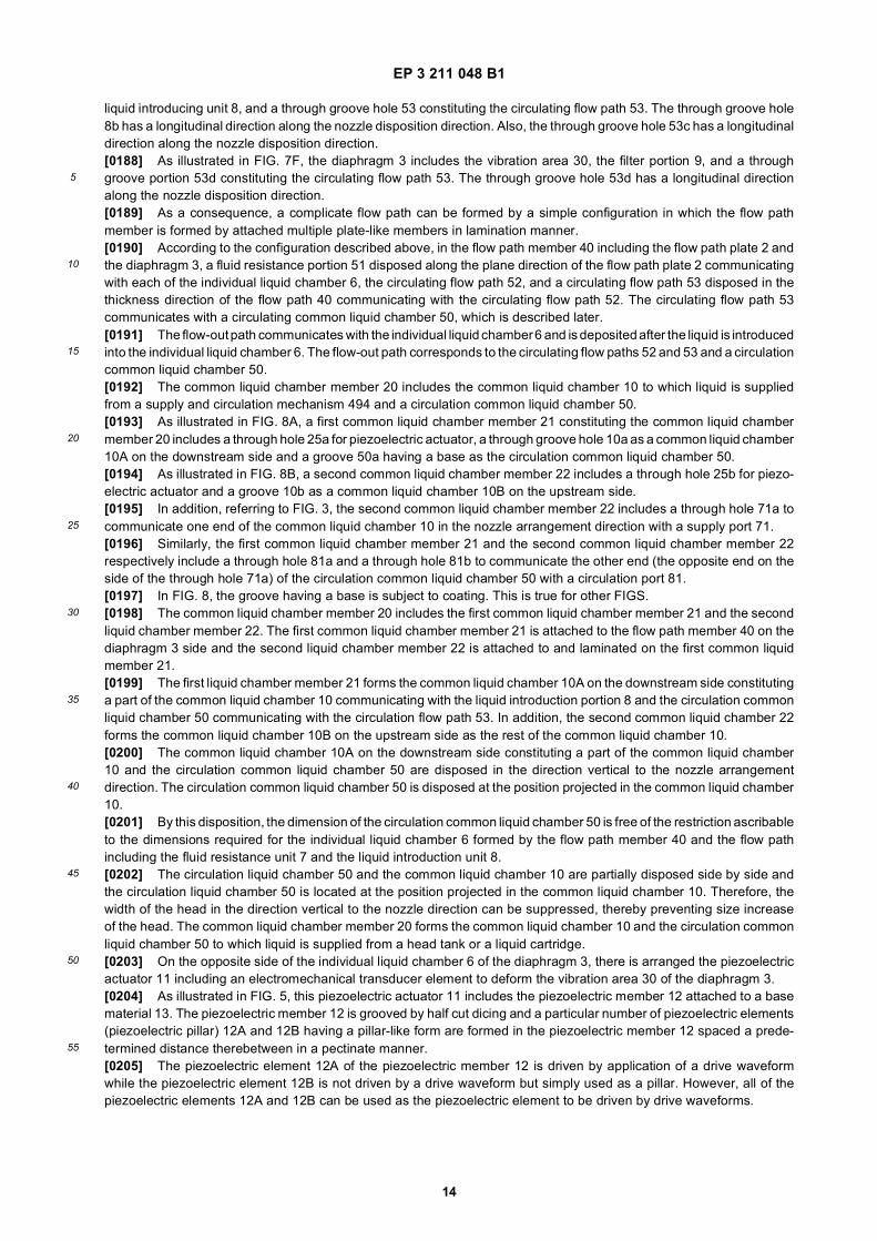
counter roller 201 and the pre-processing fluid 205 is applied to the surface of a recording medium 203 while the recordingmedium 203 passes between the application roller 209 and the rotatable counter roller 201. At the same time, a pressurecontroller 202 adjusts the nip pressure between the counter roller 201 and the application roller 209 to control theapplication amount of the pre-processing fluid 205. In addition, by controlling the rotation speed of the counter roller 201and the application roller 209, the application amount of the pre-processing fluid 205 can be adjusted. The applicationroller 209 and the counter roller 201 are driven by a power supply such as drive motor. The rotation speed of theapplication roller 209 and the counter roller 201 can be controlled by adjusting the energy of the power supply.[0171] By using the application roller 209 to apply the pre-processing fluid 205 to the recording area of the recordingmedium 203, the pre-processing fluid 205 having a relatively high viscosity can be thinly applied to the recording medium203 to subdue occurrence of uneven coloring more.[0172] The application method of the pre-processing fluid in the pre-processing unit 302 is not limited to the roll coatingmethod. Other specific methods are, for example, a blade coating method, a gravure coating method, a gravure offsetcoating method, a bar code method, and a roll coating method.[0173] The pre-processing fluid 205 can be applied to the entire recording area of the recording medium 203 or onlythe area to which an image is formed.[0174] On the thus-dried recording medium 203, an image is formed by the inkjet recording unit 304 in response toimage data.[0175] Next, an example of the liquid discharging head relating to the present disclosure is described with referenceto FIG. 3 to FIG. 8. FIG. 3 is a diagram illustrating an outlook perspective view of the liquid discharging head, FIG. 4 isa diagram illustrating a cross section of the liquid discharging head in the direction vertical to the arrangement directionof nozzles of the liquid discharging head, FIG. 5 is a diagram illustrating a cross section of the liquid discharging headin the direction parallel to the nozzle arrangement direction of the discharging head, FIG. 6 is a diagram illustrating aplanar view of the nozzle plate of the discharging head, FIGS. 7A to 7F are diagrams illustrating planar views of eachmember constituting flow path members of the liquid discharging head, and FIGS. 8A and 8B are diagrams illustratinga planar view of each member constituting a common liquid chamber member.[0176] In the liquid discharging head, a nozzle plate 1, a flow path plate 2, and a diaphragm 3 as a wall member areattached to and laminated on each other. Also, it includes a piezoelectric actuator 11 to displace a diaphragm 3 and acommon liquid chamber member 20, and a cover 29.[0177] The nozzle plate 1 includes multiple nozzles 4 to discharge liquid.[0178] The flow path plate 2 includes an individual liquid chamber 6 communicating with the nozzle 4, a fluid resistanceunit 7 communicating with the individual liquid chamber 6, and a liquid introduction unit 8 communicating with the liquidresistance unit 7. In addition, the flow path plate 2 is formed by multiple plate-like members 41 to 45 in a laminationmanner from the nozzle 1 side. The plate-like members 41 to 45 and the diaphragm 3 are layered to form a flow pathmember 40.[0179] The diaphragm 3 includes a filter portion 9 serving as an opening communicating with the common liquidchamber 10 formed of a liquid introducing unit 8 and the common liquid chamber member 20.[0180] The flow-in path communicates with the individual liquid chamber 6 and is deposited somewhere before theliquid is introduced into the individual liquid chamber 6. The flow-in path corresponds to the liquid introducing unit 8 andthe common liquid chamber 10.[0181] The diaphragm 3 is a wall member constituting the wall of the individual liquid chamber 6 of the flow path plate2. This diaphragm 3 employs a two-layered structure (but not limited thereto) including the first layer forming a thinportion and the second layer forming a thick portion from the flow path plate 2 side. A deformable vibration area 30 isformed at the portion of the first layer corresponding to the individual liquid chamber 6.[0182] The nozzle plate 1 includes a plurality of the nozzles 4 in zigzag manner as illustrated in FIG. 6.[0183] As illustrated in FIG. 7A, the plate-like member 41 constituting the flow path plate 2 includes a through grooveportion (meaning through hole having a groove form) 6a constituting the individual liquid chamber 6, a through groovehole 51a constituting the fluid resistance portion 51 and a through groove hole 52a constituting a circulating flow path 52.[0184] As illustrated in FIG. 7B, the plate-like member 42 includes a through groove portion 6b constituting the individualliquid chamber 6 and a through groove hole 52b constituting the circulating flow path 52.[0185] As illustrated in FIG. 7C, the plate-like member 43 includes a through groove portion 6c constituting the individualliquid chamber 6 and a through groove hole 53a constituting the circulating flow path 53. The through groove hole 53ahas a longitudinal direction along the nozzle disposition direction.[0186] As illustrated in FIG. 7D, the plate-like member 44 includes a through groove portion 6d constituting the individualliquid chamber 6, a through groove hole 7a constituting the fluid resistance portion 7, a through groove hole 8a constitutingthe liquid introducing unit 8, and a through groove hole 53b constituting the circulating flow path 53. The through groovehole 53b has a longitudinal direction along the nozzle disposition direction.[0187] As illustrated in FIG. 7E, the plate-like member 45 includes a through groove portion 6e constituting the individualliquid chamber 6, a through groove hole 8b (serving as liquid chamber situated downstream of the filter) constituting the
EP 3 211 048 B1
14
5
10
15
20
25
30
35
40
45
50
55
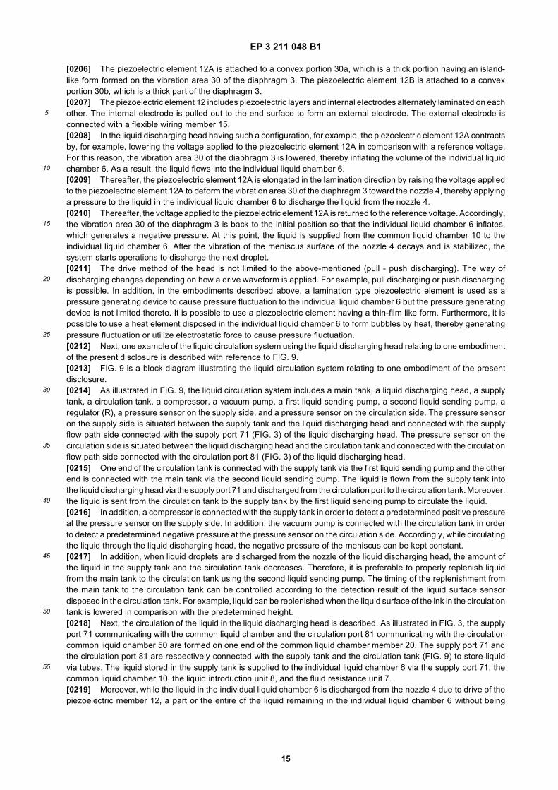
liquid introducing unit 8, and a through groove hole 53 constituting the circulating flow path 53. The through groove hole8b has a longitudinal direction along the nozzle disposition direction. Also, the through groove hole 53c has a longitudinaldirection along the nozzle disposition direction.[0188] As illustrated in FIG. 7F, the diaphragm 3 includes the vibration area 30, the filter portion 9, and a throughgroove portion 53d constituting the circulating flow path 53. The through groove hole 53d has a longitudinal directionalong the nozzle disposition direction.[0189] As a consequence, a complicate flow path can be formed by a simple configuration in which the flow pathmember is formed by attached multiple plate-like members in lamination manner.[0190] According to the configuration described above, in the flow path member 40 including the flow path plate 2 andthe diaphragm 3, a fluid resistance portion 51 disposed along the plane direction of the flow path plate 2 communicatingwith each of the individual liquid chamber 6, the circulating flow path 52, and a circulating flow path 53 disposed in thethickness direction of the flow path 40 communicating with the circulating flow path 52. The circulating flow path 53communicates with a circulating common liquid chamber 50, which is described later.[0191] The flow-out path communicates with the individual liquid chamber 6 and is deposited after the liquid is introducedinto the individual liquid chamber 6. The flow-out path corresponds to the circulating flow paths 52 and 53 and a circulationcommon liquid chamber 50.[0192] The common liquid chamber member 20 includes the common liquid chamber 10 to which liquid is suppliedfrom a supply and circulation mechanism 494 and a circulation common liquid chamber 50.[0193] As illustrated in FIG. 8A, a first common liquid chamber member 21 constituting the common liquid chambermember 20 includes a through hole 25a for piezoelectric actuator, a through groove hole 10a as a common liquid chamber10A on the downstream side and a groove 50a having a base as the circulation common liquid chamber 50.[0194] As illustrated in FIG. 8B, a second common liquid chamber member 22 includes a through hole 25b for piezo-electric actuator and a groove 10b as a common liquid chamber 10B on the upstream side.[0195] In addition, referring to FIG. 3, the second common liquid chamber member 22 includes a through hole 71a tocommunicate one end of the common liquid chamber 10 in the nozzle arrangement direction with a supply port 71.[0196] Similarly, the first common liquid chamber member 21 and the second common liquid chamber member 22respectively include a through hole 81a and a through hole 81b to communicate the other end (the opposite end on theside of the through hole 71a) of the circulation common liquid chamber 50 with a circulation port 81.[0197] In FIG. 8, the groove having a base is subject to coating. This is true for other FIGS.[0198] The common liquid chamber member 20 includes the first common liquid chamber member 21 and the secondliquid chamber member 22. The first common liquid chamber member 21 is attached to the flow path member 40 on thediaphragm 3 side and the second liquid chamber member 22 is attached to and laminated on the first common liquidmember 21.[0199] The first liquid chamber member 21 forms the common liquid chamber 10A on the downstream side constitutinga part of the common liquid chamber 10 communicating with the liquid introduction portion 8 and the circulation commonliquid chamber 50 communicating with the circulation flow path 53. In addition, the second common liquid chamber 22forms the common liquid chamber 10B on the upstream side as the rest of the common liquid chamber 10.[0200] The common liquid chamber 10A on the downstream side constituting a part of the common liquid chamber10 and the circulation common liquid chamber 50 are disposed in the direction vertical to the nozzle arrangementdirection. The circulation common liquid chamber 50 is disposed at the position projected in the common liquid chamber10.[0201] By this disposition, the dimension of the circulation common liquid chamber 50 is free of the restriction ascribableto the dimensions required for the individual liquid chamber 6 formed by the flow path member 40 and the flow pathincluding the fluid resistance unit 7 and the liquid introduction unit 8.[0202] The circulation liquid chamber 50 and the common liquid chamber 10 are partially disposed side by side andthe circulation liquid chamber 50 is located at the position projected in the common liquid chamber 10. Therefore, thewidth of the head in the direction vertical to the nozzle direction can be suppressed, thereby preventing size increaseof the head. The common liquid chamber member 20 forms the common liquid chamber 10 and the circulation commonliquid chamber 50 to which liquid is supplied from a head tank or a liquid cartridge.[0203] On the opposite side of the individual liquid chamber 6 of the diaphragm 3, there is arranged the piezoelectricactuator 11 including an electromechanical transducer element to deform the vibration area 30 of the diaphragm 3.[0204] As illustrated in FIG. 5, this piezoelectric actuator 11 includes the piezoelectric member 12 attached to a basematerial 13. The piezoelectric member 12 is grooved by half cut dicing and a particular number of piezoelectric elements(piezoelectric pillar) 12A and 12B having a pillar-like form are formed in the piezoelectric member 12 spaced a prede-termined distance therebetween in a pectinate manner.[0205] The piezoelectric element 12A of the piezoelectric member 12 is driven by application of a drive waveformwhile the piezoelectric element 12B is not driven by a drive waveform but simply used as a pillar. However, all of thepiezoelectric elements 12A and 12B can be used as the piezoelectric element to be driven by drive waveforms.
EP 3 211 048 B1
15
5
10
15
20
25
30
35
40
45
50
55
[0206] The piezoelectric element 12A is attached to a convex portion 30a, which is a thick portion having an island-like form formed on the vibration area 30 of the diaphragm 3. The piezoelectric element 12B is attached to a convexportion 30b, which is a thick part of the diaphragm 3.[0207] The piezoelectric element 12 includes piezoelectric layers and internal electrodes alternately laminated on eachother. The internal electrode is pulled out to the end surface to form an external electrode. The external electrode isconnected with a flexible wiring member 15.[0208] In the liquid discharging head having such a configuration, for example, the piezoelectric element 12A contractsby, for example, lowering the voltage applied to the piezoelectric element 12A in comparison with a reference voltage.For this reason, the vibration area 30 of the diaphragm 3 is lowered, thereby inflating the volume of the individual liquidchamber 6. As a result, the liquid flows into the individual liquid chamber 6.[0209] Thereafter, the piezoelectric element 12A is elongated in the lamination direction by raising the voltage appliedto the piezoelectric element 12A to deform the vibration area 30 of the diaphragm 3 toward the nozzle 4, thereby applyinga pressure to the liquid in the individual liquid chamber 6 to discharge the liquid from the nozzle 4.[0210] Thereafter, the voltage applied to the piezoelectric element 12A is returned to the reference voltage. Accordingly,the vibration area 30 of the diaphragm 3 is back to the initial position so that the individual liquid chamber 6 inflates,which generates a negative pressure. At this point, the liquid is supplied from the common liquid chamber 10 to theindividual liquid chamber 6. After the vibration of the meniscus surface of the nozzle 4 decays and is stabilized, thesystem starts operations to discharge the next droplet.[0211] The drive method of the head is not limited to the above-mentioned (pull - push discharging). The way ofdischarging changes depending on how a drive waveform is applied. For example, pull discharging or push dischargingis possible. In addition, in the embodiments described above, a lamination type piezoelectric element is used as apressure generating device to cause pressure fluctuation to the individual liquid chamber 6 but the pressure generatingdevice is not limited thereto. It is possible to use a piezoelectric element having a thin-film like form. Furthermore, it ispossible to use a heat element disposed in the individual liquid chamber 6 to form bubbles by heat, thereby generatingpressure fluctuation or utilize electrostatic force to cause pressure fluctuation.[0212] Next, one example of the liquid circulation system using the liquid discharging head relating to one embodimentof the present disclosure is described with reference to FIG. 9.[0213] FIG. 9 is a block diagram illustrating the liquid circulation system relating to one embodiment of the presentdisclosure.[0214] As illustrated in FIG. 9, the liquid circulation system includes a main tank, a liquid discharging head, a supplytank, a circulation tank, a compressor, a vacuum pump, a first liquid sending pump, a second liquid sending pump, aregulator (R), a pressure sensor on the supply side, and a pressure sensor on the circulation side. The pressure sensoron the supply side is situated between the supply tank and the liquid discharging head and connected with the supplyflow path side connected with the supply port 71 (FIG. 3) of the liquid discharging head. The pressure sensor on thecirculation side is situated between the liquid discharging head and the circulation tank and connected with the circulationflow path side connected with the circulation port 81 (FIG. 3) of the liquid discharging head.[0215] One end of the circulation tank is connected with the supply tank via the first liquid sending pump and the otherend is connected with the main tank via the second liquid sending pump. The liquid is flown from the supply tank intothe liquid discharging head via the supply port 71 and discharged from the circulation port to the circulation tank. Moreover,the liquid is sent from the circulation tank to the supply tank by the first liquid sending pump to circulate the liquid.[0216] In addition, a compressor is connected with the supply tank in order to detect a predetermined positive pressureat the pressure sensor on the supply side. In addition, the vacuum pump is connected with the circulation tank in orderto detect a predetermined negative pressure at the pressure sensor on the circulation side. Accordingly, while circulatingthe liquid through the liquid discharging head, the negative pressure of the meniscus can be kept constant.[0217] In addition, when liquid droplets are discharged from the nozzle of the liquid discharging head, the amount ofthe liquid in the supply tank and the circulation tank decreases. Therefore, it is preferable to properly replenish liquidfrom the main tank to the circulation tank using the second liquid sending pump. The timing of the replenishment fromthe main tank to the circulation tank can be controlled according to the detection result of the liquid surface sensordisposed in the circulation tank. For example, liquid can be replenished when the liquid surface of the ink in the circulationtank is lowered in comparison with the predetermined height.[0218] Next, the circulation of the liquid in the liquid discharging head is described. As illustrated in FIG. 3, the supplyport 71 communicating with the common liquid chamber and the circulation port 81 communicating with the circulationcommon liquid chamber 50 are formed on one end of the common liquid chamber member 20. The supply port 71 andthe circulation port 81 are respectively connected with the supply tank and the circulation tank (FIG. 9) to store liquidvia tubes. The liquid stored in the supply tank is supplied to the individual liquid chamber 6 via the supply port 71, thecommon liquid chamber 10, the liquid introduction unit 8, and the fluid resistance unit 7.[0219] Moreover, while the liquid in the individual liquid chamber 6 is discharged from the nozzle 4 due to drive of thepiezoelectric member 12, a part or the entire of the liquid remaining in the individual liquid chamber 6 without being
EP 3 211 048 B1
16
5
10
15
20
25
30
35
40
45
50
55
discharged is circulated from the fluid resistance unit 51, the circulation flow paths 52 and 53, the circulation commonliquid chamber 50, and the circulation port 81 to the circulation tank.[0220] The liquid can be circulated during not only the operation of the liquid discharging head but also waiting time.Circulating the liquid during waiting time is preferable because the liquid in the individual liquid chamber is constantlyrefreshed and agglomeration or sedimentation of the component contained in the liquid can be suppressed.[0221] Furthermore, a restoring device can be disposed to restore the head from defective discharging. The restoringdevice has a capping device, a suction device, and a cleaning device. The head is moved toward this restoring devicewhile standing by for printing and the head is capped by the capping device to keep the discharging orifice in a wet stateto prevent defective discharging ascribable to ink drying. Moreover, by jetting ink having nothing to do with recording inthe middle of recording, ink viscosity in all the discharging orifices is kept even to stabilize discharging performance.[0222] When defective discharging occurs, the nozzle orifice of the head is sealed by the capping device, air bubbles,etc. is suctioned from the nozzles via a tube together with ink by the suction device, so that the ink and dirts attachedto the nozzle surface is removed by the cleaning device, resulting in restoring the nozzles from defective discharging.Moreover, the ink suctioned is ejected to a waste ink storage disposed on the bottom of the printer (image formingapparatus) and absorbed and held in an ink absorbent inside the waste ink storage.[0223] This recording device may include not only a portion discharging ink but also a pre-processing device to applythe liquid component of the present disclosure as the pre-processing fluid and a post-processing device as referred toas a post-processing device.[0224] As an example of the pre-processing device and the post-processing device, as in the case of the ink such asblack (K), cyan (C), magenta (M), and yellow (Y), a liquid container containing a pre-processing fluid or a post-processingfluid and a liquid discharging head are added to discharge the pre-processing fluid or the post-processing fluid in aninkjet printing method.[0225] As another example of the pre-processing device and the post-processing device, it is suitable to dispose apre-processing device and a post-processing device employing a blade coating method, a roll coating method, or aspray coating method other than the inkjet printing method.[0226] How to use the ink is not limited to the inkjet printing method. Specific examples of such methods other thanthe inkjet printing method include, but are not limited to, blade coating methods, gravure coating methods, bar coatingmethods, roll coating methods, dip coating methods, curtain coating methods, slide coating methods, die coating methods,and spray coating methods.
Ink Cartridge
[0227] It is also possible to include a cartridge including a container to accommodate the surface treatment liquidcomposition of the present disclosure and other optional members.[0228] There is no specific limit to the container. Any form, any structure, any size, and any material can be suitablyselected. For example, a container including at least an accommodating portion formed of aluminum laminate film, aresin film, etc. can be suitably used.
Printed Matter
[0229] The printed matter relating to the present disclosure includes an image thereon using the recording method ofthe present disclosure.[0230] Having generally described preferred embodiments of this invention, further understanding can be obtained byreference to certain specific examples which are provided herein for the purpose of illustration only and are not intendedto be limiting. In the descriptions in the following examples, the numbers represent weight ratios in parts, unless otherwisespecified.
EXAMPLES
[0231] Next, the present disclosure is described in detail with reference to Examples but is not limited thereto.[0232] Next, the present disclosure is described in detail with reference to Examples and Comparative Examples butnot limited thereto.
Preparation of Emulsion of Nonionic Resin Particle
Preparation of Ethylene Vinyl Acetate Resin Emulsion A
[0233] 1,061 g of PVA-1 (degree of polymerization: 1,700, degree of saponification: 88 mol percent, manufactured by
EP 3 211 048 B1
17
5
10
15
20
25
30
35
40
45
50
55
KURARAY CO., LTD.), 19,440 g of deionized water, 12.7 g of L(+) sodium tartrate, 10.6 g of sodium acetate, and 0.4g of iron chloride were charged in a pressure resistant 50 litter autoclave equipped with a nitrogen introducing opening,a thermometer, and a stirrer. The recipe was completely dissolved at 95 degrees C and thereafter cooled down to 60degrees C followed by nitrogen replacement.[0234] Next, 22,360 g of vinyl acetate was added and ethylene was pressurized to 45 kg/cm2 and introduced. 1,000g of 0.4 percent aqueous solution of hydrogen peroxide was injected in five hours to conduct emulsion polymerizationat 60 degrees C.[0235] When pH at the initial stage of the polymerization was checked, it was 5.2[0236] When the remaining amount of vinyl acetate became 10 percent, ethylene was discharged to adjust the ethylenepressure to be 20 kg/cm2 and 50 g of 3 percent aqueous solution of hydrogen peroxide was injected in to continuepolymerization.[0237] When the amount of vinyl monomer remaining in the emulsion became 1.5 percent, ethylene was dischargedand cooled down.[0238] Subsequent to cooling down, pH was checked. It was 4.8 Thereafter, 20 g of sodium sulfite was added andthe resultant was subject to de-ethylenization for one hour at 30 degrees C with a reduced pressure of 100 mmHg.[0239] The system was returned to atmospheric pressure by nitrogen and thereafter, 10 g of t-butylhydroperoxide wasadded followed by stirring for two hours.[0240] When pH at the completion of the polymerization was checked, it was 4.7[0241] The thus-obtained emulsion was filtered and the solid portion was adjusted to be 50 percent to obtain a resinemulsion A of copolymer of ethylene-vinyl acetate.[0242] When Tg of the resin emulsion A was measured by a differential scanning calorimetry (thermo plus EVO2/DSC,manufactured by Rigaku Corporation), it was zero degree.
Preparation of Urethane Resin Emulsion A
[0243] To 1 mol of 1,6-hexanediol, 1.4 mol of dicyclohexylmethane isocyanate, 0.1 mol of diisocyanate compoundprepared by reacting 1 mol of isocyanulate trimer of 1,6-hexamethylene diisocyanate with 1/3 mol of polyethylene glycolmonomethylether having a molecular weight of 1,000, N-methyl-2-pyrolidone accounting for 15 percent for the total masswere placed in a reaction flask to conduct reaction for two hours at 90 degrees C in nitrogen atmosphere to obtain aprepolymer.[0244] 450 g of the-thus obtained prepolymer composition having a solid portion of 85 percent was dripped in 15minutes to 600 g of water in which 0.2 g of silicone-based defoaming agent (SE-21, manufactured by Wacker AsahikaseiSilicone co., ltd.). Subsequent to ten-minute stirring at 25 degrees C, the compound represented by the following Chemicalformula 1, ethylene diamine, and hydrazide adipate to obtain a polyurethane resin emulsion A.
H2N-C3H6-Si-(OC2H5)3 Chemical Formula 1
[0245] When Tg of the polyurethane resin emulsion A was measured by a differential scanning calorimetry (Thermoplus EVO2/DSC, manufactured by Rigaku Corporation), it was 20 degrees C.
Preparation of Polyester Resin Emulsion A
[0246] First, 3.0 parts of hydroxyethyl cellulose (METOLOSE 60SH-50, manufactured by Shin-Etsu Chemical Co.,Ltd.) and 30 parts of nonionic emulsifier (EMULGEN 1108, manufactured by Kao Corporation) were preliminarily dissolvedin 225 parts of water in solid portion conversion to prepare an emulsifier aqueous solution.[0247] Thereafter, 150 parts of amorphous poly-lactic acid (VYLOECOL BE-450, manufactured by TOYOBO CO.,LTD.) was dissolved in 300 parts of toluene in a reaction container equipped with a thermometer, a nitrogen introducingtube, a stirrer, and a condenser. The emulsifier aqueous solution obtained above was added to conduct preliminaryemulsification by stirring and mixing at 45 degrees C for 30 minutes.[0248] The thus-obtained preliminary emulsified matter was emulsified under a pressure of 300 kg/m2 by a highpressure emulsifying machine (Manton-Gaulin Company) to obtain a fine emulsified matter.[0249] This fine emulsified matter was heated and evaporated with a reduced pressure under 130 mmHg to removetoluene. Thereafter, a solid portion was prepared to obtain a polyester emulsion having a solid portion of 45 percent, apH of 2.4, and a particle diameter of 0.32 mm. Thereafter, the emulsion was prepared to have a pH of 7.0 by 25 percentammonium water.[0250] 0.6 parts of a thickening agent (PRIMAL™ ASE-60, manufactured by Rohm and Haas Electronic MaterialsK.K.) was added to the polyester emulsion to prepare the solid portion to be 40 percent to obtain a polyester resinemulsion A.
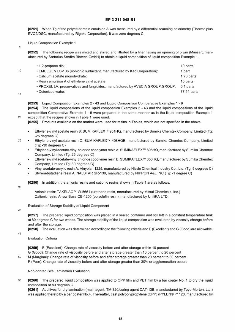
EP 3 211 048 B1
18
5
10
15
20
25
30
35
40
45
50
55
[0251] When Tg of the polyester resin emulsion A was measured by a differential scanning calorimetry (Thermo plusEVO2/DSC, manufactured by Rigaku Corporation), it was zero degrees C.
Liquid Composition Example 1
[0252] The following recipe was mixed and stirred and filtrated by a filter having an opening of 5 mm (Minisart, man-ufactured by Sartorius Stedim Biotech GmbH) to obtain a liquid composition of liquid composition Example 1.
[0253] Liquid Composition Examples 2 - 43 and Liquid Composition Comparative Examples 1 - 9[0254] The liquid compositions of the liquid composition Examples 2 - 43 and the liquid compositions of the liquidcomposition Comparative Example 1 - 9 were prepared in the same manner as in the liquid composition Example 1except that the recipes shown in Table 1 were used.[0255] Products available on the market were used for resins in Tables, which are not specified in the above.
• Ethylene-vinyl acetate resin B: SUMIKAFLEX™ 951HQ, manufactured by Sumika Chemtex Company, Limited (Tg:-25 degrees C)
• Ethylene-vinyl acetate resin C: SUMIKAFLEX™ 408HQE, manufactured by Sumika Chemtex Company, Limited(Tg: -30 degrees C)
• Ethylene-vinyl acetate-vinyl chloride copolymer resin A: SUMIKAFLEX™ 808HQ, manufactured by Sumika ChemtexCompany, Limited (Tg: 25 degrees C)
• Ethylene-vinyl acetate-vinyl chloride copolymer resin B: SUMIKAFLEX™ 850HQ, manufactured by Sumika ChemtexCompany, Limited (Tg: 30 degrees C)
• Vinyl acetate-acrylic resin A: Vinyblan 1225, manufactured by Nissin Chemical Industry Co., Ltd. (Tg: 9 degrees C)• Styrenebutadiene resin A: NALSTAR SR-130, manufactured by NIPPON A&L INC (Tg: -1 degree C)
[0256] In addition, the anionic resins and cationic resins shown in Table 1 are as follows.
Anionic resin: TAKELAC™ W-5661 (urethane resin, manufactured by Mitsui Chemicals, Inc.)Cationic resin: Arrow Base CB-1200 (polyolefin resin), manufactured by UnitiKA LTD.
Evaluation of Storage Stability of Liquid Component
[0257] The prepared liquid composition was placed in a sealed container and still left in a constant temperature tankat 80 degrees C for two weeks. The storage stability of the liquid composition was evaluated by viscosity change beforeand after the storage.[0258] The evaluation was determined according to the following criteria and E (Excellent) and G (Good) are allowable.
Evaluation Criteria
[0259] E (Excellent): Change rate of viscosity before and after storage within 10 percentG (Good): Change rate of viscosity before and after storage greater than 10 percent to 20 percentM (Marginal): Change rate of viscosity before and after storage greater than 20 percent to 30 percentP (Poor): Change rate of viscosity before and after storage greater than 30% or agglomeration occurs
Non-printed Site Lamination Evaluation
[0260] The prepared liquid composition was applied to OPP film and PET film by a bar coater No. 1 to dry the liquidcomposition at 80 degrees C.[0261] Additives for dry lamination (main agent: TM-320/curing agent CAT-13B, manufactured by Toyo-Morton, Ltd.)was applied thereto by a bar coater No.4. Thereafter, cast polypolypropylene (CPP) (PYLEN® P1128, manufactured by
• 1,2-propane diol: 10 parts• EMULGEN LS-106 (nonionic surfactant, manufactured by Kao Corporation): 1 part• Calcium acetate monohydrate: 1.76 parts• Resin emulsion A of ethylene vinyl acetate: 10 parts• PROXEL LV: preservatives and fungicides, manufactured by AVECIA GROUP:GROUP: 0.1 parts• Deionized water: 77.14 parts
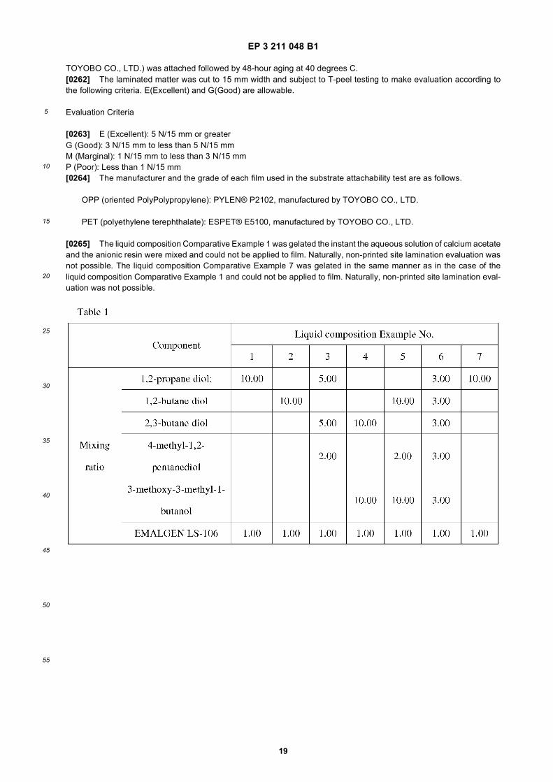
EP 3 211 048 B1
19
5
10
15
20
25
30
35
40
45
50
55
TOYOBO CO., LTD.) was attached followed by 48-hour aging at 40 degrees C.[0262] The laminated matter was cut to 15 mm width and subject to T-peel testing to make evaluation according tothe following criteria. E(Excellent) and G(Good) are allowable.
Evaluation Criteria
[0263] E (Excellent): 5 N/15 mm or greaterG (Good): 3 N/15 mm to less than 5 N/15 mmM (Marginal): 1 N/15 mm to less than 3 N/15 mmP (Poor): Less than 1 N/15 mm[0264] The manufacturer and the grade of each film used in the substrate attachability test are as follows.
OPP (oriented PolyPolypropylene): PYLEN® P2102, manufactured by TOYOBO CO., LTD.
PET (polyethylene terephthalate): ESPET® E5100, manufactured by TOYOBO CO., LTD.
[0265] The liquid composition Comparative Example 1 was gelated the instant the aqueous solution of calcium acetateand the anionic resin were mixed and could not be applied to film. Naturally, non-printed site lamination evaluation wasnot possible. The liquid composition Comparative Example 7 was gelated in the same manner as in the case of theliquid composition Comparative Example 1 and could not be applied to film. Naturally, non-printed site lamination eval-uation was not possible.
EP 3 211 048 B1
20
5
10
15
20
25
30
35
40
45
50
55
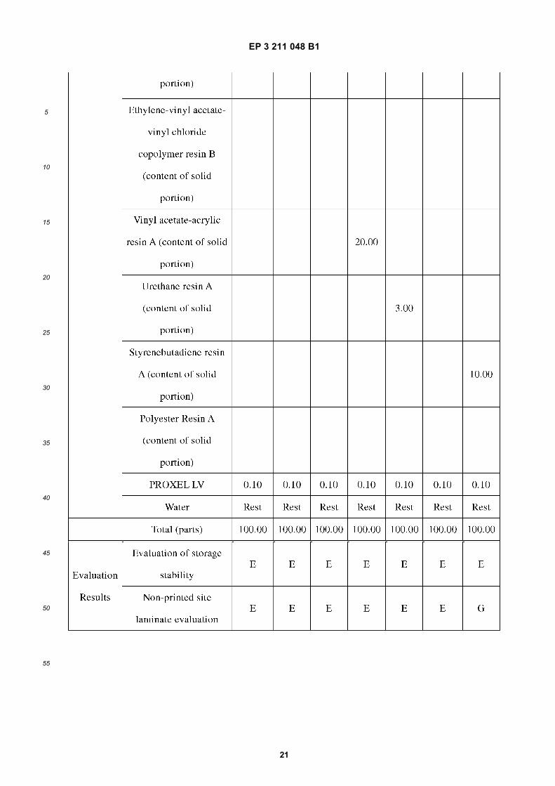
EP 3 211 048 B1
21
5
10
15
20
25
30
35
40
45
50
55
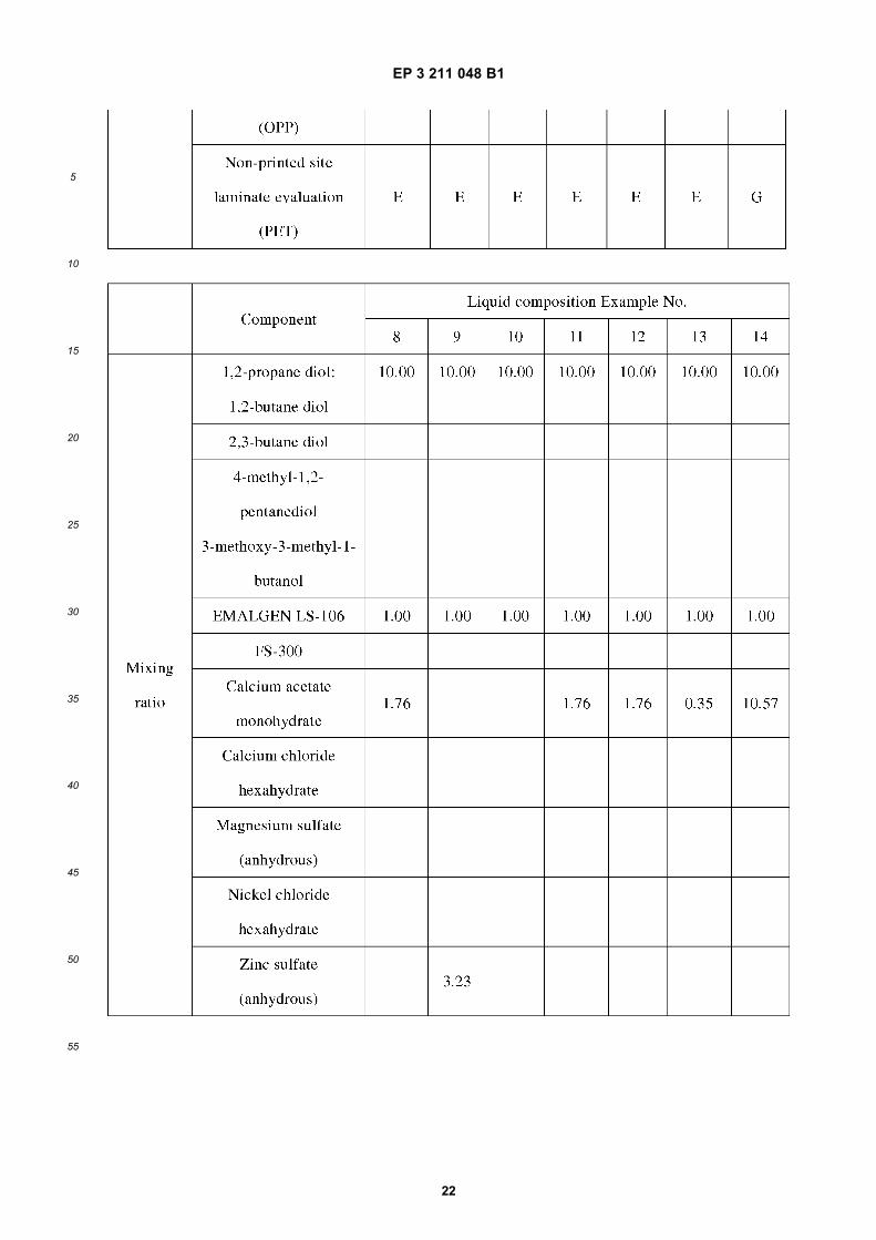
EP 3 211 048 B1
22
5
10
15
20
25
30
35
40
45
50
55
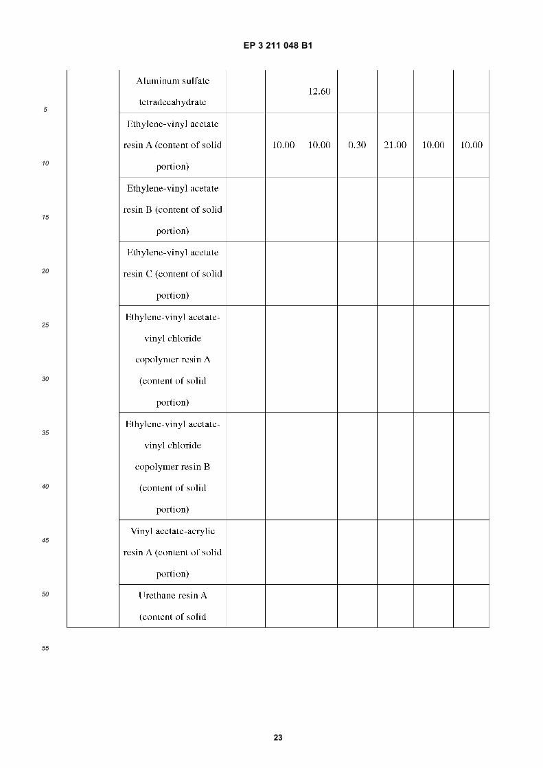
EP 3 211 048 B1
23
5
10
15
20
25
30
35
40
45
50
55
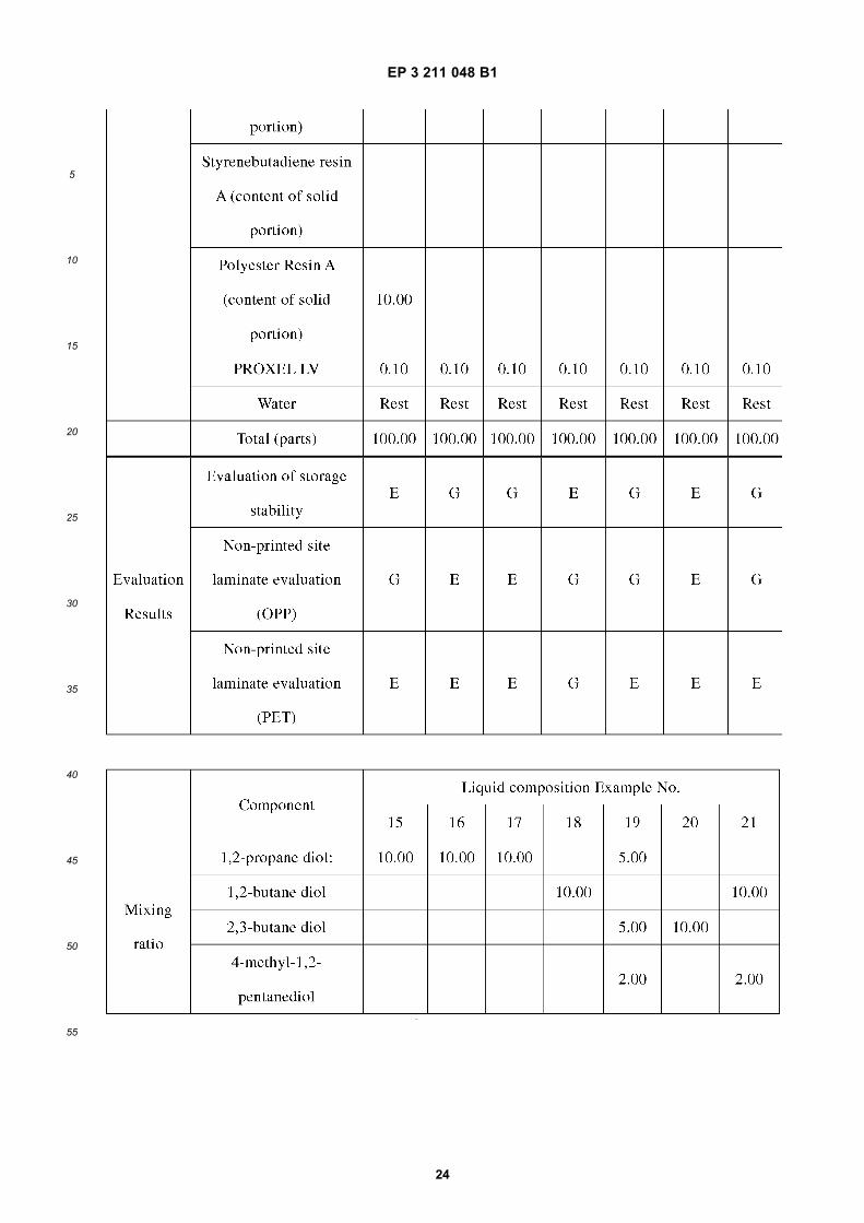
EP 3 211 048 B1
24
5
10
15
20
25
30
35
40
45
50
55
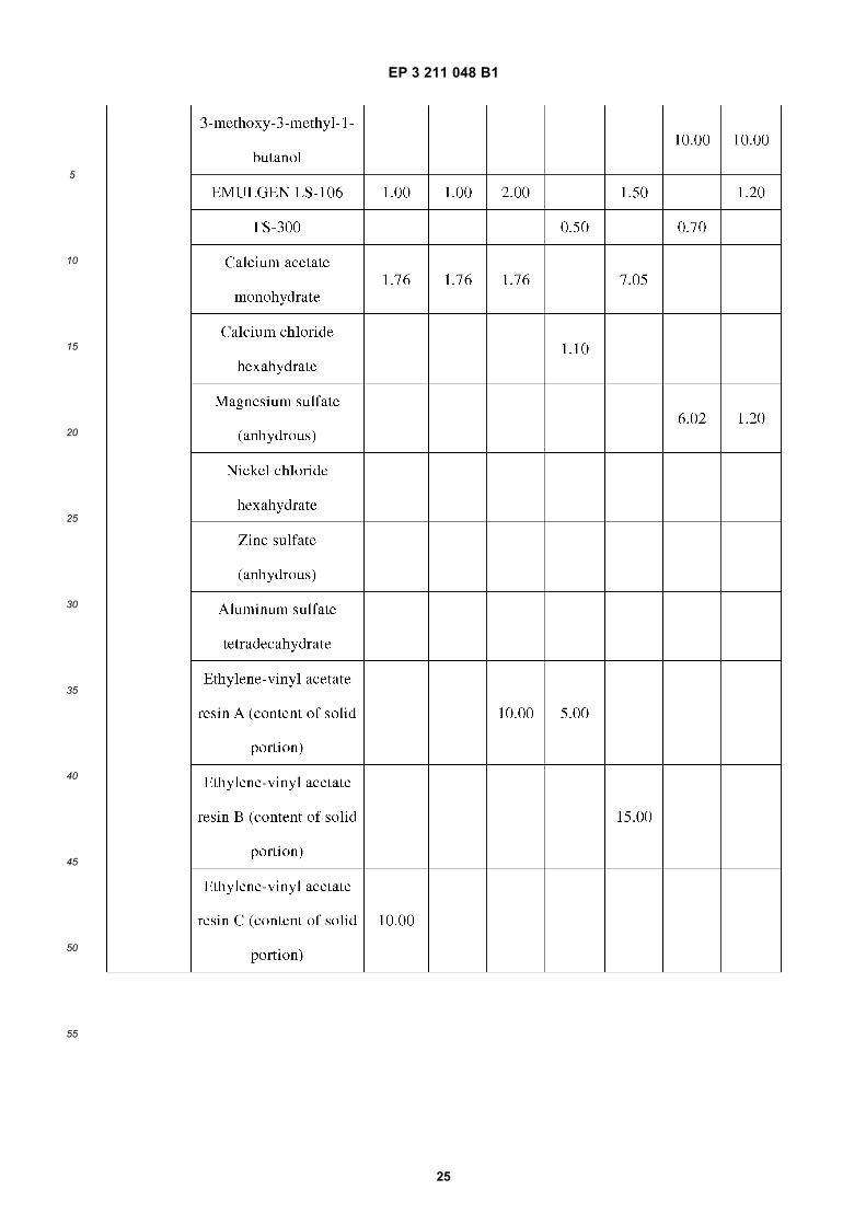
EP 3 211 048 B1
25
5
10
15
20
25
30
35
40
45
50
55
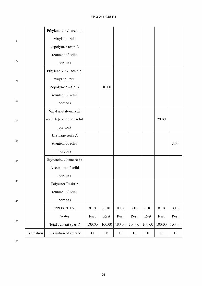
EP 3 211 048 B1
26
5
10
15
20
25
30
35
40
45
50
55
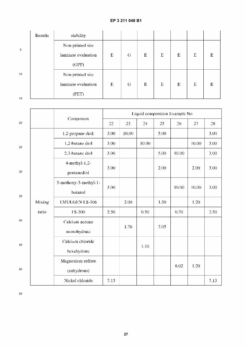
EP 3 211 048 B1
27
5
10
15
20
25
30
35
40
45
50
55
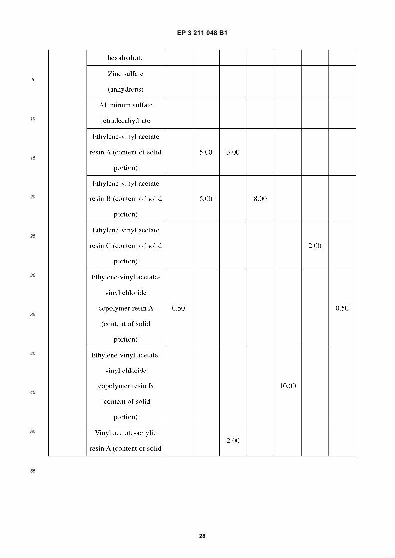
EP 3 211 048 B1
28
5
10
15
20
25
30
35
40
45
50
55
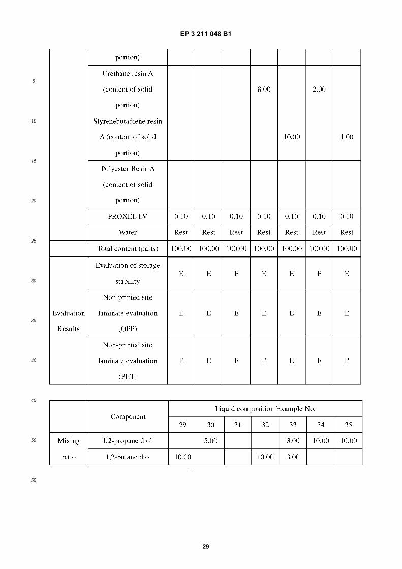
EP 3 211 048 B1
29
5
10
15
20
25
30
35
40
45
50
55
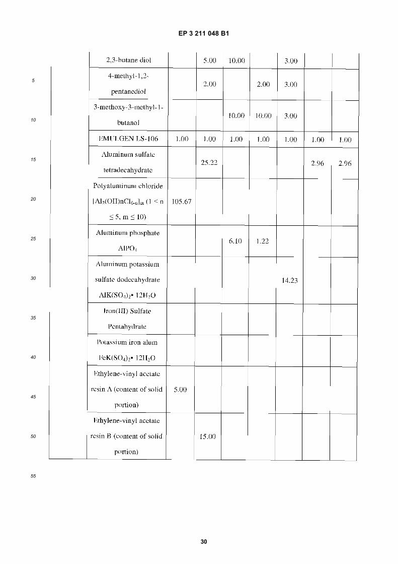
EP 3 211 048 B1
30
5
10
15
20
25
30
35
40
45
50
55
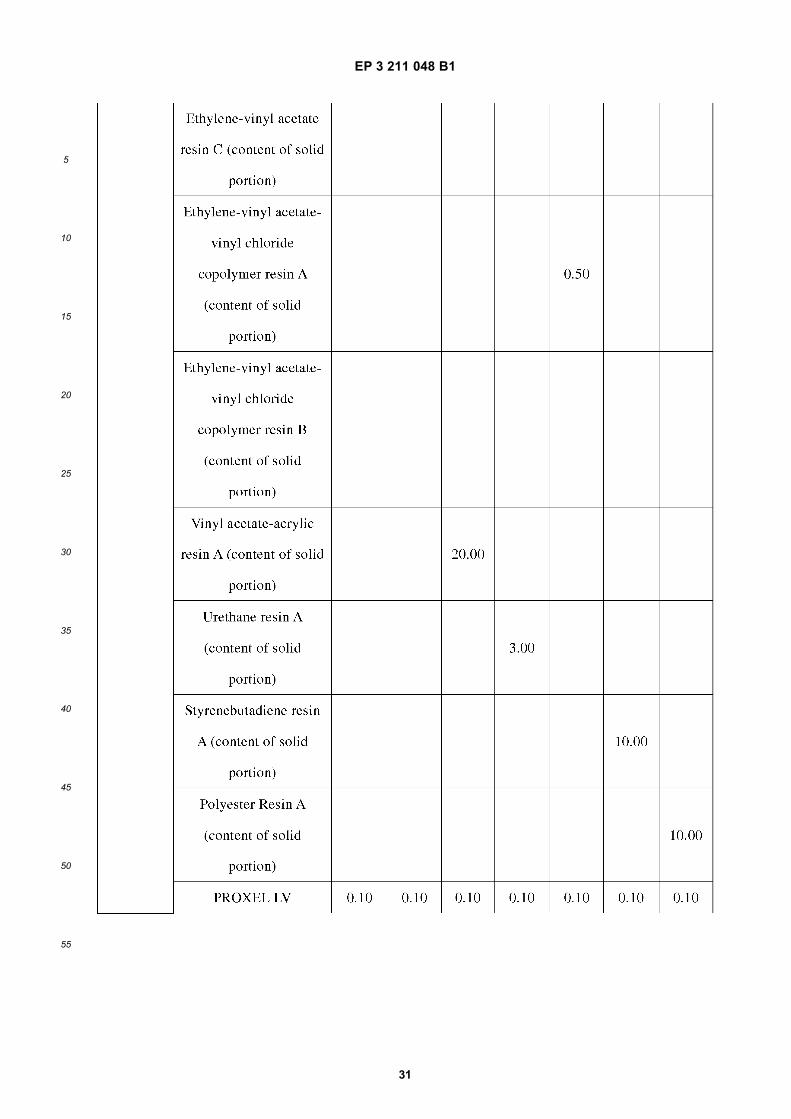
EP 3 211 048 B1
31
5
10
15
20
25
30
35
40
45
50
55
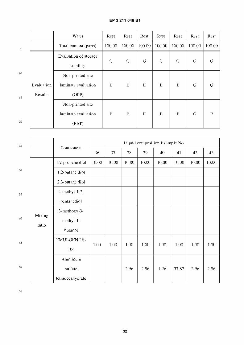
EP 3 211 048 B1
32
5
10
15
20
25
30
35
40
45
50
55
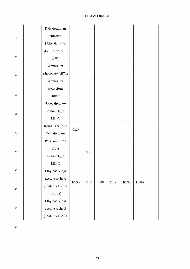
EP 3 211 048 B1
33
5
10
15
20
25
30
35
40
45
50
55

EP 3 211 048 B1
34
5
10
15
20
25
30
35
40
45
50
55
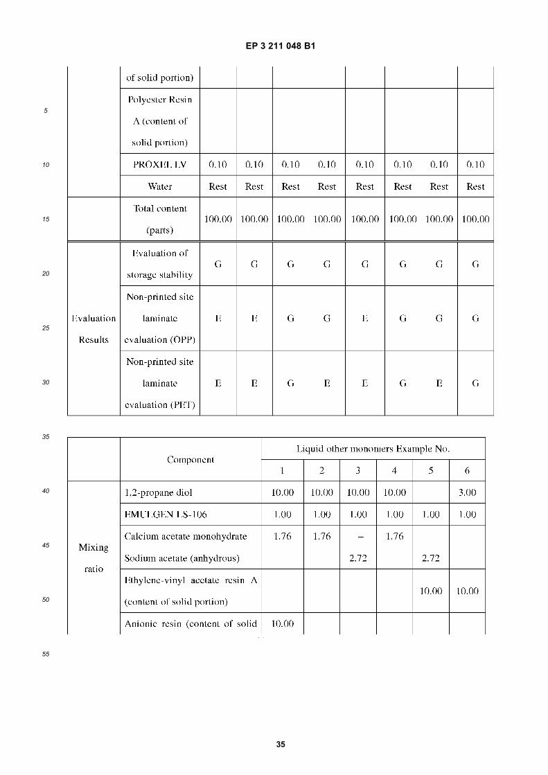
EP 3 211 048 B1
35
5
10
15
20
25
30
35
40
45
50
55
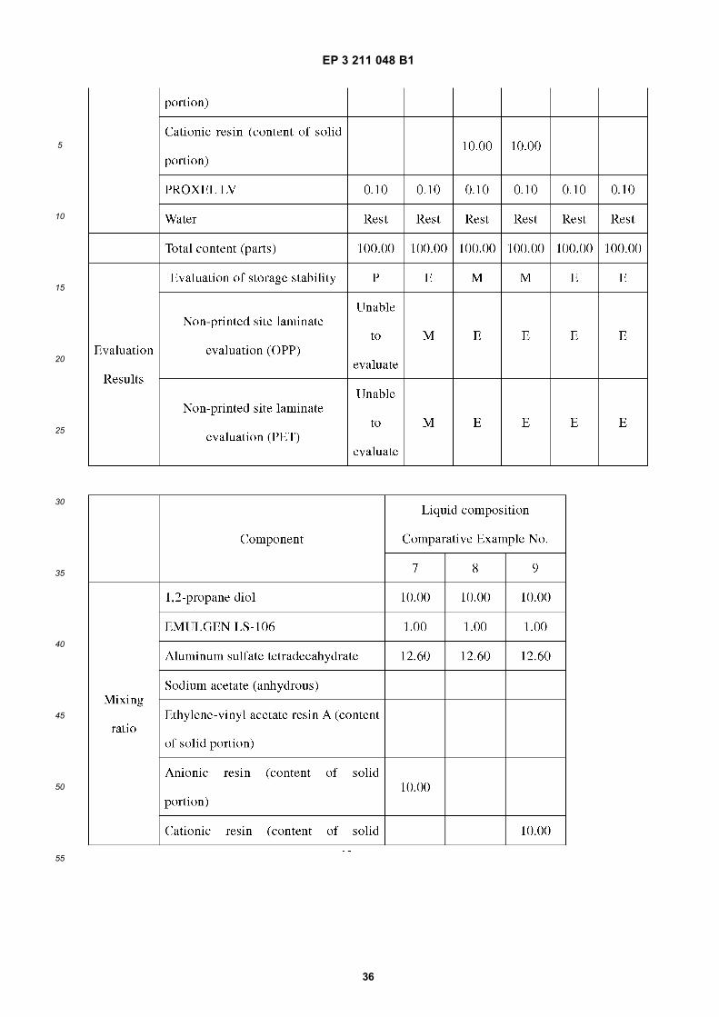
EP 3 211 048 B1
36
5
10
15
20
25
30
35
40
45
50
55
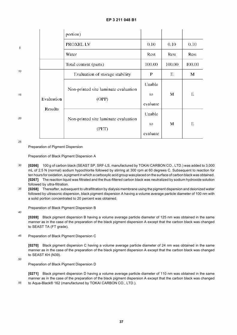
EP 3 211 048 B1
37
5
10
15
20
25
30
35
40
45
50
55
Preparation of Pigment Dispersion
Preparation of Black Pigment Dispersion A
[0266] 100 g of carbon black (SEAST SP, SRF-LS, manufactured by TOKAI CARBON CO., LTD.) was added to 3,000mL of 2.5 N (normal) sodium hypochlorite followed by stirring at 300 rpm at 60 degrees C. Subsequent to reaction forten hours for oxidation, a pigment in which a carboxylic acid group was placed on the surface of carbon black was obtained.[0267] The reaction liquid was filtrated and the thus-filtered carbon black was neutralized by sodium hydroxide solutionfollowed by ultra-filtration.[0268] Thereafter, subsequent to ultrafiltration by dialysis membrane using the pigment dispersion and deionized waterfollowed by ultrasonic dispersion, black pigment dispersion A having a volume average particle diameter of 100 nm witha solid portion concentrated to 20 percent was obtained.
Preparation of Black Pigment Dispersion B
[0269] Black pigment dispersion B having a volume average particle diameter of 125 nm was obtained in the samemanner as in the case of the preparation of the black pigment dispersion A except that the carbon black was changedto SEAST TA (FT grade).
Preparation of Black Pigment Dispersion C
[0270] Black pigment dispersion C having a volume average particle diameter of 24 nm was obtained in the samemanner as in the case of the preparation of the black pigment dispersion A except that the carbon black was changedto SEAST KH (N39).
Preparation of Black Pigment Dispersion D
[0271] Black pigment dispersion D having a volume average particle diameter of 110 nm was obtained in the samemanner as in the case of the preparation of the black pigment dispersion A except that the carbon black was changedto Aqua-Black® 162 (manufactured by TOKAI CARBON CO., LTD.).
EP 3 211 048 B1
38
5
10
15
20
25
30
35
40
45
50
55
Preparation of Black Pigment Dispersion E
[0272] Black pigment dispersion D having a volume average particle diameter of 30 nm was obtained in the samemanner as in the case of the preparation of the black pigment dispersion A except that the carbon black was changedto general color RCF#30 (manufactured by Mitsubishi Chemical Corporation).
Preparation of Cyan Pigment Dispersion A
[0273] Cyan pigment dispersion A having a volume average particle diameter of 62 nm was obtained in the samemanner as in the case of the preparation of the black pigment dispersion A except that the coloring material was changedto Hostaperm Blue B4G (manufactured by Clariant).
Preparation of Cyan Pigment Dispersion B
[0274] Cyan pigment dispersion B having a volume average particle diameter of 75 nm was obtained in the samemanner as in the case of the preparation of the black pigment dispersion A except that the coloring material was changedto copper phthalocyanine pigment (LX4033, C.I.Pigment 15:4, manufactured by TOYO INK CO., LTD.).
Preparation of Magenta Pigment Dispersion A
[0275] Magenta pigment dispersion A having a volume average particle diameter of 87 nm was obtained in the samemanner as in the case of the preparation of the black pigment dispersion A except that the coloring material was changedto Hostaperm Pink E02 (manufactured by Clariant).
Preparation of Magenta Pigment Dispersion B
[0276] Magenta pigment dispersion B having a volume average particle diameter of 73 nm was obtained in the samemanner as in the case of the preparation of the black pigment dispersion A except that the coloring material was changedto Pigment Red 122 (manufactured by Sun Chemical).
Preparation of Yellow Pigment Dispersion A
[0277] Yellow pigment dispersion A having a volume average particle diameter of 75 nm was obtained in the samemanner as in the case of the preparation of the black pigment dispersion A except that the coloring material was changedto Hansa Brilliant Yellow 5GX03 (manufactured by Clariant).
Preparation of Yellow Pigment Dispersion B
[0278] Yellow pigment dispersion B having a volume average particle diameter of 82 nm was obtained in the samemanner as in the case of the preparation of the black pigment dispersion A except that the coloring material was changedto Pigment Yellow 74 (Yellow No.46, manufactured by Dainichiseika Color & Chemicals Mfg. Co., Ltd.).
Preparation of White Pigment Dispersion A
[0279] 25 g of titanium oxide (STR-100W, manufactured by Sakai Chemical Industry Co., Ltd.), 5 g of pigment dispersant(TEGO Dispers 651, manufactured by Evonik Japan Co., Ltd.), and 70 g of water were mixed followed by dispersionusing a bead mill (research labo, manufactured by Shinmaru Enterprises Corporation) with zirconia beads having adiameter of 0.3 mm and a filling ratio of 60 percent at 8 m/s for five minutes to obtain a white pigment dispersion A havinga volume average particle diameter of 285 nm.
Preparation of White Pigment Dispersion B
[0280] White pigment dispersion B having a volume average particle diameter of 142 nm was obtained in the samemanner as in the case of the preparation of the white pigment dispersion A except that titanium oxide was changed toSTA-100A.
EP 3 211 048 B1
39
5
10
15
20
25
30
35
40
45
50
55
Preparation of White Pigment Dispersion C
[0281] White pigment dispersion C having a volume average particle diameter of 142 nm was obtained in the samemanner as in the case of the preparation of the white pigment dispersion A except that titanium oxide was changed toSTR-60N.
Preparation of White Pigment Dispersion D (Hollow Resin Particle Dispersion)
[0282] A product (ROPAQUE™ ULTRA, styrene-acrylic copolymer hollow pigment emulsion, average particle diameter(D50): 380 nm, solid portion concentration: 30.0 percent, manufactured by Rohm and Haas Electronic Materials K.K.)was used as the hollow resin particle dispersion.
Preparation of White Pigment Dispersion E (Hollow Inorganic Resin Particle Dispersion)
[0283] 10.0 g of DISPERBYK-2008 (acrylic copolymer, effective component 60 percent, manufactured by BYK) wasdissolved in 294.0 g of highly pure water in a beaker. Thereafter, while the solution was stirred by an excel auto homog-enizer (manufactured by Nippon Seiki Co., Ltd.) at 5,000 rotation per minute (rpm) for 30 minutes, 50.0 g of hollowinorganic particles (SiliNax™, primary particle diameter of from 80 to 130 nm, silica film thickness: 5 to 15 nm, manu-factured by Nittetsu Mining Co., Ltd.) was divided into ten and admixed until no block was observed. Thereafter, therotation was gradually sped up to 10,000 rpm and stirred for 30 minutes.[0284] While cooling down the thus-obtained pigment liquid dispersion water, the pigment liquid dispersion was treatedwith an ultrasonic homogenizer (US-300T, tip diameter 26, manufactured by NISSEI Corporation) at 200 mA for onehour. Subsequent to filtration with a membrane filter (cellulose acetate film) of 5 mm, hollow inorganic particle liquiddispersion was obtained in which the hollow inorganic particle accounted for 14.1 percent by mass. The average particlediameter (D50) of the dispersion particle in the obtained dispersion was 300 nm as measured by a particle size distributionmeasuring instrument (Microtrac UPA-EX150, manufactured by NIKKISO CO., LTD.).
Preparation Method of Ink
[0285] The recipe shown in Table 2 was mixed and stirred to prepare ink. The non-white ink was filtrated by a poly-propylene filter of 0.2 mm and the white ink was filtrated by a polypropylene filter of 0.5 mm.[0286] The surfactant used was as follows.
• FS-300, manufactured by E. I. du Pont de Nemours and Company)
[0287] The resin used was as follows.
• Urethane resin A: SUPER FLEX 210 (Tg: 41 degrees C, manufactured by DKS Co. Ltd.)• Urethane resin B: SUPER FLEX 420 (Tg: -10 degrees C, manufactured by DKS Co. Ltd.)• Acrylic resin A: VONCOAT CF-6140 (Tg: 12 degrees C, manufactured by DIC)• Styreneacrylic resin A: Vinyblan 2685 (Tg: 50 degrees C, manufactured by Nissin Chemical Industry Co., Ltd.)• Styrene acrylic resin B: VONCOAT CG-8400 (Tg: 25 degrees C, manufactured by DIC)• Polyester resin A: ELITEL® KA-5034 (Tg: 67 degrees C, manufactured by UNITIKA LTD.)• Vinyl chloride resin A: Vinyblan 735, (Tg: 42 degrees C, manufactured by Nissin Chemical Industry Co., Ltd.)• Vinyl chloride-vinyl acetate copolymer resin A: SOLBIN TA3 (Tg: 65 degrees C, manufactured by Nissin Chemical
Industry Co., Ltd.)
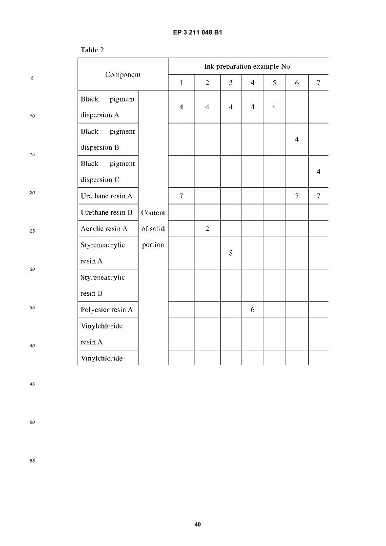
EP 3 211 048 B1
40
5
10
15
20
25
30
35
40
45
50
55
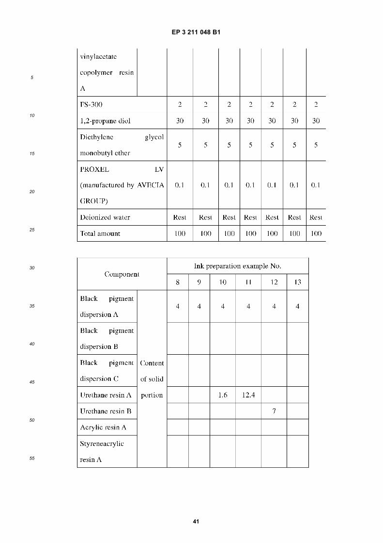
EP 3 211 048 B1
41
5
10
15
20
25
30
35
40
45
50
55
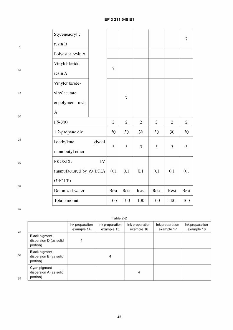
EP 3 211 048 B1
42
5
10
15
20
25
30
35
40
45
50
55
Table 2-2
Ink preparation example 14
Ink preparation example 15
Ink preparation example 16
Ink preparation example 17
Ink preparation example 18
Black pigment dispersion D (as solid portion)
4
Black pigment dispersion E (as solid portion)
4
Cyan pigment dispersion A (as solid portion)
4
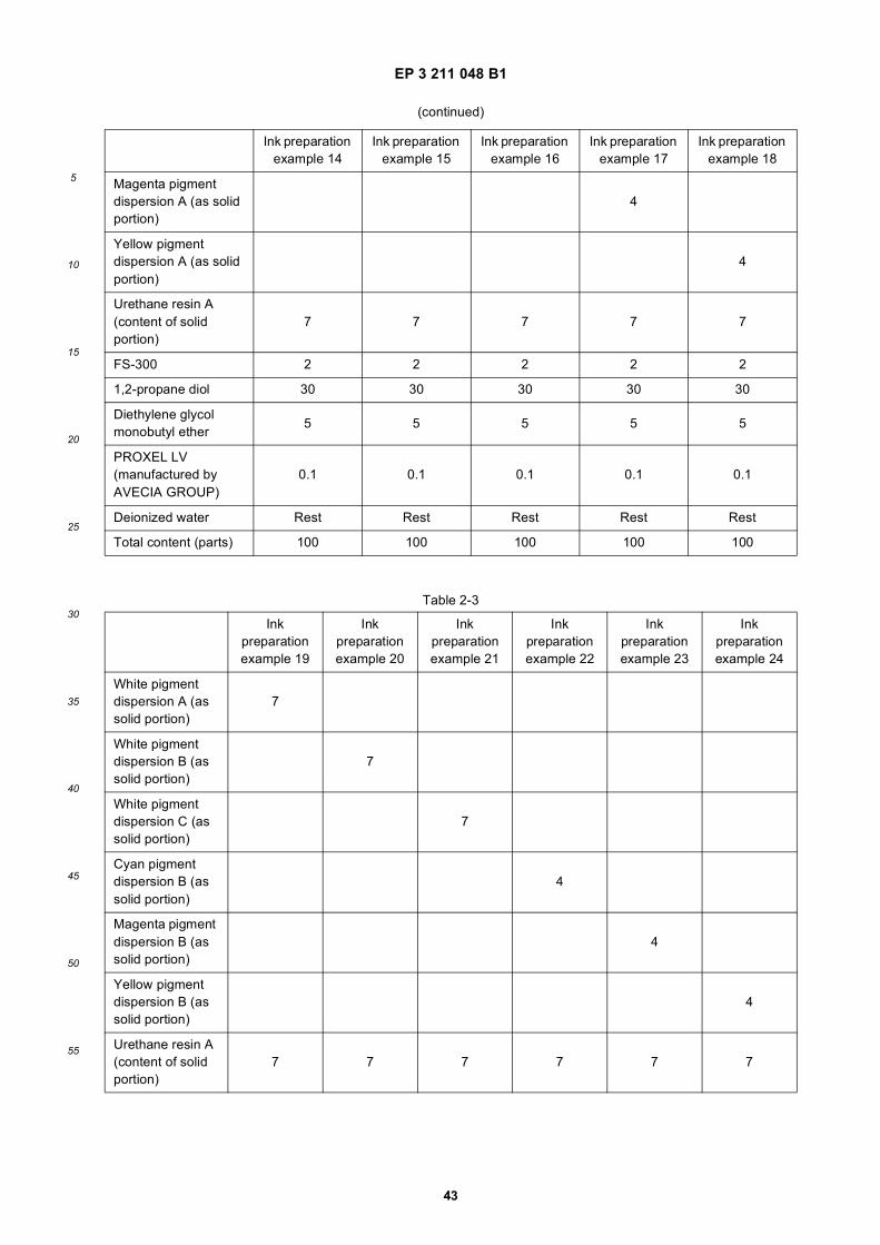
EP 3 211 048 B1
43
5
10
15
20
25
30
35
40
45
50
55
(continued)
Ink preparation example 14
Ink preparation example 15
Ink preparation example 16
Ink preparation example 17
Ink preparation example 18
Magenta pigment dispersion A (as solid portion)
4
Yellow pigment dispersion A (as solid portion)
4
Urethane resin A (content of solid portion)
7 7 7 7 7
FS-300 2 2 2 2 2
1,2-propane diol 30 30 30 30 30
Diethylene glycol monobutyl ether 5 5 5 5 5
PROXEL LV (manufactured by AVECIA GROUP)
0.1 0.1 0.1 0.1 0.1
Deionized water Rest Rest Rest Rest Rest
Total content (parts) 100 100 100 100 100
Table 2-3
Ink preparation example 19
Ink preparation example 20
Ink preparation example 21
Ink preparation example 22
Ink preparation example 23
Ink preparation example 24
White pigment dispersion A (as solid portion)
7
White pigment dispersion B (as solid portion)
7
White pigment dispersion C (as solid portion)
7
Cyan pigment dispersion B (as solid portion)
4
Magenta pigment dispersion B (as solid portion)
4
Yellow pigment dispersion B (as solid portion)
4
Urethane resin A (content of solid portion)
7 7 7 7 7 7
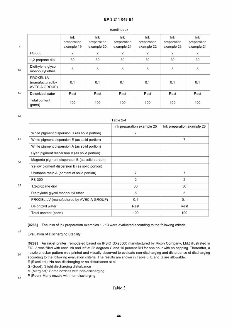
EP 3 211 048 B1
44
5
10
15
20
25
30
35
40
45
50
55
[0288] The inks of ink preparation examples 1 - 13 were evaluated according to the following criteria.
Evaluation of Discharging Stability
[0289] An inkjet printer (remodeled based on IPSiO GXe5500 manufactured by Ricoh Company, Ltd.) illustrated inFIG. 3 was filled with each ink and left at 25 degrees C and 15 percent RH for one hour with no capping. Thereafter, anozzle checker pattern was printed and visually observed to evaluate non-discharging and disturbance of dischargingaccording to the following evaluation criteria. The results are shown in Table 3. E and G are allowable.E (Excellent): No non-discharging or no disturbance at allG (Good): Slight discharging disturbanceM (Marginal): Some nozzles with non-dischargingP (Poor): Many nozzle with non-discharging
(continued)
Ink preparation example 19
Ink preparation example 20
Ink preparation example 21
Ink preparation example 22
Ink preparation example 23
Ink preparation example 24
FS-300 2 2 2 2 2 2
1,2-propane diol 30 30 30 30 30 30
Diethylene glycol monobutyl ether 5 5 5 5 5 5
PROXEL LV (manufactured by AVECIA GROUP)
0.1 0.1 0.1 0.1 0.1 0.1
Deionized water Rest Rest Rest Rest Rest Rest
Total content (parts) 100 100 100 100 100 100
Table 2-4
Ink preparation example 25 Ink preparation example 26
White pigment dispersion D (as solid portion) 7
White pigment dispersion E (as solid portion) 7
White pigment dispersion A (as solid portion)
Cyan pigment dispersion B (as solid portion)
Magenta pigment dispersion B (as solid portion)
Yellow pigment dispersion B (as solid portion)
Urethane resin A (content of solid portion) 7 7
FS-300 2 2
1,2-propane diol 30 30
Diethylene glycol monobutyl ether 5 5
PROXEL LV (manufactured by AVECIA GROUP) 0.1 0.1
Deionized water Rest Rest
Total content (parts) 100 100
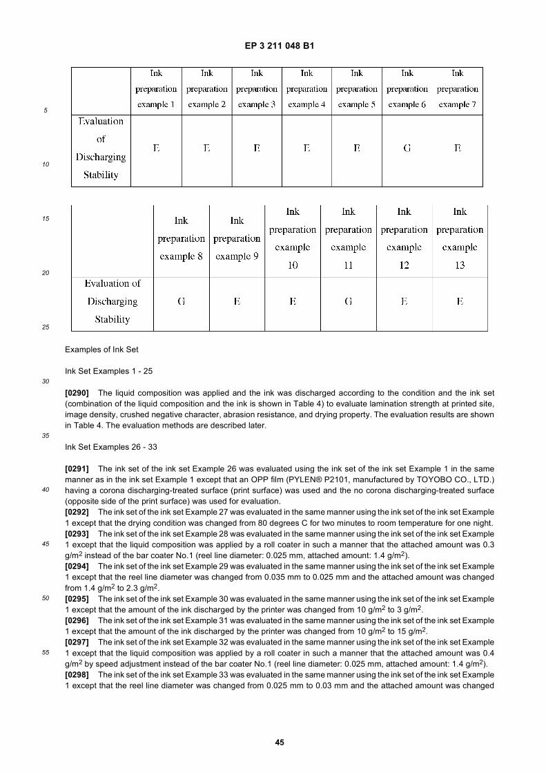
EP 3 211 048 B1
45
5
10
15
20
25
30
35
40
45
50
55
Examples of Ink Set
Ink Set Examples 1 - 25
[0290] The liquid composition was applied and the ink was discharged according to the condition and the ink set(combination of the liquid composition and the ink is shown in Table 4) to evaluate lamination strength at printed site,image density, crushed negative character, abrasion resistance, and drying property. The evaluation results are shownin Table 4. The evaluation methods are described later.
Ink Set Examples 26 - 33
[0291] The ink set of the ink set Example 26 was evaluated using the ink set of the ink set Example 1 in the samemanner as in the ink set Example 1 except that an OPP film (PYLEN® P2101, manufactured by TOYOBO CO., LTD.)having a corona discharging-treated surface (print surface) was used and the no corona discharging-treated surface(opposite side of the print surface) was used for evaluation.[0292] The ink set of the ink set Example 27 was evaluated in the same manner using the ink set of the ink set Example1 except that the drying condition was changed from 80 degrees C for two minutes to room temperature for one night.[0293] The ink set of the ink set Example 28 was evaluated in the same manner using the ink set of the ink set Example1 except that the liquid composition was applied by a roll coater in such a manner that the attached amount was 0.3g/m2 instead of the bar coater No.1 (reel line diameter: 0.025 mm, attached amount: 1.4 g/m2).[0294] The ink set of the ink set Example 29 was evaluated in the same manner using the ink set of the ink set Example1 except that the reel line diameter was changed from 0.035 mm to 0.025 mm and the attached amount was changedfrom 1.4 g/m2 to 2.3 g/m2.[0295] The ink set of the ink set Example 30 was evaluated in the same manner using the ink set of the ink set Example1 except that the amount of the ink discharged by the printer was changed from 10 g/m2 to 3 g/m2.[0296] The ink set of the ink set Example 31 was evaluated in the same manner using the ink set of the ink set Example1 except that the amount of the ink discharged by the printer was changed from 10 g/m2 to 15 g/m2.[0297] The ink set of the ink set Example 32 was evaluated in the same manner using the ink set of the ink set Example1 except that the liquid composition was applied by a roll coater in such a manner that the attached amount was 0.4g/m2 by speed adjustment instead of the bar coater No.1 (reel line diameter: 0.025 mm, attached amount: 1.4 g/m2).[0298] The ink set of the ink set Example 33 was evaluated in the same manner using the ink set of the ink set Example1 except that the reel line diameter was changed from 0.025 mm to 0.03 mm and the attached amount was changed
EP 3 211 048 B1
46
5
10
15
20
25
30
35
40
45
50
55
from 1.4 g/m2 to 2.0 g/m2.[0299] The evaluation results of Examples 26 - 33 are shown in Table 4.
Ink Set Examples 34 - 38
[0300] The liquid composition was applied and the ink was discharged according to the condition and the ink set(combination of the liquid composition and the ink is shown in Table 4) to evaluate lamination strength at printed site,image density, crushed negative character, abrasion resistance, and drying property. The evaluation results are shownin Table 4. The evaluation results are described below.
Ink Set Examples 39 - 46
[0301] The liquid composition was applied and the ink was discharged according to the condition and the ink set(combination of the liquid composition and the ink is shown in Table 4) to evaluate lamination strength at printed site,image density, crushed negative character, abrasion resistance, drying property, color gamut, and white ink sedimentationproperty. The evaluation results are shown in Table 4. The evaluation results are described below.[0302] In the ink set Example 39, the liquid composition and the black ink of the ink set Example 1 and the white inkof the ink preparation Example 19 were used for evaluation. The black ink and the white ink were applied in this order.[0303] In the ink set Example 40, the liquid composition and the black ink of the ink set Example 1 and the white inkof the ink preparation Example 20 were used for evaluation. The black ink and the white ink were applied in this order.[0304] In the ink set Example 41, the liquid composition and the black ink of the ink set Example 1 and the white inkof the ink preparation Example 21 were used for evaluation. The black ink and the white ink were applied in this order.[0305] In the ink set Example 42, the liquid composition and the black ink of the ink set Example 1, and the cyan ink,the magenta ink, and the yellow ink of the ink preparation Examples 22 - 24, and the white ink of the ink preparationExample 19 were used for evaluation. The non-white inks and the white ink were applied in this order.[0306] In the ink set Example 43, the liquid composition and the black ink of the ink set Example 1, and the cyan ink,the magenta ink, and the yellow ink of the ink preparation Examples 22 - 24 were used to evaluate the color gamut.[0307] In the ink set Example 44, the liquid composition and the black ink of the ink set Example 1 and the white inkof the ink preparation Example 25 were used for evaluation. The black ink and the white ink were applied in this order.[0308] In the ink set Example 45, the liquid composition and the black ink of the ink set Example 1 and the white inkof the ink preparation Example 26 were used for evaluation. The black ink and the white ink were applied in this order.[0309] In the ink set Example 46, the liquid composition and the black ink of the ink set Example 1, the cyan ink, themagenta ink, and the yellow ink of the ink preparation Examples 22 - 24, and the white ink of the ink preparation Example25 were used for evaluation. The non-white inks and the white ink were applied in this order.
Ink set Examples 47 - 70
[0310] Using the ink set (combination of the liquid composition and the ink was shown in Table 4), the liquid compositionwas applied and the ink was discharged according to the condition to evaluate lamination strength at printed site, imagedensity, crushed negative character, abrasion resistance, and drying property. The evaluation results were shown inTable 4. The evaluation results are described below.
Ink Set Examples 71 - 76
[0311] The ink set of the ink set Example 71 was evaluated in the same manner using the ink set of the ink set Example10 except that an OPP film (PYLEN® P2101, manufactured by TOYOBO CO., LTD.) having a corona discharging-treatedsurface (print surface) was used and the no corona discharging-treated surface (opposite side of the print surface) wasused for evaluation.[0312] The ink set of the ink set Example 72 was evaluated in the same manner using the ink set of the ink set Example10 except that the drying condition was changed from 80 degrees C for two minutes to room temperature for one night.[0313] The ink set of the ink set Example 73 was evaluated using the ink set of the ink set Example 10 in the samemanner except that the liquid composition was applied by a roll coater in such a manner that the attached amount was0.3 g/m2 instead of the bar coater No.1 (reel line diameter: 0.025 mm, attached amount: 1.4 g/m2).[0314] The ink set of the ink set Example 74 was evaluated in the same manner using the ink set of the ink set Example10 except that the reel line diameter was changed to from 0.035 mm to 0.025 mm and the attached amount was changedfrom 1.4 g/m2 to 2.3 g/m2 for bar coater No. 1.[0315] The ink set of the ink set Example 75 was evaluated in the same manner using the ink set of the ink set Example10 except that the amount of the ink discharged by the printer was changed from 10 g/m2 to 3 g/m2.
EP 3 211 048 B1
47
5
10
15
20
25
30
35
40
45
50
55
[0316] The ink set of the ink set Example 76 was evaluated in the same manner as in the ink set Example 10 exceptthat the amount of the ink discharged by the printer was changed from 10 g/m2 to 15 g/m2.[0317] The evaluation results of Examples 71 - 76 are shown in Table 4.
Ink Set Examples 77 - 81
[0318] The liquid composition was applied and the ink was discharged according to the condition and the ink set(combination of the liquid composition and the ink is shown in Table 4) to evaluate lamination strength at printed site,image density, crushed negative character, abrasion resistance, and drying property. The evaluation results are shownin Table 4. The evaluation results are described below.
Ink Set Examples 82 - 93
[0319] The liquid composition was applied and the ink was discharged according to the condition and the ink set(combination of the liquid composition and the ink is shown in Table 4) to evaluate lamination strength at printed site,image density, crushed negative character, abrasion resistance, and drying property. The evaluation results are shownin Table 4. The evaluation results are described below.
Ink Set Comparative Example 1 - 6
[0320] The liquid composition was applied and the ink was discharged according to the condition and the ink set(combination of the liquid composition and the ink is shown in Table 4) to evaluate lamination strength at printed site,image density, crushed negative character, abrasion resistance, and drying property. The evaluation results are shownin Table 4.[0321] Each of the liquid composition was applied to the corona discharging-treated surface of an OPP film (PYLEN®P2102, manufactured by TOYOBO CO., LTD.) except for the ink set Examples 26 and 71. Moreover, after the surfacereforming treatment shown in Table 4, each of the liquid composition was applied to the reformed surface under thecondition shown in Table 4. As for the ink sets of the ink set Examples 26 and 71, each of the liquid composition wasapplied to the non-corona treated surface of an OPP film (PYLEN® P2102, manufactured by TOYOBO CO., LTD.) underthe conditions shown in Table 4.
Evaluation of Printed Site Laminate Strength
[0322] An inkjet printer (IPSiO GXe5500, manufactured by Ricoh Company Ltd.) was filled with each prepared inkand the liquid composition was preliminarily applied to an OPP film (PYLEN® P2102, manufactured by TOYOBO CO.,LTD.) by bar coater No.1 and the OPP film was dried. Thereafter, a solid image was printed on the OPP film under thecondition shown in Table 4 using the ink and dried. When using black ink and color ink, a mixed color solid image wasprinted.[0323] Additives for dry lamination (main agent: TM-320/curing agent CAT-13B, manufactured by Toyo-Morton, Ltd.)was applied to the solid portion by a bar coater. Thereafter, cast polypolypropylene (CPP) (PYLEN® PI 128, manufacturedby TOYOBO CO., LTD.) was attached followed by 48-hour aging at 40 degrees C.[0324] The laminated matter was cut to 15 mm width and peel strength thereof was measured. E (Excellent) and G(Good) are allowable.
Evaluation Criteria
[0325] E (Excellent): Strength of 5 N/15 mm or greaterG (Good): 3 N/15 mm to less than 5 N/15 mmM (Marginal): 1 N/15 mm to less than 3 N/15 mmP (Poor): less than 1 N/15 mm
Evaluation of Image Density
[0326] An inkjet printer (IPSiO GXe5500, manufactured by Ricoh Company Ltd.) was filled with each prepared inkand the liquid composition was preliminarily applied to an OPP film (PYLEN® P2102, manufactured by TOYOBO CO.,LTD.) by bar coater No.1 and the OPP film was dried. Thereafter, a solid image of 1,200 dpi x 1,200 dpi was printed onthe OPP film using the ink (black). Subsequent to drying, concentration at the solid portion was measured and evaluatedaccording to the following criteria. E (Excellent) and G (Good) are allowable.
EP 3 211 048 B1
48
5
10
15
20
25
30
35
40
45
50
55
Evaluation Criteria
[0327] E (Excellent): Image density of 2.0 or greaterG (Good): Image density of from 1.5 to less than 2.0M (Marginal): Image density of from 1.0 to less than 1.5P (Poor): Image density of less than 1.0
Evaluation on Crushed Negative Character
[0328] An inkjet printer (IPSiO GXe5500, manufactured by Ricoh Company Ltd.) was filled with each prepared inkand the liquid composition was preliminarily applied to an OPP film (PYLEN® P2102, manufactured by TOYOBO CO.,LTD.) by bar coater No.1 and the OPP film was dried. Thereafter, an outline character chart of Gothic font was printedon the OPP film using the ink (black ink) under the condition shown in Table 4 and thereafter dried.[0329] Illegibility of the characters of the thus-obtained image was visually checked and evaluated according to thefollowing criteria. S (Super), E (Excellent) and G (Good) are allowable.
Evaluation Criteria
[0330] S (Super): 2 pt Gothic font legibleE (Excellent): 2 pt Gothic font not legible but 3 pt Gothic font legibleG (Good): 3 pt Gothic font not legible but 4 pt Gothic font legibleM (Marginal): 4 pt Gothic font not legible but 5 pt Gothic font legibleP (Poor): 5 pt Gothic font not legible[0331] With regard to the ink set Examples 42, 43, and 46 using the color ink, a Gothic outline character chart wasprinted using only the color ink and illegibility of the characters was evaluated in the same manner as in the case of theblack ink. The evaluation result was the same as that of the black ink.
Evaluation on Abrasion Resistance
[0332] An inkjet printer (IPSiO GXe5500, manufactured by Ricoh Company Ltd.) was filled with each prepared inkand the liquid composition was preliminarily applied to an OPP film (PYLEN® P2102, manufactured by TOYOBO CO.,LTD.) by bar coater No.1 and the OPP film was dried. Thereafter, a solid image was printed on the OPP film using theink under the condition shown in Table 4 and thereafter dried. When using black ink and color ink, a mixed color solidimage was printed.[0333] Thereafter, the solid portion was abraded by dried cotton (unbleached muslin No. 3) with a load of 400 g andevaluated about abrasion (friction) resistance according to the following criteria. E (Excellent) and G (Good) are allowable.
Evaluation Criteria
[0334] E (Excellent): No change in image when abraded 100+ timesG (Good): Slight scratch observed when abraded 100 times but causing no impact on image densityM (Marginal): Image density lowered when abraded 100 timesP (Poor): Image density lowered when abraded 50- times
Evaluation on Drying Property
[0335] An inkjet printer (IPSiO GXe5500, manufactured by Ricoh Company Ltd.) was filled with each prepared inkand the liquid composition was preliminarily applied to an OPP film (PYLEN® P2102, manufactured by TOYOBO CO.,LTD.) by bar coater No.1 and the OPP film was dried. Thereafter, a solid image was printed on the OPP film under thecondition shown in Table 4 using the ink and dried at 25 degrees C for a predetermined period of time. When usingblack ink and color ink, a mixed color solid image was printed.[0336] Filter paper was pressed against the solid portion after drying and the drying property was evaluated checkingthe degree of ink transfer to the filter paper according to the following criteria. E (Excellent) and G (Good) are allowable.E (Excellent): Transfer of ink to filter paper stops on drying condition of 25 degrees C for 15 minutesG (Good): Transfer of ink to filter paper stops on drying condition of 25 degrees C for 30 minutesM (Marginal): Transfer of ink to filter paper stops on drying condition of 25 degrees C for 60 minutesP (Poor): Transfer of ink to filter paper continues after drying at 60 degrees C for 60 minutes
EP 3 211 048 B1
49
5
10
15
20
25
30
35
40
45
50
55
Evaluation on Color Gamut
[0337] An inkjet printer (IPSiO GXe5500, manufactured by Ricoh Company Ltd.) was filled with each prepared ink ofthe ink set Examples 42, 43, and 46 and the liquid composition was preliminarily applied to an OPP film (PYLEN® P2102,manufactured by TOYOBO CO., LTD.) by bar coater No.1 and the OPP film was dried. Thereafter, a color chart imageof 1,200 dpi 3 1,200 dpi was printed on the OPP film and thereafter dried.[0338] Thereafter, the color chart image was measured using a color measuring tool (Xrite exact, manufactured byXrite). Base on L* value, a* value, and b* value of each ink set, gamut volume was calculated and evaluated accordingto the following criteria. E (Excellent) and G (Good) are allowable.
Evaluation Criteria
[0339] E (Excellent): Gamut value is 300,000 or greaterG (Good): Gamut value is 200,000 to less than 300,000P (Poor): Gamut value is less than 200,000
Evaluation on Sedimentation of White Ink
[0340] Sedimentation of the hollow particle of the prepared ink and the pigment was evaluated using turbiscan (MA2000,manufactured by EKO Instruments).[0341] The ink was subject to ultrasonic dispersion treatment (100 W, 40 minutes) to be uniformized and thereafter5.5 mL of the ink was charged in a glass cell specialized for the device using a pipette.[0342] 30 minutes later at which the liquid surface of the ink in the cell was stabilized, the measuring was conducted.This point in time was determined as the initiation of sedimentation evaluation.[0343] Thereafter, the ink was left still at 23 degrees C and kept measured until 120 hours later. Sedimentation waschecked and indicated by deviation display using the initiation of sedimentation evaluation as reference. Sedimentationwas mainly checked by quantity survey (relative value mode) of the peaks representing changes of backscattered lightdue to production of supernatent and evaluated according to the following criteria.
A: Relative change of backscattered light 120 hours after the initiation of evaluation is less than 5 percentB: Relative change of backscattered light 120 hours after the initiation of evaluation is 5 percent to less than 10 percentC: Relative change of backscattered light 120 hours after the initiation of evaluation is 10 percent or greater
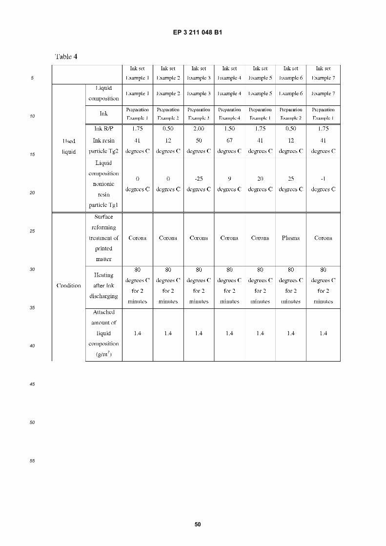
EP 3 211 048 B1
50
5
10
15
20
25
30
35
40
45
50
55
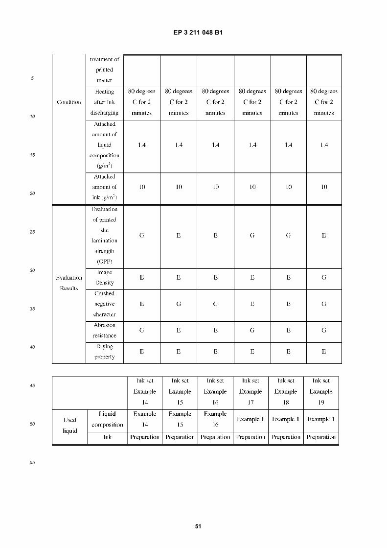
EP 3 211 048 B1
51
5
10
15
20
25
30
35
40
45
50
55
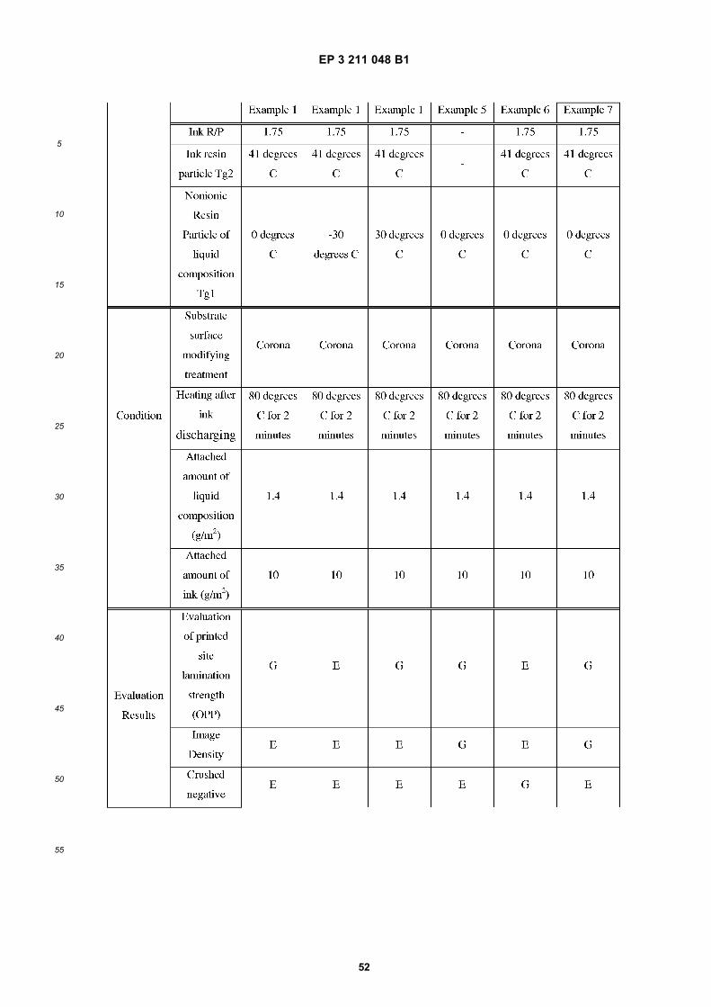
EP 3 211 048 B1
52
5
10
15
20
25
30
35
40
45
50
55
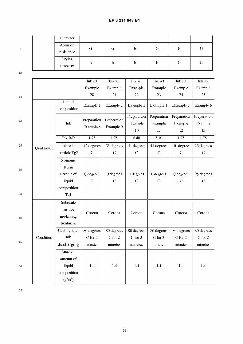
EP 3 211 048 B1
53
5
10
15
20
25
30
35
40
45
50
55
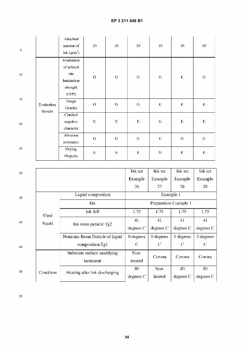
EP 3 211 048 B1
54
5
10
15
20
25
30
35
40
45
50
55
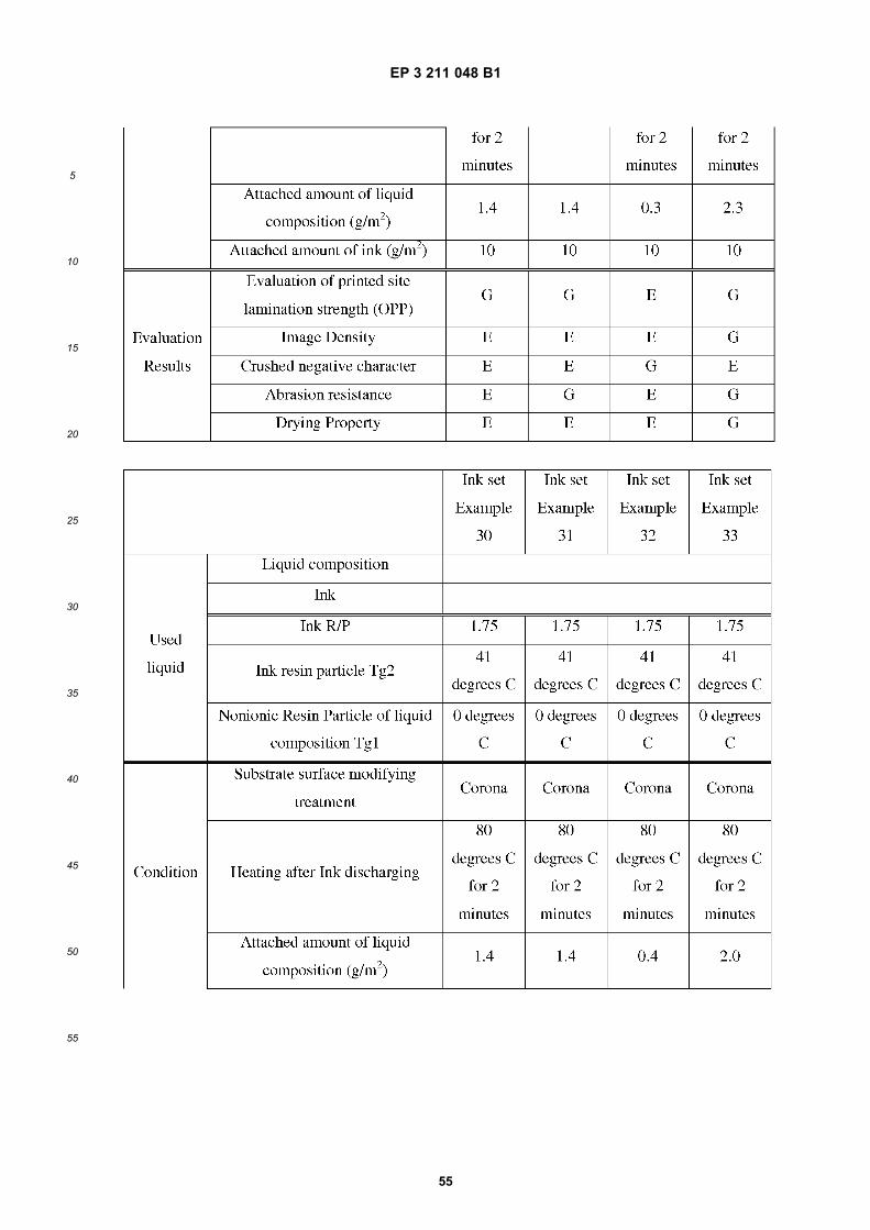
EP 3 211 048 B1
55
5
10
15
20
25
30
35
40
45
50
55
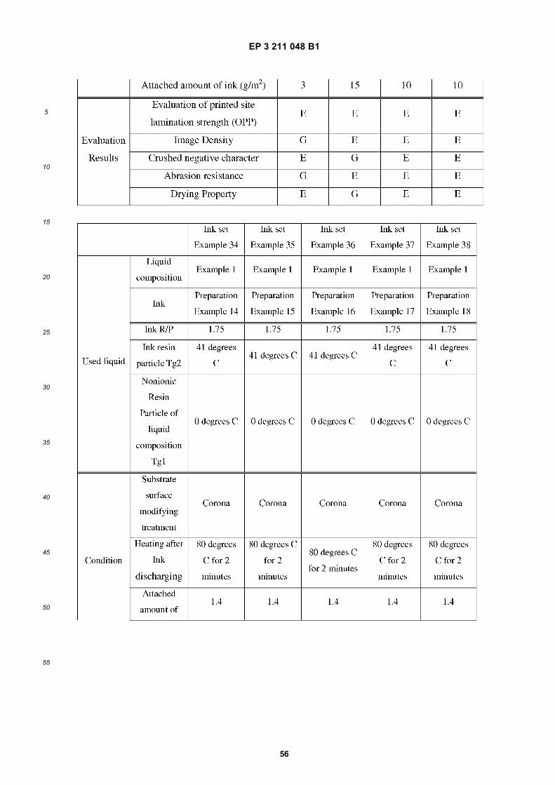
EP 3 211 048 B1
56
5
10
15
20
25
30
35
40
45
50
55
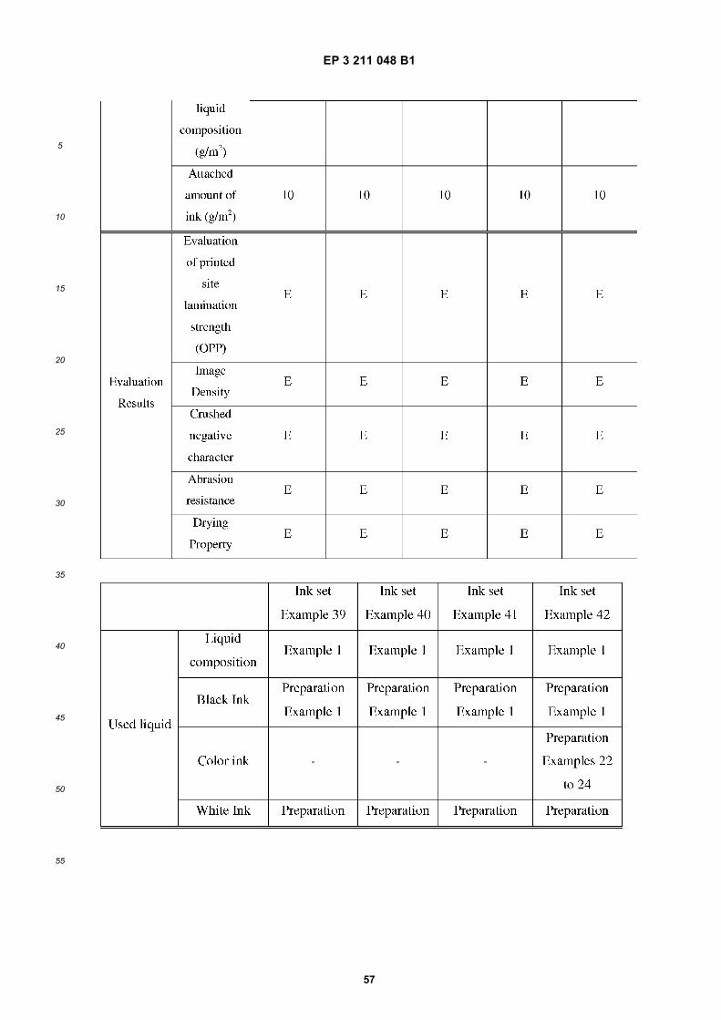
EP 3 211 048 B1
57
5
10
15
20
25
30
35
40
45
50
55
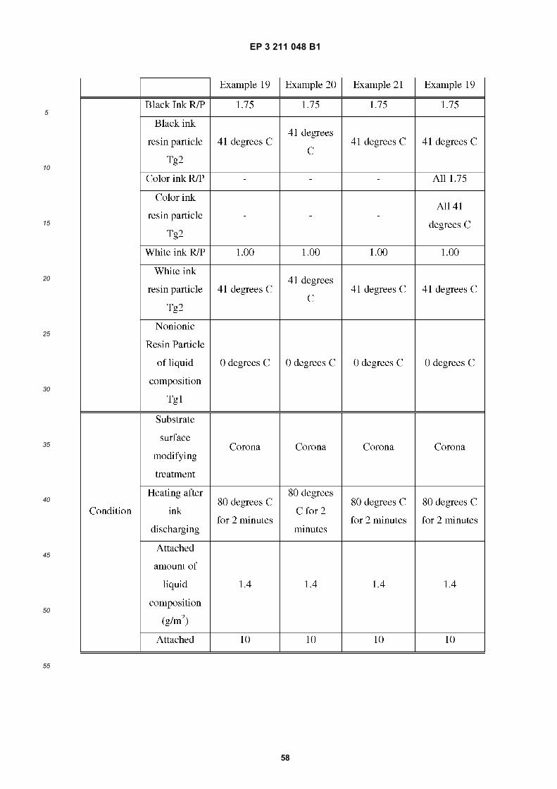
EP 3 211 048 B1
58
5
10
15
20
25
30
35
40
45
50
55
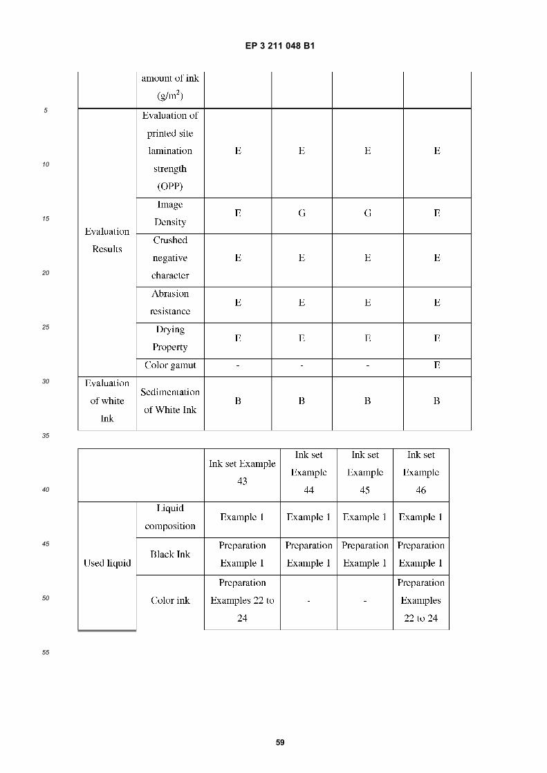
EP 3 211 048 B1
59
5
10
15
20
25
30
35
40
45
50
55
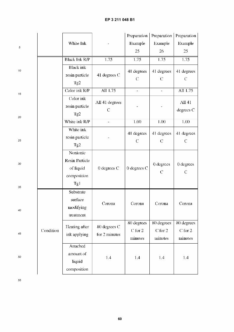
EP 3 211 048 B1
60
5
10
15
20
25
30
35
40
45
50
55
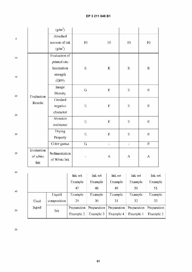
EP 3 211 048 B1
61
5
10
15
20
25
30
35
40
45
50
55
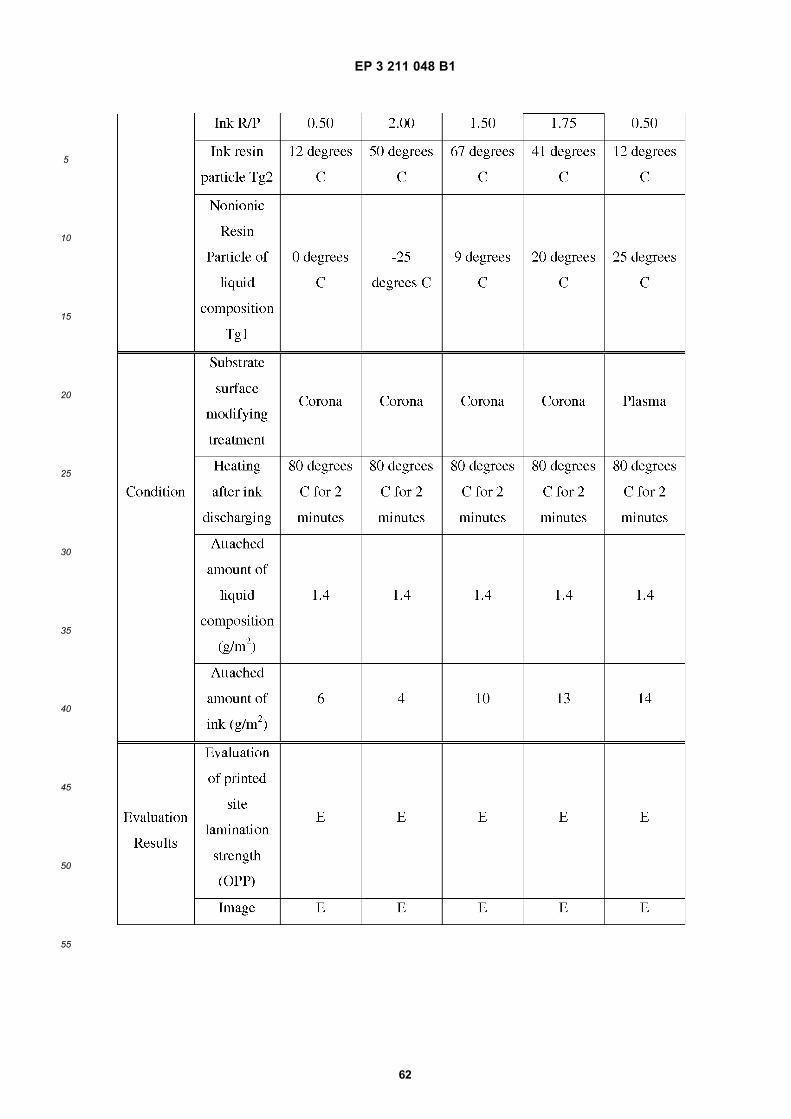
EP 3 211 048 B1
62
5
10
15
20
25
30
35
40
45
50
55
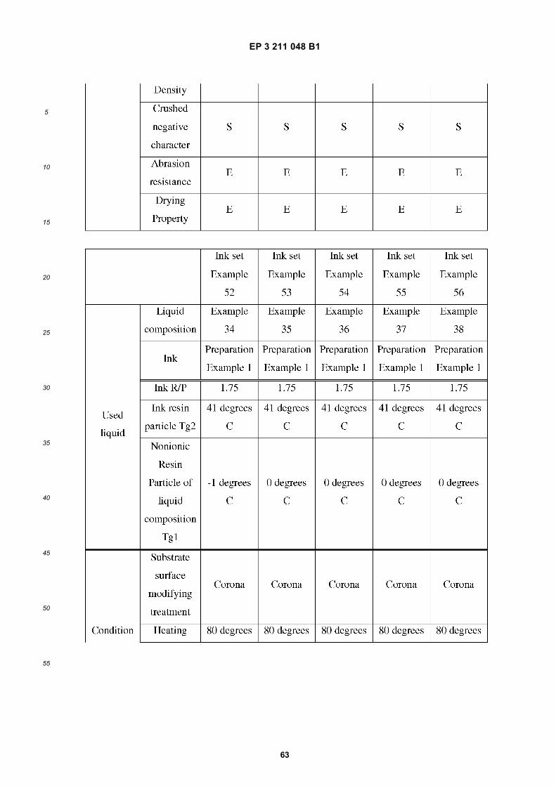
EP 3 211 048 B1
63
5
10
15
20
25
30
35
40
45
50
55
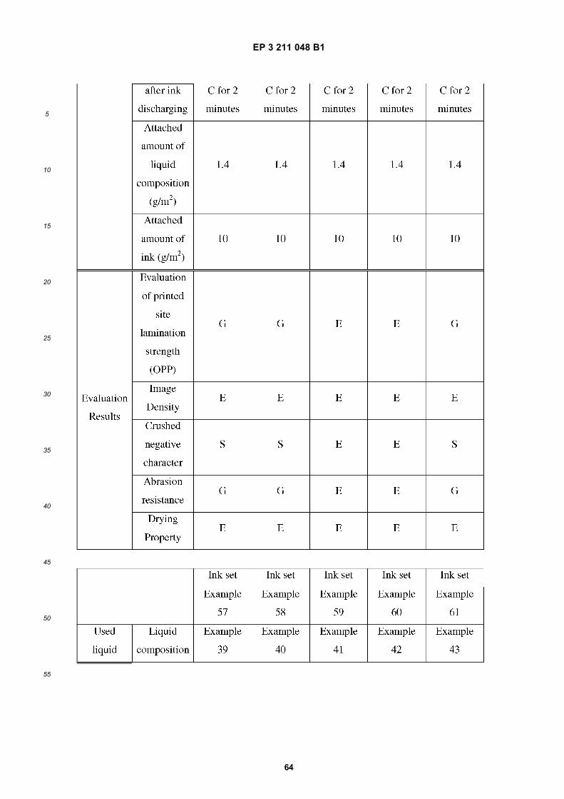
EP 3 211 048 B1
64
5
10
15
20
25
30
35
40
45
50
55
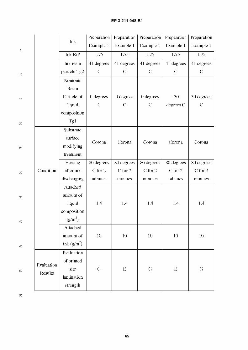
EP 3 211 048 B1
65
5
10
15
20
25
30
35
40
45
50
55
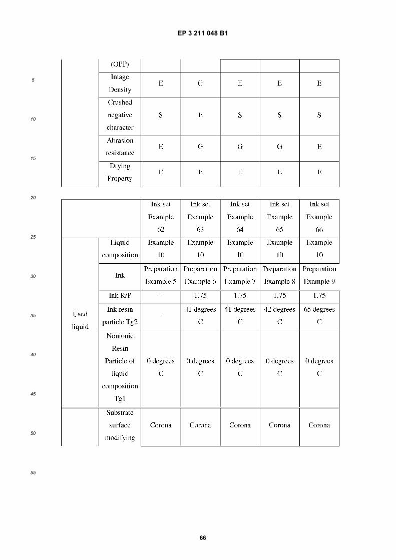
EP 3 211 048 B1
66
5
10
15
20
25
30
35
40
45
50
55
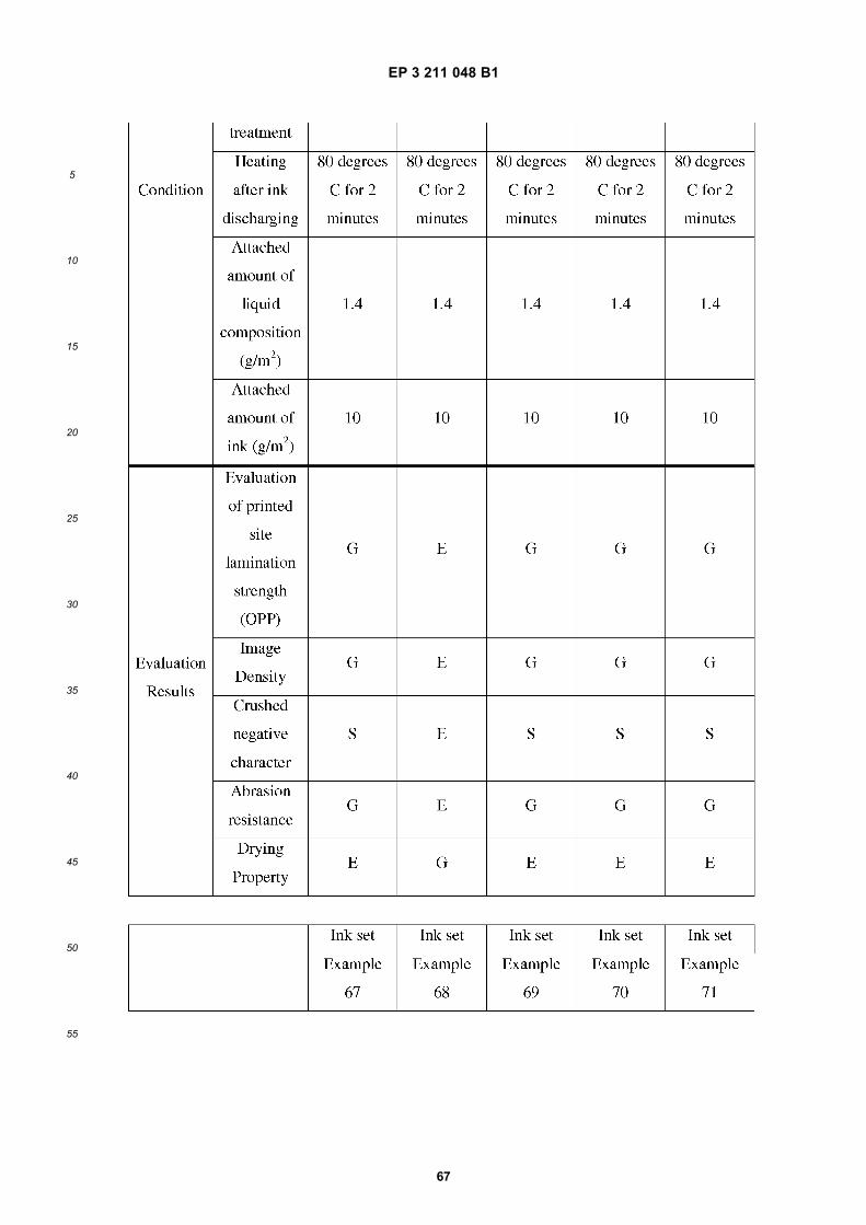
EP 3 211 048 B1
67
5
10
15
20
25
30
35
40
45
50
55
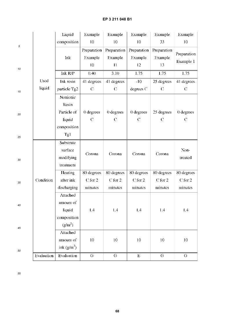
EP 3 211 048 B1
68
5
10
15
20
25
30
35
40
45
50
55
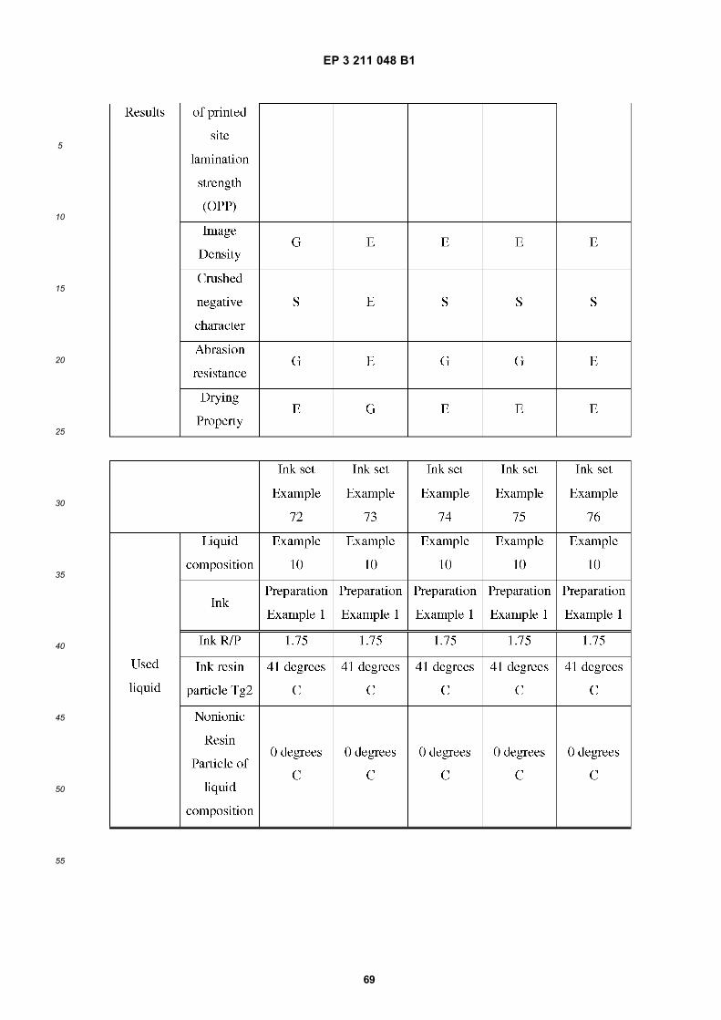
EP 3 211 048 B1
69
5
10
15
20
25
30
35
40
45
50
55
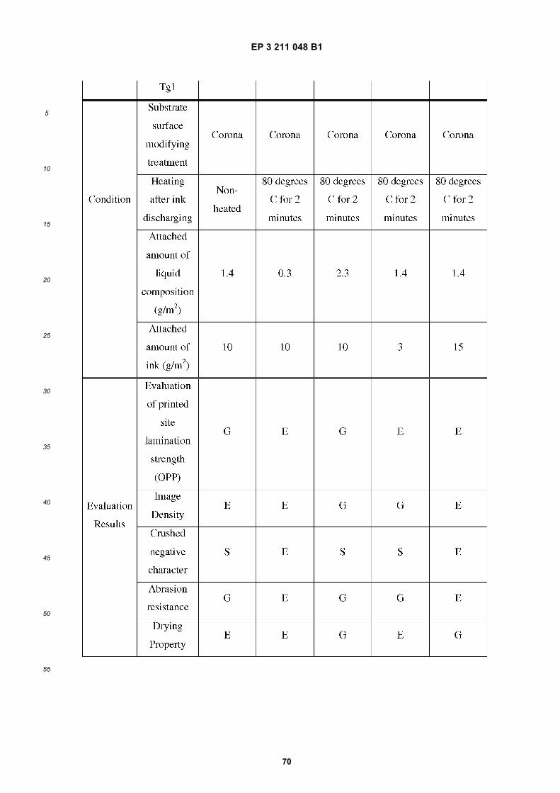
EP 3 211 048 B1
70
5
10
15
20
25
30
35
40
45
50
55
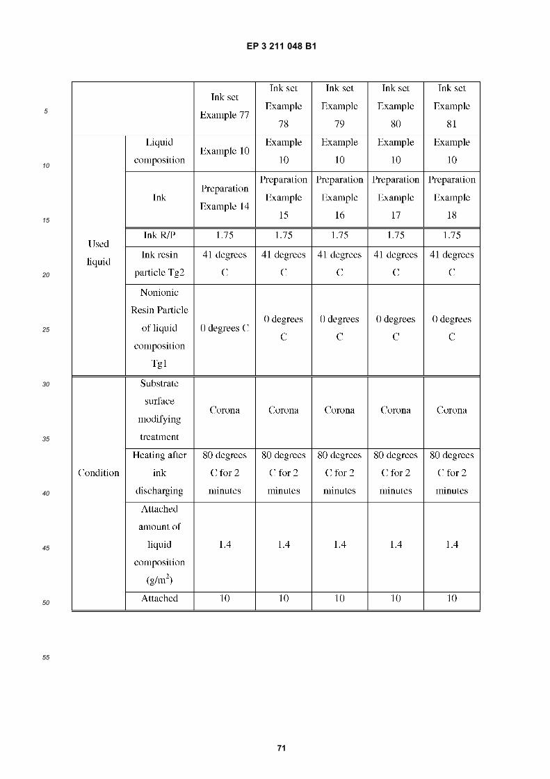
EP 3 211 048 B1
71
5
10
15
20
25
30
35
40
45
50
55
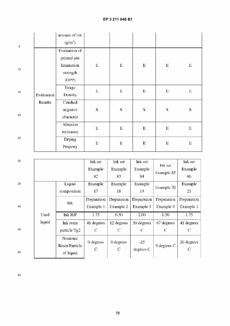
EP 3 211 048 B1
72
5
10
15
20
25
30
35
40
45
50
55
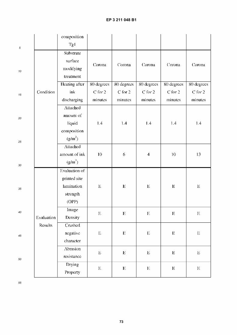
EP 3 211 048 B1
73
5
10
15
20
25
30
35
40
45
50
55
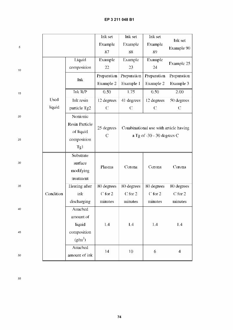
EP 3 211 048 B1
74
5
10
15
20
25
30
35
40
45
50
55
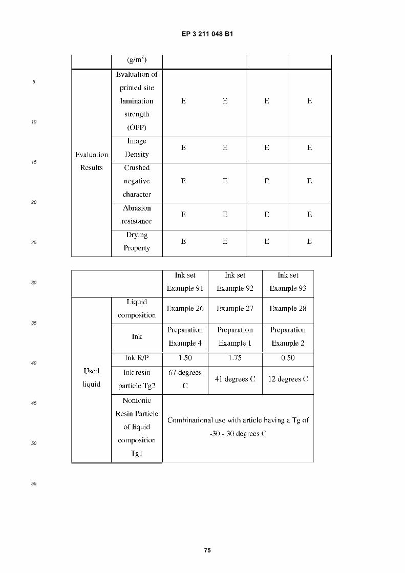
EP 3 211 048 B1
75
5
10
15
20
25
30
35
40
45
50
55
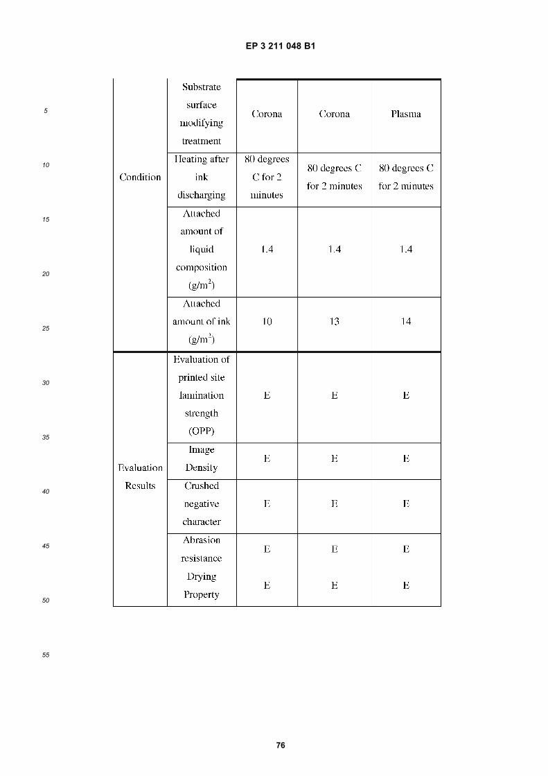
EP 3 211 048 B1
76
5
10
15
20
25
30
35
40
45
50
55
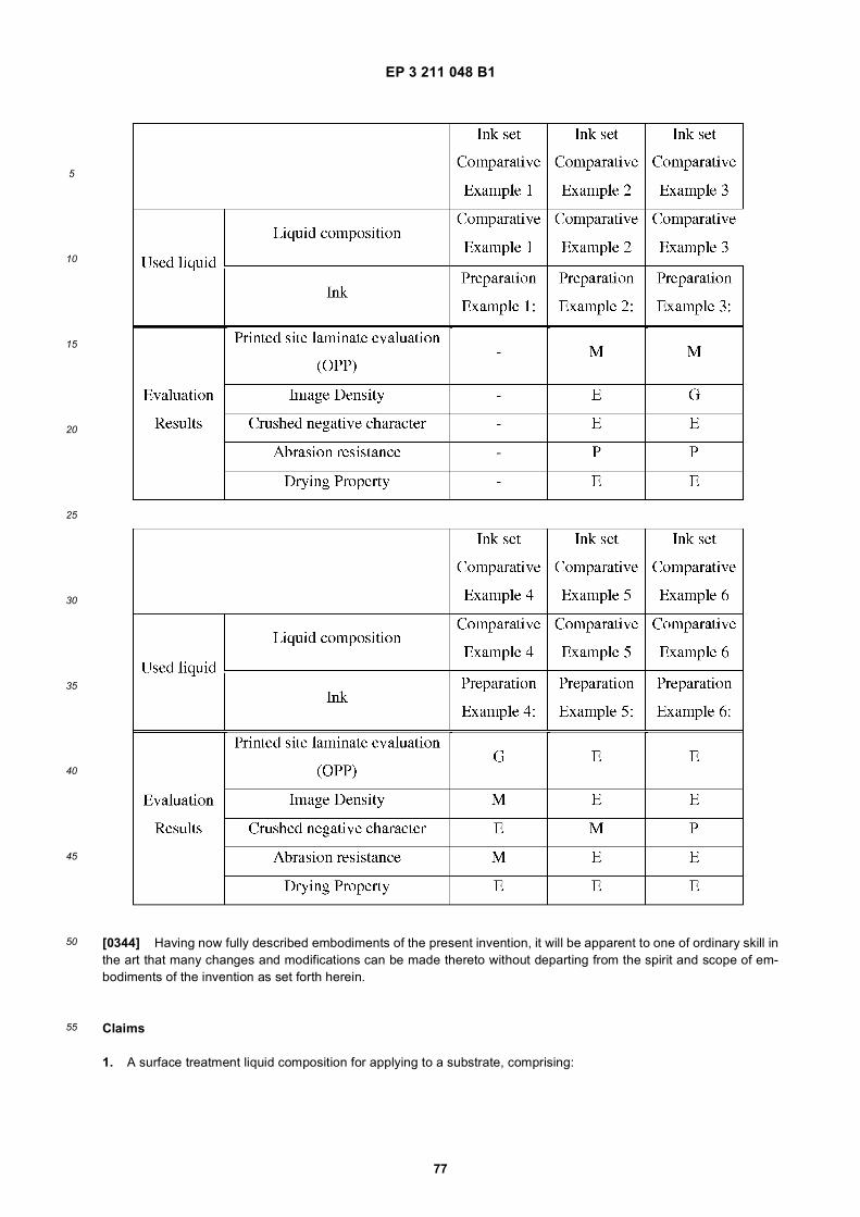
EP 3 211 048 B1
77
5
10
15
20
25
30
35
40
45
50
55
[0344] Having now fully described embodiments of the present invention, it will be apparent to one of ordinary skill inthe art that many changes and modifications can be made thereto without departing from the spirit and scope of em-bodiments of the invention as set forth herein.
Claims
1. A surface treatment liquid composition for applying to a substrate, comprising:
EP 3 211 048 B1
78
5
10
15
20
25
30
35
40
45
50
55
a nonionic resin particle;a multivalent metal salt; andan organic solvent comprising at least one of 1,2-propanediol, 1,2-butanediol, and 2,3-butanediol.
2. The surface treatment liquid composition according to claim 1, wherein the nonionic resin particle includes at leastone of a polyolefin resin, a polyvinyl acetate resin, a polyvinyl chloride resin, a urethane resin, a styrene butadieneresin, and a copolymer thereof.
3. The surface treatment liquid composition according to claim 1 or 2, wherein the multivalent metal salt includes atleast one of a calcium salt, a magnesium salt, a nickel salt, and an aluminum salt.
4. The surface treatment liquid composition according to claim 3, wherein the aluminum salt includes aluminum sulfate,aluminum phosphate, polyaluminum chloride, and aluminum potassium sulfate.
5. The surface treatment liquid composition according to any one preceding claim, wherein the nonionic resin particleaccounts for 0.5 - 20 percent by mass of the surface treatment liquid composition.
6. An ink set comprising:
the surface treatment liquid composition of any one of claims 1 to 5; andone or more inks, each ink including a coloring material.
7. The ink set according to claim 6, wherein the one or more inks include a non-white ink including a non-white coloringmaterial having a volume average particle diameter of from 30 to 110 nm and a thermoplastic resin particle.
8. The ink set according to claim 6, wherein the one or more inks include a white ink comprising a white coloringmaterial and a thermoplastic resin particle.
9. The ink set according to claim 6, wherein the one or more inks include a non-white ink including a non-white coloringmaterial having a volume average particle diameter of from 30 to 110 nm and a thermoplastic resin particle and awhite ink including a white coloring material and a thermoplastic resin particle.
10. The ink set according to claim 9, wherein at least one ink of the non-white ink and the white ink has a ratio (R/P) ofa mass ratio (R) of the thermoplastic resin particle to the at least one ink of the non-white ink and the white ink to amass ratio (P) of the coloring material to the at least one ink of the non-white ink and the white ink is 0.5 - 3.0.
11. The ink set according to any one of claims 7 to 10, a glass transition temperature Tg1 of the nonionic resin particleof the surface treatment liquid composition is lower than a glass transition temperature Tg2 of the resin particle ofthe ink.
12. A recording method comprising:
applying the surface treatment liquid composition of any one of claims 1 to 5 to a substrate; andprinting by discharging the ink of the ink set of any one of claims 6 to 11 to the substrate.
13. The recording method according to claim 12, further comprising:reforming a surface of the substrate.
14. A recording device comprising:
an ink accommodating unit accommodating the ink set of any one of claims 6 to 11;and an ink discharging head configured to discharge the ink of the ink set.
15. The recording device according to claim 14, wherein the ink discharging head includes a nozzle configured todischarge the ink, a plurality of individual liquid chambers communicating with the nozzle, a flow-in path configuredto flow the ink into the individual liquid chambers, a flow-out path configured to flow the ink out of the individual liquidchambers, and a circulating device configured to circulate the ink from the flow-out path to the flow-in path.
EP 3 211 048 B1
79
5
10
15
20
25
30
35
40
45
50
55
Patentansprüche
1. Flüssige Zusammensetzung für eine Oberflächenbehandlung zum Auftragen auf ein Substrat, Folgendes beinhal-tend:
einen nichtionischen Harzpartikel;ein mehrwertiges Metallsalz; undein organisches Lösemittel, beinhaltend mindestens eines von 1,2-Propandiol, 1,2-Butandiol und 2,3-Butandiol.
2. Flüssige Zusammensetzung für eine Oberflächenbehandlung nach Anspruch 1, bei welcher der nichtionische Harz-partikel mindestens eines von einem Polyolefinharz, einem Polyvinylacetatharz, einem Polyvinylchloridharz, einemUrethanharz, einem Styrolbutadienharz und einem Copolymer daraus umfasst.
3. Flüssige Zusammensetzung für eine Oberflächenbehandlung nach Anspruch 1 oder 2, bei welcher das mehrwertigeMetallsalz mindestens eines von einem Kalziumsalz, einem Magnesiumsalz, einem Nickelsalz und einem Alumini-umsalz enthält.
4. Flüssige Zusammensetzung für eine Oberflächenbehandlung nach Anspruch 3, bei welcher das AluminiumsalzAluminiumsulfat, Aluminiumphosphat, Polyaluminiumchlorid und Aluminiumkaliumsulfat enthält.
5. Flüssige Zusammensetzung für eine Oberflächenbehandlung nach einem der vorhergehenden Ansprüche, bei wel-chem der nichtionische Harzpartikel 0,5 bis 20 Gewichtsprozent der flüssigen Zusammensetzung für eine Oberflä-chenbehandlung ausmacht.
6. Tinten-Set, Folgendes beinhaltend:
die flüssige Zusammensetzung für eine Oberflächenbehandlung nach einem der Ansprüche 1 bis 5; undeine oder mehrere Tinten, wobei jede Tinte einen Farbstoff enthält.
7. Tinten-Set nach Anspruch 6, bei welchem die eine oder die mehreren Tinten eine nicht weiße Tinte enthalten,welche einen nicht weißen Farbstoff enthält, welche einen volumenmittleren Partikeldurchmesser von 30 bis 110nm und einen thermoplastischen Harzpartikel aufweist.
8. Tinten-Set nach Anspruch 6, bei welchem die eine oder die mehreren Tinten eine weiße Tinte enthalten, welcheeinen weißen Farbstoff und einen thermoplastischen Harzpartikel beinhaltet.
9. Tinten-Set nach Anspruch 6, bei welchem die eine oder die mehreren Tinten eine nicht weiße Tinte enthalten,welche einen nicht weißen Farbstoff enthält, welche einen volumenmittleren Partikeldurchmesser von 30 bis 110nm und einen thermoplastischen Harzpartikel aufweist, und eine weiße Tinte, welche einen weißen Farbstoff undeinen thermoplastischen Harzpartikel enthält.
10. Tinten-Set nach Anspruch 9, bei welchem mindestens eine Tinte der nicht weißen Tinte und der weißen Tinte einVerhältnis (R/P) eines Massenverhältnisses (R) des thermoplastischen Harzpartikels zu der mindestens einen Tintevon der nicht weißen Tinte und der weißen Tinte zu einem Massenverhältnis (P) das Farbstoffs zu der mindestenseinen Tinte von der nicht weißen Tinte und der weißen Tinte von 0,5 bis 3,0 aufweist.
11. Tinten-Set nach einem der Ansprüche 7 bis 10, bei welchem eine Glasübergangstemperatur Tg1 des nichtionischenHarzpartikels der flüssigen Zusammensetzung für eine Oberflächenbehandlung niedriger als eine Glasübergang-stemperatur Tg2 des Harzpartikels der Tinte ist.
12. Aufzeichnungsverfahren, Folgendes beinhaltend:
Auftragen der flüssigen Zusammensetzung für eine Oberflächenbehandlung nach einem der Ansprüche 1 bis5 auf einem Substrat; undDrucken durch Ablassen der Tinte des Tinten-Sets nach einem der Ansprüche 6 bis 11 auf das Substrat.
13. Aufzeichnungsverfahren nach Anspruch 12, zudem beinhaltend:Umformen einer Oberfläche des Substrates.
EP 3 211 048 B1
80
5
10
15
20
25
30
35
40
45
50
55
14. Aufzeichnungsvorrichtung, Folgendes beinhaltend:
eine Tintenaufnahmeeinheit, welche das Tinten-Set nach einem der Ansprüche 6 bis 11 aufnimmt;und einen Tintenablasskopf, welcher konfiguriert ist, um die Tinte des Tinten-Sets abzulassen.
15. Aufzeichnungsvorrichtung nach Anspruch 14, bei welcher der Tintenablasskopf eine Düse umfasst, welche konfi-guriert ist, um die Tinte abzulassen, eine Vielzahl von einzelnen Flüssigkeitskammern, welche mit der Düse kom-muniziert, einen Einströmungsweg, welcher konfiguriert ist, um die Tinte in die einzelnen Flüssigkeitskammerneinzuströmen, einen Ausströmungsweg, welcher konfiguriert ist, um die Tinte aus den einzelnen Flüssigkeitskam-mern auszuströmen, und eine Umwälzvorrichtung, welche konfiguriert ist, um die Tinte von dem Ausströmungswegin den Einströmungsweg umzuwälzen.
Revendications
1. Composition liquide de traitement de surface à appliquer à un substrat, comprenant :
une particule de résine non-ionique ;un sel métallique multivalent ; etun solvant organique comprenant au moins un d’un 1,2-propanediol, 1,2-butanediol et 2,3-butanediol.
2. Composition liquide de traitement de surface selon la revendication 1, dans laquelle la particule de résine non-ionique inclut au moins une d’une résine de polyoléfine, une résine d’acétate de polyvinyle, une résine de chlorurede polyvinyle, une résine d’uréthane, une résine de styrène-butadiène, et un copolymère correspondant.
3. Composition liquide de traitement de surface selon la revendication 1 ou 2, dans laquelle le sel métallique multivalentinclut au moins un d’un sel de calcium, un sel de magnésium, un sel de nickel, et un sel d’aluminium.
4. Composition liquide de traitement de surface selon la revendication 3, dans laquelle le sel d’aluminium inclut lesulfate d’aluminium, le phophate d’aluminium, le chlorure de polyaluminium et le sulfate de potassium et d’aluminium.
5. Composition liquide de traitement de surface selon l’une quelconque des revendications précédentes, dans laquellela particule de résine non-ionique représente 0,5 à 20 pour cent en masse de la composition liquide de traitementde surface.
6. Ensemble d’encre comprenant :
la composition liquide de traitement de surface selon l’une quelconque des revendications 1 à 5 ; etune ou plusieurs encres, chaque encre incluant un matériau colorant.
7. Ensemble d’encre selon la revendication 6, dans lequel la ou les encres incluent une encre non-blanche incluantun matériau colorant non-blanc présentant un diamètre de particule moyen en volume de 30 à 110 nm et uneparticule de résine thermoplastique.
8. Ensemble d’encre selon la revendication 6, dans lequel la ou les encres incluent une encre blanche comprenantun matériau colorant blanc et une particule de résine thermoplastique.
9. Ensemble d’encre selon la revendication 6, dans lequel la ou les encres incluent une encre non-blanc incluant unmatériau colorant non-blanc présentant un diamètre de particules moyen en volume de 30 à 110 nm et une particulede résine thermoplastique et une encre blanche, incluant un matériau colorant blanc et une particule de résinethermoplastique.
10. Ensemble d’encre selon la revendication 9, dans lequel au moins une encre de l’encre non-blanche et de l’encreblanche présente un rapport (R/P) d’un rapport en masse (R) de la particule de résine thermoplastique sur la aumoins une encre de l’encre non-blanche et l’encre blanche à un rapport en masse (P) du matériau colorant sur laau moins une encre de l’encre non-blanche et de l’encre blanche de 0,5 à 3,0.
11. Ensemble d’encre selon l’une quelconque des revendications 7 à 10, une température de transition vitreuse Tg1
EP 3 211 048 B1
81
5
10
15
20
25
30
35
40
45
50
55
de la particule de résine non-ionique de la composition liquide de traitement de surface étant inférieure à unetempérature de transition vitreuse Tg2 de la particule de résine de l’encre.
12. Procédé d’enregistrement, comprenant :
l’application de la composition liquide de traitement de surface selon l’une quelconque des revendications 1 à5 à un substrat ; etl’impression par décharge de l’encre de l’ensemble d’encre selon l’une quelconque des revendications 6 à 11sur le substrat.
13. Procédé d’enregistrement selon la revendication 12, comprenant en outre :le reformage d’une surface du substrat.
14. Dispositif d’enregistrement comprenant :
une unité de réception d’encre recevant l’ensemble d’encre selon l’une quelconque des revendications 6 à 11 ;et une tête de décharge d’encre configurée afin de décharger l’encre de l’ensemble d’encre.
15. Dispositif d’enregistrement selon la revendication 14, dans lequel la tête de décharge d’encre inclut une buseconfigurée afin de décharger l’encre, une pluralité de chambres de liquide individuelles communiquant avec la buse,un chemin d’entrée de flux configuré afin de faire s’écouler l’encre dans les chambres de liquide individuelles, unchemin de sortie de flux configuré afin de faire s’écouler l’encre hors des chambres de liquide individuelles, et undispositif de circulation configuré afin de faire circuler l’encre du chemin de sortie de flux au chemin d’entrée de flux.
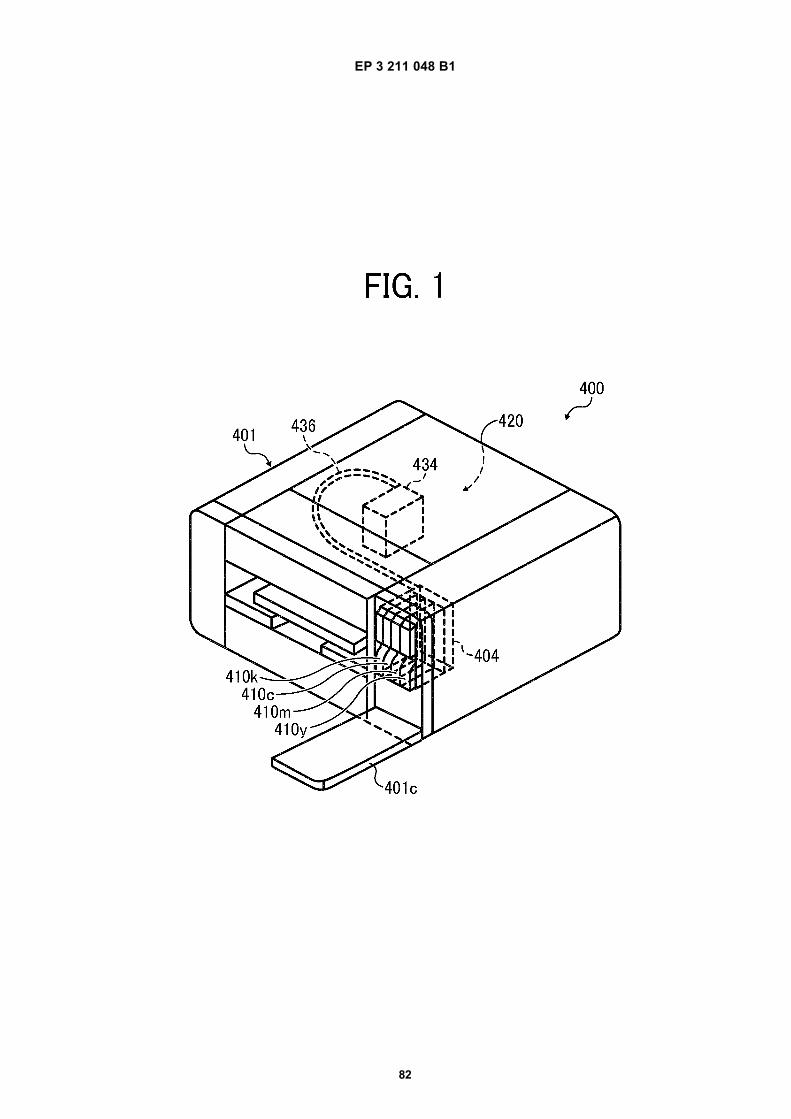
EP 3 211 048 B1
82
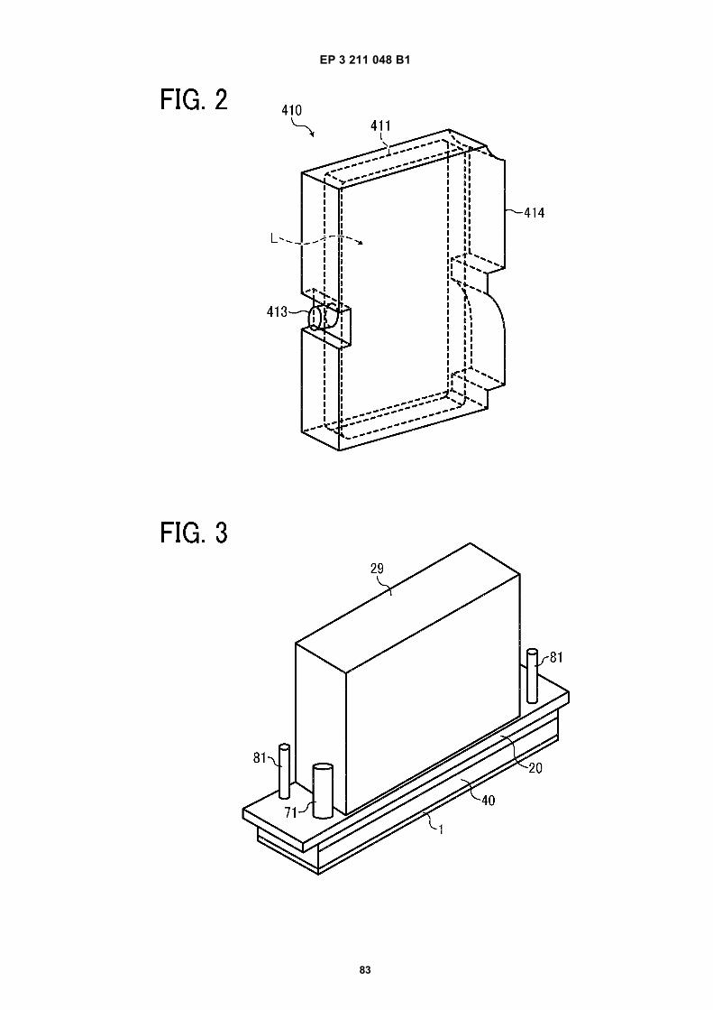
EP 3 211 048 B1
83
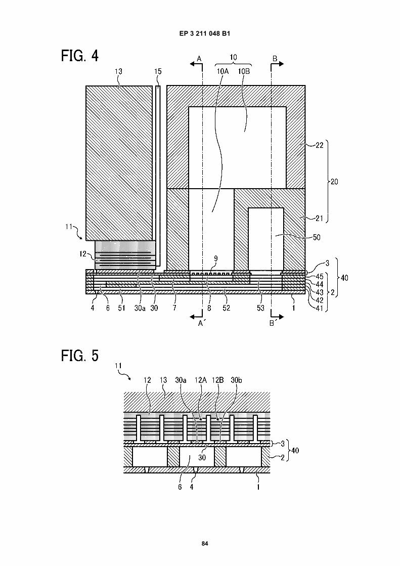
EP 3 211 048 B1
84
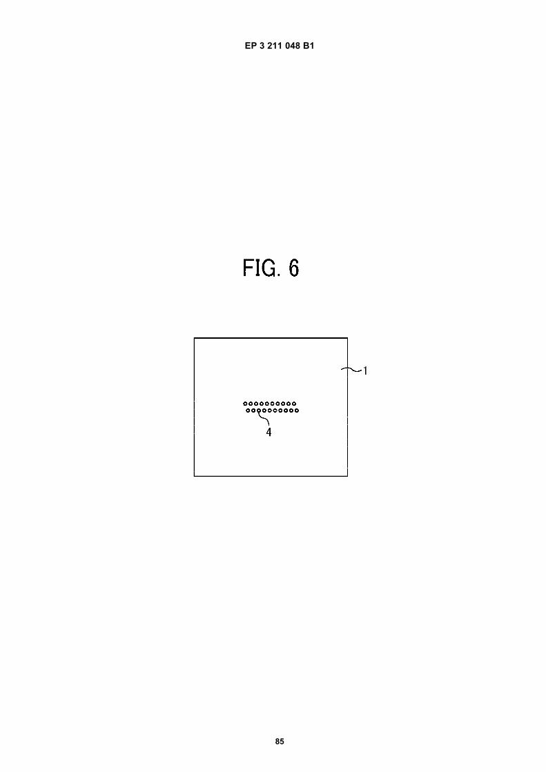
EP 3 211 048 B1
85
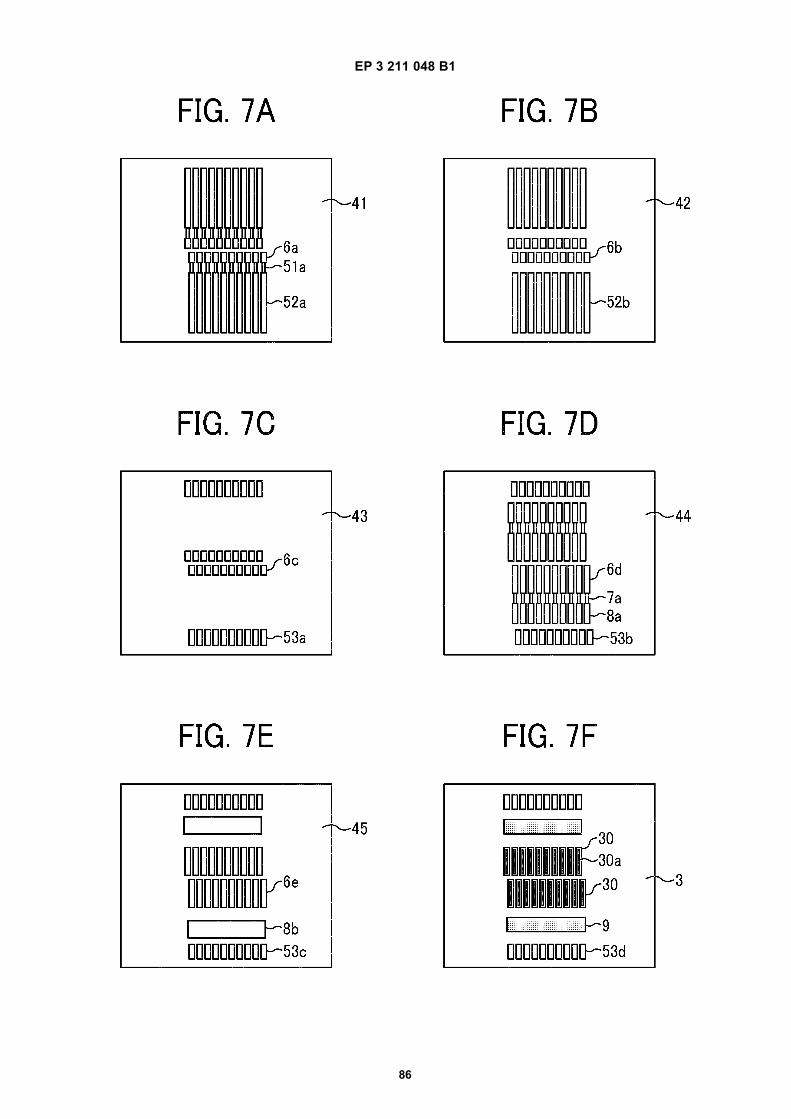
EP 3 211 048 B1
86
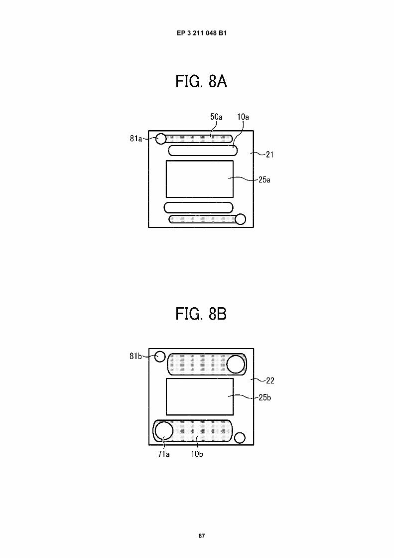
EP 3 211 048 B1
87
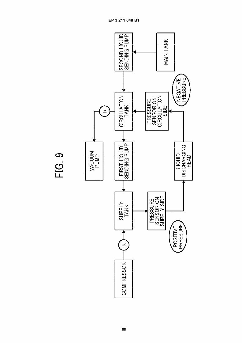
EP 3 211 048 B1
88
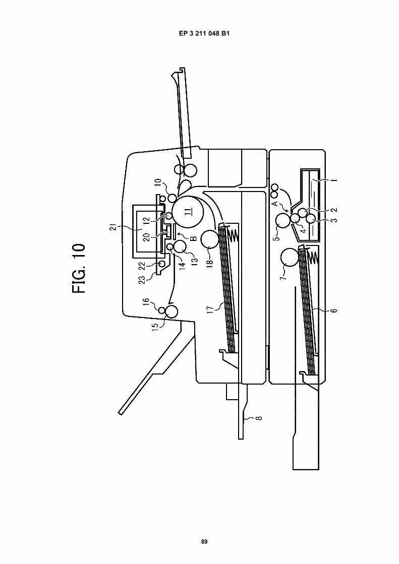
EP 3 211 048 B1
89
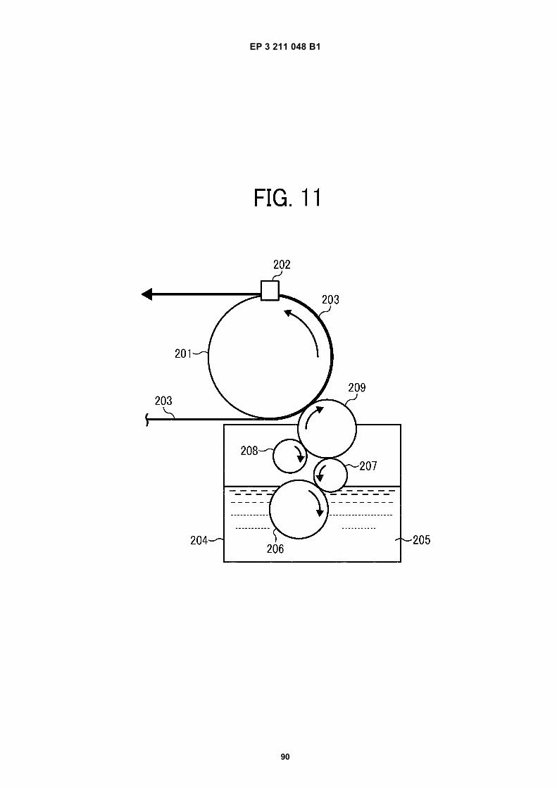
EP 3 211 048 B1
90
Related Documents